Part 010 - hans-scheel.ch
156
Online-Edition of the original book with additional Chapter 11 and Appendices A and B Part 010 Please get the complete edition from http://e-collection.library.ethz.ch/view/eth:4822 2011 © D. Elwell & H. J. Scheel
-
Upload
khangminh22 -
Category
Documents
-
view
1 -
download
0
Transcript of Part 010 - hans-scheel.ch
Online-Edition of the original bookwith additional Chapter 11 and Appendices A and B
Part 010
Please get the complete edition fromhttp://e-collection.library.ethz.ch/view/eth:4822
2011 © D. Elwell & H. J. Scheel

7. Experimental Techniques
7. 1. Principles 279 7. 1.1. Metastabte region, nucleation, seeding 279 7.1 .2 . Techniques to produce Supersaturation 293 7.1 .3. Preparation of solid solutions and homogeneously doped
crystals 3 21 7.1 .4. Preparation of special modifications and of metastabl e phases . 329 7.1 .5. Growth of compounds with defined valency states . 330
7.2. High Temperature Technology 332 7.2.1. Furnaces 332 7.2 .2. Temperature control (including programming) 340 7.2.3. Crucibles 356 7.2.4. Separation of crystals from solution 372 7.2.5 . Chemieals . 375 7.2.6. Atmosphere control 37<J 7.2.7. Stirringtechniques 381 7.2.8. High-pressure technology 396 7 .2.9 . T ypical procedures for growth of oxides and chalcogenides 399
7.3. Special Techniques, Specific Problems 404 7 .3. 1. Crystal growth from HTS at medium and high pressure . 404 7 .3.2 . Undesirable crystal growth from high-temperature solutions 413 7.3.3. Unexplored techniques and areas 41 S
7.4. Summary. 420 References 421
I t is mentioned several times in the book that the experience obtained frorn crystal growth from aqueous solutions can be applied to HTS f growth . The same is partially true for the experimental techniques. Therefore it is good practice for scientists and technicians entering the field of HTS growth to obtain some experience with solution growth at low temperatures where the growing crystals may be readily observed. For this reason, reference is made below to a few books and review papers which deal with experimental techniques in crystal growth from (aqueous) solutions: Brice (1973), Buckley (1951), Crystal Growth (1949), Gilman (1963), Haussühl (1964), Holden and Singer (1960), Khamskii (1969), Mullin (1972), Neuhaus ( 1956 ), Smakula ( 1962), Tarjan and Matrai ( 1972), V an Hook (1961) and Wilke (1973).
t HTS high-temperature solution(s).
278

7· EXPERIMENTAL TECHNIQUES 279
This chaptcr deals first with the principles and with thc main factors which have tobe taken into account when !arge crystals of high quality are tobe grown. HoweYer, the conditions for stable growth ha,·e been discussed in Chapter 6, and several aspects that arerelevant to cxperiments have becn mentioned in Chapters 3, 4 and 5.
'The sccond part of this chapter treats high-tempcraturc technology as far as is necessary for HTS growth. In particular the attainment and control of high temperatures, the crucible problems and stirring techniques are discussed in some detail.
In Section 7.3 a discussion is given of special techniques and of somc relatiYely unusual aspects, including a speculativc treatment of some possible techniques for future developmcnt.
7.1. Principles
7.1.1. Metastable region, nucleation, seeding
A typical example of a phase diagram used in crystal growth from HTS is shown diagrammatically in Fig. 7.1. The solvent can be an element, a compound or a combination of compounds. The solute is an element or a cornpound with a mclting point generally higher than that of the ~olvent, but in principle one could consider growing crystals from eutectic systems
TEMPERATURE
Metostoble supersoturoted
solution
LIQUID TL (undersoturoted solution) \
TEUT.
I
SOLUTE +LIQUID I I I I
__ V ____ ISOLUTE+SOLIDIFIED SOLVENT
nc no SOLVENT COMPOSITION SOLUTE
f1c:. 7.1. Typical eutectic phase diagram showing the metastable OstwaldMiers region and crystal growth by slow cooling (I), by solvent evaporation (2) and by gradient transport (3).

280 CRYSTAL GROWTH FROM HIGH-TEMPERATURE SOLUTIONS
in which the "solvent" has a higher melting point. As described in Chapter 3 the liquidus temperature curve is given, at least approximately in the majority of cases, by the Van't Hoff equation.
A solution of composition nA equilibrated at the temperature TA can be cooled, in the absence of seeds and agitation, to the temperature T8 at which spontaneaus nucleation occurs. In the region between the liquidus line and the dashed line intersecting B the solution is said to be undercooled or supersaturated and this region is called the metastable or Ostwald-Miers region. The metastability results because a nucleus of critical size must be formed before crystalline material is precipitated, as discussed in Section 4.2.
Metastability is a very complex phenomenon and it is still difficult to make reliable statements on the factors which critically determine the width of the metastable region. In addition, experiments are often difficult to reproduce and disagreement has often been reported between the results of workers who studied nucleation in aqueous solutions. It is, however, clear that the width of the metastable region will be greater if the build-up of high local solute concentrations can be avoided. A broad metastable region is therefore favoured by a small solution volume, a high viscosity and a low solubility. In addition the complexity of the solute and of the solution appears to have an important influence, as will be discusscd latcr in this section. The time dependence of nucleation should also be included in any discussion of metastability (see Eqn 4.11 ).
The metastable Oswald-Miers region is of paramount importance for the crystal grower since for the growth of )arge crystals the experimental conditions must be controlled to such an extent that no unwanted nucleation can occur. Homogeneaus nucleation is rather improbable in practical crystal growth experiments and will only occur in highly super saturated solutions. Generally heterogeneaus nucleation occurs on the container walls or at the surface of the solution, assuming that no undissoh·ed particles are present.
As indicated by curve 1 of Fig. 7.1, continued slow cooling of the solution from temperature T8 is accompanied by crystal growth at much lower supersaturation because of the presence of the crystals which nucleated at B. 1f solvent is evaporated at constant temperature ( curYe 2 of Fig. 7.1) the metastable region is passed and nucleation occurs at D. A.lternatiYely, as in 3, the solvent is tr.ansported from a hotter (saturated) to a cooler (supersaturated) region.
According to Neuhaus (1956) the width of the metastable Ostwald-Miers region in growth from aqueous solutions depends on the nature of the crystallizing substance, on the degree of agitation and on additives, as demonstrated in Figs 7.2(a) and (b). Figure 7.2(a) indicates that the width of the metastable region increases with increasing degree of "complexity"

7· EXPERIMENTAl. TECIINIQUE S
PROBABILITY
OF
SPONTANEOUS
NUCLEATION
(a)
PROBABILITY
OF
SPONTANEOUS
NUCLEATION
(b)
withoul slirring
wilh stirring
SUPERSATURATION
SUPERSATURATION
zRr
F1c. 7.2. (a) Probability of spontaneaus nucleation as a function of agitation and of "complexity" of participating substance (Neuhaus, 1956). (b) Probability of spontaneaus nucleation in relation to the type of additive for the example of NaCl crystallization from aqueous solution (Neuhaus, 1956).
(!\aCI - -K:-..i0 3 - -KAI(SO~)~ · 12H20), whereas stmmg produces the opposite effect. The role of additives on the habit is discussed in Chapter 5. Here the role of additives in generally increasing the width of the metastable region is shown by Fig. 7.2(b). Neuhaus attributed the etfect of urea to complex formation in front of the growing crystal, whereas dextrin is said to increase the width of the metastable region by increasing the Yiscosity .

2R2 CRYSTAI. GROWTH FROM IIIGII-TEMPERATURE SOI.UTIONS
It would be interesting to establish more quantitatively the relation between the width of the metastable region and such factors as the chemical anJ crystallographic "complcxity" of thc crystal, thc spccics prcscnt in thc solution, the viscosity and the degree of agitation.
In high-temperature solutions the width of the metastable region \·aries from 1 to 100°C, and very viscous systems (e.g. borate solutions) can br quenched as glasses. As discussed in Chapter 3, there seems to be a relationship between complex formation in the solution and the width of the metastable region. Qualitatively one is tempted to say that missing "complexity" of the crystals might be the cause of the difficulty in obtaining !arge crystals by flux growth of the simple compounds Ti0
2,
Zr02, Beü, whereas it is becoming easier to grow !arge crystals with increasing "complexity": GdV01, SrTi03, GdAI03 , Y3AI
5Ü 12 , Y
3Fe
5Ü
12,
Pb3MgNb2Ü 9• On the other hand there are many other factors which influence nucleation phenomena, for example complex formation in front of the growing crystal.
MOLTEN SALT
ALUNDUM CEMENT
GROOVED ALUNDUM CORE
- Pt SEED HOLDER
-Pt STIRRER
Pt CRUCIBLE
Pt WIRE
F1 r: . i.3. Y3 Fe,0, 2-crystallization on a rotating seed, with nutricnt m the hotter zone (Laudise, 1963).

TAULE 7.1. Crystals Prcpan:d by Top-seeded Solution Growth by the Slow-cooling Tcchniquet
Crystal
KNbO,. K(Nb, Ta)O, BaTiO,. BaTiO, NiFe20, KTaO,. K(Nb, Ta)O" K(Nb, Ta)O" Ba2Zn,Fe, 2Ü2 2 KTaO, (Ba, Pb)TiO, (Ba, Sr)TiO" KTaO,. K(Nb, Ta)O" Pb:~MgNb20, Ge02 K(Nb, Ta)O" Bi,Ti,.0 12
Gd2(Mo0,):. KNbO,. SrTiO,. Y,Ti 20, Ba2MgGe20, (Ca, Sr, Ba)Y 2(Zn, Mg),Ge,.O.,
Solvent
K2CO" K 2CO,. BaF, TiO, Na2Fe,O , K,CO" K,CO" K,CO" Ba2B,O, K2CO,. BaB20, -PbB,O, TiO, K2CO" K,CO" Pb0-B20,. Na-germanate K2CO,. Bi,O,., Bi,O:.-GeO,,
Bi,O,.-MoO,. MoO,. K,CO,. TiO, TiO, I Ba-borate GeO, Ca(Sr, Ba)O -t GeO,
Size
12- 15 g
7.5 g 20 :, lümm I cm"
14 -< 14 x 12mm
lOg
~15 x IOmm ~8 -<8 x 8mm 280 g I 75 ,< 60 x 25mm(l300g) f ~lcm"
3- 10 mm
2cm" 14 -< 14 x 6mm > I Cl11"
> I cm" > I cm"
}
t For experimentaldetailssec C hapter 10.
Refcrence
!Vliller (1958) Triebwasser ( 1959) Linares (1960) Von Hippelet al. (1%3) Kunnmann et al . (196.1) Wempie (1964) Bonner et al. ( 1965) Wilcox and Fullmer ( 1966) Aucoin et al. (1966) Senhouse et al. (1966) Perry ( 196 7) Bethe and Welz ( 1971)
3: m z ...; > r
Bonner et al. ( 196 7) 1"1
Bonnerand Van U itert(l967) g Coodrum ( 1970) Z
Epstein ( 1970)
Hurstand Linz(l971) Belruss et al. (1971) Bclruss et al. ( 1971) Bclruss et al. ( 1971) Bclruss et al. (1971)
N 00
w

284 CRYSTAL GROWTH FROM HIGH-TEMPERATURE SOLUTIONS
TABLE 7.2. Crystals Prepared by Top-seeded Solution Growth by the Gradient Transport Techniquet
Crystal Solvent Size Reference
YaFe,O," BaO x 0.6B"O" ~10 x 10mm Linares (1964) Y aFe.0 12 BaO x 0.6B,O,. ~40 x 10mm Kestigian (1967) YaFe,0 12 BaO x 0.6B 20,. Bennett ( 1968) Y 3 Fe,O," BaO x 0.6B 2Ü 3 20 x 20 x 10 mm Talksdorf (1974b) NiFe,O, BaO x 0.62B"0 3 10 x 8 mm Smith and Elwell (1968) K(Nb, Ta)O, K,CO,. ~1 cm 3 Whipps (1972) (Zn, Mn) 2Ba2 BaO x O.SB,O,. ~15 x 15 x 4 Talksdorf (1973) (Fe, Mn)"O"
t For experimental details see Chapter 10.
The temperature control requirements necessary for stable and homogeneous growth (see Chapter 6 and Chapter 7.1.3) are normally much more stringent than those necessary to prevent spontaneaus nucleation. This implies that if spontaneaus nucleation occurs during the growth of a crystal then its quality is often bad due to formation of inclusions and striations.
The growth of !arge crystals is fa,·ourcd by thc usc of secd crystals, which is common practice in crystal growth from aqueous solutions. However, in high-temperature solutions technical reasons make the use of seeds very difficult. Since the seeds cannot be observed in the (platinum) crucibles and in the opaque solutions the solubility curve has to be known Yery exactly and the conditions carefully adjusted in order to prevent dissolution of the seed crystals.
Growth on a rotating seed immersed in the solution has been described by several authors (see Table 7.5), and an example of an experimental arrangement is shown in Fig. 7.3. Timofeeva and Kvapil (1966) fixed seed crystals near the base of an unstirred crucible and still observed multinucleation. This shows that seed crystals are only of major advantage when the solution is homogenized by forced com·ection or when the solution volume issmall as is often the case in the travelling solvent technique and in liquid phase epitaxy.
The most popular means of nucleation control is by top-seeding as can be seen from Tables 7 .I and 7 .2. The arrangement used successfully at MIT for the growth of several crystals is shown in Fig. 7.4. The position of the crystal-liquid interface is important with respect to inclusion formation, dislocation density and maximum attainable growth rate. With increasing depth of the growth face (in the solution) the temperature gradient at the interface becomes smaller and the Supersaturationgradient increases, the stable growth rate decreases, but also the dislocation density

7· EXP ERII\1E TAl. TE C H I Q UE
A) BoTtOs Med 8) BaT 10, • T iOz me l: C) Pt crucib&ti 0) Zirconio cruc: ible
E) Zirconia brick post'
F1 CIOoinv l><ick Gl K- 30 r,,. l><ick
- .. . ~Mirror ~ · ~ ~ \
\ . I ' .
lGiobor heoter, I of 8
TC control
z8s
F rc. 7.4 . Arrangement for c rvs tal growth b v top seedin g (Von Hippe! et al., 1963; Be lruss et al., 197 1 ).
w ill dec rease if inclusions are not trapped . T he temperature grad ient also cl etermines the clegree of facetting as di scussed by W ilcox (1970). The technique of g rowth on rotating seed crystals at th e top of a so lutio n, w ith or without withd rawal, has been g i,·en a variety of names (Czoch ralski , Ky ropoulos, pu lling from soluti on etc.), but it seems th at th e term top-
K 2

286 CRYSTAL GROWTH FROM HIGH-TEMPERATURE SOLUTIONS
seeded solution growth (TSSG) first introduced by Linz et al. ( 1965), and described in detail by Beln1ss et al. (1971 ), is becoming increasingly popular and is thereforc adopted in the following discussion.
The size of seeds used in HTS growth has to be a compromise between various requirements. As is discussed in Chapter 6 and may be seen from the topographs of Chapter 9, edge and spiral dislocations propagate from the seed in a direction approximately normal to the growing faces. The high-quality (nearly dislocation-free) regions between these dislocation bundles are obviously !arger when small seeds are used.
Small seed crystals, on the other hand, have the disadvantage of being easily dissolved and also require an extremely low Supersaturation if the maximum stable growth rate is not to be exceeded (see Section 6.6.1 ). Therefore one has to choose the optimum seed size in relation to the solution volume and the degree of control over the supersaturation. If !arge samples are available for use as seeds, it is advantageaus to use seed plates ofthat crystallographic orientation which is optimum with respect to low impurity incorporation, high stable growth rate, and the intended application; good examples of the application of these criteria are providcd by the hydrothermal growth of quartz crystals ( Ballman and Laudise, 1963) and by the growth of ADP from aqucous solution (Egli and Johnson, 1963). In LPE-grown layers of magnetic garnets the orientation-dependent site preference of several ions is used to optimize the properties of the magnetic bubble domains as will be mentioned in the next chapter. As is well-known from crystal growth from aqueous solutions it is desirable to etch the seeds (to dissolve the damaged surface layer and to remove adsorbed impurities) before growth is commenced in order to obtain high quality material.
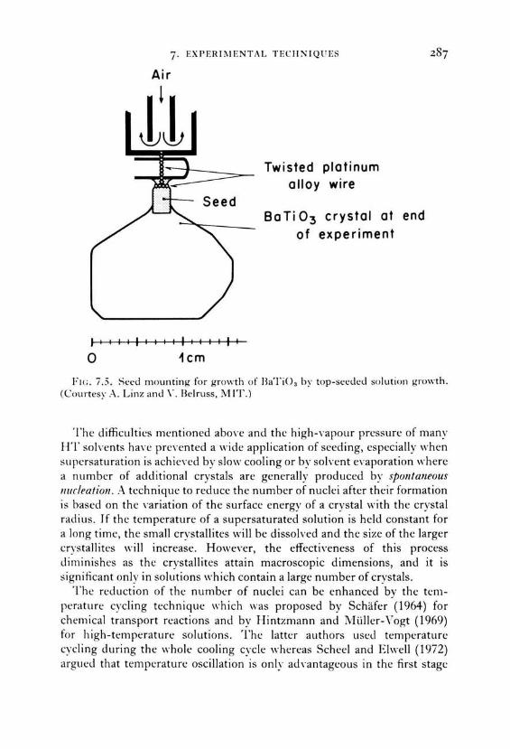
The mounting of seed crystals in ftux growth of oxides normally necessitates the use of platinum wire. Since pure platinum is Yery soft at the temperatures used and since the wire has tobeasthin as possible, it is proposed to use alloys of platinum with 1- 10% rhodium or iridium. Thc wire thicknesses should range from 0.1 to 0.5 mm depending on the size of the seed, degree of stirring and the length of the experiment. If the seeds are immersed in the high temperature solution it is generally desirable to drill a hole into the crystal so that wire may be inserted for fixing to the seed holder. The alternative of wrapping the wire araund the crystal is disad\·antageous since the crystal may become loose when an outer layer is dissolved during the first stage of the experiment. Examples of seed mountings for top-seeded solution growth are shown in Figs 7.5 and 7.6. For growth from metallic solutions a seed holder may be ground from graphite, boron nitride or alumina. The seed may be conveniently held by a peg of the same material as the holder, vvhich is inserted through a horizontal hole in the seed and the holder.
7· EXI'ERli\IENTi\L TECIINIQ U ES
Air
l
!!
Jiillflllllllllfl
0 1cm
Twisted plotinum olloy wire
Ba Ti 0 3 crystol ot end of experiment
Fll;. 7.5. Seed mounting for growth of llaTi0 3 by top-seeded solution growth. (Courtesy .-\. Linz and \" . Belruss, MIT.)
The difficultics mentioned aboYe and thc high-,·apour pressure of many HT solvents ha,·e preYented a wide application of seeding, especially when Supersaturation is achieved by slow cooling or by solvent evaporation wherc a number of additional crystals are generally produced by spontaneaus nurleation. A technique to reduce the number of nuclei after their formation is based on the ,·ariation of the surface energy of a crystal with the crystal radius. Jf the temperature of a supersaturated solution is held constant for a long time, the small crystallites will be dissolved and the size of the !arger crystallites will increase. Howewr, the effectiYeness of this process diminishes as the crystallites attain macroscopic dimensions, and it is significant only in solutions which contain a !arge number of crystals.
The reduction of the number of nuclei can be enhanced by thc temperature cycling technique which was proposed by Schäfer (1964) for chernical transport reactions and by Hintzrnann and Müller-Vogt (1969) for high-temperature solutions. The latter authors used temperaturc cycling during the "·hole cooling cycle whercas Scheel and Elwell (1972) argued that tempcraturc oscillation is only ath·antageous in the first stagc

288 CRYSTAL GROWTH FROM HIGH-TEMPERATURE SOLUTIONS
(a)
(b)
Plotinum tubes
Plotinum rod (welded to the tube)
Plotinum wire
Seed
Plotinum wires
Seed
(c)
(d) F1c. 7.6. (a)-(d) Examples of seed mounting .
Plotinum wires
Seed
Plotinum rod
Plotinum wire
Seed
of the experiment when nucleation occurs. This is demonstrated in Fig. 7.7, which shows the procedure of Scheel and Elwell. First the mixture of solt1te and solvent is held at the temperature A, about 50° abO\·e the liquidus temperature T1,, for about 15 hours (the "soaking period") in order to ensure complete dissolution. Then the temperature is lowered to C, a temperature significantly below TL and TM, the temperature of the Iimit of the metastable region. Most of the crystallites formed during this initial cooling are dissahred when the melt is heated to C. This procedure is repeated ( -?C' - ·E --,·C" - /J according to the dashed line) until a tempera-

7· EXP E RI MENT Al. TE C II N IQ U ES
TEMPERATURE (K)
1650 - A
1600
1550
24 48 72 96 120 TIME (HOURS)
F1 c . 7.7. T emperature cycl ing at th t: sta rt o f a slow cooling ex periment in o rd er to decrease the number of spontaneously nucleated crysta ls (Scheel and Elwell, 1972).
ture belo-w TL is reached suchthat only a few crystallites have "survived" . Then th e temperature programme as described in Section 6.6.1 is started from J. I f the temperatures T1~ and T.11 are accurately known, the procedure should follow the full line (A -C -~D--E -F) so that programmed cooling starts after the minimum period required for dissolution of the smaller crystallites.
D epending on th e temperature gradients in the crucible, nucleation occurs at the surface (which is also the favoured location in the case of solvent evaporation because of high local supersaturation) or at the crucible walls. In order to provide a preferred site for nucleation localized cooling has been proposed in several papers and has been used in melt growth by the classical techniques of Bridgman, Kyropoulos and Czochralski.
A "cool" spot or region can be provided by an air jet (Chase and Osmer, 1967; Grodkiewicz et al., 1967 ; Scheel, 1972), by fixing cooling fingers (heat sink, ceramic rod , heat pipe) to the crucible wall, or by placing the crucible into an appropriate temperature gradient (by suitable choice of position in the furnace with respect to the heating elements). For example nucleation at the bottom of the solutionwas achieved by Linares (1967) and by many other authors, but in most cases multinucleation occurred.

290 CRYSTAL GROWTH I'ROM IIIGII-TEMPERATURE SOLUTIONS
K vapil ( 1966) and J ohn and K vapil ( 1968) used a baffie above the cooln base in order to reducc the m1mber of nuclei as shown in Fig. 7.8. Th ey also applicd a hydratdie scal in ordcr to prcvcnt solvent cvaporation.
However, cooling of the base is often disadvantageaus in stationary crucibles: the homogenization of the solution by natural convection is minimized (see Chapter 6), and the stable growth rate is low. Therefore localized cooling of the crucible base is only effective when the solution is homogenized. With nonvolatile solutions a stirrer can be applied, and with volatile systems where the crucible has to be sealed the stirring technique of Scheel (1972) by accelerated crucible rotation (see 7.2.7) is very effecti\e
...... . ...... . . • 0 ••• • • • •••••• . . . . . . . . . . . . . .
• • • • • 0 • • •••••• • • • • • • • • • • • 0 •• . . . . . . . . . . . . . . .
. . . . . . . . . . . . . . . • • • • • • • 0 •• • ••• . . . . . . . . . . . . . . . • • • • • • • • • • • • 0 • . . . . . . . . . . . . . . . . . . . . . . . . . . . . . . . . . . . . . . . . . . . . . . . . . . . . . . . . . .
0 • ••••••• • •• 0 •• • • • • • • • • • • 0 • • •
• • • • • • • • • • • • 0 •• • • • • 0 •••• •• ••• . . . . . . . . . . . . . . .
· HYDRAULIC SEAL
SOLUTION
PT BAFFLE
F1r.. 7.8. Reduction of the number of crystals nucleated at the cooler base hy a hafHe. Flux evaporatinn is minimized by a hydrauli<.: seal (h: vapil, J<)(,(J; John and K vapil, 1968).
so that by proper control of the experimental conditions one or a Ycry fe\\ crystals are spontaneously nucleated on the cooled crucible base.
However, stirring of the solution has to he smooth; with strong agitation or by shaking of the solution the width of the metastable region is made extremely small, and multinucleation will occur due to local density fluctuations and to collision of the crystallites among themselves or with the container or stirrer. An effective technique of nucleation control was applied by Bennett (1968) and by Talksdorf (1968) and is schematically shown in Fig. 7.9(a)- (d). The crucible is contained in a high-temperaturc furnace . After soaking (a) the solution is cooled until either the saturation point is exactly reached or until spontaneaus nucleation has occurred (b ).

7· EXI'EHii\IENTAL TECIINIQUES
Seed crystol
(a)
Plotinum crucible with
welded Iid
Ceromic
Unsoturoted solution
(b)
(d)
solution
Grown crystol seporoted from
solution
FH; , 7.9. Immersion of a sced crystal into a saturated solution. (a) Initial p<~sirinn ar high rcmpcrarun.: . (b) :\ftcr a ccnain Jcgrcc nf cooling spontancous
nuclcation occurs at thc hottom, and the cruciblc is irH·erted (c) so that the saturated solution em-ers the crystal, which grows during continued cooling. (d) .-\fter tnmination of cnoling thc grown crystal is separate<.! from the solution by rclllH'rswn of the crucible into thc initial position (ßennett, 1968 ; Tolksdorf, 1968).
The crucible is then im-erted so that spontaneously nucleated crystals are separated and the seed crystal is immersed in a saturated solution and grows by continuous cooling (c). At the end of the run the crucible is inverted again, thereby separating the grown crystal from the solution (d). This tcchnique in combination with localized cooling and with the accelerated crucible rotation technique was used by Talksdorf and Welz (1972) to produce !arge inclusion-free crystals of magnetic garnets for \'arious applications.
An alternative approach to reduce the number of crystals nucleated, " -hich has been successfully used in a number of cases, relies upon the addition to the solution of small quantities of some material which is not incorporated into the crystal. The most popular additi,-e is 8 20 3 which is thought to increase the width of the metastable region, probably because of the formation with the various cations of complexes corresponding to the borates which are stable at lower temperatures. The widespread use of additi\'es such as 8 20 3 has led to the development of empirical Statements of the form: "'T'he more complex the solution, the greater the solubility and

292 CRYSTAL GROWTH FROM HIGH-TEMPERATURE SOLUTIONS
the width of the metastable region, and the fewer the number of crystals nucleated."
Remeika (1970) reported a dramatic decrease in the number of ferrite or garnet crystals nucleated in a Pb0/B20 3 solvent when 0.1-0.5 % by weight of V 20 5 was added. Similarly Scheel (see Kjems et al., 1973) was able to prevent multinucleation of LaAI0 3 from a PbO- PbF2-B20 3 flux and therefore to grow !arge inclusion-free crystals when 0.7 wt% V20 5 was added. The beneficial effect ofthissmall V 20 5 addition is attributed to the formation of La V0 4-like complexes in front of the growing crystals. If these complexes are distributed statistically among LaAI0 3-Iike complexes, they will tend to retard the formation of critical LaAI03 nuclei and hence to reduce nucleation.
In principle the effect of addition of PbF 2 to PbO could be described in the same way since it permits the formation of complexes such as LaOF. According to this model, however, V 20 5 will be particularly effective since it forms a !arger complex.
Grodkiewicz et al. (1967) reported a beneficial effect for the growth of !arge garnet crystals of adding several divalent meta! oxides or Si0 2• The effect of the latter was confirrned by Page (unpublished, reported by Brice, 1973) who found that the nurnber of Y 3Fe50 12 crystals nucleated frorn a PbO-PbF 2 flux decreased from 50- 100 when pure ehernieals were used to 3 or 4 when 0.08% Si was substituted for Fe in the melt. These impurities may also act by forrning cornplexes but additional cornplications arise frorn the tendency of iron in the crystal to exist as Fe2 ·• or Fe 4 - ions in srnall concentration. One of the most rernarkable examples of nucleation reduction has been reported by Robertson et a/. ( 1973), who obserYed the nucleationof only one yttrium iron garnet crystal frorn a PbO- PbF2- B20 3
flux when growth occurred in oxygen under a pressure of ten atmospheres. The reduction in this case was attributed to the Iack of crystals of a second phase which often act as nuclei for garnets.
One point which is frequently neglected in connection with nucleation control in HTS growth is the quality of the containers. The use of new platinum containers with polished inner walls generally results in fewer crystals (by heterogeneaus nucleation) than in crucibles which haYe been used frequently and which show strong recrystallization and a rough surface. Platinum crucibles can be re-used (as is necessary because of the high cost of re-fabrication) when they are carefully cleaned, reshaped and chemically or mechanically polished as is discussed in detail in Section 7.2.3. The same arguments apply to other types of container.
Thus control of nucleation in HTS growth is generally problematic and needs careful control of all chemical and experimental conditions. By homogenization of the solution and by use of appropriate seeds, !arge

i · EXPERI JVIENTAL TECHNIQUES 293
crystals can be grown . If spontaneaus nucleation has to be chosen, smooth stirring of the solution combined with localized cooling will Iimit the number of nucleated crystals generally to one or wry few.
7.1.2. Techniques to produce Supersaturation
A.s in crystal growth from aqueous solutions and as is obvious from Fig. i .I, supersaturation can be obtained by slow cooling ( 1 ), by sohent e1.:aporation (2) or by the temperature gradient technique (3) in which nutrient is held in a hotter region: solution saturated in the hot region is transported to a cooler region by natural or forced convection and so becomes supersaturated .. \part from these three most popular techniques there are a few special methods to obtain Supersaturation such as the reaction technique in \\·hich solute constituents formerly separated diffuse to the region where reaction ( and crystallization) proceeds. If crystal constituents are transported in the vapour phase to the liquid solution in order to precipitate the (solid) crystal, this may be termed the VLSt mechanism, which is weil known as an important mode of whisker growth (Wagner and Ellis, 1964 ). The temperature gratlient, n:actiun and \·Ls techniques, together with electrolytic growth will be referred to collectively as transport techniques. Reaction equilibria which are shifted by means other than by ternperature change (included under "slow cooling"), solwnt evaporation or temperature gradients include evaporation of "reaction products" and the salting out effect. The techniques of obtaining supersaturation will be described according to the following classification:
.\. Slow cooling, B. solvent evaporation, C. transport techniques.
The supersaturation value used in an experiment is determined by the requirernent that the growth rate should not exceed the maximum stable value, as discussed in Chapter 6. It is not possible at present to give a quantitative criterion for the maximum supersaturation, apart from that specified by Eqn 6.26. If the solution, stirring rate, temperature gradient etc. are optirnized, the supersaturation may ha,·e a maximum value such that the growth rate obtains its ultimate stable value. Very small supersaturations are, however, pointless since the crystal will exhibit growth and dissolution Auctuations as shown for Czochralski growth by Witt and Gatos ( 1968) and by Kirn et al. ( 19i2).
In practice the relative supersaturation normally has a value in the region of 0.1 - 1 ° ~ , as in aqueous solution growth, although the corresponding supercooling is appreciably higher at high temperatures. For an ideal solution with np ccexp (- cfJ jRT), the relative supersaturation is
t VLS vapour-liquid-solid.

• 294 CRYSTAL GROWTH FROM HIGH-TEMPERATURE SOLUTIONS
L1n c/JL1 T a= 1l c = RT2 .
Thus for c/1 = SO kJ fmole and T = 1200°C, L1 T = 3.6°C for a = 1°10 •
A. Slow cooling. The most common technique for producing supersaturation in flux growth is by slow cooling (see Tables 7.1 and 7.3 and Chapter 10) where generally a linear cooling rate of 0.2°C h - 1 to 10°C h - 1
is applied. I f inclusion-free crystals !arger than a few millimetres have to be grown a cooling rate of less than 1 oc h - 1 is necessary as discussed in Chapter 6.
The linear growth rate z· (in cm/h) by slow cooling is related to thc cooling rate (Laudise, 1963; Cobb and Wallis, 1967) according to
"" = ~ (dn,)(c[_f) < Ap dT dt '
(7.1)
where V is the volume of solution ( cma), A the area of the growing crystal (cm 2 ) and p its density (gcm - 3), dn, /dT the change in solubility per degrec [g cm - 3 °C - 1 ] and dTjdt the cooling rate in °Cjh. ObYiously, Eqn 7.1 only holds when all the soh1te precipitated is deposited on the crystal.
The optimum cooling rate for stable growth as a function of Yarious growth parameters is also discussed in Chapter 6. I t was shown that a constant linear growth rate and therefore a cubic decrease of tempcraturc with time will cause unstable growth. Scheel ancl EI weil ( 1972) and Poh I and Scheel ( 1975) have shown that the temperature regulation and thc coo1ing rate have tobe adjusted in such a way that the slope of the effecti\-e cooling cun·e (including any oscillations or fluctuations) ne,·er cxceeds thc s1ope of the calculated optimum cooling curYe for stable growth at thc corresponding temperature. The generat rule is that the slm\Tr the growth rate the better ancl !arger the crystals. 1-!oweYer, one has to find a compromi~e between the slow cooling rate and the correspondingly lang duration of an experiment. Also Laudise (1963) stressed thc fact that cooling rates which are not at least comparable ,,·ith thc tcmperaturc fluctuations due to inaccurate regulation are pointless .. -\ \-cry slow initial cooling rate is impractical for the (normal) case where the super-solubility curve is not known with sufficient accuracy and much time is lost beforc nucleation starts.
The ad,·antages of the slow cooling techniquc are:
1. That a closed container (sealed crucible) can be usecl thereby preventing evaporation of volatile ~olvent or solute constituents which are poisonous or corrosive and which cause uncontrolled supersaturation.
2. The technique is relatively simple for the growth of crystals up to

7· EXPERIMENTAl. TECIINIQUES
5- 10 mm size. For !arger high-quality crystals the etfort on apparatus, tempcraturc regulation and programming has to bc incrcased.
3. Thc s]m,· cooling tcchniquc is \Try suitablc for nploratory materials research. lt is usually simple ta crystallize known crystals ancl also new phases in sizes fram 2 ta 5 mm, which are suitable for X-ray structure cleterminations ancl a number of physical measurements.
The slow cooling technique has se,·eral disaciYantages which arise from the continuously changing growth temperature:
I. The concentration of equilibrium clefects varies through the crystal (ho,,·eyer for a typical temperature range such as 1500°K to 1200°K this is generallynot critical).
2. The concentration of incorporatecl impurities ancl clopants changes accorcling to the ditferences in the solubility behaYiour of the solute ancl the dopants or impurities. Frequently this is manifestecl in the shifting of equilibria in the solutions as discussed in Sectian 3.4. For example, it is extremely clifficult ta produce homogeneaus chromium cloping in :\1~0 3 and other oxides by the slow cooling ted111iyue and th<.: solYent e\·aporation or transport techniques are then preferable.
1. Far the preparation of solid solutions the same arguments as above for dopants hold, only the etfect on the composition is more clrastic. In Section 7.1.3 the techniques to obtain homogeneous solid solutions will be cl iscussed.
4. Frequently in slow-cooling experiments unwantecl phases appear (sometimes "non-reproclucibly" or clepending an the crucible size: the explanation is uncontrollecl evaporation of a soh·ent constituent as in the case of Y 3 Fe5Ü 12 crystals grown from PbO-Pb F 2- B2Ü 3 flux where magneto-plumbite, YFe0 3 or Y~0Ü 16F28 are the unwanted phases, !Iee Talksdorf ancl Welz, 1972). Reproducibility is an absolute necessity and can in this case be achiewd by sealing the crucibles by welding and by careful control of all parameters including the purity of the chemieals used .
.-\ccording to the degree of nucleation control the following Yersions of the slow-cooling technique can be distinguished:
Spontaneaus uncontrolled nucleation (Table 7.3). Reduction in the 11L1mber of crystals nucleatecl by an oscillatory
temperature variation at the start of the experiment. I .ocalized cooling. Localized cooling and ACRT stirring (see Section 7.2.7). Bennett-Tolksdorf seeding technique (with and without .-\CRT). Top-seeded solution growth.

TABLE 7.3. Examples of Crystals Grown by the Slow-cooling Technique and Spontaneaus Nucleationt
Crystal Solvent Size (mm) Remarks Referencet N \0 0\
AI ,O,. PbO /B,O,.; 30 Plates Nelson and Remeika (1964), (")
PbF, Whiteand Brightwell (1965) ::c -< BaTiO,. KF 34 X 24 X 0.4 Butterfly twin Remeika (1958) IJl -l
BeO Various 10 Prisms Newkirk and Smith (1965) > C (graphite) Fe, Ni 30 X 0.5 X 0 .5 Austerman et al. (1967) r
Cd ,_xCuxCr,Se, Cd Cl, 3-4 Tyco (1971) 0 ::c
CdS Na,Sx 15 X I X I ; 5 X 5 )o' 0.2 Prisms , plates Scheel ( 1974) 0
GaFeOa Bi,Oa!B iF ,. 12 x 6 x 6 Linares (1962) ~ -l
GdAIO, PbO/PbF,/B,O, 35 Y 30 X 25 210g,ACRT Scheel (1972) :z: Gd 3Fe,O" PbOlB,O,. 10 Remeika (1963) .."
Gd,Ga,O,, PbO /B,Oa 8 Remeika (1963) ::c 0
In ,O, PbO/B,Oa 10 X 10 ,, I Remeika and Spencer ( 1964) ?.;: LaB, La S- 8 Deacon and H iscocks ( 1971) :z: LiFe,,08 PbO /B,Oa 20 Pointon and Robertson (1967) 0 Mn,O, PbF, /Pbü JO X JO Wanklyn (1972) :z:
I
Mn Te Te 50 X 1 5 X J5 ACRT Mateika ( 1972) -l
NaCrS, Na,S ., 20 X 20 X 0 .2 Plates Scheel (1974) m 3:
Y,AI,O" PbO!PbF, B,O, 50 Large crucible Grodk iewicz et a/, (1967) " m Y,.Fe,O ,, PbO /PbF,/B,Oa ~300g Large crucible N ielsen ( 1964) ::c
> Y,Fe,O" PbO !PbF, /B,Oa ~60 Large crucible Grodk iewicz et al . (1967) -l
Y,.Fe,O" PbO 'PbF, 8,0" 57 g Bennet-Tolksdorf Bennett ( 1968) c:: ::c
nucleation control m
Y,Fe,O" PbO .'PbF, ~ 30 / 25 / 25 (49 g) nucleation Tolksdorf ( 1968) IJl 0
control r
Y,.Fe,O" PbO/Pbf, ,B,Oa 30 X 25 X 25 lnclusion-free, Scheel (1972) c:: -l
ACRT 0
Y.Fe,O" PbO /PbF, 60 X 50 X 25 250g, ACRT Tolksdorf ( 1974a) z IJl
Y,Fe, .8Ga ,.20,, PbO/PbF,I B,Oa JO X 25 Y 25 Inclusion-free Scheel (1972) ACRT
ZnO PbF, 50 Nielsen and Dea rborn (1960)
t For experimental details and for referenccs sec Chaptcr 10.

7· EXPERIMENTAL TECHNJQ U ES 297
B . E-mporation of soh·ent. Solvent e\·aporation, the basis of common salt production for thousands of years, has also been frequently used in crystal growth from HTS. In this case the linear growth rate of the crystal is giwn by
1' = ;·idd~) (7.2)
with the symbols corresponding to those of Eqn 7.1, so that dVjdt is the soh·ent evaporation rate.
Flux evaporation has been systematically used by Tsushima (1966) , Grodkiewicz and .1\itti (1966), Roy (1966), \\1ood and White (1968) and by Webster and White ( 1969). The technique has been especially used for compounds which react with the solvent at lower temperatures
(Ti02
+ Pb0 < l~on ,- PbTi03 ; Hf02
+ Pb0 <1200
,\_ PbHfü3
) or for a
cation of which the ,·alence state changes by oxidation at lower tem-
(
< ' I I OO' l' ) peratures Cr~ ·· - - - - · Cr6
t , see Section 3.4 . Roy (1966) stressed the
TABLE 7 .4. C rystals Prepared by th e Solvent Evaporation T echniqud
Crystal Solvent Size Reference ---- - -
8aTi0 3 8aCI, Timofeeva and Zalesskii ( 1959) 8aTiO" 8aCI, Arend (1960) In,O, 8,0:1 fewmm Roy(l966) TiO, _x Na,8 .o, .. few mm Roy(l966) Fe,O, ~a ,8,0,., few mm Roy(l966) Cr,0 3 Na,8 ,0," fewmm Roy (1966) VO, v ,o . fewmm Roy (1966) 8aAI.,O ,. PbF, 2 x 2 ' 0.1 mm Tsushima (1966) Al,0 3 PbF, 10 " 10 >- I mm Tsushima ( 1966) ZnAI,O, PbF, 1 >- I x I mm Tsushima (1966) ZnMn,O, PbF, 2 ' 2 x 2 mm Tsushima (1966) CoMn,O, PbF, 2 x 2 x 2 mm Tsushima (1966) LaAI0 3 PbO + PbF, 3 x 3 x 0.4 mm Tsushima (1966) HfO, PbF,-8,0:~ -l g Grodkiewicz and N itti ( 1966) ThO, PbF,- B,O" -5 mn1 Grodkiewicz and N itti (1966) TiO, PbF,- 8,0" -2mm Grodkiewicz and Nitti (1966) AI,O ,.: Cr PbF,- 8,0" 57 ·. 2mm Grodkiewicz and N itti (1966) YCr0 3 PbF,- 8,0" 7 · 4mm Grodkiewicz and Nitti (1966) MgO PbF, Webster and White (1969) SrSO, NaCI} 8aSO, N a Cl few mm Pa tel and Bhat ( 1971) Pb SO, Na Cl
t For experimental details see Chapter 10.

298 CRYSTAL GROWTH FROM HIGH-TEMPERATURE SOLUTIONS
advantages of the flux evaporation method especially for such cases where oxides of metals with a specified valence state have to be grown. The constant temperature and a carefully controlled oxygen partial pressure allow growth of oxides of lower valency states as was shown by Berkes et al. (1965), Roy (1966) and by Rartholomew and White (1970). Flux evaporation could also be used to grow crystals which show a low variation of solubility with temperature or a retrograde solubility behaviour. Several crystals prepared by solvent evaporation at high tempcratures are listed in Table 7.4, and further examples are given in Chapter 10.
Since solvent evaporation may be carried out isothermally, this techniquc offers the advantages connected with growth at constant temperaturc:
1. Easy and often closer temperature control. 2. Constant concentration of equilibrium defects. 3. Approximately constant incorporation of solvent ions as impurities. 4. In the cases where the distribution coefficient of impurities or dopants
is not extremely different from unity and if growth takes place either under the regime of pure diffusion control or under complete mixing, a homogeneaus incorporation of dopants and impurities can bc expected.
A/umma ...._ Q tube rl.h
LliJ L V t ..... - ..-- )
(.; . ~ Balance
FIG. 7 .10. Open system for solvent evaporation with monitaring by a balance (Wood and White, 1968).

7· EXPERIMENTAL TECIINIQUES 299
DisadYantages of the isothermal Aux evaporation technique are the difficulty of controlling the c\·aporation rate and thus the growth rate, and thc poi~onous and corrosivc nature of thc soiH·nt \·apours (c.g. PbF2) if an opensystemsuch asthat shown in Fig. 7.10 is used. The advantage of this systcm is that the balance permits a measurement of the rate of e\·aporation and hence of the mass deposition. The usc of an air Aow to remo,·e PbF 2
, ·apour \\·ill, howewr, normally produce temperature Auctuations. In order to preYent corrosion of furnace ceramies and heating elements
by thc action of the solvent vapours, closed evaporation systems haYe been proposed and three such designs are shown in Fig. 7.11. These systems permit control or programming of the evaporation rate through ,·ariation in the temperature T2 at which condensation occurs.
An important feature of the Aux evaporation technique isthat nucleation should take place in the lower part of the crucible. The surface region of the solution has tobe warmer, otherwise crystallization at the surface would diminish the free surface area of the solution and thereby decrease the rate of cYaporation. Therefore, in a symmetric (to the heat source) position of thc cruciblc, littlc natural thermal conn.:ction occurs.
Depencling on the relati,·e densities of solute and the solution some solutal convection can occur, the latter being favoured by a higher density of the crystal. HoweYer, any natural convection in this case of a cooler crucible hase will be slow, so that growth is diffusion-controlled unless stirring is applied. This can be achieved for closed systems by the accelerated crucible rotation technique as in the apparatus shown in Fig. 7.11(c). In this apparatus, the evaporationrate will be governed by the dimensions rL and r 2 as weil as by the temperatures T 1 and T 2 so that considerable Aexibility is aYailable to the experimeter for optimization of the growth conditions.
In principle the evaporation rate w is constant when the temperature is held constant and is giYen by the Arrhenius equation
w = w0 exp ( - H,.jRT)
where w 11 is the rate constant, H , the activation energy of vaporization, R the gas constant and T the absolute temperature. From measurement of the \\·eight loss as a function of temperature Giess ( 1966) determined an actiYation energy of 33 kcal jmole for the evaporation of PbF 2 from a Y3 Fe5Ü 12-PbO-PbF2 melt, whereas Perry (1967) estimated an activation energy of 62 c 5 kcal jmole for the e\·aporation of BaB 204-PbB20~ Aux du ring crystallization of (Ba, Pb )Ti03.
In order to achieve an optimum stable growth rate during the course of crystallization a program for the evaporation according to the principles of th e stable growth rate of Scheel and EI weil ( 1972) has to be worked out,

300 CRYSTAL GROWTH F ROM HIGH-TEMPERATURE SOLUTION S
1!11111111!1
/
0
0
0
0
T1 > T2
(a)
Solvent
Boffle T4
Solution
1 1--_ Condensotion 1 1 tube
0
Solvent
T1 > T 2
(b)
0
0
0
0
T4
F1c . 7 .II. Arrangements for ftux evaporation experimen ts . (a) System with collection of the evaporated solvent (Hart, q uoted in White, 1965). (b) Evaporation with condensation tube (Brice, 1973). (c) Flux evaporation -condensation system with ACRT stirring (Scheel, 1972).
and accordingly the rate of evaporation can be controlled by the temperature, by a gas flow to remove the solvent vapours, by baffies, by the free surface area of the solution etc.
C. Transport techniques. In principle all methods of crystal growth from solutions depend on transport of solute to the crystal, whether the Supersaturation is provided by slow cooling or by solvent evaporation. The term

7· EXPEHl iVIENTAL TECHNIQUES 301
"transport techniques" is used here for such cases whne Supersaturation is achieved exclusivdy by transport of solute or solute constituents which ,,·ere initially not dissolwd in the solution and are either solid (becoming gradually dissoln:d and transported to the growing crystal) or in the Yapour phase. The following transport techniques can be distinguished:
(i) Transport by a temperature gradient (between nutrient and crystal) in bulk solutions.
(ii) TraYelling soh·ent zone crystallization. (iii) Diffusion of reactants (solute constituents) = Aux reaction technique;
(a) Solid source (b) \'apour phase sourcc (\'LRS) (c) Shifting equilibria.
(iY) \'apour-liquid-solid (\'LS) mechanism . (Y) Electrolytic growth in high-temperature solutions.
(i) Transport in a temperature gradimt. The principle of the gradient transport technique is shown in fig. 7.1 (process 3). Nutrient is held at a temperature 7~ in a solutiun of aYerage composition nr- If by natural or forced conYection a Aow of solution occurs towards a region of a\·erage temperature 1'r: ,,·here a seed crystal is hdd, the solution bccomes supersaturated and crystallization occurs at the seed surface.
For natural com·ection the a\·erage mass transport rate and its dependence on the properties of the solution (viscosity, thermal conductiYity, thermal expansion coefficient, heat capacity) is discussed in Section 6.6.2. for a gi,·en solute-soh·ent system the mass transport rate and hence the supersaturation and gro,,·th rate may be varied by adjusting the temperature difference, the area and form of seecl and nutrient, and the clepth of the solution . . \lternatiYely the seed may be rotated so that a column of solution is drawn up from thc basal region at a rate which is giwn by Cochran (1934). An example of the \·ariation in crystal growth rate with rotation rate is shO\\·n in Fig. 4.10. A theoretical treatment of thermal gradient transport has been giYen by Dawson et al. ( 1974 ). If the Aow of solution is assumed to be rapid compared with diffusion through the boundary layer, and neglecting solwnt eYaporation, the growth rate c· is giwn by
···[p8 p8.\~·~] ["'']I "' =~ LlT ' D + D.4.\ + F RP . (7.3)
Herc the subscript .\" refers to the nutrient, 4> is the heat of solution, and the interface kinetics are taken to be such that 'L' = F(n1 - n,.)"'. The parameter which is normally ,·a ried to adjust the growth rate is the temperature differcnce Ll T between crystal and nutrient.

302 CRYSTAL GROWTH FROM HIGH-TEMPERATURE SOLUTIONS
Si 02 ompoule
PbCI2 d = 5.85 g·cm- 3
ZnS single crystols FIG. 7.12 . Apparatus used for growth of zinc sulphide by solutc transpurt
(Linares, 1968).
As an example of application of crystal growth by transport in a tcmperature gradient, Fig. 7.12 shows the growth of zinc sulphide whcrc polycrystalline nutrient is floating at the hotter surface and where transport occurs downwards to the cooler end of the ampoule.
Another example of achieving Supersaturation with the nutrient helcl in a hotter unstirred zone is shov.·n in Fig. 7.13 where GaAs nutrient material is floatinginan outer annular chamber while the slowly rotated (10 rpm) GaA.s crystal grows in a slightly cooler inner chamber and is slowly withdrawn. As shown in Table 7.2 a number of authors used a gradient transport technique where nutrient is helcl in a hotter zone ancl where thc rotated crystal is slowly withdrawn, and a suitable arrangement is shown in Fig. 7.14. This apparatus may incorporate an annular cooling jacket for control of the interface temperature gradient.
Growth on fully immersed seed holders as shown in Fig. 7.3 is normally more difficult if the phase diagram and parameters affecting growth conditions are not accurately known. A few examples are quoted in Table 7.5.
The advantage of a constant growth temperature is obvious for thc production of homogeneaus solid solutions and of homogeneously dopecl crystals as described in Section 7.1.3, and therefore the temperature gradient technique has been frequentl y used. Reccntly Tolksdorf and Welz ( 1973) described a graclient transport technique where the advantages of the Tolksdorf (1968) seeding method and the ACRT stirring technique

7· EXPERIMENTAl.
H E1 t
TEC'II N JQ UE~
GaAs seed
crystal H F:l
GaAs nutrient
1°1
Si02 glass
container Ga solution
F1r.. 7 . I :l . Gradit·nt transport technique for growth of Ga.-\s (Lyons, I ')(>5).
t Air- cooled seed holder
Seed
Solution
Boffle
Nutrient
F1r.. 7.14. Typical arrangement fnr gradient transport with top sceding.

304 CRYSTAL GROWTH FROM l-I!Gl-1-TEMPERATURE SOLUT!ONS
TABLE 7.5. Crystals Preparecl from lmmersed Seeds by the Gradient Transport Tcchniqud
Crystal
CoFe,0 4
Y,Fe,O" ThO,
Solvent
Na,B,O, BaO x 0.6B,O" Li,W,O,
Sizc
10-15 mm ~15mm
10 x 3 mm
Rcference
Reynolds and Guggenheim ( 1% I) Lauclise et al . (1962) Finch ancl Clark (1965)
t For experimental details see Chapter 10.
(Scheel, 1972) are applied to isothermal growth by temperature gradient transport. The arrangement is shown in Fig. 7.15. Large homogeneaus and nearly inclusion-free crystals of solid solutions Y 3Fe5_xGaxÜ 12 were grown. A few inclusions were trapped at the seed crystal when the air cooling was turned on in order to initiate growth, probably due to a sudden increase in the growth rate.
In growth on a rotating seed, the thickness of the solute boundary laycr is, to a good approximation, independent of the Jiameter of the crystal. As a result, whether or not pulling is used to maintain a constant diameter, the maximum stable growth rate should not change as growth proceeds. A reduction in the growth rate will, however, be necessary if the temperature gradient at the crystal-solution interface Yaries as the crystal becomes !arger.
(ii) Travellirzg soh·erzt zone crystallization (TSZC). A great variety of terminology has been used to describe the technique in which a zone of solution is made to travel through a solid in a similar manner to zone melting (Pfann, 1955, 1966): thin film solution growth, travelling heater method, thin alloy zone crystallization, temperature gradient zone melting, moving solvent method, travelling soh·ent method, zone melting with a temperature gradient, etc. TSZC has been reviewed by Wolffand 1\llaYSky (1965, 1974) and by Hemmat et al. (1970).
The principle is shown in Fig. 7.16; (a) demonstratcs the technique in which the clri,·ing force for the motion of the solution is the temperature gradient so that at the hotter side single-crystalline or dense polycrystalline feed is dissolved ancl then deposited at the cooler side of the solution zone. In (b) the solution zone is moved by motion of the heater, vvhich may be a resistance heating ring or an RF coil. As the temperature profiles (c) demonstrate, both techniques are essentially equiYalent. However, there are differences which determine the applicability of the two techniques, and which originate from the individual heat flow patterns as indicated in Fig. 7.16(d) and (e).
In the travelling solvent method (a) the solution moves towarcls an

platinum crucible
(a) (b) (c)
FH;. 7.15. Growth of solid solutions of Y,(Fc, Ga),0, 2 by gradicnt transport. (a) Starting position. (b) Position during crystallization. (c) Finalposition (after Tolksdorf and Wclz, 1973).
-: > r
m n :r z 0 c: m rn
w 0
Vl

306 CRYSTAL GROWTH FROM HIGH-TE !VIPERATURE SOLUTIONS
Heater loooooooooJ
~ Heater
Crucible
{a) {b)
Tempereture
y T1 A..... I ---- (a)
Tz ---- (b) '/
{c) {d) {e) F1c. 7 .16. Principle of travelling solvent zone method. (a) Solution zon e
travelling in a temperature gradient. (b) Solution zone travelling with a heater. (c) Temperature profiles for (a) and (b). (d) Heat ftow for (a) . (e) Heat ftow for (b).
increasingly hotter region if thc temperature gradient across the ingot or, correspondingly, if the temperature of the heater is kept constant. This would Iead to a varying composition in the case of solid solutions or doped crystals, and also the rate of moYement of the solution zone, and hence the growth rate, would increase with time. Therefore a temperature programme is adYantageous which proYides a constant growth temperature T 2 and a constant dissolution temperature TL. According to \Volff ( 1965) the solution zone in the temperature gradient driven technique can be as thin as 25-100 fLm and this allows the preparation of thin crystals and devices (Miavsky and Weinstein, 1963; Griffiths and Mlavsky, 1964). In reviews on the principles of "thin alloy zone crystallization" Hurle et al. (19M, 1967) have shown that forthin solution zones the Supersaturation gradient is much smaller than in bulk solutions and this allows fast growth rates

7· EXPERIMENTAL TECIINIQ U ES ..,o·' I
without soh·ent inclusions. Under fa, ·ourable eonditions the stable growth rates can approach those used during crystallization from pure melts as discusscd in Chapter ü. Thc migration kinctics of a solution zonc in a temperature gradient have been studied by 'T'iller ( 1963), Seidensticker ( 1966) and by Hamaker and \Vhite (1968).
In the tra\'elling heater method (THM) the solution zone is orders of magnitude wider so that this teehnique may be eonveniently used to produce !arge crystals. This technique is especially useful for the preparation of homogeneaus solid solutions and homogeneously doped erystals (see Seetion 7.1.3) if the temperature difference between the dissoh·ing and the growing interfaces is kept small and when the conditions are optimized. The maximum stable growth rate, however, is much lower than in the travelling solvent method due to the thickness of the molten solution zone. Growth rates are limited to typical values for crystal growth from bulk solutions, of the order of 500 A s- 1 or 3 to 5 mm per day. The onset of constitutional supcrcooling and the maximum stablc growth rates wcrc discussed by Hemmat et a/. ( 1970) and are also treated in Chaptcr (l.
F1c. 7.17. Construction schematic of furnacc for travelling heatcr m ethod (\\"ald et al., 1971 ).

308 CRYSTAL GROWTJ-1 FROM J-IIGJ-1-TEMPERATURE SO L U TIO NS
A typical furnace usecl for TH M growth of Cc!Te from T e solution is shown in Fig. 7.17 ancl nearly singlc crystals of 5 cm length wcrc obtaincd by Wald et al. ( 1971) and by ßdl et al. ( 1970).
Table 7.6 lists some crystals which have been grown by the travelling solvent zone method and demonstrates its wide applicability.
Modifications of the travelling heater method use a heater wi re to mm·e a solution zone along a thin crystalline layer or a heating strip which moves with the solution zone through the crystal boule. T he first method was used to grow ßaTi03 films of about 50- 125 fL thickness, as shown 111
T ABLE 7 .6. Crystals Prepared by the Travelling Solvent Zone Method
Crystal Solvent Methodt Crystal size Reference
GaP Ga Tl-IM Broderand Wolff(1 963), Wolff et al. (1958) , P laskett et al . (1967)
GaAs (;a Tl-li\ I Wolff l'l al. (1958) TH!\1 1-iemmat et al. (1970)
(Ga, In)P (;a- In TH \1 1-iemmat et al . ( 1970) (Al, Ga)As Al- Ga Tl-IM l-lern111at et al. (1 970) Ga(As, P) Ga Tl-IM Wolff et al. (1968) Si Au Tl-IM Hein (1956) S iC Cr TH:\1 Wolff et al. ( 1969) (Zn, Hg)Te Te TH\1 4.5 crn Wolff et al. (1968) Cd Te Te Tl-li\ I Bellet al. (1970) ,
Wald et al. (1971) Cdin,Te, In, Te" TH\I Mason and Cook (1961) CdCr2Se, Cd Cl, Tl-1:\I 8 '• 35111111 He111rnat et al. (1970) ZnO PbF, TH\I 2 • 3 :-; I 0111111 Wolfland LaBelle (1965 ) Y 3Fe,O., Fe,O" Tl-IM Abernethy et al. (1961) Y 3Fe,O., BaO ,' B,O" STRIP 10 ·< 3111m Tolksdo rf (1974b) (Pb, Sr)Ti0 3 (Pb, Sr),B,O, TH\1 DiBenecletto ancl Cronan
(1968) GaP Ga TS\1 We instein and \lla,·sky (1964) GaAs Ga TS\1 :\ll avsky and Weinstein ( 1963) SiC Cr T S \1 Griffiths and \llavsky (1964) BaTiO" BaB,O, STRIP He111111at et al. (1 970) CaCOa Li,CO,. STR IP 15 <20111111 Brissot ancl Bel in (1971 ),
Belin et al. (1972) InAs In TS:\1 K leinknecht ( 1966) In Sb In, Pb TSl\1 Ha111aker ancl White ( 1968) Ga, In, __ ,Sb In, Pb TSM Hamaker ancl White (1969) ZnSe,Te, _x TSM Steininger and England ( 1968) CaMoO, Li,SO, TS\·I ~ lmm Parkerand Brower (1967)
t TSM = Travell ing solvent method, THM = travell ing heater method, STRIP = travelling stripheater method.

7· EXPEHIMENTAI. TECHNIQ U ES
POSITION OF SINGLE CRYSTAL SEED
SINGLE CRYSTAL FILM (50-125,u. THICK)
SOLUTION STRIP (Bo0-282.03)
FIG. 7.18. Sehematie of thin film grnwth Iw mm·ing platimun w1n' lwatcr ( 1-lcmmat et al., 1970).
Fig. 7.1R, by moving an infrared (foeusing) linc heatcr at a rate of 8.4 cm per day along with a strip of the RaB ,0, solution (Hemmat et al., 1970). A travelling strip heater was first used by Brissot ancl Relin (1971) and by Belin et al. (1972) to grow !arge CaC03 crystals from a solution in Li 2C03
by an apparatus which is diagrammatically shown in Fig. 7.19. In this case the solution technique allows the growth at 1- 2 atm. CO~ and 700- SOOcC of a compound which at its melting point of about 1340°C would haYe a C0 2 equilibrium pressure of about 100 atm. The linear growth rate was 600 A s - 1 or 5 mm per day, ancl the seed crystal was rotated.
Plaskett et al. (1967) found that in GaP crystals grown by THM in the [211] direction the twinned regions grew faster. Thus they used twinned seeds in order to obtain !arge inclusion-free twinned crystals from which high quality substrates for the preparation of LED t devices were cut parallel to the longitudinal twin planes.
The rate of advance of the solution, which is equal to the crystal growth rate z: and to the rate of dissolution, is estimatecl by Wilcox ( 1968) tobe
(7.4)
where G is the temperature gradient in the liquid, D is the cliffusion coefficient, Pc and Psn the densities of the crystal and the solution, m the slope of the liquidus on the crystal-soh·ent phase diagram ( e.g. the change
t LED = light-emitting diodes.

310 C RY STAL GROWTII FROM HIGH-TEMPERAT URE SOL UTJO NS
ßell Jar
S in le red C n C 0 3
Fi xe d Iead
Pt slrip hea I er
Sol ven t zon e
Single cr ys tal
Seed
Rot a ti on mo lar
_ Tr an slat io n m oto r
F1c. 7.1 9 S trip heate r apparatus fo r growth of calcite (13rissot and Relin, 197 1 ).
in liquidus temperature per change in weight fraction) and n,n the solutc concentration in the solution. This relationship is equally applicable to th c movement of inclusions in a temperature gradient as di scussed in Chaptcr 9 and shows that the solution zone travel rate increases with increas ing temperature gradient , increas ing solubility, increasing dependencc of solubility on temperature and with increasing diffusion coeffici ent. Thc latter three properti es increase with temperature, so that the temperature and the temperature gradient can be gi,·en values which allow stable growth (see discussion in Chapter 6). If the a,·erage temperature and thc temperature gradient across the solution zone are kept constant , then also the maximum stable growth rate is constant because of the non-Yarying size of the crystal. On the oth er hand impuriti es w ith k < 1 are continuously enriched in the travelling soh ·ent zone and may necessitate a decreasing growth rate, and also an increasing crystal perfection ( decreasing number of dislocations) acts in th e same direction . Equation 7.4 is approximate since it neglects the effect of interface kinetics, and applies only if thc transport occurs only by diffusion.

7· EXPEHIMENTAL TECIINIQ UES JII
An impurtant aspect of the traYelling so!Yent zone methud is its purifieation etfect. Although purification is a general etfect of crystal growth from solutions (as long as growth is stable) and has been used in preparative chemistry for more than 700 years (recrystallization from solutions) the purification in TSZM is specially pronounced when the rclati,·ely small amount of so!Yent is considered. Even if impurities for \Yhich I? > 1 are present in thc soh·ent, the uptake of such impurities from the solution is clearly much lower than in growth from bulk solutions.
(iii) Diffusion of reactants ( = fiux reaction teclmique). In this section those techniques are discussed which ditfer from those in Sections i, ii and iv in that certain of the crystal constituents are present in the solution while other constituents diffuse from a solid source or enter the solution from thc Yapour phase. These techniques should not be confused with reactions between starting materials which may occur in the solution prior to the production of supersaturation. For example, mixtures of Y 20 3 and Fe20 3
crystallize from Pb0- 8 20 3, PbF2 or BaO. 0.68 20 3 soh·ents as YFe03 ,
Yafe50 12 , PbFe 120t9, Fe 20 3, Y803 or YOF depending on the relative concentrations of starting materials but not on the degree of ( or ahsence of ') priorsolid state reaction. As another example, 8aW0.1 crystallizes from a homogenized solution whether the starting mixture is N a2W0 4 + BaCI 2 or Ba\<Y.0 4 + NaCI. Despite the fact that reactions take place in both the abon: examples it would be rather inconvenient to classify all such experiments under the term "reaction technique" or "indirect Aux method' '.
In the following we shall restriet the term "reaction technique" to those examples where by a reaction between constituents (formerly separated) supersaturation is achieved and precipitation occurs , or where by oxidation or reduction during the experiment supersaturation is continuously produced. The "reaction" is taking place during the crystal growth process, generally by transport ( on a macroscopic scale) of the reactants to the crystallization region. Several examples of this "reaction technique" were reported in the last century and are listed in Table 2.1.
(a) Solid source. To this category belong the cases where cruciblc constituents become constituents of the crystal or serve as reduction or oxidation media. Reactions with crucible materials are frequentl y undesirable and many examples were reported in the 19th century. As a recent example Iead feldsparsolid solutions PbAI 2Si 20 8- KAJSi 30 8 crystallized in prisms up to 15 mm length on a sillimanite-type ceramic Iid on " ·hich PbO and PbF 2 from a flux growth experiment condensed (Scheel, 1971 ).
In the thirties cmeralc\ was produccc\ hy I G Farben ( Espig, 1960) by a Aux reaction technique as shown diagrammatically in Fig. 7.2U(a). Pieces of silica Auat on a solution containing beryllia and alumina in the correct

312 C RY STAL GROWTH FROM HIGH-TEMPERATURE SO L UTIO NS
(a)
( b)
(c)
Solid silica source
Molybdate or tungstate solution with BeO and Al 2 0 3
Growing emerald crystals
Stirrer
Diaphragm
Growing crystals
A (Solid) Localized
cooling
8 (Solid)
l~ Stream of PH 3
Gallium solution
0 RF coil
Crystallizing GaP
t'- Air cooling
FI<;. 7.20 . Examplcs of the flux reaction technique . (a) Growth of cmerald by the m ethod of Espig (IG Farben) with si li ca as the solid sou rce (after \Vilke, 1956) . (b ) System of two reactants separated from the g rowth region b y Jiaphragm s. (c) Crystalliza tion of gallium phosphide from ga llium solution with PH, vapour as phosphora us source.
proportians and by dissolution and diffusion the reaction product emerald (Be3Al2Si60 18 : Cr) is precipitated . A more sophisticated arrangement is shown in Fig. 7.20(b ), where the reactants A and Bare separated from the growth regions by diaphragms. Preferentially the site of nucleation is

7· EXPERIMENTAl. TECIINIQ U ES 3 13
prO\·idcd Iw localiznl cooling. or a ~ccd cr~: ~tal can ])l' applicd \\'hcn thc solution i~ ~aturatcd .
Exampks of thc usc of solids which slowly dissoln; and producc reduction reactions haYe been published by McWhan and Remeika ( 1970) and by Foguel and Grajower (1971). The former usecl slowly dissoh·ing V:\ in order to grow \" 20 3 from KF + \' 20 5 melts in platinum crucibles, whereas Foguel and Grajower reduced \. 20 5- KF melts vvith the graphite crucible and grew high purity ,. 20 3 crystals up to 6.5 mm length and 2 mm diameter.
(h) Vapour phau source (VLRS). As discussed in Chapter 2, among the carliest crystals grown from high-temperature solutions were tungsten bronzes prepared by vVöhler (1823) from sodium tungstate melts which were reduced by hydrogen to produce ?\a,.vV0 3 . Since that time many crystals haYe been prepared by the ~·apour-liquid-reaction-solid (VLRS) technique, and in the following only a few examples will be giYen. Transparent crystals of BaFe 120 19, SrFe 120 19 , Fe20 3 and LiFe5 0M ha,·e been prepared from BaC1 2 or Ba F2 , Sr Cl 2 , 0: aCl and Li Cl melts, respecti' ely, containing Fc20 3 , "·hich \\'erc reacted with oxygen ;H 12S0° hy Brixner ( 1959). Similar experiments on growth by reaction with oxygen or water yielded crystals of CalVIn 20~, Ca 2.:\'b 20 7 , CaFe20~, Ca:1Al 100 18 ,
CaCrO~, Ca 2Si0~, Ca 2P0 4Cl, Ba 5(\·0,hCl, Ba5(Mn0 4hCl, BaCr0.1,
BaSb 20 6 , BaFe 120 19, BaWO" BaB 20 1, BaSi 20 5 , BaPb0 3 and BaTi 30 7
(Brixner and Babcock, 1968), Sr 2 \'0 4Cl and Sr 2 VO 4Br (Brixner and Bouchard, 1970), Ca 2P0 4Cl, Ca2VO~Cl, Sr5(P0 1hCl, Sr2VO,Cl, Ba 5(PO ~) 3Cl and Ba5(VO 1hCI ( Brixner and Weiher, 1970).
Semiconductors such as the II I- ,. compounds may also be prepared from solutions in the Group II I metals, with the Group V element supplied Yia the yapour phase, as in the experiment of Plaskett ( 1969) ancl of Poiblaud and Jacob (1973). The principle is shown in Fig. 7.20(c), the growth of gallium phospide being promoted by the relatiYe motion between the ampoule and the RF coil. .\ similar technique was developed by Kaneko et al. ( 1973, 1974) for production of GaP crystals from gallium solution. The supply of reactant or dopant gases is also frequently used in liquid phase epitaxy as mentioned in Chapter 8.
Decomposition resulting in a volatile crystal component occasionally has been used to grow bulk crystals or crystalline layers from high-temperature solutions. As an example, De Vries ( 1966) was able to control the decomposition of molten Cr03 at medium oxygen pressures in order to grow thin layers of Cr0 2 epitaxially on Yarious substrates .. \nother example is the crystallization of the highly refractory uranium monosulphide (l\I.P. 2460°C) by decomposition of uranium disulphide (M.P. 1560c) at 1700-19UOc in tungsten crucibles, as reported by \ 'an Lierde ancl Bressers (1966).

314 CRYSTAL GROWTII FROM HIGII-TEMPERATURE SOLUTIONS
Camplexsystems haYe been used by \"on Philipsborn (1967, 1969) and by Von Neida and Shick (1909) and Shick and Von Neida (1971) to grow a variety of chalcogenide spinels by VLRS technique. Von Phi1ipsborn (1971) reviewed crysta1 growth of chalcogenide spinels of which it is clifficult to obtain crystals )arger than 5 mm. Another example of the VI ,RS mechanism is the growth of NiO whiskers from molten nicke) (Ahmad anti Capsimalis, 1967).
An interesting modification of the VLRS mechanism has been proposed by Wagner ( 1968) and named SLV growth: by a reaction B + 2HX -+ BX 2 + H 2 volatile BX~ is removed from the solution of A in ß so that A crystallizes.
(c) Technique of shifting chemical equilibria. According to the law of mass action (which in its ideal form only holds for dilute solutions) of Guldberg and Waage (1867) solution equilibria are shifted when a volatile component is vaporizing. This shift in equilibrium may be used to crystallize compounds which otherwise woulcl not precipitate. This source of Supersaturation was alreacly known in the 19th century, ancl Morozewicz ( 1 R99) cxpressed the temperature-dependent relationship
Dugger ( 1966, 1967) reported on a "new hydrolysis technique" wh ich, however, must be a shifting equilibrium technique when one analyses the experimental conditions. Large amounts of water which would be required to grow MgAI 20 1 crystals by hydrolysis could not be present in a molybdenum crucible containing BaF 2, MgF ~ and Al 20 3 , which was heated at 900°C in vacuum and then heated up to 1650°C for three hours in a helium atmosphere. Thus hydrolysis cannot ha\·e taken plaCl~. lt is much more probable that according to the equation
aluminium Auoride with a boiling point of 1537°C was eYaporated and thc chemical equilibrium shifted to cause the precipitation of MgAI20~.
This mechanism of shifting chemical equilibrium should be applied more often to grow other crystals of highly refractory compounds. On the other hand the growth temperature is relatively high which is disadvantageous both from the experimental point of Yiew ancl because of the higher concentration of defects.
Another technique of shifting chemical equilibria which apparently has not been used in flux growth is based on the so-called "salting-out effect" where a more soluble compound dissolves ancl so precipitates the requirecl phase. The isothermal solution mixing technique ofWoodall (1971), which

7· EXPEHii\IENTAL TECIINIQUES 31 5 was used to grow multiple-layer films (see Section 8.4.4), is a further cxample of growth by shifting equilibria. As illustrated in Fig. 8.13, solutions of Ga/AI /As of different composition may be mixed isothermally to produce a supersaturated composition from which a GaL _ _"AI .As solid solution precipitates.
(iv) Vapour-liquid-solid (VLS) mechanism. In general the VLS growth mechanism is one by which the solute is transported in the vapour phase prior to dissolution in the solvent and subsequent crystallization. lt therefore differs from other transport techniques only in that the solute is initially transported as a ,·apour rather than by dissolution of nutrient material. Although this technique has been applied to the growth of bulk crystals and films, its initial application was in the growth of whiskers and the main emphasis in VLS growth has remained in this area.
The use of the VLS mechanism was first reported by \Vagner and Ellis ( 1964, 1965) who produced whiskers of silicon up to 0.2 mm in diameter on dots of gold which were deposited on a silicon crystal. At temperatures abovc the eutectic, the gold dissolves the substrate and preferentially removes the relatively imperfect regions. The Iiyuid can absorb material from the vapour readily so that the surface droplet becomes supersaturated and crystalline material is deposited. As growth proceeds, the liquid droplet remains at the end of the filament which may grow at a rate of about 1/.<mjmin. A solidified droplet may be seen at the end of the Caß" whiskcr (Rea and Kostiner, 1971) which is shown in Fig. 7.21. The whiskers are of high quality and are often free from dislocations. The uniformity may also be very good although thickening may occur by direct deposition from the vapour at steps on the lateral faces.
A crystalline substrate is not essential for whisker growth since supersaturationwill still occur due to absorption from the ,·apour. As dissolution from the vapour continues, crystals will nucleate and will tend to grow as needles. In the experiments of Frosch ( 1967) needles were grown on the wall of the container where wet hydrogen was passed over adjacent crucibles containing GaP and Ga, respectively. The characteristic solvent droplet (in this case gallium) was found at the end of most needles. Schönherr ( 1971 ), however, disputes the effectiveness of the VLS mechanism in the growth of GaP whiskers by transport in wet hydrogen since growth was observed to cease when a whisker became covered with a Ga droplet.
\Vagner (1967) has discussed the perfection of silicon whiskers grown by \"LS and demonstrated that the branching and kinking, which is frequently observed, results from lateral driving forces. Temperature gradients along the substrate surface are particularly effective in producing such phenomena. Occasionally whiskers of ,·ery complex shape haYe been

316 C RYSTAL GROW TH FROM HI G H-T EM P ERAT R ESO L UT I ONS
F1 c. 7.2 1. \' L S growth demonstrated b" thc solidifi ed droplet at thc end of Ca 13 , " ·hi ske rs (Rea and Kostine r, 197 1 ).
prod uced by th c \'LS m cchani sm , fo r example th e continuous coils and spi rals of Z nS ancl GaAs obsen ·ecl by Aclclamiano ( 1971 ).
Quite a " ·icl e ,·ari ety of material s ha,·e now been grown by th c \ ' L S techniquc, eith er cleliberately or b\' acc icl ent . Examples are g l\ren In Tabl e 7. 7. ] n aclcl ition, som e interes ti ng experiments were reportecl by G i,·arg izo,· ancl S hcftal ( 197 1) in whi ch compos ite whiske rs were g rown , for cxamp le of sili co n and lanth anum hexaborid e in alternate sections .
Th c mcthods usccl to trans port th e ,·apour depend on th e materi al crysta lli zcd and co rrespond in general to th ose usecl fo r chcmical transport rcactions and ,·apou r phase ep itaxy . S ilico n , for example, may be transport ed by d irect sublimati on ,,·hi ch has th e ad,antage that impurities fr om th e ca rri cr gas are a\·oid ccl. :\ transporring gassuch as H C l or H 2/ H 20 is normally prefe rrecl particular ly for such materia ls as GaAs ancl GaP. Th e ca rri er gas shou lcl ha,·e a ,·e ry lo,,· so lubility in th e so lY ent or, if thi s so lubility is app rec iablc , should bc rejectecl from the g rowing crystal. Doping of the whiskers during growth may be effect ed by admixtures to the vapour phase.
Few quantitative studi es of ,.,·hi sker g rowth haYe been presented, a notablc cxception bcing that of Bootsma and Gassen (197 1) who studicd

7· EXPERli\IENTAL TECHNIQ U ES
'1'.·\III.F 7.7. Ma teri als (;rown hy the VLS Method
Material Soln~nt Form Size Reference ---~.~ -~
C (diamond) N i, Fe, :\In Whiskers 130 ·' 50 J-Lm Derjaguin et al. (1968) Caß 6
) Whiskers 100 ·. 20/-Lm Rea and Kostiner (1971) c; aAs :\u, Pd, Pt Whiskers Barns and Ellis (1965) ( ;aP (;a Whiskers Holonyak et al. (1965) (;aP c;a Bulk crystals 20 · 1-2 mm Ellis et al. (1968) '\iHr, C u , Co, :\ln , Fe Whiskers Sickafus and Barker
(1967) Pb, .,Sn.,Te Bulk crystals 60 x 9 mm :Vlateika ( 1971) Se Tl Whiskers Keezer and Wood (1966) Si Au Whiskers 200 J-Lffi dia Wagner and Ellis (1964) Si Au Film 15/-Lm thick Filby and N ielsen (1966) SiC :'\i Film 20 l'm thick Berman and Corner
(1969) SiC Si e tc.:. Whiskers Berman and Ryan (1971)
the growth of s ilicon and germanium whiskers using silane (SiCI 4 ) and germane (GeCI 4 ) decomposition, respectively. These authors found evidence to support the validity of the VLS mechanism and concluded that th e decomposition at the vapour-liquid interface is rate determining rather than the solid-liquid interface mechanism.
\ ' LS may also be used for the growth of bulk crystals but again few examples are available. Ellis et al. (1968) im·estigated the growth of GaP crystals in gallium meta! with transport by wet hydrogen from a GaP source . .\'eedle-shaped crystals up to 2 cm in length and 1- 2 mm in cross-section were grown in an hour but many crystals exhibited twinning, branching or even cun·ature. Tiller (1968) proposed the use of VLS for the growth of a number of compound semiconductors in the convection-free cell which is shown in Fig. 6.19.
The largest crystals grown to date by the VLS method are probably those of Pb 1_J.Sn JTe solid solutions reported by M ateika ( 1971 ). Crystals up to 60 mm in length and 9 mm diameter have been prepared by a specific drop technique but it should be mentioned that the liquid in this case is not a so lution but a melt of the same composition as the growing crystal.
For the growth of epi taxial layers, transport of solute constituents including dopants in the vapour phase may be convenient and the technology of vapour transport , particularly of semiconductors, is weil established . The use of a thin layer of solution rather than a bulk liquid is discussed in Section 6.3 where reference is made to the potential value of this arrangement for fast stable growth . If the problern of the stahility of a
I ~

318 CRYSTAL GROWTH FROM HIGI-1-TEMPERATURE SOLUTIONS
thin surface layer can be solvcd, this arrangement could weil become an important mode of application of thc VLS techniquc.
Activity in whisker growth by VLS appears to have declined since 1970- 71 but the versatility of the VLS technique makes it a useful tool which may be used to tackle otherwise difficult materials problems.
(v) Electro/ytic growth. The use of electrolysis in the growth of crystals from high-temperature solution is analogaus to its use for electro-deposition of metals except that in the latter case precautions are normally taken to avoid the formation of large crystals. The crystals grown by electrolysis have, however, not normally been of metals but of transition metal oxides such as Mo0 2 • The essential characteristic of electrolytic growth is that oxidation or reduction occurs at the electrodes and many applications of interest yield crystals in which the valence of a constituent element differs from that of its ions in the solution.
Typical experimental arrangements for electrolytic crystal growth, based on the designs of Kunnmann and Ferretti ( 1964) and of Rogers et al. (1966) are shown in Fig. 7.22(a) and (b). In the latter arrangement a central cathodc carries a seed crystal (crystallization alternatively proceeds on tiH' wire itsdf) which is insertecl into an inner cell. The crucible wall is used as an anode so that the scparation of thc cathode ancl anocle compartments prevents re-oxidation of the crystal by the gas evolved. at the walls. The inner cell is mounted on a ceramic support which also provieles thermal insulation and growth normally proceeds isothermally at low current densities, typically araund 10 mA jcm2 • Holes in the cell partition permit the A.ow of ions in the solution but preYent the A.ow into the growth region of crystallites of undissolved nutrient material which may be present in the outer cell. A similar cell to that shown in Fig. 7.22(b) is described by Perloff and Wald ( 1967), who used an alumina crucible. The cell actually shown was used in attempts to grow Fe 30~ crystals from a solution of FeP3 in Ba0/0.628 20 3.
According to the reYiew of Kunnmann ( 1971 ), dectrolytic crystallization may be performed in three ways- direct electrochemical decomposition of the solvent, electrochemical decomposition of a solute in an inert soiYent, or by the use of electrochemical transport phenomena. The latter alternati\·e could in principle he applied to any material which may be dissolved and subsequently recrystallized electrochemically but no examples of its use are kno\\·n to the authors. The distinction between the first and second techniques is not always clear but many experiments may be considered in the first category. As an example, Mo0 2 has been crystallized up to 7 x 3 x 2 mm in size by reduction of K 20 /Mo0 3 and Na20 /Mo03 melts at about 600cC (Wold et al., 1964; Perloff and Wold, 1967). The process involves a reaction of the form

7 EXPEHii\IE N Ti\1. TE C II:"<IQl . ES
(a)
PLATIN UM POWER LEAD
PLATINUM CRUCIBLE SUPPORT
ALUMINA TUBING
PLATINUM ELECTRODE
CATHOOE----~~--~
PLATINUM SCREEN--it---
(b)
PLATIN M COVER
PLATIN UM CRUCIBLE SUPPORT
PLATINUM ELECTROOE
SLIT
ALUMIN.ll CRUCIBLE
PLATINUM SAfETY CUP
LAVA
--VENT HOLES
t--+---- INNER CELL
•--OUTER CELL (anode)
JI9
F1c. i.22. (a) Cd l for c rystal g ro\\"th by electrolysis of ftuxed rnelts (1-:unnmann and Ferretti , 1964 ). (b) Platin um double cell for electrol ysis (Rogers et a/ ., 1966 ).

320 CRYSTAL GROWTH FROM HIGH-TEMPERATURE SOL UTION S
K2Mo2Ü7 ->K2Mo0~ + Mo02~·(cathode) + k0 2 t (anode).
The so-called sodium tungsten bronzes, which are highly conducting oxides of composition NaxW03, may be similarly prepared by reduction of sodium tungstate fluxes:
Reactions ofthistype suffer from the disadvantage that the composition of the liquid, and therefore possibly of the crystal, changes continuously as growth proceeds.
The most successful attempt to grow crystals by electrolytic decomposition from an "inert" flux was probably the crystallization of Co1+x V 2 _xÜ4 spinels from sodium tungstate fluxes by Rogers et a/. ( 1966 ). The description of the dissolution and crystallization process in terms of Lewis acid-base theory is given in Section 3.7.1. The general idea is that the basicity of Na2W 20 7/yNa2WÜ 1 solvents increases directly with the \·alue of y; if the solute can bc considcred as a solid solution A:ßt - = of components A and B which differ in their basicity, then the value of:::: of the crystallizing phase will be determined by the value of y of the sah ent. In the growth of Co1u V 2_x0 4 spinels, electrolytic reduction of V5
• to V1 ·
and V3+ is required and the value of x was found to depend upon the solvent composition in agreement with the principles outlined abm·e.
Cuomo and Gambino ( 1970) have proposed the use of electrolysis for crystal growth and epitaxial deposition of compound semiconductors. They demonstrated that, for example, gallium phosphide could bc deposited on a silicon substrate from a melt of composition
2NaP03 + 0.51'\aF + 0.25Ga~Oa
at 800°C. A current of SO mAjcm 2 was employed and a I 00 fliTI layer \\a:; deposited in twenty hours.
In principle a great variety of borides, carbides, germanidcs, etc. ma\· hc prepared by electrolytic reduction of melts containing the corresponding oxidized form- borate, carbonate, germanate, etc.
Many preparations of such compounds from halide solutions wcre reported by Andrieux and co-workers (Andrieux, 1929; Andrieux and vVeiss, 1948; Andrieux and Marion, 1953). These syntheses are normal!\· performed at very high current densities and may therefore yield metastabl~ phases. Kunnmann (1971) has reported attempts to reproduce the experiments at low current densities and finds that these are successful in over half the examples considered. Although preparations of this kind are the subject of a not inconsiderable number of patent applications, furth er

7· EXPEHIMENTAL TECHNIQ UES "21 .l
~t11dy appear~ nccessary heforc thc reproducible growth of crystals of good :;izc and qualit\· can hc achicn·d.
7.1 .3. PrEparation of solid solutions and homogeneously doped crystals
!\lany of the materials of intercst for devices or for academic studies are solid solutions or contain dopants which are added in order to produce a desired change in some property. The ability to vary the composition of a crystal is clearly an extremely powerful tool for the materials scientist and the concept has been developed of molecular engineering- tailoring a material to meet a specific set of properties by the addition of controlled quantities of dopants to some suitable host-crystal. The difference between a solid solution and a doped crystal is mainly one of degree, although the term "solid solution" is restricted to members of an isostructural series whereas dopants may differ in structure and even in valence from the host. However, the chromic oxide which is added to alumina to produce the characteristic red colour of ruby would normally be referred to as a dopant, whereas a compound Al 1 8Cr0.~0 3 would be termed a solid solution between .-\1~0:1 and Cr~Oa. In thc prcparation of solid solution crystals it is of great importance that thc properties should not vary significantly throughout the material, which implies that the composition should be uniform.
There are two types of concentration variation which normally concern th e experiments: the relati vely long range variation due to a change in the solution composition or growth temperature or growth rate as the crystal grows, and short range variations due to transients within the solution. Time-dependent effects ha,·e been treated by Slichter and Burton ( 1958) who consider th e changes in concentration due to a step-function change in the melt concentration and to sinusoidal variations in the growth rate . The latter fluctuations normally Iead to the periodic variations in composition termed striations (see Section 9.2.4). In crystals pulled from the melt the dopant concentration frequently exhibits a radial variation due to t1ow effects not associated with crystal rotation, such as thermal convection or crucible rotation (Carruthers, 1967). The major cause of striated dopant distributions in melt growth and probably in solution growth is oscillatory Yariation of the temperature (Hurle, 1966, 1967; Hurle et al., 1968). The relation between striations and composition in solid solutions is weil illustrated by Fig. 7.23, in vvhich the Tajl\'b ratio in crystals of nominal composition KTa0 . 64 !\b0 . 36Ü 3 is compared with the optical absorption (Whiffin, 1973). In the diagram, cantrast between the bands is maximized by arrangement of crossed polars, and the TajNb ratio is determined by electron microprobe.
Striations may be eliminated if temperature oscillations can be suppressed , as is discussed in Section 9.2.4. The use of artificially induced

Cl ...J D z ---Cl ...J
322 C RY STAL G ROWTII FR Ol\1 HI G H-TEMPERAT U RE SO L UTIO NS
Direction of scan -Run 1 -Run 2
D z -~ 0 +' 0 L 2 01
~ I .
0 (1 ~ I
u E 0
K (Nbo·339Tao 661)03
+' .~
» 0 L I
X
+' 4:
200 400
Position ( J.Jm) Frc . 7.23. Striations in a K{Ta, Nb)O" crvstal indi ca ted hv elcctron mi croprol)('
measurements and an on~ rl a id transmission photograph nf the crystal taken in p ola rizecl li ght (Whiffin, 1973).
striations as a means of determining th e instantaneous growth rate as suggested by Witt and Ga tos ( 1969) is a potentiall y ya}uable tool for the investigation of segregation in crystals grown from high-temperature solution. The interesting technique of Mateika ( 1971) of producing !arge homogeneaus crystals of solid solutions from the melt with a vapour source has been mentioned in Section 7.1.2 (C.iY). The problern of avoiding relati,·ely long range \·ariations in flux growth will be treated in this section.
Distribution coefficient . The incorporation of an impurity into a crystal may be characterizecl by a distribution coefficient k which is definecl as the ratio of th e concentration of the dopant in the solid to that in the liquid . lt is possible to define three distrihution coefficients:
the equilibrium coeffici ent k0 = n,jn" , ('L· = U) the interface coefficient !?* = n,jn"'" (z = 0) the effecti,·e coefficient k = nj n,11 (<· * 0)
where n"'" is th e concentration of the dopant in thc solution ancl n., that in the solid.
The value of k0 may be determined from th e phase cliagram. Thurmoncl and Struthers ( 1957) ha\T giYen an expression of th e form
I k = LIHr! - LIH11 ' _ '}_ HF' _ LIH/ - Ll /1/ .,/ I (I _ .\:~ ) 0 0 RT RT ' AH , n · ' ;\/ m LI f.
(7.5)

7· EXPERIMENTAL TECH~IQL1 ES 323
whcrc iJHF is the enthalpy of fusion of the solvent of melting point T .. " iJffr.' and iJH.u' the enthalpy of fusion and mixing respectively of thc solt1te, which mdts at tcmperaturc T.u', and .\" the fractional concentration of solt1te. \·alues of k0 for a \\·ide \·a riet y of crystals and dopants haYe been tabulated by Krüger (1964) and by ßrice (1973) .
Kamenetskaya (1967, 1968) has calculated the change in composition of solid-solution crystals nucleating in a two-component liquid by considering the changes in free energy . This theory may be usecl to estimate the Yariation in the concentration of soh·ent molcCLdes present substitutionally in the crystal but does not refer to the more usual situation in solution grmnh \\·here the soh-cnt is rejected by thc crystal.
In general the effecti\·e Yalue of k will differ from k 11 and a relati\-cly simple rdation which has bcen widcly applicd was dcri\-cd by Burton, Prim and Slichtcr ( 1 953), namely
1
(7.6)
.-\ecording to this equation, h will tencl to 1?11 at low n1lues of 7· (and h) ancl to unity at high Yalues of growth rate . In practice ~· often \·a rics im·ersely as 8, for example as the crystal rotation rate is changed, so that h will vary mainly through its depenclcncc on hn and /) unless growth occurs mainly under kinetically limited conditions where this im·ersc dcpendence cloes not apply.
Equation 7.6 is deri\·ed by soh·ing thc time-ineiependent ditlerential cquation for solute flow in the usual boundary laye r approximation. Earlier treatments of the segregation of dopants haYe been gi\·en by Hayes and Chipman ( 1939) ancl by Wagner ( 1950), the latter considering the effects of natural com·ection in aclclition to convection by the rotating crystal. A rc\·iew of segregation inclucling reference to its importance in purification has been giYen by Pfann ( 1966 ).
The Burton-Prim-Slichter equation is Yalicl only so long as !?* -:::/?0 . If this condition is not met , a correction may be appliecl by considering thc solute concentration in an adsorbcd surface laye r. Trainor and Bartlett ( 1961) considered the build-up of impurities due to the propagation of stcps across the surface at a rate 7", 1 and arriYed at a relation
(7.7)
in which D, is the surface diffusion coefficient of the impurity, T ) T 1 thc ratio of sticking times of soh·ent and impurity on the surface ancl ß a function which depends on the growth rate and the rate of impact of impurity atoms.

324 CRYSTAL GROWTH FROM HIGH-TEM PERATURE SOLUTIONS
An alternative approach to the same problern has been uscd by Kröger (1964). By combining Eqn (7.6) with a theory due to Hall (1952, 1953), he arrives at an expression
k = - ko + (knds - ko) exp ( - '~-'<!_e"_<f< / 1") (7.8) 1 - { 1 - exp (- v8 /D)} {1 - k0 - (kads- k0 ) exp ( - 'c,,, ,",) z·)}
where z·dends is the rate of transfer of impurity atoms from the surface layer to the solution and kads is the distribution coefficient for adsorption into this layer. Equation (7.8) reduces to the Burton-Prim-Slichter equation if kad., = k0 and, while it is clearly of wider applicability, its value is reduced by the difficulty of predicting Yalues of kods and z·d eud.'·
Examples of distribution coefficient measurement. Measurements of thc distribution coefficient in solution growth should be treated with caution since in some cases the dopant may be present in minute inclusions rather than substitutionally in the crystal lattice. This is particularly the case when the dopant is a constituent of the solvent, and some examples where high values of distribution coefficient may have such an origin are discussccl in Chapter 9. I f the dopant has a valence which differs from that of the host lattice, the distribution coefficient will depend strongly on the prescncc of charge compensating ions. The theory of coupled Substitution of ions of unlike valence has been considered by Millett et al. (1967), who determined the distribution coefficients of Iithium and chromium in zinc tungstatc pulled from the melt, using radioactive chromium (see Section 3.6.2).
Rare earth ions in Y 3Al 50 12 : Rare-earth doping of yttrium aluminium garnet is of practical importance in connection with the application of these materials as Iasers. Monchamp et al. (1967) found a regular dependence of the distribution coefficient on the size of the ionic radius of the rare-earth ion. The value of the distribution coefficient was found to vary with increasing rare-earth ionic radius from 1.9 for Tm to 0.25 for Pr for growth from a PbF2/B20 3 flux. An alternative and closely related plot was givt~n by V an Uitert et al. ( 1970) who plotted the distribution coefficient of Y:1 ' in (Y, R)3Al 50 12 (R =rare earth) solid solutions and showed that the logarithm of this coefficient varies linearly with the Espinosa ionic radii of the R3 ·
(Fig. 7.24). Also shown in Fig. 7.24 is the distribution coefficient of Pb in orthoferrites grown from PbO 1 B20 3 fluxes.
The distribution coefficient of rare-earth ions in garnets depends on the crystal facet into which substitution occurs, as was demonstrated by Wolfe et al. (1971 ).
Gallium in Y3Fe50 12 : The Saturation magnctization of yttrium iron garnet is too high for several applications, for example in microwave devices and for bubble domain memories. Gallium substitution is

a::
~ 10 ,.
.Jt'.
a:: I
.0 CL
.Jt'.
ci !;( a:: .... z lol !:? u. u.
~ u z Q .... ::> CD
a:: .... Cf)
0
7· EXPERIME N TAL TE C HNIQ U ES
~ INTO(Y,R)3AI 5 0 12 PbF2 - s2o3 !Iux
128 130 132
ESPINOSA IONIC RAOII
1.34
UPPER SCALE, ORTHO FERRITES:LOWER SCALE,GARNETS
325
Fig. 7.24. Distribution coefficient ratios ky /kR and hh/kR 'L-ersus radii of ra reearth ions R, fo r Y entering the garnet (upper line) and for Pb entering rare-earth orthoferrites (lo wer line) (after V an U itert et al., 1970).
frequently employed as a means of reducing the magnetization and uniformity is often very important. The distribution coefficient of Ga in Y3 Fe5Ü 12 grown from PbO/PbF2 solvent was measured by l\ielsen et al. ( 1967). These authors defined a coefficient in terms of the fractional concentration of gallium, that is
moles Ga .,Ü3 . -- -- - ---- m crystal
h' = moles Ga2Ü3 + moles Fe2Ü 3
moles Ga2Ü 3 . . ----- - - m solutwn moles Ga2Ü 3 + moles Fe~Ü 3

326 CRYSTAL GROWTH FROM HIGH-TEMPERATURE SOLUTIONS
The value of k' was found tobe in the region of 2.0 and to vary only slowly with temperature and with the absolute Ga concentration. A !arge changc was found to result from the preferential evaporation of PbF 2 from imperfectly sealed crucibles and the resulting variation in magnetization throughout the crystal is plotted in Fig. 9.6(a). When sealed crucibles wen: used a much more uniform gallium distribution was observed, since the temperature variation in k' compensates for the change in gallium concentration in the solution as growth proceeds.
Makram et al. ( 1968) also reported the preparation of solid solutions of Y 3 Fe5 _"'GaxÜ 12 by slow cooling from Iead salt solvents. In their experiments a high pressure of oxygen was used to suppress solvent evaporation. The value of k' was found to be about 1.7. Large inclusion-free and homogeneous crystals of the samesolid solution were also grown by Scheel ( 1972) using accelerated crucible rotation and sealed crucibles.
Distribution coefficients for Ga have also been measured in magnctic garnet films grown by liquid phase epitaxy. Giess et al. ( 1972) found values of 1.94-1.74 foralinear growth rate of 0.98- 5.18 x 10 - 6 cm s - 1 at 980° for solid solutions Y2. 4 Eu0 . 6 Fe5 _ _,.Ga_,.Ü 12 grown from Pb0-·B20 3 •
These values are in good agreement with the 1. 96- 1.76 reported by Blank et al. (1973) between 1065° and 918°C. Blank ancl Nielsen also measured the clistribution coefficient in Y 3 Fe5 _:cGa:rÜ 12 solid solutions and notcd that their values of 2.26- 2.09 between 1077° and 879°C wen: within to·;~ of the values found in bulk crystals. Data for gallium distribution coefficient as a function of temperature for Y2_7Gci 0 _3 Fe 5 _ _,.Ga,.0 12 films arc reported by Janssen et al. (1973) who usecl a radio-isotope labeHing technique. These values range from k' = 2.0 at 1000cc to k' = 1.4 at 780°C and are therefore in general agreement with the data of other groups.
In general, however, distribution coefficients in films grown by LPE will depend upon the mismatch between thc film and the substratc. This dependence is illustrated clearly for Pb and Bi incorporation into garnet films by Robertson et al. (1975). Robertson et al. (1974b) have also noted that the Pb conccntration may be much high er in the initial stages of gro\\th than in subsequent growth of the film and this variation should be taken into account when any results of distribution coefficients in epitaxially grown films are quoted .
E.\perimental methuds. Of thc mcthods available for thc prcparation of homogeneaus solid solutions, the most widely used arc thc gradient transport techniques. These have the advantage that growth occurs isothermally and, even if the distribution coefficient differs appreciably from unity, there will be equilibrium between the growth and dissolution rates of the various constituents provided that growth does not occur too

7· FXPERIMENT.\L TECIINIQUES
rapidly . The succes~ of the gradient transport method in th e preparation of solid ~olutions of composition Y3 Fc5 _ , . _ ,Ga,AI,0 1 ~ by Linarc~ (1965) is discussed in Section 9.2.4 (see Fig. 9.14). Other examples of the application of graclient Iransport to grow homogeneaus solid solutions are I nAs 1 _ _ ,.Sb, (Stringfellow and Greene, 1971 - see Section 8.4.1 )ancl Y 3 _ ,.]'\ d,.-\l 5 _,.Cr,0 1 ~ (Timofena et al., 1969). In the latter case the impro\·ed homogeneity compared with crystals grown by slow cooling was confirmed by electron probe microanalysis.
Talksdorf and Welz (1972) have developed apparatus in which thc gradient transport method is used in combination with seeding by the Rennett- Talksdorf technique (Section 7.1.1) and with stirring by Scheel's accelerated crucible rotation (Section 7.2.7). In the initial stage shown in Fig. 7.15( a), the solution is saturated, and spontaneaus nucleation might occur. The crucible is then inverted as in Fig. 7 .15(b) with the temperature maintained constant but with a "cool finger" brought into contact with the region immediately below the seed crystal. The nutrient material is supported on a perforated baffie and is in contact with the solution so that dissolution may occur, and the transport of so1utc across an adn·rsc temperature gradient is enhanced by accelerated crucible rotation. The homogenizing effect of the stirring action is particularly valuable in this case. ,-\fter growth has occurred for the required period, typically a fe\v days, the crucible is reinverted and the solution runs oll the crystal as in Fig. 7.15(c).
In such experiments, where solid solution crystals are grown on a seed which is an end member of the series (e.g. Y3Fe5 _ j.Ga.~D 12 on Y3Fe50d defects can arise because of the lattice mismatch between the seed and the crystal. A solution to this problemwas suggested by Chicotka (1971) which can be applied to certain cases such as the growth of Ga 1_x ln ,.P crystals on a GaP seed. lf crystallization occurs initially at a relatiYely high temperature, the composition of the phase deposited is close tothat of GaP. The temperature is then lowered with the solution in contact with nutrient material, and the crystal composition becomes progressively richer in indium as growth occurs by slow cooling. When the temperature has been lowered to that corresponding to the terminal composition, cooling is stopped and subsequent growth occurs by gradient transport. In this way the composition of the crystal is changed gradually and an abrupt change in lattice parameter is avoided.
The travelling solvent zone method (Section 7.1.2. CII) may similarly be used to prepare homogeneaus crystals, provided that growth conditions are isothermaL Di Benedetto and Cronan ( 1968) were able to prepare very homogeneaus crystals of Pb 1_.rSr.rTi03 by the slow passage of a Pb0/Sr0/B20 3 soh·ent zone through the source material. The soh·ent

328 CRYSTAI. GROWTH FROM HIGH-TEMPERATURE SOLUTION S
composition was found to bc critical for thc growth of homogcneous crystals.
lf polythermal methods are used thc resulting crystals will normally bc inhomogeneaus and any exceptions to this rule require rather unusual conditions. In attempting to grow Ni 1_xZnxFe2Ü 1 crystals from PbO solution, Manzel (1967) determined the separate solubilities of NiFe2Ü 1
and ZnFe2Ü 4 and selected a temperature range over which the slope of the solubility curves was the same for both components. This condition will not, however, always result in homogeneity since the competing ions may have very different probabilities of incorporation into the crystallattice.
Since according to Eqn 7.6 the interface distribution coefficient will depend upon the growth rate and the thickness of the boundary layer, it is possible in principle to prepare homogeneaus solid solutions by programming growth in such a way that kinetic effects are used to compensate for the temperature dependence of the equilibrium distribution coefficient. This programming may be effected by changing the cooling rate, and hencc the growth rate, or by a variation in the degree of stirring which will affect the boundary layer thickness . This type of procedure has not yct bccn attempted, sofaras the authors are aware.
Homogeneaus solid solutions may also be prepared by many of thc reaction techniques described in Section 7.1.2C. Such reactions normally occur at constant temperature and the composition of the crystal grown will mainly depend upon the rate of arrival at the interface of the reactants. Since the transport rate of the various reactants may be varied independently in, for example, growth by the method illustrated in Fig. 7.20(b), the composition may be maintained constant once a steady state has been established.
Luzhnaya ( 1968) discusses several examples of the preparation of so I id solutions from metallic solvents. The majority of the compounds listed are solid solutions of the II 1- ,. semiconductors, such as GaSb 1 _:rp " .. Stambaugh et al. (1961) utilized programming of the vapour pressure above the melt to prepare solid solutions of Ga 1_:rAI . As and Ga 1_)n:rP. This method relies on the introduction into the melt of the more volatile metallic species by transport in the vapour phase. The crystals grown in these experiments were not homogeneaus but the use of the VLS mechanism does provide an alternative means of achieving homogeneity if the vapour pressure is suitably adjusted. This method was in fact used by Rodot et al. ( 1968) who supplied phosphoraus and arsenic from separately heated ampoules to prepare homogeneaus crystals of GaAs 1_xp x from gallium solution.
Several examples of characterization of solid solution crystals are discussed in Chapter 9 where methods of studying homogeneity are treated.

7· EXPERIMENTAL TECHNIQUES
7.1.4. Preparation of special modifications and of metastable phases
In general those phases crystallize from high-temperature solutions which are thermodynamically stable. In the following a few examples will be given of the growth of special modifications stabilized by trace impurities and of the growth of metastable phases. Mineralogists are familiar with the fact that rutile is the only stable modification of pure TiO~ and that anatase and brookite are modifications which are stabilized by trace impurities. Similarly tridymite is a form of Si02 which is stabilized by alkali ions ancl which is not a moclification of pure silica as was shown by Flörke ( 1955).
Similarly four modifications of sodium disilicate have been prepared by Hoffmann and Scheel (1969) from !\a2Si 20 5 glass on a variety of meta! oxicle pellets, the meta! oxides having either a chemical or an epitaxial effect on the crystallization of the various N a2Si 20 5 moclifications. As an example of the etfect of impurities on the crystallization behaviour of alloys the compound Al 3 Er may be mentionecl which crystallizes in the cubic AuCu3
type unless traces of silicon (less than 10- 2 wt% ) are present in which case a rhombohedral form of AI 3Er crystallizcs (Mcycr, 1970). Thus if a moclification cannot be crystallizecl in its stability region, the inftuence of epitaxy ancl trace impurities is worth investigating. The effcct of solvents on the crystallization of carbon as cliamond or graphite is cliscussed in Section 3.7.3.
Metastahle phases occasionally grow in the stability fiele! of an other phase when its nucleation and growth is facilitated, for instance by providing seed crystals. Thus Roy and White ( 1968) claim to have grown cm-size quartz-type Ge0 2 crystals on substrates of natural quartz from high-pressure solutions, and propose the use of high-pressure solution growth technique at relatiYely low temperatures for growth of metastable phases.
I t was shown by Scheel ( 1968) that in cases where a system is far from cquilibrium metastable phases can be grown. In the example given, crystals of up to 2 mm length of the metastable ß-quartz phase of the composition MgAI 2Si 30 10 were grown from a glass ofthat composition in the presence of a small amount of Iithium tungstate Aux in the temperature range 600°-800c whereas higher temperatures or long heating resulted in crystallization of the thermoclynamically stable cordierite phase. According to Ostwald's step rule the less metastable quartz-phase crystallizes from a metastable glass quenched from high temperatures (and having still the high-temperature structure) until finally the stable cordierite phase is formed. The crystallization of metastable phases from glasses is a common phenomenon, and accordingly one would expect that metastable phases could also be crystallized from ,-iscous high-temperature solutions, when

330 CRYSTAL GROWTH FROM IIIGH-TEMPERATURE SOLUTIONS
the system is far from equilibrium. Similarly from systems which allow high supersaturation of the stable phase, crystals from another phasc (which might be thermodynamically unstable) might form if seeds of thc required phase or a substrate which allows epitaxial overgrowth arc provided. As discussed in Section 3.8.5. and by Blank and Nielsen (1972) a rare-earth garnet Pb0-B 20 3 solution can be saturated with respect to rare-earth orthaferrite and supersaturated with respect to garnet, simultaneously, thus explaining the growth of phases in a metastable field.
The importance of seeds for thc growth (reproduction) of the various polytypes of silicon carbide has bcen demonstrated by Knippenberg and Verspui ( 1966) although in this case the degree of "mctastability" as deducible from differences in free energy is expected to be very small for the SiC polytypes (Knippenberg, 1963).
7.1.5. Growth of compounds with defined valence states
The great majority of HTS growth experiments yield materials in which the ions are in "normal" valence states, so that the atmospheric conditions need not be closely specified. So, for cxamplc, most crystal growth from molten salt solutions occurs in an air ambient and crystallization from metallic solutions takes place under hydrogen or an inert gas. Many cxamples are known, however, where materials having ions in relatively unusual valence states have been prepared from HTS or where special conditions have been used in order to produce material of high stoichiometry. The techniques which are available for such preparations may be broadly divided into three groups: (i) electrolytic growth, (ii) the use of a solvent of controlled oxidizing or reducing power, (iii) the use of controlled atmospheres.
Crystal growth by electrolysis is discussed in Section 7.1.2 wherc thc examples are discussed of MoOl and the sodium tungsten bronzes. Further examples of transition meta! oxides with ions in reduced Yalence states arc giYen in thc table of Chapter 10, and it is likcly that further applications of this tcchnique will be made, for example to produce materials of highcr than normal Yalence state, or to grow crystals of magnetic oxidcs with controllable concentrations of Fe2 ~ or Fe4 ' .
Reference is also made in Sections 7.1.2 and 3.4.1 to examples where the oxidation state of transition metals may be inAuenced by the basicity of the sohcnt. In general, additional factors such as the solubility will havc a major inAuence on the choice of a solvent, and atmosphere control proYidcs a simpler means by which the valence state may be varied.
Thc usc of atmospherc control in thc crystallization of phascs unstable in air at thc growth tempcraturc is discussed in somc dctail in Section 3.4.1. In that section the Magneli phases TinÜ 2n_1, europium chalcogenides,

7· EXPERIMENTAl. TECIINIQUES
\anadiunt dioxidc \ ' 0~ and chromium-containing oxidcs arc quotcd as cxamplc~ of matcrials which can hc crystallizcd from high-tcmperaturc solution when the atmosphere is adjusted to the equilibrium range for thc n:quired phase.
Many other examples of materials, especially oxides, are known in which an atmosphere other than air is used in order to improve stoichiometry. Oxides containing iron are often difficult to prcpare as single crystals with the iron in a single valence state, and considerable effort has been devoted to the preparation particularly of the ferrite spinels with negligible concentrations of Fe2 - . The equilibrium partial pressure of oxygen above these materials may be extremely high at temperatures near the melting point, and Fern:tti et al. ( 1962) found that an oxygen pressure of nearly 120 atmospheres was required to prepare crystals of Cofe2Ü .1 free from Fc2
·
ions from a highly concentrated solution in NaFeO~ at 1590°C. Such pressures require rather expensive autoclaves and the use of more easily realizable pressures at lower temperatures has been advocated by Makram and co-workers. Makram and Krisiwan (1967) used an oxygen pressure of 15 atm . for the growth of garnet crystals from PhF) I'hO hy slow cooling from 1300°-<JOOOC. Thc application of a gas pressure can causc major changes in the nucleation and growth characteristics, particularly from thc mlatile Iead soh·ents, so that the properties of the crystals grown rnay be changed by factors other than those associated with the variation in stoichiornetry. Some complexities of yttrium iron garnet crystal growth und er pressure have been discussed by Robertson and N eate ( 1972) and by Robertson et al. ( 1973). The work of the latter authors is of partictiiar interest since the reproducible crystallization of only one crystal per crucible is reported under oxygen pressures in excess of ten atmospheres, as discussed in Section 7.1.1. Makram et al. (1968) reported that the gallium distribution in solid solutions of composition Y3 Fe5_".Gax0 12 was homogeneaus when crystals were grown by slow cooling under an oxygen pressure of 15 atm . ; they attributed this homogeneity to the absence of inclusions and voids in their crystal so that strained regions with locally high concentrations of Ga were avoided. However, the results of .1'\ielsen et al. ( 1967) and Scheel (to be published) show that good homogeneity of the Y3 Fe5 _".GaJ.Ü 12 crystals is achieved by prevention of PbF2 evaporation and seems to be relatiYely unrelated to the mechanism suggested by Nlakram and co-workers.
The growth of nicke! ferrite NiFe20 4 under oxygen pressure has been reported by Makram (1966) and by Robertson et al. (1969). In the latter experiments borate solvents were uscd and the application of oxygen pressures of only two atmospheres was found to increase markedly thc concentration of flux inclusions.

332 CRYSTAL CROWTH FROM IIICH-TEMPERATURE SOLUTIONS
7.2. High Temperature Technology
7.2.1. Furnaces The discussion here of furnace design is necessarily brief, and detailed descriptions of Iabaratory and industrial furnaces may be found in various handbooks of physics and engineering and in the books of Campbell ( 1959), Smakula (1962), Wilke (1963, 1973), Otto (1958) and Brice (1973).
Of the various types of heating only resistance and induction heating arc used, while heating by flames, plasmas, Iasers, image techniques and by electrons has not found significant application in crystal growth from high-temperature solutions. Reactions between heating elements, insulating materials, crucibles, thermocouples, etc. are important in the design and use of high-temperature furnaces, and these aspects will be discussed in Section 7.2.3.
Resistance furnaces for flux growth are generally used up to 1600°C, while at high er temperatures induction heating by R. F. generators is preferred. However, the range of resistance heating can be extended by usc of molyhdenum, tungsten or graphite heating elements in neutral or hydrogen atmospheres or in vacuum, whereas in oxidizing atmospheres rhodium (up to 1800°C), zirconia or thoria may be used. The two latter have the disadvantages that they require pre-heating and that they need high power and are sensitive to thermal shock and to steep thermal gradients. Table 7.8 summarizes the properites of a few popular heating elements, of which Kanthalt A 1, silicon carbide (Globar, Crusilite, Crystolon, Silit) and molybdenum disilicide (Kanthal, Super Mosilit) are most frequently used in flux growth.
Furnaces with Kanthal A 1 and sirnilar heating elernents are readily available in many shapes, and also various types of heating elements and Kanthal Al wire are available. lt should be noted that metal-based heating elements such as Kanthal Al become brittle after the first firing. The lifetirne is long if corrosion is prevented and if the ternperature does not exceed 1150°C for extended periods in the case of Kanthal A 1.
Siliconcarbide heating elements in the form of rods, tubes or spiral tubcs are suitable for the construction of simple furnaces according to individual requirements. Asthermal insulation a half brick (about 4~ inches) around the hot space is sufficient when a layer of 1 to 2 cm of ceramic wool or similar insulating material is placed between the bricks and the outer wall of, for example, asbestos. lt is possible to connect the heating elements directly to the thyristors, but the latter should be adjustable according to the ageing of the SiC elements. (Usually cornpensation is provided for 100 to 500% increase of resistance, which tends to occur after one month
t Registerd trademark by Bulten-Kanthal AB, Sweden.

7· EXPERIMENTAL TECHNIQ U ES 333
TAI:!LE 7.8. Properties of Heating Elements Most Frequently Used in Flux Growth
Heating element
Kanthal Al Silicon carbidt· Kanthai-Super ST Kanthai-Supe r ':\ Kanthal-Super 33 Platin um Rhodium ThO, (with La,O :s or CcOJ ZrO, (stabilized) \ lolybdenum Tantal um Tungsten
Graphite
Max. working temperatures CC)t
1 375 " (w), 1150° (y) 1550° (w), 1 350" (m), 1200° (y) 170(Y (w), 1600° (m), 1500° (y) 1700· (w), 1600° (m), 1500° (y) 1800 (w), 1700c (m), 1600° (y) 1550' (m) 1800" (w) 2000 ' (w) 2400 1800 (w). 2400 2600 (w) 2600 (w) 3000° (w) 2600 (w)
Atmosphere
atr (dry) air air! air! air! atr atr atr atr Vacuum or H, Argon or H, Vacttum .\rgon Inertgas
t For L'stimatcd or expcricnccd durations of thc ordcr of wec ks (w) . months (m) or a \'car (y). :\s discussed in the text thc lifctimc ma,· ,·ary significantly.
I In non-oxiclizin.l( atmosphcres thc maximum working tcmpcrature is reducccl h,· I 00 to J)() ·.
to four months use.) SiC heating clemcnts are adYantageous when thc duration of typical ( 1300°C) experiments does not exceed one or two ,,·eeks and ,,·hen the furnace requires frequent cooling to room temperature although it is better to keep the furnace always above 750° even when not in use. Eimer (1953) and Bovee (1953) have discussed the properties of SiC heating elements and their lifetime. Of the latter it must be said that it depends Yery much on the conditions (Ioad, ambient atmosphere and temperature, continuous or intermittent use) and on the fabrication with Globar, Crusilite and Crystolon being known for reliability. A stagnant oxidizing atmosphere is best for a long lifetime, and if corrosive vapours are produced in flux growth experiments it is preferable to blow air gently along the heating elements. Because of the so-called "silicon carbide pest" SiC elements should never be used below 750°C, otherwise the protective Si0 2 film will crack and fastoxidationwill occur. The relationship between surface Ioad and surface temperature of the SiC heating elements and the furnace temperature is shown in Fig. 7.25; for comparison the permissible surface Ioad of Kanthal Al wire heating elements at 1000°C is 4 V·i /cm 2 and at 1250°C 1.7 W fcm 2•
Molybdenum disilicide heating elements have significant ad vantages over SiC such as a Ionger lifetime, higher maximum working temperature and absence of ageing effect. Disadvantages are the higher price and low resistancc, and MoSi 2 elements haYe to be handled with great care, so that
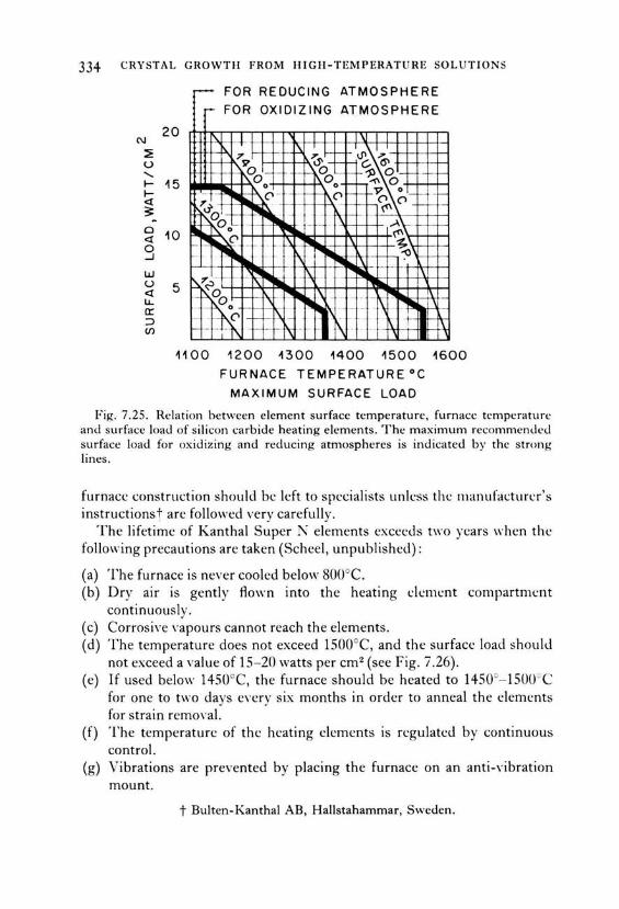
334 CRYSTAL GROWTH FROM HIGH-TEMPERATURE SOLUTIO NS
N
~ u ' I-I-<l 3: ~
0 <l 0 ...J
w u <l LJ... a: ::> (/)
~ FO ED C G ATMOSP ERE R R u IN H r- FOR OXIOIZING ATMOSPHERE
20 \1
15
w
1\, [',.~::>± '~~ V c. 6' ~~-fd- 000 1l 0 0 r---1'\ 0
'..T ["'I .. o -- [\.0 ,_ V o -
~('\ ~- -
- _-- r\ ~~ ~\-~
~-- (' \'\ - ~ 1\
,. .- 1"11111
5 l'lllll -.., _ 11111 1\
~,..~
-~00 "''I "' .. \ - - - - -- ---
~~~ lil!~ - \ - 11111 ,_ 1:'-. -- . I ~ 1--_, 1\ - . -
1100 1200 ßOO 1400 1500 1600
FURNACE TEMPERATURE°C
MAXIMUM SURFACE LOAD
Fig. 7.25. Relation between element surface temperature, furnace temperature and surfacc Ioad of silicon carbide heating elements. The maximum recommended surface Ioad for oxidizing and reducing atmospheres is indicated by thc strong lines.
furnacc construction shoulcl bc left to spccialists unlcss thc manufacturcr's instructions t are followecl very carefully.
The lifetime of Kanthal Super l\' elements excecJs two ycars when thc following precautions are taken (Scheel, unpublishecl):
(a) The furnace is never cooled below 800°C. (b) Dry air is gently flown into the heating clcmcnt compartmcnt
continuously. ( c) Corrosive vapours cannot reach the elements. (d) 'T'he temperature does not exceed 1500°C, and the surface Ioad shoulJ
not exceed a value of 15- 20 watts per cm2 (see Fig. 7.26). (e) If used below 1450°C, the furnace should be heated to 1450°- l500°C
for one to two days evcry six months in order to anneal the elements for strain remo,·al.
(f) The temperature of thc heating clements is rcgulatcd by continuous control.
(g) Vibrations are prevented by placing the furnace on an anti-vibration mount.
t Bulten-Kanthal AB, Hallstahammar, Swcden.

N
~ u ....... I-I-<t ?;
0 <t 0 ...J
w u <t u.. a:: :::> (/)
40
30
20
w
7· EX P F HI !\ I ENTA I. TEC II N I QUES
(h) The U-shapeJ hea ting dements shouiJ hang freely from th c top uf the fu rnau :.
(i) Thc hot zone of thc clemcnt should not rcach into thc cerami c insulation .
(j ) Thc terminals shoul cl bc: kcpt cool hy haYing a fn.:e di stancc bct\\-ccn th e roof and th e contact of 4-5 cm .
T he surfacc Ioad of Kanthal Super d emcnts ancl their tempcraturc and current are plott ecl aga inst the furnace temperature in Fig. 7.26. Thc s hadcd area shows the optimum conditions. Thc res istancc incrcascs
woo HOO ~200 ~300 1400 1500 1600 °C 1700
FURNACE TEMPERATURE F1c. 7.26. Surface Ioad, temperatures and current of kanthal super hea ting
d cments (of 6 and 9 mm di ameter) versus furn ace temperatu re.
stceply with temperaturc as shown in Fig. 7.27, wherc for compari son thc rcsistancc 7·ersus temperature ch ange of SiC, graphitc anc! K anthal .-\I arc also shown .
The ox idat ion behaYi our of l\IoSi2 heating elements has been stud iccl by ,-,uious groups. Fitzer (1 956) was the fi rst to desc ribe an anomala us m: idati on behaYi our at tem peratures below 800° and ca lled it "silicidc pt·st". O n se ,·e re oxiclation the " pest" oxicle consisting of crystalline !\ loO" and amorphous S i O~ parti cles is formcd and th c hea ting clemcnt

336 CRYSTAL GROWTI-1 FROM 1-IIGH-TEMPERATURE SOL UTIO N S
4
3
2
1
0
·10- 1 .ncm for SiC
.10- 4.ncm for M s· G h't o 12 , rop 1 e ond A1 Konthol
J
V
/ 1/
~ .-- SiC )
' / ....... Mo Si 2 \ · V \ J l\ )
I' ,J ~ ~ _.
Konthol A1 k' .... 1---' 1.--- ...... ~ 17 ~
,....
"---r--.. ~ V ....... Graphite
17' ~
~
0 400 800 1200 1600 oc F1r.. 7 .27. Electrical resistivity of various heating element materials.
disintegrates. Above 800°C a protective SiO~ layer can form according to
2MoSi~ + 70~ -2Mo03 + 4Si0~,
ancl the molybclenum oxide eYaporates (Bartlett et al., 1965) . .-\s was show" by Wirkus and \Vilder ( 1966 ), another oxidation reaction occurs abon.: 1200°C and just beneath the protective SiO~ layer. This reaction may be described by
Thus typical MoSi 2 heating elements consist of interior bulk MoSi 2, a thin Mo5Si3 and an outer glassy or semicrystalline Si0 2 layer. The overall oxidation of the MoSi 2 elements is controlled by oxygen cliffusion through the Si02 layer. Generally MoSi 2 heating elements have a protective oxide layer when delivered, and it is proposed to keep this intact by a slow Aow of dry air along the heating elements.

TABI.E 7.9 Properlies uf Firebril:ks and lnsulating Ceramies
:'\anll' Cnn1posit ion Max. Mclting Dcnsit,· of Thermal conducti,·iry ! .in . Thermal .-\tmusph. Hc:marks working point compound hrick compound Ceramie t cxpansion shock
tenlpL·ratun..· ceran11C hrick codlicicnt n..·sistatH.:e
-- - - ----- - - -Siiica SiO, IIOO' C 1710 (" 2.30 1.5 0.012 0 .003 0.5 10 ,; , c good oxicl. Corrocled hy Auoriclcs Sillimanitc· .-\1 ,0" ,. SiO , 1500 3.25 2.3 o.oos 0.003 nH:diun1 oxid . Corroclccl hy Auoricl"s Mullit<· 3AI,03 > SiO, 1650 1920 3.16 . 2.0 0.00'1 0.007 5.3 nH:diunl uxid. Corro<kd ll\· Auoriclcs .-\Iumina .-\1,0, 1800 2020 3.97 2.X O.OH 0.005 9.0 IX.6. 9.5) poor any Spine I MgAI,O, IS50° 21.l5 3.60 2.2 0.013 0.005 X.H poor ox icl . Zircon ZrSiO, 1700 2420 4 .56 J.3 O.OOX 0.005 4.2 (3.4. 5.h) good nxid. Corroclccl hy Auorides 7,irconia ZrO,t 2300 2700 5.60 ·4.4 0 .005 0.002 10.0 po<lr oxicl. Jkryllia Beü 2300" 2570' 3.01 2.X 0.046 0.02 X.'! goocl oxicl. Extrcmely poisonous
clust ancl n1pours i\lagrH:sia MgO 2400 2XOO 3.5X 2.5 0.016 0.006 H nH·diunl oxid. Thoria Thü, 2400 3050 9.86 6.3 0 .007 0.005 9.7 poor any Haclioactivc U rania uo, 2200' 2XOO 10.96 0.02 10 oxid. Haclioactivc Yttria v,o, 2000 2410 5.01 '!.3 any
Graphill" c 3000 ' >· 3600 2.25 -I.'! 0.16 2- 5 gond I reducin,g Horon nitridc· BN (hcxag.) 2000' 30000 ( clec.) 2.25 -1.9 0.04- 0.12 O.f)J - 0.07 0 .05 - 10 ( - 2) goocl f or Yacuurn Silicon SiC 1600 2X30 (dcc .) 3.22 · 2.6 0.10 ll.ll2 4.4 good oxid. Corroded hy Auoridt:s
carhidt· Silicon nitridc Si,'\.1 1500 1900" (dec .) 3.44 . · 2.0 0.045 3.2 (2.47) good neutral Corroded by Auorides
Silica glass SiO, 1000 1710 2.30 0.012 -0.001 good oxid. Corrodecl h,· Auorides woul
Cc·ramic wool 1200 -1700 3.20 o.oox -0.00 1 gnod nxid. Corrnclcd by Auorides Zirconia wool ZrO,t 2300 2550 ° 5.60 0 .005 -0.0005 good oxid.
t At 1000°C, in cal /cm ' C sec. ! Stahilizecl " ·ith CaO or Y ,0".

338 CRYSTAL GROWTH FROM HIGH-TEMPERATURE SOLUTIONS
Thermal insulation in resistance furnaces is generally achievcd by firebricks of which the most common with their properties are listed in Table 7.9. Dense bricks can carry Ioads and are resistant to abrasion whilc the lighter (porous) bricks are better insulators. The maximum working temperature of firebricks based on mullite and sillimanite increases with the alumina content. The space containing the crucibles is preferably separated from the heating elements by dense ceramic tubes or plates. lf platinum crucibles are used, care must be taken that thcy cannot come into contact with silicon carbide ceramic because platinum alloys with SiC at high temperatures; also borides, nitrides and metals should not contact platinum. Only dense alumina-rich firebricks or pure alumina, spincl, magnesia or zirconia ceramies are recommended as supports for platimun crucibles.
Corrosion by flux vapours shortens the lifetime of the firebricks, especially if porous bricks face the chamber containing the crucibles. The resistance to corrosion is increased if such firebricks are coated with an alumina-rich high-temperature cement. Also zirconia or SiC wall plates may be used in order to decrease the number of repairs necessary. Anothcr application of insulating bricks and ceramies is to fill the furnace chamber as much as practical in order to reduce temperature fluctuations by air convection and to increase the thermal capacity of the whole furnace.
lnduction heating is generally used when the required temperature exceeds about 1600°C. At such high temperatures difficulties arise with heating elements and their atmosphere requirements and with dense ceramics, cspecially when the duration of experiments is of the order of weeks or months as in many growth experiments from high-temperaturc solutions. For work in neutral or reducing atmospheres graphite, molybdenum, tungsten and tantalum heating elements may be used, and excessiYc loss of heat is prevented by the use of metallic radiation shields, generally contained in water-cooled meta! containers. For oxidizing atmospheres ancl temperatures exceecling 1700°C stabilized zirconia or thoria tubes may bc used as heating elements; howeyer, these oxides haYe to be prcheatecl to about 1600°C in order to make them sufficiently conductive.
The most reliable and practical way of heating to about 2000cC in any atmosphere for crystal growth from high-temperature solutions is hy induction heating, and this source of heat has been reviewed by May ( 1950), Stansel ( 1949), Brunst ( 1957) ancl Simpson ( 1960). The frequcncy of generators is about 450kHz, and it should be noted that typical RF generators have an output of about 50% of their power consumption. For most applications generators of 15 to 30 k W R F power arc appropriate, and care should be taken in obtaining sufficient coupling between the RF coil and the conclucting crucible or melt . Also the wall thickness of meta!

7· EXPERIMENTAL TE C IINJQ UES
crucibles should he unifor111, and thc crucihlcs as weil as insulation ur radiation shiclds should b~.: ~.:mtn:d carcfully in th~.: coil.
.-\ccording to Duncan et al. (1971) the penetration dcpth of thc RF heating is givcn hy
[ with p thc rcsistivity in ohm-cm of the heated material, p. the relative permeability of the heated material ( = 1 for non-magnetic materials), f thc induction heating frequency (Hz) and d the skin depth of the material heing heated, at which the current density reaches 1 /e~ 37° ;, of the value at the surface]. The value of d is about sevcn times greater for 10kHz than for 500 kHz (2.8 mm and 0.4 mm for platinum, respectively). Thus these authors propose the use of 10kHz RF heating in orcler to overcome thc common problems of hot spots ancl catastrophic failures, especially when crucibles are used near their melting points. Also 10 kHz motor-generators arc said tobeinsensiti ve to line valtage fluctuations ancl tobe n :ry reliabk.
Special hcat sourccs might bc used for specific experi111ents. Thus for transparent solutions the crystal growth process may be observed if furnac es with transparent regions are used. For temperatures up to 11000 quartz-glass tubc furnaces with a slit in the insulation or reflectors havc been usecl, and Lord and Moss (1970) described a furnace with water cooling between t\VO concentric glass tubes. A furnace consisting of an inner quartz-glass tube with the heating wire wound araund it and an outer concentric quartz-glass tube with a thin gold layer evaporated on it was first described by Rabenau (1963 / 1964) and later in detail by Reed (1973) . . -'\n approximately 200- 500 A thick gold layer shows high reflecti vity for thc infrared but is partially transparent to visible light. Another example of transparent furnaces was reported by \Vood and Van Pelt (1972) who used tin-oxide coated silica-glass tubes as transparent heating elements. A spray coating system was used to achieve a uniform coating, and such furnaces have been used up to 700°C.
Localized heating as necessary for temperature-gradient transport and tra,·elling solution zone techniques has been discussed in Section 7.1.2. Heat pipes may be useful for localized heating as \\·eil as for localized cooling as indicated by Steininger and Reed (1972) but except for a brief mention in a paper of Steininger and Strauss (1972) heat pipes have not yet founcl wide application in crystal growth from high-temperature solutions. With heat pipes temperatures approaching 2000°C may be obtained, ancl the lifetime of the heat pipe using Iithium as fluid ancl TZM alloy as pipc material is said to be above one year (Harbaugh ancl Eastman, 1970) at a temperature of 1500°C. Temperature stabilization neecls special precautions

340 CRYSTAL GROWTH FROM HIGH-TEMPERATURE SOLUTIONS
and is best achieved by pressurc control of open hea t-pipe systems according to Vidal and II aller ( 1971 ).
7.2.2. Temperature control (including programming)
Temperature evaluation. Of the variety of temperature measurement ancl control techniques only a few are generally used because of their reliability, accuracy and convenience, and these are indicated in Fig. 7.28, tagether with their common ranges of measurement and control. Thermometers based on thermal expansion of liquids (and gases) and of solids (bimetal thermometers) are very common and may be used up to relatively modest temperatures (500°C) but are not applicable or reliable at higher temperatures. Thus, in this section only resistance thermometry, thermoelectric thermometry and optical pyrometry will be discussed. The measurement and control of temperature have been reviewed in
Liquid exponsion ---- -·· ···-Thermometers ~
.Resistonce Thermometry
Thermoelectric Thermometry
---------- ---~··········· ···~
!-------+----············ ····-
Opticol pyrometry r-- ---------- ----------I I I
Temp
0 1000 2000 3000 oc F1c. 7.28. Temperature ranges for m easurement (broken lines) and reliahle
control (solid lines) fo r various common temperature evaluation techniques.
"Temperature" ( 1941, 1955, 1962), by Baker et al. ( 1953, 1961 ), Kostkowski (1960), Rubin and by Best (1967).
How precisely and accuratelyt can a temperature be measured ? This question has been cliscussed, in addition to above references, by Dike ( 1958), Roeser and Lonberger ( 1958), Stimson ( 1961) and by Gray ancl Finch (1971).
According to the International Practical Temperature Scale of 1968 (IPTS-68, 1969) the temperature is established by interpolating between the points 100°C (boiling point of water), 419.58°C (freezing point of zinc), 961.93°C (freezing point of silver) and 1064.43°C (freezing point of gold).
t Precision is qualitatively the inverse of the (mean) deviation from a given temperature, whereas accuracy is the inverse of the (mean) deviation from a point on the (absolute) International Practical Temperature Scale of 1968.

7· EXPERIMENTAL TECHNIQUE S 34 1
In \ · ariou~ lahnratoril·s thc frcezing pnints nf antimony (fi30S"C), alurninium (fifiO. I °C) and coppl:r (I fiX3 oC) an.: u~cd for calihration, hut extreme carc is necessary with respect to purity (corrosion of container, inAucnce of gases) in all direct calibration work.
Chemieals of high purity needed for calibration according to IPTS-68 may be obtained either from a national institution of standardization or from the ::\ational Bureau of Standards, Washington, D.C., U.S.A. However, it is more convenient to obtain calibrated thermocouples, resistance thermometers or pyrometers from comrnercial suppliers or from the aboYe institutions. The accuracy of temperature measurement at the gold point (1064.43 °C) using calibrated Pt-PtRh 10°f< , thermocouples may be as good as 0.2°C, and using non-calibrated commercial thermocouples the accuracy is generally better than 2.5°C.
A standard thermocouple properly used has a precision of 0.1 oc around the gold point, that means that the standard deviation is 0.1 o about the mean of that laboratory. At the National Bureau of Standards Pt- PtRh10% thermocouples are annealed for one hour at 1450°C before calibration.
For ternperatures exceeding the melting point of gold thc mclting points of palladiurn (1552°C) and platinurn ( 1769°C) have been proposed as standards. For temperatures up to 1300°C the platinum 'cersus platinum 10% rhodium thermocouples are reliable to within 0.25 % if used in a clean oxidizing atmosphere and if extended periods above 1300°C are avoided. The International Temperature Scale above the gold point is defined in terms of the Planck radiation equation and the ratio of the spectral radiance, in the visible region, of a black body at the temperature to be measured to the spectral radiance of a black body at the gold point. However, with a black body and using a calibrated optical pyrometer (with disappearing filarnent) the standard deviations from IPTS-68 at the gold point and at 2000°C may be as low as 0.6° and 3°, respectively. Generally in practice it is found difficult to obtain a precision of better than 6°C using an optical pyrometer.
The first part of the following section deals with temperature sensors whereas the second part brieAy treats techniques for the control and programming of the temperature of furnaces.
Resistance thermometry. This topic has been reviewed in the general references mentioned previously and by Berry ( 1966) while Daneman and Vlergner (1967) discussed the equipment necessary for measuring exact resistance ratios . Resistance thermometry is based on the change of resistance of materials with temperature, and the resistance change is measured with resistance bridges or potentiometers.
The resistance of pure metals increases with temperature whereas semi·'1

342 CRYSTAL GROWTH FROM HIGH-TEMPERATURE SOLUTIONS
conducting materials (e.g. gcrmanium, oxides) show a logarithmic decrease in resistance with increasing temperature which is used in the so-called thermistors.
Resistance thermometers allow very precise measurements of temperature as long as the resistance of the meta! is not changed by recrystallization, oxidation, impurities or evaporation. Thus nicke! and copper are generally used only up to 200°C, platinum up to 1000°C, and tungsten, molybdenurn and tantalum (in a protective atmosphere) up to 1200°C, whereas thermistors are used up to 300°C and with special compositions (though not reliably) up to 1600°C. The platinum resistance thermorneter may be calibrated if prepared from ultra-pure platinurn and if mounted in a helium-filled jacket. In Fig. 7.29 the dependence on ternperature of the resistance of various materials is shown.
Resistance thermometry allows the measurement of temperatures up to 1000° with a precision not achieved by other techniques (MeT ,aren, 1957). However, the limited temperature range and lifetime have prevented its wide use in crystal growth from high-temperature solutions. An exception i~ the range of Controllers marketed by CNS r nstruments, wh ich liSC
5.0
4.0
(.) 3.0 0
0 er
' 1-er 2.0
Tungsten
~.0
0 0 200 400 600 aoo •c
Tempereture T
FIG. 7.29. Resistance ratios for temperatures T to the temperature of o ·c for various metals and a typical thermistor.
7· EXPERIMENTAL TECIINIQUES 343
platinum rcsistancc thermometers for temperature control up to 1400°C, but for temperature regulation over extended periods the rcsistance thermometer should not be used at temperatures higher than about 1000° because of the change of resistance due to evaporation and recrystallization of the platinum.
Thermoelectric thermometry. The most common temperaturc measuremcnt ancl control techniques arc basecl on thermocouples. Since the thermodectric power of a variety of meta! and alloy combinations is known, thc temperature of one junction can be determincd provided the other junction has a known temperature, preferably the ice point (0°C). The thermoelectric power of a variety of thermocouples has been listed as a function of temperature by Shenker et al. (1955) and is shown for high and low temperatures, respectively, in Fig. 7.30(a) and (b). Table 7.10 lists thc sensitivities at various temperatures, the maximum temperatures of use, the necessary atmospheric conditions and the stability of a variety of thermocouples.
At temperatures up to 600° the similar thermocouples copper-constantan and iron-constantan are commonly used, whereas for temperatures up to 900°C the chromel-alumel thermocouple is popular. Palladort and Platine!~ (Pt, Pd, Ir, Au alloys) are thermocouples with a high sensitivity, comparable with chromel-alumel, and which can be used up to 1200 and 1300°C. Platinum ursus platinum rhodium 10% is the most frequently used thermocouple for the range 500° to 1400°C, although other thermocouples based on noble metals are now available which are more stable at higher temperatures and have similar sensitivity above 1000°C. As an example the platinum 94% rhodium 6% versus platinum 70% rhodium 30°~ is listed which has the advantage of having a negligibly small sensitivity around room temperature. Scheel and West ( 1973) use thermopiles made from several PtRh6% ·versus PtRh30% couples as sensing elements for furnace control. Suchthermopiles have the advantage of very high sensitivity so that changes in e.m.f. due to variation in the furnace temperature are very !arge in comparison with noise or changes due to variation in the ambient temperature. The latter effects normally result in ftuctuations at the input to a furnace controller of about ± 3 p. V which corresponds to the change in output from a Pt ·ursus PtRh10% thermocouple due to a change in the furnace temperature of ± 0.3°C. A sensing device of high sensitivity to variations in the furnace temperature but insensitive to cold junction temperature changes is therefore necessary if stabilization to say :: 0.05°C is to bc achieved. The PtRh6% 'i'ersus
t 'T'rademark of Johnson Matthey LtJ. t Trademark of Engelhard Industries.
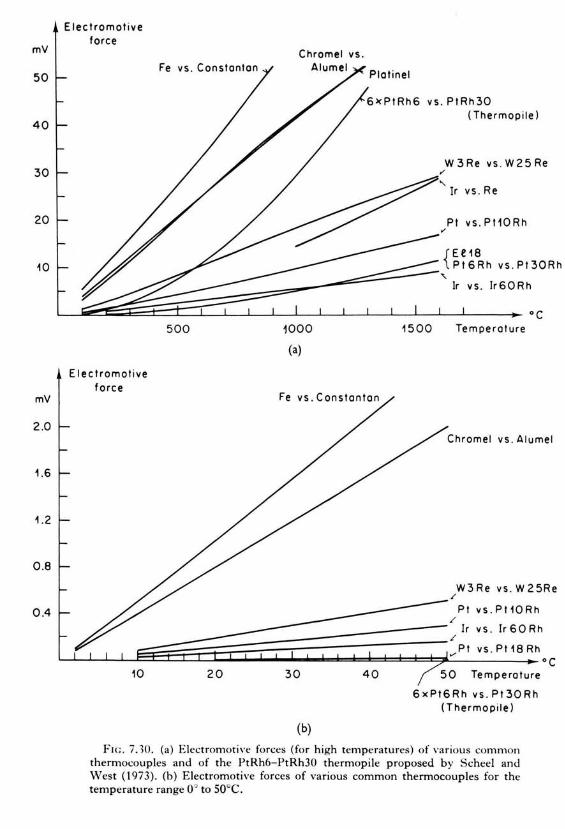
mV
50
40
30
20
~0
mV
2.0
~ .6
~ .2
0 .8
0.4
Electromot ive force
vs. PtRh30 ( Thermopile)
vs . Re
Pt vs. Pt10Rh
{Ee18 Pt6Rh vs.Pt30Rh
Eieeiremotive force
500 1000
(a)
1500
Ir vs. lr60Rh
Tempereture
Chromel vs . Alumel
W3Re vs . W25Re /
Pt vs.Pt10Rh /
t~~~~l_J§§E~§i~~~~~~~~~~~~~~::::::~~~/~Ir~v;s_. ~I~r~6~0~Rh Pt vs . Pt18Rh v'
10 20 30
(b)
40 50 Tempereture
6xPt6Rh vs . Pt30Rh (Thermo pile)
F1c. 7.10. (a) Electromotive forces (fo r high temperatures) of various common thermocouples and of the PtRh6-PtRh30 thermopile proposed by Scheel ancl West ( 1973) . (b) Electromotive forces of various common thermocouples for the temperature range 0° to 50°C.
oc

TABLE 7. 1 0. Prope rti es of Various Thermocoupfes
Thermocouple Sensi t ivi ty: I' V, "C at i\1ax. temp . of use Atmosphere Estimated tempera ture shift at 25 °C soocc 1200°C inter- con- tcmp. I 0 hours 1000 hou rs
mittent tinuous
I ron- Constantan 51 64 800°C 6So -c reducing 650 ' 2.5 inert, o r ox idizing
C hromei- Aiume l 40 40 36 1260cC 1100 c ox idiz ing 1000° 0.5 5.0 or neutral 1200 ' 2.0 ' fails
Pd- Pt85 1r1 5 19 37 45 1500°C inert or 1200° O . .'i , s.o oxidizingt ...... ,
Platine! J2 4 1 39 1300°C 11SWC oxidizing , 1200 ' 3.0 inert or r.'l
reducing X
""' Pt- Pt90Rh l0 6 10.9 12.0 1700°C 14SOOC oxidizing 120W 0.2 2.0 r.'l ;c
1500° 1.0 3: Pt94Rh6- Pt70Rh30 0.07 7.5 5 10.5 1800°C 1500°C ox idi zing 1700" 4.0° ~
Thermopi le of z 6PtRh6- PtRh30 0.4 45 .3 63 t soooc 1600°C oxidizing -l
>-thcrmocoup1es :-Pt80Rh20- Pt60Rh40 1830°C 1600 ' C oxidizin g 1SOO 6.0 ...,
r.'l
25 °C 1600°C 2000°C (')
:I:
Ir- Rh60 I r40 3 5.8 6.2 2000°C 1800°C inert or 2100 10.0' z slight1y 0
c::: oxidizing r:1
W - Ir 25 26.3 2100°C 2ooooc inert or 2 1000 1 0.0 Cf)
vacuum Re- Ir 2100°C 2ooooc inert or
vacuum W97Re3- W75Re2.'i 10 17 14 2400°C 2200 ' C inert or
reducing or vacuum
W- Rc -5 12 6.5 2400°C 2200 c inert or rcducing
'-"' or vacuun1 + S iC- C ~300 -300 ~2700°C vacuum Fragile, not reliable '.FI
B,C-C ~330 ~330 ~2400°C vacuum Fragi le, not reliable
t Pd is oxidized slow1y in air between 700° and 900' C, iridiu m above 900°C.

:Hf> CRYSTAI. GROWTII FROM IIIGH-TEMPERATURI' SOLUTIONS
PtRh30% thermocouples have the additional ad\·antage of a long lifetime at temperatures up to 1600°C.
For tempcratures t~xcectling 1~Uuvc thcrmocouplcs basctl on tungstcn or rhenium are used, but the brittleness, the instability and the stringent requirements on atmosphere Iead many researchers to prefer optical pyrometry where possible. The fragile nature of the carbon-based thermocouples prevent their popularity although their sensitivity is extremely high.
Some remarks on the thermocouples based on platinum alloys are appropriate as these are in common use in crystal growth from hightemperature solutions, and several of the points also hold for other thermocouple materials. Many aspects, including chemical and physical properties and stability, are discussed by Caldwell (1962) and by Vines ( 1941 ). The generat features of thermoelectric temperature measurement have been discussed by Finch ( 1966 ).
The most stringent requiremcnts are those of purity, which should be better than 99.99% of the individual meta! or alloy, and of homogeneity. Any physical and chemical inhomogeneities produce spurious effects by acting as thermocouples themseh-es . A clean oxidizing atmosphere (e.g . air) is necessary, and traces of hydrogen, carbon monoxide, hydrocarbons, sulphur (or other chalcogenide), pnictides (except N 2) or metal-containing vapour corrode the platinum-based thermocouples or may have an effect on its thermoelectric characteristics. The oxidizing atmosphere also keeps all trace impurities oxidized so minimizing their influence. In addition, the insulating ceramic tubes should be of high purity and should not contain silica (Si0 2, mullite, sillimanite) since Si0 2 has a detrimental effect in reducing atmosphercs or at high temperatures, and metals, carbides, borides etc. cannot be used in contact with platinum-based thermocouples because of alloying. Also the ceramic sheath tubes made of high-purity alumina should be impervious in order to prevent volatile Aux components (e.g. PbFJ from coming into contact with the thermocouplc. The high temperature Iimit for a variety of thermocouples as given in Table 7.10 may be lowered by the material which it contacts (insulating or sheath tubes), and this aspect is discussed in Section 7.2.3 .
The optimum diameter for thermocouples based on platinum is 0.5 mm but thinner wires of 0.1-0.2 mm may be preferred for a fast response, and thicker wires are used under harsh conditions because of their mechanical and thermal stability. Volatility is an important factor for noble meta! thermocouples (and resistance thermometers) at high temperatures. For instance, the loss of platinum in vacuum is 7 x 10- 20 g cm- 2 s- 1 at 727°C, 5 x 10- 11 at 1227°C and 10- 6 at 1727°C (Vines, 1941 ). According to Crookes ( 1912) platinum is twice as volatile as rhodium in air at 1300°C, one-third as Yolatile as palladium, and one-thirtieth as volatile as iridium, and these

7· EXPERllVIENTAL TECIINIQUES 347
differcnccs in volatility are pa1 tially explaincd by the relative casc uf formation of volatile oxides.
Recrystallization isanother cause of limited lifetime. Alternating cooling and heating, by its expansion effects, may cause failure of a recrystallized thermocouple junction. In order to achieve precise and reliable thermocouple output thc thermocouples should be regularly replaced after a period of hours or months depending on the couple material and the conditions of use.
For exact temperature recording and control a reference junction held at a precisely controlled reference temperature is required, or the thermocouple may be connected to copper held at exactly Ü°C (see Figs. 7.31a and b ). A controlled 0°C junction based on Peltier cooling is convenient and the triple point cell of waterwith a temperature of + 0.0099° ± 0.0001 oc may be used if the duration of experiments is not too long (both reference systems are commercially available). Reference baths at other temperatures than Ü°C have the disadvantage that the e.m.f. is not zero (or nearly zero).
Extension wires prepared from alloys with similar thermoelectric characteristics are frequently used hecause of their lower price and higher mcchanical stability. In this way a thermocouple is extended to the reference temperature or the measuring or control unit. However, the accuracy decreases with the use of extension wires, and care must be taken that all Connections of the pair of thermocouple wires or any extension wires areisothermaL
The small thermocouple signals necessitate careful shielding and grounding, otherwise stray voltages may be introduced by direct coupling or by capacitive coupling. If the thermocouple line is close to motors, transformers or power-circuits it can only be fully shielded by magnetic shielding. Non-magnetic shielding can be penetrated by magnetic fields of not too high frequency. Twisting of the thermocouples minimizes such magnetic interactions. Also a coaxial arrangement of the thermocouple line has many advantages. Grounding should be effected according to Fig. 7.31(c) or (d).
In certain cases the use of a thermopile might be necessary in which a number n of thermocouples are connected in series and produce n times the e.m.f. of a single thermocouple and thus a )arger signal. If an average temperature signal is required then several thermocouples of equal resistance are connected in parallel. A special arrangement for rotating thermocouples using electrically isolated ballbearings as coupling elements in a thermocouple circuit has been described by Robertson and Scholl (1971). Such an arrangement may be advantageaus as an alternative to a commutator for growth on a rotating seed or by the accelerated crucible rotation technique (see Section 7.2.7).

348 CRYSTAL GROWTH FROM HIGH-TEMPERATURE SOLUTIONS
FURNACE FURNACE
Pt 10% Rh Pt
"" '
I I I I I REFERENCE I I I TEMPERATURE I I I (OoC) I I
:> ~: AMPLIFIER
COPPER +- + /
( 0) ( b) (c) (d)
F1c . 7.31. (a)-(d) Thermocouple ar rangemen ts and m ethods of shie lding.
Temperature measurement by optical py rometry is used when thermoelectric techniques are not reliable, for example at high temperatures and in corrosive gas atmospheres, or in induction heating. HO\\'e\·e r, vapours and material condensed on the observation windows might have a dramatic effect on the reliability of optical techniques. Optical thermometry has been described in "Temperature" ( 1941, 1955, 1962), by Harrison ( 1960), Dike et al. ( 1966 ), Euler and Ludwig ( 1960), Kostkowski and Lee ( 1962) and by Poland et al. ( 1961 ).
Many optical pyrometers ( e.g. the disappearing filament) indicate the brightness temperature, so the spectral emissivity of the radiating source (the region of which the temperature has to be measured) as weil as reflectance and absorption of the windows and Jenses between object and pyrometer may Iead to deviations from the true temperature. Thus the indicated temperature can be more than 10% lower than the actual temperature. ldeally the whole arrangement should be cal ibrated us ing fixed points. Emissivity is thc emittance of a material having an optically

7· EXPERIMENTAl. TECHNIQUES 349
smooth surface and a thickncss sufficient tobe opaque, and cmittance is the ratio of thc encrgy radiatcd by a surfacc (pcr unit area and unit time) to thc energy which would be radiatcd by a black body at the same temperature. Applying vVien's law, the true tcmperature T is related to the brightness temperature T11 by
~~-} = - (A(CJ log,. E;,
where C 2 is the second radiation constant (1.438 cm degree) and E;. the emittance at wavelength >.. Typical values of spectral emittance are given in Table 7.11 and a few temperature corrections for various emittances and temperatures are listed in Table 7.12. Quartz-glass windows and lenses necessitate corrections of the order of 5 to 30°C. In applying temperature corrections it must be kept in mind that the surface structure of the observed hot body ( e.g. crucible) has a significant etfect on the emittancc. The prohlem of the cmissivitv may be reduccd by thc use of a two-colour pyrometer which compares the radiation at two different waYelengths as suitablc filters are introduced alternately into the radiation ("Temperature" 1962, p. 419). The output voltage from the detection system may be calibrated in terms of the source temperature.
Radiation pyrometers or photoelectric pyrometers can, in addition to indicating, also record and control the temperature and are used for example in silicon production by Czochralski-pulling.
TABLE 7.11 . Spectral Emittances < for Various :\1aterials
Material - - - --- - ---- -
Graphite Graphite, powder Gold, solid Gold, liquid Iron, solid lron, liquid :\1olybdenum, solid Platinum, solid Platinum, liquid Tantal um Tungsten
.\12
0.76 0.95 0.04-0.16 0.07-0.22 0.35-0.37 0.37 0.37-0.43 0.30-0.38 0.38 0.50 0.39-0.46
Al,O" BeO Fe"O"
Material
Fe2Ü3, liquid steel, oxidized :\1g0 Th02, solid Th02, liquid Ti02, solid and liquid Y,O" Zr0 2
0.30 0.31-0.35 0.63-0.98 0.53 0.75-0.90 0.70 0.50-0.57 0.69 0.51, 0.52 0.60 0.40

350 CRYSTAL GROWTH FROM HIGH-TEMPERATURE SOLUTIONS
TABLE 7.12. Temperature Corrections for Various Emittances • and Temperatures, Calculated for the Effective Wavelength ,\ = 0.655 11.
• 800°C 1000° 1200° 1400° 1600° 1800° 2000° 2200°C ------- -
0.1 136 196 269 355 457 575 710 864 0.2 91 131 178 233 297 371 453 546 0.3 67 95 129 169 214 265 323 387 0.4 so 71 96 125 158 196 238 284 0.5 38 53 72 93 117 145 175 209 0.6 27 39 52 68 85 105 127 151 0.7 19 27 36 47 59 72 87 103 0.8 12 17 22 29 36 45 54 64 0.9 6 8 10 13 17 21 25 30
In order to overcome the problern of absorption by vapours and windows a light pipe has been proposed. A sapphire single crystal is fixed near to or at the object (crucible), and the radiation transmitted by this lightpipeout of the hot region is sensed by appropriate thermocouples or radiation sensitive devices.
An infrared television system has been successfully applied to Czochralski growth of refractory oxides and of copper crystals by O'Kane et al. ( 1972) and by Gärtner et al. ( 1972). Process control using a Computer allowed exact control of the crystal diameter, and similar equipment could be helpful or necessary for the growth of "difficult" crystals by the top-seeded solution growth technique.
Temperature control. The signals obtained from the various temperature sensors are generally amplified and used to control the power input to th e furnace. In the following we shall restriet the discussion to thermocouple sensors and resistance heating, the arrangement most typically used in crystal growth from high-temperature solutions. The regu lation of RF generators has been discussed in Section 7 .2. 1. Mechanical temperature regulators and on-off control do not fulfil the requirements of crystal growers and have been progressively replaced by electronic Controllers and by proportional or continuous ( or stepless) temperature control to wh ich the following discussion will therefore be restricted.
In a regulation system as shown diagrammatically in Fig. 7.32 pure proportional control of the furnace temperature is defined by
P-P0 =Kp(W-X),
where P0 is a chosen mean value of the input power. If P- P0 and W- X are expressed in the same units then Kp is a dimensionless constant which

7· EXPERIMENTAL TECHNIQUES 35 1
r-- F U R N A C E
INPUT p OliTPUT X (THER.'IOCOUPLE S lGNAL) (HEATING POWER)
FEEDBACK
DEVIATION P lD CONTROLLER AMPLIFIER (PROPORTIONAL BANDWIDTH 100/K ,
p INTEGRAL !IME CONSTANT ' r• DIFFERENTIAL TIME CONSTANT T D)
mV SET POINT
w
Fig. 7 .32. Temperature regulation circuit (diagrammatic).
ts a measure of the amplification of th e feedback signal W- X. Thc reciprocal Yalue 100/ Kr expressed in percent is called the proportional band width. A purely proportional-controlled system is stable only if the output indicates any changes in the input (heating power) immediately and proportionally. In normal systems this is never the case, and the time constant is a measure of the delay time caused by the heat capacity of the furnace and of the sensing thermocouples. With pure proportional control the steady-state temperature deviates from the set point, and the degree of deYiation changes irregularly within the Iimits of the proportional band. The difference W- X decreases with !arge Kp, but either the stability of the system or the instrument itself Iimits the maximum Kp.
In order to achieve a stable temperature without a setting error in real systems with a response time lag the so-called three-term Controllers or PI D controllers should be used. These contain in addition to the adjustable proportional band (P-term) the integral (/) and the differential (D) terms. The idealized I-term depends on the integral of the feedback signal so that the power delivered to the furnace includes a term
P1(t) = 1 J1
(W - X) dt, TJ 0
where ( W- X ) is again expressed in thc same units as P and 1/T1 is the

352 CRYSTAL GROWTH FROM HIGH-TEMPERATURE SOLUTIONS
adjustable proportionality factor of the I-term, -r1 being called the integral time. Thus the integral term produces an increase in the heating power which is linear with time. Integral control (also named reset control) has the effect of shifting the proportional band in such a way that the deviation of the actual temperature from the set point is minimized (which is achieved neither by P- nor by P + D-control).
ldealized differential control or derivative ( or rate) control depends on the differential of the feedback signal so that, at time t, the output of the controller has a component
d Pv(t)=Tv dt (W- X).
The addition of differential control reduces the tendency towards oscillation when the proportional band is narrowed (i.e. Kp made large). If the chosen derivative time -rv is too large, a small change of the actual temperature will drive the Controller to its Iimits of zero and maximum power, so that the systcm tcnds to\vards on-off control with a long time constant.
The generat equation for a three-term Controller is
1 J1 d(W-X) P(t) -P0 =Kp(W- X) + - (W- X) dt +TD --d-- . ~ 0 t
Although it would be possible to calculate the optimum proportional bandwidth, integral time and derivative time such a calculation would be very complicated considering the many factors which have to be takcn into account (furnace design, characteristics of heating elements, power supply, thermocouples, etc.) and which are generally not known.
In practice the P, I and D terms are set by "experience" or by measuring the time constant of the system. A practical procedure to optimize the parameters of PID Controllers has been described by Ziegler and Niehots ( 1942). Firstly, the I and D terms are adjusted in order to obtain pure proportional control by setting the integral time as !arge as possible and the differential time as small as possible. By increasing the amplification Kp to a value Kp( crit.) where undamped oscillations are just achieved the period T(crit.) ofthese oscillations can be determined. Then the parameters of a PI D controller are set as follows:
Kp = 0.6 Kp( crit.) T 1 =0.5 T(crit.) Tn=0.12 T(crit.).
If the dynamic behaviour (amplification factor FA, time constant Tn dead

7· EXPERIME N TAL TE C HNIQUES 353
time Tr~) of thc control ~y~tcm •~ known thcn thc paramete r~ are set according to Oppclt (1()64):
f-:1, = 1.2 ~ c -~ Trt f .. J
TJ = 2 T.t
TJJ = Ü.42 T.t
(see also Smith and Murrill, 1966). The effect of the various control techniques for a typical furnace system
is demonstrated in Fig. 7.33. A.s shown with examples 1 and 2 the sensing thermocouple should be near to the heating element and the same applies in PI D control, since the dead time is thus decreased. In addition to an optimum setting of the PI D terms, a stabilized power supply is necessary for highest precision of the temperature control, as proved by examples 8 and 9 where the temperasure is shown tobe unaffected by a change in the line Yoltage.
X· The'M 1rt altyp!Uit end dlfOfr'od ()fl ~~ agpiQttQI'I
Xl"c I 1-
2 3 6 7 8
Lin< Volls ktNW
F1 c. 7.33. Typical control records, recorded from the control thermocouple, using various control methods. Thermocouple :\ inch from heater in all cases except 2 (Courtesy Eurotherm Ltd.). (1) On-off control. (2) On-off control. Thermocouple 1 t in from heater. (3) Proportional control. Proportional band too narrow. (4) Proportional control. Proportional band wide. (5) Proportional control. Proportional band optimum. (6) Proportional + integral control. (7) Proportional + integral + derivative control. (8) Proportional + integral + derivative with power stabilization . (9) Proportional -~ integral + derivative with power stabilization with derivative start up.

354 CRYSTAL GROWTH FROM JIIGH-TEMPERATURE SOLUTIONS
By using a high-quality commercial PID controller and an arrangement similar tothat shown in Fig. 7.34(a), by careful installation of the sensing thcrmocouplc and of thc signal lincs, vcry prccisc control of furnacc temperatures may be achieved, of the order of 0.1 to 0.5°C at temperatures around 1200°C using anormal Pt/Pt- 1 ORh thermocouple. The arrangemen t of Fig. 7.34(a) is a typical example.
FURNACE (LOAD) 1+----------1
THERHOCOUPLE
PROGRAMHER (ELECTRONIC RAMP GENERATOR,
HELlPOT DRIVE, ETC.)
( b)
CONSTANT VOLTAGE SUPPLY (D.C.)
(a)
STABILIZED POWER SUPPLY
THYRISTOR OR
SATURABLE REACTOR
PID CONTROLLER
POSSIBLE SEPARATED FROM THE POWER SUPPLY TO THE
THYRISTORS).
(c)
F1c. 7.34. (a) Example of furnace-sensor-controller arrangement for precise temperature regulation. (h) Continuous control by phaseangle firing. (c) Continuous control by fast cycling.

7· EXPERi lVIENTAL TECIINIQUES 355
Thc signal from the PI D controller may regulate a saturablc rcactor or a thyristor which is itsclf connected to the heating elements directly (resistive Ioad) or Yia a Yariac or transformer (inductiYe Ioad). Saturable reactors ( or magnetic amplifiers) are very reliablc and not sensitive to mechanical, electrical or thermal disturbances whereas the thyristor (also called siliconcontrolled rectifier S.C.R.) is faster, eheaper and more sensitive. In thyristors the power control is achieved either by phase angle .firing or by fast cycling, the principles of which are schematically shown in Fig. 7.34(b) and (c). Phase angle firing obviously distorts themains waveform and with !arge installations this might be serious. It can also cause radio interference, and for these reasons phase angle firing should not be used in research laboratories except where precautions are taken. Rapid cycling if synchronized ,,·ith the mains does not distort the mains waveform, and therc is no radiated interference. However, in both cases, specific difficulties may arise and should be discussed with specialists.
Temperature progranzming. According to Fig. 7.34(a) programming is achieved by changing the rnillivolt set point. The sirnplest way to do this is to changc the resistance in the m V circuit by means of a motor-driven potentiometer (Hclipot) or similar device. The precision is frcquently not sufficient, and potentiorneters are sensitive to dust and vapours thus necessitating frequent cleaning. Motors with changeable gears t attached to helipots pro,·ide a wide range of cooling rates which are, depending on thc type of therrnocouple, more or less linear. As was pointed out by Scheel and EI weil ( 1972), by Pohl and Scheel ( 1975), and in Section 6.6, the cooling rate should frequently be below 1 °C per hour and the ternperature regulation better than 0.1 oc for flux growth of oxides by the slow-cooling technique, and these goals necessitate the application of fully electronic programmerst or of computer-assisted process control. Also the commercially available instrurnents with rotating cams or drurns, in which thc programmed Yalue of the temperature is sensed mechanically or optically, are generally not sufficiently precise. Laudise ( 1963) pointed out that the precision of the temperature control should be cornmensurate with the slow cooling rat es used, and Scheel and EI weil ( 1972) expressed the necessity of a continuous (stepless) cooling curve if crystals of high quality are to bc grown. Further details of temperature programming in the slow-cooling technique are discussed in Sections 6.6 and 7.1.2.
t For instance of Halstrup, 7815 Kirchzarten, W -Germany. ~ For example, Eurotherm Ltd. (Worthing, Sussex, England) offers electronic
programmers in which capacitors are slowly discharged by field-effect transistors and thus generate an electronic ramp.

356 CRYSTAL GROWTH FROM HIGH-TEMPERATURE SOLUTIONS
7.2.3. Crucibles Most experiments in crystal growth from high-temperature solutions are carried out in containers, either in crucibles or in ampoules. Thus crystal growers are faced with the choice of a practical crucible material which should be resistant to corrosion by the solvent, solute and the atmosphere at the high growth temperatures. Further requirements are a high mechanical strength, ease of shaping and of cleaning, good thermal shock resistance, reasonably long lifetime (little recrystallization) and a low price.
There are two materials which fulfil most of the above requirements, namely graphite and silica glass (also called quartz glass). These two materials have many unique properties and find wide applications, graphite for several metals which have a low tendency towards carbide formation and for such compounds which are stable against reduction, especially for the preparation of semiconductor crystals and of semiconductor layers by liquid phase epitaxy. Silica-glass crucibles, boats and ampoules may also be used for the preparation of semiconductors and for those metallic melts which do not cause reduction. Obviously Si0 2 glass cannot be used to contain solvents for oxides and for oxide melts, and its upper Iimit of temperature is around 1100°C (1000° for extended use). For growth of most oxides and oxide compounds, platinum is the only choice because of its resistance to corrosion, and it has to be used despite its high price and softness. Thus the various aspects of the use and handling of platinum crucibles will be discussed in some detail.
As a rule suitable crucible materials are those which have a type of bonding different from that of solvent and solute provided that no decomposition reaction occurs. The difference in the chemical bond type generally Ieads to a sufficiently small solubility of the crucible material in the solvent, especially when this material has a relatively high melting point. Examples of the bonding difference rule are the use of platinum crucibles for ionic melts, of (ionic) oxide and of covalent graphite and nitride crucibles for metallic melts, and further examples are given in Table 7.13 which lists the most common crucible materials with their properties and their applications. Table 7.14 summarizes the corrosion resistance of various crucible materials against a variety of molten metals for 300° and 600°C, respectively, and several properties of a variety of crucible materials have already been listed in Table 7.9 (see Section 7.2.1). In Table 7.15 examples of crucibles for a variety of melts and solutions, together with the temperature range, are given [ see also J anz ( 1967 )] .
A well-known rule in solid-state reactions is that the reaction between two compounds of similar bond type starts at temperatures of 0.3- 0.4 TF for metals, of 0.6 TF for ionic compounds and 0.8-0.9 TF for silicates.

7· EXPERIMENTAL TECHNIQUES 357
TF is the mean absolute melting point of the two components. According to these values, compounds may be melted in crucibles of the same bond type if the above values are not exceeded, that is, if the melting point of the solvent or solution is much lower than that of the crucible. For example, sodium chloridc may be melted in alumina crucibles, and several low melting point metals may be contained in refractory meta! crucibles. However, many refractory meta) crucibles (except noble metals) cannot be used for ionic compounds since they are oxidized by the latter.
Table 7.16 gives the temperatures at which reactions between refractory materials start, so that mechanical contacts between two different materials (for instance crucible and support) should be held at significantly lower temperatures than those given in the table. Further information on the usefulness of crucible materials and of their reactions may be obtained from the appropriate phase diagrams (see Sections 3.7- 3.9).
Much information on refractory materials, on high-temperature oxides, refractory metals, carbides, nitrides and on the corresponding phase diagrams has been collected in a book series edited by Margrave ( 1965- ), in High Temperature Technology (1960), by Campbell (1959) and by Kingery (1959).
Composite materials, glass-ceramics and cermetsfind several applications in high-temperature technology due to the often unique properties originating from the combination of two or more components. However, in ftux gro\\·th corrosion is generally the greatest problem, and so crucible materials are chosen mainly to minimize this problem. However, coatings of more corrosion-resistant materials on Containers made of materials with high mechanical strength (and frequently lower price) may be useful for several applications in crystal growth. For instance, oxides (AI 20 3, Zr02)
are ftame- or plasma-sprayed on to refractory metals and vice versa. Frequently one may observe that resistance to corrosion increases with higher purity of the crucible material.
Corrosion is related to the wetting angle of the melt. The )arger the difference in the type of bonding between crucible and melt, the smaller the wetting and the corrosion normally observed. Although it has been proposed to determine covalency or more generally the bonding character from the measured wetting angle and thus to select optimum crucible materials, such determinations of wetting angles are not conclusive. The contact angles frequently depend strongly on the atmosphere, on the surface finish of the solid phase, on adsorbed gas and impurity layers and sometimes even on surface reaction products. However, some useful conclusions may be obtained if a series of experiments are performed as by Champion et al. (1973) on the wetting of refractory materials by molten intermetallic compounds.

'J'ABLE 7.13. C rucible Materials, P ropertics and Applicationst ...... VI 00
C rucible Melting Used fo r Max. temp. Atmosphere Remarks (")
material point CC) of use (°C) " -< ------------ ---------- ----- - Ul -!
N ickel 1453 (R. E.)F,., ZrF,, halides 900 oxygen-free stable in air up to :>
-9oooc r
-1100 reducing, neutral Na + K 800° C)
" N iobium 2415 -2000 reducing, neutral, Na + K 600° 0 :;:
vacuum -! Molybdenum 26 10 1900 reducing , neutra l, T i20, 1820-1920, :t
vacuum (not : T iO reacts) ..., Al"O" 2050 reducing, neutral, Hg 600°, Na + K 700° " 0
vacuum ~
Tantalum 3000 2400 reducing, neutral, Na + K 600° :t vacuum · C)
La 1700 reducing, neutral , :t I
vacuum -! tTl
Rhenium 3180 2380 reducing, neutral, :: vacuum "0
tTl T ungsten 3410 2500 reducing, neutral, Eu( + Euü) 2150°, " :>
vacuum H g, Na600° -!
AI"O,., La"O"S 2050 reduci ng, neutral, c:
" vacuum tTl
S ilver 961 KO J-1 550 Ul 0
halides > 750 r c:
Gold 1063 vanadates - 1000 -!
Na,CO,., e tc. 900 Au-Pd alloys are 0
stronger and resistent z Ul
to higher temperatu re
t T herma l shock resistance and othc r propcrties; sec T ah lc 7.9.

Platinum 1772 silicates, ea rth alka li borates, - 1500 oxidizing LaF, PbO, PbF,, Bi,O:., Pb0- 13,0", 1300 oxidi zing V ,0,, mol ybdates , tun gstates l'\aCI 1000
Rhodium 1960 Iridium 2442 stable oxide compou nds 2200 neutral Graphite -3700 (subl.) metals, alloys - 1000-2000 neutral, reducing stab le in air up to
500CC fluorides Hg 350" -;-1
G lassy carbon a lkali halides, sulphides 1000 si licon 2000 (2200 ~
for SiC) X ."
Boron nitride 3000 (dec.) s imilar to graphite approx. 2000 neutral , rcducing stable in air up to ~
700°C "' 3: Ga ( + GaP) '> I 050 ~
Aluminiumnitride - 2200 (dec .) cryolithe, metals, alloys 1000-1600 neutral, reducing stablc in ai r up to z -l
700''C > Si licon nitride 1900 (dec .) m etals, alloys 1500 neutral , reducing
:-"
Siliconcarbide 2830 (dec.) metals, alloys 1500 neutral, reducing stable in air up to -l ~
(sec Section 7.2.1) 1600° (')
Tantal um carbide 3875 metals, alloys approx . 3000 z Oxideglasses 800- 1200 halides (except fluoridcs) 500 Na 1 K 300", Hg 350° 0
(Pyrex, Duran, metals, alloys, su lphides, etc. -:::: ~
Vycor, Supprem ax, (f)
e tc.) S ilica g lass 171 0 halides (except fluorides) 900 oxygen -free
metals, alloys 11 00 ox ygen-f ree su lphides, selenides, tellu rides oxygen-free si licon 1500 oxygen-free Tc 1 (Zn , Hg) Te
650" Mullite, S illimanite 1850 metals, alloys -1400 oxygen-free Hg 350°
alkali polysulphides -1000 oxygen-free ._, '.Jl -o

TABLE 7.13 cont.t
Crucible material
Alumina
Spinel Zircon
Zirconia Beryllia
Calcia Magnesia Thoria Fluorite
Melting point ("C)
2020
2135 2420 2715 2550 2570
2600 2800 3050 1360
Used for
metals, alloys sulphides, selenides halides (except Auorides) Ga ( + GaP) alkali polysulphides metals, alloys metals, alloys
metals, alloys metals, alloys
metals, alloys metals, alloys metals, alloys Bi.O" ftuorides, metals
Max. temp. of use (0 C)
1800
1000 1150 1000
1100 -1150
Atmosphere Remarks
oxygen-free Na + K 500° Na 2CO, 900°
halogen or neutral
oxygen-free oxygen-free oxygen-free
oxygen-free :c vapours and dust very
0 poisonous ! :c Na + K 600,
Na + K 200° radioactive
attacked by HCI, chlorides
t Thermal shock resistance and other properties; sec Table 7.9.
cn 0 t""' c:: -! .... 0 z cn
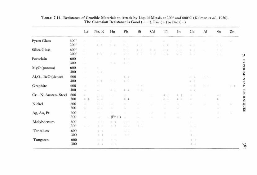
TABLE 7.14. Resistance of Crucible Materials to Attack by Liquid Metals at 300° and 600 ' C (Kelman ef nl ., 1950). The Corrosion Resistance is Good ( .l. + ), Fair ( + ) or Bad ( - )
Li Na , K Hg Pb Bi Cd Tl ln Ga .-\I Sn Zn --- ---
Pyrex Glass 600° 300" I , . + I ' ~
Si lica Glass 600° ~ I ·I I I· ' I
300° ! " I ~ ' : --;-! Porcelain 600 ~
tT:
300 I" ;;..: "0
MgO (porous) 600 tT:
" 300 ~
AI ,O,., BeO (dense) 600 + tT1 z
300 + ·- ,. + - -1- .....,
Graphite 600 >
++ r 300 + + + : ·- -'- ~
....., tT1
Cr- Ni Austen. Steel 600 .,. ++ + ·! + -1 n
300 :t
+ + + + + + ++ + ·- ~ z Nickel 600 ++ 0
300 + + + c: m
Ag, Au, Pt 600 Vl
300 - (Pt + ) -
Molybdenum 600 _._ ~ ~
300 -- I + Tantal um 600
300 I I + Tungsten 600 ·I
300 + I I I w o-

362 CRYSTAL GROWTH FROM HIGH-TEMPERATURE SOLU1'1-QNS
TABLE 7.15. Crucible Materials Used for Various Melts and Solutions, and the Maximum Temperatures Applied
Melt or solution Crucible Temp. (0 C) Reference
Pb Nb, Ta 950 BeO, SiO, 1000 c 550 Porcelain 850 Pyrex 350
Bi Mo,C 1000 Nb 450 SiO, 900
Bi- Pb- Sn Eutectic w 500 Pyrex 300
Ga W,Re 800 Ta, Zr0 2 , Pyrex 500 Nb, Mo 400 c > 800 BeO > 1000 AI,0 3 1150 SiO, 1160 if oxygen-free atm .
Al AI,O,, BeO 1000 c 1200(1700) ThO,, ZrO, > 1000
Zn C, Al 20 3 , SiC 900 Sb c 1300 Ti Y,O, -1700 Helferich and Zanis (1973) La + LaB, Ta 1200-1700 Deacon and 1-liscocks
(1971) Eu + EuO w 2150 Shafer et al. ( 1972) US, + US w 1700-1900 V an Lierde and Bressers
(1966) Ti,O, \lo 1820-1920 Reed et al. ( 196 7) Alkalihalides Supremax glass 750 Janz (1967) Bi,O, ThO, 1100(4h) Ti ehe and Spear ( 1972) KOI-1 + BeO Ag 550 Levin et al. (1952) KF + V,O. + V,O, Pt 950 McWhan and Remeika
(1970) v,o. Pt max. 700 Kennedyeta/. (1967) PbO + PbF 2 + Oxides Pt 1300 Various authors PbO + B,O, + Oxides Pt 1300 Various authors PbO + V,O, + Oxides Pt 1350 Various authors BaO x 0.6B20 3 + Oxides Pt 1400 Various authors KF + BaTi0 3 Pt 1200 Various authors Na,CO, + BaTi0 3 Ni 1200 Reducing atm., Kawabe
and Sawada (1957)

TAilLE 7.16 T empera turcs of first noticeablc rcaction (upper right part) and the maximum wo rking tempe ratures (lower le ft part) m °C .
,, ;'\ h Zr To "' .... l.."nflO (l h .
ohr;- 11.
.. ~ J .. I;,~,
ll'U M!O II : ?Sf) SR C'IN !R)
1:\1 _ .• 'J : ...... · ~ 111 ,1()
75•1;-.:R O N CR)
.0.1.• ' , :u1 ~ m
11•).) ( \ ') 0!\'R ~ . ,., 1-. ;1) 10 )
:"·~ · \ ' .>; ~ •• IV" · ~) h ~')
O~R
: Ii•~·
•'· '•:" lf,!MI ( \ ' J
~ ~1111 ( II ) 1 ~(\(1 '""' 11\S•l (OSJ 0 .•.,;; .... ,,. ~ "" ' \lifiO ,..., 10) :'\:R
I'\,< I: ]11Mo \ '
~~·~· Ult("o ..- 1!100 II!)) ":":
:\ '•:-" ~ ~ · '·• ]11 ~ 1 _,.,,)') :~. ...... · ~ ] ~ ~ ~~
- ii» {SM ) AS ........
IU>O .-... : '''" 161)0 ,.,., , ".) ) (0)
I 71~•' ,.,., Al '\"
• , \ 1))1)
.... J, l , .... ." J I))o)
]JIMo\ '
"'' n•~ · ,.
'""" \\' .' ~I W I \ ' _. ,"..,.)
l'l'lo)
·' ' I ] I MII ,, Ito
l •))o)
71Mii lt J
J : <OI I/ (1 1 111~ 1 I I 1)
:-.,\' ,,

364 CRYSTAL GROWTH FROM HIGH-TEMPERATURE SOLUTIONS
Thermodynamic data may give some general indication of the stabilities of crucible materials and their reactions with high-temperature melts, but results to better than thc order of magnitude must not be expected because of the limited reliability of much thermodynamic data, of the influence of the grain size, impurities and dislocations of the crucible material, as weil as of the detailed chemistry of the solution and the gas atmosphere. The data for stabilities of the crucible materials given in Tables 7.13 to 7.16 must be regarded as approximate. As an example of the estimation of interface reactions using thermodynamic data, the paper of Armstrang et al. (1962) may be mentioned. These authors claimed that at fairly high temperatures strong reactions with silica occur for those metals of which the oxidesform low-melting eutectics with silica.
In the following paragraphs two classes of crucible materials will be discussed in detail because they are the most frequently used in flux growth, namely (A) ceramic crucibles, and (B) noble meta! crucibles. The generat aspects of the size of crucibles are discussed in Section B.
A. Ceramic crucibles. Silica: Silica glass is highly corrosion-resistant and is easy to form to any
desired shape. It is transparent and has a low thermal expansion coefficient, so that it is resistant to thermal shock. The resistance of silica against corrosion can be increased by deposition of a thin carbon layer obtained by decomposition of acetone or ethanol at 500 to 700°C in an atmosphere low in oxygen or by deposition of an alumina layer about 500 A thick as reported by Widmer (1971 ). Silica glass crystallizes slowly around 1000°C (especially where traces of alkali, like NaCI from sweat, are present) and more quickly above 1100°, and the crystallization products, tridymite and cristobalite, undergo destructive phase transitions between 100 and 400°C so that recrystallized silica frequently breaks or explodes in this temperature range. At temperatures above 1100° softening takes place, but silica glass can be used for Czochralski growth of silicon at 1540° when its shape is maintained by an external graphite Container. Chemically silica is stable against carbon, many metals, sulphides, selenides and halides up to 1000°C, but it is attacked by fluorine-containing vapours and liquids, basic melts (with formation of silicates), many oxides, hydroxides, phosphates, alkali and alkaline earth metals, aluminium and boiling phosphoric acid. Lead, tin and cadmium corrode silica only if the ampoule contains traces of oxides. For experiments in oxygen- and water-free atmospheres the hydroxide layers adsorbed at the surface must be removed by etching with HF-HN03 mixtures, immediately followed by short rinsing with metalfree distilled water and subsequent heating at 1000°C for two hours in vacuum. For use at temperatures below 750°C silica glass may be re-

7· EXPERIMENTAL TECHNIQUES
placed by Vycort or Suppremaxt, below 500°C by Pyrext or Durant glass.
Oxide ceramies: Of the pure oxide ceramics, alumina finds the wielest application in crystal growth from high-temperature solutions, but the more expensi,·e zircon ZrSiO . ., zirconia Zr0 2 and thoria Th0 2 are generally more restant against corrosion. For example, thoria is not measurably attacked by bismuth oxide at 1100° and thus can be used for growth of Bi4Ti 30 12 and similar compounds (Tiche ancl Spear, 1972). For many applications (melts of metals, sulphides and halides except Auorides) the relatiYely inexpensiYe porcelain (mullite, sillimanite), or ceramies based on magnesium silicates, pyrophyllite ancl Lavitet which can bc shaped before the first firing are adequatc. For example, glazed porcelain crucibles have been repeatedly used for potassium pyrosulphate melts between 700 and 900°C in order to clean platinum crucibles. Accorcling to J aeger ancl Krasemann (1952), who inwstigated the stability of alumina against various agents, borax melts polish the surface of alumina ceramics. However, silicatesarenot useful in reducing atmospheres at high temperatures. Most ceramic crucibles are sensitiYc to acids and are cither dissolved ( BeO, MgO, CaO), or show cracking when reheated after cleaning with acicl. In many aspects new types of ceramies which have nearly 100% density and are translucent or c\·en transparent (AI 2Ü 3 , Yttraloxt = 90°6 Y 20 3 , 10°6 Th02 )
have many adYantages (corrosion resistance, vacuum-tight, high maximum working temperature) but are clisaclvantageous with respect to thermal shock resistance. For special applications single crystalline alumina crucibles and tubes proclucecl by Aame fusion or edge-defined film-fed growth might be useful.
Ceramic containers and tubes may be sealed if required either by a hightemperature cement or by welding with a Aame or plasma. In principle cheap ceramic containers coverecl with a thin platinum layer might be used as a replacement for the very expensive platinum crucibles, or corrosionresistant layers (e .g. of Al 20 3 or Zr0 2) may be evaporated or plasmasprayecl on to porous and thus shock-resistant crucibles, but such combinations have not yet founcl wide applications.
Base metals and non-oxide ceramies: Of the base metals nicke!, stainless steel, molybdenum, tungsten and tantalum are most frequently used as crucibles, but at temperatures above about 500° oxygen- and water-free atmospheres are required. At such low oxygen pressures as 10 - 3 atm and at high temperatures up to 10 atom 0 6 oxygen is dissoh·ed in niobium and tantalum whereas in molybdenum and tungsten the oxygen solubility is smaller by orders of magnitude. At high er oxygen concentrations the metals are completely oxidized. The oxidation behaviour ancl other properties of
t Trademarks.

366 CRYSTAL GROWTH FROM HIGH-TEMPERATURE SOLUTIONS
refractory metals have been described by Jaffee in High Temperature Technology (1960), and the oxidation of Nb and Ta is discussed by Fromm and J ehn ( 1972). Molybdenum and tungsten crucibles are suitable for containing melts of pure molten alumina, but are attacked by ruby melts.
In crystal growth from high-temperature solutions Mo, W and Ta crucibles are probably most widely used for growth of chalcogenides of the lower valency states from the corresponding meta! melts (e.g. EuS, EuSe, EuTe from Eu) as weil as for growth of other refractory compounds (WC, LaB4) from metallic solutions.
Sawada et al. ( 1951) and Kawabe and Sawada ( 1957) used nicke! crucibles for the growth of BaTi03 from Na2C03 solution in a reducing atmosphere and found no attack of the crucible. In air or even in nitrogen, nickel is attacked by carbonate melts. Hauptman et al. (1973) used iron crucibles for growth of Fe2Ti04 from Ba0- B20 3 solutions in a nitrogen atmosphere and Garrard et al. (1974), Ni and Mo for growth of fluorides.
Of the non-meta! non-oxide refractories graphite is probably the oldest and most popular, and the development of pyrolytic graphite and of glassy carbon has extended the usefulness of carbon crucibles. A characteristic of graphite is that its strength increases with temperature and so is higher than many other refractories (BeO, MgO, Zr0 2, W) above 2000°C. Because of its corrosion resistance, its excellent thermal shock resistance and its relatively low price, graphite is the first choice as crucible material formetals (except those which form carbides), fluorides, and sulphides. lts disadvantages are its reducing action and that it has to be protected from oxidation above about 500°C. The I II -V analogue of carbon, boron nitride, shows a slightly better oxidation resistance and a \·ery high electrical resistiYity of about 107 Q cm at 1 000°C. BN is resistant to moltcn nonferrous metals and many salts, and its oxidation in air starts only aboYe about 900°C.
Another III - V analogue is the nitride Air-;, and All\ ceramies containing small amounts of silicon carbide decompose above 2200°C and are Yery resistant towards molten metals. They are not wetted by molten steel and do not react with cryolite melts at l040°C. In air AIN is oxidized aboYe about700°C.
Silicon carbide is the most important of the refractory carbides. lt has a hardness 9 on the Mohs scale, a high thermal conducti\·ity and low thermal expansion coefficient and is thus very resistant towards thermal shock. Another advantage of SiC is its oxidation resistance up to about 1550c (with the exception of the range below 750°C where "silicon carbide pest" occurs and where the protective Si0 2 layer cannot form so that SiC is oxidized).
Little attention has been given to refractory borides, silicides and

7· EXPERIMENTAL TECIINIQUES
sulphides and thcir application to Aux gro'vvth although thcy arc cxpected to exhibit a good corrosion resistance against metals and fused salts, and a reasonablc stability bccausc of thcir high mclting points, gcncrally bctwecn 2000 and 3000°C. For example, zirconium boride ZrB 2 has a melting point of 3040°C, is oxidation-resistant up to 1000° and is not wetted hy many molten non-ferrous metals such as Zn, Al, Pb, Cu, Sn and brass.
B. N oble meta! crucibles. In crystal growth of oxide compounds and of some Auorides from high-temperature solutions the most common crucible materials are noble metals, and from this group of metals platinum has found by far the widest application. Since platinum has a relatively high price, thc initial cost as weil as refabrication costs form a significant (if not the largest) portion of the costs of Aux growth of oxides. The prices of platinum (and of iridium) Auctuate enormously, as may be seen from Fig. 7.35 . In this connection it should be noted that several companies and syndicates ask prices which are 50% and more higher than the free market (U.S.) price. The free market price tends to be a sensitive indicator of demand and supply trends. The bulk of platinum is costed at the tlxed producer price, and both prices vary widely . .'\ price of 120 dollars per
$ PER OUNCE TROY
PLATINUM
AVERAGE ANNUAL PRICES OF PLATINUM AND IRIDIUM
(iN DOLLARS PER OUNCE TROY)
S PER OUNCE TROY
IRIDIUM
180
160
140
120
100
80
60
40
20
(+- Price
Monetory crisis end doller devoluotion
(+potential use of Pt in automobile
1930 1935 1940 1945 1950 1955 1960 1965 1970 YEAR
Ftr.. 7.:l5. Price fluctuations of platinum and iridium.
360
320
280
240
200
160
120
80
40

368 CRYSTAL GROWTH FROM J-IIGH-TEMPERATURE SOLUTIONS
ounce platinurn may be uscd as a guideline for the free rnarket price, and SO dollilrS pcr ouncc for thc produccr pricc. In 1971 /1972 therc was a shortfall in the free market price of about 40 dollars per ounce until the U.S. government decided not to postpone the Clean Air Act of 1970. The steep increase in the platinurn price caused by the potential demand for platinurn in automobile exhausts was accelerated by the rnonetary crisis of 1972/1973 . The platinum price may drop significantly if the crisis is settled, if an alternative to platinum in exhausts is adopted or if Russia offers abnormally !arge quantities of platinum to the Westernmarketas happened at the end of the fifties.
Platin um crucibles for flux growth may be obtained from various sources, either in standard shapes or to special order. Frequently it may be faster and more convenient to order round platinum sheets and have them shaped by a local noble meta! spinning shop. A variety of crucible forms used in several laboratories are shown in Fig. 7.36; (a) shows a standard crucible with Iid which is commercially available in several sizes; (b) a modification of the crucible rirn and Iid of K vapil ( 1966) and J ohn and K vapil ( 1968), which allows sealing by a liquid; (c) a special crucible form used by Scheel (1972) and Scheel anrl Schulz-DuBois (1971) which is rnechanically stable and to which a flat round Iid can be welded. After the experiment, crucible and Iid are separaterl by cutting the welded rirn, and can be re-used about five tim es; ( d) shows a rnodification of the Iid with a hole of 0.4 mrn diameter (Elwell and Morris, unpublished) which is loosely covered by a platinum sheet and which can be sealed after heating up and expansion of the enclosed air by pressing on this sheet from abo\"e; ( e) the crucible arrangement of Tolksdorf ( 1968) made from a !arge diameter platinum tube and with a Iid sealed to it having a platinum capillary to release pressure; and (f) shows a diagram of the !arge crucibles used at Bell Laboratories and at .'\irtron for pilot plant flux growth . Slightly conical crucibles are advantageaus for remo\·ing solidified flux and for reshaping which should be clone on plastic formers with a plastic or leather hammer. Preferred wall thicknesses are from 0.5 to 1 mm for a crucible volume of 30 to 1000 cm3,
0.3 mm being the practical minimum. A greater wall thickness increases not only the lifetime of the crucible, but also allows the destruction by beating with a slightly convex hammer of grains formed by recrystallization.
The crucible size is discussed here because it has a dramatic and often restricting effect when expensi\·e noble metals have to be used as crucible materials. According to Block ( 1930), Goethe had already recognized that increasing the crucible size tends to increase the crystal size, and during the past century crucible sizes up to 50 I were used as discussed in Chapter 2. In recent years platinum crucibles of 4 I and even 8 I were used by various

7· EXPERIMENTAL TECHNIQ U ES
(a) u lblu
(c)
HOLE OF / -0.05mm '/!
t LOCALIZED COOLING
(d)
(e)
( f)
~~___,.., ~-1 HOLE OF 0 4 mm 111
co . 20-25cm (8-10 tnches)
t co. 20cm ( 8 inches l
/'.
FIG. 7.36 . Examples of crucible shapes used in flux growth (not to scale).
companies for the growth of garnets and ruby. Ho,,-e,·er, I arge crucibles are not always adYantageous for a number of reasons .
In Section 6.6.1 the experimental requirements for stable growth are discussed, and for !arge crucibles extremely low cooling rates for the first weeks or months are requirecl if one or a wry few inclusion-free crystals are to be grown. If multinucleation is tolerated or if seed crystals of suffi.cient area are available "normal" cooling rates (between 0.1 o h - 1 and 1 oc h - I) and duration of experiments can be applied. The effect of the crucible size is demonstrated in Fig. 6.16, which also shows the importance of high solution ftow rates at the crystal surfaces in order to achieYe stable growth. The !arger the crucible the more stirring is necessary in order to

370 CRYSTAL GROWTH FROM HIGH-TEMPERATURE SOLUTIONS
prevent convection pockets and thus uncontrolled nucleation, as discusscd in more detail in Section 7.2.7. As a general rule stirring is worthwhile for crucibles !arger than 100 cm3 and is necessary for crucibles !arger than about 500 cm3• Another requirement with !arge crucibles is that temperature control and programming have to be very precise, and it is estimated that temperature oscillations !arger than 0.1 oc with periods !arger than about one second might have harmful effects on the quality of the grown crystals.
Another obvious disadvantage of !arge cruciblcs is their price and the requirements on the size of the furnace and controller, and thc total cost of systems based on crucibles more than 1 litre in stze is oftcn prohibitive.
An advantage of !arge crucibles is the low ratio of wetted cruciblc surface to the volume of solution which determines crucible corrosion and incorporation of crucible material into the growing crystals. Thc incorporation of, for example, platinum can be significant depending on experimental parameters as was demonstrated by Bradt and Anseil ( 1967). These authors found 0.1 wt% Pt in BaTi03 crystals grown from K F whrn a soaking time of four hours was applied, whereas without soaking only 0.065 wt% Pt was found.
Another advantage is obviously the quantity of crystals which can bc grown simultaneously, and !arge crucibles are required when large-scalc production of crystals is applied. Grodkiewicz et al. (1967) obtained a yield of 2.8 kg YI G from 8 I crucibles although about 2/3 of the volume of 1 hc YIG crystals contained inclusions. This fraction of included crystals might be reduced if stirring, seed crystals and precise temperature control are applied, as discussed above.
On comparing the advantages and disadvantages of !arge cruciblcs 1 hc conclusion is reached that an optimum crucible size exists as a compromisc. As a rule, crucible sizes of 25- 100 cm3 are suggested for crystals of a fc\\. mm size, but for crystals !arger than 1 cm3 the crucible size should increase by about 100 cm3 per cm3 crystal.
Occasionally an influence of crucible size on the crystallizing phase has been reported and explained by Flicstein and Schieber (1973). lf a composition lies near the boundary of stability fields of different phases, then the difference in the eYaporation rate in crucibles of different sizcs might shift the PbO- PbF 2 ratio (in this case) and thus Iead to different phascs.
In order to produce the smallest possible surface and thus to minimize corrosion ancl nucleation sites the crucibles should be mechanically and chemically polished. The latter is performed for example with a potassium pyrosulphate melt at 700 to 800°C (however, Rh-containing crucibles are

7· EXPERIME N TAL TECH N IQ U ES
attacked by pyrosulphate) for onc to four hours, and any reshaping and hammering should be followed by chemical polishing.
A short prehcating of Pt cruciblcs to about 1200vC bcforc usc prcvcnts excessive welding of new platinum pieces when in contact. Special care in the use and handling of platinum crucibles is necessary in order to preYent crucible failures during the growth experiments (and too frequent reshaping). Platinum crucibles should only be used for ionic melts (Auorides, oxides, silicates) but never for elements and for compounds with strong covalent or metallic bonding. Thus metals, phosphorus, arsenic, antimony, bismuth, silicon, boron and sulphur should never be heated in Pt crucibles. Especially carbon, carbides or organic compounds should not contact hot Pt containers and reducing atmospheres should be prevented under all circumstances. For example, traces of organic compounds or of hydrogen may reduce the heavy-metal compounds like Bi 20 3 , PbO and Pb F 2 and may Iead to destruction of the crucible. In order to maintain oxidizing conditions an oxidizing agent like Pb02 (Garton and Wanklyn, 1967) is frequently added, or a buffer like V 20 5 which is more easily reduced to V20 3 th ;m PbO to Ph. Also a reducing atmosphere can be preventecl by slowly blowing air into the furnace chamber. As supports stable oxicle ceramies shoulcl be usecl since silica ancl silicates are easily reduced above 1000° to 1200°C, and the resulting SiO (or Si formecl by clisproportionation of SiO) forms with Pt low-melting eutectics. Thus, only alumina or other stable oxicles shoulcl be usecl in conjunction with platinum.
Cleaning of platinum crucibles to remove adhering flux or oxides is clone by careful tapping with a plastic hammer, and /or by clissolution with the appropriate hot acid or alkali solution, or by clissolution with a flux. N itric acicl or hydrochloric acicl may be usecl separately, but a mixture of these two acids (aqua regia) will form free chlorirre and dissolve platinum (iridium-rich platinum alloys are rather resistant to aqua regia) . Aclhering oxide crystals, if not easily removed mechanically may be clissolvecl in melts of potassium pyrosulphate at 700- 800°C (S03 vapour is formed), in N a2C03- K 2C03 melts araund 900°, in borax at about 1200°, or in KF or Pb F 2 melts at 1200°C. Silicates are easily removed with concentratecl hyclrofluoric acid . After leaching these melts and after any hammering or reshaping the platinum crucibles should be treated with hot nitric acid for one hour, ancl after rinsing with sufficient distilled water the crucible shoulcl be clried by heat (not with a towel) and kept dust-free until use.
Generally pure platinum is usecl for growth of oxicle compounds from thcir solutions in malten salts. Alloys of platinum frequently have aclvantages or are even required for special applications. Thus for growth of SrTi03 ancl BaTi03 from melts cantairring excess Ti0 2, Pt- Ir or Pt-Rh alloys are used because of their higher melting points, ancl for still high er

372 CRYSTAL GROWTH FROM HIGH-TEMPERATURE SOLUTIONS
temperatures iridium might bc used . According to Nielsen ( 1974) iridium crucibles might bc used for PhO-frcc Ph F 2 solutions in inert or slightly reducing atmosphere since Iris not attacked by Pb up to 1600°C.
The disadvantages of Rh and Ir (and Pt-Ir alloys) isthat they are more easily corroded than pure platinum by the normal Pb- or Bi- containing solvents and at low temperatures. For example Cloete et al. (1969) found in MgAI20 4 crystals no platinum, but traces of iridium which was probably present as an impurity in the platinum crucible used, and rhodium is frequently found in crystals grown from Pt crucibles. Small rhodium addition (0.5- 1 %) to the platinum increases its mechanical strength and decreases the tendency to recrystallization . Pt- Au and Pt-Au- Rh alloys are ve ry little wetted by borate and silicate melts, but on the other hand Au and Rh are easily extracted from platinum containers. Iridium evaporation (as lr0 2)
might be minimized by rhodium plating. In summary, for all applications special crucible materials, shapes and
sizes may be found which, with the appropriate experimental conditions, might contribute significantly to the size and quality of the Aux-grown crystals . Aspects of handling nohle m eta! crucibles are given in booklets and catalogues of the producer companies and in the reYiews and papers of Brice and Whiffin ( 1973), Cockayne ( 1968), Darling et al. ( 1970), Robertson (1969), Robertson et al. (1974a) and V an Uitert (1970). The development of eheaper crucibles would probably extend the application of the Aux method.
7.2.4. Separation of crystals from solution In general crystallization from high-temperature solution is terminated with the solution at a temperature above the eutectic point, and the crystals produced may be separated from the excess solution either at this "final" temperature or following relatively rapid cooling to room temperature. The former alternative is generally preferable when this is com·enient, as in top-seeded growth where the crystal may normally be raised out of the solution b y a motorized drive mechanism .
\Vhen the crystals are grown by spontaneaus nucleation, cooling of the crucibles to room temperature prior to removal of the crystals is fairly widely practised because of its relatiYe simplicity. The excess solution is then normally dissolved in some aqueous reagent, a process sometimes referred to as "leaching". The leaching process relies on the differential solubility in this reagent of the crystal and the high-temperature solvent and it is clearly important for easy removal of the crystals that a suitable reagent should be available. Aqueous solvents for the more popular hightemperature solvents are listed in Table 3.13.
The great disadvantage of removing the excess solution at or around room temperature isthat the rate of dissolution may be extremely low. A

7· EXPERIMENTAL TECIINIQUES 373
mnnth or en·n Ionger may Iw required tn rcmm-r, fnr e:-;ampk, bismllth borates from a cruciblc of only 100 ml capacity and mcans of avoiding such delays are clearly desirable. Warming the container uscd for leaching will promote dissolution and the resulting saving in time can be dramatic especially i f leaching is performed at a temperature close to the boi ling point of the aqueous reagent. As an example, Elwell and Morris (unpublished) have found that excess PbOjPbF2/B20 3 may be dissolved within 1- 2 days when the crucible is maintained in fairly dilute nitric acid close to its boiling point. Boiling chips must be added to the acid and the temperature of the acid bath maintained constant by a hot plate or oilbath. The most rapid leaching rates require that the acid be replenished at frequent intervals which depend on the volume of the container used.
Cooling of the crucible and crystals to room temperature suffers from the additional disadvantage that strain may be introduced in the crystals because of the contraction of the solution as it solidifies. This is especially the case when relatively soft crystals like sulphides are grown from malten salts. However, even if crystals are removed while the solution is molten, thermal strains will be present and the crystals should be annealecl if freedom from strain is important.
Removal of the excess solution above some critical temperature may be essential if the system is suchthat re-dissolution of the crystals would occur on further cooling. Even in systems where no such dissolution would occur, the saving in time which is achievecl with hot pouring has Iee! to its increasing use. The simplest means of pouring off the excess solution is to remove the crucible from the furnace with tongs and to decant the liquid after removing the crucible Iid. This method is possible only when the Iid fits loosely onto the crucible, since it is desirable that the crucible should be returned to the furnace as rapidly as possible in order to minimize thermal shock to the crystals; especially when crystals !arger than about 1 cm3 are grown cracking may occur on any sudden temperature changes.
An alternative procedure has been suggested by Grodkiewicz et al. (1967) who puncture the base of the crucible from below with a steel spike, without removing the crystal from the furnace. The drainage hole may be re-welded so that the crucible can be used several times before refabrication IS necessary.
The seeding technique of Bennett ( 1968) and Talksdorf ( 1968), describecl in Section 7.1.1, provieles a particularly convenient means of removing the crystal from the residual solution by inversion of the crucible. Crucible inversion is applicable to sealed crucibles and may be used for unseeded growth if some mechanism is provided within the furnace. This mechanism may be extremely simple, for example, a wire attached to the base of the crucible which is pulled vertically upwards, provided that the crucible is
~

374 CRYSTAL GROWTH FROM HIGH-TEMPERATURE SOLUTIONS
mounted on a suitable pivot (J. M. Robertson, private communication). A device which may be used for simultaneous hot pouring by inversion of a number of crucibles is shown in Fig. 7.37(a) and (b). The crucibles are mounted in a cemented firebrick block which has the primary advantage of providing a high thermal Capacity during growth. At the termination of growth, a clamp mounted on a relatively massive trolley is brought into contact with the block, which may then be removed from the furnace, inverted and returned to the furnace very rapidly with little thermal shock to the crucibles. The crucible Iids are crimped tightly to minimize evaporation during growth, but provide imperfect seals so that the excess solution drains away into the surrounding powder and firebrick, which is replaced after every experiment.
(a)
ALUMINA POWOER
(b)
ALUMINA FIREBRICK
FIG. 7.37. Device for simultaneaus hot pouring of several crucibles. (a) Mechanical setup. (b) Cerarnic block with crucibles (Srnith and Wanklyn, 1974).
Completely sealed crucibles permit a greater degree of reproducibility in the crystal growth conditions but inversion and subsequent solidification of the residual solution presents problems in the removal of the Iid and of access to the crystals. Scheel (unpublished), using the sealed crucible design shown in Fig. 7.36(c), has found it more convenient to pour off the solution from the crucible by puncturing holes in the Iid with a small steel spike after rapid removal of the crucibles from the furnace. The crucible is quickly replaced into a furnace which is then slowly cooled to room temperature. The small thermal shock introduced by this procedure is more than offset by the ease of access to the crystals after cooling to room temperature.
An isothermal technique to remove excess solution has been used by Kawabe and Sawada (1957) who, after growth of BaTi03 from Na2C03
solution at 900°C, sucked up the stillliquid flux through a nicke! pipe by a rotary pump, and then cooled the furnace with the crucible to room
FLUXED MELT

7· EXPERIMENTAL TECHNIQUES 375
temperature. In a similar manner for sealed crucibles, pressurc from outside could be used to pump the excess solutionout of the crucible.
7.2.5. Chemieals
The importance of attention to chemieals cannot be overemphasized and many problems of Iack of reproducibility in crystallization from high tcmperature solution may be related to differences in the starting materials. Most experimenters prefer to buy pure chemieals from specialist suppliers rather than undertake thcir own purifications but it is weil known that different batches of chemieals may vary in their impurity content andin thc assay of thc substance in qucstion.
In general thc chemieals which are supplied can be classificd into four broad categories- laboratory or rcagent grade with a purity normally quoted in the region of 99°,6, "analytic grade"-about 99.9~~ , "spectroscopic grade"- up to 99.999% , and ultra-high purity grades of certain chemicals, supposedly with even higher purities, may be available according to the nature of the material required. The increasing availability of high puritv chemieals has been of great value in crystal growth and has been a contributory factor in the preparation of relati,·ely perfect crystals. The experimenter should, however, be aware of the clangers of unquestioning reliance on the manufacturer's analysis. Even where the material is accompanied by the typical result of spectrographic analysis quoting impurity Ievels in the ppm range, it should be realized that the manufacturer does not guarantee the assay of the material. So, for example, the material may contain volatile impurities such as organic matter, carbon clioxide or water vapour. Moreover, the stoichiometry may differ very considerably from the nominal compostition.
,\s cxamples of the types of problern encountered by the authors, a sample of high purity Al 20 3 from a well-known manufacturer with a stated molecular weight of 101.9 was found by X-ray diffraction to consist mainly of hydrates. Similarly a batch of nicke! oxide "NiO" from a different supplier contained about 30% by weight of metallic nicke!.
Departures from ideal compositions can increase with storage, particularly once a container has been openecl, and particular care is necessary with hygroscopic materials such as B20 3 , La2Ü 3, many halides and even the y-modification of alumina, especially in powder form. Materials in powder form are particularly liable to attack from the atmosphere on account of their !arge specific surface area. In several cases it might be necessary to handle such hygroscopic substances or other reactive materials ( e.g. metals) in dry-boxes or at least under a dry stream of nitrogen. It is clesirable to record in a Iabaratory notebook the batch number of any new dehery of chemicals, and the dates on which it was receiYed and opened.

376 CRYSTAL GROWTH FROM HIGH-TEMPERATURE SOLUTIONS
Checks of new batches of chemieals by X-ray powder diffraction, and possibly also by chemical analysis, are desirable, and the use of a thermobalance is valuable for detection of departures from stoichiometry of oxides or of the presence of free or bound water. Chemieals should also be checked for the presence of foreign bodies such as hair or other fibres, or pieces of furnace constructional material which may have entered the sample during manufacture. It is obvious that all containers and tools which come in contact with the chemieals or the growth solution must be absolutely dry and clean. The presence of any contaminant will, of course, Iead to errors in weighing out the constituents of a growth experiment, and to impurity contamination which in most cases has a bad and sometimes a castastrophic effect as for instance traces of silicon in fl.ux growth of Beü (Austerman, 1965). The positive infl.uence of some impurities on growth has been discussed in Chapter 3, and the effect of impurities on the habit in Chapter 5.
For specialized preparations or when the highest purity is required the availability of facilities for purification is essential. The techniques of synthesis of high-purity substances and of chemical purification have been reviewed by Kröger (1964), by Wilke (1973) and by Jonassen and Weissberger ( 1963- 1968). The synthesis of inorganic compounds in general is the topic of books of Angelici (1969), Brauer (1960/1962), Hecht (1951), J olly ( 1970) and Lux ( 1970) and of the series Inorganic Syntheses (Vols 1, 1939- 13, 1972). Purification can be clone by sublimation or distdlation, by heating, possibly in a vacuum, to evaparate volatile impurities and burn off organic contaminants, and by recrystallization. For metals, electrolysis may also be used to separate the meta! from its salts and from other meta! impurities. These methods all rely on the preferential distribution of impurities between different phases, so that the principles follow the discussion of distribution coefficients outlined in Section 7.1.4. The most important technique for the preparation of high purity metarials for crystal growth is zone refining, which employs repeated crystallization from thc melt with the impurities concentrated into a thin molten zone which traverses the material. Zone refining or zone melting is the subject of books by Pfann ( 1966) and Schildknecht ( 1966 ), both of whom quote examples of the application of this technique to oxides, salts and metals in addition to the semiconductors and organic materials for which the technique was developcd.
Additional purification mcthods may bc used to purify certain materials, in particular by the addition of rcagents which react with impurities to form volatilc species. As an example, Wanklyn (1969) removed traces of oxides and hydroxide ions from fl.uorides by heating with ammonium bifl.uoride NH 4 • HF 2 to form volatile ammonium compounds, as by the reaction
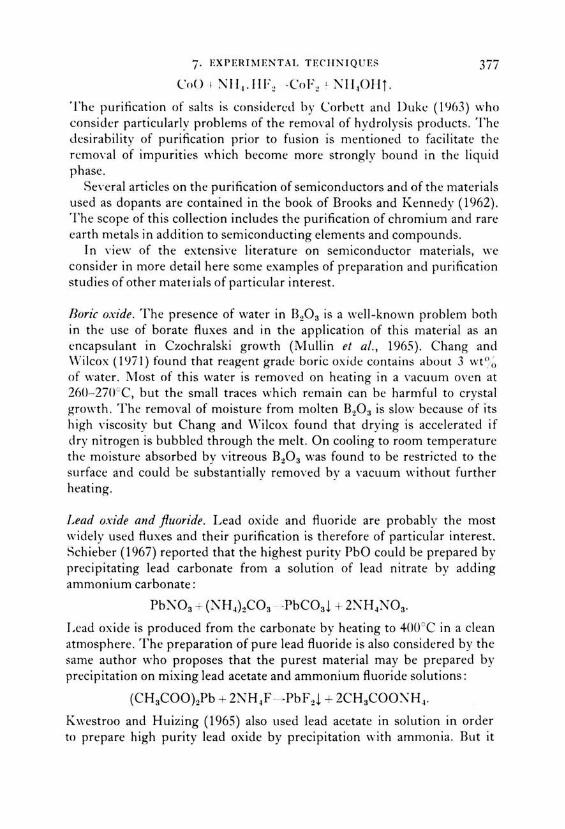
7· EXPERIMENTAl. TECJJNIQ U ES 377
CnO I NII 1 .IIF~ - CnF~ L J\'11 101-IT.
The puritication of salts is considen.:d by Corbctt and Duke (I %3) who consider particularly problems of the remO\·al of hydrolysis products. The desirability of purification prior to fusion is mentioned to facilitate the remo,·al of impurities which become more strongly bound in the liquid phase.
SeYeral articles on the purification of semiconductors and of the materials used as dopants are contained in the book of Brooks and Kennedy ( 1962). The scope of this collection includes the purification of chromium and rare earth metals in addition to semiconducting elements and compounds.
In Yiew of the extensive Iiterature on semiconductor materials, we consider in more detail here some examples of preparation and purification studies of other mater ials of particular interest.
Boric oxide. The presence of water in B20 3 is a well-known problern both in the use of borate Auxes and in the application of this material as an cncapsulant in Czochralski growth (Mullin et al., 1965). Chang and Wilcox (1lJ71) found that reagent grade boric oxide contains about 3 wt % of water. Most of this water is removed on heating in a vacuurn oven at 26U- 2700C, but the small traces which remain can be harmful to crystal growth. The removal of moisture frorn rnolten B20a is slow because of its high ,·iscosity but Chang and Wilcox found that drying is accelerated if dry nitrogen is bubbled through the melt. On cooling to room temperature the moisture absorbed by vitreous B20 3 was found to be restricted to the surface and could be substantially removed by a yacuum without further heating.
Lead oxide and ftuoride . Lead oxide and Auoride are probably the most widely used Auxes and their purification is therefore of particular interest. Schieber ( 1967) reported that the highest purity PbO could be prepared by precipitating Iead carbonate frorn a solution of Iead nitrate by adding ammonium carbonate:
PbN03 + (NH~hC03 - -PbC03 l + 2:\H~N03 .
Lead oxide is produced from the carbonate by heating to 400°C in a clean atmosphere. The preparation of pure Iead Auoride is also considered by the same author who proposes that the purest material may be prepared by precipitation on mixing Iead acetate and ammonium Auoride solutions:
(CH 3C00hPb + 2NH~F - -PbF2l + 2CH3COO:'\H~.
K westroo and H uizing ( 1965) also used Iead acetate in solution in order to prepare high purity Iead oxide by precipitation with ammonia. But it
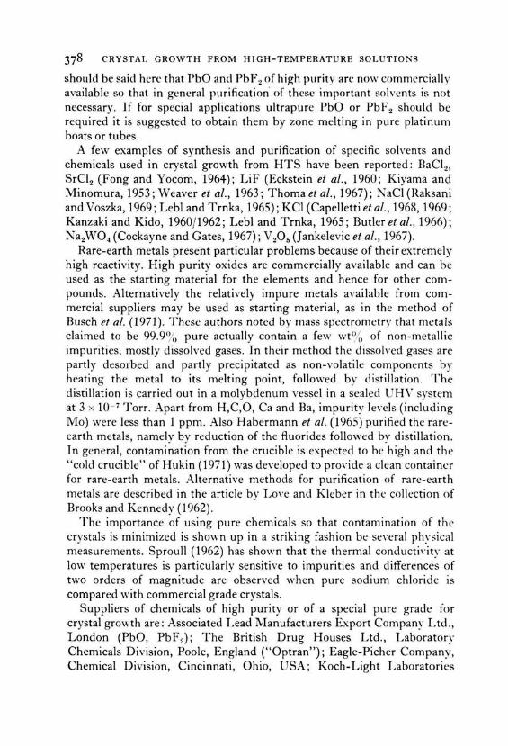
378 CRYSTAL GROWTH FROM HIGH-TEMPERATURE SOLUTIONS
should be said here that PbO and PbF 2 of high purity are now commercially available so that in gencral purification· of thesc important solvents is not necessary. If for special applications ultrapure PbO or PbF2 should be required it is suggested to obtain them by zone melting in pure platinum boats or tubes.
A few examples of synthesis and purification of specific solvents and chemieals used in crystal growth from HTS have been reported: BaCI 2 ,
SrCI 2 (Fong and Yocom, 1964); LiF (Eckstein et al., 1960; Kiyama and Minomura, 1953; Weaver et al., 1963; Thoma et al., 1967); NaCI (Raksani and Voszka, 1969; Leb! and Trnka, 1965); KCI (Capelletti et al., 1968, 1969; Kanzaki and Kido, 1960/1962; Leb! and Trnka, 1965; Butleretal., 1966); Na2WÜ4 (Cockayne and Gates, 1967); V 20 5 (J ankelevic et al., 1967).
Rare-earth metals present particular problems because of their extremely high reactivity. High purity oxides are commercially available and can be used as the starting material for the elements and hence for other compounds. Alternatively the relatively impure metals available from commercial suppliers may be used as starting material, as in the method of Busch et al. ( 1971 ). These authors noted by mass spectrometry that metals claimed to be 99.9% pure actually contain a few wt % of non-metallic impurities, mostly dissolved gases. In their method the dissoh,ed gases are partly desorbed and partly precipitated as non-volatile components by heating the meta) to its melting point, followed by distillation. The distillation is carried out in a molybdenum vessel in a sealed UHV system at 3 x 10- 7 Torr. Apart from H,C,O, Ca and Ba, impurity Ievels (including Mo) were less than 1 ppm. Also Habermann et al. ( 1965) purified the rareearth metals, namely by reduction of the fluorides followed by distillation. In general, Cantamination from the crucible is expected to be high and the "cold crucible" of Hukin ( 1971) was developed to proYide a clean containcr for rare-earth metals. Alternative methods for purification of rare-earth metals are described in the article by Lo\'e and Kleber in thc collection of Brooks and Kennedy ( 1962).
Thc importance of using pure chemieals so that contamination of the crystals is minimized is shown up in a striking fashion be se\'eral physical measurements. Sproull (1962) has shown that the thermal conductiYity at low temperatures is particularly sensitive to impurities and differences of two orders of magnitude are observed when pure sodium chloride is compared with commercial grade crystals.
Suppliers of chemieals of high purity or of a special pure grade for crystal growth are: Associated Lead Manufacturers Export Company Ltd., London (PbO, Pb.F2); The British Drug Hauses Ltd., Laborator:-· Chemieals Division, Poole, England ("Optran"); Eagle-Picher Company, Chemical Division, Cincinnati, Ohio, USA; Koch-Light Laboratories

7· EXPER!1viENTAL TECHNIQUES 379
LtJ., Colnbrook, Bucks, England; Materials Research Corporation, Orangcburg, N.Y.; E. Merck AG, Darmstadt, W-Germany ("Suprapur", ··optipur"); '1\ew Metals and Chemieals Ltd., Poole, England; Johnson \1atthey Chemieals Ltd., London E.C.l. ("Specpure", "Puratronic", ·· Spectroflux"); Research Chemical Corporation, Phoenix, Arizona; MolybJenum Corporation of America, 6 Corporate Park Drive, White Plains, N.Y.; MCP Electronics Ltd., Alperton, Wembley, Middlesex, England; Schweizerische Aluminium AG, '1\euhausen, Switzerland (Gallium and its compounds); LeYy West Laboratories Ltd., Harlow, Essex, England ( niobates, tantalates ).
7.2.6. Atmosphere control Thc importance of atmospherc control has becn discussed at several points within this book, particularly in Section 7.1.5 in connection with the preparation of phases haYing ions in unusual valence states. In general the requircd phase must be grown in an atmosphere in which it is stable, although in practice some modification of the equilibrium condition may bc effected according to the solvent in which the crystal grows. The practical problems of atmosphere control may bc considered as thrcefold: purification of thc gases if impurities are likely to enter thc crystal or to affect gro\\·th; pressure control of a single pure gas phase, and partial pressurc control of an active component in a mixture of gases. The vital questions of leak prcYcntion and detection are beyond the scope of this book.
Commercial gases generally are impure, typical impurity concentrations in high-purity oxygen being 0.1°/c, water, andin argon being 20- 100 ppm oxygen. The removal of harmful impurities from the atmosphere is of particular importance in high-temperature solution growth in view of the long times required for an experiment and of the crucible lifetime, for example. A Yariety of methods is available for gas purification, based both on physical and chemical properties. The most commonly used technique is by chemical reaction by flowing the gas over or through a reagent which will react with the impurity but not with the principal constituent. As an example, the concentration of oxygen in nitrogen or argon may be considerably reduced by flow over copper turnings at about 600°C. Other examples of interest to crystal growers are the catalytic remO\·al of oxygen from hydrogen or hydrogen-containing mixtures by using Pt or Pd contacts with removal of the resulting water by freezing or drying agents, and the removal of 0 2, N 2, CO and C02 from He or Ar by passing the gas over titanium powder at 850°C. Very low oxygen concentrations in inert gases were obtained by Steinmetz et al. (1964) by ftowing the gas through aluminium amalgam. Thc oxygen reacts very readily with the aluminium

380 CRYSTAL GROWTH FROM HIGH-TEMPERATURE SOLUTIONS
to form Al 20 3, which floats on the amalgam, and oxygen partial pressures of 10-27 atm may be achieved.
A common practice is the drying of gases, and the efficiency of drying agents increases from CaCI 2, CaS04, H 2S04, KOH, Mg(Cl04h, BaO to P20 5, and especially P20 5 distributed in silicagel is a practical drying agent. On the other hand controlled humidities can be produced by bubbling the respective gas through !arge volumes of specified aqueous solutions as listed in Lange's Handbook of Chemistry (1967).
The principal alternative to chemical methods utilizes differences in the boiling or freezing points of gases, and, for example, water vapour and carbon dioxide may be effectively removed from oxygen at not too high pressures by flow through a reservoir containing liquid air or a similar refrigerant. Hydrogen, which is commonly used as atmosphere in crystal growth from metallic solutions, may be purified by diffusion through solid palladium since its diffusion coefficient is much higher than that of the heavier gases. Methods of purification of gases have been reviewed by Müller and Gnauck ( 1965) and by Lux ( 1970).
The total pressure of the gas may be regulated by a dc,·ice which is based on the operation of a relay by a pressure sensor for the required range. As an example, a device capable of regulating pressures up to 1 atmosphere was described by Oxley and Stockton ( 1966 ). Generally pressure regulators for operation both above and below atmospheric pressure are obtained from commercial sources. The use of high vacua is generally to be avoided in HTS growth in view of the volatility of most solvents, and a static or flowing inert atmosphere is normally preferred for syntheses at low oxygen pressures.
Contralied oxygen partial pressures in the range below about 10- 1 atm may be most readily achieved using gas mixturessuch as H 2/C02, CO jC0 2
or H 2/H 20. Data for the variation of oxygen partial pressure with relative concentration and temperature may be obtained from Fig. 3.4. Similarly sulphur partial pressures for mixtures of H 2S with H 2 are available from Fig. 3.5. A fairly detailed account of the importance of partial pressure in material syntheses is available in the book by Reed ( 1972). AlternatiYe systems for the provision of controlled atmospheres are discussed by Kröger (1964), who treats in great detail crystal imperfections and their relation to the atmosphere.
An unusual example of the use of special atmospheres in crystal growth from high-temperature solution is the preparation of MgO and LaAI0 3
crystals doped with 170 by Garton et al. ( 1972). The high cost of this isotope requires experiments on a small scale and crucibles of 10 ml capacity were used. The isotope-enriched oxygen gas was introduced into an evacuated, sealed platinum tube at room temperature with the tube

7· EXPERIMENTAl. TECIINIQUES
contaim·d inside a brass cylinder, the pressurc within which was adjusted so as to a\·oid pressurc ditfercnces which might fracture or distort the platinum tube. The concentration of 170 in the crystals grown was about J0° ;" a similar Yalue tOthat in the SOllrCe powder.
7.2.7. Stirring techniques Stirring was introduced into the field of crystallization by Wultf (1884) and has become routine in crystal growth from aqueous solutions, both for growth of single crystals and for mass crystallization. Stirring is also applied in other crystal growth techniques ( e.g. Czochralski growth, zone melting) whereas in crystal growth from high-temperature solutions it has not yet found widespread application mainly because of experimental problems .
.4. Elfecis of stirring. The main etfects of stirring can be divided into two categories, namely the etfects due to homogenization of the solution and those due to a high solution ftow rate at the growing crystal faces.
A solution homogeneaus with respect to solute and impurity concentration and to temperature may result from various stirring techniques. For example, if a stirrer (with seed crystal) is inserted in the solution and rotated in a stationary container, mixing and homogenization occurs between the regions of solution moving with the stirrer and the regions adhering to the container walls. This homogenized solution contains no thermal or solutal convection cells which frequently Iead to uncontrolled nucleation. Thus the whole solution is influenced by the presence of any crystal, the Supersaturation is not likely to exceed the critical value for nucleation so that spontaneous nucleation can be avoided. Another etfect of homgenization is that the growing crystal always sees a homogeneous ditfusion field, and thus inhomogeneities in crystals such as striations are prevented or at least reduced to a minimum Ievel. Forced convection, that is a high solution ftow rate along crucible walls and crystals decreases the Ostwald-Micrs range of metastability, and spontaneous nucleation might occur, especially in highly concentrated and viscous solutions. t Therefore, stirring should be not too vigoraus and should be adjusted according to the concentration and to the viscosity in order to avoid spontaneous nucleation. The narrowing of the metastability region Ieads to a requirement of precise temperature control, which in flux growth we estimate should be to better than ::.: 0.1 °C.
t As an example, in the growth of iodic acid from very concentrated and viscous aqueous solutions, stirring is disadvantageaus according to S. Haussühl (private communication). However, Daval (1974) grows !arge HIO, crystals of high quality from stirred solution.
Sl

382 C RY STAL G ROWTH FROM H! G l-l- TEMPE RAT RE SO LUT ION
Forced com·ection also Ieads to a decreasc in supersa turation, th e latte r being inAuenced by th e habi t of th e crystals present, by nucl eation at th e surface and by th e degree of stirring. In general , thi s decrease in Supersaturation corresponds app rox imately to th e narrowi ng of th e metastabi lity range, so that no enhanced spontaneaus nucleation is obsen ·cd , at least at modest stirring rates .
A high solution Aow rate along the growing crystal faces has seYcral advantages which have been demonstrated by Scheel and Elwell (1972, 1973) and mentioned in Section 6.6.2. Stirring decreases th e diffusion boundary laye r and reduces the supersaturation inhomogeneity ac ross th e crystal thus allowing a faster maximum stable growth rate than th at without stirring. Because of the faster stab le growth rates made poss ibl e by s.tirring, the duration of experiments may be decreased (see Fig. 6. 16). Stirring is necessary if crystals larger than about 1 cm3 are tobe grown cconomica ll y. The importance of stirring is underlined by th e X-ray topograph of Vergnoux et a/. (1 97 1) which sho,vs growth instability at th c cvent of interruption of stirring, sce Fig. 7.38 .
The decrease in th e bounclary laye r thi ckness has an effect on th e g rowth mechanism and on th e surfacc structure of the crystals grown. Surfaces of
F 1c. 7.38. X-ray top ograph of a Strontiumformate c rvs tal showing d eve lop ment of di sloca tions, proba bl y at inclusions, at the event of interrupti on of st i rring (Vergnoux et al. , 1971 ).

7· EXPERIMENTAL TECHNIQ UES
crystals grown from stirred solutions under not too high Supersaturation are Yery Aat compared to crystals grown from unstirred solutions. This led Scheel and Schulz-DuBois ( 1972) to propose stirring in liquid phase epitaxy, for instance by rotation of the substrate(s) in the solution, and Blank and i\ ielsen ( 1972) as weil as Giess et al. ( 1972) and G hez and Giess ( 1973) confirmed by experiment the advantage of stirring. Stirring in LPE has becom~.: increasingly widely applied (Vilms and Garrett, 1972; Scheel, l<.J73).
Through the d~.:creased boundary layer stirring influences the incorporation of impurities or solvent ions as discussed in Section 7.1.3 .. \ccordingly the stirring rate should not bc varicd too much during an experiment if inhomogcneous incorporation of impmitics is tobe aYoided.
H .. \"atural romwtion. In unstirred solutions bulk material transport by natural comTction occurs in most growth experiments due to temperature differences (thermal convection) and due to density differences arising from variations in solute concentration (solutal convection). Since natural com-ection has been discussed in some more dctail in Section 6.6.2, here only a fe\\· generat rcmarks will be made.
The aYerage comection Aow rate for typical high-temperature solutions lies between about 0.()1 and 0.1 cm s- ' (sec Fig. 6.16) and thus is about two orders of magnitude smaller than typical Aow rates in stirred aqueous solutions. Problems arise when the convection streams are irregular or when they form com-ection cells or pockets because in these cases spontaneaus nucleation might occur, competing with growth of the crystals already present. Time-eiependent convection also Ieads to striations or even unstable gro\\th. Consequently a steady convection Aow should bc produced, for instance by heating one crucible wall and cooling the other, or in generat by achieving temperature profiles and crucible shapes which fa,·our a steady com·ection Aow. As an alternative, comTction may be minimized as in the com·ection-free cell of Tiller shown in Fig. 6.19, but experimental difficulties may arise when this cell is applied in crystal grO\\"th from high-temperature solutions. lt is obvious frorn the discussion of stirring in Scction A, that if possible smooth and continuous stirring should be applied and that the hydrodynamics in crystal growth from solutions should be dominated by adjustable forced conYection.
C. Seed rrystals an stirrers. Seed crystals on stirrers are used in crystal growth from aqueous solutions both in small-scale and in large-scale production of monocrystals, thus the adYantages of homogeneaus solutions and of high solution Aow rates can be utilized. Howe\·er, experimental parameters such as the rotation rate, the position of the seed between the

384 CRYSTAL GROWTH FROM HIGH-TEMPERATURE SOLUTIONS
rotation axis and the container walls, the orientation and the fixing of the seed crystals must all be carefully adjusted. Since a small quantity of the solution rotates with the seed crystals and since a sufficient solution flow rate is needed along all faces in ordP.r to prevent inclusion veils the rotation should be reversed at least once aminute (Holden, 1949).
On the other hand, Sip and Vanicek ( 1962) pointed out that abrupt termination and reversal of rotation affect the crystal very unfavourably, and sudden acceleration of the solution might even cause spontaneaus nucleation. Therefore Sip and Vanicek proposed that changes in thc rotation rate of the seed holder should occur smoothly and that any reversals should be preceded by a pause. As an alternative to attaching thc seed crystal to a rotating ( or reciprocating) holder it could be fixed to thc container, and the solution moved by an independent stirrer.
Seed crystals immersed in solution are not often used in crystal growth from high-temperature solutions. Laudise et al. ( 1962) applied seeds in an arrangement as shown in Fig. 7.3 in order to grow yttrium iron garnet crystals from BaO. 0.61 B20 3 solutions. A crucible of 7.6 cm diameter was used, and the seed holder was rotated at 200 r.p.m . with the direction of rotation reversed every 30 seconds. The dissolution of the feed material was the rate-determining step, as was discussed in detail by Laudise ( 1963), at least for rotation rates faster than about 50 r.p.m . One would expect that for abrupt changes in the rotation rates as above, uncontrolled nucleation would occur, and this in fact was observed. I t seems that stirring is also applied in the commercial synthesis of emeralds but details of the process cannot be found in Iiterature nor obtained from the emerald producers. There is no doubt that in any large-scale commercial crystal synthesis stirring will be applied, and the experience obtained in the growth of crystals from aqueous solutions may be applied in crystal growth from high-temperature solutions. The use of seed crystals on stirrers is generally only proposed when a number of !arge crystals of the same family have to be grown, in view of the effort required to determine the optimum conditions.
D. Top-seeded solution growth (TSSG). This topic has already been discussed with respect to nucleation control in Section 7 .1.1, therefore the discussion of TSSG here will be restricted to its hydrodynamic aspects. The principle of TSSG is demonstrated in Fig. 7.39(a) (the whole apparatus is shown in Fig. 7.4 ). A seed crystal is cooled by an air stream flowing through the seed holder. The solid-liquid interface is below the liquid Ievel so that this method differs from the Czochralski technique where in general the interface is above the melt Ievel. Since in TSSG the crystal dips into the solution, the temperature gradient at the interface is

7· EXPERIMENTAL TE C HNIQ U ES
Thermal radiation conduction
~~~
Heat
(a)
(b)
t Slow pulling
Seed crystal
Heat
-
r··:(i r· ··:(i ... · ·..• . .. · · ....
(c)
38-, )
FIG. 7.39 . Heat flow (a) and hydrodynamics (b) and (c) of top-seeded solution growth.
less steep than in Czochralski growth, and this encourages the facetting which is normally observed on TSSG-grown crystals.
Due to the similarity of the Czochralski and TSSG techniques the hydrodynamics and the stirring effects are expected to be similar. The effects of seed rotation on Czochralski-grown silicon crystals have been

386 CRYSTAL GROWTH FRO M HIGH-TEMPERAT UR E SOL UTIO NS
studied by Goss and Adlington (1959), and Robertson (1966) has shown that a !arge crystal diamcter (more than 10 mm) and high crystal rotation rates of more than about 50 r.p.m. are required to produce the upward ftow (towards the crystal) as indicated in the examples of Fig. 7.39(b), (c) . Cochran (1934) has analysed the ftow to a rotating disc ( of infinite diameter), and Burton, Prim and Slichter (1953) based their derivation of the boundary laycr thickness on Cochran's analysis . An advantage of an axial rotating seed isthat the solute ftow is, to a first approximation, independent of the crystal radius. Greenspan (1968) extended Ekman's study of the "hydrodynamics" of hurricanes to any fluid medium and demonstrated the existence of the so-called Ekman layer ftow. This isaradial ftow within a narrow horizontal layer which occurs when there is a difference in rotation rates between the fluid medium and a solid boundary that is approximately perpendicular to the rotation axis (Schulz-DuBois, 1972); seealso the discussion in Section 7.2.7E. Carruthers and Nassau (1968) have identified a number of ftow patterns as shown in Fig. 7.40 by simulation experiments in which the relative rotation rates of crystals ancl cruciblc wen: varicd o\·cr a widc range.
In addition to the !arge variety of ftow patterns indicated abovc th ermal convection may Iead to temperature oscillations in the melt with the result that it is extremely clifficult to grow striation-free crystals by the Czochralski and TSSG techniques. In discussing turbulent-free comection in Czochralski crystal growth Wilcox and Fullmer ( 1965) agree with M alkt1s (1954) that fluid baffiing is relatively ineffective in reducing turbulent free convection, and propose shielding or an afterheater for this purpose. In contrast Whiffin ancl Brice ( 1971) propose, in acldition to afterheaters, the use of baffies in order to damp thermal oscillations, as in the convectionfree cell of Tiller (1968).
It seems reasonable that a stationary baffie 5 to 15 mm beiO\\. thc rotating crystal will minimize thermal convection not only because of the smaller effective volume of the melt and the reduced ( vertical) Rayleigh numbcr (Whiffin and Brice, 1971) but also because of its stirri ng effect .. \!so Cockayne et al. ( 1969) proposed shallow melt depths to reduce temperature ftuctuations in the melt and pointed out the influence of con\·ection in the gas above the melt .
Although many of the principles discussed above for Czochralski growth will be valid for TSSG, deviations are expected because of th e difference of the height of the interface, the different temperature profil e and the facetting of many crystals grown by TSSG.
E. Accelerated crucible rotation technique (ACRT) . One of the problems of crystal growth from high-temperature solutions using volatile solvents

7· EXPERIMENTAL TE C H N IQ UES
n, !.Jrot.ALL
OR ZERO
flz LAA(i[
-I n, INcAras•Nc.
t 0, •NCAE &StNG
1•1
0 1 S .. ALL
-n, ... CRE ASING IN REvERS€
hd
1
'---=--Jl--', LAAC. ... lt--1:-:SOC::RCC:OT:-:AT:-:IO_N_OO_C_:~-IAf-I~-~~-G-COU-NT-ERRO-T-AT-ION-1 ~O i-n, LAAG( <-f' n1 SirlALL
n, · n2
fi 1 O(C"[ASING
n,-o
CRYSTAL OOMINATING
l
,,,
i Q, OHCO{ASO ...
~ - -- -
Fi<;. 7.·+0. \"ariation of flow patterns with the relative directions and magnitudes of crystal ancl crucible rotation (Carruthers and Nassau, 1968).
like PbO and PbF 2 isthat the crucible should be sealed in order to prevent solYent e\·aporation. The high temperatures and the restriction on crucible materials pre\·ent the application of conventional stirring techniques . . -\.ccording to J. vV. N ielsen ( 1974) alternate rotation and Counterrotation of crucibles with high-temperature solutions were used by Remeika and Van L'itert at Bell Laboratories and by Lepore at Airtran for initial stirring to promote dissolution of the solute; continuation of this agitation during growth did not allow control of nucleation so that this procedure was abondoned, as by Nelson and Remeika (1964) who used rotation reversal only in the initial stage in order to enhance dissolution of the components but not during crystal growth. However, Scheel demonstrated that a beneficial stirring effect in flux growth could be achieved by periodic acceleration and deceleration of the crucible rotation and by alternating the sense of

388 CRYSTAL GROWTH FROM HIGH-TEMPERATURE SOLUTIONS
rotation. This accelerated crucible rotation technique (ACRT) permitted firstly, in a sealed crucible, the restriction of nucleation by localized cooling to one to three crystals and secondly the growth of !arge inclusionfree crystals (Scheel and Schulz-DuBois, 1971; Scheel, 1972).
There are two typical ftow mechanisms which occur during the acceleration and deceleration of container, namely the spiral shearing distortion and the Ekman-layer ftow, although on strong deceleration a transient Couette ftow might occur.
The spiral shearin~: distortion for an infinite tube ( thus neglecting the effect of the crucible base) has been analysed by Schulz-DuBois (1972). This type of ftow is conveniently considered by reference to a uniformly rotating cylinder containing two immiscihle liquids shown as black and white in the cross-section of Fig. 7.41(a). lf the rotation of the tube is
(o) (b)
(c) (d)
(e) (f)
Frc. 7.41. Successive spiral shearing distortion of two liquids in a rotating tube when the rotation is suddenly stopped (after Schulz-DuBois, 1972).

t 3 -3
w ~ a: z Q
s 0 a: w
1.0
0.75
0.5
> 0.25 ~ ...J w a:
0 0
7· EXPERIMENTAL TECHNIQ UES
TIME PARAMETER
.,.._ .,., t ·-~
0.25 0.50
RELATIVE RADIUS r / R
0.75 1.0
Flc ;. 7.42 . D ecreasc of re lative rotati on rate vc rsus relative radius in spiral shcaring disto rtion (Schulz-DuBois, l<J72) .
suddenly stopped, the rotation rate of the liquid near the wall decreases rapidly due to friction, while the central region of the liquid decelerates much more slowly because of its inertia. Thus shearing occurs between the Yarious ring-like liquid regions, and a spiral develops through successive changes in rotation as demonstrated in Figs 7.41(a)-(f). The decrease of the relati\·e rotation rate wjw0 versus the relative radius r jR is shown in Fig. 7.42, w0 being the initial rotation rate. After a time t = 0.1(Ew0 } -
1 =
0.1 pR2frl , the rotation rate at the centre is reduced to about 0.5w0 • For crystal growth by ACRT, especially in tall narrow containers where spiral flow may be the dominant one, the acceleration and deceleration periods should be of this order since for greater periods the changes in the velocity fi.eld become increasingly slower. In the above discussion Eis the Ekman number = YJ / pw0 R2 with YJ the viscosity and p the density of the solution. For a typical melt with a kinematic viscosity YJ I p = 10- 2 cm2 s - 1 and a crucible of diameter ZR = 10 cm the time t has a value of 250 s. However, shorter time intervals are required for the periods of continuous acceleration and deceleration to achieve an optimum and yet smooth stirring effect and for increasing the Ekman flow .

390 CRYSTAL GROWTH FRO M HIGH-T EMPE RATURE SOLUTIONS
If the liquid is allowed to come to rest after the sudden halt in the rotation, it will have rotated relative to the container by the shear angle
(7.9)
with r being the distance from the axis. From this equation the number N of spiral arms is derived as
N = w11 pR2/ 16Trry = (161TE)-1
and the width Llr of the spiral arms is
Llr = 4-rrTJ f pw0 r = 41TER2/r.
(7 .10)
(7 .11)
In order to achieve efficient mixing, Llr should be bet\\'l:en 0.1 and 1 mm, then homogenization by thermal conduction and by diffusion occurs in less than 10-1 seconds. The spiral shearing mechanism as weil as the Ekmanlayer flow can bc clearly recognized in simulation expcriments dcscribed by Scheel ( 1972).
A flow mcchanism which is of comparahle importance to the spiral shcaring is the so-called Ekman-/ayer fiow. According to Greenspan ( 1968) Ekman describcd the rapid flow of air in a rclatively thin laycr near the surfacc of thc earth in rotating wind systems such as hurricanes. The rapid suction of air occurs in this "Ekman-layer" because there the pressure difference betwcen the high outside the hurricane and th e low in the centre is not balanccd by ccntrifugal forces as demonstrated in Figs 7.43(a), (b) . A similar Ekman-layer flow occurs in a crucible when thc rotation is dccclerated. The oppositc flow occurs as the crucible is accelerated, due to a thin laycr at the cruciblc bottom of which the liquid is accelerated first and thrown outwards due to ccntrifugal forces . The Ekman-layer flow for acceleration and deceleration is shown in Figs 7.43(c) and (d) and may be demonstrated with a cup of tea containing tea lea\·es (Scheel, 1972). The tea leaYes at the bottarn flow radially outwards, \\·hen thc tea is stirrcJ, and back towards the centrc when the stirring is interrupted.
According to Greenspan (1968) and to Hide and Titman (1967) the thickness d of the Ekman layer may be approximated by
(7 .12)
which is about 0.5 mm for the numerical example g1Yen aboYe. The maximum radial Yelocity in the Ekman layer is
(7.13)
and easily exceeds 10 cm s- 1 for the example. Ekman components of the flow velocities in the bulk of the liquid are considerably smaller, about

HIGH
~
II "'-
'I 4--
"
7· EXPERIMENTAl. TE CH :--J IQ U ES
HURRICANE
HEIGHT
HIGH LOW
w~
- 1 km (o l
HIGH
EKMAN LAYER
(b)
(c) /
(d)
~ ...._ .........
' ~ i it--\~ r '
~
~ J ~ ~
~ i \,
" l'~"' EKMAN l'~, "-,.,
\~~ f'f/ \ t~ ~t) LAYER M~ ~>t; \~~ ~u ·····~···············~··· ~ I ····-:::.···············..::t····
DECELERATION ACCELERATION
OF CRUCIBLE ROTATION - 5 cm
39 1
".
Fig . 7.43. Ekman-laycr flnw in a hurricane (a), (h) and in a crucihle of which rotarinn is decelerated and accelera ted (c), (d).
0.2 cm s- 1 • Ekman layc r Aow in a container occurs only during acceleration and deceleration and ceases as soon as uniform rotation is achieved, approxirnately after the time
(7.14)
which for abO\·e example corresponds to about 20 s (Schulz-DuBois, 1972). I f the whole liquid is accelerated from zero to w 0 then it has passed once entirely through the Ekman-layer where it experiences accelcration, and thus the Ekman-layer Aow is a Yaluabk supplement to the circurnferential rnixing effect of the spiral shearing.
The high Ekman Aow rate given by Eqn 7.13 occurs not only at the crucible hase but also on crystals growing there and on any crystal (or

392 CRYSTAL GROWTH FROM 1-JIGH-TEMPERATURE SOLUTIONS
baffle) facc which i!i approximately perpcndicular to thc rotation axis. Thus it also occurs in the top-sccded solution growth (and Czochralski) technique below the rotating crystal if it has a sufficient diameter and rotation rate as discussed in Section 7.2.7D.
Another mechanism of flow near the walls of a rotating cylinder of !arge diameter is possible when its rotation is decelerated rapidly. This modified, transient type of Couette flow (Chandrasekhar, 1961) occurs in convection cells resulting from interior regions of fluid with higher rotation rates which are driven towards the walls by centrifugal forces during the transient of strong deceleration. It is unlikely that the typical conditions used in ACRT are sufficient to establish the transient Couette flow in the region near the Container walls.
The stirring action of ACRT can be adjusted by the rates of acceleration and deceleration, and by the differences of the rotation rates (Scheel, 1972). Typical examples of ACRT cycles are shown in Fig. 7.44(a). The reversal of the sense of rotation as in A is advantageaus for homogenizing the interior parts of the liquid which have not come to rest and which otherwise would rotate continuously and thus be affected relatively littl e by the ACRT mechanism. In order to achieve a smooth change when altering from acceleration to deceleration or the sense of rotation, short periods of constant (or zero) rotationrate might be used as indicated in example C. A slow ACRT stirring action is suggested in the case of relatively concentrated and viscous solutions in order to prevent spontaneaus nucleation , but in very viscous systems ACRT would not be of advantage.
In Fig. 7.44(b)~(d) examples of experimental arrangements for flux growth by ACRT are shown, namely for nucleation control by localized cooling (b ), for the application of a seed crystal in the slow-cooling technique (c) and for the gradient-transport technique with a seed (d). Similarly, Talksdorf and Welz (1972) used ACRT in combination with the Ben nett~ Tolksdorf nucleation control (Section 7 .1.1 ). The crucible is positioned on a rotable pedestal which is connected to a motor by a belt. The rotation cycle of the motor according to Fig. 7.44(a) is obtained, for example, by electromechanical means ( motor-driYen cam on a motorspeed Controlling potentiometer) or by commercially available electronic units with ramp generators. t
ACRT was first applied to the growth of gadolinium aluminate, and the first experiment resulted in a GdA10 3 crystal of 210 g weight shown in Fig. 7.45(a), (b). Only this one crystal nucleated in a 500 cm3 crucible and represented 67 % of the starting material. In successive experiments more !arge GdAl03 crystals and !arge inclusion-free crystals of magnetic garnets have been grown from relatively small crucibles (Scheel and
t Eurotherm Produkte AG, Glattbrugg, Switzerland.

7· EXPER IMENTAL TECHNIQUES
RPM (clockwise)
50
-50
RPM (counterclockwise)
CERAMIC INSULATION
Pt CRUCIBLE WITH CRYSTAL GROWING FROM t SOLUTION AIR
(b)
( a)
ACCELERATED AND DECELERATED CRUCIBLE ROTATION
( c)
393
Pt BAFFLES
NUTRIENT
( d)
FIC. 7.44. (a) Examples of cycles of accelerated and decelerated crucible rotation. Experimental setup for ACRT with localized cooling (b), with a seed crystal (c), with seed crystal and gradient transport (d) (Scheel, 1972).

(a)
(b)
F1 c. 7.45 . Exarnple of a !arge crystal grown by .-\C RT. (a) Gado linium alumimne of 210 g weight g rown in a 500 cm 3 crucible. (b) Same crystal with light reftected ins ide the crys tal at a natural face (Schee l, 1972).

7· EXPERIMENTAL TECIJNJQ U E::; 395
Schulz-DuBois, 1971; Schce11972), and experiments in other laboratories haYc confirmed the ,-aluc of ACRT-stirring to achie,·e nucleation contro1 and inclusion-frec crystals (Tolksdorf and Welz, 1972; Mateika, 1972). Rccently nucleation control and growth of !arge crystals with the help of .-\CRT haYc been achieved by Puttbach at Airtron (Nielsen, 1974) and for growth of 80 g Y\"0.1 crystals at .-\llied Chemical Corporation (Vichr, 1973).
I t is not easy to predict the effect of ACRT when crystals of needle or platy shapes are to be grown but preliminary experiments of Aidelberg et al. (1974) indicate a beneficial effect of .-\CRT in the growth of magnetoplumbite plates.
Striations might occur in systems with !arge changes in the boundary layer thickness, and ohYiously changes in the boundary layer thickness do occur in .-\CRT. But the popular periodic rotation reversal of the seed crystal holder in crystal growth from aqueous and high-temperature solutions also Ieads to changes in the boundary layer thickness, and to the authors' knowledge no striations due to these hydrodynamic changes have heen proven . Only Damen and Robertson ( 1972) have claimed to ha,·e obSt:r\-cd striations due to ACH.T. However, the periodicity of striations expected from thc experimental conditions used is an onler of rnagnitude less than the resolution of X-ray topography. Further studies are requirecl to clarify this question.
Experiences in various laboratories show that ACRT is a powerful stirring technique applicable to Iabaratory and pilot plant crystal procluction, ancl it is obvious that ACRT coulcl be useful in other crystal growth methods, such as the hydrothermal, chemical vapour transport and Briclgman-Stockbarger techniques where stirring is to be achievecl in closed containers as weil as in Czochralski growth (Scheel, 1972) .
. -\n alternative stirring technique has been proposed by Gunn ( 1971) and consists of circulating the solution around the inside of a container by moYing the centre of the container in a horizontal circular path, without rotating the container at all. This technique is frequently usecl in rinsing out a beaker with water and is appliecl by chemists cluring titration as an alternative to magnetic stirring. The circulatory action may be adjusted by ,·arying the angular speecl of the centre of the crucible and of the crucible itself; crucible rotation in the same clirection as the circular motion of the crucible centre clecreases the fluid circulation while Counterrotation would cnhance it. In cantrast to ACRT this action procluces a constant solution flow (if it is not interruptecl), but it is technically more complicatecl to apply in crystal growth from HTS.
F. Additional st1~rring techniques. A variety of st1rnng mechanisms have been conceived but haYe not been widely applied in crystal growth from

396 CRYSTAL GROWTII FROM JIIGII-TEMPERATURE SOLUTIONS
high-temperaturc solutions. Kirgintsev and Avvakumov ( 1965) invcstigated the stirring cfficiency of thc various stirring techniques shown in Fig. 7.46 by measuring the distribution of calcium nitrate impurity in solidifying potassium nitrate. Rotation of astirrerat high speed and rotation of a partially filled horizontal tube have been found most effective. Bubbling gas through the liquid is less effective and vibration of a stirrer at 50 Hz showed no stirring effect at all . It is interesting to note that Wulff used a seed crystal and a rotating horizontal cylinder in 1901. Magnetic stirring is limited to temperatures of about 500°C and is thus not of interest for
Vibra
I 2 ,]
F1c. 7.46. Various stirring techniq ues studied by Kirgintsev and Avvakumov (1965).
HTS growth . The same is true for R.F. stirring at about 10kHz which is not easily applied to high-temperature solutions in platinum crucibles, and if R. F. is applied for heating also, then problems arise in obtaining the required precision of temperature regulation.
7.2.8. High pressure technology The growth of crystals at pressures in the kilobar region requires a technology completely different from that for synthesis under modest gas pressures as described in Section 7.1.5. High pressures are generated by the action of a hydraulic ram operating on a piston, or by a combination of several such rams or pistons, and it is now possible to maintain pressures of 200 kbar at temperatures of 2000°C or above . The techniques used in high pressure technology have been reviewed by Bridgman ( 1952), Bundy (1962), Munro (1963) and Rooymans (1972), the latter with emphasis on
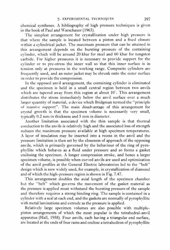
7· EXPERIMENTAL TECHNIQUES 397
chcmical syntheses. A bibliography of high pressure tcchniques ts gtven in the book of Paul and Vv"arschauer ( 1963).
The simplest arrangement for crystallization under high prcssurc is that "·hcre the sample is located bctween a piston and a fixed closurc within a cylindrical jacket. The maximum pressure that can be attained in this arrangement depencls on the bursting pressure of the containing cylindcr, which will be araund 20 kbar for steel and 60 kbar for tungsten carbide. For higher pressures it is necessary to pro,·ide support for the cylindcr or to pre-stress the inner wall so that this inner surface is in tcnsion only at prcssures in the working range. Compositc cylinders are frcquently uscd, ancl an outer jacket may bc shrunk onto the outer surface in order to proYide the compression.
in the opposecl am·il arrangement, the containing cylincler is eliminatecl and thc specimen is helcl in a small central region between two anvils which are tapered away from this region at about 10°. This arrangement distributes thc stress immediately below the anvil surface oYer a much !arger quantity of material, a device which Rridgman termcd the "princ-iple of rnassi\-e s11pport". The main disadvantage of this arrangement for crystal growth is that the spccimen volume is necessarily ,·ery small, typically 0.2 mm in thickness and 5 mm in diameter.
.-\nother Iimitation associatcd with the thin sample is that thermal conduction to the anvils is relatively high and the associated loss of strcngth rccluces the maximum pressurc available at high specimen temperatures. i\ layer of insulation may be inserted into a recess in the anvil and the pressure Iimitation is then set by the closeness of approach of the opposing am·ils, which is primarily governed by the behaviour of the ring of pyrophyllite which behaves as a fluid under pressure and so forms a gasket enclosing thc specimen. A Ionger compression strake, and hence a !arger spccimen volume, is possible when curved anvils are used and optimization of the anvil profiles at the General Electric laboratories led to the "belt" design which is now widely used, for example, in crystallization of diamoncl and of which the high-pressure region is shown in Fig. 7.47.
This arrangement doubles the axial length of the specimen chamber but the "belt" which goYerns the movement of the gasket material as the pressure is applied must withstand the bursting pressure of the sample and therefore requires a strong binding ring. The sample is contained in a cylinder ,,·ith a seal at each end, and the gaskets are normally of pyrophyllite ,,·ith meta! Iaminations and extrude as the pressure is applied.
RelatiYely !arge specimen \·olumes are also possible with multiplepiston arrangements of which the most popular is the tetrahedral-anvil apparatus (Hall, 1958). Four anvils, each having a triangular end surface, are located at the ends of four rams and enclose a tetrahedron of pyrophyllite

398 CRYSTAL GROWTH FROM 1-liGH-TEMPERATURE SOLUTIONS
Current nng
~eated core
i nsutatin~ p.tt
FIG. 7.47. High-pressure region m the belt apparatus used for diamond synthesis (Wentorf, 1966 ).
some 10%) )arger in edge dimensions than the amil faces. The pyrophyllite acts as a pressure-transmitting medium and is bored out to contain the sample and heating element. Normally pressure is applied only to one ram (with the other three mounted in a support ring) which must move in such a way that non-uniform stresses are avoided. Apparatus with six rams acting on a pyrophyllite cube has also been used.
Arrangments for the production of high temperatures combined with high pressures have been reviewed by Strong (1962). External heating of the whole apparatus is possible at pressures below 10 kbar and temperatures less than 600°C. For higher temperatures, the decrease with temperature in the strength of the chamber materials requires that the specimen region only be heated while the anvils and surrounding chamber are kept cool. The main problern is then that of insulation of the specimen together with the pre\·ention of reaction between the pressure transmitting medium and the specimen container, thermocouple and heater coil. Heating is normally effected by passing a current through the specimen or, more usually, through a tube or coil surrounding it. The low resistance of the heating element requires high currents, typically 500- 1500 A at 1-3 V. The volume and friction changes caused by increase in temperature tend to reduce the pressure, and compensation for such reductions is difficult because of the absence of a suitable sensing element which may be located close to the specimen.
The measurement of high pressures presents quite severe experimental problems especially at higher values where free-piston and strain gauges are inappropriate. The change in resistivity of manganin wire has been

7· EXPERIMENTAL TECJINIQ U ES 399
extcnsi\-ely uscd for prcssurc rneasuremcnts hut thesc arc inaccuratc when pyrophyllite or a sirnilar material is uscd to transmit prcssurc, sincc thcsc mcdia arc not pcrfcctly hydrostatic. Calihration of thc apparatus using tabulated transforrnations, such asthat of Bi I I I- V at 77 kbar, is then necessary. Thc measurement of high pressure has bcen discussed, for exarnple, by Munro (1963).
Temperature measurement at high pressure is complicated hy the effect of pressurc on the e. m.f. of the therrnocouple. Corrections for Pt/Pt- 1 0° ~ Rh, Pt/Pt-13"{1 Rh, chrornel-alumel and iron-constantan thermocouples have been tabulated by Hanneman and Strong ( 1965). The correction for a Pt/Pt-10° ;> Rh couple at 1300°C and 50 kbar exceeds 50°C. Independent measurements, with some deYiations, ha\-e been reported by Peters and Ryan ( 1966) and sources of error in thermocouple measurements are discussed by Hanneman and Strong (1966). In general the measured e.m.f. will vary according to the pressure Yariation along the therrnocouple wire, so that the apparent temperature will change with the cl esign of the cell unlcss careful precautions are taken.
One prohlem in crystal growth at high pressures still to be soh-ed in order to obtain !arge crystals of high quality is stirring. According to the discussion in Chapter 6 and Section 7.2.7 on the effect of stirring on the maximum stable growth rate the duration of cxperiments (for diamonds of 1 carat, about a week) could be shortened or the crystal size increased if forced conYection could be applied. Stirring is particularly required in high pressure systems ,,·here natural transport phenomena are retarded by the densification.
7.2.9. Typical procedures for growth of oxides and chalcogenides
In this section detailed instructions are giwn for the preparation of sornc representative materials from high-temperature solutions. These "recipes" arc intended for beginners in the field as illustrations of the practical procedures which are used. The complexity ancl the estimated price for apparatus and chemieals increase from the first to the last example; for instance the cost of apparatus ancl crucibles is about 200 dollars for the first cxperiment and up to 100 tirnes more for the last experiment while the price of chemieals will Yary from 5 dollars to se,·eral hundred dollars, depending upon the purity used.
A. Sodium chromium sulphide, l\aCrS 2• 4.5 g coarse chromium powder is placed on the bottom of an unglazed ccramic crucible of about 6 crn diameter, and cowred with 10 g sulphur and 60 g :\a2S x 9H 20 . Thc crucible is closed by a 2 mm thick disc of cerarnic vvool, which just fits into the crucible, and Co\·ered with a ceramic Iid. lt is placed in the simple

400 CRYSTAL GROWTH FROM HIGH-TEMPERAT URE SOL UTIO!'\ S
Cl HIIMI( WOOL \
I
i I
HEATING 'i.LEMENT
l MULLITE
f ,;;;~;~N
COARSE ALUMINA POWDER
• T IIFJlMOf.OIII'I r
I\\_ Na 2 S-S MELT
. L CERAMIC BAFFLE
COARSE ME TAL
POWDER
FH; . 7.4X. :\rrangement of crucible in muffle furnace for crystallizatinn of meta I sulphides from alkali polysulphide melts (Scheel, 1974 ).
muffle furnace sho\\'n in Fig. 7 .48. The space below, on the sides and abon~
the crucible is filled with coarse alumina powder in order to reduce the oxidation of melt by air. During heating to 1000 -'- 30°C (in about three hours) excess sulphur evaparates and removes residual oxygen and water by reaction to S02 and H 2S, respectively, and this requires that the furnace is placed in a hood with good ventilation. The temperature is set by a \·ariable transformer, and is reduced by about 25 °C per hour by means of a motor-driven variac. At 300°C the power is shut otf, and after cooling to room temperature the sodium polysulphide solvent is dissohed in water lea\·ing hexagonal plates of :\aCrS~ up to 1 mm thickness and 2 cm cliameter. The aqueous solution of polysulphidc is poisonous and should bc neutralizecl by an aqueous ZnCI~ solution or should be reacted \\'ith K.Mn0.1 solution.
This simple sodium polysulphicle process can be used for se\-eral other binary and more complex meta! sulphides (Scheel, 1974), such as :\ainS~, K.CrS~, KFeS!, CdS, ZnS, PbS, FeS 2 , CoS~, I'\iS 2 , MoS~, Cu 3VSÜ CuS, a:-MnS, HgS etc., with modified temperature programmes. In order to control nucleation and to achieve stable growth it is necessary to pre\'ent evaporation of sulphur and to apply slower cooling rates. In the simple arrangement shown in Fig. 7.48 a ceramic baffie has been found to reducc the rate of reaction and transport and so to yield !arger crystals.

7· EXPERIMENTAL TECHNIQUES 401
B. Barium titanate, BaTi03 . 37 g BaTi03 and 90 g anhydrous KF an: weighed into a 100 cm3 platinum crucible which is covered by a platinum Iid and placed into a horizontally loaded resistancc furnace at 1100°C. This temperature is held for 8 hours after which the temperaturc is lowercd by 15c h - I to 900°C. The crucible is then removed from the furnacc and the liquid portion poured off (in a weil Yentilated room). The crucible is then returned rapidly to the furnace and cooled to room temperature; the crystals are freed from the remaining solidified KF by immersing the crucible in hot distilled water. Typical "butterfly" twins, as describecl in Section 5.5.2, of up to 1 cm size are obtained ( Remeika, 1954; Remeika et al., 1966 ). Undissolwcl ßaTi03 is required for genesis of the butterfly twins, and the cooling rate has tobe adjusted to prevent excessiYe spontaneaus nucleation and to presen-e the platy habit. The poisonous flouride Yapours require the use of a Yentilated hood during growth. A modification of this Remcika proccss to grow ßaTi03 was published by Bradt and Anseil ( 196 7).
C. Spine/, \lg.-\1 20 1• 80.6 g MgO, 204 g .-\1~0 3 , 1500 g PbF~ and 10 g B~03 an.: premelted in a 500 cm'1 platinum crucible at 900°C, then a further WOg PbF~ is addcd. The cruciblc is sealed by a platinum Iid which has at its centre a hole of 6 to 9 mm diameter which determines the evaporation rate of the soh·ent . The crucible is then placed on a zirconia ceramic plate into a siliconcarbidemuffle furnace which is heated to 1200°C -= < 0.5 ° in 8 hours, and kept at that temperature for two weeks which is sufficient time to eYaporate most of the solvent. After cooling to room temperature the crystals are remoYed mechanically and residual flux is remO\·ed by hot dilute nitric acid . Typically octahedra of 1 to 2 cm size may be obtained (Wood and White, 1968). It should be noted that the cvaporated PbF~ is poisonous ancl hea,·ily corrodes furnace ceramies and heating elements.
n. Gadolinium aluminate, GdA10 3 • 264 g Gd 20 3 , 120 g Al 20 3 , 840 g PbO, 440 g Pb F 2 , 48 g ß 20 3 and 12 g Pb0 2 are premelted in a new 500 cm3
platinum crucible (previously cleaned and chemically polished with a potassium pyrosulphate melt) of a shape shown in Fig. 7.36(c), then 400 g PbF2 is added. The platinum Iid with a hole of about 0.1 mm is sealed to the crucible by argon-arc welding. The crucible is placed into a Superkanthal muffle furnace and is centred on a ceramic holder which is mountcd on a rotatable ceramic tube as shown in Fig. 7.44(b). Thc temperaturc of the furnace room is brought to 1290°C and is maintained for 15 hours during which time the accelerated crucible rotation technique (.-\CRT)+ is applied using thc cycle of Fig. 7.44(a): C with a maximum
"!" Furnace and ACRT mechanism are available frum Käsermann & Sperisen, lliel /Switzerland and from Eurotherm Schweiz, Glattbrugg ZH, Switzerland.

402 CRYSTAL GROWTH FROM HIGH-TEMPERATURE SOLUTIONS
rotation rate (in both directions) of 90 r.p.m. Localized cooling at the centre of the crucible bottom is now provided by a constant air stream, and the furnace temperature is reduced by 1 o per hour to l200°C, with a maximum ACRT rotation rate of 70 r.p.m. The temperature is raised to 1270°C and held at this temperature overnight, then the temperaturc is lowered by 0.3°C per hour to 1150°C and then by 0.5°C per hour to 900°C. During the whole cooling time the ACRT action is applied with a maximumrotationrate of 70 r.p.m. and a period of about two minutes. At 900°C the ACRT mechanism is stopped, the crucible is taken out of the furnace, and the excess solution is poured off after two holes have been punched into the Iid. Then the hot crucible is quickly placed into a kanthal furnace at 850°C in order to prevent cracking of the (generally) one to three !arge crystals formed (see Fig. 7.45a, b) and this furnace is then slowly cooled to roorn temperature. After cutting the crucible rim the residual flux is dissolved in hot dilute nitric acid, and the crystals are mechanically moved from the crucible.
High precision and stability are required of the ternperature controller and prograrnmer and the application of the PtRh6/PtRh30 thermopile of Scheel and vVest ( 1973) helps to achieve I arge crystals. Also the air flow for localized cooling has to be weil regulated, otherwise nucleation control and continuous stable growth ( except for a short dendritic growth period at the beginning) may not be obtained (Scheel and Schulz-DuBois, 1971; Scheel, 1972; Scheel and Elwell, 1972, 1973).
E. Yttrium iron garnet, Y3 Fe5Ü 12{YIG). A cornposition in mole ~ ~ of 36.3Pb0, 27.0PbF2, 5.4B20 3, 20.78Fe2Ü 3 and 10.42Y20 3 and of approximately 1 kg weight is premelted in a crucible shown in Fig. 7.36(e). A Iid containing a narrow S-shaped platinum tube for pressure release is welded to the crucible which must be sealed by welding. A seed crystal is fixed to the centre of the Iid. The crucible is mounted into a ceramic arrangement which can be inverted as described by Bennett (1968) and by Talksdorf ( 1968) and which additionally can be rotated around a vertical axis in orcler to achieYe stirring by ACRT after the horizontal axial holders have been withdrawn, as discussed by Talksdorf and Welz ( 1972). The initial arrangement is shown in Fig. 7.9(a). After heating OYernight at a temperature of about 1250°C the crucible base is locally cooled by an air fl.O\\" of about 160 1 per hour and the temperature is recluced to 1180°C. Then the ternperature is slowly reduced by 1 oc per hour to 1100°C at which temperature the solution is saturated and spontaneaus nucleation occurs (Fig. 7.9b). The crucible is smoothly turned into the position of Fig. 7.9(c) so that the seed crystal is irnmersecl in the saturatecl solution. The temperature is now reducecl at the sarne rate to 950°C with the cooling

7· EXPERIMENTAL TECII N IQ U ES
air Row maintaincd on thc region now in contact "·ith the sced crystal. Thc solution is separated from the grown crystals (typically 3 cm in size) by imerting the cruciblc again into the position of Fig. 7.9(d), and thc furnace is cooled to room temperature at 50°C per hour.
During the cooling from 1100° to 950°C, stirring is achiewd by thc accelerated crucible rotation technique descrihed in cletail in the preYious example. In addition to the production of YIG crystals this process might be useful when crystals of the same material haw to be grown repeatedly to a size !arger than 1 cm3 in pilot plant production. The adYantages are the Bennett- Talksdorf nucleation control, the ACRT stirring of Scheel ( 1972) and the possibility of using the high temperature solution several times, thus sa,·ing chemicals.
F. JVic!?el ferrite, I\iFe20 4• Weil-mixed powders of 179.4 g BaC03 and 43.2 g dry B20 3 (to give BaO x 0.62B 20 3 solvent) are placed in a weighed platinum crucible of 7 cm diameter and 7 cm height which is fitted with a Iid and slowly heated to 1000- 1100°. An automatic temperature program with a heating and cooling cvcle of 24 hours is useful. Several fusions may be required before enough soln·nt has been added to produce a melt depth of about 3 cm.
After cooling to room temperature the crucible is weighed in order to ohtain the mass of borate solvent. N iO and Fe20 3 are added in 1: 1 molar proportians such that theseoxidesform 30% of the total weight of solution. This concentration provieles several grams of N iFe20 4 to act as nutrient. The crucible without a Iid is placed into the crystal growth furnace in a region such that the base is hotter than the melt surface. A furnace having a horizontal di vision and with the two sections heated independently is preferable.
The seed crystal of [111] orientation is tied firmly onto a platinum seed holder which can be cooled, rotated and withdrawn at adjustable rates (see for example the apparatus of Belruss et al. (1971), but also a commercial Czochralski pul! er with a modified seed holder would suffice ).
The crucible is heated to 1320°C for a day with the seed just above the melt, then cooled to about 1250°C with the temperature difference L1 T across the solution adjusted to 10°C; direct control of this difference by opposed thermocouples is preferable (one advantage of gradient transport is that the exact grO\vth temperature need not be accurately set and the liquidus temperature not accurately known).
The seed crystal is inserted just below the surface of the melt and rotated at 60 r.p.m. Cooling of the seed is desirable by water or air through the seed holder, typically by 5-10 ljmin of air. The crystal is observed intermittently, preferably in reRected light. If it grows outward relatively

404 CRYSTAL GROWTII FROM IIIGII-TElVIPERATURE SOLUTIONS
quickly it is raised at about 2 mm/clay. The growth speed is regulated by incrcasing or dccrcasing LJT. After a fcw days thc crystal is slowly withdrawn from the solution and cooled over several hours in the furnace or by gradual removal to a cooler region (Smith and Elwell, 1968; see also Linares, 1964; Kestigian, 1967; Whiffin, 1973).
The above six recipes have been tested on several occasions, and the first two procedures are suggested for experimental courses in crystal growth. A collection of crystal growth procedures checked in independent laboratories, similar to "Organic Syntheses" and "I norganic Syntheses", would be very helpful for many crystal growers and especially for occasional crystal growers such as physicists who require crystals of one or a few materials for research purposes. Such a compilation of "recipes" would prevent much duplication of work in the field of crystal growth.
7.3. Special Techniques, Specific Problems
7.3.1. Crystal growth from HTS at medium and high pressure The study of high pressure phases and phase transformations has grown rapidly with the development of high pressure apparatus, particularly due to the pioneering work of Bridgman. However, the main effort has been devoted to transformations in the solid state, although an appreciahle amount of research has also been carried out on hydrothermal synthesis of minerals at medium pressures and temperatures (500- 3000 atm, 200-8000C). The latter work has resulted in the !arge scale synthesis of quartz and recently of ziron but, as was mentioned in Chapter 1, crystal growth by the hydrothermal method is beyond the scope of this book.
Relatively little crystal growth at medium or high pressure has been effected in non-aqueous solvents, with the notable exception of diamond, which is now produced very widely. The reasons for the neglect of HTS growth und er pressure are mainly that:
(a) The experimental effort required is extremely great, and increases ,·ery rapidly with the pressure p, and correspondingly with temperature T and solution volume V.
(b) The difficulty of finding solvents in which the solute has an appreciable solubility, but for which corrosion-resistant containers exist, increases withp and T.
(c) The difficulty in Controlling the growth parameters to the degree necessary for the synthesis of good quality crystals increases with p and T. At the very high pressures used for diamond synthesis, stirring is still impossible.

7· EXI'ERil\IENTAI. TECII N IQ U ES
In thi~ :-;cction tiH· growth nf diarnnnd cr~·s tals ,,-jj( bc hridly discusscd and a fc,, . namplcs will thcn bc giH·n of othcr crystab which ha,·c bccn grown from I-ITS at high pressure .
. 4. Crystalli:.:atiun of diamond. Se\·eral tons of diamond are nm\· producecl per year for a Yariety of applications, especially for use as an ahrasiYe. The bulk of the diamond is in the size range from 1 to 100 fl-m ancl the pricc of synthetic diamond grit is comparable with that of the natural mineral.
Although the synthesis of cliamond has attractecl the attention of scicntists sincc the last century, a reproducible synthesis was reportecl only in 1955 . The use of metallic solutions at 50- 60 kbar and 1400- 1600°C is no,,· practisecl in se,·eral centres and has remainecl the only commercial process, in spite of stuclies of alternative techniques such as growth from the pure melt (Buncly, 1963), at about 4000 K ancl 140 kbar, ancl by metastablc epitaxial cleposition from the vapour phase at atmospheric pressure ( :\ngus et al., 1968).
'L'he apparatus used for the solution growth cxpcriments of diamond is of thc " belt" type (Hall, 1960), the high pressure region of which is shown in Fig. 7.47. Potential solvents have been cliscussecl by Wakatsuki (1966) and especially by Wentorf (1966). 1\on-metallic soh·ents such as Cu~O, Cu Cl, :\gCI, ZnS, Cc!O, FeS ancl silicate melts containing OH- ions were founcl to produce only graphite, whereas se,·eral transition metals such as Fe, :\i, Co, Cr or Mn or alloys of refractory transitionmetals with Cu procluce diamond under the same conclitions of temperature and pressure. Th is obsen·ation was attributed by Wentorf to the low solubility ( < 1% ) of carbon in the former group comparecl with that in the metallic solutions. In adclition the nature of the dissoh·ecl carbon coulcl play a Yital role since Wentorf ( 1966) showed that carbon has a positiw charge in meta! solutions, a negati\·e charge in CaC 2 or Li2C~ ancl is neutral in the compouncl soh·ents.
The phase cliagrams Fe- C, 1\:i-C ancl Fe-N i-C at 57 kbar haYe been dctermined by Strong ancl Hanneman (1967) and Strang ancl Chrenko (1971) ancl are shown in Fig. 7.49(a)-(c). In the Fe-C system, crystallization of diamond is restricted to the region between the diamond-graphite equilibrium at 1830 K and the melting point of Fe3C at 1688 :K. The Ni- C eutcctic lies at a lower carbon concentration ancl at a higher temperature than in the Fe- C system. The ternary Fe-Ni-C system has seYeral ad\·antages oYer the binary systems since the cliamoncl-solution liquiclus extends O\t:r a wider range of temperature as shown in the 1400°C section . . -\ similar aciYantage has been reported for the Fe- .'\1-C system (Strang and Chrenko, 1971 ). lt is interesting that soh·ents which form cornpounds with

400 CRYSTAL GROWTI-1 FROM I-IIGI-1-TEMPERATURE SOL UTIONS
2013
1618
1568
0.08
1100
1600
1~00
1400
IJOO
L + g
1830°
I d L + d
J-r---,-~~----------~16~8~8~o~I<~T I
0.17
~~-------1
--l~--------\
0.25 Xe
F1c. 7.49 (a)
c + d
I
0 .997
r-----r----.----.----,~1--~----~
Ni · C ~Hb
·c
L+o L + di
L +1 111[ TA STABlEI -- ------ --! 1---------Eitl
• +di
1~0 0~---,lo----~2~0--~J~o--~•~o~.,~.~c~ 100 4.7 9.0 IJ ~~ 16 1 Aloe
F1r.. 7.49 (b)

7· EXPERIMENTAL TE C IINIQ U ES
Fe
57 kb, 14oo•c
di LL-----''-------'"--'-'-- "- - "-' - - "---"----"------''----'= C
ATOMIC FRAGTION
(c)
FH; . 7.4lJ. Phase diagrams at 57 kbar applied to di amon d s\·n thes is. (a) lroncarbon with X,. the fraction of ca rbon . (b) :--lickel-carbon and (c) iron- nickelcarbon (Strong and Hanneman , I'J6 7; Strong and Chrenko I 971 ).
thc solutc at lowcr temperatures (c.g. Fe3C, :\i3C) arc the most suitable for diamond growth, which supports thc principles discussed in Chapter 3.
Use of the phase diagrams has facilitated the growth of gem-quality diamonds up to 5 mm in diameter (0.2 g) by Wentorf (1971). A gradient transport technique was used, as shown in Fig. 7.50, at a constant pressure in the range 55- 60 kbar with diamond m1trient at a temperature of about 1450°C and diamond seed crystals at about 1420°C. The use of seeds is essential since kinetic factors othcrwise fa,·our graphite crystallization, and
PRESSUR(, KB.
HMP[RAIURf, •K
F1c. 7.50 . Portion of the pressure-temperature phase diagram of carbon (\Ventorf, 197 1).

408 CRYSTAL GROWTH FROM HIGH-TEMPERATURE SOLUTIONS
it was found advantageaus for the growth of )arge crystals to locate crystals at the lower end of the pressure cell. Diamond crystallites formed by spontaneaus nucleation then tend to rise towards the hotter region and an: re-dissolved. With a temperature gradient of about 100°C cm - 1 the Aow of solute to the seed crystals was estimated tobe of the order of 10- 4 g cm - 2 s - J.
If this Aow is too rapid unstable growth will occur and graphite may nucleate and grow as )arge Aakes . The maximum stable growth rate was found tobe
where Y is the average crystal diameter in mm and b has a \·alue of 2.5 hr mm - 2 • Thus the time required to grow a 5 mm diameter crystal is in thc region of a week, which is similar to that required for a typical experinwnt at normal pressure (see Section 6.4).
The growth mechanism is reported tobe by spreading of layers nucleatcd at corners and edges of the crystal (Wentorf, 1971) or at growth spirals of which a typical one published by Strong and Hanneman (1967) is shown in Fig. 7 .51. Further observations on surface features and morphology haYe been reported by Bovenkerk ( 1961 ). The habit was obsen-cd tn depend on the concentration of nitrogen in the solwnt; melts containing nitrogen fa\·our the development of { 100} and {111} with minor { 110} and { 113}, while in 1\ -free solutions the {11 0} and { 113} faccs, and sometimc~ [ 117}, frequently have slower growth rat es than the cube and octahedron faces. The dependence of th e habit of diamond crystals on the growth temperature and pressure has been discussed by Lit\·in ff al. ( 1968) and by Bezrukov et al. ( 1969). N aturally facetted synthetic diamonds of gcm quality ancl weighing about 0.2 g (I carat) are shown in Fig. 7.52. Thc nitrogen impurity reduces the oYerall growth rate by a factor of about 1(3.
Thc nitrogcn content tends to produce a ydlo\\. colouration and a rcsi stiYity grcater than l0 1 ~Q cm, whilc boron doping Ieads to a blul· colour and a low resisti\·ity of 10- l06Q cm. lt was recently estahlishcd (Collins, 1972) that boron rather than aluminium is responsible for thc blue colour of natural as weil as synthetic diamonds (Chrcnko, 1971 ). !Vlost natural and synthetic diamonds show facet-related incorporation of impuritics as discussed in the review of diamond crystal growth by Strong and \Ventorf ( 1972). Although the results of diamond crystal gro\\ th arc spectacular, the cost of the !arger crystals is much higher than that of natural gems. The genesis of the Yery )arge naturally occurring diamonds of high quality, such as the Cullinan with a wcight of 3(Jl6 carats, is still unexplained.

7· EXPER TMENTr\1 . TE C II N TQ UE S
F1 c . 7.5 I. Cro\\·th spiral on a ( 100) face o f cli am on d gro\\"n in ni ckt- ! (Strong and ll anncma n, 196 7).

410 C RY STAL C.ROWTH FROM IITGI!-T EMPE RAT U RE SOL UTTON S
F1 c. 7 .. 12 . Syntheti c diamond crvs tals ofgem qua lit\' " ·ith natural : 100 ; and { 111 } faces (Cou rtesv R. 1-1 . vVentorf. General El ectri c Co mp .).

7· EXPERIMENTAL TECHNIQUES
R. Other crysta/s gruwn at medium and high pressures. The preparation of high pressure phases is of interest to chemists and mineralogists and also offers the materials scientist the opportunity to obtain particularly novel compounds or phases. In addition to the hardest materials diamond and borazon (cubic boron nitride), interesting superconducting compounds have been synthesized as an example of the variety of compounds and modifications the properties of which are related to their highly condensed structure. The crystal chemical aspects of high pressure phases have been reviewed by l\ euhaus ( 1964 ), Kleber and \Vilke ( 1969), Klement and Jayaraman (1967), Goodenough et a/. (1972), Rooymans (1972) and by Joubert and Chenavas (1975).
In several high pressure transformations it has been shown that the addition of small amounts of "catalysts", "mineralizers" or "fluxes" has the effect of lowering the transition pressure ancl temperature or of enhancing the rate of reaction. The transformation of graphite to diamoncl discussed above will occur only in the presence of the meta! solvent and, as a further example, the transformation of quartz into coesite, which oceurs without "catalysts" at about 90 kbar and 20000C, will proceed at 20- 35 kbar and at 5UU to 75UcC \\ ith the adclition of H 20, H 3H0 3 or (l\H.1) 2HP0.1• In reality the additions act as high temperature solvents ancl thus increase the mobility of the crystal constituents.
Thc growth of crystals of the high pressure phases is highly desirable for structural studies and for determining the physical properties, but it has been achieved only in relatively few cases. Examples are given below.
Cubic boron nitride ("Borazon", BN): Cubic B.:\i is the II I- V analogue of diamond and seems to have a slightly higher hardness than diamond, and also has the advantage of a higher resistance to oxidation. The first successful crystallization of cubic BN was reported by Wentorf ( 1957, 1961, 1962). He used Li, other alkali and alkaline earth metals and nitrides, Sb, Sn and Pb as solvents at pressures of 45-64 kbar and temperatures of 1500- 1900°C and postulated the formation of a LiaN x 3BN-complex actingassolvent Depending on the growth conditions and on the impurity content small white, yellow or black crystals were prepared. DeVries and Fleischer (1972) determined phase equilibria pertinent to the growth of cubic BN, and Bezrukov et a/. (1968) and Matecha and Kvapil (1970) studied the perfection and the growth phenomena of high pressure-grown diamond and borazon crystals.
Boran phosphide BP: Baron phosphide decomposes und er atmospheric pressure at 1200°C, which is weil below its melting point. It has been crystallized by slow cooling from solution in nicke! or iron (Stone, 1959) and from solution in black phosphorus at temperatures of 1200- 1300°C and a pressure of 15 kbar by l\iemyski et a/. ( 1967). The growth process
412 CRYSTAL GROWTH FROM HIGH-TEMPERATURE SOLUTIONS
appeared to be by isothermal transport of BP in solution with boron located at the base of the graphite container acting as nutrient. Baranov et al. (1967) used Cu 3P as solvent and grcw crystals up to 4 >~ 3 x 2 mm in size over a period of one month.
Cobalt diphosphide CoP 2 has been crystallized from germanium at temperatures between 800° and 1200°C at 65 kbar by Donohue ( 1972). Thc same author crystallized MnCoP.1 from excess phosphorus at 1200°C ancl 65 kbar.
Crystallization of compounds of high oxidation states at high o.\ygen pressures: The synthesis of garnets and ferrites free from divalent iron at a few atmospheres oxygen pressure has been mentionecl in Section 7.1.5. Although considerable research has been clone on "dry" and on hydrothermal systems (see for instance Roy, 1965) high pressure crystal growth to obtain crystals of high valency states does not yet seem to have bcen given much attention, with the exception of Cr0 2 .
Ferromagnetic Cr02 is at atmospheric pressure only stable up to 300°C, but at pressures of 40 kbar the stability field extends to about 1400°C according to DeVries (1967) and Fukunaga and Saito (196R). DeVrie~
(1966) grew Cr02 layers from Cr03 by liquid phase epitaxy at high pressure, and Chamberland ( 1967) grew crystals of Cr02 up to 0.4 mm size from \·a rious Auxcs at 60- 65 kbar ancl 500- l000°C, the bcst Aux being Na2Cr0 1•
Crystallization of compounds with high coordination numhers at h(I:h pressures: Quitc a number of compounds are likely to form clenser moclifications at high pressures, and the high pressure synthesis of seYeral ne\\. compounds has been reported . But here again the limitecl Yolume a\·ailable in high pressure apparatus and the experimental clifficulties haYe preYented a wide actiYity in this most interesting field . Examples of successfu l crystal growth experiments are giYen in the following.
Lithium metaburate LiB0 2 has at normal p- T conclitions a monoclinic chain structure. 1\larez io and Remeika ( 1965) reported a tetragonal high pressure phasc (y-LiB0 2) with a zinc blende-like structure and were able to grow crystals of this compound from LiCI Aux at 15 kbar ancl 950°C (1966). The solution was held for one hour's growth time in a small tantalum container in a furnace assembly described by Kennecly et a/. (1962). The solvent was dissolved in methanol, and small colourless crystals \\·ere obtained. vVith a LiCI-rich solution another phase was synthesized which was face-centred cubic with a lattice constant of 12.13 Ä and which could be a Iithium chloraborate of boracite type although no chemical analysiswas made.
In order to study o:-Ga 2Ü 3 as a possible Iaser host for chromium analogaus to the isostructural corundum, crystals ofthishigh pressure modifi-

7· EXPERIMENTAL TE CIIN!Q U ES
catinn nf Ca~03 han:~ bccn grmn1 hy Rcmcika and Marcziu (1'166) although Fostcr and Sturnf (1 1JSI) succccdcd in thc prcparation of mctastablc a
Ga20:1 at normal pressure. In a similar experimental arrangernent as rnentioned for the LiBO~ synthesis Remeika ancl Marezio usecl NaOH as solvent, ancl 44 kbar and 1000°C were applied during one hour. .\fter extraction of the srnall colourless crystals two kinds of growth habit resembling the hexagonal plates and the rhomboheclra of a-AI~O:J were observecl. Chromium cloping resulted insmall green rhomboheclra of which the difference in colour cornpared to red ruby was considered to be caused by a ditference in crystal fiele! splitting due to the significant size ditference between the AP · and Ga 3 " ions.
During studies on the effect of high pressures on rare-earth garnets it was found that some of them decomposed to the rare-earth aluminates of perovskite type and the sesquioxides of corundum type (Marezio et a/. 1966a). Using this reaction in the presencc of a l\aOH flux at 70 kbar ancl 1000°C YGa0 3 and YbGa03 coulcl be crystallizecl in one hour as small transparent crystallites (Marezio et a/. 1966b ). Recently Dernier and Maines ( 1971) reportecl on the high pressure synthesis ancl crystal data of the rare earth orthoalurninates.
Further examples of crystal growth at high ternperatures ancl high pressures haYe been listed by Rooyrnans ( 1972), Gooclenough et a/. (1972) and by J oubert ancl Chenavas ( 1974 ).
7.3 .2. Undesirable crystal growth from high temperature solutions
In a number of processes involving high temperature solutions there is unclesired crystallization. In rnetallurgy ancl in the ceramic and cernent industries the developrnent of !arge crystals or the crystallization of unclesirecl phases might eiegrade the rnechanical and thermal properties of the product, and de,·itrification in the glass industry rnakes the proclucts worthless, unless devitrification is achiewd intentionally as in the fabrication of Pyroceram f -type ceramics.
A common problem in nuclear-reactor technology occurs in the cooling circuits (when low-rnelting metals ancl alloys such as sodiurn or sodiumpotassium are used as coolants) as weil as in the recently developed liquid uranium-bismuth alloy fuelled homogeneaus reactor. A solidliquid interaction (corrosion) occurs in the hot region in the reactor, and crystallization of the dissoh·ed containermaterial or of its compounds with the liquid meta! occurs in the cooler region (Weeks ancl Gurinsky, 1958).
Another example of unwanted crystallization is the crystal growth of whiskers by the VLS rnechanisrn which occurs occasionally in electric installations when the appropriate conditions are accidentally fulfilled.
t Trademark of Corning Glass \Vorks , Corning, 1'\.Y. 0 2

414 RY T AL GROWT II I'ROM !IT GTT-T EM P ERATU RE SOLU T!ON S
However, it is not intended to give a broad survey of the topi c of thi s section. T he above examples merely ilJustrate where un wanted crysta l growth processes might occur and how important it mi ght be in certain cases to prevent or to con trol th em . In th e folJ owing di scuss ion a few examples of undesired effects observed in the practice of Aux g rm1·th arc brieAy mentioned.
U nwanted crystal growth obviously occurs when th e experiment results e ither in ve ry smalJ crystal or in crystals of an undesired phase. T he former problern has been discussed in Secti ons 3.4.3, 3.6.2., 7. 1.1 and
F1 c . i .53 . . -\ ccidenta ll y fo rm ed crvstals of Iead feldspar (Scheel, 19i I).
7 .2.7, th e latter is a matter of th e stability fie lds as d iscussed in Sect ion 3.8.5. :\noth er cxampl e of unexpected Aux gro11·th occurred during th c preparati on of Zn.'\.120 1 crystals from PbO-PbF2-B~03 soh ·cnt : th e p latinum crucibl es co1·ered with a Ii d (bu t not sea led) were pl aced into mullite- type ce rami c crucib les wi th ceramic Iids. After th e slo11·-cooli ng experiment and remm·al from the furnacc th e undersidc of th e ce rami c Iid showed elongated crystals whi ch 11·e re identifi ed as sol id so lutions of th e fe ldspars 1C \1 S i30 8 and Pb:\1 2S i20 8, th e first synth es ized Pbconta ining feldspar crystals (Schee l, 197 1), see Fig. 7.53. Wanklyn and Hauptman ( 1974) reported that s ilicate crystals grew in so lutions for exampl e of Er20 3/Mo0 3 in Pb0/Pbf 2 when gro11·th occurred in a sillimanite muffle furn ace.
Crystal s of up to 5 mm of platinum ancl of seYeral platinum-l ea cl

7· EXPERIMENTAL TECHNIQ UES
compounds have been observed in flux growth experiments with corrosi,·e Iead- and fluorine-containing melts, especially when the conditions were slightly rcducing. In general these crystals are not v.·anted, cspecially when they intergrow with the required crystals. Therefore a slightly oxidizing atmosphen: or a redox buffer in the melt, such as \ ' 20.;, are used to minimize flux growth of Pt-containing crystals .
!\lost cxperimentalists will haYe obsen·ed examples of um,·anted crystal growth from high-temperature solutions. Identification of the crystalline phase, for instance by X-ray powder diffraction, is worthwhilc, as in somc cascs interesting or noYel materials may have crystallizecl. On the other hancl an im-estigation of the crystallized phases may indicate thc parameters to bc moclifiecl in ordcr to preYent the unwantcd crystallization .
7.3.3. Unexplored techniques and areas
0."early all areas of crystal growth from high-temperature solutions are not weil understood, thus the whole field might still be said to be "unexplorecl". HowcYer, in the following discussion only examples of those (experimental) topics will bc brieflv discussed which arc or might become of gcneral interest .
. i . . Yezv materials . . -\ number of matcrials with interesting propcrties for rescarch and with potential applications exist which haYe not yet been grown reproducibly as crystals of sufficient size and quality by crystal growth from melt or from Yapour. Several of these could probably be grmm from high-temperature solutions, for example BeOt, BiFe03, SbSI, SiC and TaC. An interesting example of the success of a !arge effort is thc growth of colourless diamoncl crystab of gem quality and up to 1 carat sizc as discussed in Section 7.3.1.
:\o,-el materials with interesting properties may still await discovery, because of all possiblc compounds .\,.8" of elements A and B only approximatcly 50°/o are known, and of the compounds A ... B!/CZ the estimate of Lydtin ( 1972) isthat 1% are known, and of quaternary compounds ABCD a small fraction of a percent is known. Thus many compounds are still to be discoYered, for instance by imestigation of the corresponding phase diagrams or by isomorphaus replacement in known structure types. In addition solid solutions might be prepared to optimize the required properties .. -\. class of compounds which has not yet found wide interest is that containing elements in unusual Yalency states, partially because of experimental difficulties of preparation. Also extreme conditions (pres,;ure, tempcrature) could produce interesting new materials.
t The reproducible growth of ]arge BeO crystals has recently been reported by ::>. B .. \usterman (priYate communication).

416 CRYSTAL GROWTH FROM HIGH-TEMPERATURE SOLUTIONS
Bo New solvent systemso As in the case of new materials, there are likely tobe novel solvent systems for old and new materials which have advantages over the solvents now in useo The approach is to achieve optimum characteristics with respect to solubility and corrosivity, viscosity, metastable region, stable growth, and purity of the crystals grown from themo In developing new solvents the aspects of compound and complex formation as discussed in Chapter 3 might be useful. With increasing knowledge of solutions and of thermodynamic properties of the components the choice of solvents might be made on theoretical groundso
It is suggested to use the "hydroflux" method for growth of various oxide compounds, hydroflux being a co11bination of the hydrothermal and the flux techniqueso In natural crystallization water is known to be an excellent modifier of solution properties and accordingly one would expect its beneficial influence on certain solvent systems at the medium pressures requiredo An approach in this direction is the use of highly concentrated salt solutions, of about 50 mole o/o , in hydrothermal crystal growtho
Co High temperatures, high pressureso Extreme conditions such as very high tcmpcratures and high pressures arc Jifficult to achieve, especially in the volumes required to grow sufficiently !arge crystals from high-temperature solutionso With the exception of diamond and boron nitride, not much work has been done either at temperatures above 1500°C or at pressures exceeding a few atmosphereso Examples where high temperatures have been required to grow extremely refractory crystals are the growth of SiC, \VC and the europium chalcogenideso Recently crystals of LaB4 , which is incongruently melting at around 1800°C, have been prepared by Deacon and Hiscocks (1971) by slow cooling from 1700°C and are reproduced in Figo 70540 Although the experimental difficulties increase enormously with tcmperature and especially with pressure, significant new results are tobe expected from studies in this areao
D 0 Elertrolysis; an electric field as a driTing force for supersaturation 0 Crystal growth by electrolysis in molten salts seems a promising area (see Section 701.2), especially for the growth of refractory compounds like borides and pnictides and of compounds with defined (lower) valency stateso Howe,·er, the Iiterature indicates that many compounds haYe been prepared by high-temperature electrolysis, partially on a production scale, but relatiYely little systematic work has been done on the application of electrolysis to the growth of !arge high-quality crystalso
Another application of electric fields across ionic solutions might be considered, namely as an easily controlled driving force for Supersaturation, even in the absence of electrolytic reduction or oxidationo The growth rate may be controlled by varying the electric current through the

7· EXPEH L\I EN TAL T EC I-I N I QUE S 4 1 7
F1c. 7.5~. Lanthanum tdrabo ride crvs tal o f S.'i mm length g rmn1 from lanthanum soluti on bv coo lin g from 1700 to 1200 (D eacon an d 1-1 iscocks . 197 1 ).
soluti on in an iso th ermal melt in a uniform tem perature zone as was demonstrated by Elwell (unpubli shed ) fo r th e growth of Fe20 3 fr om Ba0/13 20,1. 1 t is poss ib le that an electri ca l dri,·ing force m ay Iead to enh anced stab ility of gro,,·th compared \\·ith a th ermal dri,·ing fo rce. An additi onal use of an electri ca l dri,·ing force is in th e p rm·ision of time markers fo r growth rate cl eterminations, as in th e e:-; pcrim ents of T ,ich ten s te igere/ a/. ( 197 1 ).
E. Crowth of specia/ crysta / shapes. Thi s topic has been ex tensi,·cly di scusscd in C hapter 5. S pec ial crystal hab its are of ad ,·antage for ce rtain applications ancl physical m easurements. For example the BaTi03 butterA y t\\·ins consisting of two thin single-crystalline platelets, as gro \\·n by R emeika ( 1954), were important fo r a ,·a ri ety of measurements and contributed s ignificantl y to the deYe lopmen t of ferroe lectri cs. ]n th e case of BaTi03
th e twin-plane reentrant edgc (T PRE) growth on undissoh·ed crysta llites was responsibl e for th e formatio n of platelets of barium titanate w hi ch oth erwise grows as cubes or sim ilar compact shapes . Oth er examples of TPRE growth of platelets are alumina .Al 20 3 (\Va ll ace and \\"hite, 1967) and beryllia BeO (A usterm an, 1964). lt is probab le that under appropriate conditi ons m any more compounds could be g rown as p lates by a t\\·in

418 CRYSTAL GROWTH FROM 1-IIGI-I-TEMPERATURE SOLUTIONS
mechanism, and a number of examples of semiconductors grown by TPRE were given by Faust and John (1964).
Crystalline fibres or whiskers of various materials (SiC, Al 20 3) arc applied as components of high-strength materials. U ntil now most whiskers have been produced from the gasphasevia a liquid droplet by thc Vl~S mechanism but they could also be crystallized from bulk hightemperature solutions. For example, crystalline fibres of Ti02, Zr02 and ZrSiO 1 have been prepared from borate melts (Russell et al., 1962), and Morgan and Scheffier ( 1965) showed how these fibres could be separated from the solution.
On the other hand there are a variety of crystals which grow in inconvenient shapes like needles or plates and which are required as equidimensional bulk crystals, such as Ti02, YV04 , Beü, SbSI and SiC. There is as yet no simple general solution to this problem. The approach until now has been to modify the solvent, growth temperature and Supersaturation, but it might be preferable to control the flow pattern with respect to crystal orientation in order to influence the crystal habit.
F. Liquidphase epita.\y. This topic is discussed in Chapter H, and here it will be briefly mentioned that LPE is a still unexplored field. One of thc reasons isthat since the first report on LPE by Nelson ( 1963) this technique has been little studied as such since most LPE work has been concentrated on fabrication of specific devices. A comparison of LPE and chemical Yapour epitaxy has recently been published by Minden ( 1973), and the first proposal for LPE as a commercial process has been made by Bergh et al. (1973). However, it is a lang way from growth on a single substrate to the batch process proposed by Scheel and Schulz-DuBois (see Section 8.4.2) and to a continuous Aow process as discussed in Section S.fi.
G. Grmuth of !arge rrystals. Thc parameters which arc important for growth of !arge crystals haYe been discussed in this chapter, and crystals of several cm in diameter and weighing seyeral hundred grams ha,·c been obtained of ,·arious compounds. Ho,,·e,·er, only two materials are grown commercially as !arge crystals from HTS, namely magnetic garnets and emerald, the former as inclusion-free crystals 2- 5 cm in size or with inclusion-free regions of 1- 2 cm thickness. It is expected that !arge crystals could be grown if required by application of the technology which corresponds to commercial crystal growth from aqueous solutions. Seed crystals could be fixed on rotated seed holders or into rotated solutions, and the precise temperature control and programming as discussed in Chapter 6 and in Section 7.2.2 are required. For volatile solutions accelerated crucible rotation is the alternative stirring technique. lt was shown

7· EXPER!i'v!ENTAL TECHNIQUES
throughout the book that it is now possible to grow large crystals of high purity and perfection, although the effort to achien~ this goal ,·aries for different materials.
H . . Hass rrysta/h::;ation. The large-scale production of small crystals may be diYidecl into two fielcls. In the first a (arge excess of solute, of material to be crystallized, is present with only a small amount of soh·ent whereas in the sccond field the mass of small crystals is precipitated from prcviously homogeneaus solutions.
An c:.;ample of the first field is thc industrial crystallization of diamond to bc used as abrasiYe: only small amounts of metals or alloys (l·'t?, Ni, Cr) as soiYents are present, and accordingly the term "catalyst" has been frcquently used for the metal solvent. In the high-pressure cell, under the temperature and pressure conditions required for diamond synthesis (sec Sections 7.2.8 and 7.3.1), graphite or a carbon-containing compound recrystallizcs through the thin solvent layer to form diamond.
A similar mechanism, crystal formation or recrystallization through a thin solution layer, occurs in manv processes where materials arc preparcd at high tl'mperatures. Examples arc the fabrication of porcelain and ccment or thc rccrystallization of cadmium sulphide phosphors at high temperatures by the addition of a small amount of a salt, usually sodium chloride. Generally the tcrm "mineralizer" is uscd for thc soh·ent which might rcmain as a component of the product as in thc case of porcelain and cement or which might be subsequently dissoiYed, as is the r\ aCI aftcr recrystallization of cadmiurn sulphide.
Solid state reactions used for synthesis of materials may not akays be reactions in the solid state (by diffusion): the formation and crystallization of the ne"· compounds frequently occurs in a liquid layer. This liquid might be a eutectic of the componcnts and impurities which accelerates the rate of reaction significantly. On the other hand, small amounts of a suitable solvent might be dcliberately added to the components of the required compound, as in the preparation of CdTe, GaP and other chalcogenides and pnictides at relatively low ternperatures by the adclition of the corresponding rnetal iodide (Kwestroo et al., 1969; Kwestroo, 1972). Other exarnples are the preparation of metallic silicides and germanides by an amalgam method (Mayer et al., 1967), of rare-earth nitrides by the <lrnalgam method by Busch et al. ( 1970), of oxide cornpounds by thc addition of salts (Wilke et al., 1965; Wickharn, 1970; Petzold et al., 1971 ), of several sulphides by the addition of alkali polysulphides (Scheel, 1974), and of carbides by the additon of a meta) bath (often 70 wt% fe, 30 wt% :\i, called "menstruum") as described by \~'indisch and Nowotny (1972).
Other examples of industrial applications of mass crystallization from

420 CRYSTAL GROWTH FROM HIGH-TEMPERATURE SOLUTIONS
high-temperature solutions are the fabrication of Al20 3 and SiC whiskers by the VLS mechanism, and the electrolytic preparation of refractory materials (metals, borides, carbides, etc.) from molten salt solutions. In these cases the precipitation of the crystals or layers occurs from homogeneous solutions, the electric field being the driving force for supersaturation. Examples of mass crystallization from high-temperature solutions with solvent evaporation or with slow cooling as driving forces for supersaturation are not known to the authors although there are methods for the preparation of interesting materials which seem easier and better than conventional technology. As an example, tons of CdS phosphor and photoconductor are fabricated by a complicated many-step process (Weisbeck, 1964) and could be crystallized from alkali polysulphide melts (Scheel, 1974) with metallic cadmium or a Cd compound as starting material.
7.4. Summary In this section no attempt is made to summarize the whole chapter but attention is drawn to a few major points.
The experimental techniques which appear to offer most promise for the growth of !arge, relatively perfect crystals are slow cooling in sealecl crucibles stirrecl by the accelerated crucible rotation technique, topseeded solution growth, and the travelling solYent zone method. The two latter methods are restricted to solvents of low volatility and this restricts their applicability. For growth in sealed crucibles, solvents in the system Pb F 2/PbO /B20 3 haYe been particularly successful for refractory oxides which still form the most important class of materials crystallized from high-temperature solution.
lmprovements in crystal size and quality can often be obtained by the use of seeds, and the introduction of the Bennett- Talksdorf seeding technique is a valuable innoYation. The use of temperature cycling and localized cooling to restriet nuclcation are particularly worthwhile sincc the introduction of stirring by the accelerated crucible rotation technique.
QuantitatiYe models are now available for growth by most of the techniques mentioned and the main criteria for the design of apparatus haYe been establishecl. The necessity to maintain the growth rate below the maximum stable Yalue has been strcssed. Temperature stabilization is of particular importance in any experimental methocl .
Although this chapter has been concerned with the growth of bulk crystals, one prediction which can be made with confidence is that the emphasis will movc in the direction of crystal growth of thin layers by liquid phase epitaxy.

7· EXPERIMENTAL TECH N IQ UES 421
References :\bernethy, L. L. , Ramsey, T. H. and Ross,]. W. (1961)]. Appl. Phys. 32,376 S . . -\ddamiano .. -'\ . ( 1971) ]. Crystal G rmcth 11, 351. .-\hmad. I. and Capsimalis, G. P. (1967) In "Crystal Growth" (H. S. Peiser, ed. )
l'ergamon, Oxford . . -\iJelberg , J ., Flicstein, J. anJ Schiebn, M. (1974)]. Crystal Gron·th 21, 195 . . -\ndrieux, J. L. (1929) Resea rch on the Electrolysis of Meta! Oxides dissolved in
.-\nhydrous Boric Oxide and llorate Fluxes, Thesis, Paris . . -\ndrieux, ]. L. and Marion, S. (1953) Compt. R end. 236,805. Andrieux, J. L. and Weiss, G. (1948) Bu/1. Soc. Chim. 596. Angelici, R. J . (1969) "Synthesis ancl Techniquc in Inorganic Chemistry"
Saunclers, Philadelphia . . -\ng us , ]. C., Will, H .. -'\. and Stanko, W. S. (1968)]. Appl. Phys. 39,2915 . . -\rend, H. (1960) Czech.]. Phys. B 10,971. .-\rmstrong, W. M., Chaklader, .-'\. C. D. and DeClecne, M. L. .-'\ . (1962) J. Am.
Ceram. S'oc. 45, 407 . . -\ucoin, T . R ., Savage, R. 0. and Tauber, .-'\ . (1966)]. A ppl. Phys . 37,2908 . . -\uste rman, S. B. (1964)]. J\!ucl. Mat.14, 225 . . -\usterman , S. B. (1965)]. A m. Ceram . Soc. 48,648 . . -\uste rman , S. B., Myron, S. B. and Wagner,]. W. (1967) CarbonS, 549. Baker, H . D., R yder, E. A. and Baker, N. H . (1953, 1961) "Temperature Measure
m ent in Engineering" \'ul. 1 ( 1953), II ( 1961) \\' ilcy, Ncw York. Uallman , .-'\ .. -'\. and Lauclise, R .. -'\ . (1963) In "The Art and Science of Growing
C rys tals" (]. J . Gilman, ed.) p . 231. Wiley, New York . Barano\· , 8. V., Prochukhan, V. D. and Goryanova , N. A. (1967) lnorg. k faterials
USS R 3, 1477. llarns, R. L. and Ellis, W. C. (1'J65)]. A ppl. Phys. 36,2296. ßartholomew, R. F. and White, W. B. (1970)]. Crystal Grmcth 6, 249. Bartlett, R. \V., McCamont,J. W. and Gage, P . R. (1965)]. Am. Ceram .Soc.48, 551. Bel in, C., Brissot, J. J . and J esse, R. E. (1972) J. Crystal Grmcth 13/14, 597 . Bell , R. 0., Hemmat, N. and Wald, F. (1970) Phys. Stat. Sol. (a) 1, 375. Belruss, \ ' ., Kalnajs, j ., Linz, .-'\. and Folweiler, R. C. (1971) Mat. Res. Bu/1. 6, 899. Ben nett, G . . -'\. (1968) J. Crystal Grmcth 3/4, 458 . Bergh, .-'\ .. -'\.,Sau!, R. H . and Paola, C. R . (1973) J. Electrochem. Soc. 120, 1558. Berkes, J . S" White, W. 13 . and Roy, R. (1965)]. Appl. Phys. 36, 3276. Berman, I. and Corner, J. J . ( 1969) Mat. Res. Bu/1. 4, 107. Berman, I. and Ryan , C. E. (1971)]. Crysta!Grmcth9, 314. Berry, R. J. (1966) Metrologia 2, N o. 2, 80. Best, R . ( 196 7) Der Elektroniker 4, 203. Bethe, K and Welz, F. (1971) Mat Res. Bu/1. 6, 209 . Bezrukov, G. N ., Butuzov, V. P . and Korolev, D. F . (1969) Gron·th ofCrystals 1, 91. Bezrukov, G . ~ .• ButUZO\', V. P., N ikitina , T . P., Fel'dchuk, L. I., Filonenko,
N. E . and Khatelish\·ili , G. V. (1968) Dokl. A kad. N auk SSSR 179,1326. Blank, S . L. and N ielsen , J. \V. ( 1972)]. Crystal Grmcth 17, 302. Blank, S . L. , Hewitt , B. S., Shick, L . K. and Nielsen , ]. W. (1973) Proc. AlP Conf.
M ag. and :VIag. :VIat . .Ko. 10, p. 256 . Block, R. (1930) In "Ullmann's Enzyklopädie der Technischen Chemie", p. 814.
2nd Edition, Berlin-Wien. Bonner, \V . . -'\. and Van U ite rt , L. G. (1967) Jlfat R es . Bu/1. 2, 131. Bonner, W .. -'\., Dearborn , E. F. and \'an Uitert, L. G. (1965) Am. Ceram. Soc.
Brtll . 44, 9.

422 CRYSTAL GROWTH FROM HIGH-TEMPERATURE SOLUTIONS
Bonner, W. A., Dearborn, E. F. and Van Uitert, L. G. (1967) In "Crystal Growth" (H . S . Peiser, ed.) 437. Pergamon, Oxford.
Bootsma, G. A. and Gassen, H. ]. (1971)J. Crystal Gron·th 10, 223. Bovee, B. A. (1953) Am. Ceram. Soc. Brtll. 32, 26. Bovenkerk, H. P. (1961) Am Min. 46, 952. Bradt, R. C. and Ansell, G. S. (1967) Mat. Res. Bull. 2, 585. Brauer, G. (1960/1962) "Handbuch der präparativen anorganischen Chemie"
Enke, Stuttgart. Brice, J. C. (1965) "The Growth of Crystals from the Melt" North-Holland,
Amsterdam. Brice, J. C. (1973) "The Growth of Crystals frorn Liquids" North-Holland,
Amsterdam. Brice, ]. C. and Whiffin, P. A. C. (1973) Platinrau Metals Re'L·. 17, 46. Bridgman, P. W. (1952) "The Physics of High Pressure" Bell, London. Brissot, J. J. and Belin, C. ( 1 971) J. Crystal Grozcth 8, 213. Brixner, L. H. (1959)J. Amer. Chem. Soc. 81,3841. Brixner, L. H. and Babcock, K. (1968) Mat. Res. Bull. 3, 817. Brixner, L. H. and Bouchard, R. J. (1970) Mat. Res. Bull. 5, 61. Brixner, L. H. and Weiher,]. F. (1970)J. Solid State Chem. 2, 55 . Broder, J. D. and Wolff, G. A. (1963) J. Electrochem. Soc. llO, 1150. Brooks, M. S. and Kennedy, J. K. (1962) (editors) "Ultrapurification of Semi-
conductor Materials" Macmillan, New York. Brunst, W. (1957) "Die induktive Wärmebehandlung" Springer, Berlin. Buckley, H. E. (1951) "Crystal Growth" Chapman and Hall, London. Bundy, F. P. (1962) In "Modern Very High Pressure Techniques" (R. H. Wentorf,
ed.) p. 1. Butterworths, London. Bundy, F. P. (1963)J. Chem . Phys. 38,631. Burton, ]. A., Prim, R. C. and Slichter, W. P. (1953)J. Clrem. Phys. 21, 1987. Busch, G., Kaldis, E., Schaufelberger-Teker, E. and Wachter, P. (1970) Rare
Earth Conference Paris May 1969, Coll. Intern. C.N.R.S. I, 359. Busch, G., Kaldis, E., Muheim, J. and Bischof, R. (1971) J. Less-Common
Metals 24,453. Butler, C. T., Russell, j. R., Quincy jr., R. B. and La Valle, D. E. (1966) Rcport
ORNL-3906. Caldwell, F. R. (1962) "Therrnocouple Materials" NBS Monograph 40, US
Government Printing Office, Washington, D.C. Campbell,'J. E. (1959) (editor) "High Temperature Technology" Wiley, New York. Capelletti, R., Fano, V. and Scalvini, M. (1968) Ricerca Sei. 38, 668, 886. Capelletti, R., Fano, V. and Scalvini, M. (1969) J. Crystal Grmcth 5, 73. Carruthers, J. R. (1967)J. Electrochem . Soe. ll4, 959. Carruthers, ]. R. and Nassau, K. (1968)J. Appl. Phys. 39,5205. Chamberland, B. L. (1967) Mat. Res. Bull. 2, 827. Champion,]. A., Keene, B. ]. and Allen, S. (1973)J. Mat. Sei. 8, 423. Chandrasekhar, S. (1961) "Hydrodynamic and Hydromagnetic Stability"
Clarendon Press, Oxford. Chang, C. E. and Wilcox, W. R. (1971) Mat. Res. Bu/1. 6, 1297. Chase, A. B. and Osmer, J. A. (1967)J. Am. Ceram. Soe. 50, 325. Chicotka, R. J. (1971) IBM Tee/rn. Discl. Bull. 13, 3037. Chrenko, R. M. (1971) Nature, Phys. Sei. 229,165. Cloete, F. L. D., Ortega, R. F. and White, E. A. D. (1969) J. Mat. Sei. 4, 21. Cobb, C. M. and Wallis, E. B. (1967) Report AD 655 388.

7· EXPERIMENTAL TECHNIQUES
Cochran, W. G. (1934) Proc. Cambridge Phi!. Soc. 30,365. Cockayne, B. ( 1968) Platinum Metals Rev. 12, 16. Cockayne, 13. and Gates, M. P. (1967)]. Mal. Sei. 2, 118. Cockayne, B. Chesswas, M., Plant, j. G. and Vere, A. W. (1969)]. Mat. Sei. 4, 565. Collins, A. T. (1972) Diamond Res., Suppl. Ind. Diamond Rev. (cited by Strong
and \Ventorf 1972) . Corbett, J. D. and Duke, F. R. (1963) In "Techniques in Inorganic Chemistry"
(H . B. Jonassen and A. \Veissberger, eds.) p. 103. Vol. I, Interscience, New York.
Cotton, F .. -\. (1939-1972) (editor) "Inorganic Syntheses" McGraw-Hill, New York.
Crookes, W. (1912) Proc. Roy. Soc. (London) A 86,461. Crystal Growth (1949) Disc. Faraday Soc. No. 5. Cuomo, J. J . and Gambino, R. J. (1970) US Patent 3.498.894. (March 3). Damen, j. P. M. and Robertson, j. M. (1972)]. Crysta/Grozcth 16, 50. Daneman, H. L. and Mergner, G. C. (1967) Instrumentation Technology, May
and J une 196 7, Reprint A I. 2102 RP of Leeds and Northrup, Philadelphia. Darling, .-\. S., Selman, G. L. and Rushforth, R. (1970) Plalimnn Metals Rev. 14,
54, 95, 124. Da\·al, J. (1974) C.N.R.S. Grenoble, private communication. Dawson , R. D., Elwell, D . and 13rice, J. C. (1974) ]. Crystal Growth 23, 65. Deacon, J .. -\. and Hiscocks, S. E. R. (1971 )J. Mat. Sei. 6, 309. Derjaguin, ll. V., Fedoseev, 0. V., Lukyanuvich, V. M., Spitzin, B. \ ·., Ryabov,
\' .. -\. ancl Lavrentyev, A. V. (1968)]. Crystal Grozcth 3(4, 380. Dernier, P. D. and Maines, R. G. (1971) Mal Res. Bull. 6, 433. De\'ries, R. C. (1966) Mat. Res. ßull. 1, 83. DeVries, R. C. (1967) Mat. Res. Bull. 2, 999. De\'ries, R. C. and Fleischer, J. F. (1972)]. Crystal Grozcth 13/14,88. Dil3enedetto, 13. and Cronan, C. J. (1968) J. Am. Ceram. Soc. 51, 364. Dike, P. H. (1958) "Thermoelectric Thermometry" 3rd Edition, Leeds and
Northrup, Philadelphia. Dike, P . H., Gray, W. T. and Schroyer, F. K . (1966) Optical Pyrometry, Leeds and
Northrup Techn. Publ. A. 1.4000. Donohue, P. C. (1972) Mal Res . Bull . 1, 943. Dugger, C. 0. (1966)]. Electrochem. Soc.l13, 306. Dugger, C. 0. (1967) In "Crystal Growth" (H. S. Peiser, ed.) p. 493. Pergamon,
Oxforcl. Duncan, C. S .. Hopkins, R. H. and Mazelsky, R. (1971) J. Crystal Growth 11, 50. Eckstein, j., Holas, M ., Jindra, ]., Uchytilova, A. and Wacht!, Z. (1960) Czech.J.
Physics 13 10, 24 7. Egli, P. H. and Johnson, L. R. (1963) In "The Art and Science of Growing
Crystals" (J. J. Gilman, ed.) p. 194. Wiley, New York. Ellis, W. C., Frosch, C . J. and Zetterstrom, R. B. (1968) J. Crystal Grmcth 2, 61. Eimer, T. H. (1953) Am. Ceran!. Soc. Bull. 32, 23. Epstein, D . J. (1970) Report AD 715'312. Espig, H. (1960) Chem. Tech. 12, 6, 327. Euler, J. and Ludwig, R. ( 1960) "Arbeitsmethoden der optischen Pyrometrie"
Braun, Karlsruhe. Fajans, K. (1921) Natumiss. 9, 729. Fajans, K. and Karagunis, G. (1930) Z. Angen·. Chem. 43, 1046. Faust jr ., J. W. and John, H. F. (1964) J. Phys. Chem. Solids 25, 1407.

424 CRYSTAL GROWTH FROM HIGH-TEMPERAT URE SOL UTIONS
Ferretti, A., Kunnmann, W. and Wold , :\. (1962)]. Appl. Phys. 34,388. Filby, J. D . and Nielsen, S. (1966) Microelectnmics and R eliahility 5, II. Finch, C. 8. and Clark, G. W. (1965)]. Appl. Phys. 36,2143 . Finch, D. I. (1966) General Principles of Thermoelectric Thermometry, Techn.
Pub I. D 1.1000, Leeds and Northrup, Philadelphia. Fitzer, E. (1956) Plansee Proceed. , 2nd Seminary, Reutte, Tirol. p . 56. Flicstein, J. and Schieber, M. (1973) ]. Crystal Grou·th 18, 265. Flörke, 0. W. (1955) Ber. Dt. Keram. Ces. 32, 369. Foguel, M. and Grajower, R. ( 1971) J. Cry stal Grmcth 11, 280. Fong, F. K. and Yocom, P. N. (1964)]. Chem. Phys. 41, 1383. Foster, L. M. and Stumpf, H. C. (1951 )J. Amer. Ch('11/. Soc. 73, 1590. Fromm, E. and Jehn, H. (1972) Metallurg. Transact. 3, 1685 . Frosch, C. J. (1967) In "Crystal Growth" (H. S. Peiser, ed .) 305. Pergamon, Oxford. Fukunaga, 0. and Saito, S. (1968)]. Am. Ceram. Soc. 51,362. Garrard, 8. j . , Wanklyn, 8. M. and Smith, S . H . (1974) J. Crystal Growth 22, 169. Gärtner, K. j., Rittinghaus, K. F. , Seeger, A. and Uelhoff, W. (1972) J. Crystal
Growth 13/14,619. Garton, G . and Wanklyn, 8. M. (1967)]. Crystal Grmcth 1, 164. Garton, G., Hann, 8. F., Wanklyn, B. M. and Smith, S. H . (1972) J. Crystal
Grou:th 12, 66. Gasson, D. 8. (1965) J. Scient . lnstr. 42, 114. Geary, D. A. and Hough, J . M. (1968)]. Crystal Grozcth 2, 113 . Ghez, R. and Giess, E. A. (I 973) Jl;Jat . Res. Huf!. 8, 31 . Giess, E. A. (1966) J. Am. Ceram. Soc. 49, I 04. Giess, E. A., Kuptsis, J . D. and White, E . . \ . D. (1972) J. Crystal Grmcth 16, 36. Gilman, J . J. (1963) " The Art and Science ofGrowing Crystals" Wiley, Ncw York. Givargizov, E. I. and Sheftal, N . N . ( 1971) J. Crystal Grmcth 9, 326. Goodenough, J. 8., Kafalas, j . . \. and Longo, J. M . (1972) In "Preparative
Methods in Solid State Chemistry" (P. Hagenmuller, ed.) p. I . Acaclemic Press, New York .
Goodrum, J. W. (1970)]. Crystal Grmcth 7, 254. Goodwin, A. R., Gordon, J . and Dobson, C. 0., (1968)]. Phys . D 1, 115. Goss, A. J. and Adlington, R. E. (1959) Marconi Rez· . 22, I S. Gray, W. T . and Finch, D . I. (197l)Physics Today24, 9, 32 . Greenspan, H. P. (1968) "The Theory of Rotating Fluids" Cambridgt' Uni\·.
Press. Griffiths, L . 8. and Mlavsky, .\. I. ( 1964) J. Electrochem. Soc . 111, 305. Grodkiewicz, W. H . and Nitti, D. ] . (1966)]. Am. Ceran1. Soc. 49,576 . Grodkiewicz, W. H., Dearborn, E. F. and \'an U itert. L. G . (1967) In "Crystal
Growth" (H. S. Peiser, ed.) 441. Pergamon, Oxford. Guldberg, C. and Waage , P. ( 1867) "Etudes sur I es affinites chimiques" Christiana. Gunn, j. B. (1971) private communication, seealso IB.M Techn. Disd. Bult. 15,
1050 (1972). Habermann, C. E., Daane, .\. H. and Palmer, P. E. (1965) Trans. AIME233, 1038. Hall, H. T. (1958) Rn·. Sei. lnstrum. 29,267. Hall, H. T . (1960) Re'L·. Sd. lnstmm . 31, 125. Hall, R. N. (1952) Phy s. Rez·. 88, 135. Hall, R. N. (1953)]. Phys. Chem. 57,836. Hamaker, R. W. and White, W. 8. (1968)]. Appl. Phys. 39, 1758. Hamaker, R. W. and White, W. 8 . (1969)]. Electrochem . Soc. 116,478. Hanneman, R. E. and Strang, H. M. (1965)]. Appl. Phys . 36,523.
7· EXPERL\1ENTAL TECHNIQUES
Hanneman, R. E. and Strong, H . M. (1966)]. Appl. Phys. 37,612. Harbaugh, W. E. an d Eastman , G. Y. (1970) Heating, Piping and A ir Cond. 42,
10, 92. Harrison, T. R. (1960) "Radiation Pyrometrv and its Underlyin g Principles of
Radiant Heat Transfer" Vl iley, New York. Hart, P. B. (1965) Brit. Pat. :\pplicat. 21979/62 (quoted by White 1965). Hauptman. Z., \Vanklyn, ß. M. and Smith , S. H. (1973)]. Mat. Sei. 8, 1695. Haussühl , S. (1964) .\"euesJahrb. Min. Abh . 101, 343 . Hayes , A. and Chipman, J. (1939) Trans. AlME 135, 85. H echt, H. ( 1951) "Präparati,·e anorganische Chemie" Springer, Berlin. Hein, C. C. (1956) US Patent 2'747'196. H elferich, R. L. and Zanis, C .. -\ . ( 1973) Report .-\D 754'092. Hemmat, ;.--;., Lamport, C. B. , Menna , A .• -\. and Wolff, G . .-\. (1970) Solution
Growth nf Electronic Compounds and Their Solid Solutions. Preprint ,·olume, Mat. Engng. and Seiences Di,·., Biennial Conf., Febr. 15-18, 1970, Atlanta, Amer. lnst. of Chem. Engs., 112- 121 (see also AD 722,785) .
Hide, R. and Titman, C . \V. (1967) J. Fluid NledJ. 29, 39. High T emperature T echn ology (1960) Proc . lnt. Symp. 1959, McGraw-J-Iill,
New York. Hintzmann, W. and M üller- \"ogt, G. (1969)]. Crystal Grozcth 5, 274. Hippe!,.-\ . von et al. (1963) N/IT Tee/ur. Report 178,45 . Iloffmann , \\". anJ Schee l, II. J. (I 969) 7.. Krist . 129, .196. Holden, .-\. N. ( 1949) Disc Faraday Soc. 5, 312 . Holden, .-\. and Singer, P . ( 1960) "Crystals and C rystal Growing" 1-le inemann,
London. Holonyak, N., Wolfe, C. !VI. and Moore J. S. (1965) A ppl. Phys. Let!. 6, 64. Hukin , D. (1971) Paper at ICCG 3, Ma rseille. Hurle, D. T. ) . (1966) Phi/. Mag. 13,305. Hurle, D. T. ). (1967) In "Crystal Grnwth" (H. S. Peiser, ed.) p. 659. Pergamon ,
Oxford. Hurle, D . T. J ., Mull in , J. B. and Pike, E. R . (1964) Phil. Mag. 9, 423 . Hurle, D. T. J ., Mullin, J . ß . and Pike, E. R. (1967)]. Mat. Sei. 2, 46. 1-lurle, D. T . J ., Jak eman , E. and Pike, E. R. (1968) J . Crystal Gr01cth 3/4, 633. Hurst, J. J . and Linz, .-\ . (1971) M at . Res . Bult . 6, 163 . IPTS-68 (1969) Internat. Practical Temperature Scale of 1968, in Metrologia 5,
r-;:0. 2, 35. Jaeger, G. and Krasemann, R. (1952) Werkstoffe 11. Korrosion3, 401 . Jankelevic, G., Vinarnv, I. V., Seka, I..-\ . and Frajman, I. B. (1967) Ukrain . Chim.
Z. 33, 1040 (russ.). Janssen, G.A. !VI., Robertson,J . !VI. and \"erheijke, M. L. (1973) Mat. R es. Bull. 8, 59. Janz , G.]. (1967) "l\1olten Sa lts Handbook", p. 388. Academic Press, New York
London. John, V. and Kvapil, J . (1968) Kristallu . Teclwik 3, 59. J oliv, W. (1970) "The Synthesis and Characterization of I norganic Compounds"
Prentice-J-Iall , Englewood Clifrs. N .] . ] onassen, H. B. and Weissberger, .-\. ( 1963- 1968) (editors) "Technique of lnorganic
Chemistry" Vols. I-VII, lnterscience, NewYork. ] oubert, J. C. and Chenavas, J. (1975) tobe published. Kamenetskava, D. S. (1967) Soz-. Phys. -Cryst. 12, 1; (1968) In "Growth and
Perfeetion of Metallic Crystals" (D. E. Ovsienko, ed.) p . 245. Consultants Bureaux, New York.

426 CRYSTAL GROWTH FROM HIGH-TEMPERATURE SOLUTIONS
Kaneko, K., Ayabe, M., Dosen, M., Morizane, K., Usui, S. and Watanabe, N. (1973) Proc. IEEE61, 884; (1974),]. Electrochem. Soc. 121, 556.
Kanzaki, H. and Kido, K. (1960)]. Phys. Soc.Japan 15, 529; (1962),]. Appl. Phys. 33,482.
Kawabe, K. and Sawada, S. (1957)]. Phys. Soc.Japan 12,218. Keezer, R. C. and Wood, C. (1966) Appl. Phys. Let/ . 8, 139. Kelman, L. R., Wilkinson, W . D. and Yaggee, F. L. (1950) U.S. A.E.C. Report
ANL-4417. Kennedy, G. C., Jayaraman, A. and Newton, R.C. (1962) Phys. Re7.-·. 126, 1363. Kennedy, T. N . , Hakim, R. and Mackenzie, ]. D. (1967) Mat. Res. Bu/1. 2, 193 . Kestigian, M. (1967)]. Am Ceram. Soc. 50, 165. Khamskii, E. V. (1969) "Crystallization from Solutions" Consultants Bureau,
NewYork. Kim, K. M., Witt, A. F. and Gatos, H. C. (1972)]. Electrochem. Soc.119, 1218. Kingery, W. D. (1959) "Property Measurement at High Temperatures" Wiley,
New York. Kirgintsev, A. N. and Avvakumov, E. G . (1965) Sot·. Phys.-Cryst. 10,375. Kiyama, R. and Minomura, S. (1953) Rev. Phys. Chcm.Japan 23, 10. Kjems, J. K., Shirane, G., Müller, K.A. and Scheel, H.1 . (1973)Phys . Rn·. B 8,1119. Kleber, W. and Wilke, K. T. (1969) Kristallu. Technik 4, 165. Kleinknecht, H. P. (1966)]. Appl. Phys. 37,2116. Klement, W. and Jayaraman, A. (1967) Progr. Solid Statc Chcm. 3, 289. Knippenberg, W. F. (1963) Phifips Res. Repts. 18, 161. Knippenberg, W. F. and Verspui, G. (1966) Phifips Res. Repts. 21,113. Kostkowski, H. 1. (1960) In "High Temperature Technology" Intern. Symp. 1959,
p. 33. McGraw-Hill, New York. Kostkowski, H . J. and Lee, R. D. (1962) "Theory and Methods of Optical Pyro
metry" NBS Monograph 41, US Government Printing Office, Washington, D.C.
Kröger, F. A. (1964) "The Chemistry of Imperfect Crystals" North-Holland, Amsterdam.
Kunnmann, W. (1971) In "Preparation and Properties of Solid State Materials" (R. A. Lefever, ed.) I. Dekker, New York.
Kunnmann, W. and Ferretti, A. (1964) Ret·. Sei. lnstrum. 35, 465. Kunnmann, W., Ferretti, A. and Wold, A. (1963)]. Appl. Phys. 34, 1264. Kvapil, J. (1966) Kristallu. Technik 1, 97. Kwestroo, W. (1972) In "Preparative Methods in Solid State Chemistry"
(P. Hagenmuller, ed.) p. 563. Academic Press, New York . Kwestroo, W. and Huizing, A. (1965)]. inorg. nucl. Chem. 27,1951. Kwestroo, W., Huizing, A. and de]onge, J. (1969) Mat. Res. Bull. 4, 817. Lange, N. 0. (1967) "Handbook of Chemistry" lOth Edition, p. 1432 . McGraw
Hill, New York. Laudise, R. A. (1963) In "The Art and Science of Growing Crystals" (J. 1. Gilman,
ed.) Wiley, New York. Laudise, R. A., Linares, R. C. and Dearborn, E. F. (1962) J. Appl. Phys. 33,
1362. Leb I, M. and Trnka, J. (1965) Z. Physik 186, 128. Levin, E. M., Rynders, G. F. and Dzimian, R. 1. (1952) Growing Beryllium
Oxide Crystals, NBS Report No. 1916. Lichtensteiger, M., Witt, A. F. and Gatos, H. C. (1971) J. Electrochem. Soc. 118,
1013

7· EXPERIMENTAL TECHNIQUES
Lierde, W. van and Bressers,]. (1966)]. Appl. Phys . 37,444. Linares, R. C. (1960) J. Phys . Chem. 64, 941. Linares, R . C. (1962)]. Am. Ceram. Soc. 45,307. Linares, R. C. (1964) J. Appl. Phys. 35, 433. Linares, R . C. (1965)]. Am. Ceram. Soc. 48, 68. Linares, R. C. (1967) Am. Nlin. 52, 1554. Linares, R. C. (1968) Trans. Met. Soc. AlME 242, 441. Linz, .-\ ., ßelruss, \ ·. and Na iman, C. S. (1965) Electrochem. Soc. Spring Meeting,
San Francisco, Extended Abstracts 2, 87. Litvin. Y .. -\. , Lisoyvan, V. 1., Sobolev, Y. V. and Butuzov, V. P. (1968) Dokl.
Alwd. N auk SSSR 183, 144. Lord, G. W. and Moss, R. H. (1970)]. Phys. E: Scientif. Instr. 3, 177. Lux, H. (1970) "Anorganisch-chemische Experimentierkunst" 3rd Edition.
8arth, Leipzig. Luzhnaya, N. P. (1968) J. Crystal Growth 3/4, 97. Lydtin, H . ( 1972) private communication. Lyons, \".]. ( 1965) US Patent 3.198.606 (Aug. 3, 1965). Makram, H. (1966) Czech.J. Physics B 17,387. Makram, H. and Krishnan, R. (1969) In "Crystal Growth" (H. S. Peiser, ed.)
p. 467. Pergamon, Oxford. \1akram , H ., Touron, L. and Loriers,]. ( 1968) J. Crystal Grmcth 3/4, 452. Malkus. M. V. R . (1954) Proc. Roy. Soc. (London) A 225,185. Manzel, M. (1967) Kristallu . Technik 2, 61. Marezio, M. and Remeika , ]. P. ( 1965) J . Phys . Chem. Solids 26, 2083. Marezio, M. and Remeika,] . P. ( 1966) J. Chem Phys. 44, 3348. Marezio, M., Remeika,]. P. and] ayaraman, A. (1966a) J. Chem. Phy s. 45, 1821. ~larezio, M., Remeika, ]. P. and Dernier, P. D. (1966b) Mat. Res. Bull. 1, 247. Margrave, ] . L. (1965) (editor) "Refractory Materials, a Series of Monographs"
.-\cademic Press, New York-London. Mason, D. R. and Cook,] . S. (1961 )J. Appl. Phys. 32,475. \'latecha,] . and K vapil, ] . ( 1970) J. Crystal Grou·th 6, 199. \llateika, D. (1971) J. Crystal Gron·th 9, 249. \1ateika, D. ( 1972) J. Crystal Grmcth 13/14, 698. \1ay, E. (1950) "Industrial High-Frequency Electric Power" Wiley, New York. \1ayer, 1., Shidlovsky, I. and Yanir, E. (1967)]. Less-Courmon Metals 12, 46. \1cLaren, E. H. (1957) Can.J. Phys. 35, 78. \1cWhan, D. 8. and Remeika, J. P. (1970) Phys. Ret·. 8 2, 3734. \1eyer, A. (1970) J . Less-Common Metals 20, 353. \1iller, C. E . (1958)]. Appl. Phys. 29, 233. \1illett, E. ]., 8rice, J. C., Whiffin, P. A. C. and Whipps, P . W. (1967) In "Crystal
Growth" (H . S. Peiser, ed.) p. 673. Pergamon, Oxford. \1inden, H. T. (1973) Solid State Techno/. (January, 1973). \1lavsky, A. I. and Weinstein, M. (1963) J. Appl. Phys. 34, 2885. \1onchamp, R. R ., Belt, R . and Nielsen,]. W. (1967) In "Crystal Growth" (H. S.
Peiser, ed.) p . 463. Pergamon, Oxford. \1organ, W. L. and Scheffier, L. F. (1965) US Patent 3.224.843. Vlorozewicz, ]. (1899) Tschermaks Min. Mitt. 18, I, 105, 225 . \1orris, D. F. C. (1968) Structure and Bonding 4, 63; 6, 157. \1üller, G. and Gnauck, G. (1965) "Reinste Gase" VE8 Deutscher Verlag der
Wissenschaften, Berlin. \1ullin, ]. W. (1972) "Crystallization" 2nd Edition. 8utterworths, London.

428 CRYSTAL GROWTH FROM HIGH-TEMPERATURE SOLUTION S
Mullin, 1. B., Straughan, B. W . and Brickell, W . S. (1965)./. Phys. Chem. Solids 26, 782.
Munro, D. C. (1963) In "High Pressure Physics and Chemistry" (R. S. Bradley, ed.) Vol. 1, p. 11. Academic Press, London.
Nelson, D. F. and Remeika, 1. P. (1964)]. App/. Phys. 35,522. Nelson, H. (1963) RCA Revien· 24, 603. Neuhaus, A. (1956) Chem. lng. Techn. 155,350. Neuhaus, A. (1964) Chimia 18, 93. Newkirk, H. W. and Smith, D. K. (1965) Am. Min, 50, 22, 44. Nielsen, 1. W. (1964) Electronics (Nov. 30, 1964). Nielsen, 1. W. (1974) private communication. Nielsen, 1. W. and Dearborn, E. F. (1960)]. Phys. Chem. 64,1762. Nielsen, 1. W., Lepore, D. A. and Leo, D . C. (1967) In "Crystal Growth" (H. S.
Peiser, ed.) p. 457. Pergamon, Oxford. Niemyski, T., Mierzejewska-Appenheimer, S. and Majewski, 1. (1967) In "Crystal
Growth" (H. S. Peiser, ed.) p. 585. Pergamon, Oxford. O'Kane, D. F., Kwap, T. W., Gulitz, L. and Bednowitz, A. L. (1972)]. Crystal
Grozvth 13/14, 624. Oppelt, W. (1964) "Kleines Handbuch technischer Regelvorgänge" 4th Edition.
Verlag Chemie, Weinheim. Otto, C. A. (1958) "Electric Furnaces" London. Oxley, C. E. and Stockton. 1. (1966)./. Scient. lnstr. 43,767. Parker, H. S. and ßrower, W. S. (1967) In "Crystal Growth" (H. S. Peiser, ed.)
p. 489. Pergamon, Oxford. Pate!, A. R. and Bhat, H. L. (1971 )]. Crysta/ Gron·th 11, 166. Paul, W. and \Varschauer, D. M . (1963) "Solids under Pressure" McGraw-Hill,
New York. Perloff, D. S. and Wold, .'\. (1967) In " Crystal Growth" (H. S. Peiser, ed .) p. 361.
Pergamon, Oxford. Perry, F. W. (1967) In "Crystal GrO\nh" (H. S. Peiser, ed .) p . 483. Pergamon,
Oxford. Peters, E. T. and Ryan,]. 1. (1966) I Appl. Phys. 37, 933. Petzold, D. R., Schultze , D . and Wilke, K. T. (1971) Z. Anorg. Allg. Clmn. 386,
288. Pfann, W. G. (1955) Trans . AIME263, 961. Pfann, W. G. (1958) In "Liquid Metals and Solidification" (ß . Chalmers, ed.)
Amer. Soc.f. J\1/eta/s, Cleveland , Ohio. Pfann, W. G. (1966) "Zone Melting" 2nd Edition. \\'iley, :'\ew York. Pfann, W. G., Benson, K. E. and Wernick, j. H. (1957)I Electron. 2, )97. Plaskett, T. S. (1969)]. Electrochem. Soc.116, 1722. Plaskett, T . S., Blum, S . E. and Foster, L. M . (1967) I Eli'cfroclmn. Soc. 114, 1304. Pohl, D. and Scheel, H. 1. ( 197 5) to be published. Poiblaud, G. and 1acob, G . (1973) Mat. Res. Brt!l. 8, S45. Pointon, A. 1. and Robertson , 1. M. (1967)I Mat . Sei. 2, 293 . Po land, D . E., Green, 1. W. and MargraYe, J. L. ( 1961) Corrected Optical Pyro
meter Readings, NBS Monograph 30, US Go,·ernment Printing Office, Washington, D .C.
Rabenau, A. (1963 /1964) Philips' Techn. Rundschau 25, 365. Raksani, K. and Voszka, R. (1969) Kristall u. Technik 4, 227. Rea, J . R. and Kostiner, E. (1971)]. Crystal Grmrth 11, 110. Reed , T. R., Fahey, R. E. and Honig, 1. M. (1967) Mat. Res. Brt!l. 2, 561.

7· EXPERIMENTAL T EC H N IQ U ES
Heed, T . B. (1972) " Free Energy of Binary Compounds" MIT Press . Heed, T. B. (1973) Solid State Resea rch Report, Lincoln Lab., No. 1, 25. Remeika, 1. P. (1954)]. A mer. Che111. Soc. 76, 940. R cm e ika , 1. P. (1958) U.S . Pat. 2, 852,400. Rem eika, 1. P. (1963) U.S. Patent 3'079'240 (Febr. 26. 1963) . Rcme ika , 1. P. ( 1970) Paper presentecl at Int. Conf. on Ferrites , Kyoto. Remeika, 1. P. ancl Marezio, M. (llJ66) Appl. Phys. Lett. 8, 87. Remeika , 1. P. and Spencer, E. G . (1964) J. . .Jppl. Phys . 35,2803 . Rcmeika, 1. P., Dodcl , D . M. ancl DiDomenico, M. (1966)]. Appl. Phys . 37, 5004. Revnolds, G. F. and Guggenheim, H . J . (1961) J. Phys. Chem. 65, 1655 . Rohertson, D. S. (1966) Brit.]. A ppl. Phys.17, 1047. Robe rtson, G. 0. ancl Scholl, R . F. ( 1971) Rc1 ·. Sei. lnstmm . 42, 882. Rohe rtson , J. M. ( 1969) Engelhard lndustries T eclm. Bu/1. 10, 77. Robe rtson . 1. M. and :\'eate, ll. W . (1972)]. C rystal Gnnrth 13/14, 576. Rohe rtson , j. M . (1974) private communication. Robertson, 1. M. , Smith , S. H. and Elwell, D. (1969) J. Crystal Crmrth 5, 189. Robertson, 1. M., Kamminga, \V. ancl Rooymans, C. J . M. (1975) tobe published. Rohe rtson , ]. M., Wittekoek, S., l'opma , T. j . . -\. and Bongers, P. F. (1973) A ppl.
Phys. 2, 219. Robertson , 1. M .. Damen , J. P. M. , Jonker, H. 0., \ 'an I-I out, M. J. G., Kamminga,
\V. and \'oermans, .-\. B. (1974a) Platin. Nietals Re1·. 18, 15. Hohertson , ). 1\-1. , \'an l· lotlt , M . ). C., \'erplanke, ) . C'. and Brin·. ]. C'. (1974h\
JHat . Res. Bu/1. 9, 555 . Rodot, H ., H ruby, .-\ . and Schneider, !VI. ( 1%8) J. Crystal C rml' th 3/4, 305. Rocse r, v,·. F. and Lonherger, S . T. ( 1958) Methods of T esting Thermocouples
and 'T'hermocouplc Materials , N llS Circular 590, US Go\·ernment Printing Office, \Vashington, D.C.
Rogers , 0. ll., Ferretti, .-\ . and Kunnmann , \V. (1'J66) J. Phys. Chem. Solid.1· 27, 1445.
Rooymans, C. ]. M. (1 972) In "Preparative Methocls in Solid State Chemistry" (P. Hagenmuller, ecl.) p . 72 .. \cademic Press , 1\'ew York .
Roy, R. (1965) Bu/1. Soc. Chim. Franc. 1065. Roy, R. (1966) Mat. R es . Bu/1. 1, 299 . Roy, R. and White, W. ll. ( 1968) J. Crystal Crml'th 3/4, 33. Rubin , L. G. Temperature-Concepts, Scales ancl Measurement Techniques,
Report .-\ 1.000 1 RP, Leeds ancl No rthrup, Philadelphia. Russell , R. G., Morgan, W. L. ancl Scheffi er, L. F. (1962), US Patent 3.065 .091. Sawacla, S., Nomura , S. ancl Fujii, S . ( 1951) Rept . Inst . Sei. Teclm ., Unh·. Tokyo
5, 7. Schäfer, H. ( 1964) "Chemical Transport Reactions" .\cademic Press , New York. Scheel, H. J. ( 1968) J. Crystal Grmuh 2, 411. Scheel, H. 1. (1971) Z. Krist. 133, 264. Scheel, H . 1. (1972) J. Crystal Crmrth 13/14, 560. Scheel, H. 1. (1973) Swiss Patent 541.353 (Sept. 15, 1973), US Patent pending. Scheel, H. 1. ( 1974) ] . Crystal Crml'th 24/25, 669. Scheel , H . J . ancl Schulz-DuBois, E. 0. ( 1971) J. Crystal C rmrth 8, 304. Scheel, H. 1. ancl EI weil , D . (1972)]. Crystal Crmrth 12, 153. Scheel, H . 1. and Schulz-DuRois, E. 0 . (1971) IBM Ted111. Discl . Bu/1. 14, 2850. Scheel, H . 1. and Elwell, 0 . (1973) J. Electrochem. Soc. 120, 818. Scheel, H. J. ancl West, C. H . (1973) J. Phys. E: Scientif. I nstr. 6, 1178. Schieber, M. (1967) Kristallu . T echnik 2, 55.

430 CRYSTAL GROWTH FROM HIGH-TEMPERATURE SOLUTIONS
Schildknecht, H. (1966) "Zone melting" Academic Press, New York. Schönherr, E. (1971) J. Crystal Growth 9, 346. Schulz-Du8ois, E. 0. (1972)]. Crystal Grozvth 12, 81. Seidenstricker, R. G. (1966) J. Electrochem. Soc. 113, 152. Senhouse, L. S., Paolis, M. V. de, Loomis, T. C. (1966) Appl. Plzys. Lett. 8, 173 . Shafer, M. W., Torrance, J. 8. and Penney, T. (1972) J . Phys. Chem. Sol. 33, 2251. Shenker, H., Lauritzen jr., ]. 1., Corruccini, R. ]. and Lonberger, S. T. (1955)
N8S Circular No. 561, US Government Printing Office, Washington, D.C . Shick, L. K. and Von Neida, A. R. (1971) US Patent 3'627'498. Sickafus, E. N. and 8arker, D. 8. (1967) J. Crystal Grmcth 1, 93 . Simpson, P. G. (1960) "Induction Heating Coil and System Design" McGraw
Hill, New York. Sip, V. and Vanicek, V. (1962) Grmcth of Crystals 3, 191. Slichter, W. P. and 8urton, ]. A. (1958) In "Transistor Technology" (H. E.
8ridgers, ]. H. Scaffand j. N . Shive, eds.) p. 107. Van Nostrand, Princeton. Smakula, A. (1962) "Einkristalle" Springer, 8erlin. Smith, C. L. and Murrill, P. W. (1966) ISA Journa/13, 5, 50. Smith, S. H. and Elwell, D. (1968)]. Crystal Gron·th 3/4, 471. Smith, S. H. and Wanklyn, 8. (1974)]. Crystal Grmcth 21, 23. Sproull, R. L. (1962) Scient. Amer. (December 1962) . Stambaugh, E. P., Miller, ]. E. and Hines, R. C. (1961) "Metallurgy of Eiemental
and Compound Semiconductors" p. :117. lnterscienc<', N.,w Ynrk . Stansel, N. R. (1949) "Induction Heating" McGraw-Hill, New York . Steininger, J. and Eng land, R. E. (1968) Trans. A IM E 242, 436. Steininger, J. and Reed, T. 8. (1972) J. Crystal Grmcth 13/14, 106. Steininger, J. and Strauss, A. J. ( 1972) J. Crystal Gron·th 13/14, 657. Stimson, H. F. (1961) Internat. Practical Temp. Scale of 1948-Text Revision of
1960, N8S Monograph 37, US Government Printing Office, vVashington, D.C.
Stone, 8. D. (1959) US Patent 3.009.780 (June 20, 1959). Stringfellow, G. 8. and Greene, P. E . (1971)]. Electrochem. Soc. 118,805. Strong, H. M. (1962) In "Modern Very High Pressure Techniques" (R. H.
Wentorf, ed.) p . 93. 8utterworths, London . Strong, H. M. and Hanneman, R. E. (1967)]. Chem. Phys . 46,3668. Strong, H. M . and Chrenko,!R. M. (1971)]. Phys. Chem. 75, 1838. Strong, H . M . and Wentorf, jr ., H. R. (1972) Natunciss. 59, I. Tarjan, I. and Matrai , M . (1972) "Laboratory Manual on Crystal Crnwth"
Akademiai Kiado, 8udapest. "Temperature, its Measurement and Control in Science and Industn·" \'ol. I
( 1941 ), Vol. 2 (1955), Vol. 3, Parts I and I I ( 1962) Rein hold, l\ew York. Thoma, R. E., Goss, R. G. and Weaver, C. F. (1967) In "Crystal Growth" (H. S.
Peiser, ed .) p. 147. Pergarnon Press, Oxford. Thurmond, C . D. and Struthers, J. D. (1957)]. Phys. Chem. Solids 57, 831. Tiche, D . and Spear, K. E. (1972) Report AD 736.639 . Tiller, \V.:\. (1963)]. Appl. Phys. 34,2757. Tiller, W. A. (1968) J. Crystal Gron·th 2, 69. Timofeeva, V. A. and Zalesskii, A. V. (1959) Gro<cth of Crystals 2, 69. Timofeeva, V. A. and Kvapil, J. (1966) Sov. Phys . Cryst. 11, 263. Timofeeva, V. A., Lukyanova, N. 1., Guseva, I. N. and Lider, V. V. (1969) Sot·.
Phys.-Cryst. 13,747. Toiksdorf, W. (1968) J. Crystal Gro?ctlz 3/4, 463.

7· EX PI'Rii\'IFNTAL TFCIINIQUFS
T nlksdorf. \V. and \Velz. F. ( 1972) J. Crystal r:rmrth 13/14, 566. Tnlksdorf. \\' . (1973)]. Crystal r;rrnrth 18, 57 . T nlksdorf, \V. ( 1974a) pri,·ate communication. Tolksdorf, \V. (1974b) Acta Electrrm. 17, 57. Tnlksdorf. W. and Welz, F. (1973)]. Crystal Gro1rth 20, 47. Trainor, .\ . and Bartlett, 11. E. ( 1961) Solid Statt' Electron . 2, I 06. Triebwasser, S. (1959) Phys. RtT. 114,63.
43 1
Trumbnre. F . . \., Porbansky, E. M. and Tartaglia, .\ .. \. (1959)) J. Phys. Chem. Solids 11, 239.
Tsushima, K. (1966)]. Appl. Phys. 37,443. Tyco Laboratnries lnc., Waltham, Mass. (1971) Report .\0 722.785. \'an I-look, .\. ( 1961) "Crystallization, Theory and Practice" Reinhold, :\iew York. \-an Uitert, L. G. ( 1970) ?Iatinum Metals Rez·. 14, 118. \'an Uitert, L. G., Bonner, \ •\i .. \ . , Grodkiewicz, \V. I-1., Pietroski, L. and Zydzik,
C. J. (1970) Mat. Res. Bu/1. 5, 825. \'crgnoux, .\. M ., Riera, M .. Ribet, j. L. and Rihet , M. (1971) J. Crystal r;rmrth
10, 202. \'ichr, M. ( llJ7J) private communication. \'idal, C. R. and Haller, F. B. (1971) Re1·. Sei. lnstrum. 42, 1779. \'ilms, J. and Garrett, J. P. (1972) Sol. State. Electr. 15, 443. \'ines, R. F . ( 1941) "The Platinum \ letals and thei r Allm·s" Internat. :'\ ickel
Comp .. New Y nrk . \'on :'\eida, .\. R . and Shick, L. K. (1969)]. .4ppl. Phys. 40, 1013. \'on Philipsbnrn, H. ( 1967)]. Appl. Phys . 38, 955; (I %7) I-feh. Phys. Arta40, Rl 0. \'on Philipsborn, 1-1. ( 1969)]. Crystal Grmrth 5, 135. \'on Philipsborn, I-1. (1971) J. Crystal (;rmrth 9, 296. \Vagner, C. ( 1950) J. Phys. and Co//. Chem. 53, I 030. Wagner, C. (1954) Trans. A !ME 200, 154. Wagner, R. S. and Ellis, W. C . (1964) Appl. Phys . Lett. 4, 89. Wagner, R. S. and Ellis, W. C. (1965) Trans. AlME 233, I 053. \Vagner, R. S . (1967) In "Crystal Growth" (1-1. S. Peiser, ed.) p. 347. Pergamon,
Oxford. Wagner, R. S. (1968) J. Crystal Grmrth 3/4, 159. \Vakatsuki, M. (1966)Japan.]. Appl. Phys. 5, 337. Wald, F .. Bell, R. 0. and Menna, A. A. (1971) Interim Techn. Rept., Contact l\'o .
. \T(30-I )-4202, Tyco Labs., Waltham, Mass. \Vallace, C .. \. and White, E .. \. D. (1967) In "Crystal Growth" (1-1 . S . l'eiser,
ed.) p. 431. Pergamon, Oxford. Wanklyn , B. M. ( 1969) J. Crystal Gro?rth 5, 279. Wanklyn , B. \ •1. (1972)]. Mat. Sei. 7, 813. Wanklyn, B. !VI. and Hauptman, Z. (1974)]. Nlat. Sri. 9, 1078. \Vea\'er, C. F ., Ross, R . G. and Thoma, R. E. (1963)]. Appl. Phys. 34,1827. Webster, F. W. and White, E .. \. D. (1969)]. Crystal Grozrth 5, 167. \\'eeks, J. R. and Gurinsky, D. H. (1958) In "Liquid Metals and Solidification"
p. I 06 .. \mer. Soc. for Metals, Cleveland/Ohio. \Veinstein, M. and Mlavsky, .\.I. (1964)]. Appl. Phys. 35,1892. \Veisbeck, R. (1964) Chem. lng. Teehn. 36,442. \Vemple, S. 1-1. (1964) MIT Techn. Rept. 425, (see also the Thesis, MIT, 1963). \Ventorfjr., R. 1-1. (1957)]. Chem. Phys. 26,956. Wentorf jr., R. 1-1. ( 1961) ]. Chem. Phys. 34, 809 (see also US Patent 3' 192'015). \\'entorfjr., R. 1-1 . (1962)]. Chem. Phys. 36,1990.

4-32 CRYSTAL GROWTH FROM HIGH-TEMPERAT U RE SOI. UTIOl'\ S
Wento rf jr., R H. (I 'J6o) Ber. ßiiiiSI'IIgcs . Phys. C hmz. 70,975. Wentorf, jr., R. II. (I 'J71) ]. Chem. Phys. 75, I ~33. Wernick, j. 1-1. (I'J56).J. Chem. Phys. 25, 47. Wernick, J. H. (1957)]. Metals 9, 1169. Whiffin , P. :\. C. and Brice , J. C. (1971)]. Crysta/ Crmcth 10, 91. Whiffin, P. A . C . (1973) Mullard Research Labs. Report No. 2848 . Whipps, P. W. (1972)]. Cry sta/Crmcth 12,120. White, E. A. D. (1965) Brit.]. App/. Phy s. 16,1415. White, E. A. D. and Brightwell, J. W. (1965) Chem . and I11d. 1662. Wickham, D. G. (1970) Proceed. Intern. Conf. Ferrites (Kyoto), 105 . Widmer, R . (1971) J. Crystal Crmcth 8, 216. Wilcox, W. R . (1968) I11d. Eng. Chem . 60, 13. Wilcox, W. R . (1970)]. Crystal Crmcth 7, 203. Wilcox, W . R. and Fullmer, L. D. (1965) J. Appl. Phys. 36, 2201. Wilcox , W. R. and Fullmer, L. D . (1966)]. Am. Ceram . Soc . 49, 415 . Wilke, K. T. (1956) Fortschritte d. Mineral. 34, 85. Wilke, K. T. (1963) "Methoden der Kristallzüchtung", Verlag H . Deutsch,
Frankfurt and VEB Deutscher Verlag der Wissenschaften, Berlin . Wilke, K. T. (1973) "Kristallzüchtung" VER Deutscher Verlag der Wissen
schaften, Berlin. Wilke, K. T., Töpfer, K . and Schultze, D. (1965) Z. Phys. Chem. 230, 112. Windisch, S. and Nowotny, H . ( 1972) In "Preparative Methods in Solid Statt·
Chemistry" (P . Hagenmuller, ed .) p. 533. Academic Press, New York. Wirkus, C. D. and Wilder, D. R. (1966)]. Am. Ceran1. Soc. 49, 173. Witt, A. F. and Ga tos, H. C. (1968)]. Electrodzem. Soc. 115, 70. Witt , A. F. and Ga tos, H. C. (1969) J. Electrodzem . Soc. 116, 511. Wöhler, F . (1823) A1111. Chim. Phys. 29, 43. Wold, A., Kunnmann, \V ., ..\.rnott, R . j . and Ferretti, .\. (1964) lnorg. Chem. 3,
545. Wolfe, R., Sturge, M . D., Merritt, F. R . and \'an Uitert, L. G. (1971) Phys. RtT.
Lett. 26, 1570. \Volff, G . A. (1965) In " Adsorption et Croissance Cristalline" p. 722. Colloq.
Intern. CNRS, N o. 152, Paris . Wolff, G .. \. and Labelle, H. E. (1965) J. .-Im. Ceram. Soc. 48, 441. Wolff, G . . \ . and Mlavsky, .\.I. (1965) In ".\dsorption et Croissancc Cristalline"
p. 711. Colloq. Intern. C N RS , No. 152, Paris. \Volff, G. A. and Mlavsky, A. I. (1974) In "Crystal Grmnh, Theory and Tech
niques" Vol. I (C. H. L. Goodman, cd .) 193. Plenum Press. London- :\ew York.
\Volff, G .. \., Herbert, R .. \., Broder, j. D. (1958) Proc. Intern. Coll. on Semiconductors and Phosphors.
\Volff, G .. \., La Belle, H. E. and Das , B. :\i . ( 1968) Tra11s. A I:\4 E 242, 436. Wolff, G . . \.,Das , B. N ., Lamport, C . B., Mla,·sky, .\. I. and Trickett, E .. \. ( 1969)
Afat Res. Bu/1. 4, 567. Wood , C. and \ 'an Pelt, B. (1972) Re"< ·. Sci . lnstrw11. 43, 1374. Wood , J. D. C. and White, E. A. D . (1968)]. Crystal Crmcth 3/4,480. Woodall, J. M. (1971) J. Electrochem. Soc. 118, 150. Wulff, L. (1884) German Patent DRP 33 .190. Ziegler, j. G. and Nichols, N. B. (1942) Trans . ASJ'v1E64, 759.