
Instruction Manual for Model DSRV-16-4 Diesel Engine
262
.. _ - ._ _ __ _ . _ = = _ _ - . _ - _ . . _. _ -_ _ __ _ _ _ _ . .. VGGTLE ~. O ' Transamerica ; Delaval - ; 4um m n pum | | Instruction Manual Model DSRV-16-4 Diesel Engine / Generator Serial Nos. 76021-2871 O 76022-2872 76023-2873 76024-2874 Georgia Power Company Alvin W. Vogtle Nuclear Plant ! , , . I Transamerica Delaval Inc. Engine and Compressor Division | O ne=8m% S f - , - . - _ - - - . . - . - .- . . - . . . . _ _ _ . _ _ _ . _ - _ _ _ . - - - - - _ - . - . . - -
-
Upload
khangminh22 -
Category
Documents
-
view
0 -
download
0
Transcript of Instruction Manual for Model DSRV-16-4 Diesel Engine
.. _ - ._
_ __ _ . _ = = _ _ - .
_ - _ . . _. _ -_ _ __ _ _ _ _ . ..
VGGTLE~.
O'
Transamerica; Delaval -
;
4umm
n pum|
|
Instruction ManualModel DSRV-16-4 Diesel Engine / GeneratorSerial Nos. 76021-2871O 76022-2872
76023-287376024-2874
Georgia Power CompanyAlvin W. Vogtle Nuclear Plant
!
,, .
I
Transamerica Delaval Inc.Engine and Compressor Division |
One=8m%S
f
- , - . - _ - - - . . - . - .- . . - . . . . _ _ _ . _ _ _ . _ - _ _ _ . - - - - - _ - . - . . - -
.
OInstruction Manual |
|
For
Model DSRV-16-4Diesel Engine / Generator
Serial Numbers76021-287176022-287276023-287376024-2874
01
Manufactured For:Georgia Power Company
Alvin W. Vogtle Nuclear Plant
P.O. No. PAV 481 & 6-20
Date Of Issue,
1
Manufactured By
Transamerica Delaval Inc.Engine and Compressor Division550 85th Avenue, P.O. Box 2161
Oakland, California 94621Phone: (415) 577 7400/ Telex. (47) 33 5304/ Cable: Entertound
A x4 A x01-5 09 -1*
'
_ ... . . . . . . . .
. - - _ . . . . . . . ..
Instruction Manual ii
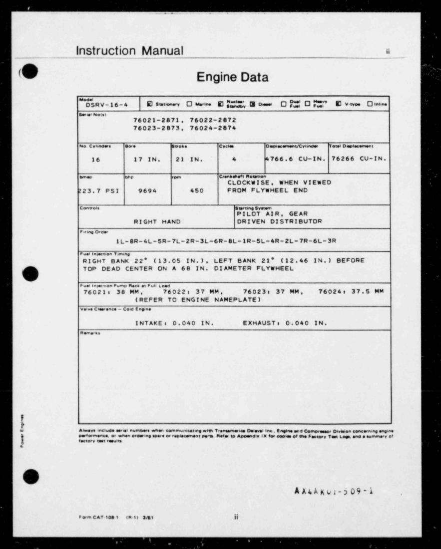
b Engine Data
SRV-16-4 E s1.t6ea-y O u-= E M', 3 oi e O ?".*,' O O T' E v tv O laiin.
s.t6.i Peo(s)76021-2871, 76022-2872;
76023-2873, 76024-2874,
I*eo. cyiino ra so,. sirom. cyci. o .comenucvienes, tet.i o pia.m.ni
16 17 IN. 21 IN. 4 4766.6 CU-IN. 76266 CU-IN.
mm.o ting , , . c,.nmen ei net i n
CLOCKWISE, WHEN VIEWED223.7 PSI 9694 450 FROM FLYWHEEL END
contreis s rtine system
PILOT AIR, GEAR |RIGHT HAND DRIVEN DISTRIBUTOR |
9iting Order
1L-8R-4L-5R-7L-2R-3L-6R-8L-1R-5L-4R-2L-7R-6L-3R i
e u.i ens.cteen viming |RIGHT BANK 22' (13.05 IN.). LEFT BANK 21' (12.46 IN.) BEFORETOP DEAD CENTER ON A 68 IN. DIAMETER FLYWHEEL
e... ins.ction rump neca et e use Lo.o
76021: 38 MM , 76022: 37 MM, 76023: 37 MM. 76024: 37.5 MM(REFER TO ENGINE NAMEPLATE)
vei.. cia,ence - coio Ene.n.
INTAKE: 0.040 IN. EXHAUST: 0.040 IN.m.m.,m.
It
Aiw.ys inclue. <6.i numtsers wn.n .ommunic.teng wHh Tren m.e6 O.4.v.I in . Engen. enil Compe oe Dev6.ien sene.cning .nein.au
. ,4.,m.nc.. ., wit.n .. ring .. ., , i.c.m.nt . n.t., Apowidl.1 X for .o06 of Wi. F.ctory T t I..e .nd . .umry ofg f.ctory 1 tF lts.
JA X4 A K ul-5 09 -1 .
F orm C AT-1081 t R-1) 3/31 ||
_ .. .. . _
- .= __ - . .. . ._ ._
instruction Manual iii,
!
n
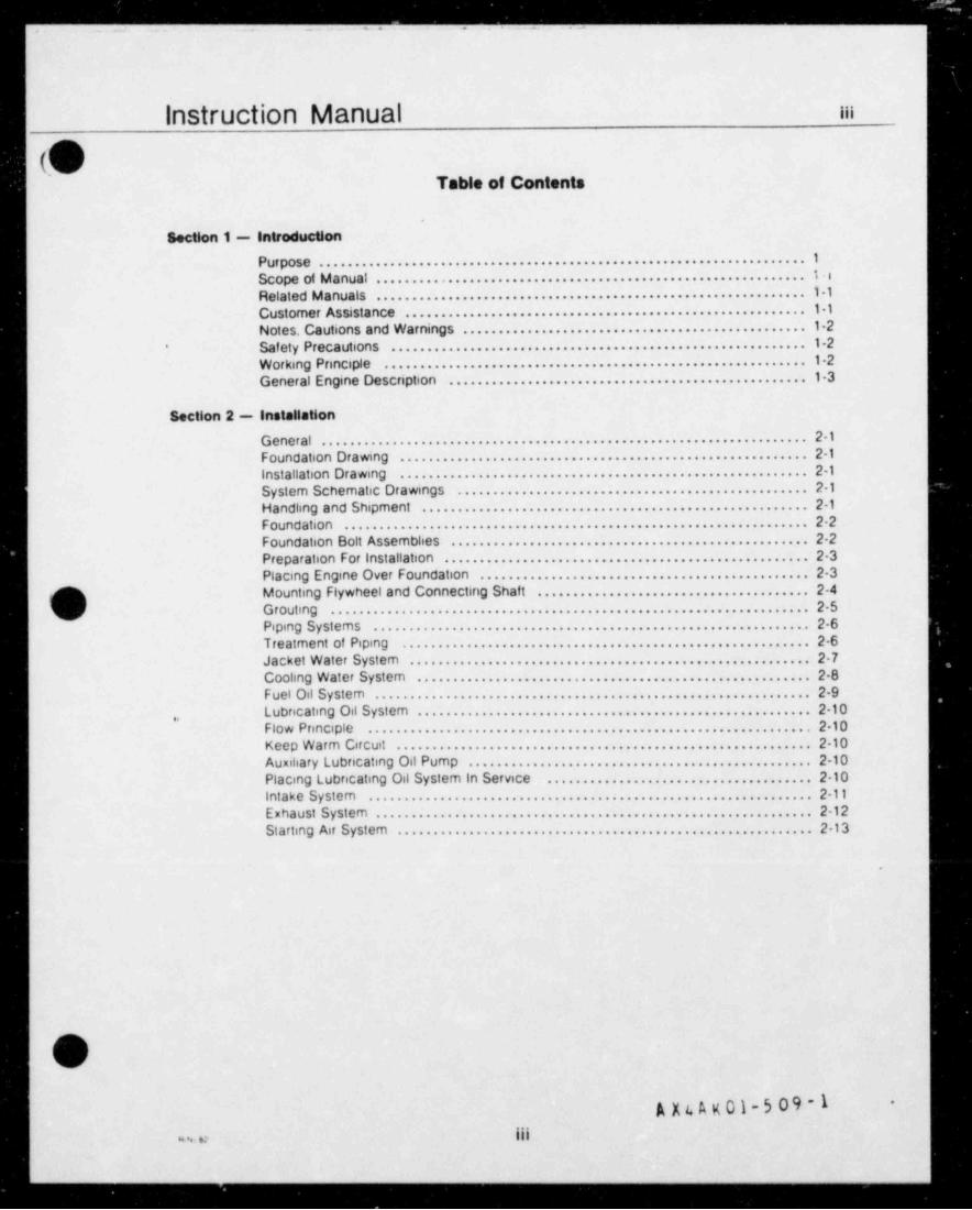
Table of Contents
Section 1 - IntroductionPurpose...................................................................1
Scope of M a nual . . . . . . . . . . . . . . . . . . . . . . . . . . . . . . . . . . . . . . . . . . . . . . . . . . . . . . . . . . . . t . :Rel ated M a nuals . . . . . . . . . . . . . . . . . . . . . . . . . . . . . . . . . . . . . . . . . . . . . . . . . . . . . . . . . . . 1 1Cust ome r Assista nce . . . . . . . . . . . . . . . . . . . . . . . . . . . . . . . . . . . . . . . . . . . . . . . . . . . . . . . 1 1Notes. Cautions and Warnings . . . . . . . . . . . . . . . . . . . . . . . . . . . . . . . . . . . . . . . . . . . . . . . 1 2Saf et y Preca utions . . . . . . . . . . . . . . . . . . . . . . . . . . . . . . . . . . . . . . . . . . . . . . . . . . . . . . . . . 1 -2*
Wor ki ng Pnnci ple . . . . . . . . . . . . . . . . . . . . . . . . . . . . . . . . . . . . . . . . . . . . . . . . . . . . . . . . . . 1 2General Engine Description ................................................. 1-3
Section 2 - Installation
General...................................................................2-1F oun d ation Dr a wing . . . . . . . . . . . . . . . . . . . . . . . . . . . . . . . . . . . . . . . . . . . . . . . . . . . . . . . . 2- 1
Installation Drawing ........................................................2-1
System Schematic Drawings . . . . . . . . . . . . . . . . . . . . . . . . . . . . . . . . . . . . . . . . . . . . . . . . 2-1Handling and Shipment .....................................................2-1
F o un d ati o n . . . . . . . . . . . . . . . . . . . . . . . . . . . . . . . . . . . . . . . . . . . . . . . . . . . . . . . . . . . . . . . . 2 2Foundation Bolt Assemblies . . . . . . . . . . . . . . . . . . . . . . . . . . . . . . . . . . . . . . . . . . . . . . . . . 2-2Preparation For installation . . . . . . . . . . . . . . . . . . . . . . . . . . . . . . . . . . . . . . . . . . . . . . . . . . 2 3Placing Engine Over Foundation . . . . . . . . . . . . . . . . . . . . . . . . . . . . . . . . . . . . . . . . . . . . . 2-3Mounting Flywheel and Connecting Shaft ..................................... 2-4*
, Grouting ..................................................................25Pi pin g Sy st e m s . . . . . . . . . . . . . . . . . . . . . . . . . . . . . . . . . . . . . . . . . . . . . . . . . . . . . . . . . . . . 2 6Treatment of Piping ........................................................ 2-6
Ja c k et Wa t er Syst e m . . . . . . . . . . . . . . . . . . . . . . . . . . . . . . . . . . . . . . . . . . . . . . . . . . . . . . . 2 7Coolin g W at e r Sy st e m . . . . . . . . . . . . . . . . . . . . . . . . . . . . . . . . . . . . . . . . . . . . . . . . . . . . . . 2 8F u el Oil S y st e m . . . . . . . . . . . . . . . . . . . . . . . . . . . . . . . . . . . . . . . . . . . . . . . . . . . . . . . . . . . . 2-9L ubnc atin g Oil Sy st e m . . . . . . . . . . . . . . . . . . . . . . . . . . . . . . . . . . . . . . . . . . . . . . . . . . . . . . 2- 10
,.
Flow Principle .............................................................210
Keep Warm Circuit .........................................................210
Auxiliary Lubncating Oil Pump . . . . . . . . . . . . . . . . . . . . . . . . . . . . . . . . . . . . . . . . . . . . . . . 2-10Placing Lubncating Oil System in Service ....................................2-10
Intake System .............................................................2-11
E x h a ust S yst e m . . . . . . . . . . . . . . . . . . . . . . . . . . . . . . . . . . . . . . . . . . . . . . . . . . . . . . . . . . . . 2- 12
St a rtin g Ai r S yst e m . . . . . . . . . . . . . . . . . . . . . . . . . . . . . . . . . . . . . . . . . . . . . . . . . . . . . . . . . 2 - 13
.
n't(
A X 4 A K 01-5 09 - 1-
iii~
- -- _
!
||
8'Instruction Manuals
section 3 - Engine Controis
General...................................................................3-1 ;
Ref er ences . . . . . . . . . . . . . . . . . . . . . . . . . . . . . . . . . . . . . . . . . . . . . . . . . . . . . . . . . . . . . . . . 3 - 1 i
Dr a win g s . . . . . . . . . . . . . . . . . . . . . . . . . . . . . . . . . . . . . . . . . . . . . . . . . . . . . . . . . . . . . . . . . . 3 - 1
System Overview ..........................................................3-1Description of Operations . . . . . . . . . . . . . . . . . . . . . . . . . . . . . . . . . . . . . . . . . . . . . . . . . . . 3-2Electrical Start Circuitry . . . . . . . . . . . . . . . . . . . . . . . . . . . . . . . . . . . . . . . . . . . . . . . . . . . . . 3 2Pneumatic Control Circuitry . . . . . . . . . . . . . . . . . . . . . . . . . . . . . . . . . . . . . . . . . . . . . . . . . 3-4
Pneumatic Functions At Start . . . . . . . . . . . . . . . . . . . . . . . . . . . . . . . . . . . . . . . . . . . . . . . . 3 5Autorr atic Safety Shutdown . . . . . . . . . . . . . . . . . . . . . . . . . . . . . . . . . . . . . . . . . . . . . . . . . 3-7Emerge ncy St art s . . . . . . . . . . . . . . . . . . . . . . . . . . . . . . . . . . . . . . . . . . . . . . . . . . . . . . . . . . 3-8
Other Pneumatic Functions .................................................3-10Other Electrical Functions . . . . . . . . . . . . . . . . . . . . . . . . . . . . . . . . . . . . . . . . . . . . . . . . . . . 3-11G enerator Interconnections . . . . . . . . . . . . . . . . . . . . . . . . . . . . . . . . . . . . . . . . . . . . . . . . . 3-12
Section 4 - Engine Operation
General...................................................................41Cle ar Cylin de r C he c k . . . . . . . . . . . . . . . . . . . . . . . . . . . . . . . . . . . . . . . . . . . . . . . . . . . . . . . 4 -2Saf ety P r ec a ution s . . . . . . . . . . . . . . . . . . . . . . . . . . . . . . . . . . . . . . . . . . . . . . . . . . . . . . . . . 4 -2 AStandby Mode Status Check ................................................ 4 3Test Start Procedure ....................................................... 4 7E m e rg e ncy St a rt s . . . . . . . . . . . . . . . . . . . . . . . . . . . . . . . . . . . . . . . . . . . . . . . . . . . . . . . . . . 4 10Stopping Engine ...........................................................411
D'
\
|
A X t A K01-5 09-1 8|'
ivw,omi am.
. . .. = .
Instruction Manual v
,- xY
);USection 5 - Inspection and Maintenance
Part A - Preventive MaintenanceGeneral.........................................................5-A-1M aint e na nce Practice s . . . . . . . . . . . . . . . . . . . . . . . . . . . . . . . . . . . . . . . . . . . 5- A- 1
Perf orrnance C urves . . . . . . . . . . . . . . . . . . . . . . . . . . . . . . . . . . . . . . . . . . . . . 5- A- 1
Operating Reports ............................................... 5.A-4
Part B - Suggested Maintenance SchedulesG e n e r al . . . . . . . . . . . . . . . . . . . . . . . . . . . . . . . . . . . . . . . . . . . . . . . . . . . . . . . . 5 B - 1Maintenance Schedules . . . . . . . . . . . . . . . . . . . . . . . . . . . . . . . . . . . . . . . . . . 5 B 1Inspection Guides ...............................................5B1Daily inspection Guide ........................................... 5 B-2Weekly inspection Guide ......................................... 5-B 3Monthly /Each Exercise Test inspection Guide ...................... 5 B-4Annual /Each Plant Shutdown inspection Guide ..................... 5 B 5Bi-Annual / Alternate Plant Shutdown inspection Guide ...............5B6
Every Five Year inspection Guide ................................. 5 B-7
Part C - Preservation and StoragePreparation For Shiprnent and/or Storage .......................... 5 C-1Pre servatio n M ate rial s . . . . . . . . . . . . . . . . . . . . . . . . . . . . . . . . . . . . . . . . . . . . 5-C-1
De si cc a nt s . . . . . . . . . . . . . . . . . . . . . . . . . . . . . . . . . . . . . . . . . . . . . . . . . . . . . . 5 C - 1General Preservation Proce Jures . . . . . . . . . . . . . . . . . . . . . . . . . . . . . . . . . . 5-C 1Long Term Storage .............................................. 5-C-2em
i ) Le vels of St or a g e . . . . . . . . . . . . . . . . . . . . . . . . . . . . . . . . . . . . . . . . . . . . . . . . 5 C.3V' R eceiving i ns pe ction . . . . . . . . . . . . . . . . . . . . . . . . . . . . . . . . . . . . . . . . . . . . . 5-C 4
On Site Preparation For Storage . . . . . . . . . . . . . . . . . . . . . . . . . . . . . . . . . . . 5 C 5St ora ge i ns pections . . . . . . . . . . . . . . . . . . . . . . . . . . . . . . . . . . . . . . . . . . . . . . 5 C 5Recoating Of Preserved Surf aces . . . . . . . . . . . . . . . . . . . . . . . . . . . . . . . . . . 5 C 6Generator.......................................................5C-6
Part D - Inspection and Maintenance RecordsGeneral .. .....................................................5-D-1
Instructions For Use ............................................. 5-D 1
1
1\(
)i
LNg
4 Y t t v C1-5 09-1
v..
- . . . . - ... . - . .. - - .
Instruction Manual vi
n -
(O1
Section 6 - Overhaul and Repair
Part A - GeneralRotation and Cylinder Designation . . . . . . . . . . . . . . . . . . . . . . . . . . . . . . . . . 6- A-1
Assembly of Parts ............................................... 6-A-1Use of Assembly Drawings ....................................... 6-A 1Cleanliness ..................................................... 6 A-2T or q uin g . . . . . . . . . . . . . . . . . . . . . . . . . . . . . . . . . . . . . . . . . . . . . . . . . . . . . . . . 6- A 2Torqu e Ta ble s . . . . . . . . . . . . . . . . . . . . . . . . . . . . . . . . . . . . . . . . . . . . . . . . . . . 6 A 2Adhesives and Sealants . . . . . . . . . . . . . . . . . . . . . . . . . . . . . . . . . . . . . . . . . . 6 A 3Saf ety Preca utions . . . . . . . . . . . . . . . . . . . . . . . . . . . . . . . . . . . . . . . . . . . . . . . 6 A 6
Part B - Cylinder Heads and ValvesCylinder Head Removal .......................................... 6 B 1Inspection ...................................................... 6 B 1
Val v e s . . . . . . . . . . . . . . . . . . . . . . . . . . . . . . . . . . . . . . . . . . . . . . . . . . . . . . . . . . 6 - B 2Valve Spring Replacement ........................................ 6-B 2Valve Removal From Cylinder Head . . . . . . . . . . . . . . . . . . . . . . . . . . . . . . . . 6-B 2Valve inspection ar'd Reconditioning . . . . . . . . . . . . . . . . . . . . . . . . . . . . . . . 6-B-3Cylinder Head Inst allation . . . . . . . . . . . . . . . . . . . . . . . . . . . . . . . . . . . . . . . . . 6 B 3
Part C - Pistons and RodsGenera!.........................................................6-C1
Parts Lists ...................................................... 6 C-1
Special Tools ................................................... 6-C 2
Link Rod and Piston Removal ..................................... 6 C 4p Piston and Master Rod Removal (Link Rod Removed) . . . . . . . . . . . . . . . . 6-C 6V Piston and Master Rod Removat (Link Rod Not Removed) ............ 6 C 6
Removal of Piston From Rod . . . . . . . . . . . . . . . . . . . . . . . . . . . . . . . . . . . . . . 6 C-7Removal of a Seized Stud . . . . . . . . . . . . . . . . . . . . . . . . . . . . . . . . . . . . . . . . . 6 C 7Inspecting Connecting Rod Bearings . . . . . . . . . . . . . . . . . . . . . . . . . . . . . . . 6 C-8Checking Piston Pin Clearances . . . . . . . . . . . . . . . . . . . . . . . . . . . . . . . . . . . 6 C 8inspecting Connecting Rod ....................................... 6 C-9
Checking Piston Ring Side Clearances . . . . . . . . . . . . . . . . . . . . . . . . . . . . . 6 C 9Piston Ring Replacement ......................................... 6 C 9
Cle a nin g Piston Rings . . . . . . . . . . . . . . . . . . . . . . . . . . . . . . . . . . . . . . . . . . . . 6-C 10Checking Picon Amg Gap Clwances .............................6-C10inspecting Piston ................................................6-C10Disassembling Piston . . . . . . . . . . . . . . . . . . . . . . . . . . . . . . . . . . . . . . . . . . . . . 6 C 10Assembling Piston ............................................... 6-C-11
Installing Piston Rings . . . . . . . . . . . . . . . . . . . . . . . . . . . . . . . . . . . . . . . . . . . . 6 C 12Replacing Piston Pin Bushing .....................................6C12Replacement of Link Pin Bushing . . . . . . . . . . . . . . . . . . . . . . . . . . . . . . . . . . 6 C 13Assembly of Pistons to Rods . . . . . . . . . . . . . . . . . . . . . . . . . . . . . . . . . . . . . . 6-C 14Inspecting Cylinder Liners ........................................6C-15
Liner Deglazing Procedure . . . . . . . . . . . . . . . . . . . . . . . . . . . . . . . . . . . . . . . . 6-C 15Removing Cylinder Liner . . . . . . . . . . . . . . . . . . . . . . . . . . . . . . . . . . . . . . . . . . 6 C 16Installing Cylinder Liner . . . . . . . . . . . . . . . . . . . . . . . . . . . . . . . . . . . . . . . . . . . 6-C 16Installation of Piston and Master Rod . . . . . . . . . . . . . . . . . . . . . . . . . . . . . . . 6-C 16Installing Piston and Link Rod .....................................6C17Seating New Rings in Liner .......................................6C.18
v
A X 4 A K 01 - 5 0 9 - 1. .
vi.i. u
--, - - . - - . . . .
,
Instruction Manual viix,
(> Section 6 - Overhaul and Repair (Continued)
Part D - Crankshaft and BearingsM ain Be a rings . . . . . . . . . . . . . . . . . . . . . . . . . . . . . . . . . . . . . . . . . . . . . . . . . . . 6-D- 1
Bearing Ca p Removal . . . . . . . . . . . . . . . . . . . . . . . . . . . . . . . . . . . . . . . . . . . . 6-D-1Bearing Shell Replacement .......................................6-D-2
Bearing Cap Installation .......................................... 6-D 2Crankshaft Alignment and Thrust Clearance . . . . . . . . . . . . . . . . . . . . . . . . 6-D 4Checking Thrust Clearance . . . . . . . . . . . . . . . . . . . . . . . . . . . . . . . . . . . . . . . 6-D-4 i
Crankshaft Web Deflection . . . . . . . . . . . . . . . . . . . . . . . . . . . . . . . . . . . . . . . . 6-D-5Deflection St anda rds . . . . . . . . . . . . . . . . . . . . . . . . . . . . . . . . . . . . . . . . . . . . . 6-D-5Corrective Action ................................................ 6-D-5 |
|Part E - Cams Camshafts and BearingsG e ne r al . . . . . . . . . . . . . . . . . . . . . . . . . . . . . . . . . . . . . . . . . . . . . . . . . . . . . . . . . 6 E- 1Camshaft Bearing Replacement ................................... 6 E-1Cam Replacement ............................................... 6 E-1Timing Gears ................................................... 6-E-3Inspection ...................................................... 6-E-4
lA s s e m bl y . . . . . . . . . . . . . . . . . . . . . . . . . . . . . . . . . . . . . . . . . . . . . . . . . . . . . . . 6- E 4'
C a m s h a f t Timin g . . . . . . . . . . . . . . . . . . . . . . . . . . . . . . . . . . . . . . . . . . . . . . . . . 6- E- 5.
Part F - Fuel SystemFuelinjection Equipment ......................................... 6-F 1Parts Lists ...................................................... 6-F-1Fuel injection N onles . . . . . . . . . . . . . . . . . . . . . . . . . . . . . . . . . . . . . . . . . . . . 6-F-2
C Nr'ule Adjustment ............................................... 6-F 3\ Cleaning Spray Tips ............................................. 6-F-3
Fuel inje ction Pumps . . . . . . . . . . . . . . . . . . . . . . . . . . . . . . . . . . . . . . . . . . . . . 6- F 3Description of Operation . . . . . . . . . . . . . . . . . . . . . . . . . . . . . . . . . . . . . . . . . . 6 F-4M alf unctioning Pump . . . . . . . . . . . . . . . . . . . . . . . . . . . . . . . . . . . . . . . . . . . . . 6 F 5Pump Removal .................................................. 6-F-5
Disassembly of Pump ............................................ 6-F-6Asse m bly of P um p . . . . . . . . . . . . . . . . . . . . . . . . . . . . . . . . . . . . . . . . . . . . . . . 6-F-7Pump Installation and Timing . . . . . . . . . . . . . . . . . . . . . . . . . . . . . . . . . . . . . . 6-F-8
Part G - Eng;ne ControlsO v e r s pe e d T ri p . . . . . . . . . . . . . . . . . . . . . . . . . . . . . . . . . . . . . . . . . . . . . . . . . . 6-G - 1Overspeed Tnp Adjustment .......................................6-G2Governor Dnve Replacement .....................................6-G-3
Logic Board Trouble Shooting . . . . . . . . . . . . . . . . . . . . . . . . . . . . . . . . . . . . . 6-G-4Checking Logic Elements . . . . . . . . . . . . . . . . . . . . . . . . . . . . . . . . . . . . . . . . . 6-G 4
Part H - Engine BalancingG e n e r a l . . . . . . . . . . . . . . . . . . . . . . . . . . . . . . . . . . . . . . . . . . . . . . . . . . . . . . . . . 6- H - 1
Cylinder Balance ................................................ 6 H 1FuelInjection Equipment ......................................... 6-H 1E n gi n e O ut Of Tun e . . . . . . . . . . . . . . . . . . . . . . . . . . . . . . . . . . . . . . . . . . . . . . 6 H - 1Preventiv e M ainte nance . . . . . . . . . . . . . . . . . . . . . . . . . . . . . . . . . . . . . . . . . . 6 H 2Trouble Shooting ................................................ 6 H 2
m\,
v
A)4A K Cl-5 09-1g
._ .
w . . . - . . . _ ._ - - ~ - - . - - . .. ,_
Instruction Manual viii, ,
\' Section 6 - Overhaul and flopelt (Continued)
Part I - Starting Air SystemG e n e r al . . . . . . . . . . . . . . . . . . . . . . . . . . . . . . . . . . . . . . . . . . . . . . . . . . . . . . . . . 6 1 - 1Air S u p ply . . . . . . . . . . . . . . . . . . . . . . . . . . . . . . . . . . . . . . . . . . . . . . . . . . . . . . 6- 1 1
O peratio n . . . . . . . . . . . . . . . . . . . . . . . . . . . . . . . . . . . . . . . . . . . . . . . . . . . . . . 6- 1 - 1
Starting Air Valvo Removal . . . . . . . . . . . . . . . . . . . . . . . . . . . . . . . . . . . . . . . 6-I-2Valve Disassembly . . . . . . . . . . . . . . . . . . . . . . . . . . . . . . . . . . . . . . . . . . . . . . 6-I 2Valve Assembly .................................................6-1-2
Valve inst allation . . . . . . . . . . . . . . . . . . . . . . . . . . . . . . . . . . . . . . . . . . . . . . . . . 6-1 2Timing Starting Air Distributor .....................................6I-3
Air Filter Inspection ..............................................61-3
Part J - Cooling Water SystemsG e n e r a l . . . . . . . . . . . . . . . . . . . . . . . . . . . . . . . . . . . . . . . . . . . . . . . . . . . . . . . . . 6-J - 1Water Treatment Program ........................................ 6-J-1O pe r at io n . . . . . . . . . . . . . . . . . . . . . . . . . . . . . . . . . . . . . . . . . . . . . . . . . . . . . . . 6 -J 1Use of Ethylene Glycol ........................................... 6-J-1Scale and Corrosion ............................................. 6-J-1Treatment of Jacket Water . . . . . . . . . . . . . . . . . . . . . . . . . . . . . . . . . . . . . . . . 6 J-1Environmental Considerations . . . . . . . . . . . . . . . . . . . . . . . . . . . . . . . . . . . . . 6-J-2Cleaning the Jacket Water System . . . . . . . . . . . . . . . . . . . . . . . . . . . . . . . . . 6-J-2
Part K - Lubricating Oil SystemFilt e rs and Strainer s . . . . . . . . . . . . . . . . . . . . . . . . . . . . . . . . . . . . . . . . . . . . . . 6- K 1Lubricating Oil Pump . . . . . . . . . . . . . . . . . . . . . . . . . . . . . . . . . . . . . . . . . . . . . 6-K 1n' R e m ovin g P u m p . . . . . . . . . . . . . . . . . . . . . . . . . . . . . . . . . . . . . . . . . . . . . . . . . 6 K .1Pu m p Di s a s s e m b!y . . . . . . . . . . . . . . . . . . . . . . . . . . . . . . . . . . . . . . . . . . . . . . . 6 K- 2P u m p R e a s s e m bly . . . . . . . . . . . . . . . . . . . . . . . . . . . . . . . . . . . . . . . . . . . . . . . 6- K 3Pump Gear Camer Assembly ..................................... 6 K 4
Disassembly and Assembly of Gear Carrier Assembly ............... 6-K 4Pressure Regulating Valve . . . . . . . . . . . . . . . . . . . . . . . . . . . . . . . . . . . . . . . . 6 K-5Adding Lu bn cating Oil . . . . . . . . . . . . . . . . . . . . . . . . . . . . . . . . . . . . . . . . . . . . 6- K-6Selection Of A Lubncating Oil . . . . . . . . . . . . . . . . . . . . . . . . . . . . . . . . . . . . . 6-K-7Chang:ng Lubricating Oil ......................................... 6-K-7
A na f y sis of O il . . . . . . . . . . . . . . . . . . . . . . . . . . . . . . . . . . . . . . . . . . . . . . . . . . . 6- K 7Turbocharger Beanng Lubncation ................................. 6-K 8
Part L - MiscellaneousManometer .....................................................6L1Measuring Vacuum ..............................................6L1Operation and Maint enance . . . . . . . . . . . . . . . . . . . . . . . . . . . . . . . . . . . . . . . 6 L-1Crankcase Ventilation . . . . . . . . . . . . . . . . . . . . . . . . . . . . . . . . . . . . . . . . . . . . 6-L-2Air B utt erfly Valve . . . . . . . . . . . . . . . . . . . . . . . . . . . . . . . . . . . . . . . . . . . . . . . . 6 L 3
IO..
3<
:/m )Ea
bA4AtIl-5*
.
.... . vill -
_ _ - -. -- n ..
Instruction Manual ix
(c '
.' Section 7 - Trouble Shooting
cene,ai ................................................................... 7.i
Records ..................................................................71
Section 8 - APPENDICES
Conversion Factors and Other Useful Information ...........82Appendix | -
Operating Temperatures and Pressures . . . . . . . . . . . . . . . . . . . . 8 3Appendix 11 -
Table of Clearances . . . . . . . . . . . . . . . . . . . . . . . . . . . . . . . . . . . . . 8 4Appendix 111 -
Torque Tables .......................................... 8 5Appendix IV -
Timing Diagram .......................................... B 6Appendix V -
Lubricating Oil Recommendations . . . . . . . . . . . . . . . . . . . . . . . . . 8 7Appendix VI -
Alarms and Safety Shutdovens . . . . . . . . . . . . . . . . . . . . . . . . . . . . . 8 8Appendix Vil -
Appendix Vill - Fuel Oil Specifications ...................................89
Appendix IX - Torsional Stress and Critical Speeds . . . . . . . . . . . . . . . . . . . . . . . 8 10Appendix X - F a ctory Te st Logs . . . . . . . . . . . . . . . . . . . . . . . . . . . . . . . . . . . . . . . 8 1 1
Section 9 - Drawings
n
e
.
!,
i
i
Q
AA4A X04-50'-iv,
1
_ _ . _ . _ _ _ _ _ , . . _ . . _ , --
.- . . _ ._ _ ._
instruction Manual xt T(U List Of Illustrations
Fig. No. Title Page
11 Diagram of Working Principle . . . . . . . . . . . . . . . . . . . . . . . . . . . . . . . . . . . . . . . . . . . . . . . . . . . . 1 -212 Cross Section. Typical Model RV Diesel Engine . . . . . . . . . . . . . . . . . . . . . . . . . . . . . . . . . . . . 1 42-1 Suggested Foundation Bolt Template . . . . . . . . . . . . . . . . . . . . . . . . . . . . . . . . . . . . . . . . . . . . . 2-222 Flywheel Mounting ............................................................. 2-45 D-1 Inspection and Maintenance Record. Main Bearing Caps . . . . . . . . . . . . . . . . . . . . . . . . . . . 5-D-35-D 2 Inspection and Maintenance Record Crankshaft Web Deflections ................... 5 D 45D3 Inspection and Maintenance Record. Main Bearing Shells .......................... 5 D 55-D 4 Inspection and Maintenance Record, Crankshaft . . . . . . . . . . . . . . . . . . . . . . . . . . . . . . . . . . . 5-D 65D5 Inspection and Maintenance Record. Cylinder Liners . . . . . . . . . . . . . . . . . . . . . . . . . . . . . . . 5-D-75D6 Inspection and Maintenance Record. Connecting Rod Bearing Shells ................ 5 D 85D7 Inspection and Maintenance Record, Connecting Rod . . . . . . . . . . . . . . . . . . . . . . . . . . . . . . 5 D 95-D-10 inspection and Maintenance Record. Piston . . . . . . . . . . . . . . . . . . . . . . . . . . . . . . . . . . . . . 5 D 105 D-9 Inspection and Maintenance Record. Piston Rings .................................5-D-11
5-D 10 Inspection and Maintenance Record. Cams and Tappet Assemblies . . . . . . . . . . . . . . . . . 5 D - 125 D11 Inspection and Maintenance Record. Camshaft Bearing Shells ......................5D13
5-D-12 Inspection and Maintenance Record. Gearset .....................................5D-145 D-13 Inspection and Maintenance Record, Cylinder Head . . . . . . . . . . . . . . . . . . . . . . . . . . . . . . . . 5-D 155-D-14 Inspection and Maintenance Record. Intake and Exhaust Valves . . . . . . . . . . . . . . . . . . . . . 5 D 165 D-15 Inspection and Maintenance Record. Fuel injection Pump . . . . . . . . . . . . . . . . . . . . . . . . . . . 5-D 175-D-16 Inspection and Maintenance Record. Fuel injection Nozzle and Holder . . . . . . . . . . . . . . . 5 D 18
p 6A1 Engine Rotation and Cylinder Designation . . . . . . . . . . . . . . . . . . . . . . . . . . . . . . . . . . . . . . . . . 6- A.1
6 B-1 Cylinder Head Lifting Fixture . . . . . . . . . . . . . . . . . . . . . . . . . . . . . . . . . . . . . . . . . . . . . . . . . . . . 6 B- 16B2 Valve Spnng Compressor Tool . . . . . . . . . . . . . . . . . . . . . . . . . . . . . . . . . . . . . . . . . . . . . . . . . . . 6 B 26 B-3 V alv e S pnn g R et ain e r . . . . . . . . . . . . . . . . . . . . . . . . . . . . . . . . . . . . . . . . . . . . . . . . . . . . . . . . . . . 6- B 2
6B4 Tightening Sequence For Cylinder Head Stud Nuts . . . . . . . . . . . . . . . . . . . . . . . . . . . . . . . . . 6 B 36C1 Connecting Rod and Bearing s . . . . . . . . . . . . . . . . . . . . . . . . . . . . . . . . . . . . . . . . . . . . . . . . . . . 6 C 16C2 Bearing Replacement Tool Arrangement .......................................... 6 C 26C3 Tools installed For Removing Piston and Link Rod ................................. 6-C-36C4 Lifting Piston and Link Rod From Cylinder Liner . . . . . . . . . . . . . . . . . . . . . . . . . . . . . . . . . . . . 6-C 46-C 5 Tools Installed For Piston and Master Rod Removal ................................ 6 C 56C6 Lifting Master Rod and Piston From Cylinder Liner ................................. 6 C 66-C 7 Measunng Bearing Shell Thickness .............................................. 6 C-86C8 Measuring Piston Pin in Bushing Clearances . . . . . . . . . . . . . . . . . . . . . . . . . . . . . . . . . . . . . . 6 C.96C9 Piston Ring Side Clearance ..................................................... 6 C 9
6 C 10 Pist o n M e a s ur em e nt s . . . . . . . . . . . . . . . . . . . . . . . . . . . . . . . . . . . . . . . . . . . . . . . . . . . . . . . . . . . 6- C- 106 C-11 Piston Assembly ...............................................................6C-116 C 12 Lin e r Se a li n g Ri ng s . . . . . . . . . . . . . . . . . . . . . . . . . . . . . . . . . . . . . . . . . . . . . . . . . . . . . . . . . . . . . 6 C.146 C 13 Cylinder Liner Wear Patterns . . . . . . . . . . . . . . . . . . . . . . . . . . . . . . . . . . . . . . . . . . . . . . . . . . . . 6 C.146 C.14 Pistor' and Rod installation ...................................................... 6 C 166 C 15 Tightening Sequence For Connecting Rod Bolts and Nuts .......................... 6 C 176 D-1 M ai n B e a nn g C a p . . . . . . . . . . . . . . . . . . . . . . . . . . . . . . . . . . . . . . . . . . . . . . . . . . . . . . . . . . . . . . 6 D - 1
6D2 Crankshaft Thrust Rings ........................................................6-D-1
6D3 Pre Str esser Asse mbly . . . . . . . . . . . . . . . . . . . . . . . . . . . . . . . . . . . . . . . . . . . . . . . . . . . . . . . . . . 6- D 2
6D4 Crankshaft Alignment Record. Form D-1063 . . . . . . . . . . . . . . . . . . . . . . . . . . . . . . . . . . . . . . . 6 D 66F1 Typical Fuel Injection System . . . . . . . . . . . . . . . . . . . . . . . . . . . . . . . . . . . . . . . . . . . . . . . . . . . . 6 F.16F2 FueiInjection Nozzle Assembly .................................................. 6 F-26F3 Pump Plunger and Barrel Arrangement ...........................................6F44
i 6F4 E f f e ct iv e St r o k e . . . . . . . . . . . . . . . . . . . . . . . . . . . . . . . . . . . . . . . . . . . . . . . . . . . . . . . . . . . . . . . . 6- F - 4;V
A nAyC)-5cA ; 4
w x
. . .: - x - :_ =- = .. i.
. instruction Manual, c, g-
.
: Lbt of diustrations (Contlaued)x.- g
Fig. No. Title p.g,-
6-F 5 Fuel Pump .............,...................................................... 6-F-56-F 6 Flywheel Timing Marks ......................................................... 6-F 86-F 7 Pump Base To Tappe' Adjustment ............................................... 6-F 86 G-1 Overspeed Trip Governor ........'............................................... 6-G 16-G-2 Governor Drive Coupling . . . . . . . . . . . . . . . . . . . . . . . . . . . . . . . . . . . . . . . . . . . . . . . . . . . . . . . . 6-G-36-11 Starting Air Valve . . . . . . . . . . . . . . . . . . . . . . . . . . . . . . . . . . . . . . . . . . . . . . . . . . . . . . - . . . . . . . 6-1-26-12 Starting Air Distributor Cam Arrangement .........................................6-I-3
6-K-1 Lubricating Oil Pump and Gear Carrier Assembly . . . . . . . . . . . . . . . . . . . . . . . . . . . . . . . . . . 6 K-16-K 2 Lubricating Oil Pump Assembly . . . . . . . . . . . . . . . . . . . . . . . . . . . . . . . . . . . . . . . . . . . . . . . . . . 6-K 26-K 3 Gear Carrier Assembly ......................................................... 6 K-46 K-4 Oil Pressure Reguf4 ting Valve ................................................... 6 K 56 K-5 Turbocharger Bearing Drip Lubrication System . . . . . . . . . . . . . . . . . . . . . . . . . . . . . . . . . . . . 6 K 8
i
|
|
l
1,
1l
|
<
b NA % , * *
1
1
- - . - - - - . .
.. - -. - -- ... . ...
Tggggg Traneamence Detevel Inc.Enonne and Congressor Division
Delaval --P.O. Son 2161
E Oakland, CalHomia 94621
O. T lI
GUARANTEE
Unless otherwise specifically stated, all machinery and equipment purenamed hereunder is sublect to the followingwarranty: Transamerica Delaval Inc., Engine and Compressor Division (hereinafter celled Company) warrants thatmachinery and equipment manufactured by Company and fumished and delivered to the Purchaser hereunder shallbe of the kind and quality described in the Company's specifications, and no other warranty or guaranty except oftitle is made or shall be implied. If any part of said machinery and equipment thus manufactured by the Company failsbecause of defective workmanship or material within one year from the date of starting the engine after delivery,butnot exceed;ng fifteen months from the date of shipment, the Company will, provided such machinery and equipmenthas been used for the purpose and in the manner intended and the Company's examination shall disclose to its satis-faction that such parts are defective, replace such defective parts free of charge, f.o.b. cars at its warehouse in Oakland, |California, but the Company will not be liable for repairs or s:terations unless the same are made with its written con- |sent or approval. The Company will not be liable for damages or delays caused by such defective material or work-manship, and it is agreed that the Company's liability under all guaranties or warranties, either express or implied, isexpressly limited to the replacing of parts failing through defective workmanship or material within the times and inthe manner aforesaid. Parts claimed to be defective are to be returned to the Company at its option, transportationprepaid. The Company makes no guaranties or warranties whatsoever in respect to products other than that manu-f actured by the Company as they are sold under the regular warranties of the respective manufacturers, copies ofwhich will be furnished if requested. All warranties and guaranties as to efficiency and capacity are based upon shop j
tests when operating under specified conditions, but do not apply to any condition varying from the foregoing. Theliability of the Company (except as to title) arising out of the supplying of said machinery or equipment or its use,
O- whether on warranties or otherwise, shall not in any case exceed the cost of correcting defects in the machinery orequipment as herein provided, and upon the expiration of said warranty, as herein provided, all such liability shallterminate.
PRODUCTIMPROVEMENTS
The Company reserves the right, where possible, to include changes in design or material which are improvements.Also reserved is the right to furnish equipment of design modifications best suited to a particular installation, location,or operating condition, as long as such modification exceeds Purchaser's design specifications. The Company cannotbe responsible for including improvements made af ter start of production on Purchaser's equipment.
OA X 4 A K 01-5 09 -1
Foem S 991 (R 2) 3/79
. .. .- - .. __ _ _ ..-. _ _ ._-. -_-- - - -
o
Instruction Manuals
0') Changes-
t4.mm-
D Purpose of ChangeChange Number Date of Chan9e w %
||
|
||
l
('3x_J
Comments:
/
's /v
bNkbE~
Form CAT 119-5 (R-4) 5/82
-_ _ _
_ . _ . ._ . . ..._.. .. .. _ . _ _ . .-..._ _ . - _ _ - - - __,
(
Section 1Introduction
|
|
4
.d.*.
- 2
. ,, s . . . ,, c ..
- ,
. .. . . . .
- --.. - .. -
Instruction Manual 1-1
O SECTION 1
INTRODUCTION
PURPOSE.
The purpose of this Instruction Manual is to assist the owner and operating personnel in the operation,maintenance, adjustment, overhaul and repair of the equipment described on the data sheet in the front of themanual The instructions given herein cover generaliy the operation and maintenance of this equipment. Shouldany questions arise which are not answered specifically by these instructions, they should be referred to
.Customer Service Department, Transamerica Delavallnc., Engine and Compressor Division for further detailedinformation and technical assistance. The name Transamerica Delaval, as used in this manual.shall be taken tomean the Engine and Compressor D; vision unless anotner Transamerica Delaval division is specifically named.
SCOPE OF MANUAL.
This manual cannot possibly cover every situation connected with the operation, adjustment, inspection, test,overhaul and maintenance of the equipment furnished. Every effort is made to prepare the text of the mant:31 sothat engineenng and design data is transformed to the most easily understood wording Transamenca Delava ,in furnishing this equipment, must presume that the operating and maintenance personnel assigned theretohave sufficient technical knowledge to apply sound safety and operational practices which may not be other-uise covered herein. In applications where Transamerica Delaval equipment is to be integrated with a processor oth er machinery, these instructions should be thoroughly reviewed to determine the proper integration of theequipment into the overall plant operational procedures.
RELATED MANUALS.
In addstion to this instruction Manual, a Parts Manual and an Associated Pubhcations Manual are normallyprovided The contents of these manuals is as follows
a The Parts Manual contains engine specifications, assembly parts lists and assembly drawingsInstructions are provided to assist in the ordering of spare and replacement parts The assembly drawings areintended to assist in the identification of parts, however,it is recommended that the part numbers appeanng onthese drawings not be used when ordering parts. Rather, use the part numbers shown on the appropriate groupparts list
b The Associated Pubhcations Manualis a compilation of manufacturer's bulletins, forms, instructions,drawings. etc., which are applicable to components and equipment which is furnished with the engine, but notmanufactured by the Engine and Compressor Division. The contents are indexed, both alphabetically bymanutacturer's name, and numencally by Transamerica Delaval part number. Complete instructions for usingthe manual are contained in the manual
CUSTOMER ASSISTANCE.
Transamerica Delaval maintains a staff of factory trained customer service personnel who are available atnominal rates to assist or advise in tne installation, ove%..t or repair of Enterprise machinery. It is recom-mended that one of these customer service representan es be requested when extensive repairs are beingmade on the equipment if assistance is required. wnte or wire the Engine and Compressor Division, CustomerService Department, furnishing complete information, including all senal numbers.
OAx4AK01-5 M ~i1-1_ . .
-. . -- _- . .
Instruction Manual 1-2
m
- NOTES, CAUTIONS AND WARNINGS.
Notes, cautions and warnings, as used in this manual are intended to convey the following meanings.
a. NOTES - operating procedures, conddions, etc., which it is essential to emphasize or highlightbecause of their importance to the proper operation of the machinery,
b. CAUTIONS - Operating procedures, practices, etc., which, if not strictly observed, could result indamage to, or destruction of equipment.
c. WARNINGS - Operating procedures, practices, etc., which couldresult in injury orpossible loss of11Ieif not followed correctly.
SAFETY PRECAUTIONS.
Although the design features of the Transamerica Delaval engine include considerations for the safe operationof the machine, all operating and maintenance personnel should be fully aware of the potential hazards that arepresent during the operation and maintenance of any large, medium speed, internal combustion engine. Thesehazards encompass many areas - rotating machinery, temperatures, pressures, handling of heavy weights,flammable liquids, slippery surfaces, and an environment of high nose levels. This Instruction Manual should notbe considered all inclusive in the area of safety, but rather as but one source of information for the formulation ofa comprehensive plant safety program. Specific safety precautions in the form of cautions and warnings aregiven throughout this manual for specific conditions and situations. In addition, general precautions areprovided in Section 4 for operation of the equipment, and in the beginning of Section 6 for overhauland repairactivities Sately programs, to be effective, must be the concern of all levels of management as well as theindividual worker. Transamerica Delaval will be pleased to advise on any specific situations which are notconsidered to be adequately covered by these instructions.
OQ WORKING PRINCIP1.E.
Transamerica Delaval Enterprise engines operate on the four stroke cycle principle. The complete cycle foreach cylinder consists of the intake, compression, power (or expansion) and exhaust strokes, and requires twocomplete revolutions of the crankshaft.
Nr',' ['d ew En . N m s'e-.man one w
dd; M. M djpp w m_
$.i L W ; ;,_ r , . . c ,_ _r , < c
.- . . , , A 2.
J....
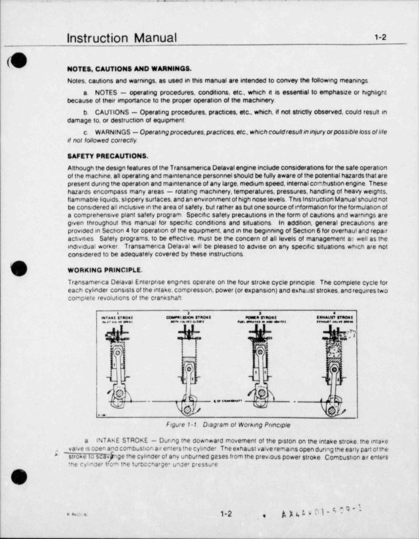
Figure 1 1. Diagram of Working Principle
a INTAKE STROKE - During the downward movement of the piston on the intake stroke,the intake_ valve is open and combustion air enters the cylinder. The exhaust valve remains open during the early part of the,,
"stroke to scavjrnge the cyhnder of any unburned gases from the previous power stroke. Combustion air enters ,
the cyhnder from the turbocnarge under pressure 1
G
v
, AX4,tVOI eQ.iS# ~
. no .. 1-2,
- _ .
- . . - _ _
|
Instruction Manual 1-3
m(U. '
b. COMPRESSION STROKE - Shortly after the piston passes bottom center and starts upward, theintake valve closes and the air is compressed, raising the temperature of the air to well above the ignitiontemperature of the diesel fuel. Just before the piston reaches top center, diesel fuelis injected into the combus-tion chamber by a nozzle which atomizes the f uel and spreys it in a pattern that will achieve optimum combustionefficiency. The heat of compression ignites the fuel.
c. POWER STROKE - The burning fuel air mixture expands and forces the piston downward. Thisdownward thrust transmits power through the connecting rod to the crankshaft, causing it to rotate. Towards theend of the power stroke the exhaust valve opens and exhaust gases start to leave the cylinder.
d EXHAUST STROKE - As the piston moves upward, past bottom center, exhaust gases are forced outof the cylinder through the open exhaust valves. During thelast half of the exhaust stroke theintake valve opensto admit combustion air into the cylinder for scavenging purposes.
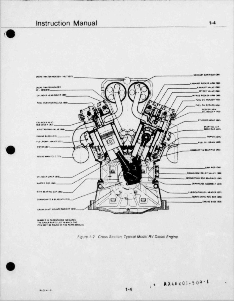
GENERAL ENGINE DESCRIPTION.
The Model RV diesel engine is a four-stroke-cycle, turbocharged, aftercooled, V type engine. The angle of theVee is 45 degrees. Trunk type piston, removable wet-type cylinder liners, pressure lubrication and mechanicalfuel injection are features of the engine. Individual fuelinjection pumps are provided for each cylinder and, asthey are of standard design, are interchangeable. The fuellines are of equallength and are relatively short,reducing line surge to a minimum. Fuel pumps. nozzles and orifice size and angle are all carefully matched to theengine and the fuel to be used to give a maximum thermal efficiency. Engine totation and cylinder bankdesignations are determined while f acing the engine at the flywheel end. Number one cylinders are always thepair farthest from the flywheel end
v
.
,-
i ''.',..1-3. u ..
.-. . - x _ - , _ _ - . . . . = . - - . - . - . . . .- - - - - - - - - - - - - - - .--
.
Instruction Manual 1-4
O
AAcati Waft A NE ADE a - auf 017) f
tapeAVET DoCERR AfIns 0801iJacatt Waf t e set ADE R e (EMAUST WALyt tason
''m.831W 6s, m1Att WALvt DEDI
CVtese08 A Mt AO COvt A DB7' assiARE moCatn Anes Deel
PUtL Ook set ADS A 48801
f ut L leutCTeoss esoztLa (M -
e ADEn e466#
CYLiseOf A est AD Dhoe
'sf Apf essG AsR
AIR $7ARTING WAlvt EM ERAasef 0LD e4416
8 c.=4 eLoCa oiti 5-tTs o
PutL PU., L60sEAGE 83713- '
tutt Oak DA&Ise 44 toti
0 p| x H-'---
|m, A.E .A= .oLo i3m
i
-. vi.= aoo nao.
CRANKCASE RELitf WALvl (M
CTLWDE A L1888 A Gil', / .CC9888tCTIIeG floD DEARas G6 omors
asastsa moo peos CRAssaCASE AssteseLY Ulst
kk % ;y . , _,.A .tA.. CA,to, . to...CA, L , Aot, o.,,s
" ' ii
CnA .i Aef a et Anacs nioi g ' s ca tCT o moo o o.0,
g , , ,
% , ,,C.. _. , _Tt t -T ... -
T'."o", %"'fL"'I'."..'E'"t(1816 004T St FoumD ese TMt PAaT3 eIA80UAL
Figure 1-2. Cross Section, Typical Model RV Diesel Engine.
||
l
| A X4 A K 01-5 09 -1 -
s,
'
1-4.co u. .-
_ _ - - - . _ . _ _ - - - _ . , _ - . , .__._--- ._ ._ __- - - - __

. .- _- .. . .-. . .. . . _ . __ --
|
||
|
;
Section 2Installation
*i
,
I
|
|
|
|
1-
**, e,. s . 6;,,' ,.,'s M. $*
.., . r~s.-) . h;..g., , i,' - = v*..,..
.. ,
,, ;,..m --{e~ _
..
' ~ kf W \&W*j' wQ ,g *, ?" d m -_ M. 13 wy -
.. ~
,
- . - - .- - - . _ . - . - . - ~ - - - . - - .,- - , - - - , ., -- - , , - 4 ,
- . . - -- - . ~. . . . . . ..
_
Instruction Manual 2.i
CSECTION 2
INSTALLATION
GENERAL.i
As the installation requirements for en engine may vary from site to site, the instructions contained in this section ofthe manual are representative of a typical installation and not necessarily the exact procedure for a specihc site.
7 Certified installation and foundation drawings are furnished to each customer which detail the dimensions andinstallation requirements for that particular unit.
FOUNDATION DRAWING.
The foundation drawing will be accurately dimensioned and must be carefully observed. Carelessness in locatingfoundation bolts, pipes, conduits and drains will cause difficulty during installation and alignment of the unit. It isessential that the foundation be constructed to the highest standards of accuracy.
INSTALLATION DRAWING.
The installation drawing details the measurements for machinery location, distances required for normal maintenancetasks and the overhead clearances necessary for piston removal. In addition,the drawing willindicate the location andtire of connection points f or pipes and the electrical requirements for alarm and control mechanisms.
SYSTEM SCHEMATIC DRAWINGS.
( Electrical and flow diagrams are f urnished f or the various systems. Flow diagrams describe graphically the recommendedsystem for interconnecting the various items of equipment in that particular circuit, as well as the minimum pipe sizes.
HANDLING AND SHIPMENT.
Care must be exercised to avoid damage during the handling of the engine and associated equipment during shipmentand installation. The unit should be lifted only from the lif t pads on the side of the engine base (where provided) asindicated on the installation drawing. When securing the engine during shipment or other movement, make sure nobinding stresses are imposed on the engine base or crankshaft.
R
l' E&
D px4 A x oi-s o9-1V >
y .,21
. .. ._ .: . . . - ' 2;e.: =w 2 :. . .. .
)
Instruction Manual 22#_
FOUNDATION.Make a foundation bolt template, using the certified foundation drawing to determine the location of the equipmentmounting bolts. See figure 21 for a suggested method of building the template. Exercise care in locating bolt centers.Place and support the template from the foundation forms. Andior securely to prevent movement of the template.Thread foundation bolt into lower nut in pipe sleeve being careful not to damage cap at bottom of nut. Insertfoundation bolts and sleeves in holes provided in the tempic.e then tighten the upper r:Jts. Sleeves must be securelyheld in correct position to prevent any movement when pouring concrete. A suggested method is to use reinforcing
,
rods welded to each sleeve or on top of each anchor plate in both rows of bolts, running the length of the engine,and adding "X" bracing between the two rows of bolts. Another suggestion is to tie the bolt assemblies to otherreinforcing rods already in the foundation. Recheck semplate position, alignment arNf ederation before pouring concrete. It is recommended that a Transamerica Delaval Engine and Compressor Division service representative he present
.
to check bolt layout. The foundation is to be poured monolithic and must be suitably reinforced with reinforcing steel.Let concrete set for 10 days before installing equipment, and 30 days before running equipment.!
.
MATERI AL: wCODEN PLANILS SECURELY N AILED TOoETHER
i i s s i i
l ii iI I 2 m 6 's N AILED TOGETHE Rl '
s 1 m 6 CROSS BR ACING.' '' ' ' #
NOTCH TOP OF 2 a 8 AT CORNERS TO SutT.r
+ T2 a 6 ON EDGE PIPE SPACER
+ A, / /1. . n.
.s .
+ + 2'- -.
, , , . 1 3/4" 7 allow 1/32" CLE AR ANCE{, A ) &, , ON DIAMETER_,
| ! NIe i'
, . , a ' I
PLANviEw SECTION A- A
figure 21. Suggested Foundation Bolt Template1>
1 FOUNDATION BOLT ASSEMBLIES.
j g The foundation bolts are so designed that the anchor studs can be removed from the anchors after the foundation
g has been poured. This permits the engine to be placed over the foundation without any interference or danger ofdamage to the studs. Once the engine is in place, the studs are installed and screwed into the anchor assembhes.
i e) C
||
> A X4 A K 01-5 09-1 ,,
22. _ _ _ _ . . . _ _ _ _ _ . _ _ _ _ . . _ _ _ _ _ _ _ _ _ _ _ _ _ ,
. . . - . .. _ -- .. . . _ - . -- _
1
Instruction Manual 23
U |I s'
!
PREPARATION FOR INSTALLATION.Before landing the unit on the foundation, the surf aces of the foundation must be roughened wherever grout is to be fapplied. Chip and clean as necessary to remove all laitance and foreign matter so that the clean, dry, sharp aggregate
i
required for a good bond to epoxy yout is exposed. The machined surfaces of the sole plates and chocks must bethoroughly cleaned and the leveling screws waxed to prevent their sticking to the yout. The machined bottom facesof the engine base must also be cleaned thoroughly Remove engine foundation bolts. Place steef plates at Lcking screwi
locations, level plates and yout in place.
PLACING ENGINE OVER FOUNDATION.
Position engine over foundation and insert four toe jacks, one at each comer of the engine, inboard of the shippingskids. If engine is rolled into position, the ends of the jacking screw shields and foundation bolt shields mt.st beprotected to avoid damaging shield ends with the rollers. Do not place jacks in the center of the engine as this couldcause damage to the engine base. Insure that the combined capacity of the jacks is at least fif ty percent greater thanthe total weight of the engine. See Installation Drawing for weights.
Remove shipping skids, thoroughly clean mounting rails and then lower engine to grade. Be sure thea.foundation bolt holes in the engine base are correctly aligned with the foundation bolt sleeves in the foundation for
easy installation of the foundation bolts.
b. Clean sole plates and chocks with a deyeasing type solvent. It is recommended that af ter the sole platesare washed, they be primed with a primer recommended by a yout manuf acturer. Lubricate the threads of the jackingscrews with a mixture of powdered graphite and engine lubricating oil. The lower end of the jacking screws should becoated with wax to prevent the epoxy grout material from binding to the screws.
Place sole plates and chocks in position under the engine as shown in the foundation drawing. Install solec.plate retainers on the front and rear sole plates, making sure the sole plates are forced tightly against the shoulder atthe inner edge of the engine mounting rails,
Lubricate lower threads of the foundation bolts with standard paphite and oil mixture, install bolts ind.sleeves and screw firmly into the threads at the bottom of the sleeve. Lubricate threads at the upper end of foundation
, bolts with oil and graphite powder then place washers and nuts on bolts..
Level and align the engine. Refer to Section 6, Part D of this manual for the method of taking crankshafte.web deflection measurements. Record web deflection measurements on Form D 1063. Insure that all sole plate lackingscrews are to ar$usted as to distribute the weight evenly on all sole plates.When leveling and alignment is satisfactory,snug down the foundation bolt nuts to prevent movement of the engine during installation of the driven equipmentand grouting.
2
s*?Eo ,
!
; )u t. v 01 - 5 0 9 - 1 1
23 iw ans
. - . . _ . . _ __ _ . _ _ _ _ _ _ _ _ _ _,.. . .
Instruction Manual am
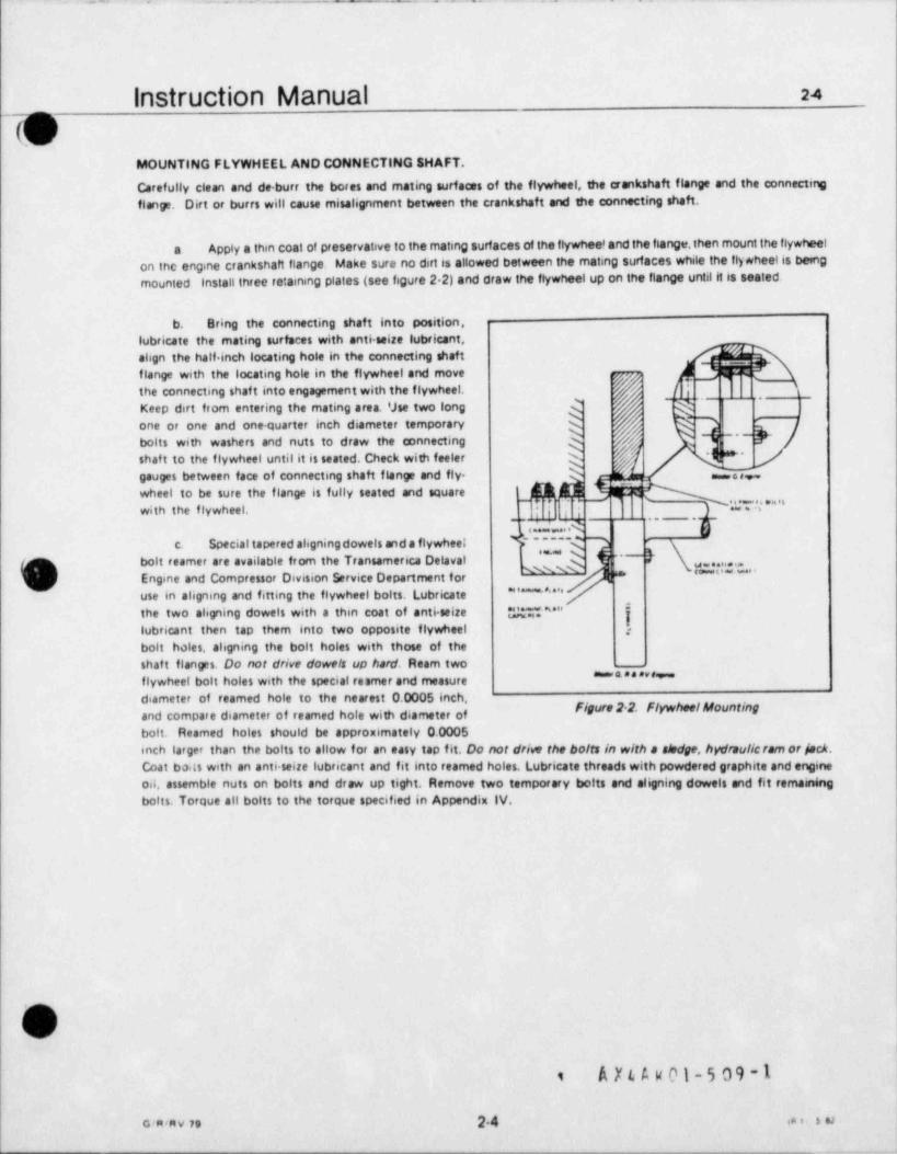
MOUNTING FLYWHEEL AND CONNECTING SHAFT.
Carefully clean and de burr the bores and mating surf aces of the flywheel, the crankshaft flange and the connectingflange. Dirt or burrs will cause misalignment between the crankshaft and the connecting shaft.
Apply a than coat of preservative to the mating surfaces of the flywhee' and the flange, then mount the flywheelaon inc engine crankshaft flange. Make sure no dirt is allowed between the mating surfaces while the ii)*heelis bemgmounted install three retaining plates (see figure 2 2) and draw the flywheel up on the flange until it is seated.
b. Bring the connecting shaft into position,lubricate the mating surfaces with anti seize lubricant,align the half inch locating hole in the connecting shaft kgflange with the locating hole in the flywheel and move | Hthe connecting shaf t into engagement with the flywheel. [
- ~ ~$
Keep dirt from entering the mating area. 'Jse two long7 -one or one and one quarter inch diameter temporary g d ~~~kbolts with washers and nuts to draw the connecting g ,
**shaft to the flywheel untilit is seated. Check with feelergauges between face of connecting shaft flange and fly- %wheel to be sure the flange is fully seated and square 'k $4|~ ' O Y "'with the flywheel.
__ .
- .
44, .. .
i~"-*c. Special tapered aligning dowels and a flywhee;-
bolt teamer are available from the Transamerica Delaval{
, , , , , , , , , ,
* ' " " * " * ' " * "g Engine and Compressor Division Service Department for
''''** **"use in aligning and fitting the flywheel bolts. Lubricatethe two aligning dowels with a thin coat of anti seire "M " {lubricant then tap them into two opposite flywheel g
bolt holes, aligning the bolt holes with those of theshaf t flanges. Do not drive dowels up hard. Ream two
'"""'''" "flywheel bolt holes with the special reamer and measurediameter of teamed hole to the nearest 0.0005 inch,
Ngure 2 2. @heeWountingand compare diameter of teamed hofe with diameter ofbolt. Reamed holes should be approximately 0.0005inch larger than the bolts to allow for an easy tap fit. Do not drive the bolts in w/th a ahdpe, hydraulicram or /scA.Coat bo.ts with an anti seize lubricant and fit into reamed holes. Lubricate threads with powdered graphite and en0 nei
oil, assemble nuts on bolts and draw up tight. Remove two temporary bolts and aligning dowels and fit remainingbolts. Torque all bolts to the torque specified in Appendix IV.
1
|
s
(v/A X t A k 01-5 09-1$
G*MV 79 24 in t . A si
-
. - - . . e. .a .. -- s . ,
instruction Manual 2.s
, <k\.
GROUTING. j
Check alignment of crankshaf t, then align driven equipment. Tighten foundation bolts on driven equipment moderatelywith lacking screws in place, then recheck entire alignment including crankshaft. Record sankshaft deflections onForm D 1063, Cranksheft Alipiment Accord. Engine and Compressor Division service representative must be presentto supervise alignment procedures.
Pour and vibrate the yout under the engine and driven equipment. It is recommended that a representativea.of the yout supplier be present et the installation to be sure that yout is propered and placed in accordance withspecifications. Do not fill bolt shield holes with yout,
b. After yout has wred, back off the sole plate lading screws one turn each and torque the foundation boltsto the specifeed value. Snug all bolts in a aisscoes pattern, then apply a light torque to ea&, using the same criss. crosspottern Continue applying torque in increments and in the same pattern until the final torque value is reached.
)
.
+
!|4
I
1
|
|.
:
$
|
i 2
$, sI k| C
I
[
,
j ., ; ;nt..I
!I
25
- --- -- -. - _ _ _ _ _ _ _ _ - _ - _ _ - - - - _ - , _ _ - - _ _ _ _ _ _ - _ _ __ _
- - - - - +s , s. . . , , _
,
2-7Instruction Manual
k JACKET WATER SYSTEM.'
The jacket water system is individual for each engine, and provides the cooling medium for the engine, oitcooler, turbochargers, exhaust manifold jackets, the governor and the air coolers. The recommendedwater treatment is sodium dichromate and boiler compound. Refer to Section 6, Part J of this manual forthe recommended method of treatment. The jacket water system consists of an engine-driven jacket waterpump to circulate the coolant, a temperature control valve to regulate the temperature of the water, passageswithin the engine through which the water flows, and where heat is absorbed from the engine, a cooler to cootthe water and a standpipe to maintain a constant head on the pump and to allow for expansion and bleedingof entrained air. The standpipe is fitted with a heater for warming the water and a " keep warm" pump forcirculating warm water through the system to keep the engine warmed while in a standby status. The pump,engine and cooter are connected in a series circuit, and drains must be installed at alllow points and ventsat all high points. All piping must be properly supported to minimize pipe vibration and flange loading.Flexible couplings are not recommended at customer connections because of potential failure hazard duringoperation. Refer to the jacket water piping schematic drawing in Section 9 of the manual for tne relativelocation of system components, recommended pipe sizes and direction of flow,
i\
.
,
((
2-7w, 'u:> rs.u
A X t A v 01 - 5 09 - 1 *-
- _ - . _ _. __ __. - - - ._ - __
_. . _ .._ . . ..
*~*
Instruction Manual M_
COOLING WATER SYSTEM.Transamerica Delaval does not provide the cooling water system for this installation. Nuclear service coohngwater from the owner's systems is provided at connected 276 and returned at connection 277 after being
) circulated through the kcket water cooler, Part No. 76021 104.
)
f
)
O
6
.
.
. .
A X4 A K 01-5 09 -1 :2-8 -w. ,.w , ,.. ,
-- .... _ ._ .

- +w- . . .-
Instruction Manual 28, s
|
FUEL OIL SYSTEM.IThe fuel system provides the means for storing fuel in the day tank, removal from the day tank and delivery to the fuel
<
injection pumps et the cylinders. The fuel oil system piping schematic drawing in the '' Drawings" section of this manualshow the pipe sizes, connections, direction of flow and relative location of all major components. Fuel injectionequipment on the engine is hand lapped to extremely close tolerances, therefore, fuel cleenliness is of the utmost ,
importance. The fuel system must be kept cleon as possible during installation and assembly, and should be cienned |internally and blown clean before initial stort up. All piping must be properly mpported to minimize pipe vibration |
end fienge loading. Flexible connections are not recommended at customer connections because of the potential fsilure |hazard during operation. All piping must be mechanically cieened after welding and preserved to prevent rust. Theday tank should be mounted high enough to provide adequete suction at the enginedriven fuel oil booster pump.Drains should be provided at all low points and vents et all high points.
I1
!i
i
* |
|!
!
!|
::
EO
><!a
.
.- ,
29 AX6AK0}*509*1 4
. _ . . .__. _ - _ . _ _ . _ _ _ _ . _ - - -. _ _ - _ - - - .
--
. .- . . - . - _ _ - -. .. - - - ._
Instruction Manual 2-io^
,
LUSRICATING OIL SYSTEM.'
The lubncating oil system is of the dry sump type which has a sump tank for holding the oil supply. Oiliscirculated through the system by an engine-driven pump. Refer to the lubricating oil piping schematic drawingin the " Drawings" section of this manual for the specific details of the system, relative location of majorcomponents, direction of flow, and notes relative to installation of the system.
FLOW PRINCIPLE.>
Pump suction draws the lubricating oil from the sump tank and discharges it to the lubricating oil cooler. Flowfrom the cooler is through a lubricating oil filter and pressure strainer to the engine main headers. A branchline from the strainer takes oil to the turbochargers. Retum is by gravity flow from the engine base to the sumplank. Separate knes direct retum flow from the turbochargers from the sump tank. A rekef valve, set at 70 psi,
j provides protection to the system, and pressure regulating valves regulate the system pressure
KEEP WARM CIRCulT.
) A " keep warm" circuit is provided to maintain the lubricating oil charge, and thereby the engine, in a warmedand lubncated condition when in the standby status. Heaters at the pump lank warm the oil which is thenpumped by the keep warm pump to the, keep warm filter and strainer and then to the main engine lubricatingoil header. To prevent flooding of the turbochargers, there is no supply to the turbochargers in this circuit Thelubricating oil heater thermostat should be set at 150' F.
PLACING LUBRICATING OIL SYSTEM IN SERVICE.
Before the engine is first started, the assembled lubnCating oil piping system must be thoroughly flushed withoil Disconnect the pipe at the pressure strainer inlet and arrange a temporary bypass from this pipe to the
(n) sump tank The bypass will permit oil circulation through the pipes without filling the internal lubricating oil\/ system of the engine Several thickness of cloth sack should be secured to the outlet of the bypass to Catch
debris as it is flushed out The sump tank and engine base must be thoroughly cleaned before being filled Theauxihary lubocating oil pump, or any other continuous duty pump of sufficient capacity, can be used to pump oildunng flushing operations Flushing should continue for at least eight hours if care was exercised dunngfabncation of the system. As much as 24 hours of flushing may be required for a dirty system. When oilescirculating inrough the system, the pipes should be thoroughly pounded several times with a heavy hammerto loosen dirt and debris Hot flushing oil will clean better than cold oil. Paping around the oil cooler requiresspecial attention to insure that the pipes and oil cooler are properly flushed. Precautions must be taken toinsure the complete removal of testing fluids, water or other liquids before attempting to flush the cooler.
NoteEngines may be received with the strainer mounted on the engine and connected to theengine lubncating oil header. It it is certain that the connections between the strainer andthe engine oil header have not been disconnected since the engine left the factory, thefollowing paragraph may be omitted
Disconnected iumper tubes between the engine lubricating oit header and the main bearings, and between mainheaders and auxikary heaoers Secure a fine screen such as a nylon stocking over each main header fitting tocatch debris that may be washed through as the system is flushed. Cover main bearing fittings and open endsof auxikary header feeders to prevent tne entry of dirt. Engine oil should be pumped through the open systemfor at least four hours to be sure that any foreign matenal remaining in the headers is removed Reassembleinternal tubes and brackets as required
n 1
[ ) |v ||
~
2-10mu
. .. -- - - - _ . _ _ .. , - _ - - - -
Instruction Manual 2-11
(ONTAKE SYSTEM. .
Each engine has an independent intake system, the combustion air bein0 piped from outside the engine roomthrough a remotely installed air filter. An inline asiencer is fitted in the pipe just ahead of the turbocharger airinlet. The air filter protects the working parts of the en0ine from the entry of dust. Fdters should tm cleaned at
I regutar intervals to maintain adequate protection against abrasion and wear. fWer to the piping schematic inthe " Drawings" section for connections, pipe sizes and relative locations of components.
.
|
( |
,
= .. 2-11 A X 4 A K 01- E C9 -1
.. . . . ... . - . . .- s - --- - - - - - - --.
InStrUCliOn Manual 2_u
b EXHAUST SYSTEM.
Each engine is provided with an individual, independent suhaust system. The water jacketed, midti-ppepassage manifold thscharges directly into the engine mounted turbocharger (s), and the gas then dischargesfrom the turbocharger (s) through exhaust piping and a silencer to atmosphere. As few bends as possibleshould be used when laying out exhaust piping. Necessary bonds should be of long radius. If three to sixbonds are used, the entire pipe should be increased to the next nominal size. If more than six bends amnecessary, pipe size should be increased two nominal sizes. The length of exhaust piping is not critical,however, if an unusually long pipe is used, the pipe size should be increased to reduce back pressure. Alength of flexible metal tubing should be instc; led in the exhaust line as near the engine as possible to allowfor movement, heat expansion, and for isolation of vibration. The exhaust line should be legged to minimizeheat radiation in the engine room. A separate support should be provided so the weight of the exhaust silencerand line is not borne by the engine. Refer to tne piping schematic in the " Drawings" section f or connections.pipe sizes and relative locations of components.
(
., ''
..
. . . . _ . . ... . .
...: m *W, '', * *,'se.
,,, .,
A X4 A k 01-5 09-1''2-12. . ,
-
. .. .. . ..
instruction Manual 2.iam __. _
{
STARTING AIR SYSTEM.
The required redundancy of the starting air system is accomplished by utilizing two separate systems. Each consists
|of a motor driven air compressor, an air dryer, an aftercooler and a storage tank. Each storage supply is then pipedto solenoid valves, two for each system, which block air flow until a starting signal is applied. Check valves downstream
| of the solenoid valves prevent back flow from one system to the other, When a start signal is applied, the solenoidt
valves open, admitting starting air to the interconnected headers on the engine. The two starting air distributors thenl'
send timed pilot signals to the starting air valves in the cylinder heads in the correct sequence and, as each startingair valve opens, starting air is admitted to the combustion chamber of that cylinder, forcing the piston downwardand rotating the crankshaf t. This system permits the engine to be cranked even though one supply system fails tooperate, or if three of the four solenoid valves fail to function. Reference should be made to the starting air pipingschematic drawing in the " Drawings" section of this manual for complete details of the system.
|
||
7_
5
(
A x 4. A y 01 - 5 0 9 - 12 13
. . - . - - . . . . _ _ . _ _ _ . - - - . . _ _ .. _,_
, ,-
,
!
Section 3
fO Enginet. Controls
,
,
|
'T.
eOC !
S S tit:I6,
(E
(1
Sect. . .
t,
1
.|| |l
f
!
i,. .
I
4
i
SSC, ,
OG,
i G 9 (*OG
| 99(' OG
SSti 94 1
;
I,
l
,
i
|
\ \
,
i
--_ _ _ ___ _ -.. - _ .--- -. --.---,-, - . ------,-n-.-,-,,.-.-,_,-...-,.---.--
- - -
,. . .. _ .. _ . . . __
Instruction Manual 3-1-
%
SECTION 3
i ENGINE CONTROLS
GENERAL
The following is a description of the local engine control system and its operations. The system will start, stop,protect, operate and monitor the integrity of the diesel generator in the various modes of operation.
REFERENCES
The Associated Publications Manual contains the manuf acturer's literature covering the various componentsof the system. Of special significance are the ARO Corporation's publications which give a clear, conciseexplanation of the functions of the pneumatic logic elements used in the pneumatic Control circuits. Whenordering spare or replacement parts for the system, refer to the Parts Manual for the correct part numbers
DRAWINGS
The drawin,s provided with these instructions include system schematics, layouts pertaining to the pneumaticlogic assemblies. drawings detailing the engine mounted equipment, and interface drawings for the vendorequipment Refer to the DRAWINGS section of this manual for the drawings applicable to the control system.
SYSTEM OVERVIEW
The control system provides the means f or starting, stopping. running and loading the diesel generator, as wellas controthng auxiliary devices Control operations are normally carried out from the owner's remote controls
panel The unit starts automatically in response to remote contact closure, and generator adjustment andloaoing operations are controlled from the remote location. In addition, controls provided at the local enginecontrol panel and the local generator control panel permit local control of all engine generator operations;
a There are two base modes incorporated into the system, the OPERATIONAL mode and theM AINTEN ANCE mode Selection of MAINTENANCE mode at thelocalengine controlpaneldisarms allstartingand operating circuits. botn remote and locat MAINTENANCE mode is intended for repa.r and maintenanceoperations, wth the lockout of the start circuitry affording complete safety for maintenance personnetReturn of the unit to OPERATIONAL mode from the local engine control panel arms all start circuits
b The LOCAL / REMOTE SWITCH (LRS). located at the local generator control panel, permits selectionof control location Under normat conditions. the switch is placed in the REMOTE position, enabling allstarting and operating controls at the remote controllocation. If the LRS is placed in the LOCAL position, theunit may be controlled from the local control panel, with remote control isolated. Note that selection ofMAINTENANCE mode is possible only when LOCAL operation is selected.
c There are two basic types of start, the Emergency Start and the Normal Start. During Normal Startsthe automatic safety shutdown system,a network of malfunction sensing devices,is activated if a malfunctionexists when a Normal Start signalis applied the unit will not st3rt untilthe malfunctionis repaired if a malf unction'
occurs when the unit is running. the automatic saf ety shutdown system will bring the unit to a stop. Normal startsmay be applied manually from the remote location, provided the Local / Remote Switch is in the REMOTEposition Conversely, Noriaal Starts may be applied from the local control panel manual start pushbutton. if tneLocal / Remote Switch is m the LOCAL position. A Normal Start with fullautomatic safety shutdown protection isalso initiated by closure of the owner's LOOPS (Loss of Offsite Power Start) contacts, provided the Local.'
! Remote Switch is in the REMOTE position!
! r3k)
!
'
3-1a , w, u.
t
. .- . . . - - . .a- .- ;
|
Instruction Manual 3-2-
(v)Dunng Emergency Starts, most of the automatic safety shutdown system is disarmed. Only certaind-
major malfunction sensors remain active for tripping during the emergency condition. Two-out of three logicis employed for certain vitat trip parameters. An emergency start is initiated upon closure of the owner'sremote SIAS contacts, provided the Local / Remote Switch is in the REMOTE position. A breakgtass station isalso provided at the local panel for application of a local emergency start. A Test Bypass pushbutton is providedat the local panel to allow the operator to insure that the shutdown system is properly disarmed dunngemergency operations. Note that the emergency start condition remains in effect after application until a manualreset signal is initiated from the local control panel, if such a reset signalis applied, the engine may remainrunning, with shutdown protection reinstated.
The unit may be stopped after a Normat Start from either the local or remote location, whichever hase.been selected for control at the Local / Remote Switch. During emergency start operations,these normal stopcontrots are disarmed However, emergency stop controts are provided at both the local and remote stations.
DESCRIPTION OF OPERATIONSThe control system is divided into two subsystems, the pneumatic subsystem and the electncal subsystemThe pneumatic portion of the system is used in the control of the fuel Supply permissive,in Conjunction with themonitoring of vanous engine environment parameters,such as pressures and temperatures. Pneumatic controldevsces and sensors are mounted at the engine, and a pneumatic logic system at the local Control panelcoordinates pneumatic operations. The electrical portion of the system controls most other functions, includingthe start and stop inputs, alarm functions, generator interface and control of auxiliaries. Devices such aspressure switches and solenoid valves, which function both electrically and pneumaticaffy, are used tointerf ace the two subsystems The following instructions begin with a consideration of the electncal circuitsfor starting These circuits accept start inputs from the controlling station, and produce signals for startingp air admission and also signals used by the pneumatic systemfor the alarm and shutdown equipment. A detailed>
discussion of the pneumatic circuitry follows The various other electrical circuit functions are covered afterthe pneumatic circuitry. These functions include post start operations, generator controlinterconnections,the alarm system and control of the auxiliaries.
ELECTRICAL START CIRCulTRY (See Drawing 09 500 76021)
There are two separate 1E start circuits, the "A" circuit on sheet 3 of the referenced drawing. and the "B"circuit, shown on sheet 4. The redundant circuits are physically spaced as far apart as possible within thepanel, and each may be connected to a separate de power source. Each start circuit controls a pair of solenoidvalves which are mounted on the engine in the starting air piping When a start signalis applied, each startcircuit acts independently to energize two starting air solenoid valves to crank the engine. In addition, eachcircuit generates signals which are transmitted to the pneumatic circuitry to control the alarm and shutdownequipment Note that the redundancy of the start Circuits permits either circuit alone to start the Unit,in theevent of the loss of the other circu.t. The start circuits function as follows
The "A" circuit is shown on sheet 3 of the referenced drawing Since the "A" and "B" circuits areavirtually identical in start circuitry, only the "A" circuit will be referenced here. Note that the same events occu'in the "B" circuit at the same time An Emergency Start is initiated due to closure of the owner's remote STAScontacts (line 7) Upon closure of the contacts, solenoid valves SOL 1 A. SOL 2A and SOL 202 2A areenergized, on lines 7,8 and 9 respectively. Solenoid valves SOL 1 A and SOL 2A, located on the engine, admita charge of starting air to the engine Solenoid valve SOL 202 2A acts to de energize the automatic safetyshutdown system Since this operation occurs in the pneumatic portion of the system,it will be described in asubsequent section. In addition to these solenoid valves, time delay relay TDI A on line 11 is energized by
<
clos,Jte of tne SIAS contacts on line 11. After one second, the TD1 A contact on line 19 closes to energ'2esoienoid valve SOL 202 5A This solenoid valve transmits a signat to the generator control circuitry for fieldfiash Note inat there are various permissives in the SI AS start circuit. Pressure switch PS 40 A must be closed |
b l
32.. . ,o , ,. a
e - * . -..m ~ < ~ _ wn,, ms- , ,.
Instruction Manual 3-3
Oindicating that the unit is in the OPERATIONAL mode. The LRS (Local / Remote Switch) at the generator controlpanel must be in the REMOTE posit 6on, arming the remote control panel. Also, the starting air pressure switch,PS 4A, must be closed, indicating at least 150 psi starting air present in the receivers. Note that oc power mustbe available to the circuet for all of the above to take place.
b. A Local Emergency Start is generated upon closure of pressure switch PS 45A on line 11, sheet 3of the referenced drawmg. Referring to sheet 2 of the same drawing, note that pressure switch PS 45A (andPS 458 for the "B" circuit) is controlled by the manual emergency start valve, which is located at a breakglassstation at the local control panel. Pressure switch PS-45A energizes the same emergency start circuit asdesenbod above. That is, the starting air scienced valves at the engme are energized to admit starting air tothe engine, and the shutdown de activate solenoid valve, SOL 202 2A is energized to transmit the shutdownde activate signal to the pneumatic portion of the system. Time delay relay TDI A is also energized for fieldflash. Permissives for the local emergency start include the OPERATlONAL mode pressure switch, PS-40A,and the starting air pressure switch, PS 4A, which was noted above. Note that there is no contact of the LRSin the local emergency start circuit.
c. The three remaining start types, Remote Manuel Start, Local Manual Start and the Loss of OffsitePower Start (LOOPS) are classified as Normal Starts. As distinct from Emergency Starts, these starts activate.the automatic safety shutdown system. The automatic safety shutdown system will prevent a Normal Startfrom taking place if a malfunction is present when the starting signalis received. If a malfunction occurs whilethe engine is operating in the Normal Start mode, the automatic safety shutdown system will cause the engineto shut down. The Remote Manual Start contact is shown on ime 14 for the "A" circuit. Note that the contact iswired in series with pressure switch PS 40A for OPERATIONAL mode, and with contacts of the LRS switch.The unit must be in OPERATION AL mode and the LRS must be in REMOTE for a Remote Manual Start to occur.Closure of the Remote Manual Start contact energizes relay R4A on hne 15, time delay relay TD2A on hne 16and solenoid valve SOL 2021 A on hne 17. Contact R4A 1 isolates the Emergency Start circuits on hne 11,contact R4 A 2 energizes the starting air solenoid valves on line 14, and contact R4A 31stches the circuit onhne 17. These contacts change state again after five seconds maximum for starting air admission. Note thatsolenoid valve SOL 2021 A is energized, and a signal is sent to the pneumatic circustry to arm the automaticsafety shutdown system
o The Local Manual Start circuit is identical to the Remote Manuel Start circuit,except that the sourceof the initiating signal and the LRS switch are LOCAL. Note that the LRS switch must be in Local position for aLocal Manual Start. The Local Start pushbutton is shown on sheet 2 of the referenced drawing Whendepressed, the pushbutton Causes activallon of pressure switch PS 12A (and PS 128 for the "B" circuittOn hne 15. sheet 3. closure of PS 12A causes relay R4A, time delay relay TD2A and solenoid valve SOL 202 1 Ato become energized Contacts of relay R4A connect the starting air solenoids with the circuit for five seconds
e The owner's LOOPS contacts are shown on line 21. Note that the LRS contacts shown in serieswith the LOOPS contacts indicate that the switch must be in the REMOTE pns6 tion. Solenoid valve SOL 202 7A.energized on 1:ne 21 by closure of the LOOPS contacts, is shown on sheet 2 of the referenced drawingThis valve activates the PS 44 pressure switch group, and pressure switch PS 44A on hne 12 closes toinitiate a Normal Start As with Normal Starts previously described, solenoid valve SOL 2021 A is energizedto transmit the shutdown activation signal to the pneumatic cifcuitry, and relay R4A energizes the air startsolenoid valves for five seconds
f. The redundant tachometer relays (item 4g,line 30 in circuit "A") play an important role in the startingcircuits. Each tachometer relay monitors a magnetic pick up mounted on tre engme. The relay contactsshown at the tachometer relay are shown with the system in the de energized state When power is madeavailable to the circuit, the contacts transfer to a state opposite to that shown. The contacts will transfer tothe states shown when they reach their rpm setpomts. Contacts SS1 A and $32A transfer at 200 rpm SSI Ais connected at kne 18 in the "A" circuit, where it energizes the field flash solenoid valve, SOL 202-7A. Note
AX4 A Ku t-5 09-13-3us . w . % .
- . . _ _ _ - . .. ..
Instruction Manual s-4
that the tachometer relay contact and the contact of relay TDI A both perform the same function in energizingthe field flash solenoid valve. At the tachometer relay, contact SS2A energizes solenoid valve SOL 202 3Aon line 34 at 200 rpm. This solenoid valve transmits the " running" signal throughout the electncal circuitry.Tachometer relay contacts SS3A and SS4A transfer at 440 rpm. Contact SS3A acts in conjunction with acontact of the undervoltage relay to energize relay R11 A on line 35. This relay transmits the * Ready To Load"signal through the various electnca! circuits.
h. In summary, the various start circuits function to admit starting air to the engine, and also sendsignals to the pneumatic portion of the system for control of the fuel permissive and the automatic safetyshutdown system. Emergency starts isolate the automatic safety shutdown system for the most part, whileNormal starts arm the shutdown system. Basic permissives include selection of OPERATIONAL mode andselection of the appropriate Control station at the Local / Remote Switch. For Emergency Starts,150 psistarting air must be available. Note that examples given for the "A" circuit above apply to the "B" circuit as well.Before covenng the various post clart functions in the electricat Circuitry, the following section will survey thefunctions of the p noumatic portion of the system.
PNLJMATIC CONTROL CIRCulTRY ( See Drawing -09 500 70021)
The pneumatic portion of the control system affords malfunction protection for the unit, by means of theautomatic safety shutdown system. The system is compnsed of various sensors mounted on the engine andother equipment. These sensors are monitored by a senes of pneumatic logic circuits mounted inside thelocal control panet. If a sensor inps due to a malfunction dunng Normal start operations, the logic circuitrygenerates a shutdown signal. This signal is used to extend the fuel racks to the NO FUEL position. and theengine stops due to fuel starvation. Dunng Emergency Start operations,the pneumatic logic system locks outmost of the malf unction sensors, and will permit fuel operation except when certain major malfunctions occur.Note that the pneumatic portion of the control system also controls Normal and Emergency Stop functionsO by cutting off fuel supply. In addition to the above referenced drawing, which shows the panel mounted logiccircuits, refer also to drawing 09 695 76021, which shows the engine mounted components The followingsection details the operations of the pneumatic portion of the control system, and its interface with theelectncal circuitry
a The pneumatic logic system is shown on sheet 1 of Drawing 09 500 76021. Allcomponents shownare mounted inside the Local Engine Control Panel The core of the system is a senes of pneumatic logicboards, which are mounted on a pneumatic mother board. Each distinct logic board assembly is comprised ofpneumatic logic elements, which are miniature vatves. The logic elements perform digitallogic functions,such as AND. OR and NOT. The logic elements are connected by pasages cutin gasket matenal,andinputsand outputs of the boards are througn numbered ports The heavy lines on the drawing indicate gasketcuts in the mother board.whichinterconnects the vanous logic boards. At the left of the drawing are a seriesof numbered terminals, which are labeled as to their function. These terminals represent pneumatic tubingconnections which exit the panet Refernng to Drawing 09 695 76021, note that the pneumatic connectionsto the engine mounted devices are labeled in a similar manner. The panel mounted logic system communicateswith the engine mounted equipment through pneumatic tubing lines. The logic system is interfaced witn theelectncal portion of the system by means of solenoid valves and pressure switches. Solenoid valvesrepresent inputs from thn electrical system, which generate pneumatic signals for use in the pneumatic systemPressure switches are outputs from the pneumatic system whicn are used as status and controlinputs tothe electncal portion of the system The pneumatic control medium is air at 60 psi, symbolized by Son thedrawings
The system is shown at rest, with control air available at all points marked S Pressure entersethe logic system at Port 10 of logic board 1 A 6926. showninthe lower center of the drawing Pressure at Port 10enters logic board 1 A 6926 and pressunzes the "B" ports of elements MEM 10. DEL 3, MEM 11 and AND 12.Since all of these elements require secondary signals for activation. there is no further signal propagation at
OV
I ' *
3-4m. , . . . ,w
.. - . _. ._.
- . .. . - - .
l
!
J
Instruction Manual s-s
h ,
assembly 1 A 6926 at this time. Note that a control air pressure at Port 10 of logic baard 1 A 6926 also travetsintough a mother board gasket cut to Port 9 of logic board 1 A 7055, and also to Poit 4 of the two redundant1 A 6943 logic assembhes.
Pressure at Port 9 of logic board 1 A 7055 acts as follows The "B" ports of elements NOT 1.c.MEM 23, AND 24 and AND 19 are pressurized. Pressure at port "B" of NOT 1 passes through that elementand pressun2es port "B" of elements MEM 10 and AND 9. In addition,the output of element NOT 1 is appliedto onfice 5. The pressures at the "B" ports of elements MEM 10 and AND 9 have no further effect at this time.Pressure at the orifice is metered through to Port 2 of logic board 1 A 7055. This rising pressure feeds the Group isensors, on hnes E 18 and E 19. As shown on the engine pneumatic drawing 09 695 76021, the sensorson these knes will be in the blocking position unless a malfunction exists. Astuming that the tube oil and mambeanng temperatures are not in trip range at this time, the sensors will block pressure flow, and the sensor kneswill fill with air. At the panel, pressure wit! back up to Port 2 of logic board 1 A 7055. Note that a pressure gaugeis installed in the line adjacent to the logic board. As rising pressure fills the lines, pressure will equalize acrossthe orifice and flow will stop. Note that port "A" of element NOT 13 and port "B" of AND 14 are pressun2ed.
d Pressure at Port 4 of each redundant 1 A 6943 logic assembly acts to operate the shutdowncircuitry when control air is first made available. At both boards, Port 4 pressure is applied to the "B" ports ofelements NOT 8, MEM 7, MEM 6 and MEM 5. Pressure flows through NOT 8 and is apphed to the "B" portsof elements NOT 11, NOT 10 and NOT 9 These elements transmit, resulting in outputs from elementsAND 15. AND 14 and AND 13 These outputs result in a pressure from element OR 20 The output of OR 20pressunzes Port 6 of 1 A 6943, and also pressunzes port "B" of NOT 12 and onfice/ check 16. Note that thepressure at orifice / check 16 is passed to two accumulators at Port 11. After approximately 1wo minutes,theseaccumulators fill up, and port "A" of element NOT 12 is pressurized. During this two minute penod, elementNOT 12 has an output. The NOT 12 output passesthrough element OR 4 and pressurires Port 12. Atthe upper
O board. the Port 12 output is applied to Port 7 of the lower board, and this pressure passes through elementOR 4 to produce an output from Port 12. The net result therefore,is an output from PM 12 of the lower boardThis pressure passes through a shuttle valve and is applied to Port 4 of logic board 1 A 7055 Note that thissignal also actuates the PS 40 pressure switches and pressure switch PS 23N after a delay. At logic board1 A 7055 the Port 4 input passes through element OR 16 to produce a retained output from the memory circuitconsisting of elements S/R 20 and MEM 23 This output causes element AND 24 to transmit The AND 24output pressunzes Port 7 of 1 A 7055 Note that the AND 24 output lasts for approximately two minutes Thisis because of one output at AND 24 is metered inrough orifice 12 to a pair of accumulators at Port 8, whenthe accumulators are filled, an output from element AND 19 tesets element S/R 20 andterminatesthe memorysignalto AND 24 Pressure at Port 7 of 1 A 7055 passes through valve P.and solenoidvalve SOL 3Btochargehne E 89 On the engine pneumallC drawing (09 695 76021), pressure in line E 89 pilots a three way valve(item 11 L causing controf air at 60 psifrom kne E 53 to pass through the valveIoline E 90. This pressure causesthe Fuel Rack Shutdown Cylinder (item 8) to extend, which moves the engine fuel racks to the NO FUELposition This prevents admission of fuel to the engine. Note that pressure switches at the panel on line E 90willinoicate the snutdown condition to the electrical circuitry.
As previously noted timing circuits within the logic system will reset the shutdown cylinder signal,andethe fuel rack shutdown Cyhnder will retraCl after two minutes. At this time, the logic system will be futly pres-sunzec and if the Grcup I shutdown sensors do not indicate a malfunction,the engine will accept a start signal
PNEUMATIC FUNCTIONS AT START (See Drawing 09 600 76021)
As desenbed earher, a start signalis apphed through the electrical system, where contact closure results in Dsignat to the pneumatic portion of the system During Normal Starts, solenoid valves SOL 2021 A ancSQL 2021B are energ: red and during Emergency Starts, solenoid valves SOL 202 2A and SOL 202 28are enegized The foliowing instructions will detailthe results of both types of start signal, starting witn NormalStett
1
|
|
3-5 *I ''g,,,, ... . . . .
j
g m=mrnrr m.=_==-s._.m.- ---- -
.
:
!
! Instruction Manual u
O |
a. The Normal Start sulenoid valves, SOL 2021 A and SOL 20218, are shown adiacent to logic ;
assembly 1 A 6926. When energ4ed, the valves admet 60 psi control air to Port 12 of logc board 1 A 6926. Inaddition, control air passes through a gasket passage to Port 10 of logic board 1 A 7055. Pressure at Port 12 |of logic board 1 A 6926 is directed through element OR 8 and emits from Port 8 to activate the PS 32 group of
'
pressure switches. These pressure switches tranam t the " Starting" signal to the electrical circuitry Pressure ;
at Port 10 of logic board 1 A 7055 arms the shutdown system, as follows Port 10 pressure passes through ;'
element OR-2 and is apphed to port "C" of element S/R-6. This results in a maintamed output from element |MEM 10, which produces a maintained output from element AND 9. The output of AND 9is apphed to port i
;
"B" of element NOT 13, to port "B" of element T/N 11, and to onhce/ check 15. Each of these outputs are |
| very sigrwficant for an understandmg of the system. j
!
b. The AND 9 output which is apphed to port "B" of element NOT 13 arms the shutdown system. At thispoint in the start sequence, only the Group 1 shutdowns are active to trip the unit. It will be recalled that the |;
j Group i sensors are fed by orifice 5 theough Port 2. Assuming that the sensors are blocking, a pressure is present ;
Jat port "A" of element NOT 13. Trus pressure acts toinhibit the output of element NOT 13. If one of the Groupl |
sensors detects a malfunction at the time a start sigr'el is applied, pressure at port "A" of element NOT 13'
4
| exhausts through the venting sensor. This allows the AND 9 output to pass through element NOT 13,through j
elements NOT 17 and NOT 18, and through element OR 16 to trigger elements S/R 20. Ttws results in a !
maintained output from element MEM 23, and a consequent output from element AND 24. The AND 24 output i
j pressurizes Port 7 and kne E 89, which causes the fuel rock shutdown cylinder at the engine to extend Thismoves the fuel racks to the NO FUEL position, and prevents the engine from starting. Note that loss of a Group l !
sensor at any time will move the fuel racks to the NO FUEL position. As noted earlier, the shutdown signalis {
terminated after a delay of approxirrately two minutes to allow restarting the engine. f. c. Assuming that the Group i sensors ere good,the AND 9 output is apphed to both port "B" of element |
| AND 11 and to onfice/ check 15 Note that orifice / check 15 feeds an accumulator at Port 3. The time required ,
i for the metered signal to fill the accumulator - approximately 90 seconds -is known as Group 18 lockout |
{ timing When the timing period is completed, accumulator pressure is apphed to port "A" of element T/N 11,I which causes T/N 11 to stop transmitting Note, however, that element T/N 11 has an output throughoutI Group 18 lockout timing
d. The output of element T/N 11 pressurires Port 12 of logic board 1 A 7055, and is also meteredthrough orifice 8 and OR 7 to feed Port 11. The Port 12 signal pilots valve Pa and is also apphed to Port 2 of each
,
j of the redundant 1 A 6943 logic assembhos. At the upper assembly, note that Port 2 pressure also feeds hneE 24 At the engine (drswing 09 695 76021), kne E 24 pressure locks out the vibration switches for the engine;
! and turbocharger during start up. At the penet, pressure at Port 2 of the 1a 6943 logic boards is apphed toj port "A" of element NOT 8, and is also metered through orifice / checks 1,3, and 5. Pressure at the NOT 8i elements at each board vents the downstream pressure which flowed to element NOT 12 while the engine! was at rest. Pressure metered through the orifice / checks feede Ports 1,3 and 6 at each of the 1 A 6943 logicj boards At the upper board, these knes monitor the engine mounted Low Pressure Lutwiceting Oil sensors. At [
} the lower board, the same ports monitor the High Temperature Jacket Water sensors. Referring to the engine
|pneumatic schematic drawing momentanly (drawing 09-895 70021), note that the Jacket Water Temperature
j sensors are held in the blocking position by spring pressure unless a malfunction is present The metered :
! pressure from the lower logic boatd fills the knes leadmg to the sensors. The Lubricating Oil Pressure sensors |
! will be in the venting position at a start until lute oil pressure builds to 30 psi. As the engine starts and pressure [! builds, the sensors close to block flow of the meleted pressure from the logic system Assuming that conddeons
! are normal, the lubricatmg oil pressure and jacket water temperature sensors will be permessive, and pressure ,
will fill the knes leading to Ports 1,3 and 5 of the 1 A 49431ogic boards. These signals pressunae the "A" ports of |! '
elements MEM 5. MEM 6 and MEM 7 at each board. As a result. the memory elements produce outputs '.
! which are applied to the "A" ports of elements NOT 9, NOT 10 and NOT 11. These signals act to 6nhitut the |i outputs of the NOT elements.!!
l[ !;
I A )u, A y 01 - 5 0 9 - 1
| . ..m >. ,
. ,
-,n_ .,--a,-.v.---sw ..ww-nr-n- m-.--,w-,n-----,------m,re,.n,-.-e---,r---,e--,,,-v----r-,,---w-~,---~----n,-----n-,--,,,- e,.v--~~,--.-.~ emm ,-v n --,.-+
- - _ _ _ _ . _ _ _ . _ _
,
Instruction Manual sa', -
;m
Note that there is a metered output from Port 11 of logic board 1 A 7055 during Group 18 lockoute.timing This pressure feeds Port 4 of logic board 1 A 6926, where it is applied to port "B" of element AND 7,to port " A" of element S/R-6 and to port "B" of element OR 5. The OR 5 signal pressurizes Port 1 of 1 A-6926.Port 1 pressure is applied to the pilot of valve Pa and is also metered to the Group 11 sensor knes, E 68. E 92,E 14 and E 23. The sensors monitored by theselines are shown on the engine pneumatic schematic drawingAs operating parameters reach normallevels after a start,the sensors close to block the flow of air. By the timethe Group || lockout timing period is completed, the hnes are filled with air,
f. Group 11 lockout timing is completed when the output of element AND 9 fills the accumulator at Port 3of logic board 1 A 7055 through orifice / check 15. At that time,the accumulated pressure is applied to port "A"of element T/N 11 and to port "A" of element AND 14. The signal at port"A"of T/N 11 causes that e'ementto stop transmitting after a short delay, and the downstream pressure fed through Port 12 exhausts throughT/N-11. Note that pressure downstream of Port 11 is retained, however, as the feed to Port 11 is maintained byelement AND 14. Significantly, element AND 14 is also supplied by pressure from onfice 5 at its "B" portThis is the same onfice which feeds the Group i sensor knes through Port 2. The net effect is that the Group iand Group 11 sensor networks are joined Note that the loss of the Port 12 output from board 1 A 7055 causes apressure drop at Port 2 of each of the 1 A 69431ogic boards This stopstheinput pressure to onfice/Ghecks 1,3and 5, and the input to port"A" of the NOT 8 elements The NOT 8 elements arethus freetotransmit,but sincethe integral checks maintain pressure in the sensor hnes, elements NOT 9, NOT 10 and NOT 11 inhibit theNOT 8 outputs Note that loss of Port 2 of the upper board results in a loss of the vibration switchlockout $sgnatin hne E-24 This reinstates vibtation protection At this time the engine is runnmg normally witn full shutdownprotection after a Normat Start
AUTOMATIC SAFETY SHUTDOWN (See Drawing 09 800-70021)
If the engine is operating in response to a Normal Start signal, a malfunction detected by one of the shutdownsensors will cause the engine to shut down When a safety sensor vents due to detected malfunction, a controlair pressure extends the fuel rack shutdown cyhnder at the engine. The cylinder moves the fuel racks to theNO F UEL position, ar.d the engine stops due to f uel atarvation. Note that two out of three logic is provided for thelow pressure luencating oil and high temperature jacket water sensors. In addition,the overspeed inp hasspecial features which insure dependable inpping under any circumstances These shutdown features arediscussed in the following paragraphs
As an example of the functions of the logic system dunng a trip. consider the operation of the JacketaWater Low Pressure sensor, shown on the engine pneumatic schematic drawing. 09 695 76021. If JacketWater pressure falls below 10 psi, the sensor shifts to the venting position, and air in kne E 14 exhausts fromthe system inroug*n the sensor. At the panel, a pressure switch on hne E 14 indicates to the electrical systeminat a malfunction has occurred in the Jacket water system Note that check valves are instatted in all sensingknes to insure first out starm indications When the sensor inps, all pressure downstream of onfice 5 at logicboard 1 A 7055 exhausts through the sensor. The vent path is from orifice 5, through elements AND 14 andOR 7 and Port 11 of 1 A 7055 through Port 4, element OR 5 and Port 1 oflogicboard1 A 6926.andouthneE 14through the venting sensor. Tne entical result is a loss of pressure at port "A" of element NOT 13 at logicboard 1 A 7055 This permits passage of the AND 9 output through NOT 13,through elements NOT 17 andNOT 18,andthroughelementOR 16tosetgateS/R 20. Thisresuttsinamemoryoutputfromelement AND 24The output of element AND 24 is appked to both Port 7 and to orifice / check 12. Port 7 pressure is the signaltothe fuel rack shutdown cyhnder, and the signal at the onfice/ check will terminate the stop signal and resetthe cyhnder after a two minute delay Port 7 pressure passes through valve P and solenoid valve SOL 3B tocharge kne E 89 At the engine,line E 89 pressure pilots a three way valve which admits hne E 53 control airpressure to kne E 90 This pressure extends the fuel rack shutdown cylinder, moving the fuei racks to the NOFUEL position The engine stops due to fuel starvation.
Od1
~' '' ''3-7os., ,m, nm. ,
1
_ _ _ _ _ _ _ _ _ _ . ___.______ ______
_ . _ _ _ _ _ _ _ - -
a-8Instruction Manualn
w 'The circuitry for overspeed inpping is located on the engine itself. Referring to drawingb.
09 695 76021, note that the overspeed tnp valve (item 22) is shown in the blocking position. Pressure fromhne E 53 is fed inrough an 0.014 inch onfice to the valve, and as pressure rises in the blocked kne,it pilots athree way valve If an overspeed inp occurs, pelot pressure at this three way valve exhausts through theoverspeed inp valve. Pressure from kne E 53 then passes through the valve to pressunze hne E 20. Pressure inhne E 20 passes through the Stop/Run Valv6 (stem 13) and through a shuttle valve to pressurize hne E 90 Thispressure extends the fuel tack shutdown cylinder, which cuts off the fuel supply to the engine. Note that hne,
E 20 pressure also extends the Air Shutoff Cytinder (item 7) when an overspeed trip occurs. This cyhndercontrols a butterfly valve in the intake manifold. Closure of the butterfly valve cuts off the supply of combustion
g air to the engine. Note that the engine shuts down due to both fuel and air strangulation at an overspeed trip
Sensors for High Temperature Jacket Water and Low Pressure Lubricating Oil inps providec.two out of three logic for engine shutdown. Since these sensors remain active during both Normal Start andEmergency Start operations, their functioning will be discussed in the following section on Emergency Starts
EMERGENCY STARTS (See Drawing 00 500 70021)
When an emergency start signalis apphed to the system, contact closures in the electncal portion of the syste.nenergize solenoid valves SOL 202 2A and SOL 202 28. These solenoid valves are shown adjacent tologicboard 1 A 6926 on sheet 1 of the referenced drawing The system responds as fo! tows.
Pressure from the emergency start solenoid valves is apphed to Port 7 of logic boatd 1 A 6926 Port 7apressure produces a maintained output from etement MEM 11 in conjunction with element S/R 4,which resultsin an output from element ANO 12. This output pressurizes Port 11 of logic board 1 A 6926, and also passesthrough element OR 8 to pressurize Port 8 of that board Port 8 pressure activates the PS 32 group of pressureswitches The PS 32 group transmits the " Starting" signal to the electrical circuitry, as in Normal Starts Note
d that pressure switch PS 35B2 is activated 30 seconds after the engine reaches 200 rpm at Emergency startsPressure switch PS 35B2 acts to delay the protective devices at the generator controlequipment The outputfrom Port 11 of logic boara 1 A 6926 is apphed to Port 6 of logic boatd 1 A 7055. Note that the PS 10 group ofpressure switenes are activated by Port 6 pressuro These pressure switches transmit the ' EmergencyStart" signal to the electncal circuitry
Pressure at Port 6 of logic board 1 A 7055 performs two functions. First,the Port 6 signalis apphed tobport 'B" of element NOT 4 to charge the malfunction sensor system. Second,the Port 6 signal pressunzes the"A" ports of elements NOT 17 and NOT 18 to inhibit the shutdown hne The NOT 4 input is transmitted toeiement On 2, where it produces a maintained output from the memory circurt compnsed of elements S/R 6and MEM 10 This resultsin an output from element ANO 9,which armsthe shutdownhne at port"B"of elementNOT 13. initiates Group il lockout timing by metenng pressure to the accumulator at Port 3, and charges theGroup 11 lockout sensors through Ports 11 and 12. For a complete survey of the Group 11 lockout circuitry, referto the previous section on Normal Starts Note that the safety sensor network is charged during Emergencystarts in the same manner as during Normal Starts However, since the shutdown line is inhibited in theemergency condition, a detected maltunction will not cause a shutdown. The shutdown notwork is charged sothat the pressure switches in the sensor knes will remain available to transmit malfunctions to the electncatsystem. The signal at Port 6 of 1 A 7055 acts to inhibit the shutdown kne by pressurizing the "A" ports of ef ementsNOT 17 and NOT 18 As expla ned previously, a venting sensor hasthe effect of venting pressure downstreamof orifice 5 of 1 A 7055 through the sensor. This removes theinhibiting signalfrom port"A"of elementNOT 13.and a shutdown signalis sent through elements NOT 17 and NOT 18 to the inp circuit. Since the EmergencyStart signalinhibits NOT 17 and NOT 18, a shutdown signalis not produced
O*
A X4 A v 01-5 09 1
38ow. rwiam.
_ _ _ _ _ _ _ _ _ _ _ _ _ _ _ _ _ _ _ - _ _ _ _ _ _ _ - _ _ _ _ ____ - __ - ___ _______. _ _ _ - _ _ _ _ _ _ _ _ _ . _ _ _ _ _ _ _ -
- _ - - _ . . _ _ _ - . . . _ _. . . .
Instruction Manual a-o
bc. The High Temperature Jacket Water and Law Pressure Lubncating Oil sensors remain acteve for.
trippmg during the Emergency operation. As shown on drawing Og-6g5 76021, three sensors are used tomonitor each of these parameters. At least two of these sensors must trip before a shutdown occurs Forexample,if only the Low Pressure Lutmcahng 0:1 sensor on line 10A trips, there is a loss of pressure at Port 1 ofthe upper 1 A 4943 assembly. This causes element MEM 5 to stop transmiteng, which,in tum, causes element t
NOT g to have an output. The NOT g output is apphed to port "A" of element AND 13, and is also applied Io '
Port 8 of the assembly, through elements OR 17 and OR 18. Pressure at Port 8 activates pressure swdch ,
PS-44N, whchindcates to the electrical system that one of the lube oil sensors has meNunctioned. If a second ilube oil sensor were to indcate a meNunction con SIson, the engme would shut down. For example,6f the sensor [on hne E 108 vents, in addnion to the sensor on line E 10A, then the loss of pressure at Port 3 of the upperI A 6g43 board would result in an output from element AND 13. The AND 13 output pressurires Port 6 of the ,
assembly, and is also apphed to both port "B" of element NOT 12, and to an accumulator pair at Port 11 theough~
orifce/ check 16 Port 6 pressure causes pressure switch PS 42N to transmit the trip inacaten to the alarmsystem. NOT 12 has an output for approximately two trwnutes, until termeneted by the accumulator timer. TheNOT 12 output pressurires Port 12 of the upper assembly, and is transmitted through the lower assembly to i
pressurire Port 4 of logc board 1 A 7055. Note that the Port 4 stop signal bypasses the NOT 17 and NOT 18elements which inhibd a normal safety shutdown. The Port 4 segnal produces a memorized output from elementAND 24 whch entends the fuel tack shutdown cylmder through Port 7 of 1 A 7055. This shutdown signalisterminated after approximately two minutes to allow the engme to be restarted if the problem is corrected.
d. When an emergency start signal is apphed to the urut, a TEST BYPASS cwcuit may be employed to :
test whether the system is functioneng normally. The Test Sypass signal must be appised manually at the local ,
panel This segnal tests the circudry simulating the action of a ventmg sensor. The Test Sypass button is shown !
ad acent to logic boerd 1 A 6g26 Whun depressed,the valve admits air to Port 5 of the logic board The Port 5 '
isignal pressunres port *B" of element OR 2 and port "A" of element DEL 3. The signal at element DEL 3pressurires element AND 7 after a 1 second delay. The AND 7 output vents to atmosphere, semulatog theinpping of a shutoown sensor. That is, pressure downstroom from orifce 5 at logic board 1 A 7055 exhauststhrough AND 14,OR 7, Port 11 of 1 A 7055,then theough Port 4 andelement AND 7 at 1 A 6g26. Wah the sensor iline vented, element NOT 13 at board 1 A 7055 is free to transmet if the shutdown deactivate circuet is !
functionmg properly dunng Emergency Start operation, however,the shutdown signal produced by NOT 13 willbe inhibited by elements NOT 17 and NOT 18 If a feelure occurs 6n the Emergency circuitry,these elementswill not inhibit the shutdown segnal, and the NOT 13 segnal will produce a shutdown segnal at Port 7 of 1 A 7055The Port 7 signal will ordmarily pressunze the fuel rock thutdown cyhnder et the engme to cut oft the fuel supply.This signal is intercepted by the Test Bypass signal, however. Note that the Test Bypass input to Port 5 of1 A 6926 passes through element OR-2 to produce a maintained output from the memory circuit of elements ,
S/R.6 and MEM 10 This segnal is applied to port "B" of element AND 1, to Port 2, and to Port 1 throughelement OR-5 The output itom Port 2 pilots valve P4, which will then block any shutdown signal produced atPort 7 of logic boatd 1 A 7055 The output from Port 1 of 1 A 0026 pilots velve Pa, and maintains pressure in thesafety sensor moortonng knes Note that if a shutdown signalis actually produced from board 1 A 7055 at
1
Port 7, this pressure is detected to Port g of logc board 1 A eg26. In coriunction weh the Test 8ypass segnaf,this produces an output from element AND 1, The AND 1 signalletches in the memory circuit to maintam the ;
Test Bypass tegnal, and also pressuntos pressure ownch PS 32N. This pressure switch indcates to the'
electncat circudry that the emergency bypass system is not funcisonmg property. Note that in the event of such a imalfuncticn, the signal at valve P4 6s memteined until the shutdown signet tesets itself after approximately twommutes. If the shutdown deactivate csrcuit is functionmg property, no the Adown signalis produced itom Port 7 oflogic board 1 A 7055 in that case, when the Test Oypass pushbutton is reisesed, the vent at AND 7 of 1 A 6926closes. As a result, pressure metered from ordce 5 at 1 A 7055 posses from Port 11 of that board to Port 4 oflogic board 1 A 6g26. At the same teme the r6seg pressure resets element S/M 6 to terminate the Test Bypassoutputs, the supply to Port 1 of 1 A 6926 is taken over through element OR 5. This maintams pressure m the
| Group 11 sensors At this time the test of the shutdown deactivate system is completed, and the engme is runnmgj m the emergency state with shutdowns inhebeled ;
|
|*
!
i
$ x 4, ! v ',, l " $ d I) m mum. 34
- _ _ . _ _ _ _ _ - _ . , _ . _ _ _ _____
. . . . _ . - . -. .
Instruction Manual 3-1o
n
e. When the emergency condition is completed, the safety shutdown system may be reactivated with ,
the engine running using the Roset From Loca pushbutton. The pushbutton is shown schematically adiacent tologic board 1 A 6926. When depressed,the pushbutton causes air admission to Port 6 of logic boatd 1 A 6926This signal resets element S/R-4, terminating the output of element MEM 11. This stops the outputs from Ports11 and 8 of 1 A 6926. Loss of Port 8 causes the PS 32 group of pressure switches and pressure switch PS 478to become deactivated. Loss of pressure switch PS-478 reinstates normal generator protective circuits. Lossof the Port 11 output terminates the input to Port 6 of logic board 1 A 7055. This removes the inhibiting signalfromelements NOT 17 and NOT-18, which permits a shutdown signal to pass through these elements. This has theeffect of reinstating normal shutdown protection.
I OTHER PNEUMATIC FUNCTIONS (See Drawing 09 500 76021)
Certain control functions not yet discussed are also performed pneumatically, or in a pneumatic combinationwith the electrical system. Selection of MAINTENANCE and OPERATIONAL modes, for instance,is performedby the pneumatic circuitry. the Stop circuits also act through the pneumatic logic system. In addition,certaindesign features are included for special situations which should be noted.
a The M AINTEN ANCE mode feature permits routine maintenance or repair to the engine with all startingc'rcuits locked out This allows maintenance personnel to work in and around the engine without the hazard ofmoving parts Refernng to sheet 4 of the referenced drawing, note thatthe MAINTEN ANCE mode pushbuttonisshown on line 175. When depressed,the contact closure energizes solenoid valve SOL 201 18 Note that theLRS contact on hne 177 must be closed, indicating that the local station has been selected at the Local / RemoteSwitch, and relay contacts R5B 3 and R108 3 on hne 175 must also be closed Relay contact R58 3 indicatesthat a LOCA signahs not present, and relay contact R10B 3 indicates that the engine is not running Assumingthat these permissives are satisfied, solenoid SOL 201 1B is energized by selection of MAINTENANCE modeIn the pneumatic portion of the system, on sheet 1 of the referenced drawing, solenoid valve SOL 201 1B is
(q'] shown in the upper right. When energized, the valve pilots valve P2, which has a self feeding pilot to maintainits position after the MAINTENANCE pushbutton is released The output of valve P2 pressurizes Port 1 oflogic board 1 A 7055 This pressure inhibits the output of element NOT 1,thereby preventing pressurization ofthe shutdown sensor system. The output of valve P2 also activates pressure switches PS-46N.PS 40A PS 40Band PS 23N Line E 89 and the pilot of valve Pi are also pressurized. Pressure switches PS 40A and PS 40Bisolate the start signa's in the electrical system (see sheet 3, hne 9 for the"A" circuit) The other switches aref or status and annunciation purposes Pressure in kne E 89 is directed to the fuel tack shutdown cyhnder at theengine, as discussed previously. This prevents fuel admission during MAINTENANCE mode Valve Pt ventsthe barring device interlock, which permits operation of the barring device dunng MAINTENANCE modePressure from kne E 85 exhausts from valve Pt. At the engine (drawing 09 695 76021), the barring devicelockout cyknder retracts, allowing the interlock valve to shift, which frees the barring device. Note that pressurein hne E 48 activates pressure switches PS 138 and PS 13N on sheet 2 of the panel drawing On hne 174sheet 4 of the panel drawing. note that pressure switch PS 13B latches inthe MAINTENANCE mode solenoidvalve This mainta:ns the unit in MAINTENANCE mode until the barring device is locked out again. Anothersignificant feature of MAINTENANCE mode is shown on sheet 3 of the paneldrawing,hne 9 Pressure switchPS 40A opens at M AINTENANCE mode selection, enabhng the engine roll circuit. This allows the engine to becranked on starting air without starting, a usefut maintenance feature
b Assuming that the barring device is disengaged and locked out, the unit may be returned toOPERATIONAL mode pushbutton at the local panet As shown on kne 173, sheet 3 of the panelschematic,thiscauses solenoid valve SOL 2013B to become energized. At the pneumatic logic system, solenoid vafveSOL 2013B vents pressure from the pilot of valve P2, which exhausts pressure from the MAINTENANCElockout circuits
OmI b I, k N f.I 1 .
,
3-10wm s..
__
. . . . - - - , . . - . . -,_ - _. -- ..
,
11
instruction Manual 3-11
Another significant design feature is shown on sheet 2 of the panel schematic drawing. Note that knesc.E 31R and E 31F monitor the starting air pressure at front and rear headers. If pressure in these knes falls below150 psi, valves Ps and Ps wdl admit passage of a 60 psi control air signal. This signal activates pressure
I switches PS-4A and PS-48, and is also applied directly to Port 5 of logic board 1 A 7055, as shown on sheet 1.The PS-4 switches are installed in the electncal emergency start circuits in both the "A" and "B" circuits inthe "A" circuit, pressuie switch PS-4A is shown on kne 11. Note that the emergency start signal to the startingair valves is terminated only by the opening of pressure switch PS-33A on line 7, which opens when the eng:nestarts running if a failure to start occurs, the starting air valves would cranit until the air supply were exhausted,)unless the PS-4 switches were present in the circuit. If such a start failure were due to a minor problem - avalve closed in the fuel supply hne, for instance - the action of the PS 4 switches insures that enough airremains in the receivers for several manual start attempts. Note that the pneumatic signal at logic board1 A 7055 resets the shutdown system to allow such a manual start attempt after a LOCA start fadure. The useof this feature is not expected under normal circumstances, but it is present if the need anses.
d. There are two types of intentional Stop signals Normal stops and Emergency Stops The sourcesof these signals wdl be discussed in a subsequent section deshng with the electrical system The effect of aNormal Stop signal is energization of solenoid valve SOL 201 2B, This valve admits pressure to Port 4 of logicboard 1 A 7055 Port 4 pressure tnggers a shutdown signat, as the memory circuit produces a timed outputfrom Port 7 of 1 A 7055 which pressurizes line E 89. This hne extends the fuel tack shutdown cyhnder to cutoff the fuel supply. The Emergency Stop signal energizes solenoid valve SOL 38, which admits control airdirectly to hne E 89 to cut off the fuel supply to the engine. In both cases, the engine stops due to fuetstarvation.
OTHER ELECTRICAL FUNCTIONS (See Drawing 09 800 78021)
Thus far only the start Circuits have been discussed in the electrical portion of the circuitry. In addition toperforming a start input functions,the electncal circuits accept inputs for MAINTENANCE and OPERATIONALmodes and also accept Normal and Emergency Stop inputs. The electrical system also provides contror ofthe Lube Oil and Jacket Water Circulat ng Pumps and the Crankcase Fans The vanous alarm and statusfunctions are performed electncally, or in combination with pressure switches which monitor the pneumaticsystem Generator status and control interface is also electncally handled. Also, vanous internal controlrelays are provided in the electrical circuitry to propagate control and status signals as the unit goes throughstarting. stopping and shutdown sequences
Control inputs for Stopping and Mode Selection are shown in the "B" circuit, on sheet 4 of theareferenced drawing The locat normal stop pushbutton is shown on hne 177, and the remote normal stopcontact is wired in parallel on hne 179 Note thLt contacts of the Local / Remote Switch are placed as permis-sives in these circuits, arming the normal stop circuit at the selected station. The contact of relt,y 1868 on hne178 wdl cause a tnp if certain generator f aults are detected. Note that contact R58 2 on hne 177 wdlisolate thenormal stop circuits when relay RSB is energized. The relay cod is shown on hne 123, where it is energized'
when pressure switch PS 10B indicates that a LOCA condition exists In the absence of a LOCA signal.application of a Stoo signal from the appropnate station energizes solenoid valve SOL 201 28,which generate 5a pneumatic stop signal as previously discussed The MAINTENANCE and OPERATIONAL pushbuttons,and the solenoid valves they control, are shown m the same area of the "B" Circuit as the normal stop contro!sThe Emergency Stop controls are shown m the "B" circuit also The various emergency stop contacts act toenergize relay R23B on kne 139, and contacts of R23 energize both the normal and emergency stop solenoidsThe action of these solenoid valves is described in the pneumatic section above. The R23 relay is latchedfrom the following sources The local Emergency Stop pushbutton, at a breakglass station at the local panel.shown on line 136 A contact of relay R68 on the following hne is energized when an Overspeed tripis detectedThe remote emergency stop contact on kne 138.the generator differential contact of relay 186A on the followmgkne. and pressure switch PS SOB on hne 141 all act to energize the emergency stop relay. Pressure switen ;
PS 50B is energized when either the Jacket Water Temperature or Lube Oil Low pressure sensors indrcate as
two out of three logic malfunClion
' *3-11we w
t
_ _ - _ _ - _ _ _-- . - . _ - - , _ - - _ . _ - - - . . - - - . - . _ _ _ - - - . . . _ . - - _ - . -
. _ _ ,. . . m.________ ._ __
instruction Manual 3-u
OOb. Wnen the engine start signalis applied, certain operations are performed automatically, as the start
and run signals are propagated through the electrical system. Sheet 5 of the referenced drawing shows theD1 and R1 Auxiliary relays, which are latched in by pressure switch PS-32N1 when the engine starts. Contactsof relay R1 are used in the automatic circuits of the lube oil and Jacket water circulating pumps to stop thepumps at a start. An R1 contact starts the engine hourmeter, and another R1 contact on line 221 energizesrelay R8 and timer TD3. Relay R8 controls the crankcase fans and the generator space heater shutoff. TimerTD3 delays the activation of certain Group 11 status and alarm indications which do not reach normallevelsuntil after the unit has started and warmed up.
c. Status lamps are provided which inform the operator of the condition of various parameters during theoperating sequence Of significance is the " Unit Available" circuit on line 263. Monitored sources includepressure switch PS-29 for Overspeed, pressure switch PS-31N for DC power availability, pressure switchPS 23N for MAINTENANCE lockout, and a contact for availability of starting air at 150 psi.
d The annunciator circuitry is shown on sheets 7 and 8 of the referenced drawing The annunciatormonitors field contacts for engine parameters, relay contacts for pyrometers, opticalisolator contacts forgenerator faults, and other alarm or failure contacts. The annunciator included both audible and visual alarmfunctions Alarm functions test pushbuttons are included in the system to check the operations of theannunciator. Refer to the manufacturer's bulletins in the Associated Pubhcations Manual for details onannunciator wiring
e Drawing 09 688 76021 shows the wiring details for the engine and skid mounted electricalcomponents. Components are shown schematically on sheet 1 of that drawing. including wire numbers andjunction box connections. Sheets 2 and 3 of the drawing show the physicallocations of the components inrelation to the engine and skid For f urther details on the location and relationships of various sensors and otherdevices to their respective systems, refer to the piping schematics for the various fluid subsystems A list ofthese reference drawings is included on sheet 1 of the 688 drawing
GENERATOR INTERCONNECTIONS (See Drawing 06 500-76021,52440)
Various signals are sent to the generator control panel from the engine control panel for control and statuspurposes The generator controf panel also generates signals for use at the engine control panel. Refer to sheet9 of the control panel drawing for the terminal designation legends which differentiate between circuits usedin the respective locations
a Connections and contacts from the "A" circuit which connect with the generator control equipmentare shown on sheet 3 of drawing 09 500 76021. Beginning on line 43, tne governor is connected with thegenerator panel for speed and frequency control On line 49. pressure switch PS 9A opens at an engine stopor shutdown, locking out the exciter regulator. Pressure switch PS 30A is used for field flash and enabling theexciter regulator. Pressure switch PS 10A places the voltage regulator and governor in isochronousmode in the LOCA condition, and permits unit parallel operation in normal start mode. The undervottage relay atthe local panel monitors generator leads for developing the " Ready To Load" signal Note that various Contactsfrom the protective relays at the generator are used in conjunction with an optical isolator to yield troubicalarms and annunciations at the local panel
b Similar contacts are present in the "B" circuit Starting on line 143, the PS 902 pressure switch asused in the pre position circuit for the governor and voltage regulator. The PS 9 and PS 30 switches act in theexciter lockout and field flash circuits as in the "A" circuit. The R6B relay contact and the pressure switchPS 9B1 contact act to trip the generator breaker to disconnect the unit from load whenever an overspeed tripor engine shutdown signal is generated
(, n.m,1
mwe 3-12|
lL
. . . . - - . . .. . . . _ -. . .,
Instruction Manual 3-13
c. Drawing 52440 shows how these contacts interconnect with the equipment at the generator controlpanel. Sheet 1 shows the automatic voltage regulator adjust circuit and the unit parallel and pre positioncircuits. Note that the TDX relay in the. pre position circuit will place the voltage regulator and governor attheir preset settings any time a stop or LOCA signal occurs. The TD relay stops the preset signal aNer 15seconds to allow the operator to adtust load thereafter. Sheet 2 0152440 shows the manual voltage adjustcircuit and the feld flash and exciter shutdown circuits. Note that the fold flash coilis energized by operationof the PS-30 pressure switches. Sheet 3 of 52440 showsthe auto / manual selector 1or vohage regulation. Sheet4 shows the alarm and inp circuits and the governor controls. Refer to the generator control panetmanufacturer's documentation for further details on the equipment mounted at the generator control panel
O
|,
..
. .
j
, ed.,fy , e ' '' -
"9-,
. , . ..
g y y p 10 \ - 5 M * 1|'
3,,3 ,
w rs.v reu.
. . - - - - - - . . -._ _ .-- l . - :^"
- .. .
Section '4
( EngineOperation
.
e--
Cb^
-
b
U-e43v
4rt
|
|
i
|
I
1
| l
I
1
i
t
f
f 7
i |
1
. __ .___ . . . _ - - . - - - . - - - - . - . - - - . _ - _ . . _ ~ . - . _ . - - . . . - - . . - . - . - - - - _ . - - - . - - - - . .
.- . ~ ---
Instruction Manual 41
O 3ECTION 4
ENGINE OPERATION
GENERALIf the engine is being started for the first time, remove any preservative materials that may have been appliedto the control and exterior surfaces of the engine. Rust preventive which has been sprayed inside the enginewill mix with the lubricating oil without causing contamination. To reduce the amount of preservativeabsorbed by the oil charge, however,it may be desirable to wash and clean the interior surfaces of the enginebefore circulating oil for the first time. Do not attempt to wash connecting rods, crankshaft or pistons as thismay deposit dirt between the bearing surfaces. The following inspections and checks are recommendedprior to starting the engine for the first time, or after a long shutdown or major overhauf.
Check bolts nuts and capscrews, both inside and outside the engine to insure that alllocking wires,aclips and cotter pins are in place and secure.
Inspect all piping systems Trace out each system to insure that all connections are secure and thatb.all valves and other control devices are properly positioned for engine operation.
Check lubricating oil strainers and filters for cleanliness and proper assembly.c.
d Check that lubricating oil and cooling water systems are clean and filled to the proper level
Check starting air system for cleanliness and absence of moisture.e
f. Check all controllinkages for proper adjustment and freedom of movement Verify that allfasteners
;) are properly tightened- g Check crankshaft web defleClions and thrust clearance (See Section 6 Part D)
j
|t
v
d '- -gmr . .
4-1# .s
1J
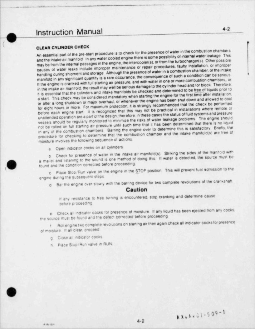
-- .__ . . . . . . . ..
4-2Instruction Manualn
M iv i
CLEAR CVLINDER CHECKAn essential part of the pre start procedure is to check for the presence of water in the combustion chambersand the intake air manifold in any water cooled engine there is some possibility of internal water leakage. Thismay be from the internal passages in the engine, the intercooler(s), or from the turbocharger (s). Other possiblecauses of water leaks include improper maintenance or repair procedures, faulty installation, or improperhandling during shipment and storage. Although the presence of water in a combustion chamber,of the intakei
manifold in any significant quantity is a rare occurance, the consequence of such a condition can be seriousIf the engine is cranked with full starting air pressure, and wrth water in one or more combustion chambers., orin the intake air manifold, the result may well be serious damage to the cylinder head and/or block. Therefore.it is essential that the cylinders and intake manifolds be checked and determined to be free of liquids prior toa start. This check may be considered mandatory when starting the engine for the first time after installation,or after a long shutdown or major overhaul, or whenever the engine has been shut down and allowed to coolfor eight hours or more. For maximum protection,it is strongly recommended that the check be performed
It is recognized that this may not be practicalin installations where remote erbefore each engine start.unattended operation are a part of the design, therefore, in these cases the status of fluid systems and pressurevessels should be regularly monitored to minimize the risks of water leakage problems. The engine shouldnot be rolled on full starting air pressure until such time that it has been determined that there is no liquidin any of the combustion chambers Barring the engine over to determine this is satisfactory. Onefly, theprocedure for checking to determine that the combustion chamber and the intake manifold (s) are free ofmoisture involves the following sequence of actions.
a Open indicator cocks on all cylinders
Check for presence of water in the intake air manifold (s). Striking the sides of the manifold withba mallet and listening to the sound is one method of doing this. It water is detected, the source must bep found and the condition corrected before proceeding
fPlace Stop/Run valve on the engine in the S_ TOP position. This will prevent fuel admission to thec
engine during the subsequent steps
Bar the engine over slowly with the barring device for two complete revolutions of the crankshaft.dCaution
if any resistance to free turning is encountered, stop cranking and determine causebefore proceeding
Check all ind:cator cocks for presence of moisture. If any liquid has been ejected from any cocks,ethe source must be found and the defect corrected before proceeding
Roll engine t ao complete revolutions on starting air then again check allindicator cocks for presencef
of moisture if all clear, proceed
g Close allindicator cocksn Place Stop/Run valve in RUN
l
i
bai
A x6 A v C1-5 09-14-2 I
'*
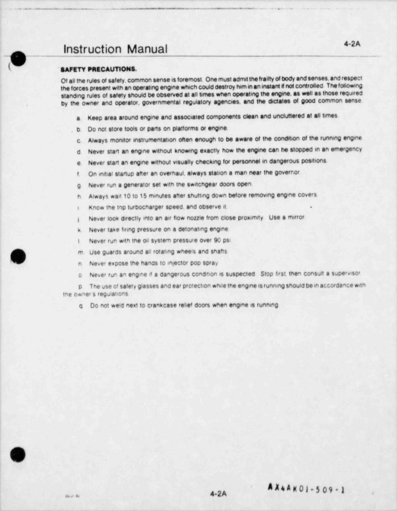
. . . . - , . - - . . . . . .
4-2AInstruction ManualopSAFETY PRECAUTIONS.
Of all the rules of safety, common sense is foremost. One must admit the frailty of body and senses,and respectthe forces present with an operating engine which could destroy him in an instant il not controlled. The followingstanding rules of safety should be observed at all times when operating the engine, as well as those requiredby the owner and operator, governmental regulatory agencies, and the dictates of good common sense.
Keep area around engine and associated components clean and uncluttered at all times.a.
. b. Do not store tools or parts on platforms or engine.
Always monitor instrumentation often enough to be aware of the condition of the running engine.c.
d. Never start an engine without knowing exactly how the engine can be stopped in an emergency.
e. Never start an engine without visually checking for personnel in dangerous positions.
f. On initial startup after an overhaul, always station a man near the governor,
g Never run a generator set with the switchgear doors open.
h. Always wait 10 to 15 minutes after shutting down before removing engine covers
i Know the inp turbocharger speed, and observe it. .
i Never look directly into an air flow noule from close proximity. Use a mirror,
k. Never take firing pressure on a detonating engine
1. Never run with the oil system pressure over 90 pst
m Use guards around all rotating wheels and shafts
n Never expose the hands to injector pop spray
o Never run an engine if a dangerous condition is suspected Stop brst, then consult a supervisor.
p The use of safety glasses and ear protection while the engine is running should be in accordance withthe owner s regulations
q Do not weld next to crankcase relief doors when engine is running
i O
4 A K 01-5 09 - 1'
4-2A ,w .,
. - _ _ _ - _ _ - - _ _ _ _ _ _ _ - - - _ _ - _ - _ _ _ _ _ _ - -_
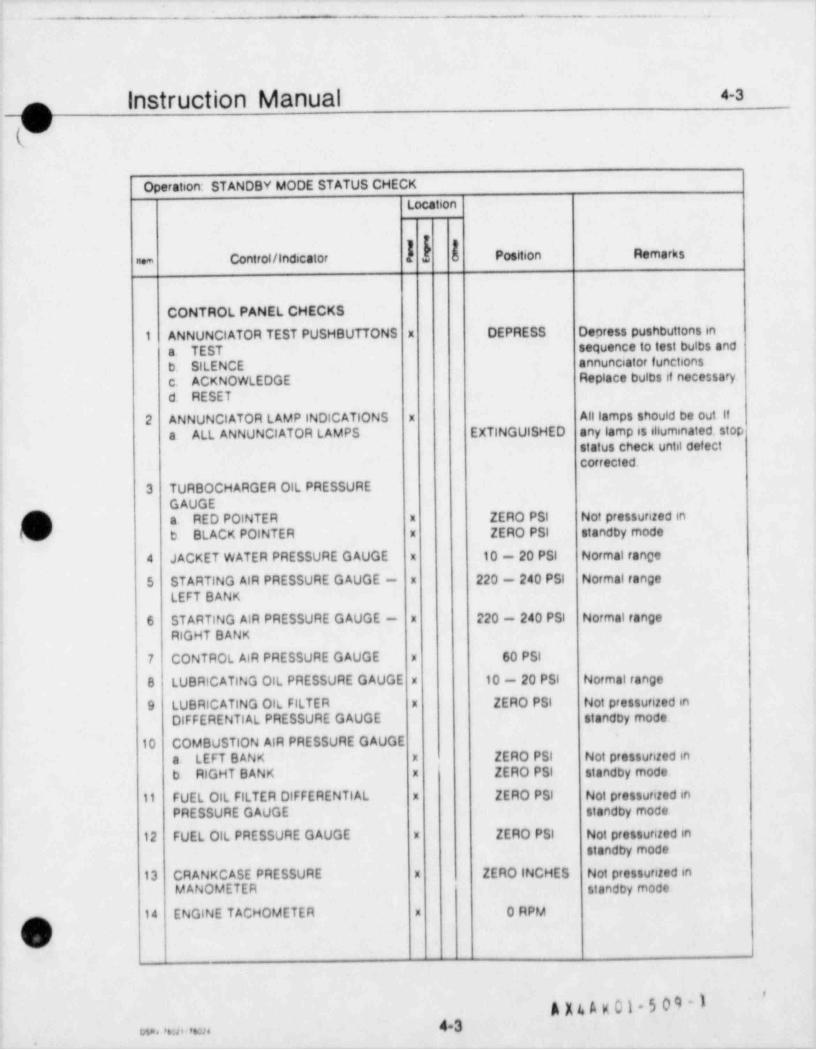
._ - . _ . . . _ _ .
Instruction Manual 4-3
$(Operation: STANDBY MODE STATUS CHECK
Location
k Position Remarksne Control / indicator
CONTROL PANEL CHECKS
1 ANNUNCIATOR TEST PUSHBUTTONS x DEPRESS Depress pushbuttons in
a TEST sequence to test bulbs and
b SILENCE annunciator functions
c. ACKNOWLEDGE Replace bulbs if necessary
d RESET
2 ANNUNCIATOR LAMP INDICATIONS x Alllamps should be out ifa ALL ANNUNCIATOR LAMPS EXTINGUISHED any tamp is illuminated. stop
status check until defectcorrected
3 TURBOCHARGER OIL PRESSUREGAUGE
/ a RED POINTER x ZERO PSt Not pressunzed in'
La) b BLACK POINTER x ZERO PSI standby mode
4 JACKET WATER PRESSURE GAUGE x 10 - 20 PSI Normal rance
5 STARTING AIR PRESSURE GAUGE - x 220 - 240 PSI Normal range
LEFT BANK
6 STARTING AIR PRESSURE GAUGE - x 220 - 240 PSI Normal rangeRIGHT BANK
7 CONTROL AIR PRESSURE GAUGE x 60 PSI
x 10 - 20 PSI Normal range8 LUBRICATING OIL PRESSURE GAUGE
9 LUBRICATING OIL FILTER x ZERO PSI Not pressunzed in
OlFFERENTIAL PRESSURE GAUGE standby mode
10 COMBUSTION AIR PRESSURE GAUGEa LEFT BANK x ZERO PSI Not pressurized inb RIGHT BANK x ZERO PSI standby mode
11 FUEL OIL FILTER DIFFERENTIAL x ZERO PSI Not pressurized inPRESSURE GAUGE standby mode
12 FUEL OIL PRESSURE GAUGE x ZERO PSI Not pressunted instandby mode
13 CRANKCASE PRESSURE x ZERO INCHES Not pressunted inMANOMETER standby mode
14 ENGINE TACHOMETER x 0 RPMn
).
'
A X 4 A K 01- 5 09 - 143w . .. .s . ,.m
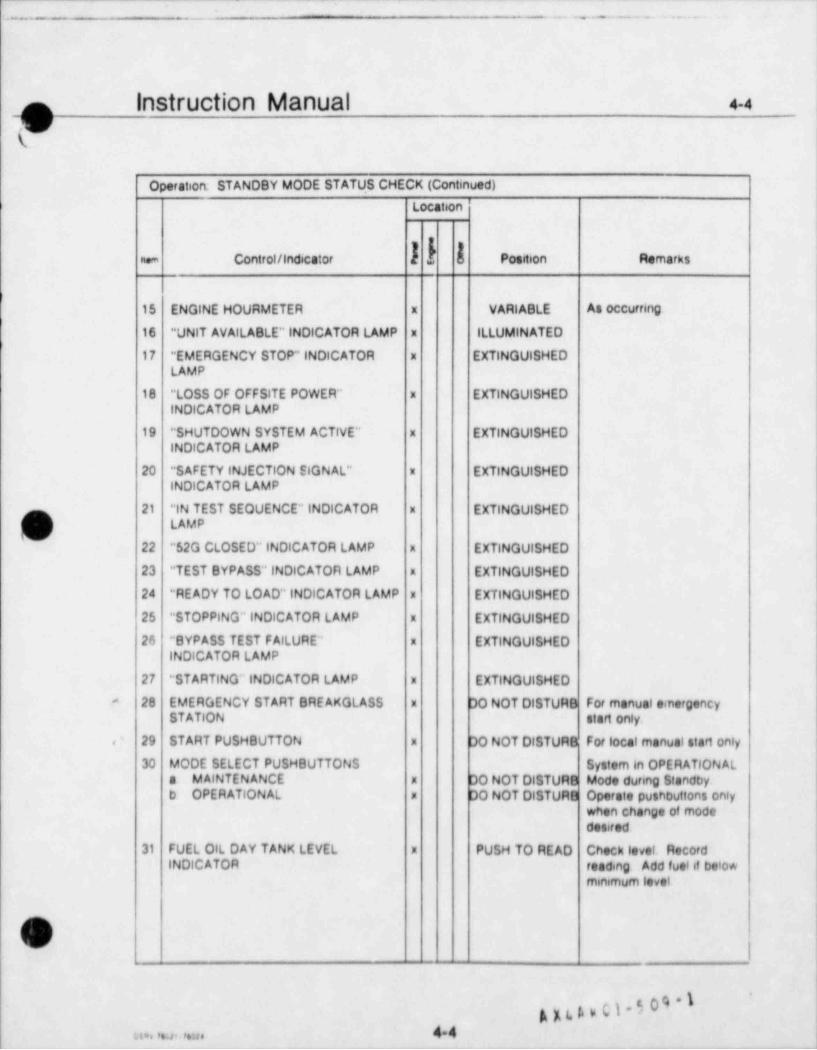
;.. - -.- . . . .
Instruction Manual 4-4
-Ot
Operation. STANDBY MODE STATU.S CHECK (Continued)
i Location
ne Control / indicator Position Remarks
15 ENGINE HOURMETER x VARIABLE As occurring
16 " UNIT AVAILABLE" INDICATOR LAMP x ILLUMINATED
17 * EMERGENCY STOP" INDICATOR x EXTINGUISHEDLAMP
18 " LOSS OF OFFSITE POWER" x EXTINGUISHEDINDICATOR LAMP
19 * SHUTDOWN SYSTEM ACTIVE" x EXTINGUISHEDINDICATOR LAMP
20 * SAFETY INJECTION SIGNAL" x EXTINGUISHEDINDICATOR LAMP
21 "lN TEST SEQUENCE" INDICATOR x EXTINGUISHED,ml 1 LAMP
^
22 "$2G CLOSED" INDICATOR LAMP x EXTINGUISHED
23 " TEST BYPASS" INDICATOR LAMP x EXTINGUISHED
24 " READY TO LOAD" INDICATOR LAMP x EXTINGUISHED
25 " STOPPING" INDICATOR LAMP x EXTINGUISHED
26 " BYPASS TEST FAILURE" x EXTINGUISHEDINDICATOR LAMP
27 * STARTING" INDICATOR LAMP x EXTINGUISHED
28 EMERGENCY START BREAKGLASS x DO NOT DISTURB For manual einergency-
STATION start only
, ' 29 START PUSHOUTTON x DO NOT DISTURB For local manual start only
30 MODE SELECT PUSHBUTTONS System in OPERATIONALa MAINTENANCE x DO NOT DISTURB Mode during Standbyb OPERATIONAL x DO NOT DISTURB Operate pushbuttons only
when change of mododesired
31 FUEL OIL DAY TANK LEVEL x PUSH TO READ Check level. RecordINDICATOR reading Add fuelit befo*
minimum level
,-
gK(hb(}*44a..# .m
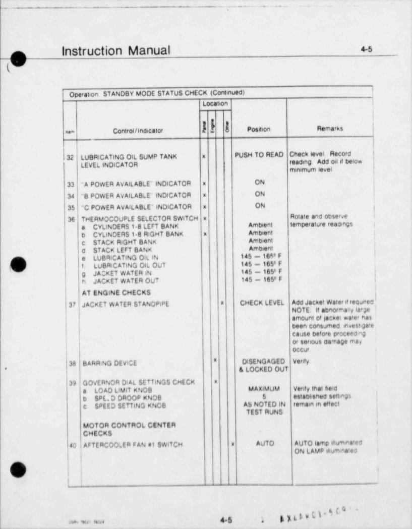
-. - . - - . - - - .
.
Instruction Manual 43
Operation STANDBY MODE STATUS CHECK (Continued) |
Location j
k Position Remarksne + Control / Indicator
1
32 LUBRICATING OIL SUMP TANK x PUSH TO READ Check level. Record
LEVEL INDICATOR reading Add oil of belowminimum level
33 "A POWER AVAILABLE" INDICATOR x ON
34 "B POWER AVAILABLE" INDICATOR x ON
35 "C POWER AVAILABLE" (NDICATOR x ON
Rotate and observe36 THERMOCOUPLE SELECTOR SWITCH x
a CYLINDERS 18 LEFT BANK Ambient temperature readings |
b CYLINDERS 18 RIGHT BANK x Ambient ;
i
c STACK RIGHT BANK Ambient
d STACK LEFT BANK Ambient
CN e LUBRICATING OIL IN 145 - 165' Ft LUBAICATING OIL OUT 145 - 165' F
['' !g JACKET WATER IN 145 - 165' Fh JACKET WATER OUT 145 - 165'F |
!AT ENGINE CHECKSl
37 JACKET WATER STANDPIPE * CHECK LEVEL Add Jacket Water it requitecNOTE. If abnormauf a*ge !l
amount of acket water hasJ
been consumed. investigatecause before proceed ng
|or serious damage mayoccur. ,
"38 BARRING DEVICE DISENGAGED Verify.
'& LOCKED OUT*
39 GOVERNOR DI AL SETTINGS CHECK *
a LOAD LIMIT KNOB MAXIMUM Verif y that field'
b SPE.D DROOP KNOB $ established settings
c SPEED SETTING KNOB AS NOTED IN remain in effect |
TEST RUNS |t
6MOTOR CONTROL CENTERCHECKS |
40 AFTERCOOLER F AN s1 SWITCH s AUTO AUTO lamp illuminated i
ON LAMP alluminatea '
('
i
45 . k%LL'C~
s,. , ,m . ,. a .__.

- . - - - . . _ , . . . .- - - - - -
|
|
Instruction Manual 4-s
(9Operation: STANDBY MODE STATUS CHECK (Continued)
Locat.on
n.m Control / indicator Position Remarks
41 AFTERCOOLER FAN #2 SWITCH x AUTO AUTO lamp illuminatedON LAMP illuminated
42 AIR COMPRESSOR s1 SWITCH x AUTO AUTO lamp iltuminatedON Lamp illuminated itcompressor operating
43 AIR COMPRESSOR s2 SWITCH m AUTO AUTO tamp illuminatedON lamp illuminated ifcompressor operating
44 JACKET WATER KEEPWARM PUMP a AUTO AUTO tamp illuminated
SWITCH ON lamp illuminated
x AUTO Lamp illuminated if45 JACKET WATER KEEPWARM HEATERSWITCH Heater operating -
thermostat controt, '^^yI'- 46 LUBRICATING OIL KEEPWARM x AUTO AUTO tamp illuminated
PUMP SWITCH ON tamp illuminated
47 LUBRICATING OlL KEEPWARM x AUTO Lamp illuminated if
HE ATER SWITCH Hester operating -thermostat controi
48 GENERATOR SPACE HEATER SWITCH x AUTO Lamp illuminated ifHeater operating -thermostat controt
,
,n,
.
g g g y c).5 09 -I46w. m. "m. ,
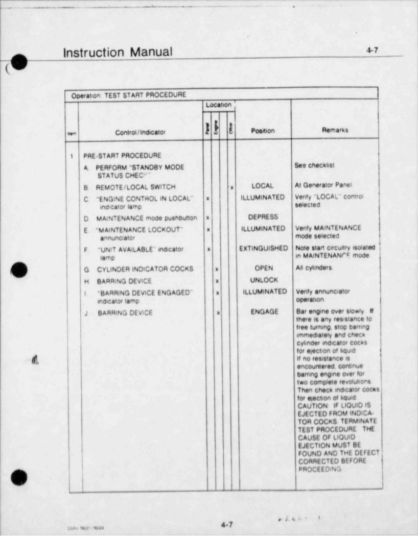
.--
- - - - .
-
.
Instruction Manual 4-7-
(-
Operation: TEST START PROCEDURE
Location '
ii.* Control / indicator Position Remarks
1 PRE START PROCEDURE
A. PERFORM " STANDBY MODE See checklist
STATUS CHEC''"
LOCAL At Generator PanelB REMOTE / LOCAL SWITCH -x
C " ENGINE CONTHOL IN LOCAL" x ILLUMINATED Venfy " LOCAL" control
indicator lamp selected
D. MAINTENANCE mode pushbutton x DEPRESS
E * MAINTENANCE LOCKOUT" x ILLUMINATED Venty MAINTENANCE
annunciator mode selected
F. " UNIT AVAILABLE" indicator x EXTINGUISHED Note start circuitry isolated
lamp in MAINTENANFE mode-
( ) G CYLINDER INDICATOR COCKS x OPEN All cyt;nders,
H. BARRING DEVICE x UNLOCK
I *BARRING DEVICE ENGAGED" x ILLUMINATED Venfy annunciatorindicator lamp operation
J BARRING DEVICE x ENGAGE Bar engine over slowly ifthere is any resistance tofree turning. stop barnngimmediately and checkCytander indicator Cocksfor election of liquid
M, if no resistance isencountered, continuebarring engine over fortwo Complete revolutionsThen check indicator cocksfor election of liquidCAUTION IF LIOUlO ISEJECTED FROM INDICA.TOR COCKS. TERMINATETEST PROCEDURE THECAUSE OF LIQUIDEJECTION MUST BEFOUND AND THE DEFECTCORRECTED BEFOREPROCEEDING
i ,
' ' '4-7v.. , **u i a ., .
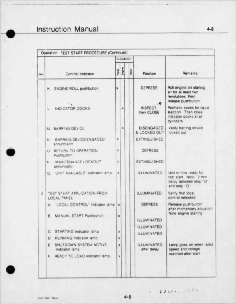
_ -__ _ _ . . _ . . . . , . . . . ..
Instruction Manual 4-8
_O(
Operation: TEST START PROCEDURE (Continued)
Location
f k Position Remarksne+ Control / Indicator
K. ENGINE ROLL pushbutton x DEPRESS Roll engine on startingair for at least tworevolutions, then
,4 release pushbutton,
,,
L INDICATOR COCKS x INSPECT. Recheck cocks for liquidthen CLOSE election. Then close
indicator cocks at allcylinders-
M BARRING DEVICE x DISENGAGED Venty barnng device& LOCKED OUT locked out
N "B ARRING DEVICE ENG AGED" x EXTINGUISHEDannunciator
f O RETURN TO OPERATION x DEPRESS- Pusnbution
P " MAINTENANCE LOCKOUT' x EXTINGUISHEDannun:iator
O " UNIT AVAILABLE" indrcator lamp n ILLUMINATED Unit is now ready fortest start Note 2 mindelay between step "O"and step *O"
2 TEST START APPLICATION FROM ILLUMINATED Venty that localLOCAL PANEL control selected
A " LOCAL CONTROL" indicator lamp x DEPRESS Release pushbuttonafter momentary actuation
e enge staqB MANUAL START Pushbutton a
ILLUMINATED
ILLUMINATEDC STARTING Indicator lamp x
ILLUMINATEDD RUNNING Indicator lamp x
E. SHUTDOWN SYSTEM ACTIVE : ILLUMINATED Lamp goes on when ratedindicator lamp after delay speed and voltage
reached after startF. HEADY TO LOAD indicator lamp
,i
) ), 4 s . 3 $ C " <s
48eso, tsw awe

- - .- .- - . . _ . ..
Instruction Manual 49
$(Operation. TEST START PROCEDURE (Continued)
Location
k Position Remarksnem Controt/ indicator
3 APPLICATION OF TEST START FROMREMOTE PANEL
A REMOTE / LOCAL SWITCH x REMOTE Control station selected atgenerator control panel
B " LOCAL CONTROL" indicator lamp x EXTINGUISHED Verify local control 1
isolated
C REMOTE START Pushbutton x DEPRESS Release pushbutton aftermomentary actuation Note ;engine starts and builds |voltage automatically i
i
D REMOTE INSTRUMENT ATION x OBSERVE Note engine start andacceleration
(3k'
I
!
|
|
|
-
__.
A~
*
49u , ,.a . ,,;, ,
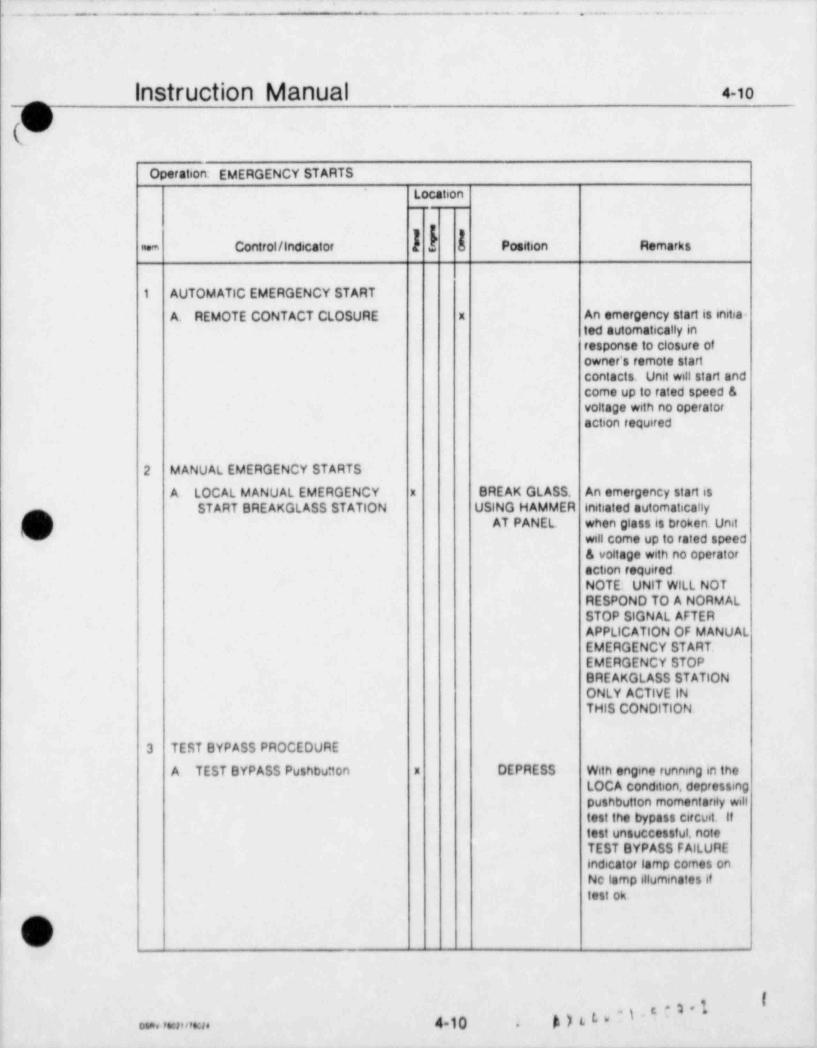
__ ___ _ ____ _ _ _ _ _ _ _ _ _ _ _ _ _ _ _ _ _ _ _ _ _ _ _ _ _ _ _ _ _ _ _ _ _ _ _ _ _ _ _ _ _ _ _ _ - _ _ _ _ _ _ _ _ _ _ _ _ _ _ _ _ _ _ _ _ _ _ _ _ _ _ _ _ _ _ _ _ _ _ _ _ _ _ _ _ _ _ _ _ _ _ _ _ _ _ _ _ _ _ _ _ _
|nStruction Manual 4-io
Operation: EMERGENCY STARTS
Location.
k Position Remarksnem Controt/Indecator
1 AUTOMATIC EMERGENCY START
A. REMOTE CONTACT CLOSURE x An emergency start is initia-ted automatically inresponse to closure ofowner's remote startcontacts. Unit will start andcome up to rated speed &voltage with no operatoraction required
2 MANUAL EMERGENCY STARTS <
A. LOCAL MANUAL EMERGENCY x BREAK GLASS. An emergency start isSTART BREAKGLASS STATION USING HAMMER initiated automatically
O'' AT PANEL when glass is broken. Unitwill come up to rated speed& voltage with no operatoraction requiredNOTE: UNIT WILL NOTRESPOND TO A NORMALSTOP SIGNAL AFTERAPPLICATION OF MANUALEMERGENCY START.EMERGENCY STOPBREAKGLASS STATIONONLY ACTIVE INTHIS CONDITION
3 TEST BYPASS PROCEDURE
A TEST BYPASS Pushbu* ton x DEPRESS With engine running in theLOCA condition, depressingpushbutton momentanly willtest the bypass circuit. Iftest unsuccessful, noteTEST BYPASS FAILUREindicator lamp comes onNo tamp illuminates iftest ok,
a
o.a. ,mn en. 4 10 4)L b*~'~.
_ _ _ _ _ _ - _ _ -
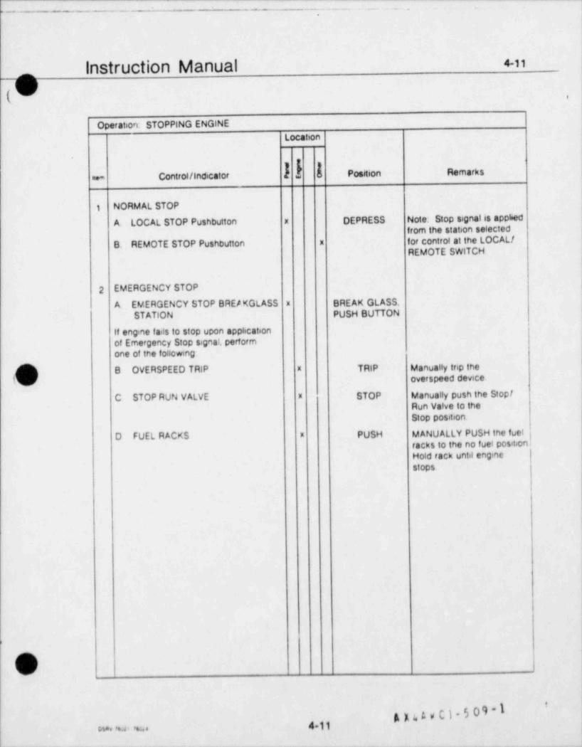
- -- - - ._ _. - .
_
Instruction Manual 4-11
Operation: STOPPING ENGINELocation
nem Control / Indicator Position Remarks
1 NORMAL STOP
A. LOCAL STOP Pushbutton x DEPRESS Note: Stop signal is apphedfrom the station selected
B. REMOTE STOP Pushbutton x for control at the LOCAL /REMOTE SWITCH
2 EMERGENCY STOP
A EMERGENCY STOP BREA KGLASS x BREAK GLASS.STATION PUSH BUTTON
If engine fails to stop upon apphcationof Emergency Stop signal, performone of the following
O B OVERSPEED TRIP x TRIP Manually trip the
k. _d' overspeed device
C STOP RUN VALVE x STOP Manually push the StopfRun Valve to theStop position
D FUEL RACKS * PUSH MANUALLY PUSH the fuel jracks to the no fuel position.Hold rack until enginestops
,
/~
t
__.
AI''"~
4 11a. , ..a . ,.;. .
_
-- . . . - - . - - - . .. __ .. ~. , ,
'
|
!
QSection 5
Inspection &Maintenance
)?
!-i736"
.* .
t .
m*19
34
C
O.
I
e
9
.
t
Oi
,
- - - - - - . ~ - ~ - - - - - . ~ - - __ - - , - - - _ _ _ . _ - . - - - , - + - - - - , - - - - - - _ ~ - - ,
L _ . _ _ . _'
.
n Instruction Manual s-A-4
(w) PART A - PREVENTIVE MAINTENANCE (Continued) ,
OPERATING REPORTS.
A record should be maintained of the conditions of engine operation,andin the case of an engine /generatof set,the generator as well This record may be kept in any form which proves to be suitable to the owner for hispurposes however, it is recommended that as a minimum the following condstions be recorded
a Load (%)
b Engine Speed
c Crankcase vacuum readings
d Fuel pump rack positions (mm settings)
e Temperatures.
(1) Ambient air.
(2) Intake air manifold
(3) Lubricating oil ;
!(4) Cooling water
(5) Ennaust (cylinder and stack)
f Pressures
(1) Ambient air
(2) intake air manifold
(3) Lubricating oit
(4) Fuel
Transamerica Delavat Forms E 276 and E 277, copies of which follow, are available for this purpose,and maybe oroered from the Parts Department Form E 276 provided for a daily recording of data. and Form E 277 isdesigned to provice a periodic summary of the daily reports Due to the normally limited operating hobrs of aneng ne in nuclear standby service. the frequency of observations will, of course, depend upon the frequency ofoperat.on
4
Lj
.-, .
kb
5A4<s.- _ _ _ _ _ . _ _ _ _ _ _ _ _ - _ - _ _ _ _ _ _ - _ - . - _ - _ _ _ _ _ _ _ _
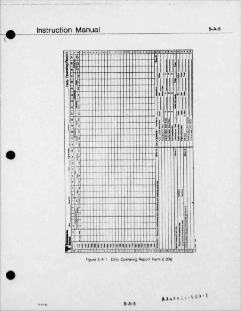
. . .- - . - . . . . - ..- .
||
|nStruction Manual S-A-5
_9l..... - - . . . . . . . . . . . . . . . . . . . . . . . . . . . . . . . . .
.a 1 .
In' i-1 Ia .
| ) )s a sF. t
I[ i l '
ja 1 :
| a l s a j- - -n- Ia a g
~
I |~
= = =a 1 j j j l
* '
_ ); __
| |s,s, ' ja s
1 .I.
3 1 1 1 I l g I t
iI l j i l
'
'- j j } )' '
i' ' i l I I s.| f l! !|j.
[l | I Ie
1 , a . . .o
C l i I I Ie
l i i III , ,
_ .i .-
l'*
t t- _. . . .. .. _ __.__
* f-
1.
. (' .
~, ..
] tj{ || | | I-
i.I, i.,_
p|<-,.....-,.L..4,. . . ._,_.,, .. .....,_,.._ .|
. ,I 1-
|19, ig 1
*
|'1 - ,
i 1
....,I .. . . .
,j' i
' e ;-
y. ,
1',
3 I i< . [ i11 I;I|11 11.1,1,1,1! ! !;l I;I;!I;I1!|l) ! . |y..
- ...3 1
1.i.I. 1.i.I.i.is :I. i19i. p j e 1 1. i e I , i Ti,TTl TTT_TT77 |i 1
fogure 5 A.1, Onoly Operatong Report, form E.276
7-F
. _ .
A g & A v. O i . 5 0 9 - I. . . . > S.A.s
-
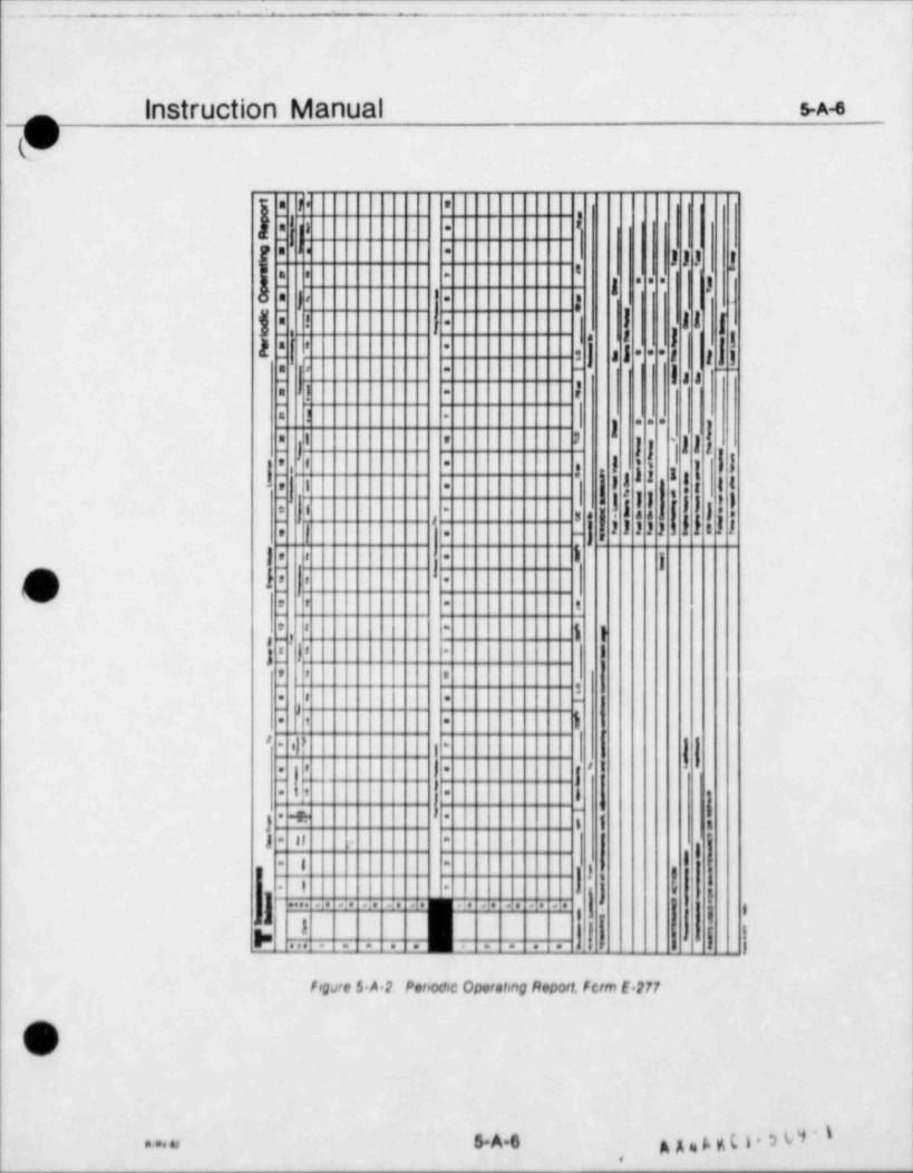
, - . _ - ... -. - .. ...-. .
Instruction Manual m
a f e *,
$ i '._
" ' *
I l l jt3 g 3
- -. . .
). ;, .
I 1 1 {i ! . .
a I |u
[-
t t h|5 ',- |
' *
s | * * **
. r~
g , ,--.
. 1_
- r.
in 1 | . . .
I ' 'I J ] | '| I l l
| ||e i *. i.i e_
.
3 1 3 i s ,e I- . I.
,l ,i'
'.,
,) i, s -
,
#,
? |] ] ] ] ] } }.,
Ij{r |a .e
f j I .
\v ; r - t,-
e : - g gre -
g Jr i-
e r :!-
. . -
I.1. , .
#i|?
- -
> t. , .,
. : , .'
i I i+- -
}- Pj If-
g,
I- -
I !j3 ,
1r=' J. .
,
- -
im .. .. .. . . . . . . . . . 1
i-
, ,
h|..}.. -':-'77 l 1t 1
'--- . . . . <
Fogre $.A.2 Periodic Operating fleport, ferm E 277
p( /
/
. . . . , 6A6 A A= A KL i 0 0,
_ . . . _ _ . _ _ . . . _ _ ]i
|1
Instruction Manual s-B-1
$k PART B - SUGGESTED MAINTENANCE SCHEDULES
GENEPLAL
The maintenance schedules outlined on the following pages are those recommended as an acceptable meansfor maintaining the engine in peak operating condition. Operating experience and the particular needs of theowner may indicale Ihe need f or additional inspections. Inspection intervals used ere considered io be genera #yideal, but operating experience must be used to decide the ultimate suitability of the suggested schedulesWhere expenence indicates more frequent inspection of a particular part or system is needed, the time intervalbetween inspections should be shortened.
MAINTENANCE SCHEDULES.
Unless otherwise stated on the inspection Guides, the following inspection intervals are recommended for use
a DAILY - Operations which are to be performed on a daily basis, independent of engine operatinghours
b WEEKLY - Operations which are to be performed weekly, regardless of engine operating hours
c. MONTHLY / EXERCISE TEST - Operations which should be performed each time the unit undergoesits penodic exercise test but in no case less frequently than once a month.
d ANNUAL /EACH PLANT SHUTDOWN -Inspections that should be performed on an annual basis,or at plant shutdown for reactor refueling The interval may be adjusted to meet plant shutdown schedules
e Bl. ANNUAL / ALTERNATE PLANT SHUTDOWNS - To be performed at siternate reactor refuetrnoshutdowns. or be annually
f. FIVE YEARS - To be performed at the nearest plant shutdown penod pnot to a five year interval
INSPECTIONS GUIDES.
The recommended traintenance actions are listed on Inspection Guides, divided 6nto inspection intervalsThe guides are further separated by component groups such as the diesel engine, electncal components,auxiliary equipment, etc References are provided to direct the user to the sources of information needed toassist in portorming the maintenance actions in addition to those maintenance actions listed on the individualguides, all external parts of the engine should be frequently felt by hand, particularly dunng the first few hundredhours of operation, to detect any excessive temperatures on heads and crankcase side covers
OV
g nAy0g.509*I...+u 5D1,
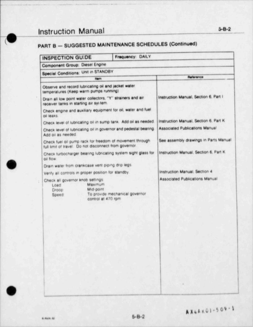
-- -. . - . . . - . . - .- 1
5s-2Instruction Manual_mN
PART B - SUGGESTED MAINTENANCE SCHEDULES (Continued)
INSPECTION GU;DE Frequency: DAILY
Component Group; Diesel Engine
Special Conditions: Urvt in STANDBYnesee.ne.nem
Observe and record lubricating oil and locket watertemperatures (Keep warm pumps running)
Drain alllow point water collectors,"Y" strainers and air Instruction Manual, Section 6, Part I'
receiver tanks in starting air syttem.
Check engine and auxihary equipment for oil, water and fueloil leaks
Check level of lubricating oil in sump tank. Add oil as needed. Instruction Manual, Section 6, Part K
Check level of lubricating oil in governor and pedestal beenng Associated Publications Manual
Add oil as needed
Check fuel oil pump rack for freedom of movement through See assembly drawings in Parts Manual
fulllimit of travel. Do not disconnect from governor.
Check turbocharger bearing lubricating system sight glass for instruction Manual, Section 6, Part K
oil flow.
Drain water from crankcase vent piping drip legs
Verify all controls in proper position for standby. Instruction Manual, Section 4
; Check all governor knob settings Associated Pubhcations Manual
Load MammumDroop Mid pointSpeed To provide mechanical governor
control at 470 rpm
| e
OU
5B2naur
- - - _ _ _ _ _ _ _ - - _ - _ _ _ _ _ _ _ _ _ _ _ _ _ _ _ _ _ _ _ _ _ _ _ _ _ _ _ _ _ _ _ _ _ _ _ _ _ _ _ _ _ _ _ _ _ _ _ _ _ _ _ _ _ _ _ _ _ _ _ _ ___
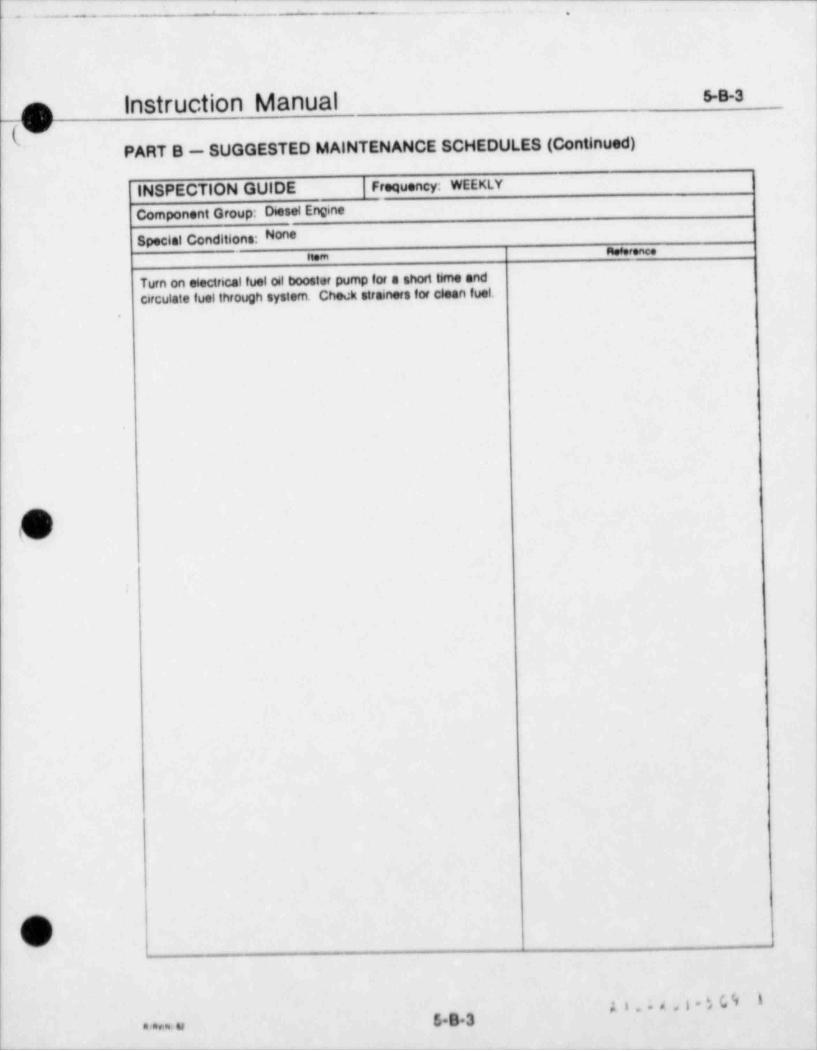
I - --- - _ . _ . _ ,.
5.s-3_n Instruction Manual("
PART B - SUGGESTED MAINTENANCE SCHEDULES (Continued)
INSPECTION GUIDE Frequency: WEEKLY
Component Group: Diesel Engine
Special Conditions: Nonemomencee
Turn on electncal fuel oil booster pump for a short time andcirculate fuel through system. Check strainers for clean fuel.
.
O
O
#'**'''~593"* ~> u
___ _ ____-___ ______
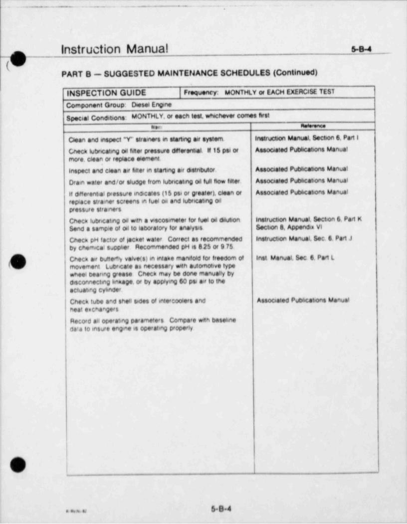
._ -_ _ _ _ , ._
Instruction Manual s4_o(V
PART B - SUGGESTED MAINTENANCE SCHEDULES (Continued)
INSPECTION GUIDE Frequency: MONTHLY or EACH EXERCISE TEST
Component Group: Diesel Engine
Special Conditions: MONTHLY, or each test, whichever comes firstn.m am n
Clean and inspect "Y" strainers in starting air system. Instruction Manual, Section 6 Part 1
Check lubricating oil filter pressure dWferential. If 15 psi or Associated Pubhcations Manualmore, clean or replace element.
Inspect and clean air filter in starting air estnbutor. Associated Publications Manual
Drain water and/or sludge from lubricating oil full flow filter. Associated Publications Manual
11 offerential pressure inecates (t 5 ps6 or greater), clean of Associated Pubhcations Manualreplace strainer screens in fuel oil and lubncating ofpressure strainers
Check lubricating oil with a viscosimeter for fuel al slution. Instruction Manual, Section 6. Part KSend a sample of of to laboratory for analysis Section 8, Appendix VI
Check pH factor of lacket water. Correct as recommended Instruction Manual, Sec. 6, Part J
by chemical suppher. Recommended pH is 8 25 or 9.75.
Check air buttertty vatve(s)in intake manifold for freedom of inst. Manual. Sec. 6, Part L1
x movement Lubricate as necessary with automotive typewheel beanng grease Check mdy be done manually bydisconnecting knkage, or by applying 60 psi air to the
1 actuating cyhnder.
Check tube and shell sides of intercoolers and Associated Pubhcations Manualheat exchangers
Record all operating parameters Compare wfth basehnedata to insure engine is operating properly.
O
5B4. ..u
_ _ - - _ _ _

. _
. - . -.- . -... .. ,
instruction Manual s-B-sn
hPART B - SUGGESTED MAINTENANCE SCHEDULES (Continued)
INSPECTION GUIDE Frequency: ANNUAL /EACH PLANT SHUTDOWN
Component Group: Desel Engine
Special Conditions: Annual or each shutdown, whichever comes firstItem u m ace
Drain lubricating oil system. Refill with new oil Inst. Manual, Sec. 6, Part K,Section 8 Appendix VI
Remove alternate left side doors and examine inside ofengine for any abnormal condition. Check with a good lightfor evidence of babbitt flakes. If excessive water or sludge ispresent, drain crankcase. Determine cause and takenecessary corrective action.
Check valve lash. (If equipped with hydraulic valve litters, instruction Manual data sheet,perform leak down test, reinstall and adjust). and Section 6, Part B
Remove fuel injector nozzles, clean, reset and reinstall. Instruction Manual, Sect. 6, Part FAsso. Publications Manual - Bendix
Check connecting rod and link rod bearing clearances. Instruction Manual, Section 6 Part C andSection 8. Appendix ill
Visually inspect foundation for breaks in bond betweend sole plates and grout.
~
Check foundation bolts for correct torque. Retorque as instruction Manual, Section 6.necessary. Check and record crankshaft web deflections. Part D and Section 2
Check lubricating oit jets for plugged or broken lines.
Remove cam covers and cylinder head covers. Inspect. Ir.st. Manual. Sec. 6, Parts B & Ecams, tappets, rollers, rocker arms, push rods and springs.
Drain governor oil. Clean and flush, then refill with new oil. Instruction Manual, Sec. 6 Part KReplace governor drive coupling element Asso. Publications Manual Woodward
Check cold compression pressures and maximum firing Inst. Manual, Sec. 6, Parts B & Cpressures. If so indicated, remove cytinder heads, gr.novalves and reseat. Check nngs and liners.
Remove end plates from heat exchangers and intercoolers. Associated Publications ManualExamine and clean as necessary ,
Inspect intake air filter, and service as recommended by Associated Publications Manualmanufacturer.
/
\
\
|
,
it
f,
=
'
I i s-B-5.a-u. _ - . _ .
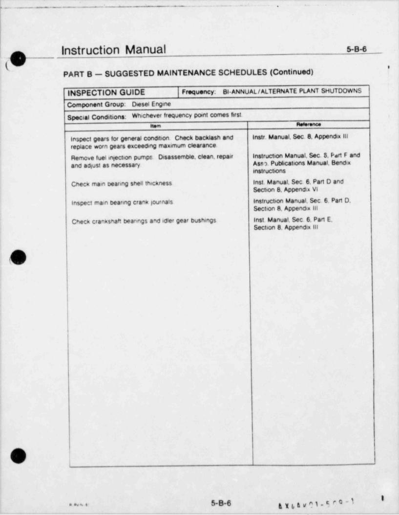
[ -: :.. .
~ ^
2 .
Instruction Manual s-B-6,p(U~
PART B - SUGGESTED MAINTENANCE SCHEDULES (Continued) |
INSPECTION GUIDE Frequency. Bi-ANNUAL / ALTERNATE PLANT SHUTDOWNS
Component Group: Diesel Engine
Special Conditions: Whichever frequency point comes first. ,
nem meeerence
inspect gears for general condition. Check backlash and Instr. Manual, Sec. 8 Appendix ill
replace worn gears exceeding maximum clearance.
Remove fuelinjection pumps. Disassemble, clean, repair Instruction Manual. Sec. 8, Part F andAss 3. Publications Manual, Bendix,
; and adjust as necessary.instructions
Check main bearing shell thickness. Inst. Manual Sec. 6. Part D andSection 8 Appendix VI
Inspect main bearing crank journals. Instruction Manual, Sec. 6 Part D,Section 8 Appendix lil
,
! Check crankshaft bearings and idler gear bushings. Inst. Manual, Sec. 6. Part E.Section 8 Appendix ill
!
|
4
OV
'aans- 5-B-6 616&v^1-50"'I
_ _.
.-_ _ _ _ -- .- - . __.- _
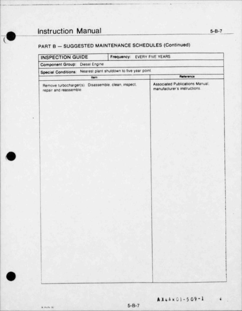
l- -._ - _ - . . . .
Instruction Manual 5-B-7nV '
PART B - SUGGESTED MAINTENANCE SCHEDULES (Continued)
INSPECTION GUIDE Frequency: EVERY FIVE YEARS
Component Group: Desel Engine
Special Conditions: Nearest plant shutdown to five year point.nom nosorence
Remove turbocharger (s). Disassemble, clean, inspect. Associated Publications Manual,manuf acturer's instructions.repair and reassemble.
.
O
.
O
A X4 A k 01-5 09-1 4'
5-B-7a a **
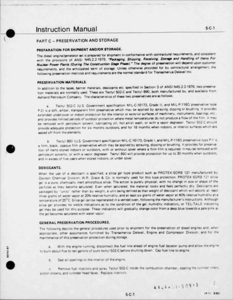
L _ . _ . ._ . .
n Instruction Manual 5-C iW
PART C - PRESERVATION AND STORAGE
PREPARATION FOR SHIPMENT AND/OR STORAGE.
The diesel engine / generator set is prepared for shipment in conformance with contractural requirements, and consistentwith the provisions of ANSI N45.2.21978, 'fackseing Shipping, RaceMng, Storage and Handling of items ForNudane Power Monts (During The Construction Supe Phasel." The degree of preservation will depend upon customerrequirements, and the anticipated term of storage. Unless otherwise provided for by contractural arrangement, thefollowing preservation methods and requirements are the normal standard for Transamerim Delavel Inc.
PRESERVATION MATERIALS.In addition to the tapes, barrier materials, desiccants etc. specified in Section 3 of ANSI N45.2.2-1978, two preserva-tion materials are normally used. These are Tectyl 502-C and Tectyl 890, both manufactured by, and available fromAshland Petroleum Company. The characteristics of these two preservatives are as follows.
Tectyl 502 C (U.S. Government specification MIL-C 16173 Grade 11, and MIL-P 116G preservative typea.P 2) is a soft, amber, transparent film preservative which may be applied by spraying, dipping or brushing. It providesextended undercover or indoor protection for the interior or exterior surfaces of machinery, instruments, bearings, etc.,and provides limited periods of outdoor protection where metal temperatures do not produce a flow of the film. It maybe removed with petroleum solvent, lubricating oil, hot albli wash, or with a vapor degreaser. Tectyl 502 C shouldprovide adequate protection for six months outdoors, and for 18 months when indoors, or interior surfaces which aresealed off from the elements.
b. Tectyl 890 (U.S. Government specification MIL-C 16173. Grade I, and MIL-P-116G preservative type P-1 isa firm, black, opaque film preservative which may be applied by spraying, dipping or brushing it provides for preserva-tion of items stored indoors or outdoors, with or without cover where a firm film is required. It may be removed withgpetroleum solvents, or with a vapor degreaser. Tectyl 890 will provide protection for up to 30 months when outdoors,and in excess of five years when stored indoors, or under cover.
DESICCANTS.
When the use of a desiccant is specified, a silica gel type product such as PROTEK SORB 121 manufactured byDavison Chemicat Division, W.R. Grace & Co. is normally used for this type protection. PROTEK SORB 121 silicagel is a pure, chemically inert amorphous silica. The action is purely physical, with no change in size or shape of theparticles as they become saturated. Even when saturated, the material looks and feels perfectly dry. Desiccants arepackaged by " units" rather than by weight, a unit being defined as that weight of desiccant which will absorb at leastthree grams of water vapor at 20% relative humidity, and at least six grams of water vepor at 40% relative humidity at atemperature of 25 C. Silica get can be regenerated in a vented oven, following the manufacturer's instructions Althoughsihca get provides no visible indications as to the condition of the gel, humidity indicators, or TEL TALE indicatinggel may be used for this purpose. These indicators will gradually change color from a deep blue towards a pale pink asthe gel becomes saturated with water vapor.
GENERAL PRESERVATION PROCEDURES,
The following depicts the general procedures used prior to shipment for the preservation of diesel engines and, whenappropriate, other appurtances furnished by Transamerica Delaval, Engine and Compressor Division, and for themaintenance of this preservation protection during storage.
With the engine running, disconnect the fuel line ahead of engine fuel booster pump and allow the eng ney a.
I to burn about five to ten gallons of pure tectyl 502 C bef ore shutting down. Cap fuel line to engine.
5b. Seal all openings to the interior of the engine.
,
c, Remove fuel injectors and spray Tectyl 502 C inside the combustion chamber, coating the cylinde' liners.
|piston crowns, and cylinder head faces. Replace injectors.
|
| s
axo a u ;)-5 09-1 *
( 5C1 mii see
L
L- - - . - . . . . - . - .
instruction Manual s.c.2f-
PART C - PRESERVATION AND STORAGE (Continued)
d. Plug all openings to each fuel pump. Disconnect the drain line and pump Tectyl 502-C through the connec-tion until Tectyl is observed leaking past the fuel rock. The pump is then reversed and all excess Tectyl removed.
e. Drain jacket water and cooling water systems, especially the water pump, thermostatic valves and inter.coolers,
f. Remove cylinder head covers and coat all areas inside sut> cover with Tectyl 502-C. Replace covers.
g. Remove com gallery side doors and thoroughly cost the entire mmshaft and housing with Tectyl 502 C.Replace doors.
h. Remove cover plates and inspection doors on geercase covers. Coat gears with Tectyl 502 C. Replace coverplates and doors.
i. Remove engine side doors and spray all accessible machined interior surfaces within the crankcase withTectyl 502-C. Replace side doors.
j. Remove upper half of rear oil seal and spray Tectyl 502-C on the shaft and throughout the area. Reinstallupper half of rear oil seal.
k. Carefully examine all pw sts and equipment removed from engine for damage prior to reinstallation.Replace all gaskets that show signa of damage.
1. Wrap rear crankshaft oil seat with duct tape,
m. Coat all machined and unpainted surfaces on the exterior of the engine with Tectyl 890.
n. Fill governor to top with oil. Any good 40 weight automotive type oil will be sufficient.
o. Check that all openings to interior of engine are closed. Replace all covers, plates, blind flanges, etc. thatwere removed.
LONG TERM STORAGE.
In addition to those procedures outlined in the previous paragraphs, the following promdures can be used prior toshipment of diesel engines and their appurtenances to prepare them for long term (six months or longer) storage.Although each of these procedures is strongly recommended, they must be specified by contract if they are to be per.formed by Transamerica Delaval. *
} a. Remove liquid filled gauges from the engine and store them separately to protect them from accidentalbreakage or damage.
b. Place one 80-unit bag of desiccant per cylinder on a 1 x 3 inch board in the bottom of the crankcase Ablank plate with a t&pped hole should be bolted over the crankeese wnt opening and a probe type humidity indicatorinsta!Ied in the tapped hole.
OI c. Place one 80-unit bag of desiccant at either end of the intake manifold. One 16-unit og of desiccant should8 be placed within the intake port of ec::h cylinder head and either taped in place, or secured to some kind of wooden
block,
d d. Place one 4-umt bag under each cylinder head cover,
g p A g 01- 5 M 'I*
5c2 ]
.---
_ ,
.
s-C 3
[b |nStrUCliOn Manualqw
PART C - PRESERVATION AND STORAGE (Continued)
Grease all gaskets on both sides during reassembly, and bolt all surfaces tightly together.e.
Remove all lines from fuel pumps und injectors. Wrap in plastic bags together with desiccant and tapef.closed. Store in a box. Cap all injector and pump openings. Tape a 4 unit bag to each pump. staple an indicator to eachbag of desiccant and wrap the pump in a 5,lastic bag. Tape shut with duct tape. Make sure all fuel racks and linkagesare thoroughly greased, or coated with Tectyl 502 C.
The barring device, air distributors, air solenoid valves, governor and overspeed trip should each have ag.4-unit bag of desiccant taped to it, together with an indicator and then wrapped in plastic and sealed with duct tape.
Each junction box on the engine should have a 4-unit bag of desiccant placed inside and the cover sealedh.with duct tape.
One 16-unit bag of desiccant should be placed within the turbocharger (s) outlet port. Seal all turbochargeri.openings with blind flanges and duct tape.
j. Highly visible warning placards should be placed on each piece of equipment, or at each access to areasf
which contain desiccant to warn of the presence of the desiccant, and to serve as a reminder to remove the desiccant
bef ore the engine is started.
LEVELS OF STORAGE.
If the engine and Osociated equipment is to be placed in storage prior to installation, the preservation proceduresapplied prior to the shipment must be maintained. For long term storage (six months or longer), the following levels
/ of storage, as defined by ANSI N45.2.21978 are recommended.
Level B - Storage within a fire resistent, tear resistent, weathertight and well ventilated building, or equi-a.valent enciosare, not subject to flooding and with a paved or otherwise surf aced floor with good drainage. Items shouldbe 0: aced on pallets or shoring to permit air circulation. Temperature control and uniform heating to prevent conden-
0 0sation and corrosion, and to provide temperatures between the ranges of 40 F minimum to 140 F maximum. Thefollowing types of equipment provided by Transamenca Delaval should be stored in Level B facilities.
1. Motor controf centers
2. Gene'ators.
3. Switchgear.
4. Control Panets.
5 Air filters.
Level C - All provisions and requirements of Level B except for heat and temperature control.b.j
1. Engines and attached equipment.
2. Pumps and Vaf ves.
3. Auxiliary skids.Y
4. Lubrirating oil filters and strainers.
Transamerica Delavai recommends that items listed for Level C storage have heat and temperatu e contro',
roF c.
8 as well.
information concerning storage levels eittracted from American Na tionalStandard Packing, Shipping, Peceiving. Storageand Handhng of items for Nuclear Power Plants (During the Construction Phase) ANSIN24.2.21978, with the permis-
'
sion of the publisher, The American Society of Mechanical Engineers. United Engineering Center,345 East 47th Street,New York,NY 10017.
s'
[g EL bt I. m n a'as6C3
!
- . .:- -.. ...
n Instruction Manual s.C4
b PART C - PRESERVATION AND STORAGE (Continued)
RECEIVING INSPECTION,
A visual examination of the engine and other equipment should be made before off.looding to determine if any damagewas incurred during shipment. This inspection should be made in accordance with ANSI N45.2.21978.Thefollowingareas of inspection should be conducted.
a. Fire - Charred wood, paper or paint, indicating exposure to fire or extremely high temperatures.
b. Excessive exposure - Weatherboaten, frayed, rusted, or stained containers indicating prolonged exposureduring transit.
c. Environmental damage - Water or oil marks, damp conditions, dirty areas, or salt film (indicating exposureto sea water or winter road salt chemicals),
d Tiedown failure - Shifted, broken, loose or twisted shipping ties, and worn material under ties, indicatingimproper blocking and tiedown during shipment.
e. Rough handling - Splintered, torn or crushed containers indicating improper handling Review of impactrecording instrument readings.
f. Item inspection - Unless the package marking prohibits unpacking, the contents of all shipments should bevisually inspected to verify that the specified packaging and shipping requirements have been complied with. When '
items are contained in transparent, separate moisture proof begs or envelopes,a visual inspection without unpackmg isg
(preferred. Statistical sampling methods may be used for groups of similar items. Care shall be taken to avoid contamina.'
,
tion of the items during inspection. The inspections shall I;e performed in en eres equivalent to the level of storagerequired f or the item. These inspections are examinations shall include the following, as appropriate.
1. Identification and Marking: Verification that identification and markings are in accordance withapplicabie codes, specifications, purchase orders, drawings, and these instructions.
2. Complete Shipments: Verify that the contents match packing lists. If there are discrepancies, contactTransamerica Delaval, Engine and Compressor Division, Customer Service Department immediately.
3. Manufacturing Documentation: Assurance that the document certifying that the item received wasfabricated, tested and inspected prior to shipment in accordance with applimble code, specification, purchase orderand/or drawings is included in shipment if applicable.
4. Protective Covers and Seals: Visual inspection to assure that covers and seels are secure.
f 5. Coatings and Preservatives. Verification that coatings and preservatives are applied in accordance withspecifications, purchase orders or manufacturer's instructions.
6. Inert Gas Blanket: Verification that the inert gas blanket pressure is within the acmptable limits, ifused.
G 7. Desiccant: Verification that the desiccant is not saturated, determined by the use of humidity indica-
[ tors. Desiccants shall be regenerated or replaced as necessary in accordance with manuf acturer's instructions.
) 88. Physical Damage. Visual inspection to assure that parts of items are not broken, cracked, m:ssmg.
detormed or misaligned and rotating parts turn without bind.ng. Accessible internal and external areas shall be free ofv detrimental gouges, dents, scratches and burns.
'
il'$XLt.VC1 * C '*
5-C4 ta n see

..,.
- _ _ _ _ . . _ . _ . _
Instruction Manual s-c4nQ
PART C - PRESERVATION AND STORAGE (Continued)
9. Cleenliness: Visual inspection to assure that accessible internal and external areas are within thespecification requirements for dirt, soil, mill scale, weld splatter, oil, grosse, or stains, inspection for cleanliness is per-formed prior to sealing and shipping, therefore, if receiving inspection indiates that there has been no penetration ofthe sealed boundry, then inspection for internal cleenliness is optional.
Conformance Inspection - Unless the completed item was inspected or examined at the source, it shouldg.be inspected or examined at the point of receiving to verify that the following characteristics conform to the specif eedrequirements. These inspections or examinations should include such items as the following'
1. Physical Properties: Nondestructive examination to assure that physical properties conform to thespecified requirements and the chemical and physical test reports, if required, meet the requirements.
2. Dimensions: Random visual inspection to assure that important dimensions conform with drawingsand specifications. Examples Base plate mounting holes, owrall external size, configuration and orientation of parts
3. Weld Preparations: Random verification that weld preparations are in accordance with apphmble
drawings and specifications.
4. Workmanship. Visual inspection of accessible areas to assure that the workmanship is satisfactory tomeet the intent of the requirements.
5. Lubricants and Oils. Verification of presence of proper lubricants and oils, if required, by erther
O specification, purchasa order or manufacturer's instructions.
V6. Electrical Insulation. Performance of insulation resistence tests for rnotors, generators, control and
power cable, to ensure contormance with specifications.
h. Special Inspection - Where receiving inspection in addition to that described above is reouired, the "$pecialInspection" procedure, complete with documentation instructions, shall be attached to the item or container, this 41 inaddition to the ingection, and the results of the m9ection shall be documented.
ON SITE PREPARATION FOR STORAGE,
if the engine and other components are to be placed in storage prior to installation, the engine should be offlooded andmoved to its storage location. Place engine onto Tectyl coated hardwood blocks. The mounting flanges must be sup-ported by 50% of their area, equally spaced The engine should be completely covered by a tarpaulin, and the tarpaulrnsecurely fastened to the skid. lf the storage is to be long term, the preservation procedures applied prior to the shepmentmust be maintained. The engine should be stored in the level of storage specified in proceeding paragraphs.
STORAGE INSPECTIONS.I Six month inspections of the unit should be conducted to the following criteria, witnessed by a Transamerica Delaval
service representative (upon receipt of a purchase order), or documented by a f ormal report by the owner's inspec2cr.
a. Do not rotate the engine,
'
5 b. Examine all engine cover plates for tightness and samling ability. Do not open the engine unless it is abho-
g lutely necessary.
m c. E xamine gaskets for any covers removed and replaced if any damage exists.
d. Examine all humidity indicators for 60% saturation. Replace or regenerate the saturated sihca get as necek
sary. If the interior of the engine is exposed ior any reason, reapply Tectyl as needed.
A x o n 01-5 M -1*
,
5C5

-- - .n-.,......-
!
(l InStruCliOn Manual 5-C-s
}/PART C - PRESERVATION AND STORAGE (Continued)
e. Inspect the hardwood supports for any indiation of settling. If settling has occurred during storage, supportsshould be replaced or adjusted as necessary,
f. Examine intake manifolds and turbocharger (s) for deterioration. Clean and preserve as necessary.
g. Replace tarpaulins and secure.
RECOATING OF PRESERVED SURFACES.
In view of the finite life of the preservative material,it is recommended that the surfaces be recoated as follows duringthe term of storage.
Every six months, or less if inspection indicates nond, all outside surfaces of the er.gine which have beena.coated with Tectyl 502-C should be recoated.
b. Every 18 months all interior surfaces of the engine and other equipment must be recoated,
c. livery 30 months all exterior surfaces which were coated with Tectyl 890 should be recoated.
GENERATOR.
Largo,one bearing generators are shipped disassembled.and are preserved for shipment and storage by the manufacturer.In addition to those requirements specified for engines and associated equipment, the following conditions apply to allgenerators. Additional requirements may be specified by the manufacture *.
] a. Inspect Shipment - Inspect stator, rotor and bearing pedestal to determine condition as received. Damage
j to skid timbers is evidence of humping or rough handhng. Damage to tarpaulins and plastic covers could expose equip-ment to moisture. Inspect leads and accessories. Check bearing and shaft surface for moisture and rust. Inspect statorand rotor windings and test insulation resistance, a low value indicating presence of moisture or contaminant on coils.If generator is shipped as a sealed unit, do not open for inspection unless there is evidence of external damage to thepacking.
months. Take a one minute reading with a 500 volt megger. Recommended minimum values are gs every three to sixb. Insulation Resistance - Take insulation resistance tests on stator and rotor windin
""*f * g* ' 1j ,
x megohm on stator and one megehm on rotor. A dry, clean winding will test much higher. A more thorough test ofinsulation is to continue megger test for one to 10 minutes. The 10 minute reading should be much higher than the oneminute reading For dryout procedure, refer to generator instruction manual. This paragraph applies only if generatoris not completely sealed.
c. Storage - Should be in a Level B storage facility as defined by ANSI N45.2.21978.
d. Bearing and Shaf t - Pedestal bearing should be stored in a clean, dry area and covered or boxed. The sleevebearing surface is greased or coated with Tectyl for shipment. For long term storage, a desiccant placed inside thecovering is recommended.
CAUTION.A
Some desiccants may be corrosive on contact.
Level C storage is recommended. Bearing and pedestal parts should be inspected after the first month and every three
5 months thereaf ter. They should be cleaned and regreased if necessary. Unpainted surfaces on bearing housings should2 be kept covered with grease or Tectyl 502 C. Unpainted parts of the shafts are covered with a rust preventitive such as
Cosmoline, or with Tectyl 502 C,and should be inspected every three months. If bearings and shaf ts are not assembled,then set both parts on a block of wood, preserve with Tectyl 502 C and cover.
\ )e. All generator equipment must be inspected at six month intervals by the manufacturer's service represen-"
tative. The windings must be me22ed at this time, and accurate reports sent to Transamerica Delaval, and to the manu-facturer of the generator,
4 'g n k v el-5 09
5C6 nm a a
L._. - _ _ _ . . _ . _.
n instruction Manual s-o-1
'V-
PART D -INSPECTION AND MAINTENANCE RECORDS
GENERAL
in addition to operating records, and any other record which may be kept by the owner or operator,it isrecommended that a permanent record be kept of essentiatinspection and maintenance observations. A senesof " inspection and Maintenance Record" forms,Transamerica Form E-267 (Figures 5-D-1 through 5-D-16) areavailable for this purpose. These are used by Customer Service Representatives to record clearances, torques,and other vital inspection observations and conditions. These records will be of great value in the futureplanning of maintenance and overhaul requirements, and to assess the wear trends and performancecharacteristics of the engine.
INSTRUCTIONS FOR USE.
To be of value in helping to determine both present and future repair and replacement needs,it is essential thatall information be accurately recorded. The following should be observed when using the forms
Torque values should be recorded in foot pounds (ft lbs) unless otherwise noted.a.
b Clearances should be recorded in thousandths of an inch,i.e. 4=0.004 in.; 2=0 002 in.; 25=0 025 :n.;1.2=1.002 in.; 1.25=1.025 in., etc. If other than inches is used, specify on each sheet the unit of measurementused.
Where significant, dialindicalor readings should be recorded as + or -(plus of minus) A reading not soc.specified will be assumed to be a plus (+) reading
d. The heading of each form is filled out as follows.
1. Component Group Title- Pre-pnnted with name of major component which is covered by thatsheet
2. Parts Group No : The three digit parts group number to which the component group belongs,andin which it may be found in the Parts Manual.
3 Sheet The identity of the record within a parts group
4 Page The page number for a particular parts group / sheet.
5. Customer: Fillin name of owner / operator of equipment.
6 Equipment Location: Physical location of equipment, specified by name, position number, ofother desCnptive term which may be appropnate to clearly identify the location.
7, Engine Model Complete model as appearing on nameplate.
]8 Senal Number: The number appearing on the engine nameplate. Usually consists of a five digt
group. a dash and a four digit group.
9 Customer's designation. When an owner or operator has a specified designation for the enginewithin his system wnich serves to identify it to him, enter this designation.
)O 10 Total Eng?ne Hours Hours since first startupU
kDpoN5-D-1..
.
_. _ _ . . . . -
n instruction Manual s-D-2
qvPART D -lNSPECTION AND MAINTENANCE RECORDS (Continued)
11. Hours Since Last inspection: The time between the present Total Engine Hours reading and thelast inspection.
12. Date This inspection: Self explanatory.
13. References: Preprinted. Indicates sources of instructions that should be used in conjunctionwith the inspection being performed.
Ensure that the proper designation is entered on all sheets where the position of the componente.being inspected serves to identify it. For instance, a separate sheet is needed for each bearing each cylinderhead, each piston and rod, etc. Identify these items.
,
i
!
O1 |
A X4 A K 01-5 09 -1;
I
|5-O-2==
. .. - _. . -. .. _. - - - . - .- _ - _ -
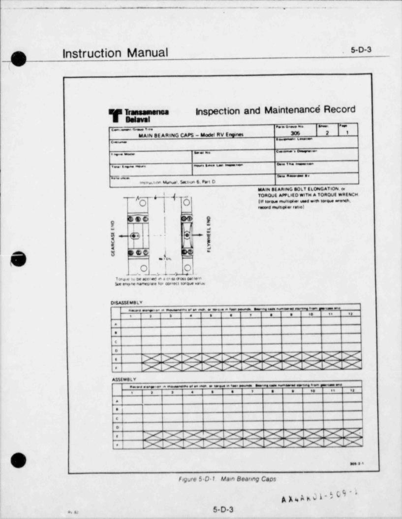
L. _ _ ,. . . _ . _ .. .
.
n Instruction Manual s-o-3.
y
1
uis Transamensa inspection and Maintenancd RecordE Batsval
e...... .
..MAIN BE ARING CAPS - Model RV Enynes 306 2 1
a __ _ 6c
C.: ._e. m.e ., ,
o. v -i ae . .s u
o.. m e,G.
anwust.nn Manuai. Sett.un 6. Part O
MAIN SE ARING BOLT ELONG ATION. or
4 '-d-- OTOROVE APPLIED WITH A TOROUE WRENCH
A-o .
l'o-~ ~li. - - -a ~~ - aa.Orecord enultiW.or reteel
-
c ni :
dj :!g_ p -.:
a see j te -
(o, ... -
O I ON
.a..- a- n .
10f$e tu be SOOled in a t'.14 0068 pattern$ne ensyne nameptate tor CorreCl torque valuw
OISASSEMBLY
mes . .ae....a . - r .e m . .. . e , -_ e,,,,,,,,,,,,,.,,,.--
9 3 3 4 5 8 ? O 9 40 99 93
a
O
C
D
' N
XXXXXXXXXXX*
As%E MBLY
m..e . a - - _- : .e . e ; -- e , , ,,
I $ I O O O I $ $ %$ 99 93
a
O
C
D
'
XX><1XXXXXXXX-
( .,, x.
|
figure S D 1. Main Beanng Caps
g nAx01-5Ci9~lI
5-D-3.. u
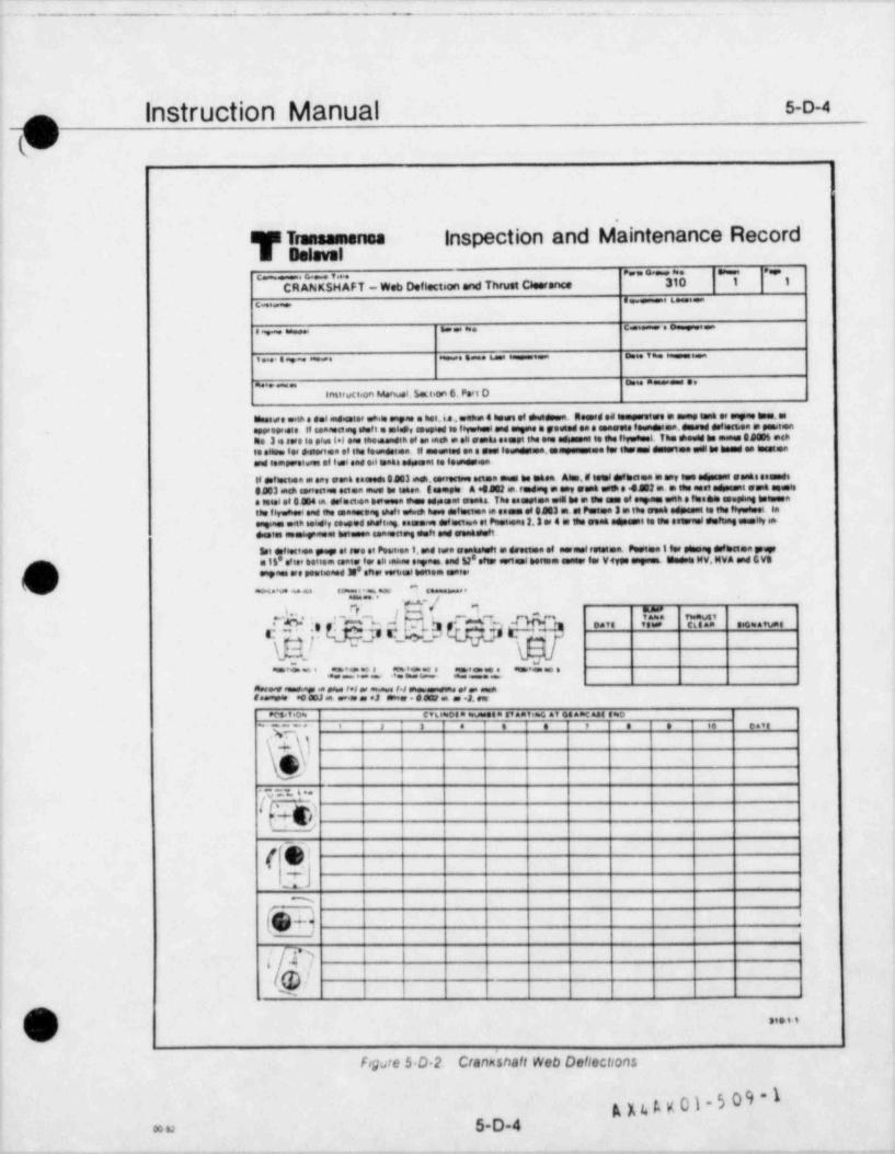
. . . . - _ . - .- ._ -_ . _ - __ _ . _- _. . -.
^ eM &.MD Me4 ee.,m,m -
1
instruction Manual s-o-4f(u)
l
WE Transamensa inspection and Maintenance RecordE enlevel
e. . ~. ~ ..e._ . . ,
CRANKSHAFT - Web Deflection and Thrust Clearance 310 1 1
e_ - 6c
.e e. n. e- -- .r _ ==
i . a .o . .s um - o Y a e=== ===_
m... o. n== e,
;, tainwei.on eAenwei. Sai.an 6. Peri D;
ese.co,ete e del me astee c.hile empse a het 4 e,enha 4 to.es of sheedsen. Seemed ed temssetere a same tant es empus bem. ass.as.t teo.d.el.,s - epee.edene e.ela .de.ed- - .. .leseswe ese
-
he 3 e sere to oius (+l one eneesmen of as meh a se senes esgot the eng adesuset to se lovedual. The shoutd be mens SaW6 ochte enom ter dimerten of the leundstee il essepend en a geel leundgles,espengstee let lagtsugl duestes edl to tend en lggelensud lemeeretuses el lei and eel tanks ediment le leaneusen
II defiesten a seg eaan eseseds B403 inch,eerseruse esten mest to thest Ahm, W teel Wesones e any ese etsmat esses enaundsOSO3 mesi ennectou eaen ment to takee E sempes A e4m m. redsag m est east use e .452 m. m see aest seament sent seeisa tenei et 824 en selectica beevesa ihme adssono seatt The esanoten ele to a the ease el espam one e $tesets asephag teemenatee 16yushool and tne maassoas eheti asmeh home deftsamen a penas of $483 m. el Pastea 3 m tee seek edpasst te the leysteel laengines one newy so eed shaf hag esasense def eurtoa et Peassens 2,3 er 4 m gas peak 04seunt le se estrual esfeng useley es>4Glas Westeg.aeal betessa geasecog delt and genbdeft
I Set deflectea gnup et see et Peaet.en 9.and two senteluft a deessee el mermet reassee. Pestee i ler gammag dufteten genera ll' atit' bottom teate ter all enhas esynes and 52' efer eartent bettee emneer ter Vtyos anysmL Godses if W. MVA and G VS
,a. .e ,esiease 3s* ener .wi.ei ten.m e .e.;
ae g.y,.a. e-,.. a
.g I q9,4. L r, ,,,,,e,
_. e ._ . . .a e... _.
= _. m. = . e_ _ ..
Aer.ve sums. ass e ca s f*l er .m aem f.er e SN an. as .J eseu J powasesina of an aman
f.eespo *e deJ an. er.se as J 888
.Ma t .o* c,t e.oea asuessea semat.s r, av esancnos gno
- , . . e e , e e .e e.,,
g, - -)-#
9. n . ../p SY h,3
(h|1 -
-..
m
fe4:n&!
,,.t,;
s
Figste 5 0 2. Crankshaft Web Deflections
A x t. ta g 01 5 0 9 - 1
_ ___ _ _ _ _ - _ _ - _ _ ._ - . _ _ , -- _ --_. . _ _ - _ _ _ . _ _ _ - -
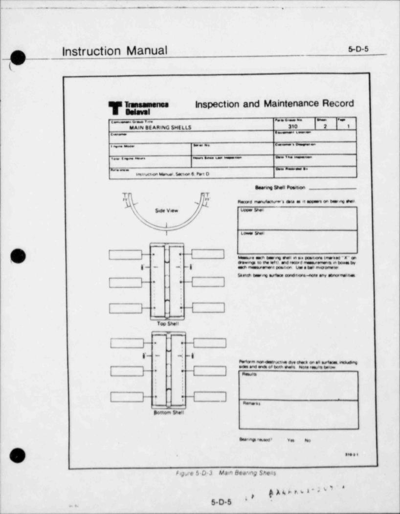
. - . - . _ . . - . . . . . - . . . .
n instruction Manual 50-s
if
us Tremessiones inspection and Maintenance Recorda esisual
e. . . - ..- .
MAIN SE ARING SHELLS 310 2 1
. - _ .-..
.. .. _ .: .,_
. . . . . -- - , - -
- - . ...
stairuci.on Manuel. $.ction 6. P.rt D
So. ring Well Poesteo,1
T T" "'
%. no c, . . . .. - - .n.s
s, v u , Sa .
Losser $hesi
_
l H~
H Ir - . . ,.n. .n . . . r on-
stowmes to the ief t). .nd r. cord rr. s.msnm an bone tryw *
-: -i. , --, -i u. . .ma -, -i,- - .
- f $tetdi hearmg asiew con 61.ns-not. .ny abnorretslite
I F 1 t H I:
':. - .
I F i . i -1 1_-
Top 5 hell
H I| H r,-
.
i- < --
I F *,- : n-oc, 4. o, .li
. n..
.no am o, noin e . ,in m io..
Td I nooin: :
~
: :. - .
q_k' - n- . .'h d j| FSottom Sheil
Bas,.asn '.u.ed' v eso,
|. . . . ..
hgate $ O 3 Marn Beatong Shellsi
6
A 4, b r b A * ' '< )a
j *y,
5-D 5'
I. . .
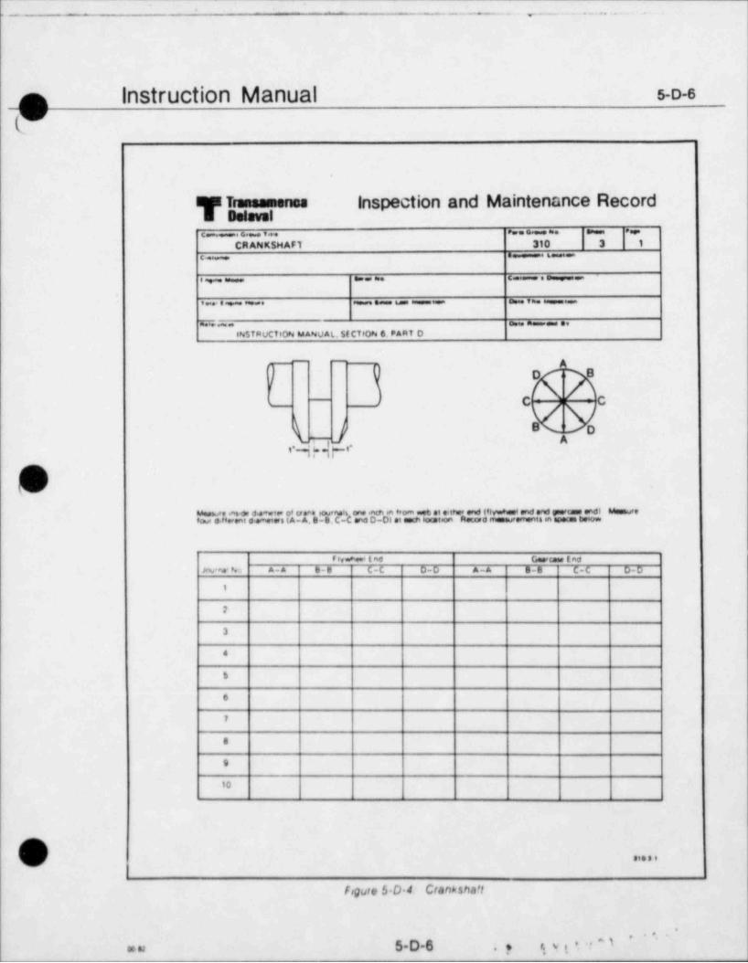
\ -- -. , .. . . . . . . .
f3 Instruction Manual s-o-e
C"'
W Tress m een se inspection and Maintenance RecordE Belovel.- . ~ . . . - .
CRANK 5HAF1 310 3 1
c- 6
I- . . . . - .
. . . . . _ , _ . - , _
m - - . .INSTRUCTION MANUAL. 5ECTION 6. PART D
_ _
! o am
c ;c-m
B o'
^i 4.j ,-i-N
Ju.o e.. u , ... .,~,,C .n..n - .t t, i,i - en. - e~i
fowe 0.t's.ent 6,emetes (A- A, S-8. C- and D-D) et oss lost.on Rewr0 mesurements in .petas tutow
81vw'*.iino C asttaas inoJav'ma' No A-A S-B C-C D-D A-A B-8 C-C D-D
1
7
3
4
S
6
7
8
9
10
kg 81699
Fogure 5.D.4. Ctankshaft
'''
y qyt*''\'
5D6oo u .
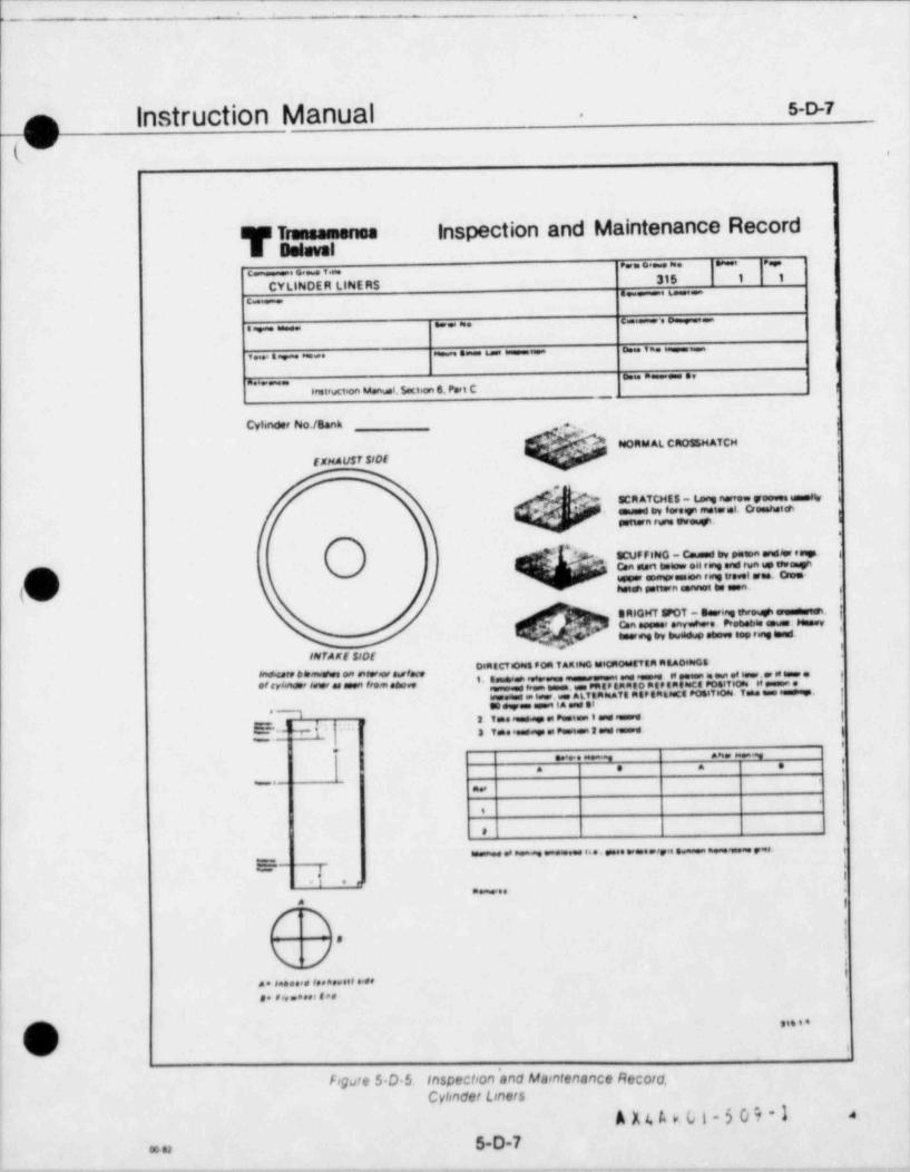
L._ . --- -. ..
n instruction Manual s-o-7.
W !'
1
T Transamenosinspection and Maintenance Record
Delaval I
... .. .. - . ,
.- :.315 1 1
CYLINDER LINERS .. -
.- . e .-...
_ . _ . _ . .. ,
. . . .
i'
n ......
trairuct.on Manusi.5act.an 6. Pert C g
.
Cyhnder No18.nk g .. ,
NORM AL CROS& HATCH .
ExnAust sr0E (t*
.
SCR ATCHEs - W narrow yooves esmetty iemuasd try foresyi sneterel. Oceahatsti
|pottern ruris swe.gi.
4,
-- SCUF FING - Caused Irv peton andW esign i
.
con si.rt tietow e4 rang and run up teve.gnimmer enmsmessen ring trevel sea. One-
/ hsiah pottern sannot to seen. ,
t
O RIGHT FOT - Seering thro #. sumu.nuquh |C.n r .nv . . er.wt, u. ,
emerang try buoidup stove see ring tesul.i
INTAKf slDfOtaECTsoses FOR TARies0 tseCptoesttim AEA048sG8
Wre 6D w wfm ,,,' ,%, ,,;,',, -.< <r= ,e e c,r.. ' = * - ~,,,,,. ,,,,,,,,,~ , = ,,; , =Tsose Tsaae e *.igs.
i-rn
.ta.m.ee.=.a.w.uA.LTtaesaTE RtP Ga6estt Pota',
. ni .i.
i T.. . t t,
g ,._L T.. .e := _ .O.L
.m an.
. . . .
- ,-n
. .
'
e.-.......,,, .
.
iI .r.~..
A
V' ;. . . . . . . . . . . . . . . . . . . .o. ,,,.... u..
A , , , , ,
(v) \\.
Fogare S.D.$ Inspection and Marntenance Record. j<
Cylinder Loners 1
A X 4 A > (., t - 5 0 9 - 3 4
5.D-7 1
1co n
- .-_
' " " + * ' *^
. - . . . -.....,=6 ..
Instruction Manual s-o-ao_(U'
.
Ti m inspection and Maintenance RecordBehwal
e. . ._.o.,_
CONNECflNG ROD BE ARING SHELLS 340 1 1
e -..
.. .-.: . -.
..s. . e_. _ -.
~ ***~~ensuuttion Manus'.$ect on 6. Pert C
Seering Shell Position
T Ts s' s s'
Record enormdecturer's deto es et appears on beering smens
Sede View upper snesi
a.ower Snest
--- - [ . _
H l(d I F ', Musasre som bearing shell en sia positions imersed "X" on'-
'- .
$sennp to the left).erw$ recuard mammarements an boses tryg*_ _ ,,.' _g*
som measurement pc ateori. Use e bedt m.crometer
; g ,.setmb_ , _ _._.._. ,.,_ _
i r .
:'. .
:. -
I F i . H Ia"
Top Shell
-w
I H~
H, I.-
-
r_ _: _ g-Perfarm nonestruct= ere esos on sei m,veces.incius.ng
. _,
suses and ends of both sheets Note ramalts below{,,
Resultsi ..
*'
' .
. .
. -
g_HI H Iaer, ,ss
Bottom Shell
Elserinp reused' Yes No
..s
Fogure S D 6 Inspectron*and Maintenance Record.Connectsng Rod Bearing Shells
1
5-D-8 A y 1. t. v r.1 ' M ~ I=u|
1
. . . . . . . _ . . . - . . , _ _ _ . (
.
lI
Instruction Manual 5-D-9_.n(V
Inspection and Maintenance RecordWT - - - .
E Delaval
:_, ~ -CONNECTING ROD - Mod. RV 3 & RV-4 Ergne 340 2 1
s-
see sus Camuse e T _e syne ename
emist SmW tem emism.n .us he ensammetes tagse em
instruction Manual Section 6. Part C
@
@ $ CYUNDER,
.
g ,n,'
>
D LJ'
^
'MO N '* ~~'"
. **
x%'' e o..
g ...
.*O @ t .~*
rd ",oe WYg. MOD -__:>
3Lg e,y .co mv. - o o
. .L ED ML.0 8mJ,8
C.Ta",a*:'*L'"" "" _~ ee":
% "c"o". !c'' "m" "On" | | eo;* '
- r.;I,:,,' |i a ::!':::: '. .""' ~ . - -
:: T.J'* """ *''"* | |'
--'l ' **.O Oca Poe
:: LT,'rJ*,To pee .0LT %w
' " ****'"% io .
risi.a em suoniae.u..w. eso o, mc r er in rod paion pn own.as wm nerome., u w. m n.cs p.ai .no non,o,s.i ce si
pen.. w ee.n u..we on nom eno. <g. rcem eno ev.n.*L t.o een ororn ene as euen no To. um m w.merusOn matter rod plion pn Duansr'0
| u n.e ,
***' . e-o a-, ...
G..<cese End
F4.n ' End| m
(v , . . , - ,,
|
Figure 5 D 7. Inspection and Maintenance Record.Connecting Rod
A X4 A K 01-5 09 -1 .
| a. n 5-D-9
_ _
u -
- _ _ _ _ . _ . . . . . ... _ ._ ._, _ . . _ _
|nStruction Manual 5-D-9A||
,
T Trammamanosinspection and Maintenance Record
Balsvelear o a. sa=== e
crCONNECTING ROD - Geodel MV.3 & RV 4 Enyne 340 2 2
L=6 Pm and samassh6wsine ese d smeio of tw* pen tamhang with m.crometer Take enmanements in wartual (A.Al and horgantal (8 81seaes. 90 apae Mwas re on both erwas Ignercame and flywhomi).one ench from and of tiumhng Mamasse outsste demeter ofD
ide two unth metromets Manasse on both ends, one entti en trorn ed of pen en tioth wertscal (A A) and horgantal (8 8)
IdawsLea Pin 84.no I D L"* Pm Suihme O O
Step 2 g,, g,g g_a g.g
Guercew End
Flywni=1 End
connecime Red seerme morekatsentiw aunut.ng rod tion to measure la cutes 40und conditaans at connectme rod bearing bore Do not install bear-
f euipa nuts tu full toruur weiuer as shuan in instruction Manual Mansure cormactwg rod baseme tore weide diamriesee m p
im tasth evids. nne end in trom outer edges Measure en vertocal (A Al and horarantal (SB) pienes Take measurenwnt iA Alurw towin ash we tai usiivas te sadas of split line a shown on sketch
Connectag Rod Bamame Bore e DStep 3 ,,, g,,
Geacase ind'
F 8,whmi ( nd
NonDestrustree Testsbehsia non destruct.ww test such as dye checs on connecting rod boa and all fasteers Record resatts turlow
$tep 4
fseit forgues.
Returo deseswmbly (Dresh away| and genembly torgses (W Connettmg fod end link rod tuolts identify bolts by number (sarTorove bo ts in sequence shown, appsymg twowe in 20% 6.fts until firnal taous is reached Refer to Instruct.on.lius er a t.on t s
e4%e' for correst toruve valuesint To Pin e it Taciue mbaiStep 5A
i 2 3 4
D sastembiv
Aunbey
Conriettsrun Rod to Bos & Connecting %on Hee Head Boets Torque 48: lessStep 58
1 2 3 4 5 e
Densembe y
Assember
/n asa a a
O)Figure S.D 7. Inspection and Maintenance Record,
Connecting Rod (Contsnuec;
A X 4 A K 01 -5 C 4 - I 45-D-9Aam
- -_ - - ._- - . - . . .
.
n instruction Manual s-D-io-
(M'
TT . -- Inspection and Maintenance Record
Behwal.. - .
. . . . .M1 1 1
PISTONS - Two Piecese 6sc
> . e. . c .o= ,
I
v.e. ws6w o v we =
. sa . e.semer et.on Manual. 5.ct.on 6. Part Cw
Cviender No./ Sank
|
'
p_ - C*
acr_.. _ .a9e C
..}_p p
[ .,%',,,
y' @/;. .
. . . , .
(0* -
.. - . . . - . . . . -oL.)
, .,oo_ .._ - _e n e.g y a m n = e .e is e, as ee
iaaaecco0:. imes.ecPos t.on AA 33 C4 0D
Upo.t
Low.e
a u ..... o. o ..ee n a.3m.* ..a.s e.,ea um .ea a e ei . . te., oa
Pos,teon A 3
Forward End
Attend
s u-. . .., ea a e e, .,. e .* s o.e a,i
Pos t.on A 3
Foreerd End
|Att End
j . . . - z. . . . -. - ~. . o e , .
Pos. tion 1 2 3 4
0.u.ew,
Assembly
e . oe....e -..
o, ....sG
Fig.ste 5 D 8 Inspechon and Maintenance Record.Poston - Two Poece
'
\ *: ,::
| L f L. l. 'i O . *
mu 5-D-10|
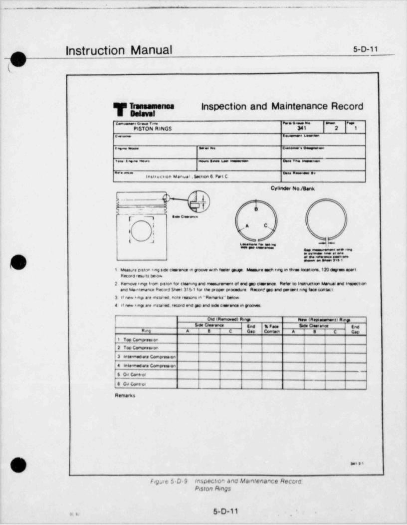
.. . _ . . . _ _ .
Instruction Manual s-o-11,n;
W
IF Traneamense inspection and Maintenance Recorda Belavele o. e. . .- - e.e.
PISTON RINGS 341 2 1
e e--
. e. .. c-.
. . . . e-- - , -
~ 'instruct *on Manust , Secten 6. Peri C
Cylwider No/Benk
h_ --_ _l_
17 % #.o.r-
- *,
i A C~
''
I I
k 8 u f. e" * * " " * ' " * ' y .** reae
1:::.'::"e::::m'i'"''
1 Measu e p.ston eeg s.de cleerene in poove with feeder gouge. Mommste each ring in three laceteors,120 dayens sportr
Record results Deson
2 Remove rings ftorn peston for cleen ng and measurerrent of oral gap cteersrum Refer to instructmon Manuel and inspectionand Me.ntenants Recor$ $heet 31b1 for the proper procedure Recort* pp and paraent rene fece crsitect.
3 If new eg ere insteiled, note reesons in '' Remarks ** tietow
4 at new regs are ensteM retor6 end gop and s.de clarence en ycoves
i
Oss (Remo.ed) R.ngs penw (Rossessmenet R nas5.ee Caserena End % Fees 8'ee Casorene' End
A.nt A 0 C Geo contact A e C Gap
1 Too Compress oa
2 Too Compreis.on
3 eatermed.ete Compression
4 Intermed.ete Comoress.on~
6 0 s Conteot,
4 0 4 Conteet
Remarks
(mN sai s i
fogart $ O 9 InspeCloon anc Maontenance Record.Poston Rings
5-D-11 '.x ., , ,
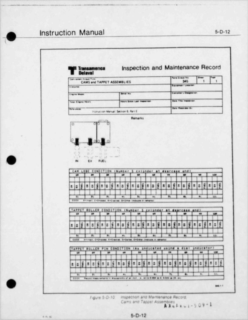
..
_ . - _ . . _ _ _ . _ . .
||
p Instruction Manual s-o-12
W.
T Traneamensainspection and Maintenance Record
Bolevel. . . . . . , .
_..CAMS.nd TAPPET ASSEMellES 345 1 1
e -. 6 =.c
.. . . -,_
..e.,. us. o..v ==
o ... . . . .
t*.ateuct.an M.nua'. 5.co.on 6. P.ct E
R.marki
O 0 3 0
.
w - .m oo.n Oen.
cr ,; s -i; ;;- 2y ti n .,- ,, i,
-
~ ~'N g ,, 9 - g ; ~ ;f_ ,y
.
IN EM FUEL
CAM L(BE CONDITION I WWmD.P 1 CFlin..e 81 ..GrCAl. en.). .
s : |i |s : | : s yj : | |: j : | n s s :s
u ,, ,, .. ., n . .. i .,
. . . . . . . . . . . . . . . . . . . . . . .
TAPPET ROLLE. CONDIT ION (Nu aber i tylinear at maareana anet
. .i
s : |s : | : s { | |i s j |a : j: | : ! s : sa
u a ., ., . .. . . .. . . .' . . . . . . . . . . . . . . . . . . . . _ . . ,
r. Pcf .0ttc. ein c0=oir:0= ... in.ic.i.. ..in. . . .. in.ic.i.r>. --
I
.s : | : a ls : |: : p : 3 : : 3 s a y s a y : 3
: : p
., ,, .. .. .. ., n ., .. ...
. . . . .....-._n..........,.-
|
\ s
fogure $ D 10 Inspection ana Maontenance Recora,Cams ana TaDptt Assembhes
A X 4 8. k v a - 5 0 9 - 1
5-D-12. .. u.. _

...- .__ . _ . . . . _ .
1
Instruction Manual s.o-ia |
) aus Transamensa inspection and Maintenance Recordu antavel_ . . . . e. . . er .
CAMSHAFT BE ARING SHE LLS - Model RV Engine 360 1 1
c sw
. e. =. c.
.ee. ..u- s
* * * * * * * * * " " ' 'saanwci.on u.a si, sai.an 6. Pci tu
ver o roenen et recors,ne meermer en en ..en e oore. sea.nye we numeerar m .sergusace grar, ny n.r4 the enrest aser.nr _ , - -
) er rae one,caer end aur precoes.ar. _
-,,_
sooerde the fo . hen end , ;- - - -r
7
J'| yl
. }. .
. .
6 i ,,
q \ ._ ~ __ _
_
THRUST CLE ARANCE a a. c ees,
gs Move camshaft aH the way att with a bar theri rnaasure thrust Legg
( \ clearance with a teeter ga#Je between camshaf t thrust collar
(v) and thrust bearing p,gh t
BE ARING CLE AR ANCE/THIC KNESSMeasu e bearing sheH to camshaf t clearance with a feeler gou0e. Or baaring sheti thick ness with ar
m.crometer ind,cate rnethod wsed and record in appaopeiate spaces below
$t ARING TO CAMSM AF T CLt AR ANCE - Fee 6er Gasse
1 2 ) a 6 6 7 e e I6
) Le's B.6
Rge seen
St ARING $HI LL TH6CE NESS = W.oreme,er
, , , . . . . . , ,e
(#16 a.I
m.,r i k.a
Remarks
)
(h( ) m,
Ns'f og.s! ; b D.11 InsptCloon ana M.n.nten,t*1Ce Recorat
Ca'nsnart Ucarong Shens
AA4AKO1-$09-1a. se S D.13
_ _ _ _ _ _ _ _ _ _ _ _ _ _ _ _ _
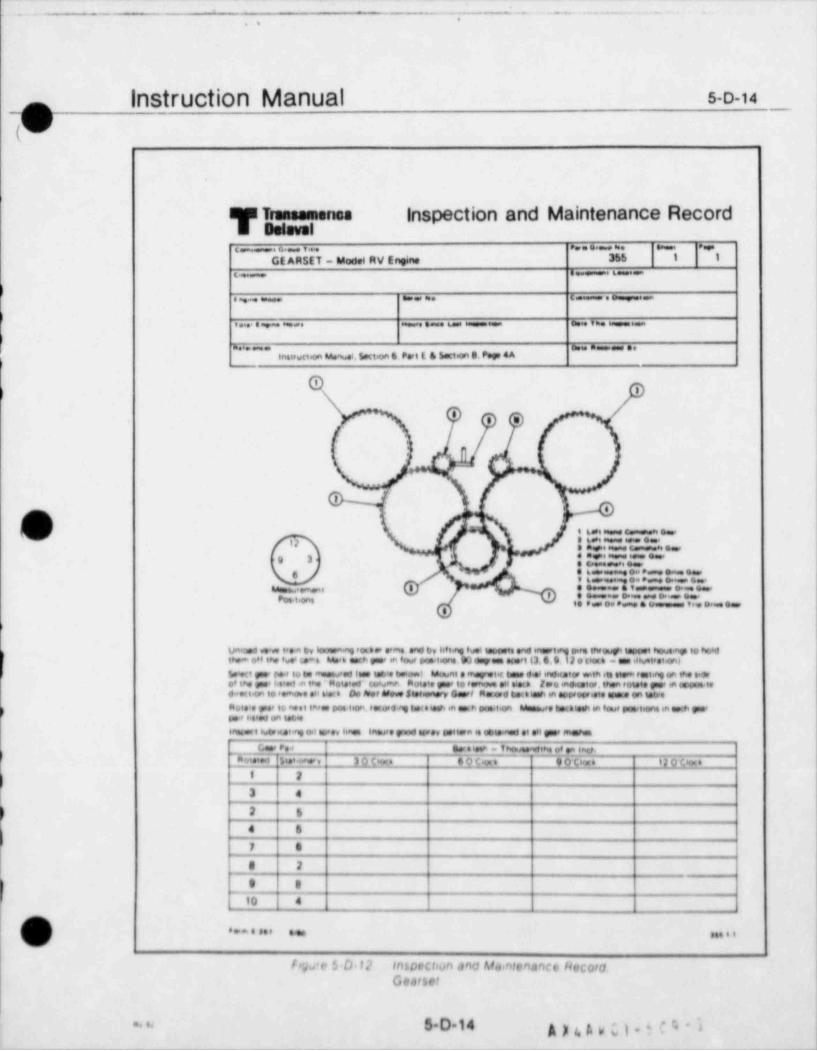
(_ _ _ . . . . . _ _
.. .
Instruction Manual s-o-14_
T TraneamenosInspection and Maintenance Record
Dohwol._.c... .... . .
GE ARSET - Model RV Ervne 355 1 1
6 - .. s.
e m. c .o= .a
. ..eaca. = .. .6.-==- c. . n.
* ~ * " * *sa.wwet.on u w.l. 5.ct.o e P.,e t & 5.c1.on 8. P.y 4 A
Oi
'e e
.
...
i.f3
t \
L ,/ F 6..==.ci, e..t.
. . . . ., 3 c,6.<. . . . . . ..
t .a. .
u m. . -
. . . . - . .sp.,,,,,,
i..
.....i, ..,
v.a.o.4.. it .a er. io.i.a.ae '=.., .,m.
.ao ir. i.si.ae 'w.i imet. .as eae.il o.o.ouen iw.i now..aa io now
. .- on i,. s .w. u . .mn e e ., v.i.on so a., w,i is. e. e . cas. . .n .ie.i.on>o cn w
S ct ., r , io to m ,,.d f i ta teowImm.. , . .- t.s d i .nd.raiw w in it. iem .si.a. on ih. orAAm.no m.o t e.. i .. i... .a now..a co.wma m. i.. .aeain. ,, ..wi. . wo....on.. ..nm o.m.ee suranyc.,em .ai ..emw. wop i. .onan..ac, . . ,., i. a.. in, po....oa. .. e3 i . .e . n w i.ca u w,. em we ia sou, n.i.on. a * ,.,
., ...o oa u wea..e i awa. o..a. i ., i.a. in.,,e anoe u... i n.. i. in ..a.e . .n , in.n.
c. ,e., e..i -tno.,.wn .aiaen,,.e_. s i.~.a . 3 o o... e o o.. . e o p.. . i a o o,. ._
t 2
3 4
2 6
4 6
7 4
8 3
} 9 8
/ 10 4
m
( ) . . . . . . . . ....iV
f r';J'y ' D. f 2 InSDrCitun and MkhttnanCc heCOrda
Gearset
5.D.14 gy6t,wcg. ~4-i. . . .
_ _ _ _ _ _ - - _ _ _ _ _
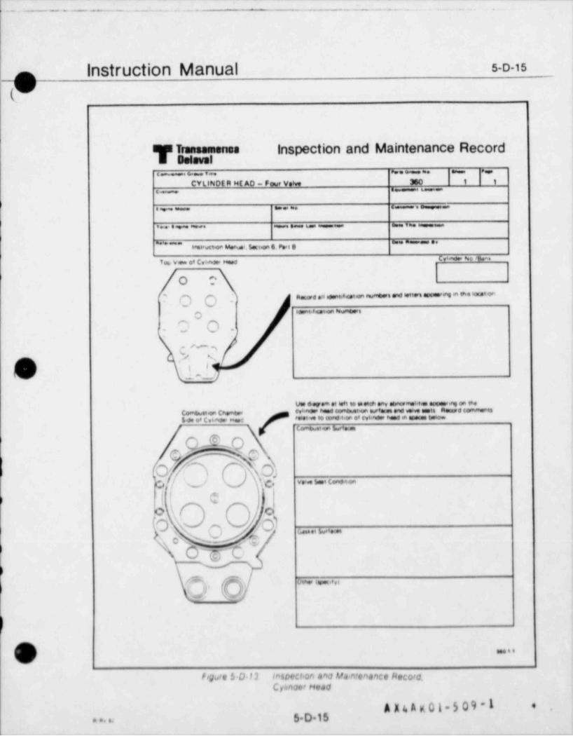
( . - _ _ _. - _ _ _ _ _ _ . . _ _ - =_ . . _ . . . . .
Instruction Manual s.o-is
-O(.
T TransamenosInspection and Maintenance Record
selevelc-- . . .. ~ .
CYUNDE R HE AD - Four volve 380 1 9
s -. 6 ,6 = =.
lie =. c.
i. e awa. a . u o,
i* * * * * " * " " " " * " ' * " ' '
ormieucie u.ausi, soci.an 6. Poe t a
Cya ao No 'twa.Toi, view o' Cvi.nor Head
O Oa-**"'*"'"-'#""''*''''"''''*''"-"'""'"*'""'"' OO- i
.,..,e,._,oO p-
1- " - |
re5,/ N
G | _)v d o .,e , - ,,ei.. . ,
Corr $wete chemtwe Wl'AG.' head ComtmAte wfmet end wig teett MMd CONMont4s,o. os c s,no, une teiet'* to end,te of cyt.nde hand a aosa.s ts+om
Comtm1 tion burfetas
@..
.
0.- .;e. , ., v.. - -, C- e
$)o\ o
01. O \. s o e... e, m, ,
'\ C 's NM $';I
,-- - ' .
v
/ ' 'E viw tes.c.e,s
),0' \~s
em
( ) ..
v
f! Quit b D 13 In$Dectron and Ma>ntenance Recora_Cyo<nourhead
*# ~'
5 D.15a a ..

L. . _ _- _ a_ _ _ _ - _ _ _ . _ . _ . . - . .
Instruction Manual s-o-is
-O(,
T Transamensainspection and Maintenance Record
selsvol. .. - .
m- ..INTAKE ond EXHAUST VALVES 360 2 1
. - . .e.
. . e .= .
. . . ~ . ._ ....
-. . e ..
stetruct an seenust. 5.nion 6. Peri 8
Cvieno.r No / bent
:
4'.1.-j.;'l'
, .> .- ~ ,-,al g, , . Q1
s%y -- == -
, ,
| v-- ,. , 3,
s,i ,e
1 . 44 3 4.. :7. . . ..
,o N.. e .,
( ) '. -' ,j .-
' rw a reure a rweVet *Tc4uede ClearenceMeasure by noting oef 6ection on valve beeJ while rocking valve in its guide Remove wedges. retairwrn(or totators) and springs Lay cylinder head on its side with valve e s es in the horisontal plane Leave awedge on valve stem and push velve out until stopped by wedge hitting guide (see Figure 2)Position a dial endicator as shown in F9Jres 1 and 2 no that spindle of endeutor is bearin0 against sadeof valve head on the A-A asis (see Figure 31 Jero it.e indicator, then apply suffic.ent pressure byhand at a point diametrically opposite the spendie to anove the valve en the guide Record this deflectionRepeat the prouas m the B-B amit and record all feedings in the space provided below $seFeguretfor valve identification ([X 1,IN 1.etc L
A s t/Ve+v. sai |3y |N 1 iN )A-A
B-8)
Valve Heed ThicknessMeasure vatve head thics ness (Figure 4) with a mioometer and record en spare below
vow tal ta2 es t eN ;
T h.tsasu
Generel inspectioninspect va've for generat condition and not all abnotmahties or other signifiunt information below
/D * . s ee r a.e , , , , ,( )v
Iogate $ 0 14 InsptCloon and M.pntenance hec 0/0Infant and i shav5! V&vt*5
A E '' A * ' ' ' ''e e, s, 5.D.16_ __ _ _ _ _ _ _ .-.
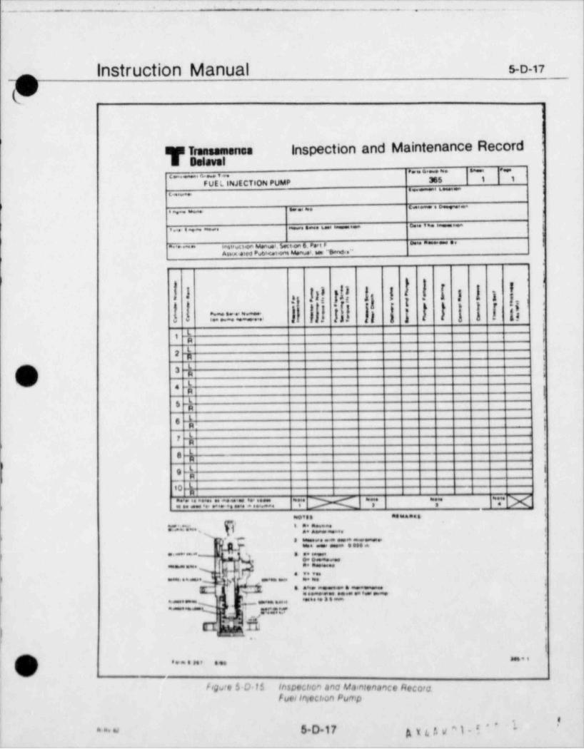
----
- - . . _ . - . . . . .
|nStruCt|On Manual s-o-17-
l-,
1
i
l
i
T Transamenosinspection and Maintenance Record
'
selevel. . . . . . - ~ '-
. . . ,
365 1 1FUE L INJECTION PUMP
._ .. . .
...m.=..._ ,
. .._ ._ . . . _ . _ ,. . . . . . - . _ .I,
. . . . .. .. ,_ c.. m. . ....,,. . . . _ '
Asian ieied Publ at.on M.nu.t. e "Ba.w3..''
l 1 f I 1 I i j.,,-3 li! !!
si Ii e:jo .
.t r h-. .
l a 1 ;:, ;:-a a.. - - - . _ . . ' 3. -.
rL,R r
2 R
_La i
, ,A
6 .p
I
m ,
8 -
h
9 3 Ie
'
--h10
:: =.=. .: .=. ,-x r .- x--,
... ....
= x,yyF:::= .
e e~. ~. . . . .
.. _ ., . . .4 .
. .. i ..
,..~. 4cy -44 9. v
.
C . . . . ~ . . ~9 f.e ~'*"*
.. . - .~s==*
,, .
s., ..y
_
:'=.
y11 .
\
[.
!
* ..( ) . . . . . . . . .(w/
foy e $ D 15 Inspection anc Maintenance Recora.f uelIniccison Pump
e'
,'
a a. w 5 D-17 gyt3g a)-i'~ i *
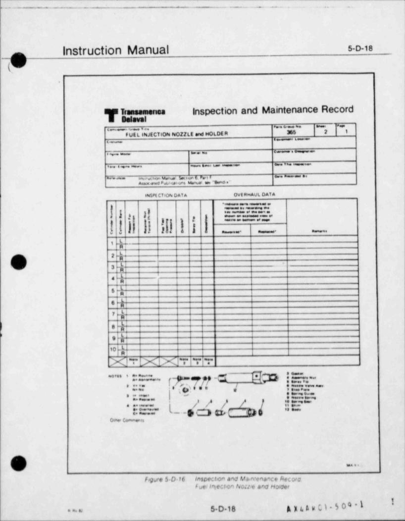
L. - . . _ _ _ . . .. _. 1
Instruction Manual s-o-18_
-.
T Transamenosinspection and Maintenance Record
noisval. . . . . .
. . . . . . . ,
FUEL INJECTION NOZZLE and HOLDE R 365 2 1
. . _ , -.-
. c - .: .-.
,~. ... - . . _ .
~ . . - . ..... ,~....~,,u..,A-....-.-.-
'NSPE CTioN D AT A ovE RMAUL OAT A
* ...| ..t . .
,i jE,
.c . ,.
pq. .
;. L. a s ,. _.. . ... ,
'tR
-hfN, 2
V 4-
3
L,R|'I
5 R1'6 R
y L131'!e RtLigR
10 '
R
Xv XX T T T
''" ',!!! r-~ r.. g 7..p/ -C1 D :! ! E ~r. -; :. ::-~.| .9.....
. - . .-. . . .
.:::~::.~--- , ./ /, /,.
.* * * 'apa"~'8 w '** !.'*7 .- g, Q g . <
o= c-,.
/ \
( j ....%/
figure $.D.16 Inspection and Ma>ntenance Recoraf uelInjectron tio: lie and HOIQer
1
5 D-18 A X 1. f. v C 1 5 0 4 - I'
. a. o
>. m - - - ^me gems wa. e -e mo e
k Sect'on 6Overnaul &
r.epalr
.
I
wi
&I, O
cI
w
O) *
.:4M
e4
/
)
|
)\
g, . ;<'. .. . .
. . . ,. ,
~-....
_ _ _ _ . _ _ _ _ _ - _ _ _ _ . , , _ , . . _ _ _ . _ _ _ _ , , _ . _ , , _ . . . _ _ _ _ . _ _ _ _ . _ _ - _ _ ~ _ _ _ _ _ . _ , _ _ , _ _ . - - .__
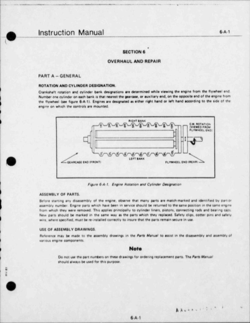
L__ _ _ _ . _ - ,-- - _ . ._ l
Instruction Manual sA1|~
\k I
.
SECTION 6
OVERHAUL AND REPAlR
PART A-GENERAL
ROTATION AND CYLINDER DESIGNATION.
Crankshaft rotation and cylinder bank designations are determined while viewing the engine from the flywheel end.Number one cylinder on each bank is that nearest the geercase, or aunitiary end, on the opposite end of the engine fromthe flywheel (see figure S A 0. Engines are desegnated as either right hand or left hand according to the side of theengine on which the controls are mounted.
AtGHTBANs" ~
EWE FRv , PLVwMit L INDI
~
E : : ! -r9_
v-
s
' --
LtFT BAhnOtARCASEEN0tFRoNTI PLYwMitLINotREAR)
figure 6 A 1. Engine kotation and Cylinder Designation
ASSEMBLY OF PARTS.
Before starting any disassembly of the engine, observe that many parts are match marked and identified by part orassembly number. Engine parts which have been in service should be returned to the same position in the same enginefrom which they were removed. This applies principally to cylinder liners, pistons, connecting rods and bearing caps.New parts should be marked in the same way as the parts which they replaced. Safety clips, cotter pins and safetywire, where specified, must be re installed correctly to insure that the parts remain secure in use.
USE OF ASSEMBLY DRAWINGS.
Reference may be made to the assembly drawings in the Parts Manual to assist in the disassembly and assembly ofvarious engine components.
MDo not use the part nurrbers on these drawings for ordering replacement parts. The Parts Manus /should always be used for this purpose.
'0a
OG
Sw,,,:i -
6A1

(_ _ _ _ = _ . - _ _ _ . - . . ..
Instruction Manual 6A2
9PART A - GENERAL (Continued)
CLEANLINESS,
) Cleanliness is essential to the proper operation of an engine. Care must be exercised to keep dirt, grit,and other debrisfrom entering any of the lubricating oil, fuel or cooling water systems as well as from the bearing surfaces of movingparts.
TOROUING,
All torque values stated in this manual,unless otherwise specified,are based on the use of a thread lubricant composedof equal parts by volume of engine lubricating oil and Dixon number two medium powdered flake graphite, or equal.They do not apply to dry threads, or to threads lubricated with so called " Super Lubricants". Dry threads can result intorque readings as much as fif ty percent in error. The following procedure should be used when torquing fasteners
a Lubricate threads with a mixture of oil and graphite and assemble threads. Tighten hand tight,
t- Tighten all fasteners by snugging the first one, then moving to the one farthest removed and continue in acriss cross pattern until all fasteners are snug
c. Unless otherwise specified, apply 20 percent of the required torque to each fastener in the sequence de.scribed above, then repeat procedure in increments of 40,60, 80 and 100 percent of the prescribed torque value.
d. Active nuts which are secured with cotter pins must be brought to the specified torque value beforeattempting to abgn the Cotter pin holes. If the hole in the bolt is halfway between the slots in the nut,or beyond,
/7 the nut should be tightened to make abgnment. If the hole is short of the halfway points, nuts on bolts larger than
( ) one inch in d'ameter may be backed off to the nearest point where it will align.- _
TOROUE TABLES.
Ref er to the Toraue Tables, Appendix IV, Page 8 5 to find the torque value to be used when tightening fasteners on theenyne. The tables a e divided into two parts, the first being for those f asteners f of which specific torque value has beenassigned The sectnd part conta'ns general torque values for use when no special torque value is assigned 8ecause oftheir sae, location and hegh torque requirements, main bearing cap studs are pre-stressed when the stud nuts are in.stalled, rather than being torqued with a wrench. This is accomplished by stretching the studs with a hydrauhc tool,then tightening tne stud nuts When the tool is removed, the stress in the stud provides the clamping force to hold thestud nut in place
2
E
A A 4 4 V u l-5 09-1 *,
6A2 va si a si
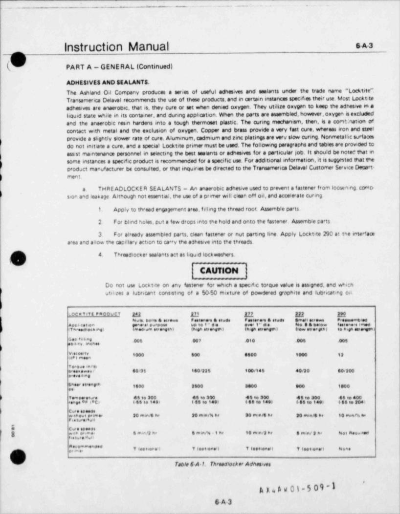
, .-. . .. . . .
Instruction Manual 5^-3_
i,
b PART A - GENERAL (Continued)
ADHESIVES AND SEALANT 8.
The Ashland Oil Company produces a series of useful adhesives and seslants under the trade name "Locktite**,Transamerica Delaval recommends the use of these products, and in certain instances specifies their use. Most Locktiteadhesives are anaerobic, that is, they cure or set when denied oxygen. They utilize oxygen to keep the adhesive en aliquid state while in its container, and during application. When the parts are steembled,however, oxygen is excludedand the anaerobic resin hardens into a tough thermoest plastic. The curing mechanism, then, is a cor9t: nation ofcontact with metal and the exclusion of oxygen. Copper and brass provide a very fast cure, wheroes iron and steelprovide a slightly slower rate of cure. Aluminum,cedmium and rinc platings are very slow curing. Nonmetallic surfacesdo not initiate a cure, and a special Locktite primer must be used. The following paragraphs and tables are provided toassist maintenanca personnel in selecting the best seelants or adhesives for a particular job. It should be noted that insome instances a specific product is recommended for a specific use. For additional information,it is sugysted that theproduct manufacturer be consulted, or that inquiries be directed to the Transamerice Delavel Customer Service Depart-rnent.
a. THREADLOCKER SEALANTS - An anaerobic adhesive used to prevent a fastener from loosening. corro-sion and leakage. Although not essential, the use of a primer will clean off oil,and accelerate curing.
1. Apply to thread engagement area, filling the thread root. Assemble parts.
2. For blind holes, put a few drops into the hold and onto the fastener. Assemble parts
3. For already assembled parts, clean fastener or nut parting line. Apply Locktite 290 at the inter'aaearea and allow the capillary action to carry the adhesive into the threads.
4 Threadlocker saatants act as liquid lockweshers.y _-_
CAUMON
Do not use Locktite on any fastener for which a specific torque value is assigned, and whichutilizes a lubricant consisting of a 50-50 mixture of powdered graphite and lubricating oil.
'.ocwTitt emoovet 24] jjj 2,7J7,M ,eteews
19,0Nuts. beats & screwe Psetenere & stude Footeners & etude emet Proceeemtpied
we,,e.o, et,ees,,,, o,ver 1" die ,i No a.& b,esew tes.teaere imod1" d e
Ase,i ca. tion e,sme. ras swepose,n>i, t i ,i n ee e et ii.w t,* ,ta, ,e ,e,, es,e,tn >ira ee ien. s, i,,e .w n .t.ee.
,",,','',"j,,,, .00s .007 .010 .006 .005
{','j ', '',',', 1000 800 e600 1000 12
v., ewe ,n/i.
eveeme*ey/ 60/25 100/225 100/148 40/20 00/200erese ieng
8,,","' 8 "'" 8'" 1400 2600 3000 a00 1e00
f empee stwee 46 to 300 48 to 300 45 to 300 45 to 300 48 to 400esage *P t'ct Ielto 1896 6 SS to 140) ( SS to 14e) ( SS to f eel 1 48 to fool
Cwee seseosw,inewt peimer 20 m6a/s he to en6n/4 he 30 m6n/6 hr 30 min /6 he 10 men /% neFes twee/tw ie
O cw e speedse
..ea 6 m.a/2 he 6 m6n/h .1 he 10 min /2 he 8 min /2 hr Nee meevandg t ,. t w,e, im e,,e,tvi
,", 7 *'**** T test.eced 7 (optiones) T testiona0 7 feet.eae9 Neae
Table 6.A.1, Thraedlocker Adhesives
'
A n A g 01-5 09 -1
6A3- _ _ _ _ _ _ _ _ _ _ _ _ _ _ _ _ _ _ _ _ _ _ _ _ _ _ _ _ _ _ _ _ _ _ _ _ _ _ _ _ _ _ _ _ _ _ _ _ _ _ _ _ _ _ _ _ _ - _ _ _ _ _ _ _ _ _ _ _ _ _ - - - _ _ _ _ _ _ _ _ _ _ _ _ _ - _ _ - - _ _ _ _ - - _ _ _ _ _ _ - _ _ _ _ _ _ _ _ _ _ _ _ - _ - _ - _ - _ -
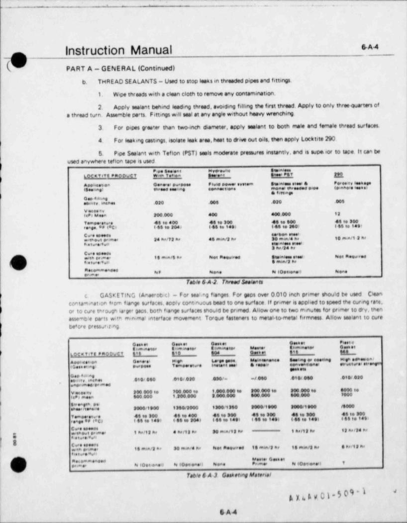
(- . _. . .. .
|,
1
11
l
6-A 4 lInstruction Manual19 PART A - GENERAL (Continued)
b. THRE AD SE ALANTS - Used to stop leaks in threaded pipes and fittings.
1. Wipe threads with a clean cloth to remove any contamination.
2. Apply sealant behind leading thread, avoiding filling the first thread. Apply to only three quarters ofa thread turn. Assemble parts. Fittings will seal at any angle without heavy wrenching
3. For pipes greater than two inch diameter, apply sealant to both male and female thread surfaces.
4 For leaking castings, isolate leak area, heat to drive out oils, then apply Locktite 290.;
5. Pipe Sealant with Teflon (PST) seals moderate pressures instantly, and is supe.ior to tape. It can beused anywhere teflon tape is used.
e,pe seeient wverevne aminineLoextite emoover with te i a seeisat stees est me
Apoisestion oenoesi owee u rsw6e eewee eyeiem steinsen stees & Per esis, seee eee
isnime) te.eeee seeime eennut no manei threeees eine a pinnoie iese si* " ' " ' '
o.o.einingetsinty. incan .020 .00s .020 .005
V esesity(epi Meen 200.000 400 400.000 12
Tempeestwee 45 to 400 45 to 300 45 to 600 45 to 300seage.** (*Cl 6-66 to 204) 158 to teel t SSto 2e0) t-SS to 149)
Cwee cosees seenon steelwitnews primee 24 he/72 he el min /2 he 30 mm/4 he 10 min /12 hefintwee/fwH etsinises steet:
3 he/24 heCwee seeeceO with primer 18 min /lne Not meewleed ste6miees steei- Not Meowieod
(#h, fiatwee'twH 5 m6n/2 he' a",';"- a= ~, u.n. ~ io ,tenen u.no
,
Table 6 A 2. ThreadSealants
c. GASKETING (Anaerobic) - For seahng flanges For gaps over 0.010 inch primer should be used Cleancontamination from flange surfaces, apply continuous bead to one surface. If primer is applied to speed the curmg rate,or to cure through largar gaps, both flange surf aces should be primed. Allow one to two minutes for primer to dry, thenassemble parts with minima! interf ace movement. Torque fasteners to metal to metal firmness. Allow sealant to curebefore Pfessuribng
o est et o enet cask et oesnet Piestiee hminatee S timins ter e hmmatee Mester eismmetos osen et
/ Locativt PRoovCt St6 810 804 D es t et stb $4 8i
A pohee teen osaseet H en L.eepe pope. Melatemense Seeiing er e eting Hign ednesient
IGeometmel swepose T empeeetwee Instant eeel & repear eenventlenet etewstwesi eteeneteesseets
Geo tilbagseint v. insnes .010/050 .010/.020 .030/- -/.060 .010/.060 .010/ 020
,
was,imed/pe med
vesseest, 200 000 to 100 000 to 1.000 000 to 200 000 to 200.000 to a000 te
(c')eneen 500.000 1.200.000 3.000.000 000.000 s00.000 7000
S te eagtn. poienesetteasise 2000/1900 1350/2000 1300/1360 2000/1900 2000/1900 /8000
f emoeestw e 45 to 300 46 to 400 45 to 300 45 to 300 48 to 300 46 to 300e
esageor t'C) t 89 to 149p 445to 204) {$6to1491 4 SS to 1491 4SSto 1491 (ll to 1891
Cw espesose
1 he/12 he a he/12 he 30 min /12 he 1 he/12 he if helle hewei,n e,w t,somer
aas ,, , , , f ,y
b Cure spesceniin onmer il enin/2 he 30 ensei/4 he het Roewired 18 enin/2 he 18 enin/2 he a herit hefistweeefwnj Meeter oeenet/ j an ommeaceit
( j .pimee ~ io. .ee.o s io. ..n.o n.n. e,im.e nio.fi.neo e
vTable 6 A1 Gasketmg Material
A ya A v 01 - 5 09 - 1d
6.A 4j
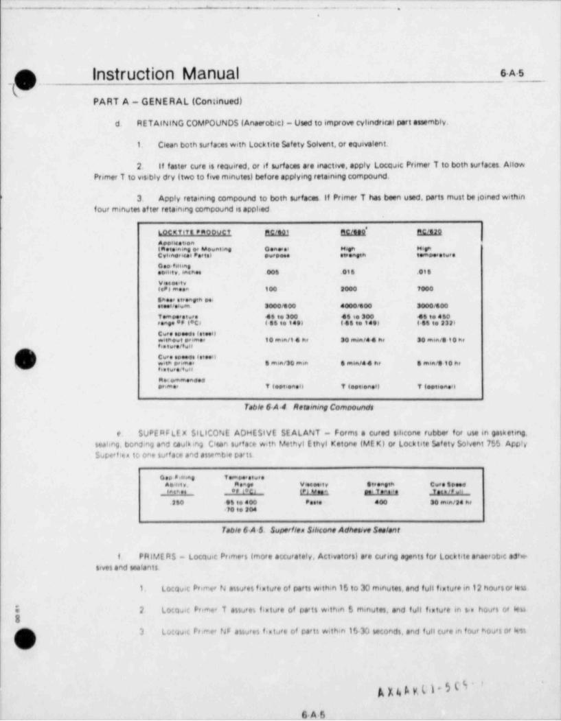
- -
- . .. - . . . . .
.
- O. Instruction Manual e A.s
PART A - GENERAL (Continued)
d. R ETAINING COMPOUNDS (Anaerobic) - Used to improve cyhndrical part assembly.
1. Clean both surf aces with Locktite Safety Solvent, or equivalent.
2. If faster cure is required, or if surfaces are inactive, apply Locasic Primer T to both surfaces. AllowPrimer T to visibly dry (two to five minutes) before applying retaining compound.
) 3. Apply retaining compound to both surfaces. If Primer T has been used, parts must be joined withinfour minutes of ter retaining compound is apphed
*LOCMTif t PmooVCT Mitgj RC/taQ E/12,9Apolleateen(note ning e* Mewnting Geneese Hesh HignCvhnences Portel purpose steeneth tempee stwee
oso fiHingob6hty. 6nsmes 006 .016 .018
V ess esit yteP) meen 100 3000 7000
Shee, etesagth peestoet/olwm 2000/800 4000/600 3000/600Tempeestwee 45 to 300 48se300 46to 460rangeertect i es te 149) 185 to f eel 6 54 to 232)
Cwee eseeds totee0withewt seemer 10 min /14 he 30 men /4 4 he 30 m6n/010 hefis twee/f wil
/ CweesoeeenInteen
( 's)h wtm premer 8 min /30 enin 8 m6n/44 hr 8 min /910 he,, . tu, e rt w n
m e< ommendedenmer T testioney 7testioney T deptioneo
Toble 6 A.4 Retsining Comoounds
e SUPERFLEX SILICONE ADHESIVE SEALANT - Forms a cured sihcone rubber for use in gasketmg.seahng, bonding and caulking Citan surf ace with Methyl Ethyl Ketone (ME K) of Locktite Safety Solvent 75S ApplySuperfiea to one surf ace and assembie parts
ceo seuias t emoee stveea n.nt v. meage Vieeesis, steeaeth Cwee speed
eae et _ er teci (P) veen mei Teae ie _f ac e /P w's
.250 et to 400 Poste 400 30 min /2 he70t 20
Table 6 A 5. Superfien Sibcone Adhesive Sealant
f. PAlME AS - Locquic Primers (more accurately, Activators) are curing agents for Loc 6 tite anaerobic ad'ie-sives and trialants
Locqu,c Primer N assu es fixture of parts within 15 to 30 minutes,and full fisture in 12 hoursor itu1. r
O 2 Locasic Frimee T assures finture of parts within S minutes, and full feature 6n sis hours or 6en8
N, 3 to: u ,c reimet Nr assures f,eture of parts within 15 30 secondi, and full cure in four hou s or +ssr
nua?-
G.A 5 .
- - - - -
-.. ..- _ _ .. .- - . . _ . . . ,
I
|
Instruction Manual 6A4_g( PART A - GENERAL (Continued)
SAF ETY PRECAUTIONS.
Personnel performing maintenance, overhaul and repair work on the engine and its associated equipment must beaware of the hazards involved in this type of work,and observe all safety precautions. In addition to those precautionslisted in Section 4 for engine operation, the following are some of the areas in wtacn safety practicas are indicated
a Observe all specific Warnings listed in this manual for the operation being performed.
b if, in the course of maintenance work, it becomes necessary to crank or operate the engine, those precau-
tions listed in Section 4 should be observed.
When handling heavy weights, all weight handling equipment must be inspected bef ore use.c
d Exercise extreme care to insure that the weight of all parts being handled is under complete control at all
times
)e Unde' no circumstances should any person extend any part of his body under any suspended heavy part,
f. When handung liquid nitrogen, or other super cold liquid, wear suitable gloves to protect the hands Glovesshould be of a type approved for protection against extremely low temperatures.
9 Crankshaf t should be blocked to prevent inadvertant movement when working in the crankcase
h h. Do not exceed maximum allowable hydraulic pressure on hydrostatically operated tools and equ pmenti
ju-
Do not disconnect any pressurized line until you have determined positively that no pressure exists in thei
1.ne
i E nercise good housek eeping practices to provide good footing on platforms, ladders and other areas aroundthe engine and associated equipment
k Under no circumstances should any interlock, safety switch, or other safety device be bypassed, blocked
or otherwise rendered enactive
e
8
A X4 A x 01-5 09 -1'
3
6A6m
L . _ _ . . _ . . . .
n Instruction Manual e A-7
(vCOMPONENT WElOHTS.
The component weights listed below are approximate, and are intended to assist in handling and assemblyoperations Suitable weight handling equipment of sufficient weight lifting capacity must always be usedwhen handling heavy and unwieldy parts and assemblies,
Appromimate Weight (Ibs)item1100
Cylinder head ....................................................600Piston and rings (less pin) .........................................120P i s t o n pi n . . . . . . . . . . . . . . . . . . . . . . . . . . . . . . . . . . . . . . . . . . . . . . . . . . . . . . . .624Master rod .......................................................700
Link tod and box ..................................................600Cy lin de r li ner . . . . . . . . . . . . . . . . . . . . . . . . . . . . . . . . . . . . . . . . . . . . . . . . . . . . .365Cylinder he a d sub c ov er . . . . . . . . . . . . . . . . . . . . . . . . . . . . . . . . . . . . . . . . . . .30Cy linde r he a d c ov e r . . . . . . . . . . . . . . . . . . . . . . . . . . . . . . . . . . . . . . . . . . . . . . .
675C a m sh aft (les s c a m s) RV.12 . . . . . . . . . . . . . . . . . . . . . . . . . . . . . . . . . . . . . . .
RV16....................................... 75020Cams (average) ..................................................
370Main bearing caps Front ..........................................*
I nt e r m e di a t e . . . . . . . . . . . . . . . . . . . . . . . . . . . . . . . . . . . . 200300Front rear ......................................300Rear rear ......................................
-
'A X 4 A M 01-5 09 -1
6-A-7..
w______-____________-___________________ _ _ _ _ _ _ _ _ _ _ _

_ - __ - __ .. _ ___-__ _
... . - --- ..._.-. .
Instruction Manual s.a.i
(
PART B - CYLINDER HEADS AND VALVES
i CYLINDER HEAD REMOVAL.
! Each cylinder head may be removed from the block independently of the other cylinder heads. The cylinder head
{has two intake and two exhaust valves, together with their associated springs, wedges, retainers, etc. Valve s ;ngs
j may be replaced with the cylinder head installed on the engine provided the piston is at top dead center to preventj the valves from f alling into the cylinder. To remove a cylinder head from the engine, proceed as follows.i
,
s. Drain jacket water from engine.
i
{b. Remove cylmder head cover. *
c. Remove air jumpers...
,
* *d. Disconnect exhaust and intake air mani. ' I'folds.
e. Disconnect fuel injection lines and norrie ,y, |j drain fittings. 1 e
!f. Remove rocker assemblies and push rods.
) Remove hydraulic valvelittersif engine is to equipped. !
g Remove fuel injection norries and holder
assemblies.
!
h. Remove cylinder head sub-cover. .
i. Attach htting feature to the fuelinjection |studi as shown in Figure 6 B.1. Attach an overheadhoist to the lifting ring of the fixture. g .,.
g e a ..'
'j. Remove cyhnder heed stud nuts and ' *
'
washtrs. fi9ure 6-B.1. Cylinder Head liftmg ha ture
'
k. Lif t head from block. If head sticks it may be necessary to take a strain on the hoist and break the headloo.c by atsik!r.g the sides with a babbitt or let,d hammer..
. INSPECTION.1
Clean inside of combustion chamber. Bar engine over until piston is at bottom dead center and clean and inspect upper,
2 portion of cylinder bore. Clean gasket surfaces of engine block and cyhnder head. Remove intake and enhaust vattenj fieface and restat as necessary, following the procedures outhned in subsequent paragrsphs.
I'
r
!
!,
|
!
!
A X t. A x 01 - 5 0 9 - 1 11 083|
_.
.. - -. . . - - . .,
Instruction Manual s.B.2f(V PART B - CYLINDER HEADS AND VALVES (Continued)
VALVES.Intake and exhaust volves on diesel engines are interchangeable. When replacing velves that have been removed foryinding and seating, however, they should be returneed to the same relative lomtion as that from which they wereremoved.
VALVE SPRING REPLACEMENT (Cylender Head Not Resnecesil.CValve springs may be replaced without removing the
cylinder head from the block. Remove rocker arm assem- " " " " * ' " *blies and fuel injector, then bar engine over until the Qaottenpiston of the cylinder being worked on is at top dead , ,
center. This is important as the velves an fall into theenacnetcombustion chamber if piston not at top center. Attach anartsn astaman ,
a valve spring compressor tool,part number 00L5906155 N ,
'
(see figure GB-2) to the cylinder head by positioning the g}g*8@ ""***tool support over the fuel insector studs. Place a washer
-
p/-on each stud, then thread a spacer nut on each stud to m -
racsa nuthold tool in place. Slide the adapter retainer over the* 88''''"* rvalve spring retainer (figure 68-3), then swing bracket to
j |[**"'"position compressing screw over adapter retainer. Turnscrew in until all slack is removed, check proper engage- """N i | i
ment of the adapter retainer to the velve spring retainer,then continue to turn screw in, compressing the velve p ,i'spring When sonng is compressed sufficiently to permit . ,
hremoval of the two wedges (figure 48-3),lif t velve by its [ q.g,,
--estem and remove the two wedges. Slack off on compres-sing screw and swing bracket arm clear. Remove valve \, , , , , , , , , , ,
esseamos tookspring retainer and valve springs. Tool can then be usedto remove other valve springs on that cylinder head. Notethat vvhen tool is mounted on injector studs, all four , , , , , , , , , , , , , , ,,,
valves are accessible without removing cylinder head sub. a,a sj,.g.o v',''Easo ustc6
Me as sue cove ncover. An alternate method is to mount the tool on thestarting air valve studs, however, only the intake valve Figure 6 8 2. Valve Spr/ng Compressor Toof
springs can be removed with toolin this position instal-lation if the reverse of removal.
VALVE REMOVAL FROM CYLINDER HEAD. uneess e vatve me
With cyhnder head removed from engine, install valve p,yfaa
spring removal tools as shown above, ard remove valve | |springs Remove valves by pushing out of guides on thecombustion chamber side of the head \
g s
m:@ G
S _
%
t _ eva,ve ... ucp
Vfigure 6-83 Valve Spring Retainer
.
A > a A K 0)-5 09 -1682_ _ _ _ _ _ _ _ _ _ _ _ _ _
. _ _ _ _ _ _ _ _ _ _ _ _ _ __ _ _ _ _ _ _ _ _ _ _ _ _ ___ _ _ _
_, _ _ . _ , _
i ---- -- - - . _
|
|'
| |
s.s.3. G |nStruCliOn Manual:M
PART 8 - CYLINDER HEADS AND VALVES (Continued)I
VALVE INSPECTION AND RECONDITIONING.s
The seating surface of valves, particularly exhaust valves, may have the appearance of pitting due to small carbonporticles which may have been trapped on the seats and impressed on the metal. This condition has no effect onoperation unless there is an indication of blowby, in which cose the valves should be reseeted. Valves may be re faced
! on a standard valve re f acing machine, or on an ordinary lathe. The seating should be exactly 45 degrees. If done ona lathe with a cutting tool, be sure to use very fine feed and a sharp tool for the final cut. If a grinding wheelis used,the wheel should be dressed for exact trueness before the final pinding cut is taken. Remove just enoughmaterial toeliminate pits and to make the seat run exactly true with the stem. If the valve guide is worn, a new guide should be
i
installed before re facing valve seats. Re seat head with a valve yinder. If a yinder is not available, use a 45 deyee !
1 f/64 inch J
hand teamer. Face just enough for trueness and removal of pits. Limit width of vafve seat to 19/32
l (1.5120.04 cm) with a 45 degree tool, if the engine is equipped with valve rotators, the rotators must be replaced !i
whenever the valves are serviced. Before removing intake valve guides from the cylinder head, match mark both the |
| cylinder head and the wide to insure proper alienwnt when pides are reinstalled in the heads. Remove, clean and|
I inspect valve guides as necessary. It is not practical to measure exhaust valve inf de clearances directly. Therefore,i
wear is determined by measuring the diameter of the exhaust valve pide bore at two points, one at a point one half inchfrom the top of the bore and the other two inches from the bottom of the bore. Refer to Appendix lif for the proper
|I bore diameters.
|CYLINDER HEAD INSTALLATION.Use new seals when the cylmder head is installed on the engine block. Make sure all areas are clean and free of dirt|
'
|or other foreign matter,
<
s. Attach lifting fixture to cylinder head'
and hoist head in place over cylinder head studs. hb. Carefully lower head into place, taking
care not to damage stud threads or seals. ,
c. Lubricate cylinder head studs and nutthreads with a 50 50 mixture of graphite and lu-bricating oil. Assemble washers and nuts on studsand run down on the threads.
d. Tighten nuts in increments, and in across-cross pattern, following the sequence shown
I;
| in figure 6-B-4. Torque to the specified torque j.,value. This procedure will pull the head down '
,
evenly. ,
.-I
t'>
?* .,
h b k -Q ;'
ffigure 6 84. Tightening Sequence forsa Cylinder Hood Stud Nuts.
A x4 A gui-5 09-1*
|
iP * W8683- - _ _ _ _- -

L= __- _ _ _ _ _ _ . _ . _ . |
,
|.
Instruction Manual e-c 1mm :
L)PART C - PISTONS AND RODS
GENERAL.
The design features of the Enterpriseg Model RV engine makes it possible to remove the pistons and their attachedrods by pulling them straight out through the cylinder liners. Normal procedure is to remove the hnk rod and pistonfirst, t?en the master rod and its piston. It is possible, however, to remove either rod without having to remove theother, including its cylinder head. The procedure for removing the master rod without first removing the hnk rod isshghtly different than if the hnk rod were removed. Connecting rod bearings may be removed without removing eitherrod and piston, and without having 1o remove either cyhnder heed.
The procedures in the following paragraphs involve the handhng of heavy and unwieldy parts ina confined space. All weight handhng equipment must be inspected before use, and entremecare must be esercised to insure that the weight of the parts being handled is under completecontrol at all times. Under no circumstances should any person to extend any part of his bodyunder any suspended part.
s
.. .
o cw-- .--.- -
f .
/ . - - . . ._ , ,
- - . - .
hg Y/-a
r- ,,,,.- 'gw ... .
**4{ :.""L "".
'*1. . . .
_ _ , , , , ,
i''::'.".:", """.
"t::::.**4 ".*** "T". . . . , , -. . . .
Figure 6C1. Connecting Rod and Bearings
PARTS LISTS.
Refer to the below htted group parts hsts in the Parts Manuel for a breakdown of the parts covered in this part of tre
; manual.>* a. 340 Group Parts List, Connecting Rods
b. 341 Group Parts List, Pistons.pt. . 315 Group Parts List, Cyhnder Block and Liners.
d. 690 Group Parts List, Special Toots
A x4 Agol-509-1 -- -
6C1
. ._ _
__ - . . . . .. . .-
i
InStruCliOn Manual s.C.2 |rq-
PART C - PISTONS AND RODS (Continued)
SPECIAL TOOL 8.
The following special tools, listed in the 500 Group Parts List in the Parts Adenuelare required to perform the operationsoutlined in this part of the manual,
s. Piston Pulling Fixture, Part No. 00L59041 OWb. Piston Ring Guide, Part No.18661c. Piston Holder Spacer Rings, Part No. 00'500 01 BMd. Chain Puller Bracket, Part No.16103e. Connecting Rod Saddle, Part No. 00-590 010Sf. Saddle Plate. Part No. 00 590-010Tg Master Rod Bar Assembly, Assembly No. I A 3036h Chain Puller, Part No.154841. Chain Assembly, Part No.16097j Locking Ring Assembly, Assembly No.1 A 1840k. Liner 0 ring installation Ring, Part No. 02 59041 AE
,/$ (c / y
' /' I &
i, /d.N(V y
(W g*me
O.
sacalma s(ets T 7;
\ '~*g g 4* . i.s -|
'(Math Pwikte --
3'
Jattime s(Die|
! j[c0NNttilh6 000 gla;ckt 4 PLAft /
Wst two (MAlms
Figure 6 C 7 SeerIng Meptocement Tool Artegement
REPL ACING CONNECTING ROD BEARINGS (See Fipwre 8 C.2),
Connecting rod bearing shells may be removed for inspection and/or replacement without having 1o remove the pistoniand rods from the engine, Special tools, Dositioned as shown in figure 6 C 2,are needed to 8Ccomplish the job. RemoWengine side doors adiacent to the bearing to be pulled Position crankshaft with crank at the twelve o' clock pas, tion and
,' block cranb shaft to prevent fJrther movement. Proceed as follows.e
LOonen four conneCling rod bolla and rod to bos bolt slightly, but do not remove.a
O e instan connuiin, rod ime and piste on master rod s.de of eng.no Adiuti iscsing screw or tooi io noi tio"'V Mddle snug eJainst fr.asta * rod to hold r<d in place against crank pin.
;i.:,gc).$09-1 ' '
_ _ _ - _ _ _ _ _ _ _ _ _ _ _ _ _ _ _ _
- - - - - - - - - - - - - -
- -- - -- - - - . . - . - . - .. .
n Instruction Manual 5c3i ; _. .- ..
w.-
PART C - PISTONS AND RODS (Continued)
C, Attach chain puller brachet to side of crankcase, then attach chain puller. Attach chains to each end of linkpin with capscrews, connect other end of chains to chain puller erd take up slack with chain puller as neceitary to holdthe link iod firmly against the crank pin.
d Place a piston holder spacar ring in the lower end of each cylinder liner. then install two jacking asemblitt*
in each cylinder liner and bolt in place to tetsin the spacer fingt
e Adiust locking ring attembly lacking screws until spacar ting it snug against thirt of piston, holding 416nplace in the liner.
f. Remove connecting rod bolts and rod to bon bolts to free connecting rod boa from master rod. $ lack offchain puller to allow bon to twing clear of bearing shell. Adjust locking ting attembly lacking screw at necessary toprevent binding
g Back of on connecting rod saddle lacking screw until matter tod 64 clear of crankpin
h $wpport lower hearing shell by hand = remove locking Clips, then remove both bearing shellt
intrect, clean and replate bearing theilt before working on any other bearings Only one ut at a time shouldi
be removed
i instaf f bearing thetit and lock in plate with clipt
k Uw connect.ng tod sm13 e lacking screw to position matter tod firmly age ntt bearing shell Locking ring, m, assembly and lacking scre*t rest be used to adwit vertical position of tod it may be necetury to totste the bearing,
f_ ;) thellt sligntly to help with dowel engNamentI
1. Tighten chain pulie and g#de connecting rod boe into engagament with cranhoin and terf ated loint ofmaster rod.
m lenta'l connecting rod boits and to'Que to the value stecifini in Aptendis IV.
Nemove a'l tools and talocking from eng non
eitt04 PWillha entwootPlatwat |
},
\8\ .. j
\ g'>ts .t..l. , m t.
... .t,
'l N f
c..,4emy} j Oy,
,um;'ny,/ i
| %L=,\ ~
ti:-
:.
v'uit ,e, ..ist
heare 6 C 2 Tools entratw for Memourns heron and Lens Mod
1 I',.i.. og.509*,
6C3
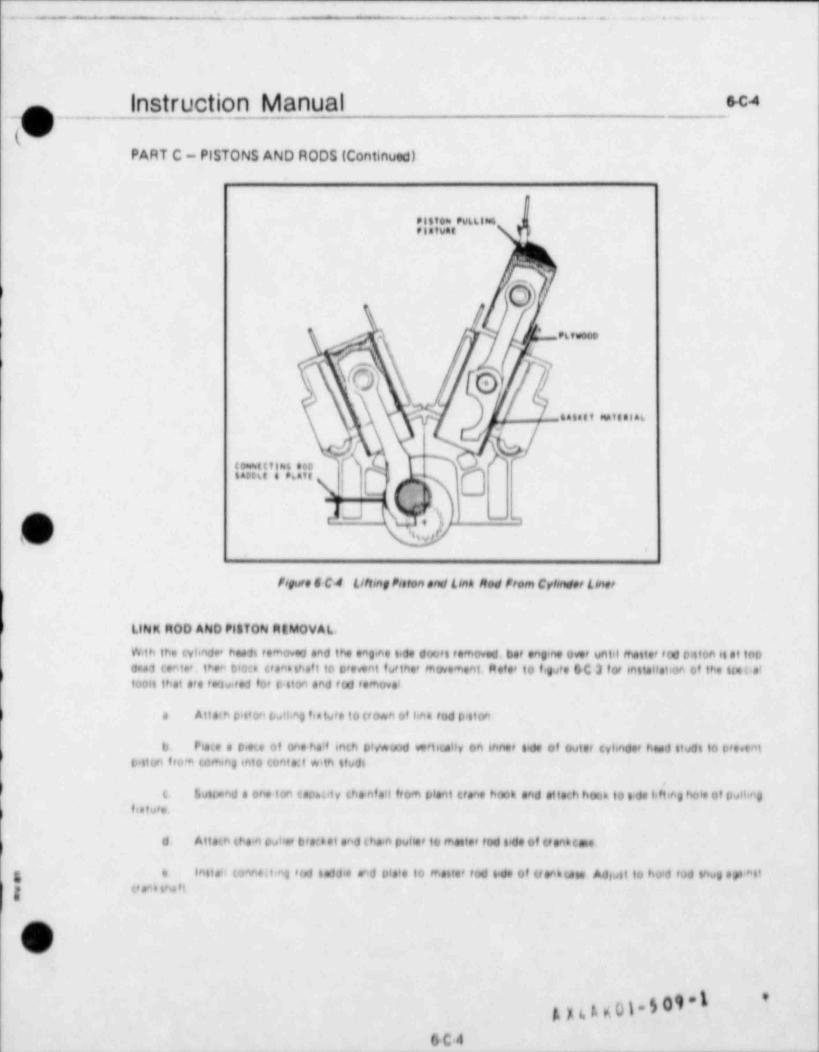
-~- -
_ - = . - . . . . . . . .. .
Instruction Manual Sc4.-,; o .- _(v;
PART C - PISTONS AND RODS (Continued)
Filtem Pv4LIN4fistWat
6>
/ Pktwees
%\ Y.) Q )
9 -talett stattelak
te=%ttilme 80slacott t 96att <>
-
--a
o u sey -
W,o,
forure C C4 Lthing Poefon and Link Med from Cyhnder t her
/ LINK MOD AND PilTON MtMOVAL.
#th the cyhnde* heeft femoved and the one no side doof t femoved bet eng no ont until fnettet f te piston tiet topowed tente'. then blott Ctenathef t to prevent tw ther movement Meter to figste DC 3 for miteHetion of the llatis'e
tools that sto fequired for p 4106 and f 0d femove'
) e Atte:h ciston twlbn0 h'tw's to (f own of het fod D'aton
b Piece e Ome et one he't enth p'v*uod wetsully 06 66 net tide of Outer tyhndet head stude to preventf piston from coming into tentact with ltudt
$vitand a one ton tapetity ths.nfe'l from plant tiene hook and etteth hoon to 6.de lifbeg hole of puHingt
f e a t u's.
d. Atleth thein puliet brett et and thein puhet to mettet fed tide of of ent toe.
e inste'l tonne.1 hg fod laddie and plate to mettet fed lede of tienn ute Adiwat to ho d fod Vtug spantegg Camb thef t
sJ
g nt.g0)-509 1 '
6C4_ - _ _ _ _ - _ _ - _ . .-

_- - - - - - - - - - -
_ . . _ _ . . . _ - - -- - - - -- . - - - - - - - - - - - - - ---- -
._ _. - __ _ . _ .-
Instruction Manual e c.s,n 1
(PART C - PISTONS AND RODS (Continued)
P6twooo y,
Nr,esto= Pv6 Lins .
ision.f
\
>T
'eaY I"''&ju ttaa eoo N r(ea
N-| IdN \cometta=6 soo ,
tato6s t e6*ts ,
, ,
W) ' wit two cnaintt- '
fmure 6 C 8 Took InstoIIed for haarn and Meeter Med Momeret
f. Attach a ths n to each end of link pin with upstrews and connett other endt to chain puller and tete up
...< t in (n. 6
g Nemove Connecting f od botti and tod to bon bollt (see figJf e 6 C Il then lleck ofI on thein pullet, ellowinglink tod boa to twing ties' of trentpin
h Une them Dwher et netetwy to polition connecting tod while tiestin0 boa from crankshaft Adjust untillenh tod it in line with the asil of the cylindet liner.
) Coat waH6 of tvimder lee' with tiesn lubricating oil, then place a pece of 3/32 inch comprensed pathet6
material between link tod bos and linet we'l to prevent boa from 6 coring linef well. Coat lide of gathet material which
) tentatti line' weit with clean lub'itating oil
| Carefstty hoist piston and tod out of linet with one ton thainfall taking care not to allow piston to bindi
tn linet (see figs e 6 C 4)e
k. Wren bottom end of connecting iod boa is tiest of liner, move pitton and fod cleet of eng'ne and lowe' tofloor of a evitable stand
)5)tm
(G\
6C4 AJr6,1,yp J.g 0r,. { __ _
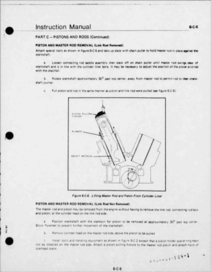
E _.__ .._ . ..
Instruction Manual Sc4Ip
PART C - PISTONS AND RODS (Continued)
MSTON AND MASTER ROO REMOVAL (Link Red Removed).
Attach special tools as shown in figure SC 5 and take up slack with chain puller to hold mester rod in pleos agernet shecrankshaft.
a. Loosen connecting rod anddle assembly then stack off on chain puller until master rod swings cieer ofcrankshaf t and is in line with the cylinder liner bore.11 may be necessary to adjust the position of the piston and rodwith the chainfall
0b. Rotate crankshatt approximately 30 past top conter, awey from mester rod to permit tod to cesor aank-shaf t journal.
c. Pull piston and rod in the same manner as piston and link tod were pulled (see fsgure 6C.6),
'l
k
pasto= PwtLik6Platw t 'ea
i \
Q,x.. eg ,
('j '\ h hp \
-3
q.) '
e .it ..ft.i.,- ,
ST*
e- o q m
i figure SC4 Lifting Maeter Mod and Ponton from Cyhnder liner
P1870N AND MASTER ROD REMOVAL (Link Red Not Removed).
) The master rod and piston ma v be removed from the engine without having to remove the link tod, Connecting fod boaand piston, or the cylinder head on the link tod side.
a Position uankshaf t with the trankpin for piston to be removed at appromimately 300 past top center.g Block flywheet to prevent further movement of the crankshaf t
,
I b. f4emove cylinder head on the master rod side, above the piston to be pulled
c. Instait too's and handang equipment as shown en figu's fsC 2 encept that a piston holder spacer ring needV not tie instatied on the master rod side. Atta;h a piston pulling feature to the master rod piston and attach hook of
overhead uano
p g , ,, ,. 4 i ~ b,
s c-e
L. -
- _ . . _ _ _ . . _ .. _._
,
1.
n InStruCliOn Manual eC7 ;
i !
'
PART C - PISTONS AND RODS (Continued)
d. Separate connecting rod box from master rod,and slack off on mein puller until connecting rod bon lewell clear of crankpin with the link rod restig against the lower end of the cylinder liner. A piece nf compressed gasketmeterial or leather should be used to protect the liner,
e. Remove cheln puller, chain and puller bracket from master rod side of engine and install on link rod side.Connect chain to master rod as shown in f egure 6-C 5 and take up slack.
f. Beck off on connecting rod saddle jocking screw and remove tool Slack off on main puller and lift pistonand rod out through cylinder liner.
REMOVAL OF PISTON FROM ROD.
Susoend piston and attached rod with the piston down from the overhead hoist. Lower until the weight of the assemblyis resting lightly on the piston crown. Remeve piston pin retainer rings from grooves on ends of piston pin then slidepin out of piston. Lift rod assembly clear of piston.
REMOVAL OF A SE12ED STUO.
When it is evident that a bolt has seized in the connecting rod bon, do not attempt to force it. The following procedureis recommended for the removal of a seized connecting rod bolt.
a. Position crankshatt to place connecting rod at its closest point to the engine side door and block crankshaftto prevent movement.
b. Leave at least one good bolt in position to hold master rod and connecting rod box together while esiredbolt is being removed.
vc. Form a shield of a suitable fireproof meterial around mester rod to catch molten metal and slag, and to
prevent it from falling into the engine bene.
d. Cut off head of seized bolt with an oxy *oetylene cutting torch. Exercise great core not to damage themaster rod with the cutting flame.
1 e. Clean out slag and bumed metal, and remove shield meterial.
f. Install a connecting rod saddie and plate to hold master rod firmly against crankshaft journal. Install too6sand fixtures necessary to remove link tod and piston. See figure 6 C 3.
g. Remove remaining bolts and carefully disengage link tod and connecting rod box from mester rod. Carefullyguide headless bolt stud through its hole in the master rod. Allow the link and box to rest against the lower edge of thecylinder liner,
h. Place a shallow pen of water beneath the stub of the seized bolt to cats the molten metaland slag wiWO'
the stub is cut off, then cut the stub of f approximately one inch from the surface of the connecting rod box.
l. Clean debris from the area then remove the link tod and piston assembly from the engine in the normalmanrA . riemove the connecting rod box from the link rod.
g i. Set connecting rod box up on a good radial drill and drill out the remainder of the seired bolt. Esercise
g care to drill the bolt on dead center to prevent demage to the threads in the tapped hole in the connecting rod boa,
k. Try a new bolt in the hole to be sure the throeds are good and that the bolt will run free in the tapped hole.
l. Reassemble the link rod and connecting rod box and place the piston and connecting rod assembly in theentne in the normal manner. Use new locking devices when assembling the link rod to the isnk pin.
g K g, k W (, l . r; 0 9 " I*
s.c.7
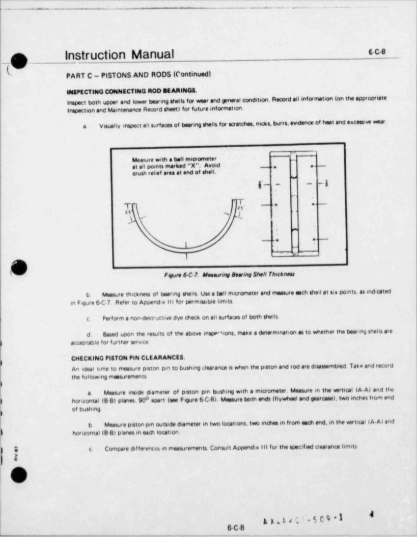
L-- - - _ .__ _ .. _ ... _ ,
p instruction Manual ec4
W PART C _ PISTONS AND RODS (Continued)
INSPECTING CONNECTING ROO BEARINGS.
Inspect both upper and lower bearing shells for weer and general condition. Record all information (on the appropriateInspection and Maintenance Record sheet) for future information.
Visually inspect all surfaces of bearing shells for scratches, nicks, burrs, evidence of host and excessiw wear.a.
Measure with a bell micrometer -1at all points marked "X". Avoid _ ,, ,
crush relief area at end of shell. i
w_gr_. _ _.
I,. -
T C's- - -a - -
" % i *
\
f'
e
. .. _
'
i, .
"r-g
'
Fevre 6 C 7. Meesuring neering Shell Thicknees
b. Measure thickness of bearing shells. Use a bell micrometer and measure each shell at sin points, as indicated
in Figure 6 C 7. Refer to Appendis 111 for permissible limits.
c. Periorm a non destructive dye check on all surfaces of both shells.
d. Based upon the results of the above inspedions, make a determination as to whether the bearing shells are
) acceptable for further service
CHECKING PISTON PIN CLEARANCES.) An ideal time to measure piston pin to bushing clearance is when the piston and rod are desateembled. Tak e and record
the following measurements
Measure inside diameter of piston pin bushing with a micrometer. Measure in the vertical (A.A) and thea.horizontal (B B) planes,90 apart (see Figure 6 C4). Measure both ends (flywheel and gearceae), two inches f rom end0
of bushing
b. Measure piston pin outside diameter in two locations, two inches in f rom each end, in the vertical ( A Al and
) horizontal (B-B) planes in each location.
Compare dif f erences in measurements. Consult Appendia Ill it,r the specified clearanca limitsc.
O
"6 C.B
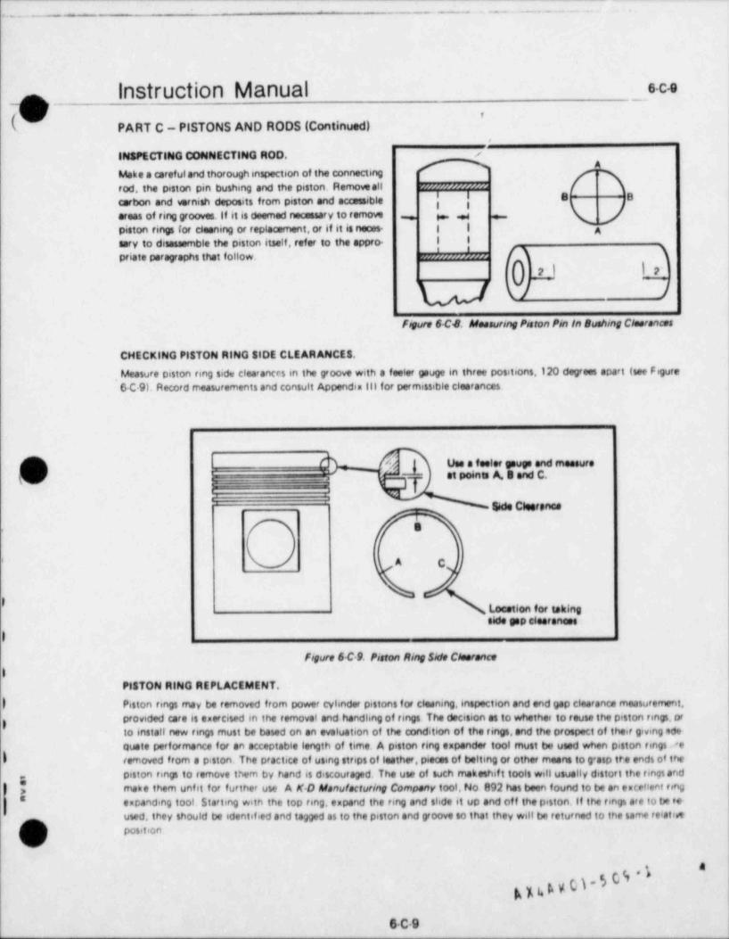
,- - .
- . . - . . - . - . .
Instruction Manual s-C4
!\ ,
k PART C - PISTONS AND RODS (Continued,
INSPECTING CONNECTING ROD. /
Make a careful and thorough inspection of the connectingrod, the piston pin bushing and the piston. Removeall -- -
' I E |Bcarbon and wrnish deposits from piston and accessibleareas of ring grooves. If it is deemed necessary to remow , .
piston rings for cleaning or replacement, or if it is neces- | | 4sery to disassemble the piston itself, refer to the appro- | 1
priate paragraphs that follow. }' '
0 m Lt'
WW J
FM 6C4. Mensuring Ponton Pin in Buehing Cientances
CHECKING PISTON RING SIDE CLEAR ANCES.
, Measure piston ring side clearances in the groove with a feeler gevge in three positions, 120 degrees apart (see Figure6-C 9). Record rneasurements and consult Appendix lli for permissible clearances.
O ! A J Use a feeler gauge and measure' 'U p _ T '' '''"" ^' ' *"' ''
:S6de Cleerenes
s,
|
) A C
) Looetion for takingtido gap e6estanees
)Figure 6 C 9. Piston Ming Side Coserence
3PISTON RING REPLACEMENT.
) Piston rings may be removed from power cylinder pistons for cleaning, inspection and end gap clearance measurement,provided care is esercised in the removal and handling of rings The decision as to whethen to reuse the piston ring, or
gto install new rings must be based on an evaluation of the condition of the rings,and the prospect of their giving ode-quote performance for en acceptable length of time. A piston ring expender tool must be used when piston rings.<e
I removed from a piston. The practice of using strips of leather, pieces of belting or other means to g* asp tr.e ends of thepiston rings to remove them by hand is discouraged. The use of such makeshif t tools will usually distort the rings and
| make them unfit for further use A K D Manufacturing Company tool, No. 892 het been found to be en excellent ringI espanding tool. Starting with the top ring, espond the ring and slide it up and off the piston. If the tengs are to be re-
used, they should be identilied and tagged as to the piston and groove to that they will be returned to the same relatineposition.
%
k % i. 4 V g . 5 0 9 '
6C9

( _ ___ _ -_ ________________ _______ ______ _______ ______ ____ __ ___ _______ _ _ _ _ - _ _ _ _ _ _ _ _ _ _ _ _ _ _ _ _ _
.. - . . - - = . . - - - ---- .. .-
I
|nStructIOn Manual s c tonm :5 /
PART C - PISTONS AND RODS (Continued)
CLEANING Pl4 TON RINGS.
Hardened steel scrapers, steel wire brushes or power wire butfor must not be used to clean piston rmgs. Rings can bestbe cleaned by immersing them in a commercial cleaning agent such as Tarco, Trorupo, DeUte Cer6eney, PennweftChener 45, or equal. Follow the rnanufacturef's directions for the cleening agent se6ected
CHECKING PISTON RING GAP CLEARANCES.
Gap (end or tystti cleerance of the piston rings is measured with the ring in the Imer. Used rings must be measured mthe hner from which they were removed, and if new rangi are to be used, their end clearance must be measured wheninstalled m the kner in which they will be used The rings must be square with the surface of the bore. Position tmg mone of two positions in the kner, the preferred position being sia 6nches from the bottom of the hner, the s' ternateposition being three inches from the top of the kner. Ensure that tmg is the same distanm frcm the top or bottom ofthe hner all around to make sure it is square m the lmer. Measure gap between ends of tmg with a feeler gauge andrecord the measurement for the engine records. Appendin lit. Table of Cleerences hits clearances when new, and thereplacement clearances in the case of used rings.it is suggested that it is economically unwise to attempt to teuse pistonrmgs with end clearance enceedmg 0,165 nch for chrome fewd compression rings. O 150 mch for taner f aced comprassion tmgs, and o.110 for oil contro! tmgs
INSPECTING PISTON.
Inspect oiston for wear and other abnormal coeditions such as scuffmg, scratches, etc Pistons can tw cleaned byimmersmg them m one of the commercial clean ng solutions hsted for clearing piston tmgs Measure ski't outsidediameter of piston at two locJtions, fou.' inches below bottom ting groove and four 6nches above bottom of thirt Tabefour measurements (A A, B 0, C C and D D, Fig 6C.10)at each location. Measure piston om bore mside diarrwter at
yj either end m two direct 6ons, perpendicular to one another (A A and C C, or B 0 D D)
I I
p= -u wb,- 4
D Bo
_i _ .
CC : :>
B o")
& A_t_
)
Fmure 6-C.10. Pieten Menurementey
) 018ASSEMSLING PISTON (See F6gure 8 C.11),
if it es determined to be necessary to disassemble the piston crown f tom the skirt for further inspection, or replee.ement.
) proceed as follows.
)f a inspect connectmg tod bearing shells for evidence of scratches, nicks, burrs, enuissive but and war Clea'-s ante tables should be consulted fof the required bearing shell wall thickness.
[ b Inspect pistons for wear or abnormal conditions flemove all carbon and va'fush deonsits from pis19hs and' / sccessible areas of the ring grooves Unless they are to be replaced, do not remon piston imos from g'ooves if nors*
sary, disaswmble pestons es follows
&K4.W0I*bbf
_ _ _ _ _ _ _ _ _ _ _ _ _
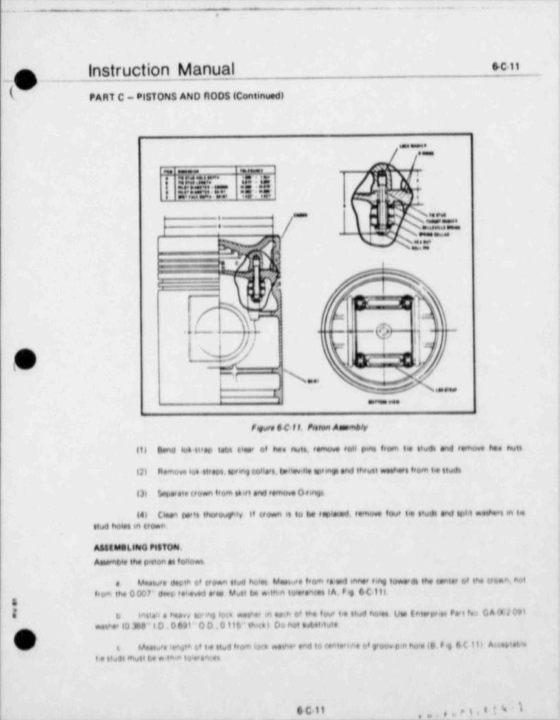
I __ __. . . . . .. . .
.
I
n ___ InStruCliOn Manual*C it
_\ ;v
PART C PISTONS AND F10DS (Continued)
..
? W w. 'T"%-" ' *
"!" :".S %i||'.41.'"'t. +
:S||i,'/ t,'"; ,*.'.';,';.g y A4
f N..Ne.., . ;.
w* t .w \ e... maj.- \ ..
~.~___ 4
-
''_ . _ _ 1* -. y
; ._
,
' so
1y . - .
,,,r^^
-,
)f' ~
a .-
-- p.y - .. -.. ...--
e/'
p) |q _|
_
-
v .. . , ,, _ ; ,,
, - av _ ,,,f s
", , , , . . ,
. _.
Fogare 6 C 11, Ponton Aenmbly
til band loh titsp tabt one' of has nutt, temove toll pint from tee studi and re'nove hen nutt
(2) Ftemove lot sttsol, tor 6og tolla't, talleville notingt and thtutt wethett from tie 4tudt
th Letierate uown from thitt and remove O ne
(4) Ciman torts truovghly It uown it to be tople<*d, remove tout tie pudt and notil wediert en tiestud holet m (town
A48tMilLINO PflTON.AtMPmbie the pitton et follows
M.atv e depth of uoan ttwd bolet Mantu e from te wo inner ting to*e'dt the tenter of the troen, note refrom the 0 001" dao tehe e1 sten Mwit be witnin toietsmet (A, hg 0 C>111.
I b 166taa e been to'ing luo *ev.e m wh tat the fov' t'e tiud holes Ow interer.t. Pa'l ha G A 9.1091*sv e' (0 30ft" | 0 . 0 631" 0 0 ,0 lib" thio l Da not not,ttitute
,-
| '?
(_> t v..iu,e senatn c/ i e itud from imt *sei., end n centvi.no of geoo, p.n baie (o, hg o e t ti Au.otewit e stuf t mutt t;e *. thin to cteMel
G C 11 ,, , g . a ; 4 1,g , , ,
w x -
. ,. - . .. .. .
i
-O -- Instruction Manual-
s c.ir. .-
,
k PART C - PISTONS AND RODS (Continued!
d install tie stude m crown with groov pm hoie vp. Use Lod tile "f heeed60ther 2d2" on threeds, and toeewe |ttwee to 100 fi 166. |
:
e, fe6e e mictometer mesoweement of aown end thif t p6Lott (C. O, Fig 6 C.11). Mwet be withm tolerentet to !
ensure esse of ensemely without demep to 04 np ;
i
f. Mosewee th 6f t toot fue depth (t, F es 4 C.t I p. Should to w* thin tieted toiweneet i
g install 0 tings on pitt. Do not twitt eine du'*6 instelletion. Ues no edheten, yeem or toiwnt on empMenetet oil may be weed to eene entry of 04mg6 6eto teown
h. Ateemble uown to e ett Oteerve thet there le e dowel pm in the crown whech mutt entw the dowet ho6e inthe pitt Chet 0 eine foe peow pot.t oning
6. Ciese och Believ.he noting and the seems colieri by d'poing them 66 toivent then thoroutfils d'ving Dio eil i
Ndingt and toHeat into e t,0 60 mintw's of rephite and eap.no o 1, mening sure weeher fuse eve completely wettedi
Innteil the it wehe on wh I.e stwd, then steteil esecily 13 telieville tovings on exh stud, concaw nede I| w
to*rdi to ett insteil 13 more bedevitie umnet on etwot, con (sw &de towe'dt trown |t
6 Imteit kw eng toHe's on each tie stud, then eentoit two 106 ottopt a thown in Figwte 6 C 11.
I Apply Lootite "Threedioor 222" to etwd threeds, and enemble hos outs to stwde and tighten finpelight Do not Iwbtete threeliv
ien Abgn eeth wmbee ties with finpet to outet ede of wether HHh it own TotGve eeth nut to 116 ft Ib,
then both oH threcovettee tw ne
n estotowe enth nut to 10$ ft Ibn end ahoo etenenent of tie etud roo, pint holes w>th not tioti Imfeww !
tot uwe si neto6w y to shgn ycov pin holet w6th tietett nwt tiot. Do het eetoed 116 f t Ibn
o Choo fo' p'00e8 Mwmber Otoov p.n hoie m Hud thould be een with, or e mee6 mum of I/10" abow l
tote of nut tiot if within then tolereNo, tieen o'cov pin hoie end insteit roov 066, uthg Ltk6 tile "1bisodiou et 212".;
if not within toie'eNo, theo stumbly of de16 for prot +t Use end tostNt num6*e of Ndmpi '
p Bend loa itten teot up wtweely age nit 6 de of nute
Wef ALLING Pf6 TON nWO4 lese Pegwe 0>C 91,
Uw the pitton teng eependet tool when toti ating p.tton ring on the pitton if the eine ete being touted. insure thatl
een tmg et totv net to its original petition. Mengt see me' led eithw "UP" of "f 0P M'' on the.# wet ** lides Note 4e
tmst in stoons to that este e<e staggaed e'ownd titewmfweme of piHon. Te6e tote not to steesd ringt onetiwtywhite inste!hng them on pitton MeMute end FMo'd pitten ting bde (lesteNe in Foove. Tale masturements in t*We,po&tions (A 9.C) for anh ting
L
meetACho Ptef0N PW 4WGNWO.,
g Uw the foHoning method to teo'e's the totien tva bwth+g in the tonemt+g tod
e if an esbot tafete it eve tecie tdMe the bwth+g f*0m the tod, othet*4e, te#etwily kiht the tmth*g w it ahate ten s*$d 6# ve it out of the f oi hemove all bwHe end (l%16 the (bhnMiing tbd
V
g g i,l.w< I . 8; O 9 * I
*
fe C.12
_ - - - _ _ _ _ _ _ - _ _ _ _ - - _ _ _ _ _ .
-- - - - - - - - -- --- - .- - - - - - - - - - - . - - - - - - - - - - - - - - - - - - - - - - - --
,. . .. - . . - . .. - . - - - - - -. . - . . . .
.
m Instruction Manual e c ta
'PART C - PISTONS AND HODS (Continued)
tt P'isce ttw new buvung in a nuitable tonta not to(,5 at a buttet of a deep pen
i
c P til the conta> nee w th liquid nit' ogen. Nitroven leal thould te oppfoe6 mate's one 6 nth from the 100 ofthe bushing to 4How for heNung
d Lav connetting rod on its lide on a suitabie tuppoel Both endt of the piston pin taenNog t<>'e thovid tosueu bie
)
). ... t - . . g .t . h. _ _, ,0 . _. . ,0 , . .- t _ t t_ t . . .tyl's ett'ovetl f ' p'Ote(tion 8)4 hit esliefhe low 10Phpe'etuf et0
e Yvhgn the nitf egen 6tfspi bo.hnj. femove the butNog ff orft the tonte net and inteel in the bore,146.ng ta<eta s',ga the toi hoiet w>th the o.1 patempt in the *.onnetting tod insufe that the buthing p#ottudet the w+e d stante06 both $Nt The ope'etion Phutt t<0 dahe Qu'(6 ft belo's l' e tivthing e stendt due 10 h8tet 04 6 up
MtPLActMtNT OP LINK PIN BU4HINO,
if the 6 he enth hg to t#eet reo e:em=ht, ceoc J ei fon etv
4 f4p+0 9 the tul'"N %6 toh, toht the (suthing *'th a had We to f ebeve attett, then d'ive InstNhg Out of''
(enha(t ry #(*1 bu e
( /
1, (meh the (ohhe>,19 tod bo e, f emovmg a1 [mert and f ouf lof fetet
t he't he* buth ha ih a e edeb o tonte he' luth at a but.6 el 08 e deep pan
I di tu te ha' W'th I')#164tiogan h te gen levet thould be $tidot*Pbetely bhe toth ff 0m the top bf thetl a oImth'h3 to alon f o' h4M fy
e Lev the tun ^et t>hJ tvl bus bh its t'de bn a tu. table tuttif#t T h'ee p 9'et Of t h 6ha N f ough tirn t ,14 'lt o'awt On a trp<a 69 & cts' pisie, *di (dovide ehtigte tappept fo the bee end att et a ttop to# the t*utNhg to that itr
W 't i e fluth w th the t jo of the boe when ,Q 63 ihts#to j
... t . . . -. .t . h. _.,, (_ g ,0 . _. e ,. ,h. .- t - t t_ t . f .t yt4 St-(#0ve'l hrf D'Ote({!rph eJ4'ont esiteme low tempe'etufet
f Ygheh the hitt njs*1 thypt (30 lehg f atheye thg hughshg (f M thg (qhtg,hytt
g |hteet the [tath bg th the (tynhea tinj f Orj bot, jgb ing (A8e 10 lehe WD the |)ytfung tujouit W,th the #ipehal69803 e (Ont,yvf ti$ jh8 b*)e lhtu e th % hOth thjg n| the buth'hj $'e $hghe | Wirith the I de Of the l>'le T h t # ut'l-#f 4
b d * * U mtlig I'e80'e the tr>Vi hg pet 4Mt d to lo hast b'tt utei
\
0 C 13

- - - -
. - . _ . . . - . . . -- . . . .
Instruction Manual _ _
s c.a- _ . - . ~ . - - - - - -
b' PART C - PISTONS AND HODS (Cont 6nued)
ASSEM8LY OF PISTONS TO MOO 8,
) Auemble pistons, fodt end tonnecting fod bus at follows Mete to's pittons and t(wit see feattembled in the ta4*feletive potetson at they oc. cup.ed tiefore d tauembly.
e inter 1 hek iod pin 66 tunnecting iod boe bore and solition hnh tod on bnh pen
Apo't a lubricant cont,tt ng of a t,0fs0 mistu e of v)*dered graphite and tube 6cating oil to the thronellr tb) 0' the kn6 f od to pin telts Torgue t>olta Io t(*cified tarQue and Wute mth lud wire
t Place tutton unt de down, fetting on 6tt trown. Lef t tonnetting fod eth fod tu'ning plate then how,*) end of conn *(fing f od 6hto D'lton, thgnMg pitt96 pin hoe # 60 f od with that of D.4106
Chat 0 itan s'.n a.th mol b knum o tuloh.de (sio* to siwebhng in both>ng Une a f eg o* Mt ts. itis taushd y
Mut,bJe"um d tup'd. Il evt.labie ff o9 Ite"ineme' ira Delavel unds' It'l No O Gr0 9________ - - _ .
'
CAuflONoo noi s ,m.t me,bd. hum o isoh ie, o, .4 ~mi.iulof si in come into toni.a ..in se,
~
o me,t+num o tuio,,iae mn env. ii.of,ed tow.* toih,..u; t.ite o.i t r., t., e.nt . e
ovetti*ett the f atteme's All to%e voi et s's tan *J on the ute of a t,0 r;0 meetu's of tw*d.'e jv
g'4Lh te and lubhtet n@ O.I
[ e thg.810 419h pin thf ough p tinn and f ud (lesi gntion g'nove and the outt.de end of the totton tun 'ete r*f >hgt ehd ihtee t f e'8 het fin 14 ihto tottn'9 0'bovet et e1the' eh't of p'ttron Inh Alt y "LfRtl'te" QJ endt of f et8 f*' fiffl!
to ('' event fih)* l'Om f uteting in the g*ijo.st
* * * % ,a f8 $
- . . t eost.. .t .g_ .j,
\ NA*y
- -Ms dr. K- w. . .......t..t .... e _ .
\\ L . j **.* e..*. ....-. ....
Y W.? .,|
< .
$.4.r. $ ese#3 . (w p, ,,,,. pq ., ,9/ D1 - p|
e # e. .e.e on ,,,t~.,,....,,. wwoe s e .**..t.
i.a aset ;*
|..
*** y[,,,,,.r.b4OI. n.
$4 6 9 yn9.e. . # .
.,m. ,p e ,.4
/ N,%p<- .. ... .& N e
t ,-.....,4g ..
\ q <s.V!ogs>e C C 92 L tr.e* 5eo mt Mmpt ! rete e C l.1 CvhmH+ Lw ne** tottentr
A m voi.5098 1 8
o c 14
_. _. . _ _ _ . . _ _ .
Instruction Manual oCasO . _ _ _ _ _ _ _ _ _
- _ _
k PART C - PISTONS AND HODS (Continued)
INertCTING CYLINDEM LINEMS,
The weter contact tyto tyhnde howi |*t 6nto the tyhndee blod three techng fingt m gnuivet at the lo**' end of thehnee peevent water from enteeing the t'enttale lhe libcone wel piet mio the lowv* Dehng f mg groove it 46 #emmmonded that the knet to day'esed tefove pistont and ringt see toole<eit 66 the ergne in the taas of r*w paion tity,they thould be mitehad only m new hasus, et to hners that had teen (kgletk1 T he gletel tuf fe(et of a tyhndse hnewhah het teen m prv4e wdl not teet tww pilton f 6tg Qughty at owtehtly, Hingt whgh are not (offet. tty wated eat4160w blu*by of uwebuttion poet, and toute estensive utegn of lubf KAtmg oil. Leyte e blu*by tan dett'of the od filmon the hnee tuttate end (aute ting toutfing and tuntibly Wen piston wifuve Cheone femt utmpeewon tingt w.it hottonform to tyhnde lir*'t wh4h s's out of found by more then 0 003 66th (** entti of tae'e d.e+ete' (0 0$1 erwh f o*MteJet H & NV ttynnt Top ** fe ed (omewest.on eitwJt and tonto#mebts oil Omt'ot iengt wdl not Ointo#m to bortwhich see out of eound by more then 0 001 inch 1*e enth of to #e d. emete t0 017 6ath fo' Model N/ftV eng nee W04 ton eingt w,H wet in bneel wh<h he,e ynov,t, tidpt. oe low sgott on the livfe< e of the bne' tMe Cabon deed 15from the too of the 66 . sto.. the p. con ring tie i res should hw t *n eveuve.1 prio to pumhothe p.cor4 Weihr
int"Je td hne' with tWe*ht e^ liet d'y V+#40v 6hte*(t bhe' and hoto any of the unnet.t ont illutt'ait i by P 10e 0 C 1)
LINtM 0t0L AllNO PM0Ct00Mt.f he Sunnen M Av AN tit ti tw tetoe hohe with do state leag'h itone N9de's, and Swnnen W41 J10 o' W4 7 J4 7 it*nin the t19he holdef t het bp*h #ouhrj to be ettet,trys fif der [4|ihg The (gjling etnhty Of the 4thh$t (An |@ Ifbpettyed |ig(uttrhg egg e' l'ott et tutt the fece of the othhen A her.ttee (An be bled to cut the slott The tiett d'ine the hun ngl
flu it 10 Ph0's 6st ly weth the 4,utt9% f f om the 4toheg Tim hon,ng (hed (An {m t ef otthe, teeycht bt toep t estHPrente<t bon h3 oot a+e e OsUe, but s>s est* wee and do t>ot setes' to do any beDe tob then the fiu'dl twent otedDieget o l malet a vof y pt.m48 huh hg fluul*
l /9'_ / e l/s hie e e fiere gosmtute bet Aten the 4toheg shq) the gipfg.e pf the bhed beite to feebe luf e the tinhet e'e
tutt fy
Me ele h e Osm-!, f u'* 6 honiby h+ 1 to the stohet tu *eh e Asp the tuttihyl sh:110 p'eventltOheg'ehhg8bAHehje a thcot Photel plM[ uhqce the (otto + (d the ( yhndse hhe810 (ef f y 60 the flued sh | tutbhgt bu 601 eDOW t he
the (f e66 ghe$t ehd 6h90 the ths.n {peef ngt (ey a teetet hf alean W gehg f ejl [eth$sh jhe(utt*hj la Nh bu d il bU8 ofsf t
Usht gholt y,of g ghd the fe e 6 [sgo hg (Att tu L' event it lat e f |ludj ItoH1 totWib) the f%$'n | pef ehJ% (e**(te(Aieht
W en fe+ochj the isJt that tutt'hJt 69 691 Isli thtu the thein beenhgt8
u , ton tu tohg o'et teit sa tioll teotot 1he egete e it ed of the h +e Honsat bh,. the hohe * th a Weee t l e
es,e t,* ihthe*e,r u n *,0 fem ho". het, a+1 ene+te n a steot ehg tete (;f smoe*sie', m to+tse9 t,t 'et a+>t+ m d e
d Af te* the f all #Ahuts ts' hohihg 'e*Uve the hohe f t jm the bhat and wath the leMe tuf f e'e ehd *py ti4 g 10 deiseth.hs d thof e Fe shy oh hrjtt || low tpytt sie (GunfI, ff*ald's th8 |*de ( A'ef hyk wat t the tuf f e e (Ate 9J j d
..th iht "fe ma #omte ta detw+ne it hae* * 0 to uwebie, tie if it thutt to #We+1
e (nhth ,e hhn.ty wht d s't 6 s''e o g'ere it f emnve=1 A idot*'ly dog'e ted bhe* enit have e uhdo''e tehh g> stet18We'v e Wlh a gw] (ft tt' e'th (gtte# n T he bhat tyf the (f ogthetth |isite+M thnuld 6htef ter.1 et so shJ e hf et D80sitheie'y 93 deg* pel
Noteea h .,es sue,,a t v .4 haien,heo,o.on(4+empt * w h de r i. ihe N,h w tao.e,s,
& t h4 .i en e.,.,su putm.et mhI
i W, eh hee y .4, h 4,.* i .44,, n.s r+ v.,e .eii .an e e.n ts.ob b.uth sha h i t .ie e+f #e.e. t. ueh , 2^
is , t. , ,ep., r" ^ h t e s* t d' i * "4s 1 A h v *e6 N ih* t d'e' * N! t * d'* f f 9' 0C*' e"I " +f * th eN *ha> % oit,t,'s<entfue la*ene*i++ tot m outthe8vt.84em'tubat0! 9"$H'pIJPW8 hWe he' 'u!h A8'
b +e y1 w M b n4,te.eentos,jtregaf,ttbyid-,*HJ 606 sj
* Nk h e, $ e 4 |>'
6 C ib
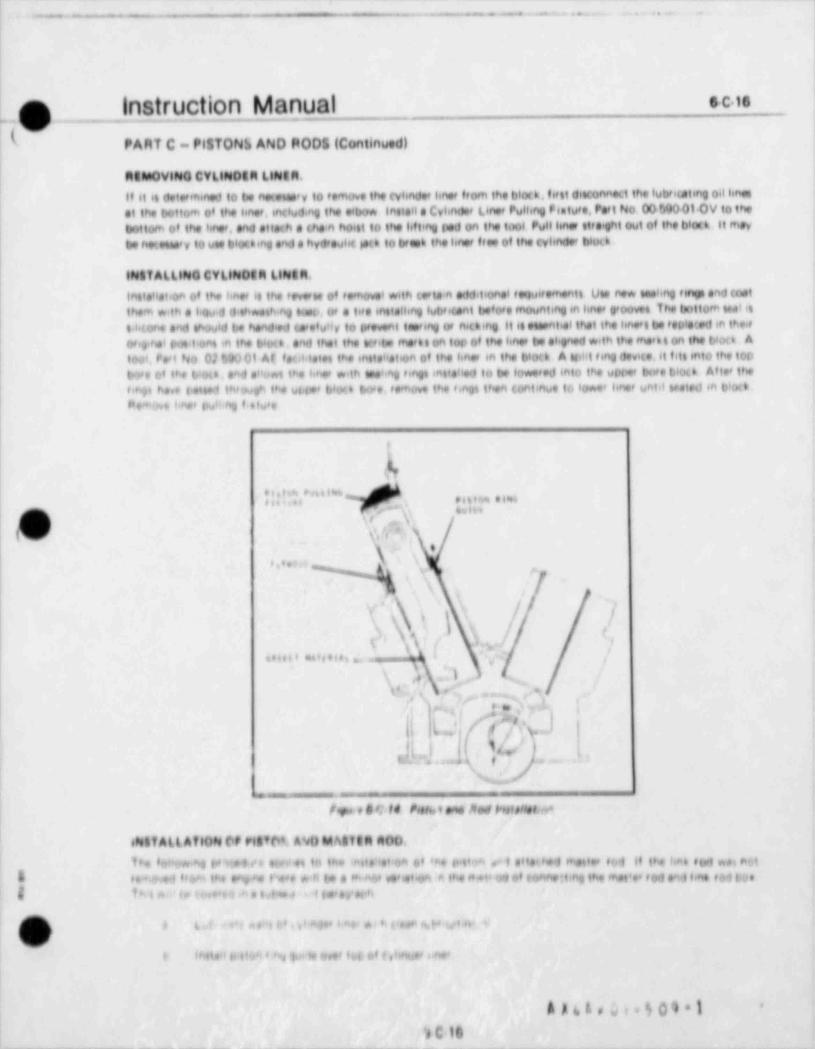
- - - - - --- -- - - - - _ - - - - - -_ - - - - - - - - - - - _
. - . - - . - - . . . - . .. - .
1
1
f] instruction Manual * C is
( PART C - PISTONii AND MODS (Continued) |i
Mets 0Vt000 CYL4000GM Lle64M.
Il 41 el determined to be notetee'y to temove the cyhndet tenet itom the bloth. I6 fit ditConnect the lubtoting oil hneset the bottom of the tenef, mCluding the elbow. Install e Cytendet Liner Pulhng hature, Peri No. 00690010V to thebottom of the l+ne', and elleth a the'n hoint to the lifting god on the tool Pullimer titeft out of the bleth. It may ,
be t*,eteney to one bloding and a hyd'oubt le(n to brent the Imer f#se of the cyhnde blod.
1800f ALLifee CYLite00M LleetM. !'
InsteHation of the hnef 48 the feverw of removel with tete.n erlditional toqu6fementt Uw e** tambng test and tastthem with a 1 ou.d d th*ething topp, of a life motelhng lub'ent before mounting m knet groovel The tottom wat it6.i40ne and thould be hend'ed (seetuitt to prevent tw6ng or nithing it 6e eteential that the hne's be topieted m the,#orig.nel P*t'ont m the biod, and that the tu.te mee66 on top of the ht* be ehened with the me'klon the bloo A
At feet,tetet the inste ei.on of the one, m the bloo A toht teng devne,it fits mio the too100'. i'e't No 02 00 01 u
two of the blo(a, and eHo*t the hhet with enehng f engt innteHed to be lowered mio the upre tore blod Atte' theongs he,e t<mes thvough the ut tee t, loo bose, temove the fings then continue to lo*** knot until wated in biod,he*Ott 1 nef bu l.ng fietuf ei
= . - v .,l,- .,_. e evitt
fe
\
% >
r+* '\ | ,
h\|.t) YJ !u..
-/ve..............\,T,+ " \, sY , s, '
*% ,A* ' % ' ', .* * ,\ y L !
g/j..).
'A'L.'q 1'
c.3, ,,,,3 f . . ~ . . ,
.
t
,. _ -_
j f tw e e C ld h%1 ene Red Vttf 6Hetare
e8stf ALLAfl0N 0f Mofot, A'eu h4A414M A00,
The to e*.nq (%ef *e elev+t to the +tteushoe of *Ae pitch ,* I ette9*4 met'** tbd if the hnb etert wei nttn
S te%e 1 feeH the e6e-no t'**e *-ft (* a f4n6# vehetion 6 the n*t' 04 bt (6mbett4ng the met *e* f od and hat toi tius'
I thinm i, e o,.u ,* e nt..o < t e.>e,ierb'
} # L t . =4 e u", td . ,1 n f ese8. er83t+ ,e W v o+t. t
ml' |htisti it it99 8 by jir# le beef tut 60 ( g hhe,68 s.hs'
AAL&eLi.601 1 '
ic te. - - _ - - - - . - _ - _ - - _ - - _ _ - _ _ - - - - _ - - - _ _ _ _ _ _ _ _ _
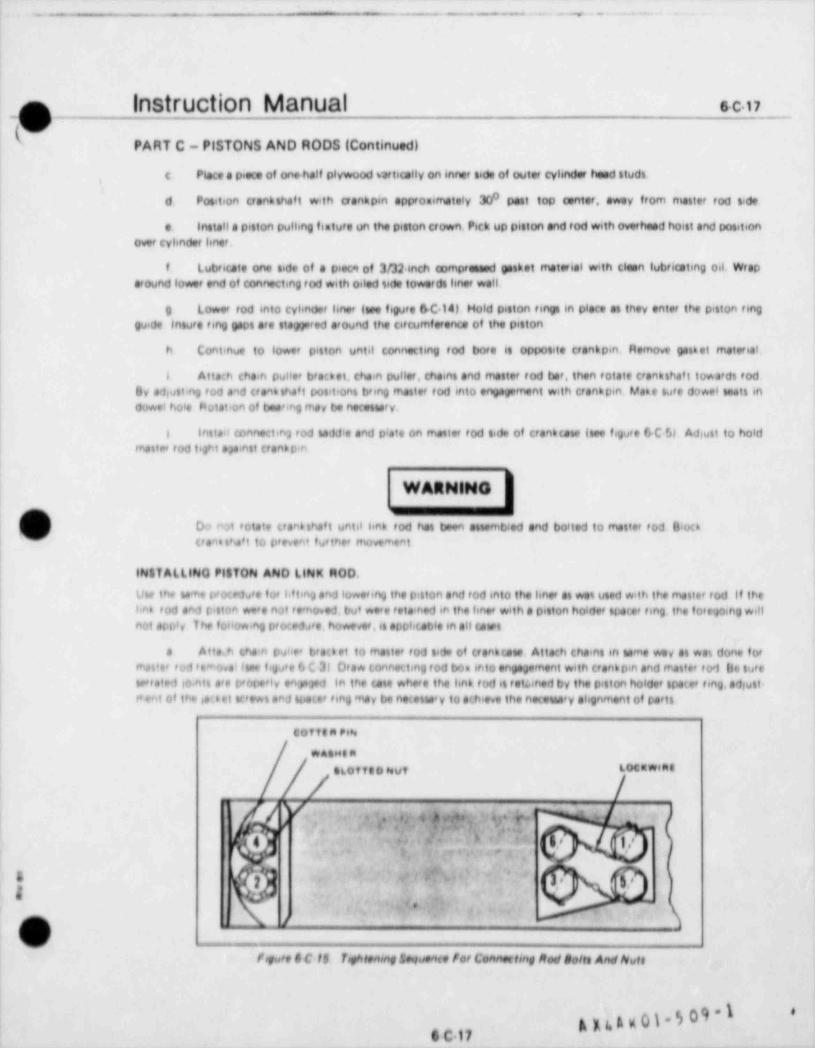
. _ _ _ _ _ _ _ _ _ _ _ _ _ _ _ _ _ _ _ _ _ _ _ _ _ _ _ _ _ _ _ _ _ _ _ _ - _ _ _ _ _ _ _ _ _ _ _ _ _ _ _ _ _. _ . ______-___________
-- - . . - . .
O |nStruction Manual s C.n- .
__
p'PART C - PISTONS AND RODS (Continued)
c. Place a piece of one half plywood vartically on inner side of outer cyhnder head studs,
0d Position crankshaf t with crankpin approximately 30 past top center, away from master rod side,
e. Install a piston pulkng feature un the piston erown, Pick up piston and rod with overhead hoist and positionover cylinder knef,
f. Lubtiute one side of a piece of 3/32 inch compressed gasket material with clean lubricating oil. Wrapatound lower end of connecting rod with oiled tide towerds hnet wall.
O Lo*e' tod 6nto cyhnder hne (we figure 6C 14). Hold piston tings in place at tney enter the piston ring
| guide insure ting gaps are staggered around the circumference of the piston
h Continue to lower piston until connecting rod bore is opposite crankoin. Remove gasket materiat.
i 6 Attach cha4n pullet bracket, chain puller, chains and master tod bar, then rotate crankthaf t towardt rodBy ad,usting rod and cran 6 thaf t positions bring mastet tod into engagement with trankpin Make sure dowel teats induwel hoie flotation of beat ng inay be necettery,i
I insta'l connectin2 rod saddle and plate on matter tod tide of crankcaw (see figure 6 C 5) Adsult to holdrnattee rod titt spinst crankptn
O) Do rut totate crann thaf t until hnk tod has been attembled and bolted to matter tod Bio <k(d' crane tha't to prevent fu tne' movementr|I
| INSTALLING PitTON AND LINK MOD.
| Uw the name proce%te f of I'tting and luwering the piston and tod into the hner at was used with the matter tod if the
| be6 rod and ruttnn wa's not removed, but were totsined in the hner with a petton holder tpater ting, the foregoing willI not arti y The following of(Kedpe, howevef,it opphcable en all utetl
e Atta h tha'n puttee bredet to matter tod tide of crankute Attach chaint in same wey at was done totraatter iod iemesvat (pe figee 6 C 31 Dra* connecting iod boa into engagement with tranb pin and matter rod De tutep*tated loints see properte en' ppd in the ute whefs the hnk tod it totened by the piston holde' tracer ting, ad utt<i
t'ent of the is'.6 ei v'ews and space' fing may be noteswy to achieve the necennary alignment of parts
cottent:4
WAaMinLOC"Wiat
- /aLotteokut /y' .. . :. n, ; ww
i '' * b 5 . r: 5,?., ,,
*-,a . ,
*
8-
o),
fogure 6 C 15 bphrenmg Sequente for Connecting Morf salts And Nuts
gydg0).509"I *
- - - .-
%
|
Instruction . Manual s-C-is ;'
m. - 'y 3.
h' ) PART C - PISTONS AND RODS (Continued)
b. Apply a mixture of powdered graphite and lubricating oil to the threads of the connecting rod bolts and therod to-box bolts. Assemble bolts, washers and nuts install washers so that bolt heed or nut rests in the counterbore ofthe washer. Tighten to torque specified in the Torque Tables, Appendix IX in three steps, and in the sequence shown infigure 6-C 15. Safety wire the bolt heads and install cotter pins in the slotted nuts as shown in figure 6-C-15.
c. Remove all installation tools, brackets, fixtures and other installation equipment. Install cylinder heads.
SEATING NEW RINGS IN LINER.
New piston rings must be seated in the liner as quickly as is practical in order to assure a good ges seal, and an acceptablelubricating oil consumption rate. The following run in schedule should accx>mplish these objectives.
a. Replace all covers on the engine except cylinder head covers.
b. Start engine and run on diesel fuel at one-half speed and no load for 15 minutes (Note. Direct connectedmarine propulsion engines driving fixed pitch propellers will have a small amount of load). During the run inspectrocker arms, valves, pushrods. fuel injection pumps, nozzle holders, high pressure fuel injection lines, and drip returnheader to be sure all are secure, functioning properly, and that there are no fuel leaks.
c. Stop engine and remove crankcase side door covers. Feel connecting rod bearing boxes, main bearing caps,crank webs, cylinder liners and pistons to be sure there are no indications of excessive heat. Do not overlook the areasadjacent to the piston pins,
d. Replace all covers and run engine at 20 percent load for one hour,
s e. Stop engine and remove side door covers and cylinder head covers. Bar engine over to place each piston 'rn
'
turn at top center. Inspect the lower part of the liner bore. Bar engine over to place each piston in turn at bottomcenter and inspect piston skirt. Inspect rocker arms, rocker shafts, nozzle holders, high pressure fuel injection lines,drip return header connections. and all other mechanisms under the cylinder head cover to be sure all is in good orderand that there are no fuel leak 5
f. Reptace all covers and run at 35 percent Icad for one hour.
g. Increase tw1 to 50 percer:t and run for two hours.
h. Increase toad to 'sb inrcent anc' run for two hours.
i. Reduce load to 25 perce.nt and run f or one hour.
g. Increase load to 100 mrcent and run for two hours.
k Stop eng ne ed make a hot cranksnaft web oeflection check. Record on Transamerica Detavet FormD 1063.
l. Allow engine to cool, then make a thorough internal inspection as a sub paragraph e. above.
m. Replace all covers sod start engine. Take and record cold compression pressures. Cold compression chec+should be made at 185 rpm.
n. Compare operating data during 100 percent load run with that of the factory test record, and with operatingrecords to be sure the engine is operating as it should.
2 Note=
Loads for engines not driving generators can be determined by fuel injection pamp rack position,by referring to load / speed curves. or by observing the relative position of the iael control hnkageg) or the governai terminal snaf t lever.(v
~1|
A MAgC1-50
6 C 18-
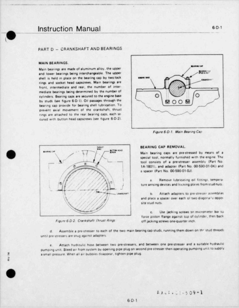
. -- _ . _ . . _ . . . . . .
,
Instruction Manual emm
W)_ - _ .q
PART D - CRANKSHAFT AND BEARINGS
MAIN BEARINGS.""
Main bearings are made of aluminum alloy, the upperk77d"and lower bearings being interchangeable. The upper j
Eshell is held in place on the bearing cap by twolock esses sans '"'rings and socket head capscrews. Main bearings are i!
*front, intermediate and rear, the number of inter-
- ~ 'mediate bearings being determined by the number of
'
cylinders. Bearing caps are secured to the engine base Q Qby studs (see figure 6 D 1). Oil passages through the EOOEbearing cap provide for bearing shell lubrication. Toprevent axial movement of the crankshaft, thrustrings are attached to the rear bearing caps, each se-cured with button head capscrews (see figure 6 D 2).
Figure 6 D 1. Main Bearing Cap
'=aus' BEARING CAP REMOVAL.'
MF "'' Main bearing caps are pre stressed by means of ama**'5" -
special tool, normally furnished with the engine. The%
L- tool consists of a pre stresser assembly (Part No.- 2
} @ I A 1801), and adapter (Part No. 00 590 01 OK) ands
7' // '/a spacer (Part No. 00-590-010J).-
,,
/. a. Hemove lubricating oil fittings, tempera-'/ ' / k}g
'/ ture sensing devices and los: king plates from stud nuts.(
'
f
/ / ,,t j'- ' %*j -
.;-
ua.uaa" b. Attach adapters to pre-stresser awmblies' / -,
[ ''. - and place a spacer over each of two diagort'y oppo-'
// / '/ site stud nuts.
. J/ /,//** c. Use lacking screws on micrometer har to
force piston flange against top of cylinder, then backFigure 6 D-2. Crankshaft Thrust Rings off |acking screws one quarter ench.
d. Assemble a pre stresser to each of the two main bearing cap studs, running them down on the stud threads
until pre-stressers are snug against adapters,
Attach hydreulic hose between two pre stressers, and between one pre.stresser and a suitable hydraulice.
pumping unit. Bleed air from system by opening pipe plug on second pre-stresser then operating pumping unit to supplyE a small pressure. When all air bubbles disappear, tighten pipe plug.
.
E'
1
O| OL
r
A A u L e ;,1 - 5 0 9 - 1
l 6D1_

- - -- - .- - - . - . . - . - . .
|
|
o Instruction Manual e.D.2
-(\._,/,--
.
PART D - CRANKSHAFT AND BEARINGS (Continued)
" ' " " ' * * *f. Slowly apply hydraulic pressure to pre-stresser assemblies until bearing cap studs have .
stretched sufficiently to permit stud nut to be , ~ ~ ,|
loosened. Approximately 10,500 psi pressure will f'n'_, , , , , , , , , , , , ,
be required. Use a brass drif t pin through the g ,,
spacer side opening to loosen nut. Do not turn nut v j j,j * "'"up tight against lower face of adapter as it will, (
bind when hydraulic pressure is released. Do not "'"N h _
\exceed maximum allowable pressure of 11.500 psi.'
N 2. } ! ' '&s
~
x:
hgl L ad jEg. Relieve hydraulic pressure on pre- u y.'p $Qgstressers, remove pre stressers, spacers and adapters , os
from stud. Remove stud nuts. tg,
-
h. Repeat procedure on remaining studs, ( %' 4,. _ , _
#_];%; ,f j'[
following a criss cross pattern. Remove all stud * W .~
nuts and litt bearing cap from crankshaf t. . \p % __,f) - - 2 j ,
(J '
Ip i.E
t- i 3.
BE ARING SHELL REPLACEilENT. Figure 6 D 3. Pre Stresser Asse-nbly
if it ,s necessary to remove t.ie main bear;ngs, remove the two socket nead capscrews an:|lu.k rangs : hat hold the upperbearing shell to the main bas'ing car 69d carefully re nove the shell from the esp. trut#!. a bearing shell rtmoval tout(Part No. 00 590 01.AE) in the crankshaf t journal oil hole then slowly rotate the e,tankshaf t until the tool is bearingagainst the bearios shell. SloMy continue to rotate the crankshaf t and roll the bearing 55 ell out of the j3urnal. Toremove tne thrust rings from the rear bearing caos, temuve the button head screws and puli tne thrust rings. Reversethe procedure to 'nstatt thrust eings and bearing 9. ells.
'BE ARING C AF INSTALLATION.
Install bearing cap in positio1 it' the reverse order of removal. Taka care nct to darrage the bearing shells. The oearmg|- cap studs are tightened as to'iows.
) a. Install pins to lock lower stud nuts to studs, then place wedges between lower nuts and the base cavitybottom and side vwalls. Check that height of stud end es 113/16 inch above cap mounting surf ace to permit proper
) engagement with the pre stresser assembly.
] b. Lubricate threads with 50 50 mixture of oil and graphite and tighten upper stud nuts hand tight. Placespacers (Part No. 00 590 01-OK) to the pre-stresser assemblies. Use jacking screws to force piston flange, tight against,
) ; top of cylinder. Back off jacking screws 1/4 inch.a
c. Install pre stresser assemblies on two diagonally opposite studs and assemble the micrometer bar on the| / units.
! !'
v
g u k w 01-5 09 -1"
,
6D2
t -.- - . . . . . . - -.
-
l>
Instruction Manual SD3m,)
PART D - CRANKSHAFT AND BEARINGS (Continued)
d. Insert micrometer head into the hole in the micrometer bar, making sure that it is fully seated. Tightenknurled knob to hold micrometer head in place.
e. Attach hoses to pre stressers and apply pressure to bleed air.
f. Run micrometer spindle against the micrometer pin until the pin is snug against the end of the bearingcap stud. Observe and record the micrometer reading.
g. Loosen knurled knob and remove micrometer head from the micrometer bar, insure that jacking screwson pre-stressers and backed off one-quarter inch for each stud.
CAUTION
Failure to back off on micrometer spindle will result in damage to the micrometer,
h. Apply 10,500 psi pressure to pre-stressers and hold while using brass drif t pin through spacer opening totighten nut snugly (about 50 ft-lb). Relieve pressure.
NoteThis operation is necessary to insure proper seating of parts and to minimize the effect of dirt
O or high spots on future readings,
i. Apply 10.500 psi pressure and hold. Tighten nuts to a snug fit with drif t pin (about 50 tt Ib).
Do not e .cetd maximum allowab'e pressure of 11,500 psi.
j. Relieve hydraulic pressure and install micrometer head in the r e:rometer bar. Hun spendie snug againstmicrometer r,in and record reading. Subtract the first readirt, from ti'il readirg. This is the amount the stud hasstretch:.'. Stud should streten 0 056" 0.051". Repeat operation if stretch is nct with'n specified range.
k. Remove pre stres.sr assemblies and repeat operation on next pair of diagonally opposite studs
.
:
'?
AV
#
A x 4 A v 01-5 09 -16 D-3
__. - _ _ _ _ _ _ . _ . . . . . . _ .
Instruction Manual s.D4ok
PART D - CRANKSHAFT AND BEARINGS (Continued)
CRANKSHAFT ALIGNMENT AND THRUST CLEARANCE.
It must be emphasized that excessive crankshaf t deflection can lead to an ultimate catastrophic f ailure of the crankshaft.This is costly in both time and money. It is recommended that crankshaf t alignment and thrust clearance be measuredimmediately after youting or chocking of the unit,the day before initial start up,af ter the first seven days of continuousoperation, and at six month intervals thereaf ter. Refer to Transamerica Delaval Engine and Compressor Division FormD 1063 (see figure 6rD 4) for an outlins of these procedures. Note that space is provided for recording both deflectionand thrust clearance readings. Copies of this form may be obtained from Transamerica Delaval.
CHECKING THRUST CLEARANCE.
Experience has shown that the feeler gauge method of measuring thrust clearance does not always produce satisfactoryresults. The dial indicator method is recommended to produce the desired accuracy of readings. A Starrett No.196,or similar, type dial indicator with magnetic base and extension rod long enough to allow the indicator to be mountedbetween the engine and flywheel with the spindle bearing on the flywheel. Check thrust clearances as follows:
Start auxiliary (B& A) lubricating oil pump. Bar engine over at least one-half revolution to establish an oila.film between the main bearings and their journals. This should permit easy movement of the crankshaf t.
b. Mount dial indicator on rear of engine frame, between f rame and flywheel. Spindle of indicator must bearon flywheel to measure horizontal movement of the crankshaft,
c. The crankshaft may be moved forward and af t in the horizontal plane with a pry bar such as a heavy, Spade-type, tempered steel digging bar, approximately six feet long. Make sure bar is clean enough for use inside the engine.Insert bar between rear crank web and nearest frame member inside crankcase. Do not insert bar deeply enough todamage either the main bearing shell or the craqirshaft journal.
d. Pry crsnksh ft forward. towards the gearcase end as f ar as it will go. If the crankshaft is SIl the way forwa d,it should be imot.ssibie to insert a 0.0015 inch feeler giuge between t5e o ankshaft rear thrust collar and the rear thrustring Zero the dial indicator, allowing f or at least 0.030 inch rnevera.ent towards the minus direction. ,
? Note.
if cranksnaf t canriot be rioved 's the limit of its possible travel by use of the pry bar alone.itmay be hecessary to ha the ar.gine over with tne barring device while at tht same time exert.nga horizo* tat force on the crankshatt writ' the bir to move it.
e. Reposition pry bar to move crankshaft to the rear, towards the flywheel end. Pry crankshaft to the rearas far as it will go as indicated by the inability to insert a 0.001S inch feeler gauge between the forward crankshaftthrust collar and the forward thrust ring.
f. Observe dial indicator. The number of thousandths (minus) indicated on the dial is the crankshaft thrustclearance. Record reading in the appropriate space on Form D 1063, and compare with previous thrust clearancereadings.
1 2 Note$ If there is any doubt as to the accuracy of the reading, repeat procedure.
a|
f
09 OCdgpk%6D4
. _ _
L.__ --
. _ _ _ _ - - . . . _
l
instruction Manual ses_
PART D - CR ANKSHAFT AND BEARINGS (Continued)
CRANKSHAFT WEB DEFLECTION.
The irrportance of crankshaft web deflection measurements is such that the care and attention to detail required toobtain and record these measurements cannot be overemphasized. Placement of the dial indicator is vital if accuratereadings are to beobtained. Form D 1063 (see figure SD4) illustrates the five positions of the crankshaft at which webdeflections are to be measured, and the starting position of the crankshaft for each crank web. Care must be exercisedto insure that the dial indicator is positioned in the center of the web, exactly opposite the center of the crankpin,andone-fourth inch from the edge of the crankweb. Take deflections as follows:
a. Remove engine side doors to gain acass to the crankcase.
b. Bar engine over in direction of normal rotation with barring device until number one crank is 52 degreesafter vertical bcttom center.
c. Insert dialindicater between web for number one crank. Double check that crankshaf t is properly positioned.If not in correct position, it is possible that the connecting rod will knock the dial indicator out of the web astheengine is barred over to the next position. Insure the two bearing points of the indicator are in a line exactly parallelto the centerline of the crankshaft. If indicator is not parallel, erroneous readings will be obtained. Zero the indicator,
d. With the dialindicator in place and not disturbed, bar the engine over, stopping at each position (2,3,4 & 5)as indicated on form D 1063. Record reading at each position in mits (plus or minus)in the appropriate space for each
;- position.e)
e. Repeat entire procedure for each crankshaf t web and record readings on Form 01063.
f. Compare all readings with each other and with previous measurements. Evaluate results, based on thestandards set forth in the following paragraph, and dete'mine need for corrective action.
{DEFLECTION STANDARDS.
If the deflection in any crank of an engine in service exceeds 3 mits t0.003 inch /0 0762 rom), corrective action is
) indicated if the deflectica in any web exceeds 6 mds (0 006 inch /0.1524 mm), the engine should be s sken oat ofservice unto the f ait .s corrected. Corrective action is also necessary of the total deflection in any pair of adiacentcranks exceeds 3 mos. For examp;e .f the def ketbn in or e crank is plus two mill, and the deflectior 3 i en adjacentcr.nk is min 45 two mils, the t31al detketion is four rnits. end corrective action is indicated.
CORRECTIVE ACTION.
The nature of the corrective action needed to deal with excessive crankshaft deflectio'ts niU va y, depending upon thespecific cause of the defect. The cause may be worn main bearings, impeoper foundation bolt torace.the foundatsonitself, or the grouting, misalignment of the engine and/or driven equipment, or a combination of eternents. For instance,excessive deflection at positions two, three or four in the crank web adjacent to the external shafting on engines havinga solidly coupled connecting shaf t usually indicates misalignment between the connecting shaf ting and the engenecrankshaf t. In some cases replacement of main bearings may correct the problem, and often the problem is correctableby realignment of the engine. If one portion of the engine base is found to be lower than other parts,it may be neces-
g sary to jack the base wdh jacking screws and shim the low area. It must be emphasized that engine alignment is a> complex, trial and error procedure which should be undertaken only by experienced and qualified personnel who are
capable of correctly interpreting the web deflection pattern, and of taking the appropriate measures to correct defects.
/] It is recommended that the Transamerica Delaval Engine and Compressor Division Customer Service Department be! consulted prior to undertaking any corrective measuresinvolving a suspected or confirmed crankcase alignment problem
w./
g,y L.eg.509'l-
6D5 +' 5 r*
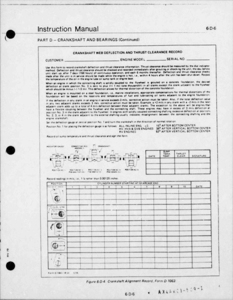
-. - . . . ~ . . . _ .
.
|nStruction Manual soo_ _
'
PART D - CRANKSHAFT AND BEARINGS (Continued) |
CRANKSHAFT WEB DEFLECTION AND THRUST CLEARANCE RECORD
CUSTOME R ENGINE MODEL SE RI AL NO.
Use this form to record crenkshaft deflection and thrust eteerence intormation. Thrust ctearance should be measured by the dial indicatormethod. Deflection and thrust c6earance should be checked sad recorded immediately after youtme or chocking the unet, the day beforeunit start up. etter 7 days (168 hours) of contin ous operaten, and each 6 months thereafter. Deflection and thrust clearance checesumade after the unit is in service should be made while the engme is hot, i.e.. withm 4 hours after the unit has been shut down. Reaardthe temperature of the oilin the engine lubs oil sump tank or engme base.
When en engme in which the connecting shah is solidly coup 6ed to the flywheel is youted on a concrete foundation. the desireddeflection et crank position No. 3 is aero to plus (*) 1 mil tone thousandth) in all cranks except the crank ediacent to the flywheelwhich should be minus (41/2 mil. This deflection ellows for thermal distortion of the conerete foundation.When an engme is mounted on a steel foundation, i.e.. marme installations, appropriate compensations for thermal distortions of snefoundation will be based on the locations and temperatures of fuel and lubricating oil tanks ed6acent to the engme foundation.If the deflecten in any crank en en engine in service exceeds 3 miss. corrective action must be taken. Also. if the total deflection valuem any two adiacent cranks exceeds 3 remis, corrective action must be taken. E mample e e2 mits in any aank with a .2 mies in the neutediacent crank adds up to a total of 4 mais deflecten between these ad acent eranks. The esception to the above will be engmes thatihave a fiesibie coupling twtween the flywheel and the connecimo shaf t. These engines may have m escess of 3 miis defiection etpas.t on No. 3 m the crank ediacent to the flywheel. In engmes with solidiv coupled connectmg shaf ting.escessive deflection at portionsNo 2. 3. or 4 in the crank odescent to the enternal shaf ting usually mdicates misalignrhent tutween the connectmg shaftmo and sneengine cranksha't.Set the detiection gauge at sero at pos tion No. I and tu n the crankshaf t m the direction of normal rotation.r
Position No. I for placmg the deflecten gauge is as follows. ALL INLINE ENG c5 15' AFTER 80TTOM CENTERHV HVA as GV8 ENGINES 38' AFTER VERTICAL 80TTOM CENTYRRV ENGINES 52* AFTER VERTICAL BOTTOM CENTER
Record oil sump temperature and thrust clearance end seen the form.
p con =.s .seO anoicatos saut.a conne i soo
Y(v) \ - I' 1~E suuerr TANE THaust*~qW= Daft Tip* CLlan sicNaTunt
w .=>
3
$J $''
_,: s._m . _ ._ __ i.o r_ .c ..
.. . .~. a u w. .-
Record readings in mils, i e.,14 eothe than 0 00125 mehes.
PQait 'ON CY6eNOrm Nuustm STARTING af Gl.amCant END";*-- i | 7 1 3 a s e 7 e o I to caer
;A7-- O
h j
. x.m .( %- .)
,
i
f. - + .
'
|-
!^)
e.
i'
3 j :.~ i ji
i |' jf~o1 i e i ! i
i
( )w/
e en * O 90b 3 t m 3 s/ Ps
figure 6 D-4. Crankshaft Alignrnent Record, Form D 1061*c-9-1,
4 bEkb '' '
6D6
4._ -- _ _ _ . _ ..
,
p Instruction Manual s.E.i
VPART E -CAMS, CAMSHAFTS AND BEARINGS
GENERAL.
The induction hardened steel cams are shrink fit on the precision ground camshaft, using hydraulic expansion of thecam bore to position them on the camshaft. Camshaft bearings are aluminum alloy and are pressure lubricated. Cams,camshaf ts and associated operating gear should be checked periodically for wear and/or damage.
CAMSHAFT SEARING REPLACEMENT.
Should it be necessary to inspect and replace camshaf t bearings, do the following.
a. Remove covers over camshaft.
b. Disconnect lubricating oil line from bearing cap.,
c. Remove bearing cap, lock rings and upper bearing shell, then roll lower bearing shell out of its saddle.
d. Inspect bearings for evidsoce of damage or wear. Refer to Appendix lit for permissible wear limits.
e. Installation is the reverse of removal.
CAM REPLACEMENT.
Cams are positioned on the camshaft t the factory by hydraulically expanding the cam bore and sliding the camty into position on the shaf t. If it ever becomes necessary to remove and replace cams in the fi91d, the followir'g
procedu'e is recommended.
s. Cams are located on the camshaf t by scribe marks on the cams and,the camshaf t, placed there duringmanufacture. Circumferential marks locate the cams longitudinally on the camshaft, and longitudinal marks locatethe cams circumferentially. Cams have a radial scribe mark on the side of the cam which passes through the center ofthe hole in the side of the cam.
,
b. Make a sketch of the camshaf t assembly, indicatin0 the location of the cama and the distance betweeneach. Make sure the camshat' ad all cams are scribed.
| c. Clean the camshaft and place on Vee blocks on top of a clean workbench. Make sure all burrs, dennand other irregularities are reduced to the common diameter of the camshaft. Irregularities will prevent removal ofthe cams.
{ d. Obtain a hydraulic pump unit, such as a ''Porto-Power", complete with a hose and fittings, and a pressure,
gauge capable to reading up to 20,000 psig.u
I
I e. Remove camshaf t gear from camshaf t, then connect hydraulic unit to the first thrust ring. Raise pressure
) to approximately 2000 psig and slide thrust collary off camshaft. Repeat procedure to remove other thrust ring.Ej f. Connect hydraulic unit to first cam nearest the tapered end of camshaft. Apply approximately 16.000> psig pressure (or pressure that will allow the cam to slide on the camshaft) and move the cam towards the drive end
! of the shaft.
,
'
t
,
A )u t. x C 1 - 5 0 9 - 16E1
.. _ _ . .
-- . . . - . . - .
Instruction Manual s.E.2_
PART E - CAMS, CAMSHAFTS AND BEARINGS (Continued)
The camshaf t has a taper near the drive end which serves as a starting ramp when installingthe cams. As the cams reach the taper there is a strong tendency for them to shoot off theshaft with considerable velocity. Arrange a stop plate at the end of the shaf t to keep the camsfrom shooting off the camshaft,
g. Remove all cams in order,
h. Wash and tiry the camshaf t and the replacement cams. Check that scribe marks are clean, sharp and clear 1yvisible. Lay cams out on a clean surface in the correct sequence and orientation for installation. Refer to the skett:hand make sure the cams are facir g in the proper direction.
i. Choose the cam which will be f arthest from the drive end of the camshaf t and slide it up on the startingramp as f ar as it will go.
j. Attach the hydraube unit to the cam and start raising the pressure. A vigorous effort will be required tomoy? the cam up the starting ramp to the straight part of the shaf t. Approximately 16,000 psig pressure will berequired.
k. k'ove the cam to its correct location on the shaf t. Align the edge of the cam bore with the circumferentialscribe mark and align the radial (longitudinal) scribe mark on the shaf t with the mark on the cam. Release the hydrautepressure when the cam is correctly aligned.
1. Install and position the rf maining cams in order, then replace the thrust rings,
i
ku!l<
I'
C
$1
|
v
pyu s V'(S-I. u
t
6E2
C.. _ . . . _ _ _ _
instruction Manual ee3_
PART E - CAMS, CAMSHAFTS AND BEARINGS (Continued)
TIMING GE ARS.
Timing gears are enclosed in the gearcase, and are lubricated by lets of oil. Gearcase covers should be removed period-ically, and the gears inspected for wear and for backlash. Refer to Appendix ill for backlash clearances. If theprescribed backlash clearance is exceeded by 0.006 inch, or if damage is discovered, perform the following disassemblysteps to the degree necessary to accomplish the required inspection and repair. Accessories are doweled at assembly.If it is necessary to remove a dowel to reposition an accessory, drill and team another dowel hole of the proper sitein the accessory mounting flange and in the gearcase.
Remove the governor, overspeed trip, pumps and other accessories which would interfere with gearcasea.removal. As the pumps are removed, cover the shaf t, orive gears and openings in the pump housing to exclude dirtand to prevent damage. Cover the open ends of connecting pipes and tubing.
b. Remove gearcase from engine. The gearcase is heavy and difficult to handle, therefore, rigging must bedone very carefully to insure that it is under control at all times.
(1) Rig chainfalls and stings for handhng gearcase.
(2) Remove bolts and capscrews. then lift gearcase from engine. Do not let it drop or swing. Set aside,secured in such a manner that it cannot f all,
nI I Remove the governor drive assembly, and the overspeed trip and fuel booster pump drive assembly.c.(%
d. Insure that the crankshaf t, camshaf t and idler gears are match marked for proper positioning at reassembly.
If a new gear is to be installed. check both cyhnder banks to insure that the number one fuel injection pumps arecorrectly timed. Fuel injection pump timing marks will serve as a reference point when reinstalling the gears.
e. Remove idler gear and bracket assembhes.|
(1) Rig a small chainf all and wire rope sling to lift the idler gear and bracket assembly from the engine.
)(2) Straighten locking clips. Remove top bracket retaining capscrew and replace with a long capscrew
to serve as a guide and safety device while removing the gear and bracket assembly.
(3) Remove remaining capscrews and take a strain on the chainf all.
(4) Carefully pry bracket assembly free of the aligning dowels at the top and bottom of the bracket.
- (5) Slide gear teeth clear of other gears, taking care not to damage any teeth.
(6) Remove long guide capscrew, and move bracket assembly clear of engine,
1 f'. Remove camshaf t gear assemblies.
f (1) Remove cotter pins from camshaf t gear hub retaining nut. A gear puller may be needed to start thegear hub off the shaft. The gear assembly will usually jump when it breaks free of the taper, if the initial movementuis too great the ram effect may cause displacement of camshaft collars or upset thrust clearance. To prevent this,7-
( ) loosen hub retaining nut only f ar enough to hmit this initial movement to 1/16 inch.%j
t. y : ; ) - 5 0 9 - 1
6-E 31
- - ._..-..-. ..'-
,
1i
Instruction Manual _ ;E4sm
e--
PART E - CAMS, CAMSHAFTS AND BEARINGS (Continued)
(2) If the gear assembly will not come loose with a gear puller, use an oxy acetylene torch and quicklyapply heat to expand the hub. Protect the front camshaf t bearing from the torch flame.Do not owtheat.
(3) Remove camshaf t gear hub retaining nut and slide gear of f shaf t.
g. Remove camshaf t gear.
(1) Protect the front main bearing with a wet asbestos heat dam.
(2) Make two 3/4 inch diameter handling rods,24 inches long with 3/4-10 threads at one end. andscrew rods into the two tapped holes in the gear.
(3) Use two " Rosebud" type heating torches to quickly heat the gear until it can be shpped off thecrankshaf t with the handling rods. Be sure the exposed end of the crankshaf t is clean and free of burrs.
INSPECTION.
Inspect gears for broken teeth, or other damage. If gears are damaged, inspect camshaf t with dial indicator to determine
if shaf t is bent.
Clean camshalt tapers and check fit of drive keys in hubs.a.
O. b. Clean gear seat area of crankshaf t.
If it is necessary to remove the idler gear from the bracket, cut the safety wire and remove the four boltsc.that hold the idler gear stub shaf t in the bracket. Remove the stub shaft then carefully slide the gear out of the bracket.When reassembling the idler gear in the bracket take care not to damage the bushings of the gear teeth.
)ASSEMBLY.
4. Install camshaf t gear.)
(1) Lubr'cate camshaf t taper with white lead and lubricating oil if a new gear hub is being installed,fit a new key in the key slot.
(2) If a new gear and hub are being installed, position the slotted holes in the hub over the drilled holesin the gear, install camshaf t gear to hub bolts, washers and nuts. Tightm to hold gear and hub together.
(3) Using a chainfall and sling, lif t gear assembly into position and slide onto camshaft taper. Assemblewasher and nut, tighten, and install cotter pin,
b. Install crankshatt gear.
)0(1) Heat camshaf t gear to 350 F in hot oil. Do not overheat.
,,
) ''
3 (2) Screw two handhng rods into tapped holes in gear. Lif t gear out of the oil with rods, and withone>
) smooth, continuous motion, position heated gear against the shoulder. This must be done quickly before the gearcools. Allow gear to cool, then proceed.
V
g n A g01- 5 09 -16 64.
_ - - - - .
. . .- -- - - . - . . . . . -
Instruction Manual s-s ef. .
, 4
PART E - CAMS, CAMSHAFTS AND BEARINGS (Continued)
Set up a one inch travel dial indicator on the pump base for number one fuel injection pump with thec.spindle of the indicator bearing on top of the tappet pin for number one fuel tappet, master rod bank, and zero theindicator,
d. Bar the flywheel in the direction of normal rotation until the tappet roller for number one fuel injectionpump starts up the lif ting ramp of its cam.
Continue barring the flywheel until the degree mark for fuel injection for number one master rod bank ise.directly in line with the flywheel pointer. This degree mark is shown on the Engine Data Sheet in front of the manual,and on the engine nameplate.
f. Observe the dial indicator to determine the lif t of the fuel tappet at this point. Lif t should be 0.197 inch.If lif t is other than 0.197 inch, camshaf t timing must be corrected.
(1) Loosen two fitted bolts that f asten camshaf t ring gear to gear hub.
(2) Loosen remaining four bolts and rotate camshaft gear within ring gear to raise or lower the tappetas necessary.
(3) If there is not enough travel in the slotted holes in the gear hub to allow the requircr1 correction,it
[] will be necessary to lift the gear end of the camshaf t until the cam gear teeth disengage from the idler gear teeth, and
[] shp the mesh one or more teeth as judged necessary. Re<ngage the teeth of the cam gear and idler.
(4) Observe dial indicator to find tappet lif t after correction. Make final correction by rotating thecamshaf t gear hub within ring gear.
(5) When correct tappet lif t is obtained, lock up the four bolts in the slotted holes and drill and teamfor two fitted bolts. New holes for fitted bolts should be moved approximately one inch from the original holes.
(6) Torque six bolts that f asten ring gear to hub to a torque value of 70 f t Ib, plus or ininus"20 ft 6b as$ required to abgn cotter pin holes. Tighten and lock camshaf t bearing cap bolts if they were loosered to shp gear
tooth mesh,
g. Replace number one fuel injection pump, master rod bank.
h. Bar flywheel to place fuel injection timing point for number one, master rod bank, directly under flywheel; pointer,
done r ma te d k
1 Bar the flywheel in the direction of normal rotation approximately 315 degrees to position the degreemark for fuel injection for number one, hnk tod bank cylinder directly in line with the flywheel pointer. Refer to
i
f, Engine Data Sheet or engine nameplate for the correct degree mark. This will place the timing and firing order of the
$ master rod bank and the hnk tod bank in the correct relationship.
$k. Time the number one, hrik tod bank fuel injection pump in the same manner as used to time the master
; rod bank pump
V' l. When both banks are timed, recheck fuelinjeClion pump timing and Cylinder head valve lash for both banks
A A A A K 01 - 5 0 9 - 1 3
Il _ , c n o _.1
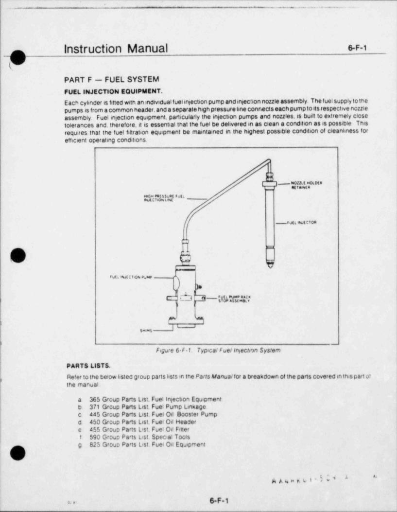
*
. - . . . .
Instruction Manual 6-F-1
PART F - FUEL SYSTEMFUEL INJECTION EQUIPMENT.
Each cyhnder is fitted with an individual fuelinjection pump and injec' ion nozzle assembly. The fuel supply to thepumps is from a common header, and a separate high pressure hne connects each pump t0 its respective nozzleassembly. Fuel injection equipment, particularly the injection pumps and nozzles, is built to extremely closetolerances and, therefore, it is essential that the fuel be delivered in as clean a condition as is possible Thisrequires that the fuel filtration equipment be maintained in the highest possible condition of cleankness forefficient operating conditions.
~Nt|UEcEE.}}$''""
_ eva wwtetoa
'*O* I
(_& 7
ruttwut:rio o v
>sY' E="sNd*
l
P R;I'
'
s ..s
) -
Fogure 6-F 1. TypicalfuelInjectnn System
PARTS LISTS.
Refer to the below listed group parts lists in the Parts Manualfor a breakdown of the parts covered in this part of)
the manual.
a 365 Group Parts List, Fuel injection Equipment.b. 371 Group Parts List, Fuel Pump Linkage.c 445 Group Parts List. Fuel Oil Booster Pumpd 450 Group Parts List, Fuel Oil Headere 455 Group Parts List. Fuel Oil Filterf 590 Group Parts List. Special Toolsg 825 Group Parts List. Fuel Oil Equipment7m,
(s.s
6-F-1c. . .1
____ _ _ _ _ _ _ _ _ _ _ _ _ _ _ _ _ _ _
. _ _ _ _ _. 7 . ___
Instruction Manual 6.F.2f(V i
FUEL SYSTEM (Continued)
FUEL INJECTION NOZZLES.Because nozzles and tips are subjected to extremes in pressure and temperatu's, they normally are among thefirst sources of engine trouble. A nozzle in good condition must pop open atthe proper pressure without dnbble,'
then close completely almost immediately. When subjected to a steady pressure at the opening pressure,it 'should " chatter", that is, open and Close rapidly, The spray form should be a uniform, finely atomized mistpattern, never a solid stream. If the fuel nozzle is suspected of malfunctioning, remove from engine and test asfollows.
Disconnect high pressure line and drain connections.a
b. Remove nuts from injector studs and remove nozzle retainer.
Lift or pry the nozzle holder assembly from the cylinder head. The use of a nozzle assembly puller toolc(part no 00 590 0188)is recommended This toolis available for purchase from the Transamenca Delavatparts sales department.
Plug opening in cylinder head to prevent dirt or other foreign matter from entering the combustiondchamber.
Test the nozzle holder and tip assembly on a suitable nozzle tester, checking for the followinge.
Conditions
(1) Apply pressure and check nozzle for popping action. The valve should chatter it it is seatingproperly
(2) Raise pressure slowty to determine pressure at which valve opens The valve should open at3000 psi (211 kg cm*) plus 200 psi (14.06 kg cm'), minus zero psi. The opening pressure is adjusted bymeans of shims in the valve assembly, requiring disassembly of the unit. See Figure 6 F 2.
(3) Dry off spray tip and raise pressure to within 100 psi of the opening pressure and observe tip fordnbbing of fuel
(4) Check to see if any spray tip holes are plugged.
(5) Flace a clean piece of paper under nozzle tip and check spray pattern for uniform density and asymmetncal pattern
Nozzles that f ail to perf orm satisf actorily should be repaired or replaced Refer to manu'acturer's(0)instructions in the Assocsated Pubhcations Manual
WARNINGThe penetrating power of atomized fuel under high pressure is sufficient topuncture the skin and serious injury can tesult. To avoid this danger, the handsniust be kept away from a spraying nozzle.
i
2 6..
g g g e g v i ' ~ -* *,
6-F-2 . . . .
x .. e a
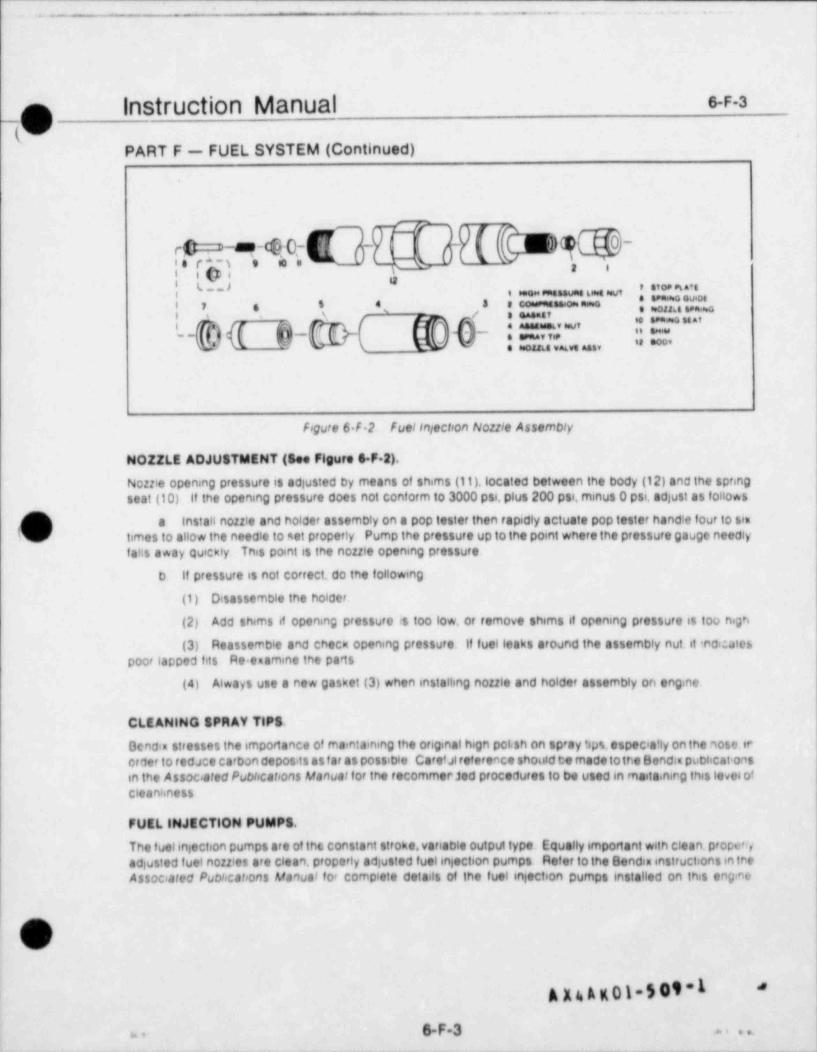
.- - - . _ . . - .
Instruction Manual 6-F-3~
_
y .
PART F - FUEL SYSTEM (Continued)
f,%c i",T; b I'~ N-
*'i i ,| t> , .. ...
, , , , , , , , _ , , , , , ,
i t ,8 : = ~~ 'L?a 0|2 .
L-{s}(( (i)-@( @V(e3-: Ot;" % '~f "''-- M a --. om. . ..
Figure 6 F 2 FuelIntection Nozzle Assembly
NOZZLE ADJUSTMENT (See Figure 6 F 2).
Nozzle opening pressure is adjusted by means of shims (11), located between the body (12) and the springseat (10) If the opening pressure does not conform to 3000 psi, plus 200 psi, minus O psi, adjust as follows
) a Install nozzle and holder assembly on a pop tester then rapidly actuate pop tester handte four to simc/ times to allow the needle to set properly Pump the pressure up to the point where the pressure gauge needly
fatis away quickly This point is the nozzle opening pressure
b If pressure is not correct. do the following
(1) Disassemble the holder.
(2) Add shims if opening pressure rs too low, or remove shams if opening pressufe is too high
(3) Reassemble and check opening pressure if fuelleaks around the assembly nut. it ndicatespoor lapped fits Re examine the parts
(4) Always use a new gasket (3) when installing nozzle and holder assembly on engine
CLEANING SPRAY TIPS.
Ocncia stresses the importance of maintaining the original hign pct.sh on spray tips, espec'a'ly on the nose.trerder to tedace carbon deposits as f ar as possibie Caretat reference should te made to the Bend.: publicat onsin the Associated Publications Manual fof the recommer jed procedures to be used in maita nirg this level ofcleanliness
FUEL INJECTION PUMPS.
The fuelinjection pumps are of the constant stroke. variable output type. Equally important with clean. prope",-adjusted fuel nozzles are clean, property adjusted fuelinjection pumps Refer to the Bendia instructions in theAssoc,ated Publications Manual for complete details of the fuet injection pumps installed on this engme
, cI .y
A X 4 A K 01-5 09-1*
6-F-3 , . ...
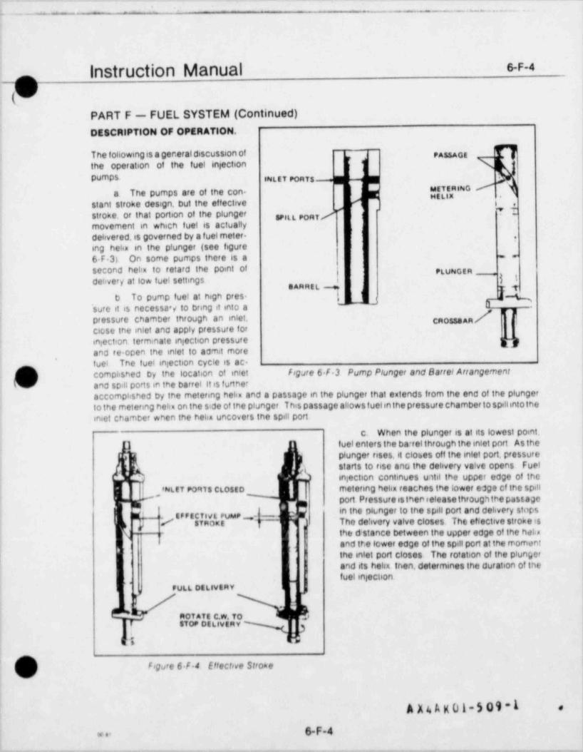
- -_ - _ . . . --
Instruction Manual 6-F-4-m 1
i '
(VPART F - FUEL SYSTEM (Continued)DESCRIPTION OF OPERATION.
T he following is a general discussion ot ,,33, g ,
the operation of the fuel injectionpumps. ,g t , y ,gg y , ,,,,,,
METERING'
a The pumps are of the con-HE''* *
stant stroke design, but the effective , ,
stroke, or that portion of the plunger SPILL PORT /'I
movement in which fuel is actuallydelivered, is governed by a fuel meter-
*,
ing helin in the plunger (see figure6F3) On some pumps there is a .,
second helix to retard the point of ; ,
delivery at low fuel settings j jgBARREL %
b To pump fuel at high pres- !5-~
[ .,
,sure it is necessa'y to bring it into apressure chamber through an inlet. / U l
1
close the inlet and apply pressure foriniection terminate injection pressure gand re open the inlet to admit more
' tuel The fuel iniection cycle is ac-complisned by tne location of intet Fogure 6 F 3 Pump Plunger and Barrel Arrangement
d and spill ports in the barrel it is furtheraccomplished by the metering helix and a passage in the plunger that extends from the end of the plungerto the metering hehu on the side of the plunger This passage allows f uelinthe pressure chamber to spillintothein6et chamber when the helin uncovers the spilt port
c. When the plunger is at its lowest point,] fuel enters the ba rel through the inlet pnrt As the
g plunger rises, it closes off the inlet port, pressurer- starts to rise ano the delivery Valve opens Fuel
. h injection continues until the upper edge of the,
8NLET Ponts CLOSED metering helix reaches the tower edge cf the spill
(' port Pressureisthenieleasethroughthepassage,
in the ph.nger to the spill port and delivery stopss,' EP FECTl/L PUMP -| --
The de!ivery valve closes The ettective stroke is/. STROKE j"
the d stance between the upper edge of the helis- r
and tr.e lower edQO of the spill port at the moment
|the inlet port closes The rotation of the plunger
) and its helin then, determines the duration of the'
fuel injeClion.,
FULL DELIVERY7,
Rot ATE C.W. 70 s
STOP DELIVERY
t a
?) Fogure 6 F 4 Effective Strokev
A X4 A K 01-5 09-1 ,
6-F-4* .-
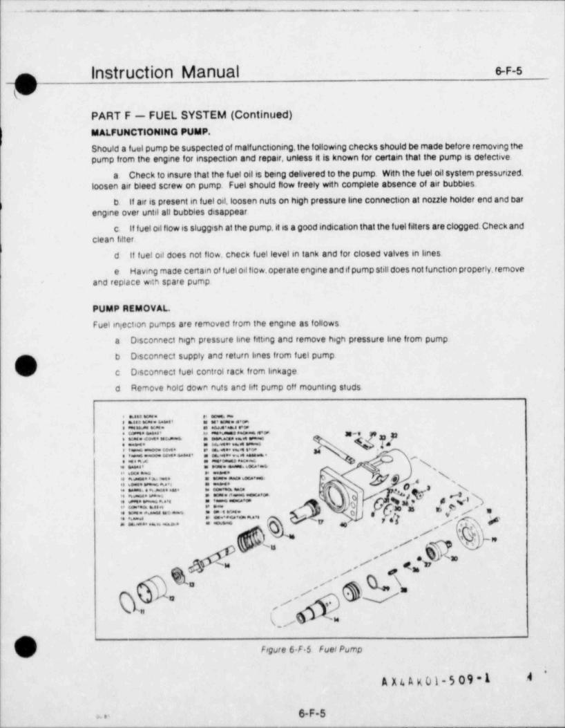
.- . . - - . .
Instruction Manual 6-F-5
PART F - FUEL SYSTEM (Continued)MALFUNCTIONING PUMP.
Should a fuel pump be suspected of malfunctioning,the following checks should be made before removing thepump from the engine for inspection and repair, unless it is known for certain that the pump is defective.
a Check to insure that the fuel oil is being delivered to the pump. With the fuel oil system pressurized.loosen air bleed screw on pump. Fuel should flow freely with complete absence of air bubbles.
b. If air is present in fuel oil, loosen nuts on high pressure line connection at nozzle holder end and bar)
engine over until all bubbles disappear.
c. If fuel oil flow is sluggish at the pump,it is a good indication that the fuel filters are clogged. Check andclean filter.
} d 11 fuel oil does not flow, check fuel level in tank and for closed valves in lines.
e Having made certain of fuel oil flow, operate engine and if pump still does not function properly, removeand replace with spare pump
PUMP REMOVAL.
Fuel injection pumps are removed from the engine as follows
a Disconnect hign pressure line fitting and remove high pressure line from pump.
b Disconnect supply and return lines from fuel pump
b c Disconnect fuel control rack from linkage
d Remove hold down nuts and litt pump off mounting studs.
: = = _ .. : = . . ..I - 5555E~ "Vy/!W: = = = .. : :== . -
=- : :===. #x: = .._. : = _ . _ . & #f ' ,'s: ===.. : =_ v 'sj,v .c:.,3: ==.. : ==- o
'
y rl,l j '', ,|,a: :== : :.-. ' ' 9: . -
;=' ... : C''*" ~'' 'n .(* /s, 7-) "6-
. // W
f sQ/ ,
* V,, \= "=
-s,,
N_/ ~"
p) Figure 6 F $ FuelPump
,
A X 4 A x 01-5 09 -1 A
6-F-5x.,
;. - - --.
_o Instruction Manual 6-F-6
VPART F - FUEL SYSTEM (Continued)
fDISASSEMBl.Y OF PUMP (See Figure S-F 5)
The manufacturer's instructions contained in the Associated Publications Manualprovide detailed instructionsf or the overhaul and repair of fuel injection equipment, arvi should be consulted when any work is being done onfuel injection pumps. Pumps may ve disassembled as follows.
a. Secure pump in the inverted position in a soft jawed vise. Depress the plunger follower and insert a %inch diameter pin in the hole in the pump flange.
b. Remove lock ring by prying it out with a screwdriver. Again depress follower and remove % inch pin.
c. Remove plunger follower. Take lower spring seat from plunger, then carefully remove plunger frombarrel. Carefully submerge plunger in spindle oil.
)d Remove plunger spring, then pult control sleeve using a specially fabricated puller, or a pair of pliars
whose jaws are wrapped with masking tape. The upper spring plate will come out with the control sleeve.
e Remove pump from vise and re-secure in an upright pasition.
f. Remove delivery valve flange and delivery valve holder. Remove and discard preformed packing
g Remove delivery valve stop and spring. then, using a delivery valve puller, carefully remove deliveryvalve
h Remove barrel locating screw then slide barrel from housing
C Remove control rack locating screw and control rack Do not remove timing indicator or shims unlessi
k pump is to be re catio<ated
,
L
bv
1 ) u A kcl-5 09 -16-F-6< . .
- . - .
- '
- . . . . - .
instruction Manual e-F-7o
(VPART F - FUEL SYSTEM (Continued)
ASSEMBLY OF PUMP (See Figure S-F-5).
Assemble the pump as follows, observing the manufacturer's instructions in the Associated PublicationsManual.
a. Secure pump housing in a vise in an upright position.
b. Posit.on control rack in housing with teeth facing center of pump. Instaillockwasher and control racklocating screw, making sure the screw enters the rack locating groove,
c. Insert barrelin pump housing. Locating groove must be aligned with locating screw hole. Installiock-washer and locating screw.
d. Invert pump and install control sleeve so that tooth directly under timing mark meshes between twoteeth indicated by timing dot on control rack.
e. Install upper spring plate and plunger spring then carefully start plunger into barrel. It should settle inof its own weight. Turn plunger so marked end of crossbar will gointo controf sleeve slot that has a mark adjacentto it
f. Position lower spnng plate on end of plunger. Fit plunger follower into housing. Compress andinsertpin in housing flange. Install lock ring and remove pin.
g Install delivery valve assembly in pump housing Lubncate and install preformed packing and installdelivery valve spring and delivery valve stop. Assemble flange in housing
h. Install pressure screw and new copper gasket. Install bleed screw and new gasket.
i. After pump is completely assembled. hold it horizontally with the control rack vertical. The rack shouldsettle to its lower extreme by its own weight.
j If pump will not be immediately installed, fill inlet and outlet with clean, anti corrosive lubricating oil andcicsc openings with caps
.
O
U1-509-1 '
.
6-F-7w .--_

_,
_ _ _ . .
n Instruction Manual s-F-8
}v'PART F - FUEL SYSTEM (Continued)
PUMP INSTALLATION AND TIMING.~
Refer to the Engine Data Sheet in the front of the, , , , .,
manual, and to page 6-A-1 for determination ofengine rotation, bank designation (V-type en-,,,
| ':! gines) and cylinder numbering. The flywheel is' '"
;", marked to locate top oead center (TDC) of each' *
; '* ; cylinder, and is laid out in one degree increments
| |for the twenty five crankshaft degrees preceeding"
A0 '~'" 0 TDC (see figure 6-F-6). For instance, on a six"
-" ' " cylinder inline engine, there will be marks "TDC
L 186", "TDC 2&5" and "TDC 3&4", each pre-ceeded by degree marks. On eight cylinder inline' '
k k engines the markings will be for cylinder pairs188,2&7,316 and 4&5. Markings on the flywheelw -
for V-type engines follow the same pattern.except* - - - - - . ' -
that the banks are also designated Refer to thefigure 6 F-6 Flywheel Tsming Marks Engine Data Sheet in the front of the manual f or the
fuel injection point. Install and time f uel pumps asfollows.
m a Before mounting pump on engine, and with the fuel tappet roller on the base circle of the f uel cam (see
'
figure 6-F-7), measure distance from the fuel pump mounting surface on the base assembly to the tappet with adepth micrometer. Add or remove shims from the top of the base assemblyto obtain a measurement of approx-imately 0.197 inch
b. Place pump on base assembly and install nuts on studs Torque nuts as specified in Appendix IV
c. Bar engine over in the direction of norinal rotation*
until Ihe flywheel pcinted is al'gned with the f uel injection point OE' ***T "JO*L(oegrees BTDC specified on Engine Data Sheet or Name- ,-
platt) for the cyl rider str,ed t/ the f uel psmp being installed ~T 'd- -
f',"'-~
o Obs3rve plunge:r fct:ower finiing mark in pumptiming windew if the plunger follower timir'g mark does notline up with the index mark on the timing window, remove ,Q,o,,,..,,
pt.mp and add or remove shims between the pump and the / g,,
pump base assembly as necessary so that the rnarks williane g, , , , ,~ ~ * *up Re instcilthe cump and bar engine through one complete
mjection cycle to iqs'.'re that marks do align at the fuel /~injection point j
Figure 6 F-7. Pump Base To TappetAdjustment
CAUTIONThe timing mark on the plunger follower must never go beyond the upper or
; lower edge of the timing window. If it does, the pump may be severelyv damaged-
~
6-F-8 hX' #m.,
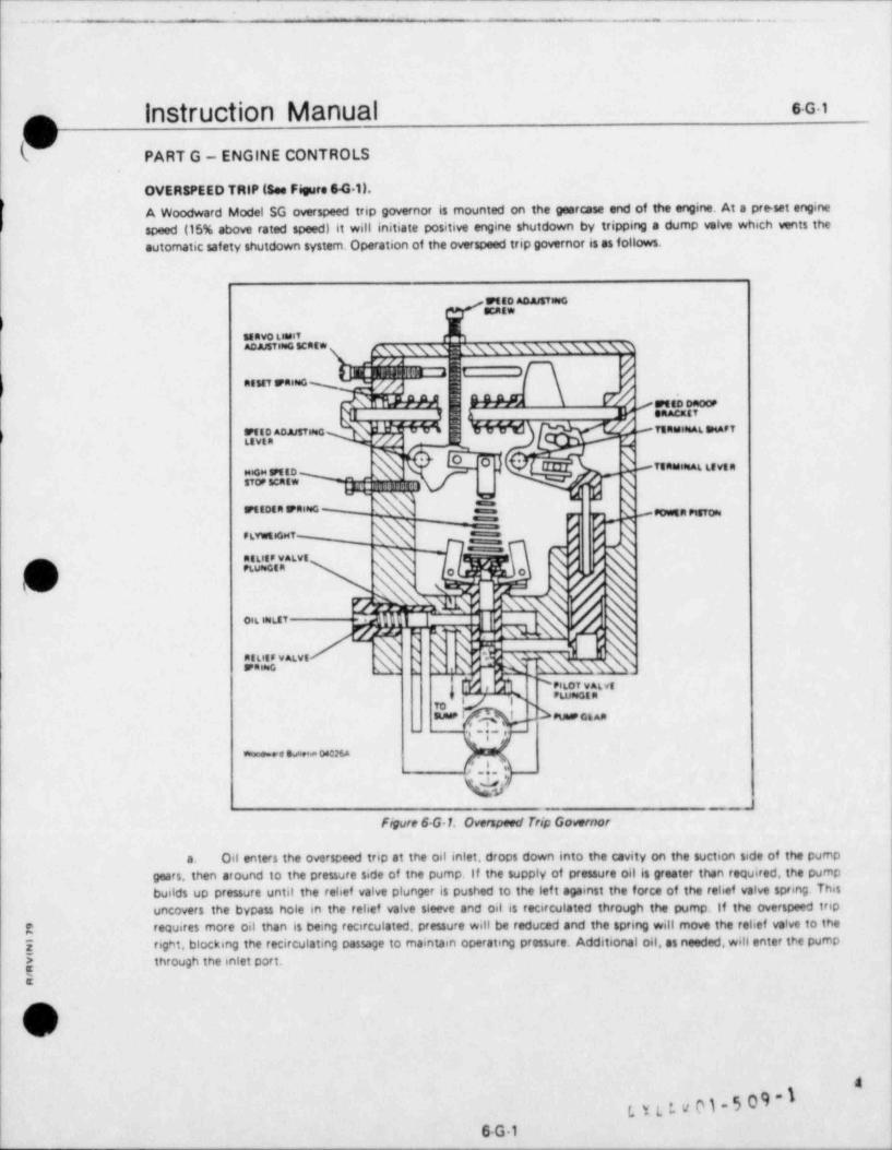
.- - _
-- _ . _ . _ .
1
Instruction Manual sGioO
PART G - ENGINE CONTROLS
OVERSPEED TRIP (See Figure 641).
A Woodward Model SG overspeed trip governor is mounted on the gearcase end of the engine. At a pre set enginespeed (15% above rated speed) it will initiate positive engine shutdown by tripping a dump valve which vents theautomatic safety shutdown system. Operation of the overspeed trip governor is as follows.
ES"")
senvo timit^8^*'"'''C"'* mmummxmxm'
Q L. L._,,_,> -
s .giganustmoQ N ===u - ream mate. net
)H
N \*-tsa==46 tevs ameo
stor scatw
g Nmaoan sramo-, ,
FtVwtiGHT
Dv('N L'u E' P ''' \
s
Vaq u% '
eoi6 most . HH I i <
Zg " PNM . %\ g
ThE$M
4'!%"^''',:n = .s
,,oSUuP bPUMaosAa-
-
i ; ,.
%,e su.a osma
_N!. i/
Figure 6-G 1, Overspeed Trip Gomemor
a. Oil enters the overspeed trip at the oil intet, drops down into the cavity on the suction side of the pumpgears, then around to the pressure side of the pump. If the supply of pressure oil is greater than required, the pumpbuilds up pressure until the relief valve plunger is pushed to the lef t against the force of the relief valve spring Thisuncovers the bypass hole in the relief valve sleeve and oil is recirculated through the pump. If the overspeed trip
R requires more oil than is being recirculated, pressure will be reduced and the spring will move the relief valve to the
E right, blocking the recirculating passage to maintain operating pressure. Additional oil, as needed, will enter the pumpthrough the inlet port.
ls
\V
t y t :. v M . 5 0 9 - 16-G 1
--
.
L- -- - - - . . . . _ . . . _ , _
o Instruction Manual SG2.w
(V,
PART G - ENGINE CONTROLS (Continued)
b. The pilot velve plunger controls the movement of the power piston by directing oil to or from the eresbeneath the power piston. The poww piston in turn controls the position of the taminal lever, and, therefore, theposition of the terminal shaf t. Two opposing fotoss act upon the pilot valve plungee . the speeder spring force tendsto push the plunger down and the centrifugal force developed by the rotating flyweights tends to lift the plunger,
When the engine is operating below the trip set point the speeder spring force holds the pilot valve plungstc.down and connects the oil under the power piston to drain. The reset spring, pushing the reset rod against the terminal
lever, holds the power piston down,
If engine speed rises above tripping speed the centrifugal force of the flyweights overcomes the speederd.spring force and lifts the pilot valve plunger. As the plunger rises, pressure oil flows to the underside of the powerpiston, forcing the piston up. As the terminal lever is rotated by the upward movertent of the power piston, the pinin the speed droop bracket raises the right end of the floating lever.This decreases the downward force of the speederspring and the flyweights move to their extreme out position.The power piston then moves to the top of its stroke,
. as allowed by the terminal lever, which rotates the terminal shaf t. The external lever on the terminal shaf t thenact'uates the trip valve.
When engine speed drops back below the reset speed the speeder spring pushes the pilot valve plunpree.down and the area under the power piston is again connected to the sump. The reset spring rotates the termenal leverand pushes the power piston down. Oil is then recirculated through the pump as betore.
OVERSPEED TRIP ADJUSTMENT.
The speed at which the unit trips is determined by the position of the speed adjusting screw. Turning the screw intothe cover raises the tripping speed, and turning et out lowers tripping speed. The overspeed set point is adjusted sithe f actory, and under normal conditions should not be changed in the field, if it becomes necessary to reset the tripooint, follow these steps.
Back out servo limit ed usting screw to that et dots not limit travel in the power piston,i1 s.
b Make tentative speed droop brnr,.k et setti sg at opproximately one half its travel f rom minimum to maesmum
droop.
Make prelimentry trepir g spe*j ad ustment with spe*'s adjusting scre vI c i
:
d. Readjust speed droop bracket to obtain appromir9st ly ten percent oncess range, then readjust trippingspared. The speed edusting lever can be lecked in ptsce by tightemng the h'gh speed stoo screw aganst the speed
ediusting lever,
Reset overspeed trip at a speed slightly below the desired reset speed. The servo limit ajiusting screwe.off acts only the reset speed. Turn in to raise the reset speed to the desired value.
9eE
#C
G .
,Y, .,. *s
g n k, e n-5 09-1'
6G2
E. _- - _ _ _ _ _ . _ . . . . . .
Instruction Manual s.G4
9PART G - ENGINE CONTROLS (Continued)
LOGIC BOARD TROUSLE SHOOTING.
Trouble shooting of the logic boards should be approached in a logiant manner, eliminating the obvious first Thefollowing steps will assist in the finding of faults in the system.
Check that there is proper supply pressure in the system, as specified on the applicable system drawingsa
b. Check that all operator controls are in the correct positions for the selected mode of operation
Check the board for the proper output signals. Since the system is designed to provide a predictable seriesc.of output signals, the first place to start trouble shooting is to determine if the output signals that should be present arepresent, and which ones should not be present when the problem occurs. Check out procedures for individual logicboards are shown on the drawing for that board. Also, check to see if the signals come on and off sharply withoutgradual increases or decreases in pressure unless this is called for in the check out procedures. If the increase or decreaseis slow, check for leaks, pinched tubes, etc. If the proper signals are present, then the malfunction may be in one of thepower devices
d Check for proper input signals to the logic board Once the determination has been inade that the outputsignals from the board are not on and off at the proper time, check the input signals to the board to make sure they arecorrect Once again, return to the controf schematic drawings and determine which input signals are to be on and whichare supposed to be off when the problem occurs Of equal importance is the order in which they go on and off.
Once the output signal conditions have been checked and found to be incorrect, and af ter the input signatse.cshave been checked and found to be correct, then and only then is the circuit board to be considered for trouble; ;
hd shooting Make sure the problem is in the circuit board betore proceeding
CHECKING LOGIC ELEMENTS.
If a log +c board is not performing properly, the logic elements should be checkad for proper installation on the boardbefore removing them Then. if the functioning of an element is suspect,61 may be removed and repla&d Testing andthe repair of the elements should be in accordance with the manufacture *'s instructions In 164 Associatedfublicatsorts
Atanual
a Refer to the layout o,agram on the appropriate assembly drawing and chwk element to stion on the*circuit boa'd to mak e certain that all elemsnts are in it.eir proper loustions.
b Check for proper rotat.on of each eterrert. Elements can be rotate 11GC". providing two $tte ent positionsthat it can assarr e on the beard. Tres rotat.m is sevteJ at the time sne cercuit is des +;nco and must a; tee witrithacirco.t pattern lav out, Eact element ins an "a" or a "I'" torstrid or. its top cover an1 thew let'ers are te ')e (sientM asshown on tr e essembly Jrawirig Any element that is m.slocated s rotated should be changed and the circuit recheaed
z
!E
:
N , , .
A X4 A x 01-5 09-1 si
G.G.4-
- - - - - - - - - - - - - - - - - - - - - - - - - -
.. - . - - ... .. - . - . .
Instruction Manual emOPART H - ENGINE BALANCING
CENERAL.
The load on a diesel engine should be evenly divided between all cylmders. If it is not, one of more of the cyhndetswill be forced to catty more than their share of the load while other cylinders loaf with a resulting loss in operatingeconomy and the possibehty of espefiencing one or more of the following conditens,
s. Scored pistons and liners.
b. Encessive vibration.
c. E nemive piston, valve, bw mg and aankshaf t wear.
d. Enemive fuel consumpton.
e. E s cessivo lubricating oil uuge.
CYLINDER BALANCE.
The balance between power cyhnders on Enterprise diesel engines as obtairied by havmg all the fuel aniecten pumpsread the same milkmeter of rack position when the governot is in a position equivalent to full load In ordet toaccomphsh this et is essential that all fuel pumps be cabbrated in accordance with the fuel pump manuf acturet'sspecifications The fuel pump rack levers are ediusted during factory test and the leve# clamps are then doweled to thefuel rack shaf t
/
t ;
CAUTION
This setting should not be changed m the feeld, not should shimming ever be used betweenthe fuel tack lever clamp and the fuel tack levet to change fuel tack settings for individualcyhnders Also, the female rod end whim connects the fuel rack lever to the fuel tack shouldnot be actusted. WSen a variation en cylmder enhaust temperatures indicates on overloaded oran unde's-adeo cyhnder, this condition should not be rervdied by changing the indiv: dual fuelrects settmy. 9e'.ie' t%e real cause of the matfuncton should be determined and corrected
FUEL NJECTION EOUIPMENT.
Cisan toel is esuntial to the operation of a d,eset engine iniection equipw it 6: inan sfacticed iv th clow worungto'eiences end thertfare, dirt or othe' tre.rutitws m the fuel can cause r' amps or sp sy nott'es to mali nction. Smilee
etepressions en *njector valve seats, some to small they are not v+ble to the naked eye, may be caused by smal, tearticlesof dirt an t will effect spray pa' terns in the combustion chamber. Pumps s')d valves must be checked and clear'edperiodically. The frequency or cleaning can tiest be determmed from esperwnce, however, ca's must be temen ret towait too long before cleaning F uel pumps should dehver esact amounts of fuel acccedmg to the milhmeter settmgs oftheir fuel pump racks. If they do not, obviously the balance of the cyhndets will be af fected and the problem must twcorrected it is recommended that whenevet a fuel pump is disassembled for any reason,it be recabbrated m accordancewith the manufacturer's specifications
l'ENGINE OUT OF TUNE.g
( Spray notates are usually suspect if an engme is out of tune or smokmg There are other factors which may alsoa contribute to these cond.tions. All of them should be considered when evaluatmg engme performance
<.
p/
0 H.1
-.
... - - . . . . . . . . . .-
.
_Instruction Manual 6.H 2
PART H - ENGINE BALANCING (Continued)
a. Ignition timing
b. Short or long burning lag in some fuels.
c. Cetone rating of the fuel.
d. Low compression pressure due to leaking valves.
e. * Worn piston rings and/or liners.
f. A change 6n fuel oil.
g. Defective fuel injection pumpts).
h. Valve or linkage maladjustment.
PREVENTIVE MAINTENANCE.
All available operating information should be used as diagnostic tools for determining the condition of an engine andin planning preventive maintenance actions to maintain the engine in peak operating condition. Among the conditionsto be considered. peak firing pressures and cylinder enhaust temperatures are very valuable indicators of the conditionof a cylinder. The pyrometer and thermocouples provide individual cylinder enhaust temperature information. The'sare a number of commercial instruments available to take peak firing pressures and cold compression pressures. and
["; the manufacturer of the modet selected can provide detailed instruct 6ons for its use. The engine log is also en eactilent
j tool for use in recordmg engme performance and making degnostic evaluations for preventive maintenance purposesReadings should be taken and recorded houtty and be supplemented with written observations of all pertment iactors.
TROUBLE SHOOTING.
When tre wble shootmg the sig ne, all available mtormation should be used to determine the cause of a maffunction.The trouh.e shootmg tabl*$ in $estion 7 can be of ass' stance. as well as the preventive maintenance Curves and theengine logs
?55sE
,~
x_/
6 H.2
- - - - - - - - - - - -- _.
-
- ... ... ...
Instruction Manual . tief| O
k PART I-STARTING AIR SYSTEMI|,
GENERAL.
The engine is started by the timed admission of high pressure starting air to the power cylinders during the equivoientof the power strokes of tne respective cylinders. The air is admitted at approximately top conter of the power stroke.and admission continues until appronimately the opening of the exhaust volves. The pressure is then releewd, therebycreating rotation of the engine comparable to the normal power stroke. As the engine accelerates on starting air, theheet of compression of the combustion air plus the starting air covelops sufficient temperature to ignite the insectedfuel within a few revolutions and the engine then imt6stes normal combustion and begins to accelerate under its ownpower without further aid of starting air.
AIR SUPPLY.
There are two teoarate, independent air supply systems,eech consisting of a motor driven air compressor, a refrigerantdrier and a storage tank. Each supply is available to the engine, independent of the other. The starting air supply as
8stored at 250 ps g (17 57 hg/cm ), and the full 250 psig pressure is available to the starting air header without reduClionto provide manimum acceleration for entremely f ast and rehable starting
OPgRATDON,
The on*ng;ne portion of the starting air system consilts of a remotely controlled, pilot operated diaphragm valve en theair supply line, two camshaf t drawn starting air distributors, one for each cylinder bank, an air filter for each destre-butor, and a pilot operated air starting velve (figure 611) in each cylinder head, When the starting air admission wlve
8in the supply line is opened. 250 psig (17.57 kg/cm ) starung air is admitted into the statung air manifold and,therefore, to the starting air volves in the cylinder heads as well as to the starting air distributors individual spool |
O valves in the distributors (one for oath cylinder of the bank serviced) are engaged by air pressure and follow the profileof the starting Cam attached to the end of the Camshaf t. The com profile is such that at least one spool vatve is sleeys'
in position to emit a pilot signal to its respective starting valw in the cylinder, allowing starting air to enter the combustion chamber of that cyhnder, rotating the engine. As the engine rotates, the starting air com will cause the spootvalves to emit timed and sequenced pilot air signals to the starting air wives. The starting proossa will continue untilthe signal to the starting air admission valve is terminated The starting air distributors emit a timed pilot air signal thatstar 15 f ew degrees os'o's top deed ccatre and ends at 115 degrees af ter top deed center on the power stroke
1
P
E
E'
| m
| [V\
,
gut. 01-509-1 d
|
| S|1L_-_ _____-_ .______ _ ___ _ ____
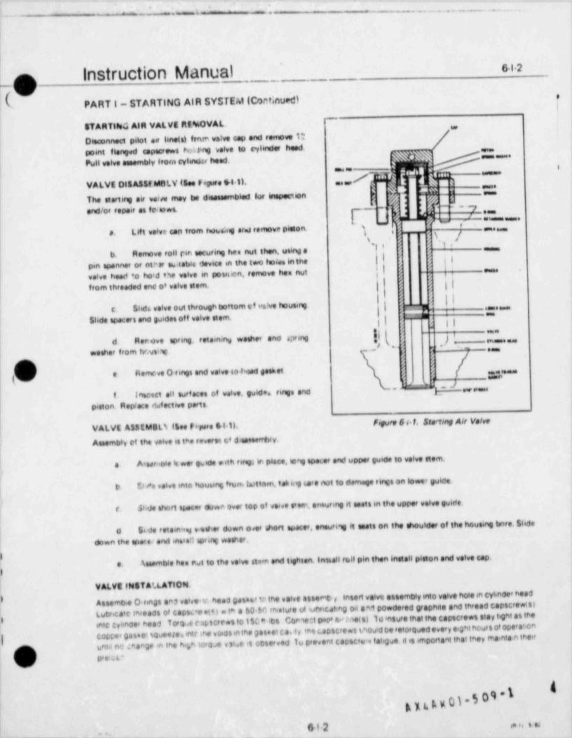
-' ' ' .
-
. _ ' - - - ^ - - ~ - - -,. .
_ . _ ..-- .- v - .
Instruction Manual J sa.2o .
b| (. PART I- STARTING AIR SYSTEM (Cominued) 1
,
STARTiteG AIR VALVE RfMOVAL.Dieconnect pilot se line(s) fresm valve cap and remove 10 /*
/point flenged ospecrews heung velve to caf inder head. Z.l
Pull velve assembly irom cylindu heed.'"""*
VALVE DISASSFMGLV (See Frgure 611). .. ,,/] @'
'" P
" " ' '
The eterting air vain may be diesseembled tot inspection | j '" i
E _,s,'s;-{ f J ,,j
.
,
and/or repeir es fe tows.n e.
s O #
Lift volve con from tun,sig arid remove pieson, i o s -m-a g f"'" *as
e.;s <
' >'
j 'l i .1 '| b. Remove roll rin securing hee not then, usity a
| |' pin spanner of othat sWeebla device in the two tunive inthe
valve heed to hoid the velve in poseien, remove hem nut ,| ,,
' .
| from threaded end of valve stem. 7 g? ||h , ,,~
r
| |IShd6 velve out theough bottom c.f vstve housing
'." '**"c. > cSlide spaceri and guides of f valve stem.
I i l,
=a
d. Renove spring. retainirN weeher ano apring ( i" " ' " ' '
r. _ _ _ _.~wether from tv.usns; , , , .
s
e Romeve O tings end valve to bead geeket..
__.
-
' ~ ~ d -w.f. Insosci ett surf aces of valve, guide. tings and
piston. Replace &fective parts.
|VALVE ASSEMBLS flee Fepare gri 11. figure 6 d.f. Stading A/r Ve/ve
Assembly et the valve es the toverts c dieseeerrbly.e
1 A'sernote it not guid* *ith terg; in place. long spacer and uppet guide to volve stem.| a
We valve into housing frum tottom, tanvJ we not to damage tings on lowe* guide.bj
$hde short spacer down over top of weeve s'ern, er suring it toets in the uppet volve guitfe,r.
Sirde retam49 v ether down over short spacet. eneuti90 t tests on the shoulder of the housing bnte. Slideio
down the opere/ and entra?! sosing washer.
) Assemble hen rwt to the velve stem end tighten. Install roll pin then Install pleton end volve cap.e.)
VALVE INST A'.LATION.
3 Assemo.e O tends ans valves ness gamt to the vatve assemb y insert valve assembly mio velve hoto in cylinder headLucrecate inreads of capsec ut4 *in a 60 M rnisture 9 69tvicating oil aart powdered graphite and thread capscre*tst1
h ente :yuncer head Torone c:iLscrews to t 50" 104 Consett o.,o' n.'ine(s) h msure inat the capscrews stay tig$t as tnecopre, gas.eaoueese. inte ine voios in the gass et ca.it y ,no capscre ws t.noutd oe ref otowed every eigni hours of ope'abonu,,,, nma,ge ,, ine n.r ,oroe vse is oo,orved w preveni ca,,c,u.,latioe. ,t .s , ,ona,nnanne, ,es, eta.e tees,
p,Ji o, e -%
n )-5 M"Ioms+2 a. , , s ..
.
. _ - - _ . _.
-- -- - _ _
|
mf Instruction Manual
PART J - COOLING WATER SYSTEMS. ,ll
GENERAL.
All enterprise engines are cooled by a closed loop system in which a fixed supply of treated water is continuouslycirculated by the lacket water pump with practically no loss in quality. The water supply for the jacket water evenem
,
should be completely treated for both scale and corrosion, and raw untreated water must never be introduced intothe system. The deyee and type of treatment depends on the source of the water. Distilled water and rain water areusually considered as being completely soft and noni:orrosive, but they generally require treatment for desolvedcorrosive geses sus as oxygen whis may accelerate rusting. Plain distilled water is not recommended unless it isproperly treated. Rain water may also require treatment for fungus picked up in the air or from contamination frornair pollutants. Delavet Engine and Compressor Division does not specify any particular form of water treatment,nrthe frequency of water analysis. Rather, it is recommended that a water treatment specialist be consulted.The degreeand frequency of treatment, then, will be based on the water being used. It must be reme' bered, however, thatm
additives to the coolmg water supply should not af ter the heat transfer characteristics to which the system was designed.The specific heat of the jacket water system should be kept as close to 1.0 as possible.The following discussions
of water treatment are suggestions only. The actual means used to treat t water should be determined by the
owne r.
. OPE R ATION.
All coolmg surf aces must be kept free of scale or other deposits as any such accumulation will degrade the cocimgcapabihty of the system and, therefore, coolmg water temperatures will not accurately indicate the extent of coolingAny coating on the cooling surfaces will act as an insulating material and will prevent transfer of heat. If for anyreason there is a disruption of the circulation of cooling water flow, the engine should be shut down as soon aspracticable to prevent a build up of temperatures and possible serious damage to the engine. To avoid thermal shock,which could cause damage to the engine, do not admit cold water to the cooling system until the temperature of thecoolmg surf aces in the engine have dropped to approximately that of the inlet water. The use of ethylene glycolantifreeze in the coolmg water will materially affect the cooling capacity of radiators and other cooling der.ces. A50% ethylene glycol mixture will reduce radiator coolmg capacity approximately 12%. Therefore, unless the coolingsystem ws: or:ginally denigried for tn.s coolant miuture, the Deiawsl Engine and Compressor Division Customer Se'viceDepartinent shoji (* 'Je it nsultej prior to using such a coolant.
|
TR EA*V ENT OF .'ACKET WATER.
The pH value of the lacket water it reu'd be memtained with~n a range of 8.25 and 9 75. The minimum pH valueisneestsary to reevent acid atteot on the metallic sarfs.,es, and the GJ6 maximum value will prevent corrosion due tohp alb aime contant in the water. A suggested water treatment meterial for jacuet water systems is sodium d chromateord a co.nme':ial boiler 90mpound however, it is recommended that a commercial water treatment co npeay beconsited to 6nsure that local conditions are taken fully into secount. Sodium d. chromate is an inewpensive source ofalkaime chromate (Croa) which has been found to form a protective film on metallic surta:ss that prevents attack bythe corrosive elements found in the jacket water. Sodium dichrorr. ate is so acid compound which must have an alkalenccompound such as boiler compound added to convert the dichromate to en effective alkaline chromate form.The
;
alkalme chromate concentration must be maintained between 700 and 1700 parts per million (ppm). Less than 700'
ppm can result in accelerated corrosion while more than 1700 ppm serves no useful purpose and is a waste of material.'
The cloride content must not be allowed to exceed 100 ppm as the effectiveness of alkaline chromate decreases as thecloride content increases. When initiating alkalme chromate water treatment for the first time, or af ter the system hasbeen refilled,the water should be tested daily for alkaline chromate concentration and for pH value.When the treatmentbecomes stable, the test interval can be extended to weekly tests. After and addition of chemicals, the water shouldbe circulated through the system, then tested to insure that the required limits are met.g
'S
lO
se1 an_
_ .
--- -- - - _ . _ _ _ . . . .... _ ._I
_
6s2
C) Instruction Manual-
( PART J - COOLING WATER SYSTEMS (Continued)
WATER SOFTENERS.
Depending on the location of the installation and the source of the cooling water supply,it may be advisable to utiliresome means of softening the water This can best be accomplished by consulting a commercial water treatment companyfor technical assistance so that the specific needs may be determined and the proper treatment method instituted.
CLEANING THE JACKET WATER SYSTEM.
The following methods may be used to clean rust and scale from the lacket water system. Most water treatmentcompanies have their own proprietary solutions and method for cleaning engine lacket water systems which areequally as effective. The following scid cleaning method con not be used for systems whidt have components con-taining aluminum.
Rust can be removed f rom the jacket water system by filling the system with a solution of 75 pounds ofa.ammonium citrate in enough fresh water to make 100 gallons of solution. Make enough solution to fill the jacketwater system then operate the engine for two hours. The lacket water system must then be flushed with fresh waterand neutralized.
0b. Scale can be removed from the system by using a scale solvent solution composed of 7 gallons of 20 Baume
muratic (hydrochloric) acid, one half gallon of liquid inhibitor and 92% gallons of fresh water at 100'F, Make enoughsolution to fill the system. Circulate the acid solutitm through the system for one or two hours, depending on theextent of the scale deposit. The temperature of the acid solution must be maintained at 160'F during circulation.Af ter circulating the acid solution, drain the jacket water system and then fill with clean fresh water and flush itthoroughly. After flushing. neutralire the s(stem with a solution composed of 20 pounds of soda ash (sodium
f carbonate) and enough fresh water at 160 F to make 100 gallons of neutralizing solution. Fill the lacket water system0
with the neutralizing solution and circulate it through the system for one half hour, Maintain the temperature of theduring circulation.
ENVIRONMENTAL RESTRICTIONS.Alkaline r.hromate water treatment compounds, such as sodium dichromate, may be considered environmentallyobjectionable in some locations, or may be prohibited. In these instances, nitrite compounds such as sodium nitrite(NANO ) are suggested as adequate substitutes. W'.en using sodium nitrite, the concentration must be 500 ppm with a
2
pH of 7.5 to 8.5 to achieve effective corrosion control. Nitrite compounds for treating engine lacket water systemsare available from most comr*iercial chemical supply houses, and instructions for their use are available from thechemical supplier.
e8
L
A )us A x 01 - 5 0 9 - 1*
e
6J2.
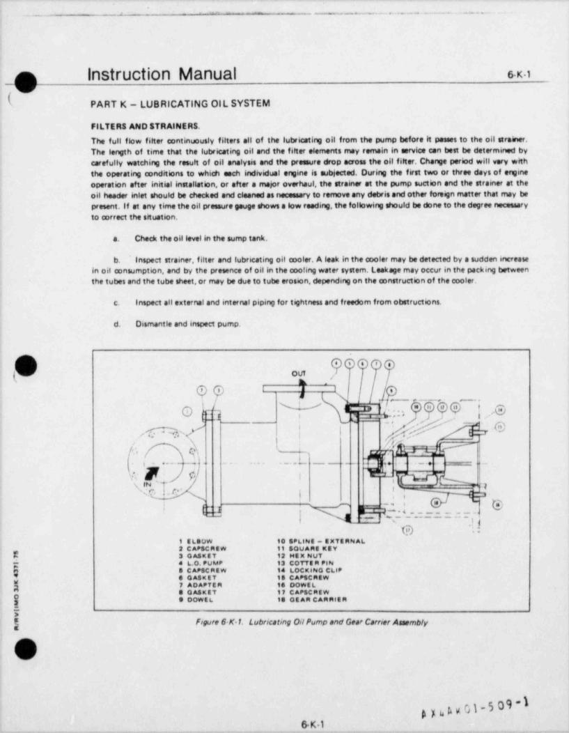
-. - - - . - - . - . _ . - . . - . . -
p Instruction Manual s.x iv
PART K - LUBRICATING OIL SYSTEM
FILTERS AND STRAINERS.
The full flow filter continuously filters all of the lubricating oil from the pump before it passes to the oil strainer.The length of time that the lubricating oil and the filter elements may remain in service can best be determined bycarefully watching the result of oil analysis and the pressure drop across the oil filter. Change period will very withthe operating conditions to whicti each individual engine is subjected. During the first two or three days of origineoperation after initial installation, or after a major overhaul, the strainer et the pump suction and the strainer at theoil header inlet should be checked and cleaned as necessary to remove any debris and other foreign matter that may bepresent, if at any time the oil pressure gauge shows a low reading, the following should be done to the degree necessaryto correct the situation.
a. Check the oillevel in the sump tank.
b. Inspect strainer, filter and lubricating oil cooler. A leak in the cooler may be detected by a sudden increasein oil consumption, and by the presence of oil in the cooling water system. Leakage may occur in the packing betweenthe tubes and the tube sheet, or may be due to tube erosion, depending on the construction of the cooler,
c. Inspect all external and internal piping for tightness and freedom from obstructions.
d. Dismantle and inspect pump.
(]( ge.,,OUT '
'h .
e, ji i ,
l. ',.., Oa@eY W reL.t w :- > , __ l -
/ VWe'< fM(,.._. _ .. .. .'___ _ ___
1 c ._. . - _
'
w Le| _ :q
! : m.,
e. - ._ , -,
(_
d.| M Q ,L.=..=.=q'
=
g -;;1 ELsOW to SPLINE - EXTERN AL2 CAPSCREw 11 SQUARE REY
$ 3 oASKET 12 HEX nut
% 4 L.O. PUMP 13 COTTER PINe S CAPSCREW 1a LOCKINo CLIP* e oAsKET to CArsCmEw
7 ADAPTER to DOwtLe oASKET 17 CArsenEw |j e powEL is ot AR CAmnlEn
i* figure 6 K 1. Lubricating OilPump and Gear Carrier Assemblyg
n'
v
1
g y u s v 01-5 09 -1 i
6K1 |_ _ .
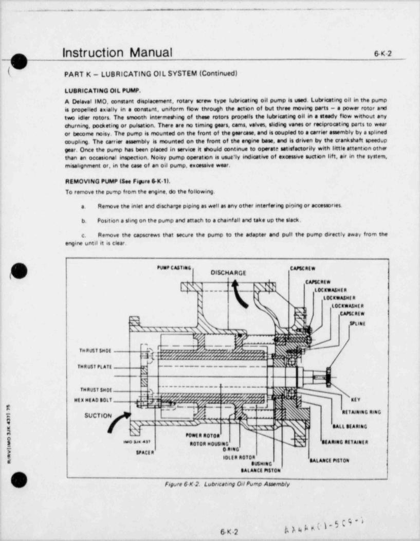
.- -
-- - - . . . _ . . . - .
instruction Manual s.x.2 Inm ,
PART K - LUBRICATING OIL SYSTEM (Continued)
LUBRICATING OIL PUMP.
A Delaval IMO, mnstant displacement, rotary screw type lubricating oil pump is used. Lubricating oil in the pumpis propelled axially in a constant, uniform flow through the action of but three moving parts - a power rotor andtwo idler rotors. The smooth intermeshing of these rotors propells the lubricating oil in a steady flow without any '
churning, pocketing or pulsation. There are no timing gears, cams, valves, sliding vanes or reciprocating parts to wearor become noisy. The pump is mounted on the front of the georcase, and is coupled to a carrier assembly by a splined !
coupling. The carrier assembly is mounted on the front of the engine bees, and is driven by the crankshaft speedupgear. Once the pump has been placed in servics it should mntinue to operate satisfactorily with little attention otherthan an occasional inspection. Noisy pump operation is usue'ly indicative of excessive suction lift, air in the system,misalignment or, in the case of an oil pump, excessive wear,
REMOVING PUMP (See Ficare 6-K.U.
To remove the pump from the engine, do the following.
s. Remove the inlet and discharge piping as well as any other interf ering piping or accessories.
b. Position a sling on the pump and attach to a chainf all and take up the slack.
c. Remove the capscrews that secure the pump to the adapter and pull the pump directly away from theengine until it is clear.
\ PUseP CASTHIG CAPSC REW) DISCHARGE3v ^ CAPSCREW
LA3 t0C main., n
_____
) LOCtwASME R
N N LOCKwASME R
d.h,\ CAPSCAEW
@s s s m s e m x """jg r e. m
., _ . . _ ..
mTHRU$f$N0t % ,11,1,1,
, $A , ,,,3
&(,"WAX 5555559L n'+%S79,5?5%5%1|
THRU$T PLAff3
_
[ Ety' ' ' 'MtXHEAD 0i . A 4. _ .- % s3g U. L~ ! -'ja- . - -
RE m NINGniNGM'
hhi SUCTION [ A . ...' -
g s- xss, s su m g ags -
,,u,,,,,,,,
E POWERA0f0a N! ROTOR MouslNG Q{"'8'"" * MAnmG RtTA HR
o**G7 yaci,IDW ADMA SALAIICE PitTONggg gg
BALAlett MSTON
s_.] Figure 6 K 2. Lubricatmg Oil Pump Assembly
6 K.2 bh4b6~
_ . _ - . . _ . . _
|nStruction Manual 6.K.a_
(' PART K - LUBRICATING OIL SYSTEM (Continued)
PUMP DISASSEMBLY (Se Figure &K.2).
k If it is necessary to disassemble the pump,, exercise care to keep the parts clean so that no dirt, grit or other foreign/ matter will be present when the pump is assembled. Disassemble as follows.
Set pump on suction end and remove caoscrews and lockwashers holding balance piston housing in pumpa.casing. Remove two capscrews with lockwashers from opposing positions,180 degrees apart and insert % - 13 eyeboltsinto vacated holes. Lift internal assembly out of pump case and set assembly on its side. Do not set it down on thrustplate. Remove eyebolts.
I
b. Remove bolts, lockwashers, spacers and thrust plate from suction end of rotor housing. Note location ofeach spacer with respect to the rotor housing. Support and remove each spacer as each bolt is removed. Set parts aside
I in order of removal.
c. Grasp thrust shoe on end of each idler rotor and unscrew idler rotors from rotor housing. Do not removethrust shoe from idler rotor,
d. Remove capscrew with lockwashers and bearing retainer. Grasp coupling end of power rotor shaft and pullpower rotor out of rotor housing. Avoid hitting bushing with and of power rotor as it is removed. Inspect power rotorand ball bearing.
e, if it is necessary to reptare the ball bearing, proceed as follows. Remove retaining ring. Obtain wheel orgear puller and small piece of sof t metal. Place soft metal over end of power rotor shaft and use puller to remove the
[h ball bearing from balance piston. Discard bearing.
h f. Remove retaining capscrews with lockwasher and separate balance piston housing from rotor housing. Donot disassemble bushing from balance piston housing unless it requires replacement. This completes disassembly neces-sary for maintenance purposes.
PUMP RE ASSEMBLY (See Figure &K.2).
a. If ball bearing was removed, pressure a new bearing into position on the balance piston. Replace retainingring. If a new bushing is required, coat outside diameter of new bushing with Locktite Retsining Compound and insertbushing into balance piston housing.
b. Set rotor housing on suction end and install new O. ring. Place balance piston housing on discharge end ofrotor housing and fasten down with four capscrews and lockwashers, leaving two holes,180 degrees apart, vacant.
c. Lay rotor housing on its side and insert power rotor into housing from discharge end. Fasten bearingretainer to balance piston housing with capscrews and lockwashers.
E d. Insert idler rotors into rotor housing from suction end. Raassemble thrust plate to rotor housin2 with bolts
3 and washers, making sure that each spacer is assembled to the housing in its originallocation. Note: The fourspacers
| have been machined to close tolerances to assure securate spacing between thrustplate and rotor housing. A minimumR torque of 800 in..lb spolied to each bolt should assure proper spacing between thrust plate and rotor housing. Improper
$ spacing will result in accelerated west of internals.
i!E e. Insert two %" x 13 eyebolts into vacated holes in t'afance piston housing and lift internal assembly into" position over pump case. Insert assembly into pump case, being careful not to damage 0-ring during process. Fasten
| g internal assembly to pump case with capscrews and lockwashers.
N.)\t|
\
I
l.
6K3<
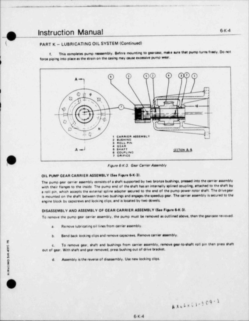
_ _ .-- _..__ _ .... ..
_O Instruction Manual e-k-4
k PART K - LUBRICATING OIL SYSTEM (Continued)
f. This completes pump reassembly. Before mounting to geercasa, make sure that pump turns freely. Do not
force piping into place as the strain on the casing may cause excessive pump wear,
,o e,,,s s,
:>&ot,
r.. .
'ar. ,1 >Q/ \ \ p 1_ _ i
,_ ..[_- .
~
._ ._-
\ h,.
j ,' "3,^^
>so a
l e~
NN s CARRIER ASSEMBLY "2 auSHINO
I 3 ROLL PIN4 GsAR
^ e $"ou'p[iNo stCTioN A A
7 oRipics
(d Figure &K4. Gear Carrier Assembly
OIL PUMP GEAR CARRIER ASSEMBLY (See Figure 6 K 3).
The pump gear carrier assembly consists of a shaft supported by two bronze bushings, pressed into the carrier assemblywith their flanges to the inside. The pump end of the shaft has an Internally splined coupling, attached to the shaft bya roll pin, which accepts the external spline adapter secured to the end of the pump power rotor shaft. The drivegearis mounted on the shaft between the two bushings and engages the speedup gear. The carrier assembly is secured to the
engine block by capscrews and locking clips, and is located by two dowels.
DISASSEMBLY AND ASSEMBLY OF GEAR CARRIER ASSEMBLY (See Fipare 6-K 3).
To remove the pump gear carrier assembly, the pump must be removed as outlined above, then the gearcase renewed.
a. Re nove lubricating oil lines from carrier assembly.
b. Bend back locking clips and remove capscrews. Remove carrier assembly.
Ci c. To remove gear, shaft and bushings from carrier assembly, remove gear.to shaft roll pin then press shaft
} out of gear. With shaft and gear rerreved, press bushing out of drive bracket.
Ao d. Assembly is the reverse of disassembly. Use new locking clips.!7E$
f\ >xs-
g nLv.g.609 1i -
6K4
>-' m . _ . . . . .
|
f
I Instruction Manual s.x.c
-4( PART K - LUBRICATING OIL SYSTEM (Continued)
e
d The oil in the annular space around the spool valve, at the adjusting screw end, will leak past the sealing'
grooves of the spool valve and into a cavity in the cap. This cavity functions as a buffer chamber. To stop valveoscillation, an adjust &Ule needle valve controls oil spillage from the buffer cavity to the outlet section of the valve
The oil header pressure is set by increasing or decreasing the spring force acting against the header pressure ,e.in the valve sensing chamber. Turning the adjusting screw in will increase header pressure, and backing it out willdecrease pressure.
f. Normal lubricating oil pressure is 50 psi, measured between the engine lubricating oil strainer and theengine oil header which is also the pickup point for all gauges and other instrumentation that show or indicate enginelubricating oil pressure. Lubricating oil pressure shutdown devices may take their sensing point at the opposite end ofthe engine in which case the shutdown set pressure will take into account the normal change in pressure between thesupply end of the engine and tne shutdown sensor under all conditions of engine speed and lubricating oil temperature.
ADDING LUBRICATING OIL.' ll connection and a dipstick, located on the top oi the intake sectionThe lubricating oil sump tank is provided with i
.of the tank. A level indicator may be provided at the control panel for monitoring purposes, however, the level in thesump tank should be verified by means of a visual reading of the dipstick before oil is added to the system, andtheexpected rise in the level in the sump tank must be verified by means of the dipstick. Oil may be added to the systemwith the engine running or with the engine stopped The dipstick has two sets of marks, one for the static Conditionand one for the running condition The markings are " Full Static" and " Low Static" on one side of the dipstick,and" Full Run" and '' Low Run" on the other. Before oil (3 added,it should be determined that the correct oil is availabtg
i Appendin VI of this manual contains the recommended specifications for the lubricating oil to be used'
)_,
CAUTION,
Oil must never be added from any location other than the fill connection on the sump tank, Donot everfill. Attempting to fill from any other location could result in oil reaching other thandesign locations
5i
B
*\0 'A4Phn
,
6 K-6
_ _ _ _ _ _ _ _ _ _ _ _ _ _ _ _ _ _ _ _ _ _ _ _ _ . ____ _ _ _ _ _ ___-- ___ __ _ _ _
. - - - . . - . - . . - - . . .-. . ...
[ |nStruction Manual s.x.7
(v s
PART K - LUBRICATING OlL SYSTEM (Continued) i
SELECTION OF A LUBRICATING OIL.The selection of a lubricatmg oil to be used in the engine is a complex matter, and is very important to the engine'ssuccessful operation. The recommendations of both the oil supplier and the engine manufacturer should be carefulfyconsidered. Transamerica Delavel's recommendations for a suitable lubricating oil are stated in Section 8, Appendix VI.Other f actors to be considered include the price, service life, load factor and fuel sulphur content as well as the filtration
i
and oil purification system used.
CHANGING LUBRICATING OIL.Once an oil has been selected the engine user, in consultation with the oil supplier, should map out a plan for periodicsampling and laboratory analysis of the oil. A careful review of these results by the owner, the oil suppher and thetestmg laboratory can then become the basis for deciding whether or not the oil needs to be changed. TransamericaDelaval recommends that oit be changed on the basis of condition of the used oil rather than on a time schedJle
ANALYS15 OF OIL.Various chemical and physical tests have been developed to classify and identif y new oil,and to determine what changeshave occured in these oils while in service. The American Society for Testing Materials (ASTM) has standardised thesetests, and certa >n of these tests have been approved as an American National Standard by the American NationalStandards Inst, tuts. Inc. (ANSI). Transamerica Delaval, as stated in Section 5. recommends that representative oilsamotes bv submitted tci a quahfied laboratory for analysis on a monthly basis, or of tener if operating conditionsindicats The following tests should be conducted
Olt VISCOSITY - Tested in accordance with ASTM D88. 0445, ANSI 211.2 and ANSI Z11.107. Theaviscosity test wdl indicate whetner the proper grade of oil is being used, and will indicate oxidation (by increawdN viscosity) or fuel d.lution (decreased viscosity). The oil suppher can provide advice regarding the significance of thespecific values octa ned
WATE A/ GLYCOL CONTAMINATION - A measure of water and/or glycol contammation of the oil canb.g've warning of potential problems. Water or glycol contamination can come from kner seals, turbocha'ger casing > 0'faally lubricating od htJt exchangers
NEUTRAll2ATION VALUE - Test in accordance with ASTM D664, D974, ANSI Z11.69 and ANSIc.Eng no oas a e intentionally formulated shghtly alkanne so that they are capable of neutrabring the acid.4211.131
compou ds that form from products of combustion and of oil oxidation. Generally this reserve alkehnity is depletednand the weak organic acids that attack bearing surfaces can be destructive. Periodic evaluation of Totaf Base Number(TBN) and Totat Acid Number (TAN) are an important measure of oil degradation. As time goes on.TBN is depleted
t
and T AN beg,ns to rise.
PENTANE AND BE2iNE INSOLUBLE $ - ASTM D893. This test is a measure of oilinsofubte materiais.doilresinous matte' from od or additive degradation, external contammation, fuel carbon and highly carbonised materuts)from deg'adation of fuel, oil, additives, engine weer and corrosive materiaft
SPL CT ROGR APHIC ANALYSIS - This test is used to measure quantitively the mineral elements in the od.etorrosion metals such as alummum, chromium, iron, copper, silver, lead and tm. Also, ditt conte.
I includino m .se i 4nants fion, na a .tvlet such as boron, potassium and sodeum.
I. Noteiransawu Delasat Customer Service Department in Oakland.Cahfornia will welcome ao,
| It*3 euwu ng ud selection endist toting Although Transamereca Delawa cann tr u
. . .o . (r dent ,
(V) ..od a sp6.if ef, iubin e t, nu' accept arly [email protected]'hty for the performance of the fuhie-ne. .
seh .tud by the owner,it will bt pleased to discubs its esperience with a 9'ven od prod 41.''. . . . *
,I; p' . *
your od aruf siland offer comments t/. n...
6K7-_ _ _ _ - _ - _ _ - - - _.
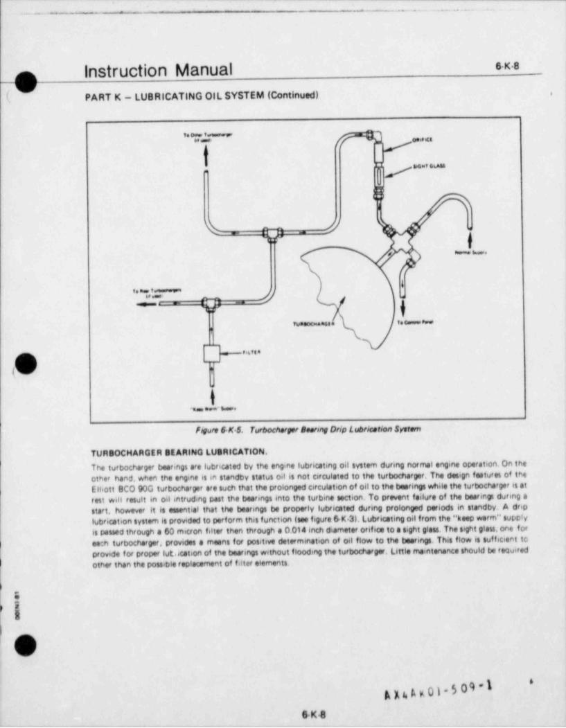
--
- - . . . . . - . . - . . - .
exsInstruction Manualo-
(g PART K - LUBRICATING OIL SYSTEM (Continued),
n,..,-
p ..e_
bI
%_ O=. _.
f7;f'
-..
4. . , -
Z_ n - 0 -
}w, _ _ . ,. e._ -
,
.
. 6, .oh T
-
, _ . . . _ .
figure 6 K 5. Turbocherger Bearing Orlp Lubricetion System
TURBOCHARGER BEARING LUSRICATION,
The turbocharger bearings are lubricated by the engine lubricating oil system during normal engine operation. On theother hand, when the engine is in standby status oil is not Circulated to the turbocharger, The design features of theElliott BCO 90G turbocharger are such that the prolonged Circulation of oli to the bearings while the turbocharger is atrest will result in oil intruding past the bearings into the turbine section. To prevent failure of the bearings during astart, however it is essential that the bearings be properly lubricated during prolonged periods in standby. A driplubrication system is provided to perform this function (see figure 6 K 3). Lubricating oil from the " keep worm" supolyis passed through a 60 micon filter then through a 0.014 inch diameter orifica to a sight glass. The sight glass, one foreech turbocharger, provides a means for positive determination of oil flow to the bearings. This flow is sufficient toprovide for proper lut.ication of the bearings without flooding the turbocharger, Little maintenance should be required
I other than the possible replacement of filter elements.
EI
P
l''ov'
k n A K 01- 5 09 -18K8
_ _ _ - _ _ _ _ _ _ _ - _ _ _ _ _ _ _ _ - - _ _ - _ _ _ _ - _ _ _ _ _ _ _ _ _ - - _ _ _ _
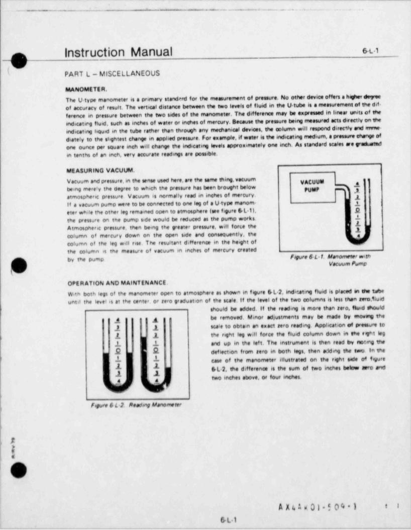
~ - _ _ . . . ..
1
Instruction Manual suo\ /
( %./ PART L-MISCELLANEOUS
MANOMETER.
The U-type manometer is a primary standerd for the measurement of pressure. No other device offers a higher degreeof accuracy of result. The vertical distance between the two levels of fluid in the U tube is a measurement of the dif-ference in pressure between the two sides of the manometer. The difference may be expressed in linear units of the6ndicatir g fluid, such as inches of water or inches of mercury. Because the pressure being measured acts directly on theindicating lequid in the tube rather than through any mechanical devices, the column will respond direc')y and imme-diately to the slightest change in applied pressure. For example, if water is the indicating medium, a pressure change ofone ounce per square inch will change the indicating levels approximately one inch. As standard scales are Traduatedin tenths of an inch, very accurate readings are possible.
MEASURING VACUUM.
Vacuum and pressure,in the sense used here,are the same thing, vacuum ggbeing mere'y the degree to which the pressure has been brought below PUMP T*atmospheric pressure. Vacuum is normally read in inches of mercury. yif a vacuum pump were to be connected to one leg of a U type manom- 1eter while the other leg remained open to atmosphere (see figure GL 1), pthe pressure on the pump side would be reduced as the pump works. 1
#Atmospheric pressure, then being the greater pressure, will force the - . - -1column of mercury down on the open side and consequently, thecofumn of the leg will rise. The resultant difference in the height ofthe column is the measure of vacuum in inches of mercury createdby the pump Figure 6 L 1. Manometer wrth
Q} Vacuum Pump
OPERATION AND MAINTENANCE.
With both legs of the manometer open to atmosphere as shown in figure GL.2, indicating fluid is placed in the tubeuntil the level is at the center, or rero graduation of the scate, if the level of the two columns is less than zero,Tluid
fshould be added. If the reading is more than zero, fluid shouldbe removed. Minor adjustments enay be made by movmg theA g
UA1 1 - scale to obtain an exact reto reading. Application of preesure to
2., 1 the right leg will force the fluid column down in the trght leg)
1 1 and up in the lef t. The instrument is then read by noting theE E deflection from aero in both legs, then adding the two. In the1 1 case of the manometer illustrated on the right side of figure:
'
GL.2, the difference is the sum of two Inches below airro andtwo inches above, or four inches,
4 4
i
Fogure 6 L.2. Reading Manometer
1>
!u
|
OO
A X4 A g 01-5 04 1 f i
GL1
4
~ -'~-.
instruction Manual e.t.2~ ,\
( PART L - MISCELLANEOUS
CRANKCASE PRESSURE.
The crankcase is fully enclosed and theoretically air tight. To remove gases and vapors from the crankcase, crankcasepressure is maintained at a level slightly below atmospheric, measured in inches of water by a standard U type mano-meter.
CRANKCASE VENTILATION SYSTEM.
The crankcase ventilation system is designed to expel vapors from the crankcase while the engine is running. Thesystem will also assist in determining the general condition of the engine, particnJlarly piston ring and cylinder linerwear. If piston ring and/or liner wear becomes excessive, piston blowby will osues a rise in crankcasepressure and,therefore, will be evidenced by a change in the crankcmas preneure towards a positive pressure. Two motor. drivenblowers are used to draw directly from the crankcess through an oil separator and discharge directly to atmosphereoutside the engine room. Oil particles suspended in the air are removed as the air passes through the separators, and theoil drains back to the engine crankcase. The blower motors are started automatically when the engine is started, andshut down when the engine is stopped.
CRANKCASE VACUUM.
A crankcase vacuum of 0.2 to 0.5 in. H O is normal when the engine is operating at rated load and speed. Crankcase2
vacuum readings should be taken carefully, and compared with previous readings, in this way gradual changes can bedetected and investigated to that minor problems con be corrected before they reach major proportions. Should thereadings indicate a loss of crankcase vacuum, the cause should be promptly determined and corrected.
t
.
J,
e:58a
s
A X 4 A K 01-5 09-1 I I
6.L 2_. .__-_- -- _ - . . _ - - .- __ _ - - - .-.
_. . . - - . - -- --
_ . . . .
'"*''" " " M "" '*-'-'
-O ,(
I .
PART L - MISCELLANEOUS (Continued) | |
AIR BUTTERFLY VALVE.
Grease fatings are provided on both ends of the air butterfly valve shaft. The shaft should be manuaffy checkedfor freedom of movement, and the bushings lubricated as determined to be necessary. This action should be 'performed at the intervals specified in the recommended maintenance procedures (See Section 5. Part B), oroftener if local conditions should warrant. A standard automotive wheel bearing grease is acceptatWe, such asMobil Oil Mobilgrease 532, Mobilgrease MP, Mobilgrease Special, or equal. The valve shaft is notched at thelever end to indicate the orientation of the valve. Adjust the hnkage between the actuating cylinder and thebutterfly valve lever so that the butterfly valve is fully open when the cylinder rod is fully retracted.
|
!
l,
l
I
1
i
'
B
'ie
6
|
|
_________a=,si_---- -_. - _ -..-_ _ -L-3__ ,_ _ _ _ _ _ _
6
, _ __ . _ _ . . _ _ _ _ _ _ _. _ . _ _ _ _ _ _ _
.
___
_ . _ . _ . . . _ . _ . . . . . . _ . .
k
Section 7TroubleShooting
.
M0
&Om
1
-
M.sl
4.%
4,
I
1
!,
I
e
. _ _ _ _ - _ . - . . _ . _ _ _ _ _ _ _ . _ - _ . - . . - _ , _ _ _ _ _ _ _ _ _ _ _ _ _ _ _ _ _ _ - _ _ _. _ _ _-_ _
-. - . - . . . . . . . .-
Instruction Manual 7.in.
SECTION 7
TROUBLE SHOOTING,
GENE R A t..
Effective maintenance trouble shooting requires a sound knowviedge of the engine in both a theoretical and a practicalsense. The mechanic must analyse the cause and effect of different conditions and, where the cause is not readilyapparent, he must employ a fine sense of logic based upon the ues of all the tools available to determine that cause.Section 5 of this manual illustrates some trouble shooting data that can be obtained from the charts and curves whichare recommended. In addition,this section contains a listing of poss;ble troubles that may be encountered,their possible
}causes, and the action that would appear to be appropriate.
RECORDS.
All possible malfunctions and their probable causes cannot be foreseen and recorded in advance. Each engine willdevelop and display characteristics which may not be common to all engines of the same model or type. Also, the sameoperator or mechanic will not always perform the trouble shooting and repair work, it is, therefore, suggested that theowner establish a detailed repair and trouble shooting record system. Each malfunction should be recorded m a readilyusable form, listing the indications and findings for each malfunction enmuntered together with the repair actionrequired. This record will be of assistance in determming the cause of any future malfunctions, and will be a valuabletraining a:d for all operators and mechanics.
4
)
e
5d
O'
V
i
S p A K 01-5 09 -1 * .
I 71
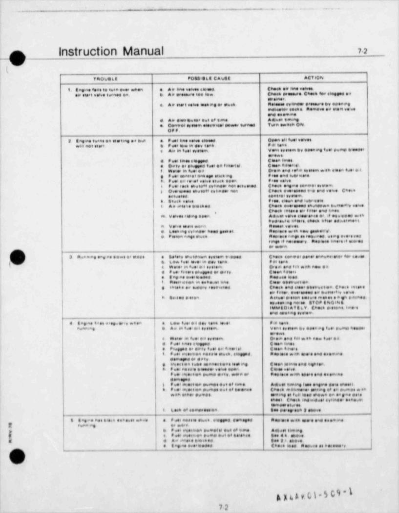
--- -- - --- - _ - - - - - - - - -- - - -- _ _ __
- - . . - . . . . . - . . . . ~_
|
n instruction Manual 72g /
r (v .,
| taoveLa ,oesista c.ves .CTION
t .. , ,............ .. ., . . . , ~ ~ . . . , ~ .. . .. . ... ... . . . . . . . . . . .. .. . ... ..
.... . ...a....,,-............g.....
~. . . . . . . ..a.
. . . . . . . . . . . . .. . . . . . . .. 1, . ..., o N .o,,.. .. ..
.
. . - ....... ... . . . ....a.~,.a..a....,.....,...v,... .....a..i . . . . . . . . . . . .
. ..... . . .. . ... ...... . .| .. .
c...m.. . ... ... . .. .............t.,.
. . . ~ , . . . , . . . . . . . . . . . . . .. . , ~ , . . .. ..
.....a,..........., .,. . . .
. . . . . . . . . . . . . . . . . . . . . . . .c ~. . .. ..~,...a....... co...,~.......... . . ~ ,..... . . . . , . . . . ~ . ~ c .. ...
. ...... ..i . . . . . . .. . . . . . . .....a~,...
. ...a,.,.... . . . . . . . . . . . . . .. . . . . . . . . . ~ , - .
.. . . . . . . . . , . . . . ~ . . . . . . . . . . . . . . .
. ...... . ... . .... ,.., ~ ,, ,
,, v~....., . . . . :
< ..,~ ~, ...n....... ... ,.........
. . . . . . . . , ~ . . . . ... . . . ... a . ..
|a...... ..
. . . ,
i C11
a n . ..a . . a. . a. ... .. . . ... . . . . . . . . . . . . . . . . c...........a..........| p. w v.,m
.. .a . ....... t...... .u . .
1 . .......,c.m. o,...a.em...a .a| . . ...... .. ..... . ~ . . ,, . ,,.a......~ . . . .I e . . .. . a .. .. . . i.a . c .... a
! , ,a,....m...... c~..~.........a......... . . . . . . . . . . . . . . . . ..
. .........a . . . . . . . . . . . ~ . . . . . . , . . . . . . . .
. 40,.TGLV Ch 8NO.N&...a.... .ag a. Ofo,
I .....a| .a..see.g ,c.m.
| . sa..a. .... .....*. . 6..e.v...... . ..e ,m..I e. aa .a . . . . .a e .. . a . ..... v.a .. . . ,. a.y e.. .. . . ...
.e..... W .. 6a f. .e . . ., .m. D. . .a. ii., . n m m.. f... .
, . ha.e .6 Ct a..a...
., o.,.. .. . .e.s, f... .d f a . .t C a t, Hee,.
f..,a.m.s... . a m. e e 6.
e...., .s.gg..,..e a,. m 6.e. ...n .e . .a. . . .m.i.
,.a........
,.. . aa.. . a. 6..h ,ag C a ). .a. ,ight.a.3! h n. e e , C,...'....a,..........a..ea . .a . , , . n ., m.. .m . .a. . . .m m.
., .m .s i
.,an..eti.a .....f. . . .., t .aq ( . age.|
. si.th., m.,..,.f .a.. Ch... m... . .M .g ,....h ,L
.. . .a, .e . a ..m .H ..m.. . .th., ,ag ., f .H .h..a .a .a p.a. ..t .
.h . C h.e . ,#,. .. ... . , ha..e . . .. . . ,
m ....I L.e. .f..m '.a t ..e .g, n 3 ..
t 8 ap .a . h.4 . i.. . . . > ..., .8 8 . , . a. # 8 '. .... . , .s.gg... . .m.g p e. ..tn . .a. .. .m6a.
2 e.an ag ..,....a.
. .. , me . . . ..a .. m.. . . . , . 4 . .m. S..m.a6...p
I.n .e...a ..m. ....t....a... . . . . . .
y. . ....g....... . . .
. ea... ....a.,.
l. !x-
g p, t, y 61 - 5 C 9 ' 1'
72_- _ _ _ _ _ _ _ _ _ _ - _ _
- - - -
_ _ . . _ _ . . . _ ,- _-
,
73p instruction Manualy
,.ou.t. ,0 ..a c.u.. .e, .o.
,,s....,~o.o..~........ . - . .m . t. .. .o.
. ..e..o .. ,. . . .. e...~_.e..,,_.....e. ,f o.a.
e,9., n......,e.,. ., a . .
.. . ,..t.a. . .t...,0. . .e
,. ......h,. ...e....- e...~..... , - n. t. . .. t .
.,
.A.t
sp. .. f .., ,,.. o. f- ... .- h . .
C.nes.ol e.a.e,.4a
,,ept e,n pe,t
,Def tt f.el too.et.j ..
taee .so,e e.t es. pt e .n.t if.h.t M f I t. se.e . ,0. .es.t.n to.a. M tea ...| ,eng| __.r e.le e o n p.,96
f, L p6 e p., ., pin hea ,te.epas.on.4 t. m .es.. mater. W,,th
.rybe,,es.o p68 af.,io.. fm ..o.Din .. chImg ,,s ,y.
! . C.aa tone ... b.e me 8eet 8 Cho.. .tes .ah De' ti m.. b ta.
C,u.e. .ees,.a.o.
I
. Lee s..r.ei co .n p s.a e. . Lee .it e .e in me o.a.. A .is.Cas.. ..m.,.a..ie.m |
D.L ,l t6ag .68 .t.a . tem.ul
ehee. 4 meg.t.a n.e ,y.L.e e.h,i ttng .64 p.6ag
.L.e.e. f H.,.6em.a t. C,e ., . l . .t. ment.
.,ee .n. .te.m .
.a 9 p.mp.e..t.. . eng .t. ,. .se. . ..ple..
D,,.8ts e 6 teng..Ip.msf.
s.a . ,e to.. A.#..e s...L . .,
l.t.ag . e t to...n too,6a , Cme.. D.e,lae .i.e..ah.
. Hi b,0.steag .66 p.e.e... . e.. ..b. .t. ., , .a. . le.n.
. De e, l ,* tiae .N ese e., ., f.se fee. C n,
O fitte... ,, e . . i.tiae .. e .t t high ..l..t t. so...et p.e ..
t(,. s . n .v. e en,tsh aa.c .
io we..i...t...,aitt.m. . h. A en ..+., .v. w. i .
t. v es.m. Ch u ee, p.m. = t.co ...
..m. ... t a ., . h.,g. .t.ege. Ch.e. .a. . teen
O..onn. .e p.m., .a t.. .f . tion.
I - ..m... .a.. t
. . atn. .. .. . - . . 4 h
. t . . on . .f. .. .. t .. .o. at
o. 4,.t .. a ..
....
.6
.a. . .e t e n.
.
t
i o . ..t. .. . .a
. . . . . . . . . e ... ,
c.,.............a..i t . . . ... . .. .t n. . e..........,......t..... . . t . . . e. . .. . . . . . . . . . .
.. .. . en e.t t. . m..a..... . .
.o,t i.. .e. ., .. t., t .
. . , . . . . . . . . . .t.,..........t.m..... ( . . e,.... ..
.
.n . . .., , , . . . .. .a .t .. . . n e . ..e.......| . . . .
. . . t .t . . . f .t.. . n.
is u, .... . t . .. vc.. e. e .. .. .. . t
i. .. . . .a. i . . t..a ..t .f 0-i. . .t .
.
e..
i . . . ... . .. . .. .t t.,,, . t ... .n . ....t... .... . . . . . . . . . . . . i, .e . . .
t . .. . ~ .... ,, ... .,t,......
Ei s. c .. t ...a. .. ...t . . . . . . . . . .. . .
( . e. e . ........e.... . . ...m.....a.......n...
. . . . . . . . . . . .. . . . . . t.a. . . .. ...o.0,,........a t . . . . . . .t., e..
m
k k $. h P. h*
_ _ _ - _ _ _ _ . __ _.
- - - - __ .
|_ . _ _ .
___ _
I
o Instruction Manual 74
\ /
%/ , i(
inoue6s ,oesists c.use .CT ,0N
. . . < . - . . . . . . .. . ... . . . . .
. . . . . .. . . , , . . . .
. . ~ ,... .
. . , ~ . . ... ~ , , , . . . . . .
, , , , , . ., , . . . . . . . . . . . . . . . . , . . , . . . . . .: .... , , . . . . . . . . ., . . . . . . - ~. ,
. , , ... .. . . ...
. , ~ , ..
.
. . . . - , . . . ,,, _ .. . .
. . . . . . . . ..
. . . . . . . , 6 . . ...,~. .
, , . . . . , ~ , . . . . . . . . . .. . . ~ . . . . . . . ., , . . . . . . .
. . . . - . . . . . . . .,, e....... ,. . . . . . . .
. .
. . . , , , . . . . . . ... . . . . . . . . . . . . . . . . . . . . ~ . . . . .. . . . . . . . . . . . .
,, .... ........ ...,........ . 6............. e~........ . . . . . . . . . . . .
. . . , . . . . . . .
e.~..~,...., , . . . . . . . , . . . . . . . . . . . , , . . . . .
. . . . .. . .. .... -
.. . . . . .
n............, , . . . . . . . . . .
. . . . .
. . . . . . . .. . . . . . . ..
, , . . . . . . . . .... ... ...
.e....... .
. . ... .. .. ~ . . . ~ . . . . . . . . . . . . . .. . . . . . ~ . . . , . . . . . . . .p
(O , , . . . . . . . . . .o.,,,,,,.......... . , . . . . . .
.o......... e,,... .
.... . .. . . . .. . . . . . . . ...., . .
. . . . ,.
. . . . ..
. . . . . . . . . . . . , . . . . . . . . , , , . . . . . . . . . . . . . . . . . . . . . . . . . , . . . .. . . . . .
. . . . . ..t......., ...
. . . . . , . . . . . . . . . .
, , . . . . . . . . . . . . . . . . . . . . . . . ~ . , ~ . . . . e.....,............... . . . . . . . . . . . . . . . .
. . . . . . . . . . . . . . . . . , , . . . . . . .< ....
. . . . . . . . . , . .
. . . . .... ~, . .,,.... ...
. . . . . . ~ . . . . . . ... . . .
.. . . . . . . . . . . , ~ . . . . . . . . . . ~ . . , ~ , . . .
.,,. . . ... . . . . . ~ . . . e.......
. . . . . . . . . . . . . . . . . . . , , .
. . . . ~ . . . . . . . .
c.. .~ . . ., , . . . . , ~
. . . . . . . . . . ., . . . . , . . . . . . . . . ,
...., .. ...., ~ ,.. . ... ... ~ , , . . . , ~ ~ . . . ~. . . . . . . . . . . . . .
. , . . . . . - . ~ . . . .. . ....... .... ~ .. ,..., . . . . .
/
( s)i /
QJ
,...., .- . .-.
14_ _ _ _ _ __. - _ _ _ _ _ _ _ _ _ . _ _ _ _ . _ _ _ _ _ _ - _
--
- . .- - . - . - - -.. .... .
Instruction Manual 7.sn,-
pTA0U0LE POSSIOL8 CAUSE ACT10 N
9,1, t.e,. w6. f.,.I e,8. C,e. ,f t.ee,s.e,... N. f . .mp e...vos ye ., e . , t.n. eme,yee,ve.ve6#, #,ee,eend.
f. to t.e,.. o p.e, .it,ene ee.ee,6#,.e.,e, 9f,s.n, ee,ever, .
we v.s 6,, fb. . . .e, , p e.e. sed e, f,,,.e C ee, e,pe Cl.se, f 6 e.m.#,t.
etement Wirty.e. Ao test 6n pump. Vent pump and ness 6ed. pwmp plunger reme6ne swapended la Therewghly steen ett porte, poetacuterly
bar r el. plunget one bettet. f f either ero demaged.testees both with es,eret
e. Staten plunger emelng Restees with spees.
f. Deewery volve not emoting prepeely, Cesen eenvery volve one test. ff eitheeare comoged repiece wnh esere.
8 Delivery volve apt 6ng been en. Rep 6ece.
h. Leonego back te evetten ehember from Cleon f ecos. Remove bures end Garetehoemerfetee betwoon top of herret end from selevery wetoe seet end beteel.We4every weeve seet.
L veern er se44teve plunget et berfel. Replese witt, esote
1 Ort eeuseng pume plunger to km. Diementle pump end steen.
h. Centret testIel tested with det. Cteen and twbelsete1. Sweety eenneet.on seene gnetesi new geenet er geeiece eennecten
ifsemogedm. Leetoge poet seeing gwhle etweed by Replete defeatsve herto whh speett
worn p6wnpot, se lense soor emel et-
herese en main best.n. 949n peseewee connesten toene instatt hige, preeewee twbe only en the
eylenese* fee wheen et wee fettery frttedRepiece tone et eene se demoged
37. In etteen messie velve steeneng e. Dwt en nessie. Remove end steen nessies
D. Pese twbreacting gwelity of f ust sal. ' Anelise twee ett temple Change of toete$ 6adic ate
Chest twel e.nd filtet.Roolese nessiee. Netsie body and valve setteeed. et
body end ve ve with esseeseroded due to ered. wetee e# est antwee eel
e Jeont between nessie heleet and Casen f ases Remove butes end mettehetp ,,es s e ,,et tet fet m ,,estle e.y and he,eer
e Nes s, vehe ween ee d .co- ,,es s,e Re.,eee e,ess,e body ee,d we,ve .eem spete.
body. Chech twet end f etteesf. Nos3,e volve etwet en eleand seest en Remove end sleen messto
se nessie eesbete eleseeg Coeten espos te en passie Cieen noesle
'Cheet fuel being used fee eenfeemease tosepteved teceifisettent int'sWwee
addittve en fuel of reseminondee
33 Heen poet f weng seeewe e Oveeeeed eenettien. Redweetoedb Seelv talettien.
t e. weitoneteen.ng e,essie
is L.. peen f.eng peseewee e Lo,e egneteen.
I
R
i
o)(v
h
75
- _ _ . . _ _ _ . _ _ .-_ . - - _ . . . - . . . ._ _ ._.- .___ _ _ .__ - -__ - _ __ ,
'
. . . . . . - . . . . . . . .- - -
2
ia
!
1
k.. j
Section 8i Appendices,
:1 M
l
r=etTOc
IM \
O%.1
) -3%at
.
i
|
|
'Oi
!
it
i
I
|
l
i
|
|
\|
- - - - _ - . - . . _ _ _ _ - . _ , . . - . - . - - . - - - - - . . - - , . . - . - . - . - . . - . _ _ - - - - . - _ - - - - - - . - . -
- -- - . _ . _ _ . ..
Instruction Manual e-1_
Section 8Appendices
The purpose of this section of the manualis to provide a tingle location for data which,6f located within the text ofthe manual, would be more difficult to locate. As a general rule, specific values, such as pressures, clearances,torques etc., have been omitted from the text and, where appropriate, reference is made to the applicableappendix
The following appendices are provided in this section:
AppendixI Conversion Factors and Other Useful Information
Appendix II Operating Pressures and Temperatures
)Appendix ||1 Table of Clearances
Appendix IV Torque Values
Appendix V Timing Diagram
Appendix VI Lubricating Oil Recommendations
Appendix Vil Alarms and Safety Shutdowns
Appendix Vill Fuel Oil Recommendations
Appendix IX Torsional Stress and Critical Speeds
Appendix X Factory Test Logs and Test Results
)
)
i
4
,
,
,
O !
A A c t. 5 01 - 5 0 9l'
8-1''J
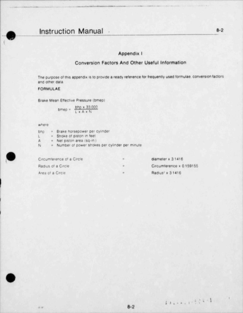
- . _ _ . _ _ . . . . . .
n Instruction Manual . s-2
L(Appendix I
Conversion Factors And Other Useful Information
The purpose of this appendix is to provide a ready reference for frequently used formulae, Conversion factorsand other data.
FORMULAE
Brake Mean Effective Pressure (bmep)
bhp x 33 000,
LxAxN
where
bhp = Brake horsepower per cylinderStroke of piston in feetL =
Net piston area (sq in )A =
Number of power strokes per cylir. der per minuteN =
Circumference of a Circle diameter x 31416=
Circumference x 0.159155Radius of a Circle =
Radius' x 31416Area of a Circle =
4
,
i
|
'O'
ti.... -t';'I
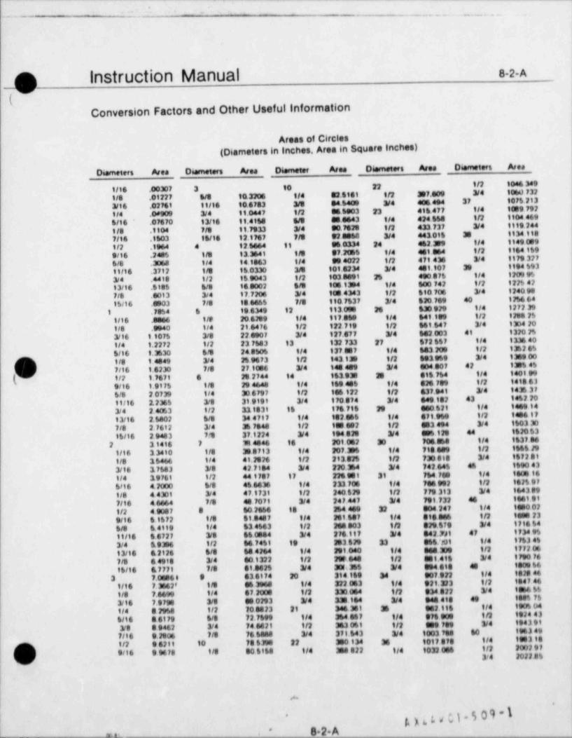
.
. . _ _ . . .-
_O Instruction Manual 8-2- A
v
Conversion Factors and Other Useful Information
Areas of Circles(Diameters in inches. Area in Square Inche8)
Diameters Area Diameters Area Diameter Area Diameters Area Diameters Ared
1116 .00307 3 10 22 I/2 1046 349
1/8 .01227 6/8 1(13206 114 82.6141 1/2 307.009 3/4 10td) 732
3/16 .02761 11196 10.6783 3/3 84.6400 3/4 406 494 37 1076213
t/4 .08909 3/4 11.0447 1/2 86 6003 23 416.477 1/4 1089 792
6/16 * .07670 13/16 11.4168 5/5 880443 114 424658 1/2 1904 469
t/8 .1104 7/8 11.7933 3/4 30.7628 t/2 433 737 3/4 1919 244
7/16 1503 16/18 12.1767 7/8 928068 3/4 441016 38 1934 188
1/2 1964 4 12.6464 11 96 0334 24 462. 3 9 tid 1949 089
9/16 .2485 1/8 13.3641 115 97.2WS t/4 481.864 1/2 1864 169
6/8 .3068 1/4 t o 1863 tid 904072 1/2 471 436 3/4 1179 327
11/16 .3712 1/8 16.0330 3/5 101.4234 3/4 401.107 38 1994 693
3/4 4418 t/2 159043 1/2 1038e91 25 490 076 tid 12a9 95
13/16 . stb 5 6/8 160002 t/s 108 1354 1/4 600 742 1/2 122S42
7/8 .0013 3/4 17.7206 3/4 108 4343 1/2 510 706 3/4 1240 98
1S11 6 .e903 7/8 106655 7/8 110 7537 3/4 $20. 769 40 1256 64
1 .78S4 6 19 6349 12 113 098 26 630 929 1/4 1272 39
t/16 .3066 t /I' 20 6289 114 117.060 t/4 649.189 1/2 1298 2S
1/8 .9940 114 21.6476 1/2 122.719 1/2 661.647 3/4 1304 20
3/16 1.1075 3/8 22 0907 3/4 127.877 3/4 682.003 41 1320 2S
tid 1.2272 1/2 23 7643 13 132 733 27 572657 114 1336 40
6/06 1.3630 6/8 248505 014 137.887 1/4 643 Poe 1/2 1362 6S
O 1/8 1.4849 3/4 2S 9673 1/2 143 139 1/2 903959 3/4 1389 00
7/16 1.6230 7/8 27.1086 3/4 140 409 3/4 004 807 42 1M% 45
t/2 1.7671 6 25 2744 14 163.938 33 316.764 1/4 1401 99
9/16 1.9175 t/8 29 4648 1/4 169 40$ t/4 G M 789 t/2 1418 61
6/8 2 0739 1/4 30 6797 t/2 196 122 1/2 437.941 3/4 1435 37
11/16 2.2366 3/8 31.9191 3/4 170 874 3/4 649182 43 14S2 20
3/4 2.4053 t/2 311831 16 176 716 29 se0 521 1/4 1449 14
13/16 2.5402 6/8 34 4717 ild 102 865 t/4 671.969 1/2 1486 17
7/8 2.7612 3/4 36 7848 1/2 188 802 1/2 083 494 3/4 1603 30
16/16 2 9483 71 37.1224 3/4 194 8N 3/4 se61M 44 1620 63
2 31416 7 114646 16 201.052 30 706.868 1/4 1837.86
1/16 33410 1/8 30 8713 114 207.36 1/4 7tt le9 1/2 1H% 29
t/8 1 6466 114 41.M26 1/2 213.825 t/2 730 818 3/4 1672 8 f
3/16 17683 3/8 42 7184 3/4 220.364 3/4 742.645 en 1690 43
t/4 39769 1/2 44 1787 17 226 981 31 764 fee 1/4 1908 16
6/16 4.2000 6/8 46 6636 1/4 233 706 114 70s 902 1/2 1625 97
1/8 4 4301 3/4 47.1731 t/2 240.829 1/2 779 313 3/4 164399
7/16 4 6664 7/8 48 7071 3/4 247.447 3/4 798.732 46 1661.9%
t/2 4 9087 8 60.2666 18 364 449 32 304 247 ti4 1050 02
9/16 6 1672 t/8 61.8487 1/4 261 647 1/4 ets se6 t/2 18en 23
6/8 6.4119 t/4 634563 t/2 204 903 1/2 329.573 3/4 1716 64
11/16 66727 3/8 650884 3/4 276.117 3/4 842.7A t 47 1734 96
3/4 19396 1/2 6474St 19 383 629 33 066/01 t/4 1763 4%
13/16 &2126 6/8 64 4264 1/4 291.040 t/4 ges.30s 1/2 1772 06
7/8 6 4918 3/4 80.1322 1/2 290 644 1/2 333,416 3/4 1790 76
16/16 867771 7/8 61.962S 3/4 301 36$ 3/4 334 618 48 180s 66
3 7.0e06 0 9 43 8174 20 314 169 34 307.922 914 1828 46
1/16 7. 3n62' t/8 e6 3e64 1/4 322 063 1/4 921.223 1/2 1847 46
t/8 7.6699 t/4 67.2006 II2 330 064 1/2 334 022 3/4 teh6 %
3/16 7.9798 3/8 900293 3/4 3M 164 3/4 944 418 et 188% 76
1/4 82958 1/2 708423 21 346.361 3 3s2.116 tid 190S D4f! 6116 86179 6/8 72.7699 1/4 364 467 1/4 374 90s 1/2 1924 43
3/8 39462 3/4 14 6621 1/2 363 061 1/2 set ?t9 3/4 1943 91
7/16 9.2806 7/8 76 SA48 3/4 37l643 3/4 10037es to 1963 49
1/2 96211 10 786398 22 380 134 36 1017878 tid 1883 18
p; 9/16 9 9678 1/8 80 6168 t/4 3s8822 1/4 1032 006 t/2 2002973/4 20228%(w'
|
|
+
g)4 hs/hk*s.2.A-
' . , . . _
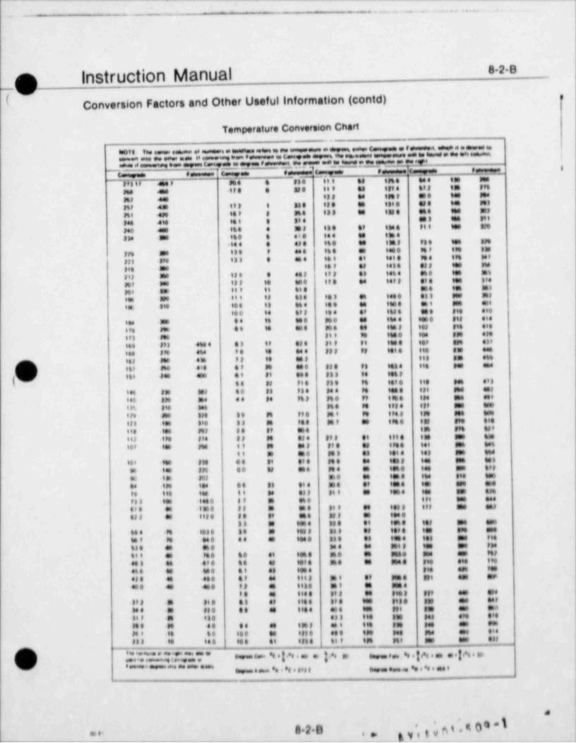
_ _ _-. _ . _ . . _ .. . .-
820p Instruction ManualI Conversion Factors and Other Useful Information (contd)
>
Temperature Conversion Chart.
.s . . .e . .wi.. e. w- . *,as c. =. . = , e + .a.a a *. ..so , . .ey e-= i
1.
. w w e
_
. ... =,,j.n ..m.,e1.,..a. e c a
, ivd ,= , =.a 8
e 7c y=c e c. .
. . n. u . = -. . . . . . , i n. .,,3 , ,
n, m.u .. . ,, =.. . u.o ne, o. n
n. .n,. . ni. .. . ni, , , i n.
n ,. 3D,..,47. i., , M. .33 .4 .N.. = in
. . . . v. ..... . . .3 , . . . ., iM . . . . ie. 3.'.
. . .,.0
. . . . . . ,. .. . . . .,, .n,. ., m... . . . . . . i.
.,.. m i
. . .
... . . .. ..m, n. u,
. . . n, . m, , . in . . . . . ..
. ., ~. . , , . u.. -
. . . . ... . . , i.. u. . , .. .,,,, .
i. .. . . i.,, .. ...n., , , - ., . , .. i. . . . ..u,., .. . . . . . . ..
i ,. u.., .. ... m. .. . ...,. . . .. . . , , . . . .iu . ..., . , . . . ,. . .. . . i.
.. .. . . . . , ...
n.. . ... . . .. m, iu ... ...,,. ,. ..
= m. , ,. .,.n. ,,in ~
n ... i., u,n, , . , . , ., ... ,, u....
.* i. . n n . . . . ii....
,o = .. ,, n ., .. mo; i. .n.n, n. ... ., n .. n. n .u .;
v n, . .. n . . . ni n m,
n.. . . n,n . . . . ..... n . . .
i n,. m.. ,. ..... ,. ., .. n n.
, ..-. n,. m, ... .. n, n.... n.,,, .
n, ,. .. n.in . . ., m .n. =
n. . .in = m 3. n. . ,. , . , , . . in m
m, n. . , ,in -
n ., n, , .m u.i .. in.
n, 6.n .,. , , , .. ii, . ..i. i,.
i n ., , , . u n. ... .io, . m . . . ...u.n . .. , . >
. ..in .,i., = n. .. i. .. n.
. .,,
m. .. . m .. u . n.iu ... ,.,. i. ,o ..
.. i. .... m . .. n . . . ... , .- . . . m.
., i, .,n, u .,.. n. a.
i,, .. . . . . .. o. . ,, .. , , , . . . . n .
. . , . .,.. ... u,, .,n. .. ,u, =. ,i m.. iu.
.n .. i
.n. u .,. . . .. . . .= in .m. i., ...
n. .. .... . .. . . . n.u. . ..
u .. . . n,
.u. m... ... .. m. . . ,,. ... ,,.
.o. ...
, , . .. . . ,. u. .. ..ni mi ., . ni .,
. . , , ,u . . . . o
. , , , , . ... m... . . . ,,,n.,. ., .,. , , . . . . . , , ,
n ., n. n..= n.u, e.n m.. n. . n. . = ,.
... . ... .. ...a n. . n..i.
. . . .,.. .. . , , ,n. .. in. ,,. o . ...
. n. .i . .. . . . , . . . ,n.i .. . .. in. u m n ,., .,ni ___
O ;;..~. :.~, .~.:, - . . : ... . ; .., ,,, . . : ,.. . . . : , . i,.' - ~ ~ . - - - - . . . . ,,,, . . . . . . . . ,
man
gyitvps.s00*\'
'820m i. .- _ - - - - _ _ _ _ _ _ _
- -- - - - - - -- -- - - - - - - - -
, _ _ . _ - . .. . _. ._ - __ _
o Instruction Manual s.2.c--
Conversion Factors and Other Useful information (cont'd)Altitude and Atmospheric Proteures
--
*g y n, . ,.. . . . . . - , . - . . . . . - ,..g.....- _. _
Asiitwte Anse,4 See Lovet Tempusene,o" te,emetse' s eAemees ieres veen,,e
t'''t___ t,"a Abt,,
**'"' '""feet * W,tet tece,t' 89 *C pgaA
..HD AA'6_ _ HD A46,
tasal .MM ff M a te satI ef as 1FMewe .9373 M M B as WBe if it i feeasumi 9730 73 33 30 of 894 3 MM t lesJhtm . tam it pf med met M a# t tesDuel GM M it atIf Set t MM i tog
fWe' M9 m 30 WM 954 Me 1 930
fuse 4tt es to 30 to 044 MM tto
ibm 404 M te 39 he Of9 19 99 9pt 1
08'ul M 43 If 99 98 3589 94 93 t ef t68e 'M3 49 M 2 49 ff a t 94 98 l ebt
0 8 he M 98 97 985 0 f e et 99133tdu) Sta 49 le NS MS3 4449 l ett
imm 3,6 tt 13 m en fate $4 4 Gh4
t tsal ed M if a 13 199 4 1399 9,8
pesi ett 68 40 ff88 MSG t a tt Gers
fwas Ma te te pt N est tiet 943Dem GM e 9 38 08 ett 9307 em
I Jvn, taas ef a m 13 me tie # snu
! e(e n t#M e f MM G83 t# m 908ewsi 1373 43 g 3t 37 goe s ti et oft
tass 4 e tt MM 40 t 94 00 6W4 49 99 teftesses t9 telt E 3 fles W3 t t 90 .8 89,.Mfissa t3 It at M 1 93 le SAS 9 il M
tis si tt feet St il M 93 tad 4 te tt .fe tDani ti fles If 3 ft.3 M13 le M ,73
, p t .. t. ,) 6 .. #, 0. t. .,t.
k ,t.g tsse .ogff M a.s t.a ipg 6 .te ege t SM
fu.3 . i.t a .f. .3t. .n 93 9 m.4 ,. s, 3. .M n il ele t 4M e,. . , .9
A' (s ee t9 9tta .48 .44 0 993 Set t 4 3P .28
M Wa2 et to tte et f een tM3 Set ,944
et Was 94 95 Pas .M 69 6 648 tot 3 0 73 .it tet tuas 0% tlfW .ft 48 4 37% til 1 3 14 444
%di a s. 94 tt Mt .fo -49 S eed Of t SS 999
64 tes.s it e 94 70t .it 49 $ tti 99 f.33 mm&b te d' li e It we .M 49 Sim MS Im .ef epu is se tal 30 ta f 49 44 iM 34 9 At tete
gto tess 46 i f e esee of 48 94 f f t , 30 0 .45 .4884
es tasi et t fl egg 99 40 4 94, 119 .Jbt .0t79Ita; tas) 10 9 Dante lt +4B 130r8 SE .M8 .ette
g
t io tsee fft a tti M .45 t 2A Seg1 49t eo tssa fe t 48 f14 4 .M G Mf ,
94 99 ,glidt fes# 31 e e Ott 35 >f 9 748 gleusse M# 44 tte it 9 9 fee SM
3 gPsi u s, 37 9 et,eso 3 .it t ten Ie
If M. ine e.t t 4,9 ti,f. 9 Sf.f:I 4 49 ;
.44 48
. .lfa. 6u . .3e m.
f) M 3,. .t . .6tI,e . . d 8foo tr o tst en efe .t m es e tol set
0 43a; tsaa to 9 98.6 m .tIf a 17ff 9W
06es sen 94 9 eff ees & 3 '' 93
f
.too, t.gge.s. #94
s.tiWes e, m es et t
It.,-4.'et. . . - , ,
# It we tem toe at, tee &t tm
0 Ot BM tool P94 En9M f9 $WN e4 4'es (se see 4if Ien ef Ie
e en '8M
t ese tuer sie an' tej 3e Mt o e me set tee tes to ett'Of" IMIm*We att eta pan- _ _ _ _ _ _ . ._ _
(3 14 te** Id ASA Steade,d Atmeesf+,e 4,9821gs ' t ., . 9,, . .,o., o t 4,,,.. t ,. ,, , et . .lt.,
( ) " i .+0. . 6,, . . .It..t. ea
i.,t.,. .. f . M ., M., t.e,4a
if.et... .9,.ee,0,,,t... lif t,,t .,~ wf av
p3,,,,,,,.$09*I*
8204, . .
_ _ _ _ _
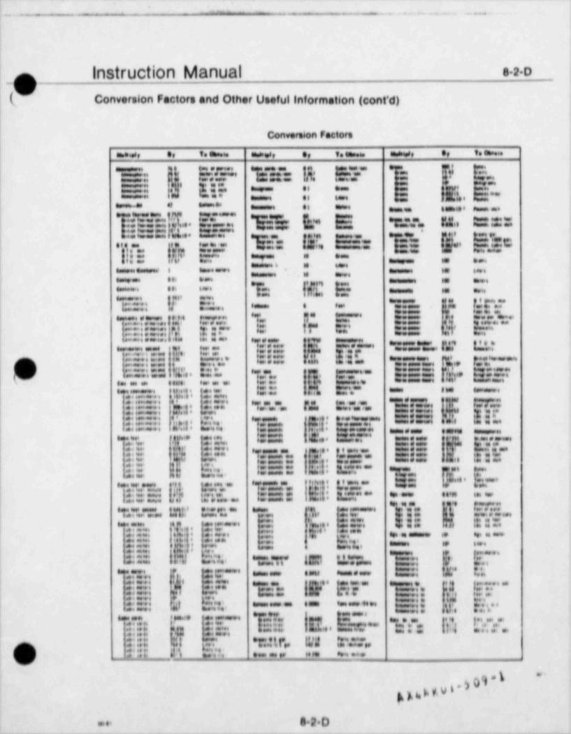
.
.. =- = _ _ . . . . . ._ . . . -
instruction Manual . 2.o: _o\ |
(ms Conversion Factors and Other Useful Information (cont'd)'
'
Convero6on Factors1
m.s. e, v. em. me..s, e, v. a me s, e, v.,
1, . '
a.,12 .. .| . . ,,'t . . ..t .
. .. - . . *:: !!(' 3:::. ei ."
-a a '-. = a m.-. .i . !. **., - _ ,, . -- e .. . - .
| ::::::::,,.,$,. . ' .? .. $$ |;,'.*.E, *ggy. |W,, 2=:g:=
. . . L. . ||L .. .4. - , g=,,
n, . . ..,.) *
.' , C' . * . = 5::= !E,, ; :: |' .'. e". c ., m. . ,,,, ,
f y .,--p., I., 6 p..* 86' ***
1 %, ,l *-.a a-a.* * 6.-. -. . ..-
,, , , , , ,* = + = Hi 6 =. . ..
*C.., y,4. g:", , ,. e ., i. ,,,,,,,, ,,, ,,,,,
-
l .. . I..ii.. .,
,
o .u. [.,..
.. ;e e e- ..-
k.,.. . .
.. .i g:: ::|-
* *:. .**
{ga,,,,,,, ... . . . . p",,. .! ,,),,.. .~ . . : ,,,.,|), ,. . , . .
.. .. ...4 . ..,,...
e =... . . .
, . . . . . . . .. , , , .k. ["'.,*7"' *::"."=*E|.' IE f.'l.J
,
! 6.~; =:-t. 7,',, :r::' I".'::: ..
:::::::: 1.;;. . ::" ag=,=,,,t, ,,t.. ,,, p::t ..~.., *,.. ~ . . . L ' .al ... . :..:., ;*:::::::: -*
:
4,, . , . , , , , .. ,
2: .==,,, 2* la,l,,,
% . . . , ,
l .. .. - = . < ~.e . . , . , . . . -
1::::: ., .,,- e. .. . ..-. . l .,. .1. |e. ... . . , . . .
. ...,,,1.
| ::'' ' * = . , , , = , , ,f,g, 1g,,=;=,,, d .'"'"' "T.o %. C.||!::';:::: 4 . ..|
, oWi . 1.,. .,,
..., o ,e .. . . . .
1.,,,.,.,,,,,,.,.,k,.,,,l i ., . . . ,. .. , . , . . ,,,. - . . ., _ , , , , , , , , , , , , , , , , _ , ,
' * ' " ' . '.' f. * t c.. |||:::|| 2,. . I||L*.'"** g=. . =: gL , 2,.,.,.y..;,
'
!;P* . - -a" .| a.::: <p . . f , ,,. . .,
i . , .m L, i .
~a . ,, , ..le .- .
6 -..:::.. . ..
|- . 3,:, , ,. , ,2 . ...
- . i'
.Lo. 4 . .
.~-' , . . . .... .e .e, .e.. .
. . A.,.t, .L . , - ... ., = a..
. .. , , , , , . . . , , . . , , , , ,. . ..- . . , .o .2 . .. .
* " ?. "g*? f,. ;*/.'.,' ."...e. 1.1,,, . . . g.. . . . . . . . . . . . .
|E. ::E*** *:' .. V..o . *: C=+' 3 M,p,'3.,,. 9."T .##
! .
m: c,,,;;,. , * ' " . = = = ' * .Ti * * ~ +| :::: ., '.!,"!.: :.::'' >
=, , i.., . w' . . . . , 4..g .o . g::'"24 *:.= ,T* 1R1 f,1,i:'-' "l"*k; h I,E,'''
. w.
:::::: 1J.) ., ,
EE: x :.l . ::. o ==~ - e -.
1:::. . F Far Ei: y, !Er-'hlkh h, e;,1
"
i.)e.. , = . . . . .::=..::=: - . - . e - . ..m . ..
*k'" |===.C' *"TM"-"*"'* * * * 3** * ::r-++ p m. . . . . . ;.. ..
', ,,
|||:: ::| $1 i'. f ..::.:.:.:.:$.,!:
-
.::::'*'
-
g .p ;;,g ...> ::::: y e,.f,. ,
.-. . +..M . ._ u. ,.4...
J ,.a. ..v
pp,>gui.y0et.1..
. .. e.2.o. _ _ _ _ _ _ _ . _ ___ - _.
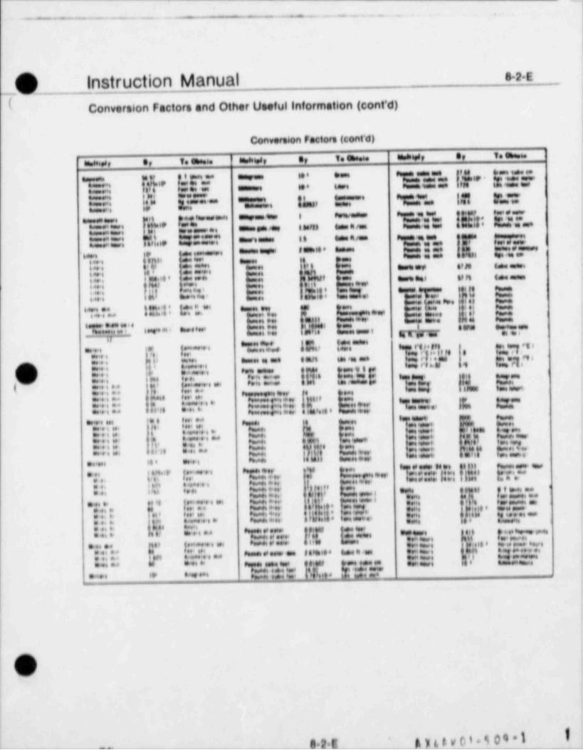
.-
._ -- _ _ . _ .. ___ ..
- _ _ . _ _ . _ . _ .
O Instruction Manual s.2 s'
-
( Conversion Factors and Other Useful Information (cont'd) |
|
Conversion Factors (cont'd) ,
an s, e, T. en 6. ahnt,s, e, T. ch a. thaDesif et T.en.p.|1
, . , ,. , ,. .<
,
. . , , ,, , , . . . . 1..
|;i..,... - . .L':-** "I=::,.. fl.u :="' "E2" I,ft F'-
. " .:::" ,..
t** gi =g,.,::w= !!: F ';'=, i.,., im ,::==:
Ft,f.,, ..- ..23::::' = = . . = = is ==a- g.= '." y. , . . ",
o:::::::: *
.. . < .. a.a. , e ie. n ":||:.
o i .
,4'. .gn <. , , , ,. . . . m ., un s. .|: 1 2 ::''.
,*--
n O'' ' |m* **3{ ,k,,:: En,,,.,, e- nu :::=
' = = =. un s ,
!::m E::: . ,
w ** f g:::,,,,,, ,,,,,, g*,'*' ]yg-'TA *1. 1 2'.::! L* :'..'" . , . , ,
.. o n a. ,
i ~ , . - . . . . ca, n.o *> ,;;; ,, i g=, ,,,,, , .. a.. .
|'' . , , , ,nranr . ,
u
*:., , 1:~~'" "':|::% 15i. !*'. '"*' 3' '.s .m. e . ng!!' '
"'"R i*
|j*f " .4, ;:: , a-* * = enn . , . c,;;.: 4 *.'.i*=
1,i...~o,. i.. .. . .
; .,~. . n, , . g|e,,.=i. ,.,... . . . .
7,( ..... .
a. "= w~ ,'':::::: 4,... .::: :'., 4 <,g
::::: " fi.n 17"." * ;;;;~I,,jj$ d',,',,, h "t.*:||* , g, ||||r,;". , . ,,,,,,,
.. .i . . . . . . , ' = . ' =~.:::*: :* !".|.:':.. g .
"g,f %%.,w''||.,":2':::* .
::.::::: l!. |,r.. ;.". ** g;;;; g::::,,,,, ::'::::;* n. '-
< *inol' C ,.,.. , , ..n ..
1. . . . , m .a.. . , ,
.. . . . . . . w.,
t . ,. . .,, w|4.ni.
,, ;sw. . . . ,.. , e l ..n "E" ., ... n o... . . ,..
, r.ye .. .. - .
... . . . . . g.;;;;..;. . ,
,, ....., - , .
J II. o.,
,,,,,., ,,.. ,
!d,,,, f., ., .,,.,.,,,,,..4. .o,,. ..... . . . ...
.
.n
o,g. i . .. .- .,...
. in, ..... ,. . , -.. .. , . . ..
a .. m .. . . . . e g,:g,.. -=:. . . . ..o .,%..
. .. : y, gn ,
ag.,y ,, ,,,,,- ut;ge |g g,, ,,,,,,,, , , , , f,,,,,.,,,,,,,. . . . ., ..n..
g., ;'. ~.n . ==:..... . . .
. , - on. .
4:'" :h::~.::7,'". . . . . .
. .',.:':. . .. - . .. .::::: k, o ..., . g:::: l'.' ;. * . * **. ng.,, *$,,e 3;'3:::".L
* ** wa w::::::',,
._ n
v
^ -- - - - - - - - 42E __ _ _Ayal.v0).J04*1'
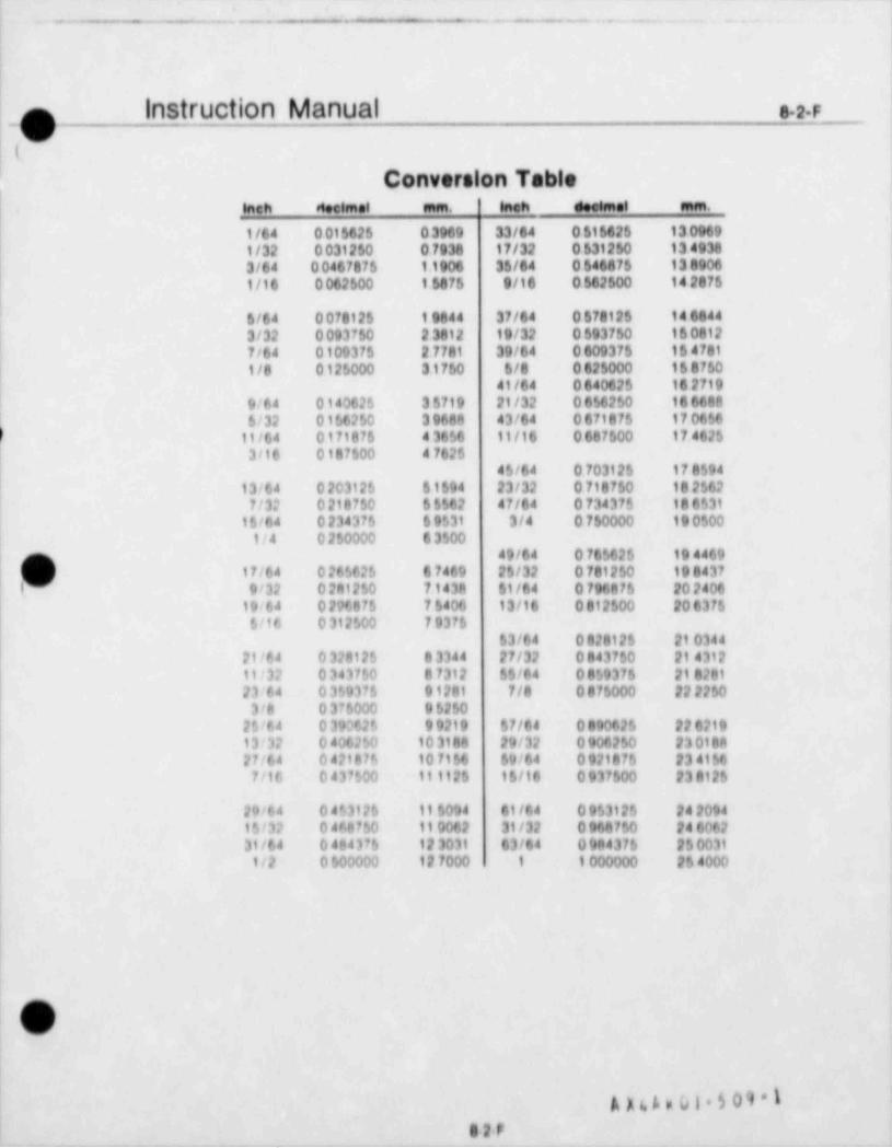
_- ---
- - .. _ - - __ - _._. ..
i
|
|n instruction Manual .r|v
(
Conversion Table| w .w e . wi mems = = .
t/64 001662$ 0 3969 33/64 0 616625 13 0969'
! 1/32 0 031250 0 7938 17/32 0 631260 13 49383/64 0 0467876 1.1906 36/64 0 644476 13 89061/16 0 062500 1 6875 9/16 0 642600 14 2476
6/64 007812$ 1 9844 37/64 0 670125 144444,
! 3/32 0 093750 2 3812 19/32 0 693750 16 0612l 7/64 0100375 2 7781 39/64 0 609375 16 4781| 1/8 0 125000 31750 6/8 0 625000 16 8750
| 41/64 0 640625 16 27199/64 0140625 3 6719 21/32 0 656260 18 6688'
( 6/32 0156250 3 9688 43/64 0 671875 17 0656
/ 11/64 0171875 4 3656 11/16 0 661600 17 46253/16 0187500 4 7625
4S/64 0 70312S 17 8594,
13/64 0 203125 61594 23/32 0 718750 18 2562!1 7/32 0 218750 65562 47/64 0 734376 18 6531
15/04 0 234375 6 9531 3/4 0 760000 19 0500! t/4 0 250000 6 3500'
49/64 0 76562$ 19 446917/64 0 265626 67469 2S/32 0 781250 19 8437
f 9/32 0 281250 7.1438 61/64 0 796876 20 240619i64 0 206875 75400 13/16 0 812500 20 6375S/16 0 312500 79376
63/64 0 828125 21 034421/64 0 328125 83344 27/32 0 843760 21 431211/32 0 343750 8 7312 $$/64 0859376 21 828123/64 0 359375 91281 7/8 0 875000 22 22503/8 0 376000 96250
25/64 0 390626 9 9219 67/64 0 890626 22 621913/32 0 406250 10 3188 29/32 0 906250 23 018827/64 0 421876 10 7156 69/64 0 921876 23 41567/16 0 437500 111125 16/16 0 937500 23812$
29/64 0453125 11 6094 61/64 095312$ 24 2094| 16/32 0 468750 11 0062 31/32 0 966760 24 6062| 31/64 0484376 12 3031 63/64 0 984376 2$0031
1/2 0 600000 12 7000 1 1 000000 26 4000
|
|
)C/|
A ul.p01 $09 1e2P
. _ _ _ - - - _ _ _ _ _ - _ _ _ - _ _ _ _ _
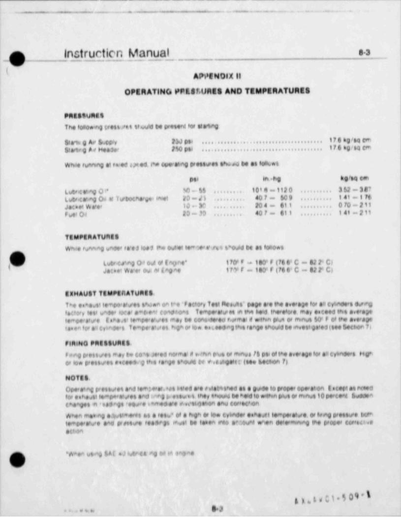
_ - - _
- . ..- - - -- . - . . - .. . .
Instruction Manual sag(
AWENOlX ||
OPERATINCs PPE80URES AND TEMPERATURES
PMatsuMtsThe following prettJ't.t truutd be p'etent fof starting
176 kgftQ cmSta' tis g Ai' Suppty 2SJ poi ......................................17 6 kg/sa emGiartitig A f Headet 2*20 pai ......................................
While funning at twed u ed, Ina Oputating prettuten tho ed be at follown
kO/qcmpal in bg t
Lubncating O l' $0 - S$ 10181 - 112 0 . . . . . . . . . 3 52 - 3 07..........
' 0 -il 401 - 609 141-116Lub'icating Oil of lutbochaf wer inlet 4 .......... ..........
Jachet Wate' 10 3C 204 - 611 070 - 211.......... ..........
F uel 0,i 20 - 30 401 - 611 141 - 211......... ..........
TEMPERATUfitS
Whae funn,ng unce' f a'e31o#1 the outlet IpW' thro t*ould bt at follo*n
[ Lub'icting 01 out o' [nyne' 170* F t80' F (70 6' C - 62 2' C)Jaoet We'er out niing ne 17? f - 100' f (10 0' C - 82 2' C)
EXHAUST TEMPtnATUMES.
|The eehaust tempo'atu'en tha*n on t*r)' F actory f ett flesuttt" page are the average fof all cylindef t duonDf acto'y lett unde' loca' attnant cortd front Tempe'atu'at in thi held thef etof e. may eaceed thin avef agelembe'ature tabastt tempe'atuten may be cont'de'ed r.ufmalif w. thin plut of minun 60* F of the ave' ageta.an to# s'i criandeet Tempe'atu'et h'gh o' low en.eed,ng then f ange thould be invent' gated (teo Gection 71
FIMING PMttlVMil.f eting p'entuf et may be c03t Je'ed nOf that #t v,dhin O'un Of minue /6 pte of the avetage for all cylinde't lifio' lo* prettutet onceedmg th's f ahJe thould te ( tatigatt t'(toe thection 7)
NOTES.
Opern'ing pf ettu'en and tem,.ctat.'on listed a'e ritat4sthed at a Ou'de to pfoper operat on tscert at feed*
f 0' entidult tempa'atu et and M*@ brestuccit. they thuuld be held 10 within plut of minut 10 percent LudJonr
changen in '9A1*gt 'eQude th'hed ate 'fievnt.f14tiOf1 and ebff t.Chon
When fhthing el uttmphit let a fetu'' Of a high Of 10* cylindet enhauf f temperatufe. Of fifing p'entu's t tttSl
tempe'atu'e and p'estufe fealP3% Matt be laben into GNount W' ten determining the of 0Def cbff6t.l veaction
'When ug,eg $ Al mJ iubhc A *g ful 16 f nd heX
k)a.l' iib \*5s.3. . , u ..
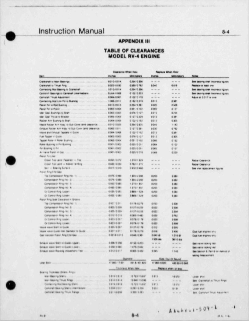
_ . __ _ _ -
- . ._. _ _
Instruction Manual e-4o
N Appendix m
TABLE OF CLEARANCESMODEL RV 4 ENelNE
c- _ ,~m ,a.a., to.esi .iepu. .au.a e e
c,...........................,.... . . , . - -.--- -__
. . . . . , . . . . . . , . . . . , . , . . . , . - . -. . . . . . . . . . . . . . . .
Ic , , e,.- . . . . . . . . . . . . , . . . . . . , . . , .,... --. . .
, . . . . . . . . . . . . . .,, . m m,.--. ___
c...--.. . . , . . , .. , ,,. . . . . . , .. . . . . .. . .-- -.
. . . . . . . . . . . . . . . . . . . , . . . . . . . . . . ,, - . ~ . . ..
~ , . . , . . . . . . . . . , . . m ,. . . .. .. .. ..
-. . . . . , , . . , , . . . , .. . . . ,. .
.. ,. .~.. . . . . . . . . . . . , , . . . . ... . .
. . . . ... . . , , ,, . m . . , . . . ,.
- . . . , . ~ . . . . .. . . . . . . . . . . , . . ..
......c.~-.. .......m . m . . .. .m , , . ,, ~ . . . . . . . . . - . . . , . . . . . . . . , . , , , , . . ... .,o
~ , . . . . . - . . . . . , . . . .,. .
... .. ...r. . . . . . . , , . . , , ..,. ..
I , - . . . . . . , , . . . . . . . . , .. ,,o.
- . , . . . - . . . . . . . . . . . . .. . . . ,
. . . . . . . . , . . . . , ... . . , ,
i .... . . ....,,.m . . . . . . . . , , , ,..
s. s3 c..,,,... . . , . . , , , ,, , , m| m. c .-.. ---
J c.,~.....,. ....m . ro , , ,,, .-. .-_ c .~...,m. . . . , , , . . . . . . . , , . , ___ ___ m..
. .. .,.I . < . , ~ , . . . . . . , . . , m , , ,. ,,. ..'
- . . . - , ~ , . . . . . . , . , . . . . , . .,. .. .
... ., . . . . . , , , , , , , , , .,. .
I. . . . , ~ . . . . . . . . . , , , . . . . . . .,. .m ..,, . ...m,... ...,u. .. .. . . , , . . . . . . .o. . .
..,m...... - . - , ~ , . . . . . . . . , . . . . . , , . ..
; e . .- , ~ , , . . . . . . . . , , . . . . .-' c...-,~.. . . . . . . .,,,,.m . . , . ..
. . . . , ~ . . . . . , , . . . . . . . . . ... . . . ,
| m..... ....... . . . . . . . . . .. ...'
m .., ,,,. .. ....... , . . . . , . . . . . ..
. . . . . . . . . . - . . . . . . . . . . . . . . , , , . . . , .. .
. . . - . .. . . . . . , . . , . . , , , . . . . . , , - . . .
. . . . , , . . . . . . . . . . . , . . , . . , .. . . . . . , , . . , , . . ,.
.. . . ..~... _ , .. . . . . . ..... ... ... . . . . ,
.~ . ... . . . . . . . . . . , . . . , m ,..-- -_
, ~ , . . , _ , . . . . . . . , , . . . , . . . . . , .m , , , , . . , . . ,.
..
thave 0 !oJ ty h,w
6 .e.. , ,, pe z, , .D i . 0, . < . H m ,,.e.'. . a. . i... . ,
''it..,,,. s * 8temet. . sea >e ae
. b . u t .. .a...sen *, 5. . , . . ' . . . . . ..,,l',...' ..'l . . . . . L.e. .%.
n t..a .e *, es.a 8b,. . , ..'. .... ..t.. c,.w e.a,,,s. a .eg.... ...' ) Lam +ag he.t ....g .*.1 . . ' . . ' . . . ,, 9 , l . . ' ..'8 6. . .. ,s.e.= .*.
/L ( .4 .6 ... * W . ,de.' *.. .. . ,0 .,3' , ,. I . N .N . ,3, 6+
t.*.*.a .e. * h. , e g. . .,...,a. . M. . .. I .e. C .+ a.a s. ' .e * *. *=== ===
A p. A o 6 5 09 ' l ''.
. ., s.4 ,,
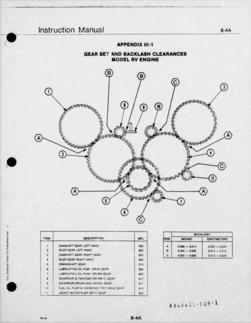
.
._ __ ___ _ . .
1
Instruction Manual 8-4A |
(U APPENDIX 111-1
GEAR SET AND BACKLASH CLEARANCESMODEL RV ENGINE
BC
3
1 l
'--:,s,
8 '-
,- ,3 g 3 -- u,' A / sg
f ,' \\ // \l' \\ II \j' tt i l \
,i' . , ' ',7 ',
"
t' ,3 os i :i -
i ! /'/\\ jr,-(-''.) '
t 's . I . :::.' |i ge ,
|
A ', s s N--
'
-
" , ' NN ff ... /s'
/f NT--ss
& f Y' '',I\'
,
f I '% il
* ~~//f gg
g\ ,#/ {0' % %,sf
$ I | C . W- . ' , . ''' ="
k/s N /e g:==:; .' 9 @- - -
. . .5 %- 7
6
C.
j SACKLASH,
ITEM DESCRIPTION OPL PO8. INCHES CENTIMETERS
( 1 CAMSHAFT GEAR, LEFT HAND 350 A 0008 - 0010 0 020 - 0 025g 2 IOLER GEAR. LEFT HAND 355 8 0 004 - 0 006 0 010 - 0 015e 3 CAMSHAFT GEAR, RIGHT MAND 350 C 0 005 - 0 008 0 013 - 0 025
f 4 IDLER GEAR. RIGHT HAND 355
.; 5 CRANKSHAFT GEAR 310
,! 6 LUSRICATING OtL PUM''ORivE GEAR 355
5 7 LUBRICATING Ort PUW ORivEN GE AR 420
} 8 GOVERNOR & TACHOMETER DRWE GEAR dit
] 9 GOVERNOR ORivEN AND DRIVEN GE AR 411
'j 10 FUEL Ort PUMP & OVERSPEED TR'P drive GEAR 410
11 JACKET WATER PUMP DR'vE GE AR 425
A n A x 01-5 09 -11
av u 8-4A_ _ _ . _ _ . - -
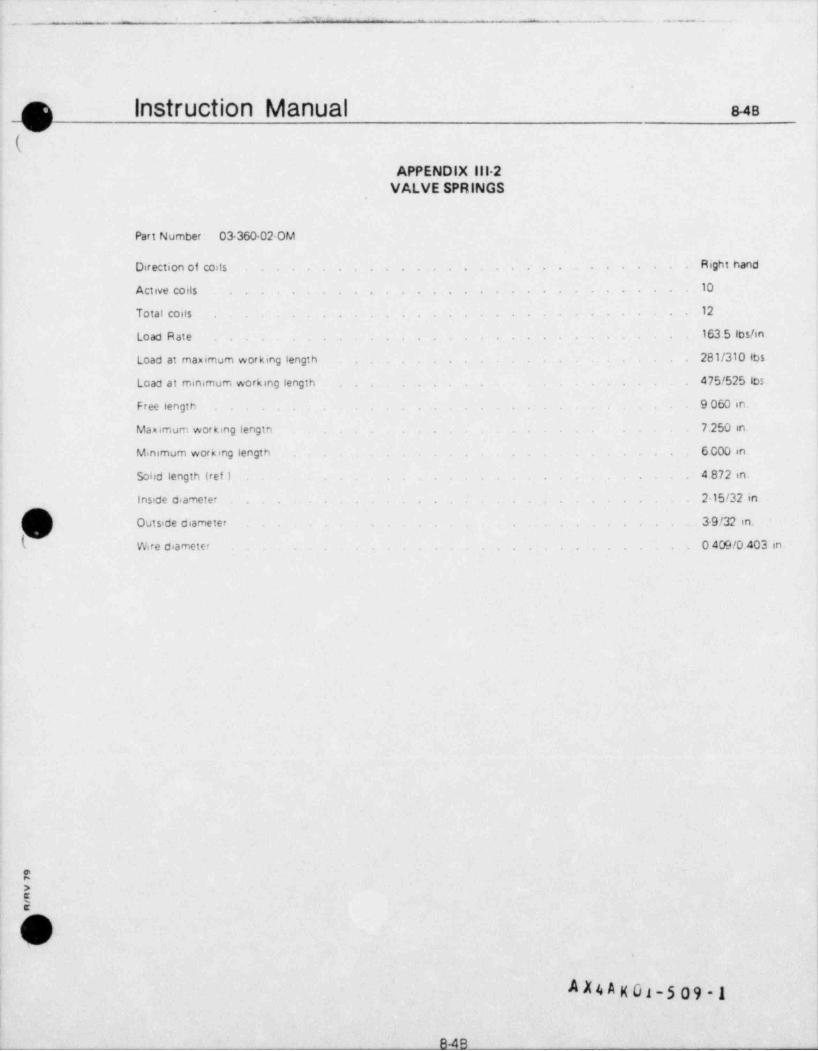
._._ _ _ - . .-.. . . , ,. . . .- . . _.- _ -. - - . .
= ~ ~ - -- - . . ~ . .
_
;
i I
i |
I
! ra instruction Manual us'
<N-
*(- :1 1
'
f APPENDIX lil-2t
VALVE SPRINGS;
! !
Part Number: 03-360 02-OM
. . . . .. . .. . Right handDirection of coils
Active coils 10 f. . . . .......... . .,
! Total costs 12 . ;, . . .
1
. . . . 163.5 leshn.; Load Ratet
i Load at maximum working length 281/310 lbs.. .
475/525 los.Load at minimum working length . . .
; Free length 9 060 in. ;, .
'1
Maximum working lengtn 7.250 in. [.
L
i Minimum working length 6.000 in..
Solid length'(ref ) 4.872 in.. .
I . Inside diameter 215/32 in. .
I Outside diameter - 39/32 in.. . . . .
! k Wire diameter 0 409/0.403 in.. . ... .
i
4
i1,
; ,
it
1
ii
: [
!
:4
i
!
!'2i >
u!
"P
!
i' .%
| #
1 .AX4A K 01-5 09 - 1,
g . |
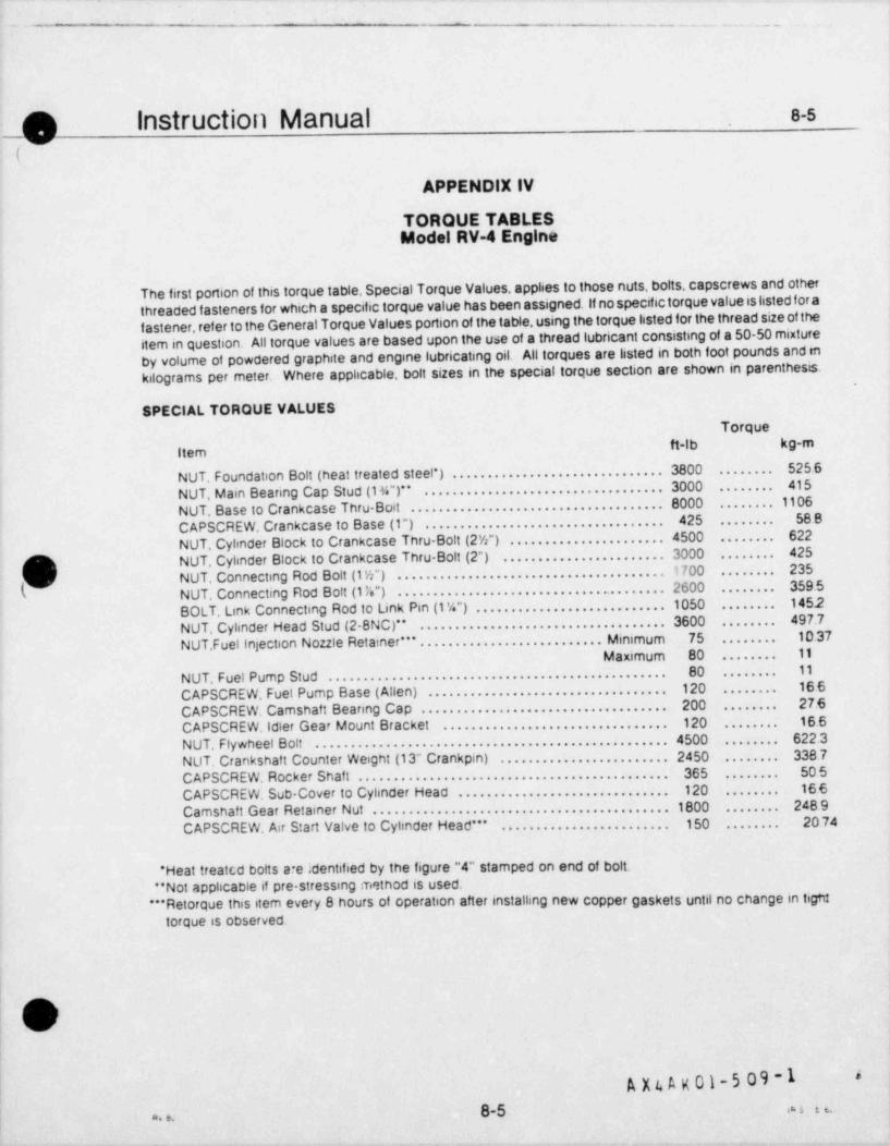
-- -
- - . . . - .-1
O Instruction Manual 8-s I,
m(
APPENDIX IV
TORQUE TABLESModel RV-4 Engine
The first portion of this torque table. Special Torque Values, applies to those nuts, bolts, capscrews and otherthreaded f asteners for which a specific torque value has been assigned. If no specifictorque value is listed foraf astener, ref er to the General Torque Values portion of the table. using the torque listed for the thread size of theitem in question. All torque values are based upon the use of a thread lubricant consisting of a 50-50 mixtureby volume of powdered graphite and engine lubricating oil. All torques are listed in both foot pounds and enkilograms per meter. Where applicable, bolt sizes in the special torque section are shown in parenthesis.
SPECIAL TORQUE VALUESTorque
ft-lb kg-mitemNUT, Foundation Bolt (heat treated steel *) . . . . . . . . . . . . . . . . . . . . . . . . . . . . . 3800 525 6........
NUT. Main Beanng Cap Stud (1%")** ................................. 3000 415........
NUT. Base to Crankcase Thru-Boit ................................... 8000 ....... 1106425 58 8CAPSCREW, Crankcase to Base (1") ..........................................
622NUT, Cylinder Block to Crankcase Thru Bolt (2W") . . . . . . . . . . . . . . . . . . . . . 4500 ........
NUT. Cylinder Block to Crankcase Thru Bolt (2") ...................... 3000 425
I(O........
,/ NUT, Connecting Rod Bolt (1%") ..................................... 1700 235........
NUT. Connecting Rod Bott (1'.") ............................. ....... 2600 359.5/ ........
BOLT, Link Connecting Rod to Link Pin (1 %") . . . . . . . . . . . . . . . . . . . . . . . . . . 1050 1452........
NUT, Cylinder Head Stud (2-8NC)" .................................. 3600 497.7........
NUT, Fuel Injection Nozzle Retainer *" . . . . . . . . . . . . . . . . . . . . . . . . . . Minimum 75 10 37........
Maximum 80 11........
80 11N U T, F uel P um p St u d . . . . . . . . . . . . . . . . . . . . . . . . . . . . . . . . . . . . . . . . . . . . . . . ........
CAPSCREW, Fuel Pump Base ( Allen) . . . . . . . . . . . . . . . . . . . . . . . . . . . . . . . . . . 120 16 6........
C APSCREW, Camshaf t Beanng Ca p . . . . . . . . . . . . . . . . . . . . . . . . . . . . . . . . . . . 200 27.6........
CAPSCREW, idler Gear Mount Bracket 120 16.6................................ ........
NUT. Flywheel Bolt .... ............................................ 4500 622.3........
NUT. Crankshaft Counter Weight (13" Crankpin) ....................... 2450 338.7........
C APSCR EW, R ock er Shaf t . . . . . . . . . . . . . . . . . . . . . . . . . . . . . . . . . . . . . . . . . . . . 365 50.5........
CAPSCREW, Sub Cover to Cylinder Head . . . . . . . . . . . . . . . . . . . . . . . . . . . . . . 120 16 6........
Camshaf t G ear Retainer Nut . . . . . . . . . . . . . . . . . . . . . . . . . . . . . . . . . . . . . . . . . 1800 248.9........
CAPSCREW, Air Start Valve to Cylinder Head *" 150 2074........................ ........
' Heat treatt,d bolts a*e identified by the figure "4" stamped on end of bolt."Not applicable if pre-stressing method is used.
"*Retorque this item every 8 hours of operation after installing new copper gaskets until no change in ligtdtorque is observed.
,
11
\
| ,O>(/
1'
|i
,
A X4 A x 01-5 09 -14
|,
4
|8-5 m n |
e e.
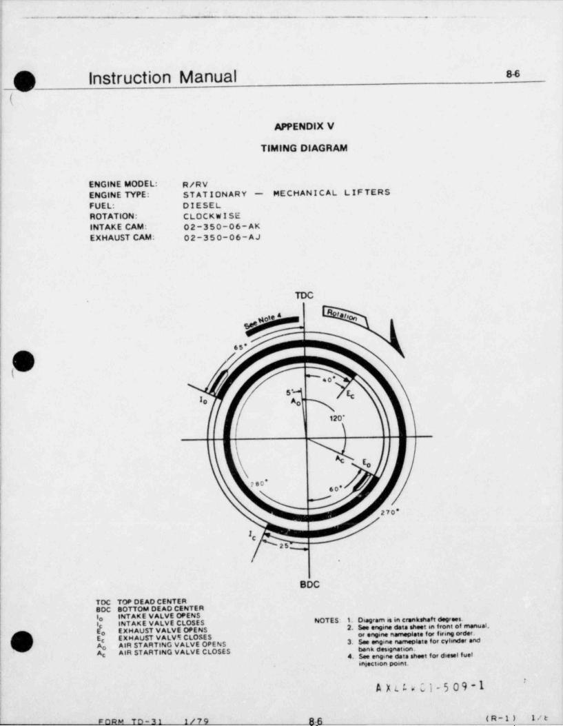
.
--. - . . - .. . .
;;
!
@ Instruction Manual 8-8
i(!
APPENDIX V .
14
I TIMING DIAGRAM
!4
f ENGINE MODEL: R/RV! ENGINE TYPE: STATIONARY - MECHANICAL LIFTERS! FUEL: DIESEL! ROTATION: CLOCKWISEf INTAKE CAM: 02-350-06-AK
EXHAUST CAM: 02-350-06-AJ!
!
|[
l
TDC
'*' %,
.5*
|pI so*
s- c,Io Ao
120'|
hI
[o!i
| 2e0* .0-,
.70*
! C
.. ~,
BDC|
TDC TOP DE AD CENTERBDC 80TTOM DEAD CENTERlo INTAKE VALVE OPENS
INTAKE VALVE CLOSES NOTES: 1. Diagram is in crankshaft degrees.
i[o2. See engine data sheet in front of manual,
EXH AUST VALVE OPENS
O Ec EXH AUST VALVE CLOSES or engine nameplete for firing order.
Ao AIR STARTING VALVE OPENS3. See engine nameplete for cylinder and
Ag AIR STARTING VALVE CLOSES bank designation.4. See engine data sheet for diesel fue!
, injection pomt.
'A X t t w 01 - 5 0 9 -1
;
TN W @ ~ _ - _ . . .____ ._ __ _ _ _ _ ._ ! _R - 1 { _ __1 / t_ _
.
-.
.- . - - - . - . ..- .
O Instruction Manual s.7-
-
(,
APPENDIX VI
LUBRICATING OIL RECOMMENDATIONS
The Transamerica Delaval Engine and Compressar Division -8aes not recommend lubricants by brand name. The finalmeasure of the quality of an oilis its performance in service.The shriant supplier must work with the fuel oil supplierto insure the use of the proper lubricant. The cesistent quality ed performance of a suienble heavy duty oilmust,therefore, be the responsibility of the company making the Aubricmt.
_ ____
|
It must be the mncern of the operator to consult with the oil supplier concerning the properselection of a lubricant whidi will perform compatibly with the type of fuel to be used inorder to insure the most satisfactory performance and life with overall economical operation.In the case of unresolved questions, the Transamerica Delaval Engine and Compressor Divisionshould be consulted.
To determine the condemning limits for oil in service, have the oil supplier take representative samples at regularintervals for oil analysis. His recommendations, then, for either further service or for condemnation will be based onqualitative f actors. The following applies to new oil only.
l( RECOMMENDED LUBRICATING OIL CHARACTERISTICS
SAE GRADE 40 OIL
Maximum Minimum
Viscosity Index (ASTM D567) - 700 0Gravity. A.P.I. at 60 F (25.6 C) (ASTM D287) 30 20
O 0Flash Point F (ASTM D92) - 425 (218 C)O 0Pour Point F (ASTM D97) - 10 (5.6 C)
below coldestoil startingtemperature
OIL RECOMMENDATIONS
DIESEL ENGINES (Using fuel oil with less than 1.05% sulfur):
Engines rated 205 bmep and below - APl/SAE Classification "CC" or better.
:g Engines rated 206 bmep and above - APl/SAE Classification "CD" or better.
( 0l >
(. x
| v'i
|
|i
k A L E V Cl-5 09! 4
87.. -_. _ _ - - .
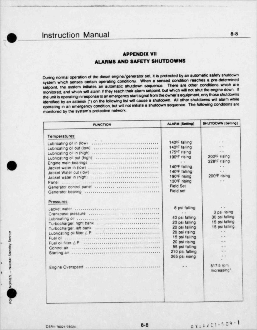
______
- - - . ~ . . . ~ . . . . . . .
(^d'instruction Manual .-8
i
APPENDIX Vil
ALARMS AND SAFETY SHUTDOWNS
During normal operation of the deesel ernine/ generator set. it is protected by an automatic safety shutdownsystem which senses certain operating conditsons When a sensed condstion reaches a pre-determined
There are other conditions which aresetpoint, the system initiates an automatic shutdown sequencemonitored, and which win alarm if they reach their alarm setpoint, but whech will not shut the engine down. Ifthe unit is operating in response to an emergency start signal from the owner's equipment. only those shutdownsidentified by an asterisk (*) on the following list wiu cause a shutdown. All other shutdowns wiu alarm whileoperating in an emergency condition, but will not initiate a shutdown sequence. The following conditions aremonitored by the system's protective network.
FUNCTION ALARM [ setting] SHUTDOWN [Settmg]
Temperatures:
Lubricating oil in (low) .....'............................ 140'F falling~
-
140'F falling -
Lubricating oil out (low) ................................
Lubricating oil in (high) . . . . . . . . . . . . . . . . . . . . . . . . . . . . . . . . . 175'F rising -
190cF rising 200cF risingLubricating oil out (high) ...............................2280F risingC Engine main be aring s . . . . . . . . . . . . . . . . . . . . . . . . . . . . . . . . . . --
i. Jacket water in (low) . . . . . . . . . . . . . . . . . . . . . . . . . . . . . . . . . . . 140'F falling --
140*F f allingJacket Water out (low)--
.................................
J acket water in (high) . . . . . . . . . . . . . . . . . . . . . . . . . . . . . . . . . . 1900F rising 200cF rising1300F rising --
Panet ................................................Field SetGenerator control panel .......... .....................
G e nerat or bearing . . . . . . . . . . . . . . . . . . . . . . . . . . . . . . . . . . . . . Field set
Pressures:
J a c k et w at e r . . . . . . . . . . s . . . . . . . . . . . . . . . . . . . . . . . . . . . . . . . 8 psi falling --
3 psi risingCrankcase pressure . . . . . . . . . . . . . . . . . . . . . . . . . . . . . . . . . . . .
Lubric ating oil . . . . . . . . . . . . . . . . . . . . . . . . . . . . . . . . . . . . . . . . 40 psi falling 30 psi falling, 20 psi falling 15 psi falhngTurbocharger, right bank ...............................
20 psi falling 15 psi fallingTurbocharger,left bank ................................
E Lubricating oil filter L P ....:........................... 20 psi rising --
Fueloil............................................... 15 psi falling --
g 20 psi rising0 Fuel oil filter a P ...................................... -
gp Co nt r ol a i r . . . . . . . . . . . . . . . . . . . . . . . . . . . . . . . . . . . . . . . . . . . . 55 psi f alhng --
St a rti n g a i r . . . . . . . . . . . . . . . . . . . . . . . . . . . . . . . . . . . . . . . . . . . . 210 psi falling --",, 265 psi rising ,-n
0 $ 517.5 rpm$ Engine Ove r speed . . . . . . . . . . . . . . . . . . . . . . . . . . . . . . . . . . . . . --
increasing *o I
|$z
' 61 z
Oa
g, y t [. V C 1 - 5 0 9 - I0-0DSRv.76021/76024
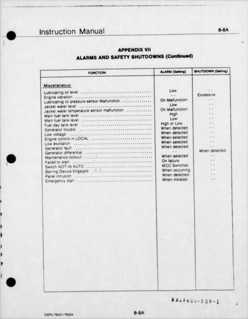
. . _ . __ ._
f3 Instruction Manual 8-8A
,V'
( '
APPENDlX Vil
ALARMS AND SAFETY SHUTDOWNS (Conunued)
FUNCTION ALARM (Seeha0] SHUTDOWN (Settmg)
Miscellaneous:Low --
Lubricating oil level . . . . : . . . . . . . . . . . . . . . . . . . . . . . . . . . . . . .Excessive--
Engine vib r atio n . . . . . . . . . . . . . . . . . . . . . . . . . . . . . . . . . . . . . . .Lubricating oil pressure sensor Matfunction . .'. . . . . . . . . . . . . On Malfunction --
Low -
Jacket water level .....................................Jacket water temperature sensor malfunction . ........ .... On Malfunction --
M ain f uel tank level . . . . . . . . . . . . . . . . . . . . . . . . . . . . . . . . . . . . High -
M ain f uel ta nk level . . . . . . . . . . . . . . . . . . . . . . . . . . . . . . . . . . . . Low -
High or Low --
Fuel day tank level ....................................When detected --
Generator trouble .....................................When detected --
Low voltage ..........................................
Engine control in LOCAL . . . . . . . . . . . . . . . . . . . . . . . . . . . . . . . When selected -
When Selected --
Low excitation ........................................
G e ner at or f a ult . . . . . . . . . . . . . . . . . . . . . . . . . . . . . . . . . . . . . . . . When detected --
When detectedGenerator differential .................................. --
[m M aintenance lockout . . . . : . l . . . . . . . . . . . . . . . . . . . . . . . . . . . . When selected --
f Failed to start ...........~.............................. On failure .-
S wit ch N OT I N AUT O . . . . . . . . . . . . . . . . . . . . . . . . . . . . . . . . . . MCC Switches -
Barnng Device Engaged ..'..?.......................... When occurring ..
Pa nel intrusion . . . . . . . . . . . . . . . . . . . . . . . . . . . . . . . . . . . . . . . . When detected --
When initiated -
E mer g e n cy st a rt . . . . . . . . . . . . . . . . . . . . . . . . . . . . . . . . . . . . . . .
)
)
)
)
D.
0
0
0
11v
|
f
A A4 A N 01-5 09 -1
. osavaso2inso24 - 8-8A
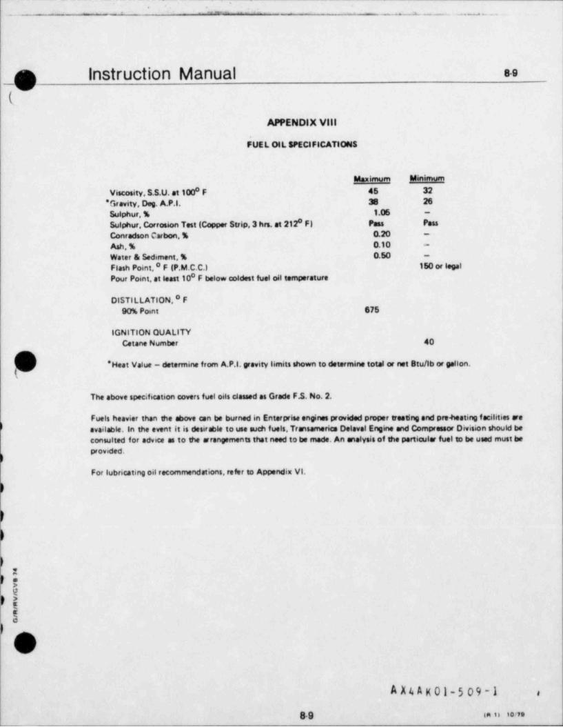
-
.
*
..-- . - - - .
_n Instruction Manual 8-e
(APPENDIX Vill
FUEL 01L SPEClFICATIONS
Maximum Mensmom
Viscosity, S.S.U. at 100 F 46 320
*Grevity, Dog. A.P.I. 38 26
Sulphur, % 1.06 -
8Sulphur, Corrosion Test (Copper Strip,3 hrs. at 212 F) Pass Pass
Conradson Carbon, % 0.20 -
Ash, % 0.10 -
Water as Sediment, % 0.50 -
Flash Point, O F (P.M.C.C.) 150 or legal0Pour Point, at least 10 F below coldest fuel oil temperature
DISTILLATION, * F90% Point 675 |
IGNITION OUALITYCetane Number 40
' Heat Value - determine from A.P l. yewity limits shown to determine total or not Stu/lb or gallon.
The above specification covers fuel oils classed as Grade F.S. No. 2.
.Fuels heavier than the above can be burned in Enterprise engines provided proper treeting and preheating f acilities are
) available, in the event it is desirable to use such fuels, Transamerice Delavel Engine and Compressor Division should beconsulted for advice as to the arrangements that need to be mode. An analysis of the particular fuel to be used must beprovided.
For lubricating oil recommendations, refer to Appendix VI.
)
9e>Ee
)
A X4 A K 01-5 09-1 ,
8-9 sa is ione
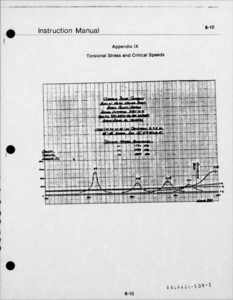
.
-- - . . ~ .
8-' "p Instruction Manual
(.Appendix IX
Torsional Stress and Critical Speeds
1
' /, ?- ' . 'ti' l! I'{|;'l h( !P : i' y' : I"-i!- ; . i.l ! d.
'
QM{!; ]..i ! I
gi;y ,i .g{qi .
.p' , ,i
q f .I'.5"i ..
'
]! . . {. ._ y.. j..
A|[email protected] a e"
,i. . . . .
@-*,
4+i& 0 ir:w -
i p s,, e, hn m.t. $ .s+ -+4 .1.
m : .- . -
4 3 qa $ ! .e i. ;
-
_.r. . o. .,. . & _.% , . .i . .o ,
n m - - . ..*
), . .
....,.b_If --
,g,i S . i
,;
| I |'l | f .,
;' i....,d tb |! ' hik
g
'f$.. . .. | it I.
..i}ir y! ;;i ';- ..: q m , y, . . ',! a . :.,
l I '( ,ip'
i " . -la! f 'i ! T ,
0
I l! . p.!+! 4., . . .%bi.'., t~ . ,
' '~
i .!!i' h' '
i 'i.1 :. m,-q.n['_".;i! !c . .- , ..i .
ii %._, ...:p 4!i!!Mi $ l
.
$s-
... .,
L.+-P- r* =- e > ^ - a w. _
!M% &..
1 :/ht|%.u m - W a'. ~~ *w~-sr+.. a a.
.
;. ,*~^
-
;;l;;! ? n|l i / ||j j'I ! q dg' { y' ij {i M. ;j iy'
+. , . ',.
g ![ '|.Ib i .' 1 . ,
' y .p. ..i._ ]. .- -
'.y |.' .!,-
. i ,' ~~' S fr .
,'
Z'' .... . . . v
a',n]:|
'
i j'
' ...,'. -''. i ' l. 'j '; f'' . ' , ' .: m*
l 'i '-' mo, .
( m '1p ; a .
; m =A,l.
h. l ,'j! ! !,..
ke i 1 d ' ' '. i l iI )a'd ..p. 7,,
.
!m;I['d.. .c,:|... 'e d ,!'i u. .f.s,ek.g*u#s'1!' {.- n (k S }'
.. ,o :s .
a,,,,,, e'l; ulaiseS- ' w.. c.. pa ., . .. '
tit I
,f . ,% i
'
hqj1 e r g oj p[ h; <M _d._!. jh, "!
..i i!!m !I,< i.1~
,. Ig.pth- j|.p't.m ';- il.
,", [kh -;;.*-,. ,- ! !! l. ;[il btr7
.h,|11 ,;,;gi
| .| r,..
|'|I,
''i. - -
t #,i-
.,... . .... ,,
7. .
.,
u!Op+IM'h'0I
r'
l 'N I '! ! ! ' i !'
''j ;u11* I I I
' ' -- + -
-: M$ju.. .!'M '' i. ''(th
- ';
'
- -.
h.iI t.
I . I ".'{l{r'
l[ 'i.'.l- '-
h-
hh'hM..y e. j'M 0 '.. .'!d {. ] . :- 4 ty' .c.a ;.m n m 3,
. ..... 7 .. .
we *.- -, % -.--
..# ,,s. .. - . . . . ..- ..
I' '
'".
) h |i' i'' '
i.
; , ,i
!lnv1
A ju. A g 01 - 5 0 9 - 1
| 8-10. _ .
_ _ _ _.
-. . - ~ - . _ -- ..
|nStrUCtiOn Manual 8-iipdk.
Appendix X
Factory Test Logs
Copies of the Power Engine Factory Test Logs and a summary of the tests are provided in this appendix to assistoperating personnelin becoming familiar with the operating characteristics of the engine (s). The data includedis that recorded during the actual f actory test of the engine. For ready reference, a summary of the factory testresults is also provided.11 should be noted that the exhaust temperatures are those recorded at the factory,under local ambient conditions. Temperatures expenenced by the owner / operator, therefore. may exceed thisaverage temperature
)
.
.
)i
.
OL X 4 k K o i-5 09-1 -
8-11-
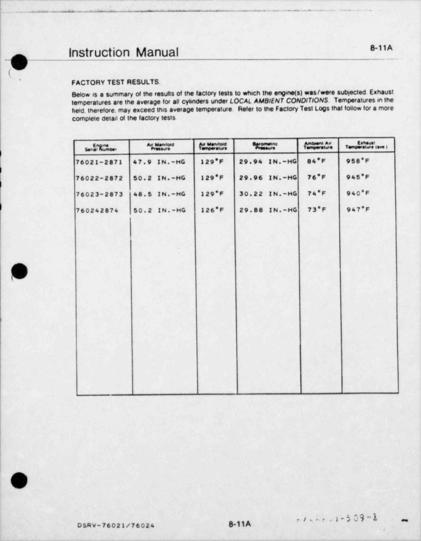
_.
.
--
- - __._ - . . . _ _
8-11 AInstruction Manualf
(G''
FACTORY TEST RESULTS.
Below is a summary of the results of the factory tests to which the engine (s) was/were subjected. Exhausttemperatures are the average for all cylinders under LOCAL AMBIENT CONDITIONS. Temperatures in thefield, therefore, may exceed this average temperature. Refer to the Factory Test Logs that follow for a morecomplete detail of the factory tests.
tur"e TempereNteve )serNmeer PressuYr Tempere$ T
76021-2871 47.9 IN.-HG 129'F 29.94 IN.-HG 84*F 958*F
76022-2872 50.2 IN.-HG 129'F 29.96 IN.-HG 76*F 945'F
76023-2873 48.5 IN.-HG 129'F 30.22 IN.-HG 74*F 940*F
760242874 50.2 IN.-HG 126*F 29.88 IN.-HG 73*F 947'F
,
(G
^#'^''I-5 ~"
DSRV-76021/76024 8-11 Ai
-- - - .-. -. _ _ _ . . . _ _ _ __ . _ , _ . _ - _

- .. . .
"'
^ -- , eerden..%%,,
ENTERPR SE ENG NE
org a hr WanyCUSTOMER
MODEL DSRV-16-4 ENGINE NUMBER 76021 J08 NUMBER 2871
DATE November 6.1981!
CUSTOMER REPRESENTED BY :
......................................................2: :j TEST CER11FIED CORRECT j! Transamerica Delaval Inc. !5 Engine and Compressor Division i
5 " ..k:.!.5$.i..ti. |'
. ...
! mu . .Nnage,r ., ,Re,s,eay,@,,& j, , = D6Vsl,opmedt :
,,,,
L n......................................................
REPORT' 0F
ENGINE SHOP TESTING
SE RIAL NO. 76021-2871|
Transamerical
DelavalTransamerica Delaval Inc.
Engine and Compressor Division550 85th Avenue P.O. Box 2161|
O o.wiene.Caiiiornia 4e2i
A x u s g u i- 5 09 *
. . o-o m.n zm
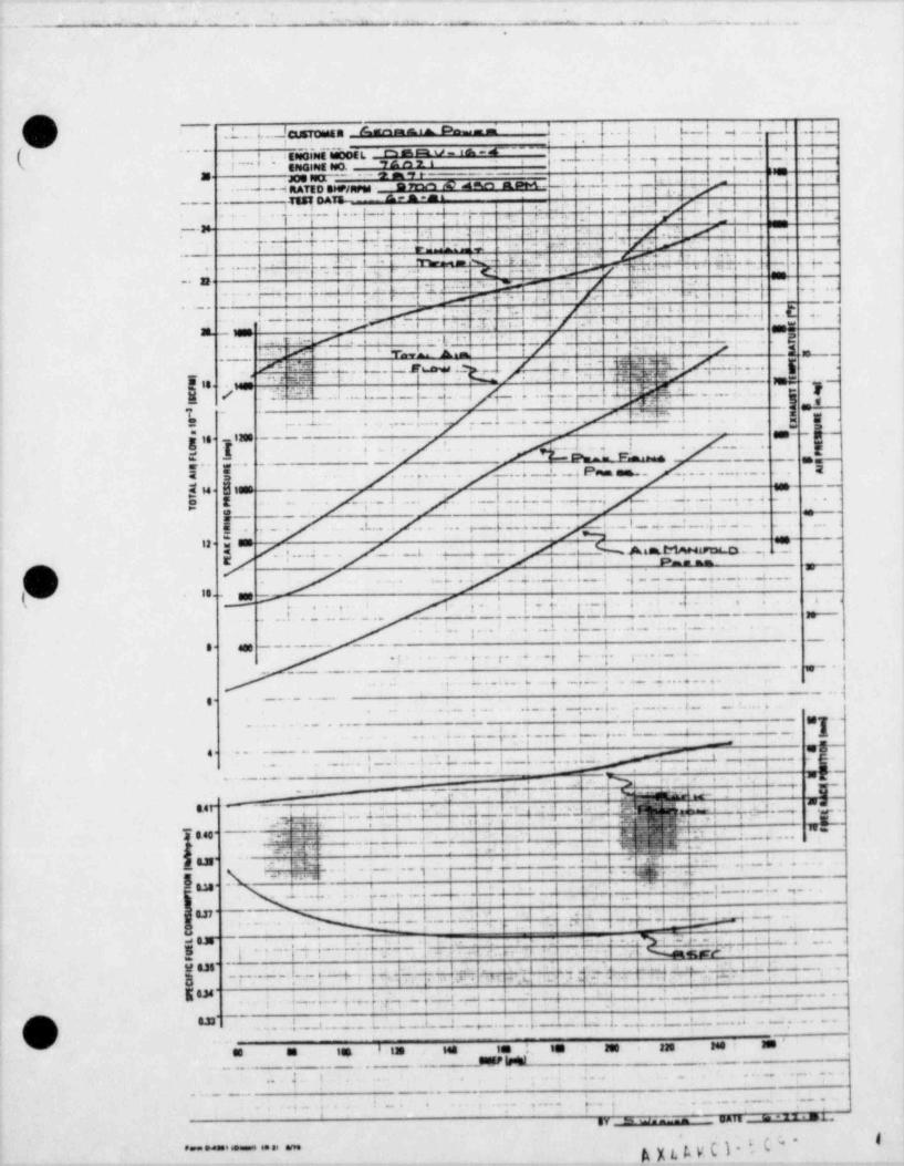
|
|-
" .. - .. ... . ..,
l*
,
I
/m.
'
\ .1. .. i.. JcusTonsta h = = D-- - I. . t,. wI l. __t ..i.ci'
,
f . e,
(' N*'''U''-d''~~~ l i i - i't - 's -"i -+----f - f '. 6
; -** i * EseGeset eWOEL. t : ,
'T #= n 'i i ; ig*
,,seEleO.BeeGe =.
a sa-- - '- e n s e -
; , '; ,d,
.> ,/" j. -t.'
. ..H RATED eMP/npes AN E N EN,---
." !-
m ons - - A ..7_. - ! ! |
. q . . . i 4 . .. . |_- .. . - .p__ 4. .i
., ,. _
, ,
~ ~ ~ ~ '. -t..-----{. p. ri . .: e : 4 -
~' f. !
e e 4'--
. .
_ , . , , # .
- 7-. -
7 ,. . . - e. _; . , _ . , ' , ' .-
:7 y
* ' ' * * **. .. . ,t .L- . . " k- ~ ".'.
' *
.
.. 3.-
*i , m .... : .1y - / - ..
.-
''_.'t i ,p%< -6.s. f.* li- 6 i
..b
d"'.,-. .j. . 4-
.
L. ...
6.. ... . i,-
6 I 7.. ...l . - -4.. .| . . L,
: . 4
_' r- i _, int a jg i mr e e. ..
, .. .a is -:- .
Lam.-
.,9 /. . -'f/ */..' . C
! * "I'mwk-L
1._,
1[. *
bl. . ... |,,
'' * ~ 'NN
"T d-i' ' T' ..h . - .EbdNd;.h7., ., , . Mg i 6'- e& vgig. -er , )_._
' Dg ..i . .. i ;. . q*. . ..j T'-''' ''T* ' R [ !_/ ' '~' ~ .N! E- ' * * -. Af i
1#g--
. w=.. i. g .g -
.. . . . . . . . . eni . ,
. . . . . . . . . . . .
a g
,g..Img14 (
---
....} . .,
! . . . .; . :
s.
A. hm . _ .-;; . g .. . .. - - _ .
' Pennes...
EE , .,. . ~ . . + 4 . . . . . . . _ .
s .a "-. -
;E S4 a i"' . .,
. :. . ..,
g t . . _ .i .. .. t .. 5._ 1 |. ... .. . .
e----| . ..l.....~_,
r . .. g . __.5 1.... l. .. | . | _. . .; .. . .
.''''-3 _ _*
E'" ~ ['.. . ; _.-L % A6mLMANatad.D. ..., 5' 8 -~ '
.
' ' * i i su. -
(m - . . _4 . . _2. . .. t ._.: .if- , .
.2.....__ _,.._.
' 'se- see g-{ ; _ j. ,._; ;. .; . e . . ., ,
- . , ,. y .. ,,
... . _ ... ... ... __ -
.L_....... .. ! ._..1. . .
I.. 6 t - -
*
8- aos - - - - - - - - - - - - ,
..} p. j. .._ s..;. .. .y 74 y
. _ . _ .. w._ .
..y ._ , .
-- .g.j 4 ... .,......a.
g. . . . . -
g .. ; . ._......( _ '- . . .. . .. . . . . . . . _ . .
go.y . ... . . _ . . . _
- l . . L _..h .. ... r. . l. . m . ! _.,j,'' >
j e n~.. ... _. ! . . i . 4 ..d !.'.
$=
,
-
4M,j -
- = - ~
' .i
"E -i __, %;. . . . _ _ . . .. ,
i i ~' f.y-.~_jg j ,55 d '""tr- mi .
-|, ,'" -- |.g,'e. .f-. . . , . - ,
4- g.$4f" 4, - y, ;~~ * . ~ , - *ar- -i 3.. :_
urs s .t.- r n. ,
h,,,, -+- ,.: ~a. , , . i - i ; ., p=1 040'~
. c, - :
. .- ._.e ...j.- . , . - -
I L s I_. i . ., .,.m,*
- - -,
--
.|.e-, t..i i.
- - - - .,..b . .EN' .
<+ -. .. .... .. 4 ..a ..p- t _ *@i .kf { l
lS.II"~I i e
.. pr i
[. ,} -| ,-..-.i..N' '' I - j j g,e ,i, - .
a . . , . . ,._....9 ,1
- ,!
-! i i
|.'.| . , . 7 .-[ p ._ .g .] {.. . .,. e ",g..
,,
.i y ..h.- . g. L . l''d 0.I' . t
,. . . .p . ..I _4 . -# i
. . . -. . - . . .
-i .I % w ,! _3,, l.,... t.
W 8.36'~
,,
. , i.
!~
, .a - ~| .. .j ~l i +.-: . ..
:'
.
8 -, .
_. I- _ +- r.. .i . . i. -i- i
.
. - - - ,
E . j . ;... .; .. ,. { 7 , . 9 _t . i - -
| ; j -4I . . - ..-
; | . .
i .i*
. - . . - -/m\ S.33 ......,1.. 1. ._....,w... 6 -.4'.._, .. ,..' '6.J..........'.t._..*i p -
.
g 4i s / J
ne m m' Nd = i. i in = = . m me .
suse w . . . . _ _ . _. . _ .
,. . . . . ... -- -
- _ _ . . .,
l ).. 4 *f
i. . . . ; . . - . . . . , . - - .. -. , _. . -, . . . , . . .
, .
t gy Eh W- ^ _ pH T E _ ""''*"3
. .
I(=*k[LkY(g* .ee= odese seemse se se ame '
*
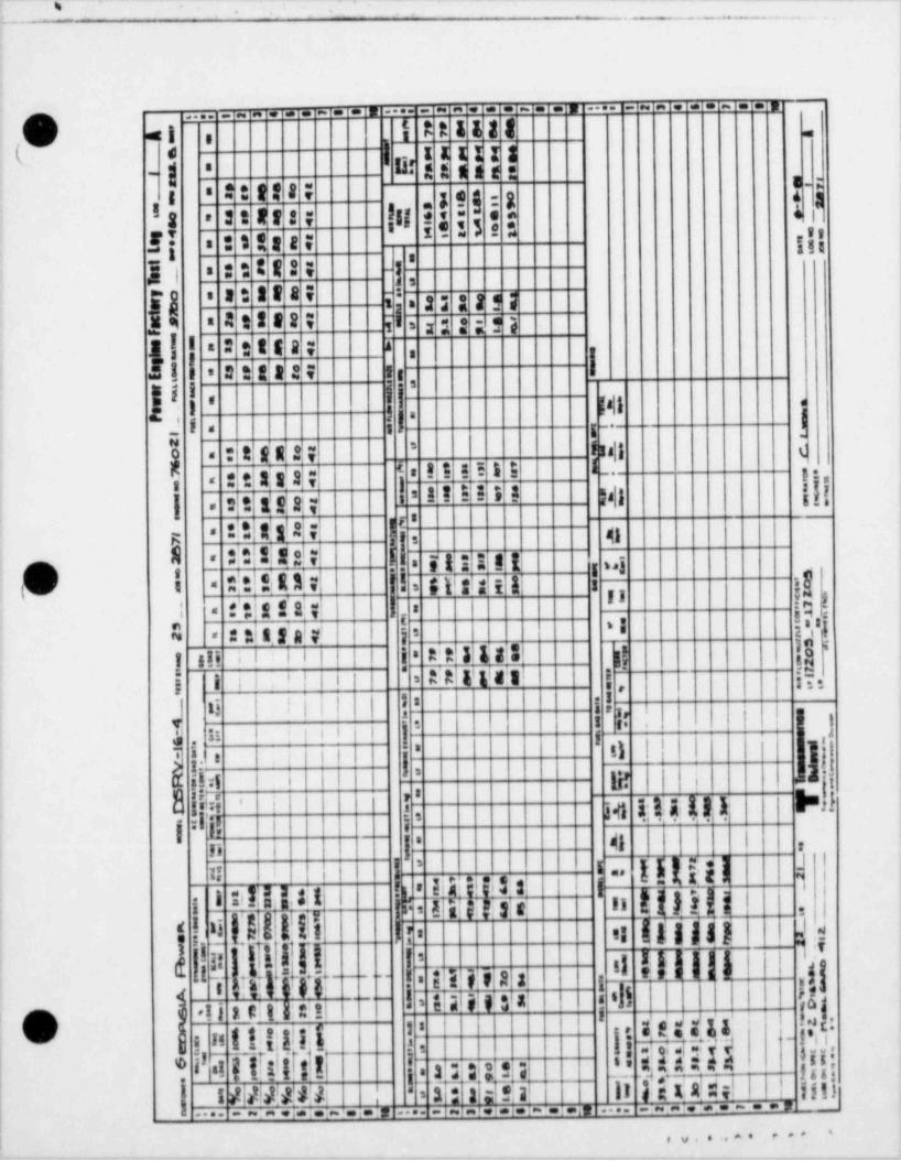
. ,. _ _ _ ____ _
,,
;_. -
. . ~ . . . .... .. . . . . . . . ..... ...~......__ ..
I R R & & 8 8(d'
el i,,
'
* : : : :| B t t a se s
.
'-
E ;.= 2 I f 8 ;
-
ek $ 3g
"!I E= S t Rf ! ; I|| L ieS D "'
. : : : : : : ;;;)y '= 2 8 t ! i -|j
i s t tf a i -:f.!j*
= 2 3 285 3- a n s e n t i n :- ns ,
| I s i t tf a ; a
|,
! ! ' # 2 II t !.i e s
f '; ! MI' a
j.
i . i g _.
gisall e'
2 i32,7_
! ! !5 I E ig :: 3;3'a|; j =.g.,
=
_.:a r ti ; n ,,|3 ;jg
,,
. s t na;;I.
9|,- 4gt|32;!1!til=-
R, 3;g 2;..
y !! I a liI:!! !RAv '! syss, g ! ,r 3
: .'~e . .
isi i- ,
i
e g|) A ! a' ;. .:! -
! ,8,: 11.3 al p | 'IS - ,
A't 318 3 |I 18 i
t sii iI i iI' I i '
A:All'1a's: j |@,-''
i| | |j i ;I ' =
',i; i i
.io-
.
tii i i-
j <s j u''3
-]-
. - -
.- a i- ,.
j =' il || | ijj ji n il-
lee a:s i i || IN- ! L 'l
isr=i. | I.0 ' - 8
1 41 113181 P3liFi
--
|li i |, 41 l :
I%IIiiI I hh |ju sin [ji I i
!j ,b.
ni s ti! b: . ,i
d j; - ! 'I III' I I Ii 1, M a s i.
ii |I) .i j i c;ij :;;j !j6iw;
i!ali ,3 :: g=
O g ,a n iit:iin 1 it iMut1
n-
iij(f H 4 |jjj;
! igpT;i[ jn j ;3l
3p$re,;a _11 li t'a W l I liti|
.
: a ;,.i...i / /!MG =a-
,_ ;...-......i.i- .1.,,. . .;.;. .,.:. ..........
........ ... -|
-_-__ _ _ __ - -____ __. .. _
. - _ _ _ _ _ _ _ _ _ _
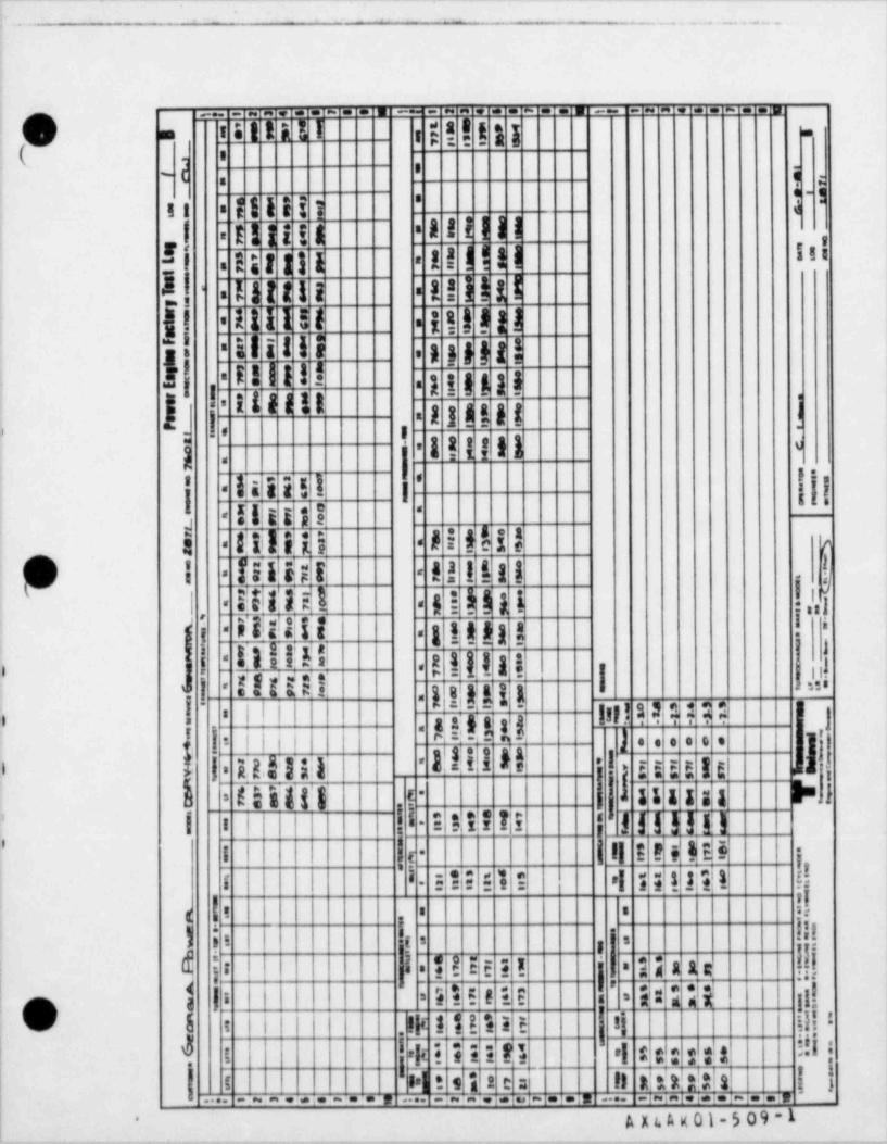
_ . _ _ _ _ _ _ _ __ - - _ _ _ _ _ _ _ - _ _ _ _ __ -.
,
. _ _ . . . . . . . - . . . . _ . .
_. . . - . . . = _ . . . - . . . _ . _ _ . . . . - . . .
!O . ; = ! i n i'
- i s i t a n i -
( ._
f ' a-;.
*| | | | { ][| .
A l l i l !! I~
E ll i ! d'
,
Il a g t : 1 115'! ! ! l l !-
.
!! ! ! i l l tI t t l i' -.
i s t ! ! !j! i nI I ! !' .
g! i i l l H n s i g g ||-
.
K| i l l l lu g i g g g a''
., """ n i m i ;1 i ', .
, -o
l ! ! !I l e.
)'
,
lji'
l!iii!! u' '
-
! !!!.t,i ' ''
llil '-
A i fl i !I!!il1i iii -
g-
i :Jil!is ti l ! ! ! ! !-
y.
l i llih !,'h3 !!Iliil)itti!!;II 1 -i
s p!a g !',
: h l--
si l a s'.
|O llM.; H i : n
!. u.*
l ., I l . l:- -o $5'
[ |', ta g a,3 t g 1
u.
i -< j a ts:ss|1||- -
s e;i n' ai - ,, g.-. . -.' .-.- y,),
I,
||i| ".- - ->.
s re
1.fi I III0 N j l f g i gg I gl ,ELg~
i t !!]ii '".
|1 c s s as u "1silit: 1 < --.
I i I ! I ; *if f! lltl,
_Hy!# $Eii'' -
i | i || 1 j-t
i 51|E ! ! ! el is1 f111 d'
f -
!!| ! , i
!!;= '
] 9 5 s !: s -
g
!! !E ! ! | linAr !!! i{ia.
3 | iN ii! |Il
|O'I I I ! 8 E E s = iti5
s , ,i .i< i tt > > E : ii iiii l.
!!I|Y j |4t i Ili fi 'l * : :t'
> t s i2 e s il RA1!ala |3| . . . .t, _i-i.,i.i.i. - . . . , ,.... .. .. . . - .. . ..... -.....~...;
j A x c t. x 01 - 5 0 9 - 1-
_ _ _ . __ . ._. _ _.7 _ _. .;, __._______-._7_._.-.__.
. _ _ _ _ _ . _ _ _ _ _ _ _ _ _ _ _ _ _-
,
;O E:TERPRISE ENG NEi
|
CUSTOMER Georgia Power Company
|MODEL DSRV-16-4 ENGINE NUMBER 76022 JOB NUMBER 2872
DATE November 6, 1981 .
'
CUSTOMER REPRESENTED BY '
. vie.. .esseese.eesiseeeeeees. .seess.sesseessess.sesenai
: :i TEST CERT 1FIED CORRECT i |
: :*
Transamerica Delaval Inc. i! Engine and Compressor Division !! .. d.. 4. . p... =....... 9. ,.........i.,,
j = . ..
!
n . . . . . . . . .. . . . . D. .e.v. .e.l o.p me n t,s,e ay,@, ,$ , , , ,! mu ..Ma.n a 9.e.n. .Re j
i : :.. ............e....s..........s.i
i
REPORT
0F: ENGINE SHOP TESTING
| SERI AL NO. 76022-2872
:
'
4p Transamerica| RH Delaval
Transamerica Delaval Inc.'
Engine and Compressor Division550 85th Avenue P.O. Box 2161 1
Oakland, California 94621,O'
AA4Ay-1-509-1p.,,,, o.t a (n.13 ma
- _ - - _ _ _ _ _ . _ - . . _ - . _ _ _ _ _ __- ..____ _ .._ -_ _ ..-__-__._..... . - __.- - ____ _ _- ._ _ -_. ..-_ _ -
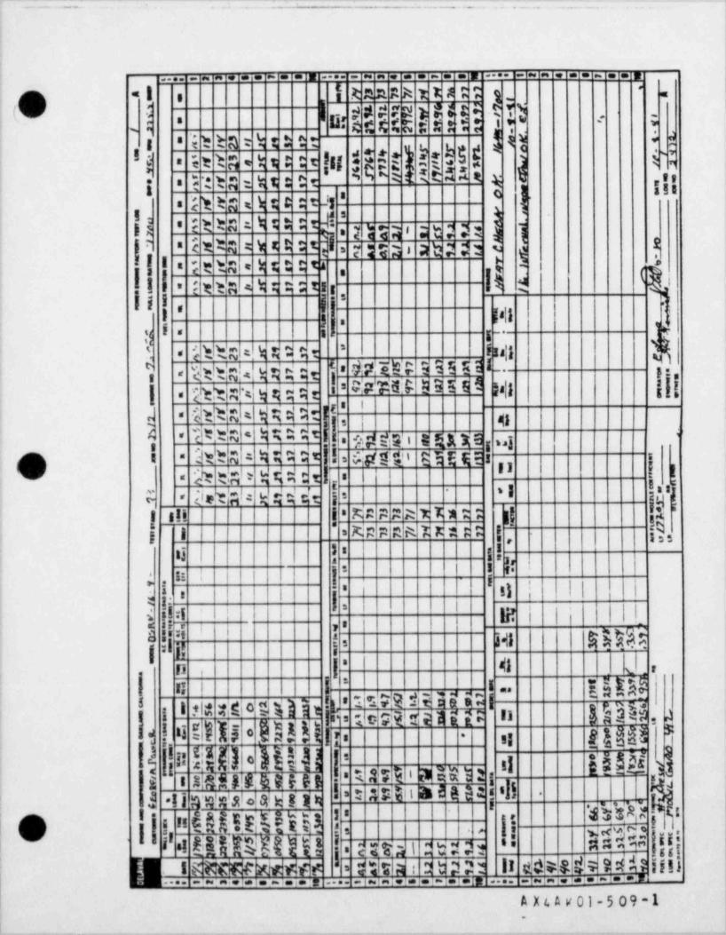
--: . - . _ . . . . :_ _ . _ .
.... . . .. - . . . .... _ ~ . . . . - . . . .... -- - . . . - . . .
c al i Rana k t r a ; ';: g'
.e
I
i).O : # # ;f ? p! ) is.c f R TI3f s t s C E :: W H : . -
'
j'' *
s
.i b h a t h t t t : e 4 dsi|Il $*E $ E )(k i !I ME t h A h 9 0 t
3j * =
N a - y ,,,n tn, u : e ..; .
f *' D
} i tgl = h ; C ; tJ3a
f j!"! j tha h 5 5' ; m e ; t s a:.
h q h" < t ta t h * E t ~3 5;; a b ? ;52
|Ns
! I kl t ha = h t ti t ta >a
[g g gl i l,
; , 3'ni . n e: , , ,.
11 8 a a=,
18|1 N! 's;.i M'
,
I =y.
*g --
-l Miht.R=h M # 4r i n a'i =
$tt'g!<'k in it j '=MIU E 35 O I", ! g, ,=
WW5$ E 9 # 8.i 5 |s|1 ||[;ig h = g qg; e[i,
!
[lbd;ta i auxedt!t|E= dN 4 4:I= qn
} 'd*Mel' W5 45= '
: .33t!b NI: 4, d 4 O t ll 6.ggti gig n ip a = : .
'3 !' Iihe t.Ab W(dtt I=
Ilet'al: Wdddr ! 'I !'. |,.
''
E=
xn n enwn: !-
!'
M P M A T,7, * : : itlt s!! a'
$.'j i o
' '''-
3 : , s; 3 : ,,
.' il | | | | I ! I',
y j. : I i j . II ,; || i I,
. -
'
,~ Is .ibi li i g! | |, |||. i<
..pf |., ,
idl kN!lf=
41
||I*
sii
. t . r,
| I,n i
, p- = t., e: En~
a a%! h~ 92 -.n :,1'g fh"
.3 g
.g o g w$ g 3!w4
EdaJ 4,
|1 |.i Io n ic-@@!tE lEEE Il7_ .
'i N#' Mal $t |I is eg@$2g 5= -
!
E Mi ' 3 MD2 1'g* 3 UE" b3EH j 'l~ I
1 Ii gwc $ gale!g k!! b- g.,..
,NMl * By3 l '$ g!*S,, nr:i s i'-
i j'; i riMng{
i QI t 's ' - - - -
: V =
{}ht !'l .I unu e c ,- ;t:s ggIs.a %. sC 4 4.ca g! ,t2-
g m-=
M D? ll 04449 N40 IlliN@ W*N e,t . . .' $ d il;d :1.. .i.i% r1-.......-i...w.. i-i.1.. . 1. . ,... . ........ .
A X t. A v 01 - 5 0 9 - 1.
- - - -
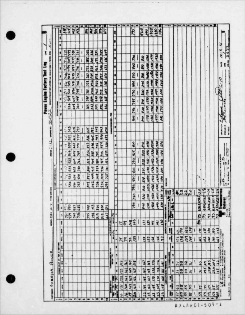
.._ . . __ _ . _ _ _ _ _ . . _ . .
_._ _, , . . . ~ . . . = - . . . . . - . . . __ _ - . . . . - . . .
h g g g g(. R!M E k k t i;i.g .
,
i sC' =,
j g g,$ i | ] ) h j Q*[[ =
A l a t t i l* -
l ts?s i a l g a=-
ina,Il J i a I ! ! tsna i s a s si -
a
k.!.
I l 3 l i ! IlMX I 3 5 t h G=a o
l l ! ! I l l d@$|5]I l 2 3 3 8j!! ~' = '
c i um @an i m os
,|.
sni us s i = , 9 18- -._
| ! W3IA'l 3 ~d E2 3 $ gi '
' g,gg t, ,i - o' '
g i g ! }B a %'
.
|l.
8 %-
,i ~-
lji'QM J 's EE it'
I '',
sn isys ts: --
ll %%3 1I 'p.$3,E i E hi! --,
f)]!'' 8 ''''"'5''' 86'ii
1381 dNE '.O' -
E I ! ! { {{ ]-
,
i 95;S15 Un53 s: eaggg ! >-. .
Mdl EEED k.i|{ gjg Ij| x |g-
g {,g (g|II., .
.,
|'I
q q!I t ei n - ...- gi i---
- ~ .g
I! 45341 .MNI !iI! I
S t BilsE F|'
I, li: !!I d*ME= e
' ,
!MI3 i.
l il iigg ahis;Eli HED E 'E l
'-
&E2|| E Edd3 P | i k dd e "Ji =
I ll i i nME l Esti B ' #=-
! !! d4?si B Hui j'
I t '-
k it R E I E BRM i d$$1 5 diis !!I -
I fi8 s a s
[-,
I{ litsh I I 5 5
f.I-
i g'
!!; R W R 1 s dE;- ld | E EE 4 1 9 5 EY5 |
='-,
'
? E t a i 9 5 E E a s = a mm at a Eli: g!!5 l i =
l ii !!!'O i i m anv i ne ai! $ 5 H Ei Whit i cks i ht tt:t Si+
-. . . ; ,a!$dd{ ! >| e : eta'i a dq m ; R Otismt cE
.i. . - . .., _ . _ . ~; + .... .... . . . . . . . . - . . . .. .
A x c A K 01-5 09-1___ . _ _ _ _ _ _ _ _- - . - _ - - _ . . .- - --
. - = - - - - - - - - -
.
O ENTERPRISE ENGINE
CUSTOMER Georgia Power Company
287376023 JOB NUMBERMODEL DSRV-16-4 ENGINE NUMBER
DATE December 8, 1981 l
CUSTOMER REPRESENTED BY
l1........................................................
I .
3 TEST CER11FIED CORRECT !-
! Transamerica Delaval Inc. !'
i Engine and Compressor Division !
! .,.a.4..#.*.k.... |.
i 1,1 m m se... m ar a .4..... !K.............hr.vfd9a9mT,........................i
,
REPORT'
0FENGINE SHOP TESTING
;
76023-2873SERIAL NO.
1 1
,' :s TransamericaDelaval
Transamerica Delaval Inc.Engine and Compressor Division550 85th Avenue P.O. Box 2161
Oakland, California 94621
|
||
e. - o-o mmm A x 4 A g a 1_5 o9 -1 4

|
-
:t 1t ; . .' f |i{ , ,' ,
_
.. 1 2 3 8 * e 7 8 9 N .;. I 2 3 4 5 * I 8 8 N;| r 3 * 5 e 7 8 9 N_
s / / 3 g 2 s 2 1. 5w. *=' 7 7 9 p 7 r 2_W|7o-e
f,
a=
nOa
._
1 . A_
.r
'7~ s __s 2- 0'S 6 7 (tr
0. n.e sst.J s e- 1
_r I 2 2. e . .' - /. t. a.
e # 0 a g- *- I' ,-
m. s : 0 0 * a
'
f. -s h- - c 13 S.3 5 4 J 5 St
*i -
ssx w E 9 Va--
Mo a
e - 1. ?v
aa 8 3f -s-/ s ' 1 7 f 7 ees siM
- 2-
L.7 e /
t J rn 8- & J r,. T
J2a.r r- r 7M w2e 9% P 8,. r 8 3 6 t a.t . t1 , r 1 s
w r1o t /e 6 .t J 4 J/s i # ..= r. /. P.,'
3 4 r 7 Mysr? tot 1 5. c /1 / 1 7 o
'e.
.'g t 9 a , .s. . tet a3 S f( 1 E s,~
-
. s si /3 r *o.
.. 't *
Ew2. t- 5
... ".
_o |0 /. o /_
.
:5 7 9R 511 *.
2o 3 1 si. t| f t A e , e
M _
_.K _m .
?s.
' ' t _ " _ss 779 e- nsia . f s
s i ! 2 MK33/ l 9a& '/s "T a 4 _t. ao 5 c s R t36_l- i r.e ,
w2 v - / _J .
m. Y$1 E. E u."c. 'A_K 'aCs . ga 2 1 os - a5 7 9 o es f [|1, o
_1. 7 s n_A * ts I. f. o 1 M3 t.
_ 1 i . .1 s t'A__ a f pi S 0s'. . . f s t rf f729 w>
- d'bh1.
. . s
.9 3, / E_
._
i i i i 2i 223I . .- . : ., t
.~
45 _. . nr .f E ,- ,53 ?_1 o a7 9. . - t1 5
-s 2 t Y . / /t i f Iu . . ,.. i
a ..
8. _
. m. - =. . " , ..
. = " l.__
o =. 3s
= c.!= - - .n Sf D 27 o o e
~ - e
",-t :o t 9 sfTLA 1 Tl=
S. r 'a A 3~c i 1 s
..EI i s l t
t_% J qbat *M'j/9 i
.s e yse27Lo rlL/s os- Ot11_
t r3-7=
t 3_ 2 _ o-3 lV o..I_11 1 A. 7 .
-pes 2y1 T '
3_3 f yf g 1 r /I 1 i Tw
ta2e
s .9. r 5'5. 7kg 2t gt 0 tr7 t - i;
e.. 911 4 2 21 A ..,
.S E S'. C. 7 2 7 os =.
23J1Y ., n. a_-. 9e BS
_
n2t s.
2- .1_ 'r
S E F_1. 3 %0 79T0 =-.
'
. ? 9%
t B2 2 . f;lo /c % w.t 9 e s
2 L4 ti / 1 StI i . '.5,e.
=.. f_J t
f 1 S. ..3 t. 5 5. ?_ 9 4 o- =. .sf12O i %w779S a =6 I f ,ls. = 1 r r
=.f t i r3I r j1 2 1 t' S = .eU. 3_ 2 9
iP .. / tff sf
i- J '.
f 7 . o = n .
= 9 1 5 r s- _ 7 =/ / 7 A s A 3 31V =-i
. L r
a_t1 . .. e. '.tT S -u25 S7 9 to . . _. ..3 c
n =. i V 3 1 lY . -2 . . _ r r,t
/i l 23it;: 21 f
.
. oo ._ _ . 1 / /. ,,:: _. _. _ _ 7772297(,7 %? r. .A. .. :
,: . .
_.1 / / 3'S1 6_1 15 = .i 2
a.
..
1 7 7 'f 7 7 /' 7 87 ' . i_. __ . .,
m " ,., ts
_. . "r. ._ ". . .u .
. _ _ _.
.
- ._ _ . _. mi
:.
___.= . _
_.
4 '.-_. _ .- = .
t ;. _ _ . - .
E_ i6 .
=;. _
1 .-v = , t.. _ ._:.
_
r 2W$,5 oq0.
-:., 4 _ _
.f . .5 .
" - wM s. 3rGD .
_
. : :!. __ i _ . . .:
=_=
= _ _ a_ -.
2e ._
. n.. ..
. . . 4 v2 WD't
)c.
c. _ _.. . 2 3, M. . y i 1
y' 25f W nA.s.
/1 y 5 @ 7._ mf. S t
.u 11S4 _ s. 6zLtw36n s: 2 v. rA- r._ .=.
1. _ 7, r t 6 t '2 s2 tlc.
5.s Sff/ a i. 1
nNSno '. / .1 9 os25 fGYf m s. -/.qf.a,4y!f J 6c = E. s % l_ 2. I2s1 1- 2 .2s Y l_ic t 5
W V t. r t 9 2wm21' 1 2'
=s
/ 91i.t c. Ds
Is .; _t o 2e - _ as
. . .. ee msgeSv a
sa*MSvG&km?mi / .
o C { Is f.MunY_oa i ti. a 6 {&.P '
tt R 1
_=wj
. d
0@P. a ts .
_ 9s D.
-0 saa 6 .. i . e v* 33 es . s eCjJJ 6 'r9pKe f "
c=s3 e aM%pl 1 r u$ a_I
_g 3 v
0 e .
sf@2W91t m
r I 1 J_
Mg L* 0 D_ d pg&&5._
__ n - . 1
*xf f 9_ t =' 2 . .. a } l J6h6 g, g t 4
: ^3 h Y. g f s#s. /Tg2_ e . e
2 a G. s S V**_ r5sEtL_f_4~: 5I a 0 . .
i : -1_ o 1
* * - sfe1
r 4 (G. 8M7. N .#_/_ -c*a e . .
O . . fl ooo a .
?o_G t o D S,rw.F 1 ?= = i G3 s ...
ofWf8 ,
1j s . .* 43 3 1 1. m9. ._. u,. g
*o5MeR13mfyysr. 1
ew. ag A
e o Zuk n.-t ts 3_1 5 e v.t o. e .. tG8_ o Y3 s. f. s s e,cm
.t he . o,
_
a_. 2 3 c E f2 2 0 i i'
t_ io
h j, 2yf f o l % 2. @3n . ..
.m..,
21 ' 1%%L%%% 5 e 3 9 o $ 0 cs. s. ir 6_ /. &58 g TyOefvh' 3 '> s.n. i .
u. a af s g.
1 2 s E I 8 e.N. ;: ' 2 4 5 e3 s * e ..; ' 2 3 4 se7 e 9 e iA.' l
3' ypxOTvo4:y ...' i .! ,| ,I.l |
! ,, | .'' 1 '
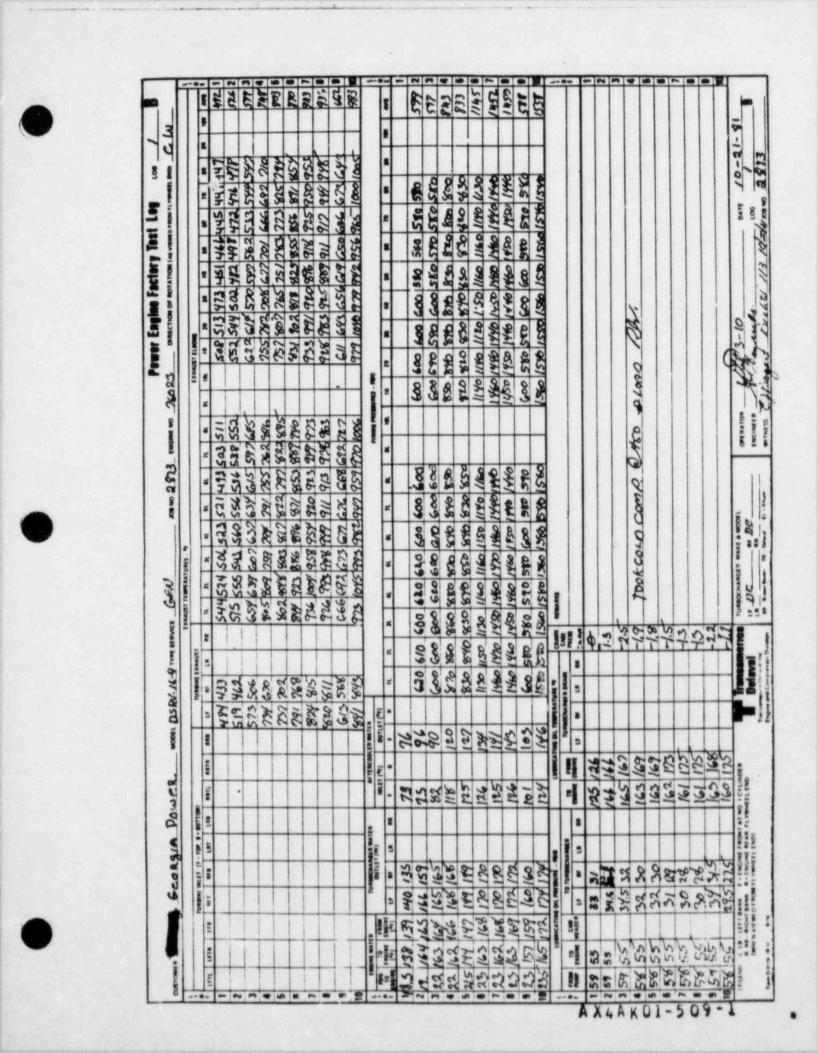
. -..--._ - - -- . .. : - --
_.. . . . - . . . _.. ~ . . . . ~ . . . _ . _ - . . . ~ . ..
g g gd j @ga s t E E R E B E E 4 E : -
O- - +a , .n . -
3 fl f h'
II s '
6 H ? HH 1'
I M t s s t at 5 1-
,
!! igm sd a rs H4 ! U H 15'-
a t H i H t ! l.
!! un Em u --
B U B J l l a ! $EDU i t&3 5j!' =
! d3DM E!M ! -j j J t !$ ?3 j j'
I|.
k. Sil55WH ES51 1 E f 6 =82 5 f !-.
I A gg .< g''#g p# p* -
I 'l-
|i k||I
-
' " %33 f 3 1 %$ $ $* e n
$'
$3ABt M32 3-
| EN[MB3 El'
$'namen -
-.
ii 316 H MH sHDH@ GE --
311 3 th a t ] -!HDD h d!i --
U- ?ShRHS dB $$$$Heg g s !dh- -,
Sggu 3 !*01 D NBaas
s{aigg{{gui - -
I|5 H d 61$id't ! g gj j'-
!g',
i ggggj liG h6H49 1 =='-, ,
!.
,.!4,sE999MM !i!i I
''' ' lif3'l!lIhs'id y)
' i
I i - jj|ij-
| |=S$&QE$sR@ OM dMNS ! , My' '
%Mu M25 t I =.1a-
= -,
I i ji i l t#BE EB$ l i j- =
i I ! | 11ME$EBEN$$- -t,
'
I l' I mmh ud&'eh 'I pph d@$Ena$ -
,q i i > > 9.
h O{ h!.!!!
'
5 s u. , mways1 if 1 Esuste eej' . - a
'li I = : 194@S$ 11!MnMBE%*=
O | ' ''' ' 'I' s M " 5554 ! 'l ! L- ''!''
' >
: PM&gh 4 uh%WhMWHI'|
| [ .. ..i- E- sTI $s@JW#$6MI.
i n eldWERPa i j '
_; ;....-..,_,-.;..- .,- .... m ,- ...;.,-; ,... ....
A X4 A K 01-5 09 -1 .
1
____
= =- _
- - __ _
i,
: O ENTERPRISE E:G NE
*CUSTOMER
D M -16-4MODEL ENGINE NUMBER JOSNUMBER
DATE Decerrber 8,1981
CUSTOMER REPRESENTED BY
i
. . . . . . . . . . . . . . . . . . . . . . . . . . . . . . . . . . . . . . . . . . . . . . . . . . . . . . . ,: :
i TEST CERTIFIED CORRECT i: :
.
I Transamerica Delaval Inc. ! ,
i Engine and Compressor Division ! |'
i ,,. 0.... t.... f.. u...........). ,........ !., ,.. ...
j ! m m ... m u n r. 8. m . c h .e... !: Develo :''
pment'
O '
;
REPORTOF
ENGINE SHOP TESTING
SERI AL NO. 76024-2874 ,
| |,
i
45 Transamenoai
Ell DelavalTransamerica Delaval Inc.|
! Engine and Compressor Division550 85th Avenue P.O. Box 2161
Oakland, California 94621
. . _ . . . . . . , , _ ~ m . s 0, . 3. ,
- - - - _- -- - _ _ _
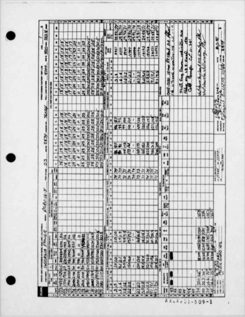
. . .: -^~ ~. ..l L _..;--- . -. - . -. L - '. ..
~ ^ ~ ~ ~ ~
.
:
)
.... . .. _ . . . .... . . . . - . . . .... . . . . - . . .
I I ha AR 2 0 C h k& Y ?*e <
g'o W m a rn t p ;rhV 4 t t, n: , m'
s y , yh h t % : 4 N d $
_
1 7 g i k'
f 1RI
t ttp = : hn !u i E**MEE j ~is ! .j i'$ .'i w et c . . pn s 4 g, i;;u = =- -
': j!twe t= n4H a 1 1 4
5s dcy 9 .
w g.
l,e "t e ts = : m i a P i-
; , y, , , ,
d19 Ct t ts: 4W ii 6 5 a , ! y|'
,
3 *t s :e 9 qN Jli i t.
! ! ! | k$ 3 h*,
tIQ UNEt tt4 =' sl it i *'
I I ' 1811j )-*g i 2 t.
g _.=, ,,
gy%f jq
*t tR iq = h
-.ll4 _ 1= a.
&#!44 ' EUE M Iy teg, a, i.,,
= r:S t 5 M Ee H1 ij[pp gL g j[i.
tot % : Di d j ',g e
l I.NfdN ! *"3 gg-
o .$ n% ,a' 'l.
,s 'IMtt% LDH io -
ai'WRik,2.2 N kh A |! |II sii i *
| 1'
WRWA & )k F |
|f[hs
83 l I !',
A p i i |j j 5 8 e
I'
I II t) |'-
i i
!. 1'I ! ; laj4 ,,
g !{' | I 34 W.9:
f1 I |' 41. :,
hei I
b] k li i
h ! $ 'M$N R)b ko hj [!l * ' si
3 I'[K JI 1hi! 5l
Q13 8 E55RM i -
g. - - gj* I I () 1
*2
bdialet!gggjT i '
gDN ' NEN 'l!hB2 ' '
!j g,
, ,4 u, w.. .
u,_a u w-6 m[84,
n [ ew e itagO MD l!j,
:j 'I - E $l t |
.. .
'V ' G SQA4c:t a=.
.i..:.i.1.M!#M.. -i. .',.i-i.i.;,R S MO11 % Rt$t ill1L i RGR49ffeltinMt; . . ' . .$ 'Ia$'
. ~ i . . i. i . i- i. i. i, <-!..:.. .... ....
A A * A 7 01 -5 09 -1 .
__ __ __ _ _ _ _ . _ ._
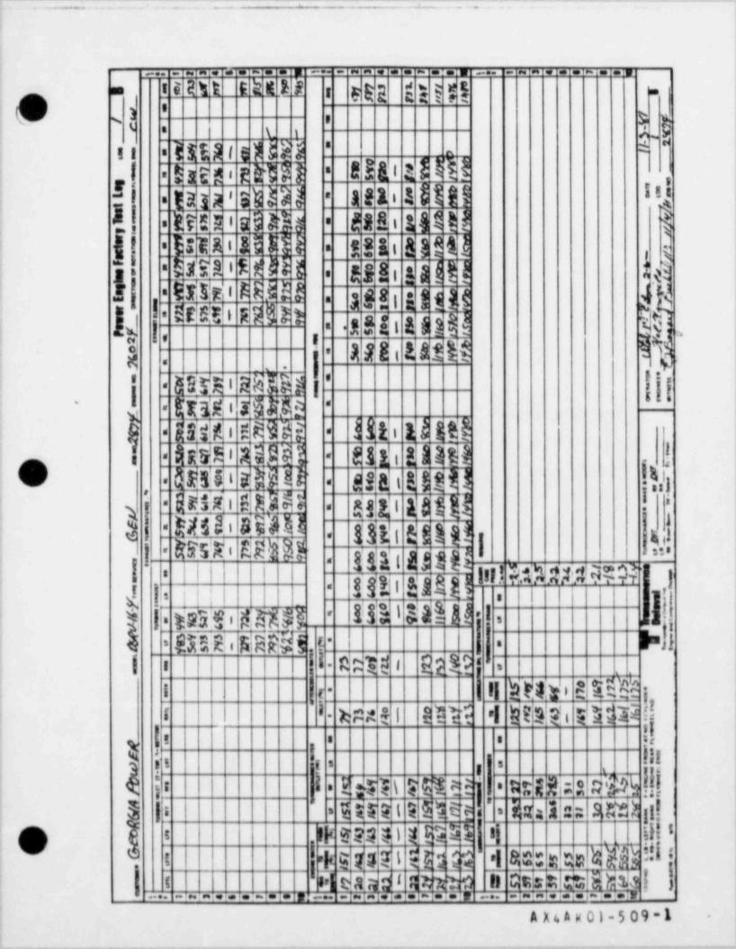
f[l: I t | t I i!( - .[ ,||( . L1 |!t! i!Il| :! [:j;|iI " | | I
il| is . , |. t:| ;i . , ,
t . t a 3 * e e 7 e8 I g . i 2 s * e e '* *'}. 8 a 3 * s e 7 e e s
5 . * m# w - 'U s e e's y 3 1 r i M w uo. / . _
i uw r 1 J e9 . rn f f f1l . f F F s n #. ' t
- V.
~_
7
W. f-
/ i--.
a9m ~ . uM9MS ss
15 . --
>me 9e U.-
5. >. 9e 5. s. n
eM e- os e -
ys d m.M . e _ya dmgp- n hMt7 .
Wssm - ,, i /fr- . 1s s Ii le1 s9 9
s-. 1 ,
-
>f
= ,._
9 e_ e w >s- e f u u.ttKa. s t . ..E
. e- ,.L s R a . .. -ss At op- # e D D w _ s<h o set. ags
>mft.
h-p
M.
eh
_ s 9 s t m, s % r'f 7 5 s O a t- ni A . u s.aj-t 7.
. fc sn _.u e 4 Q se P 1 8d 1y- xA a s I_
- r ommM8__m- s
> ae_9s3 A D n.Pa e 2e
e t e. 9s e -9
m-t 4 .e
H s 1' A ~ iSs . 1 Ie- MtQo . mm 4a 1
v KFo'M/
e *
h- 1 Ws5n-e o a_
. e 2 9 & . s e o a ne
2w-4,u-g-g a k i
sbSs7 i T , B e_ IEgt_
m 7 v 2sE . 1 hssM-
r 2 s n the=A $#
s . d7 g 9 e e a- or__
-
r . 58 25119 . e- ' i sL S W #
s t,as Ie . . 7s 79 - - ' lr y].2s
- s _ i s 8 a a Aa1v5' ?W 9 9 e J.
r 'sj-et 9 re - . .7s 5rw
Eu%e e n- rf_ I u. n f f.. . .
.
8- 2 e on o>Eb.
e . . 4stf 'o 6yJ3g- 1El fM.
%_ 'mI f /.
_*_p'a .. _7 .- W 'a tsY
f|
a _
- S s 6_2 -m2r 14. p .1-
G 19 . -. .. . .
sv2e F%DUt g l. k <6 1 .
_* -
.ss62 d -
f. I5 .
h s_-Uh
oe 0
'A e L n_Ase2-m 1@J/ L/**"@0 -w
8 _7 2 2 . eyi . 7 9 9s 1S
G.o
sriul@, /
'3 2 s * s e = *s 8 o .-.
_
M* ts_l -r 9 . e- f i r-
9 d. eo eS 6p- f = M fm6- ' .-e ;. ' f Jtg 1d'ev
"
" F~=so p_ e o > f se n "
s6M-. "
O t 8myao i af_ .. a. s h. i 5 sw
- s_ s.
E t l 1/' ..
2tmR- m2gD2Fa>
s nJMt,.
. eo 8 8 3 t e -2a6 W
J 6.2 -e ._ )e 4 5W t
yc6a5 e *2 l F
2gsm J1 l//7 oot on D tm " -
M.
_ $ s. 6 t -. f 3 a2 ie .
-e g .
6(r_ Fn Mi. . - sTece J -. I
Wy1_ t - m7'2E5a0ag1 .l t. .
e. .
=
% a_6 __ 7
k5r =g.at E s0as8 ._
._ Ss67h
79. . s. =
0 o0 . n i r. 6.~5.a % 2l/ /
' ,1.939D..
i 1' 63 e
_ _ _ a O c. e_
-_ . -
's "a 4 2 1- L4: . t .-
U _ _ _ _ , 6., & 1_ -.
s. 8d3 5u
.Y- -
! 3i i e_ l f1r j s,- . m
_ e0oo 8 a_ 0 o.66S_ Tm6asf . .
e.
""60T mE 15 mVM44sK 8 ef / c .049 2 /0 s_
- e :.5$ 6 - .1. 9 1 .I
- & t
Wy8_ Y -
7J3 s
E_ .=27VG , ..
. o1 Y 39 e . .._ A fs$? - -_ ,
. _
g S_.i _
. 3 O- et - 2o gO. _ 7dt r_. ,
2'J ,/I 1 ft
61W5-_ t
91rr6r-- es. e y
* . ,- . .
p 11I0-
I 6, e4s. '. a-
t15 m -p T. ,__i
r-
. . 1
41.g1 <ae 1
i 7- o36 8, t k6j1 a. c4-
., . s 4 ".s u Kv 1
.' 17p
i 1 y i/ :.. :
'.. . . . ;
f .... * '.
" :. .
f '.. :.
w.
N",d pM
::. .
- f. :.- |
. :I1 :. _
e n ys 2'e s - |7 96f 1 -f
A.
.
- 4 5 4 -y 1e . , t o 2 s :.1 :s
.. 6 g1 - s- s t *:a. j s. / 1 1T . - " .
a.a_sr s. aixtM 4 - # 9 M t11wM . o s5 ..'. 7 7 f
7 l. .1 s
i -
, :.. gi. s t f . . ssi n3 :
t I
.- sMA/- 6 =-A 9 t - s.- :
'.:.-._ 3f fS6. i g a ''.a v 6 6 5/. s~
j. '
GI
I
rld. ""5 i *._
6s f A a. p5~s- 2v 1 s_l. 1 Ea 4 5s s 35 u 1' .= .= B As S s% e5r .6
. / 1s L( !
rs 55
-f
- I f.( S J -
V x&;4'
n9W;
_ .
iS_9 ty5 *cs
m #$f9 7o1 "'9 5 gs'i 2 n. 1 a2 S.
.
. .
1 8 3 * ee 7 * eI .i i 3i !' e!e*4.;. 3 rs_*seI e o E' tr ' I
*[,*xOe* o'de*'
i '' :!; .| ;i i! i , |! |!' i' |t \ t|!|: i
. - - _ . . . _ . _ . . _ _ - -. . . - _ - . _ . - - _ - .
. _ - _ _ . _ . _ _ . _ . _ _ _ .__ _ ... .__ ..- .. - -_ _ _- _ _ _ .-
. .. . _.. - ...
I
l
|
i.
|
|.j
.
-
i'
Section 9i Drawings
14
; .
!i
r
|4' @
i Ii
{! &i o
|: ei'|4
; -
O ,
e*A# !
eta
!
I
l
!
!
t
j
i
i I
|
.
I
f
!|
i
:.
I
e
|
I
i
|1
,
I
l
I|: .
-------a .--.-.--. -.-_-..-.-.---w-7.~. ---a------wg- & ->&--e---r,., . -g-cyw--g--a.--ew v- y-,----y~- - -%w-a-ww---,yrw--
-- ; .... _ - - - _ _ - - . . . . . .-
^ -
Instruction Manual i
U.
SECTION 9DRAWINGS
The drawings listed below appy to this installation, and are intended to assist in the installation operat>on,overhaul and repair of the engine. In addition, the pages in the front part of this section contain information toassist in the use of the drawings as well as other information of a general nature intended to provide readyreference data to the user.
Dwg No Ry Title
R-4032 B FOUNDATION BOLTING PLANR-4033 J INSTALLATION DRAWING
ARRANGEMENT DWG. AUX. SK!D BASE EQUIPMENTR-4099 -
52431 L BLOCK DIAGRAM$2439 F OPTICAL ISOLATOR ASSEMBLY52440 G GENERATOR CONTROL SCHEMATIC (4 SHEETS)100232 D SUGGESTED CONCRETE FOUNDATION DETAILS02-550-03 D ENGINE MOUNTING00-500-76021 F ENGINE CONTROL PANEL INSTALLATION
[_sh 09-500-76021 G ENGINE CONTROL PANEL SCHEMATIC (9 SHEETS)09-688-76021 D ENGINE & SK!D ELECTRICAL SCHEMATIC & WIRING (3 SHTS)09-691-76021 B OFF-ENGINE ALARMS09-695-76021 F ENGINE PNEUMATIC SCHEMATIC09-805-76021 D EXHAUST, INTAKE & CRANKCASE P! PING SCHEMATIC09-810-76021 H JACKET WATER PIPING SCHEMATIC09-820-76021 G LUBE O!L PIPING SCHEMATIC09-825-76021 E FUEL O!L PIPING SCHEMATIC09-835-76021 F STARTING AIR PIPING SCHEMATIC61-560-6926 A TEST SD BLOCK & SD ACTIVATE SEL. LOGIC BOARD61-560-6927 6 PNEUMATIC MOTHER BOARD ASSY
TWO OUT OF THREE LOGIC BOARD ASSY.61-560-6943 -
61-560-7055 A SHUTDOWN PNEUMATIC LOGIC BOARD ASSY62-500-76021 B WIRING CONNECTIONS (3 SHEETS)65-500-76021 A WIRING DIAGRAM (10 SHEETS)
| Ai,V
t. ) :. * C i - 5 0 9 - 1 ,
9-1 ORIGINAL 8/82
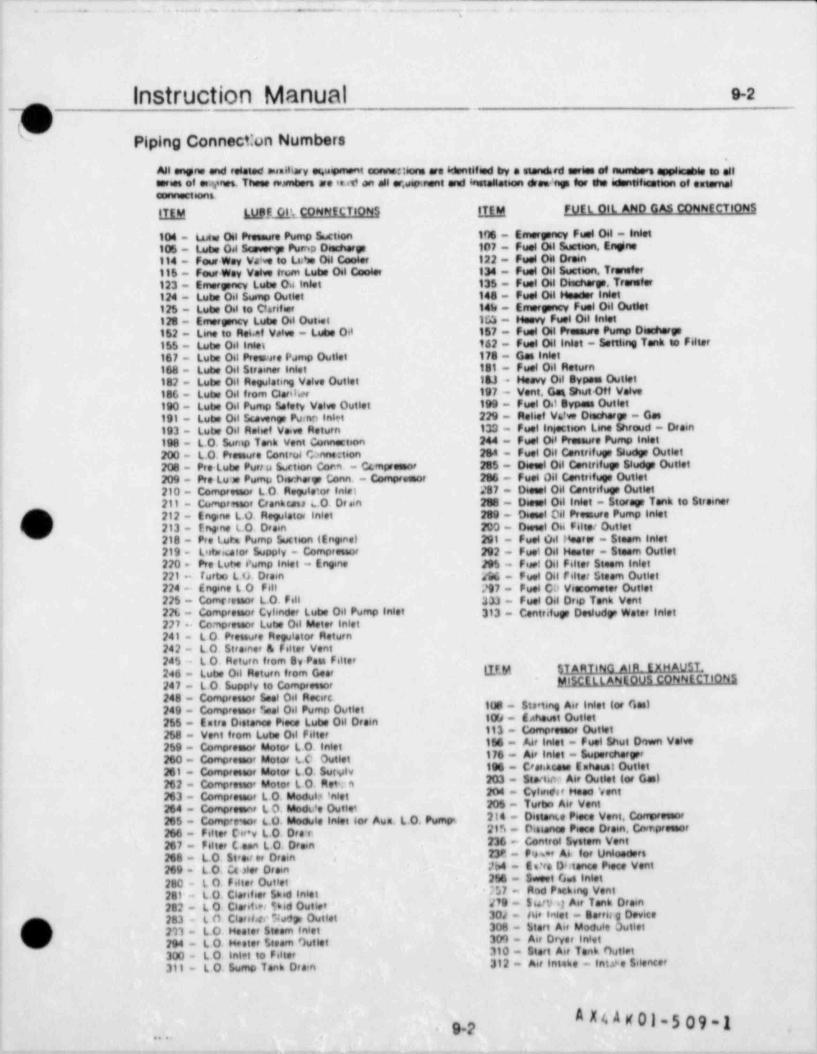
- .-
,. . .. . . . .. .- - .. . - . . . ,
1
Instruction Manual e-2
C.
Piping Connecton Numbers~
All onene and reisted suailiary es.upment connettions are identified by e etendard series of nusedners suplieshle to allseries of erynes. These swmbers se ie.M on oil er.ueenvent and installation dres> rigs for the ident6fiestion of estameleennections.
LILM WP.EAL',. CONNECTIONS LILM FUEL OIL AND GAS CONNECTIONS
104 - Luw Oil Pressure Pump Suction Ifl0 - Emeryncy Fuel Oil - Inlet106 - Lutw Del Seeverge Pump Deschery 107 - Fuel 01 Suetion, Engine114 - Four Woy Vaive to Lea'se Oil Coseer 122 - Fuel Oil Drewt115 - Four Wey Ve6ve trum Lutie Oil Coster 134 - Fuel Oil Svetion, Transfer123 - Emerpacy Lutie Od talet 135 - Fuel Oil 06echery. Transfer124 - Lube Oil Sump Outlet 144 - Fuel Oil Hender inlet125 - Lutie Oil to Clarifier 141e - Emerpacy Fuel Oil Outlet128 - Emergency Luke Oil Out.et 153 - Heavy Fuel Oil inlet152 - L6ne to Re6.et Velve - Lutie Oil 157 - Fuel Oil Pressure Pump Desehery155 - Latie Oil inlet 162 - Fuel Oil Inlet - Settling Tank to Filter167 - Lube Oil Preente Pamp Outlet 178 - Gas Inlet168 - Lube Oil Strainer Inlet 181 - Fuel Oil Return182 - Lutw Oil Regulating Velve Outlet 143 -- Heavy Oil typees Outlet186 - Lutw Oil from Claril.et 197 - Vent, Get Shut Off Velve190 - Lube Oil Pump Safety Velve Outlet 199 - Fuel O.t typass Outlet191 - Lube Oil Scaveny Puirm Inlet 229 - Mehet V6?ve Deschery - Gas193 - Lube Oil Rehet Va.ve Return 133 - Fuel insection L6ne Shroud - Drain
244 - Fuel Oi Preneurs Purno inlet8198 - LO. Surno Tank vent Connection200 - LO. Pressure Control fbnnect6on 264 - Fuel Oil Centrifur Study Outlet208 - Pro Lube Portu Lction Corm - Ccmpreenor 205 - Diesel Oil Centrifup 58udy Outlet209 - Pro Lu as Pump Dier:hory Conn - Compressor 206 - Fuel Oil Centrifuge Outlet210 - Compreenor LO. Rele or inlet 287 - Diesel Oil Centrifuge Outlet211 - Comprmor Cranhesu LO. Draan 258 - Disent Oil iniet - Storey Tank to Streiter
g' 212 - Engine LO. Rmlator inlet 200 - Diesel Oil Proesure Pump Inlet
( 213 - Ergne LO. Drain 203 - Deeeel Oei F61ter Outlet218 - Pro Lura Pump Suction (Enginel 291 - Fuel Oil Heerer - Steem inlet219 - Listwaator Supply - Compreseo' 202 - Fuei Oil Hester - Steam Outlet220. Pro Lutie e' ump intet - Ergrw J95 - Fuet Oil Filter Steem inlet221 - furte L O. Drain ggc . puet oil reiter Steam Outlet224 - frvne L 0 Fall /97 - Fuel CD Viacometer Outlet225 - Comrressor LO. Fill 333 - Fuel Oil Drip Tonk Vent221. - Compreenor Cyhnder Lube Oil Pump Inlet 313 - Centrifup Deeludy Water inlet227 Co npressor Lube Oil Meter inlet241 - L 0 Pressure Regulator Return242 - LO Strainer 8 Filter Vent245 - L O. Return from By Pois Filter246 - Lube Oil Return from Gear LIEM $ TARTING AIR. EXHAU$L
jel5 CELL ANEOUS CONNECTIONS|
247 - LO. Supply to Compressor248 - Compressor Seel Oil Recirc.249 - Compreenor Seal Oil Pump Outlet tus - Steeting Air inlet for Ges)
255 - Estre Distence Piece Lube Oil Drain 109 - Eehevet Outlet258 - Vent from Lube Oil Filt,, 113 - Compreenor Outlet
198 - ^4' Inlet - Fuel Shut Down Velve259 - Compreenor Motor LO. Inlet260 - Compreenor Motor LO Outlet 176 - A6e inlet - Supercheryr
ISS - Crar.hcess Enheust Outlet261 - Compressor Motor LO. SuNiv203 - 54e<titt, A6e Outlet for Ges)262 - Compresto' Motor L O. Rett 3
263 - Compreteor L O. Modul,* 'nlet 204 - Cyfeider Heen 'eent206 - Tuttin Air Vent264 - Compreenne L O. Moth,'e Outlet
265 - Compre eor LO. Medute inlet lor Aus. LO. Pumsm 214 - Dieterne Piece Vent Congreenor
266 - Fitter Cir*v LO. Dra r 215 - Distenes Piece Drom, Crwr.preenor
267 - Filter Loen L O. Drain 236 - Control System Vent,
268 - LO. 5t's.t er Drain 238'. - Pwe A6. for Unioeders,
269 - LO. Cc >ler Drain 264 - Ee?rs D6tence Piece Vent
280 - t O Felter Outlet 296 - Sweet G.e inlet281 - L O. Clerifier Shid in6et 757 - Rod Packing vent
282 - L O. Clarit.et Sid Outlet ' #9 - Surv q Air Tank Drain'
D 283 - L O. Clarsi.ee %dp Outlet 30J - Air inlet - Berth g Devicei 211 - LO, Heater Steem inlet 308 - Start Air Module Outlet
(d 294 - LO. Hester Steam )utlet 30') - Air Dryer inlete
300 - L 0 Inlet to Filter 310 - Stort Air Tonb Outlet311 - L O. Sump Tank Dea'n 312 - Air lateke - Int 4 e Silencer6
A N K 01-5 09 -1g.p.
, , , ,
. .
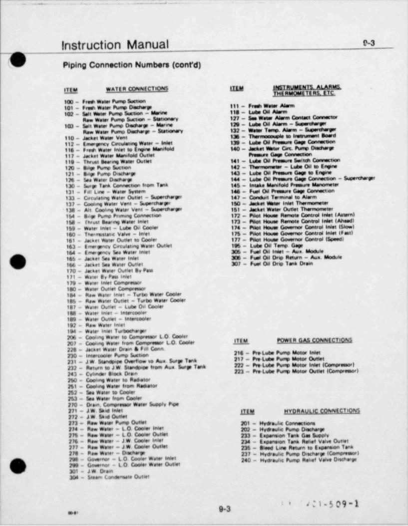
_ _ _ _ _ _ _ _ _
instruction Manual e-ae
Piping Connection Numbers (cont'd) |l1
ITEM WATER CONNECTIONS ggM HSTRutAENTS. ALARMS.THE RMORSETE RS. ETC.
100 - Fresh Water Pump Suction101 - Fresh Water Pump Dashery 111 - Fresh Weear Aiurm102 - Seit Wster Pump Suction - Marine 118 - hshe Oil Alarm
Row water Pump Suction - 5estionary 127 - see Weser Alarm Contact Connector103 - Salt water Pump Desharp - Marine 120 - Lashe Oil Alarm - saanertherger
Row Water Pump Ducherp - Seetionary 132 - Weser Teno. Aasrm - Supereherpr
110 - Jacket Water Vent 138 - Thermoseuple to leserument Board112 - Emeryncy Circulating Water - Snlet 130 - Lmbo Oil Pressure Gay Connection116 - Fresh Water inlet to Engine Manifold 140 - Jacket Illester Circ. Pump Dienhery
117 - Jacket Water Manifold Outlet Pressure Gage Conneceien119 - Thrust peering water Outlet 141 - Luise Oil Preewe sedich Connection120 - sily Pump Suction 142 - Thermometer - Luke Oil to Engme121 - 31p Pump Dischery 143 - Lube Oil Pressure Gap to Engine126 - See Water Deechery 144 - Lake Oil Pressure Gay Connecnon - Superthorpt130 - Sury Tank Connection from Tank 145 - Intake Manifold Pressure Menometer131 - Fall Line - Water System 146 - Fuel Oil Pressure Gap Connection133 - Circulating Water Outiet - SupercherFr 147 - Conduit Terminal to Alarm137 - Cooling Water Vent - Supercharpe 130 - Jacket Weeer inlet Thermometer138 - Alt. Cooling Water Vent - SupertherPr 151 - Jacket Water Outlet Thermometer154 - Bilge Pump Priming Connection 172 - Pilot House Remote Control inlet (Astern)158 - Thrust Bearing Water inlet 173 - Ptiot House Remote Control Inlet (Ahead)159 - Water inlet - Lube Oil Cooler 174 - Ptiot House Govemoe Control inlet (Slow)160 - Thernestatic Velve - Inlet 175 - Pilot House Gowemor Control talet (Festl161 - Jacket Water Outlet to Cooler 177 - Pilot House Governor Control (Speed)163 - Emerency Circulating water Outlet 196 - Luke Oil Temp. Gap164 - Emeryncy Sea Water inlet 306 - Fuel Oil Intet - Aum. Moskale
~
165 - Jocket See Water inlet 306 - Pust Oil Drip Return - Aum. Module166 - Jacket Sea Water Outlet 307 - Fuel Oil Drip Tank Drain170 - Jacket Water Outlet By Pass171 - Water By Pass Inlet179 - Water inlet Compressor180 - Water Outlet Compressor184 - Raw Water inlet - Turbo Water Cooler185 - Raw Water Outlet - Turbo Weter Cooler187 - Water Outlet - Lube Oil Cooler188 - Water inlet - Intercooler189 - Water Outlet - Intercooler192 - Raw Water inlet194 - Water intet Turbocharger206 - Cooling Water to Compressor LO. Cooler
ITEM POWER GAS CONNECTIONS207 - Cooling Water from Compressor L.O. Coog,,228 - Jacket Water Drain & Fill Conn.230 - Intercooter Pump Suction 216 - Pre Lube Pump Motor inlet
231 - J W. Standpipe Overflow to Aum. Sury Tonk 217 - Pre Luise Purvy Motor Outlet232 - Return to J.W. Standpipe from Aum. Sury Tank 222 - Pre Lube Pun, Motor inlet (Compreenori
223 - Pre-Luke Pun, Motor Outlet (Compreenor)243 - Cylinder Block Drain250 - Cooling Water to Radiator251 - Cooling water from Radiator252 - See Water to Cooler253 - See Weter from Cooler270 - Drain, Compreesor Water Supply Pipe
;
271 - J.W. Skid inlet illM HYDR AULIC CONNECTIONS272 - J W. Skid Outlet273 - flew Water Pump Outlet 201 - Hydre loc Connections274 - Row Water - L.O. Cooler inlet 202 - Hydraulic Pump Diechery275 - Row Water - L.O. Cooler Outlet 233 - Espension Tank Gee Supply276 - Row Water - J.W. Cooler Inlet 234 - Empension Tank Relief Velve Outlet277 - Row Water - J W. Cecier Outlet 236 - B6eed Line Return to Emperson Tank278 - Raw Water - Drechery 237 - Hydraulic Pump Discherge (Compreenor)298 - Governor - L O. Cooler Water intet 240 - Hydraulic Pump Relief Velve Descharge
( 299 - Governor - L.O. Cooler Water Outlet! 301 - J W. Drein,
304 - Steam Condensate Outlett
: ' / 1-5M-1' 9-3ees,
.- _ -. . -- - . _ . -. . _ - .. .-
--_c - . - - . . - . . _ - . j
Instruction Manual e-4
((vl- Piping Symbols
M ANOMETE R PRESSURE REDUCER LEVEL GAUGE
y
y PRESSURE swivCH N GATE VALVE X ''"***OI AL THE RMOMETE R GLOSE VALVE ST R AINE R
(Q) PLuc vat vE * o'REenoa or r'owT TEMPEaATuRE switch
SIGHT FLOW GAUGE |g| SUTTERFLY VALVE h WELD DIEDUCER(T6get S isng Ty )
ENGINE SHUT DOWN CHECK VALVg -] SCREWED CAP ANDPRESSURE SWITCH 4 NIPPLE
STOP COC K h UNIONhPYROMETER
>] PRES $URE $ HUT DOWN ELEMENT SAFETY OR RELtEF WELD C APVALVE
TEMPER ATURE CONNECTION - PRESSURE CONNECTION -R .. w .. . . . .n R . . w . .. . . .
( , in.. ..m.i .. . .n. ... . . n . . L *n m'*. o _ . .
..w . w .nin...i. . .iw ... (ri .i.e.i.in m.m.i.. ii .no w n.ie co .ii,. sg
f., t.mp. .tu . switen... etc. (Fe.id .s oi..ct.d my o.n...)
.-.i...,,.,..i
Y ST R AINE R "Y" SOLENOID VALVE
h DRESSER COUPLINGTEMPE R ATURE $ HUT DOWNELEMENT
-.. ELECTPiC WIRING h EXPANSION JOINT
|--. - C APILLARY TUBING ORIFKE
_ __
*dl SLIND FLANGE *, . 4; A . gff
- - a
THE RMOMETE R PRESSVRC C AUGE
TEMPER ATURE GAUGE METER;
FLOAT VALVE ) FLOAT SWITCH
Di APHM AGM CONT ROL THERVOSTATIC TEMP. Tais f o,m e.m. .
VALVE CONTROL V ALVE P.,m D4313 *,
\
. . . g.4 i. s01-509-1 8
..w.--. . . > . . - . . - . . . . . . - . .. .,
instruction Manual e-s
'( Electrical Schematic Symbols
symbot | Devies symbol | Device symbos _Devios
altlTCHES - Generet SELECTOR $ Time Doley Retey Coil.Normelty Dosed Slow Operating Type .e e
Desmnnect (2 pole) Manuel On energiration. con-.
**) Normally Open tects eense state efter
M=nus' deiny and remi im.. .
-\ Carcuit Breaker (2 polel Normally Open d''WY "" d**"''''#*'e/ e/ toon. (5 sec, shown)
%* Normally Open Limit ei e kmeHy N Time Doley Retey Coel .Held Open Slow Reisese Type on
m arpretion. conuctsn- Three Positionom Normally Closed Limit dange state immediate ,WL.2-- Spring Return
V Held Closed Limit to Center fy and reset efter deleyon doenergitation
ed Held Open LimitSlow Operating Normel-** Three Position
Normally Open .Ca A Maintained Position ly Open Energirede *
ConmetLequid Level ( i
Slow Operating Normel-P Normally Closed PUSHSUTTONS
Q Liquid Level Normally Open A
o Normally Open 4 Normally Ciceed ePressure Slow Release Normally
eTe Normally Ciceed. Held Open Energized Contact*
Normally Closed Open~
pk Slow Release Normally'''"''
yClosed Energized
*!* Multiple Contacts.* Normally Open ContactDif ferential Pressure E Mechanically Connected
a.d.a OTHER COILS
CONDUCTORSNormally Closedh SolenoidDif ferential Pressure (
ConnectedDual ContactDitferential Pressure RELAYS helood. Thermat
IRelay Coil- numbers
iNormally Open to right of ledder indi.*
i Temperature --@- :I cate contact locations -normetly Cloted Con- '
Normally Closed tects ore underlinedTemperature
Normally Open contact
e Normally OpenThermostatic - gy
Normally Closed contactAdjustabie 3Normally Closed
Letch / Reset Relay Coil .
%:e----Thermostatic -numbers indicate con.
Y j d'esAdiustable
tact iocations. normeilye fly Open closed contacts under.
lined
ormativ ClosedpO'
95 b)'... -509-1 .4...
- - . - - - _ . _ . -m . _ _ , ,,, ,*
instruction Manual s.s
(I Electrical Schematic Symbols (cont'd),
Symbol | Device Symbol Orvice
MISCELLANEOUS 8 Rheostat- 4C:D- Fuse
Y Thermocouple
Horn /
t> Terminals3 IAlarm Bell
Plug & Remptacle Wtws-e-Line Plug
Receptacle
Fixed Capacitor Magnetic Pick Up, ,
With SheldC-'' ''
Ad ustable Capacitori
Motor, AC
Diodequ.)
b SCR
MI
Earth Ground-
)Chassis Ground
1777 7777
Lamp
Motor Starter orContactor
Motor, DC
| @-.-{ }- 4 Remote Location
.. - Resistor
,M- Adjustable Resistor
O -i- ' ~ ' ~''''
;
, v 01 - 5 0 9 -1 ?9-6 . ,.i
_ - . _ . - . . - _ - . _ . - - . - . , . . - - - - - - - - . . . . _ . - . - _ . - , , - . _ , . .

-- - , - - -
. -. . . - - ..
Instruction Manual 8-7-
k Valve Symbols
TWO POSITION VALVE (w/O ACTUATOR) ACTUATORS
Basic two posetoon W Spring return
| Two wey, two posetson M menues push actueior'
_
\T Three way, two positson w M unausi puis actusior*9 _
-
;'
Four wey, two posetson - M Oeigni.d mano.i scio.ior
Det. T
h Fsve way, two position P ere=ure octuator
~TH AEE POSITION VALVE (W/O ACTUATORI W Solenoid actuator
-
Basic three positson_
Y Vibration actuator-
i -
Three way, closed center, three position,7 77 y
- F Fion actuato,
, ;j Three wey, open center, three position
b Licluid level actuator~
| Four way, closed center, three position3
- T T.mperatu,. .etu.i ,
, f h.-
~, Four way, open center, three posetson
1. Actuators (there may be one or two) are shown attachedto either end of volve symbol.
Normal, reissed*, condition. "* ' ''' **T'' "" "*' * * *N Fave way, open center, three position-
y yyy 93. The tube or pipe connections to the volve are considered
to be emmoveable, while the 6nternet possage blocks ereuFeve way, closed center, three position mentally shif ted between the enternal connections to
T fYY f visuelare volve action.
Ex AMPLES
N T\- Three way wadve, two position, pressure octuated, spreng return'T
Output~
N ~ Velve connected normat!y closed (supply shut off when no pilot pressure esists)T T Note output is connected to enhaust.
E mhaust - 4- Supply pressure
Output'
Vefve shonn with pilot pressure applied (actuated). Supply is now connected to outp61-
T(:p ~paiot end ..n.ui, is biock.d. Note that connect 6cns have not moved, and volve body is shef tede _
'T to the lef t, caus'ne the right p**seee block to come beneath the connections. Also note.-
E mhaustJ ' Supply this view will not show up on drawings.
x,/
'e 9-7 '. Y L1 v ;). : 00 l- - . - - - - - . . - -. -. - - . . - .. . - - _ .
-
: : . -- . . - .. . . . . . . _ .. _ ,
- ., ., ,
instruction Manual u'
(V) Pneumatic Control Device Symbolsi'
'
Symbni Deva Symbol Osva
,,Tubing connections.
Pneumatic Fise Indicator, ,
H Not connected r *
Pneumatic Indator,, g g
Spring Return Typee
Pressure Switch Pneumatic Indiator,
W|A $ Spring Return Type,-
, i. With Position Lock''
'' #*Differential Pressure a- c--Switcn
,- e -,
. ..
Manually Operated p;,Two way Valve -normally open unless Votherwise indoted
Manually Operated Filter Regulator withThree way valve Pressure Gauge
\ VSingle Acting Pneumatic
Shuttle Valve yW Cylindef = Spring Extended,,
1 Pressure Retracts Piston
Single Acting Pneumatic
- /////j ,| Cylinder - Spring Retracted,Pressure Relief ValvePressure Extends Pistonj
h Pressure Gas.geI Pilot Operated Two way -
Valve - normally closedunless otherwise indicated
,/ Ditforentist Pressure Gauge
I Duplex Pressure GaugeManometer, **U" type
=
||| Bulkhead Termination'
T, capped Test Tee,
(n)v
'*, i
9-8m,
___ - . . - _ _ . _ _ _ _ - - --
.. _- - _ _ . . _ ._ .
. _ _ _ . - _ . _ ~ _ . -_ - - _ - .
. ._ __ - - .- - - . - . . . . - - . .
Instruction Manual 8-8,
.
( _ Pneumatic Logic Element Symbols,
Symbol Device Symbol Devical
Af00 AGERARULATORPremare flemus from port S to port C A fieed useume eheneer uend fur tenmg
eden there le pensure et A and E If purpemus Commenfy used 6n sonountien
A e6ther A er 3 to depenurtsed, C erdi suesh an erefeso, the assumunesor to fitted
sont through 6neornet emetuneet port. by a sneeered preamte to deley or denson.,
with 80 psi mapp6v et 8, element enes almuet funeteens.artmg at 40 pas reewg and 20 pe6 fe8hne
RAWAORYItypsell.Pressure faseos from 8 to C if A is res.
gh g, sur6 sed. ty presmrtems. then Mechme
~a_,OR JPressure floses from port A to part C, or A. O to C feess is moentound konsues
E- from port 8 to port C when there es y emme port C presano Meads tech to portA to eseroame preamte tenhage,60 eny.7_ pressure et A ce B Without preneure et '
sither A or 5, pressure vents best from ff port A senes comptetely, port C sents
C to e tewough entemos eehaust port.
Bec7 MT191088T - 800RBORYPreneure flouve from port 3 to port C Common confesaretion of het/Reest andoneset ashen there se pressure et port A. Monery eaemente esmtmed to eenvertj NOT g
3 S/R ,_, g g, momeniary input seness no nomwaadW,th ,,es u,e et A C venis throughe,,,,, p,e,m,e ,novi ei ,o,t C et s/Renternet enhoust port. Elament enen
I artmo et 40 pse riams and 20 pas folhne eeuess pressere fieve to port B of $/M.' (typeceil- "I suh.ch flows to port A of MtM e6ement
With pressure M part A of MGM eeement,8007 weth PheWad Eshaust Menne pressare fleuse from port 5 of MGM towov function es amove, not hmeet get ,e,s C of MEM. When pramre *noved
/ 6e blocted Prensare flows from 3 to C 9,em port C of 8/R etement, pressureaT t- e ,o,, , hen the,e e ,,e,,,,e e, A. W,ih ,,,,e,,, t,,,,,, no,,,sen ,e,t e ef s/R-
pressure et A, pressure fles, from 5 to C and port A el MGM Pressure flows from,I stops. but C does not vont Preme#re part e of MGM to port C et MEM ten-roteined downetream of C. twenes, afuepete less of $/R eneut segnol
With ne preamte et port C of 3/R etsment,TIME R possure opphed et port A of SIR einnent
,
' Provuses twnmg with elow preneure rees, ensens preamte hotuusen port 9 of S/Rfrom 0 00 tc 7.5 socornes adevotamie and port A of MEM to enheust through
i TIM ' W'th swa''' Pre''w'e et A, soon ns.ag ,e,t C of s/R. With no preneure ei portpressure et C, reaching full preemare when A of MGM, no pressure fees, from port Seletey compoeted. Without preamre et A, te port C of MEM-C vents through meernet enhaast port
CMSCK VALVEOtLAY Permrts one wey poseure flow from portj
k" O to esmmen evtput ports A and C. Pro.With pressure et 8 onty, no premure fioni
from 5 to C. When pressure appeed to sents preneute heckflow from common
.A g E. A, flow permetted from 5 to C sher twns parts A and C to B.einsey. Output asetey adtustable from0 05 to 7.5 esconds Ports A and 5 same.yIwnee sonnected to common source for Provedes e restrettien hetuneen two perte' twns eletey output funstens .ees
a . - e of a sorcuit. With poenure appled to8 ^ emmmen ports A and C, penure is
9,gg gjyggy O ** " # I""*'*8'"''"m"oeted on drawingI With pressure et port 8 only, remure Ordue ese is
! fleurs from port 8 to port C. When| -h flow from port B to port C as tennensted PAR ALLE L ORIPICS/CMGCM
preneure es appled to port A, preunure'
.
i eher detey. Output termeneten twns Caneenes funeteens of eritsee end thschadevotabte frern 0 m to 7.6 escends. un6ve 6a paree6el. With preemre appled etPorts A and S esmetwnes connected to b commen input peru A eed C, presosto isa egammon seurte for omgae shot puses e - - spietered through ersfee portion of the
'"output element to port 9 When preneure to
tented upstream et semmon eneute AOlP FE RE NTI ATOR emf C, pressure et port O enhswets civicely
| 3 g g, With pressure et 6ngut port 8, there to e 40ereu@ ehest weeve perten of the see.egle shot outsuut avlee from port C. ment. Oritmo sise end seted en dromeng
' Putes output spuretion as W mese.|
SST/R48tf SSRIES OntPICt/CHECMPressure fion from port C to port 5 w6sl Comemes function of orifice end theoset seement Preneure output et port 0 to8ve m seres. With preneure essa.ed e
A S/R 8- ''**'*'"'''*8""'*'"'"''''''tC6e J port s. preneure passed throveh ehecaremovest Pressure opphed et port A we8ve end es metered through orifice tocauses prenure et port 5 to enheest common output ports A and C Theq chect we ve port.on of the eiement ce |athrough port C Pressure et port C over.redes peessure et port A 60 both pressures vents pressure fion itom poris A and C
,
present et the name owne to port S Orehce sise mdicated on drousne '
''9-9 !
'
.et
).__ - _ .-. . - _ . _ - - _ _ - _ - -
- -
. _ _ _ . . _ _ _ _ - __ . . . _ . . . . . . . . . . _
m.
.-
. A I ! 5g I
J i rc HM1 .O ini$r '!).%ide ii
I! r f j!!|N 4Wil ia..U,!'. I lii E Illit i LUd!: 1 ivi .'f
I} 7 L jf'
-.
ij g- -
L. ..J
h, . xi,o .. e s'' , ,,, im.
nh_1tij, ,, , n ;
t -_A NC, * :
t L:= u.7sj;
t,-
1j. !-
In,L ..- .:
|| | fi, m s
p 4r i| 9 ir *@ In,
Y hy| E' h'(b. , 4?-r b ' l I@$d , ND.- !1
O N,E W',- -
-
wif?N|-|e-apa-cq I$3 i IEs:iJ .,
t I|' =-
* " i |~+L]%q'IlI k I,L =
m i .
r =T [- ~ s w *s_ n:g jce ' Uy- - ,,
iIc g - .., | | - - 4 y w=wr i
,m.(Tl,L.hbiElidi6.d ;, f$g).
> i' wg 1 ;M'i : a
I iij 3 t |i' 7_E
'*--i.
[:ht h d! f1t t
"I LJC ff' \ ._'_'
9 p 'f i "
+t -w;wS.g e,
$ -----f[ / '
_" ki:f ,T'* *
.
fei___. _
| .F E__1 i| l.i__Jn:'
. . . . me , w 7=.m.r-
|II- { ,,!aC=q3'
8 j , ,I
i't af.6*1
; k-n J.r.1 :'
, m -.q-,, 2,m
.
|k} p , ], 7'r--t _J |'v, y: #44. ,1 ,1 , 5
- ..3,- w =e,r, ,
ti -r ?* ^^ ? h.,.. . .m.
fa y-a "n%Wi - _.eel
o
_ ___.1 ~ . .~. i . J -~.1.1 1' . - _ _ :. ~ ~
|- .-
L _ . . _ - - - -
l;i'MF", , ' .ti. $.. t . :II 'd!'| fFjl i :'' i' !@o
liia|| | |-
O, ,i ,' "."s * '' ' =rg' | L - . .v . , . -
' ' h. . ! | U - h k|{ f ,'6
j
<,jo, - th ||i di s i4 iL li i e : I.|| oe . . m I , .( , |1 i i li- -
q g c, . t i, | ,,
v i 3- y
rf}i" ::! ! ,ki pk d , ' |[# 7
\w i F t h[,
% 2 &,bq [_,1 N. 7
w_- .
I '
bez r s ,;,.
QM (r;@.._.S-{ ,--"jk-
51.iI;;;jj L &y a' ' v '
-
N.D|||g<;1i, /,/i , ' . .
R.t
,ilr i. 1 e _
o,$ 1 ,: A_, ' (% E lq -
-
b | =qs h. yLi
.; _
Y g, :NNe ~ a $, x, -
Q,o '
? '
| N7 # ~ _ ,. _ v,f , [ g, ' %.
n .
hwt, # : .
.
Ig t
x n ). x"4tq d g.
,
s. .,
i la ''c , - --.
3
f(,
i c CDt g W.r m-"* =, ,
. Q ,M .,Y.
gg,'P ,7I
'
|
i,W2 6rtil j ' 7' . -*~
.,
if 2-.9,|=;.n X ]s-
v,0q:- g. ' a "-r. - .
,: .! g _A g v- =
p- k .._ i|. ~
'y _ ' "Q -
,
,,,- t| ,$, '
up i 3- -
'D !
._
p @' * i, I[g'.
'
>i ,,, _ . . ,,
< L ' ~~"k)#r4i!! h,'N =8
4s
O c i a t5" t! ftm 5 | f! +- b Ti PZs.,
,.
.
.- _. _ __ __ - - _ _ - _ _ _ . _ _ _ _ _ _ _ _ _ _ - . _ .
. . . _ . . . _ - . . . _ . . _ _ _ _ .
.
| 0 _e i1
c. .
0 - k f} 9 7'
,"
i
i[O__r|} [ ||1. # $,1 -I ' .
Ie d.,-,-,# . . . . . .. . . . . . .-
-
)I i t' ;|
t- &' %, t- :. ; a. V , %. kyg, ,
lam 4 ,1; ,, , > g|!: r,- !
,.I,,, 3.s ... ;, - -,;m -
j j j,
._
h g
%&
UsC-
CD -
i
,, , ..
'
f _**a ,
%7 i [r % _I 'I
, "EUCi d li NT '
ie jsrb.A@ yw% yJA; x
ow c. .
. ,
- ~ ~ . -'
.sr
w ._l\ '
.ua :
_ |''
u
m |' ,/jfax
,3. ! j* c- .
i
{}tar- n .
--
4u
:s.: n<a. +%.g :' ; t -......, [jl' &*- '"
T,
,5g' I .ff. #, ,
i I , "" f(* " j ]; ;si| t
| T | k I .,}k/ g ' y$/ .
I,I
'
I1gi$q 1 - 4 {!'
i.! '
' -
1 : i ;
\,I k',
if N 'k [t
ti 1 , 11 r' f
n: j sc I, ; ji1' ,
, i J,$2 E | ,I
;..w | .4.m. .g 'e_I '
. N)(,
-_ _ ,,,*
Ii r..- ..
)i
> i ,.i
..
_ _ _ _ _ _ _ _ _ _ _ . _ _ _ _ _ _ . _ _ . _ _ _ _ _ _ . _ _ _ _ _ _ _ _ _ _ . _ _ _ .
___. - - - . . .. . .
_v I'
Ni > .,| | .T |
-
.
<m. IIl ,.
y > =- l,-,.. . . . < o ,
( I - $ Si
~+ l ' '' " ' jf kl '[ !'
.n.., - ;- -
: -
f**
,! ' 'l ''i il| e e,,. 19.,-
i-r !!i . . i .Ii.L.. .. . s a g; . r,
h @! '8' i, 12i 5 J. H,ii'
,
gR._I
, .....-' ' O ' '@q s. ,
* I @} il
G.-
i i e i1 '
8 ii
@; >vv- . i
!Ii g *
.
. =.
i e a
g $ q Ii
i e e e i i c _.-.
e e is I, [.I '
re i e J * - -
I j i' @ !~ @ g, i q L !i 4,'
''' I hI*
' eg ,g. c,,
-
L,,.o.= c .W x' |L
i E N i @*
t. e. I U . '?,t Iif1
-a.
.
si
- i.0 .
; I @ 6; 112 1I I t 9 'i , , g v. 3,
g'
5tf \
g1:i1 2 i s |._
e.le
i
.3
[i- _q$. 11..I I
*= 1i i a- je t;
I.j T g !,i: . . ,, .
|\ *eIi 6 . t
......-
s l a. t.....s
d.p, fd.k3L=.-m : :w ,,..
; v;--e e. t*e.....DI' ly y
,a
N13.~k'
Il 5' ' ' ' ~ ~
h.RL:----: .1aO ilti. it
...
D'T'"'i.,a. .- sDUt' .J ! .hax_/ !.....: "-~
k
|f* : '-
,f I :: [ ,.i[ ,,t,. ! [
I ..I
. u d n,z~
1
- m.T ,,''.. ,,a;.,., . .1 -e. .
., u 9 9_ u c 0
M. t- s 3 5. .
cO ,u_,,_n W
n
.,.- a.s -.A 4u
m _ m
l.a. T 2 ieE
Ne sw r 5
w..e
u J ,..- i
.-
. . .. . I ... T. ,
w 9 o s*U''
s -.
mm8
m m . .- m. =,r
_ " i e..dir e
Me_ y.t.." ... a
2 f ._. . u .._#..
. c = -, s *'
E.. m..
S;2. . . 3. .. , . E , .
. i .. r [i.,. o m. . *
v.
_ 7;T. ,_..r._.... .
f . L.* . 4 , .. i -.s r
.. "w ._c.
,..
..- - . .
ii
. .
~,.
. _
.
=5... .~ ,p- .g.-
a.,. $,.,.L . ~. .. - ," z.e. . ..
..g... . .
Uau.aEwi~ n
5,.
_
a F .. .i.
7.-.
,
4..
_ ,_'.
,
.w,. r.
. d
Ww 4l@\' M
- .,u ...
.
- .
", .. . .~
.
" 7 M l
>,1-r - - - ~ - _ er. . , 3..
", H, q
;
2,,v ,-,,.. . ,, ~ s- - 1; .
- - - , W', - M z&= ;? m- \-
3.'
.{1_ '\
k _ ;>A7.QH
9
@__1
G- M,
O s A' + _V.
Nr.e
-
a ._t
m,, Oey 3
6'
@.[ f .L q._ o.}
i
)7 e
! n1 %,,
, r, e
! :[2 4 ioi$!u R
Wu'
. _
| .
-\
[c.r
.
@ 1Ipn.Op|
.?
j 5r
m _
_
O-
+ ~
.-- ..-.- .--. . -.. - -. . . - . -
'. - . - . - . . . - . . . . . - - - - . . . . - - . . - . . . - -
. . . . . _ . . . _ .,
124
$'
( e e
||l0d' $_-jt t~rA! :t''
!
r +m # - gg", ; n.
.
n&f@ 8 h6. } I, f# '1
|[*. O ,. u m Aug
, 4- y -r Y $Eu 'uu o_
---6... _ ,
,
dI [ L
r .- *
QT
| | |,p@@' ---,
: ,, ,,,w.' ~
#K%Jg gaig- '
OSwon iegW4gh;g$enen nae ia, $, .
f h t' 4'O C
v , , ,N g, -i,n -
.-. g -.
~
O @ O O 0 0glg El E3 83 E3 E3 E3-.
h@w @y@\ k'N I'N fN YN fN ffh
''
@ @ @ @ @ @ (t(gg
I k I $ k k I' k k k! k[ kke e 8 [ ti
g |re
i = i
|iII|If i I!Ig-
!,1I;|!!l Ii i i i ii. i iiiili ii>i
i i|
O'~
iiic i iei i i ,mm
|
L
. . . . . .. - .
*
igg &&Mw= ?T* - J'1 2- *'' L !L L v L ' ~~ - - - - - - - -
tm _ ,,
11 -
| !'| !'| the lhe1 h
d di ,6@ * Il Ii-
@ ! $ 3h h kI
IN @ I'N @ !N @ l Du ,. a
I 50 53 hb I '!~~
pgg@ 11 ,l e e e i
, ,
dkdk *ds d4 !a
} |iN@ N @ l $$ |
@ f@ hp*
fM@ fM@ fN@ fN @ tN @ t j
1% efM@ f5 @ ('N @ $N @ ri '~fME
?, . , . . . .
NhNh, YNh YN@ ?D,
y---
%%dayiMya ih e :ks
#pK6""o i a e! i
| ['N @ g.
., .,
Ei!! f} 8 r2 a
$$$bb b elmi, ihc ,
* g@[9@
j i1 __ __ __
G [jL_>e' e' ' u e' e eg - ~
q@ {@{@ {@ {@ @D @D EO E@ M l& @fM NG, ,
*.@
ff{ YM YM fM fMYM YN@YN @ r|ND,, '''@ @ @ @ @@ yq>,__ y 0 -
- Yp" YM YM |% @
@[} @() I @ @ I Kr @?)eno, * -
A, o o 4,p j ji p ' j >
!"i o
,,4 <. .. - <
': ! ! ! ! L I e .g.
!$ E : I *ja
l|'|'|il, lII,I,II 1[tn I
! I hh5 E |I
=
'<m; .ii e e , ,
,,,, r
- Iii I $ f 1 1 1 || |t I1 I'' gg
:,
._ ('
_.. . . . . . _ . . . . . . _ . _ . . . . . . . _ . _
___
. - .-- - _ . - . . _ . . . . . . - .
__
in
'""
| 4| I b*
(O-
i i nI I" ,!$ "II w
fl ' ' i 5 d|! ps|
'i . .
I t,' :,
ig lf Wgg g) I!!!IIItil iO h
-
IIIIIII!Il! IW A
g | , j , ii ,,,
,_:..-: :| t-1,, ,J
.
I <a l,
,l8 .I .l LI .i J .i
; |g:.._:Ili' _:
...e -. ,,r r r
i i :--|
I,: :
i t 1 J l cr, , , ': L _ 7 ___ _ _ _ _ _ _ _ g +g
-
| | i |'
,
s
.t ,j | , i l ! .,.4.N ltill f " " * "''"'iiii i , -,
J @- . 3,. 4 ,
, i, ...<,,,,i si .r.awweeoevwwea yi
li f $"i C!d- | | !'
I w[$.w w, n.3Y;t 3; cr
e e Mey,i'
, .
i ii i } su . .. . . . <i.,., ,
1 I .
,i gfg' i9 g|'t 9 g| tijr r '
8'
e<I.Ied e bf[h~h ,
. . 8| i ,!Ill!!, I , , , ,2
p p 3 l!.. ,, ,. . . . . . . . . . . . . . . . . . . .
Ol<
i, i| ?I ! Ie i !:,1!il i i 11II.| |
.1t .a, .
d.,..)e.i. I k.e,- l,! il, ,. Me ,,i 6o. 2 u
q, , r~id<= I I s,,
8 N 8 8 M n e' "1qj p- -,l lt_
f-, , , , ,,
:.I i: 4,__E.i_iJ
t.a.@ :!! ^, g .. .
p, g- t,. --
o i. ,
$' d U E i *, t'~
,
'ti--iTN 3d,. l(
[[_ , .*
i. se a ., _a-
-
6q-i:
tr---g e . -.
8 ., r i.... ...J ,,f'Ih*)l~-
.
',j//, se
o ....................... .... .............-
m..
m 6
_ _ . - _ _ _ . _ _ _ - . _ _ ~
ggg. g -- M MO % dam M%O 4*M G
- e
s'* |
E $ i
(O 19 ?i h :d a) :|I
'
e
it ! |,.
= : :;.
gu; i ,
If..d ' 3
g - .
m, ' LLJ s.e g _ .
| 'a| |^1 ro pt
t
[g ;, J,g 34, p-ti ,
$ igi i
' 1. .'Ay, 4.y|,|g .i.|;.|,.g| ,|r,dkk!i'I,1,1, i lf1 8'
' ili r
g,a y'f g7
i i i,,ig.i 1. 'L'h,h,),i i,i! [j,
l f j 5"I *_
# 1 i i: =. -u!o +,
Mh jI .lefsftM1.fsf fifkt $!ou ',o .a s. i 4. zlittitlifff!!ft!!Ittillfiti ! !!!!!Etttleti
Ot I i''.| |
,1 !'l|| l'
11 1ii ,1 d i I ,..I i t i
-
,,6 v (;e
, sI e fg7 i
',yg',l....$[g I. 0@ IAUl
,f ut J O 't 'I i
s
81 ' 8 I " U" J. , s..@ g.
[y y!l8 ' 8' 8' 8 8 rm r+8)$5 _ 'H 1,
I |4 g.[:6 6,. ,.
y! At. , , ,gA gp ee e-Hs- .
$t_ se i i.
! A 4 t : '
j ih h:!* A-,'
e , i i Jr 7 P 5- "+e i D_i We'h y 5 f i e,,
h,| l ,, tdl ,f" I
,1.------{j p. fi: yj |}4 L*y'| |Lg- 4I i
gg -.
iy |1 5g.1 y,,g;k ---- m '3,
.
3,---.... .3
pd ,,J J l' .t,_ i 9,, t 't' -,,
.. iiiiiiiirtiiciiii.iiiiiiiii.. ienisii,,
EH --
( .
. ..
. . - - ..- . .
-.
D ,-
|
nnnnemnnnrirm,fsm!! Mil10 |i k0 II I h ;'
1
<O 1.
en-
I 1.l.4 F i. l..I l.. l.. l .i..l.l . i.. l.. I i. i.. i..i..iR.i i..i.. i. 41,
t . . . . . , ,
ffi i f'l IIIE !~
OI I i !IIII 11 5
!| | 1I d ||
I |1! ; ,
. ||i i i i i
-
i I a s i 1. E i
peM &' ' 'e g). .
itOr Jr M o.g) g g g, r g'"" Z
l L l | E L | [ l i
I nd bi In
| 7 |iils!LI t .4
to !* !"' #'
,$r,,y $
>[r
'
,
t11 1 111114 tlitIkIIIII11111titittttttttita
-|i igI t l | |j I 1 i, i ii.
.
1- ' | ff
,
tit IIt i Ist jj
J. 1 Ill lif El t' le 8 i its a.
h$b | G) 49 ao. a6 au a la p;.8 I t i t ,-
Lb.4
: a i ,,,,
i "!# l9
4j i
i_ i i i i::ia |,
g 's ele!3,.3 I. t
(|(j8-
,
d U'
N' . .!I1 i : ''-
%rit).L de. r
sp
4I381111111!!!!!L111titilliIEte 3gg(Laiat
g 7.---
( . _ . . -._ . .
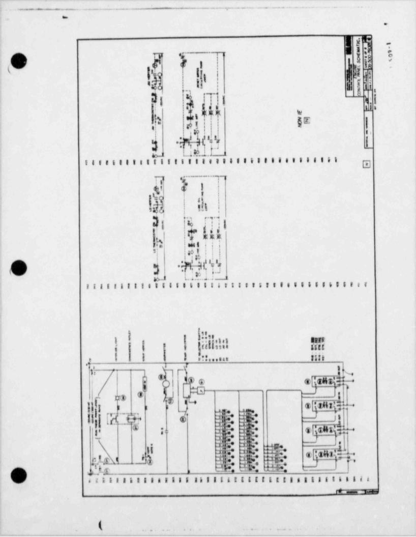
_ . _ , -
- M_ __..h WwN64G.i.44.%O 56e w& S .D- -
en
G.
we
|c b,'- - q -np8 8 ) i !('dh ai y
f i,,:: rl i..,~ d
_
i3 )(MM W/
d |ele
II*j?tb . r. .
,
j. l...1.2er ._
,
io_ :
IIIeiIIIIItit!IIIIeII&IIIIIIIeIIIIIii gg.._ . .q_ ..
dsI I
I II ,
I .3 c . .y . 4
(r te! ,
EEE| s'
Ie me t i 'S 40 t i
O 3 *@'tp l.. ; . . . . .i.. ; '
I!!!!!!!IeItilllitt3**I: tsItIeElitf655ttt
|
I
h!,,i.ii e
i un1
i.(|.| 7 t
.
f ssia gggg
!' 1 | 1 .::...... iiii.'
_.f i.j'* -
',
fq n %'@@ @l(GM&TMj '
3;; a 2G an@ g i-
@[i d I N MU! I I i
al3E ; ' it11,' [K M* i,ei. :: 4+e
= . iia c Ma : -J-
.1 - a.
I I $ (,'
s_p I =. w, a4( t
c - -i - -..s,_ _Z i l l I n I I I A I I I I Il l I t & E E I I I E t t I g I i 18 I L l i l iAs a
&
k ... _.. .. .. ..
__ . .__
~
- - |_
__ .
.
- - - - . - .
- . .---.
.
.
! I
|lli, il ;f |f ;,| j g I I * II t ;I i%g! IC tit ;;eglt ;i i e, 5, &: b
.
11r ii iirrE ; o;; r, g le ;in 9 n r r .
L- in-
! :- ',d.,.u, ,l uiarx... c.2.a.. .. .~.= s. ,
1-}-I i " i 'l] ,--!16 iJ If f M
'n n 'I g 4, "If' i f !1 1, ,, , .
--, -
.
E i
i II &I IiI IiI III I IiI I&I i! i ! ~_. si.. q-
-
,._
)sI l | 3. i gIl s.8 8 13 8 1gg .. , .i 2 . . e * r .
f! .ri g'0 i rit I i r I se ,ru t sit t4 tua ej te
e q,8
i , s i i , i t r t >
-%
In L* -I-i 1 : 1 u kM 4.f :emitaL4->4 5:d liks las te:d HiH ..Ed It LYd.I< +s-1 E s k=p I.I'd<s-I Is hh tteI-4 Ia L 9-i.I4,c1
i [ r i e i,
t :-
n.( _. g; gf gg g/sp |,@s,,,.
::. , , -
--
i ii n, 6,
In i i i s .
I i I ii i I iii!i TEE EIE EEI & I I I I I$_1 1 b !
'
s
i H is
,h|g .I t g ,I li'L/ lh. |'. l .
I , i, !! i, 1 I !!i, illi il,i,d,
' gg ,s i g, i.I ,,
If n i, Ilj i, 11i " "ms, en! mni en, >J vs, $Jqi I t | | | | t I i l i l i l b i'
4 _ __ 4,4 1-,.L 4 _L ._ 1._a_
__ . ._|. ._ _] ..
Q ss+1.:.1 u : i os s-,i.1.jg . .u u 4- i.mg_ o wua 3 3.,. u.m
is !y ! 8 ly ly !S ly !y !vi i t
.
;,
r$ i ;
I ti!I EE! !! !! 11 !! ! II & I I I IIE IE.
7.u-
l d't i
~
):4- !s: Is: Is: It s (I
.J_ I r si e r,,, iii.s, tie r(Itii.r,lil i, si ;r,. .
r. g . , .I'd i |1 l I lq n .n .pIg,,,_
,I _ |.u mm.r.n nmm mueu -+m sm+mm.mo, ,-,r gy 4, r ,iO e i -i i aaaae,o r ,1 1 i,n.
dup .n: = ,, __
.
I si ! ' ' ' hi imi-
d 4 i i 5, i,i
i
Q)_ IIE I II I III II II$ IIT! s ; i I a e. n
\i i $ $ $Ii I I I i ! I 1v
L _f '$**p g_ , xR - __
|
.( . ._ -..._...- ..... .... . . . . . - - . - - - .
. ,
1.- x.-..-..-
---
-
uh agl i
i :[ i '||II ||J f l|i tI!I Ii g I I 3i i 3
f 11 f { h -
lifn ,<i, n ,<i,(s) I le ti in ,< ,1 nn, en, nn, En
gj l(y
{s,
I ! I I l i"' t t i s n i i n
-.. .__ _. __-,
i -
Il.l'
. .__3 . .
.m muuu mw .m mm m m-; J .. |. . mm<ms.. . 1
11 l7-- r- - ~ ~s r- - r- -- 1 $12 1 8 g s
*\ r h [*' g v g i-r --
"hh,h fd'd|['M gL M i *" Ig
't Ntt.. --
,'
III eIi iII &II IiI III I i I I8
,n ,-
| ii ! E 80 i i i |.! iI|lI I|II!I|tfgE 3,
||5rf *if P rI I I i lo! fi L t ss
i
i *n *rm mar ,
9L.e. .ri m4.. i mm.e..-. grui.{mum m,-- . im ..u
I i f > b b : 3g
f t I"" t-
~ ., " l e,- $4 g g' s ' q g nej j jj#
id- <,g s e~
., . , , ,
i! !Ii Iii I Ii i IE i !E I EI E Ii
'O I .
|!e, , . . I .
t|.|: k. .
.s.
e e a i tV f .| a t It I ! l! I Ilitse I f,n ,, ,1 < n ,I s, . < t i, . t s, ,ot 6,, q' '
nnli l | | i l L i k t l i iI I
,, ,,. . :.s am.1 Q m u.i.T.T i m ,s.e. ., er.mn m,<.1.. -I r,-
.ri m~
| ~M~~
i~ l l~
l
ju ;: ;u ;:: ;:: ;::
E i e
i ! i
EI iti !1 I i i! Ii! !II Iii I I
|l|:f; 11 ; il ; ; ; ;i 11 I il i I ii f I
* n' *r t' *i1 *rf *if *if *f
m_m mu,us m.t.m au.i.zi su cia m,- . ;., m, . . ,
a i t 6 i k- - - ~ l$> [u
, L, &, Is Ili II , y g g.. ..
S- e, s, s, L s, 6, i,
o i i e i ,
$h$ $h $ b| h Ib h hI h! h | $ I | | .d h Akd l
vl i . . ._ m .._.
.
. ( . . .
..@
, _ .
_. _ _ ..
D - - ,,.
a ?
(Oi..i -.il:II:lili= >iilliil I II-l liiill lililil 'li I l 4 !
g
,
g b -
6... ...................... ....... .. .. ... ......t',in miinm.imm i Oi!!! !!!!!!!!!!!!!!!!!!!m niim || !! Ih| ;gi. i..!!!! | 11!!!!!!!!!! .
[ t d.i hi4Ii||iiI.!.'I;ii.,ii!n.;jlii!I'! i,i|li.lI e !:ii ?!iii.
" "l I~3
inI.|Ilhi;; ut Im in!,li iih fu mi
1 ''
an n..n n m .i........n... ..:...................... _
.
ilillllllimithil k71,li Tillli!!! i6- - --= -- --+----- -- -**. + ==*
Italtitt!Iti 1D Elite 8! tit ft!!ititt!!I8 t,!!!!!!!!!!!!!!!!!!!!!!!!!!!!!!!!!!!!!!!!i
I
8 ! !! is si 85'
11!!!!!! 3!illilijill,s!:s!ffIutilitiliii, Ilillin19111|.i.iiiniall.
Q -.................. m tc.,t m ... ..:.
.
f|ri|s!II1
l ti!!t!!.i!,f|!jiit5 E ' " "}|
*as ' -
!!'|f|ji,!,I|i,!.!I !|!|r- |f |
iI
! I | I ll)i|| g<[. as
q:|i;|||jj[]Wjj!. j || j[.f, f 41
.a..>y
' il; Illl 1 n!!*4 ,..
r [ h' I!
|| .!.'il!!!. 'I ,1:1
e.....:.....!8!. o* r :-
**S4, ..o= %_CKQ,
i
%shf.~ia.=,it-1 w ..55M .
-N f6'ei
11E1m|!m.
I,l I'E'!'"if T4Hy8 Ei i
tielfgih'- " i|| .illlll!Ill!!!(ll.b*li ll(!.g || O| IUI'!!!!!s! I E9 Q' F'is!ilts | I p.nRfI #"'
!!!ii!1111111111111111111111111!!!!!1111illyd r _,:wn 1-
| o -..........,,...m....m..n..................;......g.....--
n .g .;;;.......... ' g'l sN,3 :: 4 P -- --
-
; :--. <.,_ _.
-. -- - _ - . _ . _ _ __ _ _ _ _ _ _ _ _ _ _
-
.. - - - . . . . . . . . .
.
. .
-
{'J.i;"
'
| .
Ij i i.
i.ninuninanunnin(qe. .
|- .Mi, iU i..................... ...
I t'
ta
| !,h,c9d
.n .
l.in.ono in
i il. l.s a.s an.
, ,.
ia. .u..ip..i o. .a..- .., ..
| .i i
j 1m. ,. . . ,,
; fill "kI,,g i u t,. ||||"n t .|A | Cr CJ li l-n < >. w....'l fit 11 11 WHH
.! Lin . lH- .!! Id='i |iJuJ <l t.3u__J,
ii.........................
Ec<ccr; Lu
OD ..s.e. . ....r - ;, _-
|ll |heii~~ -
,
u :.= :. '*
| |Nei ije
: m==
nQ;,OD.'|eDic....r -f;
g(|[-cielt = = [.~=";
i .=..=i gg;
n% -(g ; .,. s....a..
k: *r*
*
I* .. ...
'
f tillH!@ii: : ! " _ ' " _ |::: g!m
5 5 r --- .
8-
iA : 55 g!c. c. , s .,A ;:; .
.. - -
):Q; *4 i. .. .....
Ik ;......, ~, ] i !'
== =" v
je t,.q +:'
-
: ;. '
I >=: :. *- 4, . . . . . . . ,, 7-, y w - g,y,
'
*+.*.+ ++:E U- ,
| '$ l i.:4--
* x* -
| ,. 4,,. -" r, ***, -_. ,
- -, .**-. ,e.g
--I
__ | p#.\$ f 4e,. ,'3Y
~ ;p :: |ge'
-- :4 -
ein- :: -
;4 5 ::,
-_' :=' ,,
:[') ! j*O ;_ Z !!I , ' ,;
"" E ir*j,$e i I' - . - , s.x.:...: . ,.._
., . ~
.: cr4 . . . ..-g, e:.:n . .........s, ........
|--
.-,. , .|M
^
0......
:.w-
g,
, ('__: Dy.
*,. g gig h.-. r*~,
- ' 0, O
r. ,'
*$ * fF*,
. 14 -O4T,
it< Z 6I' O,4
_
,b;h,
r""": _- :.E ',*.,$ .: <
'
' ' . ' " * | -
1 ! . :|C- -, ,
7"_-,te 4,~ ~
: |*e,. +., s, _
! | "| !-< _- . * ' , . *,Is ,, .
_ ,,
--- _|| -
,:c. . ., ,
g, , is< -; ;;; |r ,i ,r..-- ' me |:Q ; ,
:c.('[.....!.,
i+3 .-... :,. .+pJ .,.... .. _. ,
r. ...a , ,,. . . , . . , .
qq_ -
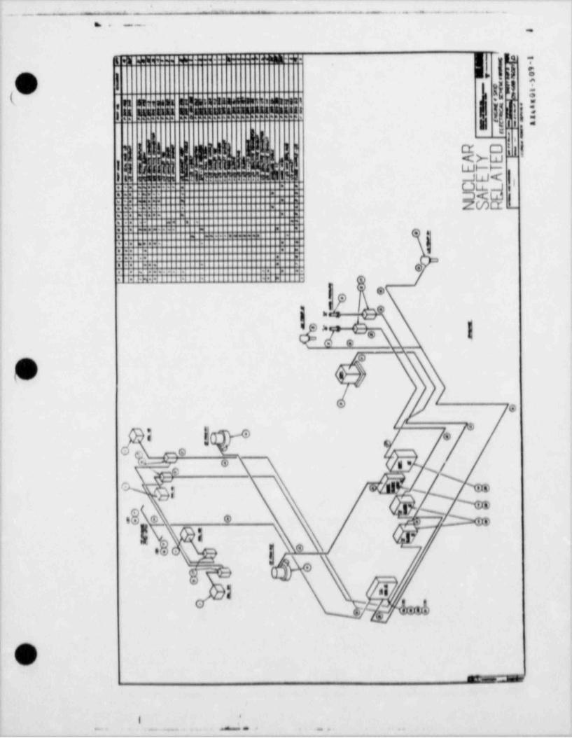
. --
-- ... . - - - . . . . . . . .
. . - . - ._
,.m- .: -.i i o . .. ......
(O i !@,L .:n u,,,,n niinnmam. ..nmn
$g1 1 [3,
i !! !I !!!!!! ||!!!I!Il!!!!!!!!!!!!!!!!!!'u g-[i {il I i ' cr o'
l ,l i | | | ,. Ii I I < >- w.
l a i i weri is io mii i !!i?!''?!!!!!?h I ._J W < |I,
m ,. .. . .,.... .
r;:g: . ; : gNL<-
. -'
:H-: '.: . . ..
i~:- -- .:~=
..
- -- - '
.., .. . .......
" ~
: : !,
i .: ".-m: . : m
. .
~ ' ' " *:. : Tk: :ii I . ,
I. e
g,i 1 e
o e_
-
.
(
x ... e, s x
0 ; 40~
lb *\ e ks NSG ._ N p>
'.$ (
m
egy )
a00 0.: , , ,
0.
'
I ,
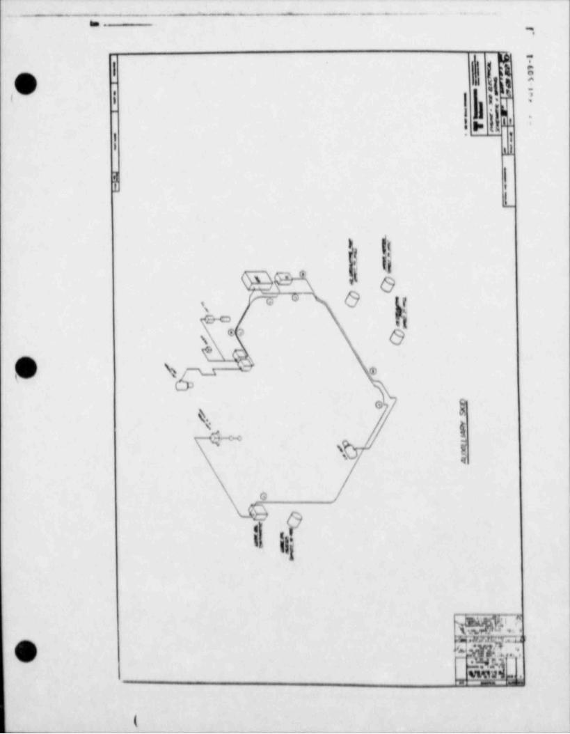
m .. w. . g estm+easmes-as + .e. e e-e ,- a.^^-
bt
O ! l,it ib
, ,~
.
l > .; 11 '
|f
11
).l,
.
i.
{
>s (tl k..|i' 6V '
er o O tr,
pgs4,4 4[\* b
(D sp - *
ae
\ l% ,>ps
s q
G,
'
9 \..t
hi
sp?,f ).
O y:n.g_ g,, .
.Nj t
-
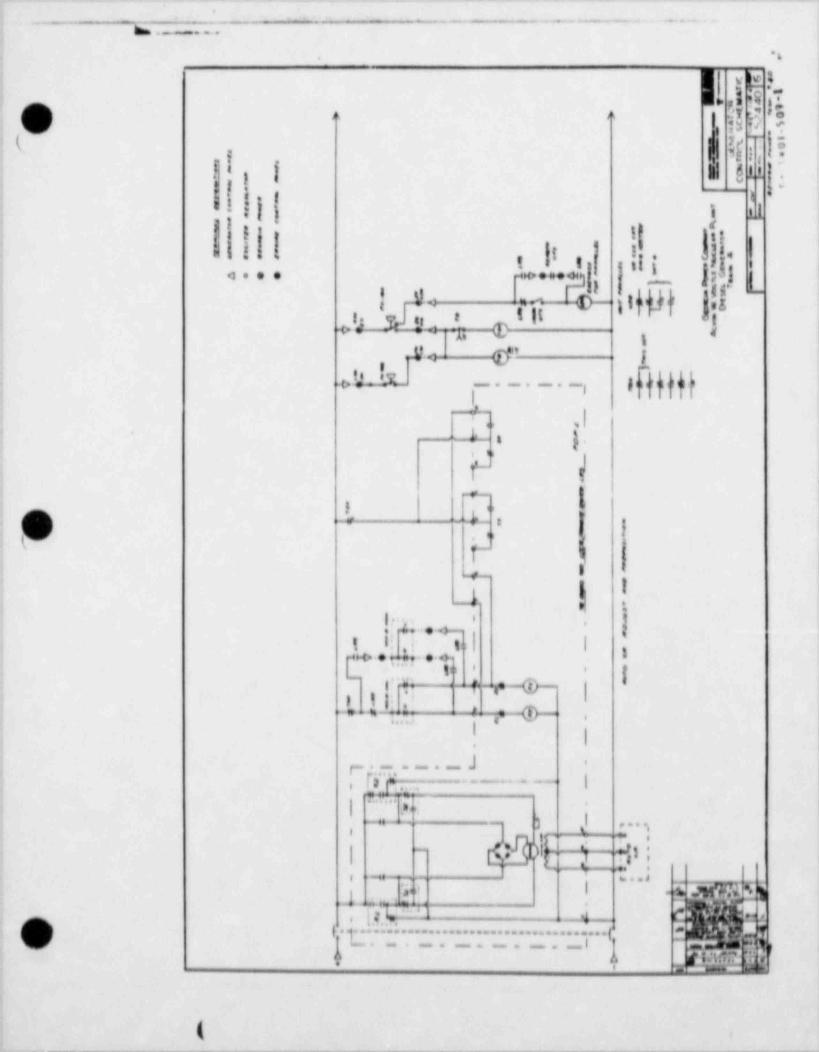
__ _ _. ._ ___ - . - _ _ .- _ _ _ _ _ _ - . _- _ _ . .
.
__ _- - _ . . . - . . . - - - . - ..---~
*6.
k' T I,5 k 'T
c n n a h;,
D u ,t
( I [ ';o5 : *-
[It i
*,
- -
- :| 1 11 :eI I I| U|1.,| ji; j. !: 9, ,
jj [,
,
4... . . . + '
, _
g \t flif i..; %-
e Ill i.<- qi O 4+g
fI*;<
.,4.. [ - _
I-...g |0d 4if11
+ ,I,,
k,,,
l~i e4 = n |
k' h !k ,
i ..I_1 .
, .
! n . .. '|
-
t i! i i Im ... -. ,. . . . . >
'*' 'g: n 8 e
-
I l.p r,_q>_.r-
?I ' , -q)--*. - + -* 3,.,- j: ,
lI l
'
.
r- [ . .- . - -J -
,
|m. . L.e ,-
3 - . - - - - -, ,
. .
. ,, ,
3_ J- -
- . - - 7. . .,,
)h_. _ a' 3|=
| g T4gi |_
1
1_ , ,
' ,
t . me beeJ _
jo' | d,1- 4
g. . [ .g , N. . .". . . . . . . . . . . . . . . . . . . . . .4__ , c mg, 3 - o......r. .....
(,/ '
+ -. . . . ,. l l| p~
,,a lit rnee -
, ,
_ _ _ _ - - - - - - - - _ - _ _ -
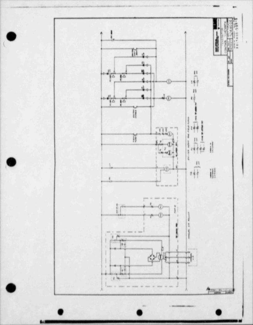
). -_--
- .-. . -.-- . .. .. ..- .. . _ ,
lue,.
~..ye
k 1
n ;Y :7 eIs ng. s - |SJM 14. .: : '
( 'l if fvI
| E u -
'I d.4--*
t11
11_ 4 -
$+- |I''
4 ,[6 36,
- ,
'Io : @ v.f |t '
., -
=+ ll4+ 4@ al,<.4L4 -1
,
iA na' IIe e ..
!Tu ,i
e I
'I' il T - 1 | l'"
|| I|- GS 4' ~i 'f#3 4 . edqf |j|
i,: : 1r ) t I
1
i v. . . . . .; , go
I I It.
t , _; .- '.
N.f!p C ,-_.
u }1 'ps]I, |- -,
, ,-1
l _I
p __ .,
f~ - h 4
i- II, ., . q.>- i j
, :.-
j' s t
, :. . -- - - - - | ';1 '
,
; h ,. .I
-
|.3 ,1--
=
' +. . . . . ,
qt- - - 1,gt 1 3.,_
.
i..
I, -- : .......:,
,,. - a w ay.4 <
, ;, % -- 4_ .
p i_.._ ________J%.2,v - -
;
. . . .-
L.
S & W' -
b ..
(. . ..
_ E
a '98 8 if ggq P f f As
j j ''tp 3 .: - _,
_.Il (~
!!..
IIf4. . a 1. . *-
Jf I
p h m. . . n .!-
I k
||| f.v.h?' '
.,-
t!. ...
.
t r
i,Y6;
a: .-
e
v ,,
m,
IT,
, .
i ii ,
! .' k*
n
I T,~ 7-
't' ir
. ',
s.' s e ai
b. 1*q'$*n,
b
, ,- ... u. .... .~ ,
,
--.m.- ---4_ .
(
O i
'
(
O '
(V mmed ,. ,. ;,,.
44i
A1E===( )=. -W *e ,' 48=
..i >W :i
i
1 . -- J 'H 83 -4 ;7| ,-- v %c. ' -e i j
. ,
'==W { '
-y. wy--s e ;'
'r' F's%W Hy
2 p ,q;.t-f y > <,-, f:$- , - - ,u ,
I lii ay m)*
,.----eg,,a iy n ,.,
,- ' 64i
Y h.p1. . . . . . . . . . . . . . . . ,
, . , , , , , , , , , , ,
j.7 ,_ _' _ ,.,_ _+, ,. : j,lr- | | ,1
l ' ,_ % , . ,4
u,,,.4:g ea
l u.6.- :i,-e' i #. ' ,'v
, ;i , b4 4.~ Ja. II | , 8 '
l ,3... . -
. m ..... . . .- . - , .
"I atL -,, -,,m. . i i;n
.-} } y, . . r " - T i,,
!i--.
i I,L ") i h.4 U
!.jI-*- |i-[ 1 -*ei...! " 7 fi[3, 1 -. . . . - -
0< .- l.,............. I% 1,- . . . . . . . . . .5,4
~* .e, tu; . . -t *;--> t,n., - - . .
.i . . . . . .
c. . . |... t . ~.i.Ci
,
; ;4,
| . , ,
| i -, 3 3. . .
_
t,. ,| ,
|- emo L g .
, e F .3 .m tj 7 . .!.t.4
-
i.i e', W--,, 'dfl* ti If ,
y y. I%-. ! i
p. ag | |i,- t~ t''r '
!, .
"
c.'.
(' ,) ;. o f |- ~+-
, q p;* i * . -
\ j .a '
h '41 | - -- =1 ei |
1.!'. -
d. Iae.n .. - : _:_ .
--
.- -
0
9 41_ _ _ _ _ - - - _ _ _ _ _ - _ _ . ._ _ _______ - - - _ - - _ _ _ _ _ _ _ _ _ _ _ _ _ - _ _ - . _ _ _ .
'
._
,
f. h hI| . ._.
I.yij , s ] g
. m$. .s! hj' kj!
A]>*Jj' ~
'. p. .
8 a fkd.' . : |O ,
s &} i lj }-d'
[ - -..
. , . _, a ..f
.
L, i} KM' < 1 (i
[ di
i i|g - ,
oa,,a 'i,;, u- iy{
.
, .-
..,.... , .-
p4,.w L,. , h- p.h [ 1,$ gsu oi ,i i
/ c 1,d .. mpg y I,'
ey r ,.,'r , , , ,
|J8,mrgTi' f , q;'stij. t- ., " . c (:-
'-
CG@_..
i'H
' ' f-||
' -
13,fr k.or ', [,
.
It,, m t,7.rw}..j../e,. car-v-Kw--
.
;..,g ,;,.. m.w....a. .
, . . . ,,,..
.
f kI '
L. N|- -: ~f)f i in G 'iqp_= a ti lwy,,tt .,
t] n?r ii @A g g Tdi k,.a-
E 5 -|i : i b,- rIa (r"h [
b[p..],/'- ,.
t. .
>wi .p. ... .;.- - . .
3' !... ,1,.U,',V.'.'.U. .U,1 b.
([9, pin r t.',[ .nnun n o n ' n.in-
i ,j jg523b'
t
I i. - h l.-t
il- '[oQ
, m-
.s.,a i,, . *
!. J. Q1 ' -
t
|Q1, ?.
--,
l-+4| ,- t. , p'
.
D]])I { {.
'-
_ _ _ .. _ ,,.g_. n .-
g .,1Q . -v
1d W. x pil.-
Sb,
--j
l.!.g - ;'
,d_ .j.1...i,
..
4 .. . , _ . .,
J. , . . -,- m.
[j ysL ~. ~
bjy % j )s
-7
.
|'
.
n. > -
L r_ d n:. d h,X _f n f' - e ,,
- .. -- -
.
k|p,.:=w 1tJ:;- - . . ,.. -
i . . ~ , . . _ _ . _.
i[3f I',. . -.
W .. <q , . .pJ q g'
,
/ ~28 pili | "==.%~~",,
g' c- i
-
-n q . m s-2 ..
[ h[ gg <[Nf f''
a, e. - .
.r-s.%
> .e.,p.509-1 i
- ~ . - . . . . . . . . _ ._
. z.
, -
1 ! s. -- n_- .
! i,I'
{!! 1 $hD'
e.
u Ildd - g ; jp z I'
h b ! .', .
"WLM,dhO A g, iA _ ?. -
r5 in E !.
Gbn h '
I ?? ! II |(" if I'j!| l- .cn%n'G!jl!ij'$ '\ 4 % 5 G I '^.- '~
[jei,b}ff' "
y! i;Igs
Or
T |-.-
JdiH5iM".?|: d 9 Ls,..,,n,v 1 $ir ' '$|. . , ,,k''.! |) o,
n . .n , ,
i
.
o=NI'
%K!792@ .
, u
| -/l'T ,
y ) -
EE 4. .
| r- i, g|q ,,-e
lb.-
f$ ![4
/' *d
w ,a .* iy ag-7 . r ,.
t<1. ;
.Th-$.-
-
y
b'
't' i
i y - _1,. _
e : ., -< ,.' *
k '.', , [ CT. . . e
::y :h1.''
8E(:
'
f+.. ,.4 2
. -.4--;j.-{ [[. . ,
D:: t .1: .
-
www;t g] _ m5-<- . w
7.,
*-
t t:t, ,
l ! [Y .4_ _A'--'
_ i.. d I. _ju F +W._
I~
.l c 4 7q-6. , .
Z3C:? -'dij - -+
d'i br- -,
! E G <
dd"
g. . =m.
; 2r.: :.::4s.
. C,v . ii - , . .' . ,
YkSI.- . . . ';_.
4A A 4 e r. 2 - ..
.
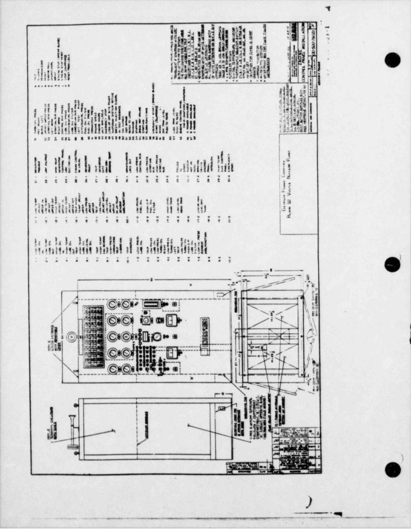
,
j h. *-
e! j i i!|;'1|iUI|IW?11!!ji!ji
{!{! !! i Ii[ ! I si ('
i 8
;!!!!Iii !I! id|$Nhli||!i|!!!!!:t
i
Oh
- - -- -- Lifl;t #,;. . . . . . . . . . .i 11y j
! ! !1| !!'
1 .
A 2: 3 SAE S 3 0s553895393333122:38848 83 3 an3
It -
I !!! !!i!!!1iill |!!!II: .,IIhLNil!!!! j;;iiii;ii;;;;;;;z;;i 9
bb
!!!!!!!!!!!!!!i!!ii!I!!i!!!!!II! II!! !!! Ms
d;;;;;;;;;i;;;;;;;;;i
I
h 1 1,14 1 !, il I! 8 'in'41is's:,Iit.!!ilt.it:111111 hit il !! 11 IIIsllillill:iti!l
i-- ::::::::; gA u t...
i ..
; a c rg~~~{~~~ gig 2M g f- "~ ~~f
fh r---------" - ~ ~
r*' Nr ' nQ f !@ @, E881E[_b- T /N/
--*
f,
.!|=0 $!@@!i[30-= ,-M. frf
+ '=
T gI M:!!=yHi y INc'
N________D@q$.!'I'
'; _
_j'
L., ,
,,_ x.s m' 1|I [i
' m1- iilli !!u!Hd i
;31 u I N !'
sm- .
-; / ;mm- : |' ~~
i m.
&)*,i _ ^^ 1~'
f., %~:i 'M:
),
. . _ _ . __. _ .. . _
4
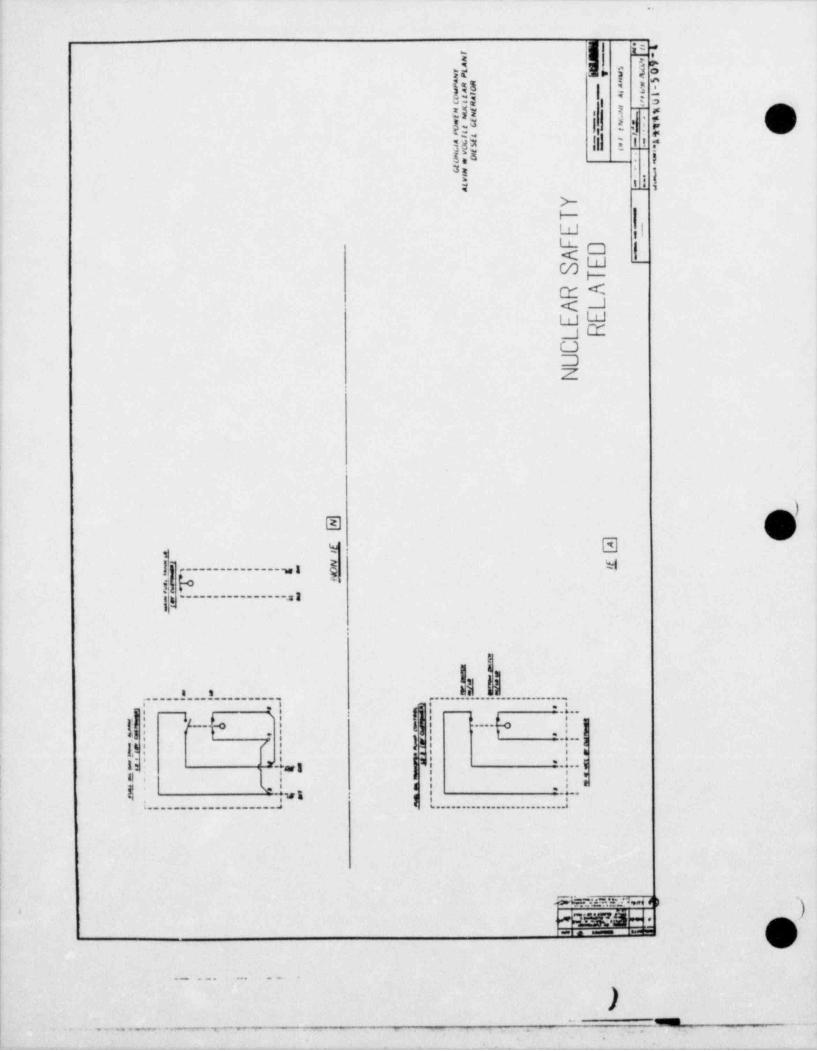
e
s 1 - ey 5 otr -
< r ?1' e g|I2- 2 -
e. t a
i!.e=! il !li s O- - . .9 3 I |
- 7n . -Ie
do, Ia. ig
h, __ i
to ,ikC -
|gutF-
T <J< Ld-
Ld.J ZC.JDZ
*
. stj .. . . . _ _ _ _ _ _ _ _ _ , i g mJ
i.gb '
ll,._______________,,I
.......a....e.......... ................ - .
[!|! 'f---h [|,r|| a..~ ~
| )l U----h ..! ]'
I ,-, . |,
}4 , .-3, e .i - , t , 'i i 4g,n
li ' ' ., 3 ,|'| -i--1* '
-'
:8
$' L, | i | : *I .;wn I |6.----..--.......--.------it-|
i____..___.... ._a
1
!1
SW:2:n.1% * >> qggg- . .
eia em te8 EWE
- - . . . - - . - *
..
$ % ** gg 9 MM % IT * * Y- C e g
9

I 7
.
3$eh' | lh%.-'
-
I E!-!|III E Y8 y'' _- .x s, o.
(p,at ,gt;,)t ;i !!... ,
.
l,
j _t ;.tivisstil is i-
:4q ; jj ,4j}h|Il ! g}l!! I
. . . ..................
I f,.rflH !NN!!NNN!!I |;. :- - ini iA! ,tL!= ::::::::::::::ii l,
y
. fjh ! " @I- i i i
h!!!|'hN!!!!!|||h k*
l';Hi!1:i!!!ilill '' ';.........,=,,,,u,,n.,
SS..
I $" ? f f$ $ |
s e l 1]p|.III ! ! i -! ; ii I!si ! 11 i j i#
'!! ! 'i l ! , | |, |1i lii i ;!!!!!!! |l i i!, ! c|44; 33 1111'm a l , !tr ,ii -
A I.;!!!!f 11 3 i i lli :linu t til i im
.? .!.!..! .! !- .! a? ! ! ! !!! '!!!!!! ! ! ! !!.! .! _,.!.,i! ...,U. ,. ,y~
8 '@ q g { 3
# !,M.hh aa- g g ti , . i / ' ja {g:>--}
7 -; ; e :hyr r y - -
n >n ,r n a n n
j %,' b. I b !-|11s 1 ,s is
I[t h- J[ s1 *I i*
, mi- e-
Tf a ,w. _Kx:.
e.lj | e :-*
||N h id)8'
11'
Ij ,e -2e 2efti-
i.L li.13'
itil!'
I
e' ~
,
- - 7 _-
5 Y
h1 N$%$h.!PI '!'
!e1x ! ! ! ! I L L.. '
-
_ =_ _. _.
, _ ..
g. . . _ -
11
)'
. . _ _ _ . _ .- _. 1
-- ,.
. .
,

"1
!s gQ i
{f ] |'!!
;.
9[[eI
$1j!!!!|If.|:|||ijli|jj j j!!!!!,p!|Iill!!j!i.i!| I' '
!i n i. t. ;
!!!!!!Ill!Il,u,n g' t%J4e ! *j, .
i! .i! !! |ii,
w!!iliii!! !..I I h!! !! e a ir ,,. ..
d .
s
1
7 . |I !b f.
2, ~
-
Jg sa t @!f N h| p- ;
k | || f| * ;}u! | | |E ! |a!
y t -"X_ I3
gx ej gcgg g g-|w o~
3ri n 1 > pil a r L .~i w Q |'c_ _ _ _ _ E s __. j
.| .h~
Esse.a sg -.
t---_1 % 97.
- , _ .. ,
(
O-. . .
_ _j-9. - - _ _ _ _ _ _ . ---
_
., ,
. .
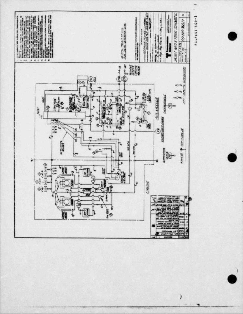
.'@
o
I
dpb
pn i, , , , i,
$i a i i I A.! :
gf-- i.!y,jp f| j I: ii Y
*| |l[b'>l''
|Fi !ji,. ni i
p[e.
!!!!its: !!usN i! 15
s sb(I,|, r! Qa .
:.... ......
5)5& 3
hWM.
(1@ hlil
Oq -
eg q. .... ... ..,
| ? T y~-
I Zs h hdl | *tpI.
'I .' Y s, [ s,i'
h = - <
j ,o f d[Ib) ri s'" e-c
; 9m *% | *Qb 'g |
c U -
*%[_.*g
*LJA 2 -
.
'8'
!!'N,
gg g-
;~
- ec3 e 3
) 5$*
| i n m
't ;gr G>
' 'se, m n j y.
e. . . .. ..... ,..
f,2- k.g;j'*~~*
9u.yesp Js
#3-6 1 :
S&g)/,igs-gbgl9 ,y
8)'
*'
ql Te n g a.:
n_ ;y: .
-_ _ _ _ .
(~ 'w a
-- - -
4 33 .- .
1 :7.==?!.
|
|
@
>- - - ,
.--. - - .. , _
_ _ _ _ _ _
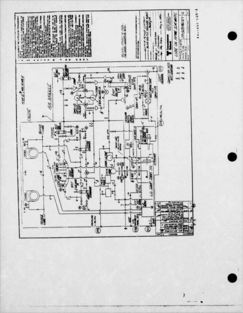
ad
ah
e 1 rr ti :!! if i' [pg
;
f, 1;
t[|h:!)d!,!!i!.8I'E !} I ds |' d4
' ~
A|*
ilrig! s i s'!
:i: R 3 g3! i'
{E hI,!kh1| i !jl|1$ acIi!!!!!j!ilill!!!ii!!ih$|.|
-
!,
i
i.m .. ...... ... ....
g@ ! e
i g +g1 f k V j f t 4 l]i
-
C--
1 - W |i :% v it le- ij, ;ip# iny l
'
a|-g
-: 1 .
4 .t.
4 g* ' s,p ' Wii.
-
hy 4 ; 'e!s '
8 ~ |};$g,e**N -
*i |g''
-'
r.
- , ,. _
,
< , ma u,ne'O il t.' - >-- s f-,
Ie* $j31 LL
$s t)P thi.4, )M-
-
4 t 4c f~# 1,
'
2 t- <.
-
g:
*@M O 5$ e:10 ' i.
). 4!, ' m.d:H.wm a
,-
- - a- _= - ,-.
vdMEi.-.i [1 !r y
_ p"
.
g :y &,gj;- i! -- -
,
--
.. . . ..
|
)
O'>
-
'
_ . _ . . . , ,
**...w..,%.. ... .
- ----
_
I11D(i'ly|1|_ O
"'
q|i!|9!!";hi!!il Iii
;!| | !{M
yi l' !
"
i
! ii; p:-i a i
,I j| II'd !!IL 3 |!=03
:
I
Ig
illi!LNhl!!N !!||. IW %.! i il_.
,I, . i.--..._.. .. .... . .
1
! $' ii.%g .o w
=O '#t
$ Ily|1
'r -o s,
fi si iI
9 4__f4! a 8
7 + ___ _t---- ---- l y
L%'? W t i 1_
k!"/)pt.at~~~E-~ -@k@!@) $ k O4- 15: !
u,\T- -
v ,1 :-
.!g ,% ~'
m-
ni 2 ]+~.,
-
,
|f| 'i. 3 _
""
gjr) pfggyap CB ,).
3 & ,t,{ p's u
jln " -
,i:
s, c, q :,~e|p b ( xg== c
. teri? 5t. i ,c .=== :.
-- -- -- -. . . - - ...
1
0, ..
.~. ~ '- - - - . .- . _,,;
_
.
,li ! !I i , i_ |i
=! : 1 li .!!!!,!> !.I!!!!|| . l. ! '
iii'>
I.l ,..- ...-.. . ... ... ... ,i e
1%24 h . .$T 2 W
g ~.- 1
(4 g .~g _. J..' - _ ._., p1. ..
. _ __ _ _ _ _ _ _T__ _ _ __ _ _ __ _ _. .$+$. I
W| ,
| L t--:w- !'g------+g.A- i g g'i
jg .__|g n
t 1{0j {p"d | z'i,
b,
-
11fj{'--- - -
:
2b.
1+ ekjes-[if r r-jE"1gte !
'
+ ,
d-.l*j O'*
p41x q >r i3
.r-- r| ;,-
+g,Q sy|p|g|,1y,u!: ,
y .j !!- -
.
t rg_* s,[+ ys ., , u
,
og i -+ I'+ t 3 ':i||i !*
-n
J s 1 sh v + ma a: -
ze 15 15j art,. ng.. .. . __... . . _ _ _ . . .._
. >'
O, ..
,
_ _ . ,
_ _ _ _ _ _ _. . .
1
, . _ . . . _ _ _ _.
!| fif: ; Mid"% N |'
I,
3 L:I,1|1 914-|1! G.t i 1
1,v
( i, :m t,i sv3 :ie t,tr
_ p' i..,
,l, , , gI i t iehe rwa iu __j i . jj]ij 1
- t
i, l,*
1 13
' h, 2-
:;1 ) ,
g t its*= 't. m.. i
-,
{.| !i |;I g i j'.. . . , . ..
-; EO
'M il ||i --iid 'I i c z a,,
; | .
.: x x- ,
' 11 18 : a= - p
ll.
Ik h 11.. q,|,11 , u1..l. }-IId
,ai,n.. 14r
Ig ;- , . xxx -
I . { || g, jx , ; j7 j d.
a:
- - - - k. ;h]gi![,: : -:
F' W |$ftil 11 lii'li
_
p{'{i
i lEih.Wi :r 7 5;m i .uIu. ~. . e_cr i.i H- H- *ip H = : ;
........7..j'''
Is. ,
* 1 ti--e
$i 2 . o" 7. [ *. 7. [ ''
.
[ *.g[I* g' j\
. . 2
j,\* *I
3.I ..I .l * .1 * pg .! 3 . t * ., o p.: y.. . .
3* *ff **
e. ,8 31f.*3'gf. 3 .- *
s.1i
.s - i,. L. . . . , , . . , . .
-
-.
.
,. ... ,
. .
s ... .. j 3 ,. 3 #, .
a*.
i n.
.L\. -5 , .i sW s .J ..T hAs.ru
2.i.. . . - .. .
/ . . i^ - /7.
.l. . . . s . i ). . ,,
.2 .2 ..s. }-.. .., -
.._ ..,. .. ..
.
' h
: O!I,, .
, . Q ~
u
f N4-
g
l.
i ,. . . .! ,. . !|:, ,
VS .4 <!3 ,'g,*14. . .s - ..
*
. 3 {~ -g.'. 85 *.t 9A o dh a
i 5 E.h @p y ow= |9*
|i.-
g s.
ib ,1 s~ ..,5, 5- y
+, .3- = gg yg | ] j ' 41 * * * 3
i s
|p- i ; i. . . .[ p .
g._ g t _ _ _ _ _ _ _ _ _ _ _ _ _ _\_ i,'s. d3
c e..,
o*
a su uu ou o 6! - e
* -
!. _.
)"
i j q. o ,..
..
,-"
* C ,-'
,.*
8 .,
*..s. .
e
!-
.,- . .%. . . , - - . . -
..1
5 a 4U- --- p-i : ssE.ea
y.i'E-5
,
: 1-
.i | )i,
.! 1 y :-.
'
!p h..i t- tsg.
|'-bj :
2- 'I*~.I yo g; !L[[tl.;;;,j; ,j h
.1.''i 11115 5 5 s,' i s: Il .e
, iii,. . b ,rian...
I!!!!!!!fif'#1! :! . siCN.rtinir I! ! 11 :,!! t .
..--.
. , l im ,
.. . t ] : t |I --tr| | tj s
,t ! Wi b ' 3'
' .
I h I .
e .,... .,.1 1... ~
,. ,
% e
G
*
'' --
o 4403. 3 oje $t-d' y
''
e|D s_.
>t
. i;4 - -..- - - r .:m . :n.
123 t,^
Wik .kgs
.~
O [ O 'O @mmmer
@ E!.1D. .,5 I.O ~~g- - - - - --
M. g)''
P
W1rLs. > es# . 9g::,E:., . .
! .
e . 1, @.
.o, .,.7----_ r:2 , 4,-
3- O O
' -%1 E:!. ;no h9 =;;.y .
| | o o.
# ],.
=a e-og -o ; ., # g< %
, a: e
s;- = -
#m+ - - , K ..A > 4> ;;.y| 3 . O O
...
- ,
+ .E:.5.s ;i. he . 23
o o 5'O;g'O.f,'Ol.'O')@o s
' #j...:
__j _3 0 -h .i .Wo h so. ,
l
.,.e. .
san -, .
I...0 - .: , .:
O|,
>. . . _ _ , ,
.-. ,.- w m -- . _. .
_ _ _ _ _ _ _ _ .- ~ - - - ~ --
-
-
m hp-
g'. , g,f, a'
-
Namm !! q g t,
I!| o! LE?.
3 ai d ] n ! *' $3 4 i se - .
-, 8 ''d ff l%.:pi i s3 U 9" s
-
etN p sigw@_ irg -
pi
% .E. Il! 11
'j|-
g,
hl]*,
.j si. ;! 1 L).
I h, . }I id - t= r - -
... i. !-. .:i. . . . .o .
g! |.
*j ]j lj ] i- - i !- i
;|-. ;;,i: ::,
,; .g 9...!,w pp..: !,; 6.@i
: -H.. ..ya n4n I i. I I ...
-| .! :. . ! ! s. ..!. 1
. i; i .1.!
.
,
>
: .! .. :- i:.,1_.~1 .; p-
.r.. ;. :.
' !!k' ..! l: |I it Ii i11
_. . .;..
Ir
4'. i! I.I I j. ,
1 :,. .::!: ? 1'
il .........r
.. .. . . . . . . , . . . . gI.. : :.:
.F. .' . i. . . I -. . '. . ! . 1. *' ~
. . I- ;-g;g .* - -
. . .. . . ..
. . . .,. . s .
. . . r .,r, . . . . . . . . . . .N
.
. a.r.;.T- _. p . -n- . :. . . . .=- ..b
- r-. .
t- i=
I N{. 5'-.
TQ ,.|; ';.';';}3| |f.l ., &:7~!.i .F..! . .. .
-Q%R ... .
. my,g | %.,1-
-- -
. .
.o . l,.
v...c. . |. q.-. ..
. ;[.4. . f _.n e . -
[-[.
....!... ....
..- .| f. . ..* eg:- .. p.
)..
.. . . ..l , . . ..L, I , ,
...........~l,
. *
i r.i- o
1 ..i - r.Z- l. (+ i.
-
. . . . .i * I-i.j j s . j _ L.j: . . %s.
. .-.-.
*
|,2 1 I']-g- . .
. .i. . i. . . m - -. . _ . .. .
.. . s . , . .\ .h .. . r- % <
. ? .! S .6. j s/ *.=A. .*l F. <
%. I's
. u .- ,) fe. . . y,y .;e ; .
/, a a n
.,9qt
. .
. . . ._. .D 8: 3r 8e 8
d, 1,
{yII.. . . .
okI *9: ] 9e {{ s 4g
& &. .-. . . .
,s9- - -
% .1* 2'.9- 2' k,eg,,
Q'g .1- 3- .Y" 2*"9 E.93 3 3 -
g -
,e a,
gg . 33 gg . g .cw o o " u
.. . r- .
g |. . .
k . |,S . .t. _1 ______.a )--
g-- .1
). ,,
. . . . . , .
.._ . - - ,w. . .
.
--
; > ~,. r p ,' -myea!y;,}14in |1 ! i ~. !i ll gA :
,
i ps.am =.
. .
5 n
! .!)!i h,- .
,+,9,,a,, li|||%e.in.t.iil.ni!!i..q',i
-
... ,.. =. . . . . . ., ,,
i
._. . . . . . . .. aees ._
,. ,. j , ,a- ,.j ,.j .; 3};- .
.e .u . :.-| r.
.:~.:,...)r..
., ...
..-',. s.. .s..q,
3 , -. . . . . . ,
.,:,. . .. .
p(. . . . <-
. .: ::e.i- -
n $$4. e. y.
t ; : : :;.: -- ..
.
.y.* i ..i"
.i 4- l.b.etr .. \. -. . . . . . .,-
S,e- IF,8...u}..lj li*j p
-j .* .- .7 i . .....
~
i : .; ; :-
.i .2 .
. ..
si ,. , ,7 | : :r-
.- --
e - ., .
.L 181 !; .: e; -l : :: : :yL4g
. .i . J .i G. A .b. . '. 6.N ., j] n: f 1
..
'
a . . ._ _ ,. . . ..
e e eaa- -
.i, u
,l. .
.,
i, i, t, a i, . .... . ..
|_b .
da ic it $e 8e idP_ *%:
,4 a. ,-I
. i. '31x .-
.. A.'-g' a. 5 a.- -
- ( . . : *
%'
%,im s- s- 5-
... . ..
} .c.-g ,}'. _; r/w ,
.J. _- g g>
-. .. ....
$-
8 |aygat >. g,m _.
- .- --s
.. . . _ . ..__.)-M
... _.. - .._..._, _ - _ _-
..
._ -,
- __ _ _ _
l is$ h
'
1 i;1(la (r,|r |, gh ;
1i tg ?t -
ta ti l 1: ,
hj |||i '-f G,|
liii j i, ,
!|-H-HH-i+ "i".5;+:6+ks95W'+H !! !!!!!!!!! Ilitlisilill 1333 Illill
I|
Lt,i!,i u n is in hI!I15
,,,n -- Lu-
ZC
81-H+H+H-H+!#H+H+Hh'!**H+i+M Zi
utaltt!!alf Atat llifssitIIIL
1
S_
!I-H+HH+H++H+HSHMNSHM+H'Hi'
IIIIIllill Illilll333 tilitIIEll
l' s.
,
tilllillt! 3518311tti altlittill
'
i 1.-
*.
),
- - - -. _ . . . . . . . - . . . . . . . . - . . _. -
-- r--
.
t
i
e
i . ru -,- ~ -
J en
tw L8L % .; ." -
*- - -
, --
,. 3*
J et emw e _ui : -t- - -,,
:: ,,
l'. :-- . . , . ,
I A
,-, . .+,- A <., -- . .g= A,
, ;--a ]C -{-" *ToId s.nar ==
j+ 3 ,, x >- - A . e--h *
j ** * " *) _n:
. - - $ j~ 'e
* -1- erX8-9, f- A
'- _L$ 9 -,'
. 3: --e" J'- ~' 2_?
E IE- '.".I= .>- . A8* A 88 J_'
8" A** A-
. ere St.A-88 J-- 83 -*' .h
en ,.B _ -
m sean A .,e ,~* J*-.
e .n- .m.e< pe
~=: |** R- see pse A ,, ,wJ,,t _ .as A ,,, ,,,
, en ,_m_ ' - - -
et A 'p-seg g~em A ~m-~1 m
8.A- me -seJ' ese ese [,~p[O A J se en e
.J'._ .se 'e~28 .se ~~~.-
A ,.
A'- | _'*E'_*
-- *= . _ . , .
*[j-e_ e ,. ,'
'e'esp
,S -
' . - -
* ~ '
y y-$,e A , ore -y-,.
-
o A se,* A me ye ''8 J'. ao N ''<
* f8- f ed as es '''s'*.A .,e '- ),- , m,eA_ < **
en g
g' p -" A sanas ese
$ "e a
-
I NUCLEAR SAFETY = = - , *,
,-v
sym risant rTa3nf1
REI Al.FD,
i l I-- .- _.S-- - r.<,-. - . .
. ..a m o t -5 09 4
.
t~
e 9O-
_ _ _ _ _ _ _ _ _ _
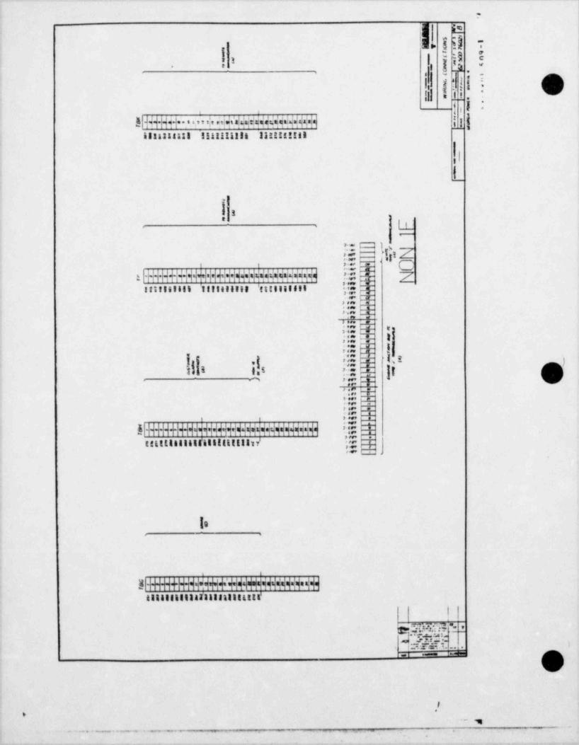
7
I>ii
$ kh 7|
|i I h .EO ta3
' *-
1',l *t' ! !.e -
s-1,ll
-
1=i .
I ,'| |, i
!H4+Hi+ s+!*Wyu$!MS H 11 |1811331113 I!!!!!!!!n 11!!!!!!!I
|liL
l!]5 -
. : 1-
-
F'm
.<
, , > ., x C,ii@g;H+HMMi+H l H H HH+H=Hii+H H+H E Z
s:1IiIIei IIttiiie1 'titiIIIeII 7,;,c.: p:$h$.5.. %xin''* _A |';: +- I|,!.I,
} .g - z )I 5 - I5
'
**.:is I::: a
, >- _i_
tetttttilittillittttIIn' '] 3
la
al|||||-||4|HOHF+M+NM$$Ht 3441841534T3333135 t t tIL'
wm2"St$: ,
5. T.S. 1. . . i
. i . 1..ame
I*
*
. . . . . . . _ . . . - . - - __ _,~1 ,
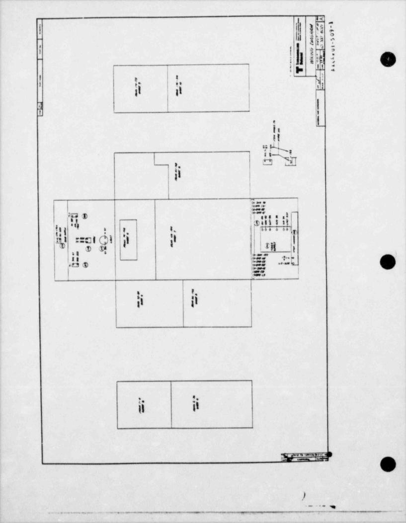
r, p -
I li hi -
L oa-
j d j3 i
! | g1 s,
! ii1| 5 g' >. }
-
. , . !!.=
!s
e. e $.1Ig |k
1,1 I1 I
! -
It
II*i k8%h
t.11
;-.
bh l_I] @ jl nos e ag
|$4tl5119
I|g| ::cg j] 'j ;|t , " ' * '' Lt:
|I I ; g .-15 i -**@ v*!|E.:~.t.. Q540 e ,y=
- - . -
s
t. f,
11 il
. .
Il il
m-...-....'M e Iq
a
. _ . . . ,. - . - - - - - - - - , _
.
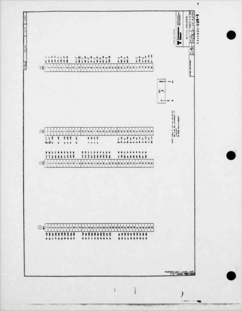
i
I '* S- nI > ,8i j g+ e
e
; c =3 !$ i
j|
-
w 3_,
i-
.t ,, -# u. 4,:
tu. <
! I .s
I fii i l?-**?.*9 'I e v'viv v' v?v? v'r?!!8valiittti alltitananal ilsI 33: 41:,
u1 gg|,|. .. . . . . . ,, t t , , et , e t . a e a e a 4 4 te a'a : a 4 .
; g
_i
@.
. . , .
It
li)n,HI:!;eg . . . . . . . . . . . . . . . . . . . . . . . . . i s . . . . . . . . .
le ,
I)! ! !!! 5 !!!! {!!!!!IIl tI I -
i. e - a - . - a - a - t Iia. . ,,, , ....
setteeasas aatteareas setteensaa
33iiiitill II!$ilitif illitatist
=.|:e; - . . . . . . . . , = , , , , , e . . s . = = i n t i e= i, = =
.I,e. . . . . . . . . . . . . . . . . . , . . . . . . .. . . . . . . . .
9fiff91179 .!!I999.=919.I. .v.ff!*f..in99.=i.===== .. si. ..
)_ . . . . , , -, ,.
I-
,.._...m
-~-e - . , . , , ,
% e
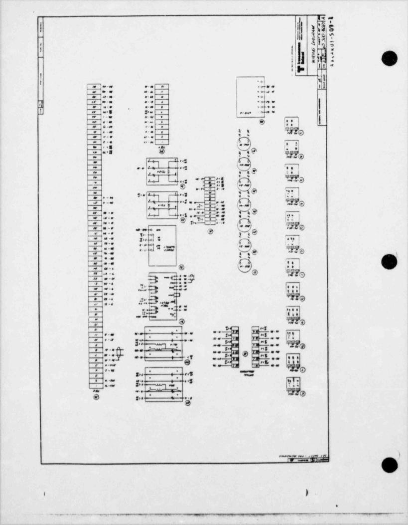
e
gg W
;Dl ec_
5 y9 -8 o| M E
I . . <""' j ljh ,
I.'
4 i,- 4.
| g .a> --
|* -c.
| ..| N I
.7.. 11. . . , . . . .,
m @=M W. .g M s .o .R .
O O*8 .* m 6
] ., .D a N ,e4 . .@a f. .h I- .. . . ....
.
1 . , , , .+ = 1., ..s p.., ... ... . s
g l. l., ... .. .e.., .. ... ;-
3 *He-
a. ... ... , ,
. ... ... .
,*G .# . .g *'
u .gi g
- ,.s g % a%88 MIE y%, h%' % T6
M. .M ". .:--
, , , , , ,. 1- ..s 'N I a 4 4 %, .. .88
' '9,,y, ,,gQ Q" as - a = s. d,,,
-- g* | ':S'-..
" .o % o C * e, * y:,,ei; s- mc -~s ...
--,: , .-- --
y. - , ,--
...L ..s.._ .-. .. 4. '.. ...
g . T*.1>. w. .ee |= ... .,, , , . ,
s. .
- n.. ane
. .. @-~- ... ... O 3 .O< . . . , , . .J .i*
., . . . .., , , .I, ... o
.. . .e k.. - @ 3W .8 * W ,g ,
*%0 .*W. e.m I8
8 i' L--., . . .
O ?.rre- . . . .
-ct.p,, .. .
= . * . ..., .. ::: ||;;,3:3 _-:. ..
a m.S. .- .
. . . . . , <
*; gr q., . .a -,, , , ,
D . **em es . S. 4.
it . , - la . &,
@ &&h@a
me,
. .@9i Ei "d- . . .. ,- - -
... .- : ...- .. n. . , ,n .. ... .- - ... g as eng3
: ,;;q --e uw-- v-e... . . _,@. o s .-p. e. m..
@T*- * e ,sg 3 ,.e 404, ,..
.se E, 444g . ., 5 g 3 - e.m, e. TO, ... . .
,.s, s., . *. .. ... ..g Z*
, . se e-m ., ,;.*
- M.es .e^s :- .-. .
S. g,. 1 e.er
! O
Ii
i
)- ... - ,-Iy e.ssee E I.M
.
* n p -* * ** . m - - , . - -,.,
4
.
M% 0g4 e'
Y , o- at }j 4 W e
e4 gp-
,
| $. b,j , , ., h B- e-a
> --1'
I i--7 a.: 1
[ -ya.
-2~ p. :. 1-
i;| 3 --
kA,A, 11i-7 -s s
*Ek-.n$ .-1
u & .
.. I..
L.
8#p ay,
E _ =. w 4.-~r1 y-
- .- . , .
O .. . '.W def .S . q#
...- .p .gc u-- . my-2e ~- * ~ . ;-
. .
.,1 nsO C *.m9
""- 7 =<3 W. .uf , - .,.
.. M e#-8.#1 at e.
.:: .%. "."eG -_
- " " .. . _j -u.,4 ..
.,
"T4 .r* ., ...,;. . - :3...m" . .
** e ._" # b% ..e. '
.swe
~ e - .et ^ ". "
C_,M m.3 - *
.. . - .-- --4- g .,..,, , ,
3 . ... . . .
. Des h .-
.k .*- e p.e
.- }.[ ",0*.|0
s
~n-* . IL} Ld. . . ''.'.'."'- d ei '*..g
-.. : .:s *.. .a . .
me,g -, -
SW .f.,
g-$''' 'g N# #' W. ,i 1 .: w , , , ,
a -* qa=-...a ... ..- ...
. : .
3 ,MeF
:. 4,7)
g.m*%
*- a, g -- . =S39
L;J L; .mp.";-. s. _'. "I ';.. ..eem .- : 4.$
/ :.|: -- 00,:e. ea. ..s :.. , . . s. w . ...
es ne ar.g 38 * "_ @m.- 1_ . _.8.. J rr-
jaadp aJ -p g ";am :,-
-
# y. .e en,e. e.s,_ _ r.r.g md
* *ee . roer-4. Q me.eeg . .
.O. 0 Ont .d. .n0 D>. O*
|sw ** =.s . * = .- --.5
,e .t-
.,-
3 ano.J ..3 ; ng*
8 89. g . #, *&D O *** $
Mr_ .-e,e
so. pes *-d. @ see. e gg ,. s. -'-
..D.6>S..M .me. ear ;- nf
8.,,:@
gy. .
.=g :- _ _ , ,e,
- -.- - - ..,. -s. ., :e . .. ., :,
_- = . . . . ,I . . _
::'",,, -
5. .'.,*,.-<. 3 .L .. r. .
.,. 4 ; -
.S*',"'- - -@se 4>. as .3 -,s
sm.e.-8 eT' g,
4 no . e **= ** *.f
,,
3>.se .J g ";^=** omo.nw env* . u=* * *4.
| a.*ew - _ - - -' IE m W IM1
|'
| ) .. .
- . - ~ . - - - . -. _ ___ _ . , . . . -
. D
~4,
g , + , .da
k |-
3 13 7 l-
_2.
h'I | 2)-
i .1 .|'
n :! )= 11
i '
1:I
il
|?J .
__
(-- ,=a ;..
e -;.+.-,. :
m~c
ee' m
~- n o.1[ ~, .:. _.
e ~,.e2.. - __
- ---
C_-..
-a-
.@ 4eeer
.l''
e.. :I t- ..: O3:.:: -
.
r.2 e .-- '-
2 3 Ig;*", 3 r
"- 7 "* E T
4: @ L -" " ' "
.
g ,_-g=.*.. ..
A
.t)* i
- w ame twIy masse m IM
+
---- -
..- _ _ - -- -_..
,
.
9 || | 1w.s ,
1.ul
s >2e-
.se eg.]s.. :E..2 | 4,, u _., , 2. . , .
, . . ...a. 4.
....
,.. .. _u. _ _..
.. s., s. , ,y; :_..._
.. s. s. .. s s . .... p i ii,a ... . . .., cr-s s a _ ,2 s tr a s : q,
N
E,E . ,, 2. E-c
.s..b.5.a.:51 a
d....t...
e.. .. ., .. . ...... . . .
..s. s. IJ. . .,s, ; s,3; .. .. ..
. . ..._ . . _.
1 # Es @ cL @ Es t
|; c;::
t. E- -
; :...; -..
.i..s.i..I .s. s. s.8_. __ .. .. . .s e .,_..s. _ , ; _...
._3 l ... .. E. . 6._.
,sx a-
4.E..s.
.J,_ s. 5
...s , . . . . . .
. . . . . . ... . . . . .u.. . _3 e.m _.. . s, z. .2 m.. . ...
._ _,..
Tv GB D GB D L* J'
...:; .. ,..a>5E,s3.. ,, 2 3,
4, g . -
.. . .
..s . . . . v... _. .. ., ..z a . .... .
.. 5 , . ..s .. $
() 3b n) Es O E
i, E3
1.=5.s.E s>
.... ,
_s 3s , ..
s. , _e,, e ,.. . .,.- , ...,
_..e _., f . .
x..e_ .,
ea., :
...s. ;.t. g. i,1s...
_.l. b.
..
s .s. .. .. s,i .e....
. .. ... . : .,.e :. ~. .s.. ., . . .....eu. g _ee. > y
.D E1 @ t @ dJ
,. .. s. s- . :.. :.. . .. . . ..,. . _. . ; .. .; ,
ss i_. .. _. ____
s) 2 @ .I @ 3'
i.. ; s s s... . : :.H ;
11 i - -.. . .
: !-s es e- -
.J ..]. - - ..-e s - ..;..; ..
s''$ l-* E 2 0- D, |- =
.; .- 3
., ;.o;|. s.*=! +--
... :- -
r.= .. , i,.
- 2
! += . ' =s; .,... i.. -- --i.. ; -.. . . ..
.; | g ., a. ._o G i @ > a
)- .. .n ~,. -
).._.__ ,
.. .. .
eq . g
. .
$
.
I | w* ,:3 o
_ 'i L i4
i | 1s ; i,
-
n .f , ,. i, , it t u1 ,] b! $l"
'
i i -,i ., ,,, o i, r , 4 i p ~~ *'
f3* * i .T)
|t .t .I si '. .; o s i
*
1 ,'** e* *** ,
ga .
ili@l ; c3 D,, c ,, i D t * i
h t ">y i. 6 , _L. . L
i..... tu, .; 1 ,t. a
... .= . .. i, a @le
L' @Sn '' Gat I- "'i
;,
LR li. .
*; I @y (c . .
, * =1 . .
I.: . % ! @n 13 1
h|'a Ill '. l '.:
@ r.. @i i @n, !. tt, ;
.|.,1,, ,|l * . I hl .:-
' . . .
@- ti .
. ~ . - -.. w @i, @ , @ .
@8u it' i * _C" :1:,, ,,.- .
Uniti9 tit 2. .. -.m ;
|| jiiiiiii'ii s,'-' ,;-Ib @geu
. .: , i
ijhOi l/ 3 i a->,. _ . _D
!m I,[m..
ii. .
Mi s/ ; i . .".-. ,,f f ,S . . ..' w } ;x. . . .m *
D @,n
t.h::si
g ,a? ] iii--, . ..
*:- .;e . . . . . -
ir. . .
! ~:"." ;F @ i *~._i_
-l/ t i i,-,.. ,'~ ,
l gesi -,- TI< .; @,iy@ . . , . . .,
j .,4 yM. .., . . . . . .
!. -- -
i~ ; .. .:. .4tti i - :::''': _ ~ _@mpi4446g6S(I 2h ...tai t e .gg g . . , .
la.,,. a
f ..... .' - - .. . . n .
g.- . .- ,.. . . , .
.
si , , , .
,f @ .... .
|| .;. ... . I-
- o..,,, ,
. . . , , , ,
t'...'' '' ~~:";.
. .
e .. .
t * .. . Tt
, . . . . .
I. .,, . . . . . . , .
= ,.. .
*I@'. ..., .
@ . , . .....
I h .',*
)_ , ,
r.. .- -
.
j_ _ . _ _ _ . . _,-
.. ,
_
_
' ' * * * * *- * * ' ' - -- - , ,, _. _
.
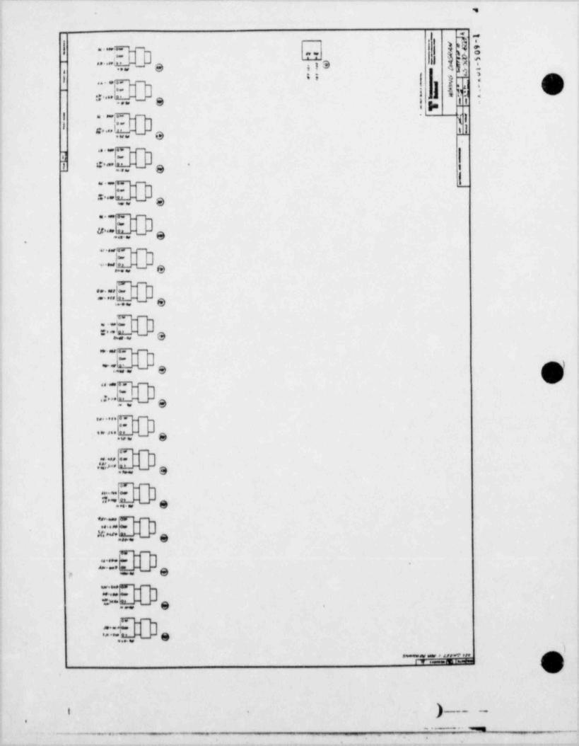
. '9
} ..- s ,sq a.g%. O- .,- J 4-y 3 ,1m
+.Ie
..s ..JA "- Q t
"" =. -,
1 $} t --... . .g -
{ 1 m gl 6,
{ g !b- .:.. y _ g .
,
} 'p 11 '
ig. .Q. -\n. o
-3 {1
l-. . .
|1@.
. . .- -
3,
.:..m..._J-
1 3 i-.
|. a- -
z... n. _3_
.
ve.
g.5.-
u.. n.e . - a. U=
y.
Tr"-""]%,s. ,eet L.e e.
"_ Q. W
... .,
_ 3 ,-
.. . -
am 64
Y.. .
-"
.r 3 aw w
. c47" "'- ,
J8W",,#
.. K3L. _ e.:.
,,.... 1ri" "",
J..
go ase n4."-g.
w.. ~ 3-
..
9.
-
3.
=. u _ e.
w- -
un.u -] e-
.. e.
--*M
'
. . . _ ., _
two.a. E
"3, _
. n. _ , .ep
pu--3,
-
.
.. . n.e e._e
G. . . . . . - .[Y .ese.M IM
) __ _ -i .
.
.,- - - ,. -- *$.m
*
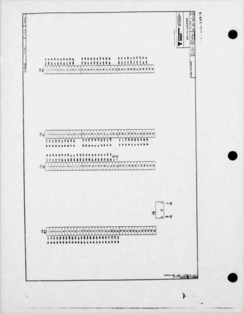
.
u.s i,;|i
- w :.'G oi
1 !] IEi 3 O'] p 11 '
I~ d
I 11.......... iii...ii.. iiii . o i ? -
triasisitt titztattle Isttt!!!al|-,
t uH-:-! I i i- l t i l' i ! != '!' !!=!'!I!!'|-|''- '_I
.
.je a|a:!ay,Ne.{. si s s : : =Sg .... . 3s .. . s i.
:::::t:: tattiittii ltiennetti iiii.iis as..... sis amiea.***.
**? ??*?***?????? ??!3sie!(tttitilllintttttttatis
af|alafefe:!afa'.|, .{n a aa i a@g ........ .i , e = = . .
.a-
@_t:, -T
- . . . . . . . . s i t t * 5 . t t i n a t a e e 4 4 e n a s a s a n aTi
!33!!!!!II!!!!!.!.!!!!.!.!!.3............ . si . .
'? $'?.E
).i i
.
. . . - . . . . . _ _. -e.
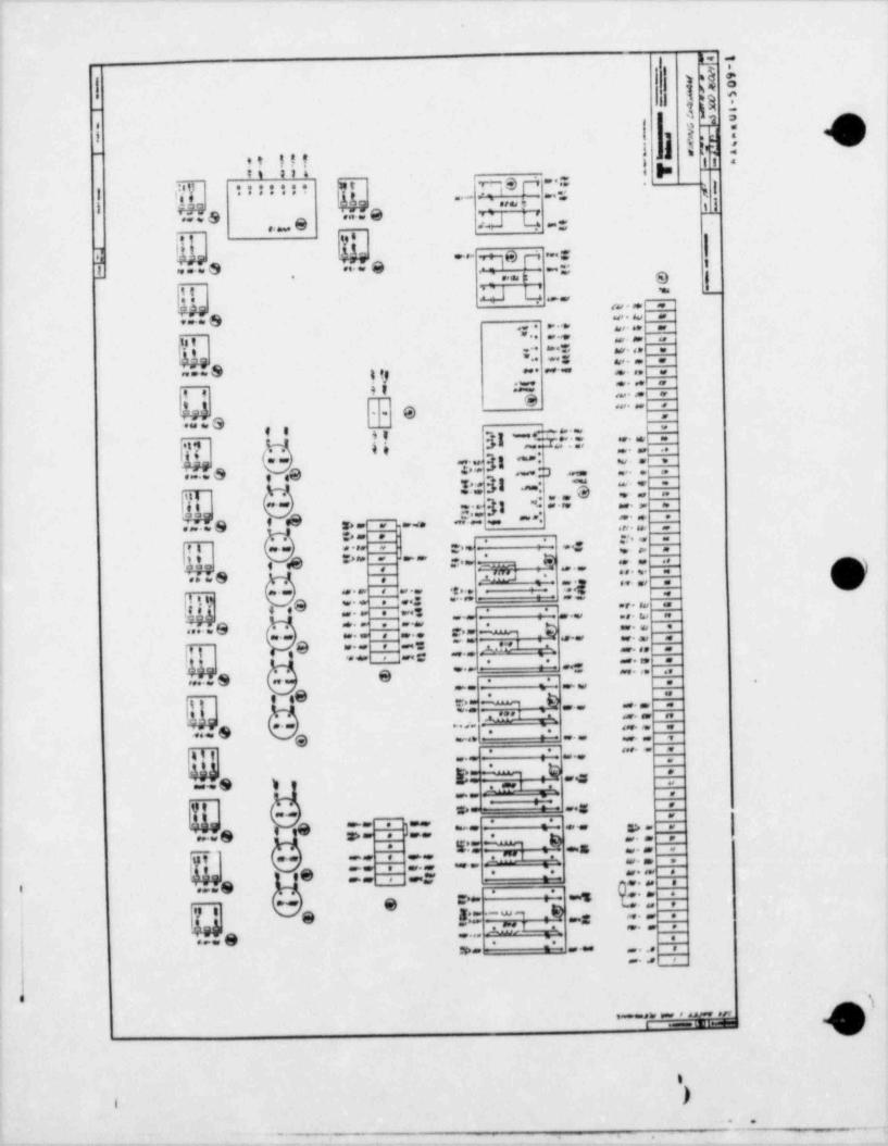
L- -
=6 E|
os e-
-) 'j g3.
i1 3e ,
! g .;:.; :i .-
o ut i,
i s =
.' b~~
*i ::i** q.s p-- =
i I| [ tt; ::t -;g - - ,,g1i
m.. . S ... e .;.L.
,
u,J.. @.. . .
-
.-
,
\ $~y ..-.S ... 9 Dg f. ~' .=. s
~7_ == s a g
.,. .
,, w L; - --.
g,9 a,.. > . ,
,.
.; . . -..- .,-. . . .
. , , . , ,;,, , - = <. w.., .
* * *
-- S ; =; ,- ,
'
. ,,
9,9 .<e =,, . .g--
_e_ ,.
w. .Q .*a - g _ -
., g 3 I _ ' .*. . .,,
+ *'" "* -r
45 J ..
|4 - - -**:-= . ~- =' .g ;
b. h31.,m -. .. S e eg . . . .~ .. . -
: .3 -,
. *'i | . . e. w. , .
, *. . 9 f O C; .' *og = " * . m. n. .s> w . .eae .or w .
, ,-:. .. -..
,,,g, , _.. .. n .. .q.
o , g ... . .,, , ~ ~ _:*".~, ~,w ._
. . . . . .: ..*
a.;ne :w _- - g, ..w.
. . . .. . . . , , . .- ., ..: . . . ~
.4 ,9 .. . ...Q . . , : ,- --.
-- . . . ,.. . ... ..... e ,t ... ... e.- %,. , ..... .. , ... -- ...-
.e . , = , :,- ;-.. . ... .
ig. ... .
e - -= . S. :-+'
-- . .. . . . . .. -
.b -
e: 4@e .... m.
. ,. ,
._ .... -. -.- . .
.. . . . . . - :-
T4. . , , , . . .
I =.2 ;: ,
E- A,.. . ,.. 3 . a.1 . ,
_ ._ _ --- -
, . .z.= n ..g. .
. ..
} -- :: -- s, . .,
., 8 z. . . .
5) -= -g"~ m, 7* .s , . , .-
, .,-ut . .. . .,. . . ..-Ie . . ..g ' = u. . .'
-
' ,,,, y -. . e. e ee
g @e. h 4 .8 .
- *:gg g g. .m, *" ***- _
g,-h,r -- .. ., 8 ... .
|. .
n- =; . , , . . . , ,
.
1
[
.,
9.u* #ht F 8 d Af8'. .Pf1 .6 EM 1m
). . .
' " ' ".
.
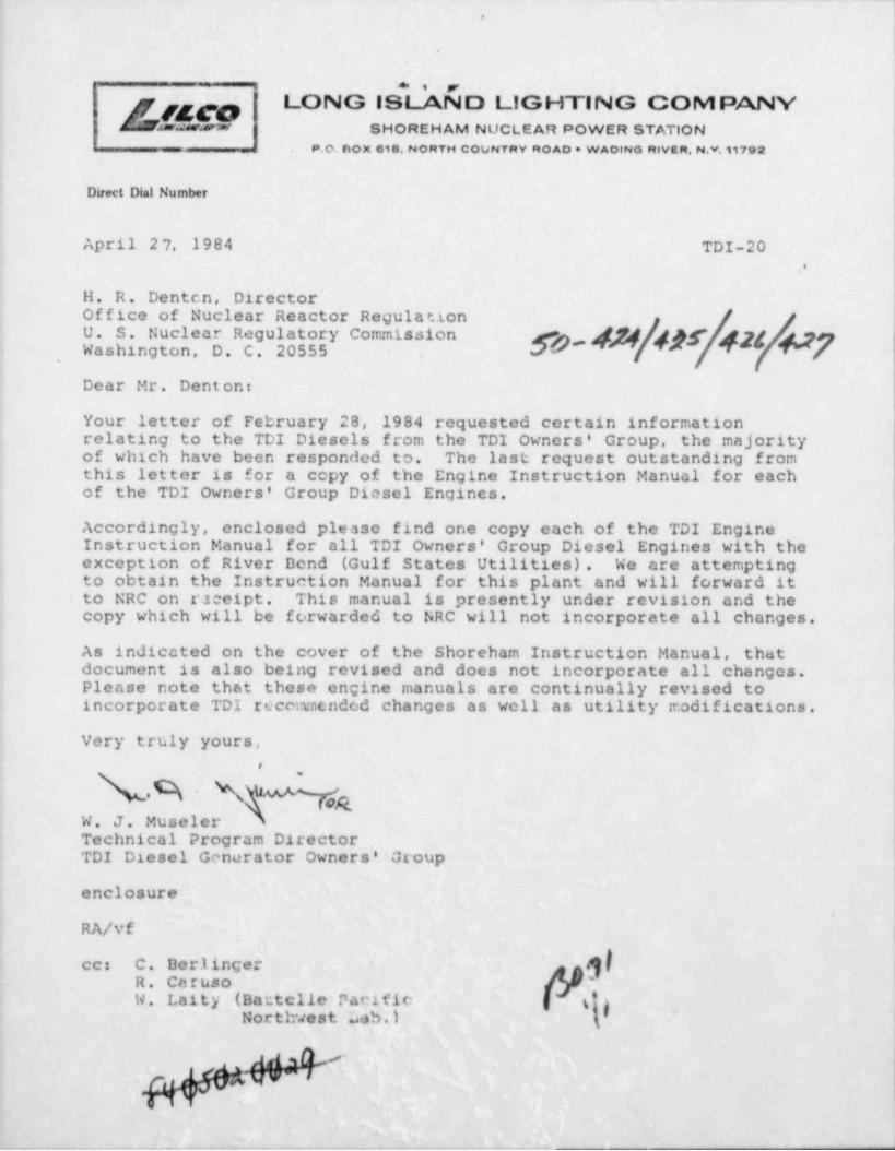
_ _ _ _ _ _ - _ _ _ _ _ _ _ _ _
,
.
's
' LONG ISLAND LIGHTING COMPANY|
* SHOREHAM NUCLEAR POWER STATION-
_. P.O. DOX 618, NORTH COUNTRY ROAD * WAOlNO RIVER, N.Y.11792
Direct Dial Number
April 2 7, 1984 TDI-20'
,
H. R. Denten, DirectorOffice of Nuclear Reactor RegulationU. S. Nuclear Regulatory Commission ,gp gf gJg gWashington, D. C . 20555
,
Dear Mr. Denton:
Your letter of February 28, 1984 requested certain informationrelating to the TDI Diesels from the TDI Owners' Group, the majorityof which have been responded to. The last request outstanding fromthis letter is for a copy of the Engine Instruction Manual for eachof the TDI Owners' Group Diesel Engines.
Accordingly, enclosed please find one copy each of the TDI EngineInstruction Manual for all TDI Owners' Group Diesel Engines with theexception of River Dend (Gulf States Utilities). We are attemptingto obtain the Instruction Manual for this plant and will forward itto NRC on rJeeipt. This manual is presently under revision and thecopy which will be forwarded to NRC will not incorporate all changes.
As in'dicated on the cover of the Shoreham Instruction Manual, thatdocument is also being revised and does not incorporate all changes.Please note that these engine manuals are continually revised toincorporate TDI recowncnded changes as well .as utility modifications.
Very truly yours,
ab * gW. J. MuselerTechnical Program DirectorTDI Diesel Generator Owners' Group
enclosure
RA/vf
jfcc C. DerlingerR. CerusoW. Laity (Battclle Pacific dgNorthwest Lab.) 3
etaldrww<
,