Vol 1 to, "Instruction Manual,Model DSRV-20-4 Diesel Engine ...
236
INSTRUCTION MANUAL Volume I Model DSRV-20-4 Diesel Engine Serial Nos. 75041-2803 75042-2804 SOUTHERN CALIFORN EDISON COMPA San Onfre Nuclear Power Station, L'4. I 421 7 3 MANUAL97 mMoDR ADOCK 050002DR iS
-
Upload
khangminh22 -
Category
Documents
-
view
1 -
download
0
Transcript of Vol 1 to, "Instruction Manual,Model DSRV-20-4 Diesel Engine ...
INSTRUCTION MANUAL
Volume I Model DSRV-20-4 Diesel Engine Serial Nos. 75041-2803
75042-2804 SOUTHERN CALIFORNIA EDISON COMPANY San Onfre Nuclear Power Station, L'4. I
421 7 3 MANUAL97
mMoDR ADOCK 050002DR iS

DELAVAL ENGINE AND COMPRESSOR DIVISION 550-85TH AVENUE OAKLAND. CALIF 94621
ENGINE DATA SHEET
Manufactured for So es Order No.
Southern California Edison Company 75041 & 75042
For Installation: Purchase Order No.
San Onofre Generating Station Unit No. 1 B-8273001
ENGINE DATA Model Serial No(s).
DS RV-20-4 75041-2803, 75042-2804
Stationary 0 Marine [NDiesel D u.al Fuel O Heavy Fuel V-tvpe Inline
No. Cylinders Bore Stroke Cycles Total Displacement Cont anad
20 17 in. 1 21 in. 4 95,332 cu-in. I ih ad1 etHn BMEP Brake Horsepower Crankshaft Rotation Starting System Pilot air,
154.6 psi 8375 @ 450 rpm CW, viewed from flywheel end gear driven distributors Firing Order
1L-1OR-3L-8R-5L-6R-7L-4R-9L-2R-1OL-1 R-8L-3R-6L-5R-4L-7R-2L-9R Fuel injection Timing
Left Bank 24 Left Bank 1&-7/8 RIght Bank 23 oBTDC, set Right Bank 181/8 inches BTOC on a 90 in. diameter flywheel
Fuel Injection Pump Rack at Full Load
DIESEL 29 mm PILOT OIL NA Valve Clearance - Cold Engine
INTAKE NA EXHAUST NA Equipped with hydraulic valve lifters
FACTORY TEST RESULTS (Average Full Load Data)
Item Diesel Dual Fuel
EXHAUST TEMPERATURE 8800 F
AIR MANIFOLD PRESSURE 32.2 In.-hg
AIR MANIFOLD TEMPERATURE 1250 F
AMBIENT TEMPERATURE 740 F
BAROMETRIC PRESSURE 29.88 in.-hg
C NT:Exhausr temperatures ste the sverage for alcylindrs during factory rest under LOCAL AMBIENT CONDI TIONS.
Temperatures in the field, therefore, may exceed this average temperature. Always include serial numbers when communicating wirh DELA VAL Engine and Contenssor Division concerning engine performance, or when ordering spare or replacement parts.
0
Form CAT-108-1 1/74
GUARANTEE
Unless otherwise specifically stated, all machinery and equipment purchased hereunder is subject to the following warranty: DELAVAL TURBINE INC., Engine and Compressor Division (hereinafter called Company) warrants that machinery and equipment manufactured by Company and furnished and delivered to the Purchaser hereunder shall be of the kind and quality described in the Company's specifications, and no other warranty or guaranty except of title is made or shall be implied. If any part of said machinery and equipment thus manufactured by the Company fails because of defective workmanship or material within one year from the date of starting the engine after delivery, but not exceeding fifteen months from the date of shipment, the Company will, provided such machinery and equipment has been used for the purpose and in the manner intended and the Company's ex3mination shall disclose to its satisfaction that such parts are defective, replace such defective parts free of charge, f.o.b. cars at its warehouse in Oakland, California, but the Company will not be liable for repairs or alterations unless the same are made with its written consent or approval. The Company will not be liable for damages or delays caused by such defective material or workmanship, and it is agreed that the Company's liability under all guaranties or warranties, either express or implied, is expressly limited to the replacing of parts failing through defective workmanship or material within the times and in the manner aforesaid. Parts claimed to be defective are to be returned to the Company at its option, transportation. prepaid. The Company makes no guaranties or warranties whatsoever in respect to products other than that manufactured by the Company as they are sold under the regular warranties of the respective manufacturers, copies of which will be furnished if requested. All warranties and guaranties as to efficiency and capacity are based upon shop tests when operating under specified conditions, but do not apply to any condition varying from the foregoing. The liability of the Company (except as to title) arising out of the supplying of said machinery or equipment or its iuse, whether on warranties or otherwise, shall not in any ecase exceed the cost of correcting defects in the machinery or
equipment as herein provided, and upon the expiration of said warranty, as herein provided, all such liability shall terminate.
PRODUCT IMPROVEMENTS
The Company reserves the right, where possible, to include changes in design or material which are improvements. Also reserved is the right to furnish equipment of design modifications best suited toa particular installation, location, or operating condition, as long as such modification exceeds Purchaser's design specifications. The Company cannot be responsible for including improvements made after start of production on Purchaser's equipment
&* Perm 9-991 (A-11 9/72

INSTRUCTION DELAVAL ENGINE AND MANUAL FOR COMPRESSOR DIVISION ENTERPRISE 550-85TH AVENUE ENGINES OAKLAND, CALIF 94621
TABLE OF CONTENTS
SECTION 1 -INTRODUCTION
Purpose............... .............................. 1-1 Notes, Cautions and Warnings . . .. . ... . . . . . . . . . . . . . . . . 1-1 Maintenance Practices . . . . . . . . . . . . . . . . . . . . . . . . . 1-1 Customer Assistance . . . . . .. . . . . . . .. . . . . . . . . . . . . 1-1 Parts Manual.......................... .............. 1.2 Associated Publications Manual . . . . . . . . . . . . . . . . .. . . . . . 1-2 General Engine Description..... ................... ......... 1-2
SECTION 2- INSTALLATION
General......................................... 2-1 Foundation Drawing ..... .............................. 2-1 Installation Drawing ............................... 2-1
System Schematic Drawings......... . . . . . . . . .. . . . . . . 2-1 Handling and Shipment.. . . . . . . . . .. ... . . . . . . . . . . . 2-1 Foundation ....................... ............... 2-2 Foundation Bolt Assemblies . . . . . . . . . . . . . . . . . . . ... . . 2-2
Preparation For Installation.. ...... . . . . . . . . . . . . . . . 2-3 Placing Engine Over Foundation . ... . . . . . . . . . .. . . . . . . ... 2-3 Mounting Flywheel and Connecting Shaft . . . *. ... . . . . . . . . . . . . 2-5
Grouting ..... ..................................... 2-5 Piping Systems . . . . . . . . . . . .. ... . P . . . . . . . . . . 2-6
Treatmentof Piping... .................... .............. 2-6 Jacket Water System .......... .......................... 2-7 Raw Water System........................ .......... 2-8 Intercooler Lines............................................2-8 Fuel System ........................ ............... 2-9 Fuel Gas System.......................... ............. 2-9 Lubricating Oil System . . . .. . . . . . . . . . . . . . . . . . . . . . 2.10 Flow Principle ........................... ........... 2-10 Auxiliary Lubricating Oil Pump ...................... 2-10A Installation Precautions.. ...... . . . . . . . . . . . . . . . 2-10A Placing Lubricating Oil System In Service . . . . . . . . .. . .. . . .. . . . .. 2-10A Intake System ....................... ............... 2-11 Exhaust System.... ....................... ............ 2-12 Starting Air System . . . . . . . . . . . . . . ...... . . . . . . . . . 2-13
SECTION 3 - OPERATING PRINCIPLES
PART A- GENERAL Working Principle .............. ................... 3-A-1 Intake Stroke.......... ........................ 3-A-1 Compression Stroke . . . . . . .. . . . . . . . . . . ... . . . 3-A-1 Power Stroke... ............ ................ . 3-A-1 Exhaust Stroke........... ....................... 3-A-1
R/RVISl-75 In-l 1/76
INSTRUCTION DELAVAL ENGINE AND MANUAL FOR COVPREzSSOR DIVISION ENTERPRISE 550-85TH AVENUE ENGINES OAKLAND, CALIF" 94621
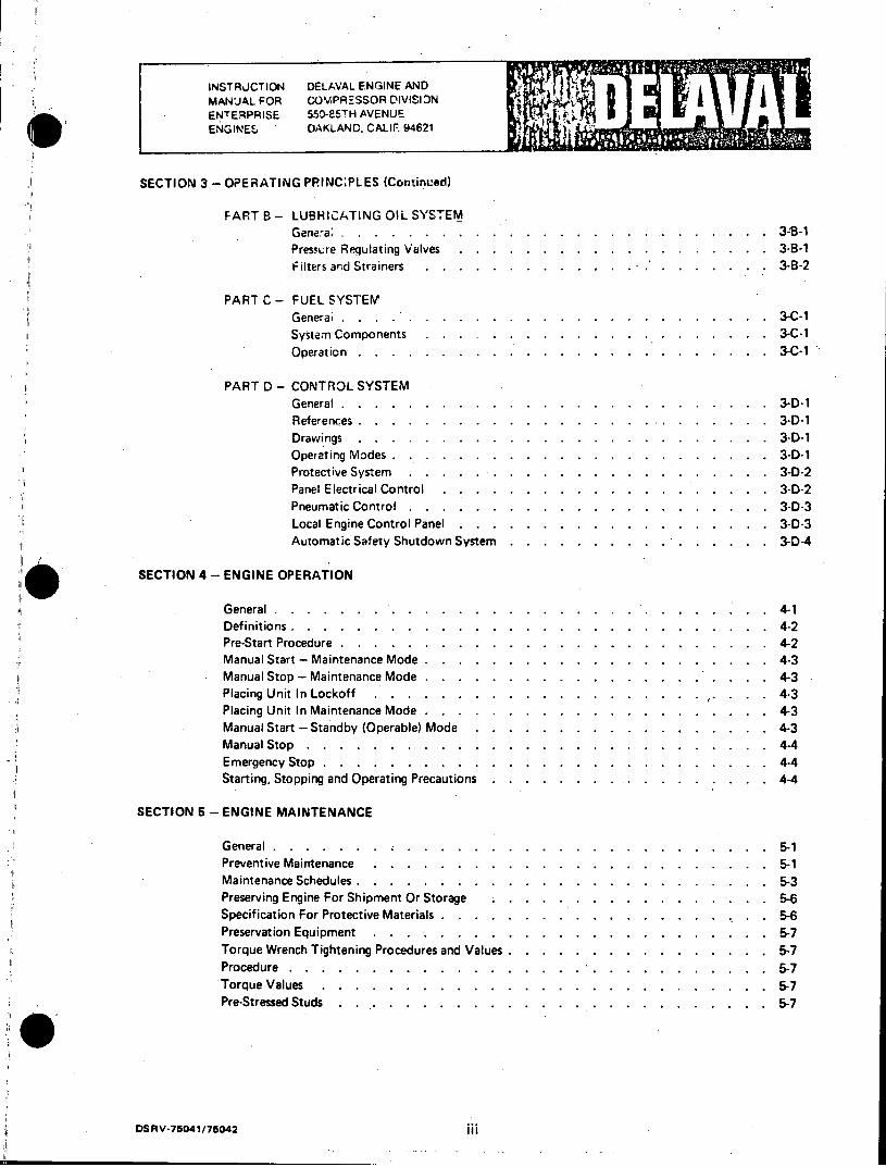
SECTION 3 - OPERATING PRINC:PL ES (Continued)
FART B - LUBRICATING OIL SYSTEM Genera;....... .............................. 3-B-1 Pressure Regulating Valves......... .... . . . . .. 3-B-1 Filters and Strainers............. .... . . . .. 3-B-2
PART C - FUEL SYSTEM Generai . . . . .................. 3-C-1 System Components.............. .... . .. 3-C-1 Operation. . ......... . . . ... .... . . . .. 3-C-1
PART D - CONTROL SYSTEM General............ ............................ 3-D-1 References........... ........................... 3-D-1 Drawings ........... ........................... 3-D-1 Operating Modes.......... ......................... 3-D-1 Protective System ......... ........................ 3-D-2 Panel Electrical Control . . ....... . ........ 3-D-2 Pneumatic Control......... ........................ 3-D-3 Local Engine Control Panel . . . . . . . . . . . . . . . . . . . 3-D-3 Automatic Safety Shutdown System . . . . . . . . . ... . . . . . 3-D-4
SECTION 4 - ENGINE OPERATION
General.................... ...... . . .. 4-1 Definitions.............. ...... . . . . . . . . . 4-2 Pre-Start Procedure............... ..... . . . . .. 4-2 Manual Start - Maintenance Mode............ ... . . . . . .. 4-3 Manual Stop - Maintenance Mode . . . . . . . . . . . . . . . . ... . . . 4.-3 Placing Unit In Lockoff . . . . . . . . . . . . . . . . . . . . .. 4-3 Placing Unit In Maintenance Mode . . . . . . . . . . . . . . . . . . . . . 4-3 Manual Start - Standby (Operable) Mode . . . . . . . . . . . . . . . . . . 4-3 Manual Stop............ .............................. 4-4 Emergency Stop............ ............................. 4-4 Starting, Stopping and Operating Precautions......... ..... . . . 4-4
SECTION 5 - ENGINE MAINTENANCE
General .5-1 Preventive Maintenance....................... ... 5-1 Maintenance Schedules ...................... .... 3 Preserving Engine For Shipment Or Storage................. 5-6 Specification For Protective Materials . ... ................. 5-6 Preservation Equipment..................... .... 5-7 Torque Wrench Tightening Procedures and Values .............. ... 7 Procedure . . . .......................... 5-7 Torque Values..................... ...... 7 Pre-Stressed Studs ..... . .............. ............... 5-7
DSRV-75041/75042.
INSTRUCTION DELAVAL ENGINE AND MANUAL FOR COMPRESSOR DIVISION ENTERPRISE 550-85TH AVENUE ENGINES OAKLAND, CALIF. 94621
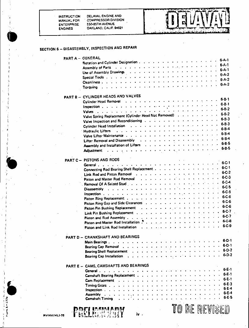
SECTION 6 - DISASSEMBLY, INSPECTION AND REPAIR
PART A - GENERAL Rotation and Cylinder Designation . . . . . .. . * . * * . .. . . . 6-A-i
A s s e m b l y o f P a r t s . . . . * * * * * * * * . . . . . . 6
Use of Assembly Drawings . . . . . . . . * . * * * * . ...... 6-A-1
S p e c ia l T o o ls . . . . .. . . . . * * * * * * . . . . . . . .. 6 -A -2
C le a n lin e ss . . . . . . . . * * * * * * * .. . ... . . . . .6 -A -2
Torquing ............ *.*................ 6-A-2
PART B - CYLINDER HEADS AND VALVES
Cylinder Head Removal . . . . . . . . .. * . * * * ....... 6-B-i
Inspection . . . . . . . . . . . - ... . . . . . . ... 6-BValves-------------------------------------------------------6-B-2 Valve Spring Replacement (Cylinder Head Not Removed) . . . . . . . . . 6-B-2
Valve Inspection and Reconditioning . . . . . . . . . . * * . . . * 6-8-3
Cylinder Head Installation--------------------------------------- -8-3
Hydraulic Lifters . . . . . . - * * * * * * * * * . . . . . . 6-B-4
Valve Lifter Maintenance . . . . . . . - -- - - * * * * * -- 6-B-4
Lifter Removal and Disassembly------------------------------------6-B-4 Assembly and Installation of Lifters . . . . . . . - - . . . . . 6-8-5
Adjustment .....-.-.-.- *-.-********.------------------. &B-5
PART C - PISTONS AND RODS General----------------------------------------------------.-CConnecting Rod Bearing Shell Replacement------------------------------6-C-1
Link Rod and Piston.Removal--------------------------------------6-C-2 Piston and Master Rod Removal eplace t . . . . . . . . . . . . . . C1
Removal Of A Seized Stud- . . . . . . .. . ..- ..-. .* * * * *-6-C-4
Disassembly--------------------------------------------------6-C-5 Inspection nd Master Rod R l . . , . . . . . . ...-- * * . . . . . 6-C-3
Piston Ring Replacementd . . .. . . . . . ..- . .*. . . . . . . 6-C-6
Piston Ring Gap and Side Clearances......----**********-------------6-C-6 Piston Pin Bushing Replacement . . . . . . . ..- - . . . . .. . 6-C-6
Link Pin. Bushing Replacement-------------------------------------.-C Piston and Rod Assemblyearances . . . . . . . . . . . . . . . . 6-C-6
Piston and Master Rod Installation - . . . . . . . . .* * * * * * * * 6-C
Piston and Link Rod Installation . . . .. . . . . . . - * * * 6-C-9
PART D - CRANKSHAFT AND BEARINGS Main Bearingste Rod .nsta n . . . . .-. . . . . * * * . . . . . 6-D-8
Bearing Cap Removal lation . . . . . . . . . . . . . . . . . . 6-D-9 Bearing Shell Replacement--------------------------------------- -- 2
Bearing Cap Installation . . . . . . . . . .- - - . . . . . . 6-D-2
PART E - CAMS, CAMSHAFTS AND BEARINGS General-....-.-.--------------... ----- ***** *....-..6-E-1
Camshaft Bearing Replacement . . . . . . . . . . . . . . . . . . 6-E-1
Cam Replacement . . . . . . . . . . . * . * * * * * . . . . 6-E-1
Timing Gears-......-..-..-.-.-.-.-.--***---..-... -6-E-3
Inspection-....--------.....--.... *****.- ..-..-. -E-4 Assembly-..-.-... .-.-------------. .-- ***** *.-...6-E-4 Camshaft Timing ........-.-..-.-...-....-.-..--- 6-E-5
AV(4V/14L)-75 IV -: -
* INSTRUCTION DELAVAL ENGINE AND MANUAL FOR COMPRESSOR DIVISION ENTERPRISE 550-85TH AVENUE ENGINES OAKLAND. CALIF 94621
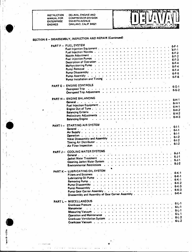
SECTION 6 - DISASSEMBLY, INSPECTION AND REPAIR (Continued)
PART F - FUEL SYSTEM Fuel Injection Equipment . . . . . . . . . . ... .. 6-F-1
Fuel Injection Nozzles . . ... . . .. . * . * * . ... . . . ..6-F-2 N ozzle A djustm ent . . . . * . . * * * * . . . . . . . . . . . 6-F-2
Fuel Injection Pumps . . . . * . * * * * * . . . . ' . . . 6-F-3 Description of O peration . . . . . . * . * * * * . . . . . . . 6-F-3
Malfunctioning Pump . . . . * * * * * * * . . . . . . . . . . 6-F-4 Pump Removal . . . .. . . . . * * * . . . . . . . ..... 6-F-4 Pump Disassembly . . . . . * * * * * * * * . . . . . . .. . 6-F-5 Pump Assembly .... . .6-F-6 Pump Installation and Timing . . . . . . . . . . . . . . . . . .6-F-6
PART G - ENGINE CONTROLS Overspeed Trip . . . * . * . . . . .6-G-1
Overspeed Trip Adjustment . . . . . . . . . . ... . . . . . . 6-G-2
PART H - ENGINE BALANCING G e n e r a l . . . . . . * * * . * * * * . . . . . . . . 6 -H -1
F u e l In je c tio n E q u ip m e n t . . . . * * * * * * * . . . . . . . . 6 -H -1
Engine Out of Tune . . . .. . . . * * * * * . . . . . . . . . 6-H-2
Balancing Criteria 6-H-2 Preliminary Adjustments . . . . . . . . . . . . . . . . . . . . 6-H-2
Balancing Engine . . . . . . . . * * * * * * * .. 6-H-3
PART I - STARTING AIR SYSTEM General. . . . . . . . * * * * * * * * *. . . . .. 6-1-1
Air Supply . . . . . . . * * * * * * * * * *. . . . . . 6-1-1
O p eratio n . . . . . . . .* * * * 6 -I- 2
V alve Disassem bly and Assem bly . . . . . * * * * * * . * . . . 6-1-2
Timing Air Distributor . . . . . . . . ... . . . . . . ... 6-1-2
Air Filter Inspection . . . . * * * * * * * * * *. 6-1-2
PART J- COOLING WATER SYSTEMS G e n e r a l . . . . . . . . * * . .* * * * . . . . . . . 6 -J -1
Jacket Water Treatment . . . ... . . . . . . . . . . . . . . 6--1
Cleaning Jacket Water System . . . . . . . . . . .. . . . . . 6-J-2
Environmental Restrictions . . . . . . . . . . . . . . . . . . 6--2
PART K - LUBRICATING OIL SYSTEM Filters and Strainers . . . . . . . * * . . * * * * * . . . . 6-K-1
Lubricating Oil Pump . . . . . * . * * * * * * * . . . . . . 6-K-1
Removing Pump . . . . . * * * * * * * * *. *. .. 6-K-i
Pump Disassembly . . . .. . . * * * * * * * * * * . . . . 6-K-2
Pump Reassembly . . . . . . * . * * * * * * * * . 6-K-3
Pump Gear Carrier Assembly . . . . . . . . . . . . . . . . . .6-K3
Disassembly and Assembly of Gear Carrier Assembly . . . . . .. . . ... . 6-K-4
PART L - MISCELLANEOUS Crankcase Pressure . . . . . . . . . * * * * * * * . . * . . . 6-L-1
Manometer ..... 6.. .L-1 Measuring Vacuum . . . . . . . . . * * * * * * * * * * . . 6-L-1
Operation and Maintenance . . . . . . . . . . . . . . . . . . .6L-1
Crankcase Ventilation System . . . . . . . . . . . . . . . . . 6-L-2
Crankcase Vacuum . . . . . . . . * * . ... . . . .. . . . 6-L-2
V
INSTRUCTION DELAVAL ENGINE ANDv MANUAL FOR COMPRESSOR DIVISION ENTERPRISE 550-85TH AVENUE ENGINES OAKLAND, CALIF 94621
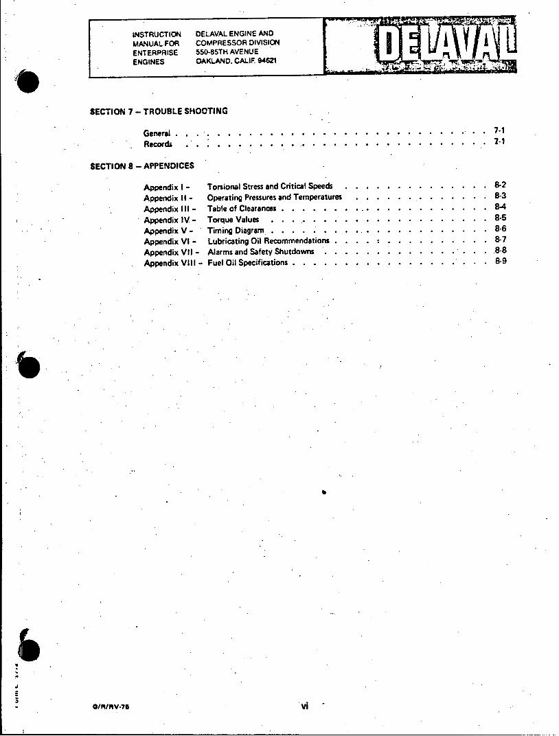
SECTION 7 - TROUBLE SHOOTING
General . . ... . .*......................7.1 Records . . . . *...................... .*. 71
SECTION 8 - APPENDICES
Appendix I - Torsional Stress and Critical Speeds . . . . . . . . . . . . . . 8-2
Appendix II - Operating Pressures and Temperatures . . . . . ... . . . . . . 8-3
Appendix III - Table of Clearances . . . . . . .... . . . . . . . . . . . .- 4
Appendix IV - Torque Values . . . .. . . . . . . . . . . . . . . . . . 8-5 Appendix V - Timing Diagram . . . . . . . . ... . . . . . . . . . . . 8-6 Appendix VI - Lubricating Oil Recommendations . . . .. . . . . . . . . . . 8-7 Appendix VII - Alarms and Safety Shutdowns . . . . . . . . . . . . ... . . . 8-8 Appendix VIII - Fuel Oil Specifications . . . . . . . . . . . . . . . . . . . 8-9
O/R/RV*76 vi
INSTRUCTION .DELAVAL ENGINE AND MANUAL FOR COMPRESSOR DIVISION A
ENTERPRISE 550-85TH AVENUE ENGINES OAKLAND, CALIF 94621
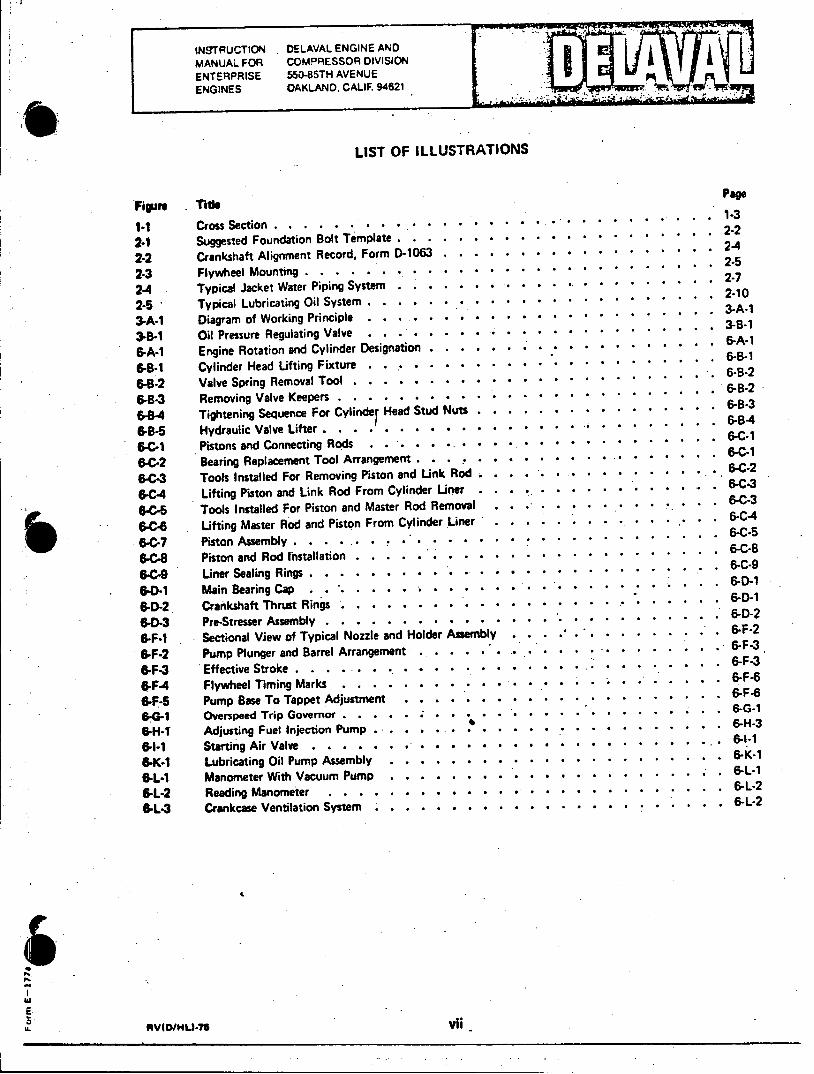
LIST OF ILLUSTRATIONS
Figure Title
1*1 Cross Section . . . . . . ... . . . . . . . . ..... ....... 1-3
2-1 Suggested Foundation Bolt Template . . . . .. . . . . . . . . .*..
2-2 Crankshaft Alignment Record, Form D-1063 . . . . . * . * * * . * . * ..... 2-4
2-3 Flywheel Mounting........ * .. .................... 2-5
2-4 Typical Jacket Water Piping System . . . . . .. * . * * * * * . . '......7
2-5 Typical Lubricating Oil System . . . . . . .. . . * . * * . * . . . ...... 2-10
3-A-1 Diagram of Working Principle . . ... . ... . . . * * * * * . . . . . ..... 3-A
3-B-1 Oil Pressure Regulating Valve . . . . . . * * *.. . . . . * . . . . . ...... 3-B
6-A-1 Engine Rotation and Cylinder Designation . . . . . . .. . . . . . . * . .. .... 6-A
6-B-1 Cylinder Head Lifting Fixture.... . . . . . .*.*.....**... . . . . ..... 6-8
6-B-2 Valve Spring Removal Tool . . . . . .. . . . * * * * * . . . . .... ... .6B2
6-B-3 Removing Valve Keepers . . . . . * . * * . . * * * * * * . . . . ..... 6-B2
.8-4 Tightening Sequence For Cylinder Head Stud Nuts . . . . . .. * * . * * . .. .. 6-83
6-8*5 Hydraulic Valve Lifter.... . . . . . * * * * * * * * * * * * . . . . . . 6-B4
S.C-1 Pistons and Connecting Rods . ... . . ... . . . . * * * * * * . . . .. ... 6-C-1
6-C-2 Bearing Replacement Tool Arrangement . . . .. .. . . . . . . *.... . . .... 6-C
6C-3 Tools Installed For Removing Piston and Link Rod . . . . .. .. . . * .* *......6-C-2
6C4 Lifting Piston and Link Rod From Cylinder Liner . . . .. . .. . .. . . . .. . 6-C-3
6-C-5 Tools Installed For Piston and Master Rod Removal.... . . . . . .* * * . *... 6-C-3
6-C4 Lifting Master Rod and Piston From Cylinder Liner . . . . . .. . ... . . . .... 6-C-4
.6C-7 Piston Assembly . . . ... . . . * * * * * * . * * * . . . . ....... 6-C-5
6-C-8 Piston and Rod Installation . . . . . .. .. . . * .. . * * . * . ..... . 6-C-8
6-C-9 Liner Sealing Rings . . . . . .. . . .. . . . * * *.... . . . . . .6-C-9
6-D-1 Main Bearing Cap ..... ........... *.. ..... 6-D
-D-2 Crankshaft Thrust Rings . . . . .. . . .. . . . . . . . . . 6-D-1
6-D-3 Pre-Stresser Assembly . . . . . .. . . . . * * * * . * . . . . ...... . 6-D-2
6-F-1 Sectional View of Typical Nozzle and Holder Assembly . . . . . . . . 6-f-2
6-F-2 Pump Plunger and Barrel Arrangement ... . . . . .. . * . *... . . . *6-F-3
6-F-3 Effective Stroke..............*....*.*.*.*.*......*.*.*.*.*.*.*.*.*6-F-3 6-F4 Flywheel Timing Marks . . . . . . . * . * . . * * *... . .. . .... 6-F
6-F-5 Pump Base To Tappet Adjustment . . . . .. . .. ... . . . . * . * . . *.. . 6-F6
6G-1 Overspeed Trip Governor..... . * * * * * *.. . . . ... . . ....... 6-G-1
'HI Adjusting Fuel Injection Pump . -. .... . . . ... 6-H-3 61-1 Starting Air Valve . . . . . . * * * .. * * * .... ..* . .......... 6-11
6-K-1 Lubricating Oil Pump Assembly..... .. . . . *............. . 6-K-i
6-L-1 Manometer With Vacuum Pump . . . . . * * * * *............. -L
6-L-2 Reading Manometer.... . . . .. *.............. ...... 6-L-2
6-L-3 Crankcase Ventilation System. ....... ............. .. ..... 6-L2
E
RVE1..-76 v2i

SECTION 1
INTRODUCTION
PURPOSE.
The purpose of this instruction manual is to assist the owner and operating personnel in the operation, maintenance,
adjustment and repair of the DELAVAL Engine and Compressor Division's "Enterprise" engine. Maximum efficiency
and continuous, trouble-free service will be the result of careful study and application of the contents.
NOTES, CAUTIONS AND WARNINGS.
Notes, cautions and warnings, as used in this manual, are intended to convey the following meanings.
a. NOTES - Operating procedures, conditions, etc., which it is essential to highlight or emphasize because of their
importance to the proper operation of the machinery.
b. CAUTIONS - Operating procedures, practices, etc., which, if not strictly observed, could result in damage to, or
destruction of equipment.
c. WARN INGS - Operating procedures, practices, etc., which could result in personal injury or possible loss of life
if not correctly followed.
MAINTENANCE PRACTICES.
. Continuous design refinement and many years of experience in the manufacture of large diesel, dual fuel and spark
ignited engines have become a part of the "Enterprise" engine. Each engine is thoroughly tested and inspected before
shipment. To realize the longest operating life with a minimurm of engine down time for unscheduled maintenance or
repair, a program of cleanliness, inspection, preventive maintenance and record keeping is essential.
a. Cleanliness, because it makes a thorough inspection easier, helps keep dirt out of moving parts and indicates in
large measure the care the machine receives in other ways.
b. Inspection, because areas of minor wear will be revealed before they become major and require repair or replace
ment.
c. Preventive maintenance, because it, in combination with cleanliness and inspection, will permit the repair or re
placement of wearing parts before they can cause serious malfurition and/or damage to the engine.
d. Record keeping because, when kept on adequate forms and at regular intervals, records will keep operating
personnel informed of the current running condition of the engine. Comparison of present and past log sheets will
reveal gradual changes in temperatures, pressures, noise and performance, all indicators of the engine's condition which
can be of assistance in the planning of overhaul and repair schedules.
CUSTOMER ASSISTANCE.
DE LAVAL Engine and Compressor Division maintains a staff of factory trained service personnel who are available at
nominal rates to assist or advise in the installation, overhaul and repair of "Enterprise" machinery. It is recommended
that one of these service men be requested when extensive repairs are being made on the equipment. If assistance is re
quired, write or wire DELAVAL Engine and Compressor Division, Service Department, furnishing complete information
including serial numbers.
o 00-74 11

INSTRUCTION DELAVAL ENGINE AND MANUAL FOR COMPRESSOR DIVISION I ENTERPRISE 550-85TH AVENUE M ENGINES OAKLAND. CALIF. 94621 r ,r
PARTS MANUAL.
The Parts Manual furnished with the engine contains engine specifications, parts lists and part numbers for all furnished
equipment together with instructions for ordering spare and replacement parts. Assembly drawings are also included
in the manua! to assist in the identification of parts, however, part numbers appearing on the assembly drawings should
not be used when ordering parts. Always use the part numbers appearing on the appro, riate Group Parts List in the
Parts Manual.
ASSOCIATED PUBLICATIONS MANUAL.
The Associated Publications Manual is a companion publication to this instruction manual, and contains manufacturer's
instructions, bulletins and parts lists applicable to parts and equipment not manufactured by DELAVAL engine and
Compressor Division, but which are furnished with the engine and which require servicing and/or adjustment.
GENERAL ENGINE DESCRIPTION.
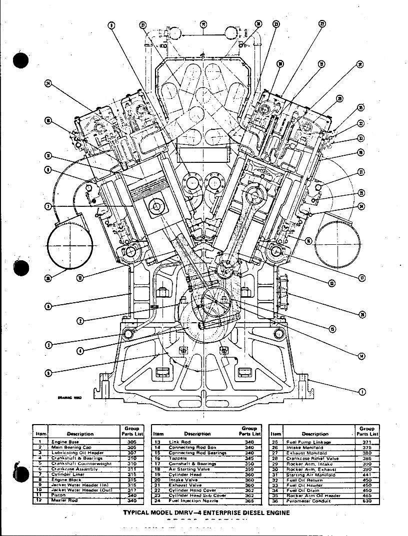
The Model RV engine is a four-stroke-cycle, turbocharged, aftercooled, V-type engine, built in 12. 16 or 20 cylinder
arrangements. The engine is available in either diesel or dual fuel versions and may be equipped to operate on heavy
(residual) fuel. The angle of the Vee is 45 degrees. Trunk-type pistons, removable wet-type cylinder liners, pressure
lubrication and mechanical fuel injection are features of the RV engine. Individual fuel injection pumps are provided
for each cylinder, and as they are of standard design, are interchangeable. The fuel lines are of equal length and are
relatively short, reducing line surge to a minimum. Fuel pumps, nozzles and orifice size and angle are all carefully
matched to the engine and the fuel to be used to give maximum thermal efficiency. A gear-driven starting air distributor
provides a timed distribution of pilot air to open the air start valves, permitting the engine to be started cold in a few
seconds with a 250 psi starting air supply. Engine rotation and cylinder bank designation are determined while facing
the engine at the flywheel end, number one cylinders always being the pair farthest from the flywheel.
E RV(M/N/4V)-75 1-2
'II
.. r
42
ann 13
Group Group Group stem Description Parts List item Description Parts List Item Description -Parts List
1 Engine Base 305 13 Link Rod 340 25 Fuel Pump Linkaeo .. 71.L 2 Main Boaring Cap 305 14 Connecting Rod Box 340 26 Intake Manifold 375
*3 Lubricating Oil Header 367 i5 Connecting Rod Bearings 340 27* Exhaust Monifold 380 4 Crehktaft & Barinigs 310 16 'Toppers 345 28 Crankcase Relief Valve 386
SCr~ankshat Countorweight 310 17 Comshaft & Bearings 350 29 Rocker Arm, Intake 390 ti ankcase Assembly 31 1 8 Air Starting Valve 359 36 Rocker Arm, Exhaust 390 7 Cylinder Liner 315 19 Cylinder Head 360 31 Starting Air Manifold 441
8 kEngine Block 31 20 Intake Valve 360 32 Fuel Oil eturn 450 9 Jacket Water Header (InI 315 21 Exhaust Valve 360 33 Fuel Oil Header 450
10 Jacket Water Header (Out) 317 22 Cylinder Hood Cover 3G2 34 Fuel Oil Drain 450 P1 iston 340 23 Cylinder Head Sub Cover 362 3W Rtocker Arm Oil Header 465b
12 Master Rod 34 24 Fuel iection Nozzle 365 36 Pyromerer Conduit 630
TYPICAL MODEL DMRV-4 ENTERPRISE DIESEL ENGINE
INSTRUCTION DELAVAL ENGINE AND
MANUAL FOR COMPRESSOR DIVISION
ENTERPRISE 550-85TH AVENUE ENGINES OAKLAND. CALIF. 94621 W *
SECTION 2
INSTALLATION
GENERAL.
The installation of a DELAVAL Engine and Compressor Division "Enterprise" engine may vary from site to site,
therefore, the instructions contained in this section of the manual are representa~ive of a typical installation and not
necessarily the exact procedure for a specific site. Certified installation and foundation drawings are furnished to
each customer which detail the dimensions and installation requirements for that particular unit.
FOUNDATION DRAWING.
The foundation drawing will be accurately dimensioned and must be carefully observed. Carelessness in locating
foundation bolts, pipes, conduits and drains will cause difficulty during installation and alignment. It i$ essential
that the foundation be constructed to standards of the highest accuracy.
INSTALLATION DRAWING.
The installation drawing details the measurements for machinery location, distances required for normal maintenance
tasks and the overhead clearances necessary for piston removal. In addition the drawing will indicate the location and
size of connection points for pipes and the electrical requirements for alarm and control mechanism.
SYSTEM SCHEMATIC DRAWINGS.
Electrical and flow diagrams are furnished for the various systems. Flow diagrams specify pipe sizes and the type and
location of fittings and apparatus. These represent minimum requirements. To insure compatibility, any changes should
be approved by DE LAVAL Engine and Compressor Division engineers before installation.
HANDLING AND SHIPMENT.
Care must be exercised during the shipment and handling of the engine and associated equipment during installation
to avoid damage. The unit should be lifted only from the lift pads on the side of the engine base (where provided) as
indicated on the installation drawing. When securing the engine during shipment or other movement, make sure no
binding stresses are imposed on the engine base or crankshaft
E

INSTRUCTION DELAVAL ENGINE AND MANUAL FOR COMPRESSOP DIVISION ENTERPRISE 550-85TH AVENUE ENGINES OAKLAND. CALIF. 94621 imar Ar 1e 96
FOUNDAT!ON.
Make 8 foundation bolt template, using the certified foundation drawing to determine the location of the equipment
mounting bolts. See figure 2-1 for a suggested method of building the template. Exercise care in locating bolt centers.
Place and support the template from the foundation forms. Anchor securely to prevent movement of the template.
Thread foundation bolt into lower nut in pipe sleeve being careful not to damage cap at bottom of nut. Insert
foundation bolts and sleeves in holes provided in the template then tighten the upper nuts. Sleeves must be securely
held in correct position to prevent any movement when pouring concrete. A suggested method is to use reinforcing
rods welded to each sleeve or on top of each anchor plate in both rows of bnlts, running the length of the engine,
and adding "X" bracing between the two rows of bolts. Another suggestion is to tie the bolt assemblies to other
reinforcing rods already in the foundation. Recheck template position, alignment and elevation before pouring con
crete. It is recommended that a DELAVAL Engine and Compressor Division service representative be present to
check bolt layout. The foundation is to be poured monolithic and must be suitably reinforced with reinforcing steel:
Let concrete set for 10 days before installing equipment, and 30 days before running equipment.
MATERIAL: WOODEN PLANKS SECURELY NAILED TOGETHER
S2x6'sNAILEDTOGETHER
1 x 6 CROSS BRACING. NOTCH
NOTCH TOP OF 2 N 6 AT CORNERS TO SUIT.
2 6ON EDGE PIPE SPACER
IA3/4"IALLOW 1/32" CLEARANCE A -ON DIAMETER
PLAN VIEW SECTION A-A
Figure 2-1. Suggested Foundation Bolt Template
FOUNDATION BOLT ASSEMBLIES.
The foundation bolts are so designed that the anchor studs can be removed from the anchors after the foundation
has been poured. This permits the engine to be placed over the foundation without any interference or danger of
damage to the studs. Once the engine is in place, the studs are installed and screwed into the anchor assemblies.
6 E Lo G/R/RVISI-74 2-2

INSTRUCTION DELAVAL ENGINE AND MANUAL FOR COMPRESSOR DIVISION ENTERPRISE 550-85TH AVENUE ENGINES OAKLAND. CALIF 94621
-PREPARATION FOR INSTALLATION.
Before landing the unit on the foundation, the surfaces of the foundation must be roughened wherever grout is to be applied. Chip and clean as necessary to remove all laitance and foreign matter so that the clean, dry, sharp aggregate required for a good bond to epoxy grout is exposed. The machined surfaces of the sole plates and chocks must be thoroughly cleaned and the leveling screws waxed to prevent their sticking to the grout. The machined bottom faces of the engine base must also be cleaned thoroughly. Remove engine foundation bolts. Place steel plates at jacking screw locations, level plates and grout in place.
PLACING ENGINE OVER FOUNDATION.
Position engine over foundation and insert four toe jacks, one at each corner of the engine, inboard of the shipping skids. If engine is rolled into position, the ends of the jacking screw shields and foundation bolt shields must be protected to avoid damaging shield ends with the rollers. Do not place jacks in the center of the engine as thiscould cause damage to the engine base. Insure that the combined capacity of the jacks is at least fifty percent greater than the total weight of the engine. See Installation Drawing for weights.
a. Remove shipping skids, thoroughly clean mounting rails and then lower engine to grade. Be sure the foundation bolt holes in the engine base are correctly aligned with the foundation bolt sleeves in the foundation for easy installation of the foundation bolts.
b. Clean sole plates and chocks with a degreasing type solvent. It is recommended that after the sole plates are washed, they be primed with a primer recommended by the grout manufacturer. Lubricate the threads of the jacking screws with a mixture of powdered graphite and engine lubricating oil. The lower end of the jacking screws should be coated with wax to prevent the epoxy grout material from binding to the screws.
C. Place sole plates and chocks in position under the engine as shown in the foundation drawing. Installsole plate retainers on the front and rear sole plates, making sure the sole plates are forced tightly against the shoulder at the inner edge of the engine mounting rails.
d. Lubricate lower threads of the foundation bolts with standard graphite and oil mixture, installbolts in sleeves and screw firmly into the threads at the bottom of the sleeve. Lubricate threads at the upper end of foundation bolts with oil and graphite powder then place washers and nuts on bolts.
e. Level and align the engine, following the crankshaft alignment on DELAVAL Engine and Compressor Division Form D-1063. Record deflection readings on the form. Insure that all sole plate jacking screws are so adjusted as to distribute the weight evenly on all sole plates. When leveling and alignment is satisfactory, snug down the foundation bolt nuts to prevent movement of the engine during installaion of the driven equipment and grouting.
4 0G/R/RVISI-74 2-3
INSTRUCTION DELAVAL ENGINE AND MANUAL FOR COMPRESSOR DIVISION ENTERPRISE 550-85TH AVENUE ENGINES OAKLAND, CALIF. 94621
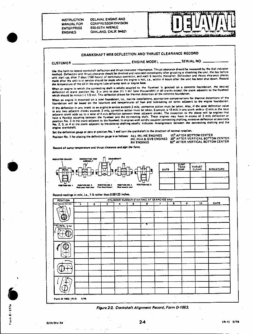
CRANKSHAFT WEB DEFLECTION AND THRUST CLEARANCE RECORD
CUSTOMER ENGINE MODEL _SERIAL NO.
Use this form to record crankshaft deflection and thrust clearance information. Thrust clearance should be measured by the dial indicator
method. Deflection and thrust clearance should be checked and recorded immediately after grouting or chocking the unit, the day before
unit start -up, after 7 days (168 hours) of continuous operation, and each 6 months thereafter. Deflection and thrust clearance checks
made after the unit is in service should be made while the engine is hot. i.e., within 4 hours after the unit has been shut down. Record
the temperature of the oil ir. the engine lube oil sump tank or engine base.
When an engine in which the connectring shaft is solidly coupled to the flywheel is grouted on a concrete foundation, the desired
deflection at crane position No. 3 is zero to plus (+) 1 mi! (one thousandth) in all cranks except the crank adjacent to the flywheel
which should be minus (-) 1/2 mil. This deflection allows for thermal distortion of the concrete foundation.
When an engine is mounted on a steel foundation. i.e., marine installations, appropriate compensations for thermal distortions of the
foundation will be based on the locations and temperatures of fuel and lubricating oil tanks adjacent to the engine foundation.
If the deflection in any crank in an engine in service exceeds 3 mils. corrective action must be taken. Also, if the total deflection value
in any two adjacent cranks exceeds 3 mils. corrective action must be taken. Example, a *2 mils in any crank with a -2 mils in the next
adjacent crank adds up to a total of 4 mils deflection between these adjacent cranks. The exception to the above will tbe engines that
have a flexible coupling between the flywheel and the connecting shaft. These engines may have in excess of 3 mils deflection at
position No. 3 in the crank adiacent to the flywheel. In engines with solidly coupled connecting shafting, excessive deflection at positions
No. 2. 3, or 4 in the crank adjacent to the external shafting usually indicates misalignment between the connecting shafting and the
engine crankshaft. *
Set the deflection gauge at zero at position No. I and turn the crankshaft in the direction of normal rotation.
Position No. 1 for placing the deflection gauge is as follows: ALL INLINE ENGINES 150 AFTER BOTTOM CENTER RV. HVA& GV8 ENGINES 380 AFTER VERTICAL BOTTOM CENTER. RV ENGINES 520 AFTER VERTICAL BOTTOM CENTER
Record oil sump temperature and thrust clearance and a? Ud form
OCAOR 11AUCEi CO cieCTING "O CRAMNAFT
SUMP
DATE TANK CLAR SIGNATURE
pasmo mo. I wasTa No 2 POsITIOea a 0SImon No posmoi NO s
(Red emr fen woul (T.. Des Caewi te tes yo
Record readings in mils, i.e., 1-. rather than 0.00125 inches.
POSITION CYLINDER NUMBER STARTING AT GEARCASE END
1 2 3 4 5 6 7 8 9 10 DATE
Pr.m 0 tn t M-21 1/%
Figure 2-2. Crankshaft Alignment Record, Form 0- 1063
0 /ARRV.74 2-4 (A-11) 3/75
INSTRUCTION CDELAVAL ENGINE AND MANUAL FOR COMPRESSOR DIVISION
ENTERPRISE 550-&'TH AVEN4uE
ENGINES OAKLAND. CALIF 94621
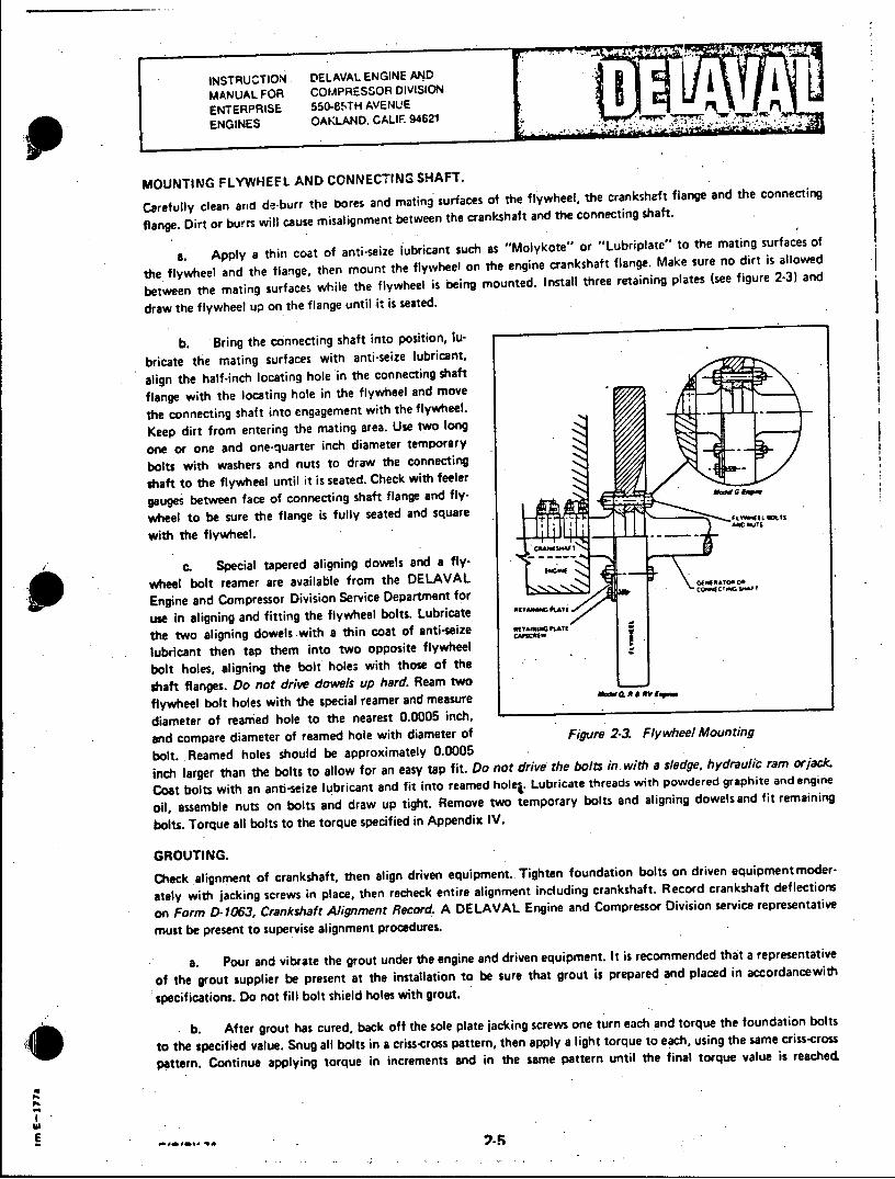
MOUNTING FLYWHEEL AND CONNECTING SHAFT.
Carefully clean and de-burr the bores and mating surfaces of the flywheel, the crankshaft flange and the connecting
flange. Dirt or burrs will cause misalignment between the crankshaft and the connecting shaft.
a. Apply a thin coat of anti-seize lubricant such as "Molykote" or "Lubriplate" to the mating surfaces of
the flywheel and the flange, then mount the flywheel on the engine crankshaft flange. Make sure no dirt is allowed
between the mating surfaces while the flywheel is being mounted. Install three retaining plates (see figure 2-3) and
draw the flywheel up on the flange until it is seated.
b. Bring the connecting shaft into position, lu
bricate the mating surfaces with anti-seize lubricant,
align the half-inch locating hole in the connecting shaft
flange with the locating hole in the flywheel and move
the connecting shaft into engagement with the flywheel.
Keep dirt from entering the mating area. Use two long
one or one and one-quarter inch diameter temporary
bolts with washers and nuts to draw the connecting
shaft to the flywheel until it is seated. Check with feeler
gauges between face of connecting shaft flange and flywheel to be sure the flange is fully seated and square with the flywheel.
C. Special tapered aligning dowels and a flywheel bolt reamer are available from the DELAVAL
Engine and Compressor Division Service Department for
use in aligning and fitting the flywheel bolts. Lubricate
the two aligning dowels with a thin coat of anti-seize
lubricant then tap them into two opposite flywheel
bolt holes, aligning the bolt holes with those of the
shaft flanges. Do not drive dowels up hard. Ream two
flywheel bolt holes with the special reamer and measure a
diameter of reamed hole to the nearest 0.0005 inch,
and compare diameter of reamed hole with diameter of Figure 2-3. Flywheel Mounting
bolt. Reamed holes should be approximately 0.0005
inch larger than the bolts to allow for an easy tap fit. Do not drive the bolts in, with a sledge, hydraulic ram or jack.
Coat bolts with an anti-seize lubricant and fit into reamed hole. Lubricate threads with powdered graphite and engine
oil, assemble nuts on bolts and draw up tight. Remove two temporary bolts and aligning dowels and fit remaining
bolts. Torque all bolts to the torque specified in Appendix IV.
GROUTING.
Check alignment of crankshaft, then align driven equipment.. Tighten foundation bolts on driven equipment moder
ately with jacking screws in place, then recheck entire alignment including crankshaft. Record crankshaft deflectiors
on Form a 1063. Crankshaft Alignment Record. A DE LAVAL Engine and Compressor Division service representative
must be present to supervise alignment procedures.
a. Pour and vibrate the grout under the engine and driven equipment. It is recommended that a representative
of the grout supplier be present at the installation to be sure that grout is prepared and placed in accordancewith
specifications. Do not fill bolt shield holes with grout.
b. After grout has cured, back off the sole plate jacking screws one turn each and torque the foundation bolts
to the specified value. Snug all bolts in a criss-cross pattern, then apply a light torque to each, using the same criss-cross
pattern. Continue applying torque in increments and in the same pattern until the final torque value is reached spcfctosUontfl otsil oe ihgot
. . Atrgothscrdpakoftesl.lt akigsrw n unec n oqetefudto ot
toteseiidvlepngalblsi rs-rs atr, hnapyalgttru oecuigtesm rs-rs
patr.CniuIpligtruIninrmnsadi hIaeptenuti h ia oqevlei ece
INSTRUCTION DELAVAL ENGINE AND MANUAL FOR COMPRESSOR DIVISION ENTERPRISE 550485TH AVENUE ENGINES OAKLAND, CALIF. 94621
PIPING SYSTEMS.
DELAVAL Engine and Compressor Division furnishes suitable piping diagrams to the purchaser or his design agent, recommending minimum pipe sizes for all service lines. In addition, the following should be observed in the fabrication and installation of piping not furnished with the unit, but procured from other sources.
a. Piping must never cause deflection in the mounting of reciprocating or rotating auxiliary equipment, nor should heavy auxiliary equipment ever be supported by service piping.
b. Whenever there is a possibility of deflection, flexibility must be designed into the piping.
c. Chill rings should not be used in welded pipe joints as they tend to retain scale, welding slag and beads which can come loose as the pipe becomes hot during operation.
TREATMENT OF PIPING.
It is strongly recommended by DELAVAL Engine and Compressor Division that all lubricating oil and fuel gas system piping be pickled by a company specializing in this kind of work. Such a company will have the necessary equipment and possess the technical knowledge to completely clean and prepare the pipe for service. Piping which is furnished by DELAVAL Engine and Compressor Division with the unit will have been pickled at the time of fabrication. All piping procured from other sources should be pickled and prepared as follows:
a. Accessible welds inside carbon steel pipes and fittings must be visibly inspected and the welding beads ground off. All fabricated steel pipes, valves and fittings must be blown clean with steam or air to remove loose scale, sand and welding beads, and be cleaned by the following procedure before the pickling process.
(1) Wirebrush the entire surface, including the interior with boiler tube brushes or a commercial pipe cleaning apparatus, then blast thoroughly with air to remove loose particles.
(2) Depending on the degree of contamination, submerge parts for 15 minutes or longer in a solution containing seven to ten ounces of anhydrous trisodium phosphate or sodium hydroxide and one ounce of detergent, Military Specification MIL-D-16791 to one gallon of water at 2000 F (93.30 C) to insure complete removal of paint and grease.
(3) Rinse parts in warm, fresh water at 1200 F (48.90 C) to prepare them for the acid treatment.
(4) Pickle fabricated carbon steel pipes and fittings by submerging them for 30 to 45 minutes in an acid bath containing one part of sulphuric acid, 660 Baume to 15 parts fresh water, supplemented with an inhibitor. The acid bath must be maintained at a temperature between 1600 F (71.10 C) and 1860 F (82.20 C). While the parts are submerged, agitate the bath. At the end of the pickling procedure, rinse parts in warm, fresh water. After the rinse the parts must be momentarily submerged in a cooling solution containing four ounces of sodium carbonate per gallon of water, then rinsed in cold fresh water and dried by air blast.
b. Immediately following pickling and rinsingcoat both the inside and the outside of the fabricated steel pipes and fittings with a rust and corrosion preventive compound and seal the ends to prevent entry of dirt. The compound must be soluble in the lubricating oil that will be used, and compatible with it so as not to contaminate the oil. Ordinary lubricating oil will not prevent rust in the pipes. Mechanical cleaning will not completely clean the pipes, therefore, this method is not acceptable. Apply the compound by spraying or flooding the pipes-swabbing with rags or mops will leave lint.
Note The above procedure is a minimum requirement to produce acceptable clean piping. Substitute methods may produce pipes and fittings of equal or better cleanliness.
E o G/R/RV.74 2-6 II.
INSTRUCTION DELAVAL ENGINE AND MANUAL FOR COMPRESSOR DIVISION I ENTERPRISE 550-85TH AVENUE
ENGINES OAKLAND, CALIF 94621
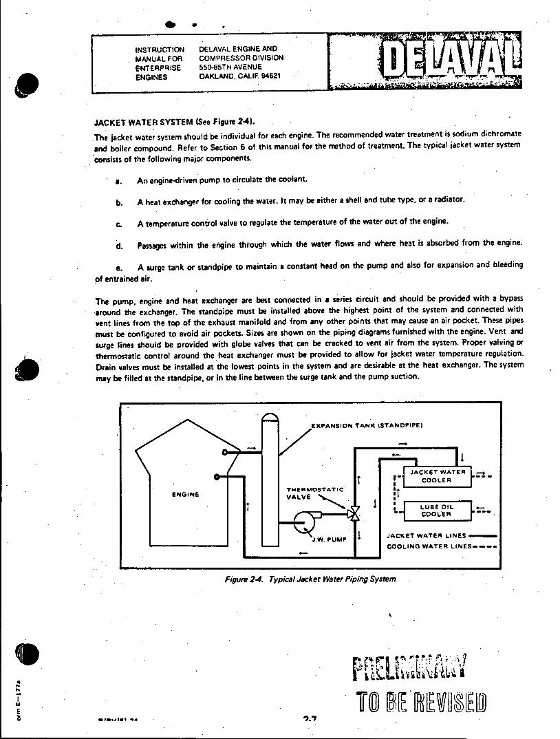
JACKET WATER SYSTEM (See Figure 2-4).
The jacket water system should be individual for each engine. The recommended water treatment is sodium dichromate
and boiler compound. Refer to Section 6 of this manual for the method of treatment. The typical jacket water system
consists of the following major components.
a. An engine-driven pump to circulate the coolant.
b. A heat exchanger for cooling the water. It may be either a shell and tube type, or a radiator.
c. A temperature control valve to regulate the temperature of the water out of the engine.
d. Passages within the engine through which the water flows and where heat is absorbed from the engine.
e. A surge tank or standpipe to maintain a constant head on the pump and also for expansion and bleeding
of entrained air.
The pump, engine and heat exchanger are best connected in a series circuit and should be provided with a bypass
around the exchanger. The standpipe must be installed above the highest point of the system and connected with
vent lines from the top of the exhaust manifold and from any other points that may cause an air pocket. These pipes
must be configured to avoid air pockets. Sizes are shown on the piping diagrams furnished with the engine. Vent and
surge lines should be provided with globe valves that can be cracked to vent air from the system. Proper valving or
thermostatic control around the heat exchanger must be provided to allow for jacket water temperature regulation.
Drain valves must be installed at the lowest points in the system and are desirable at the heat exchanger. The system
may be filled at the standpipe, or in the line between the surge tank and the pump suction.
EXPANSION TANK (STANDPIPE)
JACKET WATER I
V
* coTE THERMOSTATIC'COE ENGINE
VALVELUEOL
COOLER
W. PUMP JACKET WATER LINES
4 -- COOLING WATER LINES---
Figum 24. Typical Jacket Water Piping System
I
INSTRUCTION DELAVAL ENGINE AND MANUAL FOR COMPRESSOR DIVISION ENTERPRISE 550-85TH AVENUE ENGINES OAKLAND. CALIF 94621
RAW WATER SYSTEM.
The raw water system, if used, provides a cooling medium for various engine units and accessories as required. Raw
water may be pumped from its source through a lubricating oil cooler and heat exchanger then returned to its sump.
Provisions are necessary to maintain control over jacket water and lubricating oil temperatures. Such control can be
achieved by means of bypasses in either the liquid-to-be-cooled, or in the raw water lines. In some applications it may
be necessary to run raw water lines to accessory equipment coolers.
INTERCOOLER LINES.
When an intake air cooler is used, it is located between the turbocharger air discharge and the air manifold. Raw water
is usually used as the coolant and is piped as indicated in the piping diagrams furnished with the engine.
Finv-7 2-8
FUEL SYSTEM.
The fuel system must be maintained in as clean a condition as is possible. Every precaution must be taken to keep water from mixing with the fuel. Fuel injection on the engine is hand lapped to extremely close tolerances, and, therefore, fuel filtration equipment must be of the highest quality and carefully maintained. Engine mounted fuel system components will include:
a. A fuel oil strainer.
b. An engine driven booster pump with built in relief valve.
C. A duplex absorbent type filter.
d. Fuel oil supply and return headers.
e. Fuel injection pumps and nozzles, individual for each engine.
f. Pressure regulating valve at downstream end of header.
g. Necessary drains and drip lines.
/ E
At/AVIDI -74
INSTRUCTION DELAVAL ENGINE AND MANUAL FOR COMPRESSOR DIVISION ENTERPRISE 550-85TH AVENUE ENGINES OAKLAND, CALIF. 94621
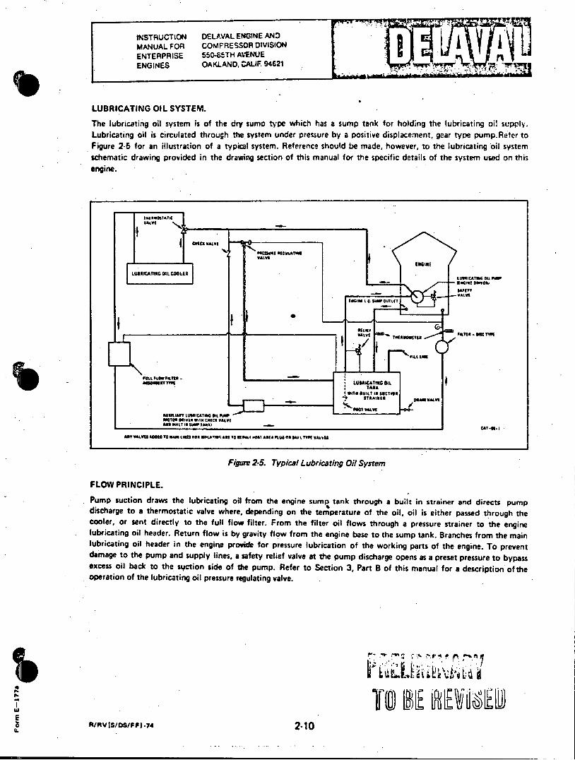
LUBRICATING OIL SYSTEM.
The lubricating oil system is of the dry sumo type which has a sump tank for holding the lubricating oi! supply. Lubricating oil is circulated through the system under pressure by a positive displacement, gear type pump.Refer to Figure 2-5 for an illustration of a typical system. Reference should be made, however, to the lubricating oil system schematic drawing provided in the drawing section of this manual for the specific details of the system used on this engine.
VALV"
miECK VAL
WINIREUATIVE
LEO SPlLY It 113RIMMING
LUORCATING OIL COO0LER LtF- ICATu Sit 0 it
FLOW FP RI NCIPT
WALVI THRVAMLTE
PILL LME
PULL #LOW FILTER. assesetr TregLUBRICATING DIL
WITI SUILT Is SUCTION STNAItItB DRAWALVE
AUXILIARY LUBSICATIES OIL PtWPL71 MOTOR DRIVtER W.7 COICI VALVE ANDSUILtTI MPTAAIIIItT0
ARY VALVES ADDED TO MAIN LINES FOR ISPLATIA.4 ARE TOO .041 @ia ASIA PLUS at W~ L V VA IWE
Figure 2-5. Typical Lubricating Oil System
FLOW PRINCIPLE.
Pump suction draws the lubricating oil from the engine sump tank through a built in strainer and directs pump discharge to a thermostatic valve where, depending on the temperature of. the oil, oil is either passed through the cooler, or sent directly to the full flow filter. From the filter oil flows through a pressure strainer to the engine lubricating oil header. Return flow is by gravity flow from the engine base to the sump tank. Branches from the main lubricating oil header in the engine provide for pressure lubrication of the working parts of the engine. To prevent damage to the pump and supply lines, a safety relief valve at the pump discharge opens as a preset pressure to bypass excess oil back to the stoction side of the pump. Refer to Section 3, Part B of this manual for a description of the operation of the lubricating oil pressure regulating valve.
IA.
E li A/RVIS/DS/FF)*.74 2-10
INSTRUCTION DELAVAL ENGINE AND MANUAL FOR COMPRESSOR DIVISION ENTERPRISE 550-85TH AVENUE
ENGINES OAKLAND, CALIF. 94621
AUXILIARY LUBRICATING OIL PUMP.
An auxiliary lubricating oil pumo, sometimes called a Before and After (B&A) pump is normally furnished with the engine. It is motor driven and installed in the system to provide a means for pre-lubrication of the engine before starting and to aic in cooling the engine after it has stopped.
INSTALLATION PRECAUTIONS.
The following precautions are among those which must be considered in the procurement and installation of lubricating oil servicing equipment when that equipment is not furnished with the engine.
a. The lubricating oil pump must be of the positive displacement type and provided with adequate relief valves.
b. A strainer should be provided in the line where the lubricating oil enters the main lubricating oil header, and be of a type that can be cleaned without being disassembled.
c. An auxiliary (B&A) lubricating oil pump is recommended for pre-lubricating of the engine before starting.
d. Provisions should be made for controlling the temperature of the lubricating oil.
e. Provisions should be included to temporarily bypass the oil cooler in the event of a leak in the cooler.
f. Flexible connections are recommended wherever there is a possibility of deflection.
PLACING LUBRICATING OIL SYSTEM IN SERVICE.
Before the engine is first started, the assembled lubricating oil piping system must be thoroughly flushed with oil. Disconnect the pipe at the pressure strainer inlet and arrange a temporary bypass from this pipe to the sump tank. The bypass will permit oil circulation through the pipes without filling the internal lubricating oil system of the engine. Several thicknesses of cloth sack should be secured to the outlet of the bypass to catch debris as it is flushed out. The sump tank and engine base must be thoroughly cleaned before being filled. An auxiliary lubricating oil pump, or any other continuous duty pump of sufficient capacity, can be used to pump oil during flushing operations. Flushing should continue for at least eight hours if care was exercised during fabrication of the system. As much as 24 hours of flushing may be required for a dirty system. When oil is circulating through the system, the pipes should be thoroughly pounded several times with a heavy hammer to loosen dirt and debris. Hot flushing oil will clean better than cold oil. Piping around the oil cooler requires special attention to insure that the pipes and oil cooler are properly flushed. Precautions must be taken to insure the complete repnoval of testing fluids, water or other liquids before attempting to flush the cooler.
Note Engines may be received with the strainer mounted on the engine and connected to the engine lubricating oil header. If it is certain that the connections between the strainer and the engine oil header have not been disconnected since the engine left the factory, the following paragraph may be omitted.
Disconnect jumper tubes between the engine lubricating oil header and the main bearings, and between main headers and auxiliary headers. Secure a fins screen such as a nylon stocking over each main header fitting to catch debris that may be washed through as the system is flushed. Cover main bearing fittings and open ends of auxiliary header feeders to prevent the entry of dirt. Enrgine oil should be pumped through the open* system f or at least f our hours to be sure that any foreign material remaining in the headers is removed. Reassemble internal tubes and brackets as required.
LL R/AV isins/F Fl1-74 2-10A I C., 7o: I.-
INSTRUCTION DELAVAL ENGINE AND MANUAL FOR COMPRESSOR DIVISION ENTERPRISE 550-85TH AVENUE ENGINES OAKLAND, CALIF. 94621 . .7
INTAKE SYSTEM.
Each engine has an independent intake system, the combustion. air being piped from outside the engine room through
a remotely installed air filter. An inline silencer is fitted in the pipe just ahead of the turbpcharger air inlet. The pir
filter protects the working parts of the engine from the entry of dust. Filters should be cleaned at regular intervals
to maintain adequate protection against abrasion and wear.
E E

INSTRUCTION DELAVAL ENGINE AND MANUAL FOR COMPRESSOR DIVISION ENTERPRISE 550-85TH AVENUE ENGINES OAKLAND, CALIF. 94621
EXHAUST SYSTEM.
Each engine is provided with an individual, independent exhaust system. The water jacketed, multi-pipe passage
manifold discharges directly into the engine mounted turbocharger(s), and the gas then discharges from the turbo
charger(s) through exhaust piping and a silencer to atmosphere. As few bends as possible should be used when )aying
out exhaust piping. Necessary bends should be of long radius. If three to six bends are used, the entire pipe should be
increased to the next nominal size. If more than six bends are necessary, pipe size should be increased two nominal
sizes. The length of exhaust piping is not critical, however, if an unusually long pipe is used, the pipe size should be
increased to reduce back pressure. A length of flexible metal tubing should be installed in the exhaust line as near
the engine as possible to allow for movement, heat expansion, and for isolation of vibration. The exhaust line should
be lagged to minimize heat radiation in the engine room. A separate support should be provided so the weight of the
exhaust silencer and line is not borne by the engine.
n/RV-74 2-12
INSTRUCTION DELAVAL ENGINE AND MANUAL FOR COMPRESSOR DIVISION ENTERPRISE 550-85TH AVENUE ENGINES OAKLAND, CALIF. 9421
STARTING AIR SYSTEM.
Compressed air from the starting air tanks at 250 psi (17.6 kg-cm 2) is applied to the upstream side of the starting air
admit, valve where it is blocked until a starting signal is applied to the pilot of the starting air admit valve. When a start
signal is applied to the starting air admit valve pilot, the valve opens and admits starting air to the starting air mani
fold on the engine and to the gear-driven starting air distributor. Timed pilot signals are sent to the air start valves on
the engine in the correct sequence, and as each air start valve opens, starting air is admitted to the cylinder, causing
that piston to be forced downward, rotating the crankshaft. The starting air tanks are provided with isolating valves
and pressure relief valves. Refer to the starting air schematic drawing for the location of filters, strainers, regulators
and valves, and for the direction of air flow.
R/R VIM/N1.75 2-13
INSTRUCTION DELAVAL ENGINE AND MANUAL FOR COMPRESSOR DIVISION a
ENTERPRISE 550-55TH AVENUE ENGINES OAKLAND CALIF. 94621
SECTION 3
OPERATING PRINCIPLES
PART A - GENERAL
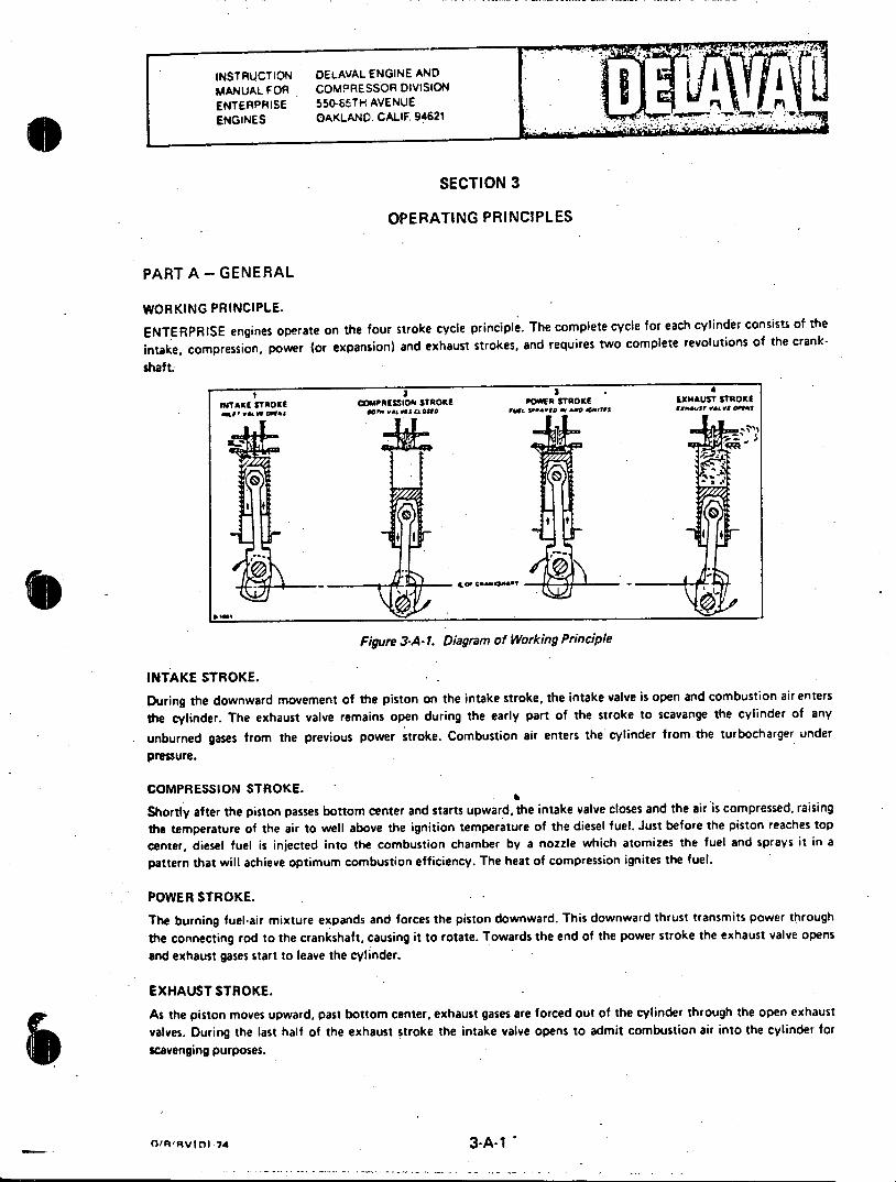
WORKING PRINCIPLE.
ENTERPRISE engines operate on the four stroke cycle principle. The complete cycle for each cylinder consists of the
intake, compression, power (or expansion) and exhaust strokes, and requires two complete revolutions of the crank
shaft.
- 2 3 4
INTAKE STROKE COMPRESSIO4 STROKE POWER STROKE EXMAUST STROKE ML V~ CMq @am e.Vs rA one 5rf C408s ftL *~ -0 WO.6'Tfi fs. V., V9 afth
a . I;,
0 0
Figure 3-A-1. Diagram of Working Principle
INTAKE STROKE.
During the downward movement of the piston on the intake stroke, the intake valve is open and combustion air enters
the cylinder. The exhaust valve remains open during the early part of the stroke to scavange the cylinder of any
unburned gases from the previous power stroke. Combustion air enters the cylinder from the turbocharger under
pressure.
COMPRESSION STROKE.
Shortly after the piston passes bottom center and starts upward, the intake valve closes and the air is compressed, raising the temperature of the air to well above the ignition temperature of the diesel fuel. Just before the piston reaches top
center, diesel fuel is injected into the combustion chamber by a nozzle which atomizes the fuel and sprays it in a
pattern that will achieve optimum combustion efficiency. The heat of compression ignites the fuel.
POWER STROKE.
The burning fuel-air mixture expands and forces the piston downward. This downward thrust transmits power through
the connecting rod to the crankshaft, causing it to rotate. Towards the end of the power stroke the exhaust valve opens
and exhaust gases start to leave the cylinder.
EXHAUST STROKE.
As the piston moves upward, past bottom center, exhaust gases are forced out of the cylinder through the open exhaust
valves. During the last half of the exhaust stroke the intake valve opens to admit combustion air into the cylinder for
scavenging purposes.
fl'R'RVIDI .74 3-A-1

INSTRUCTION DELAVAL ENGINE AND MANUAL FOR COMPRESSOR DIVISION ENTERPRiSE 550-85TH AVENUE COMPRESSORS OAKLAND. CALIF. 94621
PART B - LUBRICATING OIL SYSTEM
GENERAL.
An engine-driven pump draws oil from the surop through a strainer, and discharges it to a thermostatic valve where,
depending on the temoerature of tne oil, it. is either passed through the lubricating oil cooler, or directly to the filter.
Filtered oil is then passed through a strainer to the engine lubricating oil header. Oil return to the sump tank is by
gravity flow. An integral safety valve on the pump preventsexcess discharge pressure, and a pressure regulating valve
controls the pressure in the engine lubricating oil header. Refer to the lubricating oil system schematic drawing for
the relative location of components and for the direction of flow.
NEEDLE VALVE
SEAL CAP
SPRING
ADJUSTING SCREW
SPRING 1UPPER CAVITY CAP SLEEVE SPRING SPOOL VALVE
SENSING CHAMBER
Figure 3-8-1. Oil Pressure Regulating Valve
PRESSURE REGULATING VALVE.
Lubricating oil header pressure in the engine is regulated by a pressure regulating valve, mounted on the pump dis
charge piping so that the pump discharge is directed to this valve before reaching any other system components. Set
at 50 psig, it senses header pressure and regulates the bypass volume to maintain the set header pressure. Besides
regulating header pressure, the valve protects the system from excessive pressure during starts with cold oil, or when
flow in the system is restricted between the pressure regulating valve and the header pressure sensing point. The
functioning of the valve is as follows.
a. The "IN" port of the valve is connected to the pump discharge line and the "OUT" port is connected to a bypass line leading back to the engine base. A sensing tube, connecting the valve seal cap to a point on the main engine oil header, applies header pressure to the valve pressure sensing chamber.
b. The pressure in the sensing chamber acts against the end of a spool valve, compressing a spring atthe adjusting screw end of the assembly. If the sensed pressure rises above the set point, the lands of the spool valve will clear the lands on a sleeve. Oil then flows from the inlet section to the outlet-section of the regulating valve and back
to the engine base to bypass a part of the pump discharge to reduce the pressure in the header.
R/RV-74 Engine Driven L.O. Pump 3-8-1
INSTRUCTION DELAVAL ENGINE AND MANUAL FOR COMPRESSOR DIVISION ENTERPRISE 550-85TH AVENUE ENGINES OAKLAND, CALIF. 94621
PART B - LUBRICATING OIL SYSTEM (Continued)
C. A drilled passage connects the inlet section of the valve to the annular space around the spool valve atthe
adjusting screw end. This allows pump discharge pressure to act aainst the end of the sleeve and oppose the spring force at the other end. When an excessive pressure differential exists between the pump discharge and the header
pressures, such as when starting with cold oil, or because of an obstruction in the system between the regulating valve
and the header pressure sensing point, the sleeve is forced towards the sensing chamber end, compressing the spring. This will uncover the lands of the spool valve and the excess oil will bypass through the spool valve and the excess
oil will bypass through the outlet side of the valve back to the engine bese.
d. The oil in the annular space around the spool valve, at the adjusting screw end, will leak past the sealing grooves of the spool valve and into a cavity in the cap. This cavity functions as a buffer chamber. To stop valve oscillation, an adjustable needle valve controls oil spillage from the buffer cavity to the outlet-section of the valve.
e. The oil header pressure is set by increasing or decreasingthe spring force acting against the header pressure in the valve sensing chamqer. Turning the adjusting screw in will increase header pressure, and backing it out will decrease pressure.
FILTERS AND STRAINERS.
The full flow filter continuously filters all of the lubricating oil fromthe pump before it passes to the oil strainer. The
length of time that the lubricating oil and the filter elements may remain in service can best be determined by cardfully watching the result of oil analysis and the pressure drop across the oil filter. Change periods will vary with the operating conditions to which each individual engine is subjected. During the first two or three days of engine operation after initial installation, or after a major overhaul, the basket-type strainers at the pump suction and at the oil header inlet should be checked and cleaned as necessary to remove any debis and foreign matter that rmay be present. If at any time the oil pressure. gauge shows a low reading, the following should be done to the degree necessary to correct the situation.
a. Check the oil level in the sump tank, or engine base.
b. Inspect strainer, filter and lubricating oil cooler. A leak in the cooler may be detected by a sudden increase in oil consumption, and by the presence of oil in the cooling water system. Leakage may occur in the packing between the tubes and the tube sheet, or may be due to tube erosion, depending on the construction of that particular cooler.
c. Inspect all external and internal piping for tightness and freedom from obstructions.
d. Dismantle and inspect pump. Refer to manufacturer's instructions on the Associated Publications Manual.
A/RV-74 3-B-2
INSTRUCTION DELAVALENGINE AND MANUAL FOR COMPRESSOR DIVISION ENTERPRISE 550-85TRAVENUE ENGINES OAKLAl0, CALIF. 94621
PART C - FUEL SYSTEM
GENERAL.
Fuel oil snould be maintained in as clean a condition as is possible. Every precaution must be taken to keep (vater from mixing with the engine fuel. The fuel injection equipment on the engine is hand lapped to extremely close tolerances and, therefore, fuel filtrationequipment mist be of the highest quality and carefully maintained.
SYSTEM COMPONENTS.
Engine mounted fuel system components include the following:
a. A duplex fuel oil strainer.
b. An engine driven booster pump with built in relief valve.
c. A duplex absorbent type fitter.
d. A d-c motor driven fuel oil, booster pump.
e. Fuel oil supply and returnheaders.
f. Fuel injection pumps and nozzles, individual for each cylinder.
g. Pressure regulating valve at downstream end of header.
h. Necessary drains and dripines.
OPERATION.
Fuel is drawn from the day tank by the engine driven booster pump and the d-c motor driven booster pump, operating in parallel. The engine driven pump daws fuel through the strainer and discharges it through the filter to the engine headers. The d-c motor driven pumpdischargers directly to the filter. The fuel pumps, actuated by fuel cams on the camshafts, deliver fuel to the cylinders, depending on the position of the fuel control racks of the pumps. In the event of engine driven pump failure, an isoktion valve and a check valve prevents fuel from being pumped back to the engine driven pump. Return flow is back to the day tank. A fuel waste return pump on the fuel oil waste tank returns waste fuel oil to the day tank.
DSRV-75041/75042 3-C-1
INSTRUCT;0N DELAVAL. ENGINE AND MANUAL FOR COMFRESSOR CIVISION ENTERPRISE 55U-351H AVENUE ENGINES OAKLAND, CALIF 94621
PART D - CONTROL SYSTEM.
GENERAL.
The following is a description of the local engine control system and its operation. The system will start, stop, protect, operate and monitor the integrity of the diesel generator in the various modes of operation under guidelines specified by various regu!ptory and standards committees.
REFERENCES.
The Associatec' Fublications Manual contains manufacturer's literature covering the various components of the system. Of special significance are the ARO Corporation's publications which give a clear, concise explanation of the functions of the various log.c elements as well as a parts breakdown and repair procedures. When ordering spare and replacement parts for the system, refer to the Parts Manual for the correct part numbers.
DRAWINGS.
The drawings provided with these instructions include system schematics, layouts and connections pertaining to the logic board assembly, showing the location and orientation of the components on the board, the circuit diagram and checkout procedures. Refer to the control panel group parts list 02-500 for 75041 in the Parts Manual for a listing of drawings applicable to the system.
OPERATING MODES.
There are two base modes incorporated into the system, the STANDBY mode and the MAINTENANCE mode. In the STANDBY mode the unit may be started in response to an emergency start signal, or manually to exercise it on a routine basis. The MAINTENANCE mode permits routine maintenance, or repair.
a. While in the STANDBY mode the unit will accept a manually injected starting signal from a local or remote location. If the unit's entire protective system is permissive, it will start, come up to speed and build voltage automatically. Controls provided by the owner are then used to load the unit onto an energized bus. While running in this mode, both the speed/load and voltage setpoints are adjustable from either the local or remote location. Provided the generator circuit breaker is open, the unit can be stopped from either location by momentarily pressing a guarded stop button.
b. If an emergency "Start Diesel" signal is generated by the owners equipment while the unit is in the STANDBY mode, the unit will start with only overspeed and generator differential protection permissive, and if d-c power is available. The unit will come to speed and voltage as required and a "Ready To Load" signal will be generated for use in the owner's sequencing equipment. No other protective device is functional under this condition, and control air need not be available to effect a start.
c. If the unit is undergoing its periodic "Exercise Test" at the moment a "Start Diesel" signal is received, whether it is starting, running disconnected, running loaded, tripping on a fault other than overspeed or generator differential, or coasting to a stop, the control system will cause the unit to return to its rated speed and voltage, and will disarm all protection except overspeed and generator differential. The "Ready To Load" signal will be sent to the sequencer as above.
d. While running as a result of a sequencer signal, both speed/load and automatic voltage setpoints are adjustable, either locally or remotely. Every time the engine is shut off, or given a sequencer start signal, the setpoint of the governor and the automatic setpoint of the voltage regulator are reset to normal. Fifteen seconds after going to normal, the reset signal is released to allow the operator to control voltage and speed.
oSRV-75041/75042 3-D-1

ENTERPRISE 550-ESTH AVENUEaa ENGINES OAKLAND: CALIF 94621
PART D - CONTROL SYSTEM (Continued)
e. To change the unit from the STANDBY mode to the MAINTENANCE mode, the circuit breaker must be. locked out. This is accomplished by turning the circuit breaker control switch to "Trip" and pulling the handle out. It will remain in this position until manually returned to "Normal". Whiie in the "Trip/Lockout" position, the circuit breaker cannot be closed, either manually or automatically, and the "Unit In Maintenance" light is lighted. The engine may be run manually while the circuit breaker is locked out.
f. When in the MAINTENANCE mode the unit may be "Locked Off", i.e., prevented from starting. To place the unit in "Engine Lockoff", the two "Engine Lockoff" pushbuttons, one in the local engine control panel and one in the remote diesel generator panel, must be pressed simultaneously. A light in the remote panel indicates when the unit is in "Lockoff". Return to "Engine Operative" is accomplished by turning the handle of the "Engine Operative/ Lockoff" switch in the iocal engine panel to the "Operative" position. While in "Lockoff" the "Engine Roll" pushbutton or barring device may be engaged to rotate the engine for maintenance purposes.
g. Mode selection is accomplished so as to afford maximum protection for the plant and also for maintenance personnel. If the system is in "Engine Lockoff", only the local operator can place it back in "Engine Operable". If the unit is in the MAINTENANCE mode, simultaneous operation of pushbuttons, local and remote, is required to place the system in "Engine Lockoff". Status lights report the system's status in the remote location. Furthermore, the barring device cannot be engaged in the STANDBY mode. While in the "Engine Lockoff" position in the MAINTENANCE mode, the barring device must be disengaged and locked out in order to switch back to the engine operable state.
PROTECTIVE SYSTEM. The unit's protective system is a hybrid electro-pneumatic system. Since pneumatic devices function better than other types in the diesel environment, vital shutdown functions are performed pneumatically. All faults, both alarm and shutdown, are displayed on a solid state, dual rate flashing annunciator with horn silence provisions. Handoff contacts for use with a remote annunciator or mimic display are provided. When running as a result of a sequencer start signal, even though most of the shutdown system is not able to effect a unit trip, the action of the individual tripping devices is monitored and displayed on the annunciator so that the operator will be aware when a vital device has acted. Status lamps, separate from the annunciator, are used to show the condition of the unit as it proceeds through a starting sequence. The engine starting circuits are duplicated in total, and can receive d-c power from two separate conduit entries, if desired. Further, ancillary devices are arranged so that, even if they fail to function as intended, the unit will start and generator voltage will build up. It is possible that starting air will not be shut off as intended after a start if certain devices fail, but the balanced design of the engine's air start valves will keep them closed as soon as combustion occurs.
PANEL ELECTRICAL CONTROL (See Drawing 52189). The local engine control panel electrical circuitry is shown in schematic form on sheets 1 of 4 through 4of4onthe referenced drawing.
a. Starting circuitry is shown on the left side of sheet 1. Note that there are two redundant circuits, each having a separate d-c power source. These circuits are physically spaced as far apart as possible on the panel. Solenoid valves SOL-1R, SOL-1L, SOL-2R and SOL-2L are located on the engine, and when energized admit starting air headers on the engine, and when energized admit starting air to the starting air headers on the engine. They are controlled by contacts of relays R3, R4, R6 and R7. Relays R3 and R6 are the emergency start relays, and R4 and R7 are for normal starting.
b. The redundant "Start Diesel" signal (SDS) contacts are from the owner's equipment. When either set of contacts close, an emergency start is initiated, provided SS-1 is closed (i.e., if the unit is not running at rated speed), and if pressure switch PS-7 or PS-8 is closed, indicating at least 150 psi starting air is left in the receivers. These pressure switches are present so that, if for some reason the unit does not fire (valve closed in fuel supply line, for instance), there will be enough starting air left for several manual starts.
OSRV-75041/75042 3-D-2

PART D - CONTROL SYSTEM (Continued)
c. Note that when relay R3 or R6 is energized, R9 or R10 is also energized. Contacts of these relays operate solenoid valves SOL-6 or SOL-7, either of which cause the shutdown system to disarm instantly except for overspeed and generator differential protection. Also, if SS-1 fails to transfer, or if the device is faulty and fails to function at all, SS-1 remains closed and the unit will start. If SS-1 fails to open at the prescribed speed, combustion pressure will close and the air start valves and engine operation is not affected.
d. For a manual start, either of the switch contacts (local or remote) are closed which causes relay R4 or R7 to energize for three seconds. The shutdown system deactivating relay is not operated. Rather, solenoid valve SOL-3 is activated by either relay which arms the shutdown system. The "Engine Operable/Lockoff" must be in the "Engine Operable" position for any of the above to take place. If it is in the "Engine Lockoff" position, the "Engine Roll" button on the local panel only is operative. If the barring device is locked out, the pressure switch shown will be closed and the unit can be turned over on starting air without starting - a useful maintenance procedure.
e. When the unit receives a start signal, either of the four start relays will latch the four run relays, R1, RIA, R18 or RIC if pressure switch PS-33 or PS-34 shows the unit not tripped. Note that a SDS will cancel trips and the pressure switches will remain latched. In the generator shunt trip circuit, relays R1 and R1A contacts are connected in series in such a manner that if either relay latches, the generator circuit breaker may be closed. The contacts are connected in parallel to allow the field to be flashed through either relay R13 or R14. As in the start circuit,SS-2 failure will not prevent field flashing. At normal voltage and/or 430 rpm engine speed, the VR-1 and/or SS-2 series contacts will open to prevent energizing time delays TD-5 or TD-4. Time delays TD-4 and TD-5 are present to reset relay R1 should the unit fail to achieve "Ready To Load" status for any reason. Once voltage is close to normal, VR-1 and VR-2 energize relays R1 1A and R 11B, the "Ready To Load" relays. One normally open contact of each relay should be connected in parallel to the owner's sequencer so that when either closes, the power delivery cycle is initiated.
f. The three R2 relays shown are responsive to the latching of relay R1 or R1A, but there is a 20 second time delay (TD-3) before R2 latches. Contacts of R2, R2A and R2B are used to disarm various alarm functions which are normally in a fault state when the unit is stopped, starting or stopping.
PNEUMATIC CONTROL.
The shutdown system is a network of vent-to-fault pneumatic devices which are arranged in the various systems on the engine. The venting of such a device is sensed by the pneumatic logic circuitry. This circuitry then produces a 60 psi pressure signal which operates a cylinder on the engine to shut off fuel. This showdown signal is automatically vented after the unit has rolled to a stop, retracting the cylinder and readying the unit for a restart. Note that the sensor network is always pressurized; it is merely the shutdown signal which is inhibited in the emergency condition. This allows sensors to be electrically monitored under any condition. Upon application of starting air, several things occur directly from the air start header. The governor oil pressure is pneumatically boosted, and the stop/run valve on the engine is pressure driven to the run position. Only the overspeed trip remains active.
LOCAL ENGINE CONTROL PANEL (See Drawing 52191). The engine local control panel houses those control components which are not engine or remotely mounted. Access to the panel is through hinged doors in the back and removable access panels on either side. A 60 point annunciator is mounted in the upper portion of the face of the panel. Beneath this, and at eye level, are ten pressure gauges which monitor lubricating oil, fuel oil, jacket water, combustion air and starting air systems. An electronic temperature indicator with digital readout and integral linearization and cold junction compensation is used to monitor thermocouples inserted in the engine exhaust, lubricating oil and jacket water systems. Temperature alarm sensing is done in the lubricating oil and water systems.
DSRV-75041/75042 3-D-3

INSTRUCTION DELAVAL EN3INE AND MANUAL FOR COMPRESSOR DIVISION ENTERPRISE 553-85TH AVENUE ENGINES OAKLAND. CALIF. 94621
PART D - CONTROL SYSTEM (Ccntinued)
a. Status lamps are provided as follows:
1. DC Control Power ON - Lights if all d-c circuits are energized.
2. AC Power ON.
3. Unit Available For Start - Lights when following conditions are met.
(a) DC Booster Pump in AUTO.
(b) Mode selector in STANDBY.
(c) DC power available - sufficient circuits to start.
(d) Starting air pressure available.
(e) Overspeed device not tripped.
(f) Generator lockout relay not tripped.
4. Unit Starting - Lights when any of the four starting relays energize.
5. Unit Loaded - Lights when generator breaker closed.
6. Ready To Close Generator Breaker - Lights when voltage normal.
7. Test Trips Set - Lights when armed and functional.
8. Unit Stopped - Lights when fuel shut off on the engine.
9. Engine Lock Off - Lights when mode selector is in ENGINE LOCK OFF.
b. There are three level gauges used, one to indicate fuel oil day tank level, one to indicate lubricating oil sump tank level, and one to indicate main fuel oil tank level.
c. An engine. hour meter is provided which is responsive to relay R1. A tachometer is also included, reading the speed in rpm directly from the speed transmitter. A remote output is available from this transmitter by removing the burden resistor and connecting on the 4-20 MA terminals.
Note Since overspeed protection and generator fault tripping are the only active trips during an emergency, "two out of three" logic is not used. Overspeed shutdown is inherently safe from nuisance tripping. Generator fault tripping is derived from the owner's protective relaying.
d. De Laval engines are arranged so that the engine-driven fuel oil pump is driven from the free end of the overspeed trip drive assembly. For nuclear service, a d-c booster pump is used in parallel with the engine driven pump. If the drive fails the operator would have no indication that there is no longer overspeed protection. An annunciator is provided which senses loss of engine driven fuel pump pressure and, therefore, alerts the operator of possible loss of overspeed protection.
OSRV-75041/75042 3-D-4
INSTAUCTION CE.4VAL ENGINE AND MANUAL FOR COMPRESSOR DIVISION ENTERPRISE 55N85TH AVENUE ENGINES CAKLAND, CALIF 94611WI
PART D - CONTROL SYSTEM (Continued)
AUTOMATIC SAFETY SHUTDOWN SYSTEM (See Drawing 52187). The engine/generator set is protected by an automatic system which senses certain operating conditions and, when any of these sensed parameters exceeds a pre-set trip po;nt, an automatic shutdown sequence is initiated. During emergency operations in response to a "Emergency Start Diesel" signal, however, the engine will stop only due to an engine overspeed or a generator differential, all other shutdown sensors being disabled in this mode of operation. There are other monitored conditions that will alarm when they reach their alarm point to inform operating personnel of adverse operating conditions which, though not of sufficient gravity to cause a shutdown, nevertheless should be attended to. Shutdowns are placed into two groups, Group I shutdowns are those which must be "GO" in order for the engine to start, and Group II shutdowns are those that would be in a shut down (venting) condition until the engine is running. Lubricating oil pressure, for instance. Group II shutdowns are locked out during engine starts for a fixed time period. The Shutdown Logic Board, IA-5907 (3) functions to provide the necessary shutdown signals to the engine and, when operating in an emergency situation, prevents the engine from shutting down while still giving panel indications of an existing shutdown condition. During a start, Port 12 of the board is momentarily pressurized which results in an output from Ports 2, 9 and 10, and 90 seconds later an output from Port 3 and a loss of output from Port 9. Ports 2 and 10 pressurize the shutdown sensor circuits. If an unsatisfactory condition should develop which would trip one of the shutdown sensors, there will be a loss of pressure at either Port 10 or Port 2, resulting in an output from Port 8. This pressure is transmitted through a shuttle valve (21) to connection E-89 to the pilot of a pressure actuated valve (13, Dwg. 52186) then through a shuttle valve to extend the shutdown cylinder (6, Dwg. 52186) which moves the fuel rack to.the "No Fuel " position, shutting the engine down. A shutdown due to engine overspeed is accomplished in a different manner. Air pressure supply at 60 psi from connection E-53 is applied through an orifice (12, Dwg. 52186) to the overspeed trip valve (11, Dwg. 52186) and, as the trip valve is blocking flow, the pilot of a three-way valve (13, Dwg. 52186) is pressurized, venting the air shutoff cylinder (8, Dwg. 52186). Tripping of the overspeed trip valve will extend the air shutoff cylinders, movingthe air butterfly valve in the intake airmanifold. The shutdown cylinder (6, Dwg. 52186) is also extended, moving the fuel rack to the "No Fuel" position. The engine is stopped due to both fuel and air starvation. During operation in the emergency mode, solenoid valves SOL-6 and SOL-7 are energized, allowing 60 psi air to be applied to Port 7 of the Shutdown Logic Board. This blocks output from Port 8 and there will be no shutdown signal. Shutdown indications, however, will still be displayed on the control panel to inform the operator that a shutdown condition does exist. Overspeed and generator differential protection are retained, however.
4
DSRV-75041/75042 3-D-5

INSTRUCTION DELAVAL ENGINE AND MANUAL FOR COMPRESSOR DIVISION ENTERPRISE 550-85TH AVENUE ENGINES OAKLAND. CALIF 94621
SECTION 4
ENGINE OPERATION
GENERAL.
If the engine is being started for the first time, remove any preservative materials that may have been applied to the control and exterior surfaces of the engine. Rust preventive which has been sprayed inside the engine will mix with the lubricating oil without causing contamination. To reduce the amount of preservative absorbed by the oil charge, however, it. may be desirable to wash and clean the interior surfaces of the engine before circulating oil for the first time. Do not attempt to wash connecting rods, crankshaft or pistons as this may deposit dirt between the bearing surfaces. The following inspections and checks are recommended prior to starting the engine for the first time, or after a long shutdown or major overhaul.
a. Check bolts, nuts and capscrews, both inside and outside the engine to insure that all locking wires, clips and cotter pins are in place and secure.
b. Inspect all piping systems. Trace out each system to insure that all connections are secure and that all valves and other control devices are properly positioned for engine operation.
c. Check lubricating oil strainers and filters for cleanliness and proper assembly.
d. Check that lubricating oil and cooling water systems are clean and filled to the proper level.
e. Check starting air system for cleanliness and absence of moisture.
f. Check all control linkages for proper adjustment and freedom of movement.
g. Check crankshaft alignment (see Section 2).
h. Open indicator cocks on cylinders and bar engine over four revolutions to make sure cylinders are clean, and that engine is ready to run.
CAUTO
Any resistance to free turning must be investigated and corrected before engine is started.
I. With the indicator cocks open, fuel controls off, crank engine several revolutions.
j. Close indicator cocks. If all conditions for starting are satisfied, the engine may be started, using the procedures contained in subsequent paragraphs.
O/R/RIVIDI *74 4-1 -

INSTRUCriON DELAVAL ENGIwE AND MANUAL FOR COMPRESSOR DIVISION ENTERFRISE 550-85Tr4 AVENUE ENG:NES OA:CAND, CALIF 94621
DEFINITIONS.
Certain terms used in these instructions require definition to ensure that their exact meaning is understood.
a. STANDBY MODE - The "Operable" mode in which the unit will accept an "Emergency Start Diesel" signal from the owner's equipment, or a manual start signal from either the local or remote position for periodic test.
b. MA!NTENANCE MODE - The routine maintenance or repair condition. Unit may be run in this mode, or prevented from starting. depending on the positioning of controls.
c. LOCKED OUT - The engine is locked out while in the MAINTENANCE mode by positioning the main circuit control switch in "Trip". Unit may be manually operated, the circuit breaker cannot
d. LOCKOFF - When the engine is in LOCKOFF, in the MAINTENANCE mode, the engine cannot be started. Simultaneous action by both the local operator and the remote location is required to place the unit in LOCKOFF. Only the local operator can place the unit back in the "Engine Operable" (STANDBY) condition.
PRE-START PROCEDURE.
When starting a cool engine after a shutdown, it is very important that the following procedure be carried out prior to attempting a start in the MAINTENANCE mode, or prior to placing the unit in the STANDBY (Operable) mode.
a. Ensure unit in MAINTENANCE mode.
b. Place unit in LOCKOFF.
c. Barring device interlock locked out.
d. Open indicator cocks on all cylinder heads.
e. Push the "Engine Roll" pushbutton on local engine control panel, allow engine to roll at least two revolutions, then release pushbutton.
f. Inspect all indicator cocks. If liquid has been ejected from any of the cocks, the source must be found and the defect corrected before proceeding.
g. Close indicator cocks.
MANUAL START - MAINTENANCE MODE.
The following actions must be performed by the local operator to start the unit in the MAINTENANCE mode.
a. Ensure pre-start checks have been completed.
b. Open all flow valves.
c. Electrical power (a-c and d-c) ON.
d. Control air ON.
e. Lockoff/Operative selector in OPERATIVE.
f. Rotate keyed Manual Test Start switch to START position. As soon as the engine has fired once or twice, release switch.
DSRV-75041/75042 4-2
INSTRUCTION DELAV4L ENGINE AND MANUAL FOR COMPPESSOR DIV!SION g ENTERPRISE 550-85TH AVENUE ENGINES OAKLAND, CALIF 94621
MANUAL STOP - MAINTENANCE MODE.
Depress "Stop" pushbutton on la- control panel.
PLACING UN;T IN LOCKOFF.
To place the unit in Lockoff while in the MAINTENANCE mode, perform the following.
a. Simultaneously depress the "E nginc Lockoff" pushbuttons on both the local and remote panels.
b. A light on the remote pane! will show the unit in lockoff.
PLACING UNIT IN MAINTENANCE MODE.
Turn the main circuit breaker control switch to "Trio" and pull handle out. It will remain in this position until manually returned to "Norma!". The "Unit In Maintenance" light on the control panel should light.
PLACING UNIT IN OPERABLE (STANDBY) MODE.
The following must be performeo to return the unit to the STANDBY (Operable) mode from the MAINTENANCE
mode.
. a. Check levels of fuel oil and lubricating oil day tanks.
b. Select fuel oil transfer pump to be used if day tank requires filling. Select either AUTO or HAND operation.
CAUTIO If HAND operation is selected, operator attendance is required to prevent overfilling of tank.
c. Lubricating oil heater, jacket water heater and fuel oil standby pump in HAND or AUTO as desired.
d. Check lubricating oil and jacket water keep warm pumps ON.
e. Check a-c and d-c power ON.
f. Check starting air pressure.
g. Place Lockoff/Operative control to OPERATIVE.
h. Place main circuit breaker control switch in NORMAL.
i. Check "Unit Available For Start" light ON.
MANUAL START - STANDBY (OPERABLE) MODE.
To start the unit manually, either locally or from the remote location, while in the STANDBY mode, perform the
following.
a. Rotate keyed Manual Test Switch to START. As soon as the engine has fired once or twice, release switch.
b. If unit'sentire protective system is permissive, it will start, come up to speed and build voltage automatically.
Note If an "Emergency Start Diesel" signal is received while the unit is being manually operated,
whether starting, running disconnected, running loaded, tripping on a fault other than overspeed or generator differential, or coasting to a stop, the control system will cause the unit to return to
its rated speed and voltage, and will disarm all protection except overspeed and generator differ
ential.
oSRV-75041/7042 4-3
MANUAL STOP.
The unit is manually stopped by opening the main circuit breaker then depressing the "Emergency Stop" pushbutton on either the locai or the remote panel.
EMERGENCY STOP.
Perform one of the following actions to stop the engine in an emergency situation.
a. Open main circuii breaker and depress "Stop" pushbutton.
b. Manually place the StopiRun valve on the engine to STOP.
c. Ifr none of the above procedures work, the engine may be stopped by pushing a fuel pump lever towards the engine block. This will rotate the fuel shaft and cut off pump delivery. Hold the lever until the engine stops.
STARTING, STOPPING AND OPERATING PRECAUTIONS.
As soon as the engine is running, all gauges should be checked for proper operating pressures and temperatures as shown in Appendix II. If running in other than the STANDBY (Operable) mode, and in response to an "Emergency Start Diesel" signal from the owner's equipment, shut down engine and determine cause before restarting if conditions are not normal.
Use only compressed air for starting. Substitution of compressed gasses, especially oxygen, may result in a violent explosion.
OSRV-7s041/75042 4-4

INSTRUCTION DELAVAL ENGINE AND MANUAL FOR COMPRESSOR DIVISION ENTERPRISE 55C-85TH AVENUE n ENGINES OAKLAND, CALIF 9462.
SECTION 5
ENGINE MAINTENANCE
GENERAL.
The DELAVAL Engine and Compressor Division does not recommend the type of progressive maintenance system
practiced by railroad maintenance shops, nor is any specific time interval between major overhaul or cylinder head
valve reconditioning recommended. The insoection and maintenance schedules outlined in this section are intended as
guides only. Experience and operating conditions will dictate the actual frequency of upkeep, overhaul and repair
actions.
PREVENTIVE MAINTENANCE.
The following is intended as a supplement to the normal maintenance schedule (Which provides up to date information
concerning the mechanical condition of the engine. Wnen the following curves are maintained daily, then summarized
monthly and plotted on a yearly curve, small troubles can be detected and corrected before they become major prob
lems. The data for the curves shoull be taken at the same load each time. This load should be selected according to average operating conditions and be in the range of 75% to 100% of the rated load.
Temperature
Pressure
TIME - DAILY AND MONTHLY SUMMARY
a. If lubricating oil pressure starts to fall off but the temperature holds constant, it would indicate that the
bearings are starting to wear to excessive clearances, that the lubricating oil pump is wearing excessively, or that the relief valve is not functioning properly. It could also indicate excessive fuel oil dilution. If the lubricating oil pressure falls off and the lubricating oil temperature increases, it might indicate that the heat exchanger equipment is plugging
up.
A sudden increase in lubricating oil temperature with an increase in the amount of vapor from the crankcase ventilation discharge can indicate some overheated internal part of the engine. This could signal an approaching piston seizure and a possible crankcase explosion. A sudden increase in lubricating oil temperatures requires immediate reduction or removal of the load and an investigation of the cause.
G/R/RV-74 5-
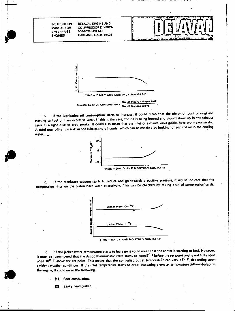
INSTRUCTION DELAVAL ENGINE AND MANUAL FOR COM-RESSOR DIVISION ENTERPRISE 550-85TH AVENUE ENGINES OAKLAND. CALIF. 94621 ) I
C
TIME - DAILY AND MONTHLY SUMMARY
No. of Hours % Rated BP Specific Lube Oil Consumption I No. of Gallons added
b. If the lubricating oil consumption starts to increase, it could mean that the piston oil control rings are
starting to foul or have excessive wear. If this is the case, the oil is being burned and should show up in the exhaust
gases as a light blue or grey smoke. It could also mean that the inlet or exhaust valve guides have worn excessively.
A third possibility is a leak in the lubricating oil cooler which can be checked by looking for signs of oil in the cooling
water.
.2* 0
> -2.
TIME - DAILY AND MONTHLY SUMMARY
c. If the crankcase vacuum starts to reduce and go towards a positive pressure, it would indicate that the
compression rings on the piston have worn excessively. This can be checked by taking a set of compression cards.
Jacket Water Out O
3 Jacket Water in a
TIME - DAILY AND MONTHLY SUMMARY
d. If the jacket water temperature starts to increase it could mean that the cooler is starting to foul. However,
it must be remembered that the Amot thermostatic valve starts to open 50 F before the set point and is not fully open
until 100 F above the set point. This means that the controlled outlet temperature can vary 150 F, depending upon
ambient weather conditions. If the inlet temperature starts to drop, indicating a greater temperature differential across
the engine, it could mean the following.
(1) Poor combustion.
12) Leaky head gasket.

INSTRUCTION DELAVAL ENGINE AND MANUAL FOR COMPRESSOR DIVISION ENTERPRISE 55( 5TH AVENUE ENGINES OAKLAND, CALIF 94621
(3) Scuffed piston.
(4) Faulty venting of the jacket water system.
(5) Faulty water pump.
MAINTENANCE SCHEDULES.
The daily operating report is the basis for the preparation of the weekly and monthly charts and curves, recording
temperatures, pressures and other significant data. Comments and remarks which clarify any abnormal readings or
conditions should be entered at the bottom of the sheet. Inspection frequency may be keyed to either calendar time
or engine operating hours, and may vary for certain items due to local conditions. The following maintenance schedules
are suggested for use with the preventive maintenance system.
a. HOURLY INSPECTION
(1) Read all instruments carefully and record in engine log. Note any unusual change in readings, and investigate.
(2) Walk around the engine and listen for any unusual noise. Also check for any fuel, lubricating oil, and water leaks.
(3) Check level in lubricating oil tank, governor, turbocharger, pedestal bearing, and thrust bearing if marine.
(4) Turn handles on all knife edge strainers at least once every eight hours.
(5) Check lube oil filter differential pressure at least once every eight hours.
J b. DAILYINSPECTION
(1) Drain water or sludge from lubricating and fuel oil filters and strainers, and air tanks.
(2) Oil linkage pins and shaft bearings on the govesnor and fuel controls.
(3) On reversible engines, also, oil starting and reversing mechanism through holes in housing.
(4) Plot daily engine data on Preventive Maintenance curves. Plotted data should be selected at the same engine load daily for best results.
c. WEEKLY (168 Hour) INSPECTION
(1) Clean strainer screens in fuel oil and lubricating oil strainers. (Lube oil suction strainer inspection for babbitt material is a check on conrod and main bearing condition.)
(2) Check and clean air inlet filter system as required. Visually check air inlet piping system for leaks.
(3) Check lube oil for fuel dilution with a Viscosimeter.
INSTRUCTION DELAVAL ENGINE AND MANUAL FOR COMPRESSOR DIVISION ENTERPRISE 550-85TH AVENUE ENGINES OAKLAND, CALIF. 94621
d. MONTHLY (720 Hour) INSPECTION
(1) Remove the alternate left side docr covers and examine the inside of engine for any abnormal
conditions. Check with light for any babbitt flakes. If excess water or sludge is present, drain crank
case and determine cause.
(2) Check PH factor of the cooling water and correct as recommended by chemical supplier (suggested
PH 8.25 to 9.75).
(3) Lube oil sample should be taken and sent out for analysis.as to viscosity at 2100 F and 1000 F,
T.B.N., B.S. & W. and Flash Point 0 F.
(4) Plot the summary of this month's operating data on the Preventive Maintenance curves. Note ary
deviation from normal and take corrective action if necessary.
(5) When equipped with Brown Boveri Turbocharger, drain lube oil, clean, examine for any abnormal
condition and refill with lube oil. See Brown Boveri Instruction Manual (Approximately 1000 hours.)
e. THREE MONTH (2190 Hour) INSPECTION
(1) Adjust all valve clearances by the "go" and "no go"feeler gage method. Excess clearance indicates
the possibility of a worn cam roller bushing.
(2) Remove, clean, and reset fuel injector nozzles as determined by operating data.
(3) On dual fuel and spark engine, check adjustment of gas admission timing.
f. SIX MONTH (4380 Hour) INSPECTION
(1) Review the Preventive Maintenance curves and take necessary steps to correct the engine if so
indicated.
(2) Check connecting rod clearance by the bump method with dial indicator. (On RV engines also
check link rod clearances.) Main bearing clearances cannot be satisfactorily checked by the bumpor
feeler gage method. However, main bearing condition can be checked by web deflection indications,
babbitt in the lube oil suction. strainer (weekly inspection) and noting a drop in lube oil pressure
with a B & A pump.
(3) Take crankshaft web deflections and record. On marine engines check Kingsbury thrust clearance.
(4) Check foundation for breaks in bond between the base or soleplate and the grout.
(5) Check foundation bolts for proper torque, after which recheck web deflections and compare with
deflections taken before torquing. (See (2) above.) If retorquing is necessary see Appendix IV.
(6) Inspect gears, check backlash of all gears and note general appearance. Check gear lubrication oil
jets for plugged or broken lines.
n~p. %A r.
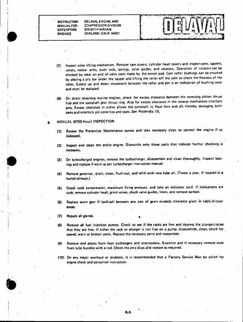
INSTRUCTION DELAVAL ENGINE AND MANUAL FOR COMPRESSOR DIVISION ENTERPRISE 550-651 H AVENUE ENGINES OAKLAND, CALIF. 94621 ...
(7) Inspect valve lifting mechanism. Remove cam covers, cylinder head covers and inspect cams, tappets,
rollers, rocker arms, push rods, springs, valve guides; and rotators. Operation of rotators can be
checked by wear on end of valve stem made by the swivel pad. Cam roller bushings can be checked
by placing a pry bar under the tappet and lifting the roller off the cam to check the freeness of the
roller. Excess up and down movement between the roller and pin is an indication of bushing wear
and must be replaced.
(8) On direct reversing marine engines, check for excess clearance between the reversing piston thrust
hub and the camshaft gear thrust ring. Also for excess clearance in the reverse mechanism interlock
pins. Excess clearance in either allows the camshaft to float 4ore and aft thereby damaging both
cams and interlock pin cone-tips and seats. See Appendix Ill.
ANNUAL (8760 Hour) INSPECTION
(1) Review the Preventive Maintenance curves and take necessary steps to correct the engine if so
indicated.
(2) Inspect and clean the entire engine. Dismantle only those parts that indicate further checking is
necessary.
(3) On turbocharged engines, remove the turbocharger, disassemble and clean thoroughly. Inspect bear
ings and replace if worn as per turbocharger instruction manual.
(4) Remove governor, drain, clean, flush-out, and refill with new lube oil. (Twice a year, if located in a
humid climate.)
(5) Check cold compression, maximum firing pressure, and take an indicator card. If.indications are
such, remove cylinder head, grind valves, check valve guides, liners, and remove carbon.
(6) Replace worn gear if backlash between any pair of gears exceeds clearance given in table of clearances.
(7) Repack all glands.
(8) Remove all fuel injection pumps. Check to see if the racks are free and depress the plungerstosee that they are free. If either the rack or plunger is not free on a pump, disassemble, clean, check for scored, worn or broken parts. Replace the necessary parts and reassemble.
(9) Remove end plates from heat exchangers and intercoolers. Examine and if necessary remove scale from tube bundles with a rod. Check the zinc discs ad replace as required.
(10) On any major overhaul or problem, it is recommended that a Factory Service Man be called for engine check and personnel instruction.
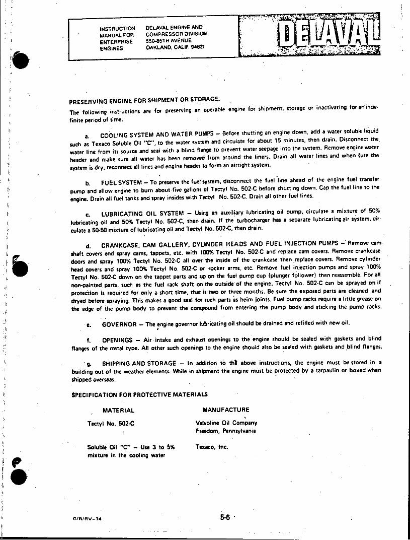
INSTRUCTION DELAVAL ENGINE AND MANUAL FOR COMPRESSOR DIVISION ENTERPRISE 55"5TH AVENUE ENGINES OAKLAND, CALIF. 94621
PRESERVING ENGINE FOR SHIPMENT OR STORAGE.
The following instructions are for preserving an operable engine for shipment, storage or inactivating for an'inde
finite period of time.
a. COOLING SYSTEM AND WATER PUMPS - Before shutting an engine down, add a water soluble liauid
such as Texaco Soluble Oil "C", to the water system and circulate for about 15 minutes, then drain. Disconnect the.
water line from its source and seal with a blind flange to prevent water seepage into the system. Remove engine water
header and make sure all water has been removed from around the liners. Drain all water lines and when gure the
system is dry, reconnect all lines and engine header to form an airtight system.
b. FUEL SYSTEM - To preserve the fuel system, disconnect the fuel line ahead of the engine fuel transfer
pump and allow engine to burn about-five gallons of Tectyl No. 502-C before shutting down. Cap the fuel line to the
engine. Drain all fuel tanks and spray insides with Tectyl No. 502-C. Drain all other fuel lines.
C. LUBRICATING OIL SYSTEM - Using an auxiliary lubricating oil pump, circulate a mixture of 50%
lubricating oil and 50% Tectyl No. 502-C, then drain. If the turbocharger has a separate lubricating air system, cir
culate a 50-50 mixture of lubricating oil and Tectyl No, 502-C, then drain.
d. CRANKCASE, CAM GALLERY, CYLINDER HEADS AND FUEL INJECTION PUMPS - Remove cam
shaft covers and spray cams, tappets, etc. with 100% Tectyl No. 502-C and replace cam covers. Remove crankcase
doors and spray 100% Tectyl No. 502-C all over the inside of the crankcase then replace covers. Remove cylinder
head covers and spray 100% Tectyl No. 502-C on rocker arms, etc. Remove fuel injection pumps and spray 100% Tectyl No. 502-C down on the tappet parts and up on the fuel pump cup (plunger follower) then reassemble. For all
non-painted parts, such as the fuel rack shaft on the outside of the engine, Tectyl No. 502-C can be sprayed on if
protection is required for only a short time, that is two or three months. Be sure the exposed parts are cleaned and
dryed before spraying. This makes a good seal for such parts as heim joints. Fuel pump racks require a little grease on
the edge of the pump body to prevent the compound from entering the pump body and sticking the pump racks.
e. GOVERNOR - The engine governor lubricating oil should be drained and refilled with new oil.
f. OPENINGS - Air intake and exhaust openings to the engine should be sealed with gaskets and blind
flanges of the metal type. All other such openings to the engine should also be sealed with gaskets and blind flanges.
g. SHIPPING AND STORAGE - In addition to tht above instructions, the engine must be stored in a
building out of the weather elements. Mile in shipment the engine must be protected by a tarpaulin or boxed when
shipped overseas.
SPECIFICATION FOR PROTECTIVE MATERIALS
MATERIAL MANUFACTURE
Tectyl No. 502-C Valvoline Oil Company Freedom, Pennsylvania
Soluble Oil "C" - Use 3 to 5% Texaco, Inc. mixture in the cooling water
CIR/RV-74
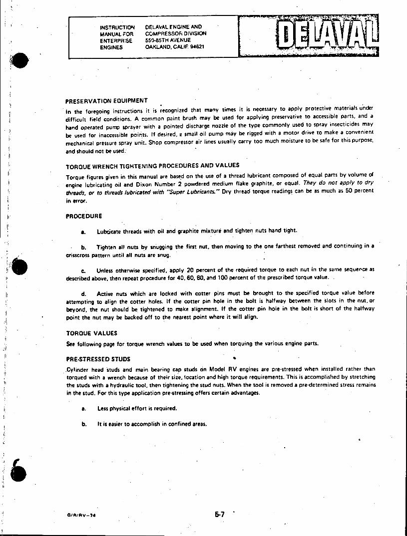
INSTRUCTION DELAVAL ENGINE AND MANUAL FOR COMPRESSOR DIVISION ENTERPR!SE 55-85TH AVENUE ENGINES OAKLAND, CALIF. 94621
PRESERVATION EQUIPMENT
In the foregoing instructions it is recognized that many times it is necessary to apply protective materials under
difficult field conditions. A common paint brush may be used for applying preservative to accessible parts, and a
hand operated pun sprayer with a pointed discharge nozzle of the type commonly used to spray insecticides may
be used for inaccessible points. If desired, a small oil pump may be rigged with a motor drive to make a convenient
mechanical pressure spray unit. Shop compressor air lines usually carry too much moisture to be safe for this purpose,
and should not be used.
TORQUE WRENCH TIGHTENING PROCEDURES AND VALUES
Torque figures given in this manual are based on the use of a thread lubricant composed of equal parts by volume of
engine lubricating oil and Dixon Number 2 powdered medium flake graphite, or equal. They do not apply to dry
threads, or to threads lubricated with "Super Lubricants." Dry thread torque readings can be as much as 50 percent
in error.
PROCEDURE
a. Lubicate threads with oil and graphite mixture and tighten nuts hand tight.
b. Tighten all nuts by snugging the first nut, then moving to the one farthest removed and continuing in a crisscross pattern until all nuts are snug.
c. Unless otherwise specified, apply 20 percent of the required torque to each nut in the same sequence as
described above, then repeat procedure for 40, 60, 80, and 100 percent of the prescribed torque value.
d. Active nuts which are locked with cotter pins must be brought to the specified torque value before attempting to align the cotter holes. If the cotter pin hole in the bolt is halfway between the slots in the nut, or
beyond, the nut should be tightened to make alignment. If the cotter pin hole in the bolt is short of the halfway point the nut may be backed off to the nearest point where it will align.
TORQUE VALUES
See following page for torque wrench values to be used when torquing the various engine parts.
PRE-STRESSED STUDS
.Cylinder head studs and main bearing cap studs on Model RV engines are pre-stressed when installed rather than torqued with a wrench because of their size, location and high torque requirements. This is accomplished by stretching the studs with a hydraulic tool, then tightening the stud nuts. When the tool is removed a pre-determined stress remains in the stud. For this type application pre-stressing offers certain advantages.
a. Less physical effort is required.
b. It is easier to accomplish in confined areas.
Oininv-7a 5-7
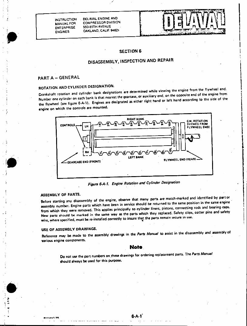
MAuAO MscoMORESSOR DIVISION. a ENTERPRISE 550r85TH AVENUE n ENGINES OAKLAND, CALIF. 94621
SECTION 6
DISASSEMBLY, INSPECTION AND REPAIR
PART A - GENERAL
ROTATION AND CYLINDER DESIGNATION.
Crankshaft rotation and cylinder bank designations are determined while viewing the engine from the flywheel end.
Number one cylinder on each bank is that nearest the gearcase, or auxiliary end, on the opposite end of the engine from
the flywheel (see figure 6-A-). Engines are designated as either right hand or left hand according to the side of the
engine on which the controls are mounted.
RIGHT BANK
CONTOLS c r Cc 1 ccC.W. ROTATION
CONTROLS LI I IVIEWEOPROM LM FLYWHEEL END)
LEFT BANK FYHE GEARCASEED(RN)FYHE END (REAR)
II
Figure 6-A-I. Engine Rotation and Cylinder Designation
ASSEMBLY OF PARTS.
Before starting any disassembly of the engine, observe that many parts are match-marked and identified by part or
assembly number. Engine parts which have been in service should be returned to the same position in the same engine
from which they Were removed. This applies principally to cylinder liners, pistons, connecting rods and bearing caps.
New parts should be marked in the same way as the parts which they replaced. Safety clips, cotter pins and safety
wire, where specified, must be re-installed correctly to insure that the parts remain secure in use.
USE OF ASSEMBLY DRAWINGS.
Reference may be made to the assembly drawings in the Parts Manual to assist in the disassembly and assembly of
various engine components.
Note
Do not use the part numbers on these drawings for ordering replacement parts. The Parts Manual
should always be used for this purpose.
!1
INSTRUCTION DELAVAL ENGINE AND MANUAL FOR COMPRESSOR DIVISION ENTERPRISE 550-85TH AVENUE ENGINES OAKLAND, CALIF. 94621
PART A - GENERAL (Continued)
SPECIAL TOOLS.
Refer to the 590 Group Parts List in the Parts Manual for a listing of the special maintenance tools and equipment
furnished with the engine.
CLEANLINESS.
Care must be exercised to keep dirt, grit or other debris from entering any of the lubricating oil or cooling water
system as well as from the bearing surfaces of pistons, shafts, etc.
TORQUING.
Make reference to Section 5 for the correct method of torquing nuts and bolts, and to Appendix V for thespecified torque values.
o074 6-A-2
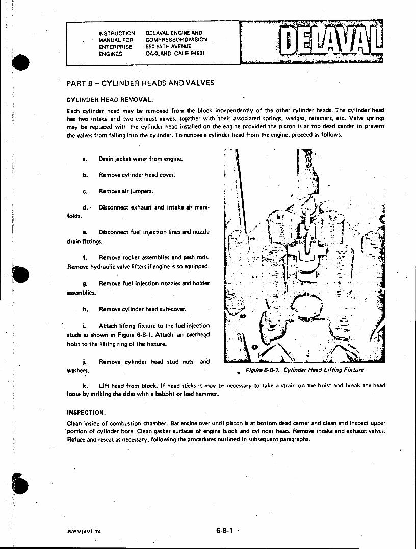
INSTRUCTION DELAVAL ENGINE AND MANUAL FOR COMPRESSOR DIVISION ENTERPRISE 550-85TH AVENIJE ENGINES OAKLAND, CALIF. 94621
PART B - CYLINDER HEADS AND VALVES
CYLINDER HEAD REMOVAL.
Each cylinder hcad may be removed from the block independently of the other cylinder heads. The cylinder'head has two intake and two exhaust valves, together with their associated springs, wedges, retainers, etc. Valve springs may be replaced with the cylinder head installed on the engine provided the piston is at top dead center to prevent the valves from falling into the cylinder. To remove a cylinder head from the engine, proceed as follows.
a. Drain jacket water from engine.
b. Remove cylinder head cover.
c. Remove air jumpers.
d. Disconnect exhaust and intake air manifolds.
e. Disconnect fuel injection lines and nozzle. drain fittings.
f. Remove rocker assemblies and push rods. Remove hydraulic valve lifters if engine is so equipped.
g. Remove fuel injection nozzles and holder assemblies.
h. Remove cylinder head sub-cover.
i. Attach lifting fixture to the fuel injection LL studs as shown in Figure 6-B-1. Attach an. overhead hoist to the lifting ring of the fixture.
I. Remove cylinder head stud nuts and washers. Figure G-B-1. Cylinder Head Lifting Fixture
k. Lift head from block. If head sticks it may be necessary to take a strain on the hoist and break the head loose by striking the sides with a babbitt or lead hammer.
INSPECTION.
Clean inside of combustion chamber. Bar engine over until piston is at bottom dead center and clean and inspect upper portion of cylinder bore. Clean gasket surfaces of engine block and cylinder head. Remove intake and exhaust valves. Reface and reseat as necessary, following the procedures outlined in subsequent paragraphs.
/RVi4VI-74 6-B-1 -

INSTRUCTION DELAVAL ENGINE AND MANUAL FOR COMPRESSOR DIVISION ENTERPRISE 550-85TH AVENUE ENGINES OAKLAND, CALIF 94621
PART B - CYLINDER HEADS AND VALVES (Continued)
VALVES.
Intake and exhaust valves are constructed of alloy steel, however, the steel alloy specifications differ. Valves may be
identified by the marking "IN" for intake valves and "EX" for exhaust valves, stamped on the valve stem. The intake
valves on dual fuel engines also serve as gas admission valves and are so constructed that an enlarged portion of the
valve stem fits into the lower portion of the valve guide to form a gas admission valve. At the proper point of the intake
valve opening stroke, gas is admitted through ports in the valve guide to mix with the intake airstream.
VALVE SPRING REPLACEMENT (Cylinder Head Not Removed).
Valve springs may be replaced-without removing the cylinder head from the block. Remove rocker arms assemblies then bar engine over until piston of cylinder being worked on is at
top dead center. Attach valve spring removal tool to the two fuel injector studs as shown in Figure 6-B-2. Make sure the nuts are rundown far enough on the studs to hold securely. Tight
en nut on cross arm, making sure the cross arm is not bearing on the top of the wedges. Tighten nut until valve springs are compressed. Lift the valve by its stem and remove the two keepers from each valve. Back off on compression nut on tool, then remove tool from cylinder head. Springs may be lifted off valve stems. Spring 7, installation is the reverse of removal.
Figure 6-B-2. Valve Spring Removal Tool
VALVE REMOVAL FROM CYLINDER HEAD.
With cylinder head removed from engine, install
valve spring removal tool as shown above, and remove valve springs. Remove valves from com
bustion side of cylinder head.
Figure 6-8-3. Removing Valve Keepers.
amueV 4 1-7 6-B-2-

INSTRUCTION DELAVAL ENGINE AND MANUAL FOR COMPRESSOR DIVISION ENTERPRISE 550-85TH AVENUE ENGINES OAKLAND, CALIF. 94621 ..
PART B - CYLINDER HEADS AND VALVES (Continued)
VALVE INSPECTION AND RECONDITIONING.
The seating surface of valves, particularly exhaust valves, may have the appearance of pitting due to small carbon particles which may have been trapped on tne seats and impressed on the metal. This condition has no effect on operation unless there is an indication of blowby, in which case the valves should be reseated. Valves may be re-faced on a standard valve re-facing machine, or on an ordinary lathe. The seating should be exactly 45 degrees. If done on a lathe with a cutting tool, be sure to use very fine feed and a sharp tool for the final cut. If a grinding wheel is used, the wheel should be dressed for exact trueness before the final grinding cut is taken. Remove just enough material to eliminate pits and to make the seat run exactly true with the stem. If the valve guide is worn, a new guide should be installed before re-facing valve seats. Re-seat head with a valve grinder. If a grinder is not available, use a 45 degree hand reamer. Face just enough for trueness and removal of pits. Limit width of valve seat to 19/32 t 1/64 inch (1.51 t 0.04 cm) with a 45 degree tool. If the engine is equipped with valvi rotators, the rotators must be replaced whenever the valves are serviced.
CYLINDER HEAD INSTALLATION.
Use new seals when the cylinder head is installed on the engine block. Make sure all areas are clean and free of dirt or other foreign matter.
a. Attach lifting fixture to cylinder head and hoist head in place over cylinder head studs. 7
b. Carefully lower head into place, taking care not to damage stud threads or seals.
C. Lubricate cylinder head studs and nut threads with a 50-50 mixture of graphite and lubricating oil. Assemble washers and nuts on studs And run down on the threads.
d. Tighten nuts in increments, and in a criss-cross pattern, following the sequence shown in figure 6-B-4. Torque to the specified torque value. This procedure will pull the head down evenly.
IK PORT
Figure 6-B4., Tightening Sequence For Cylinder Head Stud Nuts.
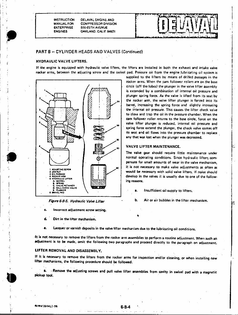
INSTRUCTION DELAVAL ENGINE AND MANUAL FOR COMPRESSOR DIVISION ENTERPRISE 550-E5TH AVENUE ENGINES OAKLAND. CALIF. 94621
PART B - CYLINDER HEADS AND VALVES (Continued)
HYDRAULIC VALVE LIFTERS.
If the engine is equipped with hydraulic valve lifters, the lifters are installed in both the exhaust and intake valve rocker arms, between the adjusting screw and the swivel pad. Pressure oil from the engine.lubricating oil system is
supplied to the lifters by means of drilled passages in the rocker arms. When the cam follower rollers are on the base circle (off the lobes) the plunger in the valve lifter assembly
I is extended by a combination of internal oil pressure and plunger spring force. As the valve is lifted from its seat by
BA the rocker arm, the valve lifter plunger is forced into its barrel, increasing -the spring force and slightly increasing
3 / the inifternal oil pressure. This causes the lifter check valve A to close and trap the oil in the pressure chamber. When the
4 cam follower roller returns to the base circle, force on the
so valve lifter plunger is reduced, internal oil pressure and spring force extend the plunger, the check valve comes off
iseat and oil flows into the pressure chamber to replace any that was lost when the plunger was depressed.
S VALVE LIFTER MAINTENANCE.
The valve gear should require little maintenance under iim ~ normal operating conditions. Since hydraulic lifters com
I ADJSTIN SCRW BE it is not necessary to make valve adjustments as often as 2 JAM NTN C would be necessary with solid valve lifters. If noise should 3 OIL PASSAGE ' tevleitiduto fth41 4ROCKER ARM develop in th avsi susually du oone ofth*ollowBIYDRAULIC LIFTER igraos
A. BARREL S. SPRING C. VALVE RETAINER D. BALL CHECK VALVE D. PLUNGER a. Insufficient oil supply to lifters.
6 SIAIVEL PAD
Figure 6-8-5. Hydraulic Valve Lifter . b. Air or air bubbles in the lifter mechanism.
C. Incorrect adjustment screw setting.
d. Dirt in the lifter mechanism.
*e. Lacquer or varnish deposits in the valve lifter mechanism due to the lubricating oil conditions.
-It is not necessary to remove the lifters from the rocker arm assemblies to perform a routine adjustment. When such an adjustment is to be made, omit the following two paragraphs and proceed directly to the paragraph on adjustment.
UFTER REMOVAL AND DISASSEMBLY. If it is necessary to remove the lifters from the rocker arms for inspection and/or cleaning, or when installing new lifter mechanisms, the following proctedure should be followed.
a. c Remove tht adjusting screws and pull valve lifter assemblies from cavity in swivel pad with a magnetic pickup tool.
~IvOHJ-75 6-B-4 -

INSTRUCTION DELAVAL ENGINE AND MANUAL FOR COMPRESSOR DIVISION I ENTERPRISE 550-F5TH AVENUE ENGINES OAKLAND, CALIF. 94621
PART B - CYLINDER HEADS AND VALVES (Continued)
b. Insert a soft wire in one of the plunger fill holes then slide the plunger out of the barrel, taking care rot to let the ball check valve and the valve retainer drop. Remove the spring from the barrel cavity and wash all items in kerosene. Use lacquer thinner to remove lacquer and varnish deposits caused by lubricating oil conditions. Do not use grinding compound or a hard tool to clean the barrel or plunger as this may scratch the surfaces which are built to close tolerances. Wipe all parts with a clean, lint-free rag.
c. The condition of the unit may be best determined by performing a leakdown test. Specifications for a new unit require that, with the unit completely assembled and filled with kerosene, the plunger should travel 0.125 inch in one and one-half to three seconds when subjected to a 50 pound load. Plungers are not interchangeable in the barrel as the units are factory assembled for a specific leakdown rate.
ASSEMBLY AND INSTALLATION OF LIFTERS.
Assemble lifters in the reverse order of disassembly. Insure that all parts are clean, free of dirt or other foreign matter, and do not stick or bind. Fill and purge the assembled unit then install in the engine as follows:
a. Hold the check valve off its seat by inserting a soft wire about 3/8 inch into one of the fill holes, then submerge the unit in clean SAE-10 or SAE-20 grade oil. Push in and release the plunger repeatedly until air is no longer expelled from the assembly. This will purge the unit of air and fill it with oil.
b. Remove the wire from the fill hole and remove the assembly from the oil. The plunger should extend 1/8 inch from the barrel and should not compress when pushed in by hand.
c. With the rocker arms completely assembled and installed on the cylinder except for the hydraulic valve lifter assemblies and adjusting screws (the swivel pad assembly is held in the rocker arm by a roll pin), fill the cavity of the swivel pad with clean oil.
d. Insert the valve lifter into the swivel pad cavity. The rocker arm must be kept in a near horizontal position after the lifter has been inserted to keep the lifter submerged in oil. Install the adjusting screw and locknuts.
ADJUSTMENT.
After the lifters have been installed, or if a periodic adjustment is to be made, bar the engine over to position the cylinder being worked on at top dead center on the 1ompression stroke and adjust lifters by one of the following methods. The first method (Method "A") involves advancing Ie adjusting screw until it just contacts the lifter, but does not compress it, then advancing the screw one additional turn. The alternate method (Method "B") is to completely collapse the lifter, then back off one full turn from the point where the valve just seats. Either method, if properly done, will accomplish the same thing. It must be kept in mind, however, that cold oil will increase the time required for the lifter to leak down to complete collapse when using the latter method.
a. METHOD "A".
(1) Hold the rocker assemblies tight against the pushrods to remove all play, then advance adjusting screw by hand until the end of the screw just contacts the lifter under it, taking up all the slack in the valve operating gear. Make sure the swivel pad rests squarely on the valve stem. Due to variations in threads, the feel of turning the adjusting screw is not sensitive enough to make an accurate determination as to when all slack has been removed, therefore, the feel for taking up the slack has to be on the pushrod or cross (intermediate) rod and the swivel pad onthe adjusting screw. Lift each swivel pad by hand to make sure that all clearance is removed between the swivel pad and the valve stem.
R/VID/HLI.75 6-B-5
INSTRUCTION DELAVAL ENGINE AND MANUAL FOR COMPRESSOR DIVISION
ENTERPRISE 550-85TH AVENUE ENGINES OAKLAND, CALIF. 94621
PART B - CYLINDER HEADS AND VALVES (Continued)
(2) Turn the adjusting screw one full turn (0.070 inch) with a wrench and tighten the locknut. This will
locate the lifter plunger near the middle of its 1/8 inch travel.
b. METHOD "B".
(1) Advance adjusting screw with a wrench until the valve begins to lift off its seat, then advance adjusting
screw at least two additional turns.
(2) Wait approximately ten seconds (longer if oil is cold) then back off on adjusting screw until valve
seats. The point at which the valve seats may be easily felt by the reduced torque required to turn the screw.
(3) Note the position of the wrench at the point where the valve just seats, then advance screw at least
one-half turn.
(4) Back out adjusting screw until valve just seats. If the position of the wrench is the same as (3) above,
the lifter is fully collapsed. If not, repeat procedure until the position of the wrench is the same each time the valve
seats.
(5) Back out adjusting screw one full turn from position where valve seated then tighten locknut
c. Swivel pads should now be free to be rotated by hand. If they cannot be rotated, the adjusting screw has
collapsed the lifter to the end of its 1/8 inch travel and the valve has been lifted off its seat.
d. Swivel pad clearance should be such that the pad cannot be rocked on top of its valve stem. If the swivel
pad can be rocked it means that the lifter is either fully extended and not at the mid point of its travel, or that it has
not been completely purged of air. This may be due to an improper adjustment caused by burrs or dirt on the adjusting
screw threads, or because of incomplete purging of air from the assembly.
0 E. RIJUVIDIN-I .79 .4
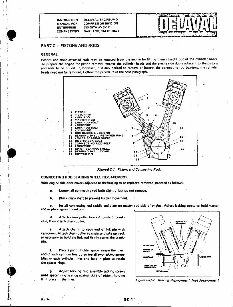
INSTRUCTION DELAVAL ENGUMI AND MANUAL FOR COMPRESSOR DWISION ENTERPRISE 550-85TH AVENUE
. COMPHESSORS OAKLAND, CALIF.94621
PART C - PISTONS AND RODS
GENERAL. Pistons and their attached rods may be removed from the engine by lifting them straight out of the cylinder, liners. To prepare the engine for piston removal, remove the cylinder heads and the engine side doors adjacent to the pistons and rods to be pulled. If, however, it is only desired to remove or inspect the connecting rod bearings, the cylinder heads need not be removed. Follow the procedure in the next paragraph.
4'S
1 PISTON 2 PISTON PIN 3 LINK ROD A MASTER ROD 5 LINK ROD BOLT 6 LOCKWIRE 13 7 LINK ROD BOLT 7 14 8 LOCKWIRE 9 BOX BUSHING LOCKPIN
10 BEARING SHELL RETAiNER RING * 11 LOWER BEARING SHELL 15 12 ROD TO BOX BOLT 16 13 CONNECTING ROD BOLT 14 LOCKWIRE 15 UPPER BEARING SHELL, 16 BEARING SHELL DOWEL 10-17 COTTER PIN 1
12
12
Figure 6-C-1. Pistons and Connecting Rods
CONNECTING ROD BEARING SHELL REPLACEMENT.
With engine side door covers adjacent to the bearing to be replaced removed, proceed as follows.
a. Loosen all connecting rod bolts slightly, but do not remove.
b. Block crankshaft to prevent further movement.
c. Install connecting rod saddle and plate on master rod side of engine. Adjust jacking screw to hold master rod in place against crankpin.
d. Attach chain puller bracket to side of crankcase, then attach chain puller.
e. Attach chains to each end of link pin with capscrews. Attach chain puller to chain and take up slack as necessary to hold the link rod firmly against the crankpin.
f. Place a piston holder spacer ring in the lower end of each cylinder liner, then install two jacking assemblies in each cylinder liner and bolt in place to retain the spacer rings.
g. Adjust locking ring assembly jacking screws UK_ _ _ _ _ _
until spacer ring is snug against skirt of piston, holding It in place in the liner. Figure 6-C-2. Bearing Replacement Tool Arrangement
PaV-74 6-C-1
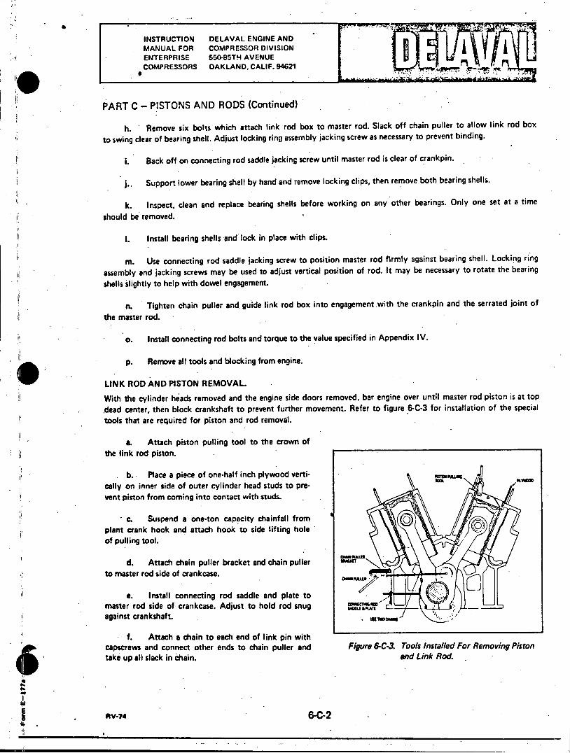
INSTRUCTION DELAVAL ENGINE AND MANUAL FOR COMPRESSOR DIVISION ENTERPRISE 550-85TH AVENUE COMPRESSORS OAKLAND, CALIF. 94621
PART C - PISTONS AND RODS (Continued)
h. Remove six bolts which attach link rod box to master rod. Slack off chain puller to allow link rod box
to swing clear of bearing shell. Adjust locking ring assembly jacking screw as necessary to prevent binding.
i. Back off on connecting rod saddle jacking screw until master rod is clear of crankpin.
j.. Support lower bearing shell by hand and remove locking clips, then remove both bearing shells.
k. Inspect, clean and replace bearing shells before working on any other bearings. Only one set at a time
should be removed.
1. Install bearing shells and lock in place with clips.
m. Use connecting rod saddle jacking screw to position master rod firmly against bearing shell. Locking ring assembly and jacking screws may be used to adjust vertical position of rod. It may be necessary to rotate the bearing shells slightly to help with dowel engagement.
n. Tighten chain puller and, guide link rod box into engagement with the crankpin and the serrated joint of
the master rod.
0. Install connecting rod bolts and torque to the value specified in Appendix IV.
p. Remove all tools and blocking from engine.
LINK ROD AND PISTON REMOVAL.
With the cylinder heads removed and the engine side doors removed, bar engine over until master rod piston is at top dead center, then block crankshaft to prevent further movement. Refer to figure 6-C-3 for installation of the special tools that are required for piston and rod removal.
a. Attach piston pulling tool to the crown of the link rod piston.
. b. Place a piece of one-half inch plywood vertically on inner side of outer cylinder head studs to prevent piston from coming into contact with studs.
* c. Suspend a one-ton capacity chainfall from plant crank hook and attach hook to side lifting hole of pulling tool.
cMNu0
d. Attach chain puller bracket and chain puller to master rod side of crankcase.
e. Install connecting rod saddle and plate to master rod side of crankcase. Adjust to hold rod snug against crankshaft.
f. Attach a chain to each end of link pin with capscrews and connect other ends to chain puller and Figure 6-C-3. Tools Installed For Removing Piston take up all slack in chain. and Link Rod.
6-C-2 -
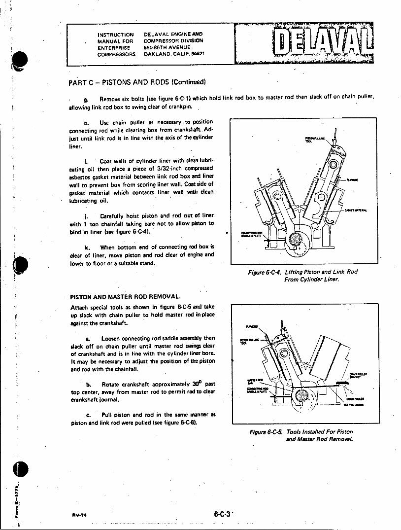
INSTRUCTION DELAVAL ENGINE AND MANUAL FOR COMPRESSOR DIVISION ENTERPRISE 550-85TH AVENUE COMPRESSORS OAKLAND, CALIF. 94621 .
PART C - PISTONS AND RODS (Continued)
- g. Remove six bolts (see figure 6-C-1) which hold link rod box to master rod then slack off on chain puller,
allowing link rod box to swing clear of crankpin.
h. Use chain puller as necessary. to position
connecting rod while clearing box from crankshaft..Adjust until link rod is in line with the axis of the cylinder nnI
liner. 0
i. Coat walls of cylinder liner with clean lubricating oil then place a piece of 3/32-inch compressed
asbestos gasket material between link rod box and liner wall to prevent box from scoring liner wall. Coat side of gasket material which contacts liner wall with clean lubricating oil.
J. Carefully hoist piston and rod out of liner
with 1 ton chainfall taking care not to allow piston to
bind in liner (see figure 6-C-4).
k. When bottom end of connecting rod box is
clear of liner, move piston and rod clear of engine and lower to floor or a suitable stand.
Figure 6-C4. Lifting Piston and Link Rod From Cylinder Liner.
PISTON AND MASTER ROD REMOVAL.
Attach special tools as shown in figure 6-C-5 and take up slack with chain puller to hold master rod in place against the crankshaft.
a. Loosen connecting rod saddle assembly then 0 slack off on chain puller until master rod swings clear of crankshaft and is in line with the cylinder liner bore.
It may be necessary to adjust the position of the piston and rod with the chainfall.
b. Rotate crankshaft approximately 30 past top center, away from master rod to permit rod to clear SoI crankshaft journal. DMR\E)
c. Pull piston and rod in the same manner as piston and link rod were pulled (see figure 6-C-6).
Figure 6-C-5. Tools Installed For Piston and Master Rod Removal.
EI fty.74 6-C-3

INSTRUCTION DELAVAL ENGINE AND MANUAL FOR COMPRESSOR DIVISION ENTERPRISE 550-85TH AVENUE COMPRESSORS OAKLAND. CALIF. 94621 "
PART C - PISTONS AND RODS (Continued)
. REMOVAL OF A SEIZED STUD.
When it is evident that a bolt has seized in the connecting rod box, do not attempt to force it. The following procedure is recommended for the removal of a seized connecting rod bolt.
a. Position the crankshaft to place the connecting rod at its closest point to the engine side door and block the crankshaft to prevent movement.
b. Leave at least one good bolt in position to hold the master rod and connecting rod box together while the seized bolt is being removed.
c. Form a shield of asbestos gasket material around the master rod to catch molten metal and slag and prevent it from falling into the engine base.
d. Cut off the head of the siezed bolt with an oxy-acetylene cutting torch. Exercise great care not to damage the master rod with the cutting frame.
Figure 6-C46 Lifting Master Rod and Piston From Cylinder Liner.
e. Clean out the slag and burned metal and remove the gasket shield.
f. Install a master rod retaining bar and plate assembly to hold the master rod firmly against the connecting rod bearing and crank journal.
g. Install the tools and fixtures necessary to remove the link rod and piston.
h. Remove the remaining bolts and carefully disengage the link rod and connecting rod box from the master rod. Carefully guide the headless bolt stud through its hole in the master rod. Allow the link rod and box to rest against the lower edge of the cylinder liner.
I. Place a shallow pan of water beneath the stub 6f the seized bolt to catch the molten metal and slag when the stub is cut off, then cut the stub off approximately one inch from the surface of the connecting rod box.
I. Clean the debris from the area then remove the link rod and piston assembly from the engine in the normal manner. Remove the connecting rod box from the link rod.
k. Set the connecting rod box up on a good radial drill and drill out the remainder of the seized bolt. Exercise care to drill the bolt on dead center to prevent damage to the threads in the tapped hole in the connecting rod box.
I. Try a new bolt in the hole to be sure the threads are good, and that the bolt will run free in the tapped hole..
m. Reassemble the link rod and connecting rod box and place the piston and connecting rod assembly in the engine in the normal manner. Use new locking devices when assembling the link rod to the link pin.
RV-74 6-C-4
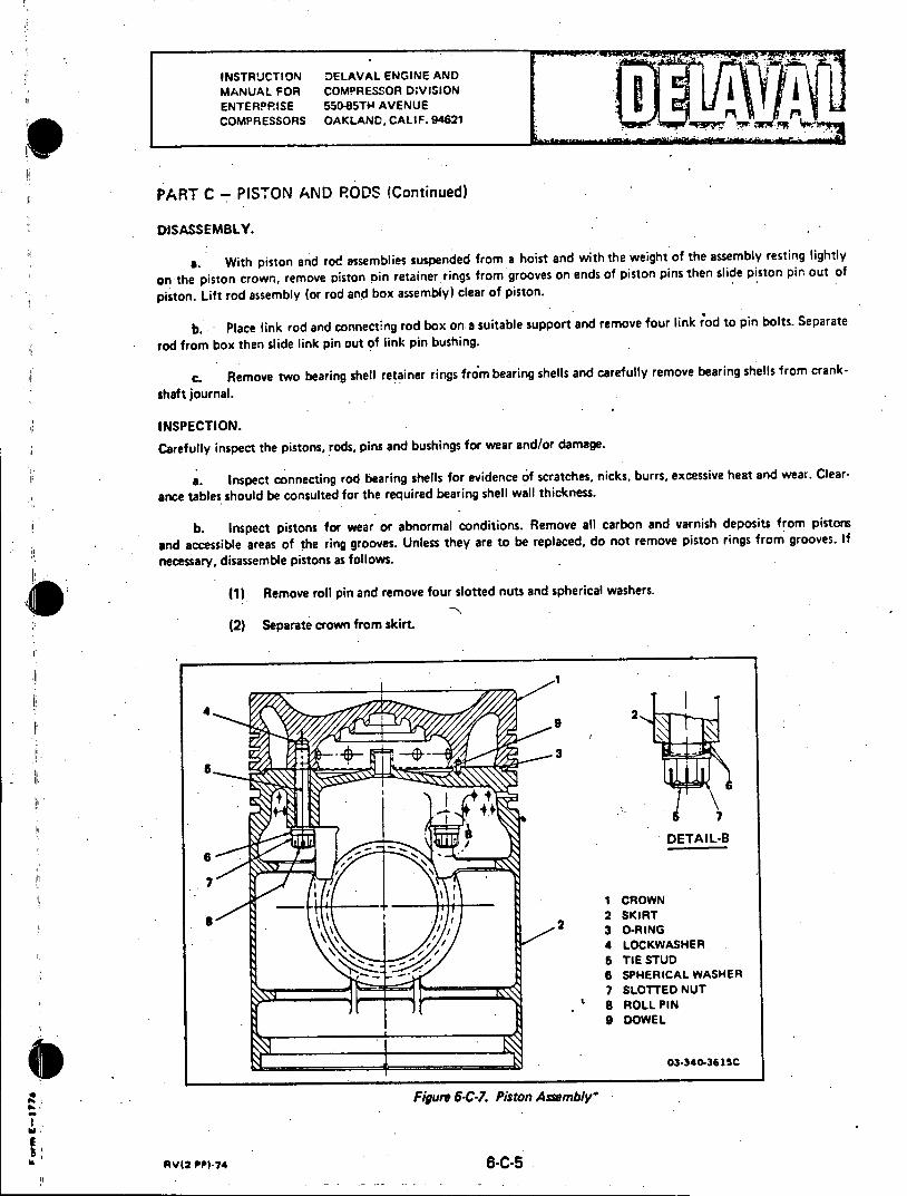
INSTRUCTION DELAVAL ENGINE AND MANUAL FOR COMPRESSOR D;VISION ENTERPRISE 550-85TH AVENUE COMPRESSORS OAKLAND, CALIF. 94621
PART C - PISTON AND RODS (Continued)
DISASSEMBLY.
a. With piston and rod assemblies suspended from a hoist and with the weight of the assembly resting lightly
on the piston crown, remove piston pin retainer rings from grooves on ends of piston pins then slide piston pin out of
piston. Lift rod assembly (or rod and box assembly) clear of piston.
b. Place link rod and connecting rod box on a suitable support and remove four link rod to pin bolts. Separate
rod from box then slide link pin out of link pin bushing.
c. Remove two bearing shell retainer rings from bearing shells and carefully remove bearing shells from crank
shaft journal.
INSPECTION.
Carefully inspect the pistons, rods, pins and bushings for wear and/or damage.
a. Inspect connecting rod bearing shells for evidence of scratches, nicks, burrs, excessive heat and wear. Clear
ance tables should be consulted for the required bearing shell wall thickness.
b. Inspect pistons for wear or abnormal conditions. Remove all carbon and varnish deposits from pistors
and accessible areas of the ring grooves. Unless they are to be replaced, do not remove piston rings from grooves. If
necessary, disassemble pistons as follows.
(1) Remove roll pin and remove four slotted nuts and spherical washers.
(2) Separate crown from skirt.
4 2 9
7
I CROWN
2 2 SKIRT 3 O-RING 4 LOCKWASHER. 5 TIE STUD 6 SPHERICAL WASHER 7 SLOTTED NUT
. 8 ROLL PIN 9 DOWEL
dIR 03-340-361SC
Figure 6-C-7. Piston Assembly.
AV(2 PI-74 6-C-5
INSTPUCTION DELAVAL ENGINE AND MANUAL FOR COMPRESSOR DIVISION ENTERPRISE 550-85TH AVENUE COMPRESSORS OAKLAND. CALIF. 94621
PART C - PISTONS AND RODS (Continued)
(3) Clean parts thoroughly. If crown is to be replaced, place a 3/8-inch steel lockwasher in each of the four tie stud holes, making sure they are resting square in the bottom of the-hole. Install four tie studs and bottom
out against lockwasher in the hole. Torque studs to 215 ft-lb. Install dowel in dowel hole in crown.
(4) Assemble new O-ring on the crown, then lower skirt over the four tie studs. Correct position is determined by the dowel in the crown.
(5) Install spherical washers on studs. The convex half of the washer must be installed first, flat side
against the piston skirt. The concave half is then installed with the flat side towards the nut end of the stud. See
Figure 6-C-7.
(6) Assemble the slotted nuts and torque to 120-160 ft-lb. Install roll pin through each slotted nut.
PISTON RING REPLACEMENT.
If piston rings require replacement, remove and install as follows.
a. Starting with top ring, spread and slide piston rings up and off piston. Four brass strips, measuring approximately 1/32" x 1/2" x 8" may be inserted under rings to protect piston during removal and installation of rings.
b. Replace piston rings in reverse order of removal. Intermediate compression rings are marked "UP" on the upper sides. Top compression rings may be installed with either side up. The oil cutter rings must be installed with the cutting edge down.
c. Rotate the rings in the grooves so gaps are staggered around circumference of pistork
PISTON RING GAP AND SIDE CLEARANCES.
Piston ring gap may be measured by inserting piston ring into cylinder liner and sliding it down squarely, measuring the gap at various levels in the liner. The gap clearance should be determined at the smallest diameter, usually near the bottom of the liner. Piston ring wear is usually indicated by excessive ring gap clearance. Refer to "Appendix Ill" in Section 8 for correct gap clearance. If the recommended gap clearance is exceeded by 1/16-inch or more, the bore of the liner should be measured with an inside micrometer. if the bore at any point is worn more than shown in "Appendix Ill" the liner should be replaced. Liner wear is usually limited to the last few inches of ring travel near the top.
PISTON PIN BUSHING REPLACEMENT.
Use the following method to replace the piston pin bushing in the connecting rod.
a. If an arbor press is available, press the bushing from the rod, otherwise, carefully split the bushing with a hacksaw and drive it out of the rod. Remove all burrs and clean the connecting rod.
b. Place the new bushing in a suitable container such as a bucket or a deep pan.
c. Fill the container with liquid nitrogen. Nitrogen level should be approximately one inch from the top of the bushing to allow for handling.
d. Lay connecting rod on its side on a suitable support. Both ends of the piston pin bushing bore should be accessible.
AV-74 6-C-6

II INSTRUCTION DELAVAL ENGINE AND MANUAL FOR COMPRESSOR DIVISION ENTERPRISE 550-85TH AVENUE COMPRESSORS OAKLAND, CALIF. 94621
PART C - PISTONS AND RODS (Continued)
Wear asbestos gloves when handling bushing to avoid injury to the hands.
e. When the nitrogen stops boiling, remove the bushing from the container and insert in the bore, taking
care to align the oil holes with the oil passages in the connecting rod. Insure that the bushing protrudes the same
distance on both ends. The operation must be done quickly before the bushing expands due to heat pickup.
LINK PIN BUSHING REPLACEMENT.
If the link bushing requires replacement, proceed as follows.
a. Remove the bushing lock pin, split the bushing with a hacksaw to relieve stress, then drive bushing out of
connecting rod box.
b. Clean the connecting rod box, removing all burrs and rough surfaces.
*c. Place new bushing in a suitable container such as a bucket or a deep pan.
d. Fill container with liquid nitrogen. Nitrogen level should be approximately one inch from the top of the
bushing to allow for handling.
e. Lay the connecting rod box on its side on a suitable support. Three pieces of 1-1/2 inch rough stock, laid
parallel on a piece of metal plate, will provide adequate support for the box and act as a stop for the bushing so that
it will be flush with the side of the box when it is inserted.
WARNG
Wear asbestos gloves when handling bushing to avoid injury to hands.
-f. When the nitrogen stops boiling, remove the bushirdj from the container.
g. Insert the bushing in the connecting rod box, taking care to line up the bushing cutouts with the internal
surface contour of the box. Insure that both ends of the bushing are aligned with the side of the box. This must be
done quickly before the bushing expands due to heat pickup.
PISTON AND ROD ASSEMBLY.
Assemble pistons, rods and connecting rod box as follows. Make sure pistons and rods are reassembled in the same
relative position as they occupied before disassembly.
a. Insert link rod pin in connecting rod box bore and position link rod on link pin.
b. Apply a lubricant consisting of a 50-50 mixture of powdered graphite and lubricating oil to the threads
of the link-rod-to-pin bolts. Torque bolts to specified torque and secure with lockwire.
TJ
NI

INSTRUCTION DELAVAL ENGINE AND MANUAL FOR COMPRESSOR DIVISION ENTERPRISE 550-8STH AVENUE COMPRESSORS OAKLAND, CALIF. 94621
PART C - PISTONS AND RODS (Continued)
c. Place piston upside down, resting on its crown. Lift connecting rod with rod turning plate then lower
end of connecting rod into piston, aligning piston pin hole in rod with that of piston.
d. Insert piston pin through piston and rod. Clean piston groove and the outside end of the piston pin retainer
rings and insert retainer rings into piston grooves at either end of piston pin. Apply "Locktite" to ends of retainer
rings to prevent rings from rotating in the grooves.
PISTON AND MASTER ROD INSTALLATION.
Install a piston pulling tool on piston crown then suipend piston and rod from an overhead hoist then proceed as follows.
a. Lubricate walls of cylinder liner with clean lubricating oil. & uL
b. . Install piston ring fixture on top of cylinder liner.
*c. Place a piece of one-half inch plywood vertically on inner side of outer cylinder head studs.
d. Position crankshaft with crankpin approximately 300 past top center, away from master rod side.
e. Position piston and rod over cylinder liner.
f. Lubricate one side of a piece of 3/32-inch asbestos gasket material with clean lubricating oil. Wrap around lower end of connecting rod with oiled side towards liner wall. Figure 6-C-8. Piston and Rod Installation *
g. Lower rod into cylinder (see figure 6-C-8). Hold piston rings in place as they enter the piston ring fixture. Insure ring gaps are staggered around circumference of piston.
h. Continue to lower piston until connecting rod bore is opposite crankpin. Remove gasket material.
I. Attach chain puller bracket, chain puller, chains and master rod bar then rotate crankshaft towards rod. By adjusting rod and crankshaft positions, bring master rod into engagement with crankpin. Make sure dowel seats in dowel hole - rotation of bearing shell may be necessary.
j. Install connecting rod saddle and plate on master rod side (see figure 6-C-5) and set to hold master rod tight against crankpin.
Do not rotate crankshaft until link rod has been assembled and bolted to master rod. Block crankshaft to prevent movement
RV-74 6-C-8
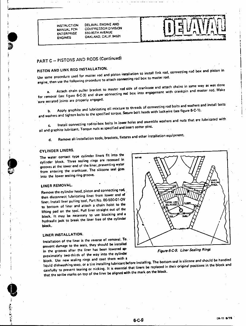
PART C - PISTONS AND RODS (Continued)
PISTON AND .LINK ROD INSTALLATION. .
Use same procedure used for master rod and piston installation to install link rod, connecting rod box and piston in
engine, then use the following procedure to attach connecting rod box to master rod.
a. Attach chain puller bracket to master rod side of crankcase and attach chains in same way as was done
for removal (see figure 6-C-3) and draw connecting rod box into engagement with crankpin and master rod. Make
sure serrated joints are properly engaged.
b. Apply graphite and lubricating oil mixture to threads of connecting rod bolts and washers and install bolts
and washers and tighten bolts to the specified torque. Secure bolt heads with lockwCire (see figure 6-C-1).
c. Install connecting rod-to-box bolts in lower holes and assemble washers and nuts that are lubricated with
oil and graphite lubricant. Torque nuts as specified and insert cotter pins.
d. Remove all installation tools, brackets, fixtures and other installation equipment.
CYLINDER LINERS.
The water contact type cylinder liners fit into the
cylinder block. Three sealing rings are recessed in
grooves at the lower end of the liner, preventing water
from entering the crankcase. The silicone seal goes
into the lower sealing ring groove. SEALING
LINER REMOVAL. **
Remove the cylinder head, piston and connecting rod,
then disconnect lubricating lines from lower end of
liner. Install liner pulling tool, Part No. 00-590-01-OV to bottom of liner and attach a chain hoist to the 01 HEDE
lifting pad on the tool. Pull liner straight out of the
block. It may be necessary to use blocking and a
hydraulic jack to break the liner free of the cylinder
block..
LINER INSTALLATION.
Installation of the liner is the reverse of removal. To.
prevent damage to the seals, they should be installed
in the grooves after the liner has been lowered ap
proximately two-thirds of the way into the cylinder Figure 6-C-9. Liner Sealing Ring
block. Use new sealing rings and coat them with a
liquid dishwashing soap, or a tire installing lubricant before installing. The bottom seal is silicone and should be handled
carefully to prevent tearing or nicking. It is essentiar that liners be replaced in their original positions in the block and
that the scribe marks on top of the liner be aligned with the mark on the block.
6-C-9 (R-1) 5/76

INSTRUCTIOir DELAVAL ENGINE AND MANUAL FOR COMPRESSOR DIVISION ENTERPRISE 550-85TH AVENUE COMPRESSORS OAKLAND, CALIF. 94621
PART D - CRANKSHAFT AND BEARINGS
MAIN BEARINGS.
Main bearings are made of aluminum alloy, the upper and lower bearings being interchangeable. The upper shell is held in place on the bearing cap by two lock IMNE GAs
rings and socket head capscrews. Main bearings are front, intermediate and rear, the number of intermediate bearings being determined by the number of cylinders. Bearing caps are secured to the engine base by studs (see figure 6-111). Oil passages through the bearing cap provide for bearing shell lubrication. To prevent axial movement of the crankshaft, thrust
rings are attached to the rear bearing caps, each se
cured with button head capscrews (see figure 6-D-2).
Figure 6-D- 1. Main Bearing Cap
RBEARING CAP REMOVAL.
CSARKSMAF
Main bearing caps are pre-stressed by means of a
special tool, normally furnished with the engine. The tool consists of a pre-stresser assembly (Part No. 1A-1801), and adapter (Part No. 00-590-01-OK) and a spacer (Part No. 00-590-01-OJ).
a. Remove lubricating oil fittings, temperature sensing devices and locking plates from stud nuts.
b. Attach adapters to pre-stresser assemblies and place a spacer over each of two diagonally opposite stud nuts.
c. Use jacking screws on micrometer bar to force piston flange against top of cylinder, then back
Figure 6-D-2 Crankshaft Thrust Rings off jacking screws one-quarter inch.
d. Assemble a pre-stresser to each of the two main bearing cap studs, running them down on the stud threads until pre-stressers are snug against adapters.
e. Attach hydraulic hose between two pre-stressers, and between one pre-stresser and a suitable hydraulic
pumping unit. Bleed air from system by opening pipe plug on second pre-stresser then operating pumping unit to supply a small pressure. When all air bubbles disappear, tighten pipe plug.
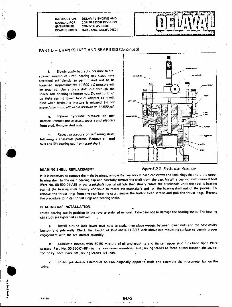
INSTRUCTION DELAVAL ENGINE AND MANUAL FOR COMPRESSOR DIVISION ENTERPRISE 550-85TH AVENUE COMPRESSORS OAKLAND, CALIF. 94621
PART D - CRANKSHAFT AND BEARINGS lontinued)
f. Slowly apply hydraulic pressure to prestresser assemblies until bearing cap studs have stretched sufficiently to permit stud nut to be loosened. Approximately 10,500 psi pressure will be required. Use a brass drift pin through the
spacer side opening to loosen nut. Do not turn nut
up tight against lower face of adapter as it will bind when hydraulic pressure is released. Do not exceed maximum allowable pressure of 11,500 psi.
g. Relieve hydraulic pressure on prestressers, remove pre-stressers, spacers and adapters from stud. Remove stud nuts.
h. Repeat procedure on remaining studs, following a criss-cross pattern. Remove all stud nuts and lift bearing cap from crankshaft.
BEARING SHELL REPLACEMENT. Figure 6-D-3. Pre-Stresser Assembly
If it is necessary to remove the main bearings, remove the two socket head capscrews and lock rings that hold the upper
bearing shell to the main bearing cap and carefully remove the shell. from the cap. Install a bearing shell removal tool
(Part No. 00-590-01-AE) in the crankshaft journal oil hole then slowly rotate the crankshaft until the tool is bearing
against the bearing shell. Slowly continue to rotate the crankshaft and roll the bearing shell out of the journal. To
remove the thrust rings from the rear bearing caps, remove the button head screws and pull the thrust rings. Reverse
the procedure to install thrust rings and bearing shells.
BEARING CAP INSTALLATION.
Install bearing cap in position in the reverse order of removal. Take care not to damage the bearing shells. The bearing
cap studs are tightened as follows.
a. Install pins to lock lower stud nuts to studs, then place wedges between lower nuts and the base cavity
bottom and side walls. Check that height of stud end is 11-3/16 inch above cap mounting surface to permit proper
engagement with the pre-stresser assembly.
b. Lubricate threads with 50-50 mixture of oil and graphite and tighten upper stud nuts hand tight. Place
spacers (Part No. 00-590-01-OK) to the pre-stresser assemblies. Use jacking screws to force piston flange tight against
top of cylinder. Back off jacking screws 1/4 inch.
c. Install pre-stresser assemblies on two diagonally opposite studs and assemble the micrometer bar on the
units.
RV-74 6-D-2'
INSTRUCTION DELAVAL ENGINE AND MANUAL FOR COMPRESSOR DIVISION ENTERPRISE 550-85TH AVENUE COMPRESSORS OAKLAND, CALIF. 94621
PART D - CRANKSHAFT AND BEARINGS (Continued)
d. Insert micromete head into the hole in the micrometer bar, making sure that it is fully seated.Tighten knurled knob to hold micrometer head in place.
e. Attach hoses to pre-stressers and apply pressure to bleed air.
f. Run micrometer spindie against the micrometer pin until the pin is snug against the end of the bearing
cap stud. Observe and record the micrometer reading.
g. Loosen knurled knob and remove micrometer head from the micrometer bar. Insure that jacking screws
on pre-stressers and backed off one-quarter inch for each stud.
Failure to back off on micrometer spindle will result in damage to the micrometer.
h. Apply 10,500 psi pressure to pre-stressers and hold while using brass drift pin through spacer opening to
tighten nut snugly (about 50 ft-lb). Relieve pressure.
Note This operation is necessary to insure proper seating of parts and to minimize the effect of dirt or high spots on future readings.
. Apply 10,500 psi pressure and hold. Tighten nuts to a snug fit with drift pin (about 50 ft-lb).
Do not exceed maximum allowable pressure of 11,500 psi.
j. Relieve hydraulic pressure and install micrometer head in the micrometer bar. Run spindle snug against
micrometer pin and record reading. Subtract the first reading from. this reading. This is the amount the stud has
stretched. Stud should stretch 0.056"-0.051". Repeat operation if stretch is not within specified range.
k. Remove pre-stresser assemblies and repeat operation on next pair of diagonally opposite studs.
'IL
eI INSTRUCTION DELAVAL ENGINE AND
MANUAL FOR COMPRESSOR DIVISION
ENTERPRISE 553-85TH AVENUE ENGINES OAKLAND, CALIF. 94621
PART E - CAMS, CAMSHAFTS AND BEARINGS
GENERAL.
The induction hardened steel cams are shrink fit on the precision ground camshaft, using hydraulic expansion of the
cam bore to position them on the camshaft. Camshaft bearings are aluminum alloy and are pressure lubricated. Cams,
camshafts and associated operating gear should be checked periodically for wear and/or damage.
CAMSHAFT BEARING REPLACEMENT.
Should it be necessary to inspect and replace camshaft bearings, do the following.
a. Remove covers over camshaft.
b. Disconnect lubricating oil line from bearing cap.
c. Remove bearing cap, lock rings and upper bearing shell, then roll lower bearing shell out of its saddle.
d. Inspect bearings for evidence of damage or wear. Refer to Appendix Ill for permissible wear limits.
e. Installation is the reverse of removal.
CAM REPLACEMENT.
Cams are positioned on the camshaft at the factory by hydraulically expanding the cam bore and sliding the cam
into position on the shaft. If it ever becomes necessary to remove and replace cams in the field, the following
procedure is recommended.
a. Cams are located on the camshaft by scribe marks on the cams and the camshaft, placed there during
manufacture. Circumferential marks locate the cams longitudinally on the camshaft, and longitudinal marks locate
the cams circumferentially. Cams have a radial scribe mark on the side of the cam which passes through the center of
the hole in the side of the cam.
b. Make a sketch of the camshaft assembly, indicating the location of the cams and the distance between
each. Make sure the camshaft and all cams are scribed.
c. Clean the camshaft and place on Vee blocks on top of a clean workbench. Make sure all burrs, dents
and other irregularities are reduced to the common diameter of the camshaft. Irregularities will prevent removal of
the cams.
d. Obtain a hydraulic pump unit, such as a "Porto-Power", complete with a hose and fittings, and a pressure
gauge capable to reading up to 20,000 psig.
e. Remove camshaft gear from camshaft, then connect hydraulic unit to the first thrust ring. Raise pressure
to approximately 2000 psig and slide thrust collary off camshaft. Repeat procedure to remove other thrust ring.
f. Connect hydraulic unit to first cam nearest the tapered end of camshaft. Apply approximately 16,000
psig pressure (or pressure that will allow the cam to slide on the camshaft) and move the cam towards the drive end
of the shaft.
R/RV-76 (Hyd. Applied Cams) 6-E.

INSTRUCTION DELAVAL ENGINE AND MANUAL FOR COMPRESSOR DIVISION ENTERPRISE 550-85TH AVENUE ENGINES OAKLAND, CALIF. 94621
PART E - CAMS, CAMSHAFTS AND BEARINGS (Continued)
The camshaft has a taper near the drive end which serves as a starting ramp when installing
the cams. As the cams reach the taper there is a strong tendency for them to shoot off the
shaft with considerable velocity. Arrange a stop plate at the end of the shaft to keep the cams
from shooting off the camshaft.
g. Remove all cams in order.
h. Wash and dry the.camshaft and the replacement cams. Check that scribe marks are clean, sharp and clearly
visible. Lay cams out on a clean surface in the correct sequence and orientation for installation. Refer to the sketch
and make sure the cams are facing in the proper direction.
1. Choose the cam which will be farthest from the drive end of the camshaft and slide it up on the starting
ramp as far as it will go.
J. Attach the hydraulic unit to the cam and start raising the pressure. A vigorous effort-will be required to
move the cam up the starting ramp to the straight part of the shaft. Approximately 16,000 psig pressure will be
required. k. Move the cam to its correct location on the shaft. Align the edge of the cam bore with the circumferential
scribe mark and align the radial (longitudinal) scribe mark on the shaft with the mark on the cam. Release the hydraulic
pressure when the cam is correctly aligned.
1. Install and position the remaining cams in order, then replace the thrust rings.
R/RV.TR Im.se Annu.e Ban 6-E-2
INSTRUCTION DELAVAL ENGINE AND MANUAL FOR COMPRESSOR DIVISION ENTERPRISE 550-85TH AVENUE ENGINES OAKLAND, CALIF 94621
PART E - CAMS, CAMSHAFTS AND BEARINGS (Continued)
TIMING GEARS.
Timing gears are enclosed in the gearcase, and are. lubricated by jets of oil. Gearcase covers should be removed period
ically, and the gears inspected for wear and for backlash. Refer to Appendix III for backlash clearances. If the
prescribed backlash clearance is exceeded by 0.006 inch, or if damage is discovered, perform the following disassembly
If it is necessary to remove a dowel to reposition an accessory, drill and ream another dowel hole of the proper size
in the accessory mounting flange and in the gearcase. t
a. Remove the governor, overspeed trip, pumps and other accessories which would interfere with gearcase
removal. As the pumps are removed, cover the shaft, drive gears and openings in the pump housing to exclude dirt
and to prevent damage. Cover the open ends of connecting pipes and tubing.
b. Remove gearcase from engine. The gearcase is heavy and difficult to handle, therefore, rigging must be
done very carefully to insure that it is under control at all times.
(1) Rig chainfalls and slings for handling gearcase.
(2) Remove bolts and capscrews, then lift gearcase from engine. Do not let it drop or swing. Set aside,
secured in such a manner that it cannot fall.
C. Remove the governor drive assembly, and the overspeed trip and fuel booster pump drive assembly.
d. Insure that the crankshaft, camshaft and idler gears are match-marked for proper positioning at reassembly.
If a new gear is to be installed, check both cylinder banks to insure that the number one fuel injection pumps are
correctly timed. Fuel injection pump timing marks will serve as a reference point when reinstalling the gears.
e. Remove idler gear and bracket assemblies.
(1) Rig a small chainfall and wire rope sling to lift the idler gear and bracket assembly from the engine.
(2) Straighten locking clips. Remove top bracket retaining capscrew and replace with a long capscrew
to serve as a guide and safety device while removing the gear and bracket assembly.
(3) Remove remaining capscrews and take a strain 8n the chainfall.
(4) Carefully pry bracket assembly free of the aligning dowels at the top and bottom of the bracket.
(5) Slide gear teeth clear of other gears, taking care not to damage any teeth.
(6) Remove long guide capscrew, and move bracket assembly clear of engine.
f. Remove camshaft gear assemblies.
(1) Remove cotter pins from camshaft gear hub retaining nut. A gear puller may be needed to start the
gear hub off the shaft. The gear assembly will usually jump when it breaks free of the taper. If the initial movement
is too great the ram effect may cause displacement of camshaft collars or upset thrust clearance. To prevent this,
loosen hub retaining nut only far enough to limit this initial movement to 1/16 inch.
V-73
INSTRUCTION DELAVAL ENGINE AND MANUAL FOR COMPRESSOR DIVISION ENTERPRISE 550-85TH AVENUE ENGINES OAKLAND, CALIF. 94621
PART E - CAMS, CAMSHAFTS AND BEARINGS (Continued)
(2) If the gear assembly will not come loose with a gear puller, use an oxy-acetylene torch and quickly
apply heat to expand the hub. Protect the front camshaft bearing from the torch flame. Do not overheat.
(3) Remove camshaft gear hub retaining nut and slide gear off shaft.
g. Remove camshaft gear.
(1) Protect the front main bearing with a wet asbestos heat dam.
(2) Make two 3/4-inch diameter handling rods, 24 inches long with 3/4-10 threads at one end, and
screw rods into the two tapped holes in the gear.
(3) Use two "Rosebud" type heating torches to quickly heat the gear until it can be slipped off the
crankshaft with the handling rods. Be sure the exposed end of the crankshaft is clean and free of burrs.
INSPECTION.
Inspect gears for broken teeth, or other damage. If gears are damaged, inspect camshaft with dial indicator to determine
if shaft is bent.
a. Clean camshaft tapers and check fit of drive keys in hubs.
b. Clean gear seat area of crankshaft.
c. If it is necessary to remove the idler gear from the bracket, cut the safety wire and remove the four bolts that hold the idler gear stub shaft in the bracket. Remove the stub shaft then carefully slide the gear out of the bracket. When reassembling the idler gear in the bracket take care not to damage the bushings or the gear teeth.
ASSEMBLY.
a. Install camshaft gear.
(1) Lubricate camshaft taper with white lead and lubricating oil. If a new gear hub is being installed, fit a new key in the key slot.
(2) If a new gear and hub are being installed, position the slotted holes in the hub over the drilled holes in the gear. Install camshaft gear to hub bolts, washers and nuts. Tighten to hold gear and hub together.
(3) Using a chainfall and sling, lift gear assembly into position and slide onto camshaft taper. Assemble washer and nut, tighten, and install cotter pin.
b. Install crankshaft gear.
(1) Heat camshaft gear to 3500 F in hot oil. Do not overheat.
(2) Screw two handling rods into tapped holes in gear. Lift gear out of the oil with rods, and with one smooth, continuous motion, position heated gear against the shoulder. This must be done quickly before the gear cools. Allow gear to cool, then proceed.
INSTRUCTION DELAVAL ENGINE AND MANUAL FOR COMPRESSOR DIVISION ENTERPRISE 550-85TH AVENUE ENGINES OAKLAND, CALIF. 94621
PART E - CAMS, CAMSHAFTS AND BEARINGS (Continued)
43) Set the flywheel to the left bank fuel injection point (see Engine Data Sheet in front of manuM1).
(4) Set the left bank camshaft so that number one fuel injection pump timing marks are matched.
c. Install idler gear and bracket assembly.
(1) Camshaft, idler and crankshaft bears are match-marked at the factory. If the original gears are being
replaced, install and align gears with these marks. If a new gear is being installed, the following procedures must be
used to insure correct camshaft timing and engine firing order.
(2) Lift the gear and bracket assembly into position with a chainfall and suitable sling. Align with match
marks (if present) and mesh teeth. The camshaft bear may be moved part of a tooth to allow gears to mesh.
(3) Install a long capscrew through the top bracket mounting hole to serve as a guide. Seat bracket on
engine block and install all capscrews.
(4) Rotate flywheel in the direction of normal engine rotation to the right bank fuel injection point.
(See Engine Data Sheet in front of manual or engine nameplate).
(5) Set right bank camshaft with number one fuel injection pump timing marks matched.
(6) Lift right idler gear and bracket assembly into place and install capscrews. The camshaft gear may be moved part of a tooth to allow the three gears to mesh.
d. Adjust backlash clearance between gears.
(1) Make four brass shims, 0.010 inch thick by one-half inch wide and six inches long. Insert shims
between crankshaft gear and idler gears, and between idler gears and camshaft gears.
(2) Loosen capscrews holding idler gear bracket to engine block, and lift idler gear assemblies until shims are held tight between gear teeth. This will establish the required backlash between each gear. Tighten idler gear retaining capscrews on each idler assembly.
(3) Rotate the flywheel and check backlash clearanee in at least four places around each gear. Refer to the Table of Clearances. If backlash is within tolerances, tighten all idler assembly retaining capscrew to torque values shown in Appendix IV. Remove shims.
(4) Drill and ream two holes in each idler bracket, install No. 108-2 dowels in holes, and stake in place.
CAMSHAFT TIMING.
The camshafts of four-valve head model engines must be timed to the engine crankshaft by the fuel injection pump tappet lift method only. These camshafts are equipped with hydraulically expanded keyless cams and cannot be timed by the cam key method. Failure to observe the proper camshaft timing sequence can result in an altered firing order and an incorrectly operating engine.
a. Remove number one fuel injection pump on master rod bank.
b. Bar the flywheel over until the tappet roller for number one fuel injection pump, master rod bank, is on the base circle of its cam.
yVAVU-7-
INSTRUCTION DELAVAL ENGINE AND MANUAL FOR COMPRESSOF DIVISION ENTERPRISE 560-85TH AVENUE ENGINES OAKLAND. CALIF. 94621
PART E - CAMS, CAMSHAFTS AND BEARINGS (Continued)
C. Set up a one-inch travel dial indicator on the pump base for number one fuel injection pump with'the
spindle of the indicator bearing on top of the tappet pin for number one fuel tappet, master rod bank, and zero the
indicator.
d. Bar the flywheel in the direction of normal rotation until the tappet roller for number one fuel injection
pump starts up the lifting ramp of its cam.
e. Continue barring the flywheel until the degree mark for fuel injection for number one master rod bank is.
directly in line with the flywheel pointer. This degree mark is shown on the Engine Data Sheet in front of the manual,
and on the engine nameplate.
f. Observe the dial indicator to determine the lift of the fuel tappet at this point. Lift should be 0.197 inch.
If lift is other than 0.197 inch, camshaft timing must be corrected.
(1) Loosen two fitted bolts that fasten camshaft ring gear to gear hub.
(2) Loosen remaining four bolts and rotate camshaft gear within ring gear to raise or lower the tappet
as necessary.
(3) If there is not enough travel in the slotted holes in the gear hub to allow the required correction, it
will be necessary to lift the gear end of the camshaft until the cam gear teeth disengage from the idler gear teeth, and
slip the mesh one or more teeth-as judged necessary. Re-engage the teeth of the cam gear and idler.
(4) Observe dial indicator to find tappet lift after correction. Make final correction by rotating the
camshaft gear hub within ring gear.
(5) When correct tappet lift is obtained, lock up the four bolts in the slotted holes and drill and ream
for two fitted bolts. New holes for fitted bolts should be moved approximately one inch from the original holes.
(6) Torque six bolts that fasten ring gear to hub to a torque value of 70 ft-lb, plus or minus 20 ft-lb as
required to align cotter pin holes. Tighten and lock camshaft bearing cap bolts if they were loosened to slip gear
tooth mesh.
g. Replace number one fuel injection pump, master rod bank.
h. Bar flywheel to place fuel injection timing point for number one, master rod bank, directly under flywheel
pointer.
I. Remove number one, link rod bank fuel injection pump. Set up dial indicator in same manner as was
done for master rod bank.
j. Bar the flywheel in the direction of normal rotation approximately 315 degrees to position the degree
mark for fuel injection for number one, link rod bank cylinder directly in line with the flywheel pointer. Refer to
Engine Data Sheet or engine nameplate for the correct degree mark. This will place the timing and firing order of the
master rod bank and the link rod bank in the correct relationship.
k. Time the number one, link rod bank fuel injection pump in the same manner as used to time the master
rod bank pump.
.. When both banks are timed, recheck fuel injection pump timing and cylinder head valve lash for both banks.
INSTRUCTION DELAVAL ENGINE AND MANUAL FOR COMFRESSOR DIVISION ENTERPRISE 550-85TH AVENUE ENGINES OAKLAND. CALIF 94621 j
PART F - FUEL SYSTEM
FUEL INJECTION EQUIPMENT.
Each cylinder is fitted with an individual fuel injection pump and nozzle. The fuel supply to the pumps is from a
common header, and a separate high pressure- line connects each pump to its respective nozzle. As was stated in
Section 2, fuel injection equipment is built to extremely close tolerances and, therefore, requires a great deal of
care when being worked on to avoid damage to the parts. Only trained fuel injection equipment mechanics should
be allowed to perform this work.
FUEL INJECTION NOZZLES.
Because nozzles and tips are subjected to extremes in pressure and temperature, they normally are the first source
of engine trouble. A nozzle in good condition must pop open at the proper pressure without dribble, then close
completely almost immediately. When subjected to a steady pressure at the opening pressure, it should "chatter",
that is, open and close rapidly. The spray form should be a uniform, finely atomized mist pattern, never a solid
stream. If the fuel nozzle is suspected of malfunctioning, remove from engine and test as follows.
a. Disconnect high pressure line and drain connections.
b. Remove nuts from injector studs and remove nozzle retainer.
c. Lift or pry the nozzle holder assembly from the cylinder head.
d. Close opening in cylinder head to prevent dirt or other foreign matter from entering the combustion chamber.
e. Test the nozzle holder and tip assembly on a suitable nozzle tester, checking for the following.
(1) Apply pressure and check nozzle valve for popping action. The valve should chatter if it is seating
properly.
(2) Raise pressure slowly to determine pressure at which valve opens. The valve should open at 3000. psi (211 kg-cm2) pressure. The opening pressure is adjusted by means of shims in the valve assembly, requiring disassembly of the unit. See figure 6-F-1 and "Nozzle Adjustment" instructions.
(3) . Dry off spray tip and raise pressure to within 100 psi of the opening pressure and observe tip for dribbling of fuel.
(4) Check to see if any spray tip holes are plugged.
(5) Place a clean piece of paper under nozzle tip and check spray pattern for uniform density and a symmetrical pattern.
(6) Nozzles that fail to perform satisfactorily should be repaired or replaced. Refer to manufacturer's instructions in the Associated Publications Manual for overhaul instructions.
WARNG
The penetrating power of atomized fuel under high pressure is sufficient to puncture the skin and serious injury can result. To avoid this danger, the hands must be kept away from a spraying nozzle.
G/Rinviove-74 6-F-1.

INSTRUCTION DELAVAL ENGINE AND MANUAL FOR COMPRESSOR DIVISION ENTERPRISE 550-85TH AVENUE ENGINES OAKLAND. CALIF 94621 '&
PART F - FUEL SYSTEM (Continued)
Sendsa HOL, H4L from L-510-2
s 3
I HIGH PRESSURE LINE NUT 5 SPRAY TIP 9 NOZZLE SPRING 2 COMPRESSION RING 6 NOZZLE VALVE ASSY. 10 SPRING SEAT 3 GASKET 7 STOPPLATE 11 SHIM 4 ASSEMBLY NUT 8 SPRING GUIDE 12 BCDY
Figure 6-F-1. Sectional View of Typical Nozzle and Holder Assembly
NOZZLE ADJUSTMENT (See Figure 6-F-1).
Nozzle opening pressure is adjusted by means of shims (11), located between the body (12) and the spring seat (10). If the opening pressure does not conform to 3000 psi (211 kg-cm 2), adjust as follows.
a. Install nozzle and holder assembly on a pop tester then rapidly actuate pop tester handle four to six times to allow needle to seat properly. Pump the pressure up to the point where the pressure gauge needle falls away quickly. This point is the nozzle opening pressure.
b. If pressure is not correct, do the following.
(1) Disassemble the holder.
(2) Add shims if opening pressure is too low, or remove shims if opening pressure is too high.
(3) Reassemble and check opening pressure. 1M fuel leaks around the assembly nut, it indicates poor lapped fits. Re-examine the parts.
(4) Always use a new gasket (3) when installing nozzle and holder assembly on engine.
FUEL INJECTION PUMPS.
The fuel injection pumps are of the constant stroke, variable output type. Equally important with clean, properly adjusted fuel nozzles are clean, properly adjusted and timed fuel injection pumps. Refer to the manufacturer's instructions in the Associated Publications Manual for complete details of the fuel injection pump installed on this engine.
0 E
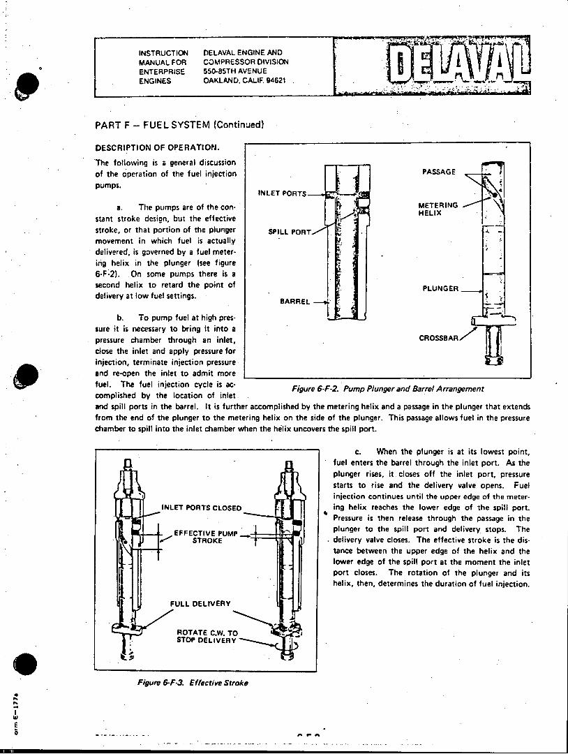
INSTRUCTION DELAVAL ENGINE AND MANUAL FOR COMPRESSOR DIVISION ENTERPRISE 550-85TH AVENUE ENGINES OAKLAND. CALIF. 94621
PART F - FUEL SYSTEM (Continued)
DESCRIPTION OF OPERATION.
The following is a general discussion of the operation of the fuel injection PASSAGE pumps.
a. The pumps are of the con- METERING stant stroke design, but the effective stroke, or that portion of the plunger SPILL PORT movement in which fuel is actually delivered, is governed by a fuel metering helix in the plunger (see figure 6-F-2). On some pumps there is a second helix to retard the point of PLUNGER delivery at low fuel settings.
BARREL
b. To pump fuel at high pressure it is necessary to bring it into a pressure chamber through an inlet, close the inlet and apply pressure for injection, terminate injection pressure and re-open the inlet to admit more fuel. The fuel injection cycle is ac- Figure 6-F-2. Pump Plunger and Barrel Arrangement complished by the location of inlet. and spill ports in the barrel. It is further accomplished by the metering helix and a passage in the plunger that extends from the end of the plunger to the metering helix on the side of the plunger. This passage allows fuel in the pressure chamber to spill into the inlet chamber when the helix uncovers the spill port.
C. When the plunger is at its lowest point, fuel enters the barrel through the inlet port. As the
* plunger rises, it. closes off the inlet port, pressure *starts to rise and the delivery valve opens. Fuel
injection continues until the upper edge of the meterINLET PORTS CLOSED ing helix reaches the lower edge of the spill port.
Pressure is then release through the passage in the EFFECIVE PMP,.plunger to the spill port and delivery stops. The
a STROKE delivery valve closes. The effective stroke is the distance between the upper edge of the helix and the lower edge of the spill part at the moment the inlet port closes. The rotation of the plunger and its helix, then, determines the duration of fuel injection.
FULL DELIVERY
ROTATE C.W. TOSTOP DELIVERY
Figure 6-F-3. Effective Stroke
E
complished~~0 by th oato f ne
INSI RUCTION DELAVAL ENGINE AND MANUAL FOR COMPRESSOR DIVISION ENTERPRISE 550-85TH AVENUE ENGINES OAKLAND, CALIF 94621
PART F - FUEL SYSTEM (Continued)
MALFUNCTIONING PUMP.
Should a fuel pump be suspected of malfunctioning, the following checks should be made before removing the pump from the engine for inspection and repair, unless it is known for certain that the pump is defective.
a. Check to insure that fuel oil is being delivered to the pump. With the fuel oil system pressurized, loosen air bleed screw on pump. Fuel should flow freely with complete absence of air bubbles.
b. If air is present in fuel oil, loosen nuts on high pressure line connection at nozzle holder end and bar engine over until all bubbles disappear.
c. If fuel oil flow is sluggish at the pump, it is a good indication that the fuel filters are clogged. Check and clean filter.
d. If fuel oil does not flow, check fuel level in tank and for closed valves in lines.
e. Having made certain of fuel oil flow, operate engine and if pump still does not function properly, remove and replace with spare pump.
PUMP REMOVAL.
Fuel injection pumps are removed from the engine as follows.
a. Disconnect high pressure line fitting and remove high pressure line from pump.
b. Disconnect supply and return lines from fuel pump.
c. Disconnect fuel control rack from linkage.
d. Remove hold down nuts and lift pump off mounting studs.
PUMP DISASSEMBLY. The manufacturer's instructions contained in the Associated Publications Manual provide detailed instructions for the overhaul and repair of fuel injection equipment, and should be consulted when any work is being done on fuel injection pumps. Pumps may be disassembled as follows.
a. Secure pump in the inverted position in a soft jawed vise. Depress the plunger follower and insert a 1/8 inch diameter pin in the hole in the pump flange.
b. Remove lock ring by prying it out with a screwdriver. Again depress follower and remove 1/8 inch pin.
c. Remove plunger follower. Take lower spring seat from plunger, then carefully remove plunger from barrel. Carefully submerge plunger in spindle oil.
d. Remove plunger spring, then pull control sleeve using a specially fabricated puller, or a pair of pliars whose jaws are wrapped with masking tape. The upper spring plate will come out with the control sleeve.
G
G/ A/ RV/G V 8 1end i x -74 6-F-4
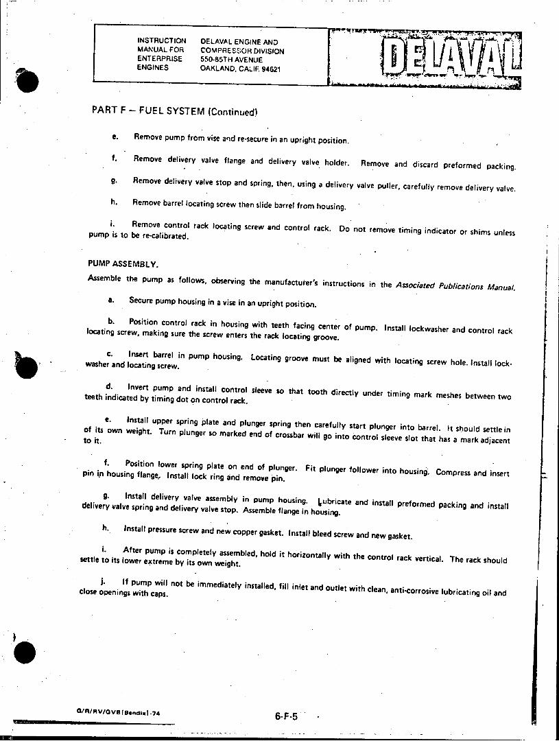
INSTRUCTION DELAVAL ENGINE AND MANUAL FOR COMPRESSOR DIVISION ENTERPRISE 550-85TH AVENUE s ENGINES OAKLAND, CALIF. 94621
PART F - FUEL SYSTEM (Continued)
e. Remove pump from vise and re-secure in an upright position.
f. Remove delivery valve flange and delivery valve holder. Remove and discard preformed packing.
g. Remove delivery valve stop and spring, then, using a delivery valve puller, carefully remove delivery valve.
h. Remove barrel locating screw then slide barrel from housing.
i. Remove control rack locating screw and control rack. Do not remove timing indicator or shims unless pump is to be re-calibrated.
PUMP ASSEMBLY.
Assemble the pump as follows, observing the manufacturer's instructions in the Associated Publications Manual. a. Secure pump housing in a vise in an upright position.
b. Position control rack in housing with teeth facing center of pump. Install lockwasher and control rack locating screw, making sure the screw enters the rack locating groove.
C. Insert barrel in pump housing. Locating groove must be aligned with locating screw hole. Install lock
d. Invert pump and install control sleeve so that tooth directly under timing mark meshes between two teeth indicated by timing dot on control rack.
e. Install upper spring plate and plunger spring then carefully start plunger into barrel. It should settle in of its own weight. Turn plunger so marked end of crossbar will go into control sleeve slot that has a mark adjacent to it.
p . Position lower spring plate on end of plunger. Fit plunger follower into housing. Compress and insert pin iyi housing flange, Install lock ring and remove 'pin.
g. Install delivery valve assembly in pump housing. Lubricate and install preformed packing and install delivery valve spring and delivery valve stop. Assemble flange in housing.
h, Install pressure screw and new copper gasket. Install bleed screw and new gasket.
i. After pump is completely assembled, hold it horizontally with the control rack vertical. The rack should settle to its lower extreme by its own weight.
clos If pump will not be immediately installed, fill inlet and outlet with clean, anti-corrosive lubricating oil and close openings with caps.
G/R/RV/GVI3le@ndlx -7 6-F-5
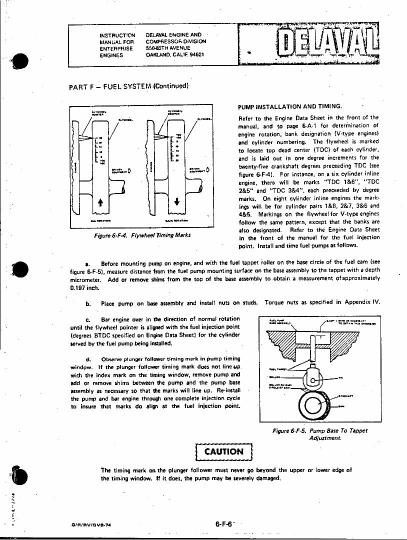
INSTRUCTION DELAVAL ENGINE AND MANUAL FOR COldPRESSOR DiVISION ENTERPRISE 550-85TH AVENUE ENGINES OAKLAND, CALIF. 94621
PART F - FUEL SYSTEM (Continued)
PUMP INSTALLATION AND TIMING.
/ '-W.' Refer to the Engine Data Sheet in the front of the
manual, and to page 6-A-1 for determination of
engine rotation, bank designation (V-type engines) Si:: and cylinder numbering. The flywheel is marked
to locate top dead center (TDC) of each cylinder, and is laid out in one degree increments for the
twenty-five crankshaft degrees preceeding TDC (see
figure 6-F-4). For instance, on a six cylinder inline
engine, there will be marks "TDC 1&6", "TDC 2&5" and "TDC 3&4", each preceeded by degree marks. On eight cylinder inline engines the markings will be for cylinder pairs 1&8, 2&7, 3&6 and 4&5. Markings on the flywheel for V-type engines follow the same pattern, except that the banks are also designated. Refer to the Engine Data Sheet in the front of the manual for the fuel injection point. Install and time fuel pumps as follows.
a. Before mounting pump on engine, and with the fuel tappet roller on the base circle of the fuel cam (see
figure 6-F-5), measure distance from the fuel pump mounting surface on the base assembly to the tappet with a depth
micrometer. Add or remove shims from the top of the base assembly to obtain a measurement of approximately
0.197 inch.
b. Place pump on base assembly and install nuts on studs. Torque nuts as specified in Appendix IV.
c. Bar engine over in the direction of normal rotation until the flywheel pointer is aligned with the fuel injection point (degrees BTDC specified on Engine Data Sheet) for the cylinder served by the fuel pump being installed.
d. Observe plunger follower timing mark in pump timing window. If the plunger follower timing mark does not line 4sp. with the index mark on the timing window, remove pump and add or remove shims between the pump and the pump base assembly as necessary so that the marks will line up. Re-install the pump and bar engine through one complete injection cycle to insure that marks do align at the fuel injection point.
Figure 6-F-5. Pump Base To Tappet Adjustment.
CAUTION
The timing mark on the plunger follower must never go beyond the upper or lower edge of the timing window. If it does, the pump may be severely damaged.
o/R/AV/V-74 6-F-6*
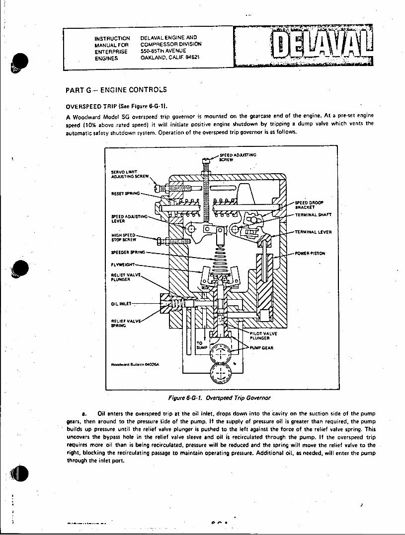
INSTRUCTION DELAVAL ENGINE AND MANUAL FOR COMPRESSOR DIVISION ENTERPRISE 55t-85TH AVENUE ENGINES OAKLAND. CALIF 94621
PART G- ENGINE CONTROLS
OVERSPEED TRIP (See Figure 6-G-1).
A Woodward Model SG overspeed trip governor is mounted on the gearcase end of the engine. At a pre-set engine
speed (10% above rated speed) it will initiate positive engine shutdown by tripping a dump valve which vents the
automatic safety shutdown system. Operation of the overspeed trip governor is as follows.
SPEED ADJSTING
SERVO LIMIT ADJUSTING SCREW
RESET SPRING
WO~~~dPEE DROOPn0426
SPEED ADJUSTING -TRIA HF
LEVER
HIGH SPEED -TRIA EE
STOP SCREW
SPEEDER SPRING PWRPSO
FLYWEIGHT ----
RELIEF VALVE PLUNGER00
OIL INLET.
RELIEF VALV SPRING
TERLtNA SHAFT
TOL PLUNGER
MU PUMP GEAR
Woodwd Bulletin 04026A
Figure 6-G- 1. Overspeed Trip Governor
a. Oil enters the overspeed trip at the oil inlet, drops down into the cavity on the suction side of the pump gears, then around to the pressure side of the pump. If the supply of pressure oil is greater than required, the pump builds up pressure until the relief valve plunger is pushed to the left against the force of the relief valve spring. This uncovers the bypass hole in the relief valve sleeve and oil is recirculated through the pump. If the overspeed trip requires more oil than is being recirculated, pressure will be reduced and the spring will move the relief valve to the right, blocking the recirculating passage to maintain operating pressure. Additional oil, as needed, will enter the pump through the inlet port.
INSTRUCTION DELAVAL ENGINE AND MANUAL FOR COMPRESSOR DIVISION ENTERPRISE 550-85TH AVENUE ENGINES OAKLAND, CALIF. 94621
PART G - ENGINE CONTROLS (Continued)
b. The pilot valve plunger controls the movement of the power piston by directing oil to or from the area
beneath the power piston. The power piston in turn controls the position of the terminal lever, and, therefore,,the position of the terminal shaft. Two opposing forces act upon the pilot valve plunger - the speeder spring force tends
to push the plunger down and the centrifugal force developed by the rotating flyweights tends to lift the plunger.
c. When the engine is operating below the trip set point the speeder spring force holds the pilot valve plunger down and connects the oil under the power piston to drain. The reset spring, pushing the reset rod against the terminal lever, holds the power piston down.
d. If engine speed rises above tripping speed the centrifugal force of the flyweights overcomes the speeder spring force and lifts the pilot valve plunger. As the plunger rises, pressure oil flows to the underside of the power piston, forcing the piston up. As the terminal lever is rotated by the upward m6venent of the power piston, the pin in the speed droop bracket raises the right end of the floating lever. This decreases the downward force of the speeder spring and the flyweights move to their extreme out position. The power piston then moves to the top of its stroke, as allowed by the terminal lever, which rotates the terminal shaft. The external lever on the terminal shaft then actuates the trip valve.
e. When engine speed drops back below the reset speed the speeder spring pushes the pilot valve plunger down and the area under the power piston is again connected to the sump. The reset spring rotates the terminal lever and pushes the power piston down. Oil is then recirculated through the pump as before.
OVERSPEED TRIP ADJUSTMENT.
The speed at which the unit trips is determined by the position of the speed adjusting screw. Turning the screw into the cover raises the tripping speed, and turning it out lowers tripping speed. The overspeed set point is adjusted at the factory, and under normal conditions should not be changed in the field. If it becomes necessary to reset the trip point, follow these steps.
a. Back out servo limit adjusting screw so that it does not limit travel in the power piston.
b. Make tentative speed droop bracket setting at approximately one-half its travel from minimum to maximum droop.
c. Make preliminary tripping speed adjustment with speed adjusting screw.
d. Readjust speed droop bracket to obtain approximately ten percent excess range, then readjust tripping speed. The speed adjusting lever can be locked in place by tightening the high speed stop screw against the speed adjusting lever.
e. Reset overspeed trip at a speed slightly below the desired reset speed. The servo limit adjusting screw affects only the reset speed. Turn in to raise the reset speed to the desired value.
G/R/V/GVB-74 6-G-2
INSTRUCTION DELAVAL ENGINE AND I MANUAL FOR COMPRESSOR DIVISION ENTERPRISE 550-85TH AVENUE ENGINES OAKLAND, CALIF. 94621
PART H - ENGINE BALANCING
GENERAL.
The load must be equally divided between all cylinders when the engine is loaded between 75 and 100 percent of its
rated capacity. If it is not, one or more cylinders will be forced to carry an overload while the others loaf with resulting loss of operating economy, and possibly one or more of the following conditions.
a. Scored pistons and liners.
b. Excessive vibration which may cause loose foundation bolts, cracked grout and broken pipe connections.
c. Excessive piston, valve, bearing and crankshaft wear.
d. Excessive fuel consumption.
e. Excessive use of lubricating oil.
f. Frequency swings.
All temperature and pressure gauges required for proper operation of the engine are provided. The operator must be able to interpret gauge readings, know why any given pressure or temperature must be maintained, and how or when to make corrections if any change is noted. An engine log is an excellent tool to assist in achieving optimum operating efficiency. Readings should be taken and recorded hourly, and be supplemented with written observations. This will permit a complete evaluation of operating conditions, and provide information for oncoming operators.
FUEL INJECTION EQUIPMENT.
Clean fuel is essential. Injection equipment has close working tolerances, therefore, dirt or other impurities in the fuel can cause pumps or spray nozzles to malfunction. Small depressions in injector valve seats, some so small that they are not visible to the naked eye, may be caused by small particles of dirt and will affect spray patterns in the combustion chamber. Pumps and valves must be checked and cleaned periodically. The frequency of cleaning can best be determined from experience, however, care must be taken not to wait too long before cleaning. Fuel pumps should deliver exact amounts of fuel oil according to the millimeter setting of their fuel pump racks. If one pump requires a two or more millimeter. variation from the setting of other cylinders to maintain the desired temperature or pressure, it indicates something wrong with that cylinder as a unit. The engine and pumps are designed to operate and maintain proper temperature with less than one millimeter difference in rack settings.
ENGINE OUT OF TUNE.
Spray nozzles are usually suspect if an engine is out of tune, or is smoking. There are other factors which may also contribute to these conditions. All of these must be considered when evaluating engine performance.
a. Ignition or injection timing.
b. Long or short burning lag in some fuels.
c. Cetane rating of the fuel.
d. Low compression pressure due to leaking valves.
e. Worn piston rings and/or liners.
W
E R/RVID/4VI-75 6-H-1

INSTRUCTION DELAVAL ENGINE AND
MANUAL FOR COMPRESSOR DIVISION ENTERPRISE 550-85TH AVENUE ENGINES OAKLAND. CALIF 94621 *r
PART H - ENGINE BALANCING (Continued)
f. A change in fuel oil.
g. Defective fuel injection pumps.
h. Incorrect air-fuel mixture.
i. Maladjustment of valves or linkage.
BALANCING CRITERIA.
The normal values used for balancing an engine, whether diesel or dual fuel, are exhaust temperatures and firing
pressures. If there is any question as to the accuracy of thermocouples or pyrometers, they should be calibrated.
a. . At full load, the individual cylinder exhaust temperatures should not vary more than 50 degrees fahrenheit
(100 C).
b. Firing pressures will vary in direct proportion with exhaust temperatures, and should vary no more than
30 psi (2.11 kg/cm ) between cylinders
C. The closer each cylinder is balanced to the next the better the engine performance. Time and patience
are necessary to properly balance an engine - there is no short cut.
d. The timing of fuel delivery in relation to piston position in the cylinder, will determine the pressure in the
cylinder. Each cylinder is an engine in itself and must be treated as such to insure that it is carrying its share of the
load. Exact timing will always depend on engine speed, type of fuel, altitude, etc., therefore, final timing must be
done under actual field conditions at the installation site.
PRELIMINARY ADJUSTMENTS.
Before operating the engine for the first time, or after an overhaul, the engine should be checked over, and preliminary
adjustments made to the diesel fuel system as follows.
a. Adjust valve clearances or. if the engine is equipped with hydraulic valve lifters, check lifter adjustment.
Refer to Part B of this section of the vrenual for procedures.
b. Check fuel injection equipment as follows.
(1) Remove all nozzle holder assemblies, clean and if necessary, readjust nozzle opening pressure. The
correct opening pressure of nozzle hoider valves should be maintained within 50 psi .(3.52 kg/cm 2) of each other.
See page 6-F- for opening pressures. Adjustment may be made with an adjusting screw or with shims, depending on
the particular installation. Refer to the manufacturer's instructions in the Assoiated Publications Manual. Any great
difference. in nozzle opening pressure will affect engine balance, nozzle spray patterns, temperatures and smoke.
(2) Check proper spray pattern. This may be done by placing a piece of paper under the nozzle while
it is in the test stand. This will reveal non-uniform patterns and plugged nozzle holes.
(3) Nozzle holder assemblies must not dribble under pressure, or after popping open under the set
pressure.
(4) Re-install nozzle holder assemblies in cylinder head. Carefully tighten nuts with a torque wrench
to the value shown in Appendix IV. Improper installation can result in malfunctioning.
E o n,.fg~gdI1~6.-1-2
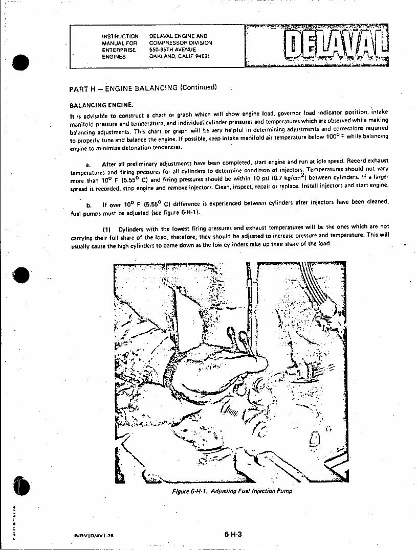
INSTRUCTION DELAVAL ENGINE AND MANUAL FOR COMPRESSOR DIVISION ENTERPRISE 550-85TH AVENUE ENGINES OAKLAND, CALIF. 94621
PART H - ENGINE BALANCING (Continued)
BALANCING ENGINE.
It is advisable to construct a chart or graph which will show engine load, governor load indicator position, intake
manifold pressure and temperature, and individual cylinder pressures and temperatures which are observed while making
balancing adjustments. This chart or graph will be very helpful in determining adjustments and corrections required
to properly tune and balance the engine. If possible, keep intake manifold air temperature below 1000 F while balancing
engine to minimize detonation tendencies.
a. After all preliminary adjustments have been completed, start engine and run at idle speed. Record exhaust
temperatures and firing pressures for all cylinders to determine condition of injectors. Temperatures should not vary
more than 100 F (5.550 C) and firing pressures should be within 10 psi (0.7 kg/cm2 ) between cylinders. If a larger
spread is recorded, stop engine and remove injectors. Clean, inspect, repair or replace. Install injectors and start engine.
b. - If over 100 F (5.550 C) difference is experienced between cylinders after injectors have been cleaned,
fuel pumps must be adjusted (see figure 6-H-1).
(1) Cylinders with the lowest firing pressures and exhaust temperatures will be the ones which are not
carrying their full share of the load, therefore, they should be adjusted to increase pressure and temperature. This will
usually cause the high cylinders to come down as the low cylinders take up their share of the load.
10
Figure 6-H- s1. dutn ulijcinPm
/ dGW
R D 76
Fiue6H .Ajsin ulIjcinPm
R/V /V -56--
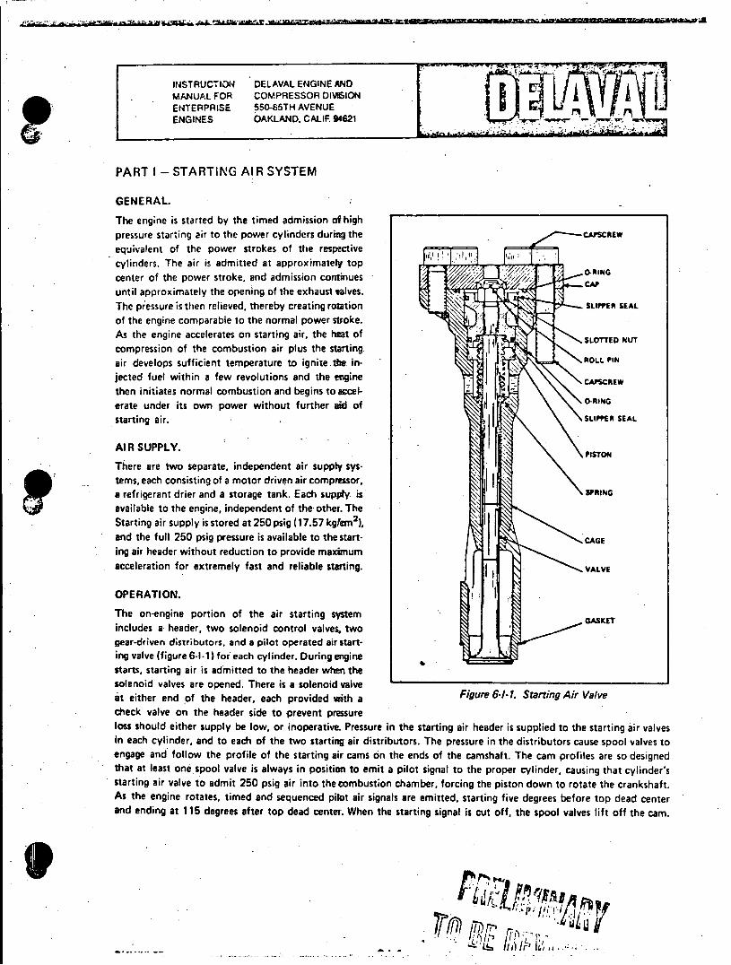
INSTRUCTION DELAVAL ENGINE AND MANUAL FOR COMPRESSOR DIVION ENTERPRISE 550-65TH AVENUE L ENGINES OAKLAND, CALIF 94621
PART I - STARTING AIR SYSTEM
GENERAL.
The engine is started by the timed admission of high pressure starting air to the power cylinders during the equivalent of the power strokes of the respective cylinders. The air is admitted at approximately top center of the power stroke, and admission continues until approximately the opening of the exhaust calves. CAP
The pressure is then relieved, thereby creating rotation of the engine comparable to the normal power stroke. As the engine accelerates on starting air, the heat of compression of the combustion air plus the starting air develops sufficient temperature to ignite the injected fuel within a few revolutions and the engine then initiates normal combustion and begins toaccelerate under its own power without further aid of starting air. .
AIR SUPPLY.
There are two separate, independent air supply systems, each consisting of a motor driven air compressor, a refrigerant drier and a storage tank. Each supply is SPRING
available to the engine, independent of the other. The Starting air supply is stored at 250 psig (17.57 kglam2), and the full 250 psig pressure is available to the starting air header without reduction to provide maximum acceleration for extremely fast and reliable starting.
OPERATION.
The on-engine portion of the air starting system includes a header, two solenoid control valves, two gear-driven distributors, and a pilot operated air starting valve (figure 6-1-1) for each cylinder. During engine starts, starting air is admitted to the header when the solenoid valves are opened. There is a solenoid valve at either end of the header, each provided with a Figure 6-1-1. Starting Air Valve check valve on the header side to prevent pressure loss should either supply be low, or inoperative. Pressure in the starting air header is supplied to the starting air valves in each cylinder, and to each of the two starting air distributors. The pressure in the distributors cause spool valves to engage and follow the profile of the starting air cams on the ends of the camshaft. The cam profiles are so designed that at least one spool valve is always in position to emit a pilot signal to the proper cylinder, causing that cylinder's starting air valve to admit 250 psig air into the combustion chamber, forcing the piston down to rotate the crankshaft. As the engine rotates, timed and sequenced pilot air signals are emitted, starting five degrees before top dead center and ending at 115 degrees after top dead center. When the starting signal is cut off, the spool valves lift off the cam.
INSTRUCTION DELAVAL ENGINE AND
MANUAL FOR COMPRESSOR DIVISION ENTERPRISE 550-85TH AVENUE ENGINES OAKLAND. CALIF. 94621
PART I - STARTING AIR SYSTEM (Continued)
VALVE DISASSEMBLY AND ASSEMBLY (See Figure 6-1.1).
Remove valve from cylinder head then remove socket head capscrews and lift cap from valve. Remove roll pin and
slotted nut from valve stem then slide valve out through bottom of cage. Remove piston from top of assembly. Remove
slipper seals and 0-rings, taking care not to damage them. Inspect all surfaces of valve assembly. 0-rings and slipper
seals. Replace any defective parts. Assembly is the reverse of disassembly.
TIMING AIR DISTRIBUTOR.
*The timing of the starting air distributor should be checked if the distributor is replaced, or if the engine camshaft
has been replaced or retimed.
a. Position engine flywheel with number one cylinder (the bank the distributor is mounted on) five degrees.
before top dead center (BTDC) on the compression stroke.
b. Position starting air distributor so that centerline of spool valve for number one cylinder is. in line with
the TDC scribe mark on the opening ramp of the starting air cam. Note direction of engine rotation.
c. . The spool valve for number one cylinder will not be in position to just start emitting an air signal. Shop
air at 125 psig (9.79 kg/crn) can be connected to the distributor supply to verify the valve position.
AIR FILTER INSPECTION.
The air filter in the supply line to the air distributor should be inspected and cleaned at regular intervals. The frequency
of inspection and cleaning should be determined by operating conditions and experience.
STRAINERS.
Low point water collectors, '"Y strainers and air receiver tanks must be drained daily whether engine-generator is run
or not. Inspect and clean "Y" strainers weekly. If the fouling of the strainers are such that more frequent inspections
are warranted, then shorten the inspection interval.
FVRVINUCI -75 6-1-2-
INSTRUCTION DELAVAL ENGINE AND MANUAL FOP COMPRESSOR DWISION ENTERPRISE 55CL85TH AVENUE ENGINES OAKLAND, CALIF 94621
PART J - COOLING WATER SYSTEMS
GENERAL.
If, for any reason, there is a disruption in the circulation of the cooling water flow, the engine should be shut down as soon as practicable to prevent a build up of temperatures and possible serious damage to the engine. To avoid thermal shock which could cause damage to the engine, do not admit cold water to the cooling system until the temperature of the cooling surfaces in the engine have dropped to approximately that of the inlet water. All cooling surfaces must be kept free of scale or other deposits as any such accumulation will degrade the cooling capability of the system and, therefore, cooling water temperatures will not accurately indicate the extent of cooling. Any coating of the cooling surfaces wi l act as an insulating material and will prevent transfer of heat. A check of the pressure differential between the inlet and outlet of coolers will indicate the need for cleaning of the tubes.
JACKET WATER TREATMENT.
It may be advisable to consult a commercial water treatment company concerning the treatment of jacket water to insure that local conditions are taken fully intoaccount. A suggested water treatment material for jacket water systems is sodium dichromate and boiler compound. Sodium dichromate is an inexpensive source of alkaline chromate (Cr0 4 ) which has been found to form a protective film on metallic surfaces that prevents attack by the corrosive elements found in the jacket water. Sodium dichromate is an acid compound which must have an alkaline compound such as boiler compound added to convert the dichromate to an effective alkaline chromate form. The alkaline chromate concentration must be maintained between 700 and 1700 parts per million (ppm). Less than 700 ppm can result in accelerated corrosion while more than 1700 ppm serves no useful purpose and is a waste of material. The pH value of the water must be maintained within a range of 8.25 and 9.75. The minimum pH value is necessary to prevent acid attack on the metallic surfaces, and the 9.75 maximum value will prevent corrosion due to high alkaline content in the water. The chloride content must not be allowed to exceed 100 ppm as the effectiveness of alkaline chromate decreases as the chloride content increases. When initiating alkaline chromate water treatment for the first time, or after the system has been refilled, the water should be tested daily for alkaline chromate concentration and pH value. When the treatment becomes stable, the test interval can be extendeto weekly tests. After each addition of chemicals, the water should be circulated through the system then tested to insure that the required limits are met Where necessary, an anti-freeze coolant solution such as ethylene glycol or similar may be used.
CLEANING JACKET WATER SYSTEM.
Rust can be removed from the jacket water system by filling the system with a solution of 75 pounds of ammonium nitrate in enough fresh water to make 100 gallons of solution. Make enough solution to fill the jacket water system then operate the engine for two hours. The jacket water system must then be flushed with fresh water and neutralized. Scale can be removed from the system by using. a scale solvent solution composed of 7 gallons of 200 Baume muratic (hydrochloric) acid, one-half gallon of liquid inhibitor and 92'/ gallons of fresh water at 1600 F. Make enough solution to fill the system. Circulate the acid solution through the system for one or two hours, depending on the extent of the scale deposit. The temperature of the acid solution must be maintained at 1600 F during circulation. After circulating the acid solution, drain the jacket water system and then fill with clean fresh water and flush it thoroughly. After flushing, neutralize the system with a solution composed of 20 pounds of soda ash (sodium carbonate) and enough fresh water at 1600 F to make 100 gallons of neutralizing solution. Fill the jacket water system with the neutralizing solution and circulate it through the system for one-half hour. Maintain the temperature of the solution during circulation.
CAUTION
The above methods of cleaning must not be used for systems which have components containing aluminum.
00-75 6-J-1
INSTRUCTION DE LAVAL ENGINE AND
MANUAL FOR COMPRESSOR DIVISION
ENTERPRISE 550-8511H- AVENUE
ENGINES OAKLAND. CALIF94621 rrtr
PART J - COOLING WATER SYSTEMS (Continued)
ENVIRONMENTAL RESTRICTIONS.
Alkaline chromate water treatment compounds, such as sodium dichromate, may b nsi d nment
objectionable in some locations, or may be prohibited. In these instances, nitrate compounds such as sodium nitrat
(NaNO2) are suggested as adequate substitutes. When using NaNO 2, the concetration must be 500 ppm with a pH
of 7.5 to 8.5 to achieve effective corrosion control. Nitrate compounds for treating engine jacket water systems are
available from most commercial chemical supply houses, and instructions for their use are available from the chemical
supplier.
00n7 6-J-2
INSTRUCTION DELAVAL ENGINE AND
MANUAL FOR COMPRESSOR DIVISION
ENTERPRISE 550-855TH AVENUE . P ENGINES OAKLAND, CALIF. 94621
PARTK - LUBRICATING OIL SYSTEM
FILTERS AND STRAINERS.
The full flow fitter continuously filters all of the lubricating oil from the pump before it passes to the oil strainer.
The length of time that the lubricating 6it and the filter elements may remain in service can best be determined by
carefully watching the result of oil analysis and the pressure drop across the oil filter. Change period will vary with
the operatinG conditions to which each individual engine is subjected. During the first two or three days of engine
operation after initial installation, or after a major overhaul, the strainer at the pump suction and the strainer at the
oil header inlet should be checked and cleaned as necessary to remove any debris and other foreign matter that may be
present. If at any time the oil pressure gauge shows a low reading, the following should be done to the degree necessary
to correct the situation.
a. Check the oil level in the sump tank.
b. Inspect strainer, filter and lubricating oil cooler. A leak in the cooler may be detected by a sudden increase
in oil consumption, and by the presence of oil in the cooling water system Leakage may occur in the packing between
the tubes and the tube sheet, or may be due to tube erosion, depending on the construction of the cooler.
c. Inspect all external and internal piping for tightness and freedom from obstructions.
d. Dismantle and inspect pump.
LUBRICATING OIL PUMP.
A Roper positive displacement, internal gear type pump is used. The pump is mounted on the engine gearcase by
means of an adapter, and is driven by the idler gear through a gear carrier assembly. A spline on the pump shaft engages
the internal splines on the gear carrier shaft coupling. The pump is a "gear-within-a-gear" design. With every revolution
of the pump shaft a definite amount of oil is drawn into the pump through the suction port. The pump rotor, driven
by the rotor shaft, in turn rotates the idler. As the teeth draw away from the rotor teeth, a suction is createdwhich
draws oil into the pump through the suction port. The space between the rotor teeth and the idler teeth is completely
filled with oil which is then carried by the teeth past a crescent which devides the flow. As the teeth mesh again, oil is
forced out of the discharge port and the meshed teeth form a barrier between the discharge and the suction ports.
REMOVING PUMP.
To remove the pump from the engine, do the following.
a. Remove the inlet and discharge piping as well as any other interfering piping or accessories.
b. Position a sling on the pump and attach to a chainfall and take up the slack.
c. Remove the capscrews that secure the pump to the adapter and pull the pump directly away from the
engine until it is clear.
R/RVIRoner 28771-75 6-K-1 I ; ; .
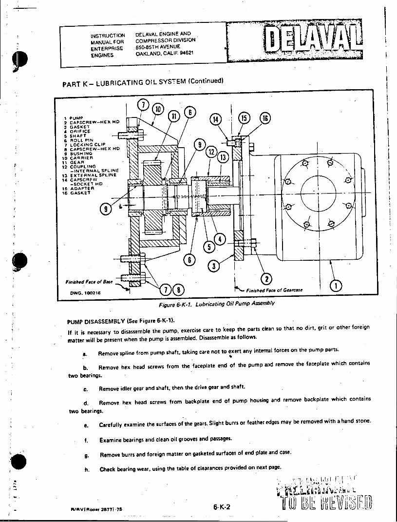
INSTRUCTION DELAVAL ENGINE AND
MANUAL FOR COMPRESSOR DIVISION
ENTERPRISE .550-85TH AVENUE ENGINES OAKLAND, CALIF. 94621
PART K- LUBRICATING OIL SYSTEM (Continued)
I Pump 2 CAPSCREW-HEX Mo 14 15 3 GASKET 4 ORIFICE 5 SHAFT 6 ROLL PIN 7 LOCKING CLIP a CAPSCREW-HEX HO 9 BUSHING 1
T0 CARRIER 11I GEAR
I 2 COUPLING
-INTERNAL SPLINE 13 EXTERNAL SPLINE 14 CAPSCRFW
-SOCKET HD 15 ADAPTER 16 GASKET
Finished Face of Base
DW. 100216 Finished Face of Gearcase
Figure 6-K-1. Lubricating Oil Pump Assembly
PUMP DISASSEMBLY (See Figure 6-K-1).
If it is necessary to disassemble the pump, exercise care to keep the parts clean so that no dirt, grit or other foreign
matter will be present when the pump is assembled. Disassemble as follows.
a. Remove spline from pump shaft, taking care not to exert any internal forces on the pump parts.
b. Remove hex head screws from the faceplate end of the pump and remove the faceplate which contains
two bearings.
C. Remove idler gear and shaft, then the drive gear and shaft.
d. Remove hex head screws from backplate end of pump housing and remove backplate which contains
two bearings.
e. Carefully examine the surfaces of the gears. Slight burrs or feather edges may be removed with a hand stone.
f. Examine bearings and clean oil grooves and passages.
g. Remove burrs and foreign matter on gasketed surfaces of end plate and case.
h. Check bearing wear, using the table of clearances provided on next page.
6-K-2 L)l C
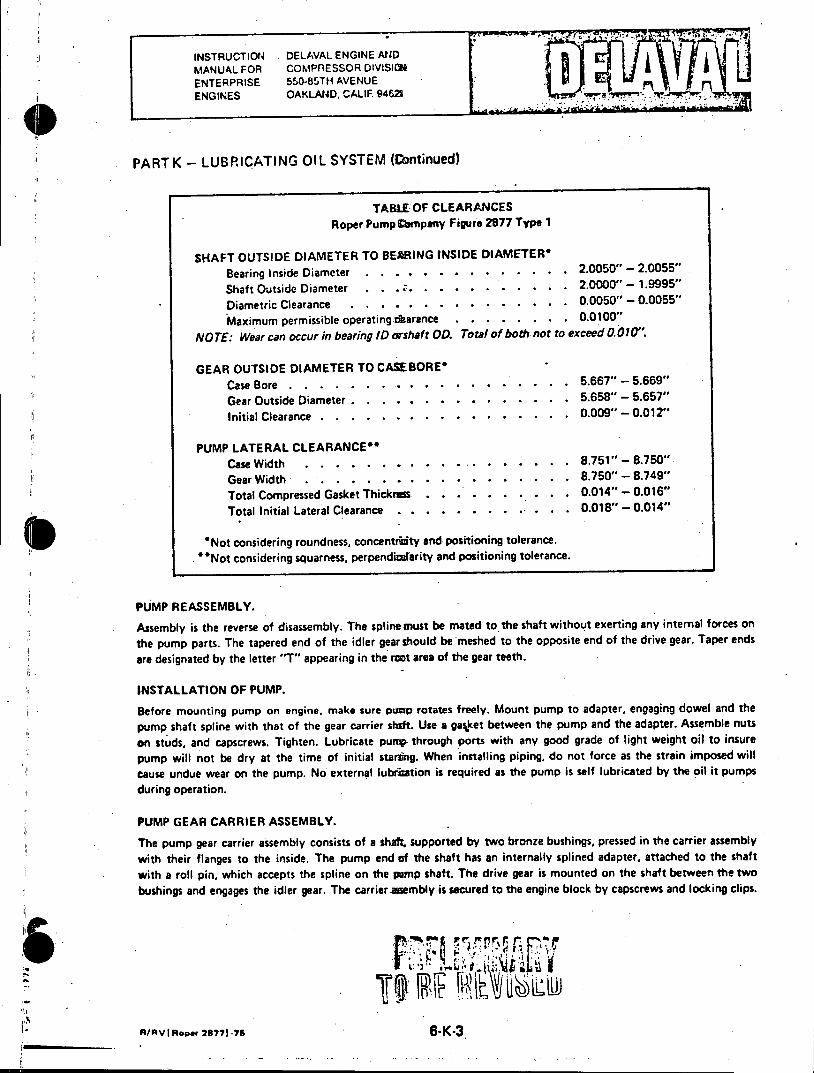
INSTRUCTION DELAVAL ENGINE AND MANUAL FOR COMPRESSOR DIVISION
_____ AVENU ENTERPRISE 550-85TH AVENUE ENGINES OAKLAND, CALIF 94621 0a
PART K - LUBRICATING OIL SYSTEM (Continued)
TABLE OF CLEARANCES Roper Pump Cmpany Figure 2877 Type 1
SHAFT OUTSIDE DIAMETER TO BEARING INSIDE DIAMETER* Bearing Inside Diameter. . ........... .. 2.0050" - 2.0055"
Shaft Outside Diameter . . ....... ... . . 2.. 0000" - 1.9995"
Diametric Clearance........ ..... .. 0.0050" - 0.0055"
Maximum permissible operating darance..... . . .. 0.0100"
NOTE: Wear can occur in bearing ID orshaft OD. Total of both not to exceed 0.010".
GEAR OUTSIDE DIAMETER TO CASEBORE* Case Bore . . . . . . ... . . .. . . . . . . . 5.667" - 5.669"
Gear Outside Diameter . . . . . . . . . . . . . . . 5.658" - 5.657" Initial Clearance. . ......... . . . . .. 0.009" - 0.012"
PUMP LATERAL CLEARANCE" Case Width .......... ......... 8.751" - 8.750" Gear Width ............. . .. 8.750" - 8.749"
Total Compressed Gasket Thicknss . . . ... ..... 0.014" - 0.016"
Total Initial Lateral Clearance ........ .. . . . 0.018" - 0.014"
*Not considering roundness, concentriity and positioning tolerance. "Not considering squarness, perpendiafarity and positioning tolerance.
PUMP REASSEMBLY.
Assembly is the reverse of disassembly. The spline must be mated to the shaft without exerting any intemal forces on
the pump parts. The tapered end of the idler gear should be meshed to the opposite end of the drive gear. Taper ends
are designated by the letter "T" appearing in the rwt area of the gear teeth.
INSTALLATION OF PUMP.
Before mounting pump on engine, make sure pump rotates freely. Mount pump to adapter, engaging dowel and the
pump shaft spline with that of the gear carrier shaft. Use a gasket between the pump and the adapter. Assemble nuts
on studs, and capscrews. Tighten. Lubricate pump through ports with any good grade of light weight oil to insure
pump will not be dry at the time of initial staring. When installing piping, do not force as the strain imposed will
cause undue wear on the pump. No external lubruation is required as the pump is self lubricated by the oil it pumps
during operation.
PUMP GEAR CARRIER ASSEMBLY.
The pump gear carrier assembly consists of a shalL supported by two bronze bushings, pressed in the carrier assembly
with their flanges to the inside. The pump end of the shaft has an internally splined adapter, attached to the shaft with a roll pin, which accepts the spline on the pamp shaft. The drive gear is mounted on the shaft between the two
bushings and engages the idler gear. The carrier amembly is secured to the engine block by capscrews and locking clips.
R/AVIRopor 28771-76 6-K-3
INSTRUCTION DELAVAL ENGINE AND I
MANUAL FOR COMPRESSOR DIVISION a
ENTERPRISE 550-e5TH AVENUE n ENGINES OAKLAND. CALIF. 94621 -r
PART K - LUBRICATING OIL SYSTEM (Continued)
DISASSEMBLY AND ASSEMBLY OF GEAR CARRIER ASSEMBLY.
To remove the pump gear carrier assembly, the pump must be removed as outlined above, then the gearcase removed.
a. Remove lubricating oil lines from carrier assembly.
b. Bend back locking clips and remove capscrews. Remove carrier assembly.
c. To remove gear, shaft and bushings from carrier assembly, remove gear-to-shaft roll pin then press shaft
out of gear. With shaft and gear removed, press bushings out of drive bracket
d. Assembly is the reverse of disassembly. Use new locking clips.
A/RVIRar 28771 -78 6-K.4
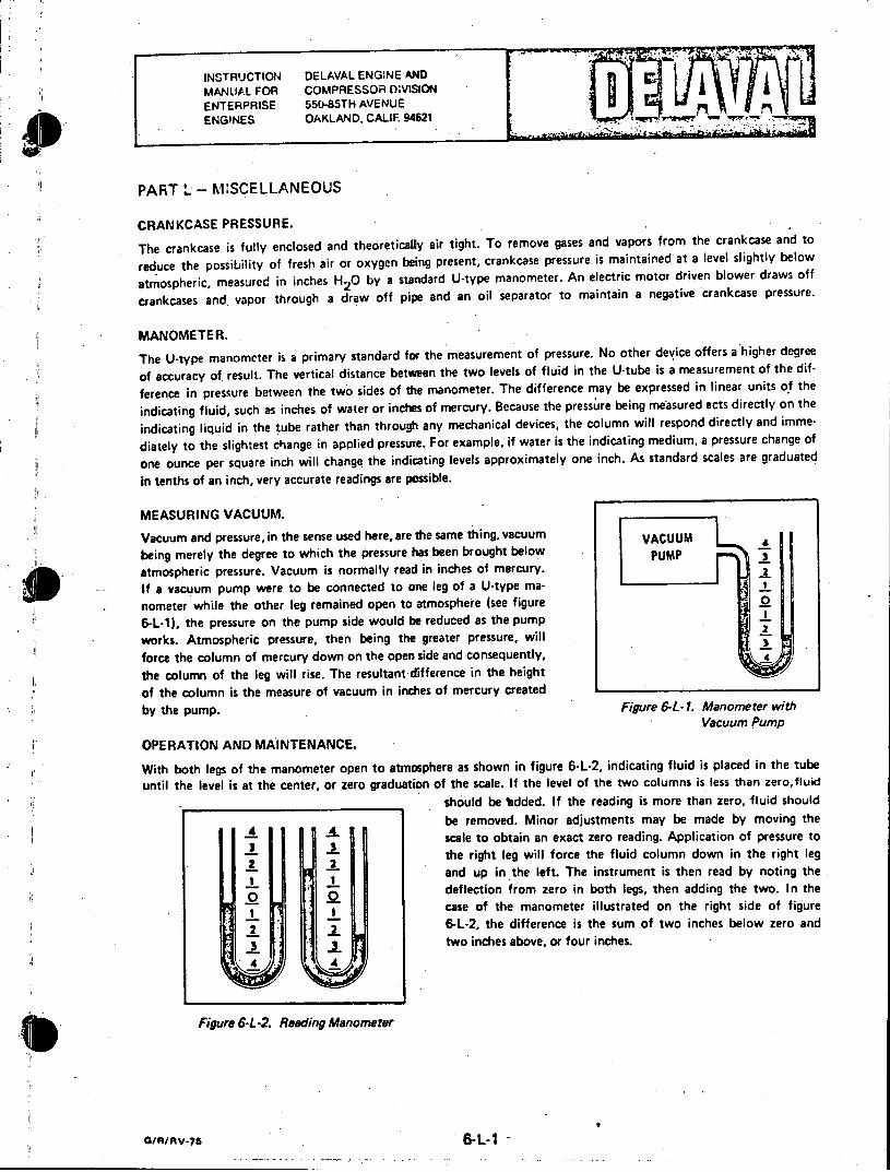
INSTRUCTION DELAVAL ENGINE AND MANUAL FOR COMPRESSOR DIVISION ENTERPRISE 55(-85TH AVENUE n ENGINES OAKLAND, CALIF 94621
PART L - MISCELLANEOUS
CRANKCASE PRESSURE.
The crankcase is fully enclosed and theoretically air tight. To remove gases and vapors from the crankcase and to
reduce the possibility of fresh air or oxygen being present, crankcase pressure is maintained at a level slightly below
atmospheric, measured in inches H20 by a standard U-type manometer. An electric motor driven blower draws off
crankcases and vapor through a draw off pipe and an oil separator to maintain a negative crankcase pressure.
MANOMETER.
The U-type manometer is a primary standard for the measurement of pressure. No other device offers a higher degree
of accuracy of result. The vertical distance between the two levels of fluid in the U-tube is a measurement of the dif
ference in pressure between the two sides of the manometer. The difference may be expressed in linear units of the
indicating fluid, such as inches of water or inches of mercury. Because the pressure being measured acts directly on the
indicating liquid in the tube rather than through any mechanical devices, the column will respond directly and imme
diately to the slightest change in applied pressure. For example, if water is the indicating medium, a pressure change of
one ounce per square inch will change the indicating levels approximately one inch. As standard scales are graduated
in tenths of an inch, very accurate readings are possible.
MEASURING VACUUM.
Vacuum and pressure, in the sense used here, are the same thing, vacuum VACUUM £ being merely the degree to which the pressure has been brought below PUMP _
atmospheric pressure. Vacuum is normally read in inches of mercury. 2
If a vacuum pump were to be connected to one leg of a U-type manometer while the other leg remained open to atmosphere (see figure 0
6-L-1), the pressure on the pump side would be reduced as the pump works. Atmospheric pressure, then being the greater pressure, will 2
force the column of mercury down on the open side and consequently,
the column of the leg will rise. The resultant difference in the height
of the column is the measure of vacuum in inches of mercury created
by the pump. Figure 6-L-1. Manometer with Vacuum Pump
OPERATION AND MAINTENANCE.
With both legs of the manometer open to atmosphere as shown in figure 6-L-2, indicating fluid is placed in the tube
until the level is at the center, or zero graduation of the scale. If the level of the two columns is less than zero,fluid
.__should be *added. If the reading is more than zero, fluid should
be removed. Minor adjustments may be made by moving the
scale to obtain an exact zero reading. Application of pressure to 5 3
the right leg will force the fluid column down in the right leg
and up in the left. The instrument is then read by noting the deflection from zero in both legs, then adding the two. In the case of the manometer illustrated on the right side of figure
2 2 6-L-2, the difference is the sum of two inches below zero and two inches above, or four inches.
Figure 6-L-2. Reading Manometer
G/R/V7 6-L-1 -
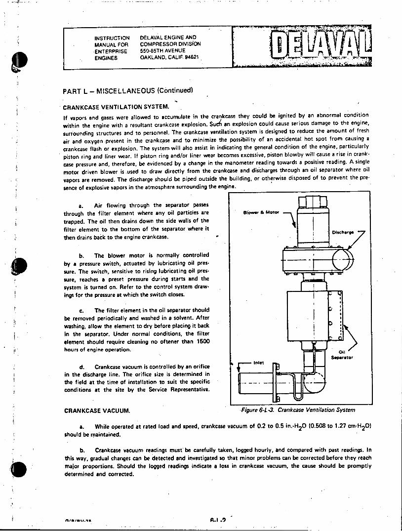
INSTRUCTION DELAVAL ENGINE AND MANUAL FOR COMPRESSOR DIVISiON ENTERPRISE 550-85TH AVENUE ENGINES OAKLAND, CALIF 94621
PART L - MISCELLANEOUS (Continued)
CRANKCASE VENTILATION SYSTEM.
If vapors and gases were allowed to accumulate in the crankcase they could be ignited by an abnormal condition
within the engine with a resultant crankcase explosion. SuS an explosion could cause serious damage to the engine,
surrounding structures and to personnel. The crankcase ventilation system is designed to reduce the amount of fresh
air and oxygen present in the crankcase and to minimize the possibility of an accidental hot spot from causing a
crankcase flash or explosion. The system will also assist in indicating the general condition of the engine, particularly
piston ring and liner wear. If piston ring and/or liner wear becomes excessive, piston blowby will cause a rise in crank
case pressure and, therefore, be evidenced by a change in the manometer reading towards a positive reading. A single
motor driven blower is used to draw directly from the crankcase and discharges through an oil separator where oil
vapors are removed. The discharge should be piped outside the building, or otherwise disposed of to prevent the pre
sence of explosive vapors in the atmosphere surrounding the engine.
a. Air flowing through the separator passes through the filter element where any oil particles are s &owe a Morer
trapped. The oil then drains down the side walls of the filter element to the bottom of the separator where it then drains back to the engine crankcase. . *
b. The blower motor is normally controlled by a pressure switch, actuated by lubricating oil presgPI sure. The switch, sensitive to rising lubricating oil pressure, reaches a preset pressure during starts and the system is turned on. Refer to the control system drawings for the pressure at which the switch closes.
c. The filter element in the oil separator should be removed periodically and washed in a solvent. After washing, allow the element to dry before placing it back in the separator. Under normal conditions, the filter element should require cleaning no oftener than 1500 hours of engine operation.
Serator
d. Crankcase vacuum is controlled by an orifice in the discharge line. The orifice size is determined in the field at the time of installation to suit the specific ... . . -
conditions at the site by the Service Representative.
CRANKCASE VACUUM. Figure 6-L -3. Crankcase Ventilation System
a. While operated at rated load and speed, crankcase vacuum of 0.2 to 0.5 in.-H20 (0.508 to 1.27 cm-H 20) should be maintained.
b. Crankcase vacuum readings must be carefully taken, logged hourly, and compared with past readings. In this way, gradual changes can be detected and investigated so that minor problems can be corrected before they reach major proportions. Should the logged readings indicate a loss in crankcase vacuum, the cause should be promptly determined and corrected.

INSTRUCTION DELAVAL ENGINE AND MANUAL FOR COMPRESSOR DIVISION ENTERPRISE 550-85TH AVENUE .
ENGINES OAKLAND, CALIF 94G21
PART L - MISCELLANEOUS (Continued)
c. Crankcase vacuum readings should be carefully observed during heavy load operations. Should the pressure
go from a vacuum to a positive reading, the engine should be shut down immediately. The engine should never be
operated with a positive pressure inside the crankcase as this indicates that the suction source for purging the crank
shaft has been plugged and/or otherwise obstructed, or that some condition exists that is creating abnormal heat. If a
hot spot develops in the engine and the oil flows or splashes over it a considerable amount of oil vapor will be formed.
This vapor is explosive and the engine must be stopped immediately. Allow engine to rest for fifteen minutes to allow
fumes and vapors to dissipate before removing any engine covers. Determine the cause and correct before continuing
operation.
0v G/R/RV-75 6-L-3
INSTRUCTION DELAVAL ENGINE AND MANUAL FOR COMPRESSOR DIVISIGN
ENTERPRISE 550-85TH AVENUE ENGINES OAKLAND, CALIF 94621
SECTION 7
TROUBLE SHOOTING
GENERAL.
Maintenance trouble shooting, to be effective, demands a sound knowledge of the engine in both a theoretical and a
practical sense. The mechanic must analyze the causes and effects, and where the cause is not readily apparent, he
must employ a fine sense of logic based upon the use of all tools available. Section I discussed preventive maintenance.
The technique of that program is, to varying degrees, applicable to trouble shooting as well. To assist in determining the
causes of improper performance, this section contains a listing of some of the more common engine malfunctions
their probable causes and the logical remedies.
RECORDS.
All possible malfunctions and their probable causes cannot be accurately foreseen and recorded in advance. Each
engine will develop and display characteristics which may not be common to all engines of the same model or type.
Also, the same operator or mechanic will not always perform the trouble shooting and repair work. It is, therefore,
suggested that the owner establish a detailed repair and trouble shooting record system. Each malfunction should
be recorded in a readily usable form, listing the indications and findings for each malfunction encountered together
with the repair action required. This record will be of assistance in determining the cause of any future malfunctions
and will be a valuable training aid for all operators and mechanics.
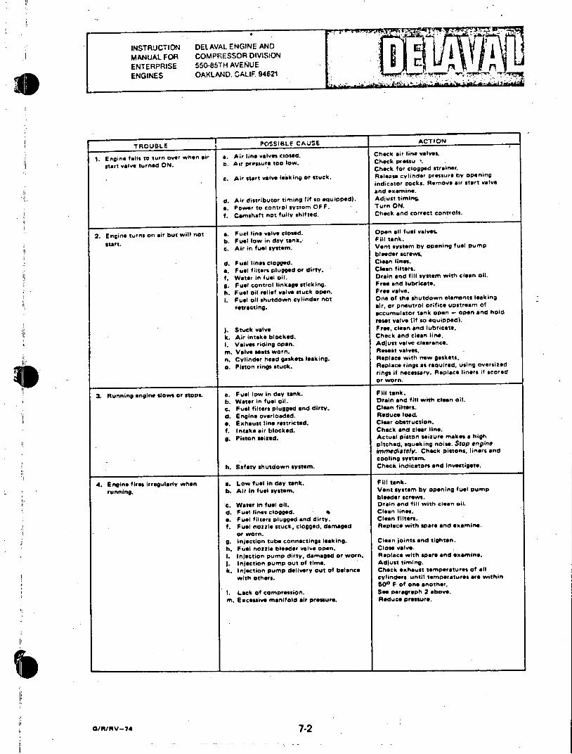
.~ ..~ . ...
INSTRUJCTION DEL AVAL ENGINE AND MANUAL FOR COMPRESSOR DIVISION
ENTERPRISE 55(-85TH AVENUE ENGINES OAKLAND. CALIF 94621
TROUBLE POSSIBLE CAUSE ACTION
1. Engine fails to turn over when air a. Air line valves closed. Check air line valveL
start valve turned ON. b. Air pressure too low. Check pressu Check for clogged strainer.
c. Air start valve leaking or stuck. Release cylinder pressure by opening indicator cocks. Remove air start valve and examine.
d. Air distributor timing (if so eouipped). Adjust timing. e. Power to control system OFF. Turn ON.
1. Camshaft not fully shifted. Check and correct controls.
2. Engine turns on air but will not a. Fuel line valve closed. . Open all fuel valves
b. Fuel low in day tank. Fill tank. start. c. Air in fuel system. Vent system by opening fuel pump
bleeder screws. d. Fuel lines clogged. Clean lines. e. Fuel filters plugged or dirty. Clean filters. f. Water in fuel oil. Drain and fill system with clean oil.
g. Fuel control linkage sticking. Free and lubricate. h. Fuel oil relief valve stuck open. Free valve. 1. Fuel oil shutdown cylinder not One of the shutdown elerrnts leaking
retracting. air, or pneutrol orifice upstream of accumulator tank open - open and hold reset valve (if so equipped).
j. Stuck valve Free, clean and lubricate. k. Air intake blocked. Check and clean line. 1. Valves riding open. Adjust valve clearance. m. Valve seats worn. Reseat valves. n. Cylinder head gaskets leaking. Replace with new gaskets.
o. Piston rings stuck. Replace rings as required, using oversized rings if necessary. Replace liners if scored or worn.
3. Running engine slows or stopa a. Fuel low in day tank. Fill tank. b. Water in fuel oil. Drain and fill with clean oil. c. Fuel filters plugged and dirty. Clean filters. d. Engine overloaded. Reduce load. e. Exhaust line restricted. Clear obstruction. 1, Intake air blocked. Check and clear line. g. Piston seized. Actual piston seizure makes a high
pitched. squaking noise. Stop engine irrimediately. Check pistons, liners and cooling system.
h. Safety shutdown system. Check indicators and investigate.
4. Engine fires irregularly when a. Low fuel in day tank. Fill tank.
running. b. Air in fuel system. Vent system by opening fuel pump bleeder screws.
c. Water in fuel oil. Drain and fill with clean oil. d. Fuel lines clogged. Clean lines. a. Fuel filters plugged and dirty. Clean filters. I. Fuel nozzle stuck, clogged, damaged Replace with spare and examine.
or worn. g. Injection tube connectings leaking. Clean joints and tighten. h. Fuel nozzle bleeder valve open. Close valveI. Injection pump dirty, damaged or worn. Replace with spare and examine. j. Injection pump out of time. Adjust timing. k. Injection pump delivery out of balance Check eKhaust temperatures of all
with others. cylinders until temperatures are within 500 F of one another.
1. Lack of compression. See paragraph 2 above. m. Excessive manifold air pressure. Reduce pressure.
G/R/RV-74 7-2
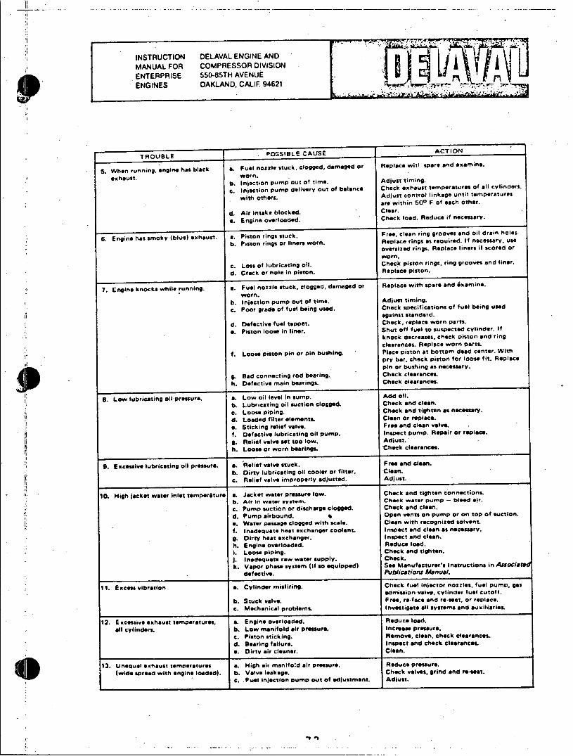
INSTRUCTION DELAVAL ENGINE AND MANUAL FOR COMPRESSOR DIVISION ENTERPRISE 550-85TH AVENUE ENGINES OAKLAND, CALIF. 94621
TROUBLE POSSIBLE CAUSE ACTION
5. When running, engine has black a. Fuel nozzle stuck, clogged, damaged or Replace witl spare and examine.
exhaust. wornl. b. injection pump out of time. Adjust timing.
c. Injection pump delivery out of balance Check exhaust temperatures of all cylinders.
with others. Adjust control linkage until temperatures are within 500 F of each other.
d. Air intake blocked. Clear.
a. Engine overloaded. Check load. Reduce if necessary.
6. Engine has smoky (blue) exhaust. a. Piston rings stuck. Free, clean ring grooves and oil drain holes. b. Piston rings or liners worn. Replace rings as required. If necessary, use
oversized rings. Replace liners if scored or worn.
c. Loss of lubricating oil. Check piston rings, ring grooves and liner.
d. Crack or hole in piston. Replace piston.
7. Engine knocks while running. a. Fuel nozzle stuck, clogged, damaged or Replace with spare and examine.
worn. b. Injection pump Out of time. Adjust timing. c. Poor grade of fuel being used. Check specifications of fuel being used
against standard.
d. Defective fuel tappet. Check, replace worn parts.
e. Piston loose in liner. Shut off fuel to suspected cylinder. If knock decreases, check piston and ring clearances. Replace worn partL
f. Loose piston pin or pin bushing. Place piston at bottom dead center. With pry bar, check piston for loose fit. Replace pin or bushing as necessary.
g. Bad connecting rod bearing.. Check clearances. h. Defective main bearings. Check clearances.
8. Low lubricating oil pressure. a. Low oil level in sump. Add oIl. b. Lubricating oil suction clogged. Check and clean. c. Loose piping. Check and tighten as neceesary.
d. Loaded filter elements. Clean or replace. a. Sticking relief valve. Free and clean valve. f. Defective lubricating oil pump. Inspect pump. Repair or replace.
g. Relief valve set too low. Adjust. h. Loose or worn bearings. Check clearances.
9. Excessive lubricating oil pressure. a. Relief valve stuck. Free and clean. b. Dirty lubricating oil cooler or filter. Clean. c. Relief valve improperly adjusted. Adjust.
10. High jacket water Inlet temperature a. Jacket water pressure low. Check and tighten connections. b. Air in water system. Check water pump - bleed air.
c. Pump suction or discharge clogged. Check and clean. d. Pump airbound. 1 Open vents on pump or on top of suction.
a. Water passage clogged with scale. Clean with recognized solvent. f. Inadequate heat exchanger coolant, inspect and clean as necessary.
g. Dirty heat exchanger. Inspect and clean. h. Engine overloaded. Reduce load. 1. Loose piping. . Check and tighten. ). Inadequate raw water supply. Check. k. Vapor phase system (if so equipped) See Manufacturer's Instructions in Associaea
defective. Publications Manual.
11. Excess vibration a. Cylinder misfiring. Check fuel injector nozzles, fuel pump, gas admission valve, cylinder fuel cutoff.
b. Stuck valve. Free, re-face and re-seat, or replace. c. Mechanical problems. Investigate all systems and auxiliaries
12. Excessive exhaust temperatures, a. Engine overloaded. Reduce load.
all cylinders. b. Low manifold air pressure. Increase pressure. c. Piston sticking. Remove, clean, check clearances. d. Bearing failure. Inspect and check clearances. a. Dirty air cleaner. Clean.
13. Unequal exhaust temperatures a. High air manilod air pressure. Reduce pressure.
(wide spread with engine loaded). b. Valve leakage. Check valves, grind and re-seat. c. Fuel injection pump out of adjustment. Adjust.
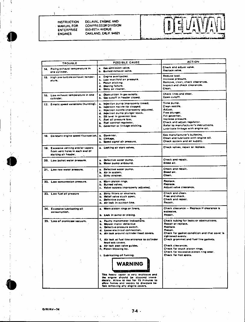
INSTRUCTION DELAVAL ENGINE ANDI MANUAL FOR COMPRESSOR.DIVISION ENTERPRISE 550-85TH AVENUE
ENGINES OAKLAND, C LIF 94621 . **
TROUBLE POSSIBLE CAUSE ACTION
14. Rising exhaust temperature in a. Gas admission valve. Check and adjust valve.
one cylinder. b. Burned exhaust valve. Replace valve.
15. High pre-turbine exhaust temper- a. Engine overloaded. Reduce load.
ature. b. Low manifold air pressure. Increase pressure. c. riston sticking. Remove, clean, check clearances.
d. suing failure. Inspect and check clearances.
a. Dirty air cleaner. Clean.
16. Low exhaust temperature in one a. Obstruction in gas supply. Check lines and clear.
cylinder. b. Gascutoff in header closed. Open cutoff.
17. Erratic speed variations (hunting). a. Injection pump improperly timed. Time pump. b. l'iection nozzle tip clogged. Clean nozzle. c. fection nozzle improperly adjusted. Adjust. d. *sjection pump plunger stuck. Free plunger. a. Cif level in governor low. Fill governor. f. Fuel oil pressure low. Increase pressure. g. fuel control regulator. Check and adjust regulator. h. Governor or linkage sticking. Refer to manufacturer's instructions.
Lubricate linkage with engine oil.
18. Constant engine sped fluctuation. a. Governor. See manufacturer's bulletins. b. Likage. Clean and lubricate with engine oil. c. Speed signal air pressure. Check system and air supply.
19. Excessive venting and/or vapors a. Leaking air start valves. Check valves, repair or replace. from vent holes in each end of starting air header.
20. Low jacket water pressure. a. Defective water pump. Check and repair. b. Water pump airbound. Bleed air.
21. Low raw water pressure. a. Defective water pump. Check and repair. b. Air in system. Bleed air. c. Dirty strainer. Clean.
22. Low compression pressure. a. Worn piston rings. Replace. b. Durned valves. Replace. c. Valve tappets improperly adjusted. Adjust valve clearance.
23. Low fuel oil pressure a. Dirty filters or strainers. Check and clean. b. Salief valve stuck open. Free and check. c. Defective pump. Check and repair. d. Air leak in suction line. Repair.
24. Excessive lubricating oil a. Worn piston rings or liners. Check clearance - Replace if clearance is consumption. excessive.
b. Leak in sump or piping. Repair.
25. Loss of crankcase vacuum. a. Faulty manometer indications. Check tubing for leaks or obstructions. b. lObwer motor defective Repair or replace. c. Defective pressure switch. Replace. d. Loose electrical connection. Repair. e. Air leak around cylinder head covers. Check for gasket condition and that cover is
tightened evenly. f. Air leak at fuel line entrance to cylinder Check grommet and fuel line gaskets.
fead sub covers. g. Air leak past valve guides. Check clearances. h. Piston blowing by. Check for stuck piston rings.
Check for excessive piston ring wear. I. Lubricating oil fuming. Check for hot spots
This heavy vapor is very explosive and the engine should be stopped imme diately. Allow to rass for 15 minutes to alow fumes and vapors to dissipate be. fare removing any engine covers.
0/R/RV-74
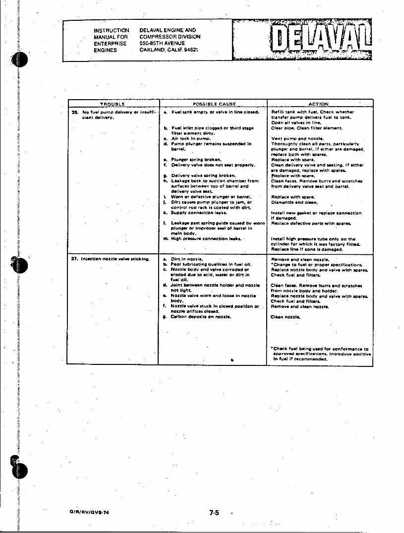
INSTRUCTION DELAVAL ENGINE AND MANUAL FOR COMPRESSOR DIVISION ENTERPRISE 550-85TH AVENUE ENGINES OAKLAND, CALIF 94621fro
TROUBLE POSSIBLE CAUSE ACTION
26. No fuel pump delivery or insuffl- a. Fuel tank empty or valve in line closed. Refill tank with fuel. Check whether cient delivery. transfer pump delivers fuel to tank.
Open all valves in line. b. Fuel inlet pipe clogged or third stage Clear Pipe. Clean filter element.
filter eement dirty. c. Air lock in pump. Vent pump and nozzle. d. Pump plunger remains suspended In Thoroughly clean all parts, particularly
barrel. plunger and barrel. If either are damaged, replace both with spares.
a. Plunger spring broken. Replace with spare. f. Delivery valve does not seat properly. Clean delivery valve and seating. If either
are damaged, replace with spares. g. Delivery valve spring broken. Replace with spare. h. Leakage back .to suction chamber from Clean faces. Remove burrs and scratches
surfaces between top of barrel and from delivery valve seat and barrel. delivery valve seat.
L Worn or defective plunger or barrel. Replace with spare. j. Dirt causes pump plunger to jam, or Dismantle and clean.
control rod rack is coated with dirt. k. Supply connection leaks. Install new gasket or replace connection
if damaged. 1. Leakage past spring guide caused by worn Replace defective parts with spares.
plunger or improper seal of barrel in main body.
m. High pressure connection leaks. Install high pressure tube only on the cylinder for which it was factory fitted. Replace line If cone is damaged.
27. Injection nozzle valve sticking. a. Dirt in nozzle. Remove and clean nozzle. b. Poor lubricating qualities in fuel oil. Change to fuel or proper specifications. c. Nozzle body and valve corroded or Replace nozzle body and valve with spares
eroded due to acid, water or dirt in Check fuel and filters fuel oil.
d. Joint between nozzle holder and nozzle Clean faces. Remove burrs and scratches not tight from nozzle body and holder.
e. Nozzle valve worn and loose in nozzle Replace nozzle body and valve with spares body. Check fuel and filtera
f. Nozzle valve stuck In closed position or Remove and clean nozzle. nozzle orifices closed.
9. Carbon deposits on nozzle. Clean nozzle.
'Check fuel being used for conformance to approved specifications. Introduce additive in fuel If recommended.
/ O7
O/RIRV/oV*.747-
INSTRUCTION DELAVAL ENGINE AND MANUAL FOR COMPRESSOR DIVISION A
ENTERPRISE 550-85TH AVENUE ' ENGINES OAKLAND. CALIF. 94621
SECTION 8
APPENDICES
The purpose of this section of the manual is to provide a single location for specific data which, if located within the
body of the manual, would be more difficult to locate. As a general rule, specific values have been omitted from the
text and, where appropriate, reference is made to the applicable appendix. The following appendices are contained
in this section.
Appendix I Torsional Stress and Critical Speeds
Appendix II Operating Temperatures and Pressures
Appendix III Table of Clearances
Appendix IV Torque Values
Appendix V Timing Diagram
Appendix VI Lubricating Oil Recommendations
Appendix VII Alarms and Safety Shutdowns
Appendix VIII Fuel Oil Recommendations
Appendix IX Power Engine Factory Test Logs
a//RV-7S 8-1
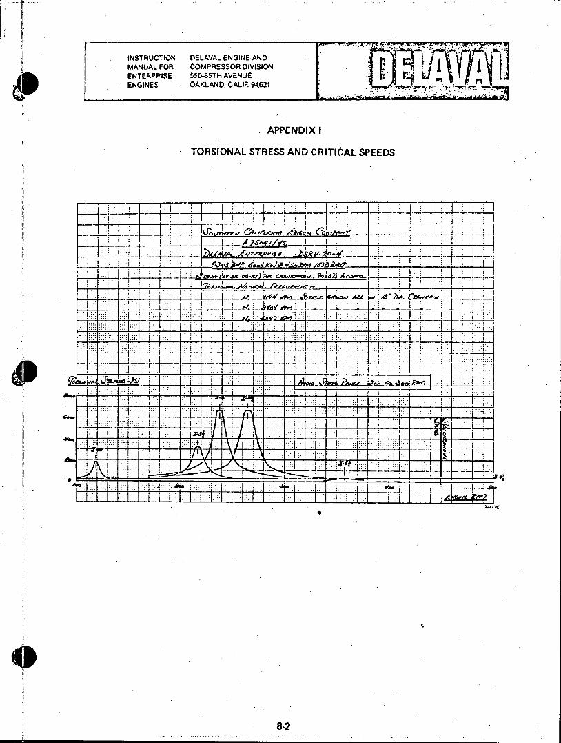
INSTRUCTION DELAVAL ENGINE AND MANUAL FOR COMPRESSOR DIVISION ENTERPPISE 550-85TH AVENUE ENGINES OAKLAND. CALIF. 94621
APPENDIX I TORSIONAL STRESS AND CRITICAL SPEEDS
ZIE - IItZI
::'.r: ':[7 .. .
I i ITI I _T
a: 1: IIT:
8-2
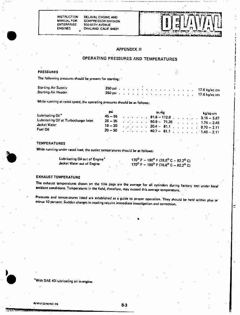
INSTRUCTION DELAVAL ENGINE AND MANUAL FOR COMPRESSOR DIVISION ENTERPRISE -550-85TH AVENUE ENGINES OAKLAND, CALIF 94621
APPENDIX II
OPERATING PRESSURES AND TEMPERATURES
PRESSURES
The following pressures should be present for starting:
Starting Air Supply 250 psi..... . . . . . . . . 17.6 kg/sq cm Starting Air Header 250 psi........ * . . 17.6 kg/sq cm
While running at rated speed, the operating pressures should be as follows:
psi in.4ig kg/sq-cm Lubricating Oil* 45-55 . . . . . . 91.6-112.0 . . . . . . 3.16-3.87 Lubricating Oi! at Turbocharger Inlet 25 -35. . . . . . 50.9 - 71.26 . . . . . 1.76 - 2.46 Jacket Water 10-30 . ..... 20.4- 61.1 . . . . . .. 0.70-2.11 Fuel Oil 20-30 . ... . . . 40.7- 61.1 . . . . . . 1.40-2.11
TEMPERATURES
While running under rated load, the outlet temperatures should be as follows:
Lubricating Oil out of Engine* 1700 F - 1800 F (76.60 C - 82.20 C) Jacket Water out of Engine 1700 F - 1800 F (76.6o C - 82.2 C)
EXHAUST TEMPERATURE
The exhaust temperatures shown on the title page are the average for all cylinders during factory test under local ambient conditions. Temperatures in the field, therefore, may exceed this average temperature.
Pressures and temperatures listed are established as a guide to proper operation. They should be held within plus or minus 10 percent. Sudden changes in reading require immediate investigation and correction.
With SAE 40 lubricating oil in engine.
R/RV(oM/N .75 8-3
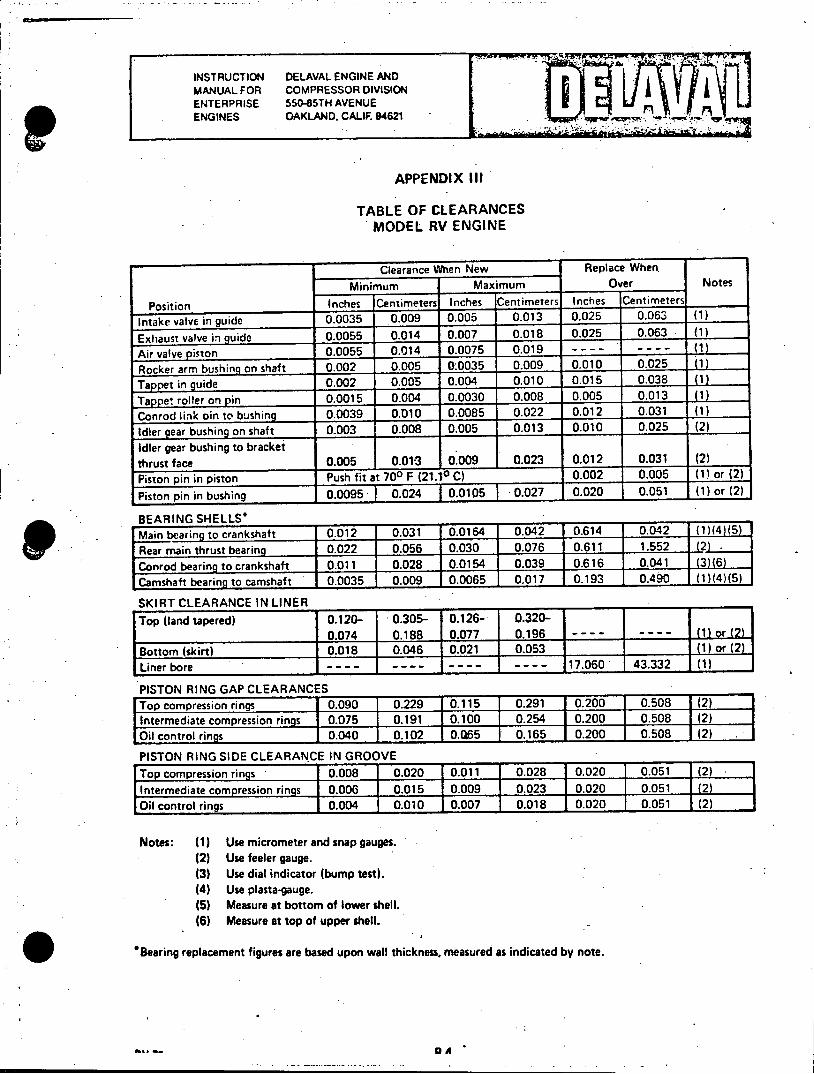
INSTRUCTION DELAVAL ENGINE AND MANUAL FOR COMPRESSOR DIVISION ENTERPRISE $50-85TH AVENUE n ENGINES OAKLAND, CALIF. 94621
APPENDIX III
TABLE OF CLEARANCES MODEL RV ENGINE
Clearance When New Replace When Minimum Maximum Over Notes
Position Inches Centimeters Inches Centimeters Inches Centimeters
Intake valve in guide 0.0035 0.009 0.005 0.013 0.025 0.063 (1)
Exhaust valve in guide 0.0055 0.014 0.007 0.018 0.025 0.063 (1)
Air valve piston 0.0055 0.014 0.0075 0.019 - - - - - - - - (1)
Rocker arm bushing on shaft 0.002 0.005 0.0035 0.009 0.010 0.025 (1)
Tappet in guide 0.002 0.005 0.004 0.010 0.015 0.038 (1)
Tappet roller on pin 0.0015 0.004 0.0030 0.008 0.005 0.013 (1)
Conrod link oin to bushing 0.0039 0.010 0.0085 0.022 0.012 0.031 (1)
Idler gear bushing on shaft 0.003 0.008 0.005 0.013 0.010 0.025 (2)
Idler gear bushing to bracket thrust face 0.005 0.01-3 0.009 0.023 0.012 0.031 (2)
Piston pin in piston Push fit at 700 F (21.10 C) 0.002 0.005 (1) or (2)
Piston pin in bushing 0.0095 0.024 0.0105 0.027 0.020 0.051 (1) or (2)
BEARING SHELLS*
Main bearing to crankshaft [0.012 0.031 0.0164 0.042 0.614 0.042 (1)(4)(5)
Rear main thrust bearing 0.022 0.056 0.030 0.076 0.611 1.552 (2)
Conrod bearing to crankshaft 0.011 0.028 0.0154 0.039 0.616 0,041 (3)(6) Camshaft bearing to camshaft 0.0035 0.009 0.0065 0.017 0.193 0.490 (1)(4)(5)
SKIRT CLEARANCE IN LINER
Top (land tapered) 0.120- 0.305- 0.126- 0.3200.074 0.188 0.077 0.196 - -- (1) or (2)
Bottom (skirt) 0.018 0.046 0.021 0.053 (1) or (2)
Liner bore ---- ---- - - - - 17.060 43.332 (1)
PISTON RING GAP CLEARANCES
Top compression rings 0.090 0.229 0.115 0.291 0.200 0.508 (2) Intermediate compression rings 0.075 0.191 0.100 0.254 0.200 0.508 (2) Oil control rings 0.040 0.102 0.Q65 0.165 0.200 1 0.508 (2)
PISTON RING SIDE CLEARANCE IN GROOVE
Top compression rings 0.008 0.020 0.011 0.028 0.020 0.051 (2) Intermediate compression rings 0.006 0.015 0.009 0.023 0.020 0.051 (2) Oil control rings 0.004 0.010 0.007 0.018 0.020 0.051 (2)
Notes: (1) Use micrometer and snap gauges. (2) Use feeler gauge. (3) Use dial indicator (bump test). (4) Use plasta-gauge. (5) Measure at bottom of lower shell. (6) Measure at top of upper shell.
*Bearing replacement figures are based upon wall thickness, measured as indicated by note.
-. -- 0A

. INSTRUCTION DELAVAL ENGINE AND
MANUAL FOR COMPRESSOR DIVISION
ENTERPRISE 55045TH AVENUE ENGINES OAKLAND, CALIF. 94621
APPENDX V-1
GEAR SET AND BACKLASH CLEARANCES MODEL RV ENGINE
B 3
3r
L%
AA
55
BACK ASH STEM DESCRIPTION GPL POS INCHES CENTIMETERS
1 CAMSHAFT GEAR, LEFT HAND 350 A 0.008 - 0.010 0.020 - 0.025 2 IDLER GEAR, LEFT HAND 355 B 0.004 - 0.006 0.010 - 0.015 3 CAMSHAFT GEAR. RIGHT HAND 350 C 0.005 - 0.008 0.013 - 0.025 4 IDLER GEAR. RIGHT HAND 355 B CRANKSHAFT GEAR 310 6 LUBRICATING OIL PUMP DRIVE GEAR 355 7 LUBRICATING OIL PUMP DRIVEN GEAR 420 B GOVERNOR& TACHOMETER DRIVE GEAR 411 9 GOVERNOR DRIVE AND DRIVEN GEAR 411
10 FUEL OIL PUMP & OVERSPEED TRIP DRIVE GEAR 410
AV-74 8-4A
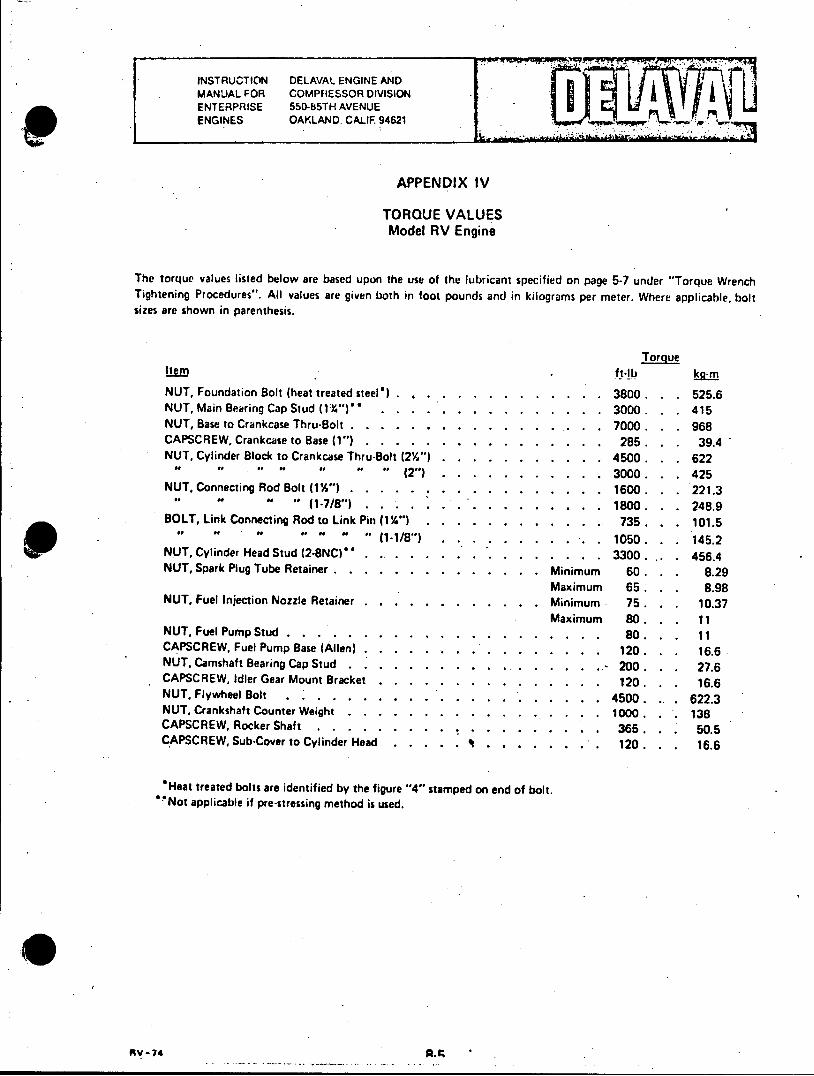
INSTRUCTION DELAVAL ENGINE AND MANUAL FOR COMPRESSOR DIVISION ENTERPRISE 550-85TH AVENUE ENGINES OAKLAND. CALIF. 94621 .
APPENDIX IV
TORQUE VALUES Model RV Engine
The torque values listed below are based upon the use of the lubricant specified on page 5-7 under "Torque Wrench Tightening Procedures". All values are given both in foot pounds and in kilograms per meter. Where applicable, bolt sizes are shown in parenthesis.
Torque Item ft-lb NUT, Foundation Bolt (heat treated steel') . . . . . . . . . . . . .. . 3800 . . . 525.6 NUT, Main Bearing Cap Stud (1%")".... . . . . . . . . . . .. 3000 . . . 415 NUT, Base to Crankcase Thru-Bolt . . . . . . . . . . . . . ... . . 7000 . . . 968 CAPSCREW, Crankcase to Base (1") . . . . . . . . . . . . . . . . 285. . . 39.4 NUT, Cylinder Block to Crankcase Thru-Bolt (2%") . . . . . . . . . . . 4500 . . . 622
" " " " " " "(2") .... ........... 3000 . . . 425 NUT, Connecting Rod Bolt (1%") . . . . . ....... ..... 1600 . . . 221.3
" "(1-7/8")....... ................. 1800. . . 248.9 BOLT, Link Connecting Rod to Link Pin (1%") . . . . . . . . . . . . 735 . . . 101.5
v .. P " .. - (1 -1/8") . . . . . . . . . .. . 1050 . . . 145.2 NUT, Cylinder Head Stud (2-8NC) . .. . . . . .. . .. . . . . . . . 3300. ,. . 456.4 NUT, Spark Plug Tube Retainer . . . . . . . . . . . . . . Minimum 60 . . . 8.29
Maximum 65. . . 8.98 NUT, Fuel Injection Nozzle Retainer . . . . . . . . . . . . Minimum 75. . . 10.37
Maximum 80 . . . 11 NUT, Fuel Pump Stud.......... .................. 80. . . 11 CAPSCREW, Fuel Pump Base (Allen) . . . . . . . . . . . . . . . . 120 . . . 16.6 NUT, Camshaft Bearing Cap Stud . .. . . . .. . . .. . . ..- 200 . . . 27.6 CAPSCREW, Idler Gear Mount Bracket . . . . . . . . . . . . . . . 120 . . . 16.6 NUT, Flywheel Bolt .... *.*......... ................ 4500. .. 622.3 NUT, Crankshaft Counter Weight . . . . . . . . . . . . . . . . . 1000. . . 138 CAPSCREW, Rocker Shaft ...... ...................... 365. . . 50.5 CAPSCREW, Sub-Cover to Cylinder Head . . . . . It . . . . . . .. . 120. . . 16.6
*Heat treated bolts are identified by the figure "4" stamped on end of bolt. "Not applicable if pre-stressing method is used.
RV-74
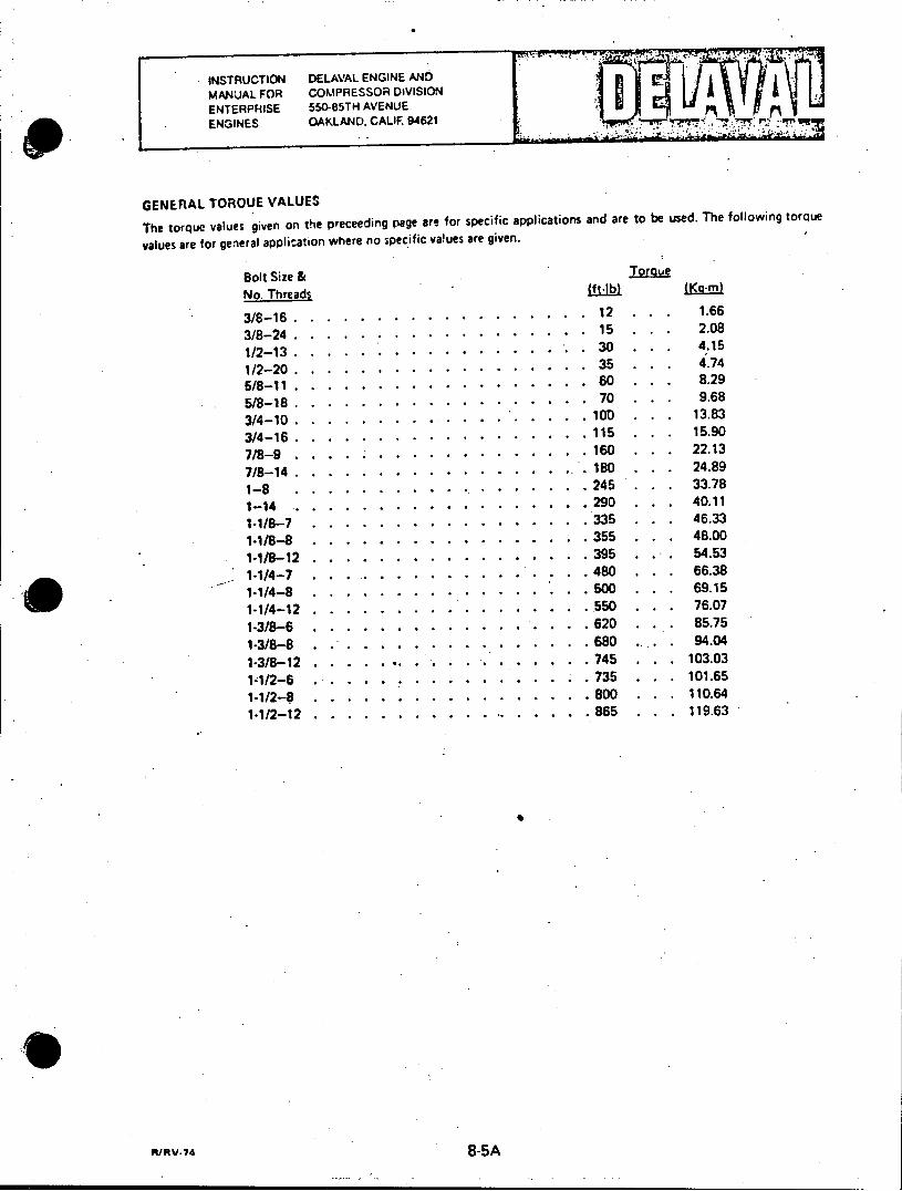
INSTRUCTION DELAVAL ENGINE AND
MANUAL FOR COMPRESSOR DIVISION ENTERPRISE 550-85TH AVENUE ENGINES OAKLAND. CALIF. 94621 **r** , .
GENERAL TOROUE VALUES
The torque values given on the preceeding page are for specific applications and are to be used. The following torque
values are for general application where no specific values are given.
Bolt Size & Torque No. Threads fft b) LK9.rn
3/8-16.......... ............. 12 ... 1.66
3/8-24........... ........... 15 . . 2.08
1/2-13.........*....*.*...........30 ... .. 4.15
1/2-20...........................35 ... .74
5/8-11........ . ................... 60 . . . 8.29
5/8-18..... ....................... 70 . . . 9.68
3/4-10... ...................... 10D ... 13.83
3/4-16........ .................... 115 . . . 15.90
7/8-9........*.*.*....... ......... 160 . . . 22.13
7/8-14...... ..................... 180 . . . 24.89
1-8 ...... *...*.*...... ........ 245 ... 33.78
1-14 ......... .................... 290 . . . 40.11
1-1/8-7 ....... ................... 335 . .. 46.33
1.1/8-8 ....... ................... 355 . . . 48.00
1-1/8-12....... ................... 395 . . . 54.53
1.1/4-7 ......... ................. 480 . . . 66.38
1-1/4-8 ....... ................... 500 ... 69.15
1-1/4-12........................550 . . . 76.07
1-3/8-6 ........................ 620 . . . 85.75
1-3/8-8 ....... ................... 680 ... 94.04
1-3/8-12......*.................745 . . . 103.03
1-1/2-6 .......................... 735 . . . 101.65
1-1/2-0 ....... ................... 800 . . . 110.64
1-1/2-12.................. ....... 865 . . . 119.63
ft/iV74 8-5A
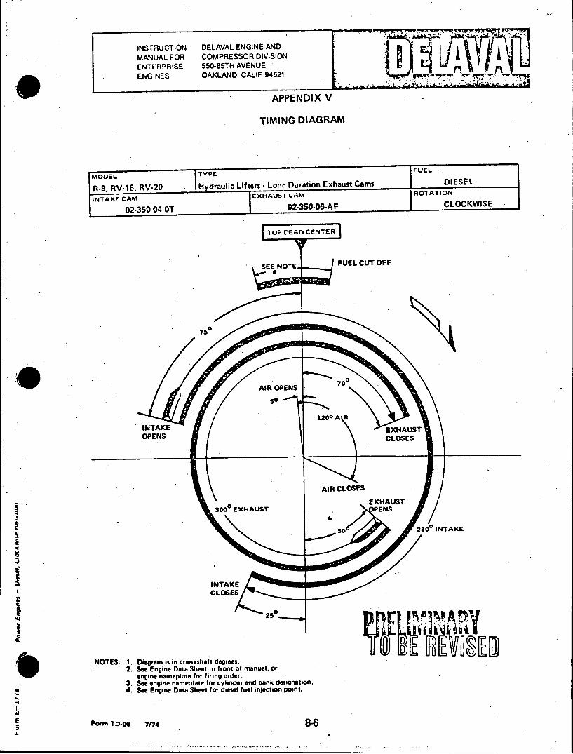
INSTRUCTION DELAVAL ENGINE AND MANUAL FOR COMPRESSOR DIVISION ENTERPRISE 550-85TH AVENUE ENGINES OAKLAND, CALIF. 94621
APPENDIX V
TIMING DIAGRAM
FUEL IMODEL jTYPE FE
RB, RV-16. RV-20 Hydrauic Lifters - Long Duration Exhaust Cams DIESEL
INTAKE CAM EXHAUST CAM ROTATION
02-350-04-0T 02-350-06-AF CLOCKWISE
TOP DEAD CENTER
SEE NOTE FUEL CUT OFF 4
70
70 AIR OPENS 7
so
1200 AR INTAKE EXHAUST OPENS CLOSES
AIR CLOSES
EXHAUST 3000 EXHAUST .ENS
50 2800 INTAKE
INTAKE CLOSES
250
NOTES: 1. Diagram is in crankshaft degrees. 2. See Engine Data Sheet in front of manual, or
engine nameplate for firing order. 3. See engine nameplate for cylinder and bank designation. 4. See Engine Data Sheet for diesel fuel injection point.
E Porm TD-06 7/74

INSTFUCTION DELAVAL ENGINE AND MANUAL FOR COMPRESSOR DIVISION ENTERPRISE 550-85TH AVENUE ENGINES OAKLAND, CALIF. 94621
APPENDIX VI
LUBRICATING OIL RECOMMENDATIONS
The DELAVAL Engine and Compressor Division does not recommend lubricants by brand name. The final measure
of the quality of an oil is its performance in service. The lubricant supplier must work with the fuel oil supplier to
insure the use of the proper lubricant. The consistent quality and performance of a suitable heavy duty oil must,
therefore, be the responsibility of the company making the lubricant.
CAUTION
It must be the concern of the operator to consult with the oil supplier concerning the proper selection of a lubricant which will. perform compatibly with the type of fuel to be used in order to insure the most satisfactory performance and life with overall economical operation. In the case of unresolved questions, the DELAVAL Engine and Compressor Division should be consulted.
To determine the condemning limits for oil in service, have the oil supplier take representative samples at regular intervals for oil analysis. His recommendations, then, for either further service or for condemnation will be based on qualitative factors. The following applies to new oil only.
RECOMMENDED LUBRICATING OIL CHARACTERISTICS
SAE GRADE 40 OIL Maximum Minimum
Viscosity Index (ASTM D567) - 70 Gravity, A.P.I. at 60oF (25.60 C) (ASTM D287) 30 20 Flash Point OF (ASTM 092) - 425 (2180 C) Pour Point OF (ASTM D97) - 10 (5.60 C)
below coldest oil starting temperature
OIL RECOMMENDATIONS
DUAL FUEL ENGINES: Use low ash lubricating oil of the following specifications.
Engines rated 205 bmep and below - API/SAE Classification "CC" or better.
Engines rated 206 bmep and above - API/SAE Classification "CD" or better.
DIESEL ENGINES (Using fuel oil with less than 1.05% sulfur):
Engines rated 205 bmep and below - API/SAE Classification "CC" or better.
Engines rated 206 bmep and above - API /SAE Classification "CD" or better.
HEAVY FUEL ENGINES:
Engines using fuel oil with less than 1.5% sulfur - Use classification "CD" oil only.
Engines using fuel oil with more than 1.5% sulfur - Use classification "CD" lubricating oil, worked out for high sulfur service in conjunction with lubricating oil supplier.
/R/RV-74 (SAE-40) 8-7
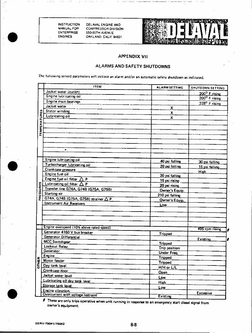
INSTRUCTION DELAVAL ENGINE AND MANUAL FOR COMPRESSOR DIVISION ENTERPRISE 550-85TH AVENUE ENGINES OAKLAND. CALIF 94621
APPENDIX VII
ALARMS AND SAFETY SHUTDOWNS
The fol;owing sensed parameters will initiate an alarm and/or an automatic safety shutdown as indicated.
ITEM ALARM SETTING SHUTDOWN SETTING Jacket water (outlet) o2000 F risin Engine lubricating oil 20O0 F rising Engine main bearings 2280 F rising Jacket water X Stator winding X Lubricating oil X
cc
Engine lubrcating oil40 aln 0 psi falling Tubcare ubiaioil 20 psi falling 5pi aln Crankcase pressureH g
Engine fuel oil 2 s aln Engine fuel oil filter P15pirsn
-Transfer line G74A, G74B (G75A, G75B) OnrsEUD Starting air21psfaln
c G74A, G748 (G75A, G75B) strainer APOwe' ui. instrument Air ReceiversLo
Lo
Engine overspeed (10% above rated speed) Generator 4160 V bus breakerTrpe Generator Differential P 0psiisn MCC Switchear TripOer Lockout RelayTrpostn Generator sner eq. Engine v e a r e5 i
u Motor feeder Tripped Day tank leveTlrip psto Crankcase door Open Jacket water level Low Lubricating oil day tank level High Storage tank level Low En-mie vibration
__________ Excessive Overcurrent with voltage restraint Existing If These are only trips operative when unit running in response to an emergency start diesel signal from owner's equipment.
DSRV-75041/75042 8-8
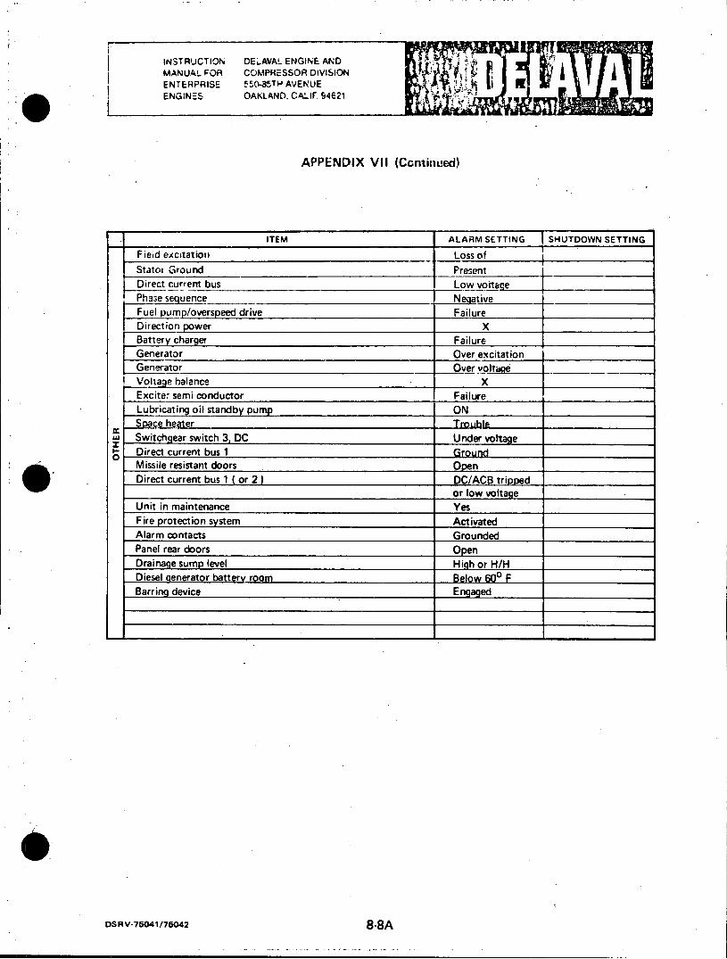
INSTRUCTION DELAVAL ENGINE AND MANUAL FOR COMPRESSOR DIVISION ENTERPRISE 5I0-8TH AVENUE fl ENGINES OAKLAND. CALIF 94621
APPENDIX VII (Continued)
ITEM ALARM SETTING SHUTDOWN SETTING
Field excitation Loss of
Stator Ground Present
Direct current bus Low voltage Phse sequence Neuative
Fuel pump/overspeed drive Failure Direction power X Battery charger Failure
Generator Over excitation
Generator Over voltage Voltage balance X
Exciter semi conductor Failure Lubricating oil standby pump ON Space heater Trouhle__
w Switchgear switch 3, DC Under voltage Direct current bus 1 Ground 0 Missile resistant doors Open Direct current bus 1 ( or 2) DC/ACB tripped
or low voltage
Unit in maintenance Yes Fire protection system Activated Alarm contacts Grounded
Panel rear doors Open Drainage sump level High or H/H Diesel generator battery room Below 600 F Barring device Engaged
DSRV-75041/75042 8-8A

INSTRUCTION DEL AVAL ENGINE AND MANUAL FOR COMPRESSOR DIVISION ENTERPRISE 550-85TH AVENUE ENGINES OAKLAND, CALIF. 94621
APPENDIX VIII
FUEL OIL SPECIFICATIONS
Maximum Minimum Viscosity, S.S.U. at 1000 F 45 32
*Gravity, Deg. A.P.I. 38 26 Sulphur, % 1.05 Sulphur, Corrosion Test (Copper Strip, 3 hrs. at 2120 F) Pass Pass Conradson Carbon, % 0.20 Ash, % 0.10 Water & Sediment, % 0.50 Flash Point, 0 F (P.M.C.C.) 150 or legal Pour Point, at least 100 F below coldest fuel oil temperature
DISTILLATION, 0 F 90% Point 675
IGNITION OUALITY Cetane Number 40
*Heat Value - determine from A.P.I. gravity limits shown to determine total or net Btu/Ib or gallon.
The above specification covers fuel oils classed as Grade F.S. No. 2.
Fuels heavier than the above can be burned in Enterprise engines provided proper treating and pre-heating facilities are available. In the event it is desirable to use such fuels, DELAVAL Engine and Compressor Division should be consulted for advice as to the arrangements that need to be made. An analysis of the particular fuel to be used must be provided.
For lubricating oil recommendations, refer to Section 2, Page 5.
i/R/Rv/GVB-74 8-9
INSTRUCTION DELAVAL ENGINE AND
MANUAL FOR COMPRESSOR DIVISION ENTERPRISE 550-85TH AVENUE
ENGINES OAKLAND, CALIF. 94621
.APPENDIX IX
POWER ENGINE FACTORY TEST LOGS
Copies of the Power Engine Factory Test Logs are provided in this appendix to assist operating personnel in becoming
familiar with the operating characteristics of the engine. The data included is that recorded during actual factory test
of the engine.
OI.;.V-7. 8-10-

... ... .. ...
u. !l TIME t: .......--JO
. ..... --- T TF.: T-i' :J ilw :--. Vi T-H I:. 7 t. w-"p: A .: I ::J:. A: [it
1.. :7.
m 1 7 1
JJ*
so H., _ d i.
r A I FS S,
lb.. L
. ........ Trt. 14 : i
it
1.7 :. i Wt. v A 7. .1in I p 1 .7. i .7. o w
it m! wa
w t I on! I=_ I; za t: -Z ti
1 ME -1- 1 ;Z7
T. 4!
tTt w;
;:I L: ;It: _=w i
41 :W.: iffl-MUM-i ;M-tt. :wt: nt:7t tt
4;V:; :A * L It tv. 'ti tit
waRUP i H
1:-. V; w I
.ilr n V : :tIjI.A . ... ... wi nt 1: 1 It: t: _V. TH:
4.:.: Fit: ittl'! ;4. 1-Tw:L "i A :! ::.;i 9T:T. pt 7% -r
N M: -_ 7: Vt; ; l I Off V Iltt tt
T- -7. :7:1 nit Eli
-fd_ tT iF: tt t1i : mi V .. _'5 Jill 40 -_4 H ;1. - ."'T --E:.: M As ix
t t 7L ::tI;77 _it ZF, r::
!w:
ti- t :.
lirlili-M li M; 1,; A in u
:.4 ti. = 't:4 =tgi
ig. 1-pt'jiiiii :'fl .- 4.. gh M111ii: nl: :!fj 4: aa.._
mi Mi illf 1:1 R n mi It Ft!. 1: :: .= .. . .:.,. 1 49tog Up .1 i"Tri. E li , it %iM it tfli it 1: ' i V11 kd i I i;Ti 4NEV in: IT. it :.1' 49141 "M W ill 1W RIfffill nc:iv tt. I il -!% , I U ri U .'" RL
t to, 1:1 14 1 TO ;II't iifili :'I ii; t W M mq tifii:!! lit, 11 i !"IMI! 11HP;* 11 4 :: it!: un:
:!Il i i!!PiH1t ilk ll J . i Hill; ;11IL'i liPu iiii P. fli': ii tll E 7 7ri, 1 F1 i! lifil'Olliolfil,11 1:MOr! Ili! H jilt Ilk il.1 OU IN, ill: FT I;, A Pit lt!i i4
i;[ P i :j T 1! ;J I; FT:l !!ii iij: ,::! 1M 11. Cl 1, Pll li;"vo
i A lt i ii:. I i.. it !J J.A ;i1i 1'1: id!Vi '111 I-r i dli:1!Vll :;I, 1;;1i Jilt .1 h4!! :1:0 : 44;! flT: U. IA'It
.' aW. H ilL TTT*
W! i!:T: :J it:: it:
i: :g I :t miliT It, li'l '71 .i UP i 4 lli L W
LY 'Wo

In~ Ani Ot~h~i t) Olf. AOChi CiA~O~ttA OA t.Ctd ~ttV 101 OG AO I A
1-0 -h. 101,
'5 2S W*7 M3. 0 oqc 21 i 3=4--, 5 37 .7-- 4P. 7751 7 ~. i1171 IsI 8 4 A~2k -i opsm ilS1 S7116 11. ___ 1 15! 14. 152-: 2.0 *%~272*7'3a4 .3' 2.6:lc I702.i5.112. __Z_ 22oL, 2 -5 1.2..iq2i 162., %-52 .034 34' _173Z& C) "7b 2 3 DOI~ ______ 2302______'2S3 25353~c
1.4. 701M. EISi. SIOK.z1 I-,'I Ic I.." I o4- 46i I.__ _ ~ 34.o 7777 773 37Mo -7-7 ------
~~~~~~~~~2 AOL 15L "84 --L af __________ratM . jS !4t l L 1.32. :77 --~ (67CI ~1Z LF __ - . TIR4N 34 IL4844
4--Vo -w. 434 a. N'51?S jihw 0. -T - --. 9 ~~~G~J11_A5 37-7-~ 77tf~l .30f8F 7IZCCj. 3944IO-rn~4 -08,80 ib -6049/ 16wl~ 821871_e:7~Sn~~ qjaj.I 6sa8 -1lI 1.1 001( -IC IF*N00 -- - - - -[ 412,7 ,.,. r I I ,NNID(7 b4 1 .2 OL."RER ROM-E 1.. 752IR TI7LN
AABOJG11. I FI O I L I ti Lh O D I BL ONT R t f OF LA I F ffh tAB IL Xa, Ua L AL f B, TO 3 E B2 t2M OhhOahB o ISot 3170115 34--jOS~t Ba 44 43o+39IO LI 4,3 A4S4- 4P At15303813. !3 -11,1'171S16 2.8j 75_9;.s _ -- --,., -65 Z1~. 1664 17s 77Z '71- _____
2i ___ ___ ___________ 711 c?.in; IS 1~2I5Z9 (511q 4 A 10101 14 (75o an ans~ ~~~~~~p BIG-t SANK Bt 176ciA 7i62IBBABOOS~h. ~A 1-a~ 750W tt(5 LWtOr(o o.._____U-BCSB- . -LO __________B 7a5.b A...06 1- lla4 -76 h nt 1t 0 1 AA% l-.
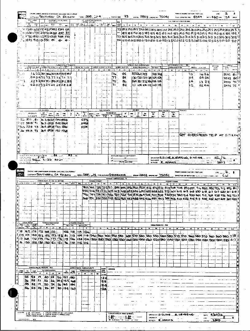
~ 5r~-b~ .\ t~~.cAj ow *v~iv 2 .vo24N03 1io~it 504i ttoo..1 634ql -"4S0... :s
.'0621d -31 19 4 29.~a 31. 313532.03s5a 3l.C 2q 1-2k 5
II130I~~~~~~~~!O. .0O Sdg5 I0 -D29 S.Z. r5Z,~Sa~ q qO~9 290Oci i' .'&4S IR 6-C 3 1la- zOl2.S!2-.lz0 12.0 IZ.a IO1.5201.S1 1- V 30:2S2.13 013.0 ' 1C' 14
-A I'
LE RE LI 1 ItI F. ~
:2,23. -. 3~3fe 35 N5 281 -26k [I*4 j.4- L3 33j1. 1
3R. 1-71, --6 L312. I 11 It .1 1___P 0.I BZj:- Zq 2I: SZIII .4..4 K- -Z Oz -l 4,
1.I.*.r.I'', III UL M7 K ~ ~ IR. %ItR mW~ a~it~~le WIL-.E
is Si it_ _ 05 3-i'73e ~ ~ I~C 2ArP$:: O." 2:~~- - l~'l~E~ 101 i . . ___ * . ~
1,3 ~t ICFRRRVi~ Oii.A aAti~t R3R :1.4il4 FACTOR ttl to4 to 2. 31- ORI 3 5-B T'Neg14 , C E IO., -5 4vot~ ). w RO 1111 0 *iTOl0*11*1t o.0lOli~ i
C.. iv 61~~~Ri~i TRIR7AO -r v sP e zIp Ars
IURRAi il? 1.110 S 501*1!IARSI tROAR i~iA~tl 1
7 ! t I ? I l l e R ~ t I T I C I R i i t i t i t i t U t i i ~ ~ I i I C S 1 0 :
I FL FO LE(.fIL'.
SEE- - - 2
OERE INEE flIW _ _ _ _ _ _ _ _ _ _ _ _ _ IRCIRIRITIC TINEIASI tills-Q- AtlimOmtt RE.-50 1 0111INDF"I MI ,,
Silt~~~~.-S ItWPRTUD -iA Wit-1i03*8001i
It, IRtO LR LtI l11hMT WiT 1' 1 SOI 1 1 1 L 1 t 1. 1 1
I1 83 &Wi5I5I II 16 64 1io56 (AQ 7e (.20 &11 67 165657 5'5 2 3 i7' 7?19FI% l I'II72(.~~j4-1 15 ~f 37j 4 9300 iZIiZ 34.3033 1 10'0'5 I R tR 3q 9Z S13
4! -- R492 CE 913
:- 171Z1 IZ Z IZ Z z -~1
HON iISSRE -FEE-S LA I FA RUA 111 - 0 eI A IRR ~ tt IL It REi~li it 'RAR IRA
Is 13 -OAWTAA IITc~iORO~. ti -- ______________
175.14 '(53 1iq 15Q12 2. l- !11p III+ -i"56 9%- 57.51 IIS o -o 56,a 51 & .~ o51
4 s ~ l~ 1&~. j04 #5 is 1-1- -l 11111 is__1__1t;
7 - -T T- -F 7- F 7 - _
I.w -NFU- f., I
1-513 1 1- 20 .24 24 1318 . .65 i tlilx.ll& Z7e 30qtyw SSf 1UIW R IQRR Iil
l~ull~t~i~i~aL~a~t 1101~I~7 - li~ilill . .. t~. _____________ 7
1 7 11, Rl
Il.l I *115 ~ M - .i.
__
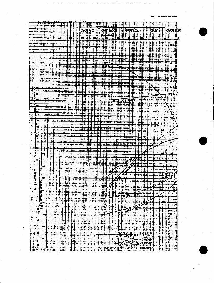
0" 49-41 UORG) L99" -d
2 1 wrl M173%4 -n AN 1.1IJ:
iTT-.
i;:, F:; FA
ill 12 :!L!::: :iIii;: T; 5 :1 M! it 4 1. i. I t .;T : i
"ro: ni tIll ill: ia t
:11H A: ! . Lp.- :; i - .:
il: P ill :it! a I I 1 1: 11, 1 IM V I i:J;pvii i;.; "fir vn It it , ;
JIFIF, i:, ME T.- ;, ilU IL 7, 4h, :r: 7. f;lM! Pit F: 11: i d l! fl' -94
4,T, i it 4X::: i im H1 ili Of Hill HL. all :if fit
L -L If in.93 lot T:.. !1ij, M. Im 9 i tit- iL 4Lftm,
i it:::
il:v ;,JI: HUM
:-Wr; tl: F.- irI nit T I If
ti I-: 1: 1: If id. TRK i: fIn; : :n. :-i=;: 4 4:: 1 n n ::R r. t:: t., :T!:; KaM -Ip if
47. -pr q t:
:ao
.7 p i;;: ni
tIl I, lI: T, i7i nw; Iw.
rw; i:y ,: LVAb: It .. I
tin M--.: 0'. w4
IIIt n :4:9 . Tiii i
nff] _211 W. =a
::A :t:: -n
w F: - l7 p 11 -- nt T ff;. di ELE in:
n .,1. .1:1,: j t:4- ii
- 117 I . . . * :: ii P. .: :, 1" l:, I .. j I., . ....... j - .t .4
-ni -1 V nn n.7n V:Z M;:- iv
L,::
n: ;mTii fill 3:
j" :7F
it -t.,: nl!: ::,l . ::: . ; :
qq _7tl
L
n: ft _IT
4F
PA -1 J -T :j a. 4;
F .. ti
wo.: :Tm j: F-s F i; ;.I:,:wl--i A: t:. r
T V : . .. .... , I:: : = - . %.; ! i, .. rr i! :fi lIn M = .F71 u X 1:::, n .7 7 ....... ... ... ...... n: n I mn Ill. 7
if I tit
ml:i !I :. . . .... ..
It
m q

EA~a D a t eolvSW.OKLNDLN at - . ToNvts., L
c 50c SO. CAu. EDISON - DSRf0A man.o 23 =.* 2804 ow.o..o 7S04 2 opos.-. 9349 -450 -S 154
o A Na t ans r uass
L' D~i o t" .-. 1 ; 1 T .0 O r - F' 1' .o U-t 1 . A
14i 530 0745 25 2 0 2l580oot 38 5 14.0 I f;.st1 e ts 25 W WIo24sys iotst la 1o2
.01 190203o 25 3702114 38 5 ;o 3ro f3 ' ene 3002400 soln0ow773428 77 4.e a22.0 4
sm o 5 4 745 4., 21Q22.S221S22u 210 2202322 2.522225to22.5230-210.210 2. 5
4oo?4275 4 &751 2L a t 2.52(s2s2 o2o2to o e
0 4 a o" 1 a729t 1049-o 2tetoso2t290 29 2to2 no 0 4 9
klS LDI T D10 ALOma .1cemana;( I. -, . (0 INTU taini 50 )0 Tue sewxa ntlo ta 0 Patin ceaA toi se...l tuoati ZZ L..Io01 asc LA 0o 199 aso r 125 so r582873 S.1. as - T -n e s a n Ia s as)a oa n). ot %
3 1 38 L. 7A 75 78 n I1+ _ _ 1 29.Fo Ie
.o . 5 .9 5504 29.79 74
74 Z'--112. . 07 9.2 471t i~ -7 0.7 iJ~J L~6 2 19 6"39I__ 3 es116 2 07 _' 73 J03 o a to0 141 .2 2.7 9078 . 7 3 74 d Ji 3u 4.4, i o .
113 1 291. 211.i . 9(Es IIS 125IA as.. 7 14979 21. 80 f 10 1 21 21.1J.( 21.2f e.f ti 14 85 IR17 19 20112S25 10 S' 29.78 to 5
pa0T552. l I / --.- - - - - - - 77 0 3 31 St 0S e7 7 2s ra 729.7 7418
it3'V' 2os 79 73 6g **St isQ29 14
4._ _ o 3 3 7 6L I 455 Il .81$7,30 17' 7 P
* F4154.0 94 "77I46o 4 7 a__ _ __M
94.40a94 377 m@4o leto 1900?~ ___ __0 355_____ _e
. .1ZI I I X"'.. Aoc 9* 4 -..
. 2---- -"_ . I r - 3 dN us
curoant SO, I. it ED. o st ***== OSV-2 _7T
NATr w arr Ls et Las sort ersT Nss tF NA to as it n St 54 t5 4 n ,t a l a 0. A o so S a so a1 S re IS so5, *on w 3 3 0 37 3 1 360 342'37 40. f437 4140 34744 4/149 429 4 397 1 ---37 409 ) 491 424 437395 494 4'7737 44!4 t14/ 4434344444o4041 2
3 51 SR$ 524 545 142 St 529S 521l ]JO7 I4 SUS AU 3 t 4 S sssart59$2
4t*- 48 44 5 9 847 £60 675667 676 I46 £62 id 64 6 7.564559 I6648 Sasg 6 02st 7 39 9 9 _ e 7s 9 os
753-- - - - - - 6 -5 77 975 9/9 0 99 7 890 9 3 9 89I7|5I5 7 458787 0 218 5
-r--- - - -- - - -_ gli _G_ ---.tt 577-U? A
o147 ,34 5o 5Y7 See -o23 " (i 2t o 147 st t ooz is t io tor do ip o
1ACMNA~~~s a n COAZAC .AMPk N CAJMNA0ARICM AINVt O
q s asq war a iI
A 9.f19 An II.LITa 122T M2N I.A% It"WS 9.1A
2 ..1953 954W A34_ 9r A56 1I5A 74 75 A I K 2
44 3700 is 371 341 us 342o7 46t7 9
44 4.o'S 148 91 4Mt1is 9i 7 it 12t 49 3 1 Sto157 I37 i09 164 -1 -34 7'1 4M 42 1 A 40 4 1 1t-1 1 1-0-1 "9 69 140 1{96 7
S972 177 48 2550 -O 171 S 54_ 1
1 1 v o !5 4o 25 0 2 4 1 3 0 5 32 5_ 10!70 19 1501IS3 SS2 |5 S
4, OI~ib cors.. AL ML USI11 $63 TOW47~h "0n M40050080 U 4 "$6541I? 83!
7 5Os6 toots. caMe 76s o4 c 1 4 1 7
To5 109 - . - -1__-_
2 7 1 3 0 .740 834 (S 0 sp sto9 W(40-6 W3 1 e4 S 1 f3 t d344fo 4014 # 1805:7,,.lj 6#
1, 1 o 2o to o 0 907 9o f ia 0 /o 90 7 907a* 24 18 90 900 909 919 of o 84 8 0 87010 11 2 II S 41 o 1 M I40. 1it oII I 12o IIo floo I I0 1t 604 10 I 3 1 1 5 1_0_ito0a__II
5Alt 131t IS
I .F 5 I* 001*. Q ." F a I A f ft*5 KtWtE Iat st __ _ I t I-t A tu 6
I ~ ~ ~ ~ T . J#1 120A It M 12 2
3j S ep 114.51 . li t. ato12 7 ItI3
2a 0! Sit s ss nof W- o-t 12 - L60fo36MMI0 4 3v ofo06395U63106
T42011( 117 is 34.0 3J 22 7 13 [tt1MI tt s
,W 2s) 2S 13)Iiott 11T.
50 2 1 .0 4 0 2_ _ d57 _ 07 0
1104 ~ ~ 3. 703.&fi Ii 132. 2 _. IS I 4 OS0SS 4 S01093 4 4 I [4 a 4 3. 2. 5 3M.8 2TNN IS I AW M ,Fw.Nwl
A& o L. Ae . a To A
StO& 3t.5 194. 21 16 fZ R3to915 5340 0 so ato is US 19ha
ioi. k-tt2-5'^3".0 ':U.S:. -2m,0'CEEIDN10 i S IN41VI 330E UD 2qF1R FLMELEND
9 SM U *0 32.0-111 1.2 A" . I5
i7-4g-1* 6q0 S
NA - A--- E O
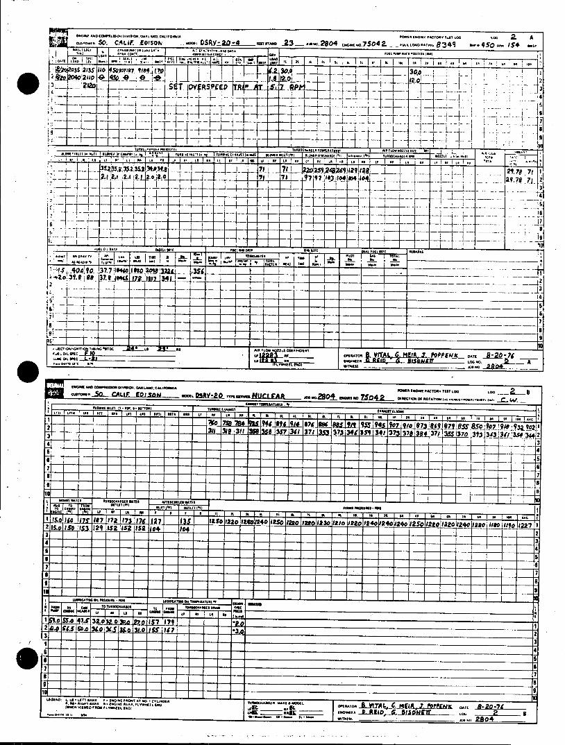
E WE f) fVGONN AK E P Mm tM 54 TTML
care.... SO. CALIF. E1SO DSRV**20-4 _ 23 - *.2804 w......7504 _ 8349 * 450 154 s A1 c10 o * EA LuAU LAI A I Se*I"' .TC AD DATt
o ~ InA. o asr no zu 1I e 1o nou
0U1 LDL0 S T FF F., A. F 0Sit I LUC INF te st A F' F
& L~~i2,s T' L" o~i :11 t~ 3! I.~J .. _ , .0c . 11iF A 1 WTI
os o 377 * o7--no soto 9. 8 37Iett 0 j - I 120 20
our 4 .no Ic .J A* e *__ T2M PIYRSPEi~-'~ -A
c L- c a-L M D PIo f * *
.. .tTESS -. A te 01 N'LII 1. wir Ut"I'40 - 'CO AAOO TASlOFLIPI ' L 1. AT 00001*1A I.,WM KOMM OUT I *Mj ~ a I1,4 O'OAAMF II I, F U.BaFL Q.I AC~ 4 . o. 11
I 0181 IFSCOMAS0 F' tSO .0 LAMD CatPDM I T 0 S 0 L M lpA M .0 * PO WER I 0gMEFR TES LO M LOG CUSTOMER3934. - MDEL SA.&.rv 4eses I 5eem ~ 1iY 2 ... L.. nsro., uao u Iv.......5...m.
- I .ml E. Lt 4n 12912
3.o58 83.iw.1n~i8 -1 t s oa t M 7 9ars 7137 e 7 s
5
88
----- --- --- 3
ft_ -0 -4_ 5
T_ _7
LLasicALiA 010TEW RAEues* DATE
FOOT LEUIOFFIIC. TFIFOG MT GL I 1
4ND C"ICM LOWE WEMFOG0F To L L F FO FL S 0CFI@r_" 391 _ .0*.'? Tvu3oc" L&_____CI Moito MIDTnrA..
Lm Lt e - uI Lou so o t rea on ge so nL
F'Ais sa"o o A Ko fst Ws-
6 4
-a it-tl~ 500
88
. .OOWI M-"an 2
IIFI IFI US Mfl AO LE O I F f AI OF LM I I It I nt 00 St IK M t F 4 M S To 6. Loo5 AFA
2~ 7E0 ISO 152 12151$ IS7 Of~ I84t qg 9 IUq
I - I] 3
4 1 1.---.~f- 'F f
0 9 It 's I gAls
"'aSS 0 M 4 32. 32 0 P& I2* '*3 7
4 -7
10 9 :L I-A loom ...- - - - - -
- - -- - - - - - - -VIWE PR FLWHE Mo -I ,4 -P N -T . - - - - - - 2- - -- - - - - - - - - - - -- - - -2 AA - - - - - - - - - - - -

INSTRUCTION DELAVAL ENGINE AND MANUAL FOR COMPRESSOR DIVISION ENTERPRISE 550-85TH AVENUE ENGINES OAKLAND, CALIF. 94621
DRAWINGS
The drawings provided in this manual are intended for the customer's use in the installation and operation of the unit. They include installation, foundation (where applicable) and system piping schematic drawings. Control system drawings are also included. Assembly drawings may be found in the Parts Manual, Volume II.
Porn CAT-122 3/75

MANUAL FOR COMPRESSOR DIVISION
ENTERPRISE 550-85THJ AVENUE
ENGINES OAKLAND. CALIF. 94621 . .w
PIPING SYMBOLS
MANOMETER PRESSURE REDUCER LEVEL GAUGE
PRESSURE SWITCH GATE VALVE PLUGGED
DIAL THERMOMETER GLOBE VALVE STRAINER
TEMPERATURE SWITCH PLUG VALVE DIRECTION OF FLOW
SIGHT FLOW GAUGE BUTTERFLY VALVE WELD REDUCER (Tight Sealing Type)
ENGINE SHUT DOWN CHECK VALVE - SCREWED CAP AND PRESSURESWITCH NIPPLE
PYROMETER STOP COCK UNION
PRESSURE SHUT DOWN ELEMENT SAFETY OR RELIEF WELD CAP VALVE
TEMPERATURE CONNECTION - PRESSURE CONNECTION
Requires 46" half coupling for all dial Requires V2" coupling, nipple. thermometers and separable socket Stop Cock, 'b" x Is" bushing thermometer wells and Oh" half couplings _0' and V" plug. (Field locate
for temperature switches, etc. (Field as directed by owner.) locate as directed by owner.)
STRAINER -" SOLENOID VALVE
TEMPERATURE SHUT DOWN DRESSER COUPLING ELEMENT
ELECTRIC WIRING EXPANSION JOINT
CAPILLARY TUBING ORIFICE
BLIND FLANGE ALARM CIRCUIT
THERMOMETER PRESSURE GAUGE
TEMPERATURE GAUGE METER
[>V LOAT VALVE .- O FLOAT SWITCH
DIAPHRAGM CONTROL THERMOSTATIC TEMP. This form same as VALVE CONTROL VALVE Form 0-4313
Form CAT 123 3/75

INSTRUCTION DELAVAL ENGINE AND MANUAL FOR COMPRESSOR DIVISION
ENTERPRISE 550-85TH AVENUE ENGINES OAKLAND. CALIF 94621
ELECTRICAL SCHEMATIC SYMBOLS
SWI TCH ES TIME DELAY C THERMOCOUPLE
DISCONNECT NO. ENERGIZED METER
O CIRCUIT BREAKER N.C. ENERGIZED
N.O. LIMIT (Neutral 0 @IIf)N.O. DEEEGZDLAMP, PUSH TO TEST
Position) (Denote color by letter)
0---T N.C. LIMIT
HELD CLOSED LIMIT N DEENERGIZED FIXED CAPACITOR
-4~-ADJUSTABLE HELD OPEN LIMIT CONDUCTORSCACIO
N.O. LIQUID LEVEL - NOT CONNECTED \_ MOTOR STARTER
Ii ~ MOTOR. CONNECTEOM
N.CN.C ENERGDZEDE
LIQUID LEVL REMOTE LOCATION
-o RELAYS, TIME DELAYS;. -D TRANSFORMER
S OVERLOA D. THERMAL Il TERMINAL
.N.C. PRESSURE . .SOLENOID F RESISTOR
N.O. TEMPERATURE SELECTOR SWITCH ADJUSTABLE RESISTOR
N.C. EMPERTURENORMALLY CLOSED
N.C.~~~ TEPEAUR--~ LIGHTNING ARRESTOR
NORMALLY OPEN PHONO JACK
N.O. PLOW 0 0
MEMOT LOCATIO
N.C. FLOW LINE PLUG
PUISHUTTONS SHELD OPEN RECEPTACLE
-J- NORMALLY OPEN DIODE
00
0 0 MECHANICALLY *CONNECTED
LNORMALLY CLOSED 0 0
MISCELLANEOUS
DOUBLE CIRCUIT -E-FUSE
0 0 H ORN
GENERAL CONTACTS PLUG AND RECEPTACLE
NORMALLY OPEN DIODEMETERSHUNT
CLOSED-hCONNECTEDm .a
NORMALLY CLOSED GROUND
a MSACL. ANE AOU
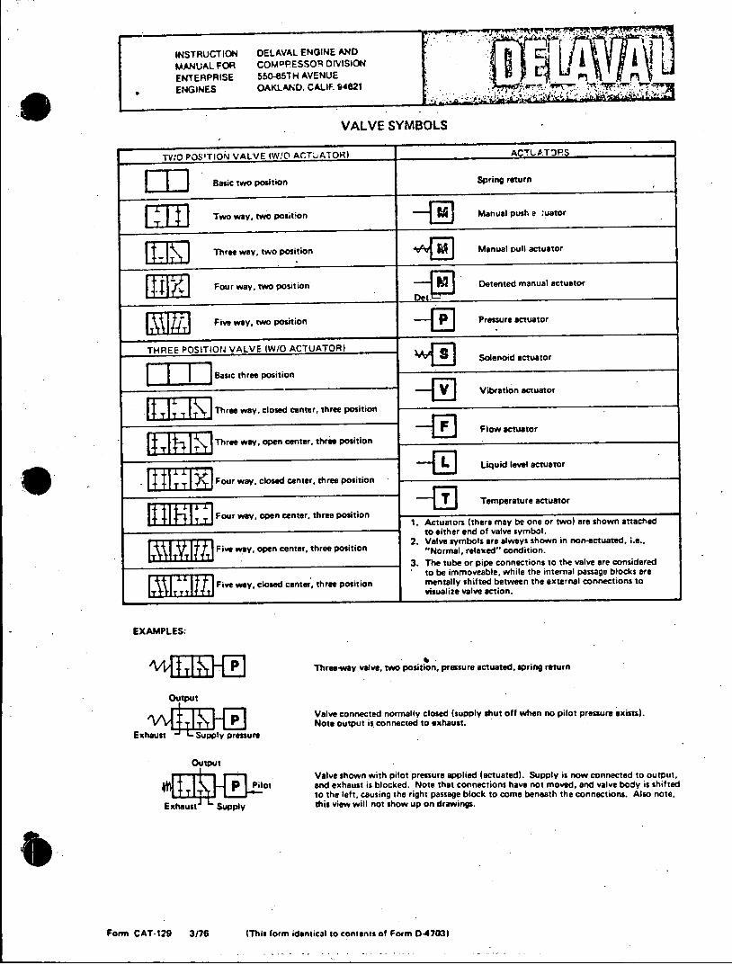
I-v
INSTRUCTION DELAVAL ENGINE AND
MANUAL FOR COMPRESSOR DIVISION
ENTERPRISE 550-85TH AVENUE
ENGINES OAKLAND. CALIF. 94621 Trim
VALVESYMBOLS
TWO POSITION VALVE IW!O ACTUATOR) ACTUATnPS
Basic two positionreturn
Two way, two position Manual push a uator
77IIM Three way, two position Manual pull actuator
Four way, two position Detented manual actuator
Five way, two position Pressure actuator
THREE POSITiON VALVE (W/O ACTUATOR)
Basic three position
Three way, closed center, three position
Three way, open center. three position
ForayLiquid level actuator
Four way, closed center, three position FieTemperature atuator
Five way, coen center, three position
Fourwayopencener, hreeposiion 1. Actuators (there may be one or two) are shown attached to either end of valve symbol.
2. Valve symbols are always shown in non-actuated, .e.. Five way, open center, three position "Normal, relaxed" condition.
3. The tube or pipe connections to the valve are considered to be immoveable, while the internal passage blocks are
Five way, closed canter, three position mentally shifted between the external connections to visualize valve teion.
EXAMPLES:
Three-way valve, two position, pressure actuated, spring return
Otput
Valve connected normally closed (supply shut off when no pilot pressure exists). 3.P Note output is connected to exhaust.
Erust v , tressure
Output
Valve shown with pilot pressure applied (actuated). Supply is now connected to output, Pilot and exhaust is blocked. Note that connections have not moved, and valve body is shifted
to the left, causing the right passage block to come beneath the connections. Also note, Exhaust Supply this view will not show up on drawings.
Form CAT-129 3/76 (This form identical to contents of Form D-4703)

PROCEDURE NOTES FOR MOUNTING ENTERPRISE ENGINES ON CONCRETE FOUNDATIONS
MATERIAL: WOODEN PLANKS SECURELY NAILED TOGETHER
2 a 6's NAILED TOGETHER
1 x 6 CROSS BRACING. NOTCH TOP
OF 2 6 AT CORNERS TO SUIT
2 x6 ON EDGE PIPE SPACER
A ALLOW 1/32" CLEAR. ANCE ON DIAMETER
PLAN VIEW SECTION A-A
SUGGESTED FOUNDATION BOLT TEMPLATE
OBSERVE THE FOLLOWING SEQUENCE OF OPERA- goti ob ple ormv atne i tis t.
TION:antopoiearuhdrsufcfogodbnigf
1. Construct a foundation bolt template, using certified eoygott onain
foundation drawing to determine positioning of founda- 7 eoeegn onainblsfo hed n e
tion bolt holes. See sketch for a suggested template de- asdwhrteyilnobeamg.Pacjckg
sign. Exercise great care in locating bolt centers. srwpae npsto tec akn ce oain
2. Position and support template from foundation forms, coreestrgoudinpa. securely anchoring it to prevent movement.
3. Thread foundation bolt into lower nut in shield assem- rle nopstoed ffudto otsilsms
bly, being careful not to damage cap at bottom of nut. bepoctdoprvndag. Insert foundation bolts and shields in holes provided in
template, then tighten upper nut. Shields must be secure- 9 nettejcsa orcreso nie utibado
ly held in correct position to prevent any movement sipn kd ospotegn hl kd r en
during pouring of concrete. A suggested method is to rmvd ATO:T vi aaet aecsig
use reinforcing rods, welded to each sleeve, or on top of d o oaejcsa etro nie eoesipn
each anchor plate in both rows of bolts running the sis la niemutn al n oe niet
length of the engine, and then adding "X" bracing, be- grd.Bsuefnatoblthesiegneaeae
tween the two rows of bolts. Another method is to tie cortlaigewthfudinbltsevsnfud
the bolt assemblies to other reinforcing rods already in tinfresisaltonffudtonbt.
the foundation.
4. Recheck template positioning, alignment and elevation vn.Atrcenni srcmeddta oepae
before pouring concrete. It is recommended that a bepidwtharmrrco endbygutav
DELAVAL Engine and Compressor Division Service atrrLuicethadofjkngsewwthamx
Representative be present to check bolt layout. ueopwdrdgahtanegielbctngi.
5. Foundation is. to be poured monolithic and must suita- topentpxygutmerafombdigoscw.
bly reinforced with reinforcing steel. Let concrete set for
10 days before installing equipment and 30 days before 1.Paesl ltsadcok npsto ne niea
running equipment. sono onaindaig ntl oe lt eanr
gn rot sd toea pple ptos makitncue ole tais e.
6. Tp srfae o fondaionmus berouhend wereer oand tiprovid agaioughder urfacer go onine
epox grout1 tofudai
7.Rmv+niefudto blsfo hed n e asdhrete il o edaae.Pac akn
OBSERVE THE FOLLOWIN SEQUENCE OF OPEbA-rotect to aprlevento remov age. eolsanst.
TI9N:Inser toeroacks at rouhry uraer or gied jutibord of shi_ poxingroutd to oudatorngiewiesid.ren
V 1.~ Construc. aAfoundationaoltidedamaatetousing certifie founatin drwin todetemin postioingof fundd7 Reove engie jacksatio olter ofrinm seldsven shipin tio bot hles Se sktchfo a uggste teplae d- skidsea egie thywlmotin rael daaged. lae jacingt
signExrcis grat cre n loatig bot cnter. srae plaes inr poundtion at holes acin engine loaseiare Platectlyoulid ithb medi foundation be ee nfonda
2. osiio an sppot empatefrm funatin ormioncfrt esyo ins teion plfoace. ols
secureanlyoanchotsring itcktoithravegneaingvtymesol vn. Bingrenginin poitisn oreoumndedatin Ifolge lts
3. Treadfounatio bol ino loerntinshiedaeem-rolled owoition, endse rof mendio byolted must
Inactuter.undaticnteoltseand sfieldsiin solessprotidedmin temlat, hentigte uper ut Sheld mst e scue- .Iet oeaksa fowdre ornerst and engine, jusrtinor ofl
ly held in correct position to prevent aneoeenphpin kd o suppt engeriale kidsn aorews.in
usereiforingrod, wlde toeac sleve oron op f d1. o Plce lacs ad chocksrinfpositionundereengineias
thenonfunatfounwdgatsaliolonat.etinr 10. frotanra sole platesocswt maingresine tpesoare
6.eTprsenatie be prendto check bol layout.e whree foredo powdered agaitole ainnereedgicofiengine
LomDd& Fowefjcig cessol e otdwt a
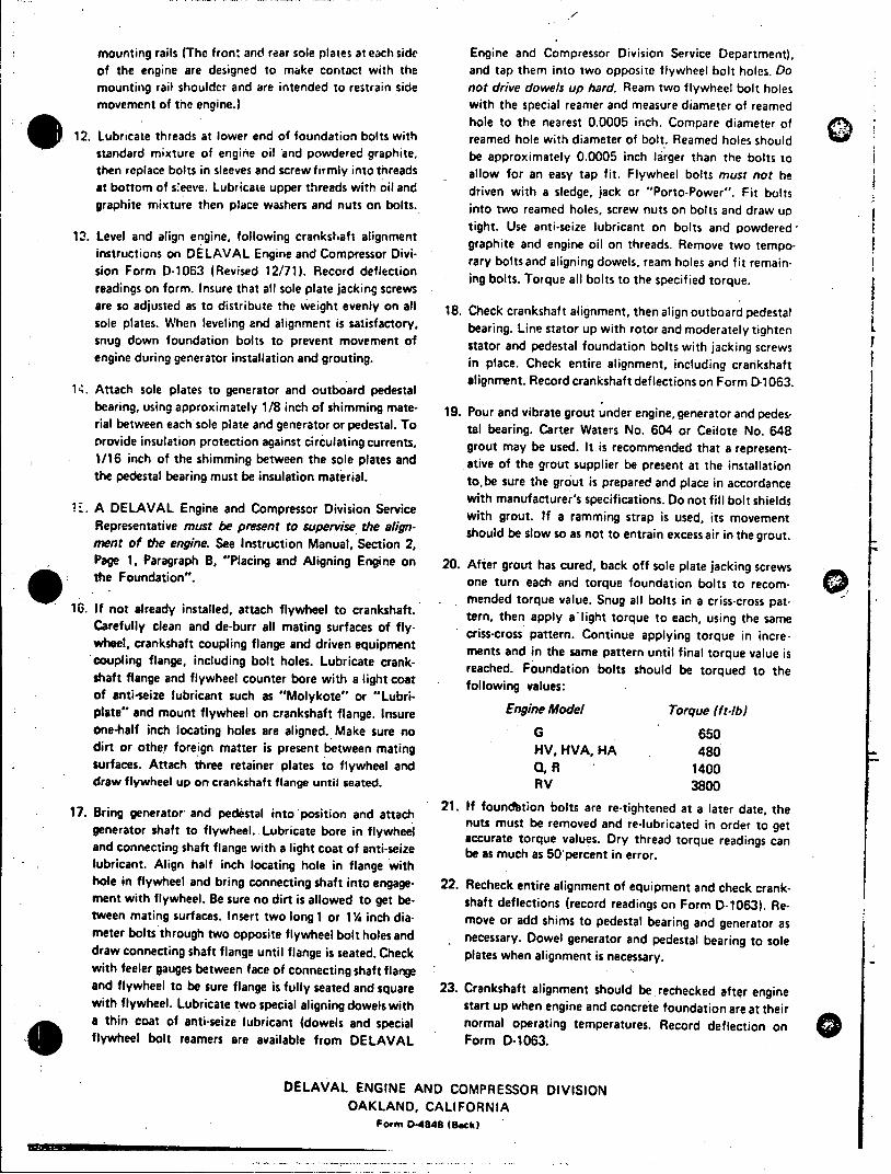
mounting rails (The fron: and rear sole plates at each side Engine and Compressor Division Service Department), of the engine are designed to make contact with the and tap them into two opposite flywheel bolt holes. Do mounting rail shoulder and are intended to restrain side not drive dowels up hard. Ream two flywheel bolt holes movement of the engine.) with the special reamer and measure diameter of reamed
hole to the nearest 0.0005 inch. Compare diameter of 12. Lubricate threads at lower end of foundation bolts with reamed hole with diameter of bolt. Reamed holes should
standard mixture of engine oil and powdered graphite, be approximately 0.0005 inch larger than the bolts to then replace bolts in sleeves and screw firmly into threads allow for an easy tap fit. Flywheel bolts must not be at bottom of seeve. Lubricate upper threads with oil and driven with a sledge, jack or "Porto-Power". Fit bolts graphite mixture then place washers and nuts on bolts. into two reamed holes, screw nuts on bolts and draw up
12. Level and align engine, following crankshaft alignment gaphite aneine oint Reove twempo instructions on DELAVAL Engine and Compressor Divi
sionFor D-063 Revsed12/7). ecod delecionrary bolts and aligning dowels, ream holes and fit remainsion Form D-1063 (Revised 12/71). Record deflection igbls oqealblst h pcfe oqe readings on form. Insure that all sole plate jacking screws are so adjusted as to distribute the weight evenly on all 18. Check crankshaft alignment, then align outboard pedestal sole plates. When leveling and alignment is satisfactory, bearing. Line stator up with rotor and moderately tighten snug down foundation bolts to prevent movement of stator and pedestal foundation bolts with jacking screws engine during generator installation and grouting. in place. Check entire alignment, including crankshaft
alignmnent. Record crankshaft deflections on Form D-1 063. 14. Attach sole plates to generator and outboard pedestal bearing, using approximately 1/8 inch of shimming mate- 19. Pour and vibrate grout under engine, generator and pedesrial between each sole plate and generator or pedestal. To tal bearing. Carter Waters No. 604 or Ceilote No. 648 provide insulation protection against circulating currents, grout may be used. Itis recommended that a represent1/16 inch of the shimming between the sole plates and ative of the grout supplier be present at the installation the pedestal bearing must be insulation material. to.be sure the grout is prepared and place in accordance
E. ADELAAL Egineand omprssorDiviionwith manufacturer's specifications. Do not fill bolt shields A DELAVAL Engine and Compressor Division Service with grout. If a ramming strap is used, its movement Representative must be present to supervise the align- should be slow so as not to entrain excess air in the grout. ment of the engine. See Instruction Manual, Section 2, Page 1, Paragraph B, "Placing and Aligning Engine on 20. After grout has cured, back off sole plate jacking screws the Foundation". one turn each and torque foundation bolts to recoi
mended torque value. Snug all bolts in a criss-cross pat10. If not already installed, attach flywheel to crankshaft. tern, then apply alight torque to each, using the same
Carefully clean and de-burr all mating surfaces of fly- criss-cross pattern. Continue applying torque in increwheel, crankshaft coupling flange and driven equipment ments and in the same pattern until final torque value is coupling flange, including bolt holes. Lubricate crank- reached. Foundation bolts should be torqued to the shaft flange and flywheel counter bore with a light coat following values: of anti-seize lubricant such as "Molykote" or "Lubriplate" and mount flywheel on crankshaft flange. Insure one-half inch locating holes are aligned. Make sure no G 650 dirt or other foreign matter is present between mating HV, HVA. HA 480 surfaces. Attach three retainer plates to flywheel and 0, R 1400 draw flywheel up on crankshaft flange until seated. RV 3800
17. Bring generator and pedestal into position and attach 21. If foundation bolts are re-tightened at a later date, the generator shaft to flywheel. Lubricate bore in flywheel acut e remves d re ad or e aigc and connecting shaft flange with a light coat of anti-seize be as much as 50percent in error. lubricant. Align half inch locating hole in flange with hole in flywheel and bring connecting shaft into engage- 22. Recheck entire alignment of equipment and check crankment with flywheel. Be sure no dirt is allowed to get be- shaft deflections (record readings on Form D-1063). Retween mating surfaces. Insert two long 1 or 1 % inch dia- move or add shims to pedestal bearing and generator as meter bolts through two opposite flywheel bolt holes and necessary. Dowel generator and pedestal bearing to sole draw connecting shaft flange until flange is seated. Check plates when alignment is necessary. with feeler gauges between face of connecting shaft flange and flywheel to be sure flange is fully seated and square 23. Crankshaft alignment should be rechecked after engine with flywheel. Lubricate two special aligning dowels with start up when engine and concrete foundation are at their a thin coat of anti-seize lubricant (dowels and special normal operating temperatures. Record deflection on flywheel bolt reamers are available from DELAVAL Form D-1063.
DELAVAL ENGINE AND COMPRESSOR DIVISION OAKLAND, CALIFORNIA
Form "-848 (Beck)
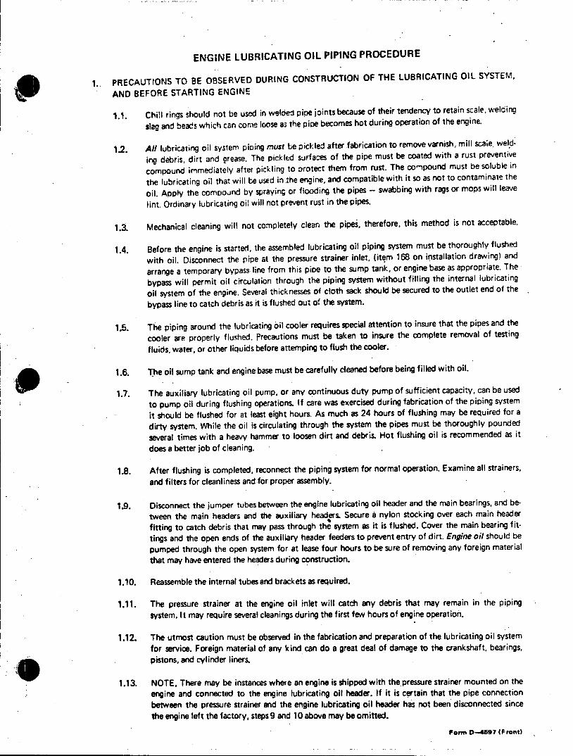
ENGINE LUBRICATING OIL PIPING PROCEDURE
I. PRECAUTIONS TO BE OBSERVED DURING CONSTRUCTION OF THE LUBRICATING OIL SYSTEM,
AND BEFORE STARTING ENGINE
1.1. Chill rings should not be used in weloed pipe joints because of their tendency to retain scale, welding
slag and beads which can come loose as the pice becomes hot during operation of the engine.
1.2. All lubricating oil system piping must be pickled after fabrication to remove varnish, mill scaie. weld
ing debris, dirt and grease. The pickled surfaces of the pipe must be coated with a rust preventive
compound immediately after pickling to orotect them from rust. The cornpound must be soluble in
the lubricating oil that will be used in the engine, and compatible with it so as not to contaminate the
oil. Apply the comooind by spraying or flooding the pipes - swabbing with rags or mops will leave
lint. Ordinary lubricating oi! will not prevent rust in the pipes.
1.3. Mechanical cleaning will not completely clean the pipes, therefore, this method is not acceptable.
1.4. Before the engine is started, the assembled lubricating oil piping system must be thoroughly flushed
with oil. Disconnect the pipe at the pressure strainer inlet, (item 168 on installation drawing) and
arrange a temporary bypass line from this pipe to the sump tank, or engine base as appropriate. The
bypass will permit oil circulation through the piping system without filling the internal lubricating
oil system of the engine. Several thicknesses of cloth sack should be secured to the outlet end of the
bypass line to catch debris as it is flushed out of the system.
1.5. The piping around the lubricating oil cooler requires special attention to insure that the pipes and the
cooler are properly flushed. Precautions must be taken to insure the complete removal of testing
fluids, water, or other liquids before attemping to flush the cooler.
1.6. The oil sump tank and engine base must be carefully cleaned before being filled with oil.
1.7. The auxiliary lubricating oil pump, or any continuous duty pump of sufficient capacity, can be used
to pump oil during flushing operations. If care was exercised during fabrication of the piping system it should be flushed for at least eight hours. As much as 24 hours of flushing may be required for a
dirty system. While the oil is circulating through the system the pipes must be thoroughly pounded
several times with a heavy hammer to loosen dirt and debris. Hot flushing oil is recommended as it
does a better job of cleaning.
1.8. After flushing is completed, reconnect the piping system for normal operation. Examine all strainers, and filters for cleanliness and for proper assembly.
1,9. Disconnect the jumper tubes between the engine lubricating oil header and the main bearings, and be
tween the main headers and the auxiliary headers. Secure 6 nylon stocking over each main header
fitting to catch debris that may pass through the system as it is flushed. Cover the main bearing f it
tings and the open ends of the auxiliary header feeders to prevent entry of dirt. Engine oil should be
pumped through the open system for at lease four hours to be sure of removing any foreign material
that may have entered the headers during construction.
1.10. Reassemble the internal tubes and brackets as required.
1.11. The pressure strainer at the engine oil inlet will catch any debris that may remain in the piping
system. It may require several cleanings during the first few hours of engine operation.
1.12. The utmost caution must be observed in the fabrication and preparation of the lubricating oil system for service. Foreign material of any kind can do a great deal of damage to the crankshaft, bearings, pistons, and cylinder liners.
1.13. NOTE, There may be instances where an engine is shipped with the pressure strainer mounted on the engine and connected to the engine lubricating oil header. If it is certain that the pipe connection between the pressure strainer and the engine lubricating oil header has not been disconnected since the engine left the factory, steps9 and 10 above may be omitted.
Form 0-4697 (Front)
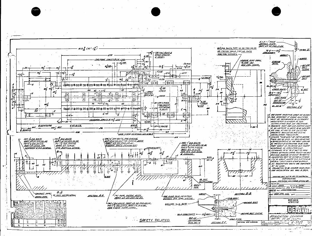
(4) 030 01A. SHIEfLD -FRT NO 7245Z
J7 1 PrP-, FOR PiPE SUPPCtWh
-4 -I £A/. MrIA AIA e
; -l I/ PoCCC/1A. Sl
VF -1 42-3
ir ~'7 5 5 AP 4q t// R/S
14LF 117MA 12 I VI/ /
AA7/Z RIW4,S aOItI/ 3-A
a &I 44 r r Al T W.;O )
rpomtw4), e.'tf~ [0/fOol -erd
ov /.c, ol, /a _______________
-,O -g -0L *~~/ R-fW Al- SUIT //JTAIATOA Is '5 Ili5
7 7"" 21 F/' Z. s'CAAESeP PIA
.411d' AW100k corr~l U^AO

THE~~~ -Y " 't1 0-1. r
!%T~. CL~X ILY 7,1125 IS ! T DY 715::'..J ?:; cQNI:c-nw~ u.:: j -,. A . L- 10
-y -Pr "S:W!.AlTW -i~i ~
14. ~" J.5 ~:i et t-C1C'Id n4* Ilipi i ". .
1r:r~ :1 MDM'. TO FP'WI;'CT AC!A'! EY rtv. -;c-' AS ~~~O TrJRSOC1HARGERS
uP.Tl.*~)
:n 2.
:,':1
- - ~S. r.FvxTHLI. C()IIPI.I l(' ARE HOTp~ I~1rI
IW ;I!I:o PO TENTIAL F IUfIC IIAZLOD D I(II" l
7-In FULL FLOW JFILTER ~ ' A ~ ~ :.!:.
FrL-'.u, (S8., 1......fT.. LATT-I"Ii. S CA'Tr'AcronflS) To SUPPLY ?.'L
0rrri IVEI(?A JI 1t 'i rtfl:r ITYCS, *II P
IARA -2 187) r-WT 13G1c
AUXII.IApy FSKIO PIPIIIG, SY!,T.?.
4- ____ 0 I . :Y X'V rot !.U!;! OIL :' .D:A 'I
C~ ...0 II!
~ RLUE VE1, ~I *v.1 T ~v')TS1r'' VlL1E ~ ~ :, t~I ~ 7~'I3.W j.~ Ii~.~,Lty!.i. IAN Di
-I fg B -4~ cr''~ . -r--
P II IC I v ~J1P~' LV~~ '.~ A\
.~~I..-P £.O BtE ,1BRM *!:..
_ _ _n r__ _ N p _ _
_______PIP F...C. PIPNG ,CIDI1\TI
1 1 5~
-----.----- ,,
PiIN SCHEMATIC(t~M~i
L.. I _.g",RL
Al . ,.- .~ *. ~ -- .L.O.uM 1ANK Wv ivioI .,' : Si AIN'L 9 AND PIPING6 7.. .O . - ... ~ ....
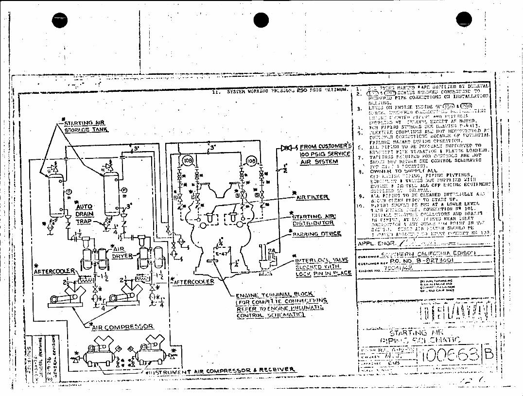
UA~ w r;DEiD'',''
........... .. SSZ1 O~lo sUz "0Pi txmm
3.O Y.N-,T::r 1VZ11j) os CT' 7, -'
c~ PrT'I.o s7"!Ui.s ; 'j .,A1;;rf i
c v " ' l .:"L :TC1J ujCAti- ' I ('I1I
- ~ ~ - . . 5 FROM CU5'rOMER). F AMM L A. 'L" Ah10 iii; 'r(.tINGrII.'~'
I ~100 PSIG SERV4ICE' l. ''/ I E v1.'riATIOl & FL'l!, LOADU1
5' T. 7. TAN .. 11 3s r-:'ii3PLI r'()( AR JniOTr
to . PR____________ Sti'.... bk'' 11P.ii!R SEE CONCR1OL SCl&E.fATIC j I
It I ~riTE g* ' p 1; 'T 10 CLATE I:r1r.:'LE L In :. I
:1DAINO 1'.FF1 ''ZE FU' AT A LOWER LEVIr.
~...). ___________ T I"" ' 1.' r 1!.. .3 NEAR! IIET
AI g-APPLE., i' '.~' ___
* CUE1..3M(NE , 2-j Ze .- PNI 'A.Cle
*E 14 li . T04VINP. eLOrI'. Q* Q.0 CAIV 0 O-Q
4 (FQR ~~COMPI IlE CMtINP( l"r% '**)N 3*A*
V~ ~ 4 --.--.-
3
ff-4-.. FoCrIC-Trlj V/.W
II R O N P .--
b)P 4.-..
Di,
,.1 \--1q 'TEr1 rTARCM 0R - '(
T T
>,c .. .4
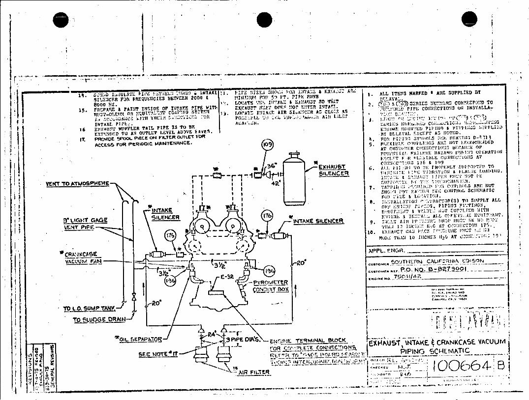
38000 HtZ. ''.L0(ATS '.W'. 111*7A.Z' & E)i!A'J3T 50 TIT T'A:
15 EAU a PAINT ISIDE OP INTAYE PIPE WITI-. ~~5 ' DOES NOT~ E!!TET VITAr.. . c~ih& 3)~ 3::nlhl RS2~! COYMSMID T
nR C I''.: r,:AT- !'.T::AR A 'Q.A I ~ ~~~~~~INTAKE PJ.L.AA8.P1 lTl:3~It.kzA G,~.C~;.
16 BYlI'USTi W4IPFLER TAIL PIPE 13 TO B9 EXThIl-D 'TO A14 OUTLET LFVEL ADIVYE EAVES.
:(NE10IDI
IT, PRO'MDE 5IFCOL PIECE 0N FITR ULE'VO B DELAVA. "rXCEPT AS VIOTED.
ArcCE FOR PERIODIC MAItMTEN'AMCS.. FoTj pil11 Sy',iitOl.S :,!->- MlA"1i13 D-11,1113
AT CIl5'.'I!l-: C IliErTIONIS bE~CAU:tE OF
POl'i!J'II ATII. iII AZAHt!) r'j!1011 UJI'LIATJItl MrL!;T F~ Ht~i. IDLIE (:u:JIIEC. 1:15; AT
C0:1:IWC--,I3 16 & 1019 EX Au ST fi AIJ, F Ii II. TiO 21;RiPE'H;LY ZEWTOPTIFl) To
rt'c~~r'1 SI5LENCER I I ! %21 "\'[MA'iOll 9 HX. i.A.. IOADIU.
V"t4T TO A1VO5!pHE1HE-~.*~~CU.!i'u'S~0~A
" II S10'J IO A-I1I -i C011THOL sc!iEM-ArIC
I I FONl -I:E & lX*,' '':1.
A . ::-TiAIi1A'T'10:1 '.'-A(c'r-,(S) TO) SIIPPLY AM,
INTAKE Pl~~:iIk.g::0*PI113 FI'."rI:JOS
IIIG- -IEWE 17 F'V;IF.& I''! AL L 0!-F E'C4i i. EL i!l.
9t 14TGG 5~CRITAKE SILENCERt 9;:as 1,1 pr:-/1.-. aJtt Yu'l E fir.T
____________ 9 ''I.1 11 INC.j: fi..i AT CO,!2:i.,CSIOtI 17S1 .
-10 . E ).A I T A' WP' Vr";1 *" n;u E :'z *
T'\ / ~ /. MuhIC ThiA: 10 IiICHES 112(J AT C::.'N:.c.lc.. if)
VACUUm' FAN -CSTME -- OuTII 'RW CALIrR~A JN
I E-3 -7 C e..L 11. 41R
..- s~... *r'. --..
TO sLUDGE DRAIN-)~
W E 9~MINAL OLOCK L~N1A~ AUW
-1 11 __R _____7O
SEC WOTE'rr - " ''.~ .~"~'. IPING 15CILM/NTIC
:.I 00(. 64
(-a1 0 W--
I (' )'.b" *A' B
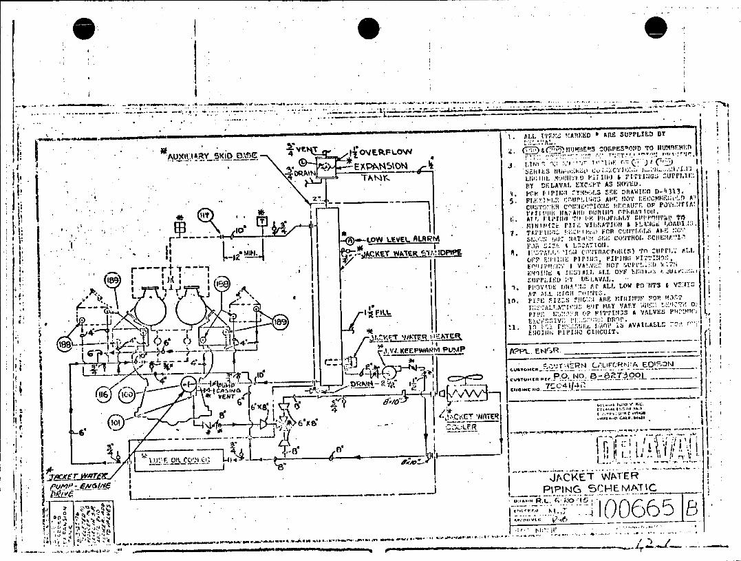
U ' ~ LL 117' .X 1 A RU E D 8 A R CS SUPPLIED B
~I' J . ALJ~ RY SKIO 0.1. 4 II'EkF-l c. T'ncflII4E0 01S?1D TO
BY DEI LAVA L EXC-i' TA3 !lRYMD.
- - ~ ~ ~ ~ **1. VP ' r'i iX4;: AVE!.'M I:O'lEcCMMF;;tL) A" ctis~M c~u~a'~PtoI~ Iir~t . or' PO'i'.:r A
plm. I I _ __ _
~~ lINI?~'lZi ltz VII,!ATIOI'N & tIIit I.OAVAljlJ
p~ -i --O -EE -L~ -7. !:i .' k FCIR C~LIfTr(j,.SA :.
1.POVF E!lUE bIIAL Al L. LOWl
).c spUvi : w 'Zw~i rAI OW P. )?TS V
18 PTP RII fT!J VLE l'"
I/ I s'-,ALAL
It=o P.O 0. B3- ___!
1c, - . . . . . . ..
p~P-~~/N~; I JACET ATER r ~ L~~ZJJZZ~J .PIPING SCHEMATIC
-~~~~~~~~~~~~ -0.----- .--
UI, I.4iOI 066 5 8 .
v 1 S.
.h .4 t
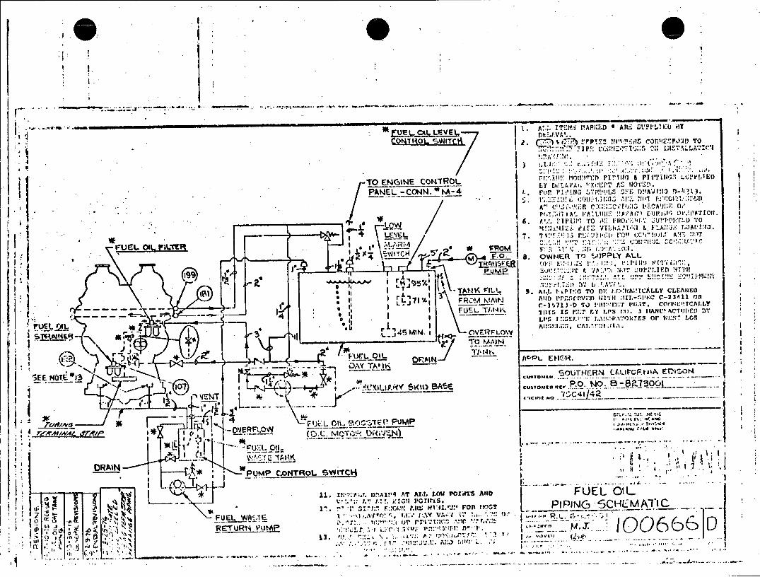
QM -O %Ir- -4 p v I.v :i co tv10 1T
LY ' I I1 EP , A 11Z
PA E -CNN - -U.P.!I 7'tL F )AI1
~~~.) IT'. r'AiL V N07~~u$ A" r~ P ' CAr~IJF T,1
TO~~~ !NNC NTO i~l'"' I L.I i I'J A'I!!,E
VUJEL OIL IrILTF .,j.Tl: .c!A .17 I__ 6. t'!I W T
I~~ I -TANK( FILl-~ AIL TiP!:G TO ftt .IICAL CLEANED
rlF ROMK.I' lOI~I I, L I ll. ItS'C C- 23411 011
, .. - _ I 3 ti I _
,EE~_,5MN I OVERR Arc.' E~O
t AIOL3 DAY' ? (DA~. I K
100 lUXIpC~iARY SWI1C . A ,5
ORA1IN [1.0 N
N.
A i.
11.x.. I)n.Aliq AT ALL LMPOXS4TS AND FE
r.4AE±~ V . Tr .:.c AI; p V.vrr FO7" PIPING .,':r1 _E4 - j ( T~I (t 77

-. 1 T 77150 -yP W
2Snr wR S.ommIVR.VE 4 P1011 VIASATION y E 3S ~~CRnNR1.RSE PAESS ISR1RP'II ~..
'/C 18 1 8£59 INTAKE 1,AIF. Pe PRESS R.8 4 Hr ww C11/WI 2 4L
(Z)~~ Z4 V P VCC LoK771'7 CYL. '2 E- 3G lAD RE? WAFTER PRESS 10 _Jc~~ 7~I v~;.~ E.GF/E I ".-I E'RSPEED 7RIP71M.SE P-153o,0 S 0:1 jE4 P1/EL OIL PRESS FILTER OLff Ia CRIIICE 9,4 . P7,,13 aS'. v
0"f -4 FIE OLPRESS-PILTER IN 14T 'H./LEj %WL. VE ELR FP73Z,5f5 .
-. ~ ~ ~ ~ ~ ~ C -S FU___________ 5 1EL PISIIOVERSPED F, 1. I2
AiE 35 LUAP OIL PRESS to RESi*&P-GJRTT ?o£*C I9S TIMER/Par ELEENT 1.573-307* 1 k
731Ev p (a.. I .C LOW PRE39 LLIAE OIL 20 -~p TRI HIGH 727i ,. GO T #338 -3 a1RGOLPRS.R
-J" r ... ... J1
+ W,. 2 .,
22~~ 348!Isi~m 71JP3 CI.; 7 12ES r OIL18801 PRESS
-CAL
R .. I . . I y 6 921 LOW PARSTU RBO LOILq1 M91A
E~~~ ~S /7/P. TUB ClLSES R
Z48 IG TU E MP O ILESSR . IF. .
Cp--S 7/P;: ES ER.F.
16£53 H, IH~ TE1. BERIG K m- ---- .- .. F L, .. /3 ,TP T'L ..
rr
P 0 /1 1 8 ( 1; : IsD R : A 3
A~~E 2 OV R P E PEP T88 AIM 0 -- oR p p J pl-
V1 I . E mS PP i S AT ,RI E ARES 4 AC M INC~ ' m vl'JR WIIPC,
E. 31 .R :K I TRATINS:;:I RSS LpPFRME ~ur

EPL~~~ 20CF3.R hL A SEt4509 !'W PRISSIlTING PHmLF ',ESFU.A RFE1UG
4 SI1OPSIR I R4 P~S i"~ .5703~
IN 7 K GlF l -- l PI0'PS IR £R 3. 77 4 S'JM J N L ) c 8 0A
7 P I R P E S L - 1 1 5 C S , R 4EI G FR5 S VFTP .RV ! 'A4 F W E SI ' s u o P - 7 7 0 4 .1 : k
i.PK 7\ 1 9 r IAP I OSIG A I EVENT STFRT .'.',V7EL ,-~s.p. 030C.P F,.577 04, Z7
sosFDSN nIS EVEF ~ ~ LI;±
I__ -. CSEP PEY -m 12
FUE OI PRES FILTER OUN E-4 511-0/ 0 ~ PLO-1 I v IF/,v Afllv & C- L MS F-3 U.Y-MIV
.. R LOLP E SFLE N E 5Arz s- p TLE I V.LVE te F J*' 1 ." C
4575IF 4!PSIF I 7' i t
UBO LVSF OIL PRESSI fjEOI HTOLNVP~ 7 1
6~~~~3 2,34 Irsi 19 IF-.
7U I R S FIL TE IN -2 (Ji' G, ;N3~~xiIE AP ON N'OUH~i
9 IPI AR7U F5LP -S .7I'.E
lIIIE23 20PL FT L. E, ,T~ILE
451-5 FLIN OIL0Z~, P S HUDONVEI
3?Q
455P3 F PNl7 EOTQLO UE PI
IpLWLO PPSST'OIL ESS T L 23 .. 3 PS . .
. ~ ~ ~ ~ 2 31 PA' 40HC SL 1N'I E S.2 LCONTRVL iN-E L7P £,,
C 36 9 45P0311 PLPRJI EAO FE E H,PF:,s CEV IC P3 ESWIDW 1z-Z
I.... . . . . . .
P-P
05 rs 29 4J.3-9 57R'S SihD r~E LEVELNC01
51 o*3*\ FUE PL~.'ES E 'E'LE ML1,. JO fsaerooM9 Mor NC F A I- 7 U13UN. OI31I7EtAPL 4jB EOIL '318 -20 45P~il
anan eo L PRESS1 l.:.Lr P.3 32 INEAOC ErMC C
'I~S tCI7 0 Jr. 8 r-3 33.3 P538Y PSIS~
0S11'e &V/ MIRE~3'.Al ~~PS- 19
7RP-D!-SY PP5/f /.VSOAYT
r*3.F5A ATSF'/EA9
-s toUL' 3N 4V O AlASS SESO .PSE'/ LFVE_:rIAE
0 : L A_ _ _
P . P. _ _ _ _ _ _ _ 4 5 P_ _IF P LI_ _ _ _ __M O_ _ A / A V:PJS J
V IC0 JE
W3 77'0
VISUfl'75 'ISou £ c 24-~~I ~e/6~f
-R -I ; 7 K /3
1 9 4
~ S TR IM E.31F 1- -,C _ _ 0 , ®mj 0 - -4 CA)
1 0 ' Q: _ _ _J ,
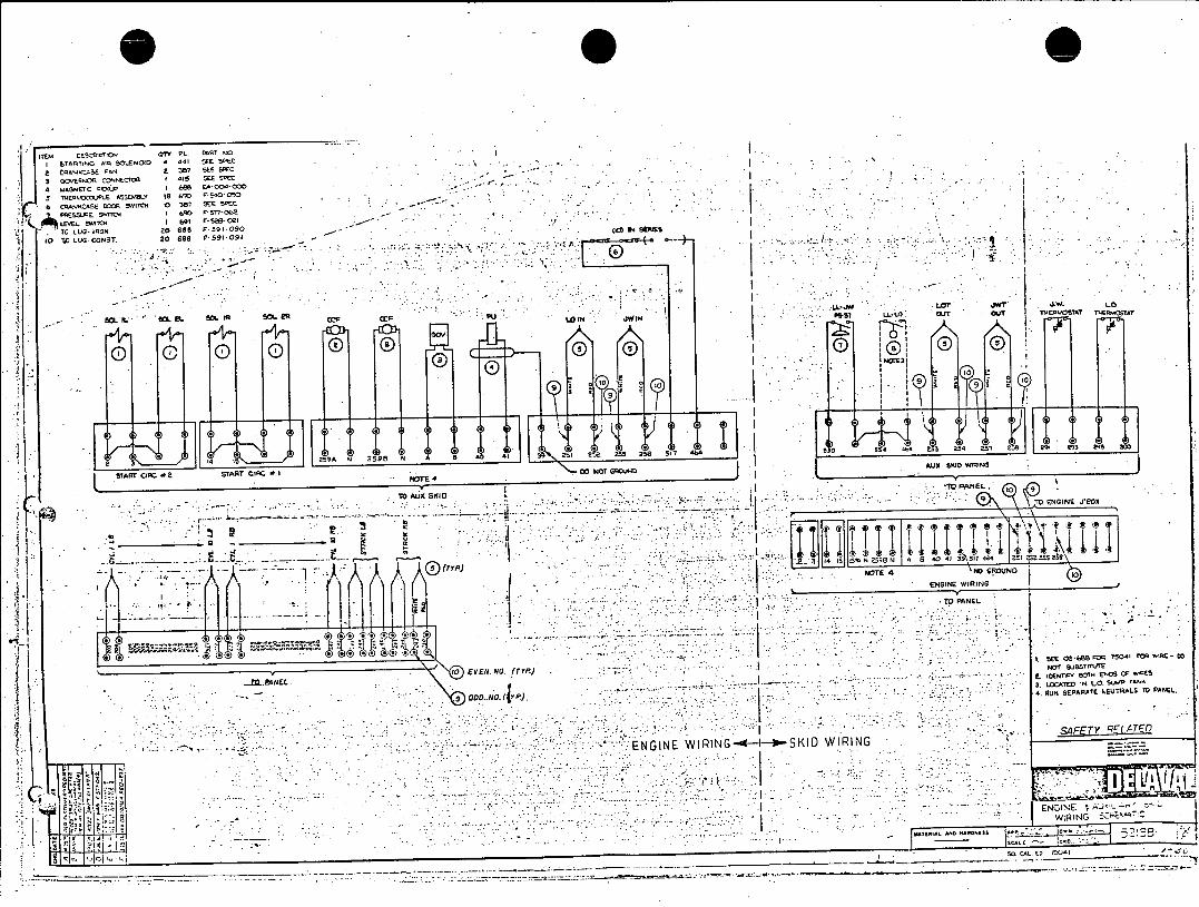
iTEM TS-as -r. GITY PL. MR? At SOL.ENOID A do SEE 5 EC
a to 9 CAN 23D7 SEE SEC SGqEQNOC COiNE.COQ 1 15 SEE Sr E
4 MAGNETC "Lp keS EA-OO<.000
5 TVEsakOCJ.E ASSEMBLY to 690 r- 5000 6 CRANKCASE DOOR 'witL O 361 SEE SPEC
PRESSU .1 77 062 I
LEi VEL ELVI2 lic5 TCLUG-IRON to 6 68 F .591 090
10 TC LUG CONST 20 608 PF591 09 0 o--.-.
ot a SIL ISM eiL SO_ A sLe C Pu INo1I03
0 0 0 0 cO0 ~I 0 oo n 0
2 4 9259A N 292 N B 4 Al 3 351 2 25 256 517 1.4 0 554 414 5 254 257 5 &9 3 299 O
st r Tw sr4ra c00 NOT G20touND
oP
.. .. .. ... .. .. .o...ius~i .... ~.. . K I ~0\ CNGIN6 J 805
' *4 *N5 287 46 404 25 5
IN4TE4 N1(GROUND START -a START i GNOTGR DA wKIWRING
NGO NEI W G KD IRN ENGINE
.O N
I 7
-- 7
- WENGINE RING
.ir ne no Sss ow I
TO PANEL C)I OI
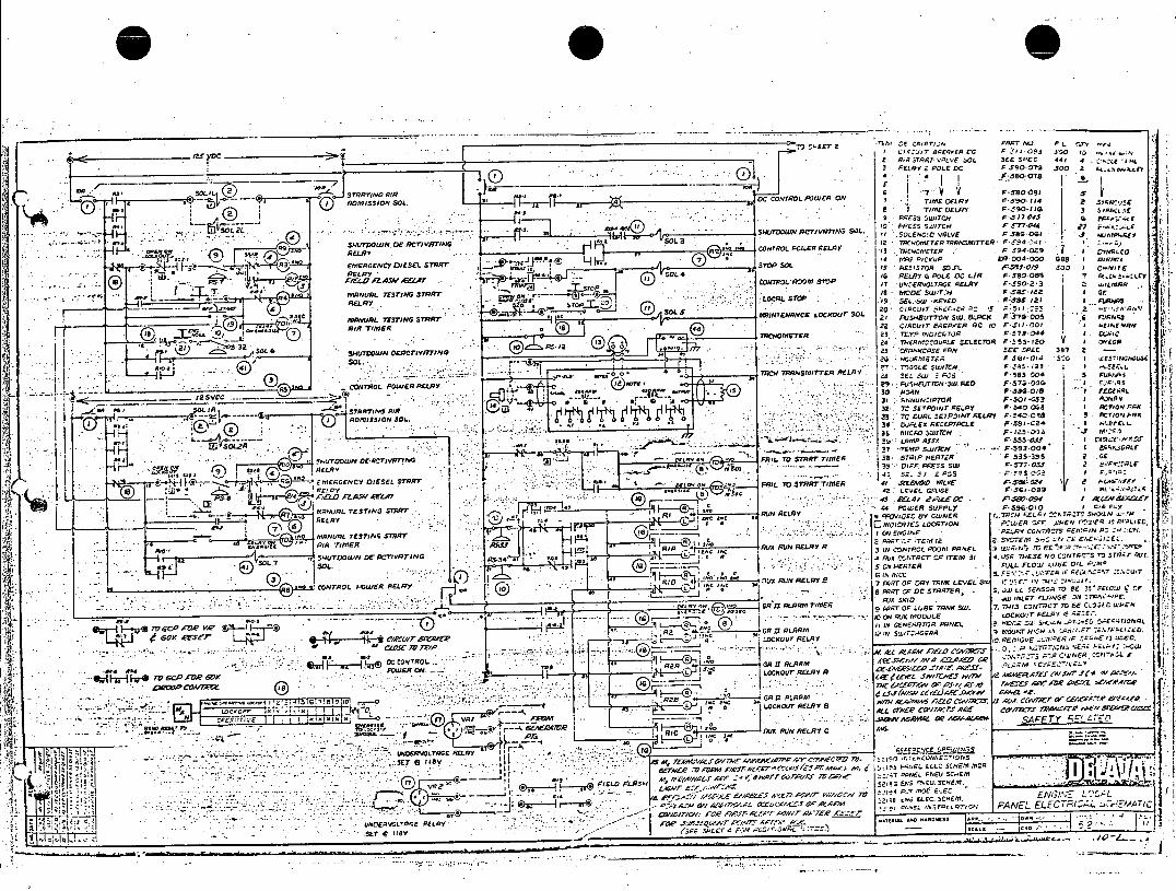
~ I2T2 ',khI -- s cx'pr,.I FART INI P L STY .rv 73C ZjIT 8gEAPER cc 9 .1'I OF'S JO ~o
_____________ A TRTVLV SEE SPEC 443 1
3FLRY 2POLE CC J,90-072 500 2 *A.f
2 '4 FEIqI
AMSNSOL. D -rl C CONTROL POWER ON; TIME DELP FS w 130 34 5 j
- I TIME 0E/F F*50*3 j JS77 -~~~ ESS SWITCh P.77L ' *
SW2u CIR"GS). i PREs sx, rcH FF74 :cc-~
3, ' T~- I spvvouu~'mIP GOL I OLENC!O V9LVE F .58-Ort gE E
AS' CONTROL PCIER RELA3Y I2 SNLI,,, ETEp'ASYTE F IF54.I Oa RELR4 J I2R PICEIIP -7 RMO4.000 R36
z Is 33 ISNTA 5.11. F 3945W0159 .V
RELRY SOL 4ISSO J. /5!0930IC9T CONTROL a~2 163 RELPY G POLE DC L/R P.580108" Y N .t.
COTOL-O SD I UN.ERVOLTPAE RELAY F-.550' . OLA
_wmNA TESTING STqrT Is M ncoE SWUITN -Sg IS 3E OALSO 9! SEL~s SW EYE IEA F23ARsA.I
~ SOS 2IN7ENCc LOCKour SOL 21 PUSHBUTTON SW. BLOCK F 570-O 00POR
19 MA -L TESIN STOA -- 22 LIACUIT AEAPEA PC #al P. '10. co
TAC"OMvTER 2 t IOITLR P704 D" 1 2 TERMSS(NOCr'TE ELECTOR ORS S 4 3 .,2
A CEESPEO 301 SOCL W.AP.SMITTE RELAY~625 CPNSE FJORFNS35
SOL 21 .33C 17T1 34 F355C04 S 5311.
bL 29. PulIUT TGN SulL RED . P37200AG
_______- 30VC OA0N . I.52I3
a~I..J SL L.. --- aN7N3IP710A "P.S 32 T SCURLI SpofRELA Y r-!4c.055 1 AT3O RA
I Q) ~~~~~AMISSION Sol..~OJLO7SNR~r 505 CI'R.
~i-4H 0 134'.JE REEPTACLE P.58i-C2R I ofr4 ~ .
v OZ 7-TMA AlSOM Pr593O 00 1 U~S~RO
___ O~~~~.YO RIL TO S-MRT TIMER 8 SAPNAE 553
FAIL V ... 35' 3FF PESS SUJ P.577-053 2 -P~L
9)oA2EICY OEE TR ~.f 3l ~ FI 0SATT;AOL':
~~~~~~~; 44IA ETN TAT IIGiM PUER SUPPLY Y-53G-0I0 I
SIUR L TE TN STAT -F 'V-,;;oTo 5-I.1, 'A'E
RlRUN AELAV -FOV3,ED BY CWNER .Tl"gl4Y
- RELAY , 4~ ~ INN- ENGINEE LOCATION PZWE N --F E X'. EI C 'LE
QA O O W TI M E R R T N 12 1 0 U X R U N R E LA Y A 3 'CN R L 2 5 3 P N E L TO IT E'S :z 7EA -' .. " '~ Ti 3
503.. ~ tIN It- 4 A1J2 C3.TACT !SF ITEM 3I 4. USE THESE NO0 CONTAC-S -M STP~r ALE '.
soL. ~j 65C ETR-. SL FLOW LUdE OIL 1
M
RI II POWER I , AZO ~iRI0I ~ U33312 ADAL, I 7 FQRT OF OAY 7PNK LEVE LOU ITS2 '. ''Cp3
CONTROL. POE RERI MO .0P 3134C 8 Pl 5 T r 4TOE,~T -. -. RLAY: 8 ARS OFDC STORMEN, . .. LL 5E150 AV BE 55oSlO' ~~'0 R I AAR TIER - Rix SKID .. WINLET FLAIGE O TO.IF
MIST 0" 5 PA~~~~~RT OF .. DAE TONIC Sw. 7 HSCTTLTTN OL 3
TO~~~~~~1 RAD MI- - .OON A'.A MODUJLE WOCRIIDU FLzI A ETE-.
40GAa Vs r*t T 4eL-,,q1E~ CAAR ISLTIOA 9 MOUNT HIGHN 3.",I2.LLI
;Rz)- 2- SwlNC,'7
3 .T C Er 3T
A.At A&I'S7W0-4/ 64 ASFACO S.S E/EA
N CS .5 ' 30 ~,O' -LOCpKOUT REALAY At
17.7SI-a- 1
0 I -LA 117 AL4.-,AViI Aa RUEMX RI.IN RELA CC IPR
C KI~ RELR Y 8- w - a c r a , C I l Ile" _vWSA+ Ol %AfAV-e S4 FE T- rEO.VLIG RELAf 934_____________________0_ ~ fRlC R
RUNI RER
- 555 ViN . E "'P('A4l.~,~!.I I-EL ELEZ SCREM A CA At,-
-7?.ef1N.... 4c75 .7SV 8vr C1/'A§A 7v~1e .- jil OP1 LO PIE Ck
vqz FELD L~jS 41&r 4* ax- AC V FANEL ELCRI
SLNOEAVO6LrANE RELA (EEL OWNT p .,.TLP 1
7 SET . Ife 3C/L
_ _ _ _ _ _ _~ _ _ _ _ _ _ _ _ _ _ _ _ _ _ _ _ _ _ __--
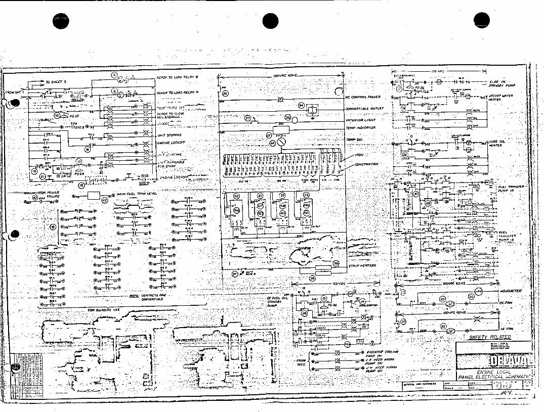
tA~
FPhl S97' I
5 A6 &
(D, RERDY 70LORD RELAY n 22A 1.- 7.C COV1W6L POWER 'g inor -- .LDTU~rfi8
!17 rCOVETIBLE OU I
-. '~~ 528 ~ INTERIOR LIGHT r--TMP ,NOtC5R I .U . t
n~~e at S I~U~ T STOPPED S. * 05 I
C;;' .',tTG.'P/GBLE -I * r~., . - ,O .r- 1 IRL
e ~ -~ Tom- IRO, 4 .80.0.'.~ 'sto. !..I. S*,*.E.* * i. 5 tF
.7 Fc -r .----
[I ENtE-OCC#
fl8 OR *
-7V r's P 1 M~" 2J~D DODNIRO POWERt aD t
-puff.Iin
~~Ad -4.-11* -EL
M4t *---- " L' HAES 1.
*815 ***33
814 081 3 0W. + A
/770 r7-7A_ _ _ _ _ _ _
C. ... 5 .. 3
81.CDIVERT8LE 0C FU ~ EL OIL
FOR OwJNEisSE P1/M P A3
-5 cc - IA
77- -L-4-*
, D iOD
t$C . a -.
PEALTV-z Lq ..
- - '~~PANEL ELECTPC,L :Z.M. 4,M 1
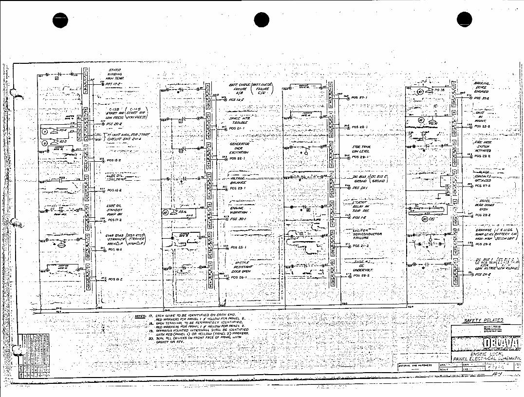
AI~rq 72?IAV
Aw -2- -.. W -- A/ C/L '
I I ~I .AecJ'
j - - ~ A/II~t R/L) ~ " I
,>7. A/S (14 C ''BmI4 s'I ."
.fl2PT~~~~Aer AI Vn~ r/ C, e)----- 4W1'~1
ftf~ )- -"F SI l~ A177.7 .A,
SS at- OSZ
I 7, e.vl A w -A RM/~rV
1=1 smat
co7w4P 2748 571 78- ~' ' .S MIXDCO . -e -\JU71A
F o -,- .OI 2 2 It
FOSOSis 2
JOIL. .1 S .j -- *. , I I .a
IFO 23 .-0w. 14- AUF4I CCO/Th'
e~v ~ .. IF- *~R WW.~T87'.L(~t4
51~ P03732 L7S6
-*P532. V
t u ll OIL _ _ _t rC V U 7 . :,I. -- "d' g&
LwrwMA l.CD R6o
oe3
MJTES 17S 25MWRElB IETPkOO RCIL PRED.
AoRsR Az P, P1ELWLO B/L2
IS ERNTENINL 0 EP~rRTEY CY/PE. .. .. AFTY P-4
M, -O W8T2 RED FFoA/s: OR- fi o wpN F) /.8- 2 E7
Dlcie -. Vr - -r e-q~~
pcas. ps.a
4~
F.,. 7.E41IR T EIE& FE N RYEO

*XO 0 ... C
'VIE CwM ORU7 'Wa
F31 -P3- 'I-.L .' P0?:! .a .,-...^ .. PO- m ; 1- l- rri p-- 4 s so .0 J2P0 1
~~~~~ ',EC# .AtV W 5... - I- * ~ ~ - ~ - , /?Z5&'- ~-ERA mr~~'71~ 4/5575* .,.A I FL,* £c0:-Vl8
_______ t,-.1I ~-- I Mj' .
pI . .,- v 'e R'~
Pa 2. 1. - - If dO~e7Vq "OS OF
'o PS1 oppIIICIA elm o -zf ;w
PS27OBnr -. ('..
- ~ . :. I I.. ". -- ' 11 z.
'al 700 - FI ovAFET CCAV/4~r
-4 ~ ~ ~ ~ ~ ~ ~ ~ ~ ~ ~ ~ ~ ~ ~ O AWM E zeQ' _______________________7197 7,VRNH1 ALc.
PC Fq57 zn/ 5,1
PS G1 o J ~ 'I -' -- -. -- P NEL LJ-.C57'
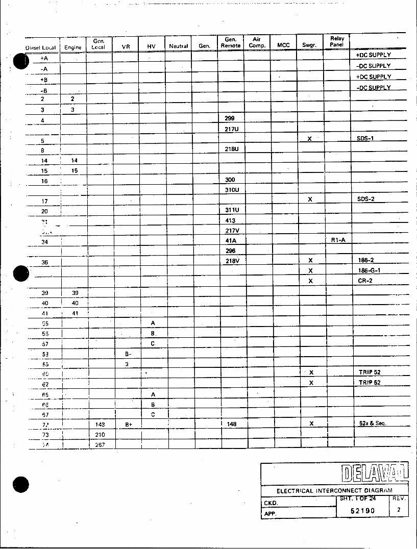
Gen. Gen. Air Relay
Diesel Local Engine Local VR HV Neutral Gen. Remote Comp. MCC Swgr. Panel
+A +DC SUPPLY
-A -DC SUPPLY
+B +DC SUPPLY
-B __-DC SUPPLY
2 2
3 1 3
4 299
217U
5 X SDS-1
8 218U
14 14
15 15
16 300
31 OU
17 X SDS-2
20 311U
? _413
217V
34 _ 41A Ri-A
296
36 218V X 186-2
X 186-G-1
X CR-2
39 39
40 40 _.
41 41
55 A
57 C
53 B
5 3
X TRIP 52
62 X TRIP 52
F 5 A
72 148 B+ 148 X 52a & Seq.
73 .1210
)^ 267
ELECT RICAL INTERCONNECT DIAGRAM
I~~5] I UP Z __ TI
CKD.
APP. 52190 2
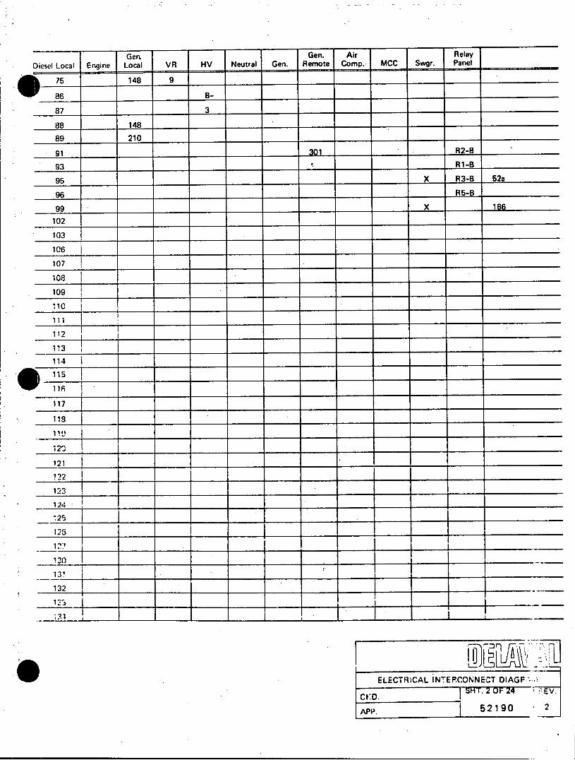
Gen. Gen. Air Relay Diesel Local Engine Local VR HV Neutral Gen. Remote Comp. MCC Swgr. Panel
* 75 148 9
86 B
87 3 1
88 148
89 210
91 301 R2-B
93 _ R1-B
95 X R3-8 52a
96 R5-B
99 X 186
102
103
106
107
108
109
'10
112
1V3
114
117
118
12k
121
122
123
124
125 25
131
132
ELECTRiCAL INTERCONNECT DIAGP'-1
CKD. SHT.20OF 24 *- PEV.
APP. 52190 -2
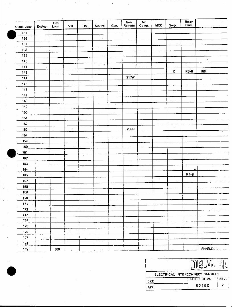
Genm Gen. Air Relay Diesel Local Engine Local VR HV Neutral Gen. Remote Comp. MCC Swgr. Panel
135
136
137
138
139
140
141
142 X R6-B 186
144 217W9
145
146
147
148
149
150
151
152
153 280D
154
159
160
161
162
183
164
165 R4-B
169
170
171
1-72
173
174
176 177
179 360 , ,SHFT
ELECTRICAL iNTERCONNECT DIAGR 1. SHT. 3 OF 24 tEV.
CKD. h
APP. 52 190 2
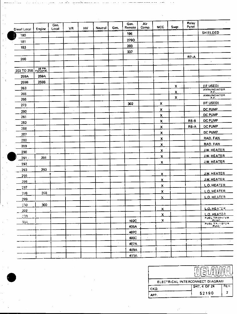
Gen. Gen. Air Relay
Diesel Local Engine Local VR HV Neutral Gen. Remote Camp MCC Swgr. Panel
10196 _ __ _ SHIELDED
181 _279D
183 203
337
200 R7-A
28 PR. 203 TO 258 Fe/const.
259A 259A
259B 259B
263 _X (IF USED) ANNUNCIATOR
265 _X P_.F.
ANNUNCIATOR
266 L X P.F.
273 302 X (IF USED)
280 _X DC PUMP
281 X DC PUMP
282 X R8-B DC PUMP
286 X R8-A DC PUMP
287 X DC PUMP
288 X RAD. FAN
289 X RAD. FAN
290 X J.W. HEATER
291 - 291 X J.W. HEATER
292 X91 _ J.W. HEATER
293 293
295 X J.W. HEATER
296 X J.W, HEATER
297 X L.O. HEATER
298 2 8 X L.O. HEATER
299 X L.O. HEATER
30300
202 __ ___ x ______I L.O. HE.E
x L-O0 HFATER FUEL TRANSFER
304192C X P___
FUEL Tq,..SFER 405A PUw'
407C
409C
407A
409A
411A
ELECTRiCAL INTERCONNECT DIAGRAM
CKD. SHT. 4 OF 24 REV.
APP. 1 52190 2
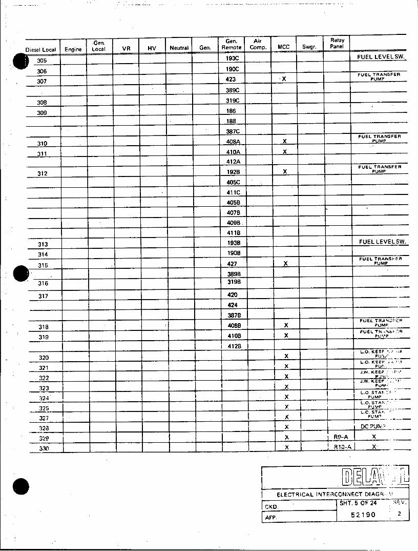
Gen. Gen. Air Relay
Diesel Local Engine Local VR HV Neutral Gen. Remote Comp. MCC Swgr. Panel
... .93C FU EL LEV EL SW .
FUEL TRANSFER
307 423 -X PUMP
389C
308 . 319C
309 186
188
______ ___ __ ______ 387C_ _ __________
FUEL TRANSFER
310 408A X PUMP
311 410A X
412A
FUEL TRANSFER
312 192B X PUMP
405C .
411C
405B
407B
409B.
411B
313 193B FUEL LEVEL SW.
314 1908
FUEL TRANSFER
315 427 X PUMP
3898
316 3198
317 420
424
3878 FUEL TRA -C EP
318 408B X PUMr
FUEL TR(-S --;IA
319 410B X puvp
41283 - L.O. KEEF "
320 X Pu__r
321 X P: J.W. KEEP '.
32J.W. KEEP . -_i 7
324 X ____323 L.0 STA.
324 X PUMP L.O. STAN.
325 ____ 1V .-- _ L.C. STA4P
3 T - PUM _
328 XDC PUI'
329 x R
3.30 X R0
ELECTRICAL INTERCO-NNE-CT DIAGR.
FC K D. SHT. 5 OF 24 'iE V. CKD. 52190 2
z~I_______1____

Gen Gen. Air Relay Diesel Local Engine Local VR HV Neutral Gen. Remote Comp. MCC Swgr. Panel
W 332 388C
334 388B
LOW-LOW FUEL 339 189 1 1 swITCH
340 187 LOW FUEL SW.
341 406A LOW-LOW FUEL
342 425 SWITCH
343 421 LOW FUEL SW.
344 406B
345 422
408C
410OC
346 426
406C
412C
451 217P *
217R
217S
217T
C
452 352 CHIME
453A 217G
392
393
454 218T
455 218P
456 218R
457 218S
461 125
464 464 104 56 -201 X X DAY TA64K
106
108
130
132
142
145
166
170
172
173
ELECTRICAL INTERCONNECT DIAGR-i
CKD. SHT. 6 OF 24
APP. I 52 190
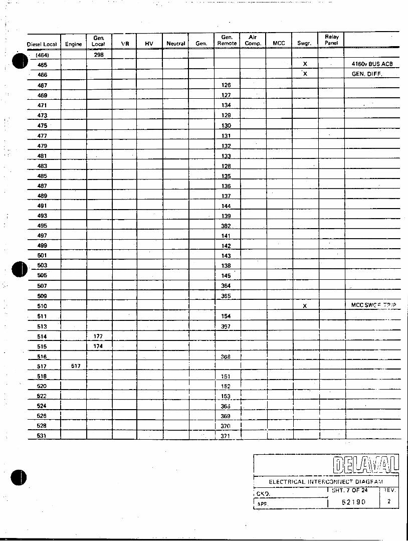
Gen, Gen. Air Relay Diesel Local Engine Local VR HV Neutral Gen. Remote Comp. MCC Swgr. Panel
(464) 298
465 X 4160vBUSACB
466 X GEN. DIFF.
467 126
469 127
471 134
473 129
475 130
477 131
479 132
481 133
483 128
485 135
487 136
489 137
491 144
493 139
495 382
497 141
499 142
501 143
503 138
505 145
507 364
509 365
510 X MCC SWG 7!!P
511 154
513 367
514 177
515 174
516 S68
517 517
518 151
520 152
522 153
524 368
526 369
528 370
531 371
ELECTRICAL INTERCONNECT DIAGFAM THT.7 OF 24 REV.
I 52190 2

Gen. Gen. Air Relay Diesel Local Engine Local VR HV Neutral Gen. Remote Comp. MCC Swgr. Panel
O 532 DAY TANK SW,
533 164
534 DAYTANKSW.
535 ____394 ____ ______ _______
536 3MOTOR FEEDER
536 TI
537 395
538 X 51-V
539 161
540X FIELD
541 162
542 X STATOR GRD.
543 163
545 372
547 165
549 166
550 550 ___ ___ ___ ___ _____ ___
551 167
553 174
554 554 ____ ________ ___ ___
555 169
556 TRANS. LINE PRESS.
* 557 _____ __170 ___ _______
558 TRANS. LINE PRESS.
559 TRANS. LINE PRESS.
560 ____ _ _ _____171 ,___ _ _ _ ____________
562 172
583___ __ _ __ _ _ _ _ _ _ _ _ _ _ _-____ D.C.BL .W 564 173
565 X NEG.PH SE ?Q.
566 168
567 x REV. PC L.
568 ,175
570 105
107
131
141
143
57117
573 1-77
ELECTRICAL INTERCONNECT DIAGRAM
CKD.I SHT. 8UOF24 REV.
APP. 52190 2
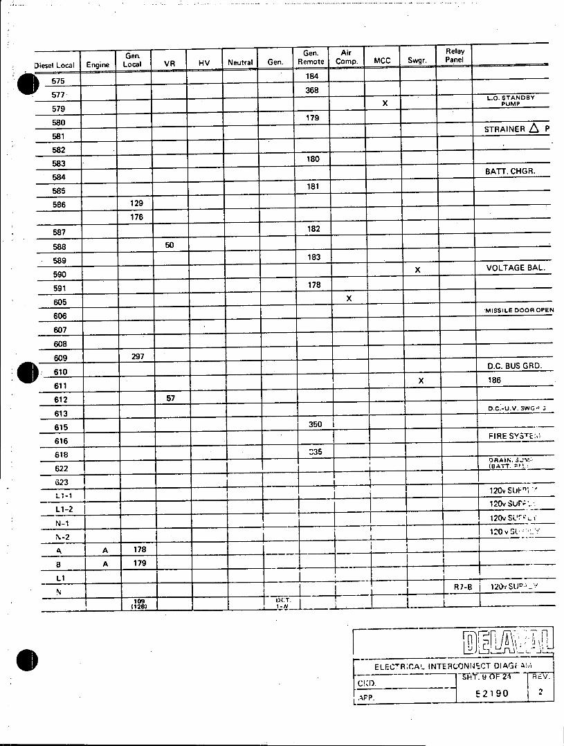
Gen, Gen. Air Relay
Diesel Local Engine Local VR HV Neutral Gen. Remote Comp. MCC Swgr. Panel
575 ______ ______ ______184 ___
L.O. STANDBY X PUMP
579_______ _
580 _179
STRAINER L P 581
582 _
583 180____ ___
584 180_ BATT. CHGR.
585 181
586 129
176
587 182
588 50
589 ____ 183 _______
589 183_ _X VOLTAGE BAL. 590
591 178
605 X _
606 MISSILE DOOR OPEN
607
608.
609 297 D.C. BUS GRD.
610 D.C. BUS GRD.
611 X 186
612 57 1
613 o.C.-U.V. 3WG' 3
615 .. 350
616 FIRE SY TE:
618 "35 - ) v__ _
62 (BATT. All-:
622 OAN J
623 120v SUP
120v SUP;L1-2I N12 120v SLJILf
120 v SL
A A 178
8 A 179 I L1
N09 I:.IR7-B 12vSUoJ-/
__ _ _ _ _ (128) __ _ _ _ __ __ _ L__1_ _
ELECTR;CAL INTERCONNCT DIAGF AM .9 0F 24 REV.
C .
52190 2

Gen. Gen. Air Relay
Diesel Local Engine Local VR HV Neutral Gen. Remote Camp MCC Swgr. Panel
110 DET. 1-W
111 DET. 1-W
112 DET. 1-R
113 DET.2-W
114 DET. 2-W
115 DET. 2-R
116 DET. 3-W
117 DET. 3-W
118 DET.3-R
119 DET. 4-W
120 DET. 4-W
121 DET.4-R
122 DET. 5-W
123 DET. 5-W
124 DET. 5-R
125 HTR.1-W
126 HTR.2-W
127 HTR.2-R
128 (109)
133 CT1-X1
135 CT3-X1
lie 140 140
.146 8- 146
(270) 38 40
149.
150
? 51 42I
152 41.
154 43
155 37
157 3615
158 39 1-58
160 160
162 120 v SUP :.*-_
163 120v SUP.-.
167
171
175
ELECT3ICAL INTERCONNECT DIAGRA.'
SH T. 1(072 RV
APP52192
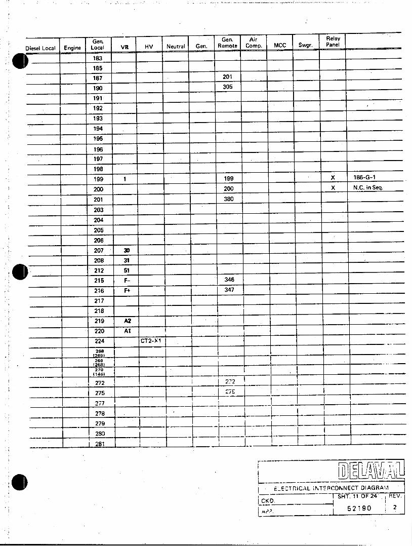
Gen. Gen. Air Relay Diesel Local Engine Local VR HV Neutral Gen. Remote Comp. MCC Swgr. Panel
)__ 183
185
187 201
190 305 ______________
191____ ________ ___ _
192 ___
194 195
196
197
198
199 1 199 X 186-G-1
200 200 X N.C. in Seq.
201 380
203
204
205
206
207 3D
208 31
212 51
215 F- 346
216 F+ 347
217
218
219 A2
220 A_
224 CT2-X1
268
269
270 ________ ______ (146) _ _ _ _ _ _ _ _ _ _ _ _ _ _ _ _ _ _ _ 1
278
279
280
281
-~~~ Ec LUI__ ____
EECTRICAL NTFRCONNECT DIAGRAMI H ST. 11 OF 24 REV.
5 2 9 0 2
____ _____ 20 ~1 I _____ _________A?

Gen. Gen. Air Relay
Diesel Local Engine Local VR HV Neutral Gen. Remote Comp. MCC Swgr. Panel
282
283 283
284 284
286 C
287 B
288 A
289 289
290 . 290
291 291
292
293
296
300
301
308A
308B
308C
308D
308E
308F
308G
308H
309A
3098
309C
309D
309E
309F
309G,
309H
310A
310B
310C
310D
310E
310F
310G
310H
311A
i ELECTRICAL INTERCONNECT DIAGPM
CKD. REV
APR. 52190 2

Geri Gen. Air Relay
Diesel Local Engine Local VR HV Neutral Gen. Remote Comp. MCC Swgr. Panel
3118
311C
311D
311E
311F
311G
311H
312A
312B
312C
312D
312E
312F
312G
312H
313A
313B
313C
313D
313E
313F
313G
313H
314A
314B
314C
314D
314E
314F
314G
314H ........
315A
315B
315C
315D
315E - T -315F
315G
315H
.E-CTR'ICAL IN ,EFCCNNECT DIAGR; M H13OF 24 REVI
I152190()

Geri Gen. Air Relay Diesel Local Engine Local VR HV Neutral Gen. Remote Comp. MCC Swgr. Panel
316A
316B ,
316C
316E
316F
317A
317B
317C
317E
317F
318A
318B
318C
318E
318F
319A
319B
31 9C
319E
319F
320 HTR. 2-R
321 HTR. 2-W
322 HTR. 2-W
323 DET. 6-W
324 DET. 6-W,
325 DET. 6-R
326A
326B
326C
326D
326E
326F
326G
326H.
327A
327B
327C
327D D
q 327E
E.-ECTR C7AL INTERICONNECTDIG SHT.14OF 24 REV
31~ ~ ~ ~ ~~~~~~~~~~C BE D___ ___ ____________ _______
31~~~~~ BF _____ 9___ 0_______
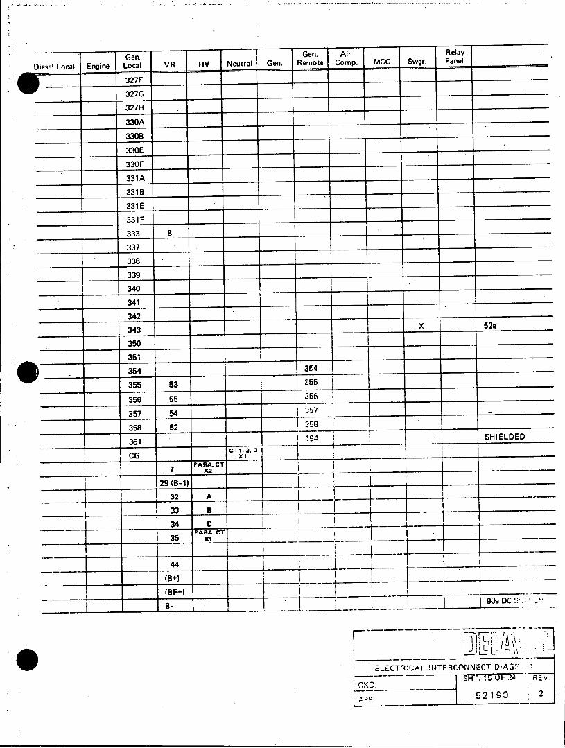
Gen. Gen. Air Relay
Diesel Local Engine Local VR HV Neutral Gen. Remote Comp. MCC Swgr. Panel
327F
327G
327H
330A
330B
330E
330F
331 A
331 B
331 E
331 F
333 8
337
338
339
340
341
342
343 X 52a
350
351
354 3E4
355 53 355
356 55 356
357 54 357.
358 52 358
361 A SHIELDED 361 -CT1 2, 3I
CG ~ PARA. CT x 7 X2
29 (B-1)
32 A
33 B
343 j C___ 2
PARA. CT 35 x6
44
(B+)
(B F+ 90a DC
3ECTCALH INTERDONNEDCT CRE.
A- 52190 2
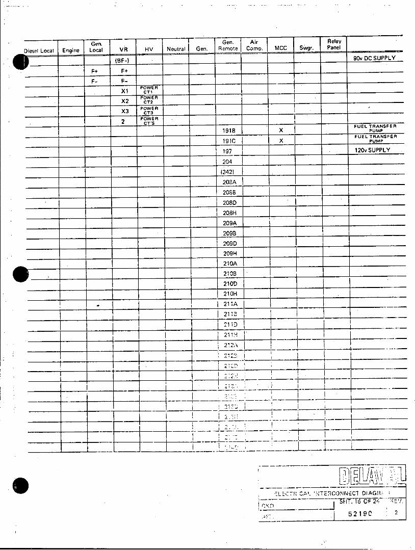
Gen. Gen. Air Relay
Diesel Local Engine Local VR HV Neutral Gen. Remote Comp. MCC Swgr. Panel
(BF-) 90v DC SUPPLY
F+ F+
F- F
POWER Xl CT1
POWER X2 cr2
POWER X3 cra
POWER _ 2 CT'S
FUEL TRANSFER 191B x PUMP
FUEL TRANSFER 191C X PUMP
197 120v SUPPLY
204
___ __ __ __ _ _ __ __(342) .__ _ _ _ _ _ _ _ _ _ _ _ _ _ _ _ _ _ _
208A
2086B
208D
208H
209A
I _ _ 209B
209D
209H
210A
210B
21 OAH _ _ _ _ _ _ _ _ _ _ _ _ _ _ _ _ _ _ _
I . 211AB
211D
212A
I 14
~LECTh D,. NTE! CONNECT DIAGil
SHT.160F24 EY. ___ __ __52j1 9 0 2
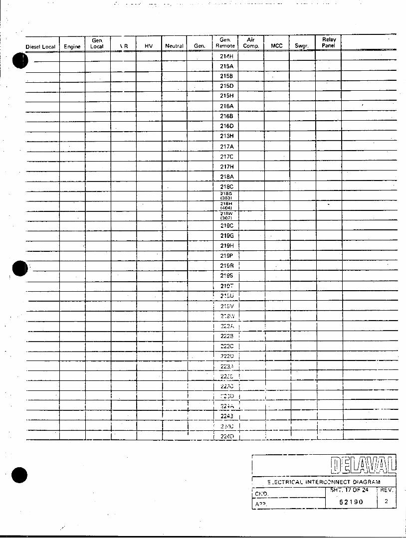
Gen. Gen. Air Relay Diesel Local Engine Local % R HV Neutral Gen. Remote Comp. MCC Swgr. Panel
_214-H
215A
215B
215D
215H
216A
216B
216D
218H
217A
217C
217H
218A
218C
218G (353)
218H (404)
218W (307)
219C
219G
219H
219P
219R
219S
21 _7
211U I 219"v
2223
222C
2220
223.
2243_
224D
[-CTRICAL- INTERCONNECT OIAGRAM SH.. 17 OF 24 REV.
CE:0.
Aug 52 1902
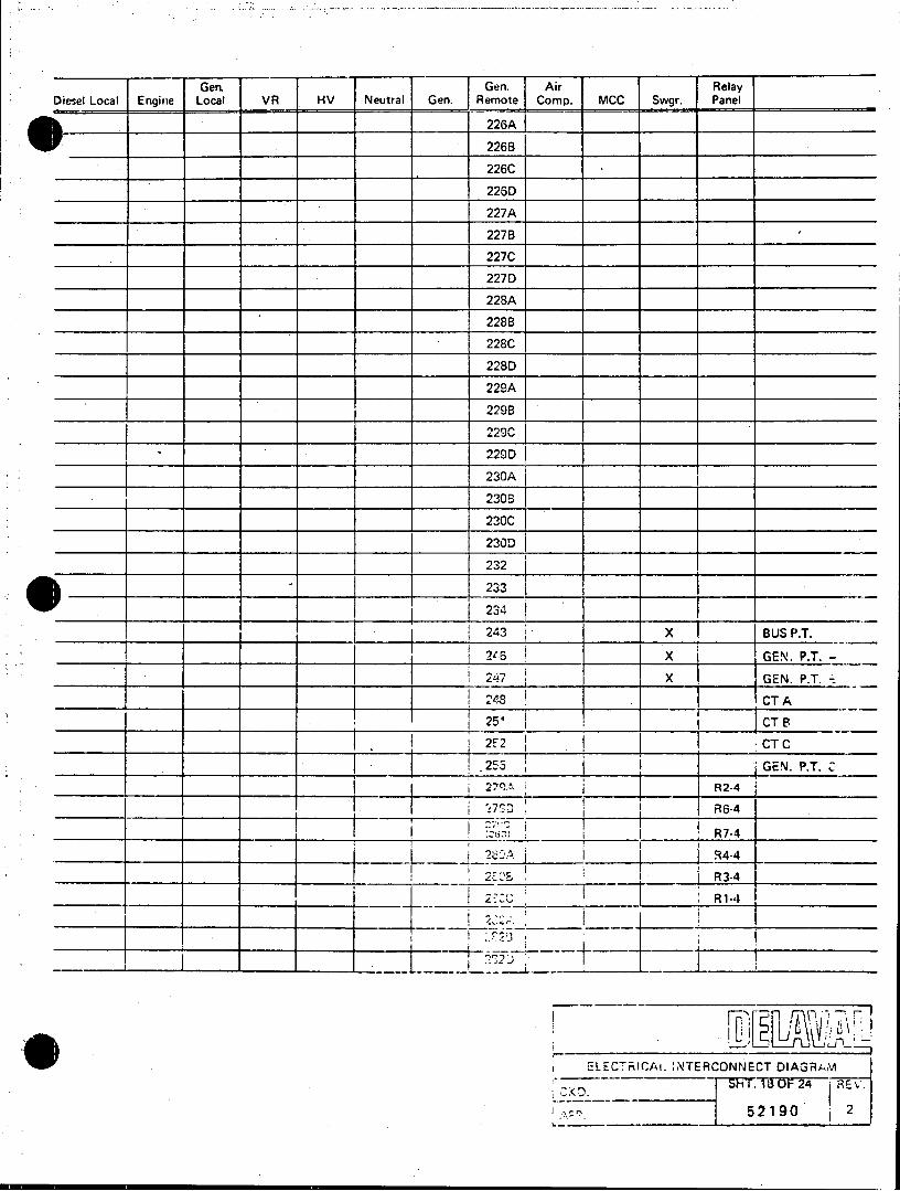
Geni Gen. Air. Relay Diesel Local Engine Local VR HV Neutral Gen. Remote Comp. MCC Swgr. Panel
226A
226B
226C
226D
227A
227B
227C
227D
.__228A
228B
228C
2280
229A
229B
229C
229D
230A
230B
230C
230D
232 _
~233 234
243 X BUS P.T.
246 X GEN..P.T.
247 X GEN. P.T.
248 .CT A
25- CTBE
2F 2 CT C
.253 GEN. P.T. C 27 9A6 R2-4
273 R6-4
:Ca R7-4
?$D-A .94-4
2 'E'% R 3-4
27ZCC R1i-4I
ELECTRICAL INTERCONNECT DIAGRA ,M
ShT 1L iOF 24 REV.
_52190 _1 2
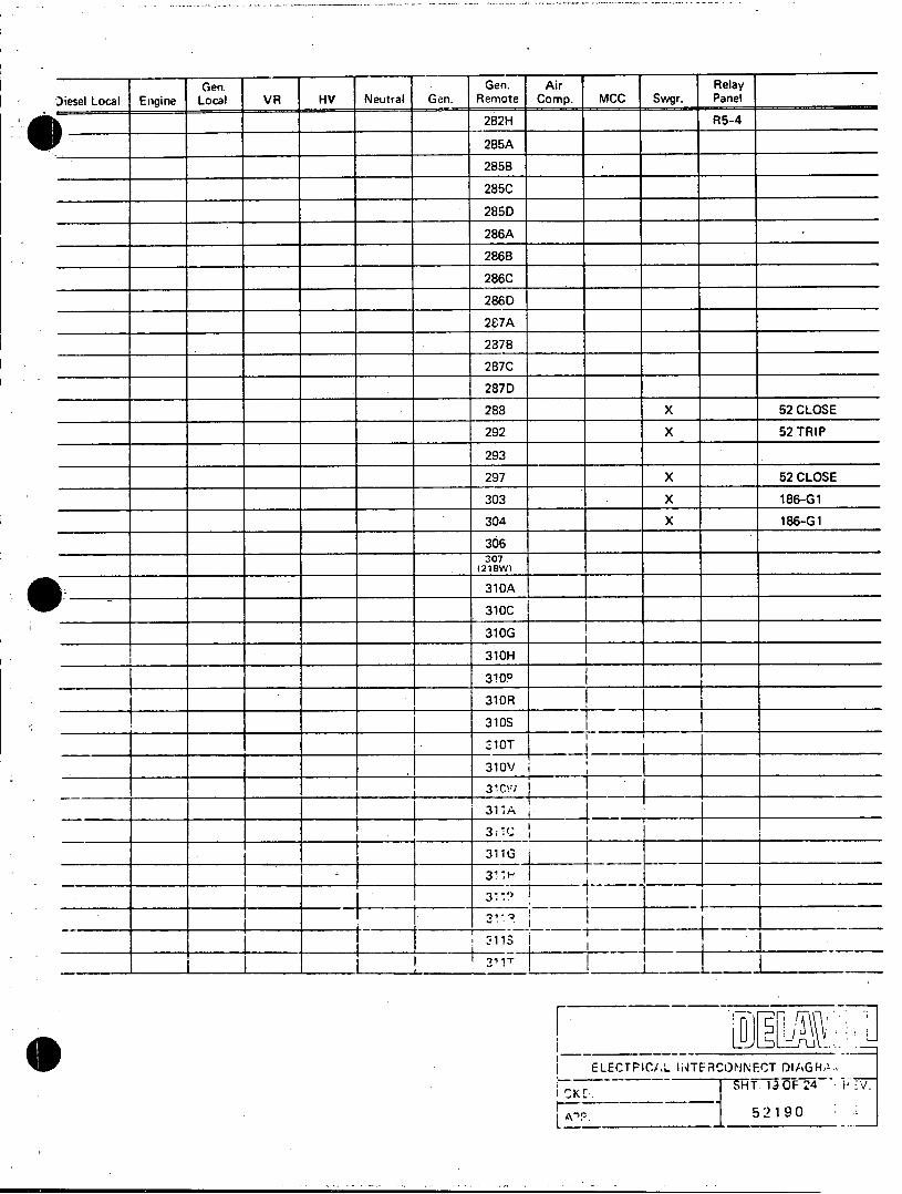
Gen Gen. Air Relay Diesel Local Engine Local VR HV Neutral Gen. Remote Comp. MCC Swgr. Panel
282H R5-4
285A
2858
285C
2850
286A
286B
286C
286D
287A
2387B
287C
287D
288 X 52 CLOSE
292 X 52 TRIP
293
297 X 52 CLOSE
303 X 186-G1
304 X 186-G1
306
307 (218W)
)_31 OA
310C
310G
310H
310P
310R
310S
310OV
31C1A
311AG
3:1
311G
IELECTPICiAL INTERCONNECT DIAGH,!
no 52 190
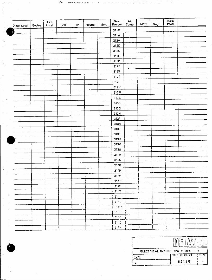
Ge -Gen. Air Relay Diesel Local Engine Local R HV Neutral Gen. Remote Comp. MCC Swgr. Panel
31 1V
311W
312A
312G
312H
312P
312R
312S
312T
312U
312V
312W
313A
313C
313G
313H
313P
313R
313S
313T
313U
313V
313W
31 -A
3'4C
31 -*T
3
ELECTRICAL INTERCCNNEC-T DIAGR, 1I
SH- 2O OF 24 -V.
17F. . 52 190
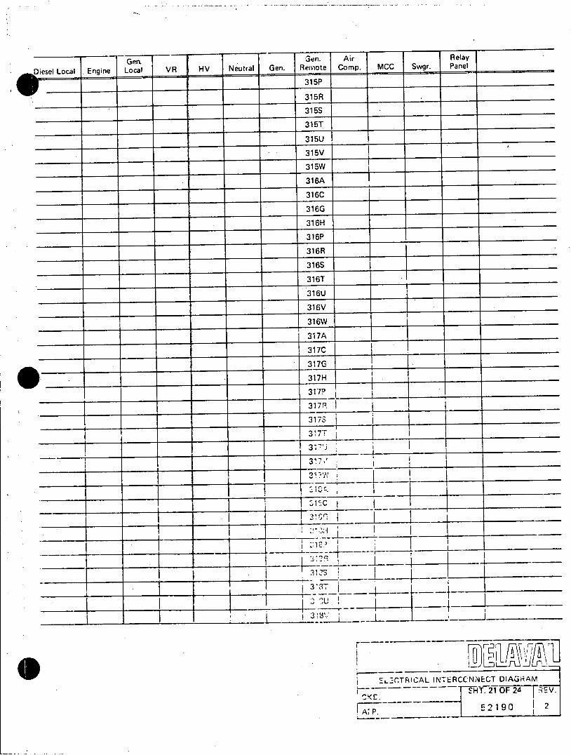
Gen. -Gn. Air Relay
Diesel Local Engine Local VR HV Neutral Gen. Remote Comp. MCC Swgr. Panel
VV _315P
315R _
315S
315T
315U
315V
315W I
316A
316C
316G
316H
316P
316R
316S
316T
316U
316V
316W
317A
317C
317G
317H I 3170
3HT 21 OF 6 E
3175 317-8
3'
3.
u
E' -CTR CAL INKTE RC-NN ECT DIAGRAM ST. 21 0F 24 R EV.
p. 52190 2

Gen. Ge -Gn. Ai Relay
Diesel Local Engine Local VR HV Neutral Gen. R,'mote Comp. MCC Swgr. Panel
320A
320B3
320C
320D
320E
320F _
320G
320H
320J
320K
320L
320M .
321 A
3218
321CD
321DE 321E
321F
321G
321H
321 J
321K
321L~ ______ ___ ________
321M 322A
-_ _3223
3220
322E_
322F I
2'
ELFCTRICAL. INTERCONNECT DIAGF<'' 52 190
52 19 0 2
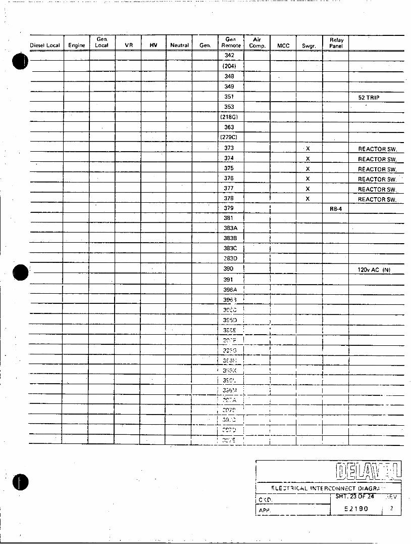
Gen. Gen. Air Relay Diesel Local Engine Local VR HV Neutral Gen. Remote Comp. MCC Swgr. Panel
342
(204)
348
349
351 52 TRIP
353
(218G)
363
(279C)
373 X REACTOR SW.
374 X REACTOR SW.
375 X REACTOR SW.
376 X REACTOR SW.
377 X REACTOR SW.
378 X REACTOR SW.
379 R8-4
381
383A
3838
383C
283D
390 120v AC (N)
le. 391
396A
396 3
3!5
3 S
ELE TrAL INTERCONNECT DIAGR' CHT. 23 OF 24 i
I,(D
_______~FAP 5 2 19 0 2_ _ _ _ _ _ _ .
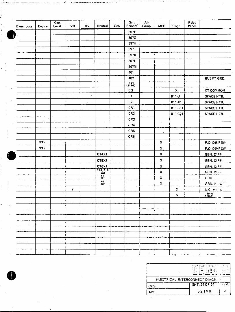
Gen. Gen. Air Relay Diesel Local Engine Local VR HV Neutral Gen. Remote Comp. MCC Swgr. Panel
397F
397G
397H
397J
397K
397L
397M
401
402 BUS PT GRD. 404
(218 G)
CG X CTCOMMON
__L1 B11-U SPACE HTR.
. L2 B11-X1 SPACE HTR.
CR1 B11-C11 SPACE HTR.
CR2 B11-C21 SPACE HTR.
CR3
CR4
CR5
CR6 335 X F.O. DRIP SW
336 X F.O. DRiP SW.
CT4X1 X GEN. DOFF
CT5X1 X GEN.CIcF.
CT6XI X GEN. DIFC.
cT4, 5, 6 XA X GEN. D;F P T xi I X GRD.
x2 X _ GRD. F
2 X NC r . I 1136-GI
X 186-2
E0-ECTRICAL INTERCONNECT DIAGR CKD. SHT. 24 0F 24 zEV. APP. 52190 '

AYSMW4 55 ANI CaTOPPED
ZAt'rrorAOV Exlqrl /a/ '35 56 UNIT
AWD .LCIPr v Ma- FOR STr;RT AM&A' 1611rTAWV' 57 UNIT'
04-I ZV &t~s/ ( BUS 2 24-1 IL -Re /5 or ff 37 ST.qAh'T/A Q/R RME-sUe/E STPRTiNG IsWbV~ £0 fr~r)- 6~GWo ~e'~~0RED~- LfrT RCAR 55 TES5T
- .&AW ATAYA4 - 7R I p. lo tfw 39 7Z/'M 014 W'&-Z6' 5-9 PRDO
Pis- LEfr A/r 'T CLOSE IS-i R £f rO/ AW-r.I M/35iwL CA-R~/twr GEN BRERKER
F/L7ar' rI.'~ITV 40 lh8 0/90 C11AXSOMR GO UNIT LORDEP/FEPOY M0 LCP4
"grat MW lpl~r RAW62 TrAVSrFre p4~ .p .r~-'
LO~~~f - ~41 FLIEL OILPFRESS 3 EL sP- s,2 W~TL42 DIFFERENTIAL PRESSURE 64 PLICL Z r~ ~'
to-# P./A, P/81 F'PO 6- FUEL OIL FILTER 65 zB(e- O A'lorrR 74W L/AE 70ML/NE) 4 (VoSusTIoN PIR PRESSups 66./ AFTw714'k 7
zOW PL- v./P&eJsj LEFT SANK p I G HT sIMN G7 4Q11ri 19* I fl t 4'*p/ 29-1 JM7. WiK 44 DIFFERENTI9L PRESSURE G8 D'AY 7XAIC f&V(,
AMW LE5 BSE Oil FILTER Q.9 Iee a-'fDYEW 45 UJPCKET wprEp PRESSUR( 70 Z-0- AV'- -. 'r* c Ao
/ f 4 30- 1 EAE/iVE 4d tkpNKCRSE. PRESSURE 7/ a*W ZEW kr4V p.1A .' ~ 5T4GTQQ/R 41 kAIGINE SPEED 7cxQ/Azh 1,0.16 r~AY el.
* LOV'WA 5 O0IVGEZ)f 48 ENGINE 04OURS '73. CRRPtCsE r,4rIS ONv 5 52 EA47K 282 ~r/~R49 MNURL TEST Trqr i
P~rSE- -- Erdf7CaVDvouff 50 mAINTENANcE sTANDBY * 5~CE- FRILURE 51 WIVRIN7ENRNCE M~DE SELECT4
12- 2 a'herrxw ea-2' GEN * 32 MIJTENRNCE MODE ONLY A-vb O WE VER=-. .....
* ~ ~ 2- -9- . crw .. .f.
13-2~~~~tl J71&A1PRZ 23-2r WS 0 .L-~' E~E AX~P'//7r -w/NDA' 7-WlZ7h'-etV4 Ar.A'k: #/7,V /4
25-2 MNI Ze-A-A
y 014 v le - QIV A4
iv~z g REAZSET
5*7-Z W&- OIL '.26-2 AIR-AM a TSLENCET~' ' i/E
87-2 lvse 0/1- -28-2 AZG4/E h TrfJ7D lrc . 04-~rt iw - 7: -,v~74
3MAWY Je~s OFF A IL ZETIM it/ X'
AVW2~ .v 89L~ur 2U D1/A, 0- $we -W I7 If~A t'ih~
(;;;ADO NOT; SCALE DRAWI
V*, 6m - iOSFNS-4RRG R
-..- %~~~~ -- INERO 70 &16 ?.N.EFET-.
-4. 57erle .JArI 30NTR2 CABIET PEC
5e199 . . NEL ErVSTAIL 5~. c
- ~O&Q SCALE I**' G~. . ~
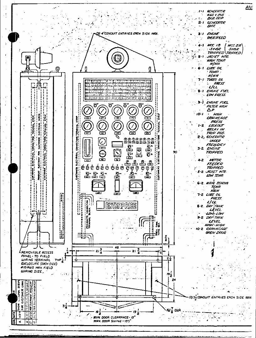
ANM
2- G1 .. * .
47CNDITENTIE E SDE/19X JOof
7p.
- 0 61 t~&O/Z 76"yp
:J .: .,1
Ig WL
Al M e JOl Ia ___16A
-1 MW
. I. AV71,1 11:- 4:.:3
it 2-t a.WW
at L J at
' I..,3 ~ci at
LOW Ii * ~~ ~c 17 Min * '~ ta,
* a I 'S .1 oIil 1*7\ Am*l MA Aa
1 a~a a~au~ II8-2 AY hAr *1..~ I 1 u 5
* Lj CEO r= 7Z ze OX
0' -V16. -v oc '-~~~~~ fita- 02C~~~4
-ftcpA&C1' * I. L~
OCSO 4ow,,. 48 3
PPEL- TO FIELD 4I j.t--------- 2±= WIRNG TER777INRL TVP4 - _ ____ ______
ENr-LosuRE (EAcH s/cE) - 50w0 w x. FIELD rIi
-~ ~ .. ~ -- . *~M~jR -- (3 ~.(XNOUrr ENTRIES ERCH SIDE MflX
XI ORCLEPRPRNCE 1'-.
MR1. DRSWING. aIV .
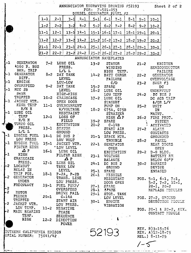
ANNUNCIATOR ENGRAVING DRAWING 452193 Sheet 2 of 2 FOR: F-501-053
DIESEL GENERATOR EANEL 2
1-1 2-1 3-1 4-1 15-11 6-1 7-1 8-1 9-1 10-1 1-2 2-2 3-2 4-2 5-2 6-2 7-2 8-21 9-2 10-2
11-1 12-1 13-3 14-1 15-1 16-1 17-1 18-1 19-1 20-1
11-2 12-2 13- 14-2 15-2 16-2 17-2 18-2 19-2 20-2
21-1 22-1 23- 24-1 25-1 26-1 27-1 128-129-1 301 I
.21-2 22-2 23- 24-2 25-2126-227 28-2 29-2 30-2 ANNUNCIATOR NAMEPLATES
-1 GENERATOR 7,2 LUBE OIL 13-2 STATOR 21-2 EXCITER 4160 Y. BUS PRESS. WINDING SEMICONDUCTOR BKR. TRIP L/L L HIGH TEMP. FAILURE
-1 GENERATOR 8-2 DAY TANK 14-2 BATT CHRGR 22-2 GE'ERATOR DIFF. LEVEL v FAILUREOT -1 ENGINE LOW-LOW C/D 23-2 SWGR f3
OVERSPEED 9-2 DAY TANK 15-2 SPARE DC -1 MCC 2B LEVEL 16-2 LUBE OIL UNDERVCLT
SWUR HIGH-HIGH LOW TEMP 24-2 1C BIS 2 TRIPPED 10-2 CRANKCASE 17-2 LUBE OIL DC ACB
-1 JACKET WTR. OPEN DOOR STANDBY &/OR.L/V HIGH TEMP 11-1 OVERCURRENT PUMP ON 25-2 UNIT
H/H H W/VOLTAGE 18-2 G75A, G75B IN -1 LUBE OIL RESTRAINT STRATER MAINT.
TEMP 12-1 LOSS OF HIGHAP 26-2 FIRE PROT. H/H H FIELD 19-2 SPARE SYSTEM
* TURBO OIL EXCITATION 20-2 C-14B ACTIVATED PRESS. 13-1 STATOR START AIR 27-2 ALAFM L/L L GROUND LOW PRESS. CO0 TACTS
-1 ENGINE FUEL 14-1 DC BUS 2 21-1 SPACE HTR. LOW PRESS LOW VOLT TROUBLE 28-2 PANEL
-1 ENGINE FUEL 15-1 JACKET WTR. 22-1 GENERATOR REAR DOORS FILTER HIGH LOW LEVEL OVER OPEN
A P 16-1 LUBE OIL EXCITATION 29-2 D-G BLDG. 1 HIGH FILTER HIGH 23-1 VOLTAGE BATTERY FYM
CRANKCASE A P BALANCE BELOW 6.00 F PRESS. 17-1 LUEE OIL 24-1 DC BUS 2 30-2 BARRING
-2 LOCKOUT TANK LOW GROUNDDEVICE RELAY IN LEVEL 25-1 SPARE T1IP P0S. 18-1 P-2A, P-2B 26-1 MISSILE
2 GENERATOR TRANS. LINE RESISTANT POS. 5-1p 6-1, 7-1t UNDER LO' PRESS. DOOR OPEN 5-2, 7-2, 13-i,
FREQUENCY 19-1 FUEL PU!M:?/ 27-1 SPARE 20-1m 20-2 2 OVERSPEED 28-1 5?ARE REFLASH MOULES 2 MOTOR DRIVE FAIL 20-1 STOR. TANK
FEEDER 20-1 C-14A LOW LEVEL POS. 27-2, G. 27D TRIPPED START AIR 30-1 ENGINE DETECTION NODUl
2 JACKET WTR. LOW PRESS. VIBRATION LOW TEMP. 11-2 NEGATIVE .
2 MAIN BEARING PEASE CONTACT ODULE TEMP. SEQUENCE HIGH 12-2 DIRECTION
POIWER POERREV. B)3-15-7'
OUTERN CALIFORNIA EDISON REV. A)i2-i8ERIAL NUIMBER: 750141/142. 2 9 REL.) 8-11-75

14 MTM DSCRIPON pATr 114 OY
,-...- I LUILET /2 F- 509- C%09 4
& LREIET-112 P-50 94 ~.-. ... .: L%.LET -I VatT-59-Oel 13
* * LItLET COVER FOR ITEMds 3 F-SQ 071 LEFT FRONT 6 U*4LEr GAIErFO ItEM 3 F-50-0, 14
START AIR ADN41SSXM 7 UCILIE GAS'E ASSY 1/2 ~ ~ os .
* £~~A~T;E ArY 509 -078 32
97 SEALTITE ELOW - 3,0 /s' F-509- 123SAfT 3ON - l6'av~q , 0~~~~ I SEA4.TITE CONN - Ilan 112 -0 I # i
It 5EJTT CON-35r12V59 l 11 SEITE PULL ELSO.' - 1/2 aI/Z 5013 9 tr
8 U SAL~iTE CODF / F509- 1)9 Ac 4 f:: 4ELTT CONDUI - SI/I' AR 4 NOTE 1 6 9W cON'ECTOR - I/Z i 1/2 F-50-10 t
ISE~ ~ ~ lb ACONOUCTO CABLE -M ^ 4 'a T eaCODUT 112 00 91 AR
RSqCABLE CONVER F S = -509- 178 10
01 '4ISE CBECNEOR-18-to r-509. 331
~~xj~~gTIP42 *W OGIET Th'tSTLOC-rMLE(S9 99lMOC ~ShC- MALE F_ 5c: Po
25 ST~NPIi 9 A~T1 PC~P S * SI4IELOW CABL.E F-509-12-5 AR ;L
2 10 abTavA m ~ P -~j 4 sx -~-0 Ilt 1 8 27 AIRE P 509 -337 AR
23 28 ENCLOS.WE 8.6."3 F-510-016 5
It COLTITE GASK(ET F-ogo Z 7 0 EALTT ELOW- 11 09- 2ib I ; 10 3 31SMITECo~tim r -509amb AQ (.
92 0CLOULRE it - C s V-S1,10072 1 ( 1433 NIPPLE. -OCOSE - 112 9-509-043 1 (
go 34 PAES&i4E SWInT~m - JwL F_ 577- 062 1 3S LEVEL SOVMN -OIL r-5&-O01 4
353b SEALTITE CONN - t r0-~
2- 937 U4IL~T - Ile95c I A
2s 8 TI4ERNOOCOLPLE WRE' F- 50- 323 AQ i
NOEa39 TERMINAL SNZIP - S CIRCUiT iF-59-0s b 1NOE540 TERMINAAL STRIP - I RuTP-9
BE OI MOUNT ON STANIPIDE, 35-
PIP
L USE MAKE SM TO "OLD ITDA
31 PaTIE THMCONDUIT RUN~S UNIE C4A:~~A
3. -,wS =_= -*Z N -. ,C '.4. ALLO w CN~ uiT 4 WIRE TO ".r.
40 3L.oP TAN S. ALLOW CONDIT 4 WIPqE TO PEACH
14 7 EN.iJNE J'8Ox. 01SCONNAECT AT EF. 14 t4TE5 START J'Sx FCRA Sm!PvENT.
TAT 6. USE R:NG TCGAJ w;kA%ATNS Of ALL TERMIN'AL BLOCKS
7. IVEt4TWY BOTH ENDS OF WIRE
0. OUT .J50r ON PRONT Or .c. as 40 9. MOUNT XBOX ON FRONT OF' AUX.
CONuT ACI 25IUA 3s AWS PPi-,.
10~SAL 30 &4rl:~~x
5O 6A. 37 Zci

o o
ompj
4NAr
PtlVJY i' wA .
aV3,3b ~
LLC
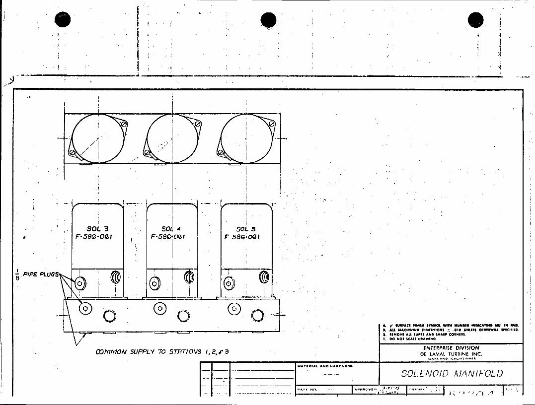
0 0 0
SOL 3 S06 4 SOL 5 F58G0*OGI F-58 (CX3l F-58G OG
PIPE PLUGS
0I
4. s' SUOPACS PINIS" SYM04 WITN NUMBER INDICATING MU. IN DMS. 2. AU MACHININo DIMtmsONS t .010 UNlSS OTHIWIll SPICIFIED.
3. RMOVI AlL $UP*S AND SHARP CORNERS. 1. DO NOT SCAtt DRAWING
COMMONJ SUPPLY TO STPTIOVS 1, 2,.eENTERPRISE DIVISION DE IAVAL TURRINE INC.
QAKI.AND CALifolfNIA
MATERIAL AND HARONRas
--- SOL.ENO/O MAN/FOLD
"Ar No. -- Apnown ,, ns , !*

I______ MATERIAL LIST
S3 I CIR Ull MO.:)LLE AZKT
4 t 5 1 !.PCI ____ T_____ nLILE GA-Z ET
S. .. 6 2 EEkll p II-. -- :3E
0 10 zz ALE mEA: 01&-!2 Y)F G
0 j0 C I F;;FLLEL -.- ';FI:E Ch-CK C-6
!0
-c 0 0 c
________________________________________ 0 TEV. 10 TC S E VSEw T MOUNT "k. F iC E FAC TO CI2AD
5® CU TOUTr AS SHOWN -V~r WIDE CHANNELS FUNCTIOAr: 'M PqCICE NECESSARY 5S47'%WN 310jfi=L5 CIRCUIT MODILE GASKETS USE F-573-291 . ... .70VIE.
CA-EAR GAKE OLES AND ADJACENT CUTS BY V9S
T TEST *1CD XZ
1, . *-L.. IfAPtTS OU-TPIJTS TO BE 66 PSI.
* 0 0 P. 0 ONPWJYS TO BE (EfiTED UjkAiN F7O X,;E5L~iZEZ.
*"% on0.7 c (2, F -57i32roCCUlWLTRT0 0 ki7'r . Ier00 - 4. GE OUJTPUTS -7r PtlS 2.3. S.9 0/.
A__R 12,,C NOTE C~jrPZT$ PT #9Po!;T5 2f; . - 7 CX 7A: C
100 ce.XT /0, A10TE, OzUTP4T :; A~cT a.
Q~ NOTE OCITP~JT r , ~~P73. Z f 3 RAD LCSS OP C 7;' - P7*
$o 80 0, 0cBVEr FiLIT X, ?.- Los op ~ T at,=. A7
(: C . K CU'j . ; 1-:-g. 7c. .. SURZ ~T1,-r
* .1
_ _ _ _ _ _ _ _ _ _ _ _ _ _ _ _ _ _ _ _ _ _ II -6.
- ~DO NOT SCALE DRAWVING
~VUVAIC L2GIC B:2LPDAtSI fTIMAL. AftO lqh*0fES bpp .- r z.
-SA~ IC - 77-.- S ~Q5
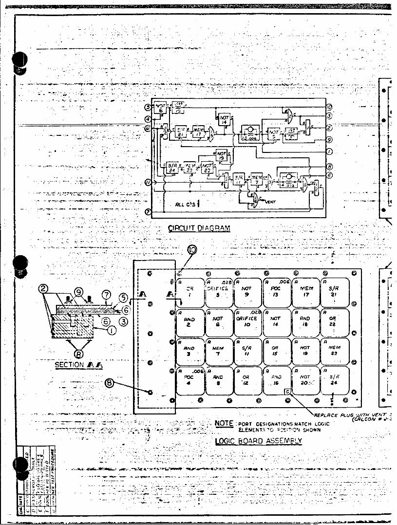
RL CS
-- - c Nor me..mrs/R
ICT
- a .oor.n.a a 2 e
S.00 G 9
C..,
. R~.EC L IHVN ELE"; MEN O ''SON
- * . -~ * 0 -0
& 0 28' Rr 00 p ofI
N0a RN
\\ 'h~t -. ~ 2610 14 Is za
1o
3 it Is5 59 3
SECTION AAAD MM ~ O
-. ~ --. ~ . . . OTE:POT DS~GA~tNS \REPLCE PUG Uffr"VE4' f
EEE Z 70. -- ' SHOWN
LOGIC BOARD ASSEMELY
WIWI-4.
-. ~-~1-7: .0t -
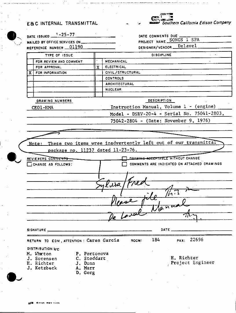
ESC INTERNAL TRANSMITTAL - S ' Southern California Edison Company
DATE ISSUED 1-25-77 DATE COMMENTS DUE
MAILED BY OFFICE SERVICES ON PROJECT NAME SONGS 1 SPA
REFERENCE NUMBER 01190 DESIGNER/VENDOR Delavel
TYPE OF ISSUE DISCIPLINE
FOR REVIEW AND COMMENT MECHANICAL
FOR APPROVAL X ELECTRICAL
X FOR INFORMATION CIVIL/STRUCTURAL
CONTROLS
ARCHITECTURAL
NUCLEAR
DRAWING NUMBERS DESCRIPTION
CE01-HMA Instruction Manual, Volume 1 - (engine)
Model - DSRV-20-4 - Serial No. 75041-2803,
75042-2804 - (Date: November 9, 1976)
Note: These two items wree inadvertently left out of our transmitta
ackae no. 11237 dated 11-23-76.
REVIEWERS C I . . WITHOUT CHANGE
OECHANGE AS FOLLOWS: O COMMENTS ARE INDICATED ON ATTACHED DRAWINGS
SIGNATURE DATE
RETURN TO EDM, ATTENTION : Caren Garcia ROcM: 184 PAx: 22696
DISTRIBUTION VrC
M. Whrton P. Portonova J. Sorensen C. Stoddart H. Richter H. Richter J. Dunn Project Engineer J. Ketzbeck A. Marr
D. Gorg
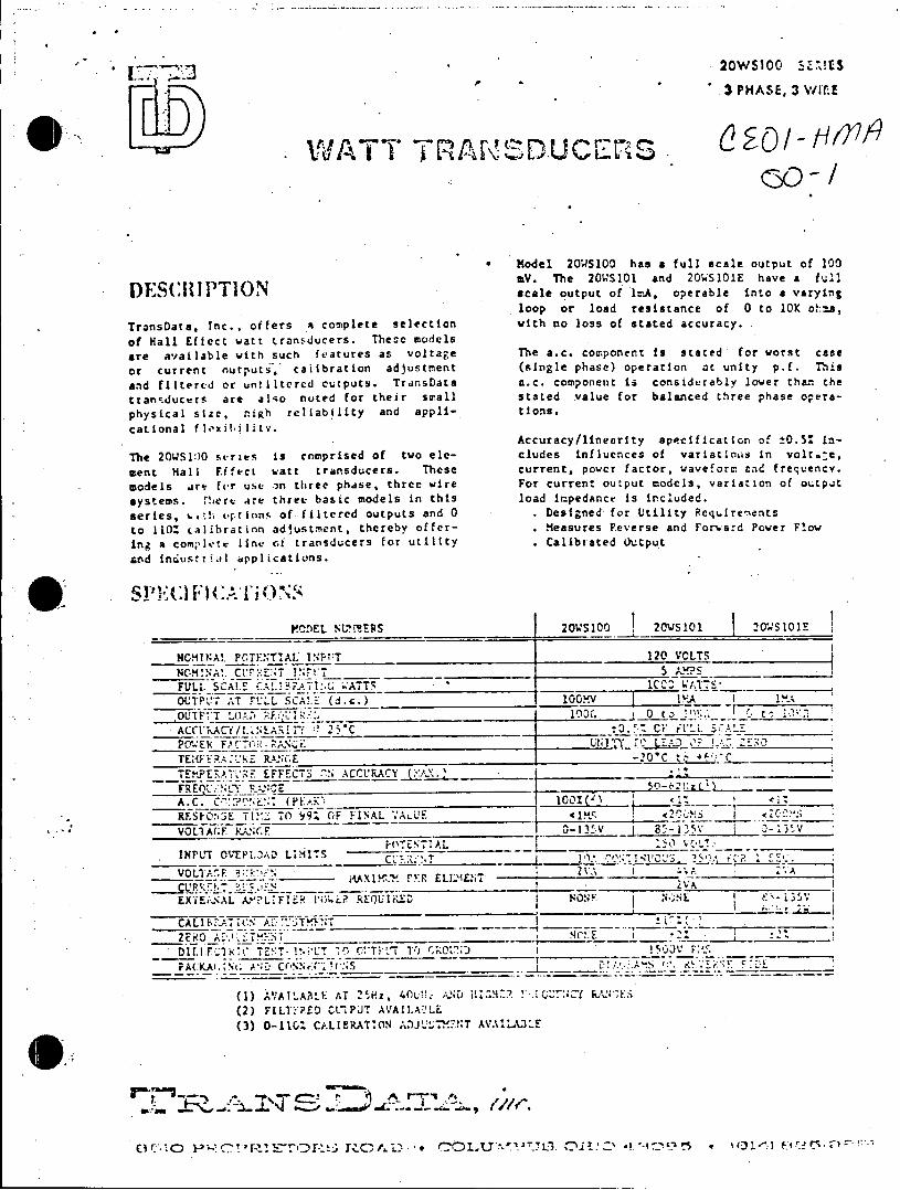
20WS100 5E.T!ES
3 PHASE, 3 WIf4E
sou WA T T T RASD UCErS S
Model 20WS100 has a full scale output of 100
mV. The 20WS101 and 2OWS101E have a full
DESCRIPTION output of irA, operable Into a varying loopor lad esisanc of to10K oha,
TransData, Inc., offers a complete selection with no loss of stated accuracy.
of Hall Effect watt transducers. These models
are available with such features as voltage The a.c. component Is stated for worst case
or current nutputs. caitbration adjustment (single phase) operation at unity p.f. This
and filtered or unailtcrcd cutputs. TransData a-C. component is considerably lower than the
transducers are also noted for their small stated value for balanced three phase opera
physical size, high reliability and appli- tions.
cational fl'xibiliztv. catinal lixi~i~lt~v.Accuracy/linearlty specification or ±0o.5: in
The 20WS110 stries is comprised of two ele- cludes influences of variatio.s in volt.-c,
ment Hall Effect watt transducers. These current, power factor, waveform end frequency.
models are fer use on three phase, three wire For current output models, variation of outpjt
systems. Tiere are three basic models in this load Impedance Is included.
series, '.,t '!prinns of filtered outputs and 0 Designed for Utility ReqLirenents
to 110% Calibration adjustment, thereby offer- Measures Feverse and Forward Power Flow
ing a com;'lete line of transducers for utility Calibrated output
and in*usMrioul applications.
IS 1,VC IP I F:.i.v0 INS MOaVEL TheS20WS1OO01 20WSIO1 2hvS11E
NCMTsaAl PoTEfTIAt 1A op al in 120 VCLTS
NOM!~A~ ct:~E-~T !~:T ________ _____________5 Yk~? S___________
FULL. SCALE no losATT lCCf a a .cu y .
TUTPLhe aT cmoe SCAis (d.c.) for wort aM s
OLITtT 0l. _______________ lX 0 $t '
ACCV;%ACYf/. _AR7. :1 25% __________ ±____ .-. C jiLL St-i_________ PCY.4EkH FAC,-.1 - PANC WdTIy L
(single_ phase)_operaion -t iC pV.. This
TP .~~.EFFECTS : N ACCRACY I~
FREOU~. F ':* ______-_____6_____2__
A.C. Coonent i cnirb lortnh
RE!OS Tl.: TO 99% OFFINAL <~LF 2________ Z Cl. 2
VOL.AGF KANCF ______ t 0-135V I.8'-25V 02-,)',V
s a d a e o b aeALd h e as o r
EXTU;-. AL AY:L!FlI; R'Oi? QiUIF,2lD NONK N I .1
CALIKCL.TiC.N A:~M~
_________ V)Y rRI -: -
(c) AurtLArLe AT 2noz, 40(wer!_ f r vd u
(2) F1LTYP.ED CL!P'JT AVAIILAM'IL (3) 0-110. CkLIERATIflN ;A)JU$7XflT AVAIU flLE
Fnm vo
la ien si
U 52 -'-:C'R!~'Dr:~ ~O D *.COL~-'~Ui. Desined fo Utility Requirements-'
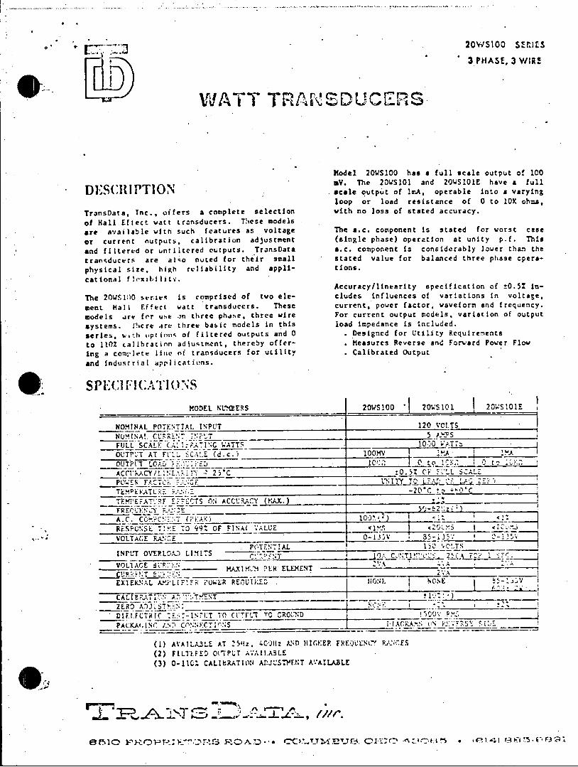
-I-J 20WS100 SERIES 3 PHASE, 3 bYIR!
WATT TRASDUCERS
Model 20WS100 has a full scale output of 100 mV. The 20WS101 and 20WS101E have a full
DS(RIPTION l' ( scale output of lr.A, operable into a varying loop or load resistance of 0 to 10K ohs,
TransData. Tnc., offers a complete selection with no loss of stated accuracy.
of Hall Eftect watt transducers. These models are available with such features as voltage The a.c. component is stated for worst case
or current nutputs, calibration adjustment (single phase) operation at unity p.f. This
and filtered or untiutered outputs. TransData a.c. component is considerably lower than the
tran-ducers are alIo noted for their small stated value for balanced three phase cpersphysical size, high reliability and appl1- tions.
cational floxability. Accuracy/linearity specification of ±0.5: in
The 20WS1lO stries is comprised of two ele- cludes influences of variations In voltage, sent Hall Effect watt transducers. These current, power factor, waveform and frequency. models .re for use .3n three phdse, three wire For current output models, variation of output systems. Ihcre are three basic models in this load impedance is included.
series, wth vprion- of filtered outputs and 0 . Designed for Utility Requirenents
to 110% calibratinn adjustment, thereby offer- . Measures Reverse and Forward Power Flow
ing a compvlete line of transducers for utility Calibrated Output and industrial applications.
SPEC lIC.IATIQNS
MODEL NLMERS 20WS100 20WS101 20 50lE
NOMTNAL POTENTTAL INPUT 120 VCT.TS NOMINA. CU 1_ _T 5 AYYS
FULL SCALF CA: AT -ING .ATT_ 1000 VATT
OUTPUT AT FIL. <-A!.- (d.c.) 100MV IA IMA
OUTPUT LOAD :-___ ____ 1007. O to 105.. O to .L:.3
ACC1* .CY/1'.tL141 ' 25C :0.5Z OF FLL SCALE
PC'ETR TACT':. 3. LNITY TO LA C '!J ZE
TEKTUEAT'.RE EFFECTS ON ACCURACY tMAX_)
A.C.CCcE:T (P'Al)
RESC!OSi. T!KE TO 993 OF FINAl .ALUE -C I VOLTAGE RAN5E _-135V
.PoTENTI1AL 1- ,!T INPLT OVEPLOA.. LIMITS r TT A T - 2%
VOLTAGEt 'MI.M ?ER ELEMENT A
EXTERNAL AyyLIF:F i'UWLR REUIKED NONE I
CALMP.ATION AD 1ENT
ZERO A)J7STREN:
DIELIFCTiRIC V0 (-NPTTOCTTLT TO, CRO' N.D F
___ __ _ 1 I_ _ _ __ _ _
PA(:KAi.l NC- ;.N:) CO'NNtECT'.NS
(1) AVATLA3LE AT 25hz, 40-At: AND HIIcGEP. FREQUENCY PANCES
(2) FILITPED OtTP'dT AVAIL.ABLE (3) 0-110 CALIBRATION ADJ'.STNENT A.AILABLE
8f'510 PROPRIF""O S ROAD-.* C U-jE TB. CI-O * ' I 885-03

* * 20WS100 SEr ilt 3 PHASE, 3 WlI.E
WATT T RAPDUC ES
Mod eI -20WS100 has & full scale output of 100 DESUII PTIOWV. The 2O04S101 and 2O0.SIOlE have a full
DESC IPTIONoutput of lA, operable Into a vary
crirs cplee sletio . loop or load resistance of 0 to 10K ohlzs,. TransData, Inc., with no loss of stated accuracy.
of Hall Effect watt transducers. These models
are available with such features as voltage The a.c. component is stated for worst case
or current nutputs, calibration adjustment (Single phase) operation at unity p.f. Thi
and filtered or untiltered outputs. TransData s.c. component is considerably lower than the
tran'ducers are also noted for their small stated value for balanced three phase opera
physical size, high . reliability and appli- tions. cational floxibility.
Accuracy/lineerity specification of !0.51 in
The 20WSI:0 series is comprised of two ele- cludes influences of variations In voltage,
ment Hall Fffect watt transducers. These current, power factor, waveform and frequency.
models are for use on three phase, three wire For current output models, variation of output
systems. There are three basic models in this load impedance is included.
series, vt pt'ions of filtered outputs and 0 Designed for Utility Requirenents
to 1102 calihration adjustment, thereby offer- Measures Reverse and Forward Pcwer Flow
ing a complete line of transducers for utility Calibrated output and industria0 applications.
MODEL NTh2ERS ?OWS 10 20 2 SL11 2hwsal l
NOMINAL P 17E:,TtAL INPUT -120 VOLTS
NOsloNAup IrAT 5 eabs i
FULL SCALE .looATp o.rATload reis0 1 t oATT0K o
OUTPUT AT F''L -,CAIE "d.c.) I__________ rOCM FI i MA
OUT~~100f L" 0I~ - lO.tc lO ": i 0 t_-:2:.
with no lossof -taC t a c y
TEL,?EF .F EFFCTS _CN ACC:.Ak-Y ! ';,. i
FRFq'J ; ± _________________f___ A.C. CT a (c. C o t st r t case
RIES P ON S S T 70 99 t CF. I NA 1 ~A 1UE 0M xOM lT S V0TAFk'- C-13JV 6,- &-35V i- 3
aOc. componen is- cosdeal loehaIh
POTENTIAL ________ l0 VOLTS _____
INrULT O1.TR'CtU) LIMITS IC CCNT1!'L'Y -L 5s F . - .r VOLTAGEKAXIM'2H PER ELZ.X-ENT I ____________________
CURI ENT E______________- VA _________
EXTEFS'L AJLC-_F!EH PU;.LR REQ'IRPD 1l NC AL El N C,~
CALl ATi., A.-P-'T !________ _______
DIEI FCT'.T(' 77--;L:T To _______ 1530V' F?$ _____
- - ___ ___i_____fNo's __ - - -
(1) AX'ATLALLE AT 2511z, P C IC HIGHER FFE;:UFIXY' kANES (2:' FILlERE~D O1TP1.T AVAI:.APLF.
(3) 0-110t CAL1611.TIONIAJLTI AVAILABLE
0 .) 10J0:f t-_
sttdvlefrblncdtrepaeoea
8t~l) ~'CP~~C~25 ~ C LU%!!JU~ ~M 0 * j~-tions...

20WS100 SEKIES
3 PHASE, 3 WIP.E
WATT TRANSDUCERS
Model 20WS100 has a full scale output of 100 mV. The 20wS1l and 20WS101E have a full
[)ESCIlPTIO() scale output of leA, operable into a varying loop or load resistance of C to 10K chuz,
TransData, Tnc., offers a complete selection with no loss of stated accuracy.
of Hall Eftect watt transducers. These models are available with such features as voltage The a.c. component is stated for worst case
or current nutpurs. calibratiun adjustment (single phase) operation at unity p.f. This
and filtered or untiltered outputs. TransData a.c. component is considerably lower than the
transducers are alo nuted for their small stated value for balanced three phase opera
physical size, high reliability. and appli- tions.
cational flexibilitv. Accuracy/linearity specification of ±0.5: in
The 20WS100 series is comprised of two ele- cludes influences of variations in vcltage,
ment Hall Effect watt transducers. These current, power factor, waveform and frcqiency.
models ar! for ust on three phase, three wire For current output models, variation of output
systems. 1tere are three basic models in this load impedance is included.
series, o.1h Lptions of filtered outputs and 0 . Designed for Utility Requirements
to 110% calibration adjusLment, thereby offer- . Measures Reverse and Forward Power Flow
ing a com;,lete line of transducers for utility . Calibrated Output
and industrial applicativns.
SI E(:11'F!CATIO:NS
MODEL NUMEERS 20WS100 1 20'S101 20WS101,E
NOMINAL P0TEN.TAr. INPUT 120 VOLTS
NUMINA. CU;RE':T INPUT 5
FULl. SCALE (A:.AT ''ATT- 1000 'ATTS
OUTPUT AT FULL SCALE (d.c. 100___V lAOIM OUPt1_LCAD ___5____7.__:__ 1000_ 0 __.O:
ACCi)>ACY/LINE.L'. ?25C -0.5Z OF F.L SC.LE
POWER FACTR _;.*:CE UN17 TO LL7
TLEATURE RA!.NGE -)c tc ....._ TEEVERAT'Kz SIFECT7 .N ACCUKR.CY (KAX.)
A.C. CO-wIONENK!T <pA: RESPONSE TI'ME T0 94t CF FINAL VALUE VOLTACE RA.%CE 0- 13__,7_35_1___
POTENTIAL i5 __
INPUT OVERLOAD LIMITS.
VOLTA.GE agPe. F 2vA VAXIM:.-M PER' ELEM.ENT
EXTENA.L uYIFIER P'OUER RE'UIRKED NE - 1
PA( KA:.c. A'.,Ci',TTt S____- - _____
(1) AVAILABLE AT .SH:, 4& 11z ANI HIGHE? FREQUENCY .AN (.S (2) FILLTEED OUTPUT AVAILABLE (3) 0-1101 CALIBRATION ADJLSTuE.!T AVAILABLE
E~~~~~15!c~~~~~~~3 -1 F3~~'~OrE FiD- CO.!5.!Y..3 C-)C E) * ;74' F I5.
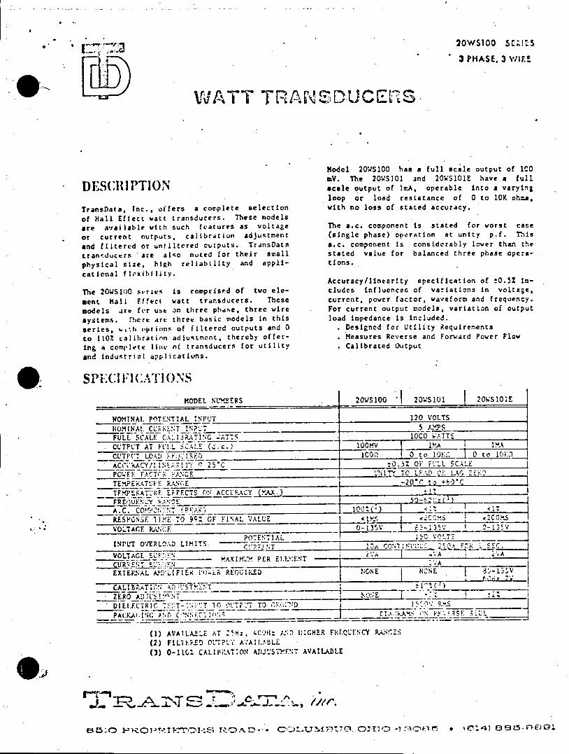
a. 2OWS100 SCIZ.'S
3 PHASE, 3 VWIF.
WATT TRANSUCE"S
Model 20WS100 has a full scale output of 100 mV. The 20WS)01 and 20WS101E have a full
DE(S(C IPTION scale output of ImA, operable into a varying loop or load resistance of 0 to 10K oh=a,
TransData, Tnc., offers a complete selection with no loss of stated accuracy.
of Hall Effect watt transducers. These models
are available with such features as voltage The a.c. component is stated for worst case
or current outputs. calibratiun adjustment (single phase) operation at unity p.f. This
and filtered or untiltered cutputs. TransData a.c. component is considerably lower than the
tranaducers are aI o nuEed for their small stated value for balanced three phase opera
physical size, high reliability and appli- tions.
cational flexibility. Accuracy/linearity specifica.tion of ±0.51 in
The 20WS100 se-ries is comprised of two ele- cludes influences of variations in voltage,
ment Hall Effect watt transducers. These current, power factor, waveform and frequency.
models ire for use on three phdse, three wire For current output models, variation of output
systems. rhere are three basic models in this load impedance is included.
series, w,!'h options of filtered outputs and 0 . Designed for Utility Requirements
to 110. calibration adjustment, thereby offer- . Measures Reverse and Forward Power Flow
ing a conlete line of transducers for utility . Calibrated Output
and industrial applicatiuns.
spECI Ft (ATION MODEL NU BERS 20WS100 20WS101 1 20WSIOIE
NOMINAL PnTENTIALINPUT 120 VOLTS
NOMINAL C .: T I ? __T 5 A.PS
FULL SCALE CA. IRATING 1ATTS 1000 1.TTE
CLTPLT AT FI'L SCALE (.c.) 100MV 1RA 1 MA
CUTP: LO0 lc0 0 to 10.. 0 to 1.1 AC(i KAC/L INEA Rl" ! 25'C _ :0.5% OF FL".L SCALE
POWE FACTr- _ _ _ _ _ _ _ _ll" TO LEAD .JZ L E:-0 i
TEMPERATU'E R.P0\tE -20*r to '-0C TFERATURE EFFECTS ON ACCRACY (AX) '
FREQUFNC:Y RRE5-'E A.C. 0? PA)10')<1<t
RESPONSE TIME TO 99Z OF FINAL VALUE <'l s <COMS <TOS
VOLTACE PA;CF. RN-G3V --13; 2-135V POTENTIAL 150 VOT3
INPUT OVERLOAD LIMITS C!R^'7 T 10s.TCOw _L'c__ s VOLTAGE EL _____. PE ,N' 2'.A '.A .A
-'AXlML.. PER. EllY.FNT V
EXIEKS.AL A~f'LIFIEi i'ty.LR REQUIFED NONE NZ NE 8 13V
CALIBRATION AD:STME:T _ _ _ '_ _ _
ZERO ADI.RS!^T __ I *;
DIEILCTCRIC 7E:T-::':T .. 0 01'TP7' TO R D _ ._ ____S
PAt:KAI. C N.(; P. ' ! (11 S E___________ jIA .kAMI 'N FY . _SF~~I
(1) AVAILABLE AT Z5Hz,4CO: D ICGHE.R FREQENCY RANG S (2) FILTERED 0tL'P'J AV'AIL-ABLL (3) 0-1101 CALLbiATI0N AIJU'.SThEVT AVAILABLE
0)1 TC6L5..O1 3(1kr 9 kIT-T'JL F-1D- -4 E3i'U3 032C t3 - n~4 895fEJ
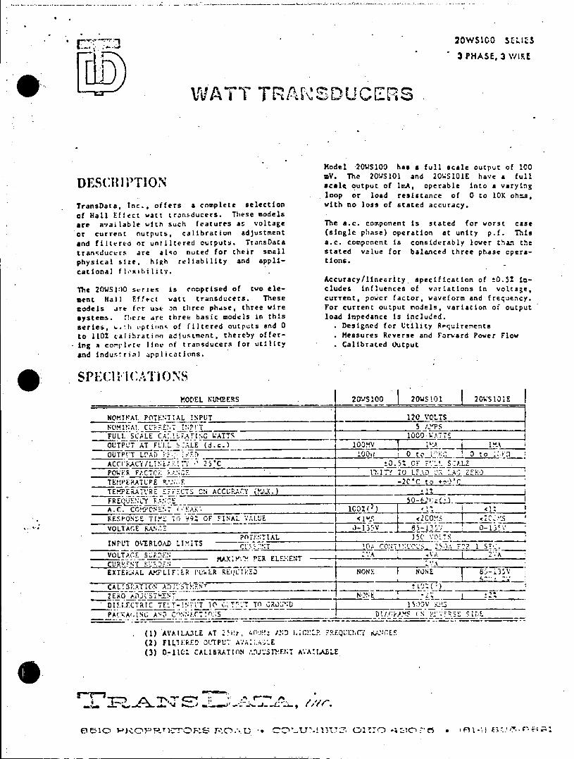
20WS10O SrULS
3 PHASE. 3 \YIRE
WATT TRANSDUCErS
Model 20WS1OO has a full scale output of 100 DV. The 20WS101 and 20WS101E have a full
DES(:Ill i l()IO ' scale output of ImA, operable into a varying loop or load resistance of 0 to 10K oh.a,
TransData, Inc., offers a complete selection with no loss of stated accuracy. of Hall Effect watt transducers. These models are available with such features as voltage The a.c. component is stated for worst case or current nutputs. calibration adjustment (single phase) operation at unity p.f. This and filtered or untiltered outputs. Trar.sData a.c. Component is considerably lower than the tran'ducers are alqo nuted for their small stated value for balanced three phase operaphysical size, .high reliability and appli- tions. cational flxibility. .
Accuracy/lineerity specification of !0.51 inThe 20WS100 scries is comprised of two ele- cludes influences of variations in voltage, sent Hall Effect watt transducers. These current, po-'cr factor, waveform and frequency. models ire for use :)n three phase, three wire For current output models, variation of output systems. ,here are three basic models in this load impedance is included. series, %-!h uptions of filtered outputs and 0 . Designed for Utility Requirements
to 110% calihratinn adjustment, thereby offer- . Measures Reverse and Forward Power Flow Ing a conplete line of transducers for utility . Calibrated output and industrial applications.
SPECIICATIONS
MODEL NUMEERS 201-S100 20WS101 20WS101E
NOMINAL POTENTIAL !NPUT 120 VOLTS NO'MINA!. CURF-ENT INFP!T 5 L"PS FULL SCALE CA..!;_ATING ATTS 1000 UATTE OUTPUT AT FULL LALE (d.c.) JOOV___A___IA
OU*T LOAD P. L.;D 100_ 0 to 1 ! to :v.)
ACCtr:ACY/LINARiT. -' 25-C :0.5Z OF P._J. 5:AL
POWE.R FACTCir 11__7fITT TO U.AD 0:.A! Z-R '
TE.!PERATURE @.*::.__-2CC to +')*c TEXPERATLRE EFFECTS CN ACCURACY (;X.) _ _1 FREuZfNCY F.t::CE I0-;,_ E
A.C. COP '7NENT 1'0AK0%__)__ 3L< __ RESPON'E TIZ TO 992 OF FINAL VALUE c2CONs I <
VOLTAGE RAN2 JE Z_____I___S_
POTINTIAL 1-C 'oLs INPUT OVERLOAD LIXITS - ,... j
VOLTACF 5R ____ _ MAXO,:M,'M PER ELE:-:ENT 2.A
CURRE NT VAFDE EXTERNAL AMPLIF ER C'.ER REQUIiED 8ON 1 '.'
CALIB;AT(N A'.'STMENT
ZERO EJT IN
DIELETCTRIC TETI 1iTT GT. TO %GR0*T:ID 15:)-V F-1PAC.KAI.NG AND C NETONS DO ;r.LM N FYSE ";L
(1) AVAILA3LE AT "Hy, 40 .:) /SD C QUELCT ANCES (2) FLITERED OL'TPU_. AVA.:.AstEU (3) 0-1lC CALIBRATION A.IJUSTIENT A'.ABLE
i~~~~~~Ic~~~~~~' C~c,~? -'M. T.CI.\ 1 E"'7!l~7 r.,: j7C'~ * f~~ '*- :

20WS100 SErI[S
3 PHASE, 3 WIRE
Li DWATT TANSDUES
Model 2OWS100 has a full scale output of 100 alV. The 20WS101 and 2OWS101E have it full
DESCRIPTION scale output of lmA, operable into a varying
loop or load resistance of 0 to 10K ohms.,
TransData, Inc., offers a complete selection with no loss of stated accuracy.
of Hall Effect watt transducers. These models
are available witn such features as voltage The a.c. component is stated for worst caee
or current outputs. calibratiun adjustment (single phase) operation at unity pA. This
and filtered or un!iltered outputs. TransData a.c. component Is considerably lower than the
transducers are also noted for their small stated value for balanced three phase opera
physical size, high reliability and appli- tions.
cational flexibility. Aecuracy/lIzicarity specification of ±0.5! in
The 20WS100 series is comprised of two ele- cludes influences of variations in voltage,
sent Hall Effect watt transducers. These current, power factor, waveform and frequency.
models are for use On three phase, three wire For current output models, variation of output
systems. There are three basic models in this load Impedance Is included.
series, -Ath ptions of filtered outputs and 0 Designed for Utility Requirewerts
to 1101 calihration adjustment. thereoy offer- Measures Reverse and Forward Power Flow
ing a complete line of transducces for utility Calibrated Output
and 2ndu0tria0 hopaications.
AMI S'(IIAINS
MODEL NTheEYS 20WS100 a WS201 20WS101E
NOMINAL PnTEN'71AL INPUT 120 VOLTS
CN4!N*AL CU?'.T 7!PUT 5 A2%TS_________
F L SCAscE__ otputA o A1 C operable into 1000_ ATv y
OUTPUT AT K'LL SZALE (d.c.2 borxv y
Loop or loa reitanc !Of-o10 b
ACLtC-i Y/LNI 1 r 5C___________!_i______ tO.iZ Oi I"-L -cCAL Z
POWER _.ACXC-( _________________________ ..iIiL f JC L-.',7 OF !.' z EN______
TL .PERATUF.E P.>__________________ 201C t.) -&60%
TETR-,'-E ET-F,-S ON, ACCFR.LY (!AX.)__________
(singl phase) operatio t unt pf.Ti A c. componentis considerablIuerthanIth
REPOS !!Mv 7. 99%. CF HN'AL VALUE Zl~ ,CC.. 1 XC'.S
l.OLTA.C'E FA;E 13-13 -l' POTENTIAL j150 V.OLTS_________
!NPL'T OVERLOAD LIMITS - - z f;_o'~2 _ S.
OL~~.L MAXiK Y. PER~ ELE.Y-ENT a 2.AAA CtRR IL'T _____ ____________ 2 VA
ixT£P..AL_!- ~LIFIEi( PC0LR R~i'JUD P "
D!Ei CT"7i-NU 10 0t7i-"T TO1 CPC _______ 100
PACKAr.%',(.AND~ C>'-,NCTl(",S -- jCAG .:; 07,' '.'7E"Sv
(1) AVAILAELE AT 25fdz 4.Cliz H...l' F F. 1,E ;CY PAN GE S
(2) F1LILP.FD OUTPUT A',AI!.ARLZ
(3) 0-110', CAL18 RATION ADJU57MENT AV A' A'iLE
c
Acc racy 11 ne rit 4%.D spIe i a o C of5 .5I i n
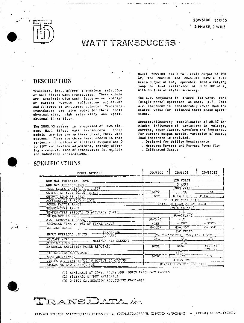
20WS100 SERIES
3 PHASE, 3 V/lTE
WATT TRANSDUCEMS
Model 20WS100 has a full scale output of 100 aV. The 20'S101 and 20WS101E have a full
DES(RIPTION .ale. output of lmA. operable into a varying
loop or load resistance of 0 to 10K ohms,
TransData. Inc., offers a complete seletion with no loss of stated accuracy.
of Hall Eftect watt transducers. These models are available with such features as voltage The a.c. component is stated for worst case
or current outputs, calibration adjustment (single phase) operation at unity p.f. This
and filtered or untiltered outputs. TransData a.c. component is considerably lower thz.n the
transducers are alqo noted for their small stated value for balanced three phase opera
physical size, high reliability and appli- tions.
cational f!oxibility. Accuracy/linearity specification of !0.5% in
The 20WS1:O series is comprised of two ele- cludes influences of variations in voltage,
sent Hall. Effect watt transducers. These current, power factor, waveform and frequency.
models are for use on three phdse, three wire For current output models, variation of output
systems. There are three basic models in this load impedance is included.
series, %. ' h options of filtered outputs and 0 . Designed for Utility Requirenents
to 110Z calibration adjustment, thereby offer- Measures Reverse and Forward Power Flow
Ing a compiete line of transducers for utility . Calibrated Output
and industrial applicatiovns.
- SPECIFICT.-'IONS MODEL N MERS I 20S100 1 20WS101 20'WS10lE
NOMINAL POTENTTAL INPUT 120 VOLS NUMINA!. CU:RENT I5 NPUS FULL SCALE CALibr ATTS 1000 ATTS
CUTPUT AT FULL SCALE (d.c.) 1_
OUTPIT LOAD :_ 0 to 10K j 0 to
POWER FACTCR FANGE n; IT' :0 L Ak QR.L ZK
TE.VEV:ATLVE RAN E t'C '
TEMPERATLU'F EFFECTS N ACCURACY XMAX .
FREQUzN\CY zANCE
A.C. C)C NENT (PFAK_ I <1Z
RESPOSSE TIME TO 99t uF FINAL VALUE 11M5 ,:oxs 1
VOLTAGF RANCE _8515% 0-135V
PO0 1NAL . Io .T INPUT OVERLOAD LIMITS T _ !jA C'L Sr. r
VOLTAGE StPRE_ MAXILM PER ELEMENT A
EXTEPNAL A.PLI TFIER i'G-ER REOUIRED NONS N:N
CAtL R.IONADILSTMT
DIELFCT!C TEFT-I[N' 0 Ct'T O T T IorV RND
PACK(.!5 ANDS
(1) AVA!LA.BLE AT 291Hz, 'GIzAJND HICHCR I-FEY A S
(2) FILTELED 0I:-?OUL AVAIAAFAL0 (3) -110t CALINDIAT0 ADJLST -:E!T AVAICA.LCr
e~io pjc ~Er =z p P ci T- z c CCLL T t T 3. 1 -T -3t 0 Fa-3f~ 135O-~

* r - 20W5100 SEZIlps
3 PHASE, 3 WI\.1
WATT TRANDUCE:RS
Model 20WS100 has a full scale output -of 1c0 DV. -The 20WS101 and 20WS101E have a full scale output of InA, operable into a varying loop or load resistance of 0 to 10K oh:=,
TransData, Inc., offers a complete selection with no loss of stated accuracy.
of Hall Effect watt transducers. These models
are available with such features as voltage The a.c. component is stated for worst case
or current outputs, calibration adjustment (single phase) operation at unity p.f. ThIs
and filtered or untiltered cutputs. TransData a.c. component is considerably lcuer than the
transducers are alqo noted for their small stated value for balanced three phase opera
physical size, high reliability and appli- tions.
catitonalI fle.xibilIitY. Accuracy/linearity specification of !0.52 it
The 20WS10O series is comprised of two ele- cludes influences of variations in voltage,
ment Hall Effect watt transducers. These current, power factor, waveform and frequency.
models are fcr use an three phase, three wire For current output models, variation of output
systems. Tiere Are three basic models in this load impedance is included.
series, with options of filtered outputs and 0 . Designed for Utility Requirements
to 1102 calibration adjustment. thereby offer- . Measures Reverse and Forward Fower Flow
ing a complete line of transducers for utility . Calibrated Output
and industrial applications.
SPE(C111'AllONS MODEL NUMEERS 20'.S1oo 20'.S11 I 205l0lE
NOMTNAL POTENTTAL INPUT " 120 VCLTS NUM!NA!. CU:RR' T INPT 5 ;'jS FULL SCALE C- tA.EAI'C FATTS 1033 .ATTS
OUTPLT AT FULL SCALE (d.c.) 1OV A I
OUTPI LOAD :C0 '0 tc rK , , 0
ACCURACYil.:N4Ai 1? 25C !0. 51 C F*.L SCA.LE
PO*FR FACT(' UI Tv T!T O NGLE *
TEMPERATURF ' o
TEMPERAITER EFFECTS ON ACCURACYj(IAX.) FREQUF'-.NC'Y .NE A.C. CO "T (PEAK) __ <
RESPONSE T'. TO 99. UF FINAL VALUE <.. .. n
VOLTAGE RANC- V 6 .is"
POTENT!AL 1-') VOLTS INPLT OVERLOAD LIMITS RF.T VOLTAGE E^ ______ AX!1 PER ELEENT
URENT Ch= EXTERNA.. A.'?LIFIER POWER REOL'iRED
CALIb.ATC, A.1 RSTMNT FRO AD.1'T: sT.ENT
DIELECTRIC TE'T-INPUT 70 __t.T TO CRO.:.D
PA(.Y. :!NiG AN'D CPNN :CTICNS I A__ FA
(1) AVAILAELE AT 2511z, 4001 AND HICHER FRFQLUENCY RA.NCFS (2) FILTERED OITPUT AVAILABLE (3) 0-1101 CALI5l.A'icN4 ADJUSTMENT AVAILA3LE
E31510 PRO~urA T'CiA.D- CCL'T iEUC'. 0110 *IC'lo3C * 'X41 ) rf5-F7l

2OWS100 SENIES
3 PHASE, 3 WIRE
WATT TRANSDUCERS
Model 2OWS100 has a full.acale output of 100 mV. The 20WS101 and 20WS101E have a full
DT scale output of IrA, operable into a varying loop or load resistance of 0 to 10K oh=s,
TransData, Inc., offers a complete selection with no loss of stated accuracy. of Hall Effect watt transducers. These models
are available with such features as voltage The a.c. component is stated for worst case
or current outputs, calibration adjustment (single phase) operation at unity p.f. This
and filtered or untiltered cutputs. TransData a.c. component is considerably lower than the
transducers are alto noted for their sma1ll stated value for balanced three phase operaphysical size. high reliability and appli- tions. cational flexibility.
Accuracy/linearity specification of !0.51 inThe 20WS1)0 series is comprised of two ele- cludes influences of variations in voltage, ment Hall Fffect watt transducers. These current, power factor, waveform and frequency. models ire for use 3n three phdbe, three wire For current-outpzt models, variation of output systems. Tiere are three basic models in this load impedance is included. series, i.,th options of filtered outputs and 0 . Designed for Utility Requirenents
to 110! calibration -adlustrment, thereby offer- . Measures Reverse and Forward Power Flow ing a com;plete line of transducers for utility . Calibrated Output and Industrial applications.
SPECl fl..TIONS MODEL NUMERS 20WS100 2OWS101 20WS101E I
NOMTNAL POTENTIAL INPUT 120 VOLTS
NOMINA!. CURRE.T INPLT 5 A. PS
FULL. SC.ALE CM.11.1 .LAATTS 1000 VATTS OUTPUT AT FULL SCALE (d.c.) __100XV I ItA YIA
O0L'TP___LO____.__'____ 100 0 to l0on 0 to .
ACCI'k!CY/!LNEAR!7Y 2C 20.5 OF FULL SCA11 POWER TAfCTOR: ?..;GE L~IlN I O LEDlEL'"Z TEXPERATULE P.p;,E -20*C to +60'C TE PERAlTU? ZFFECTS *n ACCURACY (KAX.) **
FRECUENCY t-:;E It-__ _ __ _ _
A.C. OnecN::NT (PEAK) 100:__< (<l RESPONSE TIME TO 99% CF FINAL VALUE <___ <2CO03 <0A_ _S
VOLTALE LRANCE l0-13V 85E-135V .013 POTE5IAL VOLTS
INPUT OVERLOAD LIMITS .
VOLTAGE.. PER E'...ENT 2' 4VA 2VA
EXTERNA. AYFLIFIER FU.c. R REQUIRED NO~i NON
CALIL iCN A!I'STMENT ZE.' ADr; S-; -!ENT N' C:; _
DIE1FCThrI T.ST-INPUT 10 CIUT TO (CrON'J ______ j ;
PACKAi.IN:1 ANi CNLCT N S : .
(1) AVAILABLE AT 25Hz, 400t!z E! HGLHER FrEQLENCT RA'ES (2) FILTEFED 0YTPUT AVAILA3LE
(3) 0-1101 CALIbRATION ADJLSTY.!LT AVAILAELE
SEf 1c I'C)T-1I'CiT-1 12CD-- CZ 7LIhi2UF3. C)C:TI *''AC' * (514) 88t3 -03"!
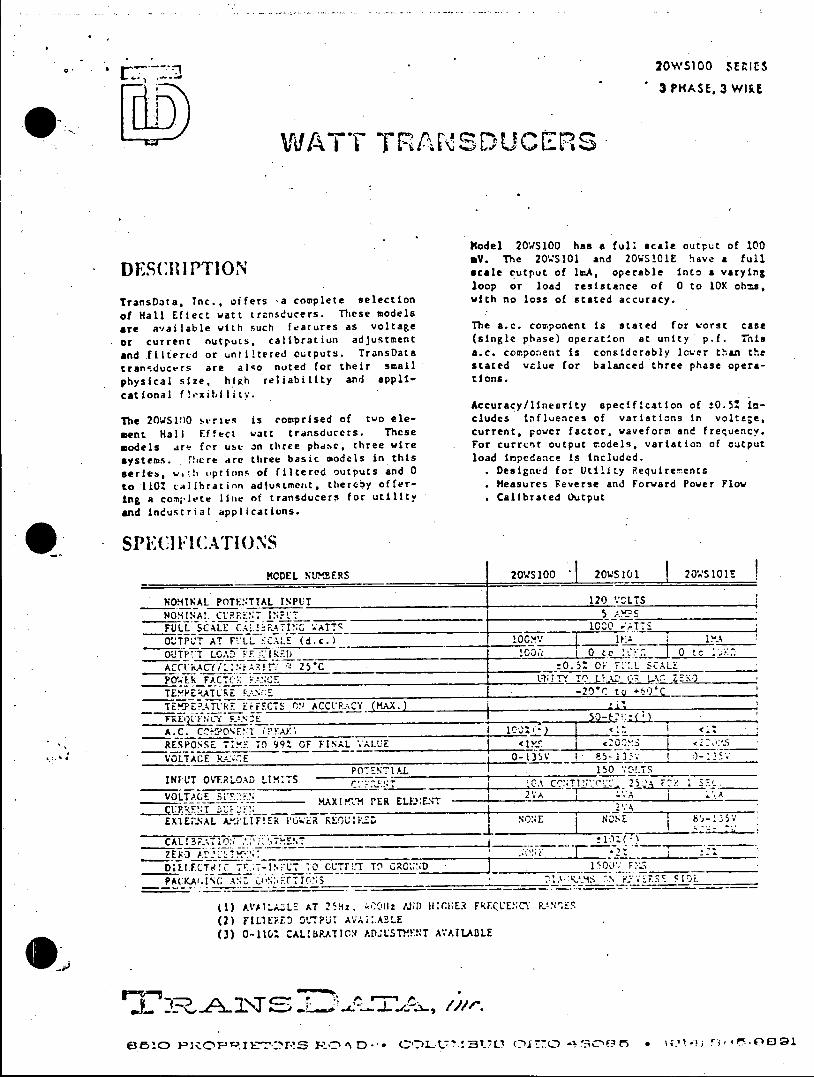
20WS100 SENIES
3 PHASE, 3 WIRE
WATT TRANSDUCERS
Model 20WS100 has a full scale output of 100 mV. The 20WS101 and 20WS101E have a full
DESCRIPION a cale output of InA, operable into a varying loop or load resistance of 0 to 10K ohms,
TransData, Tnc., offers -a complete selection with no loss of stated accuracy.
of Hall Effect watt transducers. These models
are available with such features as voltage The a.c. component is stated for worst case
or current nutputs. calibration adjustment (single phase) operation at unity p.f. This
and filtered or untiltered outputs. TransData a.c. component is considerably lcwer than the
transducers are alqo noted for their small stated value for balanced three phase opera
physical size, hiRh reliability and appli- tions.
cational flixibility. Accuracy/linearity specification of !0.51 in
The 20WS100 series is comprised of two ele- cludes influences of variations in volta;e,
ment Hall Effect watt transducers. These current, power factor, waveform and frequency.
models a.re for use an three phasc, three wire For currcnt output models, variation of output
systems. "!ere are three basic models in this load impedance is included.
series, weh options of filtered outputs and 0 . Designed for Utility Requirements
to 110 calibratinn adjustment, thereby offer- . Heasures Feverse and Forward Power Flow
Lng a complete line of transducers for utility . Calibrated output
and industrial applications.
SPEC FICATIONS MODEL NUMMERS 20WS100 20WS101 20'S101! .
NOMINAL POTENTIAL INPUT 120 VOLTS NOM11INA 1. CURREN-, INFLT 5 S
FULL SCL AF.A7IN0 AT f 1000 T O'JTPU
T AT FILL 5CALE (d.c.) 100V 1. I_. _
OUTP TT LGA . Ik 100__0 k 0 e O
ACCiiAC.f/4CY/' ARI'" ' 25%C !0.5"O Or FL:.L SCALE_ POVWER FACE:-: _______ LNJTY T? LEAD 97 L ZEKR
TEMPEcATLrE _.._ __. -20*C to +50C
TEMPERA.TV kFF ErFECTS OACCURiCY (MAX.) *1I
A.C. C.HPOET (P_____A______ 100%') 1 I < _______
RESPONSE TIM 7 99. OF FINAL VALUE <CMS <2
VOLTAGE RANCE 0-135V 8 5- 13. 1 0- 1
POTENTIAL 150 1*0!.TS INTUT OVERLOXD LIM:TS I.. 0CTI 2 FI 1 5__.
_____________ F___._ ________ _ 1CA C TI' 5 F -- ______
VOLTAGE EI*R 5 2VA 4VA 1A MAX! PER ELFE:ENT
EX1ERNAL A. LIFIER i'G ER REUIRZD NONE NONE 8 '
C AL f3R7-' :7 T T___
DIEl.FCT! -.0.;IN 0 CUTTI.T T_ GRO___ND 100V F__
PACKAr.INGANfi0::lCNS % R..'_ ____S_ ___5 ___.
() AVAILAZLE AT 25Hz, l D 1llCER FRECCENCY R.!N E5
(2) FILTERED OL'PUT AVAI:.ABLE (3) 0-110. CALIBRATION ADUSTM'ENT AVAILABLE
..e RA.o S C RvIID. *OA.(Ti -,*/w..
C-315 -I r) , -'03R Iart ! ~s.'oe Vrm T".D A'<TT IDT~ T -U :' (0171 axC-)9S * \41*'0<$*Ocg1
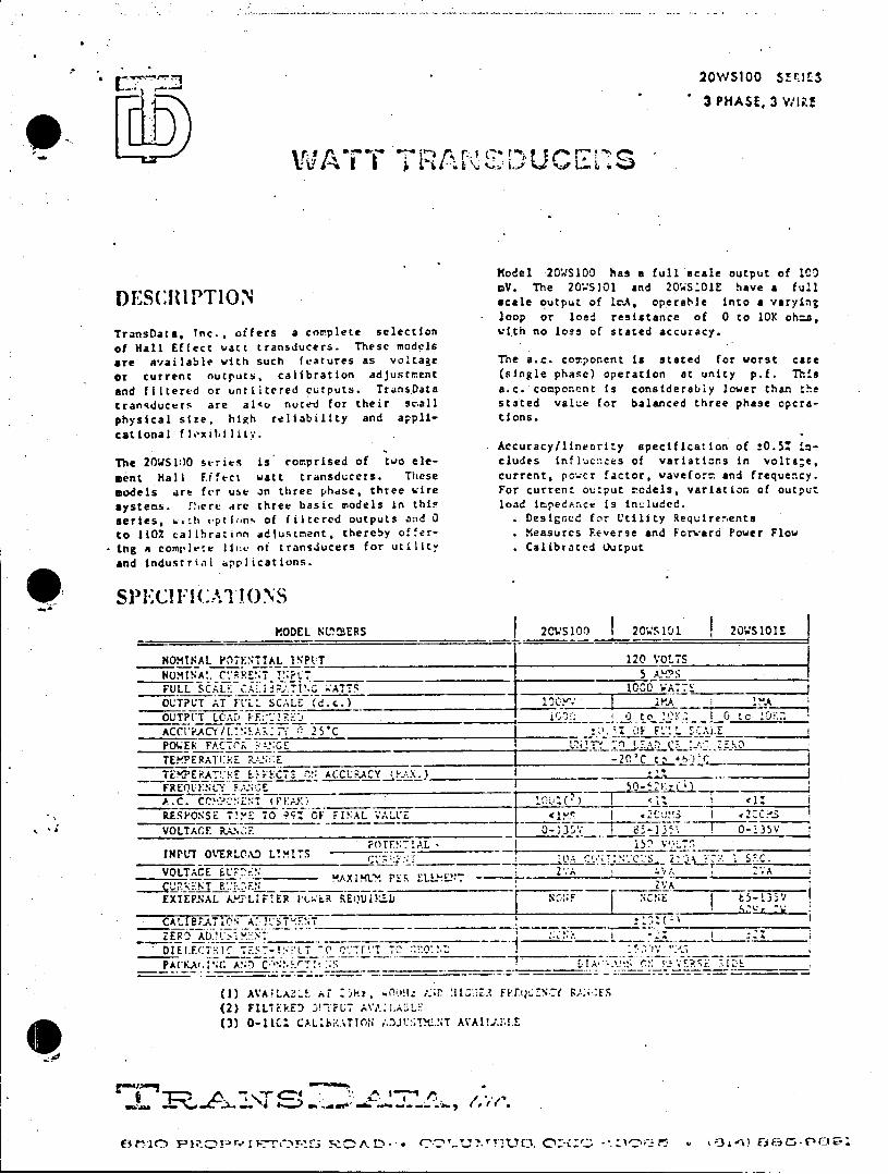
LIT 2.J20WS100 Srr.113 PHASE, 3 WI;.
Model 20WS100 has a full scale output of 100 aV. The 20WS101 and 20'WS101E have a full
'S. TOscale output of IrA, operable into a varying -loop or load resistance of 0 to 10K obsa,
TransData, Inc., offers a conplete selection with no loss of stated accuracy.
of Hall Effect watt transducers. These models
are available with such features as voltage The a.c. com.ponent is stated for worst case
or current nutputs, calibration adjustrment (single phase) operation at unity p.f. This
and filtered or untiltered outputs. TransData a.c. component is considerably lower than the
tran*-ducers are alqo nute-d for their smaIl stated value for balanced three phase opera
physical size, high reliability and appli- tions.
cational fl.xibilitV.. Accuracy/linearity specification of ±0.5: In
The 20WS1O series is comprised of two ele- cludes infljcnces of variations in volta;e, ment Hall Effect watt transducers. These current, powcr factor, waveform and frequency.
models are for use in three phdse, three wire For current output eCdels, variation of output
systems. There are three basic models in this load impedance is included.
series, w.th -prisons of filtered outputs and 0 . Designed for Utility Requirenents
to 110% calibratinn adjustment, thereby offer- . Measures Reverse and Forward Power Flow
Ing a complete Iline of transducers for utility . Calibrated Output
and Industrial 4pplications.
MODEL NU'BERS 2CS100 I 20VSV11 20WS101E
NOMINAL POTENTIAL l.INPUT 120 VOLTS NOMINAL C'_ __ENT I_ 5
FULL SCALE I -;ATTS 10CV AT7G
OUTPUT ;T FL'L. SCALE (d.c.)
OUTPUT LCAD o F IR E t ACCURACY/lAL C ________f: 25_C
POLER FACTCR '-.!.NGE 0 'OL~DF' 8 TEMPERATIEE E_._:E -20'C tz +_
TEMPERtAT'E :FFC7S fl! ACCURACY (KX. *''
FRE NLY E..NGE _ 16 'LLFIk A.C. Cc'2NiNT ('iK 107.( ) < 1 RESPONSE T!ME TO 9qZ OF IA ALUE <M S <200MS_<2 ____
VOLTAGE RAN2E 7 -0-1357 13, 0135V
POTFNIA.L 15U V':L-S INPUT OVERLOAD L!MITS -C . _g__ i T ' t:__2 SC.
VOLTACE ELF"Et ZAXIHL_. P L.A VA___A
(URR2NT E .__.___VA
EXTEP.NAL APLIFIER PI(R REQUIELJ NOF NCNE -3
CALIB.TiO' A'ST'ENT__ ___(
D IEI.FCT: -: T S7-b' LT " ft T -T2 10l ll A -PACKAA.NG .') ANC~ ::S 2IA X- C.
(1) AVAiLAB..! Ar dr, 400!1Z: .;llP FREQ:N _f ;k.ES (2) FILIERED DTFU7 AVA:LA!LF
(3) 0-11%c CAL b.ATION ,'.J1I.TXNT AVAIJ.11.E
YC ;3 AAEiFpC;0C12

'L-j-- -JJ 20WS100 SE!ES 3 PHASE, 3 Wi;.5
WATT TRAINUCES
Model 20WS1OO has a full scale output of 100 Vm. The 20VSI1 and 20WS101E have a full
'ES RITO scale output of Ir.A, operable into a varying loop or load resistance of 0 to 10K oh:s,
TransData, Tnc.. offers a complete selection with no loss of stated accuracy.
of Hall Eftect watt transducers. These models
are available with such features as voltage The a.c. component is stated for worst case
or current Outputs, calibration adjustment (single phase) operation at unity p.f. This
and fIltered or unt.iltered cutputs. TransData a.c. component is considerably lower than the
transducers are also noted for their small stated value for balanced three phase opera
physical size. high reliability and appli- tIons.
catitonal f lixibilIity. Accuracy/linearity specification of !0.51 in
The 20WS100 straes is compribed of two ele- cludes influences of variaticns In voltae.
went Hall E!fect watt transducers. These current, power factor, vaveform and frequency.
models are for use cn three phase, three wire For current output models, variation of output systems. !lsere Are three basic models in this load impedance is included.
series, 6*h vption% of filtered outputs and 0 . Designed for Utility P.equirenents
to 110% calihrationadjuStMent, thereby offer- . Measures Reverse and Forward Power Flow
Ing a complete line of transducers for utility . Calibrated Output
and Industrial applications.
2 ; Il':III'H:AllIl)\S
MODEL NIMERS 2OWS I LI I 2OWS101E
NOMINAL POTENTIAL INFUT 120 VOLTS
NORINAL CURRENT INPUT _
20VS10 20L510 I20k'S101-.
FULL SCALE C.41.1RAIN ATTS 10^O ;ATTS OUTPLT AT FULL SCALE (d.c.) 100KV 1. lA OUTPtT L(AD
1UIRED 100_ I0o 0 .
ACCkA'"Y/t :.EAITY. : 25'C _0.5_ OF F .L SC.1.!E
TLMP~.LVE ?..'E -2tC tg *)
TEP.RVL'E EFFECTS C'N ACCURACY (MA) FFE'?1ANCY F_-1_1, 3 E oA1*. A.C. COC:ENT (Pay) 10-: It _ _ <1 _
RESPONSE TIME TO 99t OF FINAL .ALUE <IMS 200.sI <M:S
VOLTAGE i.P.tE 3-135V 35-15. I C-8-55 POTENTIAL
INPT OVEPLOAD LIMITS C' T ;:T 2' F.,K
VOLTACESLTIFN RAX1ER~t E.F..T
CUR*!'* T 2 A
EXTERNAL AkLIFIER F0 ER REQUIRED NONE 1 NCNE 65-13"'
CALIAC.'A .T.NT 1__ _)
2ER AD.. :':^ __ __1| *2::
DIEUCTKIC F':T-!p'UT 10 OUTP5T TOCGRU) i 1500V R__ _ _
PA(:KAi.1WC. AND C !KTCN' ______-- *S~c~.C ___
(1) AVAILABLE AT 25!!z. 4COM .ND Il .2 F. F LENCY ..NG. (2) FILTEkED 01TPUT AVAILALE (3) 0-111. CA1IbRATION ADJLSThENT AVAILLB!.E
r-1(7 -1*39 .W 2RANS 2 r.TA, iwr.
E545510 PFEL.TCEMT'0T -8 ?<311 * CQ3.17'ITBC17C ~- OCD3C * 014' 8 2 .. r

Lfl4 L ( A B
0o O
L OUTPUT
00 031 20v
0 0 0 it I?
789 1011 12 .
a I ExT
PAR. R. sLOAD
Connection diagram to a three
phase three wire line using
current and potential transf orme rs
Dimension A The external power for the
20WS100 .......... 3 1/4 amplifier for nodel 20WS101 E
20WS101 .......... 4 is connected to terminals 9 and
20WS101 E .......... 4 12. On the other models these terminals are unused.
Mounting holcs (4).. 3/16 Dia. The dots shown on the trans
Can is steel with integral formers are relative polarity
mounting flanges. markings and show. the proper connection polarity. Instru
Terminal screws are 8-32 ment trarsformer terminals are
binding head. marked with a dot, a ± symbol or other identifiable mark on both primary and, secondary. Failure to observe the proper polarity may result in erroneous readings.
Grounding consideraticns may dictate connectirg thie prir.ry opposite from the way shown. This is pervissible if the secondary is also reversed, maintaining the same relative polarity.

LIM A BC
-120v
DCB
o o OUTPUT
I __
?*9* LAD
Dimension A
20S10 .......... 3 1/4
20WS101..........*** iscnetdt emnl n
20WS101 E ..........
Mounting holes (4).. 3/16 Dia.
*Can is steel with integralfomr ae rlaie oart
mounting flanges. mrig n hw te poe
Termiinal screws are 8-32 mn rnfre emnl r
Connection diagram to a three
phase three wice line using current and potential trans
formers.
Dimension cosdrtinAa
The external power for the.
2OWS00 ........ 1/4amplifier for model 20WS101 E
20WS11 ........ 4is connected to terminals 9 and
20WS01 E ........ 412. on the other models these
terminals are unused.
Mouninghole (4.. 316 ia.The dots shown on the trans
s wformers are relative polarity markings and shw. the proper connection polarity. Ins tru
,ermnal crew are8-32ment transform-er terminals are
binding head. marked with a dot, a ± symbol
or other identifiable mark on
both primiary and secondary.
Failure to observe the proper
polarity ma2y result in erroneous
.readings.
Grcunding considerations mray
dictate conne-cti-ng the prima:ry
opposite from che way shown.
This is permlissible If (he
secondary is also reversco,
maintaining the same relat i'.0
8 polarity.
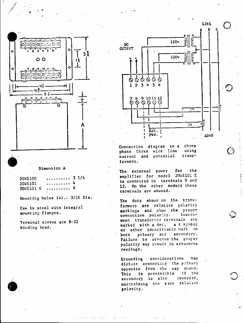
/
LME
A B
O 0 120v
H e , 13~b - 2T
__ r1.ll 5
8 9 101 12
ro
-1)-_ LO&%D
-Connection diagram to a three
phase three wire line using
current and potential trans0 - formers. Dimension A Dimenion AThe external power for the
20WS100 .......... 3 1/4 amplifier for model 2OSl03 E
20WS10......... is connected to terminals 9 and 20 S101 ......... *.
20S 101 E ........... 4 12. on the other models these terminals are unused.
Mounting holes (4).. 3/16 Dia.
Can is steel with integral formers are relative polarity
mounting flanges. markings and show. the proper connection polarity. Instru
Terminal screws are 8-32 ment transformr terminals are
binadCng head. marked with a dt, a t sybor or other identifiable mark n
both pricary arnd secondary.
Failure to otserve the proper polarity may result in. erro .necus readings.
Grounding considertios hay
dicote cnnectial the p9 ary
opposite from the way sthon. This is permissible ia the
secondary is also everscy
main s dhniowg the spme relrLiVe polarity.

A B C
o o OUTUT 10
00 120v OI
o o
41 2 3 4 5 6
II I4,
rk "=1~K 7 (3 9 101112
711
IExt. I L04D
Connection diagram to a three phase three wire line using (T
formers. poeia
Dimension A The external power for the.
20WS100 .......... 3 1/4 amplifier for model 20WS1O1 E
20WS101 .......... 4 is connected to terminals 9 and
20WS101 E ........... 4 12. on the other models these terminals are unused.
Mounting holes (4).. 3/16 Dia. The dots shown on the trans
Can is steel with integral formers are relative polarity
mounting flanges. markings and show the proper connection polarity. lrnstru- .
Terminal screws are 8-32 ment transformer terminals are
binding head. marked with a dct, a ± symbol or other identifiable m.ark on
both pritnary and secondary. Failure to ose.rve the procr polarity ay result in erroneous readrgs.
Groundini consideratirns 9ndy dictate ,orctn tnt: rriry
opposite from the ay shown.
Thin is permissible if tne
secondary i s also reversed, omintinag re same relative
polarity.

. A B C
o 1 3365 120vU
~f 123456 .
E 0 1
00
I(Si
LOAD
Connection diagram to a -three
current and potential. transformers.
Dimension Ath Dimc~sin AThe external power for th
20WS100 . ........... 3 1/4 amplifier for model 20.S1O1 E
20WS101 .......... 4 is connected to tern**nals 9 and
20WS101 E .......... 4 12. On the other mcdels these teritin--1s are unused.
Mounting holes (4).. 3/16 Dia. The dots shown on the trans
Can is steel with integral formers are relative polarity
mounting flanges. markin-s and shOw. the propcr connection polarity. Instru
Terpinal screws are 8-32 ment transformer terminals are
bininCanc markd wiah a dot, a ± sybol
or other identifinble uark on
both primary and secondry.
Failure to observe the proper
polarity may result in errncu readings.
Groundi ng ccrnsiderationfs ray
dictate connecteinal the pri r
oppcntte from the oay s shown.
Thd is pernssib e in the
secondary is also reversid, mintaining the same relatrv
polatio.
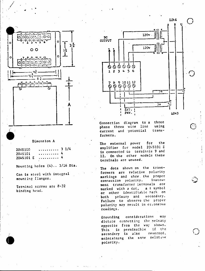
A B 'C
120v
DAC
o. 3 o 1OUTPUT
001 -p1 OT 3
120v
0 0
I x 7 1k0 S P&*WLAD
Dimension A
2 S100 .......... 3 1/4 20 M 101 ........ * i
20WS101 E............ 12 nte ohr mdl hs
Mounting holes (4).. 3/16 Dia.
Can is steel with integral omr r eaie plrt
mounting flanges.mains ad hc. he por
Connection diagram to a three
phase three wire line usingC31
current and potential transformers.
. The external power for the.
201-S10 ........ 31/4amplifier for model 20''S101 E
20 n 101. ris connected to terhinaols 9 and
12. On the oter models these terminals are unused.
The dots shown on the trans
formers are relative polarity
markings and shcw. the proper connection polarity. Instru-,
ment transformer terminals are
binding head. marked with a dot, a + sym~bol
or other identifiable mark on both primary and secondary. Failure to observe se proper polarity may result in reoneous readings.
Grounding considerations may
dictate connecting the primary
opposite from the way shown.
This is permissible if thre
secondary is also reversed,
maintaining the same relative
polarity.

LINE A B C
o o --0 OUTPUT 10
OO I
20 fS10 0 ..... . 1 VT
4 4 L
outng hoe (l).. 3/62ia
A ; 3a
I. SLOAD
- 4Connection diagram to a three
20W100phase three wire line using 7 current and potsntial trans
formers. eThe external power for the
1/4 amplifier for model 20'n'S101 E
20WS101...........4 is connected to terminals 9 and
20WS101 E...........4 12. On the other models these
terminals are unused.
Mounting holes (4).. 3/16 Dia. Tedt hw nte tas The dots shown on the trans
Can is steel with i lformers are relative polarity
mounting flanges. terarkings and show. the proper connection polarity. InsLru
Terminal screws are 8-32 ment transforter terminals are
binding head. marked with a dot, a ± symbol or other icentifieble mark on
both primary and secondary.
Failure to observe the proper polarity may result in erroneous
readings.
Grounding consldcrations ray dictate connecti. the primary
opposite from the way shown. This is permissible if the
secondary is also reversed,
maintaining the same relative 0I polarity.

A B C
120v DC OUTPUT
00
O o
123 456
r. 2 6 9 1011:12
I b'5
r0
EXT. -I AOA V 8* IDAD
Connection diagram to a three
phase three wire line usingQ current ,and potential trans
Dimension A fr te The external power fo th
20WS100 .......... 3 1/4 amplifier for model 2OWS101 E
20WS101 .......... 4 is connected to terminals 9 and
20WS101 E .......... 4 12. On the other models these terminals are unused.
Mounting holes (4).. 3/16 Dia.
Can is steel with integral forrers are relative polarity
mounting flanges. markin-s and show. the proper connection polarity. Instru- L
Terminal screws are 8-32 ment transfor-rer terninals are
binding head. marked with a do*, a ± symbol or other identifiable mn2rk on
both primary and secondary.
Failure to observe the proper polarity may resilt in crrcneous readings.
aromndin considerations 1 ay
dictate connectn the priary 1pponte f!fo the modal thowre.
This is pernissible if the
secondary is also rvrsid,
maintasnisg she Sate relative
cpolarty.

A B
120V. DC F
10 ~ 7~Y 6 OOUTPUT
30 120V
7 8 9 1011 12
1:,0 I I-I
Connection diagram to a three phase three wire line using current and potential transformers.
Dimension A . The external power for the
2OWS100...............3 1/4 amplifier for nodel 20'4S101 E
20WS10....4 is connected to term:inals 9 and
20WS101 E........... 4 12. On the other models these
terminals are unused.
Mounting holes (4).. 3/16 Dia. The dots shown on the trans
Can is steel with integral formers are relative polarity
mounting flanges. markings and shcw the proper connection polarity. instru
Terminal screw3z are 8-32 ment transformer terminals are
binding head. marked with a dot, a ± symbol or other identifiabla mark on
bcth primary and secondary. Failure to observe the proper
polarity may result in erroneous readings.
Grounding considerations nay dictate connecting the primary opposite from the way snown.
This is permissible if rhe secondairy is aiso reversen,
maintainin3 the sar'e relatve polarity.
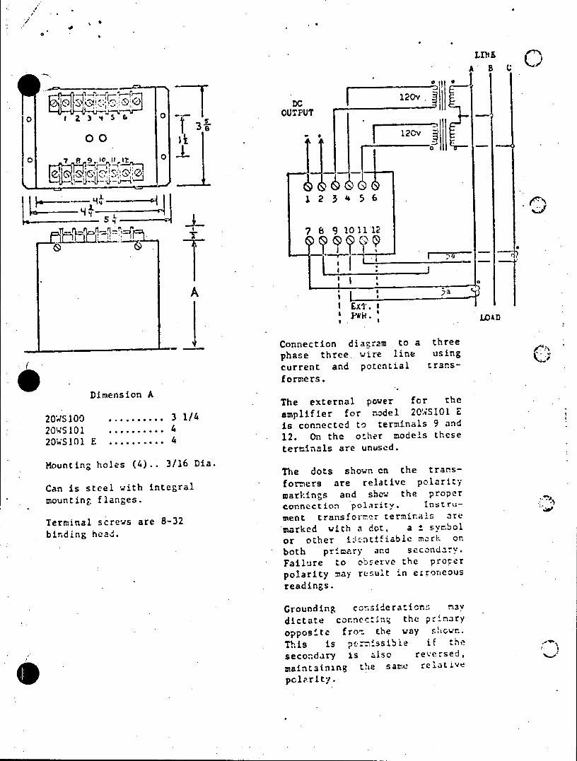
A B C
o DC 120v.
1 2 3 4 0 OUTPUT
-3
H, 5a 6~ 4-1 Lx
oo01 .1 12
o O om
Dimension A
20 100 .......... 3 1/4 amplifier for nodel 20WS1
20WS101 ........... 4 is connected to terminals 9 and
20WS101 E ........... 4 12. On the other models these terminals are unused.
Mounting holes (4).. 3/16 Dia. The dots shown en the trans
Can is steel with integral forners are relative polarity monig lne.markings and show, the proper J
mounting flanges. connection polarity. Instru
Terminal screws are 8-32 ment transfortm2 terminals are
binding head. marked with a dot, a *± sym~bol or other iz-_ntifiable mnark~ or.
both pricary and. secondary. Failure to observe the proser polarity ay result in etroneous readings.
Grounding ccTsiderationr thv
di connectmina the prinary opposnte fro the way slhew. This is pea-issible if the secondary is also reersed, maintainig the sap relaLiVe pcolriti.

A BC
o o 00 UT120v .
0O O 3 .4 . 6 120v o o UTU
00 120V
0 7I E
i.2 0 1
phsrheewr in sn
*~ ~ ~ ~~~ 10mpi1e1ormde10'210
20 100 ... ... .. s/isConnecte di g a to mi al 9hand
thaemnl ahre unued.na usn
Mouning oles (4) . 3/6 Di .rT endts shd otnothel trans
formers a
Can isera pteel with intgra amarkfigs and shode 20'the0 poEr
mecntetransfoe terminals 9are
Terminal scr ws are 8-32mrk d l it a un d . t s m c
biunding hoes or). 3/6Da h ote idewntifiable m anso
Can i rtee w~ interalbother piary eandv peondary.
Failure to o wrv the proper
montngflngsGmrounding on siei n ma
dtconnecti lrthe Insru-r
Terminal ~~~ ~ hi icesae83 et tasforer tess ibl afrte
makd wthado ,a. ,!.c
seondaprisr also sevondred
maailnng th ~se ste rltie
polarity.myrsl i roeu
~~-44---4 I
Grunin cnidraios6a
- - - onec onr ials o a tree phasenthreen wte line!:,a uing 0 pourtyadp.eta tas
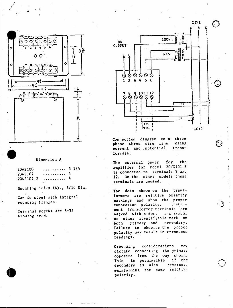
*A e LIVE
.A' BC
ooUUT120v
I Z~--' 3 _45 ___0OUPU
.4_ .54
Aa SPWR* ' 14
phase three wire line, using current and potential trans
formers. Dimension A
The external power for the.
20S100 .......... 3 1/4 amplifier for model 2QWZlOI E
2O'S101 ........... 4 is connected to terminals 9 and
20WS101 E ........... 4 12. On the other models these terminals are unused.
Mounting holes (4)., 3/16 Dia. The dots shown on the trans
Canis tee wih itegalformers are relative polarity Can is steel with integral markings and sow the proper mounting flanges.
connection polarity. Instru
Terminal screws are 8-32 ment transformer terminals are
binding head. marked ith a dot, a ± symbol or other identifiable mark on both primary and secondary. Failure to observe the prcper polarity may result in errozncous
read-Ings.
Grounding considerations may
dictate connect o then rinary opposite from the way shown.
This is pernissihe it the
secondary is also reversed, tsintainng the sape relatve
polarity.
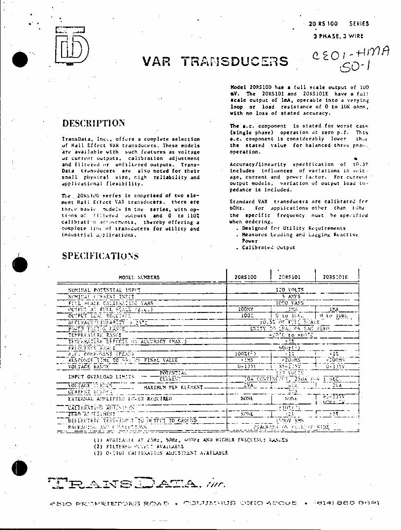
20 RS 100 SERIES
3 PHASE. 3 WIRE
'"R~~~~ AO r ISDU 71o VAR TRA1SDUCS
Model 20RS100 has a full scale output of 1U0 V. The 20RS101 and 20RS101E have a ful!
acale output of lmA, operable into a veryinq loop or load resistance of 0 to 10K ohs, with no loss of stated accuracy.
DESCRITION The a.c. component is stated for verst case (single phase) operation at zero p.f* This
TransData, Inc., offers a complete selection a.c. component is considerably lower th.,t of Hall Effect VAR transducers. These models the stated value for balanced three pha!.-. are available with such features as voltage operation. or current outputs, calibration adjustment and filtered o*r unfilt.ered outputs. Trans- Accuracy/linearity specification of t0.57 Data transducers are also noted for their includes influences of variations in yIt
small physical size, nigh reliability and age, current and power fac-tor. For cLrrert
ipplicational flexibility. output models, variation of output load irnpedance is included.
The 20KS00 series is comprised of two element Hall Effect VAR transducers. there are Standard VAR transducers are calibrated frr
thre basic mc.dels in the series, witn op. 60Hz. For appitcations other than tC0i
tions of fi:tvrvJ outputs and 0 to 110w the specific frequency must he specified calibrati- -n.i r.stnts, thereby offering a when ordering. complete line of transducers for utility and . Designed for Utility Requirements industrial applicaticns. . Measures Leiding and Ligging Reactive
Power Calibrated output
SPECIFICATIONS
MO)EI. NLERS 20RS100 2'0RS101 20RS101F
NUM!.NAL POTENTIAL NPI? 120 VOLTS N____ I A! < RENT INFLT________ AS F,!.L 4tALE CA:.15S 1.11O VARS OUTIl A- Ft'! .,:'_ rc.. ____ 00XV ____ ___
OLt.PLT LC. L 10. (. ' lIfFoIKC
TE YPr E i ____RN__._F C to t*.. _ _____
AKATTIZ.k C "I ACCURACY (A.)
ESPONSE TIM- CO : DC- FINAL VALUE
KIT~~ FNTSA
]SPLIT OVRM.OAD LIX'T7 L of:L -:~.C. ~.)Vi C~~i:RUN'7___ _ i ~ ~ 'O CTNz' 5A SEC.
%OJ100 :A. -S 2 ~ovr~c ::::rL!: AX IWL) PEP~ EI.F-.,'ET
* :(E,.ENA1. A>-!FLl FI's . RiQL1RED NOE \ON t
CAL10.0oTi1 I. A!0: to.>lsN.
DIUFLC:THIC T;- T., 01 UPV TO ri.0!'1;D ML S,
VOLACE!:C C"A6 ';
i1) A'Al! A:.1. A7 25H:, 50Hz, 40*"It0 AND HICHER FRQuEL E.AN' - S (2) FILTEki, .? AVAILAELL
(3) 0-10CEAI ADS N AreAILABLE
P~ir7 r-r X E'~" O - "'T,]. LTTD-1 . 0 -1)8 tsG
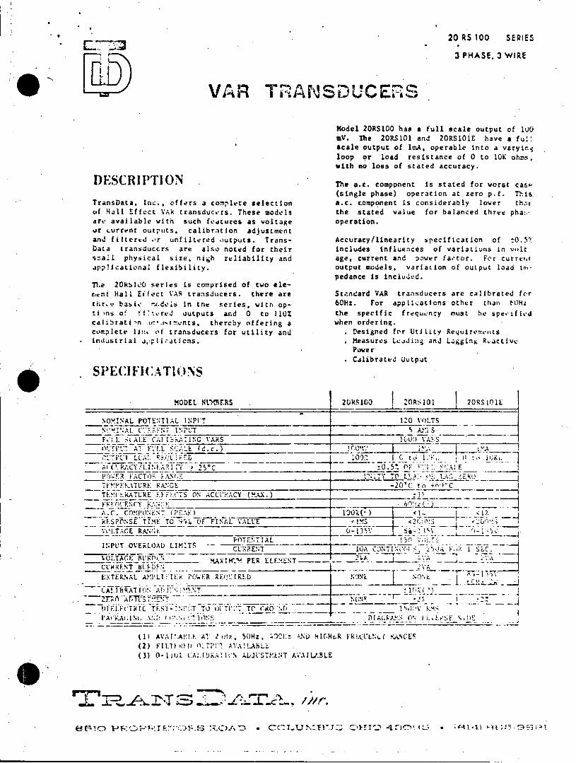
20 RS 100 SERIES
3 PHASE, 3 WIRE
VAR TRANSDUCERS
Model 2ORS100 has a full scale output of 100 mV. The 20RS101 and 20RS1OiE have a ful: scale output of ImA, operable into a varyinq loop or load resistance of 0 to 10K ohms, with no loss of stated accuracy.
D ESCRIPTION The a.c. component is stated for worst case (single phase) operation at zero p.f. This
TransData, Inc., offers a complete selection a.c. component is considerably lower thor of Hall Effect VAR transducers. These models the stated value for balanced three pha.* are available with such fedcureS as voltage operation. or turrent outputs. calibration adjustment and filtertd or unfiltered outputs. Trans- Accuracy/linearity specification of t0.51 Data transducers are also noted for their includes influences of variations in volt szall physical size, nigh reliability and age, current and power factor. For curret applicational flexibility. output models, variation of output load in
pedance is included. The 20K:l00 series is comprised of two elecment Hall Eifect VAR transducers. there are Standard VAR transducers are calibrated for
thr*. basic n..dels in tne series, witn op- 60Hz. For applications other than NOHz
timns of utcred outputs and 0 to 110% the specific frequency must he spectfied calibrati n ar.drents, thereby offering a when ordering. comr.plete lin. of transducers for utility and . Designed for Utility Requirements industrial aJplications. . Measures Leading and Lagging Rvactive
Power
Calibrated output
SPE(I FI CAlT(.NS
MODEL NLuMERS .20RS10 20RS101 20RS101E
NOMINAL POTEENTIAL INT 120 VOLTS
F'L.I. WAL.E Cl I iNC VARS E_00 AA-S. OCTFC ATrF'.*.L SCAE(d.c.) !_OL i1i. A( C'.RACY!Lt.A?.I F * :0.5. OF ''FF ____,I
FOL:ER FACTOR FANGE __ UNTY TO L.A .":
.......... TUR AGE -20'( to +6rT c TLTE RATLRE EFF.CTS ON ACCLRACY (MAX.)
~ 0' ~ ry~N~: 1/60'.1 A.C. COPOEN 1PC".
__SPONSE T O F FINAL VALUE VOLTACE RkA:L4F
POTENTIAL INPUT OVERLOAD LIMITS - -----CUX.RENT l) ,,A Vi IS C L.GTACE BURPi..L tAXIM'- 4 PER ELEMENT- __ -- -CCHRENT 8000________
E:.*TERNAL A!'PLI YIER POWER "EQVIR.D 'N.
ilEJ~CTRIC TES1 - ".N'tT TO 01 TI1'T TC (RO :.ri tsV S AA tA; Ni..-*,! I ~ DIAGRA. :3 0% [i..Lt SE D
(I AVAf:A!!1.E AT 2 ut, * 50Hz, ')0t:: -.ND 4l.H6R FRP.(LEN'f KANCES
(2) F11il1.0H) OILT~il A.A!LABL
(3 -1W1I*JKIISAAUT*'L' VALL
r'c =0 F0-f~(3 ~ ' cTU.EJ.ClI~43~' £.* c~.l~;'
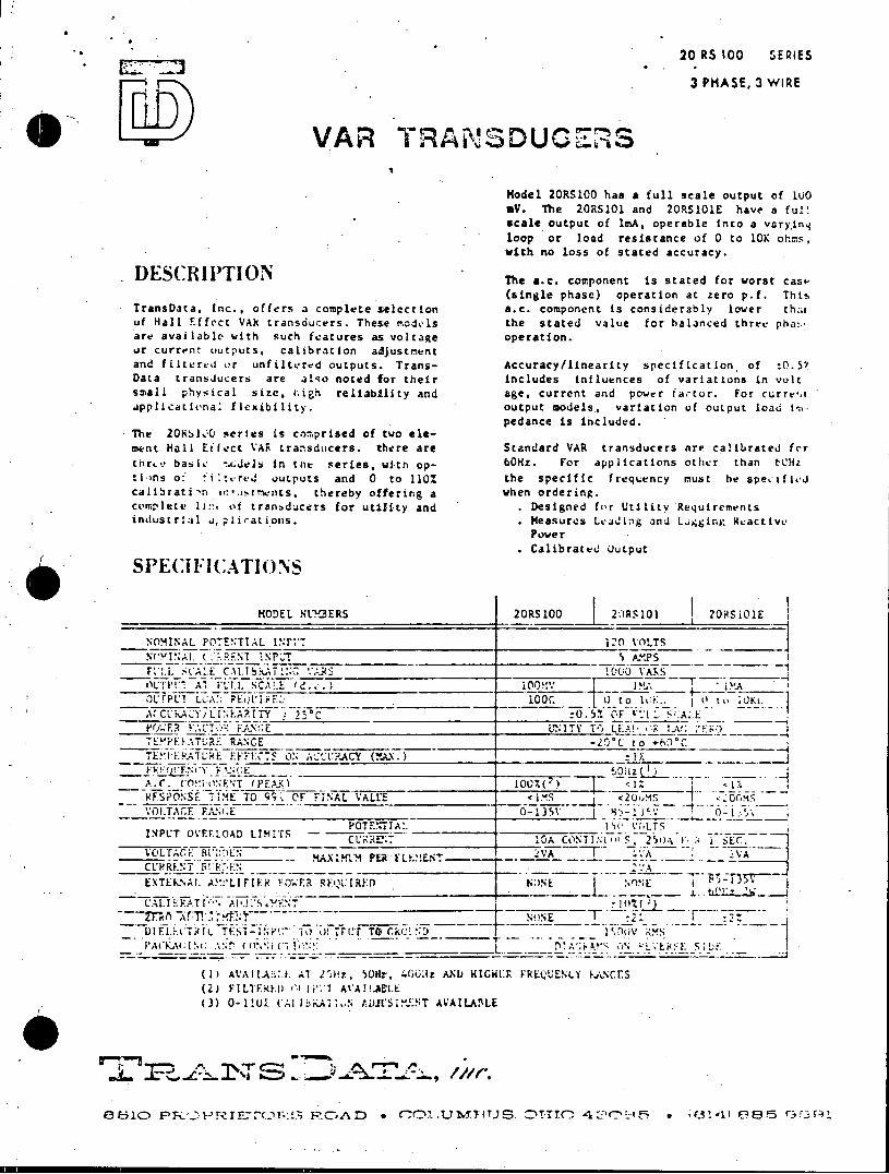
20 RS 100 SERIES
3 PHASE, 3 WIRE
VAR TRANSDUCES
Model 20RS100 has a full scale output of lu0 aV. The 20RS101 and 20RS101E have a full scale output of imA, operable Into a varying loop or load resistance of 0 to 10K ohms, with no loss of stated accuracy.
DES(RIPTION The a.e. component is stated for worst casp (single phase) operation at zero p.f. Thts
TransData, Inc., offers a complete selection a.c. component is considerably lower th:a uf Hall F.ffect VAR transducers. These models the stated value for balanced three pha:are available with such features as voltage operation. or current outputs, calibration adjustment and filtered or unfiltered outputs. Trans- Accuracy/linearity specification of tO.57 Data transJucers are also noted for their includes influences of variations in volt small physical size, ;igh reliability and age, current and power factor. For curre-,t applicational flexibility. output models., variation of output load in
pedance is included. The 20KS100 series is comprised of two element Hall Effect VAR transducers. there are Standard VAR transducers are calibrated for thre basic -.GJels in tne series, witn op- 60Hz. For applications other than tCHz
tins of fi t red outputs and 0 to 110% the specific frequency must he specified calibrati'n tso.it-tments. thereby offering a when ordering. complete l:!. ot tranbducers for utility and . Designed for Utility Requirements industrial aplicationis. . Measures Lcading and L.gging ,Ractive
Power
Calibrated Output
SPE(1I C .4TIONS
MODEL NLIBERS 20RS100 20RS101 20HS101E
NOMINAL POTENTIAL 1N*F- 12n VOLTS NPI .!.( .RENT NPUT S A.PPS
F*2.i. .CA.E CAl.!b:LATING I..:(< 1000 VARS OCTV'1 A, FULL SCALE (d. .) 0 'J1 . .A
1t'TPUT LCA:; PQFi E:'ii~ . _ L0 o0 to 1F.. 0 to ACKACYL I' EA.ITY :2C :0.5. OF F'I _'_A.__E
VOj-F .CT- FANE UNITY TO- Li..!- L A E EYPERATURI: RANCE -2?C to t,.C
TE.l K.ATLRE EFFECt ON ACURACY (M.)
A.C .O FET (PEAX)___________ 0%~ .2i~ NSO Sr TIME TO q91 OF FINAL VALE.s
POTEIALUL INPLT OVERLOAD LIMITS -. A TI VOLTAGE: BDEN MAX IIfu PER L FM ENT;7--CLRf.NT -%! _N
~z~?vxn ~'F _____NONE F
- PA C 61; 1 P .% -- r ( .1"' ____ C-, I_____~k
(1) AA IA;1. AT flI'. 50ftz, 4663ti ANJ HIcWI:RF FREQtUENCY 1,\NCES (2) F LF1.007.()< AVAIAtLE
(3) 0- 1 !1. (Al I:bKA t. ,aj S i.1NT AVALLAITiLE
Fb',C~lS) *T10 CONTIN S.5 (301 -1SEC-4 F.5 f-3 I

20 RS 100 SERIES
3 PHASE, 3 WIRE
VAR TRANSDUCERS
Model 2ORS100 has a full scale output of WO0 MV. The 2ORS101 and 2RS101E have a DuP scale output of lmA, operable into a varytna loop or load resistance of 0 to 10K ohms,
aith no loss of stated accuracy. DESCRIPTUION The a.c. component is stated for worst casip
(single phase) operation at zero p.f. This TransData. Inc., offers a complete selection a.c. com~ponent is considerably l'o%. e r th:at of Hall Effect VAR transducers. These models the stated value for balanced thre.e pha... are available with such features as voltage operation. or current outputs, walibration adjustment
and filtered or unfiltered outputs. Trans- Accuracy/linearity, specification of t0.57 Data transducers are also noted for their includes influences of variations in volt smaLl physical size, .iigh reliability and age, current and power iactor. For rurrent applicational flexibility. output. models, variation of output load im
The 20R!)l00 series is comprised of two element Hall Effect VAR transducers. there are Standard VAR transducers are calibrated for thre basic -adels in tae series, with Op- 60Hz. For appications other than tCz tiins o ilt.erJ outputs and 0 to 110% the specific frequency must he specIfied calibrati ,n .rlt,tminrs, thereby offering a when ordering. corplete line ot transducers for utility and Designed for Utility Requirements industrial ajppli-atiuns.. Measures Leiding anJ Ligging Ractive
Power Calibrateu output
S PECI F]C AT! 0 15
VODEL TERS 20RS100 20RS101 20RS101Eave caALl oPTEuTIAL !o A e e aT oavar
loopS or load r Saneo0to1Ko
O: P AT FULL SCA .. (d. c .* lorC t, I7
ThPe( LCAa KEQLl loc. c o t s t s ft A( C-iUkCY, INA1f 25-C Q._______ 15% _Fl 1"'.C E
(singl phas) oEAtina:eo-.Ti
_____-___________ -- ____ -20'C to ** -- C ___
T E*!Ii.K rR E.. E F FC 7 ON- ,L' R.%Y ("AX. : ____ ~ _______
aTc component i cosierbl loe thato C
~r,-, S _ TME o F- FI AL TALUE <2Ju- S 2(i I
INPU OVRLA LIMITSEN 250 C'!:k~ I SEC.
CA! I PATLION All It"; iMYN! i;0NE
incldes nflenceNofvaritios invot
1)f ,;T k IC -T-ESiT *- I LP. - 75 _T T-1-T T ROR0' D 1 "-0 *-.
(1) AVAIIAAI. AT 25Hz, SOHz. a0OHz Acre HIaHn FRpoQL' atr F rNrES (2) FlI.TJVR I OWTP' AVA A%I.L (3) 0-1 l0t LAI.!!KA~. Lc' AL*STMEZNT A*.'AIABLE
pdciinue
6151 PRO T-~r~~ R AD CCLMStandardil V tansdcer ar caibrated~ forP
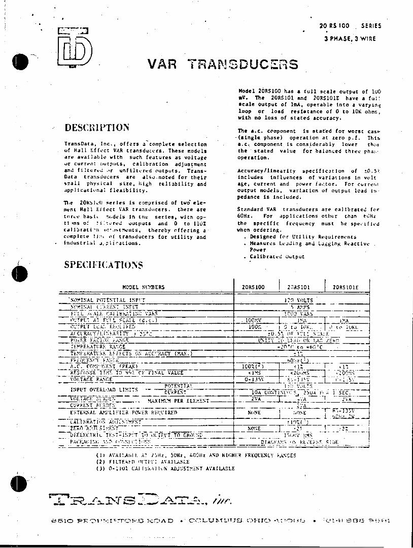
20 RS 100 SERIES
3 PHASE, 3 WIfRE
VAR TRANSDUCERS
Model 20RSIOO has a full scale output of 100 mV. The 20RS101 and 20RS101E have a ful: scale output of 1mA, operable Into a varying loop or load resistance of 0 to 10K ohms, vith no loss of stated accuracy.
ES4IIl The a.c. component is stated for worst caso-(single phase) operation at zero p.f. This
TransData, Inc., offers a complete selection a.c. component is considerably lower th;i of Hall Effect VAR transducers. These rodels the stated value for balanced three pha:.. are available with such features as voltage operation. %)r current outputs. calibration adjustment and filtervd or unfiltered outputs. Trans- Accuracy/linearity specification of t0.5' Data transducers are also.noted for their includes influences of variations in volt small physical size, high reliability and age, current and power factor. For curreto applicativnal flexibility. output models, variation of output load im
pedance is included. Tie 20Kibl, series is comprised of two alement Hall Eifect VAR transducers. there are Standard VAR transducers are calibrated for turse basbi !r.dels in tnt series, with op- 60Hz. For applications other than t0He ti 'ns of f ilered outputs and 0 to 110% the specific frequency must be spetfied calibrati'n 4.:*cstents, thereby offering a when ordering. complete !J: (it transducers for utility and Designed for UtIlity Requirements
* Industrial j,.plic-ations. . Measures LeaJing and Ligging Reactive Power
Calibrated uutput
SPECI l( :ATlONS
MODEL NUBERS 20RS100 2RS101 20RS101E
NOYINAL POTENTIAL INP'T __0_ VOLTS
FN !.LIN tAl 11 A i. 1S AIINU 1_ A APS.
I.,. ';A:AL EEO;A i F; 100". !'Ci. 10 Tk I J KA(PLt A ft! ' "ALE (d c.) _ ! 1 A.
O77LP 1.c.. F.?., iLr OR . .t, ,l
A(CURACY!I .EARIT____________________ . :.5o"C
TEYPFAATUR' RANGE 2rto+.ic Tr..IEKATL d F. hFECTSC ACC".4'CY (.AX.-.)
A.C. COMPO'ET (PFA.K) _1)
RE.SPONSE TIM~ T" 92 CF FINAL VALUE _ UM - MVOLTACE PAN_ __GE
POTENITA!. INPUT OVERLOAD LIMITS C__PEN
-. REN 10 _____j OCOTINL' c 25UA F, k SEC. 1 VOLTAGE~ --RDE RAXIwLN PER ELEM*T--- CLRRENT F!.D.A
EXTERNAl. AP'LIKIER PO'd:R PecIRED) O
10R0'. t T 0 IS f t1. i tE W0 .
(IJ AVAflABiI L Al ' /4. 50Hz , 4rC-11z AND HIGHE 1 FRQCOEN NY k.SCES (2) FILTFD ofl TIT' AVA!LAMLE (3) 0-11U0 CAlI k~ll : ADJUSTM'iNT AVAILABOLE
CO,.1.'-7S! .... : A 'T ."., 7 e. I
e510 PRO T-:I,77OPL, UOA *, CO T.7T_.C>. O-1I1 0 0 0_1-4) 00t5.a

20 RS 100 SERIES
. _3 PHASE, 3 WIRE
. VAR TRANSDUCERS . Model 20RS100 has a full scale output of lijo mV. The 2ORS101 and 2ORS101E have a ful! scale output of lmAT operable Into a varinD loop or load refiHance of 0 to 10K ohms, with no loss of staaed accuracy.
DESCRIPTION The a.c. component is stated for worst cs (single phase) operarion at zero p.f. This
TransD.:ta, Inc., offers 3 comple'te selection a.c. co.mponent' is considerably lower thai of Hall Eftfect VAR( transducers. These models the stated value for balanced three phat.are available with- such fe~atures as voltage operation.
t Lurrent outputs. calibration adjustment
and filtered or unfiltered outputs. Trans- Accuracy/linearity specification of Data tranbiucers are also noted fur their includes influences of variations in volt smaAl physical size. nigh reliability and age, current and powrr factor. For curreia applicationa1 flexibility. output nouels, variation of output loio in
pedarnce is included. The 20K!,!, G series is comprised of two eleent Hall Eifect VA. transducers. there are Standard VAR transducers are calibrated for
tur.* basic -wodels in the series, with op- Hz. For applications other than t.Hz ti ns of t,.red outputs and 0 to 110% the specific frequency muit he spettfit-d
callbtati n scarncnts, thereby offering a when ordering. cofrwpIetEv lin of tranbducers for utility and Designed for Utility Requirements industrlal dapiications. Measures Lu*JJng anJ Ligging F~active
Power CalibratJ Output
S SP EC I F C AT TI Ce N S
MODEL NTe2RERS S0RS1 20RS101 2 hRSIOE
NOMINAL POTEN~TIAL l-P!'T 1______ I0 VOLTS_____ Ntscal output oENf 1mA! operable into a vr ins
loopOo or lodrIsac f0t 0 hs
ich noVIL oss of stated accuracy .
(single phaseo0 to atizeo p.f A( U K-A;LY.' i.!'? *\I- 0_____.__ _____ .!0: Yl 1 %A.E -.
ac.coponetisc-2VC to ntierb loCer_ tha
L F.CTS ONACC1-!L!ACY (MA.) 17______ ___
--(FSAPONScr TIMa TO y/1Fnr J i pefc i o _ _.1 0
-A
IoupuT CVEmLOAD o.1els5, vi0 aio of o od
Scandar VAR transducersPER _L are a
AM'IIR?' RNONE 0- T 0 AHz. For Apcr
.-- .- -F
e - :.*. the Q~I) speciicfrquenc must hespe
SP C (ATI( ON
MODELTF 1 N)L'EERS 20RS100S 20S0I2R11
(3)~l L.RRENT INFU1 Yi! A.LTLN IA!.,L
P 6 .5 1. C- - IT C.'N "LIr114 -
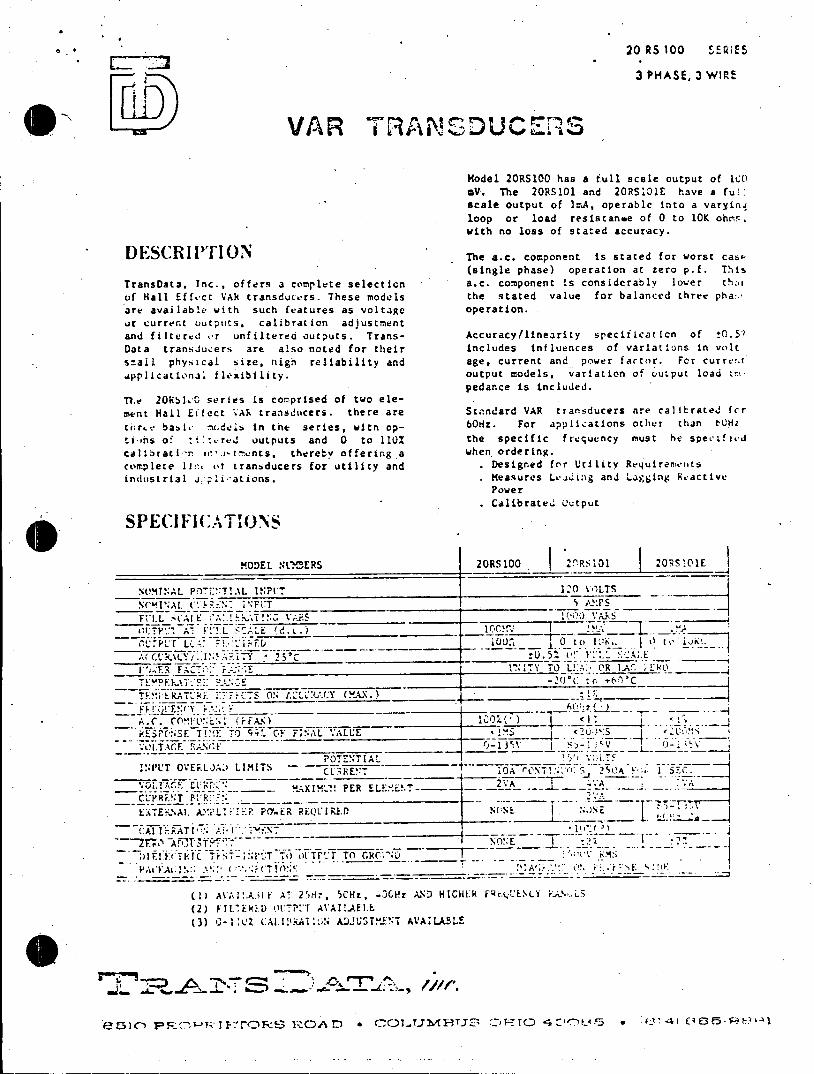
* 20 RS 100 SERIE5
3 PHASE, 3 WIRE
VAR TRANSDUCERS
Model 20RSlOO has a full scale output of 10O mV. The 20RS101 and 20RS101E have a ful scale output of IrA, operable into a varyinq loop or load resistanwe of 0 to 10K ohmrb. with no loss of stated accuracy.
DESCRIITION The a.c. component is stated for worst casp (single phase) operation at zero p.f. This
TransData. Inc., offers a complete selection a.c. component is considerably lower th:.z
of Hall Effecr VAR transducers. These models the stated value for balanced three pha:.
are available with such features as voltage operation.
ur current outputs, calibration adjustment
and filtered or unfiltered outputs. Trans- Accuracy/linearity speciication of 0.5'?
Data transJucers are also noted for their includes influences of variations in volt
smail physical size, nigh reliability and age, current and power factor. Fcr curre'.t
applicational flexibility. output models, variation of output load impedance is included.
T7e 2051"L0 series is comprised of two ele
ment Hall Eifect VAR transducers. there are Standard VAR transducers are calibrated for
thr.ee babi, ruodels in the series, with op- b0Hz. For applications other than tCHz
ti tns o' :ilured uutputs and 0 to 110% the specific frequency must he specified
calibrati- n ie.,ntments, thereby offering a when ordering.
complete li:!. ot transducers for utility and . Designed frr Utility Requirements
industrial aiiations. . Measures Leadin:g anJ Lagging Reactive Power
Calibrate.' output
SPECI FI CA1 ONS
MODEL NLn'ERS 20RS100 20RS101 20R5101E
NVMINAL POT ::T!.L INPVI 120 k-ILTS
NC'l'A1. (LE::N.NFCT I !'- %_7T
)I:T:. "Al I. SC. .. 1.. .) 100_1_!__
A(,11CYi ,.1A1n-Y. 25-C i !0.5.tS
0'. ER F.4Cl F. ._____ITY TO L:A- QR LA' O
< U.1 c___ S
-VESP(:NSE TIE TO 99. F FIAL ALUE *lS <20' 5 <S
.0I.TACE 0 0-13Y1 -_1_J_ V I-1 l_ ___
POTENTIAL V ' INP'L'T OVEFR.L)A.* LIMITS -E 10A r JNT 250A 1 ISC.
MAXIMHLT. PER ELXE.NT-2A gA1 CL'P.ERT R -" . -- A
ENTEF-.AL. ' :1 P0'.ER REQUIRE-D NO NE _N E
~ A~PT"~ -- - t NO!:E 21:lF~l~:rT.TCT d TO 70 LTPI-* TO cCRW.' V RMS ~
(1) Ali!At: A: 2')H7. SCHz, OGHz AND HIGHER fkr.LELNLY r..
(2) FIL7ER.D O.PTAVA!!.AELL (3) 0-1: CZA.I rA110N ADJUSTn.ENT AVALABLE
.31. A 1 Z5 I -)) A I).J *wr.

20 RS 100 SEiES
3 PHASE. 3 WIRE
O VAR TRASDUCERS
Model 2RSff haV a full scale output t uf T s aV. The 2RS0 and 2RS rE have a vua scale output of iuA, operable into a varyins loop or load resistance of 0 to 10K ohms, ainh no loss of stated accuracy.
DES RIPTION The a.c. component is stated for (single phase) operation at zero p.f. This
TransDta. Inc., offers a complete selection a.c. component is considerably lower t-ui uf Hall Effect VAR transducers. These models the stated value for balanced three pha :.. are available with such features as voltage operation. or current, outputs, calibration .idlLstritnc and fittr re or unfittred outputs. Trans- Accuracy/linearity specification of 11.50 Data trasducers are also noted for their includes influences of variations in volt s?.aAl ;hysical. size. niigh reliability and age, current and- powtir fa,7cor. For currv?,t .pplicaticnal flexibility. output models variation of output load 10
pedance is included. The 2or loa0 rerees is cs nfprised of teo eloment Hall Eitect VAR transitcers. there are Standard VAR transducers are calbrate for
t'rv basic n l In tne series, witr. op 6ngZ. For applications other than TJHz
ti'nrs o' *i:t..red outputs and 0 to 110% the specific 'freque~ncy must he specified call!tati -:a comp.ornnenrst thereby offering a when orderint.
cvnp Ie t e 11:, of transducers for utility and .tDesigned for Utility Requirements indus t L. 1 .,~L a n.. Measures L,~igadLigigRatv
Power Calibrated futput
SPECiI1C A TIO(3N S
MODEL NL ERS j20RSID0 20RS101 2ORS101f.
POTENTIAL I _________________ 120 VOLTS ____
A e1 sp ec ifi c !0.5! rIuY us A.h ep
F") K.Jaue LYd':) LEand Lin.gFReactiv
T T-* E E F.CCTaSlibrateACY uptkut
SIlA.lC(.T (.N
NOMINA;l: POTETTALI1P3 1 &0 'OLT N*X TIOA 1-' -ENi FINAL 5A11I IAM3 0F
POT ETIAL INPUT OLE.;LOAD LIITS -
ou_ ::.AXIK 'LX .. EENT- - 2VA' CL*4 i.'.. 2*1 VA
r A AMPLIN H Y.K REQUIREk10 NONE L OA
I -- +-- --10007.. 1 o n.. ( t i
'PA" '0L A 0 I }8
(H AAI .A~~.A 2 : , , 004-, iJD1 E1IGHRFkHLQUE1LY- .AVCS (2) FILTE I "t 70. AVA<Al. (3 1LTS
f'51( PF 2 :'f7''~i5 IZ.~D CC~L~i.'10AS <NTIC *i i. 2>J E I SEC. ~~
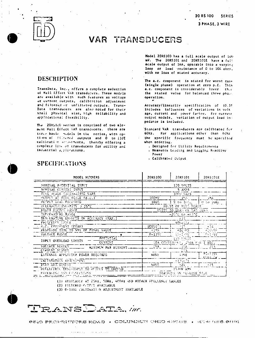
20 RS 100 SERIES
3 PHASE. 3 WIRE
VAR TRANSDUCERS
Model 20RS100 has a full scale output of 10O mV. The 20RS101 and 20RS1OE have a fu! scale output of lI.A, operable into a varyin. loop or load resistance of 0 to 10K ohs, with no loss of stated accuracy.
DESCRIPTION The a.c. component is stated for worst cas (single phase) operation at zero p.f. This
TransData. Inc., offers a complete selection a.c. component is considerably lower th'i of Hall Effect VAk transducers. These models the stated value for balanced three pha:.. are available with such fwatures as voltage operation. or current outputs. calibration adjustment W and filtered or unfiltered outputs. Trans- Accuracy/linearity specification of t0.57 Data transducers are also noted for their includes influences of variations in volt small physical size, high reliability and age, current and power fartor. For curreva applcattena: flexibility. output models, variation of output load im
pedance is included. The 20R:100 series is comprised of two element Hall Effect VAR transducers. there are Standard VAR transducers are calibrated fcr tnrce basic "sdels In the series, with op- 60Hz. For applications other than t0hz ti ns o: it.rvd outputs and 0 to 110% the specific frequency must he specitied calibrati -nr jrments, thereby offering a when ordering. complete Iit:! ot transducers for utility and . Designed for Utility Requirerentts industrial a,plications. Measures Leading and Lagging Rvactive
Power Calibrated output
SPECIFICA lt)IONS
MODEL NI UERS 20RS100 20RS101 2ORS-01E
NOMINAL POTENTIAL INPVT 120 VALTS Nl. 'L RENT INPLr 5 A'_5
n t 1: U, d. c ox IO . o 1F ~ -(CURACY!!.LM.A?17C 1 25% _____ or
FACTC: iANEC_ r:,TY r0 LLA:. k .Ek-. TLERTF' R RAN C E -2Qct C TE.M: IERATRE EiFIFCTS ON ACC.UACY (.A.t.)_
ESPcNSE TIlL TO 99'/. OF FINAL VALUE VUI.TACE P;J'r;E 0 13Y.L V
POT-NT!AL i INPLT OVERLOAD LIMITS ------ C T
VOL.:ACE: buh:N - MXIKLM PLR ELE,NT------
L.%TEKNA1. AlIFiIER0 PO .ER REQUIRE.D N 0! N N
CA!!%0ATI: A'J'S1 r
1)1 F L K'7k T F. IN I"-- T 0 ' 0 10T To GF.CID 1 4 i..A
(UAAI!A;;1.F AT 2Th1z. O01z, 400iiz -UL HICiHtR i L .LENLfi 1AES (2) 1,11.1ER.D '.riAVAILABEAL (3) C-11I CAL.Ik"fl.-N ADJUST!-.iNT A'JAII.JULE
711-1
.L. FR.A2\T Sr 'T , eFwV.
eL0'>c1 PCC2-'rTI'ES E.)/A) * CO)LUJN1-3t-4 OF-IC) - :-US * v: .pr '5 E6l4
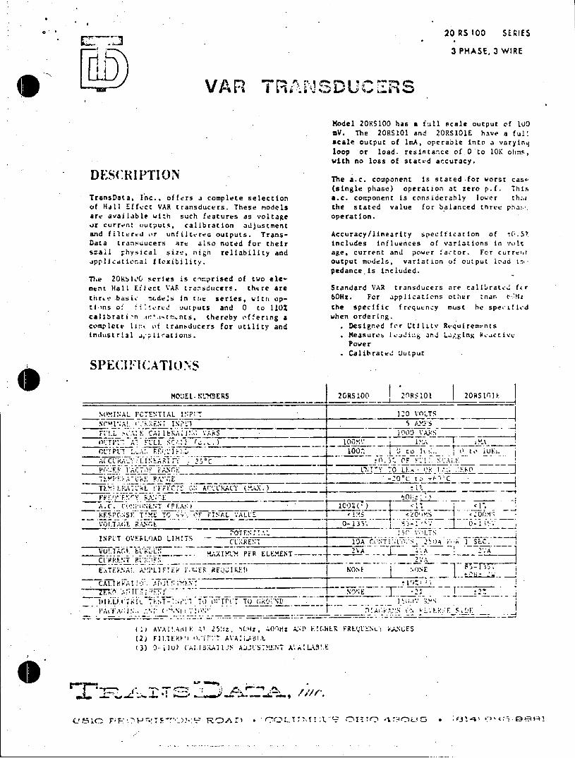
0 20 RS 100 SERIES
3 PHASE, 3 WIRE
Model 20RS100 has a full scale output of 100 mV. The 20RS101 and 20RS101E have a ful' scale output of ImA, operable into a varying loop or load. resistance of 0 to 10K ohns, vich no loss of stated accuracy.
DES(:RIPTION The a.c. component is stated for worst cass(single phase) operation at zero p.f. This
TransData, Inc., offers a complete selection a.c. component is considerably lower th.r of Hall Effect VAR transducers. These models the stated value for balanced three pha .-. are available with such features as voltage operation. ..r current outputs, calibration adjustment and filtered or unfiltered outputs. Trans- Accuracy/linearity specification of to.57 Data transducers are also noted for their includes influences of variations in volt small physical sizu. nitn reliability and age, current and power factor. For currctf ipplicdtional flexibility. output models, variation of output 1ao in.
pedance.is included. The 20K!lk, series is c'mprised of two element Hall Eflect VAR transducers. thtre are Standard VAR transducers are calibrated for
Enre.-basic moudels in the series, witr op- 60Hz. For applications other man t-'H.4z
tins of 4tred o utputs and 0 to 110% the specific frequency must he speciflid calibrati-n tfe'.jtr-nts, thereby offering a when ordering. COmplete 1i::< Of tranbducers for utility and . Designed for UtiliLv Requirements industrial ,-lirations. Measures Icding and Liiging Wcactive
Power Calibrated utput
-S'E(.HI'CATlONS
MooEL. NLMBERS 2Rsloo 20RS1o 20RStl0 I
NOINAL C'TENTTAL I?'_P__!_ _ 120 _ _LTS
!L :.: CAl1:1 I bA ARS 1009 C'T PE LL,, R.q' 1'.lfO)\A2 _ _ _
'! P7 L'_ Fr K11. 100Z to. It 0_ t 00 VUA 1. 1tR.2 NI A 1 2 5 C OF_____ 1.7 S_____ 1'. i: F
E '~~L;! Y '7O LE,: OR 1 - _
FFQ IAC7Y bW; - '-0L" TEMP_:-_it:_-@._._CE -0 (C to r C
A.C ClA:?U ENf FCA :': .C (%X) ____________ -___
iF.SPCNSE TI TO . C.'F FINAL .ALL <1_5 <__0 _Ms_<20
VOL.TAGE. RAR.E _______ ____0-135 . -1. ' -1,. POTFN r!.%' 5__%__
INPL"T OVY LOAD LIM!TSCUEN. C- CLKEN- _IA C.ONTI , 2.0 A 1 SEC U'. ;,r .2VA A2A
CALT -A o -- PE. E PFRtW.AENTA
C (I AViR!1T *.A 5 (1 FRE 2:A
L7TFF A!. A'L 'r RF'.!j I RE! NO.k ()NE 4 -. C Ti.- I N '\iP A 1 'h : P-E t:.2 Vit ~ s~m
(2) FI 1),DWI I AVAI,.adLE (3) 0 11 U AL R ljN AJCS.MELNT A.A ILALE
050P P!E"") '9R AD *C LId: ? r7T~iT *1-'90L4-: * V314' 5

20 RS 100 SERIES
3 PHASE, 3 WIRE
VAR TRANSDUCERS
Model 2RSa I has a full scale output of slc mV. The 2RSc and 2RSOE have a fu l scale output of imA, operable Into a varyind
loop or load resistance of 0 to 10K ohms, with no loss of stated accuracy.
DESCRIPTION The a.c. component is stated for worst ca (single phase) operation at zero p.f. This
TransData, Inc. ffers a complete selection .c. component Is considerably Iower th.;a
uf Hall Effect VAR transducers. These models the stated value for balanced thtee p'a ..
are available wdth such features as voltage operation. or current outputs, calibration adjustment
and fj It e r.d o'r unfiltered outputs. Trans- Accuracy/linearity specification of t0.5.
Data transducers are a-o noted for their includes influences of variations in volt
s.ail physical size, high reliability and age. currentand podrr factor. Fr currion
app~lieational flexibility, output mudels. variation of output load ir00 pedance is included.
D.. lop raC serrses is coitnprised of two t0o mat Hall Effect VAv transducers, there are Standard VAR transducers are caltrated fr
lr.*e babi.- -(dess in thi series, with sg- 60Hz. For appications other than thz
ti -ns & i:..t' outrpu~s and 0 to 1101. the specific frequency must he specified
cairata.cn com t thereby cfferino a when ordering.
com~plete l1nh %, transducers for utility and Designed for Utility Requireme ats
irndustrial,; iiations. .aMeasures Lj.ing and Laging Ractivet Powve r
output mues, vartio fouptlodt.
SPECSFa rRATItNrndcrarcliatdf
MODEL NLU ERS 2015Co IRSIOI 2ORSICIEI
NM.INAL POTEN.TIAL 1!:?IT1 I. VI____ ..- s
~'~60':. For appitcations-other than edz
'' St. E CAI' NCVA;6 ______ ___ _________
"1" A*-F ' .(d.c.) 1OCV
. Calibrate culpo
SPCIFIATION
I .7tAT A I; '. TIN A VS "!2 VA.L
PTNT I -AL I V' 1.TS INPUT OVELA __ LIMITS O__ TA C__t__.t' o S, : il F' , S__.
ii) Al AT_!!___________I RO''C'N 1: EN
(2) FILT n, CTPVl ALAll.AS_
( - L i .: ALJSTME::7 AAILBLE
-- -.. mAE,-k- --- <.U H U *
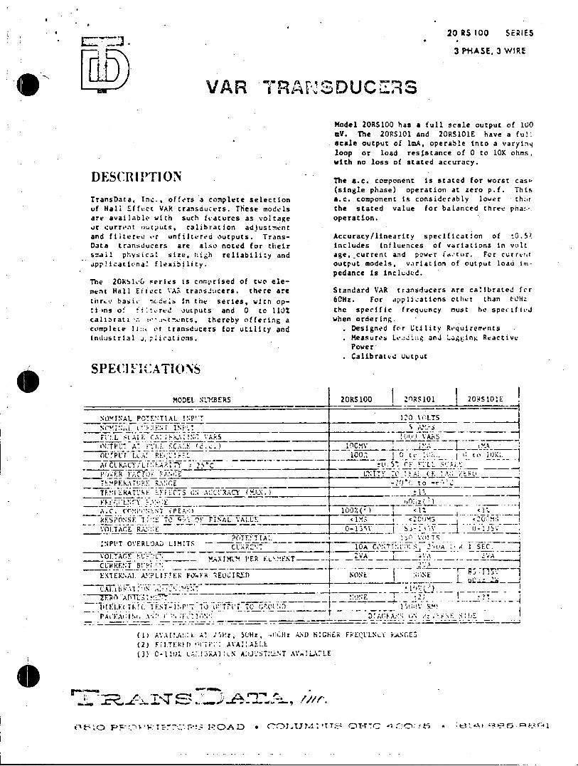
20 RS 100 SERIES
3 PHASE, 3 WIRE
~j. VAR TRANSDUCERS
Model 20RS100 has a full scale output of 10O 0V. The 205101 and 20RS101E have a ful! scale output of 1mA, operable into a varying loop or load resistance of 0 to 10K ohms, with no loss of stated accuracy.
DESCRI TrION The a.c. component is stated for worst cass (single phase) operation at zero p.f. This
TransData, Inc., offers a complete selection a.c. component is considerably lower the uf Hall Effect VAR transducers. These models the stated value for balanced three pha:.*. are availablc with such features as voltage operation. .r current outputs, calibration adjustment and fiiterru or unfiltered outputs. Trans- Accuracy/linearity specification of tO.5? Data transducers are also noted for their includes influences of variations in volt small physical size, tigh reliability and age,_current and power factur. For curre!,t .pp!icational flexibility. output models, variation of output load in%
pedance is included. The 20S1L00# series is comprised of two element Hall Effect VA. transiucers. there are Standard VAR transducers are calibrated fcr
thrle.e basil. m.dels in the series, witn op" 60Hz. For applications other than t01h tiens of fi>tred outputs and 0 to 1102 the specific frequency must he specified
calibrata w. .ie.r-nts, thereby offering a when ordering. complete 11:.. ot transducers for utility and . Designed for Utility Requirements industrial s ications. . Measures Ld and Laogging Reactive
Power Calibrated output
SPECIl :I.Al )IONS
MODEL. NILIERS 20RS100 2ORS101 205101*E
NOMINAL POTTA I 1 ''0lA3 V!LYS -(17
01tTP T A. Y ' 7. C.A:.E dF . OL'CT L0Tif RE !?'
A( CLIACY/'Li' ARIT ; .25*C :L. P".-JR FAClu- -7:! ;E
Sto TE.1"I 'RALtE.CF i ON A'TACY (MA):.) 11,
A.C. (COMP:T (PE.__-.
; SPONSE' 'I. T1 'F A A.UEC S VOLTACE R A . _ E 0 J
?OTF.!TIA:. Vo TS
INPUT OVERLOAD LIMITS CURRES0
O .:EELMENT- ER -.F CLIHRENT B!''W :
(XTEX:,A1. A_-'LI F!E1 F%..1 'EOL:IP-fl I NON:
.IL~~1 ~ ~. ~;'~100.______0_________.__ t.Ll'0 .
10 COT N 'N Eu 2iSC
(1) A.Al!.A: i. Al -hz 5f0Hz, *C.ir AND HIGHER FFEQLLN&t RANGES (2) F'I.TERI) :MT . AVA:.AELL
(3) C-1101 ;. .!:3KAILN A:)JST:.NT A TalL."LE
1-:T P C ?- O * O-*
~ PFo~'c.'72'-cr!.;1'OAID *C~IJA !?.O-0- r~4
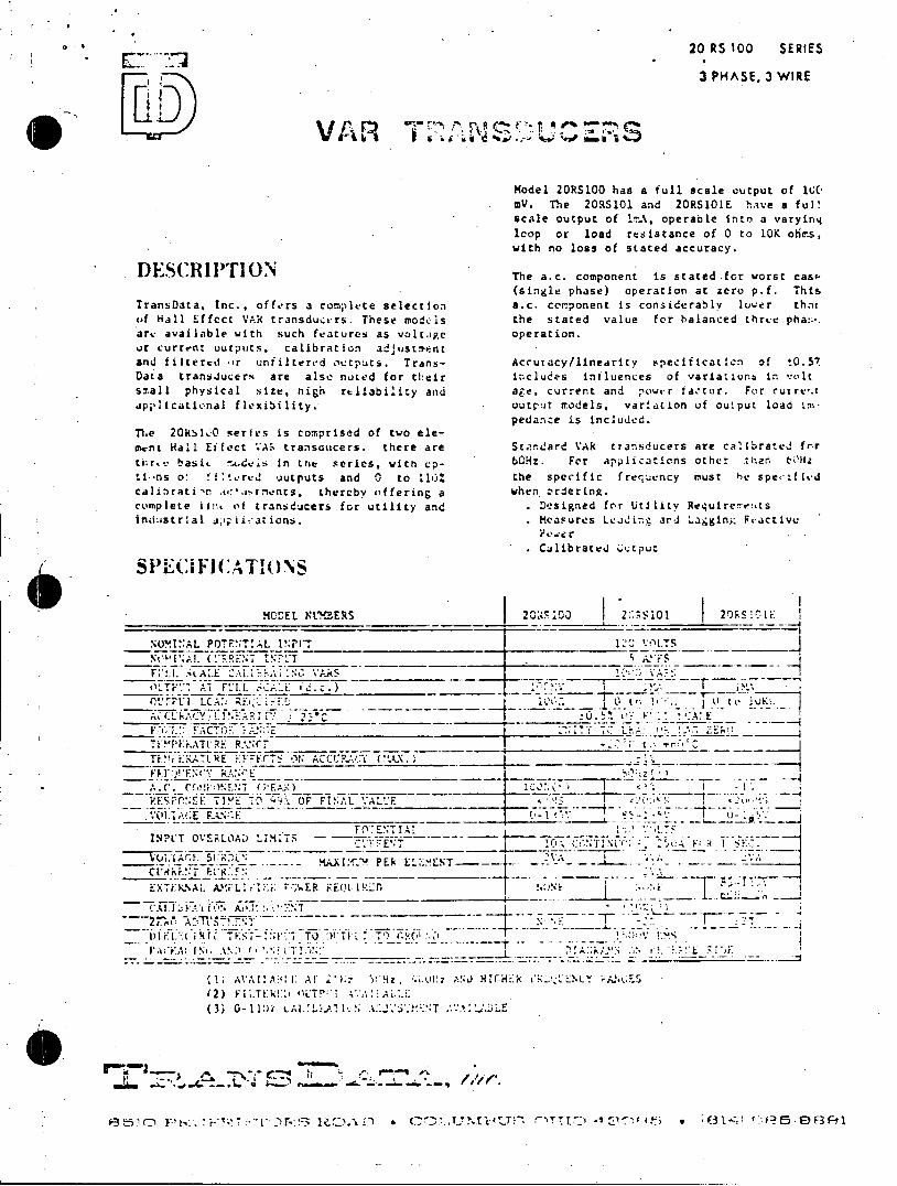
20 RS 100 SERIES
3 PHASE, 3 WIRE
Model 20RSIOO has a full scale output of lUC mV. The 20RS101 and 20RS101E hive a fu!l scale output of 1%A, operable into a varying loop or load resistance of 0 to 10K obies, with no loss of stated accuracy.
DESCRIPTION The a.c. component is stated.for worst cast (single phase) operation at zero p.f. This
TransData, Inc., offers a complete selection a.c. component is considerably lower that of Hall Effect VAR transducers. These mod.ls the stated value for balanced three pha.*. arc available with such features as voltage operation. or current uutputs, calibration adjustment and filtered or unailtered outputs. Trans- Accuracy/linearity specificaticn of t0.57 Data transJucers are also noted for their includes influences of variations in. volt small physical size, nigh reliability and age, current and nowur factor. For curre.t applicational flexibility. output rodels, variation of output load Im
pedance is included. The 200 O series is comnprised of two eleaent Hall Eifect 'A, transoucers. there are St'.ndard VAR transducers are calibrated fnr
tEro*.* baste .odes in one series, wltn vp- 60Hz. For applications other than t0fHz ti *ns o: ftdred Outputs and 0 to ll% the specific frequency must he specified caIibrati n .ro:'.I-roents, thereby offering a when ordering. complete Ii: of transducers for utility and . Designed for Utility Require-e:.ts industrial .ipiications. . Measures Leading and "agging Pcactive
? e.i r
Calibrated ouvtput SPE(AFI CATIONS
MOCEL 'LMBERS 2CRF 100 2'RS11E
NOMI'AL POTENTIAL 1!:PUT 1."J LOLTS
N I'sI'.M. (.". OIF Ft AA"FS
At F LL :. .) l'PLTI LCAi
.0- t o - -0
YAC'G&F. Tti L;-:
ACCUACY;Ll'.A? C 23*
Tf.!IEEATLRE EFECTS ON ACCt:?.:Y RI U)!'FN(T R.4N'E 4, Z
.ESP7:SE TI'E6 9 F FINA 'A:-.'FS
A(;1. AE RAkN.E
.. Al. OVEROAD LI : ER
Tli (ik. T S-1 TT: TR FNLf i F; C~ UR ~ ' h_ -i.h: FN F-.F'
1A,11!A . A7 Hz, .. U S , HICH k a LY 2. DIFI iRIC. T~ 0 - 11- TO t;I W.Aj I L 7 T A2.
32)F L rLA .
Star 0 e- .:1 .T G 't.O..1D * Cr E.7 tn s* 5 , a SO

LINE A B C
DC F 7 o Z3Ise 0 T , OUTPUT 3e
00 120v
1 123456
____7 8 9 10 11 12
t1 S 3
IEAT. I
. * .LOAD
-Connection diagram to a three phase three wire 1!ne using current and potential transformers.
Dimension A The external power f or .tile
20PS100. .......... 3 1/4 amplifier for model 2ORS1OI E 20RS101 ........... 4 is connected to t4rmnals 9 and 20RS101 E ........... 4 12. On the other models thesi
terminals arE unused. Mounting holes (4).. 3/16 Dia.
The dots shown on the tas Can is steel with integral formers are relative polarity mounting flanges. markings znd show the proper
connection polarity. lnstruTerminal screws are 8-32 ment transformer turminals are binding head. marked with a dot, a i symbol
or other iden fiall m~ark on both Primary and secon~dary. Failure to observe tho proper polarity may result in erroneous readns.
arounding considerlt0ons may dictate cnnectin r 9.arv
12. ~ ~ ~ t On th oh r moel the
opoaite f rrc t. C w.n - shcwn. This is* pernissible if tile seccndary £s . a Isc reverusd, manainn the sav relative polar ity
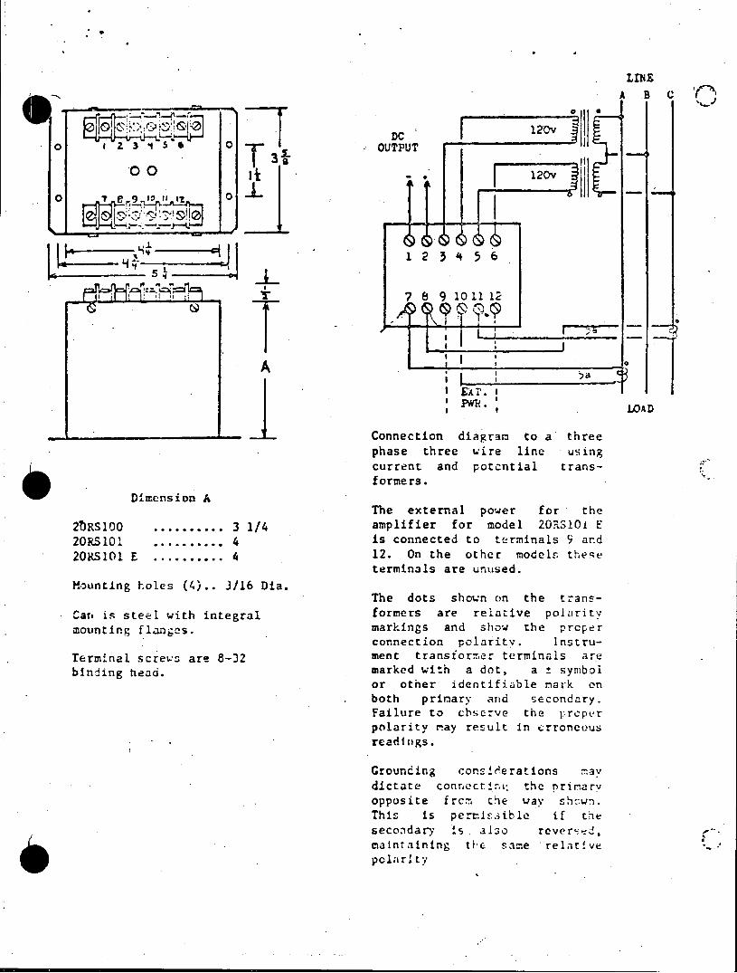
LINE
A. B
o IDC 00 sZ 3 OUTPUT
T3 OO I 20v
1 2 3 4 5 6
T7 8 9 10 11 12
Pe. I . LOAD
-Connection diagram to a' three phase three wire line using current and potential transforme rs.*
Dimension A The external power for- the
20Rslo0 ........... 3 1/4 amplifier for model 2ORSlOi E 20RS101. ........... 4 is connected to terminals 9 and 20RS101 E ........... 4 12. On the other model these
terminals are unused. Mounting holes (4).. 3/16 Dia.
The dots shown on the transCareis seelwithinteralformers are relative polarity C1an is steel with integral
mounting flanges. markings and show the prcper connection polarity. lnstru
Terminal screws are 8-32 ment transtormer terminals are binding head. marked with a dot, a ± symbol
or other identifiable mark on both primary arid secondary. Failure to cbserve the y:rcper polarity ay result in irrongous readings.
Grounding consweerations tay dictate conectto the nriarv opposite fro the way shws. Thi is per.iib if tre secondary is l relver .d, maintaining the sape relative cpolarity
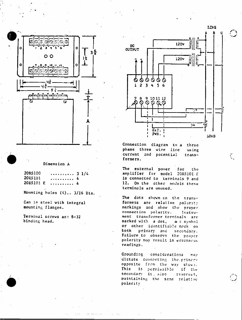
LIN E A B C
07 0 6
I DC I'4~ 0 1 .2 3 OUTPUT
r s.
It 00 020
' 7 8 9 101112
A 5a
EAr. I _ LOAD Connection diagram to a three phase three wire line using current and potential transformers.
Dimension A The external power for the
20RS100 .......... 3 1/4 amplifier for model 20RS101 F 20RS101 .......... 4 is connected to terminals 9 and 20RS10l E .......... 4 12. On the other miodels these
terminals are unused. Mounting holes (4).. 3/16 Dia.
The dots shown on the transCan is steel with integral formers are relative polarity mounting flanges. markings and show the proper
connection polarity. InstruTerminal screws ar.i 8-32 ment transformer terminals are binding head. marked with a dot, a t symbol
or other identifiab2e mark on both primary and secondary. Failure to observe the proper polarity may result in errcnacus readings.
Grounding considerations Mav dictate connecting theTprimayV opposite fro-m the way shcwi. This is pernissiblc if the seccr.darv is . .lso reversed, maintaining the same relative polarity

A B C IN oil0
DC 120v ~ <~;~;~~ -IDC o 3 4 0 . OUTPUT
00 11 120v
1 2 3 4 5 6
7 9 101112
Q 0 P 0 -'q____
AEA. I 'Pwk .
LOAD
-Connection diagram to a three phase three wire line using current and potential transformers.
0 . Dimension A 4 .Dienio AThe external power for the
20RS100 ......... 3 1/4 amplifier for model 2ORS1OI E 20RSC1 .......... 4 is connected to terminals 9 and 20F.S101 E .......... 4 12. On the other model. these
ter-Aiaiis are unused. Mounting holes (4).. 3/16 Dia.
The dots shown on the transCan in steel w-ith integral formers are relative polarity mounting flanges. markings and show the proper
connection polarity. InstruTerminal scrtews are 8-32 ment transfor-,r terminals -re binding head. marked with a dct, a ± symbol
or other idenr.~f-able miark orn both primary anid secondary. Failure to observa th2 proper polariy may reslt in erronccs readins.
Groundn corsidrat ors dictate connectinen the pr9 nd oppoSI. O fro te way hese This ds per ossible if the secc'nda-r: is a.;-,a revorsed, amntaining the sae relativp e o c polarity
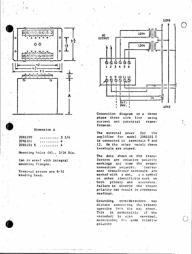
o ai3 ss~ 0 OUPU
0 0 120v?
1 2 3 4 5 6 IN
A B ____' sW LAD .. Connection diagram to a three
T -u
phase three wire line using current and potential trans
) formers. Dimension A
The external power for the 20RS100. ........... 3 1/4 amplifier for model 20RS101 E 20RS10............4 is connected to terminals 9 and 20RS101 E............4 12. On the other models. these
terminals are unused. Mounting holes (4).. 3/16 Dia.
The dots shown on the transCan is steel with integral - formers are relative polarity mounting flanges. markings and show the proper
connection polarity. InstruTerminal screws are 8-32 ment transformer terminals are binding head. marked with a dot, a symbol
or other identifiable mark on both primary and scondary. Failure to observe the proper polarity may result in erroneous readings.
Grounding considerations may dictate connecting th primary opposite from the way shown. This is perrissibln if the secondar is . dlso reversed, mailtainin ' the samerelative polarity

LINS A B C
DC j120v o 1Z 3 4 5 T OUTPUT
00 0 T3
IJ~iiZT~' 12345
1 2 3 4 5 6
4 47 8 9 1011 12
I I 0
I EAT. I
s__I *LOAD
-- -Connection diagram to a three phase three wire line using current and potential transformers.
Dimension A The external power for the
20RS100 .......... 3 1/4 amplifier for model 20RS101 F 20RSlU1 .......... 4 is connected to terminals 9 and 20RS101 E .......... 4 12. On the other models these
terminals are unused. Mounting holes (4).. 3/16 Dia.
The dots shown on the transCan is steel with integral formers are relative polarity mounting flanges. markings and show the proper
connection polarity. InstruTerminal screws are 8-32 ment transformer terminals are binding head. marked with a dot, a = symbol
or other identifiable mark on both primary and secondary. Failure to observe the proper polarity may rejult in erraneous readings.
Grounding consider&tions M'aV dictatE connectin:: te primar; opposite from the way Thown. This is pennissible if the seccndar-y is . also reverscd,
maintaining the ame relative polarit'.
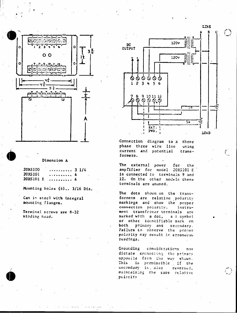
LINE A B C
io , - --
120v
DC 1O~ 0 Z OT1 2 3 4 5 6
00T
0 8 9 10 11 1i
5P&H
1 ~~ 21145
IEAT.I ___1 a a LOAD -- Connection diagram to a three
phase three wire line using current and potential transformers.
Dimension A The external power for the
20RS100 .......... 3 1/4 amprifier for mcdel 2ORS101 E 20RS101 .......... 4 is connected to terminals 9 and 20RS101 E .......... 4 12. On the other models these
terminals are unused. Mounting holes (4).. 3/16 Dia.
The dots shown on the transCan i- steel with integral formers are relative polarity mounting flanges. markings and show the prcper
connection polarity. InstruTerminal screws are 8-32 ment transformer terminals are binding head. marked with a do:, a t symbol.
or other identifiable mark on both primary and seccndary. Failure to observe the pro'er polarity may result in erronecus readings.
Grounding consideratio.s may dictate connec:-.i-n the prmarv op;posi :e freo :I- way shown. This is permissible . if the secondary is . also reversed, maintainig the same relative pulzrity
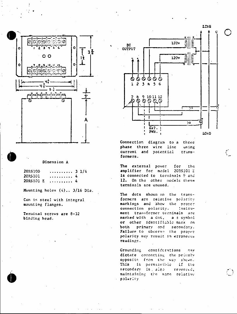
LINS
A B C t
DCC o 1 Z 3 oI SG 0 F OUTUT 120
00 3 - 120v
1 2 3 .4 5 6 5
7 89 1011 12
In
A I 'W
I EX T. I __-I P&. LOAD -- Connection diagram to a three
phase three wire line using current and potential transformers.
Dimension A The external power for the
20RS100 .......... 3 1/4 amplifier for model 20R1S101 E 20P.S101 .......... 4 is connected to terminals 9 and 20RS101 E .......... 4 12. On the other models these
terminals are unused. Mounting holes (4).. 3/16 Dia.
The dots shown on the transCan ir. steel with integral formers are relative poI arit. mounting flanges. markings and Show the procer
connection polarity. Instru
Terminal screws are 8-32 ment transformer terminals are
binJing head. marked with a dot, a t symbol or other identifiabl2 mark cn both primary and secondary. Failure to observe the proper polarity may result in erronecus readings.
Grounding ccnsiderations Tav dictate connecting, the primarv opposi'te from the way ShC.n. This Is permissible if the secondary is .lso reverstd, maintairine tie same relative pbonlarity
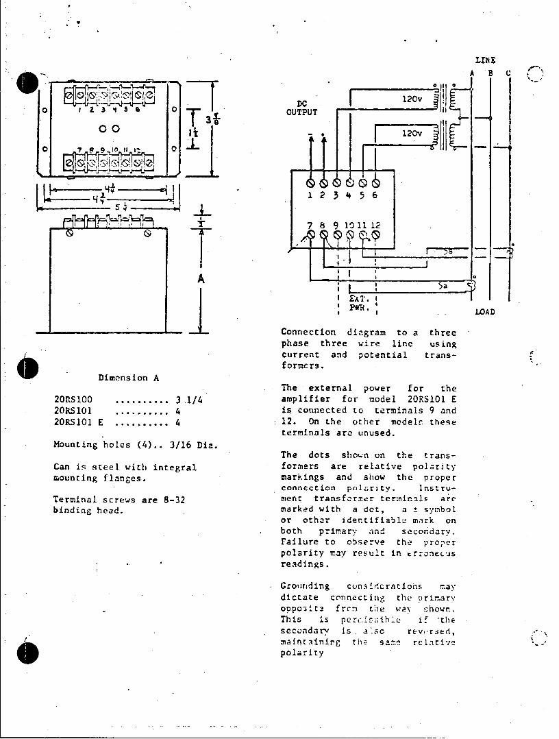
LINE ABC
0I 0 IDC 10 o0 3tS 3 OUTPUT
30 00 120v
7~~ 2 91 11 1!6
7 8 9 10 11 12
I a0
A ; ...J5a 'S0
EA£T. I _____.1.LOAD Connection diagram to a three phase three wire line using current and potential transformers.
Dimension A The external power for the
20RS100 .......... 3.1/4 amplifier for model 20RS101 E 20RS101 .......... 4 is connected to terminals 9 and 20RS101 E .......... 4 12. On the other models these
terminals arc unused. Mounting holes (4).. 3/16 Dia.
The dots shown on the transCan is steel with integral formers are relative polarity mounting flanges. markings and show the proper
connection polarity. InstruTerminal screws are 8-32 ment transformer terminls are binding head. marked with a dot, a t symbol
or other identifiable mark on both primary and secondary. Failure to observe the proper polarity may result in erroneu'Js readings.
Grounding considerntions may dictate connecting the arimary oppo3it3 frcn the way shown. This is pert:.iE;ihe if 'the secondary is . also rev'rsed, maintainirg the sa-e relative polarity

LINE 00
DC12 o 1 Z 3 4 5S 0 , OUTPUT
00 T 3-L~ 126 120v
O 7 8 9 1t 0
H4 1 2 3 4 5 6
7 8 9 10 11 12
A
A LOAD
Connection diagram to a three phase three wire line us ing current and' potential trans
Dimension A The external power for the
20RS100 .......... 3 1/4 amplifier for model 2ORS1OI E
20RS101 .......... 4 is connected to terminals 9 and
20RS101 E .......... 4 12. On the other -models these terminals are unused.
Mounting holes (4).. 3/16 Dia. The dots shown un the trans
Can is steel with integral forners are relative polarity mounting flanges. markings and show the proper
connection rolarity. Instru
Terminal screws are 8-32 ment trsformer terminals are binding heaC. marked with a at, a symbol
or other edentifiable mark n both prit-ary ant secondary. Failure to observe the prorr polzrity m~ay result in errcriecus readings.
Groudi g cslerations te dictate coaencct d the. nrir
This is shrnnsibia if the seored arey i als reverstd, . maintaining than s te : olative
pola:ity
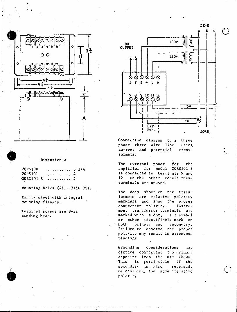
LINE
A B C
DC 120v o t 2 3 4 S OUTPUT
0I - . 120v
o 0 0 """
L,;LK
I 7 8 9 101112
I AT. I *I# LOAD - -Connection diagram to a three
phase three wire line using current and potential transformers.
Dimension A The external power for the
20RS100 .......... 3 1/4 amplifier for model 20PS101 E 20RS101 .......... 4 is connected to terminals 9 and *20RS101 E ........... 4 12. On the other odels these
I . terminals are unused. Mounting holes (4).. 3/16 Dia.
The dots show.- on the tran~sCan is steel with integral formers are relative polrity mounting flanges. markings and show the proper
connection rolarity. Instru
Terminal screws are 8-32 ment transformer terminals are binding head, marked with a dot, a ± symbol
or other identifiable mark on both primary and secondry. Failure to observe the proper polarity ay result in erroneous readings.
Grounding considerations 9a dictate connocterg ohel priar opposite rom tswae.' This is shown on if the secondary is . tsc rt'.ersc.d, .*
nalntafonrr thel aame rei tyi.'c po larity

LINE
oi
-C 120v 003 OUTPUT
7 8 9 10 11 12
PKR. I
s W . LAD
Dimension A
20RS100.............3 1/4aplfe fo oe 2Ol1E 20RS . .......... i 20RS101 E .......... 12
Mounting holes (4).. 3/16 Dia.
Can is steel with integralfoer ae rlaie oart mounting flanges. mrig n hw tepoe
Terminal screws are 8-32 mn rnfr~e cmnl r
Connection diagram to a three phase three wire line using current and potential transformers..
arThe external power for the amplifier for model 20RS101 E 2 1 ..is connected to terminals 9 and
S12. On the -other models these terminals are unused.
The dots shown on the transformers are relative polarity mrkings and show the proper connection polarity. Instru
Termnal crew areB-32ment trans-former terminals are binding head. marked with a dot, a t symbol
or other identifiable cmark or. . both primary and secondary.
Failure to observe the proper polarity may result In erroneous re adings.
Grounding considerations mayh dictate connecting the prin-ary opposite frcm the wa,, snown. This iL pernissib-le if the secondary; i s . l so re- orhed, maintaining the same relative polarity
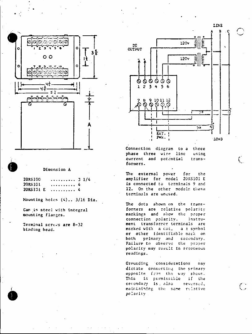
LINE
DC 120v 0 3 1 54o . OUTPUT
3215
H 1 2 3 4 5 6
7 8 9 1011 12
EAT. I
.a . LOAD
Connection diagram to a three phase three wire line using current and potzntial transformers.
Dimension A The external power for the
20RS100 .......... .3 1/4 amplifier for model 20RS101 E 20P101 .......... 4 is connected to terminals 9 and 20RS101 E .......... 4 12. On the other modelf these
terminals are unused. Mounting holes (4).. 3/16 Dia.
The dots shown on the transCan is steel with integral formers are relative polarity mounting flanges. markings and show the proper
connection polarity. InstruTerminal screws are 8-32 ment transformier terminals are binding head. marked with a cot, a ± symbol
or other identifiable mark on both primary and secondarv. Failure to observe the proper polarity may result in erroneous readings.
Grounding considerations may dictate connecting tne primary opposite f:o the way shcwr.. This is pcrmissible if the secondary is . also revcrsed, matrtainirg the same rtlitive pclarity

LMNE
A B C C
I - 120v
o eZ3. DC ___ ____
0 To OU 6 -UTPUT
0 C
I_ _ H, 12 3'4 56
7 8 9 10 11 12
5a EA£T. I _ LOAD
Connection diagram to a three phase three wire line using current and potential transformers.
Dimension A The external power for the
20RS100 .......... 3 1/4 amplifier for model 2ORS101 E 20RS101 ...........4 is connected to terminals 9 and 20RSIO E .._o.......4 12. On the other models thee
terminals are unused. Mounting heles (4).. 3/16 Dia.
The dots shown on the transCan is steel with integral formers are relative polarity mounting flanges. markings and show the proper.
connection Polarity. InstruTerminal screws are 8-32 ment transformer Lerminals are binding head. marked with a dot, a t syn'bcl
or other identifiable mark on both primary anda secvndarv. Failure to observe the proper polarity ay result in urrongous readngs.
Croundirg considerations may
dictate cennctin the prrmari9 opposite ther r t h e ay shew. Thie is s n e rrihis e if t secondary is rei e rversei, mraintarning the sane reoatier polarity
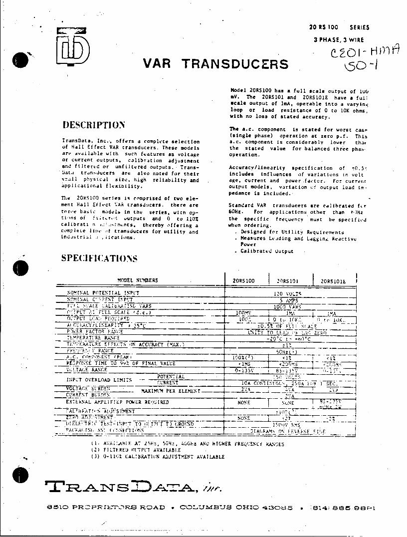
20 RS 100 SERIES
3 PHASE, 3 WIRE
VAR TRANSDUCERS od Model 2ORS100 has a full scale output of luC, mV. The 20RS101 and 2ORS101E have a full scale output of imA, operable into a varyinq loop or load resistance of 0 to 10K ohms, with no loss of stated accuracy.
I)ESCRIPTION The a.c. component is stated for worst case
(single phase) operation at zero p.f. This TransData, Inc.., offers a complete selection a.c. component is considerably lower that of Hall Effect VAR transducers. These models the stated value for balanced three phas art' dvdilable with such features as voltage operation. or current outputs, calibration adjustment and filter.d or unfiltered outputs. Trans- Accuracy/linearity specification of tO.S Jata tran.ducers are also noted for their includes influences of variations in volt
small physical size, high reliability and age, current and powerfactor. For current applicational flexi.bility. output models, variation cf output load im
pedance is included.. The 20RS100 series is enmprised of two element Hall Eiffct VAR transducers. there are Standard VAR transducers are calibrated fkr three basic madelb in the series, with op- 60Hz. For applications other than tHz ti-ns of ft, re! uutputs and 0 to 110% the specific frequency must be specitivJ calibrati n.....ents, thereby offering a when ordering. com.plete lintt of transducers for utility and Designed for Utility Requirements industril .1 .iications. Measures Lviding and LsggLng Reactive
Power Calibrated h autput , SPECIFIC:ATIONS
aV. The 2 1RS1 0 R aORS101 2ORShavE I
scaleA outputIA of'L 1mA, opral it avryn
IL I -lE Ab-! A 7~ 1 AR S _______0__ __________
!0PUT A7 F1,11 S! L 1".c.)
P*) ER FACTOR L'NITY TO LI-AD r.1-VZ, ( ih PEnAToRh lsf's(tae cuay
T(sngl pha) op e ACCURACY (roAX. ato aze pf T Y. RAN.CE _____________ j'fi
nsn.. I PA1 _:-0 1lc;z )AU 'll '1' Vt; T (Fl' RATNGE 0- 135VVTI JA 8A U 5 -lM 13rp'.'
V ~ 2 T A E R A . . O T E N '7 1 A L 5 03\ I ) j S
INsPUT OVERLOAD LIMItS RET ____ AC.IVL .,J W E VOLAGE~RlE ~ - AXIL-4 PER ELKN 2'-:A __ _ _ __
EXTEkNAL APLIF~IP POW;-R REQ)UIRED ~NONE f 'JE
A_____________________ jo
LW! lh' TEST- INP 1 T-) G:1 T' T) GROIND - 1 ___I Cov-F ?A( A(; I (a Ac. comp t is M cA ON siderabl etFh
(I, AVA;:.ARIE A 25k-.. 50Hzi, .LC l-z ANCL HICHER FREQ1:ENC;L KAMES (Ac) FILTEREut saPtT AVAILABLE (3) O-114;Z CAL:BRATlCN IDJLSTMENT AVAILABLE
6510C PR FaI'C'S R AD C0:LMBJS 01410 430k85 E314) 8E35 9E8P1
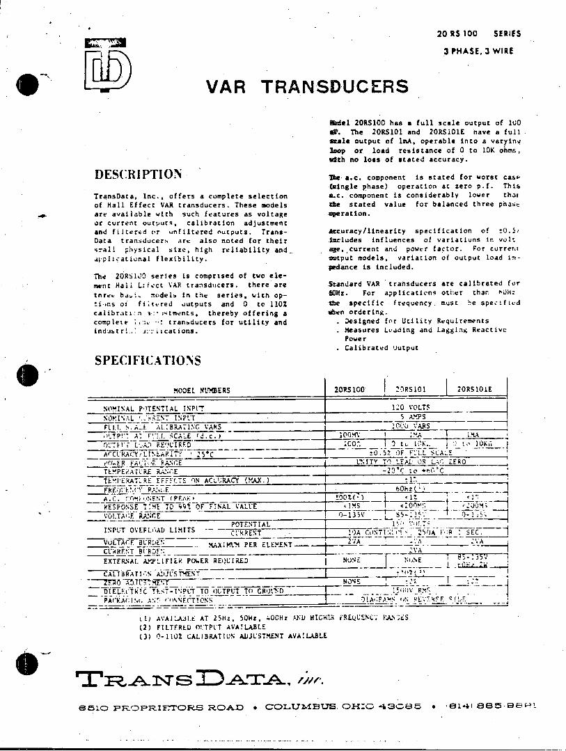
20 RS 100 SERIES
3 PHASE, 3 WIRE
VAR TRANSDUCERS
Abdel 20RS100 has a full scale output of 100 as. The 2ORS101 and 20RS101E have a full scale output of lmA, operable into a varying lsop or load resistance of 0 to 10K ohms, idth.no loss of stated accuracy.
DESCRI PTION De a.c. component is stated for worst case (single phase) operation at zero p.f. This
TransData, Inc., offers a complete selection ac. component is considerably lower thar
of Hall Effect VAR transducers. These models the stated value for balanced three phase
are available with such features as voltage operation. or current outputs, calibration adjustment and filtered or unfiltered outputs. Trans- Accuracy/linearity specification of !0.5i
Data transducers are also noted for their ieludes influences of variations in volt
simall physical size, high reliability and. age,,current and power factor. For current
.wplicational flexibility. antput models, variation of output Load impedance is included.
The 20RS100 series is comprised of two ele
ment Hall L:fect VAR transducers. there are Standard VAR transducers are calibrated for
tnree ba,.. modeli In the series, with op- 6i0z. For applications other than JHz
tins of fitEred outputs and 0 to 110% the specific frequency must he specified
calibrati:n v:* : tments, thereby offering a shen ordering. complete .:> : tranbducers for utility and Designed for Utility Requirements
indubtri... ications. . Measures Leading and Lagglng Reactive Power Calibrated output
SPECIFICATIONS
MODEL NUMBERS ZORS100 20RS101 20RS1OIE
NOMINAL POTENTIAL INPVT 10 VOLTS
NOMINAL *.:BENT I NPUT 5 AMPS FUi. S. LA. Ai.:BRATING VARS 00 VARS _
0'TP!*- A, F-;*L ,CA:-E (J.c.) r 10 M1 I 4A iMA
OtFET L..A.) RE'' CIRFD iC.^. I 0 to 10K.. to 10KG ArCURACY!LIN APIY 25'C :0.57 OF F!'LL SCAL
e O.ER FACT RANCE LNITY TO LEAl -R L. ZERO TLMPEPATLRE RAN.E -204C to +60*C
TE'"ERATRE EFFF(.TS ON AC-URACY (XAX.)
FRE01 .Y R'_-E _ _ _-- -- --hz---A. C. V'.9i*.'NE!,T (PEA:_____________I______ 1
RESPONSE T.ME TO 9 OF FINAL VALUE ________________________________ rj-l35 +
VOLTAGF RANCE 0-135A 0 1
POTENTIAL I _ _ -4 INPUT OVEFLOAD LIMITS -- CU'RRENTCONT:" JA i >R SEC. VULTACF BRENPER ELEENT-----CUkRENT BERD. E .VA EXTERNAl. AMPLFIER POER REQUIRED NUNE N1%E
CALTBRATI N A.JSTMENT
DIELECTTC TET-P;?LT TO OUTPUT TO CROUND S00V R.%* PACKA( I.A 'lNFCTTONS (LE.15Fi C_! F
LL) AVA1l.A3l.L AT 25Hz, 50Hz, 40CHz PFl) HIGHZ FREQUENC VAINS (2) FILTERED 0!.TPUT AVAILABLE (3) 0-1101 CALIBRATION ADJUSTMENT AVAILABLE
66I ANSn ADT', 1a.
AthleO ParoPIOR2ELE FEDAID * CDLI74MBOS OH:OC 43CLE85 * 65141 a3885-698

20 RS 100 SERIES
3 PHASE, 3 WIRE
VAR TRANSDUCERS
Model 20RS100 has a full scale output of 10O MV. The 20RS101 and 20RS101E have a ful! scale output of lmA, operable into a varying loop or load resistance of 0 to 10K ohms, with no loss of stated accuracy.
DESCRIPTION The a.c. component is stated for worst case (single phase) operation at zero p.f. This
TransData, Inc., offers a complete selection a.c. component is considerably lower thu, of Hall Effect VAR transducers. These models the stated value for balanced three phas. are available with such features as voltage operation. ir current outputs, calibration adjustment and filtered or unfiltered outputs. Trans- Accuracy/linearity specification of t0.5Z Data transducers are also noted for their includes influences of variations in volt small physical size, nigh reliability and age, current and pcwer tactor. Fcr current applicaLional flexibility. output models, variation of output load in
pedance is included. The 20MbleC series is comprised of two element Hall Eitect VAR transducers. there are Standard VAR transducers are calibrated for t1arav basic models in tne series, with op- 60Hz. For applications other than ttdHz ti ns of !t::cred outputs and 0 to 110% the specific frequency must he specified calibrati ''. er:..rmnts, thereby offering a when ordering. complete l1:1. of tranaducers for utility and . Designed for Utility Requirements industrial , p.i--ations. . Measures Leading and L,;gging Rcactive
Power Calibrated Uutput
SPECI FICATIO NS
MODEL NUMBERS 20RS100 20RS101 20RS101E
NOMINAL POTENTIAL INPIT 120 toLTS N"PA <EETINFLT 5 AV PS
F:.. s1ALt CA:.IbR .1NCG VARS 1000 VS , A-, fLi. SCA'E (d.c.) 100MV
'DP.7P LIA. OUl.t1 ____ 100 ~ 0 to I~r I. 0TT7 JUK ACCURACY/LIN.A?.17Y ' 25C __.5% OF v1:. SCAl E
.CTa. fANGE L'NITY TO LEALr OR 0 ZERO TEPE ATURE RANGE -20*C to *tC
T EMRATLRE EFFCTE ON ACL'RACY (MAX. :t
A.C. rFYo.ENT (PEA) 100%() <1 RFSFONSF TIME TO 99*. OF FINAL VALUZ <1MS 20 M <200Ms
VOLTAGE P.ANr.E 0-135V P5-1 ' 0-.35 POTFNTIAL
INPUT ObERLOAD LIMITS 0EA CO7INT-1 2 U A I SEC. VOL7AGE BUPDEN MAXIM' PER ELEMENT -CL'iHRFNT 5t'ROFN i.TEkNALA.P&LlIER POER REQUIRED NONE ONE
CAlIERATION ADJ * YFNT _ _ _ _
10A CT~r 2>71 F EC
DIF.LE(TRTC TEST-P.P T TO OI1TrLT TO GROLND 1 SC;.'RMS (7':;[1C nDIAGRAYS (. PL.LFSE S'DF.
(0 AIlAtL.r. AT 15Kz, 50Hz, 400Hz AND HICHER FkLQUEN.Li K;ANGES (2) FILTERED nLTF:T AVAILABLE (3) 0-1ul CAL.fBkATION ADJUSTMENT AVAILABLE
e10 R .A N S D 4EATA, tr. e510 PROPRIETCRS ROAD * CO.t.7M3.'S OHIO 4sous * .el41 ess 9891
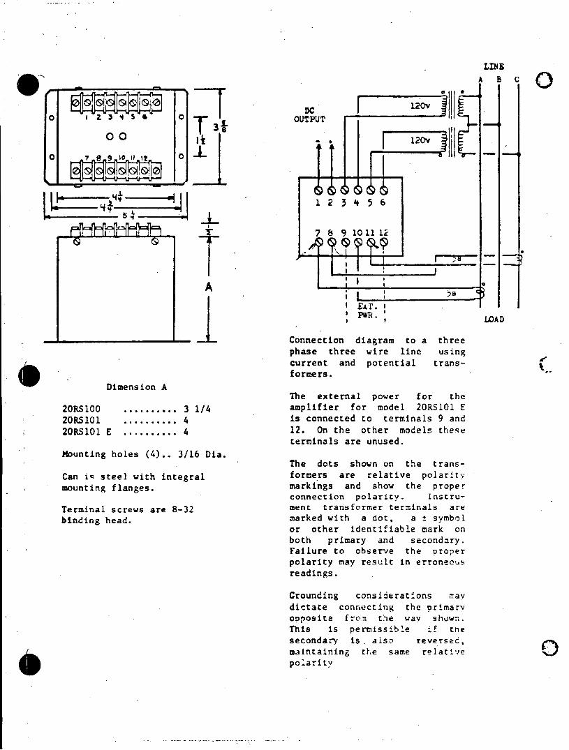
LINE
DAC
og OUTPUT 10 To 00 120v
1445
7 8 9101112
A ~I -II IEAT. I
** * LDAD
Connection diagram to a three phase three wire line using current and potential trans
Dimension A The external power for the
20RS100 .......... 3 1/4 amplifier for model 2ORS101 E 20RS101 ........... 4 is connected to terminals 9 and 20RS101 E ........... 4 12. On the other models these
terminals are unused. Mounting holes (4).. 3/16 Dia.
The dots shown an the trans
Can iq steel with integral formers are relative polarity mounting flanges. markings and show the proper
connection polarity. Instru
Terminal screws are 8-32 menc transformer terminals are binding head, marked with a dot, a ± symbol
or other identifiable mark on both primary and secondary. Failure to observe the proper polarity may result in erroneous readings.
Grounding consiieratons 1ay dictte connecting the rrmmar opposite frot the way shw. This is permissible if tne secondary isr asi reversed, maintaining the same relative polarity
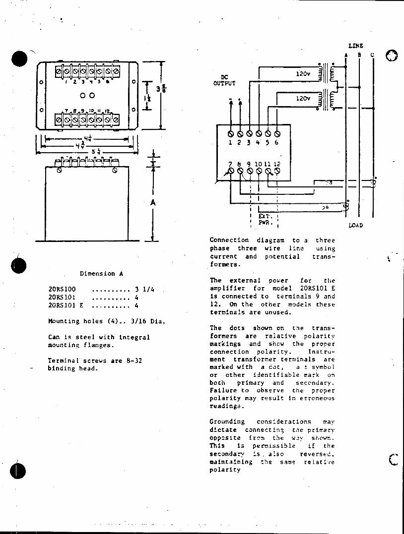
LINE
-A B C
o0 0 T 3 OUTPUT
123'256
3
U 1 2 3 4 5 6
7 7 8 9 10 11 12
A
Fw. LOAD
Dimension A The external power for the
20RS100 .......... 3 1/4 amplifier for model 20RS101 E 20RS101 ........... 4 is connected to terminals 9 and 20RS101 E ........... 4 12. On the other models these
termi~nals are unused. Mounting holes (4).. 3/16 Dia.
Can is steel with integral formers are relative polarity mounting flanges. markings and shcw the proper
connection polarity. InstruTerminal screws are 8-32 ment transformer terminals are binding head. marked with a got, a t symbl
or other identifiable uiark on both primary and secndary. Failure to observe the proper polarity may result in erroneous readings.
Grounding consmderaions may dictate connectn tne primary oppste frn the westhese This is pernissible if the secondarr asr also reversed, maintaining the same rerative c c polarity

LIN0
DAB
0 Z s 3 4 OUTPUT
o 0
01 11 1
L ~1 2 3 4 5 6
LUI * 4- 7 8 9 101112
1 IJ
SEXT. I 'PWR. LAD
phase three wire line using
Dimension A The external power for the
20RS100 .......... 3 1/4 amplifier for model 2ORS101 E 20RS101 ........... 4 is connected to terminals 9 and 20RS101 E ........... 4 12. On the other models these
terminals are unused.
Mounting holes (4).. 3/16 Dia. The dots shown on the trans
Can is steel with integral formers are relative polarit: mounting flanges. markings and show the proper
connection polarity. Instru
Terminal screws are 8-32 ment transformer terminals are binding head. marked with a dot, a t syhrc!
or other identifiable mark on both primary and secondary. Failure to observe the proper polarity may result in erroneous readings.
Grounding considerations may dictate connecting the primar opposite from the way shown. This is permissible if tuse secondary i also reversit, maintaining the same relative polarity
4ettasomrtrias.r
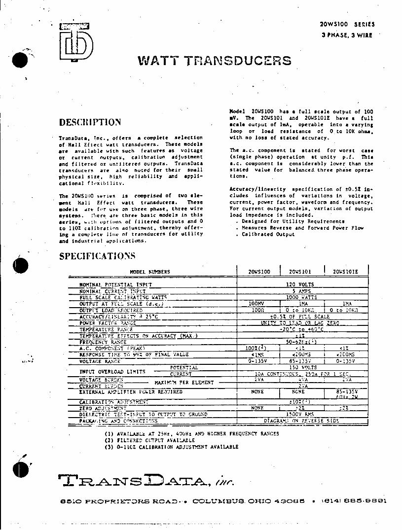
J2WSI U SEIIcS
3 PHASE, 3 WIRE
WATT TFANSDUCERS
Model 20WS100 has a full scale output of 100 aV. The 20S101 and 20WS1OIE have a full DESCRI PTION scale output of 1mA, operable into a varying loop or load resistance of 0 to 10K ohms,
TransData. Tnc., offers a complete selection with no loss of stated accuracy. of Hall Eftect watt transducers. These models are available with such features as voltage The a.c. component is stated for worst case or current nutputS, calibration adjustment (single phase) operation at unity p.f. This
and filtered or uniltered outputs. TransData a.c. component is considerably lower than the transducers are also noted for their small stated value for balanced.three phase operaphysical size, high reliability and appli- tions. cational flexibility.
Accuracy/lineerity specification of t0.52 inThe 20WS110 series is comprised of two ele- cludes influences of variations in voltage, sent Hall Effect watt transducers. These current, power factor. waveform and frequency. models are frr use an three phase. three wire For current output models, variation of output systems. !here are three basic models in this load impedance is included. series, .. ch upri.ns of filtered outputs and 0 . Designed for Utility Requirements to 1102 calibration adiustment, thereby offer- . Measures Reverse and Forward Power Flow ing a complete Ii&e of transducers for utility . Calibrated Output and industrial applications.
SPECIFICATIONS MODEL WULERS 20WS100 20KS101 20WS101E
NOMINAL POTENTIAL INPtT 120 VOLTS
NOMINAL CURRENT INPT 5 A.P S FULL SCALE CALIATI A 1000 .ATTS OUTPUT AT FLL. SCALE (d.c.) 100MV LMA 1IA OUTPUT LOAD k.FOUIETRED . 00 0 to 10K 0 to 10K ACCUKACY/LINEAI:T a 25'C t0.5% OF FULL SCALE POWER FACT(R !ANCE UNITY TO Q LAQ ZERO
TEMERATURE PAN-F _20_C to +60C
TEPYERAT.PRE ETFECTS ON ACCURACY (MAX.) ___
FREQUENCY RANCE _ _-62__'_
A.C. COMPCNE:;T ?EAK 100!(2)1 RESPCNSE TIM'E TO 9SZ OF FINAL VALUE <1tS <200.s I <200MS
VOLTAGE RAN__E 0-135V 85-135'.. 0-'35V
VO E POTENTIAL 150 VOLTS INPUT OVELOAD LIMITS CURRENT 10A C0NTT;.US 25A FOR 1 SEC. VOLTAGE BUPPMAXIN ER ELEMENT 'VA ; AVA VA
CURRENT SLDN2.'A EXTERNAL .A.'?LIFTEIER GluER REVUIRED NONE NGNE 85-135V
CALIBRAt1')!: A STKEN7 0%(-)
ZERO ADJUSTENT NONE *2: :2% DIE.FCTRIC TESfT-IN;PUT TO OUTPUT TO GRUUND 150cV R.NS PACKAr.LvG AND C)NNFCTITNS DIACA.L* ON FPF'EFSE SIDE
(1) AVAILABLi AT 25Hz, 400jHz AND HIGHER FREQUENCY RANGES (2) FILTERED CUTPLT AVAILA.LE (3) 0-110% CALIBRATION ADJ,.STwENT AVAILABLE
Sate PR0FRIE7 fR. WRFOAD-. COLTATJ("- at4ISE30 * E514) E385 9391

20WS100 SERIES
3 PHASE, 3 WIRE
WATT TRANSDUCERS
Model 20WS100 has a full scale output of 100 mV. The 20WS101 and 20WS101E have a full
DESCRIPTION scale output of imA, operable into a varying loop or load resistance of 0 to 10K ohms,
TransData. Inc., offers a complete selection with no loss of stated accuracy. of Hall Eftect watt transducers. These models
are available with such features as voltage The a.c. component is stated for worst case or current nutputs. calibration adjustment (single phase) operation at unity p.f. This and filtered or untiltered outputs. TransData a.c. component is considerably lower than the transducers are also noted for their small stated value for balanced three phase operaphysical size, high reliability and appli- tions.
cational f!.xibility. Accuracy/linearity specification of ±0.52 in
The 20WS1:w0 s eries is comprised of two ele- cludes influences of variations in voltage, ment Hali Effect watt transducers. These current, power factor, waveform and frequency. models ar- f'r use in three phase, three wire For current output models, variation of output systems. FTere are three basic models in this load impedance is included.
series, .*,:! iptions of filtered outputs and 0 . Designed for Utility Requirements to 110! calibration adjutment. thereby offer- . Measures Reverse and Forward Power Flow ing a comI'lete line of transducers for utility . Calibrated output and industrial applications.
SPECIFICATIONS MODEL NUMBERS 20WS100 20WS101 20WS101E
NOMINAL POTENTIAL INPUT 120 VOLTS NOMINA! CURRENT INPUT 5 A.PS FULL SCALE C.AL.IRATING WATTS 1000 WATTS OUTPUT AT FULL SCALE (d.c.) 100V IMA IMA OUTPI LOAD 'GUIRED 1000 0to 1 0 to UK1 ACC-FACTiLINEARiT 7 25*C !0.54 CF ELl SCALE
POWER FACTOR AXLE UNITT 0 'sEA OR ' ZERO TEPYEPATCPE RANCE -20'C to __toc
TEMPERA7VRF EFFECTS ON ACCURACY (MAX.) __ ,
FREQUENCY PANGE _0-62__1)
A.C. COMPONEN TY7TAY 1552_(_)_<_._<it
RESPONSE TIME TO 99Z OF FINAL VALUE <1.LS <20 <20CMS
VOLTAGE .AE -0-135V I -135'. I 0-135V *POTENTIAL 150 VOLTS
INPL'T OVERLOAD LIMITS .'*RENT i0A CONTNUOL , 25QA FOR I SEC. VOLTAGE BU~ih. MAXI':M PER ELEMENT 2 ZVA4V CURPENT EUREE _.A
EXTERNAL AMPL;FIER FPcER ROUIRED NONE NONE 85-135V
CAL:EPATION AS7'57ENT fln(
ZERO ADJLb-MENT NCNE 2% :2
DIE.FCIPIC TEST-INPLT 'O O'TP')T TO GROUND 1500V LMS PAC:KA..'G AND C*iNFCT ONS j )IAGRAMS ON RF:IRSE SIDE
'1) AVAILABLE AT 250z, 4C0Hz AND HICHER FREQUENCY R.A'CES (2) FILTE?ED Cl.LTP'T AVAILA3LE (3) 0-110. CALIBRATION ADJSTENT AVAILABLE
e5~ Pl~CRI~.~PS OAr- 9 COL..UMB17. OHInO 43CDE3 641-4) IBE8-9891
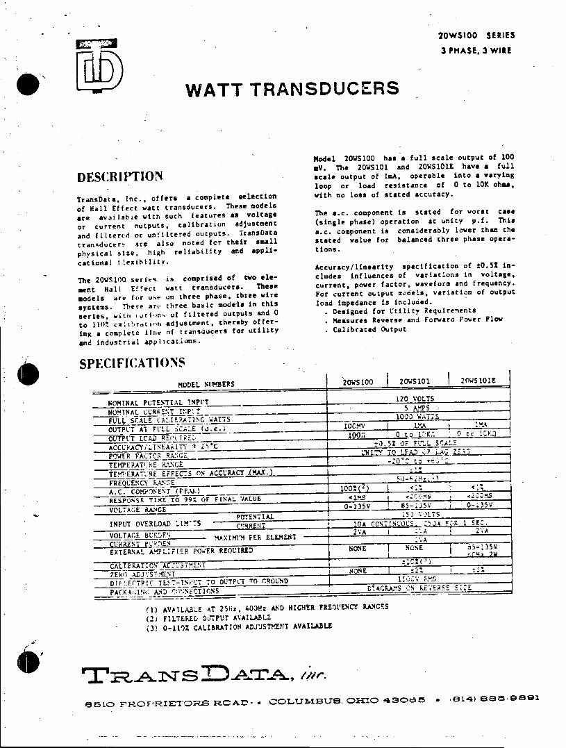
20WS100 SERIES
3 PHASE, 3 WIRE
WATT TRANSDUCERS
model 20WS5100 has a full scale output of 100
my. The 2OWS101 and 2OWS101E have a full
DESCRIPTION scale output of IsA, operable into a varying loop or load resistance of 0 to 10K ohm,
TransData, Inc., offers a complete selection with no loss of stated accuracy.
of Hall Effect watt transducers. These models
are available with such features as voltage The s.c. component is stated for worst case
or current outputs, calibration adjustment (single phase) operation at unity p.f. This
and filtered or unaltered outputs. TransData a.c. component is considerably lower than the
transducer- are also noted for their small stated value for balanced three phase opera
physical size. high reliability and appli- tions.
cational *!exibilitv. Accuracy/linearity specification of t0.52 in
The 20WS100 series is comprised of two ele- cludes influences of variations in voltage,
ment Hall Effect watt transducers. These current. power factor, waveform and frequency.
models are for use on three phase, three wire For current output models, variation of output
systems. There are three basic models in this load impedance is included.
series, with .ijt1ons of filtered outputs and 0 Designed for Utility Requirements
to 110% cabr.tion adjustment, thereby offer- Measures Reverse and Forward Power Flow
ing a complete line of transducers for utility Calibrated Output
and industri2S apphicataons.
a SPECIFfCATIONS MODEL NaVTERS h20WS101 20WS101 20WS 1 01E
NOMINAL POTENTIAL !NPUT 120 VOLTS
NOMINAL CL'RFENT 1!;P'2 5 AY S
OUTPU SAlLE 100-L, Wuc~__________ lC1ATT
OTUAlFULL SCLE AAJI c WATT ________ 1023 I :7
OUTPl o or1 l oad0resi st an ce of 0 to 1 K0 ac K. s
ACCUACY/LINEAi1I Y 2S'C ____________j:0. 52 OF FLL. 5SALE
POWER FACT03 .;Gi TO1 7 0 L A , Z? -R 3
TEMPERAT'HE RiUNGE 2 t
TEMIE0F_'R E _EFFEC-5S 0% ACCURACY (MA.X.) .
FREQUENCY RANC.E_____________________________________ aA.C . CO.C
pEo e (PEi
s c onsid er abl y o1e th anth
RESPONSE TIME TO 99Z OF FINAL VALUE -C 2C YS
VOLTAsE vNaE l0- 135Vf b- 3v h o-135V
POTyE NT IAL 15,11 VOLTS
INPUT OVERLOAD LIM-S - C -RRENIT ICA CNT!N:LUS_ _15Jh C 1 SEC.
VOLTAGE BUAcFc! ura y/1 ne Pr t ELs eaT 2 VAo 20.5
EXTERNAL kA ~F PER REOUIREDNOE I OE 35
CALcludes iln of varitU3i MEoTn Eu r n pLJoSercNT t r , a o a
DIF.FrT1CTE 7-INWI:T TO OUTFPUT TO CCUND __________0c _______;_
PACKA:Pi(;t Xi*4 - ,NC~N - - -GA"S CS kEEE S_:i
(1) AVAILALE AT 25orz, crtp: AND HIelER FREOsoENCY RANCES
(2) FIL7LEE 0J7PUT AVAILADLZ (3P 0-1102 CALIBRATION EDJCSTANT AVAITABLE
4:35 OI FNRF RIET S O1{O 43POT 8NT14) 8!N5-9PT1
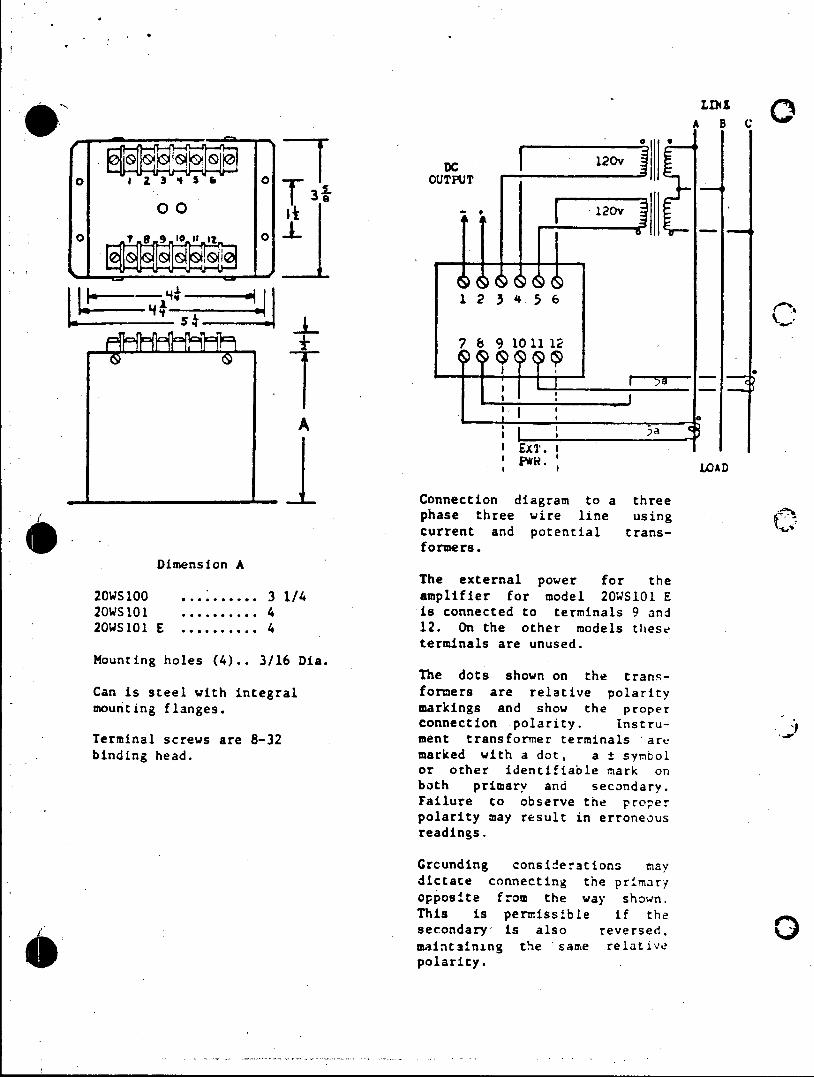
D 120v
o '1 3 4S' 0 OUTPUT T3 0 00
8 10 1112
A SExT. I * PWN. S ILOAD
Connection diagram to a three
phase three wire line using current and potential transformers.
Dimension A The external power for the
20WS100 . . 3 1/4 amplifier for model 20WS101 E 20WS101 .......... 4 is connected to terminals 9 and 20WS101 E .......... 4 12. On the other models these
terminals are unused. Mounting holes (4).. 3/16 Dia.
The dots shown on the transCan is steel with integral formers are relative polarity mounting flanges. markings and show the proper
connection polarity. InstruTerminal screws are 8-32 ment transformer terminals are binding head. marked with a dot, a ± symbol
or other identifiable mark on both primary and secondary. Failure to observe the proper polarity may result in erroneous readings.
Grcunding considerations may dictate connecting the primary opposite from the way shown. This is permissible if the secondary is also reversed. 0 maintaining the same relative polarity.
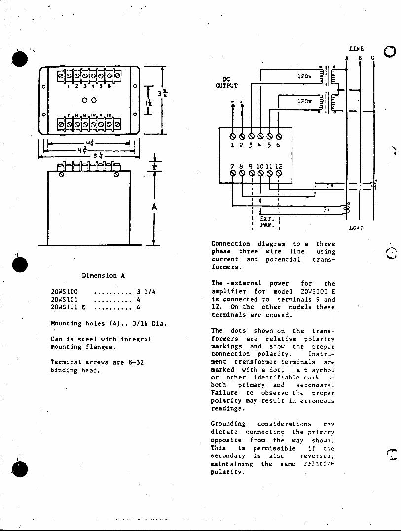
AB8
DC 120v
0o 3 4# * oOUTPUT
00) -. -* 120vo TA
7 6 9 101112
A
I EXT. I ' PWR. LZAD
-Connection diagram to a three phase three wire line using current and potential transib~. formers.
Dimension A The -external power for the
20WS100 .......... 3 1/4 amplifier for model 2OWSl01 E 20WS101 .......... 4 is connected to terminals 9 and 20WS101 E ........... 4 12. On the other models these
terminals are unused. Mounting holes (4).. 3/16 Dia.
The dots shown on the transCan is steel with integral formers are relative polarity mounting flanges. markings and show the proper
connection polarity. InstruTerminal screws are 8-32 ment transformer terminals are binding head. marked with a dot, a ± symbol
or other identifiable mark on both primary and seconar. Failure tn observe the proper polarity may result in erroneus readings.
Grounding considerations 9anv dictate connectirg mode prithr opposite fom the way shown. This is permissible if the secondary is alsc reverstd,
maintaining the same rolatpe c c polarity.
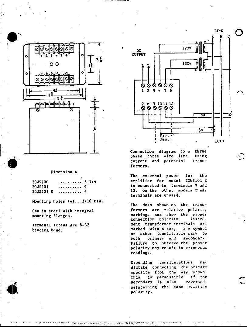
N liLINEI 0 0 oO k 120v -O
120v Ji
7 8 9 1011 12
T_ I Ext.
F*R* ,LOAD
._ Connection diagram to a three phase three wire line using current and potential transformers.
Dimension A The external power for the
20WS100 .......... 3 1/4 amplifier for model 20WS101 E
20WS101 .......... 4 is connected to terminals 9 and
20WS101 E .......... 4 12. On the other models these terminals are unused.
Mounting holes (4).. 3/16 Dia. The dots shown on the trans
Can is steel with integral formers are relative polarity
mounting flanges. markings and show the proper connection polarity. Instru
Terminal screws are 8-32 ment transformer terminals are
binding head. marked with a dot, a ± symbol or other identifiable mark on both primary and secondary. Failure to observe the proper polarity may result in erroneous readings.
Grounding considerations may dictate connecting the primary opposite from the way shown. This is permissible if the secondary is also reversed, maintaining the same relative 4 polarity.
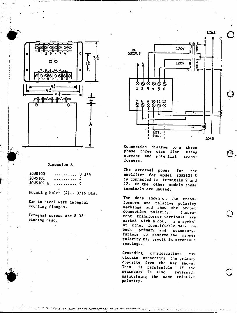
LIN
DC 120v 0 1 3 4 o OUTPUT
0010* *3 120v 0 00
1 2 3 4 5 6
7 8 9 1011 12
I EXT. I PWR.
LOAD
Connection diagram to a three phase three wire line using current and potential transformers.
Dimension A The external power for the
20WS100 .......... 3 1/4 amplifier for model 20WS101 E 20WS101 .......... 4 is connected to terminals 9 and 20WS101 E .......... 4 12. On the other models these
terminals are unused. Mounting holes (4).. 3/16 Dia.
The dots shown on the transCan is steel with integral formers are relative polarity mounting flanges. markings and show the proper
connection polarity. InstruTerminal screws are 8-32 ment transformer terminals are binding head. marked with a dot, a ± symbol
or other identifiable mark on both primary and secondary. Failure to observe the proper polarity may result in erroneous readings.
Grounding considerations may dictate connecting the primary opposite from the way shown. This is permissible if the secondary is also reversed, maintaining the same relative polarity.