in-line diesel engine series 71 - Tractorparts.com
206
-
Upload
khangminh22 -
Category
Documents
-
view
0 -
download
0
Transcript of in-line diesel engine series 71 - Tractorparts.com


X-591 0
mAlnTEnAn[EmAnUAL
IN-LINEDIESEL ENGINE
SERIES 71
GMC TRUCK & COACH DIVISIONGENERAL MOTORS CORPORATION
PONTIAC, MICHIGAN
© 1959 General Motors CorporationGMC Truck & Coach Division
10M-Mar. 1959Printed in U.S.A.
Reprinted 8M-Feb. 1960Reprinted 1M-Feb. 1963Reprinted 2M-Aug. 1963Reprinted 3M-Feb. 1964Reprinted 3M-Feb. 1965Reprinted 3M-Mar. 1966
"
I

This maintenance manual includes complete maintenance andrepair information on the basic current GM Diesel engines used inGM coaches and GMC Trucks.
Information on accessories allied with the diesel engine suchas starters, generators, air cleaners, etc., are covered in applicabletruck or coach Maintenance Manuals. Operation information fromthe standpoint of the driver will be found in applicable Truck orCoach Operating Manuals.
The manual is divided into ten general sections as shown onopposite page. The page numbers in the book are consecutive; however, the illustration numbers are consecutive within each section.
The index on opposite page shows page numbers of each majoritem in each general section. The alphabetical index at end of booklists important subjects together with page numbers.
Page ii

SECTION INDEX
General Information
The GM 2-Cycle Diesel Engine
Starts onPage No.
\
\\'
Starts onPage No.
GM Diesel Engine Data. . . . . . . . .. . . . . . . . . . . . . . . . . . . . .. 2
1
Basic Engine Overhaul
Cylinder Block .Cylinder Block End Plate .Cylinder Liners 12Crankshaft and Main Bearings 17Flywheel and Clutch Pilot . . . . . . . . . . .. 24Flywheel Housing and Gear Train Cover 26Vibration Damper .Crankshaft Front Cover and Oil Seal ..Pistons and Connecting Rods .Gear TrainCamshaft and Balance Shaft .Cylinder Head .Valves and Injector OperatingMechanism . . . . . . . . . . . . . . . . .. 62
Exhaust ManifoldEngine Timing and Balance
Lubrication System
Circulation and Distribution 72Engine Oil Recommendations 78Oil Filters and Strainers 79Oil Cooler 79Lubricating Oil PumpOil Pressure Regulator Valve ....
Cooling System
Water PumpHydraulic Fan Drive
711
283031404552
69
70
8287
8992
Air Intake SystemBlower
Fuel System
Fuel Oil RecommendationsFuel Injectors .Fuel Oil PumpFuel ManifoldsFuel Modulating GovernorLimiting Speed Governor ..Limiting Speed Governor-EconomyRange .
Engine Run-In and Tune-Up
Engine Run-In .Engine Tune-Up .
97
115118136140142152
162
169170
Diagnosis and Trouble Shooting
Testing and Diagnosis 175Trouble Shooting 180
Special ToolsSpecial Tools . . . . . . . . . . . . .. 190
195
SpecificationsBolt and Nut Torque Specifications 193
Fits, Tolerances, and ServiceSpecifications ....
ALPHABETICAL INDEX
Page iii
199

The models 4-71 and 6-71 Diesel engines are supplied ascomplete automotive replacement units for trucks. Available infour and six cylinder models, with a wide power range to choosefrom, these engines provide operators and the truck replacementfield in general with a complete automotive power plant.
Everyday GMC engineered Diesel replacement power unitsare making new records of savings in fuel and maintenance costsin many different makes of trucks and tractors.
The GMC Diesel reputation for performance and "up to theminute" improvements is upheld by the experience of our Transportation Engineers who have been modernizing commercialequipment with the GMC Diesel power unit for many years.
When replacing present equipment with GMC Diesel power,you may be sure of these four points:
1. Correct Application for your requirements.
2. Engineered installation.
3. Nation-wide parts and service.
4. Latest Diesel design and engineering.
See your GMC dealer for information on the availability ofGM Diesel engines for installation in practically any make oftruck.
Page iv

DIESEL ENGINE MANUAL Page 1
THE GM 2-CYCLE DIESEL ENGINE
THE DIESEL PRINCIPLEThe Diesel engine is an internal combustion
power unit, in which the heat of fuel is convertedinto work in the cylinder of the engine.Diesel engines differ from gasoline engines prin
cipally in the method used to introduce and ignitethe fuel. Gasoline engines draw a mixture of fueland air through the carburetor into the combustionchamber, where it is compressed, then ignited by an. electric spark. In the Diesel engines, air alone iscompressed in the cylinder; then, a charge of fuelis sprayed into the cylinder, after the air has beencompressed, and ignition is accomplished by theheat of compression.
THE GM 2-CYCLEENGINEFour strokes are required to complete a cycle in
the four-cycle engine, which functions half the timeas an air pump.In the two-cycle engine, intake and exhaust take
place during part of the compression and powerstrokes. A two-cycle engine, therefore, does not function as an air pump, so an external means of supplying the air is provided. A specially designed blower,on the side of the engine, forces cleaned air into thecylinders to expel the exhaust gases and fill thecylinders with fresh air for combustion, as shown infigure 1.A series of ports cuts into the circumference of the
cylinder wall (liner), above the piston, in its lowestposition, admits air from the blower into the cylinderwhen top face of piston uncovers the ports, asshown in figure 1. The swirling flow of air towardthe exhaust valve produces a scavenging effect, leaving the cylinders full of clean air when the pistonrises and covers the inlet ports.As piston continues on upward stroke, exhaust
valves close and the charge of fresh air is subjectedto the final compression, as shown in figure 1. Air incylinder is heated to approximately lOOO°F.whilebeing compressed.
Figure J -Transit Coach Power Plant

Page 2 DIESEL ENGINE MANUAL
GENERAL INFORMATION
Shortly before the piston reaches its highest position, the required amount of fuel is sprayed into thecombustion space by the unit fuel injector. The intense heat generated during the high compression ofthe air ignites the fine fuel spray immediately, andthe combustion continues as long as the fuel spraylasts. The resulting pressure forces the piston downward to provide a power stroke. Figure 3 illustratesfuel injection and beginning of power stroke.
As piston nears the bottom of the downwardstroke exhaust valves are opened (fig. 1) and spentgases are released. Still further downward movements of piston uncovers liner ports and cycle isrepeated.This entire combustion cycle is completed in each
cylinder for each revolution of the crankshaft, or, inother words, two strokes; hence, the "two strokecycle."
GM DIESELENGINE DATAGENERALAn engine model and serial number are stamped
on the blower side of the cylinder block at the upperright hand corner. Refer to figure 4.When ordering engine parts, order by part num
ber and description, and refer to engine model andserial numbers.The two-cycle Diesel engines discussed in this
text include the four- and six-cylindermodels having
the same bore and stroke and using the same partswherever possible. Thus, different power capacitiesare available in the same type of engine, in whichthe major working parts, such as injectors, pistons,connecting rods, and all bearings and other numerousparts are interchangeable. Engines with either direction of rotation can be supplied to suit specificrequirements.Furthermore, the blower, water pump, oil cooler,
Figure 2-Truck Diesel Engine-4 Cyl. Shown

DIESEL ENGINE MANUAL Page 3
GENERAL INFORMAliON
AIR ENTERING COMBUSTION CHAMBER AIR BEING COMPRESSEDWITHTHROUGH CYLINDER LINER PORTS THE EXHAUST VALVE CLOSED
CHARGE OF FUEL BEING INJECTEDINTO COMBUSTION CHAMBER
EXHAUST TAKING PLACE ANDCYLINDER ABOUT TO BE SWEPTWITH CLEAN SCAVENGING AIR TP·6406
Figure 3-GM Diesel Engine 2-Cycle Operation

Page 4 DIESEL ENGINE MANUAL
GENERAL INFORMATION
Figure 4-Engine Mode' and Serial Number L.ocations
oil filter, governor, and fuel pump form a group ofstandard accessories which can be located on eitherthe right or left side of the engine, regardless of thedirection of rotation. Further flexibility in meetinginstallation requirements can be had by placing theexhaust manifold and water outlet manifold oneither side of the engine. This flexibility in thearrangement of parts is obtained by having both thecylinder block and cylinder head symmetrical atboth ends and with respect to each other.Figure 4 shows these various arrangements, which
are designated by the letter R or L in the model
number, denoting right-hand or left-hand rotation,and the letters A, B, C, or D designating the accessory arrangements. The table in figure 5 shows theparticular arrangement of standard accessories andexhaust and water outlet manifolds designated byletter A, B, C, or D, used as part of the modelnumber.Right and left side of engine is determined by
standing at rear (transmission end) and looking toward front. Transmission end of engine is referredto in manual as rear end, while opposite end is front.Rotation is determined by standing at front and
CAMSHAFT(THRUST-REAR) CAMSHAFT
(THRUST-fRONT) CAMSHAFT CAMSHAFT(THRUST-fRONT) (THRUST-REAR)
RA MODELS RS MODELS Re MODELS RD MODELS
CAMSHAFT(THRUST-REAR)
ENGINE TYPE ON LEFT SIDE ON RIGHT SIDEA All standard accessories Exhaust outlet. Water outletB All standard accessories
Exhaust outletWater outlet
C Exhaust outlet All standard accessoriesWater outlet
D All standard accessoriesExhaust outlet
LA MODELS Water outletTPM-2672
Figure 5-Rotalion and AccessoryArrangement

DIESEL ENGINE MANUAL Page 5
looking toward rear (transmission end). If crankshaft rotates clockwise engine is right-hand or "R"model, or if rotation is anti-clockwise engine is lefthand or "L" model.
Selection of the proper flywheel housing permitsplacing the starting motor on either the right or leftside of the engine. Other accessories may be drivenfrom either the camshaft or balancer shaft timinggear at the rear end of the engine or from the frontend of the crankshaft.
GENERAL INFORMATION
GENERAL SPECIFICATIONS6-71Engine Model . . . . . . . . . . .. 4-71
Number of Cylinders. . . 4Bore 4-W'Stroke . . . . . . . . . . . . . . .. 5"Total Displacement-Cu. In. 283.7Taxable H.P. (S.A.E.-A.M.A.) 28.9Firing OrderR.H. RotationL.H. Rotation
64-~"5"425.643.35
1-3-4-21-2-4-3
1-5-3-6-2-41-4-2-6-3-5
MAXIMUM ENGINE RPM..
The following information is the approved maximum no-loadsetting of governor for current engines used in various truck and coachmodels. Do not permit engine operation with governor settings higherthan indicated.
No-Load RPMModel Gov. Setting
4-71-Truck 2450+ 0 - 256-71-Truck . . . . . . . . . . 2450+ 0 - 256-71-("E" or "SE" Series) Truck 2150+ 0 - 25Transit Coach (4-71) 2100+ 0 - 25Transit Coach (6-71) . . . . . . . . . . . . . . . . . .. 2100+ 0 - 25Parlor Coach (PD-4104) 2150+ 0 - 25
USE OF ORIGINAL PARTSAt the present time several types and capacities of units, such as:
injectors, pistons, cylinder liners, and blowers are being used. In noinstance should operators install any parts other than those originallyused in the engine, unless permission is obtained from an authorizedsource. The use of such parts may result in premature failure of engineparts, and will be considered sufficient cause to void the warranty.

Page 6 DIESEL ENGINE MANUAL
GENERAL INFORMATION
SERVICE BULLETINSService Bulletins are issued, whenever required, supplementing information inthis Manual. The information contained in these bulletins should be noted in thetext and bulletin filed for future reference.

DIESEL ENGINE MANUAL Page 7
BaUc C, · (j~~ .
CONTENTS OF THIS SECTIONSubjectCylinder Block .Cylinder Block End Plate .Cylinder Liners .Crankshaft and Main Bearings .Flywheel and Clutch Pilot .Flywheel Housing and Gear Train Cover.Vibration Damper .. ' .
Page7111217242628
This section includes maintenance and repairinformation on the components and subassemblies ofthe basic engine assembly under major sub-titles.Reference is made to other sections for informationon related units. It is recommended that the informa-
Subject PageCrankshaft Front Cover and Oil Seal 30Pistons and Connecting Rods .. . . . . . . . . . . . . . .. 31Gear Train 40Camshaft and Balance Shaft .. 45Cylinder Head . . . . . . .. 52Valves and Injector Operating Mechanism 62Exhaust Manifold .. 69Engine Timing and Balance 70
tion in special tools and equipment also specifications sections be studied before using this section,particularly bolt sizes, torque specifications, and fitsand tolerances.
CYLINDER BLOCKCylinder block and crankcase (fig. 1) which ismain
structural part of the engine, is a box-like, one-piececasting made of alloy cast iron. The blocks for thefour- and six-cylinder engines are identical in designand dimensions, except the necessary length for theadditional bores and the correspondingly largerblower mounting flanges. The two ends of block aresimilar, so that same flywheel housing and gear traincan be installed on either end of anyone of the models.Rugged transverse members, cast integral, provide
rigidity and strength, and assure perfect alignment ofbores and bearings under all loads. Cylinder bores arecounterbored and fitted with an insert to supportcylinder liners, into which a number of air inlet portsare drilled. Water jackets extend full length of boresand are divided into upper and lower sections, whichare connected by hollow struts. Cooling water entersat bottom of water jacket from the water pump andleaves jacket at top through holes which register withcorresponding openings in cylinder head. Surrounding the water space is an air chamber which conductsair from blower to all of the inlet ports in cylinderliners (fig. 2).The upper halves of main bearing seats are cast
integral with block. Drilled passages in block carrylubricating oil to all moving parts thereby eliminatingtubing.Hand-hole plates (fig. 3) on the side opposite to
4 Air Box Drain5 Water Pump Opening6 Air Box
1 Cylinder Liner Bore2 Camshaft and Balance
Shaft Opening3 Balance Weight Cover
Drain TPM·2673
Figure I-Typical Cylinder Block andCrankcase

Page 8 DIESEL ENGINE MANUAL
CYLINDER BLOCK
8 7 15 12
6
3 11
1 Vertical Oil Passage2 Oil Gallery3 Oil Passage to Crankshaft4 Coolant Passage5 Coolant Inlet to Liner Jacket6 Liner Cooling Jacket
7 Air Box8 Air Passages to Cylinder9 Bore for Cylinder Liner10 Bore for Cam or Balance
Shaft
11 Upper Half of Main BearingSeat
12 Water to Cylinder Head13 Air from Blower14 Water from Pump15 Plugged Holes Each Corner
TPM·2526
2
Figure 2-Cylinder Slock and Crankcase Sections
Figure 3-Hand-hole Plates and Air Intake Ports
blower permit access to air chamber, and inspectionof liner wall, pistons, and rings through the air intakeports in cylinder walls. The six-cylinder engine alsohas two hand-hole plates on the blower side.Camshaft and balancer shafts, located on opposite
sides near the top of the block, are supported by bearings located in machined supports near top of block.
DISASSEMBLYProcedure for removing each assembly and sub
assembly from the cylinder block together with disassembly, inspection, repair, and reassembly of each,will be found in the various sections of this manual.Reference to the subject and alphabetical indexes willshow the location of any desired information on particlar accessories or engine parts.After stripping and before any parts are reassem
bled to the cylinder block, the block should be cleanedand thoroughly inspected for any conditions thatwould render the part unfit for further use.
CLEANINGSince the cylinder block is main structural part of
engine, whenever engine is being overhauled, blockshould be thoroughly cleaned and inspected for anyconditions that would render the block unfit for further use. Such inspections should take place after

DIESEL ENGINE MANUAL Page 9
block has been thoroughly cleaned in either live steamor suitable solvent and blown dry with compressedair.If shop facilities are available, it is recommended
that block be completely disassembled; then cleanedof grease and scale in the following manner:l. Remove grease by agitating the block in a com
mercial heavy duty alkaline bath as sold by tradechemical suppliers.2. Wash in hot water or steam clean to remove
alkaline.3. Remove scale by agitating the block in a bath of
inhibited commercial pickling acid, as sold by tradeChemical suppliers. A 50-50 solution of Oakite 32 andwater has been found satisfactory. After block iscleaned of grease and scale it must be rinsed and thecleaner acid neutralized. Carefully follow directionsof chemical manufacturer as to cleaning, rinsing, andneutralizing.4. Wash block in a bath of clean water or steam
clean.5. Make certain that all oil galleries, water pas
sages, and air box drain holes are thoroughly cleaned.6. After block is inspected, dip in rust preventive,
such as Rust Ban No. 392 or equivalent as castingsfree of grease and oil will rust immediately whenexposed to atmosphere.NOTE: Completely clean all traces of rust preven
tive from block before reassembling.
INSPECTIONAir box drains should be. opened and blown out
with dry compressed air after air box has beencleaned. NOTE: When servicing air box drains on anassembled engine, remove or at least loosen an airbox hand hole cover, or blower or end plate gasketsmay be damaged by excessive air pressure. Refer to"Air Box Drains" in AIR INTAKE SYSTEM sectionof this manual.After cleaning inspect all surfaces to be sure that all
traces of gaskets and sealing compound are removed.
PRESSURE TEST1. Block off water inlets and outlets so that they are
air tight (fig. 4).2. Immerse cylinder block for twenty minutes in
water heated to 1800 to 200°F.3. Using a suitable fitting at one of the water inlets
or outlets, apply 80 to 100 lbs. per sq. inch of air pressure and observe water in tank for air bubbles. Presence of air bubbles in water indicates cracks or leaksJn block.
CYLINDER BLOCK
figure 4-Checking Cylinder Slock forCracks and Leaks
FLATNESSl. Remove cylinder head studs from cylinder block
and smooth down any nicks or raised areas aroundstuds.2. Check flatness of block using straight edge and
feeler inmanner illustrated in figure 5. Top of blockshould not vary more than .003" transversely orlongitudinally more than .007" for the 4-71 and .009"for the 6-71 engines.3. Whenever necessary to machine top of cylinder
block do not remove more than .008". The amountremoved should be stamped on the face of the block.Counterbores for oil and water seal rings must be
Figure 5-Checking Top of Cylinder Block

Page 10
CYLINDER BLOCK
DIESEL ENGINE MANUAL
Figure 6-Engine Mounted in Overhaul Stand
machined deeper by the same amount as was removedfrom top of block. Counterbores for cylinder linersshould not be deepened, since .004" and .008" undersize inserts are available.
STUDSCylinder block studs should be inspected for dam
aged or stretched threads, also for straightness andtightness. Studs should extend 4%6" ± %2" above theblock. Studs should be tightened to 50 ft. lbs. whenbeing installed.
MAIN BEARING BORE ALIGNMENT1. Install main bearing caps and tighten cap bolts
to recommended torque.2. Check for longitudinal alignment using an align
ing bar which has a diameter of .00075" less thanbearing bore. Aligning bar must extend through all thebores.3. If bores are in proper alignment the alignment
bar can be turned with a 15" wrench.4. Main bearing bores that are out of alignment can
be line bored. However, not more than 0.001" of stockshould be removed from any bore.
COUNTERBORESCheck cylinder liner counterbores for squareness,
depth and diameter. Refer to SPECIFICATIONSsection of this manual for dimension and limits.
Whenever top of cylinder block has been machined,it is not necessary to deepen the liner counterbore asundersize inserts are available.Check oil and water seal ring counterbores for depth
and diameter. Counterbores for oil and water sealsmust be deepened whenever top of cylinder block ismachined to provide flatness within limits.
CYLINDER BLOCK LINER BORERefer to CYLINDER LINERS section later in this
manual for information on inspection, boring, andfitting of cylinder liner in cylinder block.
MOUNT ENGINE ON OVERHAULSTAND
1. Locate center lug of overhaul stand supportplate in proper air-box opening on exhaust manifoldside of block. The center lug is located in the numbertwo air-box opening on four cylinder engines, and inthe number four air-box opening of six cylinderengines (see fig. 6).2. Loosen lock nuts on the two holding lugs of over
haul stand and lower engine while entering these lugsinto air-box openings opposite adjacent cylinders.
3. Tum holding lugs crossways of air-box openings.Tighten lock nuts, drawing engine tight against overhaul stand support-plate.4. To insure engine does not shift on or break away
from the overhaul stand support-plate, insert a %6"-14 x 2" bolt through hole in overhaul stand supportplate and into pad on cylinder block, using a plainwasher under head of bolt.
CAUTION: Be absolutely positive that engine issecurely mounted to stand before releasing liftingsling. Severe injury to personnel and destruction ofengine parts will result if engine breaks away fromoverhaul stand. Check fastenings carefully.
SERVICE CYLINDER BLOCKNOTE: Cylinder block must have an opening at
port area that will fully expose liner ports. Whenevernew block is being installed inspect carefully to besure that all liner ports are fully exposed.
Service cylinder blocks are furnished with cylinderhead studs, also main bearing caps, studs and nuts.Included with each service block is a bag containingmiscellaneous plugs, studs, dowel pins, and othersmall parts. Whenever a service block is being built-

Page 11DIESEL ENGINE MANUAL
up, extreme caution should be exercised to be sure thatthe new block is fitted the same as the old block. Insome instances, it may be necessary to remove some ofthe plugs already installed in block in order that new
CYLINDER BLOCK END PLATES
block will be the same as old block. Bag attached toblock, contains an assortment of parts that would benecessary to build any type of block, therefore all ofthese parts are not always necessary.
CYLINDER BLOCK END PLATES
AIR BOX DRAINS
Figur. 7-Cylinder Block EndPIal. Inslallol;.,.
GENERALA flat steel end plate, bolted to each end of cylinder
block, affords a rigid construction and a means ofattaching flywheel housing at the rear, and the balance weight and crankshaft cover at the front. Sincethe blower drive gear assembly is supported on therear end plate, this plate has a different contour thanone used at front. As both ends of cylinder block arealike, the same gasket is used between block andeach end plate.
INSPECTIONCylinder block end plates should require very little
service under ordinary conditions. At the time of complete engine overhaul or of cylinder block change, endplates will be removed and reinstalled. When suchreplacement is necessary, inspect as follows:
1. Remove all of the old gaskets from inner andouter plate surfaces. Clean both surfaces of plates to
remove all dirt, grease or other foreign matter.2. Plates must be flat and smooth.3. Remove nicks or damaging marks which would
prevent a tight seal between the surfaces of blockand plates, also flywheel housing, and plate.
INSTALLATIONThe holes in the end plates for cam and balancer
shaft bearing cages are not the same size. The smallerhole is accurately machined to 2.1885" diameter whilelarger hole measures 2X" diameter. When installingend plates, the smaller hole must be accurately alignedwith the bearing bore in cylinder block before endplate attaching bolts are tightened. The smaller holein front end plate should be on same side of cylinderblock as the smaller hole in the rear end plate. Installation may be properly accomplished by referring tofigure 7 and proceeding as follows:1. Inspect to be sure that all necessary plugs are
properly installed in block and end plate to cylinder
--------------- -

Page 12 DIESEL ENGINE MANUAL
CYLINDER LINERS
block dowels are in place (fig. 7). Four guide studsmade locally (~"-13 x 6") with screwdriver slot inend, such as shown in figure 7 will be found essentialwhen locating the plates on the cylinder block.2. Apply a light even coating of non-hardening
cement to each side of gasket. Position new gasket atend of cylinder block, being careful that gasket isaligned with mating holes.3. Carefully position end plate over temporary
guide studs and with blower drive gear opening inrear plate on blower side of the block.
4. Temporarily install bearing (fig. 7) through thesmaller of the two cam and balancer shaft holes inend plate to align plate with block. Start six attaching bolts into place and draw up only finger tight.BE SURE REAR PLATE is installed with blowerdrive support bore on blower side of block, also thatSMALL CAM OR BALANCE BEARING HOLE infront and rear plates are both on same side.S. The six cap screws may now be tightened and
bearing removed. Temporary guide studs can be leftin place until flywheel housing has been installed.
CYLINDER LINERS
Figure 8-Cylinder Liner, Insert, and GasketMounting in Block
GENERALConstruction of cylinder block, cylinder head, and
liner provides that top of cylinder liner flange bebelow the top of cylinder block and compression sealis accomplished by use of individual gaskets at eachcylinder (fig. 8), thus cylinder head rests directly oncylinder block and is called metal-to-metal contact.Water and oil passages between cylinder block andcylinder head are individually sealed with specialgrommet type rubber gaskets which are installed incylinder block counterbores.The replaceable liner, made of hardened alloy
cast iron, in each cylinder is accurately honed to avery smooth finish. Even temperature and minimum
t
4S/64"-Except "E"29/32"-"E" SeriesW/2 ValveHead
TPM-6261·1
Figure 9-Cylinder Liner
distortion are insured by cooling each liner over itsentire length, except at the ports, which are cooledby the scavenging air. To permit introduction of freshair into the cylinder, twenty ports, with a figure 8appearance, are drilled into the circumference ofeach cylinder liner. Refer to figure 9.
NOTE: Cylinder liners with three sizes of ports areused. Liner used in "E" series engines with twovalve heads measure .900" (approx. 2%2") high, or

DIESEL ENGINE MANUAL Page 13
1% -1" with four-valve heads, others measure .703"(approx. -1% -1" ). Refer to figure 9.
LINER MAINTENANCECylinder liners will render satisfactory service for
extended periods if the engine has proper care. Wearon a cylinder liner and piston is directly related tothe amount of abrasive dust and dirt introduced intothe engine combustion chambers via air intake. Dustso introduced and combined with lubricating oil onthe cylinder walls forms an ideal lapping compound.To avoid such a condition, the vehicle air cleanersshould be serviced regularly as instructed in themaintenance manual covering the specific vehicle.
When the clearance between the piston andcylinder liner becomes excessive the performance ofthe engine will be unsatisfactory. Replacement orreconditioning of liners and associated parts will benecessary.
When a cylinder liner change is necessary, due toeither wear or scoring, the old liner may be removedfrom the cylinder block and a new liner installed, orthe old liner may be honed oversize and reinstalled.New cylinder liners are available only in the standard size inside diameter; however, .005", .010", .020",and .030" oversize outside diameter liners are available for use in cylinder block bores which have beenoversized to correct distortion or out-of-roundness.
CLEANING LINER PORTSWhenever 1000 hour inspection indicates that air
ports in liners require cleaning, the operation can beperformed as follows:
1. Remove hand hole covers at side of cylinderblock, also remove blower assembly.
2. Use suitable tool to remove deposits from linerports, being careful that liner is not damaged.
3. Use vacuum to lift all carbon deposits from airbox, then use compressed air to remove all remaining particles.4. Inspect air box drains to be sure they are clean.
5. Install blower assembly and hand hole coversas directed in respective sections of this manual.6. Whenever cylinder liners have been removed,
the air ports can be cleaned by soaking in a hotcaustic soda or lye solution to loosen carbon deposits.Final cleaning can then be accomplished by brushing loose deposits.
CYLINDER LINERS
Figure lO-Removing Cylinder Liner
LINER REMOVALTo remove a cylinder liner, the following pre
liminary operations will be necessary.1. Remove the cylinder head assembly as in
structed in CYLINDER HEAD section of this manual.2. Remove the oil pan.3. If necessary, remove the lubricating oil pump
and discharge line assembly together with the pumpdrive shaft. Refer to LUBRICATING OIL PUMPin LUBRICATION section of this manual.4. Remove cylinder liner compression gasket from
each liner.5. Scrape carbon from the upper inner surface of
cylinder liner, before attempting to remove pistonassembly.6. Remove piston and connecting rod assembly.
Refer to PISTON AND CONNECTING ROD section later in this manual.7. Since the cylinder liners are a loose fit, they
may be removed easily from the top of the cylinderblock by hand, after loosening with the tool illustrated in figure 10. Use tool in following manner:
(a) Slip lower puller clamp upward on pullerrod and off tapered cone. Cock lower clamp on
Page 14 DIESEL ENGINE MANUAL
CYLINDER LINERS
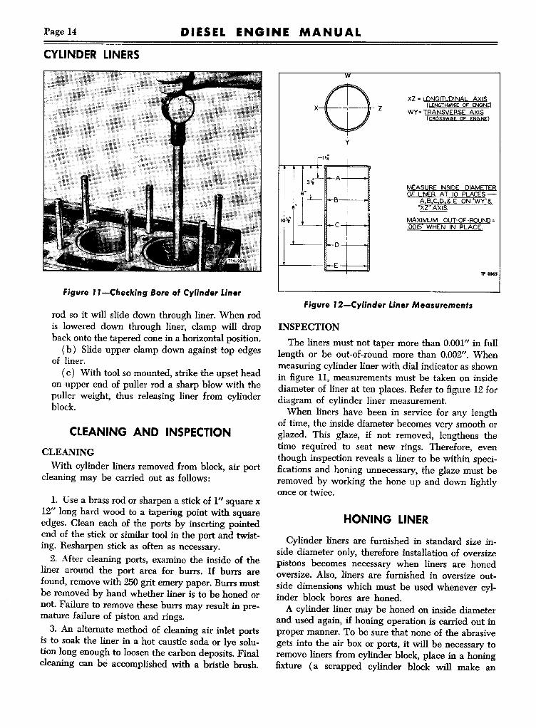
Figure ll-Checking Bore of Cylinder Liner
rod so it will slide down through liner. When rodis lowered down through liner, clamp will dropback onto the tapered cone in a horizontal position.(b) Slide upper clamp down against top edges
of liner.(c) With tool so mounted, strike the upset head
on upper end of puller rod a sharp blow with thepuller weight, thus releasing liner from cylinderblock.
CLEANING AND INSPECTIONCLEANINGWith cylinder liners removed from block, air port
cleaning may be carried out as follows:
1. Use a brass rod or sharpen a stick of I" square x12" long hard wood to a tapering point with squareedges. Clean each of the ports by inserting pointedend of the stick or similar tool in the port and twisting. Resharpen stick as often as necessary.2. After cleaning ports, examine the inside of the
liner around the port area for burrs. If burrs arefound, remove with 250grit emery paper. Burrs mustbe removed by hand whether liner is to be honed ornot. Failure to remove these burrs may result in premature failure of piston and rings.3. An alternate method of cleaning air inlet ports
is to soak the liner in a hot caustic soda or lye solution long enough to loosen the carbon deposits. Finalcleaning can be accomplished with a bristle brush.
"'!
x$' xz • !.QNGITUQINAL..A~IS(I.ENGTHWISE OF ENGINE)
Wy· TRANSIIEBSE A~ISICROSSWISE OF ENGINE)
y
r";I}~l'f--AMEAS!.!BE INSIQE DIAMEIEB
60L I OF LINER AT 10 PLACESf+-B A,B,C,D,& E ON -Wy"&
,~,~'Xl" AXIS.
MAXIMUM OUT-OF-ROUND·f--C .OOI!:>"WHEN IN PLACE.
r
-D
ETP 3165
Figure J 2-Cylinder Liner Measurements
INSPECTIONThe liners must not taper more than 0.001" in full
length or be out-of-round more than 0.002". Whenmeasuring cylinder liner with dial indicator as shownin figure 11, measurements must be taken on insidediameter of liner at ten places. Refer to figure 12 fordiagram of cylinder liner measurement.When liners have been in service for any length
of time, the inside diameter becomes very smooth orglazed. This glaze, if not removed, lengthens thetime required to seat new rings. Therefore, eventhough inspection reveals a liner to be within specifications and honing unnecessary, the glaze must beremoved by working the hone up and down lightlyonce or twice.
HONING LINER
Cylinder liners are furnished in standard size inside diameter only, therefore installation of oversizepistons becomes necessary when liners are honedoversize. Also, liners are furnished in oversize outside dimensions which must be used whenever cylinder block bores are honed.A cylinder liner may be honed on inside diameter
and used again, if honing operation is carried out inproper manner. To be sure that none of the abrasivegets into the air box or ports, it will be necessary toremove liners from cylinder block, place in a honingfixture (a scrapped cylinder block will make an

DIESEL ENGINE MANUAL Page 15
excellent honing fixture), and then hone to propersize. After honing, the liners may then be replacedin the cylinder block.Whenever liners must be honed to cylinder block,
completely dismantle engine, and then after honing,wash block in a solution of hot caustic soda, to besure that all abrasive is removed from openings inblock and liners.
The ordinary honing stones used on cylinder blocksare rather ineffective on hard cylinder liners. Forrough honing, use a No. 80 grit and for smooth mirrorfinish required for inside of liners use No. 120 grit.
Necessary steps for honing liners are as follows:1. Remove liner from cylinder block as previously
described under "Liner Removal" in this section.2. Place liner into liner honing fixture.3. Hone liner in fixture with honing stones de
scribed above.4. After cylinder liner has been honed and removed
from honing fixture, it must be thoroughly washed andblown off with air before installation into cylinderblock. If this precaution is not taken some of the honing abrasive might be drawn into engine and causeserious damage.5. Remove liner from fixture and install in cylinder
block in manner described under "Liner Installation"in this section.
HONING CYLINDER BLOCK
The fit of a liner depends to a great extent upon thecondition of the bore before honing. Distortion maycause low spots that will not clean up. A low spot isnot objectionable above the ports if it does not exceed1~" or the size of a half dollar. Below the ports, largerspots are permissible.The hone, selection of hone stones, and method of
honing are important, especially when truing distorted bores. An adjustment for setting the cuttingradius of the stones is preferable to spring loadedstones. Spring loaded stones will follow instead ofremove irregularities in the bore. Keep the stonesdressed and brush them frequently to prevent loading. Follow the hone manufacturer's instructions regarding the use of oil or kerosene on the stone. Witha dry type hone, such cutting agents should not beused. Roughing and finishing stones should be fairlycoarse. A No. 80 grit stone may be used for roughing,and a No. 120 grit stone is satisfactory for finishing.
The following inspection should be made beforehoning cylinder block:
CYLINDER LINERS
1. Remove oil, dirt, and grease from the bore andinlet port opening.2. Measure the bore for high spots and the most
narrow section.3. Liners are fitted from .0005" to .0025" loose. A
clearance of .0005" produces a slip fit and .0025"clearance allows the liner to slide freely into place.Refer to chart for standard and oversize cylinder linerbore in cylinder block.
CYLINDER LINER AND CYLINDERBORE DIMENSION CHART
Use Next OversizeLiner Block Liner when Bore
Size Diameter Diameter Measures
Std. 4.6250" 4.6265" 4.6280"4.6260" 4.6275"
0.005" 4.6300" 4.6315" 4.633"4.6310" 4.6325"
0.010" 4.6350" 4.6365" 4.638"4.6360" 4.6375"
0.020" 4.6450" 4.6465" 4.648"4.6460" 4.6475"
0.030" 4.6550" 4.6565" 4.658"4.6560" 4.6575"
Rough HoningInsert hone in bore and adjust stones snugly to the
most narrow section. When correctly adjusted, honewill not shake in bore, but will still drag freely up anddown the bore while the hone is stopped.Start hone and "feel out" bore for high spots. These
will cause an increased drag on the stone. Move honeup and down bore with short overlapping strokesabout 1" long. Concentrate on the high spots in thefirst cut. As these are removed, the drag of the honewill become lighter and smoother. Do not hone as longat the ports as in the rest of the bore-this area, as arule, cuts away more rapidly. When drag of hone becomes light and smooth, increase the feed on thestones. Feed lightly to avoid excessive oversize ofbore; roughing stones cut rapidly even under lowtension.When bore is fairly clean, remove hone to inspect
the stones and measure bore. Decide carefully whichspots must be honed most. To move the hone from topto bottom of bore will not correct an out-of-roundcondition. To remain in one spot too long may causebore to become tapered. Where and how much to honecan be judged by feel. A heavy cut in distorted boreproduces a more steady drag on the hone than a lightcut and so makes it difficult to feel the high spots.Therefore, use a light cut with frequent stoneadjustment.

Page 16 DIESEL ENGINE MANUAL
CYLINDER LINERS
Figure 13-Checking Depth of Liner BelowTop of Block
FINISH HONING AND FITTING LINERRough hone cylinder bore until the liner can be
pushed from 3" to 4" into the bore, or until bore iswithin approximately .0005" of the diameter of theliner. Do not expect finishing stones to remove morethan .001" of stock, or to true up the bore to anyextent.
Work the finish hone with short, rapid strokes upand down the bore. Use light tension on the stonesand hone only enough to allow the liner to enterthe bore either with a light push fit or a free slip fit.
If new liners are to be used after honing theblock, follow instructions for replacing loose liners.If old liners requiring rehoning on the inside diameter are to be used, follow instructions under "Honing Liner" previously in this section.
LINER INSTALLATIONCheck bore in cylinder block. Bore must be round
and smooth within .0015" from top to bottom. Whenchecking for these conditions, use a dial indicator,or if a new, undamaged (round) liner will slip fitinto the bore, the fit is satisfactory. Hone bore asoutlined under "Honing Cylinder Block" previously
in this section to remove roughness or distortion.Before installing the liner or insert in cylinder
block wipe the liner, insert and block counterboreuntil absolutely clean. Use a fine flat honing stoneto remove any burrs that may be present on theliner or insert or in cylinder block counterbore. Linermust be installed dry-do not use oil.Since cylinder head and cylinder block are metal
to-metal contact, each cylinder liner is sealed individually by compression seals. This construction requires that top of liner flange be .0465" to .050"below top of cylinder block.When insert and cylinder liner are installed,
height of liner must be checked to determine thatliner is proper distance below top of cylinder block.Install hold-down tool over top of liner to hold linertightly in place, while measuring liner depth belowtop of block (fig. 13). Use a dial indicator and asurface plate on a flat surface gauge to measuredepth of cylinder liner below top of cylinder block.
LINER HEIGHTWhen cylinder liner and insert are installed and
liner depth is checked in manner previously outlined the depth should be .0465" to .050" as indicated. If liner depth is not within these limits, andinspection indicates they are properly installed, theinsert or liners or both should be removed for careful inspection of mounting surfaces and conditionof cylinder block counterbore. Undersize cylinderliner inserts are available for use when top of cylinder block has been "trued up" by removing a smallamount of stock. DO NOT USE SHIMS TO OBTAIN CORRECT LINER HEIGHT.Having replaced the cylinder liners, the pistons
may be fitted and the engine rebuilt. In this process,see "Fitting Pistons," in PISTON AND CONNECTING ROD section later in this manual, also refer tothe various other sections of this text for detailedinstructions relative to correct location of parts, bearing clearances, etc.Operate engine as instructed in ENGINE RUN-IN
PROCEDURE section later in this manual.

DIESEL ENGINE MANUAL Page 17
CRANKSHAFT AND MAIN BEARINGS
CRANKSHAFTAND MAIN BEARINGSCRANKSHAFTCrankshaft is high-carbon steel drop forging,
heat-treated to insure strength and durability. Allmain and connecting rod bearing journal surfacesare hardened by the Tocco process.
Complete static and dynamic balance of the rotating parts has been achieved by counterweights incorporated with the crankshaft.Crankshaft thrust is taken through two-piece
washers (fig. 14) on each side of the rear main bearing. Crankshaft is drilled for full pressure lubrication to the main and connecting rod bearings.The 4-71 has 5, and 6-71 engine has 7 main bear
ings, each 3J~"in diameter and lJ~"long. The crankshaft pins are 2W' in diameter and 2)~"long on allSeries 71 engines.
MAIN BEARINGSMain bearing shells are the precision type and are
replaceable without machining. Main bearing capsare attached to the crankcase and carefully machinedin place to receive the precision bearing shells. Eachbearing cap is marked "1," "2," "3," etc., and whenremoved must always be replaced in its respectiveposition. Bearing cap "5" on 4-71 or "7" on 6-71 mustalways be at flywheel end.
Upper halves of main bearing shells are seated inthe crankcase; lower halves are held in place by themain bearing caps, each of which is held to thecrankcase by two special bolts and lock washers.Each half of the bearing shell is prevented fromendwise or radial movement by a tang at the parting line on one side of the bearing. Each bearingcap is locked from sidewise movement by a milledslot in crankcase.All upper halves of the main bearing shells carry
a circular groove midway between the bearing edgeswhich runs from parting-line, and furnishes registration with the oil holes in the crankshaft journals atall times. An oil hole in this groove midway betweenthe parting lines provides oil registry with holes inthe cylinder block, by way of the bearing shells,to the drilled passages in the crankshaft leading tothe various connecting rod bearings.
All lower halves of the main bearing shells arealike but have no oil grooves. Consequently, theupper and lower halves of these bearing shells arenot interchangeable.All the main bearing load of these engines is car-
4 Rear Main BearingThrust Washer
5 Main Bearing Shell- Upper
6 Cylinder Block TP.""
1Main Bearing CapScrew
2 Main Bearing Cap3 Main Bearing Shell
- Lower
Figure 14-Upper and Lower Main Searing Shells,Searing Caps, and RearMain Searing
Thrust Washers
ried on the lower half of the bearings only. Themain bearing caps, as well as the connecting rodbearing caps, should be removed one at a time, andthe lower half of the main bearing shells and theupper half of the connecting rod bearing shells inspected for scoring, chipping, cracking, or signs ofoverheating. Bright spots on backs of the shells willindicate that shells have been shifting in their supports, and must be carefully inspected before beingreinstalled. If crankshaft has been overheated, examine the journals for cracks. If the crankshaft journalsshow signs of overheating or are badly scored; thenthe crankshaft must be removed from the engine,and either replaced or reconditioned.
Low oil pressure may be an indication of wornmain bearings, as evidenced by slow response of oilpressure gauge when starting and insufficient pressures at running speeds.
CRANKSHAFT OIL SEALSEffective oil seals have been incorporated in fly
wheel housing cover at rear, also in cover at frontof crankshaft. Seals consists of a special treated liptype seal assembly set into front and rear covers.

Page 18 DIESEL ENGINE MANUAL
CRANKSHAFT AND MAIN BEARINGS
The rolled-over inner diameter of the seal is heldby a coil spring, to prevent oil leakage. The crankshaft timing gear at rear acts as an oil slinger andthrows surplus oil from the gear teeth back into acavity adjacent to the gear. The oil from this cavityflows back into the oil pan. An oil slinger at frontalso assists in preventing excessive oil reaching seal.An effective oil seal is also used at front end of
crankshaft and is installed in front cover. Refer toCRANKSHAFT FRONT COVER and OIL SEALsection later in this manual.
CRANKSHAFT REMOVAL
When necessary to remove crankshaft the operation may be performed as follows:
1. Drain oil from the oil pan, then remove theoil pan.2. Remove the lubricating oil pump assembly as
instructed under LUBRICATING OIL PUMP inLUBRICATION SYSTEM section of this manual.3. Remove the vibration damper assembly, if used,
as instructed in VIBRATION DAMPER sectionlater in this manual.4. Remove flywheel and flywheel housing as in
structed in their respective sections in this manual.5. Remove crankshaft front cover as instructed in
CRANKSHAFT FRONT COVER AND OIL SEALlater in this manual.6. Remove connecting rod bearing caps. Note that
TP-6076
Figure J 5-Crankshaft Journal Ridge-Typical
each cap and rod is stamped with a number corresponding with the cylinder number.7. Remove main bearing caps. Note that each cap
is stamped with a number which corresponds withnumber stamped on cylinder block.8. Lift crankshaft, timing gear, oil pump drive
gear and slinger as an assembly from crankcase.9. Remove main bearing inserts from crankcase
and bearing caps, also thrust washers at rear mainbearing. Carefully identify each bearing so that itcan be replaced in its original location, providinginspection indicates that it is within permissibletolerances and is satisfactory for continued use.
CRANKSHAFT INSPECTIONCLEANINGEntire crankshaft must be thoroughly cleaned
with steam or other suitable cleaning solvent. Remove all pipe plugs. Particular attention should begiven oil passages to be sure all oil deposits or otherforeign material is removed. Dry with compressedair and coat with oil to prevent rusting.
ALIGNMENTPosition crankshaft on V-blocks or in lathe and
check alignment at two intermediate journals, usingdial indicator. If run-out limit is greater than givenin SPECIFICATIONS section of this manual, crankshaft must be replaced.
JOURNALSJournals which do not meet inspection require
ments as to diameter, taper or out-of-round shouldbe reground; also, all journals must be reground ifone or more do not pass this inspection.The journals may be reground undersize, and
undersize main bearing shells (.010"; .020"; .030")used. If the crankshaft journals have been overheated, the heat-treating will be destroyed; then anew crankshaft should be used.Carefully check each bearing journal for evidence
of a raised ridge around circumference of journal inline with the oil hole (fig. 15). This ridge must beremoved before new bearings are installed, if ridgeis .0002" or more in height. A good method of removing ridge not in excess of .0002" is to wrapcrocus cloth, wetted in fuel oil or kerosene, aroundbearing journal. Then using a belt or strip of clotharound crocus cloth, work the belt or cloth backand forth as a bowstring. Rotate crankshaft at frequent intervals to maintain concentricity of journal.

DIESEL ENGINE MANUAL Page 19
For ridges in excess of .0002" first use 120 gritemery cloth to clean up ridge, followed by 240 gritemery cloth to finish it off; then wet crocus clothshould be used for the polishing operaion, in mannerdescribed above. Whenever ridge is .001" or greatercrankshaft should be reground.
Measure each bearing journal to determine if regrinding is necessary, also measure thrust surfaces,(fig. 16). These measurements must be taken withextreme care and should be accurate to .0002".Check each journal for taper and out-of-round condition. Taper must not exceed .0005" and out-ofround must be within .00025".
CRACKSCarefully check all surfaces of crankshaft for
evidence of cracks. Note particularly for crackswhich start at an oil hole and follow the journal surface at an angle of 45° to axis. Any crankshaft witha crack at an oil hole must be replaced as thesecracks indicate torsional fatigue. It is advisable, ifat all possible, to magnaHux the crankshaft to determine the presence of minute cracks not visible to theeye. Very careful attention should be given the areain the vicinity of journal fillets as circumferencecracks at this point usually indicate early failure.
THRUST SURFACESCarefully check thrust surfaces for evidence of
excessive wear or roughness. In many instances onlyslight grinding or "dressing up" of the thrust surfaces is necessary. In such cases, use of new standardthrust washers will probably hold the thrust clearances within the dimensions given in SPECIFICATIONS, otherwise it may be necessary to use .005"oversize rear thrust washer or regrind thrust surfaces to maintain end thrust with oversize thrustwashers.
KEYWAYInspect keyways for evidence of cracks or worn
condition, and replace shaft if necessary.
OIL SEAL CONTACTCarefully inspect crankshaft in area of rear oil
seal contact for evidence of rough or grooved condition. Any imperfections of oil seal contact surfacewill result in oil leakage at this point. Refer toFLYWHEEL HOUSING AND GEAR TRAINCOVER section later in this manual for methods ofrelocating oil seal.
CRANKSHAFT AND MAIN BEARINGS
r(
(
(
~2125,:gg! ~I0- @0000
+~
1 I ~1.500~~- ~
Main BearingJournal Dia. B
3.5003.5003.4903.4803.470TPM-2671
figure J 6-Cranksha't Journals andThrust Surfaces-Standard Dimensions
CRANKSHAFT GRINDINGGrinding operations should be performed care
fully in accordance with grinding equipment manufacturer's recommendations and good shop practices.Care must be taken to avoid localized heating whichoften produces grinding cracks. The crankshaftshould be cooled while grinding, using coolant generously. The grinding wheel must not be crowdedinto the work.
JOURNALSMeasurement of the crankshaft journals and com
parison of these measurements to the diameters required for various undersize bearings shown in figure 16 will determine the size to which crankshaftjournals must be reground. The .002" undersizebearings are for use with a standard crankshaft onlyto maintain minimum allowable bearing clearances.
BearingSizes
Conn. RodJournal Dia. A
2.7502.7502.7402.7302.720
Standard.002Undersize.010 Undersize.020 Undersize.030 Undersize

Page 20 DIESEL ENGINE MANUALCRANKSHAFT AND MAIN BEARINGS
/I
lJl 1.50lih v-t- 1499
L...-1.005.1L, .995
-
TP-6403
Figure J 7-Cranlcshaft Rear Main SearingThrust Surfaces
Crankshaft main and connecting rod bearings areavailable in standard, .002", .010", .020", and .030"undersizes.Reground crankshaft journals will be subject to
excessive wear unless the ground surfaces arepolished absolutely smooth. A simple test to determine if surfaces are smooth enough is to rub theedge of a penny over the surface. If a copper coloredmark is left, the surface is too rough and needsfurther polishing. Surfaces must be clean and drywhen this test is made.
THRUST SURFACESThe amount of grinding necessary on the crank
shaft thrust surfaces depends upon how badly the
AVOIDSHARPCORNERS ~ ,INSUFFICIENT
~LLET
~TP-6404
Figure J 8-Crankshaft Journal Fillet
surface is scored or worn. This in turn determinesthe particular thrust washers, standard or oversize,which must be used after grinding. In many casesonly slight grinding or "dressing-up" of the thrustsurfaces is necessary. In such cases, use of newstandard thrust washers will probably hold thethrust clearances within the specified .004 to .011of an inch. However, if thrust clearance exceeds .018of an inch when crankshaft thrust is checked, afterslight grinding of the crankshaft and with newstandard thrust washers, then .005 of an inch oversize thrust washer should be installed in place of thestandard washer on the crankshaft rear thrust surface face (against thrust surface "A," figure 17).Standard dimensions which indicate that standardthrust washers should be used are illustrated in figure 17. Comparison of these dimensions with corresponding dimensions on crankshafts with regroundthrust surfaces will indicate size of thrust washerrequired to provide correct clearance.
The information given for grinding journals alsoapplies to the grinding operations for thrust surfaces. Likewise, the fillets where journal joins thethrust surfaces must be properly ground, as described below.
After grinding thrust surfaces of crankshaft they,like the journals, will wear excessivelyif not polishedabsolutely smooth. The penny test can be applied tothe thrust surfaces in the same way as for checkingfinish of journals.
FILLETSGrinding the fillets at the end of crankshaft jour
nals requires careful dressing of the grinding wheel,as the fillets must have a smooth radius, free fromscratches. The radius must be not less than" of aninch, and preferably %2 of an inch, when measuredwith a fillet radius gauge. A correctly ground filletis shown in figure 18 together with incorrect fillets.
OPERATIONS AFTER GRINDINGThe edges of all oil holes in the journal surfaces
should be stoned smooth to provide a radius of approximately %2 of an inch at the edge of the hole.Plugs at the ends of the oil holes should be removedand a stiff wire brush run through the oil holesafter which plugs should again be installed.After all regrinding operations have been com
pleted, the crankshaft should be magnaHuxed againto determine whether grinding cracks have originated due either to insufficient cooling or crowding

Page 21DIESEL ENGINE MANUAL
"A" IS .001' SMALLERTHAN "8"
"C" IS .0005' THICKERTHAN "0"
"E" IS .030' GREATERTHAN "F"
o
C -It' APPROX.
TP 3170
figure J 9-lnside Diameter of Bearing Shell atParting Line and 900 to Parting Line
of grinding wheel during grinding operations.Finally, crankshaft must be demagnetized.
MAIN BEARING INSPECTIONMain bearing shells are of the precision type and
replaceable without machining. The clearance between the main bearing shells and the crankshaftjournals is from .0014" to .0044". Main bearing shellsare furnished in standard, and undersizes.As will be seen in figure 19, bearing shells when in
place have .001" larger diameter at parting line than90 deg. from parting line. Also, thickness of bearingshells 90 deg. from parting line is .1548"-.1553".The two shells do not form a true circle when notinstalled, and when measured for inside diametermust be installed in the caps and block, with capsbolted in place.The two halves of the shells have a squeeze fit in
case and cap, and must be tight when cap is drawndown. Shells may be measured with micrometers atpoints marked "C," as shown in figure 20.A recommended method of determining running
clearance is to insert a soft lead or plastic wireacross center of each lower bearing shell by removing and replacing one bearing cap at a time. Whenall insertions have been made, tighten bearing capscrews, thus "squeezing" wire or plastic to shimthickness between shells and crank journals. Remove the lead shims and measure for thickness.Clearance between shells and journals should be asspecified in SPECIFICATIONS section.
CRANKSHAFT AND MAIN BEARINGS
BEARING SHEll
TP 3869
figure 20-Measuring Thickness of Bearing Shell
If one or two shells are worn or scored to exceedthe maximum clearance of .006" and the other shellsare within the recommended limits, the worn shellsonly may be replaced; otherwise, all main bearingsshould be changed.NOTE: If all shells are worn beyond limits, then
all shells must be replaced. Observe that lower halfonly of main bearings are loaded and subject towear; therefore, if upper halves are not scored andare serviceable, lower halves only may be changed.
CRANKSHAFT AND MAIN BEARINGINSTALLATION
The crankshaft main bearing upper shells aregrooved for lubrication; the lower shells are notgrooved. When replacing the bearing shells, priorto setting the crankshaft in place, see that thegrooved shells are placed in crankcase as shown infigure 14.l. After the bearing upper shells have been placed
in the crankcase, apply light film of clean engine oilto all crankshaft journals, and set crankshaft in place.When setting the crankshaft in place with the timinggear bolted to the crankshaft flange, be sure thetiming marks on the gears are in alignment. Referto GEAR TRAIN section later in this manual.2. Install the two-pieced thrust washers on each
side of the rear main bearing.
NOTE: IF ONE CRANKSHAFT THRUST SURFACE HAS BEEN REGROUND, IT IS SOMETIMES NECESSARY TO INSTALL THRUST

Page 22 DIESEL ENGINE MANUAL
CRANKSHAFT AND MAIN BEARINGS
Figure 21-Removing Main Bearing Upper Shell(Except Rear Main} As Shown
WASHERS OF DIFFERENT THICKNESSES INORDER TO PROPERLY CENTER CRANKSHAFTAT MAIN BEARING JOURNAL. IF THRUSTSURFACES WERE NOT WORN ENOUGH TOREQUIRE REGRINDING, OR IF WORN ANDGROUND OFF EQUALLY, THEN THRUSTWASHERS OF THE SAMETHICKNESS SHOULDBE INSTALLED ON BOTH SIDES OF THESAME BEARING.3. Main bearing caps are numbered "1," "2," "3,"
etc., indicating their respective positions. Themarked side is always toward blower side of cylinder block. Noting the marks, place bearing lowershells in bearing caps, and install caps, locking inplace with bolts and washers. Tighten to torquerecommended in SPECIFICATIONS at end of thismanual. When tightening bearing cap bolts, rap capsseveral sharp blows with a plastic hammer to assistin positioning shells.NOTE: IF BEARING HAS BEEN PROPERLY
INSTALLED, THE CRANKSHAFTWILL TURNFREELY WHEN ALL MAIN BEARING CAPSARE BOLTED TIGHT.4. In the event oil pump drive gear has been
removed from crankshaft, install as directed underLUBRICATING OIL PUMP in LUBRICATIONSYSTEM section of this manual.5. Position new gasket to bolting flange of crank
shaft front cover, and attach to cylinder block withlock washers and cap screws finger-tight only. Do
not tighten cap screws until after front spacer isput in position, as described in next item.6. Replace the spacer or vibration damper inner
(rear) cone (or spacer) on front end of crankshaftnext to the oil slinger. Refer to VIBRATIONDAMPER section of this manaul.NOTE: THIS SPACER OR CONE MUST NOT
BE PUT IN PLACE UNTIL AFTER THE FRONTCOVER IS IN PLACE, OTHERWISE, THE OILSEAL IN THE COVER MAY BE DESTROYED.7. Tighten cover cap screws as directed inCRANK
SHAFT FRONT COVER AND OIL SEAL sectionlater in this manual.
8. Install flywheel housing and flywheel as directed in respective sections of this manual.9. Install connecting rods as directed in PISTON
AND CONNECTING ROD SECTION LATER inthis manual.10. Refer to LUBRICATING OIL PUMP in
LUBRICATION SYSTEM section for oil pump installation instructions.
MAIN BEARING REPLACEMENTREMOVALWhen removal of upper half of main bearing
shells becomes necessary and the removal of thecrankshaft is undesirable, this operation can be performed by using the following procedure and byreferring to figure 21. All main bearing journals except the rear are drilled for an oil passage. The procedure, therefore, for removing the upper half ofthe shells, with crankshaft in place, is somewhat different on the drilled journal than on the rear that isnot drilled.1. Remove the oil pan to expose the main bear
ing caps.2. Remove oil pump as directed under Lubricat
ing Oil Pump in LUBRICATION SYSTEM sectionof this manual.NOTE: If shims are used between the oil pump
mounting brackets and bearing caps, special caremust be taken of them so that they may be reinstalled in exactly the same location when reinstalling the oil pump.3. Remove one main bearing cap at a time and
complete replacement of shell and reinstallation ofcap before another cap is removed.4. Two-piece thrust washers are used each side
of the rear main bearing. The lower half of thesewashers will be removed when removing the rearmain bearing cap; upper half can be removed by

DIESEL ENGINE MANUAL Page 23
Figure 22-Removing Rear Main Bearing Upper Shell
pushing one end of washer with a suitable instrument, thus forcing washer around and out on opposite side of bearing.5. The bearing cap having been removed, insert
a ~" x I" bolt with a ~" diameter and a VI6"thickhead into the crankshaft main bearing oil hole; thenrevolve shaft in direction necessary to move notchlock from its recess and roll the bearing shell out ofposition, as shown in figure 21. The head of the boltshould not extend beyond the outside diameter ofthe shell.6. Upper half of all main bearing shells may be
removed in the above manner except the rear main.On this bearing, the upper shell must be removedby tapping on the edge of the bearing shell with asmall curved rod, at the same time revolving thecrankshaft, thus rolling the shell from position, asshown in figure 22.
INSTALLATIONClean bearing shells, caps, crankshaft, and crank
case thoroughly then apply lubricating oil to journalsand shells.The upper and lower halves of the main bearing
shells are not alike. The upper half is grooved forlubrication and the lower half is not.CAUTION: Be sure to install the grooved shell in
CRANKSHAFT AND MAIN BEARINGS
Figure 23-Rear Main Bearing Lower Shell,Cap, and Thrust Washer
crankcase and non-grooved shell in bearing cap,otherwise oil supply to bearing will be cut off.1. When replacing upper half of main bearing
shells with crankshaft in place start the end of theshell having no tang around crankshaft journal sothat when shell is in place tang will fit into groove inshell support.NOTE: Main bearing caps are bored in position
and marked "1," "2," "3," etc. Whenever bearing capsare removed, they must be replaced in their originalpositions with marked side of caps toward blowerside of cylinder block.2. With lower half of bearing installed in bearing
cap, replace cap and draw tight. The caps shouldfirst be drawn up snugly, then rapped sharply witha plastic hammer to align bearing shell. The capscrews may be tightened to recommended torquethen locked.NOTE: Since the bearing shells have a squeeze
fit in the cap and block, bearing nuts should bedrawn tight so shells will not shift.3. If bearings have been installed properly, the
crankshaft will turn freely with all main bearingcaps bolted tight.4. Install lubricating oil pump, drive and dis
charge pipe assembly. Refer to LUBRICATING OILPUMP in LUBRICATION SYSTEM section.

Page 24 DIESEL ENGINE MANUAL
FLYWHEEL AND CLUTCH PILOT
Figure 24-Checking Crankshaft End Play
5. Install oil pan with new gasket.6. After installing new bearing shells, the engine
should be operated on a run-in schedule as instructedin ENGINE RUN-IN PROCEDURE section laterin this manual.
REAR MAIN BEARING THRUST WASHERSAs shown in figure 23, crankshaft thrust washers
located at rear main bearing consist of two pieces oneach side of bearings. The lower portion is doweledto bearing cap in two places at each side of cap. Ifwashers have become scored, or otherwise damaged,they must be replaced. End thrust as measuredbetween crankshaft flange and thrust washer shouldbe .004" to .011" and should not exceed .018". Endthrust is checked with dial indicator in mannerillustrated in figure 24. Washers for replacement areavailable in standard .005" an .010" oversize.
FLYWHEEL AND CLUTCH PILOTFLYWHEEL
Flywheel is made of alloy cast iron or steel forgingand is attached securely to crankshaft flange withcap screws and straight dowels.A starter ring gear made from heat-treated steel is
shrunk onto the rim of flywheel. The ends of thering gear teeth are chamfered to permit a smooth,
Figure 25-Flywheel Lifting Hook
silent, and positive engagement of starter gear whenengine is being started.
MAINTENANCEThe construction of the flywheel makes the neces
sity for service on this part remote. Service operations, such as replacing clutch pilot bearing andstarter ring gear, require removal of the flywheel.
REMOVALThe power transmitting unit and clutch, having
been removed from the flywheel housing and flywheel respectively, the flywheel may be removedfrom crankshaft flange, using puller screws andlifting hook (fig. 25).l. Withdraw the lockwire (if used) from the six
cap screw heads then remove cap screws and pilotbearing retainer (when used).2. Screw the two puller screws into tapped holes
provided at flywheel bolting flange until inner endsof tool press against crankshaft flange. Continue toturn puller screws until flywheel is removed fromdowels.
INSTALLATIONInstall two pilot studs in crankshaft flange (fig. 25)
to support flywheel when it is being located ondowels. Due to one offset hole in the crankshaftholding flange, flywheel can be located in only oneposition. Install pilot bearing, retainer and retaining

DIESEL ENGINE MANUAL Page 25
cap screws. Install and tighten six cap screwsalternately and evenly to torque listed in SPECIFICATIONS section of this manual. Run wire throughthe heads of each two screws and twist together toprevent screws loosening.
Mount dial indicator on clutch housing and checkrun-out of flywheel at clutch facing contact. Runoutshould not exceed .005" total dial indicator reading.
RING GEAR REPLACEMENTREMOVALWith flywheel removed from crankshaft, the old
ring gear may be removed from the flywheel bygrinding a notch through the ring at the root of onetooth, then expanding ring and driving from position. Unless ring gear is already broken at the rootof a tooth, no attempt should be made to drive itfrom position without first splitting gear as instructed.
INSTALLATIONThe ring gear is shrunk on the flywheel by uni
formly heating the gear to 450°F. (red heat visiblein the dark); then placing it in position on the flywheel which is at room temperature.
After heating, start ring gear onto flywheel withchamfered ends of the teeth on the ring gear towardsthe cylinder block when flywheel is installed. Theseedges of the teeth engage the pinion on the startingmotor. Drive gear down tight against shoulder onflywheel. Ring gear should be air-cooled before using.
Ring gear should not be heated excessively as theoriginal heat treatment will be destroyed. However,it must be heated sufficiently to expand the ring andmake a tight fit on flywheel when cooled.
CLUTCH PILOT BEARINGREMOVAL
On some engines it is first necessary to removepilot bearing retainer before bearing may be removed from flywheel. Remove bearing with recommended removal tool as follows:
1. Adjust puller with thumb until fingers on pullerare closed.2. Insert puller through base of bearing as far as
it will go, then tighten thumb screw to spread pullerfingers behind bearing.
3. Slide weight sharply against stop nut on pullershaft to remove the bearing.
FLYWHEEL AND CLUTCH PILOT
INSPECTIONAfter removal and before installing, the clutch
pilot bearing should be thoroughly washed in cleangasoline, blown out with compressed air, and inspected for corrosion or rough spots on either theballs or the races. This may be done by holding theinner race to prevent turning; then revolving theouter race slowly by hand. A few revolutions in thismanner will show any rough spots on either ballsor races. If bearing does not tum freely, or is excessively loose, it must be replaced.
INSTALLATION1. Fill cavity in crankshaft and lubricate bearing
with high melting point grease.2. Start bearing into bore of flywheel by hand;
then, using a suitable driver, drive bearing flush withouter face of flywheel.CAUTION: Do not drive bearing on inner race.
Be sure bearing is not cocked in flywheel, and thatit rotates freely after installation.3. Install pilot bearing retainer.
CLUTCH PILOT BUSHINGVehicles using automatic transmissions use a
bronze bushing, instead of the conventional pilotbearing, in the flywheel. Also, trucks equipped withHydra-Matic use a steel sleeve at flywheel hub.When inspection indicates that bronze bushing or
steel sleeve are worn, replacement is necessary.
REMOVAL1. Remove flywheel assembly as directed under
heading "Flywheel Removal" in this section.2. Use suitable removing tool or arbor press to
remove bushing. Bushing should be pressed ordriven from engine side of flywheel.
INSTALLATION (Coach V-Trans.)1. Locate bushing over hole in flywheel on cou
pling side (opposite engine side) then install roundpilot in bushing. Pilot is part of special tool listed inSPECIAL TOOLS section of this manual. Pilot willhold inside diameter of bushing to its correct sizeand therefore provides proper bushing clearance.2. Position legs of anvil against opposite (engine)
side of flywheel. Insert special bolt through anvil,flywheel, bushing and pilot, then install bearingand nut on bolt.3. Thread nut on bolt until finger tight then
locate bushing and tool, so that bushing will be

Page 26 DIESEL ENGINE MANUAL
FLYWHEEL HOUSING AND GEAR TRAIN COVER
drawn straight into flywheel.4. Tighten nut with wrench while bolt is being
held with another wrench. Continue tightening nutuntil bushing is drawn flush with flywheel and pilotcollar prevents further entry.
INSTALLATION (Truck Hydra-Matic )1. Position bushing over replacer tool then drive
bushing into flywheel hub until it is Y16" below edgeof hub.2. When bushing is positioned, it should be bored
or honed to dimension given in SPECIFICATIONSsection of this manual.
3. Position steel sleeve over flywheel hub, thenusing hardwood block, drive sleeve onto hub, untilit is Ys/' below end of hub.4. Grind outer diameter of steel sleeve to dimen
sion given in SPECIFICATIONS section of thismanual.
Combination flywheel housing and gear traincover is attached to cylinder block end plate, idlerhub, and spacer hub at rear of engine.The engine is usually supported by stabilizing
cushions, used between flywheel housing and enginesupports. These stabilizers absorb torsional vibrationand produce a smooth operating power plant.
FLYWHEEL HOUSING AND GEAR TRAIN COVER
MAINTENANCEAt periodic intervals, flywheel housing and gear
train cover must be checked for looseness of bolts,oil leaks, and deterioration of stabilizing cushions orother evidence of failure.
REMOVALWith engine in overhaul stand or out of vehicle
the combination housing is removed in followingmanner:
1. If cylinder head has not been removed, it willbe necessary to remove the two bolts holding enginelifting bracket to cylinder head, leaving the lifterbracket attached to flywheel housing for conveniencein handling.2. Remove accessories such as air compressor,
generator, starter, etc. mounted to gear train coveror flywheel housing.3. Remove flywheel as directed in respective sec
tion of this manual.4. If oil pan is not already removed remove plug
to drain pan, then remove bolts attaching pan to flywheel housing, cylinder block, and crankshaft frontcover. Remove pan.5. Remove twelve bolts from inside and twelve
from outside of housing, also two from front side ofend plate.6. With flywheel housing supported by chain fall
at the lifter bracket, strike housing on alternate sideswith plastic hammer until loosened from locatingdowels.
INSPECTION1. Inspect all bolt holes.
2. Crankshaft rear oil seal should be replaced.3. Remove all traces of old gasket and gasket
cement. Check gasket flange for nicks or otherimperfections, clean with stone if necessary.4. Examine engine mountings. If deteriorated, re
place.5. Using straight edge or surface plate. Check
flywheel housing for warp. Replace if damaged.
OIL PANWhile flywheel housing is removed, this is an
excellent opportunity to clean and inspect oil panand oil pump inlet screen. Inspect as follows:
1. Examine pan carefully inside and out for evidence of corrosion. If apparent, replace with newpart. Check for bent or damaged condition, also forloose bafHe plates (if used). Special attention mustbe given to bolting flange to be sure it is straight inorder to form a tight seal at crankcase, crankshaftfront cover, and flywheel housing.
2. Examine threads in oil pan, and in oil pan drainhole and drain plug. Replace plug gasket if necessary.
3. Replace gaskets, even though they appear to bein good condition.
OIL SEAL REPLACEMENTWhenever inspection of oil seal reveals that seal
is cut, worn or otherwise damaged it must bereplaced to prevent loss of engine oil.
REMOVALDe£ective oil seal can be driven from flywheel housing, using a blunt drift and hammer. During removal

DIESEL ENGINE MANUAL Page 27
FLYWHEELHOUSING AND GEAR TRAIN COVER
MECHANICAL TRANS V-DRIVE TRANS
Sleeve
SLEEVE INSTALLEDSPACER INSTALLED1P·6313
Figure 26-Cranlcsha't Rear Oil Seal Modifications
tap seal alternately around edges so as not to damage the seating surface in flywheel housing.Thoroughly clean seal seating surface of any sealingcompound or other foreign matter.
INSTALLATIONApply a light coating of sealing compound around
circumference of seal to prevent oil leaks betweenseal and flywheel housing. Position seal on flywheelhousing with lip of seal toward inside (engine side).Use suitable replacing tool to drive seal tightly intoplace.
SEAL MODIFICATIONSWhen sealing surface at crankshaft becomes
grooved or worn as illustrated in figure 26. In orderthat crankshaft may continue to be used the following modifications may be applied.
Spacer InstallationAs illustrated in figure 26 a spacer may be inst~lled
before seal is installed which re-positions seal in flywheel housing and therefore permits lip of seal tocontact crankshaft at a new location.
Sleeve InstallationAs illustrated in figure 26 a sleeve may be in
stalled on crankshaft to provide a new seal surface.Position sleeve to crankshaft and drive into placewith oil seal sleeve installing tool. Refer to SPECIAL
1 Flywheel Housing2 Rear Oil Seal3 Dowel Pin Hole4 Oil Seal
5 Temporary AligningStud
6 Flywheel DowelHole
figure 27-lnstalling flywheel Housing
TOOLS AND EQUIPMENT at end of this section.Be sure sleeve in held to %2" dimension as indicatedin figure 26.
INSTALLATIONRefer to figure 27 for use of guide tools. Install
flywheel housing as follows:1. Position new gasket to bolting flanges of fly
wheel housing.2. To prevent oil seal damage, be sure to install
rear oil seal guide tool on the two dowels at rear endof crankshaft. Locate housing in place over dowelpins being sure that housing is fully seated, theninstall cap screws, bolts and washers.3. The cap screws and bolts should first be tight
ened finger tight, then drawn down in the ordershown in figure 28 until they are snug, finally tightento recommended torque in sequence illustrated infigure 29. Be especially careful that cap screws numbered 1 through 6 (fig. 29) are tight since an oilleak at this point would necessitate complete disassembly to correct.4. Use dial indicator mounted on crankshaft and

Page 28 DIESEL ENGINE MANUAL
VIBRATION DAMPER
Figure 28-Flywheel Housing Initial Tightening
check concentricity of housing pilot diameter, alsomounting flange. The permissible concentricity between these surfaces and crankshaft axis is .0065"
Figure 29-Flywheel Housing Final Tightening
( .013" total indicator reading).5. Reinstall flywheel as directed in FLYWHEEL
AND CLUTCH PILOT section previously.
VIBRATION DAMPER
Dowel Pin
Damper Assembly
Cap Screw
Outer Cone
TPM-3015
Figure 30-Sectional View of RubberVibration Damper
Engines which operate in the higher speed rangesor under unusual conditions are equipped with avibration damper connected to the front end of thecrankshaft. The damper is in the form of a flywheeland operates to reduce crankshaft stresses to a safevalue.
Two types of damper assemblies are used, one ofwhich is an elastic type and the other a fluid orviscous type. The elastic type consists of a rubberring bonded to a heavy metal ring on one side anda stamped metal disc on the opposite side (fig. 30).The fluid type consists of a heavy metal disc suspended in fluid inside a sealed metal drum (fig. 31).Each damper assembly is securely bolted and
doweled to a hub. Hub assembly is accuratelylocated on crankshaft by two tapered cones whichsupport the hub. When fan hub or pulley is drawnup tight against outer cone by the bolt in end ofcrankshaft the cones, damper hub and pulley or fanhub are held rigidly in their correct location.

Page 29DIESEL ENGINE MANUAL
MAINTENANCEThe elastic type damper should be kept as clean
and free of fuel and lubricating oils as possible asthey are destructive to rubber.Inspect hub to damper bolts at regular intervals
to be sure they are tight.At regular intervals inspect fan hub or pulley bolt
in end of crankshaft to be sure it is tight. Any looseness of this bolt will allow cones to become looseand thus minimize effectiveness of vibration damper.The fluid type damper is sealed; therefore, no
servicing is required other than keeping the mounting bolts tight.
REMOVALThe following procedures apply when engine is
out of vehicle or with engine in vehicle and radiatorassembly removed. Since several installation arrangements are used it is important that relative locationand manner of installation be noted at time of removalso that reassembly can be correctly accomplished.
1. On coaches remove snap ring inside fan hub,then remove bolt, retainer and spacer. Remove fanhub using special puller.
2. On trucks, remove pulley retaining bolt andwasher. Remove fan belt pulley using suitable puller.CAUTION: Do not strike viscous type dampers
with hammer, as damper will be useless and requirereplacement if it should be bent. Also damper is notrepairable. .3. Remove cap screws and lock washers attach
ing damper assembly to hub, then remove damperfrom hub.4. Strike the front face of the damper hub, near
the outside diameter, a sharp blow with a heavyrubber hammer, to loosen outer cone wedged between the crankshaft and damper hub. After loosening in this manner, the cone may be removed frombeneath damper hub with two screwdrivers atopposite sides of cone.5. Pry against damper hub, using a bar between
damper hub and crankshaft front cover. At the sametime, strike opposite outer face with rubber hammer.Pull hub away from shaft.6. Remove inner cone by inserting a small bolt or
rod in the two puller holes provided in the cone.
INSPECTIONAfter removal and before damper is assembled to
VIBRATION DAMPER
1 Dowel2 Vibration Damper -
Light3 Vibration Damper -
Heavy4 Vibration Damper
Hub5 Oil Slinger6 Oil Pump Drive
Gear
7 Tapered Cone -Inner
8 Oil Seal9 Crankshaft Front
Cover10 Cap Screw11 Tapered Cone -
Outer12 Crankshaft
TPM·2.503·1
figure 3J-Secfional View of fluidVibration Damper
crankshaft, inspect to see that rubber is firmlybonded to the metal parts at each side, and thatflanges are not bent. If rubber damper assembly hasbeen exposed to fuel oil, lube oil, or excessive heat,the rubber may have loosened from the metal. Inthis event, the damper assembly should be discardedand replaced with a new unit.Viscous type dampers should be carefully in
spected for any dents or nicks in outer surfacedamper. Should damper become bent it is not repairable and must be replaced.Inspect both retaining cones (inside and outside
diameters), damper hub, and crankshaft front endfor "gall" marks or burrs. Remove slight scratches orburrs with emery cloth. If seriously damaged, the

Page 30 DIESEL ENGINE MANUAL
CRANKSHAFT FRONT COVER
damper parts should be replaced and the crankshaftremachined.
INSTALLATION1. Having carefully inspected each part, slide
inner cone on crankshaft next to oil slinger, withtapered end of cone pointing toward front end ofcrankshaft.2. Install damper hub with long end of hub to
ward crankcase.
3. Install outer cone over shaft and into hub ofdamper.4. Place fan hub, or pulley, as case may be against
outer cone and insert bolt into end of crankshaft.5. Draw bolt up to correct torque then strike end
of bolt with hammer and retorque.6. Install damper assembly to damper hub, using
cap screws and lock washers, also dowel pin.CAUTION: Be sure that damper assembly is
attached to hub in same manner as when disassembled, also that all bolts are tight.
CRANKSHAFT FRONT COVER AND OIL SEAL
16 Oil Slinger7 Pump Drive Gear8 Pump Driven Gear9 Pump Idler Gear10 Dowel
1 Vibration DamperCone
2 Front Cover3 Oil Seal4 Gasket5 Crankshaft TPM-2528
Figure 32-Cranksltaft Fr.,.., C.ver Mounting
Crankshaft front cover, containing a spring loadedlip type oil seal, is attached to cylinder block frontend plate with cap screws and locating dowels.
Oil seal in front cover bears against inner cone ofvibration damper assembly. Front flange of oil panis retained to crankshaft front cover flange with capscrews. Refer to figure 32 foe cover and mountingdetails.
MAINTENANCEFront cover and oil seal assembly must be visually
checked periodically for evidence of oil leaks thatmay occur at oil seal, oil pan front flange gasket, orbetween cover and front end plate, also betweenplate and crankcase.
Figure 33-'nstallin, Oi' S•• , Space, (Inner ConeJ
REMOVALCrankcase front cover may be removed from
cylinder block front end plate in the followingmanner:
After oil pan, fan hub, pulley, or pulley andvibration damper, have been removed as instructedin respective sections of this manual, the cover maybe removed by removing capscrews attaching coverto front end plate. Do not damage oil seal when removing cover from crankshaft.
INSPECTION1. Remove all traces of old gasket from cover and
oil pan bolting flange.2. Inspect cover for cracks and warpage. Replace

Page 31DIESEL ENGINE MANUAL
if necessary.3. If oil seal is damaged, replace.4. Inspect oil pan bolting flange. Flange must be
flat and cap screw holes clean.
INSTALLATION1. Position new gasket to bolting flange of crank
shaft front cover, and attach to front plate with lockwasher and cap screws finger tight only. Do nottighten cap screws until after front spacer or vibration damper inner cone is installed.2. Replace the spacer or vibration damper inner
(rear) cone, on front end of crankshaft next to oilslinger (fig. 33).NOTE: THIS SPACER OR CONE MUST NOT
BE PUT IN PLACE UNTIL AFTER FRONTCOVER IS IN PLACE, OTHERWISE THE OILSEAL IN THE COVER MAYBE DESTROYED.
CRANKSHAFT FRONT COVER
Figure 34-Crankshaft Front CoverTightening Sequence
3. Tighten cover cap screws to proper torqueusing tightening sequence illustrated in figure 34.
PISTONS AND CONNECTING RODSPISTONS, PINS AND RINGSMalleable iron pistons (fig. 35) with extra long
skirts, accurately ground the full length, are platedbelow compression ring grooves with a coating oftin, which permits a closer fit in cylinder, eliminating. scoring and prolonging life of piston.
NOTE: Two types of piston and piston ring arrangements are being used, as illustrated in figure 36.Standard type piston incorporates a conventionalarrangement of four compression rings above pistonpin. Piston and ring arrangement, used on "E" seriesengines, consists of three conventional compressionrings above piston pin and a "Fire Ring" near topof piston. Oil control ring arrangement near bottomof piston skirt is same for both type pistons.
The top of the piston forms the combustionchamber, and is designed to displace the air intoclose proximity to the fuel spray. The under side ofthe piston head is strongly reinforced with circularribs, to provide maximum strength. The ribs are alsoconnected to piston pin bosses for better stress distribution. The ribbed head is cooled by lubricatingoil forced from spray jet on top of connecting rod.Each piston boss is lined with a bronze bushing
which serves as a bearing for piston pin which Boatsin piston and connecting rod. Bushing has helicaloil grooves for passage of oil from connecting rod
PROPER ...SSEMBlY OFTHREE·PlECEOilCONTROL RINGS
Oil RETURNHOLES
figure 35-P;ston and Piston RingAssembly
bushing. Piston pin is held in piston with a retainerat each side of piston. Retainer prevents lubricatingoil, which returns from the sprayed piston head andthe grooves in piston bushings from reaching cylinder walls.A balancing rib is provided on the inside at bot
tom of piston skirt. Because of this design, all pistonsare balanced to within .05 lbs., whether the piston isstandard or oversize. One or more oversize pistonsmay be installed in an engine with other standardpistons, without effecting balance.Each piston is fitted with six rings of the butt joint

Page 32 DIESEL ENGINE MANUAL
Fire RingGroove
PISTONS AND CONNECTING RODS
EXCEPT "E" AND "SE" TYPETPM-2676-2
"E" AND "SE" TYPE
Figure 36-Piston Assemblies
type. Four ~" wide compression rings with chromeplated face, are placed above the pin, and two %2"wide special oil control rings and expanders are usedin each of the two grooves below the piston pin.
CONNECTING RODS AND BEARINGSEach connecting rod (fig. 37) is made of drop-
t-~PISTON PIN OIL PASSAGE
ORIFICE
•• , CONNECTING ROD
SPRAYJET
BEARINGOIL PASSAGE UPPERBETWEEN BUSHINGS SHELL
Figure 37-Connecting Rod, Piston Pin, andBearing Assembly
forged heat-treated carbon steel, and forged to anI-Section with a closed hub at the upper end, andan integral cap at the lower end. The rod is rifledrilled for lubrication of the upper end, and isequipped with an oil spray jet for cooling of thepiston head.
The lower end of the connecting rod shank isfitted with a plug which meters oil through the rifledrilled connecting rod. Connecting rod bearing shellsare of the precision type, without shim adjustment.The upper and lower halves of the connecting rod
bearing shells are not interchangeable. The bearingshowever are replaceable without machining.
The upper bearing shell is grooved midway between the bearing edges, part way up from eachparting-line, with an oil hole through the shell atthe termination of each groove. The lower shell hasan oil groove in line with that of the upper shell, andcircling the shell from parting-line to parting-line.These grooves maintain a continuous registry withoil holes in crankpins, thereby providing a constantsupply of lubricating oil through the hollow connecting rod to the piston pin bearings and spray jet.

DIESEL ENGINE MANUAL Page 33
A helically-grooved, steel backed, bronze bushingis pressed into each side of the connecting rod upperend for the piston pin bearing. A cavity of 7is"between the inner ends of bushings which registerwith the oil passage in the connecting rod, forms aduct around the piston pin whereby the pin bearingis lubricated, and oil can be forced to the spray jet.The piston pin Boats in the connecting rod bushingsand piston bushings.The connecting rod assembly as serviced includes
the lower bearing cap and retainers (less bearingshells), the rifle drilled hole plug, spray jet, and theupper piston pin bearings pressed in place and boredto size. The spray jet and rifle drilled hole plug arenot removable.
The bearing shells (upper and lower) are replaceable without machining, and the upper piston pinbushings are also replaceable. Beating shells areavailable in .002", .010", .020" and .030" undersizes.
PISTON AND CONNECTING RODREMOVAL
The piston and connecting rod may be removedas outlined below. These procedures apply whenengine is in overhaul stand or with engine in vehicle,with cylinder head, oil pan, and oil pump removedas directed in respective sections of this manual.
INSPECTION BEFORE REMOVALBefore removing the piston and connecting rod
assemblies, check for any excessive looseness of thepiston in cylinder liner. Check for excessive end playof connecting rods on crankpins. End play is minimum .006", maximum .012". Results of inspectionshould be noted for use when assembling or repairing connecting rods.
IDENTIFICATIONThe piston and connecting rod are so closely
related from a service standpoint that one cannot beentirely separated from the other.Connecting rods and caps are stamped with
cylinder number in which they are installed.
NOTE: This number is stamped on the blowerside. H number is not visible use a numbering stampto identify rod. Do not file or cut marks on rod.
REMOVAL1. Remove carbon from the upper inside diam
eter of the cylinder liners.
PISTONS AND CONNECTING RODS
PISTON RING REMOVINGAND REPLACING TOOL
/PISTON
Figure 38-Removing and Installing Piston Ringwith Tool
2. Remove cotter pins, nuts, and bearing capfrom the lower end of the connecting rod and pushthe piston and rod assembly out through the topof cylinder block. Piston cannot be removed frombottom of cylinder block.
DISASSEMBLING PISTONS1. Secure connecting rod in a vise equipped with
soft jaws. Remove piston rings from pistons usingremover and replacer tool in manner illustrated infigure 38.2. Remove piston pin retainer. It will be neces
sary to pierce retainer with chisel. Remove pistonpin from connecting rod and piston. Place pistonpin inside of piston from which it was removed.
CLEANING AND INSPECTIONPISTONRemove gummy deposits from piston walls and
ring grooves with fuel oil or gasoline.NOTE: If fuel oil or gasoline will not remove de
posits, parts may be cleaned by using a chromecleaner or its equivalent, and then blown off withdry compressed air. After cleaning the piston skirt,the piston rings and ring grooves should be thoroughly inspected. The tin coating extends frombottom of lower compression ring groove to bottomof piston and presence of this coating of soft metal,will therefore indicate the absence of wear. If, however, the tin is worn off in spots, a careful examination should be made for score marks or other indications of improper piston clearance. A badly scoredpiston should be discarded.Closely examine the inside of the piston for cracks
across the struts or ribs. Observe piston for evidenceof excessive heat and scoring. Discard piston if such
------- --

Page 34
PISTONS AND CONNECTING RODS
DIESEL ENGINE MANUAL
Figure 39-Measuring Piston RingGap
conditions are evident.Carefully measure piston out-of-round, taper, and
width of ring grooves. Refer to SPECIFICATIONSsection of this manual for dimensions.The standard clearance between cylinder liner and
piston skirt is given in SPECIFICATIONS sectionof this manual. The upper part of the piston (abovethe lower compression ring) is not tin-plated anddoes not touch the cylinder wall. If this part ofpiston shows any coating of hard carbon, rings mustbe removed and piston surface, as well as ringgrooves, thoroughly cleaned using a ring groovecleaning tool or section of discarded piston ring,ground for this purpose. Open oil return holes inlower grooves of piston skirt, using a %2" drill in ahand bit. The piston head should be absolutely cleanon the outside as well as on the cooling ribs on theunderside. Any thick coating of carbon on the partsindicates failure of cooling oil supply, and necessitates the cleaning of orifice at lower end of connecting rod; spray jet at upper end of connecting rod;and oil passage in the connecting rod.
PISTON PIN BUSHINGInspect and measure the inside diameter of the
piston pin bores or bushings. If bushing is wornexcessively, install new bushing. If bushing bore inpiston is damaged, install new piston.
PISTON RINGSThe presence of the original tool marks on the
piston ring surfaces indicates the general absenceof wear. Rings should be inspected for free fit in thegrooves, side clearance, and wear.
New piston rings should always be used with newpistons. Furthermore, if the engine has been in service for some time, even though the same pistons areagain used, it is advisable to use new rings.
CONNECTING RODAfter washing connecting rod assembly in clean
gasoline, or fuel oil, the bushings at the upper end,oil passages, spray nozzle, etc., should be examinedto see that all parts are satisfactory for further use.Refer to SPECIFICATIONS section of this manualfor fits and tolerances. Such an inspection would include the following:
1. Measure the outside diameter of piston pin todetermine amount of wear.2. Measure inside diameter of the bushing in the
connecting rod to determine amount of wear. Ifbushings show excessivewear, they may be replaced,and reamed to size as outlined below. Worn clearances up to .0lO" are permissible.3. Inspect restriction plug hole at lower end, and
the spray jet at upper end of connecting rod, andblow dry compressed air through rifle drilling in rod.Be sure all oil passages are clean and free of obstructions.4. The connecting rod bearing load is on upper
half of shell only. Any wear, therefore, will showonly on upper half of shell. If connecting rod bearing trouble is suspected, upper halves of shellsshould be examined for scoring, chipping, corrosion,cracking, or signs of overheating. The backs of thebearing shells should also be inspected for any brightspots. Bright spots on backs of shells will indicatethat shells have been moving in their supports, andare unfit for further use. If any of above conditionsexist, the shells must be replaced.
FITTING PISTON RINGSReplace rings at each overhaul period. When
fitting piston rings, the gap between the ends ofthe ring should be measured with the ring insertedin the bore parallel with the top of the cylinderblock as shown in figure 39. This may be done bystarting the ring in the bore, and then locating thering by sliding piston into bore on top of ring.The specified gap on the compression rings also
oil ring gap is given in SPECIFICATIONS sectionof this manual. The gap may be changed by usinga thin, flat, fine mill file, however chrome platedcompression rings must not be filed.

DIESEL ENGINE MANUAL Page 35
Figure 40-Measuring Piston RingC'earance inPiston Groove
Position each ring in its respective groove (fig.40) and check ring to groove clearance with feelergauge. Proper clearance is given in SPECIFICATIONS section of this manual. Replace piston whenmaximum dimensions are exceeded.After the proper gap has been fixed, the rings
may be installed on the piston with tools as shownin figure 38.
NOTE: The oil rings are the three-piece type andshould be placed in the grooves as instructed inreplacement kit and illustrated in figure 35. This isimportant to control piston lubrication properly. Toobtain best results, the piston rings specified by themanufacturer should be used.
Space the rings on the piston to stagger the gapsaround the piston, and apply engine oil to the pistonwall, rings, and lower connecting rod bearings before replacing in cylinder block. See CYLINDERLINER section previously in this manual for removing glaze from liner when installing new piston rings.
PISTON PIN BUSHING REPLACEMENT(At Connecting Rod)
REMOVALPiston pin bushings may be removed from the
connecting rod with remover and replacer toolsshown in figure 41 in the following manner:
PISTONS AND CONNECTING RODS
Driving Handle
M t; @;;:
TPM-2309
Figure 4J-Removing or 'nstalling Piston PinBushings in Connecling Rod
1. Rest connecting rod on block, and hold in placewith thumb screws.2. Drive bushings from rod, using driving handle
in manner illustrated in figure 41.
INSTALLATIONPiston pin bushings are replaced in the connect
ing rod with the same tool used for their removal(fig. 41).
78 Piston Pin Connecting
Rod Bushing9 Connecting Rod10 Connecting Rod Bolt11 Connecting Rod Cap12 Front Guide Boss13 Rear Guide Boss
1 Arbor2 Guide Bushing - Rear3 Body4 Flutes (Cutting
Edges)5 Guide Bushing -
Front6 Handle
3892
Figure 42-Preparafion for Reaming Pin Bushings InConnecling Rod

Page 36
PISTONS AND CONNECTING RODS
DIESEL ENGINE MANUAL
1 Guide Bushing - Rear 42 Reamer 5 Rear Guide Boss3 Connecting Rod TP 3893
Figure 43-Reaming Piston Pin Bushings inConneding Rod
NOTE: Split in bushing must be toward top orupper end of connecting rod.Each bushing is pressed into the rod until outer
end of bushing is Hushwith outer edge of rod, leaving an oil space of approximately %6" between thebushings.
REAMINGSince inside diameter of replacement bushing is
smaller than final finished diameter, bushing mustbe reamed after pressing into place. This operationis accomplished with tool as illustrated in figures 42and 43, respectively. Figure 42 illustrates how connecting rod is placed on fixture preparatory to ream-
Piston
Driving Head
V-Block
Figure 44-lnstalling Pin Bushings in Piston
ing. Figure 43 shows actual reaming operation.
1. Place connecting rod over arbor (1) on fixturebody (3), and draw bearing cap up tight.2. Slide bushing (2) into rear guide boss (13) of
fixture with hollow end facing slot in fixture forupper end of connecting rod.3. Rotate connecting rod into position for ream
ing so that upper end of rod rests on boss of toolbed.4. Install bushing (5) on reamer (7) . Insert
reamer into front guide boss (12) and turn clockwise with uniform motion. Do not crowd reamertoo hard as better results will be obtained by moderate pressures when turning.5. After reaming, inspect for good bearing in
bushings, with a very light coating of prussian blue,and slide a standard piston pin through the bushings to check for clearance. If bushings have beenproperly reamed, the clearance will be as indicatedin SPECIFICATIONS section of this manual.
PISTON PIN BUSHING REPLACEMENT(At Piston)
REMOVALPiston pin bushings may be removed from the
piston with remover and replacer tools, as illustratedin figure 44, and in the following manner.
1. Place piston on holder, so that bushings alignwith hole. Install remover into bushing at inside ofpiston, then install handle through opposite bushingand into remover. Refer to figure 44.2. Press bushing from piston, then repeat above
operation at opposite piston bushing.
INSTALLATION1. Install spacer in hole in piston holder, then
position piston in holder with spacer protruding intobushing hole.
2. Install bushing on installer, then slide insidepiston and over hole.
3. Insert handle through upper bushing bore andinto installer. NOTE: Split in bushing must be toward bottom, or away from piston head. Press bushing until it bottoms on spacer, which should properlyposition bushing.
4. Repeat above operations at opposite bushing.5. Inspect bosses inside piston and remove any
metal chips. Inner edge of bushing must be Hushwith piston boss.

Page 37DIESEL ENGINE MANUAL
Figure 45-Reaming Piston Pin Bushings in Piston
REAMINGSince the inside diameter of replacement bushings
is smaller than the final finished diameter, the bushings must be line reamed after being pressed intoplace. Suitable fixture is available for this operationas shown in figure 45.
1. Place holding fixture in vise (fig. 45).2. Place piston in fixture with piston bushing and
hole in fixture in alignment. Place clamping bar overpiston and install wing nuts.3. Slide reamer through piston bushing until reamer
pilot engages hole in fixture. Tighten wing nuts untilclamping bar holds reamer and fixture in alignment.4. Turn reamer clockwise with a smooth uniform
motion.. DO NOT force reamer too hard as betterresults Will be obtained when moderate pressure isused. Continue turning until reamer bottoms.
FITTING PISTONMeasurements and fitting of piston to cylinder
liner should be accomplished while liner is installedin cylinder block. Never check piston-to-liner clearance on the bench, since the reading is false. Fittingshould always be performed with parts and room ata temperature of 70°F. Install cylinder liner holddown clamp in manner illustrated in figure 46.Pistons are furnished in standard and oversizes.
Liners are furnished with standard inside diameteronly, however they are available with oversize outside diameter. Oversize pistons are available in .010",.020", and .030"; also cylinder liner oversizes are.005", .010", .020", and .030". Refer to CYLINDERLINER section previously in this manual for linerinstallation fitting instructions, also to SPECIFICATIONS section for piston and liner fits andtolerances.
PISTONS AND CONNECTING RODS
Figure 46-Using Cylinder LinerHold-Down Clamp
FITTING STANDARD PARTSWhenever new pistons are being installed in new
liners it is important that they be fitted, since otherfactors not readily apparent may affect the fit ofthese parts. Even though standard pistons and linersare being installed it is also necessary to fit theliner to cylinder block bore in manner described inCYLINDER LINER section previously in thismanual.
FITTING OVERSIZE PARTSThe piston must be fitted in cylinder liner with
piston upside down (fig. 47). Select a ribbon feeler~" wide and 15" long, attached to a spring scale.Insert feeler in cylinder sleeve at side, 900 oppositeto piston pin axis. Insert piston into liner until oilring grooves are above liner. Pull spring scale and
Figure 47-Measuring Piston to Cylinder LinerClearance

Page 38
PISTONS AND CONNECTING RODS
DIESEL ENGINE MANUAL
1 Piston Spray Nozzle2 Bushing - Piston Pin
- Connecting Rod3 Connecting Rod4 Bolts - Connecting
Rod
5 Bearing Shell (Upper)6 Bearing Shell (Lower)7 Bearing Cap -
Connecting Rod8 Nut - Connecting Rod9 Cotter Pin TP 3894
Figure 4B-Connecfing Rod Assembly Delail.
note tension necessary to withdraw ribbon feeler.Tension of 6 lbs. on a feeler indicates that piston toliner clearance is .001" greater than feeler being used.
An alternate method of checking piston to linerclearance is to place a ~" wide feeler ribbon in theliner, then insert a piston in the liner. When thepiston will slide slowly to the bottom of the liner,the clearance between liner and piston will be .001"greater than the thickness of the feeler being used.If the piston or feeler binds, examine feeler andpiston for smoothness and freedom from burrs.
ASSEMBLING ROD TO PISTON1. Install one piston pin retainer, using recom
mended tool to seat retainer in place.2. Locate connecting rod in place in piston in
line with pin bushings. Lubricate pin with cleanengine oil, then slide pin into position. Pin should
Figure 49-In,'alling PisIon and Rod inliner Inslalled in Block
slip readily into place without forcing, if fitted correctly.3. Install opposite retainer in same manner as
previously described above.
CAUTION: Do not drive too hard on retaineras piston pin bushing may be driven inward so asto interfere with connecting rod or retainer mayinterfere with pin.
PISTON AND CONNECTING RODINSTALLATION
The lower end of each connecting rod, as wellas the caps, are stamped on one side="I," "2," "3,"etc. These numbers identify caps with rods, and showthe particular cylinder in which each rod is used.These locations should always be maintained whenrebuilding an engine. The marked side of rod mustalways be on blower side of cylinder block (fig. 48).1. Stagger piston ring gaps around piston, apply
clean engine oil to piston and rings. Position pistoninserter over cylinder liner with large end of taper

Page 39DIESEL ENGINE MANUAL
Figure 50-Installing Piston in Cylinder Liner
up. Turn piston and rod assembly so that identification mark on lower end of connecting rod is toward blower side of cylinder block.2. Align lower end of rod with crankshaft before
pushing piston in cylinder. Push piston in the cylinder bore by tapping on upper end of piston witha wood block (fig. 49). Hold compressor tool downtight on top of liner so rings cannot snap out beforeentering liner bore.3. Piston and connecting rod assembly can also
be installed in liner as a bench operation (fig. 50)with wood, heavy cardboard, or cloth protectingliner. Insert piston into the large end of piston inserter. Align piston and inserter with top of linerand press the piston into liner with a steady pushuntil piston and rings are completely within the liner.4. Turn assembly so that identification marks on
PISTONS AND CONNECTING RODS
Figure 51-Installing Piston, Rod, andLiner Assembly in Cylinder Block
connecting rod are on blower side of blocks, thenpush (fig. 51) entire assembly' into cylinder bore.5. Clean and lubricate each connecting rod
crankshaft journal. Install upper bearing shell withthe one short groove at each parting-line in theconnecting rod (fig. 48) then position rod ontocrankshaft journal.6. Heeding the marks on the bearing caps, install
lower bearing shell with the one continuous groovefrom parting-line to parting-line into bearing capwith tang of shell in groove of cap; then positioncap and shell in place.7. Lock cap securely in place with bearing cap
bolts and nuts, tighten to recommended torque theninstall cotter pins.8. Install lubricating oil pump assembly, oil pan,
and cylinder head as directed in respective sectionsof this manual.9. After installing new pistons, rings, main bear
ings, or connecting rod bearings, the engine shouldbe operated on a run-in schedule, as instructed inENGINE RUN-IN PROCEDURE section later inthis manual.

Page 40 DIESEL ENGINE MANUAL
GEAR TRAIN
GEAR TRAIN
1 Blower Drive Gear2 Camshaft Drive Gear3 Balance Shaft Drive Gear4 Spacer Hub5 Crankshaft Dowel6 Crankshaft Gear7 Crankshaft8 Idler Gear9 Cylinder Block End Plate
TPM-2525 -1
Figure 52-Gear Train and Timing Marks
A train of five helical gears, illustrated in figure52, is located at rear of engine, and is completelyenclosed between cylinder block end plate andflywheel housing or gear train cover.A gear bolted to crankshaft flange drives camshaft
and balancer shaft gears, as well as the blower andaccessory drive gear, through an idler gear mountedbetween the crankshaft and either the camshaft or
balancer shaft gear.Camshaft gear and balancer shaft gear mesh with
each other and run at same speed as the crankshaft. Either one of these gears may be driven fromcrankshaft through the idler gear. Such drive arrangement depends upon crankshaft rotation. Camshaft and balancer shaft gears are keyed to theirrespective shafts, and held securely against a

Page 41DIESEL ENGINE MANUAL
shoulder on shaft by a nut and retainer. While camshaft and balancer shaft may be placed on eitherside of cylinder block the right-hand gear (L.H.Helix) always remains on the right side, and theleft-hand gear (R.H. Helix) is always installed onthe left side.The idler is mounted between the crankshaft gear
and camshaft or balance shaft gear depending uponwhether the engine is an "L" (counterclockwise) oran "R" (clockwise) crankshaft rotation. Idler gearis mounted on opposed roller bearings and stationaryhub attached to cylinder end plate and crankcase.
Blower drive gear is driven by the camshaft orbalancer shaft gear depending upon which side ofthe engine the blower is mounted. Gear is supported by a hub which is assembled into a housingand attached to front side of cylinder block endplate. Arrangement of blower drive gear is shownin figure 53 and details in figure 54.
INSPECTIONWhenever accessible, or at regular major inspection
intervals as established by the operator, careful inspection should be made of the following items inthe gear train.1. Visually inspect all gears to be sure that teeth
are not chipped, burred or rough.2. Check backlash between each mating gear.
Gears that are worn .005" more than new limitmaximum should be replaced. Refer to SPECIFICATIONS for new limits.3. Check tightness of bolts attaching gear to
crankshaft, also those attaching blower flexible drivecoupling and gear to drive hub.4. Check tightness of nuts attaching cam and
balance gears to their respective shafts. This is especially important since these gears are also used todrive accessory units such as air compressor, generator, etc. Gear nut retainers should also be secure.5. Idler gear should be removed, disassembled,
and inspected as directed under "Idler Gear Assembly" later in this section.
CRANKSHAFT GEARCrankshaft gear, mounted against flange at rear
of crankshaft, is slip fit and is held securely in placeby six cap screws and lock washers.
REMOVAL1. Remove flywheel housing and gear train cover
GEAR TRAIN
1 Lock Ball2 Support Seal3 Seal Clamp4 Oil Pipe Elbow5 Cap Screw6 HubSupport7 End Plate8 Blower Drive Shaft9 Blower Drive Gear10 Coupling Support11 Cover12 Cap Screw13 Coupling Bolt14 Lock Washer
15 Retaining Ring(If Used)
16 Coupling Cam17 Cover Gasket18 Cam Retainer19 Flywheel Housing20 Drive Gear Hub21 HubBearing22 Support Gasket23 Oil Supply Pipe24 Thrust Washer25 Lock Washer26 HubNut27 Drive Cover28 Blower Gear Hub
TPM-2315
Figure 53-Typical Slower Drive Assembly
as directed in FLYWHEEL HOUSING AND GEARTRAIN COVER section previously in this manual.2. Remove six cap screws and lock washers at
taching gear to crankshaft.3. Gear will ordinarily slide off, however suitable
puller should be used whenever necessary.
INSTALLATION1. Note that one bolt hole is slightly offset and
correctly locates gear to crankshaft.2. Position gear onto crankshaft with flat finished
face of gear toward cylinder block. Rotate crankshaft and gear until timing mark "R" or "L" matchescorresponding mark on idler gear (fig. 52).3. Slide gear against crankshaft flange noting that
offset holes in crankshaft flange and gear are inalignment and that timing marks match.4. Install cap screws and new lock washers, then
tighten to specified torque.5. Install flywheel housing and gear train cover
as directed in FLYWHEEL HOUSING AND GEARTRAIN COVER section previously in this manual.

Page 42 DIESEL ENGINE MANUALGEAR TRAIN
2 3 4 5 6
\b19
1 Seal Clamp2 Cover to Support Seal3 Gear Hub Nut4 Nut Lockwasher5 Hub Thrust Washer6 Hub Support Bushing7 Oil Tube Fitting
14
8 Oil Filler9 Oil Filler Screen
10 Drive Gear Support11 Plug12 Support Gasket13 Drive Gear Hub14 Lock Ball15 Blower Drive Gear
18
16 Spring Support17 Drive Springs18 Spring Seat19 Drive Cam20 Cam Retainer21 Lockwasher22 Support to Gear Bolt
TP·6322-1
BLOWER DRIVE GEAR ASSEMBLY
Figure 54-Details of Slower Drive Assembly
Following text covers only the blower drive gear,coupling, hub and housing assembly, as illustratedin figures 53 and 54. Blower rotor drive gears areillustrated and described under BLOWER in AIRINTAKE SYSTEM section of this manual.
Coupling assembly consists of support, 42 springs,four seats and cam (fig. 54)
Figure 55-Checking End Clearance ofSlower Drive Gear
REMOVAL :,,~,.Following procedures apply when removing blower
drive gear assembly. Flywheel housing and geartrain cover may be removed, if desired, as describedunder FLYWHEEL HOUSING AND GEAR TRAINCOVER section previously in this manual.
1. Remove cap screws and nuts from throughbolts, then remove cover and gasket at flywheelhousing.2. Use a pair of sharp nose pliers and compress
snap ring retaining drive shaft in flexible coupling.3. Pull drive shaft out of flexible coupling as
sembly.4. Remove six cap screws and lock washers secur
ing flexible coupling assembly to blower drive gear.Remove retainer and coupling assembly throughopening in flywheel housing. '5. Loosen blower from cylinder block' and also
from the various other attaching points, as describedin Blower section of this manual; then move blowerassembly forward sufficiently to permit removal ofblower drive gear assembly.6. Before loosening lock nut on gear hub, check
end clearance between gear hub bushing and thrustwasher (fig. 55). If end clearance is excessive, this

Page 43DIESEL ENGINE MANUAL
condition alone is sufficient reason for renewing theinner bearing assembly. Specified end clearance between gear hub and thrust shoulder of hub bushing isgiven in SPECIFICATIONS section of this manual.7. If gear has not been removed from hub and
still engages either camshaft or balance shaft gear,the ears on lock washer may be straightened andlock nut loosened before support is completelyloosened from cylinder block end plate. If gear waspreviously removed, loosening of lock nut may follow removal by holding assembly in vise.
8. Loosen nuts at each end of oil line leading fromcylinder block to blower drive gear housing, thenremove oil line.9. Remove cap screws holding housing to cylin
der block end plate, then tap the assembly forwardfrom end plate to complete removal.
DISASSEMBLYIf blower drive gear assembly is to be disassembled
for inspection or to change any parts, the following procedures apply:
1. Remove the previously loosened lock nut, lockwasher, lock ball, and thrust washer from end ofgear hub; then withdraw hub from hub support.2. If bearing support is to be changed, remove
oil line connection.3. Press drive gear from gear hub.4. If inspection indicates necessity remove bush
ings from drive gear support.5. Disassemble flexible coupling assembly by re
moving cam, springs, and spring seats from coupling.
INSPECTION1. Inspect inside diameter and thrust faces of
bushings in blower drive gear hub bearing support.Inspect outside diameter of drive gear hub at bearing surfaces (journals) for wear. The proper clearance between bushings and hub journal is listedin SPECIFICATIONS section of this manual andmust not exceed maximum by more than .0025".2. Bearing support bushings are diamond-bored
in place; therefore, in case of bushing failure or ifinspection shows bushings or journals worn in excess of .005", a new support and bushing assemblymust be installed.
3. Inspect serrations on blower drive shaft andif worn so that appreciable backlash is felt whenshaft is inserted into flexible coupling cam or blowertiming gear drive flange, a new shaft must be used.4. Iuspect driving springs and cams of flexible
--~
GEAR TRAIN
4 Spring-Blower Drive(21 Each Pack)
5 Seat-Blower Drive Spring
1 Wood Blocks2 Support-Blower Drive
Spring3 Cam-Blower Drive 6 Spring Spreader 1001-
No. CSD-1471 TP
figure 56-'nse""'. I'ewer Drive Cam inShim '8ck wit" Spreader Too'
couplings. Springs must be intact and cams not worn.5. Oil holes must be open and cavities free from
dirt.
REASSEMBLYThe relative positions of all parts constituting
the blower drive gear assembly are shown in figure53. All parts having been cleaned and inspected, theymay be assembled as follows: Reference numbersfollowing refer to figure 54.
1. Coat outside diameter of drive gear hub (13)with engine oil, then slide hub into support (10)from rear.
2. Install locking ball (14) into gear hub then install thrust washer (5) in place over ball, with largediameter flat face of washer next to thrust face ofbushing.
3. Prevent hub turning by inserting bolts intotwo holes in hub; then holding with a bar. Install anew lock washer (4) next to thrust washer, andtighten lock nut until clearance (fig. 55) betweenthrust washer and bearing flange is as given inSPECIFICATIONS section of this manual. Bend theears of lock washer against flats on nut to preventnut loosening.
4. Tap blower drive gear (15) onto hub. Flatfinished face of gear must be away from bearing

Page 44 DIESEL ENGINE MANUALGEAR TRAIN
Assemble with Hub SlotsOpposite High Points of Cam "·623
Flgur. 57-Reassemble flexible CouplingGear and Hub as Shown
1 Idler Gear2 Retainer Bolt Lock3 Retainer Bolt4 Bearing Retainer5 Spacer Ring6 Special Washer
7 Hub Bolt8 Idler Gear Hub9 Idler Gear Bearing10 Cylinder Block11 Hollow Dowel Pin12 End Plate TPM·2316
Flflure 5'-Idl.r Gear Ass.mbly
support.5. Place drive spring support (16) on two blocks
of wood, as shown in figure 56.6. Grease springs (17) to hold the leaves to
gether. Slide two spring packs consisting of 21springs each into spring support together with adrive spring seat (18) at both ends of each springpack. Locate spring seats (18) so rounded surfaceof seats will set in corresponding curve in springsupport.
7. Install blower drive cam ( 17) over end ofspreader tool; then insert tool between spring packsuntil lower edge of cam rests on blocks beneathspring support.8. The outer end of flexible drive coupling cam
is counterbored for about W' on the inside diameter. Counterbore must be away from face of gear.Also slots in hub must be opposite high points ofcam (fig. 57) to provide proper lubrication at cam.9. Place retainer (20) against outer face of cou
pling, with flange at center of shield pointing awayfrom coupling. Lock in place with lock washers andcap screws.10. Install a new seal around drive gear hub
support.
INSTALLATIONThe blower drive gear assembly is attached to
front face of cylinder block rear end plate (fig. 53).1. Finished face of support should be up against
end plate, and a new gasket placed between endplate and support.2. Replace the cap screws and through-bolts when
flywheel housing is installed. If cap screws are toolong and project inside gear housing they may interfere with the gears.
3. Install oil line from blower drive gear housing to cylinder block into its two connections.4. Install shaft into serrations of drive coupling
cam, then secure with snap ring located either onshaft or inside coupling cam.5. Apply engine oil at each thrust shoulder of
bushing, and again check end clearance betweenbushing and thrust washer (fig. 55).6. Blower may be installed at this time without
interfering with any other work to be performedon the gear train. Refer to "Blower Installation" inAIR INTAKE SYSTEM section of this manual.
IDLER GEAR ASSEMBLYIdler gear assembly and mounting is illustrated

Page 45DIESEL ENGINE MANUAL
in figure 58. Gear and opposed tapered roller bearings are supported by a hub held securely betweencylinder block end plate and flywheel housing. Gearthrust, is absorbed by opposed tapered roller bearing. Lubrication to gear bearings is supplied underpressure through a hollow dowel pin leading fromcylinder block oil passage to drilled passage in support hub.
REMOVAL1. Remove flywheel housing and gear train cover
as directed in that section of this manual.2. Remove cap screw and lock washer from center
of idler gear hub and withdraw hub, gear and bearing as a complete assembly.3. Before disassembling further, check for bearing
pre-load as instructed in paragraph following.4. If further disassembly is necessary, remove six
cap screws, three lock plates, and retainer, thenpress hub from bearing and bearing from gear.
INSPECTIONBefore the idler gear assembly is reassembled,
each part should be washed in clean kerosene, inspected for wear, and worn parts replaced. Theforce required to rotate the idler gear on its bearings should be measured to determine if assemblyis satisfactory for further use.
1. Mount assembly in a vise, using soft jaw plates,so that inner races are pinched tightly against spacerbetween races.2. Tie small piece of soft metal or wood to end
of ~" cord, then lay metal or wood piece betweengear teeth and wrap cord around circumference ofgear. Attach a set of pull scales to end of cord.3. Maintain a straight pull on scales and note pull
on scales at time gear starts to rotate on its bearings.Make several checks to be sure that correct scalereading is obtained.4. Normal scale reading should be between 2 to
25 inch lbs. If indicated scale reading cannot beobtained change spacer several times and recheck
GEAR TRAIN
after each change.5. If reading is below specified torque it indicates
that bearing is worn or inner races are not tightlypressed against spacer. If the reading is above thespecified torque or if the bearing is rough it shouldbe carefully inspected before being installed andreplaced if necessary.
INSTALLATION1. Press bearing outer race into idler gear until
race seats against Hanged lip of gear.2. Press hub into bearing inner race until race and
hub are Hush with each other.3. Position hub and inner bearing race into idler
gear outer race, then install spacer over hub.IMPORTANT: SPLIT IN SPACER MUST BE
1800 (DIRECTLY OPPOSITE) FROM HOLLOWDOWEL PIN IN HUB.4. Press outer bearing race onto hub and tighten
against spacer. Be sure split in spacer is still opposite to dowel pin.5. Install bearing retainer to idler gear using six
bolts and three bolt lock plates. Tighten bolts torecommended torque, then bend lock plate earsagainst Hat of each bolt head.6. Check for proper bearing preload and correct
if necessary as described in "Inspection" paragraphpreviously.7. Position crankshaft gear and either balancer
shaft gear or camshaft gear so marks (fig. 52) alignwith those on idler gear; then roll idler gear intoposition. Rotate gear hub so that hollow dowel pinregisters with oil hole in the end plate.8. Tap hub gently until hub seats against end
plate. Secure hub in place with cap screw and lockwasher at center of hub. Tighten cap screw to recommended torque.9. Check backlash between various mating gears
in gear train, which should be from .002" to .004"between each set of gears.10. Attach dummy hub (spacer) on side opposite
to idler gear.
CAMSHAFT AND BALANCE SHAFTCAMSHAFTCamshaft is a one-piece drop-forging, case hard
ened at cams and journals, and is located near topof cylinder block. A bearing assembly with copperlead, steel-backed bushings at each end, and intermediate bearings between each set of cams, provide
rigid support. Loose steel-backed bronze thrustwashers, are used at the thrust end of the shafts.Details of camshaft and balance shaft are shown infigure 59.The intermediate bearings are two-piece, and
held together by lock rings. Each bearing assembly

Page 46 DIESEL, ENGINE MANUALCAMSHAFT AND BALANCE SHAFT
15/'
<w( ','I}.C: t;II ' ...2730
1 Cotter Pin2 Nut3 Balancer WeightHub4 Balancer Weight5 Balancer Weight Springs6 Balancer WeightBolt7 Balancer WeightSpring
Spacer8 Balancer WeightSpring
Retainer9 Camshaft Bearing - Front10 Camshaft Plug11 Camshaft
12 Camshaft IntermediateBearing
13 Bearing Retaining Screw14 Bearing Lock Ring15 WoodruffKey16 Camshaft Bearing - Rear17 LockWasher18 Cap Screw19 Gear Balancer Weight20 Camshaft Gear21 Balancer WeightBolt22 Gear Nut Retainer23 Retainer Bolt
24 Gear Retaining Nut25 Balancer Shaft Gear26 Balancer Shaft Bearing -
Rear27 Balancer Shaft28 Thrust Washer29 Balancer Shaft Bearing
- Front30 Balance WeightAssembly31 Retaining Nut32 Retaining Nut LockWasher33 CapScrew34 LockWasher TPM·2318·2
Figure 59-Cam and Balancer Shaft Details
is located and locked in the cylinder block by afillister-head screw, sunk into a counterbore at thetop of the block.Cams are ground with parallel surfaces to insure
efficient, quiet roller action. Heat-treatment provideshard, wear-resistant cam lobes.
is to counterbalance the rotation of the weightedcamshaft, and thus effect a stabilizing action uponoscillatory impulses set up within the engine. Eccentrically positioned weights, at front ends of bothshafts, are so designed as to dampen out these forces.
BALANCE WEIGHTSIn addition to counterweighted gears at rear end,
balance weights are used at front end of both camshaft and balancer shaft, as shown in figure 59. Frontend balance weights are different for the four andsix cylinder engines in that the weights are heavierfor the four cylinder than for the six cylinder.The balancing members used on early six cylinder
engines (fig. 60) are known as balance-weights andhub assemblies. The hub of each assembly is securely fastened to the front ends of both camshaft
BALANCER SHAFTBalancer shaft, running parallel to camshaft and
at same distance from crankshaft, is located on opposite side of cylinder block. Balancer shaft is supported in same manner as camshaft, except no intermediate bearings are used. End bearings, togetherwith loose thrust washers at the thrust end, areidentical with those used on camshaft. Details ofcamshaft and balance shaft are shown in figure 59..The function of balancer shaft, as its name implies,

Page 47DIESEL ENGINE MANUAL
BOlT SPRINGS
~,~"'A<N" "1.
SPRING SPAC~R
BALANCE WEIGHT
KEYWAY
NUT
~•TP 3875
figure 60-Cam and Balancer Shaft Details(6-cyl.-Early TypeJ
and balancer shaft by means of a Woodruff key andnut. Weights incorporate a bushing, which bears onthe hardened surface of the hub, permitting theweight to oscillate (rock) on the hub. Torque variations, developed in shafts during speed or loadchanges, are transmitted from hubs to weightsthrough the spacers and spring leaves. The bolt,retainer, and nut maintain the correct relation between the weights and hubs.All four cylinder and latest 6-cyl. engines are
equipped with one-piece non-adjustable balanceweights. Weights are attached to cam and balanceshafts by means of Woodruff key and nut.
REMOVAL1. Remove cylinder head as directed in CYLIN
DER HEAD section later in this manual.2. Remove flywheel housing as directed in FLY
WHEEL HOUSING and GEAR TRAIN COVERsection previously in this manual.3. Remove cap screws holding balance weight
cover to cylinder block and front end plate. Loosencover from gasket surface and remove.4. Wedge a block of wood between balance
weights to prevent rotation; then loosen nuts at bothends of shafts with socket wrench, as shown in figure61.5. Remove balance weight assemblies by using two
heavy screwdrivers, or pry bars, between heads ofbearing retainer bolts and balance weight hubs, asshown in figure 62. Remove Woodruff keys.6. Remove the special fillister-head screws from
top of cylinder block at each camshaft intermediatebearing. .7. Remove three cap screws from rear end of both
camshaft and balancer shaft bearing cages by means
CAMSHAFT AND BALANCE SHAFT
figure 6J-Loosening Cam and Balancer ShaftWeight Retaining Nut (Early 6-cyl. ShownJ
of a socket wrench inserted through hole in the webof timing gears (fig. 63).8. Remove loose washers, located between bear
ing and balance weight hubs; then withdraw balancershaft and camshaft (with gears and bearings assembled) from rear end of cylinder block.NOTE: If the loose washers, located between the
bearings and the thrust shoulders on the shafts are,
figure 62-Removing lalancer Weight Assemblies(Early 6-cyl. ShownJ

Page 48 DIESEL ENGINE MANUALCAMSHAFT AND BALANCE SHAFT
1 Cam or BalanceShaft Gear
2 Cap Screw
3 End Cover Plate4Wrench5 Retaining Nut
TP·6241·1
Figure 63-Cam and Balance Shaft BearingRetaining Screw
not removed tog-ether with the shafts, they shouldbe removed when removing the bearings as outlined in item 9 below.9. Remove the three cap screws at front end of
engine holding each balancer shaft and camshaftbearing to end plate, then remove bearings andloose washers from cylinder block. See note in item8 above relative to removal of loose thrust washerswith bearings.
1 Camshaft Gear2 Camshaft3 Bar4 Puller Tool
5 Wrench6 Clamp Bolts7 Puller Bracket8 Puller Screw
TPM·2573
Figure 64-Removing Cam and Balancer Gearswith Gear Puller
DISASSEMBL YCAMSHAFT AND BALANCER SHAFT1. Support camshaft in soft jaws of bench vise,
being careful not to damage cams, then pull gearfrom shaft, using puller tool as shown in figure 64.2. Back out puller screw in fixture and attach
puller to outer face of gear with the four boltsprovided.
3. Turn puller screw down against end of shaft.Hold puller with bar in manner illustrated as pullerscrew is turned to remove gear.4. After gears are removed, bearings may be with
drawn from shafts.5. Remove lock rings from camshaft intermediate
bearings, also, remove the two halves of each bearing. Tachometer drive (if used) may be removedwith special tool.
BALANCE WEIGHT-Early 6-Cyl. (Fig. 60)1. Remove cotter pin from nut and remove nut.2. Remove bolt and retaining washer.3. Separate balance weight from hub.4. Push springs and spacer from balance weight.5. If bushing is excessively worn, press bushing
from weight.
INSPECTIONAfter parts have been cleaned with fuel oil and
dried by air, inspect all bearings and journals forgood bearing surfaces and wear before replacing.Refer to SPECIFICATIONS section of this manual.Examine both faces of cam and balancer shaft
bearing thrust washers, and if either face is scored,replace the washers. If both faces are smooth, thewashers are satisfactory for further use. Also, examine surfaces against which thrust washers contact,and if these surfaces are scratched, but not severelyscored, they may be smoothed up with an oil stone.However, if score marks are too deep to be removed,or parts badly worn, use new parts.Should thrust surface (side facing loose thrust
washer) of balance weight hub be damaged, it willbe necessary to install an entire new balanceweight-and-hub assembly. The close limits of balance maintained in this assembly necessitate the useof matched parts, measured and machined as anassembled unit.Radial clearance on camshaft and balance shaft
bearings is given in SPECIFICATIONS section ofthis manual and should not exceed the maximum by

DIESEL ENGINE MANUAL Page 49
BALANCE WEIGHT _TP 3876
Figure 65-/nstalling Spring Spacer BetweenSpring Pack (Early 6-cyl.}
more than 0.006".Radial clearance between balance weight bush
ing and balance weight hub is given in SPECIFI·CATIONS section of this manual and should notexceed maximum by more than 0.006". End clearance between weight and hub should be as indicated in SPECIFICATIONS section of this manual.If bearings are scored or worn so clearances exceed
limits, install new bearings. Examine cam surfacesfor wear or scoring. A shaft with scored cams shouldnot be used.Oil is fed through the hollow camshaft to its in
termediate bearings; therefore, all oil holes shouldbe examined in both the shaft and bearings. Sludgeaccumulations, which might restrict the oil flow,must be removed.
ASSEMBLYBALANCE WEIGHT AND HUB-Early 6.Cyl.1. If old bushing was removed from balance
weight, press new split bushing into place. Edge ofbushing should be flush with shoulder opposite flatmachined side of weight. Burnish bushing to dimension given in SPECIFICATIONS section of thismanual.2. Select 17 springs to make up spring packs. Pack
thickness to be determined while springs are tightlycramped together in vise or arbor press and mustbe within limits given in SPECIFICATIONS section of this manual.CAUTION: Wash springs clean, and dry with
compressed air before making measurements.3. Place weight, machined face down, flat on
clean work bench.
CAMSHAFT AND BALANCE SHAFT
Hub BalanceWeights
TP 3877
Figure 66-Measuring Salance Weight toHub Clearance (Early 6-cylJ
4. Dip spring pack into lubricating oil, completely coating all springs.5. Arrange the two spring packs, one on each
side of spring cavity, in balance weight.6. Place spacer on blade of screwdriver. Enter
spring spacer, tapered end first, between springpacks. As spacer becomes fully enclosed, tilt spacerinto upright position, bolt hole up. Press spacer intoplace in balance weight (fig. 65).7. Place journal of hub into bushing of balance
weight. Weight should swing freely on hub. Burnishbushing if specified clearance is not present.8. Place retainer on spring spacer and insert bolt
through retainer, spacer, and hub. Fasten with castellated nut.9. Check clearance between weight and hub, as
shown in figure 66. Refer to SPECIFICATIONSsection for clearance. Adjust clearance by tighteningor loosening castellated nut. Lock nut in positionwith cotter pin when proper clearance is obtained.
CAM AND BALANCE SHAFTCamshaft gears and balance shaft gears are the
same for all engines; however balance weights are

Page 50 DIESEL ENGINE MANUAL
CAMSHAFT AND BALANCE SHAFT
Figure 67-Use of Cam and Balance Shaft GearReplacing Tool
attached to these gears on the four and six-cylinderengines for balancing purposes. Camshaft and balance shaft gears from a four cylinder engine may beused on the six cylinder engine if the necessary specified weights are attached to the gears. Refer to"Balance Weight" previously in this section for description of cam and balancer shaft weights.When viewing engine from flywheel end the
gear with right-hand helical teeth is located on leftside of engine and carries a timing mark "R." The"L" marked gear has left-hand helical teeth and islocated on right side of engine. These marks are inaddition to the "0" which is used to time camshaftand balancer shaft gears.On engine models RA, RD, and LA the cam
shaft and balance shaft thrust is taken by loosethrust washers installed at rear of engine. On modelsRB and RC the thrust is taken in the same mannerexcept that the loose thrust washers are installed atfront of engine.1. Determine if thrust washers are to be used on
gear end or opposite end of shafts. Install thrustwashers with steel side of washer facing bearing.Use cup grease to hold washer in place during as-
sembly. Lubricate the journals, and place supportbearings on shaft journals, with bolting flange ofbearing towards outer ends of shafts.2. Install Woodruff keys in both shafts.3. Rest end of shaft on wood block and start gear
onto shaft by hand so keyway aligns with key andwith flat finished face of gear, away from bearing.4. Using replacer in manner illustrated in figure
67, drive gear onto shaft, tightly against shoulder.Drive gear on balancer shaft in same manner.5. Start nuts on shaft by hand, and tighten after
shafts are installed.6. Install intermediate bearings on camshaft, and
lock the two halves together with two lock rings oneach bearing (fig. 59).
INSTALLATIONGENERALThe timing marks "0" on camshaft and balancer
shaft gears must match. Refer to figure 52 for gearmarkings. Looking at engine from flywheel end,the gear on left side of block, which may be eitherthe camshaft gear or balancer shaft gear, alwayscarries the letter "R." The gear on the right side ofblock always carries the letter "L." The crankshaftgear and the idler gear, which are different for righthand and left-hand rotation engines, carry the marking "R" for right-hand rotation and the marking "L"for left-hand rotation. The idler gear has this markingin two places for matching the corresponding markings on the crankshaft gear, and either the camshaftgear or balancer shaft gear.If engine is right-hand rotation (RA RC RD
RB), the idler gear is located on the left ~ide ~f cyl~inder block, and the marking "R" which appears oncrankshaft gear must match one of the "R" marks onthe idler gear. The other "R" mark on idler gearmust match the "R" mark on either the camshaftgear or balancer shaft gear, whichever one of thesetwo gears meshes with the idler gear (fig. 52).If engine is left-hand rotation, (LA) the idler gear
is located on right side of cylinder block, and themarkings "L" on crankshaft gear, idler gear, andeither camshaft gear or balancer shaft gear, mustmatch each other (fig. 52).
BALANCE SHAFT1. Coat steel side of thrust washer (when washer
is used at front) then install washer over bearingwith steel side toward bearing support. In~tall support bearings for front end of camshaft and. balanceshaft in cylinder block front end plate. Secure in

Page 51DIESEL ENGINE MANUAL
place with lock washers and cap screws. Be carefulnot to dislodge loose washers on ends of bearings.2. Start balancer shaft, including rear bearing
and gear assembly, into position at rear end of block.On models having thrust bearing at front, use carethat thrust washer on inner end of front bearing isin position. Continue to push shaft into position tothe point where gear teeth are about to engage.3. Correctly position crankshaft, idler, and bal
ancer gears so the timing marks ("R" or "L") matchas shown in figure 52, then slide balancer shaft gearinto mesh.4. Secure balancer shaft rear bearing to engine
block end plate with three lock washers and capscrews. Cap screws are accessible through the webof gear, (fig. 63).
CAMSHAFTAfter the balancer shaft is installed in the cylinder
block, the camshaft may be installed, as follows:l. Start camshaft and gear assembly into cam
shaft bore in cylinder block, use extreme care notto damage cams when installing shaft. When teethof camshaft gear are about to engage balancer shaftgear, revolve gears, if necessary, so the "0" markson camshaft and balancer shafts gears match; alsorotate idler gear until timing mark ("R" or "L") onidler gear and camshaft match. Refer to figure 52for timing gear marks. Slide gears into mesh. Becareful not to dislodge loose thrust washers at thethrust absorbing bearing.2. Secure camshaft rear bearing to engine block
end plate with three lock washers and cap screws.Cap screws are accessible through web of gear(fig. 63).3. Revolve camshaft intermediate bearing assem
bly so locking holes in bearings align with holesin top of cylinder block; then secure lock screwsin place.
BALANCE WEIGHTSl.When loose thrust washers are used at front
of engine, coat steel side with grease then installwasher over bearing with steel side toward bearingsupport.2. Install WoodruH keys in keyways at front of
camshaft and balancer shaft.3. Align keyway in balance weight hub with key
in shaft; then place balance weight-and-hub assembly on camshaft, with weight and spring retainerfacing away from engine block. On the four-cylinderengines, balance weight is placed on end of shaft,
CAMSHAFT AND BALANCE SHAFT
with overhanging section of weight facing away fromengine block.4. Place balance weight-and-hub assembly on bal
ancer shaft. Install lock washers and plain nuts onboth shafts.5. Wedge a block of wood between balance
weights, as shown in figure 61 and tighten the locknuts, using a l~" socket wrench.CAUTION: When tightening retaining nuts for
balance weights and gears, double check and makesure the loose thrust washers are in their properposition over the extended bronze bushings.6. Wedge a clean cloth between the gears, at
the rear of the engine, and tighten the lock nutswith the same wrench used above.7. Position gear nut retainer over both gears and
secure with cap screws. Refer to figure 59.
FLYWHEEL HOUSINGRefer to FLYWHEEL HOUSING AND GEAR
TRAIN COVER section previously in this manualand install cover as instructed. Proper tighteningsequence of attaching bolts is extremely importantand should be carefully followed.
BALANCE WEIGHT COVERl. Remove traces of previously used gasket and
check bolting flange of cover for any imperfectionsthat could cause oil leaks.2. Position new gasket to front end plate. Install
cover and secure with bolts and lockwashers. Referto figure 68 and tighten bolts in sequence indicated.If cylinder head is removed, leave top bolts looseto prevent interference when installing head.
13 TP·6242
Figure 68-80lonce Weight CoverTightening Sequence

Page 52
CYLINDER HEAD
DIESEL ENGINE MANUAL
CYLINDER HEAD
S 3 12 VALVE TYPE-EXTERNALFUELMANIFOLDS-LESS CONTROLRACK
1 6 1 4 1 14 VALVE TYPE-INTEGRAL FUELMANIFOLDS-WITH CONTROLRACK
1 Valve Rocker Arm 5 Fuel Outlet Manifold - External Type2 Injector Rocker Arm 6 Fuel Outlet Manifold - Internal Type3 Fuel Inlet Manifold - External Type 7 Fuel Jumper Line4 Fuel Inlet Manifold - Internal Type 8 Injector Control Tube TPM·6304.1
Figure 69-Cylinder Head Assembly
DESCRIPTIONCylinder head (fig. 69) is a one-piece alloy iron
casting which may be removed from the engine asa complete assemblywith valve mechanism, injectors,and fuel lines. The head is securely held to top ofcylinder block by heat-treated alloy steel studs andnuts.
Cylinder block mating surfaces are milled flat, thuspermitting metal-to-metal contact and elimination ofconventional cylinder head gasket.Located in the head are two or four exhaust valves,
(fig. 69), a fuel injector, and three drop-forged rockerarms, also valve and injector operating mechanismsfor each cylinder. The two outer arms operate the
exhaust valves, and the center arm operates the fuelinjector as shown in figure 88.
VALVE SEATSExhaust valve seats (fig. 70) are shrunk into the
cylinder head, thus accurate seating of the valvesunder varying temperature conditions and prolongedlife of cylinder head is attained. Seats are ground tovery accurate limits to prevent loss of compression,freedom from warpage, and maximum valve life.
VALVE GUIDESExhaust valve guides are pressed into cylinder
head and are pre-finished type which do not requirereaming.
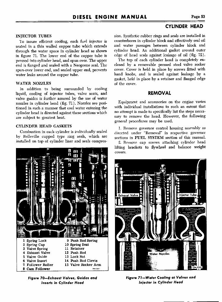
DIESEL ENGINE MANUAL Page 53
INJECTOR TUBESTo insure efficient cooling, each fuel injector is
seated in a thin walled copper tube which extendsthrough the water space in cylinder head as shownin figure 71. The lower end of the copper tube ispressed into cylinder head, and spun over. The upperend is flanged and sealed with a Neoprene seal. Thespun-over lower end, and sealed upper end, preventswater leaks around the copper tube.
WATER NOZZLESIn addition to being surrounded by cooling
liquid, cooling of injector tubes, valve seats, andvalve guides is further assured by the use of waternozzles in cylinder head (fig. 71). Nozzles are positioned in such a manner that cool water entering thecylinder head is directed against these sections whichare subject to greatest heat.
CYLINDER HEAD GASKETSCombustion in each cylinder is individually sealed
by Belleville cupped type ring seals, which areinstalled on top of cylinder liner and seals compres-
9 Push Rod Spring10 Spring Seat11 Retainer12 Push Rod13 Lock Nut14 Push Rod Clevis15 Valve Rocker Arm
1 Spring Lock2 Spring Cap3 Valve Spring4 Exhaust Valve5 Valve Guide6 Valve Insert7 Follower Roller8 Cam Follower TPM-2321
Figure 70-Exhausf Valves, Guides andInserfs in Cylinder Head
CYLINDER HEAD
sion. Synthetic rubber rings and seals are installed incounterbores in cylinder block and effectively seal oiland water passages between cylinder block andcylinder head. An additional gasket around outeredge of head seals against leakage of oil (fig. 72).The top of each cylinder head is completely en
closed by a removable pressed steel valve rockercover. Cover is held in place by screws fitted withhand knobs, and is sealed against leakage by agasket, held in place by a retainer and flanged edgeof the cover.
REMOVALEquipment and accessories on the engine varies
with individual installations to such an extent thatno attempt is made to specifically list the steps necessary to remove the head. However, the followinggeneral procedures may be used.
1. Remove governor control housing assembly asdirected under "Removal" in respective governorsections in FUEL SYSTEM section of this manual.2. Remove cap screws attaching cylinder head
lifting brackets to flywheel and balance weightcovers.
Figure 71-Wafer Coo'ing af Valves andInjector in Cylinder Head

CYLINDER HEAD
DIESEL ENGINE MANUALPage 54
1 Water Seal Ring - Large2 Oil Seal Ring3 Water Seal Ring - Small4 Oil andWater Seal Ring5 Cylinder Block6 Liner Insert7 Compression Gasket TPM-2577
Figure 72-Cylinder Compression Gaskets,Oil and Water Seals
3. Loosen jumper line nut at injector, then remove line at connectors and swing line aside so thatcylinder head stud nuts can be reached.4. Remove cylinder head hold-down stud nuts
using special wrench to reach nuts under injectorcontrol tube. If wrench is not available remove control tube and brackets.CAUTION: When removing cylinder head with
injectors in place, care must be taken to avoiddamaging injector tips and cam followers at theinstant head clears the cylinder head studs. Raisecylinder head clear of studs. DO NOT ALLOWCYLINDER HEAD TO BIND ON STUDS.5. When resting cylinder head assembly on work
bench, protect injector tips, also cam followers androllers by resting the valve side of head on woodenblocks at least 2" thick.6. Remove cylinder head compression and oil
seal gaskets.7. If engine is removed from vehicle for a major
overhaul, and is positioned in engine overhaul stand,cylinder liner clamps should be installed betweeneach two cylinders to prevent possibility of liners
falling from block while engine is turned to various5 positons in overhaul stand. Install liner clamps over
cylinder block studs and secure with cylinder headhold down stud nuts.
DISASSEMBL YConditions will arise when a complete cylinder
head overhaul becomes necessary. For such conditions the removal of all working parts attached tocylinder head is necessary. NOTE: New cylinderheads are furnished with valve guides, studs, injectorcopper tubes and plugs. If a new cylinder head is tobe installed, some of the used parts removed fromthe old head, or new parts must be installed in thehead before it is attached to cylinder block. Thefollowing procedure applies when a cylinder headis to be completely overhauled:
l. Remove rocker arms and shafts as instructedunder "Rocker Arm, Shaft and Bracket Replacement"in VALVESAND INJECTOR OPERATING MECHANISM section later in this manual.2. Remove valve springs as instructed under
"Valve Spring Replacement" in VALVES AND INJECTOR OPERATING MECHANISM section laterin this manual. After valve springs and locks are removed valves may be removed from lower side ofcylinder head.3. Remove injectors as instructed under FUEL
INJECTORS in FUEL SYSTEM section of thismanual.4. Remove fuel oil connectors and manifolds as
instructed under "Fuel Manifolds" in FUEL SYSTEM section of this manual.5. Remove cam follower and guide as instructed
under "Push Rod, Cam Follower, and Spring Replacement" in VALVESAND INJECTOR OPERATING MECHANISM section later in this manual.
CLEANINGWhenever engine is overhauled, the cylinder
head -should be thoroughly inspected for any condition that would render it unfit for further service.Such inspection will take place after the head hasbeen removed from the block, completely disassembled, and thoroughly cleaned in either live steamor a suitable solvent; then cleaned with dry compressed air.If shop facilities permit, grease and scale should
be removed from disassembled head in followingmanner:

DIESEL ENGINE MANUAL Page 55
1. Remove grease by agitating the head in abath of commercial heavy duty alkaline, as sold bytrade chemical suppliers.2. Wash in hot water or steam clean to remove
alkaline.3. Remove scale by agitating the head in a bath
of inhibited commercial pickling acid as sold bytrade chemical suppliers. A 50-50 solution of Oakite32 and water has been found satisfactory. After headis cleaned of grease and scale, it must be rinsed andthe cleaner acid neutralized. Carefully follow directions of chemical manufacturer on cleaning, rinsing,and neutralizing.
4. Wash head in a bath of clean water or steamclean.5. After head is inspected for cracks, dip in rust
preventive to prevent rusting. Castings free of greaseand oil will rust immediately when exposed toatmosphere.
INSPECTIONThe information described under the following
headings pertain to the cylinder head after it hasbeen removed from the engine, disassembled andthoroughly cleaned.
WARPAGE (FLATNESS)
The cylinder head must be Hat within certaintolerances longitudinally and transversely in order toensure proper contact with the cylinder head gasketsand cylinder block to obtain the desired sealingeffect. In continued service, cylinder heads may assume a contour to match that of the cylinder blockand gaskets over a prolonged period of operation.This is a normal reaction. However, if the cylinderheads are allowed to become overheated because ofcoolant loss, high temperature causes stresses tooccur in the castings which affects the flatness of thecylinder head. The maximum allowable variation incylinder head flatness is shown in the followingtable:
Engine4-716-71
Longitudinal.008".010"
Transverse.004".004"
When determining or measuring the flatness ofthe cylinder head fire deck, the use of a heavy, accurate straight edge and accurate feeler gauges shouldbe employed. Measurements should be taken longitudinally at each bridge between cylinders and on
CYLINDER HEAD
Figure 73-Check Cylinder Head Flatness atPoin's Indicated
both right and left sides of the cylinder head(fig. 73).If the flatness is not within the dimensions given
in the table, then the fire deck of the cylinder headshould be refaced. A limit of .015" to .020" is themaximum amount of stock that should be removed.Critical dimensions such as protrusion of valve seats,valves, injector hole tubes, and injector spray tipsshould be observed. In the event a cylinder head isnot Hat within its re-use limits then head should bereplaced.
LEAKSFollowing the inspection of the cylinder head for
Hatness as described above, the next step thatshould be performed is checking the cylinder headfor leaks. Install dummy injectors, tap lightly, andhold in place with injector crab and nut tightenedto recommended torque. Dummy injectors may bemade up with old injector nuts and bodies-the injector spray tip is not necessary. Remove pipe plugsat both ends of the cylinder head oil gallery.Seal all water openings in the cylinder head with
suitable gasket material and clamping fixture equipment; however, provision should be made to introduce air into the water passageway cavities of thecylinder head as it is being tested.The cylinder head assembly should then be sub
merged into water heated to a temperature of 1800to 2000 for about fifteen to twenty minutes tothoroughly heat the cylinder head. Any leaks in thecylinder head assembly will be detected by allowing air to enter the cylinder head water passageways until a pressure of 80-100 lbs. (maximum) hasbeen attained and noting any air bubbles in thewater. Some of the places to inspect for leaks areas follows: Bottom and top of the injector tubes;oil gallery; cylinder head stud holes; exhaust ports;top, bottom, and sides of cylinder head proper.

Page 56 DIESEL ENGINE MANUAL
CYLINDER HEAD
Figure 74-Removing Valve Seat Insert fromCylinder Head
Relieve air pressure, remove cylinder head fromwater, remove gaskets and clamps, and allow cylinder head to dry. Replace any leaking injector tubes.If leaks are apparent in the cylinder head, it shouldbe replaced.
INJECTOR COPPER TUBESIf pressure test for leaks, previously performed,
indicates that a leak exists at the bottom of thetube, compression will leak into cooling systemcausing loss of coolant. A leak at top of tube willpermit water to leak into lubricating oil.
Whenever either of these conditions exist the tubemust be replaced as directed under "Injector CopperTube Replacement" later in this section.
Figure 75-lnstalling Valve Seat Insert inCylinder Head
WATER DEFLECTOR NOZZLESWater nozzles must be in good condition (not
corroded or distorted) and flush with the bottom ofcylinder head. Nozzles are press fit in cylinder headand can be replaced as instructed under "WaterNozzle Replacement" later in this section.
VALVE GUIDECarefully inspect each valve guide for fractured,
chipped, scored or excessively worn condition. Ifinspection indicates replacement is necessary, referto "Valve Guide Replacement" later in this section.
VALVE SEAT INSERTInspect valve seat to determine if they are fit for
further use. Inspection should include cleanliness,concentricity, flatness, and presence of cracks. Sunburst pattern of cracks in the cylinder head aroundvalve insert indicates head has been overheated,also cracks between the valve insert and injectortube may be the result of overstressed injector crabsas well as overheating.Before installing a new or used valve, the valve
seat in the cylinder head must be reconditioned asdescribed later in this section. If exhaust valve seatinserts are loose in cylinder head, or if for any reason due to wear pitting, etc., replacement of valveseat is necessary, oversize (.010") exhaust valve seatinserts are available.Check for concentricity of seat as directed under
"Valve Seat Insert Replacement" later in this section.
CAM FOLLOWER HOLESInspect cam follower holes in head to be sure
they are clean and smooth so as to permit properoperation of cam follower. Any existing score marksshould be removed.
VALVE SEAT INSERT REPLACEMENT
REMOVALValve seat insert is shrunk into cylinder head and
must be removed with special tool to avoid damageto head.l. Place cylinder head on bench, and insert the
collet inside of valve insert so that lip at bottomof collet flange is flush with bottom side of valveinsert. While holding collet in this position, expandsame by turning screw handle. Be sure that flangeof collet firmly engages bottom of valve insert. Referto figure 74.2. Insert driver bar through valve guide and
against collet. Tap driver with hammer to move

DIESEL ENGINE MANUAL Page 57
seat from head. Readjust collet, if necessary so thatcollet flange is below seat.
INSTALLATIONParticular care must be used when replacing
valve seat inserts. The inserts are installed into cylinder head with a .0005" to .0025" press fit, andmust be started true with counterbore in head.1. If oversize inserts are to be installed, counter
bore exhaust valve port to oversize dimensions aslisted in SPECIFICATIONS section of this manual.It is extremely important that head be counterboredwithin these limits, and that bore is concentric withhole in valve stem guide within .003" total indicatorreading.2. Cylinder head must be clean, particularly the
counterbore for inserts.3. Immerse cylinder head for 30 minutes in water
at temperature of 1800 to 200°F.4. Place new inserts in dry ice for a minimum of
15 minutes before installing.5. Place cylinder head bottom-side-up on bench;
blowout insert counterbores with air; and place aninsert in counterbore valve side up.6. Using replacer tool in manner shown in figure
75 insert pilot end of tool into valve guide, and driveinsert down .tightly into counterbore. This operationmust be don~ quickly, while the valve seat insertis cold.7. Grind valve seat insert, check concentricity
with valve guide, and depth of seat in manner described under "Reconditioning Valves and ValveSeats" in VALVES AND INJECTOR OPERATINGMECHANISM section of this manual.
INJECTOR TUBE REPLACEMENTWhenever inspection indicates that injector copper
tube in cylinder head requires replacement, the operation must be performed with the greatest of careand with special tools in the manner following.
REMOVAL1. Cylinder head must be completely disassem
bled and should be installed in cylinder head holdingplates for ease of handling.2. Apply a small amount of light engine oil to
inside of copper tube, then thread tap into coppertube until approximately ~" of threads are obtained.Refer to figure 76.NOTE: If the tube begins to rotate while thread
ing tap into tube, drive tube holder into tip end anduse wrench at tube holder to prevent tube turning.
CYLINDER HEAD
Figure 76-Removing Iniecfor Copper Tube fromCylinder Head (Operation No. J J
3. Remove tube holder, if used. Insert driving rodthrough injector tip hole until it is against centerof tap. Use hammer and drive against end of rod.thus forcing threaded tap and copper tube fromcylinder head. Refer to figure 77.
INSPECTIONInstallation of the injector tube requires careful
preparation and inspection to make sure that the areaof the cylinder head is clean so that when tube contacts the cast iron cylinder head, foreign materialwill not prevent tube seating at bottom or sealingat top. Refer to figure 78, and check at points indicated by arrows.
Figure 77-Removing Iniector Copper Tube fromCylinder Head (Operation No. 2J

Page 58 DIESEL ENGINE MANUAL
CYLINDER HEAD
figure 78-When Replacing Injector Copper Tube,Check for Absolute Cleanliness at Points
Indicated by Arrows
INSTALLATION
1. Install seal ring into cylinder head injector tubecounterbore.2. Position driver through injector tube, then in
sert pilot into small opening of injector tube, andthread pilot into driver (fig. 79).3. Insert injector tube, with tools attached, into
bore in cylinder head. Drive tube down until flange
figure 79-lnstalling Injector Copper Tube inCylinder Head (Operation No. 1J
at upper end of tube is against the seal ring, andlower portion of tube is against bevel seat in thebottom of cylinder head tube bore (fig. 79).
4. Remove pilot from injector tube and driver.Install flaring die through injector tube tip andthread into driver. Tighten flaring die, using torquewrench (fig. 80), until a torque reading of 30 ft. lbs,is obtained. Remove flaring die and driver from injector tube. Follow reaming instructions as describedin following paragraphs.
REAMINGReamers used in the following operation are
hand type and must not be used with a fixture,clamp, or drill press. Reaming must be accomplishedcarefully and slowly so as to provide a smooth surface. Use a light cutting oil on reamer flutes and donot tum reamer in opposite direction as this willdull the cutting edges. Reaming operations aredivided into two operations-Reaming Body Nutand Spray Tip, and Reaming Bevel Seat.
Reaming Body Nut and Spray Tip1. Apply a few drops of light cutting oil on reamer
flutes, then position reamer in tube. Tum reamerclockwise at all times until shoulder of reamer contacts injector tube (fig. 81).NOTE: Withdraw reamer frequently and clean
chips from tube and reamer flutes. During installation and removal of reamer always tum in a clockwise direction.2. Insert injector tube tip refinisher into injector
tip hole, then using a socket and speed handle to
figure 80-lnstalling Injector Copper Tube inCylinder Head (Operation No.2)

DIESEL ENGINE MANUAL Page 59
remove excess from tube tip. When refinisher contacts cylinder head the operation is complete andtube tip will be flush to .010" below surface of head.
Reaming Bevel Seat1. Clean interior of injector tube with clean fuel
oil to remove all metal particles, then dry with compressed air.2. Apply a few drops of light cutting oil on reamer
flutes, then carefully insert reamer into injector tubeuntil the reamer contacts the bevel seat (fig. 82).3. Make one or two turns of the reamer, using a
very light pressure, then remove reamer and cleaninside of injector tube.4. Use injector as a gauge, and continue reaming
and checking with injector until the shoulder of thespray tip is flush to .015" below the surface of thecylinder head. Refer to figure 83.
VALVE GUIDE REPLACEMENTWhenever inspection indicates valve guides should
be replaced this should be done before valve insertsand valves are reconditioned.
REMOVALSupport the cylinder head so that guide can be
removed from head. Use valve guide remover anddrive guide downward and from the head.
INSTALLATION1. Insert countersunk end of valve guide into
installer tool.
Figure 8f-Reaming In;ector Copper Tube inCylinder Head for In;ector BodyNut and Spray Tip
CYLINDER HEAD
Figure 82-Reaming In;ector Copper Tube BevelSeat for In;ector Body Nut
NOTE: Valve guides must be installed withcountersunk end up to provide lubrication to valvestems.2. Position valve guide squarely into head, then
drive or press into place (fig. 84).3. When the guide is properly installed, it will
project above the cylinder head. Refer to "Specifica-tions" for dimension. When installer is used, thisdimension is automatically provided.
1 Spray Tip2 Orifice - Injector
Spray Tip
3 Cylinder Head4 Straight Edge-
Figure 83-Checking location of In;ector Spray Tipin Relation 10 Surface of Cylinder Head

CYLINDER HEAD
DIESEL ENGINE MANUALPage 60
Figure 84-Va've Guide 'nstaller
REAMINGGUIDE IS MANUFACTURED TO SIZE AND
DOES NOT R:&QUIRE REAMING AFTER INSTALLATION.
Figure 8S-Cylinder Head Water Nozz'e 'nstallationl4-Va've HeadJ
WATER NOZZLE REfLACEMENTREMOVALIf it should become necessarylto install new water
nozzles, removal of old parts can be easily accomplished with cape chisel or other suitable tool. Usecaution during removal so that I no burrs are raised.
INSTALLATION I
1. Clean the two water holes at each end with~" diameter drill. Break edges I of holes slightly.2. Clean all other water holbs with 1%6" diam
eter drill. Break edges of hol~s slightly.3. Check fit of nozzles in tHeir respective holes.
Nozzles must be a press fit so that the nozzle opening maintains proper directional How of coolingwater. If the water holes in the cylinder head havecorroded so that when cleaned I they are larger thanthe nozzle, the nozzles must b~ tinned with solderon the outside diameter so they will remain tightafter installation. I
4. On two valve heads, press nozzles into placewith their openings parallel with the center line ofengine (fig. 86). On four-val~e heads, press thenozzles into heads so that openings are directed diagonally across the head. Refer tp figure 85.
5. Nozzle should be Hush to V32" below the seating surface of the cylinder head. The nozzles mustnot interfere with proper seating of the cylinderhead, when installed.
Figure 86-Cy'inder Head Water Nozzle 'nstallationl2-Valve He1dJ

DIESEL ENGINE MANUAL Page 61
HEAD GASKET INSTALLATIONSealing cylinder combustion is by use of individ
ual ring seals at each cylinder (figs. 8 and 72). Oiland water passages between cylinder block and headare sealed by synthetic rubber seals installed incounterbores at top of cylinder block. Installation ofthese seals requires careful placement of each part.
1. Clean top of cylinder block, area around cylinder liners, also oil and water passage counterboresso to remove all traces of dirt, carbon or other foreign material that may effect good seal between cylinder block and head.2. Install large synthetic rubber oil seal in milled
slot on four sides near edge of cylinder block. Besure gasket is evenly distributed and is not drawnthin on one side of block.3. Two seals are figure eight shaped and should
be installed in counterbores at each end of block.4. Install two small seals (:Ii" dia.) and large
(11;16" dia.) seals in counterbores in cylinder block.Six cylinder engines require ten and four cylinderrequires six of the large seals.5. Position one compression seal ring carefully
over each cylinder liner, being especially cautiousthat ring rests evenly on top of liner flange.
CYLINDER HEAD INSTALLATIONBefore installing cylinder head (fig. 69), be sure
seals (fig. 72) are properly installed and that allparts are dirt free. The necessary steps for replacinghead are outlined below:1. Wipe under side of cylinder head clean, and
by means of the lifting brackets, set cylinder headin place on block.2. Loosen cap screws that attach lifting brackets
to cylinder head so bracket is loose. Coat cylinderhead studs with Hypoid lubricant, then install andtighten cylinder head stud nut to recommendedtorque, in the sequence shown in figure 87. Tightening of stud nuts will be simplified by the use ofspecial wrench in conjunction with torque wrench.3. Tighten cap screws at each end of cylinder
head that attach lifting brackets to flywheel housing and balance weight cover in sequence illustratedin figure 88.4. Install valve and injector operating mechanism
as directed under respective headings in VALVESAND INJECTOR OPERATING MECHANISM section of this manual.
CYLINDER HEAD
"_CYLINDER ENGINECYLINDER HEAD
6_CYLINOER ENGINE CYLINDER HEAD
TP·6240
Figure 87-Head Stud Nut Tightening Sequence
5. Install injectors as instructed under "InjectorInstallation" in FUEL INJECTOR section of thismanual.6. Install and position injector control rack as in
structed under "Control Rack Positioning" in FUELINJECTOR section of this manual.7. Time injectors as instructed under "Timing In
jectors" in ENGINE TUNE-UP section of thismanual.8. Lash exhaust valves as instructed under "Valve
Lash" in VALVES AND INJECTOR OPERATINGMECHANISM section of this manual.9. Install fuel jumper lines between injectors and
fuel manifold connectors. Be sure connections aretight and leak proof.10. Install governor control housing as directed
in respective governor section of this manual.11. During engine run-in check for fuel and water
leaks. Recheck and tighten cylinder head stud nutsto recommended torque.
TP·6243
Figure 88-Head Lifting Bracket Tightening Sequence

Page 62
VALVE AND INJECTOR MECHANISM
DIESEL ENGINE MANUALI
VALVES AND INJECTOR OPERATING MECHANISMI
Figure 89-Valve and InjectorOperating Mechanism-2-Valve
Two types of valve operating mechanism aredescribed in text following; (1) 2-valve type illustrated in figures 89 and 91, (2) bridge type usedon four-valve heads, illustrated in figures 90 and 92.
DESCRIPTIONROCKER ARMSValve and injector rocker arms for each cylinder
operates on a separate shaft supported by two castiron brackets. A single bolt fastens each bracket securely to top of cylinder head.The valve and injector ends of rocker arms are
hardened and ground to a cylindrical surface, whichbears directly on the end of the valve stem or injector follower. Rocker arms are operated from camshaft through short push rods.
51 Lock Nut6 .Injector Assembly7 Valve Spring81 Bridge Spring
TPM·6282
1 Valve Rocker Arm2 Injector Rocker Arm3 Valve Bridge4 Valve Lash Adjusting
Screw
Figure 90-Valve and InjectorOperating Mechanism-4-Valve Type wi~hBridge

DIESEL ENGINE MANUAL Page 63
2
2S24 '----13
"---- 14lS
::~II~ .... 17
20 '! ~ 18, ~ --- 19
~1Rocker Shaft Bolt2 Oil Passage Hole3 Valve Rocker Arm
- Left4 Bushing - Large5 Injector Rocker Arm6 Bushing - Large7 Valve Rocker Arm
- Right8 Bushing - Small9 Rocker Shaft10 Rocker Shaft Bracket11 Push Rod Clevis Pin12 Push Rod Clevis13 Push Rod
14 Follower Spring Seat- Upper
15 Follower Spring16 Follower Spring Seat
- Lower17 Cam Roller Guide18 Lockwasher19 Bolt20 Cam Roller Pin21 Cam Roller Bearing22 Cam Roller23 Cam Roller Follower24 Follower Spring Seat
Retainer25 Push Rod Lock Nut
TP·7136·1
figure 91-Valve and Injector Operating MechanismDetails
CAM FOLLOWERSContact between cam followers and cam is made
by a hardened steel roller. The roller is equippedwith a steel-backed bronze bushing running directlyon a pin in lower end of cam follower. A separatecoil spring, located inside of the hollow cam follower,is held in place in cylinder head by a spring seatretainer. A drop-forged steel guide, shown in figure93, is provided for each set of three cam followers.This guide, located on bottom of cylinder head,keeps the rollers in line with cams and also serves asa retainer during assembly and disassembly.
VALVE AND INJECTOR MECHANISM
1 Bridge AdjustingScrew
3 Valve Bridge4 Spring Lock5 Spring Cap6 Bridge Spring7 Valve Spring8 Spring Seat9 Bridge Guideo Valve Guide11 Valve Seat Insert12 Exhaust Valve13 Cam Roller14 Cam Follower15 Spring Seat - Lower
~~11~"
rT~
I10
~8
10
16 Follower Spring17 Spring Seat - Upper18 Push Rod19 Retainer20 Lock Nut21 Push Rod CleviS22 Rocker Arm
TPM-4488 -2
figure 92-Valve Operating Mechanism Details-4-Valve Type with Bridge
EXHAUST VALVES.Two or four exhaust valves are provided for each
cylinder. Valves are heat treated and ground to theproper stem diameter and seat angle.

VALVE AND INJECTOR MECHANISM
DIESEL ENGINE MANUALPage 64
figure 93-Cam follower and Guide Assembly
MAINTENANCE(On Vehicle)
Several service operations which may be accomplished on cylinder head, valves, and injectors assembly without necessity of removing the cylinderhead assembly from the block. These operations are:1. Valve Lash.2. Valve Spring Replacement.3. Valve Bridge Adjustment (Bridge Type).
figure 94-Compressing Valve Spring with Toolto Remove Valve Lock (2 Valve HeadJ
4. Rocker Arm, Shaft, or Sh~ft Bracket Replace-ment. I
5. Injector Replacement.6. Cam Follower Retainer ~pring Replacement.7. Cam Follower Replacement.8. Push Rod Replacement.
VALVE LASH AN~ BRIDGEADJUSTME~T
Refer to ENGINE TUNdup section of thismanual for valve lash and bridge adjustment pro-cedure. lCAUTION: Whenever a pu h rod has been dis
connected from the push rod fclevis, the rod mustbe screwed back into the clev s, Hush with the topof the threaded portion of th. clevis before valvelash is checked. IF THIS IS NOT DONE, BEFORE ENGINE IS TURN~D' THE PISTONMAY HIT HEAD OF VAL E DUE TO THESMALL CLEARANCE BET EN VALVES ANDPISTON HEAD AT THE1· PISTON UPPERPOSITION.
Correct valve lash is import nt due to high compression pressures. Too little clearance causes aloss of compression, missing ~tlinder, and eventualburning of valves and valve s~ats. Too much clearance between valve stem and valve rocker arm results in noisy operation of tngine, especially inidling range.NOTE: It is recommended when lashing valves
to set them first cold; then stalengine and warm upto normal operating temperat reo Reset valve lashafter engine has warmed up t operating temperature. Refer to "Specifications" for dimension.
VALVE SPRING RElLACEMENT
REMOVAL J1. Crank engine until pisto is at top of stroke,
which is indicated when the injector plunger hastraveled approximately %6" on the downward stroke.2. Disconnect and remove (uel feed lines from
injector to fuel oil connectors. After removing fuellines, temporarily install injec10r shipping caps toprevent dirt entering injectors3. Remove two cap screws holding rocker arm
shaft brackets to cylinder head!' then remove brackets and shaft.

..DIESEL ENGINE MANUAL Page 65
Two-Valve Headl. Install a cap screw through valve lifter tool
bushing and valve lifter tool (fig. 94). Thread thiscap screw into tapped hole of cylinder head adjacent to the valve spring to be removed.2. With slight pressure on end of the tool, the
valve spring retainer can now be depressed, thelocks, retainer, and spring removed.
Four-Valve Headl. Remove exhaust valve bridges and springs
(when used).2. Thread adapter end of compressor tool 0-7455)
into rocker shaft bolt hole in cylinder head (fig. 95).3. Place compressor foot on top of the valve spring
cap (fig. 95).4. Press down on compressor handle to compress
valve spring, then remove two spring locks.
INSTALLATIONl. The valve spring may be installed by reversing
the sequence of operation for removal.2. After replacing the valve spring, adjust the
valves, also bridge on 4-valve heads and retime injector as instructed under respective headings in ENCINE TUNE-UP section of this manual.NOTE: Connect the fuel feed lines to the injector
and fuel oil connectors. Before valve cover is installed and after the engine has been started, inspectall fuel oil connections for leaks. Should fuel oil leakinto cylinder head and dilute lubricating oil, enginebearings may be seriously damaged.
INSPECTIONExamine valve and bridge springs for pitted or
fractured coils. Test valve springs for pounds pressure at height and length given in SPECIFICATIONS section of this manual.
ROCKERARM, SHAFT, AND BRACKETREPLACEMENT
REMOVALl. Disconnect and remove fuel feed lines from
injector to fuel oil connectors. After removing fuellines, temporarily install injector shipping caps toprevent dirt entering injectors.2. Remove the two cap screws holding rocker arm
shaft brackets to cylinder head, then remove brackets and shaft.3. Loosen lock nut at upper end of push rod, then
unscrew push rod clevis from push rod.
VALVE AND INJECTOR MECHANISMINSPECTIONBefore installing rocker arms or parts, check the
bushings inside the rocker arms for excessive wear.Clean out oil holes in rocker arms, hollow bracketbolt, and rocker shafts with fuel oil, small wire, anddry compressed air.
INSTALLATIONl. Note that the injector rocker arm-the center
arm-is different from the exhaust valve rocker arms;also that the boss for the shaft on the valve rockerarm is longer on one side than on the other. Thelong side of the boss must face the injector rockerarm.2. With the rocker arms selected as above, screw
the upper end of each push rod into the rocker armclevis so the end of the rod is just flush with the topof the threaded portion of the clevis. Do not tightenthe lock nuts until cylinder head is installed andvalves are lashed.3. Slide rocker arm shaft through rocker arms and
then place one of the end brackets over each end ofshaft, with finished face of the bracket boss nextto rocker arm. Position rocker arm bracket bolts inplace through brackets and shaft; then tighten bolts.
figure 95-Compressing Valve Spring with Tool toRemove Valve lock (4 Valve HeadJ

Page 66 •DIESEL ENGINE MANUAL
VALVE AND INJECTOR MECHANISM
4. After replacing rocker arms, valve lash andbridge must be adjusted and injector retimed asinstructed under respective headings in ENGINETUNE-UP section of this manual before engine isstarted.
NOTE: Connect the fuel feed lines to the injectorand the fuel oil connectors. After engine has beenstarted and before valve cover is installed, inspectall fuel oil connections for leaks. If fuel oil leaksinto cylinder head and dilutes lubricating oil, enginebearings may be seriously damaged.
PUSH ROD, CAM FOLLOWER,ANDSPRING REPLACEMENT
REMOVAL (Head Installed)
1. Remove valve rocker arm cover,2. Crank engine until piston is at or near top of
stroke, which relieves follower spring to minimumtension.
3. Disconnect and remove fuel feed lines from injector to fuel oil connectors. After removing fuellines, temporarily install injector shipping caps toprevent dirt entering injectors.4. Remove two cap screws holding rocker arm
shaft brackets to cylinder head; then remove brackets and shaft.
5. Loosen lock nut at upper end of push rod, thenunscrew push rod clevis from push rod.6. Use a screwdriver to press follower spring
upper seat down to relieve spring tension on retaineror lock wire. Use another screwdriver to dislodgeretainer from groove in cylinder head.
7. Lift push rod, spring and retainers from camfollower, Lift cam follower and roller assemblyfrom cylinder head.
REMOVAL (Head Removed)
Cam followers can be removed from either topor bottom of cylinder head, however they can bestbe removed from the bottom when the head is removed, as follows:
1. Place cylinder head on its side on bench asillustrated in figure 9.3.Remove two cap screws thatsecure cam follower guide to head, then removeguide.
2. Pull cam follower and roller assembly from
bottom of cylinder head.
3. Loosen lock nut, then un,crew push rod frompush rod clevis.
4. Pull push rod, spring, anf spring seats frombottom of cylinder head.5. Push rod spring seat retainer (lock wire) re
mains in the cylinder head an~ may be left thereunless cylinder head is to be changed.
INSPECTION I
1. Clean and inspect cam follower for wear ordamage. Check follower to cylinder head clearance.2. Check roller for wear, Jlso for scuffed and
flat spots. Replace if necessary,3. Should follower roller in~pection reveal that
roller is scuffed, inspect camshaft lobes.4. Inspect push rod clevis td rocker arm for evi
dence of excessive wear at bJshings and pin. Repair or replace as necessary.
INSTALLATION (Head InstJlled)1. Install cam follower and roller assembly in
opening in cylinder lead. Assemble follower springlower seat, spring, upper seat and retainer (lockwire) to push rod, then install ~ssembly in follower.2. Compress follower sprink with screwdriver,
then install retainer lock wire t'n groove in cylinderhead.
3. Reinstall rocker arm clevis to push rod andinstall shaft, brackets, and bolt] as instructed under"Rocker Arm, Shaft, and Brackbt Replacement" previously in this section.
4. Adjust valve lash as instructed under "ValveLash"; also adjust bridge as instructed under "BridgeBalancing Adjustment" in ENqINE TUNE-UP section of this manual. Retime ipjector as instructedunder "Timing Injector" in ENCINE TUNE-UP section of this manual.
INOTE: Connect the fuel feed lines to the injector
and the fuel oil connectors. ~hen engine has beenstarted, and before valve cover is installed, inspectall fuel oil connections for leaks. If fuel oil leaks intocylinder head and dilutes oil, ~ngine bearings maybe seriously damaged. I
INSTALLATION (Head Remrved)1. If removed, install push rod spring seat retainer
(lock wire) in place in cylindr head.

DIESEL ENGINE MANUAL Page 67
2. Assemble to push rod the lower spring seat,push rod spring, upper spring seat and lock nut.Insert the assembly into cylinder head from thebottom.
3. Thread push rod into rocker arm clevis as faras possible or until rod contacts rocker arm.
4. Observe oil hole in the cam follower, theninstall follower assembly into head with oil holepointing away from valves so that the hole is notcovered by the follower guide.
5. Secure follower assembly to cylinder headusing follower guide, two cap screws, and lockwashers.
RECONDITIONING VALVES ANDVALVE SEATS
Before either a new or used valve is installed, theseat in the cylinder head for the valve should beexamined for proper valve seating. Furthermore, ifvalve once used is to be installed again, the valvestem should be cleaned, and the face reground toproper angle. The valve guide should be thoroughlycleaned with valve guide cleaner in manner illustrated in figure 96. If bore in valve guide is wornoblong, or if valve heads are warped relative to thestem, the parts should be replaced.
REFER TO CYLINDER HEAD SECTION OFTHIS MANUAL FOR VALVE SEAT, ANDVALVE GUIDE REPLACEMENT INSTRUCTIONS.
Exhaust valves which are to be reused may berefaced. The edge of the valve at the valve headshould not be less than .020" in thickness after refacing. Before installing either a new or used valve,examine the valve insert in the cylinder head forproper valve seating. The proper angle for the seating face of both the valve and valve seat insert is 30°.The angle of the valve seat insert must be exactly
the same as the angle of the valve face so as to provide proper seating of the valve.When new valve seat inserts are installed or old
inserts are reconditioned, the work must be donewith a grinding tool (Fig. 97). The eccentric valveseat grinder set, used to recondition or grind valveseat inserts consists of: Grinder, Dial gauge, Pilot,and 15°, 30°, 60° Grinding wheels.Grind the valve seat in the following manner:1. Use 30° grinding wheel on valve seats.
VALVE AND INJECTOR MECHANISM
figure 96-C/eaning Valve Guides
2. Use 60° grinding wheel to open the throat ofthe insert.3. Grind top surface with 15° wheel to narrow
width of seat to )~6" to %2", see figures 98 and99. The 30° face of the insert may be adjustedrelative to the center of valve face with the 15°and 60° grinding wheels.
CAUTION: For best results, do not permit grinding wheel to contact the cylinder head when grinding the inserts.
figure 97-Reconditioning Valve Seat Insert

Page 68 DIESEL ENGINE MANUAL
VALVE INJECTOR MECHANISM
Figure 98-ln51allalion of Valve and Valve SealIn5erl-(Two Valve Head)
As shown in figures 98 and 99, a new valve mustnot protrude more than .0212" beyond the surfaceof the two-valve cylinder head or .006" beyond thesurface of the four-valve head. After several reconditions, the valve seat insert diameter will beincreased so that the valve will recede into the head.After the grinding has been completed, clean the
valve inserts thoroughly with fuel oil and blow drywith air. Set the dial indicator, in position as shownin figure 100 and rotate to determine the concentricity of each valve seat insert relative to its valveguide. Total ronout for a good insert should notexceed .002". If a ronout of more than .002" is indicated, check for bent valve guide before regrinding insert.
Figure 1OO-Checking Concenlricily of Valve Sealwilh Valve Guide
Figure 99-ln51allalion of varve and Valve SealIn5erl-CFour VaIv Head)
When a valve insert runou within the desiredlimits is obtained, the position of the contact areabetween valve and valve insert may be determinedin the followingmanner: ~
1. Apply a very light coat of Prossian blue orsimilar paste to the valve seat insert.2. Lower stem of valve in [the valve guide and
"bounce" valve on the insert, but do not rotatevalve. This procedure will show (on the valve face)the area of contact. The mostfesirable area of contact is at the center of the v lve face.
After valve inserts have bee ground, the cylinderhead should be thoroughly cleaned before installingthe valves.
EXHAUST VALVE REPLACEMENTINSPECTION IInspect and clean exhaust valves thoroughly. If
valve stem is excessively warped, burned, or worn,the valve must be discarded. then the valve headsare burned, warped, or pitte excessively, replacewith new parts. Valves whic are not excessivelyburned, pitted or warped m y be refaced as described previously in this section.
INSTALLATION .The valve guides having ~een checked or re
placed and the valves ground, Ithevalves and springsmay be replaced as follows: !
1. After the valves have been located in theirproper positions in the cylinder head, tum the head,valves down, with valve hea~s resting on a woodblock. A wide piece of maskin tape stretched acrossthe valve heads serves to ho d the valves in placewhile inverting the cylinder head.2. Compress the valve springs and insert the spring
locks, using tool as illustrated in figures 94 and 95.

DIESEL ENGINE MANUAL Page 69
EXHAUST MANIFOLD
EXHAUST MANIFOLDTwo exhaust passages from each cylinder lead
through a single port in cylinder head to exhaustmanifold. Studs in cylinder head, located betweeneach exhaust port and at each end of the two endports, serve the dual purpose of supporting andsecuring the manifold to cylinder head by meansof special clamp washers and nuts. As a safeguardagainst exhaust gas leaks, a heat-resisting gasket,supported on the studs, is used between cylinderhead and exhaust manifold.Due to the material from which exhaust mani
folds are made, and the method of support, verylittle service should be required on the parts unlessthe engine has met with an accident.
REMOVALThe exhaust manifold will usually be removed
along with cylinder head; however, in case exhaustmanifold gaskets are to be replaced, the exhaustmanifold may be removed without removing thecylinder head as follows:
1. Remove exhaust pipe.2. Remove exhaust manifold-to-cylinder head stud
nuts, and special washers, then pull exhaust manifold straight out away from engine.
3. Remove manifold gaskets from cylinder headand manifold flanges.
INSTALLATION
When manifold is removed from engine alongwith cylinder head, it should be separated to facilitate handling of the head during service operations.When replacing, the manifold should not be tightened in place until after the head assembly has beendrawn down tight. The manifold location shouldthen be checked to make sure it is resting on thelands at top of cylinder block-if the manifold hascorresponding bosses-and then the stud nuts drawnup tight against the conical washers.When the manifold has been removed independ
ent of the cylinder head, it may be replaced by reversing the sequence of operations for removal asfollows:
1. Place gasket over the studs.2. Set manifold over studs and next to gasket.3. Set a clamp washer-dished side toward mani
fold-over each stud and next to manifold.4. Replace nuts and tighten evenly to torque
recommended in Specification section of this manual.

Page 70 DIESEL ENGINE MANUAL
ENGINE TIMING AND BALANCE .
ENGINE TIMING AND ENGINE BALANC~ENGINE TIMING
When the engine is properly timed, the markedteeth on the timing gears will be matched togetheras shown in figure 52.
Firing orders for Series 71 Engines are as follows:
R.H. rotation (''R'' in model number) 4-71-1-3-4-2;6-71-1-5-3-6-2-4L.H. rotation (''L'' in model number) 4-71-
1-2-4-3;6-71-1-4-2-6-3-5
CHECKING ENGINE TIMING
When an engine is suspected of being out of time,due to an improperly assembled gear train, a quickcheck can be made without having to remove the flywheel housing to inspect the gear train markings.The following procedure may be used on Series
"71" engines installed in any unit, provided accessto the flywheel or vibration damper is possible. Insome instances, it may be necessary to remove thestarter to get to the flywheel to "bar" the engine andto mark top dead center indications.
Procedure1. Remove the cylinder head cover.2. Select any cylinder for the "timing" check-it
is suggested that a cylinder adjacent to one of thecylinder head cover studs be chosen inasmuch asthe stud may be used for mounting a dial indicator.3. Remove the injector fuel jumper lines (at the
cylinder selected); make sure that the valve andinjector rocker arms are all in the "up" position, thenremove the rocker shaft bracket bolts, and swingthe rocker arm assemblies back out of the way.Remove the injector assembly as instructed under"Injector Removal" in FUEL INJECTORS sectionof this manual.4. Carefully place a length (W' x 12") drill rod
through the injector hole and on top of the piston.Bar the crankshaft slowly in the direction of rotation,and stop barring when the rod reaches the end of itsupward travel. Remove the rod then bar the crankshaft opposite the direction of rotation between Yt6and ~ of a tum.5. Select a dial indicator having .001" graduations
and with a spindle movement of at least 1". Usesuitable mounting attachments for the indicator so
that it can be mounted over th~ injector hole in thecylinder head. Provide an extension for the spindleof the indicator. The extension must be long enoughto ~~ntact the piston as it arproaches its upperposition,6. Mount the indicator over the injector hole and
tighten mountings sufficiently to hold the indicatorrigid. The mounting attachments may be threadedinto the cover stud; or, the sthd may be removedfrom the cylinder head and the attaching partsthreaded into its tapped hole~Jdepending upon thelength of the rod used in ma,ing-up the mountingparts. Make sure that the spindle extension is freein the injector hole, does not bind, and is free totravel its full I" movement. I
7. Provide a suitable pointer and temporarilyattach it to the crankshaft front cover or engine frontend plate. Pointer should extend over the vibrationdamper, or crankshaft pulley, Iwhichever is used.8. Bar the crankshaft slowly in the direction of
rotation until the hand on the dial indicator juststops moving. I
9. Continue to bar the crankshaft in the directionof rotation until the indicator hand just starts tomove. Reset dial to "0."Continue barring slowly untilindicator reading is .010"-th~n stop turning.10. Scribe a line on the damper (or crankshaft
pulley) at the pointer.11. Bar crankshaft slowly in ~heopposite direction
of rotation, until the hand on the dial indicator juststops moving. Reset dial to "0." Slowly continuebarring until indicator reading is .010"-then stopturning. 'I
12. Scribe a second line on ,the vibration damper(or crankshaft pulley) in the same manner as inStep 10.13. Scribe a third line half-kay between the first
two lines. This is positive rob (top dead center).Remove the indicator from the engine.14. Install the injector as~embly as instructed
under "Injector Installation" iIllFUEL INJECTORSsection of this manual. Swing the injector and valverocker arms back into position and install rocker armbrackets and tighten bolts to pt·oper torque. Lash theexhaust valves and time the injector as instructedunder respective headings in ENGINE TUNE-UPsection of this manual. Bar the engine until theexhaust valves in the selected I cylinder are open.15. Install the dial indicator once again so that

Page 71DIESEL ENGINE MANUAL
the spindle of the indicator rests on top of the injector follower. Set indicator dial to "0." Bar thecrankshaft slowly in the direction of rotation, andstop when TDC mark on the vibration damper orcrankshaft pulley lines up with the pointer.16. Note the reading on the dial indicator and
compare with the following:1. If the indicator reading is .223" to .233", the
engine is in time,2. If the indicator reading is .188" to .204", timing
is one tooth retarded,3. If the indicator reading is .249" to 257", timing
is one tooth advanced.17. After completing the timing check, remove
the dial indicator: install the injector fuel jumperlines, making sure that they are tightened to preventany leaks; install the cylinder head cover; and,remove the pointer attached to the front of the engine.
ENGINE BALANCEBoth rotating and reciprocating forces are com
pletely balanced in 71 series engines. The eccentricrotating masses of the crankshaft and connecting rodare balanced by counterweights on the crankshaftchecks. The reciprocating masses (the piston andparts of the rod) produce an unbalanced couple byvirtue of an arrangement on the crankshaft in whichreciprocating masses, though equal, are not opposite.
ENGINE TIMING AND BALANCE
This unbalanced couple, which tends to rock theengine from end to end, is balanced by an arrangement of rotating counterweights, which produce acouple equal and opposite in magnitude. Consequently, the engine will operate smoothly and inperfect balance throughout the entire speed range.Balance weights consist of two eccentric weights
at each end of the engine, as shown in CAMSHAFTAND BALANCE SHAFT section of this manual.Each set of weights rotate in opposite directionswith respect to each other. When the two weightsat either end of the engine are in a vertical plane,their centrifugal forces are in the same direction,and oppose the unbalanced couple. When in a horizontal plane, the centrifugal forces of these balanceweights are opposite, and therefore cancelled. Frontbalance weights are eccentric in a direction oppositeto the rear balance weights; therefore rotation willresult in the desired couple, effective only in a vertical plane.Balance weights at the rear end of the engine are
integral and camshaft and balancer shaft drive gears.Weights at front end consist of eccentric slugs. Onsix-cylinder engines only, these weights are flexiblymounted, and spring loaded to serve also as torsionalvibration dampers. One crescent-shaped weight isbolted to each gear for the four-cylinder engine, andone weight attached to each gear for the six-cylinderengine.

Page 72 DIESEL ENGINE MANUAL
CONTENTS OF THIS SECTIONSubjectCirculation and DistributionEngine Oil RecommendationsOil Filters and Strainers
Page727879
SubjectOil Cooler
Page........ 79
8287
Lubricating Oil PumpOil Pressure Regulator Valve .. :1. : . : : : : .
CIRCULATION AND DISTRIBUTION .vided through drilled crankshJt from the adjacentforward main bearings. The gear train is lubricatedby overflow of oil from camsh~ft pocket through apassage into gear train cover. O~lspills into the gearcover from camshaft, balancer shaft, and idler gearbearings. The blower drive gear bearing is lubricatedthrough an external pipe fro~ rear horizontal oilpassage of cylinder block. I
A second longitudinal gallery is arranged on camshaft side of cylinder head and supplied with oilfrom one of the vertical bores atjeach end of cylinderblock. Oil from this gallery epters hollow rockerarm shafts through rocker shaft brackets, hollowcapscrews, and lubricates rocker arm bearings andpush-rod clevis bearings. I
Excess oil from rocker arms lubricates valve endsand push rods, and drains to cam pockets in cylinderhead from which cams are lubricated. As shown infigure 5, after reaching a certain level, this oil overflows through two holes at each I end of blower housing, providing lubrication for blower drive gearsat rear end and governor drive gear at the front.A dam in blower housing cover maintains an oillevel which submerges teeth df the lower blowerrotor timing gear. A slinger on opposite end of lowerrotor throws oil into governor weight assembly.Surplus oil passes from blowerl to oil pan throughdrilled holes in cylinder block.
The full-flow lubrication system, used on all latestengines, is schematically shown in figure 1 and consists of oil pump, oil filter, oil cooler, and by-passvalves around filter and cooler.The by-pass lubrication system, schematically
shown in figure 2, has been superseded by thefull-flow type and consisted of oil pump, oil filter,oil cooler, oil strainer (coach only) and cooler bypass valve.The oil cooler adapter has a spring loaded by-pass
valve which assures continual lubrication eventhrough oil cooler fails to function. Should the oilpressure at cooler inlet become 40 pounds greaterthan at cooler outlet, the by-pass valve in cooleradapter opens, and oil is then by-passed directlyfrom oil pump to oil gallery. However, under theseconditions, the oil is not cooled.The gallery oil pressure is limited to 45 pounds
per square inch by a spring loaded pressure regulator valve at the end of oil gallery. While a part of oilgallery, this regulator is actually located in crankcase, and is integral with pump discharge line.Continuous filter action is provided by by-passing
a portion of the oil through a filter from whencefiltered oil is returned to crankcase.Oil from cooler is conducted through a vertical
passage to a longitudinal main gallery on blowerside of crankcase. As shown in figures 3 and 4 thisgallery distributes the oil, under pressure, to mainbearings, and to a horizontal, transverse passage ateach end of cylinder block. From these two horizontal passages, two vertical bores at each end of cylinder block carry the oil to end bearings of camshaftand balance shaft, as well as to oil passage in camshaft, which in tum conducts the oil to camshaftintermediate bearings.Oil for lubrication of connecting rod bearings,
piston pins, and the cooling of piston head, is pro-
CRANKCASE VENTILATIONUnder normal operating conditions, harmful vapors
may collect in crankcase and valve compartment.These vapors may, under certain conditions, causeetching of highly finished surftces and dilution ofoil unless withdrawn. The crankcase and valve compartment are continually cleaned of harmful vaporsby a breather pipe attached to governor upper housing and venting to atmosPherel

DIESEL ENGINE MANUAL Page 73
1 Oil Pan2 Screen - Oil Pump3 Oil Pump4 Valve - Pressure ReliefTPM-4838
6 Oil Cooler7 Cylinder Block Oil Gallery8 Passage to Main Bearings
OIL CIRCULAliON
9 PassageBlock and Head
10 Cooler By-pass Valve11 Filter By-pass Valve12 Pressure Regulator Valve
Figure l-Schematic Diagram of Full-flow Engine Lubrication System
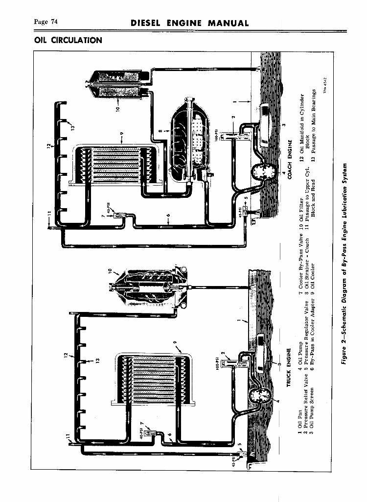
Page 74 DIESEL ENGINE MANUAL
OIL CIRCULAliON
til
""bIJ=Ql .~"0=~ Ql~
U =.S ~~ 0
in ~ .......~I §~ Ql
b.OIU ::?:l,9 «IZ til
=;:::1lI tilt; «IZ 0 A.IU "" '"I~~ ..... .....
E>, CII-U lit
U"""0
>.Ql «I en§;Ql c;:J:I:: 020"0 -"".....§ a
;§ ~~ o~..•~ cIj (.) .Q~ til 0
=~?!i :::I...Oil.
CII0 ..... C......... 06,Ql C.!:.c loLl~ <.)
lit«I0 lit
~u a«I I 0..A. I
"" >.~ Q) M CCIr:Q.; ~ -~.bg 0.....oou E8:-;:::-;::uoo a..<-co", ena
"" 2iQl Ql> .......... .,.o~«I «I
>"0 -",,< ao "" E..... Ql CII«I ..... ..c..... 0~o ...QlU iil:< .S
.,.Ql C"48 "" til CII... :0 :0 ~ ..
N ! A.~A. :::Iin CI Ql I en:::M>'~ .. Z OA.~ iA:6 IU2 .... on<o
lII:U Ql::I .!:GIl «II- >
:§ =QlQl
0; ""il:<rl5Ql .,.
= "" 8«I :0 :0A.~A...... Ql ....." •.-4 M ..-4OA.O
in.... "" '"..
6..

DIESEL ENGINE MANUAL
OIL CIRCULATION
Page 75
-oIe.2-uGIen......o..U
D.S"'0::I
~Ieo....II")
GI..::I.~...
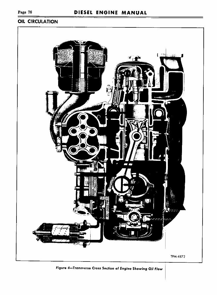
Page 76 DIESEL ENGINE MANUAL
OIL CIRCULATION
TPM-4872
Figure 4-Transverse Cross Section of Engine Showing Oil Flow

DIESEL ENGINE MANUAL Page 77
OIL CIRCULATION
~:..:0<500: ......... cc000:<{UJUJO.....z..... :::::i-~Ou
~0i:i:::0Dlc:°i0..c:
t;: en'"<{CIIi?i 0;:0
~ '"'"CIIu~ u0 .q:00: ."....
eZ Q< ..00: CII0 ~0CQI.."CII..:tDlii:

Page 78 DIESEL ENGINE MANUAL
OIL RECOMMENDATIONS
o::N
For cold weather, select viscosity based on lowest anticip.ated temperature.Forhot weather, selectviscositybased on highest temperature expected duringthe day. PM·2236
Normal Operation at
120
110
100
90ProlongedExposuretoLow Temperatures
Crankcase oils in service, unless protected by suitable addition agents, oxidize, form sludge and varnish, and under some driving conditions, corrosiveacids may accumulate in the crankcase. Heavy Dutyengine oils minimize the formation of these harmfuldecomposition products and generally aid in obtaining extended trouble free service.
80
70
60ToFacilitateColdStarling
50
40
32
20
10
o
10
20
30
figure 6-Engine Oi' Viscosity Chart
TYPESOF OIL
RECOMMENDATIONS
Heavy Duty engine oils designated for service"DG," "DM," or classified as MIL-L-2104A type,Supplement 1 (S-I) and which meet or exceed theMIL-L-2104A specifications are recommended foruse in Diesel engines as used in GMC trucks. Regardless of oil type used, reputable oil suppliers
1. Good resistance to "scuffing':or excessive wear.
2. Good resistance to low te~perature depositsand rust. I
3. Good resistance, at high temperature, to formation of deposits, to thinning out, or excessive oilconsumption.
I
CHANGING ~ILIt is recommended that engine crankcase oil be
drained initially at 500 miles in order that certainoil contaminants such as water, l'rt, etc., be removedfrom engine as soon as possible after the engine isplaced in service.The intervals at which cran case oil should be
changed depend entirely upon the type and qualityof oil used, the severity of truc~ operation, and themechanical condition of the en ine. Oil changing isclosely related to filter element and air cleaner element changing. THE OIL MU T BE CHANGEDOFTEN ENOUGH TO KEEP. T NONABRASIVEAND NONCORROSIVE. It is imperative that regular intervals be established anI crankcase oil andoil filter element be changed regularly. The oilsupplier will assist in determining fixed oil changeintervals from laboratory tests f used oils from thecrankcase. .Crankcase should be drained only after a run or
when oil is 'hot.
VISCOSI~Atmospheric temperatures and severity of service
determine the viscosity or grade of oil to use. Incold weather operation, if veht1.Ie is not stored in aheated garage, starting the en ine may be difficult,if heavier oil than recommende is used. The use oflighter oils will not only lessen . old weather startingdifficulties, but will result in fuel economy andlonger engine life. For correct. viscosity of oil usedat various atmospheric tempettures refer to "Viscosity Chart" shown in figure 1 The S.A.E. viscositynumbers constitute a classifica ion in terms of viscosity or Huidity but with no r ference to any othercharacteristics or properties.

DIESEL ENGINE MANUAL Page 79
CHECKING OIL LEVELA bayonet type oil gauge at rear of engine is used
to determine the quantity of oil in the engine oilpan. This gauge is marked with two designations,"Low" and "Full." Oil should never be allowed todrop below "Low" mark, and no advantage is gainedby having oil above "FULL" mark. Dipstick is ac-
OIL FILTERSAND STRAINERS
cessible at rear of cab as illustrated in figure 6.Daily, or oftener if necessary, check level with
engine at normal operating temperature and afterengine has stopped for 3 to 5 minutes. Remove dipstick, wipe with clean cloth, replace in crankcaseand remove again. Note oil on dipstick and, if necessary, add sufficient oil to bring level up to "FULL"mark. Never run engine if oil is below "LOW" mark.
OIL FILTERSAND STRAINERS
Diesel engines are equipped with at least one oilfilter. On some coach engines an oil strainer is alsoused, and some truck engines use two filters.
OIL FILTERThe oil filters incorporate a replaceable, non-clean
able filtering element through which only a meteredportion of the circulated oil passes. These filters remove any impurities which may be detrimental tothe engine. Filter element must be discarded andreplaced with new element at each oil change; otherwise new oil will become contaminated, and eventually How of oil through filter will cease resultingin possible serious damage to engine.
MAINTENANCESeveral types of oil filters are used on trucks and
coaches, depending upon the particular engine,therefore instructions regarding the replacement of
filter element is carried in applicable maintenancemanual.
OIL STRAINEROil strainer (when used on coach engines) incor
porates a cleanable type element through whichpasses all the oil leaving the oil pump. Strainer removes all particles larger than .005" in diameter.Strainer element must be thoroughly cleaned at
each oil change. If strainer is not cleaned it willeventually become restricted or even clogged; thenHow of oil is by-passed around strainer and oil cooler.Under these conditions oil will not be strained orcooled with serious damage to engine resulting.
MAINTENANCERefer to applicable maintenance manual covering
vehicle being serviced for disassembly, cleaning,and reassembly instructions.
OIL COOLER
Engines are equipped with an oil cooler whichnot only cools the hot engine, but, by means of thecooling water temperature control, provides a meansof rapidly raising the oil temperature during thewarm-up period.The oil cooler is the single-pass, multiple-type,
with a corrosion-resistant steel cooling unit con-
tained in a housing. Cooling water drawn throughthe housing by the water pump completely surroundsthe cooling unit. (See fig. 7).The hot oil enters the cooling unit at the bot
tom, flows through the inside passages and is discharged at the top into a vertical passage in thecylinder block.

Page 80 DIESEL ENGINE MANUAL
OIL COOLER
Figure 7-0il Cooler Assembly
Should the cooler element become clogged, aby-pass valve located in the cooler adapter, bypasses oil around the cooler and directly to the oilgallery in the cylinder block. Refer to figure 8 formethod of mounting cooler, filter, and straineradapter, and by-pass valve for coach engines.If occasion requires, the cooling unit may be re
moved from the cooler housing or the entire coolerassembly may be removed from the cylinder block.Since the element through which the oil passes,while being cooled, is surrounded by water insidea housing, the cooling element must be well sealedagainst water getting into the oil or oil getting intothe cooling water. Therefore, special care must betaken at assembly to have the proper gaskets inplace and the retaining cap screws tight.
CHECKING COOLERA definite check for a clogged cooler may be
accomplishedon enginesequipped with an oil strainerby attaching a pressure gauge to the oil strainer
Figure 8-0il Cooler, Filler, StrJiner, ana Sy-PassValve Mounting Stackel
drain plug. This gauge will indicate the oil pumppressure. When this pressure is Icompared with thegallery pressure, the differenceIshould not exceed25 psi. A pressure drop in excess of 25 psi indicateseither a clogged strainer or cooler, both of whichshould be removed and cleaned.The same test with a gauge t9 check for pressure
drop can be made on engines With full-flow lubricating system which do not h~ve the oil strainer.A )~"tapped hole with plug is Ii>rovidedin the sideof oil cooler adapter for installation of gauge. Onengines without oil strainer, a~d without the ~"plug in adapter, gauge can be connected in cylinderblock into passage from oil pump to cooler adapter.A tapped hole and ~" plug are provided for thispurpose.
REMOVA~COACH ENGINE1. Drain cooling system and oii strainer.2. Disconnect water connectifn from radiator at
lower end of oil cooler.3. Break hose clamp conne~tions between the
water pump and oil cooler. I
4. Remove cap screws whict attach oil coolercasting to combination adapter; then remove coverand cooler element as an assembly, Be careful whenwithdrawing assembly not to drop and damage cooling element.
I

DIESEL ENGINE MANUAL Page 81
Above operations are necessary to remove oilcooler element; if combination adapter, strainer, andfilter are to be removed, then continue as follows:6. Remove filter and strainer. Remove cap screws
that hold adapter to cylinder block then removeadapter.
TRUCK ENGINE1. Drain cooling system.2. Disconnect. water connection from radiator at
lower end of oil cooler.3. Break hose clamp connection between water
pump and oil cooler.4. Remove cap screws retaining oil cooler cover
casting to adapter and remove cover. Be carefulwhen withdrawing assembly not to drop and damagecooling element.The above operations are necessary to remove
oil cooler element; if adapter is to be removed continue as follows:5. Remove cap screws retaining adapter to cylin
der block and remove adapter.
CLEANINGSince the function of the oil cooler is to reduce
the engine oil temperature, the oil passages and thewater side of the cooler must be kept clean for efficient cooling. The frequency of cleaning will varydepending on the type of lubricating oil used, operating conditions, and the filter medium employed.When the cooler becomes clogged, the oil pres
sure on the inlet side of the cooler increases and theoutlet pressure decreases, thus causing an increasein the pressure drop across the cooler. When thispressure drop reaches a predetermined value, theoil cooler by-pass valve opens and the oil circulatesthrough the oil cooler by-pass and consequently isnot cooled. The gallery oil pressure then becomesless than normal because of the lowered viscosityof the oil due to lack of cooling and the resultingincrease in oil temperature.
CLEANING EQUIPMENTThe recommended oil cooler cleaning equipment
consists of a gear or centrifugal pump of 25 to 30gallons per minute capacity and two metal tankswhich must be of sufficient capacity to clean theunit or units involved. One tank should containkerosene, or an equivalent solvent, and the secondtank should contain an alkaline base solution, madeup in accordance with supplier's recommendations.
OIL COOLERCLEANING OPERATIONSThe kerosene, or equivalent solvent, should be
circulated through the cooler. If a circulating pumpis not available the cooler can be immersed in thesolvent for an indefinite period. This will removesome of the dirty oil and sludge and will avoid contamination of the alkaline base solution which isused later to further clean the oil passages. If thecooler is not cleaned immediately after removal fromthe engine, it should be kept in the solvent solutionin order to avoid drying out and hardening of theoil sludge.The alkaline base solution should be circulated
through the oil cooler passages in reverse directionto the normal oil Bow. The cooler should be connected with the cleaning solution inlet at the bottom in order to assure that the cooler is filled withthe cleaning solution at all times. The cleaning operation usually requires from 20 to 30 minutes, depending on the condition of the unit involved.Following this operation, the cooler must be
thoroughly Bushed with clean water and blown dry.If the cooler is not to be reinstalled immediately,some protective measure against rust must be taken.If the water side of the cooler is coated with
mineral deposits, it can be cleaned in a solution oftwo or three parts muriatic acid to seven or eightparts water, taking care to plug the oil inlet andoutlet during this operation in order to avoid theintroduction of acid into the oil passages. After theaction of the acid on the scale has ceased, the coolershould be thoroughly washed in a neutralizing solution such as ordinary baking soda or soda ash.
REASSEMBLYAND MOUNTINGThe lubricating oil cooler is assembled and
mounted by reversing the sequence of operationsfor removal.1. Clean the old gaskets from the bosses where
the oil cooler adapter sets against the crankcase, andaffix new gaskets to these bosses.2. Locate the adapter into place and attach to
cylinder block with the cap screws.3. Clean the old gasket from both sides of the
Bange on the cooler element, also from the finishedface of the adapter and the finished face of the oilcooler cover; then install a new gasket to each Bangeof the cooler element.4. Position the cooler element into inside the

Page 82 DIESEL ENGINE MANUAL
OIL PUMP
cover; then set cover with element against adapterand secure with lock washers and cap screws.5. Install oil filter and strainer.
6. Connect radiator and watF,r pump water connections being sure they are ti,ht to prevent waterleakage. :
LUBRICATING OIL PUMP
1 Idler Gear2 Cap Screw3 Locking Washer4 Retaining Washer5 Cap Screw6 Gear Support7 Pump Driven Gear8 Woodruff Key9 Drive Shaft Bushing
10 Valve Retaining Plug11 Gasket12 Gear Cavity to Pump Outlet
Passage13 Pressure Relief Valve14 By-Pass to Inlet Side of Gear
Oil Passage15 Pressure Relief Valve Spring
16 Driv.n Gear Assembly17 Gear]Bushing18 Drive Gear19 Intak~ Oil Passage20 Shaft Bushing21 Pum Cover22 Driven Gear Shaft23 Pump Body24 Driv~ Shaft TPM-2617
Figure9-0il Pump Assembly-lA, Ie, and aD Shown

DIESEL ENGINE MANUAL Page 83
CONSTRUCTIONThe lubricating oil pump (fig. 9) is gear type and
is mounted on main bearing caps (fig. 10). Pumpis driven from a gear on crankshaft through an idlergear attached directly to the oil pump assembly.A plunger type relief valve in the pump body
by-passes excess oil to the inlet side of pump whendischarge pressure exceeds approximately 100 poundsper square inch.To accommodate either direction of engine rota
tion, and have the How of oil through the pump inthe proper direction, the relief valve assembly may bechanged from one side of pump housing to oppositeside. Pump cover must be properly installed in order
Intake ScreenScreen RetainerInlet PipePump Cover
5 Pump AssemblyCap ScrewCover Plate
8 Gasket
9 Relief Valve Cap10 Relief Valve Spring11 Relief Valve12 Cap Screw13 Outlet Pipe14 Cap Screw15 Regulator Valve Body16 Driven Gear17 Pump Idler Gear
OIL PUMP
to direct oil intake on correct side of pump gears.Refer to figures 15 and 16.
To protect oil pump gears, and as an insuranceagainst pump losing its prime, a screen assembly ofample size is attached to oil pump suction pipe, andpartially immersed in the lubricating oil containedin oil pan.
The oil pump screen, oil strainer, and oil filter allserve to clean the lubricating oil of foreign particlesand impurities which might be harmful to enginebearings. Clean oil and an occasional overhaul of oilpump if oil becomes sludged, are essential to longengine life.
8 9
\
18 Cap Screw19 Pressure Regulator Valve20 Regulator Valve Spring21 Regulator Valve Cap22 Cap Screw23 Main Bearing Cap24 Cap Screw25 Screen Support
TP-6236
Figure 'O-Oil Pump Installed

Page 84 DIESEL ENGINE MANUAL
OIL PUMP
Figure II-Removing Oi' Pump Drive Gearfrom Crankshaft
Due to the simplicity and ruggedness of the lubricating oil pump, service operations on the pumpshould seldom be necessary. However, for certainconnecting rod and main bearing service operations,lubricating oil pump and inlet screen must be removed from main bearing caps.
DRIVING GEAR REPLACEMENTREMOVAL1. Remove drive pulley and vibration damper
from front end of crankshaft as directed in VIBRATION DAMPER section of this manual.2. Remove crankshaft front cover as directed in
CRANKSHAFT FRONT COVER AND OIL SEALsection of this manual.3. Remove lubricating oil pump assembly as in
structed under "Pump Removal" later in this section.4. Slide oil slinger and spacer or cone off crank
shaft; then with puller pull drive gear off crankshaft (fig. 11).
INSTALLATION1. The extended-hub side of gear must be next to
crankshaft main bearing. Place Woodruff key incrankshaft; then start gear on crankshaft over key.With a suitable pipe for a driver (fig. 12), drivegear tight against shoulder on crankshaft.2. Place the oil slinger over crankshaft with
dished outer diameter away from gear.
Figure J 2-'nstalling Oi'Cranksh
CAUTION:to oil slinger until after theThe oil seal in front coverforced over the spacer or3. Install lubricating oil
rected under "Pump4. Install crankshaft front
CRANKSHAFT FRONTsection
or cone nextcover is in place.be damaged if
To remove the lubricating oil pump assembly proceed as follows:1. Drain oil from pan and THTnrn,.,
2. Remove oil pump screenretainer.3. Loosen nuts from two holding screen
cover to supports and pump pipe, and two capscrews holding inlet pipe to body. Removescreen cover, intake pipe, and at pump body.4. Remove lock washers artaenmg regulator valve
body to cylinder block; also cap screws and lockwashers retaining oil outlet to pump body andregulator valve. Remove oil pipe assembly,together, with two gaskets.5. Pump is separated from
four cap screws, holding pumpNOTE: Observe and
tween legs of oil pump body
NOTE: Carefully observe location andposition of relief valve parts (fig. 9) and pump

Page 85DIESEL ENGINE MANUAL
cover markings (figs. 15 and 16) so that these partscan be reassembled to their proper location.
1. Remove two retaining nuts and copper gasketsfrom each side of pump body; then remove reliefvalve assembly from body.2. Remove four cap screws and lock washers;
then separate pump cover from body.3. Remove pump idler gear from stub shaft.4. Support pump body and drive shaft assembly,
including gear, in bench vise; then by means of agear puller, pull gear from pump shaft, as shownin figure 13. Remove Woodruff key from shaft, andwithdraw shaft and gear assembly from pump body.5. If gear is to be removed from shaft, place gear
and shaft assembly on bed of arbor press with longend of shaft through slot in bed plate and face ofgear resting on plate. With arbor on gear end ofshaft and under ram of press, press shaft from gear.
PUMP INSPECTIONWash all lubricating oil pump parts in cleaning
solvent to remove all accumulated deposits, beforeinspection.The principal wearing parts of the lubricating oil
pump are the gears. If the oil has been kept cleanthe wear of these parts will be very slow. If, however, impurities have been allowed to accumulate inthe lubricating system, oil pump gear wear may berather pronounced in a comparatively short time.The oil pump, as well as the other wearing parts ofthe engine, should be protected against abuse bydiligent attention to oil filters, oil strainers, and aircleaners.Before assembling pump, inspect gear teeth, in
side of gear housing, and body bushings for wear.If gear teeth are scored, or worn appreciably theyshould be replaced. If gear housing is scored, thepump body and cover should be replaced.Oil pump gears must be smooth, and without
scratches or score marks on their sides. Also, teethmust be smooth without nicks or rough spots. Clearance between gears and housing should be withinlimits given in SPECIFICATIONS section of thismanual.Inspect seat and plunger of relief valve, and
change if necessary.
PUMP ASSEMBLYSince the crankshaft rotation in these engines may
be either right-hand or left-hand, this fact must betaken into consideration when assembling the oilpump. The oil pumps for right- and left-hand crank-
OIL PUMP
1 Pump Body2 Driven Gear
3 Gear Puller4 End Wrench TP-6239
Figllre J 3-Removing Driven Gear from Pump Shaf,
shaft rotation differ in two respects:1. The location of the pump intake or pump cover.2. The position of the relief valve relative to the
pump intake.When viewing the oil pump from the drive gear
end, the shaft revolves clockwise on right-hand engines, and counterclockwise on left-hand engines.Again, as viewed from the drive end, the intake
opening will be positioned on left and relief valvespring on same side of pump for right-hand rotatingengines, and on the right for left-hand rotatingengines.With the above identification features in mind,
and by reference to figures 15 and 16 assemble theoil pump, as follows:
1. The pump gear end of drive shaft has a keyway about 1%2" from end of shaft. If gear was removed, install Woodruff key at this position andstart gear onto shaft in line with key. Press gear
//////_LLL
B~ " ---" 11
LLLLLLLL.,L_
6%"- 4 Cyl.J6%"'- 6 Cyi. ""'"JUS
Figure J4-0il Pump Drive Gear andShaf, Assembly Dimensions

Page 86 DIESEL ENGINE MANUAL
OIL PUMP
WoodruHKey~.
DrivenGear. '1Gasket~Retainer_... 0Nut ..
Valve RetainerSpring ReliefValve N.ut
.. at 19'Cover Plate Gasket,.r
Cover
Rotation
Idler Gear
Figure 75-0il Pump Details-RA, RC, RD, 18
onto shaft with arbor press until dimension fromend of shaft to gear is as shown in figure 14.2. Lubricate shaft with engine oil, and insert into
pump body.3. Install idler gear support over pump body and
secure with cap screw.4. Install Woodruff key at drive gear location,
align keyway with key and start gear onto shaft withflat face facing pump body. Support pump gear endof shaft on bed of arbor press and press gear ontoshaft to within .005" of pump body.5. Lubricate and position pump idler gear onto
WoodruHKey~DrivenGear .~ ,
Retainer --v.alveJut ReliefValve• QEI faGasket Cover1.Plate Screws
~GasketUII-Retainer Nut
Figure J 6-0il Pump Details-LA
stub shaft in body.6. See that finished face ofl pump cover is per
fectly flat to make tight joint between cover andpump body and bolt cover in place with four lockwashers and cap screws. I
NOTE: No gasket is used aIt this joint.7. Position idler gear on support and install retain
ing washer, locking plate andj cap screw. Be sureretaining washer is over support dowel; then tightencap screw.8. Note on what engine model the pump is to be
used, then refer to figures 15 and 16, and assemblethe relief valve in the pump body. As viewed fromgear end of pump, the intake opening in body coverand relief valve spring will b~th be on left side ofpump for right-hand rotating ¢ngines, and on rightside of pump for left-hand rotating engines. Bodyend covers are marked "RH" or "LH" and "TOP."Cover marked "RH" must always be used withright-hand rotation engines, khile cover marked"LH" must be used with left-hand rotations. Covermarked "TOP" must always be ISO installed.
CAUTION: After pump is assembled, revolveshaft by hand for any bind. Pump shaft must tumfreely when pump is completely assembled.
PUMP INSTALJATIONWhen main bearing caps Ie in place and the
pump driving gear is on the crankshaft the lubricating oil pump may be instal ed as follows:
1. Position oil pump assembly against main bear-ing caps so that idler gear and is flush with
Figure 77-Checking Clearan Setween Oil PumpDrive Gears

DIESEL ENGINE MANUAL Page 87
driving gear at crankshaft.2. Secure pump mounting feet to main bearing
caps, using cap screws and lock washers.3. Check clearance between gears using feeler
gauge (fig. 17).Refer to SPECIFICATIONS sectionof this manual for backlash dimension.4. Shims are used between the pump mounting
feet and main bearing caps when necessary to makean adjustment to obtain backlash. Equal shim packthickness must be used under each foot. Each .005"shim removed or added changes the backlash .0035".5. Using new gasket at each end, attach oil outlet
pipe to pressure regulator valve and oil pump body,with two lock washers and cap screws at each end.CAUTION: The two bolts for oil outlet pipe to
pump body must not exceed 'Vs" in length. Longerbolts will extend into housing and damage gears.
PRESSURE REGULATOR VALVE
7. Position screen supports on the two correctmain bearing caps with lock washers on cap screws,start bolts in place. Do not tighten.8. Using new gasket at pump end, secure oil inlet
pipe to pump.9. Set screen cover (screen side facing oil pan)
over casting at outer end of oil inlet pipe and capscrews to outlet pipe casting and screen supports.Tighten screen supports to bearing caps.
10. Attach oil screen and lock in place with wireretainer.
11. Re-check all cap screws for tightness to makesure there will be no oil leaks in connection with thepump installation.
12. Install new gasket to oil pan, then install panto cylinder block. Tighten all bolts evenly and securely but not excessively.
OIL PRESSURE REGULATOR VALVEStabilized lubricating oil pressure is maintained
within engine at all speeds, regardless of oil temperature by means of a pressure regulator valve located at end of the oil gallery and integral with oilpump discharge line, as shown in figures 1 and 2,and installed as illustrated in figure 10.The regulator valve assembly consists of a hollow
piston-type valve, a compression spring, a plug toretain the spring, and a valve body. Details of oilpressure regulator valve is shown in figure 18.The valve is held on its seat by the spring, which
is held in compression by plug screwed into valveopening in valve body. The entire assembly is boltedto lower flange of cylinder block and sealed againstoil leaks by a gasket between the two members.When conditions are such that oil pressure at valveexceeds 45 pounds per square inch, valve is liftedfrom its seat and oil from engine gallery is by-passedto engine crankcase. Thus stabilized lubricating oilpressure is maintained at all times regardless of oiltemperature.
MAINTENANCEUnder normal conditions, pressure regulator valve
should require very little attention. If lubricatingsystem has been allowed to sludge up, regulatorvalve may not work freely, thereby remaining openor failing to open at normal operating pressure.Whenever lubricating oil pump is removed for
inspection, regulator valve and spring assembly
should be removed also; thoroughly cleaned in fueloil and inspected for wear.
REMOVALValve assembly may be removed from cylinder
block and valve from body as outlined below:1. Remove oil pan.2. Remove capscrews retaining valve body to
cylinder block, and oil pump outlet pipe assembly
234~~J1 Gasket2 Regulator
Valve
3 Valve Spring4 Plug5 Cap Screw
6 Lock Washer7 Regulator
BodyTPM-2356
Figure J 8-Lubricating Oi' Pressure Regu'ator

Page 88 DIESEL ENGINE MANUAL
PRESSUREREGULATOR VALVE
to oil pump.3. Strike lower end of valve body lightly to sepa
rate body from gasket and cylinder block. Removeand discard gasket.
DISASSEMBLYRegulator valve may be disassembled as follows:1. Clamp flange of valve body in bench vise and
remove plug from valve body.2. Remove spring and valve from valve body.
INSPECTIONAfter removal and before assembly, regulator
valve body and parts should be thoroughly cleaned,parts and passages dried with compressed air, thenparts inspected before assembly.Oil passages must be open and the valve free
from score marks. Valve must move freely in valvebody. Check free length of valve spring. Refer toSPECIFICATIONS section of this manual for springspecifications.
REASSEMBLYAll parts having been cleaned and inspected, as
semble as follows: i1. Apply clean engine oil t outside of valve;
then position in valve body wi open end of valvetoward threaded end of valve opening.2. Position spring inside valt·e, and while com
pressing spring, start plug into alve body. Tightenplug.
INSTALLATION I
After assembly, the regulator valve may be attached to the cylinder block as follows:
1. Removeall traces of old ga~ketfrom valve bodyand cylinder block.2. Affix new gasket to regulator valve body so
that opening in gasket register~with hole in body.3. Position regulator valve ~ody and oil pump
outlet pipe assembly to cylinder block and oil pump,and secure with capscrews.

DIESEL ENGINE MANUAL Page 89
Control of engine temperature is accomplished bymeans of a thermostat directing the How of coolingliquid within a sealed cooling system. A sealed system utilizes a pressure valve which maintains a slightpressure within the system when engine is runningat normal operating temperature, thus raising theefficiency of the system. A condensing tank or surgetank, permits expansion of cooling liquid without lossfrom the system.Cooling liquid is circulated by means of a cen
trifugal pump driven from the blower. Pump drawscooling liquid through radiator and oil cooler, discharging it into lower part of cylinder block. Openings in water jackets around cylinder bores connectwith corresponding openings in cylinder head, circulating liquid around exhaust valves and fuel injectors. A water manifold bolted to cylinder head,discharges cooling liquid into radiator where it is
then cooled by action of fan.During the engine warm-up period, action of
thermostat closes offHow of cooling liquid into radiator, directing the How of cooling liquid through aby-pass tube. This arrangement permits circulationof liquid within the engine warming the engine andshortening the warm-up period. As engine reachesnormal operating temperature, thermostat valveopens gradually, allowing cooling liquid to Howthrough radiator, thus maintaining an efficient operating temperature.Thermostatically controlled radiator shutters auto
matically assist engine thermostat in controlling engine operating temperature.Refer to applicable vehicle maintenance manual
for specific, thermostat and radiator shutter information; also for information regarding other cooling system units as used on specific vehicles.
WATER PUMPDESCRIPTION
A centrifugal type water pump (fig. 2) is used forcirculating the cooling liquid through the engine. Abronze impeller with straight blades is pressed andpinned onto one end of a case-hardened steel shaft,and a pump drive coupling and oil slinger is pressedonto the opposite end. Oil slinger shrouds inner endof pump body Hange to prevent oil from seepingalong shaft and through shaft bearing. Shaft is supported at drive end on a sealed, double-row combination radial and thrust ball bearing. Shaft is preventedfrom moving endwise by staking pump housing atthe inner end of the bearing.
A spring loaded carbon and Neoprene seal,retained in impeller by a steel stamping, preventswater from seeping along shaft from impeller end.The slinger is fitted on shaft between pump housingand ball bearing to prevent moisture from creepingalong shaft to the bearing. As shaft serves as innerrace of ball bearing pump shaft, bearing and slingerconstitute one assembly and are serviced as such.
Water pump ball bearing is of the "Sealed" typeand filled with lubricant when assembled, requiringno further lubrication.
1 Flange - Outlet Packing 6 Housing - Oil Cooler2 Drain Cock 7 Bolt - Water Pump to3 Body - Water Pump Blower4 Blower End Plate 8 Bolt - Packing Flange5 Inlet Seal to Cylinder Block
9 Hose Clamp TPM·3021
Figure J -Wafer Pump Insfalled-Typical
REMOVALRefer to figure 1 and remove water pump in the
following manner:
1. Drain cooling system.

WATER PUMP
DIESEL ENGINE MANUALPage 90
1 Coupling and SlingerAssembly
2 Shaft and BearingAssembly
3 Shaft Slinger4 Body Insert
5 Body Assembly6 Impeller7 Body Stud8 Seal Assembly9 Impeller Pin
TPM·2357
Figure 2-Water Pump Assembly
1 Oil Cooler2 Seal Clamp3 Inlet Seal4 Pump Inlet5 Water Pump
6 MountingBolts7 Blower End Plate8 Special Wrench9 Drain Cock
TPM·2739 -1
Figure 3-Water Pump Mounting andUse of Special Wrench
Figure 4-Pre55ing Water Pu~p Impeller fromDrive Shaft
2. Loosen clamp (9); then slil inlet seal (5) downon oil cooler neck. I
3. Remove two cap screws ($) and loosen flange(1) which holds pump outle~ to cylinder block.Move flange and packing towards pump body.4. Remove cap screws (7) which holds pump to
blower. The inner cap screw fan be removed byusing a special wrench as shown in figure 3.5. Remove water by-pass tube from water pump
inlet. I
6. Loosen pump by jarring }Vith palm of hand,then rotate assembly until pump will clear the governor drive housing and oil cooler housing neck.
I
DISASSEMBlYIf removal of the spring seal assembly or the im
peller is necessary, the following sequence of opera-tion will apply: I
1. Remove pump cover or inlet from body.2. Drive out pin retaining impeller to shaft.3. Support the water pump in an arbor press flange
down as shown in figure 4 and press the shaft throughthe impeller. Shaft and bearing 1ssembly will also beremoved from the pump body during this operation.4. If the water seal only is I to be inspected or
changed, no further disassembly is necessary and thenew seal may be installed and I pump reassembled.The water seal is an assembly and is furnished com-plete with spring. I
5. If further disassembly is necessary the pump

Page 91DIESEL ENGINE MANUAL
drive coupling and slinger assembly may be drivenfrom the shaft in manner illustrated in figure 5.
CLEANING AND INSPECTIONCLEANING BEARINGSWater pump bearings are sealed type. No attempt
should be made to clean or lubricate these bearingsas they have been packed at time of manufacture withsufficient lubricant to last throughout life of bearings.To clean properly, use cloth moistened in cleaningfluid and wipe off any surplus lubricant or foreignmatter on bearing or shaft. NEVER immerse waterpump bearing in cleaning fluid as this will dissolvelubricant and render bearings unfit for further service.
INSPECTION1. Replace bearing and shaft assembly if distorted,
noisy, lumpy or rough.2. Inspect steel insert in pump body against which
seal turns. Surface must be smooth and free fromscores. If inspection indicates necessity replace insertand check squareness of body with insert face whichshould be within .0004" total indicator reading.
ASSEMBLY1. Press slinger onto pump shaft with the flanged
end towards bearing. Slinger should be pressed onto
WATER PUMP
3 Shaft - WaterPump Drive
4 Steel Bar5 RemovingTool "M-m,-'
1 Assembly - PumpDrive CouplingandOil Slinger
2 Ball Bearing
Figure 5-Removing Wafer Pump Coupling fromImpeller Shaff
shaft until dimension between face of slinger andbearing is %6".2. Support pump body and install shaft and bear
ing assembly into pump body by pressing againstthe outer race of the bearing. Outer end of bearingshould be flush with face of pump body when installed. Stake the pump body in three places tohold bearing in place.
1 PumpDrive andOilSlinger Assembly
2 Drive Coupling3 Shaft and Bearing
Assembly
4 Impeller Pin5 Outlet Packing6 Packing Flange7 Pump Body
~6
8 Gasket9 PumpSeal Assembly10 Seal Spring11 Impeller
12 Pump Inlet13 Nut14 LockWasher15 Stud16 Drain Cock TPM-3033
Figure 6-Wafer Pump Detail.

Page 92 DIESEL ENGINE MANUAL
WATER PUMP3. Coat shaft and insert with Lubriplate or equiva
lent. Carefully position seal assembly over bearingshaft and slinger. Install spring over seal, with largeend of spring toward impeller.4. With pump set in press so it is supported on
the outer end of pump shaft, press impeller ontopump shaft.CAUTION: Be sure assembly is supported properlyto prevent damage to bearing and staking.5. Press impeller onto shaft until outer face of
impeller hub is .052"-.072"below face of pump body(fig. 2). Impeller must be positioned on shaft so pinhole in shaft is located midway between blades ofimpeller. Rotate impeller to be sure clearance existsbetween face of impeller blades and pump body.6. Using the hole in the pump shaft as a jig, drill
a .184" diameter hole through impeller hub. Holeshould be located approximately midway betweenimpeller blades. Drive pin into hoie through shaftand impeller.7. With pump positioned in press so it is sup
ported on the impeller end of pump shaft, drivecoupling and slinger assembly on opposite end of'shaft until coupling is flush with end of shaft.Coupling must be a tight press fit on shaft since nodrive key is used.8. Position gasket to pump body at bolting flange
for combination inlet and cover. Install cover overstuds and up against body, with elbow pointingdown, and pump outlet toward cylinder block.Tighten cover in place with nuts and lock washers.Test bind between impeller and cover by turning
pump shaft by hand.
9. If pump drive coupling nd slinger assemblywas removed from the blower shaft, insert splinedend of coupling into mating sp ines of blower shaft.Insert the screw tightly to ho d coupling. Be surecoupling is fully in place bef re tightening screw;otherwise a preloading of the water pump bearingmay cause damage.
1. Place water pump outlet packing flange overpump outlet, with flat machi ed face away frompump body. Place packing over outlet next to flange.2. With inlet elbow opening ointing down, install
hose clamp and water pump inlet seal over inletelbow.
3. Position pump assembly a end of blower coverso that lugs register on the tw drive couplings. Inthis position pump will be corr ctly positioned withrespect to cylinder block and 0 I cooler. Secure withcap screws and lock washers.4. Install water outlet packin and packing flange
against cylinder block; then se ure with cap screwsand lock washers.5. Slide pump inlet seal and hose clamp in place
at junction of oil cooler and pu p inlet elbow; thentighten clamp screws.
6. If water by-pass tube is att ched to inlet it mustbe reconnected using new gas et and cap screws.7. Fill cooling system and c eck for water leaks.
HYDRAULIC DRIVEN FANDESCRIPTION
A thermostatically-controlled hydraulic-driven fanthat operates only when engine cooling is neededis used as standard on truck engines and as optionalon coach engines. Two types of mounting are usedone at balance weight cover (fig. 7) and the other atfront of crankshaft (fig. 8). The arrangement shownin figure 7 is'driven by conventional belts and pulleys,while type shown in figure 8 is driven directly fromcrankshaft.The fan drive consists of a driving and a driven
torus member enclosed within an aluminum housing. Speed of fan is variable, depending upon operating temperature. When engine is cool, little or nopower is transmitted to the driven torus and fan idlesor may stop. When engine is hot, full power is transmitted to the fan to assist in cooling the engine.
A thermostatically-operated alve is installed inwater return between radiator a d oil cooler (fig. 9).The amount of oil retained in the torus housing iscontrolled by the valve, which is actuated by watertemperature.Under cold conditions, the alve is open permit
ting oil to return to the crank ase and no power istransmitted to fan by torus driven member. As thetemperature of the coolant rea hes a predeterminedsetting the valve starts to close, retaining oil in torushousing and power is gradually transmitted to fan.The fan speed varies with t e amount of oil re
tained in the coupling as det rmined by the temperature of water. The fan spee is varied graduallyas temperatures change due to perating conditions.

Page 93DIESEL ENGINE MANUAL
REMOVAL AND DISASSEMBLYThe following instructions apply only to the type
of Huid fan drive mounted on engine balance weightcover as shown in figure 7.1. Remove cap screws (26) attaching fan blades
( 1) to fan hub (2), then remove blade assembly.2. Remove cotter pin and hex nut securing fan
hub (2) to torus driven member shaft (8). Removehub with puller.3. Remove cap screws (3) and lock washers at
taching pulley (5) to torus driving member hub(4), then remove pulley. Remove woodruff keyfrom driven shaft.4. Remove cap screws (11), plain washers, and
lock washers attaching driving torus member housing (21) to balance weight cover (15).
5. Pull entire assembly straight outward andaway from balance weight cover. Remove thrustwasher (14). Place assembly on bench for furtherdisassembly.6. Pull torus driven member and drive shaft as
sembly (19) from torus driving member hub. Remove thrust washer (13) used between two torusmembers.7. If inspection indicates necessity, torus driven
member (19) can be pressed from drive shaft (8).8. Remove 6 set screws (10) attaching driving
torus member (20) to torus driving member hub(4), then remove torus from hub.9. Torus driving member hub (4) with hub oil
seal (25) and sealing ring (6) can now be removedfrom torus housing assembly (21).
10. If inspection indicates necessity, remove sealing ring (6), oil seal assembly (25), and bushings(22) from torus driving member hub (4).11. If inspection indicates necessity, remove bush
ing (7) and oil seal assembly (24) from torus housing (21).
ASSEMBLY AND INSTALLATIONThe following instructions apply only to the type
of fluid fan drive mounted on engine balance weightcover, as shown in figure 7.
1. If removed, press new bushing (7) into torushousing. Inner edge of bushing must not protrudebeyond housing. Machine and polish bushing todimension given in SPECIFIC ATIONS section of thismanual, also chamfer outer end of bushing to anangle of 30 degrees for a distance of 0.060".2. Coat outer surface of lip type oil seal assembly
(24) with Permatex to prevent leaks, then press sealinto housing with lip toward housing bushing. Outer
HYDRAULIC FAN
edge of seal is to be Hush with housing.3. If removed, install two bushings (22) in torus
driving member hub (4) with edge of bushingsHushwith end of hub. Line ream to dimension givenin SPECIFICATIONS section of this manual.4. If removed, press oil seal bushing (23) onto
torus driving member hub (4). Bushing is properlylocated when a dimension of 3.495"-3.505" is obtained between end of hub and edge of bushing.
5. Coat outer surface of lip type oil seal assembly(25) with Permatex to prevent leaks, then press sealinto torus driving member hub (4) until edge of sealis Hushwith hub.6. Install sealing ring (6) in groove in torus driv
ing member hub (4).
'l-lZ~;;:jlMl~~~~~~~fh:;~-------:_--:: ~, IIIIIIIII
1 Fan Blades2 Fan Hub3 Cap Screw4 Driving Torus Hub5 Fan Pulley6 SealingRing7 HousingBushing8 Driven Torus Shaft9 Thrust Washer10 Screw11 Cap Screw12 Gasket13 Thrust Washer14 Thrust Washer15 Balance Weight
Cover
16 Oil Seal Drain17 Oil Inlet18 Oil Return to
Control Valve19 Driven Torus20 Driving Torus21 Torus Housing22 HubBushing23 Seal Bushing24 Oil Seal25 Oil Seal26 Cap Screw27 HubNut
TPM.4418 ·1
figure 7-fluid Driven fan-Balance CoverMounted Type

Page 94 DIESEL ENGINE MANUALHYDRAULIC FAN
7. Apply engine oil liberally to oil seal, bushings,and sealing ring. Install torus driving member hub(4) into housing (21) using care that sealing ring( 6) is not damaged.B. Install thrust washer (9) over hub (4) and
against housing (21). Position torus driving member (20) to hub (4) and secure with six screws( 10). Tighten screws evenly and alternately.9. Install fan pulley (1) to driving hub (4) using
six cap screws and lock washers. Tighten cap screwsevenly and alternately.
10. Press torus driven member (19) onto drive
14 Oil Seal Drain1 Bearing 15 Driving Torus2 Driven Torus Housing 16 Driven Torus3 Gasket 17 Cap Screw4 Driving Torus Housing 18 Seal Ring Bushing5 Oil Return to Control 19 Sealing Ring
Valve 20 Ring Carrier6 Seal Ring Bushing 21 Fan Hub7 Sealing Ring 22 Retaining Washer8 Oil Seal 23 Cap Screw9 Cranksruut 24 Key10 Crankshaft Cover 25 Oil Seal11 Vibration Damper 26 Snap Ring12 Retaining Washer 27 Bolt and Nut13 Retaining Bolt 28 Fan Blades
TPM·4416·2
Figure 8-Fluid Driven Fan-CrankshaftMounted Type
shaft (8) with drilled oil hole 1n shaft in alignmentwith oil slot in torus member. Shaft should protrudethrough torus member .16B"-.~BB" when properlypositioned. I
11. Coat oil seal and bushings in torus drivingmember hub liberally with en~ine oil. Install thrustwasher (13) onto drive shaft, I then position driveshaft through driving hub.
12. Install woodruff key in shaft, then install fanhub (2) and secure with nut I(27) and cotter pin.
13. Lubricate thrust washer (14) and positionover end of drive shaft.
14. Position assembly to bafance weight cover,using new gasket (12), and secure with cap screws( 11), plain washers, and lock washers. Tighten capscrews evenly and alternately.
15. Install fan blade assemb~y on fan hub usingcap screws and lock washers. .
REMOVAL AND DI,ASSEMBL YThe following instructions aJply only to the type
of fluid fan drive mounted on engine crankshaft, asshown in figure 8. I
1. Remove two cap screws (~3) and washer (22)retaining fan hub (21) to driven torus.
2. Using two tapped (~"-16) poles, install puller atfan hub (21), then pull hub wi~ blades from driventorus (2).3. Remove inlet and outlet oil lines from torus
housing. I
4. Remove IB cap screws (17), plain washers,and lock washers attaching two halves of torushousing to each other. Mark driyen and driving torushousings for reassembly reference.5. Remove driven torus housing (2) with driven
torus (16), bearing (1), and seals from drivingtorus housing. Remove and discard gasket (3).6. Remove key (24) from dri~en torus stub shaft.
Press driven torus (16) from ball bearing.7. Remove lip type oil seal r· ssembly (25) from
driven torus housing.8. Remove snap ring (26) then press ball bearing
(1) from driven torus housing.9. If inspection indicates th~t sealing ring bush
ing (IB) should be replaced it can be pressed outof driven torus housing.
10. Remove sealing ring (IQ) and carrier (20)from driven torus by using suiltable puller.
11. Remove retaining bolt (13) and washer (12)from end crankshaft.

DIESEL ENGINE MANUAL Page 95
12. Use puller #80-0041to pull driving torus (15)from crankshaft.13. Remove four bolts, lock washers, and plain
washers attaching driving torus housing to crankshaft front cover, then pull housing from cover.14. Remove lip type oil seal assembly (8) from
driving torus housing.15. If inspection indicates that sealing ring bush
ing (6) should be replaced it can be pressed out ofdriving torus housing.
ASSEMBLY AND INSTALLATIONThe following instructions apply only to the type
of Ruid fan drive mounted on engine crankshaft,as shown in figure 8.1. If removed, press sealing ring bushing (6) into
driving torus housing. Bushing must be positionedso that one edge is Rush with chamfer in housingbore. Machine and polish seal ring bushing to dimension given in SPECIFICATIONS section of thismanual. Inner diameter of bushing at torus side mustbe chamfered to 20 degrees, which facilitates assembly of torus to housing without damage to sealingring.2. Coat outer surface of lip type oil seal assembly
(8) with Permatex to prevent oil leaks, then pressseal into housing with lip toward torus member side.3. Install oil sealing ring (7) in groove provided
in driving torus member.NOTE: Sealing ring can be positioned in oppositegroove of driving torus when groove is worn or bushing is rough.4. Install two woodruff keys in keyways of crank
shaft.5. Lubricate lip type oil seal assembly and sealing
ring thoroughly with engine oil. Insert driving torus( 15) into driving torus housing (4), using extremecaution so as not to damage either of the seals.6. Position driving torus and housing assembly
onto crankshaft with housing dowels in alignmentwith crankshaft front cover.7. Start 4 cap screws, lock washers, and plain
washers attaching housing to cover.8. Coat retaining washer (12) and bolt (13) on
crankshaft side with Permatex to prevent oil leaks,then install at end of crankshaft. Tighten bolt to180-200ft. lbs. torque. Tighten 4 cap screws attaching torus housing to crankshaft front cover.9. If removed, press oil seal bushing (18) into
driven torus housing. Bushing must be positioned sothat edge is Rush with undercut on bearing side.
10. Support driven torus housing (2) at center
HYDRAULIC FAN
Figure 9-Hydraulic Fan Fluid ControlValve Mounting
and install bearing (1), with shielded side towardbushing. Install bearing retaining snap ring (26).11. Install oil sealing ring (19) in ring carrier
(20). Position carrier and ring assembly in driventorus housing against ball bearing, with large chamfer on inside diameter of carrier away from bearing.12. Support torus driven housing on inner race of
ball bearing, then press driven torus (16) throughring carrier (20) and bearing (1) until ring carrierand bearing are tight on torus member.13. Install woodruff key in driven torus member.
Coat outer surface of oil seal assembly (25) withPermatex to prevent oil leaks, then press seal intohousing with lip toward bearing. Remove excessPermatex and lubricate lip of seal with engine oil.
14. Position driven torus and housing assemblyto driving torus housing, using new gasket andaligning the two housings as indicated by marksmade at time of disassembly. Install 18 cap screwswith lock washers and plain washers. Tighten evenlyand alternately until tight.15. If removed, attach fan blades to fan hub (21).
Install blades and hub assembly to torus membershaft. Coat inner side of retaining washer (22)and two cap screws (23) with Permatex to preventoil leaks. Tighten two cap screws until hub is fullyseated against bearing.
FLUID CONTROL VALVEA fluid control valve (fig. 10) is mounted in water
return between radiator and engine oil cooler (fig. 9).Purpose of valve is to control Row of oil from torus

Page 96 DIESEL ENGINE MANUAL
HYDRAULIC FAN
t1-1/16"Approx.
I
1 Element2 LockNut3 "0"Ring4 Stem5 BodyPlug6 RetainingRing7 Return Spring8 Override Spring9 Seal Retainer10 Valve11 Body12 ValveSeal
TPM-4870
figure 10-Sectional View of Hydraulic fanControl Valve
housing. When temperature of water is such thatcooling is required, the valve starts to close, thus Howof oil from torus is restricted. Speed of fan is variabledepending upon the amount of oil being restricted intorus.MAINTENANCEOrdinarily valve requires only a minimum amount
of maintenance.1. After prolonged use, wear within element may
occur, resulting in the valve closing at a slightlyhigher temperature. Should this occur it may beadvisable to readjust as directed under "AdjustingValve."2. Whenever it is believed that valve is not seating,
due to dirt or other foreign matter, the inlet and outlet lines can be disconnected and valve Hushed withfuel oil and blown out with compressed air.ADJUSTING VALVESuitable test equipment must be available, which
provides water under pressure, also a means of immersing element in water heated to at least 175°F.1. Connect valve inlet to water source which will
provide 30 psi pressure.2. Immerse power element in water heated to
172°F.-174°F.3. Maximum leakage past valve should be 1 pint
per minute with element heated to 172°F.-174°F., andwith 30 psi pressure at inlet.4. Should adjustment be necessary, loosen element
lock nut (2) and tum element (1) in to decrease orout to increase closing temperature. CAUTION: Usewrench on Hats of element stem. Do not grasp element with pliers. Each full tum of element changesthe operating temperature about 5°F.REPLACE ELEMENT1. Loosen lock nut (2) then thread element out of
body plug (5) and remove "0" ring (3) also lock nut(2) from element.2. Apply thin coating of thread compound on ele
ment threads, then thread nut and "0" ring ontoelement.3. Thread element into body plug. When element
projects 11~6" above plug it is in its approximatelycorrect location. Adjust as previously instructedunder "Adjusting Valve."DISASSEMBLY1. Loosen lock nut (2), then thread element (1)
out of body plug (5).2. Temporarily place assembly in vise while body
plug (5), is loosened.3. Remove body plug (5) from body, then lift
valve, stem, and springs from body.4. Remove three retaining rings which will permit
removal of springs, valve, seal, and valve retainerfrom stem.ASSEMBLY
1. Install retaining ring (6) in center groove ofstem then install small spring (8) with small end ofspring against ring.2. Install seal retainer (9) over stem with Hat side
down, then install seal (12), and valve (10). Compress spring and secure these parts to stem usingretainer ring (6) in stem lower groove.3. Position large spring (7) over small spring and
valve and secure with retaining ring (6) in stemupper groove.4. Place body in vise, then position stem and spring
assembly in body. Apply thin coating of thread compound, then thread body plug into body until it canbe felt that lower end of stem is bottoming in body,then back off plug slightly.5. Using a small (~") rod press down on upper
end of stem until it can be felt that lower end ofstem is entering guide hole in bottom of body. Whileholding stem down, tighten body plug.6. Again press down on upper end of stem to be
sure it is free to move up and down.7. With lock nut (2) and "0" ring (3) in place on
element stem, thread clement into body plug. Whenelement projects 11116" above plug it is in approximately the correct location.8. Adjust as previously instructed under "Adjust
ing Valve" in this section.

Page 97DIESEL ENGINE MANUALBLOWER
BLOWER
DESCRIPTION AND OPERATIONIn the scavenging process employed in GM 71
Series two cycle engines, air is forced into cylindersby blower which thoroughly sweeps out all of theburnt gases through the exhaust valve ports, andalso helps to cool internal engine parts, particularlyexhaust valves. (See fig. 1.) At the beginning ofcompression stroke, therefore, each cylinder is filledwith fresh, clean air, which permits highly efficientcombustion.
The blower, designed especially for efficientDieseloperation, supplies the fresh air needed for combustion and scavenging. Its operation is similar to thatof a gear-type pump. Two hollow rotors each withthree lobes, revolve with very close clearances in ahousing bolted to the side of the engine. To providecontinuous and uniform displacement of air, therotor lobes are made in a twisted or helical form.
NOTE: Two types of blowers are described andillustrated in this section. Standard type, illustratedin figure 3, is used on most applications and has aspeed ratio of 2 to 1 of engine speed. Type illustrated in figure 2 has a reduced ratio of 1.69 to 1,on "E" Series and 1.55 to 1 on "T" Series engines.Reduced ratio is accomplished by the addition ofa pair of gears (fig. 2). By the addition of these. gears the drive is through the lower rotor gear instead of the upper; therefore, rotor clearance "C"becomes "CC," likewise "CC" becomes "C" whenchecking this type blower.
The air entering the blower inlet from air cleaneris picked up by the lobes and carried to dischargeside of blower as indicated by arrows in figure 1.The continuous discharge of air from blower createsair pressure in cylinder block air chamber of about4~ pounds @ 2000 rpm for standard blower or 3~pounds @ 2000 rpm for blower used on "E" and"T" Series engines.
Air sweeps through intake ports, which start toopen before bottom dead center, and close afterbottom dead center. The angle of intake ports imparts a rotational motion to the intake air as it
figure J -Air Intake System ThroughSlower and Engine
enters the cylinder. This rotation persists throughoutcompression stroke and improves combustion.
Two steel timing gears on drive end of rotor shaftsspace rotor lobes with a slight clearance. Consequently, as rotors do not touch each other at anytime, they require no lubrication. Highly effectiveseals prevent air leakage at ends of the lobes, andalso prevent oil, used for lubricating timing gears androtor shaft bearings, from entering rotor compartment.
The flexible coupling which prevents transmissionof torque fluctuations to blower is formed by anelliptical cam driven by two bundles of leaf springs.Each rotor is supported in doweled end plates ofblower housing by straight roller bearings at frontend. Rear end of rotors are carried on double rowradial and thrust ball bearings.
For Description and Service Information on AIRCLEANERS and ENGINE EMERGENCY STOP,refer to applicable Vehicle Maintenance Manuals.

Page 98 DIESEL ENGINE MANUALBLOWER
IICl.>....."aIIIICl.en"a
>. II...- ::»8 "aGI
III IIIC
'" I~ C"I0 II- ..III ::»"0 .~II I&,II~"0IIU.gIIIX:
IICl.>....."a..a"aea...enI
C")GI..::».~ >..I&, -.Q
EIIlitlit..q:..II~0-III-0~IIs"6c.~......IIen

DIESEL MANUAL Page 99ENGINE
BLOWER
1o.cenCIIQ,>...."'CICIICIIQ,en"'CICIIu;)"'CICII!:IIIt:.,Q.
C;
.~-.,uo...CII.~'0"iiIII:"'CIe.,
6:1
Ii-1I rI II
~·6-CIIQ
IIL J
IIIIL _ ...J
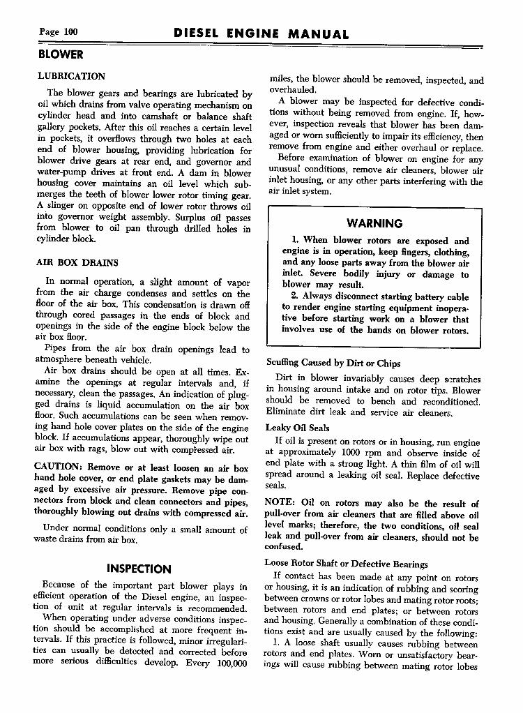
Page 100 DIESEL ENGINE MANUALBLOWER
LUBRICATION
The blower gears and bearings are lubricated byoil which drains from valve operating mechanism oncylinder head and into camshaft or balance shaftgallery pockets. After this oil reaches a certain levelin pockets, it overflows through two holes at eachend of blower housing, providing lubrication forblower drive gears at rear end, and governor andwater-pump drives at front end. A dam in blowerhousing cover maintains an oil level which submerges the teeth of blower lower rotor timing gear.A slinger on opposite end of lower rotor throws oilinto governor weight assembly. Surplus oil passesfrom blower to oil pan through drilled holes incylinder block.
AIR BOX DRAINS
In normal operation, a slight amount of vaporfrom the air charge condenses and settles on theBoor of the air box. This condensation is drawn offthrough cored passages in the ends of block andopenings in the side of the engine block below theair box Boor.Pipes from the air box drain openings lead to
atmosphere beneath vehicle.Air box drains should be open at all times. Ex
amine the openings at regular intervals and, ifnecessary, clean the passages. An indication of plugged drains is liquid accumulation on the air boxBoor. Such accumulations can be seen when removing hand hole cover plates on the side of the engineblock. If accumulations appear, thoroughly wipe outair box with rags, blowout with compressed air.
CAUTION: Remove or at least loosen an air boxhand hole cover, or end plate gaskets may be damaged by excessive air pressure. Remove pipe connectors from block and clean connectors and pipes,thoroughly blowing out drains with compressed air.
Under normal conditions only a small amount ofwaste drains from air box.
INSPECTIONBecause of the important part blower plays in
efficient operation of the Diesel engine, an inspection of unit at regular intervals is recommended.When operating under adverse conditions inspec
tion should be accomplished at more frequent intervals. If this practice is followed, minor irregularities can usually be detected and corrected beforemore serious difficulties develop. Every 100,000
miles, the blower should be removed, inspected, andoverhauled.A blower may be inspected for defective condi
tions without being removed from engine. If, however, inspection reveals that blower has been damaged or worn sufficiently to impair its efficiency,thenremove from engine and either overhaul or replace.Before examination of blower on engine for any
unusual conditions, remove air cleaners, blower airinlet housing, or any other parts interfering with theair inlet system.
WARNING1. When blower rotors are exposed and
engine is in operation, keep fingers, clothing,and any loose parts away from the blower airinlet. Severe bodily injury or damage toblower may result.2. Always disconnect starting battery cable
to render engine starting equipment inoperative before starting work on a blower thatinvolves use of the hands on blower rotors.
ScuffingCaused by Dirt or Chips
Dirt in blower invariably causes deep scratchesin housing around intake and on rotor tips. Blowershould be removed to bench and reconditioned.Eliminate dirt leak and service air cleaners.
Leaky Oil SealsIf oil is present on rotors or in housing, run. engine
at approximately 1000 rpm and observe inside ofend plate with a strong light. A thin film of oil willspread around a leaking oil seal. Replace defectiveseals.
NOTE: Oil on rotors may also be the result ofpull-over from air cleaners that are filled above oillevel marks; therefore, the two conditions, oil sealleak and pull-over from air cleaners, should not beconfused.
Loose Rotor Shaft or Defective BearingsIf contact has been made at any point on rotors
or housing, it is an indication of rubbing and scoringbetween crowns or rotor lobes and mating rotor roots;between rotors and end plates; or between rotorsand housing. Generally a combination of these conditions exist and are usually caused by the following:l. A loose shaft usually causes rubbing between
rotors and end plates. Worn or unsatisfactory bearings will cause rubbing between mating rotor lobes

DIESEL ENGINE MANUAL Page 101
at some point or perhaps allow rotor assemblies torub blower housing. This condition will usually showup at end of rotors at which bearing has failed.2. Excessive backlash in blower timing gears usu
ally results in rotor lobes rubbing throughout theirentire length.To correct either of the above conditions the
blower must be removed from engine, and eitherrepaired or replaced.
Broken or Cracked PartsIf inspection reveals any defective parts, blower
should be repaired before operation.
Noisy or Jammed BlowerIf blower develops a harsh metallic sound, clear
ances have taken up and adjustments or repairs arenecessary. If blower does not turn over, do NOTattempt to run engine. Remove blower for overhaul.
Defective Blower DriveOperate engine at idling speed. Defective coupling
will cause loose rattling sound within blower.
NOTE: A loose water pump coupling will sometimescause a similar noise. Check movement of rotors atlobe tips. Rotors should move 3/s" to 5/s" with aspring-like action. When released, they should springback at least 1,4". If this test indicates necessity,repair coupling as instructed in GEAR TRAIN section of this manual.
Rotor ClearancesBlower clearances are given in figure 24. If rotors
bind on feeler in any of the following tests, blowermust be removed, disassembled, and repaired. Makepreliminary check of rotor lobe clearance as follows:
1. Insert feeler between lobes of rotors as shownin figure 25 for "C" clearance, and as shown infigure 26 for "CC" clearance.NOTE: When checking "C" clearance, do not insertfeeler too far as "CC" clearance will be obtainedinstead. Also, when measuring clearances greaterthan .005," laminated feelers made up of .002",.003" or .005" are more practical than one singlethick feeler.2. Turn engine slowly with bar while feeler posi
tion is changed to located tight spots. Check clearance at several points along length of each rotor.
3. Now insert feeler between lower rotor andhousing to check for "D" clearance.4. Insert feeler between upper rotor and housing
to check for "D" clearance in same manner.
BLOWER
REMOVALRemoval of the blower assembly together with
governor drive, water pump, fuel oil pump, andblower drive shaft cover, will be found advantageousin most cases. For removal of this assembly thefollowing may be used as a guide:
1. Drain water from cooling system as instructedin manual covering respective vehicle.2. Remove the governor control housing assembly
as directed in respective GOVERNOR in FUELSYSTEM section of this manual.3. Disconnect fuel lines at fuel pump.4. Remove water pump connections at oil cooler
and cylinder block as directed under WATER PUMPin COOLING SYSTEM section of this manual.5. If engine is equipped with the hand control
emergency stop, disconnect Bowden wire control atvalve shaft lever-located at lower rear corner ofblower air inlet housing. If engine is equipped withelectrically operated stop solenoid, disconnect wires.6. Remove air cleaners and blower air inlet
housing, including striker plate and blower screenwhich are mounted between inlet housing andblower.7. Loosen blower drive tube seal clamp. Remove
retaining cap screws at top and bottom of blowerhousing.8. Raise front end of blower slightly to clear water
pump to oil cooler connection. Then pull blowerassembly (including accessories) forward withdrawing blower drive shaft cover and seal on drive gearhousing. Remove drive shaft from coupling attachedto blower upper rotor timing gear.
DISASSEMBL Y
TOOLS REQUIREDCertain special tools are required for disassembly
and assembly of blower. For information relative tovendor of such tools, refer to SPECIAL TOOLSsection of this manual.
ACCESS0RY REMOVALAfter the blower assembly has been removed from
engine, the various accessories may be removed asfollows, before the blower is disassembled.
1. Remove cap screws attaching fuel pump toblower end cover plate, then remove fuel pump anddrive coupling.2. Remove cap screws attaching blower drive shaft
cover to blower cover plate, then remove cover.

Page 102
BLOWERDIESEL ENGINE MANUAL
Figure 5-Removing Water Pump Coupling Screw
3. Remove cap screws attaching water pump toblower cover plate, and remove pump by tappingpump housing lightly with copper hammer.
4. Remove six cap screws attaching governorweight housing to blower cover plate, and withdrawgovernor drive shaft and weight housing from blowerrotor shaft.
DISASSEMBLY PROCEDURES
Clean exterior surfaces of blower. Do not use ahot solvent which may destroy oil seals. Mark endof blower housing and end plates so that unit maybe assembled correctly. Disassemble blower in following manner: Refer to figures 2, 3, and 4.
Figure 6-Removing Blower Reduction Gears'(Reduced Speed Blowers'
Remove End Covers
Remove ten cap screws in each end cover, andpull cover off dowels at top and bottom of boltBange. Do not pry between cover and end plate,as this will damage gasket surfaces.
Remove Water Pump Coupling
Using a %6" Allen Wrench, loosen bolt, at centerof front end of blower lower rotor shaft, and withdraw water pump coupling from shaft. lRefer tofigure 5.
Remove Drive Shaft Hub
Remove capscrews retaining drive shaft hub,spacers and drive plates on drive gear. Tap hub toloosen and remove.
Remove Gear Retainers
Wedge folded cloth between rotors to preventrotors turning. At upper and lower drive gears removegear retaining screw, locking washer, and retainingwasher.
Remove Drive or Rotor Gears
1. On reduced speed blowers, used on '''E'' and"T" Series engines, install puller tool 6270-1 oneach gear in manner illustrated in figure 6, thenpull gears from rotor shaft. Gears can be removedseparately if desired.2. Install puller tool 6270-1 at each rotor drive
gear in manner illustrated in figure 7, then tumpuller bolts uniformly so that both gears a:re withdrawn from rotor shafts simultaneously.
figure 7-Removing Blower Rotor Gears

DIESEL ENGINE MANUAL Page 103
3. Remove shim pack (if used) from each rotorshaft and tag for identification, so that they can bereplaced in their original location.
Remove Bearing RetainersRemove three cap screws and lock washers at
each rotor shaft bearing retainer, then remove retainers.
Remove End Plates1. Loosen (do not remove) two fillister head
screws attaching front end plate to housing.2. Install puller tool J-6270-1 at rear end plate in
manner illustrated in figure 8.3. Tum puller screws evenly and alternately until
front end plate is loose.4. Remove two fillister head screws attaching
rear end plate to housing.5. Turn puller screws evenly and alternately until
rear end plate is removed.6. At blower front plate, remove the two fillister
head screws which were previously loosened.7. Install puller tool J-6270-1 at front end plate,
then tum puller screws evenly and alternately untilfront end plate is removed.
Remove RotorsIn most instances rotors may be pulled out of
housing, however a burr sometimes may interfere.If necessary, remove burrs so that rotors can be removed without interference.
Remove Seal Ring and Carrier1. Use special pliers to spread seal ring and per
mit removal from ring carrier (fig. 9).
Figure 8-Removing Slower End Plales
BLOWER
Figure 9-Removing Seal Ring
2. If inspection indicates necessity, remove sealring carriers from rotor shaft by use of puller J-6270-1and adapter J-6270-2. Application of tools is illustrated in figure 10.
Remove Seal and Bearing
NOTE: Removal of seal collar (or rubber seal) isnot necessary unless leaks are indicated. However,if rubber seal is brittle or charred, or if seal collaris worn these parts must be replaced.
Support end plates on wood blocks in arbor presswhile bearing, collar (or rubber seal) are pressedfrom plate. Use remover tool J-6270-3 in mannerillustrated in figure 11.
Figure J O-Removing Seal Ring Carrier

Page 104 DIESEL ENGINE MANUAL
BLOWER
Figure II-Removing Sea' Collar (or LipType Sea"and learing from End "at.
INSPECTION(On Bench)
After blower has been completely disassembled,remove old gaskets and clean all parts thoroughly.DO NOT use wire brush or emery cloth. Blowerparts must be handled carefully as aluminum partsare easily dented or burred.
HousingRotor bores must be smooth; end plate flanges
must be smooth and Hat. Cylinder block flange mustbe Hat. Remove all rough spots or burrs with finemill file or scraper. Replace housing if badly scored,warped or cracked.
Rotor AssembliesRotors must be smooth without burrs. All shafts
must fit TIGHTLY in rotors. Rotor shaft pins must
Oil Seal
TP 4242
Figure J 2-0versize 1i,. Type Oil Sea' and RotorShaft Spacer 'nstalled
be tight in rotors. Internal splines in front rotor shaftsmust not be excessively worn. Oil seal wiping surfaces on shafts must be smooth without sharp edges.Remove all high spots and burrs from rotors withfine mill file or scraper. Replace rotor assembles ina scored condition, or with loose shaft, pins, or badlyworn shaft splines.
Bearings
When washed clean and lubricated with light oil,bearings should roll smoothly. Replace loose, rough,or over-heated bearings.
Rotor Gears
Maximum allowable backlash is .004". Teeth mustbe in good condition and splines not worn. Use newgears if these conditions do not obtain.
Oil Seals
Seal lip must be smooth, pliable and leak-proof.Replace all oil seals which have been removed fromend plates, or are brittle thin or cut. On blowersusing piston ring type seals, inspect ring type sealbushing in end plate and replace if rough or worn.Also, inspect seal ring and ring carrier at rotor shaftfor wear or damage and replace if necessary.
End Plates
End plates must be free from cracks (check closelyabout bearing bosses and bearing retainer bolt holes.)Flat faces of plates must be true, smooth and unscored. Counterbores for bearings must not be wornor ridged. Bearings must fit counterbore with lightpush or tap fit. Oil seals must not project above Hatsurface of end plate. Remove all burrs or minor localscore marks by filing or scraping CAREFULLY.Replace plates that are cracked, badly scored, distorted, or have worn bearing counterbores.
SPECIAL SEAL AND SPACERINSTALLATION
NOTE: The following information is applicable onlyto lip type Hexible seals.In some instances blower inspection may reveal
that seal contact surface at blower rotor shaft isworn and unsatisfactory for further use. In suchinstances a special spacer and oil seal is availableand may be installed to permit further use of suchrotor and shaft assemblies. Proceed as follows:1. Inspect rotors, which have shaft end seal sur
faces worn, to be sure they are otherwise in usable

DIESEL ENGINE MANUAL Page 105
condition. If so, remove burrs and roughness fromend shaft, but do not grind.2. Press special spacer on rotor shaft until outer
edge of spacer is flush with the bearing shoulderusing J6270-6installing tool (fig. 12). Spacer shouldbe .001" press fit on shaft. Use caution when pressing spacer on shaft to prevent distortion of rotorwhere shaft is pinned in place.
3. Install special seal in same manner as describedfor standard seal, except that special installing tool(11682-13) should be used.
BLOWER ROTOR SHAFT REPLACEMENTIn the past, whenever the rotor drive shaft serra
tions became worn it was necessary to replace thecomplete rotor. Method of removing and installingthe rotor shaft is described in the following paragraphs.
REMOVAL
1. Remove core plug in rotor lobe directly opposite visible tapered pin hole.2. Drive tapered pin back as shown by dotted
lines in figure 13,then, bend and repeat process untilpin drops into rotor body.3. Remove plug from rotor shaft by driving plug
thru into rotor body.4. Clamp rotor assembly firmly in vise, using soft
wood blocks to prevent damage to rotors.5. With segments held in retracted position insert
puller shaft into stub shaft until segments are beyond stub shaft splines. (Figure 13).
TP·6458
Figure J 3-Blower Rotor Shaft Removal
BLOWER
6. Slide expander tube over puller shaft and pushsegments onto large diameter of puller stud, thenremove expander tube.
7. Install puller spacer over puller shaft also installpilot washer and puller nut. Coat threads and pilotwasher with extreme pressure lubricant.8. Tum puller nut until stub shaft is pulled from
rotor. (Nut torque may reach 100 ft. lbs.)9. Shake core plug and stub shaft plug from rotor.
INSTALLATION1. Coat the shaft with lubriplate to facilitate easy
installation. Press new shaft and plug assembly toheight of installing spacer.2. Drill and ream new pin hole (.250 dia. ~"
deep) 1200 from existing pin hole. Drive new pininto hole until ¥l6" below rotor surface.3. Install new core plug in rotor lobe.4. Stake pin and core plug to prevent loosening.
Remove any existing raised burrs.
ASSEMBLYBlower assembly must be made on a clean bench,
with all clean parts, in the followingmanner:
INSTALL SEAL RING AND CARRIERL Position seal ring carrier over end of rotor
shaft, then use tool J-6270-4and hammer in mannerillustrated in figure 14, to drive carrier solidly intoplace.2. Use special pliers to spread seal ring sufficiently
to permit installation in ring carrier groove. Referto figure 9.
Figure J4-In.tollin.Se.I Ii,.. Carrier

Page 106 DIESEL ENGINE MANUAL
BLOWER
figure J 5-lnstalling Oil Seal Collar in End Plat.
INSTALL PLATE SEAL1. Support end plate on wood blocks in arbor
press and using replacer tool J-6270-4 press sealcollar (Fig. 15) into plate until tool bottoms againstplate. Use of tool properly locates collar the required 0.002" to 0.008" below surface of plate.Taper, at inner diameter of collar, must be towardinside.
SEMI·CIRCULARTOP
OIL RETURNHOLESLEADINGFROM BLOWERTIMING GEARS
TO CRANKCASETP 3805
figure J 6-810wer End Plate
TOP FLANGE OFBLOWER
TP 3806
figure J 7-Po$ition of BlowerfrontEnd Plate-RC, RD
2. Lip type rubber seals are installed in the samemanner as described above for ring type seals, except; that replacer tool J-6270-3 must be used. Lipof seal must be toward outside.
INSTALL FRONT END PLATEThe top of the blower housing may be identified
by the flange which extends along the top of thehousing and provides a rest on top of the cylinderblock. The end plate is semi-circular at the top, asshown in figure 16 and is also marked "TOP" onouter, ribbed side.When viewing blower housing from cylinder block
(outlet) side, the end plate for the front will beassembled to the right-hand end of the housing forRB, and LA model engines, and to the left-hand endfor Re, and RD model engines, as shown in figures17 and 18.With these identifications clearly in mind, proceed
as follows:1. Start end plate dowels in dowel holes of blower
housing. Rap dowels and end plate lightly withbabbitt hammer to fit end plate to housing.NOTE: No gaskets are used between end plates andhousing, therefore mating surfaces must be perfectlyHat and smooth.
2. Lock end plate securely to housing with twofillister head screws. No lock washers.
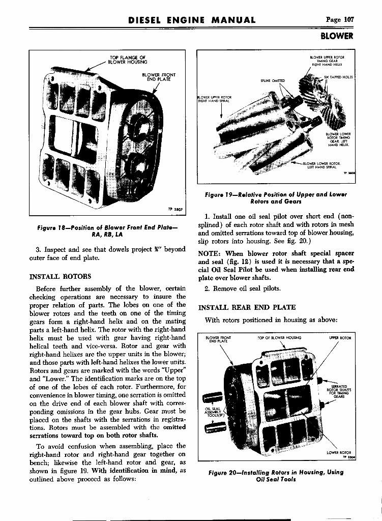
DIESEL ENGINE MANUAL Page 107
TOP FLANGE OFBLOWER HOUSING
TP 3807
Figure J 8-Position of Blower Front End PlateRA, RB, LA
3. Inspect and see that dowels project ~" beyondouter face of end plate.
INSTALL ROTORS
Before further assembly of the blower, certainchecking operations are necessary to insure theproper relation of parts. The lobes on one of theblower rotors and the teeth on one of the timinggears form a right-hand helix and on the matingparts a left-hand helix. The rotor with the right-handhelix must be used with gear having right-handhelical teeth and vice-versa. Rotor and gear withright-hand helixes are the upper units in the blower;and those parts with left-hand helixes the lower units.Rotors and gears are marked with the words "Upper"and "Lower." The identification marks are on the topof one of the lobes of each rotor. Furthermore, forconvenience in blower timing, one serration is omittedon the drive end of each blower shaft with corresponding omissions in the gear hubs. Gear must beplaced on the shafts with the serrations in registrations. Rotors must be assembled with the omittedserrations toward top on both rotor shafts.To avoid confusion when assembling, place the
right-hand rotor and right-hand gear together onbench; likewise the left-hand rotor and gear, asshown in figure 19. With identification in mind, asoutlined above proceed as follows:
BLOWER
BLOWER UPPERROTORTIMING GEAR
RIGHT HAND HELIX
Figure J 9-Relative Position of Upper and LowerRotors and Gears
1. Install one oil seal pilot over short end (nonsplined) of each rotor shaft and with rotors in meshand omitted serrations toward top of blower housing,slip rotors into housing. See fig. 20.)
NOTE: When blower rotor shaft special spacerand seal (fig. 12) is used it is necessary that a special Oil Seal Pilot be used when installing rear endplate over blower shafts.2. Remove oil seal pilots.
INSTALL REAR END PLATE
With rotors positioned in housing as above:
BLOWER FRONTEND PLATE
TOP OF BLOWER HOUSING UPPER ROTOR
Figure 20-lnstalling Rotors in Housing, UsingOil Seal Tools

Page 108 DIESEL ENGINE MANUAL
BLOWER
BLOWER FRONTEND PLATE
TOP OF BLOWER HOUSING BLOWERREAR END
PLATE
LOWER ROTOR TP 3810
Figure 21-Use of Oil Seal Tools When InstallingRead End Plate
1. If lip type seals are being used, install one oilseal pilot over serrated end of each rotor shaft. (Seefig. 21.)2. Identify top and bottom of end plate as pre
viously described, and shown in figure 17, start endplate dowels into dowel holes in blower housing. Tapdowels lightly to fit end plate to housing.3. Lock end plates securely to housing with two
fillister head screws. No lock washers.4. Inspect and see that dowels project "" beyond
outer face of end plate.5. Remove oil seal pilots, if used.
INSTALL FRONT BEARINGS
Straight roller bearings are used at the front endof the blower rotor shafts and double-row ball bear-
Figure 22-lnstalling RotorShaft Bearings
ings at the rear (serrated) end. The bearing numberis stamped at one end of the ball race only. Whenassembling the markings are away from blowerhousing. Straight roller bearings are installed withside having inner and outer races flush toward theoil seal.1. Start the straight roller bearings onto front end
of rotor shafts (short end with internal splines).2. Using tool J6270-4 shown in figure 22, tap bear
ings into end plates.NOTE: When installing straight roller bearings it isrecommended that the inner and outer races bepressed alternately to prevent damage to bearingassembly.
3. Retainers for straight roller bearings are flatand can be installed with either side toward bearing.Lock each retainer with three cap screws and lockwashers.
INSTALL REAR BEARINGS
Install the rear rotor shaft bearings in exactly thesame manner the fronts were installed except usetool J6270-7. Be sure markings on bearing race areaway from blower housing.NOTE: Rotor to housing and rotor to end plateclearances may be checked at this time, as describedunder "Rotor Timing and Clearances" later in thissection.
INSTALL ROTOR GEARS
If blower onee used is being reassembled shimswere no doubt used back of one, or perhaps bothblower rotor (timing) gears-they should be installed
Figure 23-lnstalling Blower RotorGears

DIESEL ENGINE MANUAL Page 109
BLOWER
B A GEAR END
SERlEl A B C CC D EMIN• •007 .007 .012 .002 .016 .004
3-71MAX. .006MIN• •007 .009 .014 .002 .016 .004
4-71MAX. .006MIN• •007 .014 .014 .002 .016 .004
6-71MAX .006nME ROTORSTO DIMENSIONSABOVECHECK"CC" CLEARANCEFROMBOTHINLETAND OUnET SIDEOF BLOWER
·IMPORTANT:Wh.n ch.cklng rotor clearanc•• on .... uced ratioblowera, it il ntial to remember that "C" and "ee" clearanc••a.. tho .. v of .tondarel blow.... In other worel. Ihe "CC" clear-anc. I. tok.n betw•• n leading .Id. of upp.r rolor and trailing .Id.of blower rolor, In.tead of botw.. n trailing .Id. of upper rotor andloading .Id. of low.r rotor, a. In .tondarel blow....
LEFT HAND BlOWERRA_ RB, LA AND LBENGINEMODELS
RIGHT HAND BLOWERRe. RD, LC AND LDENGINEMODELS
"0" liE"
·"C'liD' uE"
110' liE" liD"
·"CC'
"0' uD"
AU VIEWSFROMREAROF ENGINETPM·2831·2
Figure 24-Diagram of Blower Clearances
in their original positions before pressing gears ontoshafts. If new gears or rotors are used, assemble without shims, and use later if necessary when timingrotors.
NOTE: Rotor timing gears are matched. Replace asa complete set when necessary.
1. Be sure that both rotor shafts with the omittedserrations, as shown in figure 19, point toward topof blower; that the gear with six tapped holes in hub,is located on the upper rotor shaft; and, if old partsare being reinstalled that original shims are placedon their respective shafts.2. Start both gears onto shafts with omitted serra
tions on shafts and gears registering. An "0" mark isindented into end of shaft at omitted serration toassist in locating gears properly.
CAUTION: Gears must be pressed to position at thesame time to avoid damage to gears and rotors. Donot pull gears up tight if rotors are in contact.
3. Attach blower gear installing tools J-6270-6and J-6270-7with puller screws J-6270-8and J-6270-9threaded into blower shafts as illustrated in figure23. Install lower gear first until ;!$" of splines protrude.4. Turn puller screw nuts evenly and alternately
until gears are tight against bearing inner races.Torque puller screw nuts to 55-65 ft. lbs, to be surethat gears are fully seated.
ROTOR TIMING AND CLEARANCES
At this stage of the blower assembly, the blowerrotors must be timed.The three lobes on each blower rotor are spiral
(helical) relative to the center line of the rotor shaft.The teeth on the timing gears are also helical, and,as previously stated, the rotor with the right-handhelical lobe is driven with a gear having right-handhelical teeth (fig. 19).

Page 110 DIESEL ENGINE MANUAL
BLOWER
Checking "c" Clearance on StandardSpeed Blowers or "CC" Clearance onReduced Speed Blowers at Inlet Side TPM-4611
Figure 25-Checking RotorClearance
Checking "c" Clearance on StandardSpeed Blowers or "CC" Clearance onReduced Speed Blowers at Outlet Side TPM-461 3
Figure 27-Checking Rotor Clearance
The blower rotors, when properly positioned inthe housing, run with a slight clearance between thelobes. This clearance may be varied by moving oneof the helical gears in or out on the shaft relative tothe other gear.If the upper gear is moved out, the upper rotor
will tum counterclockwise when viewed from thegear end. If the lower gear is moved out, the lowerrotor will tum clockwise when viewed from thegear end. This positioning of the gear, to obtain theproper clearance between the rotor lobes, is knownas Blower Timing.
Moving the gears OUT and IN on the rotors isaccomplished by adding or removing shims betweenthe gear hub and the bearing back of the gears.
Checking "CC" Clearance on StandardSpeed Blowers or "c" Clearance onReduced Speed Blowers at Inlet Side TPM-4612
Figure 26-Checking RotorClearance
Checking "CC" Clearance on StandardlSpeed Blowers or "c" Clearance onReduced Speed Blowers at Outlet Side TPM-4614
Figure 28-Checking Rotor Clearance
Blower rotors to be efficient must rotate within theclearance specified in figure 24. Check and timeblower in the following manner:IMPORTANT: ~EN CHECKING ROTORCLEARANCES ON REDUCED RATIO BLOWERS(FIG. 3), IT IS ESSENTIAL TO REMEMBERTHAT "C" AND "CC" CLEARANCES ARE THEREVERSE OF STANDARD BLOWERS. INOTHER WORDS THE "CC" CLEARANCE ISTAKEN BETWEEN LEADING SIDE OF UPPERROTOR AND TRAILING SIDE OF LOWERROTOR, INSTEAD OF BETWEEN TRAILINGSIDE OF UPPER ROTOR AND LEADING SIDEOF LOWER ROTOR, AS IN STANDARDBLOWERS.

DIESEL ENGINE MANUAL Page 111
ROTOR TO ROTOR CLEARANCES"C" AND "CC"
Rotor lobe clearance is greater between the leading side of the upper rotor and the trailing sideof the lower rotor, than between the trailing side ofthe upper rotor and the leading side of the lowerrotor. These clearances are designated as "C" and"CC" respectively. Refer to figure 24 for specifiedclearances and to figures 25, 26, 27, and 28 formethod of checking.
NOTE: Do not insert feeler too far when checkingCCC"clearance, or "CC" clearance will be measured.(See fig. 25.) Also when measuring clearancesgreater than .005", laminated feelers made up of.002", .003", or .005" are more practical than a singlethick feeler. Adjustment is made as described under"Adjust Rotor Clearance" in text following.
ROTOR TO HOUSING CLEARANCE "D"AND "E," (FIG. 24).
This clearance is not adjustable. If rotors bind,disassemble to determine cause.
ROTOR TO END PLATE CLEARANCE"A" AND "B"
Insert feelers between end of rotors and endplates. Determine minimum distance. This operation
Leading SidelUpper Rotor j
Trailing SideLower Rotor
BLOWER
must be performed at the ends of each lobe making12 measurements in all. Refer to figure 24 for dimensions. This clearance is not adjustable. If rotors bind,disassemble to determine cause.
ADJUST ROTOR CLEARANCEAdjustment is made by removing or adding shims
behind either upper or lower gear. Refer to figures25, 26, 27 and 28. Check clearances at several pointsalong the length of each rotor lobe. Always determine point of minimum clearance and adjust forthat point.
NOTE: Three .002" thickness shims are required torevolve rotor .002".
Having determined the amount one rotor mustbe revolved to produce the proper clearance observeengine model on which the blower is to be usedand add shims back of either the upper or lowergears, as shown in figure 29, to produce the desiredresult.When additional shims are required, both gears
must be pulled from the rotors, as directed under"Remove Rotor Gears" previously in this section.Install the required thickness of shims back of the
proper gear and next to the bearing inner race, andagain press the gears tightly in place. Recheck clearances between rotor lobes.
{Shim Top GearTo Increase
Clearance Here
Figure 29-Diagram Showing Proper Location of Shims for Correct Rotor Lobe Clearances
TPM·4610

Page 112 DIESEL ENGINE MANUAL
BLOWER
Figure 30-Installing Blower Reduction Gears(Reduced Speed BlowersJ
COMPLETE mE ASSEMBLY
Install Reduction GearsThe following information is applicable only to
reduced ratio blowers, shown in figure 3.1. Position lower reduction gear on splined rotor
shaft, making sure that wide serration on gearmatches missing serration on shaft.2. Use J-6270-7 installer and J-6270-8 screw to
force lower reduction gear (fig. 30) solidly againstinner drive gear.3. Install double row ball bearing in upper re
duction gear. Use J-6270-7 installer and J-6270-8screw to force upper reduction gear bearing againstupper drive gear.
Secure GearsSecure gears in place by installing special locking
washer and retaining 'washer with washer lugs engaging slots in gear hub and lock washer ears engaging washer and cap screws.
Install Fuel Pump CouplingInstall locking plate and fuel pump coupling
disc on retaining bolt with tangs of disc engagingslot in gear hub and locking plate ear engaging slotin coupling disc. Tighten retaining bolt to recommended torque.
Install Drive HubAssemble plate to hub using special cap screw,
lock washer and Hat washer between plate and lockwasher. Attach plate to gear using spacer between
gear and plate also Hat washer between plate andlock washer.
Install Water Pump CouplingInsert splined end of water pump intermediate
shaft and coupling into front end of lower rotor shaftand hold coupling tight against end of shaft whiletightening Allen screw securely with =%6" wrench.
Install End Plate CoversInstall a new gasket to each blower end plate
cover. Attach both end plate covers using cap screwsand washers.NOTE: Foreign matter inside the blower will ruinthe unit. Mter blower has been assembled, temporarily attach the gasket and cover over the air openings of the blower housing to prevent foreign matterentering blower.
INSTALL ACCESSORIESTime may be saved and operations simplified if
the various accessories are assembled to blowerbefore the unit is attached to engine.
1. Install a new gasket to bolting flange of thegovernor weight housing, and slip governor shaftstraight into serrations at front end of blower upperrotor shaft. Secure finger tight only to front coverwith lock washers and cap screws.2. Install new gasket to water pump bol~ flange,
and with intake for pump pointing toward-bottomof blower, slide water pump into position at frontof blower lower rotor shaft, with driving lugs onpump shaft registering with driving lugs on rotorshaft. Lock securely to cover with lock washers andcap screws.3. Using new gasket and lock washers with cap
screws, attach blower drive shaft cover to blowerrear cover at upper rotor shaft.4. The fuel pump is driven by a "U"-coupling
from the squared-end of the pump shaft. The pumpcover is marked at the pump intake. The markingsshown should always be set next to the cylinderblock.CAUTION: Be sure driving fork is fully on fuelpump shaft. .
5. Install a new gasket to pump bolting flange.With pump drive coupling on pump shaft so thatarms are directed away from pump, and intake anddischarge openings at bottom and markings on pumpcover toward cylinder block, attach pump to lowerrear cover at lower rotor shaft, using lock washers

DIESEL ENGINE MANUAL Page 113
and cap screws. Do not force pump into place. Suchtreatment is not necessary if the drive couplingregisters with mating member on rotor shaft.
INSTALLATIONAttach blower assembly including blower, fuel
pump, blower drive shaft sleeve, water pump, andgovernor weight housing to cylinder block in thefollowing manner: •
1. Before attaching to engine, examine inside ofblower for any foreign material and revolve therotors by hand for smooth operation. Rough particlesin blower may score rotors and impair blowerefficiency. Install a new gasket to cylinder block atblower pad.2. Slip water pump outlet packing flange-flat face
out-and packing over pump discharge, also hoseclamp and seal over pump inlet.
CAUTION: The blower will slide into positioneasily if the blower drive shaft serrations are linedup with the mating serrations in the blower rotor
BLOWER
shaft. Do not force the blower assembly into position and damage the serrations on the blower shaft.
3. Check carefully and note if blower drive shaftis in position inside of blower drive flexible coupling.Avoid damage to gasket at blower pad on cylinderblock.4. Slide the blower assembly into position with
blower drive shaft registering with serrations indrive shaft flange,and shaft sleeve and seal assemblysliding over blower drive gear housing. Attachblower housing securely to cylinder block withwashers and cap screws. Tighten drive shaft sleeveseal retainer clamp.5. Connect water pump intake to oil cooler
housing and cylinder block.6. The fuel line from the primary filter connects
to the intake (opening nearest to cylinder block) ofthe fuel pump and the discharge from the pumpleads to the intake of the secondary filter. With theseitems in mind, attach fuel lines to pump.7. Install governor as directed in respective "Cov
ernor" under FUEL SYSTEMsection of this manual.

Page 114 DIESEL ENGINE MANUAL
Diesel Fuel Oil Should Meet Specifications Recommended in Service Bulletins, Which Will Be Furnished Upon Request.
Use Care in Storing and Dispensing Diesel Fuel toPrevent Contamination by Dirt and Water.

DIESEL ENGINE MANUAL Page 115
CONTENTS OF THIS SECTION
SubjectFuel Oil Recommendations.Fuel Injectors ..Fuel Pump
Page. .... 115
.118.... 136
DESCRIPTIONFuel system includes fuel pump, fuel filters, fuel
lines, fuel oil manifold, and injectors.Fuel is drawn from vehicle fuel tank, through
primary filter by the fuel pump which is driven fromrear end of blower lower rotor shaft. From thepump, fuel is forced through secondary filter and tofuel intake manifold which supplies the injectors.Surplus fuel, flowing through injectors, is returnedthrough fuel outlet manifold to vehicle fuel tank.To insure combustion, a small quantity of accur
ately metered; finely atomized fuel must be mixed,at the end of the compression stroke, with the chargeof air which has been forced into the cylinder by the
SubjectFuel Manifolds ..
Page. 140...... 142
.152.. 162
Fuel-Modulating GovernorLimiting Speed Governor.Limiting Speed Governor-Economy Range ..
blower. This is accomplished by a high-pressure fuelinjection device called an injector.Before injection can be effected, the fuel pressure
must be higher than that of the air charge in thecombustion chamber. Consequently, the fuel injectorperforms a quadruple duty: 1st, metering and injecting fuel; 2nd, creating high fuel pressure; 3rd, atomization; 4th, continuous by-pass of fuel through theinjector body which acts as a coolant and alsoeliminates air pockets. The unit fuel injector, developed by General Motors and used in these engines, combines in a single unit all parts necessary toperform the above functions, thus providing a complete and independent injection system for eachengine cylinder.
FUEL OIL RECOMMENDATIONSIt is recommended that only completely distilled
fuel oil, such as number one grade fuel oil or kerosene be used, because, residual (undistilled) fuel oilcontains high amounts of sediment and sulphur.
SELECTION OF FUELSelection of fuel is a very important factor in the
successful operation of Diesel engines in coach andtruck service. Good quality and suitability of the fueloil will lead to economical and satisfactory performance in the over-all operation and maintenance program. Quality however, is the responsibility of theindividual refiner or marketer. Therefore, his reputation is the best indication of quality.
FUEL CHARACTERISTICS
Cetane NumberThe cetane number of a fuel oil is an index to its
ability to burn smoothly and start easily, bothimproving with an increase of the cetane number.Ignition quality of a Diesel fuel can be accurately
determined only by an engine test. Although 45minimum cetane number is approved for fuels foruse in GM Diesel engines, higher cetane fuels aredesirable from the standpoint of smooth operationand easy cold starting.
Pour PointPour point of a fuel is of importance with respect
to bulk handling, pumpability in engine, and fuelfilter performance. Pour point and cetane numberare sometimes related, low pour points often indicating low ignition quality. The pour point shouldtherefore not be specified lower than necessary, although for best results it should be at least lOoF.below the lowest atmospheric temperature to whichthe fuel will be exposed for any considerable lengthof time.
VolatilityVolatility of a fuel oil determines degree to which
vaporization takes place before injected fuel ignites.Fuel cannot ignite and burn cleanly until vaporized.

FUEL OIL
DIESEL ENGINE MANUALPage 116
figure J -Do not Store fuel Oil inUnprotected Containers
Normally, temperatures of air within combustionchambers are high enough for complete vaporizationbut incomplete vaporization is liable to occur during cold weather, light load operation or duringperiods of idling. Fluid fuel drops impinging on therelatively cool combustion chamber walls will causeincomplete combustion accompanied by blue ordark gray exhaust smoke, and by formation of excessive deposits within the engine. Heavier fuels oflow volatility form deposits more rapidly than dolighter or highly volatile fuels.Suitability of the fuel depends, very much, on the
engine operating conditions. When frequent speedand load changes are encountered, cleaner burningfuels should be chosen rather than those satisfactoryfor constant speed operation.
Storage and Handling
It is important that extreme care be exercised inthe handling and storage of all diesel fuel oil, asabsolute cleanliness is essential to satisfactory engineoperation. The following recommendations apply tothe storage and handling of diesel fuel.Wherever fuel oil is stored, adequate filtering
equipment should be provided. It is suggested thatthe fuel oil be specially filtered or strained betweenstorage tank and dispenser to remove all moistureand sediment.Approximately every ten days a hand pump should
be inserted in lowest portion of storage tank to remove accumulated water and sludge. Some layouts,for removal of dirt and water, may include a sludgecollection pan, eliminating need for hand pump.
~-' ......-.,N._
figure 2-Typical Approved Method ofOutside Storage
Should small amounts of water be carried intothe fuel system of an engine and remain there during a shut-down period, there is danger of corrodingfuel pump parts, injector plunger and bushings, andother parts of the fuel system. If a considerable portion of water is injected into the combustion chamber of an engine, power and performance will falloff and rough or irregular running may be noted.Pistons, exhaust valves and piston rings may becomecoated with deposits from erratic combustion due tothe water in the fuel. In winter there is also dangerof water in the system freezing and obstructing thepassage of fuel into the engine.Keep water out of the fuel oil by preventive main
tenance. Regularly drain the fuel filters and syphonor pump water from the storage tank. A few suggestions are:1. Buy fuel oil only from a reputable supplier.2. Have fuel oil delivered directly from truck to
tank, if possible.3. Drain, syphon or pump water caused by con
densation out of tank regularly.Delivery of diesel fuel oil in barrels or drums is
not as desirable as having the suppliers truck pumpthe fuel into the customer's large storage tank. Eventhough the barrels are clean, this necessitates extrahandling, additional containers, and added precautions, which are easily overlooked.Delivery of fuel oil in barrels is also more expen
sive as compared with delivery from tank truck tostorage tank.The least desirable method of receiving fuel oil
from the oil supplier is to have the fuel pumped

DIESEL ENGINE MANUAL Page 117
from the tank truck into the customer's upright barrels or drums (fig. 1). Clean fuel quickly becomescontaminated because of scale, dirt, and water whichcollects in fuel oil barrels over a period of time.Upright storage of fuel oil barrels is to be avoidedas much as possible since water will stand in thetops of the barrels after a rain or a snow and maylater seep into the barrel through the plugged opening, thus contaminating the fuel. Barrels used forsupplying daily fuel oil requirements should be
FUEL INJECTORS
stored horizontally, with the outlet end slightlyhigher than the other end, in order to allow sediment and water to settle out.If storing of fuel oil above ground is unavoidable,
operators are cautioned to use containers horizontallyand protect them as much as possible from weather(fig. 2). The last few gallons remaining in barrelsshould then be dumped into a separate collectingbarrel where accumulation can be allowed to settle,thus permitting salvage of useable oil.
FUEL INJECTORS
DESCRIPTIONAND OPERATIONThe cross section of the injector illustrated in fig
ure 5, shows the various fuel injector parts. Fuel oilsupplied to injector enters the drop-forged steel bodyat the top through the filter cap. After passing
NOINJECTION
IDLINGLOAD
HALFLOAD
FULLLOAD
TP 3812
Figure 3-Fuel Metering Produced byRotating Plunger
through the filter element in inlet passage, the fueloil fills the supply chamber between bushing andspill deflector. The plunger operates up and down inthis bushing, the bore of which is connected to fuelsupply by two funnel-shaped ports.
Motion of injector rocker arm is transmitted to
END OFINJECTIONSTROKE
BOTTOMOF
STROKE
TOPOF
STROKE
START OFINJECTIONSTROKE
Figure 4-lniector Operation by VerticalTravel of Plunger
---------- ------------- ----- . - -

FUEL INJECTORS
DIESEL ENGINE MANUALPage lI8
plunger by follower which bears against plungerspring. Follower is positioned in body by a followerstop pin. In addition to up and down motion, theplunger can be rotated, in operation, around its axisby gear, which is in mesh with control rack. Thefuel is metered by an upper helix and lower helixwhich are machined into lower end of plunger. The
relation of these helixes to the two ports changeswith the rotation of the plunger. As plunger movesdownward, fuel oil in high-pressure cylinder or bushing is first displaced through the ports back intosupply chamber until lower edge of plunger closesthe lower port. Remaining oil is then forced upwardthrough center passage in plunger into recess be-
1 Follower 14 Filter Element2 Follower Spring lS Filter Spring3 Follower Stop Pin 16 Gasket4 Gear 17 Filter CapS Gear Retainer 18 Identification Tag6 Plunger 19 Valve Seat
8 7 Spill Deflector 20 Valve8 Injector Nut 21 Valve Spring9 Plunger Bushing 22 Valve Cage10 Seal Ring 23 Valve Stop11 Dowel 24 Check Valve12 Rack 2S Spray Tip13 Injector Body
TPM-2361-1
(·~·'··l.'...·.'\"~-~ -,./'
18
Figure 5-Fuel In;ector Assembly Shows Fuel Flow (in RedJ

Page 119DIESEL ENGINE MANUAL
tween upper helix and the lower cut-off from whichit can still flow back into supply chamber until helixcloses upper port. Rotation of plunger, by changingposition of helix, retards or advances the closing ofthe ports and beginning and ending of injectionperiod, at the same time increasing or decreasingdesired amount of fuel which remains under plungerfor injection into the cylinder.
Figure 3 shows the various plunger positions fromNO INJECTION to FULL INJECTION. With control rack pulled OUT completely (no injection),upper port is not closed by helix until after lowerport in uncovered. Consequently, with control rackin this position, all of the fuel charge is forced backinto supply chamber, and no injection of fuel takesplace. With the control rack pushed IN completely(full injection), upper port is closed shortly afterlower port has been covered, thus producing a fulleffective stroke and maximum injection. From thisNO INJECTION position to FULL INJECTIONposition (full rack movement) the contour of thehelix advances closing of ports and beginning ofinjection.
FUEL INJECTORS
Figure 4 shows four positions for downward travelof plunger, rack fixed. On downward travel ofplunger, the metered amount of fuel is forcedthrough center passage of the valve assembly, throughcheck valve, and against spray tip valve. When sufficient fuel pressure is built up, valve is forced off itsseat and fuel is forced through small orifices inspray tip and atomized into the combustion chamber.Check valve prevents air leakage from combustion
chamber into the fuel system.On return upward movement of plunger, the high
pressure cavity at lower end of bushing is againfilled with fuel oil through the ports. Constant circulation of fresh, cool fuel through the injectors,which renews the fuel supply in the chamber, helpsto maintain even operating temperatures of injectors,and also effectively removes all traces of air whichmight otherwise accumulate in system and interferewith accurate metering of fuel.The fuel injector outlet opening, which returns the
excess fuel oil supplied by fuel pump, is directlyadjacent to inlet opening.Injector used in Series 7l-GM Diesel Engines
may be one of five different types, each designed for
Timing Metal Identification Tag Pressed
Injector Color 8pray Tip Plunger Dimension Into Recess In Injector Body
HV55 Orange 6-006-155-H 55 1.484"55E(+) Orange 8-0055-165 55 1.460"855(+) Orange 8-0055-165 55 1.460"-HV6 Blue 6-006-155-H 6H 1.484"(*)6E8 White 8-005-155 6H 1.460"60E(+) Blue 8-0055-165 6E 1.460"860(+) Blue 8-0055-165 6H 1.460"688(+) White 3-005-165 6ll 1.484"(*)
HV7 Black 7-006-155-H 7H 1.460"870(+) Black 7-006-155-H 7H 1.460"
HV8 Green 7-006-155-H 8H 1.460"880(+) Green 7-006-155-H 8H 1.460"
*Use 1.460" gauge when timing injectors used in "E" or"SE" engines.
-Offset body for use in 4-valve head.
TPM-6300-1
Figure 6-Fuel Injector Identification

Page 120
FUEL INJECTORS
DIESEL ENGINE MANUAL
a specific requirement. Refer to figure 6 for injectoridentifying marks. The correct injector must be usedand type can be determined by checking injectorin engine for number which appears on color tagpressed into body.
INJECTOR MOUNTINGThe injectors are mounted in the cylinder head,
with their spray tips projecting slightly below topof inside surface of combustion chambers as shownin figure 7. A clamp, bolted to cylinder head andfitting into a machined recess in each side of injectorbody, holds injector in place in a water-cooled copper tube which passes through cylinder head. Adowel pin in injector body registers with a hole
in cylinder head for accurately locating injectorassembly.A copper tube is installed in cylinder head with a
seal ring at flanged upper end. The lower end ispeened into a recess of the cylinder head. Thetapered lower end of injector seats in copper tube,forming a tight seal to withstand the high pressureinside combustion chamber.
INJECTOR SERVICE
Injector is one of the most important and carefully constructed parts of the engine. On this unitdepends the injection of the correct amount of fuelat exactly the right time into combustion chamber.Due to the fact that injector works against hiighcom-
RockerArm
Hold Down Clam
TPM-2748-1
figure 7-fuellniector and Operating Mechanism Installed
DIESEL ENGINE MANUAL Page 121
pression in combustion chamber, efficient operationdemands that all injector parts be maintained inclean, first-class condition at all times. This will necessitate the use of only clean fuel in injector, andintelligent care when servicing unit. No service operations should be attempted on injector withoutfirst acquiring a complete understanding of its construction and operation. This section of text thoroughly describes the working principle, shows theconstruction, and explains how to service unit.While a skilled mechanic may intelligently service
injectors, using the instructions in this section as aguide, time and expense may be saved by changingunit rather than attempting repairs especially in dirtysurroundings.
Before starting to dismantle an i.qector, it is necessary to have an extremely clean workbench onwhich to work and to store parts. Cleanliness for theinjector and its parts is emphasized because practically all injector service troubles are directly traceable to dirt, loose particles, grit, 01' other foreignmatter.When preparing to assemble an injector, it is ab
soiutely essential to wash the hands thoroughly anoto dean .111injector parts in either clean fuel oil orcarbon tetrachloride. Parts should then be blowndry by compressed air (filtered-free of dust andmoisture), making sure to blow through all passagesin injector body and all drilled holes, slots, etc., ininjector parts. Waste or rags should never be usedfor cleaning injector parts, since this would leave lintand other particles which could collect and clogparts of injector when assembled.
Toilet tissue is a good and inexpensive materialfor wiping an injector part, or on which to placeinjector parts after cleaning with liquid and blowing dry with air. After liquid wash and subsequentdrying with air, it is essential that parts be placedin a clean location until assembled. Clean, light oilshould be used liberally on injector parts duringassembly to protect them from rust in case injectoris not used immediately and to provide initial lubrication when engine is started.
CARE OF INJECTOR (When Replacing)Because of important part the injectors play in
operation of engine, the necessity for proper careand cleanliness of these units cannot be overemphasized. Instruoaons below should be carefullyfollowed:
1. Whenever the fuel lines are removed from aninjector which is installed in engine, protect the two
FUEL INJECTORSfuel fittings with shipping cap, part No. 5226414, toexclude dirt.2. Do not dismantle an injector in dirty surround
ings or on a dirty workbench. Use clean paper onthe bench, and, after parts have been removed frominjector, store loose parts in clean fuel oil as a protection against dirt and corrosion.3. With more than one injector disassembled, it
is not only good practice, but necessary, to keepparts of each injector separate. The plunger must befitted, always with the same bushing. It is advisableto keep the parts of tip assembly spring, stop, spraytip valve and seat, as a unit, as it insures that "pop"pressure and calibration built into injector will remain essentially the same as when it was first testedand assembled.4. After injectors have operated in an engine, the
filter caps or filters should not be removed from injector when injector is in engine. If filter caps orfilters are to be removed, injector must be completely disassembled and cleaned.5. Whenever an injector has been removed and
reinstalled, or a new injector installed in engine, theinjector must be timed and racks positioned. Referto "Control Rack Positioning" later in this section,also to "Timing Injector" in ENGINE TUNE-UPsection of this manual.
6. Whenever an injector is to be out of service foran extended period, the injector should be purgedas outlined under "Storing Injectors" later in thissection.7. Before installing any used or rebuilt injectors
in an engine, test each injector. See "Injector Tests,"later in this section.
INJECTOR REMOVAL
If it becomes necessary to remove one of the fuelinjectors for inspection or replacement, follow theprocedure given below:
1. Remove valve rocker cover.2. Remove fuel lines from both the injector and
the fuel connectors.
Immediately after removal of fuel lines from aninjector, the two fuel feed fittings should be protected with shipping cap, part number 5226414, toprevent dirt entering injector.
3. If necessary, crank engine with the starter ora bar at flywheel ring gear until the three rocker arm

FUEL INJECTORS
DIESEL ENGINE MANUALPage 122
7 Rocker Shaft Bracket8 Bracket Bolt9 Injector Control Tube
10 ShippingCaps11 Injector Assembly
1 Remover Tool2 Fuel Return Pipe3 Fuel Inlet Pipe4 Stud Nut5 Washer6 Injector Hold-Down
Clamp TPM·2363
Figure 8-Removing Injector from Cylinder Head
clevis pins, at outer end of arms, are in line.4. Loosen two rocker arm bracket bolts holding
brackets to cylinder head and swing rocker armassembly over away from valves and injector.5. Remove injector hold-down stud nut, special
washer, and injector clamp.6. Using tool as illustrated in figure 8, pry injector
from its seat.7. Lift injector from seat, at the same time disen
gage control rack linkage.
INJECTOR TESTS
After removing the injector from the engine andcleaning the exterior, inspect the injector. If inspection does not reveal any external damage, then aseries of tests may be made to determine the condition of the injector to avoid unnecessary overhauling.Use injector testing and popping fixture and injectorcomparator (if available), in determining the condition of the injector.An injector that passes tests outlined below may be
considered to be satisfactory for service without disassembly, other than the visual check of the plunger.
However, an injector that does not pass one or moreof the tests is unsatisfactory and the faults should becorrected. ALL OF THE TESTS should be performed before disassembling an injector to correctanyone condition.Identify each injector and record its pop pressure
and fuel output as indicated by the following tests:
CHECK INJECTOR RACK ANDPLUNGER MOVEMENTPurpose of the check is to see if plunger works
freely in its bushing and whether the control rackmoves back and forth freely.1. Free movement of a plunger may be checked
by placing the injector against a bench, as shownin figure 9, and depressing the follower to the bottom of its stroke while moving the rack back andforth. Failure to produce a free rack indicates thatthe internal parts of the injector are damaged ordirty. CAUTION: The injector must always be heldin such a way as to prevent any fuel spray frompenetrating the skin. Fuel oil which enters the bloodstream may cause serious infection.
VALVE OPENING (POP PRESSURE) TESTPurpose of the pop pressure test is to determine
the pressure at which the valve opens and injectionbegins.1. Place the injector in testing and popping fix
ture, figure 10, with dowel on underside of injectorlocated in the proper slot of the set. When testingoffset body injectors, install adapter plate on thetest fixture. Position injector support plate an-I popping handle support to the proper height.
CAUTION: The injector must always be in theproper position in relation to the spray deflectorbefore it is tested, in order to prevent the fuel sprayfrom penetrating the skin. Fuel oil which enters theblood stream may cause a serious infection.
2. Close clamp with inlet tube on injector. Operate pump handle until all air is purged from thetest fixture and injector. Then close the outlet clamp.3. With the injector rack in FULL FUEL posi
tion, pump handle of test fixture with smooth evenstrokes (fig. 11) and record the injector valve opening (pop) pressure, indicated when injector spraysfuel. The pop pressure should be 450 to 850 psi. Ifthe pop pressure does not fall within the aboverange, refer to "Low or High Pop Pressure" chartat end of this section.

DIESEL ENGINE MANUAL Page 123
VALVE HOLDING PRESSURE TESTThe valve holding pressure test will determine
whether the various surfaces in the injector aresealing properly.1. Operate the pump handle to bring the pressure
up to a point just below the injector pop pressure.2. Close the fuel shut-off valve and note the pres
sure drop. The time for a pressure drop from 450 psito 250 psi should not be less than 40 seconds.3. If the injector pressure drops from 450 psi to
250 psi in less than 40 seconds, the injector shouldbe checked as follows:a. Thoroughly dry the injector with compressed
air.b. Open test fixture fuel valve and operate pump
handle to maintain the testing pressure.c. Observe for a leak at the injector rack opening.
If this occurs, a poor bushing-to-body fit is indicated.d. A leak around the spray tip or seal ring is
usually caused by a loose injector nut, a damagedseal ring, or a brinelled surface on the injector nutor spray tip.e. A leak at the filter cap indicates a loose filter
cap or damaged filter cap gasket.f. A "dribble" at the spray tip orifices indicates a
leaking valve assembly due to a damaged surfaceor dirt. Leakage at the tip will cause preignition inthe engine.NOTE: A drop or two of fuel at the spray tip is
only an indication of the fuel trapped in the spray
Figure 9-Checking Rack Freeness
FUEL INJECTORS
Figure' O-/nstalling Injector in Testing and PoppingFixture
tip at the beginning of the test and is not detrimental as long as the pressure drop specified is notless than 40 seconds. H the holding pressure doesnot fall within the above limits refer to "InsufficientInjector Holding Time" chart at end of this section.
Figure "-Pumping Up Testing and Popping Fixture

Page 124 DIESEL ENGINE MANUALFUEL INJECTORS
Figure l2-In;ector High Pressure Test
HIGH PRESSURE TESTThis test is performed to discover any fuel leaks
at the injector filter caps, body plugs, nut seal ringand internal lapped surfaces which did not appearduring the valve holding pressure test. The highpressure test also indicates whether or not plungerand bushing clearances are satisfactory.
1. Thoroughly dry the injector with compressedair.
2. Check fuel connections for leaks and tightenif necessary. If leaks have occurred, dry injectoragain.
Figure l3-Removing In;ector Follower Stop Pin
3. With injector rack in FULL FUEL positionand popping handle locked in position by means ofthe handle lock (fig. 12), operate pump handle tobuild up and maintain pressure.4. Use adjusting screw in the popping handle to
depress the injector plunger just far enough to closeboth ports in the injector bushing. The point atwhich both ports are closed may be easily ascertained by the fact that injector spray will decreaseappreciably and a rise in pressure will occur.5. At this time, the condition of the plunger and
bushing may be established. If there is excessiveclearance between the plunger and bushing, theoperator will be unable to pump up pressure beyondnormal valve opening (pop) pressure. Replacementof the plunger and bushing assembly is: then required.6. Pump up test fixture and maintain a pressure
of 1400 to 2000 psi and inspect for leaks at the injector filter cap gaskets, body plugs, injector nutseal ring area, and injector rack hole. If any of theseconditions exist, refer to "Insufficient Injector Holding Time" chart at end of this section.
CAUTION: Do not permit the pressure in thetest fixture to equal or exceed the capacity of thepressure gauge.
SPRAY PATTERN TEST1. With the injector rack in FULL FUEL posi
tion, operate pump handle to maintain a fuel pressure just below the valve opening (pop) pressure.Pop the injector several times with the poppinghandle and observe the spray pattern emitted fromthe spray tip orifices. Fuel should be discharged fromeach orifice and the spray should produce a uniformpattern.2. If the spray tip does not produce a uniform
pattern, clean the orifices in the spray tip, using a.005" diameter wire for spray tips with .005" or.0055" diameter holes, or a .006" wire for tips with.006" diameter holes. Refer to "Incorrect Fuel Output" chart at end of this section.
VISUAL INSPECTION OF PLUNGERAn injector which passes all of the previous tests
should have the plunger checked visually, under amagnifying glass, for excessive wear or a possiblechip on the bottom helix. There is a small area onthe bottom helix and lower portion of the upperhelix, if chipped, that will not be indicated in anyof the tests. Remove plunger from the injector asfollows:

DIESEL ENGINE MANUAL Page 125
FUEL INJECTORS
B c ED
A. Tight rack causing bindingin up and downmovement.
B. Dirt in fuel. This showsadvanced stages of abrasive matter in fuel.
C. Chipped at lower helix.D. High pressure scoring
caused by a plugged tip orwrong size tip being installed.
E. The condition shown canbe caused by either lackof fuel at high speeds orwater in fuel.
TPM-6302
. Figure 14-Damaged and Unusable Plungers
1. Support injector, right side up in holdingfixture.2. Compress follower spring. Then, using a screw
driver, raise spring above stop pin and withdraw thepin, as shown in figure 13. Allow plunger spring torise gradually.3. Remove injector from holding fixture and turn
injector upside down, to prevent entry of dirt ininjector, and catch spring and plunger in hand.4. Inspect plunger and, if chipped, the plunger
and bushing should be replaced after fuel outputcheck is performed. Figure 14 illustrates unusableplungers.
FUEL OUTPUT TESTOperate injector in GM Diesel injector com-
parator (fig. 15) to check the fuel output as follows:1. Place injector in comparator and seal firmly.2. Pull rack out to NO FUEL position.3. Start comparator by turning on switch shown
in figure 15.4. After comparator has started, push injector
rack to FULL FUEL position.5. Let injector run for approximately 30 seconds
to purge air that may be in. the system.6. After 30 seconds, press fuel flow start button.
This will start the How of fuel into the vial. The
comparator will automatically stop the How of fuelafter a thousand strokes.7. After fuel stops Howing into the vial, pull rack
out to NO FUEL position.
Figure 15-In;ector Comparator

Page 126 DIESEL ENGINE MANUAL
FUEL INJECTORS
8. Turn comparator off.9. Reset counter.10. Observe reading on vial.11. Refer to chart on comparator, and check if
injector fuel output falls within its specified limits.If the quantity of fuel in the vial does not fall withinthe specified limits, refer to "Incorrect Fuel Output"chart at end of this section for cause and remedy.The comparator may be used to check and select
a set of injectors which will inject the same amountof fuel in each cylinder at a given throttle setting,thus resulting in a smooth running, well balancedengine.An injector which passes all of the above tests may
be put back into service. However, an injector whichfails to pass one or more of the tests must be disassembled and rebuilt.Any injector which is disassembled and rebuilt
must be tested again before being placed in service.
FILTERCAPS (8)
COPPER GASKETS (Z)
FILTERSPRINGS (Y)
BOTTOM SlOE
INJECTOR BODY (A)
TP·6327
figure J 6-lniectOf' fihe.rs, $ftrilt.. , .ltd Caps
INJECTOR DISASSEMBLYIf required, the injector may be disassembled in
the following manner:1. Support injector upright in injector assembly
fixture, and remove filter caps,· springs, filter elements and gaskets (fig. 16).NOTE: Whenever injector is disassembled, filter
elements and gaskets should be discarded and replaced with new filters and gaskets.2. Compress follower spring as shown in figure
13. Then, using a screwdriver, raise spring abovestop pin and withdraw pin. Allow follower springto rise gradually.3. Refer to figure 17 for details and remove
plunger follower, spring and plunger as an assembly(fig. 18).4. Reverse the injector in the fixture and, using
socket wrench, loosen nut from injector body (fig.19 ).5. Lift injector nut straight up by hand, being
If/wo,
1;;·°'Plunger Spring
~"O'BOd'
TPM·2746
figure J 7-1,,;'dor Plung., and follower Details

DIESEL ENGINE MANUAL Page 127
careful not to dislodge the spray tip and valve parts.Remove the spray tip and valve parts off bushingand place in a clean receptacle until ready for assembly.6. When an injector has been in use for some
time, the spray tip, even though clean on the outside, may not be pushed readily from the nut withthe fingers. In this event, support the nut on a woodblock and drive the tip down through the nut, asshown in figure 20, using recommended tool.7. Remove spill deflector, and seal ring, from in
jector nut (fig. 21).8. Remove plunger bushing, gear retainer, and
gear from injector body (fig. 21).9. Withdraw injector control rack from injector
body (fig. 21).
CLEANING INJECTOR PARTSSince most injector difficulties are the result of
dirt particles, it is essential that a clean area beprovided on which to place injector parts aftercleaning and inspection.1. Wash all parts with clean fuel oil or a suitable
cleaning solvent and dry with clean, filtered compressed air. Do not use waste or rags for cleaningpurposes. Be sure to clean out all passages, drilledholes and slots in all injector parts.2. Spray tip should be cleaned with reamer (fig.
Figure l8-Removing or Installing Injector FollowerSpring and Plunger
FUEL INJECTORS
Figure 19-1temoving Injector Nut
Figure 20-Removing Spray Tip From Injector Nut

Page 128 DIESEL ENGINE MANUAL
FUEL INJECTORS
Injector Nut
.. /Seal Ring
~ -: ,.;11 o.II"'M
It'/SprayTip1/_........Check Valve
~ ~ValveCage........-_.......- Valve Stop:::=--:Valve Spring,, Valve....--- Valve Seat
Injector Body
TPM-2747
figure 21-ln;edor Rack, Gear, and Spray Tip Details
22). Turn reamer in a clockwise direction to removecarbon deposits. Wash spray tip and dry with compressed air. Clean spray tip orifices, using a .005"diameter wire for tips with .005" or .0055" diameter
figure 22-Reaming In;edor Spray Tip
holes, or a .006" diameter wire for tips with .006"diameter holes (fig. 23).3. Before using wire, hone the end of wire until
it is smooth and free of burrs, using stone. Washspray tip in clean fuel oil and dry with compressedair.4. Clean and brush all passages in injector body,
using fuel hole cleaning brush and rack hole cleaning brush. Blowout passages and dry with compressed air.5. Carefully insert reamer in injector nut as shown
in figure 23A.Tum reamer in a clockwise directionto remove carbon deposits. Use care in reaming toprevent removing any metal or setting up burrs onthe spray tip seat. Then, wash in clean fuel oil anddry with compressed air. Carbon deposits on thespray tip seating surface of the injector nut will result in poor sealing and consequently fuel leakagearound the spray tip.6. When handling the injector plunger, do not
touch finished plunger surfaces with the fingers.Wash plunger and bushing with clean fuel oil anddry with compressed air (fig. 23B). Final cleaningmay be accomplished with soft tissue paper. Wraptissue paper around bushing cleaner tool and cleanout bushing bore (fig. 23B). Keep plunger and bushing together as they are mated parts.7. After washing, submerge parts in clean recep
tacle containing clean fuel oil. Keep parts of eachinjector assembly together.
INSPECTION1. Inspect teeth on control rack and control rack
gear for excessive wear or damage. Also, check forexcessive wear in bore of gear. Replace if damagedor worn.2. Inspect both ends of spill deflector for sharp
edges or burrs which could create burrs on the in-
figure 23-Cleaning Spray TipOrifices

DIESEL ENGINE MANUAL Page 129
jector body or injector nut and cause particles ofmetal to be introduced into the spray tip and valveparts. Burrs may be removed with a medium stone.3. Inspect plunger spring for defects and check
in spring tester. The plunger spring has a free lengthof 2.039". A load of 38 -+-3 lbs. is required to compress the spring to a length of 1.027". The springshould be replaced when a load of less than 30 lbs.will compress it to the 1.027"length.4. Check the seal ring area in the injector body
for burrs or scratches. Also check the surface whichcontacts the injector bushing for scratches, scuffmarks or other damage. If necessary, lap this surfaceas outlined below. A faulty sealing surface at thispoint will result in high fuel consumption and contamination of the lubricating oil.5. Inspect injector plunger for scoring, erosion,
chipping or wear at helix (fig. 14). Check for sharpedges on that portion of plunger which rides in gear.These sharp edges may be removed with a 500 gritstone. Wash plunger after stoning. Inspect plungerbushing for cracks or chipping. Slip plunger straightinto bushing and check for free movement. Badlyworn, chipped, or scored plunger and/or bushingmust be replaced. Plungers and bushings are matedparts and must be replaced as an assembly.6. Examine spray tip seating surface of injector
CLEANING BUSHING-BRUSH CSD-236
DRYING BUSHING WITH FILTEREDAIR
CLEANING BUSHING WITH TISSUEAND TOOL-CSD-1291-A CLEANING VALVE NUT-BRUSH CSD-237
FUEL INJECTORS
Figure 23A-Cleaning Injector Nut Tip Seats
nut for nicks or burrs or brinelling. Reseat surfaceor replace nut if severely damaged.7. The injector valve spring plays an important
part in establishing the valve opening (pop) pressure of the injector assembly. Replace a worn orbroken valve spring. When compressed to a lengthof .240", the valve spring has a loading of 5~-+-~lbs. The spring should be replaced when a loading
TESTING FIT OF PLUNGER IN BUSHING
Figure 23B-Cleaning Plunger, Bushing, and Nut

FUEL INJECTORS
DIESEL ENGINE MANUALPage 130
Lap Surfaces Indicated By Arrows
Figure 23C-Sealing Surfaces of Injector Parts Requiring Lapping
of less than 4}~lbs. will compress it to the .240"length.8. Inspect the sealing surfaces of the spray tip
and valve parts indicated in figure 23C. The sealingsurfaces should be examined with a magnifyingglass, for even the slightest imperfections will prevent the injector from operating properly. Checkfor burrs, nicks, erosion, cracks, chipping and excessive wear. Also, check for enlarged orifices inspray tip. Replace damaged or worn parts.9. If inspection reveals the injector body, injector
bushing, spray tip, and valve assembly seating surfaces require reconditioning, it should be carried outas outlined under "Lapping Injector Parts" following.10. When reinstalling used valve parts in an injec
tor, all the sealing surfaces (fig. 23C), with the exception of the crown valve, must be lapped as outlined under "Lapping Injector Parts" following.11. Due to the possibility of parts being burred
or nicked during handling, it is good practice tolightly lap the sealing surfaces (with the exceptionnoted above) on new valve parts before installingin an injector assembly.
Figure 23D-lnstalling In;ector Follower Stop Pin
LAPPING INJECTOR PARTSLapping of the sealing surfaces may be carried
out as follows:1. Clean the lapping blocks with compressed air.
Do not use a cloth or any other material for thispurpose.2. Spread a good quality, 600 grit dry lapping
powder on one of the lapping blocks.3. Place the part to be lapped flat on the block and,
using a figure eight motion, move it back and forthacross the block. Do not press on the part, but usejust enough pressure to keep the part flat on theblock.It is important that the part be kept flat on the
block at all times.4. After each four or five passes, clean the lap
ping powder from the part by drawing it across aclean piece of tissue placed on a flat surface andinspect the part. Do not lap excessively.5. When the part is flat, wash in cleaning solvent
and dry with compressed air.6. Place the dry part on the second lapping block.
After applying lapping powder, move the partlightly across the block, in a figure eight motion,several times to give it a smooth finish. Do not lapexcessively. Again wash part in cleaning solventand dry with compressed air.7. Place the dry part on third block. Do not use
lapping powder on this block. Keep the part flat andmove it across the block several times, using thefigure eight motion. Lapping the dry part in thismanner gives it the "mirror" finish required for perfect sealing.8. Since only the edge of the hole in the crown
valve seat contacts the valve, this edge must benearly perfect, must be a true circle, and presentan unbroken surface. Examine the edge of the holeunder a magnifying glass for chipping or cracks. Ifedge of hole shows small irregularities, the holeshould be lapped with deburring tool.

Page 131DIESEL ENGINE MANUAL
9.- Mount deburring tool in drill motor and placea small amount of lapping powder and oil mixture onthe tool. Place valve seat over pilot of tool and startdrill. Holding valve seat with fingers, touch it lightlyagainst rotating lapping tool so as to produce auniform seat at the hole. After lapping the edge of thehole in this manner, flat lap the face of the seat lightly,then clean and examine the width of the edge. Widthof the chamfer produced at the edge of the hole shouldbe within .002" to .005". A width in excess of theselimits, due to excessive lapping, will lower the poppressure of the injector.10. Wash all the injector parts that were lapped in
clean fuel oil or suitable cleaning solvent and drywith compressed air. Clean the inside of the injectorbushing by wrapping clean tissue around bushingcleaner tool, and rotate in and out through bushingas shown in figure 23B.
INJECTOR ASSEMBLYBefore starting to assemble an injector, it is neces
sary to have an extremely clean bench on which towork and place the parts. Refer to figures 16, 17, and21 for proper relative positions of the injector partsand the methods for their assembly prior to proceeding with assembly. Since the plunger and bushing arematched parts, they must be considered as one pieceand, if one is replaced, both must be replaced.For purposes of simplicity, the injector assembly
has been subdivided into four sub-assemblies and willbe so treated in the assembly procedure. These subassemblies are: (1) Filter assembly, (2) Rack andgear assembly, (3) Valve and related parts assembly,(4) Plunger and follower assembly.
ASSEMBLE INJECTOR FILTERSNew filters and gaskets should always be used
when reassembling injectors.1. Holding the injector body right side up, place a
filter in each of the fuel cavities in the top of theinjector body (fig. 16). The fuel entering the inletside of the injector body surrounds the filter element, passes through the element, and is dischargedthrough the bottom of the filter. The flow is in thereverse direction on the outlet side of the injector.Note that the fuel filters have a dimple in one end.When assembling the filters, always have the dimpleat the bottom.2. Place a spring above each filter, a new gasket
up against the shoulder of each filter cap, lubricatethe threads, and tighten the filter cap in place in the
FUEL INJECTORS
injector body to a torque of 65 to 75 ft.-lbs., using a%6" deep socket wrench. It is important that thefilter caps be tightened securely so as to compressthe gaskets and effect a good seal with the injectorbody. Also, when the caps are tightened, they compress the filter springs which hold the filters securelyin place so all fuel entering the injector is properlyfiltered.3. Install shipping caps on injector filter caps to
prevent any dirt particles from entering injector. Besure shipping caps are clean.
ASSEMBLE RACK AND GEARRefer to figure 21 and note that two of the teeth
of the injector rack have a drill spot mark; also noteone tooth of the mating gear is similarly marked.When rack and gear are assembled, the marked toothof the gear must be engaged between the two markedteeth on the rack.1. Hold the injector body bottom end up and slide
the rack through the proper hole in the body. Thetwo marked teeth can then be observed when lookinginto the bore for the gear from the bottom of theinjector body. The injector rack can be placed in theinjector body in only one position and have the toothmarks show in the opening for the gear.2. Holding the rack in position so the tooth marks
show, slide the gear into proper engagement withthe rack.3. Slide gear retainer down on top of gear; then
place plunger bushing down onto retainer with locating pin in bushing guided into slot of injector body.
ASSEMBLE INJECTOR VALVEANDRELATED PARTSAfter having lapped and cleaned the injector valve
and related parts, refer to figures 5 and 21 and assemble in the followingmanner:1. Support the injector body in injector assembly
fixture, bottom end up.2. Locate seal ring on shoulder of body. Slide spill
deflector over barrel of bushing.3. Place valve seat on end of bushing. Insert stem
of valve in one end of valve spring and valve stop inopposite end of spring. Lower valve cage over thisassembly so that stop seats in cage, as shown in figure5, then position the valve cage assembly on valveseat.4. Locate the check valve centrally on cage, and
place spray tip over check valve and against cage.5. Lubricate threads and carefully pilot nut over
the spray tip and check valve assembly. The tip will

Page 132 DIESEL ENGINE MA~UAL
FUEL INJECTORS
Figure 23E-Tighteningln;ector Nut with TorqueWrench
slide through the hole in the small end of nut.6. Screw the nut in place by hand making sure that
the valve assembly does not shift. Do not use a wrenchto tighten nut at this time. If the valve parts are notcentrally located on the end of the bushing, they willnot enter the counterbore of the injector nut. To facili-
Figure 23F-Checking In;ector Spray Tip Concentricity
tate assembly in such case, turn the end of spray tipwith the fingers while screwing the nut onto the bodyby hand.
ASSEMBLE PLUNGER AND FOLLOWER1. Refer to figure 18, and slide the head of plunger
into the follower. Insert this assembly through plungerspring for assembly to injector.2. Invert the injector in the assembly fixture-con
nector side up-and push the rack all the way IN;then insert free end of plunger into top of injectorbody.3. Refer to figure 23D and start the stop pin into
position in injector body so that bottom coil of follower spring rests on the narrow Range on the stoppin. Then, with slot in the follower and hole in theinjector body in alignment for the stop pin and Ratside of plunger positioned to engage Rat side of gear,press down on top of follower and at the same timepress follower stop pin into position with the thumb.The stop pin will slip into position as soon as the slotin follower and hole in injector body come in alignment. When in place, the spring will hold the stoppin in position.4. Invert the injector assembly in the assembly fix
ture, and by means of socket wrench and torquewrench (fig. 23E) tighten injector nut to torque of55 to 65 ft.-Ibs. Do not exceed specified torque, otherwise plunger will bind in bushing.
CHECK SPRAY TIP CONCENTRICITYThe spray tip and injector nut MUST be concen
tric within .008" to ensure correct alignment of thespray tip hole of the cylinder head (or injector holetube).1. Place the injector in concentricity gauge as
shown in figure 23F.2. Adjust dial indicator to "0." Rotate injector 360°
and note total run-out as indicated on dial. If thetotal run-out exceeds .008", remove injector fromgauge. Loosen injector nut, re-center spray tip,tighten nut, and recheck concentricity. If, after several attempts, the spray tip cannot be positionedsatisfactorily, the assembly of the complete injectormust be checked.
FINAL TESTING1. Before placing a reconditioned injector in serv
ice, all of the tests (except the visual inspection of theplunger) previously outlined in this section under"Injector Tests" must be performed again.

DIESEL ENGINE MANUAL Page 133
2. If the injector passes these tests, it is satisfactoryfor further use. However, failure to pass anyone ofthe tests indicates that defective or dirty parts havebeen assembled. In this case, the injector must bedisassembled again, cleaned, inspected, reassembled,and tested again.3. If an injector is not to be used immediately,
shipping caps should be installed on the injectorcaps. The injector test oil remaining in the injectorafter the fuel output test will serve as a rust preventive while the injector is in storage.
INJECTOR INSTALLATIONBefore installing a new or reconditioned injector
in an engine, the carbon deposits must be removedfrom the beveled seat of the injector hole tube in thecylinder head. If this carbon is not removed, the injector may be cocked during installation resulting inundue stresses being exerted against the spray tip.This could ultimately result in a fractured spray tip.Injector tube bevel seat reamer should be used to
clean the carbon out of the tube before installing theinjector. Refer to "Reaming" in "CYLINDER HEAD"section of this manual. Care must be exercised to remove ONLY the carbon so that the proper clearancebetween the injector body and cylinder head is maintained. The flutes of the reamer should be packedwith heavy grease to retain the carbon removed fromthe tube.
1. Refer to figure 7 and insert the injector into theinjector tube with the locating dowel registering withthe locating hole in the cylinder head and with thepin on the injector control tube lever registering withthe injector control rack lever.2. Place injector clamp over stud. Install special
washer and nut and tighten nut to torque of 20 to25 ft.-lbs. Check to make sure clamp does not interfere with valve or injector springs.NOTE: Check injector rack for free movement.
Excess torque will cause the injector control rack tostick or bind.3. Move rocker arm assembly into position and
secure rocker arm bracket bolts to torque of 90 to100ft.-Ibs. (fig. 8).4. Connect fuel pipes (fig. 8) to injector and fuel
connectors.5. As a precautionary measure against any possi
bility of scoring injector parts upon initial installationdue to lack of lubrication, any entrapped air shouldbe bled from the injector before tightening the connections on the fuel outlet side of the injector. This
FUEL INJECTORS
may be accomplished by cranking the engine brieflywith the injector rack in the NO FUEL position andthen tightening the fuel pipe connection.6. When installing injector fuel lines, connections
should be tightened only enough to prevent leakageof fuel. Excess tightening may result in the flared endof the fuel line being twisted or fractured. When allinjector fuel lines are installed, the engine should berun long enough (during tune-up procedure) tocheck for leaks. Should leaks occur, the connectionsshould be tightened only enough to stop the leak.7. Following installation of the injectors in the
engine, a complete engine tune-up should be performed. However, if only one injector has been removed and replaced, and other injectors and thegovernor adjustment have not been disturbed, it willonly be necessary to adjust the clearance of the valves,valve bridge, and time the injector for the one cylinder, and position the control rack on the cylinderinvolved to correspond with that of the other racks.
CONTROL RACK POSITIONING1. Whenever injector control tube has been re
moved, care should be exercised when replacingassembly to be sure that no bind exists between tubelevers and injector racks to hamper free operationof the latter. The levers are free to move endwise ontube a limited distance.2. Whenever the adjusting screw and the levers
are tightened, levers should be so positioned ontube that operating lug at lower end of lever doesnot bind in slot of injector rack. Furthermore, thebrackets holding tube assembly to cylinder headshould be so positioned that coil spring on controltube will return injector racks to NO FUEL posi·tion freely.
3. Control tube and bracket assembly may beshifted by loosening bracket-to-cylinder head boltsand tapping brackets lightly to change their positions on cylinder head, then retightening hold-downbolts. Instances may arise when an injector rackdoes not move freely in the injector or the plungerin the bushing. This is particularly true if injectorhas been used over a long period of time withoutcleaning.4. If no bind exists between rack control tube and
injectors, and the tension spring on control tubefails to return racks freely to NO FUEL positionwhen control tube is disconnected from governorfuel rod, the cause may be due to a sticking injectorrack. A sticking injector rack may be located bychecking each injector as follows:

Page 134 DIESEL ENGINE MANUAL
FUEL INJECTORS
a. Loosen adjusting screws in all but one of therack control levers.b. Turn engine crankshaft so exhaust valves are
closed and injector in non-injection position (thethree rocker arms in line) on cylinder in whichadjusting screws were not loosened.c. Press down on injector follower with screw
driver and at same time move injector rack ofcylinder being checked in and out by means ofcontrol tube lever. Control tube and injector rackmust operate freely. Mer checking loosen adjusting screw.5. The following four operations are involved
to position the injector control racks:a. Make preliminary rack setting so engine can
be safely started and run.b. Set the governor spring gap to obtain full
engine power. Refer to respective GOVERNORsection of this manual.c. Position injector racks to full fuel position
(engine not running). Refer to respective GOV-
ERNOR section of this manual.d. Set governor idling speed. Refer to respective
GOVERNOR section of this manual.
THROTTLE DELAY CYLINDERThe function of throttle delay cylinder unit (used
only on transit type coaches equipped with hydraulictransmission) is to momentarily retard full fuel injection when accelerator is depressed. This aids in reducing exhaust smoke on acceleration and in reducingoverall fuel consumption. The throttle delay cylinderis mounted at the center of the injector rack andoperates by oil supplied to the cylinder through adrilled opening in the throttle delay cylinder holddown bolt. Surplus oil flows from the cylinder to theengine cam pockets.An oil bleed hole together with a check valve are
installed in the end of the bracket assembly and control the movement of the throttle delay piston duringacceleration of the engine. Refer to "Engine Tune-up"for adjustment procedure.

Page 135DIESEL ENGINE MANUALFUEL INJECTORS
INJECTOR TROUBLE SHOOTINGLOW OR HIGH POP PRESSURE
LOW POP PRESSURE-Cont.LOW POP PRESSUREWORN OR ERODED VALVE SEAT-Valve seatmay be lapped, but not excessively as this wouldreduce thickness of valve and cause a deviation invalve stack up dimension.
VALVE SEAT CHIPPED AT POINT OF CONTACT-When seat is chipped, lap surface of seat andI.D. of hole. Do not lap excessively.
CRACKED VALVE SEAT-Replace valve seat.
WORN OR BROKEN VALVE SPRING-Replacespring. Check valve cage and valve stop for wear.
WORN VALVE OR VALVE STOP-Replace parts.DIRT OR FOREIGN MATERIAL IN INJECTORDisassemble injector and clean.
WORN VALVE STOP SEAT IN CAGE-Replace.
HIGH POP PRESSURECARBON OR FOREIGN MATERIAL IN SPRAYTIP-Remove and clean with tip reamer.
CARBON IN TIP ORIFICES-Remove and cleanwith proper size wire.
INSUFFICIENT INJECTOR HOLDING TIME
POOR BUSHING TO BODY FIT-Lap injector body.
INJECTOR NUT NOT TIGHT-Tighten nut to recommended torque. Do not exceed.
CRACKED VALVE PARTS-Replace parts.
VALVE SEAT CHIPPED AT POINT OF CONTACT-When seat is chipped, lap surface of seat andI.D. of hole. Do not lap excessively.
WORN OR ERODED VALVE SEAT-Valve seatmay be lapped, but not excessively as this would reduce thickness of valve and cause a deviation in valvestack up dimension.
WORN OR BROKEN VALVE SPRING-Replacespring. Check valve cage and valve stop for wear.
WORN VALVE-Replace.
DEFECTIVE SEAL RING-Replace.
BODY PLUG LEAKS-Plug body.
FILTER GASKET LEAKS-Replace gaskets andtighten caps to recommended torque.
LEAK AT FUEL FITTINGS SEAL SURFACESClean sealing surfaces or replace filter caps.
DIRT OR FOREIGN MATERIAL IN INJECTORDisassemble injector and clean.
INCORRECT FUEL OUTPUT
SPRAYTIP OR ORIFICES PARTIALLY PLUGGED-Remove and clean with proper size wire.
SPRAYTIP ORIFICES ENLARGED-Replace spraytip.CARBON IN TIP ORIFICES-Remove and cleanwith tip reamer.
WORN PLUNGER AND BUSHING-First checkfor incorrect or faulty spray tip, also try changingspray tip. Replace plunger and bushing if output stilldoes not fall within limits.
CRACKED VALVE PARTS-Replace parts.
CRACKED BUSHING-Replace plunger and bushing.
POOR LAPPED SURFACES-Re-Iap sealing surfaces.
FOREIGN MATERIAL BETWEEN VALVE ANDSEAT-Disassemble injector and clean.
RACK AND GEAR NOT IN TIME - Reassemblewith spot on tooth between marks on rack.

FUEL OIL PUMP
DIESEL ENGINE MANUALPage 136
FUELOIL PUMP
1 Gears2 Steel Ball3 Drive Shaft4 Oil Seals5 Pump Body6 Idler Shaft7 Valve Plug
8 Plug Gasket9 Straight Pin10 Valve Spring11 Pump Valve12 Cover Screw13 Pump Cover14 Dowel Pin
TPM·2816
Figure 24-Fuel oil Pump Assembly
The fuel pump shown in figure 24 is positivedisplacement gear type.Pump is bolted to blower rear end plate cover
and is driven from lower blower rotor shaft througha U-shaped steel stamping which acts as a universal joint. Drive shaft and idler shaft are supported by pump body and cover. Cover and bodyare held in alignment by straight dowel pins. Drivegear and idler gear are supported by respectiveshafts. Drive gear is locked to shaft by a small steelball, and driven gear is pressed onto idler shaft.
EngineHose FittingRubber Hose orFlexible Tube Fuel in
7 Fuel Return Man(Upper) TP
6
4 Three or Four GallonContainer
Figure 25-Measuring Fuel and Checking Air inFuel System
Two oil seals are used inside the flange at endof drive shaft. Lip of both seals is toward blowerand effectively prevents lubricating oil in blowercompartment from creeping along pump shaft. Sealsare located so that a drain hole, located between thetwo seals, vents to atmosphere and permits any fluidpassing lip of seal to be drained away.Fuel oil entering the pump on the suction side
fills the space between gear teeth and pump body.The gear teeth then carry the fuel oil to the discharge side, where oil is forced out of the outlet

DIESEL ENGINE MANUAL Page 137
as teeth of gears come together during rotation.Relief valve normally does not open since its pur
pose is to relieve excessive pump pressure in caseany of fuel lines or filters become plugged and buildup an extremely high pressure in pump. If valveopens, fuel passes from the discharge side (pressureside) to the suction side of pump.
TESTSUneven running, excessive vibration, stalling when
idling, and a loss of power, may be caused by aninsufficient fuel supply to injectors due to one of thefollowing conditions:
1. Clogged primary or secondary fuel filter ele-ment.
2. Air in the system.3. Clogged injector fuel filters.4. Partially plugged fuel lines.5. Defective fuel oil pump.
The various conditions may be checked by conducting either a flow test of fuel being returnedfrom injector fuel return manifold or checking fuelpressure in the return manifold at end opposite tothe fuel line leading back to fuel tank. A screw plugat that location may be removed to attach a pressure gauge. If gauge shows a reading of 10 or morepounds at 600 to 800 engine rpm, flow tests outlinedbelow need not be run.
CLOGGED FUEL FILTER AND AIRIN SYSTEM
1. After connecting one end of rubber hose orflexible tube to fuel return (upper) manifold andimmersing other end in a large container as illustrated in figure 25, start engine and run at 1200engine rpm. Measure fuel being returned from manifold, which should be approximately one-half gallonper minute; also observe if air is being pumpedthrough fuel system as will be indicated by airbubbles appearing as foam on fuel in container.
2. If air is present, correct this condition bytightening all fuel connections on fuel lines on suction side of fuel oil pump; then run engine to ascertain smooth operation and power before conductingfurther tests.3. Stop engine and remove element from primary
fuel oil filter and again run flow test as in (1). Anincreased How of fuel with filter element removedindicates proportionate clogging of element. In suchcases element should be cleaned.
FUEL OIL PUMP
Injector Plunger Follower
Figure 26-Cutting Out an Injector
CLOGGED INJECTOR FUEL FILTERIf engine still runs "ragged" with suitable fuel re
turn, one or more injector filters may be faulty, inwhich case:
1. Run engine at idling speed and cut out eachinjector in tum to determine faulty cylinder. Injectoris cut out by holding follower down with screwdriver, as illustrated in figure 26, while engine isrunning.2. Stop engine and remove fuel line between re-
turn manifold and injector.3. Hold finger over injector fuel outlet and crank
engine with starter. Gush of fuel at injector whilestarter is turning engine indicates ample fuel supply.
PUMP REPLACEMENTREMOVAL
Whenever pump fails to rotate when blower isrunning, the cause may be due to a broken drivefork on end of fuel pump shaft. Remove pump fromblower as follows:
1. Disconnect both intake and discharge fuellines from the pump.2. Remove the three pump Hange-to-blower end
cover cap screws. Cap screw next to the cylinderblock can be removed readily with special wrenchor, if not available, a similar tool as illustrated infigure 27. Withdraw pump straight out from rearblower end plate cover.3. After the pump has been removed, rotate shaft
- - -------------------------
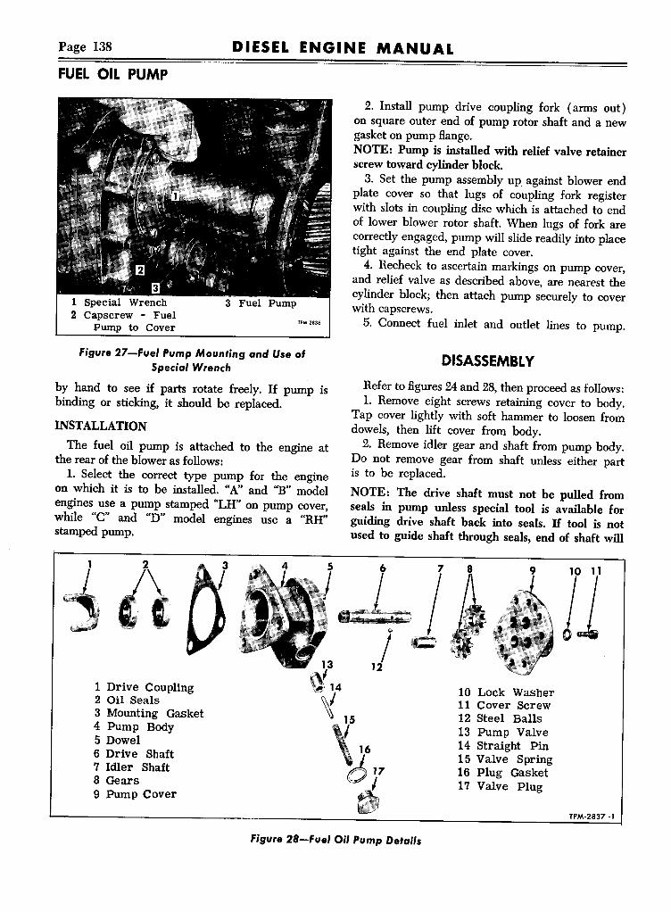
Page 138 DIESEL ENGINE MANUALFUEL OIL PUMP
1 Special Wrench2 Capscrew - Fuel
Pump to Cover
3 Fuel Pump
TPM-2836
Figure 27-Fuel PumpMounting and UseofSpecial Wrench
by hand to see if parts rotate freely. If pump isbinding or sticking, it should be replaced.
INSTALLATION
The fuel oil pump is attached to the engine atthe rear of the blower as follows:1. Select the correct type pump for the engine
on which it is to be installed. "A" and "B" modelengines use a pump stamped "LH" on pump cover,while "C" and "D" model engines use a "RH"stamped pump.
2. Install pump drive coupling fork (arms out)on square outer end of pump rotor shaft and a newgasket on pump flange,NOTE: Pump is installed with relief valve retainerscrew toward cylinder block.3. Set the pump assembly up against blower end
plate cover so that lugs of coupling fork registerwith slots in coupling disc which is attached to endof lower blower rotor shaft. When lugs of fork arecorrectly engaged, pump will slide readily into placetight against the end plate cover.4. Recheck to ascertain markings on pump cover,
and relief valve as described above, are nearest thecylinder block; then attach pump securely to coverwith capscrews.5. Connect fuel inlet and outlet lines to pump.
DISASSEMBL YRefer to figures 24 and 28, then proceed as follows:1. Remove eight screws retaining cover to body.
Tap cover lightly with soft hammer to loosen fromdowels, then lift cover from body.2. Remove idler gear and shaft from pump body.
Do not remove gear from shaft unless either partis to be replaced.
NOTE: The drive shaft must not be pulled fromseals in pump unless special tool is available forguiding drive shaft back into seals. H tool is notused to guide shaft through seals, end of shaft will
2
\.
1 Drive Coupling2 Oil Seals3 Mounting Gasket4 Pump Body5 Dowel6 Drive Shaft7 Idler Shaft8 Gears9 Pump Cover
13
~14
~ 15
"/12
Ic8
II10 Lock Washer11 Cover Screw12 Steel Balls13 Pump Valve14 Straight Pin15 Valve Spring16 Plug Gasket17 Valve Plug
Figure 28-Fuel Oil PumpDetails
TPM·2837·1

DIESEL ENGINE MANUAL Page 139
Figure 29-Removin. Ojl S•• ,. Ire", Pump Body
destroy sealing edges of seals and pump will leakexcessively.
3. If oil seal pilot tool is not available, drive shaftmust not be removed. Pull shaft from body onlyuntil steel ball can be removed from between gearand shaft, then remove gear from shaft.
4. Remove relief valve retaining plug and gasket.Remove relief valve, spring and pin from pumpbody.
5. Using seal remover tool as shown in figure 29,screw threaded end of tool shaft into outer oil seal.Tap end of tool with hammer and remove seal. Repeat this operation to remove the inner seal.
INSPECTION1. All pump parts should be washed in fuel oil
and carefully inspected before assembly. The oilseals, once pulled from the body cannot be usedagain. If the feather edges of the seals are damagedin any way so they do not form a perfect seal aroundthe shaft, either a fuel oil or lubricating oil leak willresult. Use new seals.
2. Carefully inspect cover and body for evidenceof wear at areas contacted by gears and shafts. Replace parts showing evidence of wear.3. Position gears on shafts and install in body
to check radial clearance between gears and body.4. Check width of gears for excessive wear.5. Check drive shafts for wear at area connected
FUEL OIL PUMP
Figure 30-"tst.lling 'nner and Outer Sea' in'u"'P .ody
by oil seals. Shafts must be smooth and free of anyimperfections that may impair efficiency of oil seals.
REASSEMBLYRefer to figures 24 and 28, then proceed as follows:
1. Use installer tool and adapter and install bothseals with lip of seals pointing away from pumpbody or toward the blower. Use of installer toolcorrectly positions seals %6" apart. (Fig. 30).
Figure 3'-1 ........ FUM 'ump DriveShaft ThroughOil Seals

Page 140
FUEL MANIFOLDS
DIESEL ENGINE MANUAL
2. Support holding fixture in bench vise, set pumpbody on three pins of fixture.3. Place oil seal pilot over square end of gear
drive shaft. Lubricate pilot tool with clean engineoil and insert pilot and shaft carefully into seals.(Fig. 31).4. Position drive gear over drive shaft with open
end of ball slot toward cover. (Fig. 24).5. Locate steel ball in indent of shaft and in align
ment with slot in gear. Press shaft into place, withsteel ball locking gear to shaft.
6. Press driven gear onto idler shaft until gear isin exact center of shaft, Install in pump body.
7. Position cover to body with inlet "IN" opening on same side as relief valve. Install lock washersand cap screws attaching cover to body. Tightenscrews finger tight, then tighten alternately andevenly.
8. Install valve, spring and straight pin into pumpbody then install gasket and retaining plug (Fig.24). Tighten plug.
FUEL MANIFOLDSTwo types of manifolds have been used, some are
external type as illustrated in figure 32; others areinternal type which are simply drilled passages incylinder head.Fuel injectors are supplied with fuel oil by the
pump through fuel manifolds located on side of cylinder head and connected to injectors by short steellines, as shown in figure 32.
INTERNAL TYPESince internal fuel manifolds are drilled passages in
the cylinder head no maintenance is required. Accessto drilled passage is gained through several plug open-
ings. Upper passage serves as fuel inlet and lower isoutlet. Connectors (fig. 34) must be tight and newgasket should be used whenever installing a connector.
EXTERNALTYPEUpper manifold returns excess fuel from injectors
through tubing to fuel tank. Both manifolds arelocked in position at side of cylinder head by fuelconnectors which set into tapered seats in manifoldfittings.
Since manifolds are positioned and locked withtapered-seat fuel connectors, care must be exercised
1 Fuel Outlet Pipe2 Fuel Inlet Pipe3 Injector Assembly
4 Fuel Outlet Manifold5 Fuel Inlet Manifold6 Cylinder Head7 Fuel Connectors
8 Pipe Plug9 Inlet ManifOldFitting10 Outlet ManifOldElbow
TPM-2374
Figure 32-External Fuel Manifolds and Jumper Lines at Cylinder Head

DIESEL ENGINE MANUAL Page 141
1 Fuel Connector2 Lock Nut3 Copper Washer4 Fuel Inlet Manifold
5 Straignt Fitting6 Fuel Outlet Manifold7 Elbow-RestrictedB"T' Connectors TP"-2375-1
figure 33-ExterDa' fue' Manifo'd Detai's
when a connector is removed, to see that taperedseats are perfectly clean and properly positionedin manifold fittings.
REMOVALWhen occasion requires, either fuel oil manifold
may be removed. However, before removing, referto figures 32 and 33 for assembly and relative location of parts; then proceed as follows:
1. Remove valve rocker cover.2. Disconnect fuel inlet and outlet pipes (jumper
lines) between injectors and fuel connectors.3. Install shipping caps at two injector filter caps
to prevent entry of dirt.4. Disconnect inlet and outlet fuel lines from
inlet and outlet manifolds.5. Loosen lock nuts (if USE) on connectors, a
few turns.6. Unthread connectors from head and (if used)
discard copper washer.7. Remove manifold, being careful that tee con
nectors do not bind in head.
INSTALLATIONRefer to figure 33, and note that the "T" con
nectors on the manifolds leading into cylinder headare on top side of lower (inlet) manifold and onbottom side of upper (outlet) manifold. Thesemanifolds are not interchangeable, due to locationof tapered hole.NOTE: Several types of fuel connector arrange
ments may be used. One type uses a lock nut and
FUEL MANIFOLDS
TPM-6344
figure 34-Types of fue' Connectors
copper washer to prevent fuel oil leaks at connector, another type uses a plastic button at connectorthreads and nut is eliminated. Refer to figure 34.
1. Use compressed air to clean holes in cylinderhead for fuel connectors and manifold fittings.2. Guide manifold "T' connectors attached to fuel
manifold, into openings at side of cylinder head sothat tapered seat is in approximate alignment withhole in top of head for fuel connector.3. Centralize "T' connectors with fuel connectors
by alternately turning connectors and moving manifold. This is an important operation and is necessary to insure leak-proof joints.4. Tighten fuel connectors equally (30-35 ft. lbs.)
and secure lock nuts against new copper washer (ifused).5. Attach fuel inlet and outlet lines at fuel con
nectors and injectors.6. Connect fuel lines (inlet and outlet) to re
spective manifolds.
IMPORTANT: Before replacing valve cover, runengine and see that all fuel line connections aretight, so that no fuel oil leaks into cylinder head todilute the lubricating oil. H lubricating oil is dilutedwith fuel oil, engine bearings will be seriouslydamaged.
7. Replace valve rocker cover.NOTE: Any leakage between fuel connectors and
tapered seats of manifold would he observed atholes on outside of cylinder head.

FUEL MODULATING GOVERNOR
DIESEL ENGINE MANUALPage 142
FUEL MODULATING GOVERNORDESCRIPTION
The "Fuel-Modulator" governor (fig. 35) has beendeveloped to improve combustion and fuel economy during low-speed full-throttle operation. This"Fuel-Modulator" incorporated with the mechanicallimiting speed governor automatically controls thefuel input to assure complete combustion, thus providing maximum fuel economy, clean exhaust, andlonger engine life. This control is assured regardlessof the throttle setting maintained by the operator.The governor includes a low speed spring, a high
speed spring, a set of low speed weights, and a setof high speed weights, similar to those included inlimiting speed mechanical governor.In addition, the governor incorporating the "Fuel
Modulator" includes a fuel modulator spring (55),which provides governor control for the purpose ofgradually reducing the fuel input in the fuel modulating range. Over this speed the forces of the lowspeed and modulator springs react against the forceof the high speed weights.As the engine speed decreases below top mod
ulator range, the gradual reduction in high speedweight force permits the force of the low speed (59)and modulating spring (55) to open the fuel modulator gap in the governor by moving the low speedspring cap (61) back away from the high speedspring plunger (39). The movement of the lowspeed spring cap moves the operating lever (31)- - - and the operating lever carries the differentiallever (35) toward the engine, causing the differential lever to rotate around the pin which connectsit to the operating lever. The rotation of the differential lever is restricted by the engagement of theroller (34), On the bottom of the lever, with thefuel modulator cam (47). The cam causes the differential lever to rotate in a direction which pullsthe governor link back into the governor and thuspulls the injector racks out from the full fuel position.During this time the differential lever torsion
spring (36) opposes the above rotation with a lighttension and maintains the roller (34) in its properposition against the fuel modulator cam (47). It isthis differential lever torsion spring which allowsthe "Fuel-Modulator" to operate regardless of thethrottle position maintained by the operator.The fuel modulator spring tension is set so that
injector racks start to leave the "full in" position asengine speed is reduced. Engine speed at whichthis occurs is controlled by the rate and tension ofmodulating spring used. Fuel modulating actionbegins at approximately 200 rpm below the fuelmodulating gap closing speed with 80 cu. mm. injectors, and approximately 300 rpm below fuelmodulating gap closing speed with 70 cu. mm. and60 cu. mm. injectors. Delay in modulating actionwith 70 cu. mm. and 60 cu. mm. injectors is due tohelix design on injector plunger, which does notreduce the fuel input until after .075" rack movement.The following chart specifies proper fuel modu
lating and high speed spring combination to be usedwith each size injector at desired full load enginerpm.
Engine RPM, Injector, and Spring Combinations
RPM" Fuel High SpeedInjector ModulatingMax. Min. Spring Spring
2300 2075 70 225# (W) 55# (Y)2300 2075 80 225# (W) 55# (Y)2300 1975 70 17.5#(G) 55# (Y)2300 1865 70 150# (B) 55# (Y)2000 1650 60 70# (Y) 50# (R)
"RPM given is full load-to obtain no-load (floor setting)speed, add 125 RPM.When engine is equipped with rubber damper full loadspeed must not exceed 2000 RPM. When full load speedin excess of 2000 RPM is desired engine must be equippedwith fluid (viscous) damper.Color Stripe-(W) white, (G) Green, (B) Brown, (Y) Yellow, (R) Red, (A) Aluminum.
DISASSEMBLYGovernor can be completely or partially dis
assembled by accomplishing one or more of thefollowing sub-assembly disassembly procedures.Refer to figure 35 for all nomenclature references
in following text.
CONTROL HOUSING COVER
1. Disconnect external control linkage connectedto governor control levers. Remove four cap screwsand lockwashers, then lift cover (7) and lever assembly from control housing.2. Remove pin clip and flat washer, then loosen

Page 143DIESEL ENGINE MANUAL
FUEL MODULA liNG GOVERNOR
1 Lubrication Fitting2 Throttle Shaft3 Washer4 Clip Pin5 Stop Lever6 Cap Screw7 Control Housing Cover8 Cap Screw9 Housing Plug10 Ball Bearing11 Washer12 End Cap13 Retaining Screw14 Screw Lock15 Gasket16 Ball Bearing17 Operating Fork18 Thrust Bearing19 Riser20 Weight Shaft21 Weight Housing22 High Speed Weights23 Needle Bearings24 Weight Pin25 Weight Carrier26 Weight Pin27 Set Screw28 Low Speed Weights29 Control Housing30 Operating Shaft31 Operating Lever32 Torsion Spring Screw33 Roller Pin34 Roller35 Differential Lever36 Torsion Spring
55 Modulating Spring56 High Speed Spring57 Modulating Spring Plunger58 Low Speed Spring Seat59 Low Speed Spring60 Retainer Ring61 Low Speed Spring Cap62 Lock Nut63 Low Speed Gap Adjusting
Screw64 Cover Gasket65 Roller Bearings66 Control Cam67 Seal68 Seal Washer69 Taper Pin70 Control Lever71 Cap Screw72 Throttle Lever
37 High Speed Lock Nut38 High Speed Adjusting Screw39 High Speed Spring Plunger40 Modulating Screw Lock Nut41 Modulating Speed Adjusting
Screw42 Idle Speed Screw Lock Nut43 Idle Speed Adjusting Screw44 Adjustment Cover45 Buffer Screw Lock Nut46 Buffer Screw47 Modulating Cam48 Cam Adjusting Screw49 Screw Lock Nut50 Cam Lock Screw51 Plugging Screw52 Clip Pin53 Washer54 Modulating Spring Seat
Figure 35-Fuel Modulating Governor Assembly

FUEL MODULATING GOVERNOR
DIESEL ENGINE MANUALPage 144
figure 36-Governor High Speed Air Piston, Ring,Sleeve, and Spacer (PD-4S0J J
clamp bolt and lift stop lever (5) and cam (66)from cover stud.3. Remove lubrication fitting from throttle shaft.
Loosen clamp bolt and lift throttle lever (72) fromshaft.4. Use small punch and hammer, to remove taper
pin (69 ) from throttle control lever (70) andthrottle shaft.5. Pull throttle shaft assembly (2) down through
bottom of cover. Lift washer (68) and seal (67 )
1 Low Speed Spring Cap2 Low Speed Spring3 Low Speed Spring
Seat4 Retainer Ring5 Modulating Spring
Plunger6 Modulating Spring7 Modulating Spring
Seat8 High Speed Spring
Plunger
9 High Speed Spring10 High Speed Adjusting
Screw11 High Speed Lock Nut12 Modulating Screw
Lock Nut13 Modulating Adjusting
Screw14 Idle Speed Adjusting
Screw15 Idle Screw Lock Nut·16 Adjustment Cover ".,,,.
figure 37-Governor Springs, Plungers, andAdjusting Screws (StandardJ
from cover.6. Wash cover and bearing assembly in fuel oil
and inspect bearings for damage or wear. If bearings are satisfactory for further use, removal is unnecessary.7. If bearing removal is necessary, support cover
in soft jaws of bench vise or support on a workbench. Then, use a small punch and hammer todrive lower bearing down and upper bearing upuntil removed from cover.
SPRINGS, PLUNGERS AND ADJUSTINGSCREWS
Springs, plungers and adjusting screws (Fig. 37)can be removed from control housing as an assemblywith governor either installed or removed; however, it is necessary that control housing cover (7)and levers assembly be removed.
1. Remove adjustment cover (44). Loosen highspeed adjusting screw lock nut (37) using spannerwrench. Use end wrench to thread high speed adjusting nut (38) out of control housing. When adjusting nut is free of housing entire assembly ofsprings and plungers can be removed and placed onbench for further disassembly.
NOTE: On Coach Model PD-450l a high speedair piston, ring, sleeve, and spacer are also incorporated (fig. 36) which functions to reduce enginerpm when operating in third overdrive.
2. Remove low speed spring cap (61), low speedspring (59), and low speed spring seat (58).3. Loosen idle speed adjusting screw lock nut
(42), also modulating speed spring adjusting screwlock nut (40).4. Remove idle speed adjusting screw (43), also
modulating spring adjusting screw (41).5. Use sharp-nose pliers and remove modulat
ing spring plunger retainer ring (60) from highspeed spring plunger.6. Remove modulating spring plunger (57), mod
ulating spring (55) and modulating spring seat (54)from inside high speed spring plunger.
CONTROL HOUSING
With control housing removed from weight carrierhousing and with springs, plungers, and adjustingscrews removed, the housing may be further disassembled as follows:
1. Remove pin clip (52) and washer, then lift

Page 145DIESEL ENGINE MANUAL
differential lever (35) assembly from operating lever(31).2. Remove special screw (32) retaining torsion
spring (36) to differential lever, then remove springfrom screw.
3. Remove lockscrew, lockwasher and plain washerholding upper bearing (10) in control housing.4. Remove expansion plug at lower end of con
trol housing, using sharp punch and hammer.5. Remove set screw attaching operating fork
( 17) to operating shaft (30).6. Invert housing and drive operating shaft, oper
ating lever and bearing from control housing, usinglong drift pin and hammer at lower end of shaft.7. Remove operating fork (17) through opening
at lower end of control housing.8. If inspection indicates necessity, use long drift
pin and hammer to drive lower bearing down andout of control housing.9. If inspection indicates that upper ball bear
ing and operating lever requires replacement, theoperating lever can be removed by pressing shaftfrom lever and tapping ball bearing from shaft.
WEIGHT AND HOUSINGBefore removing any part from weight housing
assembly, the unit should be thoroughly washed incleaning solvent, dried with compressed air, andthen inspected for worn, damaged, or binding parts.If all parts are in good working order, disassemblywill be unnecessary. If bearings only need replacing, then removal of weights from carrier will notbe necessary. Complete disassembly is as follows:
1. Support the governor weight housing in a viseand remove bearing end cap (12). A hex wrenchhead on the cap makes removal a simple operation.A gasket between bearing outer race and plug prevents oil seeping through the threads.
2. Straighten lip on lock and remove retainingscrew (13) from outer end of weight carrier shaft(20).3. Using a %6"-24 bolt, thread bolt into tapped
hole at end of weight carrier shaft, then removeshaft from bearing by tapping on bolt head. Use abolt of sufficient length, so bolt head will not interfere with bearing inner race before the shaftleaves the bearing.
4. Remove the thrust ball bearing (18) and riser( 19) from the weight carrier shaft.5. Mark weights and carrier with center punch
for identification, also note position of thin washersbetween weights, so parts can be replaced in their
FUEL MODULATING GOVERNOR
original locations; then remove Allen set screws,weight pivot pins and weights from carrier. Thegovernor weight carrier is only serviced with theshaft and should not be removed.6. Press ball bearing from housing. Usually only
slight pressure is required to remove bearing.
CLEANING AND INSPECTIONCLEANING
Immerse all governor parts in suitable cleaningfluid to loosen and remove all accumulations offoreign material. Use bristle brush and compressedair as necessary to assure absolute cleanliness ofall parts.
INSPECTIONThe function of the governor is to control the
fuel injection by means of linkage within the governor and inter-connecting linkage between governorand injector. It is extremely important that all moving parts be absolutely free and that no bindingexists under any condition of operation.
Inspect all bearings to be sure that they areabsolutely free of corroded or pitted surfaces andthat they are otherwise satisfactory for further use.
Inspect spring seats, plungers, adjusting screws,lock nuts, and other parts of control housing fordefects that might effect governor operation.Inspect governor weights, weight pins, shaft and
carrier for excessive wear or other damage. Weightsshould be assembled and checked for free movement.
ASSEMBLYKey numbers in text refer to figure 35.
WEIGHT AND HOUSING1. Using wood block, tap annular ball bearing
( 16) into outer end of weight housing.2. Observe marks previously placed on governor
weights and carrier, also noting position of washersbetween weights, attach weights (22 and 28) toweight carrier (25) with pins (24 and 26) and lockeach pin with the Allen set screw (27). Stake Allenscrews at two places after replacing.3. Support serrated end of shaft (20) vertically
in vise between copper jaws and slip riser (19),then thrust bearing (18) onto upper end of shaft.Drop carrier housing (21) over shaft, then usingblock of wood on inner race of ball bearing, drive

FUEL MODULATING GOVERNOR
DIESEL ENGINE MANUALPage 146
shaft through bearing tight against shoulder onshaft.4. Thread lock screw (13) through lock (14)
and into end of weight shaft (20). Tighten screwand bend tang of lock over flat of screw head. Install new gasket (15) and install end cap (12).
CONTROL HOUSING
l. If operating lever (31), bearing (10) andwasher (11) were removed from operating shaft install washer over shaft and against shoulder. Tapor press bearing onto shaft then press operatinglever onto shaft, until lever is against bearing innerrace.2. If lower bearing has been removed, tap new
bearing into housing until seated against shoulder inhousing. Install expansion plug at lower end of housing.3. Lubricate ball bearing also needle bearings. In
sert operating shaft assembly (30) into housinguntil lower end is through lower bearing. Installoperating fork (17) to operating shaft (30) so thatmachined surfaces of fork will bear against thrustbearing washer (18).4. Push fork (17) onto shaft until seated against
shoulder on shaft. Install set screw retaining fork toshaft and tighten with Allen wrench. Stake walls offork against set screw, using pointed anvil andpunch.5. When installation of shaft assembly is complete,
hold operating lever (31) and force operating fork(17) in direction of normal load in order to properlyseat lever and fork on the shaft. A torque of 250-300-inch pounds should be applied.6. Install flatwasher, lockwasher and screw retain
ing shaft ball bearing (10) in housing. Tightenscrew securely.7. Install torsion spring (36) to differential lever
(35) using special screw. Tighten screw (32)securely.8. Install differential lever assembly (35) to
operating lever (31) and secure with flat washer(53) and pin clip (52). Check differential lever forfree movement on operating lever.
SPRINGS, PLUNGERS AND ADJUSTINGSCREWS (Figs. 35 and 37)1. Thread idle speed adjusting screw (43) into
modulating spring adjusting scre.w (41), then threadthese two pieces into high speed spring plunger(39).2. Install modulating spring seat (54), modu-
lating spring (55), and modulating spring plunger(57), into high speed spring plunger (39). Seatshoulder must be toward spring.3. With modulating spring seat, spring, and
plunger installed in high speed spring plunger, install retainer ring (60) in groove-near end of highspeed spring plunger (39). Be sure ring is fullyseated in groove.
4. Install low speed spring seat (58), low speedspring (59), and low speed spring cap (61) intohigh speed spring plunger (39). Seat shoulder mustbe toward spring.5. Slide high speed spring (56) and high speed ad
justing screw (38) over high speed spring plunger(39).NOTE: On governor having air piston and associated parts (Fig. 36), install high speed sleeve andspacer after high speed spring is installed, then install high speed adjusting screw over high speedsleeve.6. Hold assembly while being positioned in con
trol housing with high speed spring plunger againstsupport in housing. Thread high speed spring adjusting screw into housing sufficiently to retainassembly.7. Thread high speed adjusting screw (38) into
housing until end of screw is approximately %" fromspanner lock nut (37). Thread modulating springadjusting screw (41) in until end of screw is approximately 1~" from spanner lock nut.
CONTROL HOUSING COVER
l. If throttle shaft bearings were removed fromcover, start bearings straight in the cover by hand,then use a block of wood on end of bearing whilebeing pressed into place. Install opposite bearing insame manner.NOTE: Lower bearing is pressed flush with coverhub. Upper bearing is pressed lfg" below cover hub.2. Lubricate roller bearings with grease, then
slide throttle shaft (2) through bearings from thebottom of cover.3. Install seal (67) over throttle shaft and into
cover counterbore at top of upper bearing, theninstall flat washer (68) over shaft as a seal retainer.4. Lubricate shaft and install cam (66) over shaft
with cam boss away from cover. Install stop lever(5) over cam boss and tighten only sufficiently tohold lever. Install washer (3) and clip pin (4).5. Install control lever (70) over throttle shaft
with lever pin inside cam. Install taper pin (69)attaching lever to shaft and seat pin securely.

Page 147DIESEL ENGINE MANUAL
6. Install throttle lever (72) to throttle shaft andtighten clamp screw only sufficiently to hold lever toshaft.7. Install gasket to housing (64). Install cover
assembly to control housing, being sure that throttleshaft fulcrum pin is between differential lever fork(35) and torsion spring (36). Install and tightenfour cap screws and lockwashers attaching cover tohousing.
INSTALLATIONDifficulties encountered in installing governor will
be minimized if control housing is separated fromweight housing.
1. Position gasket to governor weight housingflange, then locate housing assembly against blowerend plate with governor weight shaft splines meshing with splines in hollow blower shaft. Install attaching bolts finger tight.2. Position the control housing assembly to weight
housing assembly using a new gasket between theseparts.NOTE: Be sure that operating fork is assembledwith machined faces bearing on outer thrust washerand not between the washer and balls.3. Install weight housing cover and gasket and
secure control housing to weight housing, usingcover cap screws and lockwashers.4. Using a new gasket, attach control housing to
cylinder head with cap screws and lockwashers.5. Tighten bolts, previously installed finger tight,
securing weight housing to blower.6. Perform complete governor adjustment as in
structed under "Governor Adjustments" followingin this section of this manual.
GOVERNOR ADJUSTMENTSGovernor adjustments should not be performed
until the following engine tune-up procedures havebeen accomplished.
1. Start engine and operate at part throttle untilengine is thoroughly warmed up and water temperature is at least l60°F.2. Adjust valve lash (.009" hot-.012" cold).3. Time injector - use timing gauge and adjust
follower height in accordance with approved practice described in ENGINE TUNE-UP section of thismanual.
FUEL MODULATING GOVERNOR
Governor adjustment procedures should be performed in the following step-by-step sequence. Anydeviation from the following order may result in animproperly adjusted governor.Prior to adjustment the service man should read
the following instructions, study the illustrations,and familiarize himself with the general design, alsonomenclature and location of various parts. REFERTO FIGURE 35 FOR ALL NOMENCLATUREREFERENCES IN FOLLOWING TEXT.
ADJUSTMENT SEQUENCEThe following 7 basic steps in setting a fuel modu
lating type governor, must be performed in theorder listed.
Setting No. 1. Set fuel modulating spring tension.Setting No.2. Set low speed spring gap.Setting No.3. Check fuel modulating gap closing
space.Setting No.4. Set fuel modulating cam.Setting No.5. Set injector racks.Setting No.6. Set no load high speed.Setting No.7. Set idle speed.
Only settings 1, 3 and 4 are new and peculiar tothe fuel modulating governor. Settings 2, 5, 6 and 7are the same as or somewhat similar to those of thelimiting speed governor; however, the followingadjustment procedures should be thoroughly studiedand carefully followed.These seven basic settings are set forth in bold
face type in the following pages. The adjustmentsrequired before each of these seven settings can bemade are set forth prior to each setting and arelisted as "Preliminary Adjustments" to step 1, 2,3, etc.
No.1-FUEL MODULATING SPRINGTENSION SETTING
Preliminary ProceduresA. Remove governor adjustment cover (44), con
trol housing cover (7), housing plug (9) and coppergasket. Disconnect governor external control linkageand remove cylinder head cover.B. Loosen idle speed screw lock nut (42) and
back out idle screw (43) until low speed spring (59)exerts no pressure on low speed spring cap (61).This may be determined by moving low speed capin and out. Use care not to back the screw out toofar as it is possible to turn it completely out of thelow speed spring seat (58).

FUEL MODULATING GOVERNOR
DIESEL ENGINE MANUALPage 148
Figure 38-Preliminary Adiustment of Low andHigh Speed Springs
NOTE: H type of fuel modulating spring (55)· is notknown (70, 150, 175 or 225 lbs. per inch) thehigh speed plunger assembly should be removedfrom the governor, retainer ring (60) removed andthe type of spring determined by color code (seechart) before proceeding with preliminary adjust.ment CCC"below.
C. Loosen high speed lock nut (37) and tumhigh speed adjusting screw (38) into body untilBats on end of high speed spring plunger (39) arefully exposed.
D. Loosen modulating screw lock nut (40) andturn screw (41) out by hand until modulatingplunger (57) may be moved back toward the highspeed plunger %6" before touching spring,
Figure 39-Preliminary Adiu.tment ofModulating Cam
Adjustment No.1
Tum screw (41) in by hand until resistance indicates that spring has forced plunger forward to contact retainer ring (60). Repeat as necessary untilsure that plunger is just contacting ring with notension on spring, then tum modulating adjustingscrew (41) in ~ of a turn (one Bat). Lock adjustingscrew in position with locknut (40).
CAUTION: The high speed plunger (39) and thefuel modulating spring adjusting screw (41) shouldboth be held securely in position with two wrencheswhen tightening fuel modulating adjusting screwlocknut (40) to prevent screw and plunger relationship from being disturbed.
No.2-LOW SPEED SPRINGGAP SETTING
Preliminary Procedures
A. Reset idle adjusting screw (43) to 2" projection ("A" Fig. 38) and replace control housingcover, attaching with two screws.
CAUTION: Be sure that throttle shaft pin is positioned between torsion spring (36) and end of differential lever (Fig. 35).
B. Start engine and make preliminary idle speedsetting by setting speed at 385 RPM with low speedscrew (43) and advancing speed to 400 RPM byturning in buffer screw (46 ). Tighten low speedlocknut (42).
C. Stop engine.
D. Remove governor control housing cover (7)and lever assembly. Remove cover gasket. Disconnect link rod between differential lever and injectorcontrol tube lever, then remove link thru governor.
E. Thread buffer screw (46) outward 4 or 5 turns.
F. Loosen cam adjusting screw locknut (49). Remove plugging screw (51), and use Allen wrench toloosen cam lock screw (50) approximately J$ turn,to permit cam to be moved in and out without allowing it to turn in housing.
G. Thread cam adjusting screw (48) into housinguntil screw extends "" beyond locknut when nut isagainst sleeve (Fig. 39). Tighten cam lock screwwith Allen wrench to hold cam in position until adjusted later.
H. Start engine and operate between 600 and 700RPM using tachometer.

Page 149DIESEL ENGINE MANUAL
NOTE: Governor to control tube link is removedand engine speed must be controlled by hand ortemporary adjustable link and spring at controllever tube. (Figs. 40 and 41. )
Adjustment No.2Check gap between low speed spring cap (61)
and modulating spring plunger (57) with .0015feeler gauge (fig. 42), or by using oil bead method.If gap is not within .001"-.002" at 600-700 RPM,
loosen locknut (.62) and tum low speed gap adjusting screw (63) as necessary to obtain proper gap.Tighten lock nut (62) and recheck gap.
No.3-CHECKING FUEL MODULATINGGAP CLOSING
Preliminary ProceduresA. If adjustable link has been used it should be
removed (Figs. 40 and 41).
B. Install control link between differential leverand injector control tube lever. Link is secured atgovernor end with Hat washer and hair pin clip.Straight pin and cotter pins are used at control tube.Link must be free with no binding.
C. Start engine and control speed manually byexerting force against torsion spring (36) with finger.CAUTION: Care should be exercised to avoid overspeeding engine.
Adjustment No.3Advance engine speed gradually until low speed
spring cap (61) contacts high speed plunger (39).Do not exceed 2100 RPM. Gap closing speed shouldbe checked by a .0015" feeler between mating surfaces of (61) and (39), or by oil bead method andwill vary according to following table:
F. M. Spring225 #/inch·WHITE175 #/inch·GREEN150 #/inch-BROWN70 #/inch- YELLOW
ClosingSpeed Range1950-20401850-19401750-18401525-1625
If closing speed does not fall in correct range thenrecheck setting No. I-or preliminary "B" to settingNo.2-or check for correct fuel modulating spring.( See chart. )If, after rechecking adjustments as indicated above,
closing speed still does not fall within specifiedrange, modulating spring should be replaced.
FUEL MODULATING GOVERNOR
C\!!!!!!!iljjj:!!!!il!!IiIT!\!!!!lllIiili!!ft!j!!!iilllrn :)TP·7084
Figure 40-Adjustab.e 'njedor RackContro'Linkand Spring
Figure 4J-'njedor RackAdjustab'e Link andSpring 'nstalled
Figure 42-1ow Speed Spring Gap Adjustment

Page 150 DIESEL ENGINE MANUAL
FUELMODULATING GOVERNOR
figure 43-Closing Modulator Gap WithSpecial Screw
No.4-FUEL MODULATINGCAM SETTING
Preliminary ProceduresA. Stop engine.B. Set high speed adjusting screw (38) to extend
:li" beyond high speed screw locknut (37) when nutis tight against housing (29) (Fig. 38).C. Temporarily install cap screw (~-13x 2") into
front of control housing and thread screw inwarduntil gap between low speed cap (61) and highspeed spring plunger (39) just closes (Fig. 43)being careful that high speed spring plunger isnot moved.
figure 44-Modulating Cam Adjustment
figure 45-Adjusting No. J Rack to Governor
D. Loosen inner and outer adjusting screws ateach control rack lever until each lever is free oncontrol tube.E. Install cover to governor control housing
gasket (64). Install control housing cover assembly(7), being sure that throttle shaft pin is betweendifferential lever (35 ) and torsion spring (36 ).Secure cover with four screws and lockwasher.
Adjustment No. 4Use Allen wrench and loosen cam lock screw (50)
only sufficiently (J~ turn) to permit turning camadjusting screw (48) with fingers. If lock screw isbacked out further, cam may be released and turnedby its own weight out of the operating position.With control lever in full throttle position (Fig.
44), thread cam adjusting screw (48) outward withfinger tips until cam (47) can be felt bottomingagainst roller (34) on the bottom of the differentiallever (35). Thread cam adjusting screw outward anadditional J~ turn to provide positive engagementbetween differential lever roller and cam. Aftermaking contact it may be necessary to turn thescrew very slightly in or out to produce the final%4" clearance illustrated in figure 44 which is required after the Allen screw has been tightened.Tighten lock nut (49); also install plugging screw(51 ).CAUTION: The adjustment of the modulating camis extremely important and must be carefully andaccurately performed.
No.5-INJECTOR RACK SETTING
Preliminary ProcedureA. Manually hold control lever in full throttle
position (fig. 45).
Adjustment No.5Adjust No.1 injector rack lever (fig. 45) so that

Page 151DIESEL ENGINE MANUAL
figure 46-Ad;usting No.2 Rack to No. J Rack
very light finger tip pressure at coupling will produce a tendency to roll, but coupling should not beloose.CAUTION: Do not set No.1 or any other rack tootight as this will produce clearance between the camand differential roller and will result in delay andreduction of the fuel modulating action.
Hold injector control tube lever for "feel," whileadjusting remaining control rack couplings (fig. 46).Adjust No.2 rack control lever so that it has thesame "feel" as No. 1 coupling. Repeat this procedure on all remaining racks. That is, compare No.3rack with No.1, etc., making certain no other injector is tighter than No.1.
figure 47-Ad;usting High Speed
FUEL MODULATING GOVERNOR
figure 48-Ad;usting ,d'e Speed
No.6-NO.LOAD HIGH SPEED SETTING
Preliminary ProceduresA. Remove temporarily installed cap screw then
install control housing plug (9) with gasket.B. Loosen high speed adjusting screw locknut if
tight.C. Install cylinder head cover.
Adjustment No.6Start engine and move throttle lever toward full
fuel position while observing tachometer. Avoidoverspeeding engine more than 100 RPM abovedesired speed.Tum high speed adjusting screw (39) until desired
(see table) speed is obtained with throttle lever in.wide open position (fig. 47). Lock nut (37).
figure 49-Ad;usting BufferScrew

Page 152 DIESEL ENGINE MANUAL
LIMITING SPEED GOVERNORNo.7-IDLE SPEED AND BUFFER
SCREW SETTING
Adjustment No.7
With engine running at idle speed, observe engineRPM at tachometer, then loosen locknut (42) andthread idle adjusting screw (43) in to increase orout to decrease until 385 engine RPM is obtained(fig. 48). Tighten locknut.With engine running at idle speed, thread buffer
screw (46) in until "surge" or "roll" of engine justdisappears, but not higher than 400 RPM. Variationfrom this speed will affect fuel modulating action.
Do not raise engine speed more than 20 RPM withthe buffer screw, otherwise it may not be possibleto stop the engine. Hold screw (46) and tightenlocknut (fig. 49). Stop and start engine severaltimes to be sure of its stopping.
INSTALL REMOVED PARTS
1. Install and tighten governor adjustment cover(44).2. Connect throttle control rod to throttle control
lever at governor cover.3. Connect linkage to engine stop lever at gov
ernor cover.
LIMITING SPEEDGOVERNOR
GENERALRequirements on the engine continually vary, due
to fluctuating loads, therefore some means must beprovided to control the amount of fuel required foridling, intermediate, and full throttle operation. Ano fuel position in a cam for stopping the engine isused on trucks. To accomplish this control, a governor is inserted in the linkage between the manualthrottle control and the fuel injectors.In the governor, force is transmitted from hinged,
mechanical rotating weights through the governoroperating mechanism to the injector control racks,which are connected to the governor by a link.Forces created by the rotating weights are counterbalanced by springs in the governor, tension ofwhich determines engine speed.This governor has the following characteristics:(a) Controls the engine idling speed.(b) Limits maximum engine speed.(c) Manual control between maximum engine
speed and idling.(d) Permits return of injectors to no fuel position
at speeds above idling range.NOTE: All illustrations in this section show thegovernor for LA engine models, unless otherwisespecified.
DESCRIPTIONThe limiting speed governor (figs. 51, 52 and 55)
incorporates two high speed and two low speedweights; each set of weights having a fixed stop forthe inner and outer positions. A high and low speedspring is also employed in this governor; the former
works in conjunction with the high speed weightsto limit the maximum engine speed, the latter worksin conjunction with both the low and high speedweights to control the engine idling speed.The motion produced by the travel of the
governor weights, between their inner and outerpositions, is transmitted to the injector racks by asystem of cams and levers on which can be superimposed a manual control.The governor, which is mounted at front of blower
as shown in fig. 50, is divided into two main assemblies embodied in separate housings. These assemblies are: Governor control housing and governorweight and lower housing, and the cover.The two sets of weights are carried on a horizontal
shaft inside governor weight housing. Weight carriershaft is mounted on an annular ball bearing at oneend and opposite end is supported inside and drivenby hollow blower upper rotor shaft. The blower endof governor shaft is serrated and engages with corresponding serrations inside blower shaft, whichdrives the governor shaft and weights.Control mechanism transmits motion of governor
weights to the injector racks. This mechanism consists of a vertical shaft mounted inside a housing,with a fork or yoke fixed at lower end, an operatinglever fixed at upper end, and a high and low speedgoverning spring with suitable adjustments. Thevertical shaft is mounted on an annular ball bearingat upper end and a bushing at lower end.The motion of the governor weights is transmitted
to the vertical shaft through a movable riser on theweight carrier shaft and the fork on the lower endof the vertical shaft. This motion is, in turn, transmitted to the injector control tube by means of the
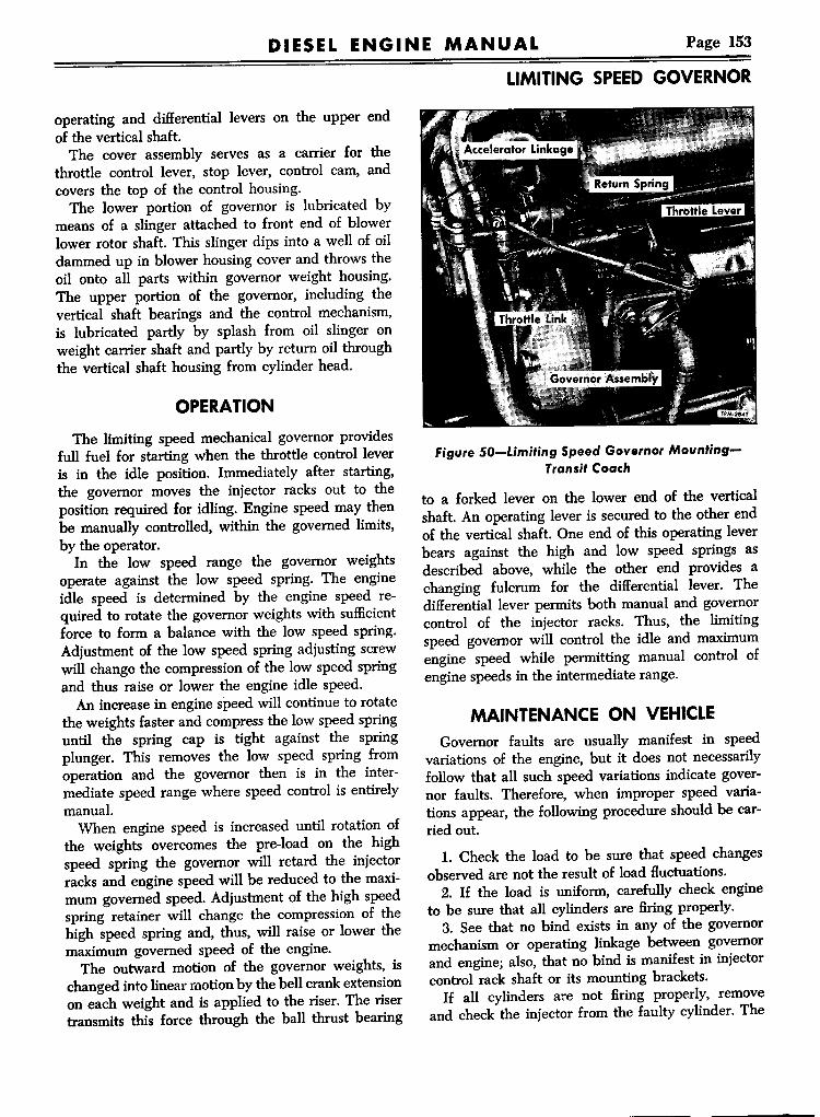
Page 153DIESEL ENGINE MANUAL
operating and differential levers on the upper endof the vertical shaft.The cover assembly serves as a carrier for the
throttle control lever, stop lever, control cam, andcovers the top of the control housing.The lower portion of governor is lubricated by
means of a slinger attached to front end of blowerlower rotor shaft. This slinger dips into a well of oildammed up in blower housing cover and throws theoil onto all parts within governor weight housing.The upper portion of the governor, including thevertical shaft bearings and the control mechanism,is lubricated partly by splash from oil slinger onweight carrier shaft and partly by return oil throughthe vertical shaft housing from cylinder head.
OPERATIONThe limiting speed mechanical governor provides
full fuel for starting when the throttle control leveris in the idle position. Immediately after starting,the governor moves the injector racks out to theposition required for idling. Engine speed may thenbe manually controlled, within the governed limits,by the operator.In the low speed range the governor weights
operate against the low speed spring. The engineidle speed is determined by the engine speed required to rotate the governor weights with sufficientforce to form a balance with the low speed spring.Adjustment of the low speed spring adjusting screwwill change the compression of the low speed springand thus raise or lower the engine idle speed.An increase in engine speed will continue to rotate
the weights faster and compress the low speed springuntil the spring cap is tight against the springplunger. This removes the low speed spring fromoperation and the governor then is in the intermediate speed range where speed control is entirelymanual.When engine speed is increased until rotation of
the weights overcomes the pre-load on the highspeed spring the governor will retard the injectorracks and engine speed will be reduced to the maximum governed speed. Adjustment of the high speedspring retainer will change the compression of thehigh speed spring and, thus, will raise or lower themaximum governed speed of the engine.The outward motion of the governor weights, is
changed into linear motion by the bell crank extensionon each weight and is applied to the riser. The risertransmits this force through the ball thrust bearing
LIMITING SPEEDGOVERNOR
Figure 50-limiting Speed Governor MountingTransit Coach
to a forked lever on the lower end of the verticalshaft. An operating lever is secured to the other endof the vertical shaft. One end of this operating leverbears against the high and low speed springs asdescribed above, while the other end provides achanging fulcrum for the differential lever. Thedifferential lever permits both manual and governorcontrol of the injector racks. Thus, the limitingspeed governor will control the idle and maximumengine speed while permitting manual control ofengine speeds in the intermediate range.
MAINTENANCE ON VEHICLEGovernor faults are usually manifest in speed
variations of the engine, but it does not necessarilyfollow that all such speed variations indicate governor faults. Therefore, when improper speed variations appear, the following procedure should be carried out.
1. Check the load to be sure that speed changesobserved are not the result of load fluctuations.2. If the load is uniform, carefully check engine
to be sure that all cylinders are firing properly.3. See that no bind exists in any of the governor
mechanism or operating linkage between governorand engine; also, that no bind is manifest in injectorcontrol rack shaft or its mounting brackets.If all cylinders are not firing properly, remove
and check the injector from the faulty cylinder. The
Page 154 DIESEL ENGINE MANUAL
LIMITING SPEED GOVERNOR
injector check should consist of "popping" the injector as described under "Injector Tests" in INJECTOR section of this manual. If this test showsany of the holes in spray tip to be plugged, removeand clean tip as described under "Spray Tip Cleaning." With governor control link connected to injector rack control shaft, the mechanism should befree from bind throughout entire travel of injectorracks. Should friction exist in the mechanism, itmay be located and eliminated as follows:1. Injector racks may stick or move too hard.
This may be due to the injector hold-down clampbeing too tight or not positioned properly, and canoften be eliminated by tapping the foot of the clamplightly with a small hammer and a long punch orscrewdriver. An injector which has been in servicea long time may get sticky due to an accumulationof foreign material. This can be corrected by washingin a pail of clean gasoline.2. Injector rack may stick due to being cramped
by the rack control lever being out of position orcocked. Loosen screws in rack control lever, and ifthis relieves binding, move lever endways on control tube until rack control lever no longer crampsinjector rack. Cocking of rack control lever mayalso be due to damage to ends of adjusting screws orsurfaces which they contact, and may be correctedby filing. After trouble has been remedied, rack controllever must again be adjusted for proper position.When injector rack control tube is free from bind,
shaft should return freely to no-fuel position by tubereturn spring only. Whenever control tube bearingsupports have been loosened, adjustment of rackcontrol lever should be checked.
CAUTION: Never stretch or tamper with rack control spring to change tension. If spring is distorted,replace.
3. Control tube may have too much friction dueto bent control tube spring. Replace with a newspring.4. Pin in link connecting governor to control tube
may be binding in control tube lever. Remove bind.Having made all the above checks and governor
still fails to control engine properly, governor maybe worn or otherwise unfit for further use until unithas been completely tom down, inspected, and rebuilt or replaced.If removal and overhaul of governor is necessary,
instructions gIven below will simplify and shortenoperations.
REMOVAL1. Remove engine valve rocker cover.2. Disconnect control rods at governor throttle
and stop levers on governor control housing cover.3. Remove screws attaching governor control
housing cover to control housing then remove cover.4. Disconnect governor to injector control tube
link from both the differential lever and control tubelever then remove link.5. Remove two screws which attach governor
control housing to cylinder head.6. Remove four cap screws which attach cover
and control housing to weight carrier housing andremove cover plate.NOTE: Two dowels are used at junction of verticalhousing and weight housing. Do not bend upperhousing too far away from cylinder head withoutremoving lower end at same time.7. Remove cap screws which attach weight car
rier housing to front end of blower and separategovernor shaft from front blower shaft by pullingstraight out. The rear cap screw may be easily removed by using the special wrench required forremoving fuel pump inner cap screw.
DISASSEMBLYFor purposes of simplicity, the governor assembly
described has been divided into subassemblies andillustrated as follows:
1. Control housing cover assembly.2. Springs and plunger assembly.3. Control housing assembly.4. Weight and housing assembly.
CONTROL HOUSING COVER
With governor cover removed from control housing, proceed with following necessary operations:
1. Remove pin clip and special washer from control camshaft. Loosen clamp bolts on both operatingand stop lever, then remove the two levers.2. Using small punch and hammer, remove taper
pin from pedal control lever hub then remove lever.3. Remove control cam assembly.4. Pull throttle shaft assembly down through bot
tom side of cover. Remove two plain washers andpacking washer. At this stage of disassembly, washcover and roller bearings (bearings assembled incover) thoroughly in cleaning solvent or fuel oil andinspect bearings for wear or damage. If bearings aresatisfactory for further use, removal is unnecessary.

DIESEL ENGINE MANUAL Page 155
1 Operating ShaftLever
2 Low Speed SpringCap
3 Low Speed Spring4 Low Speed Spring
Seat5 Spring Plunger6 Lock Nut7 High Speed Spring8 High Speed Spring
Retainer
9 Lock Nut10 Low Speed Adjusting
Screw11 Bolt12 Spring Cover13 Cover Gasket14 Control Housing15 Differential Lever16 Lock Nut17 Buffer Screw18 Lock Nut19 Gap Adjusting Screw
TPM-2376
Figure 51-Governor Control Mechanism
5_ If bearing removal is necessary, support coverin soft jaws of bench vise or suitably on a workbench. Then by means of a small punch and hammer, drive lower bearing down through bottom ofcover and upper bearing out through top of cover.
SPRINGS AND PLUNGERWith the governor control housing detached from
the weight housing, the springs and plunger can beremoved from the control housing. Refer to figures51 and 53.
1. Remove two bolts and lock washers attachingspring cover to control housing. Remove cover andgasket.2. Loosen low speed spring adjusting screw lock
nut, then loosen adjusting screw to relieve tensionon low speed spring.3. Loosen high speed spring retainer lock nut, then
thread high speed spring retainer out of controlhousing. This will permit removal of low speedspring cap, spring, seat, adjusting screw, lock nut,and retainer. Refer to figure 53.
LIMITING SPEEDGOVERNOR
1 Adjusting Screw2 Lock Nut3 Retainer4 Washer5 Differential Lever6 Ooerating Lever7 Flat Washer8 LockWasher9 Retaining Screw
10 Upper Bearing11 Washer12 Control Housing13 Operating Shaft14 Lower Bushing15 Operating Fork16 Set Screw17 Expansion Plug
TPM-2813-1
Figure 52-Governor Control Housing Assembly

Page 156
LIMITING SPEEDGOVERNOR
DIESEL ENGINE MANUAL
1 2 3~ 461mao ' }? .;fj;;' ")10
Q1 Low Speed Spring Cap2 Low Speed Spring3 Low Speed Spring Seat4 Spring Plunger
5 High Speed Spring6 Low Speed Adjusting Screw7 Lock Nut8 Spring Retainer Lock Nut~ High Speed Spring Retainer
10 Gasket11 Spring Cover12 Bolt13 Lock Washer
TPM·2815
Fi."re 53-Relative Localion of High alld Low Speed Springs, Plunger and Seats
CONTROL HOUSINGWith control housing removed from weight car
rier housing, and spring and plunger assembly removed, the operating shaft and associated parts (fig.52) may be removed 2S follows:L Remove pin clip, washer, and differential lever
off lever pin of the operating shaft.2. Remove screw, lock washer, and plain washer
retaining ball bearing in control housing.3. Remove operating shaft yoke set screw. Remove
expansion plug at bottom of control housing.4. Invert control housing and drive shaft from
fork as shown in figure 54.5. H control housing bushing requires replace
ment it can be removed by driving with a long rod
Figure 54-Removing Operatin, ForiefromGov.r".,Operating SIt"t
and hammer.6. Ball bearing can be removed, if necessary, by
pressing shaft from lever and bearing.
WEIGHT A.L~DHOUSINGBefore removing any part from weight housing
assembly, (fig. 55) the unit should be thoroughlywashed in cleaning solvent or fuel oil, dried withcompressed air, and then inspected for worn, damaged, or binding parts. If all parts are in goodworking order, disassembly will be unnecessary. Ifbearings only need replacing, then removal ofweights from carrier will not be necessary. Completedisassembly is as follows:
NOTE: Governor assemblies have a threaded capscrewed into the bearing end of the weight carrierhousing. This threaded. cap screws tight against thebearing outer race thus cap serves as a bearingretainer.
1. Support the governor weight housing in a viseand remove bearing cap. A hex wrench head on thecap makes removal a simple operation. A gasketbetween bearing outer race and plug keeps oil fromseeping through the threads.2. Straighten lip on locking washer and remove
lock screw from outer end of weight carrier shaft.3. Using a %6"-24 bolt, thread bolt into tapped
hole at end of weight carrier shaft, then removeshaft from bearing by tapping on bolt head, Use abolt of sufficient length, so bolt head will not interfere with bearing inner race before the shaft leavesthe bearing.4. Remove the thrust ball bearing and riser from
the weight carrier shaft.5. Mark weights and carrier with center punch
for identification, also note position of thin washersbetween weights, so parts can be replaced in theiroriginal locations; then remove Allen set screws,weight pivot pins and weights from carrier. The governor weight carrier is only serviced with the shaft

Page 157DIESEL ENGINE MANUALLIMITING SPEEDGOVERNOR
1 End Cap2 Retaining Screw3 Screw Lock4 Gasket5 Ball Bearing
6 Thrust Bearing7 Riser8 WeightHousing9 Weight Shaft10 HighSpeedWeights11 Weight Pin
12 Needle Bearings13 Weight Carrier14 Weight Pin15 Set Screw16 Low SpeedWeights
TPM-2814
Figure 55-Governor Weight and LowerHousing Assembly
and should not be removed.6. Press ball bearing from housing. Usually only
slight pressure is required to remove bearing.
INSPECTIONAll the governor parts having been washed in
cleaning solvent or fuel oil and dried with compressed air, the parts may be inspected for wear andfitness for further use.Since the function of governor is to control fuel
injection by means of suitable linkage within thegovernor and inter-connected linkage between governor and injector control, absolute freedom of alImoving parts within governor, as well as the interconnecting linkage, is of utmost importance.When inspecting governor parts, therefore, bear
in mind that all parts must work freely with theirmating parts.Revolve outer race of annular bearing slowly for
any indication of rough spots. Replace pitted or corroded balls and races.At lower end of control housing examine bushing
for wear, and replace if necessary.Examine journals on shafts at bearing locations,
and if journals are worn excessively, replace shafts.Examine all sleeves, pins, shaft journals, and
links for wear; also for fits, and, if necessary, dresswith crocus cloth for proper fit. The weights shouldbe suspended in their carrier sufficiently free to fallfrom the extended to the inner position by their ownweight, and the suspending pins should not be usedif worn more than .002" out-of-round.
ASSEMBLYThe governor may be assembled by reversing the
sequence of operations for disassembly. The workwill be much simplified by close reference to thevarious detailed illustrations accompanying the following text. Having thoroughly inspected each partand by reference to the various illustrations, governor may be assembled as follows:
WEIGHT AND HOUSINGRefer to figure 55 and proceed as follows:

Page 158 DIESEL ENGINE MANUAL
LIMITING SPEEDGOVERNOR
l. Using wood block, tap annular ball bearinginto outer end of weight housing.2. Heeding marks previously placed on governor
weights and carrier, also noting pcsition of washersbetween weights, attach weights to carriers and lockeach pin with the Allen set screw. Stake Allen screwsat two places after replacing.3. Support serrated end of shaft vertically in vise
between copper jaws and position riser and thrustbearing onto upper end of shaft. Drop carrier housing over shaft, then using block of wood on innerrace of ball bearing, drive shaft through bearingtight against shoulder on shaft.4. Thread lock screw through lock plate and install
in end of weight shaft. Tighten screw and bend tangof lock plate over flat of screw head. Install newgasket and install end cap.
CONTROL HOUSINGDue to the flatted shaft ends and the "D" holes
in the hub of both the lower forked lever and theupper operating lever, these parts are properlylocated. Through this method of establishing theproper relationship between operating lever, shaft,and yoke, anyone of the three pieces may be replaced without changing the relationship of the system. Refer to figure 52 and proceed as follows:l. If operating lever, bearing, and washer were
removed from the shaft, set the washer in placeagainst shaft shoulder, tap or press bearing ontoshaft then, using an arbor press, replace operatinglever against ball bearing inner race.Install new expansion plug.2. Lubricate ball bearing and insert operating
shaft assembly down through bushing. Positionthe fork lever (yoke) so machined surfaces offork will bear against ball bearings thrust washer.When lower end of control shaft appears throughthe lower bushing put fork in position and slideshaft assembly down through hub of fork.3. Push forked lever onto shaft just far enough to
contact the bushing, then back off just enough tomake the shaft movement perfectly free. Tighten setscrew securely with an Allen wrench. The walls ofthe forked lever should be staked down tight againstthe set screw using a pointed anvil and a pointedpunch. After the installation of the shaft and leversin the housing is completed, hold the upper operating lever and with the heel of the hand, gently forcethe lower operating fork in the direction of normalloading in order to properly seat the operating leverand fork on the shaft. A torque of about 300 inch
pounds should be applied to the shaft.4. Install differential lever to operating shaft lever
and secure with washer and clip.
SPRING AND PLUNGERRefer to figures 51 and 53 and proceed as follows:l. Position one end of low speed spring into
spring cap, then place spring seat on opposite endof spring. Install this assembly into governor springplunger.2. Install this assembly into position through open
ing in control housing.3. Install high speed spring over end of plunger.
NOTE: Loosely wound end of spring MUST beagainst shoulder of plunger.4. Thread lock nut about half way down on high
speed spring retainer. Position retainer over highspeed spring, then thread into housing until againstnut.5. Thread lock nut about halfway down on low
speed adjusting screw, then thread screw into housing until against nut.6. If governor is to be placed in stock install gas
ket and spring cover and secure with two bolts.
CONTROL HOUSING COVERl. If bearings for throttle shaft were removed
from cover, start either upper or lower bearingstraight in the cover by hand; then, using a block ofwood on end of bearing, press into position. Installother bearing in the same manner.
NOTE: Lower bearing is pressed in flushwith lowerend of bearing boss. Upper bearing is pressed influshwith counterbore in cover.2. Lubricate roller bearings with a liberal amount
of good cup grease, slide thin plain washer over thethrottle shaft next to eccentric shoulder on lowerend of shaft, and slide shaft through bottom ofcover into position through bearings.3. Insert seal washer into counterbore for roller
bearing at upper side of cover. Install plain washerover shaft and next to seal.4. Lubricate camshaft and install cam over shaft
with boss on cam directed away from cover. Positionstop lever over operating cam assembly and insertbolt and washer. Install plain washer over shaft andinsert clip lock. On installations or models on whichthe stop lever and cam are not used disregard theseinstructions.
NOTE: After governor has been attached to theengine, and the .engine stop mechanism is about to

DIESEL ENGINE MANUAL Page 159
be connected, it may be necessary to reposition stoplever. Do not tighten bolt too securely.5. Align holes in throttle shaft and pedal control
lever and press lever onto upper end of shaft withpin at outer end of lever down in slot of cam. Locklever to shaft with taper pin.6. Position control lever on shaft over pedal con
trollever, and lock with clamp bolt.
INSTALLATIONDifficulties will be encountered in attempting to
install complete governor assembly to engine without first separating the control housing from theweight housing. Therefore, if a replacement governor, as received from stock, is to be installed onengine, the two housings must be separated. If agovernor being rebuilt is to be installed, installationmay be carried out before the two housings arejoined together, as follows:1. Position a gasket to the governor weight hous
ing attaching Bange, and slide housing assemblyup against front end of blower with splined end ofgovernor shaft entering hollow upper blower rotorshaft. Put attaching bolts in place finger tight only.2. Using a gasket between the two assemblies,
set the control housing and shaft assembly on dowelsand against the weight housing; then put weightcarrier housing cover and gasket in position, andlock cover, gaskets and the two housings togetherwith cap screws and lock washers.IMPORTANT: Be sure that forked lever is assembled with machined faces bearing on outer thrustwasher and NOT between washer and balls.3. Using a new gasket, attach upper end of hous
ing to cylinder head with cap screws and lockwashers.4. Tighten the bolts that attach weight housing
to end of blower, using the special wrench, fortightening the inner bolt.5. Pour at least ~ pint of engine oil into top of
governor, lubricating all parts thoroughly.6. At this stage of the governor assembly and
before replacing the cover, the low-speed springplunger gap-space between the spring plunger andthe low-speed spring cap may be checked and ifnecessary adjusted. When the engine is not runningthis space should be approximately .170". To adjustthe gap, if necessary, proceed as directed under"Adjust Low-Speed Spring Gap," later in this section.7. Install governor control link using clevis pin
and cotter pins at injector control tube, and plain
LIMITING SPEEDGOVERNOR
washer and pin clip at governor control lever.8. Affix gasket to cover bolting Bange then; set
cover on control housing over dowels with pin onlower end of throttle control lever engaging withslot in the differential lever. Replace cover screwsand lock washers.9. Attach throttle control link to governor operat
ing lever and engine stop mechanism to governorstop lever. The position of the operating and stoplevers may be changed if necessary to facilitatethese connections.
ADJUSTMENTSFive adjustments are necessary on the limiting
speed governor, and should be performed in thefollowing sequence.
1. Adjust engine idling speed.2. Adjust gap between low speed spring cap and
spring plunger.3. Perform injector rack to injector positioning
adjustment.4. Adjust high speed spring setting for the partic
ular maximum engine rpm for which the unit is used.5. Adjust buffer spring tension for limiting OFF
travel of differential lever.As previously stated under "Maintenance On
Vehicle" in this section, governor faults are usuallymanifest in speed variations of the engine, but itdoes not necessarily follow that all such speedvariations indicate governor faults. Therefore, beforeadjusting the governor to correct speed variations,first carry out the instructions for checking theengine as previously described under "MaintenanceOn Vehicle." These checks should also include:
1. Lash valves as outlined under "Valve Lash" inENGINE TUNE-UP section of this manual.2. Retime injectors as outlined under "Timing
Injectors" in ENGINE TUNE-UP section of thismanual, also position injector control racks asdirected under "Positioning Injector Rack" later inthis section.
IDLE SPEED ADJUSTMENTThe desirable idling speed is 360 to 375 rpm with
hydraulic or 400 rpm with mechanical transmission.Even though the low-speed adjustment is set at
the factory before the engine is shipped, it may bedesirable either to 'raise or lower the idling speed ofthe engine, in which case the adjustment is made asfollows: The engine should be at operating temperature while making this adjustment.
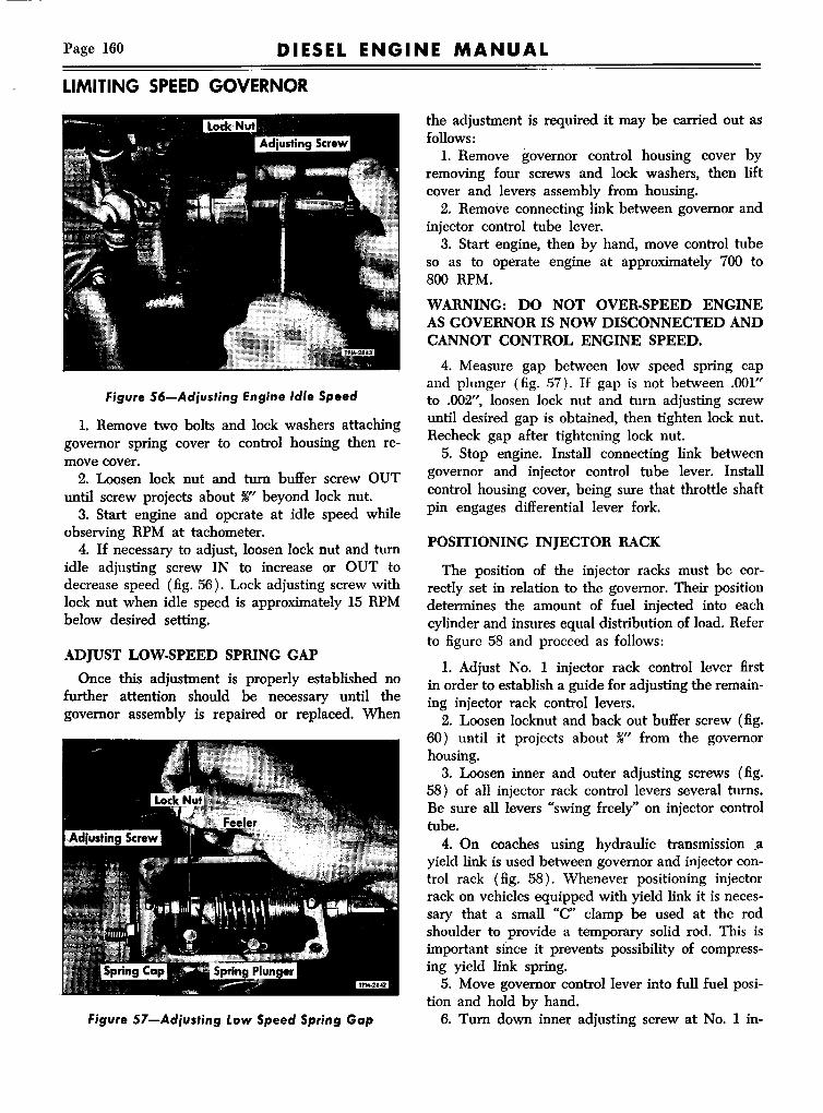
Page 160 DIESEL ENGINE MANUAL
LIMITING SPEEDGOVERNOR
Figure 56-Adjusting Engine Idle Speed
1. Remove two bolts and lock washers attachinggovernor spring cover to control housing then remove cover.2. Loosen lock nut and tum buffer screw OUT
until screw projects about 5fs" beyond lock nut.3. Start engine and operate at idle speed while
observing RPM at tachometer.4. If necessary to adjust, loosen lock nut and tum
idle adjusting screw IN to increase or OUT todecrease speed (fig. 56). Lock adjusting screw withlock nut when idle speed is approximately 15 RPMbelow desired setting.
ADJUST LOW-SPEED SPRING GAPOnce this adjustment is properly established no
further attention should be necessary until thegovernor assembly is repaired or replaced. When
figure 57-Adjusting Low Speed Spring Gap
the adjustment is required it may be carried out asfollows:
1. Remove governor control housing cover byremoving four screws and lock washers, then liftcover and levers assembly from housing.2. Remove connecting link between governor and
injector control tube lever.3. Start engine, then by hand, move control tube
so as to operate engine at approximately 700 to800 RPM.
WARNING: DO NOT OVER-SPEED ENGINEAS GOVERNOR IS NOW DISCONNECTED ANDCANNOT CONTROL ENGINE SPEED.
4. Measure gap between low speed spring capand plunger (fig. 57). If gap is not between .001"to .002", loosen lock nut and tum adjusting screwuntil desi.red gap is obtained, then tighten lock nut.Recheck gap after tightening lock nut.5. Stop engine. Install connecting link between
governor and injector control tube lever. Installcontrol housing cover, being sure that throttle shaftpin engages differential lever fork.
POSITIONING INJECTOR RACK
The position of the injector racks must be correctly set in relation to the governor. Their positiondetermines the amount of fuel injected into eachcylinder and insures equal distribution of load. Referto figure 58 and proceed as follows:
1. Adjust No. 1 injector rack control lever firstin order to establish a guide for adjusting the remaining injector rack control levers.
2. Loosen locknut and back out buffer screw (fig.60) until it projects about 5fs" from the governorhousing.3. Loosen inner and outer adjusting screws (fig.
58) of all injector rack control levers several turns.Be sure all levers "swing freely" on injector controltube.4. On coaches using hydraulic transmission .a
yield link is used between governor and injector control rack (fig. 58). Whenever positioning injectorrack on vehicles equipped with yield link it is necessary that a small "C" clamp be used at the rodshoulder to provide a temporary solid rod. This isimportant since it prevents possibility of compressing yield link spring.5. Move governor control lever into full fuel posi
tion and hold by hand.6. Tum down inner adjusting screw at No.1 in-

Page 161DIESEL ENGINE MANUAL
jector rack control lever until governor control leverstarts to move away from full fuel position.7. Tighten outer adjusting screw to lock rack con
trol lever in position. This should accomplish thedesired setting of No.1 injector rack control lever.8. Check the adjustment, holding governor con
trol lever in full open position, then pull injectorcontrol tube lever towards governor. Movementshould not exceed Ya4" (max.).9. If movement is in excess of %4", it will be
necessary to readjust "setting" of No.1 injector rackcontrol lever.10. After No.1 injector rack control lever is once
correctly set, IT MUST NOT BE CHANGEDTHROUGHOUT ADJUSTMENT OF REMAININGINJECTOR RACK CONTROL LEVERS.11. With governor control lever held in full fuel
position, note rotary movement of No. 1 injectorrack to lever coupling. Pressure of finger tip willproduce a tendency to rotate, but coupling shouldnot be loose. All injector rack control levers mustnow be adjusted to the same "feel" at coupling toinsure same amount of fuel injected into eachcylinder at full load as follows.12. Hold governor control lever in full fuel posi
tion. Adjust No. 2 injector rack control lever byturning down inner adjusting screw while finger tipis touching No. 2 injector rack coupling. Whencoupling loses its rotary movement, tighten outeradjusting screw.13. "Feel" No.2 and No.1 injector rack couplings
with finger tip to check rotary movement.14. If No.1 injector rack coupling now feels loose,
No.2 injector rack coupling is too tight. Correct No.2 injector rack adjustment by loosening inner adjusting screw and tightening outer adjusting screw.15. If No.2 injector rack coupling feels loose, cor
rect by loosening outer adjusting screw slightly andtighten inner adjusting screw.16. When No.2 injector rack coupling "feels" the
same as No.1, repeat this procedure (operations 12,13, 14, 15) on all remaining injector racks. That iscompare No.3 injector rack coupling with No.1, etc.17. Recheck idle speed as previously instructed in
this section.
NOTE: An accurate rack setting in "full fuel" position will result in balanced injection throughout theentire operating range. Therefore, a "rough" idleafter tune-up calls for a check of governor, injectorsand related controls. Do not attempt to change rackposition with engine idling or operating at any
LIMITING SPEEDGOVERNOR
Figure 58-Governor 10 Injector Rack Yield Linkspeed. When one rack is adjusted "in" more thanthe others, only that one injector rack can reach"full fuel" position. As a result, maximum output ofthe engine will be reduced.
HIGH SPEED NO-LOAD ADJUSTMENTAt time of vehicle delivery governor is adjusted to
maximum specified speed and further adjustments
Figure 59-Adjusting No-Load High Speed

Page 162 DIESEL ENGINE MANUAL
LIMITING SPEEDGOVERNOR
Figure 60-8uffer Spring Screw Adjustment
are ordinarily unnecessary. However, in the eventof a governor change, it may be necessary to adjustthe maximum no-load speed. Whenever it is necessary to adjust, the engine should be at operatingtemperature and the following procedure used:
1. Remove two bolts and lock washers attachinggovernor spring cover to control housing, then remove cover.2. Loosen the high speed spring retainer lock nut
using a spanner wrench.3. Start engine and operate at maximum speed.
CAUTION: THERE ~UST BE NO LOAD ONENGINE DURING THE MAXIMUM NO-LOADSPEED ADJUSTMENT.
Observe engine RPM at tachometer.4. Tum high speed spring retainer IN to increase
or OUT to decrease speed (fig. 59) until desired noload setting is obtained.5. Hold high speed spring retainer, then tighten
lock nut, using spanner wrench.6. Recheck and if necessary readjust after tighten
ing lock nut.7. Install governor spring cover and secure with
two bolts.
BUFFER SPRING ADJUSTMENTGovernors are equipped with buffer springs, the
purpose is to prevent low speed engine "roll" or"stalling," which is manifest on some engines andabsent on others.To adjust after the screw has been backed out
as directed for the low speed adjustment, tum screwIN until engine idling speed, is increased slightly(not over 20 rpm), thus insuring spring contactwith the differential lever (fig. 60).NOTE: Accelerate and decelerate engine severaltimes. H smoke is visible in exhaust when engine isdecelerated, check buffer spring to make sure injector racks are returning to No-Fuel position.
ECONOMY-RANGE LIMITING SPEEDGOVERNORA limiting speed economy-range type governor is
used on some trucks. This governor is essentially alimiting speed type and in many respects is the sameas previously described under heading "LimitingSpeed Governor." However, an air operated pistonis added, which provides two high speed ranges(fig. 61).When vehicle is being operated in the reduced
transmission and axle ranges, air is present at governor and engine is permitted to operate at maximum RPM. When transmission is in 4th or 5th speedand rear axle is in high range, air is shut off fromgovernor and piston returns to a position whichreduces engine approximately 200 RPM.
REPLACEMENTInstructions given previously in this manual cov
ering removal and installation are also applicable toeconomy range governor.
SPRINGS AND PLUNGERS REMOVAL
Governor springs, plungers, seats, and retainers(fig. 62) located in control housing (fig. 61) can beremoved and installed while governor is installed orat bench, as follows:1. Remove two bolts attaching piston housing to
control housing, then remove housing, with cover,piston, and sleeve.2. Remove cover from housing, then push piston,
sleeve, and seal from housing.3. Remove spring retainer nut from control hous
ing, using nut wrench J-1652-01. Spring seats,springs, plunger, adjusting screw, and spring capcan now be removed from control housing. Refer tofigure 62 for arrangement of these parts.
SPRINGS AND PLUNGERS INSTALLATION
Refer to figure 62 and proceed as follows:1. Position one end of low speed spring into cap,

Page 163DIESEL ENGINE MANUAL
then place spring seat on opposite end of spring.Install this assembly into governor spring plunger.2. Thread low speed adjusting screw into spring
plunger.3. Install this assembly into position through open
ing in control housing.4. Install high speed spring and spring guide over
plunger.5. Thread spring retainer into housing (fig. 63)
and tighten with nut wrench.6. If sleeve and piston have been separated they
should be threaded together until a preliminarymeasurement of 2%2" for 6-71 or 1%2" for 4-71 engines is obtained (fig. 64).1. Install piston, sleeve, and seal ring assembly in
piston housing.8. Secure piston housing and piston assembly to
control housing, using new gaskets at each end ofhousing.
CONTROL HOUSING
Disassembly, maintenance, repair, and reassemblyof control housing is described previously in thissection.
WEIGHTS AND HOUSING
Disassembly, maintenance, repair, and reassemblyof weights and housing is described previously in thissection.
GOVERNOR-ECONOMY RANGE
1 Housing Bolt 13 Lock Nut2 Spring Retainer 14 Buffer Screw3 Spring Seat 15 Control Housing4 High Speed Spring 16 Gasket5 Spring Plunger 17 Lock Nut6 Low Speed Spring 18 Idle Speed Adjusting
Seat Screw7 Low Speed Spring 19 Seal Ring8 Low Speed Spring 20 Piston Sleeve
Cap 21 Piston9 Lock Nut 22 Housing Covero Gap Adjusting Screw 23 Lock Nut1 Operating Lever 24 Reduced High SpeedBuffer Spring Adjusting Bolt TPM-4702
figure 61-Economy-Range GovernorControl Mechanism
8 7 6 4 5 4 3
\
~
,
~017 16 15 14 13 12 11 10 9
\ \ \ \ \.~ \ \(- IWWU' ~ lii'iti' ! (JB1l -- - t;
1 Adjusting Bolt and Nut 7 Piston 13 High Speed Spring2 Bolt 8 Piston Sleeve 14 Spring Plunger3 Housing Cover 9 Spring Retainer 15 Low Speed Spring Seat4 Gasket 10 Lock Nut 16 Low Speed Spring5 Piston Housing 11 Idle Speed Adjusting Screw 17 Low Speed Spring Cap6 Seal Ring 12 Spring Seat TPM-4579
figure 62-Relative Location of Governor High and Low Speed Springs, Plunger, Seats, and Piston

Page 164 DIESEL ENGINE MANUAL
GOVERNOR-ECONOMY RANGE
Figure 63-High Speed Spring Retainer Insta,IIed
ADJUSTMENTSSeven adjustments are necessary on limiting speed
economy-range type governor, and should be performed in the following sequence:
1. Adjust engine idling speed (preliminary).2. Adjust gap between low speed spring cap and
spring plunger.3. Perform injector rack to injector positioning
adjustment,4. Adjust high speed piston for maximum engine
RPM.5. Adjust high speed piston for reduced speed
RPM.6. Adjust engine idling speed (final).7. Adjust buffer spring tension.
1- 2 5/ 32:' 6 CY-t9/32~4 CYL.
TPM-4581-1
Figure 64-High Speed Piston Preliminary Setting
IDLE SPEED ADJUSTMENT
Even though the low-speed adjustment is set atthe factory before the engine is shipped, it may bedesirable either to raise or lower the idling speed ofthe engine. The engine should be at operating temperature, while adjustment is being made as follows:1. Remove two bolts attaching piston housing to
control housing, then remove housing and pistonassembly.2. Loosen lock nut and turn buffer screw OUT
until screw projects about %" beyond lock nut.3. Start engine and operate at idle speed while
observing RPM at tachometer.4. If necessary to adjust, loosen lock nut and turn
idle screw IN to increase or OUT to decrease speed(fig. 65). Lock adjusting screw with lock nut whenidle speed is approximately 15 RPM below desiredsetting.
ADJUST LOW-SPEED SPRING GAP
Once this adjustment is properly established nofurther attention should be necessary until the governor assembly is repaired or replaced. When theadjustment is required it may be carried out asfollows:
1. Remove governor control housing cover byremoving four screws and lock washers, then liftcover and levers assembly from housing.2. Remove connecting link between governor and
injector control tube lever.3. Start engine, then by hand, move control tube
so as to operate engine at approximately 700 to 800RPM.
WARNING: DO NOT OVER-SPEED ENGINEAS GOVERNOR IS NOW DISCONNECTED ANDCANNOT CONTROL ENGINE SPEED.
4. Measure gap between low speed spring capand plunger (fig. 57). If gap is not between .001" to.002", loosen lock nut and turn adjusting screw untildesired gap is obtained, then tighten lock nut. Recheck gap after tightening lock nut.5. Stop engine. Install connecting link between
governor and injector control tube lever. Install control housing cover, being sure that throttle shaft pinengages differential fork.
POSITION INJECTOR CONTROL RACKS
The position of the injector racks must be correctly set in relation to the governor. Their positiondetermines the amount of fuel injected into each

Page 165DIESEL ENGINE MANUAL
cylinder and ensures equal distribution of the load.A fuel modulator assembly is installed in cylinder
head on turbocharged engines. This unit is controlled by air box pressure and operates in such amanner as to retard fuel injector racks as air pressure drops, due to reduced engine rpm. In addition,injector racks cannot move into full speed position,until air box pressure is sufficient to provide propercombustion.When adjusting the fuel control racks on engines
equipped with a fuel modulator, be sure no interference is encountered from the fuel modulating device.This may be assured by loosening the fuel modulatorlever "U" bolt and moving the modulator lever alongthe injector control tube to avoid contact with modulator cam or adjacent cylinder head stud nut.
NOTE: When the modulator lever is in position,it may strike the cylinder head stud nut when therack is moved toward the OFF position. The NOFUEL position is reached before this contact takesplace and should therefore cause no concern.
No.1 injector rack control lever must be adjustedfirst to establish a guide for adjusting the remaininginjector rack control levers.
1. Disconnect any linkage attached to governorthrottle lever.2. Loosen lock nut and back out buffer screw
approximately %"3. ON ENGINES EQUIPPED WITH FUEL
MODULATOR, loosen lock nut and back out idlespeed adjusting screw until o/i6" of thread projectsbeyond lock nut. NOTE: This lowers the tension onthe low speed spring permitting the governor gap toclose completely without overcoming the control tubefuel modulating spring.4. Loosen all injector control rack inner and outer
adjusting screws, as shown in Figure 66. Be sure allcontrol levers are free on the injector control tube.5. Move governor throttle control lever to the
FULL FUEL position as shown in Figure 66. Turninner adjusting screw down until a slight movementof the control tube is observed or a step up in effortis noted. This will place 'No. 1 injector rack in theFULL FUEL position. Turn down outer adjustingscrew until it bottoms lightly on the injector controltube. Then alternately tighten both the inner andouter adjusting screws until tight.
PARAGRAPHS 6 AND 7 FOLLOWING AREAPPLICABLE ONLY TO ENGINES EQUIPPEDWITH FUEL MODULATOR.
GOVERNOR-ECONOMY RANGE
figure 65-Ad;u51ing Idle Speed
6. Check the setting of No. 1 injector rack bymoving the governor control lever toward the NOFUEL position while holding the governor to control tube link, with light finger pressure, In a direction toward the governor. This pressure will retainthe low speed spring gap in the closed position whenthe throttle control lever is moved from the fullspeed position toward the idle position. A properrack setting will be indicated by an immediate corresponding movement of the No. 1 injector rackfrom the FULL FUEL position when the governorcontrol lever is moved away from the FULL SPEEDposition.
7. If no immediate corresponding movement ofthe injector rack is observed in Step 6, back off inneradjusting screw approximately Ys of a turn and
figure 66-P05ilionin9 In;ector Conl;ol Rack

Page 166 DIESEL ENGINE MANUALGOVERNOR-ECONOMY RANGE
tighten outer adjusting screw. When the setting iscorrect, the injector rack will be snug on the pin ofthe rack control lever and still maintain the movement specified on item 6.
PARAGRAPHS 8 AND 9 FOLLOWING AREAPPLICABLE ONLY TO ENGINES NOTEQUIPPED WITH FUEL MODULATOR.
8. With the governor control lever held in theFULL FUEL position, check for movement of theinjector control tube lever. There should be a slightmovement not to exceed .005".9. If no movement is observed, back off inner
adjusting screw approximately Ys of a turn andtighten outer adjusting screw. If the movement exceeds that specified, back off outer adjusting screwapproximately Ys of a turn and tighten inner adjusting screw. When the setting is correct, the injectorrack will be snug on the pin of the rack control leverand still maintain the movement specified in itemabove.
10. Remove clevis pin between the fuel rod andthe injector control tube lever. See Figure 34.11. Manually hold No. 1 injector in the FULL
FUEL position and turn down inner adjusting screwof No. 2 injector until the injector rack of No. 2injector has moved into the FULL FUEL positionand the inner adjusting screw is bottomed on theinjector control tube. Turn outer adjusting screw
down until it bottoms lightly on the injector controltube. Then alternately tighten both the inner andouter adjusting screws until tight.12. Recheck No. 1 injector fuel rack to be sure
that it has remained snug on the pin of the rackcontrol lever while adjusting No. 2 injector. If therack of No. 1 injector has become loose, back offslightly on the inner adjusting screw on No. 2 injector rack control lever. Tighten outer adjustingscrew. When the settings are correct, the racks ofboth injectors must be snug on the pin of theirrespective rack control levers.
13. Position the remaining control rack levers asoutlined in items 11 and 12.
14. Insert the clevis pin between the fuel rod andthe injector control tube lever.15. Reset idle speed adjusting screw until it pro
jects %" beyond the lock nut. Tighten lock nut.
HIGH SPEED ADJUSTMENT
This type governor has two high speed no-loadadjustments (1) maximum high speed (2) reducedhigh speed. Each of these adjustments is accomplished separately and in the following order:
Maximum High Speed Adjustment
1. Start engine and operate at full speed. Be sureair is supplied to governor. No load speed is 125-150RPM above full load speed shown on chassis serialnumber plate on cab door hinge pillar.2. Remove two bolts attaching piston housing to
governor control housing, then remove housing andpiston assembly.
3. Remove piston and sleeve assembly with sealring from piston housing.
4. Measure distance from end of piston to end ofsleeve (fig. 64). This dimension should be approximately 2%2" for 6-71 or 1%2" for 4-71 engines.5. Should it be necessary to increase engine RPM
the dimension, shown in Figure 64, should be increased. Also, when necessary to decrease engineRPM the dimension, sho~n in Figure 64, should bedecreased. NOTE: Each full tum of piston andsleeve will change engine approximately 100 RPM.6. Install piston and sleeve assembly in piston
housing, then install piston housing to governor control housing.
7. Check for proper setting and readjust as neces-Figure67-Reduced High SpeedAdjus'men' sary.

DIESEL ENGINE MANUAL Page 167
Reduced High Speed Adjustment1. Disconnect wire at governor air supply solenoid
so as to prevent air reaching governor.2. Start engine and operate at full speed while
observing RPM at tachometer. Proper adjustment isapproximately 200 RPM below maximum no-loadspeed.3. Loosen lock nut and turn adjusting bolt (fig.
67) as necessary to obtain proper reduced high speedRPM. Lock screw with nut when proper adjustmentis obtained.4. Should it be necessary to increase engine RPM
turn adjusting bolt (fig. 67) in to increase, or out todecrease engine RPM.5. Reconnect wire to solenoid when adjustment is
completed.
READJUST IDLE SPEED
With the no-load maximum high speed and re-
------ --- - .
GOVERNOR-ECONOMY RANGE
duced high speed properly adjusted, the idle speedshould be readjusted as recommended under heading "Idle Speed Adjustment" in this section.
ADJUST BUFFER SCREW
1. Maximum no-load speeds and idle speed mustbe in proper adjustment as previously described.
2. Start engine and operate at idle speed. Turnbuffer screw in so that it contacts the differentiallever as lightly as possible and still eliminates theengine roll. Buffer screw final adjustment should bemade after engine has thoroughly warmed after several hours of operation.
3. Recheck maximum no-load speeds. If it hasincreased more than 25 RPM from the speeds previously set, back off buffer screw until increase is lessthan 25 RPM.

Page 168 DIESEL ENGINE MANUAL
All Tune-up Operations and Adiustments
Should Be Performed Carefully and In
Proper Sequence

DIESEL ENGINE MANUAL Page 169
ENGINE RUN-IN SCHEDULEEngines in which new pistons or piston rings,
cylinder liners, main bearings, or connecting rodbearings have been installed, should be operated ona RUN-IN schedule prior to release for service.
The purpose of the RUN-IN schedule is to assureproper alignment and seating of parts before theengine is subjected to FULL-LOAD operation.When filling the lubrication system, remove valve
cover and pour a gallon of oil over the valvemechanism.
Check valve lash and injector timing before crank-ing the engine.A minimum water jacket of 160°F. should be
maintained throughout the run.The recommended oil pressures are 30 lbs. mini
mum at 2000 rpm (4 lbs. minimum at idle.)Frictional losses in the engine will continue to
decrease for 10 or 20 hours and consequently engineperformance will improve. During this period it isdesirable to avoid maximum power output exceptfor short intervals.
SCHEDULE WITHOUT DYNAMOMETERWhere dynamometer is not available, engine
RUN-IN schedule must be performed in the following manner.
1. Start engine and operate at fast idle until watertemperature reaches 1600 F. Observe and correctany existing oil or water leaks.
2. Run engine for 15 minutes at 1000 RPM-noload.3. Run engine for 30 minutes at 1900 RPM- no
load.4. Tighten cylinder head nuts.5. Lash valves, and adjust bridge on four-valve
heads with engine hot. Refer to "Specifications" fordimensions.
6. Check injector rack for proper positioning, alsocheck governor for proper operation.
7. Release vehicle to operator with instructionsto continue with the following:
a. Run engine on road for 30 minutes at governedspeed with load and with transmission not higherthan 3rd speed.b. Run engine on road for 30 minutes at governedspeed with load and with transmission not higherthan 4th speed.S. Change lubricating oil and filter element, also
clean strainer at or before 500 miles to remove anyforeign material which may have accumulated during run-in period.
DYNAMOMETER SCHEDULETime (Hours) Engine RPM % Load
1/0 1000 074
~ 1000 20~ 1300 301/00 1500 5072
~ IS00 SO1 2000 100
TOTAL RUN-IN PERIOD-3~ HOURS0Warm-up and inspection period. This is a mini
mum run-in schedule and if time permits, the engineshould be run for longer time increments than specified before applying full load.
(I (ICheck valve lash with engine hot. Check injectortiming. Refer to "Specifications" for dimensions.
Check injector balance and idle operation. (Referto "Control Rack Positioning," in INJECTOR sectionof this manual and "Governor Adjustment," in respective GOVERNOR sections of this manual.
Inspect for oil and water leaks and tighten allexternal bolts.
Change lubricating oil and filter element, alsoclean oil strainer (where used) after completing therun-in to remove any metallic or foreign materialaccumulated during this period.

Page 170 DIESEL ENGINE MANUAL
ENGINE TUNE-UP
Figure I-Engine Tune-up Chart
TUNE-UP CHARTResults obtained from an engine tune-up may be
unsatisfactory if a "hit and miss" method is usedinstead of a systematic approach to the job; thereforethe logical solution is a complete checkup followingthe cycle in figure 1 and carrying out each step asdirected below.
NOTE: Before tune-up procedure is started it isimportant that air cleaners and fuel filters areserviced as described in applicable maintenancemanuals. Crankcase breather tube and air boxdrains must be clean and unobstructed. Air boxdrains may be cleaned with compressed air.
CAUTION: Remove or at least loosen an air boxhand hole cover, otherwise blower or end plategaskets may be damaged by excessive air pressure.
Reference should be made to "TESTING ANDDIAGNOSIS" also to "TROUBLE SHOOTING" forengine diagnosis, trouble symptoms, causes, andremedial measures.
The following tune-up adjustments are applicableto two and four-valve cylinder head engines.
TUNE-UP PROCEDURESTo completely tune-up an engine, all adjustments
except bridge balancing adjustment and exhaustvalve cold setting must be performed only after enginehas reached its normal operating temperature.
Results obtained from an engine tune-up are usually unsatisfactory, unless a step-by-step, systematic,and orderly approach is used. Refer to figure 6 andproceed in the following sequence:
1. Bridge Balancing Adjustment (4 Valve Head)2. Exhaust Valve Lash Adjustment3. Time Fuel Injectors4. Adjust Governor Gap5. Adjust Injector Control Racks6. Adjust MaximumNo-Load Speeds7. Adjust Idle Speed8. Adjust Buffer Screw9. Adjust Fuel Modulator (Turbo-Charged)
NOTE: Whenever a push rod has been disconnected from the clevis, the push rod must bescrewed back into place until end of push rod appears through the clevis. H this is not done, thepiston may hit the head of the valve when theengine is being turned, due to the small clearance,between the valves and piston head at the piston'supper position, or an injector plunger may "Bottom"before being properly adjusted.Clearance between valve rocker arm and exhaust
valve stem, or bridge with engine at operating temperature is important and should be maintained.Too little clearance causes a loss of compression,misfiring of cylinders and eventual burning of valvesand valve seats. Too much clearance results in noisyoperation of the engine, especially in the low speedrange.
BRIDGE BALANCING ADJUSTMENTThe exhaust valve bridge assembly is adjusted and
the adjustment screw locked securely at the time thecylinder head is installed on the engine. Until wearoccurs with the operation of the engine, no furtheradjustment is required on the exhaust valve bridge.When wear is evident, make complete bridge balancing adjustment as outlined in the following steps:

DIESEL ENGINE MANUAL Page 171
1. Refer to "Fuel Injector" in Fuel System Sectionand remove injector fuel jumper lines, then removerocker arm shaft brackets. Lift rocker arms and swingback to provide accessibility to valve bridge.2. Remove bridge and spring from guide.3. Place bridge in a vise and loosen adjusting screw
lock nut.4. Install bridge on bridge guide without spring.5. Press straight down on the pallet surface of
bridge (fig. 2). Tum adjusting screw until it justtouches the valve stem, then tum screw an additionalJ$ to }.:,tum and tighten locknut finger tight.6. Remove bridge and place in a vise. With screw
driver, hold screw from turning and tighten lock nuton the adjusting screw. Complete the operation bytightening the lock nut to 25 ft. lbs. torque, being surethat screw does not tum.IMPORTANT: Do not tighten while on engine as
binding may damage bridge, guide, and valve.7. Apply engine oil to bridge and bridge guide.8. Reinstall the bridge in its original position with
out the bridge spring.9. Place a .0015" feeler under each end of the bridge
(fig. 3). NOTE: Feeler used at inner end of bridgemust be narrow enough to fit in bridge locatinggroove. Pressing down on the pallet surface of thebridge, both feelers must be tight. H both feelers arenot tight, readjust the screw as previously instructed.10. Remove the bridge and reinstall in its original
position with the bridge spring in place.11. Adjust remaining bridges as instructed in previ
ous paragraphs.12. If cylinder head has been removed, reinstall on
the engine. Tighten cylinder head stud nuts to theirspecified torque before assembling the rocker shaftbrackets to the head. This precaution is necessary toprevent valve damage due to mislocated bridges.13. Install the rocker arm assemblies, being sure
valve bridges are properly positioned on the innervalve stems.14. Tighten rocker shaft bracket bolts to their rec
ommended torque.15. Reconnect fuel jumper lines to injectors and
connectors.
VALVE LASH ADJUSTMENT(4 Valve Type)
The clearance between the bridge adjusting screwand the valve stem should be set with the engine
figure 2-Adjusting Valve Bridge (4-Valve HeadJ
COLD. This setting should result in proper clearanceat normal engine operating temperature. Refer to"Specifications" for COLD and HOT settings.All valves may be lashed in firing order sequence
during one full revolution of the crankshaft. CAUTION: Left hand rotation engines should not bebarred in direction of rotation by use of wrench oncrankshaft bolt. Refer to "General Information" in thismanual for engine firing order.VALVE LASH MUST ALWAYSBE ADJUSTED
AT THE PUSH ROD. DO NOT DISTURB BRIDGEADJUSTING SCREW.
1. Place governor throttle control lever in the NOFUEL position.
figure 3-Valve Bridge Adjustment Check(4-Valve HeadJ
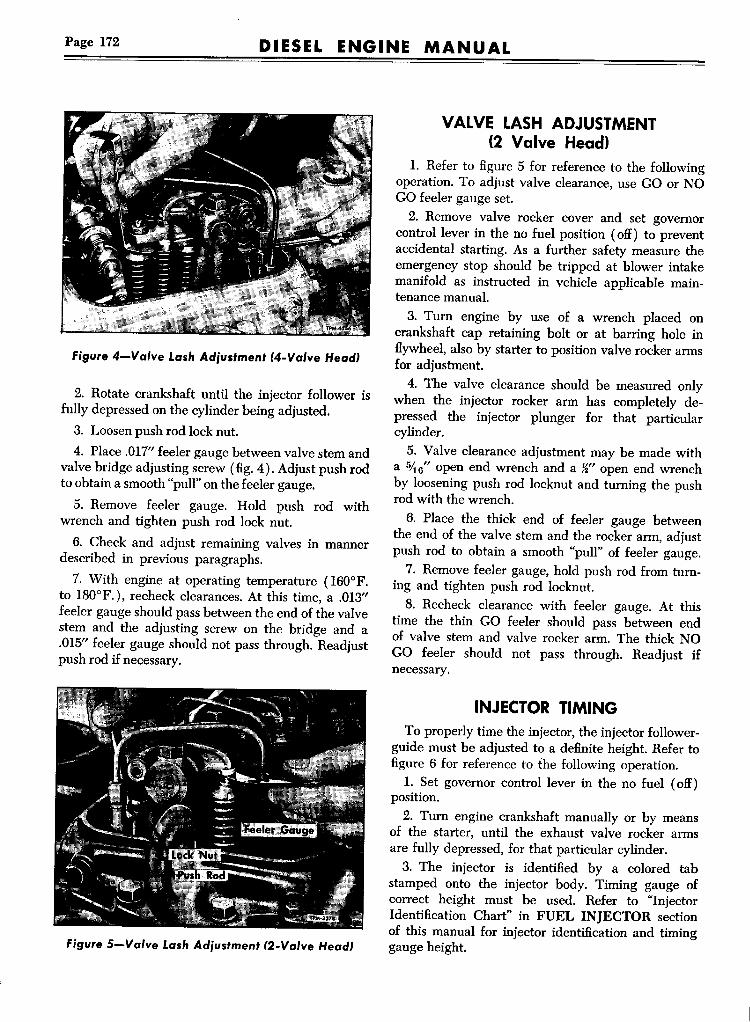
Page 172 DIESEL ENGINE MANUAL
Figure 4-Valve Lash Ad;'ustment C4-Valve HeadJ
2. Rotate crankshaft until the injector follower isfully depressed on the cylinder being adjusted.3. Loosen push rod lock nut.4. Place .017" feeler gauge between valve stem and
valve bridge adjusting screw (fig. 4). Adjust push rodto obtain a smooth "pull" on the feeler gauge.
5. Remove feeler gauge. Hold push rod withwrench and tighten push rod lock nut.6. Check and adjust remaining valves in manner
described in previous paragraphs.7. With engine at operating temperature (160°F.
to 180°F.), recheck clearances. At this time, a .013"feeler gauge should pass between the end of the valvestem and the adjusting screw on the bridge and a.015" feeler gauge should not pass through. Readjustpush rod if necessary.
Figure 5-Valve Lash Ad;ustment C2-Valve HeadJ
VALVE LASH ADJUSTMENT(2 Valve Head)
1. Refer to figure 5 for reference to the followingoperation. To adjust valve clearance, use GO or NOGO feeler gauge set.2. Remove valve rocker cover and set governor
control lever in the no fuel position (off) to preventaccidental starting. As a further safety measure theemergency stop should be tripped at blower intakemanifold as instructed in vehicle applicable maintenance manual.3. Tum engine by use of a wrench placed on
crankshaft cap retaining bolt or at barring hole inflywheel, also by starter to position valve rocker armsfor adjustment.4. The valve clearance should be measured only
when the injector rocker arm has completely depressed the injector plunger for that particularcylinder.5. Valve clearance adjustment may be made with
a 5;l6" open end wrench and a ~" open end wrenchby loosening push rod locknut and turning the pushrod with the wrench.6. Place the thick end of feeler gauge between
the end of the valve stem and the rocker arm, adjustpush rod to obtain a smooth "pull" of feeler gauge.7. Remove feeler gauge, hold push rod from turn
ing and tighten push rod locknut.8. Recheck clearance with feeler gauge. At this
time the thin GO feeler should pass between endof valve stem and valve rocker arm. The thick NOGO feeler should not pass through. Readjust ifnecessary.
INJECTOR TIMINGTo properly time the injector, the injector follower
guide must be adjusted to a definite height. Refer tofigure 6 for reference to the following operation.1. Set governor control lever in the no fuel (off)
position.2. Tum engine crankshaft manually or by means
of the starter, until the exhaust valve rocker armsare fully depressed, for that particular cylinder.3. The injector is identified by a colored tab
stamped onto the injector body. Timing gauge ofcorrect height must be used. Refer to "InjectorIdentification Chart" in FUEL INJECTOR sectionof this manual for injector identification and timinggauge height.

DIESEL ENGINE MANUAL Page 173
4. Place the injector timing gauge in the hole provided on top of the injector body with one of the"Hats" toward the injector.5. Adjust the injector rocker arm by loosening
lock nut and turning the push rod with an endwrench, until the bottom of the timing gauge headwill just pass over (drag lightly) the top of the injector follower guide.6. Hold push rod from turning and tighten lock
nut. Recheck adjustment with injector timing gaugeand readjust if necessary.
GOVERNOR ADJUSTMENTSMaximum efficiency, economy, and satisfactory
performance of the engine cannot be obtained unlessthe governor is carefully and accurately adjusted.Adjustments must be performed in logical sequence.Reference should be made to respective GOVERNORsection of this manual for complete adjustment procedure, also to "Control Rack Positioning" in FUELINJECTOR section of this manual.
THROTTLE DELAY ADJUSTMENTThe following instructions outline a procedure to
follow when adjusting the throttle delay cylinder.Refer to figure 7.1. Adjustment is made with the engine stopped.2. Loosen two bolts attaching clamp to injector
control tube.3. Temporarily install a gauge between injector
body and shoulder on injector rack (fig. 7). Gaugeis .404" (approx. 1%2") thick and can be madelocally.4. Position gauge as shown and exert a light pres
sure on the control tube in the direction of full fuel.5. Align the piston so it is Hush with the cylinder
edge.6. Tighten the two clamp bolts, then remove gauge.7. Rotate the injector control rack from "OFF" to
"FULL" position to be sure it does not bind.NOTE: Each time the injector racks are set the
throttle delay must be first taken out of adjustment;injector racks are then set and the throttle delay readjusted.
FUEL MODULATOR ADJUSTMENTThe following adjustment should only be performed
after other adjustments, such as, bridge balancing,
Figure 6-Timing Fuel Iniector
valve lash, fuel injectors and governor adjustmentshave been completed.
1. Hold fuel modulator piston and cam in highspeed position by applying not less than 20 psi airpressure to piston or by prying cam out with a screwdriver (fig. 8).
Figure 7-Throttle Delay Adiustment
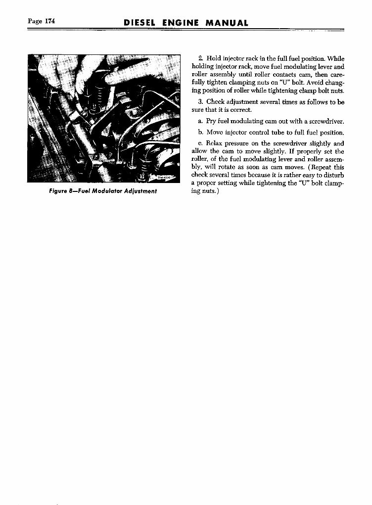
Page 174 DIESEL ENGINE MANUAL
Figure 8-Fuel Modulator Adjustment
2. Hold injector rack in the full fuel position. Whileholding injector rack, move fuel modulating lever androller assembly until roller contacts cam, then carefully tighten clamping nuts on "U" bolt. Avoid changing position of roller while tightening clamp bolt nuts.
3. Check adjustment several times as follows to besure that it is correct.
a. Pry fuel modulating cam out with a screwdriver.
b. Move injector control tube to full fuel position.
c. Relax pressure on the screwdriver slightly andallow the cam to move slightly. If properly set theroller, of the fuel modulating lever and roller assembly, will rotate as soon as cam moves. (Repeat thischeck several times because it is rather easy to disturba proper setting while tightening the "U" bolt clamping nuts.)

DIESEL ENGINE MANUAL Page 175
.2>~ ~ <J1UUIIJe g~TESTINGAND DIAGNOSIS
Various diesel engine pressures can be a definiteaid in determining the condition of an engine or indiagnosing engine difficulties when abnormal operation is apparent. An engine which operates satisfactorily is characterized by normal air box pressure,crankcase pressure, exhaust back pressure, compression pressure, and low air intake restriction. Normalpressures are indicative of an efficient engine which,if properly tuned, is providing maximum power andtorque for vehicle requirements while consuming aslittle fuel as possible consistent with the design ofthe engine.
Normal diesel engine pressures are presentedherein and will prove useful as a means of measuringthe operating condition of an engine. An attempt ismade to list symptoms and causes of abnormal pressures however experience with the diesel engine anda basic knowledge of its operation are pre-requisitesto the intelligent use of the pressures shown. The"TROUBLE-SHOOTING" section of this manualwill also prove helpful in diagnosing the cause ofabnormal pressures when encountered.
DIESEL ENGINE NORMAL PRESSURE CHARTManometer
orMagnehelic Gauge
PressureGauge
Minimum Air Box PressureExcept "E" and "SE"-4-71Except "E" and "SE"-6-71 ."E" Series-2 Valve Head"ES" Series-4 Valve Head ·········
9.0" HG10.0" HG6.5" HG6.0" HG
4.4 PSI4.9 PSI3.2 PSI3.0 PSI
Maximum Crankcase Pressure4-716-71
2.7" H203.0" H20
Exhaust Back Pressure 5.0" HG 2.5 PSI
Maximum Blower Intake RestrictionClean Air CleanerDirty Air Cleaner
20.0" H2030.0" H20
Fuel Pressure at Inlet ManifoldNormalMinimum
40-50 PSI20 PSI
Lubricating Oil PressureNormalMinimum for Safe Operation.
40-60 PSI30 PSI
Coolant Temperature-160°-185°Lubricating Oil Temperature-200°-225°Compression Pressure-600 RPM at Sea LevelAverage-New Engine-Except "E" and "SE".Average-New Engine-"E" and "SE"...Minimum-"E" and "SE".Minimum-Except "E" and "SE" ...
450 PSI475 PSI420 PSI400 PSI
NOTE: Unless otherwise indicated, above specifications are taken at 2000 RPM,at 1500feet above sea level, and at 90°F.
H20=Water-HG=Mercury-PSI=Lbs. Per Sq. In.

Page 176 DIESEL ENGINE MANUALTESTING AND DIAGNOSIS
Figure I-Cutting Out an In;ector
2 3
4 Fuel Pressure Gauge5 Compression Gauge6 Tachometer7 Compression Gauge Adapter8 Thermometer9 Pressure Gauge 0-100#10 Pressure Gauge 0-15#
13 Connector14 Bushing15 Adapter16 Manometer - Mercury17 Manometer - Water18 Hose19 Mercury
Figure 2-Diagnosis Test Kit
LOCATING A MISFIRING CYLINDER1. Start engine and run at part load until it reaches
normal operating temperatures.2. Remove valve cover.
3. Run engine at IDLE speed and check valveclearance. The clearance should be .009" (two valvecylinder head) or .014" (four valve cylinder head).4. Hold the No. I injector follower down with a
screwdriver (fig. 1), thus preventing operation of theinjector.If the cylinder has been misfiring, there will be no
noticeable difference in the sound and operation ofthe engine. If the cylinder has been firing properly,there will be a noticeable difference in the sound andoperation when the plunger is held down. This issimilar to short-circuiting a spark plug of a gasolineengine.
S. If cylinder No.1 is firing properly, repeat theprocedure on the other cylinders until the faulty onehas been located.
6. Providing that the injector operating mechanism of the faulty cylinder is functioning satisfactorily, replace the fuel injector.
7. If the installation of the new injector does noteliminate the misfiring, the compression pressure of allcylinders should be checked.
COMPRESSION PRESSURETEST1. Start engine and run at approximately one-half
rated load until normal operating temperature isreached.
2. With engine stopped, remove fuel pipes fromthe injector and fuel connectors.
3. Remove the injector from No.1 cylinder, theninstall adapter and pressure gauge in its place asshown in figure 3.
4. Use one of the two fuel pipes as a jumper connection between the fuel inlet and return manifoldto permit fuel to flow directly to the return manifold.S. Start the engine and run at 600 rpm. Observe
and record the compression pressure indicated on thegauge.
NOTE: Do not crank the engine with cranking(starting) motor to obtain the compression pressure.6. Perform this operation on each cylinder. The
compression pressure in anyone cylinder should benot less than 400 psi at 600 rpm. In addition, the varia-

Page 177DIESEL ENGINE MANUAL
tion in compression pressures between cylinders ofthe engine must not exceed 25 psi at 600 rpm.7. Low cylinder pressures may result from anyone
of several causes:a. Piston rings may be stuck or broken. To deter
mine the condition of the rings, inspect them throughhand hole cover openings.b. Compression may be leaking past the cylinder
head gasket, the valve seats, the injector tubes, or ahole in the piston.
CRANKCASE PRESSURE TESTA crankcase pressure of two to three inches of water
at 2000 rpm is normal and indicates the amount ofair passing between the oil control rings and the linerinto the crankcase, most of which is clean air fromthe air box. A slight pressure in the crankcase is desirable to prevent the entrance of dust. A loss of enginelubricating oil through the governor breather tube,crankcase ventilator, or dipstick hole in the cylinderblock is indicative of excessive crankcase pressure.The causes of high crankcase pressure may be
traced to excessive blow-by due to worn piston rings,a hole or crack in a piston crown, loose piston pinretainers, worn blower oil seals, defective blower, cylinder head or end plate gaskets, or excessive exhaustback pressure. Also, the breather tube or crankcaseventilator should be checked for obstructions.The crankcase pressure may be checked by means
of manometer in the engine diagnosis test kit. Themanometer should be connected to the oil level dipstick opening in the cylinder block (fig. 4). Checkthe reading obtained with the pressure given in"Diesel Engine Normal Pressure Chart."
EXHAUST BACK PRESSURE TESTA slight pressure in the exhaust system is normal.
However, excessive exhaust back pressure seriouslyaffects engine operation. It may cause an increase inthe air box pressure with a resultant loss of efficiencyof the blower. This means less air for scavengingwhich results in poor combustion and higher temperatures.Causes of high exhaust pressure are usually a result
of an inadequate or improper type of muffier, an exhaust pipe which is too long or too small in diameter,an excessive number of sharp bends in the exhaustsystem, or obstructions such as excessive carbon formation or foreign matter in the exhaust system.The exhaust back pressure, measured in inches of
TESTING AND DIAGNOSIS
figure 3-Checking Compression Pressure
mercury, may be checked with manometer in theengine diagnosis test kit. The manometer is connectedfor that purpose (fig. 5). If there is no opening provided, one can be made by drilling an 1"32" hole inthe exhaust manifold companion flange and tappingfor Ys" pipe thread.
figure 4-Checking Crankcase Pressure
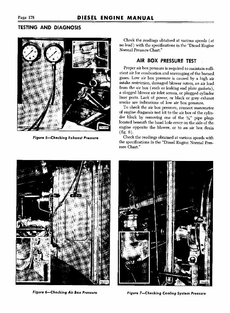
TESTING AND DIAGNOSIS
DIESEL ENGINE MANUALPage 178
Figure 5-Checking Exhaust Pressure
Figure 6-Checking Air Box Pressure
Check the readings obtained at various speeds (atno load) with the specifications in the "Diesel EngineNormal Pressure Chart."
AIR BOX PRESSURE TESTProper air box pressure is required to maintain suffi
cient air for combustion and scavenging of the burnedgases. Low air box pressure is caused by a high airintake restriction, damaged blower rotors, an air leadfrom the air box (such as leaking end plate gaskets),a clogged blower air inlet screen, or plugged cylinderliner ports. Lack of power, or black or grey exhaustsmoke are indications of low air box pressure.To check the air box pressure, connect manometer
of engine diagnosis test kit to the air box of the cylinder block by removing one of the ~" pipe plugslocated beneath the hand hole cover on the side of theengine opposite the blower, or to an air box drain(fig. 6).Check the readings obtained at various speeds with
the specifications in the "Diesel Engine Normal Pressure Chart."
Figure 7-Checking Cooling System Pressure

DIESEL ENGINE MANUAL Page 179
AIR INTAKE RESTRICTION TESTExcessive restriction of the air intake will affect
the flow of air to the cylinders and result in poor combustion and lack of power. Consequently, the restriction must be kept as low as possible considering thesize and capacity of the air cleaner. An obstruction inthe air inlet system or dirty or damaged air cleanerswill result in a high blower intake restriction.The air intake restriction may be checked with
manometer of engine diagnosis test kit. Connect themanometer to the blower air inlet assembly in thedrilled and tapped hole provided for the cold weatherstarting aid connection.Check the normal air intake vacuum at various
speeds (at no load) and compare the results withspecifications given in "Diesel Engine Normal Pressure Chart."
COOLING SYSTEM PRESSURE TESTRemove the radiator test cock or convenient plug
opening that will permit installation of 0-15 pressuregauge (fig. 7).Start engine and observe pressure. With engine at
normal operating temperature, from one to four andone-half (1 to 47~) pounds pressure should be indicated on the gauge.
ENGINE OIL PRESSURE TESTTo check operating oil pressure connect the 0-100
pressure gauge to the oil gallery or into oil line fromgallery to oil fifilter (fig. 8).Start engine. At 2,000rpm normal engine operating
oil pressure is between twenty-five (25) and fifty (50)pounds.
FUEL PRESSURE TESTThe Fuel Pressure Gauge is designed for use in
checking fuel pressure at the injector with the enginein operation. Remove the jumper line from the injectorto the return fuel manifold and connect the fuel gaugein place of the jumper line (fig. 9). At 2,000 rpmnormal fuel pressure should be fifteen (15) poundsminimum.
TESTING AND DIAGNOSIS
Figure 8-Checking Engine Oil Pressure
Figure 9-Checking Fuel Pressure at Iniector

Page 180 DIESEL ENGINE MANUAL
TROUBLE SHOOTINGThe satisfactory performance of a Diesel engine
depends on two items of foremost importance, (1)Sufficiently high compression pressure, and (2) Theinjection of the proper amount of fuel at the righttime.The first one of these items depends entirely on
pistons, piston rings, valves, and valve operatingmechanism; the second item depends on injectorsand their operating mechanism, and fuel system.Lack of engine power, uneven running, excessive
vibration, and tendency to stall when idling may becaused by either a compression loss or faulty injectoroperation.
The causes of trouble symptoms may be varied;therefore a hit-and-miss search should be avoided.A proper diagnosis of symptoms is an orderly processof diagnosing the symptoms. An "orderly process"means to check the most probable common causefirst; then proceed with the next probable cause.
The quick reference Trouble Shooting Charts onpages following lists symptoms, with probable causes,and remedies. References are made to other charts,also to various sections in this manual, which listcorrect remedies and procedures.
Trouble-Cause-Remedy
LOW STARTING R.P.M.
IMPROPER LUBE OIL VISCOSITY-Refer to "Engine Oil Viscosity Chart."
INFREQUENT OIL CHANGES-Change oil at recommended intervals.
LOW BATTERY OUTPUT-Check for the following:
1. POOl'or Shorted Connections-Properly connect or replace leads and terminals.
2. Undercharged or Defective-Recharge or replace battery.
3. Low Ambient Temperature-Use a starting aid.
FAULTY STARTER OR LOOSE STARTER CONNECTIONS-Replace starter or tighten connections.
LOW COMPRESSION
EXHAUST VALVES STICKING OR BURNED-Overhaul cylinder head.
COMPRESSION RINGS WORN OR BROKEN-Overhaul cylinder liner assemblies.
CYLINDER HEAD GASKET LEAKING-Replace cylinder head gasket.
IMPROPER VALVE CLEARANCE ADJUSTMENT -Adjust valve clearance.
BLOWER NOT FUNCTIONING-Check blower drive shaft and couplings.
EMERGENCY SHUT-OFF VALVE PARTIALLY OR COMPLETELY CLOSED-Reset.

DIESEL ENGINE MANUAL Page 181
TROUBLESHOOTING
HARD STARTING (ContJ
FUEL
AIR LEAKS, FLOW OBSTRUCTION, FUEL PUMP-Refer to "No Fuel or Insufficient Fuel" chart.
INJECTOR RACKS NOT IN FULL FUEL POSITION-Check control tube for binds and resetgovernor and control rack, if necessary.
FUEL TANK OR FUEL FILTER EMPTY-Fill fuel tank or prime filter.
IMPROPER GRADE AND TYPE FUEL-Refer to "Fuel Oil Specifications."
DILUTED FUEL-Check storage and handling methods.
IMPROPERLY FILTERED OR RESTRICTED FUEL FLOW-Refer to "No Fuel or Insufficient Fuel"chart.
AIR IN FUEL SYSTEM-Bleed air from fuel system at secondary fuel filter.
Trouble-Cause-Remedy
UNEVEN RUNNING OR FREQUENTSTALLINGCYLINDERS CUTTING OUT-Check for the following:
1. Valve Clearance Set Incorrectly-Readjust valve clearance as directed under ''Valve Lash" in
"Engine Tune-up."
2. Insufficient Fuel-Refer to "No Fuel or Insufficient Fuel" chart.
3. Faulty Injector-Refer to "Injector Tests" under "Fuel Injectors."
COOLING SYSTEM TEMPERATURE BELOW NORMAL-Refer to "Abnormal Engine CoolantTemperatures."
NO FUEL OR INSUFFICIENT FUEL-Refer to "No Fuel or Insufficient Fuel" Chart.
FAULTY INJECTORS-
1. Improper Timing of Injectors-Retime injectors as directed under "Injector Timing."
2. Incorrect Rack Setting-Readjust injector racks as outlined in the appropriate governor tune-upprocedure.
3. Injector Spray Tip Leaks-Replace fuel injector.
CYLINDER PRESSURES LOW-Refer to "Hard Starting" chart.

Page 182 DIESEL ENGINE MANUAL
TROUBLESHOOTING
ABNORMAL ENGINE OPERATION (Cont.)
UNEVEN RUNNING OR FREQUENTSTALLING-Cont.GOVERNOR INSTABILITY (HUNTING)-Check for the following:
1. Governor Instability-Perform engine tune-up.
2. Binding Injector Rack-Replace injector.
3. Faulty Adjustments-Perform appropriate tune-up procedure as outlined for the governor.
IMPROPER GRADE AND TYPE FUEL-Refer to "Fuel Oil Specifications."
DILUTED FUEL-check storage and handling methods.
IMPROPERLY FILTERED OR RESTRICTED FUEL FLOW-Refer to "No Fuel or InsufficientFuel" chart.
DETONATION
OIL PICKED UP BYAIR STREAM-Check for the following:
1. Oil Pull Over From Air Cleaners-Remove, clean, and fill air cleaners with engine oil to properoil level.
2. Accumulation in Air Box-Clean air box and air box drain tubes.
3. Defective Blower to Cylinder Block Gasket-Remove blower and gasket and install a newgasket and reinstall blower.
4. Leaking Blower Oil Seals-Remove and overhaul blower.
LOW COOLANT TEMPERATURE-Refer to "Abnormal Engine Coolant Temperatures" chart.
FAULTY INJECTORS-Check for the following:
1. Improper Timing-Retime injectors as directed under "Injectors Timing" in "Engine Tune-up."
2. Check Valve Leaking-Replace injector.
3. Spray Tip Holes Enlarged-Replace injector.
4. Broken Spray Tip-Replace injector.
LACK OF POWER
IMPROPER ENGINE ADJUSTMENTS-Check for the following:
1. Governor Gap Set Incorrect-Perform appropriate governor tune-up.
2. Rack Setting Incorrect-Perform appropriate governor tune-up.
3. Injector Timing Incorrect-Time fuel injectors as directed under "Injector Timing."
4. Valve Clearance Set Incorrectly-Readjust valve clearance as directed under "Valve Lash"in "Engine Tune-up."

DIESEL ENGINE MANUAL Page 183
TROUBLESHOOTING
ABNORMAL ENGINE OPERATION (Cont.)
LACK OF POWER-Cont.
INSUFFICIENT FUEL-Refer to "No Fuel or Insufficient Fuel" chart.
INSUFFICIENT AIR-Check for the following:
1. Air Cleaners Damaged or Clogged-Remove and clean, repair or replace damaged parts.
2. Cylinder Liner Air Inlet Ports Clogged-Clean cylinder liner ports.
3. Low Compression-Refer to "Low Compression" in "Hard Starting" chart.
4. Blower Air Intake Obstructed-Check and clean air cleaner and air inlet hom and screen.
5. Excessive Exhaust Back Pressure-Inspect exhaust pipe and muffler and replace if damaged.
(Checks to be made with water outlet temperature of 165°F. minimum)
Trouble-Cause-Remedy
BLACK OR GRAY SMOKE
INCOMPLETELY BURNT FUEL-Check for the following:
1. Insufficient Combustion Air-
a. High exhaust back pressure (measured with manometer) -Check exhaust piping and muffierfor obstruction.
2. Restricted Air Inlet-
a. Cylinder liner ports clogged-Clean liner ports.
b. Air cleaner clogged or damaged-Remove and clean, repair or replace damaged parts.
c. Emergency stop not completely open-Check operation of emergency shutdown device andadjust if necessary.
d. Blower to air hom screen clogged-Remove screen and clean.
EXCESSIVE FUEL OR IRREGULAR FUEL DISTRIBUTION-Check for the following:
1. Improper Injector Rack Setting-Perform appropriate governor tune-up.
2. Improper Timing of Injectors-Time fuel injectors as directed under "Injector Timing."
3. Faulty Injectors-Replace injectors.
4. Lugging Engine-Correct driving practices.
IMPROPER GRADE OF FUEL-Refer to "Fuel Oil Specifications."

Page 184 DIESEL ENGINE MANUALTROUBLE SHOOTING
EXHAUST SMOKE ANALYSIS (Cont.)BLUE SMOKE
FUEL OR LUBRICATING OIL NOT BURNED IN CYLINDER (BLOWN THROUGH CYLINDERDURING SCAVENGING PERIOD )-Check for the following:
1. Internal Lubricating Oil Leaks-Refer to "High Lubricating Oil Consumption" chart.
2. Pullover of Air Cleaner Oil-Oil level to high or to light viscosity.
FAULTY INJECTOR-Refer to "Uneven Running or Frequent Stalling" in "Abnormal Engine Operation"chart.
COOLING SYSTEM TEMPERATURE BELOW NORMAL-Refer to "Abnormal Engine CoolantTemperatures" chart.
WHITE SMOKE
MIS-FIRING CYLINDERS-Check for the following:
1. Faulty Injectors-Replace injectors.
2. Low Compression-Refer to "Hard Starting" chart.
3. Low Cetane Fuel-Refer to "Fuel Oil Specifications."
Trouble-Cause-Remedy
AIR LEAKS
LOW FUEL SUPPLY-Fill fuel tank.
LOOSE CONNECTIONS OR CRACKED LINES BETWEEN FUEL PUMP AND TANK OR SUCTION LINE IN TANK-Tighten connections and replace defective lines and fittings.
DAMAGED FUEL OIL STRAINER GASKET-Replace gasket.
FAULTY INJECTOR TIP ASSEMBLY-Make "Fuel Pressure Test" after ascertaining that all fuel linesand connections are assembled correctly. Replace faulty injectors.
FUEL FLOW
FUEL FILTER OR LINES RESTRICTED-Make "Fuel Pressure Test" and clean primary filter elementor replace secondary and injector filter elements, also fuel lines if necessary.

DIESEL ENGINE MANUAL Page 185
TROUBLE SHOOTING
NO FUEL OR INSUFFICIENT FUEL (Cont.)
FUEL FLOW-Cont.
TEMPERATURE LESS THAN io-r. ABOVE THE POUR POINT OF FUEL-Refer to "Fuel OilSpecifications."
RESTRICTED FITTING MISSING FROM RETURN MANIFOLD-Install new restricted fitting.
FAULTY FUEL PUMP
RELIEF VALVE NOT SEATING-Make "Fuel Pressure Test" and clean and inspect valve and seatassembly.
WORN GEARS OR PUMP HOUSING-Replace gear and shaft assembly and fuel pump if housing isdamaged.
FUEL PUMP NOT ROTATING-Check condition of fuel pump drive and blower drive and replaceif necessary.
Trouble-Cause-Remedy
EXTERNAL LEAKS
OIL LINES AND CONNECTIONS LEAKING-Tighten or replace defective parts.
GASKET OR OIL SEAL LEAKS-Replace defective gaskets or oil seals.
HIGH CRANKCASE PRESSURE-Refer to "High Crankcase Pressure" chart.
EXCESSIVE OIL IN AIR BOX-Refer to "Detonation" in "Abnormal Engine Operation" chart.
INTERNAL LEAKS
BLOWER OIL SEAL LEAKING-Remove and overhaul blower.
OIL COOLER CORE LEAKING-Replace oil cooler core and use a good cooling system cleaner toremove oil from water passages.
ENGINE BLOCK END PLATE GASKETS LEAKING-Replace block to end plate gaskets.
---------

Page 186 DIESEL ENGINE MANUALTROUBLE SHOOTING
HIGH LUBRICATING OIL CONSUMPTION (Cont.)
OIL CONTROL AT CYLINDER
OIL CONTROL RINGSWORN, BROKEN,OR IMPROPERLYINSTALLED-Replace rings on piston.
PISTON PIN RETAINER LOOSE-Replace piston retainer and defective parts.
SCORED LINERS, PISTONS, OR OIL RINGS-Remove and replace defective parts.
PISTON AND ROD ALIGNMENT (CAUSED BYWORN CRANKSHAFTTHRUST WASHERS)Replace worn and defective parts.
EXCESSIVE INSTALLATIONANGLE-Decrease installation angle.
(Check to be made with engine water outlet temperature of 165°F.minimum)
Trouble-Cause-Remedy
LUBRICATING OI,L
SUCTION LOSS-Check oil level and bring to "FULL" mark on dipstick or correct installation angle.
LUBRICATING OIL VISCOSITY-Check for the following:
1. Wrong Viscosity Lubricating Oil-Refer to "Engine Oil Viscosity" chart.
2. Plugged Oil Cooler-Clean oil cooler if oil temperature is abnormally high.
3. Fuel Oil Dilution-Check for fuel leaks at injector seal ring, fuel jumper line connections, andfuel manifolds.
PRESSUREGAUGE
FAULTYGAUGE-Replace gauge.
GAUGE LINE OBSTRUCTED-Remove and clean line, replace if necessary.
ORIFICE PLUGGED-Remove and clean orifice.
ELECTRICAL INSTRUMENT SENDING UNITS-Repair or replace defective equipment.

DIESEL ENGINE MANUAL Page 187
TROUBLE SHOOTING
LOW OIL PRESSURE(Cont.)
CIRCULATION
STRAINER OR FILTER CLOGGED-Remove and clean or replace element.
COOLER CLOGGED-Remove oil cooler and clean.
COOLER BY-PASS VALVE NOT FUNCTIONING PROPERLY-Remove by-pass valve, clean valveand valve seat and inspect valve spring.
PRESSURE REGULATOR VALVE NOT FUNCTIONING PROPERLY-Remove pressure regulatorvalve and clean and inspect spring.
EXCESSIVE WEAR OF CRANKSHAFT BEARINGS-Change engine bearings, clean oil pan, refer to"Engine Oil Viscosity Chart" for proper grade, and change oil filter element.
INTAKE SCREEN PARTIALLY CLOGGED-Remove oil pan and screen, clean oil pan and screen,refer to "Engine Oil Viscosity Chart" and refill crankcase and change oil filter element.
GALLERY, CRANKSHAFT OR CAMSHAFT PLUGS MISSING-Replace plugs.
OIL PUMP
RELIEF VALVE NOT PROPERLY FUNCTIONING-Remove and inspect valve, valve bore, andspring.
AIR INTAKE IN PUMP INLET SYSTEM-Disassemble piping and install new gaskets.
PUMP WORN OR DAMAGED-Remove pump, clean and replace defective parts.
FLANGE LEAK PRESSURE SIDE-Remove flange and replace gasket.
Trouble-Cause-Remedy
CYLINDER BLOW-BYCYLINDER HEAD GASKET LEAKING-Remove and replace head gaskets.
PISTON AND LINER DAMAGED-Remove and replace piston and liner.
PISTON RINGS WORN OR BROKEN-Remove and replace piston rings.
PISTON PIN RETAINER LOOSE-Remove.
~--~------ -----

Page 188 DIESEL ENGINE MANUALTROUBLE SHOOTING
EXCESSIVE CRANKCASE PRESSURE(Cont.)BREATHER RESTRICTION
OBSTRUCTION OR DAMAGE TO BREATHER-Clean, repair or replace breather.
AIR FROM BLOWER OR AIR BOX
DAMAGED BLOWER-TO-BLOCK GASKET-Remove blower and gasket, replace with new gasket.
ENGINE BLOCK END PLATE GASKETS LEAKING-Replace block to end plate gaskets.
BLOWER OIL SEAL LEAKING-Remove and overhaul blower.
EXCESSIVE EXHAUST BACK PRESSURE
EXCESSIVE MUFFLER RESISTANCE-Repair or replace muffler,
OBSTRUCTION IN MUFFLER-Repair or replace muffler.
EXHAUST PIPING-Check for the following:
l. Too Small-Replace with larger piping.
2. Too Long-Replace with larger piping.
3. Excessive Number of Bends-Reduce number of bends or replace with larger piping.
4. Use of Street Elbows-Replace with pipe elbows.
Trouble-Cause-Remedy
ABOVE NORMAL OPERATING TEMPERATURES
INSUFFICIENT HEAT TRANSFER-Check for the following:
l. Scale Deposits in Cooling System-Clean cooling system with a good cooling system cleaner andflush thoroughly.
2. Radiator Core Plugged Preventing Normal Air Flow-Clean outside of radiator core.
3. Fan Belt Loose-Tighten fan belt.
4. Improper Installation-Improper shrouding of fan.

DIESEL ENGINE MANUAL Page 189
TROUBLE SHOOTING
ABNORMAL ENGINE COOLANT TEMPERATURES(Cont.)
ABOVE NORMAL OPERATING TEMPERATURES
POOR CIRCULATION-Check for the following:
1. Coolant Level too Low-Fill radiator to filler neck.
2. Hoses Collapsed or Disintegrated-Replace hoses.
3. Thermostat Damaged-Replace thermostat.
4. Water Pump Impeller Loose on Shaft-Replace impeller and pin to shaft.
5. Inadequate Water Supply on Suction Side of Pump-Caused by:
a. Radiator Clogged-Clean radiator.
b. Combustion Gases in Cooling Water-Replace all head gaskets and inspect cylinder head forcracks on injector tube leaking.
c. Air in Cooling System-Caused by:
(1) Air Leak on Suction Side of Water Pump- Replace defective parts.
(2) Thermostat Housing Vent Not Open When Filling System-Open vent valve while fillingsystem.
BELOW NORMAL
POOR CIRCULATION-Check for the following:
1. Thermostat Housing Vent Valve Open or Not Seating-Remove and clean up vent valve andseat in housing.
2. Thermostat Inoperative-Replace thermostat.
3. Thermostat Seat Damaged-Replace thermostat.

Page 190 DIESEL ENGINE MANUAL
Reference is made to special tools and in manyinstances, are illustrated in this manual. These tools,or their equivalent, are necessary and are recommended to more readily and efficiently accomplishcertain service operations. The tools, however, arenot supplied by GMC Truck & Coach Division. Namesand addresses of vendors or manufacturers are shownas a reference, and since such vendors are the sup-
VENDORTOOL
NUMBER
J1926-02J-6837J-8196J-6387
J-1927-01J-1918-02J-5518
J-5580
J-3051J-4194J-872-5J-1359J-4195J-5356
J-1904-01J-6361-01J-4257J-1927-01
J-3187-AJ-3895J-6307
J-1915J-1917-AJ-5901-3
TOOL NAME
SHOP EQUIPMENT
EngineOverhaul Stand and Adapter PlateEngineOverhaul StandAdapter PlateEngineParts Dolly
CYLINDER BLOCK AND LINERS
Cylinder Block End PlateAligning Stud SetCylinder Liner RemoverCylinder liner Clamp Retainer SetCylinder liner Clamping and Checking SetCylinder Diameter Checking Gauge Set
CRANKSHAFT
Crankshaft Gear PullerCrankshaft Oil Seal Sleeve InstallerDrive Handle for J-4194Crankshaft Oil Seal ExpanderCrankshaft Oil Seal Expander ForOversize SealFan Puller Hub Puller
flYWHEEL AND CLUTCH PILOT
Flywheel Puller ScrewsFlywheel Lifting HookFlywheel Replacing StudsFlywheel Housing Aligning StudsFlywheel Bushing Installer (V-Transmission)Clutch Pilot Bearing PullerClutch Pilot Tool Truck 4-71-Prior to 1955Clutch Pilot Tool 6-71 Truck, also 4-71
after 1955Clutch Pilot Tool Coach 4-71Clutch Pilot Tool Coach 6-71Tachometer Drive RemoverTachometer Drive RemoverAdaptor
pliers of these tools, information regarding availability, price etc. should be obtained directly fromthem. The tools are listed on following pages inorderof reference in the text.
VENDORSJ=Kent Moore Organization, Warren, Michigan
KMO=Kent Moore Organization, Warren, Michigan
VENDORTOOL
NUMBER TOOL NAME
PISTON AND CONNECTING ROD
J-3174-A Piston Fitting Feeler Gauge SetPiston-to-liner Feeler Gauge Set
(Includes Next 3 Items)HM-593-1 Tension ScaleJ-593-14 Swivel ConnectionJ-3147-A Feeler Gauges (9-14")
J-8128 Piston RingRemoverand InstallerJ-3272-02 PistonRingCompressor and InstallerJ-3071-01 Piston BushingReamerSetJ-1513-02 Piston and Connecting RodBushing Installer
and Remover(Includes Next 6 Items)
J-5438
J-1513-1 Supporting BlockJ-1513-2J-1513-3J-1513-4J-1513-6J-5118-A
Driver HandleBushingRemoverSpacerBushing InstallerConnecting Rod Holder
J-1686-01
Pistonand Connecting RodBushingRemoverand Installer Set
Connecting RodBushingReamerSet(Includes Next 4 Items)
J-1686-5J-1686-9J-1686-10
Rear Guide BushingFixture and ArborReamer
J-1686-11 Forward Guide BushingJ-4895-01 PistonPin Retainer Installer
CAMSHAFT AND GEAR TRAIN
J-1902-01J-1903J-1471
Camshaft Gear Puller W /ScrewsCamshaft and Oil PumpGear InstallerBlower Coupling Spring Spreader
CYLINDER HEAD AND VALVE MECHANISM
J-1928-01J-3087-01
Cylinder Head Nut WrenchCylinder Head Holding Plate Set

DIESEL ENGINE MANUAL Page 191
VENDORTOOL
NUMBER
J-267J-6569J-4144J-6570J-5437J-4824-01J-6567J-1736J-6568J-1227-01J-7455J-6846J-5840J-3092-01
J-2624
J-2624-1J-2624-2J-2624-3J-2624-4
J-3051J-1903
J-4242J-1930J-3277-01
J-3277-1J-3277-2J-3277-3J-3277-5
SPECIAL TOOLS
SPECIAL TOOLS (Cont.)
TOOL NAME
Valve Guide CleanerValve Seat Insert Remover(2 Valve Head)Valve Seat Insert Remover(4 Valve Head)Valve Seat Insert Installer (2 Valve Head)Valve Seat Insert Installer (4 Valve Head)Valve Spring Compressor (2 Valve Head)Valve Spring Compressor (4 Valve Head)Bridge Guide Replacer (4 Valve Head)Camshaft Follower Holding FixturePushRod RemoverSet
OIL PUMP
Oil PumpBushing ReamerSet (IncludesNext 4 Items)
Reamer(.622" Dia.)Reamer (.645" Dia.)ReamerGuideCanvas Bog
Oil PumpGear PullerOil Pumpand Camshaft Gear Installer
WATER PUMP
Water PumpWrenchWater PumpCoupling RemoverWater Pump Impeller Installing Set
(Includes Next 4 Items)Installer-New Impeller-New ShaftInstaller-Old Impeller-New ShaftInstaller-New Impeller-Old ShaftLeatherette Kit
BLOWER
J-6270 Blower Service Tool Set-Standard andReducedSpeed Types (Inc. Next 9 Items)
J-6270-1 Gear, EndPlate, and Seal RingCarrierPuller
J-6270-2 Seal RingCarrier RemoverAdopterJ-6270-3 Bearings, and Seal or Collar Removerand
Lip Seal Installer
CYLINDER HEAD AND VALVE MECHANISM-Cont.J-8168 Valve LashFeeler Gouge (.008"-.010")J-6653 Valve LashFeeler Gouge (.013"-.015")J-6864 Valve LashFeeler Gouge (.015" -.017")
Valve Guide Installer and RemoverSetValve Guide Remover(2 Valve Head)Valve Guide Remover (4 Valve Head)Valve Guide Replacer (2 Valve Head)Valve Guide Replacer (4 Valve Head)
VENDORTOOL
NUMBER
J-6270-Cont.
J-6270-4
J-6270-5J-6270-6
J-6270-7J-6270-8
J-6270-9
J-1698-02J-4254
J-4254-1J-4254-2J-4254-3J-4254-4J-4254-5J-4254-6J-4254-8
J-1242J-1853J-1227-01J-7509J-1261J-3179J-3179-1J-6259J-6260J-6261J-5119J-6868J-1241-03
J-8152J-8150J-8170J-8169J-1243J-4983-01J-1291-01
J-4986-01J-4987
TOOL NAME
BLOWER-Cont.
Seal Ring Carrier, Collar, and BearingInstaller
Blower Shaft PilotGear and Bearing, and Seal Spacer
InstallerGear and Bearing InstallerGear Installing Screw, Nut, and Washer
(Long)Gear Installing Screw, Nut, and Washer
(Short)Blower Feeler Gouge SetBlower Rotor Shaft Removerand Replacer Set
(Includes Next 7 Items)ScrewBody SleeveCopForcing NutTubeColletSpacer
FUEL INJECTORS
Injector Timing Gouge (1.484")Injector Timing Gouge (1.460")Injector RemoverInjector Testing FixtureInjector Body Vise (2 Valve Head)Lopping Block (Set of 3)Lopping BlockMusic Wire (.005" x 5')Music Wire (.006" x 5')Music Wire (.007" x 5')Injector Tip Concentricity GougeInjector Holding Fixture (2 or 4 Valve Head)Injector Service Set (Inc. Next 9 Items)
Cleaning Brush (Rockand Bushing)Cleaning Brush (Injector Nut)Wire Sharpening StoneSpray Tip Hole CleanerSpray Tip ReamerInjector Nut Wrench
Injector Spray Tip Driver and BushingCleaner
Injector Nut Tip Seat Reamerlnjector Valve Seat Deburring Stones
(Pair)

Page 192
SPECIAL TOOLSDIESEL ENG.lNE MANUAL
TOOL NAME
ENGINE TUNE-UP-Cont.
Metol Box0-15 Pound U.S. Pressure Gouge0-100 Pound U.S. Pressure GaugeFuel Pressure Gauge, 0-100 Pound
(J-8151 )Compression Gauge, 0-1000 PoundCompression Gauge Adapter300-3600 R.P.M. TachometerTachometer-3 Ft. Flexible Extension
1/8 to 1/4 Pipe Bushing3/16 Tube-l /8 Pipe-Inverter Flare
Male ConnectorHoses (2 Required)"Series 71" Tachometer Drive Adapter
Spring ScaleGovernor Spring Retainer WrenchFuel System Primer
IMPORTANT-Tools are not available from GMCTruck & Coach Division. Order directly from vendor.
J-4209-10 Male Friction AdapterJ-4209-11 Female Friction AdapterJ-5209-46 6" Section of 7/16" I.D. HoseJ-7333-11 Manometer-MercuryJ-7333-6 Manometer-WaterJ-7333-5 ThermometerJ-7436-7 Tachometer Cable AdapterJ-7333-13 Bottle of MercuryJ-7333-12 Hoses for Manometer (2 Required)
SPECIAL TOOLS (Cont.)
TOOL NAME
VENDORTOOL
NUMBER
VENDORTOOL
NUMBER
J-5286
J-5286-1J-5286-2J-5286-3J-5286-4J-5286-5J-5286-6J-5286-7J-5286-13J-5286-14J-5286-8J-5286-9J-5286-10
FUEL INJECTOR-Cont.Injector Tube Reconditioning Set(Includes Next 10 Items)
Tube HolderTapTap Driving RodInstaller BodyInstaller PilotInstaller Flaring DieFirst Reamer (Inc. Next 2 Items)
First Reamer BodyPilot Reamer
Tube Tip RefinisherSecond ReamerBox and Filler
J-7436-Cont.
J-7436-1J-4209-7J-4209-8KMO-320-B
J-6692J-6694J-4209-9J-4209-12
J-5907-3J-5355
FUEL Oil PUMP
J-1508-02 Fuel Pump Service Kit (Inc. Next 4 Items)J-1508-7 Oil Seal RemoverJ-1508-8 Oil Seal Installer HandleJ-1508-9 Oil Seal InstallerJ-1508-10 Fuel Pump Holder
J-4242 Fuel Pump Wrench
J-5345J-7436
ENGINE TUNE-UP
Engine Tune-up KitDiesel Engine Diagnosis Test Kit
Test Kit Above Consists of Following 21 Items:
HM-593-1J-1652-01J-5956

DIESEL ENGINE MANUAL Page 193
gpec;li.cdioH4,BOLT, NUT AND STUD TORQUE SPECIFICATIONS
The latest recommended bolt, nut, and stud torquespecifications for Series "71" General Motors DieselEngines are presented in the following tables. It isimportant that special care be exercised to replaceall bolts in their respective location during assemblyof the engine and its sub-assemblies.Table I lists the standard torque specifications for
all bolts and nuts used on all Series "71" engineunits, except those listed in Table II or Table III.
Table II lists the exceptions to the standardtorques in Table I and identifies them as regardstheir application.
Table III lists stud torque specifications in eithertorque or driven height depending upon the application. Where a height is specified, the stud threadsare cut so that the studs are tight by the time theyhave been driven to the given dimension.
TABLE ISTANDARD BOLT AND NUT TORQUE SPECIFICATIONS
Size Nut Torque Size Nut Torque Size Nut Torqueor Bolt (Ft.-Lbs.) or Bolt (Ft.-Lbs.) or Bolt (Ft.-Lbs.)
';4-20. ......... . 7-9 %6-20 ............ 57-61 %-10 .. . ....... 240-250';4-28 ......... 8-10 Y2-13 ......... 71-75 %-16. . ........... 290-300%6-18 ........ 13-17 Y2-20 .......... 83-93 %-9 ... . ........... 410-420%6-24 .......... 15-19 %6-12. .......... 90-100 %-14 .............. 475-485%-16 .............. 30-35 %6-18. ........... .107-117 1 -8 ............... 580-590%-24 ............. 35-39 %-11. ........... .. 137-147 1 -14 ............. 585-595%6-14 ............. 46-50 %-18 ........... .. 168-178
TABLE IIEXCEPTIONS TO STANDARD TORQUE SPECIFICATIONS
APPLICATION
Control Shaft Bracket Bolts
Size Nut Torqueor Bolt (Ft.-Lbs.)
';4-20 10-12';4-20 12-15%6-24 20-25%6-24 25-30%6-24 25-30%6-24 25%-16 10-15%-16 16-20%-16 25-30%-16 35-40%-16 25-40%-16-24 25-30%-16-24 25-30%-24 25-30
Cam Follower Guide Bolts .Blower Drive Coupling Bolts .Blower Rotor Gear Hub Bolts .Blower Rotor Gear Flexible Drive Bolts .Water Pump Drive Coupling Attaching Bolt .Hand Hole Cover Bolts .Air Inlet Housing to Blower Bolts .Water Pump Coupling Intermediate Shaft Expander Screws .Cam and Balance Shaft End Bearing Bolts .Flywheel Housing to Idler Gear and Dummy Hub Bolts . . . . . . . .Balance Weight Cover Bolts , .Flywheel Housing Bolts ., .. , , " .Crankshaft Front Cover Bolts .. ,.,', " ,"", .

Page 194 DIESEL ENGINE MANUALSPECIFICATIONS
BOLT, NUT AND STUD TORQUE SPECIFICATIONS (Cont.)
TABLE II (Cont.)
APPUCATION Size Nut Torqueor Bolt (Ft .•Lbs.)
%-24 45·50%-24 35·39%-24 20·25%-24 20-25%-24 25-30%-24 25-30%-24 25-30%-24 25-30%6-14 55-60%6-14 55-60%6-20 30-35%6-20 65-75112-13 80-90%6-20 30-35lf2-13 80-90lf2-13 90-100lf2-13 90-100Y2-20 55-65Y2-20 60-70o/t6-18 150-160%-11 180-190%-18 155-185%-18 165-175
1 -14 180-200VIs-18 300-325lY2-16 50-60
Accessory Drive to Balance Gear Bolts (steel disc) .Accessory Drive to Balance Gear Bolts (fiber disc) .Exhaust Manifold Outlet Flange Nuts (brass) .Injector Clamp Nuts .Balance Weight Hub Bolts and Nuts .Water Manifold Nuts .Balance Weight to Timing Gear Bolts .Blower Drive Ass'y Attaching Bolts and Nuts .Blower to Block Bolts .Lifter Bracket Bolts .Fuel Manifold Connector Nuts .Connecting Rod Bolts .Crankshaft Front Cover Bolt .Exhaust Manifold Nuts .Idler Gear Hub and Dummy Hub Bolts .Flywheel Housing Bolts .Rocker Shaft Bolts .Blower Rotor Gear Retaining Bolts .Oil Pump Drive Idler Shaft Nuts .Flywheel Bolts .Main Bearing Bolts .Main Bearing Nuts .Cylinder Head Nuts .Crankshaft End Bolts .Cam and Balance Shaft Nuts .Blower Drive Gear Hub Nuts .
TABLE IIISTUD TORQUE SPECIFICATIONS
APPUCATION TORQUE OR HEIGHT
Injector Clamp Studs. . . . . . . . . . . . . . . . . . . . . . . . . . . . . . . . . . . . . . . . . . . . . . . . . . . . . . . . . . . . . .. 10-25 Ft.-Lbs.Water Manifold Studs 10-25 Ft.-Lbs.Exhaust Manifold Studs . . .. 25-40 Ft.-Lbs.Cylinder Head Studs Drive to height of 4%" +%6'" . . . . . 35-75 Ft.-Lbs.Main Bearing Studs Drive to height of 4" + 7'32". . . . . . . . . .. 35-75 Ft.-Lbs.

Page 195DIESEL ENGINE MANUAL
SPECIFICATIONS
FITS, TOLERANCES AND SERVICE SPECIFICATIONSCYLINDERBLOCK
Block Bore 4.6265"-4.6275"Bore Out-of-Round (Max.) 0.001"Bore Taper (Max.). . . . . . . . . . . . . . . . . . . . . . . . 0.001"Cam and Balancer Shaft Bearing Bore 2.1875"-2.1885"Main Bearing Line Bore 3.812" -3.813"Cylinder Liner Counter bore
Diameter 5.046" -5.0485"Depth 4785"-.4795"
Flatness At HeadTransverse 0.003"Longitudinal. (4.71-0.007") (6.71-0.009")
Refacing Limits(Max.) 0.008"
CYLINDERLINERType DryOutside Diameter 4.6260"-4.6250"Inside Diameter 4.2495"-4.2511"Flange Diameter 4.776"-4.766"Clearance-Liner to Bore 0.0005"-0.0025"Out-of-Round 0.002"Taper 0.001"Oversizes Available-O.D 0.005"-0.010"
0.020" -0.030"Depth Below Block 0465"-.050"Shims Available None
Liner InsertThickness 1795"-.1800"Outside Dia 5.044"-5.046"Inside Dia 4.640"-4.645"
Available Oversize & UndersizeOversize I.D Standard ThicknessStandard I.D•....................... 0.004" UndersizeStandard I.D 0.008" UndersizeOversize I.D 0.004" UndersizeOversize I.D 0.008" Undersize
CRANKSHAFTNumber of Bearings
4-71 56-71 7
Journal Diameter-Main Bearing 3.499"-3.5000"Journal Diameter-Conn. Rod 2.749"-2.750"Journal Out-of-Round 0.00025"Journal Taper 0.0005"Runout-Total Indicator Reading
4 Cylinder@ #2 and #4 0.002"@ #3 0.004"
6 Cylinder@ #2 and #6 0.002"@ #3 and #5 0.004"@ #4 0.006"
Thrust Taken at Rear Main BearingThrust Washer Thickness 0.1220"-0.1205"Available Oversize Thrust Washers 0.005" -0.010"Normal Thrust Clearance 0.004"-0.011"End Thrust (Max.). . . . . . . . . . . . . . . . . . .0.018"
MAIN BEARINGSBearing Type Heavy Duty PrecisionBearing Diameter (Vertical) 3.5014"-3.5034"Bearing Clearance 0.0014"-0.0044"Adjusting Shims Used NoneBearing Thickness-90° from Parting Line 0.1553" -0.1548"Available Undersizes 0.002"-0.010"-0.020"-0.030"
PISTONSFitting Pistons See InstructionsDiameter
At Top (Standard) 4.219"-4.222"At Top (E Series) 4.2217"-4.2247"At Ring Lands 4.235"-4.238"Skirt (Below Compression Ring Groove
to Bottom) 4.2433"-4.2455"Clearance
Top of Skirt 0.004"-0.0078"Bottom of Skirt 0.004"-0.0078"
Out-of-Round-Max 0.0005"Taper-Max 0.0005"Diameter of Pin Bosses 1.6875"-1.6880"Compression Ring Groove Width
Upper (Standard) 0.134"-0.136"Upper (Fire Ring-E Series) 0.088"-0.090"2nd 0.132"-0.134"3rd 0.130"-0.132"4th (Standard) 0.130" -0.132"
Oil Ring Groove Width 0.1875"-0.1895"Piston Pin Bushing Diameter 1.5025"-1.5030"Oversize Pistons Available 0.01 0"-0.020" -0.030"
PISTON PINSDiameter 1.4996"-1.5000"Pin to Piston Bushing Clearance 0.0025" -0.0034"Oversize Pins Available 0.01 0"Pin to Rod Bushing Clearance 0.0015"-0.0024"Length 3.605"-3.620"Pin to Retainer Clearance 0.008"-0.0315"
PISTON RINGSCompression Rings
Number Used Each Piston 4Width
Fire Ring 0.077"-0.078"Standard 0.1230"-0.1245"
Gap 0.018" -0.043"Ring to Groove Clearance
Fire Ring (E Series) 0.010"-0.012"#1 0.010"-0.0125"#2 0.008"-0.0105"#3 0.006"-0.0085"#4 (Standard) 0.006"-0.0085"
Oversize Available 0.01 0"-0.020"-0.030"Oil Rings
Type 3 PieceNumber Used Each Piston 2Width 0.1840" -0.1860"Gap 0.008"-0.023"Ring to Groove Clearance 0.0015" -0.0055"Oversize Available 0.01 0" -0.020" -0.030"
CONNECTING RODLength-Center to Center 10.124"-10.126"Lower Bore-Dia 3.062"-3.063"Upper Bore-Dia 1.7490"-1.7510"Upper Bushing Diameter 1.5015"-1.5020"Normal Rod End Thrust 0.006"-0.012"
CONNECTING ROD BEARINGBearing Type Heavy Duty PrecisionBearing Diameter 2.7514"-2.7534"Bearing Clearance 0.001 4"-0.0044"Adjusting Shims Used NoneBearing Thickness 90° from Parting Line 0.1548"-0.1553"Available Undersizes 0.002"-0.010"-0.020"-0.030"

Page 196 DIESEL ENGINE MANUAL
SPECIFICATIONS
FITS, TOLERANCES AND SERVICE SPECIFICATIONS (Cont.)TIMING GEARS
Blower Drive GearNo. of Teeth ...............•............... 39Type ............••..•.•.•.••......... HelicalBacklash 0.003"-0.008"Gear to Hub Fit O.OOOS"Press-0.001" Free
BlowerDriveGear SupportSupport BushingI.D•...••..•.••... 1.6260"-1.626S"Bushingto HubClearance ...•..••.•. 0.00 1"-0.002S"Support to End Plate O.OOOS"Pres-0.002S" Free
BlowerDriveGear HubDiameter (At Bushing)......•....•.. 1.624" -1.62S0"Hub to Support BushingClearance 0.001" -0.002S"Hub to Cam Clearance 0.002"-0.007"End Thrust ..............•........ O.OOS"-0.008"
Idler GearNo. of Teeth ............•.•............... 68Type ......................•.......... HelicalBacklash 0.003"-0.008"Bearing Type " Opposed Tapered Roller
Camshaft and Balance Shaft GearsNo. of Teeth ..............•................ 78Type HelicalBacklash 0.003"-0.008"Gear to Shaft 0.0000"-0.00IS" Press
Crankshaft GearNo. of Teeth '" 78Type ......................•...•....... HelicalBacklash 0.003"-0.008"Gear to Shaft 0.001" Press-0.001" loose
CAMSHAFT
No. of Bearings4-71 S6-71 6
Shaft Diameter-At BearingsFront and Rear 1.497S" -1.4970"Center and Intermediate 1.498"-1.4985"
Clearance-Shaft to BearingsFront and Rear ..........•.•...... 0.002S" -0.004"Center and Intermediate 0.003" -O.OOSS"
Runoutat Center Bearing (WhenMountedon EndBearings) .......•.......•.•....... 0.002"
End Thrust 0.004"-0.012"ThrustWasher Thickness ........•...... 0.120"-0.122"Oversize Washers Available ........•.. O.OOS"-0.010"
CAMSHAFTBEARINGS
Bearing MaterialFront and Rear Steel Backed Copper LeadIntermediate ..............•.••........ Aluminum
Inside DiameterFront and Rear ..........•...•..... I.S00" -1.S0 I"Center and Intermediate I.S01 "-1.S03"
Undersize Bearing Available .•....•.... 0.010"-0.020"Clearance-Bearings to Shaft
Front and Rear 0.002S"-0.040"Center and Intermediate 0.002S" -0.0050"
BALANCERSHAFT
No. of Bearings ............•••.•••............. 2Shaft Diameter at Bearings 1.4970"-1.4975"Clearance-Shaft to Bearings ..•••.•.•• 0.002S"-0.004"End Thrust 0.004"-0.012"ThrustWasher Thickness ........••.•.•. 0.120"-0.122"Oversize ThrustWashers Available .•.••.• O.oOS"-0.010"
BALANCERSHAFTBEARINGS
Bearing Material Steel Backed Copper LeadInside Diameter ............•....•... 1.500"-1.501 "Clearance-Shaft to Bearings .....••.•. 0.0025"-0.004"
BALANCEWEIGHTS (EARLY6-71)
Balance Weight BushingDiameter •..... 1.8755"-1.8775"ShimPack Thickness. . . . . .. . .•....... 0.243"-0.259"Individual ShimThickness ........•••... 0.015"-0.016"Clearance-Weight to Hub 0.010"-0.023"
CYLINDERHEAD
Flatness (Max.Limits)..............•........ See TextRefacing Limits(Max.) ...........•...•....... 0.020"Cylinder Head Stud Height ..........••........ .41{,"Valve Guide Height Above Head ...•............ 11%2"Cam FollowerBore .......•.....•..... 1.062" -1.063"ExhaustValve Seat Insert Counterbore
Diameter (2 Valve) 1.626" -1.627"Diameter (4 Valve) 1.260".1.261"Depth (2 Valve) 0.3705" ·0.384S"Diameter (4 Valve) 388" -.352"
VALVESEAT INSERT
Location .......................•... Cylinder HeadExhaust Valve Seat Angle 30°Exhaust Valve Seat Width ..•............... See TextOversize Available ........•............... 0.010"Diameter of Seat Counterbore in Head
Standard (2 Valve) 1.6275" ·1.628S"Standard (4'Valve) 1.2615"·1.2625"
Valve Seat Runout . . . . . . . . . . . . . . . . . . . . . . . .. .002"
EXHAUSTVALVE
Location .......................•••. Cylinder HeadDiameter of Head (2 Valve) 1.579"·1 .S89"Diameter of Head (4 Valve) 1.195"-1.205"Stem Diameter (2 Valve) 0.3415" -0.3425"Stem Diameter (4 Valve) 0.3095" ·0.3105"Clearance-Stem to Guide 0.002"-0.004"Valve Lash(Hot) (2 Valve) 0.008" Go 0.01 0" No GoValve Lash (Cold) (2 Valve) 0.011" Go 0.013" No GoValve Lash (Hot) (4 Valve) 0.013" Go 0.015" No GoValve Lash (Cold) (4 Valve) O.OIS" Go 0.017" No Go
VALVEGUIDE
Location ...........•...••••••••••... Cylinder HeadHeightAbove Cylinder Head (2 Valve) 1%"Height Above Cylinder Head (4 Valve) 0.880"

DIESEL ENGINE MANUAL Page 197
SPECIFICAliONS
FITS, TOLERANCES AND SERVICESPECIFICATIONS (Cont.)VALVEGUIDE-Cont.
Diameter-Inside (2 Valve) 0.3445"-0.3455"Diameter-Inside (4 Valve) 0.31 25"Clearance-Stem to Guide •..•.•.••••.. 0.002"-0.004"Oversize Available ......•••.••••.......... 0.016"
VALVESPRING
Load-Valve Open @ 14%4" (2 Valve) 142-150 Ibs.Min.Load-Valve Open @ 1.416" (4 Valve) 85-89 lbs, Min.
ROCKERARMAND SHAFT
Rocker Shaft Diameter ....••..•..... 0.8735"-0.8740"RockerArm Large Bushing-I.D•.••..•. 0.8750"-0.8760"Clearance-Shaft to Bushing .•...•.•... 0.001"-0.0025"Rocker Arm Small Bushing-I.D••.•...... 0.564" -0.565"Clevis Pin Bushing-O.D .......•.•.... 0.562"-0.5625"Clearance-Pin to Arm Bushing 0.0015"-0.003"Clevis Pin Bushing-I.D ....•...•.•••. 0.4375"-0.4385"PushRodClevisPin-O.D ...•.....•.•. 0.4380"-0.4385"Clearance-Pin to Bushing .. 0.001" Tight-0.0005" LoosePush RodClevis-I.D .....•........•. 0.4370" -0.4385"Clearance-Pin to Clevis .•. O.OOIS" Tight-O.OOOS"LooseEnd Play-Clevis to RockerArm 0.008"-0.017"
CAM FOLLOWER
Diameter ...........•......•••••... 1.060"-1.061"Clearance-Follower to Head ..•.•••.. , .0.001 "-0.003"Width of RollerSlot 0.5635"-0.5685"RollerPinHoleDiameter ..••••.•.•..•. 0.4362"-0.437"
CAM FOLLOWERROLLERAND PIN
Roller-O.D. . 0.902" -0.907"Roller Bushing-I.D 0.4395"-0.4390"Roller Pin-O.D .......•••....•.•.. 0.4374-"0.4377"Clearance-Pin to Bushing .•..•..••••. 0.0008" -0.0016"End Play...;...Rolierin Follower ..•.•••.••.. 0.0IS"-0.023"
CAM FOLLOWERSPRING
Free Length 2 o/a "Valve Open @ 2~" 176-192 Ibs.
OIL PUMP
Drive Gear-On CrankshaftType SpurNo. of Teeth ..........•.••••••.••.••....... 40Backlash to Idler Gear 0.010"-0.012"Crankshaft Dia. at Gear ..••.•••••... 2.499"-2.500"Gear Inside Diameter ......•••••••• 2.S01 "-2.S005"Clearance-Gear to Shaft 0.002."-0.006"
Idler Drive GearType ..............•••••..•••........... SpurNo. of Teeth •.....••..••..•.••....•....... 308acklash to Pump Gear 0.002"-0.010"Support Diaineter ........•....... 0.9980"-0.9985"Gear BushingDiameter .........•. 1.0000"-0.9995"Clearance-Gear to Support. .••....•. 0.001" -0.002"
Drive Driven GearType ...•..•.......•.••.•••............. SpurNo. of Teeth ........•..•.•..••.•..•.••.•... 24
OIL PUMP-Cont.
Backlash 0.002"-0.010"Drive Gear
Diameter-Outside .••.•••••••••••.. 1.682"-1.683"Diameter-Inside ••.•..•••••.•••. 0.6243"-0.6250"Width (4 Cyl.) ....••.•••••••••••.. 1.269"-1.270"Width (6 Cyl.) ...••.••..•••••••• 1.7470"-1.7480"Gear to Shaft Fit ..•...•.•.•••.••.......... PressRadial Clearance-Gear to Housing •... 0.004"-0.008"End Clearance-Gear to Housing 0.002"-0.005"Backlash ...........••.••.••.•... 0.018"-0.022"
Idler GearDiameter-Bushing 1.0•..•••.•.•••. 0.624S" -0.6255"Diameter-Outside •.••.•...•.••.•.. 1.682"-1.683"Width (4 Cyl.) ....•.....••..•..... 1.269"-1.270"Width (6 Cyl.) ........••.••••... 1.7470"-1.7480"Backlash ...............••.•...•. 0.018"-0.022"Clearance-Bushing to Shaft •••.••.. 0.001"-0.0025"
Oil Pump BodyBushing-I.D .......••.........•. 0.6213"-0.6225"Idler Shaft Bore in Body •.•••.••... 0.6213"-0.6225"Diameter of Gear Bore ....•...•.•... 1.687"-1.690"Depth of Gear Bore
4 Cyl.........•......•..•..••. 1.270"-1.272"6 Cyr. ........•..•...•..•.•... 1.750"-1.752"
ReliefValve Bore .......•..••.... 0.7505"-0.7495"Oil PumpCover
Bushing-I.D. . .....••.•...•..•.. 0.6235"-0.6247"Idler Shaft Bore ...........••.•.. 0.6235"-0.6247"
Oil PumpDriveShaftDiameter-at Bushings ..•••...••.. 0.6200" -0.6205"Diameter-at Gear ..•.••.•.•••..• 0.6258"-0.6253"Clearance-Shaft to Bushing •.•.•... 0.0008"-0.0025"
Oil PumpIdler ShaftDiameter ...................••.• 0.6235"-0.623"ProjecfionBeyondBody .••...•••••.•......... 3,4 "Shaft to Body Fit ........•.•.••.••......... Press
Pressure ReliefValveReliefValve Diameter ......•.•..•.. 0.747"-0.7465"Clearance-Valve to Body ....•..... 0.004"-0.0025"
ReliefValve Spring- Free Length ..........•••.•.•••••......... 2~"Lbs.Pressure @ 1.596" ••..••..••••..••.... 48-53
OIL PRESSUREREGULATORVALVE
Valve Diameter ....•.••...•••••.•. 0.623"-0.622"Housing Bore ..............•.••.. 0.624"-0.6255"Clearance-Valve to Housing ..••..•. 0.001 "-0.0035"
REGULATORSPRING
Free Length .......•.•...••...•••••......... 23~"Lbs.Pressure at 12Ji'2" ••••••••••••••••....•.•. 14-15
OIL COOLERBY-PASSVALVE
Type RDand RBEnginesValve Diameter-O.D •..•••...••.... 0.622"-0.623"Adapter Ream ..............••.•. 0.624"-0.6255"Clearance-Valve to Adapter .....•.. 0.001 "-0.0035"ReliefValve SpringFree Length ........•.•.•••••.•.••..•..... 2)(/'

Page 198 DIESEL ENGINE MANUAL
SPECIFICATIONS
FITS, TOLERANCES AND SERVICE SPECIFICATIONS (Cont.)OIL COOLERBY-PASSVALVE-Cont.
Lbs.Load @ 1.793" ....••............. 13%-14%Type LAand RAEngines
Valve Diameter-O.D. . 0.4970"-0.4985"Adapter Ream 0.4995"-0.5005"Clearance-Valve to Adapter .. , 0.001 "-0.0035"ReliefValve SpringFree Length 11~6"Lbs. Load @ 1.520" ..........•.......... 12-131f.4
FLUIDFAN DRIVE-BALANCEWEIGHT COVER
Torus HousingBushing-Line Ream ...•............ 2.376"-2.378"
Torus DrivingMember HubBushing-Line Ream 1.126"-1.127"EccentricityBetweenDiameters •............. 0.002"
DriveShaft and DrivenTorusShaft & Torus Face
Square Within.. 0.010" Total Indicator ReadingFan Drive Shaft
Diameter 1.124"-1.125"ThrustWasher
Thickness 0.124"-0.126"Sealing Ring
Width 0.0930"-0.0935"Diameter-Compressed 2.375"
FLUIDFAN DRIVE-CRANKSHAFTTYPE
Sealing RingBushing-At DrivenTorusHousingDiameter ..............•......... 2.375"-2.376"
FLUIDFAN DRIVE-CRANKSHAFTTYPE-Cont.
Sealing RingBushing-At DrivingTorusHousingDiameter 3.029"-3.031"
Sealing Ringat FanDrivingTorusWidth 0.123"-0.1235"[email protected]" Dia........•........ 0.005"-0.014"
Sealing Ringat Fan DrivenTorusWidth .....................•.... 0.122"-0.124"Gap @ 2.375" Diameter 0.005" -0.010"
FUELPUMP
CapacityAt 1500 EngineR.P.M 90 Gal. Per Hr.ReliefValve Opens (Max. Lbs.Pressure) 75
Pump BodyShaft Opening 0.5010"-0.5015"ReliefValve Opening 0.3740"-0.3755"Gear Opening-Diameter 1.1663" -1.1658"Gear Opening-Depth 0.2500"-0.2510"
Pump CoverShaft Opening 0.501 "-0.5015"
PumpGearsDiameter 1.1628"-1.1633"Width 0.2492"-0.2489"Shaft Opening 0.4990"-0.4995"Clearance-Gear to Body 0.0005"-0.0015"
Drive& DrivenShaftsDiameter ...................•.. 0.4995"-0.5000"
ReliefValveDiameter 0.372"-0.373"
ReliefValve SpringFree Length 13)')2"Lbs. Pressure @ 1:1i'6" 7.1-7.5

DIESEL ENGINE MANUAL Page 199
Subject PageNo.
ALPHABETICAL INDEXPageNo.
AAdjustments
Blower IIIBridge Balancing 170Control Rack Positioning 133-150-160-164Engine High Speed 151-161-166Engine Idle Speed 152-159-167Engine Tune-Up 170Fuel Modulator 174Governor, Fuel Modulating " 147Governor, Limiting Speed 159Governor, Limiting Speed-Economy Range .. 162Injector Timing 173Throttle Delay 174Valve Lash 64-170
Air Box Drains 100Air Box Pressure Test 178Air Intake System 97Air Intake Restriction Test 179
BBalance Shaft 45
177
Bearings, Main .Block, Cylinder .Blower
Adjustment IIIAir Box Drains 100Assembly . . . . . . . . . . . . . . . . . . . .. 105Clearances 109Disassembly 101Inspection 100-104Installation 113Intake Restriction Test 165Removal 101Rotor Shaft Replacement . . . . . . . . . . . . . . . .. 105Seal and Spacer Installation 104Timing 109
CCamshaft 45Clutch Pilot 24Compression Pressure Test 172Connecting Rod 31Cooler, Oil 79Cooling System 89Cooling System Pressure Test 179Cover, Crankshaft Front 30Cover, Gear Train 26Crankcase Pressure Test 177Crankshaft 17Crankshaft Front Cover . . . . . . . . . . . . . . . . . . .. 30Crankshaft Front Oil Seal 30Cylinder Block 7Cylinder Head . . . . . . . . . . . . . . . . . . . . . . . . . . .. 52
Cleaning 54Gasket 61Disassembly 54
Subject
Removal 53In~allation 61Inspection 55
Cylinder Liners 12
DDamper, Vibration 28Diagnosis and Testing 175Dynamometer Schedule 169
EEnd Plates, Cylinder Block 11Engine Oil 78Engine Timing and Balance 69Exhaust Back Pressure Test . . . . . . . . . . . . . . . .. 177Exhaust Manifold 67Engine Oil Pressure Test. . . . . . . . . . . . . . . . . . .. 179
FFilter, Oil 79Flywheel 24Flywheel Housing 26Fuel Injectors 118Fuel Manifolds 140Fuel Oil Pump 136Fuel Pressure Test 179Fuel Oil Recommendations 115Fuel Oil Specifications 114Fuel System 115Fan, Hydraulic Driven 92
GGasket, Cylinder Head 53-61Gear, Blower Drive , .. , . .. . .. . .. . .. . 42Gear, Crankshaft 41Gear, Idler 44Gear Train 40Gear Train Cover . . . . . . . . . . . . . . . . . . . . . . . .. 26Governor
Fuel Modulating 142Limiting Speed 152
Governor, Fuel ModulatingAdjustments 147Assembly 14.5Cleaning and Inspection 145Description 142Disassembly 142Installation 147
Governor, limiting SpeedAdjustments 159Assembly 157Description 152Disassembly 154Inspection 157Installation 159Maintenance On Vehicle 153Operation 153Removal 154
Guide, Valve, Replacement. . .. . .. . .. . 59

Page 200 DIESEL ENGINE MANUAL
A" •• ETICAL INDEX (Cont.)Subject PageNo.
HHead, Cylinder 52Housing, Flywheel 26
Injector, Fuel 11iAssembly 131Cleaning 12iControl Rack Positioning 133Disassembly 126Identification ...• . . . . . . . . . . . . . . . . . . . . .. 119Inspection '. . . . . . . . . . . . . . . . . . . . .. 128lnstallation ,............... 133,·Lapping , 130Mounting . . . . . . . . . . . . . . . . . . . . . . . . . . . . .. 120Operating Mechanism 62Removal , 121Service 120Tests ,......................... 122-132Timing , .' 173Tube Replacement 5i
Injector Rocker Arm and Shaft Replacement .. ,. 65Insert, Valve Seat , . . . . . . . . . . . . . . .. 56
LLash, Valve ' , ,. 64-170tiners, Cylinder 12Lubrication System , .. ,...... 72
MMain Bearings........................... 17Manifold Exhaust , . . . . . . . . . . . . . . . . .. 67Manifolds, Fuel 140
oOil Cooler 79Oil, Engine ,... 78Oil Filter and Strainer 79Oil Pressure Regulator Valve 87Oil Pressure Test ,'........ 179Oil Pump, Lubricating ,... 82Oil Pump, Fuel
Disassembly 138Inspection , , ,. 139Reassembly 139Replacement 13iTests , 13i
p
Pump, Fuel Oil , ,... 136Pump, Lubricating Oil , .. , . . . .. 82Pump, Water............................ 89Pistons ..... ,............................ 31Piston Rings 34Positioning Injector Rack 133-150-160-164
Subject PageNo.
R
Regulator, Oil Pressure 87Rings, Piston '.' .. " 34Rocker Arm Replacement 64Rod, Connecting , '... 31Run-In, Engine .. , .. , " 169
5
Seal, Crankshaft Oil , , ,. 30Specifications ',., "., 193Strainer, Oil , .. ,'.,............... 79
T
TestsAir Box Pressure , , 178Blower Intake Restriction ., .. , .. ,.'...... 1i9Cooling System Pressure ,. 179Compression Pressure 176Crankcase Pres;ure , 177Engine Oil Pressure ."., ,... 179Exhaust Back Pressure . . . . . . . . . . . . . . . . . .. 177Fuel Pressure ,., ,.,'. 179
Testing and Diagnosis '................. 175Timing, Engine ,., .. ,............... 69Timing Gean , 40Timing Injector ,.................. 173Tools , , 190Torque Specifications ,.... 193Trouble Shooting 180Tube, Injector Replacement 57Tune-Up, Engine , 169
vValve Guide Replacement ' . . . . . . . . . .. 59Valve Lash ' .. , .. ,. 64-170Valve, Oil Pressure Regulator , , .. 87Valve Operating Mechanism , , .. , " 62Valve Push Rod, Follower and
Spring Replacement , .. 66Valve Rocker Arm and Shaft Replacement. . . .. 65Valve and Seat Reconditioning , , . . . . .. 67Valve Seat Replacement 56Valve Spring Replacement , , , 64Vibration Damper .,...................... 28
wWater Nozzle Replacement , .. . . . . . .. 60Water Pump. . .. . .. 89

GMC
eM