
O.F HEAVY -- -. - Tractorparts.com
113
" .... ;~ ,.' ,: ',< " _ ... -, . " " , ,. -. i , I ~I 1 , J " ' , ,) '. , , , . WORLD'S LARGEST BUILDERS O.F HEAVY DUTY AIR COOLED ENGINES -- -. ',~., , ' " -, \ ', . . . /"
-
Upload
khangminh22 -
Category
Documents
-
view
1 -
download
0
Transcript of O.F HEAVY -- -. - Tractorparts.com

"
....;~,.' ,:
',<
"_ ... -,." " ,
,.
-.i ,
I
~I
1,J
" ', ,) '. , ,
, . WORLD'S LARGEST BUILDERS O.F HEAVY DUTY AIR COOLED ENGINES-- -. ',~., , ' " -, \
', .. . /"

•
•
BOOK OF INSTRUCTIONS
WISCONSINFOUR CYLINDER ENGINE
MODELS VH4, VH4D3~" Bore3~" Stroke107.7cu. in. Disp.
HOTE, The VH4 engine with STELLITE exhaust valve. and seat inserts has the letter'D' suffixed to the model designation and is referred to as the Model VH4D.
WISCONSIN MOTOR CORPORATIONMILWAUKEE 46, WISCONSIN
MI-498

INTRODUCTION
This manual has been compiled to suit the service requirements of the basic engine andaccessories most commonly supplied with engines.
Wisconsin Motor Corporation adapts its engines to suit individual customer requirementswhenever practical. It evidently would become too involved to include all variations inone manual; therefore, should any problems arise concerning engine servicing, we advisethat a Wisconsin distributor or authorized service station be contacted as they are capable of identifying all parts by the specification number stamped on the name plate ofengine.
A listing of approved Wisconsin service stations appears in the back of this manual.
Wisconsin heavy duty air cooled engines are of the most advanced design and are builtin a modern factory, equipped with the latest machinery available. Only the best materials,most suitable for the particular part, are used. During production every part is subjectedto the most rigid inspection, as are also the completely assembled engines. After assembly, every engine is operated on its own power for several hours, and all adjustmentsare carefully made so that each engine will be in perfect operating condition when itleaves the factory.
Back of the Wisconsin Motor Corporation is fifty years of engineering experience in thedesign of gasoline engines for every conceivable type of service. The performance ofthese engines is proof of the long satisfactory service you too can expect from yourengine.
Like all fine machinery, the engine must be given regular care and operated "in accordance with the instructions.
SAFETY PRECAUTIONS
Precaution is the best insurance against an accident.
Never fill fuel tank while engine is in operation or hot, to avoid the possibility of spilledfuel causing a fire.
Never operate engine in a closed building unless the exhaust is piped outside. Thisexhaust contains carbon monoxide, a poisonous, odorless and in'visible gas, which ifbreathed causes serious illness and possible death.
Never make adjustments on machinery while it is connected to the engine, without firstremoving the ignition cables from the spark plug. Turning over the machinery by handduring adjusting or cleaning might start the engine, and machinery with it, causing seri-ous injury to the operator. -
Keep this book hancly at all times, familiarizeyourself with the operating instructions.
MI......9 2

Agricultural Engine Instructions 15
Air Cleaner and Pre-Cleaner 10
Battery Ignition - Wiring and Timing Diagram.. 13
Bore and Stroke .
Carburetor Ad j ustment 11
Carburetor Repair - See Manufacturer's Bulletinin Back of Manual.
Choke ~............................... 9
Clutch...................................................................... 24Clutch Adjustment :............ 25
Clutch Reduction Unit 25
•
Compression .
Compression - Restoring .
Cooling ~ .
Cross Section of Engine .
Disassembly and Reassembly .Air Shrouding .Camshaft .Camshaft Gear .Carburetor and Manifold .Crankshaft .Cylinders .Cylinder Head .Flywheel .Fuel Tank .Gear Cover .Id ler Gear and Shaft .Oil Pan .Oil Pump .Piston Ring and Rod Clearance Chart .Piston Rings : .Pistons and Connecting Rods .
Distributor - Battery Ignition 12
Di stributor and Generator Maintenance 15
•
Distributor Timing .
Electric Starter and Generator .
Firing Order ~ .
Fuel .
Fuel Pump .
Fuel Strainer .
General Information and Design .
Governor Adjustment .
Governor - Operation .
Horsepower .
PAGE
17
15
751818232019232219181920202020222121
13
912
8810
72423
7
INDEX
PAGE
Ignition Switch 9Illustration of Engine and Power Unit 4
Lubrication 7
Lubrication System 7
Lubrication System -lllustration.......................... 6
Magneto Breaker Point Adjustment 11
Magneto Ignition Spark 11
Magneto Repair - See Manufacturer's Bulletinin Back of Manual.
Magneto Timing Diagram........................................ 13
Magneto Timing 12
Neon Lamp Timing.................................................. 14
Oi I Filter 10
Oil- Grade of 8Oi I Pressure 8Parts List Section c........................................... 27
Reduction Gears 25
Rotation.................................................................... 7
Safety Precautions.................................................. 2
Safety Switch - High Temperature 15
Service Station Directory - See Back of Manual.
Spark Plugs 15
Starting and Operating Instructions...................... 7
Starting and Operation of New Engine - SeeInside of Front Cover.
Starting - Hand Crank 9
Stopping Engine- Vapor Lock and Dieseling 9Storage of Eng ine for Winter 26
Testing Rebuilt Engine.......................................... 18
Troubles-Causes and Remedies 16Backfiring Through Carburetor 18Ignition 17Knocking 17Missing 17Overheating........................................................... 17Starting Difficulties............................................ 16Stops 17Surging or Galloping 17
Valves - Grinding and Tolerances........................ 22
Valve Tappets 23
Warm-Up Period - Overspeed ing .. 9
3 MI-497-2

FUEL
PRE·CLEANER -- ....
CARBURETOR
FUEL PUMP PRIMER HANDL EOIL FILLER ANDBREATHER CAP
GASOLINE STRAINER
OIL SABER
MAGNETO STOP SWITCHFUEL TANK
TAKE.OFF (Side Mount Tank) VIEWOF ENGINE
AIR VENT HOLE
AIR CLEANER
FUEL TANK-
CHOK E BUTTON
VARIABL E SPEE-DGOVERNOR CONTROL
OIL FILL ER AND BREATHER CAP
CYLINDER NUMBERS
FLYWHEEL SHROUD
POWERUNIT FAN END VIEW OF ENGINE
Fig. 1
MODEL VH4 OPEN ENGINE AND POWERUNIT
218641C-l2186~2C-l
MI·499 4

CL:::E;:)CL
-'
:J:ol-iUl
0I-
'"ZC)«:::E -'\ '"'":J:31:
~u,IZ
• ~
C)
0::;:)-''" CL 0:: .a: CLz « zC( l) '" '"10 !J C(0:: II: « 0::I- '" Ul c 0Ul 0:::J:
0:: '" "'~'" z -''''-'0::-' :::i ;:;:10... 0... Ul -,0;:) « _z:::E C) 0«
~31:'"0::l)tn
• C)Z 0:: .;,i= '" iUl :::E 0 -';:) it' 0 N.., C) a: N0 CL ! I- 0« IL C) Z
CL CL I- 0:: « z0 :::E :::E ... « :J: i= ~-' ;:) ;:) « ... Ul l) 0::g CL CL
'" :J: 10 " '" a..-' > Ul Z Z Z Ul
Z ... -' :::E C( « z -'« :> « « 0:: 0 (5:::E > u :::E u l)
":.J Z10 «:::E-' 0::
'" oUl 0Ul a: a: C)« I- C(o Zz i=0:: 00 o -':> a:
"'0 ~z "'a: 0::0:: '" :J::J: ~'" " lI:Ul '"> 0~ -' -' /'
0 :J: (5 0C) u
Fig. 2CROSS SECTION OF ENGINE MODEL VIU
5 MI-SOO-2

0:::w C) wI- ::J on:::! ...I -c
::lEUu, a. 0:'::Z o:::Z<i u.«0:::0:: Zu0 0::
::JO1-1-WZ0:::-...10::-w01-
...Iu,
...Io
ZwW0:::Uon0:::WZ<i0:::Iii
wco::JI-0:::wo-cw::c
W...l0:::-~OonZw«0:::a.'"...10-ZO::J-0
~o. -eu~..., ~"-
ww ~~d'()'()
>0::: -;:l!~ www0.1-0:::
>'" ::e«-w w::e::Ju.o::: 1--0wo. Xw
::::i'"C)OO:::
0::: zo:::W wO -0.1-C) o:::Z 1-0.0Z ::J ~«Zwo...I 0:::0. Ww'"'" ::J..., a. co-
"'- 0 won I-...IC)wo:::0:::0 «:::!::J
I- o.u. w3l:«u, ...II- zo:::C)~ -w -ww
0'" C)oo:::'" z«~:.::Z Ww« ::C::c'"0::: I- wU -zo:::3l:_0.
Fig. 3LUBRICATION SYSTEM
MI.SOI 6

GENERAL INFORMATION AND DESIGN
Wisconsin engines are of the' four cycle type, in whicheach of the four operations of suction, compression,expansion and exhaust requires a complete stroke.This gives one power stroke per cylinder for each tworevolutions of the crankshaft.
COOLING
Cooling is accomplished by a flow of air, circulatedover the cylinders and heads of the engine, by acombination fan-flywheel encased in a sheet metalshroud. The air is divided and directed by ducts andbaffle plates to insure uniform cooling of all parts.
Never operate an engine, with any part of theshrouding removed, because this will retard theair cooling.
CARBURETOR
The proper combustible mixture of gasoline and airis furnished by a balanced carburetor, giving correctfuel to air ratios for all speeds and loads.
IGNITION
The spark for ignition of the fuel mixture is furnishedby a high tension magneto driven off the timing gearsat crankshaft speed. The magneto distributor rotorturns at half-engine speed. The magneto is fitted withan impulse coupling, which makes possible a powerful spark for easy starting. Also, the impulse couplingautomatically retards the timing of the spark for starting, thus eliminating danger of a kick-back from theengine while cranking. When electric starter and generator is furnished, battery ignition is used. See Page13. '
LUBRICATION SYSTEM
A gear type pump supplies oil to four nozzles whichdirect oil streams against fins on the connecting rodcaps. Part of the oil enters the rod bearing throughholes in the rods, and the balance of the oil forms aspray or mist which lubricates the cylinders and otherinternal parts of the engine. An external oil line fromthe oil header tube in the crankcase lubricates thegovernor and gear train, see Fig. 3.
GOVERNOR
• A governorof the centrifugal flyball type controls theengine speed by varying the throttle opening to suitthe load imposed upon the engine. A variable speedregulator, to control the governed speed of the engine,or an idle control, is furnished upon request.
ROTATIONThe rotation of the crankshaft is clockwise whenviewing the flywheel or starting end of the engine.This gives counter-clockwise rotation when viewingthe power take-off end of the crankshaft. The flywheelend of the engine is designated the front end, and thepower take-off end, the rear end of the engine.
HORSEPOWERR.P.M. HORSEPOWER
1400 17.2
1600 20.01800 22.5
2000 24.72200 26.5
2400 28.02600 29.2
2800 30.0
The horsepower given in the above chart is for anatmospheric temperature of 60° Fahrenheit, at sealevel, and at a Barometric pressure of 29.92 inchesof mercury.
For each inch lower Barometer reading, deduct 371%from above horsepower.
For each 10° higher temperature, there will be a reduction in horsepower of 1%.
For each 1000 ft. altitude above sea level, there willbe a reduction in horsepower of 371%.
The friction in new engines cannot be reduced to theultimate minimum during the regular block test, butengines are guaranteed to develop at least 85 percent of maximum power when shipped from the factory. The power will increase, as friction is reduced,during a few days of operation. The engine willdevelop at least 95% of power shown on chart whenfl-iction is reduced to a minimum.
For continuous operation, allow 20% of horsepowershown, as a safety factor.
INSTRUCTIONS FORSTARTING AND OPERATING
Engines that have a sheet metal house built around it,as shown in bottom view of Fig. 1, are called powerunits. Others are furnished without a house, as shownin top view of Fig. 1, and are called open engines.
On engines with a house, the side doors mustalways be removed when operating.
This is to give proper circulation of air for coolingthe engine.
LUBRICATION
Before starting a new engine, fill the oil base withgood "gasoline engine" oil, as specified in the "Gradeof Oil" chart. Fill through the breather tube shown inFig. 3, with 4 quarts of oil.
After the engine has been run for a short time, the oillines and oil filter will have been filled with oil. Shutoff the engine and check the oil level by means ofthe oil gauge saber. If necessary, add enough oil tobring the level up to the full mark. An oil saber islocated on the left hand side of the engine below theoil filler and breather tube, as well as on the opposite side, see Fig. 3.
7 MI·SO:l-2

Too much emphasis cannot be given to the matter ofoil selection. High grade oil of the body suited to therequirements of your engine is the most importantsingle item in the economical operation of the unit,yet it is the cheapest item of operating cost. Selectyour oil solely on quality and suitability - never onprice - for no one thing is so sure to bring about unsatisfactory performance and unnecessary expense asincorrect lubrication.
High-grade, highly refined oils corresponding in bodyto the S. A. E. (Society of Automotive Engineers)Viscosity Numbers listed in the following chart willprove economical and assure long engine life.
Important: S.A.E. Viscosity Numbers classify oils interms of body only, without consideration of quality orcharacter, therefore we list certain grades of Mobiloilas typical examples of lubricants possessing thequalities we believe desirable in oils for Wisconsinengines. Weplainly state that these grades of Mobiloils are listed because of their recognized quality andworld-wide distribution. There are other high qualityoils on the market that are equally satisfactory forWisconsin engines.
GRADE OF OIL
SEASON OR GRADE EXAMPLETEMPERATURE OF OIL
Spring, SummerMobiloil Aor Autumn SAE 30
+ 120°F to +400F
Winter SAE 20-20W Mobiloil Arctic+400F to + 5°F
Winter SAE lOW Mobiloil lOW+ 5°F to _20°F
Crankcase Capacity 4 Qts.
Follow summer recommendations in winter if engineis housed in warm building.
Check oil level every 8 hours of operation.
The old oil should be drained and fresh oil addedafter every 50 hours of operation.
To drain oil, remove drain plug illustrated in Fig. 3.Oil should be drained while engine is hot, as it willthen flow more freely.
OIL PRESSURE
At engine operating temperature, the oil pressure willbe about 4 to 5 pounds per square inch. Due to thislow pressure system, an oil pressure gauge is not required. When the engine is cold, the pressure will behigher and a relief valve is fitted to the oil pump sothat under these conditions the maximum pressurewill be limited to 15 pounds.
FUEL
These engines are furnished either with a gravity feedtank mounted above the level of the carburetor, with
MI·503-2
a side mount tank, or tank mounted below the en~ine.In the latter two cases a fuel pump is· furnished onthe engine, to pump the fuel up to the carburetor.
The fuel tank should be filled with a good qu.alitygasoline free from dirt and water. The capacity of thetank is approximately 6 gallons. Some of the poorergrades of gasoline contain gum which will deposit onvalve stems, piston rings, and in the various smallpassages in the carburetor, causing serious tr~ublein operating, and in fact might prevent the enginefrom operating at all.
Use only reputable, well known brands of gC!soline of the REGULAR GRADE.
Gasoline engines should not be operated on fuel 'withan octane rating below 74 (Research Method). fuelwith a lower octane rating will cause detonation, andif operation is continued under this condition, severedamage will result to the engine. The cylinders andpistons will be scored, head gaskets blown out, bearings will be damaged and etc.
Be sure to open the gasoline shut off valve below thefuel tank on power units. Also be sure that air venthole in fuel tank cap is not plugged with dirt, as. thiswould prevent fuel from flowing to the carburetor.
Fig. 4 83622C
FUEL PUMP
On engines equipped with a fuel pump, when startingthe first time, or when engines have been out of operation for a while, the hand primer lever on the' fuelpump should be used to pump fuel into the dry carburetor, and thus prevent hard starting. When priming byhand lever, a distinct resistance of the fuel pumpdiaphragm should be felt. If this is not the case, the engine should be turned over a revolution so that thefuel pump cam will be rotated from its upper position,which would prevent priming. The primer. lever sliouldbe given about 20 to 30 strokes, depending on. howmuch fuel, if any, there is in the carburetor floatchamber, see Fig. 4. When the carburetor is full, thehand primer lever will move more easily:
8

CHOKE
Before starting a cold engine, close the choke on thecarburetor by pulling out the choke button located atthe flywheel end of the engine as shown in Fig. 1.After the engine starts, the choke should be openedgradually as the engine warms up. More choking isnecessary when starting in cold weather than in warm.If the engine is warm, very little choking is necessary. The operator will soon gain experience in howmuch choking is necessary. The choke button shouldalways be pushed in after the engine is 'warmed up.
If after several unsuccessful attempts to start engine,gasoline begins to drip from carburetor, the chokeshould be opened fully, otherwise the fuel mixturemay become too rich to burn. The regular startingprocedure should then continue as in paragraphs on"Starting", but with the choke open.
The choke is closed when button is pulled out, andopen when button is pushed in.
IGNITION SWITCH
Magneto ignition is standard on these engines, witha lever type switch, on the side of the magneto,which is always in the on or running position, exceptwhen depressed for stopping the engine. See top viewof Fig. 1.On power unit engines, a push button ignition switchis mounted on the outside of the house panel at theflywheel end. See bottom view of Fig. 1. When startingengine, the ignition switch button is pulled out. Tostop, push in.
STARTING
•
HAND CRANK
With the engine base filled with the correct grade ofoil, fuel shut-off valve open and magneto switch inthe on position, close the carburetor choke valve bypulling out the choke button. If engine is equippedwith a variable speed governor control, set throttleabout 1/3 open. Apply the crank at the flywheel endof the engine and pull up briskly on the crank in aclockwise direction. Do not attempt to spin the engine with the starting crank. If the engine does notstart on the first pull up of the crank, re-engage thecrank and repeat the operation. When engine starts,push choke button in gradually, as engine warms up.
After starting a new engine for the first time, the engine should be "run-in" gradually, to insure troublefree service and long engine life. Refer to "Startingand Operation of New Engine" instructions, on theinside of the front cover of this manual, for correct"running-in" procedure.
ELECTRIC STARTER AND GENERATOR
Engines equipped with electric starter and distributorignition are started by pulling out the ignition switchbutton, closing the carburetor choke and then depressing the starter switch.
The electric starter, generator and distributor are op-
tional accessories, furnished only upon request whenengine is purchased, and cannot be mounted in thefield, unless provisions were made when engine wasordered. The starter, generator and distributor areproducts of the Electric Auto-Lite Company, Toledo,Ohio, and it is recommended that all repairs for thisaccessory be done through their authorized ServiceStations. For wiring diagram, see Fig. 12. Battery isnot furnished by engine manufacturer and the electriccircuit is positive ground.
WARM-UP PERIOD
When starting a gasoline engine for its days work,the engine should be allowed to warm up to operatingtemperature, before the load is applied. This requiresonly a few minutes of running of the engine at moderate speed.
Racing an engine or gunning it, to hurry the warm-upperiod, is very destructive to the polished wearingsurfaces on piston, rings, cylinder, bearings, etc.,as the proper oil film on these various surfaces cannot be established until the oil has warmed up andbecome sufficiently fluid. This is especially important on new engines and in cool weather.
Racing an engine by disconnecting the governor, orby doing anything to interfere with the governor control of the speed of the engine, is extremely dangerous. Quite naturally the operator of the engine desires to get all possible power out of an engine, andthe engine manufacturer does his best to supply thiswant, but if all of this power is used merely to speedup the engine, without any load being imposed uponit, dangerously high speeds will result.
The governor is provided as a means for controllingthe engine speed to suit the load applied, and also asa safety measure to guard against excessive speeds,which not only overstrain all working parts, but whichmight cause wrecking of the engine, and possibleinjury to bystanders.
All parts of the engine are designed to safely withstand any speeds which might normally be required,but it must be remembered that the stresses set up inrotating parts, increase with the square of the speed.That means that if the speed is doubled the stresseswill be quadrupled; and if the speeds are trebled, thestresses will be nine times as great.
Strict adherence to the above instructions cannot betoo strongly urged, and greatly increased engine lifewill result as a reward for these easily appliedrecommendations.
STOPPING ENGINE
Engines, less house, have a lever type stop switchon the side of the magneto. On these, to stop engine,depress lever and hold down until engine stops.Others with house have an ignition switch on frontpanel of house. On these, to stop engine, push inswitch button, for either magneto or distributor ignition.
If the engine has been running hard and is hot, do not
9 MI-504-2

stop it abruptly from full load, but remove the loadand allow engine to run idle at 1000 to 1200 R.P.M.for three to five minutes, depending on how hot theengine has been. This will reduce the internal temperature of the engine much faster than stopping theengine, and of course the external temperature, including the manifold and carburetor will also reducefaster, due to the air circulation from the flywheel.
Two main troubles resulting from abrupt shutting offa hot engine are vapor lock and clieseling. Vapor lockwill prevent the flow of fuel in the fuel lines andcarburetor passages, which will result in hard startingof the engine. This can be overcome by choking theengine when cranking or waiting until the engine hascooled off sufficiently to overcome the vapor lock.
Dieseling, is caused by the carbon and lead depositsin the cylinder head being heated up to such an extent that they continue to fire the engine and keep itrunning after the ignition has been shut off. By idlingthe engine, as previously mentioned, the carbon andlead deposits cool off, break up and will blowoutthru the exhaust. If engine should continue to diesel,by suddenly opening up the throttle wide open and atthe same time shutting off the ignition, the enginewill stop.
OIL FILTERA by-pass type oil filter is furnished on these engines, as shown in Fig. 3, except in a few caseswhere the use of other accessories prevents themounting of an oil filter. The oil filtering cartridgeshould be replaced after every other oil change. Ifoperating conditions are extremely dusty, replacecartridge after every oil change. Refer to EngineParts List in the back of this manual, for part numberof replacement cartridge.
AIR CLEANERThe' air cleaner is an essential accessory, filteringthe air entering the carburetor, and thereby prolonging the life of the engine.
Remove the bowl from the air cleaner, as illustratedin Fig. 5, and fill to the oil level line with the samegrade of oil as used in the crankcase. Detailed instructions are printed on the air cleaner.
The air cleaner must be serviced frequently, depending on the dust conditions in which the engine is being operated. When the oil in the bowl becomes dirty,it should be removed and replaced with new oil. Thisservicing will vary from a few days of operation incomparatively clean conditions to twice a day industy conditions.
Operating the engine unclerclusty conclitions without oil in the air cleaner or with clirty oil, maywear out cylinclers, pistons, rings anclbearings ina few clays time, ancl result in costly repairs.
At least once a year, the air cleaner should be removed from the engine and the element, which is notremovable, should be washed in a solvent to cleanout the accumulated dust and dirt.
MI·505-2
Fig. 5 104577C
A collector type pre-cleaner, mounted to the top ofthe air cleaner as shown in Fig. 6, should be emptiedof accumulated dirt frequently, depending on dustconditions. Do not use oil or water in pre-cleaner,this must be kept clry.
Daily attention to the air cleaner and pre-cleaner isone of the most important considerations in prolonging engine life.
FUEL STRAINERThe fuel strainer is very necessary to prevent sediment, dirt and water from entering the carburetor andcausing trouble or even complete stoppage of the engine. This strainer has a glass bowl and should beinspected frequently, and cleaned if dirt or water arepresent. To remove bowl, first shut off fuel valve,then loosen the knurled nut below bowl and swingthe wire bail to one side. After cleaning bowl andscreen, reassemble the parts, being sure the gasket
TYPE PRE.CLEANERS
~
10
Fig. 6 217102C

Fig. 7 710S1C
is in good condition; otherwise use a new gasket. SeeFig. 7, which shows the strainer mounted to the fueltank of a power unit. On open engines, the strainer ismounted to the inlet of the fuel pump.
CARBURETOR ADJUSTMENT
The main metering jet in the carburetor is of the fixed type, that is, it requires no adjustment. The idleneedle should be adjusted for best low speed operation, while carburetor throttle is closed by hand. Forillustrations and more information, see CarburetorManufacturer's Instruction Bulletin in the back ofthis manual.
MAGNETO BREAKER POINT ADJUSTMENT
•
Magnetos are properly adjusted before leaving factory. The breaker points on the Fairbanks-Morse magneto and on the Wico magneto should be .015" at fullseparation. If the spark becomes weak after continuedoperation, it may be necessary to readjust thesepoints. To do this first remove the end cover on themagneto. The crankshaft should then be rotated withthe starting crank, (this also rotates the magneto),until the breaker points are wide open. The openingor gap should then be measured with a feeler gaugeas shown in Fig. 8 and if necessary reset. To readjustpoints, first loosen the locking screws on the contactplate enough so that the plate can be moved. Insertthe end of a small screw driver into the adjusting slotat the bottom of the contact plate and open or closethe contacts by moving the plate until the properopening is obtained. See Fig. 9. After tightening thelocking screws, recheck breaker point gap to makesure it has not changed. If it is found that the breakerpoints have become rough, they should be smoothedwith a breaker point file before the preceding adjustments are made. Replace magneto end cover carefully
BREAKER POINTS
ADJUSTING SLOT
Fig. 8 208070C
COIL
CONDENSER
MEASURE BREAKERPOINT GAP WHENOPEN. ADJUST TO
.015 INCH
BREAKER ARM------~~~~~~~
LOCKING
CONTACT PLATE
ADJUSTING
OPEN END VIEW OF FAIRBANKS-MORSE MAGNETOFig. 9
so that it will seal properly. Do not force cover screwstoo tightly otherwise cover may crack. For further information, see Fairbanks-Morse or Wico MagnetoMaintenance Manual in the back of this manual.
MAGNETO IGNITION SPARK
If difficulty is experienced in starting the engine orif engine misses firing, the strength of the ignitionspark may be tested by disconnecting the No. 1 ignition cable from the spark plug and holding the terminal about 1/8 inch away from the air shroud or anyother conveniently located metal part of the engine.If the ignition cables have a molded rubber insulatedspark plug terminal at the end, as illustrated in Fig.10, wedge a piece of bare wire up into the terminaland let one end of the wire extend out. Tum the engine over slowly by the starting crank two completerevolutions and watch for a strong spark discharge,which should occur during the cycle at the instant theimpulse coupling on the magneto snaps. Repeat thischeck with each of the other ignition cables. If thereis a weak spark, or none at all, check breaker pointopening as mentioned in preceding paragraph under
11 MI-S06-2

Fig. 10 104816C.l
"Magneto Breaker Point Adjustment". If this does notremedy the trouble, it may be necessary to install anew condenser. See Magneto Manufacturer's Maintenance Instructions in back of this manual.
FIRING ORDER
The firing orcler of the cylinders is 1-3-4-2, and themagneto and battery type distributor rotate at one-halfengine speed, as is the case with conventional "inline" engines. The intervals between the firing of thecylinders is 180°. No.1 cylinder is the one nearest tothe flywheel in the left bank of cylinders, when viewed from the flywheel end of the engine. No.3 cylinderis the other cylinder in this bank. No. 2 cylinder isthe one nearest to the flywheel in the right bank ofcylinders and No.4 is the other cylinder in this bank.The cylinders are numbered from 1 to 4 on the airshroud near the spark plugs. The flywheel end of theengine is designated the front and the power take-offend, the rear of the engine.
MAGNETO TIMING
The magneto is properly timed to the engine at thefactory, but if for any reason it is necessary to retimethe magneto, it can be done in the following manner.
First remove the screen over the flywheel air intakeopening by taking out the screws holding the screenin place. This will expose the timing marks on flywheel and shroud. See Magneto Timing Diagram,Fig. ll.
Next, remove the spark plug from No. 1 cylinder andturn the engine over slowly by the starting crank, atthe same time holding a finger over the spark plughole, so that the compression stroke can be determined from the air blowing out of the hole.
The flywheel is marked with the letters 'DC' near one
MI-507-2
of the air ci lating vanes. This vane is further identified by an X' mark cast on the end. See Fig. 11.When the ai blows out of the No. 1 spark plug hole,continue tur ing the starting crank until the edge ofthe markecl one on flywheel is on line with the markon the verti 01 centerline of the shroucl as shown onFig. 11. Lea e flywheel in this position. At this pointthe keyway or mounting the flywheel is also on top.Reassemble spark plug.
Next, remov the inspection hole plug from the magneto timing opening, located in the gear cover asshown in Fi • ZO.
Assuming t at the magneto has been removed fromthe engine, he following procedure should be followed before re ounting.
The Number 1 cylinder firing position of the magnetomust be det rmined. Insert the ignition cable into theNo.1 tower terminal of the magneto end cap and holdthe spark p ug terminal at the other end, about 1/8"away from e magneto body. Turn the magneto gearin a clockwi e rotation, tripping the impulse coupling,until the N . 1 terminal sparks, then hold the gear inthis positio . Mount the magneto to the engine, meshing the gea s so that when the magneto is in place,the gear tooth marked with an 'X' will be visiblethrough the I lower half of the inspection hole in thegear cover'i as shown in Timing Diagram, Fig. 11.Tighten the nut and capscrew for mounting the magneto to th gear cover, making sure the magnetoflange gask t is in place.
The No. 1 rminal is identified on the magneto cap.The termin s follow the proper firing order of 1-3-4-2in a clock ise direction viewing the cap end. Theleads from he magneto should be connected to sparkplugs of co responding numbers.
No.1 cylin r is the cylinder nearest the fan-flywheelof the engi e in the left bank and No.3 cylinder is theother cylin er in that bank. No.2 cylinder is acrossthe engine rom No.1 and No.4 is across from No.3.
When the m gneto is properly timed the impulse coupling will s p when the 'DC' and 'X' marked vane ofthe flywhe 1, line up with the mark on the flywheelshroud whidh indicate the centerline of the No.1 and3 cylinders! This can be checked by turning crankshaft over ~lowly by hand with the starting crank. Theimpulse wil] also snap every 180° of flywheel rotationthereafter. .
The proper spark advance is 23°. To check timingwith a neo light, the running spark advance is indicated by a slotted hole on the flywheel shroud. Thelower half f the hole is 23° before the centerline ofNo. 1 and o. 3 cylinders, see Fig. 11. The end ofthe 'X' marked vane should be whitened with chalkor paint for [this operation.
DISTRIBU~OR- BATTERY IGNITION
Whentheselngines are furnished with electric starterand direct ounted generator, battery ignition is usedinstead of agneto ignition. The distributor is mounted to the d of the generator as shown in Fig. 15,
12

N91 TERMINAL INDICATED ON MAGNETOEND CAP AS SHOWN. OTHER TERMINALSFOLLOW FIRING ORDER IN CLOCKWISEROTATION.
FIRING ORDER 1-3-4-2VERTICAL CENTERLINE
MARK ON SHROUO FOR TIMING MAGNETO\
'X'MARKED VAt.{ ON FLYWHEEL \
EDGE OF VAt.{ IN LINE WITH MARK ON/ SHROUD WHEN TIMING MAGNETO.
READ INSTRUCTIONS
Nl! 2
N24
\MARKED GEAR TOOTH,VISIBLE .THUS THROUGHOPENING,WHEN FLYWHEEL IS LOCATEDAS INDICATED ABOVE.
IDLER GEAR
Fig. 11. MAGNETO TIMING DIAGRAM
with the primary terminal toward the circuit breakeron the generator and the snap springs vertical.The distributor is of the automatic advance type andit is driven off an engine speed shaft through a pairof 2 to 1helical gears, thus giving the distributorone half engine speed in a counter-clockwise direction when viewed fromabove. The automatic advanceis 11Y:z0 in the distributor, equal to 230 on the crankshaft which is the full amount of spark advance required. Distributor is fully advanced at 1800 R.P.M.of engine. The generator drive gear does not have tobe timed to the gear train as timing is set by meansof the distributor gear.
ELECTRICAL WIRINGCIRCUITSNOTE: Beginning with engine serial No. 3987113,
BATTERY
FLYWHEELKEYWAYON TOP
CRAN~.PIN
the standard wiring circuits for all 12 volt electricalequipment is negative ground polarity, in place ofthe previously furnished positive ground. All 6 voltsystems remain positive ground.
The wiring diagram, Fig. 12, illustrates a negativeground circuit. If polarity of generator is for a positive ground circuit (engines built previous to serialNo. 3987113), terminal connections at ammeter,ignition coil and batter are just reversed fromthoseillustrated.
DISTRIBUTORTIMINGRemovethe screen over the flywheel air intake opening by taking out the screws holding the screen in
IIII..,.-In,
, ....J~_p, REMOTE
.J---'---III'· " Sl~~i~~GAUTOMATIC
CHOKE I(WHEN SPECIFIEO),)
//
A /.....__ .;:~a-~>-_....
'-~II"SOLENOID STARTING SWITCH
FOR REMOTE STARTING IN PLACEOF STARTER SWITCH (OPTIONAL)
STARTERSWITCH
IGNITIONCOIL
HI-TEMPERATURESAFETY SWITCH
(WHEN SPECIFIEO)
DISTRIBUTOR
"NEGATIVE GROUND CIRCUIT ILLUSTRATED"
Fig. 12. BATTERY IGNITION-WIRING AND TIMING DIAGRAM
13 MI-S08-3

RUNNING SPARKADVANCE TIMINGHOL E FOR CHECKINGWITH NEON LIGHT
Fig. 13 78399C·1B
place. This will expose the timing marks on the flywheel shroud, also the vane on flywheel, marked byan 'X' and the letters 'DC'. See Fig. 13. Next, removethe spark plug from No.1 cylinder and turn the engineover slowly by the starting crank, at the same timeholding a finger over the spark plug hole, so that thecompression stroke can be determined from the airblowing out of the hole.
Upon reaching the compression stroke, continue turning the starting crank until the leading edge of themarked vane on the flywheel is in line with the centerline mark on the flywheel shroud of the No. 1 cylinder. The No. 1 piston is on top dead center in theposition shown in Fig. 13. Reassemble spark plug.
Remove the upper half of the distributor body by disengaging snap springs. The centerline of the distributor rotor should be in line with the center of the notchin the distributor housing. No.1 cylinder is ready tofire in the retarded timing position, when the distributor rotor is in this position, as shown in Figs. 14 and15. If the distributor rotor is not in the above mentioned position, withdraw the entire distributor fromthe generator. Remove the distributor rotor in orderto take off the dust cover from the distributor body,which will expose the breaker points. Mount rotorback on distributor shaft. Assemble distributor togenerator with the distributor rotor in line with thenotch in the distributor housing as shown in Fig. 14,and the primary terminal pointing toward the generatorcircuit breaker. See Fig. 15. Be sure that the advancearm lockscrew, Fig. 14, which is mounted to the distributor clamp is tight, as a manual spark advance isnot used with these engines.
With the advance arm clamp screw loose, turn the distributor body slightly in a counter-clockwise rotationso that the breaker points are firmly closed. Thenturn the distributor body in a clockwise rotation untilthe breaker points are just beginning to open, seeFig. 14. At this point, a slight resistance can be feltas the breaker point cam strikes the breaker pointarm. Tighten aclvance arm clamp screw. The No. 1cylinder is now ready to fire in the retarded position,
MI-509-2
Fig. 15"t:illL'l'Ull1t: of the distributor rotor in line with
notch in the distributor body as
gap should be .018 to .022 inches.hould be checked before the distributor
e any adjustment made to theopening will change the ignition ad
L""'UL" ... '" distributor dust cover. If care is exeroperations, the spark timing should
ugh for satisfactory starting, however,aclvance with a neon lamp, as des-Lamp Timing', is necessary.
The four cables from the distributor shouldbe connected to the proper spark plugs. The cylindershroud are marked for identification. The No.1 terminal
body. The terminal sequencecounter-clockwise rotation. See Fig. 15.
The engine be timed to the 23° advancecl po-sition at not than 1800 R.P.M.
The timing stoU1d be checked with a neon lamp connected in serres with No.1 spark plug. Chalk or paint
14

the end of the'X' marked vane on the flywheel, white.Then with the engine operating at 1800 R.P.M. orover, allow the flash from the neon lamp to illuminatethe whitened vane. At the time of the flash, the leading edge of the vane should line up with the lowerhalf of the running spark advance timing hole on theflywheel shroud, see Fig. 13. If it does not, the advance arm clamp screw should be loosened as shownin Fig. 14, and the distributor body turned slightlyclockwise or counter-clockwise, as required, untilthe white flywheel vane matches up with the lowerhalf of the advance timing hole. Be sure advance armclamp screw is then carefully tightened, If the engineis running below 1800 R.P.M. when timing, the automatic advance in the distributor will not be fully advanced and the inaccurate timing may cause seriousdamage to the engine when operating at high speeds.
Be sure and mount flywheel screen after correct timing has been accomplished.
DISTRIBUTOR AND GENERATOR MAINTENANCE
The distributor breaker point gap should be .018 to.022 inches. To readjust breaker point gap, turn engine over by means of the starting crank until the distributor breaker arm rubbing block is on a high pointof the cam. Loosen the stationary contact lock-nutand screw fixed contact, in or out, until correct gapis obtained. Tighten locknut and recheck gap.
The generator and distributor should be periodicallylubricated and inspected for external conditionswhich would affect their operation.
It is recommended that the generator oiler, locatedbelow the primary terminal of the distributor, be given3 to 5 drops of medium engine oil after every 50hours of operation.
Every 50 hours of operation, the. oiler on the side ofthe distributor base should have 3 to 5 drops of medium engine oil added, and the grease cup given onecomplete turn. Use a high melting point grease.Every 100 hours, apply 3 to 5 drops of medium engineoil to the felt in the top of the cam sleeve. Do notover-lubricate.
SPARK PLUGS
The spark plug gap should be thirty thousandths(.030) of an inch, and plugs should be kept cleanboth inside and out. See Fig. 16. If the porcelaininsulator is cracked, replace with a new plug ofcorrect heat range, like Champion No. D-16, AC No.C86 Commercial, or equal. The spark plug thread is18 millimeter. Be sure to use a good gasket underthe spark plug. Tighten spark plugs, 25 to 30 footpounds torque.
RESTORING COMPRESSION
On a new engine or on one which has been out of operation for some time, the oil may have drained offthe cylinder so that compression will be weak. Thismay cause difficulty in starting. To remedy this condition, remove the spark plugs and pour about a fluid
SET GAP
13C
ounce of crankcase oil through the spark plug holeinto each cylinder.
Tum the engine over several times with the startingcrank to distribute the oil over the cylinder wall.Then replace the spark plugs and compression shouldbe satisfactory.
HIGH TEMPERATURE SAFETY SWITCH
As a safety precaution, some engines have a hightemperature safety switch mounted on the cylinderhead near the No. 4 spark plug, which will automatically stop the engine when head temperatures risebeyond a safe degree.
This switch is set by the manufacturer to operate atthe correct temperature. Consequently, the adjustmentof the switch should not be tampered with. If the cylinder head temperature at the spark plug reaches 570°F.,the switch will automatically short out the magneto,or distributor, and stop the engine. A waiting period of about 7 minutes will be required before theswitch has cooled off sufficiently to re-start the engine. An overheated engine will score the cylinderwalls, burn out connecting rod and crankshaft bearings, also warp pistons and valves. The cause of theoverheating condition will have to be remedied beforethe engine is re-started. See Engine Overheats paragraph in Troubles, Causes and Remedies section.Refer to Fig. 12 for wiring.
SPECIAL INSTRUCTIONSFOR AGRICULTURAL ENGINES
KEEP YOUR ENGINE CLEAN
This engine is cooled by blasts of air which must beallowed to circulate all around the engine cylindersand cylinder heads to properly cool the engine andthereby keep it in good running condition. If dust orchaff is allowed to collect in the cylinder shroudingor in the V between the cylinders, it will retard theflow of air and cause the engine to overheat.
In Fig. 17 are pointed out the few necessary cleaningprecautions which must be followed to insure satisfactory engine performance and engine life.
1. Remove these covers frequently and clean out alldust and chaff. Be sure to replace covers.
15 MI·510-2

Fig. 17 221526C
2. Open these covers frequently and clean out alldust and chaff. Be sure to close covers.
3. Keep this space between cylinders free of dustand chaff.
4. Read instructions on this air cleaner regarding itscare. This is important. The entire air cleanershould be removedfromthe engine at least once ayear, and washed in a cleaning fluid to clean outdirt gathered in the back fire trap in the top partof the air cleaner.
5. Empty pre-cleaner of accumulated dust and dirtfrequently. Do not use oil or water in pre-cleaner,this must be kept dry.
6. Replace this oil filter cartridge every other oilchange. If operating conditions are extremely dustyreplace cartridge every oil change. Be sure thatyour replacement is a WisconsinMicro-Finefilter.
7. Do not allow shrouding to becomedamagedor badly dented as this will retard air flow.
Never operate engine with air shrouding removed. This will retard air cooling.
Always keep all parts of the engine clean.This will prolong engine life, and give moresatisfactory operation.
Every 4 to 8 hours, depending on dust conditions,check air cleaner and change oil. See Page ZO.
Every 8 hours check crankcase oil level. Keep filledto full mark on oil gauge sabre, but no more. SeeFig. 3.
Every 50 hours drain crankcase and refill with freshoil. See Lubrication, Pages 6 and 7.
TROUBLESCAUSES AND REMEDIES
Three prime requisites are essential to starting and
MI·511.2
maintaining atisfactory operation of gasoline engines. They
1. A proper f el mixture in the cylinder.
2. Good com ression in the cylinder.
3. Good spar, properly timed, to ignite the mixture.
If all three f these conditions do not exist, the engine cannot e started. There are other factors whichwill contribu e to hard statting; such as, too heavy aload for the engine to turn over at a low startingspeed, a Ion exhaust pipe with high back pressure,etc. These c nditions may affect the starting, but donot necessa ily mean that the engine is improperlyadjusted.
As a guide 0 locating any difficulties which mightarise, the fo lowing causes are listed under the threeheadings: uel Mixture, Compression, and Ignition.
In each cas , the causes of trouble are given in theorder in Whtlh they are most apt to occur. In manycases the re edy is apparent, and in such cases nofurther feme ies are suggested.
iSTARTING DIFFICULTIES
FUEL MIXT~RE!
No fuel in t nk or fuel shut-off valve closed.
Fuel pump iaphragm worn out, so pump does notsupply carb retor with fuel.
Carburetor t choked sufficiently, especially if engine is cold. See 'Choke', Page 9.
Water,dirt, r gum in gasoline interfering with freeflowof fuel 0 carburetor.
Poor grade r stale gasoline that will not vaporizesufficiently 0 formthe proper fuel mixture.
Carburetor ooded, caused by too much chokingespecially i engine is hot. See 'Choke', Page 9.
Dirt or gUmJholdingfloat needle valve in carburetoropen. This .ondition would be indicated if fuel continues to dr p from carburetor with engine standingidle. Often apping the float chamber of the carburetor very li htly with the handle of a screw driver orsimilar tool will remedy this trouble. Do not strikecarburetor w th any metal tools, it maycause seriousdamage. Al 0 if the mixture in the cylinder, due toflooding,is 00 rich, starting maybe accomplished bycontinued cr nking, with the carburetor choke open.
If, due to fl~Oding,too much fuel should have entered the cylin er in attempting to start the engine, themixture will most likely be too rich to burn. In thatcase, the sp rkplugs should be removedfromthe cylinders and t e engine then turned over several timeswith the st rting crank, so the rich mixture will beblownout th ough the sparkplug holes. The choke onthe carburet r should of course be left open duringthis proced reo The plugs should then be replacedand starting itried again.
16

To test for clogged fuel line, loosen fuel line nut atcarburetor slightly. If line is open, fuel should dripout at loosened nut.
COMPRESSION
If the engine has proper compression, considerableresistance will be encountered in the pull on thestarting crank. If this resistance is not encountered,compression is faulty. Following are some reasonsfor poor compression:
Cylinder dry due to engine having been out of use forsome time. See 'Restoring Compression', Page IS.Loose spark plugs or broken spark plug. In this casea hissing noise will be heard when cranking engine,due to escaping gas mixture on compression stroke.
Damaged cylinder head gasket or loose cylinder head.This will likewise cause hissing noise on compression stroke.
Valve stuck open due to c'trhori or gumon valve stem.To clean valve stems, see 'Valves', Page22.
Valve tappets adjusted with insufficient clearanceunder valve stems. See 'Valve Tappets', Page 23.
Piston rings stuck in piston due fo carbon accumulation. If rings are stuck very tight, this will necessitate removing piston and connecting rod assemblyand cleaning parts. See 'Piston and Connecting Rod'Page 21.
Scored cylinders. This will require reboring of thecylinders and fitting with new pistons and rings. Ifscored too severely, an entirely new cylinder blockmay be necessary.
IGNITIONSee 'Magneto Ignition Spark', Page II or 'DistributorBattery Ignition', Page 12: No spark may also be attributed to the following:
Ignition cable disconnected from magneto or sparkplugs.
Broken ignition cables, causing short circuits.
Ignition cables wet or soaked.
Spark plug insulators broken.
Spark plugs wet or dirty.
Spark plug point gap wrong. See Page IS.
Condensation on spark plug electrodes.
Magneto or distributor breaker points pitted or fused.
Magneto or distributor breaker arm sticking.
Magneto or distributor condenser leaking or grounded.
Spark timing wrong. See 'Magneto Timing', Page 12,or 'Distributor-Battery Ignition', Page 12.
ENGINE MISSESSpark plug gap incorrect. See Page IS.Worn and leaking ignition cables.
Weak spark. See 'Magneto Ignition Spark', Page II,or 'Distributor-Battery Ignition', Page 12.
Loose connections at ignition cable.
Magneto or distributor breaker points pitted or worn.
Water in gasoline.
Poor compression. See 'Compression', Page 17.
ENGINE SURGESOR GALLOPSCarburetor flooding.
Governor spring hooked into wrong hole in lever. See'Governor Adjustment', Page 24. Governor rod incorrectly adjusted. See 'Governor Adjustment', Page 24.
ENGINE STOPSFuel tank empty.
Water, dirt or gum in gasoline.
Gasoline vaporized in fuel lines due to excessiveheat around engine (Vapor Lock). See 'Stopping Engine', Page 9.
Vapor lock in fuel lines or carburetor due to usingwinter gas (too volatile) in hot weather.
Air vent hole in fuel tank cap plugged. Engine scoredor stuck due to lack of oil.
Ignition troubles. See 'Ignition', Page 17;
ENGINE OVERHEATSCrankcase oil supply low. Replenish immediately.
Ignition spark timed wrong. See 'Magneto Timing',Page 12, or 'Distributor-Battery Ignition', Page 12.Low grade of gasoline.
Engine overloaded.
Restricted cooling air circulation.
Part of air shroud removed from engine.
Dirt between cooling fins on cylinder or head.
Engine operated in confined space where cooling airis continually recirculated, consequently becomingtoo hot.
Carbon in engine.
Dirty or incorrect grade of crankcase oil.
Restricted exhaust.
Engine operated while detonating due to low octanegasoline or heavy load at low speed.
ENGINE KNOCKSPoor grade of gasoline or of low octane- rating. See'Fuel', Page 8.
Engine operating under heavy load at low speed.
Carbon or lead deposits in cylinder head.
Spark advanced too far. See 'Magneto Timing', Page12, or 'Distributor-Battery Ignition', Page 12.
17 MI·512.2

Loose or burnt out connecting rod bearing.
Engine overheated due to causes under previousheading.
Wornor loose piston pin.
ENGINE BACKFIRES THROUGH CARBURETOR
Water or dirt in gasoline.
Engine cold.
Poor grade of gasoline.
Sticky inlet valves. See 'Valves', Page 22.Overheated valves.
Spark plugs too hot. See 'Spark Plug', Page IS.
Hot carbon particles in engine.
DISASSEMBLY AND REASSEMBLYOF VH4 ENGINE
Engine re.Pairs should be made only by a mechanicwho has had experience in such work. Whendisassembling the engine, it is advisable to have several boxesavailable so that parts belonging to certain groupscan be kept together, such as, for instance, the cylinder head screws, etc. Capscrews of various lengthsare used in the engine, therefore great care must beexercised in reassembly so the right screw will beused in the various places, otherwise damage mayresult.
Tighten the capscrews and nuts of the manifolds,cylinder heads, gear cover, oil pan, connecting rods,cylinder blocks, main bearing plate and the sparkplugs to the specified torque readings indicated inthe following paragraphs of reassembly.
While the engine is partly or fully dismantled, all ofthe parts should be thoroughly cleaned. Remove allaccumulated dirt between the fins.
H it is desired to disassemble the engine, the following order should be substantially adhered to. As disassembly progresses, the order may be altered somewhat if desired, as will be self-evident to the mechanic. Reassembly of the engine should be made inthe reverse order.
TESTING REBUILT ENGINE
An engine that has been completely overhauled, suchas having the cylinders rebored and fitted with newpistons, rings and valves, should go through athorough "run-in" period, before any amount of loadis applied to the engine.
The engine should be started and allowed to run forabout one-half hour, at about 1200 to 1400 R.P.M.without load. The R.P.M. should then be increased toengine operating speed, still without load, for anadditional three and one-half to four hours.
The proper "running-in" of the engine will help toestablish polished bearing surfaces and proper clear-
MI·513-2
h.,j·",~·l>n the various operating parts and thustrouble free service to the life of your
engine.
, oil filter, magneto, and if an electricare used, these should be re-
or clutch reduction unit if engine iseither of these accessories.
ts, remove the muffler and canopy first.cleaner, choke, governor control andat the front house panel. The front
removed as part of the flywheel shroud,In the following paragraphs of dis-
screen has been removed, drivecrank pin in the crankshaft and re
eel nut and washer.
is mounted to a taper on the crankshaft.hold on the flywheel fins, pull outward
time strike the end of the crankshafthammer, see Fig. 18. The flywheel
the taper of the crankshaft. Do not useas it may ruin the crankshaft and bear
, ....<,~~,.......bling the flywheel, be sure theis in position on the shaft and that theflywheel is lined up accurately with
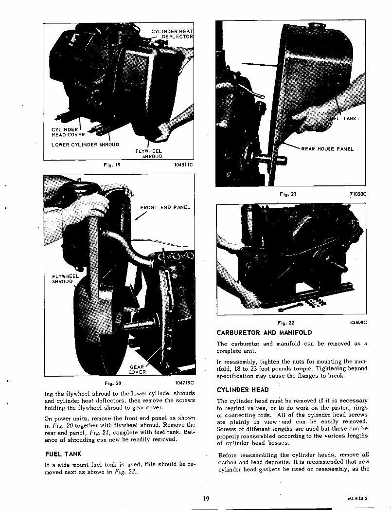
"'d"'''''~IIII;UH::: air shrouding, refer to Fig. 19. Firsthead covers and the screws mount-
18
76696CFig. 18
FLYWHEELSHROUD
Fig. 19 104811C
END PANEL
Fig. 20 104719C
ing the flywheel shroud to the lower cylinder shroudsand cylinder heat deflectors, then remove the screwsholding the flywheel shroud to gear cover.
On power units, remove the front end panel as shownin Fig. 20 together with flywheel shroud. Remove therear end panel, Fig. 21, complete with fuel tank. Balance of shrouding can now be readily removed.
FUEL TANKIf a side mount fuel tank is used, this should be removed next as shown in Fig. 22.
REAR HOUSE PANEL
Fig. 21 71050C
Fig. 22
CARBURETOR AND MANIFOLD
83608C
The carburetor and manifold can be removed as acomplete unit.
In reassembly, tighten the nuts for mounting the manifold, 18 to 23 foot pounds torque. Tightening beyondspecification may cause the flanges to break.
CYLINDER HEAD
The cylinder head must be removed if it is necessaryto regrind valves, or to do work on the piston, ringsor connecting rods. All of the cylinder head screwsare plainly in view· and can be easily removed.Screws of different lengths are used but these can beproperly reassembled according to the various lengthsof cy+inder head bosses.
Before reassembling the cylinder heads, remove allcarbon and lead deposits. It is recommended that newcylinder head gaskets be used on reassembly, as the
19 MI·514-2

old gaskets will be compressed and hard so that theymay not seal properly. Use a mixture of graphite andoil on the cylinder head screws to prevent them fromrusting tight against the cylinder block. Tighten cylinder head screws 22 to 24 foot pounds torque, andafter complete assembly and engine is run in, retorque head screws.
GEAR COYER
Disconnect the governor linkage and remove the governor. Remove gear cover screws and drive out thetwo dowel pins as shown in Fig. 23. The cover canthen be taken off, exposing the timing gears as shownin Fig. 24. In reassembly, tighten cap screws, 14 to18 foot pounds torque.
CAMSHAFT GEAR
If it is necessary that the camshaft gear be removed,this can be done by taking out the three cap screwsand lockwashers which hold the gear to the end of thecamshaft. Note that the mounting holes in the camshaft gear are staggered in such a manner that thegear can be assembled to the shaft only one waywhich will automatically time the gear to the shaft.Pry the gear off the camshaft using a screw driver orsimilar wedge tool.
IDLER GEAR AND SHAFT
Remove the Allen-head setscrew, on the magneto sideof the crankcase, which locks the idler shaft in position. With the use of a gear puller, the idler shaft and.idler gear assembly can be removed from the crankcase. See Fig. 25. In reassembly, allow .003" to.004" clearance between idler gear and shaft collar.
OIL PAN
The engine can now be inverted so that the supportsand oil pan can be removed, see Fig. 26.
Fig. 23 71056C
MI-515-3
In reassembly of oil pan, tighten mounting screws, 6to 9 foot pounds torque.
OIL PUMP
To remove oil pump, first take out the slotted pipeplug, and then with a 5/32 inch Allen wrench, removethe oil pump lockscrew, as shown in Fig.27. Removelocknut holding oil pump driving gear to shaft. Then,with a soft brass rod or punch, drive shaft throughgear as shown in Fig. 28. The oil pump can then bewithdrawn toward center of crankcase.
PISTONS AND CONNECTING RODS
After removal of the oil pump, all of the connectingrod bolts will be accessible. Remove the palnuts andhexagon nuts, then by tapping the ends of the boltslightly, being careful not to mar the threads, the connecting rod cap can be freed from the bolts. The rodwith the piston can now be pushed up through thecylinder. Be careful not to score the crankshaft jour-
GOVERNOR GEAR
IDLER OIL PUMP GEARGEAR
Fig. 24 104716C·l
Fig. 25 71066C
20

Fig. 26 104721C
Fig. 27 180178C
nals, by allowing the rod bolts to strike or scrapeacross them, when removing the connecting rod andpiston assemblies. Replace the caps on the rods immediately so that they are in the correct position forreassembly, being sure that the shims are in placebefore the cap is put on. A number is stamped on theside of the rod and cap to match each connecting rodwith its corresponding cap. These numbers should beon the same side of the connecting rod in reassem-bly, see Fig. 29. .
The piston skirt is cam-grouncl to an elliptical contour. Clearance between the piston and cylinder mustbe measured at the center of the thrust face of thepiston skirt. Refer to Chart, Fig. 32, for proper clearance. The thrust faces on the piston skirt are 90°from the axis of the piston pin hole, with the widesection of the piston skirt toward the maximum thrustside, or opposite the crankshaft rotation. See EngineSectional, Fig. 2.
Tighten connecting rod nuts, 22 to 24 foot poundstorque, then install 'Pal' locknuts and tighten with
Fig.28 8361SC
Fig. 29 104819C-I
wrench ~ turn beyond 'finger-tight' position.
Be sure piston and connecting rod assemblies areput back into the same bore from which they wereremoved.
PISTON RINGS
Install rings by placing the open end of the ring onpiston first, as shown in Fig. 30. Spread ring onlyfar enough to slip over piston and into correct groove,being careful not to distort ring.
The scraper ring must be installed on the piston withthe scraper edge down, otherwise oil pumping andexcessive oil consumption will result. See Fig. 31.
Use a suitable ring compressor in reassembly and
21 MI-S16-2

Fig. 30 71152C
COMPRESSION RINGS
SCRAPER RING
OIL RING
Fig. 31 92200C·1A
stagger the piston ring gaps 900 apart around thepiston. Oil the piston, rings, wrist pin, rod bearingsand cylinder walls before assembly.
CYLINDERS
The cylinder blocks can now be removed from thecrankcase if necessary. In reassembling, put theblocks back on the same side from which they wereremoved. Clean all dirt and other deposits from between fins and manifold ports. If the cylinders areworn more than .005 inch oversize, they should be reground and fitted with oversize pistons and rings.This work should be done by an authorized servicestation.
If in the opinion of the service station attendent, achrome re-ring is necessary, use Wisconsin TriCromepiston ring set indicated in Parts List Section.
Tighten cylinder block mounting nuts, 40 to 50 footpounds torque.
VALVES
Remove the valve tappet inspection plate. Compressthe valve springs with a standard automotive typevalve lifter as illustrated in Fig. 33. Insert a rag in
MI-517-2
PI~TON,RING AND ROD CLEARANCES CHART
PISTON TO CYLINDER.0035 to .004-AT PISTON SKIRT THRUST FACE
PISTON RING GAP .015-
PISTON RING Top Ring .002 to .0035"
SIDE CLEARANCE 2nd Ring .001 to .0025-
IN Scraper Ring .001 to .0025-GROOVES
Oil Ring .0025 to .004"
CONNECTING ROD Diameter .0007 to .002"TO
CRANK PIN Side .009 to.O 16-
PISTON PIN TOCONNECTING ROD BUSHING .0005 to .001-
STANDARD CRANK PIN DIMENSIONS
- ~ f1~
lJ-~l. 1135LENGTH1.130
_1.876DIA. GRIND1.875
Fig.32
the opening at the bottom of the valve chamber so thevalve spring seat retaining locks do not fall into theengine crankcase. Remove the valve spring seat retaining locks, seats, springs, valves and clean these,as well as the ports and guides, of all carbon andgum deposits. Tag each valve so that in reassemblythey will be mounted in the same guide they were removed from.
The valve face is ground at 450 to the vertical centerline of the valve stem and the valve seat insertshould also be ground at a 450 angle. After grinding,valves and inserts should be iapped with a suitablelapping compound or they will leak due to improperseating within the first few hours of operation. Aftervalve seats have been cleaned, apply lapping compound to the valve face and put the valves back intotheir guides. Lap the valves by rotating them backand forth with a reciprocating advancing valve tool.Occasionally lift the valves and reseat them in adifferent position to insure a uniform seat which willshow entirely around the valves. After valves havebeen lapped in evenly, remove them from the blockand wash the valves and block thoroughly with gasoline or kerosene and reassemble.
The cylinder blocks have replaceable valve guidesand the valve stems have a clearance of .003" to.005" in the guides. When the clearance becomes
22

VALVE LIFTER
Fig. 33 180188C
.007", the guides should be driven out and replacedwith new guides.
These engines that have Stel/ite exhaust valves andinserts are designated as Model VH4D and are equipped with positive type exhaust valve rotators. Theaction of the rotocap, which rotates the valve slightlyeach time the valve opens, helps prevent sticky. valveand will impart a wiping action between the valveface and valve seat, thereby preventing the build-upof foreign deposits. Valve rotation will also avoidprolonged exposure of anyone sector of the valveface to a local hot spot on the seat which will resultin lower and more uniform valve face-seat temperatures.
CRANKSHAFT
To remove the crankshaft, first remove the six capscrews in the main bearing plate at the take-off endof the engine. This plate can then be pried off, andcrankshaft removed from that end of crankcase. SeeFig. 34. Be sure to keep shims and gaskets in placeas these are necessary to give the proper end play to
Fig. 34 71075(,
the tapered roller main bearings on the crankshaft.This encl play should: be .002 to .004 inch when engine is cold. There is practically no wear in thesebearings so that no readjustment is necessary afterproper assembly.
When reassembling crankshaft, the timing marks onthe crankshaft gear and the camshaft gear must bematched as shown in Fig. 24, otherwise engine willnot operate properly, or if timing is off considerably,engine will not run at -all.
The mounting holes for the main bearing plate areoff-set in such a manner that it can only be mountedin the correct position. Tighten main bearing platecapscrews, 25 to 30 foot pounds torque.
CAMSHAFT
The camshaft must be withdrawn from the flywheelend of the engine as shown in Fig. 35. When reassembling, be sure the spring and plunger are in place inthe end of the camshaft, as they hold the camshaftin position endwise. These parts are shown in thesectional view of the engine, Fig. 2.
VALVE TAPPETS
The valve tappets are taken out after the camshaft isremoved. In reassembly, the tappets must of coursebe inserted in proper. position in crankcase, beforethe camshaft is assembled.
After the cylinder blocks have been assembled to thecrankcase, adjust the valve tappets as shown in Fig.36. With the tappets in their lowest positions, enginecold, the clearance should be .008 inch for the inletand .016 inch for the exhaust, with or without Stellitevalves.
GOVERNOR -OPERATION
The centrifugal flyball governor rotates on a stationary pin driven into the upper part of the timing gear
PULL VALVE TAPPETS,IN OUTWARDDIRECTION
Fig. 35 104726C.A
23 MI·518·3

Fig. 36 180186C
cover, and the governor is driven off the camshaftgear at crankshaft speed.
The flyweights are hinged to lugs on the gear. Hardened pins on the flyweights bear against the flangedsliding sleeve, moving it back and forth as the flyweights move in or out. The motion of the sleeve istransmitted through a ball thrust bearing to the governor lever, which in turn is connected to the carburetor throttle lever. A spring connected to the governor lever tends to hold the governor flyweights totheir inner position, also to hold the carburetorthrottle open. As the engine speed increases, thecentrifugal force in the flyweights acts against thespring and closes the throttle to a point where theengine speed will be maintained practically constantunder varying load conditions. This speed can bevaried to suit conditions by adjusting the governorspring tension to suit.
GOVERNOR ADJUSTMENT
The control rod between the governor and carburetormust be adjusted to the proper length, otherwise thegovernor action will be faulty. With the engine at restthe governor spring will hold the flyweights in, andthe control rod must be of such length as to hold thecarburetor throttle wide open at that point. The accuracy of this adjustment can be tested by disconnecting the control rod from the governor lever, andthen pushing the rod toward the carburetor as far asit will go. This will open the throttle wide. The governor lever should then be moved as far as possiblein the same direction, all of this being done with thethe rod disconnected from the lever. Holding bothparts in the above position, the rod should be screwed into the swivel block on the carburetor, until thebent end of the rod will register with the hole in thelever, then, screw the rod in two more turns. Insertthe rod into the hole in the governor lever and assemble cotter pin. With the governor lever pushed towardthe carburetor as far as it will go, there should beabout a 1/16 inch clearance between the throttlelever and the stop pin on the carburetor. The clear-
MI-519-2
LOAD NO LOAD HOLE GOVERNOR LEVERR.P.M. R.P.M. NO.
1400 1525 4 • HOLE NO.
1500 1650 5 .--121600 1725 5 .' 11• ' 101700 1850 6 • ' 9• , 81800 1950 7 .' 71900 2025 7 .' 6.' 52000 2150 8 .' 42100 2225 8 .' 3.' 22200 2350 9 .' 12300 2425 92400 2550 10
2500 2625 10
2600 2750 112700 2850 12
2800 2925 12
Fig. 37
ance will cause the lever to bounce back from thestop pin, rather than jam against the pin, when a loadis suddenly applied to an idling engine. This willeliminate excessive wear on the threads in the carburetor throttle swivel block.
The governor can be disassembled from the engine byfirst removing the governor housing, after which theentire governor can be withdrawn from the stationarypin. The construction of the governor can be bestseen from the sectional drawing of the engine, Fig. 2.
The governor lever is furnished with 12 holes, asshown in Fig. 37, for attaching the governor spring.It is very important that the spring is hooked into theproper hole to suit the speed at which the engine isoperated. The Governor Lever Chart, Fig. 37, showsthe full load and no load speeds of the engine andthe hole corresponding thereto. The full load speedwill be from 150 to 125 revolutions less than the noload speed. As an example, if the engine is to be operated at 2000 revolutions per minute under load, thespring should be hooked into the 8th hole in the governor lever and the spring tension adjusted, by meansof the adjusting screw connected to the spring, to run2150 revolutions per minute, without load. The speedat full load will then be approximately 2000 revolutions per minute. A tachometer or revolution countershould be used against the crankshaft while adjustingthe governor spring tension to give the proper enginespeed.
CLUTCH AND REDUCTION GEARSCLUTCH
The clutch furnished with this model of engine is ofthe disc type running in oil. Use the same grade ofoil in the clutch as is used in the engine crankcase.The oil should be filled through the inspection plateopening, to the height of the oil level plug. Approximately a pint of oil is required. Se e Fig. 38.
24
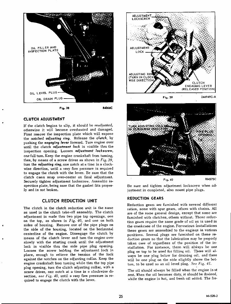
Fig- 38 84066C
CLUTCH ADJUSTMENTIf the clutch begins to slip, it should be readjusted,otherwise it will become overheated and damaged.First remove the inspection plate which will exposethe notched adjusting ring. Release the clutch, bypushing the engaging lever forward. Turn engine overuntil the clutch adjustment lock is visible thru theinspection opening. Loosen adjustment locks crew,one full turn. Keep the engine crankshaft from turning,then, by means of a screw driver as shown in Fig. 39,turn the adjusting ring, one notch at a time in a clockwise direction, until a very firm pressure is requiredto engage the clutch with the lever. Be sure that theclutch cams snap over-center on final adjustment.Securely tighten adjustment lockscrew. Assemble inspection plate, being sure that the gasket fits properly and is not broken.
CLUTCH REDUCTION UNITThe clutch in the clutch reduction unit is the sameas used in the clutch take-off assembly. The clutchadjustment is made thru two pipe tap openings, oneon the top, as shown in Fig. 40, and one on bothsides of housing. Remove one of the pipe plugs onthe side of the housing, located on the horizontalcenterline of the engine. Disengage the clutch bymeans of the clutch lever and turn the engine overslowly with the starting crank until the adjustmentlock is visible thru the side pipe plug opening.Loosen the screw holding the adjustment lock inplace, enough to relieve the tension of the lockagainst the notches on the adjusting collar. Keep theengine crankshaft from turning while thru the top pipeplug opening, turn the clutch adjusting collar, with ascrew driver, one notch at a time in a clockwise direction, see Fig. 40, until a very firm pressure is required to engage the clutch with the lever.
CLUTCHENGAGI.NG LEVER
(RELEASED POSITION
Fig. 39 244949C-A
Fig. 40 104575C
Be sure and tighten adjustment lockscrew when adjustment is completed, also mount pipe plugs.
REDUCTION GEARS
Reduction gears are furnished with several differentratios, some with spur gears, others with chains. Allare of the same general design, 'except that some arefurnished with clutches, others without. These reduction gears require the same grade of oil as is used inthe crankcase of the engine. For-various installationsthese gears are assembled to the engines in variouspositions. Several plugs are furnished on these reduction gears so that the lubrication may be properlytaken care of regardless of the position of the installation. For instance, there, will always be oneplug on top to be used for filling oil. There will always be one plug below for draining oil, and therewill be one plug on the side slightly above the bottom, to be used as an oil level plug. See Fig. 41.The oil should always be filled 'when the engine is atrest. Whenthe oil becomes dirty, it should be drained,while the engine is hot, and fresh oil added. The fre-
25 MI-520-2

OIL LEVEL DRAIN PLUG
Fig.41 76090C
quency at which these oil changes should be madedepends entirely on the kind of service in whichthese gears are used, but even with light service thechange should be made at least once every five hundred hours of operation, adding sufficient oil betweenchanges to keep the oil up to the oil level plug.
STORAGE OF ENGINE FOR WINTERWhen the season's work is completed, the followinginstructions should be carried out very carefully toprotect the engine over winter.
The outside of the engine, including the cooling finson the cylinders and heads, should be thoroughlycleaned of all dirt and other deposits.
The air cleaner, at the carburetor intake, should bethoroughly cleaned of all oil and accumulated dust,and the sediment removed from the oil cup at thebottom of the cleaner.
To protect the cylinders, pistons, rings and valvesand keep them from rusting and sticking, a half andhalf mixture of kerosene and good "gasoline engine"oil (the same kind of oil as used in the crankcase ofthe engine), should be injected into the pipe tapopening on the intake manifold while the engine iswarm and running at moderate speed. About a quarterof a pint is necessary, or enough so that a heavybluish smoke will appear at the exhaust. The ignitionswitch should then be shut off and the engine stopped. This fogging operation will leave a coating ofoil on the above mentioned parts, protecting them fromthe atmosphere.
MI·S67
On engines where the pipe tap opening on the intakemanifold is inaccessible, the rust preventative maybe injected into the air intake on the carburetor whilethe en gine is running, so the mixture will be drawninto the engine. The air cleaner connection will ofcourse have to be disconnected from the carburetorto do this.
All the oil should be drained from the crankcasewhile the engine is warm, as the oil will then flowmore freely than when cold.
Drain fuel system, including gasoline lines, carburetor, fuel pump and tank of all gasoline, to preventlead and gum sediment interfering with future operation.
The air cleaner or carburetor intake, as well as theexhaust manifold and breather openings, should betaped or otherwise sealed off, for the duration of thestorage period.
All exposed unpainted metal parts should be coatedwith grease or heavy oil.
Before starting the engine again the next season, thecrankcase drain plug should again be removed, sothat any condensation, which may have collected during the winter, may be drained before new crankcaseoil is added.
A good plan, and one that is recommended, is to remove the crankcase oil base in the spring beforestarting the engine for the new season, and scrubbingoff all sediment which may have collected there.
When replacing the engine base, a new gasket shouldbe used.
Be sure to fill the crankcase with a gooJ qualityof crankcase oil to the high level point, beforestarting the engine. Do not use any oil heavierthan SAE No. 30. Also be sure to put oil to theproper level in the air cleaner.
It is also recommended to use new spark plugs at thebeginning of the next season, especially if the engine has given considerable service.
Refuel engine and follow the starting instructions asshown on preceding pages of this 'manual.
It is highly recommended that machines be storedinside a building through the winter. If this isnot possible, the engine shoulcl be protected fromsnow and ice by a proper covering.
26

REPAIR PARTS LISTREAD THESE INSTRUCTIONS BEFORE ORDERING PARTS
THE MODEL, SPEC AND SERIAL NUMBER OF YOUR ENGINE, SHOWN ON THE NAME PLATEATTACHED TO THE AIR SHROUD, MUST BE GIVEN WHEN ORDERING PARTS.
FILL IN THE ABOVE INFORMATION ON THE PHOTO OF THE NAME AND INSTRUCTION PLATESO THAT IT WILL BE AVAILABLE TO YOU WHEN ORDERING PARTS.
243578CTO INSURE PROMPT AND ACCURATE SERVICE, THE. FOLLOWING
INFORMATION MUST ALSO BE GIVEN.
1. State exactly, quantity of each part and. part number.
2. State definitely, whether parts are to be shipped by express, freight or parcel post.
SERVICE FACILITIES
Approved engine service stations, located throughout the U.S. and foreign countries, havebeen carefully selected by the WISCONSIN MOTOR CORPORATION in order to assure complete and efficient repair and inspection service to owners of Wisconsin Air Cooled Engines.These service stations, equipped and trained for complete engine repair, also stock parts tofacilitate immediate delivery for all Wisconsin Air Cooled Engines.
A DIRECTORY OF SERVICE STATIONS CAN BE FOUND IN THE BACK OF rms MANUAL.
PARTS RETURNED FOR CREDIT
Before returning any parts, write a letter to the company from whom the parts were purchased,giving an exact list and description of the materials, why you wish 'to return them, whetherfor repairs, credit, or replacement, and also the MODEL, SPECIFICATION and SERIAL numbers of the engine from which the parts were taken. If authority is granted for their return,transportation charges must be prepaid and sender's name marked on. the outside of the boxor package.
27 MP-619-2

PARTS FOR MODEL VH4 ENGINE
Fig. 50, EXPLODED VIEW OF ENGINERefer to figure numbers for break down of parts.
MP·81S 28
222265C

•
PARTS FOR MODEL VH4 ENGINE
N-oM
~n--;;j-Hl. 000g_oo 0
M
r-,coN
...0-N
... -oN
COMN
CO r-, ...... -o... II) N -oM M -M M
No.-
NNN
Fig. 51, MANIFOLD AND CRANKCASE GROUPParts are identified by reference number.See parts list for correct part number.
222266C-l
29 MP-816-2
-------------------------------------------------------- - - - - - -

O£
'Jaqwnu :)Jud~oaJJooJOJ~sn s:)JBdaas 'Jaqwnu aouaJ:lJaJ KqpaUnuapl aJU s:)Jud
anoae coa ~NI.1::>3NNO::>aNY NO.1Sld '.1:1YHS)lNY~::> 'zs '6!:I
LlS-dW
3NI~N3 PHA 1300W ~O.:lSl~Yd

.L£
1-::>89(:<:<:<:
·~aqwnul:md lOa~~o:>~oJ1Sl1spud aas . ·~aqwnua:>ua~aJa~AqpaUnuapI a~u spud
anoao !>NI.lNnOW~3111:1110 ONV ~3.l11:1110 ';S '6!:I
Bl£-. P ;>-09£~ ~
Bll
1£1-::>£61081
tJ!D~.. tI)D~
l~£-eao~t
vl£ -L~l
vIL
9Bl
"~()J09£-~o
/-.v£l
f'lSI I
vOZ:
A1SW3SSV ~3WI~dIJNV ~3.ldVaV Z:BZ:
3NI~N3 ~HA1300W ~O::lSl~Vd

l£
::>9L06lZ
'J3qwnu lJ8d p3JJOO JOllsn slJ8d 33S 'J3qwnu aOU3J3J3JAq P3UHOOP!3.18SlJ8d
~NlanO~HS ~IY '9S '6!:I
6u!pnoJ'lS IDJnlln:>!J6y JO::!is 86Dd o J"J"~ '3.LON
£P£
t~ill ':)
of68l-\ \ Ll£
6Pl
."..0
...".,.".,.",,"£P£-",
Ll£
lSl
19l
A10W3SSY >1::>010 ~3aNI1A::> 'SS '6!:I
==s(:===a'
oJ
~Q'1==s~
1 tcor i lPl
afaf
1POL
III
,LOl
3NI~N3 J7HA1300W ~O:::lSl~Yd
6lS-dW

l-:::>6SLSB
·~aqwnu pud lOaUO:l~oJlSH spud aas ·~aqwnua:lu~aJa~ A:qpaUnuapT am s~ud
anoae ~3AO::>~"3~ ON" 013N~"W 'ss '&!:I
Oll
6lC, ~S9C
VLC-I/O
6LCSll-
06l C6lC6L·
......c I.-:. (jo~·
.-0.,.,_\)
s-- :>...-~~\...... .3
....... :> . LlC
r\L9C aLC
tlLL
LSC aLC ssz
Z-:::>9BL61
-.;:;. llC~ 0-, c.
LVC- ...."'n9VC~ ,J
:LLC-{ ~ .)/ 0
·SOl ~c. 90C 0- c. Itt
lvC llCLvL
tL£L
'_9lC'-a6L
--9l£
3NI~N3 J7HA1300W ~O.:JSl~Vd

PARTS FOR MODEL VH4 ENGINE
188 195 234 278 224,279
HOUSING ASSEMBLY
277
281FLYWEIGHT ASSEMBLY
138
Fig. 59, Ref. No. 265, GOVERNOR ASSEMBLY
CARBURETOR GASKET FUEL PUMPAOAPTER GASKET
EXHAUST 6 INLETPORT GASKET
MAGNETO GASKET MAIN BEARINGPLATE GASKET
GEAR COVER GASKET
FUEL PUMPGASKET
MAIN BEARINGPLATE GASKET
CRANKCASE GASKET
gOIL PUMP
COVER GASKET
GOVERNOR HOUSINGGASKET
~OIL FILTER
GASKET
D
:n:·U·. ... .
BOTTOM COVER GASKET
VALVE INSPECTIONCOVER GASKET
:u:OCYLINDER BASE GASKET
CYLINDER HEAD GASKET
Fig. 60, Ref. No. 208, GASKET SETParts are identified by reference number. See parts list for correct part number.
MP·821 34

PARTS LISTMODEL VH4, 4 CYLINDER STANDARD ENGINE
The followingparts are for a standard engine without house. If powerunit house parts are required, refer to Page 41.
101 AA.98-S1(VH4)
AA.9S·S7(VH4D)
ENGINE HAVING STELLITE EXHAUST VALVES AND VALVE SEAT INSERTS, HAS POSITIVETYPE EXHAUST VALVE ROTATORS AND IS DESIGNATED AS MODEL VH4D.
Description
CYLINDER BLOCK ASSEMBLY .Complete - Consisting of:1 AA·98 Cylinder block4 AD-41 Valve stem qurdes4 AE-75-B Valves4 AF-49-A Valve springs4 AG-26 Spring seats4 AH-9 Retainer locks4 HG-20 1 Valve seat inserts2 PC-405 Studs2 PH-14 Washers2 QD-612-A Gaskets2 SA-58 Inspection covers2 XD-21 Screws
CYLINDER BLOCK ASSEMBLYComplete but with STELLITE exhaustvalves, seat inserts and exhaust valveROTATORS.CYLINDER HEAD .VALVE STEM GUIDE .VALVE, inlet and exhaust, standard .STELLITE EXHAUST VALVE .For VH4D engines.
VALVE SPRING, std. inlet and exhaust2-5/16" free length. Spring rated at 49pounds when compressed to approx.1-3/8" height.VALVE SPRING, exhaust, with STEL-
I LITE valves, less valve rotators .1-31/32" free length, rated at 85pounds,when compressed to approximately1-9/32" height.VALVE SPRING, exhaust, with STEL.LITE valves and VALVE ROTATORS .•,1-13/15" free length, rated at 85 pounds,Iwhen compressed to approx. 1-1/8tl•SEAT for valve spring, std .VALVE ROTATOR and spring SEAT(exhaust) used with Stellite valves .LOCK for valve spring seat .CRANKCASE ASSEMBLY .Consisting of:I Crankcase1 LJ-300P Tube
12 PC-337 Studs2 PC-396 Studs7 PF-18 Plugs4 PF-144 PlugsI RC-91 Screen
1 RF-II28 Pipe4 RF-1143 NozzlesI RJ-159 SaberI RJ-159C Saber2 SA-26 Plugs1 SA-58 Plug2 XD-17 Screws
2 3 148 28 44 4
8 2
4 2
33 8
102 AB.l00103 AD-41104 AE·75·B
AE·75-D
106 AF·49.A
AF-51
AF·54(VH4D)
107 AG.26AG·31(VH4D)
lOS AH.9110 See Fig. A
Description
basic standard crankcasenumber is BA·4S·C. Any special
is indicated by a numberstamped on the crankcase in the location shown in Fig. A. Add this number
BA·4S-C. Order by complete numberby giving the Model, SpecificationSerial Numbers of the engine.
112 BD.l00C-2.S1 GEAR COVER ASSEMBLY .Consisting of:1 BD-100C-2 Gear coverI PF-25 Plug 1 PH-299 SealI PF-52 Button I TC-388-1 Shaft
BEARING RETAINER PLATE .114 BG·209Flywheel end.
115 BG-210C·S2 MAIN BEAR~NG PLATE ASSEMBLY,stdTake-off end. Consisting of:1 BG-210-G Bearing plateI HF-261 Cork sealI ME-l 14-2 Bearing cup1 SD-43 Cork retainer
NOTE: Engines equipped with a clutch,reduction or- clutch reduction unit, require a special main bearing plate asspecified in the rear section of this manual where these accessories are located.
6
116 BH.141.A CRANKCASE BOTTOM COVER PLATEBH.141A.l, for engines with underslungfuel tank.
ENGINE SUPPORT (cast iron) .
CRANKSHAFT ASSEMBLY .Includes:1 GA-36A .Gear 1 ME-II4 Bearing1 ME-71 Bearing I PL-53 Key
NOTE: The part number of the crankshaft will be 'found stamped on the cheekfacing the take-off end of the shaft asillustrated in Fig. B. ORDER BY THISNUMBER and by giving the Model, Specification and Serial Numberof engine.
8
117 BK.65
119 See Fig. B2 13
38
Order parts from nearest SERVICE STATION shown in directory following parts list.
IMPORTANT: Always give Model, Specification and Serial Numbers as shown on name plate.
35 MP-8~2

MODEL VH4 PARTS LIST
Ref.No.
PartNumber
EA-113
Description
121 DA-68-S1
123 DB-190A-l
125 DR-31
126 DC-209127 DC-210128 DC-211
DR-42
130 DE-65
131
132 F-61
133 GA-36-A
134 GB-45-A
135 GC-27-B-l
136 GD-93-C-4
137 GD-94-C
138 GD-l00-A
140 HF-261
141 HG-157-A-l
142 HG-201HG-201-D
143 JK-50
144 K-95-D
CONNECTING ROD ASSEMBLY.............. 4Consisting of:I DA-68 Rod (Not serviced separately)I HG-157ABushing2 PB-148 Bolts2 PD-IO Nuts2 ?D-181 Palnuts2 QA-114 Shims
NOTE: A price allowance is made onconnecting rods in which bearings havebeen burned out, but which are otherwisecomplete, and in condition to be rebobbitted.
Connecting rods are also furnished.010", .020" and .030" undersize.
PISTON, cam ground, standard size .DB-190-A,with split skirt, replaced byDB-190A-I
Pi etons are also furnished .005", .010",.020" and .030" oversize.
PISTON RING SET, standard size .Consisting of:
COMPRESSION RING .SCRAPER RING .OIL RING .Piston rings and ring sets are also furnished .005", .010·, .020" and .030'oversize.
No.~~Req Lb Oz
4
844
4
8
I 5
3
CRANKSHAFT GEAR I
CAMSHAFT GEAR I 2 2
I 6
PACKING RING I IFor fuel pumpprimer shaft.
OIL PUMP ASSEMBLY,complete (Fig.57) I 3 13
TRI-CROME RE-RING SET, std. size ....Also furnished .010", .020" and .030'oversize.
PISTON PIN, standard size 4Piston pins are also furnished .00511,
. 010", .020" ond .030" oversize.
CAMSHAFT ..
VALVE TAPPET with lockscrew............ 8
IDLER GEAR I
MAGNETO GEAR IGD-93-C and GD-93C-2, replaced byGD-93C-4.
Ref.No.
PortNumber
FUEL PUMP I
DIAPHRAGM KIT for fuel pump INOTE: Refer to fuel pump instructionsheet in back of manual. for maintenanceand repair.LQ-21-B, replaced by LQ-30.
MAIN BEARING ASSEMBLY, flywheel I I 14end. Consisting of:ME-69-1 Bearing cup-Timken 414 I 12ME-71.1 Bearing cone-Timken 420 I I 2
MAIN BEARING ASSEMBLY, take-offend I 3Consisting of:ME.114.1 Bearing cone-Timken 3382.... I 2 4ME-114-2Bearingcup-Timken3328 ...... I 12
FLYWHEEL, standard................................ I 34NC-140G-l-S 1 for engines with electricstarter I 35Includes:
GH-44 Ring gear........................................ I 13XE-17 Set screw, X"-20 x 3/8# long,
headle ss 3 I
Description
OIL PUMP COVER ASSEMBLY................ IConsisting of:I KB-42 CoverI ME-60I PE-14I PM-IIII RD-112I XA-7I XI-16
Check ballWasherSpringScreenScrewCotter pin
146 KA-61A-l-Sl OIL PUMP BO,!)Y AS5EMBLY.................. I 2Consisting of:I KA-61A-I BodyI KD-122 Stub shaft
OIL PUMP GEAR ..
GOVERNOR GEAR ..
CORK OIL SEAL ..For main bearing, take-off end.
PH-364 Oil seal for engines with clutch,reduction or clutch reduction unit.
PISTON PIN BUSHING ..
VALVE SEAT INSERT, standard ..STELLITE EXHAUST VALVE SEATINSERT - forVH4D engines. .
II
10
8
4
14
9
II
7
I
147 KB-42-S2
148 KC-56-1
149 KC-56-2
150 KD-121-S1
151 KD-122
OIL PUMP GEAR (driver) ..
OIL PUMP GEAR (driven) ..
OIL PUMP DRIVE SHAFT ASSEMBLY ..Conet sttnq of:I PA-64 PinI KC-56-1 GearI KD-I21 Shaft
OIL PUMP STUB SHAFT.. .
CARBURETOR Withgasket, Zenith No.12098 ..
CARBURETOR Withgasket, Marvel-Schebler No. TSX-690 .NOTE: The above are standard carburetors and either one may be used onthis model of engine. Refer. to stampedpart or model number on carburetor forreplacement carburetor or parts.
See carburetor bulletins in back of manual for service replacement parts list.
INLET and EXHAUST MANIFOLD.......... I 15For open engines.
MANIFOLD, for power units .Has two X-20taps for support straps .
OIL FILLER TUBE .
OIL FILLER and BREATHER CAP........ I
FUEL STRAINER, Tillotson OW-444...... INOTE: See illustration, Fig. 65, for service parts list of fuel strainer.
Order parts from nearest SERVICE STATION shown in directory following parts list.
IMPORTANT: Always give Model, Specification and Serial Numbers as shown on name plate.
MP·823-3 36
153 L-63-S1
OptionalL-64-S1
155 LD-253
LD-253-1
156 LJ-300-P
157 LO-60
159 LP-19-B
160 LP-38
LQ-30
162 ME-71
163164165 ME-114
166167
169 NC-140-G
NOTE: Because of the numerous variations in flywheels;for mounting rotating screens, stub shafts and etc.,only the standard and ring gear flywheels are listed.Therefore, give Model, Specification and Serial Numbersof engine when ordering new flywheel.
No.~~Req Lb Oz
I
I
5
2
I 12
3 8
15
6
6
6
I II
2

MODEL VH4 PARTS LIST
Ref.No.
PartNumber
188 - - - - - - OIL SEAL RETAINER (PF-118)For governor cross shaft.
Replaced by PH.571 oil seal.
170 PA·291
171 PA·333
172 PA·340
173 PB·169·A
174 PB·148·S1
176 PC·ll0
178 PC·337
179 PC·396
180 PC·406
181 PD·123
182 PD·173·A
183 PD·181
184 PD·195
185 PE-66
186 PF·52
187 PF·l0l
188APF·144
189 PG·314
190 PG·475
193 PH·299
194 PH·313·A
195 PH·571
196 PI·115·F
198 PI·143·B
200 PJ·l05
202 PK·52
203 PM·76
204 PM·l08
205 PM·l1l
206 PM·145
208 Q·12·J
Description
DOWEL PIN for gear cover .
P IN for starting crank .
ROLL PIN for governor flyweight .
VALVE TAPPET ADJUSTING SCREW
CONNECTING ROD BOLT ASSEMBLYI P8-148 BoltI PD-181 Palnut
No.~Req Lb Ox
2
I
2
8
8
I
12
2
4
I
Ref. PartDescription.
No. Net Wt.No. Number Req Lb Ox
Q·28 VALVE GRINDING GASKET SET ...•.... I 2Consisting of:
6 Q8-75 4 QD-612-A 2 QD-613-C
209 QA·114 SHIMfor connecting rod, .002" thick ... 8 I
210 QB·75 GASKET for manifold to cylinder block 6 I
211 QC·7l·A GASKET for carburetor flange ............. 3 IQG-58-A, replaced by QC-71-A.
212 QD·67 GASKET for fuel pump adapter ............. 1 1
214 QD·527.C GASKET for bearing plate, .006" thick 2 I
215 QD·527.D GASKET for bearing plate, .003" thick 1 I
216 QD·535 GASKET for oil pump cover .................. 1 1
217 QD·538-A GASKET for fuel pump mounting .....:..... 1 1
218 QD·595·A GASKET for oil filter mounting ........, .... 1 1
219 QD·610.A GASKET for crankcase bottom cover .. 1 1
220 QD·611 GASKET for gear cover .......................... 1 I
221 QD·612·A GASKET for valve inspection cover plate 4 1
222 QD·613·C GASKET for cylinder head ..................... 2 4
223 QD·614 GASKET for gear cover spacer to case 1 1
224 QD·615·A GASKET for governor houarnq .............. 2 1
225 QD·616 GASKET for magneto flange ............., .... 1 1
226 QD-6l7 GASKET for cylinder base .................... 2 1
228 QF·33·B SHIMfor main bearing plate, .006" thick 2 1
229 QF·33·C SHIMfor main bearing plate, .013" thick 2 1
231 RC·91 SCREEN for oil filler ............................ 1 1
232 RD·112 OIL PUMP SCREEN ............................... 1 1
233 RF·269 STRAIGHT FITTING in carburetor .:.... 1 2
234 RF·269·2 FITTING in governor housing foroilHne 1 2
235 RF·1225 ELBOW for fuel line ............................... 2 2l-for fuel pump outlet.I-for oil line to governor, in crankcase
236 RF·1128 PIPE for oil filter outlet,- in cronkcose 1 1
237 RF·1143 OIL SPRAY NOZZLE ............................ 4 1
237A RF·1397 ELBOW, 450 male, for fuel strainermt'g. 1 1RF-795 Nipple and XK-n Street Ell; re-placed by RF-1397.
238 RJ·159 OIL SABER (short) starter side ........... 1 2RJ-143-S1, replaced by RJ-1S9.
238A RJ·159·C OIL SABER (long) below'oil filler tube 1 3
239 RK·170 OIL SLING on crankshaft ................... ·..... 1 2
240 RK·182 SPLASH PLATE for crankcase ............. 2 3
242 RM-675 OIL LINE. crankcase to governor ......... 1 3RM-980, replaced by RM-675.
243 RM·850·1 FUEL LINE, pump to carburetor ............ 1 2
244 ------ OIL FILTER, ccnatattnq 'of:RV.40.S4 CARTRIDGES (4 pack) ........ 1 3 4RV.40A·l BASE ASSEMBLY.................. 1 1NOTE,Beginning with engine Serial·No.3408750, the RV-29-A oil filter is re-placed by a BASE ASSEMBLY and CAR·TRIDGE listed above. Replacement "Car-tridges are not interchangeable, thereforeRV·29·S4 cartridges must be used forobsolete RV-2!'rA oil frl ter, Part numberis located on top of cartridge for identi-fication.
Consisting of:1 PD-10 Nut
STUD for mcqneto mounting .
STUD for cylinder block to crankcase
STUD for starter bracket .
STUD for manifold to cylinder block ..
NUT for flywheel mounting .
NUT for governor adjusting screw ..
PALNUT for connecting rod bolt,5/16"- 24 thread .
NUT for mounting oil pump gear ..
LOCKWASHER for flywheel nut ..
BUTTON for camshaft thrust plunger ..
THRUST PLUNGER for camshaft .......
PLUG for 7/16"-14 taps in face of case 4
CLIP for spark plug ignition cables 2
BRACKET for choke control I
OIL SEAL for crankshaft, flywheel end I
WASHER for governor gear bushing I
OIL SEAL for governor cross shaft I(Neoprene) mount with lips in.
PH-318-A cork seal and PF-118 retainer,replaced by PH-57!.
GOVERNOR SPRING ADJUSTINGSCREW ·· ···· ········
OIL PUMP LOCKSCREW ..
STUD for idler gear .
RETAINING RING for piston pin .
GOVERNOR SPRING .
SPRING for camshaft thrust plunger .
SPRING for oil pump relief valve .
SPRING for fuel pump primer handle ..
GASKET SET (Fig. 60) Consisting of:6 Q8-75 1 QD-538-A 1 QD-6143 QC-71-A 1 QD-595-A 2 QD-615-A1 QD-67 1 QD-61Q-A 1 QD-6162 QD-527-C 1 QD-611 2 QD-6171 QD-527-D 4 QD-612-A10D-535 20D-613-CNOTE, QB-78, 08-79, QD-527-A and0D-527-B Gaskets, also included inthis kit, can be discarded, as they arefor the VE4 and VF4 engines.
0-12-F Gasket Set, replaced by 0-12-J.
8
1
1
1
1
1
2
1
I
3
1
1
2
2
1
1
3
I
5
1
1
1
1
8
Order parts from nearest SERVICE STATION shown in directory following parts list.
IMPORTANT: Always give Model, Specification and Serial Numbers as shown on name plate.
8
1
1
37 MP·824-3

MODEL VH4 PARTS LIST
246
SE-20-B-3
SE-74-V
PartNumber
Description
I
4
Ref.No.
245 SA-65-C
SA-68
247 SA-69
248 SD-43
,2691 TA-115
~69A TA-115-4
249 SD-115-N
PAD COVER, when oil filter is not fur-nished .
COVER PLATE for valve inspection .
COVER for fuel pumppad .For engines without fuel pump.
IRETAINER for main bearing oil sealjcork, take-off end .
!ENGINE INSTRUCTION AND NAMEIPLATE .
I
When ordering name plate, give Model,Specification Number and Serial NumberIfor correct stamping.
SCREEN for flywheel shroud .
FLYWHEEL SHROUD, for standard en-gine and power unit .SE-74-VA Withpad for mounting starterSE-74-VF Withpad for air filter mtg.....SE-74-VG Withpads for air filter and
starter mountinq .
1
1251252
253 SE-75-B
254 SE-76-B
255 SE-77-C
2561 SE-77-D
257 SE-78-C
258 SE-79-C
259 SE-80
260 SE-82-C
261 SE-83-C
265 T-89-2-S1
266 TA-111-B
267 TA-114-S1
'I LOWER CYLINDER SHROUD, Right,hand side .
LOWER CYLINDER SHROUD, Lefthand side .
CYLINDER HEAT DEFLECTOR, Lefthand side ..
CYLINDER HEAT DEFLECTOR, Righthand side I
CYLINDER HEAD SHROUD, Right handside .
CYLINDER HEAD SHROUD, Left handside .
SIDE COVER for flywheel shroud .
REAR SHROUD COVER, Left hand side I
PRIMER SHAFT, with JK-SOring .F'or engine with fuel purnp,
TA-114-C-S1 PRIMER SHAFT, with JK-SOring .For power unit with fuel pump.
274 TC-367
PRIMER HANDLE (straight) .I For engine with fuel pump.PRIMER HANDLE (bent) .For power unit with fuel pump.
PLUNGER CAP for fuel pump .
FUEL PUMP ADAPTER, not servicedseparately, order TF-96-10 (for openengines) or TF-96-12 (for power units),complete adapter and primer assemhly.
TC-322-D-S1 GOVERNOR FLYWEIGHT ASSEMBLY ..Includes TC-328-DThrust pin.
No.~~Req Lb Oz
I III II 6I II 8
i II 14
I 14
I 12
I I
1 4
2
I 2
283
284
285
U-212
VB-151
VE-464
Description
GOVERNOR SHAFT .
GOVERNOR GEAR BUSHING.................. I
THRUST SLEEVE and BEARINGFor governor.
GOVERNOR HOUSING, not servicedseparately, order TC-395-S1 Housingassembly.
GOVERNOR HOUSING ASSEMBLYConSisting of:I PF-18 PlugI PF-118 Retainer
MP-825-3
271 TB-105-B
270 TA-116
273
ADJUSTING SCREW PIN for governor ..
Ref.No.
PartNumber
3
2
2
275 TC-388-1
276 TC-389-1
277 TC-391-B
I PH-318-A SealI OD-6IS-A GasketI RF-269-2 FittingI SA-S2 PlugI TC-39SI TC-398I VB-lSII XH-I
HousingShaft and leverYokePin
No.~~Req Lb Oz
4
9
2
II
14
14
IS
3
278 TC-395
279 TC-395-S1
280 TC-398
281 TC-405
282 TF-96-10
TF-96-12
286 VE-471-4
287 VE-693
288 WD-26-A
289 WE-182-A
290 Y-97-S2Optional
Y-95-S2
CROSS SHAFT and LEVER, for gov. .... I
GOVERNOR FLYWEIGHT ASSEMBLy.... IConsisting of:I GD-IOOAGear 2 TC-322DFlyweights2 PA-340 Pins 2 TC-328DPinsI PH-313AWasher I TC-389-1 Bushing
FUEL PUMP ADAPTER and PRIMERASSEMBLY, (with straight handJe, foropen engine.) Const stInq of:I JK-SO Packing ringI PM-14S SpringI TA-III-B PlungerI TA-114 ShaftITA-lIS HandJeI TA-116 CapI TB-IOS-B Adapter
ADAPTER and PRIMER ASSEMBLY I(with bent handJe, for power units withfuel purnp.) Consisting of:I JK-SO Packing ringI PM-14S SpringITA-III-B PlungerI TA-114-C ShaftI TA-IIS-4 HandleI TA-116 CapI TB-IOS-B AdapterI XE-65 Screw
REAR SHROUD COVER, Right hand side I IS
GOVERNOR ASSEMBLY (Fig. S9) I 3 3Consisting of:I TC-391-B Thrust sleeve and bearingI TC-39S-S1Housing assemblyI TC-40S Flyweight assembly
PLUNGER for fuel pump I I(TA-1l6 must also be ordered; )
STARTING CRANK .
GOVERNOR YOKE .
GOVERNOR CONTROL ROD .To carburetor.
PRIMER CONTROL IFor power units with fuel pump ..
CHOKE CONTROL I
MUFFLER, standard, for 11." pipe tap ..
SPACER for gear cover .
MAGNETO, 'Fairbanks-Morse', No.FMX-4B7A,with gear and gasket.. .MAGNETO, 'Wico', No. XHG-4, withgear and gasket .NOTE: These engines are equipped witheither a 'Fairbanks-Morse' or 'Wico" magneto as shown above. See magneto bul-
Order parts from nearest SERVICE STATION shown in directory following parts list.
IMPORTANT: Always give Model, Specification and Serial Numbers as shown on name plate.
38
2
8
3
I
2
4
2
2
6
S

MODEL VH4 PARTS LIST
Ref.No.
291 YD.6.S1
OptionalYD.6-S2
293 YL.l00.A
305 LJ.I84
306 ME.60
PartNumber Description
letins in back of manual for service replacement parts list.
SPARK PLUG, l Bmm, CHAMPION No.0-16............................................................4AC No. CS6 Commercial .
Set of Magneto Ignition Cables with in-tegral molded spark plug boot 1Consisting of:YL.339-26 Cable for No. 1 cylinder .YL.339.34 Cable for No.2 cylinder .YL-339-32 Cable for No.3 cylinder .YL.339·38 Cable for No.4 cylinder .
YD-12 Terminal boots and YL-l 00 CableSet, (which consisted of YL-79, YL-SO,YL-Sl and YL-S2) is replaced by YL-IOOACable Set, but YD-294 Spark plug postterminal nut must be ordered for usewith the integral molded boot.
STANDARD HARDWARE
NOTE: The following pipe nipples, pins,nuts, capscrews, washers, etc. are of acommon hardware variety and can bepurchased from local plumbing, hardware or accessory stores.
NIPPLE, 1\1," x 2V," long, W.I. pipe ....For muffler mounting.
STEEL BALL, \1," di o,For oil pump relief valve.
S
307 PA·64
309 PD.l0
310 PD.ll
311 PD.12
312 PD·77
314 PD-79
315 PD-206
317 PE.3
318 PE-4
319 PE-5
PIN, l/S" dia. x Y." long, straight.. .For oil pump gear.
NUT, 5/16"-24 thread, hexagon steel ..For connecting rod bolts.
NUT, 3/S"-24 thread, hexagon steel ....For magneto stud.
NUT, 7/16"-20 thread, hexagon steel ..For mounting cylinder block.
NUT, \1,"-20 thread, hexagon steel .For governor adjusting screw pin.
NUT, 3/S"-16 thread, hexagon steel ....For magneto mounting screw.
NUT, 3/S"-24 thread (Seez-proof), hex-agon steeL............. 4For manifold to cylinder block studs.
LOCKWASHER, 1/4" Positive 472-for mounting fuel pump adaptor.6-for crankcase splash plates.6-for flywheel screen.
33-for air shrouding.
LOCKWASHER, 5/16" Positive.............. 45I-t-for crankcase bottom cover plate.6-for flywheel shroud to gear cover.15-for gear cover and spacer.4-for governor housing.2-for fuel pump.2-for carburetor.2-for oil filter.
LOCKWASHER, 3/S" Positi ve .6-for main bearing plate-take-of! end.2-for magneto.
12
S
2
12
3333
5
320 PE-6
321 PE-7
322 PE-14
323 PE-46
324 PE-49
326 PF-18
327 PF-25
328 PH-14
329 PH-22-A
330 PH-77-A
LOCKWASHI!:R, 7/16" Positive.............. 12For cylinder block to crankcase.
LOCKWASHER, 1/2" Positive .For engine .supports to crankcase.
LOCKWASHER, No. 10 Positive .For oil pump cover and screen.
LOCKWASHER, 5/16" external "Ever-lock" 3For mounting camshaft gear.
LOCKWASHER, 5/16" countersunkIEverlock I, for bearing retainer plate -flywheel end; ..
PIPE PLUG, 1/S" slotted ..l-for oil hole to pump.4-for oil spray nozzles.I-for oil pump lockscrew hole.I-for oil header.I-for governor housing.
PIPE PLUG, 3/S" slotted ..For gear cover timing hole.
PLAIN WASliER, 5/16" copper ..4-for valve inspection cover plate.2-for space~ plate to crankcase (atidler gear).
PLAIN WASHER, 3/S" steel ..l-for magneto mounting screw.4-for mcrufol.d to cylinder blocks.
PLAIN WASHER, 5/16" steel ..For mounting cylinder heads.
KEY, No. S Woodruff ..For crankshaft gear.
KEY, No. 23'WoodruffFor mounting flywheel.
KEY, No.1 Wopdruff ..For oil pump gear.
PLUG, 5/S" expansion ..For camshaft bearing oil hole.
PLUG, 1/2" expansion ..For governor housing.
PLUG, 1-3/6" expansionFor camshaft end hole.
SCREW, No.·10-32 thread x 3/S" long,steel round head 1For mounting oil pump screen.
No. Net Wt. Ref. Part No. ~~. Description ,-------:-,--------ReQ Lb 0% ~N~o~.=f:~N~u~m~b~e~r=~================FR~e~q,!:L~b~O=%~
332 PL-53
SCREW, No•.10-32 thread x 1/2" long,steel round ·head...................................... 4For mounting oil pump cover.
SCREW, 1/4"-20 thread x 3/8" long,round head · 296-for flywheel screen.4-for lower .cylinder shroud, L & R sides.2-for cylinder heat deflector, R.H. side.12-for cyl Inder head shrouds.3-for air shroud side cover.2-for rear shroud cover I lower holes.
SCREW, \1,"-20 thread x Y." long, roundhead 2For rear shroud cover, top holes.
SCREW, No.:10-32 thread x 1\1," long,steel round head 2For oil pump cover.
Order parts from nearest SERVICE STATION shown in directory following parts list.
IMPORTANT: Always give Model, Specification and Serial Numbers as shown on name plate.
333 PL-83
334 PL-137
337 SA-26
338 SA-52
SA-58339
341 XA-7
342 XA-8
343 XA-33
344 XA-36
346 XA-56
39
4
7
2
4
S
2
6
5
34
2
MP-826-2

MODEL VH4 PARTS LIST
Ref. PartNo. Number
347 XA.65
348 XA.67
Optional
XJ.46.A
351 XC·17
352 XD.3
353 XD-4
354 XD·6
356 XD.13
357 XD.14
358 XD.15
359 XD.16
360 XD.17
361 XD.19
362 XD·20
363 XD.21
DescriptionNa. ~~ Ref. Part Description
No. ~..!!:.Req Lb Oz No. Number Req Lb Oz
364 XD.29 SCREW, 3/8"-16 thread x IX" long,2 hexagon head ........................................ ... 6 2
For main bearing plate-take-off end.
365 XD.33 SCREW, 3/8"-16 thread x 2Y." long,4 hexagon head ............................................ I 2
For mounting magneto (Lower hole).
366 XD.43 SCREW, 112"-13 thread x l~" long,hexagon head ............................................ 4 2For mounting engine supports.
368 XE·55 SCREW, 5/16"-18 thread x 3/8" long,Allen head set ................... ...... ............... 1 1For idler stud.
4
4
SCREW, No.8 x 11," long, self-tapping,sheet metal .For mounting choke bracket.
SCREW, No.4 x Y." long, self-tapping,sheet metal .For mounting name cmd instructionplate.RIVET, 9/64" dia. x 3/16" long, tubularsteeI .For mounting name and instructionplate to cylinder head cover.
SCREW, 5/16"-18 thread x Y." long, flathead .For bearing retainer plate-flywheel end.
SCREW, Y."-20 thread x 3/8" long, hex-agon head 54-for lower cylinder shrouds.I-for exhaust manifold tap, R.H. side.
SCREW, Y."-20 thread x 1/2" long, hex-agon head .. .. 126-for mounting splash plates.4-for cylinder heat deflector.2-for fuel pump pad cover.
SCREW, 1/4"-20 thread x' 3/4" long,hexagon head .. 42-for cylinder heat deflector, L. H. side.2-for fuel pump adapter.
XB-75 (Allen capscrew), repI'd. by XD-6.
SCREW, 5/16"-18 thread x 1/2" long,hexagon head 6For flywheel shroud mounting.
SCREW, 5/16"-18 thread x 5/8" long,hexagon head. 1914-for crankcase bottom cover plate.S-for mounting spacer to crankcase.
SCREW, 5/16"-18 thread x 3/4" long,hexagon head .2-for mounting spacer to gear cover.
I 2-for mounting fuel pump.
I SCREW, 5/16"-18 thread x 7/8" long,hexagon head .For mounting governor housing.
SCREW, 5/16"-18 thread x 1" long, hex-agon head , .3-for mounting camshaft gear.2-for mounting carburetor.2-for oil filter mounting.
PC-II2 Studs for oil filter, replaced byXD-17.
SCREW, 5/16"-18 thread x IY." long,hexagon head 40lO-for mounting gear cover.30-for mounting cylinder heads.
SCREW, 5/16"-18 thread x 1-3/8" long,hexagon head (Special hardness) .For mounting cylinder heads.
XD-21 (111,"long), replaced by XO-20.
SCREW, 5/16"-18 thread x 111,"long,hexagon head .For valve inspection cover plates.
4
7
4
4
369 XE·65 SCREW, No. 10-32 thread x 1/4" long,Allen head set ........................... .............. 1 1For fuel pump primer shaft.
370 XH.l TAPER PIN, No.O x 3/4" Iong .....,........ 1 1For governor yoke.
371 XI.16 COTTER PIN, 1/8" x I" long ................ 1 1For oil pump relief valve spring.
372 XI·32 COTTER PIN, 3/64" x 3/8" long ..... .... 1 1For governor control rod.
374 XK.l PLUG, 1/8" pipe, square head .............. 2
I
1For inlet manifold. I .
375 XK.3 PLUG, 3/8" pipe, square head .............. 1 1For oil drain.
2
2
2
2
Order parts from nearest SERVICE STATION shown in directory following ports list.
IMPORTANT: Always give Model, Specification and Serial Numbers as shown on name plate.
MP.827.2 40

REPAIR PARTS LIST
FOR
POWER UNIT HOUSE PARTSAND
ACCESSORIES COMMONLY SUPPLIED
ON· ENGINE
WIICON liN
1&INGINII
IM.PORTANTTHE FOLLOWING 'SECTION IS INTENDED TO BE AN AID IN SELECTINGSERVICE PARTS ONLY IF THEY HAD ORIGINALLY BEEN SUPPLIED WITHTHE ENGINE.
SHOULD IT BE DESIRED TO 'CONVERT AN ENGINE TO USEANY ACCES·SORIES,CONTACT WISCONSINMOTOR CORPORATION OR AN AUTHORIZ· .ED DEALER OR ·DISTRIBUTOR BEFORE ORDERING PARTS. IN. MOST'CASES, A CONVERSION CAN ·ONLY BE MADE IF MAJOR ENGINE PARTS·ARE ALSO CHANGED.
41 MP·S48-2

VH4 ENGINE HOUSE WITH FUEL TANK AT TAKE·OFF END
-.:t-.:t,.....r-,-.:t
"'I'll -oonnC'''_ -.0-.:t
r-,co-.:t
coL.f)-.:t
MP·828
Fig. 61, ENGINE HOUSE WITH FUEL TANK AT TAKE.OFF ENDParts are identified by reference number. See parts list for correct part number.
42
222992C

VH4 ENGINE HOUSE WITH FUEL TANK AT TAKE·OFF END
-428D
REF. NO. 428-UNITED SPECIALTIES REF. NO. 429-DONALDSON
OPTIONAL AIR CLEANERS
I o
i (' t I478
~ 462 437o
If 466426-
484-1
479-"'" L- 464QJ.- 468L- 476
45~~
Ie' ........462 ...466 ~fliii-iii·iiiiiiiiiiiiiiiiiiiiiiiiiilllliiiiilllliii'_51'
460,t432 .
164959C 222993CFig. 62, END PANEL AND AIR CLEANER FOR ENGINE HOUSE WITH FUEL:. TANK AT TAKE·OFF END
Parts are identified by reference number. See parts list for correct part number.
43 MP·829

VH4 ENGINE HOUSE WITH FUEL TANK AT TA~-OFF END
Ref.No.
PartNumber
DescriptionRef.No.
Na.~Req Lb Oz
12
425 HF-380 446 WE-195
426 HF-387
427 LL-64
LO-123-S1428
428A428B428C4280428E428F428G
429 LO-120-S1
429A429B429C4290
430 LP-19
431 PG-323
432 PG-799
433 PG-801
434 PG-816
436 PH-198
437 PK-87
438 PM-137
440 RF-1225
441 RM-l049-A
442 SD-l09
443 WE-I92
444 WE-193-A
445 WE-194-A
MP-830-2
SPACER for rear panel to cylinder block
SPACER for crank mounting .I(USed only with LO-l23 air cleaner}.
IRUBBER ELBOW for air cleaner toIcarburetor .
lAIR CLEANER, United Specialties
IS~r:i::~!r·~~;···~~;;·~···~~·~·~·;~;;·;~~··~·~·;;
Numbers.A-1317 Wing nut .A-9986 Gasket .335B1 Oil cup and baffle assembly .A-l0713 Top cap assembly .A-l0962Screw, 5/16"-18 x 1/2" long .B-9982 Roller and bail assembly .C-l0724 Body assembly (Less fittings)
AIR CLEANER, Donaldson Co. No.FDA04-5780 (was No. A-4578) .Service parts: Donaldson Part Numbers.P-6658 Support screw .P-9595 Oil cup clamp assembly ..P-I64570il cup assembly ..Body assembly-not serviced, order com-plete air filter.NOTE: The VH4 power units may beequipped with either a 'United Specialties' or 'Donaldson' air cleaner as shownabove.
FUEL STRAINER, Tillotson OW-418-TNOTE: See illustration on Page 50 forservice parts list of fuel strainer.
,DOOR CLIP .I
HOUSE BRACE, flywheel end ..
HOUSE BRACE, take-off end, R.H. side
HOUSE BRACE, take-off end, L.H. sidePG-800, replaced by PG-816.
GROMMETfor fuel line ..
SPRING CLIP for crank mounting ..........
SPRING for door clip ................................ 2
ELBOWfor fuel strainer outletRF-270, replaced by RF-1225.
FUEL LINE, tank to carburetor ..
TAG for ign. switch. "To Stop Push In"..SO-108 "To Stop Pull Out" Tag. Replaced by SO-109 with YC-9-F switch.
FUEL TANK ASSEMBLY ..Consrsttnq of:
WE-192-9 Support and straps ..RC-77 Cap, Easy-on ..WE-192-4 Tank (Furnished with cap) ..
ENGINE SUPPORT, take-off end ..
ENGINE SUPPORT, flywheel end ..
2
PartNumber Description
WE-196
WE-197
LJ-175
LK-8
SIDE RAILS ..
HOUSE DOORS (Standard) ..WE-196-F (Bumped out to clear dis-tributor) ..For units with generator and distributoron left hand side of engine.
FRONT PANEL (Standard) ..WE-197-2 (With additional holes forswitch and ammeter) .For units with electric starting.
REAR PANEL .
PARTITION PLATE for canopy
CANOPY .
IGNITION SWITCHASSEMBLY ..Includes: SO-109 Tag and PE-72 L.W.YC-9-C, replaced by YC-9-F-Sl.
IGNITION WIRE, switch to magneto ...... 1YL-63 and YL-258, replaced by YL-181.
STANDARD HARDWARE
6
467 PE-5
NIPPLE, l~" x 8" long, W.I. pipeFor muffler mounting.
HOSE CLAMP, 2-1/8" 1.0 ..For air cleaner connection, cleaner end.
HOSE CLAMP, 2" 1.0 ..For air cleaner connection, carburetorend.
NUT, y.<'-20 thread, hexagon steel........ 165-for tank support to rear panel.4-for air cleaner mounting.4-for parti lion plate.I-for crank spacer. (Used with LO-123).l-for crank spring clip.l-for house brace, L.H. (T.O. end).
NUT, 3/8"-16 thread, hexagon steeL.... 4For side rails to engine supports.
NUT, No. 10-32 thread, hexagon steel..For front panel to side of shroud.
LOCKWASHER, 1/4" Posltive.............. 3410-for canopy.5-for rear panel to engine support.6-for fuel tank support.4-for air cleaner mounting.4-for partition plate.I-for crank spacer. (Used with LO-123).I-for crank spring cup.I-Ior house brace, L.H. (T.O. end).2-for house braces to manifold.
LOCKWASHER, 3/8" Posltive................ 4For side rails to engine support.
Order parts from nearest SERVICE STATION shown in directory following parts list.
IMPORTANT: Always give Model, Specification and Serial Numbers as shown on name plate.
3 447
448
450 WE-199-A86 451 WE-345
3 452 WE-3465
453 YC-9-F-Sl
4
35
454 YL-181
458
459
3460 LK-l0
8
4
6 462 PD-77
463 PD-79
464 PD-115
2
466 PE-3
17 2
102
7
2 9
44
2 I 8
2 4 8
4 8
4 4
4 4
1 7 9
I I 14
I 4 5
2
2

VH4 ENGINE I:I0USE WITH FUEL TANK AT TAKE.OFF END
PartNumber
Description No.~_!_!.:_Req Lb Oz
R.f.No.
468 PE-4S
469 PE.72
470 PH.2
471 PH·77.A
472 PH.196
474 RF·794
475
476 XA·8
477 XA-33
478 XA.34
479 XA.65
481 XD-4
482 XD-6
483 XD.7
484 xe.n
486 XD.25
LOCKWASHER,No. 10 External 'Eve"..lock' for front pcmel to side of shroud .... 2 I
LOCKWASHER,ignition switch tenninal
PLAIN WASHER, 7/16" 1.0. ·x 1/16"thick steel, for door clip ."..................... 2 I
PLAIN WASHER, 5/16" 1.0. x 1/16"thick steel.... ...•............••.....•.......... I IFor air cleaner support screw.
PLAIN WASHER, ~" 1.0. x 1116"thick steel ...........•...................................... 3 IFor rear panel to cylinder block mounting.
SCREW, S/16"-IS thread x Y,"' long,round head I IFurnished with air cleaner.'
SCREW, No. 10-32 thread x Y," long,round head .....•.... 2 IFor front panel to side of shroud.
SCREW, ~"-20 thread x 3/S" long,round head .....•...•.... I 6 I't-ior ccmopymounting.S-for for rear panel to engine support.4-for partition plate.
SCREW, No. S x y,n long, aelf-tcrppfnq,sheet metal .. 5 IFor front panel to shroud.
SCREW, ~'-20 thread x y," long, he ...agon head 2 IFor house braces to manifold.
SCREW, ~<-20 thread x r." long, hex-agon head 4 IFor mounting air cleaner.
SCREW, ~ <-20 thread x I" 10I)g, hex-agon head ._. I IFor rear panel to cylinder blo ck, R.H.side.
SCREW, 3/S"-16 thread x Y." long, hex-agon head 4 IFor si de rail s to engine support s.
NIPPLE, I/S" x r.n long, close pipe .... IFor fuel strainer mounting.
SCREW, ~"-20 thread x Y," long, roundhead .............................•.............................. II6-for fuel tank support.3-for conopy and tcmk support.I-ter crank spring clip.I.-for house brace, L.H. (T.O: end).
SCREW, ~"-20 thread x 2" Ionq, hex-agon head IFor mounting crank spacer to LD-123air cleaner.
Ref. Part Description No. Net Wt.No. Number Req Lb Oz
487 XDo41 SCREW, Y,"-13 thread x I" long, hex-agon head .................................................. 4 2For engine supports to crankcase.
488 XD.120 SCREW, ~"-20 thread x 3~" long, hex-agon head .................................................. I 2For rear panel to cylinder block, L.H.side.
489 XI·23 COTTER PIN, I/S" x 3/4" long .....•...... 2 IFor door clip.
Order parts from nearest SERVICE STATION shown in directory following ports l ist.IMPORTANT: Always give Model, Specificc+ion and Serial Numbers as shown on name plate.
45 MP-831

VH4 ENGINE HOUSE WITH UNDERSLUNG FUEL TANK
oN_U")
MP-832
r-,U")U")
t,~
U")r-,0
N r-, U")U") ('I')U") U") "<:t
\~ NU")
Fig. 63, ENGINE HOUSEWITH UNDERSLUNGFUEL TANKP arts are identified by reference number. See parts list for correct part number.
46
222994C

VH4 ENGINE HOUSE WITH UNDERSLUNG FUEL TANK
REF. NO. SOl-UNITED SPECIALTIES
~502A.
OPTIONAL AIR CLEANERS
REF. NO. S02-:00NALDSON
527
6: 542
513-. ~526553 ..
/~
531I" ,
10
~I ("I 530r ~, ....J ~
537532 505
... ...-5350- 541,,__ 548
164959C 222995CFig. 64, END PANEL AND AIR CLEANER FOR ENGINE HOUSE WITH UNDERSLUNG FUEL TANK
47Parts are identified by reference number. See parts list for correct part number.
MP·833
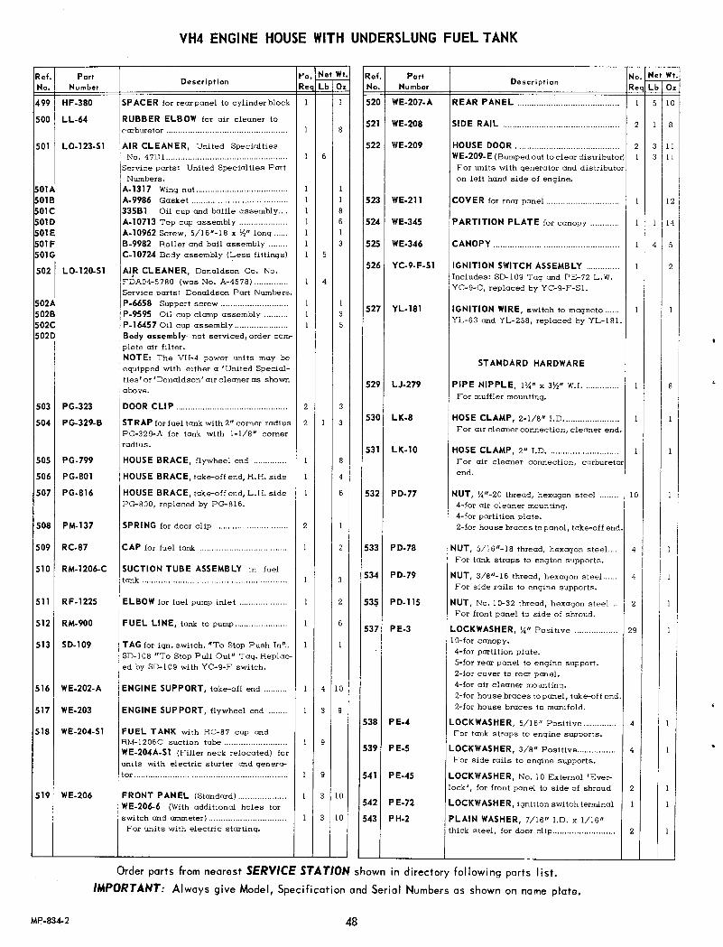
VH4 ENGINE HOUSE WITH UNDERSLUNG FUEL TANK
PariNumber
Ref.No.
499 HF-380
500 LL-64
501 LO-123-S 1
~OlA~OlB~OlC~OlD~OlE~OlF~OlG
502 LO-120-S1
502A502B502C5020
503 PG-323
504 PG-329-B
505 PG-799
506 PG-801
507 PG-816
PM-137508
Description~·o.Nel WI.Req Lb Oz
I 6
I II II 8I 6I II 3I 5
I 4
2
2
STRAP forfuel tankwith2" corner radius 2 I 3PG-329-A for tank with 1-1/8" cornerradius.
ENGINE SUPPORT, take-off end ..
ENGINE SUPPORT, flywheel end ........
I 4 10
139
FUEL TANKwith RC-87 cap andRM-1206Csuction tube I 9WE-204A-S 1 (Filler neck relocated) forunits with electric starter and genera-tm _ .
FRONT PANEL (Standard) ..WE-206-6 (Withadditional holes forswitch and cnnmeter) ..For units with electric starting.
I 3 10
512 RM-900 FUEL LINE, tank to pump...................... I 6
SPACER for rear panel to cylinderblock I
RUBBER ELBOW for air cleaner tocarburetor .
AIR CLEANER, United SpecialtiesNo. 47DI ..Service parts: United Specialties PartNumbers.
A-1317 Wingnut.. ..A-9986 Gasket ..335Bl Oil cup and baffle assembly ..A-I0713 Top cap assembly ..A-I0962 Screw, 5/16"-18 x v," long ..B-9982 Roller and bail assembly ..C-I0724 Bodyassembly (Less fittings)
AIR CLEANER, Donaldson Co. No.FI)A04-5780 (was No. A-4578) ..Service parts: Donaldson Part Numbers.P-6658 Support screw............................ IP-9595 Oil cup clamp assembly IP-16457 Oil cup assembly IBody assembly-not serviced, order complete air filter.NOTE: The VH-4 power units may beequippedwith either a 'United Specialties' or 'Donaldson' air cleaner as shownabove.
DOOR CLIP ..
HOUSE BRACE, flywheel end ..
HOUSE BRAC E, take-offend, R.H. side
HOUSE BRACE, take-off end,L.H. sidePG-800, replaced by PG-816.
SPRI NG for door clip
51350-109 TAGforign.switch.uToStopPushln" .. I ISD-I08"To StopPull Out" Tag. Replac-ed by SD-I09with YC-9-F switch.
509 RC-87 CAP for fuel tank I 2
510 RM-1206-C I SUCTION TUBE ASSEMBLY in fueltank I 3
511 RF-1225 ELBOW for fuel pumpinlet I 2
9
3 10
Ref. PariDescription No. ~~
No. Number Req Lb Oz
520 WE-207-A REAR PANEL .......................................... I 5 10
521 WE-208 SIDE RAIL ................................................ 2 I 8
522 WE-209 HOUSE DOOR ............................................ 2 3 IIWE-209-E (Bumpedout to clear distributor) I 3 IIFor units with generator and distributoron left hand side of engine.
523 WE-211 COVER for rear panel .............................. I 12
524 WE-345 PARTITION PLATE for canopy ............ I I 114
525 WE-346 CANOPY ................................................... I 4 5
526 YC-9-F-Sl IGNITION SWITCH ASSEMBLY .............. I 2Includes: SO-109Tag and PE-72 L.W.YC-9-C,replaced by YC-9-F-SI.
527 YL-181 IGNITION WIRE, switch to magneto...... I IYL-63 and YL-258, replaced by YL-181.
STANDARD HARDWARE
529 LJ-279 PIPE NIPPLE, Iy.' x 3W' W.J............... I 8For mufflermounting.
530 LK-8 HOSE CLAMP, 2-1/8" 1.0....................... I IFor air cleaner connection, cleaner end.
531 LK-I0 HOSE CLAMP, 2" 1.0............................. I IFor air cleaner connection, carburetorend.
532 PD-77 NUT, Y."-20 thread, hexagon steel ........ 10 I4-for air cleaner mounting.4-for parti tion plate.2-for house braces topanel, take-offend.
533 PD-78 NUT, 5/16"-18 thread, hexagon steel. ... 4 ! I IFor tank straps to engine supports.
534 PD-79 NUT, 3/8"-16 thread, hexagon steeL .... 4 IFor side rails to engine supports.
53~ PD-115 NUT, No. 10-32thread, hexagon steel 2 IFor front panel to side of shroud.
537 PE-3 LOCKWASHER, W' Positive .................. 29 I10-forcanopy.4-for partition plate.S-forrear panel to engine support.2-for cover to rear panel.4-for air cleaner mounting.2-for house braces topanel, take-offend.2-for house braces to manifold.
538 PE-4 LOCKWASHER, 5/16" Positive .............. 4 IFor tank straps to engine supports.
539 PE-5 LOCKWASHER, 3/8" Positive ................ 4 IFor side rails to engine supports.
541 PE-45 LOCKWASHER, No. 10External 'Eve~lock', for front panel to side of shroud 2 I
542 PE-72 LOCKWASHER, ignition switch terminal I I
543 PH-2 PLAIN WASHER, 7/16" J.~. x 1/16"thick steel, for door clip.......................... 2 I
516 WE-202-A
517 WE-203
518 WE-204-S1
519 WE-206
I35
3
4
6
Order parts from nearest SERVICE STATION shown in directory following parts list.
IMPORTANT: Always give Model, Specification and Serial Numbers as shown on name plate.
MP.834-2 48

VH4 ENGINE HOUSE WITH UNDERSLUNG FUEL TANK
DescriptionRef.No.
PortNumber
544 PH-196 PLAIN WASHER, 1/4" 1.0. x 1/16"thick steel .For rear panel to cylinder block mounting.
546 COUPLING, 3/8" W.1.pipeFor oil drain pipe.
547 RF-l086-A NIPPLE, W.I.pipe .For oil drain.
548 XA-8 SCREW, No. 10-32thread x Yo" long,round head .For front panel to side of shroud.
549 XA-33 SCREW, W'-20 thread x 3/8" long,roundhead 211O-forcanopy.4-for partition plate.S-forrear panel to engine support.2-for cover to rear panel.
550 XA-34 SCREW, Y."-20 thread x \1,"long, roundhead 2For house braces topanel, take-offend.
551 XA-65 SCREW, No.8 x \1,"long, self-tapping,sheet metal, for front panel to shroud.... 5
552 XD-4 SCREW, Y."-20 thread x \1," long, hex-agon head 2For house braces to manifold.
3
2
4
Ref.No.
PortNumber
.
DescriptionNo.~~ReQ Lb Ox
2
553 XD-6
554 XD-7
SCREW, Y."-20 thread x ~. long, hex-agon head 4For air cleaner mounting.
SCREW, y'"-20 thread xl" long, hex-agon head ......•...........................................For rear panel to cylinder block, R.H.side.
SCREW, 3/8"-16 thread x 3/4" long,hexagon head 4For side rails to engine supports.
SCREW, \1,"-13thread x 1" long, hex-agon head ..For engine supports to crankcase.
SCREW, Y."-20 thread x 3Y._H long, hex-agon head .For rear panel to cylinder block, L.H.side.
COTTER PIN, 1/8" x 3/4" long .For door clip.
PLUG, 1/8" square head pipe .For fuel tank drain.
YC-66-S9 HIGH TEMPERATURE SAFETY SWITCH KIT~ CONNECT TO DISTRIBUTOR OR
/" MAGNETO GROUND TERMINAL
/
,.'S!\ /"-----_.
TAKE-OFFEND VIEW
I
/(
555 XD-25
556 XD-41
557 XD-120
558 XI-23
559 XK-l
No.~~ReQ Lb Ox
Ref.No.
PoriNumber Descriptipn
HIGH TEMPERATURE SAFETYSWITCH KIT - Complete .Consisting of:
WASHER, 5/16" 1.0., plain steel .For switch to cylinder head mounting.
4 2
YC-66-S9
563 PHon
INSTRUCTION DECAL .
CAPSCREW, 5/16"-18 thread x 2" long,hexagon head 1For switch to cylinder head mounting.
HIGH TEMPERATURE SAFETYSWITCH...................................................... 1For replacement, order YC-66-S9Kit.
WIRE ASSEMBLY, 41" long, with termi- 1nals. Interchangeable for all enginemodels.
Order parts from nearest SERVICE STATION shown in directory following ports list.
IMPORTANT: Always give Model, Specification and Serial Numbers as shown on name plate.
2
SD.233
2
8
564
565 XD-23
566 YC·66
567 YL-226-A
49
No.~~ReQ Lb Ox
3
MP-835-2

SIDE MOUNT FUEL TANKFOR VH4 ENGINE
571575
576
579- ..578-°
ft•I04724C
Ref. Part No. Net Wt.No. Number Description Req Lb 0",
570 PG·321 STRAP for fuel tank.................................. 2 I
571 PH.24",A FELT for fuel tank strap .......................... 2 2
572 Rc-n CAP for fuel tank ...................................... I 3
573 RF.1225 ELBOWfor fuel line, in fuel strainer .... I I
57" RM-1161 FUEL LINE from tank to fuel strainer(22\12"long) .............................................. I 4RM.822for enqines with electric starter(26\12"long) .............................................. I 5
575 RM-1206-B SUCTIONTUBE ASSEMBLYfor fuel tank 1 3
576 WE.187.S1 FUEL TANK, 6 gal. capacity ................ I 7WE.187E.Sl WithRC-77 cap and RM-1206-Bsuction(OPTIONAL) tube.
5n WE.188 ENGINE SUPPORT ..............._.._............. 2 4 IIWE.188Dforengines with electric starter 5 4
STANDARDHARDWARE
578 PD·79 NUT, 3/S"-16 thread, hexagon steel ...... 4 IFor fuel tank straps to supports.
579 PE.5 LOCKWASHER,3/S" Positive ................ 4 1For fuel tank straps to supports.
580 PE.7 LOCKWASHER,112" Positive ................ 4 1For enqine supports to crankcase.
581 XD.27 SCREW,3/S"·16 thread x I" long, hex-agon head .................................................. 4 IFor fuel tank straps to supports.
582 XD....1 SCREW,1/2"-13 thread x I" lonq, hex-aqon head .................................................. 4 2For enqine supports to crankcase.
Fig. 6S
FUEL STRAINER ASSEMBLIES
No.~~Req Lb 0",
Ref.No.
PartNumber Description
583 OW-352
584 OW-363
585 OW...."7
586 06096
LP.19
LP.19.A
LP.19.B
LP.19.C
06137
FUEL STRAINERASSEMBLY.................. I(WithShut-off valve in cover, and glassbowl) T!l1otson No. OW-4IS·T.
FUEL STRAINERASSEMBLY.................. I(WithShut-off valve in cover, and metalbowl) Tlllotson No. OW-449-T.
FUEL STRAINERASSEMBLY.................. I(WithoutShut-off valve in cover, andglass bowl) T!l1otson No. OW-444.
FUEL STRAINERASSEMBLY.................. I(WithoutShut-off valve in cover, andmetal bowl) TUlotson No. OW·476-T.
The following .ervlceoble port. are in·terchangeable for all the a boy e fuel.tralner ••
FILTER SCREEN...................................... I
GLASS BOWL I
METAL BOWL I
CLAMP WIRE and THUMBNUT AS-SEMBLY...................................................... I
BOWLGASKET(Wisconsin No.QD-653) I
Order parts from nearest SERVICE STATION shown in directory following ports list.
IMPORTANT: Always give Model, Specification and Serial Numbers as shown on nome plate.
50MP·836
S
7
6
5
2
5

SIDE MOUNT AIR CLEANER FOR VH4 ENGINE
OPTIONAL PRE-CLEANERSUNITED SPECIALTIES
REF. NO. 593DONALDSONREF. NO. 594
597590-
~593A
591A
600,589-
588602
\I',601602
~601-o~ c"':"Ol
"," "'9'9r604
598-
~603
591E
592C
596 ~~ 592A591B
595 592B
DONALDSONREF. NO. 592
UNITED SPECIALTIESREF. NO. 591
OPTIONAL AIR CLEANERS
Ref. Part DescriptionNo. ~~
No. Number Reg Lb Oz
587 LJ-120 TUBE for air cleaner to carburetor elbow I I 1
588 LL-27 RUBBER HOSE for air cleaner tube ...... I 2
589 LL-67 RUBBER ELBOWfor air cleaner tube .. I 4
590 LO-96 STACK CAP for air cleaner .................... 1 12United Specialties No. 6B9.
LO-86 STACK CAP for air cleaner .................... 10Donaldson Co. No. GAXOO-2017.
591 LO-121-S1 AIR CLEANER, United SpecialtiesNo. 4504 .......................... Service Parts: I 3 12United Specialties Part Numbers.
591A 615A6 Gasket .................................... 1 1591B 214B1K011 Clamp assembly .................... I 2591C 496B 1K111 Oil cup (order baffle separately) I 6591D 415B1Kll Baffle .................................... I 3591E 311C2KOll Body assembly (less fittings) 1 3
592 LO-119A-S1 AIR CLEANER (2-5/8" long neck) ....... 1 3 12Donaldson Co.·No. FDA04-5791.
LO-119 (lYz' neck), repl'd. byLO-119A-Sl
~92AService parts: Donaldson Part Numbers.P-2846 Clamp assembly .................... I 3
592B P-14818 Oil cup assembly .................. 1 5592C Body assembly-not serviced, order com-
plete air cleaner.NOTE: The VH4 openengines may beequipped with either a 'United' or'Donaldson' air cleaner and pre-cleaner.
593 LO-109 PRE-CLEANER, collector type .............. 1 I 12United Specialties No. 3-50-B 16420.
593A A-16380 Cap assembly ........................ I 4593B B-16382 Bodyassembly ...................... I 1
593~ A-16370 Sleeve assembly .................. 1 8
Fig. 66 222996C 1
Ref. Part DescriptionNo. ~t,.!.!:
No. Number Req Lb Oz
594 LO-114 PRE-CLEANER, collector type .............. 1 1 8Donaldson -ce. No. PBHOO-0215.
Service parts: Donaldson Part Numbers.594A P-20116 Cover assembly .................... 1 4594B P-20115 Body........................................ 1 4594C P-20120 Sleeve assembly .................... 1 1
595 LO-133 BASE for United Spec. pre-screener ...... 1 4
596 LO-134 PRE.SCREENER for LO-l 09pre-cleaner I 2
597 LO.147-A PRE-SCREENER for LO-l14pre-cleaner 1 4and LO-119A-SI Donaldson cleaner.
598 PG.291 STRAP (4-3/8" Inside Diameter) ............ 1 IFor mounting air cleaner.
STANDARD HARDWARE
599 LK.8 HOSE CLAMP, 2-1/8" 1.0 ....................... 3 2For air cleaner connections.
600 LK-10 HOSE CLAMP, 2" 1.0 ............................... 1 2For air cleaner elbow, carburetor end.
601 PD·77 NUT, X"-20 thread, hexagon stee1.. ........ 4 1For air cleaner strap mounting.
602 PE.3 LOCKWASHER, Yo" Positive .................... 6 IFor air cleaner strap mounting.
603 XA.74 SCREW, Yo"-20 thread x 2Yo"long,roundhead, for air cleaner strap clamping ....... 2 1
604 XD-4 SCREW, Yo"-20 thread x Yz" long, hex-agon head, for strap to shroud ................. 4 1
,
Order parts from n/.eresf SERVICE STATION shown in directory following parts list.IMPORTANT: Always give Model, Specification and Serial Numbers as shown on name plate.
51 MP·837-2

NOTE: CYLINDER SHROUDING ON RIGHTHAND SIDE OF ENGINE IS SHOWN.
815__
831
809-'
810
840__ ~ \
84.i9l 8448~.1
C'
0__ 844,'849
219073C-1A
,
UPRIGHT AIR INTAKESTACK AND SCREEN
827
844
850-,;811
833 -t807
85t·
•t804
805-'"844- ~t850
DRUM SCREEN
t813 .. "1.,-844
849/219074C
Order parts from nearest SERVICE STATION shown in directory following ports list.
IMPORTANT: Always give Model, Specification and Serial Numbers as shown on name plate.
MP·838-2 S2

AGRICULTURAL SHROUDING, ROTATING SCREEN, UPRIGHT AIR IMTAKE STACK AND DRUM SCREENFOR VH4 ENGINE
Ref.No.
PartNumber
804 PE-62-1
80S PG-315
806 PG-325-A
807 PG-481
809 PH-426
810 PH-442
811 PK-87
812 PM-4
814 SE-20-D
813 SA-56
815
Description
NOTE: Because of the variations in flywheel shrouds withpads for mounting starter, air cleaner, stack and etc.,order by giving engine Model, Specification and SerialNumbers.
816 SE-75-B
817 SE-76-B
LOCKWASHER for starting crank nut,with air intake stack or drum screen ....
CLIP for air intake screen .
SUPPORT STRAP for air intake stack
BRACKET for crank support. .
GROMMET for center hole in rotatingscreen .
WASHER (Rubber faced) .For mounting rotating screen.
SPRING CLIP for crank support .
SPRING for crank hole cover .
COVER for crank hole in air stack .
DRUM TYPE INTAKE SCREEN .
FLYWHEEL AIR SHROUD .
LOWER CYLINDER SHROUD, R.H.side I
LOWER CYLINDER SHROUD, L.H. side I
NOTE: Beginningwith engine Serial No. 3188328,the cylinder head covers, Ref. No's. 820 and 821, have the balewire spring removed, and thus the standard cylinder heatdeflectors, Ref. No's. 818 and 819 are used.
818 SE-77-C
819 SE-77-D
820 SE-78-D-6
821 SE-79-D-5
822 SE-80
CYLINDER HEAT DEFLECTOR, L.H.side .SE-77C-2Deflector with VE-481 Pin,replaced by SE-77-C.
CYLINDER HEAT DEFLECTOR, R.H.side ISE-77D-I Deflector with VE-481Pin,replaced by SE-77-D.
CYLINDER HEAD COVER, R.H. side.. ISE-78D-I Cover Assembly, replacedby SE-78D-6.
SE-78D-I consisted of:PC-388 Clip for spring .PK-120 Spring .
6 I
I I I
5
I 5
I 12
I2
5
SE-78-D Cover .XJ-46 Rivets for clip .
II II I
II II II 132 I
3
2
CYLINDER HEAD COVER, L.H. side ..SE-79D-I Cover Assembly, replacedby SE-79D-5.
SE-79D-I consisted of:PG-388 Clip for springPK-120-A Spring .SE-79-DXJ-46
Cover .Rivets for clip .
No. Net Wt. Ref. Part No. Net Wt.Rec Lb Ox No. Number Description Req Lb Oz
~~====~==================~~~823 SE-82-C-8 REAR SHROUD COVER ASSEMBLY,
L.H. side .Consisting of:PM-128 Springfor cleanout cover .SA-76 Cleanout cover .SE-82C-2 Shroud(not serviced sep.) ..XJ-49 Rivet .SE-82C-3Cover with VE-481-APin,replaced by SE-82C-8.
14
12
SIDE COVER for flywheel shroud .
12
14
14
13I
14
4
STARTING CRANK for engines with in-take stack and rotating screen I 2Use Std. U-212crank for engines withdrum screen,
833 U-212-A
STANDARD HARDWARE
I I
824 SE-83-C-12 REAR SHROUD COVER ASSEMBLY,R.H. side .Consisting of:PM-128 Spring for cleanout cover .SA-76 Cleanout cover .SE-83C-3 Shroud(not serviced sep.) ..XJ-49 Rivet .SE-83C-4 Cover with VE-481-APin,replaced by SE-83C-12.
827 SE-99-B AIR INTAKE STACK .
828 SE-I00 AIR INTAKE SCREEN for air stack ....
2
829 SE-I02 DUST SHIELD for flywheel shroud .
831 SE-204-C-Sl ROTATING SCREEN KIT .Consisting of:I PH-426 Grommet5 PH-442 WashersI SE-204-C Screen5 XA-I04 Screws
836 UC-73-G-Sl STARTING CRANK NUT ASSEMBLY ..For engines with intake stack.Consisting of:PA-333 Pin .UC-73-G Nut (7-3/16" long) .
837 UC-73-J-Sl STARTING CRANK NUT ASSEMBLY ..For engines with drum screen.Consisting of:PA-333 Pin .UC-73-J Nut (8-3/8" long) .
840 XA-I04 LOK-THREAD SCREW .
I I 2
I4III
I I 2
I4III
I 10 5
I 6 4
I I
I 2
I 2 4
For rotating screen mounting.
843 PD-77 NUT, Y."-20 thread, hexagon steel.. .I-for crank mounling spring clip.I-for crank hole cover.
844 PE-3 LOCKWASHER, y." Positive.................. 494-for air intake stack mounting.25-forair shrouding.I-for crank support spring clip.7-for air intake support strap.6-for air in take screen.6-for drum screen.
Order parts from nearest SERVICE STATION shown in directory following parts list.
IMPORTANT: Always give Model, Specification and Serial Numbers as shown on name plate.
53 MP-839-2

AGRICULTURAL SHROUDING, ROTATING SCREEN, UPRIGHT AIR INTAKE STACK AND DRUM SCREENFOR VH4 ENGINE
Ref. PartNo. Number
DescriptionNo. ~t,!!:Ree Lb 0.
845 PE-4
849 XA-33
850 XA-34
851 XA-35
853 XD-3
854 XD-4
BS5 XD-6
856 XD-13
858 XJ-46-A
MP-840-2
LOCKWASHER, 5/16· Positive .For flywheel shroud to gear cover.
6
SCREW, \<1"-20thread x 3/8" long, roundhead 263-for air intake stack.4-for lower cylinder shroud,L & Rside2-for cylinder heat deflector, R.H. side6-for cylinder head shrouds.3-for air shroud side cover.2-for rear shroud cover.6-for drum screen.
SCREW, \<1"-20thread x v," long, roundhead 122-for crank bracket and spring clip.6-for air intake screen.4-for air intake support screen.
SCREW, \<1"-20thread x 5/8" long, roundhead ..For crank hole cover.
SCREW, \<1"-20thread x 3/8" long, hex-agon head.................................................. 4For lower cylinder shrouds.
SCREW, \<1"-20thread x v," long, hex-agon head 52-for cyl'.nder heat deflector to rearcover (L.H. side).
3-for intake support strap.
SCREW, \<1"-20thread x 0/." long, hex-i agon head 3
For cylinder heat deflectors to cylinderblock.
SCREW, 5/16"-18 thread x v," long,hexagon head 6For mountingflywheel shroud.
RIVET, 9/64" dia. x 3/16" long,tubular steel (not illustrated) 4For mounting instruction plate to R.H.cylinder head cover.
Order parts from nearest SERVICE STATION shown in directory following parts list.
IMPORTANT: Always give Model, Specification and Serial Numbers as shown on name plate.
54

TT-4S-L AND TT-4SL-lGOVERNOR CONTROL ASSEMBLIES
FOR VH4 ENGINE
f
Fig. 68r-,-------,---------------------,--.---,104568C-l
PartNumber Description No. ~__!_!:
Req Lb OzRef.No.
TT-45·L GOVERNORCONTROL ASSEMBLY-for open engine 1 1GOVERNORCONTROL ASSEMBLY-for power unit 1 1NOTE: The following parts are identical on both the above assemblies,except PG-342 bracket is not furnishedon TT-45L-l assembly.LOCKNUT for adjusting screw ..BRACKET for governor and choke control
TT·45·L.l
1 11 4
1 2
1 11 11 11 11 41 8
1 1
1 1
1 1
3 13 1
1 1
Ipc 1
604 PD·173.A605 PG-342606 PI.115·E607 PK.121608 PM.1I1·1609 TC-365610 TC.368·A611 VB.134.A612 VE-527·W
613 PE-3
614 PH.77
615 XA.62
616 XA·65
617 XI·l
618 X1·11
619
ADJUSTING SCREW ..RETAINER for adjusting screw spring ..SPRING for adjusting screw ..P IN for variable speed lever support ..P IN for adjusting screw swivel ..VARIABLE SPEED LEVER ..CONTROL ..
STANDARD HARDWARELOCKWASHER,Yo. Positive ..For support pin.PLAIN WASHER,5/16"1.0.x 5/8"0.0.x 1/16" thick steel ..For variable speed lever.
SCREW,8-32 thread x \<I' long, roundheadFor cetter pin in lever.SCREW,8x Ya"long, self-tapping, sheetmetal. For control bracket ..COTTER PIN, 1/16" x 1/2' long ..I-for variable speed lever pin.I-for adjusting screw spring.I-for chain at control.
COTTER PIN, 3/32" x 1Yo" long ..For chaln at lever.
No. I/O GALVANIZEDSAFETY CHAIN8~' long. For control to lever.
TT-4S-D-lIDLE CONTROL ASSEMBLY
869\•865~ 866.--
872 --'"" _._ 863864--. ~
8,0 ~~,t r;... 1862
868 ~ 1 871867 870
860
223371C
Ref. ParI No. Nel WI.No. Number Description Reqru;-o;-860 PG-348.A BRACKET for control lever .................... 1 2
861 PI.145.B ADJUSTING SCREW ................................ 1 2
862 TC-380 FULCRUM PIN for control lever ............ 1 1
863 TC-381 PIN for adjusting screw .......................... 1 1
864 VB.142.5 IDLE CONTROL LEVER ...................... 1 4
865 VE-452.A CONTROL ROD HEAD .......................... 1 2
866 VE-657 CONTROL ROD NUT .............................. 1 1
STANDARD HARDWARE
867 HF-390 WASHER, 9/32·1.0.x 5/8"0.0.% 1/S'thick steel .................................................. I IFor mounting bracket.
868 PD.77 NUT, Yo'-20 thread, hexagon steeL ........ I IFor fulcrum pin.
869 PD.115 NUT, No. 10-32 thread, hexagon steel .... I IFor control rod head.
870 PE.3 LOCKWASHER, \<In Positive .................. 2 II-for fulcrum pin.I-for bracket mounting.
871 XD04 SCREW, Yo'-20 thread x Ya"long, he e-agon head .................................................. 1 IFor bracket mounting.
872 XI.l COTTER PIN, 1/16" x 1/2" long .......... 1 1For adjusting screw pin.
Order parts from nearest SERVICE STATION shown in directory following parts list.IMPORTANT: Always give Model, Specification and Serial Numbersas shown on nameplate.
55 MP·841

ELECTRIC STARTER, GENERATOR AND DISTRIBUTOR IGNITIONFOR 'VH4D ENGINE'
Ref. PartDescription
No. ~~No. Number Rea Lb Oz635 GD·97·C DRIVE GEAR for generator .................... I 8
GD-97-A,replaced by GD-97-C.
636 PC·ll0 STUD for generator mounting ................. 2 I
637 PC·396 STUD for starter bracket ........................ 2 I
639 PG·514-A-l BRACKET, starter support .................... I 6
640 PG·543-A ADVANCE ARM ASSEMBLY .................. I 3For distributor, PrestolitelG-286D-A3.
641 PG-791 SUPPORT PLATE for ignition coil ...... I I
642 QD-616 GASKET for mounting generator ........... I I
643 SD-l09 TAG for ignition switch ......................... I I-To Stop Push In- •
645 VE·439·D CONTROL PANEL ................................. I 8VE-439, replaced by VE-439-D.
646 YA-19-3-S1 ELECTRIC STARTER (6 volt), Presto-lite No. MZ.4192 (was MZ.4184)......... I 18 8
OptionalYA·18·3-S1 ELECTRIC STARTER (12 volt),Presto-
lite No. MBG-4109(was MBG-4024)... 18 8
Fi_g.69 2190'1SC-l
Ref. Part Description No. Net Wt.No. Number Req Lb Oz
NOTEI For electric starter serviceparts, refer to illustration immediatelyfollowrnq this parts I1st.
647 YB-16-E GENERATOR (6 volt), Prestolite No.GA3-4306,with cut-out ............................ I IS 6YB-16-C Prestolite No. GA3-4303withtwo charge regulator, repl'd byYB-!6-E.
OptionalYB·16-G GENERATOR (12 volt), Prestolite No.
GDY-4115Nwith cut-out relay ................YB-16-G Neg. Gr. replaced YB-16-FPos. Gr.NOTEI For generator service parts, re-fer to illustration immediately followingthis parts list.
649 YC-9-B·Sl IGNITION SWITCH ASSEMBLY .............. I 2Includes: SD-I09 Tag
2, PE-72 Lockwashers
650 YC·l0·C STARTING SWITCH ............... ;................. I 4YC-lO, replaced by YC-lD-C.
651 YD-20 TERMINAL CAP for ignition ~res ...... 5 I
652 YD-20·A TERMINAL CAP at coil wire ................. I I
Order parts from nearest SERVICE STATIOH shown in directory following parts I isf,
IMPORTAHT: Always give Model, Specification and Serial Numbers as shown on name plate.56MP-842-3

ELECTRIC STARTER, GENERATOR AND DISTRIBUTOR IGNITIONFOR VH4D ENGINE
Ref. Part No. Net Wt.No. Number
Description Reqru;-'c);
- YD·165 JUMPER STRIP, for YB·16Cgeneratorwithtwochargeregulator (notillustrated) I I
~53 YD·296 TERMINAL CONNECTOR for groundstrap ........................................................... I I
654 YE·2 AMMETER ................................................ I 6
655 YF·4-A IGNITION COIL (6 volt), PrestoliteNo.200665....................................................... I I 14
OptionalYF·5·A IGNITION COIL (12 volt), Prestolite
No. 200664................................................Mountedto lower cylinder shroud, LeftHand Side.YF.4 (Prestolite 200604) mounted toPG·345 Bracket at oil f1l ter pad, re-placed by YF·4-A, but order SA·es-Call Filter Pad Cover.
656 Y F·IO·A·SI DISTRIBUTOR, HALF SPEED,Prestolite No. IAD-6004-2F................... I 3 3Includes PG-543AAdv.Arm Assembly.
658 YL·353-6 IGNITION WIRE ASSEMBLY .................. I I6" long, starting switch to ammeter.No. 14GA. cable with terminals.
659 YL-352·8 IGNITION WIRE ASSEMBLY .................. I IS" long, coil to distributor.No. 14GA. cable with terminals.
660 YL·352·26 IGNITION WIRE ASSEMBLY .................. I I26" long, ammeter to generator.No. 14GA. cable with terminals.
661 YL·352·4 IGNITION WIRE ASSEMBLY .................. I I4" long, ammeterto ignition switch.No. 14GA. cable with terminals.For open engines.
YL.352.8 WIRE ASSEMBL Y, S" long .... I IFor power unit engines.
662 YL·356-20 STARTER CABLE ASSEMBLY ............. I 420" long, starter to switch.No.4 A.W.G.cable with terminals.For open engines.
YL.356.26 CABLE ASSEMBLY, 26"long I 6For power unit engines.
663 YL·352·30 IGNITION WIRE ASSEMBLY .................. I I30" long, coil to ignition switch.No. 14GA. cable with terminals.For open engines.
YL-352.23 WIRE ASSEMBLY, 23" long.. I IFor power unit engines.
2-for mounting generator to gear cover.3-for mounting electric starter.
2
Ref.No.
PartNumber
Description No.~~Req Lb Oz
665 YL.285·F DISTRIBUTOR IGNITION CABLE SETWithintegral molded spark plug boot.ForYF.IO HALF SPEED DISTRIBUTORConsisting of:
PH.198 GROMMET I666
667
668
669
670
671
YL.339.28 CABLE to No. I spark plug.. I
YL.339.36 CABLE to No.2 spark plug.. I
YL.339.32 CABLE to No.3 spark plug.. I
YL.339.42 CABLE to No.4 spark plug.. 1
YL.278 CABLE to ignition coil ........ I
YD-12 Terminal boots and YL-2SS-CCable Set (whichconsisted of YL-42-2,YL-I4-6, YL-173,YL-25I and YL-319,is replaced byYL-2Ss-F Cable Set, butYD-294SparkPlug Post Terminal Nutsmust be ordered for use with the integral molded boot.
STANDARD HARDWARE
12
2
3
2
3
I
675 PB-24 SCREW, 3/S"-24 thread x I-liS" long,hexagon head ............................................ 3 2For mounting electric starter.
676 PD.IO NUT, 5/16"-24 thread, hexagon steel.... 2For mounting starter bracket.
677 PD.11 NUT, 3/8"-24 thread, hexagon steel...... 2For mounting generator to gear cover.
678 PD.77 NUT, Y."-20 thread, hexagon steelFor starter switch mounting.
679 PD.78 NUT, 5/16"-IS thread, hexagon steeL.. 2For ignition coil mounting.
680 PE·3 LOCKWASHER, Y." PositiveFor starter switch mounting.
681 PE·4 LOCKWASHER, 5/16" Positive.............. 42-formounting starter bracket.2-for ignition coil mounting.
682 PE·5 LOCKWASHER, 3/S" Positive ..
684 XA.65 SCREW, No.8 x Yo" long, self-tapping,sheet metal ..For mounting control panel.
5
4
686 XD.6 SCREW, Y."-20 thread x %" long, hex-agon head 2 IFor starter switch mounting.
687 XD.15 SCREW, 5/16"-IS thread x %" long,hexagon head 2 IFor igni tion coil mounting.
Order parts from nearest SERVICE STATION shown in directory following ports list.
IMPORTANT: Always give Model, Specification and Seriol Numbers as shown on name plate.
57 MP-843·3

YA-19-3-S1 ( 6 Volt) STARTING MOTOR - PRESTOLITE No. MZ-4192YA-18-3-S1 (12 Volt) STARTING MOTOR - PRESTOLITE No. MBG-4109
NOTE: YA-19-3(MZ-4192)was Prestolite No. MZ-4184.YA-18-3(MBG-4109)was Prestolite No. MBG-4024.Addition of clean-out hole in pinion housing by vender necessitated their Part No. change.
Ref. No.1
[
FRAME and FIELD ASSEMBLY---,
~-13 . Ie-12
FIELD COIL ~-1393487 ASSEMBLY e-12
14 ~-6e-2~-5
COMMUTATOR ENDHEAD ASSEMBLY
20
48
39
L 35 32 34 37 36 32! ~ -r'45 44 43
PINION HOUSING ASSEMBLY,31
BENDIX DRIVE ASSEMBLY
NOTE: All parts are interchangeable for both starting motors, except where noted.
2345678910121314
LOCKWASHER for head screw, No. 10 .
SCREW for head mounting .No. 10-32 thread x 3/8" long, fillister head.
RefNo
Presto litePort Number
Description
**
FRAME and FIELD ASSEMBLY .Consisting of:INSULATING WASHER, terminal stud .TERMINAL ..TERMINAL STUD ..INSULATING BUSHING for terminal stud .PLAIN WASHER, 5/16· for terminal stud ..INSULATING WASHER, terminal stud ..INSULATED BRUSH .INSULATION, field connection ..SCREW for pole shoe .LOCKWASHER, 5/16", for terminal stud ..NUT, for terminal stud, 5/16"-24 thread, hexFIELD COIL ASSEMBLY for YA-19-3-S1FIELD COIL ASSEMBLY for YA-18-3-S1 ......Consisting of:CONN ECTOR for field coil .FIELD COIL, U.L. .FIELD COIL, L.R .FIELD COIL, L.L. ..FIELD COIL, U.R ..
COMMUTATOR END HEAD ASSEMBLY forYA-19-3-S1 .COMMUTA TOR END HEAD ASSEMBLY forYA-18-3-S1 ..Includes:FE LT (not illustrated) ..BRUSH SPRING SET .GROUNDED BRUSH ..
***********
MZ·3005SMBG·3005S
1516171819
20 MZ·2002F
MZ·2002Q
212223
24
25
MZ·19S*
MP·649·5
2
***
Prestol itePart Number
NoReq
RefNo
Description
26 MZ·2366MBG·2366
ARMATURE ASSEMBLY for Y';"-19-3·S1 ..ARMATURE ASSEMBLY for YA-18-3-S1 ..
THRUST WASHER for Armature, C.E ..SPRING WASHER for Armature ..THRUST WASHER for Armature, Int .KEY for mounting Bendix, No.6 Woodruff .BENDIX DRIVE ASSEMBLY ..Eclipse No. 480029.
***2728293031
******
EBB·44B
422
394041
MZ·1360MZ·359
BEARING PLA TE ASSEMBLY, intermediate ..GASKET for bearing plate .SCR EW for mountingbearing plate ..No. 8-32 thread x 3/8" long, flat head.PINION HOUSING ASSEMBLY ..42 PS·1330BIncludes:
43444546
MZ·364XA·832
BEARING CAP ..BRONZE BEARING ..OIL SEAL ..
SCREW for pinion housing mounting ..No. 10-32 thread x 31-32" long, hexagon head.LOCKWASHER for housing screw, No. 10 ..COVER BAND ..SCREW for cover band ..
2I
474849
MZ·l024U
50No. 10-32 thread x 1-1/2" long, round head.NUT for cover band INo. 10-32 thread, square.
MZ-2012AS BRUSH SET for YA-19·3·S1.MBG-2012S BRUSH SET for YA-18·3·S1.P90.368 Term ina I Stud Pkg. for YA·19·3·S I.P90-333 Terminal Stud Pkg. for YA·18·3·S1.P90.448 Armature Thrust Washer Package.
2 *4 **4
58
209102
2I2I
NoReq
114
1I14
411

YB-16-C PRESTOLITE (No. GAS-4303) 6 VOLT GENERATOR - WITH REGULATORYB-16-E PRESTOLITE (No. GAS-4306) 6 VOLT GENERATOR - WITH CUT-OUT RELAYYB-16-F PRESTOLITE (No. GDY-4115) 12 VOLT GENERATOR - WITH CUT-OUT RELAYYB-16-G PRESTOLITE (No. GDY-4115N) 12 VOLT GENERATOR - WITH CUT-OUT RELAY (Neg. Ground)
cwU>0::WII)
:Jal~WII)II)«wI-c.JD..J:II):::>0::al
:Jal~WII)II)-ec«wJ:CZW
0::o~I:::>~~u
N-0
0I'-
~I'- co-0 -0
~I0::
\ 0I-«.J:::>
LO~
(!)W0::
-0 t ~-~wo-0 0::-e ~_...., -0 J:
-0 U
t0~I- ....
LIl0- -0 LO-0 LIl LO
S9
M ..., LIl............
o-.;z
co,....
180lOx.. 1MP-844-3

6 VOLT GENERA TOR6 VOLT GENERATOR
YB-16.F PRESTOLITE (No. GOY·4115) 12 VOLT GENERATORYB.16.G PRESTOLITE (No. GOY·4115N) 12 VOLT GENERATOR
YB·16·C .PRESTOLITE (No. GAS·4303)YB·16·E PRESTOLITE (No. GAS·4306)
WITH REGULATORWITH CUT·OUT RELAYWITH CUT·OUT RELAYWITH CUT·OUT RELAY (Neg. Ground)
NOTE: Parts are interchangeable for the above generators, except where noted.
RefNo
Port No Ref Part NoNumber Description Req No Number Description Req
F=F=====F=======~~======~~F=F=====F=========~======~~
10 GAS.2174B COMMUTATOR END HEAD ASSEMBLY .
234 **5678 **.9 GA5-2005D
GA5-2005AGDY·l005
1112131415 X·3172
X·15731617 GA5-4918 GA5-2021RA
1920 *21 ***22 ***23 ***2425
2627
28 GA5-2126A
2930 ***31 ***3233
3435
36
37 GA5-1232B
3839 X·30034041
42 GA5-1176
43 ****
FRAME and FIELD ASSEMBLY .Consisting of:iNSULA T ION for field coil connection .HOLD ER for field coil 4LEAD WIRE with terminal IDOWEL PIN ...........................•. 2POLE SHOE SCREW 2TERMINAL 2INSULATING BUSHING IFIELD COIL ASSEM. complete (YB-I6-C) .FIELD COIL ASSEMBLY complete (YB-16-E)FIELD COIL ASSEMBLY complete (YB-16-F,-G)
Consisting of:SPRING RETAINER for 3rd brush plate .FELT WICK .SPRING for felt wick .WASHER for felt wick .OILER (elbow type) .OILER (straight) .HEAD with GAS-49bearing .BRONZE BEARING .MAIN BRUSH PLATE ASSEMBLY .Consisting of:GROUND WIRE with terminals .MAIN BRUSH .BRUSH HOLDER .SPRING for grounded brush .SPRING for insulated brush .MAIN BRUSH PLATE .SCREW for grounded brush .No. 8-32 thread x 1/2" long, fillister head.LOCKWASHER for brush screw, No.8 .SCREW for insulated brush .No. S-32 thread x 7/16" long, binding head.
3rd BRUSH PLATE ASSEMBLY ..Consisting of:THIRD BRUSH .- .BRUSH HOLDER .BRUSH SPRING .3.d BRUSH PLATE .SCREW for 3rd brush .No. S-32 thread x 7/16" long, fillister head.LOCKWASHER for 3rd brush screw, No. S .
SCREW for plate mounting .No. S-32 thread x a/s- long, round head.LOCKWASHE R for plate mounting, No. S .
DRIVE END HEAD ASSEMBLY .Consisting of:HEAD .BALL BEARING, shielded, S.A.E. No. 204 .BEARING RETAINER .SCREW for retainer 3No. 8-32 thread x 3/s· long, flat head.
OIL THROWER .
NUT for armature shaft, Y,--20 thread, slotted ..
2
44 ****45
46
47 GAS·2175GDY·2175
48 GT·121B
49 P90·628
50
51 GAG·5eA
52
53
54 X·382
55 GW·19·A
56
57 GAS·20AS
5822
59 GAS·l024JSGA5-1024D
21
60
61
62 CB·4014RA·4002
63
64 TC·4329C
65
66
67
68
69
70
*********
*
3
2
5
2
2
4
WASHER for armature shaft nut, Y," plain .
COTTER PIN for nut, 3/32- x 1- long .
KEY for drive gear, No.8 Woodruff .
ARMATURE (YB-16-C, YB-16-E) .ARMATURE (YB-16-F, YB-16-G) .
DISTRIBUTOR MOUNTING HOUSING .
DISTRIBUTOR DRIVER GEAR, & Pin Pkg•...
PIN for driver gear .
CLAMP for distributor housing .Replaced GAG-5S.
SCREW for clamp, No. S-32 thread x 5/S-long,round head .
NUT for clamp screw, No. S-32 thread, hex.....
GREASE CUP .
COVER for distributor housing .
SCREW for distributor housing mounting .No. 10-32 thread x 7/s- long, f!llister head.
THRU BOL T PACKAGE .
LOCKWASHER, No. 10 POSitive .2-for thru bolts.3-for distributor housing.
COVER BAND (YB-I6-C, YB-16-E) .COVER BAND (YB-16-F, YB-16-G) .
SCREW for cover band .No. 10-32 thread x ly,n long, round head.
NUT, for cover band screw .No. 10-32 thread, square.
CUT·OUT RELAY ASSEMBLY (YB-16-E) .CUT·OUT RELAY ASSEMBLY (YB-16-F, -G)..
SPACER for mounting relay (YB-16-E,YB-16-F)
TWO CHARGE REGULATOR (YB-16-C) .
FUSE for regulator, 5 Amp(YB-16-C) .
SPACER for mounting regulator (YB-16-C) .
SCREW for mounting regulator or relay .No. 10-32 thread x 3/S" long, round head.
LOCKWASHER for mounting regulator or relay,No. 10•...................................................................
CARBON RESISTOR for regulator (YB-16-C)..
FUSE HOLDER (YB-16-C)....•............................
GAS·2012 Brush SetP90·370 Lead Assem. PackageP90·438 Brush Halde.\& Spring PackageP90·630 Arm. Shaft, Nut & Washer Package
NOTE: Items less part number are natserviced separately.
4
MP·845·J_ 60

PRESTOLITE IAD-6004-2F DISTRIBUTOR PARTS LISTWISCONSIN MOTOR PART NUMBER YF-l0-A-Sl
15
35 41
3 BREAK ERPLATE ASSEMBLY
50
16BASE ASSEMBLY
\+47
PrestolltePart Number Description
RefNo
**** FOLLOWER GEAR .
2 IAD-ll00LE-l CAM and STOP PLATE, 4 cyl., L.H .
3 IAD-2004 BREAKER PLA TE ASSEMBLY .
456
Consisting of:BREAKER PLATE ISPRING CLIP for contact arm ISCREW for spring clip INo. 6-32 thread x 5/16" long, hexagon headBREAKER CONTACT SET ICONDENSER.................................................... ILOCKWASHER, No.6 32-for condenser mtg. I-for spring cllp.
PLAIN WASHER for contact lockscrew, No.8 IPLAIN WASHER for spring cllp screw, No.6 ILOCKSCREW for breaker contact INo. 8-32 thread x 3/16" long, flllister head
7 IGS-2224L8 IBB-2042SS-19
101112
SCREW for condenser mounting .No. 6-32 thread x 5/32" long, !llllster head
13
1415
IAD-2015 DUST COVER ASSEMBLY, includes: .FELT WASHER .
**
BASE ASSEMBLY, inc!udes: .CONNECTOR for terminal stud .INSULATOR for terminal stud .BRACKET for mounting breaker plate .(Not illustrated)
INSULA TING BUSHING for terminal stud .BRACKET for cap spring .BRONZE BEARING .TERMINAL STUD .INSULATING WASHER for terminal stud .CLAMP SPRING for cap .NUT for terminal stud, No. 10-32thread .PLAIN WASHER for terminal stud, No. 10.·LOCKWASHER for terminal stud, No. 10 .RIVET for clamp spring ; .
16171819
**
20212223242526272829
*****
***
*****
***
187616C
NoReq
NoReq
III2
PrestolitePort Number
RefNo Description
I22II22I24
THRUST WASHER (inner) for drive shaft .
THRUST WASHER (outer) for drive shaft .
THRUST WASHER for drive shaft (Iower) .
30
31
32
34
35
SNAP RING for cam .
IG-1324D DISTRIBUTOR CAP ASSEMBLY includes: .PLUNGER CONT ACT (not illustrated) .CONT ACT SPRING (not illustrated) .
ROTOR .
61 MP·530·2
IG-16S7R
IGC-200S
IGC-2168LS
IGH-28
IGS-32
38
39
40
41
42
43
SPRING SET for governor weights .
GOVERNOR WEIGHT SET .
FEL T WICK for cam sleeve .
RUBBER PLUG for vent hole (not illustrated)
* CAM SPACER .
44 IGS-117
45 IGS-1180L
FEL T WICK (not illustrated) .
DRIVE SHAFT .
* PIN for gear .
LOCKWASHER for connector screw, NO.6··
47
48
49 SCREW for connector ..No. 6-32 thread x 3/16" long, round head.
X-1590 OILER .50
51 SCREW for breaker plate mounting .No. 10-32thread x 5/16" long, fillister head.
52 PG-543-A ADVANCE ARM ASSEMBLY .
***
P9O-390 Distr. Shaft Bearing & Ports Pkg.P9O-337 Terminal Stud & Parts Pkg.P90-429 Cap Clamp Spring Pkg.P90.427 Dist. Shaft Gear & Parts Pkg.NOTE: Parts less part number are notserviced separately.
***
****

WW-61-E CLUTCH TAKE-OFF ASSEMBLYFOR VH4 ENGINE
27
j~!
18
17 9
NOTE: THE PART NUMBER OFTHE COMPLETE ASSEMBLYIS STAMPED INTHIS LOCATION ON THE OIL INSTRUCTION TAG. --_
6 24 22 4 37 28 29
l.otjOj 2331330
35 2
"-12
NOTE: Engines equipped with a clutch take-off assembly require a special main bearing plate assembly, crankshaft andcrankcase as follows:
BG-210-C-l-S2 MAIN BEARING PLATE ASSEMBLY (Not illustrated) consisting of:1 BG-210-C-l Plate 1 PH-364 Oil Seal 1 ME-114-2Bearing CupCRANKCASE ASSEMBLY (Not illustrated) Order by giving the MODEL, SPECIFICATION and SERIAL
NUMBERS of the engine.
CA-71-A·23-S1 CRANKSHAFT ASSEMBLY (Not illustrated) consisting of:1 CA-71-A-23 Crankshaft 1 r.1E-71 Bearing 1 PL-53 Key1 GA-36-A Gear 1 ME-114 Bearing
Ref. Part DescriptionNo. .!:I_!!~
No. Number Req Lb Oz
WW-61-E CLUTCH TAKE.OFF ASSEMBLY-Complete .................................................... 1 40
1 BG·225·A BEARING RETAINER PLATE ................ 1 82 BG·234 HOUSING.................................................... 1 153 BH.158 COVER for housing .................................. 1 104 LO·44 BREATHER ................................................ 1 15 ME·36·A BEARING, N.D. No. 7208, at T.O. end .... 1 1
ME-36 (750S), replaced by ME-36-A.6 PC·392 STUDS for mounting hous'g to crankcase 4 27 PH.234·A OIL SEAL, Trotsel No. BR-124484 ........ 1 1
For yoke shaft.8 PH·344-A OIL SEAL, Victor No. 60534.................... 1 3
For T.O. shaft.9 PK.148 SNAP RING, bearing retainer, take-off 2 1
shaft. Beginning with engine Serial No.3205301.PK-136 Snap Ring for engines to and in-cluding Serial No. 3205300.
10 QD·618 GASKET for housing to crankcase .......... 1 111 QD-652 GASKET for cover .........•.•••••.................... 1 112 SD.79 OIL INSTRUCTION TAG.......................... 1 113 50-132 INSTRUCTION PLATE ............................ 1 214 VB-55·1 SHIFTING LEVER .................................... 1 215 VB·64-A CLUTCH YOKE ........................................ 1 1 316 WA·61 YOKE SHAFT,order 2 PK-i4S Snap rings 1 1417 WA.96-B CLUTCH T.O. SHAFT.............................. 1 3 1218 WC·288-A CLUTCH ASSEMBLY................................ 1 12
Rockford Drilling Model 5V, L.O.C.No. CLA-1467-AF.
:See Rockford illustration and parts listof clutch.
Ref.No.
PartNumber Description
STANDARD HARDWARE
ROLL PIN, 1/4R x 1-1/S" long 2For clutch yoke.
NUT, 7/16"-20 thread, hexagon steel.... 4For mountinqclutch housing.LOCKWASHER,Yo" Positive, cover tohousing 4LOCKWASHER,7/16" Positive.............. 4For mounting clutch housing.
WASHER, 1/4" plaln 4For bearing retainer plate to housing.KEY, 5/16" sguare x 1-1/8" long, steel 1For mounting clutch to cronkshoft,
WELCH PLUG, 1-3/8" 1ROUNDHEAD SCREW, Yo"-20 x 1/2".... 4Cover to housing.DRIVE SCREWfor instruction plate ...... 2XA-64 Self-tapping screw, replaced byXA-I06-B.
HEXAGONHEAD SCREW, Yo"-20 x lYo" 4Bearing retainer plate to housing.HEX. HEAD SCREW, 3/8"-16 x IV,"...... 1For shifter lever clamp.PIPE PLUG, 1/S" sguare head.............. 2For oil level hole.PIPE PLUG, 1/4" square head 1For oil drain hole.
ST. ELL, 1/S" - 450 brass, for breather 1XK-77 (Cast iron), replaced by XK-77-A.
21 PA·341
22 PD.12
23 PE·3
24 PE·6
26 PH-30.A
27 PL·140
28 SA·5829 XA.34
30 XA.106-B
31 XD·8
33 XD·30
35 XK.1
36 XK.2
37 XK-77·A
Order parts from nearest SERVICE STATION shown in directory following parts list.IMPORTANT: Always give Model, Specification and Serial Numbers as shown on name plate.
MP-1044-2 62
84069C·A
No.~~Re Lb Oz

668 674 673 "PPt.> _ 691.J.J,/ /667
669 -==- (!" '. Ar-- ..
WW-58-ACLUTCH TAKE-OFF ASSEMBLYNOTE: This unit is obsolete and was used on VH4 engines to and including Serial No. 3012339. Replaced by WW-61-E
thereafter, and interchangeable as a complete unit, but individual parts are not interchangeable.
681
NOTE: THE PART NUMBER OFTHE COMPLETE ASSEMBLY IS STAMPED INTHIS LOCATION ON THE OIL INSTRUCTION TAG.
ot
695677
¢:::/ - 693I:'_:-t
t ~""\\..•.694....•688 ..\.687
84069CNOTE: Engines equipped with a clutch take-off assembly require a special main bearing plate assembly, crankshaft and
crankcase as follows:
BG-210-C-l-S2 MAIN BEARING PLATE ASSEMBLY (Not illustrated) consisting of:1 BG-210-C-l Plate 1 PH-364 Oil Seal 1 ME-114-2 Bearing Cup
CRANKCASE ASSEMBLY (Not illustrated) Order by giving the MODEL, SPECIFICATION and SERIALNUMBERS of the engine.
CA-71-A-:';3-S1 CRANKSHAFT ASSEMBLY (Not illustrated) consist i.ig of:1 CA-71-A-23 Crankshaft 1 ME-71 Bearing 1 PL-53 Key1 GA-36-A Gear 1 ME-114 Bearing
* NOTE: Items marked with an (*) are Wisconsin Motor part numbers, all other items are Rockford Drilling part numbers.
Ref.No.
PartNumber Description
No. Net Wt.Req Lb Oz
CLUTCH T AK E-OFF ASSEMBLY -Complete I 40RockfordDrilling No. PTA-S5)1,15.BREATHER................................................ I I
I ISI 10I I
I 2PT-669, replaced by PT-1800.BEARING, N.D. No. 7208 I IPT-S78, use ME-I91.BEARING RETAINER PLATE................ I 8
*WW-58-A
667 *LO-44668 *PC-419
669 *QD-618670 *SD-79671 *WC-288-A
673 *PD-12
674 *PE-6
675 *PL-140
677 PT-539678 PT-557679 PT-673680 PT-1800
681 *ME-191
682 PT-536
GASKET for housing to crankcase I IOIL INSTRUCTION TAG I ICLUTCH ASSEMBLY I 12RockfordDrilling Models)I, L.O.C.No. CLA-1467-AF.See Rockfordillustration and parts listof clutch.
STUDS for mountinghous'gto crankcase 4PC-242, replaced by PC-419.
STANDARD HARDWARENUT, 7/16"-20 thread, hexagon steel.... 4For mountingclutch housing.
LOCKWASHER, 7/16" Positive 4For mountingclutch housing.
KEY, 5/16" square x 1-1/8" long, steel IFor mountingclutch to crankshaft.
HOUSING ..COVER for housing ..GASKET for cover .INSTRUCTION PLATE ..
Ref. PartDescription'
No. ~~No. Number Req Lb Oz683 PT-581 OIL SEAL, National No. 50064.............. I 3
For T.O. shaft.684 PT-623 CLUTCH T.O. SHAFT ............................ I 3 12685 PT-1704 CLUTCH YOKE ........................................ I I 3
PT-S3I, replaced by PT-1704, but order2 PT-1707 Roll pins.
686 PT-533 KEY for obsolete PT-531 Yoke .............. 2 IPT-1707 ROLL PIN for PT-1704 Yoke.................. 2 I
687 PT-1705 SHAFT for PT-1704 Yoke........................ I 14PT-534 SHAFT for obsolete PT-S31 Yoke..........
688 PT-583 OIL SEAL for yoke shaft .............• ,.,....... I I689 PT-584 WELSH PLUG ............................................ I I690 PT-532 SHIFTING LEVER - straight ................ I 2
PT-S64Off-set Lever, repl'd by PT-S32.
STANDARD HARDWARE691 PT-1832 BUTTON HEAD SCREW, cover tohous'g. 4 I
PT-S76, replaced by PT-1832.692 PT-577 PIPE PLUG .............................................. 2 I
I-for oil level hole. I-for oil drain hole.693 PT-579 HEXAGON HEAD SCREW........................ 4 I
Bearing retainer plate to housing.
694 CL-4701 LOCKWASHER (replaces PT-S80).......... 6 I4-for bearing retainer plate to housing.2-forobsolete PT-S31 yoke clamp.
695 PT-535 SNAP RING, bearing location on take-off shaft...................................................... 2 I
696 PT-582 HEX. HEAD SCREW, for obsolete PT-S31yoke ............................................................ 2 I
697 PT-352 HEX. HEAD SCREW, shifter lever clamp I I698 PT-353 LOCKWASHER, shifter lever clamp ...... I I
2
Order parts from nearest SERVICE STATION shown in directory following parts list.IMPORTANT: Always give Model, Specification and Serial Numbers as shown on name plate.
63 MP-846-2

ROCKFORD No. CLA-1467-AF CLUTCH ASSEMBLYWISCONSINMOTOR PART No. WC-288-A
124 ,123 ,
2122 !
$t251
115 13 ,11
7 CL-3468
8 UCL-I-1244-10 DRIVEN MEMBER ASSEMBLY .
*
Consisting of:UCL-SI46-1 Pressure plate assembly............ ICL-SS44 Lever 6CL-SIS6 Lever pin.... 3LM-40S Roller 3CL-S092 Cotter pin, 1/16" x 3/S" 3
110 9
8I
14
6-;. .--7
5~~
-,
;:'-4tr-3
) r28
CL-5210-1
Ref Rockford No Ref RockfordNo Part Number Description Req No Part NumberF=F=~~~================~~
NoReq
2 ME-189
CLUTCH HOUSING .
PILOT BEARING .(Wis. Motor) CL-S970, use ME-IS9.(Part Number)
SCREW, S/16"-IS x S/S" Dogpoint hexagonhead ..
3 CL-5163
4 CL-3920
5 CL-4973
6 CL-8807-1
910
LOCKWASHER, S/16" Positive ..
ADJUSTING LOCK ..
SCREW, 1/4"-20 x 3/S" slotted hex. head......CL-3917-1 (Fillister head), replaced byCL-SS07-1.
LOCKWASHER, 1/4" Shakeproof ..
Consisting of:Splined center and plate assemblyCL-S321-19 Frrcfnq (ThermoidDK)................ 2CL-IOII Tubular rivets (brass) 6
11 UCL-5146-1A PRESSURE PLATE and LEVER ASSEMBLY
1213141516
17 CL-4776
18 CL-5153
19 CL-5152
20 CL-5092
21 UCL-4-5145
2223
24
25
26 CL-5087
27 CL-5147
206587C-A
Descriptio"
CONNECTING LINK.......................................... 6
LINK PIN, long ..
LINK PIN, short 3
COTTER PIN, 1/16" x 3/8" 6
RELEASE SLEEVE ASSEMBLY ..Consisting of:CL-SI4S Release sleeye ..UCL-6-S144 Release bearing assembly ..Consisting 0 t:Release bearingCL-3335-1Screw, 5/16"-24 x 1-3/4"
hexagon head 2CL-7356 Nut, S/16"-24 elastic stop 2
RETURN SPRING :............................... 3
ADJUSTING RING : ..
SCREW, 3/S"-24 x 2-1/2" hexagon head ........ 2
NUT, 3/S"-24 hexagon ......:............................... 2
SCREW LOCK ..
LOCKWASHER, 3/S" Positive ..
(*) Not serviced separately from subassembly it is included in.
28 CL-5318
29 CL-5319
30 CL-5211
31 PT-353
Order parts from nearest SERVICE STATION shown in directory following parts list.IMPORTANT: Always give Model, Specification and Serial Numbers as shown on name plate.
MP-79S-2 64

L~B·dW
::JSLLI'OL
'a~O-ld aurou uo UMO~S so sJagwnN lo!JaS puo UO!~o:>!J!:>ads 'lilpoW aA!fi SAoMIV :lNYl~OclW'_'~S!I srrod 6U!MOlloJ AJopaJ!p U! UMO~SNOILYlS 3JlAlJ3S ~saJoau UJOJJsj rod JapJO
l'IW00
zo....m
3NI~N3J7HA ~O:lS311SW3SSY~Y3~ NOI1Jna3~ 'J13 r"a-MM

MoI'- ~cici .iijzZ ::l~- ~~"D::
, ,C) C)10 10
i.10
WW-27-J ETC. REDUCTION GEAR ASSEMBLIESFOR VH4 ENGINE
~~,J:10
C)10
o,.....C)
M....C)C)
0-~~,J:10
Ndo.~~,J:10
o~,.....C)
-0 -0 -00.. 0.. 0..~ ~ ~~ ~ ~, , ,J: J: J:10 10 10
-0 -00.. ,;~ ~~ ..., ,J: J:10 10
0- 0-
to m0.. cJ...." .."~ ...,C) C)10 10
oco 0- ~, , ,...............C) C) C)
QI QI QIill ill ill-c.~~I00'0
(; ~D:: -"c
I-
Cl ClC CW W
! ~c C::l ::la aU U
.2 2 .E
....0 ""fo 0 coN M M
~..... ..;...:. to!.N N
"i "i:3: :3:
~~cClcWG;1:::laU
~ t? ~7 -;-7.... .... ....N N N
"i "i "i:3: :3: :3:
co.....C)
0-,.....C)
QIill
QIill
:3:~cCleW
ClCW
.2 .2 .2o .... 0-0-0 ....N N M
MP-848
--
ClCW
l-u,-cJ::3:.noIL...JIL.WC?IOw:.::-<I-
,...... ....... t... ,..... " r-,
riJ ~ at cil c!J rlJcJ.. 0-. ~ 0.. 0. 0...." .." .." .." ""f .."
..- - - -d e,; c.:) d c.b c.:)10 10 10 10 10 10
co, 0- :=, ,..... ..... .....C) C) C)
~...:. r-!. cJ.. _ _ M
'10() ...... ~ "7 ...... "';'~ ~ ~ C) ~ C)C) C) C) C) C) C)
M ~..0 0.. 0-.0 ~ ~~ C) C)C) C) C)
QI QI QIill ill ill
~ ~QI QIC C.-
Cl Cl Clc: I:_ I:
W ~ W ~4i ~ G; eccc .=::l ::l ::la a aU U U
QIill
QI QIill ill
~ iQ, cLc cCl ClC CW W
ClCW
2 .2 .2 .E .2 .2.... 0' .." 0 r--, 0-o 0 co 0 -0 ....N M M N N M
-r@»
66
0-,.....C)
QI QI QIill ill ill
~QIC.0,CW
~QI1:ClCW
QIill
ClCW
QIill
~QIC
Qj !1: c::l ::la aU U
G;1:::laU
ClCW
ClCW
.2 .2 .2 .2
....0 .."0o 0 co 0N M M N
N M~ ~, ,..........r-!. ,.!.N N
"i "i:3: :3:
, ,-: ......... ~N N
-3: "i:3: :3:
-0 .........., ,; 7.... ....N N
"i "i:3: :3:
-0CWClC
QIill
~QICClCW
0-. Qo. 0: 0:o? ciJ £Xl a;'000 0.. 0.. 0'0.." .." .." .."- - - ..-c.b U c.:) dCO 10 10 10
... ~,.:. ,..:. 0..-0 ....-0
~ ~ ~C) C) C)
M .....0 0.. 0 _~ " O? ~C) ~ C) C)C) C) C) C)
QI QI QIill ill ill
.-Cl ClC CW W :3:
~e! Q) !r:::: 'E c:;:) ::l :I ena a a cU U U W
.2 .2 .2 .2 .2 .2
....0 .."0 ....0-o 0 co 0 -0 ....N M M N N M
co 000 0 ..- N M"": "7 ~ ~ ~ ~i i -, ...,-: i'" ....... r-!. ,.!. ,..... ......N N N N N N
"i :i: "i "i i i:3: :3: :3: :3: :3: :3:
QIill
QI QIill ill
~ ~QI QIC C
See following page for weights and descript,ion,
Cl ClC CW W

WEIGHTS OF PARTS SHOWN ON PRECEDING PAGE
Part NumberNet Wt.Lb 0..Part Number Net Wt. Part Number Net Wt.
Lb 0.. Lb Oz
2 WW-27.j.9............................ 62I WW.27.j.l0 .......................... 61IS WW.27.j.ll .......................... 6313 WW.27.j.12.......................... 6612 WW.27.j.13.......................... 68
2 WW.27.j.l" .......................... 6766 WW.27.j·1S.......................... 6268 WW.27·j·16 .......................... 6167 WW.27.j·17.......................... 6362 WW-27.j·18.......................... 6661 WW.27.j·19.......................... 6863 WW.27·j.20.......................... 6766 WW.27.j.21 .......................... 6268 WW.27.j.22.............•..••....... 6167 WW.27.j.23 .......................... 63
BG-l"9.B.6 .......................... 22BGol"9.B.7 .........................• 22BGol"9.B.8 .......................... 22BG.l"9.B.9 .......................... 22BH.119 ................................. 14BH.119.1............................... 14BH.II902 .............................. 14BH.119.6 ................~............ 14GG06603(30 teeth) .............. 2 12GG.67.1 (62 teeth) .............. 8 IIGG069.1(73 teeth) .•............ 10 ISGG.71 (40 teeth) .................. 5 4GG.73 (53 teeth) .................. 7 10GG.77.1 (69 teeth) ............. 10 4GG.7901(23 teeth) .............. 2GG·80.1 (19 teeth) .............. 4
GG-Bl (20 teeth) .GG.82 (15 teeth) .•.•.......•...•GG-B3(14 teeth) .Gj·8 (27" long) .Gj.9 (26" long) .Gj.l0 (30· long) .WW.27·j .WW·27·j.l .WW.27.j.2...........•.................WW·27.j.3 .WW·27.j04.........................•..WW.27-j·S...........•.................WW.27.j·6.............•..............WW.27.j·7 .WW.27·j·8.........................•..
INTERCHANGEABLE PARTS FOR WW-27·JETC. REDUCTION GEAR ASSEMBLIESFOR VH4 ENGINE
NOTE: Engines equipped with a Reduction Gear Assembly require a special MainBearing Plate Assembly, Crankshaft andCrankcase as follows:
BG.210C.l.S2 MAIN BEARING PLATE ASSEMBLY (Not illustrated) consisting of:1 Bo.210o.l Plate 1PH-364 Oil Seal 1 ME-1l4-2 Bearing Cup
CA.71 A.ll.S11PL-53
CRANKSHAFT ASSEMBLY (Not illustrated) consisting of:1CA-71A-ll Crankshaft 1ME-71 Bearing1 GA-36-A Gear 1ME-1l4 Bearing
Key
THE PART NUMBER OF THE CRANKCASE IS STAMPED ON THE FACEOF THE CASE ABOVE THE BEARING PLATE AT THE TAKE-OFF END
Ref. Part No. Net Wt.No. Number
Description Req Lb 0..
70S BG.1S0 PLATE for reta1ning bearing (outer)...... I I
706 BG.1Sl PLATE for retaining bearing (inner)...... I 6
707 HF.265 SPACER for take-off shaft ...................... I 3
708 LO",," BREATHER .............................................. I I
709 ME.76 BEARINGASSEMBLY(outer)...........•...... I I IIConsisting of:
710 I ME-76-1Cup, Timken 3525 .......•........ 10711 I ME-76-2Cone, Timken 3578 .............. I I
712 ME.77 BEARING ASSEMBLY(inner) ................ I ISConsisting of:
713 1ME-77-1Cup, Timken 02820 .............. 6714 I ME-77-2Cone, Timken 02877 ............ 9
715 PA.279 DOWELPIN for cover to housing .......... 2 I
716 PC042S STUD for housing to crankcase (outerholes) ........................................................ 2 2
717 PH·202 OIL SEAL for take-off shaft .................. I 4Kickhaefer Mfg. Co. A-31-106.
718 PH.206 COLLAR for take-off shaft spacer .•...... 1 2
719 QDoS43oA GASKETfor bearing retainer plate-inner I I
Ref. Part No. Net Wt.Nel. Number Description Req Lb 0..
720 Qo.S44 GASKETfor bearing retainer plate-outer 6 I
721 Qo.S"S GASKETfor cover to housing ................ I I
722 QD.618 GASKETfor housing to crankcase ........ I I
723 5D.79 OIL INSTRUCTIONTAG ........................ I I
72" WA-SS TAKE-OFF SHAFT .........•..................... I 6 14
STANDARDHARDWARE
725 PD.12 NUT, 7/16"~20 thread, h....agon steeL ... 2 IFor pausing to crankcase mountingstuds.
726 PE." LOCKWASHER,5/16" Positive .............. 4 1For outer bearing retainer plate.
727 PE.S LOCKWASHER,3/8" Posit1ve ................ 6 1For cover to housing mounting, aboveoil level.
728 PE-6 LOCKWASHER,7/16" Pos1t1ve.............. 2 1For housing to crankcase mounting,inner holes.
Order parts from nearest SERVICE STATION shown in directory following ports list.
IMPORTANT: Always give Model, Spe-cification and Serial Numbers as shown on name plate.
67 MP·849
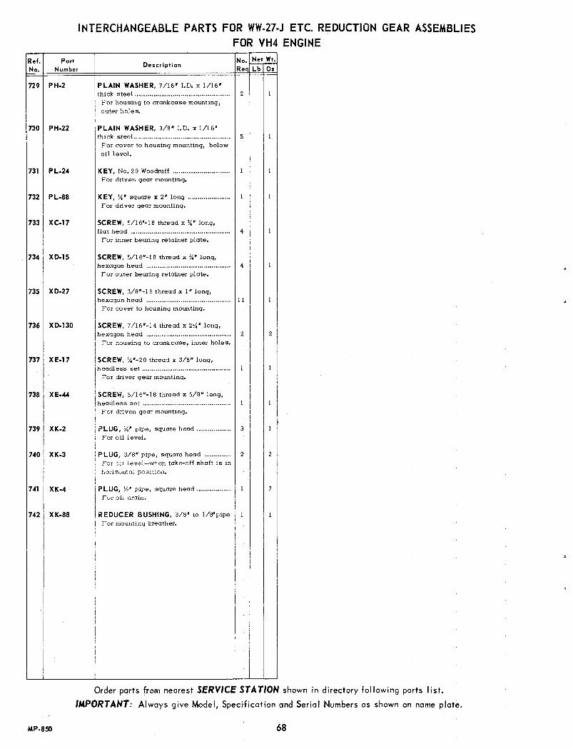
INTERCHANGEABLE PARTS FOR WW-27-J ETC. REDUCTION GEAR ASSEMBLIESFOR VH4 ENGINE
Ref.No.
PortNumber
Description No.~,,!!,:,Req Lb Oz
ns PH-2
730 PH-22
731 PL-24
732 PL-88
733 XC-17
734 XD-IS
73S XD-27
736 XD-130
737 XE-17
738 XE-44
739 XK-2
740 XK-3
741 XK-4
742 XK-88
MP·8SO
SCREW, 7/16'-14 thread x 2X' long,hexagon head 2 2For housing to crankcase, inner holes.
PLAIN WASHER, 7/16' 1.0. x 1/16'thick steel 2For housing to crankcase mounting,outer holes.
I~~~I~t!~.~~.~.~:..~.:.~::.~.·.~.,~..~~~.~.:.......5I For cover to housing mounting, belowoil level.
KEY, No.29 Woodruff ..For driven gear mounting.
KEY, X' square x 2' long ..For driver gear mounting.
SCREW, 5/16'-18 thread x %" long,flat head 4For inner bearing retainer plate.
SCREW, 5/16"-18 thread x %' long,hexagon head 4For outer bearing retainer plate.
SCREW, 3/8··16 thread x I" long,hexagon head IIFor covet to housing mounting.
SCREW, X'-20 thread x 3/8" long,headless set ..For driver gear mounting.
SCREW, 5/16"-18 thread x 5/8" long,headless set .For driven gear mounting.
PLUG, X' pipe, square head 3For oil level.
PLUG, 3/8" pipe, square head 2For 8:1level-when take-off shaft is inhorizontal position.
PLUG, Yz' pipe, square head ..For oil drain.
REDUCER BUSHING, 3/8' to lIS"pipeFor mounting breather.
Order parts from nearest SERVICE STATION shown in directory following parts list.
IMPORTANT: Always give Model, Specification and Serial Numbers as shown on name plate.
68

WW·62·AETC. CLUTCH REDUCTION GEAR ASSEMBLIESFOR VH4 ENGINE
-0o00
Order parts from nearest SERVICE STA TION shown in directory following parts list.IMPORTANT: Always give Model, Specification and Serial Numbers as shown on name plate.
69
104814C
MP-851-2

WW-62-A ETC. CLUTCH REDUCTION GEAR ASSEMBLIESFOR VH4 ENGINE
Determine position of take.offRotation Ref. No. 750 Ref. No. 751 Ref. No. 752 Ref. No. 753shaft when viewing from cranking Assembly Reduction ofend of engine. (View foe ing take· Number Ratio Take·off Shaft Driver Gear Driven Gear Chain Housing
off end are shown.) Port No. Part No. Part No. Part No.
TAKE.OFF SHAFT WW·62·A 2.07 to 1 Ctr. Engine·Wise GG-116 GG·67.1 .......... BG-215BELOW t=WW.62A.l 3.00 to 1 Ctr. Engine.'''Ise GG·117 GG·77.1 .......... BG·215
~ WW.62A.2 3.84 to 1 Ctr. Engine·Wise GG-118 GG·69.1 BG·215~
..........WW.62A·3 2.00 to 1 Engine·Wise GG·113 GG·71 GJ·8 BG·215
~ @ WW·62A·4 2.67 to 1 Engi ne·Wi se GG-114 GG-71 GJ·9 BG·215
WW·62A.5 3.79 to 1 Engin e-Wise GG·115 GG-73 GJ·l0 BG·215
TAKE.OFF SHAFT WW.62A.6 2.07 to 1 Ctr, Engin ....Wise GG·116 GG·67.l .......... BG·2l5·lON LEFT HAND SIDEas viewed from the cranking end WW.62A·7 3.00 to 1 Crr, Engin e-Wise GG·117 GG·77·1 .......... BG-215-1
-=-,[ WW.62A.8 3.84 to 1 Ctr. Engine·Wise GG·118 GG-69-1 .......... BG·215-l
~ @ WW.62A.9 2.00 to 1 Engine·Wi se GG-113 GG·7l GJ·8 BG-215·1
WW·62A.l0 2.67 to 1 Engine·Wi se GG·ll4 GG·71 GJ·9 BG·215-1
WW·62A.ll 3.79 to 1 Engin ....Wise GG·115 GG·73 GJ·10 BG·2l5-l
TAKE.OFF SHAFT WW.62A·12 2.07 to 1 Crr, Engine·Wi se GG-ll6 GG-67·l .......... BG·215-2ON RIGHT HAND SIDEas viewed from the cranking end WW.62A.13 3.00 to 1 Ctr; Engine·Wi se GG-ll7 GG·77.1 .......... BG·215·2
~ WW.62A.14 3.84 to 1 Ctr, Engine,Wise GG·118 GG·69.1 BG·215.2..........
~
WW·62A·15 2.00 to 1 Engine·Wise GG·113 GG·71 GJ·8 BG·215-2
@ WW·62A.l6 2.67 to 1 Engine·Wise GG-114 GG·71 GJ·9 BG-.215-2
WW.62A.17 3.79 to 1 Engine·Wise GG·115 GG·73 GJ·lO BG·215.2t
TAKE·OFF SHAFT WW·62A.18 2.07 to 1 Crr, Engine·Wi se GG·116 GG-67·1 .......... BG-2l5-3ON TOP
WW·62A·19 3.00 to 1 Ctr, Engi ne·Wi se GG·l17 GG·77·1 .......... BG·215·3
WW.62A.20 3.84 to 1 Crr, Engin e-Wise GG·118 GG·69.1 .......... BG·215·3
@ WW.62A.21 2.00 to 1 Engine-Wise GG·113 GG·71 GJ·8 BG·215-3~WW.62A.22 2.67 to 1 Engine·Wise GG·114 GG·71 GJ·9 BG-215-3
WW.62A·23 3.79 to 1 Engi ne·Wi se GG·115 GG·73 GJ·l0 BG·215-3
P.....;:::z»:
WEIGHTSOF PARTS LISTED ABOVEClutch reduction I Net Wt
Gear Assembly No. Ib 0%
Clutch ReductionGear Assembly No.
Net WtIb I 0%
Clutch ReductionGear Assembly No.
I Net Wt.Ib 0%
'Net WtIb 0%
WW.62·A.7.. 89WW.62·A.8.. 89WW.62·A.9.. SE.WW.62·A·l0 85WW.62·A.ll................ 87WW.62.A.12................ 89
WW·62.A·13 ....... "....... 8 9
WW.62.A .... 89
WW.62.A·l ................ 89WW.62.A.2 89
WW.62.A.3 86
WW.62.A.4 ................ 85WW.62.A.5 ................ 87WW.62·A.6 ................ B9
8
Clutch ReductionGear Assembly No.
WW.62·A·14 "......... 89WW·62·A·15 "......... 86WW·62·A·16 " .."... 85WW.62·A·17 "....... 87WW.62·A·18 " ". 89WW.62·A.19 89WW·62·A·20 89
WW·62·A·21 86WW·62·A·22 85WW·62·A.23 87
Pc rt NumberNet Wt.
I Ib 0%
Net Wt.Ib I 0%
Net Wt. Net Wt.Part Number r Ib I 0%Part Number Ib T 0%
GG·113 (20 teeth) ...... 14 GG·188 (19 teeth) ...... 12GG·114 (15 teeth) ...... 14GG·ll 5 (!4 teeth) ...... II GJ·8 (54 links) ........ 13GG·116 (30 teeth) ...... 2 10 GJ·9 (52 links) ........ 12GG·117 (23 teeth) ...... 2 I GJ·l0 (60 links) ........
BG·215 19 8BG·215.1.................... 19 8BG·21 5·2 "..... 19BG·215·3 " "... 19GG·67.1 (62 teeth).... 8 II
Part Number
GG·69.1 (73 teeth).... 10 15GG·71 (40 teeth)........ 4GG·73 (53 teeth)........ 7 10GG·77.1 (69 teeth) .... 10 4
MP·852 70

PARTS FOR WW-62-A ETC. CLUTCH REDUCTION GEAR ASSEMBLIESFOR VH4 ENGINE
NOTE: Engines equipped with a Clutch Reduction Gear Assembly require a special MainBearing Plate Assembly, Crankshaft and Crankcase as follows:
BG·210-C-l·S2 MAIN BEARING PLATE ASSEMBLY (Not illustrated) consisting of:1 BG-210-C-l Plate 1 PH-364 Oil Seal 1 ME-114-2 Bearing CupCRANKCASE ASSEMBLY (Not illustrated) Order by giving the MODEL, SPECIFICATION and SERIAL
NUMBERS of the engine.CA·71-A·23·S1 CRANKSHAFT ASSEMBLY (Not illustrated) consisting of:
1 CA-71-A-23 Crankshaft 1 ME-71 Bearing 1 PL-53 Key1 GA-36-A Gear 1 ME-114 Bearing
ParINumber
No. Nel WI.ReQ Lb 0%
Ref.No.
757 BG-150758 BG-151759 BG-216760 BH-127-B
761 BH-143762 HF.265-A763 HF-372764 HF-392
765 LO-44766 ME-189
767 ME-76
768769770 ME-77
771772773 ME-119
774 PA-279775 PC-419776 PH-202
777 PH-234-A778 PK-82
779 PL-140
780 QD-543-A781 QD-544
782 QD-592783 QD-618784 QD-619785 SD-79786 SD.125-A
787 VB-55-1788 VB-64-A789 WA-55-H790 WA-61-D791 WA-87-A792 WC-288-A
Description
I II 6I 8I 8
I 20I 6I 3
4 2
I I
I 8I I II
I 10I I I
I IS
I 6I 9
I B
2 I4 2
I 4
I 3
I I
I I
I II I
I 2
I I 8I 6 10I I 12I 2 8I 12
Ref.No.
Na.~~Re Lb 0%
795 PD.12
796 PE·4
797 PE·6
798 PH·22
799 PH-3D
800 PL-17
801 PL.24
802 SA-58
803 XA-34
804 XC-17
805 XD-7
806 XD-15
807 XD-27
808 XD·30
809 XE.44
810 PA·341
ParINumber
STANDARD HARDWAREPLATE for retaining bearing (outer) ,.PLA TE for retaining bearing (inner) .PLATE for clutch bearing .PLATE for inspection opening .BH-127,replaced by BH-127-B.COVER for reduction gear housing .SPACER for take-off shaft .SPACER for ball bearing .
SPAC ER for shifter yoke .(Used only when take-off shaft is onthe right or left hand Side).
BREATHER _ .PILOT BEARING (Furnished as part ofWC-288-AClutch Assembly) .BEARING ASSEMBLY (outer) .Consisting of:
ME-76-1 Cup, Timken 3525 .ME-76-2 Cone, Timken 3578 .BEARING ASSEMBLY (inner) .Consisting of:
ME.77-1 Cup, Timken 02820 .ME-77.2 Cone, Timken 02877 .
BALL BEARING for clutch shaft .NewDeparture No.3206.
DOWEL PIN for cover to housing .STUD for housing to crankcase .OIL SEAL for take-off shaft .Kickhaefer Mfg.Co. No. A-31-IOB.OIL SEAL for shifter lever shaft .RETAINING RING IFor clutch shaft bearing.
SQUARE KEY, 5/16B x 1-1/8" long IFor clutch drive hub.
GASK ET for bearing retainer plate (inner) IGASKET forbearing retainer plate (outer) 128 to 12gaskets required for .001" to.003" end play.
GASKET for inspection hole plate I
GASKET for housing to crankcase .GASKET for cover to 'housing .OIL INSTRUCTION TAG .INSTRUCTION PLATE, for clutch adj.SO-125,replaced by SO-l25-A.SHIFTER LEVER .SHIFTER YOKE .TAKE-OFF SHAFT .SHIFTER SHAFT .DRIVE SHAFT ..CLUTCH ASSEMBLY .Rockford Drilling Model 5V,L.O.C.No. CLA-1467-AF.See Rockfordillustration and parts listof clutch, Page 64.
811 XK-2
Description
NUT, 7/16"-20 thread, hexagon stee1.... 4For housing to crankcase studs.
LOCKWASHER, 5/16" Positive.............. 4For outer bearing retainer plate.
LOCKWASHER, J/16" Positive.............. 4For housing to crankcase mounting.
PLAIN WASHER, 3/8" I.D. x 1/16"thick stee1...:.............................................. IIFor cover to housing mounting.
PLAIN WASHER, 1/4" I.D. x 1/16"thick copper 96-10rinspection hole cover plate.3-forbearing retainer plate.
KEY, No. 13Woodruff,for di ve gear .... I
KEY, No. 29.Woodruff,for driven gear.. I
PLUG, 1-3/8" expansion IFor shifter .shaft hole.
SCREW, 114"-20thread x 1/2" long,round head. 6For BH-127-Binspection hole cover.XA-36(J{" long) for BH-127cover.
SCREW, 5/16"-18 thread x 3/4" long,flat head ._...... 4For inner bearing retainer plate.
SCREW, 1/4#-20 thread x I" long, hex-agon head 3For clutch bearing retainer plate.
SCREW, 5/16"-18 thread x 3/4" long,hexagon heod 4For outer bearing retainer plate.
SCREW, 3/8"-16 thread x I" long, hex-agon head IIFor cover t? housing mounting.
SCREW, 3/8"-16 thread x IV,"long, hex-agonhead, for shifter lever -clomp I
SCREW, 5/16"-18 thread x 5/8" long,headless set, for driven gear. 1
ROLL PIN, 1/4" dia. x 1-1/8" long 2For shifter yoke to shaft.XH-26, No.4 x 1-3/8" long, taper pin,replaced by PA-341.
PLUG, ~" pipe, square head 3For oil level.
PLUG, v''' pipe, square head \IFor oil filler.
PLUG, V,"pipe, countersunk head 3For oil drain.
STREET ELL, 1/8" pipe x 450, brass.. IFor breather mounting.XK-77,replaced by XK-77-A.
Order parts from nearest SERVICE STATION shown in directory following parts list.
IMPORTANT: Always give Model, Specification and Serial Numbers as shown on name plate.
812 XK-4
2
813 XK-6 2
814 XK-77-A
MP·813-271

FUEL PUMP MAINTENANCE AND REPAIR INSTRUCTIONSWiSCONSIN MOTOR PART No. LP·38 (Standard), LP-38-C (Cold Weather: _6S0F)
USED ON 4 CYLINDER AIR COOLED ENGINES
The fuel pump, like all other parts of the engine, is subject to wear and you will find that any time after 500 hoursof use, its efficiency will gradually decrease. This is indicated by the engines faltering at high speeds or whenheavy loads are suddenly applied. The pump can easily berestored to its normal efficiency by the installation of aWisconsin Motor No. LQ-30 or LQ-30-A repair kit.
1. Remove the fuel lines and the two mounting bolts whichhold the pump to the engine. Take the pump to a workbench or suitable place.
2. With file make an indicating mark across a point at theunion of castings (7 and 23). This is a positive location of the fuel line positions when reassembling. Remove six assembly screws (6) and remove fuel head.Dome DOlt (1) is taken out, and the dome, (3) dome gasket (4) and filter screen (5) disassembled.
3. Turn head (7) over and remove three screws (13). Remove (8,9, 10, 11 and 12) valve assemblies noting theirpositions. Discard Details 8,9 and 11.
4. Clean head thoroughly with gasoline and a fine brush.
5. Holding fuel head (7) with diaphragm surface (containing 6 clearance holes) up, reassemble the valve springretainer (10) into position deepest hole. Place newvalve plate gasket (11) in position around this hole.Stand on end one of the new valve springs (9) in theretainer. Place a new valve (8) on top of this spring.
6. Place the other new valve (8) on top of brass valveseat next to the previously assembled parts, stand theother new valve spring (9) on top of this valve.
7. Carefully place valve plate (12) over these assembliesso the large raised ring is nearest the valve gasket (ll).Insert and carefully tighten the three assembly screws(13).
8. Carefully clean and replace the filter screen (5).
9. Place new dome gasket (4) into the dome (3) and putthis unit into position on the fuel head (7).
10. Put new dome bolt gasket (2) on the dome bolt (1), insert in the hole in the dome (3) and tighten properly.
11. Place this fuel head assembly in a clean place and weare ready to rebuild the lower diaphragm section.
12. Using a screw driver inserted into the coils of rockerarm spring (17) remove this spring and save.
13. Hold the mounting bracket (23) in the left hand with therocker arm toward your body and the thumb nail on theend of the link (19) with the heel of right hand on thediaphragm (14) compress the diaphragm spring (16) atthe same time pulling toward your body, this will unhook the diaphragm from the link (19) so it can be removed.
14. Clean the mounting bracket (23) with gasoline.
15. Place the remaining new cork gasket (15) on the corresponding surface of the mounting bracket (23). Replace the diaphragm operating spring (16) standing itinto (23). Now repeat in reverse Step 13 using the newdiaphragm. Replace rocker arm spring removed in Step12.
16. Mount this assembly back on the engine in the positionfrom which it was removed, using the new mountinggasket which is the last piece of the repair kit.
17. Crank the engine over to a position where the diaphragm(14) is laying flat on the mounting bracket (23). Placethe fuel head (7) back in position so the indicatingmarks of Step 1 are in line, and start the six assemblyscrews approximately three turns. Again crank the engine over to a position where the diaphragm (14) ispulled down into (23) mounting bracket and tighten thesix assembly screws (6) tightly.
18. Connect the fuel lines and you have a completely rebuilt fuel pump.
72
7
11'8~ F====== 10
9~ ~ ~ 9~~ 11
....~---------12
76520C
INSTRUCTIONS FOR FUEL PUMPMAINTENANCE AND REPAIR
The gaskets (2 and 4) used in the fuel head (7) of the fuelpump have a natural tendency to shrink when left standingin a dry condition. This shrinking can create vacuum leakswhich result in the hard starting of the engine. It is necessary after an engine has stood on the stockroom or showroom floor any length of time that the dome bolt No. I, theassembly screws (6) of which there are six and the fuelline connections be tightened carefully to assure quickstarting and satisfactory operation thereafter.
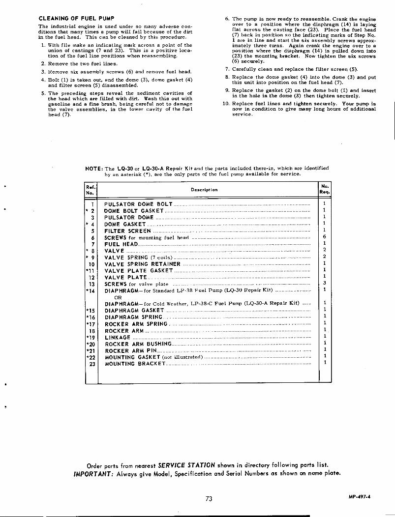
CLEANING OF FUEL PUMPThe industrial engine is used under so many adverse conditions that many times a pumpwill fail because of the dirtin the fuel head. This can be cleaned by this procedure.1. With file make an indicating mark across a point of the
union of castings (7 and 23). This is a positive location of the fuel line positions when reassembling.
2. Remove the two fuel lines.3. Remove six assembly screws (6) and remove fuel head.4. Bolt (1) is taken out, and the dome (3), dome gasket (4)
and filter screen (5) disassembled.5. The preceding steps reveal the sediment cavities of
the head which are filled with dirt. Washthis out withgasoline and a fine brush, being careful not to damagethe valve assemblies, in the lower cavity of the fuelhead (7).
6. The pump is now ready to reassemble. Crank the engineover to a position where the diaphragm (14) is layingflat across the casting face (23). Place the fuel head(7) back in position so the indicating marks of Step No.1 are in line and start the six assembly screws approximately three turns. Again crank the engine over to aposition where the diaphragm (14) is pulled down into(23) the mountingbracket. Nowtighten the six screws(6) securely.
7. Carefully clean and replace the filter screen (5).8. Replace the dome gasket (4) into the dome (3) and put
this unit into position on the fuel head (7).9. Replace the gasket (2) on the dome bolt (1) and insert
in the hole in the dome (3) then tighten securely.10. Replace fuel lines and tighten securely. Your pumpis
now in condition to give many long hours of additionalservice.
NOTE: The LQ-30 or LQ-30-A Repair Kit and the parts included there-in, which are identifiedby an asterisk (*), are the only parts of the fuel pumpavailable for service.
Ref.No.
No.Req.
1....23
* 4567
* 8* 910
*111213
*14
*15*16*1718
*19*20*21*2223
Description
PULSATOR DOME BOLT .DOME BOLT GASKET .PULSATOR DOME .DOME GASKET .FILTER SCREEN .SCREWS for mounting fuel head .FUEL HEAD .VALVE . .VALVE SPRING (7 coils) .VALVE SPRING RETAINER .VALVE PLATE GASKET . .VALVE PLATE.... .. .SCREWS for valve plate ..DIAPHRAGM-for Standard LP-38 Fuel Pump (LQ-30Repair Kit) .
ORDIAPHRAGM- for Cold Weather, LP-38-C Fuel Pump (LQ-30-ARepair Kit) .DIAPHRAGM GASKET. .. .DIAPHRAGM SPRING ..ROCKER ARM SPRING.. . ..ROCKER ARM .LINKAGE .ROCKER ARM BUSHING .ROCKER ARM PIN .MOUNTING GASKET (not illustrated) ..MOUNTING BRACKET ..
11111612211131
1111111111
Order parts from nearest SERVICE STATION shown in directory following parts list.IMPORTANT: Always give Model, Specification and Serial Numbers as shown on name plate.
73 MP·497-4

ALBERTVILLEANDALUSIAANNISTONATTALLABESSEMERBIRMINGHAM
BOAZDECATORDOTHANELBAENTERPRISEEUFAULAFLORENCE
GADSDENHEADLANDHUNTSVILLEJASPERMOBILE
MONROEVILLEMONTEVALLOMONTGOMERYOPELIKAOPPSCOTTSBOROSELMATROYTUSCALOOSA
ANCHORAGE
FAIRBANKS
JUNEAUKETCHIKAN
CASA GRANDECHANDLERCHINO VALLEYDOUGLASFLAGSTAFFNOGALESPHOENIX 85002
Printed in U.S.A.
WISCONSIN MOTOR CORPORATIONSTATIONSAPPROVED SERVICE
T~e fol ~owi~g concerns ~ave service part stocks, foci lities and trained personnel to render complete service onWlsc.onsln A~r.Cooled Engines. We recommend you work through these service stations on your Wisconsin engineservice requirements.
* DISTRIBUTORS
ALABAMA
J. D. Chandler Cycle Co.Ben Williams Equipment Co., 1609 E. Three NotchEast Ala. Auto Parts Co., 102 W. 10th StreetBrown Service Co.Warlick & Miller Bcnery Co., 218 . 18th StreetAlabama Air·Cooled Motors, 725 Graymont AvenueTractor & Equipment Co., 4401 First Ave. N.Skyl ine Service & Supply Co.Tractor & Equipment CompanyAuto Electric CompanyElba Tractor Co.Boyd & CompanyMoore Brothers GarageV. E. Lund Implement Co.The Griffin CompanyClayton Lawn Mower Shop, 138 E. Broad St.Headland Auto PartsAuto Electric Service Co., 110 Meridian St.Gaines Parts CompanyGravely of Mobile, lnc., 2014 Halls Mill Rd.Turner Supply Company, Box 1429Speed Auto Supplies, P. O. Box 227Sim's Service Center
36104 * Parts Service Co., lnc., 412 Bibb StreetEast Alabama Auto PartsAdams Farm SupplyJ. D. Chandler Cycle Co.Auto Parts CompanyThompson Auto PartsCain Steel & Supply Co., 2650· 20th Street
ALASKA
B & C Auto Electric, 2801 Spenard Rd.Northern Commercial CompanyB & C Auto ElectricNorthern Commercial CompanyNorthern Commerci a I CompanyBrougher Outboard Shop, P.O. Box 321,1212 Tongass Ave.
* Star Machinery Company241 Lander StreetSeattle, Washington 98134
ARIZONA
Diesel Electric Co., 917 N. Pinal AvenueSweet's Equipment Sales, 298 E. GalvestonChino Pump & Supply CompanyAI & Jack's Auto Elec., 247 "G" AvenueGeneral Automotive Company, 5 East BentonCommercial Distributors
* Prctt- Gilbert, P.O. Box 2230, 701 So. 7th St.Equipment Sales Company, 720 South 19th AvenueNorton Co., 1817 E. Indian School Rd.Morrison & Ledford, Inc. 733 No. 19th Avenue
KINGMANSAFFORDTUCSON
YUMA
BATESVILLEBERRYVILLEBRINKLEYCONWAYDeWITTEL DORADOENGLAND
FAYETTEVILLEFORT SMITHHARRISONHEBER SPRINGSHOXIEJONESBOROLITTLE ROCK
MAGNOLIAMALVERNNASHVILLENEWPORTPINE BLUFFSEARCY
SILOAM SPRINGSSTUTTGARTTEXARKANA
WYNNE
ALHAMBRAANAHEIMANDERSONARCATAARLINGTONBAKERSFIELDBLYTHEBRAWLEYBRENTWOODBURBANKBUTTONWILLOWCHICO
Arthur's Sales & ServiceSafford Auto Suppl yAutoplane Elec. Co., 1037 South 6th StreetEquipment Sales & Service Co., 2525 N. First AvenueYuma Automotive Elec., 229· 8th St.
ARKANSAS
Barnell & LandersBerryville Machine ShopFred Williams Welding ShopEarl Rogers CompanyGraves Electric CompanyMagneto Service & Supply Co.Morgan Lumber Co.Austin Supply CompanyReed & GriffithOtis-Tole Equipment Co.T ri-Lokes MotorsRed River Implement CompanyCox ImplementJonesboro Lock & KeyIndustrial Equipment Service CompanyLyons Machinery Co., 904 BroadwayKelso Engine & Equipment, Inc.Chainsaw Service & Supply, 414 South PecanNashville Distributing CompanyFarmers Equipment Company, Inc.Northern Saw Co. lnc., P. O. Box 701Barker Motor CompanyJoyner Motor ServiceStandard Auto SupplyWaggoner Magneto ServiceWoodard Implement & Gas Engine Company, Inc.
1221 Magnolia at State LineFrazier Repair Shop, 115 Levesque
* RCH Distributors, Inc.92 W. Carolina AvenueP. O. Box 2828Memphis, Tennessee 38102
* Keeling Supply Company4400 East Roosevelt RoadP.O. Box 5119Lillie Rock, Arkansas 72206
CALIFORNIA
Ja R Engine & Supply, 1819 W.Valley Blvd.Superior Equipment Rental & Soles, 1266 E. Lincoln St.Taylor Auto Parts, 2820 W. Center StreetBrizard.Matthews Machy. Co., 1219 Eleventh StreetR. D. C. Equipment Rental, 9500 Arlington AvenueJonco Pump & Engine Company, 2601 M StreetBob Meloy's Garage, 201 North LovekinValley Auto Supply Co., 535 "E" StreetC & H Tool Center, 236 Oak StreetR. J. Lison Co., 3800 Riverside DriveB. W.Implement Co. lnc., Box 758A. J. Boradori, 287 Humboldt AvenueJeffery Brothers, 2260 Park Avenue
·1·March, 1966 Issue MS·3·1003

I. G. Zumwalt Company, 850 Market St.Penrose Machine Co., 12903 Atlantic Blvd.Garden Equipment Company, #10 Meadow LaneSawtelle & Rosprim, P.O. Box 38Delano Repair Service, 1601 Glenwood St.Downey Mower & Saw Co., 10248 S. Paramount Blvd.Emergency Engine Service, 8117 Phlox St.Valley Auto Supply, 633 State StreetTex-Kan Service, 12231 E. Garvey Boulevard
94608 * E. E. Richter & Son, Inc., 6598 Hollis StreetThe Rix Company, 1719 64th StreetPalomar Tractor Co., 1350 Mission Rd.Rogers Machinery Co., Inc., 3428 Jacobs AvenueContractors Equipment & Supply, 1454 North ClarkJensen & Pi legard, 2510 Blackstone AvenueSchedler's Engine Rebuilding, 624 BroadwayCenterville Saw & Tool Works, 36848 Fremont Blvd.
J & M Service, 11662 AnabelLampson Tractor & Equipment Company, P.O. Box 336Acme Rents, 1855 S. Brand Blvd.Ambrose Carburetor & Electric Service, 1091 HazelHanford Farm Supply Co., 309 E. 7th StreetSteve's Auto Parts, 129 S. InezWiebe Manufacturing, Inc.,
1131 San Fel ipe Road - P.O. Box 639Suski & Sakemi Garage, Drawer SSW.K. Equipment CompanyKerman Motor Parts, 662 South Madera St.Livingston Bros. Tractor Co., 101 Highway NorthLake Ports Service, 120 Main St.Brandt Bros., 379 West Avenue IWright's Garage, 214 N. Sacramento StreetAceco Equipment Co. Inc., 321 North "G" StreetSmith & Thorp, 141 E. Anaheim
90252 * Lanco Engine Services, Inc.12915 Weber Way (Hawthorne)
Carburetor Electrical Service, 1904 East Seventh StreetLarson Equipment Co., 3838 Santa Fe Ave.Zentner Tractor, P. O. Box 1192Shafer Implement, 1721 Howard Rd.Goodwin Equipment Service, P.O. Drawer 671Middleton Implement Company, 600 Third StreetLaird Welding & Mfg. Company, 5315 Los Banos HiwayStanislaus lrnpl, & Hardware Company, 10th & 'F' Sts.Willingers Automotive Clinic, 1125 "G" Street
MONTCLAIR Wolfe & Sons Sales, 10611 Ramona AvenueMONTEBELLO S & A Engine Sales & Service, 1513 Olympic Blvd.MONTEREY Brodys Repair, 856 Lighthouse AvenueNAPA Bert Williams & Son, 831 First StreetNORTH HOLLYWOOD Oliphant Bras., 13261 Saticoy St.NOVATO Novato Equipment & Service, 1054 First StreetCAKLAND Spears Wells Machinery Company, 1832 - 9th St.ORLAND Holt Service Shop, 419 Colusa Street
COLUSACOMPTONCONCORDCORCORANDELANODOWNEY
EL CENTROEL MONTEEMERYVILLE
ESCONDIDOEUREKAFRESNO
FREMONTGARDEN GROVEGEYSERVILLEGLENDALEGRIDLEYHANFORDHEMETHOLLISTER
INDIO
KERMANKING CITYLAKEPORTLANCASTERLODILOMPOCLONG BEACHLOS ANGELES
LOS BANOSMADERAMANTECAMARYSVILLEMERCEDMODESTO
ORO GRANDEOROVILLEOXNARDPASO ROBLESPERRISPETALUMAPICO RIVERAPORTERVILLEQUINCYRED BLUFFREDDINGREEDLEYRIO VISTA
RIVERSIDESACRAMENTO
SALINAS
.2.
Jae & Elwins Repair, Route 1, Box 42BMcVey-McCarter Machinery Co.Oroville Truck Parts & Equip., lnc., Highway 40 A SouthMaulhardt Equipment Co., 815 N. Oxnard Blvd.H. A. Wood Welding & Machine Shop, 1207 - 13th StreetSteve's Auto PartsHalm Tractor & Equip't. Co., 110 Howard St.Rental Yard Supply Corporation, 7815 Paramount Blvd.Porterville Farm Implement Co., 428 S. Main StreetThe Power House, P.O. Box 416Red Bluff Auto Electric, 938-1/2 Washington St.Gerlinger Steel & Supply Co., 1527 SacramentoGrowers Supply Company, 953 "G" StreetGordon-Hansen Company, Limited
Front and Sacramento StreetsW. K. Equipment Co., 1830 Eighth AvenueBar-Hein Tractor Co., 1551 Fulton AvenueGerlinger Motor Parts, 2020 Kay StreetMunz Pumps, lnc., 301 N. 12th St.Sacramento Machinery Co., 2000 Capitol Ave.Salinas Automotive Service, 865 Abbott Street
SAN BERNARDINO Ray's Equipment Rentals, 24996 Base LineW. K. Equipment Ca., 275 South "E" StreetWrigley Pump Co., 750 Industrial Rd.Bennie's Inc., 178 South BoulevardC & J Equipment, 2301 LafayetteWebb Farm Equipment Co., 940 'K' StreetAuto Electric Supply Co., 541 Van Ness AvenueH. V. Carter Co., Inc., 52 BealeThe Rix Company, 625 BayshoreABCAB Manufacturing Company, 1277 Airport BoulevardKronk Machine & MfQ. Co., 566 'V. Julian StreetFrank's Ignition, 289 Park StreetFrancis C. Mueller, 198 South St.James Requarth Engines, 111 N. Spurgeon StreetMartin DePiazzi Autorr.otive Service, Inc.
118 East Ortega StreetSanta Barbara Marine Sales & Service Co., 29 State St.Kelly's Service, 516 Front StreetWebb Farm Suppl ies, 5381 Old Soquel-San Jose Rd.Nickson's Machine Shop, 914 W. Betteravia Rd.P. O. Bahn & Sons, 1543 Lincoln Blvd.Ed's Equipment Rentals, 614 E. Harvard StreetFreeman Tractor Co., 1015 Petaluma Hill RoadHarry B. Trembley, Inc., 3rd & B Streets
SOUTH DOS PALOS Yonkers & Johnson, P.O. Box 97SOUTH SAN FRANCISCO Re-AI Equipment Company, 1357 San Mateo Ave.STOCKTON Valley Engine Shop, 1402 East Miner AvenueTAFT Tasco Auto Parts, 306 Center St.TARZANA Tarzana Garden Equipment Co., 18451 Ventura Blvd.TRACY W& P Sales Company, South Highway 50TULARE Linder Equipment Company, 311 East Kern StreetTUlE lAKE Floyd A. Boyd CompanyTURLOCK Fernandes Implement Co., 214 S. Center StreetUKIAH Holz Company, Clay at RailroadVENTURA Gem Equipment Co., 171 W.Stanley Ave.VISALIA Charles J. Hammer Mchy. Co., 915 E. MainWASCO Wasco Farm Equipment Co., 1345 "G" StreetWATSONVILLE P & G Auto RepairWHITTIER Whittier Motor Parts, 306 S. GreenleafWILLOWS I. G. Zumwalt Company, 311 N. Butte St.WOODLAND Middleton Implement Company, Knight's landing HiwayYREKA littrell Parts, 310 S. Main Street
SAN ChRLOSSAN MATEOSANTA CLARASAN DIEGOSAN FRANCISCO
SAN JOSE
SAN LEANDROSAN LUIS OB.ISPOSANTA ANASANT A BARBARA
SANTA CRUZ
SANTA MARIASANTA MONICASANTA PAULASANTA ROSA
COLORADO
ALAMOSA Sorum TractorBRUSH Farmer's Elevator CompanyBURLINGTON McArthur Impl. CompanyCOLORADO SPRINGS Joe Coniff Company, 2522 E. Hiway 24CORTEZ Helms Implements, lnc., Box 68CRAIG Redmon Sales & Service, 845 E. Victory WayDEL TA Hinton Auto ElectricDENVER 80216 * Central Equipment Co., 4477 Garfield Street
Barter Machinery & Supply Co., 215 South Santa FeBooth-Rouse Equipment Co., 5700 Eudora StreetThe Engine Clinic, 4825 E. Evans Ave. (10)Gravely Colorado Sales & Service, 11810 W.Colfax Ave.Power Rental Equipment Co., 3440 Brighton Blvd.Rental Machinery Ca., 870 South Lipan StreetWestern States Machinery, 2400 W.7th
DURANGO Telluride Iron Works, Inc.FLAGLER Flagler Farm Equipment Co.FORT COLLINS McClure & Son, Box 547, E. an Hiway 14FT. LUPTON Whittman Implement Co.FT. MORGAN Sailsbery Supply Co.GLENWOOD SPRINGS Berthod Motors, 10th & GrandGRAND JUNCTION Western Implement Co. Inc., 2919 North AvenueGREELEY Thomas Fay Implement Co., 821 - 7th StreetKEENSBURG Peery Motor & Equipment Co.LAMAR Motor Supply

LAS ANIMASLIMONLONGMONT
LOVELANDMONTE VISTAPUEBLORIFLESTERLINGYUMA
BRIDGEPORT
DANBURYHARTFORDMANCHESTERNEW FAIRFIELDNEW HAVENNEW LONDONTORRINGTONWATERBURYWETHERSFIELD
WINDSOR LOCKS
BRIDGEVILLEDOVERMILTONWILMINGTON
Bent County MotorsGroff Equipment Co.Kats Implement CompanyLongmont Farm SupplyGeo. A. Walker Implement Co.Gair Auto & Tractor Supply, 132 WashingtonPueblo Motive CompanyRifle Auto PartsStillman Auto Electric, 517 W.MainChi Icoat & Lash
CONNECTICUT
The Arnold Company, 3225 Fairfield AvenueL. T. Dobey, Inc., 2091 Fairfield AvenuePeerless Enterprises, RFD #4McCallum Motor Service, Box 2009Capitol Equipment Company, 38 Main StreetPeerless Repair Service, RFD #4W. I. Clark Company, P. O. Box 301Creem Automotive Service, lnc., 20 Truman StreetBartram Auto Elec. Co. lnc., 176 E. Main St.Contractors Supply Company, Inc. East Aurora Street
9 F. C. Matteson, 450 Silas Deane Hwy.
* John Reiner & Company94-15 150th StreetJamaica, New York 11435
The Magovern Company, lnc., Lawn Acre Road
DELAWARE
O. A. Newton & Son Co.Cox Motor Shop, 1261 South Governors AvenueWilliam T. Hamilton Equipment Co., R.F.D.2Equipment & Service Co., 1330 Thatcher StreetF. M.Yearsley, 3600 Mill Creek Rd.
* Jos. L. Pinto5918 Baltimore Ave.Philadelphia, Pennsylvania 19143
* Potter Equipment Company6200 N. Capitol Street, N.W.Washington, D. C. 20011
DISTRICT of COLUMBIA
WASHINGTON, D.C. 20011* Potter Equip. Co., 6200 N. Capitol St., N.W.Hudson Sup. & Equip. Co., 9th & Brentwood Rd. N.E.
APOPKAAVON PARKBELLE GLADE
FLORIDA
Joiner Auto PartsArnold Mower Service, 798 South Verona AvenueGorham Coastal Motors & Equip. Co.
624 South Canal Street - EastCOCOA Rev-Cut Mower Co., 2005 N. Cocoa Blvd.DADE CITY Standard Auto PartsDAYTONA BEACH Seager Lawn Mower Shop, 801 N. Beach St.DeLAND Talton's Power Center, P. O. Box 250EUSTIS Grove Equipment CompanyFLORENCE VILLA Growers Service CompanyFORT LAUDERDALE Dela Corporation, 241 S. W. 21 Terr
Fleet Maintenance Service, 824 N. E. Third Ave.L. B. Turf Equip., Inc.
FORT MYERS Davies Cycle Center, 1407 Citrus Street
Minton Equipment Company, P. O. Box 270Myers Power Tools, 239 E. 16th AvenueHarb Tractor Co.Lemon & Son, Inc.Oliver & Dahlman Sales Co., P. O. Box 308Terrill Motor & Machinery, 1518 North Dixie HighwayCall ins Mfg. Co.
jACKONSVILLE 32206 * Marine Industrial Equipment Corp.,P. O. Box 39, Station G, 710 Haines Street
Julien P. Benjamin Equipment Co., 2300 McCoys Blvd.Ware Nurseries & Garden Supply, 5497 Timaquana Road
JAY Smith Tractor CompanyKENDALL Power Mower Sales & Service, Inc.KISSIMMEE Osceola Equipment & Supply Co., P.O. Box 1149LAKELAND Lakeland Motor PartsLAKE WALES Boyte Auto Supply Co.LARGO Gordon F. BelcherLEESBURG Tucker Heavy Equipment Co., P. O. Box 884LIVE OAK Tyre's Saw and Engine Service, 905 5th Street, N.W.MARIANNA 32446 * West Florida Equipment CompanyMELBOURNE United Parts, Inc., 320 S. Dixie HighwayMIAMI 33144 * P. H. Neff & Sons, Inc., 7270 Northwest 41st StreetMONTVERDE Whirler Glide Mower Co.MONTICELLO Small Engine Sales & ServiceNAPLES Carrara Lawn Equipment Center, 997 Third Ave., NorthNOCATEE Bassler's GarageOCALA Link BrothersORLANDO Herold & Miller Equipment Co., 102 West Grand Ave.
32802 * Highway Equipment & Supply Co., 1016 West Church St.PALMETTO Hayman's, Inc.PANAMA CITY Power Motors, Inc., 215 West 6th StreetPENSACOLA Cal's Diesel Service, 4404 Lillian Highway
Killinger Marine CompanyStandard Auto PartsBroward Palm Beach Tractor Co.Suber & JohnsonBugeski Sales & Service, 62 San Marco Blvd.Melvin's, Inc.
Swift Weed Cutter, 326 22nd Ave. N.Smitty's Snappin' Turtle Garage, P. O. Box 28Standard Auto PartsBaker Alford Company, 208 N. Adams St.
* Industrial Supply Corporation, 1800 2nd AvenueFrederiksen Enterprises, 5606 S. MacDill AvenueM. D. Moody & Sons, lnc., 6001 Hillsboro Ave.
TITUSVILLE Brevard Tractor Company, Route #1, Box 83BVERO BEACH Neely's Repair Shop, 1966 Commerce St.WAUCHULA Wilson- Tindell Pump & Supply CompanyWEST PALM BEACH Griffin Equipment Inc., 4115 Georgia AvenueWINTER GARDEN M & M Welding Co.
FORT PIERCEGAINESVILLEGROVELANDHAINES CITYHASTINGSHOLLYWOODHOMESTEAD
PLANT CITYPOMPANO BEACHQUINCYST. AUGUSTINEST. PETERSBU RG
SANFORDSARASOTATALLAHASSEETAMPA 33605
ADELALBANY 31701
AMERICUSASHBURNATHENSATLANTA 30302
AUGUSTABLACKSHEARBLAKELYBRUNSWICKCOLQUITTCOLUMBUS
CORDELECUTHBERTDALTON
GEORGIA
Adel Trading Company* Blalock Machinery & Equipment Co., Inc.
105 S. Slappey DriveFox Truck & Tractor CompanyOdom Implement CompanyRussell Daniel, Inc., 480 N.Thomas Street* Blalock Machinery & Equipment Co., Inc.
225 Forsyth St., S.W.Stovall & Company, 948 Bankhead AvenueW. C. Caye & Co., Inc., 1468 Gordon Hwy.Nimmer Tractor & Implement CompanyHolmam Tractor CompanyBrunswick Battery & Electric CompanyHilton Jones Motor Co., 288 College StreetColumbus Tractor & Machinery Company, 315 Andrews RdMowers & Motors, lnc., 1523 First AvenueGeorgia Implement & Truck CompanyRandolph Tractor Company, P.O. Box 195J. E. Pitts Garage & Machine Shop, 105 West Waugh St.
-3-

DAWSONDONALSONVILLEDUBLINEDISONFITZGERALDHAWKINSVILLEMACONOCILLAOGLETHORPEROCHELLEROMESANDERSVILLESAVANNAH
STATESBOROSYLVANIATIFTONVALDOSTAVIDALIAWAYCROSSWAYNESBORO
Fester-Aycock Truck & TractorHarvey Implement Co.Dixie Form EquipmentDuke Farm Equipment CompanyMartin Manufacturing Company, P.O. Box 389Mashburn Bembry Tractor CompanyForrestry Equipment Company, 4385 Pio Nona Ave.Ocilla Form Implement CompanyMacon County Truck & Tractor CompanySuper Service StationShorter Ave. Lawn Mower, 1946 Shorter Ave.Riner Radiator & Battery Company, P. O. Box 235Jones Equipment CompanyMargan's, Incarporated, 111 West Broad StreetPat Brannen CompanySylvania Tractor CompanyR. E. Carmichael & CompanySchroer Implement CompanySea Island Cotton Gin Company, 403 N.W. Main StreetWaycross Battery & Electric Company, 611 Albany Ave.Brinson Saw Company
* Nixon Machinery & Supply Company1300 Corter StreetChattanooga, Tennessee 37401
HONOLULU, T.H. 96802 * Honolulu Iron Works Company, Box 3140
HAWAII
BLACKFOOTBOISE 83704BURLEYCALDWELLGOODINGIDAHO FALLSLEWISTONMOSCOWMOUNTAIN HOMETWIN FALLS
ALEDOALTON
ARTHURBELLEVILLE
BLOOMINGTONCARMICARTHAGECASEYCHAMPAIGN
·4·
IDAHO
Kirkham Auto Ports & Service Co.* Arnold Machinery Co., Inc., 5024 Gage St.Elliotts, Inc.B & M Equipment Co.Gooding Tractor & Implement Co., South MainTractor Sales & Auto, lnc., 197 Park Ave.Hodgson Ford T roc tor Co., 2934 North & South HighwayState Tractor & Supply lnc., 6th & WashingtonMountain Home Auto PartsLeslie Davis & Son
* Arnold Machinery Company, Inc.433 West Second South St.Salt Lake City, Utah 84110
* Star Machinery Campany241 Lander StreetSeattle, Washington 98134
ILLINOIS
Thede Company, 213·219 E. 7th St.Braun Auto Electric, lnc., 513 Belle AvenueStanko Garage and Marina, 2616 State StreetKauffman's Sal es & Servi ceH. Edwards Form Equipment Company
S. 8th Street, Route 13Fred Simon's Engine RepairBloomington Battery Service Co., 209 So. East St.Clinton Murphy Company, 805 E. Main St.Smith Implement & Parts Co., 419 Main St.Hutton's Parts Serv ice, 14 No. 7th StreetUnited Auto Supply, lnc., 101 Ea. Springfield
CHICAGO 60623 * Industrial Engine & Parts Company2345 S. Pulaski Rd.
Air Coaled Engine Parts & Supply10504 South Hal sted Street
Engines, Inc., 2847 N. PulaskiMidtown Ignition & Parts, 3962 South Archer Ave.Midwest Handling Inc., 6900 W. 63rd StreetBill's Mower & Eng. Repair, 128 Madison St.Lewis Johnson Garage, 310 No. Elizabeth St.Danvi lie Auto Parts Company, 116 West Main StreetBruce Implement Company, 1845 North 22nd StreetCombs Service, 339 West Green Street
EAST ST. LOUIS Matt's Mower Mart & Tool Rental, 6127 State StreetNational Auto Supply, 1100 III inois Avenue
EDWARDSVILLE Madison County Tractor & Equipment CompanyEFFINGHAM H & D Motor Service, 111 E. Fayette Ave.ELGIN Phillips Auto Parts, 370 Brook StreetFAIRFIELD Stephens Oil Field Motor Repair, East Hwy. 15GARRETT Horton Bros. & HarderGRAYVILLE Oil Field Motor Service, lnc., Box 98HARDIN Smith's Garage, West Main StreetHARRISBURG Baker Machine & Supply Co., 626 North Main StreetJACKSONVILLE Cully Implement Company, 222 W. Court St.JERSEYVILLE C. & W.Equipment CompanyJOLIET Zinser- Backstrom Co., 4 North Michigan St.KANKAKEE Electrical Equipment cs.. 231 Dearborn St.KIRKWOOD Smith Implement Service, 423 Cherry St.LINCOLN Auto Electric Service, 110 No. McLean St.LYONS Keen Edge Company, 8615 Ogden AvenueMARION Patterson Auto Electric, 210 So. Court StreetMATTOON Mattoon Motor Shop, 513 No. 14th StreetMELROSE PARK Hillsman Equipment Co., 2000 North HawthorneMENDOTA Kaiser Implement CompanyMODESTO Fletcher's GarageMONTICELLO J. R. Heath & SonMOUNT CARMEL Deck Hill Battery Co., Third & Market Sts.MOUNT PROSPECT Charles B. Gray SalesMOUNT VERNON Ford National Auto Supply Co. Inc., 801 Casey St.OLNEY Farmers Equipment & Supply Co., 116·120 W. Camp Ave.PALOS HILLS Portable Equipment Co., 11234 Southwest HighwayPARIS M. Farnham Implement Company, 133 E. Wood St.PEORIA Power Equipment Co., 3610 Harmon HighwayPONTIAC Wolf's Battery & Electric, 309 No. Oak St.QUINCY E. M. Chatten Implement Co., 2701 No. 24th StreetROCKFORD Electric Apparatus Company, 101 Chestnut Street
Lawn & Garden Supply, 2525 South AlpineLohse Lawn & Garden Center, 500 16th St.Evans Ford Tractor Company, Route 50, WestM. Werner & Sons, lnc., 523 E. Church StreetCalumet Farm & Industrial Supply, 16012 Cottage GroveJames Machinery Co., lnc., 130 W. JeffersonBurl F. George Company, 118 Dakota St.Mylin's Agricultural Store, 221 E. 3rd St.R. B. Ream Electric Service, 329 No. Webster St.Power Equipment Company, 1810 East University
CHRISMANCLINTONDANVILLEDECATUR
ROCK ISLANDSALEMSANDWICHSOUTH HOLLANDSPRINGFIELDSPRING VALLEYSTERLINGTAYLORVILLEURBANA
* Allied Construction Equipment Company4015 Forest Park AvenueSt. Louis, Missouri 63108
* Engine Power, Inc.11811 W.Silver Spring Rd.Milwaukee, Wisconsin 53218
INDIANA
AUBURNBLOOMINGTONCOLUMBUSCONNERSVILLECORYDONEVANSVILLEFORT WAYNEFRANKFORT
Shorty's Motor ServiceFull·O·Pep Company, 424 S. CollegeColumbus Auto Supply, 2205 • 25th StreetWinship Tractor & Implement Co.Kenneth H. Brown & SonP. E. Phillips & SonAuto Electric Service, Inc., Harrison & Baker StreetsFarmers Implement Co.

GARYGOSHENGREENFIELDHAMMONDINDIANAPOLISKOKOMOLAFAYETTELaPORTEMADISONMARIONMICHIGAN CITYMOUNT VERNONMUNCIENEW CASTLEPENDLETONPORTLANDPRINCETONRICHMONDROCKVILLESCOTTSBURGSELLERSBURGSEYMOURSHELBYVILLESOUTH BENDSULLIVANTELL CITYTERRE HAUTETIPTONVALPARAISOVINCENNESWINCHESTER
ATLANTICBELMONDBOONEBURLINGTONCEDAR RAPIDSCLINTONCLINTONCOUNCIL BLUFFS
CRESTONDAVENPORTDECORAHDES MOINES
DUBUQUEELDORAESTHERVILLEFORT DODGEIOWA CITYKEOKUKMARSHALLTOWN
Lud's Motor Sales, 700 South Clark RoodElkhart Co. Farm Bureau Co·op. Ass'nGeo. P. Hinds GarageCarstensen's Service Company, 6950 Indianapolis Blvd.
46207 * Eagle Machine Co., Inc., 635 E. Market StreetMurray & Davis, 928 So. Union StreetLafayette Auto Parts, 118 S. 4th StreetBorst Auto & Engine Service, 610 Indiana Ave.Irwin Farmers' StareThe Challenge DistributorsMichigan City Auto Ports, 1007 East Michigan Blvd.Stephan Implement CompanyB & K Machine Co., 1215 S. Franklin St.Stohler Implement Ca.Wm.Ring & SonsJustin Schafer CompanyAdams & Morrow, Inc.Remsco, lnc., 1541 South 9th St.Cummins-Flock Implement Co. Inc.Keenan's Radiator ServiceA. Diefenbach & SonsCorde's HardwareD & S Sales & ServiceAmerican Distributing Co.Jared Implement SalesDauby Motor CompanySmith & Decker, Inc., 1026 Wabash Ave.F. Roy Hull & SonKetterman's Sales & Ser.Wabash Parts Corp.Carpenter's Auto Supply
* Atlas Machine and Supply, Inc.1326·30 W.JeffersonLouisville, Kentucky 40203
* Industrial Engine & Parts Company2345 S. Pulaski Rd.Chicago, Illinois 60623
* Cincinnati Engine & Parts Company, Inc.2863 Sta nton Ave.Cincinnati, Ohio 45206
IOWA
George's Auto Electric, 207-209 WalnutFollowwill Implement and Seed CompanyErickson Auto ElectricFrick Motor Company, 801 S. Main St.Happel & Sans, Inc.Nelson Auto ElectricNelson Auto ElectricBallinger Automotive Service Company,
113-17 East '3roadway StreetDielemon Auto PartsEmeis Electrical ServiceDecorah Implement Company
50308 * Port Huron Mchry. Company, 301 E. Court AvenueDavid Mattson CompanyFarm & City Distributing CompanyBolar Repair CompanyElectric Motor Service CompanyFort Dodge Machinery & Supply Co.Pyramid ServicesLeon Short & SonB & K Company, 112 East Church Street
MASON CITY Floyd & Leonard Auto Electric Co.MOUNT PLEASANT Peterson Implement, Inc.MUSCATINE Lomp-Rehwaldt CompanyOSKALOOSA Everett's Magneto & Carbo ServiceOTTUMWA Valley Supply Company, 1200 West 2nd St.
BARDSTOWN Bardstown Auto Ports CompanyBOWLING GREEN Motor Parts DepotCAMPBELLSVILLE Kessler Implement CompanyCARMARGO Cormorgo Oliver SalesCORBIN Central Automotive Supply, 600 Main St.CYNTHIANA Harrison Motor Co.DANVILLE Triplett Farm ServiceELIZABETHTOWN Hardin County Implement CompanyEMINENCE Foree Implement CompanyFRANKLIN Harris Feed CompanyGLASGOW G. H. Bowles & SonGREENVILLE Wein Auto & Equipment Parts Co.HENDERSON Henderson Farmers Supply CompanyHODGENVILLE A. L. HazleHOPKINSVILLE Cayce Mill Supply Company, 505 First St.LANCASTER Sonders Supply CompanyLEBANON Farmers Feed & Implement Co.LEXINGTON 40501 * Womwell Automotive Ports Co., Inc., 240 Clark St.LOUISVILLE 40203 * Atlas Machine & Supply, lnc., 1326-30 W. Jefferson St.
Ky. Lawn ServiceBaker Auto Electric Ca.Eaton Dairies Farm Supply Co.Ellington Farm MachineryMonarch Supply CompanyS & K Auto Supply Co.
SIOUX CITYSTORM LAKEWASHINGTONWATERLOOWAUKON
ARKANSAS CITYBELOITCHANUTECOFFEYVILLECOLBYDODGE CITYEMPORIAGARDEN CITYGOODLANDGREAT BENDHAYSHILL CITYHOXIEHUTCHINSONKANSAS CITYLARNEDLIBERALMARYSVILLENORTONPITTSBURGPLAINVILLERUSSELLSALINASCOTT CITYTOPEKAWAKEENEYWICHITA 67202WINFIELD
ALBANYASHLAND
MADISONVILLEMAYFIELDMAYSVILLEMOREHEADMORGANFIELDMURRAYOWENSBOROPADUCAHPARIS
Carlson Machine Works, 417-19 Wall Street_Clough Motor ServiceLoveless Supply CompanyCentral Battery & Electric, 217-219 W. 5thValiere Dundee Implement Company
KANSAS
C & M Engine Service, 1425 So. Summitt St.Boettcher Supply Company, 120 West CourtMartin Tractor Company, Box 591Acme Foundry & Machine Company, 1502 Spruce St.Gunnels Tractor Co., 145 North Franklin St.Scheufler Supply Co. Inc., 319 West TrailSperman Du-AII Fixit, 331 CommercialKemper Auto Electric, Stevens AvenueSherman Motor & Implement Ca., 1607 Main St.Scheufier Supply Co. Inc., 1515 Kansas AvenueScheufler Supply Co. Inc., 507 Main St.S & WSupply Company, lnc., West Highway 24Patman Salvage YardReno's Ace Hardware, lnc., 215 So. Main St.AAA Engine & Electric, lnc., 700 Southwest BoulevardRoth Equipment Co., lnc., 504 North Topeka, Box 310Magneto & Electric Co., 522 North Kansas St.Brauchi Bros., 704 Center St.Norton Implement Company, 218 North FirstW.A. Thomas Supply, 112 West 3rd. St.Farm Implement & Supply Co.Scheufler Supply Co. Inc., 114 West WisconsinVahsholtz Implement Company, 145 South FifthScott City Motor Supply, 408 Main StreetMartin Tractor Co. Inc., 3320 Topeka Blvd., Box 1698Midwest Marketing Company
* Harley Sales Company, 505 South Main StreetBrad's Magneto Electric, 801-807 Manning
KENTUCKY
Ferguson BrothersBarney Williams Company
McKeel Equipment CompanyE. A. Carter Supply Company, Inc. , 511 Frederica St.Rasche Cvcl e Company, 713 Kentucky StreetFarmer's Supply
.5-

PIKEVILLERUSSELL VILLESCOTTSVILLESOMERSETSTURGIS
ABBEVILLEALEXANDRIABATON ROUGE
BASTROPCOUSHATTAEUNICEGOLDEN MEADOWHAMMONDHARVEYKAPLANLAFAYETTELAKE CHARLESLAROSELOCKPORTMINDENMONROEMORGAN CITYNATCHITOCHESNEW IBERIANEW ORLEANSOPELOUSASRAYNERUSTONSHREVEPORT
VENICEWINNSBORO
AUGUSTABANGORHOULTONPORTLAND
ANNAPOLISBALTIMORE (34)
(18)
Campbell Oil Tool Company, Inc.Russellville Tractor Co.York & MasseySomerset Machi ne ShopS & K Auto Supply Co.
* Cincinnati Engine & Parts Company2863 Stanton Ave.Cincinnati, Ohio 45206
LOUISIANA
Mayers Hardware Store, 232 S. Main StreetUnited Electric and Magneto Service, 825 Tenth StreetFletcher Equipment & Supplies, 1605 Choctaw RoadKerr Lawnmower Center, 2615 Airline HighwayWm. F. Surgi Equipment Corp., Seillen Lane at
Airline HighwayKinnaird's Small Eng., 411 S. PineCoushatta Farm Implement Co.Dovic Fruge Repair ShopGolden Meadow Electric ShopWendelken Machine ShopWestside Specialty Co., 3028 Fourth St.Vermillion Motor Service, 106 W. Fifth StreetSouthland Engine Co., 103 ArnoldEagleson Lawnmower Shop, 903 Third Ave.Welch Sales & Service, P. O. Box 218Lockport Hardware CompanyMartin's Cycle & Lawnmower CenterHoward Griffin, 712 S. Grand StreetMike's Fix-lt ShopCane River Supply Co. Inc., P. O. Box 908Voorhies Machine Supply Company
70150 * Wm. F. Surgi Equip. Corp., 1149 Tchoupitoulas St.J. L. Hebert Engine Sales & Service, 111 South Liberty St.Haure Machine ShopMontgomery Feed & SeedConstruction Machinery Corp.Continental Engine Sales & Service, 2136 E. Texas St.United Power Co., P. O. Box 1383Ellzey Marine SupplyMcLemore Wholesale Grocery
MAINE
Parker Danner Company, Riverside DriveH. E. Peabody Co., 100 Thatcher St.James S. Peabody Company, Bangor StreetChcdwick-Bckoss, Incorporated, 803 Forest Avenue
* Diesel Engine Sales & Engineering Corp.Fish Pier RoadBoston, Massachusetts 02210
MARYLAND
Farmers Sup. & Equip. Co. Inc., 2024 West St.Aleo Engine Company, 1808 Taylor Ave.General Supply & Equipment Co. Inc., 530 E. 25th StreetJohn C. Louis Co. Inc., 1805 Cherry Hill Road
BEL TSVILLE John S. MocBryde Co., 10511 Tucker St.CHASE Chase Lawn Mower ServiceCHESTERTOWN Silver Hill ShopCHURCHVILLE Walter G. Coale, Inc.FREDERICK Baker'sFUNKSTOWN (Hagerstown) Lutherville Supply & Equipment Co. Inc.
108 East Baltimore AvenueGAITHERSBURG Norman & Staiger, lnc., P.O. Box 66
.6-
HUGHESVILLEHYATTSVILLEMILLINGTONPASADENAPOCOMOKE CITYSALISBURYWALDORF
South End GarageIrons Bros., Inc., 4800 Baltimore Ave.Julian E. Leager, Main StreetJack's Repair Service, 2460 Mountain RoadPocomoke Foundry & Machine WorksMacMillan Bros.Maryland Tobacco Growers
* Potter Equipment Company6200 N. Capitol Street, N.W.Washington, D. C. 20011
MASSACHUSETTS
* Diesel Engine Sales & Engineering Corp.Fish Pier Road
F. H. Sargent & Son, 1000 Montello StreetClifford T. Whittaker Company, 3 Hobart StreetParker·Danner Company, Factory StreetSmith Auto Electric Service, lnc., 1328 East StreetSpr.ingfield Auto Electric Service, lnc., 50 Carew 'StWorcester General Repair Shop, 43 Chandler Street
MICHIGAN
Auto Parts CompanyAuto Parts CompanyHaddock Brothers, 19 Green StreetO. J. HermanFowler Sales CompanyTreat Auto PartsH. Malkin & Sons, Inc., 11 Superior Ave.Arthurs Auto Parts, 837 South DixR. G. Moeller Company, 14415 Meyers RoadEscanaba Machine Co., 1704 Ludington StreetMays Nursery, 29900 Ten Mile Rd.Matthews Sales & Service
49509 * R. G. Moeller Company, 2564 Chicago Dr., S.W.Walkers ServiceVivian Paynter Equip. Corp., U. S. Hwy. 41Superior Sales & Service, 114 North StateKalamazoo lmpl, Co., 3617 W. U.S. 12Bert Howard Company, 1419 Turner AvenueCarroll Motor Supply, 321 So. Front StreetAutomotive Products Ce., 520 So., 1st StreetL. Gelder & SonsPower Equipment Distributors on Gratiot AvenueBen Traines & Sons, Inc.H. G. Davis & SonGreat Lakes Equipment Co., 1461 Evanston Avenue
NILES Klute ElectricPONTIAC King Brothers, 2391 Pontiac RoadRICHMOND J. C. ErnstSAGINAW Youngs Farm Equipment, 4135 East Rd.SCOTTVILLE Howard ThielST. CLAIR SHORES D'Haem's Tool RentalSAULT STE. MARlE Electric Equipment CompanyTRAVERSE CITY Mapleton Garage, RFD No.1TRENTON Dix Equipment Co., Dix Toledo Highway
BOSTON 02210
BROCKTONDANVERSHYDE PARKPITTSFIELDSPRINGFIELDWORCESTER
ADRIANANN ARBORBATTLE CREEKBAY CITYCHARLOTTECOLDWATERCRYSTAL FALLSDETROIT
48227 *ESCANABAFARMINGTONFLINTGRAND RAPIDSHARTFORDHOUGHTONJACKSONKALAMAZOOLANSINGMARQUETTEMENOMINEEMILBURGMT. CLEMENSMT. PLEASANTMUSKEGON
ADACHASKA
(Northern)* Engine Power, Inc
11811 W. Silver Spring Rd.Milwaukee, Wisconsin 53218
MINNESOTA
Munter Motor Service, 403 We. Thorpe AvenueMolnau Implement Company

CROOKSTON Hegland Motors, 811 South Main StreetDULUTH Ray's Auto Shop & Supply, 339 So. 1st Avenue EastEAST GRAND FORKS Johnson Iron & Machine Co., 1201 DeMers Ave.FAIRMONT International Town & Country Equipment Co.,
921 North State StreetFERGUS FALLS Worner Rambler Co., 321 So. Mill St.HIBBING Horn Electric Service, 1923 - 2nd Avenue, EastHUTCHINSON C. H. Stocking Company, 218 Main St.MANKATO Cutkosky & Jones, Jet. Highways 22 & 83 S. E.MINNEAPOLIS-ST. PAUL
R. L. Gould & Company, 500 Jackson Street (St. Paul)Industrial & Truck Parts, lnc., 4135 Hiawatha AvenueMinneapolis Equipment Company
520 Second Street S. E.Engine Parts Supply, Inc.
1221.9 Harmon PlaceZeco Company, 9033 Lyndale Ave. So.Campbell Implement Company, 311 So. First St.Koehl Sales & Service, 1012 Atlantic Ave.Griebel Implement Company, 500 No. Front StreetC. J. Ost Farm Implement Company, 114 Rose St.Schultz lmpl.Preston Iron Works, MiII St.Behrens Auto Supply Co., 211 Main St.Falls Implement CompanyAlexander Auto Electric Co., 410 - 6th AvenueVos Mower Service, 1900 7th St. No.Northern Engine & Supply, Box 111Johnson Implement Co .. 112 Tenth Ave. S. E.John Peterson Implement Company, Box 311Auto Electric Service Co., Cor. 2nd & JohnsonWestern Implement Company, 508 Oxford St.
MONTEVIDEOMORRISNEW ULMOWATONNAPLAINVIEWPRESTONRED WINGREDWOOD FALLSROCHESTERST. CLOUDVIRGINIAWASECAWILLMARWINONAWORTHINGTON
ABERDEENCLARKSDALECLEVELANDCOLUMBUSGREENVILLEGREENWOODGRENADAGULFPORTHATTIESBURG
INDIANOLAJACKSONLAMBERTLAURELLOUISVILLEMcCOMBMERIDIANNATCHEZPASCAGOULAQUITMANROLLING FORKTUNICATUPELOVICKSBURGWEST POINTYAZOO CITY
* Engine Power, Inc6336 Lakeland Avenue, NorthMinneapol is, Minnesota 55429
MISSISSIPPI
Brown Auto PartsWilson Tractor Co.George's Lawn Mower ServiceBiddy Saw WorksThompson Battery & Electric CompanyMiSSissippi Tractor Parts !1,. lr-plemenr Co. Inc.J. H. Biddy & SonsGulfport BatteryCarburetor & Ignition Company, 109 Green StreetTaylor Machinery Corp., Broadway at 63rd St.Bell ipanni BrothersTaylor Mochinery Corp., U. S. Hwy. 80 at S. GallatinBuck's Service ShopDevine Sales & Service, 329 N. Maple StreetTaylor Machine WorksGuyton's Auto Electric, 125 S. BroadwayKelley-Williams Co.Hammett Supply CompanyBell Auto Parts, 735 Telephone Rd.Reliable Weldina & Radiator CemeonvMotor Parts, Inc.Planters Tractor & Implement CompanyTupelo Farm Equipment CompanyMelsheimer's Garage, P. O. Box 739CI iett Auto Parts CompanyMotor Ports Co.
* Wm.F. Surgi Equipment Company1149 Tchoupitoulas St.New Orleans, Louisiana 70150
* RCH Distributors, Inc.92 W. Carolina AvenueP. O. Box 2828,Memphis, Tennessee 38102
CANTON Canton Implement CompanyCAPE GIRARDEAU Schneider Equipment Company
Highway 61 & Bloomfield RoadKaye Implement CompanyBlackmore's Automotive Service, Inc.,
Highway 40 & GarthEd's Lawn and Garden Shop, 1325 Manchester RoadHamilton Supply CompanyAI's Farm & Garden Equipment, 1622 West 24 HighwayHarry Blackwell, lnc., 420 Jefferson StreetMotor Electric Service, 622 Wall Street
KANSAS CITY 64105* A. A. Klughartt Machinery Company1205 Woods wether Rood
Automotive Equipment Service, 3117 Holmes StreetMARSHALL Whitlock Coal & Implement CompanyMARYVILLE Lewis G. Moore Tractor & Implement Co.MEXICO T & H Auto SupplyMONETT Gaetz Service & Supply Co.MONTGOMERY CITY Ray 01iver
CHILLICOTHECOLUMBIA
ELLISVILLEHAMILTONINDEPENDENCEJEFFERSON CITYJOPLIN
PERRYVILLEPLATTSBURGPOPLAR BLUFFRICHMONDROLLAST. JOSEPH
MISSOURI
Prost Implement CompanyLong Farm Supply CompanyVernon's Implement Co.Stuart Mach ine CompanyOzark Equipment CompanyForm Supply Company
ST. LOUIS 63108 * Allied Construction Equipment Company4015 Forest Park Avenue
SEDALIASIKESTONSPRINGFIELDTRENTONWASHINGTONWEST PLAINES
(31) Outdoor Equipment Co. Inc., 12012 Manchester Rd.George F. Smith Company, 755 South LindbergWollgast Supply Company, 2783 Dunn RoodGi bson Implement CompanyHay's Saw & Mower Center, 115 South HandyCave Carburetor Exchange, 307 W. PershingTractor Sales & ServiceHartbauer Auto Parts Co.VanderTook's Diesel, North Highway 63, 5S Route, BoxNorth Highway 63, SS Route, Box 140B
MONTANA
BIG TIMBER Starr Motor CompanyBILLINGS 59101 * Midland Implement Co., Inc., 402 Daniels
Hustad Implement Co.BOZEMANBUTTECHESTER
CHOTEAUCONRADCUT BANKDILLONDUTTONFORSYTHFT. BENTONGLASGOWGLENDIVE
GREAT FALLS
HAMILTONHARDINHARLOWTONHAVREHELENAKALISPELL
LEWISTOWNMALTAMILES CITYMISSOULA
Brennan Tractor Co.Automotive Supply CompanyChester Implement CompanyTiber Tractor CompanySimms Elevator, Inc.Farmer Supply Co-opService SupplySouthmont Tractor Co.T. J. Cheetham & SonWallin Mercantile CompanyMissouri River Lumber Co.Farm Equipment Sales CompanyKampschror Implement Co.Milne Implement CompanyJohnson Farm Equipment, Inc.Midland Implement Company, IncHami Itan Motor SupplyBig Horn Implement Co.Brown's Ranch SupplyFarm & Ranch Equipment Co.Steffeck Equipment CompanyModern Equipment CompanyStedje BrothersHorning Implement Co.Malta Auto CompanyMiles & UlmerBedford Implement Company
-7.

PLENTYWOODRED STONESHELBYSHERIDANSIDNEY
TOWNSENDWHITEHALLWOLF POINT
BEATRICE
BROKEN BOWCHADRONCOLUMBUSCRAWFORDDORCHESTERFREMONTGENEVAGORDONGRAND ISLANDGRANTHASTINGSHOLDREGEIMPERIALKIMBALLLEXINGTONLINCOLN
LYONSMcCOOKNORFOLKNORTH PLATTEOMAHAORDPIERCESCHUYLERSCOTTSBLUFFSIDNEYVALENTINEWEST POINTYORK
ELKOFALLONLAS VEGASLOVELOCKRENOWINNEMUCCAYERRINGTON
·8·
Helie Implement CompanyNosh Brothers GarageK & T Hardware, Inc.Halse MotorsRichland Machinery Co.Sidney Carburetor & Electric Co.Neifert White Co.Pehl Implement & SupplyMoe Motor Co.
NEBRASKA
Henderson Farm Equipment CompanySprague Electric ServicePirnie Bras.Chadron ImplementAutomotive Sales and ServiceBruer and Son CompanyBill's GarageAuto ElectricChaney ImplementModern EquipmentReitan's, Inc.Andrews & SonSherman Service CenterBierman ServicePrior'sRohrbaugh Farm EquipmentRay's Repair Shop
* Port Huron Machinery & Supply Company801·813 'Q' Street
Nelsen Farm EquipmentKleins Motor & ElectricHarry's MotorFrank's Farm EquipmentAmerican Auto Service, 1116 Jackson StreetHoward HuffKolterman Service CompanyHamata Bros.Keeley Auto Electric Inc.Larson Machinery Co.Lutter Implement CompanyZobel Farm StoreNabers Automoti ve
NEVADA
Bell inger Motors Sales & Service, 608 Commercial St.I.H. Kent CompanyBlystone Equipment Co., 3184 FremontCarpenter's, lnc., P. O. Box 500Air Service Company, 241 South Virginia StreetEtchart Machinery, Box 168Nevada Equipment Company
* E. E. Richter & Son, Inc.6598 Hollis StreetEmeryville, California 94608
* Lanco Engine Services, Inc.12915 Weber WayHawthorne (Los Angeles), California 90252
* Arnold Machinery Company, Inc433 West Second South StreetSalt Lake City, Utah 84110
CONCORD
MANCHESTER
WALPOLE
BELLMAWRBLAWENBURGBRIDGETONFLEMINGTONHIGHLAND PARKHIGHTSTOWNHILLSIDEJERSEY CITYLINWOODMORRISTOWNNEWARKRED BANKRIDGEWOODTRENTON
VINELANDWESTFIELDWOODSTOWN
ALBUQUERQU'=87101
ARTESIACARLSBADCIMARRONCLOVISFARMINGTONGALLUPHATCHHOBBS
LAS CRUCESLAS VEGASLOVINGTON
PORTALESRATONROSWELLSANTA FESPRINGER
ADAMS CENTERAUBURNBATAVIA
NEW HAMPSHIRE
New Hampshire Explosives & Machinery Company323 South Main Street
Dunbar Form Equipment Company,Daniel Webster Highway & West Hole Ave.: Hooksett
R. N. Johnson, lnc., Bellows Falls Rood
* Diesel Engine Sales & Engineering CorporationFish Pier RoadBoston, Massachusetts 02210
NEW JERSEY
Lawn Mower Parts, Inc., 717 Creek Rd.J. Per~y Van ZandtSerota Sons Co., 53 So. Pearl StreetFlemington Farm Equipment CompanyKish Bros., 179 Woodbridge Ave.Hights Farm EquipmentEquipco, 620 Ramsey Ave.Wishbow Bros. Ine., 696 Communi paw AvenueSeaview Service & Supply Co., 1904 Shore Rd.American Auto Parts, 8 Mt. Kemble AvenueBell Magneto Service, 191 Second StreetJ. H. Kelly Company, 157 Broad StreetAce Motor Company, 33 Douglas PlaceBill Blackwell's Garden Supplies, 1962 Olden Street
(8) Equipco- Trenton, lnc., 303 Whitehead RoadPagano Bros. lnc., 416 Wood StreetStorr Tractor Co., 469 South Ave., EastOwen Supply Company, East Ave. & Broad St.
* John Reiner & Company94·15 150th StreetJamaica, New York 11435
* Jos. L. Pinto5918 Baltimore AvenuePhiladelphia, Pennsylvania 19143
NEW MEXICO
Carson .?,. Ellis, lnc., 2401 First St.* Central Auto Electr ic Co., 808 Second Street, N. W.
Lively Equipment Company, 2601 - 4th N. W.Motor Machine CompanyHall MachineryCimcrron MarcilOnti IaTucker Equipment Co., 2119 W.7thJustis Supply CompanyTony Ray, 210 West MaloneyArcher CompanyMagneto Service & SupplyEngine". In,Justrial, 1010 BroadwayCruces Auto Supply, lnc., P. O. Draw", "B"J. S. Torres StoresMagneto Ignition CompanyMarks Engine Service, 1410 S. LoveWhite Equipnent Co., P. O. Box 177Mack & Sons Marine, 635 Call ierSavage Brothers ElectricSanta Fe Auto ElectricSpringer Service & Supply, P. O. Box 608
NEW YORK
The Talcott Falls Tractor Sales, Inc. Route 11Wayne Auto Electric, 26 E. Genessee St.Devener Automotive Supply, 238 West Main Street

BINGHAMTON Norton's Service, Inc., 359 Court StreetBOLIVAR Bolivar Magneto Co., 65 Wellsville St.BUFFALO Fox Equipment Co., 2018 Seneca StreetCANANDAIGUA Donald Howard, Hopewell Center RoodCANTON Canton Auto PartsEAST AVON Mark J. DavinEAST WALDREN Master Equipment, Route 52ELMIRA Ritter's Automotive Electric Service, 307 Railroad Ave.FREDONIA P. J. Zebrasky & Son, East Main RoadGLOVERSVILLE McCue's Auto Parts, lnc., 70 North St.GOSHEN Gee-Den's, lnc., R.D. 2, Finnegan's CornersGOUVERNEUR Gouverneur Auto Parts & Supply Ce., 16 Park StreetHUDSON Pitcher Accessories, lnc., 732 Columbia StreetHUNTINGTON STATION Island Auto Parts, 995 New York Ave.JAMESTOWN Jamestown Unit Parts Co., Inc., 208 W. Fourth StreetKINGSTON Ulster Foundry & Machine Corp., 20 St. James StreetLAKE GEORGE . Smith Equipment, Rte. #9 SouthLIBERTY Charles E. Lennon & Son, Revonah ParkMARLBORO Ralph C. Herman Company, Route 9WMASSAPEQUA PARK (LONG ISLAND) George Smith & Sons, Inc.,
4736 Sunrise HighwayV. S. Jerry & Sons Corp., East Orvis St. RoadClayton & Dickenson, R. D. Route 104
11435 * John Rei ner & Company94-15 150th Street, Jomaica
NORTH WHITE PLAINS Austin & Barrett, 868 North B'dwayNORWICH Grannis & Stratton, White Store RoadONEONTA Oneonta Tire & Auto Parts, 116 Main St.PLATTSBURG Vincent S. Jerry & Sons, lnc., 5 Macdonough StreetPOUGHKEEPSIE Waelde the Welder, 6 North Clinton StreetRIVERHEAD Tryac Truck & Equip. Company, Pulaski StreetRENSSELAER Van's Equipment Sales, Inc., Route 9 & 20ROCHESTER Keystone Builders & Supply Company, 85 Palm StreetSCOTIA Scotia Machine & Tool Co., lnc., 8 John St.STATEN ISLAND Forest Equipment Co., 1319 Forest AvenueSYRACUSE 13208 * John Reiner & Co., lnc., 2250 Park StreetUTICA Stiefvater Electric Co., 320 Lafayette StreetWASHINGTON MILLS Halligan & Roberts, Route 8WILLIAMSON Ralph A. Verbridge, Route #104WOLCOTT Wolcott Implement Co., 79 Lake Avenue
MASSENAMIDDLEPORTNEW YORK CITY
NORTH CAROLINA
AHOSKIEALBEMARLEASHEVILLEBEAUFORTBURLINGTON
L. S. Jernigan & Son, CompanyIvey Sales Co. lnc., 138 S. Depot St.R. T. Clapp Company, Inc., 201 Cox AvenueBarbour Marine Supply, Front StreetClifford Foster Repair & Parts Co.
1523 East Webb AvenueArrow Construction Equipment Co.,
1415 Independence Blvd.Contractors Service & Rental, lnc.,
317 West Worthington AvenueH. B. Owsley & Sons Co.Colvard Farm Equipment Co., 748 E. Greer St.Farmers Supply Co., 208 S. Water St.Enfield Tractor Company, 147 E. Whitfield StreetFarmville Implement CompanyEastern Turf Equipment, lnc., 148 Maxwell StreetEdmac Truck Sales & Service, Dunn RoadJohnson-Sherman Co.
27402 * King-Mciver Sales, Inc., So. Elm St. ExtensionR. F. McLawhon & Sons Co.
CHARLOTTE
DURHAMELIZABETH CITYENFIELDFARMVILLEFAYETTEVILLE
GOLDSBOROGREENSBOROGREENVILLEHENDERSONHICKORYKINSTONLAURINBURGLEXINGTONLUMBERTONNEW BERNRALEIGHROANOKE RAPIDS
Farm Tractor & Equipment Co., 231 E.Montgomery St.The Flowers Co.Johnson-Sherman Co.John Blue CompanyLeonard Machine Company, 100 West Fifth St.Johnson Cotton CompanySouthwest Equipment CompanyS. M. Crocker & SonsHarding & Grizzard, Inc., 300 Roanoke Avenue
ROCKY MOUNTSANFORDSHELBYWASHINGTONWHITEVILLEWILLIAMSTONWILMINGTONWINSTON·SALEM
BACKOOBEACHBEULAHBISMARCKBOTTINEAUBOWMANCOOPERSTOWNCARRINGTONCROSBYDEVILS LAKEDICKINSONDUNN CENTERFARGO 58103
FESSENDENGRAFTONGRAND FORKSHARVEYHETTINGERHILLSBOROJAMESTOWNLANGDONLINTONLISBONMINOTMINTONAPOLEON
NEW ENGLANDNEW ROCKFORDNORTHWOODOAKESROLLARUGBYSTANLEYVALLEY CITYWAHPETONWASHBURNWILLISTON
AKRON
ASHLANDASHTABULACADIZCANTON
CECILCINCINNATI
CLEVELAND
COLUMBUS
DAYTON
EATON
Browning Auto Parts, 205 E. Thomas StreetMann Implement Company, 312 S. Endor StreetLutz-Yelton Tractor & Truck Co., 400 N. Lafayette St.W. C. Mallison & Sons, CompanyElliott Implement Co., Highway 701 SouthReddick Equipment Co., Highway 64 WestHundley Equipment Co.Arrow Construction Equipment Company
NORTH DAKOTA
Holen Repair ShopDakota Farm EquipmentUnruh GarageBismarck Farm EquipmentOlson Equipment CompanyPond's ImplementFarmers Oi I Co.Frank Johnson Implement Inc.Sortland ImplementM. & I. Electric CompanyDecker ImplementDunn Center Motor Co.
* Fargo Farm Equip. Sales Co., Inc., P.O. Box 1911Rent or BuyWells County ImplementGrafton Auto & ElectricRent or BuyNelson Auto & ImplementHettinger Farm EquipmentRent or BuyA & D DieselRay LebrunSchotz Auto & ImplementSturdevant's Auto ElectricMotor Service CompanySuper Servi ce GarageSievert Implement & AutoHopkins & Kipp Auto Electric, 315 Bowery Ave.Western ImplementPage and Anderson, Inc.Ray Anderson ImplementTedin ImplementWelander & Son ImplementDan's AviationNelson Implement CompanyFarmotor, Inc.Sturdevant's Auto ElectricWicklander MachineElectric Magneto Service Co.
OHIO
Gauer Service & Supply, 676 WaterlooHopkins & Kipp, 348-352 W. Bowery St.Di Igard Auto Parts, 312 Cleveland AvenueFriends Auto ElectricCadiz Mfg. Company, Buffalo St.Arch-Linder Tractor & Equip. Co.,
3709 Columbus Rd., N.E.Harts Auto Parts
45206 * Cincinnati Engine & Parts Co., lnc., 2863 Stanton Ave.Farm Implements, lnc., 9770 Montgomery RoadBrooklyn Tractor & Mower Co., 247 Brookpark Rd.Industrial Engine Parts, lnc., 1437 East 32nd St.
43212 * McCune 8 Co., Inc., 1066 Kinnear RoadMachinery & Tool Rentals, 511 West Town St.Ohio Auto Parts Company, 4th & Spring St.Flack Equipment Company, 1240 McCook Ave.Ludlow IgnitionBarber & Conley
.9-

FINDLAY Phil Burt Implement, 1501 Limo AvenueGEORGETOWN East End GarageGREENVILLE Botten's Electric & Magneto Service Co.HAMILTON Savage Auto Supply Co., 630 Maple Ave.HURON Huron Auto Ports Co., 808 Williams St.LEBANON McCurley Implement CompanyLIMA Limo Flock EquipmentMANSFIELD Oaklief Sow & Mower Service, 1074 Lucas Rd.MARIETTA Marietta Ignition, lnc., 181 Front St.MENTOR Mentor Elevator Company, 927 Center StreetMIDDLEBURG Scholarie Equipment Co., Route #30MIDDLETOWN Schrock's, lnc., 801 Yankee Rd.MILLERSBURG Plains Machine Shop, R. D. No.5NORTH RIDGEVILLE Worcester Sales & ServicePORTSMOUTH Staker Sales & Service, 1424 9th St.SPRINGFIELD S.A.F. Implement Co., 1837 Columbus Ave.STEUBENVILLE Tobin Auto Electric, 807 Market StreetTIFFIN Earl J. Crane, Inc.TOLEDO Toledo Auto Electric, 35 - 17th StreetVAN WERT Van Wert Tractor SalesWALBRIDGE V. E. Peterson Compo ny, Box 183 R.D.WARREN Automotive IncorporatedWILMINGTON Compton Metal ProductsYOUNGSTOWN 44515 * McCune & Cc., lnc., 3721 Mahoning Avenue
Electric Equipment Company, 22 W.Myrtle Avenue
ADAALTUSBARTLESVILLEBLACKWELLBRISTOWCHANDLERCHICKASHACUSHINGDUNCANDURANTEAKLYENIDHEALDTONHUGOLAWTONMUSKOGEENORMANNOWATAOKLAHOMA CITY
PAULS VALLEYPERRYPONCA CITYSEMINOLESHAWNEETULSAWALTER
ALBANYBENDBURNSCANBYCOOS BAYCORVALLISEUGENEGRANTS PASS
-10-
* Eagle Machine Company, Inc635 E. Market StreetIndianapolis, Indiana 46207
OKLAHOMA
Ado Auto Supply, 301 East 12th StreetAltus Electric & Engine Service, 210 South HudsonKeystone Supply Company, 543 South RogersCrawford Welding & Magneto Service, 122 East FriscoStandard Auto Parts Co., 205 East SeventhStinchcomb Implement Co., 906 West 15th StreetSheppard's Supply, 111 So. 6th St.Dejarnett Battery & Electric Co., 216 West BroadwayMotor Ports & Service, 209 North 7th StreetWilliams Implement Company, 115 South 2nd StreetKing's Irrigation Sales & Service, Route 3Brueggemann Supply Co., 412 North IndependenceLewis Magneto & SupplyHugo Implement Company, 1104 West JacksonC & E Supply Company, 207 "0" AvenueVi ctory Motors, 215 North CherokeeSandlin Tractor Co., Route 2 - Box 47Keystone Supply CompanyCity Auto Ports & Machine, 31 Northeast 10th StreetIndustrial Engine Parts & Machine, Inc.
1016 Northwest First St.Ed Jackson Machine Shop, 301 West PaulWurtz & Wurtz Motor Company, 624 Elm StreetEdwards Equipment Co., 401 South First StreetMagneto Ignition Co. lnc., 106 North 4th StreetAbernathy Engine Works, 708 East Main St.
* Harley Sales Company, P. O. Box 1259Copeland "''luipment Company
OREGON
Herrold and Jensen Implement Co., Box 321Moty & Von Dyke Inc.Oords Service & GarageCanby Motor Ports, Box 877Coos Bay Morino, Box 1011Herrold & Jensen lmpl., 1950 So. 3rd.J & J Power Equipment, 1305 W. SixthStewarts Small F:ngine Service, 509 S. W. G. Street
Wolters Form Service, R. D.Maximon Machine Co., 801 N. Logon Blvd.Reliable Motor Parts Co., 1700 Seventh Ave.Samuel Crissman Service StationEastern Chain Sow & Supply Co.,
R. D. 2, Nazareth Pi keAdams County Fruit Pocking CompanyL. W. and M. S. KleinfelterTool "n" Toy Service CenterAviation Automotive Ports, lnc., 899 Penn St.Hoffman Auto Ports, 237 West Jefferson StreetPaul ByersFurlong ServiceGray Storage Ballery Co., 212 E. Locust StreetBack Creek Lumber CompanyDoylestown Agricultural Co.Highway Equipment & Supply Co.,
U. S. Route 309, P. O. Box 127EASTON Easton Electrical DevicesEPHRATA (Lancaster County) * Hamilton Equipment, lne., P. O. Box 178
GRESHAMHAINESHARBORHILLSBOROHOOD RIVERKLAMATH FALLSLAKEVIEWLEBANONMC MINNVILLEMEDFORDPENDLETONPORTLAND
97210 *
RICKREALLREDMONDROSEBURGSALEMSILVERTONTHE DALLESWOODBURN
ALIQUIPPAALTOONABEAVER FALLSBELLEVILLEBETHLEHEM
BIGLERVILLE
BRADFORDBRYN MAWRBUTLERCHAMBERSBURGCLARIONCLEARFIELDCONNELLSVILLEDOYLESTOWNDRUMS
ERIEGREENCASTLEGREENSBURGHANOVERHARRISBURGJOHNSTOWNKINGSTONLANCASTER
LEBANON
MARION CENTERMARTINSBURGMEADVILLEMONTOURSVILLENEW CASTLENEW HOLLAND
Vic's Motors, 1821 E. PowellHaines Commercial Equipment Co.Allied McCulloch, P.O. Box 186Hillsboro lmpl. Co., 31675 Tualitan Volley Hy.Central Sales lnc., Route 4Moty & Von Dyke, Inc., Box #801Albertson Tractor Co., Box 828Moty & Von Dyke Inc.Cascade Tractor & Implement Co .• Box 146Eatherton Engine & Equipment Co., 335 E. McAndrews Rd.Oregon Motor Service, P.O. Box 258A. S.E. Supply Company, 431 N.W. 9thHamilton Engine Sales, 2580 N. W.UpshurIndependent Distributors, 2355 N.W. Quimby St.Welders Supply Co. Inc., 2313 N. E. UnionRickreall Form SupplyKelsey's Electric, P. O. Box 1442Le Bleau Motors, Inc., 319 S.E. JacksonE. H. Burrell CompanyCascade Farm Machinery, 709 McClaine St.Dielschneider's Inc., P.o. Box 500Witham Garden Center, 894 N. Pacific Hiway
PENNSYLVANIA
Jorgensen Garage, 1929 West 26th St.Meyers Farm Supply Co.Auto Electric & Brake Service, 107 Urania Ave.W. L. Sterner, 516 Frederick StreetHighway Equipment Company, 5100 Paxton StreetBallery & Electric Corporation, 700 Franklin StreetStandard Equipment CompanyBart's Repair & Service, 1952 Landis Valley Rd.L. H. Brubaker, R. D. 4Kroll Ballery & Ignition Company, 5th & Cumberland St.Elmer Plasterer, lnc., 26 Evergreen RoadW. R. Wynkoop CompanyForshey's Feed & Groin CompanyMason's, Inc., 182 Mead AvenueKeebler's Feed & Farm SupplyStorage Ballery & Electric ServiceA. B. C. GroffHochstetler's Magneto Service, 243 E. Franklin Street
NEW PROVIDENCE Walter McVeyNORRISTOWN Edelen & Boyer Co., 1502 DeKalb PikePHILADELPHIA 19143 * Jos. L.. Pinto, 5918 Baltimore Avenue
(32) Cline-Thornton, lnc., 3307 Old York Rd.(19) Lawn & Golf Supply Co., 6701 Chew Avenue
Jock M. Lotsey, 863 N. 28th St.(14) Messick & Engl ish, 9240 State Rood(39) The Ransome Corporation, 5526 Arch St.
Service Supply Corporation, 20th St. & Erie Ave.Thompson Rubber Co., 5222 North Fifth St.

PHOENIXVILLE Lawn & Golf Supply Co., 647 Nutt RoadPITTSBURGH 15212 * Contractors Equipment Service Company
1415 Brighton Road, N. S.Ville's Mower Center, 969 Castle Shannon Blvd.
ST. MARY'S St. Mary's Super ServiceSCRANTON Penn Auto Service & Supply, 711 Mineral AvenueSHAMOKIN Shamokin Cyele Shop, 212 West Independence StreetSILVERDALE I. G. Rosenberger CompanySPRINGS (Somerset County) Miller BrothersTOWER CITY Tallman Supply Co.TUNKHANNOCK Gay·Murray CompanyVERONA Certified Auto Parts, 730 Allegheny River Blvd.WASHINGTON Kimble Farm Equipment, 2585 Jefferson AvenueWEST CHESTER Fruit Growers of Chester County
250 South Frankl in StreetWEST READING Berkleigh Tractor Dtv., Seaman Mill Supplies
200 Penn Ave.YORK Burgard Bros., West and Philadelphia Street
* McCune & Company, Inc.3n1 Mahoning AvenueYoungstown, Ohio 44515
RHODE ISLAND
EAST PROVIDENCE J. J. Gregory & Son, lnc., 77 Highland Avenue* Diesel Engine Sales & Engineering Corp.
Fish Pier RoadBoston, Massachusetts 02210
SOUTH CAROLINA
ANDERSON Foundry & Steel CompanyCHARLESTON Craven Auto Electric Co.COLUMBIA 29202 * Columbia Supply Company, 823 Gervais StreetCONWAYFLORENCEGREENVILLE
GREENWOODHEMINGWAYKINGSTRliELAKE CITYMARIONNEWBERRYORANGEBURGROCK HILLSENECASPARTANBURGSUMTER
ABERDEENBELLE FOURCHEBRITTONBROOKINGSCHAMBERLAINGETTYSBURGHOWARDHURONISABELLEMMONMcLAUGHLINMITCHELLPLATTERAPID CITY
Eastern Soles CompanyPlanters Equipment & Supply Co.Greenville Implement CompanyBattery & Electric CompanyBourne Auto Parts CompanyStuckey Bros. Farm SupplyKing Equipment & Supply Co.Johnson Cotton Co.Atkinson Implement ComponyShealy Tractor & Implement Ca.Shulers Small Engine ServiceHallman Battery & Ignition CompanyWigington Saw & Equipment CompanySpartan Automotive, lnc., 300 West Main StreetBooth Boyle Livestock Company
SOUTH DAKOTA
Paisley Auto Supply, Inc.Hoseth Auto E Iectri cThorpe Auto CompanyRobertson Auto Electric CompanyChamberlain MotorHollman Implement CompanyFrank J. DoldGeneral Auto ElectricAutomotive CompanyHersrud Implement Co.McLaughlin ImplementUnited Auto Parts, Inc.Home Implement CompanyJohnson Machine Company
LeRoy M. Hull Company, 1201 West State Street37401 * Nixon Mchry. & Supply Co., Inc., 1300 Carter St.
J. M. Collins Auto PartsJackson Bearing CompanyWilson Outdoor Equipment Co.Young Supply CompanyCox-Mi lls Machinery Co., 402 E. Market St.Nixon Machinery & Supply Co., Inc.
4717 Clinton HighwayLebanon Auto Parts CompanyLane Auto Services, 1703 East Broadway
* RCH Distributors, Inc.92 W.Carolina AvenueP. O. Box 2828,Memphis, Tennessee 38102
Choctaw, lnc., 1184 TupeloHawkins Equipment Company, 1475 Thomas StreetMid-South Small Engine Service
NASHVILLE 37210 * Nixon Machinery & Supply Co., Inc.208 Crutchfield Avenue
REDFIELDSELBYSIOUX FALLSSTURGISWATERTOWNYANKTON
BRISTOLCHATTANOOGADYERSBURGJACKSON
JOHNSON CITYKINGSPORTKNOXVILLE
LEBANONMARYVILLEMEMPHIS
SO. FULTON
ABILENE
ALICEALVINAMARILLOANDREWSARLINGTON
ATHENSAUSTIN
BAY CITYBAYTOWNBEAUMONT
BEEVILLEBIG SPRINGBONHAMBORGERBOWIEBRENHAM
BROWNFIELD
BROWNSVILLEBROWN''IOODBRYAN
CLEBURNECLEVELANDCONROECORPUS CHRISTI
Spink County Farm ImplementJake Rabenberg Implement
57101 * Dakota Iron, Box 934Black Hills Implement Co.Marquardts Service & Supply Co.Swenson Repa ir
TENNESSEE
Wilder Motor Co., 126 - 14th Ave., NorthDuke's Auto Parts Company
TEXAS
Carter Engine & Equiprrenr Co., 2316 Pine StreetHoppe Auto Electric Co., 157 Burger StreetOilfield Motor Service, Drawer 90, 301 W. 1stChristionson-Keithley Company, Box 869Wilson Ballery & Electric Service, 618 Jackson StreetMagneto Service & Supply, 906 S. MainWitch Eauipment Co. of North Texas,
316 North West StreetS. P. Borldey Company, South Corroll & Madole StreetsAustin Machine & Grinding Company
201 East First StreetM.J. Denn & Son, 1308 Avenue FSims Repair Shop, 1205 North FifthOil City Tractors, Inc.
3999 South 11th Street (Box 710)Teel's Maintenance & Supply Co., 1110 South 4th St.Roberts & McKenzie, lnc., Box 1030Hall Auto Parts, Box 1367Brown Tractor Company, Route #1Radel iff Bros. Electric Co., 504 East TenthBowie Machine Works, Inc., Drawer 630Washington County Tractor Co. Inc.
304 Lubbock (Box 885)Brownfield Magneto & Electric Company
702 Lubbock RoadBill Grindle Auto Electric Company, 953 East AdamsCarlson's, Clark & Anderson StreetsBryan Tractor & Implement Company
1008 West 25th Street (Box 512)Zimmerman Sans & Company, 1-3 East HendersonGates Saw Company, 301 North WashingtonGates Saw Company, Box 733, 112 Mi. on Highway 75Russell's Machine & Supply, Inc.,
Box 1978, 110 North Chaparral
·11.

Straube Implement Company, Ltd., Hichwcv 75 SouthDri skell Farm Servi ce Company, Houston HighwayBen Griffin Tractor Comoany, 5220 Harry Hines Blvd.P. A. Ross Machinery Company, 2424 South Central
ExpresswayTim B. Cobb Hardware Company, 822 South Main StreetTravelstead Auto Supply Co., 215 East Hickory St.Wood Implement Company, lnc., Box 1025Industrial Motor Service, 1202 East JacksonWes Kerns' Repair Shop, 2020 Bcs setrTri State Equipment Co., 1501 East Paisano Drive
FLORESVILLE Eschenburg Implement Company, l326 3rd St.FORT WORTH 4 Better Welding Company, 440 So. Main StreetFREDERICKSBURG Fredericksburg Machine & Appliance Co., lnc.,
105 East San Antonio St.
CORSICANACROCKETTDALLAS
DEL RIODENTONDONNAEL CAMPOEL PASO
Parts, Inc., 623 North Gulf BoulevardIsland Marine Sales & Service, 4222 BroadwayNational Cotton, lnc., 1828 Avenue CJaegers Incorporated, 1309 East Austin (Box 36)S & W Repai r ShopRogers Magneto & Electric, 508 Second St.Hamlin Auto Parts, 129 Scuth CentralSmith & JonesHillsboro Farm Machinery, 111-113 West Franklin
* Harley Sales Company, 4427 West 12thMcKenzie Equipment Co., Inc.
9260 Bryant Street (Box 60460)KATY Katy Farm Equipment, Inc., Box 97KERMIT Kermit Engine & Electric, Box 1144KILGORE Magneto Sales & Service Co., 707 South CommerceKINGSVILLE Burris Motor Service, 206 East LeeLaGRANGE Janssen Bros., Box 600LAREDO Yeary Battery Co. Ltd., Houston & JuarezLIBERTY Industrial Engine Service, 818 Highway 90LONGVIEW Magneto Sales & Service, 319 W. MarshollLUBBOCK Gordon Machinery Co., 2908 Avenue ALUFKIN Lufkin Supply Company, 417 Lufkin Ave.MADISONVILLE Madison County Tractor CompanyMARSHALL Power Supply Company, 305 E. AustinMcALLEN Hoff Service, Inc., 500 South 10th StreetMcKINNEY Air·Cooled Engine Supply, 344 E. LouisiannaMISSION Mission Auto Electric, W. Highway 83MONAHANS Rutherford Machine Company, 100 South CalvinMULESHOE Ladd Engineering Company, Box 75NAVASOTA Mallard Tractor Company, Box 289NORTH PORT ARTHUR Gillespie Engine Service & Supply, Box 3527ODESSA 79761 * Harley Sales Company, 701 County Road WestORANGE Nelson's Supply House, 88 West Cypress Ave.OZONA Ozona Sprayer CompanyPALESTINE Anderson County Equipment Co., 806 West OakPAMPA Radcliff Bros. Electric Company, Box 151, 519 S. CuylerPARIS Allen Farm Store, 1545 North MainPECOS Equipment Service Company, 2000 Balmorhea HighwayPERRYTON Tri-County Tractor & Equipment Co., 123 S.E. 2nd Ave.PLAINVIEW W.O. Speck Machinery Company, 1000 BroadwayPORT LAVACA Auto Parts & Grinding Co., l32 North GuadalupePOTEET Tuttle Motor CompanyREFUGIO Kircher's Repair ShopROSENBERG Lamar Tractor Company, 2810 Avenue HSAN ANGELO Rogers Machine Co., 113 East ConchoSAN ANTONIO Cotto & Putty,lnc., Box 2408, 510 Soledad St.
Gibtrac, lnc., 6625 South Flores StreetSEMINOLE Wright Motor Company, 210 East Avenue ASHERMAN Shipp Motor Company, 307·309 South Travis StreetSHINER Boehm Tractor & Auto SalesSNYDER Y-Z Engineers Service, Box 176SPEARMAN Owens Sales Company, 118 North Main (Box 116)STEPHENVILLE H. F. Walker Tractor Company, Route 1STONEWALL Simon J. Burg Sprayer CompanySULPHUR SPRINGS The Banks Company, 120 Oak AvenueSWEETWATER Sweetwater Electric Company, 100 Elm StreetTAYLOR Walter Jezek Company, Box 512TEMPLE Farm Equipment Service, 2306 Sa. First St.THORNDALE Rodenbeck Auto Supplies, 525 West Highway
FREEPORTGALVESTON
GIDDINGSGLADEWATERGRAHAMHAMLINHAMILTONHILLSBOROHOUSTON 77001
-12-
TYLERVERNONVICTORIAWACO
WAXAHACHIEWEIMARWHARTONWICHITA FALLSYORKTOWN
LOGANOGDENPROVOSALT LAKE CITY
SPANISH FORK
Acme Machinery Company, 115 North Hill AvenueBud's Automotive Machine & Supply, 1500 CumberlandUnited World Supply Co., 301 N. GeorgeThe Motor Shop, 420 South 5th StreetRichards Equipment Co., 910 Frankl inC. R. Feaster Company, 418 South Rogers StreetLoessin Implement CompanyWharton Tractor Company, 1007 IRi chmond Road NorthMike Carter Engine Works, 219 Indiana AvenueJanssen's, Box 338
UTAH
Bullens, 1475 North MainEgan Farm Service, 745 Wall AvenueBradshaw Auto Parts Company, 335 West Center
84110 * Arnold Machinery Company, Inc.433 West Second South Street
Bradshaw Auto Parts Company
VERMONT
RUTLAND Berkshire Tractor Co., 274 South Main St.SOUTH BURLINGTON Parker Danner Co., 1901 Williston Road(VERMONT STATE LINE)WALPOLE, NEW HAMPSHIRE R. N. Johnson, lnc., Bellows Falls Rd.
* Diesel Engine Sales & Engineering CorpFish Pier RoadBoston, Massachusetts 02210
VIRGINIA
ANNANDALE Universal Cycle & Mower Company,7575D Little River Turnpike
ARLINGTON Phillips Machinery & Tractor Co.,2910 Jefferson Davis Hwy.
CHESAPEAKE G & S Equipment Co., lnc., 1335 South Military HighwayDANTE Phillips Auto SupplyDANVILLE Motor Parts & Equipment Co., 920 Riverside Dr.FAIRFAX Krauser Equipment Co., 3301 Pickett RoadFARMVILLE Taylor-Forbes Equipment Co.FREDERICKSBURG A. W. Mitchell CompanyHAMPTON Dixie Diggs Auto Parts, Inc.,
Cor. N. King St. & Pembroke Ave. P.O. Box 364Mcllhany Equipment Company,
207 East Mercury BoulevardHARRISONBURG Whitesel BrothersMARTINSVILLE Motor Parts & Equipment Co. t Ten Liberty StreetLEESBURGLYNCHBURG
NEWPORT NEWSNORFOLK
PETERSBURGRICHMCND 23228
ROANOKE
STAUNTONSUFFOLKSUN
WINCHESTERWYTHEVILLE
Turpin's Supply Service, Route 4Mcllhany Equipment Co. Inc., 2280 Carroll AvenueMyers & Rhodes Equipment Co., Inc.W.L Gleason Co., 3511 Jefferson AvenueHighway & Industrial Equipment Co.
5630 Virginia Beach Blvd.Land & Coates, lnc., 3505 Virginia Beach Blvd.Ritchie Hardware & Implement Co., Inc.* Phillips Machinery, Inc., Staples Mill Rd. at GreendaleRichmond Auto Parts Co. Inc., 1207 North BoulevardBaker Brothers, Inc., 1402 Williamson RoadMcllhany Equipment Co., lnc., P. O. Box 121Whitesel Brothers, Inc.J AND E Auto SupplySun Warehouse Di st., Automoti ve Parts Warehouse
North on 63 - P. O. St. Paul, VirginiaLupton Equip. Co., Inc., 560 N. Loudoun St.R. P. Johnson Sons
* Engine Sales & Service Co., Inc.,919 Virginia Street, EastCharleston, West Virginia 25301

ABERDEENBELLINGHAMBREMERTONCENTRALIACHEHALISELLENSBURGEVERETTLONGVIEWMOSES LAKEMT. VERNONOKANOGANOLYMPIAPASCOPORT ANGELESPROSSERPUYALLUP
QUINCYSEATTLE 98134
SPOKANE 99202
TACOMAVANCOUVERWALLA WALLAWENATCHEEYAKIMA
BECKLEYCHARLESTON
CLARKSBURGFAIRMONTHUNTINGTONMOUNDSVILLEPARKERSBURGWESTON
ANTIGOAPPLETONASHLANDBARABOOEAU CLAIREFOND DU LAC
GREEN BAY
JANESVILLEKENOSHA
* Potter Equipment Company, Inc.6200 N. Capitol Street, N.W.Washington, D. C. 2001 I
WASHINGTON
Grays Harbor Equipment CompanyAutomotive Parts Service, 1322 State StreetWilliamson's Machine Shop, 2612 BurwellRon's Auto Electric, 309 West MainGraham Implement CompanyRathbun Implement Co., 3rd & Water Sts.Cordz Auto Electric, 2915 Rucker AvenueManthe Equipment Co., 1039 California WaySkagg's Automotive Supply, Inc.Piston Service Co., 410 Second StreetHamilton Farm Equipment Center, Inc.Andrews Auto Parts, North MiIler & 13th StreetPasco Motor Supply, Inc.Dobson's, P. O. Box 872General Parts SupplyRay Back Equipment Company
I lth N. W. at River RoadQuincy Truck & Implement Co.
* Star Machinery Company, 24 I Lander StreetAbel Servi ce Company, 5326 Roosevelt Way N. E.
* Star Machinery Company, East 4 I 5 Sprague AvenueAndrews Equipment Service, East 4620 TrentSkaggs Automotive Supply, lnc., 1107 West SecondMotor Parts & Equipment Co., 1745 JeffersonWheeler's Gas '::ngines, 2604 E. Evergreen Blvd.Walla Walla Motor Supply, Inc.Wells & WadeTurner Implement COMpany, 2006 SOlJt~ First Street
* Independent Distri butors2355 N.W. Quimby St.Portland, Oregon 97210
WEST VIRGINIA
Raleigh Motor Sales, lnc., P. O. Box 137025301 * Engine Sales & Service Co., Inc.
919 Virginia Street, EastWest Virginia Mine Supply Co., 212 Ohio AvenueCraig Motor Service CompanyContractors Equip. & Supply Co, 2867 Third AvenueGordon Auto Parts, Second & CedarHartman Oi I & Gas Co., 841 Janelle St.Craig Motor Service Co.Lovell Welding & Repair, Route ,4, Box 54
* Contractors Equipment Service Company1415 Brighton Road, N. S.Pittsburgh, Pennsylvania 15212
* Paller Equipment Company, Inc.6200 N. Capitol Street, N.W.Washington, D. C. 20011
WISCONSIN
Gresch Implement Company, 613 5th Ave.Schreiter Auto Supply, 603 West College AvenueFarm Equipment Service Company, lnc., 1314 W.Front St.Kinnamon Saw & Magneto Service, Rt. 4, Hwy. 12Johnson Motor & Supply Co., 508 Water StreetEricksen Auto Supply, lnc., 108 South Macy St.Fond du Lac Implement Company, So. Main StreetPaynter Equipment Corporation, 1734 Cass StreetVan's Supply & Equipment, 314 No. Madison St.Wilke Motors, 215 East MilwaukeeHighway Service Garage, Rt. 3, Box 470
Willard Auto Electric. 516 No. 4th St.Engine Power, Inc., 2501 So. Stoughton RoadSeibold Implement Company, Rt. 1, Box 285Wegner Welding & Repair, 108 North 1st StreetMayvi lie Welding Industries, 520 DaytonThe Eggert Company, 127 BroadwayKnispel & Krueger, lnc., 108 N. Genesee St.
53218 * Engine Power, lnc., 11811 W. Silver Spring Rd.Motor Grinding & Parts Company
817 W. National Avenue2529 W.North Avenue
OSHKOSH The LakeView Shop, 304 Marion RoadPORTAGE Portage Magneto & Electric ServicePRAIRIE Du CHIEN Valley's Small Engine Service, 667 East Blackhawk DriveRICHLAND CENTER Moore Electric Service, 535 W. SeminarySTURGEON BAY Len Schartner Implement Company, 25 Larch StreetSTURTEVANT Henry Rohner Implement CompanySUN PRAIRIE Hanley Implement Company, 641 W. Main St.SUPERIOR Neuman Automotive Service, 1" 1 Ogden AvenueTOMAH Kennedy Automotive Supply Company, 906 Superior Ave.WAUSAU Buch Farm Equipment, 102 W. Bridge St.WEST ALLIS J. H. Medinger Co., 9513 We. Greenfield AvenueWISCONSIN RAPIDS B & B Implement & Welding, Rt. 4 - D,OX 541
LaCROSSEMADISONMANITOWOCMARSHFIELDMAYVILLEMEDFORDMERRILLMILWAUKEE
BASINBUFFALOCASPERCHEYENNEDOUGLASGILLETTEPOWELLRIVERTONROCK SPRINGSSHERIDAN
SUNDANCETORRINGTONWHEATLANDWORLAND
WYOMING
Spratt & Bayne Implement CompanyJohnson County Implement CompanyStuder Tractor & Equipment CompanyLewis Auto Electric Co.Gene L. Payne Co.Axel W. Ostlund & SonPark County Implement CompanyValley Implement Company .Martin Construction Co. Inc.Auto Electric CompanyK-B Tractor Co.T racy Motor Co.Keeley Auto Electric Co.Burzlaff Implement Co.Fausset Implement Company
* Central Equipment Company4477 GarfieldDenver, Colorado 80216
* Midland Implement Company, Inc402 DanielsBillings, Montana 59101
* Arnold Machi nery Company, Inc433 West Second South StreetSalt Lake City, Utah 84110
-13-

WISCONSIN MOTOR CORPORATIONDISTRIBUTORS and APPROVED SERVICE STATIONS
CANADAThe following concerns have service part stocks, facilities and trained personnel to render complete service on WisconsinAir-Cooled Engines. We recommend you work through these service stations on your Wisconsin engine service requirements.
* DISTRIBUTORS
BROOKSCALGARY
CAMROSECARBONCLARESHOLMDRUMHELLEREDMONTON
ELK POINTFAIRVIEWGRAND PRAIRIEHIGH PRAIRIELETHBRIDGE
MANNINGMEDICINE HAT
OVENOLDSPEACE RIVERRED DEERSPIRIT RIVERSTETTLERTABERTROCHUVEGREVILLEVERMILIONVULCANWAINWRIGHTWESTLOCKWETASKIWIN
ALBIONCHILLIWACK
DAWSON CREEKFORT ST. JOHNKAMLOOPS
KELOWNA
NANAIMO
OLIVERPENTICTON
PRINCE GEORGE
SALMON ARMVANCOUVER
ALBERTA
Park Sales and Service* Mumford, Medland, Limited
235 - 66 Avenue, S. E.Crawford & Company, Ltd.Wright Motors Ltd.TNT EquipmentE. O. Parry Auto & Farm Machinery, Ltd.
* Mumford, Medland, Limited10809 - 105th Ave.
Zorowny Motors Ltd.Connery Motors Ltd.Kens Farm ServiceIke's Modern MotorsOliver Chemical Company, Ltd.
3 Avenue & 9 Street, NorthTurner Bros. (Manning) Ltd.Foughty Cycle Shop
580 Parkvi ew DriveAlvin CarrenStauffer's Auto Electric, Ltd., Box 1060Mora Machine ShopLoveseth Ltd., 5104 Gaetz AvenueD. Ross & SonsModern Machine Shop (Stettler) LimitedFarm Equipment CentreJ. E. Frere & SonDemkiw & Yakimetz Equipment, Ltd., 4917 -51st Ave.M. P. Norton Implements Ltd.Noble Blade Sales Ltd.Hughie's Auto ElectricA. MiIIer Farm Equipment Ltd., P. O. Box 478Pahal Motors, Limited, P. O. Box 1688
BRITISH COLUMBIA
Albion B. A. Service StationC. R. Fortin & San
125 Trans-Canada Highway WestBob Whyte Industrial Equipment, 1549 - 95th AvenueT. & W. Implement Ltd., P.O. Box 2759Stan Steele Limited
142 - 2nd AvenueKelowna Industrial Supply Company,
274 Lawrence AvenueThe Nanaimo Foundry & Engineering Warks Limited
100 Comox RoadImperial Motars, P.O. Box 946L. R. Bartle!! Ltd.
166 Westminster Ave. W.Northern Magneto and Electric
975 Second Avenue at Queen StreetPeterson Bros. (Salmon Arm) Ltd.
* Pacific Engines & Equipment, Ltd.40 East Cordova Street
Magneto Sales & Service, 126 Gore AvenueMcBain Air-Cooled Engine Co.
1968 West Georgia StreetWestern Air Cooled Engines Ltd.,
1859 West Georgia Street
MORDEN Hamms GarageMORRIS Art's Farm EquipmentNEEPAWA William WhitmorePORTAGE la PRAIRIE Dillon Electric Limited
352 Saskatchewan Avenue EastClement's Farm EquipmentFouillard Implements ExchangeLake MotorsThomas Wiebe & Company, LimitedC. P. Sorensen & Son, P. O. Box 359Runion's Farm Equipment
* Mumford-Medland, Ltd., 576 Wall Street
VERNON
VICTORIA
BALDURBEAUSEJOURBOISSEVAINBRANDONCARMANDAUPHINKILLARNEYMANITOUMELITA
RUSSELLST. LAZARESHOAL LAKESTEINBACHSWAN RIVERVIRDENWINNIPEG
FREDERICTONRIVERVIEW
SUSSEX
CORNER BROOK
GRAND FALLS
ST. JOHN'S
HALIFAX
KENTVILLESYDNEYTRURO
Jack Fuhr Limited, 3405 Bernard AvenueHub Tractor Sales Ltd., 2607 - 35th StreetMayhew & Strull Ltd., 2300 Douglas Street
MANITOBA
Ramage & SonsStefaniuks GarageDixons Auto ServiceFrank Lawson & SonsJohnston Farm SupplyB-B Farm SupplyH. L. Freeman & SonD. Voth & SonsGriffith Brothers
NEW BRUNSWICK
Engine Machine Shop & Supply Limited* Consolidated Engines & Machy. Co. Ltd.
Coverdale Road(P. O. Box 848, Moncton)
Wm.Kelso & Sons Limited
NEWFOUNDLAND
Newfoundland Tractor & Equipment Co., LtdP. O. Drawer 13
Newfoundland Tractor & Equi pment Co., Ltd.P. O. Box 100
* Newfoundland Tractor & Equipment Co., LtdKenmount Road, P. O. Box 1150
NOVA SCOTIA
* Construction Equipment Company, LtdP. O. Box 67, 135 Lower Water Street
Scotian Gold Co-Op. Ltd.Atlantic Spring & Machine Co., Ltd.Wilson Equipment Ltd.
-1s-

BRANTFORDBURLINGTONCHATHAMFORT WILLIAMHAMILTON
HUNTSVILLE
KINGSTONKITCHENER
LONDONNORTH BAY
OSHAWAOTTAWA
OWEN SOUNDPETERBOROUGHRENFREWST. CATHERINESSARNIASAULT STE. MARIESUDBURY
TIMMINSTORONTO (14)
TRENTONWALLACEBURG
WINDSORWOODBRIDGE
CHARLOTTETOWN
CHICOUTIMIMONTREAL
QUEBEC CITY
RIVIERE du LOUPROUYH
-16-
ONTARIO
Riverview Automotive Machine Co., 120 Water St.Duke Lawn Equipment Ltd.Setterington Motor SalesAckl ands Ltd., 831 May StreetCapital Construction Equipment Co. Ltd.
67 Frid StreetStandard Engines, Equip. & Supplies Ltd.
516 Parkdale Ave. N.G & G Huntsville Automotive Supply Ltd.
9 Minerva StreetKingston Auto Motor Rebuilders, 40 James St.Jacobs Tractor & Equipment, Ltd.,
1138 Victoria Ave. N.E. P_ Abey Limited, Wharncliffe Road, SouthRay Gordon Equipment Rentals Ltd.
164 Lakeshore DriveHerb Robinson Wholesale Ltd., 72 Richmond St.Craig Construction Equipment, 21 ChamberlainWelch & Johnson Ltd., 472-476 Bank StreetSlater's Auto Electric Ltd., 260 8th St. E.MacLeod Motors (Peterborough) Ltd.Powell's Auto Service Ltd.D. A. Dalziel Equipment Ltd., 251 St. Paul St., WestLombton Equip. Co., 792 Phillip StreetBert's Auto Supply Limited, 415 Queen St. E.V.O.B. Heavy Equipment Repair Ltd.
187 SiIIpoa StreetYuill & Craig Ltd., 378 Whittaker StreetHarnden and Newell Ltd., 271 First Avenue
*Consolidated Engines & Machy. Co. Ltd.,241 Birmingham Street
M.L. Baxter Ltd., 1900 St. Clair Ave. WestBuilders Tool Supplies, Ltd., 1210 Caledonia RoadHerc Industrial Engines, Ltd.,
37 Minford Avenue (Scarborough)Marathon Equipment & Supply, Limited
15 Birch AvenueQuinte Machine & Repair Co., 23 Balsam StreetLabombards (Wallaceburg) Ltd.,
330 Selkirk St.Windsor Automotive Supply, 649 Wyandotte St. E.Humber Automotive Limited
PRINCE EDWARD ISLAND
J. H. England Equipment* Construction Equipment Co., Inc.
P. O. Box 67, 135 Lower Water St.Halifox, Nova Scotia
QUEBEC
Perron Equipment, Inc., 234 Blvd. Lamarche(9) * Consolidated Engines & Machy. Co. Ltd.
8550 Delmeade Rd. (TOWN OF MT. ROYAL)Crankshaft Grinder Reg'd., 820 Notre Dame St. W.Engine Rebuilders Ltd., 6389 St. Lawrence Blvd.J. A. Faguy & SonsInternational Electric Co., 6500 Upper LachineMagneto Auto Electric Ltd., 3325 Hochelaga StreetSimplex Motor Parts, 4670 St. DenisGeneral Diesel Incorporated, 101 Henderson StreetQuebec Gas and Diesel Engines Ltd., St. Edourd St.Rene Talbat Limited, 205 St. Paul StreetJ. S. Levesque, 107 Rue FraserLariviere & Freres Ltd., Rue Principale
ST. HYACINTHEST. PHILOMENESEPT ILESTHREE RIVERS
ASSINIBOIAAVONLEACANORACARLYLECARNDUFFCARROT RIVERCHOICELANDCUTKNIFEDAVIDSONDINSMOREESTEVANESTONFRANCISGLENAVONGRENFELLGULL LAKEHUMBOLDTIMPERIAL
Maska Auto Electric Reg'd., 540 Vaudreuil StreetPridex Reg'd., R. R. #2 Hwy. 4International Electric Company, LimitedStanley Motors & Equipment Ltd., 1948 St. Philippe
SASKATCHEWAN
Harvey's Hardware Ltd.Nelson Motors Ltd.Acme Motors & Implements Ltd.Humphries GarageR - MWest End MotorsFichtner Motors LimitedLloyd R. White Farm EquipmentFinley's Auto & Farm Supply Ltd.Midway Service Ltd.A. McLellanKendall's Auto ElectricFarmer's Supply Co.S. J. Helfrick & SonsEvans MotorsSchlamp's GarageA & P MotorsHergott Farm Equipment LimitedArt Ulmer
KAMSACK Kamsack Co-operative Association Ltd.KINDERSLEY Halpenny AgenciesLANDIS Landis Co-Op AssociationLEADER Lawrence NagelLLOYDMINSTER Mayston Auto Electric & Machy. Ltd., 4402-49 Ave.LUSELAND Luseland MotorsMAPLE CREEK Link Farm EquipmentMARSDEN Forster BrothersMEADOWLAKE Auto & Tractor Supply Company, Ltd.MELFORT Creurer Bros.MELVILLE Peter's Farm EquipmentMOOSE JAW Moose Jaw Distributing CompanyNIPAWIN Rourke's Service CentreNORTH BATTLEFORD Hornsby & Son, 1022 - 102nd St.OGEMA Fritz Frank GaragePELLY Campbell's Garage LimitedPONTEIX Ponteix Central Garage Ltd.PRINCE ALBERT P. A. Electric Service Centre Lrd., 29 - 11th St. ERADVILLE E. E. Bourassa & SonsREGINA * Mumford, Medland, Limited, 740 Albert St.ROCANVILLE Goodman's Esso ServiceROSETOWN G. L. Conlin & Son Ltd.SASKATOON Certified Machinery Co., Ltd., 1729 Ontario StreetSHAUNAVON John's Auto ElectricSHELLBROOK Moker & Thompson Ltd.SPIRITWOODSTRASBOURGSWIFT CURRENTTISDALEUNITYWADENAWATROUSWEYBURNYORKTON
Green Line EquipmentE. E. EricksonHouston Equipment, Ltd.E. G. GroatKri ps (1958) Ltd.Hanson BrothersFindley Machine Shop Ltd.Maurer Motors, 301 - 1st AvenueParkland Marine & Boat Supply, 22-4th Avenue

WISCONSIN
BERMUDA
MOTOR CORPORATIONWORLD WIDE DISTRIBUTION
The following concerns have service part stocks, facilities and trained personnel to render complete service onWisconsin Air-Cooled Engines. We recommend you work through these service stations on your Wisconsin engineserv ice requi rements.
* DISTRIBUTORS
ALGERIA
ALGIERS * Hamelle-Afrique27 Boulevard Camot
* Hamelle-Afrique4 Rue de l'Artilierie
ORAN
ANGOLA (PORTUGUESE WEST AFRICA)
LUANDA * Organizacao Lusitana De Importacoes Vendas ERepresentacoes Lda. (0.L.t. V.E. R.)Post Office Box 2871
ARABIAN GULF
KUWAIT * A!-Khonaini AI·Katami Trading & Contracting Co.,P. O. Box 593
AUSTRALIA
NEWSOUTH WALES Ronaldson Bros. & Tippett Ltd.16 Warren Avenue, Bankstown
QUEENSLAND Ronaldson-Tippett (Qld.) Pty. Ltd.81 Jurgens Street, Woolloongabba
SOUTH AUSTRALIA Finsbury Sales & Service (S.A.) Pty. Ltd.570 Torrens Road, Fi nsbury
TASMANIA Eric E. Howard and Son Pty. Ltd.170 Murray Street, Hobart
Eric E. Howard and Son (Launceston) Pty. Ltd.177 Brisbane Street, Launceston
VICTORIA * Ronaldson Bros. & Tippett Ltd.Creswick Road, Ballarat
Ronaldson Bros. & Tippett Ltd.168-174 Dorcas Street, South Melbourne, S. C. 5
WESTERN AUSTRALIA Venables Service Pty. Ltd.97-101 Oxford Street, Leedervi lie
Barrow Linton Pty. Ltd.763-767 Wellington Street, Perth.
BAHAMA ISLANDS
GRAND BAHAMA Bahamas Tractor & Equipment, Ltd.P. O. Box 128, Freeport
* Bahamas Tractor & Equipment Ltd.P. O. Box 638
NASSAU
BARBADOS (B.W.I.)
BRIDGETOWN * The Emtage Electrical Co., Ltd.
BECHUANALAND
GABERONES Construction Equipment Supply Co., Ltd.
* Barlow's Tractor & Equipment Co., Ltd.P. O. Box 291Salisbury, Southern Rhodesia
BELGIUM
BRUSSELS * Materiels & Materiaux de Constructionen Belgique S.A.710- 714 Chaussee de Louvain
HAMILTON
LA PAZ
ORURO
ACRECruzeiro Do SuiXapuri
AMAZONASManaos
* Masters Ltd
BOLIVIA
* Industrial Agencies (Bolivia) LtdaAvenida Montes No. 731Cajon Postal No. 2449
* Industrial Agencies (Bol ivia) LtdaP. O. Box 430
BRAZIL
M.S. Pedreira & CiaAbib Kalume & Cia
Moto Importadora LtdaJ. G. Araujo & Cia. Ltda
CEARAFortaleza A. Fiuza Filho & Cia
DISTRITO FEDERALRio de Jc reiro * Fonseca Almeida, Comercio E. Industrial S.A.
P.O. Box 422-XC-OORIO de JANEIRO (State of)
Radio Luz Importadora, ComposBrayle & Cia., Rezen~eOficina Rex Ltda., Ria BonitoIrmaos Tardelli, Terezopolis
ESPIRITO SANTOVitoria
MARANHAOSao Luiz
MATO GROSSOPoxoreu
MINAS GERAISBelo HorizonteCarangolaJuiz de ForaLavrasManhumirimMuriaePatos de MinasPonte Nova
Theophilo OtoniSantos Dumont
PARABelem
PARANACuritibaLondrina
PERNAMBUCORecife
PIAUI
Importadora Capichaba
Guimaraes & Souza & Cia
Genesio Martins
E.Marinha S/AChevrand & MiItonMaquinas Junqueira LtdaIndus trias Libeck & Cia LtdaTostes & CiaRenato RabeloOscar PachecoOficina Mecanica GaraviniA. FonsecaHenrique Arruda & FilhoAbreu & Martins Ltda
Sac. Gera I de Export. Ltda
Limo & Valente LtdaLima & Valente Ltda
Jose Lobo Comercio S.A.
Parnaiba Pontion Rodrigues & Cia. LtdaRIO GRANDE DO SUL
Porto Alegre Cocito Irmaos Tecn. e Com. S/ACaxias do Sui Evaristo de Antoni & Cia. LtdoCruz Alta Arno L. PereiraErechim Irmaos Valentini & Cia. LtdaHorizontina Schneider, Logemonn & Cia. LtdaPelotas Soc. Com. e Import. de Materiais
Agro-Pecuari'os Ltda
-17-

Passo FundoSanta Maria
Santa RosaSAO PAULO
Sao Paulo
GEORGETOWN
BELIZE
DOUALA
YAOUNDE
CONCEPCION
OSORNO
SANTIAGO
VALPARAISO
BARRANQUILLA
BOGOTA
BUCARAMANGA
CALI
CUCUTA
IBAQUE
MEDELLIN
Menegaz, Tagliari & CiaSui Brasileiro de Com., Import. e
Representacoes (CIPRA) LtdoIrmaos Mayer Ltda
Cacito Irmaos Tecn. e Com. S/A
BRITISH GUIANA
* J. P. Santos & Co. Ltd.34 & 35 High & Leopoldo Streets, P.O. Box 106
BRITISH HONDURAS
* The Belize Supply Co., LtdP.O. Box 542
CAMEROON
* HAMELLE-AFRIQUEP. O. Box 4041
* HAMELLE-AFRIQUEP. O. Box 117
CHILE
Importadora Y. Comercial Del Sur S.A."IMCOSUR" Barros Arana 730 . Casillo 55 C
Importadora Y. Cornerciol Del Sur S.A."IMCOSUR" Ramirez 957· Casillo 520
* Sociedad General De Comercio S.A."SOGECO' Almeda B. O'Higgins 1170·Casillo 904
Socieded General De Comerdo S.A."SOGECO" Salvador Donoso 140 2 esq.Pudeto . Casi 110208·V
COLOMBIA
General Sales Corporation Ltda.Calle 37 No. 46-03
* Riccardi & Cia. Ltdo.Carrera 12 No. 16-73Apartado Aereo No. 6864
Ambrosi & Cia. LtdaCarrero 12 No. 16-73
Mecanelectro Ltda.Calle 13 #18·23
U. S. Motors De Colombia, Ltda.Carrera 10, No. 23·09Apartado Aereo No. 7958
Alfonso Silva Silva & Cia.Calle 36 No. 18-24
General Sales Corporation Ltda.Calle 25 No. 3-36
Mecanelectro LIdo.Carrero La #22·67
Almacen Del IngenieroCalle 10 No. 4·62
Herramientas & EquiposCarrero 40 #14·23
Mecanelectro LIdo.Carrero Bolivar #41·28
Peter Scnto-Mor io & Cia. LIdo.Calle 50 No. 53·2
REPUBLIC of the CONGO
·18·
ELiSABETHVILLE * Bureau Technique BiaPost Office Box 1874
LEOPOLDVILLE * Bureau Technique BieP. O. Box 8843 LEO 1.Route T raffi c Lourd
* Bureau Technique Bia
CONGO REPUBLIC
BRAZZAVILLE * HAMELLE-AFRIQUEP. O. Box 107
COSTA RICA
SAN JOSE * Costa Rica Machinery Company, IncP. O. Box 1328
DAHOMEY
COTONOU * HAMELLE-AFRIQUEP. O. Box 124
DENMARK
COPENHAGEN * Aktieselskabet Dansk WimexHauchsvej 12
DOMINICAN REPUBLIC
SANTO DOMINGO * The General Sales Co. C. Por A.Apartado 746
ECUADOR
GUAYAQUIL * Organizacion Comercial Vallejo Araujo, S.A.Ave. 9 de Octubre 721·723P. O. Box 717
QUITO * Organizacion Comercial Vallejo Araujo, S.A.P. O. Box 245
EL SALVADOR
SAN SALVADOR * Salvador Machinery Co. S.A.Boulevard Ejercito NacionalP. O. Box 125
ENGLAND
SURREY * Power Units & Equipment CompanyNo. 35 StoreCanbury Pork RoadKingston-On- Thames
REPUBLIC OF FINLAND
HELSINKI * Oy Nortek ABGeorgsgatan 30P.O. Box 10144
FORMOSA (TAIWAN)
TAIPEI * Frazar & Co. Inc.No. 29.(2) Chunghua Rd.P. O. Box 1173
* Frazar & Company, Inc250 BroadwayNew York 7, New York
FRANCE
BEZONS, (Seine·&·Oise) * Union Automobile Technique et Commerciale53 Rue Claude-Bernard

HONG KONG
TANANARIVE
REPUBLIC OF GABON
LIBREVILLE * HAMELLE-AFRIQUE TEHERANP. O. Box 31
PORT -GENTIL * HAMELLE-AFRIQUEP. O. Box 530
BAGHDAD
GREECE
ATHENS * George A. Makris30 Petraki Street TEL·AVIV
GUAM
AGANA * International Equipment of Guam, Inc. LA SPEZIAP. O. Box 637
GUATEMALA
GUATEMALA CITY * Equipos Mecanicos de Guatemala, S.A.Apartado Postal 472
ABIDJAN7A. Avenida No. 1·40/6o.Zona 9
REPUBLIC OF GUINEA
CONAKRY * HAMELLE-AFRIQUE KINGSTONP. O. Box 473
HAITI
PORT·au.PRINCE * Charles Fequiere & Cie.84, Rue Pavee SAPPORO,& 77 Rue Christophe ColombP. O. Box 398
HONDURAS TOKYO
CHOLUTECA Casa Comercial Mathews, S.A.TEGUCIGALPA, D.C. * Casa Comercial Mathews, S.A.
P. O. Box 39SAN PEDRO * Casa Comercial Mathews, S.A.
SULA, D.O. P. O. Box 37
HONG KONG * Frazar International (Hong Kong) Ltd.Room 505, Wing On Life Building22 Des Voeux Road, Central(P. O. Box 1351, General Post Office)
SEOUL
* Frazar & Company, Inc.250 BroadwayNew York 7, New York
* Honolulu Iron Works#20 Somerset RoadKowloon Tong BEIRUT
ICELAND
REYKJAVlK * Elding Trading Company MONROVIA
INAGUA
MATTHEWTOWN * Inagua General Store, Limited
INDONESIA
DJAKARTA * P. T. Masayu Trading & Industrial Co.P.O. Box 2107
IRAN
* Mohammad Sadegh MahshidSaray Mohamadi
IRAQ
* A. M. Khayat Inh. Co.Sinek Street
ISRAEL
* Palestine Engineering StoresP. O. Box 509
ITALY
* Oto MelaraVia Valdilocchi 35Casella Postale 237
REPUBLIC OF THE IVORY COAST
* HAMELLE-AFRIQUEP. O. Box 1326
JAMAICA
* Masterton, Limited23·25 Hanover Street, P. O. Box 73
JAPAN
* Frazar International (Japan) LtdSassho Bui IdingNo.2, Nishi 4·Chome Kita Ichijo
* Frazar International (Japan) LtdRoom 401, Yaesu Bldg.6, 2·Chome, Marunouchi, Chlyodc-Ku
* Frazar & Company, Inc.,250 BroadwayNew York 7, New York
KOREA
* Frazar & Company, IncBando Building, Room 624International P. O. Box 1108
* Frazar & Company, lnc.,250 BroadwayNew York 7, New York
LEBANON
* Abdunnur Commercial & Engineering Co.
LIBERIA
* Liberia Tractor & Equipment Co.P. O. Box 299United Nations Drive
MALAGASY REPUBLIC
* Henri Fraise Fils & Cie.
·19·

MALAWI
BLANTYRE * Barlow's Tractor Company (Nycsclond) Ltd.P. O. Box 526
Construction Equipment Supply Cc., Ltd.P. O. Box 526
MARTINIQUE (F.W.I.)
FORT-DE-FRANCE * Guy VieulesP.O. Box 233
MEXICOAGUASCALIENTESGUERRERO
J. Ramiro del Vi liarAlejandro Sotelo
Ave. Cuauhtemoc 79, AcapulcoCentral de Maquinaria, S. A.
PachucaMaquinaria Del Pacifico, S. A.
Esq. Lopez Cotilla Y MaestranzaGuadalajara
Motores y Maquinaria, S. A.Miguel Blanco 191, Guadalajara
* Motores de Combustion Interna Wisconsin S.A.Av. Juarez No. 157
Comercial de Maquinaria, S. A.Victoria No. 85
Ings. Acosta y Padi lIa20 de Noviembre No. 136
Aurelio Campos, Reforma y Morelos,Melchor Ocampo del Balsas
Equipos Agricolas e IndustrialesCalle del Trabajo No. 18, Morelia
Luis LunaAv. Hidalgo No. 39, Zamora
Sada Gomez
HIDALGO
JALISCO
MEXICO 1, D.F.
MICHOACAN
NUEVO LEONPadre Mier 247 Pte., Monterrey
OAXACA Federico Zorrilla BaigtsMatamoros y Garcia Vigil, Oaxaca
Eleazar LopezCalle 2 de Abril No.5, Miahuatlan
PUEBLA Accesorios y SuministrosAve. 2 Poniente No. 704, Pueblo
Serafin BalcazarConstitucion No.1, Huauchinango
Alfonso Cabrera5 de Mayo No.803-E, Puebla
Ingenieria y Equipos, S. A.Av. Reforma 3104, Puebla
QUERETARO Central de Maquinaria, S. A.de Juarez 50 Nte, Queretaro
SAN LUIS POTOSI Fundicion Pizzuto, S. A.Av. Juarez No.52, San Luis Potosi
SINALOA Cia. Comercial del Noroeste, S. A.Angel Flores y Corona, Culiacan
Ernesto Coppel MariniAqui les Serdan No. 138 Ote, Mazatlan
Surtidora Agricola y Ganadera, S. A.BAJA CALIFORNIA Alfonso B. Canseco
Ezquerro 23, La PazTubos y Equipos de California S.A.
Ave. Madero y Zaragoza, Los MochisEmiliano Zapota No.29, AguascalientesCalle del Puerto No. 270, La Paz
Genero GongoraAve. Gostelum y 12, Ensenada
CAMPECHE Luis F. Romero NicolauCalle 10 No.325, Campeche
-20-
CHIAPAS Amin Aramoni y CiaLa Pontiente 38 y 2a Ave. Sur, Tuxtla Gutierrez
Enrique GutierrezEdif. Verdun, Tapuchula
Maquinaria y ServicioCentral Norte No. 14, Tapachula
Vincente YanniniMazariegos Ote. No. 18, S. Cristobal las Casas
Rodamientos Y Maquinaria, S.A.Victoria No. 119
Super Motores, S. A.Alvaro Obregon y Minerva, Nuevo Casas Grandes
J. Jesus de 10 TorreHidalgo No. 93, Colima
Mendivil Motors, S. A.20 de Nov. y Fco. I. Madero, Durango
Rafael Angel OcampoJuarez 74-A, Celaya
A. Fernandez y Cia.Alvaro Obregon No. 94, Magdalena
Representaciones y Distribuciones,Ave. Serdan No. 285, Guoymas
Distribuidora Comercial Tabasquena, S. de R.LJosa Ma. Pino Suarez No. 13, Villahermosa
Luis ArceHidalgo y 10 Sur., Ciudad Victoria
Ferretera del GolfoAve. Ribero 412 Ote., Tampico
Abastecedora Electrica de CordobaAve. 3 y Calle 9, Cordoba
Maquinaria e Implementos, S. de R.L.Av.1 y Calle 5, Cordoba
Fi Iiberto BarreraMorelos 22, Coatepec
Refaccionaria JuarezCorregidora No.5, Coatzacoalcos
Comercial Novia S. A.5 de Mayo No. 102, Veracruz
Serafin Garcia5 de Maya 103, Veracruz
Cia Perforodora de Pozos de AguoCalle 59 No.521, Merida
Jesus de 10 MoraGonzalez Ortego 36, Zacatecas
CHIHUAHUA
COLIMA
DURANGO
GUANAJUATO
SONORA
TABASCO
TAMAULIPAS
VERACRUZ
YUCATAN
ZACATECAS
MOROCCO
AGADIR SatasP. O. Box 33
ALCAZARQUIVIR Cohen & ZefriRoute de Tanger
CASABLANCA * Hamelle-MarocP. O. Box 682
FEZ * Hamelle-Maroc42, Rue Cuny
KENITRA SocerP. O. Box 82
MECHRA BEL KSIRI * Hamelle-MorocRue Poeymirau
* Hamelle-Marocclo Ets. Monneret27, Ave. Jean Jaures
LaborAvenue Mohammed V
* Hamelle-Maroc73, Rue Capitaine Petitjean
* Hamelle-Maroc
MEKNES
OUJDA
RABAT
5101 KACEM
TETOUANAvenue Lyautey
LaTecnicaP. O. Box 83/284

LOURENCOMARQUES
ROTTERDAM
CURACAO
•
AUCKLANDBLENHEIMCHRISTCHURCHGOREHAMILTONHASTINGSHAWERANELSONOAMARUPALMERSTON NORTHRANFURLYTE PUKETIMARUWELLINGTON
•
WHANGAREI
CHINANDEGAGRANADALEON
MANAGUA
MASAYA
BERGEN
OSLO
TROMSO
TRONDHEIM
DACCA
KARACHI
MOZAMBIQUE (PORTUGUESE EAST AFRICA)
* Santos, Marques & Silva LdaRUII da Electricidade 9(Box 166)
NETHERLANDS
* R. S. Stokvis & Zonen N. V.P.O. Box 426
NETHERLANDS ANTILLES
* Frederik Mercantile CompanyCaracasbaaiweg No. 49
NEW ZEALAND
Doring Implement Supplies LimitedDoring Implement Supplies LimitedDoring Implement Supplies LimitedDoring Implement Supplies LimitedDoring Implement Supplies LimitedDoring Implement Supplies LimitedDoring Implement Supplies LimitedDoring Implement Supplies LimitedDoring Implement Supplies LimitedDoring Implement Supplies LimitedDoring Implement Supplies LimitedDoring Implement Supplies LimitedDoring Implement Supplies Limited
* Doring Implement Supplies Ltd.P. O. Box 1179
Doring Implement Supplies Limited
NICARAGUA
Nicaragua Milchinery Co.Eddie LacayoNicaragua Machinery Company
Sucursal de Leon* Nicaragua Machinery Company
Apartado 469Arnoldo Lacayo Maison
NORWAY
Maskin A/S K. Lund & Co.Strandgt 212
* Maskin A/S K. Lund & Co.Revi erstredet 3
Maskin A/S K. Lund & Co.Ski ppergt 7 A
Maskin A/S K. Lund & Co.Sondregt 14
PAKISTAN (EAST)
* Machinery & Spares Co.214 Nawabpur Road
PAKISTAN (WEST)
* Butt Engineering Stores29, Badri Building, McLeod Road
PANAMA CITY
ASUNCION
BAHRAIN
LIMA
MANILA
LISBON
PORTO
PONCE
SAN JUAN
PANAMA
* Guardia & Cia, S.A.Ave. Justo Arosemena Y Calle 29P. O. Box 481
PARAGUAY
* Oscar S. Netto S.A.Caballero Eligio Ayala Mexico
PERSIAN GULF
* Salman A. KaiksowP. O. Box 80
PERU
* Peruvian Trading Corp. Ltd. S.A.Lampo 659, Casillo 1537
PHILIPPINE ISLANDS
* Honiron Philippines, Inc.P. O. Box 282
PORTUGAL
* Joao Felix Do Silva Capucho, LimitadaP. O. Box 2121113, Rua de Sao Paulo, 129
* Joao Felix do Silva Capucho139 R. Mousinho do Silveira 143
PUERTO RICO
Southern Industrial Supplies Corp.44 Comerci a StreetP. O. Box 1764
* Ricardo Davi 10 SucesoresRecinto Sur 319P. O. Box 3669
BANGUI
REPUBLIC OF CENTRAL AFRICA (OUBANGUI-CHARI)
* Hcrnelle-AfrtqueP. O. Box 128
REPUBLIC of SOUTH AFRICA
* Barlow's (O.F.S.) LtdNuffield St. (P.O. Box 1088) Hamilton
* Thos. Barlow & Sons (Natal) Ltd.Shepstone Road, P. O. Box 74
* Thos. Barlow & Sons (Natal) LtdBox 76
* Thos. Barlow & Sons (S.A.) Ltd33 De Beer Street (Box 4862) (Braamfontein
* Thos. Barlow & Sons (Natal) Ltd791 Main Street
BELLVILLE, c.P. * Barlow's (Cape) Ltd.P.O. Box 332, Bellville, c.P.
PIETERMARITZBURG * Thos. Barlow & Sons (Notal) LtdBox 147
PORT ELIZABETH * Barlow's (Eastern Province) Ltd111 Grahamstown Rood
* Barlow's Tractor & Machinery Co.1, Bester Street, P. O. Box 254, Nelspruit
* Barlow's Tractor & Machinery CompanyP.O. Box 11, Isando
·21·
BLOEMFONTEIN
NEW GERMANY
EMPANGENI
JOHANNESBURG
KOKSTAD
E. TRANSVAAL
TRANSVAAL

WINDHOEK
JEDDAH
DAKAR
MADRID
PARAMARIBO
STOCKHOLM
ZURICH
BANGKOK
SAN FERNANDO
TUNIS
ISTANBUL
SALISBURY
BULAWAYO
CHIREDZI
UMTALI
BELLA UNIONMONTEVIDEO
-22-
* M_Pupkewitz & Sons (Pty) LtdBox 140(Southwest Africa)
SAUDI ARABIA
* Mohamed Ali Maghrabi & SonsP. O. Box 61
SENEGAL
* Hamelle-AfriqueP. O. Box 162
SPAIN
* Vidaurreta Y Cic. S.A.Atocha 121
SURINAM (NETHERLANDS GUIANA)
* C. Kersten & Company, N. V.Steenbakkeri jstraat 27P. O. Box 216
SWEDEN
* Ingeniorsfirman T. JutgardKorsbarsvagen 6-10
SWITZERLAND
* Baumaschinen AGBadenerstrasse 570, 8048
THAILAND
* Rotraca Thailand Limited231/2. Sothorn RoodP. O. Box 209
* Internatio, Inc.10 Hanover SquareNew York 5, New York
TRINIDAD
* Industrial Agencies Limited18 Lady Hailes Ave. - P. O. Box 32
TUNISIA
* Hamelle-Afrique58 Ave. de Carthage
TURKEY
* Niyazi KironP.O. Box 597, Karakoy
SOUTHERN RHODESIA
* Barlow's Tractor & Equipment Co. Ltd.P. O. Box 291, P. O. Southerton
Barlow's Tractor & Equipment Co. Ltd.P. O. Box 1192
Barlow's Tractor & Equipment Co. Ltd.Chironga Drive
Barlow's Tractor & Equipment Co. Ltd.P. O. Box 193
URUGUAY
Waldemar Perez* Storer & Cia. S.A.U.
Mercedes 1312
SALTO
SAN RAMON
ACARIGUA
BARQUISIMETO
CARACAS
GUANARE
MARACAIBO
MARACAY
Bisio & SancristobalRumi & Pereyra S.A.Melchor Diaz
VENEZUELA
Coso Roda Industrial, C. A., Avenida 15 No. 84
Coso Roda Industrial, C. A.Colle 37 Edificio la Mascota Local No.6
Intagro, C. A., Edif. La Palma, Calle 23I.A. Senior & Hijo, Sues., S. A.
Avenida 20 No. 26-47Macamps, S.A., Avenida 20 No. 28 - 70Maquinarias Mendoza, C.A.
Apartado Postal No. 13
* Leopoldo Turco RivasP. O. Box 1691
Lorenzo Bustillos M. & Cia, Susc., C.A.P. O. Box 234
C. A. de Tractores y MaquinariasEstatua Sucre a Parque Artigas
Drew-Bear & Sons, C. A.Apartado Postal No. 1089
Maquinarias Mendoza, C.A.P. O. Box 2641
Montemayor & Cia., Sue., S.A.P. O. Box 164
Oficina Tecnica StubbinsP. O. Box 7
Sanchez & Cia., S.A.Apartado Postal No. 1006
Mata Silontes, S.A.Apartado Postal No. 572
C. A. Tecnomat,Apartado Postal No. 108
Coso Roda Industrial C.A.Avenida 1 EsteEntre Colle 3 Norte y Plaza Bolivar
Oficina Tecnica Stubbins, C.A.P. O. Box 162
Rafael Molero G. & Cia., Almacen Multiple,Calle 100 No. 9-70
Maquinarias Mendoza, C. A.Avenida Bolivar No. 44 - 1 Este
PUERTO LA CRUZ Oficina Tecnica Stubbins, C.A.P.O. Box 40n
VALENCIA Mota Sifontes, S.A.Calle 91, No. 106-78
SAIGON
ST. THOMAS
VIETNAM
* Brownell, Lane Engineering, Ltd.232 Duong Trinh-Minh-The
* Brownell, Lane International, Ltd.30 Broad StreetNew York 4, New York
VIRGIN ISLANDS (U.S.A.)
* The West Indian Co. Ltd
WEST GERMANY
FRANKFURT IMain - Niederrod * Ricona G.m.b.H.Hahnstrasse 48Postfach 109

L·63 Series
ZENITH 68-7 SERIES CARBURETORWisconsin Motor Corporation Part No. L-63 Series
The Zenith 68-7 Series carburetor is of an up-draft single venturidesign with a 1" S.A.E. barrel size and a 7/8" S.A.E. flange.The carburetors are made with selective fuel inlet, and with orwithout a main jet adjustment. These carburetors are "balanced"and "sealed", and the semi-concentric fuel bowl allows operationto quite extreme angles without flooding or starving. This designmakes them particularly adaptable to smaller farm tractors and agreat variety of agricultural machines and industrial units.
FUEL VALVESEAT
FUEL VALVENEEDLE
Figure 1
Fuel supply system, Fig. 1, is made up of the threaded fuel inlet,the fuel valve seat, fuel valve needle, float and fuel bowl.
The fuel supply line is connected to the threaded inlet. The fueltravels through the fuel valve seat and passes around the fuelvalve and into the fuel bowl. The level of the fuel in the fuelchamber is regulated by the float through its control of the fuelvalve. The fuel valve does not open and close alternately butassumes an opening, regulated by the float, sufficient to maintaina proper level in the fuel chamber equal to the demand of theengine according to its speed and load.
The inside bowl vent as illustrated by the passage originating inthe air intake and continuing through to the fuel bowl, is a methodof venting the fuel bowl to maintain proper air fuel mixtures eventhough the air cleaner may become restricted. This balancing isfrequently referred to as an "inside bowl vent".
Figure 2
Idle system, Fig. 2, consists of two idle discharge holes, idleair passage, idle adjusting needle, idle jet, and fuel pick-uppassage.The fuel for idle is supplied through the main jet to a well directly below the main discharge jet. The pick-up passage is connected to this well by a restricted drilling at the bottom of this pas-
sage. The fuel travels through this channel to the idle jet calibration. The air for the idle mixture originates back of (or frombehind) the main venturi. The position of the idle adjusting needle in this passage controls the suction on the idle jet and thereby the idle mixture. Turning the needle in closer to its seat results in a greater suction with a smaller amount of air and therefore a richer mixture. Turning the needle out away from its seatincreases the amount of air and reduces the suction, and a leanermixture is delivered. The fuel is atomized and mixed with the airin the passage leading to the discharge holes and enters the airstream at this point.
Figure 3
High speed system, Fig. 3, controls the fuel mixture at part throttle speeds and at wide open throttle. This system consists of aventuri, controlling the maximumvolume of air admitted into theengine; the main jet, which regulates the flow of fuel from thefloat chamber to the main discharge jet; the well vent, whichmaintains uniform mixture ratio under changing suction and engine speeds; and a main discharge jet, which delivers the fuelinto the air stream.The main jet controls the fuel delivery during the part throttlerange fromabout one-quarter to full throttle opening. To maintaina proper mixture ratio a small amount of air is admitted throughthe well vent into the discharge jet through the air bleed holes inthe discharge jet at a point below the level of fuel in the metering wel1.The passage of fuel through the high speed system is not a complicated process. The fuel flows from the fuel chamber throughthe main jet and into the main discharge jet where it is mixedwith air admitted by the well vent, and the air-fuel mixture isthen discharged into the air stream of the carburetor.
Figure 4
Choke system, Fig. 4, consists of a valve mounted on a shaft
ML-7-16

located in the air entrance and operated externally by a levermounted on the shaft. The choke valve is used to restrict the airentering the carburetor. This increases the suction on the jetswhen starting the engine. The choke valve is of a ·semi-automatte" type, having a poppet valve incorporated in its design,which is controlled by a spring. The poppet valve opens automatically when the engine starts and admits air to avoid over·choking
or flooding of the engine. The mixture required for starting isconsiderably richer than that needed to develop power at normaltemperatures. As the engine fires and speed and suction are increased, the mixture ratio must be rapidly reduced. This changeis accomplished through adjustment of the choke valve and theautomatic opening of the poppet valve to admit more air when theengine fires.
CARB. ZENITHREF. NO. ASSEMBLY NO.
1234567891011121314151617181920212223242526
Parts are identified by reference number. See parts list for correct part number.
Ref Zenith NoNo Part Number Description Req
I CI41-4·5 * GASKET - FLANGE ........................................ 12 T315S5·4 SCREW - THROTTLE PLATE ...................... 23 C21·176 PLATE - THROTTLE for1,2,3,4,6,9,11,
13,15,16,17,19,20,21,22,23,24,25,26 .... 1C21·205 PLA TE - THROTTLE for 5, 7, 8, 10,12,14,18 1
4 CIlI·17 SPRING - IDLE NEEDLE ............................. 1
5 C.46·6 * NEEDLE - IDLE ADJUSTING ..................... 16 BODY - THROTTLE (Not serviceable. Pur-
chase complete carburetor).
7 T91·3 1/8" PLUG - FUEL INLET R.H .................... 18 C.9.75 BUSHING - THROTTLE SHAFT .................... 29 T48-9 * SEAL - THROTTLE SHAFT 2." •....................
1209812188121581232512199122051223512236122391223412288123001259912375124481244912545125431254612647122531222912238127441298213201
WISCONSINPART NO.
L·63L·63-AL-63-CL-63-DL-63-EL-63-FL-63-GL-63-HL-63-JL-63-KL-63-LL-63-ML-63-NL-63-RL-63-UL-63-VL-63-WL-63-YL-63-ZL-63-AALZ-63-2LZ-63-CLZ-63C-2L-63-AFL-63-ANL-63-AP
Ref Zenith NoNo Part Number Description Req
10 T52·57 * RETAINER -SHAFT SEAL ...................... ..... 212 C29·491 SHAFT & STOP LEVER - THROTTLE for 1,
3,6,9,11,17,19,20,21,22,23 ........................ 1C29·1301 SHAFT & STOP LEVER - THROTTLE for 4,
13 ........................................................................ 1C29·926 SHAFT & STOP LEVER - THROTTLE for 5,
7,8,10,14,18 ................................................... 1C29·1418 SHAFT & STOP LEVER - THROTTLE for 25 1C29·1476 SHAFT & STOP LEVER - THROTTLE for 15,
16 ......................................................................... 1C29·858 SHAFT & STOP LEVER - THROTTLE for 2,
24 ......................................................................... 1C29.1475 SHAFT & STOP LEVER - THROTTLE for 12 1C29·1584 SHAFT & STOP LEVER - THROTTLE for 26 1
2

PARTS LIST FOR ZENITH MODEL 68-7 CARBURETOR
Ref ZenithNo Part Number Description
15 T8S8-12
T8S8-10
16 C55-6-12
C55-22-11
17 C120-4 •
17A C117-79
18 C85-103
19 T56-70 t·20 C81-17-35 •
C81·50-35 *
C81·50-25 •C81·17·25 •
C142-74 t·B3.121 B-1B3·121A·3B3·121A·lB3·121 B·2B3-121A·2B3·121E-lB3·121 F·lB3·121D-6B3·121A·7
C138-24
SCREW - THROTTLE STOP for I. 2. 3. 4. 5. 6.7.8.9.IQ.ll.12.13.14.15.16.17.18.19.20.21.22.23. 26 .SCREW - THROTTLE STOP for 25 .
JE T - IDLE for 1. 2.3.4. 5.6.7.8.9. 10. 11. 12.13.14.15.16.17.18.19.20.21.22.23.24.26JET -IDLE for 25 .
AXLE-FLOAT ..
SPRING - FLOAT for 2. 3. 5. 7.8.9.10.11.12.13.14.15.17.18.19.22.23.24.25.26 ..
FLOAT ond HINGE ASSEMBLY ..
FIBRE WASHER-FUEL VALVE SEAT ..VALVE&SEAT-FUELforl.4.6.16.21.. 1VAL VE. SEAT. SPRING - FUEL for 2. 3. 5. 7.8.9.10.11.12.13.14.15.22.23.24.25.26.. 1VAL VE. SEA T. SPRING-FUEL for 17.18.19 1VALVE & SEAT-FUEL for 20..................... 1GASKET - BOWL TO BODY 1
BOWL-FUELfor 1.6.20.21........................ 1BOWL-FUELfor2.5.10.12.18.................. 1BOWL-FUELfor3.7.8.9.11.14.17.19.22.241BOWL - FUEL for 4 1BOWL - FUEL for 13 1BOWL-FUEL for 15.23 1BOWL - FUEL for 16 1. BOWL - FUEL for 25 1BOWL - FUEL for 26 1
PLUG -MAIN JET PASSAGE for 1. 3. 4. 8.10.15.16.19.20.21.22.23.24.26 ..
ADJUSTMENT -MAIN JET for 2. 5. 6. 7.9.11.12.13.14.17.18.25 ..
FIBRE WASHER - PASSAGE PLUG ..
JET-MAINforl.4.16.20,21 ..JET -MAIN for 2.13,25 ..JET-MAINfor5.7.11.12.14.17.18 ..JET -MAIN for 6 ..JET - MAIN for 8 ..JET -MAIN for 9 ..JET-MAIN for 10 ..JET -MAIN for 3.15.19.22.23.24.26 ..FIBRE WASHER -MAIN JET .
SCREWS - BOWL TO BODY ASSEMBLy .
PLUG - BOWL DRAIN ..
RETAIN ER - CHOK E SHAFT SEAL for 1C131-4X2thru 25 1
T52-53 • RETAINER - CHOKE SHAFT SEAL for 26 1
36 Cl08·280Cl08·279
Cl08·277
37 Cl05-286
38 Cl06-2
21
22
23
24 C71·21
31 Cl09·60C BRACKET-CHOKEforl.3.6.7.8.9.ll.14.15.16.17.19.20.21.23.24.26 1
C 109.60C·2 BRACKET - CHOKE for 4.13 IC 109·60C·l BRACKET - CHOKE for 22 1
33 C140·58 SCREWS-CHOKE BRACKET ASSEMBLY for1.3.4.6.7.8.9.11.13.14.15.16.17.19.20.21.22.23.24.26 2
25
26
T56·23 t·C52·7-22C52-7·33C52-7·26C52·7-25C52-7·19C52·7·30C52·7·2lC52·7-23
T56·24 +T301S10·10
T91·3
SHAFT & FRICTION LEVER -CHOKE for 2 1SHAFT & FRICTION LEVER -CHOKE for 5.10.12.18 1SHAFT & FRICTION LEVER -CHOKE for 25 1
SHAFT - CHOKE for 1.3.4.6.7.8.9. 11. 13.14.15.16.17.19.20.21,22.23.24.26 ..........
LEVER-CHOKE forl.3.4.6.7.8.9.11.13.14. IS. 16.17. 19. 20. 21. 22. 23. 24. 26 ..........
27
28
29
30
.~NoReq
NoReq
1
1
11111111
1
4
1
46
K·**
*•
• Parts in Repair Kit
t Parts in Gasket Set
•• Specify Carburetor Assembly Numbers
Ref Zenith1'10 Part Number
39 T8S8·7
40 T22S8
41 T41·10
42 C112·6
43 T8S8-8
44 Cll0-7
Description
SCREW-CHOKE LEVER SWIVELfor 1.3.4.6.7.8.9. 11. 13. 14. 15. 16. 17.19. 20.21. 22.23.24.26 ..
NUT - CHOKE SHAFT for 1.3.4.6.7.8.9.11.13.14.15.16.17.19.20.21.22.23.24.26 ....
LOCKWASHER - CHOKE SHAFT NUT for 1.3,4.6.7.8.9,11.13.14.15.16.17.19.20.21.22.23.24.26 .
SPRING - CHOKE LEVER RETURN for 1. 3.4.6.7. 8.9. 11. 13. 14. 15. 16. 17. 19.20.21.22.23.24.26 .
SCREW - BRACKET CLIP for 1. 3.4.6. 7. 8. 9.11.13.14.15,16.17.19.20.21.22.23.24.26
CLIP - BRACKET TUBE for 1. 3. 4. 6. 7. 8. 9.11.13.14.15.16.17.19.20.21.22.23.24.26
NUT - CLAMP SCREW for 1.3.4.6.7.8.9.11.13.14.15.16.17.19.20.21.22.23.24.26 ....
SEAL - CHOK E SHAFT for 1 thru 25 ..SEAL _ CHOKE SHAFT for 26 .
PLATE - CHOKE for 1.3.4.5.6.7.8.9.10.11.12.14.15.16,17.18.19.20.21.22.23.24.26PLATE-CHOKEfor2.13.25 .
SCREWS-CHOKE PLATE ..
PLUG - CHOKE SHAFT HOLE for 1.3.4.6.7.8.9.11.13.14.15.16.17.19.20.21.22.23.24.25.26 .
FIBRE WASHER - DISCHARGE JET ..
JET - DISCHARGE for 1.4.6. 16.20.21 ..JET-DISCHARGE for2.13.25 ..JET - DISCHARGE for 3. 9. 11. 15. 17.19.22.23.24.26 ..JET -DISCHARGE for 5. 7. 8.10.12.14.18
JET - WELL VENT for 1,4.6.16.20.21 ..JET -WELL VENT for 2.13. 25 ..JET -WELL VENT for3,9.11.15.17.19.22.23.24.26 .JET - WELL VENT for 5. 7.8.10.12.14.18.
VENTURI for 1. 3.4.6.9. 11. 15. 16. 17. 19.20.21.22.23.24.26 .VENTURI for 2.13.25 ..VENTURI for 5. 7. 8.10.12.14.18 .
LEVER - THROTTLE CLAMP for 15. 16 .
SCREW - LEVER CLAMP for 15.16
SCREW - LEVER SWIVEL for 15. 16 ..
KIT - GASKET .
KIT-REPAIR PARTSforl.4.6.16.21 ..
KIT - REPAIR PARTS for 2. 3. 5. 7.8.9.10.11.12.13.14.15,22.23.24.25.26 .
KIT-REPAIR PARTSfor18 ..
KIT-REPAIR PARTSforI7.19.20 ..
Order parts fromnearest SERVICE STATION shown in directory
IMPORTANT: Always give Model, Specification and Serial Numbersas shownon nameplate.
3
45 T21S8
48
CT57-4T48-9
C10l·8011
249
50
Cl0l·85
T315S5·4
CR37-1Xl •
51
52
T56·48 t·C66-114·60C66-114-45C66·114-50
C66·l14·40
C77.18·12C77·18-13C77-18·22
C77-l8-17
B38·74·l8
53
54
B38·74·19B3a·74·17
C24·54AD·l X2
T8Bl0·9
T8B8·10
C181·329
LQ·39
LQ·33
K·2130

MARVEL-SCHEBLER l-64 Series
TSX CARBURETER
Fig. 1FIXED JET CARBURETER
7694lC
DESCRI PTION
Fig. 1, Marvel-ScheblerNo.TSX-690Carbureter. Wisconsin MotorPart NumberL-64,for engine ModelVH4.
Fig. 2, Marvel-Schebler No. TSX-770 and TSX-676.Wisconsin MotorPart NumberL-64A,for engine ModelAGN.
PRELIMINARY ADJUSTMENTS
Set throttle stop screw so that throttle fly is openslightly. Make certain that gasoline supply to carbureter is open. Set throttle control lever to one-thirdopen position. Close choker fly by means of chokecontrol button or choke lever on carbureter. Adjustidle needle, as described in "Low Speed Adjustment"paragraph. Start engine and partially release choke.After the engine has been run sufficiently to bring itup to operating temperature throughout,see that chokeis returned to wide open position.
• LOW SPEED ADJUSTMENT
On the L-64 carbureter, the idle needle should be set7/8 of a turn, off of the seat, plus or minus '/.! turn.
On the L-64-Acarbureter, set the idle needle 1'/.!turnsoff the seat, plus or minus l(2 a turn. Care should beused when seating the idle needle so as not to scorethe point of the needle, by turning too tight.
Set throttle or governor control lever in slow idle position and adjust throttle stop screw for the correctengine idle speed. (On anew, stiff engine this speed
Fig.2 78863C
ADJUSTABLE JET CARBURETER
must be slightly higher than required for a thoroughlyrun-in engine.) Turn idle adjusting needle in, orclockwise, until engine begins to falter or roll fromrichness, then turn idle adjusting needle out, orcounter-clockwise, until the engine runs smoothly.
Note: It is better that this adjustment be slightly toorich than too lean.
HIGH SPEED ADJUSTMENT
On the L-64-A carbureter, illustrated in Fig. 2, thehigh speed adjusting needle should be set 1-5/8 turnsoff of the seat, plus or minus a l(2 turn.
Withthe engine running at governed speed under load,turn the adjusting needle in, or clockwise, a little ata time until the power drops appreciably. Then turnneedle out, or counter-clockwise, until the enginepicks up power and runs smoothly. This will give aneconomical part throttle mixture, and, due to theeconimizer action, the proper power mixture for fullthrottle operation. If, in trying out the engine, it isinclined to backfire when the load is picked up, richen the mixture by backing out the adjustment needlea little at a time until good acceleration is obtained.
FLOAT SETTING
The float should be set so that with the throttle bodyin an inverted position, the float is '/.!"fromthe throttle body to bowl gasket, keeping the edges of thefloat parallel with this gasket.
MARVEl-SCHEBlER CARBURETOR DIVISION, BORG-WARNER CORPORATIONDECATUR, ILL., U. S. A.
Printed byWis. Motor Corp.
...... -ML-9-3

MARVEL-SCHEBLERMARVEL·SCHEBLER No.
TSX.690TSX·770 and TSX·676
TSX CARBURETERS
Ref.No.
ALL PARTS ARE INTERCHANGEABLE FOR CARBURETERS LISTED ABOVE EXCEPT WHERE NOTED.Morvel.Schebler
Port Number Description
5
67
8
9
10
111213141516
17
181919A2020A
21
222324---
ML·9.3
1
2
2A
34
10·410110·425913·1246
13·1202
14·16915·118
15·42
15·285
15-40915·A82
15·A91
15·A93
15·A206
16·416·8016·44916-49124·34024·48524·26224·Al
24·A32425·66125·32226·35726-847
27.25427·58728-4928-9429·557
BOWL BODY ASSEMBLY (for L-64) .BOWL BODY ASSEMBLY (for L-64-A) .THROTTLE SHAFT and LEVER ASSEMBLY(for L-64).
THROTTLE SHAFT and LEVER ASSEMBLY(for L-64-A)
THROTTLE FLY (200) ••••••••.......•.•......•....•.•.•..
SCREW, No. S·32 x 5/S Fillister head,throttle stop (for L-64) .
SCREW, No. S-32x 3/4 Fillister head,throttle stop (for L-64-A) .
SCREW, No. 8-32 x 5/16 Fillister head,choke swivel (for L-64) .
SCREW, No. S-32 drill plug, for nozzle hole ..SCREW, No. 12-24x 5/S Fillister head,throttle body to bowl ...................................•..
SCREW, No. 4-40 x 1/4 bind head, Sems .2-for choke fly 2-for throttle fly
SCREW, No. 8-32 x 3/S Flllister head, chokebracket (for L-64) .
SCREW, No. 12-24x l-I/S Flllister head,throttle body to bowl .
GASKET, float valve seat .GASKET, throttle body to bowl .GASKET, main nozzle .GASKET, high speed needle (for L-64-A) .SPRING, idle needle .SPRING, throttle stop screw (for L-64) .SPRING, throttle stop screw (for L-64-A) .SPRING (for L-64-A) .l+for high speed needle I-for choke lever
SPRING, choke return (for L-64) .CHOKE LEVER ASSEMBLY (for L-64) .CHOKE LEVER (for L-64-A) .CHOKE SHAFT (for L-64) .CHOKE SHAFT and HEAD ASSEMBLY .(for L-64-A)
CHOKE FLY (for L-64) .CHOKE FLY (for L-64-A) .SWIVEL, choke lever (for L-64) .SWIVEL, throttle lever .CHOKE BRACKET ASSEMBLY (for L-64) .
No.
No.Req.
No.Req.
34
111111112
Ref.No.
Morvel.Schebler
Port Number Description
11111211111111
252627282929A3031
32
33343536
30·60032·2743·3343·71644·3944·3844·6346·A14546.A14447·46547-25749-101.L49-17855·23055·231
FLOAT and LEVER ASSEMBLY .SHAFT. float lever .NEEDLE, idle adjusting .HIGH SPEED NEEDLE ASSEM. (for L-64-A)PACKING, choke shaft (for L-64) .PACKING, choke shaft (for L-64-A) .PACKING, throttle shaft .VENTURI, 23/32" dia. throat (for L-64) .VENTURI, 3/4" dia. throat (for L-64-A) .NOZZLE (for L-64) .NOZZLE (for L-64 A) .IDLE JET .POWER JET (for L-64) .CUP, throttle shaft (for L-64) .RET AINER, throttle shaft packing .I-for throttle shaft packing.2-for choke shaft packing (L-64-A).
RETAINER, choke shaft packing (for L-64).LOCKWASHER, No. S, for choke shaft .WASHER, choke swivel (for L-64) ..PLAIN WASHER, high speed needle (L-64-A)PLUG, throttle shaft (for L-64-A) .PLUG, idle drilling .NUT, No. S-32, choke lever .COTTER PIN for throttle swivel .CLIP, choke swivel (for L-64) .PLUG, I/s" slotted pipe, for fuel Inlet .PLUG, lis· hex. head pipe, for bowl drain..PLUG, throttle body, Expcmston (for L-64) ..THROTTLE BODY ASSEMBLY (for L-64)THROTTLE BODY ASSEMBLY (for L-64-"A)FLOAT VALVE and SEAT ASSEMBLY .PIN, throttle stop .PIN, choke fly stop .CLIP, choke casing support .PLUG, choke shaft (for L-64) .
GASKET SET (for L-64) .GASKET SET (for L-64-A) .
REPAIR KIT (for L-64) .REPAIR KIT (for L-64-A) .
1IIII1III1111111111
37383940414243444546474849
5051525354
55·24378-6278·18478·29980·16980·17181·14582.1482-1699·499·7179.11227·1492227·1615233·53662·16762·24729.15580.167
16-59016-597
286·1228286·1248
2

WICO MODEL XHG-4 MAGNETOFOR WISCONSIN MODELS VG4D AND VH4 ENGINES
INSTRUCTIONS
TIMINGThe magneto is properly timed to the engine at thefactory. If it becomes necessary to retim e the magneto to the engine, refer to the diagram and instructions in the engine instruction book.
LUBRICATION
The only lubricating point in the magneto is the camwiper felt (Ref. No. 19). This felt, which lubricatesthe breaker arm at point of contact with the cam,should be replaced whenever it is necessary to replace the breaker contacts.
IMPORTANT
Incorrectly adjusted spark plug gaps cause magnetofailure more frequently than any other condition.
Sparkp1ugs should be inspectedat frequent intervals,the size of the gap should be carefully checked andadjusted and the plugs thoroughly cleaned.
All oil, grease, and dirt should frequently be wipedoff the magneto, lead wires, and spark plug insulators.Keeping these parts clean and the spark plugs properlyadjusted willimprove the engine performance andat the same time will prolong the life of the magneto.
DISTRIBUTOR CAP AND ARM
The distributor cap (Ref. No. 43) may be removed byloosening the 4 screws, 5622, which hold it in place.
After the cap has been removed the distributor arm,(Ref. No. 57), may be pulled off the bridge. When replacing the arm make sure the timing marks on thedistributor arm and the pinion gear are in line.
BREAKER CONTACTS-REPLACEMENTAND ADJUSTMENT
• The breaker contacts should be adjusted to .015"when fully opened. To adjust the contacts, loosenthe two clamp screws (Ref. No. 44) enough so thatthe contact plate can be moved.
Insert the end of a small screwdriver in the adjustingslot and open or close the contacts by moving theplate until the opening is .015", measuring with afeeler gauge of that thickness, tighten the two clampscrews.
WICO ELECTRIC COM'PANY
To replace the contacts remove the breaker springclamp screw (Ref. No. 48), the breaker arm lock andwasher, (Ref. No. 14) and (Ref. No. 18), then lift thebreaker arm from its pivot. R emo ve the spacingwasher, 5717,and the two breaker plate clamp screws(Ref. No. 44). The breaker plate can then be removed.
If the contacts need replacing it is recommended thatboth the fixed contact and the breaker arm be replaced at the same time, using replacement breaker setX5996 (Ref. No. 46).After assembly, the contacts should be adjusted asdescri bed in Breake r Contac ts paragraph. The contacts should be kept clean at all times. Lacquer thinner is an ideal cleaner for this purpose. Use WICOtool S-5449, to adjust the alignment of the contactsso that both surfaces meet squarely.
CONDENSER
To remove the condenser (Ref. No. 35), first disconnect the condenser lead by removing the breaker armspring screw (Ref. No. 48), then remove the two condenser clamp screws (Ref. No. 22), and the condenserclamp (Ref. No. 30). When replacing the condensermake sure it is properly placed between the two locating bosses and that the clamp screws are securelytightened.
COIL AND COIL CORE
The coil and coil core must be removed from the magneto housing as a unit. After the distributor cap, anddistributor arm, have been removed and the primarywire disconnected from the breaker arm spring terminal by removing screw (Ref. No. 48), take out thetwo coil core clamp screws (Ref. No. 21), and removethe clamps (Fig. No. 38). The coil and core can thenbe pulled from the housing. When replacing this groupmake sure that the bare primary wire is connectedunder the core clamp screw and that the insulatedwire is connected to the breaker arm spring terminal.
REMOVAL OF COIL FROM CORE
The coil (Ref. No. 40) is held tight on the core (Ref.No. 29) by a spring wedge. It will be necessary topress against the coil core wi th considerable forceto remove it from the coil. The coil should be supported in such a way that there is no danger of the primary of the coil being pushed out of the secondary.
WEST SPRINGFIELD, MASSACHUSETTS
MY.38-2 2 Pog ••

WICO MODEL XHG-4, NO. XH-2207 MAGNETOWISCONSINMOTOR CORPORATION
Y-95-S1 FOR MODEL VG4D ENGINE WITH GD.l03 GEARY-95-1-S1 FOR MODEL VH4 ENGINE WITH GD-93C GEAR
SFI:IVICJ; PARTS LIST
123456789
10111213141516171819202122232425262728293031
M·34XM.35XM·42XAM·55XAA·179X15·186A.243XIXA.256IVA·58393522122X2286228832193230353939454210son52505411541155165517551855195520X5521X5524553255365536X554955675610X561456185622
DescriptionRef.No.
WicoPart No.
*3233343536*
Printed byWis. Motor Corp.
SPACING WASHER for ground stud (insulating)WASHER for ground stud (insula.ting) .SPACING WASHER for driven flange ..GROUND STUD L.W ..TRIP ARM ..DRIVE SPRING ..SNAP RING ..WASHER for ground stud (steel) ..SPACING WASHER for drive cup ..DRIVE CUP ..DRIVEN FLANGE SPACER ..DRIVEN FLANGE GROUP .RETAINER for drive spring .PIVOT WASHER for breaker arm .NUT for ground stud ..INSULATING LOCK for ground stud ..GROUND STUD ..BREAKER ARM LOCK ..CAM WIPER FELT ..NAME PLATE SCREW .CLAMP SCREW for coil core .CLAMP SCREW for condenser .RETAINING RING for rotor bearing ..ROTOR BEARING ..IMPULSE SPACER .IMPULSE STOP GASKET .SPACER for bearing cage group ..BEARING CAGE GROUP ..COIL CORE GROUP .CONDENSER CLAMP .COIL CONTACT SCREW .SCREW for distributor cap windowclamp plate ..IMPULSE STOP GROUP .BEARING CAGE .BREAKER PLA TE BUSHING .CONDENSER ASSEMBLY ..GASKET for distributor cap ..SCREW for distributor cap ..
No.Req. De.crlptlon No.
Req.
373839
6865X6866879210407
2I 2
22
2
22
I222
2
4
Ref.No.
WicoPart No.
STOP BUTTON GROUP ..COIL CORE CLAMP ..GROUND CONNECTOR ..GROUND CONNECTION UNIT ..(Includes Ref. Nos. I, 2,4, 8, IS, 16, 17, & 39)
COIL GROUP ..ROTOR .ALIGNING WASHER for breaker point ..GASKET for distributor cap window ..WINDOW for distributor cap ..COIL CONTACT SPRING ..DISTRIBUTOR CAP UNIT ..CLAMP PLATE for distributor cap window ..CLAMP SCREW for fixed contact ..BALL BEARING SHIELD ..BREAKER CONTACT SET ..SECONDARY INTER LEAD GROUP ..CLAMP SCREW for breaker spring ..MAIN HOUSING ASSEMBLY ..OIL SEAL ..OIL SLINGER ..IMPULSE LOCK RING ..THRUST WASHER ..IMPULSE LOCK NUT KIT ..(Includes Ref. Nos. 52, 53, and nut)
CLAJAP SCREW for impulse stop ..DistRIBUTOR GEAR SCREW ..BREAKER ARM FELT ..IMPULSE COUPLING' UNIT (Includes Ref.Nos. 3, 5, 6, 7, 9,10, II, 12, 13,52, and 53)DISTRIBUTOR GEAR ..DISTRIBUTOR ARM GROUP .NAME PLATE ..BREAKER POINT ALIGNING WASHER ..(thin) (if nec.)
2
4I
*
X563256335635X5654
* Not Hl ustrated.
4041
X5700Y57105717571957535773X5n7589559005926X5996X60015431X61956199620464246425K6445
MY·38-2 2 Pag ••2
***4243
«454647484950515253*
* 646564666468X9366
5455*
565758*

FAIRBANKS-MORSEMAGNETO DIVISIONBELOIT, WISCONSIN
Y-97. 98 Series
Instruction 3070WJ.::lflUary 1957
TYPESFM-X4B7 A AND FM-XZE4B7 MAGNE'fOSFORWISCONSIN MOTOR CORPORATION
Type FM-X4B7A
SERVICEPROCEDUREImproper functioning of the magneto is often believed
to be the cause of much engine trouble arising from othersources, such as a flooded carburetor, an obstructed airintake, defective ignition connections, or corroded sparkplug points. Since a brief engine inspection will often locate the trouble before the magneto is reached, it preventsmaladjustment of magneto parts in good condition. It illeuggested that the magneto be openedonly when it is certainthat the ignition spark produced is unllatisfactory.
•
TESTINGTHE IGNITIONSPARKWith properly adjusted spark plugs in good condition,
the ignition spark shouldbe strong enough to bridge a shortgap in addition to the actual spark plug discharge. Thismay be determined by holding the end of the ignition cablenot more than 1/16 in. away from the spark plug terminalwhile the engine is running, taking the usual precautionllagainst electric shock. The engine shouldnotmisfire whenthis test is made. However, ignition tests made while anypart of the system is wet are useless .
TESTINGTHE MAGNETOSPARKTag the four ignition cables to insure proper replace
ment and remove them from their respective sockets. Inthe case of the FM-XZE4B7 magneto, the cable outlet nutsmust first be removed to free the metal cable sheaths. Theignition cables of the standard FM-X4B7Aare removed bypulling them out oftheir sockets in the endcap cover. Remove l/Z in. of the insulation from the end of a short pieceof stiff, rubber-covered wire and in s e r t in one of thesocket s , Be sure this wire reaches the bottom ofthe IIpcketand contacts the brass insert. Bend the other end of thewire to within 1/8 in. of the engine or magneto frame andwatch closely for a spark between the wire and the engine(or magneto) frame every fourth time the inlpulse couplingreleases when the engine is turned over slowly. Repeatthis test with the wire in each of the other sockets. If a
Instruction 3070WJanuary 1957
File Section
Type FM-XZE4B'I
strong spark is observed with the wire in each socket, it isrecommended that the magneto be eliminated as the sourceof difficulty and that the cables, terminals, and spark plugsbe thoroughly inspected. If no spark occur s, the ignitionswitch should be examined to make certain it has not accidentally become closed.
ENDCAP COVERREMOVAL(Type FM-X4B7A)If no spark is obtained from one or more of the mag
neto terminals, remove the end cap cover, taking care notto damage the gasket. Remove the distributor rotor andclean the distributor compartment thoroughly, observingwhether the air passages are open or clogged. It is veryimportant that these air passages be kept free of dirt andother foreign matter. If these passages are obstructedfor any length of time, corrosion of all metal parts withinthe end cap is almost certain. Examine the high tensioncoil lead brush and replace it if noticeably worn or damaged. This brush should move freely in its holder andshould be under slight spring pressure.
ENDCAP REMOVALBefore examining the breaker points of e it her the
standard Type FM-X4B7A magneto or the radio-shieldedType XZE4B7, it is first necessary to remove the end capby taking out the four end capscrews. In the case of theradio-shielded unit, the high tension lead brush and springin the center of the distributor block should be inspectedupon removing the end cap.
Inspect the breaker points for evidence of pitting orpyramiding. A small tungaten file or fine stone may beused to resurface the points except in the case of badlyworn or pitted points, which should be replaced. If it illnecessary to resurface or replace the breaker points, itwill also be necessary to a dj u s t them to their properclearance, which is 0.015 in. at full separation. Thisadjustment is made in the following man n e r: Loosenslightly the contact support locking screws. identified in
TYPE FM-X Printed by Wis. Motor Corp. in U.S.A.MY-48-A-2

Page 23070W TYPES FM-X4B7A AND FM-XZE4B7 MAGNETOS Instructions
TERMINALSCREW
Fig. 1. End View of Type FM-X4B7AMagneto
Fig. 1. Then move the contact support until the properbreaker point clearance is obtained. This is accomplished by means of a screwdriver inserted in the horizontal slot at the bottom of the contact support and pivotedbetween the two sma 11 bosses on the bearing support.Lock the a s B emb IY in place by tightening the lockingscrews. and take a final measurement of the breakerpoint gap after the locking screws are tightened.
FURTHER FIELD SERVICENOTRECOMMENDEDThe cam f e I t wick. if dry or hard. should be re
placed by a new factory-impregnated wick. This is doneby substituting a new cam wick and holder as sembly forthe old assembly. Other than this. Types FM-X4B7AandFM-XZE4B7 magnetos do not require field lubrication andany attempt to oil or grease the bearings is inadvisable.The lubricants should be renewed only dul'ing a completeoverhaul of the magneto by a Factory-Authorized Magneto Service Station. Coil and condenser replacements.while simple. are not recommended unless t est equipment is available. No attempt should be made to removethe magneto rotor from the frame. It is I 0 c ked in aspecial drive end thrust bearing and specific instructionsmust be carefully followed in releasing the shaft.
INTERNALTIMINGIf. for any reason. the magneto has been dismantled
to the extent that the distributor gear has been removedthe teeth must be properly meshed with those of the magnetic rotor gear upon reasl!embly. The gear teeth aremarked to facilitate the internal timing of the magneto.Since Types FM-X4B7A and FM-XZE4B7 magnetos areboth clockwise in rotation. the single marked tooth of therotor gear must mesh between the two teeth of the distributor gear designated by the letter C.
SEALING TYPE FM-X4B7AMAGNETOBefore replacing the end cap on the magneto frame.
clean the contact surfaces between the end cap and theframe. Then coat both contact surfaces completely withFairbanks -Morse FMC02 Gasket Varnish. p Iace a newgasket in the joint. and mount the end capon the frame.tightening the four screws securely.
TIMINGMAGNETOTO ENGINEThe importance 0 f correctly timing the magneto to
the engine cannot be overemphasized. Two methods aregiven: (I). the advance spark position method and (2).the impulse coupling trip method. Whichever method isused. the breaker points m us t first be accurately adjusted to secure proper timing of the ignition spark.
(1) Advance Spark Position MethodA. Magneto
Set the magneto for advance spark position in the
No. I cylinder. This is done by first mounting the distributor rotor on the distributor shaft and then turningthe magnetic rot 0 r until the distributor contact pointsdiagonally upward to the right. 450 above the horizontal.as illustrated in Fig. 2. This applies to both the standardType FM-X4B1A mag net 0 and the radio -shielded FMXZE4B7. The magneto is now timed for advance sparkposition in the No. I cylinder and should be held exactlyin this position until it is coupled to the engine.
B. Special Drive Gear Types FM-X4B7A and FMXZE4B7 magnetos are both equipped with a special drivegear mounted on the rotor shaft and locked to the impulsecoupling by means of the drive lugs. The gear is a slipfit on the coupling bushing. since movement of the gearwith respect to the couplingbushing and rotor shaft occursduring the impulse period. If the gear has been removed.it is necessary to exercise care in reassembly. since bothcoupling and gear are symmetrical.
Withthe distributor rotor in the position describedin Paragraph A above. mount the drive gear on the magnetic rotor shaft so that the marked tooth is aligned withthe impulse coupling pawl stop pin. See Fig. 3.
Fig. 2. Timing Diagram
C. EngineEngine builders usually indicate by marks on the
flywheel and flywheel housing the position of the enginefor advance timing. Refer to the engine instructions fordetails concerning the timing marks on your particularengine. Then rotate the crankshaft until the timing markscoincide. indicating that the No. 1 cylinder is in advancespark firing position. Be sure that the piston is on itscompression stroke.
(2) Impulse Coupling Trip MethodThill method ill convenient to use when the drive gear
hall not been removed from the magneto.A. Magneto
If the magneto ill the standard non-radio IIhieldedunit. remount the end cap cover on the end cap. followingthe lIame procedure uaed in lIealing the joint between theend cap and the magneto frame. If the magneto ill theradio-shielded FM-XZE4B7. replace the end ca"pon theframe. preferably ulling a new lead gallket between the
~11111!"""''''''''''''' PLACE DISTRIBUTORROTORIN FIRINGPOSITIONFOR
NO.I CYLINDER- THEN
REPLACE GEARWITH MARKED
TOOTH ALIGNEDWITH STOP
PIN.
Fig. 3. Drive Gear Marking and Aseembly

Instructions TYPES FM-X4B7A AND FM-XZE4B7 MAGNETOSPage 33070W
contact surfaces. Next, set the magneto for spark discharge to the No. 1 terminal. This is accomplished byuse of a short, stiff length of wire placed in the No. 1socket and bent to within 1/8 in. of the magneto frame.Then turn the magnetic rotor from the impulse couplingend in its normal direction of rotation until a spark is observed between the wire and the frame. Hold the couplingin the position in which the trip occurred.
B. EngineRemove the spark plug, or otherwise determine top
dead center for the piston in the No. 1 cylinder. Then turnthe engine over until this position is reached, being certainthe piston is just at the end of its compression stroke.
COUPLING MAGNETO TO ENGINEWithout disturbing the setting of either magneto 0 r
engine as determined above, couple the magneto to the en-
gine by engaging the teeth of the magneto gear with thoseof the engine drive gear. A slight rotation of the engineflywheel may be necessary to secure accurate alignmentof the gear teeth. Tighten capscrews and nuts securely.
MAGNETOSERVICEFACILITIESAuthorized Fairbanks -Morse Magneto Se r vic e Sta
tions, located throughout the United States and foreigncountries, have been carefully selected by Fairbanks,Morse & Co. to insure highly efficient and complete repair s e rv ice to owners of Fairbanks-Morse magnetos.These service stations, which are specially equipped formagneto repair and manned by highly-trained personnel,maintain close contact with the factory se rvice and engineering departments. The station most convenient maybe located by use of Bulletin FMl8D.
G3861
REPAIRCHART FOR FM-X4B7A MAGNETOSA6032A C60328
030A~1233
81232 ~
D24
G2788
85969
G3861
REPAIRCHARTFOR FM-XZE4B7 MAGNETOS

Page 43O"'iOW"" TYPES FM-X4B7A AND FM-XZE4B7 MAGNETOS In8t ruction 8
OrderbyPartNo.
Name of Part
1121
OrderbyPartNo.
Name of Part
1B682w8008S9DJ983AF983BD1l82B12326s6NA1233B1355XD1498G1498T1498V1498B1498BC1498DE2303TZ2425WW2425vx2430NX2430A10S10D10S14D10S18DMX2433X6s6DAX-M-R243~8S4UW2437w2437X6s6u
6s6u
8s6u
G2457AXK2457AD2458D2458E2460BH2473H2474EX8s8DR2477CRS2477C25SS14ATS2480PZ2480A2492AA2492CA2492CH2498K2498J2499AK2499AE2501K2513
FrameEnd CapEnd Cap .•• • • • • •End Cap Screw - #10-24x~End Cap Screw - #10-24xa .End Cap Screw - #10-24xliFeed-thru CondenserCondenser Mtg. Screw #6-32xi ..•Condenser (Bracket in "R" Position)Condenser Mounting Screw - #8-32~Breaker Arm Support Bracket and PointsBreaker Arm Support Bracket and PointsBreaker Terminal Screw & Lockwasher
#6-32xiContact Support Locking Screw and Lock-
washer #6- 32xiContact Support Locking Screw and Lock-
washer #8- 32xi . • . • • • • •Ground Switch Insulating BushingGround Switch Insulating Bushing 1Contact Support Locking Screw Flat Washer 1 1Ground Switch Screw Plate Washer • - 1Brush and Spring Assembly • 1 1Condenser "0" Ring Seal • - 1Distributor Block - 1Distributor Block Screws - t 32x~ - 4CoilCoil .•••••.••.•Coil Bridge Setscrew t-20xiMagnetic RotorMagnetic RotorRotor Drive End Seal Outer WasherRotor Drive End Seal Inner WasherRotor Bearing Grease Retaining WasherEnd Cap to Frame Gasket •End Cap to Frame GasketGround Switch Wire AssemblyGround Switch Wire AssemblyDistributor Shift Seal Washer ;
End Cap Cover GasketEnd Cap CoverEnd Cap Cover Screws - #8-32x9/16High Tension LeadHigh Tension LeadSuppressor InsulatorVent CoverVent Cover Screw #6-32xiVent Cover Copper WoolGround Strip GuideRotor Gear Snap RingDistributor Shaft Snap RingFulcrum Pin Snap RingGround Switch Button Snap RingRotor Drive End Bearing Snap RingRotor Drive End Shaft Snap RingOil Slinger Baffle DiscFrame •
Condenser Contact
C2513AD2514H25146s8N6LWl6NlS2514W2514L2514C8S12N8LW58LW6
8NlFX2514CF2533CZ2563BW2563CE2565A2568M2570A2572C2723A2735AM2765X2765XG2788L2788G3861C4373x4631UX4631886GQ5939XY5939C5949D5949AA5950AD5950CF5952Y5957B5963B5969
B5969COO18BOO30A6S5NA6032AC6032BD61206s3W3KlGK22GKl7sK38SK39
Ground Switch Button SpringGround Switch Insulating LeverPrimary Ground Terminal StripGround Switch Terminal Screw #6-32x~Ground Switch Terminal Screw LockwasherGround Switch Terminal Screw-NutGround Switch Push ButtonGround Switch to Contact SupportPrimary Ground Switch Complete ..Primary Ground Switch Screw #8-32xtPrimary Ground Switch Screw LockwasherPrimary Ground Switch Screw Shakeproof
LockwasherPrimary Ground Switch Screw NutPush Button Ground Switch AssemblyRotor Gear Pin •Coupling Hub Assembly •Impulse Coupling CompleteImpulse Coupling Drive SpringImpulse Coupling Pawl Stop SpringImpulse Coupling NutImpulse Coupling BushingRotor Drive End Bearing ShimGround Switch NutDistributor RotorDistributor RotorCam Wick and HolderBreaker Arm WickRotor Drive End SealGround Switch BushingBearing SupportBearing SupportBearing Support Sc.,.ew- #8-32xiDistributor GearDistributor GearRotor Drive End BearingRotor Cam End BearingRotor Cam End BearingDistributor BearingRotor GearImpulse Coupling ShellImpulse Coupling Pawl SpringContact Support Locking Screw Plate
Washer •Ground Switch Plate WasherGround Switch Insulating WasherVent CoverVent Cover Screw - #6-32x5/16Vent Cover ScreenVent Cover ScreenCoil ClipCoil Clip Screw #6-32x3/16Key (Rotor to Impulse Coupling)Gasket KitGasket KitService KitService Kit
FAIRBANKS, MORSE & CO.MAGNETO DIVISION - BELOIT,WISCONSIN
355796-015730M-WP
111
112241111111).
11111
112
4212
1111
1 1
1 1
1 11
1- 12 2- 1111111
11
11
1- 1
1
122211
111
121
1 11 11 11 11 11 11 11 11
11
1 11 11 11
1
4141
1 -1 1- 111 11 11 11 1
11122 22 2
222
111 11
111
Printed in U.S.A.

FLYWHEEL ALTERNATORlor WISCONSIN ENG.INES
12 VOLT - 30 AMPS
The flywheel alternator is of the permanentmagnet type and has no brushes, commutator, belts or adjustments.A series of coils is mounted to the engine gear cover and the magnetic flux is provided by permanent magnetsmountedin the flywheel.
A flywheel with magnetic rotor, stator and rectifier-regulator are the three major componentswhichmake up thislight weight - space saving power plant. Refer to Page 4 for engine models flywheel alternator is available on.
PERFORMANCE CURVE34
30,26
~ 22~<l 18II-:J 14Q_I-:J 100
6
! I I !
i
! !
j V~+-
i II
1/ VI! I Vi
i /1/1VII I i
I I i000000(J> N l()
ooco
ooN
oo<tN
ooI'N
oooI()
ooI()I()
ooco
oowI()
ENGINE SPEED- R.P M.291601C
There are four wires fromthe alternator, two red andtwo black, as illustrated in Fig. 1. The black wiresbring the alternating current to the rectifier-regulatorand are connected to the terminals marked "AC".Either wire can be connected to either terminal. Thetwo red wires are the control windingwires and areconnected with one to the "+ BAT-REG" terminaland the other to the "REG" terminal. These two redwires can be interchanged.The regulator consists of a bridge-type rectifier anda regulating section madewith solid state components(commonlycalled transistors). There are no coils,armatures, points, springs or anything else which canget out of adjustment. In fact, there are no adjustments required.
•
Fig. 1
WISCONSIN MOTOR CORPORATIONMILWAUKEE, WISCONSIN 53246

ALTER~ATOR WIRINGThe metallic portions of the regulator are isolated from the mounting, and so the same regulator can be used ineither a positive or negative ground system. WISCONSINMOTOR,however, has adopted negative ground a'S standardfor all 12 volt generating circuits. All alternator-regulator wiring furnished by WISCONSINwill be for negativeground, and wired in accordance with the diagram illustrated below. The white wire attached to the 'BAT -NEG'terminal on the rectifier-regulator is grounded to the engine at a lug under one of the starter mounting bolts. Thislug is also used for attaching the ground cable from the negative post on the battery, to the engine.
All leads from rectifier-regulator must be 10 gage wire and shall not exceed 10 feet in length. If longer leads areneeded, 8 gage wire must be used.
INSTALLATION OF EQUIPMENT SOLENOIDS:
1. Do not connect solenoid power lead to rectifier-regulator" + BAT-REG" terminal.
2. Make power lead connection at starter switch (as close to battery as possible). See Wiring Diagram.
3. Add by-pass condenser at solenoid term. Use a 1 MFDcondenser similar to that used for auto radio suppression.
RECTIFIER-REGULATOR MOUNTINGThe rectifier-regulator is insensitive to vibration and thus can be mounted to any type of support. Installation musthowever, be in a vertical position. This chimney effect mounting tends to dissipate heat more efficiently. The fourlead wires from the stator are 36" long, and if it is desired to mount the rectifier-regulator at some location otherthan the standard position on the engine shroud, approximately 15" of wire is available for this purpose.
REGT 1F 1ER - REGULATOR
WIRING DIAGRAM
<I UJ'" ....o J:
"
NOTE: This is a basic alternatar-regulator wiring diagram. Referto your specific engine model instruction manual for the cantinuatlon of the ignitian and starter wiring circuits, but note thatsystem Is NEGATIVE ground.
CONNECT EQUIPMENT SOLENOIDS HERE(SEE INST ALLATION INSTR. ABOVE)
NEGATIVE GROUND SYSTEM
TO DISTRIBUTORHOUSING TERM
\ 12 VOLT\ BATTERY\ NOTE: Make connection forlights at charge side of ommeter.
Because an alternator is different than a D.C. generator, there are precalltions to be exercised in its use:
1. Do Not reverse battery connections.
2. Connect booster batteries properly; positive to positive and negative to negative.
3. Disconnect the regulator to battery lead if a fast charger is used.
4. Never use a fast charger to boost battery output.
s. Do Not attempt to polarize the alternator. It needs no polarization.
6. Do Not ground output wires or field wires between the alternator and regulator.
•
7. When arc welding on machine, disconnect battery ground lead.
8. DoNot operate engine with battery disconnected from system.
Listing precautions,available upon request.
SD-293 Decal
2

TO CHECK STATOR
Examine leads for broken wires or loose connections. If none is found, remove one reel and one black lead fromRECTIFIER-REGULATOR. Using an ohmmeter with R x 1 scale (Simpson Model 260, or similar meter with ohmmeter sensitivity of 20,000 ohms/volt) check continuity as follows:
METERPROBE CONNECTIONS
REPLACE STATORCORRECTMETER VALUE
2.0 OHMS0.1 OHM
000000
---- { 0 Indicates Short Circuit,00 Indicates Open Circuit.
~=========:={Any reading indicates_ a short circuit
RED TO REDBLACK TO BLACKRED TO BLACKRED TO ENGINEBLACK TO ENGINE
FLYWHEEL ALTERNATOR - TROUBLE SHOOTINGUse following procedure only when battery is not fully charged. Determine charge with hydrometer and it shouldnot exceed 1225.
IENGINE STOPPEDREAD AMMETER I
1DISCHARGE
II JINDICATOR AT 0
I• I ISTART ENGINE AND RUN
AT NORMAL SPEED
II I
I 5 AMPS OR LESS JON AMMETER
_ll STOP ENGINE I
I1
I OVER 5 AMPS ION AMMETER
II NORMAL I
I
DISCONNECT BATTERYDisconnect red wire from "REG· terminalon YJ·49 and tape it.
RE·CONNECT BATTERYSTART ENGINE
II
I 5 AMPS OR LESS J I20 TO 30 AMPS JON AMMETER ON AMMETER
II
RECTIFIER section of YJ·49J IREGULATOR section of YJ·49 J
inoperati ve inoperative
IReplace YJ·49 l Replace YJ·49 I
II
I-------------~-----II FOR EMERGENCY USE: Operate with ·REG· wire disconnected and taped (to prevent short). After II 1 hour, connect loose red wire to "AC· terminal. Charge will be 5 amps. After additional operation, II~f batter~equires m~ charg~em~e r~ w~ fr~ MAC· a~repeat. _j
REGULATOR RECTIFIER ASSEMBLY MUST BE INSTALLED IN VERTICAL POSITION.
3

SERVICE PARTS LIST: The following items are in addition to, or replace similar parts found in the standardengine parts manuals.
5
2
/ 3 7
I J-6 ..
a-IIFOR ENGINE MODEL AGND
Ref. Part Number Description NoNo. Req
1 BG·343-S1 BEARING RETAINER PLATE andSTATOR SUPPORT ............................... I
2 N·l03 FLYWHEEL ASSEMBLY, includesmagnetic rotor and ring gear ............... I
3 PA·340 ROLL PIN for stator mounting ............ 24 PE·14 LOCKWASHE R, ~;c. i0, for stator mt'g. 45 SE·217H FL YWHE EL S~jRQUD ...•..••.....•...•....•.•• I6 XB·l06 SCREW, No. 10·32 threod , for stotor mt/q, 47 YB-67 STATOR ASSEMBLY ............................. I8 Yj·49·S1 RECTIFIER-REGULATOR ASSEMBL Y INOTE: Special crankcase re qutr ed - order by giving Model,Specification and Serial Numbers.
FOR ENGINE MODELS VH4D, VE4D, VF4D
Ref. Part Number Description NoNo. Req
1 BD·l00-F·S 1 GEAR COVER ASSEMBLY .................. I2 N·IOI FLYWHEEL ASSEMBLY, includes
magnetic rotor cmd ring gear ............... I3 PA·340 ROLL PIN for stator mounting ............ 24 PE·14 LOCKWASHER, No. 10, for stator mt'g. 45 SE·74·YC FLYWHEEL SHROUD for open engine
or (with pads for starter and air cleaner) ISE·74·Y A For power unit (with starter pad)
6 XB·106 SCREW, No. 10-32 thread,for statormt'g. 47 YB·67 STATOR ASSEMBLY ............................ I8 Yj.49·S1 RECTIFIER·REGULATOR ASSEMBLY I
____ 1
•
FOR ENGINE MODEL THO291304C
Ref. Part Number Description NoNo. Req
1 BD·l 03·F·S I GEAR COVER ASSEMBLY .................... I2 N·102 FLYWHEEL ASSEMBLY, includes
magnetic rotor and ring gear ................. I3 PA·340 ROLL PIN for stator mounting .............. 24 PE·14 LOCKWASHE R, No. 10, for stator mt'g. 45 SE·13S-AK FLYWHEEL SHROUD ............................ I6 XB·l06 SCREW,No.10-32 thread, for stator mt'g. 47 YB·67 STATOR ASSEMBLY ............................ I8 Yj·49·S 1 RECTIFIER·REGULA TOR ASSEMBLY I
FOR ENGINE MODEL VG4D
Ref. Part Number Description NoNo. Req
1 BD·l0l·B·Sl GEAR COVER ASSEMBLY .................... I2 N·l00 FLYWHEEL ASSEMBLY, includes
magnetic rotor and ring gear ................. I3 PA·340 ROLL PIN for stator mounting ............ 24 PE·14 LOCKWASHER, No. ro, for stator mt'g. 45 SE·124·AM FLYWHEEL SHROUD for power units
or (with starter pad) .................................... ISE.124·AP For open engines
(with starter pad and air cleaner pad)6 XB·l06 SCREW, No. 10-32 thread, for stator mt'g. 47 YB·67 SlATOR ASSEMBLY ............................ 18 Yj·49·S1 RECTIFIER·REGULATOR ASSEMBLY I
4
Order parts from nearest SERVICE STATION shown in Engine Instruction Book.IMPORTANT: Always give Model, Specification and Serial Number as shown on name plate.


, .',
.' .