IE - Bharat Heavy Electricals Limited
726
BHEL PSWR TENDE R S P E C I F I C A T I O N S S. No. E- TENDER SPECIFICATION NUMBER 01 BHE/PW/PUR/RGMT-BAL CVL SG U1/2485 For Balance Civil and Architectural works of SG Package of U#1 at 2X800MW NTPC Telangana STPP, Ramagundam VOLUME – IE (Part of TECHNICAL BID) OF: Sl no. INDEX 1 Specific Technical Specifications Sec C 2 Technical Specifications Sec D Bharat Heavy Electricals Limited (A Government of India Undertaking) Power Sector - Western Region 345-Kingsway, Nagpur-440001
-
Upload
khangminh22 -
Category
Documents
-
view
0 -
download
0
Transcript of IE - Bharat Heavy Electricals Limited
BHEL PSWR
TENDE R S P E C I F I C A T I O N S
S. No. E- TENDER SPECIFICATION NUMBER 01 BHE/PW/PUR/RGMT-BAL CVL SG U1/2485
For
Balance Civil and Architectural works of SG Package of U#1 at
2X800MW NTPC Telangana STPP, Ramagundam
VOLUME – IE
(Part of TECHNICAL BID)
OF:
Sl no. INDEX 1 Specific Technical Specifications Sec C 2 Technical Specifications Sec D
Bharat Heavy Electricals Limited (A Government of India Undertaking)
Power Sector - Western Region 345-Kingsway, Nagpur-440001

BHEL PSWR
Specific Technical Specifications Sec C

(A Government of India Enterprise)
TELANGANA SUPER THERMAL POWER PROJECT PHASE-I (2x800MW)
TECHNICAL SPECIFICATION
FORSTEAM GENERATOR ISLAND PACKAGE
PART – B (CIVIL)
(BOOK 4 OF 5)
SECTION - VI
BIDDING DOCUMENT NO.: CS-9591-101-2

(A Government of India Enterprise)
TELANGANA SUPER THERMAL POWER PROJECT PHASE-I (2x800MW)
TECHNICAL SPECIFICATION
FORSTEAM GENERATOR ISLAND PACKAGE
PART – B (CIVIL)
(BOOK 4 OF 5)
SECTION - VI
BIDDING DOCUMENT NO.: CS-9591-101-2
(This document is meant for the exclusive purpose of bidding against this Package and shall not be transferred, reproduced or otherwise used for purposes other than that for which it is specifically issued).

TELANGANA SUPER THERMAL POWER PROJECT PHASEE-I (2X800MW)
STEAM GENERATOR ISLAND PACKAGE
TECHNICAL SPECIFICATION SECTION-VI
BID DOC. NO.: CS-9591-101 -2
PART – B (CIVIL) (BOOK 4 OF 5)
D – 01 CIVIL WORKS
INDEX
1.0.0 GENERAL
2.0.0 SCOPE OF WORK
2.1.0 CONSTRUCTION FACILITIES
2.2.0 EXCLUSIONS
3.0.0 SUBMISSIONS
4.0.0 GENERAL LAYOUT PLAN
4.1.0 SITE LEVELLING AND SLOPE PROTECTION WORK IN PLANT BLOCK
5.0.0 SALIENT FEATURES & DESIGN CONCEPT OF BOILER / MILL & BUNKER BUILDINGS, CHIMNEY, ASH HANLING SYSTEMS, FUEL OIL HANDLING SYSTEM, OFFICE BUILDINGS, ROADS AND DRAINAGE
5.1.0 ARCHITECTURAL CONCEPTS & DESIGN
5.2.0 BOILER / MILL BUNKER BUILDING / STRUCTURES / MACHINE FOUNDATIONS
5.3.0 CHIMNEY
5.4.0 ARCHITECTURAL CONCEPTS AND FININSHING SCHEDULE
5.5.0 ASH HANDLING SYSTEM & ASH WATER RECIRCULATION SYSTEM
5.6.0 SEWERAGE SYSTEM
5.7.0 PLANT STORM WATER DRAINAGE SYSTEM
5.8.0 ROADS
5.9.0 FUEL OIL HANDLING SYSTEM
5.10.0 AREA PAVING IN MAIN PLANT BLOCK
5.11.0 BALANCE BUILDINGS

TELANGANA SUPER THERMAL POWER PROJECT PHASEE-I (2X800MW)
STEAM GENERATOR ISLAND PACKAGE
TECHNICAL SPECIFICATION SECTION-VI
BID DOC. NO.: CS-9591-101 -2
6.0.0 DESIGN CRITERIA
6.1.0 GENERAL
6.2.0 LOADING
6.3.0 CIVIL DESIGN CONCEPTS
6.4.0 CORROSION PROTECTION
7.0.0 FOUNDATION SYSTEM SOIL DATA AND GEOTECHNICAL INVESTIGATION
7.00.00 SOIL DATA
7.02.00 FOUNDATION SYSTEM
7.02.01 GENERAL REQUIREMENTS
7.02.02 OPEN FOUNDATIONS
7.03.00 SPECIAL REQUIREMENTS
7.04.00 EXCAVATION FILLING AND DEWATERING
7.06.00 SHEETING & SHORING
8.00.00 GENERAL SPECIFICATION
8.01.01 JOINTS IN CONCRETE STRUCTURES
8.01.50 ACID/ ALKALI RESISTANT LINING
8.01.51 BITUMINOUS COATING
8.02.00 CONCRETE
8.03.00 FORMWORK
8.04.00 FENCING AND GATE
8.05.00 GRATING
8.06.00 FABRICATION
9.00.00 ARCHITECTURAL CONCEPTS AND DESIGN
9.02.00 GENERAL ARCHITECTURAL SPECIFICATIONS

TELANGANA SUPER THERMAL POWER PROJECT PHASEE-I (2X800MW)
STEAM GENERATOR ISLAND PACKAGE
TECHNICAL SPECIFICATION SECTION-VI
BID DOC. NO.: CS-9591-101 -2
9.03.00 WATER SUPPLY AND SANITATION
9.04.00 FLOORING
9.04.19 PAVING
9.05.00 ACID/ ALKALI RESISTANT LINING
9.06.00 ROOF
9.06.06 ROOF WATER PROOFING
9.07.00 WALLS
9.08.00 COLOUR COATED AND OTHER SHEETING WORK
9.09.00 PLASTERING
9.10.00 PAINTING & ALUMINIUM COMPOSITE PANEL CLADDING
9.11.00 DOORS & WINDOWS
9.12.00 GLAZING
9.13.00 FALSE CEILING
9.14.00 FINISHING SCHEDULE
TABLE A -PROPOSED ACID /ALKALI RESISTANT TREATMENT
TABLE B - INTERIOR FINISHING SCHEDULE
TABLE C -EXTERIOR FINSIHES SCHEDULE
10.00.00 MATERIAL SPECIFICATION
10.01.00 CEMENT
10.02.00 AGGREGATES
10.03.00 REINFORCEMENT STEEL
10.04.00 STRUCTURAL STEEL
10.05.00 BRICKS
10.06.00 FOUNDATION BOLTS
10.07.00 STAINLESS STEEL
10.08.00 WATER

TELANGANA SUPER THERMAL POWER PROJECT PHASEE-I (2X800MW)
STEAM GENERATOR ISLAND PACKAGE
TECHNICAL SPECIFICATION SECTION-VI
BID DOC. NO.: CS-9591-101 -2
10.09.00 STATUTORY REQUIREMENTS
11.00.00 INSPECTION, TESTING AND QUALITY CONTROL
12.00.00 ANNEXURES
a) LIST OF CODES & STANDARDS
b) CONSTRUCTION METHODOLOGY
c) BORE HOLE DATA
d) WIND DESIGN CRITERIA
e) SEISMIC DESIGN CRITERIA
f) QA REQUIREMENT
g) LIST OF TENDER DRAWINGS
(k) SITE MANAGEMENT PRACTICE DURING CONSTRUCTION PHASE
13.00.00 APPENDIX
(1) ELECTRICAL INPUT FOR STRUCTURAL LAYOUT / DESIGN.

CLAUSE NO. TECHNICAL REQUIREMENTS
TELANGANA SUPER THERMAL POWER PROJECT STAGE-I (2X800MW)
STEAM GENERATOR ISLAND PACKAGE
TECHNICAL SPECIFICATION SECTION-VI, PART-B
BID DOC. NO.:CS-9591-101-2
SUB-SECTION-CIVIL WORKS
PAGE 1 OF 294
1.0.0 GENERAL
1.1.0 This specification is to cover site clearance & site levelling works, design, preparation of general arrangement drawings, construction and fabrication drawings, supply of labour & materials and construction of all civil, structural and architectural works by the bidder.
Description of various items of work under this specification and nature of work in detail are given hereinafter. The complete work under this scope is referred to as civil works. Various buildings, structures, plant and systems, facilities, etc., covered under the scope is given in Part-A and herein.
The work to be performed under this specification consists of design, engineering, construction, erection and providing all labour, materials, consumables, equipment, temporary works, temporary storage sheds, temporary colony for labour and staff, temporary site offices, constructional plants, fuel supply, transportation and all incidental items not shown or specified but reasonably implied or necessary for the completion and proper functioning of the plant, all in strict accordance with the specifications including revisions and amendments thereto as may be required during the execution of work.
All construction materials including cement, reinforcement steel, coarse & fine aggregate, structural steel and construction water etc., shall be arranged by the Bidder.
The scope shall also include setting up by the Bidder a complete testing laboratory in the field to carry out all relevant tests for structural steel, reinforcement steel & reinforced concrete (RCC) works.
Owner has carried out detailed geotechnical investigation in the main plant area, ash handling area and other miscellaneous facilities/structures etc. Most of the bore logs and lab test data pertaining to the proposed area are enclosed at Annexure-C for Bidder’s reference.
The work shall be carried out according to the design/drawings to be developed by the Bidder and approved by the Employer. For all buildings, facilities, systems, structures, etc., necessary layout and details are to be developed by the Bidder keeping in view the statutory and functional requirements and providing enough space and access for operation, use and maintenance. The Bidder’s work shall cover the complete requirements as per IS codes, fire safety norms, requirements of various statutory bodies, International Standards, best prevailing practices and to the complete satisfaction of the Employer.
The Bidder shall make the layout and levels of all structures from the general grid of the plot and the nearest GSI benchmark or other acceptable benchmark of Govt. deptt. As per the directions of the Engineer. The Bidder shall be solely responsible for the correctness of the layout and levels and shall also provide necessary instruments, materials, access to works, etc., to the Engineer for general checking of the correctness of the civil works.
All the quality standards, tolerances, welding standards and other technical requirements shall be strictly adhered to.
The Bidder shall fully apprise himself of the prevailing conditions at the proposed site, climatic conditions including monsoon pattern, soil conditions, local conditions and site specific parameters and shall include for all such conditions and contingent measures in the bid, including those which may not have been specifically brought out in the specifications.
In case of any conflict between stipulations in various portions of the specification, most stringent stipulation would be applicable for implementation by the Bidder without any extra cost to the Employer.
CLAUSE NO. TECHNICAL REQUIREMENTS
TELANGANA SUPER THERMAL POWER PROJECT STAGE-I (2X800MW)
STEAM GENERATOR ISLAND PACKAGE
TECHNICAL SPECIFICATION SECTION-VI, PART-B
BID DOC. NO.:CS-9591-101-2
SUB-SECTION-CIVIL WORKS
PAGE 2 OF 294
Wherever there is an anomaly in the design concept between the data furnished in the General Design Criteria & Design Concept of Buildings, the data furnished in the design concept of buildings shall be treated as final.
2.0.0 SCOPE OF WORK
The scope of work for the contractor shall include the analysis, design, construction, erection of all civil, structural & architectural works and all other items mentioned in part-A of this specification.
2.1.0 CONSTRUCTION FACILITIES
For details of construction facilities refer to Part-A of this specification.
2.2.0 EXCLUSIONS:
The details of exclusions and terminal points, refer to Part-A of this specification.
3.0.0 SUBMISSIONS
3.1.0 The documents and drawings as listed below are to be submitted for the approval of the employer unless specified otherwise. The list given below is not exhaustive but indicative only.
3.2.0 Project design intent document giving the basis of design, which shall cover all the aspects, parameters, assumptions, references, structural idealization / mathematical model, loading cases, load combinations, basis of analysis and design of all buildings, facilities, systems and structures etc. Shall be furnished and got approved before commencement of detailed engineering.
a) Structural analysis, design calculations and drawings of substructure and super structures for all buildings, structures, facilities, and systems.
b) Analysis, design calculations and drawings for all services like roads, culverts, bridges, road/rail crossings, drainage pump houses (if required), drains, sewers, sewage pump house, water supply, water tank, coal conveyor galleries, trestles, transfer points, trenches, ducts, etc.
c) Drawings showing underground facilities with co-ordinates and invert levels of the facilities like buried pipes, buried cables, trenches, ducts, sewers, drains, sumps, pits, culverts, manholes, etc.
d) Architectural Design and Detailing aspect of all the Building shall be rendered through professional services of a registered Architect. The Architect consultant shall be of National/ International repute, having experience in similar kind of works. The consultant shall evolve the design based on employer's guidelines and shall present it in the form of Presentation Drawings, Detail Drawings, Perspective View & 3D Model/ Walk through. All drawing and document shall be duly stamped by the Registered Architect.
e) All architectural drawings required for execution of construction work such as detail floor plans, detail elevations, detail sections and other miscellaneous architectural details such as finish schedule (internal & external), colour schemes (both internal and external), doors and windows, flooring details & pattern, north/sky light in the roof, false flooring, false ceiling, etc., architectural facia and projections, miscellaneous stair details & architectural details like, coping, flashing, khurras, water proofing, fillet, roof

CLAUSE NO. TECHNICAL REQUIREMENTS
TELANGANA SUPER THERMAL POWER PROJECT STAGE-I (2X800MW)
STEAM GENERATOR ISLAND PACKAGE
TECHNICAL SPECIFICATION SECTION-VI, PART-B
BID DOC. NO.:CS-9591-101-2
SUB-SECTION-CIVIL WORKS
PAGE 3 OF 294
decking, wall cladding, surface drains, rain water down comers, sanitary, plumbing, etc.
f) Design criteria and design calculations including dynamic analysis and drawings for all foundations subjected to dynamic loads like foundation for Mills, Fans (PA, FD, ID & Seal Air) etc.
g) Write-up on various statutory requirements and their compliance for various buildings, facilities, structures and systems, etc.
h) As Built- Final Shop drawings/fabrication drawings of all structural steel works(only for reference) on CDs and design calculations for important joints/connections
i) Construction and erection procedure for all major structures such as Mill and Bunker building including coal bunkers, Transfer Points, Conveyor Galleries, Boiler/ ESP structures, Chimney, Ash Slurry PH, Ash Water PH and other machine foundations etc. covered under the Bidder’s scope.
j) Material test certificates.
k) Design criteria (for approval) and drawings (for information only) for Boiler/ESP supporting structures.
l) As built drawings with quantities of various items of work system wise, building wise, structure wise, etc. duly certified by Site after execution of work for information/record.
m) Details of corrosion protection measures for all structures.
n) One complete set of applicable standards, references, specifications, code of practice along with soft copy (wherever required with minimum 2 years license fee) to the Engineer for use at site.
o) Wherever applicable, scheme for dewatering, shoring, strutting/sheet piling.
p) All other design details/drawings or any other submission as indicated elsewhere in this specification and as required by the Employer.
3.3.0 Commencement of fabrication and erection and construction shall be done after approval of the relevant documents and drawings. All drawings shall be of standard sizes (metric system) and shall be made on autocad. All documents shall be made using ms office. Bidder shall submit all documents and drawings as per the followings:
Drawings: - Soft copy via C-folder for all drawings.
- After approval of drawings 6 Hard copies of each construction drawing shall be submitted to Owners site office
As Built Drawings: - In CD.
Design/Document: - Soft copy via e-mail/ C-folder and two set of hardcopies.
3.4.0 In general 3d modeling and structural frame analysis and design for the plant structures shall be submitted by the bidder for employer’s review and approval. Soft copy of 3d modeling (including input and output files shall be submitted
3.5.0 All construction drawings shall include total quantity of concrete (grade wise), reinforcement (diameter wise) and structural steel (section wise).

CLAUSE NO. TECHNICAL REQUIREMENTS
TELANGANA SUPER THERMAL POWER PROJECT STAGE-I (2X800MW)
STEAM GENERATOR ISLAND PACKAGE
TECHNICAL SPECIFICATION SECTION-VI, PART-B
BID DOC. NO.:CS-9591-101-2
SUB-SECTION-CIVIL WORKS
PAGE 4 OF 294
4.0.0 GENERAL LAYOUT PLAN
The preliminary layout plan proposed for the project is shown in the drawing no. 9591-999-POC-F-001 titled "General Layout Plan". It shall form the basis for further elaboration by the bidder for the plant facilities, which are in his scope.
Bidder shall prepare the detailed layout of the plant facilities which are in his scope and shall submit the same for owner's approval.
While preparing the detailed layout, planning his facilities and deciding upon the transportation and erection strategy he shall ensure the following aspects.
a) All Statutory requirements including safe distances between various facilities as per applicable rules/acts/laws including local bye-laws are met.
b) Face of the buildings and facilities are located in such a way so as to have an offset of minimum 20m with respect to centre line of double lane road and 15m with respect to centre line of single lane road.
c) The entire construction activity shall take into account the commissioning of the units in phases matching with the phased commissioning of the plant.
d) The interface requirements with the plant construction/erection activities of other contracting agencies engaged by Owner. These agencies engaged will be working parallely with the Bidder within the plant premises.
e) The area for construction/erection facilities like lay-down, pre-assembly, offices and stores have been earmarked on the General Layout Plan.
f) No permanent facility shall be located within the safety zone limit around the fuel Oil storage tanks, Hydrogen plant complex, etc., except those permitted by Owner.
g) Transportation of all equipment and materials shall be by road as envisaged. Any other mode envisaged by the bidder may be proposed. However the same may be adopted subject to approval of the Employer.
h) All the buildings and facilities shall be approachable by fire tenders.
4.1.0 SITE LEVELLING AND SLOPE PROTECTION WORK
Complete levelling of Main plant area shall be done by the bidder
4.1.1 Each block shall be finished to the formation level as specified in Site levelling drg./GLP drawing.
4.1.2 The specified formation level(s) shall be achieved either by excavation where the existing ground levels are higher than the specified formation level or by raising by controlled filling with borrowed earth where the existing ground levels are lower than the specified level.
4.1.3 The excavation shall be in all types of soils or rock or a mixture of these. Bidder should assess and satisfy himself about the actual nature of soil present at site, before submitting his bid.

CLAUSE NO. TECHNICAL REQUIREMENTS
TELANGANA SUPER THERMAL POWER PROJECT STAGE-I (2X800MW)
STEAM GENERATOR ISLAND PACKAGE
TECHNICAL SPECIFICATION SECTION-VI, PART-B
BID DOC. NO.:CS-9591-101-2
SUB-SECTION-CIVIL WORKS
PAGE 5 OF 294
4.1.4 All materials arising out of site clearance and excavation shall be the property of owner. They shall be dealt with in the manner specified by the engineer. Earth / boulders / rock etc. Excavated and useful portion (serviceable materials) of trees cut shall be stacked at suitable places within owner's acquired land for the plant including the reservoir and the ash disposal area in a manner as directed by the engineer. Woods, branches, trunks of trees shall be termed as serviceable material. Other materials like twigs, leaves, roots, vegetable and organic matters etc. Shall be termed as unserviceable material and shall be sorted out from the serviceable materials before disposal. They shall be cleared from the area and disposed off at places within owner's acquired land for the plant including the reservoir and the ash disposal area in a manner as directed by the engineer.
4.1.5 If the excavated material is suitable and accepted by the engineer as fill material, the same can be used for filling in other areas where raising by filling is required. Otherwise the same shall be taken and stacked at places(s) within the plant boundary as directed by the engineer.
4.1.6 Filling with rock shall be done only after the written permission of the engineer in the following manner:
a) Filling with rock shall be done only in areas identified for laydown and preassembly and ash based units.
b) Original ground after removal of all organic and vegetable matters shall be consolidated by rolling as directed by the engineer subject to a minimum of six passes of 8-10 tonnes roller.
c) Excavated rock shall be laid (on original ground or after filling 300 mm thick layers of soil as specified), in layers not exceeding 1000 mm and rolled with with vibratory roller (10-15 tonnes static weight) with minimum six passes.
d) Over the compacted layer of rock, soil shall be filled in horizontal layers not exceeding 300mm in compacted thickness. The soil shall be compacted as specified elsewhere.
e) It shall be ensured that the top soil layer is in minimum 3 layers of 300 mm each. To achieve this the thickness and number of rockfill layers below can be suitably adjusted.
4.1.7 Contour map and spot levels of the area based on the preliminary survey carried out by owner is enclosed for the purpose of guidance of bidder. Refer tender drawing no. "9591-001-poc-a-001. However, owner does not take any responsibility about the accuracy of the survey details furnished and any variation of the said data shall not constitute a valid reason for changing the terms and conditions of the contract. Bidder is requested to carry out his independent assessment of the existing ground levels before furnishing his. Bid detailed survey shall be carried out by bidder after award of work and all findings as stated earlier shall be submitted for owner's review.
4.1.8 Before commencement of cutting/filling, all organic and vegetable matters like grass. Plants shrubs bushes, weeds, trees etc. In the areas to be filled, shall be completely removed along with their roots and disposed off. It shall also be ensured that the area to be filled is clear of any water, slush etc. Original ground shall be compacted by rolling as directed by the engineer subject to a minimum of six passes of 8 to 10 tonne roller the earth shall then be spread in horizontal layers not exceeding 300 mm in compacted thickness. Each layer shall be watered and compacted with proper moisture content and with such equipment as may by required to obtain a compaction of 95% or more

CLAUSE NO. TECHNICAL REQUIREMENTS
TELANGANA SUPER THERMAL POWER PROJECT STAGE-I (2X800MW)
STEAM GENERATOR ISLAND PACKAGE
TECHNICAL SPECIFICATION SECTION-VI, PART-B
BID DOC. NO.:CS-9591-101-2
SUB-SECTION-CIVIL WORKS
PAGE 6 OF 294
of standard proctor's maximum dry density. The moisture content of the fill material shall be controlled to obtain near optimum moisture content during compaction. The fill material shall be tested for determining optimum moisture content and maximum dry density by standard proctor test as per is : 2720 (part-vii). The fill material shall also be tested for determining moisture content before compaction as per is:2720 (part-ii) for each of the above tests, one sample for every 10,000 cubic metre of fill material shall be tested. Additional samples shall be tested, whenever there is a change in the source or type of fill material. The compacted soil shall be tested for its dry density as per is2720 (part-xxix) or part-xxviii). Samples shall be taken at the rate of one sample for every 10,000 sq.m. Area for each compacted layer. In addition random checks shall be carried out in compacted soils by means of proctor needle penetration. Bidder shall submit to the engineer, the test results immediately after completion of the tests. A sample shall be deemed to have passed the test when the in-situ dry density is equal to or more than the specified percentage of maximum dry density. If a sample taken from a layer fails to pass the test, the layer shall be further compacted till two samples taken and tested from this layer pass without any negative deviation. Only after this. Spreading of further layers shall be taken up.
4.1.9 Before start of filling, the Bidder shall submit to the Owner his proposal for the methodology to be adopted for compaction for each type of fill material. The Bidder shall also carry out compaction trials to establish the proposed methodology. The Bidder shall start the compaction work only after approval of the methodology by the Owner
4.1.10 The surface of the cut/filled up areas after reaching final level shall be dressed to the required levels and slopes. The difference in levels shall not be more than +/- 10cm locally.
4.1.11 The borrow areas outside the overall plant boundary limits for obtaining suitable fill material which is required over and above the earth available after cutting high grounds within the plant area, for site levelling shall be arranged by the Bidder himself and all expenses in respect of royalties, taxes, duties, etc. for borrow areas/fill material shall be borne by him. He shall also obtain and submit to the Owner the necessary clearances/permission from the concerned authorities for the borrow areas/fill material.
4.1.12 Material suitable for filling shall be loaded and transported to the filling site by the Bidder. Any coarse grained or fine grained low plastic soil, free from shingle, salts, organic matter, sod or any other foreign substances, may be used for filling. The Bidder shall test the fill material to establish its suitability and submit its results to the Owner. Fill material shall be approved by the Owner. The following types of materials shall not be used for filling:
a) Material from swamps, marshes and bogs. b) Expansive clays c) Peat, logs, stumps, sod and perishable materials. d) Materials susceptible to combustion e) Any material or industrial and domestic produce which will adversely affect other
materials in the work.f) Materials from prohibited areas
4.1.13 Bidder shall include in his offer any extra filling that may be required on account of subsidence of the original ground due to overburden of filling above and/or compaction works for site levelling.
4.1.14 After levelling, the contractor shall establish concrete pillars at the intersection points of the grid lines for future reference. These pillars shall project at least 450 mm above the formation level and shall be labeled permanently with their respective coordinates and reduced levels.

CLAUSE NO. TECHNICAL REQUIREMENTS
TELANGANA SUPER THERMAL POWER PROJECT STAGE-I (2X800MW)
STEAM GENERATOR ISLAND PACKAGE
TECHNICAL SPECIFICATION SECTION-VI, PART-B
BID DOC. NO.:CS-9591-101-2
SUB-SECTION-CIVIL WORKS
PAGE 7 OF 294
5.0.0 SALIENT FEATURES & DESIGN CONCEPT OF MILL & BUNKER BUILDING, CHIMNEY, ASH HANDLING SYSTEMS, FUEL OIL HANDLING SYSTEM, OFFICE BUILDINGS, ROADS AND DRAINAGE
5.1.0 ARCHITECTURAL CONCEPTS & DESIGN
Architectural Design and Detailing aspect of all the Building shall be rendered through professional services of a registered Architect. The Architect consultant shall be of National/ International repute, having experience in similar kind of works. The consultant shall evolve the design based on employer's guidelines and shall present it in the form of Presentation Drawings, Detail Drawings, Perspective View & 3D Model/ Walk through. All drawing and document shall be duly stamped by the Registered Architect
All buildings and structures shall be architecturally treated in such a way so as to be in complete harmony with the main plant building, surrounding structures and environment. Due considerations shall be given to orientation, and interior design. All finishes for floors, walls, ceiling, structural elements, partitions for offices and industrial areas shall be suitable for their aesthetics, durability and functional requirements and shall include the latest building material & technology. Consideration shall be given for achieving standardization & fast track construction.
Overall colour scheme of the all buildings shall be designed judiciously and in a comprehensive manner taking into account the mass and void of buildings, its facade, equipment, exposed structural elements, piping, trestles, bus ducts, and other service elements.
For adequate light and ventilation, National Building Code recommendations shall be followed. All buildings having height more than 4.0 m shall have glazed ventilators with polycarbonate sheet
All the buildings shall be architecturally designed to meet the National Building Code requirement & Fire Safety Regulations & incorporating sustainable building design.
During design stage, Technical specification as prepared shall govern the finishes.
For Control Rooms of ESP Control Buildings, Dry Wall Construction Technology shall be incorporated.
5.2.0 MAIN STRUCTURES SHALL COMPRISE OF:
Mill Bunker Building
Transfer Points, Conveyor Galleries & Trestles in Main Plant Areas
Machine Foundations
Boiler Structure
Compressor House

CLAUSE NO. TECHNICAL REQUIREMENTS
TELANGANA SUPER THERMAL POWER PROJECT STAGE-I (2X800MW)
STEAM GENERATOR ISLAND PACKAGE
TECHNICAL SPECIFICATION SECTION-VI, PART-B
BID DOC. NO.:CS-9591-101-2
SUB-SECTION-CIVIL WORKS
PAGE 8 OF 294
ESP Structure
ESP Control Building
Pipe & Cable Gallery
All Equipment Foundations & Pipe Cable Trenches/ and Pedestals below finished ground level.
5.2.1 The Bunker Building, Transfer Points, Conveyor Galleries and Trestles, Boiler Supporting Structure, ESP Supporting Structures including Inlet and Exhaust Duct Support Structures, Pipe Cable Galleries & Trestles shall have Structural Steel Framed Super Structure.
5.2.2 All other buildings may have either RCC or Structural Steel framework.
5.2.3 Bidder has to provide access to roof of all building.
Brief description of the above mentioned main buildings is furnished herein:-
5.2.4 MILL AND BUNKER BUILDING
A. Salient Features
The mill bunker building shall house coal mills, feeders, Cylindrical Coal Bunker & Conical Hopper, Tripper Conveyor & its drive and monorails. All columns, main beams and secondary beams shall be made of structural steel. The RCC floor slabs (supporting the Feeder and Tripper Conveyors) shall comprise RCC slab supported on profiled metal deck sheet (to be used as permanent shuttering) not to be considered for design of RCC slab as composite slab) and shear anchor studs welded to the top flange plate of secondary & main structural steel beams, (which supports the RCC slab & metal deck sheet).
Bidder shall integrate the Mill & Bunker Building with boiler supporting structure.
Structural steel platform cage ladder and walkway (with MS grating and hand rails) shall be provided above the feeder floor for access to the bunker coal level monitoring strain gauges.
The bottom level of base plates of columns shall be 1.20 M below the finished floor level of ground floor of Main Power House. The columns of Mill-Bunker building shall consist of built up structural steel I-sections. Rolled sections with additional cover plates on column flange shall not be acceptable for column sections.
The cylindrical coal bunker and conical hopper shall be made of structural steel. The inside surface of hopper shall be lined with stainless steel plates the details of which are mentioned hereafter in this specification.
Structural steel brackets with PTFE bearings shall be provided at the end columns to support the external gallery of the Tripper Conveyor
The Mill-Bunker building shall be provided with insulated, sandwiched metal sheet roofing comprising of troughed profile permanently colour coated sheet on outside and plain permanently colour coated sheet on inside with 50mm thick mineral wool insulation in between the two sheets. A slope of 1 in 5 shall be provided for quick drainage of rain water.
CLAUSE NO. TECHNICAL REQUIREMENTS
TELANGANA SUPER THERMAL POWER PROJECT STAGE-I (2X800MW)
STEAM GENERATOR ISLAND PACKAGE
TECHNICAL SPECIFICATION SECTION-VI, PART-B
BID DOC. NO.:CS-9591-101-2
SUB-SECTION-CIVIL WORKS
PAGE 9 OF 294
The RCC floor supporting the Tripper Conveyor shall be fully covered upto the Roof level with single skin metal sheet (& structural steel runners). The Mill –Bunker Building shall be structural steel frame super structure. The columns shall be braced in both the transverse and longitudinal directions. In the transverse direction the bracings may be waived above the Tripper Floor and near the Ground Floor due to functional requirement. Each bracing member shall be connected to column flange plate through gusset plate (minimum 12mm thick).
B. Design Concept
The Mill Bunker Building shall be conceptualized as moment resisting frames in transverse direction and longitudinal direction. In the transverse direction the bracings may be provided, wherever feasible, in order to meet the deflection requirement specified in clause 6.03.07 of this section. The bracings in the longitudinal direction shall be in 2 planes through a pair of longitudinal members laced (or battened) together. Each bracing member shall be connected to column flange plate through gusset plate (minimum 12mm thick).
Minimum thickness of structural steel Bunker plates shall be 12mm inclusive of 4mm corrosion allowance. Minimum wall thickness of Hopper shall be 8mm. Minimum thickness of stainless steel liners on the inner surface of hopper wall shall be 4mm conforming to grade SS304. To ensure smooth flow of coal, the hopper surface shall be provided with minimum angle of 73o with the horizontal plane.
The top of the cylindrical bunker shall bear no load/ reaction from the tripper floor and accordingly neoprene bellow strap shall be provided at the interface between the two structures to allow free deflection of the tripper floor. Neoprene bellow strap shall be provided all-round the bunker to effectively seal the gap between top of bunker and sealing plate below bunker.
For all other design methodology, refer to Design Criteria specified hereafter in this specification.
C. Architectural Features
The Mill & Bunker Building shall be a structural steel framed structure having RCC floors and prefabricated insulated metal sandwiched sheet sloped roof. The tripper floor side cladding shall be Single skin Metal cladding with steel louvered windows and fixed windows with poly carbonate sheet glazing. Area of windows shall be minimum 10 % of floor area. Rainwater down comer shall be of galvanized MS pipes and shall be located at every column location.
5.2.5 TRANSFER POINTS AND CONVEYOR GALLERIES IN MAIN PLANT AREA
Transfer Points 5.2.5.1. The transfer points shall be framed structure of structural steel work having RCC floors
(supported on structural steel beams) and prefabricated insulated metal sandwiched sheet sloped roof. The RCC floor slabs shall comprise RCC slab supported on profiled metal deck sheet (to be used as permanent shuttering not to be considered for deign of RCC slab as composite slab) and Shear anchor studs shall be provided with stud welding through metal deck at regular interval on all top flange / flange plate of structural beams which support the RCC slab. The side cladding shall be Single skin Metal cladding (from lowest working floor level till roof top) with steel louvered windows and fixed windows with poly carbonate sheet glazing. Area of windows shall be minimum 10 % of floor area. However the lower portion of side cladding for a minimum height of 0.9 m above the finished floor level shall be one brick thick wall plastered on both sides. In some areas like MCC floors etc., one brick thick wall cladding shall be provided. Brick wall cladding shall be supported on encased wall beams

CLAUSE NO. TECHNICAL REQUIREMENTS
TELANGANA SUPER THERMAL POWER PROJECT STAGE-I (2X800MW)
STEAM GENERATOR ISLAND PACKAGE
TECHNICAL SPECIFICATION SECTION-VI, PART-B
BID DOC. NO.:CS-9591-101-2
SUB-SECTION-CIVIL WORKS
PAGE 10 OF 294
and suitably anchored to adjoining columns and beams. Contractor shall have option to use Tubular steel sections for vertical & horizontal bracings. Horizontal bracings at all platforms levels shall be designed as beam carrying axial force and bending moment to take care of loads from platforms for maintenance and Gravity Take-up.
5.2.5.2. Brackets and beams for supporting the Conveyor gallery portal shall be provided at required elevation on columns of Transfer Point.
5.2.5.3. Grade slab shall be provided for all transfer point houses.
5.2.5.4. Steel doors and sliding steel doors of required sizes as per system requirement for personnel access and handling of equipment respectively shall be provided.
5.2.5.5. The roof of Transfer points shall be provided with pre-fabricated insulated metal sandwich panels. Pre-Fabricated Insulated Metal Sandwich Panel For RoofingSupplying, fitting and fixing in position at all level Metal faced Insulated Sandwich panels for roofing, laid to specified slope, consisting of Bottom & Top sheet of Troughed Permanently Coloured coated sheets of approved profile & shade, of high tensile steel, having minimum yield of 340 Mpa of 0.5 mm thickness (bare metal thickness i.e. metal thickness excluding thickness of coating & painting) and coated with Zinc Aluminium alloy (Zincalume) at the rate of 150gm per sq.m. conforming to AS: 1397/ class 4, ASTM A653M/ EN 10326. The outer exposed face of the sheets shall be permanently colour coated with total coating thickness of 25 micron (nominal) dry film thickness (DFT) comprising of Silicon Modified Paint (SMP with silicon content of 30% to 50% paint ) or super polyester paint of 20 micron (nominal) over 5 micron (nominal) primer coat, and the inner face of the sheets shall be colour coated with total coating thickness of 10 micron (nominal) dry film thickness (DFT) comprising of SMP, with silicon content of 30% to 50% or super polyester paint of 5 microns (nominal) over 5 micron (nominal) primer coat (SMP & super polyester paint shall confirm to product type 4 of AS/NZS2728).The insulation between the sheets shall be minimum 50mm thick Mineral Wool conforming to IS: 8183, of minimum density 32 kg / cu.m for glass wool or 48 kg / cu.m for rock wool.Sheets shall be of approved profile, sectional properties (suitable for specified loading / deflection and purlins / runners spacing), color & shade and the item shall include all labour , materials , equipments, handling, transportation, special coated self drill fasteners for sheet fixing, special coated Z spacers for insulation fixing & clip fixing, and special coated clips for clip lock system (special coating conforming to corrosion resistant class 3 of AS 3566 and tested for 1000 hour salt spray test).A slope of 1 in 5 shall be provided for quick drainage of rain water.
5.2.5.6. For TP’s in Main Plant Area, each down comer shall lead the water / coal slurry into the RCC pit (of 2 Cu.M capacity) to allow settling of coal. The water from the pit shall overflow into R.C.C drain (RCC drains with steel gratings provided around the TP), which will lead the discharge finally into plant effluent drain routed alongside the nearby road.
5.2.5.7. All stairs of over ground portion of transfer houses shall be of steel (minimum 1000 mm wide)and maximum rise should not be more than 180 mm and minimum tread width 250 mm. Stringers shall be of rolled steel channel( minimum ISMC 250 )and tread shall be of electro-forged steel gratings. Stairs shall be provided with 32 mm dia nominal bore medium duty M. S. pipe hand rail.
5.2.5.8. Handrails (for staircases, around openings, in walkways etc.) shall be of standard weight steel pipe of flush welded constructions, ground smooth using 32 mm nominal bore medium class pipe provided with double rail, top rail about 1.0 metre above platform level and pipe posts spaced not more than 1.5 metres apart. Angle handrail post may be provided when specifically called for in drawings approved by Engineering. Toe guard of size 100mm x 6mm shall be provided along the railing for all steel platforms/landings and RCC staircases.

CLAUSE NO. TECHNICAL REQUIREMENTS
TELANGANA SUPER THERMAL POWER PROJECT STAGE-I (2X800MW)
STEAM GENERATOR ISLAND PACKAGE
TECHNICAL SPECIFICATION SECTION-VI, PART-B
BID DOC. NO.:CS-9591-101-2
SUB-SECTION-CIVIL WORKS
PAGE 11 OF 294
5.2.5.9. Smooth uniform curves and bends shall be provided at stair returns and also where so ever required. Posts connected to curb plates shall have a neat closure at the bottom and a 6 mm thick plate neatly welded to posts for attachment to curb plate. All necessary fittings including inner dowels at splices, brackets, belts, bends, flanges and chains, where required shall be plugged and welded. A minimum radius of 3 times the pipe diameter shall be provided at all points of direction changes in the handrail.
5.2.5.10. Treads and landing shall be suitable for the prescribed loading. The maximum width of openings in gratings shall not exceed 40 mm. The minimum size of main bars shall be 25 x 6 mm and cross bar shall be 6mm. The usual span of grating will not generally exceed 1.5 meters. Stair case gratings shall be galvanized to grade 610g/m2.
5.2.5.11. Out side stairs to transfer points shall be open type. However sheeting shall be provided at the top.
5.2.5.12. Numbers and arrangement (including enclosures etc.) of stair cases shall be such as to meet the fire safety requirement as per guide lines of statutory regulatory bodies.
5.2.5.13. Last TP in main plant area shall be designed and constructed to take care of loads due to future expansion of conveyor gallery.
Conveyor Galleries and Trestles in Main Plant Area
5.2.5.14. Troughed belt conveyors in Main Plant Area shall be housed in a suitably enclosed gallery of structural steel. The overhead gallery shall consist of two vertical latticed girders having rigid jointed portal frame at both ends. Cross beams at floor level supporting conveyor stringer beams shall be made of single rolled steel beam or single channel section (ISMB or ISMC) or plate girder. Horizontal bracings are to be provided at top & bottom plan of the gallery (latticed girders shall be braced together in plan at the top and bottom). Common end portal frame shall not be used for adjacent conveyor spans. Roof truss shall be provided at upper node points of latticed girders to form an enclosure. Conveyor gallery shall have permanently colour coated steel sheet covers on roof and both sides. However in roof, a panel of minimum 1.5 m x 1.5 m area at about 6.0 m center shall be provided with translucent sheets of polycarbonate material for natural lighting. A continuous slit opening of 500 mm shall be provided on both sides just below the roof sheeting. Adequate provision of windows shall be kept on both sides of conveyor gallery as appended in Mechanical Section (Belt conveyor system). Windows shall be provided with wire mesh as specified elsewhere in this specification.
5.2.5.15. The maximum span of conveyor gallery shall be limited to 25 meters unless higher span is required due to site conditions, which shall be subject to approval of the Engineer. The gallery should as far as possible be erected as a box section keeping all the vertical and horizontal bracing tied in proper position. The gallery should be checked for all erection stresses that are likely to develop during handling and erection and if required, temporary strengthening of gallery members during erection shall be made. Contractor can also use tubular steel sections for conveyor galleries and supporting trestles. The tubular steel section shall be of circular/rectangular/square shape. The circular steel tube shall conform to IS 1161 and rectangular/square steel sections shall conform to IS 4923. The steel structures using tubular sections shall be designed and fabricated as per IS 806 – “Code of Practice for use of steel tubes in general building construction.” and EN 1993-1-8:2005.
5.2.5.16. For double stream conveyor gallery, two side and one central walkway of minimum width 800 mm and 1100 mm respectively shall be provided. The minimum width of two side walkways for single stream conveyor gallery shall be 800 mm and 1100 mm respectively. Both sides of central and side walkways shall be provided with pipe handrails all along the conveyor

CLAUSE NO. TECHNICAL REQUIREMENTS
TELANGANA SUPER THERMAL POWER PROJECT STAGE-I (2X800MW)
STEAM GENERATOR ISLAND PACKAGE
TECHNICAL SPECIFICATION SECTION-VI, PART-B
BID DOC. NO.:CS-9591-101-2
SUB-SECTION-CIVIL WORKS
PAGE 12 OF 294
gallery. Hand railing should not be supported on conveyor supporting stringers. The walkways shall be of chequered plate construction with anti - skid arrangement. The anti - skid arrangement will consist of welding of 10 mm square steel bars at a maximum spacing of 500 mm along the length of the gallery. Where the slope of walkway is more than 10o, chequered plate steps with nosing and toe guard shall be provided. Seal plates under the conveyor galleries shall be provided in such a way that complete gallery bottom shall form a leak proof floor. The floor of conveyor gallery all along the gallery length, shall be provided with minimum 12 gauge thick seal plates and other drainage arrangements as specified elsewhere.
5.2.5.17. Conveyor gallery shall have permanently colour coated steel sheet covers on roof and both sides. However in roof, a panel of minimum 1.5 m x 1.5 m area at about 6.0 m center shall be provided with translucent sheets of polycarbonate material for natural lighting. A continuous slit opening of 500 mm shall be provided on both sides just below the roof sheeting. Adequate provision of windows shall be kept on both sides of conveyor gallery as appended in Mechanical Section (Belt conveyor system). Windows shall be provided with wire mesh as specified elsewhere in this specification.
5.2.5.18. Conveyor gallery supporting trestles located between transfer points / buildings shall be four legged type only. One end of each gallery span shall be hinged to the supporting trestle and the other end shall be slide type. Slide type support shall be with P. T. F. E. bearings to allow both rotation & longitudinal movements.
5.2.5.19. End of conveyor gallery which will be supported over transfer point, shall be so detailed that only vertical reaction is transferred from conveyor gallery and no horizontal force in longitudinal direction is transferred from conveyor gallery to transfer point structure and vice - versa.
5.2.5.20. For trestles and trestle foundations for conveyor galleries located adjacent to existing structures, over ground and underground facilities, location and details of these trestles and foundations shall have to be decided such that there is no interference both underground as well as over ground with existing structures and facilities. Trestle columns base shall be kept 1.2m below the finished floor level of ground floor of Main Power House.
5.2.6 MACHINE FOUNDATIONS
A. Salient Features
The scope of work of the Bidder shall be design and construction of all Civil & Structural Works of Machine Foundations including supply of all materials.
PA/ FD/ID Fan foundations:
These fan foundations shall be RCC block foundation directly resting on virgin soil below Ground level. The vertical faces of this block foundation below ground level shall be isolated from adjacent footings by providing minimum 100mm thick polystyrene board of type-1 conforming to IS: 4671 with density 20 Kg/cum sandwiched between the vertical face of block foundation and 230 thick brick wall all round.
Coal Mill foundation:
Coal Mill foundation shall be RCC block foundation directly resting on virgin soil below Ground level. The vertical faces of this block foundation below ground level shall be isolated from adjacent footings by providing minimum 100mm thick polystyrene board of type-1
CLAUSE NO. TECHNICAL REQUIREMENTS
TELANGANA SUPER THERMAL POWER PROJECT STAGE-I (2X800MW)
STEAM GENERATOR ISLAND PACKAGE
TECHNICAL SPECIFICATION SECTION-VI, PART-B
BID DOC. NO.:CS-9591-101-2
SUB-SECTION-CIVIL WORKS
PAGE 13 OF 294
conforming to IS: 4671 with density 20 Kg/cum sandwiched between the vertical face of block foundation and 230 thick brick wall all round.
B. Design Concept
a) For the foundations of Fans (ID, FD and PA), Mills, etc. detailed static and dynamic analysis shall be done.
b) The bidder or his consultant should have adequate prior experience in design of machine and the machines should be in successful operation for at least one year prior to the date of submission of bid.
5.2.7 BOILER STRUCTURE
A. Salient Features
The Boiler supporting structure shall be structural steel framed superstructure adequately braced in vertical planes in both the orthogonal directions. The general arrangement & details of structural steel columns, beams, bracings, ceiling girders etc shall be as per the Bidders Boiler Structure design and detailed engineering scheme.
The bottom base plates of Boiler structure columns shall be 1.20m below the finished paving level in the Boiler area. The RCC pedestals supporting the column base plates shall be extended in order to provide RCC encasement to the structural steel columns up to at least 350mm above the top of the paving RCC slab.
Bidder shall integrate the boiler supporting structure with Mill & Bunker Building Structure.
B. Design Concept
Boiler supporting structure shall be designed by the Bidder based on working stress method for structural steel and IS: 456 for RCC.
5.2.8 COMPRESSOR HOUSE
A. Salient Features
The compressor house shall be a structural steel framed superstructure with a hand operated overhead crane of required capacity. The gantry girder for the crane shall have walkway with chequered plate on both rows and cage ladder access.
The roof shall comprise minimum 40mm thk RCC slab (with additional water proofing) supported on profiled metal deck sheet and purlins. The ground floor slab shall comprise of all RCC block foundations, cable trenches and pipe trenches. The building shall be completely covered with vertical cladding and roof.
B. Design Concept
The Design of Compressor House shall be based on working stress method for Structural Steel & IS 456 for RCC. The structural frame shall be moment resisting sway frame in the

CLAUSE NO. TECHNICAL REQUIREMENTS
TELANGANA SUPER THERMAL POWER PROJECT STAGE-I (2X800MW)
STEAM GENERATOR ISLAND PACKAGE
TECHNICAL SPECIFICATION SECTION-VI, PART-B
BID DOC. NO.:CS-9591-101-2
SUB-SECTION-CIVIL WORKS
PAGE 14 OF 294
lateral direction and longitudinally braced in the longitudinal direction. Design shall also be based on the Design Criteria specified elsewhere in this specification.
C. Architectural Features
This building shall be steel framed structure with brick wall up to window sill height & Single Skin Metal Panel cladding above it. The roof system shall be as per the detail furnished in the salient features of this building
Cut-outs and opening shall be provided in floors and walls as per requirements.
Metal Panel cladding shall be composed of different colour shades to match with the existing surroundings. External finish shall be of premium acrylic smooth exterior paint.
The size, height, door/window/rolling shutter details and building size shall be as per the approved equipment layout plan of the bidder.
5.2.9 ESP STRUCTURE
A. Salient Features
The ESP structure shall be a structural steel superstructure with vertical bracings in the required vertical planes in both longitudinal and transverse directions, the details of which shall be as per the approved ESP equipment GA & details of the bidder. The bottom level of base plate of the structural columns shall be kept such that, the top of gusset plate / top of bolts shall be at least 200mm below the top of finished floor level. The gusset plate / base plate shall be encased in concrete upto the bottom of the floor slab. The RCC pedestals of the columns shall be extended upto at least 350mm above the ground floor slab for encasement of the columns.
B. Design Concept
Design of ESP structure shall be based on Working stress method. It shall be an axially braced structure in both orthogonal directions. The ESP supporting columns shall be suitably strengthened about the minor axis for sliding movement of the base plate of ESP due to thermal movement.
5.2.10 ESP CONTROL BUILDING
A. Salient Features
ESP Control Building shall be structural steel superstructure with RCC floors at ground floor level and upper levels. The RCC floors at upper levels shall support the Switchgears, cable galleries and Control Room. The RCC floors at upper levels shall be cast in situ RCC slabs supported on profiled metal deck sheet and structural steel beams.
The roof of the building shall comprise of minimum 40mm thick RCC slab supported on profiled metal deck sheet and structural steel beams. The rainwater down comers shall be as per specification and shall be suitably concealed.
The external Transformer Yard of the building shall comprise the transformer foundations and cable slit below ground level.

CLAUSE NO. TECHNICAL REQUIREMENTS
TELANGANA SUPER THERMAL POWER PROJECT STAGE-I (2X800MW)
STEAM GENERATOR ISLAND PACKAGE
TECHNICAL SPECIFICATION SECTION-VI, PART-B
BID DOC. NO.:CS-9591-101-2
SUB-SECTION-CIVIL WORKS
PAGE 15 OF 294
The building shall have Lift structure with lift pit below ground level and staircase at each gable end of the building.
B. Design Concept
The Design ESP Control Building shall be based on Working stress method for Structural Steel & IS 456 for RCC. The structural frame shall be moment resisting sway frame in the lateral direction and longitudinally braced in the longitudinal direction. Design shall also be based on the Design Criteria specified elsewhere in this specification. However, bracings in any internal axis may not be possible due to functional requirement and columns in that row shall be designed for biaxial bending.
C. Architectural Features
This building shall be Double storeyed Steel Frame structure & shall be completely covered with Light Weight Autoclaved aerated concrete panels on all four sides except for the portion in front of the external Transformer Yard. Provision for glazed/ fire proof doors & windows shall be included. Minimum 345mm thk brick wall shall be provided for the external brick wall facing the adjacent transformer yard and the brick wall height shall be 600mm above the highest point of the transformer. Inside the building, AHU rooms, UAF Room & Battery rooms shall have brick masonry of one brick thickness.
Entire transformer yard, which shall be adjacent to the building, shall be provided with metal fencing with gates.
The building shall accommodate cable vault, toilet, staircase, switchgear rooms, control rooms and AHU room. An auxiliary transformer yard with fencing and gate shall be provided adjoining to the building. Control room and VFD room shall be air-conditioned and shall have false ceiling. Windows& Ventilators all shall be provided with Aluminium sections. All doors, windows in air conditioned area shall be provided with hermetically sealed toughened glass glazing in Aluminium frame work Steel doors and Fire proof doors shall be provided as per requirements. Internal columns in Control Room shall be encased with Aluminium Composite Panel cladding/ Laminated Board Panelling
Minimum 2 Nos. of stairs and 2 Nos. of Toilets shall be provided as per requirement. Cut-outs and opening shall be provided in floors and walls as per requirements.
External finish shall be of premium acrylic smooth exterior paint.
5.2.11 ALL EQUIPMENT FOUNDATIONS & PIPE CABLE TRENCHES/ AND PEDESTALS BELOW FINISHED GROUND LEVEL
5.2.12 PIPE & CABLE GALLERY
A. Salient Features:
The Pipe- Cable Gallery shall be Structural Steel Superstructure with Steel Truss (Lattice Girder) having a general span of 15.0m/20.0m. The steel truss shall be supported on 2 legged/ 4 legged trestles the arrangement of which shall be developed by the Bidder. The width of the Gallery shall vary depending on the functional requirement. A walkway of minimum width 600mm shall be provided along the Cable Trays supporting floor of the gallery. The walkway shall comprise 40mm thick MS grating and 1.0m high handrail made of 32NB MS pipes.
Plan bracings shall be provided at all chord levels of the cable gallery truss. Minimum gusset plate thickness shall be 8mm for all connections.

CLAUSE NO. TECHNICAL REQUIREMENTS
TELANGANA SUPER THERMAL POWER PROJECT STAGE-I (2X800MW)
STEAM GENERATOR ISLAND PACKAGE
TECHNICAL SPECIFICATION SECTION-VI, PART-B
BID DOC. NO.:CS-9591-101-2
SUB-SECTION-CIVIL WORKS
PAGE 16 OF 294
The level of the bottom chord (bottom of steel) of the gallery shall be at least 3.0m above the finished paving level in general. However, at all road crossings, the level of bottom of steel of the gallery shall be at least 8.0m from the top of road surface.
The Caged structural steel ladder shall be provided at an interval of 200m for access to the Pipe-Cable Gallery Walkway.
The total length of pipe-cable gallery shall be between 1.5 km & 2.5km approximately depending on the plant layout developed by the bidder. Suitable expansion gap shall be provided in the gallery structure by providing twin two-legged trestles at the expansion gap. The expansion gap shall be provided at an interval of 100 to 120m. Expansion gap shall also be provided at location where changes in plan dimensions (gallery width) take place abruptly.
At the inter-connection of Pipe/Cable gallery with Plant buildings, Pipe/Cable gallery shall be terminated at a maximum distance of 1.50m from the building. The foundation of the Pipe/Cable Trestle shall be constructed at a distance of 4.0M from center line of the plant building. Cantilever of 2.50m shall be taken from pipe-cable gallery/ trestle structure.
The foundation for Pipe-Cable gallery trestles shall comprise RCC pedestals with footings. The footing base shall rest on virgin soil. In case virgin soil depth is high, the gap shall be filled with PCC (M10 grade). The grade of concrete for RCC footing & pedestals shall be M25. The structural trestles shall not be supported on paving RCC slab.
B. Design Concept:
The pipe-cable structure shall be designed as a 3-dimensional space frame for all the relevant load cases mentioned in the design criteria chapter.
The gallery being an unclad building, wind load shall be evaluated based on the projected frontal area of the structural members and cable tray depth.
The end portals shall be designed as rigid frames hinged (pinned support) at the base plate level (on top of the trestle column). Deflection of end portal due to wind shall be evaluated at the portal column-rafter joint. The gallery vertical truss shall be designed as simply supported girders on trestles and detailing of end portals shall be done accordingly.
5.3.0 CHIMNEY
5.3.1 GENERAL
Salient Features
One twin flue steel lined reinforced concrete chimney shall be provided catering to the two units of the project. There will be one flue (liner) for each unit. The flue gas emission point shall be minimum 275 meters above the plant grade level.
The chimney shell (windshield) shall be constructed using slip form shuttering. Flue liner shall be of structural steel with resin bonded wool type thermal insulation. Internal platforms of steel structure shall be provided for enabling access to various elevations of the chimney and to provide support to the steel liners. Spacing of internal platforms shall not exceed 45.0 M. The platform beams shall be supported on concrete shell using suitable load bearing arrangement in the recesses provided for the purpose. The platform beams getting supported in the chimney shell shall have complete bearing support within the thickness of shell at that location and shall in no case be supported completely/partially on corbels/ brackets from the

CLAUSE NO. TECHNICAL REQUIREMENTS
TELANGANA SUPER THERMAL POWER PROJECT STAGE-I (2X800MW)
STEAM GENERATOR ISLAND PACKAGE
TECHNICAL SPECIFICATION SECTION-VI, PART-B
BID DOC. NO.:CS-9591-101-2
SUB-SECTION-CIVIL WORKS
PAGE 17 OF 294
shell. "Through openings" in shell if provided for supporting platform beams, the same shall be closed with closure wall made of RCC on the external face of the shell. Openings in the concrete shell for flue duct entry, access doors at platform levels, access door & truck entry door at ground level, air ventilation etc shall be provided. Hand railing shall be provided all around internal staircase & around the ventilation voids in the internal platform using min. 32 mm nominal bore MS pipes of medium class conforming to IS:1161 and shall be galvanized as per IS:4736 and finished with suitable paint. The minimum weight for galvanizing shall be 610 gm/sq.m and shall comply with relevant IS Codes. All welding shall be done before galvanizing. Spacing of railing posts shall not be more than 1500 mm centre to centre with a minimum height of 1200 mm. The handrail shall have three rows of horizontal members between the railing posts including the top member. Kick plate of min. size 100x6 thick shall be provided in the hand railing.
The rectangular flue duct outside the chimney shall be connected to the flue liner inside the chimney through a thermally insulated transition duct. The transition duct shall be bottom supported and shall be profiled into a circular shape to connect to the flue liner. The flue duct shall be so designed that no load is transferred on the chimney shell due to the duct. The interface between the flue liner and the transition ducting shall be provided with non-metallic fluroelastomeric fabric expansion joint.
The expansion joint in the flue liner shall comprise of non-metallic fluoroelastomer material suitable to withstand a temperature of 3000C, shall be acid resisting and shall prevent dust accumulation. The space between the expansion joint material and the liner shall be packed and sealed by providing a bolster made up of light weight compressible material suitable to withstand a temperature of 3000C confined in texturised glass fabric having a final covering of stainless steel wire mesh.
Chimney roof shall be of RCC slab over a grid of structural steel beams and provided with rainwater drainage system. An internal structural steel staircase supported from chimney shell with chequered plate floor panels and pipe handrails, shall be provided for full height of the chimney, internal ladder for a small height, over last staircase landing, to access the chimney roof through a roof access hatch and external ladder over the roof up to the top of flue liner.
The inside surface of the chimney shell above roof, horizontal surface of the shell at top, underside of roof slab, top exposed surface of external platforms etc shall be painted with acid & heat resistant black bituminous paint conforming to IS:158 (not less than four coats). Total dry film thickness shall not be less than 150 micron.
The entire outside surface of chimney shell shall be painted with alternate bands of signal red and bright white colours, out of which the top 50M of external surface of the chimney shell shall be painted with acid and heat resistant paint, for aviation obstruction day marking, in alternate bands of colours 'signal red' and 'pure/bright white'. This painting system shall comprise of two primer coats of clear epoxy paint (Min DFT of 20 microns per coat. Each coat of this paint, per square metre of the surface, should use at least 0.1 litre) and minimum two finish coats of acrylic polyurethane enamel paint (Min DFT of 35 microns and min WFT of 90 microns per coat. Each coat of this paint, per square metre of the surface, should use at least 0.1 litre). The balance external surface of the chimney shell shall be painted with minimum two coats of synthetic enamel paint (Each coat of this paint, per square metre of the surface, should use at least 0.1 litre), for aviation obstruction day marking, in alternate bands of colours ‘signal red’ and ‘pure/bright white’. The paint shall be applied on properly primed surface with compatible primer.
All structural steel works and miscellaneous ferrous components shall be painted/ coated for a maintenance free life of at least ten years as specified under Corrosion Protection Clause unless noted otherwise. Structural steel work in platforms, ladder to roof, strakes, hatches,

CLAUSE NO. TECHNICAL REQUIREMENTS
TELANGANA SUPER THERMAL POWER PROJECT STAGE-I (2X800MW)
STEAM GENERATOR ISLAND PACKAGE
TECHNICAL SPECIFICATION SECTION-VI, PART-B
BID DOC. NO.:CS-9591-101-2
SUB-SECTION-CIVIL WORKS
PAGE 18 OF 294
louvers etc.. shall be painted for high level acid & heat resistant protection with one coat of inorganic zinc silicate primer at 75 microns (DFT) followed by two coats of high build coal tar epoxy paint. Complete staircase assembly and chequered floor panels shall be painted with one coat of chlorinated rubber based zinc phosphate primer followed by one coat of chlorinated rubber based micaceous iron oxide paint and finish painted with two coats of chlorinated rubber based paint. Structural steel embedded in concrete shall be hot dip galvanized as per IS:4736 and finished with suitable paint. The minimum weight for galvanizing shall be 610 gm/sq.m and shall comply with relevant IS Codes.
The other components of the chimney include liner test ports (for continuous pollution monitoring), liner hatches, grade level slab of RCC with metallic hardener floor finish, a large electrically operated grill type roll-up door at grade level and personnel access metallic doors at grade level, roof drain basin, rain water down comer pipe (150 mm dia galvanized pipe), connection to plant drains, louvers with bird screens for ventilation and all other openings in the wind shield, galvanized mild steel strake (if required), all finishing works, electrical power distribution boards, lighting panels, power and control cabling and wiring systems, stair and platforms lighting, socket outlet, lightning protection and grounding system, aviation obstruction lighting with photoelectric controller etc, communication system, a rack and pinion elevator and other items, though not specifically mentioned but reasonably implied and necessary to complete the job in all respects.
Aviation Warning Lights (AWL) shall be mounted on door panel of required size (openable from interior of chimney shell) fixed to openings in the chimney shell at locations and levels specified elsewhere. Suitable provision for approach to the AWL shall be provided at the platform level. AWL shall be located at about 1-1.5 metres above the top of platform to enable easy handling for maintenance.
The size of roll-up door shall be determined based on minimum requirement for ventilation and transportation & erection of flue segments.
5.03.02 Design Concept
Design and construction of various components and systems of the chimney shall be in accordance with relevant Indian Standard and where provisions are not covered in Indian Standard, reference shall be made to ACI, BS, CICIND and other international standards.
In case of any conflict between this document and the Indian and International Standards, the stipulations of this document shall prevail.
Imposed loading for design of all chimney components shall not be less than 5 KN/ Sq.m. An additional 25% of liner load shall be taken as impact loading for liner erection in addition to the liner load.
The min. thickness of web for plate girders shall be kept as 12 mm.
Seismic forces on the chimney system shall be determined based on site specific seismic information provided elsewhere in this document.
Wind forces on the chimney system shall be determined based on site specific wind design criteria provided elsewhere in this document.
The chimney and its components shall be designed to resist the most onerous forces resulting from all the possible combinations of the various loadings. Design of all chimney components shall be based on working stress method.
Wind Shield
CLAUSE NO. TECHNICAL REQUIREMENTS
TELANGANA SUPER THERMAL POWER PROJECT STAGE-I (2X800MW)
STEAM GENERATOR ISLAND PACKAGE
TECHNICAL SPECIFICATION SECTION-VI, PART-B
BID DOC. NO.:CS-9591-101-2
SUB-SECTION-CIVIL WORKS
PAGE 19 OF 294
The wind shield shall be designed for vertical loading, cross wind loading, seismic loading, circumferential wind loading, thermal gradients etc.. The various loading combinations shall be as detailed in IS:4998. The wind shield shall be analysed for cases with and without flue liner loads.
Forces/stresses in the wind shield due to eccentricity effects of local (e.g. corbel) loadings, insolations effects, rotation of chimney foundations, construction tolerances and moments of second order shall also be considered.
Seismic response of the chimney shall be computed by the response spectrum method. At least, the first five modes of vibrations shall be used for this analysis.
The cross wind analysis of the chimney shall be carried out irrespective of the value of the Scruton Number for the chimney and other empirical considerations which suggest structural immunity to cross wind oscillations.
The effect of the openings/cut-outs in the shell wall shall be duly considered in the design of the windshield. The minimum thickness of shell shall not be less than 500mm.
The stresses for the shell design shall not exceed the limits given in Cl. 7.0 of IS:4998(PART-I) 1975 for various combinations of loads, excepting the stress in concrete for the case of dead load + wind load which shall not exceed 0.30fck where fck is the characteristic compressive strength of concrete.
The minimum vertical reinforcement shall be 0.3% of the concrete area. The maximum spacing of the reinforcement bars shall not be more than 250 mm on each face. The minimum circumferential reinforcement shall be 0.2% of the concrete area. The maximum spacing of the reinforcement bars shall not be more than 200 mm on each face. The circumferential reinforcement in the top 3 meters of the windshield shall be twice that required from design forces. The clear cover to reinforcement shall be 50 mm.
There shall be a continuous ring of concrete shell without any opening for a height of atleast 5m below the soffit of flue duct openings.
There shall not be any reverse (outward) slope in the inside face of chimney shell. Where there is a sudden change in slope/ profile of the shell, the circumferential reinforcement shall be increased to twice the requirement as per the design in a circumferential band extending atleast 3m above and below such slope/profile change level.
The diameter of the reinforcing bar for the main vertical reinforcement of shell shall not be less than 25mm for a shell height upto the top level of flue duct opening.
Shell thickness between any two 10m reference levels shall not vary more than 150mm.
The minimum thickness of shell/closure wall at beam support recess/ opening locations shall be 100mm.
Grade of concrete for chimney shell, and other super structure shall be minimum M 30. Only OPC cement shall be used for Chimney shell and other super structure.
The final design will be checked & verified by ‘Wind Tunnel Test’ and shall be conducted at a reputed institution. Dynamic interference effects due to additional chimney(s) located in the area or in the future expansion shall be determined along with the other topographical features of the local area through model test.
Steel Liners
CLAUSE NO. TECHNICAL REQUIREMENTS
TELANGANA SUPER THERMAL POWER PROJECT STAGE-I (2X800MW)
STEAM GENERATOR ISLAND PACKAGE
TECHNICAL SPECIFICATION SECTION-VI, PART-B
BID DOC. NO.:CS-9591-101-2
SUB-SECTION-CIVIL WORKS
PAGE 20 OF 294
The flue liner shall be made of mild steel. However, the top few meters of the liner shall be so designed and shall be of such material which shall withstand corrosion due to acid attack/condensation of flue gases.
The flue diameter shall be so sized to ensure that the flue gas exit velocity is of the order of 20-25 metres/second at the normal continuous operating load. It should be ensured that the flue gas exit velocity at the lowest continuous unit load is high enough (of the order of 15 metres/second) to enable adequate dispersion of the flue gases. For the purpose, 100 percent turbine MCR condition with design coal firing shall be considered as normal continuous operating condition, and 60 percent turbine MCR condition with design coal/ best coal/ worst coal firing (whichever yields lesser flue gas quantity) shall be considered as the lowest continuous load condition.
Two manholes placed diametrically opposite shall also be provided in each flue at all platform levels.
The supporting/restraining arrangements of the liners should be such that expansion of the liners longitudinally or circumferentially is not restrained.
The liner thickness shall be determined from structural and corrosion protection considerations. However, the minimum thickness of the liner, determined from structural conditions alone, shall not be less than 6 mm and the corrosion allowance adopted shall not be less than 4mm. Therefore, minimum installed thickness of the mild steel liners shall not be less than 10 mm in any case.
Clean-out door shall be provided below the flue for the removal of ash.
Internal Platforms
The platforms shall be designed for dead, imposed (live), erection work and other possible loadings and temperatures effects. These platforms shall provide support and lateral restraint to the steel liners and provide access for inspections and maintenance. Forces imposed on the floors due to lateral restraint of flues shall be enhanced aptly for impact effects. These platforms shall also be designed suitably for the liner erection works. The platform shall be made up of chequered floor panels supported on grid of structural steel beams. All beams shall have bolted connections.
Internal Staircase
The staircase shall have a clear passage way width of not less than 800 mm. The riser height shall not be more than 175 mm and tread width shall not be less than 225 mm.
Foundation
The chimney foundation shall be designed for the most critical combination of forces and moments, resulting from all possible combinations of the various loadings from the chimney system during all stages of constructions. The effect of water table shall be considered and the foundation shall be checked for overturning for minimum and maximum vertical loads. There should be no uplift under any portion of the foundation for any loading condition. Since chimney is a wind sensitive structure no allowance shall be made in the load carrying capacity of the bearing strata / piles under any load case/combination with wind. No allowance shall be made in the stresses for design of foundation for wind loading. The foundation diameter to depth ratio shall be maintained to around 10 and should preferably not exceed 12. The diameter of the reinforcing bar for the main radial and tangential reinforcement for the foundation shall not be less than 25mm. The spacing of radial steel at
CLAUSE NO. TECHNICAL REQUIREMENTS
TELANGANA SUPER THERMAL POWER PROJECT STAGE-I (2X800MW)
STEAM GENERATOR ISLAND PACKAGE
TECHNICAL SPECIFICATION SECTION-VI, PART-B
BID DOC. NO.:CS-9591-101-2
SUB-SECTION-CIVIL WORKS
PAGE 21 OF 294
the outer edge of the foundation shall not be more than 250mm. Grade of concrete for foundation shall be minimum M 25.
Thermal Insulation
The insulation shall be semi-rigid, resin bonded type, in the form of slabs and shall conform to IS: 8183. Blanket type insulation shall not be used. The density of insulation shall not be less than 64 kg/cu.m for resin bonded glass wool insulation and 100 kg/cu.m for resin bonded rock wool. The coefficient of thermal conductivity of insulation shall not be more than 0.52mW/cm/oC at a mean temperature of 100oC.
The insulation thickness shall be determined based on the maximum ambient temperature, surface air velocity worked out based on the draught of ventilation air in the annular space between the flue liner and chimney shell, insulation surface emissivity of 0.3 and the insulation cold face maximum temperature not exceeding 55 degree Celsius. The draught of air in the annular space shall be the natural draught created by the heating of air by the flue liner and the air being vented out through the openings in the chimney shell. The increase in the annulus air temperature due to the rising heated air shall be taken into account while calculating the insulation thickness.
The insulation thickness shall not be less than 100 mm, in any case, and shall be provided in two layers with the second layer of insulation covering the joints of the first layer. The insulation shall be wrapped on the outer-most surface with galvanised wire mesh using MS galvanised pins and speed washer.
Electrical System
415V, normal and emergency AC power supply for chimney shall be derived from main plant power supply system. Emergency supply shall feed 20% of platform lighting, 50% of staircase lighting, aviation obstruction lighting and elevator load. All other loads shall be connected on normal power supply.
Ambient temperature for design of all equipment shall be considered as 55 deg. C which is likely to be encountered inside the chimney. The equipment shall be suitable for installation and render trouble free operation at higher ambient temperature and rigorous weather conditions prevailing at chimney.
All equipment supplied shall comply with relevant IS Standards.
The distribution boards of chimney shall comprise switch fuse units of appropriate ratings. Emergency board shall have two incomers, one from emergency supply and other from normal AC distribution board itself. Auto changeover scheme shall be provided in emergency board to enable changeover to healthy source on failure of any source.
Dry type isolating transformer of Dyn connection shall be provided in emergency board to obtain neutral lead, in case 3 phase 3 wire emergency supply is derived from main plant.
Various platforms shall be illuminated by dust tight HPSV well glass lighting fixtures. Average illuminations level of 150 lux shall be maintained on equipment and 70 lux on platforms & 100 lux on staircases (minimum 1 lighting fixture at each landing).Any additional fixture to take care of dark patches/shadows shall also be provided. Lighting system shall be controlled through MCB provided in lighting panel.
A lighting and power panel each shall be located at grade level and at other in between levels as required. All distribution boards, aviation lighting controls, etc. shall be located at grade level only. At each platform, 1 No. 63A, 415V welding receptacle and 1 No. 20A, 240V

CLAUSE NO. TECHNICAL REQUIREMENTS
TELANGANA SUPER THERMAL POWER PROJECT STAGE-I (2X800MW)
STEAM GENERATOR ISLAND PACKAGE
TECHNICAL SPECIFICATION SECTION-VI, PART-B
BID DOC. NO.:CS-9591-101-2
SUB-SECTION-CIVIL WORKS
PAGE 22 OF 294
receptacle shall be provided and shall be fed from power panel. Wiring installation for lighting fixture shall be of PVC insulated copper/aluminium wires through galvanised steel conduits.
Aviation obstruction lighting system shall conform to the requirements of the latest rules and regulations of the International Civil Aviation Organization (ICAO), National Airports Authority (NAA) and Directorate of Air Routes and Aerodromes (DARA). The type of aviation obstruction lighting system shall be of high intensity aviation obstruction lights having an effective intensity of 4000 to 2, 00,000 cd depending upon back ground illuminance. Obstacle lights shall have a day time effective intensity of minimum 200000 cd. The intensity of lights shall reduce automatically to 20000 cd ± 25% at twilight through the use of photocell and again automatically to a night time intensity of 4000 cd ± 25% through the use of photo-cell. The obstacle lights shall flash simultaneously at a rate between 40 to 60 per minute. A minimum of three levels will be provided with aviation obstruction lights and there will be four light units per level. The lowest level should not be lower than 70 meters above the ground and vertical spacing of the intermediate levels could vary between 70 and 105 meters. Aviation obstruction lighting shall be complete with lights, photo cell, controller, special cables, etc.
A temporary aviation obstruction lighting system shall be provided during construction of the chimney.
Cables from distribution board to lighting panels/power panels/receptacles shall be 1100V grade, multicore FRLS HR-PVC insulated, PVC inner sheathed,armoured, PVC outer sheathed stranded copper/ aluminium laid on galvanised sheet steel cable trays. Cables shall be terminated using double compression type cable glands and solder less crimping type tinned copper cable lugs. Minimum size of the power cable shall not be less than 2.5 sq.mm copper or 4 sq.mm aluminium. Minimum size of control cable shall not be less than 1.5 sq.mm.
Lightning protection system shall comprise minimum 3 vertical air terminations for each flue liner, horizontal air terminations and minimum 4 Nos. of down conductors spaced 90 degrees apart routed all along chimney height on external surface and connected to the earthing system. Down conductors shall be of minimum 50x6 mm galvanized steel strip. Each down conductor shall be provided with a test link at 1 metre above ground level. Each test link shall be enclosed in a galvanised sheet steel enclosure. Above ground level earthing and lightning protection system shall comprise galvanised steel strips. These materials provided at top 12 meters shall have additional coating of 2 mm thick seamless lead cover and the accessories like nuts, bolts, washers etc. shall be of stainless steel to take care of corrosion. Chimney earthing system shall be interconnected to main plant earthing system.
A temporary lightning protection & earthing system shall be provided during construction of the chimney till a permanent lightning protection & earthing system is installed. In no case reinforcement bars of Shell should be used as earthing Down Conductors
Communication system comprising of telephone socket at every internal platform level and at grade level, necessary wiring installation, a telephone hand set, junction boxes etc. shall also be provided. Telephone cables shall be of minimum 0.6 mm dia annealed high conductivity electro copper conductor, PVC insulated, twisted, PVC tape wrapped, screened, rip corded, PVC sheathed, conforming to relevant ITD (Indian Telephones Department) specifications.
All equipment to be supplied shall be of type tested quality. The Contractor shall submit for Owner’s approval the reports of all type tests as listed below:
(A) Distribution boards/panels-Degree of protection tests
(B) Aviation lights:

CLAUSE NO. TECHNICAL REQUIREMENTS
TELANGANA SUPER THERMAL POWER PROJECT STAGE-I (2X800MW)
STEAM GENERATOR ISLAND PACKAGE
TECHNICAL SPECIFICATION SECTION-VI, PART-B
BID DOC. NO.:CS-9591-101-2
SUB-SECTION-CIVIL WORKS
PAGE 23 OF 294
(1) Intensity Test
(2) Degree of protection test
For various equipment, the technical requirements and practices shall conform to the relevant clauses of the main plant electrical specification.
Rack and Pinion Elevator
A rack and pinion elevator, with a load carrying capacity of 400 kg (min) (passenger cum goods), cabin floor size of 1100 mm x 1000 mm (min.) and an operating speed of 40 m/min. (approx.), shall be provided for travel from the grade level to the top of the chimney. A landing platform shall be provided at all access/ platform levels. The elevator shall be of a proven and approved make. Enclosure shall be fabricated from tubular steel and expanded metal or wire mesh, 2.1 m high (Approx.). A Safety device comprising of an over speed governor in constant mesh with the rack by means of a flame hardened steel pinion shall be provided to protect the cab against over speed during the cab downward motion and the same shall actuate the brake mechanism and stop the down ward motion gradually. The lift shall be installed using anchor fasteners. The electrical requirement of the system shall conform to the main electrical specification. Drive motor shall be of S3 duty class with CDF of 25% and maximum number of 120 starts per hour in 55 degree Celsius ambient temperature. The motor shall be provided with internal 220V AC single phase space heaters or an alternate heating system. The elevator shall be supplied, installed, painted, tested, commissioned etc. complete with all mandatory spares (as specified in Part-F of this specification) and operation maintenance manual.
5.4.0 Architectural Concepts and Finishing Schedule
Architectural concepts and finishing schedule shall be as specified elsewhere in architectural specification.
5.5.0 ASH HANDLING SYSTEM & ASH WATER RECIRCULATION SYSTEM
5.5.1 The civil works for Ash handling system (both wet and dry) shall comprise of bottom ash and fly ash handling systems, which includes Ash slurry pump house, Ash water pump house, BA slurry pump house and their related sumps/tanks, Transport/Instrument Air Compressor house, HCSD( high concentrated slurry disposal) Pump House, Switchgear /Control/RIO rooms, supporting structures and foundations for Bottom ash hopper, Buffer hoppers/Collector tanks, bottom ash overflow tank, Settling tanks and Surge tanks, HCSD silos , Silo Utility Building complex with Fly Ash Silos including development of silo area (i.e. paving, fencing/boundary-wall, access roads, office block and watchman cabin), miscellaneous equipment foundations, trenches, pipe racks, pedestals/thrust blocks for HCSD / BA pipe supports (both inside and outside the plant boundary) including bridges/ culverts for road/rail/nallah , HCSD silo area complex including fencing, paving , gates, drains etc., as required.
5.5.2 All Buildings for Compressor house, Silo utility building and pump houses shall have RCC columns and Structural steel trusses/girders with profiled metal deck roofing (filled with RCC) supported on steel purlins/secondary beams. Other buildings like MCC /switchgear rooms, control room etc. will have RCC framed structure with cast-in-situ RCC roof slabs. All buildings shall have brick cladding. Crane girders or mono rails shall be provided as per requirement and the same shall be of structural steel construction.
5.5.3 The documents and drawings as listed below are to be submitted for the approval of the Employer unless specified otherwise. The list given below is not exhaustive but indicative only.

CLAUSE NO. TECHNICAL REQUIREMENTS
TELANGANA SUPER THERMAL POWER PROJECT STAGE-I (2X800MW)
STEAM GENERATOR ISLAND PACKAGE
TECHNICAL SPECIFICATION SECTION-VI, PART-B
BID DOC. NO.:CS-9591-101-2
SUB-SECTION-CIVIL WORKS
PAGE 24 OF 294
a) Project design intent document giving the basis of design, which shall cover all the design philosophy aspects, parameters, assumptions, references, loading cases, load combinations, analysis and design of all buildings, structures, facilities etc. shall be furnished for approval, before commencement of detailed engineering.
b) Structural analysis, design calculations and drawings of substructures and super structures for all buildings/structures, facilities like pump houses, compressor houses, sumps / tanks, channels, pipe support structures, culverts/ bridges, pedestals, thrust blocks transformer yards, etc shall be submitted for approval of the owner.
c) The design and drawings for the equipments and their supporting structures like bottom ash hopper, buffer hopper/collector tanks, surge tank/settling tank, silos/bins, etc. associated with Ash Handling System, shall be submitted to NTPC for information only. However, the structural design criteria and basis of design as mentioned at (a) above, for these structures also shall be approved by the Owner.
d) Top of RCC pedestal of foundation for bottom ash hopper, fly ash silo, HCSD Silo, other columns etc. shall be 300 mm above paving level or surrounding finished ground level (FGL).
5.5.4 The finished ground level (FGL) of Ash Water Recirculation pump house (AWRPH) complex and Seepage water recirculation pump house (SWRPH) complexes shall be higher of the following a) minimum 1.5 m above high flood level (HFL) b) 500 mm above existing ground level. The finished floor level (FFL) shall be 500 mm above finished ground level (FGL). AWR System shall include Ash water recirculation pump house complex and seepage water recirculation pump house complexes near ash dyke along with related sumps/tanks, MCC/Switchgear building, control room, transformer yard, miscellaneous equipment foundations, trenches etc. The AWRPH complex and SWRPH complexes shall be confined with boundary wall and a security gate with inside road and area drainage. The complex shall be suitably connected to the road near ash dyke. The AWRS complex and SWRPH complexes shall have a peripheral drain of suitable capacity & slope and shall be suitably connected to the natural drain outside the complex. A disaster management room (single storey room of approx. size 15 m x 7.5 m and 1.5m wide verandah along the larger dimension) shall be provided in AWRPH complex. The embankment shall provided with stone pitching and drains for slope protection. Since the complex is situated outside the plant boundary, an independent sewerage system including soak pit/ inspection chamber shall be provided.
5.5.5 The Silo utility building complex shall be fenced with chain linked fencing, if placed inside the plant boundary and shall be confined with boundary wall if placed out side plant boundary. Gates shall be provided for rails, truck movement and transformers. The boundary wall shall be of one brick thick of height 2.4 m with a 600 mm high galvanized concentrina at top, such that total height is 3.0 m above formation level. The fencing shall be PVC coated G.I. Chain link of minimum 4 mm thickness (including PVC coating) of mesh size 75mm x 75 mm and of height 2.4 m above toe wall .The toe wall shall be 1 brick thick, minimum 200 mm high above paving/formation level and 300 mm below paving/formation level on 75 mm thick PCC(1:4:8) bedding. Entire area in the silo area complex shall be paved and have a peripheral RCC drain of adequate capacity & slopes covered with perforated precast RCC slabs of minimum 50 mm thickness with provision of openable galvanized steel grating covers of 1.0 m at every 4 m interval .The complex shall be provided with a sump for collection of ash water. In addition to the outer confinement, additional fencing with gates should be provided for all transformers in the complex. A watchman cabin with a minimum area of 5 Sqm shall also be provided in this area.
5.5.6 For AWR system, the pedestals/thrust blocks for pipe supports from ash dyke to AWR sump & AWRPH to ash water PH including bridges/ culverts for road/rail/nallah etc, shall be

CLAUSE NO. TECHNICAL REQUIREMENTS
TELANGANA SUPER THERMAL POWER PROJECT STAGE-I (2X800MW)
STEAM GENERATOR ISLAND PACKAGE
TECHNICAL SPECIFICATION SECTION-VI, PART-B
BID DOC. NO.:CS-9591-101-2
SUB-SECTION-CIVIL WORKS
PAGE 25 OF 294
provided as per the system requirement. The pedestals for AWR pipes may be combined with the pedestals for Bottom ash pipes or HCSD pipes in the corridor common for pipes. Pipe supports shall be provided for bottom ash slurry pipes, ash slurry pipes , AWR pipes, dust suppression pipes, dry fly ash(FA) pipes including RCC thrust blocks and any other supports required to complete the system. Over-ground pipes shall be supported on RCC pedestals except for FA pipes which shall be on steel trestles. Unless noted otherwise, the top of concrete pedestals for pipes shall be minimum 500 mm above surrounding ground level and 200mm above paving level in paved areas. Pipes shall be suitably anchored with RCC pedestals to resist lateral and vertical movements as per system requirement.
5.5.7 B.A. slurry disposal pipe line pedestals and thrust block/culverts including garlanding of bottom ash slurry dyke and RCC stairway type energy dissipation channel at discharge points on the inside slope of ash dyke shall be provided. The inside width of stairway shall be minimum 2000 mm, which shall be extended into ash dyke area by a minimum of 3 metre beyond the heel of the dyke. The side walls of dissipation channel shall be 200 mm thick and and 1200 mm high above base slab. The base slab also shall be 200 mm thick on 75 mm thick PCC. Reinforcement at 8 tor @ 200 c/c on both faces both ways for base slab & walls shall be provided. For the stairway, the riser shall be 500 mm and tread shall be as per the dyke slope.
5.5.8 If the layout requires the pipes to cross the road on top of ash dyke, all ash pipes shall be laid in hume pipes of suitable dia (NP-3 class) encased in RCC(minimum 200 mm thick) forming a hump on the road. The road shall be modified such that the slope of road along the length, at hump section, shall not be steeper than 1:20.
5.5.9 Single lane maintenance / Inspection road with 1.5m wide shoulders on both sides of the road shall be provided along the route of the ash slurry pipeline from plant boundary wall to the ash dyke along ash pipe lines. The details of road shall be as specified elsewhere for patrol road in the specification. However shoulders shall consist of 150mm thick compacted layer of moorum in place of interlocking blocks specified therein. For stretches of roads in cutting and other stretches wherever necessary, longitudinal rectangular brick side drains with minimum 500 wide and 300 deep shall be provided. Only,the inside faces and top surfaces of the drains shall be plastered with 1:4 ( cement : sand mortar) . These drains shall be connected to the nearest available natural drain or low lying area. Adequate cross drainage with RCC box culvert or RCC pipe culverts (NP-3) as per topography requirement shall be provided under the access/maintenance road to cater to the surface drainage due to rainfall and other existing drain/nallah . Camber shall be provided on the road. The finished top (crest) of all roads shall be minimum 350 mm above the surrounding finished ground level, however based on the site conditions / low lying areas the height of road top shall be increased. However, in the AWRPH complex it shall be minimum 250 mm above FGL.
5.5.10 Where the pipes are crossing the road through RCC box culverts, the culvert top generally, shall not be not more than 100 mm above the road top and a hump with slope of 1:35 shall be provided on the road. All other road crossings inside the plant area can be either underground or overhead road crossings with necessary headroom clearance. For any boundary wall crossings, pipe shall be laid through casing pipe / RCC culvert. After laying the pipe, the boundary wall shall be restored. For other water body crossings, such as local Nallah / canal, local water bodies, local drains etc. suitable structural arrangement with 800 mm wide walkway shall be provided. Minimum clearance of the bottom of pipeline for all such locations shall be 1.50 M above the High flood level (HFL). Bidder to take all statutory clearance from concerned authorities for crossing his pipe/trestles over road / rail / culverts / nallah etc. at his own cost and initiative, without any commercial implication to the owner. For any other additional works, bidder have to make their own assessment too of the quantity/ number of culverts, existing pipe pedestal crossings, nallah crossings etc., based on their site visit before quoting.
CLAUSE NO. TECHNICAL REQUIREMENTS
TELANGANA SUPER THERMAL POWER PROJECT STAGE-I (2X800MW)
STEAM GENERATOR ISLAND PACKAGE
TECHNICAL SPECIFICATION SECTION-VI, PART-B
BID DOC. NO.:CS-9591-101-2
SUB-SECTION-CIVIL WORKS
PAGE 26 OF 294
5.5.11 All ash handling system/ ash water recirculation system pipe crossings with Railway Lines including MGR lines shall be laid by thrust boring for existing rail lines & by cast in situ RCC box culvert for future envisaged rail lines. The railway track crossings are to be designed in accordance with railway Standard/RDSO guidelines and all necessary approvals from the concerned Railway authorities shall be obtained by the Bidder, without any financial implications to the owner.
5.5.12 Survey inside and outside plant boundary, required for finalization of layout for maintenance road , FA transportation pipe trestles, bottom ash slurry disposal pipe lines and HCSD slurry disposal pipelines up to ash dyke, is in the bidder’s scope. The survey shall include the longitudinal section of the entire corridor
5.5.13 All liquid retaining structure shall be designed by working stress method as given in clause 4.5 of IS 3370(Part-2):2009.
5.5.14 The thickness of base slab in liquid retaining/ carrying structures shall be minimum 150mm
5.5.15 The minimum reinforcement in each direction shall not be less than 0.24% of the gross cross-sectional area.
5.5.16 All liquid retaining structures shall be tested for leak proofness with full water level in accordance with clause no.12 of IS:3370(Part 1):2009 and IS:6494.
5.5.17 All pump houses and other substructures shall be checked fo stability as per the following guidelines:
a) Stability of structure against sliding during construction as well as operating conditions for various combinations of applied characteristic loads. In case where dead load provides the restoring moment, only 0.9 times the characteristic dead load shall be considered. Factor of safety against sliding shall not be less than 1.4 under most adverse combination of applied characteristic loads.
b) Stability of structure as a whole against overturning. It shall be ensured that the resisting moment shall be not less than the F.O.S. times the maximum overturning moment. Factor of safety against overturning shall not be less than 1.2 due to characteristic dead load and shall not be less than 1.4 due to characteristic imposed load.
c) Stability of structure against uplift due to the ground water table at finished ground levels during construction and after construction stages. Minimum factor of safety of 1.2 against uplift shall be ensured considering 0.9 times dead weight, empty condition inside and ignoring the superimposed loadings. Inclined wedge action shall be limited to 15 degree with vertical plane. Provision of pressure relief valve / flap valves etc. shall not be permitted to counter the uplift. Also FOS against uplift, to be taken as 1.0 considering the dead weight of structure and soil resting on side projections, if any, in the vertical plane. Inclined wedge action of soil shall not be considered in this case.
5.5.18 Architectural Features of Ash Handling System Buildings:
a. All the buildings shall be fully covered with brick masonry cladding and doors/ windows/ rolling shutters / ventilators.
b. Safety norms shall be followed as applicable. The buildings shall be provided for Pump houses, Switch Gear Room, Control Room etc. as per ash handling and ash water recirculation system requirements.
c. . External finish shall be of premium acrylic smooth exterior paint.

CLAUSE NO. TECHNICAL REQUIREMENTS
TELANGANA SUPER THERMAL POWER PROJECT STAGE-I (2X800MW)
STEAM GENERATOR ISLAND PACKAGE
TECHNICAL SPECIFICATION SECTION-VI, PART-B
BID DOC. NO.:CS-9591-101-2
SUB-SECTION-CIVIL WORKS
PAGE 27 OF 294
5.6.0 SEWERAGE SYSTEM
Cement concrete pipes of class NP-3 as per IS:458 shall be used below ground level for sewage disposal in all areas other than main plant area. However, for pressure pipes and in main plant areas, spun C.I. pipes conforming to IS:1536 of required class shall be used.
RCC manholes with CI cover shall be provided at every 30m along the length, at connection points, and at every change of alignment, gradient or diameter of a sewer pipeline. This shall be as per IS:4111.
Sewage pump house shall be provided as per IS:4111.
Sewage treatment plant is NOT to be provided by the Bidder. However bidder has to provide complete sewerage network for all the facilities with in bidder’s scope.
5.7.0 PLANT STORM WATER DRAINAGE SYSTEM SG area storm water drain (in bidder’s scope) shall be designed taking into account the finished ground levels of the plant area, drainage pattern, intensity of rainfall, etc with a return period of 50 years. These values shall be based on the "Detailed Area Drainage Study" subject to minimum rainfall intensity of 75mm/hr. All RCC drains shall be either RCC Cast-in-Situ or RCC Pre-cast drains. The minimum grade of concrete shall be M25 for RCC Cast-In-Situ drains and M30 for RCC Pre-cast drains. The maximum velocity for RCC open drains shall be limited to 1.8 metre per second. However, minimum velocity of 0.6 metre per second for self - cleansing shall be ensured. Bed slope not milder than 1 in 1000 shall be provided.
Open RCC rectangular section, unless required otherwise due to functioned requirement, shall be provided for all drains. The thickness of side walls and bottom slab of RCC drains shall be minimum 200 mm or as per design considerations whichever is higher. The drains shall be provided on both sides of the double lane roads and single lane roads. The drains shall be provided on one side of the patrol roads. These shall be designed to drain the road surface as well as all the free and covered areas, etc. Box culverts shall be provided at all rail, road and other crossings.
All artillery drains and the drains along the periphery of all buildings shall also have perforated precast RCC cover of minimum 50 mm thickness with provision of openable galvanized steel grating covers at about 4.0 metre intervals. In areas where vehicular loads would be coming, precast RCC covers of suitable thickness without perforations and designed for the vehicular loading shall be provided. All drains in the main plant area shall be provided with heavy duty galvanized steel grating.
All drains inside the building shall have minimum 40 mm thick grating covers. In areas where heavy equipment loads would be coming, precast RCC covers shall be provided in place of steel grating.
The invert levels of the in-plant and plant peripheral drains shall be kept such that water can be discharged by gravity to the main / trunk drains under all conditions.
5.8.0 ROADS
All roads shall be of rigid pavements unless otherwise specified. The design of rigid pavement shall be carried out as per IRC: 58. The effects of design wheel load, maximum
CLAUSE NO. TECHNICAL REQUIREMENTS
TELANGANA SUPER THERMAL POWER PROJECT STAGE-I (2X800MW)
STEAM GENERATOR ISLAND PACKAGE
TECHNICAL SPECIFICATION SECTION-VI, PART-B
BID DOC. NO.:CS-9591-101-2
SUB-SECTION-CIVIL WORKS
PAGE 28 OF 294
tyre inflation pressures, tyre contact area for the vehicle, traffic loads, environmental factors such as temperature changes in the pavement, other factors, like impact, load repetitions, etc., are to be taken. Detailed plate load tests to determine the modulus of sub grade reaction “K” shall be carried out as per the procedure outlined in IS: 1888. The design traffic load shall be a minimum value of 4 million standard axles. The road shall be designed for 30 years of life and considering a minimum traffic growth rate of 1 per cent per annum. The concrete pavement for roads shall be minimum 250 mm thick slab.
The road construction including its shoulders, base, sub base and concrete pavement shall be as per IRC standards. IRC: 58 shall be followed for the pavement design and IRC: 15 shall be followed for the construction of the concrete pavement.
The road base shall be with minimum 150 mm thick dry lean concrete over granular sub base. Dry lean concrete shall be laid by a mechanical paver and compacted by vibratory rollers. Concrete pavement of the road shall be done with fully mechanized paver fitted with electronic sensors for construction techniques. Dry lean concrete shall be minimum M10 grade and concrete pavement slab shall be minimum M35 grade concrete.
The finished top (crest) of all roads shall be 350 mm above the surrounding finished ground level.
The sub grade under all roads and its shoulders shall be compacted to achieve 95 per cent or more of Standard Proctor’s Density MDD using mechanical means.
Cutting / extending / rerouting / remaking of existing roads including associated works to maintain continuity of road system / network shall also be carried out.
All culverts and RCC bridges at crossings of all roads / rail tracks / facilities with drains / nallahs / channels / roads / rail tracks / pipes / other facilities, etc. are to be designed and constructed.
Unless otherwise specified, all roads (excluding access roads to all buildings / facilities / structures, patrol road along boundary wall and road inside the switchyard) shall be double lane roads.
5.8.1 DOUBLE LANE ROADS
The double lane roads shall be (12 metres wide) with 7.5 metres wide concrete pavement and 2.25 metres wide raised shoulders on both sides of the roads.
The raised shoulders (on both sides of the road) shall comprise of 75mm thick inter locking precast designer concrete blocks (M35 grade) at the top, over 20 mm thick sand layer. A 200mm diameter NP3 pipes shall carry the surface water from the road through a PCC drain trench (M20) on both sides of the roads to the drain. The pipes shall run over PCC (M 20) continuous cradle bedding. The pipes shall be laid at 10 metres centre to centre. A layer of 100 mm (average) thick PCC (M15) shall be laid over the pipes and below the sand layer. All roads shall be provided with edge protection on both sides of the road using pre - cast kerb blocks (450 mm long x 250 mm wide x 500 mm deep) (M25) laid in 1 (cement) : 6 (coarse sand) cement mortar.
5.8.2 SINGLE LANE ROADS
All access roads to all buildings / facilities / structures, road approaches / connections, access roads to liquid fuel storage areas and other equipment areas where access is necessary from inspection, operation and maintenance point of view and all roads inside the

CLAUSE NO. TECHNICAL REQUIREMENTS
TELANGANA SUPER THERMAL POWER PROJECT STAGE-I (2X800MW)
STEAM GENERATOR ISLAND PACKAGE
TECHNICAL SPECIFICATION SECTION-VI, PART-B
BID DOC. NO.:CS-9591-101-2
SUB-SECTION-CIVIL WORKS
PAGE 29 OF 294
switchyard shall be single lane roads. These shall be single lane roads (6.75 metres wide) with 3.75 metres wide concrete pavement and 1.5 metres wide shoulders on both sides of the roads. The shoulders shall also have 150 mm thick dry lean concrete and 75 mm thick inter locking blocks over compacted granular sub base of two layers of 75mm thick WBM grade III 53-22.4mm. All roads shall be provided with edge protection on both sides of the road using PCC blocks (300 mm long x 250 mm wide x 150 mm deep) (M25) laid in 1 (cement) : 6 (coarse sand) cement mortar.
5.8.3 PATROL ROADS
All patrol roads along the boundary wall shall be single lane roads with 3.75 metres wide concrete pavement and 1.5 metres wide shoulders on one side of the road. The shoulders shall also have 150 mm thick dry lean concrete and 75 mm thick inter locking blocks over compacted granular sub base of two layers of 75mm thick WBM grade III 53-22.4mm. All roads shall be provided with edge protection on both sides of the road using PCC blocks (300 mm long x 250 mm wide x 150 mm deep) (M25) laid in 1 (cement) : 6 (coarse sand) cement mortar. The road shall slope towards the inner drain. The centre line of the black top of the road shall run at a distance not less than 2625 mm from the centre line of the boundary wall.
5.9.0 FUEL OIL HANDLING SYSTEM
The civil works are to be provided for following fuel oil handling system areas as mentioned below:
a. Fuel Oil pressurizing pump house.
Fuel Oil Pressurizing Pump House
Salient Features:
This building shall be a single storeyed framed superstructure with RCC columns, structural steel roof truss (with rafter and tie level plan bracings), purlins and roof slab. The roof slab shall comprise 40 thick RCC slab supported on profiled metal deck sheet. Waterproofing on Roof slab shall be done as per architectural specifications. The building shall be completely covered with 250mm thick brick wall with provisions for Doors, windows, rolling shutters. the building shall have separate enclosures for the control room and the switchgear room. All rainwater down comers shall be concealed with brick wall. The minimum floor area of this building shall be as per the equipment layout plan of the bidder/ EPC contractor.
Design Concept:
The grade of concrete shall be M 25 for all columns, beams, footing and slabs. The building shall be designed as per IS: 456, IS 800, IS 1893, IS 13920 (for ductility detailing).
Architectural Features of Fuel Oil Handling Buildings:
Spaces for Pump Rooms, MCC Rooms, Control Rooms, etc shall be provided as per functional requirement.
External finish shall be of premium acrylic smooth exterior paint.
CLAUSE NO. TECHNICAL REQUIREMENTS
TELANGANA SUPER THERMAL POWER PROJECT STAGE-I (2X800MW)
STEAM GENERATOR ISLAND PACKAGE
TECHNICAL SPECIFICATION SECTION-VI, PART-B
BID DOC. NO.:CS-9591-101-2
SUB-SECTION-CIVIL WORKS
PAGE 30 OF 294
5.10.0Area PAVING IN Main Plant Block
RCC paving of minimum 150 mm thick with M25 grade concrete, over an under bed as specified herein shall be provided for areas mentioned below. RCC paving shall be designed as rigid reinforced concrete pavement for the crane/ vehicular/ equipment movement loads which the paving has to bear. The under bed for paving shall consist of preparation and consolidation of sub-grade to the required level, laying of stone soling of 200mm compacted thick for normal duty paving and 400mm compacted thick for heavy duty paving with 63 mm and down aggregate with interstices filled with selected moorum followed by 75 mm thick 1:4:8 PCC (1 part cement, 4 parts sand and 8 parts stone aggregate) with 40 mm nominal size aggregate. Paving areas shall be provided with the metallic hardener floor finish as specified elsewhere in the specification.
Entire main plant area from chimney to transformer yard as enclosed within the peripheral roads of the main plant area shall be provided with paving (on chimney side, paving shall be upto the edge of the storm water drain by Bidder.
Passages shall be provided inside the main plant block connecting to the outer periphery road to have access to the various facilities/buildings. The passage areas shall be provided with heavy duty paving for movement of heavy vehicles. The top surface of the passages shall be finished with 50 mm thick metallic hardener topping.
Heavy duty paving shall be provided for the areas in the Mill bunker building, equipment lay down area in the TG hall and handling areas for PA/FD fans with 50 mm thick metallic hardener topping.
The ground floor area in the boiler shall also be provided with normal duty paving and shall be finished with 50 mm thick metallic hardener topping.
Lightly loaded areas such as corridors below trestle and other areas in the main plant block where no heavy traffic movement is envisaged shall be provided with interlocking concrete block paving with RCC concrete blocks of minimum M 35 grade and minimum 80 mm thickness underlain by 200mm thick with 63 mm and down aggregate with interstices filled with selected moorum.
All other area inside the main plant block shall be provided with normal duty paving. 2.5 m wide paving around periphery of all sumps and underground tanks without metallic hardner.
Suitable drains shall be provided to dispose off storm water as well as floor wash of the main plant block. The paving shall be provided with slope of 1:500 to dispose the surface water/wash water to the nearest drain. Drains shall be provided to dispose the floor wash water of ESP to a sump of suitable size. Further, the overflow from the sump to be drained to the nearest storm water drain.
Sewer lines (Cast Iron), interconnected by sewer manholes (RCC) at regular intervals (not exceeding 30 meter centre to centre) shall be provided to dispose off sewage from ESP area, CD bay & transformer yard area to sewage pump house.
5.10.0 BALANCE BUILDINGS
For all other buildings mentioned in the scope of work but requirement not furnished in this chapter, the Bidder shall develop the details of such buildings based on the functional and statutory requirements.

CLAUSE NO. TECHNICAL REQUIREMENTS
TELANGANA SUPER THERMAL POWER PROJECT STAGE-I (2X800MW)
STEAM GENERATOR ISLAND PACKAGE
TECHNICAL SPECIFICATION SECTION-VI, PART-B
BID DOC. NO.:CS-9591-101-2
SUB-SECTION-CIVIL WORKS
PAGE 31 OF 294
6.0.0 DESIGN CRITERIA
6.1.0 GENERAL
6.1.1 The design criteria given herein is applicable for all structures and buildings including mill and bunker building, coal conveyor galleries/trestles, transfer points, chimney, fuel oil handling plant, light diesel oil handling system, pump houses, compressor house, and other miscellaneous buildings, culverts, bridges, water retaining/carrying structures, boiler/esp supporting structures, ash silos, roads, drains, sewers, cables and pipe trestles, all ash handling/ ash water recirculation system buildings / facilities and various other works included in the scope of the bidder.
6.1.2 Structures shall be designed for the most critical combinations of dead loads, imposed loads, equipment loads, crane loads, piping loads (static, friction and dynamic), earth pressure & surcharge loads, hydrostatic & hydrodynamic loads, wind loads, seismic loads and temperature loads. In addition, erection loads, loads and forces developed due to differential settlement shall also be considered.
6.1.3 All the buildings shall have framed super structure. If the superstructure of building is a steel structure, the framed superstructure shall be moment resisting sway frame in the lateral direction and axially braced in the orthogonal direction. Columns having depth of 400mm & less shall have bracing in single plane and at the centerline of column. For columns having depth of 500mm & above, the longitudinal bracings shall comprise a pair of members (spaced) with spacing equal to the column depth. Only where axial bracing to one vertical plane is to be waived due to functional requirement, columns in that vertical plane may be allowed to undergo biaxial bending. Beam column joints shall be detailed as per seismic resistant joint with adequate ductility.
6.1.4 All 2-legged structural steel trestles shall be completely braced in the vertical plane. All 4-legged structural steel trestles shall be completely braced in all four vertical planes. In addition, specified horizontal planes shall be completely braced to provide stiffness against torsional sway.
6.1.5 If the superstructure is RCC structure, the superstructure shall be moment resisting sway frame in both orthogonal direction and all the members shall be designed for biaxial bending. Detailing for ductility shall be followed as per guidelines of IS13920 to be effective against seismic load.
6.1.6 The Bunker building, transfer towers, conveyor galleries and trestles, boiler, ESP Control Building, ESP supporting structures, including inlet and exhaust duct support structures, Compressor House, Pipe cable Gallery shall have structural steel framed super structure.
6.1.7 All other buildings may have either RCC or structural steel framework.
6.1.8 All buildings having RCC framing shall have masonry cladding of minimum one masonry unit thickness (not less than 225 mm.) on exterior face.
6.1.9 All buildings, having structural steel frame work shall have non insulated metal cladding on exterior face above the masonry work and RCC roof over permanent metal deck shuttering, except in areas subjected to heavy loads where RCC roofing without metal deck shall be provided. For Mill & bunker buildings and TPs, insulated metal sheeting roof shall be provided.

CLAUSE NO. TECHNICAL REQUIREMENTS
TELANGANA SUPER THERMAL POWER PROJECT STAGE-I (2X800MW)
STEAM GENERATOR ISLAND PACKAGE
TECHNICAL SPECIFICATION SECTION-VI, PART-B
BID DOC. NO.:CS-9591-101-2
SUB-SECTION-CIVIL WORKS
PAGE 32 OF 294
“ELECTRICAL INPUT ATTACHED AS APPENDIX ‘1’ SHALL BE REFERRED FOR ADDITIONAL DESIGN REQUIREMENT / INPUT”.
6.2.0 LOADING
6.2.1 DEAD LOADS
Dead loads shall include the weight of structure complete with finishes, fixtures and partitions and shall be taken as per IS: 875 (Part-I)
6.2.2 IMPOSED LOADS
Imposed loads in different areas shall include live loads, erection, operation and maintenance loads. Equipment loads (which constitute all loads of equipment to be supported on the building frame) are not included in the imposed loads furnished below and shall be considered in addition to imposed loads.
For consideration of imposed loads on structures, IS:875 (Part-2) “Code of practice for design loads (other than earthquake) for buildings and structures” shall be followed. The following minimum imposed loads as indicated for some of the important areas shall however be considered for the design. If actual expected load is more than the specified minimum load, then actual load is to be considered.
Location / Building / Facility Imposed Loads A) Mill and Bunker Bay
i) Ground floor 2.50 ii) Feeder floor 0.50 iii) Tripper floor 0.50 iv) Roof (Where no equipment are located) 0.15
Roof (Where equipment are located) 0.50 Inaccessible roof 0.075
B) Pump Houses Operating floor 1.50 Maintenance bay 3.00
C) Underground Structures such as Channels, Sumps, Underground Pump House, Tanks, Trenches, etc. In addition to earth pressure and ground water pressure, the surcharge load of 2T/sq.m. shall also be considered for design of all underground structures.
D) Road Culverts/Bridges and its allied structures including RCC Pipe Crossings and Road Crossing of Trenches. Design for class ‘AA’ loading (wheeled and tracked both) and checked for class ‘A’ loading as per IRC Standard.
E) Covers for Channels/trenches 0.40 (General) or central point load of 75 kg whichever is higher As per IRC Standard

CLAUSE NO. TECHNICAL REQUIREMENTS
TELANGANA SUPER THERMAL POWER PROJECT STAGE-I (2X800MW)
STEAM GENERATOR ISLAND PACKAGE
TECHNICAL SPECIFICATION SECTION-VI, PART-B
BID DOC. NO.:CS-9591-101-2
SUB-SECTION-CIVIL WORKS
PAGE 33 OF 294
(at road crossings for vehicular traffic)
I) Railway Supporting Structures, As per Railway ‘Bridge Rail Culverts Rules’
J) Boiler/ ESP Support Structures 0.5 K) Conveyor Galleries In addition to the live
loads, loads due to cable trays, fire fighting / service water pipes shall also be considered @125Kg/m(minimum) on each of the longitudinal girder.
Roof-truss members are to be checked for supporting fire fighting pipes/ Service water pipes. Tentative locations and diameter for pipes
L) General (Unless Specified Otherwise) i) Stairs, Landings and Balconies 0.50 ii) Toilets 0.20 iii) Chequered plates, grating floors, etc., 0.50 iv) RCC floors (General) 0.50 v) Flat Roofs (where no equipment are located) 0.15
Flat Roofs (where equipment are located) 0.50Inaccessible roof 0.075
vi) Inclined Roofs As per IS : 875 (Part-II)
vii) Dust load on roof Equivalent to 0.30 M of ash deposite
viii) Walkways (General) 0.50 ix) Walkways of conveyor galleries 0.30 x) Floor of control room of switchyard control
building 1.00
xi) Cable and pipe trestles 0.40 for walkway and in addition, friction loads as applicable
Notes:
a) If erection load is higher than the specified imposed loads on any floor or part thereof, then the erection loads are to be considered for the design.
b) Additional load for cable, piping/ducting, shall be considered as applicable. For any other structures, the loads specified for those structures elsewhere in the specification shall be followed.

CLAUSE NO. TECHNICAL REQUIREMENTS
TELANGANA SUPER THERMAL POWER PROJECT STAGE-I (2X800MW)
STEAM GENERATOR ISLAND PACKAGE
TECHNICAL SPECIFICATION SECTION-VI, PART-B
BID DOC. NO.:CS-9591-101-2
SUB-SECTION-CIVIL WORKS
PAGE 34 OF 294
“ELECTRICAL INPUT ATTACHED AS APPENDIX ‘1’ SHALL BE REFERRED FOR ADDITIONAL DESIGN REQUIREMENT / INPUT”.
6.2.3 EQUIPMENT, PIPING AND ASSOCIATED LOADS
Equipment loads shall be considered over and above the imposed loads. Equipment loads shall be considered as given by equipment supplier.
6.2.4 CRANE LOAD
For crane loads, an impact factor of 25% and lateral crane surge of 10% (of lifted weight + trolley weight) shall be considered in the analysis of frame according to the provisions of IS:875. The longitudinal crane surge shall be 5% of the static wheel load. Longitudinal surge and lateral surge shall not be considered to act simultaneously.
6.2.5 SEISMIC LOAD
For design of all structures, the site specific seismic spectrum as attached in Annexure-(e) shall be followed.
6.2.6 WIND LOAD
For design of all structures, the wind loads shall be taken as per the site specific wind data specified in Annexure–(d) of this specification.
6.2.7 TEMPERATURE LOAD
For temperature loading, the total temperature variation shall be considered as 2/3 of the average maximum annual variation in temperature. The average maximum annual variation in temperature for this purpose shall be taken as the difference between the mean of the daily minimum ambient temperature during the coldest month of the year and mean of daily maximum ambient temperature during the hottest month of the year. The structure shall be designed to withstand stresses due to 50% of the total temperature variation.
Suitable expansion joints shall be provided in the longitudinal direction wherever necessary with provision of twin columns. The maximum distance of the expansion joint shall be as per the provisions of IS: 800 and IS: 456 for steel and concrete structures respectively.
6.2.8 DIFFERENTIAL SETTLEMENT LOADS
Structures shall be designed considering an additional load on account of differential settlement of 1 in 1000 between any two adjacent columns, subject to a maximum differential settlement of 8 mm.
6.2.9 ADDITIONAL LOADS
Following Minimum additional Loads shall be considered in the design of Steam generator structures, Mill & bunker buildings, Coal handling Transfer points and Trestles.
(a) Cantilever Loads of not less than 2000 Kg / M at a distance of 1200 mm from the external face of the columns, on both sides of the ESP, for Cable trays and Walkways.

CLAUSE NO. TECHNICAL REQUIREMENTS
TELANGANA SUPER THERMAL POWER PROJECT STAGE-I (2X800MW)
STEAM GENERATOR ISLAND PACKAGE
TECHNICAL SPECIFICATION SECTION-VI, PART-B
BID DOC. NO.:CS-9591-101-2
SUB-SECTION-CIVIL WORKS
PAGE 35 OF 294
(b) Cantilever Loads of not less than 500 Kg / M at a distance of 1200 mm from the external face of the columns, on both sides of the Steam Generator, for Cable trays and Walkways.
(c) Cantilever Loads of not less than 2000 Kg / M at a distance of 2500 mm from the external face of the Mill & Bunker Building columns, CHP transfer point columns/ VGTU columns & conveyor gallery trestles (on one side) for Cable trays and Walkways.
(d) Dry Fly Ash Piping Loads.
(e) Ash Water Piping Loads.
(f) Supply Air and Instrument Air Piping.
(g) Service Water Piping
(h) Loads associated with Coal Handling Plant equipment
6.3.0 CIVIL DESIGN CONCEPTS
6.3.1 Individual members of the frame shall be designed for the worst combination of forces such as bending moment, axial force, shear force, torsion, etc.
6.3.2 The different load combinations shall be taken as per is: 875 (part-5) and other relevant is codes.
a. Wind and seismic forces shall not be considered to act simultaneously.
b. ‘Lifted load’ of crane shall not be considered during seismic condition.
c. Permissible stresses for different load combinations shall be taken as per relevant IS and IRS codes.
d. For the design of pipe/cable supporting structure, the soil weight shall be considered as backfilled up to grade level for the condition of pipe running full/cables in position.
e. Frictional forces between the pipes and supporting structure in longitudinal direction need not be considered along with seismic or wind forces.
f. Paving in crane corridor shall be designed for the maximum load due to movement of crane.
g. For checking against uplift / tension case, 90% of Dead Loads with no Imposed Loads shall be considered along with other Loads
h. In all Loading Combinations, the Loads that have reduction effect on design condition shall not be taken into account in the Combination concerned.
i. Where Wind is the main Load acting on the Structure, no increase in Stresses is to be considered for Design of Structures and Foundation Bolts.

CLAUSE NO. TECHNICAL REQUIREMENTS
TELANGANA SUPER THERMAL POWER PROJECT STAGE-I (2X800MW)
STEAM GENERATOR ISLAND PACKAGE
TECHNICAL SPECIFICATION SECTION-VI, PART-B
BID DOC. NO.:CS-9591-101-2
SUB-SECTION-CIVIL WORKS
PAGE 36 OF 294
6.3.3 Design of steel structures shall be done by the working stress method. Design shall be as per provisions of IS 800:1984 and other relevant is standards. For design of coal bins and loading hopper IS: 9178 (PART I - III) shall be followed.
6.3.4 Shop connections will be all welded type and field connections shall be bolted. Field permanent bolts wherever provided will be high tensile bolts of property class 8.8(min) as per IS 1367 for all major connections. The bolted joints will be designed for friction grip or bearing type. For friction grip type connections, bolts will be tightened to develop the required pretension during their installation. However, nominal connections in the field like purlins, stairs, wall beams will be done by means of M.S. black bolts of grade 4.6 conforming to IS-1367.
For bolted connection, IS: 4000, IS: 3757, IS: 6623 and IS: 6649 shall be followed. IS: 814, IS: 816, IS: 1024, IS: 4353 and IS: 9595 shall be followed for welding of structures.
6.3.5 For calculation of coal load on moving conveyor, a multiplication factor of 1.6 shall be used to take care of inertia force, casual over burden and impact factor, etc. Thus coal load per unit length of each moving conveyor shall be
Rated Capacity of Conveyor system 1100 ------------------------------------------------ --------- 1.6 XConveyor Belt Speed
X800
6.3.5.1. Conveyor gallery structure and trestles shall be designed considering both conveyors operating simultaneously
6.3.5.2. Dynamic analysis of conveyor galleries and conveyor supporting system shall be carried out for spans greater than 25 m.
6.3.5.3. All structures close to railway line shall have clearances conforming to Railway norms.
6.3.6 HORIZONTAL DEFLECTION CRITERIA
The maximum Horizontal Deflection for various structures shall not exceed and be limited to the following:
---------------------------------------------------------------------------------------------------------------- Sl. No. Description Maximum value of ----------------------------------------------------------------------------------------------------------------
1. For Trestles and transfer points Height/1000 (Transverse deflection at Conveyor (For Wind load by Peak Wind gallery supporting level) Speed Method / Seismic Load)
2. For Mill & Bunker Building Height/500 (At Tripper floor level) (For wind load by Gust Factor
Method / Seismic Load) 3. For Height /325
ESP Control Building, Compressor House, and all other buildings envisaged in this specification

CLAUSE NO. TECHNICAL REQUIREMENTS
TELANGANA SUPER THERMAL POWER PROJECT STAGE-I (2X800MW)
STEAM GENERATOR ISLAND PACKAGE
TECHNICAL SPECIFICATION SECTION-VI, PART-B
BID DOC. NO.:CS-9591-101-2
SUB-SECTION-CIVIL WORKS
PAGE 37 OF 294
4. Vertical Metal Sheeting in Cladding Span/250
---------------------------------------------------------------------------------------------------------------------
a) Dispersion of load in any direction through soil shall be as per IS: 8009 (relevant part).
b) Dispersion of load through concrete shall be considered at an angle of 45 degrees with horizontal from the edge of contact area.
a) Permissible deflection (unless specified otherwise in this specification) for latticed framework and beams of floors other than drive floor shall be span/325.
b) The allowable deflection for beams directly supporting drive machinery shall be restricted to span/500 unless specified otherwise in this specification.
c) The deflection for manually operated cranes & monorail supporting beams shall not exceed span/500.
For electric overhead cranes:
1) Up to 50 t capacity: span/750
2) over 50 t capacity : span/1000
d) The vertical deflection of metal deck sheet for floor shall be limited to span/250.
e) Permissible deflection for all purlins, cladding runners, roofing/cladding sheets and grating / chequered plates shall be span/250. However, the maximum vertical deflection of Grating/ Chequered plate shall be limited to 6 mm.
6.3.7 Transverse coal pressure on bunker/silo/hopper walls shall be calculated as per is: 9178. The coal bunker/silo/hopper shall be designed for the following conditions
i) The Bunker/Silo/Hopper is full up to its full capacity with top surface nearly horizontal.
ii) The Bunker/Silo/Hopper is partially empty with the top surface of coal at an angle of repose of 37 degrees.
6.3.8 Coal bunker (inside mill bunker building) shall be of MS while the hopper shall be of MS with Stainless Steel (Grade SS 304) lining. The minimum thickness of MS plate and SS lining in hopper portion shall be as specified in the design concept of Mill Bunker Building in the previous chapter. Pre-formed flexible open ended bellow strap of neoprene is to be provided between top of bunker and bottom of tripper floor to avoid coal dust leakage / escape. The bellow strap shall be of minimum 200 mm wide under un-stretched condition and shall be of minimum 2mm thick.
The hopper angle with the horizontal plane be as specified in the previous chapter.
6.3.9 The live storage capacity of each bunker shall be greater of the following:
a) Total 10 hours coal requirement of the boiler for BMCR duty with worst coal firing, equally distributed over the number of bunkers (i.e. the coal mills) required in service for this duty condition as specified elsewhere.

CLAUSE NO. TECHNICAL REQUIREMENTS
TELANGANA SUPER THERMAL POWER PROJECT STAGE-I (2X800MW)
STEAM GENERATOR ISLAND PACKAGE
TECHNICAL SPECIFICATION SECTION-VI, PART-B
BID DOC. NO.:CS-9591-101-2
SUB-SECTION-CIVIL WORKS
PAGE 38 OF 294
b) Total 10 hours coal requirement of the boiler for BMCR duty with design coal firing, equally distributed over the number of bunkers (i.e. the coal mills) required in service for this duty condition as specified elsewhere.
c) Total 10 hours coal requirement of the boiler for TMCR duty with worst coal firing, equally distributed over the number of bunkers (i.e. the coal mills) required to be in service for this duty condition as specified elsewhere.
d) Filling with head discharge pulley at last bunker is to be considered for calculating the Bunker Volumetric Capacity.
6.3.10 For all capacity (volume) calculation and structural design (load calculation) unit weight of coal shall be assumed as 800 Kg/cu.m. and 1100 Kg/cu.m respectively.
6.3.11 Design pressure on coal bunker/hopper walls shall take into account all possible flow regimes (core flow, mass flow, etc.), and different aeration regimes (radial, diametrical, radial and core, impulsive, etc).
The design and construction of RCC structures shall be carried out as per IS: 456. Working stress method shall be adopted for the design wherever specifically mentioned in this specification.
For design and construction of steel-concrete composite members, IS: 11384 shall be followed.
For reinforcement detailing, IS: 5525 and SP: 34 shall be followed.
Two layers of reinforcement (on both inner and outer faces) shall be provided for RCC wall sections having thickness 150 mm or more.
6.3.12 Bidder shall submit a comprehensive scheme for water proofing treatment based on above or any other alternative scheme, internationally accepted for Employer's approval prior to commencement of work.
6.3.13 For design of all underground structures, foundations, etc. ground water table shall be assumed at the finished ground level unless specified otherwise.
6.3.14 Earth pressure for all underground structures shall be calculated using coefficient of earth pressure at rest or co-efficient of active earth pressure, whichever is applicable, depending upon the structural configuration. However, for the design of substructure of pump houses, earth pressure at rest shall be considered. Co-efficient of passive earth pressure shall be used only in design of shear keys for stability against sliding.
6.3.15 Design of Foundation for Fan foundations
6.3.15.1. SCOPE OF WORK FOR BIDDER
The scope of work for the design shall consist of the following:
a) Finalization of the general arrangement layout and levels of the foundation for FAN foundations based on the equipment layout keeping in view the layout constraint and limitations of available space.
b) Submission of design criteria and loading data of the equipment foundations.

CLAUSE NO. TECHNICAL REQUIREMENTS
TELANGANA SUPER THERMAL POWER PROJECT STAGE-I (2X800MW)
STEAM GENERATOR ISLAND PACKAGE
TECHNICAL SPECIFICATION SECTION-VI, PART-B
BID DOC. NO.:CS-9591-101-2
SUB-SECTION-CIVIL WORKS
PAGE 39 OF 294
c) Analysis of the top deck, design and detailing of the reinforcement and finalization of the spring arrangement.
d) Submission of all design calculation, all loading drawings, general arrangement drawings, embedment drawings, spring arrangement drawings and reinforcement drawings for the foundations under the scope for the approval of the Owner. Carrying out revisions / alterations based on the comments of the Owner. In addition to hard copies, the final soft copy of all drawings (in AutoCAD and pdf format) and documents shall also to be submitted.
e) Submission of construction methodology / casting sequence and special requirements (if any) for the top of deck.
Structural Arrangement of foundations for various machine foundations like FAN and shall be as specified in Chapter-5 of this specification.
6.3.15.2. ANALYSIS FOR THE FOUNDATION
For the foundations of the all equipments, details static and dynamic analysis shall be done. The static analysis shall include all operating condition, load cases and abnormal loads like short circuit, loss of blades & unbalance and seismic forces as per IS:1893. The dynamic analysis shall consist of free vibration analysis and forced vibration analysis. A minimum fatigue factor of 2.0 shall be considered for dynamic forces.
The vibration amplitudes shall be calculated at the machine bearing locations and at any other points of interest by a forced response analysis. The unbalance forces used for this analysis shall correspond to the balance quality grade of the machine as per VDI 2060 or the unbalance forces as provided by the machine manufacturer whichever is higher. It shall be ensured that the calculated amplitudes do not exceed the limits specified by the machine manufacturer and relevant Standards such as VDI 2056.
Bidder to consider the acceleration at the top of the deck for the design of supporting / fixing arrangement of machine.
6.3.15.3. DESIGN CRITERIA FOR STEEL HELICAL SPRINGS AND VISCOUS DAMPERS
The isolation efficiency for steel helical springs and viscous dampers shall be at least 90%. The ratio of actual spring supported weight to the nominal spring capacity shall not exceed 0.80. At least 3% to 5% of critical damping shall be provided in the form of viscous dampers.
6.3.15.4. GRADE OF CONCRETE AND REINFORCEMENT
Grade of concrete for Top deck shall be minimum M35 conforming to IS:456-2000. The grade of reinforcement for Top deck shall be Fe500 (TMT) conforming to IS:1786.
6.3.15.5. REINFORCEMENT DESIGN
Working stress method as per IS: 456-2000 shall be used for reinforcement design. The design shall be done for the worst load combination. Minimum reinforcement shall be provided as per IS:456-2000 and IS:2974 (Part-III), if the calculated reinforcement is less than the minimum.
6.3.15.6. BLOCK FOUNDATIONS
CLAUSE NO. TECHNICAL REQUIREMENTS
TELANGANA SUPER THERMAL POWER PROJECT STAGE-I (2X800MW)
STEAM GENERATOR ISLAND PACKAGE
TECHNICAL SPECIFICATION SECTION-VI, PART-B
BID DOC. NO.:CS-9591-101-2
SUB-SECTION-CIVIL WORKS
PAGE 40 OF 294
a. Block foundation resting on soil shall be analyzed using elastic half space theory. In case the foundation is supported over piles, Novak’s approximation shall be used for determining the spring constant and damping ratio of pile groups. The mass of the RCC block shall be at least three times the mass of machine. Free vibration analysis of the foundation shall be carried out to evaluate the natural frequencies. The fundamental natural frequency shall be kept at least 20% away from the operating frequency (speed). Forced vibration analysis shall be carried out if the dynamic forces are made available by the machine supplier in which case the amplitude limits stipulated by the machine supplier and VDI 2056, whichever is lower, shall be satisfied.
Reinforcement design shall be done by working stress method as per IS:456-2000 and IS:2974 (Part-IV).
b) For the foundations supporting minor rotating equipment weighing less than one ton or if the mass of the rotating parts is less than one hundredth of the mass of the foundation, no dynamic analysis is necessary. However, if such minor equipment is to be supported on building structure, floors, etc., suitable vibration isolation shall be provided by means of springs, neoprene pads, etc., and such vibration isolation system shall be designed suitably.
6.3.16 If RCC floor/roof is assumed to act as diaphragm, transmitting lateral loads to braced bays, it shall be provided with shear connectors. However, whenever large / more number of cut-outs are provided in the floor slab, horizontal floor bracings shall be provided below slab to transfer horizontal force to columns without considering diaphragm action from slab.
6.3.17 All roads shall be rigid pavements specified elsewhere in this specification. The design traffic load shall be a minimum 4 million cumulative standard axle. The design of concrete pavement shall be carried out as per IRC-58.
a. No cable/pipe trench is envisaged in the plant area. However, if required, pipe/cable trench can be provided inside the buildings and inside switchyard or some other localized areas.
b) All pipes and cable shall generally be routed above ground.
c) A minimum clearance (clear headroom) of 8 m shall be kept for all over-ground pipe/cable trestles for all road/rail crossings. For other areas, the requirement of trestle height is specified elsewhere in the specifications. All trestles shall be provided with continuous walkway of minimum 600mm width with hand-rails and toe-guards all along the length of the trestle along with approach ladders near roads, passageways, etc.Before and after the road/rail crossings, a barrier of suitable height shall be constructed so as to prevent the approach of cranes (having height more than 8 m) etc, up to the pipe/cable racks/trestles.
6.3.18 The SG AREA plant storm water drainage shall be designed taking into account the finished grade levels of the plant area, drainage pattern, intensity of rainfall, etc., The storm water drainage shall cater to storm water runoff resulting from one hour rainfall intensity, with a return period of 50 years. These values shall be based on the "Detailed Area Drainage Study" subject to minimum rainfall intensity of 75mm/hr. The maximum velocity for pipe drains and open drains shall be limited to 2.4m/sec and 1.8 m/sec. respectively. However, minimum velocity of 0.6m/sec. for self-cleansing shall be ensured. Bed slope not milder than 1 in 1000 shall be provided. The open drains shall be open rectangular drains of RCC unless required otherwise due to functional requirement. RC box culverts shall be provided at rail, road or other crossings.
6.3.19 Sewers shall be designed for a minimum self-cleansing velocity of 0.75m/sec and the maximum velocity shall not exceed 2.4m/sec.
CLAUSE NO. TECHNICAL REQUIREMENTS
TELANGANA SUPER THERMAL POWER PROJECT STAGE-I (2X800MW)
STEAM GENERATOR ISLAND PACKAGE
TECHNICAL SPECIFICATION SECTION-VI, PART-B
BID DOC. NO.:CS-9591-101-2
SUB-SECTION-CIVIL WORKS
PAGE 41 OF 294
Manual on sewerage and sewage treatment (published by Central Public Health Environment Engineering Organization, Government of India) shall be followed for design purpose.
6.3.20 Roof decking sheets shall be designed as per IS: 801 to carry the self load, dead load due to RCC slab and finishes and imposed load. The deflection of metal deck shall be limited as per BS: 5950. In case composite action is considered in the design, suitable shear studs shall be provided as per BS: 5950.
6.3.21 Foundations for all tanks shall be designed for as per IS: 803.
6.3.22 Footings shall be so proportioned to as to minimize the differential settlement.
6.3.23 BOILER/ ESP SUPPORT STRUCTURES SHALL BE DESIGNED FOR
6.3.23.1. Loads
a. Live/Imposed loads.
i. Dead load
ii. Static and dynamic loads of piping, movable equipment and maintenance parts.
b. Loads from cable trays and walkways supported on columns.
c. Ash water piping supported on the outermost row of boiler columns.
d. All ESP hoppers filled up with ash upto the top of the hoppers or the bottom of electrodes (whichever is more) using a bulk density of not less than 1350 kg/cu.m. for the ash, along with additional ash build-up from the end of the third field upto the inlet duct bottom level at a natural repose angle (not less than 30 degree to horizontal in any case).
e. Ash load at bottom ash hopper and pent house of the boiler shall be as mentioned in the mechanical chapter of the specifications.
f. Seismic and wind loads as specified elsewhere in the specifications.
g. Temperature variation of +/-25 C for atmospheric temperature variations.
h. Temperature variations under ESP operating condition.
i. The loads listed above indicate the minimum requirements.
6.3.23.2. Boiler supporting structures shall be so configured that the temperature of steel does not exceed 60 C unless specified otherwise. Brackets shall be provided on both sides of the outermost row of columns of both the boiler and ESP for supporting cable trays and walkways, at a height not exceeding 10.0 m. The exact levels shall, however, be decided during detailed engineering. Each ESP hopper shall be supported at four corners by providing four columns from the ground.
6.3.23.3. The bracings in boiler structure shall be provided such that under no circumstance normal/convenient access to all points in the boiler is blocked or obstructed.
6.3.23.4. In design of boiler/ ESP support structures, dynamic piping loads need not be considered acting simultaneously with wind or seismic loads. Increase in permissible stresses shall be

CLAUSE NO. TECHNICAL REQUIREMENTS
TELANGANA SUPER THERMAL POWER PROJECT STAGE-I (2X800MW)
STEAM GENERATOR ISLAND PACKAGE
TECHNICAL SPECIFICATION SECTION-VI, PART-B
BID DOC. NO.:CS-9591-101-2
SUB-SECTION-CIVIL WORKS
PAGE 42 OF 294
allowed in load combinations where dynamic piping loads are considered and shall be as permitted under seismic load conditions.
6.3.23.5. Design Criteria for foundations and some other facilities/areas are covered separately in this specification.
6.3.23.6. Plinth level of all buildings shall be kept at least 500 mm above the finished grade/formation level.
6.3.23.7. Finished floor level of boiler area paving shall be kept about 200 mm lower than the finished floor level of Main Plant buildings.
6.3.24 Joints/Connections in steel structures
Steel structures shall be detailed and connection and joints provided as per the provisions of IS:800, IS:816, IS:9595, IS:1367, and IS:9178 and as per following requirements.
a. Connection of vertical bracings with connection members and diagonals of truss members shall be designed for full tensile capacity of the bracings unless actual loads are indicated on the drawings.
b. Size of fillet weld for flange to web connection for built up section shall be as follows:
i. For box section weld size shall be designed for full shear capacity or actual shear whichever is more. Where fillet weld is not possible, full penetration butt weld shall be provided.
ii. For built up I section, weld size shall be designed for 80% of full shear capacity or actual shear, (if indicated, in drawings) whichever is more. However, weld size shall not be less than 0.5 times the web thickness. Weld shall be double fillet.
iii. All welds shall be continuous unless otherwise specifically approved. The minimum size of the fillet weld shall be 6mm.
c. Shear connections shall be designed for 60% of section strength for rolled sections and 80% of section strength for built up section or rolled section with cover plates. However, if load is more than above, the connection shall be designed for actual load.
d. Moment connections between beam and column shall be designed for 100% of moment capacity of the beam section. This can achieved either by direct butt welding of the top flange of beam with column flange or by providing top moment plate with suitable notch for additional weld length.
e. All butt welds shall be full penetration butt welds.
f. The connection between top flange and web of crane girder shall be full penetration butt weld. Bottom flange, connection with web can be fillet weld or butt weld as directed by Engineer.
g. Connection of base plate and associated stiffeners with the columns shall be designed considering the total load transferred through welds. However, minimum weld size (double fillet) shall not be less than 0.6 times the thickness of stiffeners.

CLAUSE NO. TECHNICAL REQUIREMENTS
TELANGANA SUPER THERMAL POWER PROJECT STAGE-I (2X800MW)
STEAM GENERATOR ISLAND PACKAGE
TECHNICAL SPECIFICATION SECTION-VI, PART-B
BID DOC. NO.:CS-9591-101-2
SUB-SECTION-CIVIL WORKS
PAGE 43 OF 294
h. Splicing: All work shall be full strength. Field splicing shall be done with web and flange cover plates for full strength. In exceptional cases, the field splicing shall be designed for 50% of load carried by the cover plates and remaining 50% load through full penetration butt weld. Shop splicing for all sections other than rolled shall be carried out by full penetration butt welds with no cover plates. Splicing for all rolled sections shall be carried out using web and flange cover plate.
6.3.25 Pipe Pedestals, pipe supports and other structures for Ash handling/ash water recirculation system:
a. The design of Pipe Pedestal and pipe supports shall be carried out considering Dead load, live load & seismic load / wind load. In addition to above, longitudinal forces equal to product of Co - efficient of friction (between contact surface of pipe and pedestal) with the load coming on each pedestal shall also be considered for the design of pedestal. In bends, suitable thrust block shall be provided to withstand the thrusts transferred from the pipelines.
b. All RCC pipes carrying water under gravity shall be designed for earth pressure, water and surcharge. Minimum grade of pipe shall be of NP - 2 class or heavier required as per design / specification.
c. The design and construction of RCC structures shall be carried out as per IS: 456. In general, limit state theory shall be followed for the design of RCC structures, however, working stress method shall be adopted for the design, wherever specifically mentioned in this specification.
d. Two layers of reinforcement (on inner and outer face) shall be provided for RCC wall sections having thickness 150mm and above.
6.3.26 DESIGN CRITERIA OF RCC FLOORS
a. For Mill Bunker Building, ESP Control Building, Transfer Houses of CHP and other structural steel framed buildings:
i. These buildings being steel framed structure, all RCC floors shall comprise RCC slab supported on troughed, profiled metal deck sheet of minimum thickness 0.80mm (to be used as permanent shuttering). The RCC slab shall be minimum 150mm thick above the top surface (crest) of the metal deck sheet. The spacing of structural steel secondary beams shall be based on the bending capacity of the metal deck sheet for self-weight of green concrete and additional construction load of 100 kg/m2.
ii. The permanent metal deck sheets shall be fixed to the top flange of secondary beams by means of drawn arc welding of headed shear anchor studs directly through the metal sheet. The details of shear anchor studs are specified elsewhere in this specification.
iii. The RCC slab shall be designed without considering any composite action effect of metal deck sheet (i.e. the structural strength of metal deck sheet shall not be considered for RCC slab design).
b. For other RCC buildings.

CLAUSE NO. TECHNICAL REQUIREMENTS
TELANGANA SUPER THERMAL POWER PROJECT STAGE-I (2X800MW)
STEAM GENERATOR ISLAND PACKAGE
TECHNICAL SPECIFICATION SECTION-VI, PART-B
BID DOC. NO.:CS-9591-101-2
SUB-SECTION-CIVIL WORKS
PAGE 44 OF 294
These buildings being complete RCC framed structures, conventional RCC slabs of minimum thickness 125mm shall be provided. The RCC slabs shall be monolithic with RCC beams and RCC columns
6.3.27 DESIGN CRITERIA OF RCC ROOFS:
a) For Compressor House, ESP Control Building:
The roof system shall comprise minimum 40mm thick RCC slab on top of profiled permanent metal deck sheet. The permanent metal deck sheets shall be fixed to the top flange of secondary beams by means of arc welding of headed shear anchor studs to the purlins directly through the metal sheet. The details of shear anchor studs are specified elsewhere in this specification. Water proofing treatment to roof slab shall be provided as per details specified elsewhere in this specification).
The RCC slab shall be designed without considering any composite action effect of metal deck sheet (i.e. the structural strength of metal deck sheet shall not be considered for RCC slab design.
b) For Mill Bunker Building, Transfer Houses.
Insulated sandwiched metal sheet for roofing shall be provided comprising troughed permanently colour coated sheet at top and plain permanently colour coated sheet at bottom with 50mm thick insulation sandwiched between the two sheets, the details of which are specified elsewhere in this specification.
c) Other RCC Buildings.
Cast-in-Situ RCC slab shall be provided using removable plywood shuttering. Water proofing treatment to roof slab shall be provided as per details specified elsewhere in this specification).
6.3.28 DESIGN CRITERIA FOR FOUNDATION
The founding depth shall be decided based on functional requirement.
Where structural steel columns are envisaged, the bottom of the base plate shall be kept suitably below the paving level such that the top level of the gusset plate and foundation bolt remain at least 200 mm below the top level of paving except for Boiler Structure, Bunker Building Columns, TP & Trestle Columns, ESP Control Building Columns for which the requirement of levels for bottom of base plates is specified elsewhere in this specification. Further the gusset plate and foundation bolts are to be encased in concrete up to the top of the paving level. For outdoor structural steel columns, about 300 mm height of steel columns above the top of paving level shall be provided with at lease 125 mm thick encasement with minimum reinforcement to prevent corrosion of the steel columns from surface water
6.3.28.1. OPEN FOUNDATIONS
For all major foundations, the minimum founding depth and the minimum size of foundation shall be as per foundation system and geotechnical data specified in the foundation chapter include hereafter in this specification.
For open foundations, the total permissible settlement shall be as per the criteria furnished under the foundation system specified elsewhere in this specification.

CLAUSE NO. TECHNICAL REQUIREMENTS
TELANGANA SUPER THERMAL POWER PROJECT STAGE-I (2X800MW)
STEAM GENERATOR ISLAND PACKAGE
TECHNICAL SPECIFICATION SECTION-VI, PART-B
BID DOC. NO.:CS-9591-101-2
SUB-SECTION-CIVIL WORKS
PAGE 45 OF 294
The sizing of foundation, design criteria & clear cover shall conform to IS:1904, IS:456 and other relevant Indian codes. However minimum 0.12% of reinforcement shall be provided on the top face of the foundation concrete on either direction and minimum percentage of reinforcement at bottom face of foundation shall be same as that stipulated for beam as per IS:456.
No major foundation shall rest on filled up soil. Loose soil if any below foundation is to be removed and replaced with PCC of grade M7.5.
6.4.0 CORROSION PROTECTION
6.4.1 GENERAL
(a) All equipments, pipes, etc. shall be painted as per the requirements specified in the relevant section of the specification.
(b) All Steel structures (except those embedded in Concrete) shall be provided with Painting as given below which is designed for a minimum maintenance free life of Ten (10) years (expected life, long range Ten (10) to Twenty ( 20 ) years, as per BS : 5493.
(c) All Paints shall be of high build constitution.
(d) All Painting shall be done as per approved Painting scheme of the Vendors / Manufacturers, which shall be submitted by the Bidder and as approved by the Employer. Painting scheme shall also include Item codification / Description of all Coats of Paints for manufacturer’s, from whom the Paint is intended to be procured.
6.4.2 PAINTING OF STEEL SURFACES EMBEDDED IN CONCRETE:
a) For the portion of Steel surfaces embedded in Concrete, the surface shall be prepared by Manual Cleaning and provided with Primer Coat of Chlorinated Rubber based Zinc Phosphate Primer of Minimum 50 Micron Dry Film Thickness (DFT).
b) All threaded and other surfaces of foundation bolts and its materials, insulation pins, Anchor channels, sleeves, etc. shall be coated with temporary rust preventive fluid and during execution of civil works, the dried film of coating shall be removed using organic solvents.
6.4.3 PAINTING OF STEEL SURFACES (OTHER THAN THOSE EMBEDDED IN CONCRETE)
a) All Steel surfaces shall be provided with self-curing Inorganic Zinc Silicate Primer Coat (Solid by Volume Minimum 60%) of Minimum 75 Micron Dry Film Thickness (DFT) applied over shot blast cleaned surface to near white metal conforming to Sa 2 ½ finish of Swedish standard SIS-05-5900. The Primer Coat shall be applied in Shop immediately after blast cleaning by Airless spray technique.
b) Primer Coat shall be followed with the application of Intermediate Coat of Polyamide Cured pigmented Titanium Dioxide (TiO2) or Micaceous Iron Oxide (MIO) Epoxy based Paint (Solid by Volume Minimum 60%) of Minimum 75 Micron DFT. This Coat shall be applied in Shop after an interval of Minimum overnight (from the application of Primer Coat) by Airless spray technique.
c) Intermediate Coat shall be followed with the application of Finish Coat of Polyamide Cured colour pigmented Epoxy based Paint (Solid by Volume Minimum 60%) of Minimum 75 Micron DFT. This Coat shall be applied after an interval of Minimum overnight and maximum indefinite (from the application of Intermediate Coat) either

CLAUSE NO. TECHNICAL REQUIREMENTS
TELANGANA SUPER THERMAL POWER PROJECT STAGE-I (2X800MW)
STEAM GENERATOR ISLAND PACKAGE
TECHNICAL SPECIFICATION SECTION-VI, PART-B
BID DOC. NO.:CS-9591-101-2
SUB-SECTION-CIVIL WORKS
PAGE 46 OF 294
before Erection by Airless spray technique or after Erection by brush and / or airless spray. Colour and shade of the Coat shall be as approved by the Employer.
d) Finish Coat shall be followed with the application of Final Finish Coat of Polyurethane based colour pigmented Paint (Solid by Volume Minimum 40%) of Minimum 25 Micron DFT. This Coat shall be applied within Seven (7) days (from the completion of Finish Coat), after Erection by brush and / or airless spray. Colour and shade of the Coat shall be as approved by the Employer.
6.4.4 TOUCH-UP PAINTING ON DAMAGED AREAS
a) For Coatings damaged up to metal surface
Surface preparation shall be carried out by Manual Cleaning. Minimum 6 inches adjoining area with existing Coating shall be roughened by Wire brushing, emery paper rubbing etc., for best adhesion of patch Primer.
Over this Primer Coat, Intermediate Coat, Finish Coat and Final Finish Coat shall be applied as covered above by brush with Intermediate Coat applied within maximum seven (7) days of application of touch up Primer.
b) For Coatings damaged upto Intermediate Coatings (i.e. where Primer Coat is intact).
Damaged area including Minimum 6 inches adjoining area with existing Coating should be roughened by wire brushing, emery paper rubbing etc., for best adhesion of patch Primer without damaging the Primer Coat.
Touch-up Primer, Intermediate, Finish and Final Finish Coats shall be applied as specified above for Coatings damaged up to metal surface.
6.4.5 Painting of welded areas / painting of areas exposed after removal of temporary supports / touch-up painting on damaged areas structures, where inter-connection, welding / modification etc. Has been carried out by the bidder.
a) Clean the surface to remove flux spatters and loose rust, loose Coatings in the adjoining areas of Weld seams by wire brush and emery paper.
b) Painting procedure to be followed as mentioned above for Touch-up Painting on damaged areas.
6.4.6 Dry film thickness of each coat shall be checked and measured as per the procedure specified in paint application standard no. 2 by SSPC: The Society for Protective Coating. The thickness as measured shall not be less than the minimum thickness specified for the coat of paint under relevant clauses of technical specification.
6.4.7 Coating for Mild Steel parts in contact with Water.
a) All mild Steel parts coming in contact with water or water vapour shall be hot dip galvanised. The Minimum Coating of Zinc shall be 610 Gms / Sq. M. for galvanised Structures and shall comply with IS: 4759 and other relevant Codes. Galvanising shall be checked and tested in accordance with IS: 2629.
b) The galvanising shall be followed by the application of an etching Primer and dipping in black bitumen in accordance with BS: 3416, unless otherwise specified.
6.4.8 GRATINGS
CLAUSE NO. TECHNICAL REQUIREMENTS
TELANGANA SUPER THERMAL POWER PROJECT STAGE-I (2X800MW)
STEAM GENERATOR ISLAND PACKAGE
TECHNICAL SPECIFICATION SECTION-VI, PART-B
BID DOC. NO.:CS-9591-101-2
SUB-SECTION-CIVIL WORKS
PAGE 47 OF 294
All gratings shall be blast cleaned to Sa 2 ½ finish of Swedish standard SIS-05-5900 and shall be hot dip galvanized at the rate of 610 Gms / Sq. M.
6.4.9 HAND RAILINGS AND LADDERS
All handrails and ladders shall be galvanised at the rate of 610 Gms / Sq. as per IS: 4736.
6.4.10 SEA WORTHINESS
a) All Steel Sections and fabricated Structures, which are required to be transported on sea, shall be provided with anti-corrosive Paint before shipment to take care of sea worthiness.
b) All structural steel members in switchyard (excluding fencing and gate) shall be hot dip galvanised as specified elsewhere.
6.4.11 FOR REINFORCED CONCRETE WORK
a) The protection for concrete sub-structure shall be provided based on aggressiveness of the soil, chemical analysis of soil/sub-soil water and presence of harmful chemicals/salts.
The protection to super structure shall depend on exposure condition and degree of atmospheric corrosion.
b) This shall require use of dense and durable concrete, control of water cement ratio, increase in clear cover, use of special type of cement and reinforcement, etc., coating of concrete surface, etc.,
Bidder shall furnish the details of corrosion protection measures.
7.0.0 FOUNDATION SYSTEM SOIL DATA AND GEOTECHNICAL INVESTIGATION
7.00.0 Soil Data
Owner has carried out geotechnical investigation at the project site. Available borelogs along with laboratory test results, are enclosed at Annexure-A for Bidder’s reference. The geotechnical investigation report for these areas will be made available for the Bidder’s study at the Owner’s office, if required.
Onus of correct assessment/ interpretation and understanding of the existing subsoil condition / data is on the Bidder. The ground reduced levels (RLs) as per topographical survey drawing varies from RL 145.0m to 151.0m. Bidder may refer topographical survey drawing for variation in existing ground level. As per borelog data, water table is varying from 0.9m to 6.7m at the time of field investigation and may fluctuate with season.


CLAUSE NO. TECHNICAL REQUIREMENTS
TELANGANA SUPER THERMAL POWER PROJECT PHASE-I (2X800MW)
STEAM GENERATOR ISLAND PACKAGE
TECHNICAL SPECIFICATION SECTION-VI, PART-B
BID DOC. NO.:CS-9591-101-2
SUB-SECTION-CIVIL WORKS
PAGE 53 OF 294
8.00.00 GENERAL SPECIFICATION
8.01.01 Joints in Concrete Structures
Construction Joints
All horizontal construction joints shall be provided with a groove (shear key) for transfer of shear force.
Expansions Joints
In case of expansion joints, preformed bitumen impregnated fibre board conforming to IS:1838 shall be used as joint filler. The joints shall be sealed with bitumen sealing compound conforming to IS: 1834, however in case of liquid retaining/carrying structures, two parts polysulphide sealant conforming to IS:12118 or silicon sealing compound shall be used.
IS:3414 shall be followed for details of joints in buildings. 3 mm thick stainless steel strip in matt or buff finish shall be provided over building expansion joints.
8.01.02 All steel sections and fabricated structures, which are required to be transported on sea, shall be provided with anti corrosive paint before shipment to take care of sea worthiness.
8.01.03 A screed or concrete layer not less than 100 mm thick and of grade not weaker than M 10 conforming to IS: 456 shall be provided below all water retaining structures.
8.01.04 Minimum 75mm thick lean concrete M-7.5 shall be provided below all other underground structures, foundations, trenches, etc., to provide a base for construction.
8.01.05 Monorails, monorail girders and fixtures shall be provided, wherever required to facilitate erection / maintenance of equipment.
8.01.06 Wherever possible all floor openings shall be provided with 100 mm thick 150 mm high RCC kerb all around.
8.01.07 Angles 75 x 75 x 6 mm (minimum) with 8mm dia and 150mm long MS lugs @ 150 c/c shall be provided for edge protection all around cut outs/openings in floor slabs. Angles 50 x 50 x 6mm with effective anchor lugs shall be provided for edges of concrete drains supporting grating/covers, edges of RCC cable / pipe trenches supporting covers/chequered plates/ grating, edges of manholes supporting covers, supporting edges of precast RCC covers and any other place where breakage of corners of concrete is expected.
8.01.08 Floor of switchgear room shall be provided with embedded M.S. channel suitable for easy movement of breaker panels.
8.01.09 Anti termite chemical treatment shall be given to all vulnerable areas susceptible to termite including column pits, wall trenches, foundations of buildings, filling below the floors, etc., as per IS: 6313 and other relevant Indian Standards.
8.01.10 Trenches located outside the buildings shall project at least 200mm above the finished formation level unless noted otherwise elsewhere in this specification so that no storm water shall enter the trench. The bottom of the trench shall be provided with a longitudinal slope of 1:500.The downstream end of cable trenches shall be connected through pipe drains to the nearby RCC manholes (to convey water from trenches) of storm water drainage system, but avoiding back flow of storm water. The precast covers shall not be more than 300 mm in width and shall not weigh more than 65 kg. Lifting hooks shall be provided in the precast covers. The trenches shall be given a slope of 1 in 250 in the direction perpendicular to the
CLAUSE NO. TECHNICAL REQUIREMENTS
TELANGANA SUPER THERMAL POWER PROJECT PHASE-I (2X800MW)
STEAM GENERATOR ISLAND PACKAGE
TECHNICAL SPECIFICATION SECTION-VI, PART-B
BID DOC. NO.:CS-9591-101-2
SUB-SECTION-CIVIL WORKS
PAGE 54 OF 294
run of the trenches. PVC water stops shall be provided at all expansion joints of all trenches. Trench covers near entry or at road crossings shall be designed for 10 T wheel load at centre. Pre - cast covers shall be designed for central point load of 75 Kgs. R. C. C. cable slits shall be filled with sand after erection of cables, up to top level and covered with pre - cast R. C. C. covers.
8.01.11 All steel platforms above grade shall be provided with 100 x 6 thick kick plates at edge of platform.
8.01.12 Duct banks consisting of PVC conduits conforming to IS:4998 for cables shall be provided with proper sealing arrangement consisting of fire retardant sealing compound.
8.01.13 Independent network of lines for sewerage and drainage shall be provided.
8.01.14 The sub-grade for the roads and embankment filling shall be compacted to minimum 95% of the Standard Proctor density at Optimum moisture content (OMC.)
8.01.15 Detailed scheme for dewatering shall be prepared, wherever required, before starting of deep excavation work. IS: 9758 shall be followed as general guidance for dewatering.
8.01.16 Structural steel column base plates and bolts, gussets, etc., shall not project above the floor level. These shall be encased by concrete cover up to floor level with concrete grade M 30.
8.01.17 Non-shrink flowable grout shall be used for under-pinning work below base plate of columns. Nominal thickness of grout shall be 50 mm. Non-shrink cum plasticizer admixture shall be added in the grout. Crushing strength of the grout shall generally be one grade higher than that of the base concrete. Minimum grade of grout shall be M-30. However, for equipment foundations, high strength (minimum characteristic compressive strength of 60 N/mm2 at 28 days) ready mixed non-shrink, chloride free, cement based, free flowing, non-metallic grout as recommended by equipment manufacturer shall be used.
8.01.18 Fencing for fuel oil area shall be of the same type as specified, elsewhere in this specification.
8.01.19 Plant effluent shall not be mixed with either storm water or sewage.
8.01.20 Rail-track in transformer yard area shall be provided with rigid type RCC foundation. Rail weighing 52 kg/m shall be used.
8.01.21 All building shall be design to take care of Rain Water harvesting & ground water recharging.
8.01.22 Ground Floor Slab & Area / Pathway Paving:
For Ground floor / Area paving or path - way having earthen sub-grade, the paving work shall consist of following parts i.e. 150 mm thick RCC M - 25 Grade base slab, 75 mm thick PCC (1:4:8), 275 mm thick (compacted thickness) stone / rubble soling sub base with 63 mm down aggregate compacted to 85% of original volume and interstices filled with well graded selected sand on compacted and dressed sub - grade. Reinforcement of the RCC slab shall consists of minimum 8mm dia bars @ 200 mm c / c at top in both directions.
8.01.23 As required suitable steel frames shall be provided around openings in the roof and external walls for mounting exhaust fans.
8.01.24 All foundation embedments, inserts, blockouts required for mounting of equipments and supporting any other facility like pipes etc. shall be provided.
CLAUSE NO. TECHNICAL REQUIREMENTS
TELANGANA SUPER THERMAL POWER PROJECT PHASE-I (2X800MW)
STEAM GENERATOR ISLAND PACKAGE
TECHNICAL SPECIFICATION SECTION-VI, PART-B
BID DOC. NO.:CS-9591-101-2
SUB-SECTION-CIVIL WORKS
PAGE 55 OF 294
8.01.25 Grouting of all pockets, blockouts, sleeves and the openings around the embedment, inserts, bolts etc. and under pinning below the base / sole plate shall be with non - shrink flowable grout. Grade of grout shall be one grade higher than concrete. However minimum grade of grout shall be M - 30.
8.01.26 All cable trenches shall be provided with suitable insert plates for fixing support angles of cable trays.
8.01.27 All internal cable trenches shall have minimum 6mm thick (o / p) chequered plate covers while external cable trenches shall have pre - cast RCC covers. However, the portion of the cable trench behind and sides of control panel / MCC shall be provided with suitable chequered plate covers as directed by the Engineer.
8.01.28 All foundations and surfaces of substructures coming in contact with earth shall be applied with three coats of hot applied industrial bitumen conforming to IS : 702 ( latest ), of Grade 85 / 25, at the rate 1.7 Kg / Sq.m / coat.
8.01.29 All the liquid retaining structures shall be tested for water tightness with full water level in accordance with IS : 3370 (Part - I).
8.01.30 All structures receiving acid / alkali resistant lining shall be tested for water tightness and made leak proof before lining work.
8.01.31 Base slab of large tanks may be cast in number of panels viz. I, II, III etc. Starting with I, the slab panels shall be cast alternately in chess board fashion, with proper construction joints. Adjacent panels shall be cast with sufficient time interval, so that first cast concrete would have undergone most of its shrinking before the second cast concrete is poured against it. The construction joints shall be provided with chemical injection grouting treatment. The construction joints shall have continuity of reinforcement and shall be provided with suitably keys. The size of panels shall be as per IS: 3370 recommendations.
8.01.32 For construction joint in concrete wall, the maximum height of any lift should not exceed 2 meters. However, the time interval between the successive lifts should be as small possible and the wall should be built to its full height in the least possible time.
8.01.33 1000mm wide x 100 mm thick plinth protection in PCC (M-15) shall be provided around all buildings, pits / sumps, clarifiers, tanks, etc.
8.01.34 All masonry walls shall be provided with Damp Proof Course at plinth level.
8.01.35 Wherever required PVC coated chain - link fencing shall be provided as per specification.
8.01.36 Expansion joints for all underground structures shall be made water tight by using ribbed PVC water stops with central bulb or of kicker type. The thickness and width of PVC water stops shall be as per the requirement of design. However, the minimum thickness and width shall be 6mm and 225mm respectively.
Two - part polysulphide sealant conforming to IS: 12118 shall be used for sealing of joints.
Preformed bitumen impregnated fibre board conforming to IS: 1838 shall be used as joint filler.
8.01.37 All monorail openings in the walls shall be provided with double plate flush steel door shutters with suitable access platform and ladder as required.
CLAUSE NO. TECHNICAL REQUIREMENTS
TELANGANA SUPER THERMAL POWER PROJECT PHASE-I (2X800MW)
STEAM GENERATOR ISLAND PACKAGE
TECHNICAL SPECIFICATION SECTION-VI, PART-B
BID DOC. NO.:CS-9591-101-2
SUB-SECTION-CIVIL WORKS
PAGE 56 OF 294
8.01.38 a) All drains inside the building shall have minimum 40mm thick grating covers. In areas where heavy equipment loads would be coming, precast RCC covers shall be provided in place of steel grating.
b) All drains outside building shall have perforated precast RCC covers of minimum 50mm thickness with provision of openable steel grating cover at about 4.0m interval. In areas where vehicular loads would be coming precast RCC covers of suitable thickness without perforations and designed for the vehicular loading shall be provided.
8.01.39 Hand rail height, size and material to be adopted shall be as per general architectural specification.
8.01.40 In all buildings, suitable arrangement for draining out water collected from equipment blowdowns, leakages, floor washings, firefighting etc. shall be provided for each floor with suitable floor drains.
8.01.41 All cable & pipe routing in outlying area shall be clubbed and shall run over ground on steel trestles or other supporting structures at a height specified elsewhere in this specification except in some localized area (as approved by Employer) where the same can run in trenches. In case cable route is not envisaged in the area, pipe shall be routed on ground over RCC pedestals at a height of not less than 500 mm. All trenches shall be of RCC with removable RCC covers.
8.01.42 Water supply line & drainage of pump house shall be connected with the nearest Employer's water supply & drainage line.
8.01.43 Unless specified all sand filling shall be compacted to minimum 75% of the relative density and backfilled earth shall be compacted to minimum 90% of the Standard proctor density at OMC.
However, sub - grade for the roads shall be compacted to minimum 95% of the Standard Proctor density at Optimum moisture content (OMC).
8.01.44 All liquid retaining structures shall be leak-proof. Water proofing of all liquid retaining structures shall be done by addition of plasticizer cum water proofing admixture conforming to IS : 9103, in the concrete at the time of mixing and through external treatment by chemical injection grouting at all construction joints as described in the specification. Addition of admixture should not reduce the strength of the concrete below the specified strength in any case. In addition, limit on permeability as given in IS : 2645 shall also be met with.
Further if required, chemical injection grouting treatment shall be applied to make the structure leak proof, if leakage is observed during hydro - test or otherwise, with no cost implication to the Employer.
8.01.45 Plywood formwork shall be used for all water retaining/ conveying structures (only on the face having contact with water) and for all over ground concrete works. It shall also be used for the inner face of sump of pump (i.e. faces of piers back walls, breast walls and baffle walls having contact with water. For all other areas steel/ plywood formwork shall be used.
8.01.46 All buildings shall be provided with peripheral drains by the side of plinth protection for catering to the rain water from roofs and storm water from adjacent area.
8.01.47 Under drainage arrangement for underground structures shall be provided as applicable in line with relevant codal provisions.

CLAUSE NO. TECHNICAL REQUIREMENTS
TELANGANA SUPER THERMAL POWER PROJECT PHASE-I (2X800MW)
STEAM GENERATOR ISLAND PACKAGE
TECHNICAL SPECIFICATION SECTION-VI, PART-B
BID DOC. NO.:CS-9591-101-2
SUB-SECTION-CIVIL WORKS
PAGE 57 OF 294
8.01.48 2.0m wide walkway with concrete paving shall be provided connecting all buildings and facilities. The top of walkway shall be minimum 200mm above FGL.
8.01.49 For all buildings, finished floor level (FFL) shall be minimum 500mm above finished ground level (FGL).
8.01.50 Acid/ Alkali Resistant Lining
The acid / alkali resistant lining shall be provided broadly in the areas identified. The Bidder shall give a guarantee for satisfactory functioning of the lining for a period of 36 months from the date of completion of the work or date of handing over the site to the Engineer, whichever is later. The Bidder shall replace / rectify defects is any, observed in the lining to the satisfaction of the Engineer without any extra cost during this period.
8.01.51 Bituminous Coating
Bituminous coating shall be applied on the inside faces of the water retaining structures and also on that portion of water retaining structure which are in contact with ground water. Surface to be treated shall be absolutely dry, clean and dust free. The surface shall be sand papered, before applying the coating.
The external surfaces of concrete which are in contact with ground water shall be applied with hot industrial bitumen conforming to IS : 702, of grade 85 / 25. The rate of application shall not be less than 1.70 Kg / sq.m / coat, in three coats and it should be heated to about 120oC before application. Anti stripping compound shall be added wherever necessary. After application of third coat and before it is dried up, sand shall be spread on the surface to cover it completely. Sufficient time shall be allowed after spreading sand, before back filling is done in order to allow the final coat to dry up completely.
The internal surfaces of water retaining structure which are in contact with water shall be applied with two coats of bitumen paint conforming to IS : 9862, at the rate of 1.5 Kg / Sq. M. in first coat and 1.0 Kg / Sq. M. in second coat.
8.01.52 40mm Dia. MS rods as earthing mat, placed at a distance of 1.0M away and at depths between 0.60M and 1.00M shall be supplied and laid all around the periphery of buildings, structures, and out door equipment, as per approved drawings. Riser of 40mm Dia. MS rods and connecting to the above Earthing mat shall also be supplied and laid in position by the Contractor, as per the approved drawings. Raiser shall be laid up to a height of 300 mm above the local Ground level, at each of the columns
of the buildings on the outside of the buildings, and minimum 2 (two) numbers of structures and equipment. The contractor also supply and lay necessary number of 3.0 M deep 40 mm Dia. MS rods Earthing electrodes and connecting them to the Earthing mat, as per the approved drawings and supplying and laying of 40 mm Dia. MS rods for connecting the Contractor’s earthing mat with the Employer’s earthing mat separately of two locations.
8.02.00 Concrete
General
a) Concrete work shall be carried out as per IS:456. Mix design concrete shall be used for all areas other than lean concrete work and plain cement concrete where nominal/volume mix can be permitted. Design mix shall be carried out as per IS:10262. Specific approval of the Engineer shall be obtained regarding degree of quality control to be adopted for design mix.

CLAUSE NO. TECHNICAL REQUIREMENTS
TELANGANA SUPER THERMAL POWER PROJECT PHASE-I (2X800MW)
STEAM GENERATOR ISLAND PACKAGE
TECHNICAL SPECIFICATION SECTION-VI, PART-B
BID DOC. NO.:CS-9591-101-2
SUB-SECTION-CIVIL WORKS
PAGE 58 OF 294
b) Minimum grade of reinforced cement concrete for all foundations including piling shall be M25 unless noted otherwise. Minimum grade of concrete for other structures/areas (other that machine foundations) shall be M25 for all superstructure and substructure unless noted otherwise elsewhere in this specification.
c) The minimum grades of concrete for different machine foundations and some of other important structural members shall be as follows:
Sl. No. Description Minimum grade of Concrete
i) ID, FD and PA fan Deck M-30
ii) Coal Mill Deck M-30
iii) Sub structure supporting ID/FD/PA Fans, Mills including raft/ footings M-35
d) Higher grade of concrete than specified above may be used at the discretion of the Bidder.
e) Unless otherwise specified, 20mm and down aggregates shall be used for all structural concrete works. However, 40mm and down aggregates may also be used under special conditions for mass concreting in foundation.
f) For thin concrete sections such as roof slab over profiled metal deck sheets, 12mm and down coarse aggregates shall be used for coarse aggregates.
g) All underground concrete structures like trenches, substructures of pump houses, all water retaining / carrying structures, etc., shall have super-plasticizer cum water proofing cement additive conforming to IS: 9103. In addition, limit on permeability as given in IS: 2645 shall also be met with.
h) Minimum grade of concrete for Plain Cement Concrete (PCC) has been specified in the preceding section
Special requirements for concreting of major equipment foundations shall be as given below.
a) Coarse Aggregates
Sound and durable crushed stone aggregates shall be used. All aggregates shall be tested for alkali aggregate reaction. Materials, which contain high percentage of reactive silica, shall not be used. In exceptional cases, high percentage of reactive silica content, aggregate may be allowed where low alkali content cement shall be used. Lime stone aggregate shall not generally be used for foundations which are subjected to high temperature and repeated temperature cycles (like in the case of all machine foundations). However, in case other types of suitable aggregate is not available, the Engineer may allow the use of lime stone aggregate provided the Bidder gets the sample tested from a reputed testing laboratory for satisfactory performance under high temperature and repeated temperature cycle.
Unless otherwise specifically approved by the engineer, the tests shall be carried out for a temperature range from 10 C to 65 C and for 60 (sixty) temperature cycles.
CLAUSE NO. TECHNICAL REQUIREMENTS
TELANGANA SUPER THERMAL POWER PROJECT PHASE-I (2X800MW)
STEAM GENERATOR ISLAND PACKAGE
TECHNICAL SPECIFICATION SECTION-VI, PART-B
BID DOC. NO.:CS-9591-101-2
SUB-SECTION-CIVIL WORKS
PAGE 59 OF 294
b) Temperature Control of Concrete
The temperature of fresh concrete shall not exceed 25 deg C when placed. For maintaining the temperature of 25 deg C in the top decks of machine foundations, crushed ice shall be used in mixing water.
c) Admixture
Plasticizer /super plasticizer admixture shall generally be added to the concrete for promoting workability. In addition, plasticizer/super plasticizer-cum-ratarder shall be added to retard the setting time for mass concreting work as required. In case of pumping, suitable pumping additive shall also be added to avoid segregation and increase flowability. The slump shall generally be in the range given below:
ID/PA/FD Fans,
Mill deck - 100 mm to 150 mm
Block foundation - 100 mm to 150 mm
Column - 100 mm to 150 mm
d) Form work
Plywood with film face form work shall be used for the top decks of all machine foundations
e) Placing of Concrete
Base Raft and top deck of machine foundations shall be cast in a single pour.
f) Ultrasonic Testing
Ultrasonic pulse velocity test shall be carried out for the top decks of all machine foundations to ascertain the homogeneity and integrity of concrete. In addition, additional cubes (at the rate of one cube per 150 cu.m. of concrete subject to a minimum of six cubes) shall be taken to carry out Ultrasonic Pulse velocity (UPV) testing on the cubes, to serve as reference UPV values. Testing shall be done as per IS:13311 (Part-1). In case of any defect, the Bidder shall rectify the defects suitably using cement/epoxy grout, etc.
g) Scheme for Concreting
Weigh Batching Plants, transit mixer, concrete pump shall be mobilized. Arrangements for standby Plant and Equipment shall also be made.
h) Reinforcement Steel
Reinforcement Steel shall be of grade Fe500 TMT conforming to IS1786. However minimum elongation shall be 14.5%.
8.03.0 Formwork
Formwork for building RCC Slabs/ Beams & Columns shall be of 2 different types.

CLAUSE NO. TECHNICAL REQUIREMENTS
TELANGANA SUPER THERMAL POWER PROJECT PHASE-I (2X800MW)
STEAM GENERATOR ISLAND PACKAGE
TECHNICAL SPECIFICATION SECTION-VI, PART-B
BID DOC. NO.:CS-9591-101-2
SUB-SECTION-CIVIL WORKS
PAGE 60 OF 294
Type 1 Formwork: (For RCC slab of Structural Steel Framed Buildings Only)
Troughed colour coated metal deck sheets shall be used as permanent shuttering having minimum thickness of 0.80mm. These profiled metal deck sheets shall be fixed to the structural steel secondary beams/ Purlins using Headed shear anchor studs. The detailed material property requirement of metal deck sheet is specified elsewhere in this specification.
The shear anchor studs for fixing metal deck sheet to floor structural beams shall conform to Type-B studs specified in AWS D1.1/D1.1M or equivalent as shear connector of 19mm diameter and 100mm length manufactured from cold drawn round steel bars conforming to the requirement of ASTM A 29, of grade designation 1010 through 1020, of standard quality with either semi-killed or killed, welded by Drawn Arc Stud Welding through metal deck sheet.
The shear anchor studs for fixing metal deck sheet to roof structural purlins shall conform to Type-B studs specified in AWS D1.1/D1.1M or equivalent as shear connector of 16mm diameter and 65mm length manufactured from cold drawn round steel bars conforming to the requirement of ASTM A 29, of grade designation 1010 through 1020, of standard quality with either semi-killed or killed, welded by Drawn Arc Stud Welding through metal deck sheet.
Type 2 Formwork: (For RCC Buildings)
Plywood with film face formwork shall be used for floor & roof slabs, Columns & Beams of all RCC buildings
8.04.00 Fencing and Gate
Fencing
Fencing with gate shall be provided around transformer yard, switchyard area, fuel oil area and other areas wherever necessary due to security, safety, and statutory requirements as per following specifications.
The fencing, with gate (unless specified otherwise) shall comprise of PVC coated G.I. welded wire mesh fencing of minimum 4 mm diameter (including PVC coating) of mesh size 75mmX75mm of height 2.4m above the toe wall with a 600mm high galvanized concertina at the top, such that total fence height of 3.0m above the toe wall is achieved. The diameter of the steel wire for chain link fence (excluding PVC coating) shall not be less than 2.5 mm.
The PVC coated chain link will be stretched by the clips at 0.5m intervals to three strands of galvanized high tensile spring steel wire (HTSSW) of 2.5 mm diameter interwoven with chain link wire mesh and kept under tension which in turn are attached to the fence post with security nuts and bolts. On every fourth post a clamping strip will be threaded through the links of chain link and bolted to the fence post with the help of security nuts and bolts.
Above the chain link a 600mm high tensile serrated galvanized wire (HTSW) concertina made with wire diameter of 2.5mm will be stretched to 6m and attached to two strands of galvanized HTSSW of 2.5 mm diameter by means of clips at 1m intervals. These two HTSSW strands will be attached to the fence posts with 12 mm security fasteners.
All nuts, bolts, fasteners, clamping strips, clamps, clips, etc., shall be galvanized.
All fence posts shall be of 75 x 75 x 6 MS angles spaced at 2.5m c/c distance. All corner posts will have two stay posts and every tenth post will have transverse stay post. Suitable R.C.C. foundations for the post and stays shall be provided based on the prevailing soil conditions. All posts of fencing shall be painted with chlorinated rubber paint over a suitable

CLAUSE NO. TECHNICAL REQUIREMENTS
TELANGANA SUPER THERMAL POWER PROJECT PHASE-I (2X800MW)
STEAM GENERATOR ISLAND PACKAGE
TECHNICAL SPECIFICATION SECTION-VI, PART-B
BID DOC. NO.:CS-9591-101-2
SUB-SECTION-CIVIL WORKS
PAGE 61 OF 294
primer.
Toe walls either of brick masonry with bricks of minimum 50 kg./sq.cm. crushing strength or of hollow concrete block masonry shall be provided between the fence posts all along the run of the fence with suitable foundation. Toe wall shall be minimum 200mm above the formation level with 50mm thick P.C.C. coping (1:2:4) and shall extend minimum 300mm below the formation level. Toe wall shall be plastered with cement sand mortar (1:6) on both sides and shall be painted with two coats of textured cement point (Sand tax Matt or equivalent) of approved colour and shade. Toe wall shall be provided with weep holes at appropriate spacing.
Gate along fencing
All gates shall be of structural steel of minimum 3.75 metres width for single lane access road and 8.00 m width for double lane access roads. The height of gate shall be same as that of the fence unless noted otherwise. Each gate shall have provision for wicket gate of size 1.0 m x 2.1 m.
The gate frame and post shall be fabricated from medium class MS pipe of nominal diameter not less than 75 mm. The panel plate shall be of minimum thickness 2.5 mm conforming to IS: 513.
The gate shall be complete with fabricated hinges, MS aldrops with locking arrangement, tempered steel pivot, guide track of MS tee, bronze aluminium ball bearing arrangement, castor wheel, etc.
8.05.00 Grating
All gratings shall be electroforged types. Minimum thickness of the grating shall be 40 mm for indoor installation and 32 mm for outdoor installation. The opening size shall not be more than 30mmx100mm. The minimum thickness of the main bearing bar shall be 5 mm or as per design requirement whichever is higher. All gratings shall be hot dip galvanised at the rate of 610 g. per sq.m. after surface preparation by means of shot blasting.
8.06.00 Fabrication
The fabrication shall be done as per fabrication drawing which would clearly indicate various details of joints to be welded, type of weld, length and size of weld, whether shop or site weld.
All steel structures (excluding Chimney flue liners & other ducts) shall be fabricated in factory, transported and erected at site. All factory fabricated structures shall have bolted field connections. Chimney flue liners & other ducts may be fabricated and welded at site. Coal bunkers with hopper shall be fabricated at factory in segments, transported and welded at site.
The factory referred above shall be in operation for the last two (2) years from the date of techno-commercial bid opening. The factory shall have the following facilities:
a) Multi-Axis Drilling Machine (Computer Numeric Controlled) b) Quality Set-up for carrying out necessary Non-Destructive Tests like Dye-Penetration
Tests, Ultrasonic Tests, Radiographic Tests etc. c) Heat Treatment facilities d) Area for Pre-Assembly bed

CLAUSE NO. TECHNICAL REQUIREMENTS
TELANGANA SUPER THERMAL POWER PROJECT PHASE-I (2X800MW)
STEAM GENERATOR ISLAND PACKAGE
TECHNICAL SPECIFICATION SECTION-VI, PART-B
BID DOC. NO.:CS-9591-101-2
SUB-SECTION-CIVIL WORKS
PAGE 62 OF 294
Welding
a) Welding of Structural steel shall be done by an electric arc process and shall conform generally to relevant acceptable standards viz. IS:816, IS:9595, IS:814, IS:2014, IS:4354 and Indian Standard Hand Book for metal arc welding, and other standards, codes of practice internationally accepted. For welding of any particular type of joint, Bidder shall give appropriate tests as described in any of the Indian Standards - IS: 817, IS: 7307 and international standards as relevant.
b) Submerged arc-welding shall be used for welding longitudinal fillet welds (connecting flange with web) and longitudinal / transverse butt joints for fabrication of columns, framing beams and crane girders and all other built-up members, unless manual arc welding is specifically approved by the Engineer. Necessary jigs and fixtures and rotation of structures shall be so arranged that vertically down-hand position of welding becomes possible. ‘Open-Arc-Welding’ process employing coated electrodes shall be employed for fabrication of other welded connections and field welding.
c) Wherever welding is done for assembling the components of structures, the job shall so positioned that downhand welding is possible.
d) Any structural joint shall be welded only by those welders who are qualified for all welding procedures and positions in such type of joint that is welded.
e) All records for entire welding operations such as welders identification marks, the joints welded by the each welder, the welding procedures adopted, welding machine employed, pre and post heating done and any non destructive test done and stress relieving /heat treatment performed on such joints shall be accessible to the Engineer for scrutiny.
f) In a fabrication of plated columns/beams and built up members all shop splices in each component part shall be done before such component part is welded to other parts of the member. Wherever weld reinforcement interferes with proper fitting between components to be assembled by welding, these welds shall be ground flush prior to assembly.
g) The members to be jointed by fillet welding shall be brought and held as close together as possible and in no event shall be separated locally by more than 3mm. If the local separation is 1.5mm or greater, the fillet weld size shall be increased by the amount of separation.
Edge preparation for welding as per weld joint detail shall be prepared either by machines or by automatic gas cutting. All edges cut by flame shall be ground before they are welded.
Electrodes
a) The electrodes used for welding shall be of suitable type and size depending upon specification of the parent materials, the method of welding, the position of welding and quality of welds desired e.g. normal penetration welds or deep penetration welds. However, only low Hydrogen electrodes shall be used for plate thickness above 20 mm.
b) All low hydrogen electrodes shall be baked and stored before use as per manufacturer recommendation. The electrodes shall be rebaked at 2500C - 3000 Cfor one hour and later on cooled in the same oven to 1000C. It shall be transferred to an holding oven maintained at 600C - 700C. The electrodes shall be drawn from this

CLAUSE NO. TECHNICAL REQUIREMENTS
TELANGANA SUPER THERMAL POWER PROJECT PHASE-I (2X800MW)
STEAM GENERATOR ISLAND PACKAGE
TECHNICAL SPECIFICATION SECTION-VI, PART-B
BID DOC. NO.:CS-9591-101-2
SUB-SECTION-CIVIL WORKS
PAGE 63 OF 294
oven for use.
c) Where coated electrodes are used they shall meet the requirements of IS:814 and relevant ASME-Sec. Covering shall be heavy to withstand normal conditions of handling and storage.
d) Only those electrodes which give radiographic quality welds shall be used for welds which are subjected to radiographic testing
e) Where bare electrodes are used, these shall correspond to specification of the parent material. The type of flux-wire combination for submerged arc welding shall conform to the requirements of F-60 Class of AWSA-5-17-69 and IS:3613. The electrodes shall be stored properly and the flux shall be baked before use in an oven in accordance with the manufacturer’s requirements as stipulated.
f) 308L and 309L electrodes / fillers shall be used for welding of stainless steel to stainless steel and stainless steel to mild steel respectively.
g) Specific approval of the Engineer shall be taken by Bidder for the various electrodes proposed to be used on the work before any welding is started.
Preheating inter-pass temperature and post weld heat treatment.
a) Mild steel plates conforming to IS:2062 and thicker than 20mm, may require preheating of the parent plate prior to welding as mentioned in Table-I.
However, higher preheat and interpass temperatures required due to joint restraint etc. and will be followed as per approved welding procedure. In welding materials of unequal thickness, the thicker part shall be taken for this purpose.
c) Base metal shall be preheated, not withstanding provisions of IS:9595, to the temperature given in Table-1 prior to welding or tack welding. Preheating shall bring the surface of the base metal to the specified preheat temperature and this temperature shall be maintained as minimum temperature while welding is in progress.
TABLE – 1 MINIMUM PREHEAT and INTER PASS TEMPERATURE FOR WELDING
Thickness of thicker part Welding using Low hydrogen at point of Welding electrodes or Submerged arc welding
Upto and including 20mm None
Over 20mm and upto and 20 0C including 40m
Over 40mm and upto and 66 0C including 63mm
Over 63mm 110 0C
c) Preheating may be applied by external flame which is non-carbonising like LPG, by electric resistance or electric induction process such that uniform heating of the surface extending upto a distance of four times the thickness of the plate on either

CLAUSE NO. TECHNICAL REQUIREMENTS
TELANGANA SUPER THERMAL POWER PROJECT PHASE-I (2X800MW)
STEAM GENERATOR ISLAND PACKAGE
TECHNICAL SPECIFICATION SECTION-VI, PART-B
BID DOC. NO.:CS-9591-101-2
SUB-SECTION-CIVIL WORKS
PAGE 64 OF 294
side of the welding joint is obtained.
d) Thermo-chalk, thermo-couple or other approved methods, shall be used for measuring the plate temperature.
e) All butt welds with plates thicker than 50mm and all site butts weld of main framing beam shall require post weld heat treatment as per procedure given in AWS D-1.1. Post heating shall be done upto 600 deg.C and rate of application shall be 200 deg.C per hour. The post heat temperature shall be maintained for 60 minutes per 2.5cm. thickness. For maintaining slow and uniform cooling, asbestos pads shall be used for covering the heated areas.
Sequence of Welding
a) The sequence of welding shall be carefully chosen to ensure that the components assembled by welding are free from distortion and large residual stresses are not developed. The distortion should be effectively controlled either by a counter effect or by a counter distortion. The direction of welding should be away from the point of restraint and towards the point of maximum freedom.
b) Each case shall be carefully studied before finally following a particular sequence of welding.
c) Butt weld in flange plates and/or web plates shall be completed before the flanges and webs are welded together.
d) The beam and column stiffeners shall preferably be welded to the webs before the web and flanges are assembled unless the web and flanges to the beam or column are assembled by automatic welding process.
e) All welds shall be finished full and made with correct number of runs, the weld being kept free from slag and other inclusions, all adhering slag being removed.
f) Current shall be appropriate for the type of electrode used. To ensure complete fusion, the weaving procedure should go proper and rate of arc advancement should not be so rapid as to leave the edges unmelted.
g) Pudding shall be sufficient to enable the gases to escape from the molten metal before it solidifies.
h) Non-uniform heating and cooling should be avoided to ensure that excessive stresses are not locked up resulting ultimately in cracks.
i) The ends of butt welds shall have full throat thickness. This shall be obtained on all main butt welds by the use of run off and run on pieces adequately secured on either side of main plates. The width of these pieces shall not be less than the thickness of the thicker part joined. Additional metal remaining after the removal of extension pieces shall be removed by grinding or by other approval means and the ends and surface of the welds shall be smoothly finished. Where the abutting parts are thinner than 20mm the extension pieces may be omitted but the end be welded to provide the ends with the required reinforcement.
j) The fusion faces shall be carefully aligned. Angle shrinkage shall be controlled by presetting. Correct gap and alignment shall be maintained during the welding operation.
CLAUSE NO. TECHNICAL REQUIREMENTS
TELANGANA SUPER THERMAL POWER PROJECT PHASE-I (2X800MW)
STEAM GENERATOR ISLAND PACKAGE
TECHNICAL SPECIFICATION SECTION-VI, PART-B
BID DOC. NO.:CS-9591-101-2
SUB-SECTION-CIVIL WORKS
PAGE 65 OF 294
k) All main butt welds shall have complete penetration and back surface of the weld being gouged out clean before first run of the weld is given from the back. However, partial penetration butt weld shall be permitted, when specifically shown in the design drawings.
l) Intermittent welds shall be permitted only when shown in the design drawings.
m) The welding shrinkage shall be minimized by adopting the correct welding procedure and method. In long and slender member extra length should be provided at the time of fabrication for shrinkage.
Testing of Welders
All the welders to be employed for the job shall have to qualify the appropriate tests laid down in IS: 817 and IS: 1181 and ASME IX/AWS D1.1. All the necessary arrangements required for the testing of welders are to be provided by the Bidder.
Inspection of Welds
a) Visual Inspection
100 percent of the welds shall be inspected visually for external defects. Dimensions of welds shall be checked. The lengths and size of weld shall be as per fabrication drawings. It may be slightly oversized but should not be undersized. The profile of weld is affected by the position of the joint but it should be uniform. The welds should have regular height and width of beads. The height and spacing of ripples shall be uniform. The joints in the welds run shall as far as possible be smooth and should not show any humps or craters in the weld surface. Welds shall be free from unfilled craters on the surface, under-cuts, stages on the surface and visible cracks.
Such inspection shall be done after cleaning the weld surface with steel wire brushes and chisel to remove the spatter metal, scales, slag, etc., If external defects mentioned above are noticed, there is every possibility of internal defects and further radiographic/ultrasonic examination shall be undertaken.
b) Production Test Plate
Test plates shall be incorporated on either side of at least one main butt welds of each flange plate and web plate of every main frame columns and crane girder. The weld shall be continuous over the test plate. The test plate extensions of the main plates and shall be fixed so that metal lies in the same direction as that of the main plate. Test plates shall be prepared and tested in accordance with the accepted Standards, in the presence of the Engineer or his authorized representative. Should any of these tests fail, further radiographic examination of the welds shall be done. These tests for test plates and radiographic examination are additional to those contemplated under inspection and testing.
c) Non-destructive and special testing
Radiographic / ultrasonic or other non-destructive examination shall be carried out. All tests of welds shall be carried out by the Bidder at his own cost. The cordoning of radiation zone, while Radiography testing is going on, shall be done.
In case of failure of any of the tests, re-testing of the joints shall also be carried out after rectification is done.

CLAUSE NO. TECHNICAL REQUIREMENTS
TELANGANA SUPER THERMAL POWER PROJECT PHASE-I (2X800MW)
STEAM GENERATOR ISLAND PACKAGE
TECHNICAL SPECIFICATION SECTION-VI, PART-B
BID DOC. NO.:CS-9591-101-2
SUB-SECTION-CIVIL WORKS
PAGE 66 OF 294
d) Rectification of defective welding work
Wherever defects like improper penetration, extensive presence of blow holes, undercuts, cracking, slag inclusion, etc., are noticed by visual inspection/other tests, the welds, and in such location shall be removed by gouging process. The joints shall be prepared again by cleaning the burrs and residual matters with wire brushes and grinding, if necessary, and rewelded. The gouging shall as far as possible be done using gouging electrodes.
Inspection and Testing
a) Fillet Welds
i) All fillet welds shall be checked for size and visual defects.
ii) Macroetch examination on production test coupons for main fillet weld with minimum one joint per built up beam, column and crane girder, etc.
iii) 25% weld length of tension members of crane girder shall be subjected to dye-penetration test.
iv) On all other welds, dye-penetration test on 5% of weld length with minimum 300mm at each location shall be carried out.
b) Butt Welds
i) 100% visual examination.
ii) Dye penetration test on all butt welds after back gouging shall be carried out.
iii) Mechanical testing of production test coupons - minimum one joint/built up beam, column and crane girder. The engineer may reduce the frequency of the test, after getting consistently satisfactory results of initial 10 tests.
iv) 100% radiography test on butt welds of tension flange (bottom flange) of crane girder and bunker supporting girders. All other butt welds shall be subjected to radiography test on 10% of weld length of each welder.
c) Dimensional Tolerance and Acceptance Criteria of Welds
i) Every first and further every 10th set of identical structure shall be checked for control assembly at shop before erection.
ii) All structures, components/members shall be checked for dimensional tolerance during fabrication and erection as per IS:7215 and IS:12843 respectively.
iii) Dry film thickness after painting shall be checked by using elchometer.
iv) Acceptance criteria of NDTs on welds shall be as per AWS D-1.1 (Dynamically loaded structures - Tension welds).

CLAUSE NO. TECHNICAL REQUIREMENTS
TELANGANA SUPER THERMAL POWER PROJECT PHASE-I (2X800MW)
STEAM GENERATOR ISLAND PACKAGE
TECHNICAL SPECIFICATION SECTION-VI, PART-B
BID DOC. NO.:CS-9591-101-2
SUB-SECTION-CIVIL WORKS
PAGE 67 OF 294
Correction of Defective Welds
Correction of defective welds shall be carried out without damaging the parent metal. When a crack in the weld is removed magnetic particles inspection or any other equally positive means shall be used to ensure that the whole of the crack and material up to 25mm beyond each end of the crack has been removed.
Erection of Structures
All erection work shall be done with the help of cranes, use of derrick is not envisaged.
Erection Marks
a) Erection marks in accordance with fabrication drawing shall be clearly painted on the fabricated steelwork. Each piece shall be marked in at least on two places. Each piece shall also have its weight marked thereon.
d) The centre lines of all columns, elevations and girder bearings shall be marked on the sections to ensure proper alignment and assembly of the pieces at site.
Erection Scheme
a) The Erection Scheme for the erection of all major structures shall be furnished. The erectability of the structure shall be checked by the Bidder before commencement of fabrication work to avoid future modification. The erection scheme shall indicate the approximate weight of the structural members, position of lifting hook, crane boom length, crane capacity at different boom length and at different boom inclination, etc., Bidder shall take up the erection work only after he has obtained the approval of the erection scheme from the Engineer.
b) The erection scheme shall also give details of the method of handling, transport, hoisting, including false work/staging, temporary, bracing, guying, temporary strengthening, etc., It will also give the complete details of the number and capacity of the various erection equipment that will be used such as cranes, winches, etc., along with disposition at the time of erection of columns, trusses, etc.
c) The erection of columns, trusses, trestles, portals, etc., shall be carried out in one single piece as far as practicable. No column shall be fabricated and erected in more than 3 pieces. Galleries shall generally be erected as box i.e. the bottom chord and bracings, top chord and bracings, side vertical posts and bracings, end portals and roof-trusses shall be completely welded prior to erection and if required temporary strengthening during erection shall be made. The inside sheeting runners and roof sheeting purlins may be erected individually. When erection joints are provided in columns, their location shall generally be just above a floor level.
9.00.00 ARCHITECTURAL CONCEPTS AND DESIGN
9.01.00 For Architectural Concepts and Design refer to 5.0.0 in this specification.
9.02.00 General Architectural Specifications
9.02.01 General

CLAUSE NO. TECHNICAL REQUIREMENTS
TELANGANA SUPER THERMAL POWER PROJECT PHASE-I (2X800MW)
STEAM GENERATOR ISLAND PACKAGE
TECHNICAL SPECIFICATION SECTION-VI, PART-B
BID DOC. NO.:CS-9591-101-2
SUB-SECTION-CIVIL WORKS
PAGE 68 OF 294
a) Minimum 1000 mm high (from floor/ roof level) hand railing shall be provided around all floor/roof openings, projections/balconies, walkways, platforms, steel stairs, etc., wherever the height of the building is more than 12m, railing ht to be 1.2m. All handrails and ladder pipes (except at operating floors) shall be 32 mm nominal bore MS pipes (medium class) conforming to IS:1161 and shall be galvanised as per IS : 4736 and finished with suitable paint. All rungs and ladders shall also be galvanised. Minimum weight of galvanising shall be 610 g/sqm. The spacing of vertical posts shall be maximum 1500mm. Two number of horizontal rails shall be provided including the top member. In addition, toe guard/ kick plate of min size 100x6th shall be provided above the floor level.
For RCC stairs, passages & Atriums in buildings, around all floor openings at operating floors, 1000 mm /1200mm high hand railing with 32 NB (polished) stainless steel pipe shall be provided. The spacing of vertical posts shall be 1500mm. Two number of horizontal rails shall be provided including the top member. Toe guard and kick plate shall be provided above the floor level.
b) All stairs shall have a maximum riser height of 180mm and a minimum tread width of 275 mm. Minimum clear width of stair shall be 1200 mm unless specified otherwise. For Administration Building& Service Building, stairs width shall be minimum 1500 mm, with Riser 150mm and Tread 300 mm.
c) All buildings having metal cladding shall be provided with a 150 mm high RCC toe kerb at the edge of the floor along the metal cladding. 1000 mm high hand railing shall be provided on this RCC kerb, wherever required from the safety point of view.
d) In all buildings, structures, suitable arrangement for draining out water collected from equipment blowdowns, leakages, floor washings, fire fighting, etc., shall be provided for each floor. All the drains shall be suitably covered with grating or precast RCC panels.
e) RCC staircase shall be provided for main entrance of Turbine building; control tower area and all other RCC construction buildings.
f) Parapet, Chajjas 450mm over window and 600mm door heads, 900mm over rolling shutters, architectural facias, projections, etc., shall be provided with drip course in cement sand mortar 1:3.
g) All fire exits shall be painted with fire resistant paint P.O red/signal red colour shade which shall not be used anywhere except to indicate emergency or safety measure. Fire safety norms shall be followed as per National Building Codes and fire safety requirements for providing fire exits, escape stairs and fire fighting equipment. In detailing of all buildings, fire safety requirements conforming to IS: 1641 and IS:1642 shall be followed.
h) Ramps & Lifts for physically challenged persons shall be provided for barrier free access to the buildings.
9.03.00 Water Supply and Sanitation
9.03.01 Two numbers of roof water tanks (one for storing service water and another for potable water) of adequate capacities depending on the number of users and 8 hours requirement shall be provided for each building and pump house. Polyethylene water storage tanks conforming to IS:12701 shall be used. The tanks shall be complete with all fittings including lid, float valve, stop cock, vent pipe, etc.

CLAUSE NO. TECHNICAL REQUIREMENTS
TELANGANA SUPER THERMAL POWER PROJECT PHASE-I (2X800MW)
STEAM GENERATOR ISLAND PACKAGE
TECHNICAL SPECIFICATION SECTION-VI, PART-B
BID DOC. NO.:CS-9591-101-2
SUB-SECTION-CIVIL WORKS
PAGE 69 OF 294
Galvanised MS pipe of medium class conforming to IS: 1239 shall be used for internal piping works for service water and potable water supply. The pipes shall be concealed, and painted with anti-corrosive bituminous paint (as per IS: 158) wherever required.
Sand Cast Iron pipes with lead joints conforming to IS: 1729 shall be used for sanitary works above ground level. All Buildings shall be designed with Toilets as per NBC norms.
All buildings shall have minimum one toilet block each. The facilities provided in the toilet block shall depend on the number of users. However, minimum facilities to be provided shall be as stipulated in subsequent clause. IS:1172 shall be followed for working out the basic requirements for water supply, drainage and sanitation. In addition, IS:2064 and IS:2065 shall also be followed.
9.03.02 Each Toilet block shall have the following minimum facilities. Unless specified all the fittings shall be of Chromium plated brass (fancy type). For GRIHA rated Buildings all fittings shall conform to GRIHA requirements, for water efficiency.
a) One number wall mounted coloured (excluding premium colours) glazed vitreous China European water closet and flushing valve system, water faucet, toilet paper holder as per IS:2556
b) One number white glazed vitreous China Orissa pan (580 x 440 mm) and flushing valve system, toilet paper holder as per IS:2256
c) One number colour (excluding premium colours) glazed ceramic oval shaped wash basin 450x 550 mm (approx.) mounted over 18mm thick granite beveled edge counter fitted with photo-voltaic control system for water controls, bottle trap as per IS:2556. For common toilets, number of washbasins shall be as per requirement. However for Pump Houses the same shall be provided without photo voltaic control system for water control.
d) For Male Toilets Urinal as per requirements, with all fittings with photovoltaic control flushing system as per IS:2556.
e) One number looking mirror 600 x 900 x 6 mm, edge mounted with teak beading and minimum 12 mm thick plywood backing, one number stainless towel rail 600 x 20 mm, one number liquid soap dispenser
f) One toilet with required facilities shall be provided for physically challenged persons as per National Building Code requirements
g) In addition to the facilities stipulated elsewhere Bathroom with rotating type chromium plated shower including all fitting and fixtures shall also be provided in toilet at ground and operating floor of main plant:
h) Janitor Space & space for drinking water cooler.
i) Electric operated hand dryer with photo voltaic control.
j) The pantry shall consist of one number stainless steel pantry sink, as per IS : 13983, of size 610 x 510 mm, bowl depth 200 mm with drain board of at least 450 mm length with trap, hot and cold water mixer, one number geyser of 25 liters capacity, with inlet and outlet connections, one number HDPE loft type / over head water storage tank, as per IS : 12701 and of 500 liters capacity, complete with float valve, overflow drainage pipe arrangement, GI concealed water supply pipe of minimum 12

CLAUSE NO. TECHNICAL REQUIREMENTS
TELANGANA SUPER THERMAL POWER PROJECT PHASE-I (2X800MW)
STEAM GENERATOR ISLAND PACKAGE
TECHNICAL SPECIFICATION SECTION-VI, PART-B
BID DOC. NO.:CS-9591-101-2
SUB-SECTION-CIVIL WORKS
PAGE 70 OF 294
mm dia of medium class, cast iron sanitary pipe (with lead joints) of minimum 75 mm diameter, floor trap with Stainless
Steel grating, inlet and outlet connections for supply and drainage, with all bends, tees, junctions, sockets, etc., as are necessary for the commissioning and efficient functioning of the pantry (all sanitary fittings shall be heavy duty chrome plated brass, unless noted otherwise)
k) Laboratory sink shall be of white vitreous china of size 600x400x200 mm conforming to IS:2556 (Part-5).
l) In addition, adequate number of portable toilet units with adequate plumbing and sanitary arrangement, shall be provided during construction stage.
9.04.00 Flooring
Floor finishes of approved shade and colour (non - premium colours), over under bed of cement mortar / concrete, at all levels and for all kind of works, elevations, on horizontal and vertical surfaces for all types of work (like flooring, skirting, dado, wall lining & facing, tread and risers etc.), including topping, spreading white cement slurry at an average rate of 2.5 kg/Sq. M., (unless noted otherwise), jointing and joint filling with white cement (unless noted otherwise) slurry mixed with colour pigment, to match the shade of the finishing material, laying to plumb and water level in desired pattern, line and flush butt square jointing, curing, rubbing, grinding, polishing, edge moulding, finishing and cleaning, testing, providing opening of required size and shape, casting in panels wherever specified.
9.04.01 The nominal total thickness of floor finish shall be 50 mm i.e. underbed and topping. The floor shall be laid on an already laid and matured concrete base. The underbed for floors and similar horizontal surfaces shall consist of cement concrete M20 grade. Stone chips shall be 12.5 mm down well graded( & proper filling shall be done with brick bats/cinders). Flooring like Tiles/ Stones shall be laid with 1:4 cement sand mortar and Tile/ Stone Cladding on wall shall be laid with 1:3 cement sand mortar.
9.04.02 Sunken slabs shall be made water tight by suitable water proofing treatment.
9.04.03 Metallic hardener topping -with ordinary grey cement shall be- 12 mm thick (insitu) or finishing the concrete / mortar surfaces topping shall be furnished with neat cement slurry (with ordinary grey cement)
9.04.04 Heavy duty cement concrete tiles 300 mm x 300 mm shall be in using white cement with pigment, with hard and abrasion resistant carborundum / quartz chips for wearing course as per IS:1237. Laying of tiles shall be as per IS:1443.
9.04.05 Heavy duty (grade-5) dust pressed ceramic tiles (300mmx300mm shall be as per IS 15622. Designer ceramic wall tiles of size 300 mm x 200 mm / (300x600mm).
9.04.06 20mm / 38mm / 75 mm/ 115mm thick acid resistant tile on horizontal and vertical surfaces, at all levels for all type of works shall include one coat of bitumen primer followed by 12 mm thick bituminastic layer, 20mm / 38mm/ 75 mm / 115mm thick A.R. tiles, 6 mm thick under-bed by potassium silicate mortar, pointing of joints of tiles with acid/alkali resistant epoxy/furane mortar up to a depth of 20 mm and bituminastic end sealing.
9.04.07 Mirror polished/ Matt finish (80:20) Vitrified ceramic tiles (min 9.5mm thk) with sizes of the tiles shall be as under:

CLAUSE NO. TECHNICAL REQUIREMENTS
TELANGANA SUPER THERMAL POWER PROJECT PHASE-I (2X800MW)
STEAM GENERATOR ISLAND PACKAGE
TECHNICAL SPECIFICATION SECTION-VI, PART-B
BID DOC. NO.:CS-9591-101-2
SUB-SECTION-CIVIL WORKS
PAGE 71 OF 294
a) 600 mm x 600 mm
b) 800mm x 800mm
9.04.08 For pathway, chequered and designed concrete tiles minimum 22 mm thick, 200x200 mm size conforming to IS: 13801 of approved shade and colour shall be used. 1000 wide pathways shall be provided for maintenance on rooftops of all buildings.
9.04.09 PVC flooring, wherever used, shall be minimum 2 mm thick (virgin) as per IS: 3462. The laying of flooring shall be as per IS: 5318.
9.04.10 Epoxy Flooring
Epoxy Flooring shall be provided with surface preparation of concrete substrate with Captive Shot Blasting Machine OR Light Grinding to form the required anchor profile on the floor substrate followed by application of epoxy resin based moisture barrier underlay of 2 mm thickness including filling of saw cut joints with epoxy cementitious resin based moisture barrier underlay as per manufacturer specification. Application of self smoothing epoxy floor topping of epoxy based resin of 2 mm thickness over epoxy resin based moisture barrier underlay including application of solvent free epoxy resin based two component primer.
It shall include application of PU Sealant at Expansion and Isolation Joint respectively including surface preparation of the joint, fixing of backup strip and application of sealant.
9.04.11 Mirror polished Marble stone (slab) - (Rajnagar) Plain white -18 mm thick shall be provided in main stairs & 18mm thick kota stone shall be provided in the fire escape stairs.
9.04.13 Decorative/designer prepolished, plain and pigmented, high wearing resistance concrete tiles of 20mm thickness (minimum) in various non-standard interlocking patterns.
9.04.15 Skirting in general shall be 150 mm high. Dado in toilets & pantries, shall be upto 2200 mm height from finished floor level. Skirting and Dado shall match with the floor finish.
9.04.16 Wherever required, removable metallic false flooring system shall be provided. Nominal height of the false flooring shall be 600 mm. The same shall comprise of special grade steel panels (of size 600x600mm). without any dimensional tolerance 1.2mm thick die cast to shape having 1mm thick top MS sheet spot welded together to form a composite steel panel, sitting on aluminum diecasted heads & mounted on steel pedestals of 25mm dia rod of adjustable height and supporting 1.2mm thick channel frame work at-top and 2mm thick 150x150mm base plate. The top finish shall be 2mm thick antistatic PVC sheet or High pressures laminate. Cavity area below the false flooring shall be made dust proof by using Polyurethane paint.
9.04.17 Interlocking concrete blocks shall be of various sizes and thickness having M 35 grade of concrete and pigmented to specified colours, in different pattern (in different textures chequered or other patterns in indentation for guiding band/s for visually impaired persons) including the preparation of sub base with 20mm thick sand and filling of joints with sand.
9.04.18 Matt finish (with grooves) Porselin tiles (for guiding band/s for visually impaired persons) shall be with 3mm groove joints as per approved pattern pointed neatly with 3X4mm stainless epoxy grout SP- 100 of Laticrete or approved equivalent in approved colour to match colour of tile.
24 mm x 24 mm x 3.8 mm thick (minimum) glass mosaic tiles in decorative murals and pattern.

CLAUSE NO. TECHNICAL REQUIREMENTS
TELANGANA SUPER THERMAL POWER PROJECT PHASE-I (2X800MW)
STEAM GENERATOR ISLAND PACKAGE
TECHNICAL SPECIFICATION SECTION-VI, PART-B
BID DOC. NO.:CS-9591-101-2
SUB-SECTION-CIVIL WORKS
PAGE 72 OF 294
9.04.19 Paving
a) Ground floor of all buildings shall be provided with normal duty paving with 50mm thick metallic hardener floor finish. For details of normal duty paving refer to description elsewhere in this specification.
b) PCC paving of nominal mix 1:2:4 (1 part cement: 2 parts sand: 4 parts aggregate), 100 mm thick laid over 75 mm thick bed of dry brick aggregate shall be provided for following areas:
i) 750 mm wide plinth protection around all buildings other than those covered under paved area.
ii) 2.0 m wide pathway all along pipe/ cable corridor and all around each cooling tower. 2.0 mm wide ways inter connecting all cooling towers with each other.
9.05.00 Acid/ Alkali Resistant Lining
9.05.01 The material shall conform to the following:
i) Bitumen primer shall conform to IS: 158.
ii) Bitumastic compound shall conform to IS: 9510. Where the height of bitumastic layer on vertical surface is more than 2.0 m, the bitumastic layer shall be reinforced with diamond pattern expanded metal steel sheets conforming to IS: 412.
iii) A.R. Bricks/ Tiles shall conform to class II of IS: 4860 & IS: 4457 respectively.
iv) Mortar: Potassium silicate & resin type mortars shall conform to IS: 4832 Part-I&II respectively.
9.05.02 Requirements for acid/ alkali resistant flooring and lining for different areas shall be as given Table-A enclosed at the end of this specification. Battery Room in all buildings shall be provided with acid/ alkali resistant tiles on flooring & dado 1200mm high.
9.06.00 Roof
9.06.01 Except for the roofs subjected to heavy loads, roof of all buildings having structural steel frame work shall consist of permanently colour coated (on exposed face) troughed metal sheet decking of approved profile having minimum base metal thickness of 0.8mm of galvanised (with minimum rate of galvanisation of 275 gm/sq.m.) M.S. sheet or minimum 0.8mm of high tensile steel (minimum yield strength 350 MPa) coated with zinc aluminium alloy (zincalume) (coating not less than 150 gm./sq.m). Silicon modified polyester paint having DFT of minimum 20 microns shall be used for permanent coating. The sheeting shall be fixed by means of concealed fixing system or any other compatible method approved by the Engineer. RCC slab of minimum 40 mm clear thickness in excess of trough depth shall be provided over the metal decking. Water proofing cum plasticiser compound shall be added to concrete over the metal decking. Bidder shall demonstrate that the roof is leak proof by carrying out the water-retaining test by maintaining the minimum water depth of 50mm over the roof surface for a period of 48 hours. Water Proofing Treatment as given below for RCC roof slabs shall be provided to ensure that the roof is watertight.

CLAUSE NO. TECHNICAL REQUIREMENTS
TELANGANA SUPER THERMAL POWER PROJECT PHASE-I (2X800MW)
STEAM GENERATOR ISLAND PACKAGE
TECHNICAL SPECIFICATION SECTION-VI, PART-B
BID DOC. NO.:CS-9591-101-2
SUB-SECTION-CIVIL WORKS
PAGE 73 OF 294
9.06.02 Roof of all buildings having RCC framework shall have cast-in-situ RCC slab. Such roof shall be provided with roof water proofing treatment using high solid content liquid applied elastomeric water proofing membrane with separate wearing course as per ASTM - C-836 & 898. Thickness of the membrane shall be 1.5mm (min.). This treatment shall include application of polymerised mastic over the roof to achieve smooth surface and primer coat. Wearing course on the top of membrane shall consist of 25mm thick PCC (1:2:4) cast in panels of maximum 1.2 x 1.2m size and reinforced with 0.56mm dia galvanised chicken wire mesh and sealing of joints using sealing compound/elastomeric water proofing membrane. However, chequered concrete tile flooring 22 mm (min.) thick of approved colour and shade conforming to IS: 13801 shall be provided for path way of 1 m. width for access of personnel and handling of equipment and for the entire area of the roof where equipment like AC / Ventilation plant, cooling towers, etc. are provided in place of PCC wearing course. Equipment shall be installed on raised pedestal of minimum 30 cm height from the finished roof to facilitate maintenance of roof treatment in future.
9.06.03 For efficient disposal of rainwater, the run off gradient for the roof shall not be less than 1:100 and the roof shall be provided with RCC water gutter, wherever required. Gutter shall be made water tight using suitable watertight treatment. This gradient can be provided either in structure or subsequently by screed concrete 1:2:4 (using 12.5 mm coarse aggregate) and/or cement mortar (1:4). However, minimum 25 mm thick cement mortar (1:4) shall be provided on top to achieve smooth surface.
9.06.04 For Building where metal cladding is envisaged medium class galvanised mild steel pipes conforming to IS: 1239/IS:3589 with welded joints shall be provided to drain off rain water from the roof. For rest of the buildings cast-iron pipes with lead caulked joints conforming to IS:1230 shall be used. These shall be suitably concealed with masonry work, cement concrete / or sheeting work to match with the exterior finish. The number and size of down comers shall be governed by IS:1742 and IS:2527. Roof drain level of all RCC framed buildings having cast-in-situ RCC roof shall be provided with Rain water gutter and/or 45 x 45 cm size Khurras having minimum thickness of 30 mm with 1:2:4 concrete over PVC sheet of 1 m x 1 m x 400 micron and finished with 12 mm thick cement sand plaster 1:3. All the pipes shall be provided with suitable fittings and fixtures. Gratings shall be of stainless steel.
9.06.05 Roof of the buildings that shall conform to minimum 3 star GRIHA Rating shall have over deck insulation with minimum 75 mm thick Extruded Polyurethane foam with minimum density 18 kg/Cu.m. above water proofing with mortar and Joints sealed with adhesive tape over roof and above it White glazed tile chips shall be provided for roofing over under bed of cement mortar/concrete including all workmanship, topping spreading white cement slurry at an average rate of 2.5 kg/sq m(unless noted otherwise)jointing and joint filling with white cement slurry (unless noted otherwise) ,laying to plumb and water level in desired pattern ,casting in panels .
9.06.06 Roof Water Proofing
Roof water proofing treatment shall be as follows:
a) For roofs having structural slope:
Top surface of sloped R.C.C. slab shall be finished with 15mm thick cement plaster (1:4). Over the finished surface elastomeric membrane shall be laid. The elastomeric shall comprise of high solid content liquid applied urethane laid over reinforcing layer of polyscrim cloth or non woven geo-textile. The top of the elastomeric membrane shall be finished with 20 mm thick cement: sand (1:4) mortar with chicken wire mesh and pressed precast concrete tiles of 20 mm thickness where applicable shall be laid over mortar at green stage. Provision for thermal expansion of roofing tiles shall be kept by providing an expansion gap in both directions filled up with polysulphide joint

CLAUSE NO. TECHNICAL REQUIREMENTS
TELANGANA SUPER THERMAL POWER PROJECT PHASE-I (2X800MW)
STEAM GENERATOR ISLAND PACKAGE
TECHNICAL SPECIFICATION SECTION-VI, PART-B
BID DOC. NO.:CS-9591-101-2
SUB-SECTION-CIVIL WORKS
PAGE 74 OF 294
sealant. The expansion gap shall be provided in the cement sand mortar underbed layer also.
b) For roofs having no structural slope:
Screed concrete mix (1:2:4) grading having minimum 25mm thickness at the lowest point of the slope shall be laid over R.C.C. slab and shall be laid as per the slope specified elsewhere in the specification. Top surface of grading underbed shall be finished with 15mm thick cement plaster (1:4). Over the finished surface elastomeric membrane shall be laid and top of the elastomeric membrane shall be finished with 20 mm thick cement: sand (1:4) mortar with chicken wire mesh and pressed precast concrete tiles of 20 mm thickness where applicable shall be laid over mortar at green stage. Provision for thermal expansion of roofing tiles shall be kept by providing an expansion gap in both directions filled up with polysulphide joint sealant. The expansion gap shall be provided in the cement sand mortar underbed layer also
9.06.07 Roof of all buildings shall be provided with access/approach through staircase or ladder. Roof where equipment are mounted shall be provided with access through staircase.
9.06.08 RCC parapet wall of minimum 1000 mm height (above top of slab) for all accessible roofs and 600 mm height for all non-accessible roofs shall be provided. Alternatively parapet wall comprising structural steel post, runner and sheeting may be provided for buildings with metal sheet cladding.
9.06.09 Fillets at junction of roof and vertical walls shall be provided with cast-in-situ cement concrete (1:1.5:3) nominal mix followed by 12mm thick 1:4 cement sand plaster.
9.06.10 Pathways for handling of materials and movement of personnels shall be provided with 22mm thick chequered cement concrete tiles as per IS:13801 for a width of 1000mm .
9.07.00 Walls
9.07.01 All walls shall be non-load bearing infill panel walls.
9.07.02 For initial height up to 3 metres from ground floor one brick thick masonry wall shall be provided wherever metal cladding is specified.
9.07.03 All internal walls shall be with one brick thick in cement mortar (1:6). However, internal partition walls for toilets shall be with half brick masonry thick with cement mortar (1:4).
9.07.04 For ESP building wall shall be of factory made composite modular light weight aerated concrete panels, (minimum 4 hours of fire rating) consisting of 2 fiber reinforced cement sheets (minimum 4 mm thick) on either side of light weight concrete core, having minimum compressive strength of 35 Kg / Cm2 and the density in the range of 700-900 Kg. / cu.m. of the thickness and fire rating as specified below, to provide external wall and internal partition at all levels, capable of sustaining wind pressure of 4.50 M height (H) within limiting deflection of span/250, fixed in position in tongue and groove jointing system by screwing the panels to top and bottom U channels, (channels minimum 1.25 mm thick and galvanised to grade 180 (minimum) as per IS : 277), fixing U profiled top and bottom channels to concrete / primary steel members which are placed at the maximum vertical spacing of 4.5m with the help of galvanised steel expansion fasteners, filling the joints from both faces with silicon acrylic paste and making the same water tight by covering with fibre glass tape (minimum 50 mm wide and minimum 0.5 mm thick) or by any other suitable material, so as to ensure that the entire construction done with the light weight aerated concrete panels are weather proof and panel surfaces are flush for painting, creating opening for doors / windows /ventilators /

CLAUSE NO. TECHNICAL REQUIREMENTS
TELANGANA SUPER THERMAL POWER PROJECT PHASE-I (2X800MW)
STEAM GENERATOR ISLAND PACKAGE
TECHNICAL SPECIFICATION SECTION-VI, PART-B
BID DOC. NO.:CS-9591-101-2
SUB-SECTION-CIVIL WORKS
PAGE 75 OF 294
ducts / pipes/fans/AC etc. and finishing the opening face with the same U profiled galvanized steel channel which is used at the top and bottom.
9.07.06 For other buildings, the type, thickness and initial height of external cladding facing the transformer yard shall be according to the requirements.
External face of Toilets, Air-conditioned and pressurised areas shall be provided with masonry wall as per functional / aesthetic requirements. (Inside the metal cladding wherever provided).
9.07.07 50 mm thick DPC in Cement concrete (1:1.5:3) with water proofing compound followed by two layers of bitumen coating 85/25 grade as per IS:702 @ 1.7 kg./sq.m. shall be provided at plinth level before starting the masonry work.
9.08.00 Colour coated and other sheeting work
Permanently colour coated sheet of approved shade and colour using galvanised mild steel sheet of minimum 0.6mm BMT(bare metal thickness i.e. metal thickness excluding thickness for coating and galvanizing) galvanised to grade 275 as per IS 277,of minimum yield strength of grade SS255 as per ASTM A653M / grade G250 as per AS 1397, coated with zinc of class designation Z275 / aluminium-zinc alloy coated to class AZ150 or high tensile steel of minimum 0.5mm BMT(bare metal thickness i.e. metal thickness excluding thickness for zinc aluminium coating and colour coating ) of grade SS340-Class 4 as per ASTM A792M / grade G350 as per AS 1397, coated with aluminium zinc alloy of class designation Z275 / aluminium-zinc alloy coated to class AZ150
For profiled colour coated metal deck sheet, minimum 0.8 mm BMT (bare metal thickness i.e. metal thickness excluding thickness for coating and galvanizing) of grade SS255 as per ASTM A653M / grade G250 as per AS 1397, coated with zinc of class designation Z275 / aluminium-zinc alloy coated to class AZ150, troughed profile having nominal trough depth 44 mm and pitching of 130 mm shall be used. However alternative profile meeting the strength, defection and other functional requirements such as sections modulus and moment of inertia shall be provided. To minimize the number of joints, the length of the sheet shall preferably be not less than 4.5m, cut pieces shall not be used, unless specifically approved by the Engineer. However, the actual length shall be such so as to suit the purling / runner spacing.
Steel shall be colour coated with total coating thickness of at least 35 microns (nominal) comprising of silicon modified polyester (SMP with silicon content of 30% to 50%) paint or Super Polyester paint, of minimum 20 microns (nominal) dry film thickness (DFT) on external face on 5 microns (nominal) primer coat and 5 microns (nominal) SMP or super polyester paint over 5 microns (nominal) primer coat on internal face. SMP and Super polyester paint systems shall be of industrial finish of product type 4 of AS/NZ2728. Coated surface shall be provided with a protected guard film (polyethylene) of about 40 microns to avoid any damage to the coating during handling.
Thickness tolerance of (+/-) 0.04mm is permissible, however all design calculations shall be carried out on the basis of lowest value of sheet thickness considered.
For wall cladding insulated / uninsulated and conveyor gallery sides and roof, permanently colour coated sheet of troughed profile shall be used. The nominal depth of trough shall be 30 mm. However alternative profile meeting the strength, deflection and other functional requirements such as section modulus and moment of inertia shall be provided.
Sheet shall be of approved profile, sectional properties, colour and shade.

CLAUSE NO. TECHNICAL REQUIREMENTS
TELANGANA SUPER THERMAL POWER PROJECT PHASE-I (2X800MW)
STEAM GENERATOR ISLAND PACKAGE
TECHNICAL SPECIFICATION SECTION-VI, PART-B
BID DOC. NO.:CS-9591-101-2
SUB-SECTION-CIVIL WORKS
PAGE 76 OF 294
For profiled metal decking sheets (to be used for RCC floor slab) the sectional modulus and moment of inertia of troughed profile per meter width shall be so as to limit the deflection of sheets to span/250 under total super imposed loading (DL +LL) comprising the self weight of metal deck sheet, dead weight of green concrete and an additional construction load 100kg per sqm for two span condition. The sectional modulus and moment of inertia of troughed profile shall be computed as per the provisions of IS:801 for satisfying the deflection and strength requirements.
For metal deck sheets used for roofing (with or without RCC) and side cladding, the sectional modulus and moment of inertia of troughed profile per metre width shall be such that the deflection of sheets is limited to span/250 under design wind pressure for two span condition. The sectional modulus and moment of inertia of troughed profile shall be computed as per the provisions of IS:801 for satisfying the deflection and strength requirements. No increase in allowable stress is permissible under wind load condition.
The maximum spacing of the fasteners shall preferably be 250mm (+/-) 100mm c/c on every crest along the length of purlins/runners. However exact spacing shall be as per the design done by the bidder for the fasteners considering the wind load, self load and other associated loads. Minimum diameter of the fastener shall be 5.5 mm and atleast 3 nos. of fasteners shall be used per sheet.
Z spacers if required shall be made of at least 2 mm thick galvanised steel sheet of grade 275 as per IS : 277
Sealant used for cladding shall be butyl based, two parts poly sulphide or equivalent approved, non stainless material and be flexible enough not to interface with fit of the sheets
. Filler blocks as a trough filler shall be used to seal cavities formed between the profiled sheet and the support or flashing. The filler blocks shall be manufactured from black synthetic rubber or any other material approved by the Engineer.
For insulation of cladding and other areas, mineral wool conforming to IS: 8183 shall be used. The density shall be 32 or 48 kg. /Cu.M. for glass or rock wool respectively. The nominal thickness of insulation shall be 50mm.
The polycarbonate sheet to be used for cladding and glazing purpose in conveyor galleries shall have toughed profile to match with the metal cladding profile. Minimum 2.0mm thick fire retardant and UV resistant polycarbonate clean sheet of GE plastic or equivalent approved make shall be used. The polycarbonate sheet shall be installed along with the metal cladding so as to have a watertight lapping arrangement. Suitable detailing shall be made to cater for the thermal expansion. IS: 14434 to be referred for other details.
Polycarbonate sheet minimum 2mm thick fire retardant impact resistant and ultraviolet resistant sheet shall be provided (as glazing) in transfer houses, pump houses, etc.
All flashings, trim closures, caps etc. required for the metal cladding system shall be made out of plain sheets having same material and any weather/moisture sealnts with appropriate material and coating specification as mentioned above for the outer face of the sandwiched metal cladding. Overlap shall be min. 100 mm or as specified by manufacturer.
For buildings where insulated sandwiched double metal sheets shall be used for Roof. The sandwich sheet combination shall comprise top sheet as troughed permanently colour coated sheet & bottom sheet as plain permanently colour coated for covering of exposed metal/ concrete / brick surfaces with 50mm thick insulation sandwiched between the two sheets, each sheet shall be of steel with zinc coated to class 275 with minimum bare metal thickness (i.e. excluding the thickness of coating and painting) of 0.6mm of grade G250 as per AS1397
CLAUSE NO. TECHNICAL REQUIREMENTS
TELANGANA SUPER THERMAL POWER PROJECT PHASE-I (2X800MW)
STEAM GENERATOR ISLAND PACKAGE
TECHNICAL SPECIFICATION SECTION-VI, PART-B
BID DOC. NO.:CS-9591-101-2
SUB-SECTION-CIVIL WORKS
PAGE 77 OF 294
/ grade SS255 as per ASTM A653M / grade S250GD as per EN 10326 or of steel with aluminium-zinc alloy coated to class Z275 / aluminium-zinc alloy coated to class AZ150 with minimum bare metal thickness (i.e. excluding the thickness of coating and painting) of 0.5mm of grade G350 as per AS1397 / grade SS340 class 4 as per ASTM A792M / grade S350GD as per EN 10326 or of steel with aluminium-zinc alloy coated to class Z275 / aluminium-zinc alloy coated to class AZ150 with minimum bare metal thickness (i.e. excluding the thickness of coating and painting) of 0.4mm of grade G550 as per AS1397 / grade SS550 as per ASTM A792M / grade S550GD as per EN 10326 or alternatively aluminium feed material of minimum bare metal thickness of 0.7 mm of aluminium alloy of Series 31000 and above as per IS:737 and IS:1254, steel / aluminium both colour coated with total coating thickness of at least 35 microns (nominal) dry film thickness (DFT) comprising of Silicon Modified Polyester (SMP with silicon content of 30% to 50%) paint or Polyester paint, of 20 microns (nominal) SMP or polyester paint on one side (exposed face), over 5 micron (nominal) primer coat and 5 micron (nominal) SMP or Polyester paint over 5 micron (nominal) primer coat on other side (SMP and Super Polyester paint shall conform to product type 4 of AS/NZS 2728), troughed sheet shall be of approved profile, sectional properties, (suitable for the specified loading / deflection and purlins / runner spacing), colour and shade, at all levels, including all labour, materials, equipment, handling, transportation, special coated fastener conforming to corrosion resistant Class 3 of AS3566 and tested for 1000 hours salt spray test, fixing insulated sandwiched metal sheeting assembly with the structural members below for supporting the sheeting system, scaffolding, equipment, end and side laps, cutting of openings, preparation of working drawings, testing, etc., all complete, as per specifications
9.09.00 Plastering
9.09.01 Outer face (i.e. rough side) of all brick walls shall have 18 mm thick and inner face (i.e. smooth side) of all walls shall have 12 mm thick cement sand plaster 1:6.
9.09.02 Plaster of paris (Gypsum Anhydrous) conforming to IS:2547 shall be used for plaster of paris punning over cement plastered surfaces. The finish surface shall be smooth and shall be of 2 mm nominal thickness.
9.09.03 All R.C.C. walls shall have minimum 12mm thick cement sand plaster 1:6.
9.09.04 All RCC ceilings (except areas provided with false ceiling, cable vault ceiling and metal decking) shall be provided with 6mm thick cement sand plaster 1:4.
9.09.05 Groove of uniform size 12 x 12 mm up to 20 x 15 mm in plastered surface as per approved pattern, shall be provided as per approved drawing.
9.09.06 All plastering work shall conform to IS:1661.
9.10.00 Painting & Aluminium Composite Panel Cladding
9.10.01 All painting on masonry or concrete surface shall preferably be applied by roller. If applied by brush then same shall be finished off with roller.
9.10.02 All paints shall be of approved make including chemical resistant paint.
9.10.03 Minimum 2 finishing coats of paint shall be applied over a coat of primer.
9.10.04 The paint shall be be (premium acrylic smooth exterior paint) of approved brand and manufacture. This paint shall be brought to the site of work by the contractor in its original containers in sealed condition. The material shall be brought in at a time in adequate quantities to suffice for the whole work or at least a fortnight’s work. The materials shall be kept in the joint custody of the contractor and the Engineer-in-Charge. The empty containers

CLAUSE NO. TECHNICAL REQUIREMENTS
TELANGANA SUPER THERMAL POWER PROJECT PHASE-I (2X800MW)
STEAM GENERATOR ISLAND PACKAGE
TECHNICAL SPECIFICATION SECTION-VI, PART-B
BID DOC. NO.:CS-9591-101-2
SUB-SECTION-CIVIL WORKS
PAGE 78 OF 294
shall not be removed from the site of work till the relevant item of work has been completed and permission obtained from theEngineer-in-charge.
9.10.05 Stone work for wall lining etc. (Veneer work) over 20 mm thick bed of cement mortar 1:3 (1 cement: 3 coarse sand) and jointed with grey cement slurry @3.3kg/sq.m, including rubbing and polishing in complete. (Black polished granite stone slab, 18 mm thk / polished Sadarhally grey granite slab 18 mm thk).
The final, finished coating shall be fungus resistant, UV resistant, water repellant, alkali resistant, and extremely durable with colour fastness.
9.10.06 Acrylic emulsion paint shall be as per IS:15489. Acrylic distemper shall be as per IS:428. Cement paint shall conform to IS:5410, white wash/colour wash shall conform to IS:627.
9.10.07 Fire resistant transparent paint as per IS:162 shall be provided on all wood work over French polish or flat oil paint. French polish shall conform to IS:348. Flat oil paint shall conform to IS:137.
9.10.08 All fire exits shall be painted in post office red/signal red colour shade, which shall not be used anywhere else except to indicate emergency or safety measure.
9.10.09 For painting on concrete, masonry and plastered surface IS:2395 shall be followed. For painting on wood work IS:2338 shall be followed.
9.10.10 For painting on steel work and ferrous metals, BS: 5493 and IS:1477 shall be followed. The type of surface preparation, thickness and type of primer, intermediate and finishing paint shall be according to the painting system adopted.
9.10.11 Bitumen primer used in acid/alkali resistant treatment shall conform to IS:158.
9.10.12 All internal paints shall be of low VOC content conforming to GRIHA rating for reduction of VOC content.
9.10.13 Resin bonded granular textured finish, for external applications shall consist of crushed stone / quartz chips of 2.5 mm size and of approved colour/ shade and bonded with synthetic resins, Adhesives and additives, all together in a single pack mix. For internal finish 1.2mm of approved, colour & shade (pigmented granular or flake finish)
The final finish shall have UV-Resistant, fungus/bacterial resistant properties.
Grooves shall be provided as per drawing and the same shall be filled with polysulphide sealant of matching colour/shade.
9.10.14 Aluminium Composite Panel
Aluminum Composite Panels for external wall cladding at all heights and elevation shall be fixed on to the supporting steel members, masonry wall, fastening material and hardware complete with all labour, material, equipment, handling, transportation, workmanship, preparation of working drawings, staging, scaffolding, etc., all complete. The aluminum composite panel should consist of 3mm thick thermoplastic core of anti oxidant LDPE sandwiched between 2 skins of 0.5mm thick aluminum alloy sheet making a total panel thickness of 4mm. The surface shall be finished with PVDF based coating of minimum 30 micron on the topsides and services coating on the reverse side shall be with polymer paint. Coating shall conform to ECCA or AAMA.the surface shall be protected with self adhesive peel of masking foil. The system shall be designed to withstand a wind pressure of 200kg/Sqm and shall be fixed to he Masonry/RC walls with necessary clamps, brackets and
CLAUSE NO. TECHNICAL REQUIREMENTS
TELANGANA SUPER THERMAL POWER PROJECT PHASE-I (2X800MW)
STEAM GENERATOR ISLAND PACKAGE
TECHNICAL SPECIFICATION SECTION-VI, PART-B
BID DOC. NO.:CS-9591-101-2
SUB-SECTION-CIVIL WORKS
PAGE 79 OF 294
anchor fasteners. All clamps and brackets shall be Hot dip galvanized minimum 80 microns thick and shall conform to IS: 4759-1996. The extruded aluminum section shall be anodized in approved colour with a anodic coating of minimum 20 microns. Extruded section shall be 6063 T5 or T6 alloy conforming to ASTM B221. Any other festering straps, nuts, bolts, rivets, washers, etc. shall be in stainless steel SS304 grade. EPDM gaskets, open cell polyethylene backer rods, weather sealant etc. shall be provided as per requirement.
Aluminium Composite Panel for internal encasement shall be with II B fire rated LDPE core mixed with mineral fibre.
9.10.15 Exterior Painting On Walls
The paint shall be (premium acrylic smooth exterior paint) of approved brand and manufacture. This paint shall be brought to the site of work by the contractor in its original containers in sealed condition. The material shall be brought in at a time in adequate quantities to suffice for the whole work or at least a fortnight’s work. The materials shall be kept in the joint custody of the contractor and the Engineer-in-Charge. The empty containers shall not be removed from the site of work till the relevant item of work has been completed and permission obtained from the Engineer-in-Charge.
9.11.00 Doors & Windows
9.11.01 Doors, windows and ventilators of air-conditioned areas, entrance lobby of all buildings (where ever provided), and all windows and ventilators of all buildings (unless otherwise mentioned) shall have, electro colour dyed (anodised with 15 micron coating thickness) aluminium framework with glazing. All doors of toilet areas shall be of steel framed solid core flush shutter. For Mill Bunker Building, transfer points, crusher house, conveyor gallery, steel louvered windows shall be provided.
9.11.04 Single glazed panels with aluminium framework shall be provided as partition between two air-conditioned areas wherever clear view is necessary.
9.11.05 a) The doors frames shall be fabricated from 1.6 mm thick MS sheets and shall meet the general requirements of IS:4351.
b) All steel doors shall consist of double plate flush door shutters. The door shutter shall be 35 mm (min.) thick with two outer sheets of 1.2 mm rigidly connected with continuous vertical 1.0 mm stiffeners at the rate of 150 mm centre to centre. Side, top and bottom edges of shutters shall be reinforced by continuous pressed steel channel with minimum 1.2 mm. The door shall be sound deadened by filling the inside void with mineral wool. Doors shall be complete with all hardware and fixtures like door closer, tower bolts, handles, stoppers, aldrops, locks etc.
9.11.06 Steel windows and ventilators shall be as per IS:1361 and IS:1038.
9.11.07 Wherever functionally required Rolling shutter (fully closed/partly grilled) with suitable operating arrangement (manual/Electric) shall be provided to facilitate smooth operations. Rolling shutters shall conform to IS:6248. M.S sliding doors with suitable mechanical and electrical operations fixtures as per requirement for bigger openings shall be used.
9.11.08 All windows and ventilators on ground floor of all buildings shall be provided with suitable Aluminium grill.
9.11.09 Fire-Proof doors with panic devices shall be provided at all fire exit points as per requirements. These doors shall generally be as per IS:3614 Part-II. Fire rating of the doors

CLAUSE NO. TECHNICAL REQUIREMENTS
TELANGANA SUPER THERMAL POWER PROJECT PHASE-I (2X800MW)
STEAM GENERATOR ISLAND PACKAGE
TECHNICAL SPECIFICATION SECTION-VI, PART-B
BID DOC. NO.:CS-9591-101-2
SUB-SECTION-CIVIL WORKS
PAGE 80 OF 294
shall be of minimum 2 hours. These doors shall be double cover plated type with mineral wool/wood insulation.
9.11.10 Hollow extruded section of minimum 2 mm wall thickness as per IS:1285 shall be used for all aluminium doors, windows and ventilators.
9.11.11 Minimum size of door provided shall be 2.1 m high and 1.2 m wide. However for toilets minimum width shall be 0.75 m and office areas minimum width shall be 1.20m.
9.11.12 Electrically operated, self operable/closing, aluminium framed with tinted glass. sliding doors shall be provided at the entrance of all common control rooms, entrance lobby of facility building.
9.12.00 Glazing
9.12.01 All accessible ventilators and windows of all buildings shall be provided with min. 4mm thick float glass, plain or tinted for preventing solar radiations, unless otherwise specified.
9.12.02 All inaccessible (where regular maintenance is not feasible) ventilators and windows of all buildings shall be provided with 6mm thick clear toughened glass. 2 mm thick polycarbonate sheet with profile matching with metal sheeting shall be provided in TPs, conveyor galleries and Mill Bunker Building. The Polycarbonate sheets shall be fire and u/v resistant, and suitable for continuous use up to a temperature of 1000C. Suitable aluminium beading shall be used. The open ends of the sheet shall be sealed as per manufacturer’s recommendations.
9.12.03 The sky light/ dome / north light shall have minimum 10mm thick Multiwall Polycarbonate sheet fixed with anodised aluminium frame of approved colour & the same shall be made leak proof.
9.12.04 All windows and ventilators located in fire prone areas shall be provided with minimum 6 mm thick toughened glass conforming to IS:5437.
9.12.05 For single glazed aluminium partitions and doors, 8mm or 10 mm thick clear toughened glass shall be used.
9.12.06 Toughened tinted glass of minimum 6 mm thickness shall be used for all windows/ventilators in toilets.
9.12.07 All glazing work shall conform to IS:1083 and IS:3548.
9.12.08 For glazings of Air Conditioned Buildings Composite double glazing shall be 24mm thick consisting of 6mm thick clear float glass on inner side and 6mm thick reflective toughened glass on outer side. The two glasses shall be separated by 12mm air-gap and hermetically sealed by beading of anodized aluminium with outer edge sealed with silicon sealant. Outer glass of 6mm thickness shall have following technical characteristics: Solar factor 25% or less, U-value less than 2.268 W/ SQMK,VLT min 30%: The glass to be used should be from the manufacturers of glass like Saint Gobain (India) or Asahi (India) Or equivalent. The glass should be free from distortion and thermal stress. For glazing in non A/C areas of A/C Building single 6mm thick reflective glass shall be provided.
9.12.10 Glass block masonry work with glass blocks of size 190 x 190 x 90 (min), jointed with suitable adhesive complete as per the best construction practices.
9.12.11 For internal glazed partition, 8mm thick & 10mm thick clear toughened glass shall be provided.
CLAUSE NO. TECHNICAL REQUIREMENTS
TELANGANA SUPER THERMAL POWER PROJECT PHASE-I (2X800MW)
STEAM GENERATOR ISLAND PACKAGE
TECHNICAL SPECIFICATION SECTION-VI, PART-B
BID DOC. NO.:CS-9591-101-2
SUB-SECTION-CIVIL WORKS
PAGE 81 OF 294
9.13.00 False ceiling
9.13.01 False ceiling of 12.5 mm thick tapered/square edge glass fibre reinforced gypsum board conforming to IS : 2095 having fine texture finish, including providing and fixing of frame work at all levels, for all kind of work, consisting of light weight galvanised steel member (minimum 0.8 mm thick and galvanised as per IS : 277) having maximum grid size of 1200 mm x 600 mm for supporting panels of specified size, suspended from RCC structural steel or catwalkway grid above, with 4 mm (minimum) galvanised wires (rods), with special height adjustment clips, providing angle section of minimum 25 mm width along the perimeter of ceiling, supporting grid system (minimum 0.8 mm thick and galvanised as per IS : 277 ), expansion fasteners for suspension arrangement from RCC, providing openings for AC ducts, return air grills, light fixtures, etc., all complete. (concealed grid and finished flat seamless and curve shape (dome etc.), finished smooth(seamless) along with the galvanised light gauge steel supporting system laid in profile to suit the profile of dome)
9.13.02 False ceiling of 15 mm thick mineral fibre board, in tile form of size 600mm x 600mm, along with galvanised light gauge rolled form supporting system in double web construction pre painted with steel capping, of approved shade and colour, to give grid of maximum size of 1200x600. as per manufacturers details including supporting grid system, expansion fasteners for suspension arrangement from RCC, providing openings for AC ducts, return air grills, light fixtures, etc., all complete.
9.13.03 False ceiling of 12 mm thk calcium silicate board of 'HILUX' or equivalent with suspension system as per manufacturers details including supporting grid system, expansion fasteners for suspension arrangement from RCC, providing openings for AC ducts, return air grills, light fixtures, etc., all complete. (With concealed grid and finished flat seamless).
9.13.04 Aluminium false ceiling shall be in 600 mm x 600 mm tile of 0.6 mm thk. alluminum with perforation patterns in combination with built in nonwoven tissue, for providing good acoustic properties and installed with T-Grid (of profile 24 mm) in same or contrasting colours or with 6 mm recess joints. The whole system shall be level adjusting arrangement and shall be suspended as per manufacturer guidelines of Luxalon, Armstrong or equivalent.
9.13.05 Pre-Painted Coil coated Steel false ceiling system, at all level, for all kind of works, consisting of 0.5 mm thick galvanised as per IS : 277, along with galvanised supporting steel members exposed faces of galvanised member to be prepainted with regular modified polyester coating / super polyester coating minimum 20 DFT, to form panels of specified size for tile type panels and roll formed stove enamelled 0.6 mm thick steel carrier, for fixing of lineal type panels by clip on arrangement, suspended from RCC slab / structural steel or catwalk way steel channel grid above with 4 mm (minimum) galvanised wires (rods), with special height adjustment clips, providing angle section of minimum 25 mm leg width along the perimeter of ceiling, including all labour, material, supporting grid system (members minimum 0.8 mm thick and galvanised as per IS : 277) anchor fasteners for making suspension arrangement from RCC, providing openings for AC ducts, return air grills, insulation light fixtures, etc., all complete.
9.13.06 Tile type steel false ceiling system in square pattern panels of 600 mm x 600 mm size along with galvanised light gauge rolled form. supporting system in double web ‘T’ construction with pre-painted steel, with Tee support.
9.13.07 Lineal pattern (closed type) of 100 mm nominal width, with carrier support. Metal ceiling as above in lineal/tile shape in stainless steel, bright finish instead of pre-painted coil coated finish.
9.13.08 Mineral wool insulation shall be laid on top of false ceiling panels. Additional hangers and height adjustment clips shall be provided for return air grills, light fixtures, A.C. ducts etc.

CLAUSE NO. TECHNICAL REQUIREMENTS
TELANGANA SUPER THERMAL POWER PROJECT PHASE-I (2X800MW)
STEAM GENERATOR ISLAND PACKAGE
TECHNICAL SPECIFICATION SECTION-VI, PART-B
BID DOC. NO.:CS-9591-101-2
SUB-SECTION-CIVIL WORKS
PAGE 82 OF 294
9.13.09 Suitable M.S. channel (Minimum MC75 with maximum spacing of 1.2 m C/C both ways) grid shall be provided above the false ceiling level for movement of personnel and to facilitate maintenance of lighting fixtures, AC ducts etc.
9.12.10 Underdeck insulation shall be provided on the ceiling (underside of roof slab) and underside of floor slab of air-conditioned area depending upon the functional requirements. This underdeck insulation shall consist of 50mm thk. mineral wool insulation with 0.05 mm thick aluminium foil & 0.6 mm x 25mm mesh wire netting and shall be fixed to the ceiling with 2 mm wire ties.
9.13.11 Suitable cut-outs shall be provided in false ceiling to facilitate fixing of lighting fixtures, AC grills, smoke detectors, etc.
9.14.00 Finishing Schedule
Interior and Exterior Finishes shall be as given in Tables-B & C respectively attached at the end of these specification.

CLA
USE
NO
. TE
CH
NIC
AL
REQ
UIR
EMEN
TS
TELA
NG
AN
A S
UPE
R T
HER
MA
L PO
WER
PR
OJE
CT
PHAS
E-I (
2X80
0MW
) ST
EAM
GEN
ERA
TOR
ISLA
ND
PAC
KA
GE
TEC
HN
ICAL
SPE
CIF
ICAT
ION
SE
CTI
ON
-VI,
PAR
T-B
B
ID D
OC
. NO
.:CS-
9591
-101
-2
SUB
-SEC
TIO
N-
CIV
IL W
OR
KS
PAG
E 83
OF
294
TABL
E –
A
PRO
POSE
D A
CID
/ALK
ALI R
ESIS
TANT
TRE
ATM
ENT
S.N
O.
ARE
A PR
IMER
(O
NE
COA
T)
TYPE
OF
LINI
NG A
ND
THIC
KNES
S EP
OXY
CO
ATI
NG (T
WO
CO
ATS
)
EFFL
UEN
T TR
EATM
ENT
PLAN
T
A.R
. BR
ICKS
A.
R.TI
LES
EPO
XYM
ORT
AR
BITU
MAS
TIC
1
CPU:
a) N
eutra
lisat
ion
Pit
i
) Fl
oors
Bi
tum
en75
mm
thic
k 18
mm
thic
k
ii)
Wal
ls
Bitu
men
11
5 m
m
thic
k
18
mm
thic
k
iii)
Cei
ling
Ep
oxy
150
mic
ron
iv)
Pilla
ster
s
115
mm
th
ick
b)
Ef
fluen
t Dra
ins
Bitu
men
38
mm
th
ick
12
mm
thic
k
c)
Fl
oor
arou
nd
equi
pmen
t & d
ado
Bitu
men
38
mm
th
ick
12 m
m th
ick
d)
R
egen
erat
ion
area
flo
or &
dad
o Bi
tum
en
38
m
m
thic
k
12 m
m th
ick
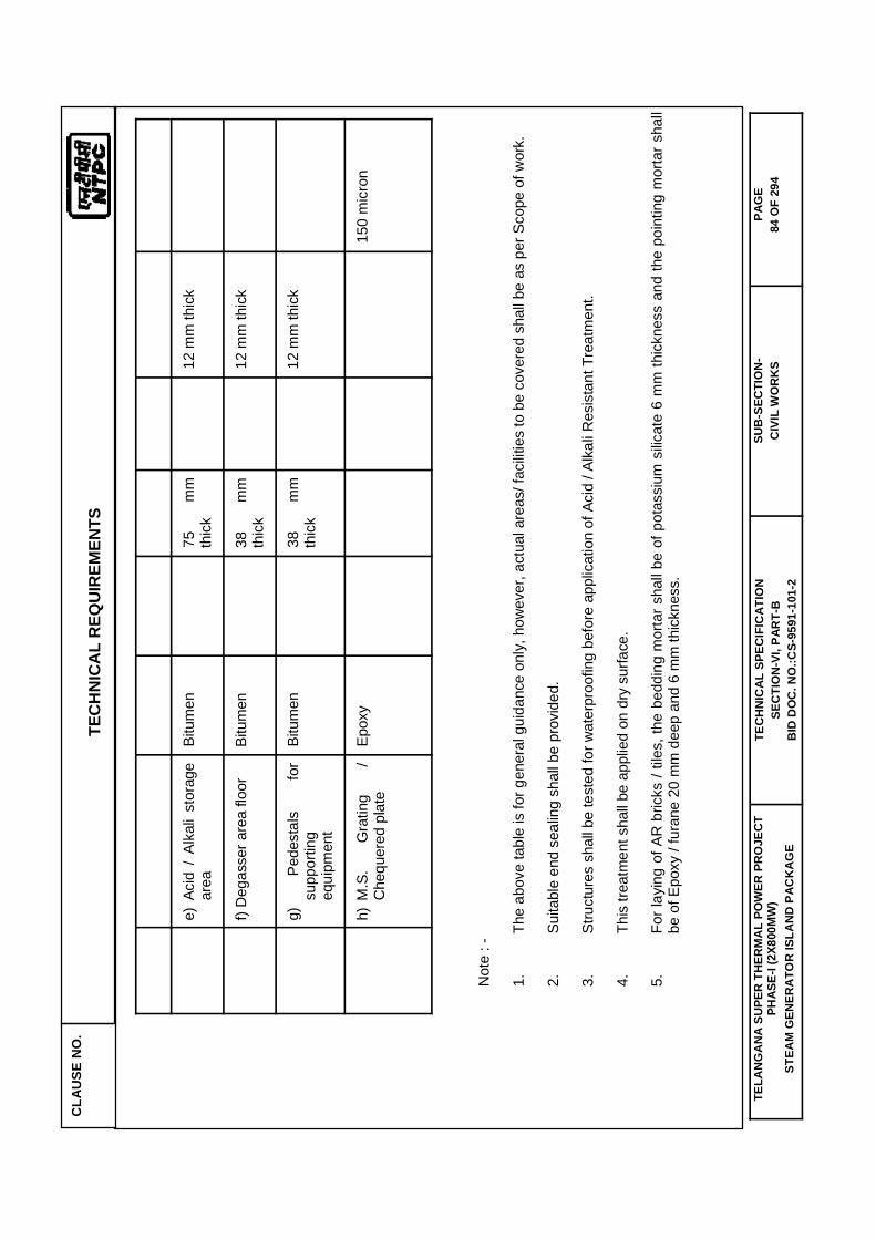
CLA
USE
NO
. TE
CH
NIC
AL
REQ
UIR
EMEN
TS
TELA
NG
AN
A S
UPE
R T
HER
MA
L PO
WER
PR
OJE
CT
PHAS
E-I (
2X80
0MW
) ST
EAM
GEN
ERA
TOR
ISLA
ND
PAC
KA
GE
TEC
HN
ICAL
SPE
CIF
ICAT
ION
SE
CTI
ON
-VI,
PAR
T-B
B
ID D
OC
. NO
.:CS-
9591
-101
-2
SUB
-SEC
TIO
N-
CIV
IL W
OR
KS
PAG
E 84
OF
294
e)
Aci
d /
Alka
li st
orag
e ar
eaBi
tum
en
75
m
m
thic
k
12 m
m th
ick
f)
Deg
asse
r are
a flo
or
Bitu
men
38
mm
th
ick
12
mm
thic
k
g)
Pe
dest
als
for
supp
ortin
g eq
uipm
ent
Bitu
men
38
mm
th
ick
12
mm
thic
k
h)
M.S
. G
ratin
g /
Che
quer
ed p
late
Ep
oxy
150
mic
ron
Not
e : -
1.
The
abov
e ta
ble
is fo
r gen
eral
gui
danc
e on
ly, h
owev
er, a
ctua
l are
as/ f
acilit
ies
to b
e co
vere
d sh
all b
e as
per
Sco
pe o
f wor
k.
2.
Suita
ble
end
seal
ing
shal
l be
prov
ided
.
3.
Stru
ctur
es s
hall
be te
sted
for w
ater
proo
fing
befo
re a
pplic
atio
n of
Aci
d / A
lkal
i Res
ista
nt T
reat
men
t.
4.
This
trea
tmen
t sha
ll be
app
lied
on d
ry s
urfa
ce.
5.
For l
ayin
g of
AR
bric
ks /
tiles
, the
bed
ding
mor
tar s
hall
be o
f pot
assi
um s
ilicat
e 6
mm
thic
knes
s an
d th
e po
intin
g m
orta
r sha
llbe
of E
poxy
/ fu
rane
20
mm
dee
p an
d 6
mm
thic
knes
s.
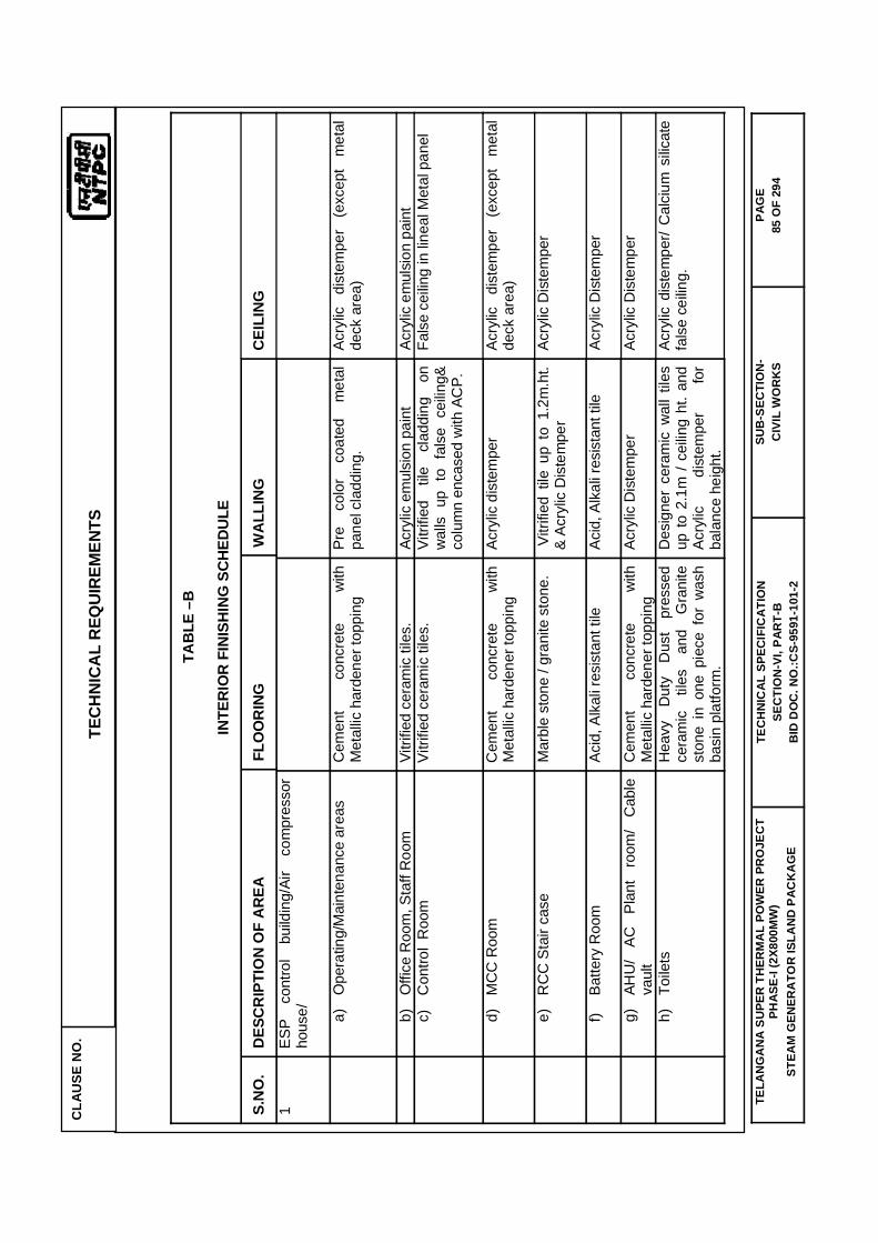
CLA
USE
NO
. TE
CH
NIC
AL
REQ
UIR
EMEN
TS
TELA
NG
AN
A S
UPE
R T
HER
MA
L PO
WER
PR
OJE
CT
PHAS
E-I (
2X80
0MW
) ST
EAM
GEN
ERA
TOR
ISLA
ND
PAC
KA
GE
TEC
HN
ICAL
SPE
CIF
ICAT
ION
SE
CTI
ON
-VI,
PAR
T-B
B
ID D
OC
. NO
.:CS-
9591
-101
-2
SUB
-SEC
TIO
N-
CIV
IL W
OR
KS
PAG
E 85
OF
294
TABL
E –B
INTE
RIO
R FI
NISH
ING
SCH
EDUL
E
S.N
O.
DESC
RIP
TIO
N O
F AR
EA
FLO
OR
ING
W
ALLI
NG
CEIL
ING
1
ESP
cont
rol
build
ing/
Air
com
pres
sor
hous
e/
a)
O
pera
ting/
Mai
nten
ance
are
as
Cem
ent
conc
rete
w
ith
Met
allic
har
dene
r top
ping
Pr
e co
lor
coat
ed
met
al
pane
l cla
ddin
g.
Acry
lic
dist
empe
r (e
xcep
t m
etal
de
ck a
rea)
b)
O
ffice
Roo
m, S
taff
Roo
m
Vitri
fied
cera
mic
tile
s.
Acry
lic e
mul
sion
pai
nt
Acry
lic e
mul
sion
pai
nt
c)
C
ontro
l R
oom
Vi
trifie
d ce
ram
ic ti
les.
Vi
trifie
d til
e cl
addi
ng
on
wal
ls u
p to
fal
se c
eilin
g&
colu
mn
enca
sed
with
AC
P.
Fals
e ce
iling
in li
neal
Met
al p
anel
d)
M
CC
Roo
m
Cem
ent
conc
rete
w
ith
Met
allic
har
dene
r top
ping
Ac
rylic
dis
tem
per
Acry
lic
dist
empe
r (e
xcep
t m
etal
de
ck a
rea)
e)
R
CC
Sta
ir ca
se
Mar
ble
ston
e / g
rani
te s
tone
. V
itrifi
ed t
ile u
p to
1.2
m.h
t. &
Acry
lic D
iste
mpe
r Ac
rylic
Dis
tem
per
f)
Batte
ry R
oom
Ac
id, A
lkal
i res
ista
nt ti
le
Acid
, Alk
ali r
esis
tant
tile
Ac
rylic
Dis
tem
per
g)
AH
U/
AC
Plan
t ro
om/
Cab
le
vaul
tC
emen
t co
ncre
te
with
M
etal
lic h
arde
ner t
oppi
ng
Acry
lic D
iste
mpe
r Ac
rylic
Dis
tem
per
h)
To
ilets
H
eavy
D
uty
Dus
t pr
esse
d ce
ram
ic
tiles
an
d G
rani
te
ston
e in
one
pie
ce f
or w
ash
basi
n pl
atfo
rm.
Des
igne
r ce
ram
ic w
all t
iles
up to
2.1
m /
ceilin
g ht
. and
Ac
rylic
di
stem
per
for
bala
nce
heig
ht.
Acry
lic d
iste
mpe
r/ C
alci
um s
ilicat
e fa
lse
ceilin
g.
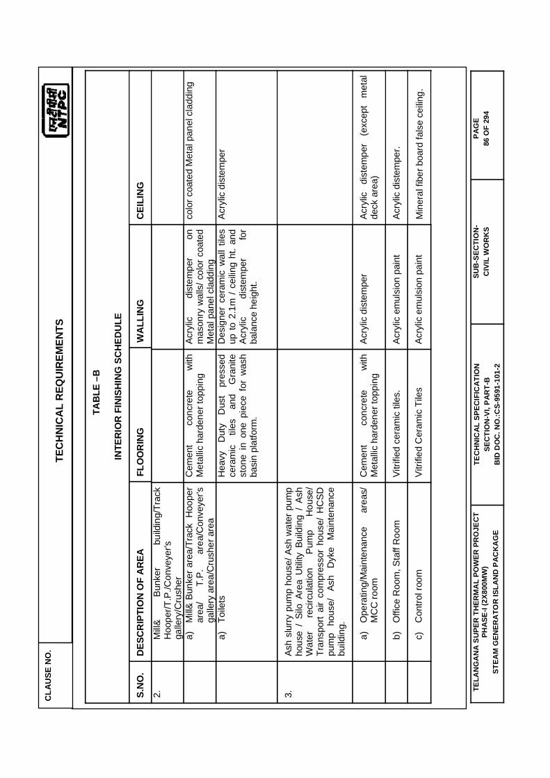
CLA
USE
NO
. TE
CH
NIC
AL
REQ
UIR
EMEN
TS
TELA
NG
AN
A S
UPE
R T
HER
MA
L PO
WER
PR
OJE
CT
PHAS
E-I (
2X80
0MW
) ST
EAM
GEN
ERA
TOR
ISLA
ND
PAC
KA
GE
TEC
HN
ICAL
SPE
CIF
ICAT
ION
SE
CTI
ON
-VI,
PAR
T-B
B
ID D
OC
. NO
.:CS-
9591
-101
-2
SUB
-SEC
TIO
N-
CIV
IL W
OR
KS
PAG
E 86
OF
294
TABL
E –B
INTE
RIO
R FI
NISH
ING
SCH
EDUL
E
S.N
O.
DESC
RIP
TIO
N O
F AR
EA
FLO
OR
ING
W
ALLI
NG
CEIL
ING
2.
M
ill&
Bunk
er
build
ing/
Trac
k H
oope
r/T.P
./Con
veye
r's
galle
ry/C
rush
er
a)
M
ill& B
unke
r are
a/Tr
ack
Hoo
per
area
/ T.
P.
area
/Con
veye
r's
galle
ry a
rea/
Cru
sher
are
a
Cem
ent
conc
rete
w
ith
Met
allic
har
dene
r top
ping
Ac
rylic
di
stem
per
on
mas
onry
wal
ls/ c
olor
coa
ted
Met
al p
anel
cla
ddin
g
colo
r coa
ted
Met
al p
anel
cla
ddin
g
a)
To
ilets
H
eavy
D
uty
Dus
t pr
esse
d ce
ram
ic
tiles
an
d G
rani
te
ston
e in
one
pie
ce f
or w
ash
basi
n pl
atfo
rm.
Des
igne
r ce
ram
ic w
all t
iles
up to
2.1
m /
ceilin
g ht
. and
Ac
rylic
di
stem
per
for
bala
nce
heig
ht.
Acry
lic d
iste
mpe
r
3.
Ash
slur
ry p
ump
hous
e/ A
sh w
ater
pum
p ho
use
/ Si
lo A
rea
Util
ity B
uild
ing
/ As
h W
ater
re
circ
ulat
ion
Pum
p H
ouse
/ Tr
ansp
ort
air
com
pres
sor
hous
e/ H
CSD
pu
mp
hous
e/
Ash
Dyk
e M
aint
enan
ce
build
ing.
a)
O
pera
ting/
Mai
nten
ance
ar
eas/
M
CC
room
C
emen
t co
ncre
te
with
M
etal
lic h
arde
ner t
oppi
ng
Acry
lic d
iste
mpe
r Ac
rylic
di
stem
per
(exc
ept
met
al
deck
are
a)
b)
O
ffice
Roo
m, S
taff
Roo
m
Vitri
fied
cera
mic
tile
s.
Acry
lic e
mul
sion
pai
nt
Acry
lic d
iste
mpe
r.
c)
C
ontro
l roo
m
Vitri
fied
Cer
amic
Tile
s Ac
rylic
em
ulsi
on p
aint
M
iner
al fi
ber b
oard
fals
e ce
iling.
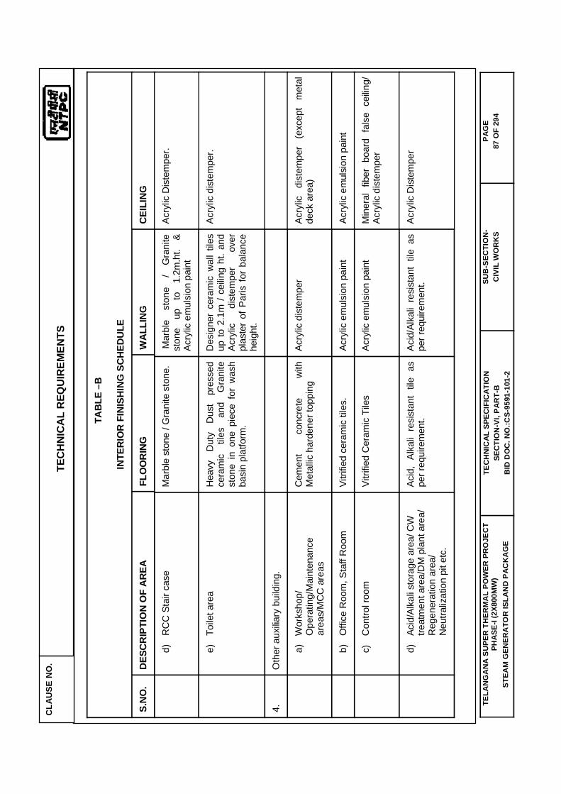
CLA
USE
NO
. TE
CH
NIC
AL
REQ
UIR
EMEN
TS
TELA
NG
AN
A S
UPE
R T
HER
MA
L PO
WER
PR
OJE
CT
PHAS
E-I (
2X80
0MW
) ST
EAM
GEN
ERA
TOR
ISLA
ND
PAC
KA
GE
TEC
HN
ICAL
SPE
CIF
ICAT
ION
SE
CTI
ON
-VI,
PAR
T-B
B
ID D
OC
. NO
.:CS-
9591
-101
-2
SUB
-SEC
TIO
N-
CIV
IL W
OR
KS
PAG
E 87
OF
294
TABL
E –B
INTE
RIO
R FI
NISH
ING
SCH
EDUL
E
S.N
O.
DESC
RIP
TIO
N O
F AR
EA
FLO
OR
ING
W
ALLI
NG
CEIL
ING
d)
R
CC
Sta
ir ca
se
Mar
ble
ston
e / G
rani
te s
tone
. M
arbl
e st
one
/ G
rani
te
ston
e up
to
1.
2m.h
t. &
Acry
lic e
mul
sion
pai
nt
Acry
lic D
iste
mpe
r.
e)
To
ilet a
rea
Hea
vy
Dut
y D
ust
pres
sed
cera
mic
til
es
and
Gra
nite
st
one
in o
ne p
iece
for
was
h ba
sin
plat
form
.
Des
igne
r ce
ram
ic w
all t
iles
up to
2.1
m /
ceilin
g ht
. and
Ac
rylic
di
stem
per
over
pl
aste
r of
Par
is f
or b
alan
ce
heig
ht.
Acry
lic d
iste
mpe
r.
4.
Oth
er a
uxilia
ry b
uild
ing.
a)
W
orks
hop/
O
pera
ting/
Mai
nten
ance
ar
eas/
MC
C a
reas
Cem
ent
conc
rete
w
ith
Met
allic
har
dene
r top
ping
Ac
rylic
dis
tem
per
Acry
lic
dist
empe
r (e
xcep
t m
etal
de
ck a
rea)
b)
O
ffice
Roo
m, S
taff
Roo
m
Vitri
fied
cera
mic
tile
s.
Acry
lic e
mul
sion
pai
nt
Acry
lic e
mul
sion
pai
nt
c)
C
ontro
l roo
m
Vitri
fied
Cer
amic
Tile
s Ac
rylic
em
ulsi
on p
aint
M
iner
al f
iber
boa
rd f
alse
cei
ling/
Ac
rylic
dis
tem
per
d)
Ac
id/A
lkal
i sto
rage
are
a/ C
W
treat
men
t are
a/D
M p
lant
are
a/
Reg
ener
atio
n ar
ea/
Neu
traliz
atio
n pi
t etc
.
Acid
, Al
kali
resi
stan
t til
e as
pe
r req
uire
men
t. Ac
id/A
lkal
i re
sist
ant
tile
as
per r
equi
rem
ent.
Acry
lic D
iste
mpe
r

CLA
USE
NO
. TE
CH
NIC
AL
REQ
UIR
EMEN
TS
TELA
NG
AN
A S
UPE
R T
HER
MA
L PO
WER
PR
OJE
CT
PHAS
E-I (
2X80
0MW
) ST
EAM
GEN
ERA
TOR
ISLA
ND
PAC
KA
GE
TEC
HN
ICAL
SPE
CIF
ICAT
ION
SE
CTI
ON
-VI,
PAR
T-B
B
ID D
OC
. NO
.:CS-
9591
-101
-2
SUB
-SEC
TIO
N-
CIV
IL W
OR
KS
PAG
E 88
OF
294
TABL
E –B
INTE
RIO
R FI
NISH
ING
SCH
EDUL
E
S.N
O.
DESC
RIP
TIO
N O
F AR
EA
FLO
OR
ING
W
ALLI
NG
CEIL
ING
e)
R
CC
Sta
ir ca
se
Mar
ble
ston
e / g
rani
te s
tone
. M
arbl
e st
one
up
to1.
2 m
.ht.
& Ac
rylic
D
iste
mpe
r pa
int
Acry
lic D
iste
mpe
r
f)
Toile
t are
a H
eavy
D
uty
Dus
t pr
esse
d ce
ram
ic
tiles
an
d G
rani
te
ston
e in
one
pie
ce f
or w
ash
basi
n pl
atfo
rm.
Des
igne
r ce
ram
ic w
all t
iles
upto
2.1
m /
cei
ling
ht.
and
Acry
lic
dist
empe
r fo
r ba
lanc
e he
ight
.
Acry
lic d
iste
mpe
r
Not
e :
1.
Al
l wal
l and
roof
are
as a
bove
fals
e ce
iling
shal
l be
plas
tere
d an
d w
hite
was
hed.
2.
Th
e co
lour
and
pat
tern
of f
inis
h sh
all b
e as
per
app
rove
d de
tails
.
3.
Al
l mat
eria
ls s
hall
be o
f rep
uted
and
est
ablis
hed
bran
d ap
prov
ed b
y En
gine
er-in
-cha
rge.
4.
W
here
ver a
ltern
ativ
e m
ater
ials
are
spe
cifie
d, th
e fin
al s
elec
tion
rest
s w
ith E
ngin
eer-i
n-ch
arge
.
5.
Th
is fi
nish
ing
sche
dule
sha
ll al
so b
e ap
plic
able
to s
imila
r fun
ctio
nal a
reas
for a
ll ot
her b
uild
ings
and
faci
litie
s.
6.
Al
l the
fini
shin
g m
ater
ials
sha
ll be
app
lied/
prov
ided
as
per m
anuf
actu
rer s
peci
ficat
ion
and
guid
elin
es u
nder
the
supe
rvis
ion
& gu
idel
ines
of
man
ufac
ture
r.
7.
R
equi
rem
ent g
iven
abo
ve a
re s
ugge
stiv
e an
d m
inim
um. B
idde
r is
wel
com
e to
sug
gest
alte
rnat
ive
sche
me
conf
orm
ing
to d
esig
n fu
nctio
nal
requ
irem
ent s
ubje
ct to
app
rova
l of t
he E
ngin
eer-i
n-ch
arge
.
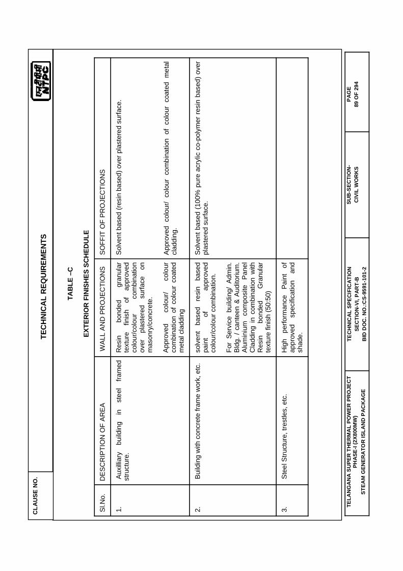
CLA
USE
NO
. TE
CH
NIC
AL
REQ
UIR
EMEN
TS
TELA
NG
AN
A S
UPE
R T
HER
MA
L PO
WER
PR
OJE
CT
PHAS
E-I (
2X80
0MW
) ST
EAM
GEN
ERA
TOR
ISLA
ND
PAC
KA
GE
TEC
HN
ICAL
SPE
CIF
ICAT
ION
SE
CTI
ON
-VI,
PAR
T-B
B
ID D
OC
. NO
.:CS-
9591
-101
-2
SUB
-SEC
TIO
N-
CIV
IL W
OR
KS
PAG
E 89
OF
294
TABL
E –C
EXTE
RIO
R FI
NISH
ES S
CHED
ULE
Sl.N
o.
DES
CR
IPTI
ON
OF
AREA
W
ALL
AND
PR
OJE
CTI
ON
S SO
FFIT
OF
PRO
JEC
TIO
NS
1.
Aux
illiar
y bu
ildin
g in
st
eel
fram
ed
stru
ctur
e.
Res
in
bond
ed
gran
ular
te
xtur
e fin
ish
of
appr
oved
co
lour
/col
our
com
bina
tion
over
pl
aste
red
surfa
ce
on
mas
onry
/con
cret
e.
Appr
oved
co
lour
/ co
lour
co
mbi
natio
n of
col
our
coat
ed
met
al c
ladd
ing
Solv
ent b
ased
(res
in b
ased
) ove
r pla
ster
ed s
urfa
ce.
Appr
oved
col
our/
colo
ur c
ombi
natio
n of
col
our
coat
ed m
etal
cl
addi
ng.
2.
Bui
ldin
g w
ith c
oncr
ete
fram
e w
ork,
etc
. so
lven
t ba
sed
resi
n ba
sed
pain
t of
ap
prov
ed
colo
ur/c
olou
r com
bina
tion.
For
Serv
ice
build
ing/
Adm
in.
Bldg
. / c
ante
en &
Aud
itoriu
m.
Alum
iniu
m
com
posi
te
Pane
l C
ladd
ing
in c
ombi
natio
n w
ith
Res
in
bond
ed
Gra
nula
r te
xtur
e fin
ish
(50:
50)
Solv
ent b
ased
(100
% p
ure
acry
lic c
o-po
lym
er re
sin
base
d) o
ver
plas
tere
d su
rface
.
3.
Ste
el S
truct
ure,
tres
tles,
etc
. H
igh
perfo
rman
ce
Pain
t of
ap
prov
ed
spec
ifica
tion
and
shad
e.

CLA
USE
NO
. TE
CH
NIC
AL
REQ
UIR
EMEN
TS
TELA
NG
AN
A S
UPE
R T
HER
MA
L PO
WER
PR
OJE
CT
PHAS
E-I (
2X80
0MW
) ST
EAM
GEN
ERA
TOR
ISLA
ND
PAC
KA
GE
TEC
HN
ICAL
SPE
CIF
ICAT
ION
SE
CTI
ON
-VI,
PAR
T-B
B
ID D
OC
. NO
.:CS-
9591
-101
-2
SUB
-SEC
TIO
N-
CIV
IL W
OR
KS
PAG
E 90
OF
294
NO
TE :
1. T
he c
olou
r and
pat
tern
of f
inis
h sh
all b
e as
fina
lized
by
Engi
neer
.
2.
All m
ater
ials
sha
ll be
of r
eput
ed a
nd e
stab
lishe
d br
and
appr
oved
by
Engi
neer
.

CLAUSE NO. TECHNICAL REQUIREMENTS
TELANGANA SUPER THERMAL POWER PROJECT PHASE-I (2X800MW)
STEAM GENERATOR ISLAND PACKAGE
TECHNICAL SPECIFICATION SECTION-VI, PART-B
BID DOC. NO.:CS-9591-101-2
SUB-SECTION-CIVIL WORKS
PAGE 91 OF 294
10.00.00 MATERIAL SPECIFICATION
10.01.00 Cement
Fly ash based portland pozzolana cement conforming to IS:1489 (Part-1) shall be used for all areas other than for the critical structures identified below. Other properties shall be as per IS code.
Ordinary Portland Cement (OPC) shall necessarily be used for the following structures.
a) Spring supported decks of all machine foundations such as PA/FD/ID Fans
b) RCC for Chimney shell.
The grade of cement shall be Grade 43 for OPC conforming to IS:8112.
In place of fly ash based portland pozzolana cement, OPC mixed with Fly Ash can be used. Batching plant shall have facility for mixing fly ash. Fly ash shall conform to IS:3812(Part I & Part II). Percentage of fly ash to be mixed in concrete shall be based on trial mix. Mix design shall be done with varying percentage of fly ash mix with cement
10.02.00 Aggregates
a) Coarse aggregate
Coarse aggregate for concrete shall be crushed stones chemically inert, hard, strong, durable against weathering of limited porosity and free from deleterious materials. It shall be properly graded. It shall meet the requirements of IS: 383.
b) Fine aggregate
Sand shall be hard, durable, clean and free from adherent coatings of organic matter and clay balls or pellets. Sand, when used as fine aggregate in concrete shall conform to IS : 383. For plaster, it shall conform to IS : 1542 and for masonry work to IS : 2116.
c) Petrographic examination of aggregate shall be carried out by the contractor at National Council for Cement and Building Materials (NCB), Ballabgarh, or any other approved laboratory to ascertain the structure and rock type including presence of strained quartz and other reactive minerals for machine foundations, etc.. In case, the coarse aggregate sample is of composite nature, the proportions (by weight) of different rock types in the composite sample and petrographic evaluation of each rock should also be ascertained. While determining the rock type, special emphasis should be given on identification of known reactive rocks like chalcedony, opal etc. The procedure laid down in IS: 2430 for sampling of aggregates may be followed.
The laboratory shall determine potential reactivity of the aggregate, which may lead to reaction of silica in aggregate with the alkalis of cement and / or potential of some aggregates like limestone to cause residual expansion due to repeated temperature cycle. If the same is established, the contractor shall further carry out alkali aggregates reactivity test as per IS: 2386 (Pt.VII) and / or repeated temperature cycle test to establish the suitability of the aggregates for the concrete work. The

CLAUSE NO. TECHNICAL REQUIREMENTS
TELANGANA SUPER THERMAL POWER PROJECT PHASE-I (2X800MW)
STEAM GENERATOR ISLAND PACKAGE
TECHNICAL SPECIFICATION SECTION-VI, PART-B
BID DOC. NO.:CS-9591-101-2
SUB-SECTION-CIVIL WORKS
PAGE 92 OF 294
test results, with the final recommendations of the laboratory, as to a suitability of the aggregate, for use in the concrete work for various structures and suggested measures, in case of results are not satisfactory, shall be submitted to the Engineer for his review, in a report form.
In case in the report, it is established, that the aggregates contain reactive silica, which would react with alkalis of the cement, the contractor shall change the source of supply of the aggregate or use low alkali cement as per recommendation or take measures as recommended in the report as instructed by Engineer. In case aggregates indicate residual expansion, under repeated temperature cycle test (from 10o Celsius to 65o Celsius and for 60 temperature cycles) the material shall not be used for concreting of TGs', BFPs' and other equipment foundations which are likely to be subjected to repeated temperature cycle. The contractor shall use aggregates free from residual expansion under repeated temperatures cycle test.
10.03.00 Reinforcement Steel
Reinforcement steel shall be of high strength deformed TMT steel bars of grade Fe-500 and shall conform to IS:1786. However, minimum elongation shall be 14.5%.
Mild steel & medium tensile steel bars and hard drawn steel wire shall conform to grade-1 of IS:432 (Part-1) or grade A of IS:2062. Welded wire fabric shall conform to IS:1566.
10.04.00 Structural Steel
Structural Steel (including embedded Steel) shall be straight, sound, free from twists, cracks, flaw, laminations and all other defects. Structural steel shall comprise of mild steel, medium strength steel and high tensile steel as specified below.
10.04.01 Mild Steel
a) Rolled sections shall be of grade designation E250, Quality A/BR, Semi-killed/ killed conforming to IS 2062. All steel plates shall be of Grade designation E250, Quality BR (fully killed), conforming to IS 2062 and shall pass the impact test value at room temperature. Plates beyond 12mm thickness and up to 40mm thickness shall be normalized rolled. Plates beyond 40mm thickness shall be vacuum degassed & furnace normalised and shall also be 100% ultrasonically tested as per ASTM –A578 level B-S2.
b) Pipes shall conform to IS: 1161.
c) Hollow (square and rectangular) steel sections shall be hot formed conforming to IS: 4923 and shall be of minimum Grade Yst 240.
d) Chequered plate shall conform to IS 3502 and shall be minimum 6 mm thick excluding projection. Steel for chequered plate shall conform to grade E250A semi killed of IS: 2062 or equivalent grade conforming to ASTM & BS standards only.
10.04.02 Medium and High Tensile Steel
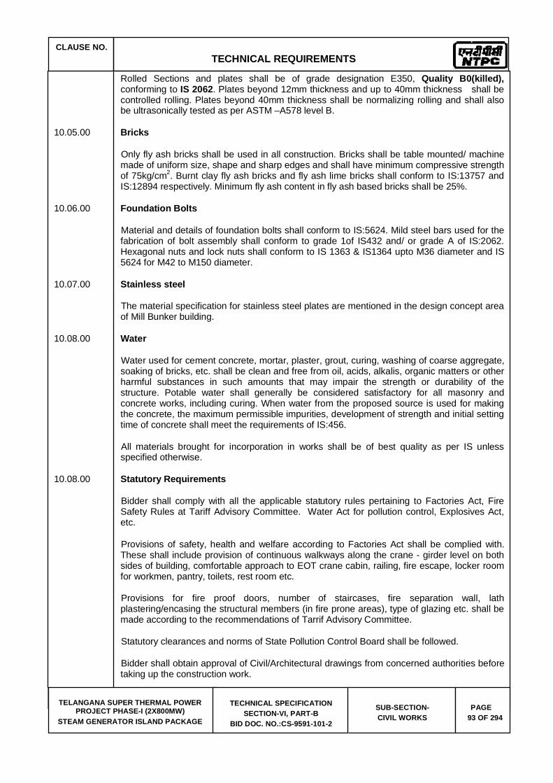
CLAUSE NO. TECHNICAL REQUIREMENTS
TELANGANA SUPER THERMAL POWER PROJECT PHASE-I (2X800MW)
STEAM GENERATOR ISLAND PACKAGE
TECHNICAL SPECIFICATION SECTION-VI, PART-B
BID DOC. NO.:CS-9591-101-2
SUB-SECTION-CIVIL WORKS
PAGE 93 OF 294
Rolled Sections and plates shall be of grade designation E350, Quality B0(killed),conforming to IS 2062. Plates beyond 12mm thickness and up to 40mm thickness shall be controlled rolling. Plates beyond 40mm thickness shall be normalizing rolling and shall also be ultrasonically tested as per ASTM –A578 level B.
10.05.00 Bricks
Only fly ash bricks shall be used in all construction. Bricks shall be table mounted/ machine made of uniform size, shape and sharp edges and shall have minimum compressive strength of 75kg/cm2. Burnt clay fly ash bricks and fly ash lime bricks shall conform to IS:13757 and IS:12894 respectively. Minimum fly ash content in fly ash based bricks shall be 25%.
10.06.00 Foundation Bolts
Material and details of foundation bolts shall conform to IS:5624. Mild steel bars used for the fabrication of bolt assembly shall conform to grade 1of IS432 and/ or grade A of IS:2062. Hexagonal nuts and lock nuts shall conform to IS 1363 & IS1364 upto M36 diameter and IS 5624 for M42 to M150 diameter.
10.07.00 Stainless steel
The material specification for stainless steel plates are mentioned in the design concept area of Mill Bunker building.
10.08.00 Water
Water used for cement concrete, mortar, plaster, grout, curing, washing of coarse aggregate, soaking of bricks, etc. shall be clean and free from oil, acids, alkalis, organic matters or other harmful substances in such amounts that may impair the strength or durability of the structure. Potable water shall generally be considered satisfactory for all masonry and concrete works, including curing. When water from the proposed source is used for making the concrete, the maximum permissible impurities, development of strength and initial setting time of concrete shall meet the requirements of IS:456.
All materials brought for incorporation in works shall be of best quality as per IS unless specified otherwise.
10.08.00 Statutory Requirements
Bidder shall comply with all the applicable statutory rules pertaining to Factories Act, Fire Safety Rules at Tariff Advisory Committee. Water Act for pollution control, Explosives Act, etc.
Provisions of safety, health and welfare according to Factories Act shall be complied with. These shall include provision of continuous walkways along the crane - girder level on both sides of building, comfortable approach to EOT crane cabin, railing, fire escape, locker room for workmen, pantry, toilets, rest room etc.
Provisions for fire proof doors, number of staircases, fire separation wall, lath plastering/encasing the structural members (in fire prone areas), type of glazing etc. shall be made according to the recommendations of Tarrif Advisory Committee.
Statutory clearances and norms of State Pollution Control Board shall be followed.
Bidder shall obtain approval of Civil/Architectural drawings from concerned authorities before taking up the construction work.

CLAUSE NO. TECHNICAL REQUIREMENTS
TELANGANA SUPER THERMAL POWER PROJECT PHASE-I (2X800MW)
STEAM GENERATOR ISLAND PACKAGE
TECHNICAL SPECIFICATION SECTION-VI, PART-B
BID DOC. NO.:CS-9591-101-2
SUB-SECTION-CIVIL WORKS
PAGE 94 OF 294
11.00.00 Inspection, Testing and Quality Control
11.01.00 Sampling and testing of major items of civil works viz. earthwork, concreting, structural steel work (including welding), piling, sheeting, etc. shall be carried out in accordance with the requirements of this specification. Wherever nothing is specified relevant Indian Standards shall be followed. In absence of Indian Standard equivalent International Standards may be used.
The Bidder shall submit and finalize a detailed field Quality Assurance Programme before starting of the construction work according to the requirement of this specification. This shall include frequency of sampling and testing, nature/type of test, method of test, setting of a testing laboratory, arrangement of testing apparatus/equipment, deployment of qualified/experienced manpower, preparation of format for record, Field Quality Plan, etc. Tests shall be done in the field and/or at a laboratory approved by the Engineer. The Bidder shall furnish the test certificate from the manufacturers of various materials to be used in the construction.
11.02.00 Workmanship and dimensional shall be checked as stipulated below.

CLAUSE NO.
TECHNICAL REQUIREMENTS
TELANGANA SUPER THERMAL POWER
PROJECT PHASE-I (2X800MW) STEAM GENERATOR ISLAND PACKAGE
TECHNICAL SPECIFICATION SECTION-VI, PART-B
BID DOC. NO.:CS-9591-101-2
SUB-SECTION- CIVIL WORKS
PAGE 95 OF 294
12.00.00 ANNEXURES
(a) List of Codes and Standards
All applicable standards, references, specifications, codes of practice, etc., shall be the latest edition including all applicable official amendments and revisions. A complete set of all these documents shall be available at site with Bidder. List of some of the applicable Standards, in original Codes and references is as given in Annexure-(a) of this specification.

CLAUSE NO.
TECHNICAL REQUIREMENTS
TELANGANA SUPER THERMAL POWER
PROJECT PHASE-I (2X800MW) STEAM GENERATOR ISLAND PACKAGE
TECHNICAL SPECIFICATION SECTION-VI, PART-B
BID DOC. NO.:CS-9591-101-2
SUB-SECTION- CIVIL WORKS
PAGE 96 OF 294
Annexure-(a)
LIST OF CODES AND STANDARDS
Excavation and Filling
IS :2720 Methods of test for soils(relevant parts)
IS:4701 Code of practice for earth work on canals.
IS:9759 Guide lines for dewatering during construction.
IS:10379 Code of practice for field control of moisture and compact ion of soils for embankment and sub-grade.
Properties, Storage and Handling of Common Building Materials
IS:269 33 grade for ordinary Portland cement.
IS:383 Coarse and fine aggregates from natural sources for concrete.
IS:432 Specification for mild steel and medium tensile steel bars and
(Part 1&2) hard drawn steel wires for concrete reinforcement.
IS:455 Portland slag cement.
IS:702 Industrial bitumen.
IS:712 Specification for building limes.
IS:1077 Common burnt clay building bricks.
IS:1161 Steel tubes for structural purposes.
IS:1239 Mild steel tubes, tubular and other wrought steel filling - MS tubes.
IS:1363 Hexagon head bolts, screws and nuts of productions
(Part 1-3) grade - C.
IS:1364 Hexagon head bolts, screws and nuts of productions
(Part 1-5) grade-A & B.
IS:1367 Technical supply condition for threaded fasteners. (Part 1-18) IS:1489 Portland-pozzolana cement. (Part-I) Fly ash based IS:1542 Sand for Plaster. IS:1566 Hard drawn steel wire fabric for concrete reinforcement.

CLAUSE NO.
TECHNICAL REQUIREMENTS
TELANGANA SUPER THERMAL POWER
PROJECT PHASE-I (2X800MW) STEAM GENERATOR ISLAND PACKAGE
TECHNICAL SPECIFICATION SECTION-VI, PART-B
BID DOC. NO.:CS-9591-101-2
SUB-SECTION- CIVIL WORKS
PAGE 97 OF 294
IS:1786 High strength deformed steel bars & wires for concrete reinforcement. IS:2062 Hot Rolled Low, Medium and High Tensile Structural Steel IS:2116 Sand for masonry mortars. IS : 2185 Hollow & solid concrete blocks. (Part 1) (Part 2) Hollow & solid light weight concrete blocks. IS:2386 Testing of aggregates for concrete. (Part I-VIII) IS:3812 Specification for fly ash for use as pozzolona and admixture. IS:4082 Recommendation on stacking and storage of construction materiel and
components at site IS:8112 43 grade ordinary portland cement. IS:8500 Structural steel-Microalloyed (Medium and high strength qualities). IS:12269 53 grade ordinary portland cement. IS:12894 Specification for fly ash lime bricks. IS:13757 Burnt clay fly ash building bricks. Cast in-situ Concrete and Allied Works IS:280 Mild steel wire for general engineering purpose. IS:456 Code of practice for plain and reinforcement concrete. IS:457 Code of practice for general construction of plain and reinforced concrete for
dams and other massive structures. IS:516 Method of test for strength of concrete. IS:1199 Methods of sampling and analysis of concrete. IS:1791 General requirement for batch type concrete mixers. IS:1834 Hot applied sealing compound for joints in concrete. IS:1838 Preformed fillers for expansion joints in concrete pavement and structures. IS:2438 Specification for roller pan mixers. IS:2502 Code of practice for bending and fixing of bars for concrete reinforcement . IS:2505 Concrete vibrators - immersion type. IS:2506 General requirements for screed board concrete vibrators.

CLAUSE NO.
TECHNICAL REQUIREMENTS
TELANGANA SUPER THERMAL POWER
PROJECT PHASE-I (2X800MW) STEAM GENERATOR ISLAND PACKAGE
TECHNICAL SPECIFICATION SECTION-VI, PART-B
BID DOC. NO.:CS-9591-101-2
SUB-SECTION- CIVIL WORKS
PAGE 98 OF 294
IS:2722 Specification for Portable Swing weigh batchers for concrete (single and double bucket type).
IS:2750 Steel scaffoldings IS:2751 Recommended practice for welding of mild steel plain and deformed bars for
reinforced construction. IS:3150 Hexagonal wire netting for general purposes. IS:3366 Specification for pan vibrators. IS:3370 Code of practice for concrete structures for the (Part 1-4) storage of liquids. IS:3558 Code of practice for use of immersion vibrators for consolidating concrete. IS:4014 Code of practice for steel tubular scaffolding. (Part-1&2) IS:4326 Code of practice for earth quake resistant design and construction of
buildings. IS:4656 Form vibrators for concrete. IS:4925 Concrete batching and mixing plant. IS:4990 Plywood for concrete shuttering work. IS:5256 Code of practice for sealing expansion joints in concrete lining on canals. IS:5525 Recommendations for detailing of reinforcement in reinforced concrete
works. IS:6461 Glossary of terms relating to cement concrete. IS:6494 Code of practice for water proofing of underground reservoir and swimming
pools. IS:6509 Code of practice for installation of joints in concrete pavements. IS:7861 Code of practice for extreme weather concreting. (Part -1&2) IS:9012 Recommended practice for shotcreting. IS:9103 Admixtures for concrete. IS:9417 Recommendations for welding cold worked bars for reinforced concrete
construction. IS:10262 Recommended guidelines for concrete mix design. IS:11384 Code of practice for composite construction in structural steel and concrete. IS:12118 Two parts polysulphide based sealants.

CLAUSE NO.
TECHNICAL REQUIREMENTS
TELANGANA SUPER THERMAL POWER
PROJECT PHASE-I (2X800MW) STEAM GENERATOR ISLAND PACKAGE
TECHNICAL SPECIFICATION SECTION-VI, PART-B
BID DOC. NO.:CS-9591-101-2
SUB-SECTION- CIVIL WORKS
PAGE 99 OF 294
IS:12200 Code of practice for provision of water stops at transverse construction joints in masonry and concrete dams.
IS:13311 Non destructive testing of concrete - methods of test. (Part 1) Ultrasonic pulse velocity. (Part 2) Rebound hammer. SP-16 Design codes for reinforced concrete to IS:456-1978. SP-23 Hand book of concrete mixes. SP-24 Explanatory handbook on Indian standards code for plain and reinforced
concrete. (IS : 456) SP-34 Hand book on concrete reinforcement and detailing. ACI-318 American Concrete Institute code for structural concrete. Precast Concrete Works SP:7 National Building Code - Structural Design (Part 6/Sec.7) Prefabrication and system building and mixed / composite construction. IS:10297 Code of practice for design and construction of floors and roofs using
precast reinforced/prestressed concrete ribbed or cored slab units. IS:10505 Code of practice for construction of floors and roofs using pre -cast reinforced
concrete waffle units. IS:15658 Pre-cast concrete block for paving. Masonry & Allied Works IS:1905 Code of practice for structural use of unreinforced masonry. IS: 2185 Part-1 Concrete Masonry Units - Specification Part 1 Hollow and Solid
Concrete Blocks Part-3 Specification for concrete masonry un its: Part 2 Hollow and solid light
weight concrete blocks IS:2212 Code of practice for brick work. IS:2250 Code of practice for preparation and use of masonry mortars. IS:2572 Code of practice for construction of hollow concrete block masonry. SP:20 Hand book on masonry design and construction. Sheeting Works IS:277 Galvanised steel sheets (Plan & corrugated). IS:513 Cold-rolled low carbon steel sheets & strips. IS:730 Hook bolts for corrugated sheet roofing.
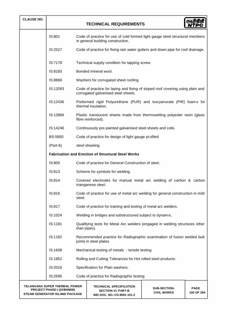
CLAUSE NO.
TECHNICAL REQUIREMENTS
TELANGANA SUPER THERMAL POWER
PROJECT PHASE-I (2X800MW) STEAM GENERATOR ISLAND PACKAGE
TECHNICAL SPECIFICATION SECTION-VI, PART-B
BID DOC. NO.:CS-9591-101-2
SUB-SECTION- CIVIL WORKS
PAGE 100 OF 294
IS:801 Code of practice for use of cold formed light gauge steel structural members
in general building construction. IS:2527 Code of practice for fixing rain water gutters and down pipe for roof drainage. IS:7178 Technical supply condition for tapping screw. IS:8183 Bonded mineral wool. IS:8869 Washers for corrugated sheet roofing. IS:12093 Code of practice for laying and fixing of sloped roof covering using plain and
corrugated galvanised steel sheets. IS:12436 Preformed rigid Polyurethane (PUR) and isocyanurate (PIR) foam s for
thermal insulation. IS:12866 Plastic translucent sheets made from thermosetting polyester resin (glass
fibre reinforced). IS:14246 Continuously pre-painted galvanised steel sheets and coils. BS:5950 Code of practice for design of light gauge profiled (Part-6) steel sheeting Fabrication and Erection of Structural Steel Works IS:800 Code of practice for General Construction of steel. IS:813 Scheme for symbols for welding. IS:814 Covered electrodes for manual metal arc welding of carbon & carbon
manganese steel. IS:816 Code of practice for use of metal arc welding for general construction in mild
steel. IS:817 Code of practice for training and testing of metal arc welders. IS:1024 Welding in bridges and substructured subject to dynam ic. IS:1181 Qualifying tests for Metal Arc welders (engaged in welding structures other
than pipes). IS:1182 Recommended practice for Radiographic examination of fusion welded butt
joints in steel plates IS:1608 Mechanical testing of metals - tensile testing IS:1852 Rolling and Cutting Tolerances for Hot rolled steel products. IS:2016 Specification for Plain washers. IS:2595 Code of practice for Radiographic testing

CLAUSE NO.
TECHNICAL REQUIREMENTS
TELANGANA SUPER THERMAL POWER
PROJECT PHASE-I (2X800MW) STEAM GENERATOR ISLAND PACKAGE
TECHNICAL SPECIFICATION SECTION-VI, PART-B
BID DOC. NO.:CS-9591-101-2
SUB-SECTION- CIVIL WORKS
PAGE 101 OF 294
IS:2629 Hot dip galvanising of iron and steel IS:3502 Steel chequred plate. IS:3613 Acceptance tests for wire flux combination for submerged arc welding. IS:3658 Code of practice for liquid penetrant flaw detection. IS:3664 Code of practice for ultra sonic pulse echo testing contact and immersion
method IS:3757 High strength structural bolts. IS:4000 High strength bolts in steel structure - code of practice. IS:4353 Sub merged arc welding of mild steel and low alloy steel Recommendation IS:4759 Hot dip zinc coating on structural steel and other allied products. IS:5334 Code of practice for magnetic particle flaw detection of welds. IS:5369 General requirements for plain washers and lock washer IS : 6623 High strength structural nuts. IS:6649 Hardened and tampered washers for high strength structural bolts & nuts. IS:6911 Stainless steel plate, sheet and strip. IS:7205 Safety code for erection of structural steel. IS:7215 Tolerances for fabrication of structural steel. IS:7307 Approved test for welding procedures (Part - I) Fusion welding of steel. IS:7310 Approval test for welders working to approval welding procedure. (Part-I) Fusion welding of steel IS:9178 Criteria for design of steel bins for storage of bulk material. (Part-1to 3) IS:9595 Recommendations for metal arc welding of carbon & carbon manganese
steel. IS:12843 Tolerances for erection of steel structures. SP:6 ISI Hand book for structural Engineers. (Part 1 to 7) Plastering and Allied Works IS:1661 Code of practice for application of cement and cement lime plaster finishes. IS:2402 Code of practice for external rendered finishes.

CLAUSE NO.
TECHNICAL REQUIREMENTS
TELANGANA SUPER THERMAL POWER
PROJECT PHASE-I (2X800MW) STEAM GENERATOR ISLAND PACKAGE
TECHNICAL SPECIFICATION SECTION-VI, PART-B
BID DOC. NO.:CS-9591-101-2
SUB-SECTION- CIVIL WORKS
PAGE 102 OF 294
IS:2547 Gypsum building plaster. (Parts 1&2) Acid and Alkali Resistant Lining IS:158 Ready mixed paint, brushing, bituminous, black, lead free, acid, alkali & heat
resisting. IS:412 Expanded metal steel sheets for general purpose. IS:4441 Code of practice for use of silica type chemical resistant mortars. IS:4443 Code of practice for use of resin type chemical resistant mortars. IS:4456 Method of Test for chemical resistant tiles. (Part I & II) IS:4457 Ceramic unglazed vitreous acid resisting tiles. IS:4832 Specification for chemical resistant mortars. (Part - 1) Silicate type (Part - 2) Resin type (Part - 3) Sulfur type IS:4860 Acid resistant bricks. IS:9510 Bitumastic acid resisting grade. Water Supply, Drainage and Sanitation IS:458 Precast concrete pipes (with & without reinforcement). IS:554 Pipe threads where pressure tight joints are made on the threads
dimensions, tolerances and designation. IS:651 Salt glazed stoneware pipes and fittings. IS:774 Flushing cisterns for water closets and urinals. IS:775 Cast iron brackets and supports for wash basins and sinks. IS:778 Copper alloy gate, globe and check valves for water works purposes. IS:781 Cast copper alloy screw down bib taps & stop valves for water services. IS:782 Caulking lead. IS:783 Code of practice for laying of concrete pipes. IS:1172 Code of basic requirements of water supply, drainage and sanitation. IS:1230 Cast iron rain water pipes and fittings.
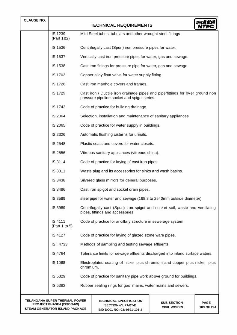
CLAUSE NO.
TECHNICAL REQUIREMENTS
TELANGANA SUPER THERMAL POWER
PROJECT PHASE-I (2X800MW) STEAM GENERATOR ISLAND PACKAGE
TECHNICAL SPECIFICATION SECTION-VI, PART-B
BID DOC. NO.:CS-9591-101-2
SUB-SECTION- CIVIL WORKS
PAGE 103 OF 294
IS:1239 Mild Steel tubes, tubulars and other wrought steel fittings (Part 1&2) IS:1536 Centrifugally cast (Spun) iron pressure pipes for water. IS:1537 Vertically cast iron pressure pipes for water, gas and sewage. IS:1538 Cast iron fittings for pressure pipe for water, gas and sewage. IS:1703 Copper alloy float valve for water supply fitting. IS:1726 Cast iron manhole covers and frames. IS:1729 Cast iron / Ductile iron drainage pipes and pipe/fittings for over ground non
pressure pipeline socket and spigot series. IS:1742 Code of practice for building drainage. IS:2064 Selection, installation and maintenance of sanitary appliances. IS:2065 Code of practice for water supply in buildings. IS:2326 Automatic flushing cisterns for urinals. IS:2548 Plastic seats and covers for water closets. IS:2556 Vitreous sanitary appliances (vitreous china). IS:3114 Code of practice for laying of cast iron pipes. IS:3311 Waste plug and its accessories for sinks and wash basins. IS:3438 Silvered glass mirrors for general purposes. IS:3486 Cast iron spigot and socket drain pipes. IS:3589 steel pipe for water and sewage (168.3 to 2540mm outside diameter) IS:3989 Centrifugally cast (Spun) iron spigot and socket soil, waste and ventilating
pipes, fittings and accessories. IS:4111 Code of practice for ancillary structure in sewerage system. (Part 1 to 5) IS:4127 Code of practice for laying of glazed stone ware pipes. IS : 4733 Methods of sampling and testing sewage effluents. IS:4764 Tolerance limits for sewage effluents discharged into inland surface waters. IS:1068 Electroplated coating of nickel plus chromium and copper plus nickel plus
chromium. IS:5329 Code of practice for sanitary pipe work above ground for buildings. IS:5382 Rubber sealing rings for gas mains, water mains and sewers.
CLAUSE NO.
TECHNICAL REQUIREMENTS
TELANGANA SUPER THERMAL POWER
PROJECT PHASE-I (2X800MW) STEAM GENERATOR ISLAND PACKAGE
TECHNICAL SPECIFICATION SECTION-VI, PART-B
BID DOC. NO.:CS-9591-101-2
SUB-SECTION- CIVIL WORKS
PAGE 104 OF 294
IS:5822 Code of practice for laying of electrically welded steel pipes for water supply. IS:5961 Specification for cast iron grating for drainage purpose. IS:7740 Code of practice for construction and maintenance of road gullies. IS:8931 Copper alloy fancy single taps combination tap assembly and stop valves
for water services. IS:9762 Polyethylene floats for float valves. IS:10592 Industrial emergency showers, eye and face fountains and combination
units. IS:12592 Specification for precast concrete manhole covers and frames. IS:12701 Rotational moulded polyethylene water storage tanks. IS:13983 Stainless steel sinks for domestic purposes. SP:35 Hand book on water supply and drainage with special emphasis on
plumbing. CPH&EEO Manual on sewage and sewage treatment Publication - as updated. Doors Windows and Allied Works IS:204 Tower Bolts. (Part 1) Ferrous metals (Part 2) Non - ferrous metals IS:208 Door Handles. IS:281 Mild steel sliding door bolts for use with padlocks. IS:362 Parliament Hinges. IS:419 Putty, for use on window frames. IS:451 Technical supply conditions for wood screws IS:733 Wrought aluminium and aluminium alloy bars, rods and sections for general
engineering purposes. IS:1003 Timber panelled and glazed shutters (doors shutters). (Part I) IS:1003 Timber panelled and glazed shutters (Part-1) door shutters. IS:1038 Steel doors, windows and ventilators.
CLAUSE NO.
TECHNICAL REQUIREMENTS
TELANGANA SUPER THERMAL POWER
PROJECT PHASE-I (2X800MW) STEAM GENERATOR ISLAND PACKAGE
TECHNICAL SPECIFICATION SECTION-VI, PART-B
BID DOC. NO.:CS-9591-101-2
SUB-SECTION- CIVIL WORKS
PAGE 105 OF 294
IS:1081 Code of practice for fixing and glazing of metal (steel and aluminium) doors, windows and ventilators.
IS:1285 Wrought aluminium and aluminium alloy extruded round tube & hollow
section (for general engineering purposes). IS:1341 Steel butt hinges. IS:1361 Steel windows for Industrial buildings. IS:1823 Floor door stoppers. IS:1868 Anodic coatings on Aluminium and its alloys. IS:2202 Wooden flush door shutters (solid core type) particle (Part-2) board face panels and hard board face panels. IS:2209 Mortice locks (vertical type) IS:2553 Safety glass. (Part-1) General purposes IS:2835 Flat transparent sheet glass. IS:3548 Code of practice for glazing in buildings. IS:3564 Door closers (Hydraulically regulated) IS:3614 Specification for fire check doors : (Part-1) plate, metal covered and rolling type. (Part-2) Resistance test and performance criteria. IS:4351 Specification for steel door frames. IS:5187 Flush bolts. IS:5437 Figured, rolled and wired glass. IS:6248 Specification for metal rolling shutters and rolling grills. IS:6315 Specification for floor springs (Hydraulically regulated) for heavy doors. IS:7196 Hold fast. IS:7452 Hot rolled steel sections for doors, windows and ventilators. IS:10019 Mild steel stays and fasteners. IS:10451 Steel sliding shutters (top hung type) IS:12823 Prelaminated particle boards.
CLAUSE NO.
TECHNICAL REQUIREMENTS
TELANGANA SUPER THERMAL POWER
PROJECT PHASE-I (2X800MW) STEAM GENERATOR ISLAND PACKAGE
TECHNICAL SPECIFICATION SECTION-VI, PART-B
BID DOC. NO.:CS-9591-101-2
SUB-SECTION- CIVIL WORKS
PAGE 106 OF 294
Roof Water Proofing and Allied Works IS:3067 code of practice for general design details and preparatory work for damp
proofing and water proofing of buildings. ASTM Standard specification for high solid content cold C836-89a liquid applied elastomeric water proofing membrane for use with separate
wearing course. ASTM Standard guide for high solid content cold C898-89 liquid applied elastomeric water proofing membrane for use with separate
wearing course. Floor Finishes and Allied Works IS:5318 Code of practice for laying of flexible PVC sheet and tile flooring. IS:8042 White portland cement. IS:13755 Dust pressed ceramic tiles with water absorption of 3%, E 6% (Group B11a). IS:13801 Chequered cement concrete tiles. Painting and Allied Works IS:162 Ready mixed paint, brushing fire resisting, silicate type for use on wood,
colour as required. IS:428 Distemper, oil, emulsion, colour as required. IS:1477 Code of practice for painting of terrous metals in buildings. (Part -1) Pretreatment. (Part -2) Painting. IS:1650 Specification for colours for building and decorative materials. IS:2074 Ready mixed paint, air drying, red oxide-zinc chrome, priming. IS:2338 Code of practice for finishing of wood and wood based materials. (Part -1) Operations and Workmanship. (Part -2) Schedule. IS:2395 Code of pratice for painting concrete, masonry and plaster surfaces. (Part-1) Operations and Workmanship. (Part -2) Schedule. IS:2524 Code of practice for painting of nonferrous metals in buildings.

CLAUSE NO.
TECHNICAL REQUIREMENTS
TELANGANA SUPER THERMAL POWER
PROJECT PHASE-I (2X800MW) STEAM GENERATOR ISLAND PACKAGE
TECHNICAL SPECIFICATION SECTION-VI, PART-B
BID DOC. NO.:CS-9591-101-2
SUB-SECTION- CIVIL WORKS
PAGE 107 OF 294
(Part -1) Pretreatment (Part -2) Painting. IS:2932 Enamel, synthetic, exterior, (a) under coating and (b) finishing. IS:2933 Enamel exterior, (a) under coating, (b) finishing. IS:4759 Hot dip zinc coatings on structural steel and other allied products. IS:5410 Specification for cement paint. IS:15489 Plastic emulsion paint. IS:6278 Code of practice for white washing and Colour washing. IS:10403 Glossary of term related to building finish. IS:12027 Silicone based water repellent IS:13238 Epoxy based zinc phosphate primer (2 pack) IS:13239 Epoxy surfacer (2 pack) IS:13467 Chlorinated rubber for paints IS:14209 Epoxy enamel, two component glossy. BS:5493 Code of practice for protective coating of iron and steel structures against
corrosion. Piling and Foundation IS:1080 Code of practice for design and construction of shallow foundations on soils. IS:1904 Code of practice for design and construction of foundation in Soils : General
Requirements. IS:2314 Steel sheet piling sections. IS:2950 Code of practice for designs and construction of Raft foundation. (Part-1) Design IS:2974 Code of practice for design and construction of machine (Part-1 to 5) foundation. IS:4091 Code of practice for design and construction foundations for transmission
line towers and poles. IS:6403 Code of practice for determination of Bearing capacity of Shallow
foundations. IS:8009 Code of practice for calculation of settlement of foundation. (Part -1) Shallow foundations.

CLAUSE NO.
TECHNICAL REQUIREMENTS
TELANGANA SUPER THERMAL POWER
PROJECT PHASE-I (2X800MW) STEAM GENERATOR ISLAND PACKAGE
TECHNICAL SPECIFICATION SECTION-VI, PART-B
BID DOC. NO.:CS-9591-101-2
SUB-SECTION- CIVIL WORKS
PAGE 108 OF 294
(Part -2) Deep foundations. IS:12070 Code of practice for design and construction of shallow foundations on
rocks. VIN:2056 Criteria for assessing mechanical vibrations of machines. VDI:2060 Criteria for assessing the st of balance of rotating rigid bodies. DIN:2089 Helical compression spring made of round wire and rod : calculation and
design of compression . DIN:2096 Helical compression spring out of round wire and rod : Quality requirements
for hot formed compression spring. DIN:4024 Flexible supporting structures for machine with rotating machines. Roads IRC:5 Standard specifications and Code of practice for road bridges, (Section-1) General Features of Design. IRC:14 Recommended practice for 2cm thick bitumen and tar carpets. IRC:15 Standard specifications and code of practice for construction of concrete
roads. IRC:16 Specification for priming of base course with bituminous primers. IRC:19 Standard specifications and Code of practice for water bound macadam. IRC:21 Standard specifications and Code of practice for road bridges. (Section-III) Cement concrete (plain and reinforced). IRC:34 Recommendations for road construction in water logged areas. IRC:36 Recommended practice for the construction of earth embankments for road
works. IRC:37 Guidelines for the Design of flexible pavements. IRC:56 Recommended practice for treatment of embankment slopes for erosion
control. IRC:58 Guidelines for the design of rigid pavements for highways. IRC:73 Geometric Design standards for rural (non-urban) highways. IRC : 86 Geometric Design standards for urban roads in plains. IRC:SP:13 Guidelines for the design of small bridges & culverts. IRC - Ministry of Surface Transport (Road wing), Publication specifications for road and bridge works.

CLAUSE NO.
TECHNICAL REQUIREMENTS
TELANGANA SUPER THERMAL POWER
PROJECT PHASE-I (2X800MW) STEAM GENERATOR ISLAND PACKAGE
TECHNICAL SPECIFICATION SECTION-VI, PART-B
BID DOC. NO.:CS-9591-101-2
SUB-SECTION- CIVIL WORKS
PAGE 109 OF 294
IS:73 Paving bitumen. Loading IS:875 Code of practice for design loads (other than earthquake) for (Relevant parts) buildings and structures. IS:1893 Criteria for earthquake resistant design of structures. IS:4091 Code of practice for design and construction of foundation for transmission
line towers and poles. IRC:6 Standard specifications & Code of practice for road bridges. (Section-II) loads and stresses Safety IS:1641 Code of practice for fire safety of buildings - General principles of fire grading
and classification. IS:1642 Code of practice for fire safety of buildings - Details of construction. IS:3696 Safety code for scaffolds and ladders. (Part-1&2)
IS:3764 Excavation work - code of safety. IS:4081 Safety code for blasting and related drilling operations. IS:4130 Demolition of buildings - code of safety. IS:5121 Safety code for piling and other deep foundations. IS:5916 Safety code for construction involving use of hot bituminous materials. IS:7205 Safety code for erection of structural steel work. IS:7293 Safety code for working with construction machinery. IS:7969 Safety code for handling and storage of building materials. Indian Explosives (As updated) Act 1940) Architectural Design of Buildings SP:7 National Building Code of India SP:41 Hand book on functional requirements of buildings (other than industrial
buildings) ECBC Energy Conservation Building Code GRIHA Green Rating For Integrated Habitat Assessment.
Chimney
CLAUSE NO.
TECHNICAL REQUIREMENTS
TELANGANA SUPER THERMAL POWER
PROJECT PHASE-I (2X800MW) STEAM GENERATOR ISLAND PACKAGE
TECHNICAL SPECIFICATION SECTION-VI, PART-B
BID DOC. NO.:CS-9591-101-2
SUB-SECTION- CIVIL WORKS
PAGE 110 OF 294
IS:4998 Criteria for design of reinforced chimneys IS:6533 Code of practice for design and construction of steel chimneys ICAO International Civil Aviation Organisation (ICAO) DGCA Instruction of Director General of Civil Aviation , India ACI:307 Specification for the design and construction of reinforced concrete
chimneys BS:4076 Specification for steel chimneys CICIND Model Code for concrete chimneys Model code for steel chimneys ASCE Code Design and construction of steel chimney liners prepared by Task committee
on steel chimney liners. Fossil power committee, Power division published by ASCE - 1975.
IS:1554 PVC insulated (heavy duty) electric cables IS:2606 Alloy lead anodes for chromium plating IS:3043 Code of Practice for Earthing IS:9537 Conduits for electrical installations. The Indian Electricity Rules The Indian Electricity Act The Indian Electricity (Supply) Act The Indian Factories Act IS:2309 Practice for protection of buildings and allied structures against lightning
Miscellaneous IS:802 Code of practice for use of structural steel in overhead trans- (Relevant parts) mission line towers. IS:803 Code of practice for design, fabrication and erection of vertical mild
steel cylindrically welded in storage tanks. IS:10430 Criteria for design of lined canals and guidance for selection of type
of lining. IS:11592 Code of practice for selection and design of belt conveyors. IS:12867 PVC handrails covers.
IS 11504 Criteria for structural design of reinforced concrete natural draught cooling towers
BS:4485 (IV) British Standard : Code of design for water cooling towers CIRIA Design and construction of buried thin-wall pipes.
Publication IS 4671 Expanded polystyrene for thermal insulation purposes.

CLAUSE NO.
TECHNICAL REQUIREMENTS
TELANGANA SUPER THERMAL POWER
PROJECT PHASE-I (2X800MW) STEAM GENERATOR ISLAND PACKAGE
TECHNICAL SPECIFICATION SECTION-VI, PART-B
BID DOC. NO.:CS-9591-101-2
SUB-SECTION- CIVIL WORKS
PAGE 111 OF 294
Annexure (b)
CONSTRUCTION METHODOLOGY
Construction and erection activities shall be fully mechanized from the start of the work.
All excavation and backfilling work shall be done using excavators, loaders, dumpers, dozers, poclains, excavator mounted rock breakers, rollers, sprinklers, water tankers, etc. Manual excavation can be done only on isolated places with specific approval of engineer.
For controlled rock blasting specialized agency, equipped with sensors to assess the impact of the blast on the adjoining existing structures, shall be employed.
Dewatering shall be done using the combination of electrical and standby diesel pumps.
For concreting, weigh batching plants, transit mixers, concrete pumps, hoists, etc. shall be used.
All fabrication and erection activities of structural steel shall be carried out using automatic submerged arc welding machines, cutting machines, gantry cranes, crawler mounted heavy cranes and other equipment like heavy plate bending machines, shearing machines, lathe, milling machines, etc. Use of derricks shall not be permitted. Special enclosures, for blast cleaning of steel structure surface preparation, shall be used.
All handling of materials shall be with cranes. Heavy trailers shall be used for transportation.
Mechanized modular units of scaffolding and shuttering shall be used.
Grouting shall be carried out using hydraulically controlled grouting equipment.
Roadwork shall be done using pavers, rollers and premix plant.
All finishing items shall be installed using appropriate modern mechanical tools. Manual punching etc. shall not be permitted.
Heavy duty hoists for lifting of construction materials shall be deployed. Compressors for cleaning of foundations and other surfaces shall be used.
Field laboratory shall be provided with all modern equipment for survey, testing of soil, aggregates, concrete, welding, etc. For testing of steel works, ultrasonic testing machines, radiographic testing machines, dye penetration test equipment, destruction testing equipment, etc. shall be deployed.
All persons working at site shall be provided with necessary safety equipment and all safety aspects shall be duly considered for each construction/ erection activity. Moreover, only the persons who are trained in the respective trade shall be employed for executing that particular work.
CLAUSE NO.
TECHNICAL REQUIREMENTS
TELANGANA SUPER THERMAL POWER
PROJECT PHASE-I (2X800MW) STEAM GENERATOR ISLAND PACKAGE
TECHNICAL SPECIFICATION SECTION-VI, PART-B
BID DOC. NO.:CS-9591-101-2
SUB-SECTION- CIVIL WORKS
PAGE 280 OF 294
Annexure- (d)
CRITERIA FOR WIND RESISTANT DESIGN OF STRUCTURES AND EQUIPMENT
All structures shall be designed for wind forces in accordance with IS:875 (Part-3) and as specified in this document.
Along wind forces shall generally be computed by the Peak (i.e. 3 second gust) Wind Speed method as defined in the standard.
Along wind forces on slender and wind sensitive structures and struct ural elements shall also be computed, for dynamic effects, using the Gust Factor or Gust Effectiveness Factor Method as defined in the standard. The structures shall be designed for the higher of the forces obtained from Gust Factor method and the Peak Wind Speed method.
Analysis for dynamic effects of wind must be undertaken for any structure which has a height
structure is less than 1 Hz.
Susceptibility of structures to across-wind forces, galloping, flutter, ovalling etc. should be examined and designed/detailed accordingly following the recommendations of IS:875(Part -3) and other relevant Indian standards.
It should be estimated if size and relative position of other structures are likely to enhance the wind loading on the structure under consideration. Enhancement factor, if necessary, shall suitably be estimated and applied to the wind loading to account for the interference effects.
Damping in Structures
The damping factor (as a percentage of critical damping) to be adopted shall not be more than as indicated below for:
a) Welded steel structures : 1.0% b) Bolted steel structures : 2.0% c) Reinforced concrete structures : 1.6% d) Steel stacks : As per IS:6533 & CICIND Model
Code whichever is more critical.

CLAUSE NO.
TECHNICAL REQUIREMENTS
TELANGANA SUPER THERMAL POWER
PROJECT PHASE-I (2X800MW) STEAM GENERATOR ISLAND PACKAGE
TECHNICAL SPECIFICATION SECTION-VI, PART-B
BID DOC. NO.:CS-9591-101-2
SUB-SECTION- CIVIL WORKS
PAGE 281 OF 294
Annexure (d) Site Specific Design Parameters The various design parameters, as defined in IS: 875 (Part-3), to be adopted for the project site shall be as follows: a. b
ground level 44 m/s
b. 1 1.07 c. Category of terrain Category-2
Note: Notwithstanding the values of the above mentioned parameters,
1) The design wind pressure "pz" at any point (computed using Peak Wind Speed method) shall not be taken less than 1500 N/Sq. metre for all classes of structures, i.e. A, B & C, as defined in IS:875(Part-3).
2) The design wind pressure " pz " at any point (computed using Gust Factor method) multiplied by the gust factor "G" shall not be taken less than 1500 N/Sq.metre.

CLAUSE NO.
TECHNICAL REQUIREMENTS
TELANGANA SUPER THERMAL POWER
PROJECT PHASE-I (2X800MW) STEAM GENERATOR ISLAND PACKAGE
TECHNICAL SPECIFICATION SECTION-VI, PART-B
BID DOC. NO.:CS-9591-101-2
SUB-SECTION- CIVIL WORKS
PAGE 282 OF 294
Annexure-(e)
CRITERIA FOR EARTHQUAKE RESISTANT DESIGN OF STRUCTURES AND EQUIPMENT
All structures and equipment shall be designed for seismic forces adopting the site specific seismic information provided in this document and using the other provisions in accordance with IS:1893 (Part 1):2002 and IS:1893 (Part 4):2005. Pending finalization of Parts 2, 3 and 5 of IS:1893, provisions of part 1 shall be read along with the relevant clauses of IS:1893:1984, for structures other than the buildings and industrial structures including stack-like structures. A site specific seismic study has been conducted for the project site. The peak ground horizontal acceleration for the project site, the site specific
horizontal direction for the various damping values and the multiplying factor (to be used over the spectral coefficients) for evaluating the design acceleration spectra are as given at Annexure-I. Vertical acceleration spectral values shall be taken as 2/3rd of the corresponding horizontal values. The site specific design acceleration spectra shall be used in place of the response acceleration spectra, given at figure-2 in IS:1893 (Part 1) and Annex B of IS:1893 (Part 4). The site specific acceleration spectra along with multiplying factors specified in Annexure-I includes the effect of the seismic environment of the site, the importance factor related to the structures and the response reduction factor. Hence, the design spectra do not require any further consideration of the zone factor (Z), the importance factor (I) and response reduction factor (R) as used in the IS:1893 (Part 1 and Part 4). Damping in Structures The damping factor (as a percentage of critical damping) to be adopted shall not be more than as indicated below for:
a) Steel structures : 2%
b)
Reinforced Concrete structures : 5%
c) Reinforced Concrete Stacks : 3%
d)
Steel stacks : 2%
CLAUSE NO.
TECHNICAL REQUIREMENTS
TELANGANA SUPER THERMAL POWER
PROJECT PHASE-I (2X800MW) STEAM GENERATOR ISLAND PACKAGE
TECHNICAL SPECIFICATION SECTION-VI, PART-B
BID DOC. NO.:CS-9591-101-2
SUB-SECTION- CIVIL WORKS
PAGE 283 OF 294
Method of Analysis Since most structures in a power plant are irregular in shape and have irregular distribution of mass and stiffness, dynamic analysis for obtaining the design seismic forces shall be carried out using the response spectrum method. The number of vibration modes used in the analysis should be such that the sum total of modal masses of all modes considered is at least 90 percent of the total seismic mass and shall also meet requirements of IS:1893 (Part 1). Modal combination of the peak response quantities shall be performed as per Complete Quadratic Combination (CQC) method or by an acceptable alternative as per IS:1893 (Part 1). In general, seismic analysis shall be performed for the three orthogonal (two principal horizontal and one vertical) components of earthquake motion. The seismic response from the three components shall be combined as specified in IS:1893 (Part 1). For buildings, if the design base shear (VB) obtained from modal combination is less than the base shear ( VB) computed using the approximate fundamental period (Ta) given in IS:1893:Part 1 and using site specific acceleration spectra with appropriate multiplying factor, the response quantities (e.g. member forces, displacements, storey forces, storey shears and base reactions) shall be enhanced in the ratio of VB/ VB. However, no reduction is permitted if VB is less than VB. For regular buildings less than 12m in height, design seismic base shear and its distribution to different floor levels along the height of the building may be carried out as specified under clause 7.5, 7.6 & 7.7 of IS:1893 (Part 1) and using site specific design acceleration spectra. The design horizontal acceleration spectrum value (Ah) shall be computed for the fundamental natural period as per clause 7.6 of IS:1893 (Part 1) using site specific spectral acceleration coefficients with appropriate multiplying factor given in Annexure-I. Further, the spectral acceleration coefficient shall get restricted to the peak spectral value if the fundamental natural period of the building falls to the left of the peak in the spectral acceleration curve. Design/Detailing for Ductility for Structures The site specific design acceleration spectra is a reduced spectra and has an in-built allowance for ductility. Structures shall be engineered and detailed in accordance with relevant Indian/International standards to achieve ductility.

CLAUSE NO.
TECHNICAL REQUIREMENTS
TELANGANA SUPER THERMAL POWER
PROJECT PHASE-I (2X800MW) STEAM GENERATOR ISLAND PACKAGE
TECHNICAL SPECIFICATION SECTION-VI, PART-B
BID DOC. NO.:CS-9591-101-2
SUB-SECTION- CIVIL WORKS
PAGE 284 OF 294
ANNEXURE I
SITE SPECIFIC SEISMIC PARAMETERS FOR DESIGN OF STRUCTURES AND EQUIPMENT
The various site specific seismic parameters for the project site shall be as follows:
1) Peak ground horizontal acceleration (MCE)
: 0.28 g
2) Multiplying factor to be applied to the site specific horizontal acceleration spectral coefficients (in units of
spectra
a) for ordinary moment resisting steel frames designed
and detailed as per IS:800
: 0.082
b) for braced steel frames designed and detailed as per IS:800
: 0.061
c) For special moment resisting RC frames designed and detailed as per IS:456 and IS:13920
: 0.049
d) for steel chimney
: 0.123
e) for design of structures not covered under 2 (a) to 2 (d) above and under 3 below
: 0.082
3) Multiplying factor to be applied to the site specific horizontal acceleration spectral coefficients (in units of
structures where inelastic action is not relevant or not permitted
: 0.16
Note: g = Acceleration due to gravity The horizontal seismic acceleration spectral coefficients are furnished in subsequent pages.

CLAUSE NO.
TECHNICAL REQUIREMENTS
TELANGANA SUPER THERMAL POWER
PROJECT PHASE-I (2X800MW) STEAM GENERATOR ISLAND PACKAGE
TECHNICAL SPECIFICATION SECTION-VI, PART-B
BID DOC. NO.:CS-9591-101-2
SUB-SECTION- CIVIL WORKS
PAGE 285 OF 294
ANNEXURE I
HORIZONTAL SEISMIC ACCELERATION SPECTRAL COEFFICIENTS (In units
Time Period Damping Factor (as a percentage of critical damping)
(Sec) 2% 3% 5% 0 1.000 1.000 1.000
0.03 1.000 1.842 1.450 0.04 1.355 2.032 1.600 0.05 1.716 2.223 1.750 0.06 2.081 2.413 1.900 0.07 2.449 2.604 2.050 0.08 2.820 2.794 2.200 0.09 3.194 2.985 2.350 0.10 3.570 3.175 2.500 0.105 3.759 3.175 2.500 0.106 3.760 3.175 2.500 0.11 3.760 3.175 2.500 0.115 3.760 3.175 2.500 0.12 3.760 3.175 2.500 0.125 3.760 3.175 2.500 0.13 3.760 3.175 2.500 0.135 3.760 3.175 2.500 0.14 3.760 3.175 2.500 0.145 3.760 3.175 2.500 0.15 3.760 3.175 2.500 0.20 3.760 3.175 2.500 0.25 3.760 3.175 2.500 0.27 3.760 3.175 2.500 0.30 3.760 3.175 2.500 0.32 3.760 3.175 2.500 0.35 3.760 3.175 2.500 0.372 3.760 3.175 2.500 0.40 3.500 3.175 2.500 0.402 3.483 3.159 2.488 0.405 3.457 3.136 2.469 0.41 3.415 3.098 2.439 0.425 3.294 2.988 2.353 0.45 3.111 2.822 2.222 0.50 2.800 2.540 2.000 0.55 2.545 2.309 1.818 0.60 2.333 2.117 1.667

CLAUSE NO.
TECHNICAL REQUIREMENTS
TELANGANA SUPER THERMAL POWER
PROJECT PHASE-I (2X800MW) STEAM GENERATOR ISLAND PACKAGE
TECHNICAL SPECIFICATION SECTION-VI, PART-B
BID DOC. NO.:CS-9591-101-2
SUB-SECTION- CIVIL WORKS
PAGE 286 OF 294
ANNEXURE I
HORIZONTAL SEISMIC ACCELERATION SPECTRAL COEFFICIENTS (In units
Time Period Damping Factor (as a percentage of critical damping)
(Sec) 2% 3% 5% 0.65 2.154 1.954 1.538 0.70 2.000 1.814 1.429 0.75 1.867 1.693 1.333 0.80 1.750 1.588 1.250 0.85 1.647 1.494 1.176 0.9 1.556 1.411 1.111
0.95 1.474 1.337 1.053 1.0 1.400 1.270 1.000
1.05 1.333 1.210 0.952 1.10 1.273 1.155 0.909 1.15 1.217 1.104 0.870 1.20 1.167 1.058 0.833 1.25 1.120 1.016 0.800 1.30 1.077 0.977 0.769 1.35 1.037 0.941 0.741 1.40 1.000 0.907 0.714 1.45 0.966 0.876 0.690 1.50 0.933 0.847 0.667 1.55 0.903 0.819 0.645 1.60 0.875 0.794 0.625 1.65 0.848 0.770 0.606 1.70 0.824 0.747 0.588 1.75 0.800 0.726 0.571 1.80 0.778 0.706 0.556 1.85 0.757 0.686 0.541 1.90 0.737 0.668 0.526 1.95 0.718 0.651 0.513 2.0 0.700 0.635 0.500
2.05 0.683 0.620 0.488 2.10 0.667 0.605 0.476 2.15 0.651 0.591 0.465 2.20 0.636 0.577 0.455 2.25 0.622 0.564 0.444 2.30 0.609 0.552 0.435 2.35 0.596 0.540 0.426 2.40 0.583 0.529 0.417

CLAUSE NO.
TECHNICAL REQUIREMENTS
TELANGANA SUPER THERMAL POWER
PROJECT PHASE-I (2X800MW) STEAM GENERATOR ISLAND PACKAGE
TECHNICAL SPECIFICATION SECTION-VI, PART-B
BID DOC. NO.:CS-9591-101-2
SUB-SECTION- CIVIL WORKS
PAGE 287 OF 294
ANNEXURE I
HORIZONTAL SEISMIC ACCELERATION SPECTRAL COEFFICIENTS (In units
Time Period Damping Factor (as a percentage of critical damping)
(Sec) 2% 3% 5% 2.45 0.571 0.518 0.408 2.50 0.560 0.508 0.400 2.55 0.549 0.498 0.392 2.60 0.538 0.488 0.385 2.65 0.528 0.479 0.377 2.70 0.519 0.470 0.370 2.74 0.511 0.464 0.365 2.80 0.500 0.454 0.357 2.85 0.491 0.446 0.351 2.88 0.486 0.441 0.347 2.90 0.483 0.438 0.345 2.95 0.475 0.431 0.339 3.0 0.467 0.423 0.333
3.05 0.459 0.416 0.328 3.10 0.452 0.410 0.323 3.15 0.444 0.403 0.317 3.20 0.438 0.397 0.313 3.25 0.431 0.391 0.308 3.30 0.424 0.385 0.303 3.35 0.418 0.379 0.299 3.40 0.412 0.374 0.294 3.45 0.406 0.368 0.290 3.50 0.400 0.363 0.286

CLAUSE NO.
TECHNICAL REQUIREMENTS
TELANGANA SUPER THERMAL POWER
PROJECT PHASE-I (2X800MW) STEAM GENERATOR ISLAND PACKAGE
TECHNICAL SPECIFICATION SECTION-VI, PART-B
BID DOC. NO.:CS-9591-101-2
SUB-SECTION- CIVIL WORKS
PAGE 288 OF 294
Annexure-(f)
QA REQUIREMENT
All Civil, Structural and Architectural construction work at the project shall be executed strictly in accordance with the Quality Assurance guidelines specified in separate part of this Specification.
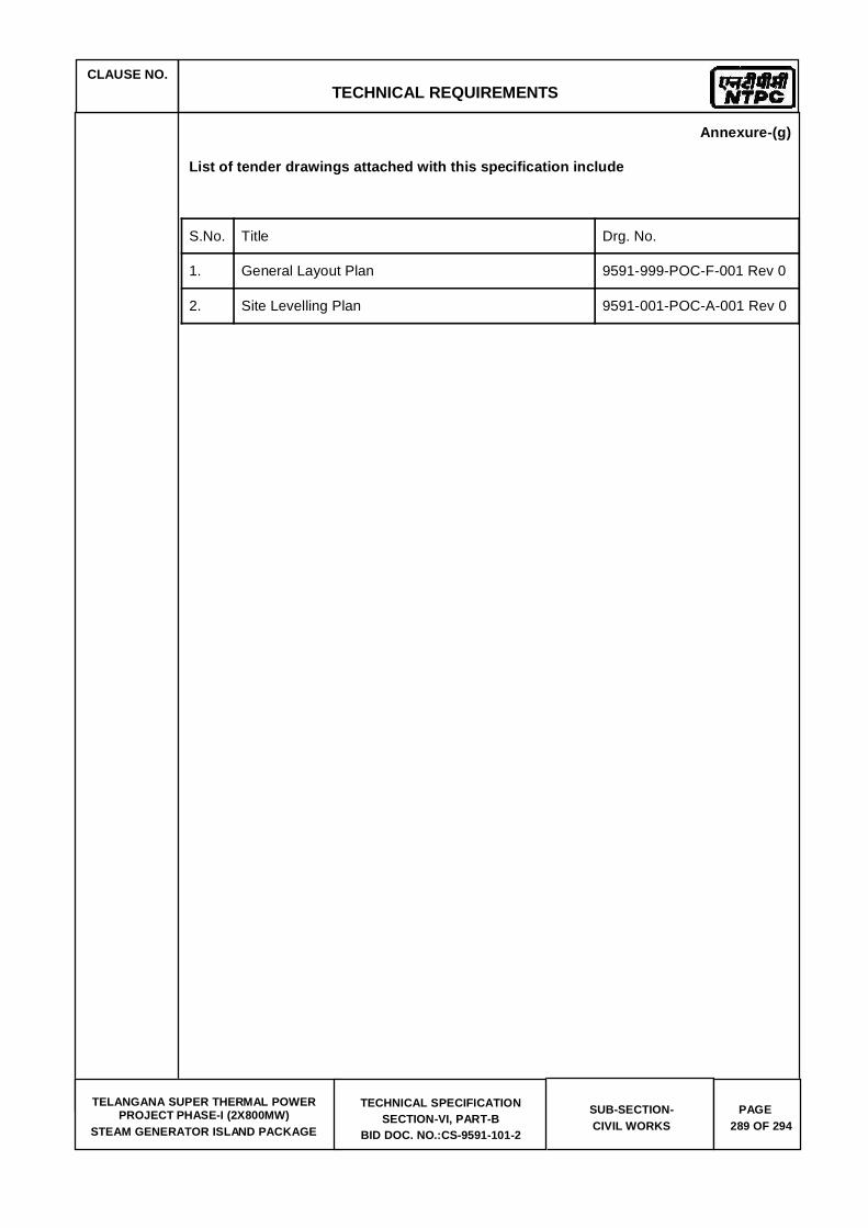
CLAUSE NO.
TECHNICAL REQUIREMENTS
TELANGANA SUPER THERMAL POWER
PROJECT PHASE-I (2X800MW) STEAM GENERATOR ISLAND PACKAGE
TECHNICAL SPECIFICATION SECTION-VI, PART-B
BID DOC. NO.:CS-9591-101-2
SUB-SECTION- CIVIL WORKS
PAGE 289 OF 294
Annexure-(g)
List of tender drawings attached with this specification include
S.No. Title Drg. No.
1. General Layout Plan 9591-999-POC-F-001 Rev 0
2. Site Levelling Plan 9591-001-POC-A-001 Rev 0
CLAUSE NO.
TECHNICAL REQUIREMENTS
TELANGANA SUPER THERMAL POWER
PROJECT PHASE-I (2X800MW) STEAM GENERATOR ISLAND PACKAGE
TECHNICAL SPECIFICATION SECTION-VI, PART-B
BID DOC. NO.:CS-9591-101-2
SUB-SECTION- CIVIL WORKS
PAGE 290 OF 294
Annexure (k) Site management during construction phase till handing over of plant. Bidder shall ensure that the plant site within the plant boundary is managed in a coordinated
and professional way all through the construction phase till handing over of plant, ensuring safe, easy & unhindered working conditions and a healthy & hygienic working environment at site. He shall ensure the following measures at site while executing the project:
Temporary access road to all work area and facilities both during the construction/
erection and as they get completed progressively. Bidder shall prioritize the construction of approach roads in his scope. He shall finalise and submit the road layout plan in his scope along with priority and completion schedule immediately after the award for review by the engineer-in-charge. He shall ensure that the roads are promptly repaired and maintained against any damages due to movement of traffic/heavy trailers & cranes/rains etc. providing motorable access at all times. Adequate onsite stock of road metal/materials shall be kept and maintained distributed over the site for repairs especially before the monsoon period.
b) Proper drainage of rain water, ground water from excavations, water flows from batching plant/construction sites etc. Till such time the permanent drainage network is done, he shall construct adequate temporary drains to ensure that there is no accumulation/stagnation of water in the plant site. Bidder may consider providing precast RCC drains for temporary/ permanent drain construction for faster construction of drains. The drain construction shall be matched with progress of road construction for preventing damage to roads. Bidder shall provide and maintain adequate number of drainage pumps (both electrical and diesel operated) of suitable capacity for pumping out accumulated water especially during the monsoon periods. All drain diversions required shall be undertaken at the start of the project itself.
c) The plant site is fully secured against unauthorized access.
d) Proper housekeeping by systematic and proper disposal of earth from excavations (separately for usable & surplus earth), muck, wastes (from concrete works etc.), packing & insulation wastes, steel scrap, cable wastes etc. generated during con struction / erection works, Suitable disposal sites for each of above shall be identified in the layout and at site in the beginning of the project itself. It shall be ensured that all agencies engaged by the bidder follow the discipline to dispose off of earth spoils and wastes at the designated places. Preferably once in a week suitable time slot will be identified for housekeeping by all agencies and suitable instructions shall be issued in this regard. Bidder may engage a separate agency or identify a gang for collection of wastes and disposal to designated places. Suitable arrangement/tie-up will also be made for periodic disposal of wastes/scrap from the designated places.
e) All fabrication area shall be suitably hard crusted to provide a water free an d proper working platforms. Suitable sheds preferably pre-engineered structures to be provided for paint shops, fabrication workshops etc. for ensuring all weather work conditions for onsite structural works. For the main plant and auxiliary buildings, bidder should
offsite works/workshops and onsite fabrication works are avoided kept minimum.
f) Suitable onsite maintenance workshop for day to day breakdown maintenance h eavy plant and equipment like batching plants, cranes, earth moving equipment, poclains,

CLAUSE NO.
TECHNICAL REQUIREMENTS
TELANGANA SUPER THERMAL POWER
PROJECT PHASE-I (2X800MW) STEAM GENERATOR ISLAND PACKAGE
TECHNICAL SPECIFICATION SECTION-VI, PART-B
BID DOC. NO.:CS-9591-101-2
SUB-SECTION- CIVIL WORKS
PAGE 291 OF 294
welding equipment etc. The workshop shall have stock of frequently needed spares and suitable repair facilities with experienced technicians/ mechanics. A central test laboratory equipped with test equipment for routine test like tests on soil, concrete, bricks, aggregates, welds etc with experienced staff shall be established at the start of the project itself.
g) All office and covered store buildings of the bidder and its agencies shall be of prefab/ pre-engineered / porta cabin construction. Shabby semi-finished constructions in brickwork/ GI asbestos roof etc shall not be permitted.
h) First aid facilities and amenities like rest rooms, suitable pre-engineered toilets (separate for men and women), drinking water fountains/tanks, canteen, crèche for women workers shall be planned and established at the beginning of the project itself These facilities shall be located distributed over the plant area to enable easy access b y the construction workers and staff and shall be marked on the plant layout. Suitable treatment for toilet discharge, like bio digesters etc. shall be planned and conventional septic tanks/ soak pits etc. shall be avoided.
i) Proper lighting of all construction/ erection areas. Bidder shall erect adequate number of high lighting masts in main plant, offsite, office and store areas for lighting during night, DG sets of adequate capacity shall be provided for emergency backup. The street lighting along the roads shall also be prioritized along with road construction. The construction power ring main shall be planned and erected immediately after the award.
j) Well planned and coordinated storage and movement of plant, equipment and construction materials. System wise/ agency wise storage / laydown areas shall be planned and marked on the plant layout at the beginning itself. Bidder shall ensure that all its agencies comply with the areas allocated to them and follow the designated storage and movement plans. Adequate covered storage shall be constructed for storage of critical equipment like switchgears, MCCs, insulation etc.
k) Proper access control for construction workers, staff and visitors. Bidder shall ensure
that suitable electronic based gate pass system is in place from start of project itself to keep record and track of all workers, staff and visitors entering / exiting the plant premises shift wise on daily basis.
l) Compliance to all safety requirements as specified elsewhere in the tender documents.
Bidders shall establish a safety Centre at the start of the project itself. It shall have a 24X7 manned safety control room in addition to a permanent safety equipment display room, separate training / lecture hall with AV facilities for safety training, store room with adequate stock of specified safety equipment, a first aid room and other amenities. Bidder shall install CCTV cameras at all strategic locations in the plant area which shall be linked to the safety control room.
m) Compliance to all environment and other conditions stipulated by the concerned statutory
authorities while according clearance / NOC to the project. Bidder shall ensure adequate sprinkling of water by deploying water tankers to prevent the fugitive dust nuisance during construction.
n) Development of rainwater harvesting within the TG area premises. Bidder shall plan to develop rainwater harvesting from the start of the project itself. The rainwater harvesting plan shall be finalized immediately after award of work and suitable work pla n with priority and schedule shall also be finalized thereafter.
CLAUSE NO.
TECHNICAL REQUIREMENTS
TELANGANA SUPER THERMAL POWER
PROJECT PHASE-I (2X800MW) STEAM GENERATOR ISLAND PACKAGE
TECHNICAL SPECIFICATION SECTION-VI, PART-B
BID DOC. NO.:CS-9591-101-2
SUB-SECTION- CIVIL WORKS
PAGE 292 OF 294
o) Provision of adequate shelters, water supply, sanitation and lighting in construction workers and staff camps. No camps for workers and staff shall be permitted within the plant premises and Bidder shall make separate arrangement outside the plant premises for locating and development of camps for construction workers and staff. The designated areas shall be suitably developed with infrastructure like roads, drains, water supply and sewerage and shall be free from water logging. Suitable low cost shelters will be provided for the workers. Complete area shall be secured by fencing and shall be provided adequate area lighting. Suitable waste disposal, shopping and recreation facilities will be developed in these camps.
Bidder shall ensure that due importance is given to site management as discussed above
and a detailed work plan considering the above aspects is finalized immediately after the award. A senior level executive shall be identified who shall be responsible for implementation of the work plan. Suitable format for progress reporting on site management plan shall be developed and made part of the project progress report. The progress on implementation of above work plan shall be reviewed along with project progress in the monthly project review meetings with owner. In case the progress in the monthly project review meetings with owner. In case the progress on site management plan is unsatisfactory Engineer-in-Charge may withhold up to 1% of the monthly running bill (for civil and site erection works) till such time the required progress is demonstrated. In case in the opinion of Engineer- in-charge bidder's response is not adequate despite reminders and the situation warrants immediate action, Engineer-in- charge may get the relevant work executed through a separate agency and deduct the expenses incurred from the Bidder's bill along with overheads @25%.

CLAUSE NO.
TECHNICAL REQUIREMENTS
TELANGANA SUPER THERMAL POWER
PROJECT PHASE-I (2X800MW) STEAM GENERATOR ISLAND PACKAGE
TECHNICAL SPECIFICATION SECTION-VI, PART-B
BID DOC. NO.:CS-9591-101-2
SUB-SECTION- CIVIL WORKS
PAGE 293 OF 294
13.00.00 APPENDIX
TELENGANA SG CIVIL SCOPE FOR ELECTRICAL EQUIPMENT: Contractor to consider loads of Electrical equipment and provide rooms for / equipment like HT/LT switchgears/lighting DBs/Battery/Battery charger/Cable vault/foundation for Service transformers and its busducts / cable trays in
scope of SG area and in its trestle etc. which are required for systems. (A) Following loads of the Electrical and associated accessories
shall be consider during designing floor beams/roof beams/ RCC/Columns/ bracings/Trestle
switchgears (Ash handling Switcgears/CHP switchgears/3.3KV Ash HT switchgears and 11KV AHP boards etc. as per SLD DWG NO: 9591-999-POE-J-001). The contractor shall place floor /roof/secondary/tertiary beams/columns/Bracings etc. in such a way that there is no blocking of opening for Power/ control cables terminating in to the switchgears and bus duct connecting to the corresponding Transformers. The scope also covers support structure/floors/tertiary beam/channels/roof beams/ trenches/slits/cable pull pits/duct banks/opening required for completion of cabling/ tray works/ panel erections etc. are in his scope.
trestle from C row to CHP control room trestle (Trunk trestle). The typical section of cable tray arrangement shall be as indicated in DWG NO: 9591-999-POE-J-004. The contractor shall consider 75KG/M/Tray of loads in his scope of trestle. The Contractor shall provide cable trestle connection from Boiler to TG at four different locations per unit. The exact location shall be informed during detail engineering and each section shall be as described in typical cable sections. The contractor shall place trestle/columns/Bracings etc. such that cable trays shall be routed in straight line as far as possible and shall be free of fouling with bracing etc.
The Contractor shall provide foundations for all service Transformers (Transformers) and foundation of support structure of Busducts located in the area under its scope. The following building MCC rooms along with associated Transformer foundations for owners Transformer are in contractor scope. 1. Fuel oil service. 2. Auxiliary boiler 3. Ash silo 4. Ash water/TAC/HCSD 5. Bunker service 6. ESP 7. AET/Bottom Ash 8. Compressor house

CLAUSE NO.
TECHNICAL REQUIREMENTS
TELANGANA SUPER THERMAL POWER
PROJECT PHASE-I (2X800MW) STEAM GENERATOR ISLAND PACKAGE
TECHNICAL SPECIFICATION SECTION-VI, PART-B
BID DOC. NO.:CS-9591-101-2
SUB-SECTION- CIVIL WORKS
PAGE 294 OF 294
9. Ash handling/CHP switchgear 10. Ash 3.3KV HT switchgear 11. 11KV AHP Board 12. Any other facilities under contractor scope supply For exact number of transformers please refer DWG NO: 9591-999-POE-J-001.
The earthing system shall be designed for a life expectancy of at least forty (40) years, for a system fault current of 50 kA for 1.0 sec. The minimum rate of corrosion of steel for selection of earthing conductor shall be 0.12mm per year.
Grounding for SG and other areas or buildings covered in the specification shall be provided in accordance with IS 3043, IS 2309, IEEE 80. Earthing system network/earthmat shall be interconnected mesh of mild steel rods buried in ground in the plant. All areas under contractor scope of supply shall be interconnected together by minimum two parallel conductors. The Contractor shall furnish the detailed design and calculations for Employer's approval. Contractor shall obtain all necessary statutory approvals for the system. All the columns shall be earthed by nearby risers and earthmat grid spacing shall be minimum. 10 X 10 mts.. Minimum two nos of risers shall be provided for each equipment in TG area. Separate dedicated riser shall be provided for C&I earthing purpose and also for Lightning down conductor connection purpose. Sufficient nos of risers near the equipment shall be provided as per the system requirement. The contractor scope also covers below ground earth mat connection between TG to boiler.


TITLE:
TECHNICAL SPECIFICATION FOR CIVIL, STRUCTURAL AND ARCHITECTURAL
WORKS OF UNIT#2 AT 2X800MW NTPC KARIMNAGAR TELANGANA STPP PHASE-I (SG ISLANG PACKAGE)
SPECIFICATION NO. PE-TS-424-600-C002 VOLUME II SECTION “C” REV. 0 DATE: 4/27/2016
SHEET 1 OF 147
VOLUME: II B
SECTION – C
SPECIFIC TECHNICAL REQUIREMENTS
CIVIL WORKS
SPECIFICATION NO: PE-TS-424-600-C002
Bharat Heavy Electricals Limited Power Sector - Project Engineering Management
PPEI Building, Plot No. 25 Sector – 16A, NOIDA (U.P.) - 201301

TITLE:
TECHNICAL SPECIFICATION FOR CIVIL, STRUCTURAL AND ARCHITECTURAL
WORKS OF UNIT#2 AT 2X800MW NTPC KARIMNAGAR TELANGANA STPP PHASE-I (SG ISLANG PACKAGE)
SPECIFICATION NO. PE-TS-424-600-C002 VOLUME II SECTION “C” REV. 0 DATE: 4/27/2016
SHEET 2 OF 147
1. TECHNICAL SPECIFICATION:
The technical specification for civil, structural & architectural works consists of two parts.
1. Section-C : Section ‘C’ is special technical specification for design & construction.
2. Section-D : Section ‘D’ is General specification for design & construction.
Section-C is special technical specification for this project and NTPC specification included as “appendix-1” is a part of this document. In case there is any conflict between technical specifications of Section D & Section C; requirements mentioned in Section-C shall prevail.
In case of ambiguity between BOQ, Part C and Part D of specification, the following priority for acceptance of items may be followed:
a) BOQ
b) Specific technical specification (Part C)
c) General technical specification (Part D)
TITLE:
TECHNICAL SPECIFICATION FOR CIVIL, STRUCTURAL AND ARCHITECTURAL
WORKS OF UNIT#2 AT 2X800MW NTPC KARIMNAGAR TELANGANA STPP PHASE-I (SG ISLANG PACKAGE)
SPECIFICATION NO. PE-TS-424-600-C002 VOLUME II SECTION “C” REV. 0 DATE: 4/27/2016
SHEET 3 OF 147
2. SCOPE OF WORK:
The scope of civil, structural and architectural works shall include construction of all civil, structural and architectural works including supply of all construction materials for all buildings, equipment and facilities for the project, except cement & reinforcement steel that shall be supplied free of cost by BHEL to the bidder at its store located inside plant area.
The nature of work generally involves earthwork in excavation, sheet piling wherever required, de-watering, backfilling around completed structures, plinth filling, disposal of surplus earth, concreting including reinforcement and form work, masonry work, plastering, painting, flooring, false ceiling, under deck insulation, false flooring, fencing, water supply and sanitation, acid and alkali resistant lining etc. at site and miscellaneous steel works (i.e. inserts, anchor bolts etc.), painting of structures, paving, gravel filling, providing pre-cast covers, damp proofing, roof water proofing, anti-weed treatment, roads, drainage, rain water harvesting, final grading and site clearance before handing over and any other items of work required for completion of all systems under the scope of work complete. The scope of Bidder for civil, structural and architectural works as defined above shall include but not be limited to the following buildings/ areas/ systems along with their foundations, super structures and finishes complete:
1. Deleted 2. Site Clearance and micro grading 3. Foundations for all buildings/ area/ systems including machine foundations as per requirement for both shallow and deep foundations. 4. All Civil, Structural, Architectural works including underground facilities like drainage, sewerage, trenches, earthing mat/ grounding for the SG,ESP, ID fan & Chimney area covering the following: a. Boiler, Mill Bunker, Mill Bunker building, ESP, etc. b. Deleted c. Elevator Pit & Civil Works for M/C room in Boiler Structure d. ESP control room building e. Mill Reject Silo & associated trenches f. Deleted g. Fan (PA/FD/ID Fans) h. Coal Mill foundations i. Seal air Fan foundation and all other equipment foundations in Boiler area. j. Deleted k. Paving in SG , ESP, ID fan & Chimney Area from outer face of C row wall of Main Power House building to 25m beyond outer shell of Chimney towards ash handling facilities enclosed between peripheral roads, including Heavy duty passages, drains, culverts, fire water trench, rail/ road crossing of fire water trench, drains. l. Auxiliary Boiler, foundations along with switchgear & Control Room Building

TITLE:
TECHNICAL SPECIFICATION FOR CIVIL, STRUCTURAL AND ARCHITECTURAL
WORKS OF UNIT#2 AT 2X800MW NTPC KARIMNAGAR TELANGANA STPP PHASE-I (SG ISLANG PACKAGE)
SPECIFICATION NO. PE-TS-424-600-C002 VOLUME II SECTION “C” REV. 0 DATE: 4/27/2016
SHEET 4 OF 147
m. Hard crusting of pre-assembly, fabrication yard, boiler area, passage ways in boiler area. n. Civil works associated with buried pipes. o. Any other miscellaneous building or facility. 5. Deleted 6. Infrastructure Works a. Approach road for building included in this package. b. Plant storm water drainage in Boiler area and along roads in Bidder’s scope c. Separate drainage network for plant effluents for all buildings and facilities in Bidder’s scope. d. Deleted e. Sewerage system for Boiler area including other buildings in Bidder’s scope and connection up to trunk sewer in the vicinity. 7. Deleted 8. Civil works associated with Air conditioning & ventilation system. 9. Pipe /Cable / duct supporting structures, trenches, culverts, duct banks, pedestals, hume pipe culverts and thrust blocks etc. associated with all systems covered under the scope. 10. Deleted 11. Fuel Oil Pressurizing pump house with switchgear room & control room. 12. Earthing mats & risers for SG area. 13. All steel structures (excluding Chimney flue liners) shall be fabricated in factory, transported and erected at site. All factory fabricated structures shall have bolted field connections. Coal bunkers with hopper shall be fabricated at factory in segments, transported and welded at site. 14. One PORTA Cabin (of 20sq. m area) for owner’s use, each in SG area and AHP area15. Facilities for Rain water harvesting in all buildings in the bidder’s scope. 16. Deleted 17. Civil, structural and architectural works though not explicitly mentioned in the above list but required for the completion of the various systems of the package shall also be in the scope of the bidder. 18. Dismantling/Removal of existing foundations / facilities if any would be in Bidder’s scope.
List of scope is not exhaustive and bidder has to carry out all works required for system completion as per instructions of engineer in charge, even though, not explicitly mentioned in above list of scope of works. No claim/additional claim shall be entertained by BHEL on account of works carried out by bidder as per instructions of engineer in charge but not covered in above list.
TITLE:
TECHNICAL SPECIFICATION FOR CIVIL, STRUCTURAL AND ARCHITECTURAL
WORKS OF UNIT#2 AT 2X800MW NTPC KARIMNAGAR TELANGANA STPP PHASE-I (SG ISLANG PACKAGE)
SPECIFICATION NO. PE-TS-424-600-C002 VOLUME II SECTION “C” REV. 0 DATE: 4/27/2016
SHEET 5 OF 147
Civil, structural and architectural works though not explicitly mentioned in the above list but required for the completion of the various systems of the power plant shall also be in the scope of the bidder.
3. General Instructions:
The work to be performed under this specification consists of design, engineering, construction, erection and providing all labor, materials, consumables, equipment, temporary works, temporary storage sheds, temporary colony for labor and staff, temporary site offices, constructional plants, fuel supply, transportation and all incidental items not shown or specified but reasonably implied or necessary for the completion and proper functioning of the plant, all in strict accordance with the specifications including revisions and amendments thereto as may be required during the execution of work.
The scope shall also include setting up by the Bidder a complete testing laboratory in the field to carry out all relevant tests for structural steel, reinforcement steel & constituents of reinforced cement concrete (RCC) etc.
The work shall be carried out according to the design/drawings to be supplied by BHEL to the Bidder. In certain cases, however, detail construction drawings may have to be developed by bidder as required by BHEL.
The Bidder shall make the layout and levels of all structures from the general grid of the plot and the nearest GSI benchmark or other acceptable benchmark of Govt. deptt. as per the directions of the Engineer. The Bidder shall be solely responsible for the correctness of the layout and levels and shall also provide necessary instruments, materials, access to works, etc., to the Engineer for general checking of the correctness of the civil works.
All the quality standards, tolerances, welding standards and other technical requirements shall be strictly adhered to.
The Bidder shall fully apprise himself of the prevailing conditions at the proposed site, climatic conditions including monsoon pattern, soil conditions, local conditions and site specific parameters and shall include for all such conditions and contingent measures in the bid, including those which may not have been specifically brought out in the specifications.
In case of any conflict between stipulations in various portions of the specification, most stringent stipulation would be applicable for implementation by the Bidder without any extra cost to BHEL.
4. Submissions: The documents listed below are to be submitted for approval of BHEL/NTPC unless specified otherwise. The list given below is not exhaustive but indicative only.
TITLE:
TECHNICAL SPECIFICATION FOR CIVIL, STRUCTURAL AND ARCHITECTURAL
WORKS OF UNIT#2 AT 2X800MW NTPC KARIMNAGAR TELANGANA STPP PHASE-I (SG ISLANG PACKAGE)
SPECIFICATION NO. PE-TS-424-600-C002 VOLUME II SECTION “C” REV. 0 DATE: 4/27/2016
SHEET 6 OF 147
Write-up on various statutory requirements and their compliance for various buildings, facilities, structures and systems, etc.
Construction procedure for all major structures such as machine foundations etc. covered under the Bidder’s scope.
Material test certificates.
Wherever applicable, scheme for dewatering, shoring, strutting/sheet piling.
5. NTPC Specifications: Included as Appendix:1.
Enclosure: Appendix:1-NTPC Specification

(A Government of India Enterprise)
TELANGANA SUPER THERMAL POWER PROJECT PHASE-I (2x800MW)
TECHNICAL SPECIFICATION
FORSTEAM GENERATOR ISLAND PACKAGE
PART – B (CIVIL)
(BOOK 4 OF 5)
SECTION - VI
BIDDING DOCUMENT NO.: CS-9591-101-2

(A Government of India Enterprise)
TELANGANA SUPER THERMAL POWER PROJECT PHASE-I (2x800MW)
TECHNICAL SPECIFICATION
FORSTEAM GENERATOR ISLAND PACKAGE
PART – B (CIVIL)
(BOOK 4 OF 5)
SECTION - VI
BIDDING DOCUMENT NO.: CS-9591-101-2
(This document is meant for the exclusive purpose of bidding against this Package and shall not be transferred, reproduced or otherwise used for purposes other than that for which it is specifically issued).
TELANGANA SUPER THERMAL POWER PROJECT PHASEE-I (2X800MW)
STEAM GENERATOR ISLAND PACKAGE
TECHNICAL SPECIFICATION SECTION-VI
BID DOC. NO.: CS-9591-101 -2
PART – B (CIVIL) (BOOK 4 OF 5)
D – 01 CIVIL WORKS
INDEX
1.0.0 GENERAL
2.0.0 SCOPE OF WORK
2.1.0 CONSTRUCTION FACILITIES
2.2.0 EXCLUSIONS
3.0.0 SUBMISSIONS
4.0.0 GENERAL LAYOUT PLAN
4.1.0 SITE LEVELLING AND SLOPE PROTECTION WORK IN PLANT BLOCK
5.0.0 SALIENT FEATURES & DESIGN CONCEPT OF BOILER / MILL & BUNKER BUILDINGS, CHIMNEY, ASH HANLING SYSTEMS, FUEL OIL HANDLING SYSTEM, OFFICE BUILDINGS, ROADS AND DRAINAGE
5.1.0 ARCHITECTURAL CONCEPTS & DESIGN
5.2.0 BOILER / MILL BUNKER BUILDING / STRUCTURES / MACHINE FOUNDATIONS
5.3.0 CHIMNEY
5.4.0 ARCHITECTURAL CONCEPTS AND FININSHING SCHEDULE
5.5.0 ASH HANDLING SYSTEM & ASH WATER RECIRCULATION SYSTEM
5.6.0 SEWERAGE SYSTEM
5.7.0 PLANT STORM WATER DRAINAGE SYSTEM
5.8.0 ROADS
5.9.0 FUEL OIL HANDLING SYSTEM
5.10.0 AREA PAVING IN MAIN PLANT BLOCK
5.11.0 BALANCE BUILDINGS

TELANGANA SUPER THERMAL POWER PROJECT PHASEE-I (2X800MW)
STEAM GENERATOR ISLAND PACKAGE
TECHNICAL SPECIFICATION SECTION-VI
BID DOC. NO.: CS-9591-101 -2
6.0.0 DESIGN CRITERIA
6.1.0 GENERAL
6.2.0 LOADING
6.3.0 CIVIL DESIGN CONCEPTS
6.4.0 CORROSION PROTECTION
7.0.0 FOUNDATION SYSTEM SOIL DATA AND GEOTECHNICAL INVESTIGATION
7.00.00 SOIL DATA
7.02.00 FOUNDATION SYSTEM
7.02.01 GENERAL REQUIREMENTS
7.02.02 OPEN FOUNDATIONS
7.03.00 SPECIAL REQUIREMENTS
7.04.00 EXCAVATION FILLING AND DEWATERING
7.06.00 SHEETING & SHORING
8.00.00 GENERAL SPECIFICATION
8.01.01 JOINTS IN CONCRETE STRUCTURES
8.01.50 ACID/ ALKALI RESISTANT LINING
8.01.51 BITUMINOUS COATING
8.02.00 CONCRETE
8.03.00 FORMWORK
8.04.00 FENCING AND GATE
8.05.00 GRATING
8.06.00 FABRICATION
9.00.00 ARCHITECTURAL CONCEPTS AND DESIGN
9.02.00 GENERAL ARCHITECTURAL SPECIFICATIONS

TELANGANA SUPER THERMAL POWER PROJECT PHASEE-I (2X800MW)
STEAM GENERATOR ISLAND PACKAGE
TECHNICAL SPECIFICATION SECTION-VI
BID DOC. NO.: CS-9591-101 -2
9.03.00 WATER SUPPLY AND SANITATION
9.04.00 FLOORING
9.04.19 PAVING
9.05.00 ACID/ ALKALI RESISTANT LINING
9.06.00 ROOF
9.06.06 ROOF WATER PROOFING
9.07.00 WALLS
9.08.00 COLOUR COATED AND OTHER SHEETING WORK
9.09.00 PLASTERING
9.10.00 PAINTING & ALUMINIUM COMPOSITE PANEL CLADDING
9.11.00 DOORS & WINDOWS
9.12.00 GLAZING
9.13.00 FALSE CEILING
9.14.00 FINISHING SCHEDULE
TABLE A -PROPOSED ACID /ALKALI RESISTANT TREATMENT
TABLE B - INTERIOR FINISHING SCHEDULE
TABLE C -EXTERIOR FINSIHES SCHEDULE
10.00.00 MATERIAL SPECIFICATION
10.01.00 CEMENT
10.02.00 AGGREGATES
10.03.00 REINFORCEMENT STEEL
10.04.00 STRUCTURAL STEEL
10.05.00 BRICKS
10.06.00 FOUNDATION BOLTS
10.07.00 STAINLESS STEEL
10.08.00 WATER
TELANGANA SUPER THERMAL POWER PROJECT PHASEE-I (2X800MW)
STEAM GENERATOR ISLAND PACKAGE
TECHNICAL SPECIFICATION SECTION-VI
BID DOC. NO.: CS-9591-101 -2
10.09.00 STATUTORY REQUIREMENTS
11.00.00 INSPECTION, TESTING AND QUALITY CONTROL
12.00.00 ANNEXURES
a) LIST OF CODES & STANDARDS
b) CONSTRUCTION METHODOLOGY
c) BORE HOLE DATA
d) WIND DESIGN CRITERIA
e) SEISMIC DESIGN CRITERIA
f) QA REQUIREMENT
g) LIST OF TENDER DRAWINGS
(k) SITE MANAGEMENT PRACTICE DURING CONSTRUCTION PHASE
13.00.00 APPENDIX
(1) ELECTRICAL INPUT FOR STRUCTURAL LAYOUT / DESIGN.

CLAUSE NO. TECHNICAL REQUIREMENTS
TELANGANA SUPER THERMAL POWER PROJECT STAGE-I (2X800MW)
STEAM GENERATOR ISLAND PACKAGE
TECHNICAL SPECIFICATION SECTION-VI, PART-B
BID DOC. NO.:CS-9591-101-2
SUB-SECTION-CIVIL WORKS
PAGE 1 OF 294
1.0.0 GENERAL
1.1.0 This specification is to cover site clearance & site levelling works, design, preparation of general arrangement drawings, construction and fabrication drawings, supply of labour & materials and construction of all civil, structural and architectural works by the bidder.
Description of various items of work under this specification and nature of work in detail are given hereinafter. The complete work under this scope is referred to as civil works. Various buildings, structures, plant and systems, facilities, etc., covered under the scope is given in Part-A and herein.
The work to be performed under this specification consists of design, engineering, construction, erection and providing all labour, materials, consumables, equipment, temporary works, temporary storage sheds, temporary colony for labour and staff, temporary site offices, constructional plants, fuel supply, transportation and all incidental items not shown or specified but reasonably implied or necessary for the completion and proper functioning of the plant, all in strict accordance with the specifications including revisions and amendments thereto as may be required during the execution of work.
All construction materials including cement, reinforcement steel, coarse & fine aggregate, structural steel and construction water etc., shall be arranged by the Bidder.
The scope shall also include setting up by the Bidder a complete testing laboratory in the field to carry out all relevant tests for structural steel, reinforcement steel & reinforced concrete (RCC) works.
Owner has carried out detailed geotechnical investigation in the main plant area, ash handling area and other miscellaneous facilities/structures etc. Most of the bore logs and lab test data pertaining to the proposed area are enclosed at Annexure-C for Bidder’s reference.
The work shall be carried out according to the design/drawings to be developed by the Bidder and approved by the Employer. For all buildings, facilities, systems, structures, etc., necessary layout and details are to be developed by the Bidder keeping in view the statutory and functional requirements and providing enough space and access for operation, use and maintenance. The Bidder’s work shall cover the complete requirements as per IS codes, fire safety norms, requirements of various statutory bodies, International Standards, best prevailing practices and to the complete satisfaction of the Employer.
The Bidder shall make the layout and levels of all structures from the general grid of the plot and the nearest GSI benchmark or other acceptable benchmark of Govt. deptt. As per the directions of the Engineer. The Bidder shall be solely responsible for the correctness of the layout and levels and shall also provide necessary instruments, materials, access to works, etc., to the Engineer for general checking of the correctness of the civil works.
All the quality standards, tolerances, welding standards and other technical requirements shall be strictly adhered to.
The Bidder shall fully apprise himself of the prevailing conditions at the proposed site, climatic conditions including monsoon pattern, soil conditions, local conditions and site specific parameters and shall include for all such conditions and contingent measures in the bid, including those which may not have been specifically brought out in the specifications.
In case of any conflict between stipulations in various portions of the specification, most stringent stipulation would be applicable for implementation by the Bidder without any extra cost to the Employer.

CLAUSE NO. TECHNICAL REQUIREMENTS
TELANGANA SUPER THERMAL POWER PROJECT STAGE-I (2X800MW)
STEAM GENERATOR ISLAND PACKAGE
TECHNICAL SPECIFICATION SECTION-VI, PART-B
BID DOC. NO.:CS-9591-101-2
SUB-SECTION-CIVIL WORKS
PAGE 2 OF 294
Wherever there is an anomaly in the design concept between the data furnished in the General Design Criteria & Design Concept of Buildings, the data furnished in the design concept of buildings shall be treated as final.
2.0.0 SCOPE OF WORK
The scope of work for the contractor shall include the analysis, design, construction, erection of all civil, structural & architectural works and all other items mentioned in part-A of this specification.
2.1.0 CONSTRUCTION FACILITIES
For details of construction facilities refer to Part-A of this specification.
2.2.0 EXCLUSIONS:
The details of exclusions and terminal points, refer to Part-A of this specification.
3.0.0 SUBMISSIONS
3.1.0 The documents and drawings as listed below are to be submitted for the approval of the employer unless specified otherwise. The list given below is not exhaustive but indicative only.
3.2.0 Project design intent document giving the basis of design, which shall cover all the aspects, parameters, assumptions, references, structural idealization / mathematical model, loading cases, load combinations, basis of analysis and design of all buildings, facilities, systems and structures etc. Shall be furnished and got approved before commencement of detailed engineering.
a) Structural analysis, design calculations and drawings of substructure and super structures for all buildings, structures, facilities, and systems.
b) Analysis, design calculations and drawings for all services like roads, culverts, bridges, road/rail crossings, drainage pump houses (if required), drains, sewers, sewage pump house, water supply, water tank, coal conveyor galleries, trestles, transfer points, trenches, ducts, etc.
c) Drawings showing underground facilities with co-ordinates and invert levels of the facilities like buried pipes, buried cables, trenches, ducts, sewers, drains, sumps, pits, culverts, manholes, etc.
d) Architectural Design and Detailing aspect of all the Building shall be rendered through professional services of a registered Architect. The Architect consultant shall be of National/ International repute, having experience in similar kind of works. The consultant shall evolve the design based on employer's guidelines and shall present it in the form of Presentation Drawings, Detail Drawings, Perspective View & 3D Model/ Walk through. All drawing and document shall be duly stamped by the Registered Architect.
e) All architectural drawings required for execution of construction work such as detail floor plans, detail elevations, detail sections and other miscellaneous architectural details such as finish schedule (internal & external), colour schemes (both internal and external), doors and windows, flooring details & pattern, north/sky light in the roof, false flooring, false ceiling, etc., architectural facia and projections, miscellaneous stair details & architectural details like, coping, flashing, khurras, water proofing, fillet, roof

CLAUSE NO. TECHNICAL REQUIREMENTS
TELANGANA SUPER THERMAL POWER PROJECT STAGE-I (2X800MW)
STEAM GENERATOR ISLAND PACKAGE
TECHNICAL SPECIFICATION SECTION-VI, PART-B
BID DOC. NO.:CS-9591-101-2
SUB-SECTION-CIVIL WORKS
PAGE 3 OF 294
decking, wall cladding, surface drains, rain water down comers, sanitary, plumbing, etc.
f) Design criteria and design calculations including dynamic analysis and drawings for all foundations subjected to dynamic loads like foundation for Mills, Fans (PA, FD, ID & Seal Air) etc.
g) Write-up on various statutory requirements and their compliance for various buildings, facilities, structures and systems, etc.
h) As Built- Final Shop drawings/fabrication drawings of all structural steel works(only for reference) on CDs and design calculations for important joints/connections
i) Construction and erection procedure for all major structures such as Mill and Bunker building including coal bunkers, Transfer Points, Conveyor Galleries, Boiler/ ESP structures, Chimney, Ash Slurry PH, Ash Water PH and other machine foundations etc. covered under the Bidder’s scope.
j) Material test certificates.
k) Design criteria (for approval) and drawings (for information only) for Boiler/ESP supporting structures.
l) As built drawings with quantities of various items of work system wise, building wise, structure wise, etc. duly certified by Site after execution of work for information/record.
m) Details of corrosion protection measures for all structures.
n) One complete set of applicable standards, references, specifications, code of practice along with soft copy (wherever required with minimum 2 years license fee) to the Engineer for use at site.
o) Wherever applicable, scheme for dewatering, shoring, strutting/sheet piling.
p) All other design details/drawings or any other submission as indicated elsewhere in this specification and as required by the Employer.
3.3.0 Commencement of fabrication and erection and construction shall be done after approval of the relevant documents and drawings. All drawings shall be of standard sizes (metric system) and shall be made on autocad. All documents shall be made using ms office. Bidder shall submit all documents and drawings as per the followings:
Drawings: - Soft copy via C-folder for all drawings.
- After approval of drawings 6 Hard copies of each construction drawing shall be submitted to Owners site office
As Built Drawings: - In CD.
Design/Document: - Soft copy via e-mail/ C-folder and two set of hardcopies.
3.4.0 In general 3d modeling and structural frame analysis and design for the plant structures shall be submitted by the bidder for employer’s review and approval. Soft copy of 3d modeling (including input and output files shall be submitted
3.5.0 All construction drawings shall include total quantity of concrete (grade wise), reinforcement (diameter wise) and structural steel (section wise).

CLAUSE NO. TECHNICAL REQUIREMENTS
TELANGANA SUPER THERMAL POWER PROJECT STAGE-I (2X800MW)
STEAM GENERATOR ISLAND PACKAGE
TECHNICAL SPECIFICATION SECTION-VI, PART-B
BID DOC. NO.:CS-9591-101-2
SUB-SECTION-CIVIL WORKS
PAGE 4 OF 294
4.0.0 GENERAL LAYOUT PLAN
The preliminary layout plan proposed for the project is shown in the drawing no. 9591-999-POC-F-001 titled "General Layout Plan". It shall form the basis for further elaboration by the bidder for the plant facilities, which are in his scope.
Bidder shall prepare the detailed layout of the plant facilities which are in his scope and shall submit the same for owner's approval.
While preparing the detailed layout, planning his facilities and deciding upon the transportation and erection strategy he shall ensure the following aspects.
a) All Statutory requirements including safe distances between various facilities as per applicable rules/acts/laws including local bye-laws are met.
b) Face of the buildings and facilities are located in such a way so as to have an offset of minimum 20m with respect to centre line of double lane road and 15m with respect to centre line of single lane road.
c) The entire construction activity shall take into account the commissioning of the units in phases matching with the phased commissioning of the plant.
d) The interface requirements with the plant construction/erection activities of other contracting agencies engaged by Owner. These agencies engaged will be working parallely with the Bidder within the plant premises.
e) The area for construction/erection facilities like lay-down, pre-assembly, offices and stores have been earmarked on the General Layout Plan.
f) No permanent facility shall be located within the safety zone limit around the fuel Oil storage tanks, Hydrogen plant complex, etc., except those permitted by Owner.
g) Transportation of all equipment and materials shall be by road as envisaged. Any other mode envisaged by the bidder may be proposed. However the same may be adopted subject to approval of the Employer.
h) All the buildings and facilities shall be approachable by fire tenders.
4.1.0 SITE LEVELLING AND SLOPE PROTECTION WORK
Complete levelling of Main plant area shall be done by the bidder
4.1.1 Each block shall be finished to the formation level as specified in Site levelling drg./GLP drawing.
4.1.2 The specified formation level(s) shall be achieved either by excavation where the existing ground levels are higher than the specified formation level or by raising by controlled filling with borrowed earth where the existing ground levels are lower than the specified level.
4.1.3 The excavation shall be in all types of soils or rock or a mixture of these. Bidder should assess and satisfy himself about the actual nature of soil present at site, before submitting his bid.

CLAUSE NO. TECHNICAL REQUIREMENTS
TELANGANA SUPER THERMAL POWER PROJECT STAGE-I (2X800MW)
STEAM GENERATOR ISLAND PACKAGE
TECHNICAL SPECIFICATION SECTION-VI, PART-B
BID DOC. NO.:CS-9591-101-2
SUB-SECTION-CIVIL WORKS
PAGE 5 OF 294
4.1.4 All materials arising out of site clearance and excavation shall be the property of owner. They shall be dealt with in the manner specified by the engineer. Earth / boulders / rock etc. Excavated and useful portion (serviceable materials) of trees cut shall be stacked at suitable places within owner's acquired land for the plant including the reservoir and the ash disposal area in a manner as directed by the engineer. Woods, branches, trunks of trees shall be termed as serviceable material. Other materials like twigs, leaves, roots, vegetable and organic matters etc. Shall be termed as unserviceable material and shall be sorted out from the serviceable materials before disposal. They shall be cleared from the area and disposed off at places within owner's acquired land for the plant including the reservoir and the ash disposal area in a manner as directed by the engineer.
4.1.5 If the excavated material is suitable and accepted by the engineer as fill material, the same can be used for filling in other areas where raising by filling is required. Otherwise the same shall be taken and stacked at places(s) within the plant boundary as directed by the engineer.
4.1.6 Filling with rock shall be done only after the written permission of the engineer in the following manner:
a) Filling with rock shall be done only in areas identified for laydown and preassembly and ash based units.
b) Original ground after removal of all organic and vegetable matters shall be consolidated by rolling as directed by the engineer subject to a minimum of six passes of 8-10 tonnes roller.
c) Excavated rock shall be laid (on original ground or after filling 300 mm thick layers of soil as specified), in layers not exceeding 1000 mm and rolled with with vibratory roller (10-15 tonnes static weight) with minimum six passes.
d) Over the compacted layer of rock, soil shall be filled in horizontal layers not exceeding 300mm in compacted thickness. The soil shall be compacted as specified elsewhere.
e) It shall be ensured that the top soil layer is in minimum 3 layers of 300 mm each. To achieve this the thickness and number of rockfill layers below can be suitably adjusted.
4.1.7 Contour map and spot levels of the area based on the preliminary survey carried out by owner is enclosed for the purpose of guidance of bidder. Refer tender drawing no. "9591-001-poc-a-001. However, owner does not take any responsibility about the accuracy of the survey details furnished and any variation of the said data shall not constitute a valid reason for changing the terms and conditions of the contract. Bidder is requested to carry out his independent assessment of the existing ground levels before furnishing his. Bid detailed survey shall be carried out by bidder after award of work and all findings as stated earlier shall be submitted for owner's review.
4.1.8 Before commencement of cutting/filling, all organic and vegetable matters like grass. Plants shrubs bushes, weeds, trees etc. In the areas to be filled, shall be completely removed along with their roots and disposed off. It shall also be ensured that the area to be filled is clear of any water, slush etc. Original ground shall be compacted by rolling as directed by the engineer subject to a minimum of six passes of 8 to 10 tonne roller the earth shall then be spread in horizontal layers not exceeding 300 mm in compacted thickness. Each layer shall be watered and compacted with proper moisture content and with such equipment as may by required to obtain a compaction of 95% or more
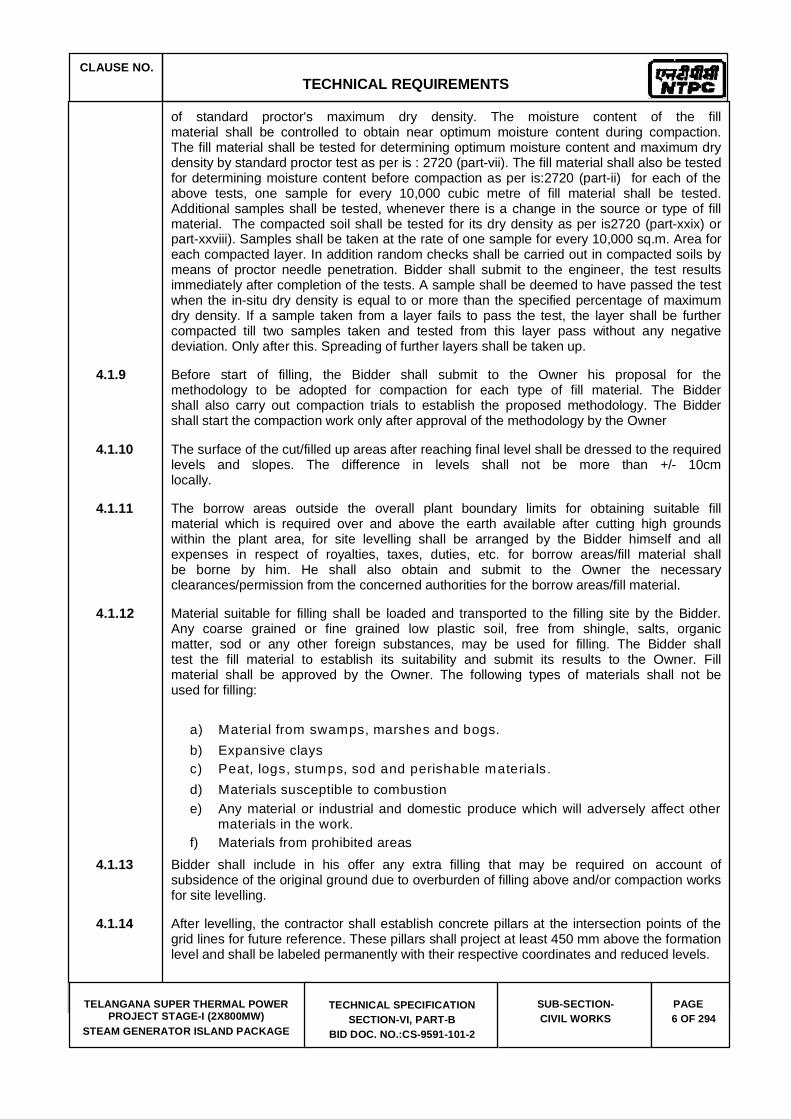
CLAUSE NO. TECHNICAL REQUIREMENTS
TELANGANA SUPER THERMAL POWER PROJECT STAGE-I (2X800MW)
STEAM GENERATOR ISLAND PACKAGE
TECHNICAL SPECIFICATION SECTION-VI, PART-B
BID DOC. NO.:CS-9591-101-2
SUB-SECTION-CIVIL WORKS
PAGE 6 OF 294
of standard proctor's maximum dry density. The moisture content of the fill material shall be controlled to obtain near optimum moisture content during compaction. The fill material shall be tested for determining optimum moisture content and maximum dry density by standard proctor test as per is : 2720 (part-vii). The fill material shall also be tested for determining moisture content before compaction as per is:2720 (part-ii) for each of the above tests, one sample for every 10,000 cubic metre of fill material shall be tested. Additional samples shall be tested, whenever there is a change in the source or type of fill material. The compacted soil shall be tested for its dry density as per is2720 (part-xxix) or part-xxviii). Samples shall be taken at the rate of one sample for every 10,000 sq.m. Area for each compacted layer. In addition random checks shall be carried out in compacted soils by means of proctor needle penetration. Bidder shall submit to the engineer, the test results immediately after completion of the tests. A sample shall be deemed to have passed the test when the in-situ dry density is equal to or more than the specified percentage of maximum dry density. If a sample taken from a layer fails to pass the test, the layer shall be further compacted till two samples taken and tested from this layer pass without any negative deviation. Only after this. Spreading of further layers shall be taken up.
4.1.9 Before start of filling, the Bidder shall submit to the Owner his proposal for the methodology to be adopted for compaction for each type of fill material. The Bidder shall also carry out compaction trials to establish the proposed methodology. The Bidder shall start the compaction work only after approval of the methodology by the Owner
4.1.10 The surface of the cut/filled up areas after reaching final level shall be dressed to the required levels and slopes. The difference in levels shall not be more than +/- 10cm locally.
4.1.11 The borrow areas outside the overall plant boundary limits for obtaining suitable fill material which is required over and above the earth available after cutting high grounds within the plant area, for site levelling shall be arranged by the Bidder himself and all expenses in respect of royalties, taxes, duties, etc. for borrow areas/fill material shall be borne by him. He shall also obtain and submit to the Owner the necessary clearances/permission from the concerned authorities for the borrow areas/fill material.
4.1.12 Material suitable for filling shall be loaded and transported to the filling site by the Bidder. Any coarse grained or fine grained low plastic soil, free from shingle, salts, organic matter, sod or any other foreign substances, may be used for filling. The Bidder shall test the fill material to establish its suitability and submit its results to the Owner. Fill material shall be approved by the Owner. The following types of materials shall not be used for filling:
a) Material from swamps, marshes and bogs. b) Expansive clays c) Peat, logs, stumps, sod and perishable materials. d) Materials susceptible to combustion e) Any material or industrial and domestic produce which will adversely affect other
materials in the work.f) Materials from prohibited areas
4.1.13 Bidder shall include in his offer any extra filling that may be required on account of subsidence of the original ground due to overburden of filling above and/or compaction works for site levelling.
4.1.14 After levelling, the contractor shall establish concrete pillars at the intersection points of the grid lines for future reference. These pillars shall project at least 450 mm above the formation level and shall be labeled permanently with their respective coordinates and reduced levels.
CLAUSE NO. TECHNICAL REQUIREMENTS
TELANGANA SUPER THERMAL POWER PROJECT STAGE-I (2X800MW)
STEAM GENERATOR ISLAND PACKAGE
TECHNICAL SPECIFICATION SECTION-VI, PART-B
BID DOC. NO.:CS-9591-101-2
SUB-SECTION-CIVIL WORKS
PAGE 7 OF 294
5.0.0 SALIENT FEATURES & DESIGN CONCEPT OF MILL & BUNKER BUILDING, CHIMNEY, ASH HANDLING SYSTEMS, FUEL OIL HANDLING SYSTEM, OFFICE BUILDINGS, ROADS AND DRAINAGE
5.1.0 ARCHITECTURAL CONCEPTS & DESIGN
Architectural Design and Detailing aspect of all the Building shall be rendered through professional services of a registered Architect. The Architect consultant shall be of National/ International repute, having experience in similar kind of works. The consultant shall evolve the design based on employer's guidelines and shall present it in the form of Presentation Drawings, Detail Drawings, Perspective View & 3D Model/ Walk through. All drawing and document shall be duly stamped by the Registered Architect
All buildings and structures shall be architecturally treated in such a way so as to be in complete harmony with the main plant building, surrounding structures and environment. Due considerations shall be given to orientation, and interior design. All finishes for floors, walls, ceiling, structural elements, partitions for offices and industrial areas shall be suitable for their aesthetics, durability and functional requirements and shall include the latest building material & technology. Consideration shall be given for achieving standardization & fast track construction.
Overall colour scheme of the all buildings shall be designed judiciously and in a comprehensive manner taking into account the mass and void of buildings, its facade, equipment, exposed structural elements, piping, trestles, bus ducts, and other service elements.
For adequate light and ventilation, National Building Code recommendations shall be followed. All buildings having height more than 4.0 m shall have glazed ventilators with polycarbonate sheet
All the buildings shall be architecturally designed to meet the National Building Code requirement & Fire Safety Regulations & incorporating sustainable building design.
During design stage, Technical specification as prepared shall govern the finishes.
For Control Rooms of ESP Control Buildings, Dry Wall Construction Technology shall be incorporated.
5.2.0 MAIN STRUCTURES SHALL COMPRISE OF:
Mill Bunker Building
Transfer Points, Conveyor Galleries & Trestles in Main Plant Areas
Machine Foundations
Boiler Structure
Compressor House

CLAUSE NO. TECHNICAL REQUIREMENTS
TELANGANA SUPER THERMAL POWER PROJECT STAGE-I (2X800MW)
STEAM GENERATOR ISLAND PACKAGE
TECHNICAL SPECIFICATION SECTION-VI, PART-B
BID DOC. NO.:CS-9591-101-2
SUB-SECTION-CIVIL WORKS
PAGE 8 OF 294
ESP Structure
ESP Control Building
Pipe & Cable Gallery
All Equipment Foundations & Pipe Cable Trenches/ and Pedestals below finished ground level.
5.2.1 The Bunker Building, Transfer Points, Conveyor Galleries and Trestles, Boiler Supporting Structure, ESP Supporting Structures including Inlet and Exhaust Duct Support Structures, Pipe Cable Galleries & Trestles shall have Structural Steel Framed Super Structure.
5.2.2 All other buildings may have either RCC or Structural Steel framework.
5.2.3 Bidder has to provide access to roof of all building.
Brief description of the above mentioned main buildings is furnished herein:-
5.2.4 MILL AND BUNKER BUILDING
A. Salient Features
The mill bunker building shall house coal mills, feeders, Cylindrical Coal Bunker & Conical Hopper, Tripper Conveyor & its drive and monorails. All columns, main beams and secondary beams shall be made of structural steel. The RCC floor slabs (supporting the Feeder and Tripper Conveyors) shall comprise RCC slab supported on profiled metal deck sheet (to be used as permanent shuttering) not to be considered for design of RCC slab as composite slab) and shear anchor studs welded to the top flange plate of secondary & main structural steel beams, (which supports the RCC slab & metal deck sheet).
Bidder shall integrate the Mill & Bunker Building with boiler supporting structure.
Structural steel platform cage ladder and walkway (with MS grating and hand rails) shall be provided above the feeder floor for access to the bunker coal level monitoring strain gauges.
The bottom level of base plates of columns shall be 1.20 M below the finished floor level of ground floor of Main Power House. The columns of Mill-Bunker building shall consist of built up structural steel I-sections. Rolled sections with additional cover plates on column flange shall not be acceptable for column sections.
The cylindrical coal bunker and conical hopper shall be made of structural steel. The inside surface of hopper shall be lined with stainless steel plates the details of which are mentioned hereafter in this specification.
Structural steel brackets with PTFE bearings shall be provided at the end columns to support the external gallery of the Tripper Conveyor
The Mill-Bunker building shall be provided with insulated, sandwiched metal sheet roofing comprising of troughed profile permanently colour coated sheet on outside and plain permanently colour coated sheet on inside with 50mm thick mineral wool insulation in between the two sheets. A slope of 1 in 5 shall be provided for quick drainage of rain water.

CLAUSE NO. TECHNICAL REQUIREMENTS
TELANGANA SUPER THERMAL POWER PROJECT STAGE-I (2X800MW)
STEAM GENERATOR ISLAND PACKAGE
TECHNICAL SPECIFICATION SECTION-VI, PART-B
BID DOC. NO.:CS-9591-101-2
SUB-SECTION-CIVIL WORKS
PAGE 9 OF 294
The RCC floor supporting the Tripper Conveyor shall be fully covered upto the Roof level with single skin metal sheet (& structural steel runners). The Mill –Bunker Building shall be structural steel frame super structure. The columns shall be braced in both the transverse and longitudinal directions. In the transverse direction the bracings may be waived above the Tripper Floor and near the Ground Floor due to functional requirement. Each bracing member shall be connected to column flange plate through gusset plate (minimum 12mm thick).
B. Design Concept
The Mill Bunker Building shall be conceptualized as moment resisting frames in transverse direction and longitudinal direction. In the transverse direction the bracings may be provided, wherever feasible, in order to meet the deflection requirement specified in clause 6.03.07 of this section. The bracings in the longitudinal direction shall be in 2 planes through a pair of longitudinal members laced (or battened) together. Each bracing member shall be connected to column flange plate through gusset plate (minimum 12mm thick).
Minimum thickness of structural steel Bunker plates shall be 12mm inclusive of 4mm corrosion allowance. Minimum wall thickness of Hopper shall be 8mm. Minimum thickness of stainless steel liners on the inner surface of hopper wall shall be 4mm conforming to grade SS304. To ensure smooth flow of coal, the hopper surface shall be provided with minimum angle of 73o with the horizontal plane.
The top of the cylindrical bunker shall bear no load/ reaction from the tripper floor and accordingly neoprene bellow strap shall be provided at the interface between the two structures to allow free deflection of the tripper floor. Neoprene bellow strap shall be provided all-round the bunker to effectively seal the gap between top of bunker and sealing plate below bunker.
For all other design methodology, refer to Design Criteria specified hereafter in this specification.
C. Architectural Features
The Mill & Bunker Building shall be a structural steel framed structure having RCC floors and prefabricated insulated metal sandwiched sheet sloped roof. The tripper floor side cladding shall be Single skin Metal cladding with steel louvered windows and fixed windows with poly carbonate sheet glazing. Area of windows shall be minimum 10 % of floor area. Rainwater down comer shall be of galvanized MS pipes and shall be located at every column location.
5.2.5 TRANSFER POINTS AND CONVEYOR GALLERIES IN MAIN PLANT AREA
Transfer Points 5.2.5.1. The transfer points shall be framed structure of structural steel work having RCC floors
(supported on structural steel beams) and prefabricated insulated metal sandwiched sheet sloped roof. The RCC floor slabs shall comprise RCC slab supported on profiled metal deck sheet (to be used as permanent shuttering not to be considered for deign of RCC slab as composite slab) and Shear anchor studs shall be provided with stud welding through metal deck at regular interval on all top flange / flange plate of structural beams which support the RCC slab. The side cladding shall be Single skin Metal cladding (from lowest working floor level till roof top) with steel louvered windows and fixed windows with poly carbonate sheet glazing. Area of windows shall be minimum 10 % of floor area. However the lower portion of side cladding for a minimum height of 0.9 m above the finished floor level shall be one brick thick wall plastered on both sides. In some areas like MCC floors etc., one brick thick wall cladding shall be provided. Brick wall cladding shall be supported on encased wall beams
CLAUSE NO. TECHNICAL REQUIREMENTS
TELANGANA SUPER THERMAL POWER PROJECT STAGE-I (2X800MW)
STEAM GENERATOR ISLAND PACKAGE
TECHNICAL SPECIFICATION SECTION-VI, PART-B
BID DOC. NO.:CS-9591-101-2
SUB-SECTION-CIVIL WORKS
PAGE 10 OF 294
and suitably anchored to adjoining columns and beams. Contractor shall have option to use Tubular steel sections for vertical & horizontal bracings. Horizontal bracings at all platforms levels shall be designed as beam carrying axial force and bending moment to take care of loads from platforms for maintenance and Gravity Take-up.
5.2.5.2. Brackets and beams for supporting the Conveyor gallery portal shall be provided at required elevation on columns of Transfer Point.
5.2.5.3. Grade slab shall be provided for all transfer point houses.
5.2.5.4. Steel doors and sliding steel doors of required sizes as per system requirement for personnel access and handling of equipment respectively shall be provided.
5.2.5.5. The roof of Transfer points shall be provided with pre-fabricated insulated metal sandwich panels. Pre-Fabricated Insulated Metal Sandwich Panel For RoofingSupplying, fitting and fixing in position at all level Metal faced Insulated Sandwich panels for roofing, laid to specified slope, consisting of Bottom & Top sheet of Troughed Permanently Coloured coated sheets of approved profile & shade, of high tensile steel, having minimum yield of 340 Mpa of 0.5 mm thickness (bare metal thickness i.e. metal thickness excluding thickness of coating & painting) and coated with Zinc Aluminium alloy (Zincalume) at the rate of 150gm per sq.m. conforming to AS: 1397/ class 4, ASTM A653M/ EN 10326. The outer exposed face of the sheets shall be permanently colour coated with total coating thickness of 25 micron (nominal) dry film thickness (DFT) comprising of Silicon Modified Paint (SMP with silicon content of 30% to 50% paint ) or super polyester paint of 20 micron (nominal) over 5 micron (nominal) primer coat, and the inner face of the sheets shall be colour coated with total coating thickness of 10 micron (nominal) dry film thickness (DFT) comprising of SMP, with silicon content of 30% to 50% or super polyester paint of 5 microns (nominal) over 5 micron (nominal) primer coat (SMP & super polyester paint shall confirm to product type 4 of AS/NZS2728).The insulation between the sheets shall be minimum 50mm thick Mineral Wool conforming to IS: 8183, of minimum density 32 kg / cu.m for glass wool or 48 kg / cu.m for rock wool.Sheets shall be of approved profile, sectional properties (suitable for specified loading / deflection and purlins / runners spacing), color & shade and the item shall include all labour , materials , equipments, handling, transportation, special coated self drill fasteners for sheet fixing, special coated Z spacers for insulation fixing & clip fixing, and special coated clips for clip lock system (special coating conforming to corrosion resistant class 3 of AS 3566 and tested for 1000 hour salt spray test).A slope of 1 in 5 shall be provided for quick drainage of rain water.
5.2.5.6. For TP’s in Main Plant Area, each down comer shall lead the water / coal slurry into the RCC pit (of 2 Cu.M capacity) to allow settling of coal. The water from the pit shall overflow into R.C.C drain (RCC drains with steel gratings provided around the TP), which will lead the discharge finally into plant effluent drain routed alongside the nearby road.
5.2.5.7. All stairs of over ground portion of transfer houses shall be of steel (minimum 1000 mm wide)and maximum rise should not be more than 180 mm and minimum tread width 250 mm. Stringers shall be of rolled steel channel( minimum ISMC 250 )and tread shall be of electro-forged steel gratings. Stairs shall be provided with 32 mm dia nominal bore medium duty M. S. pipe hand rail.
5.2.5.8. Handrails (for staircases, around openings, in walkways etc.) shall be of standard weight steel pipe of flush welded constructions, ground smooth using 32 mm nominal bore medium class pipe provided with double rail, top rail about 1.0 metre above platform level and pipe posts spaced not more than 1.5 metres apart. Angle handrail post may be provided when specifically called for in drawings approved by Engineering. Toe guard of size 100mm x 6mm shall be provided along the railing for all steel platforms/landings and RCC staircases.

CLAUSE NO. TECHNICAL REQUIREMENTS
TELANGANA SUPER THERMAL POWER PROJECT STAGE-I (2X800MW)
STEAM GENERATOR ISLAND PACKAGE
TECHNICAL SPECIFICATION SECTION-VI, PART-B
BID DOC. NO.:CS-9591-101-2
SUB-SECTION-CIVIL WORKS
PAGE 11 OF 294
5.2.5.9. Smooth uniform curves and bends shall be provided at stair returns and also where so ever required. Posts connected to curb plates shall have a neat closure at the bottom and a 6 mm thick plate neatly welded to posts for attachment to curb plate. All necessary fittings including inner dowels at splices, brackets, belts, bends, flanges and chains, where required shall be plugged and welded. A minimum radius of 3 times the pipe diameter shall be provided at all points of direction changes in the handrail.
5.2.5.10. Treads and landing shall be suitable for the prescribed loading. The maximum width of openings in gratings shall not exceed 40 mm. The minimum size of main bars shall be 25 x 6 mm and cross bar shall be 6mm. The usual span of grating will not generally exceed 1.5 meters. Stair case gratings shall be galvanized to grade 610g/m2.
5.2.5.11. Out side stairs to transfer points shall be open type. However sheeting shall be provided at the top.
5.2.5.12. Numbers and arrangement (including enclosures etc.) of stair cases shall be such as to meet the fire safety requirement as per guide lines of statutory regulatory bodies.
5.2.5.13. Last TP in main plant area shall be designed and constructed to take care of loads due to future expansion of conveyor gallery.
Conveyor Galleries and Trestles in Main Plant Area
5.2.5.14. Troughed belt conveyors in Main Plant Area shall be housed in a suitably enclosed gallery of structural steel. The overhead gallery shall consist of two vertical latticed girders having rigid jointed portal frame at both ends. Cross beams at floor level supporting conveyor stringer beams shall be made of single rolled steel beam or single channel section (ISMB or ISMC) or plate girder. Horizontal bracings are to be provided at top & bottom plan of the gallery (latticed girders shall be braced together in plan at the top and bottom). Common end portal frame shall not be used for adjacent conveyor spans. Roof truss shall be provided at upper node points of latticed girders to form an enclosure. Conveyor gallery shall have permanently colour coated steel sheet covers on roof and both sides. However in roof, a panel of minimum 1.5 m x 1.5 m area at about 6.0 m center shall be provided with translucent sheets of polycarbonate material for natural lighting. A continuous slit opening of 500 mm shall be provided on both sides just below the roof sheeting. Adequate provision of windows shall be kept on both sides of conveyor gallery as appended in Mechanical Section (Belt conveyor system). Windows shall be provided with wire mesh as specified elsewhere in this specification.
5.2.5.15. The maximum span of conveyor gallery shall be limited to 25 meters unless higher span is required due to site conditions, which shall be subject to approval of the Engineer. The gallery should as far as possible be erected as a box section keeping all the vertical and horizontal bracing tied in proper position. The gallery should be checked for all erection stresses that are likely to develop during handling and erection and if required, temporary strengthening of gallery members during erection shall be made. Contractor can also use tubular steel sections for conveyor galleries and supporting trestles. The tubular steel section shall be of circular/rectangular/square shape. The circular steel tube shall conform to IS 1161 and rectangular/square steel sections shall conform to IS 4923. The steel structures using tubular sections shall be designed and fabricated as per IS 806 – “Code of Practice for use of steel tubes in general building construction.” and EN 1993-1-8:2005.
5.2.5.16. For double stream conveyor gallery, two side and one central walkway of minimum width 800 mm and 1100 mm respectively shall be provided. The minimum width of two side walkways for single stream conveyor gallery shall be 800 mm and 1100 mm respectively. Both sides of central and side walkways shall be provided with pipe handrails all along the conveyor

CLAUSE NO. TECHNICAL REQUIREMENTS
TELANGANA SUPER THERMAL POWER PROJECT STAGE-I (2X800MW)
STEAM GENERATOR ISLAND PACKAGE
TECHNICAL SPECIFICATION SECTION-VI, PART-B
BID DOC. NO.:CS-9591-101-2
SUB-SECTION-CIVIL WORKS
PAGE 12 OF 294
gallery. Hand railing should not be supported on conveyor supporting stringers. The walkways shall be of chequered plate construction with anti - skid arrangement. The anti - skid arrangement will consist of welding of 10 mm square steel bars at a maximum spacing of 500 mm along the length of the gallery. Where the slope of walkway is more than 10o, chequered plate steps with nosing and toe guard shall be provided. Seal plates under the conveyor galleries shall be provided in such a way that complete gallery bottom shall form a leak proof floor. The floor of conveyor gallery all along the gallery length, shall be provided with minimum 12 gauge thick seal plates and other drainage arrangements as specified elsewhere.
5.2.5.17. Conveyor gallery shall have permanently colour coated steel sheet covers on roof and both sides. However in roof, a panel of minimum 1.5 m x 1.5 m area at about 6.0 m center shall be provided with translucent sheets of polycarbonate material for natural lighting. A continuous slit opening of 500 mm shall be provided on both sides just below the roof sheeting. Adequate provision of windows shall be kept on both sides of conveyor gallery as appended in Mechanical Section (Belt conveyor system). Windows shall be provided with wire mesh as specified elsewhere in this specification.
5.2.5.18. Conveyor gallery supporting trestles located between transfer points / buildings shall be four legged type only. One end of each gallery span shall be hinged to the supporting trestle and the other end shall be slide type. Slide type support shall be with P. T. F. E. bearings to allow both rotation & longitudinal movements.
5.2.5.19. End of conveyor gallery which will be supported over transfer point, shall be so detailed that only vertical reaction is transferred from conveyor gallery and no horizontal force in longitudinal direction is transferred from conveyor gallery to transfer point structure and vice - versa.
5.2.5.20. For trestles and trestle foundations for conveyor galleries located adjacent to existing structures, over ground and underground facilities, location and details of these trestles and foundations shall have to be decided such that there is no interference both underground as well as over ground with existing structures and facilities. Trestle columns base shall be kept 1.2m below the finished floor level of ground floor of Main Power House.
5.2.6 MACHINE FOUNDATIONS
A. Salient Features
The scope of work of the Bidder shall be design and construction of all Civil & Structural Works of Machine Foundations including supply of all materials.
PA/ FD/ID Fan foundations:
These fan foundations shall be RCC block foundation directly resting on virgin soil below Ground level. The vertical faces of this block foundation below ground level shall be isolated from adjacent footings by providing minimum 100mm thick polystyrene board of type-1 conforming to IS: 4671 with density 20 Kg/cum sandwiched between the vertical face of block foundation and 230 thick brick wall all round.
Coal Mill foundation:
Coal Mill foundation shall be RCC block foundation directly resting on virgin soil below Ground level. The vertical faces of this block foundation below ground level shall be isolated from adjacent footings by providing minimum 100mm thick polystyrene board of type-1

CLAUSE NO. TECHNICAL REQUIREMENTS
TELANGANA SUPER THERMAL POWER PROJECT STAGE-I (2X800MW)
STEAM GENERATOR ISLAND PACKAGE
TECHNICAL SPECIFICATION SECTION-VI, PART-B
BID DOC. NO.:CS-9591-101-2
SUB-SECTION-CIVIL WORKS
PAGE 13 OF 294
conforming to IS: 4671 with density 20 Kg/cum sandwiched between the vertical face of block foundation and 230 thick brick wall all round.
B. Design Concept
a) For the foundations of Fans (ID, FD and PA), Mills, etc. detailed static and dynamic analysis shall be done.
b) The bidder or his consultant should have adequate prior experience in design of machine and the machines should be in successful operation for at least one year prior to the date of submission of bid.
5.2.7 BOILER STRUCTURE
A. Salient Features
The Boiler supporting structure shall be structural steel framed superstructure adequately braced in vertical planes in both the orthogonal directions. The general arrangement & details of structural steel columns, beams, bracings, ceiling girders etc shall be as per the Bidders Boiler Structure design and detailed engineering scheme.
The bottom base plates of Boiler structure columns shall be 1.20m below the finished paving level in the Boiler area. The RCC pedestals supporting the column base plates shall be extended in order to provide RCC encasement to the structural steel columns up to at least 350mm above the top of the paving RCC slab.
Bidder shall integrate the boiler supporting structure with Mill & Bunker Building Structure.
B. Design Concept
Boiler supporting structure shall be designed by the Bidder based on working stress method for structural steel and IS: 456 for RCC.
5.2.8 COMPRESSOR HOUSE
A. Salient Features
The compressor house shall be a structural steel framed superstructure with a hand operated overhead crane of required capacity. The gantry girder for the crane shall have walkway with chequered plate on both rows and cage ladder access.
The roof shall comprise minimum 40mm thk RCC slab (with additional water proofing) supported on profiled metal deck sheet and purlins. The ground floor slab shall comprise of all RCC block foundations, cable trenches and pipe trenches. The building shall be completely covered with vertical cladding and roof.
B. Design Concept
The Design of Compressor House shall be based on working stress method for Structural Steel & IS 456 for RCC. The structural frame shall be moment resisting sway frame in the
CLAUSE NO. TECHNICAL REQUIREMENTS
TELANGANA SUPER THERMAL POWER PROJECT STAGE-I (2X800MW)
STEAM GENERATOR ISLAND PACKAGE
TECHNICAL SPECIFICATION SECTION-VI, PART-B
BID DOC. NO.:CS-9591-101-2
SUB-SECTION-CIVIL WORKS
PAGE 14 OF 294
lateral direction and longitudinally braced in the longitudinal direction. Design shall also be based on the Design Criteria specified elsewhere in this specification.
C. Architectural Features
This building shall be steel framed structure with brick wall up to window sill height & Single Skin Metal Panel cladding above it. The roof system shall be as per the detail furnished in the salient features of this building
Cut-outs and opening shall be provided in floors and walls as per requirements.
Metal Panel cladding shall be composed of different colour shades to match with the existing surroundings. External finish shall be of premium acrylic smooth exterior paint.
The size, height, door/window/rolling shutter details and building size shall be as per the approved equipment layout plan of the bidder.
5.2.9 ESP STRUCTURE
A. Salient Features
The ESP structure shall be a structural steel superstructure with vertical bracings in the required vertical planes in both longitudinal and transverse directions, the details of which shall be as per the approved ESP equipment GA & details of the bidder. The bottom level of base plate of the structural columns shall be kept such that, the top of gusset plate / top of bolts shall be at least 200mm below the top of finished floor level. The gusset plate / base plate shall be encased in concrete upto the bottom of the floor slab. The RCC pedestals of the columns shall be extended upto at least 350mm above the ground floor slab for encasement of the columns.
B. Design Concept
Design of ESP structure shall be based on Working stress method. It shall be an axially braced structure in both orthogonal directions. The ESP supporting columns shall be suitably strengthened about the minor axis for sliding movement of the base plate of ESP due to thermal movement.
5.2.10 ESP CONTROL BUILDING
A. Salient Features
ESP Control Building shall be structural steel superstructure with RCC floors at ground floor level and upper levels. The RCC floors at upper levels shall support the Switchgears, cable galleries and Control Room. The RCC floors at upper levels shall be cast in situ RCC slabs supported on profiled metal deck sheet and structural steel beams.
The roof of the building shall comprise of minimum 40mm thick RCC slab supported on profiled metal deck sheet and structural steel beams. The rainwater down comers shall be as per specification and shall be suitably concealed.
The external Transformer Yard of the building shall comprise the transformer foundations and cable slit below ground level.

CLAUSE NO. TECHNICAL REQUIREMENTS
TELANGANA SUPER THERMAL POWER PROJECT STAGE-I (2X800MW)
STEAM GENERATOR ISLAND PACKAGE
TECHNICAL SPECIFICATION SECTION-VI, PART-B
BID DOC. NO.:CS-9591-101-2
SUB-SECTION-CIVIL WORKS
PAGE 15 OF 294
The building shall have Lift structure with lift pit below ground level and staircase at each gable end of the building.
B. Design Concept
The Design ESP Control Building shall be based on Working stress method for Structural Steel & IS 456 for RCC. The structural frame shall be moment resisting sway frame in the lateral direction and longitudinally braced in the longitudinal direction. Design shall also be based on the Design Criteria specified elsewhere in this specification. However, bracings in any internal axis may not be possible due to functional requirement and columns in that row shall be designed for biaxial bending.
C. Architectural Features
This building shall be Double storeyed Steel Frame structure & shall be completely covered with Light Weight Autoclaved aerated concrete panels on all four sides except for the portion in front of the external Transformer Yard. Provision for glazed/ fire proof doors & windows shall be included. Minimum 345mm thk brick wall shall be provided for the external brick wall facing the adjacent transformer yard and the brick wall height shall be 600mm above the highest point of the transformer. Inside the building, AHU rooms, UAF Room & Battery rooms shall have brick masonry of one brick thickness.
Entire transformer yard, which shall be adjacent to the building, shall be provided with metal fencing with gates.
The building shall accommodate cable vault, toilet, staircase, switchgear rooms, control rooms and AHU room. An auxiliary transformer yard with fencing and gate shall be provided adjoining to the building. Control room and VFD room shall be air-conditioned and shall have false ceiling. Windows& Ventilators all shall be provided with Aluminium sections. All doors, windows in air conditioned area shall be provided with hermetically sealed toughened glass glazing in Aluminium frame work Steel doors and Fire proof doors shall be provided as per requirements. Internal columns in Control Room shall be encased with Aluminium Composite Panel cladding/ Laminated Board Panelling
Minimum 2 Nos. of stairs and 2 Nos. of Toilets shall be provided as per requirement. Cut-outs and opening shall be provided in floors and walls as per requirements.
External finish shall be of premium acrylic smooth exterior paint.
5.2.11 ALL EQUIPMENT FOUNDATIONS & PIPE CABLE TRENCHES/ AND PEDESTALS BELOW FINISHED GROUND LEVEL
5.2.12 PIPE & CABLE GALLERY
A. Salient Features:
The Pipe- Cable Gallery shall be Structural Steel Superstructure with Steel Truss (Lattice Girder) having a general span of 15.0m/20.0m. The steel truss shall be supported on 2 legged/ 4 legged trestles the arrangement of which shall be developed by the Bidder. The width of the Gallery shall vary depending on the functional requirement. A walkway of minimum width 600mm shall be provided along the Cable Trays supporting floor of the gallery. The walkway shall comprise 40mm thick MS grating and 1.0m high handrail made of 32NB MS pipes.
Plan bracings shall be provided at all chord levels of the cable gallery truss. Minimum gusset plate thickness shall be 8mm for all connections.

CLAUSE NO. TECHNICAL REQUIREMENTS
TELANGANA SUPER THERMAL POWER PROJECT STAGE-I (2X800MW)
STEAM GENERATOR ISLAND PACKAGE
TECHNICAL SPECIFICATION SECTION-VI, PART-B
BID DOC. NO.:CS-9591-101-2
SUB-SECTION-CIVIL WORKS
PAGE 16 OF 294
The level of the bottom chord (bottom of steel) of the gallery shall be at least 3.0m above the finished paving level in general. However, at all road crossings, the level of bottom of steel of the gallery shall be at least 8.0m from the top of road surface.
The Caged structural steel ladder shall be provided at an interval of 200m for access to the Pipe-Cable Gallery Walkway.
The total length of pipe-cable gallery shall be between 1.5 km & 2.5km approximately depending on the plant layout developed by the bidder. Suitable expansion gap shall be provided in the gallery structure by providing twin two-legged trestles at the expansion gap. The expansion gap shall be provided at an interval of 100 to 120m. Expansion gap shall also be provided at location where changes in plan dimensions (gallery width) take place abruptly.
At the inter-connection of Pipe/Cable gallery with Plant buildings, Pipe/Cable gallery shall be terminated at a maximum distance of 1.50m from the building. The foundation of the Pipe/Cable Trestle shall be constructed at a distance of 4.0M from center line of the plant building. Cantilever of 2.50m shall be taken from pipe-cable gallery/ trestle structure.
The foundation for Pipe-Cable gallery trestles shall comprise RCC pedestals with footings. The footing base shall rest on virgin soil. In case virgin soil depth is high, the gap shall be filled with PCC (M10 grade). The grade of concrete for RCC footing & pedestals shall be M25. The structural trestles shall not be supported on paving RCC slab.
B. Design Concept:
The pipe-cable structure shall be designed as a 3-dimensional space frame for all the relevant load cases mentioned in the design criteria chapter.
The gallery being an unclad building, wind load shall be evaluated based on the projected frontal area of the structural members and cable tray depth.
The end portals shall be designed as rigid frames hinged (pinned support) at the base plate level (on top of the trestle column). Deflection of end portal due to wind shall be evaluated at the portal column-rafter joint. The gallery vertical truss shall be designed as simply supported girders on trestles and detailing of end portals shall be done accordingly.
5.3.0 CHIMNEY
5.3.1 GENERAL
Salient Features
One twin flue steel lined reinforced concrete chimney shall be provided catering to the two units of the project. There will be one flue (liner) for each unit. The flue gas emission point shall be minimum 275 meters above the plant grade level.
The chimney shell (windshield) shall be constructed using slip form shuttering. Flue liner shall be of structural steel with resin bonded wool type thermal insulation. Internal platforms of steel structure shall be provided for enabling access to various elevations of the chimney and to provide support to the steel liners. Spacing of internal platforms shall not exceed 45.0 M. The platform beams shall be supported on concrete shell using suitable load bearing arrangement in the recesses provided for the purpose. The platform beams getting supported in the chimney shell shall have complete bearing support within the thickness of shell at that location and shall in no case be supported completely/partially on corbels/ brackets from the
CLAUSE NO. TECHNICAL REQUIREMENTS
TELANGANA SUPER THERMAL POWER PROJECT STAGE-I (2X800MW)
STEAM GENERATOR ISLAND PACKAGE
TECHNICAL SPECIFICATION SECTION-VI, PART-B
BID DOC. NO.:CS-9591-101-2
SUB-SECTION-CIVIL WORKS
PAGE 17 OF 294
shell. "Through openings" in shell if provided for supporting platform beams, the same shall be closed with closure wall made of RCC on the external face of the shell. Openings in the concrete shell for flue duct entry, access doors at platform levels, access door & truck entry door at ground level, air ventilation etc shall be provided. Hand railing shall be provided all around internal staircase & around the ventilation voids in the internal platform using min. 32 mm nominal bore MS pipes of medium class conforming to IS:1161 and shall be galvanized as per IS:4736 and finished with suitable paint. The minimum weight for galvanizing shall be 610 gm/sq.m and shall comply with relevant IS Codes. All welding shall be done before galvanizing. Spacing of railing posts shall not be more than 1500 mm centre to centre with a minimum height of 1200 mm. The handrail shall have three rows of horizontal members between the railing posts including the top member. Kick plate of min. size 100x6 thick shall be provided in the hand railing.
The rectangular flue duct outside the chimney shall be connected to the flue liner inside the chimney through a thermally insulated transition duct. The transition duct shall be bottom supported and shall be profiled into a circular shape to connect to the flue liner. The flue duct shall be so designed that no load is transferred on the chimney shell due to the duct. The interface between the flue liner and the transition ducting shall be provided with non-metallic fluroelastomeric fabric expansion joint.
The expansion joint in the flue liner shall comprise of non-metallic fluoroelastomer material suitable to withstand a temperature of 3000C, shall be acid resisting and shall prevent dust accumulation. The space between the expansion joint material and the liner shall be packed and sealed by providing a bolster made up of light weight compressible material suitable to withstand a temperature of 3000C confined in texturised glass fabric having a final covering of stainless steel wire mesh.
Chimney roof shall be of RCC slab over a grid of structural steel beams and provided with rainwater drainage system. An internal structural steel staircase supported from chimney shell with chequered plate floor panels and pipe handrails, shall be provided for full height of the chimney, internal ladder for a small height, over last staircase landing, to access the chimney roof through a roof access hatch and external ladder over the roof up to the top of flue liner.
The inside surface of the chimney shell above roof, horizontal surface of the shell at top, underside of roof slab, top exposed surface of external platforms etc shall be painted with acid & heat resistant black bituminous paint conforming to IS:158 (not less than four coats). Total dry film thickness shall not be less than 150 micron.
The entire outside surface of chimney shell shall be painted with alternate bands of signal red and bright white colours, out of which the top 50M of external surface of the chimney shell shall be painted with acid and heat resistant paint, for aviation obstruction day marking, in alternate bands of colours 'signal red' and 'pure/bright white'. This painting system shall comprise of two primer coats of clear epoxy paint (Min DFT of 20 microns per coat. Each coat of this paint, per square metre of the surface, should use at least 0.1 litre) and minimum two finish coats of acrylic polyurethane enamel paint (Min DFT of 35 microns and min WFT of 90 microns per coat. Each coat of this paint, per square metre of the surface, should use at least 0.1 litre). The balance external surface of the chimney shell shall be painted with minimum two coats of synthetic enamel paint (Each coat of this paint, per square metre of the surface, should use at least 0.1 litre), for aviation obstruction day marking, in alternate bands of colours ‘signal red’ and ‘pure/bright white’. The paint shall be applied on properly primed surface with compatible primer.
All structural steel works and miscellaneous ferrous components shall be painted/ coated for a maintenance free life of at least ten years as specified under Corrosion Protection Clause unless noted otherwise. Structural steel work in platforms, ladder to roof, strakes, hatches,
CLAUSE NO. TECHNICAL REQUIREMENTS
TELANGANA SUPER THERMAL POWER PROJECT STAGE-I (2X800MW)
STEAM GENERATOR ISLAND PACKAGE
TECHNICAL SPECIFICATION SECTION-VI, PART-B
BID DOC. NO.:CS-9591-101-2
SUB-SECTION-CIVIL WORKS
PAGE 18 OF 294
louvers etc.. shall be painted for high level acid & heat resistant protection with one coat of inorganic zinc silicate primer at 75 microns (DFT) followed by two coats of high build coal tar epoxy paint. Complete staircase assembly and chequered floor panels shall be painted with one coat of chlorinated rubber based zinc phosphate primer followed by one coat of chlorinated rubber based micaceous iron oxide paint and finish painted with two coats of chlorinated rubber based paint. Structural steel embedded in concrete shall be hot dip galvanized as per IS:4736 and finished with suitable paint. The minimum weight for galvanizing shall be 610 gm/sq.m and shall comply with relevant IS Codes.
The other components of the chimney include liner test ports (for continuous pollution monitoring), liner hatches, grade level slab of RCC with metallic hardener floor finish, a large electrically operated grill type roll-up door at grade level and personnel access metallic doors at grade level, roof drain basin, rain water down comer pipe (150 mm dia galvanized pipe), connection to plant drains, louvers with bird screens for ventilation and all other openings in the wind shield, galvanized mild steel strake (if required), all finishing works, electrical power distribution boards, lighting panels, power and control cabling and wiring systems, stair and platforms lighting, socket outlet, lightning protection and grounding system, aviation obstruction lighting with photoelectric controller etc, communication system, a rack and pinion elevator and other items, though not specifically mentioned but reasonably implied and necessary to complete the job in all respects.
Aviation Warning Lights (AWL) shall be mounted on door panel of required size (openable from interior of chimney shell) fixed to openings in the chimney shell at locations and levels specified elsewhere. Suitable provision for approach to the AWL shall be provided at the platform level. AWL shall be located at about 1-1.5 metres above the top of platform to enable easy handling for maintenance.
The size of roll-up door shall be determined based on minimum requirement for ventilation and transportation & erection of flue segments.
5.03.02 Design Concept
Design and construction of various components and systems of the chimney shall be in accordance with relevant Indian Standard and where provisions are not covered in Indian Standard, reference shall be made to ACI, BS, CICIND and other international standards.
In case of any conflict between this document and the Indian and International Standards, the stipulations of this document shall prevail.
Imposed loading for design of all chimney components shall not be less than 5 KN/ Sq.m. An additional 25% of liner load shall be taken as impact loading for liner erection in addition to the liner load.
The min. thickness of web for plate girders shall be kept as 12 mm.
Seismic forces on the chimney system shall be determined based on site specific seismic information provided elsewhere in this document.
Wind forces on the chimney system shall be determined based on site specific wind design criteria provided elsewhere in this document.
The chimney and its components shall be designed to resist the most onerous forces resulting from all the possible combinations of the various loadings. Design of all chimney components shall be based on working stress method.
Wind Shield

CLAUSE NO. TECHNICAL REQUIREMENTS
TELANGANA SUPER THERMAL POWER PROJECT STAGE-I (2X800MW)
STEAM GENERATOR ISLAND PACKAGE
TECHNICAL SPECIFICATION SECTION-VI, PART-B
BID DOC. NO.:CS-9591-101-2
SUB-SECTION-CIVIL WORKS
PAGE 19 OF 294
The wind shield shall be designed for vertical loading, cross wind loading, seismic loading, circumferential wind loading, thermal gradients etc.. The various loading combinations shall be as detailed in IS:4998. The wind shield shall be analysed for cases with and without flue liner loads.
Forces/stresses in the wind shield due to eccentricity effects of local (e.g. corbel) loadings, insolations effects, rotation of chimney foundations, construction tolerances and moments of second order shall also be considered.
Seismic response of the chimney shall be computed by the response spectrum method. At least, the first five modes of vibrations shall be used for this analysis.
The cross wind analysis of the chimney shall be carried out irrespective of the value of the Scruton Number for the chimney and other empirical considerations which suggest structural immunity to cross wind oscillations.
The effect of the openings/cut-outs in the shell wall shall be duly considered in the design of the windshield. The minimum thickness of shell shall not be less than 500mm.
The stresses for the shell design shall not exceed the limits given in Cl. 7.0 of IS:4998(PART-I) 1975 for various combinations of loads, excepting the stress in concrete for the case of dead load + wind load which shall not exceed 0.30fck where fck is the characteristic compressive strength of concrete.
The minimum vertical reinforcement shall be 0.3% of the concrete area. The maximum spacing of the reinforcement bars shall not be more than 250 mm on each face. The minimum circumferential reinforcement shall be 0.2% of the concrete area. The maximum spacing of the reinforcement bars shall not be more than 200 mm on each face. The circumferential reinforcement in the top 3 meters of the windshield shall be twice that required from design forces. The clear cover to reinforcement shall be 50 mm.
There shall be a continuous ring of concrete shell without any opening for a height of atleast 5m below the soffit of flue duct openings.
There shall not be any reverse (outward) slope in the inside face of chimney shell. Where there is a sudden change in slope/ profile of the shell, the circumferential reinforcement shall be increased to twice the requirement as per the design in a circumferential band extending atleast 3m above and below such slope/profile change level.
The diameter of the reinforcing bar for the main vertical reinforcement of shell shall not be less than 25mm for a shell height upto the top level of flue duct opening.
Shell thickness between any two 10m reference levels shall not vary more than 150mm.
The minimum thickness of shell/closure wall at beam support recess/ opening locations shall be 100mm.
Grade of concrete for chimney shell, and other super structure shall be minimum M 30. Only OPC cement shall be used for Chimney shell and other super structure.
The final design will be checked & verified by ‘Wind Tunnel Test’ and shall be conducted at a reputed institution. Dynamic interference effects due to additional chimney(s) located in the area or in the future expansion shall be determined along with the other topographical features of the local area through model test.
Steel Liners

CLAUSE NO. TECHNICAL REQUIREMENTS
TELANGANA SUPER THERMAL POWER PROJECT STAGE-I (2X800MW)
STEAM GENERATOR ISLAND PACKAGE
TECHNICAL SPECIFICATION SECTION-VI, PART-B
BID DOC. NO.:CS-9591-101-2
SUB-SECTION-CIVIL WORKS
PAGE 20 OF 294
The flue liner shall be made of mild steel. However, the top few meters of the liner shall be so designed and shall be of such material which shall withstand corrosion due to acid attack/condensation of flue gases.
The flue diameter shall be so sized to ensure that the flue gas exit velocity is of the order of 20-25 metres/second at the normal continuous operating load. It should be ensured that the flue gas exit velocity at the lowest continuous unit load is high enough (of the order of 15 metres/second) to enable adequate dispersion of the flue gases. For the purpose, 100 percent turbine MCR condition with design coal firing shall be considered as normal continuous operating condition, and 60 percent turbine MCR condition with design coal/ best coal/ worst coal firing (whichever yields lesser flue gas quantity) shall be considered as the lowest continuous load condition.
Two manholes placed diametrically opposite shall also be provided in each flue at all platform levels.
The supporting/restraining arrangements of the liners should be such that expansion of the liners longitudinally or circumferentially is not restrained.
The liner thickness shall be determined from structural and corrosion protection considerations. However, the minimum thickness of the liner, determined from structural conditions alone, shall not be less than 6 mm and the corrosion allowance adopted shall not be less than 4mm. Therefore, minimum installed thickness of the mild steel liners shall not be less than 10 mm in any case.
Clean-out door shall be provided below the flue for the removal of ash.
Internal Platforms
The platforms shall be designed for dead, imposed (live), erection work and other possible loadings and temperatures effects. These platforms shall provide support and lateral restraint to the steel liners and provide access for inspections and maintenance. Forces imposed on the floors due to lateral restraint of flues shall be enhanced aptly for impact effects. These platforms shall also be designed suitably for the liner erection works. The platform shall be made up of chequered floor panels supported on grid of structural steel beams. All beams shall have bolted connections.
Internal Staircase
The staircase shall have a clear passage way width of not less than 800 mm. The riser height shall not be more than 175 mm and tread width shall not be less than 225 mm.
Foundation
The chimney foundation shall be designed for the most critical combination of forces and moments, resulting from all possible combinations of the various loadings from the chimney system during all stages of constructions. The effect of water table shall be considered and the foundation shall be checked for overturning for minimum and maximum vertical loads. There should be no uplift under any portion of the foundation for any loading condition. Since chimney is a wind sensitive structure no allowance shall be made in the load carrying capacity of the bearing strata / piles under any load case/combination with wind. No allowance shall be made in the stresses for design of foundation for wind loading. The foundation diameter to depth ratio shall be maintained to around 10 and should preferably not exceed 12. The diameter of the reinforcing bar for the main radial and tangential reinforcement for the foundation shall not be less than 25mm. The spacing of radial steel at

CLAUSE NO. TECHNICAL REQUIREMENTS
TELANGANA SUPER THERMAL POWER PROJECT STAGE-I (2X800MW)
STEAM GENERATOR ISLAND PACKAGE
TECHNICAL SPECIFICATION SECTION-VI, PART-B
BID DOC. NO.:CS-9591-101-2
SUB-SECTION-CIVIL WORKS
PAGE 21 OF 294
the outer edge of the foundation shall not be more than 250mm. Grade of concrete for foundation shall be minimum M 25.
Thermal Insulation
The insulation shall be semi-rigid, resin bonded type, in the form of slabs and shall conform to IS: 8183. Blanket type insulation shall not be used. The density of insulation shall not be less than 64 kg/cu.m for resin bonded glass wool insulation and 100 kg/cu.m for resin bonded rock wool. The coefficient of thermal conductivity of insulation shall not be more than 0.52mW/cm/oC at a mean temperature of 100oC.
The insulation thickness shall be determined based on the maximum ambient temperature, surface air velocity worked out based on the draught of ventilation air in the annular space between the flue liner and chimney shell, insulation surface emissivity of 0.3 and the insulation cold face maximum temperature not exceeding 55 degree Celsius. The draught of air in the annular space shall be the natural draught created by the heating of air by the flue liner and the air being vented out through the openings in the chimney shell. The increase in the annulus air temperature due to the rising heated air shall be taken into account while calculating the insulation thickness.
The insulation thickness shall not be less than 100 mm, in any case, and shall be provided in two layers with the second layer of insulation covering the joints of the first layer. The insulation shall be wrapped on the outer-most surface with galvanised wire mesh using MS galvanised pins and speed washer.
Electrical System
415V, normal and emergency AC power supply for chimney shall be derived from main plant power supply system. Emergency supply shall feed 20% of platform lighting, 50% of staircase lighting, aviation obstruction lighting and elevator load. All other loads shall be connected on normal power supply.
Ambient temperature for design of all equipment shall be considered as 55 deg. C which is likely to be encountered inside the chimney. The equipment shall be suitable for installation and render trouble free operation at higher ambient temperature and rigorous weather conditions prevailing at chimney.
All equipment supplied shall comply with relevant IS Standards.
The distribution boards of chimney shall comprise switch fuse units of appropriate ratings. Emergency board shall have two incomers, one from emergency supply and other from normal AC distribution board itself. Auto changeover scheme shall be provided in emergency board to enable changeover to healthy source on failure of any source.
Dry type isolating transformer of Dyn connection shall be provided in emergency board to obtain neutral lead, in case 3 phase 3 wire emergency supply is derived from main plant.
Various platforms shall be illuminated by dust tight HPSV well glass lighting fixtures. Average illuminations level of 150 lux shall be maintained on equipment and 70 lux on platforms & 100 lux on staircases (minimum 1 lighting fixture at each landing).Any additional fixture to take care of dark patches/shadows shall also be provided. Lighting system shall be controlled through MCB provided in lighting panel.
A lighting and power panel each shall be located at grade level and at other in between levels as required. All distribution boards, aviation lighting controls, etc. shall be located at grade level only. At each platform, 1 No. 63A, 415V welding receptacle and 1 No. 20A, 240V
CLAUSE NO. TECHNICAL REQUIREMENTS
TELANGANA SUPER THERMAL POWER PROJECT STAGE-I (2X800MW)
STEAM GENERATOR ISLAND PACKAGE
TECHNICAL SPECIFICATION SECTION-VI, PART-B
BID DOC. NO.:CS-9591-101-2
SUB-SECTION-CIVIL WORKS
PAGE 22 OF 294
receptacle shall be provided and shall be fed from power panel. Wiring installation for lighting fixture shall be of PVC insulated copper/aluminium wires through galvanised steel conduits.
Aviation obstruction lighting system shall conform to the requirements of the latest rules and regulations of the International Civil Aviation Organization (ICAO), National Airports Authority (NAA) and Directorate of Air Routes and Aerodromes (DARA). The type of aviation obstruction lighting system shall be of high intensity aviation obstruction lights having an effective intensity of 4000 to 2, 00,000 cd depending upon back ground illuminance. Obstacle lights shall have a day time effective intensity of minimum 200000 cd. The intensity of lights shall reduce automatically to 20000 cd ± 25% at twilight through the use of photocell and again automatically to a night time intensity of 4000 cd ± 25% through the use of photo-cell. The obstacle lights shall flash simultaneously at a rate between 40 to 60 per minute. A minimum of three levels will be provided with aviation obstruction lights and there will be four light units per level. The lowest level should not be lower than 70 meters above the ground and vertical spacing of the intermediate levels could vary between 70 and 105 meters. Aviation obstruction lighting shall be complete with lights, photo cell, controller, special cables, etc.
A temporary aviation obstruction lighting system shall be provided during construction of the chimney.
Cables from distribution board to lighting panels/power panels/receptacles shall be 1100V grade, multicore FRLS HR-PVC insulated, PVC inner sheathed,armoured, PVC outer sheathed stranded copper/ aluminium laid on galvanised sheet steel cable trays. Cables shall be terminated using double compression type cable glands and solder less crimping type tinned copper cable lugs. Minimum size of the power cable shall not be less than 2.5 sq.mm copper or 4 sq.mm aluminium. Minimum size of control cable shall not be less than 1.5 sq.mm.
Lightning protection system shall comprise minimum 3 vertical air terminations for each flue liner, horizontal air terminations and minimum 4 Nos. of down conductors spaced 90 degrees apart routed all along chimney height on external surface and connected to the earthing system. Down conductors shall be of minimum 50x6 mm galvanized steel strip. Each down conductor shall be provided with a test link at 1 metre above ground level. Each test link shall be enclosed in a galvanised sheet steel enclosure. Above ground level earthing and lightning protection system shall comprise galvanised steel strips. These materials provided at top 12 meters shall have additional coating of 2 mm thick seamless lead cover and the accessories like nuts, bolts, washers etc. shall be of stainless steel to take care of corrosion. Chimney earthing system shall be interconnected to main plant earthing system.
A temporary lightning protection & earthing system shall be provided during construction of the chimney till a permanent lightning protection & earthing system is installed. In no case reinforcement bars of Shell should be used as earthing Down Conductors
Communication system comprising of telephone socket at every internal platform level and at grade level, necessary wiring installation, a telephone hand set, junction boxes etc. shall also be provided. Telephone cables shall be of minimum 0.6 mm dia annealed high conductivity electro copper conductor, PVC insulated, twisted, PVC tape wrapped, screened, rip corded, PVC sheathed, conforming to relevant ITD (Indian Telephones Department) specifications.
All equipment to be supplied shall be of type tested quality. The Contractor shall submit for Owner’s approval the reports of all type tests as listed below:
(A) Distribution boards/panels-Degree of protection tests
(B) Aviation lights:

CLAUSE NO. TECHNICAL REQUIREMENTS
TELANGANA SUPER THERMAL POWER PROJECT STAGE-I (2X800MW)
STEAM GENERATOR ISLAND PACKAGE
TECHNICAL SPECIFICATION SECTION-VI, PART-B
BID DOC. NO.:CS-9591-101-2
SUB-SECTION-CIVIL WORKS
PAGE 23 OF 294
(1) Intensity Test
(2) Degree of protection test
For various equipment, the technical requirements and practices shall conform to the relevant clauses of the main plant electrical specification.
Rack and Pinion Elevator
A rack and pinion elevator, with a load carrying capacity of 400 kg (min) (passenger cum goods), cabin floor size of 1100 mm x 1000 mm (min.) and an operating speed of 40 m/min. (approx.), shall be provided for travel from the grade level to the top of the chimney. A landing platform shall be provided at all access/ platform levels. The elevator shall be of a proven and approved make. Enclosure shall be fabricated from tubular steel and expanded metal or wire mesh, 2.1 m high (Approx.). A Safety device comprising of an over speed governor in constant mesh with the rack by means of a flame hardened steel pinion shall be provided to protect the cab against over speed during the cab downward motion and the same shall actuate the brake mechanism and stop the down ward motion gradually. The lift shall be installed using anchor fasteners. The electrical requirement of the system shall conform to the main electrical specification. Drive motor shall be of S3 duty class with CDF of 25% and maximum number of 120 starts per hour in 55 degree Celsius ambient temperature. The motor shall be provided with internal 220V AC single phase space heaters or an alternate heating system. The elevator shall be supplied, installed, painted, tested, commissioned etc. complete with all mandatory spares (as specified in Part-F of this specification) and operation maintenance manual.
5.4.0 Architectural Concepts and Finishing Schedule
Architectural concepts and finishing schedule shall be as specified elsewhere in architectural specification.
5.5.0 ASH HANDLING SYSTEM & ASH WATER RECIRCULATION SYSTEM
5.5.1 The civil works for Ash handling system (both wet and dry) shall comprise of bottom ash and fly ash handling systems, which includes Ash slurry pump house, Ash water pump house, BA slurry pump house and their related sumps/tanks, Transport/Instrument Air Compressor house, HCSD( high concentrated slurry disposal) Pump House, Switchgear /Control/RIO rooms, supporting structures and foundations for Bottom ash hopper, Buffer hoppers/Collector tanks, bottom ash overflow tank, Settling tanks and Surge tanks, HCSD silos , Silo Utility Building complex with Fly Ash Silos including development of silo area (i.e. paving, fencing/boundary-wall, access roads, office block and watchman cabin), miscellaneous equipment foundations, trenches, pipe racks, pedestals/thrust blocks for HCSD / BA pipe supports (both inside and outside the plant boundary) including bridges/ culverts for road/rail/nallah , HCSD silo area complex including fencing, paving , gates, drains etc., as required.
5.5.2 All Buildings for Compressor house, Silo utility building and pump houses shall have RCC columns and Structural steel trusses/girders with profiled metal deck roofing (filled with RCC) supported on steel purlins/secondary beams. Other buildings like MCC /switchgear rooms, control room etc. will have RCC framed structure with cast-in-situ RCC roof slabs. All buildings shall have brick cladding. Crane girders or mono rails shall be provided as per requirement and the same shall be of structural steel construction.
5.5.3 The documents and drawings as listed below are to be submitted for the approval of the Employer unless specified otherwise. The list given below is not exhaustive but indicative only.

CLAUSE NO. TECHNICAL REQUIREMENTS
TELANGANA SUPER THERMAL POWER PROJECT STAGE-I (2X800MW)
STEAM GENERATOR ISLAND PACKAGE
TECHNICAL SPECIFICATION SECTION-VI, PART-B
BID DOC. NO.:CS-9591-101-2
SUB-SECTION-CIVIL WORKS
PAGE 24 OF 294
a) Project design intent document giving the basis of design, which shall cover all the design philosophy aspects, parameters, assumptions, references, loading cases, load combinations, analysis and design of all buildings, structures, facilities etc. shall be furnished for approval, before commencement of detailed engineering.
b) Structural analysis, design calculations and drawings of substructures and super structures for all buildings/structures, facilities like pump houses, compressor houses, sumps / tanks, channels, pipe support structures, culverts/ bridges, pedestals, thrust blocks transformer yards, etc shall be submitted for approval of the owner.
c) The design and drawings for the equipments and their supporting structures like bottom ash hopper, buffer hopper/collector tanks, surge tank/settling tank, silos/bins, etc. associated with Ash Handling System, shall be submitted to NTPC for information only. However, the structural design criteria and basis of design as mentioned at (a) above, for these structures also shall be approved by the Owner.
d) Top of RCC pedestal of foundation for bottom ash hopper, fly ash silo, HCSD Silo, other columns etc. shall be 300 mm above paving level or surrounding finished ground level (FGL).
5.5.4 The finished ground level (FGL) of Ash Water Recirculation pump house (AWRPH) complex and Seepage water recirculation pump house (SWRPH) complexes shall be higher of the following a) minimum 1.5 m above high flood level (HFL) b) 500 mm above existing ground level. The finished floor level (FFL) shall be 500 mm above finished ground level (FGL). AWR System shall include Ash water recirculation pump house complex and seepage water recirculation pump house complexes near ash dyke along with related sumps/tanks, MCC/Switchgear building, control room, transformer yard, miscellaneous equipment foundations, trenches etc. The AWRPH complex and SWRPH complexes shall be confined with boundary wall and a security gate with inside road and area drainage. The complex shall be suitably connected to the road near ash dyke. The AWRS complex and SWRPH complexes shall have a peripheral drain of suitable capacity & slope and shall be suitably connected to the natural drain outside the complex. A disaster management room (single storey room of approx. size 15 m x 7.5 m and 1.5m wide verandah along the larger dimension) shall be provided in AWRPH complex. The embankment shall provided with stone pitching and drains for slope protection. Since the complex is situated outside the plant boundary, an independent sewerage system including soak pit/ inspection chamber shall be provided.
5.5.5 The Silo utility building complex shall be fenced with chain linked fencing, if placed inside the plant boundary and shall be confined with boundary wall if placed out side plant boundary. Gates shall be provided for rails, truck movement and transformers. The boundary wall shall be of one brick thick of height 2.4 m with a 600 mm high galvanized concentrina at top, such that total height is 3.0 m above formation level. The fencing shall be PVC coated G.I. Chain link of minimum 4 mm thickness (including PVC coating) of mesh size 75mm x 75 mm and of height 2.4 m above toe wall .The toe wall shall be 1 brick thick, minimum 200 mm high above paving/formation level and 300 mm below paving/formation level on 75 mm thick PCC(1:4:8) bedding. Entire area in the silo area complex shall be paved and have a peripheral RCC drain of adequate capacity & slopes covered with perforated precast RCC slabs of minimum 50 mm thickness with provision of openable galvanized steel grating covers of 1.0 m at every 4 m interval .The complex shall be provided with a sump for collection of ash water. In addition to the outer confinement, additional fencing with gates should be provided for all transformers in the complex. A watchman cabin with a minimum area of 5 Sqm shall also be provided in this area.
5.5.6 For AWR system, the pedestals/thrust blocks for pipe supports from ash dyke to AWR sump & AWRPH to ash water PH including bridges/ culverts for road/rail/nallah etc, shall be
CLAUSE NO. TECHNICAL REQUIREMENTS
TELANGANA SUPER THERMAL POWER PROJECT STAGE-I (2X800MW)
STEAM GENERATOR ISLAND PACKAGE
TECHNICAL SPECIFICATION SECTION-VI, PART-B
BID DOC. NO.:CS-9591-101-2
SUB-SECTION-CIVIL WORKS
PAGE 25 OF 294
provided as per the system requirement. The pedestals for AWR pipes may be combined with the pedestals for Bottom ash pipes or HCSD pipes in the corridor common for pipes. Pipe supports shall be provided for bottom ash slurry pipes, ash slurry pipes , AWR pipes, dust suppression pipes, dry fly ash(FA) pipes including RCC thrust blocks and any other supports required to complete the system. Over-ground pipes shall be supported on RCC pedestals except for FA pipes which shall be on steel trestles. Unless noted otherwise, the top of concrete pedestals for pipes shall be minimum 500 mm above surrounding ground level and 200mm above paving level in paved areas. Pipes shall be suitably anchored with RCC pedestals to resist lateral and vertical movements as per system requirement.
5.5.7 B.A. slurry disposal pipe line pedestals and thrust block/culverts including garlanding of bottom ash slurry dyke and RCC stairway type energy dissipation channel at discharge points on the inside slope of ash dyke shall be provided. The inside width of stairway shall be minimum 2000 mm, which shall be extended into ash dyke area by a minimum of 3 metre beyond the heel of the dyke. The side walls of dissipation channel shall be 200 mm thick and and 1200 mm high above base slab. The base slab also shall be 200 mm thick on 75 mm thick PCC. Reinforcement at 8 tor @ 200 c/c on both faces both ways for base slab & walls shall be provided. For the stairway, the riser shall be 500 mm and tread shall be as per the dyke slope.
5.5.8 If the layout requires the pipes to cross the road on top of ash dyke, all ash pipes shall be laid in hume pipes of suitable dia (NP-3 class) encased in RCC(minimum 200 mm thick) forming a hump on the road. The road shall be modified such that the slope of road along the length, at hump section, shall not be steeper than 1:20.
5.5.9 Single lane maintenance / Inspection road with 1.5m wide shoulders on both sides of the road shall be provided along the route of the ash slurry pipeline from plant boundary wall to the ash dyke along ash pipe lines. The details of road shall be as specified elsewhere for patrol road in the specification. However shoulders shall consist of 150mm thick compacted layer of moorum in place of interlocking blocks specified therein. For stretches of roads in cutting and other stretches wherever necessary, longitudinal rectangular brick side drains with minimum 500 wide and 300 deep shall be provided. Only,the inside faces and top surfaces of the drains shall be plastered with 1:4 ( cement : sand mortar) . These drains shall be connected to the nearest available natural drain or low lying area. Adequate cross drainage with RCC box culvert or RCC pipe culverts (NP-3) as per topography requirement shall be provided under the access/maintenance road to cater to the surface drainage due to rainfall and other existing drain/nallah . Camber shall be provided on the road. The finished top (crest) of all roads shall be minimum 350 mm above the surrounding finished ground level, however based on the site conditions / low lying areas the height of road top shall be increased. However, in the AWRPH complex it shall be minimum 250 mm above FGL.
5.5.10 Where the pipes are crossing the road through RCC box culverts, the culvert top generally, shall not be not more than 100 mm above the road top and a hump with slope of 1:35 shall be provided on the road. All other road crossings inside the plant area can be either underground or overhead road crossings with necessary headroom clearance. For any boundary wall crossings, pipe shall be laid through casing pipe / RCC culvert. After laying the pipe, the boundary wall shall be restored. For other water body crossings, such as local Nallah / canal, local water bodies, local drains etc. suitable structural arrangement with 800 mm wide walkway shall be provided. Minimum clearance of the bottom of pipeline for all such locations shall be 1.50 M above the High flood level (HFL). Bidder to take all statutory clearance from concerned authorities for crossing his pipe/trestles over road / rail / culverts / nallah etc. at his own cost and initiative, without any commercial implication to the owner. For any other additional works, bidder have to make their own assessment too of the quantity/ number of culverts, existing pipe pedestal crossings, nallah crossings etc., based on their site visit before quoting.

CLAUSE NO. TECHNICAL REQUIREMENTS
TELANGANA SUPER THERMAL POWER PROJECT STAGE-I (2X800MW)
STEAM GENERATOR ISLAND PACKAGE
TECHNICAL SPECIFICATION SECTION-VI, PART-B
BID DOC. NO.:CS-9591-101-2
SUB-SECTION-CIVIL WORKS
PAGE 26 OF 294
5.5.11 All ash handling system/ ash water recirculation system pipe crossings with Railway Lines including MGR lines shall be laid by thrust boring for existing rail lines & by cast in situ RCC box culvert for future envisaged rail lines. The railway track crossings are to be designed in accordance with railway Standard/RDSO guidelines and all necessary approvals from the concerned Railway authorities shall be obtained by the Bidder, without any financial implications to the owner.
5.5.12 Survey inside and outside plant boundary, required for finalization of layout for maintenance road , FA transportation pipe trestles, bottom ash slurry disposal pipe lines and HCSD slurry disposal pipelines up to ash dyke, is in the bidder’s scope. The survey shall include the longitudinal section of the entire corridor
5.5.13 All liquid retaining structure shall be designed by working stress method as given in clause 4.5 of IS 3370(Part-2):2009.
5.5.14 The thickness of base slab in liquid retaining/ carrying structures shall be minimum 150mm
5.5.15 The minimum reinforcement in each direction shall not be less than 0.24% of the gross cross-sectional area.
5.5.16 All liquid retaining structures shall be tested for leak proofness with full water level in accordance with clause no.12 of IS:3370(Part 1):2009 and IS:6494.
5.5.17 All pump houses and other substructures shall be checked fo stability as per the following guidelines:
a) Stability of structure against sliding during construction as well as operating conditions for various combinations of applied characteristic loads. In case where dead load provides the restoring moment, only 0.9 times the characteristic dead load shall be considered. Factor of safety against sliding shall not be less than 1.4 under most adverse combination of applied characteristic loads.
b) Stability of structure as a whole against overturning. It shall be ensured that the resisting moment shall be not less than the F.O.S. times the maximum overturning moment. Factor of safety against overturning shall not be less than 1.2 due to characteristic dead load and shall not be less than 1.4 due to characteristic imposed load.
c) Stability of structure against uplift due to the ground water table at finished ground levels during construction and after construction stages. Minimum factor of safety of 1.2 against uplift shall be ensured considering 0.9 times dead weight, empty condition inside and ignoring the superimposed loadings. Inclined wedge action shall be limited to 15 degree with vertical plane. Provision of pressure relief valve / flap valves etc. shall not be permitted to counter the uplift. Also FOS against uplift, to be taken as 1.0 considering the dead weight of structure and soil resting on side projections, if any, in the vertical plane. Inclined wedge action of soil shall not be considered in this case.
5.5.18 Architectural Features of Ash Handling System Buildings:
a. All the buildings shall be fully covered with brick masonry cladding and doors/ windows/ rolling shutters / ventilators.
b. Safety norms shall be followed as applicable. The buildings shall be provided for Pump houses, Switch Gear Room, Control Room etc. as per ash handling and ash water recirculation system requirements.
c. . External finish shall be of premium acrylic smooth exterior paint.
CLAUSE NO. TECHNICAL REQUIREMENTS
TELANGANA SUPER THERMAL POWER PROJECT STAGE-I (2X800MW)
STEAM GENERATOR ISLAND PACKAGE
TECHNICAL SPECIFICATION SECTION-VI, PART-B
BID DOC. NO.:CS-9591-101-2
SUB-SECTION-CIVIL WORKS
PAGE 27 OF 294
5.6.0 SEWERAGE SYSTEM
Cement concrete pipes of class NP-3 as per IS:458 shall be used below ground level for sewage disposal in all areas other than main plant area. However, for pressure pipes and in main plant areas, spun C.I. pipes conforming to IS:1536 of required class shall be used.
RCC manholes with CI cover shall be provided at every 30m along the length, at connection points, and at every change of alignment, gradient or diameter of a sewer pipeline. This shall be as per IS:4111.
Sewage pump house shall be provided as per IS:4111.
Sewage treatment plant is NOT to be provided by the Bidder. However bidder has to provide complete sewerage network for all the facilities with in bidder’s scope.
5.7.0 PLANT STORM WATER DRAINAGE SYSTEM SG area storm water drain (in bidder’s scope) shall be designed taking into account the finished ground levels of the plant area, drainage pattern, intensity of rainfall, etc with a return period of 50 years. These values shall be based on the "Detailed Area Drainage Study" subject to minimum rainfall intensity of 75mm/hr. All RCC drains shall be either RCC Cast-in-Situ or RCC Pre-cast drains. The minimum grade of concrete shall be M25 for RCC Cast-In-Situ drains and M30 for RCC Pre-cast drains. The maximum velocity for RCC open drains shall be limited to 1.8 metre per second. However, minimum velocity of 0.6 metre per second for self - cleansing shall be ensured. Bed slope not milder than 1 in 1000 shall be provided.
Open RCC rectangular section, unless required otherwise due to functioned requirement, shall be provided for all drains. The thickness of side walls and bottom slab of RCC drains shall be minimum 200 mm or as per design considerations whichever is higher. The drains shall be provided on both sides of the double lane roads and single lane roads. The drains shall be provided on one side of the patrol roads. These shall be designed to drain the road surface as well as all the free and covered areas, etc. Box culverts shall be provided at all rail, road and other crossings.
All artillery drains and the drains along the periphery of all buildings shall also have perforated precast RCC cover of minimum 50 mm thickness with provision of openable galvanized steel grating covers at about 4.0 metre intervals. In areas where vehicular loads would be coming, precast RCC covers of suitable thickness without perforations and designed for the vehicular loading shall be provided. All drains in the main plant area shall be provided with heavy duty galvanized steel grating.
All drains inside the building shall have minimum 40 mm thick grating covers. In areas where heavy equipment loads would be coming, precast RCC covers shall be provided in place of steel grating.
The invert levels of the in-plant and plant peripheral drains shall be kept such that water can be discharged by gravity to the main / trunk drains under all conditions.
5.8.0 ROADS
All roads shall be of rigid pavements unless otherwise specified. The design of rigid pavement shall be carried out as per IRC: 58. The effects of design wheel load, maximum

CLAUSE NO. TECHNICAL REQUIREMENTS
TELANGANA SUPER THERMAL POWER PROJECT STAGE-I (2X800MW)
STEAM GENERATOR ISLAND PACKAGE
TECHNICAL SPECIFICATION SECTION-VI, PART-B
BID DOC. NO.:CS-9591-101-2
SUB-SECTION-CIVIL WORKS
PAGE 28 OF 294
tyre inflation pressures, tyre contact area for the vehicle, traffic loads, environmental factors such as temperature changes in the pavement, other factors, like impact, load repetitions, etc., are to be taken. Detailed plate load tests to determine the modulus of sub grade reaction “K” shall be carried out as per the procedure outlined in IS: 1888. The design traffic load shall be a minimum value of 4 million standard axles. The road shall be designed for 30 years of life and considering a minimum traffic growth rate of 1 per cent per annum. The concrete pavement for roads shall be minimum 250 mm thick slab.
The road construction including its shoulders, base, sub base and concrete pavement shall be as per IRC standards. IRC: 58 shall be followed for the pavement design and IRC: 15 shall be followed for the construction of the concrete pavement.
The road base shall be with minimum 150 mm thick dry lean concrete over granular sub base. Dry lean concrete shall be laid by a mechanical paver and compacted by vibratory rollers. Concrete pavement of the road shall be done with fully mechanized paver fitted with electronic sensors for construction techniques. Dry lean concrete shall be minimum M10 grade and concrete pavement slab shall be minimum M35 grade concrete.
The finished top (crest) of all roads shall be 350 mm above the surrounding finished ground level.
The sub grade under all roads and its shoulders shall be compacted to achieve 95 per cent or more of Standard Proctor’s Density MDD using mechanical means.
Cutting / extending / rerouting / remaking of existing roads including associated works to maintain continuity of road system / network shall also be carried out.
All culverts and RCC bridges at crossings of all roads / rail tracks / facilities with drains / nallahs / channels / roads / rail tracks / pipes / other facilities, etc. are to be designed and constructed.
Unless otherwise specified, all roads (excluding access roads to all buildings / facilities / structures, patrol road along boundary wall and road inside the switchyard) shall be double lane roads.
5.8.1 DOUBLE LANE ROADS
The double lane roads shall be (12 metres wide) with 7.5 metres wide concrete pavement and 2.25 metres wide raised shoulders on both sides of the roads.
The raised shoulders (on both sides of the road) shall comprise of 75mm thick inter locking precast designer concrete blocks (M35 grade) at the top, over 20 mm thick sand layer. A 200mm diameter NP3 pipes shall carry the surface water from the road through a PCC drain trench (M20) on both sides of the roads to the drain. The pipes shall run over PCC (M 20) continuous cradle bedding. The pipes shall be laid at 10 metres centre to centre. A layer of 100 mm (average) thick PCC (M15) shall be laid over the pipes and below the sand layer. All roads shall be provided with edge protection on both sides of the road using pre - cast kerb blocks (450 mm long x 250 mm wide x 500 mm deep) (M25) laid in 1 (cement) : 6 (coarse sand) cement mortar.
5.8.2 SINGLE LANE ROADS
All access roads to all buildings / facilities / structures, road approaches / connections, access roads to liquid fuel storage areas and other equipment areas where access is necessary from inspection, operation and maintenance point of view and all roads inside the

CLAUSE NO. TECHNICAL REQUIREMENTS
TELANGANA SUPER THERMAL POWER PROJECT STAGE-I (2X800MW)
STEAM GENERATOR ISLAND PACKAGE
TECHNICAL SPECIFICATION SECTION-VI, PART-B
BID DOC. NO.:CS-9591-101-2
SUB-SECTION-CIVIL WORKS
PAGE 29 OF 294
switchyard shall be single lane roads. These shall be single lane roads (6.75 metres wide) with 3.75 metres wide concrete pavement and 1.5 metres wide shoulders on both sides of the roads. The shoulders shall also have 150 mm thick dry lean concrete and 75 mm thick inter locking blocks over compacted granular sub base of two layers of 75mm thick WBM grade III 53-22.4mm. All roads shall be provided with edge protection on both sides of the road using PCC blocks (300 mm long x 250 mm wide x 150 mm deep) (M25) laid in 1 (cement) : 6 (coarse sand) cement mortar.
5.8.3 PATROL ROADS
All patrol roads along the boundary wall shall be single lane roads with 3.75 metres wide concrete pavement and 1.5 metres wide shoulders on one side of the road. The shoulders shall also have 150 mm thick dry lean concrete and 75 mm thick inter locking blocks over compacted granular sub base of two layers of 75mm thick WBM grade III 53-22.4mm. All roads shall be provided with edge protection on both sides of the road using PCC blocks (300 mm long x 250 mm wide x 150 mm deep) (M25) laid in 1 (cement) : 6 (coarse sand) cement mortar. The road shall slope towards the inner drain. The centre line of the black top of the road shall run at a distance not less than 2625 mm from the centre line of the boundary wall.
5.9.0 FUEL OIL HANDLING SYSTEM
The civil works are to be provided for following fuel oil handling system areas as mentioned below:
a. Fuel Oil pressurizing pump house.
Fuel Oil Pressurizing Pump House
Salient Features:
This building shall be a single storeyed framed superstructure with RCC columns, structural steel roof truss (with rafter and tie level plan bracings), purlins and roof slab. The roof slab shall comprise 40 thick RCC slab supported on profiled metal deck sheet. Waterproofing on Roof slab shall be done as per architectural specifications. The building shall be completely covered with 250mm thick brick wall with provisions for Doors, windows, rolling shutters. the building shall have separate enclosures for the control room and the switchgear room. All rainwater down comers shall be concealed with brick wall. The minimum floor area of this building shall be as per the equipment layout plan of the bidder/ EPC contractor.
Design Concept:
The grade of concrete shall be M 25 for all columns, beams, footing and slabs. The building shall be designed as per IS: 456, IS 800, IS 1893, IS 13920 (for ductility detailing).
Architectural Features of Fuel Oil Handling Buildings:
Spaces for Pump Rooms, MCC Rooms, Control Rooms, etc shall be provided as per functional requirement.
External finish shall be of premium acrylic smooth exterior paint.

CLAUSE NO. TECHNICAL REQUIREMENTS
TELANGANA SUPER THERMAL POWER PROJECT STAGE-I (2X800MW)
STEAM GENERATOR ISLAND PACKAGE
TECHNICAL SPECIFICATION SECTION-VI, PART-B
BID DOC. NO.:CS-9591-101-2
SUB-SECTION-CIVIL WORKS
PAGE 30 OF 294
5.10.0Area PAVING IN Main Plant Block
RCC paving of minimum 150 mm thick with M25 grade concrete, over an under bed as specified herein shall be provided for areas mentioned below. RCC paving shall be designed as rigid reinforced concrete pavement for the crane/ vehicular/ equipment movement loads which the paving has to bear. The under bed for paving shall consist of preparation and consolidation of sub-grade to the required level, laying of stone soling of 200mm compacted thick for normal duty paving and 400mm compacted thick for heavy duty paving with 63 mm and down aggregate with interstices filled with selected moorum followed by 75 mm thick 1:4:8 PCC (1 part cement, 4 parts sand and 8 parts stone aggregate) with 40 mm nominal size aggregate. Paving areas shall be provided with the metallic hardener floor finish as specified elsewhere in the specification.
Entire main plant area from chimney to transformer yard as enclosed within the peripheral roads of the main plant area shall be provided with paving (on chimney side, paving shall be upto the edge of the storm water drain by Bidder.
Passages shall be provided inside the main plant block connecting to the outer periphery road to have access to the various facilities/buildings. The passage areas shall be provided with heavy duty paving for movement of heavy vehicles. The top surface of the passages shall be finished with 50 mm thick metallic hardener topping.
Heavy duty paving shall be provided for the areas in the Mill bunker building, equipment lay down area in the TG hall and handling areas for PA/FD fans with 50 mm thick metallic hardener topping.
The ground floor area in the boiler shall also be provided with normal duty paving and shall be finished with 50 mm thick metallic hardener topping.
Lightly loaded areas such as corridors below trestle and other areas in the main plant block where no heavy traffic movement is envisaged shall be provided with interlocking concrete block paving with RCC concrete blocks of minimum M 35 grade and minimum 80 mm thickness underlain by 200mm thick with 63 mm and down aggregate with interstices filled with selected moorum.
All other area inside the main plant block shall be provided with normal duty paving. 2.5 m wide paving around periphery of all sumps and underground tanks without metallic hardner.
Suitable drains shall be provided to dispose off storm water as well as floor wash of the main plant block. The paving shall be provided with slope of 1:500 to dispose the surface water/wash water to the nearest drain. Drains shall be provided to dispose the floor wash water of ESP to a sump of suitable size. Further, the overflow from the sump to be drained to the nearest storm water drain.
Sewer lines (Cast Iron), interconnected by sewer manholes (RCC) at regular intervals (not exceeding 30 meter centre to centre) shall be provided to dispose off sewage from ESP area, CD bay & transformer yard area to sewage pump house.
5.10.0 BALANCE BUILDINGS
For all other buildings mentioned in the scope of work but requirement not furnished in this chapter, the Bidder shall develop the details of such buildings based on the functional and statutory requirements.
CLAUSE NO. TECHNICAL REQUIREMENTS
TELANGANA SUPER THERMAL POWER PROJECT STAGE-I (2X800MW)
STEAM GENERATOR ISLAND PACKAGE
TECHNICAL SPECIFICATION SECTION-VI, PART-B
BID DOC. NO.:CS-9591-101-2
SUB-SECTION-CIVIL WORKS
PAGE 31 OF 294
6.0.0 DESIGN CRITERIA
6.1.0 GENERAL
6.1.1 The design criteria given herein is applicable for all structures and buildings including mill and bunker building, coal conveyor galleries/trestles, transfer points, chimney, fuel oil handling plant, light diesel oil handling system, pump houses, compressor house, and other miscellaneous buildings, culverts, bridges, water retaining/carrying structures, boiler/esp supporting structures, ash silos, roads, drains, sewers, cables and pipe trestles, all ash handling/ ash water recirculation system buildings / facilities and various other works included in the scope of the bidder.
6.1.2 Structures shall be designed for the most critical combinations of dead loads, imposed loads, equipment loads, crane loads, piping loads (static, friction and dynamic), earth pressure & surcharge loads, hydrostatic & hydrodynamic loads, wind loads, seismic loads and temperature loads. In addition, erection loads, loads and forces developed due to differential settlement shall also be considered.
6.1.3 All the buildings shall have framed super structure. If the superstructure of building is a steel structure, the framed superstructure shall be moment resisting sway frame in the lateral direction and axially braced in the orthogonal direction. Columns having depth of 400mm & less shall have bracing in single plane and at the centerline of column. For columns having depth of 500mm & above, the longitudinal bracings shall comprise a pair of members (spaced) with spacing equal to the column depth. Only where axial bracing to one vertical plane is to be waived due to functional requirement, columns in that vertical plane may be allowed to undergo biaxial bending. Beam column joints shall be detailed as per seismic resistant joint with adequate ductility.
6.1.4 All 2-legged structural steel trestles shall be completely braced in the vertical plane. All 4-legged structural steel trestles shall be completely braced in all four vertical planes. In addition, specified horizontal planes shall be completely braced to provide stiffness against torsional sway.
6.1.5 If the superstructure is RCC structure, the superstructure shall be moment resisting sway frame in both orthogonal direction and all the members shall be designed for biaxial bending. Detailing for ductility shall be followed as per guidelines of IS13920 to be effective against seismic load.
6.1.6 The Bunker building, transfer towers, conveyor galleries and trestles, boiler, ESP Control Building, ESP supporting structures, including inlet and exhaust duct support structures, Compressor House, Pipe cable Gallery shall have structural steel framed super structure.
6.1.7 All other buildings may have either RCC or structural steel framework.
6.1.8 All buildings having RCC framing shall have masonry cladding of minimum one masonry unit thickness (not less than 225 mm.) on exterior face.
6.1.9 All buildings, having structural steel frame work shall have non insulated metal cladding on exterior face above the masonry work and RCC roof over permanent metal deck shuttering, except in areas subjected to heavy loads where RCC roofing without metal deck shall be provided. For Mill & bunker buildings and TPs, insulated metal sheeting roof shall be provided.
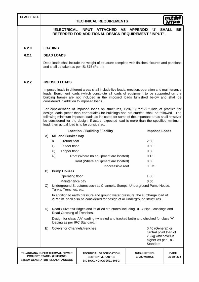
CLAUSE NO. TECHNICAL REQUIREMENTS
TELANGANA SUPER THERMAL POWER PROJECT STAGE-I (2X800MW)
STEAM GENERATOR ISLAND PACKAGE
TECHNICAL SPECIFICATION SECTION-VI, PART-B
BID DOC. NO.:CS-9591-101-2
SUB-SECTION-CIVIL WORKS
PAGE 32 OF 294
“ELECTRICAL INPUT ATTACHED AS APPENDIX ‘1’ SHALL BE REFERRED FOR ADDITIONAL DESIGN REQUIREMENT / INPUT”.
6.2.0 LOADING
6.2.1 DEAD LOADS
Dead loads shall include the weight of structure complete with finishes, fixtures and partitions and shall be taken as per IS: 875 (Part-I)
6.2.2 IMPOSED LOADS
Imposed loads in different areas shall include live loads, erection, operation and maintenance loads. Equipment loads (which constitute all loads of equipment to be supported on the building frame) are not included in the imposed loads furnished below and shall be considered in addition to imposed loads.
For consideration of imposed loads on structures, IS:875 (Part-2) “Code of practice for design loads (other than earthquake) for buildings and structures” shall be followed. The following minimum imposed loads as indicated for some of the important areas shall however be considered for the design. If actual expected load is more than the specified minimum load, then actual load is to be considered.
Location / Building / Facility Imposed Loads A) Mill and Bunker Bay
i) Ground floor 2.50 ii) Feeder floor 0.50 iii) Tripper floor 0.50 iv) Roof (Where no equipment are located) 0.15
Roof (Where equipment are located) 0.50 Inaccessible roof 0.075
B) Pump Houses Operating floor 1.50 Maintenance bay 3.00
C) Underground Structures such as Channels, Sumps, Underground Pump House, Tanks, Trenches, etc. In addition to earth pressure and ground water pressure, the surcharge load of 2T/sq.m. shall also be considered for design of all underground structures.
D) Road Culverts/Bridges and its allied structures including RCC Pipe Crossings and Road Crossing of Trenches. Design for class ‘AA’ loading (wheeled and tracked both) and checked for class ‘A’ loading as per IRC Standard.
E) Covers for Channels/trenches 0.40 (General) or central point load of 75 kg whichever is higher As per IRC Standard

CLAUSE NO. TECHNICAL REQUIREMENTS
TELANGANA SUPER THERMAL POWER PROJECT STAGE-I (2X800MW)
STEAM GENERATOR ISLAND PACKAGE
TECHNICAL SPECIFICATION SECTION-VI, PART-B
BID DOC. NO.:CS-9591-101-2
SUB-SECTION-CIVIL WORKS
PAGE 33 OF 294
(at road crossings for vehicular traffic)
I) Railway Supporting Structures, As per Railway ‘Bridge Rail Culverts Rules’
J) Boiler/ ESP Support Structures 0.5 K) Conveyor Galleries In addition to the live
loads, loads due to cable trays, fire fighting / service water pipes shall also be considered @125Kg/m(minimum) on each of the longitudinal girder.
Roof-truss members are to be checked for supporting fire fighting pipes/ Service water pipes. Tentative locations and diameter for pipes
L) General (Unless Specified Otherwise) i) Stairs, Landings and Balconies 0.50 ii) Toilets 0.20 iii) Chequered plates, grating floors, etc., 0.50 iv) RCC floors (General) 0.50 v) Flat Roofs (where no equipment are located) 0.15
Flat Roofs (where equipment are located) 0.50Inaccessible roof 0.075
vi) Inclined Roofs As per IS : 875 (Part-II)
vii) Dust load on roof Equivalent to 0.30 M of ash deposite
viii) Walkways (General) 0.50 ix) Walkways of conveyor galleries 0.30 x) Floor of control room of switchyard control
building 1.00
xi) Cable and pipe trestles 0.40 for walkway and in addition, friction loads as applicable
Notes:
a) If erection load is higher than the specified imposed loads on any floor or part thereof, then the erection loads are to be considered for the design.
b) Additional load for cable, piping/ducting, shall be considered as applicable. For any other structures, the loads specified for those structures elsewhere in the specification shall be followed.
CLAUSE NO. TECHNICAL REQUIREMENTS
TELANGANA SUPER THERMAL POWER PROJECT STAGE-I (2X800MW)
STEAM GENERATOR ISLAND PACKAGE
TECHNICAL SPECIFICATION SECTION-VI, PART-B
BID DOC. NO.:CS-9591-101-2
SUB-SECTION-CIVIL WORKS
PAGE 34 OF 294
“ELECTRICAL INPUT ATTACHED AS APPENDIX ‘1’ SHALL BE REFERRED FOR ADDITIONAL DESIGN REQUIREMENT / INPUT”.
6.2.3 EQUIPMENT, PIPING AND ASSOCIATED LOADS
Equipment loads shall be considered over and above the imposed loads. Equipment loads shall be considered as given by equipment supplier.
6.2.4 CRANE LOAD
For crane loads, an impact factor of 25% and lateral crane surge of 10% (of lifted weight + trolley weight) shall be considered in the analysis of frame according to the provisions of IS:875. The longitudinal crane surge shall be 5% of the static wheel load. Longitudinal surge and lateral surge shall not be considered to act simultaneously.
6.2.5 SEISMIC LOAD
For design of all structures, the site specific seismic spectrum as attached in Annexure-(e) shall be followed.
6.2.6 WIND LOAD
For design of all structures, the wind loads shall be taken as per the site specific wind data specified in Annexure–(d) of this specification.
6.2.7 TEMPERATURE LOAD
For temperature loading, the total temperature variation shall be considered as 2/3 of the average maximum annual variation in temperature. The average maximum annual variation in temperature for this purpose shall be taken as the difference between the mean of the daily minimum ambient temperature during the coldest month of the year and mean of daily maximum ambient temperature during the hottest month of the year. The structure shall be designed to withstand stresses due to 50% of the total temperature variation.
Suitable expansion joints shall be provided in the longitudinal direction wherever necessary with provision of twin columns. The maximum distance of the expansion joint shall be as per the provisions of IS: 800 and IS: 456 for steel and concrete structures respectively.
6.2.8 DIFFERENTIAL SETTLEMENT LOADS
Structures shall be designed considering an additional load on account of differential settlement of 1 in 1000 between any two adjacent columns, subject to a maximum differential settlement of 8 mm.
6.2.9 ADDITIONAL LOADS
Following Minimum additional Loads shall be considered in the design of Steam generator structures, Mill & bunker buildings, Coal handling Transfer points and Trestles.
(a) Cantilever Loads of not less than 2000 Kg / M at a distance of 1200 mm from the external face of the columns, on both sides of the ESP, for Cable trays and Walkways.

CLAUSE NO. TECHNICAL REQUIREMENTS
TELANGANA SUPER THERMAL POWER PROJECT STAGE-I (2X800MW)
STEAM GENERATOR ISLAND PACKAGE
TECHNICAL SPECIFICATION SECTION-VI, PART-B
BID DOC. NO.:CS-9591-101-2
SUB-SECTION-CIVIL WORKS
PAGE 35 OF 294
(b) Cantilever Loads of not less than 500 Kg / M at a distance of 1200 mm from the external face of the columns, on both sides of the Steam Generator, for Cable trays and Walkways.
(c) Cantilever Loads of not less than 2000 Kg / M at a distance of 2500 mm from the external face of the Mill & Bunker Building columns, CHP transfer point columns/ VGTU columns & conveyor gallery trestles (on one side) for Cable trays and Walkways.
(d) Dry Fly Ash Piping Loads.
(e) Ash Water Piping Loads.
(f) Supply Air and Instrument Air Piping.
(g) Service Water Piping
(h) Loads associated with Coal Handling Plant equipment
6.3.0 CIVIL DESIGN CONCEPTS
6.3.1 Individual members of the frame shall be designed for the worst combination of forces such as bending moment, axial force, shear force, torsion, etc.
6.3.2 The different load combinations shall be taken as per is: 875 (part-5) and other relevant is codes.
a. Wind and seismic forces shall not be considered to act simultaneously.
b. ‘Lifted load’ of crane shall not be considered during seismic condition.
c. Permissible stresses for different load combinations shall be taken as per relevant IS and IRS codes.
d. For the design of pipe/cable supporting structure, the soil weight shall be considered as backfilled up to grade level for the condition of pipe running full/cables in position.
e. Frictional forces between the pipes and supporting structure in longitudinal direction need not be considered along with seismic or wind forces.
f. Paving in crane corridor shall be designed for the maximum load due to movement of crane.
g. For checking against uplift / tension case, 90% of Dead Loads with no Imposed Loads shall be considered along with other Loads
h. In all Loading Combinations, the Loads that have reduction effect on design condition shall not be taken into account in the Combination concerned.
i. Where Wind is the main Load acting on the Structure, no increase in Stresses is to be considered for Design of Structures and Foundation Bolts.

CLAUSE NO. TECHNICAL REQUIREMENTS
TELANGANA SUPER THERMAL POWER PROJECT STAGE-I (2X800MW)
STEAM GENERATOR ISLAND PACKAGE
TECHNICAL SPECIFICATION SECTION-VI, PART-B
BID DOC. NO.:CS-9591-101-2
SUB-SECTION-CIVIL WORKS
PAGE 36 OF 294
6.3.3 Design of steel structures shall be done by the working stress method. Design shall be as per provisions of IS 800:1984 and other relevant is standards. For design of coal bins and loading hopper IS: 9178 (PART I - III) shall be followed.
6.3.4 Shop connections will be all welded type and field connections shall be bolted. Field permanent bolts wherever provided will be high tensile bolts of property class 8.8(min) as per IS 1367 for all major connections. The bolted joints will be designed for friction grip or bearing type. For friction grip type connections, bolts will be tightened to develop the required pretension during their installation. However, nominal connections in the field like purlins, stairs, wall beams will be done by means of M.S. black bolts of grade 4.6 conforming to IS-1367.
For bolted connection, IS: 4000, IS: 3757, IS: 6623 and IS: 6649 shall be followed. IS: 814, IS: 816, IS: 1024, IS: 4353 and IS: 9595 shall be followed for welding of structures.
6.3.5 For calculation of coal load on moving conveyor, a multiplication factor of 1.6 shall be used to take care of inertia force, casual over burden and impact factor, etc. Thus coal load per unit length of each moving conveyor shall be
Rated Capacity of Conveyor system 1100 ------------------------------------------------ --------- 1.6 XConveyor Belt Speed
X800
6.3.5.1. Conveyor gallery structure and trestles shall be designed considering both conveyors operating simultaneously
6.3.5.2. Dynamic analysis of conveyor galleries and conveyor supporting system shall be carried out for spans greater than 25 m.
6.3.5.3. All structures close to railway line shall have clearances conforming to Railway norms.
6.3.6 HORIZONTAL DEFLECTION CRITERIA
The maximum Horizontal Deflection for various structures shall not exceed and be limited to the following:
---------------------------------------------------------------------------------------------------------------- Sl. No. Description Maximum value of ----------------------------------------------------------------------------------------------------------------
1. For Trestles and transfer points Height/1000 (Transverse deflection at Conveyor (For Wind load by Peak Wind gallery supporting level) Speed Method / Seismic Load)
2. For Mill & Bunker Building Height/500 (At Tripper floor level) (For wind load by Gust Factor
Method / Seismic Load) 3. For Height /325
ESP Control Building, Compressor House, and all other buildings envisaged in this specification

CLAUSE NO. TECHNICAL REQUIREMENTS
TELANGANA SUPER THERMAL POWER PROJECT STAGE-I (2X800MW)
STEAM GENERATOR ISLAND PACKAGE
TECHNICAL SPECIFICATION SECTION-VI, PART-B
BID DOC. NO.:CS-9591-101-2
SUB-SECTION-CIVIL WORKS
PAGE 37 OF 294
4. Vertical Metal Sheeting in Cladding Span/250
---------------------------------------------------------------------------------------------------------------------
a) Dispersion of load in any direction through soil shall be as per IS: 8009 (relevant part).
b) Dispersion of load through concrete shall be considered at an angle of 45 degrees with horizontal from the edge of contact area.
a) Permissible deflection (unless specified otherwise in this specification) for latticed framework and beams of floors other than drive floor shall be span/325.
b) The allowable deflection for beams directly supporting drive machinery shall be restricted to span/500 unless specified otherwise in this specification.
c) The deflection for manually operated cranes & monorail supporting beams shall not exceed span/500.
For electric overhead cranes:
1) Up to 50 t capacity: span/750
2) over 50 t capacity : span/1000
d) The vertical deflection of metal deck sheet for floor shall be limited to span/250.
e) Permissible deflection for all purlins, cladding runners, roofing/cladding sheets and grating / chequered plates shall be span/250. However, the maximum vertical deflection of Grating/ Chequered plate shall be limited to 6 mm.
6.3.7 Transverse coal pressure on bunker/silo/hopper walls shall be calculated as per is: 9178. The coal bunker/silo/hopper shall be designed for the following conditions
i) The Bunker/Silo/Hopper is full up to its full capacity with top surface nearly horizontal.
ii) The Bunker/Silo/Hopper is partially empty with the top surface of coal at an angle of repose of 37 degrees.
6.3.8 Coal bunker (inside mill bunker building) shall be of MS while the hopper shall be of MS with Stainless Steel (Grade SS 304) lining. The minimum thickness of MS plate and SS lining in hopper portion shall be as specified in the design concept of Mill Bunker Building in the previous chapter. Pre-formed flexible open ended bellow strap of neoprene is to be provided between top of bunker and bottom of tripper floor to avoid coal dust leakage / escape. The bellow strap shall be of minimum 200 mm wide under un-stretched condition and shall be of minimum 2mm thick.
The hopper angle with the horizontal plane be as specified in the previous chapter.
6.3.9 The live storage capacity of each bunker shall be greater of the following:
a) Total 10 hours coal requirement of the boiler for BMCR duty with worst coal firing, equally distributed over the number of bunkers (i.e. the coal mills) required in service for this duty condition as specified elsewhere.
CLAUSE NO. TECHNICAL REQUIREMENTS
TELANGANA SUPER THERMAL POWER PROJECT STAGE-I (2X800MW)
STEAM GENERATOR ISLAND PACKAGE
TECHNICAL SPECIFICATION SECTION-VI, PART-B
BID DOC. NO.:CS-9591-101-2
SUB-SECTION-CIVIL WORKS
PAGE 38 OF 294
b) Total 10 hours coal requirement of the boiler for BMCR duty with design coal firing, equally distributed over the number of bunkers (i.e. the coal mills) required in service for this duty condition as specified elsewhere.
c) Total 10 hours coal requirement of the boiler for TMCR duty with worst coal firing, equally distributed over the number of bunkers (i.e. the coal mills) required to be in service for this duty condition as specified elsewhere.
d) Filling with head discharge pulley at last bunker is to be considered for calculating the Bunker Volumetric Capacity.
6.3.10 For all capacity (volume) calculation and structural design (load calculation) unit weight of coal shall be assumed as 800 Kg/cu.m. and 1100 Kg/cu.m respectively.
6.3.11 Design pressure on coal bunker/hopper walls shall take into account all possible flow regimes (core flow, mass flow, etc.), and different aeration regimes (radial, diametrical, radial and core, impulsive, etc).
The design and construction of RCC structures shall be carried out as per IS: 456. Working stress method shall be adopted for the design wherever specifically mentioned in this specification.
For design and construction of steel-concrete composite members, IS: 11384 shall be followed.
For reinforcement detailing, IS: 5525 and SP: 34 shall be followed.
Two layers of reinforcement (on both inner and outer faces) shall be provided for RCC wall sections having thickness 150 mm or more.
6.3.12 Bidder shall submit a comprehensive scheme for water proofing treatment based on above or any other alternative scheme, internationally accepted for Employer's approval prior to commencement of work.
6.3.13 For design of all underground structures, foundations, etc. ground water table shall be assumed at the finished ground level unless specified otherwise.
6.3.14 Earth pressure for all underground structures shall be calculated using coefficient of earth pressure at rest or co-efficient of active earth pressure, whichever is applicable, depending upon the structural configuration. However, for the design of substructure of pump houses, earth pressure at rest shall be considered. Co-efficient of passive earth pressure shall be used only in design of shear keys for stability against sliding.
6.3.15 Design of Foundation for Fan foundations
6.3.15.1. SCOPE OF WORK FOR BIDDER
The scope of work for the design shall consist of the following:
a) Finalization of the general arrangement layout and levels of the foundation for FAN foundations based on the equipment layout keeping in view the layout constraint and limitations of available space.
b) Submission of design criteria and loading data of the equipment foundations.
CLAUSE NO. TECHNICAL REQUIREMENTS
TELANGANA SUPER THERMAL POWER PROJECT STAGE-I (2X800MW)
STEAM GENERATOR ISLAND PACKAGE
TECHNICAL SPECIFICATION SECTION-VI, PART-B
BID DOC. NO.:CS-9591-101-2
SUB-SECTION-CIVIL WORKS
PAGE 39 OF 294
c) Analysis of the top deck, design and detailing of the reinforcement and finalization of the spring arrangement.
d) Submission of all design calculation, all loading drawings, general arrangement drawings, embedment drawings, spring arrangement drawings and reinforcement drawings for the foundations under the scope for the approval of the Owner. Carrying out revisions / alterations based on the comments of the Owner. In addition to hard copies, the final soft copy of all drawings (in AutoCAD and pdf format) and documents shall also to be submitted.
e) Submission of construction methodology / casting sequence and special requirements (if any) for the top of deck.
Structural Arrangement of foundations for various machine foundations like FAN and shall be as specified in Chapter-5 of this specification.
6.3.15.2. ANALYSIS FOR THE FOUNDATION
For the foundations of the all equipments, details static and dynamic analysis shall be done. The static analysis shall include all operating condition, load cases and abnormal loads like short circuit, loss of blades & unbalance and seismic forces as per IS:1893. The dynamic analysis shall consist of free vibration analysis and forced vibration analysis. A minimum fatigue factor of 2.0 shall be considered for dynamic forces.
The vibration amplitudes shall be calculated at the machine bearing locations and at any other points of interest by a forced response analysis. The unbalance forces used for this analysis shall correspond to the balance quality grade of the machine as per VDI 2060 or the unbalance forces as provided by the machine manufacturer whichever is higher. It shall be ensured that the calculated amplitudes do not exceed the limits specified by the machine manufacturer and relevant Standards such as VDI 2056.
Bidder to consider the acceleration at the top of the deck for the design of supporting / fixing arrangement of machine.
6.3.15.3. DESIGN CRITERIA FOR STEEL HELICAL SPRINGS AND VISCOUS DAMPERS
The isolation efficiency for steel helical springs and viscous dampers shall be at least 90%. The ratio of actual spring supported weight to the nominal spring capacity shall not exceed 0.80. At least 3% to 5% of critical damping shall be provided in the form of viscous dampers.
6.3.15.4. GRADE OF CONCRETE AND REINFORCEMENT
Grade of concrete for Top deck shall be minimum M35 conforming to IS:456-2000. The grade of reinforcement for Top deck shall be Fe500 (TMT) conforming to IS:1786.
6.3.15.5. REINFORCEMENT DESIGN
Working stress method as per IS: 456-2000 shall be used for reinforcement design. The design shall be done for the worst load combination. Minimum reinforcement shall be provided as per IS:456-2000 and IS:2974 (Part-III), if the calculated reinforcement is less than the minimum.
6.3.15.6. BLOCK FOUNDATIONS

CLAUSE NO. TECHNICAL REQUIREMENTS
TELANGANA SUPER THERMAL POWER PROJECT STAGE-I (2X800MW)
STEAM GENERATOR ISLAND PACKAGE
TECHNICAL SPECIFICATION SECTION-VI, PART-B
BID DOC. NO.:CS-9591-101-2
SUB-SECTION-CIVIL WORKS
PAGE 40 OF 294
a. Block foundation resting on soil shall be analyzed using elastic half space theory. In case the foundation is supported over piles, Novak’s approximation shall be used for determining the spring constant and damping ratio of pile groups. The mass of the RCC block shall be at least three times the mass of machine. Free vibration analysis of the foundation shall be carried out to evaluate the natural frequencies. The fundamental natural frequency shall be kept at least 20% away from the operating frequency (speed). Forced vibration analysis shall be carried out if the dynamic forces are made available by the machine supplier in which case the amplitude limits stipulated by the machine supplier and VDI 2056, whichever is lower, shall be satisfied.
Reinforcement design shall be done by working stress method as per IS:456-2000 and IS:2974 (Part-IV).
b) For the foundations supporting minor rotating equipment weighing less than one ton or if the mass of the rotating parts is less than one hundredth of the mass of the foundation, no dynamic analysis is necessary. However, if such minor equipment is to be supported on building structure, floors, etc., suitable vibration isolation shall be provided by means of springs, neoprene pads, etc., and such vibration isolation system shall be designed suitably.
6.3.16 If RCC floor/roof is assumed to act as diaphragm, transmitting lateral loads to braced bays, it shall be provided with shear connectors. However, whenever large / more number of cut-outs are provided in the floor slab, horizontal floor bracings shall be provided below slab to transfer horizontal force to columns without considering diaphragm action from slab.
6.3.17 All roads shall be rigid pavements specified elsewhere in this specification. The design traffic load shall be a minimum 4 million cumulative standard axle. The design of concrete pavement shall be carried out as per IRC-58.
a. No cable/pipe trench is envisaged in the plant area. However, if required, pipe/cable trench can be provided inside the buildings and inside switchyard or some other localized areas.
b) All pipes and cable shall generally be routed above ground.
c) A minimum clearance (clear headroom) of 8 m shall be kept for all over-ground pipe/cable trestles for all road/rail crossings. For other areas, the requirement of trestle height is specified elsewhere in the specifications. All trestles shall be provided with continuous walkway of minimum 600mm width with hand-rails and toe-guards all along the length of the trestle along with approach ladders near roads, passageways, etc.Before and after the road/rail crossings, a barrier of suitable height shall be constructed so as to prevent the approach of cranes (having height more than 8 m) etc, up to the pipe/cable racks/trestles.
6.3.18 The SG AREA plant storm water drainage shall be designed taking into account the finished grade levels of the plant area, drainage pattern, intensity of rainfall, etc., The storm water drainage shall cater to storm water runoff resulting from one hour rainfall intensity, with a return period of 50 years. These values shall be based on the "Detailed Area Drainage Study" subject to minimum rainfall intensity of 75mm/hr. The maximum velocity for pipe drains and open drains shall be limited to 2.4m/sec and 1.8 m/sec. respectively. However, minimum velocity of 0.6m/sec. for self-cleansing shall be ensured. Bed slope not milder than 1 in 1000 shall be provided. The open drains shall be open rectangular drains of RCC unless required otherwise due to functional requirement. RC box culverts shall be provided at rail, road or other crossings.
6.3.19 Sewers shall be designed for a minimum self-cleansing velocity of 0.75m/sec and the maximum velocity shall not exceed 2.4m/sec.

CLAUSE NO. TECHNICAL REQUIREMENTS
TELANGANA SUPER THERMAL POWER PROJECT STAGE-I (2X800MW)
STEAM GENERATOR ISLAND PACKAGE
TECHNICAL SPECIFICATION SECTION-VI, PART-B
BID DOC. NO.:CS-9591-101-2
SUB-SECTION-CIVIL WORKS
PAGE 41 OF 294
Manual on sewerage and sewage treatment (published by Central Public Health Environment Engineering Organization, Government of India) shall be followed for design purpose.
6.3.20 Roof decking sheets shall be designed as per IS: 801 to carry the self load, dead load due to RCC slab and finishes and imposed load. The deflection of metal deck shall be limited as per BS: 5950. In case composite action is considered in the design, suitable shear studs shall be provided as per BS: 5950.
6.3.21 Foundations for all tanks shall be designed for as per IS: 803.
6.3.22 Footings shall be so proportioned to as to minimize the differential settlement.
6.3.23 BOILER/ ESP SUPPORT STRUCTURES SHALL BE DESIGNED FOR
6.3.23.1. Loads
a. Live/Imposed loads.
i. Dead load
ii. Static and dynamic loads of piping, movable equipment and maintenance parts.
b. Loads from cable trays and walkways supported on columns.
c. Ash water piping supported on the outermost row of boiler columns.
d. All ESP hoppers filled up with ash upto the top of the hoppers or the bottom of electrodes (whichever is more) using a bulk density of not less than 1350 kg/cu.m. for the ash, along with additional ash build-up from the end of the third field upto the inlet duct bottom level at a natural repose angle (not less than 30 degree to horizontal in any case).
e. Ash load at bottom ash hopper and pent house of the boiler shall be as mentioned in the mechanical chapter of the specifications.
f. Seismic and wind loads as specified elsewhere in the specifications.
g. Temperature variation of +/-25 C for atmospheric temperature variations.
h. Temperature variations under ESP operating condition.
i. The loads listed above indicate the minimum requirements.
6.3.23.2. Boiler supporting structures shall be so configured that the temperature of steel does not exceed 60 C unless specified otherwise. Brackets shall be provided on both sides of the outermost row of columns of both the boiler and ESP for supporting cable trays and walkways, at a height not exceeding 10.0 m. The exact levels shall, however, be decided during detailed engineering. Each ESP hopper shall be supported at four corners by providing four columns from the ground.
6.3.23.3. The bracings in boiler structure shall be provided such that under no circumstance normal/convenient access to all points in the boiler is blocked or obstructed.
6.3.23.4. In design of boiler/ ESP support structures, dynamic piping loads need not be considered acting simultaneously with wind or seismic loads. Increase in permissible stresses shall be

CLAUSE NO. TECHNICAL REQUIREMENTS
TELANGANA SUPER THERMAL POWER PROJECT STAGE-I (2X800MW)
STEAM GENERATOR ISLAND PACKAGE
TECHNICAL SPECIFICATION SECTION-VI, PART-B
BID DOC. NO.:CS-9591-101-2
SUB-SECTION-CIVIL WORKS
PAGE 42 OF 294
allowed in load combinations where dynamic piping loads are considered and shall be as permitted under seismic load conditions.
6.3.23.5. Design Criteria for foundations and some other facilities/areas are covered separately in this specification.
6.3.23.6. Plinth level of all buildings shall be kept at least 500 mm above the finished grade/formation level.
6.3.23.7. Finished floor level of boiler area paving shall be kept about 200 mm lower than the finished floor level of Main Plant buildings.
6.3.24 Joints/Connections in steel structures
Steel structures shall be detailed and connection and joints provided as per the provisions of IS:800, IS:816, IS:9595, IS:1367, and IS:9178 and as per following requirements.
a. Connection of vertical bracings with connection members and diagonals of truss members shall be designed for full tensile capacity of the bracings unless actual loads are indicated on the drawings.
b. Size of fillet weld for flange to web connection for built up section shall be as follows:
i. For box section weld size shall be designed for full shear capacity or actual shear whichever is more. Where fillet weld is not possible, full penetration butt weld shall be provided.
ii. For built up I section, weld size shall be designed for 80% of full shear capacity or actual shear, (if indicated, in drawings) whichever is more. However, weld size shall not be less than 0.5 times the web thickness. Weld shall be double fillet.
iii. All welds shall be continuous unless otherwise specifically approved. The minimum size of the fillet weld shall be 6mm.
c. Shear connections shall be designed for 60% of section strength for rolled sections and 80% of section strength for built up section or rolled section with cover plates. However, if load is more than above, the connection shall be designed for actual load.
d. Moment connections between beam and column shall be designed for 100% of moment capacity of the beam section. This can achieved either by direct butt welding of the top flange of beam with column flange or by providing top moment plate with suitable notch for additional weld length.
e. All butt welds shall be full penetration butt welds.
f. The connection between top flange and web of crane girder shall be full penetration butt weld. Bottom flange, connection with web can be fillet weld or butt weld as directed by Engineer.
g. Connection of base plate and associated stiffeners with the columns shall be designed considering the total load transferred through welds. However, minimum weld size (double fillet) shall not be less than 0.6 times the thickness of stiffeners.

CLAUSE NO. TECHNICAL REQUIREMENTS
TELANGANA SUPER THERMAL POWER PROJECT STAGE-I (2X800MW)
STEAM GENERATOR ISLAND PACKAGE
TECHNICAL SPECIFICATION SECTION-VI, PART-B
BID DOC. NO.:CS-9591-101-2
SUB-SECTION-CIVIL WORKS
PAGE 43 OF 294
h. Splicing: All work shall be full strength. Field splicing shall be done with web and flange cover plates for full strength. In exceptional cases, the field splicing shall be designed for 50% of load carried by the cover plates and remaining 50% load through full penetration butt weld. Shop splicing for all sections other than rolled shall be carried out by full penetration butt welds with no cover plates. Splicing for all rolled sections shall be carried out using web and flange cover plate.
6.3.25 Pipe Pedestals, pipe supports and other structures for Ash handling/ash water recirculation system:
a. The design of Pipe Pedestal and pipe supports shall be carried out considering Dead load, live load & seismic load / wind load. In addition to above, longitudinal forces equal to product of Co - efficient of friction (between contact surface of pipe and pedestal) with the load coming on each pedestal shall also be considered for the design of pedestal. In bends, suitable thrust block shall be provided to withstand the thrusts transferred from the pipelines.
b. All RCC pipes carrying water under gravity shall be designed for earth pressure, water and surcharge. Minimum grade of pipe shall be of NP - 2 class or heavier required as per design / specification.
c. The design and construction of RCC structures shall be carried out as per IS: 456. In general, limit state theory shall be followed for the design of RCC structures, however, working stress method shall be adopted for the design, wherever specifically mentioned in this specification.
d. Two layers of reinforcement (on inner and outer face) shall be provided for RCC wall sections having thickness 150mm and above.
6.3.26 DESIGN CRITERIA OF RCC FLOORS
a. For Mill Bunker Building, ESP Control Building, Transfer Houses of CHP and other structural steel framed buildings:
i. These buildings being steel framed structure, all RCC floors shall comprise RCC slab supported on troughed, profiled metal deck sheet of minimum thickness 0.80mm (to be used as permanent shuttering). The RCC slab shall be minimum 150mm thick above the top surface (crest) of the metal deck sheet. The spacing of structural steel secondary beams shall be based on the bending capacity of the metal deck sheet for self-weight of green concrete and additional construction load of 100 kg/m2.
ii. The permanent metal deck sheets shall be fixed to the top flange of secondary beams by means of drawn arc welding of headed shear anchor studs directly through the metal sheet. The details of shear anchor studs are specified elsewhere in this specification.
iii. The RCC slab shall be designed without considering any composite action effect of metal deck sheet (i.e. the structural strength of metal deck sheet shall not be considered for RCC slab design).
b. For other RCC buildings.

CLAUSE NO. TECHNICAL REQUIREMENTS
TELANGANA SUPER THERMAL POWER PROJECT STAGE-I (2X800MW)
STEAM GENERATOR ISLAND PACKAGE
TECHNICAL SPECIFICATION SECTION-VI, PART-B
BID DOC. NO.:CS-9591-101-2
SUB-SECTION-CIVIL WORKS
PAGE 44 OF 294
These buildings being complete RCC framed structures, conventional RCC slabs of minimum thickness 125mm shall be provided. The RCC slabs shall be monolithic with RCC beams and RCC columns
6.3.27 DESIGN CRITERIA OF RCC ROOFS:
a) For Compressor House, ESP Control Building:
The roof system shall comprise minimum 40mm thick RCC slab on top of profiled permanent metal deck sheet. The permanent metal deck sheets shall be fixed to the top flange of secondary beams by means of arc welding of headed shear anchor studs to the purlins directly through the metal sheet. The details of shear anchor studs are specified elsewhere in this specification. Water proofing treatment to roof slab shall be provided as per details specified elsewhere in this specification).
The RCC slab shall be designed without considering any composite action effect of metal deck sheet (i.e. the structural strength of metal deck sheet shall not be considered for RCC slab design.
b) For Mill Bunker Building, Transfer Houses.
Insulated sandwiched metal sheet for roofing shall be provided comprising troughed permanently colour coated sheet at top and plain permanently colour coated sheet at bottom with 50mm thick insulation sandwiched between the two sheets, the details of which are specified elsewhere in this specification.
c) Other RCC Buildings.
Cast-in-Situ RCC slab shall be provided using removable plywood shuttering. Water proofing treatment to roof slab shall be provided as per details specified elsewhere in this specification).
6.3.28 DESIGN CRITERIA FOR FOUNDATION
The founding depth shall be decided based on functional requirement.
Where structural steel columns are envisaged, the bottom of the base plate shall be kept suitably below the paving level such that the top level of the gusset plate and foundation bolt remain at least 200 mm below the top level of paving except for Boiler Structure, Bunker Building Columns, TP & Trestle Columns, ESP Control Building Columns for which the requirement of levels for bottom of base plates is specified elsewhere in this specification. Further the gusset plate and foundation bolts are to be encased in concrete up to the top of the paving level. For outdoor structural steel columns, about 300 mm height of steel columns above the top of paving level shall be provided with at lease 125 mm thick encasement with minimum reinforcement to prevent corrosion of the steel columns from surface water
6.3.28.1. OPEN FOUNDATIONS
For all major foundations, the minimum founding depth and the minimum size of foundation shall be as per foundation system and geotechnical data specified in the foundation chapter include hereafter in this specification.
For open foundations, the total permissible settlement shall be as per the criteria furnished under the foundation system specified elsewhere in this specification.
CLAUSE NO. TECHNICAL REQUIREMENTS
TELANGANA SUPER THERMAL POWER PROJECT STAGE-I (2X800MW)
STEAM GENERATOR ISLAND PACKAGE
TECHNICAL SPECIFICATION SECTION-VI, PART-B
BID DOC. NO.:CS-9591-101-2
SUB-SECTION-CIVIL WORKS
PAGE 45 OF 294
The sizing of foundation, design criteria & clear cover shall conform to IS:1904, IS:456 and other relevant Indian codes. However minimum 0.12% of reinforcement shall be provided on the top face of the foundation concrete on either direction and minimum percentage of reinforcement at bottom face of foundation shall be same as that stipulated for beam as per IS:456.
No major foundation shall rest on filled up soil. Loose soil if any below foundation is to be removed and replaced with PCC of grade M7.5.
6.4.0 CORROSION PROTECTION
6.4.1 GENERAL
(a) All equipments, pipes, etc. shall be painted as per the requirements specified in the relevant section of the specification.
(b) All Steel structures (except those embedded in Concrete) shall be provided with Painting as given below which is designed for a minimum maintenance free life of Ten (10) years (expected life, long range Ten (10) to Twenty ( 20 ) years, as per BS : 5493.
(c) All Paints shall be of high build constitution.
(d) All Painting shall be done as per approved Painting scheme of the Vendors / Manufacturers, which shall be submitted by the Bidder and as approved by the Employer. Painting scheme shall also include Item codification / Description of all Coats of Paints for manufacturer’s, from whom the Paint is intended to be procured.
6.4.2 PAINTING OF STEEL SURFACES EMBEDDED IN CONCRETE:
a) For the portion of Steel surfaces embedded in Concrete, the surface shall be prepared by Manual Cleaning and provided with Primer Coat of Chlorinated Rubber based Zinc Phosphate Primer of Minimum 50 Micron Dry Film Thickness (DFT).
b) All threaded and other surfaces of foundation bolts and its materials, insulation pins, Anchor channels, sleeves, etc. shall be coated with temporary rust preventive fluid and during execution of civil works, the dried film of coating shall be removed using organic solvents.
6.4.3 PAINTING OF STEEL SURFACES (OTHER THAN THOSE EMBEDDED IN CONCRETE)
a) All Steel surfaces shall be provided with self-curing Inorganic Zinc Silicate Primer Coat (Solid by Volume Minimum 60%) of Minimum 75 Micron Dry Film Thickness (DFT) applied over shot blast cleaned surface to near white metal conforming to Sa 2 ½ finish of Swedish standard SIS-05-5900. The Primer Coat shall be applied in Shop immediately after blast cleaning by Airless spray technique.
b) Primer Coat shall be followed with the application of Intermediate Coat of Polyamide Cured pigmented Titanium Dioxide (TiO2) or Micaceous Iron Oxide (MIO) Epoxy based Paint (Solid by Volume Minimum 60%) of Minimum 75 Micron DFT. This Coat shall be applied in Shop after an interval of Minimum overnight (from the application of Primer Coat) by Airless spray technique.
c) Intermediate Coat shall be followed with the application of Finish Coat of Polyamide Cured colour pigmented Epoxy based Paint (Solid by Volume Minimum 60%) of Minimum 75 Micron DFT. This Coat shall be applied after an interval of Minimum overnight and maximum indefinite (from the application of Intermediate Coat) either

CLAUSE NO. TECHNICAL REQUIREMENTS
TELANGANA SUPER THERMAL POWER PROJECT STAGE-I (2X800MW)
STEAM GENERATOR ISLAND PACKAGE
TECHNICAL SPECIFICATION SECTION-VI, PART-B
BID DOC. NO.:CS-9591-101-2
SUB-SECTION-CIVIL WORKS
PAGE 46 OF 294
before Erection by Airless spray technique or after Erection by brush and / or airless spray. Colour and shade of the Coat shall be as approved by the Employer.
d) Finish Coat shall be followed with the application of Final Finish Coat of Polyurethane based colour pigmented Paint (Solid by Volume Minimum 40%) of Minimum 25 Micron DFT. This Coat shall be applied within Seven (7) days (from the completion of Finish Coat), after Erection by brush and / or airless spray. Colour and shade of the Coat shall be as approved by the Employer.
6.4.4 TOUCH-UP PAINTING ON DAMAGED AREAS
a) For Coatings damaged up to metal surface
Surface preparation shall be carried out by Manual Cleaning. Minimum 6 inches adjoining area with existing Coating shall be roughened by Wire brushing, emery paper rubbing etc., for best adhesion of patch Primer.
Over this Primer Coat, Intermediate Coat, Finish Coat and Final Finish Coat shall be applied as covered above by brush with Intermediate Coat applied within maximum seven (7) days of application of touch up Primer.
b) For Coatings damaged upto Intermediate Coatings (i.e. where Primer Coat is intact).
Damaged area including Minimum 6 inches adjoining area with existing Coating should be roughened by wire brushing, emery paper rubbing etc., for best adhesion of patch Primer without damaging the Primer Coat.
Touch-up Primer, Intermediate, Finish and Final Finish Coats shall be applied as specified above for Coatings damaged up to metal surface.
6.4.5 Painting of welded areas / painting of areas exposed after removal of temporary supports / touch-up painting on damaged areas structures, where inter-connection, welding / modification etc. Has been carried out by the bidder.
a) Clean the surface to remove flux spatters and loose rust, loose Coatings in the adjoining areas of Weld seams by wire brush and emery paper.
b) Painting procedure to be followed as mentioned above for Touch-up Painting on damaged areas.
6.4.6 Dry film thickness of each coat shall be checked and measured as per the procedure specified in paint application standard no. 2 by SSPC: The Society for Protective Coating. The thickness as measured shall not be less than the minimum thickness specified for the coat of paint under relevant clauses of technical specification.
6.4.7 Coating for Mild Steel parts in contact with Water.
a) All mild Steel parts coming in contact with water or water vapour shall be hot dip galvanised. The Minimum Coating of Zinc shall be 610 Gms / Sq. M. for galvanised Structures and shall comply with IS: 4759 and other relevant Codes. Galvanising shall be checked and tested in accordance with IS: 2629.
b) The galvanising shall be followed by the application of an etching Primer and dipping in black bitumen in accordance with BS: 3416, unless otherwise specified.
6.4.8 GRATINGS

CLAUSE NO. TECHNICAL REQUIREMENTS
TELANGANA SUPER THERMAL POWER PROJECT STAGE-I (2X800MW)
STEAM GENERATOR ISLAND PACKAGE
TECHNICAL SPECIFICATION SECTION-VI, PART-B
BID DOC. NO.:CS-9591-101-2
SUB-SECTION-CIVIL WORKS
PAGE 47 OF 294
All gratings shall be blast cleaned to Sa 2 ½ finish of Swedish standard SIS-05-5900 and shall be hot dip galvanized at the rate of 610 Gms / Sq. M.
6.4.9 HAND RAILINGS AND LADDERS
All handrails and ladders shall be galvanised at the rate of 610 Gms / Sq. as per IS: 4736.
6.4.10 SEA WORTHINESS
a) All Steel Sections and fabricated Structures, which are required to be transported on sea, shall be provided with anti-corrosive Paint before shipment to take care of sea worthiness.
b) All structural steel members in switchyard (excluding fencing and gate) shall be hot dip galvanised as specified elsewhere.
6.4.11 FOR REINFORCED CONCRETE WORK
a) The protection for concrete sub-structure shall be provided based on aggressiveness of the soil, chemical analysis of soil/sub-soil water and presence of harmful chemicals/salts.
The protection to super structure shall depend on exposure condition and degree of atmospheric corrosion.
b) This shall require use of dense and durable concrete, control of water cement ratio, increase in clear cover, use of special type of cement and reinforcement, etc., coating of concrete surface, etc.,
Bidder shall furnish the details of corrosion protection measures.
7.0.0 FOUNDATION SYSTEM SOIL DATA AND GEOTECHNICAL INVESTIGATION
7.00.0 Soil Data
Owner has carried out geotechnical investigation at the project site. Available borelogs along with laboratory test results, are enclosed at Annexure-A for Bidder’s reference. The geotechnical investigation report for these areas will be made available for the Bidder’s study at the Owner’s office, if required.
Onus of correct assessment/ interpretation and understanding of the existing subsoil condition / data is on the Bidder. The ground reduced levels (RLs) as per topographical survey drawing varies from RL 145.0m to 151.0m. Bidder may refer topographical survey drawing for variation in existing ground level. As per borelog data, water table is varying from 0.9m to 6.7m at the time of field investigation and may fluctuate with season.


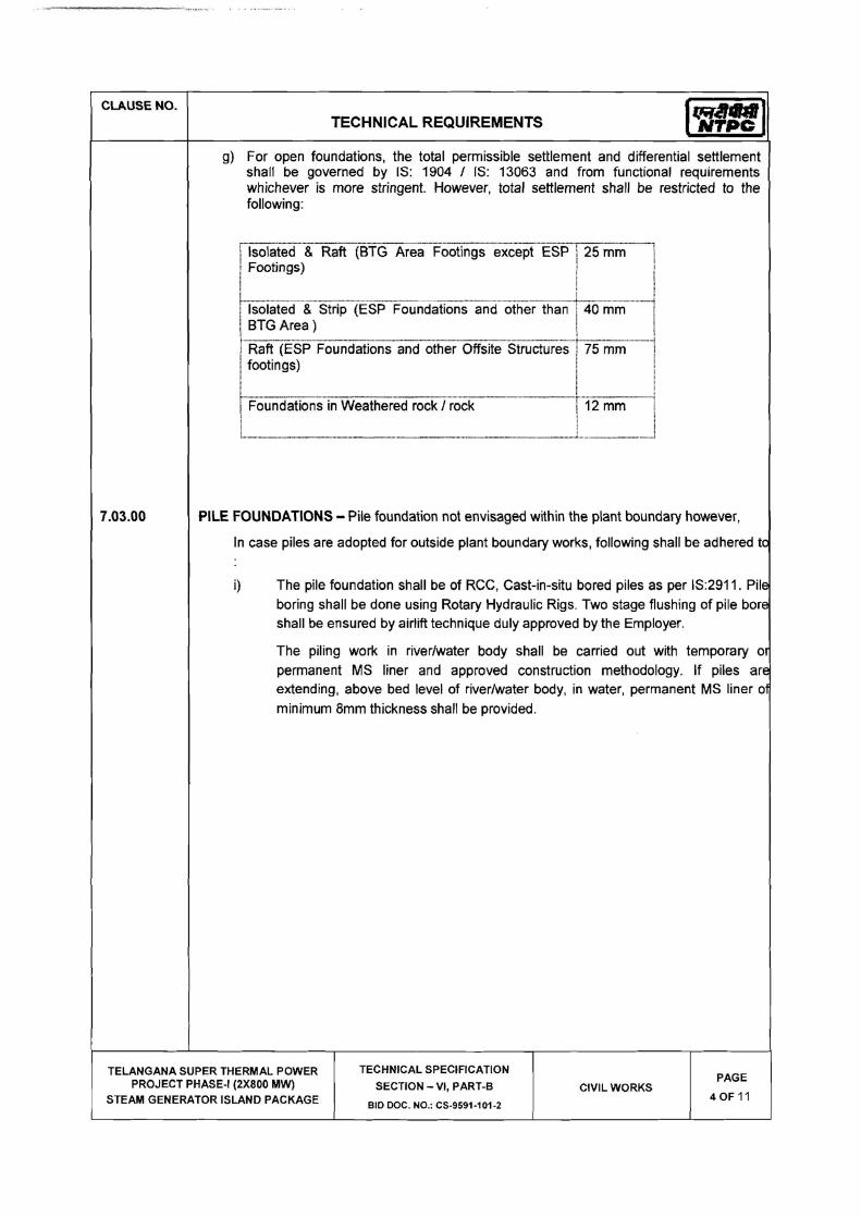
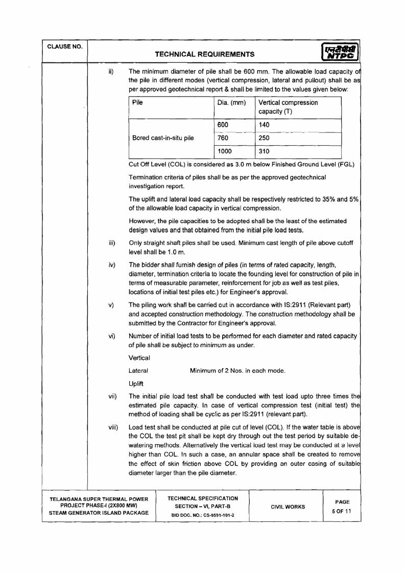


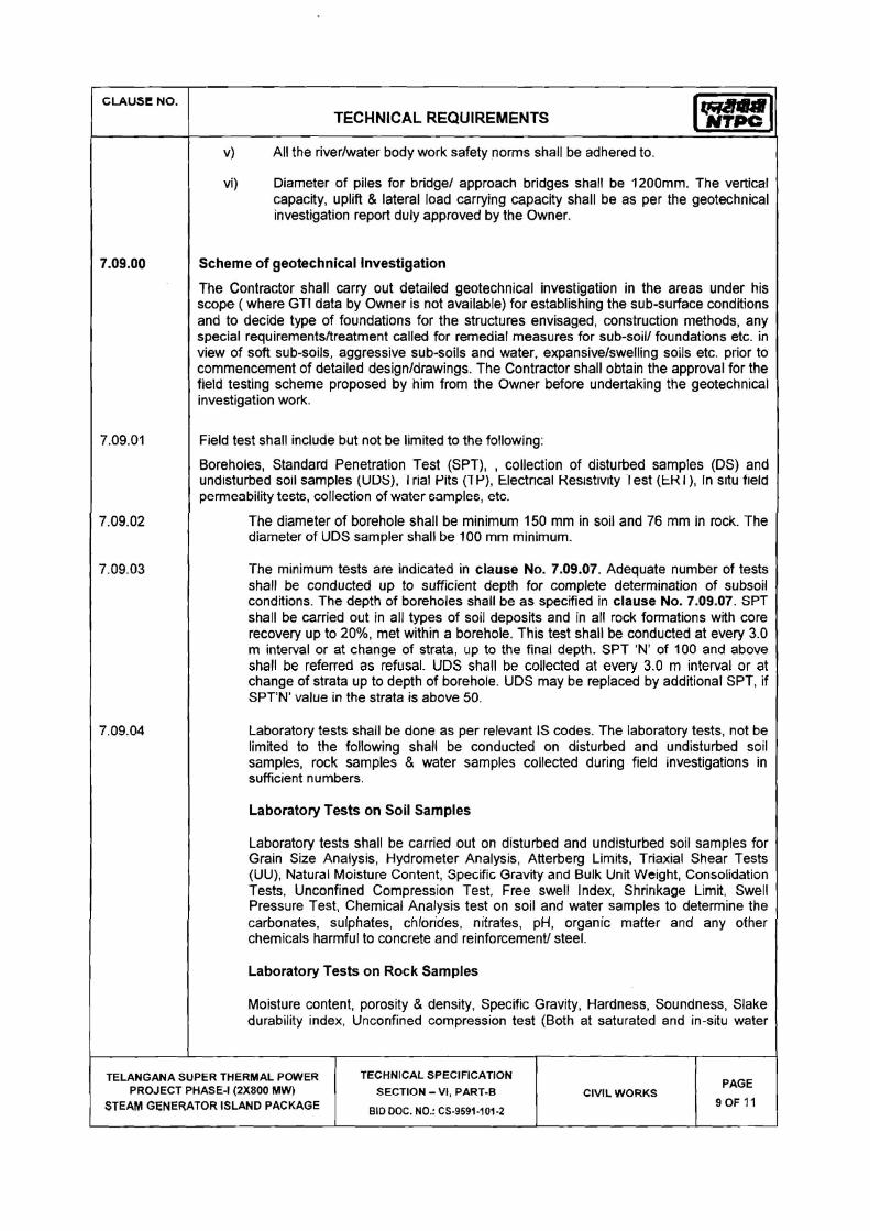
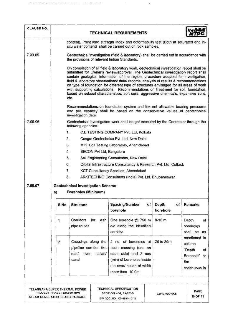


CLAUSE NO. TECHNICAL REQUIREMENTS
TELANGANA SUPER THERMAL POWER PROJECT PHASE-I (2X800MW)
STEAM GENERATOR ISLAND PACKAGE
TECHNICAL SPECIFICATION SECTION-VI, PART-B
BID DOC. NO.:CS-9591-101-2
SUB-SECTION-CIVIL WORKS
PAGE 53 OF 294
8.00.00 GENERAL SPECIFICATION
8.01.01 Joints in Concrete Structures
Construction Joints
All horizontal construction joints shall be provided with a groove (shear key) for transfer of shear force.
Expansions Joints
In case of expansion joints, preformed bitumen impregnated fibre board conforming to IS:1838 shall be used as joint filler. The joints shall be sealed with bitumen sealing compound conforming to IS: 1834, however in case of liquid retaining/carrying structures, two parts polysulphide sealant conforming to IS:12118 or silicon sealing compound shall be used.
IS:3414 shall be followed for details of joints in buildings. 3 mm thick stainless steel strip in matt or buff finish shall be provided over building expansion joints.
8.01.02 All steel sections and fabricated structures, which are required to be transported on sea, shall be provided with anti corrosive paint before shipment to take care of sea worthiness.
8.01.03 A screed or concrete layer not less than 100 mm thick and of grade not weaker than M 10 conforming to IS: 456 shall be provided below all water retaining structures.
8.01.04 Minimum 75mm thick lean concrete M-7.5 shall be provided below all other underground structures, foundations, trenches, etc., to provide a base for construction.
8.01.05 Monorails, monorail girders and fixtures shall be provided, wherever required to facilitate erection / maintenance of equipment.
8.01.06 Wherever possible all floor openings shall be provided with 100 mm thick 150 mm high RCC kerb all around.
8.01.07 Angles 75 x 75 x 6 mm (minimum) with 8mm dia and 150mm long MS lugs @ 150 c/c shall be provided for edge protection all around cut outs/openings in floor slabs. Angles 50 x 50 x 6mm with effective anchor lugs shall be provided for edges of concrete drains supporting grating/covers, edges of RCC cable / pipe trenches supporting covers/chequered plates/ grating, edges of manholes supporting covers, supporting edges of precast RCC covers and any other place where breakage of corners of concrete is expected.
8.01.08 Floor of switchgear room shall be provided with embedded M.S. channel suitable for easy movement of breaker panels.
8.01.09 Anti termite chemical treatment shall be given to all vulnerable areas susceptible to termite including column pits, wall trenches, foundations of buildings, filling below the floors, etc., as per IS: 6313 and other relevant Indian Standards.
8.01.10 Trenches located outside the buildings shall project at least 200mm above the finished formation level unless noted otherwise elsewhere in this specification so that no storm water shall enter the trench. The bottom of the trench shall be provided with a longitudinal slope of 1:500.The downstream end of cable trenches shall be connected through pipe drains to the nearby RCC manholes (to convey water from trenches) of storm water drainage system, but avoiding back flow of storm water. The precast covers shall not be more than 300 mm in width and shall not weigh more than 65 kg. Lifting hooks shall be provided in the precast covers. The trenches shall be given a slope of 1 in 250 in the direction perpendicular to the

CLAUSE NO. TECHNICAL REQUIREMENTS
TELANGANA SUPER THERMAL POWER PROJECT PHASE-I (2X800MW)
STEAM GENERATOR ISLAND PACKAGE
TECHNICAL SPECIFICATION SECTION-VI, PART-B
BID DOC. NO.:CS-9591-101-2
SUB-SECTION-CIVIL WORKS
PAGE 54 OF 294
run of the trenches. PVC water stops shall be provided at all expansion joints of all trenches. Trench covers near entry or at road crossings shall be designed for 10 T wheel load at centre. Pre - cast covers shall be designed for central point load of 75 Kgs. R. C. C. cable slits shall be filled with sand after erection of cables, up to top level and covered with pre - cast R. C. C. covers.
8.01.11 All steel platforms above grade shall be provided with 100 x 6 thick kick plates at edge of platform.
8.01.12 Duct banks consisting of PVC conduits conforming to IS:4998 for cables shall be provided with proper sealing arrangement consisting of fire retardant sealing compound.
8.01.13 Independent network of lines for sewerage and drainage shall be provided.
8.01.14 The sub-grade for the roads and embankment filling shall be compacted to minimum 95% of the Standard Proctor density at Optimum moisture content (OMC.)
8.01.15 Detailed scheme for dewatering shall be prepared, wherever required, before starting of deep excavation work. IS: 9758 shall be followed as general guidance for dewatering.
8.01.16 Structural steel column base plates and bolts, gussets, etc., shall not project above the floor level. These shall be encased by concrete cover up to floor level with concrete grade M 30.
8.01.17 Non-shrink flowable grout shall be used for under-pinning work below base plate of columns. Nominal thickness of grout shall be 50 mm. Non-shrink cum plasticizer admixture shall be added in the grout. Crushing strength of the grout shall generally be one grade higher than that of the base concrete. Minimum grade of grout shall be M-30. However, for equipment foundations, high strength (minimum characteristic compressive strength of 60 N/mm2 at 28 days) ready mixed non-shrink, chloride free, cement based, free flowing, non-metallic grout as recommended by equipment manufacturer shall be used.
8.01.18 Fencing for fuel oil area shall be of the same type as specified, elsewhere in this specification.
8.01.19 Plant effluent shall not be mixed with either storm water or sewage.
8.01.20 Rail-track in transformer yard area shall be provided with rigid type RCC foundation. Rail weighing 52 kg/m shall be used.
8.01.21 All building shall be design to take care of Rain Water harvesting & ground water recharging.
8.01.22 Ground Floor Slab & Area / Pathway Paving:
For Ground floor / Area paving or path - way having earthen sub-grade, the paving work shall consist of following parts i.e. 150 mm thick RCC M - 25 Grade base slab, 75 mm thick PCC (1:4:8), 275 mm thick (compacted thickness) stone / rubble soling sub base with 63 mm down aggregate compacted to 85% of original volume and interstices filled with well graded selected sand on compacted and dressed sub - grade. Reinforcement of the RCC slab shall consists of minimum 8mm dia bars @ 200 mm c / c at top in both directions.
8.01.23 As required suitable steel frames shall be provided around openings in the roof and external walls for mounting exhaust fans.
8.01.24 All foundation embedments, inserts, blockouts required for mounting of equipments and supporting any other facility like pipes etc. shall be provided.

CLAUSE NO. TECHNICAL REQUIREMENTS
TELANGANA SUPER THERMAL POWER PROJECT PHASE-I (2X800MW)
STEAM GENERATOR ISLAND PACKAGE
TECHNICAL SPECIFICATION SECTION-VI, PART-B
BID DOC. NO.:CS-9591-101-2
SUB-SECTION-CIVIL WORKS
PAGE 55 OF 294
8.01.25 Grouting of all pockets, blockouts, sleeves and the openings around the embedment, inserts, bolts etc. and under pinning below the base / sole plate shall be with non - shrink flowable grout. Grade of grout shall be one grade higher than concrete. However minimum grade of grout shall be M - 30.
8.01.26 All cable trenches shall be provided with suitable insert plates for fixing support angles of cable trays.
8.01.27 All internal cable trenches shall have minimum 6mm thick (o / p) chequered plate covers while external cable trenches shall have pre - cast RCC covers. However, the portion of the cable trench behind and sides of control panel / MCC shall be provided with suitable chequered plate covers as directed by the Engineer.
8.01.28 All foundations and surfaces of substructures coming in contact with earth shall be applied with three coats of hot applied industrial bitumen conforming to IS : 702 ( latest ), of Grade 85 / 25, at the rate 1.7 Kg / Sq.m / coat.
8.01.29 All the liquid retaining structures shall be tested for water tightness with full water level in accordance with IS : 3370 (Part - I).
8.01.30 All structures receiving acid / alkali resistant lining shall be tested for water tightness and made leak proof before lining work.
8.01.31 Base slab of large tanks may be cast in number of panels viz. I, II, III etc. Starting with I, the slab panels shall be cast alternately in chess board fashion, with proper construction joints. Adjacent panels shall be cast with sufficient time interval, so that first cast concrete would have undergone most of its shrinking before the second cast concrete is poured against it. The construction joints shall be provided with chemical injection grouting treatment. The construction joints shall have continuity of reinforcement and shall be provided with suitably keys. The size of panels shall be as per IS: 3370 recommendations.
8.01.32 For construction joint in concrete wall, the maximum height of any lift should not exceed 2 meters. However, the time interval between the successive lifts should be as small possible and the wall should be built to its full height in the least possible time.
8.01.33 1000mm wide x 100 mm thick plinth protection in PCC (M-15) shall be provided around all buildings, pits / sumps, clarifiers, tanks, etc.
8.01.34 All masonry walls shall be provided with Damp Proof Course at plinth level.
8.01.35 Wherever required PVC coated chain - link fencing shall be provided as per specification.
8.01.36 Expansion joints for all underground structures shall be made water tight by using ribbed PVC water stops with central bulb or of kicker type. The thickness and width of PVC water stops shall be as per the requirement of design. However, the minimum thickness and width shall be 6mm and 225mm respectively.
Two - part polysulphide sealant conforming to IS: 12118 shall be used for sealing of joints.
Preformed bitumen impregnated fibre board conforming to IS: 1838 shall be used as joint filler.
8.01.37 All monorail openings in the walls shall be provided with double plate flush steel door shutters with suitable access platform and ladder as required.

CLAUSE NO. TECHNICAL REQUIREMENTS
TELANGANA SUPER THERMAL POWER PROJECT PHASE-I (2X800MW)
STEAM GENERATOR ISLAND PACKAGE
TECHNICAL SPECIFICATION SECTION-VI, PART-B
BID DOC. NO.:CS-9591-101-2
SUB-SECTION-CIVIL WORKS
PAGE 56 OF 294
8.01.38 a) All drains inside the building shall have minimum 40mm thick grating covers. In areas where heavy equipment loads would be coming, precast RCC covers shall be provided in place of steel grating.
b) All drains outside building shall have perforated precast RCC covers of minimum 50mm thickness with provision of openable steel grating cover at about 4.0m interval. In areas where vehicular loads would be coming precast RCC covers of suitable thickness without perforations and designed for the vehicular loading shall be provided.
8.01.39 Hand rail height, size and material to be adopted shall be as per general architectural specification.
8.01.40 In all buildings, suitable arrangement for draining out water collected from equipment blowdowns, leakages, floor washings, firefighting etc. shall be provided for each floor with suitable floor drains.
8.01.41 All cable & pipe routing in outlying area shall be clubbed and shall run over ground on steel trestles or other supporting structures at a height specified elsewhere in this specification except in some localized area (as approved by Employer) where the same can run in trenches. In case cable route is not envisaged in the area, pipe shall be routed on ground over RCC pedestals at a height of not less than 500 mm. All trenches shall be of RCC with removable RCC covers.
8.01.42 Water supply line & drainage of pump house shall be connected with the nearest Employer's water supply & drainage line.
8.01.43 Unless specified all sand filling shall be compacted to minimum 75% of the relative density and backfilled earth shall be compacted to minimum 90% of the Standard proctor density at OMC.
However, sub - grade for the roads shall be compacted to minimum 95% of the Standard Proctor density at Optimum moisture content (OMC).
8.01.44 All liquid retaining structures shall be leak-proof. Water proofing of all liquid retaining structures shall be done by addition of plasticizer cum water proofing admixture conforming to IS : 9103, in the concrete at the time of mixing and through external treatment by chemical injection grouting at all construction joints as described in the specification. Addition of admixture should not reduce the strength of the concrete below the specified strength in any case. In addition, limit on permeability as given in IS : 2645 shall also be met with.
Further if required, chemical injection grouting treatment shall be applied to make the structure leak proof, if leakage is observed during hydro - test or otherwise, with no cost implication to the Employer.
8.01.45 Plywood formwork shall be used for all water retaining/ conveying structures (only on the face having contact with water) and for all over ground concrete works. It shall also be used for the inner face of sump of pump (i.e. faces of piers back walls, breast walls and baffle walls having contact with water. For all other areas steel/ plywood formwork shall be used.
8.01.46 All buildings shall be provided with peripheral drains by the side of plinth protection for catering to the rain water from roofs and storm water from adjacent area.
8.01.47 Under drainage arrangement for underground structures shall be provided as applicable in line with relevant codal provisions.

CLAUSE NO. TECHNICAL REQUIREMENTS
TELANGANA SUPER THERMAL POWER PROJECT PHASE-I (2X800MW)
STEAM GENERATOR ISLAND PACKAGE
TECHNICAL SPECIFICATION SECTION-VI, PART-B
BID DOC. NO.:CS-9591-101-2
SUB-SECTION-CIVIL WORKS
PAGE 57 OF 294
8.01.48 2.0m wide walkway with concrete paving shall be provided connecting all buildings and facilities. The top of walkway shall be minimum 200mm above FGL.
8.01.49 For all buildings, finished floor level (FFL) shall be minimum 500mm above finished ground level (FGL).
8.01.50 Acid/ Alkali Resistant Lining
The acid / alkali resistant lining shall be provided broadly in the areas identified. The Bidder shall give a guarantee for satisfactory functioning of the lining for a period of 36 months from the date of completion of the work or date of handing over the site to the Engineer, whichever is later. The Bidder shall replace / rectify defects is any, observed in the lining to the satisfaction of the Engineer without any extra cost during this period.
8.01.51 Bituminous Coating
Bituminous coating shall be applied on the inside faces of the water retaining structures and also on that portion of water retaining structure which are in contact with ground water. Surface to be treated shall be absolutely dry, clean and dust free. The surface shall be sand papered, before applying the coating.
The external surfaces of concrete which are in contact with ground water shall be applied with hot industrial bitumen conforming to IS : 702, of grade 85 / 25. The rate of application shall not be less than 1.70 Kg / sq.m / coat, in three coats and it should be heated to about 120oC before application. Anti stripping compound shall be added wherever necessary. After application of third coat and before it is dried up, sand shall be spread on the surface to cover it completely. Sufficient time shall be allowed after spreading sand, before back filling is done in order to allow the final coat to dry up completely.
The internal surfaces of water retaining structure which are in contact with water shall be applied with two coats of bitumen paint conforming to IS : 9862, at the rate of 1.5 Kg / Sq. M. in first coat and 1.0 Kg / Sq. M. in second coat.
8.01.52 40mm Dia. MS rods as earthing mat, placed at a distance of 1.0M away and at depths between 0.60M and 1.00M shall be supplied and laid all around the periphery of buildings, structures, and out door equipment, as per approved drawings. Riser of 40mm Dia. MS rods and connecting to the above Earthing mat shall also be supplied and laid in position by the Contractor, as per the approved drawings. Raiser shall be laid up to a height of 300 mm above the local Ground level, at each of the columns
of the buildings on the outside of the buildings, and minimum 2 (two) numbers of structures and equipment. The contractor also supply and lay necessary number of 3.0 M deep 40 mm Dia. MS rods Earthing electrodes and connecting them to the Earthing mat, as per the approved drawings and supplying and laying of 40 mm Dia. MS rods for connecting the Contractor’s earthing mat with the Employer’s earthing mat separately of two locations.
8.02.00 Concrete
General
a) Concrete work shall be carried out as per IS:456. Mix design concrete shall be used for all areas other than lean concrete work and plain cement concrete where nominal/volume mix can be permitted. Design mix shall be carried out as per IS:10262. Specific approval of the Engineer shall be obtained regarding degree of quality control to be adopted for design mix.
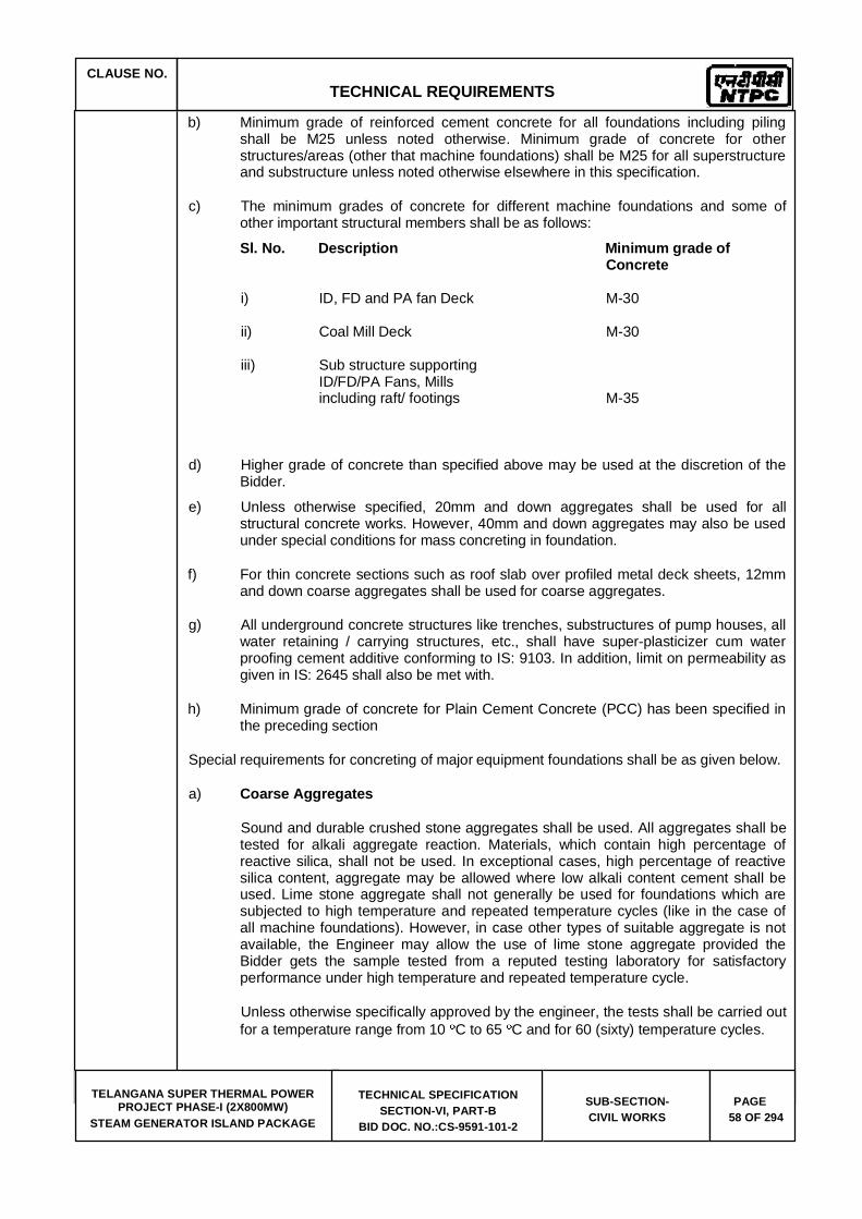
CLAUSE NO. TECHNICAL REQUIREMENTS
TELANGANA SUPER THERMAL POWER PROJECT PHASE-I (2X800MW)
STEAM GENERATOR ISLAND PACKAGE
TECHNICAL SPECIFICATION SECTION-VI, PART-B
BID DOC. NO.:CS-9591-101-2
SUB-SECTION-CIVIL WORKS
PAGE 58 OF 294
b) Minimum grade of reinforced cement concrete for all foundations including piling shall be M25 unless noted otherwise. Minimum grade of concrete for other structures/areas (other that machine foundations) shall be M25 for all superstructure and substructure unless noted otherwise elsewhere in this specification.
c) The minimum grades of concrete for different machine foundations and some of other important structural members shall be as follows:
Sl. No. Description Minimum grade of Concrete
i) ID, FD and PA fan Deck M-30
ii) Coal Mill Deck M-30
iii) Sub structure supporting ID/FD/PA Fans, Mills including raft/ footings M-35
d) Higher grade of concrete than specified above may be used at the discretion of the Bidder.
e) Unless otherwise specified, 20mm and down aggregates shall be used for all structural concrete works. However, 40mm and down aggregates may also be used under special conditions for mass concreting in foundation.
f) For thin concrete sections such as roof slab over profiled metal deck sheets, 12mm and down coarse aggregates shall be used for coarse aggregates.
g) All underground concrete structures like trenches, substructures of pump houses, all water retaining / carrying structures, etc., shall have super-plasticizer cum water proofing cement additive conforming to IS: 9103. In addition, limit on permeability as given in IS: 2645 shall also be met with.
h) Minimum grade of concrete for Plain Cement Concrete (PCC) has been specified in the preceding section
Special requirements for concreting of major equipment foundations shall be as given below.
a) Coarse Aggregates
Sound and durable crushed stone aggregates shall be used. All aggregates shall be tested for alkali aggregate reaction. Materials, which contain high percentage of reactive silica, shall not be used. In exceptional cases, high percentage of reactive silica content, aggregate may be allowed where low alkali content cement shall be used. Lime stone aggregate shall not generally be used for foundations which are subjected to high temperature and repeated temperature cycles (like in the case of all machine foundations). However, in case other types of suitable aggregate is not available, the Engineer may allow the use of lime stone aggregate provided the Bidder gets the sample tested from a reputed testing laboratory for satisfactory performance under high temperature and repeated temperature cycle.
Unless otherwise specifically approved by the engineer, the tests shall be carried out for a temperature range from 10 C to 65 C and for 60 (sixty) temperature cycles.

CLAUSE NO. TECHNICAL REQUIREMENTS
TELANGANA SUPER THERMAL POWER PROJECT PHASE-I (2X800MW)
STEAM GENERATOR ISLAND PACKAGE
TECHNICAL SPECIFICATION SECTION-VI, PART-B
BID DOC. NO.:CS-9591-101-2
SUB-SECTION-CIVIL WORKS
PAGE 59 OF 294
b) Temperature Control of Concrete
The temperature of fresh concrete shall not exceed 25 deg C when placed. For maintaining the temperature of 25 deg C in the top decks of machine foundations, crushed ice shall be used in mixing water.
c) Admixture
Plasticizer /super plasticizer admixture shall generally be added to the concrete for promoting workability. In addition, plasticizer/super plasticizer-cum-ratarder shall be added to retard the setting time for mass concreting work as required. In case of pumping, suitable pumping additive shall also be added to avoid segregation and increase flowability. The slump shall generally be in the range given below:
ID/PA/FD Fans,
Mill deck - 100 mm to 150 mm
Block foundation - 100 mm to 150 mm
Column - 100 mm to 150 mm
d) Form work
Plywood with film face form work shall be used for the top decks of all machine foundations
e) Placing of Concrete
Base Raft and top deck of machine foundations shall be cast in a single pour.
f) Ultrasonic Testing
Ultrasonic pulse velocity test shall be carried out for the top decks of all machine foundations to ascertain the homogeneity and integrity of concrete. In addition, additional cubes (at the rate of one cube per 150 cu.m. of concrete subject to a minimum of six cubes) shall be taken to carry out Ultrasonic Pulse velocity (UPV) testing on the cubes, to serve as reference UPV values. Testing shall be done as per IS:13311 (Part-1). In case of any defect, the Bidder shall rectify the defects suitably using cement/epoxy grout, etc.
g) Scheme for Concreting
Weigh Batching Plants, transit mixer, concrete pump shall be mobilized. Arrangements for standby Plant and Equipment shall also be made.
h) Reinforcement Steel
Reinforcement Steel shall be of grade Fe500 TMT conforming to IS1786. However minimum elongation shall be 14.5%.
8.03.0 Formwork
Formwork for building RCC Slabs/ Beams & Columns shall be of 2 different types.
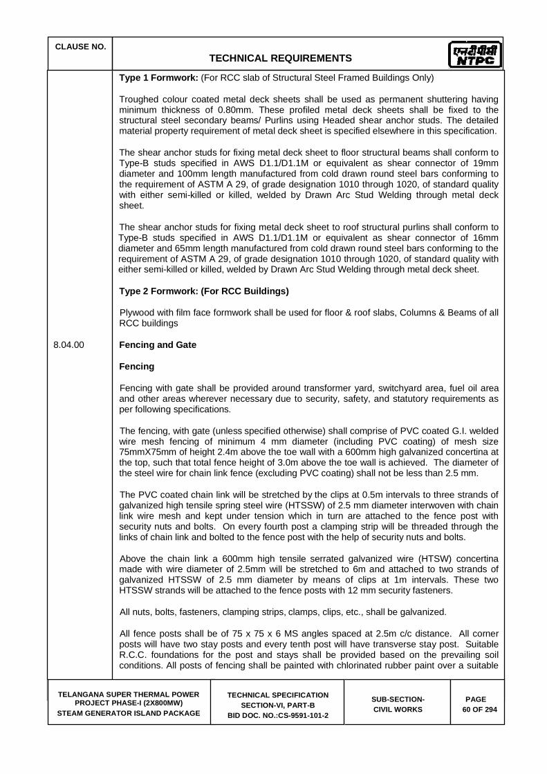
CLAUSE NO. TECHNICAL REQUIREMENTS
TELANGANA SUPER THERMAL POWER PROJECT PHASE-I (2X800MW)
STEAM GENERATOR ISLAND PACKAGE
TECHNICAL SPECIFICATION SECTION-VI, PART-B
BID DOC. NO.:CS-9591-101-2
SUB-SECTION-CIVIL WORKS
PAGE 60 OF 294
Type 1 Formwork: (For RCC slab of Structural Steel Framed Buildings Only)
Troughed colour coated metal deck sheets shall be used as permanent shuttering having minimum thickness of 0.80mm. These profiled metal deck sheets shall be fixed to the structural steel secondary beams/ Purlins using Headed shear anchor studs. The detailed material property requirement of metal deck sheet is specified elsewhere in this specification.
The shear anchor studs for fixing metal deck sheet to floor structural beams shall conform to Type-B studs specified in AWS D1.1/D1.1M or equivalent as shear connector of 19mm diameter and 100mm length manufactured from cold drawn round steel bars conforming to the requirement of ASTM A 29, of grade designation 1010 through 1020, of standard quality with either semi-killed or killed, welded by Drawn Arc Stud Welding through metal deck sheet.
The shear anchor studs for fixing metal deck sheet to roof structural purlins shall conform to Type-B studs specified in AWS D1.1/D1.1M or equivalent as shear connector of 16mm diameter and 65mm length manufactured from cold drawn round steel bars conforming to the requirement of ASTM A 29, of grade designation 1010 through 1020, of standard quality with either semi-killed or killed, welded by Drawn Arc Stud Welding through metal deck sheet.
Type 2 Formwork: (For RCC Buildings)
Plywood with film face formwork shall be used for floor & roof slabs, Columns & Beams of all RCC buildings
8.04.00 Fencing and Gate
Fencing
Fencing with gate shall be provided around transformer yard, switchyard area, fuel oil area and other areas wherever necessary due to security, safety, and statutory requirements as per following specifications.
The fencing, with gate (unless specified otherwise) shall comprise of PVC coated G.I. welded wire mesh fencing of minimum 4 mm diameter (including PVC coating) of mesh size 75mmX75mm of height 2.4m above the toe wall with a 600mm high galvanized concertina at the top, such that total fence height of 3.0m above the toe wall is achieved. The diameter of the steel wire for chain link fence (excluding PVC coating) shall not be less than 2.5 mm.
The PVC coated chain link will be stretched by the clips at 0.5m intervals to three strands of galvanized high tensile spring steel wire (HTSSW) of 2.5 mm diameter interwoven with chain link wire mesh and kept under tension which in turn are attached to the fence post with security nuts and bolts. On every fourth post a clamping strip will be threaded through the links of chain link and bolted to the fence post with the help of security nuts and bolts.
Above the chain link a 600mm high tensile serrated galvanized wire (HTSW) concertina made with wire diameter of 2.5mm will be stretched to 6m and attached to two strands of galvanized HTSSW of 2.5 mm diameter by means of clips at 1m intervals. These two HTSSW strands will be attached to the fence posts with 12 mm security fasteners.
All nuts, bolts, fasteners, clamping strips, clamps, clips, etc., shall be galvanized.
All fence posts shall be of 75 x 75 x 6 MS angles spaced at 2.5m c/c distance. All corner posts will have two stay posts and every tenth post will have transverse stay post. Suitable R.C.C. foundations for the post and stays shall be provided based on the prevailing soil conditions. All posts of fencing shall be painted with chlorinated rubber paint over a suitable
CLAUSE NO. TECHNICAL REQUIREMENTS
TELANGANA SUPER THERMAL POWER PROJECT PHASE-I (2X800MW)
STEAM GENERATOR ISLAND PACKAGE
TECHNICAL SPECIFICATION SECTION-VI, PART-B
BID DOC. NO.:CS-9591-101-2
SUB-SECTION-CIVIL WORKS
PAGE 61 OF 294
primer.
Toe walls either of brick masonry with bricks of minimum 50 kg./sq.cm. crushing strength or of hollow concrete block masonry shall be provided between the fence posts all along the run of the fence with suitable foundation. Toe wall shall be minimum 200mm above the formation level with 50mm thick P.C.C. coping (1:2:4) and shall extend minimum 300mm below the formation level. Toe wall shall be plastered with cement sand mortar (1:6) on both sides and shall be painted with two coats of textured cement point (Sand tax Matt or equivalent) of approved colour and shade. Toe wall shall be provided with weep holes at appropriate spacing.
Gate along fencing
All gates shall be of structural steel of minimum 3.75 metres width for single lane access road and 8.00 m width for double lane access roads. The height of gate shall be same as that of the fence unless noted otherwise. Each gate shall have provision for wicket gate of size 1.0 m x 2.1 m.
The gate frame and post shall be fabricated from medium class MS pipe of nominal diameter not less than 75 mm. The panel plate shall be of minimum thickness 2.5 mm conforming to IS: 513.
The gate shall be complete with fabricated hinges, MS aldrops with locking arrangement, tempered steel pivot, guide track of MS tee, bronze aluminium ball bearing arrangement, castor wheel, etc.
8.05.00 Grating
All gratings shall be electroforged types. Minimum thickness of the grating shall be 40 mm for indoor installation and 32 mm for outdoor installation. The opening size shall not be more than 30mmx100mm. The minimum thickness of the main bearing bar shall be 5 mm or as per design requirement whichever is higher. All gratings shall be hot dip galvanised at the rate of 610 g. per sq.m. after surface preparation by means of shot blasting.
8.06.00 Fabrication
The fabrication shall be done as per fabrication drawing which would clearly indicate various details of joints to be welded, type of weld, length and size of weld, whether shop or site weld.
All steel structures (excluding Chimney flue liners & other ducts) shall be fabricated in factory, transported and erected at site. All factory fabricated structures shall have bolted field connections. Chimney flue liners & other ducts may be fabricated and welded at site. Coal bunkers with hopper shall be fabricated at factory in segments, transported and welded at site.
The factory referred above shall be in operation for the last two (2) years from the date of techno-commercial bid opening. The factory shall have the following facilities:
a) Multi-Axis Drilling Machine (Computer Numeric Controlled) b) Quality Set-up for carrying out necessary Non-Destructive Tests like Dye-Penetration
Tests, Ultrasonic Tests, Radiographic Tests etc. c) Heat Treatment facilities d) Area for Pre-Assembly bed

CLAUSE NO. TECHNICAL REQUIREMENTS
TELANGANA SUPER THERMAL POWER PROJECT PHASE-I (2X800MW)
STEAM GENERATOR ISLAND PACKAGE
TECHNICAL SPECIFICATION SECTION-VI, PART-B
BID DOC. NO.:CS-9591-101-2
SUB-SECTION-CIVIL WORKS
PAGE 62 OF 294
Welding
a) Welding of Structural steel shall be done by an electric arc process and shall conform generally to relevant acceptable standards viz. IS:816, IS:9595, IS:814, IS:2014, IS:4354 and Indian Standard Hand Book for metal arc welding, and other standards, codes of practice internationally accepted. For welding of any particular type of joint, Bidder shall give appropriate tests as described in any of the Indian Standards - IS: 817, IS: 7307 and international standards as relevant.
b) Submerged arc-welding shall be used for welding longitudinal fillet welds (connecting flange with web) and longitudinal / transverse butt joints for fabrication of columns, framing beams and crane girders and all other built-up members, unless manual arc welding is specifically approved by the Engineer. Necessary jigs and fixtures and rotation of structures shall be so arranged that vertically down-hand position of welding becomes possible. ‘Open-Arc-Welding’ process employing coated electrodes shall be employed for fabrication of other welded connections and field welding.
c) Wherever welding is done for assembling the components of structures, the job shall so positioned that downhand welding is possible.
d) Any structural joint shall be welded only by those welders who are qualified for all welding procedures and positions in such type of joint that is welded.
e) All records for entire welding operations such as welders identification marks, the joints welded by the each welder, the welding procedures adopted, welding machine employed, pre and post heating done and any non destructive test done and stress relieving /heat treatment performed on such joints shall be accessible to the Engineer for scrutiny.
f) In a fabrication of plated columns/beams and built up members all shop splices in each component part shall be done before such component part is welded to other parts of the member. Wherever weld reinforcement interferes with proper fitting between components to be assembled by welding, these welds shall be ground flush prior to assembly.
g) The members to be jointed by fillet welding shall be brought and held as close together as possible and in no event shall be separated locally by more than 3mm. If the local separation is 1.5mm or greater, the fillet weld size shall be increased by the amount of separation.
Edge preparation for welding as per weld joint detail shall be prepared either by machines or by automatic gas cutting. All edges cut by flame shall be ground before they are welded.
Electrodes
a) The electrodes used for welding shall be of suitable type and size depending upon specification of the parent materials, the method of welding, the position of welding and quality of welds desired e.g. normal penetration welds or deep penetration welds. However, only low Hydrogen electrodes shall be used for plate thickness above 20 mm.
b) All low hydrogen electrodes shall be baked and stored before use as per manufacturer recommendation. The electrodes shall be rebaked at 2500C - 3000 Cfor one hour and later on cooled in the same oven to 1000C. It shall be transferred to an holding oven maintained at 600C - 700C. The electrodes shall be drawn from this

CLAUSE NO. TECHNICAL REQUIREMENTS
TELANGANA SUPER THERMAL POWER PROJECT PHASE-I (2X800MW)
STEAM GENERATOR ISLAND PACKAGE
TECHNICAL SPECIFICATION SECTION-VI, PART-B
BID DOC. NO.:CS-9591-101-2
SUB-SECTION-CIVIL WORKS
PAGE 63 OF 294
oven for use.
c) Where coated electrodes are used they shall meet the requirements of IS:814 and relevant ASME-Sec. Covering shall be heavy to withstand normal conditions of handling and storage.
d) Only those electrodes which give radiographic quality welds shall be used for welds which are subjected to radiographic testing
e) Where bare electrodes are used, these shall correspond to specification of the parent material. The type of flux-wire combination for submerged arc welding shall conform to the requirements of F-60 Class of AWSA-5-17-69 and IS:3613. The electrodes shall be stored properly and the flux shall be baked before use in an oven in accordance with the manufacturer’s requirements as stipulated.
f) 308L and 309L electrodes / fillers shall be used for welding of stainless steel to stainless steel and stainless steel to mild steel respectively.
g) Specific approval of the Engineer shall be taken by Bidder for the various electrodes proposed to be used on the work before any welding is started.
Preheating inter-pass temperature and post weld heat treatment.
a) Mild steel plates conforming to IS:2062 and thicker than 20mm, may require preheating of the parent plate prior to welding as mentioned in Table-I.
However, higher preheat and interpass temperatures required due to joint restraint etc. and will be followed as per approved welding procedure. In welding materials of unequal thickness, the thicker part shall be taken for this purpose.
c) Base metal shall be preheated, not withstanding provisions of IS:9595, to the temperature given in Table-1 prior to welding or tack welding. Preheating shall bring the surface of the base metal to the specified preheat temperature and this temperature shall be maintained as minimum temperature while welding is in progress.
TABLE – 1 MINIMUM PREHEAT and INTER PASS TEMPERATURE FOR WELDING
Thickness of thicker part Welding using Low hydrogen at point of Welding electrodes or Submerged arc welding
Upto and including 20mm None
Over 20mm and upto and 20 0C including 40m
Over 40mm and upto and 66 0C including 63mm
Over 63mm 110 0C
c) Preheating may be applied by external flame which is non-carbonising like LPG, by electric resistance or electric induction process such that uniform heating of the surface extending upto a distance of four times the thickness of the plate on either

CLAUSE NO. TECHNICAL REQUIREMENTS
TELANGANA SUPER THERMAL POWER PROJECT PHASE-I (2X800MW)
STEAM GENERATOR ISLAND PACKAGE
TECHNICAL SPECIFICATION SECTION-VI, PART-B
BID DOC. NO.:CS-9591-101-2
SUB-SECTION-CIVIL WORKS
PAGE 64 OF 294
side of the welding joint is obtained.
d) Thermo-chalk, thermo-couple or other approved methods, shall be used for measuring the plate temperature.
e) All butt welds with plates thicker than 50mm and all site butts weld of main framing beam shall require post weld heat treatment as per procedure given in AWS D-1.1. Post heating shall be done upto 600 deg.C and rate of application shall be 200 deg.C per hour. The post heat temperature shall be maintained for 60 minutes per 2.5cm. thickness. For maintaining slow and uniform cooling, asbestos pads shall be used for covering the heated areas.
Sequence of Welding
a) The sequence of welding shall be carefully chosen to ensure that the components assembled by welding are free from distortion and large residual stresses are not developed. The distortion should be effectively controlled either by a counter effect or by a counter distortion. The direction of welding should be away from the point of restraint and towards the point of maximum freedom.
b) Each case shall be carefully studied before finally following a particular sequence of welding.
c) Butt weld in flange plates and/or web plates shall be completed before the flanges and webs are welded together.
d) The beam and column stiffeners shall preferably be welded to the webs before the web and flanges are assembled unless the web and flanges to the beam or column are assembled by automatic welding process.
e) All welds shall be finished full and made with correct number of runs, the weld being kept free from slag and other inclusions, all adhering slag being removed.
f) Current shall be appropriate for the type of electrode used. To ensure complete fusion, the weaving procedure should go proper and rate of arc advancement should not be so rapid as to leave the edges unmelted.
g) Pudding shall be sufficient to enable the gases to escape from the molten metal before it solidifies.
h) Non-uniform heating and cooling should be avoided to ensure that excessive stresses are not locked up resulting ultimately in cracks.
i) The ends of butt welds shall have full throat thickness. This shall be obtained on all main butt welds by the use of run off and run on pieces adequately secured on either side of main plates. The width of these pieces shall not be less than the thickness of the thicker part joined. Additional metal remaining after the removal of extension pieces shall be removed by grinding or by other approval means and the ends and surface of the welds shall be smoothly finished. Where the abutting parts are thinner than 20mm the extension pieces may be omitted but the end be welded to provide the ends with the required reinforcement.
j) The fusion faces shall be carefully aligned. Angle shrinkage shall be controlled by presetting. Correct gap and alignment shall be maintained during the welding operation.

CLAUSE NO. TECHNICAL REQUIREMENTS
TELANGANA SUPER THERMAL POWER PROJECT PHASE-I (2X800MW)
STEAM GENERATOR ISLAND PACKAGE
TECHNICAL SPECIFICATION SECTION-VI, PART-B
BID DOC. NO.:CS-9591-101-2
SUB-SECTION-CIVIL WORKS
PAGE 65 OF 294
k) All main butt welds shall have complete penetration and back surface of the weld being gouged out clean before first run of the weld is given from the back. However, partial penetration butt weld shall be permitted, when specifically shown in the design drawings.
l) Intermittent welds shall be permitted only when shown in the design drawings.
m) The welding shrinkage shall be minimized by adopting the correct welding procedure and method. In long and slender member extra length should be provided at the time of fabrication for shrinkage.
Testing of Welders
All the welders to be employed for the job shall have to qualify the appropriate tests laid down in IS: 817 and IS: 1181 and ASME IX/AWS D1.1. All the necessary arrangements required for the testing of welders are to be provided by the Bidder.
Inspection of Welds
a) Visual Inspection
100 percent of the welds shall be inspected visually for external defects. Dimensions of welds shall be checked. The lengths and size of weld shall be as per fabrication drawings. It may be slightly oversized but should not be undersized. The profile of weld is affected by the position of the joint but it should be uniform. The welds should have regular height and width of beads. The height and spacing of ripples shall be uniform. The joints in the welds run shall as far as possible be smooth and should not show any humps or craters in the weld surface. Welds shall be free from unfilled craters on the surface, under-cuts, stages on the surface and visible cracks.
Such inspection shall be done after cleaning the weld surface with steel wire brushes and chisel to remove the spatter metal, scales, slag, etc., If external defects mentioned above are noticed, there is every possibility of internal defects and further radiographic/ultrasonic examination shall be undertaken.
b) Production Test Plate
Test plates shall be incorporated on either side of at least one main butt welds of each flange plate and web plate of every main frame columns and crane girder. The weld shall be continuous over the test plate. The test plate extensions of the main plates and shall be fixed so that metal lies in the same direction as that of the main plate. Test plates shall be prepared and tested in accordance with the accepted Standards, in the presence of the Engineer or his authorized representative. Should any of these tests fail, further radiographic examination of the welds shall be done. These tests for test plates and radiographic examination are additional to those contemplated under inspection and testing.
c) Non-destructive and special testing
Radiographic / ultrasonic or other non-destructive examination shall be carried out. All tests of welds shall be carried out by the Bidder at his own cost. The cordoning of radiation zone, while Radiography testing is going on, shall be done.
In case of failure of any of the tests, re-testing of the joints shall also be carried out after rectification is done.

CLAUSE NO. TECHNICAL REQUIREMENTS
TELANGANA SUPER THERMAL POWER PROJECT PHASE-I (2X800MW)
STEAM GENERATOR ISLAND PACKAGE
TECHNICAL SPECIFICATION SECTION-VI, PART-B
BID DOC. NO.:CS-9591-101-2
SUB-SECTION-CIVIL WORKS
PAGE 66 OF 294
d) Rectification of defective welding work
Wherever defects like improper penetration, extensive presence of blow holes, undercuts, cracking, slag inclusion, etc., are noticed by visual inspection/other tests, the welds, and in such location shall be removed by gouging process. The joints shall be prepared again by cleaning the burrs and residual matters with wire brushes and grinding, if necessary, and rewelded. The gouging shall as far as possible be done using gouging electrodes.
Inspection and Testing
a) Fillet Welds
i) All fillet welds shall be checked for size and visual defects.
ii) Macroetch examination on production test coupons for main fillet weld with minimum one joint per built up beam, column and crane girder, etc.
iii) 25% weld length of tension members of crane girder shall be subjected to dye-penetration test.
iv) On all other welds, dye-penetration test on 5% of weld length with minimum 300mm at each location shall be carried out.
b) Butt Welds
i) 100% visual examination.
ii) Dye penetration test on all butt welds after back gouging shall be carried out.
iii) Mechanical testing of production test coupons - minimum one joint/built up beam, column and crane girder. The engineer may reduce the frequency of the test, after getting consistently satisfactory results of initial 10 tests.
iv) 100% radiography test on butt welds of tension flange (bottom flange) of crane girder and bunker supporting girders. All other butt welds shall be subjected to radiography test on 10% of weld length of each welder.
c) Dimensional Tolerance and Acceptance Criteria of Welds
i) Every first and further every 10th set of identical structure shall be checked for control assembly at shop before erection.
ii) All structures, components/members shall be checked for dimensional tolerance during fabrication and erection as per IS:7215 and IS:12843 respectively.
iii) Dry film thickness after painting shall be checked by using elchometer.
iv) Acceptance criteria of NDTs on welds shall be as per AWS D-1.1 (Dynamically loaded structures - Tension welds).

CLAUSE NO. TECHNICAL REQUIREMENTS
TELANGANA SUPER THERMAL POWER PROJECT PHASE-I (2X800MW)
STEAM GENERATOR ISLAND PACKAGE
TECHNICAL SPECIFICATION SECTION-VI, PART-B
BID DOC. NO.:CS-9591-101-2
SUB-SECTION-CIVIL WORKS
PAGE 67 OF 294
Correction of Defective Welds
Correction of defective welds shall be carried out without damaging the parent metal. When a crack in the weld is removed magnetic particles inspection or any other equally positive means shall be used to ensure that the whole of the crack and material up to 25mm beyond each end of the crack has been removed.
Erection of Structures
All erection work shall be done with the help of cranes, use of derrick is not envisaged.
Erection Marks
a) Erection marks in accordance with fabrication drawing shall be clearly painted on the fabricated steelwork. Each piece shall be marked in at least on two places. Each piece shall also have its weight marked thereon.
d) The centre lines of all columns, elevations and girder bearings shall be marked on the sections to ensure proper alignment and assembly of the pieces at site.
Erection Scheme
a) The Erection Scheme for the erection of all major structures shall be furnished. The erectability of the structure shall be checked by the Bidder before commencement of fabrication work to avoid future modification. The erection scheme shall indicate the approximate weight of the structural members, position of lifting hook, crane boom length, crane capacity at different boom length and at different boom inclination, etc., Bidder shall take up the erection work only after he has obtained the approval of the erection scheme from the Engineer.
b) The erection scheme shall also give details of the method of handling, transport, hoisting, including false work/staging, temporary, bracing, guying, temporary strengthening, etc., It will also give the complete details of the number and capacity of the various erection equipment that will be used such as cranes, winches, etc., along with disposition at the time of erection of columns, trusses, etc.
c) The erection of columns, trusses, trestles, portals, etc., shall be carried out in one single piece as far as practicable. No column shall be fabricated and erected in more than 3 pieces. Galleries shall generally be erected as box i.e. the bottom chord and bracings, top chord and bracings, side vertical posts and bracings, end portals and roof-trusses shall be completely welded prior to erection and if required temporary strengthening during erection shall be made. The inside sheeting runners and roof sheeting purlins may be erected individually. When erection joints are provided in columns, their location shall generally be just above a floor level.
9.00.00 ARCHITECTURAL CONCEPTS AND DESIGN
9.01.00 For Architectural Concepts and Design refer to 5.0.0 in this specification.
9.02.00 General Architectural Specifications
9.02.01 General
CLAUSE NO. TECHNICAL REQUIREMENTS
TELANGANA SUPER THERMAL POWER PROJECT PHASE-I (2X800MW)
STEAM GENERATOR ISLAND PACKAGE
TECHNICAL SPECIFICATION SECTION-VI, PART-B
BID DOC. NO.:CS-9591-101-2
SUB-SECTION-CIVIL WORKS
PAGE 68 OF 294
a) Minimum 1000 mm high (from floor/ roof level) hand railing shall be provided around all floor/roof openings, projections/balconies, walkways, platforms, steel stairs, etc., wherever the height of the building is more than 12m, railing ht to be 1.2m. All handrails and ladder pipes (except at operating floors) shall be 32 mm nominal bore MS pipes (medium class) conforming to IS:1161 and shall be galvanised as per IS : 4736 and finished with suitable paint. All rungs and ladders shall also be galvanised. Minimum weight of galvanising shall be 610 g/sqm. The spacing of vertical posts shall be maximum 1500mm. Two number of horizontal rails shall be provided including the top member. In addition, toe guard/ kick plate of min size 100x6th shall be provided above the floor level.
For RCC stairs, passages & Atriums in buildings, around all floor openings at operating floors, 1000 mm /1200mm high hand railing with 32 NB (polished) stainless steel pipe shall be provided. The spacing of vertical posts shall be 1500mm. Two number of horizontal rails shall be provided including the top member. Toe guard and kick plate shall be provided above the floor level.
b) All stairs shall have a maximum riser height of 180mm and a minimum tread width of 275 mm. Minimum clear width of stair shall be 1200 mm unless specified otherwise. For Administration Building& Service Building, stairs width shall be minimum 1500 mm, with Riser 150mm and Tread 300 mm.
c) All buildings having metal cladding shall be provided with a 150 mm high RCC toe kerb at the edge of the floor along the metal cladding. 1000 mm high hand railing shall be provided on this RCC kerb, wherever required from the safety point of view.
d) In all buildings, structures, suitable arrangement for draining out water collected from equipment blowdowns, leakages, floor washings, fire fighting, etc., shall be provided for each floor. All the drains shall be suitably covered with grating or precast RCC panels.
e) RCC staircase shall be provided for main entrance of Turbine building; control tower area and all other RCC construction buildings.
f) Parapet, Chajjas 450mm over window and 600mm door heads, 900mm over rolling shutters, architectural facias, projections, etc., shall be provided with drip course in cement sand mortar 1:3.
g) All fire exits shall be painted with fire resistant paint P.O red/signal red colour shade which shall not be used anywhere except to indicate emergency or safety measure. Fire safety norms shall be followed as per National Building Codes and fire safety requirements for providing fire exits, escape stairs and fire fighting equipment. In detailing of all buildings, fire safety requirements conforming to IS: 1641 and IS:1642 shall be followed.
h) Ramps & Lifts for physically challenged persons shall be provided for barrier free access to the buildings.
9.03.00 Water Supply and Sanitation
9.03.01 Two numbers of roof water tanks (one for storing service water and another for potable water) of adequate capacities depending on the number of users and 8 hours requirement shall be provided for each building and pump house. Polyethylene water storage tanks conforming to IS:12701 shall be used. The tanks shall be complete with all fittings including lid, float valve, stop cock, vent pipe, etc.

CLAUSE NO. TECHNICAL REQUIREMENTS
TELANGANA SUPER THERMAL POWER PROJECT PHASE-I (2X800MW)
STEAM GENERATOR ISLAND PACKAGE
TECHNICAL SPECIFICATION SECTION-VI, PART-B
BID DOC. NO.:CS-9591-101-2
SUB-SECTION-CIVIL WORKS
PAGE 69 OF 294
Galvanised MS pipe of medium class conforming to IS: 1239 shall be used for internal piping works for service water and potable water supply. The pipes shall be concealed, and painted with anti-corrosive bituminous paint (as per IS: 158) wherever required.
Sand Cast Iron pipes with lead joints conforming to IS: 1729 shall be used for sanitary works above ground level. All Buildings shall be designed with Toilets as per NBC norms.
All buildings shall have minimum one toilet block each. The facilities provided in the toilet block shall depend on the number of users. However, minimum facilities to be provided shall be as stipulated in subsequent clause. IS:1172 shall be followed for working out the basic requirements for water supply, drainage and sanitation. In addition, IS:2064 and IS:2065 shall also be followed.
9.03.02 Each Toilet block shall have the following minimum facilities. Unless specified all the fittings shall be of Chromium plated brass (fancy type). For GRIHA rated Buildings all fittings shall conform to GRIHA requirements, for water efficiency.
a) One number wall mounted coloured (excluding premium colours) glazed vitreous China European water closet and flushing valve system, water faucet, toilet paper holder as per IS:2556
b) One number white glazed vitreous China Orissa pan (580 x 440 mm) and flushing valve system, toilet paper holder as per IS:2256
c) One number colour (excluding premium colours) glazed ceramic oval shaped wash basin 450x 550 mm (approx.) mounted over 18mm thick granite beveled edge counter fitted with photo-voltaic control system for water controls, bottle trap as per IS:2556. For common toilets, number of washbasins shall be as per requirement. However for Pump Houses the same shall be provided without photo voltaic control system for water control.
d) For Male Toilets Urinal as per requirements, with all fittings with photovoltaic control flushing system as per IS:2556.
e) One number looking mirror 600 x 900 x 6 mm, edge mounted with teak beading and minimum 12 mm thick plywood backing, one number stainless towel rail 600 x 20 mm, one number liquid soap dispenser
f) One toilet with required facilities shall be provided for physically challenged persons as per National Building Code requirements
g) In addition to the facilities stipulated elsewhere Bathroom with rotating type chromium plated shower including all fitting and fixtures shall also be provided in toilet at ground and operating floor of main plant:
h) Janitor Space & space for drinking water cooler.
i) Electric operated hand dryer with photo voltaic control.
j) The pantry shall consist of one number stainless steel pantry sink, as per IS : 13983, of size 610 x 510 mm, bowl depth 200 mm with drain board of at least 450 mm length with trap, hot and cold water mixer, one number geyser of 25 liters capacity, with inlet and outlet connections, one number HDPE loft type / over head water storage tank, as per IS : 12701 and of 500 liters capacity, complete with float valve, overflow drainage pipe arrangement, GI concealed water supply pipe of minimum 12

CLAUSE NO. TECHNICAL REQUIREMENTS
TELANGANA SUPER THERMAL POWER PROJECT PHASE-I (2X800MW)
STEAM GENERATOR ISLAND PACKAGE
TECHNICAL SPECIFICATION SECTION-VI, PART-B
BID DOC. NO.:CS-9591-101-2
SUB-SECTION-CIVIL WORKS
PAGE 70 OF 294
mm dia of medium class, cast iron sanitary pipe (with lead joints) of minimum 75 mm diameter, floor trap with Stainless
Steel grating, inlet and outlet connections for supply and drainage, with all bends, tees, junctions, sockets, etc., as are necessary for the commissioning and efficient functioning of the pantry (all sanitary fittings shall be heavy duty chrome plated brass, unless noted otherwise)
k) Laboratory sink shall be of white vitreous china of size 600x400x200 mm conforming to IS:2556 (Part-5).
l) In addition, adequate number of portable toilet units with adequate plumbing and sanitary arrangement, shall be provided during construction stage.
9.04.00 Flooring
Floor finishes of approved shade and colour (non - premium colours), over under bed of cement mortar / concrete, at all levels and for all kind of works, elevations, on horizontal and vertical surfaces for all types of work (like flooring, skirting, dado, wall lining & facing, tread and risers etc.), including topping, spreading white cement slurry at an average rate of 2.5 kg/Sq. M., (unless noted otherwise), jointing and joint filling with white cement (unless noted otherwise) slurry mixed with colour pigment, to match the shade of the finishing material, laying to plumb and water level in desired pattern, line and flush butt square jointing, curing, rubbing, grinding, polishing, edge moulding, finishing and cleaning, testing, providing opening of required size and shape, casting in panels wherever specified.
9.04.01 The nominal total thickness of floor finish shall be 50 mm i.e. underbed and topping. The floor shall be laid on an already laid and matured concrete base. The underbed for floors and similar horizontal surfaces shall consist of cement concrete M20 grade. Stone chips shall be 12.5 mm down well graded( & proper filling shall be done with brick bats/cinders). Flooring like Tiles/ Stones shall be laid with 1:4 cement sand mortar and Tile/ Stone Cladding on wall shall be laid with 1:3 cement sand mortar.
9.04.02 Sunken slabs shall be made water tight by suitable water proofing treatment.
9.04.03 Metallic hardener topping -with ordinary grey cement shall be- 12 mm thick (insitu) or finishing the concrete / mortar surfaces topping shall be furnished with neat cement slurry (with ordinary grey cement)
9.04.04 Heavy duty cement concrete tiles 300 mm x 300 mm shall be in using white cement with pigment, with hard and abrasion resistant carborundum / quartz chips for wearing course as per IS:1237. Laying of tiles shall be as per IS:1443.
9.04.05 Heavy duty (grade-5) dust pressed ceramic tiles (300mmx300mm shall be as per IS 15622. Designer ceramic wall tiles of size 300 mm x 200 mm / (300x600mm).
9.04.06 20mm / 38mm / 75 mm/ 115mm thick acid resistant tile on horizontal and vertical surfaces, at all levels for all type of works shall include one coat of bitumen primer followed by 12 mm thick bituminastic layer, 20mm / 38mm/ 75 mm / 115mm thick A.R. tiles, 6 mm thick under-bed by potassium silicate mortar, pointing of joints of tiles with acid/alkali resistant epoxy/furane mortar up to a depth of 20 mm and bituminastic end sealing.
9.04.07 Mirror polished/ Matt finish (80:20) Vitrified ceramic tiles (min 9.5mm thk) with sizes of the tiles shall be as under:

CLAUSE NO. TECHNICAL REQUIREMENTS
TELANGANA SUPER THERMAL POWER PROJECT PHASE-I (2X800MW)
STEAM GENERATOR ISLAND PACKAGE
TECHNICAL SPECIFICATION SECTION-VI, PART-B
BID DOC. NO.:CS-9591-101-2
SUB-SECTION-CIVIL WORKS
PAGE 71 OF 294
a) 600 mm x 600 mm
b) 800mm x 800mm
9.04.08 For pathway, chequered and designed concrete tiles minimum 22 mm thick, 200x200 mm size conforming to IS: 13801 of approved shade and colour shall be used. 1000 wide pathways shall be provided for maintenance on rooftops of all buildings.
9.04.09 PVC flooring, wherever used, shall be minimum 2 mm thick (virgin) as per IS: 3462. The laying of flooring shall be as per IS: 5318.
9.04.10 Epoxy Flooring
Epoxy Flooring shall be provided with surface preparation of concrete substrate with Captive Shot Blasting Machine OR Light Grinding to form the required anchor profile on the floor substrate followed by application of epoxy resin based moisture barrier underlay of 2 mm thickness including filling of saw cut joints with epoxy cementitious resin based moisture barrier underlay as per manufacturer specification. Application of self smoothing epoxy floor topping of epoxy based resin of 2 mm thickness over epoxy resin based moisture barrier underlay including application of solvent free epoxy resin based two component primer.
It shall include application of PU Sealant at Expansion and Isolation Joint respectively including surface preparation of the joint, fixing of backup strip and application of sealant.
9.04.11 Mirror polished Marble stone (slab) - (Rajnagar) Plain white -18 mm thick shall be provided in main stairs & 18mm thick kota stone shall be provided in the fire escape stairs.
9.04.13 Decorative/designer prepolished, plain and pigmented, high wearing resistance concrete tiles of 20mm thickness (minimum) in various non-standard interlocking patterns.
9.04.15 Skirting in general shall be 150 mm high. Dado in toilets & pantries, shall be upto 2200 mm height from finished floor level. Skirting and Dado shall match with the floor finish.
9.04.16 Wherever required, removable metallic false flooring system shall be provided. Nominal height of the false flooring shall be 600 mm. The same shall comprise of special grade steel panels (of size 600x600mm). without any dimensional tolerance 1.2mm thick die cast to shape having 1mm thick top MS sheet spot welded together to form a composite steel panel, sitting on aluminum diecasted heads & mounted on steel pedestals of 25mm dia rod of adjustable height and supporting 1.2mm thick channel frame work at-top and 2mm thick 150x150mm base plate. The top finish shall be 2mm thick antistatic PVC sheet or High pressures laminate. Cavity area below the false flooring shall be made dust proof by using Polyurethane paint.
9.04.17 Interlocking concrete blocks shall be of various sizes and thickness having M 35 grade of concrete and pigmented to specified colours, in different pattern (in different textures chequered or other patterns in indentation for guiding band/s for visually impaired persons) including the preparation of sub base with 20mm thick sand and filling of joints with sand.
9.04.18 Matt finish (with grooves) Porselin tiles (for guiding band/s for visually impaired persons) shall be with 3mm groove joints as per approved pattern pointed neatly with 3X4mm stainless epoxy grout SP- 100 of Laticrete or approved equivalent in approved colour to match colour of tile.
24 mm x 24 mm x 3.8 mm thick (minimum) glass mosaic tiles in decorative murals and pattern.
CLAUSE NO. TECHNICAL REQUIREMENTS
TELANGANA SUPER THERMAL POWER PROJECT PHASE-I (2X800MW)
STEAM GENERATOR ISLAND PACKAGE
TECHNICAL SPECIFICATION SECTION-VI, PART-B
BID DOC. NO.:CS-9591-101-2
SUB-SECTION-CIVIL WORKS
PAGE 72 OF 294
9.04.19 Paving
a) Ground floor of all buildings shall be provided with normal duty paving with 50mm thick metallic hardener floor finish. For details of normal duty paving refer to description elsewhere in this specification.
b) PCC paving of nominal mix 1:2:4 (1 part cement: 2 parts sand: 4 parts aggregate), 100 mm thick laid over 75 mm thick bed of dry brick aggregate shall be provided for following areas:
i) 750 mm wide plinth protection around all buildings other than those covered under paved area.
ii) 2.0 m wide pathway all along pipe/ cable corridor and all around each cooling tower. 2.0 mm wide ways inter connecting all cooling towers with each other.
9.05.00 Acid/ Alkali Resistant Lining
9.05.01 The material shall conform to the following:
i) Bitumen primer shall conform to IS: 158.
ii) Bitumastic compound shall conform to IS: 9510. Where the height of bitumastic layer on vertical surface is more than 2.0 m, the bitumastic layer shall be reinforced with diamond pattern expanded metal steel sheets conforming to IS: 412.
iii) A.R. Bricks/ Tiles shall conform to class II of IS: 4860 & IS: 4457 respectively.
iv) Mortar: Potassium silicate & resin type mortars shall conform to IS: 4832 Part-I&II respectively.
9.05.02 Requirements for acid/ alkali resistant flooring and lining for different areas shall be as given Table-A enclosed at the end of this specification. Battery Room in all buildings shall be provided with acid/ alkali resistant tiles on flooring & dado 1200mm high.
9.06.00 Roof
9.06.01 Except for the roofs subjected to heavy loads, roof of all buildings having structural steel frame work shall consist of permanently colour coated (on exposed face) troughed metal sheet decking of approved profile having minimum base metal thickness of 0.8mm of galvanised (with minimum rate of galvanisation of 275 gm/sq.m.) M.S. sheet or minimum 0.8mm of high tensile steel (minimum yield strength 350 MPa) coated with zinc aluminium alloy (zincalume) (coating not less than 150 gm./sq.m). Silicon modified polyester paint having DFT of minimum 20 microns shall be used for permanent coating. The sheeting shall be fixed by means of concealed fixing system or any other compatible method approved by the Engineer. RCC slab of minimum 40 mm clear thickness in excess of trough depth shall be provided over the metal decking. Water proofing cum plasticiser compound shall be added to concrete over the metal decking. Bidder shall demonstrate that the roof is leak proof by carrying out the water-retaining test by maintaining the minimum water depth of 50mm over the roof surface for a period of 48 hours. Water Proofing Treatment as given below for RCC roof slabs shall be provided to ensure that the roof is watertight.

CLAUSE NO. TECHNICAL REQUIREMENTS
TELANGANA SUPER THERMAL POWER PROJECT PHASE-I (2X800MW)
STEAM GENERATOR ISLAND PACKAGE
TECHNICAL SPECIFICATION SECTION-VI, PART-B
BID DOC. NO.:CS-9591-101-2
SUB-SECTION-CIVIL WORKS
PAGE 73 OF 294
9.06.02 Roof of all buildings having RCC framework shall have cast-in-situ RCC slab. Such roof shall be provided with roof water proofing treatment using high solid content liquid applied elastomeric water proofing membrane with separate wearing course as per ASTM - C-836 & 898. Thickness of the membrane shall be 1.5mm (min.). This treatment shall include application of polymerised mastic over the roof to achieve smooth surface and primer coat. Wearing course on the top of membrane shall consist of 25mm thick PCC (1:2:4) cast in panels of maximum 1.2 x 1.2m size and reinforced with 0.56mm dia galvanised chicken wire mesh and sealing of joints using sealing compound/elastomeric water proofing membrane. However, chequered concrete tile flooring 22 mm (min.) thick of approved colour and shade conforming to IS: 13801 shall be provided for path way of 1 m. width for access of personnel and handling of equipment and for the entire area of the roof where equipment like AC / Ventilation plant, cooling towers, etc. are provided in place of PCC wearing course. Equipment shall be installed on raised pedestal of minimum 30 cm height from the finished roof to facilitate maintenance of roof treatment in future.
9.06.03 For efficient disposal of rainwater, the run off gradient for the roof shall not be less than 1:100 and the roof shall be provided with RCC water gutter, wherever required. Gutter shall be made water tight using suitable watertight treatment. This gradient can be provided either in structure or subsequently by screed concrete 1:2:4 (using 12.5 mm coarse aggregate) and/or cement mortar (1:4). However, minimum 25 mm thick cement mortar (1:4) shall be provided on top to achieve smooth surface.
9.06.04 For Building where metal cladding is envisaged medium class galvanised mild steel pipes conforming to IS: 1239/IS:3589 with welded joints shall be provided to drain off rain water from the roof. For rest of the buildings cast-iron pipes with lead caulked joints conforming to IS:1230 shall be used. These shall be suitably concealed with masonry work, cement concrete / or sheeting work to match with the exterior finish. The number and size of down comers shall be governed by IS:1742 and IS:2527. Roof drain level of all RCC framed buildings having cast-in-situ RCC roof shall be provided with Rain water gutter and/or 45 x 45 cm size Khurras having minimum thickness of 30 mm with 1:2:4 concrete over PVC sheet of 1 m x 1 m x 400 micron and finished with 12 mm thick cement sand plaster 1:3. All the pipes shall be provided with suitable fittings and fixtures. Gratings shall be of stainless steel.
9.06.05 Roof of the buildings that shall conform to minimum 3 star GRIHA Rating shall have over deck insulation with minimum 75 mm thick Extruded Polyurethane foam with minimum density 18 kg/Cu.m. above water proofing with mortar and Joints sealed with adhesive tape over roof and above it White glazed tile chips shall be provided for roofing over under bed of cement mortar/concrete including all workmanship, topping spreading white cement slurry at an average rate of 2.5 kg/sq m(unless noted otherwise)jointing and joint filling with white cement slurry (unless noted otherwise) ,laying to plumb and water level in desired pattern ,casting in panels .
9.06.06 Roof Water Proofing
Roof water proofing treatment shall be as follows:
a) For roofs having structural slope:
Top surface of sloped R.C.C. slab shall be finished with 15mm thick cement plaster (1:4). Over the finished surface elastomeric membrane shall be laid. The elastomeric shall comprise of high solid content liquid applied urethane laid over reinforcing layer of polyscrim cloth or non woven geo-textile. The top of the elastomeric membrane shall be finished with 20 mm thick cement: sand (1:4) mortar with chicken wire mesh and pressed precast concrete tiles of 20 mm thickness where applicable shall be laid over mortar at green stage. Provision for thermal expansion of roofing tiles shall be kept by providing an expansion gap in both directions filled up with polysulphide joint
CLAUSE NO. TECHNICAL REQUIREMENTS
TELANGANA SUPER THERMAL POWER PROJECT PHASE-I (2X800MW)
STEAM GENERATOR ISLAND PACKAGE
TECHNICAL SPECIFICATION SECTION-VI, PART-B
BID DOC. NO.:CS-9591-101-2
SUB-SECTION-CIVIL WORKS
PAGE 74 OF 294
sealant. The expansion gap shall be provided in the cement sand mortar underbed layer also.
b) For roofs having no structural slope:
Screed concrete mix (1:2:4) grading having minimum 25mm thickness at the lowest point of the slope shall be laid over R.C.C. slab and shall be laid as per the slope specified elsewhere in the specification. Top surface of grading underbed shall be finished with 15mm thick cement plaster (1:4). Over the finished surface elastomeric membrane shall be laid and top of the elastomeric membrane shall be finished with 20 mm thick cement: sand (1:4) mortar with chicken wire mesh and pressed precast concrete tiles of 20 mm thickness where applicable shall be laid over mortar at green stage. Provision for thermal expansion of roofing tiles shall be kept by providing an expansion gap in both directions filled up with polysulphide joint sealant. The expansion gap shall be provided in the cement sand mortar underbed layer also
9.06.07 Roof of all buildings shall be provided with access/approach through staircase or ladder. Roof where equipment are mounted shall be provided with access through staircase.
9.06.08 RCC parapet wall of minimum 1000 mm height (above top of slab) for all accessible roofs and 600 mm height for all non-accessible roofs shall be provided. Alternatively parapet wall comprising structural steel post, runner and sheeting may be provided for buildings with metal sheet cladding.
9.06.09 Fillets at junction of roof and vertical walls shall be provided with cast-in-situ cement concrete (1:1.5:3) nominal mix followed by 12mm thick 1:4 cement sand plaster.
9.06.10 Pathways for handling of materials and movement of personnels shall be provided with 22mm thick chequered cement concrete tiles as per IS:13801 for a width of 1000mm .
9.07.00 Walls
9.07.01 All walls shall be non-load bearing infill panel walls.
9.07.02 For initial height up to 3 metres from ground floor one brick thick masonry wall shall be provided wherever metal cladding is specified.
9.07.03 All internal walls shall be with one brick thick in cement mortar (1:6). However, internal partition walls for toilets shall be with half brick masonry thick with cement mortar (1:4).
9.07.04 For ESP building wall shall be of factory made composite modular light weight aerated concrete panels, (minimum 4 hours of fire rating) consisting of 2 fiber reinforced cement sheets (minimum 4 mm thick) on either side of light weight concrete core, having minimum compressive strength of 35 Kg / Cm2 and the density in the range of 700-900 Kg. / cu.m. of the thickness and fire rating as specified below, to provide external wall and internal partition at all levels, capable of sustaining wind pressure of 4.50 M height (H) within limiting deflection of span/250, fixed in position in tongue and groove jointing system by screwing the panels to top and bottom U channels, (channels minimum 1.25 mm thick and galvanised to grade 180 (minimum) as per IS : 277), fixing U profiled top and bottom channels to concrete / primary steel members which are placed at the maximum vertical spacing of 4.5m with the help of galvanised steel expansion fasteners, filling the joints from both faces with silicon acrylic paste and making the same water tight by covering with fibre glass tape (minimum 50 mm wide and minimum 0.5 mm thick) or by any other suitable material, so as to ensure that the entire construction done with the light weight aerated concrete panels are weather proof and panel surfaces are flush for painting, creating opening for doors / windows /ventilators /

CLAUSE NO. TECHNICAL REQUIREMENTS
TELANGANA SUPER THERMAL POWER PROJECT PHASE-I (2X800MW)
STEAM GENERATOR ISLAND PACKAGE
TECHNICAL SPECIFICATION SECTION-VI, PART-B
BID DOC. NO.:CS-9591-101-2
SUB-SECTION-CIVIL WORKS
PAGE 75 OF 294
ducts / pipes/fans/AC etc. and finishing the opening face with the same U profiled galvanized steel channel which is used at the top and bottom.
9.07.06 For other buildings, the type, thickness and initial height of external cladding facing the transformer yard shall be according to the requirements.
External face of Toilets, Air-conditioned and pressurised areas shall be provided with masonry wall as per functional / aesthetic requirements. (Inside the metal cladding wherever provided).
9.07.07 50 mm thick DPC in Cement concrete (1:1.5:3) with water proofing compound followed by two layers of bitumen coating 85/25 grade as per IS:702 @ 1.7 kg./sq.m. shall be provided at plinth level before starting the masonry work.
9.08.00 Colour coated and other sheeting work
Permanently colour coated sheet of approved shade and colour using galvanised mild steel sheet of minimum 0.6mm BMT(bare metal thickness i.e. metal thickness excluding thickness for coating and galvanizing) galvanised to grade 275 as per IS 277,of minimum yield strength of grade SS255 as per ASTM A653M / grade G250 as per AS 1397, coated with zinc of class designation Z275 / aluminium-zinc alloy coated to class AZ150 or high tensile steel of minimum 0.5mm BMT(bare metal thickness i.e. metal thickness excluding thickness for zinc aluminium coating and colour coating ) of grade SS340-Class 4 as per ASTM A792M / grade G350 as per AS 1397, coated with aluminium zinc alloy of class designation Z275 / aluminium-zinc alloy coated to class AZ150
For profiled colour coated metal deck sheet, minimum 0.8 mm BMT (bare metal thickness i.e. metal thickness excluding thickness for coating and galvanizing) of grade SS255 as per ASTM A653M / grade G250 as per AS 1397, coated with zinc of class designation Z275 / aluminium-zinc alloy coated to class AZ150, troughed profile having nominal trough depth 44 mm and pitching of 130 mm shall be used. However alternative profile meeting the strength, defection and other functional requirements such as sections modulus and moment of inertia shall be provided. To minimize the number of joints, the length of the sheet shall preferably be not less than 4.5m, cut pieces shall not be used, unless specifically approved by the Engineer. However, the actual length shall be such so as to suit the purling / runner spacing.
Steel shall be colour coated with total coating thickness of at least 35 microns (nominal) comprising of silicon modified polyester (SMP with silicon content of 30% to 50%) paint or Super Polyester paint, of minimum 20 microns (nominal) dry film thickness (DFT) on external face on 5 microns (nominal) primer coat and 5 microns (nominal) SMP or super polyester paint over 5 microns (nominal) primer coat on internal face. SMP and Super polyester paint systems shall be of industrial finish of product type 4 of AS/NZ2728. Coated surface shall be provided with a protected guard film (polyethylene) of about 40 microns to avoid any damage to the coating during handling.
Thickness tolerance of (+/-) 0.04mm is permissible, however all design calculations shall be carried out on the basis of lowest value of sheet thickness considered.
For wall cladding insulated / uninsulated and conveyor gallery sides and roof, permanently colour coated sheet of troughed profile shall be used. The nominal depth of trough shall be 30 mm. However alternative profile meeting the strength, deflection and other functional requirements such as section modulus and moment of inertia shall be provided.
Sheet shall be of approved profile, sectional properties, colour and shade.

CLAUSE NO. TECHNICAL REQUIREMENTS
TELANGANA SUPER THERMAL POWER PROJECT PHASE-I (2X800MW)
STEAM GENERATOR ISLAND PACKAGE
TECHNICAL SPECIFICATION SECTION-VI, PART-B
BID DOC. NO.:CS-9591-101-2
SUB-SECTION-CIVIL WORKS
PAGE 76 OF 294
For profiled metal decking sheets (to be used for RCC floor slab) the sectional modulus and moment of inertia of troughed profile per meter width shall be so as to limit the deflection of sheets to span/250 under total super imposed loading (DL +LL) comprising the self weight of metal deck sheet, dead weight of green concrete and an additional construction load 100kg per sqm for two span condition. The sectional modulus and moment of inertia of troughed profile shall be computed as per the provisions of IS:801 for satisfying the deflection and strength requirements.
For metal deck sheets used for roofing (with or without RCC) and side cladding, the sectional modulus and moment of inertia of troughed profile per metre width shall be such that the deflection of sheets is limited to span/250 under design wind pressure for two span condition. The sectional modulus and moment of inertia of troughed profile shall be computed as per the provisions of IS:801 for satisfying the deflection and strength requirements. No increase in allowable stress is permissible under wind load condition.
The maximum spacing of the fasteners shall preferably be 250mm (+/-) 100mm c/c on every crest along the length of purlins/runners. However exact spacing shall be as per the design done by the bidder for the fasteners considering the wind load, self load and other associated loads. Minimum diameter of the fastener shall be 5.5 mm and atleast 3 nos. of fasteners shall be used per sheet.
Z spacers if required shall be made of at least 2 mm thick galvanised steel sheet of grade 275 as per IS : 277
Sealant used for cladding shall be butyl based, two parts poly sulphide or equivalent approved, non stainless material and be flexible enough not to interface with fit of the sheets
. Filler blocks as a trough filler shall be used to seal cavities formed between the profiled sheet and the support or flashing. The filler blocks shall be manufactured from black synthetic rubber or any other material approved by the Engineer.
For insulation of cladding and other areas, mineral wool conforming to IS: 8183 shall be used. The density shall be 32 or 48 kg. /Cu.M. for glass or rock wool respectively. The nominal thickness of insulation shall be 50mm.
The polycarbonate sheet to be used for cladding and glazing purpose in conveyor galleries shall have toughed profile to match with the metal cladding profile. Minimum 2.0mm thick fire retardant and UV resistant polycarbonate clean sheet of GE plastic or equivalent approved make shall be used. The polycarbonate sheet shall be installed along with the metal cladding so as to have a watertight lapping arrangement. Suitable detailing shall be made to cater for the thermal expansion. IS: 14434 to be referred for other details.
Polycarbonate sheet minimum 2mm thick fire retardant impact resistant and ultraviolet resistant sheet shall be provided (as glazing) in transfer houses, pump houses, etc.
All flashings, trim closures, caps etc. required for the metal cladding system shall be made out of plain sheets having same material and any weather/moisture sealnts with appropriate material and coating specification as mentioned above for the outer face of the sandwiched metal cladding. Overlap shall be min. 100 mm or as specified by manufacturer.
For buildings where insulated sandwiched double metal sheets shall be used for Roof. The sandwich sheet combination shall comprise top sheet as troughed permanently colour coated sheet & bottom sheet as plain permanently colour coated for covering of exposed metal/ concrete / brick surfaces with 50mm thick insulation sandwiched between the two sheets, each sheet shall be of steel with zinc coated to class 275 with minimum bare metal thickness (i.e. excluding the thickness of coating and painting) of 0.6mm of grade G250 as per AS1397

CLAUSE NO. TECHNICAL REQUIREMENTS
TELANGANA SUPER THERMAL POWER PROJECT PHASE-I (2X800MW)
STEAM GENERATOR ISLAND PACKAGE
TECHNICAL SPECIFICATION SECTION-VI, PART-B
BID DOC. NO.:CS-9591-101-2
SUB-SECTION-CIVIL WORKS
PAGE 77 OF 294
/ grade SS255 as per ASTM A653M / grade S250GD as per EN 10326 or of steel with aluminium-zinc alloy coated to class Z275 / aluminium-zinc alloy coated to class AZ150 with minimum bare metal thickness (i.e. excluding the thickness of coating and painting) of 0.5mm of grade G350 as per AS1397 / grade SS340 class 4 as per ASTM A792M / grade S350GD as per EN 10326 or of steel with aluminium-zinc alloy coated to class Z275 / aluminium-zinc alloy coated to class AZ150 with minimum bare metal thickness (i.e. excluding the thickness of coating and painting) of 0.4mm of grade G550 as per AS1397 / grade SS550 as per ASTM A792M / grade S550GD as per EN 10326 or alternatively aluminium feed material of minimum bare metal thickness of 0.7 mm of aluminium alloy of Series 31000 and above as per IS:737 and IS:1254, steel / aluminium both colour coated with total coating thickness of at least 35 microns (nominal) dry film thickness (DFT) comprising of Silicon Modified Polyester (SMP with silicon content of 30% to 50%) paint or Polyester paint, of 20 microns (nominal) SMP or polyester paint on one side (exposed face), over 5 micron (nominal) primer coat and 5 micron (nominal) SMP or Polyester paint over 5 micron (nominal) primer coat on other side (SMP and Super Polyester paint shall conform to product type 4 of AS/NZS 2728), troughed sheet shall be of approved profile, sectional properties, (suitable for the specified loading / deflection and purlins / runner spacing), colour and shade, at all levels, including all labour, materials, equipment, handling, transportation, special coated fastener conforming to corrosion resistant Class 3 of AS3566 and tested for 1000 hours salt spray test, fixing insulated sandwiched metal sheeting assembly with the structural members below for supporting the sheeting system, scaffolding, equipment, end and side laps, cutting of openings, preparation of working drawings, testing, etc., all complete, as per specifications
9.09.00 Plastering
9.09.01 Outer face (i.e. rough side) of all brick walls shall have 18 mm thick and inner face (i.e. smooth side) of all walls shall have 12 mm thick cement sand plaster 1:6.
9.09.02 Plaster of paris (Gypsum Anhydrous) conforming to IS:2547 shall be used for plaster of paris punning over cement plastered surfaces. The finish surface shall be smooth and shall be of 2 mm nominal thickness.
9.09.03 All R.C.C. walls shall have minimum 12mm thick cement sand plaster 1:6.
9.09.04 All RCC ceilings (except areas provided with false ceiling, cable vault ceiling and metal decking) shall be provided with 6mm thick cement sand plaster 1:4.
9.09.05 Groove of uniform size 12 x 12 mm up to 20 x 15 mm in plastered surface as per approved pattern, shall be provided as per approved drawing.
9.09.06 All plastering work shall conform to IS:1661.
9.10.00 Painting & Aluminium Composite Panel Cladding
9.10.01 All painting on masonry or concrete surface shall preferably be applied by roller. If applied by brush then same shall be finished off with roller.
9.10.02 All paints shall be of approved make including chemical resistant paint.
9.10.03 Minimum 2 finishing coats of paint shall be applied over a coat of primer.
9.10.04 The paint shall be be (premium acrylic smooth exterior paint) of approved brand and manufacture. This paint shall be brought to the site of work by the contractor in its original containers in sealed condition. The material shall be brought in at a time in adequate quantities to suffice for the whole work or at least a fortnight’s work. The materials shall be kept in the joint custody of the contractor and the Engineer-in-Charge. The empty containers

CLAUSE NO. TECHNICAL REQUIREMENTS
TELANGANA SUPER THERMAL POWER PROJECT PHASE-I (2X800MW)
STEAM GENERATOR ISLAND PACKAGE
TECHNICAL SPECIFICATION SECTION-VI, PART-B
BID DOC. NO.:CS-9591-101-2
SUB-SECTION-CIVIL WORKS
PAGE 78 OF 294
shall not be removed from the site of work till the relevant item of work has been completed and permission obtained from theEngineer-in-charge.
9.10.05 Stone work for wall lining etc. (Veneer work) over 20 mm thick bed of cement mortar 1:3 (1 cement: 3 coarse sand) and jointed with grey cement slurry @3.3kg/sq.m, including rubbing and polishing in complete. (Black polished granite stone slab, 18 mm thk / polished Sadarhally grey granite slab 18 mm thk).
The final, finished coating shall be fungus resistant, UV resistant, water repellant, alkali resistant, and extremely durable with colour fastness.
9.10.06 Acrylic emulsion paint shall be as per IS:15489. Acrylic distemper shall be as per IS:428. Cement paint shall conform to IS:5410, white wash/colour wash shall conform to IS:627.
9.10.07 Fire resistant transparent paint as per IS:162 shall be provided on all wood work over French polish or flat oil paint. French polish shall conform to IS:348. Flat oil paint shall conform to IS:137.
9.10.08 All fire exits shall be painted in post office red/signal red colour shade, which shall not be used anywhere else except to indicate emergency or safety measure.
9.10.09 For painting on concrete, masonry and plastered surface IS:2395 shall be followed. For painting on wood work IS:2338 shall be followed.
9.10.10 For painting on steel work and ferrous metals, BS: 5493 and IS:1477 shall be followed. The type of surface preparation, thickness and type of primer, intermediate and finishing paint shall be according to the painting system adopted.
9.10.11 Bitumen primer used in acid/alkali resistant treatment shall conform to IS:158.
9.10.12 All internal paints shall be of low VOC content conforming to GRIHA rating for reduction of VOC content.
9.10.13 Resin bonded granular textured finish, for external applications shall consist of crushed stone / quartz chips of 2.5 mm size and of approved colour/ shade and bonded with synthetic resins, Adhesives and additives, all together in a single pack mix. For internal finish 1.2mm of approved, colour & shade (pigmented granular or flake finish)
The final finish shall have UV-Resistant, fungus/bacterial resistant properties.
Grooves shall be provided as per drawing and the same shall be filled with polysulphide sealant of matching colour/shade.
9.10.14 Aluminium Composite Panel
Aluminum Composite Panels for external wall cladding at all heights and elevation shall be fixed on to the supporting steel members, masonry wall, fastening material and hardware complete with all labour, material, equipment, handling, transportation, workmanship, preparation of working drawings, staging, scaffolding, etc., all complete. The aluminum composite panel should consist of 3mm thick thermoplastic core of anti oxidant LDPE sandwiched between 2 skins of 0.5mm thick aluminum alloy sheet making a total panel thickness of 4mm. The surface shall be finished with PVDF based coating of minimum 30 micron on the topsides and services coating on the reverse side shall be with polymer paint. Coating shall conform to ECCA or AAMA.the surface shall be protected with self adhesive peel of masking foil. The system shall be designed to withstand a wind pressure of 200kg/Sqm and shall be fixed to he Masonry/RC walls with necessary clamps, brackets and

CLAUSE NO. TECHNICAL REQUIREMENTS
TELANGANA SUPER THERMAL POWER PROJECT PHASE-I (2X800MW)
STEAM GENERATOR ISLAND PACKAGE
TECHNICAL SPECIFICATION SECTION-VI, PART-B
BID DOC. NO.:CS-9591-101-2
SUB-SECTION-CIVIL WORKS
PAGE 79 OF 294
anchor fasteners. All clamps and brackets shall be Hot dip galvanized minimum 80 microns thick and shall conform to IS: 4759-1996. The extruded aluminum section shall be anodized in approved colour with a anodic coating of minimum 20 microns. Extruded section shall be 6063 T5 or T6 alloy conforming to ASTM B221. Any other festering straps, nuts, bolts, rivets, washers, etc. shall be in stainless steel SS304 grade. EPDM gaskets, open cell polyethylene backer rods, weather sealant etc. shall be provided as per requirement.
Aluminium Composite Panel for internal encasement shall be with II B fire rated LDPE core mixed with mineral fibre.
9.10.15 Exterior Painting On Walls
The paint shall be (premium acrylic smooth exterior paint) of approved brand and manufacture. This paint shall be brought to the site of work by the contractor in its original containers in sealed condition. The material shall be brought in at a time in adequate quantities to suffice for the whole work or at least a fortnight’s work. The materials shall be kept in the joint custody of the contractor and the Engineer-in-Charge. The empty containers shall not be removed from the site of work till the relevant item of work has been completed and permission obtained from the Engineer-in-Charge.
9.11.00 Doors & Windows
9.11.01 Doors, windows and ventilators of air-conditioned areas, entrance lobby of all buildings (where ever provided), and all windows and ventilators of all buildings (unless otherwise mentioned) shall have, electro colour dyed (anodised with 15 micron coating thickness) aluminium framework with glazing. All doors of toilet areas shall be of steel framed solid core flush shutter. For Mill Bunker Building, transfer points, crusher house, conveyor gallery, steel louvered windows shall be provided.
9.11.04 Single glazed panels with aluminium framework shall be provided as partition between two air-conditioned areas wherever clear view is necessary.
9.11.05 a) The doors frames shall be fabricated from 1.6 mm thick MS sheets and shall meet the general requirements of IS:4351.
b) All steel doors shall consist of double plate flush door shutters. The door shutter shall be 35 mm (min.) thick with two outer sheets of 1.2 mm rigidly connected with continuous vertical 1.0 mm stiffeners at the rate of 150 mm centre to centre. Side, top and bottom edges of shutters shall be reinforced by continuous pressed steel channel with minimum 1.2 mm. The door shall be sound deadened by filling the inside void with mineral wool. Doors shall be complete with all hardware and fixtures like door closer, tower bolts, handles, stoppers, aldrops, locks etc.
9.11.06 Steel windows and ventilators shall be as per IS:1361 and IS:1038.
9.11.07 Wherever functionally required Rolling shutter (fully closed/partly grilled) with suitable operating arrangement (manual/Electric) shall be provided to facilitate smooth operations. Rolling shutters shall conform to IS:6248. M.S sliding doors with suitable mechanical and electrical operations fixtures as per requirement for bigger openings shall be used.
9.11.08 All windows and ventilators on ground floor of all buildings shall be provided with suitable Aluminium grill.
9.11.09 Fire-Proof doors with panic devices shall be provided at all fire exit points as per requirements. These doors shall generally be as per IS:3614 Part-II. Fire rating of the doors
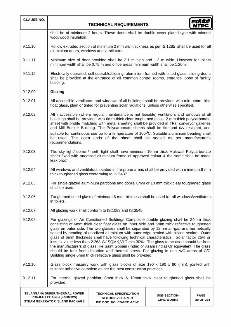
CLAUSE NO. TECHNICAL REQUIREMENTS
TELANGANA SUPER THERMAL POWER PROJECT PHASE-I (2X800MW)
STEAM GENERATOR ISLAND PACKAGE
TECHNICAL SPECIFICATION SECTION-VI, PART-B
BID DOC. NO.:CS-9591-101-2
SUB-SECTION-CIVIL WORKS
PAGE 80 OF 294
shall be of minimum 2 hours. These doors shall be double cover plated type with mineral wool/wood insulation.
9.11.10 Hollow extruded section of minimum 2 mm wall thickness as per IS:1285 shall be used for all aluminium doors, windows and ventilators.
9.11.11 Minimum size of door provided shall be 2.1 m high and 1.2 m wide. However for toilets minimum width shall be 0.75 m and office areas minimum width shall be 1.20m.
9.11.12 Electrically operated, self operable/closing, aluminium framed with tinted glass. sliding doors shall be provided at the entrance of all common control rooms, entrance lobby of facility building.
9.12.00 Glazing
9.12.01 All accessible ventilators and windows of all buildings shall be provided with min. 4mm thick float glass, plain or tinted for preventing solar radiations, unless otherwise specified.
9.12.02 All inaccessible (where regular maintenance is not feasible) ventilators and windows of all buildings shall be provided with 6mm thick clear toughened glass. 2 mm thick polycarbonate sheet with profile matching with metal sheeting shall be provided in TPs, conveyor galleries and Mill Bunker Building. The Polycarbonate sheets shall be fire and u/v resistant, and suitable for continuous use up to a temperature of 1000C. Suitable aluminium beading shall be used. The open ends of the sheet shall be sealed as per manufacturer’s recommendations.
9.12.03 The sky light/ dome / north light shall have minimum 10mm thick Multiwall Polycarbonate sheet fixed with anodised aluminium frame of approved colour & the same shall be made leak proof.
9.12.04 All windows and ventilators located in fire prone areas shall be provided with minimum 6 mm thick toughened glass conforming to IS:5437.
9.12.05 For single glazed aluminium partitions and doors, 8mm or 10 mm thick clear toughened glass shall be used.
9.12.06 Toughened tinted glass of minimum 6 mm thickness shall be used for all windows/ventilators in toilets.
9.12.07 All glazing work shall conform to IS:1083 and IS:3548.
9.12.08 For glazings of Air Conditioned Buildings Composite double glazing shall be 24mm thick consisting of 6mm thick clear float glass on inner side and 6mm thick reflective toughened glass on outer side. The two glasses shall be separated by 12mm air-gap and hermetically sealed by beading of anodized aluminium with outer edge sealed with silicon sealant. Outer glass of 6mm thickness shall have following technical characteristics: Solar factor 25% or less, U-value less than 2.268 W/ SQMK,VLT min 30%: The glass to be used should be from the manufacturers of glass like Saint Gobain (India) or Asahi (India) Or equivalent. The glass should be free from distortion and thermal stress. For glazing in non A/C areas of A/C Building single 6mm thick reflective glass shall be provided.
9.12.10 Glass block masonry work with glass blocks of size 190 x 190 x 90 (min), jointed with suitable adhesive complete as per the best construction practices.
9.12.11 For internal glazed partition, 8mm thick & 10mm thick clear toughened glass shall be provided.

CLAUSE NO. TECHNICAL REQUIREMENTS
TELANGANA SUPER THERMAL POWER PROJECT PHASE-I (2X800MW)
STEAM GENERATOR ISLAND PACKAGE
TECHNICAL SPECIFICATION SECTION-VI, PART-B
BID DOC. NO.:CS-9591-101-2
SUB-SECTION-CIVIL WORKS
PAGE 81 OF 294
9.13.00 False ceiling
9.13.01 False ceiling of 12.5 mm thick tapered/square edge glass fibre reinforced gypsum board conforming to IS : 2095 having fine texture finish, including providing and fixing of frame work at all levels, for all kind of work, consisting of light weight galvanised steel member (minimum 0.8 mm thick and galvanised as per IS : 277) having maximum grid size of 1200 mm x 600 mm for supporting panels of specified size, suspended from RCC structural steel or catwalkway grid above, with 4 mm (minimum) galvanised wires (rods), with special height adjustment clips, providing angle section of minimum 25 mm width along the perimeter of ceiling, supporting grid system (minimum 0.8 mm thick and galvanised as per IS : 277 ), expansion fasteners for suspension arrangement from RCC, providing openings for AC ducts, return air grills, light fixtures, etc., all complete. (concealed grid and finished flat seamless and curve shape (dome etc.), finished smooth(seamless) along with the galvanised light gauge steel supporting system laid in profile to suit the profile of dome)
9.13.02 False ceiling of 15 mm thick mineral fibre board, in tile form of size 600mm x 600mm, along with galvanised light gauge rolled form supporting system in double web construction pre painted with steel capping, of approved shade and colour, to give grid of maximum size of 1200x600. as per manufacturers details including supporting grid system, expansion fasteners for suspension arrangement from RCC, providing openings for AC ducts, return air grills, light fixtures, etc., all complete.
9.13.03 False ceiling of 12 mm thk calcium silicate board of 'HILUX' or equivalent with suspension system as per manufacturers details including supporting grid system, expansion fasteners for suspension arrangement from RCC, providing openings for AC ducts, return air grills, light fixtures, etc., all complete. (With concealed grid and finished flat seamless).
9.13.04 Aluminium false ceiling shall be in 600 mm x 600 mm tile of 0.6 mm thk. alluminum with perforation patterns in combination with built in nonwoven tissue, for providing good acoustic properties and installed with T-Grid (of profile 24 mm) in same or contrasting colours or with 6 mm recess joints. The whole system shall be level adjusting arrangement and shall be suspended as per manufacturer guidelines of Luxalon, Armstrong or equivalent.
9.13.05 Pre-Painted Coil coated Steel false ceiling system, at all level, for all kind of works, consisting of 0.5 mm thick galvanised as per IS : 277, along with galvanised supporting steel members exposed faces of galvanised member to be prepainted with regular modified polyester coating / super polyester coating minimum 20 DFT, to form panels of specified size for tile type panels and roll formed stove enamelled 0.6 mm thick steel carrier, for fixing of lineal type panels by clip on arrangement, suspended from RCC slab / structural steel or catwalk way steel channel grid above with 4 mm (minimum) galvanised wires (rods), with special height adjustment clips, providing angle section of minimum 25 mm leg width along the perimeter of ceiling, including all labour, material, supporting grid system (members minimum 0.8 mm thick and galvanised as per IS : 277) anchor fasteners for making suspension arrangement from RCC, providing openings for AC ducts, return air grills, insulation light fixtures, etc., all complete.
9.13.06 Tile type steel false ceiling system in square pattern panels of 600 mm x 600 mm size along with galvanised light gauge rolled form. supporting system in double web ‘T’ construction with pre-painted steel, with Tee support.
9.13.07 Lineal pattern (closed type) of 100 mm nominal width, with carrier support. Metal ceiling as above in lineal/tile shape in stainless steel, bright finish instead of pre-painted coil coated finish.
9.13.08 Mineral wool insulation shall be laid on top of false ceiling panels. Additional hangers and height adjustment clips shall be provided for return air grills, light fixtures, A.C. ducts etc.
CLAUSE NO. TECHNICAL REQUIREMENTS
TELANGANA SUPER THERMAL POWER PROJECT PHASE-I (2X800MW)
STEAM GENERATOR ISLAND PACKAGE
TECHNICAL SPECIFICATION SECTION-VI, PART-B
BID DOC. NO.:CS-9591-101-2
SUB-SECTION-CIVIL WORKS
PAGE 82 OF 294
9.13.09 Suitable M.S. channel (Minimum MC75 with maximum spacing of 1.2 m C/C both ways) grid shall be provided above the false ceiling level for movement of personnel and to facilitate maintenance of lighting fixtures, AC ducts etc.
9.12.10 Underdeck insulation shall be provided on the ceiling (underside of roof slab) and underside of floor slab of air-conditioned area depending upon the functional requirements. This underdeck insulation shall consist of 50mm thk. mineral wool insulation with 0.05 mm thick aluminium foil & 0.6 mm x 25mm mesh wire netting and shall be fixed to the ceiling with 2 mm wire ties.
9.13.11 Suitable cut-outs shall be provided in false ceiling to facilitate fixing of lighting fixtures, AC grills, smoke detectors, etc.
9.14.00 Finishing Schedule
Interior and Exterior Finishes shall be as given in Tables-B & C respectively attached at the end of these specification.
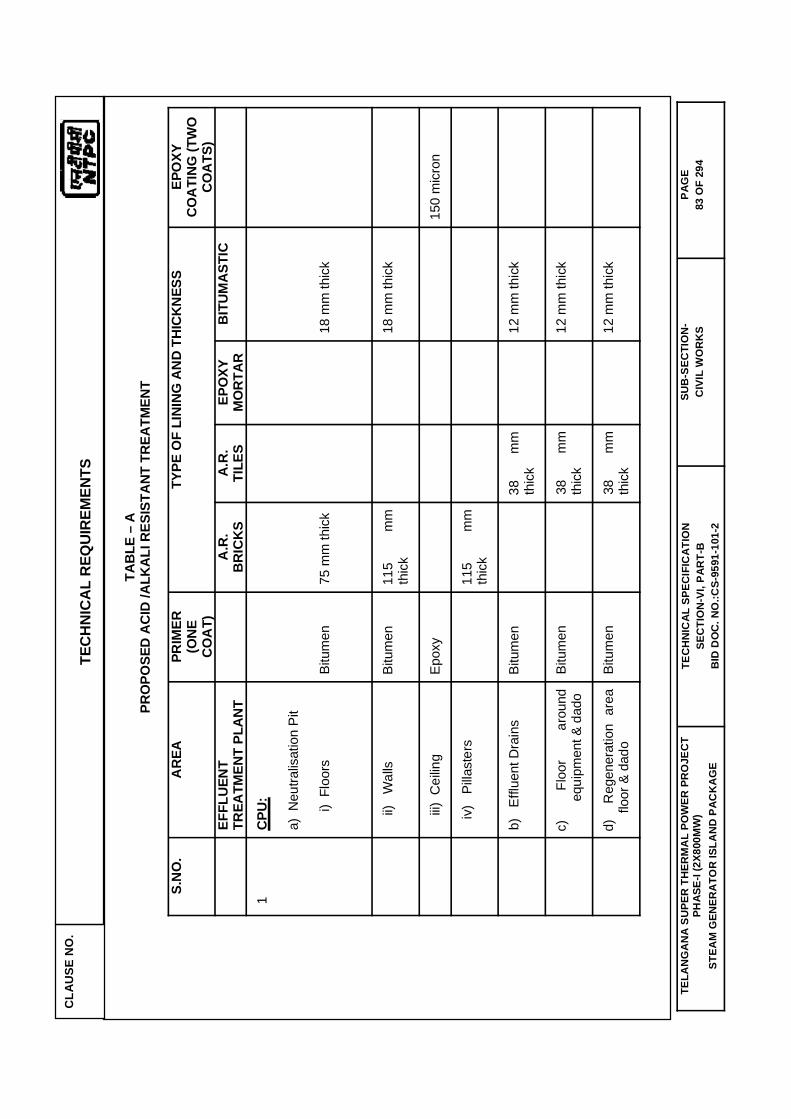
CLA
USE
NO
. TE
CH
NIC
AL
REQ
UIR
EMEN
TS
TELA
NG
AN
A S
UPE
R T
HER
MA
L PO
WER
PR
OJE
CT
PHAS
E-I (
2X80
0MW
) ST
EAM
GEN
ERA
TOR
ISLA
ND
PAC
KA
GE
TEC
HN
ICAL
SPE
CIF
ICAT
ION
SE
CTI
ON
-VI,
PAR
T-B
B
ID D
OC
. NO
.:CS-
9591
-101
-2
SUB
-SEC
TIO
N-
CIV
IL W
OR
KS
PAG
E 83
OF
294
TABL
E –
A
PRO
POSE
D A
CID
/ALK
ALI R
ESIS
TANT
TRE
ATM
ENT
S.N
O.
ARE
A PR
IMER
(O
NE
COA
T)
TYPE
OF
LINI
NG A
ND
THIC
KNES
S EP
OXY
CO
ATI
NG (T
WO
CO
ATS
)
EFFL
UEN
T TR
EATM
ENT
PLAN
T
A.R
. BR
ICKS
A.
R.TI
LES
EPO
XYM
ORT
AR
BITU
MAS
TIC
1
CPU:
a) N
eutra
lisat
ion
Pit
i
) Fl
oors
Bi
tum
en75
mm
thic
k 18
mm
thic
k
ii)
Wal
ls
Bitu
men
11
5 m
m
thic
k
18
mm
thic
k
iii)
Cei
ling
Ep
oxy
150
mic
ron
iv)
Pilla
ster
s
115
mm
th
ick
b)
Ef
fluen
t Dra
ins
Bitu
men
38
mm
th
ick
12
mm
thic
k
c)
Fl
oor
arou
nd
equi
pmen
t & d
ado
Bitu
men
38
mm
th
ick
12 m
m th
ick
d)
R
egen
erat
ion
area
flo
or &
dad
o Bi
tum
en
38
m
m
thic
k
12 m
m th
ick

CLA
USE
NO
. TE
CH
NIC
AL
REQ
UIR
EMEN
TS
TELA
NG
AN
A S
UPE
R T
HER
MA
L PO
WER
PR
OJE
CT
PHAS
E-I (
2X80
0MW
) ST
EAM
GEN
ERA
TOR
ISLA
ND
PAC
KA
GE
TEC
HN
ICAL
SPE
CIF
ICAT
ION
SE
CTI
ON
-VI,
PAR
T-B
B
ID D
OC
. NO
.:CS-
9591
-101
-2
SUB
-SEC
TIO
N-
CIV
IL W
OR
KS
PAG
E 84
OF
294
e)
Aci
d /
Alka
li st
orag
e ar
eaBi
tum
en
75
m
m
thic
k
12 m
m th
ick
f)
Deg
asse
r are
a flo
or
Bitu
men
38
mm
th
ick
12
mm
thic
k
g)
Pe
dest
als
for
supp
ortin
g eq
uipm
ent
Bitu
men
38
mm
th
ick
12
mm
thic
k
h)
M.S
. G
ratin
g /
Che
quer
ed p
late
Ep
oxy
150
mic
ron
Not
e : -
1.
The
abov
e ta
ble
is fo
r gen
eral
gui
danc
e on
ly, h
owev
er, a
ctua
l are
as/ f
acilit
ies
to b
e co
vere
d sh
all b
e as
per
Sco
pe o
f wor
k.
2.
Suita
ble
end
seal
ing
shal
l be
prov
ided
.
3.
Stru
ctur
es s
hall
be te
sted
for w
ater
proo
fing
befo
re a
pplic
atio
n of
Aci
d / A
lkal
i Res
ista
nt T
reat
men
t.
4.
This
trea
tmen
t sha
ll be
app
lied
on d
ry s
urfa
ce.
5.
For l
ayin
g of
AR
bric
ks /
tiles
, the
bed
ding
mor
tar s
hall
be o
f pot
assi
um s
ilicat
e 6
mm
thic
knes
s an
d th
e po
intin
g m
orta
r sha
llbe
of E
poxy
/ fu
rane
20
mm
dee
p an
d 6
mm
thic
knes
s.

CLA
USE
NO
. TE
CH
NIC
AL
REQ
UIR
EMEN
TS
TELA
NG
AN
A S
UPE
R T
HER
MA
L PO
WER
PR
OJE
CT
PHAS
E-I (
2X80
0MW
) ST
EAM
GEN
ERA
TOR
ISLA
ND
PAC
KA
GE
TEC
HN
ICAL
SPE
CIF
ICAT
ION
SE
CTI
ON
-VI,
PAR
T-B
B
ID D
OC
. NO
.:CS-
9591
-101
-2
SUB
-SEC
TIO
N-
CIV
IL W
OR
KS
PAG
E 85
OF
294
TABL
E –B
INTE
RIO
R FI
NISH
ING
SCH
EDUL
E
S.N
O.
DESC
RIP
TIO
N O
F AR
EA
FLO
OR
ING
W
ALLI
NG
CEIL
ING
1
ESP
cont
rol
build
ing/
Air
com
pres
sor
hous
e/
a)
O
pera
ting/
Mai
nten
ance
are
as
Cem
ent
conc
rete
w
ith
Met
allic
har
dene
r top
ping
Pr
e co
lor
coat
ed
met
al
pane
l cla
ddin
g.
Acry
lic
dist
empe
r (e
xcep
t m
etal
de
ck a
rea)
b)
O
ffice
Roo
m, S
taff
Roo
m
Vitri
fied
cera
mic
tile
s.
Acry
lic e
mul
sion
pai
nt
Acry
lic e
mul
sion
pai
nt
c)
C
ontro
l R
oom
Vi
trifie
d ce
ram
ic ti
les.
Vi
trifie
d til
e cl
addi
ng
on
wal
ls u
p to
fal
se c
eilin
g&
colu
mn
enca
sed
with
AC
P.
Fals
e ce
iling
in li
neal
Met
al p
anel
d)
M
CC
Roo
m
Cem
ent
conc
rete
w
ith
Met
allic
har
dene
r top
ping
Ac
rylic
dis
tem
per
Acry
lic
dist
empe
r (e
xcep
t m
etal
de
ck a
rea)
e)
R
CC
Sta
ir ca
se
Mar
ble
ston
e / g
rani
te s
tone
. V
itrifi
ed t
ile u
p to
1.2
m.h
t. &
Acry
lic D
iste
mpe
r Ac
rylic
Dis
tem
per
f)
Batte
ry R
oom
Ac
id, A
lkal
i res
ista
nt ti
le
Acid
, Alk
ali r
esis
tant
tile
Ac
rylic
Dis
tem
per
g)
AH
U/
AC
Plan
t ro
om/
Cab
le
vaul
tC
emen
t co
ncre
te
with
M
etal
lic h
arde
ner t
oppi
ng
Acry
lic D
iste
mpe
r Ac
rylic
Dis
tem
per
h)
To
ilets
H
eavy
D
uty
Dus
t pr
esse
d ce
ram
ic
tiles
an
d G
rani
te
ston
e in
one
pie
ce f
or w
ash
basi
n pl
atfo
rm.
Des
igne
r ce
ram
ic w
all t
iles
up to
2.1
m /
ceilin
g ht
. and
Ac
rylic
di
stem
per
for
bala
nce
heig
ht.
Acry
lic d
iste
mpe
r/ C
alci
um s
ilicat
e fa
lse
ceilin
g.

CLA
USE
NO
. TE
CH
NIC
AL
REQ
UIR
EMEN
TS
TELA
NG
AN
A S
UPE
R T
HER
MA
L PO
WER
PR
OJE
CT
PHAS
E-I (
2X80
0MW
) ST
EAM
GEN
ERA
TOR
ISLA
ND
PAC
KA
GE
TEC
HN
ICAL
SPE
CIF
ICAT
ION
SE
CTI
ON
-VI,
PAR
T-B
B
ID D
OC
. NO
.:CS-
9591
-101
-2
SUB
-SEC
TIO
N-
CIV
IL W
OR
KS
PAG
E 86
OF
294
TABL
E –B
INTE
RIO
R FI
NISH
ING
SCH
EDUL
E
S.N
O.
DESC
RIP
TIO
N O
F AR
EA
FLO
OR
ING
W
ALLI
NG
CEIL
ING
2.
M
ill&
Bunk
er
build
ing/
Trac
k H
oope
r/T.P
./Con
veye
r's
galle
ry/C
rush
er
a)
M
ill& B
unke
r are
a/Tr
ack
Hoo
per
area
/ T.
P.
area
/Con
veye
r's
galle
ry a
rea/
Cru
sher
are
a
Cem
ent
conc
rete
w
ith
Met
allic
har
dene
r top
ping
Ac
rylic
di
stem
per
on
mas
onry
wal
ls/ c
olor
coa
ted
Met
al p
anel
cla
ddin
g
colo
r coa
ted
Met
al p
anel
cla
ddin
g
a)
To
ilets
H
eavy
D
uty
Dus
t pr
esse
d ce
ram
ic
tiles
an
d G
rani
te
ston
e in
one
pie
ce f
or w
ash
basi
n pl
atfo
rm.
Des
igne
r ce
ram
ic w
all t
iles
up to
2.1
m /
ceilin
g ht
. and
Ac
rylic
di
stem
per
for
bala
nce
heig
ht.
Acry
lic d
iste
mpe
r
3.
Ash
slur
ry p
ump
hous
e/ A
sh w
ater
pum
p ho
use
/ Si
lo A
rea
Util
ity B
uild
ing
/ As
h W
ater
re
circ
ulat
ion
Pum
p H
ouse
/ Tr
ansp
ort
air
com
pres
sor
hous
e/ H
CSD
pu
mp
hous
e/
Ash
Dyk
e M
aint
enan
ce
build
ing.
a)
O
pera
ting/
Mai
nten
ance
ar
eas/
M
CC
room
C
emen
t co
ncre
te
with
M
etal
lic h
arde
ner t
oppi
ng
Acry
lic d
iste
mpe
r Ac
rylic
di
stem
per
(exc
ept
met
al
deck
are
a)
b)
O
ffice
Roo
m, S
taff
Roo
m
Vitri
fied
cera
mic
tile
s.
Acry
lic e
mul
sion
pai
nt
Acry
lic d
iste
mpe
r.
c)
C
ontro
l roo
m
Vitri
fied
Cer
amic
Tile
s Ac
rylic
em
ulsi
on p
aint
M
iner
al fi
ber b
oard
fals
e ce
iling.

CLA
USE
NO
. TE
CH
NIC
AL
REQ
UIR
EMEN
TS
TELA
NG
AN
A S
UPE
R T
HER
MA
L PO
WER
PR
OJE
CT
PHAS
E-I (
2X80
0MW
) ST
EAM
GEN
ERA
TOR
ISLA
ND
PAC
KA
GE
TEC
HN
ICAL
SPE
CIF
ICAT
ION
SE
CTI
ON
-VI,
PAR
T-B
B
ID D
OC
. NO
.:CS-
9591
-101
-2
SUB
-SEC
TIO
N-
CIV
IL W
OR
KS
PAG
E 87
OF
294
TABL
E –B
INTE
RIO
R FI
NISH
ING
SCH
EDUL
E
S.N
O.
DESC
RIP
TIO
N O
F AR
EA
FLO
OR
ING
W
ALLI
NG
CEIL
ING
d)
R
CC
Sta
ir ca
se
Mar
ble
ston
e / G
rani
te s
tone
. M
arbl
e st
one
/ G
rani
te
ston
e up
to
1.
2m.h
t. &
Acry
lic e
mul
sion
pai
nt
Acry
lic D
iste
mpe
r.
e)
To
ilet a
rea
Hea
vy
Dut
y D
ust
pres
sed
cera
mic
til
es
and
Gra
nite
st
one
in o
ne p
iece
for
was
h ba
sin
plat
form
.
Des
igne
r ce
ram
ic w
all t
iles
up to
2.1
m /
ceilin
g ht
. and
Ac
rylic
di
stem
per
over
pl
aste
r of
Par
is f
or b
alan
ce
heig
ht.
Acry
lic d
iste
mpe
r.
4.
Oth
er a
uxilia
ry b
uild
ing.
a)
W
orks
hop/
O
pera
ting/
Mai
nten
ance
ar
eas/
MC
C a
reas
Cem
ent
conc
rete
w
ith
Met
allic
har
dene
r top
ping
Ac
rylic
dis
tem
per
Acry
lic
dist
empe
r (e
xcep
t m
etal
de
ck a
rea)
b)
O
ffice
Roo
m, S
taff
Roo
m
Vitri
fied
cera
mic
tile
s.
Acry
lic e
mul
sion
pai
nt
Acry
lic e
mul
sion
pai
nt
c)
C
ontro
l roo
m
Vitri
fied
Cer
amic
Tile
s Ac
rylic
em
ulsi
on p
aint
M
iner
al f
iber
boa
rd f
alse
cei
ling/
Ac
rylic
dis
tem
per
d)
Ac
id/A
lkal
i sto
rage
are
a/ C
W
treat
men
t are
a/D
M p
lant
are
a/
Reg
ener
atio
n ar
ea/
Neu
traliz
atio
n pi
t etc
.
Acid
, Al
kali
resi
stan
t til
e as
pe
r req
uire
men
t. Ac
id/A
lkal
i re
sist
ant
tile
as
per r
equi
rem
ent.
Acry
lic D
iste
mpe
r
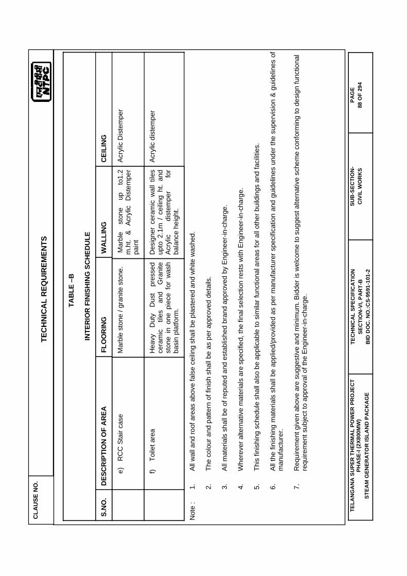
CLA
USE
NO
. TE
CH
NIC
AL
REQ
UIR
EMEN
TS
TELA
NG
AN
A S
UPE
R T
HER
MA
L PO
WER
PR
OJE
CT
PHAS
E-I (
2X80
0MW
) ST
EAM
GEN
ERA
TOR
ISLA
ND
PAC
KA
GE
TEC
HN
ICAL
SPE
CIF
ICAT
ION
SE
CTI
ON
-VI,
PAR
T-B
B
ID D
OC
. NO
.:CS-
9591
-101
-2
SUB
-SEC
TIO
N-
CIV
IL W
OR
KS
PAG
E 88
OF
294
TABL
E –B
INTE
RIO
R FI
NISH
ING
SCH
EDUL
E
S.N
O.
DESC
RIP
TIO
N O
F AR
EA
FLO
OR
ING
W
ALLI
NG
CEIL
ING
e)
R
CC
Sta
ir ca
se
Mar
ble
ston
e / g
rani
te s
tone
. M
arbl
e st
one
up
to1.
2 m
.ht.
& Ac
rylic
D
iste
mpe
r pa
int
Acry
lic D
iste
mpe
r
f)
Toile
t are
a H
eavy
D
uty
Dus
t pr
esse
d ce
ram
ic
tiles
an
d G
rani
te
ston
e in
one
pie
ce f
or w
ash
basi
n pl
atfo
rm.
Des
igne
r ce
ram
ic w
all t
iles
upto
2.1
m /
cei
ling
ht.
and
Acry
lic
dist
empe
r fo
r ba
lanc
e he
ight
.
Acry
lic d
iste
mpe
r
Not
e :
1.
Al
l wal
l and
roof
are
as a
bove
fals
e ce
iling
shal
l be
plas
tere
d an
d w
hite
was
hed.
2.
Th
e co
lour
and
pat
tern
of f
inis
h sh
all b
e as
per
app
rove
d de
tails
.
3.
Al
l mat
eria
ls s
hall
be o
f rep
uted
and
est
ablis
hed
bran
d ap
prov
ed b
y En
gine
er-in
-cha
rge.
4.
W
here
ver a
ltern
ativ
e m
ater
ials
are
spe
cifie
d, th
e fin
al s
elec
tion
rest
s w
ith E
ngin
eer-i
n-ch
arge
.
5.
Th
is fi
nish
ing
sche
dule
sha
ll al
so b
e ap
plic
able
to s
imila
r fun
ctio
nal a
reas
for a
ll ot
her b
uild
ings
and
faci
litie
s.
6.
Al
l the
fini
shin
g m
ater
ials
sha
ll be
app
lied/
prov
ided
as
per m
anuf
actu
rer s
peci
ficat
ion
and
guid
elin
es u
nder
the
supe
rvis
ion
& gu
idel
ines
of
man
ufac
ture
r.
7.
R
equi
rem
ent g
iven
abo
ve a
re s
ugge
stiv
e an
d m
inim
um. B
idde
r is
wel
com
e to
sug
gest
alte
rnat
ive
sche
me
conf
orm
ing
to d
esig
n fu
nctio
nal
requ
irem
ent s
ubje
ct to
app
rova
l of t
he E
ngin
eer-i
n-ch
arge
.

CLA
USE
NO
. TE
CH
NIC
AL
REQ
UIR
EMEN
TS
TELA
NG
AN
A S
UPE
R T
HER
MA
L PO
WER
PR
OJE
CT
PHAS
E-I (
2X80
0MW
) ST
EAM
GEN
ERA
TOR
ISLA
ND
PAC
KA
GE
TEC
HN
ICAL
SPE
CIF
ICAT
ION
SE
CTI
ON
-VI,
PAR
T-B
B
ID D
OC
. NO
.:CS-
9591
-101
-2
SUB
-SEC
TIO
N-
CIV
IL W
OR
KS
PAG
E 89
OF
294
TABL
E –C
EXTE
RIO
R FI
NISH
ES S
CHED
ULE
Sl.N
o.
DES
CR
IPTI
ON
OF
AREA
W
ALL
AND
PR
OJE
CTI
ON
S SO
FFIT
OF
PRO
JEC
TIO
NS
1.
Aux
illiar
y bu
ildin
g in
st
eel
fram
ed
stru
ctur
e.
Res
in
bond
ed
gran
ular
te
xtur
e fin
ish
of
appr
oved
co
lour
/col
our
com
bina
tion
over
pl
aste
red
surfa
ce
on
mas
onry
/con
cret
e.
Appr
oved
co
lour
/ co
lour
co
mbi
natio
n of
col
our
coat
ed
met
al c
ladd
ing
Solv
ent b
ased
(res
in b
ased
) ove
r pla
ster
ed s
urfa
ce.
Appr
oved
col
our/
colo
ur c
ombi
natio
n of
col
our
coat
ed m
etal
cl
addi
ng.
2.
Bui
ldin
g w
ith c
oncr
ete
fram
e w
ork,
etc
. so
lven
t ba
sed
resi
n ba
sed
pain
t of
ap
prov
ed
colo
ur/c
olou
r com
bina
tion.
For
Serv
ice
build
ing/
Adm
in.
Bldg
. / c
ante
en &
Aud
itoriu
m.
Alum
iniu
m
com
posi
te
Pane
l C
ladd
ing
in c
ombi
natio
n w
ith
Res
in
bond
ed
Gra
nula
r te
xtur
e fin
ish
(50:
50)
Solv
ent b
ased
(100
% p
ure
acry
lic c
o-po
lym
er re
sin
base
d) o
ver
plas
tere
d su
rface
.
3.
Ste
el S
truct
ure,
tres
tles,
etc
. H
igh
perfo
rman
ce
Pain
t of
ap
prov
ed
spec
ifica
tion
and
shad
e.
CLA
USE
NO
. TE
CH
NIC
AL
REQ
UIR
EMEN
TS
TELA
NG
AN
A S
UPE
R T
HER
MA
L PO
WER
PR
OJE
CT
PHAS
E-I (
2X80
0MW
) ST
EAM
GEN
ERA
TOR
ISLA
ND
PAC
KA
GE
TEC
HN
ICAL
SPE
CIF
ICAT
ION
SE
CTI
ON
-VI,
PAR
T-B
B
ID D
OC
. NO
.:CS-
9591
-101
-2
SUB
-SEC
TIO
N-
CIV
IL W
OR
KS
PAG
E 90
OF
294
NO
TE :
1. T
he c
olou
r and
pat
tern
of f
inis
h sh
all b
e as
fina
lized
by
Engi
neer
.
2.
All m
ater
ials
sha
ll be
of r
eput
ed a
nd e
stab
lishe
d br
and
appr
oved
by
Engi
neer
.
CLAUSE NO. TECHNICAL REQUIREMENTS
TELANGANA SUPER THERMAL POWER PROJECT PHASE-I (2X800MW)
STEAM GENERATOR ISLAND PACKAGE
TECHNICAL SPECIFICATION SECTION-VI, PART-B
BID DOC. NO.:CS-9591-101-2
SUB-SECTION-CIVIL WORKS
PAGE 91 OF 294
10.00.00 MATERIAL SPECIFICATION
10.01.00 Cement
Fly ash based portland pozzolana cement conforming to IS:1489 (Part-1) shall be used for all areas other than for the critical structures identified below. Other properties shall be as per IS code.
Ordinary Portland Cement (OPC) shall necessarily be used for the following structures.
a) Spring supported decks of all machine foundations such as PA/FD/ID Fans
b) RCC for Chimney shell.
The grade of cement shall be Grade 43 for OPC conforming to IS:8112.
In place of fly ash based portland pozzolana cement, OPC mixed with Fly Ash can be used. Batching plant shall have facility for mixing fly ash. Fly ash shall conform to IS:3812(Part I & Part II). Percentage of fly ash to be mixed in concrete shall be based on trial mix. Mix design shall be done with varying percentage of fly ash mix with cement
10.02.00 Aggregates
a) Coarse aggregate
Coarse aggregate for concrete shall be crushed stones chemically inert, hard, strong, durable against weathering of limited porosity and free from deleterious materials. It shall be properly graded. It shall meet the requirements of IS: 383.
b) Fine aggregate
Sand shall be hard, durable, clean and free from adherent coatings of organic matter and clay balls or pellets. Sand, when used as fine aggregate in concrete shall conform to IS : 383. For plaster, it shall conform to IS : 1542 and for masonry work to IS : 2116.
c) Petrographic examination of aggregate shall be carried out by the contractor at National Council for Cement and Building Materials (NCB), Ballabgarh, or any other approved laboratory to ascertain the structure and rock type including presence of strained quartz and other reactive minerals for machine foundations, etc.. In case, the coarse aggregate sample is of composite nature, the proportions (by weight) of different rock types in the composite sample and petrographic evaluation of each rock should also be ascertained. While determining the rock type, special emphasis should be given on identification of known reactive rocks like chalcedony, opal etc. The procedure laid down in IS: 2430 for sampling of aggregates may be followed.
The laboratory shall determine potential reactivity of the aggregate, which may lead to reaction of silica in aggregate with the alkalis of cement and / or potential of some aggregates like limestone to cause residual expansion due to repeated temperature cycle. If the same is established, the contractor shall further carry out alkali aggregates reactivity test as per IS: 2386 (Pt.VII) and / or repeated temperature cycle test to establish the suitability of the aggregates for the concrete work. The

CLAUSE NO. TECHNICAL REQUIREMENTS
TELANGANA SUPER THERMAL POWER PROJECT PHASE-I (2X800MW)
STEAM GENERATOR ISLAND PACKAGE
TECHNICAL SPECIFICATION SECTION-VI, PART-B
BID DOC. NO.:CS-9591-101-2
SUB-SECTION-CIVIL WORKS
PAGE 92 OF 294
test results, with the final recommendations of the laboratory, as to a suitability of the aggregate, for use in the concrete work for various structures and suggested measures, in case of results are not satisfactory, shall be submitted to the Engineer for his review, in a report form.
In case in the report, it is established, that the aggregates contain reactive silica, which would react with alkalis of the cement, the contractor shall change the source of supply of the aggregate or use low alkali cement as per recommendation or take measures as recommended in the report as instructed by Engineer. In case aggregates indicate residual expansion, under repeated temperature cycle test (from 10o Celsius to 65o Celsius and for 60 temperature cycles) the material shall not be used for concreting of TGs', BFPs' and other equipment foundations which are likely to be subjected to repeated temperature cycle. The contractor shall use aggregates free from residual expansion under repeated temperatures cycle test.
10.03.00 Reinforcement Steel
Reinforcement steel shall be of high strength deformed TMT steel bars of grade Fe-500 and shall conform to IS:1786. However, minimum elongation shall be 14.5%.
Mild steel & medium tensile steel bars and hard drawn steel wire shall conform to grade-1 of IS:432 (Part-1) or grade A of IS:2062. Welded wire fabric shall conform to IS:1566.
10.04.00 Structural Steel
Structural Steel (including embedded Steel) shall be straight, sound, free from twists, cracks, flaw, laminations and all other defects. Structural steel shall comprise of mild steel, medium strength steel and high tensile steel as specified below.
10.04.01 Mild Steel
a) Rolled sections shall be of grade designation E250, Quality A/BR, Semi-killed/ killed conforming to IS 2062. All steel plates shall be of Grade designation E250, Quality BR (fully killed), conforming to IS 2062 and shall pass the impact test value at room temperature. Plates beyond 12mm thickness and up to 40mm thickness shall be normalized rolled. Plates beyond 40mm thickness shall be vacuum degassed & furnace normalised and shall also be 100% ultrasonically tested as per ASTM –A578 level B-S2.
b) Pipes shall conform to IS: 1161.
c) Hollow (square and rectangular) steel sections shall be hot formed conforming to IS: 4923 and shall be of minimum Grade Yst 240.
d) Chequered plate shall conform to IS 3502 and shall be minimum 6 mm thick excluding projection. Steel for chequered plate shall conform to grade E250A semi killed of IS: 2062 or equivalent grade conforming to ASTM & BS standards only.
10.04.02 Medium and High Tensile Steel

CLAUSE NO. TECHNICAL REQUIREMENTS
TELANGANA SUPER THERMAL POWER PROJECT PHASE-I (2X800MW)
STEAM GENERATOR ISLAND PACKAGE
TECHNICAL SPECIFICATION SECTION-VI, PART-B
BID DOC. NO.:CS-9591-101-2
SUB-SECTION-CIVIL WORKS
PAGE 93 OF 294
Rolled Sections and plates shall be of grade designation E350, Quality B0(killed),conforming to IS 2062. Plates beyond 12mm thickness and up to 40mm thickness shall be controlled rolling. Plates beyond 40mm thickness shall be normalizing rolling and shall also be ultrasonically tested as per ASTM –A578 level B.
10.05.00 Bricks
Only fly ash bricks shall be used in all construction. Bricks shall be table mounted/ machine made of uniform size, shape and sharp edges and shall have minimum compressive strength of 75kg/cm2. Burnt clay fly ash bricks and fly ash lime bricks shall conform to IS:13757 and IS:12894 respectively. Minimum fly ash content in fly ash based bricks shall be 25%.
10.06.00 Foundation Bolts
Material and details of foundation bolts shall conform to IS:5624. Mild steel bars used for the fabrication of bolt assembly shall conform to grade 1of IS432 and/ or grade A of IS:2062. Hexagonal nuts and lock nuts shall conform to IS 1363 & IS1364 upto M36 diameter and IS 5624 for M42 to M150 diameter.
10.07.00 Stainless steel
The material specification for stainless steel plates are mentioned in the design concept area of Mill Bunker building.
10.08.00 Water
Water used for cement concrete, mortar, plaster, grout, curing, washing of coarse aggregate, soaking of bricks, etc. shall be clean and free from oil, acids, alkalis, organic matters or other harmful substances in such amounts that may impair the strength or durability of the structure. Potable water shall generally be considered satisfactory for all masonry and concrete works, including curing. When water from the proposed source is used for making the concrete, the maximum permissible impurities, development of strength and initial setting time of concrete shall meet the requirements of IS:456.
All materials brought for incorporation in works shall be of best quality as per IS unless specified otherwise.
10.08.00 Statutory Requirements
Bidder shall comply with all the applicable statutory rules pertaining to Factories Act, Fire Safety Rules at Tariff Advisory Committee. Water Act for pollution control, Explosives Act, etc.
Provisions of safety, health and welfare according to Factories Act shall be complied with. These shall include provision of continuous walkways along the crane - girder level on both sides of building, comfortable approach to EOT crane cabin, railing, fire escape, locker room for workmen, pantry, toilets, rest room etc.
Provisions for fire proof doors, number of staircases, fire separation wall, lath plastering/encasing the structural members (in fire prone areas), type of glazing etc. shall be made according to the recommendations of Tarrif Advisory Committee.
Statutory clearances and norms of State Pollution Control Board shall be followed.
Bidder shall obtain approval of Civil/Architectural drawings from concerned authorities before taking up the construction work.
CLAUSE NO. TECHNICAL REQUIREMENTS
TELANGANA SUPER THERMAL POWER PROJECT PHASE-I (2X800MW)
STEAM GENERATOR ISLAND PACKAGE
TECHNICAL SPECIFICATION SECTION-VI, PART-B
BID DOC. NO.:CS-9591-101-2
SUB-SECTION-CIVIL WORKS
PAGE 94 OF 294
11.00.00 Inspection, Testing and Quality Control
11.01.00 Sampling and testing of major items of civil works viz. earthwork, concreting, structural steel work (including welding), piling, sheeting, etc. shall be carried out in accordance with the requirements of this specification. Wherever nothing is specified relevant Indian Standards shall be followed. In absence of Indian Standard equivalent International Standards may be used.
The Bidder shall submit and finalize a detailed field Quality Assurance Programme before starting of the construction work according to the requirement of this specification. This shall include frequency of sampling and testing, nature/type of test, method of test, setting of a testing laboratory, arrangement of testing apparatus/equipment, deployment of qualified/experienced manpower, preparation of format for record, Field Quality Plan, etc. Tests shall be done in the field and/or at a laboratory approved by the Engineer. The Bidder shall furnish the test certificate from the manufacturers of various materials to be used in the construction.
11.02.00 Workmanship and dimensional shall be checked as stipulated below.

CLAUSE NO.
TECHNICAL REQUIREMENTS
TELANGANA SUPER THERMAL POWER
PROJECT PHASE-I (2X800MW) STEAM GENERATOR ISLAND PACKAGE
TECHNICAL SPECIFICATION SECTION-VI, PART-B
BID DOC. NO.:CS-9591-101-2
SUB-SECTION- CIVIL WORKS
PAGE 95 OF 294
12.00.00 ANNEXURES
(a) List of Codes and Standards
All applicable standards, references, specifications, codes of practice, etc., shall be the latest edition including all applicable official amendments and revisions. A complete set of all these documents shall be available at site with Bidder. List of some of the applicable Standards, in original Codes and references is as given in Annexure-(a) of this specification.

CLAUSE NO.
TECHNICAL REQUIREMENTS
TELANGANA SUPER THERMAL POWER
PROJECT PHASE-I (2X800MW) STEAM GENERATOR ISLAND PACKAGE
TECHNICAL SPECIFICATION SECTION-VI, PART-B
BID DOC. NO.:CS-9591-101-2
SUB-SECTION- CIVIL WORKS
PAGE 96 OF 294
Annexure-(a)
LIST OF CODES AND STANDARDS
Excavation and Filling
IS :2720 Methods of test for soils(relevant parts)
IS:4701 Code of practice for earth work on canals.
IS:9759 Guide lines for dewatering during construction.
IS:10379 Code of practice for field control of moisture and compact ion of soils for embankment and sub-grade.
Properties, Storage and Handling of Common Building Materials
IS:269 33 grade for ordinary Portland cement.
IS:383 Coarse and fine aggregates from natural sources for concrete.
IS:432 Specification for mild steel and medium tensile steel bars and
(Part 1&2) hard drawn steel wires for concrete reinforcement.
IS:455 Portland slag cement.
IS:702 Industrial bitumen.
IS:712 Specification for building limes.
IS:1077 Common burnt clay building bricks.
IS:1161 Steel tubes for structural purposes.
IS:1239 Mild steel tubes, tubular and other wrought steel filling - MS tubes.
IS:1363 Hexagon head bolts, screws and nuts of productions
(Part 1-3) grade - C.
IS:1364 Hexagon head bolts, screws and nuts of productions
(Part 1-5) grade-A & B.
IS:1367 Technical supply condition for threaded fasteners. (Part 1-18) IS:1489 Portland-pozzolana cement. (Part-I) Fly ash based IS:1542 Sand for Plaster. IS:1566 Hard drawn steel wire fabric for concrete reinforcement.

CLAUSE NO.
TECHNICAL REQUIREMENTS
TELANGANA SUPER THERMAL POWER
PROJECT PHASE-I (2X800MW) STEAM GENERATOR ISLAND PACKAGE
TECHNICAL SPECIFICATION SECTION-VI, PART-B
BID DOC. NO.:CS-9591-101-2
SUB-SECTION- CIVIL WORKS
PAGE 97 OF 294
IS:1786 High strength deformed steel bars & wires for concrete reinforcement. IS:2062 Hot Rolled Low, Medium and High Tensile Structural Steel IS:2116 Sand for masonry mortars. IS : 2185 Hollow & solid concrete blocks. (Part 1) (Part 2) Hollow & solid light weight concrete blocks. IS:2386 Testing of aggregates for concrete. (Part I-VIII) IS:3812 Specification for fly ash for use as pozzolona and admixture. IS:4082 Recommendation on stacking and storage of construction materiel and
components at site IS:8112 43 grade ordinary portland cement. IS:8500 Structural steel-Microalloyed (Medium and high strength qualities). IS:12269 53 grade ordinary portland cement. IS:12894 Specification for fly ash lime bricks. IS:13757 Burnt clay fly ash building bricks. Cast in-situ Concrete and Allied Works IS:280 Mild steel wire for general engineering purpose. IS:456 Code of practice for plain and reinforcement concrete. IS:457 Code of practice for general construction of plain and reinforced concrete for
dams and other massive structures. IS:516 Method of test for strength of concrete. IS:1199 Methods of sampling and analysis of concrete. IS:1791 General requirement for batch type concrete mixers. IS:1834 Hot applied sealing compound for joints in concrete. IS:1838 Preformed fillers for expansion joints in concrete pavement and structures. IS:2438 Specification for roller pan mixers. IS:2502 Code of practice for bending and fixing of bars for concrete reinforcement . IS:2505 Concrete vibrators - immersion type. IS:2506 General requirements for screed board concrete vibrators.

CLAUSE NO.
TECHNICAL REQUIREMENTS
TELANGANA SUPER THERMAL POWER
PROJECT PHASE-I (2X800MW) STEAM GENERATOR ISLAND PACKAGE
TECHNICAL SPECIFICATION SECTION-VI, PART-B
BID DOC. NO.:CS-9591-101-2
SUB-SECTION- CIVIL WORKS
PAGE 98 OF 294
IS:2722 Specification for Portable Swing weigh batchers for concrete (single and double bucket type).
IS:2750 Steel scaffoldings IS:2751 Recommended practice for welding of mild steel plain and deformed bars for
reinforced construction. IS:3150 Hexagonal wire netting for general purposes. IS:3366 Specification for pan vibrators. IS:3370 Code of practice for concrete structures for the (Part 1-4) storage of liquids. IS:3558 Code of practice for use of immersion vibrators for consolidating concrete. IS:4014 Code of practice for steel tubular scaffolding. (Part-1&2) IS:4326 Code of practice for earth quake resistant design and construction of
buildings. IS:4656 Form vibrators for concrete. IS:4925 Concrete batching and mixing plant. IS:4990 Plywood for concrete shuttering work. IS:5256 Code of practice for sealing expansion joints in concrete lining on canals. IS:5525 Recommendations for detailing of reinforcement in reinforced concrete
works. IS:6461 Glossary of terms relating to cement concrete. IS:6494 Code of practice for water proofing of underground reservoir and swimming
pools. IS:6509 Code of practice for installation of joints in concrete pavements. IS:7861 Code of practice for extreme weather concreting. (Part -1&2) IS:9012 Recommended practice for shotcreting. IS:9103 Admixtures for concrete. IS:9417 Recommendations for welding cold worked bars for reinforced concrete
construction. IS:10262 Recommended guidelines for concrete mix design. IS:11384 Code of practice for composite construction in structural steel and concrete. IS:12118 Two parts polysulphide based sealants.

CLAUSE NO.
TECHNICAL REQUIREMENTS
TELANGANA SUPER THERMAL POWER
PROJECT PHASE-I (2X800MW) STEAM GENERATOR ISLAND PACKAGE
TECHNICAL SPECIFICATION SECTION-VI, PART-B
BID DOC. NO.:CS-9591-101-2
SUB-SECTION- CIVIL WORKS
PAGE 99 OF 294
IS:12200 Code of practice for provision of water stops at transverse construction joints in masonry and concrete dams.
IS:13311 Non destructive testing of concrete - methods of test. (Part 1) Ultrasonic pulse velocity. (Part 2) Rebound hammer. SP-16 Design codes for reinforced concrete to IS:456-1978. SP-23 Hand book of concrete mixes. SP-24 Explanatory handbook on Indian standards code for plain and reinforced
concrete. (IS : 456) SP-34 Hand book on concrete reinforcement and detailing. ACI-318 American Concrete Institute code for structural concrete. Precast Concrete Works SP:7 National Building Code - Structural Design (Part 6/Sec.7) Prefabrication and system building and mixed / composite construction. IS:10297 Code of practice for design and construction of floors and roofs using
precast reinforced/prestressed concrete ribbed or cored slab units. IS:10505 Code of practice for construction of floors and roofs using pre -cast reinforced
concrete waffle units. IS:15658 Pre-cast concrete block for paving. Masonry & Allied Works IS:1905 Code of practice for structural use of unreinforced masonry. IS: 2185 Part-1 Concrete Masonry Units - Specification Part 1 Hollow and Solid
Concrete Blocks Part-3 Specification for concrete masonry un its: Part 2 Hollow and solid light
weight concrete blocks IS:2212 Code of practice for brick work. IS:2250 Code of practice for preparation and use of masonry mortars. IS:2572 Code of practice for construction of hollow concrete block masonry. SP:20 Hand book on masonry design and construction. Sheeting Works IS:277 Galvanised steel sheets (Plan & corrugated). IS:513 Cold-rolled low carbon steel sheets & strips. IS:730 Hook bolts for corrugated sheet roofing.

CLAUSE NO.
TECHNICAL REQUIREMENTS
TELANGANA SUPER THERMAL POWER
PROJECT PHASE-I (2X800MW) STEAM GENERATOR ISLAND PACKAGE
TECHNICAL SPECIFICATION SECTION-VI, PART-B
BID DOC. NO.:CS-9591-101-2
SUB-SECTION- CIVIL WORKS
PAGE 100 OF 294
IS:801 Code of practice for use of cold formed light gauge steel structural members
in general building construction. IS:2527 Code of practice for fixing rain water gutters and down pipe for roof drainage. IS:7178 Technical supply condition for tapping screw. IS:8183 Bonded mineral wool. IS:8869 Washers for corrugated sheet roofing. IS:12093 Code of practice for laying and fixing of sloped roof covering using plain and
corrugated galvanised steel sheets. IS:12436 Preformed rigid Polyurethane (PUR) and isocyanurate (PIR) foam s for
thermal insulation. IS:12866 Plastic translucent sheets made from thermosetting polyester resin (glass
fibre reinforced). IS:14246 Continuously pre-painted galvanised steel sheets and coils. BS:5950 Code of practice for design of light gauge profiled (Part-6) steel sheeting Fabrication and Erection of Structural Steel Works IS:800 Code of practice for General Construction of steel. IS:813 Scheme for symbols for welding. IS:814 Covered electrodes for manual metal arc welding of carbon & carbon
manganese steel. IS:816 Code of practice for use of metal arc welding for general construction in mild
steel. IS:817 Code of practice for training and testing of metal arc welders. IS:1024 Welding in bridges and substructured subject to dynam ic. IS:1181 Qualifying tests for Metal Arc welders (engaged in welding structures other
than pipes). IS:1182 Recommended practice for Radiographic examination of fusion welded butt
joints in steel plates IS:1608 Mechanical testing of metals - tensile testing IS:1852 Rolling and Cutting Tolerances for Hot rolled steel products. IS:2016 Specification for Plain washers. IS:2595 Code of practice for Radiographic testing

CLAUSE NO.
TECHNICAL REQUIREMENTS
TELANGANA SUPER THERMAL POWER
PROJECT PHASE-I (2X800MW) STEAM GENERATOR ISLAND PACKAGE
TECHNICAL SPECIFICATION SECTION-VI, PART-B
BID DOC. NO.:CS-9591-101-2
SUB-SECTION- CIVIL WORKS
PAGE 101 OF 294
IS:2629 Hot dip galvanising of iron and steel IS:3502 Steel chequred plate. IS:3613 Acceptance tests for wire flux combination for submerged arc welding. IS:3658 Code of practice for liquid penetrant flaw detection. IS:3664 Code of practice for ultra sonic pulse echo testing contact and immersion
method IS:3757 High strength structural bolts. IS:4000 High strength bolts in steel structure - code of practice. IS:4353 Sub merged arc welding of mild steel and low alloy steel Recommendation IS:4759 Hot dip zinc coating on structural steel and other allied products. IS:5334 Code of practice for magnetic particle flaw detection of welds. IS:5369 General requirements for plain washers and lock washer IS : 6623 High strength structural nuts. IS:6649 Hardened and tampered washers for high strength structural bolts & nuts. IS:6911 Stainless steel plate, sheet and strip. IS:7205 Safety code for erection of structural steel. IS:7215 Tolerances for fabrication of structural steel. IS:7307 Approved test for welding procedures (Part - I) Fusion welding of steel. IS:7310 Approval test for welders working to approval welding procedure. (Part-I) Fusion welding of steel IS:9178 Criteria for design of steel bins for storage of bulk material. (Part-1to 3) IS:9595 Recommendations for metal arc welding of carbon & carbon manganese
steel. IS:12843 Tolerances for erection of steel structures. SP:6 ISI Hand book for structural Engineers. (Part 1 to 7) Plastering and Allied Works IS:1661 Code of practice for application of cement and cement lime plaster finishes. IS:2402 Code of practice for external rendered finishes.
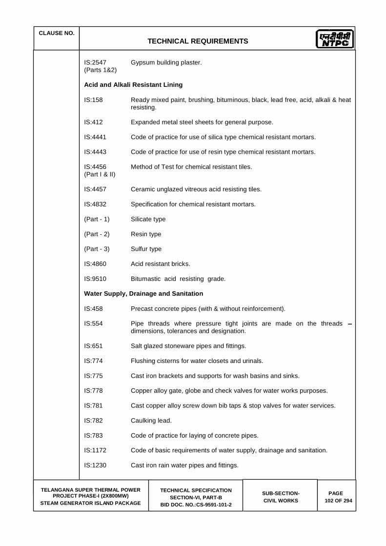
CLAUSE NO.
TECHNICAL REQUIREMENTS
TELANGANA SUPER THERMAL POWER
PROJECT PHASE-I (2X800MW) STEAM GENERATOR ISLAND PACKAGE
TECHNICAL SPECIFICATION SECTION-VI, PART-B
BID DOC. NO.:CS-9591-101-2
SUB-SECTION- CIVIL WORKS
PAGE 102 OF 294
IS:2547 Gypsum building plaster. (Parts 1&2) Acid and Alkali Resistant Lining IS:158 Ready mixed paint, brushing, bituminous, black, lead free, acid, alkali & heat
resisting. IS:412 Expanded metal steel sheets for general purpose. IS:4441 Code of practice for use of silica type chemical resistant mortars. IS:4443 Code of practice for use of resin type chemical resistant mortars. IS:4456 Method of Test for chemical resistant tiles. (Part I & II) IS:4457 Ceramic unglazed vitreous acid resisting tiles. IS:4832 Specification for chemical resistant mortars. (Part - 1) Silicate type (Part - 2) Resin type (Part - 3) Sulfur type IS:4860 Acid resistant bricks. IS:9510 Bitumastic acid resisting grade. Water Supply, Drainage and Sanitation IS:458 Precast concrete pipes (with & without reinforcement). IS:554 Pipe threads where pressure tight joints are made on the threads
dimensions, tolerances and designation. IS:651 Salt glazed stoneware pipes and fittings. IS:774 Flushing cisterns for water closets and urinals. IS:775 Cast iron brackets and supports for wash basins and sinks. IS:778 Copper alloy gate, globe and check valves for water works purposes. IS:781 Cast copper alloy screw down bib taps & stop valves for water services. IS:782 Caulking lead. IS:783 Code of practice for laying of concrete pipes. IS:1172 Code of basic requirements of water supply, drainage and sanitation. IS:1230 Cast iron rain water pipes and fittings.

CLAUSE NO.
TECHNICAL REQUIREMENTS
TELANGANA SUPER THERMAL POWER
PROJECT PHASE-I (2X800MW) STEAM GENERATOR ISLAND PACKAGE
TECHNICAL SPECIFICATION SECTION-VI, PART-B
BID DOC. NO.:CS-9591-101-2
SUB-SECTION- CIVIL WORKS
PAGE 103 OF 294
IS:1239 Mild Steel tubes, tubulars and other wrought steel fittings (Part 1&2) IS:1536 Centrifugally cast (Spun) iron pressure pipes for water. IS:1537 Vertically cast iron pressure pipes for water, gas and sewage. IS:1538 Cast iron fittings for pressure pipe for water, gas and sewage. IS:1703 Copper alloy float valve for water supply fitting. IS:1726 Cast iron manhole covers and frames. IS:1729 Cast iron / Ductile iron drainage pipes and pipe/fittings for over ground non
pressure pipeline socket and spigot series. IS:1742 Code of practice for building drainage. IS:2064 Selection, installation and maintenance of sanitary appliances. IS:2065 Code of practice for water supply in buildings. IS:2326 Automatic flushing cisterns for urinals. IS:2548 Plastic seats and covers for water closets. IS:2556 Vitreous sanitary appliances (vitreous china). IS:3114 Code of practice for laying of cast iron pipes. IS:3311 Waste plug and its accessories for sinks and wash basins. IS:3438 Silvered glass mirrors for general purposes. IS:3486 Cast iron spigot and socket drain pipes. IS:3589 steel pipe for water and sewage (168.3 to 2540mm outside diameter) IS:3989 Centrifugally cast (Spun) iron spigot and socket soil, waste and ventilating
pipes, fittings and accessories. IS:4111 Code of practice for ancillary structure in sewerage system. (Part 1 to 5) IS:4127 Code of practice for laying of glazed stone ware pipes. IS : 4733 Methods of sampling and testing sewage effluents. IS:4764 Tolerance limits for sewage effluents discharged into inland surface waters. IS:1068 Electroplated coating of nickel plus chromium and copper plus nickel plus
chromium. IS:5329 Code of practice for sanitary pipe work above ground for buildings. IS:5382 Rubber sealing rings for gas mains, water mains and sewers.

CLAUSE NO.
TECHNICAL REQUIREMENTS
TELANGANA SUPER THERMAL POWER
PROJECT PHASE-I (2X800MW) STEAM GENERATOR ISLAND PACKAGE
TECHNICAL SPECIFICATION SECTION-VI, PART-B
BID DOC. NO.:CS-9591-101-2
SUB-SECTION- CIVIL WORKS
PAGE 104 OF 294
IS:5822 Code of practice for laying of electrically welded steel pipes for water supply. IS:5961 Specification for cast iron grating for drainage purpose. IS:7740 Code of practice for construction and maintenance of road gullies. IS:8931 Copper alloy fancy single taps combination tap assembly and stop valves
for water services. IS:9762 Polyethylene floats for float valves. IS:10592 Industrial emergency showers, eye and face fountains and combination
units. IS:12592 Specification for precast concrete manhole covers and frames. IS:12701 Rotational moulded polyethylene water storage tanks. IS:13983 Stainless steel sinks for domestic purposes. SP:35 Hand book on water supply and drainage with special emphasis on
plumbing. CPH&EEO Manual on sewage and sewage treatment Publication - as updated. Doors Windows and Allied Works IS:204 Tower Bolts. (Part 1) Ferrous metals (Part 2) Non - ferrous metals IS:208 Door Handles. IS:281 Mild steel sliding door bolts for use with padlocks. IS:362 Parliament Hinges. IS:419 Putty, for use on window frames. IS:451 Technical supply conditions for wood screws IS:733 Wrought aluminium and aluminium alloy bars, rods and sections for general
engineering purposes. IS:1003 Timber panelled and glazed shutters (doors shutters). (Part I) IS:1003 Timber panelled and glazed shutters (Part-1) door shutters. IS:1038 Steel doors, windows and ventilators.

CLAUSE NO.
TECHNICAL REQUIREMENTS
TELANGANA SUPER THERMAL POWER
PROJECT PHASE-I (2X800MW) STEAM GENERATOR ISLAND PACKAGE
TECHNICAL SPECIFICATION SECTION-VI, PART-B
BID DOC. NO.:CS-9591-101-2
SUB-SECTION- CIVIL WORKS
PAGE 105 OF 294
IS:1081 Code of practice for fixing and glazing of metal (steel and aluminium) doors, windows and ventilators.
IS:1285 Wrought aluminium and aluminium alloy extruded round tube & hollow
section (for general engineering purposes). IS:1341 Steel butt hinges. IS:1361 Steel windows for Industrial buildings. IS:1823 Floor door stoppers. IS:1868 Anodic coatings on Aluminium and its alloys. IS:2202 Wooden flush door shutters (solid core type) particle (Part-2) board face panels and hard board face panels. IS:2209 Mortice locks (vertical type) IS:2553 Safety glass. (Part-1) General purposes IS:2835 Flat transparent sheet glass. IS:3548 Code of practice for glazing in buildings. IS:3564 Door closers (Hydraulically regulated) IS:3614 Specification for fire check doors : (Part-1) plate, metal covered and rolling type. (Part-2) Resistance test and performance criteria. IS:4351 Specification for steel door frames. IS:5187 Flush bolts. IS:5437 Figured, rolled and wired glass. IS:6248 Specification for metal rolling shutters and rolling grills. IS:6315 Specification for floor springs (Hydraulically regulated) for heavy doors. IS:7196 Hold fast. IS:7452 Hot rolled steel sections for doors, windows and ventilators. IS:10019 Mild steel stays and fasteners. IS:10451 Steel sliding shutters (top hung type) IS:12823 Prelaminated particle boards.

CLAUSE NO.
TECHNICAL REQUIREMENTS
TELANGANA SUPER THERMAL POWER
PROJECT PHASE-I (2X800MW) STEAM GENERATOR ISLAND PACKAGE
TECHNICAL SPECIFICATION SECTION-VI, PART-B
BID DOC. NO.:CS-9591-101-2
SUB-SECTION- CIVIL WORKS
PAGE 106 OF 294
Roof Water Proofing and Allied Works IS:3067 code of practice for general design details and preparatory work for damp
proofing and water proofing of buildings. ASTM Standard specification for high solid content cold C836-89a liquid applied elastomeric water proofing membrane for use with separate
wearing course. ASTM Standard guide for high solid content cold C898-89 liquid applied elastomeric water proofing membrane for use with separate
wearing course. Floor Finishes and Allied Works IS:5318 Code of practice for laying of flexible PVC sheet and tile flooring. IS:8042 White portland cement. IS:13755 Dust pressed ceramic tiles with water absorption of 3%, E 6% (Group B11a). IS:13801 Chequered cement concrete tiles. Painting and Allied Works IS:162 Ready mixed paint, brushing fire resisting, silicate type for use on wood,
colour as required. IS:428 Distemper, oil, emulsion, colour as required. IS:1477 Code of practice for painting of terrous metals in buildings. (Part -1) Pretreatment. (Part -2) Painting. IS:1650 Specification for colours for building and decorative materials. IS:2074 Ready mixed paint, air drying, red oxide-zinc chrome, priming. IS:2338 Code of practice for finishing of wood and wood based materials. (Part -1) Operations and Workmanship. (Part -2) Schedule. IS:2395 Code of pratice for painting concrete, masonry and plaster surfaces. (Part-1) Operations and Workmanship. (Part -2) Schedule. IS:2524 Code of practice for painting of nonferrous metals in buildings.

CLAUSE NO.
TECHNICAL REQUIREMENTS
TELANGANA SUPER THERMAL POWER
PROJECT PHASE-I (2X800MW) STEAM GENERATOR ISLAND PACKAGE
TECHNICAL SPECIFICATION SECTION-VI, PART-B
BID DOC. NO.:CS-9591-101-2
SUB-SECTION- CIVIL WORKS
PAGE 107 OF 294
(Part -1) Pretreatment (Part -2) Painting. IS:2932 Enamel, synthetic, exterior, (a) under coating and (b) finishing. IS:2933 Enamel exterior, (a) under coating, (b) finishing. IS:4759 Hot dip zinc coatings on structural steel and other allied products. IS:5410 Specification for cement paint. IS:15489 Plastic emulsion paint. IS:6278 Code of practice for white washing and Colour washing. IS:10403 Glossary of term related to building finish. IS:12027 Silicone based water repellent IS:13238 Epoxy based zinc phosphate primer (2 pack) IS:13239 Epoxy surfacer (2 pack) IS:13467 Chlorinated rubber for paints IS:14209 Epoxy enamel, two component glossy. BS:5493 Code of practice for protective coating of iron and steel structures against
corrosion. Piling and Foundation IS:1080 Code of practice for design and construction of shallow foundations on soils. IS:1904 Code of practice for design and construction of foundation in Soils : General
Requirements. IS:2314 Steel sheet piling sections. IS:2950 Code of practice for designs and construction of Raft foundation. (Part-1) Design IS:2974 Code of practice for design and construction of machine (Part-1 to 5) foundation. IS:4091 Code of practice for design and construction foundations for transmission
line towers and poles. IS:6403 Code of practice for determination of Bearing capacity of Shallow
foundations. IS:8009 Code of practice for calculation of settlement of foundation. (Part -1) Shallow foundations.
CLAUSE NO.
TECHNICAL REQUIREMENTS
TELANGANA SUPER THERMAL POWER
PROJECT PHASE-I (2X800MW) STEAM GENERATOR ISLAND PACKAGE
TECHNICAL SPECIFICATION SECTION-VI, PART-B
BID DOC. NO.:CS-9591-101-2
SUB-SECTION- CIVIL WORKS
PAGE 108 OF 294
(Part -2) Deep foundations. IS:12070 Code of practice for design and construction of shallow foundations on
rocks. VIN:2056 Criteria for assessing mechanical vibrations of machines. VDI:2060 Criteria for assessing the st of balance of rotating rigid bodies. DIN:2089 Helical compression spring made of round wire and rod : calculation and
design of compression . DIN:2096 Helical compression spring out of round wire and rod : Quality requirements
for hot formed compression spring. DIN:4024 Flexible supporting structures for machine with rotating machines. Roads IRC:5 Standard specifications and Code of practice for road bridges, (Section-1) General Features of Design. IRC:14 Recommended practice for 2cm thick bitumen and tar carpets. IRC:15 Standard specifications and code of practice for construction of concrete
roads. IRC:16 Specification for priming of base course with bituminous primers. IRC:19 Standard specifications and Code of practice for water bound macadam. IRC:21 Standard specifications and Code of practice for road bridges. (Section-III) Cement concrete (plain and reinforced). IRC:34 Recommendations for road construction in water logged areas. IRC:36 Recommended practice for the construction of earth embankments for road
works. IRC:37 Guidelines for the Design of flexible pavements. IRC:56 Recommended practice for treatment of embankment slopes for erosion
control. IRC:58 Guidelines for the design of rigid pavements for highways. IRC:73 Geometric Design standards for rural (non-urban) highways. IRC : 86 Geometric Design standards for urban roads in plains. IRC:SP:13 Guidelines for the design of small bridges & culverts. IRC - Ministry of Surface Transport (Road wing), Publication specifications for road and bridge works.

CLAUSE NO.
TECHNICAL REQUIREMENTS
TELANGANA SUPER THERMAL POWER
PROJECT PHASE-I (2X800MW) STEAM GENERATOR ISLAND PACKAGE
TECHNICAL SPECIFICATION SECTION-VI, PART-B
BID DOC. NO.:CS-9591-101-2
SUB-SECTION- CIVIL WORKS
PAGE 109 OF 294
IS:73 Paving bitumen. Loading IS:875 Code of practice for design loads (other than earthquake) for (Relevant parts) buildings and structures. IS:1893 Criteria for earthquake resistant design of structures. IS:4091 Code of practice for design and construction of foundation for transmission
line towers and poles. IRC:6 Standard specifications & Code of practice for road bridges. (Section-II) loads and stresses Safety IS:1641 Code of practice for fire safety of buildings - General principles of fire grading
and classification. IS:1642 Code of practice for fire safety of buildings - Details of construction. IS:3696 Safety code for scaffolds and ladders. (Part-1&2)
IS:3764 Excavation work - code of safety. IS:4081 Safety code for blasting and related drilling operations. IS:4130 Demolition of buildings - code of safety. IS:5121 Safety code for piling and other deep foundations. IS:5916 Safety code for construction involving use of hot bituminous materials. IS:7205 Safety code for erection of structural steel work. IS:7293 Safety code for working with construction machinery. IS:7969 Safety code for handling and storage of building materials. Indian Explosives (As updated) Act 1940) Architectural Design of Buildings SP:7 National Building Code of India SP:41 Hand book on functional requirements of buildings (other than industrial
buildings) ECBC Energy Conservation Building Code GRIHA Green Rating For Integrated Habitat Assessment.
Chimney

CLAUSE NO.
TECHNICAL REQUIREMENTS
TELANGANA SUPER THERMAL POWER
PROJECT PHASE-I (2X800MW) STEAM GENERATOR ISLAND PACKAGE
TECHNICAL SPECIFICATION SECTION-VI, PART-B
BID DOC. NO.:CS-9591-101-2
SUB-SECTION- CIVIL WORKS
PAGE 110 OF 294
IS:4998 Criteria for design of reinforced chimneys IS:6533 Code of practice for design and construction of steel chimneys ICAO International Civil Aviation Organisation (ICAO) DGCA Instruction of Director General of Civil Aviation , India ACI:307 Specification for the design and construction of reinforced concrete
chimneys BS:4076 Specification for steel chimneys CICIND Model Code for concrete chimneys Model code for steel chimneys ASCE Code Design and construction of steel chimney liners prepared by Task committee
on steel chimney liners. Fossil power committee, Power division published by ASCE - 1975.
IS:1554 PVC insulated (heavy duty) electric cables IS:2606 Alloy lead anodes for chromium plating IS:3043 Code of Practice for Earthing IS:9537 Conduits for electrical installations. The Indian Electricity Rules The Indian Electricity Act The Indian Electricity (Supply) Act The Indian Factories Act IS:2309 Practice for protection of buildings and allied structures against lightning
Miscellaneous IS:802 Code of practice for use of structural steel in overhead trans- (Relevant parts) mission line towers. IS:803 Code of practice for design, fabrication and erection of vertical mild
steel cylindrically welded in storage tanks. IS:10430 Criteria for design of lined canals and guidance for selection of type
of lining. IS:11592 Code of practice for selection and design of belt conveyors. IS:12867 PVC handrails covers.
IS 11504 Criteria for structural design of reinforced concrete natural draught cooling towers
BS:4485 (IV) British Standard : Code of design for water cooling towers CIRIA Design and construction of buried thin-wall pipes.
Publication IS 4671 Expanded polystyrene for thermal insulation purposes.

CLAUSE NO.
TECHNICAL REQUIREMENTS
TELANGANA SUPER THERMAL POWER
PROJECT PHASE-I (2X800MW) STEAM GENERATOR ISLAND PACKAGE
TECHNICAL SPECIFICATION SECTION-VI, PART-B
BID DOC. NO.:CS-9591-101-2
SUB-SECTION- CIVIL WORKS
PAGE 111 OF 294
Annexure (b)
CONSTRUCTION METHODOLOGY
Construction and erection activities shall be fully mechanized from the start of the work.
All excavation and backfilling work shall be done using excavators, loaders, dumpers, dozers, poclains, excavator mounted rock breakers, rollers, sprinklers, water tankers, etc. Manual excavation can be done only on isolated places with specific approval of engineer.
For controlled rock blasting specialized agency, equipped with sensors to assess the impact of the blast on the adjoining existing structures, shall be employed.
Dewatering shall be done using the combination of electrical and standby diesel pumps.
For concreting, weigh batching plants, transit mixers, concrete pumps, hoists, etc. shall be used.
All fabrication and erection activities of structural steel shall be carried out using automatic submerged arc welding machines, cutting machines, gantry cranes, crawler mounted heavy cranes and other equipment like heavy plate bending machines, shearing machines, lathe, milling machines, etc. Use of derricks shall not be permitted. Special enclosures, for blast cleaning of steel structure surface preparation, shall be used.
All handling of materials shall be with cranes. Heavy trailers shall be used for transportation.
Mechanized modular units of scaffolding and shuttering shall be used.
Grouting shall be carried out using hydraulically controlled grouting equipment.
Roadwork shall be done using pavers, rollers and premix plant.
All finishing items shall be installed using appropriate modern mechanical tools. Manual punching etc. shall not be permitted.
Heavy duty hoists for lifting of construction materials shall be deployed. Compressors for cleaning of foundations and other surfaces shall be used.
Field laboratory shall be provided with all modern equipment for survey, testing of soil, aggregates, concrete, welding, etc. For testing of steel works, ultrasonic testing machines, radiographic testing machines, dye penetration test equipment, destruction testing equipment, etc. shall be deployed.
All persons working at site shall be provided with necessary safety equipment and all safety aspects shall be duly considered for each construction/ erection activity. Moreover, only the persons who are trained in the respective trade shall be employed for executing that particular work.

CLAUSE NO.
TECHNICAL REQUIREMENTS
TELANGANA SUPER THERMAL POWER
PROJECT PHASE-I (2X800MW) STEAM GENERATOR ISLAND PACKAGE
TECHNICAL SPECIFICATION SECTION-VI, PART-B
BID DOC. NO.:CS-9591-101-2
SUB-SECTION- CIVIL WORKS
PAGE 280 OF 294
Annexure- (d)
CRITERIA FOR WIND RESISTANT DESIGN OF STRUCTURES AND EQUIPMENT
All structures shall be designed for wind forces in accordance with IS:875 (Part-3) and as specified in this document.
Along wind forces shall generally be computed by the Peak (i.e. 3 second gust) Wind Speed method as defined in the standard.
Along wind forces on slender and wind sensitive structures and struct ural elements shall also be computed, for dynamic effects, using the Gust Factor or Gust Effectiveness Factor Method as defined in the standard. The structures shall be designed for the higher of the forces obtained from Gust Factor method and the Peak Wind Speed method.
Analysis for dynamic effects of wind must be undertaken for any structure which has a height
structure is less than 1 Hz.
Susceptibility of structures to across-wind forces, galloping, flutter, ovalling etc. should be examined and designed/detailed accordingly following the recommendations of IS:875(Part -3) and other relevant Indian standards.
It should be estimated if size and relative position of other structures are likely to enhance the wind loading on the structure under consideration. Enhancement factor, if necessary, shall suitably be estimated and applied to the wind loading to account for the interference effects.
Damping in Structures
The damping factor (as a percentage of critical damping) to be adopted shall not be more than as indicated below for:
a) Welded steel structures : 1.0% b) Bolted steel structures : 2.0% c) Reinforced concrete structures : 1.6% d) Steel stacks : As per IS:6533 & CICIND Model
Code whichever is more critical.
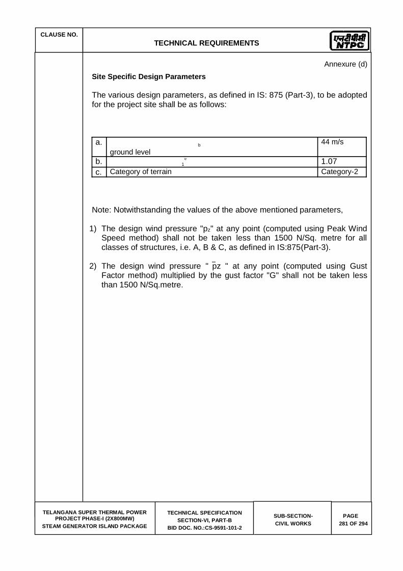
CLAUSE NO.
TECHNICAL REQUIREMENTS
TELANGANA SUPER THERMAL POWER
PROJECT PHASE-I (2X800MW) STEAM GENERATOR ISLAND PACKAGE
TECHNICAL SPECIFICATION SECTION-VI, PART-B
BID DOC. NO.:CS-9591-101-2
SUB-SECTION- CIVIL WORKS
PAGE 281 OF 294
Annexure (d) Site Specific Design Parameters The various design parameters, as defined in IS: 875 (Part-3), to be adopted for the project site shall be as follows: a. b
ground level 44 m/s
b. 1 1.07 c. Category of terrain Category-2
Note: Notwithstanding the values of the above mentioned parameters,
1) The design wind pressure "pz" at any point (computed using Peak Wind Speed method) shall not be taken less than 1500 N/Sq. metre for all classes of structures, i.e. A, B & C, as defined in IS:875(Part-3).
2) The design wind pressure " pz " at any point (computed using Gust Factor method) multiplied by the gust factor "G" shall not be taken less than 1500 N/Sq.metre.

CLAUSE NO.
TECHNICAL REQUIREMENTS
TELANGANA SUPER THERMAL POWER
PROJECT PHASE-I (2X800MW) STEAM GENERATOR ISLAND PACKAGE
TECHNICAL SPECIFICATION SECTION-VI, PART-B
BID DOC. NO.:CS-9591-101-2
SUB-SECTION- CIVIL WORKS
PAGE 282 OF 294
Annexure-(e)
CRITERIA FOR EARTHQUAKE RESISTANT DESIGN OF STRUCTURES AND EQUIPMENT
All structures and equipment shall be designed for seismic forces adopting the site specific seismic information provided in this document and using the other provisions in accordance with IS:1893 (Part 1):2002 and IS:1893 (Part 4):2005. Pending finalization of Parts 2, 3 and 5 of IS:1893, provisions of part 1 shall be read along with the relevant clauses of IS:1893:1984, for structures other than the buildings and industrial structures including stack-like structures. A site specific seismic study has been conducted for the project site. The peak ground horizontal acceleration for the project site, the site specific
horizontal direction for the various damping values and the multiplying factor (to be used over the spectral coefficients) for evaluating the design acceleration spectra are as given at Annexure-I. Vertical acceleration spectral values shall be taken as 2/3rd of the corresponding horizontal values. The site specific design acceleration spectra shall be used in place of the response acceleration spectra, given at figure-2 in IS:1893 (Part 1) and Annex B of IS:1893 (Part 4). The site specific acceleration spectra along with multiplying factors specified in Annexure-I includes the effect of the seismic environment of the site, the importance factor related to the structures and the response reduction factor. Hence, the design spectra do not require any further consideration of the zone factor (Z), the importance factor (I) and response reduction factor (R) as used in the IS:1893 (Part 1 and Part 4). Damping in Structures The damping factor (as a percentage of critical damping) to be adopted shall not be more than as indicated below for:
a) Steel structures : 2%
b)
Reinforced Concrete structures : 5%
c) Reinforced Concrete Stacks : 3%
d)
Steel stacks : 2%

CLAUSE NO.
TECHNICAL REQUIREMENTS
TELANGANA SUPER THERMAL POWER
PROJECT PHASE-I (2X800MW) STEAM GENERATOR ISLAND PACKAGE
TECHNICAL SPECIFICATION SECTION-VI, PART-B
BID DOC. NO.:CS-9591-101-2
SUB-SECTION- CIVIL WORKS
PAGE 283 OF 294
Method of Analysis Since most structures in a power plant are irregular in shape and have irregular distribution of mass and stiffness, dynamic analysis for obtaining the design seismic forces shall be carried out using the response spectrum method. The number of vibration modes used in the analysis should be such that the sum total of modal masses of all modes considered is at least 90 percent of the total seismic mass and shall also meet requirements of IS:1893 (Part 1). Modal combination of the peak response quantities shall be performed as per Complete Quadratic Combination (CQC) method or by an acceptable alternative as per IS:1893 (Part 1). In general, seismic analysis shall be performed for the three orthogonal (two principal horizontal and one vertical) components of earthquake motion. The seismic response from the three components shall be combined as specified in IS:1893 (Part 1). For buildings, if the design base shear (VB) obtained from modal combination is less than the base shear ( VB) computed using the approximate fundamental period (Ta) given in IS:1893:Part 1 and using site specific acceleration spectra with appropriate multiplying factor, the response quantities (e.g. member forces, displacements, storey forces, storey shears and base reactions) shall be enhanced in the ratio of VB/ VB. However, no reduction is permitted if VB is less than VB. For regular buildings less than 12m in height, design seismic base shear and its distribution to different floor levels along the height of the building may be carried out as specified under clause 7.5, 7.6 & 7.7 of IS:1893 (Part 1) and using site specific design acceleration spectra. The design horizontal acceleration spectrum value (Ah) shall be computed for the fundamental natural period as per clause 7.6 of IS:1893 (Part 1) using site specific spectral acceleration coefficients with appropriate multiplying factor given in Annexure-I. Further, the spectral acceleration coefficient shall get restricted to the peak spectral value if the fundamental natural period of the building falls to the left of the peak in the spectral acceleration curve. Design/Detailing for Ductility for Structures The site specific design acceleration spectra is a reduced spectra and has an in-built allowance for ductility. Structures shall be engineered and detailed in accordance with relevant Indian/International standards to achieve ductility.

CLAUSE NO.
TECHNICAL REQUIREMENTS
TELANGANA SUPER THERMAL POWER
PROJECT PHASE-I (2X800MW) STEAM GENERATOR ISLAND PACKAGE
TECHNICAL SPECIFICATION SECTION-VI, PART-B
BID DOC. NO.:CS-9591-101-2
SUB-SECTION- CIVIL WORKS
PAGE 284 OF 294
ANNEXURE I
SITE SPECIFIC SEISMIC PARAMETERS FOR DESIGN OF STRUCTURES AND EQUIPMENT
The various site specific seismic parameters for the project site shall be as follows:
1) Peak ground horizontal acceleration (MCE)
: 0.28 g
2) Multiplying factor to be applied to the site specific horizontal acceleration spectral coefficients (in units of
spectra
a) for ordinary moment resisting steel frames designed
and detailed as per IS:800
: 0.082
b) for braced steel frames designed and detailed as per IS:800
: 0.061
c) For special moment resisting RC frames designed and detailed as per IS:456 and IS:13920
: 0.049
d) for steel chimney
: 0.123
e) for design of structures not covered under 2 (a) to 2 (d) above and under 3 below
: 0.082
3) Multiplying factor to be applied to the site specific horizontal acceleration spectral coefficients (in units of
structures where inelastic action is not relevant or not permitted
: 0.16
Note: g = Acceleration due to gravity The horizontal seismic acceleration spectral coefficients are furnished in subsequent pages.

CLAUSE NO.
TECHNICAL REQUIREMENTS
TELANGANA SUPER THERMAL POWER
PROJECT PHASE-I (2X800MW) STEAM GENERATOR ISLAND PACKAGE
TECHNICAL SPECIFICATION SECTION-VI, PART-B
BID DOC. NO.:CS-9591-101-2
SUB-SECTION- CIVIL WORKS
PAGE 285 OF 294
ANNEXURE I
HORIZONTAL SEISMIC ACCELERATION SPECTRAL COEFFICIENTS (In units
Time Period Damping Factor (as a percentage of critical damping)
(Sec) 2% 3% 5% 0 1.000 1.000 1.000
0.03 1.000 1.842 1.450 0.04 1.355 2.032 1.600 0.05 1.716 2.223 1.750 0.06 2.081 2.413 1.900 0.07 2.449 2.604 2.050 0.08 2.820 2.794 2.200 0.09 3.194 2.985 2.350 0.10 3.570 3.175 2.500 0.105 3.759 3.175 2.500 0.106 3.760 3.175 2.500 0.11 3.760 3.175 2.500 0.115 3.760 3.175 2.500 0.12 3.760 3.175 2.500 0.125 3.760 3.175 2.500 0.13 3.760 3.175 2.500 0.135 3.760 3.175 2.500 0.14 3.760 3.175 2.500 0.145 3.760 3.175 2.500 0.15 3.760 3.175 2.500 0.20 3.760 3.175 2.500 0.25 3.760 3.175 2.500 0.27 3.760 3.175 2.500 0.30 3.760 3.175 2.500 0.32 3.760 3.175 2.500 0.35 3.760 3.175 2.500 0.372 3.760 3.175 2.500 0.40 3.500 3.175 2.500 0.402 3.483 3.159 2.488 0.405 3.457 3.136 2.469 0.41 3.415 3.098 2.439 0.425 3.294 2.988 2.353 0.45 3.111 2.822 2.222 0.50 2.800 2.540 2.000 0.55 2.545 2.309 1.818 0.60 2.333 2.117 1.667
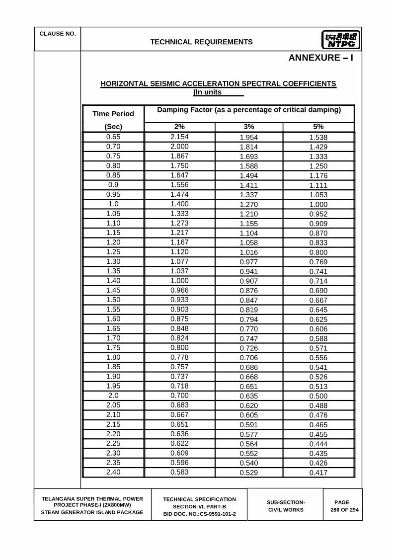
CLAUSE NO.
TECHNICAL REQUIREMENTS
TELANGANA SUPER THERMAL POWER
PROJECT PHASE-I (2X800MW) STEAM GENERATOR ISLAND PACKAGE
TECHNICAL SPECIFICATION SECTION-VI, PART-B
BID DOC. NO.:CS-9591-101-2
SUB-SECTION- CIVIL WORKS
PAGE 286 OF 294
ANNEXURE I
HORIZONTAL SEISMIC ACCELERATION SPECTRAL COEFFICIENTS (In units
Time Period Damping Factor (as a percentage of critical damping)
(Sec) 2% 3% 5% 0.65 2.154 1.954 1.538 0.70 2.000 1.814 1.429 0.75 1.867 1.693 1.333 0.80 1.750 1.588 1.250 0.85 1.647 1.494 1.176 0.9 1.556 1.411 1.111
0.95 1.474 1.337 1.053 1.0 1.400 1.270 1.000
1.05 1.333 1.210 0.952 1.10 1.273 1.155 0.909 1.15 1.217 1.104 0.870 1.20 1.167 1.058 0.833 1.25 1.120 1.016 0.800 1.30 1.077 0.977 0.769 1.35 1.037 0.941 0.741 1.40 1.000 0.907 0.714 1.45 0.966 0.876 0.690 1.50 0.933 0.847 0.667 1.55 0.903 0.819 0.645 1.60 0.875 0.794 0.625 1.65 0.848 0.770 0.606 1.70 0.824 0.747 0.588 1.75 0.800 0.726 0.571 1.80 0.778 0.706 0.556 1.85 0.757 0.686 0.541 1.90 0.737 0.668 0.526 1.95 0.718 0.651 0.513 2.0 0.700 0.635 0.500
2.05 0.683 0.620 0.488 2.10 0.667 0.605 0.476 2.15 0.651 0.591 0.465 2.20 0.636 0.577 0.455 2.25 0.622 0.564 0.444 2.30 0.609 0.552 0.435 2.35 0.596 0.540 0.426 2.40 0.583 0.529 0.417
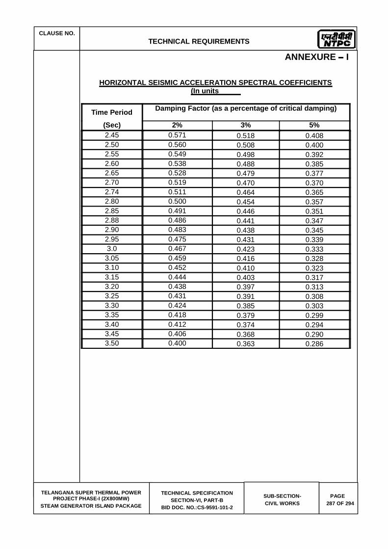
CLAUSE NO.
TECHNICAL REQUIREMENTS
TELANGANA SUPER THERMAL POWER
PROJECT PHASE-I (2X800MW) STEAM GENERATOR ISLAND PACKAGE
TECHNICAL SPECIFICATION SECTION-VI, PART-B
BID DOC. NO.:CS-9591-101-2
SUB-SECTION- CIVIL WORKS
PAGE 287 OF 294
ANNEXURE I
HORIZONTAL SEISMIC ACCELERATION SPECTRAL COEFFICIENTS (In units
Time Period Damping Factor (as a percentage of critical damping)
(Sec) 2% 3% 5% 2.45 0.571 0.518 0.408 2.50 0.560 0.508 0.400 2.55 0.549 0.498 0.392 2.60 0.538 0.488 0.385 2.65 0.528 0.479 0.377 2.70 0.519 0.470 0.370 2.74 0.511 0.464 0.365 2.80 0.500 0.454 0.357 2.85 0.491 0.446 0.351 2.88 0.486 0.441 0.347 2.90 0.483 0.438 0.345 2.95 0.475 0.431 0.339 3.0 0.467 0.423 0.333
3.05 0.459 0.416 0.328 3.10 0.452 0.410 0.323 3.15 0.444 0.403 0.317 3.20 0.438 0.397 0.313 3.25 0.431 0.391 0.308 3.30 0.424 0.385 0.303 3.35 0.418 0.379 0.299 3.40 0.412 0.374 0.294 3.45 0.406 0.368 0.290 3.50 0.400 0.363 0.286
CLAUSE NO.
TECHNICAL REQUIREMENTS
TELANGANA SUPER THERMAL POWER
PROJECT PHASE-I (2X800MW) STEAM GENERATOR ISLAND PACKAGE
TECHNICAL SPECIFICATION SECTION-VI, PART-B
BID DOC. NO.:CS-9591-101-2
SUB-SECTION- CIVIL WORKS
PAGE 288 OF 294
Annexure-(f)
QA REQUIREMENT
All Civil, Structural and Architectural construction work at the project shall be executed strictly in accordance with the Quality Assurance guidelines specified in separate part of this Specification.

CLAUSE NO.
TECHNICAL REQUIREMENTS
TELANGANA SUPER THERMAL POWER
PROJECT PHASE-I (2X800MW) STEAM GENERATOR ISLAND PACKAGE
TECHNICAL SPECIFICATION SECTION-VI, PART-B
BID DOC. NO.:CS-9591-101-2
SUB-SECTION- CIVIL WORKS
PAGE 289 OF 294
Annexure-(g)
List of tender drawings attached with this specification include
S.No. Title Drg. No.
1. General Layout Plan 9591-999-POC-F-001 Rev 0
2. Site Levelling Plan 9591-001-POC-A-001 Rev 0

CLAUSE NO.
TECHNICAL REQUIREMENTS
TELANGANA SUPER THERMAL POWER
PROJECT PHASE-I (2X800MW) STEAM GENERATOR ISLAND PACKAGE
TECHNICAL SPECIFICATION SECTION-VI, PART-B
BID DOC. NO.:CS-9591-101-2
SUB-SECTION- CIVIL WORKS
PAGE 290 OF 294
Annexure (k) Site management during construction phase till handing over of plant. Bidder shall ensure that the plant site within the plant boundary is managed in a coordinated
and professional way all through the construction phase till handing over of plant, ensuring safe, easy & unhindered working conditions and a healthy & hygienic working environment at site. He shall ensure the following measures at site while executing the project:
Temporary access road to all work area and facilities both during the construction/
erection and as they get completed progressively. Bidder shall prioritize the construction of approach roads in his scope. He shall finalise and submit the road layout plan in his scope along with priority and completion schedule immediately after the award for review by the engineer-in-charge. He shall ensure that the roads are promptly repaired and maintained against any damages due to movement of traffic/heavy trailers & cranes/rains etc. providing motorable access at all times. Adequate onsite stock of road metal/materials shall be kept and maintained distributed over the site for repairs especially before the monsoon period.
b) Proper drainage of rain water, ground water from excavations, water flows from batching plant/construction sites etc. Till such time the permanent drainage network is done, he shall construct adequate temporary drains to ensure that there is no accumulation/stagnation of water in the plant site. Bidder may consider providing precast RCC drains for temporary/ permanent drain construction for faster construction of drains. The drain construction shall be matched with progress of road construction for preventing damage to roads. Bidder shall provide and maintain adequate number of drainage pumps (both electrical and diesel operated) of suitable capacity for pumping out accumulated water especially during the monsoon periods. All drain diversions required shall be undertaken at the start of the project itself.
c) The plant site is fully secured against unauthorized access.
d) Proper housekeeping by systematic and proper disposal of earth from excavations (separately for usable & surplus earth), muck, wastes (from concrete works etc.), packing & insulation wastes, steel scrap, cable wastes etc. generated during con struction / erection works, Suitable disposal sites for each of above shall be identified in the layout and at site in the beginning of the project itself. It shall be ensured that all agencies engaged by the bidder follow the discipline to dispose off of earth spoils and wastes at the designated places. Preferably once in a week suitable time slot will be identified for housekeeping by all agencies and suitable instructions shall be issued in this regard. Bidder may engage a separate agency or identify a gang for collection of wastes and disposal to designated places. Suitable arrangement/tie-up will also be made for periodic disposal of wastes/scrap from the designated places.
e) All fabrication area shall be suitably hard crusted to provide a water free an d proper working platforms. Suitable sheds preferably pre-engineered structures to be provided for paint shops, fabrication workshops etc. for ensuring all weather work conditions for onsite structural works. For the main plant and auxiliary buildings, bidder should
offsite works/workshops and onsite fabrication works are avoided kept minimum.
f) Suitable onsite maintenance workshop for day to day breakdown maintenance h eavy plant and equipment like batching plants, cranes, earth moving equipment, poclains,

CLAUSE NO.
TECHNICAL REQUIREMENTS
TELANGANA SUPER THERMAL POWER
PROJECT PHASE-I (2X800MW) STEAM GENERATOR ISLAND PACKAGE
TECHNICAL SPECIFICATION SECTION-VI, PART-B
BID DOC. NO.:CS-9591-101-2
SUB-SECTION- CIVIL WORKS
PAGE 291 OF 294
welding equipment etc. The workshop shall have stock of frequently needed spares and suitable repair facilities with experienced technicians/ mechanics. A central test laboratory equipped with test equipment for routine test like tests on soil, concrete, bricks, aggregates, welds etc with experienced staff shall be established at the start of the project itself.
g) All office and covered store buildings of the bidder and its agencies shall be of prefab/ pre-engineered / porta cabin construction. Shabby semi-finished constructions in brickwork/ GI asbestos roof etc shall not be permitted.
h) First aid facilities and amenities like rest rooms, suitable pre-engineered toilets (separate for men and women), drinking water fountains/tanks, canteen, crèche for women workers shall be planned and established at the beginning of the project itself These facilities shall be located distributed over the plant area to enable easy access b y the construction workers and staff and shall be marked on the plant layout. Suitable treatment for toilet discharge, like bio digesters etc. shall be planned and conventional septic tanks/ soak pits etc. shall be avoided.
i) Proper lighting of all construction/ erection areas. Bidder shall erect adequate number of high lighting masts in main plant, offsite, office and store areas for lighting during night, DG sets of adequate capacity shall be provided for emergency backup. The street lighting along the roads shall also be prioritized along with road construction. The construction power ring main shall be planned and erected immediately after the award.
j) Well planned and coordinated storage and movement of plant, equipment and construction materials. System wise/ agency wise storage / laydown areas shall be planned and marked on the plant layout at the beginning itself. Bidder shall ensure that all its agencies comply with the areas allocated to them and follow the designated storage and movement plans. Adequate covered storage shall be constructed for storage of critical equipment like switchgears, MCCs, insulation etc.
k) Proper access control for construction workers, staff and visitors. Bidder shall ensure
that suitable electronic based gate pass system is in place from start of project itself to keep record and track of all workers, staff and visitors entering / exiting the plant premises shift wise on daily basis.
l) Compliance to all safety requirements as specified elsewhere in the tender documents.
Bidders shall establish a safety Centre at the start of the project itself. It shall have a 24X7 manned safety control room in addition to a permanent safety equipment display room, separate training / lecture hall with AV facilities for safety training, store room with adequate stock of specified safety equipment, a first aid room and other amenities. Bidder shall install CCTV cameras at all strategic locations in the plant area which shall be linked to the safety control room.
m) Compliance to all environment and other conditions stipulated by the concerned statutory
authorities while according clearance / NOC to the project. Bidder shall ensure adequate sprinkling of water by deploying water tankers to prevent the fugitive dust nuisance during construction.
n) Development of rainwater harvesting within the TG area premises. Bidder shall plan to develop rainwater harvesting from the start of the project itself. The rainwater harvesting plan shall be finalized immediately after award of work and suitable work pla n with priority and schedule shall also be finalized thereafter.

CLAUSE NO.
TECHNICAL REQUIREMENTS
TELANGANA SUPER THERMAL POWER
PROJECT PHASE-I (2X800MW) STEAM GENERATOR ISLAND PACKAGE
TECHNICAL SPECIFICATION SECTION-VI, PART-B
BID DOC. NO.:CS-9591-101-2
SUB-SECTION- CIVIL WORKS
PAGE 292 OF 294
o) Provision of adequate shelters, water supply, sanitation and lighting in construction workers and staff camps. No camps for workers and staff shall be permitted within the plant premises and Bidder shall make separate arrangement outside the plant premises for locating and development of camps for construction workers and staff. The designated areas shall be suitably developed with infrastructure like roads, drains, water supply and sewerage and shall be free from water logging. Suitable low cost shelters will be provided for the workers. Complete area shall be secured by fencing and shall be provided adequate area lighting. Suitable waste disposal, shopping and recreation facilities will be developed in these camps.
Bidder shall ensure that due importance is given to site management as discussed above
and a detailed work plan considering the above aspects is finalized immediately after the award. A senior level executive shall be identified who shall be responsible for implementation of the work plan. Suitable format for progress reporting on site management plan shall be developed and made part of the project progress report. The progress on implementation of above work plan shall be reviewed along with project progress in the monthly project review meetings with owner. In case the progress in the monthly project review meetings with owner. In case the progress on site management plan is unsatisfactory Engineer-in-Charge may withhold up to 1% of the monthly running bill (for civil and site erection works) till such time the required progress is demonstrated. In case in the opinion of Engineer- in-charge bidder's response is not adequate despite reminders and the situation warrants immediate action, Engineer-in- charge may get the relevant work executed through a separate agency and deduct the expenses incurred from the Bidder's bill along with overheads @25%.
CLAUSE NO.
TECHNICAL REQUIREMENTS
TELANGANA SUPER THERMAL POWER
PROJECT PHASE-I (2X800MW) STEAM GENERATOR ISLAND PACKAGE
TECHNICAL SPECIFICATION SECTION-VI, PART-B
BID DOC. NO.:CS-9591-101-2
SUB-SECTION- CIVIL WORKS
PAGE 293 OF 294
13.00.00 APPENDIX
TELENGANA SG CIVIL SCOPE FOR ELECTRICAL EQUIPMENT: Contractor to consider loads of Electrical equipment and provide rooms for / equipment like HT/LT switchgears/lighting DBs/Battery/Battery charger/Cable vault/foundation for Service transformers and its busducts / cable trays in
scope of SG area and in its trestle etc. which are required for systems. (A) Following loads of the Electrical and associated accessories
shall be consider during designing floor beams/roof beams/ RCC/Columns/ bracings/Trestle
switchgears (Ash handling Switcgears/CHP switchgears/3.3KV Ash HT switchgears and 11KV AHP boards etc. as per SLD DWG NO: 9591-999-POE-J-001). The contractor shall place floor /roof/secondary/tertiary beams/columns/Bracings etc. in such a way that there is no blocking of opening for Power/ control cables terminating in to the switchgears and bus duct connecting to the corresponding Transformers. The scope also covers support structure/floors/tertiary beam/channels/roof beams/ trenches/slits/cable pull pits/duct banks/opening required for completion of cabling/ tray works/ panel erections etc. are in his scope.
trestle from C row to CHP control room trestle (Trunk trestle). The typical section of cable tray arrangement shall be as indicated in DWG NO: 9591-999-POE-J-004. The contractor shall consider 75KG/M/Tray of loads in his scope of trestle. The Contractor shall provide cable trestle connection from Boiler to TG at four different locations per unit. The exact location shall be informed during detail engineering and each section shall be as described in typical cable sections. The contractor shall place trestle/columns/Bracings etc. such that cable trays shall be routed in straight line as far as possible and shall be free of fouling with bracing etc.
The Contractor shall provide foundations for all service Transformers (Transformers) and foundation of support structure of Busducts located in the area under its scope. The following building MCC rooms along with associated Transformer foundations for owners Transformer are in contractor scope. 1. Fuel oil service. 2. Auxiliary boiler 3. Ash silo 4. Ash water/TAC/HCSD 5. Bunker service 6. ESP 7. AET/Bottom Ash 8. Compressor house
CLAUSE NO.
TECHNICAL REQUIREMENTS
TELANGANA SUPER THERMAL POWER
PROJECT PHASE-I (2X800MW) STEAM GENERATOR ISLAND PACKAGE
TECHNICAL SPECIFICATION SECTION-VI, PART-B
BID DOC. NO.:CS-9591-101-2
SUB-SECTION- CIVIL WORKS
PAGE 294 OF 294
9. Ash handling/CHP switchgear 10. Ash 3.3KV HT switchgear 11. 11KV AHP Board 12. Any other facilities under contractor scope supply For exact number of transformers please refer DWG NO: 9591-999-POE-J-001.
The earthing system shall be designed for a life expectancy of at least forty (40) years, for a system fault current of 50 kA for 1.0 sec. The minimum rate of corrosion of steel for selection of earthing conductor shall be 0.12mm per year.
Grounding for SG and other areas or buildings covered in the specification shall be provided in accordance with IS 3043, IS 2309, IEEE 80. Earthing system network/earthmat shall be interconnected mesh of mild steel rods buried in ground in the plant. All areas under contractor scope of supply shall be interconnected together by minimum two parallel conductors. The Contractor shall furnish the detailed design and calculations for Employer's approval. Contractor shall obtain all necessary statutory approvals for the system. All the columns shall be earthed by nearby risers and earthmat grid spacing shall be minimum. 10 X 10 mts.. Minimum two nos of risers shall be provided for each equipment in TG area. Separate dedicated riser shall be provided for C&I earthing purpose and also for Lightning down conductor connection purpose. Sufficient nos of risers near the equipment shall be provided as per the system requirement. The contractor scope also covers below ground earth mat connection between TG to boiler.


BHEL PSWR
Technical Specifications Sec D
Bharat Heavy Electricals LimitedProject Engineering Management
PPEI Building, Power Sector,Plot No. 25, Sector 16A,
Noida (U.P.)-201301


c)


All earthwork shall be classified under the following categories:
No distinction will be made whether the material is dry or wet.
a) Ordinary Soil
b) Hard Soil
c) Soft and Decomposed Rock

d) Hard Rock (requiring blasting)
e) Hard Rock (blasting prohibited)


3.5.8 Dealing with Surface Water


SPECIFICATION NO. PE-TS-468-600-C001
GENERAL TECHNICAL SPECIFICATION
Bharat Heavy Electricals LimitedProject Engineering Management
PPEI Building, Power Sector,Plot No. 25, Sector 16A,
Noida (U.P.)-201301


mm


,


:
:

:
:

Bharat Heavy Electricals LimitedProject Engineering Management
PPEI Building, Power Sector,Plot No. 25, Sector 16A,
Noida (U.P.)-201301


Bharat Heavy Electricals LimitedProject Engineering Management
PPEI Building, Power Sector,Plot No. 25, Sector 16A,
Noida (U.P.)-201301


Bharat Heavy Electricals LimitedProject Engineering Management
PPEI Building, Power Sector,Plot No. 25, Sector 16A,
Noida (U.P.)-201301


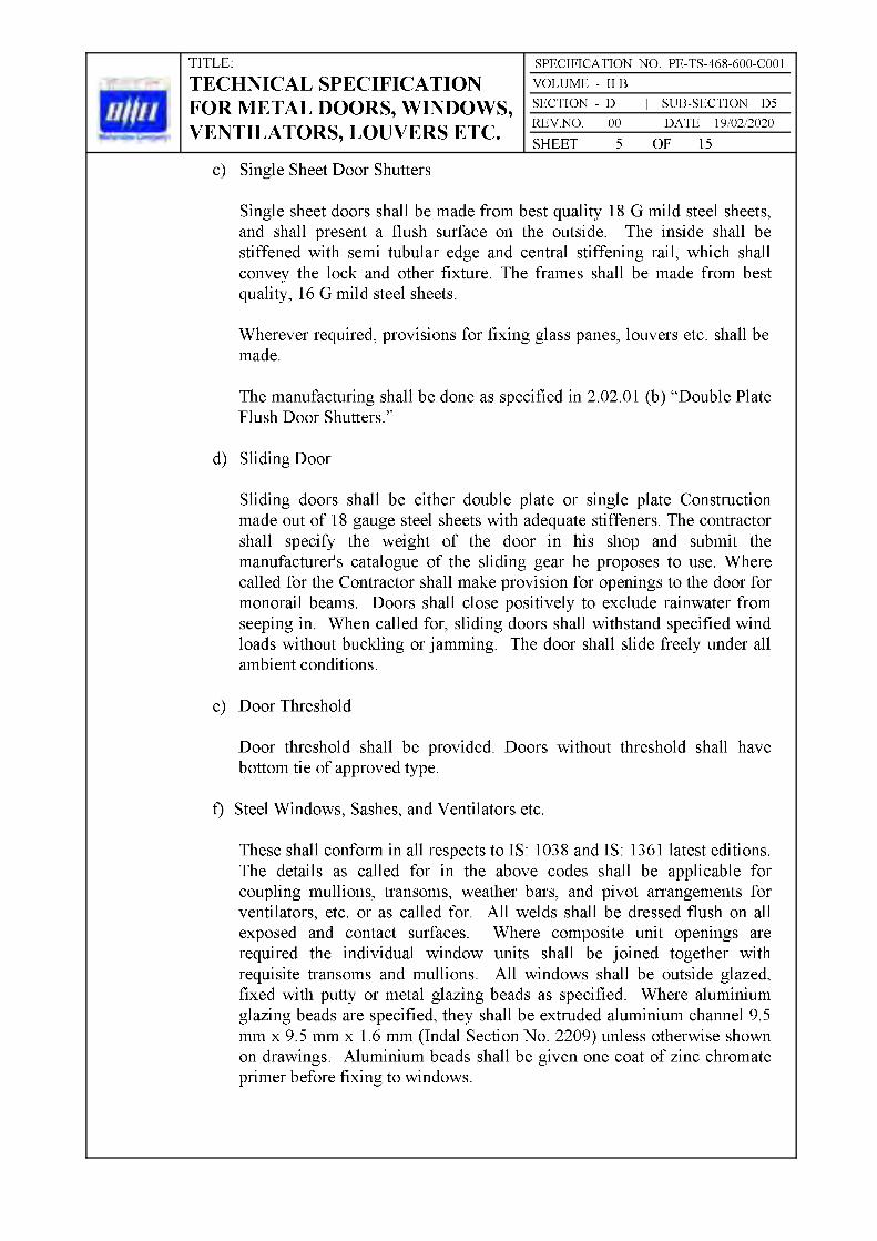

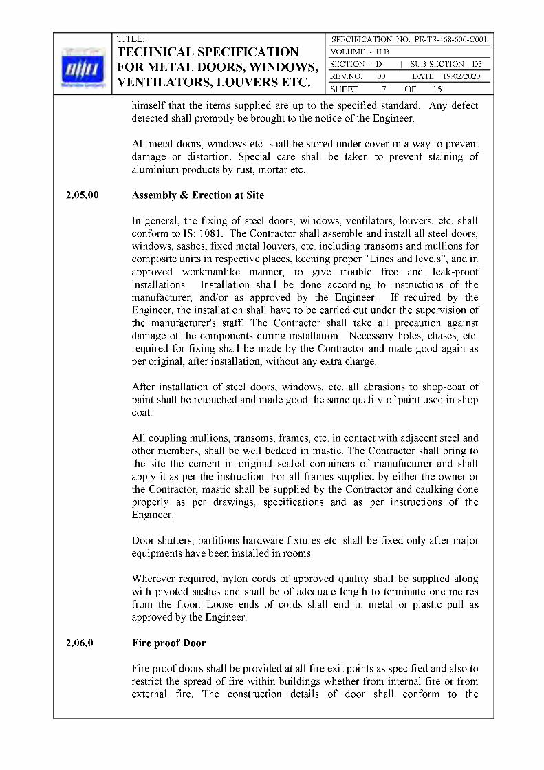


Bharat Heavy Electricals LimitedProject Engineering Management
PPEI Building, Power Sector,Plot No. 25, Sector 16A,
Noida (U.P.)-201301


Bharat Heavy Electricals LimitedProject Engineering Management
PPEI Building, Power Sector,Plot No. 25, Sector 16A,
Noida (U.P.)-201301


Bharat Heavy Electricals LimitedProject Engineering Management
PPEI Building, Power Sector,Plot No. 25, Sector 16A,
Noida (U.P.)-201301


Bharat Heavy Electricals LimitedProject Engineering Management
PPEI Building, Power Sector,Plot No. 25, Sector 16A,
Noida (U.P.)-201301


Bharat Heavy Electricals LimitedProject Engineering Management
PPEI Building, Power Sector,Plot No. 25, Sector 16A,
Noida (U.P.)-201301


Bharat Heavy Electricals LimitedProject Engineering Management
PPEI Building, Power Sector,Plot No. 25, Sector 16A,
Noida (U.P.)-201301


Bharat Heavy Electricals LimitedProject Engineering Management
PPEI Building, Power Sector,Plot No. 25, Sector 16A,
Noida (U.P.)-201301


Bharat Heavy Electricals LimitedProject Engineering Management
PPEI Building, Power Sector,Plot No. 25, Sector 16A,
Noida (U.P.)-201301

roughed zinc-aluminium alloy coated M.S. sheet

Troughed zinc-aluminium alloy coated (both sides) M.S. sheet having 0.6mm minimum thickness (or high tensile steel sheet having minimum yield strength of 350 Mpa of 0.5mm minimum thickness) shall be used on external face (outer face) of cladding system. Weight of coating shall not be less than 150 gm/sq.m. The outer side (exposed face) shall be permanently colour coated with Polyfluro Vinyl Coating (PVF2) of Dry Film Thickness (DFT) 20 microns (minimum) over primer. Inner side of external sheet shall be provided with suitable pre-coating of minimum 7 microns
Inner


Bharat Heavy Electricals LimitedProject Engineering Management
PPEI Building, Power Sector,Plot No. 25, Sector 16A,
Noida (U.P.)-201301


Bharat Heavy Electricals LimitedProject Engineering Management
PPEI Building, Power Sector,Plot No. 25, Sector 16A,
Noida (U.P.)-201301


Bharat Heavy Electricals LimitedProject Engineering Management
PPEI Building, Power Sector,Plot No. 25, Sector 16A,
Noida (U.P.)-201301


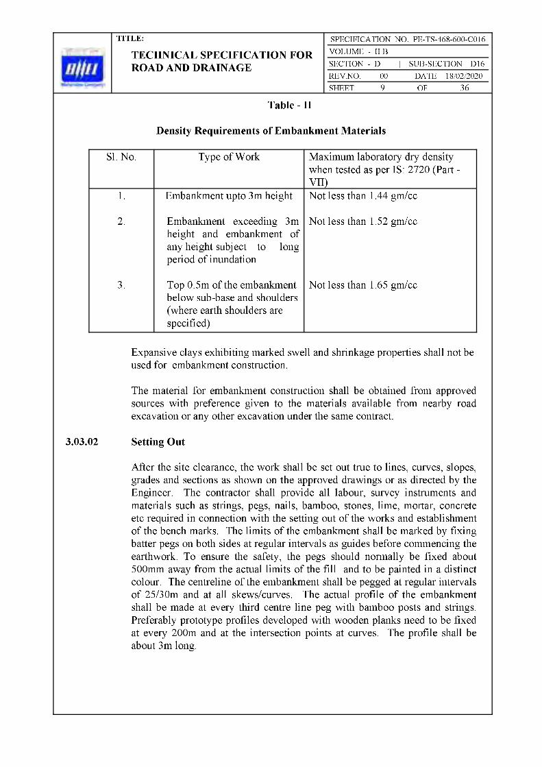
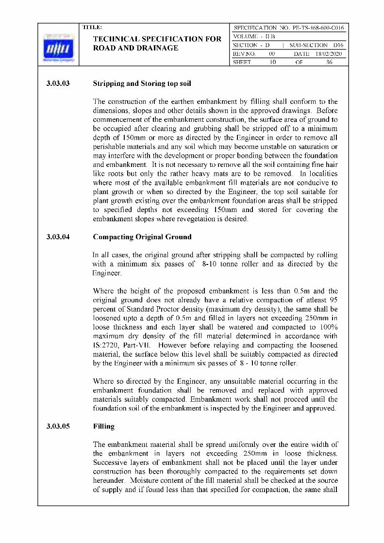
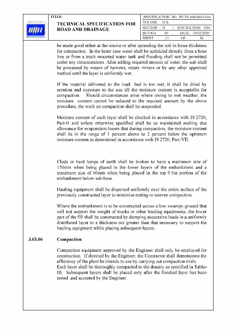


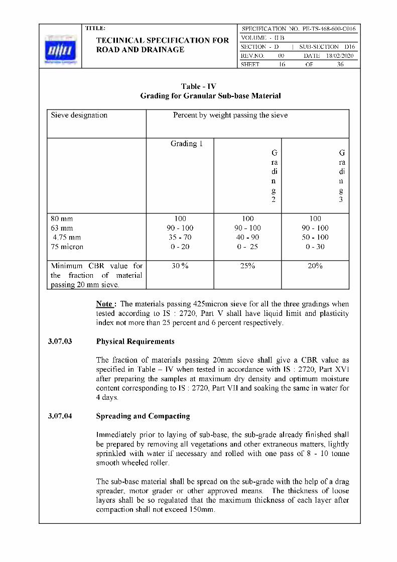

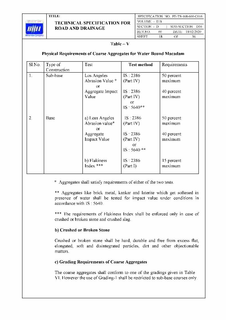

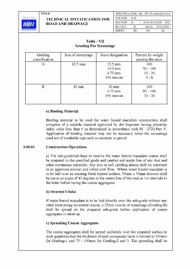


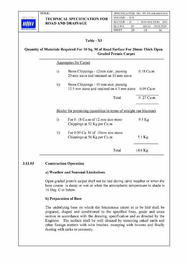


Bharat Heavy Electricals LimitedProject Engineering Management
PPEI Building, Power Sector,Plot No. 25, Sector 16A,
Noida (U.P.)-201301


:


.


Bharat Heavy Electricals LimitedProject Engineering Management
PPEI Building, Power Sector,Plot No. 25, Sector 16A,
Noida (U.P.)-201301


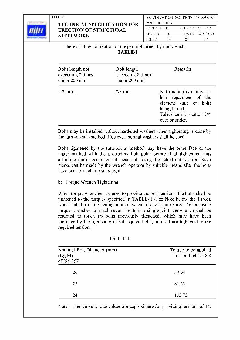


Bharat Heavy Electricals LimitedProject Engineering Management
PPEI Building, Power Sector,Plot No. 25, Sector 16A,
Noida (U.P.)-201301
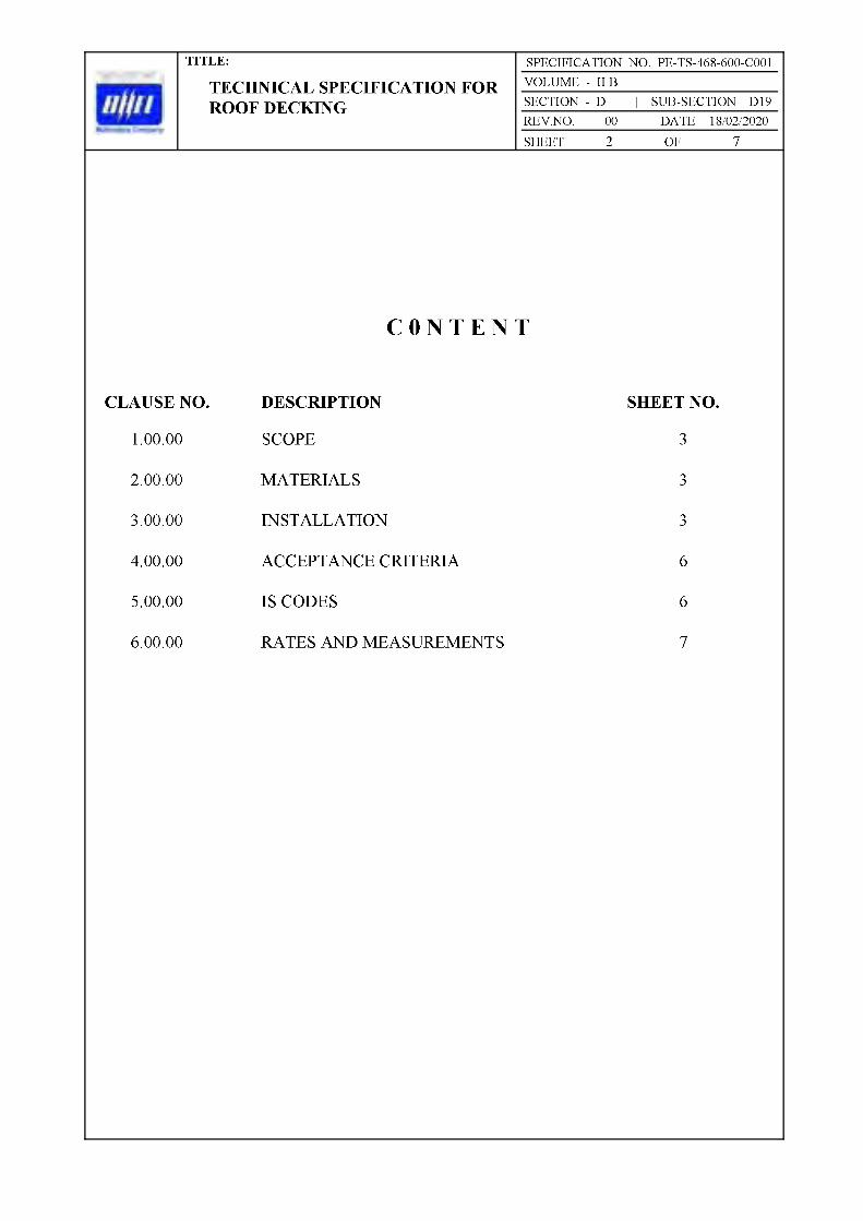


Bharat Heavy Electricals LimitedProject Engineering Management
PPEI Building, Power Sector,Plot No. 25, Sector 16A,
Noida (U.P.)-201301


h. Criteria specified for strength.

Bharat Heavy Electricals LimitedProject Engineering Management
PPEI Building, Power Sector,Plot No. 25, Sector 16A,
Noida (U.P.)-201301


b) Piles shall not deviate more than 75 mm or D/4 whichever is less (75mm or D/10 whichever is more in case of piles having diameter more then 750mm) from their designed position at the working level.
4.04.00 Boring
4.04.01 Boring operations shall be done by rotary or percussion type drilling rigs using reverse mud circulation (RMC) method. Rotary hydraulic pulley shall be preferred.

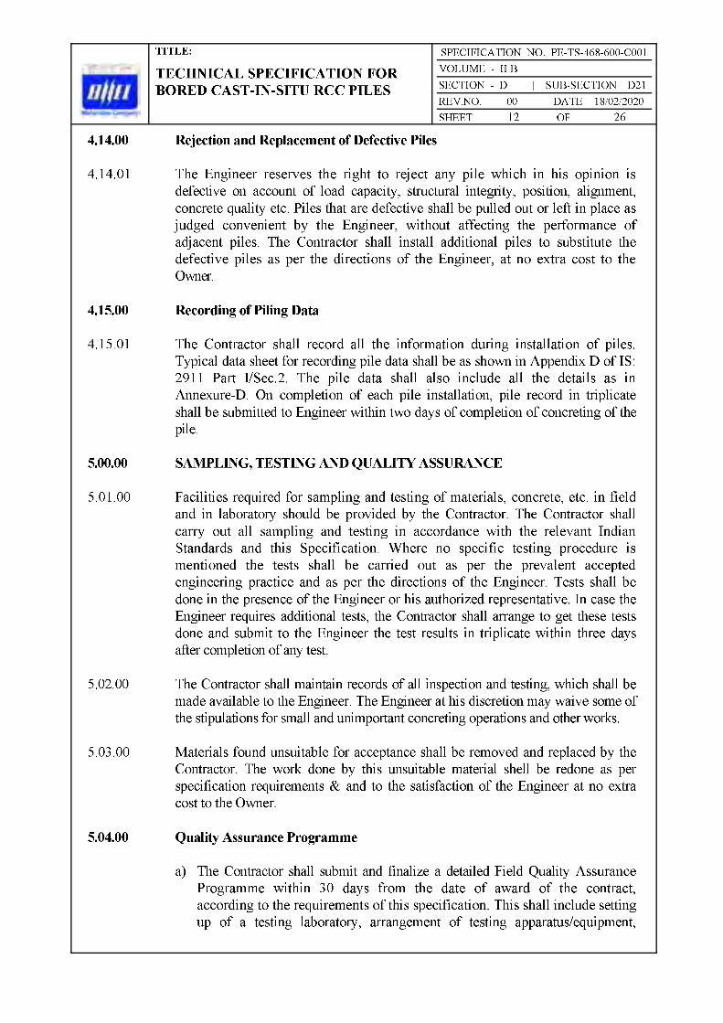
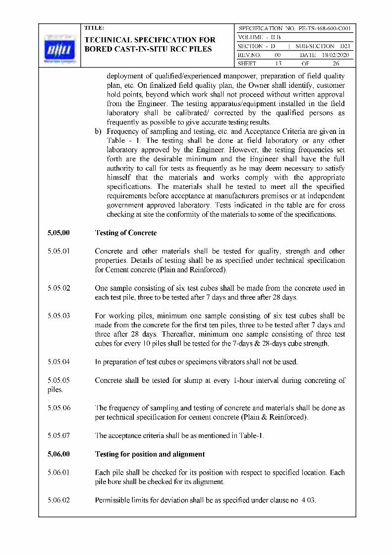


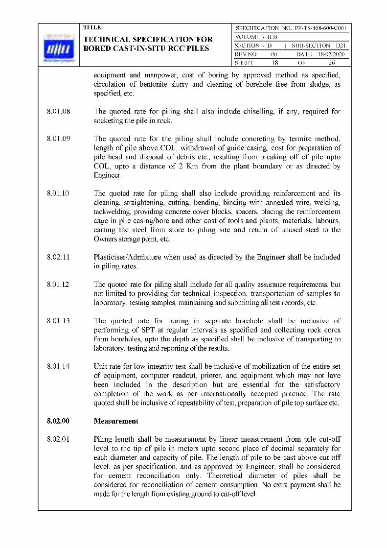

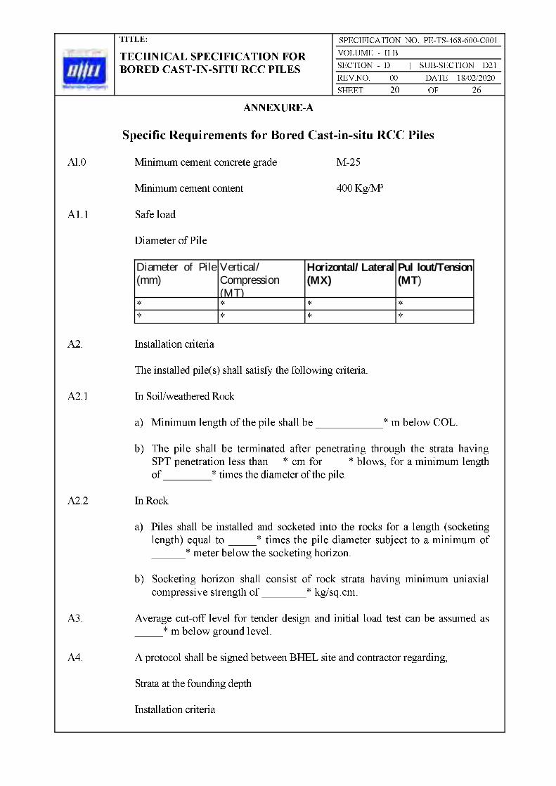
Diameter of Pile (mm)
Vertical/ Compression (MT)
Horizontal/ Lateral (MX)
Pul lout/Tension (MT)


of 150

Bharat Heavy Electricals LimitedProject Engineering Management
PPEI Building, Power Sector,Plot No. 25, Sector 16A,
Noida (U.P.)-201301


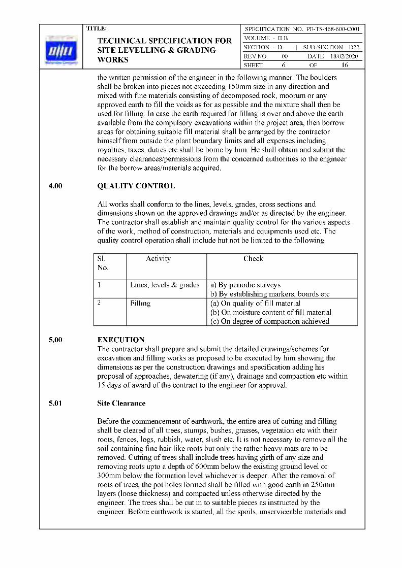


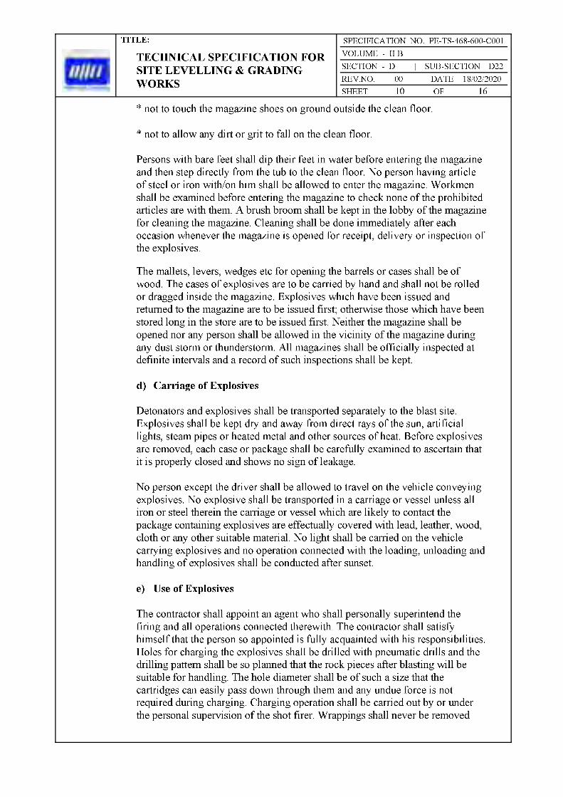


SPECIFICATION NO. PE-TS-468-600-C001
Bharat Heavy Electricals LimitedProject Engineering Management
PPEI Building, Power Sector,Plot No. 25, Sector 16A,
Noida (U.P.)-201301

1.00.00 SCOPE 3
2.00.00 EXECUTION 3
3.00.00 ACCEPTANCE CRITERIA 4
4.00.00 RATES 4
5.00.00 METHOD OF MEASUREMENT 4
6.00.00 I.S. CODES 5

1.00.00 SCOPE
The scope of work is to set up a chemical barrier against attack by subterranean termites while the building is under construction.
2.00.00 EXECUTION
2.01.00 General
All work shall in general be executed as specified in IS: 6313 Part II-1981 and as per approved specification of the agency having special know-how for the job.All necessary work to ensure uniform distribution and proper penetration of treatment of treating solution shall be done according to the instruction of the Engineer.Soil treatment shall not be done when it is raining or when the soil is wet with rain or subsoil water. Once formed, the treated soil barrier shall not be disturbed.
2.02.00 Chemicals and Rate of Application
Any of the following chemicals (conforming to relevant Indian Standards) in water emulsion shall be applied by pressure pumps, uniformly over the area treated.
Chemicals Concentration by Weight, Percentage
Chlorpyrifos Emulsifiable(IS 8944 - 1978) : 1.0Heptachlor EmulsifiableConcentrate (IS: 6439 - 1978) : 0.5Chlordane EmulsifiableConcentrate (IS: 2682 - 1984) : 1.0
2.02.01 Treatment of Column Pits, Wall Trenches and Basement Excavations
Foundations, basements etc. may either be fully enveloped by the chemical barrier or the treatment may start 500 mm below ground level. The bottom surface and sides of excavation (upto a height of about 300 mm) for column pits, walls trenches and basements shall be treated with chemicals at the rateof 5 litres / M2 of surface area. Backfills around columns, walls etc. shall be treated at the rate of 7.5 litres / M2 of the vertical surface. Chemical treatment shall be done in stages following the compaction of earth in layers. The treatment shall be carried out after the ramming operation is done by

rodding the earth at 150 mm centres close to the wall surface and spraying the chemicals in the specified dose.
2.02.02 Treatment of Top Surface of Plinth Filling
Holes 50 mm to 75 mm deep at 150 mm centres both ways shall be made with crowbars on the surface of compacted plinth fill. Chemical emulsion at the rate of 5 litres / M2 of surface shall be applied prior to laying soling or sub-grade. Special care shall be taken to maintain continuity of the chemical barrier at the junction of vertical and horizontal surfaces.
2.02.03 Treatment of Soil Surrounding Pipes, Wastes and Conduits
Special care shall be taken at the points where pipes and conduits enter the building and the soil shall be treated for a distance of 150 mm and a depth of 75 mm at the point where they enter the building.
2.02.04 Treatment of Expansion Joints
These shall receive special attention and shall be treated in a manner approved by the Engineer.
2.02.05 Treatment at Junction of the Wall and the Floor
Special care shall be taken to establish continuity of the vertical chemical barrier on inner wall surfaces from ground level up to the level of the filled earth surface.A small channel 30 x 30 mm shall be made at all the junctions of wall and columns with the floor. Rod holes made in the channel up to the ground level 150 mm apart and the chemical emulsion poured along the channel at the rate of 7.5 litres per square meter of the vertical wall or column surface. The soil should be tamped back into place after this operation.
3.00.00 ACCEPTANCE CRITERIA
The Contractor shall give a 10-year service guarantee in writing supplemented by a separate and unilateral guarantee from the specialised agency for the job to keep the building free of termites for the specified period.
4.00.00 RATES
Rates shall be of complete work per unit area as stated in the Schedule.
5.00.00 METHOD OF MEASUREMENT
Complete work of anti-termite treatment shall be measured for plinth area treated.
This includes treatment, to foundations, walls, trenches, basements, plinth, burried pipes, conduits etc. The extended portions of foundation and like beyond plinth limit shall be the part of complete work.
6.00.00 I.S. CODE
Relevant code applicable for this Specification.
IS: 6313 (Part-II) 1981 : Code of Practice of Anti-Termite Measures in Buildings Pre-constructional chemical treatment measures.


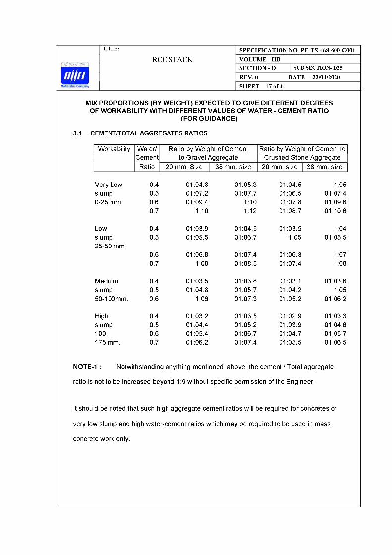


48