Installation Guide KingSeam® - Kingspan | Group
44
Installation Guide KingSeam ® Insulated Standing Seam Roof System Insulated Panel Systems North America
-
Upload
khangminh22 -
Category
Documents
-
view
0 -
download
0
Transcript of Installation Guide KingSeam® - Kingspan | Group
Installation GuideKingSeam® Insulated Standing Seam Roof System
Insulated Panel SystemsNorth America
Insulated Panel SystemsKingSeam Installation Guide
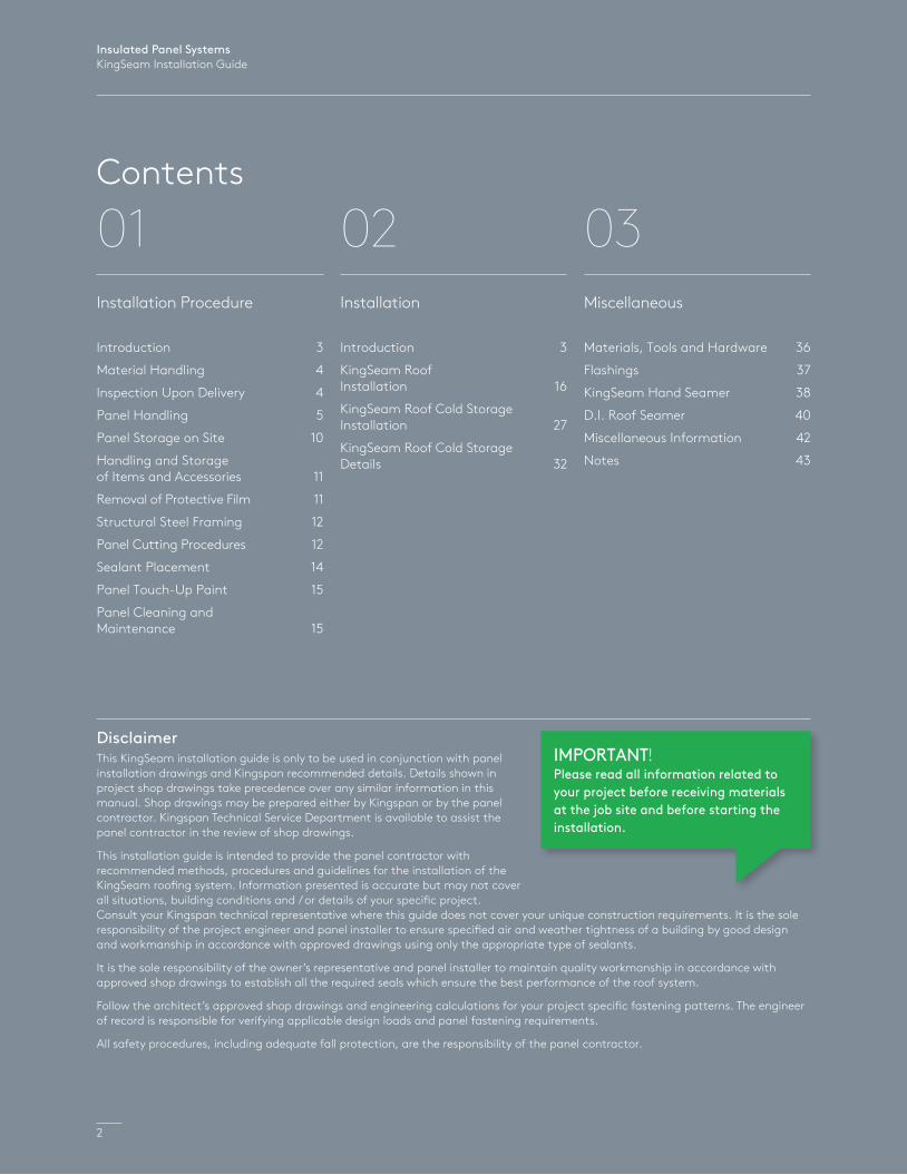
Contents
DisclaimerThis KingSeam installation guide is only to be used in conjunction with panel installation drawings and Kingspan recommended details. Details shown in project shop drawings take precedence over any similar information in this manual. Shop drawings may be prepared either by Kingspan or by the panel contractor. Kingspan Technical Service Department is available to assist the panel contractor in the review of shop drawings.
This installation guide is intended to provide the panel contractor with recommended methods, procedures and guidelines for the installation of the KingSeam roofing system. Information presented is accurate but may not cover all situations, building conditions and / or details of your specific project. Consult your Kingspan technical representative where this guide does not cover your unique construction requirements. It is the sole responsibility of the project engineer and panel installer to ensure specified air and weather tightness of a building by good design and workmanship in accordance with approved drawings using only the appropriate type of sealants.
It is the sole responsibility of the owner’s representative and panel installer to maintain quality workmanship in accordance with approved shop drawings to establish all the required seals which ensure the best performance of the roof system.
Follow the architect’s approved shop drawings and engineering calculations for your project specific fastening patterns. The engineer of record is responsible for verifying applicable design loads and panel fastening requirements.
All safety procedures, including adequate fall protection, are the responsibility of the panel contractor.
2
01Installation Procedure
Introduction 3
Material Handling 4
Inspection Upon Delivery 4
Panel Handling 5
Panel Storage on Site 10
Handling and Storage of Items and Accessories 11
Removal of Protective Film 11
Structural Steel Framing 12
Panel Cutting Procedures 12
Sealant Placement 14
Panel Touch-Up Paint 15
Panel Cleaning and Maintenance 15
02Installation
Introduction 3
KingSeam Roof Installation 16
KingSeam Roof Cold Storage Installation 27
KingSeam Roof Cold Storage Details 32
03Miscellaneous
Materials, Tools and Hardware 36
Flashings 37
KingSeam Hand Seamer 38
D.I. Roof Seamer 40
Miscellaneous Information 42
Notes 43
IMPORTANT!Please read all information related to your project before receiving materials at the job site and before starting the installation.
Insulated Panel SystemsKingSeam Installation Guide
3
Inst
alla
tion
Proc
edur
e
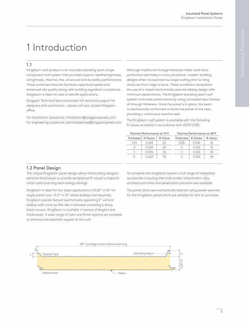
1 Introduction1.1KingSeam roof product is an insulated standing seam single component roof system that provides superior weathertightness, airtightness, thermal, fire, structural and durability performance. These combined features facilitate rapid build speed and enhanced site quality along with building regulation compliance. KingSeam is ideal for new or retrofit applications.
Kingspan Technical Service provides full technical support for designers and contractors - please call your closest Kingspan office.
For installation assistance: [email protected] For engineering assistance: [email protected]
Although traditional through fastened metal roofs have performed admirably in many situations, modern building designs often incorporate low slope roofing and / or long distances from ridge to eave. These conditions necessitate the use of a raised mechanically seamed sidelap design with minimum penetrations. The KingSeam standing seam roof system minimizes penetrations by using concealed clips instead of through fasteners. Once the panel is in place, the seam is mechanically roll formed to bond one panel to the next, providing a continuous weather seal.
The KingSeam roof system is available with the following R-values as tested in accordance with ASTM C518:
1.2 Panel DesignThe unique Kingseam panel design allows the building designer optional thicknesses to provide exceptional R-values to balance initial costs and long term energy savings.
KingSeam is ideal for low slope applications (>0.25” in 12” for single panel runs, >0.5” in 12” where endlaps are required). KingSeam panels feature aesthetically appealing 2” vertical sidelap with minor profile ribs in between providing a sharp linear accent. KingSeam is available in variety of lengths and thicknesses. A wide range of color and finish options are available to enhance the aesthetic appeal of the roof.
To complete the KingSeam system a full range of integrated accessories including thermally broken attachment clips, architectural trims and penetration solutions are available.
The panel joints are mechanically seamed using power seamers for the KingSeam panel which are avliable for rent or purchase.
Thermal Performance at 75˚FThickness K-Factor R-Value
3.25 0.043 234 0.034 295 0.028 366 0.023 43
Thermal Performance at 40˚FThickness K-Factor R-Value
3.25 0.040 254 0.032 315 0.026 396 0.022 46
Exterior face
Interior face
40” coverage shown before seaming
1”
3.25
”-6”
2”
Mesa
Standing Seam
Insulated Panel SystemsKingSeam Installation Guide
4
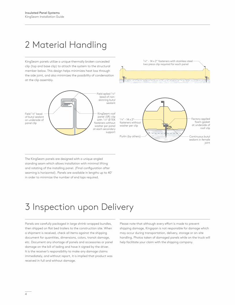
2 Material Handling1⁄4” - 14 x 2” fasteners with stainless steel two piece clip required for each panel
1⁄4” - 14 x 2” fasteners without washer per clip
Factory applied foam gasket
at underside of roof clip
Continuous butyl sealant in female
joint
Purlin (by others)
Field 1⁄8” bead of butyl sealant on underside of panel clip
Field aplied 1⁄4” bead of non-
skinning butyl sealant
KingSeam roof panel (SR) clip
with 1⁄4” Ø TEK fasteners without washer per panel
at each secondary support
KingSeam panels utilize a unique thermally broken concealed clip (top and base clip) to attach the system to the structural member below. This design helps minimizes heat loss through the side joint, and also minimizes the possibility of condensation at the clip assembly.
The KingSeam panels are designed with a unique angled standing seam which allows installation with minimal lifting and rotating of the installing panel. (Final configuration after seaming is horizontal). Panels are available in lengths up to 40’ in order to minimize the number of end laps required.
3 Inspection upon DeliveryPanels are carefully packaged in large shrink-wrapped bundles, then shipped on flat bed trailers to the construction site. When a shipment is received, check all items against the shipping document for quantities, dimensions, colors, transit damage, etc. Document any shortage of panels and accessories or panel damage on the bill of lading and have it signed by the driver. It is the receiver’s responsibility to make any damage claims immediately, and without report, it is implied that product was received in full and without damage.
Please note that although every effort is made to prevent shipping damage, Kingspan is not responsible for damage which may occur during transportation, delivery, storage or on-site handling. Photos taken of damaged panels while on the truck will help facilitate your claim with the shipping company.

Insulated Panel SystemsKingSeam Installation Guide
5
Inst
alla
tion
Proc
edur
e
Max 30’ (9.14m)
Protective plywood (not by Kingspan)
Lifting point at center of panel bundle
Fig. 4.1a
4 Panel Handling
Fig. 4.1b
4.1 Panels Handled by Forklift4.1.1 The recommended loading / unloading method for bundles less than or equal to 15’ is to use a single forklift with widely spaced forks (minimum 48”) placed under the center of the bundle as shown in Figure 4.1a. Panel bundles over 15’ in length may be moved by using two forklifts spaced equally along the length of the bundle as shown in Figure 4.1b. Inspect travel route to assure a reasonable level and compacted surface free of ruts and excavations. Use care to not over engage forks, use of foam blocks on the mast can help prevent fork damage to adjacent bundles and soften contact with the fork truck’s mast.
4.1.2 To prevent panels from damage while lifting, carefully pick up bundles one at a time.
Insulated Panel SystemsKingSeam Installation Guide
6
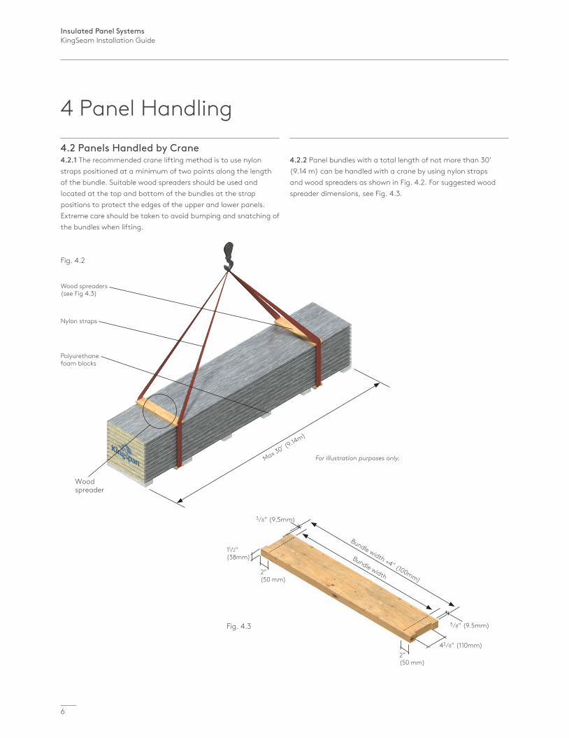
Fig. 4.2
Max 30’ (9.14m)
Wood spreaders (see Fig 4.3)
Nylon straps
For illustration purposes only.
Polyurethane foam blocks
Wood spreader
3⁄8” (9.5mm)
3⁄8” (9.5mm)
43⁄8” (110mm)
Bundle width +4” (100mm)
Bundle width
Fig. 4.3
11/2” (38mm)
2” (50 mm)
2” (50 mm)
4.2 Panels Handled by Crane4.2.1 The recommended crane lifting method is to use nylon straps positioned at a minimum of two points along the length of the bundle. Suitable wood spreaders should be used and located at the top and bottom of the bundles at the strap positions to protect the edges of the upper and lower panels. Extreme care should be taken to avoid bumping and snatching of the bundles when lifting.
4.2.2 Panel bundles with a total length of not more than 30’ (9.14 m) can be handled with a crane by using nylon straps and wood spreaders as shown in Fig. 4.2. For suggested wood spreader dimensions, see Fig. 4.3.
4 Panel Handling
Insulated Panel SystemsKingSeam Installation Guide
7
Inst
alla
tion
Proc
edur
e
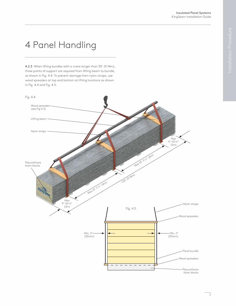
Wood spreaders (see Fig 4.3)
Lifting beam
Nylon straps
Polyurethane foam blocks
Fig. 4.4
>30’ (9.14m)
Max 13’-1
1 ⁄2” (4m)
Max 13’-1
1 ⁄2” (4m)
Max 9’-101⁄8”
(3m)
Max 9’-101⁄8”
(3m)
Polyurethane foam blocks
Wood spreaders
Wood spreaders
Nylon straps
Panel bundle
Fig. 4.5
Min. 2” (50mm)
Min. 2” (50mm)
4.2.3 When lifting bundles with a crane longer than 30’ (9.14m), three points of support are required from lifting beam to bundle, as shown in Fig. 4.4. To prevent damage from nylon straps, use wood spreaders at top and bottom at lifting locations as shown in Fig. 4.4 and Fig. 4.5.
4 Panel Handling
Insulated Panel SystemsKingSeam Installation Guide
8
4 Panel Handling
37
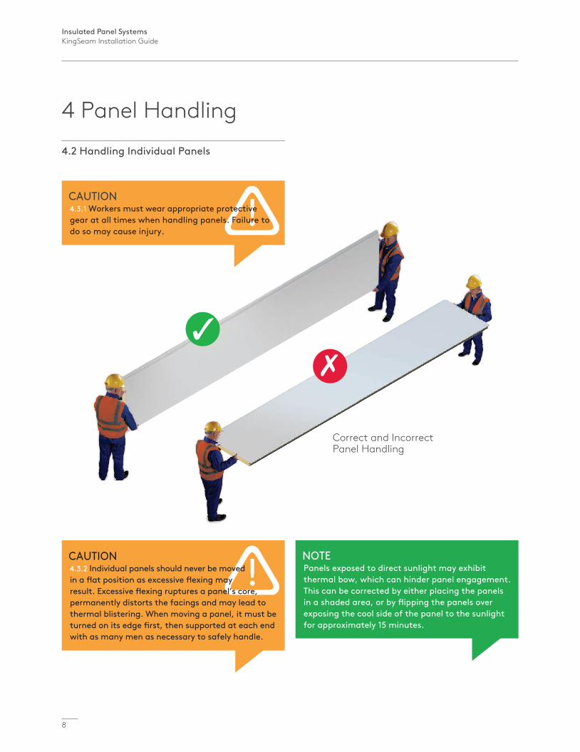
Correct and Incorrect Panel Handling
4.2 Handling Individual Panels
CAUTION4.3.1 Workers must wear appropriate protective gear at all times when handling panels. Failure to do so may cause injury.
CAUTION4.3.2 Individual panels should never be moved in a flat position as excessive flexing may result. Excessive flexing ruptures a panel’s core, permanently distorts the facings and may lead to thermal blistering. When moving a panel, it must be turned on its edge first, then supported at each end with as many men as necessary to safely handle.
NOTEPanels exposed to direct sunlight may exhibit thermal bow, which can hinder panel engagement. This can be corrected by either placing the panels in a shaded area, or by flipping the panels over exposing the cool side of the panel to the sunlight for approximately 15 minutes.
Insulated Panel SystemsKingSeam Installation Guide
9
Inst
alla
tion
Proc
edur
e
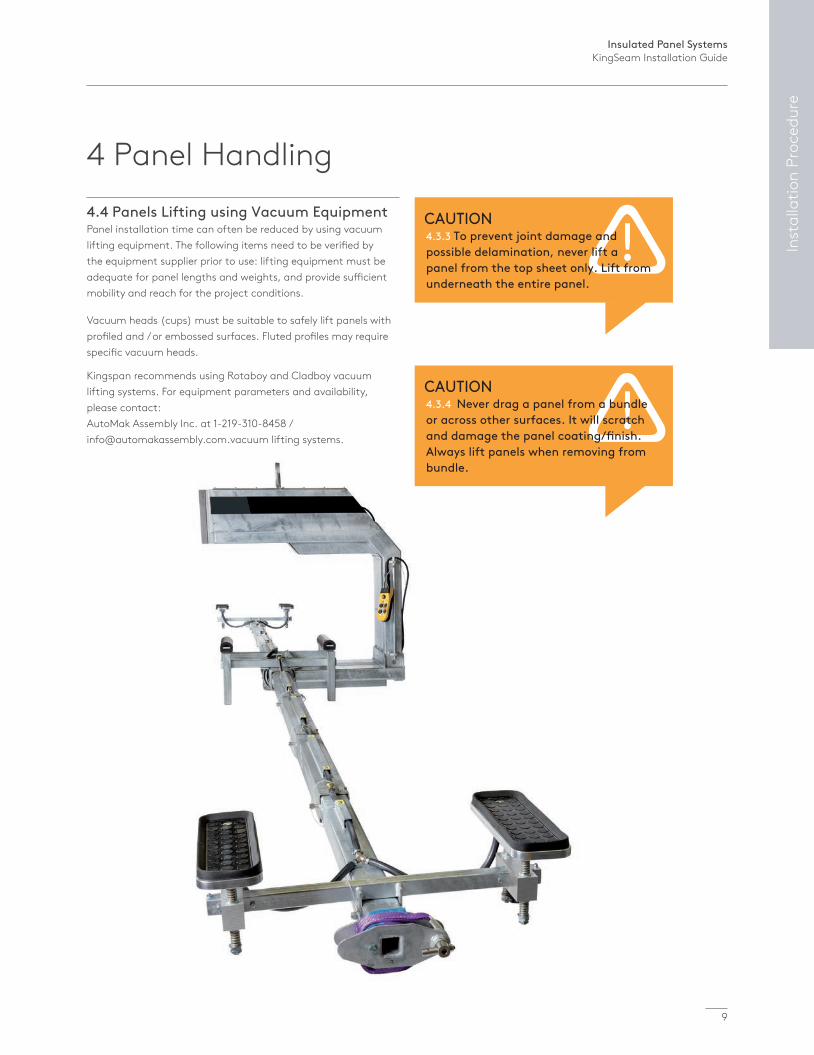
4 Panel Handling4.4 Panels Lifting using Vacuum EquipmentPanel installation time can often be reduced by using vacuum lifting equipment. The following items need to be verified by the equipment supplier prior to use: lifting equipment must be adequate for panel lengths and weights, and provide sufficient mobility and reach for the project conditions.
Vacuum heads (cups) must be suitable to safely lift panels with profiled and / or embossed surfaces. Fluted profiles may require specific vacuum heads.
Kingspan recommends using Rotaboy and Cladboy vacuum lifting systems. For equipment parameters and availability, please contact: AutoMak Assembly Inc. at 1-219-310-8458 / [email protected] lifting systems.
CAUTION4.3.3 To prevent joint damage and possible delamination, never lift a panel from the top sheet only. Lift from underneath the entire panel.
CAUTION4.3.4 Never drag a panel from a bundle or across other surfaces. It will scratch and damage the panel coating/finish. Always lift panels when removing from bundle.
Insulated Panel SystemsKingSeam Installation Guide
10
Fig. 5.2
Fig. 5.1
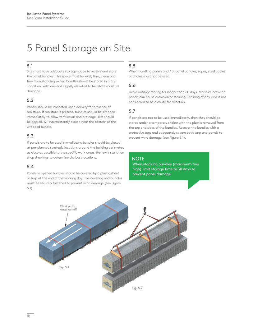
2% slope for water run-off
5.1Site must have adequate storage space to receive and store the panel bundles. This space must be level, firm, clean and free from standing water. Bundles should be stored in a dry condition, with one end slightly elevated to facilitate moisture drainage.
5.2Panels should be inspected upon delivery for presence of moisture. If moisture is present, bundles should be slit open immediately to allow ventilation and drainage, slits should be approx. 12” intermittently placed near the bottom of the wrapped bundle.
5.3If panels are to be used immediately, bundles should be placed at pre-planned strategic locations around the building perimeter, as close as possible to the specific work areas. Review installation shop drawings to determine the best locations.
5.4Panels in opened bundles should be covered by a plastic sheet or tarp at the end of the working day. The covering and bundles must be securely fastened to prevent wind damage (see Figure 5.1).
5.5When handling panels and / or panel bundles, ropes, steel cables or chains must not be used.
5.6Avoid outdoor storing for longer than 60 days. Moisture between panels can cause corrosion or staining. Staining of any kind is not considered to be a cause for rejection.
5.7If panels are not to be used immediately, then they should be stored under a temporary shelter with the plastic removed from the top and sides of the bundles. Recover the bundles with a protective tarp and adequately secure both tarp and panels to prevent wind damage (see Figure 5.1).
NOTEWhen stacking bundles (maximum two high) limit storage time to 30 days to prevent panel damage.
5 Panel Storage on Site
Insulated Panel SystemsKingSeam Installation Guide
11
Inst
alla
tion
Proc
edur
e
6 Handling and Storage of Items and Accessories
7 Removal of Protective Film
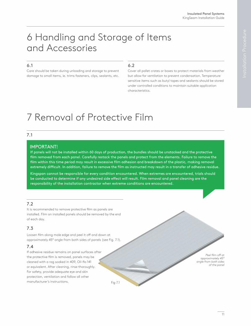
Peel film off at approximately 45º
angle from both sides of the panel
Fig 7.1
6.1Care should be taken during unloading and storage to prevent damage to small items, ie. trims fasteners, clips, sealants, etc.
6.2Cover all pallet crates or boxes to protect materials from weather but allow for ventilation to prevent condensation. Temperature sensitive items such as butyl tapes and sealants should be stored under controlled conditions to maintain suitable application characteristics.
7.1
7.2It is recommended to remove protective film as panels are installed. Film on installed panels should be removed by the end of each day.
7.3Loosen film along male edge and peel it off and down at approximately 45° angle from both sides of panels (see Fig. 7.1).
7.4If adhesive residue remains on panel surfaces after the protective film is removed, panels may be cleaned with a rag soaked in 409, Oil-flo 141 or equivalent. After cleaning, rinse thoroughly. For safety, provide adequate eye and skin protection, ventilation and follow all other manufacturer’s instructions.
IMPORTANT!If panels will not be installed within 60 days of production, the bundles should be unstacked and the protective film removed from each panel. Carefully restack the panels and protect from the elements. Failure to remove the film within this time period may result in excessive film adhesion and breakdown of the plastic, making removal extremely difficult. In addition, failure to remove the film as instructed may result in a transfer of adhesive residue.
Kingspan cannot be responsible for every condition encountered. When extremes are encountered, trials should be conducted to determine if any undesired side effect will result. Film removal and panel cleaning are the responsibility of the installation contractor when extreme conditions are encountered.

Insulated Panel SystemsKingSeam Installation Guide
12
9 Panel Cutting Procedures
8.1Review shop drawings prior to installation to verify that structural members are in the correct location.
8.2Installer must examine the alignment of the structural steel prior to installation of the roof panels. The roof structure must be square and provide adequate support to framing members intended to support the panel system. Supporting steel must be in the same plane and free of obstructions such as weld marks, bolts or screw heads. The recommended roof plane tolerances are 0” inward, and not to exceed + 3⁄16” from the control with a maximum 1⁄8” deviation for any member in any 10’-0” direction.
9.1Personnel working with panel cutting equipment should wear respiratory and eye protection at all times.
9.2Panel cutting should take place prior to panel installation whenever possible.
9.3Use the appropriate cutting tools with extreme care to avoid panel delamination. Do not use a cutting disk, torch, and other high heat producing methods for cutting. Hot filings may damage the painted surface of the panel. Kingspan recommends use of a circular saw with a fine tooth carbide tip blade (40 tooth minimum). A band saw with a suitable metal cutting blade may also be used.
9.4For small penetrations, a Dremel type router may be used to cut each face of the panel, and a serrated bread knife may be used to cut the foam core.
9.5Power snips, nibblers or hand snips may be used to cut trims and flashings.
8.3Panel supports must extend to the outer extremities at all panel terminations.
8.4Any variance from tolerances can affect both performance and aesthetics and must be reported to the architect and general contractor. All out of tolerance framing must be corrected by the responsible party prior to panel installation.
NOTEDo not use an electric grinder, reciprocating saw, or any tool that may cause serious delamination.
8 Structural Steel Framing
Insulated Panel SystemsKingSeam Installation Guide
13
Inst
alla
tion
Proc
edur
e
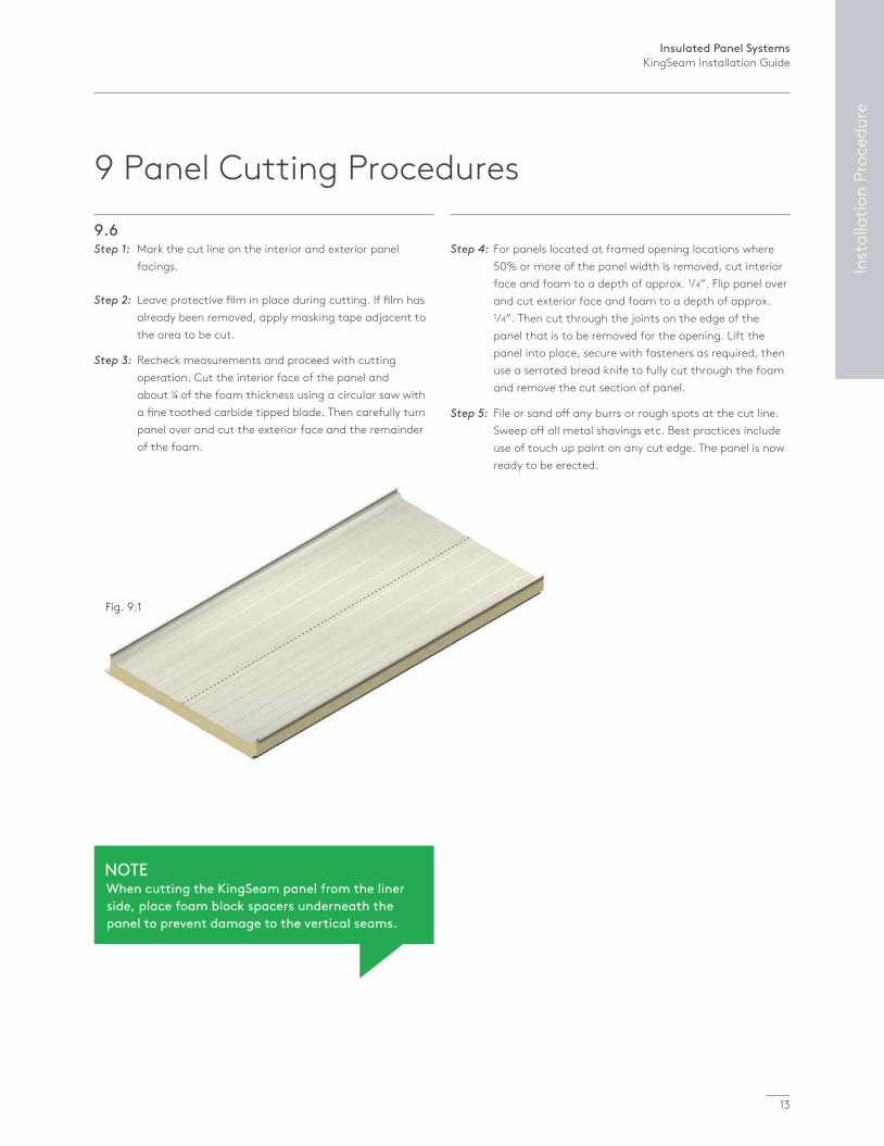
Fig. 9.1
9.6Step 1: Mark the cut line on the interior and exterior panel facings.
Step 2: Leave protective film in place during cutting. If film has already been removed, apply masking tape adjacent to the area to be cut.
Step 3: Recheck measurements and proceed with cutting operation. Cut the interior face of the panel and about ¼ of the foam thickness using a circular saw with a fine toothed carbide tipped blade. Then carefully turn panel over and cut the exterior face and the remainder of the foam.
Step 4: For panels located at framed opening locations where 50% or more of the panel width is removed, cut interior face and foam to a depth of approx. 1/4”. Flip panel over and cut exterior face and foam to a depth of approx. 1/4”. Then cut through the joints on the edge of the panel that is to be removed for the opening. Lift the panel into place, secure with fasteners as required, then use a serrated bread knife to fully cut through the foam and remove the cut section of panel.
Step 5: File or sand off any burrs or rough spots at the cut line. Sweep off all metal shavings etc. Best practices include use of touch up paint on any cut edge. The panel is now ready to be erected.
NOTEWhen cutting the KingSeam panel from the liner side, place foam block spacers underneath the panel to prevent damage to the vertical seams.
9 Panel Cutting Procedures
Insulated Panel SystemsKingSeam Installation Guide
14
Fig. 10.1
Fig. 10.1a
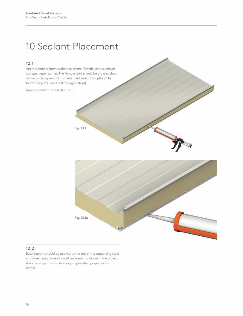
10 Sealant Placement10.1Apply a bead of butyl sealant to interior female joint to ensure a proper vapor barrier. The Female joint should be dry and clean before applying sealant. (Interior joint sealant is optional for freezer projects – see Cold Storage details).
Applying sealant on site (Fig. 10.1).
10.2Butyl sealant should be applied to the top of the supporting steel structure along the entire roof perimeter as shown in the project shop drawings. This is necessary to provide a proper vapor barrier.
Insulated Panel SystemsKingSeam Installation Guide
15
Inst
alla
tion
Proc
edur
e
12 Panel Cleaning and Maintenance
11.1The panel erector is to touch up all exposed cut edges with touch up paint. Contact Kingspan Customer Service for information on appropriate touch up paint.
12.1Proper installation and maintenance are extremely important in obtaining the very best service and appearance from pre-painted metal insulated panels.
12.2All dirt, oil, grease, fingerprints, metal filings or other contaminants should be removed to assure proper service life of the paint system. The installer should wipe-down the panels as they are erected.
12.3Dirt pickup may cause apparent discoloration of the paint after prolonged exposure. Slight chalking from strong sunlight exposure may also cause a change in appearance. A thorough cleaning will usually restore the original appearance of the panels.
12.4In many cases, a simple low pressure wash of the building with plain water will be adequate. In areas of heavy dirt deposits, a solution of water and detergent (1/3 cup liquid Tide per gallon of water) may be used. Use a rag, sponge, or soft bristle brush to clean. A clean water rinse should follow..
12.5Mildew may occur in areas subjected to high humidity. To remove mildew, use the following solution followed with a clear water rinse: 1/3 cup of detergent (Tide), 2/3 cup of tri-sodium phosphate (Soilex), 1 quart sodium hypo chlorite 5% solution (Clorox), 3 quarts water.
12.6Caulking compounds, oil, grease, tars, wax and similar substances can be removed by wiping with a cloth soaked with WD-40 lubricant. Test on an inconspicuous area first. Do not rub excessively or damage to the finish may result. Wipe only contaminated areas and follow with detergent cleaning and thorough rinsing.
12.7To remove oxidation and tough stains, use a household cleaner recommended for use on porcelain skins and bathtubs. This should be followed with a thorough rinsing. Wire brushing or any abrasive material may damage the painted surface and should not be used.
12.8Contact Kingspan Customer Service to receive a copy of the complete Kingspan Panel Maintenance Manual.
CAUTIONStrong solvents and abrasive cleaners should be avoided. Any cleaning method used should be first trialed in an inconspicuous area to ensure there is no unintended side effect.
11 Panel Touch-up Paint
Insulated Panel SystemsKingSeam Installation Guide
16
KingSeam Roof Installation
Panel length
4.25” Cutback DeLand
4.25” Cutback DeLand
4.25” Cutback DeLand
3” Cutback Modesto
3” Cutback Modesto
3” Cutback Modesto
6” Endlap
6” Endlap
6” Endlap
Panel length
Panel length
Panel length
Panel length
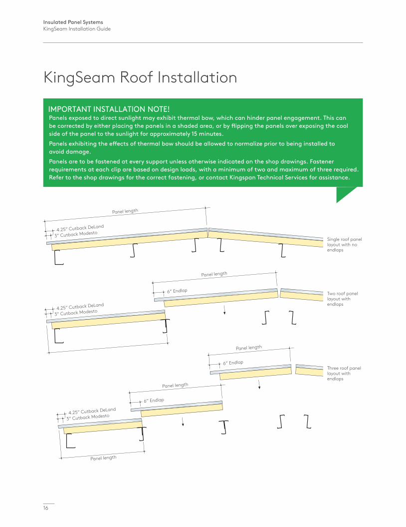
Single roof panel layout with no endlaps
Two roof panel layout with endlaps
Three roof panel layout with endlaps
IMPORTANT INSTALLATION NOTE!Panels exposed to direct sunlight may exhibit thermal bow, which can hinder panel engagement. This can be corrected by either placing the panels in a shaded area, or by flipping the panels over exposing the cool side of the panel to the sunlight for approximately 15 minutes.Panels exhibiting the effects of thermal bow should be allowed to normalize prior to being installed to avoid damage.Panels are to be fastened at every support unless otherwise indicated on the shop drawings. Fastener requirements at each clip are based on design loads, with a minimum of two and maximum of three required. Refer to the shop drawings for the correct fastening, or contact Kingspan Technical Services for assistance.
Insulated Panel SystemsKingSeam Installation Guide
17
Inst
alla
tion
KingSeam Roof Installation
Equal
Equal
Rake
Rake
Eave
Direction of installation
40” (full module)
40” (full module)
Field remove foam and inside skin
6” cutback at endlaps 3” cutback at eaves
Factory cut liner side
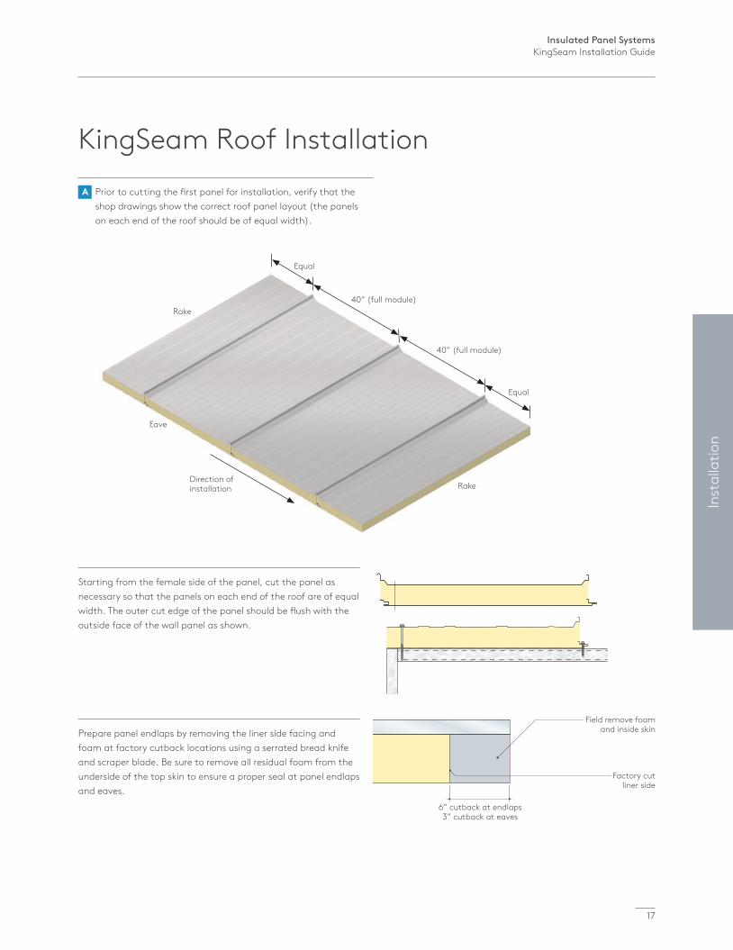
Starting from the female side of the panel, cut the panel as necessary so that the panels on each end of the roof are of equal width. The outer cut edge of the panel should be flush with the outside face of the wall panel as shown.
Prepare panel endlaps by removing the liner side facing and foam at factory cutback locations using a serrated bread knife and scraper blade. Be sure to remove all residual foam from the underside of the top skin to ensure a proper seal at panel endlaps and eaves.
A Prior to cutting the first panel for installation, verify that the shop drawings show the correct roof panel layout (the panels on each end of the roof should be of equal width).
Insulated Panel SystemsKingSeam Installation Guide
18
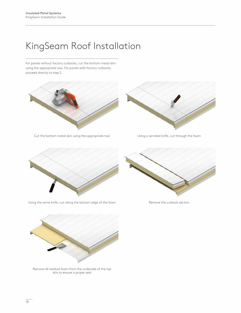
For panels without factory cutbacks, cut the bottom metal skin using the appropriate saw. For panels with factory cutbacks, proceed directly to step 2.
Cut the bottom metal skin using the appropriate tool
Using the same knife, cut along the bottom edge of the foam
Remove all residual foam from the underside of the top skin to ensure a proper seal
Using a serrated knife, cut through the foam
Remove the cutback section
KingSeam Roof Installation
Insulated Panel SystemsKingSeam Installation Guide
19
Inst
alla
tion
P1
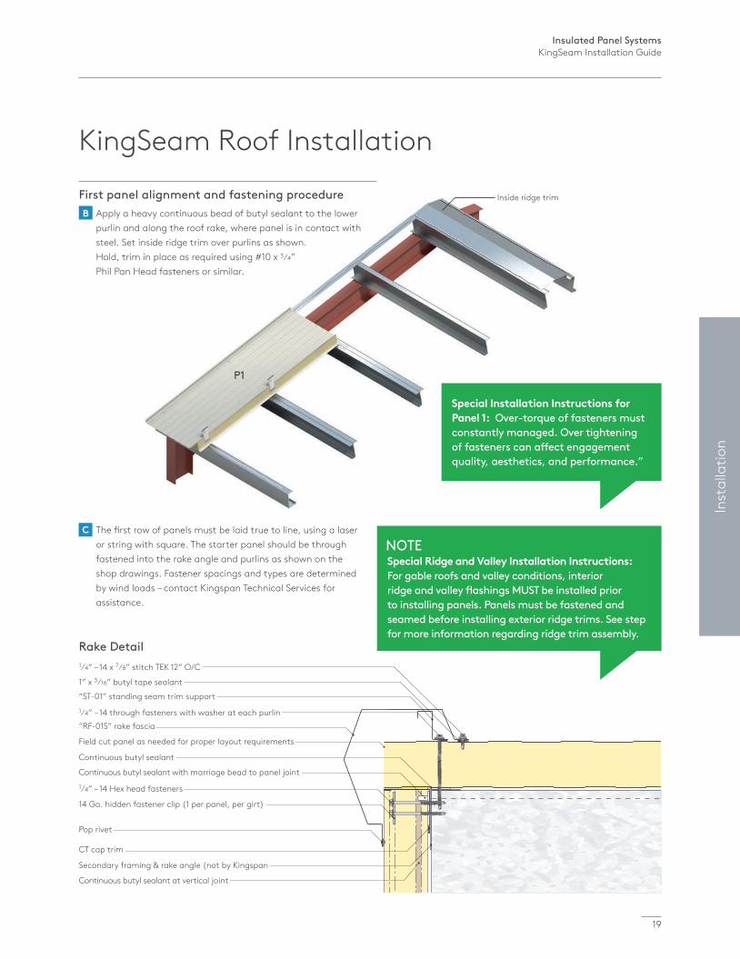
Inside ridge trim
Rake Detail1⁄4” – 14 x 7⁄8” stitch TEK 12” O/C
1” x 3⁄16” butyl tape sealant
1⁄4” – 14 through fasteners with washer at each purlin
Continuous butyl sealant
1⁄4” – 14 Hex head fasteners
Secondary framing & rake angle (not by Kingspan
Pop rivet
“RF-01S” rake fascia
Field cut panel as needed for proper layout requirements
“ST-01” standing seam trim support
CT cap trim
14 Ga. hidden fastener clip (1 per panel, per girt)
Continuous butyl sealant with marriage bead to panel joint
Continuous butyl sealant at vertical joint
First panel alignment and fastening procedure B Apply a heavy continuous bead of butyl sealant to the lower purlin and along the roof rake, where panel is in contact with steel. Set inside ridge trim over purlins as shown. Hold, trim in place as required using #10 x 3⁄4” Phil Pan Head fasteners or similar.
C The first row of panels must be laid true to line, using a laser or string with square. The starter panel should be through fastened into the rake angle and purlins as shown on the shop drawings. Fastener spacings and types are determined by wind loads – contact Kingspan Technical Services for assistance.
Special Installation Instructions for Panel 1: Over-torque of fasteners must constantly managed. Over tightening of fasteners can affect engagement quality, aesthetics, and performance.”
NOTESpecial Ridge and Valley Installation Instructions: For gable roofs and valley conditions, interior ridge and valley flashings MUST be installed prior to installing panels. Panels must be fastened and seamed before installing exterior ridge trims. See step for more information regarding ridge trim assembly.
KingSeam Roof Installation
Insulated Panel SystemsKingSeam Installation Guide
20
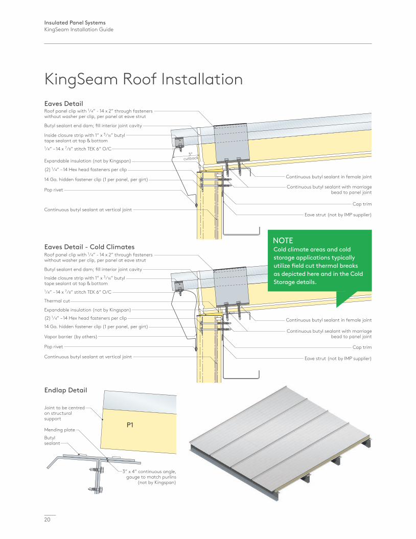
Eaves Detail
1⁄4” – 14 x 7⁄8” stitch TEK 6” O/C
Inside closure strip with 1” x 3⁄16” butyl tape sealant at top & bottom
Butyl sealant end dam; fill interior joint cavity
Roof panel clip with 1⁄4” - 14 x 2” through fasteners without washer per clip, per panel at eave strut
(2) 1⁄4” – 14 Hex head fasteners per clip
Expandable insulation (not by Kingspan)
Pop rivet
Continuous butyl sealant at vertical joint
14 Ga. hidden fastener clip (1 per panel, per girt) Continuous butyl sealant in female joint
Continuous butyl sealant with marriage bead to panel joint
Cap trim
Eave strut (not by IMP supplier)
3” cutback
Eaves Detail - Cold Climates
1⁄4” – 14 x 7⁄8” stitch TEK 6” O/C
Inside closure strip with 1” x 3⁄16” butyl tape sealant at top & bottom
Butyl sealant end dam; fill interior joint cavity
Roof panel clip with 1⁄4” - 14 x 2” through fasteners without washer per clip, per panel at eave strut
(2) 1⁄4” – 14 Hex head fasteners per clip
Expandable insulation (not by Kingspan)
Pop rivet
Thermal cut
Vapor barrier (by others)
Continuous butyl sealant at vertical joint
14 Ga. hidden fastener clip (1 per panel, per girt)Continuous butyl sealant in female joint
Continuous butyl sealant with marriage bead to panel joint
Cap trim
Eave strut (not by IMP supplier)
NOTECold climate areas and cold storage applications typically utilize field cut thermal breaks as depicted here and in the Cold Storage details.
Endlap Detail
Butyl sealant
P1
3” x 4” continuous angle, gauge to match purlins
(not by Kingspan)
Joint to be centred on structural support
Mending plate
KingSeam Roof Installation
Insulated Panel SystemsKingSeam Installation Guide
21
Inst
alla
tion
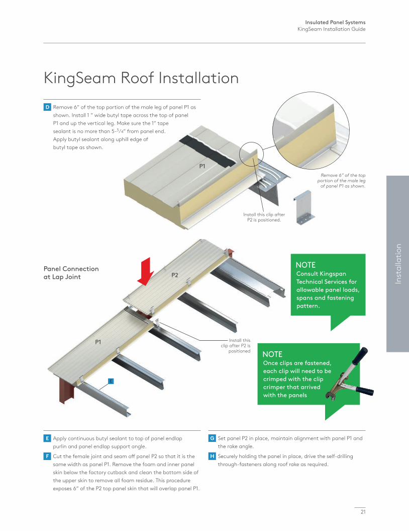
P1
P2
Install this clip after P2 is
positioned
Panel Connection at Lap Joint
Install this clip after P2 is positioned.
P1Remove 6” of the top
portion of the male leg of panel P1 as shown.
D Remove 6” of the top portion of the male leg of panel P1 as shown. Install 1 ” wide butyl tape across the top of panel P1 and up the vertical leg. Make sure the 1” tape sealant is no more than 5-3⁄4” from panel end. Apply butyl sealant along uphill edge of butyl tape as shown.
E Apply continuous butyl sealant to top of panel endlap purlin and panel endlap support angle. F Cut the female joint and seam off panel P2 so that it is the same width as panel P1. Remove the foam and inner panel skin below the factory cutback and clean the bottom side of the upper skin to remove all foam residue. This procedure exposes 6” of the P2 top panel skin that will overlap panel P1.
G Set panel P2 in place, maintain alignment with panel P1 and the rake angle.
H Securely holding the panel in place, drive the self-drilling through-fasteners along roof rake as required.
E
KingSeam Roof Installation
NOTEOnce clips are fastened, each clip will need to be crimped with the clip crimper that arrived with the panels
NOTEConsult Kingspan Technical Services for allowable panel loads, spans and fastening pattern.
Insulated Panel SystemsKingSeam Installation Guide
22
Install this clip after P2 is positioned
P1
P2
Short extension socket
Correct extension socket
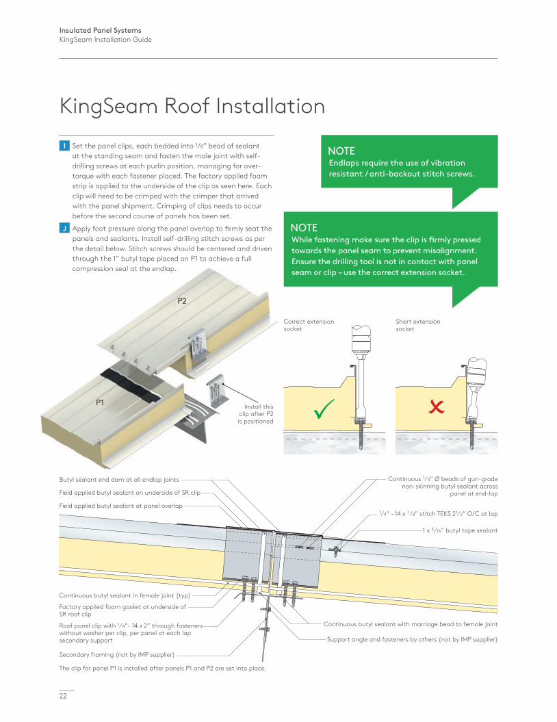
The clip for panel P1 is installed after panels P1 and P2 are set into place.
Continuous butyl sealant in female joint (typ)
Factory applied foam gasket at underside of SR roof clip
Roof panel clip with 1⁄4”- 14 x 2” through fasteners without washer per clip, per panel at each lap secondary support
Secondary framing (not by IMP supplier)
1⁄4” – 14 x 7⁄8” stitch TEKS 21⁄2” O/C at lap
1 x 3⁄16” butyl tape sealant
Continuous butyl sealant with marriage bead to female joint
Support angle and fasteners by others (not by IMP supplier)
Field applied butyl sealant on underside of SR clip
Butyl sealant end dam at all endlap joints
Field applied butyl sealant at panel overlap
Continuous 1⁄4” Ø beads of gun-grade non-skinning butyl sealant across
panel at end-lap
I Set the panel clips, each bedded into 1/8” bead of sealant at the standing seam and fasten the male joint with self- drilling screws at each purlin position, managing for over- torque with each fastener placed. The factory applied foam strip is applied to the underside of the clip as seen here. Each clip will need to be crimped with the crimper that arrived with the panel shipment. Crimping of clips needs to occur before the second course of panels has been set.
J Apply foot pressure along the panel overlap to firmly seat the panels and sealants. Install self-drilling stitch screws as per the detail below. Stitch screws should be centered and driven through the 1” butyl tape placed on P1 to achieve a full compression seal at the endlap.
NOTEEndlaps require the use of vibration resistant / anti-backout stitch screws.
NOTEWhile fastening make sure the clip is firmly pressed towards the panel seam to prevent misalignment. Ensure the drilling tool is not in contact with panel seam or clip – use the correct extension socket.
KingSeam Roof Installation
Insulated Panel SystemsKingSeam Installation Guide
23
Inst
alla
tion
P1
P2
P3
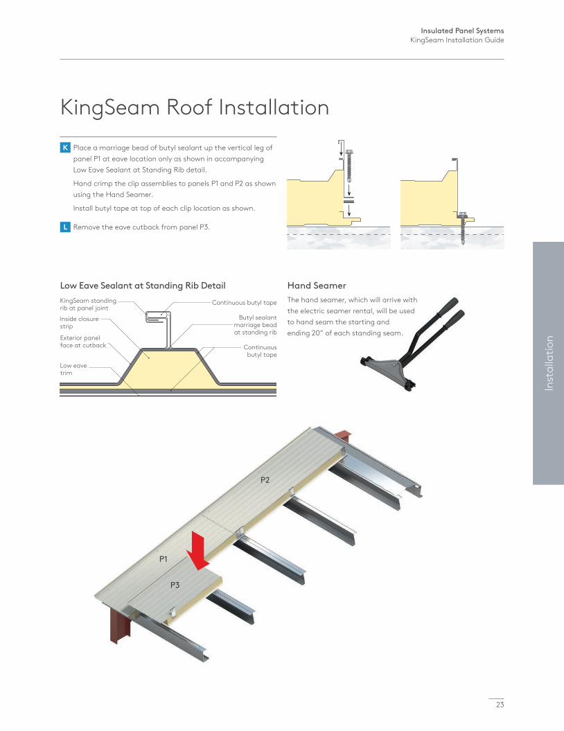
Low Eave Sealant at Standing Rib DetailKingSeam standing rib at panel joint
Continuous butyl tape
Butyl sealant marriage bead at standing rib
Continuous butyl tape
Inside closure strip
Exterior panel face at cutback
Low eave trim
KingSeam Roof Installation K Place a marriage bead of butyl sealant up the vertical leg of
panel P1 at eave location only as shown in accompanying Low Eave Sealant at Standing Rib detail.
Hand crimp the clip assemblies to panels P1 and P2 as shown using the Hand Seamer.
Install butyl tape at top of each clip location as shown.
L Remove the eave cutback from panel P3.
Hand SeamerThe hand seamer, which will arrive with the electric seamer rental, will be used to hand seam the starting and ending 20” of each standing seam.

Insulated Panel SystemsKingSeam Installation Guide
24
Remove 6” of the down leg on panel P3 as shown.
P4
P3
M Prepare panel P3 by removing 6” of the down leg as shown.
N Merge sealant tape across panel P3 with tape sealant along male leg of panel P1.
O 1 Engage panel joints.
2 Use clamps to secure standing rib assembly.
3 Hand crimp clips used to fasten panel 3.
Butyl application on standing seam
Field applied butyl
KingSeam Roof Installation
Insulated Panel SystemsKingSeam Installation Guide
25
Inst
alla
tion
P1
P2
P3
P4
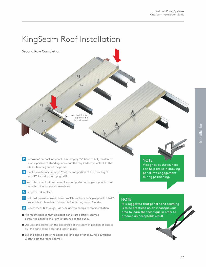
Install this clip after P4 is positioned.
Second Row Completion
It is recommended that adjacent panels are partially seamed before the panel to the right is fastened to the purlin.
Use vice grip clamps on the side profile of the seam at position of clips to pull the panel skins closer and lock in place.
Set one clamp before the panel clip, and one after allowing a sufficient width to set the Hand Seamer.
P Remove 6” cutback on panel P4 and apply 1⁄4” bead of butyl sealant to Female portion of standing seam and the required butyl sealant to the Interior female joint of the panel.
Q If not already done, remove 6” of the top portion of the male leg of panel P3 (see step on D page 20).
R Verify butyl sealant has been placed on purlin and angle supports at all panel terminations as shown above.
S Set panel P4 in place.
T Install all clips as required, then complete endlap stitching of panel P4 to P3. Ensure all clips have been crimped before setting panels 5 and 6.
U Repeat steps D through T as necessary to complete roof installation.
NOTEIt is suggested that panel hand seaming is to be practiced on an inconspicuous area to learn the technique in order to produce an acceptable result.
KingSeam Roof Installation
NOTEVice grips as shown here can help assist in drawing panel into engagement during positioning.
Insulated Panel SystemsKingSeam Installation Guide
26
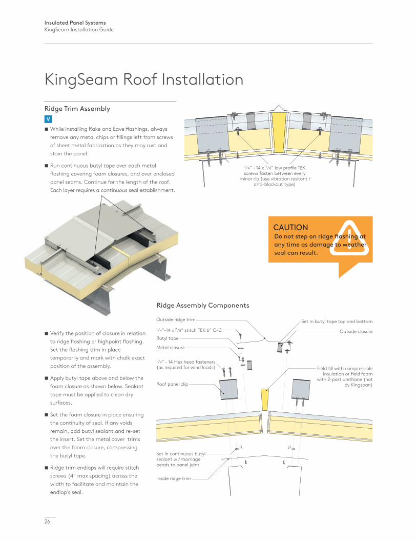
Verify the position of closure in relation to ridge flashing or highpoint flashing. Set the flashing trim in place temporarily and mark with chalk exact position of the assembly.
Apply butyl tape above and below the foam closure as shown below. Sealant tape must be applied to clean dry surfaces.
Set the foam closure in place ensuring the continuity of seal. If any voids remain, add butyl sealant and re-set the insert. Set the metal cover trims over the foam closure, compressing the butyl tape.
Ridge trim endlaps will require stitch screws (4” max spacing) across the width to facilitate and maintain the endlap’s seal.
1⁄4” - 14 x 7⁄8” low profile TEK screws fasten between every
minor rib (use vibration resitant / anti-blackout type)
Inside ridge trim
Set in continuous butyl sealant w / marriage beads to panel joint
Outside ridge trim
Butyl tape
Metal closure
Roof panel clip
1⁄4” - 14 Hex head fasteners (as required for wind loads)
1⁄4”-14 x 7⁄8” stitch TEK 6” O/C
Field fill with compressible insulation or field foam
with 2-part urethane (not by Kingspan)
Set in butyl tape top and bottom
Outside closure
Ridge Assembly Components
Ridge Trim Assembly V
While installing Rake and Eave flashings, always remove any metal chips or fillings left from screws of sheet metal fabrication as they may rust and stain the panel.
Run continuous butyl tape over each metal flashing covering foam closures, and over enclosed panel seams. Continue for the length of the roof. Each layer requires a continuous seal establishment.
CAUTIONDo not step on ridge flashing at any time as damage to weather seal can result.
KingSeam Roof Installation
Insulated Panel SystemsKingSeam Installation Guide
27
Inst
alla
tion
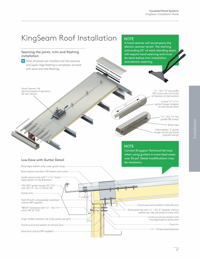
Power Seamer: P4 Nominal speed of operation: 30’ per minute.
1⁄4” – 14 x 7⁄8” low profile TEK screws (do not locate
at fastener at clip location
Locate 3⁄4” x 3⁄4” gutter hanger (angles)
at each panel seam1.0”
1⁄4” - 14 x 7⁄8” low profile TEK screws
Intermediate ‘Z’ gutter hanger at two per panel
(spaced evenly)
Butyl tape1.0”
Seaming the joints, trim and flashing installation W After all panels are installed and fully seamed, and upper ridge flashing is completed, proceed with eave and rake flashings.
Butyl tape sealant strip under gutter strap
Gutter trim
Field-fill with compressible insulation (not by IMP supplier)
“BB-01” bird block with 1⁄4” - 14 x 7⁄8” stitch TEK 12” O/C
Inside closure strip with 1” x 3⁄16” butyl tape sealant at top & bottom
Continuous butyl sealant at vertical joint
Butyl sealant end dam; fill Interior joint cavity
14 ga. hidden fastener clip (1 per panel, per girt)
“GS-02S” gutter hanger 20” O/C with (5) 1 4 - 14 x 7⁄8 stitch TEK
Eave strut (not by IMP supplier)
Continuous butyl sealant in female joint
Roof panel clip with 1⁄4” - 14 x 2” fastener without washer per clip, per panel at eave strut
Cap trim
Continuous butyl sealant with marriage bead to panel joint
1⁄4” - 14 Hex head fasteners
Low Eave with Gutter Detail
3” cutback
11⁄2”
KingSeam Roof Installation
NOTEContact Kingspan Technical Services when using gutters in snow load areas over 30 psf. Detail modifications may be necessary.
NOTEA hand seamer will accompany the electric seamer rental. The starting and ending 20” of each standing seam will require hand seaming and must be done before trim installation and electric seaming.
Insulated Panel SystemsKingSeam Installation Guide
roof slope
28
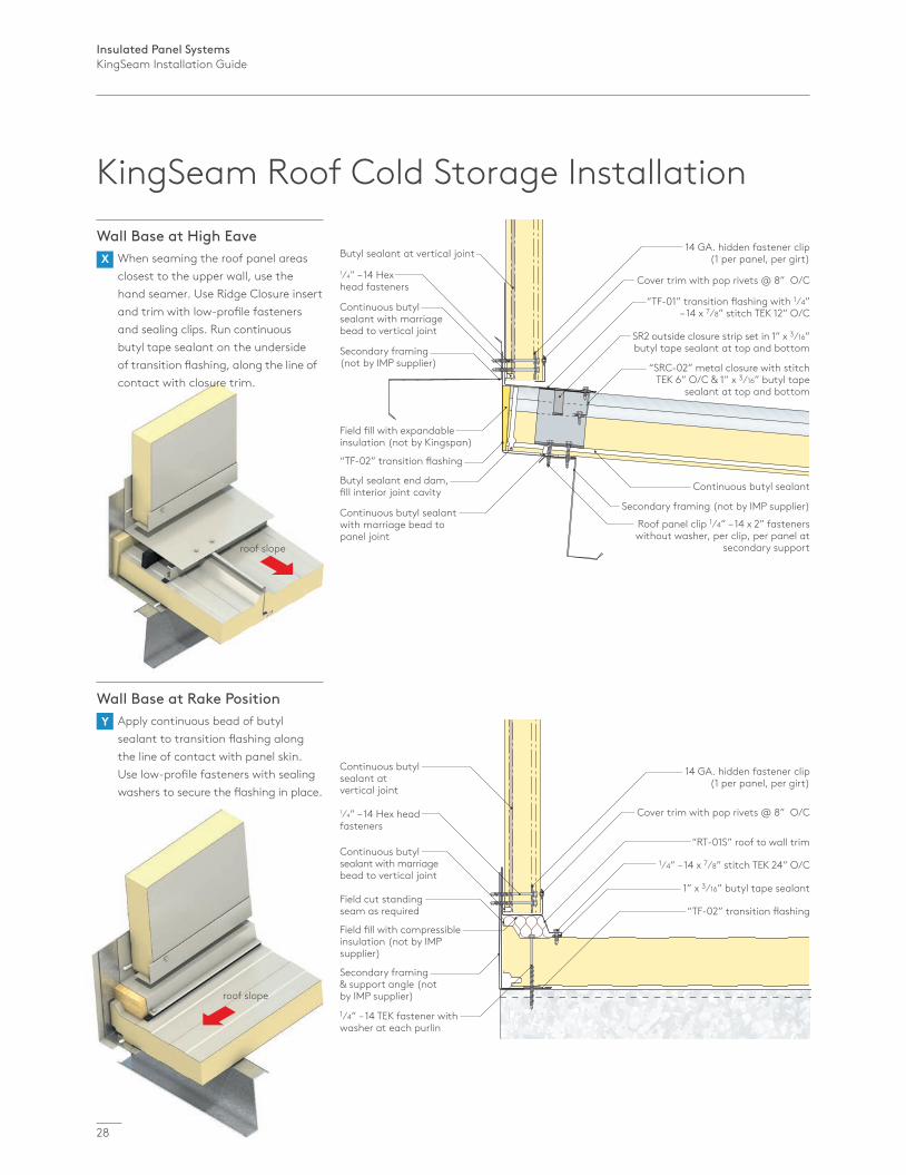
roof slope
14 GA. hidden fastener clip (1 per panel, per girt)
Cover trim with pop rivets @ 8” O/C
“TF-02” transition flashing
“RT-01S” roof to wall trim
1⁄4” – 14 x 7⁄8” stitch TEK 24” O/C
1⁄4” – 14 TEK fastener with washer at each purlin
1” x 3⁄16” butyl tape sealant
Continuous butyl sealant at vertical joint
1⁄4” – 14 Hex head fasteners
Field cut standing seam as required
Field fill with compressible insulation (not by IMP supplier)
Continuous butyl sealant with marriage bead to vertical joint
Secondary framing & support angle (not by IMP supplier)
Wall Base at High Eave X When seaming the roof panel areas closest to the upper wall, use the hand seamer. Use Ridge Closure insert and trim with low-profile fasteners and sealing clips. Run continuous butyl tape sealant on the underside of transition flashing, along the line of contact with closure trim.
Wall Base at Rake Position Y Apply continuous bead of butyl sealant to transition flashing along the line of contact with panel skin. Use low-profile fasteners with sealing washers to secure the flashing in place.
14 GA. hidden fastener clip (1 per panel, per girt)
Cover trim with pop rivets @ 8” O/C
“TF-01” transition flashing with 1⁄4” – 14 x 7⁄8” stitch TEK 12” O/C
“TF-02” transition flashing
SR2 outside closure strip set in 1” x 3⁄16” butyl tape sealant at top and bottom
Roof panel clip 1⁄4” – 14 x 2” fasteners without washer, per clip, per panel at
secondary support
Butyl sealant at vertical joint
Continuous butyl sealant
Continuous butyl sealant with marriage bead to panel joint
Butyl sealant end dam, fill interior joint cavity
Secondary framing (not by IMP supplier)
Secondary framing (not by IMP supplier)
“SRC-02” metal closure with stitch TEK 6” O/C & 1” x 3⁄16” butyl tape
sealant at top and bottom
Continuous butyl sealant with marriage bead to vertical joint
Field fill with expandable insulation (not by Kingspan)
1⁄4” – 14 Hex head fasteners
KingSeam Roof Cold Storage Installation
Insulated Panel SystemsKingSeam Installation Guide
29
Inst
alla
tion
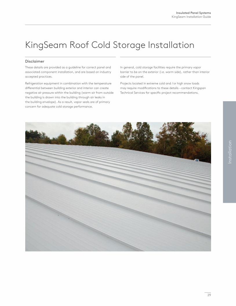
Disclaimer These details are provided as a guideline for correct panel and associated component installation, and are based on industry accepted practices.
Refrigeration equipment in combination with the temperature differential between building exterior and interior can create negative air pressure within the building (warm air from outside the building is drawn into the building through air leaks in the building envelope). As a result, vapor seals are of primary concern for adequate cold storage performance.
In general, cold storage facilities require the primary vapor barrier to be on the exterior (i.e. warm side), rather than interior side of the panel.
Projects located in extreme cold and / or high snow loads may require modifications to these details – contact Kingspan Technical Services for specific project recommendations.
KingSeam Roof Cold Storage Installation
Insulated Panel SystemsKingSeam Installation Guide
30
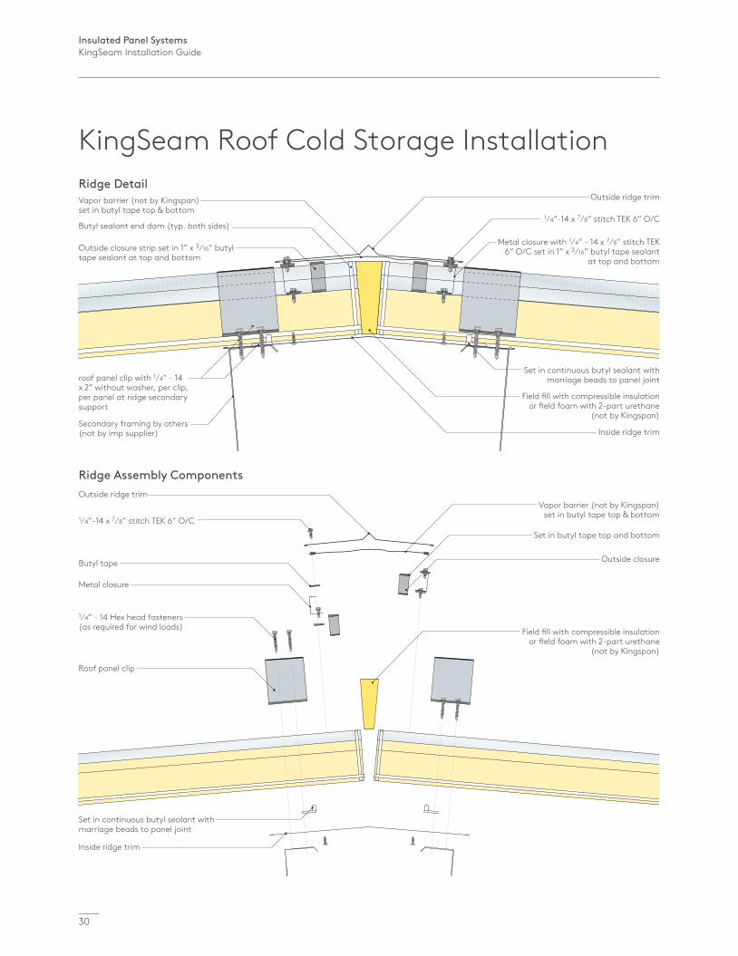
Ridge Assembly Components
Inside ridge trim
Set in continuous butyl sealant with marriage beads to panel joint
Outside ridge trim
Butyl tape
Metal closure
Roof panel clip
1⁄4” - 14 Hex head fasteners (as required for wind loads)
1⁄4”-14 x 7⁄8” stitch TEK 6” O/C
Field fill with compressible insulation or field foam with 2-part urethane
(not by Kingspan)
Set in butyl tape top and bottom
Outside closure
Vapor barrier (not by Kingspan) set in butyl tape top & bottom
Ridge Detail
Inside ridge trim
Set in continuous butyl sealant with marriage beads to panel joint
Outside ridge trim
Metal closure with 1⁄4” - 14 x 7⁄8” stitch TEK 6” O/C set in 1” x 3⁄16” butyl tape sealant
at top and bottom
roof panel clip with 1⁄4” - 14 x 2” without washer, per clip, per panel at ridge secondary support
Secondary framing by others (not by imp supplier)
1⁄4”-14 x 7⁄8” stitch TEK 6” O/C
Field fill with compressible insulation or field foam with 2-part urethane
(not by Kingspan)
Outside closure strip set in 1” x 3⁄16” butyl tape sealant at top and bottom
Vapor barrier (not by Kingspan) set in butyl tape top & bottom
Butyl sealant end dam (typ. both sides)
KingSeam Roof Cold Storage Installation
Insulated Panel SystemsKingSeam Installation Guide
Inst
alla
tion
31
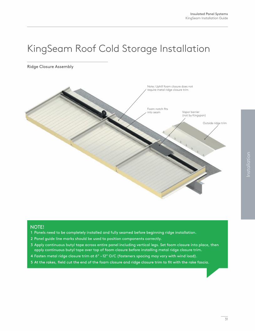
Note: Uphill foam closure does not require metal ridge closure trim
Foam notch fits into seam Vapor barrier
(not by Kingspan)
Outside ridge trim
Ridge Closure Assembly
NOTE! 1 Panels need to be completely installed and fully seamed before beginning ridge installation. 2 Panel guide line marks should be used to position components correctly. 3 Apply continuous butyl tape across entire panel including vertical legs. Set foam closure into place, then apply continuous butyl tape over top of foam closure before installing metal ridge closure trim. 4 Fasten metal ridge closure trim at 6” – 12” O/C (fasteners spacing may vary with wind load). 5 At the rakes, field cut the end of the foam closure and ridge closure trim to fit with the rake fascia.
KingSeam Roof Cold Storage Installation
Insulated Panel SystemsKingSeam Installation Guide
32
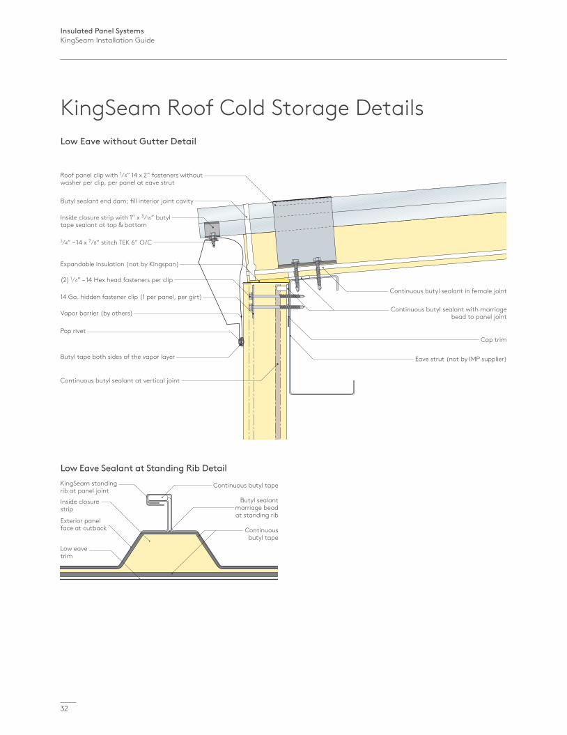
Low Eave without Gutter Detail
1⁄4” – 14 x 7⁄8” stitch TEK 6” O/C
Inside closure strip with 1” x 3⁄16” butyl tape sealant at top & bottom
Butyl sealant end dam; fill interior joint cavity
Roof panel clip with 1⁄4” 14 x 2” fasteners without washer per clip, per panel at eave strut
(2) 1⁄4” – 14 Hex head fasteners per clip
Expandable insulation (not by Kingspan)
Pop rivet
Vapor barrier (by others)
Continuous butyl sealant at vertical joint
Butyl tape both sides of the vapor layer
14 Ga. hidden fastener clip (1 per panel, per girt)Continuous butyl sealant in female joint
Continuous butyl sealant with marriage bead to panel joint
Cap trim
Eave strut (not by IMP supplier)
KingSeam Roof Cold Storage Details
Low Eave Sealant at Standing Rib DetailKingSeam standing rib at panel joint
Continuous butyl tape
Butyl sealant marriage bead at standing rib
Continuous butyl tape
Inside closure strip
Exterior panel face at cutback
Low eave trim
Insulated Panel SystemsKingSeam Installation Guide
Inst
alla
tion
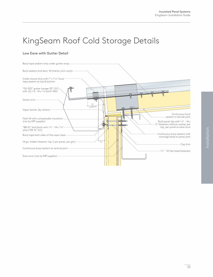
Butyl tape sealant strip under gutter strap
Gutter trim
Field-fill with compressible insulation (not by IMP supplier)
“BB-01” bird block with 1⁄4” - 14 x 7⁄8” stitch TEK 12” O/C
Inside closure strip with 1” x 3⁄16” butyl tape sealant at top & bottom
Continuous butyl sealant at vertical joint
Butyl sealant end dam; fill Interior joint cavity
14 ga. hidden fastener clip (1 per panel, per girt)
“GS-02S” gutter hanger 20” O/C with (5) 1 4 - 14 x 7⁄8 stitch TEKS
Eave strut (not by IMP supplier)
Continuous butyl sealant in female joint
Roof panel clip with 1⁄4” - 14 x 2” fasteners without washer per
clip, per panel at eave strut
Cap trim
Continuous butyl sealant with marriage bead to panel joint
1⁄4” - 14 Hex head fasteners
Low Eave with Gutter Detail
3” cutback
11⁄2”
Vapor barrier (by others)
Butyl tape both sides of the vapor layer
KingSeam Roof Cold Storage Details
33
Insulated Panel SystemsKingSeam Installation Guide
34
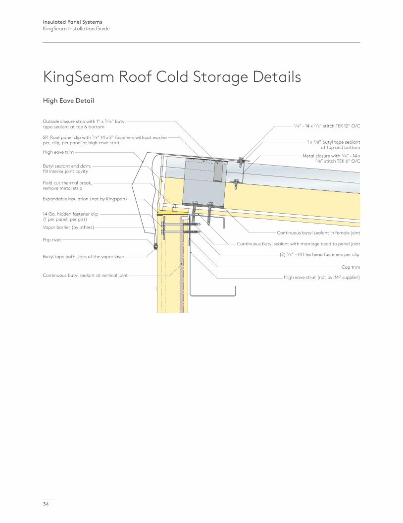
High Eave Detail
1⁄4” – 14 x 7⁄8” stitch TEK 12” O/COutside closure strip with 1” x 3⁄16” butyl tape sealant at top & bottom
Butyl sealant end dam; fill interior joint cavity
Field cut thermal break, remove metal strip
High eave trim
SR_Roof panel clip with 1⁄4” 14 x 2” fasteners without washer per, clip, per panel at high eave strut
(2) 1⁄4” – 14 Hex head fasteners per clip
Expandable insulation (not by Kingspan)
Pop rivet
Vapor barrier (by others)
Continuous butyl sealant at vertical joint
Butyl tape both sides of the vapor layer
14 Ga. hidden fastener clip (1 per panel, per girt)
Continuous butyl sealant in female joint
Continuous butyl sealant with marriage bead to panel joint
Cap trim
High eave strut (not by IMP supplier)
1 x 3⁄8” butyl tape sealant at top and bottom
Metal closure with 1⁄4” – 14 x 7⁄8” stitch TEK 6” O/C
KingSeam Roof Cold Storage Details
Insulated Panel SystemsKingSeam Installation Guide
35
Inst
alla
tion
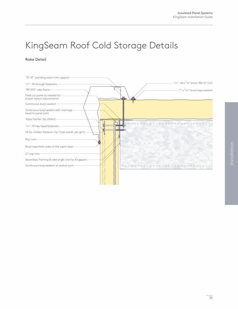
Rake Detail
1⁄4” – 14 x 7⁄8” stitch TEK 12” O/C
1” x 3⁄16” butyl tape sealant
1⁄4” – 14 through fasteners
Continuous butyl sealant
1⁄4” – 14 Hex head fasteners
Vapor barrier (by others)
Secondary framing & rake angle (not by Kingspan)
Pop rivet
“RF-01S” rake fascia
Field cut panel as needed for proper layout requirements
“ST-01” standing seam trim support
CT cap trim
14 Ga. hidden fastener clip (1 per panel, per girt)
Continuous butyl sealant with marriage bead to panel joint
Continuous butyl sealant at vertical joint
Butyl tape both sides of the vapor layer
KingSeam Roof Cold Storage Details

Insulated Panel SystemsKingSeam Installation Guide
36
Electric snips
Caulking gun
Primary fastener
Circular saw with fine tooth carbide blade
Butyl sealant tape
Through fastener (primary fastener extended by 1”)
Power nibbler
Laser or gravity levellers
Secondary fastener
Power drill
Grip clamp
Rivet fastener
Drilling bits and sockets
Hand seamerClip crimper
Expandable foam
Power seamer
2 piece clip assembly Knife and Scraper
Tools and Sealants
Fastening Hardware
Materials, Tools and Hardware
Insulated Panel SystemsKingSeam Installation Guide
37
Misc
ella
neou
s
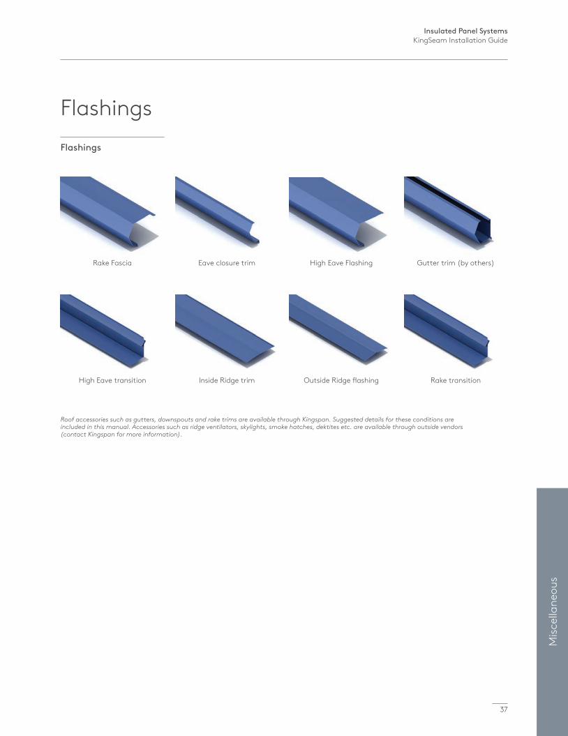
Rake Fascia
High Eave transition
Eave closure trim
Inside Ridge trim
High Eave Flashing
Outside Ridge flashing
Gutter trim (by others)
Rake transition
Roof accessories such as gutters, downspouts and rake trims are available through Kingspan. Suggested details for these conditions are included in this manual. Accessories such as ridge ventilators, skylights, smoke hatches, dektites etc. are available through outside vendors (contact Kingspan for more information).
Flashings
Flashings
Insulated Panel SystemsKingSeam Installation Guide
38
1.1 General DescriptionThe hand seamer for the KingSeam panel is used to mechanically seam adjacent panels to the hidden clip.
1.2 Features / SpecificationsFeatures Rugged, simple, compact and intuitive to use design.
Specifically designed with dimensions and clearances for the KingSeam steel roof panels.
Requires minimal operator force for seaming by using an extended lever arm.
Horizontally offset lever arm clears panels and visually indicates a proper seam when both handles are at the 180° position.
Special back cut steel angle overbends the horizontal layers of steel slightly for bounce back to a 90° angled profile thus enhancing the aesthetic appearance of the roof.
Unique bronze pivot joint never needs lubrication.
Specifications Weight: 7 Lbs
Maximum Gauge: 22 gauge
Lubrication: None Required
1.3 Operating Instructions1 The standing seam attachment clips are hand seamed first before the adjacent panel is installed.
2 One vice grip clamp is installed at the clip to pull the standing seam tightly against the sheet metal of the panel prior to screwing to the purlin.
3 Once the clips are installed along the entire panel run and the next panel is overlapped, the hand seaming can be started.
4 The supplied vice grip clamps are installed first by locking onto the standing seam side profile of the panels. The clamps should be installed at the root (base) of the standing seam, effectively pulling the two panels together.
5 One clamp is installed before the area to be hand seamed and one after. The angle steel of the clamp should not interfere with the hand seaming area. See picture 2 on page 6.
6 The seamer installs in only one orientation with the long side of the angle on the flat side of the standing seam.
7 The hand seamer should be used to seam the panel at the clip locations only. Final seaming should be done with the electric seamer.
8 To crimp the seam, push down on the handles until they are both parallel with the roof.
NOTEIt is suggested that the panel hand seaming process be practiced on an inconspicuous area to learn the technique to produce an acceptable result.
NOTEIt is recommended that every panel be seamed as they are being installed. This eases metal stresses, allows each panel to move to its installed position and will provide for a more professional and aesthetically pleasing installation.
Hand Seamer for the KingSeam panel
Insulated Panel SystemsKingSeam Installation Guide
39
Misc
ella
neou
s
1.4 SafetyNo job is so important or in such a rush to complete, that time cannot be taken to complete the work in a safe manner. While Kingspan recommends the following minimum safety practices, the company accepts no responsibility for personal injury or property damage incurred while operating the hand seaming tool.
Keep fingers clear of the pivot joint and other moving parts.
Do not attempt to seam with a damaged seamer, call the factory for an immediate replacement and return the damaged seamer to the factory for service.
Always store the seaming tool in a clean dry environment, preferably in the shipping box provided.
When working with potentially sharp sheet metal, always wear heavy leather gloves and eye protection.
Do not drop the seamer from the roof. Kingspan recommends that no one be allowed in the area below a roofing project during seaming. The use of caution tape and a ground level roofing employee should be considered a minimum requirement for a safe seaming procedure.
KingSeam Standing Seam Roof Electric Seaming Machine and Hand Seamer Rental information can be obtained from Kingspan Customer Service.
Hand Seamer for the KingSeam panel
Insulated Panel SystemsKingSeam Installation Guide
40
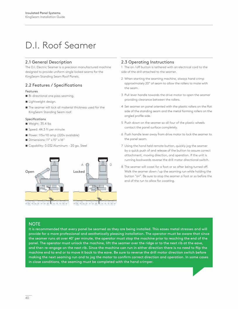
Open Locked
A D
2.1 General DescriptionThe D.I. Electric Seamer is a precision manufactured machine designed to provide uniform single locked seams for the KingSeam Standing Seam Roof Panels.
2.2 Features / SpecificationsFeatures Bi-directional one pass seaming.
Lightweight design.
The seamer will lock all material thickness used for the KingSeam Standing Seam roof.
Specifications Weight: 35.4 lbs
Speed: 44.3 ft per minute
Power: 115v/10 amp (220v available) Dimensions: 11” x 15” x 16”
Capability: 0.032 Aluminum - 20 ga. Steel
2.3 Operating Instructions1 The on / off button is tethered with an electrical cord to the side of the drill attached to the seamer.
2 When starting the seaming machine, always hand crimp approximately 20” of seam to allow the rollers to mate with the seam.
3 Pull lever handle towards the drive motor to open the seamer providing clearance between the rollers.
4 Set seamer on panel oriented with the plastic rollers on the flat side of the standing seam and the metal forming rollers on the angled profile side.
5 Push down on the seamer so all four of the plastic wheels contact the panel surface completely.
6 Push handle lever away from drive motor to lock the seamer to the panel seam.
7 Using the hand held remote button, quickly jog the seamer by a quick push of and release of the button to assure correct attachment, moving direction, and operation. If the unit is running backwards reverse the drill motor directional switch.
8 The seamer will coast for a foot or so after being turned off. Walk the seamer down / up the seaming run while holding the button “on”. Be sure to stop the seamer a foot or so before the end of the run to allow for coasting.
NOTEIt is recommended that every panel be seamed as they are being installed. This eases metal stresses and will provide for a more professional and aesthetically pleasing installation. The operator must be aware that since the seamer runs at over 40’ per minute, the operator must stop the machine prior to reaching the end of the panel. The operator must unlock the machine, lift the seamer over the ridge or to the next rib at the eave, and then re-engage on the next rib. Since the machine can run in either direction there is no need to flip the machine end to end or to move it back to the eave. Be sure to reverse the drill motor direction switch before making the next seaming run and to jog the motor to confirm correct direction and operation. In some cases in close conditions, the seaming must be completed with the hand crimper.
D.I. Roof Seamer
Insulated Panel SystemsKingSeam Installation Guide
41
Misc
ella
neou
s
Please contact D.I. Roof Seamers directly for rental information.
D.I. Roof Seamers915 Highway 45 Corinth, MS 388341-888-343-0456Office: (662) 287-6626www.kingspan.diroofseamers.com
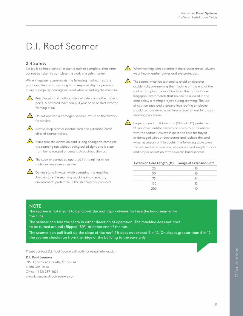
2.4 SafetyNo job is so important or in such a rush to complete, that time cannot be taken to complete the work in a safe manner.
While Kingspan recommends the following minimum safety practices, the company accepts no responsibility for personal injury or property damage incurred while operating the machine.
Keep fingers and clothing clear of rollers and other moving parts. A powered roller can pull your hand or shirt into the forming area.
Do not operate a damaged seamer, return to the factory for service.
Always keep seamer electric cord and extension cords clear of seamer rollers.
Make sure the extension cord is long enough to complete the seaming run without being pulled tight and is clear from being tangled or caught throughout the run.
The seamer cannot be operated in the rain or when moisture levels are excessive.
Do not stand in water while operating the machine. Always store the seaming machine in a clean, dry environment, preferable in the shipping box provided.
When working with potentially sharp sheet metal, always wear heavy leather gloves and eye protection.
The seamer must be tethered to avoid an operator accidentally overrunning the machine off the end of the roof or dropping the machine from the roof or ladder. Kingspan recommends that no one be allowed in the area below a roofing project during seaming. The use of caution tape and a ground leve roofing employee should be considered a minimum requirement for a safe seaming procedure.
Proper ground fault interrupt (GFI or GFIC) protected UL approved outdoor extension cords must be utilized with the seamer. Always inspect the cord for frayed or damaged wires or connectors and replace the cord when necessary or if in doubt. The following table gives the required extension cord size verses cord length for safe and proper operation of the electric hand seamer.
NOTEThe seamer is not meant to bend over the roof clips – always first use the hand seamer for the clips.The seamer can fold the seam in either direction of operation. The machine does not have to be turned around (flipped 180°) at either end of the run.The seamer can pull itself up the slope of the roof if it does not exceed 6 in 12. On slopes greater than 6 in 12 the seamer should run from the ridge of the building to the eave only.
D.I. Roof Seamer
Extension Cord Length (ft) Gauge of Extension Cord25 1850 1675 14150 12200 10
Insulated Panel SystemsKingSeam Installation Guide
42
Miscellaneous Information1. To prevent Galvanic action, isolate any aluminum surfaces from direct ferrous steel contact with any of the following methods a. Any approved sealant or sealant tape.
b. A non-absorbent gasket.
c. Duct tape or equivalent type tape.
d. Paint the incompatible metal with a coating of heavy bodied bituminous paint.
2. Flatness: Oil canning or “Scalloping” is an inherent condition of light gauge cold-formed metal products. Products with broad, flat areas or minor profiling can exhibit these inherent qualities at certain view angles. This does not affect the structural integrity or performance of the panel. Kingspan closely monitors production to ensure delivered product stays within industry expectations for IMP manufacturers and the steel industry which supplies the coil.
Oil canning or perceived waviness that are within Kingspan’s QC tolerances are not grounds for panel or trim rejection.
3. Although Kingspan’s Urethane core is acceptable for use in non-combustible building assemblies in accordance with International Building code (IBC) and have been exhaustively tested for fire resistivity based on their end use, they are not non-combustible in and of themselves. They are not “fire rated” per ASTM E119. Therefore, they shall not be exposed to extremely high temperatures or direct flame at any time. Simply stated, do not use a welding torch on or near insulated panels any more than you would on a wooden building assembly. Refer to panel test data information under “Fire” for detailed Information on ignition, heat of combustion, and surface burning.

Insulated Panel SystemsKingSeam Installation Guide
43
Misc
ella
neou
s
Notes
Issue 4: 01/2022
For the product offering in other markets please contact your local sales representative or visit www.kingspanpanels.com
To ensure you are viewing the most recent and accurate product information, please visit www kingspanpanels.com
Care has been taken to ensure that the contents of this publication are accurate, but Kingspan Limited and its subsidiary companies do not accept responsibility for errors or for information that is found to be misleading. Suggestions for, or description of, the end use or application of products or methods of working are for information only and Kingspan Limited and its subsidiaries accept no liability in respect thereof.
® Kingspan, KingSeam and the Lion Device are Registered Trademarks of the Kingspan Group plc in the US, Canada and other countries. All rights reserved. © Kingspan Insulated Panels Inc.
Contact Details
USADeLand | FL T: 877-638-3266
Modesto | CA T: 800-377-5110
CanadaCaledon | ON T: 866-442-3594
Langley | BC T: 877-937-6562