Influence of compressible medium on the operation of a ...
9
Influence of compressible medium on the operation of a reciprocating compressor Andrey Kotlov 1,* , Leonid Kuznetsov 2 , and Boris Hrustalev 1 1 Peter the Great St. Petersburg Polytechnic University, Joint Institute of Science and Technology, Scientific-Research Laboratory “Gas dynamics of turbomachines”, Polytechnicheskaya 29, Saint - Petersburg, 195251 Russian Federation 2 JSC Scientific Production Association "Compressor", Bol'shoy Sampsoniyevskiy Prospekt, 64, Sankt-Peterburg, 194044 Russian Federation Abstract. A reciprocating compressor is a volumetric machine. Consequently, the motion of gas in communications always is of non- stationary or pulsating character. The diagram of oscillatory processes in communications is complex because a number of factors affect the nature of the flow: cyclical gas supply, valve dynamics, change in the flow area of pipelines, variable cylinder volume, variable piston velocity, temperature gradients, etc. The analysis of non-stationary processes in the suction stage of a household refrigeration compressor is considered. A mathematical model of the flow of real gas in the suction system of a household refrigeration piston compressor has been developed. We performed a calculation study of the motion diagram of the suction valve, gas velocities in the suction pipe and pressure changes in the suction chamber. The results of a reciprocating compressor study while compressing various gases are given. The influence of the properties of refrigerants on the operation of the compressor and the suction system is considered. 1 Introduction Reciprocating compressors (RC) belong to the class of volumetric machines. The transition to ozone-friendly refrigerants, (in particular, the transition from R12 to R134A for household refrigeration compressors) is of great interest for RC researchers [1, 2]. Given the small size of such a compressor and the large number of household refrigerators produced in the world, the problem seems to be quite serious. For designers, it is necessary to take into account that such replacement results in the increased ratio of pressures in the cylinder, and, as result the efficiency and other performance characteristics of the compressor reduce. Also the operations of valves change, and the discharge temperature increases. The change in suction and discharge pressures entails a change in the dynamics of the valves and their efficiency and strength characteristics. Change of sound speed of the refrigerant leads to a change in the noise characteristics. To maintain the cooling capacity of the units, it is necessary to increase the volumetric capacity of the compressor. All of the aforesaid can be achieved by changing the designs of the compressor units, which is extremely undesirable for most manufacturers. * Corresponding author: [email protected] © The Authors, published by EDP Sciences. This is an open access article distributed under the terms of the Creative Commons Attribution License 4.0 (http://creativecommons.org/licenses/by/4.0/). MATEC Web of Conferences 245, 04009 (2018) https://doi.org/10.1051/matecconf/201824504009 EECE-2018
-
Upload
khangminh22 -
Category
Documents
-
view
2 -
download
0
Transcript of Influence of compressible medium on the operation of a ...

Influence of compressible medium on the operation of a reciprocating compressor
Andrey Kotlov1,*, Leonid Kuznetsov2, and Boris Hrustalev1
1 Peter the Great St. Petersburg Polytechnic University, Joint Institute of Science and Technology,
Scientific-Research Laboratory “Gas dynamics of turbomachines”, Polytechnicheskaya 29, Saint-
Petersburg, 195251 Russian Federation 2 JSC Scientific Production Association "Compressor", Bol'shoy Sampsoniyevskiy Prospekt, 64,
Sankt-Peterburg, 194044 Russian Federation
Abstract. A reciprocating compressor is a volumetric machine.
Consequently, the motion of gas in communications always is of non-
stationary or pulsating character. The diagram of oscillatory processes in
communications is complex because a number of factors affect the nature of
the flow: cyclical gas supply, valve dynamics, change in the flow area of
pipelines, variable cylinder volume, variable piston velocity, temperature
gradients, etc. The analysis of non-stationary processes in the suction stage
of a household refrigeration compressor is considered. A mathematical
model of the flow of real gas in the suction system of a household
refrigeration piston compressor has been developed. We performed a
calculation study of the motion diagram of the suction valve, gas velocities
in the suction pipe and pressure changes in the suction chamber. The results
of a reciprocating compressor study while compressing various gases are
given. The influence of the properties of refrigerants on the operation of the
compressor and the suction system is considered.
1 Introduction
Reciprocating compressors (RC) belong to the class of volumetric machines. The transition
to ozone-friendly refrigerants, (in particular, the transition from R12 to R134A for household
refrigeration compressors) is of great interest for RC researchers [1, 2]. Given the small size
of such a compressor and the large number of household refrigerators produced in the world,
the problem seems to be quite serious. For designers, it is necessary to take into account that
such replacement results in the increased ratio of pressures in the cylinder, and, as result the
efficiency and other performance characteristics of the compressor reduce. Also the
operations of valves change, and the discharge temperature increases. The change in suction
and discharge pressures entails a change in the dynamics of the valves and their efficiency
and strength characteristics. Change of sound speed of the refrigerant leads to a change in the
noise characteristics. To maintain the cooling capacity of the units, it is necessary to increase
the volumetric capacity of the compressor. All of the aforesaid can be achieved by changing
the designs of the compressor units, which is extremely undesirable for most manufacturers.
* Corresponding author: [email protected]
© The Authors, published by EDP Sciences. This is an open access article distributed under the terms of the Creative Commons Attribution License 4.0 (http://creativecommons.org/licenses/by/4.0/).
MATEC Web of Conferences 245, 04009 (2018) https://doi.org/10.1051/matecconf/201824504009EECE-2018
In connection with the problem of damping the pressure pulsations and gas velocities in
the suction system of household refrigeration compressors, great interest is attached to the
analysis of non-stationary processes in order to reduce losses and noise and to improve their
performance when replacing different types of refrigerants.
If you rank all the causes of the pulsations occurrence in a reciprocating compressor
according to its degree of influence, the three main reasons can be identified [3]:
- Pulsations of gas parameters caused by the very operation principle of a reciprocating
compressor: gas flows in the suction system only during the suction process;
- Pulsations caused by the properties of the moving medium: inertia and compressibility;
- Pulsations caused by oscillations of moving valve elements.
The use of mathematical models for research processes occurring in refrigeration
compressors makes it possible to reduce the amount of experimental work in this direction
[4, 5].
The goal of this work is to increase the efficiency of household refrigeration compressors
by improving the quality of design and reducing the time needed for experimental
development by introducing digital design methods.
The object of the study is a household refrigerating compressor with the following
technical characteristics: rotational speed is 3000 rpm; cylinder diameter is 22 mm; piston
stroke (plunger) is 22 mm. The compressor is equipped with petal valves. The discharge
valve contains a working and damping petal. The suction system has a rectangular channel
of 110 mm length with hydraulic diameter of 10.3 mm, as well as two attached chambers of
10 and 14 cm3. The hydraulic diameter of the neck is 6 mm, and the length (thickness of the
channel walls) is 2 mm.
2 Mathematical model
The mathematical model (MM) of the working process includes: the equation of the first law
of thermodynamics in differential form, the mass flow equations, the equation of state, caloric
equations, the equation of the motion mechanism dynamics and the equation of the valve
dynamics. The thermodynamic equation for a body of variable mass is written in energy
form, i.e. the equation for the internal energy change is chosen as the main one, and the values
of pressure and temperature are found from the equation of state of the gas.
The system of equations is as follows (1) [3, 6-10]
/ , / , ( , )
( , ), , /
j j k k
j k
j k
j k
dU dQ dVp i m i m
dt dt dt
dMm m
dt
M V u U M T f u
z f T p z RT i u p
(1)
where U is the internal gas energy in the considered tank; dQ/dt is the heat flow through
the surface of the considered tank; p is pressure; V is the tank volume; i is specific enthalpy;
,j km m are mass flow rates of gas flowing through the j-th hole and flowing away through
the k-th hole; t is time; M is the gas mass in the considered tank; ρ is gas density; u is specific
internal energy; T is gas temperature; k is adiabatic index; R is the gas constant; z is the
compression factor.
The equation of motion of the valve closure is as a function of time and has the following
form (2) [3, 7, 8, 11-17]
𝑚red𝑑2ℎ
𝑑𝑡2= 𝜉𝑝𝐹сΔ𝑝 − 𝑐(ℎ + ℎ0) − 𝜂
𝑑ℎ
𝑑𝑡+𝑚red𝑔 cos β, (2)
2
MATEC Web of Conferences 245, 04009 (2018) https://doi.org/10.1051/matecconf/201824504009EECE-2018
where mred is the reduced mass of the moving valve elements; h is motion of the valve
closure; ξp is the pressure ratio; Fc is the flow area in the valve seat; Δp is the pressure drop
across the valve; c is the stiffness of the elastic elements of the valve; h0 is preliminary
compression of the elastic elements of the valve; η is the damping coefficient; g is the
gravitational acceleration; β is the angle between the axis of motion and the direction of
gravity.
The combination of the above equations makes it possible, under appropriate initial
conditions, to describe the thermodynamic processes in the tank for a real gas, both constant
and variable in volume. When considering heat transfer processes, it is supposed to use a
quasistationary representation of processes with a known law of temperature distribution
along pipelines and tank wall temperatures. Heat transfer coefficients are determined by the
formulae of steady-state laminar and turbulent gas flow. For the universality of the
computational program, that is, for application to any gases, the mathematical model is
complemented by the equations of a real gas state in the form of polynomial dependencies.
For the pipeline, the equations of unsteady one-dimensional gas dynamics in partial
derivatives are used [3, 6].
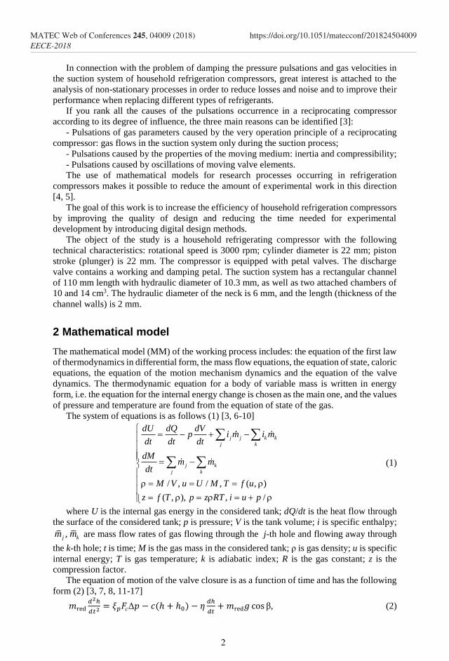
When gas moves through an arbitrary section O - O of a pipe with an area F (x) smoothly
varying in length (see Figure 1), its parameters are characterized by the average parameters:
density across the section, pressure, speed and temperature, which vary both in time and
pipeline length.
Fig. 1. Pipe element with a smoothly changing area across its length
The motion of gas through the pipe is described by the following equations:
- Continuity equation (3)
0F v
t x
, (3)
- Equation of conservation of momentum (while neglecting mass forces) (4) 𝜕𝑣
𝜕𝑡= −
1
ρ𝐹
𝜕ρ𝐹
𝜕𝑥− 𝜆fric
𝑣2
2𝑑, (4)
- Energy equation with regard to heat exchange with walls, taking into account the heat
release due to viscous friction and heat transfer by heat conduction (5) 𝜕
𝜕𝑥(𝜆fric𝐹
𝜕𝑇
𝜕𝑥) + 𝐹𝑇𝜎 + 𝐹
𝜕𝑝
𝜕𝑡+ 𝛼𝐿(𝑇wall − 𝑇) =
𝜕
𝜕𝑡(𝑖𝜌𝐹 + 𝜌𝐹
𝑣2
2) +
𝜕
𝜕𝑥(𝑖𝜌𝑣𝐹 + 𝜌𝐹
𝑣3
2), (5)
- Equations of the gas thermodynamic state (6)
1 2( , , ) 0; ( , , ) 0f p T f p T i , (6)
where v is the gas velocity; λfric is the coefficient of hydraulic friction; d is the equivalent
diameter; L is the pipe length; F is the area of the pipeline passage section; Twall is the
temperature of the pipeline walls, α is the heat transfer coefficient.
3
MATEC Web of Conferences 245, 04009 (2018) https://doi.org/10.1051/matecconf/201824504009EECE-2018
These equations describe a one-dimensional unsteady gas flow in the pipelines of a
compressor setup.
Calculation of mass flow through the gaps is performed using the formula of S.Е.
Zakharenko (7) [3, 7, 18, 19], which takes into account the gap shape and its geometric
dimensions; flow parameters before and after the gap; gas friction in the gap; pressure losses
at the inlet and outlet of the gap.
* 21 1
2
1
ln r
pm l
, (7)
where μ is the discharge coefficient; δ is the gap clearance; l is the gap depth; *1 1 2/p RT
is conditional density; p1 is the gas pressure behind the gap; T2 is the gas
temperature in front of the gap; ε is the pressure ratio in front of the gap and behind it, p2/p1;
ξ is the total coefficient of local resistances at the inlet and outlet of the gap; λfric is the friction
coefficient [20], Σ is the form factor.
The flow enters into both sides of a nonlinear equation, the solution of which, is often
sought by the method of iterations. Practice shows that for acceptable accuracy (coincidence
of four to five significant digits), 15 ÷ 30 iterations are sufficient. For the initial
approximation, one can take the value equal to one hundredth of the mass flow rate of the
compressor being modeled.
3 Results and discussions
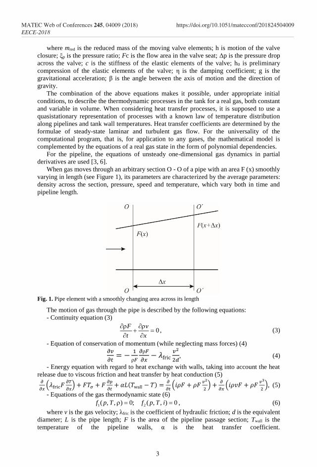
Figures 2-5 present the research data. The results show a change in the performance
indicators of the reciprocating compressor, depending on the piston clearance. The gap
between the piston and the cylinder wall is an annular slit and is chosen from 0 to 0.02 mm
with a step of 0.005 mm (0-1% of the cylinder diameter).
Fig. 2. Relative leakages: 1 – R134; 2 – air; 3 – hydrogen
With increasing the clearance, relative leakages increase too. For hydrogen, as a light gas,
this growth is very significant (see Figure 2), at a half of clearance the leakage is almost
100%. It should be noted that the graphs, primarily the indicator power (see Figure 3) and
the efficiency (see Figure 4), are not monotonous. This is especially noticeable when
considering air. To explain this fact, we consider the motion diagrams of the petals of the
suction and discharge valves for different clearances (see Figure 6). It is known that the
leakage of a reciprocating compressor is determined not only by the static leakiness of the
seals, but also by the dynamic leakage of the valves associated with their untimely closing.
At constant dynamic characteristics of the valves, their operation depends on the piston seal.
Calculated diagrams of the valve petal motions (see Figure 6) clearly demonstrate this. For a
discharge valve with a piston gap of 0.02 mm, the closing delay angle is of great importance.
4
MATEC Web of Conferences 245, 04009 (2018) https://doi.org/10.1051/matecconf/201824504009EECE-2018

So, for hydrogen (see Figure 6, c), the angle of delay reaches 25°. At the same time, the
hitting rate of the working petal on the seat increases for almost 2 times and reaches critical
values. Some part of the gas flows back into the cylinder, thereby reducing compressor
capacity. At the same time, the capacity of the compressor increases, since it is necessary to
compress the gas flowing back through the valve. For hydrogen, even the valve petal motion
diagram is changing (see Figure 6).
The influence of mass transfer (leakage) on the compression polytropic index is of
interest. Figure 5 shows variation in the polytropic index of the final parameters, depending
on the size of the gap between the piston and the compressor cylinder. For a hermetic
compressor (gap is zero), the polytropic index is equal to the adiabatic index. However, it is
clearly seen that increasing the gap leads to a decrease in the values of the polytropic index.
Fig. 3. Iindicator power: 1 – R134; 2 – air; 3 – hydrogen
Fig. 4. Efficiency: 1 – R134; 2 – air; 3 – hydrogen
5
MATEC Web of Conferences 245, 04009 (2018) https://doi.org/10.1051/matecconf/201824504009EECE-2018

Fig. 5. Compression polytropic index: 1 – R134; 2 – air
a)
b)
c)
Fig. 6. Diagrams of petal motion of the suction (1, 3) and discharge (2, 4) valves depending on the
gap size: 0 - solid line; 0.02 mm (for hydrogen 0.01 mm) - the dotted line: a) air; b) R134; c)
hydrogen
6
MATEC Web of Conferences 245, 04009 (2018) https://doi.org/10.1051/matecconf/201824504009EECE-2018
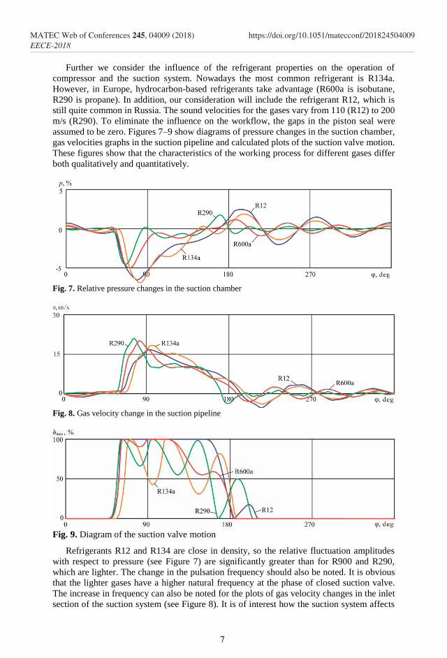
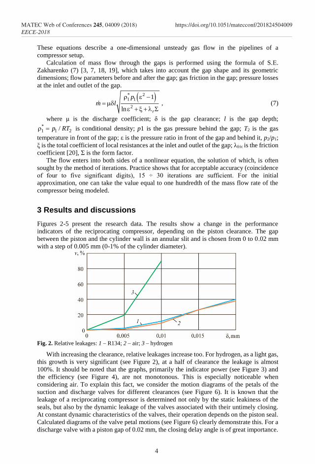
Further we consider the influence of the refrigerant properties on the operation of
compressor and the suction system. Nowadays the most common refrigerant is R134a.
However, in Europe, hydrocarbon-based refrigerants take advantage (R600a is isobutane,
R290 is propane). In addition, our consideration will include the refrigerant R12, which is
still quite common in Russia. The sound velocities for the gases vary from 110 (R12) to 200
m/s (R290). To eliminate the influence on the workflow, the gaps in the piston seal were
assumed to be zero. Figures 7–9 show diagrams of pressure changes in the suction chamber,
gas velocities graphs in the suction pipeline and calculated plots of the suction valve motion.
These figures show that the characteristics of the working process for different gases differ
both qualitatively and quantitatively.
Fig. 7. Relative pressure changes in the suction chamber
Fig. 8. Gas velocity change in the suction pipeline
Fig. 9. Diagram of the suction valve motion
Refrigerants R12 and R134 are close in density, so the relative fluctuation amplitudes
with respect to pressure (see Figure 7) are significantly greater than for R900 and R290,
which are lighter. The change in the pulsation frequency should also be noted. It is obvious
that the lighter gases have a higher natural frequency at the phase of closed suction valve.
The increase in frequency can also be noted for the plots of gas velocity changes in the inlet
section of the suction system (see Figure 8). It is of interest how the suction system affects
7
MATEC Web of Conferences 245, 04009 (2018) https://doi.org/10.1051/matecconf/201824504009EECE-2018

the operation of the compressor valve, which compresses different gases. Figure 9 clearly
demonstrates what happens in this case with the motion diagrams of the valve petal. For
R290, the gas force acting on the valve petal is less than for R134. Therefore, a premature
closure occurs. As a result, the speed of the seat hitting increases during landing. Its
subsequent opening leads to an increase in dynamic leakages and to a decrease in efficiency.
4 Conclusions
Our study shows that for the effecient operation of the compressor it is necessary to carefully
select the characteristics of all subsystems (valves, seals and suction system) for each gas.
We analyzed the influence of various gases properties on the working processes in a
reciprocating compressor. We established that for light gases, the compressor performance
drops to zero even for very small piston gaps. It is shown that the valve motion diagrams
change. When this happens, the lagging angles change, which, in turn, leads to an increase in
the dynamic leakage of valves and an increase in the overall relative leakages. We established
the mutual influence of gas-dynamic characteristics of the suction system and valves on the
compressor operation.
Acknowledgements. The research was performed by a grant of Russian Science Foundation (project
No. 18-79-10165).
References
1. J.M. Mendoza-Miranda, A. Mota-Babiloni, J.J. Ramírez-Minguela, J. Navarro-Esbrí, C.
Salazar-Hernández, Energy, 114 с. 753-766 (2016)
2. K.M. Ignatiev, B.S. Chrustalev, M.M. Perevozchikov, V.B. Zdaslinsky, Int-l Comperssor
Eng. Conf. at Purdue, 1, 201-210 (1996)
3. B. S. Chrustalev, Dis… d-ra. tekhn. nauk 377 p. (1999)
4. B.S. Chrustalev, V.B. Zdalinsky, V.A. Bulanov, International Compressor Engineering,
2 (1996)
5. B.S. Hrustalev, Kompressornaya tekhnika i pnevmatika, 14-15 (1997)
6. M.M. Perevozchikov, B.S. Chrustalyov, International Compressor Engineering, 2, 515-
520 (1994)
7. A.A. Kotlov, Dis… kand. tekhn. nauk 138 p. (2011)
8. P. I. Plastinin, Piston compressors. Vol.1. Theory and calculations (2006)
9. V.E. Shcherba, A.K. Kuzhbanov, E.A. Pavlyuchenko, G.A. Nesterenko, V.S.
Vinichenko, Omskij nauchnyj vestnik, 1(117), 82-87 (2013)
10. F.P. Disconzi, C.J. Deschamps, and E.L.L. Pereira, International Compressor
Engineering Conference, p. 2103 (2012)
11. V. S. Kalekin, D. V. Kalekin, A. N. Nefedchenko, Omskij nauchnyj vestnik, 3, 72-76
(2013)
12. T. F. Kondrat'eva, V. P. Isakov, Valves of the piston compressors (1983)
13. A.S. Makoveeva, A.I. Priluckij, A.A. Priluckij, V.Yu. Ganzha, Kompressornaya tekhnika
i pnevmatika, 1, 21-26 (2018)
14. A.F. Sarmanaeva, T.N. Mustafin, G.N Chekushkin, Kompressornaya tekhnika i
pnevmatika, 4, 17-20 (2015)
15. A Brandl, O Bielmeier, B Spiegl, International Compressor Engineering Conference at
Purdue, p. 1278 (2012)
16. D. Taranović, D. Ninković, A. Davinić, R. Pešić, J. Glišović, S. Milojević, Tehnički
vjesnik, 24, 313-319 (2017)
8
MATEC Web of Conferences 245, 04009 (2018) https://doi.org/10.1051/matecconf/201824504009EECE-2018

17. L.R. Silva, and C.J. Deschamps, International Compressor Engineering Conference, p.
2105 (2012).
18. S.E. Zaharenko, Trudy of the Leningrad Polytechnic Institute named after M.I. Kalinin,
249, 69-75 (1965)
19. V.N. Dokukin, V.A. Pronin, Nauchnyj zhurnal NIU ITMO. Seriya «Holodil'naya
tekhnika i kondicionirovanie», 3, 17-23 (2014)
20. M.Yu. Elagin, E.M. Sidorov, Izvestiya TulGU. Tekhnicheskie nauki, 6, 88-96 (2014)
9
MATEC Web of Conferences 245, 04009 (2018) https://doi.org/10.1051/matecconf/201824504009EECE-2018