Influence of Blade Deformation on Integral Characteristic of ...
11
Paper received: 25.5.2007 Paper accepted: 28.9.2007 Influence of Blade Deformation on Integral Characteristic of Axial Flow Fan Matjaž Eberlinc*1 - Matevž Dular' - Brane Širok' - Bojan Lapanja2 ‘University of Ljubljana, Faculty of Mechanical Engineering, Slovenia 2Hidria Institute Klima, Godovič, Slovenia Axial flow fan blades deform during operation due to the various forces that act on them. That is why, we can ask ourselves about the influence of the blade deformation on the integral and local characteristics. In the paper, we present a study of influence of axial flow fan blade deformation. The paper deals with measurements o f the blade deformation at the known integral working conditions. Results - deformations offan blade tip were usedfor numerical study o f the influence o f the changed blade form on the fan's aerodynamic characteristic. Fan integral characteristics were measured in accordance with the ISO-DIS 5801.2006 standard and were carried out on the wind tunnel o fthe Hidria Institute Klima, Godovič. Other measurements of the blade deformation were done on the measuring station on the Faculty of Mechanical Engineering, University o f Ljubljana, with the help of computer aided visualization. Deformations were measured in three working points, which were defined with fan integral parameters. Results o f the measurements helped to determine modified form o f the blade, which was then used for the numerical simulation for the same fan integral parameters. The study o f deformation influence, based on the numerical simulation, was carried out. © 2008 Journal of Mechanical Engineering. All rights reserved. Keywords: axial flow fan, blade deformation, visualization 0 INTRODUCTION With the development of fans, more often numerical supported CFD methods are used, which can enable predictions of machine’s integral characteristic and local flow properties. Method used here is based on the exact defined geometry of the flow tract, which was given on the basic precedent selection and boundary conditions, which were set on the machines basic nominal properties. Blade geometry of the rotor, which presents the essential element of the flow tract is constant and during simulation is not treated as deformation body. In real working conditions on the axial flow fan blade and axial flow pump blade, distinctive transformation can appear, which mainly reflects the changes of the profile angle on the tip position of the blade. This feature can typically influence the machine’s actual characteristic. Because deformations are generally not considered in CFD analysis, there poses a question of the assessment of the defonnation influence on the integral and local level of the analysis. Fig. 1 .Axial flow fan 0630 mm with five profiled blades [1] *Corr. Author’s Address: University of Ljubljana, Faculty of Mechanical Engineering, Aškerčeva 6, SI-1000 Ljubljana, Slovenia, [email protected] 15
-
Upload
khangminh22 -
Category
Documents
-
view
4 -
download
0
Transcript of Influence of Blade Deformation on Integral Characteristic of ...
Paper received: 25.5.2007 Paper accepted: 28.9.2007
Influence of Blade Deformation on Integral Characteristic ofAxial Flow Fan
Matjaž Eberlinc*1 - Matevž Dular' - Brane Širok' - Bojan Lapanja2 ‘University of Ljubljana, Faculty of Mechanical Engineering, Slovenia
2Hidria Institute Klima, Godovič, Slovenia
Axial flow fan blades deform during operation due to the various forces that act on them. That is why, we can ask ourselves about the influence o f the blade deformation on the integral and local characteristics. In the paper, we present a study o f influence o f axial flow fan blade deformation. The paper deals with measurements o f the blade deformation at the known integral working conditions. Results - deformations offan blade tip were used for numerical study o f the influence o f the changed blade form on the fan's aerodynamic characteristic. Fan integral characteristics were measured in accordance with the ISO-DIS 5801.2006 standard and were carried out on the wind tunnel o f the Hidria Institute Klima, Godovič. Other measurements o f the blade deformation were done on the measuring station on the Faculty o f Mechanical Engineering, University o f Ljubljana, with the help o f computer aided visualization. Deformations were measured in three working points, which were defined with fan integral parameters.
Results o f the measurements helped to determine modified form o f the blade, which was then used for the numerical simulation for the same fan integral parameters. The study o f deformation influence, based on the numerical simulation, was carried out.© 2008 Journal o f Mechanical Engineering. All rights reserved.Keywords: axial flow fan, blade deformation, visualization
0 INTRODUCTION
With the development of fans, more often numerical supported CFD methods are used, which can enable predictions o f m achine’s integral characteristic and local flow properties. Method used here is based on the exact defined geometry of the flow tract, which was given on the basic precedent selection and boundary conditions, which were set on the machines basic nominal properties. Blade geometry of the rotor, which presents the essential
element of the flow tract is constant and during simulation is not treated as deformation body. In real working conditions on the axial flow fan blade and axial flow pump blade, distinctive transformation can appear, which mainly reflects the changes of the profile angle on the tip position of the blade. This feature can typically influence the machine’s actual characteristic. Because deformations are generally not considered in CFD analysis, there poses a question of the assessment of the defonnation influence on the integral and local level of the analysis.
Fig. 1 .Axial flow fan 0630 mm with five profiled blades [1]
*Corr. Author’s Address: University of Ljubljana, Faculty of Mechanical Engineering, Aškerčeva 6, SI-1000 Ljubljana, Slovenia, [email protected] 15
As an example we present in this paper the influence o f blade deformation on the integral and local characteristic o f axial flow fan 0630 mm with five profiled blades, which is shown in Figure 1 [ 11-
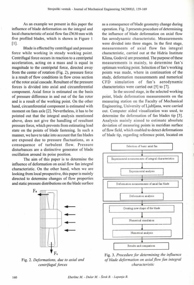
Blade is effected by centrifugal and pressure force while working in steady working point. Centrifugal force occurs in reaction to a centripetal acceleration, acting on a mass and is equal in magnitude to the centripetal force, directed away from the center of rotation (Fig. 2), pressure force is a result o f flow conditions in flow cross section o f the rotor axial cascade. Resultant o f the pressure forces is divided into axial and circumferential component. Axial force is estimated on the basis o f pressure difference in and out of the fan rotor and is a result o f the working point. On the other hand, circumferential component is estimated with moment on fans axle [2], Nevertheless, it has to be pointed out that the integral analysis mentioned above, does not give the handling o f resultant pressure force, which prevents from estimating load state on the points o f blade fastening. In such a manner, we have to take into account that fan blades are exposed due to pressure fluctuations, as a consequence o f tu rb u len t flow. P ressure disturbances are a distinctive generator o f blade oscillation around its poise position.
The aim o f this paper is to determine the influence of deformation on axial flow fan integral characteristic. On the other hand, when we are looking from local prospective, this paper is mainly directed to determine changes o f flow properties and static pressure distributions on the blade surface
as a consequence of blade geometry change during operation. Fig. 3 presents procedure of determining the influence of blade deformation on axial flow fan aerodynamic characteristic. M easurements were divided into three stages. In the first stage, m easurem ents o f ax ial flow fan in teg ral characteristic, carried out at the Hidria Institute Klima, Godovič are presented. The purpose of these m easurem ents is m ainly, to determ ine fa n ’s optimum working point. Selection of fan’s working points was made, where in continuation o f the study, deformation measurements and numerical CFD sim ula tion o f fa n ’s aerodynam ic characteristics were carried out [5] to [7],
In the second stage, in the selected working point, blade deformation measurements on the measuring station on the Faculty o f Mechanical Engineering, University of Ljubljana, were carried out. Computer aided visualization was used, to determine the deformation of fan blades tip [3]. A nalysis m ain ly aim ed to estim ate absolute deviation of measuring points in meridian surface of flow field, which enabled to detect deformations of blade tip, regarding reference point, located on
Fig. 3. Procedure fo r determining the influence o f blade deformation on axial flow fan integral
characteristicFig. 2. Deformations, due to axial and
centrifugal forces
the fan casing. Data obtained, subsequently enabled the statistic assessments of deformation conditions on the observed blade. Assessment o f oscillating am plitude depends on m axim um standard deviations o f time-averaged deviation. On the secondary axis the corresponding standardized visualization of time averaged blade deformation and fluctuations o f blade tip around its poise position enabled evaluation o f blade geometry changes on the field, which is o f highest importance for fan operation.
1 INTEGRAL CHARACTERISTIC MEASURMENTS
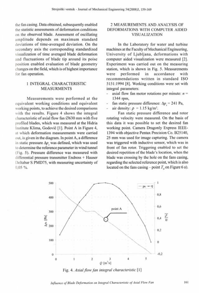
M easurem ents were perform ed at the equivalent w orking conditions and equivalent working points, to achieve the desired comparisons w ith the results. Figure 4 shows the integral characteristic of axial flow fan 0630 mm with five profiled blades, which was measured at the Hidria Institute Klima, Godovič [1], Point A in Figure 4, at which deformation measurements were carried out, is given in the diagram. In point A, a difference in static pressure Aps was defined, which was used to determine the reference parameter in wind tunnel (Fig. 5). Pressure difference was measured with differential pressure transmitter Endress + Hauser Deltabar S PMD75, with measuring uncertainty of 0,05 %.
2 MEASUREMENTS AND ANALYSIS OF DEFORMATIONS WITH COMPUTER AIDED
VISUALIZATION
In the Laboratory for water and turbine machines at the Faculty of Mechanical Engineering, U niversity o f L jubljana, deform ations with computer aided visualization were measured [2], Experiment was carried out on the measuring station, which is shown in Fig. 5. Measurements w ere perform ed in accordance with recom m endations w ritten in standard ISO 5151:1994 [8]. Working conditions were set with integral parameters:- axial flow fan motor rotations per minute: n =
1344 rpm,- fan static pressure difference: Aps = 241 Pa,- air density: p =1.15 kg/m3.
Fan static pressure difference and rotor rotating velocity were measured. On the basis of this data it was possible to set the desired fan working point. Camera Dragonly Express IEEE- 1394 with objective Pentax Precision Co. B25140, 25 mm was used for image capturing. The camera was triggered with inductive sensor, which was in front o f fan rotor. Triggering enabled to set the desired repetition of the blade’s location, when the blade was crossing by the hole on the fans casing, regarding the selected reference point, which is also located on the fans casing - point Tg on Figure 6 a).
0 1 2 3 4 5Q [m3/s]
<S\cr
Fig. 4. Axial flow fan integral characteristic [1]
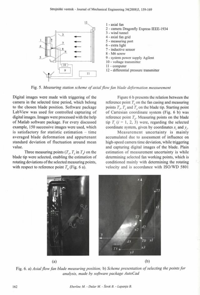
12 1 - axial fan2 - camera Dragonfly Express IEEE-19343 - wind tunnel4 - axial fan grid5 - measuring port6 - extra light7 - inductive sensor8 - M6 screw9 - system power supply Agilent10 - voltage transmitter11 - computer12 - differential pressure transmitter
Fig. 5. Measuring station scheme o f axial flow fan blade deformation measurement
Digital images were made with triggering o f the camera in the selected time period, which belong to the chosen blade position. Software package LabView was used for controlled capturing o f digital images. Images were processed with the help o f Matlab software package. For every discussed example, 150 successive images were used, which is satisfactory for sta tistic estim ation - tim e averaged blade deform ation and appurtenant standard deviation o f fluctuation around mean value.
Three measuring points ( Tp T, in TJ on the blade tip were selected, enabling the estimation of rotating deviations o f the selected measuring points, with respect to reference point Tg (Fig. 6 a).
Figure 6 b presents the relation between the reference point Tg on the fan casing and measuring points T , T2 and T on the blade tip. Starting point o f Cartesian coordinate system (Fig. 6 b) was reference point Tg. Measuring points on the blade tip T. (i = 1, 2, 3) were, regarding the selected coordinate system, given by coordinates x. and y..
M easurem ent uncerta in ty is m ainly accumulated due to assessment o f influence on high-speed camera time deviation, while triggering and capturing digital images o f the blade. Plain estimation o f measurement uncertainty is while determining selected fan working points, which is conditioned mainly with determining the rotating velocity and is accordance with ISO/WD 5801
(a) (b)
Fig. 6. a) Axial flow fan blade measuring position; b) Scheme presentation o f selecting the points foranalysis, made by software package AutoCad
standard estimated with un = 0,2 %, measuring pressure difference on the fan u = 1,4 % and determining air density in flow, which is, if every procedure is in accordance with the standard, equal to up = 0,4 %. M easurem ent uncerta in ty of v isu a liza tio n m ethod o f blade deform ation measurements can be divided only on the basis of each step o f the presented method. It results from circumferential velocity of the blade tip, fans rotor diameter and frequency of capturing the inductive sensor signals, which triggered digital camera. The highest possible absolute measurement uncertainty is 0.038°, which does not, at the expected maximum blade deformations be approximately 3°, exceed the relative measurement uncertainty o f u = 1,3 %.
A lgorithm s for recognizing the digital image samples - measuring points and calculation of measuring points position were elaborated in software package MatLab. Algorithm was aimed to recognize single measuring point on the blade tip and in continuation determining center of a measuring point, which gave the momentarily measuring point coordinate, regarding the starting
reference point Tg. Considering the fact that digitalization was carried out by 8-bit divisibility, where the value o f the variable Ep(ij,t) in Eq. (1), which represents the value o f the grey intensity (i, j ) in period of time t, is in range:
E p ( i , j , t ) e { 0 , . . . , 2 5 5 } (1).
Indices i and j of element E digital image, present the position of the cell. In observed field in formed cell - size of the window (di, dj), where di in dj presents the size of the window.
For every separate image in the sequence of blade tip digital image, scalar value function f(ij) was calculated, obtained by:
where ; and / are coordinates o f the selected window. Value o f grey intensity E in point (;,/) has boundary values from 0 (black colour) to 255 (white colour). In the observed area the function ./(/,/) is changed significantly from crossing black fie ld to w hite field , w hich belongs to each measuring point Tff Tp T2 and Ty
To set the edges o f m easuring points, gradient value off(i,j) is calculated in the next step,
where maximum scalar value allows determining o f the edge o f measuring point. Procedure of determining the contour of measuring point is the same in all observed measuring points 7), T, in Tj and reference point Tg. In the final stage, center of a contour for the selected measuring 7), T, in T} and reference point T is calculated.
Position , as well as distance between measuring points on the blade tip and reference point T0 on the fan casing are time-varying. From the analysis o f time successive digital images, the evaluation of fluctuation deviation of measuring points can be carried out, w hich enables the assessment of average deformation of tip position and assessm ent o f fluctuation in tensity of momentary deviations o f observed measuring points regarding the time-averaged deformation image.
In this paper, on the basis o f presented algorithms, blade tip main deviation values and standard deviation regarding the main deformation values, which are presented in the following chapter, were calculated.
3 EXPERIMENTAL RESULTS
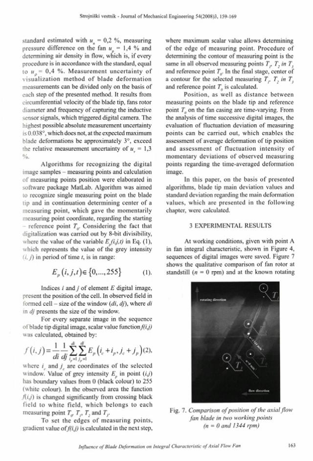
At working conditions, given with point A in fan integral characteristic, shown in Figure 4, sequences of digital images were saved. Figure 7 shows the qualitative comparison of fan rotor at standstill (n = 0 rpm) and at the known rotating
r o tu t in » d i r e c t io n %
- ’ # •
«
•
■%, .•
< 3 t O. \ % .
(low d i r e c t io n
Fig. 7. Comparison ofposition o f the axial flow fan blade in two working points
(n = 0 and 1344 rpm)
velocity (n = 1344 rpm) in working point A (Fig. 4). For easier demonstration o f the blade deviation, the blade image in two different working points was joint with the help of software package MatLab into one image, shown in Fig. 7. Blade deviation along the blade tip is clearly seen. Distinctive blade deform ation is v isib le , w hich is reflected in deviation, as well as blade tip distortion.
Q uan tita tive analy sis is based on m ethodology o f determ ining the position o f measuring points regarding the reference point Tg, as it was presented in chapter 1. In first stage the length between measuring and reference point was set. Length between points Tp Tp T3 and point Tg was calculated in two working points of the fan (n = 0 and 1344 rpm), as presented in Figure 6. Time- averaged deviation and standard deviation is given in standard form:
X — —— • 100%, y* = — • 100%, d ' = — • 100%
* *<7* = ^ • 100%, er* = —— • 100%, o ] - — -l 00%
Ro y K R0where R0 is fan radius.
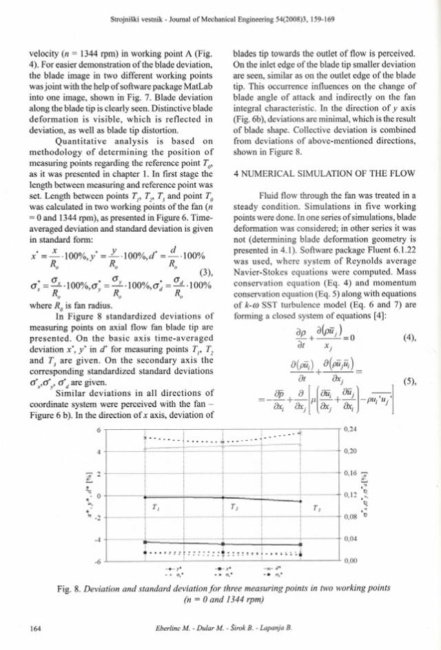
In Figure 8 standardized deviations o f measuring points on axial flow fan blade tip are presen ted . On the basic axis tim e-averaged deviation jc*, y" in d' for measuring points Tp T, and T3 are given. On the secondary axis the corresponding standardized standard deviations cfx,cy‘v, a"d are given.
Sim ilar deviations in all d irections o f coordinate system were perceived with the fan - Figure 6 b). In the direction o f x axis, deviation of
blades tip towards the outlet of flow is perceived. On the inlet edge o f the blade tip smaller deviation are seen, similar as on the outlet edge of the blade tip. This occurrence influences on the change of blade angle o f attack and indirectly on the fan integral characteristic. In the direction o f y axis (Fig. 6b), deviations are minimal, which is the result o f blade shape. Collective deviation is combined from deviations o f above-mentioned directions, shown in Figure 8.
4 NUMERICAL SIMULATION OF THE FLOW
Fluid flow through the fan was treated in a steady condition. Simulations in five working points were done. In one series of simulations, blade deformation was considered; in other series it was not (determining blade deformation geometry is presented in 4.1). Software package Fluent 6.1.22 was used, where system o f Reynolds average Navier-Stokes equations were computed. Mass conservation equation (Eq. 4) and momentum conservation equation (Eq. 5) along with equations o f k-co SST turbulence model (Eq. 6 and 7) are forming a closed system of equations [4]:
dp | djpüjd t X j
dX:
dt dxj
d dui + duj
dxj dxj dxj
(5),
-PUPU:
Fig. 8. Deviation and standard deviation fo r three measuring points in two working points(n = 0 and 1344 rpm)

a(pfc) tipku j ) ddt dX :
dipo)) | d ipan i _ ddt dXj dx.
d r dkdXj k dX]
d(0dxj
+ G
+ G k ~ Y k (6),
m+D<o(7),
where Gk is the turbulence source, due to of velocity gradient, Gm is the source of co. T, and are the effective diffbsivity k and 0). Yk and Y are dissipations o f k and co, due to of turbulence, D is the diffusive term.
4.1 Geometry and Mesh
With measurements (chapter 3) the blade deformation of blade tip was determined. To be able to set the deformed blade geometry, following procedure was adopted:
that blades (at fixing area on the motor) are not deforming,deformations are increasing linearly from the root to the tip o f the blade, blade deformation in fans different working points does not significantly change.
Comparison between blade original and .leformed geometry is shown in Figure 9.
Meshes o f original and deformed blade were topologically equivalent. Computational domain was discretized with structural mesh. To reduce the calculating time, only one interblade area (1/5 total area) was calcu lated , on borders a periodic boundary condition was regulated. Influence of the mesh was examined only at optimum flow and for the case o f original - not deformed blade. Finally, the mesh with approximately 400.000 nodes was used, which was on the channel walls and along
Fig. 9. View o f original and deformed blade
the fan blade refined - y+ was between 30 and 80. With this kind of mesh density we evaluated the error o f discretization to 0,5 %. Geometry, as well as deformed blade mesh, was equivalent for all working points - it was adopted, that for every single w orking point o f the axial flow fan, deformation does not change significantly.
4.2 Convergence Criterion
Convergence criterion was set, regarding the pressure development on the inlet and velocity on the ou tle t from the com putational dom ain. Parameters were always converging, when the residuals sum of transport equation in the entire computational domain was less then 1 x 10³. Finally, for convergence criterion, the situation was used, when the residuals decreased below IMO“4, for which approximately 350 iterations were needed. Iteration error was estimated to 0,05 %.
4.3 Calculating Condition
- Flow: for turbulence k-co SST turbulence model was used;
- Boundary conditions: on the channel walls, fan blade and rotor no slip boundary condition was assumed;
- On the inlet air flow was defined (= 1.31, 2.11, 2.76, 3.52, 4.22 m3/s);
- On the outlet pressure was defined (0.1013 MPa);- Fan rotating velocity was constant (1344 rpm),
fan rotating was described by rotating reference frame model.
Air density was 1.225 kg/m 3, dynamic viscosity was 1.79x 1 O'5 Pas. The results from numerical simulation are presented in chapter 5.
5 RESULTS
Results from prediction of flow fields for original and deformed - modified form of the blade in various working points o f the machine, final numerical predictions and axial flow fan integral characteristic measurements are presented.
5.1 Numerically Predicted Blade Pressure Distribution
Pressure distributions in three different working points of the fan (1.31, 2.76, 4.22 m3/s)
O r i g i n a l b l a de Pressure side Suction side
D e f o r m e d b la de Pressure side Suction side
1 60e+02 7.50e+01
-I.OOe+01 -9.50e+01 - I 80e+02 -2.65e+02 -3.50e+02
-4.35e+02 -5.20e+02 -6.05e+02 -6.90e+02 -7.75e+02 -8.60e+02
-9.45e+02 -1.03e+03 -1 12e+03
-1 20e+03
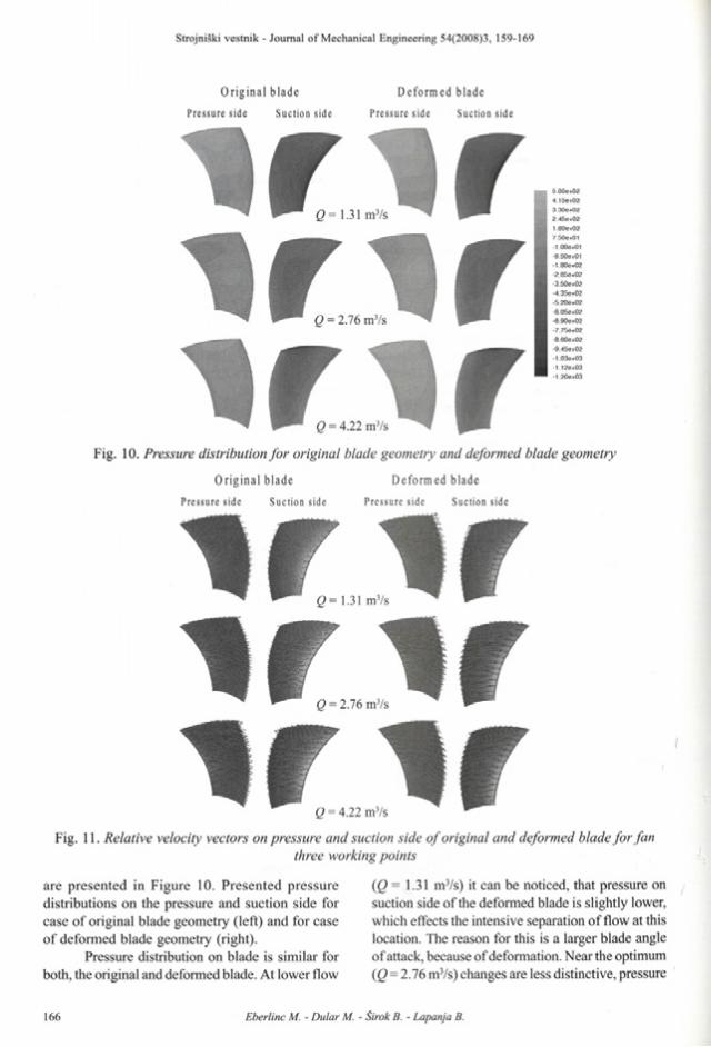
v i r i n ri r j rFig. 10. Pressure distribution fo r original blade geometry and deformed blade geometry
O r i g i n a l b l a d e D e f o r m e d b l a dePressure side Suction side Pressure side Suction side
Q= 1.31 mVs ~i r i ri r i rQ = 4.22 m3/s
Fig. 11. Relative velocity vectors on pressure and suction side o f original and deformed blade fo r fanthree working points
are presented in Figure 10. Presented pressure distributions on the pressure and suction side for case o f original blade geometry (left) and for case of deformed blade geometry (right).
Pressure distribution on blade is similar for both, the original and deformed blade. At lower flow
(Q= 1.31 m3/s) it can be noticed, that pressure on suction side of the deformed blade is slightly lower, which effects the intensive separation of flow at this location. The reason for this is a larger blade angle of attack, because of deformation. Near the optimum (Q = 2.76 m3/s) changes are less distinctive, pressure
on suction side of deformed blade is slightly lower that in the case of original blade. In working point 4.22 m3/s, pressure conditions on blade are not distinctive. Pressure on the trailing edge on the section side of the deformed blade is slightly higher in comparison to the pressure on the same place of the original blade. The difference is the result of better flow conditions for the deformed blade, because the angle of attack is larger (optimum moves to the higher volume flow).
Despite the deformations, conditions on the blade pressure side remain mostly the same, and changes are negligible.
5.2 Numerically Predicted Velocity on the Blade
Figure 11 shows relative velocity vector on pressure and suction side of original and deformed blade in fan’s three different working points (Q = 1.31,2.76, 4.22 m3/s).
It can be noticed, that in case of smaller volume flow (Q = 1.31 m 3/s), the flow on the deformed blade is less settled. On the blade tip on suction side, a large vortex can be seen, which is smaller in case of original blade. The cause for
detaching of flow on this side and this working point is a larger angle of attack of the blade, which is even larger, because of deformation. We can also see a larger disorder of flow on the pressure side o f the deformed blade. It seems that vectors point from the middle side o f the blade in direction towards the tip and root of the blade. The reason is that flow cannot follow increased curvature of blade and hits into it, instead o f flowing around it.
Near the optimum point (Q = 2.76 m3/s) the differences in flow field are less distinctive. On the suction side of the deformed blade, on the top, near the trailing edge, a field of lower velocity is seen, which can be assigned to separating of flow on this place (the reason again being larger blade angle of attack). Similar (but less obvious) as in the case of a smaller volume flow, hitting of the flow against the pressure side of the deformed blade can be seen.
At higher volume rate (Q = 4.22 m 3/s) differences are not visible.
5.3 Velocity on Blade Tip
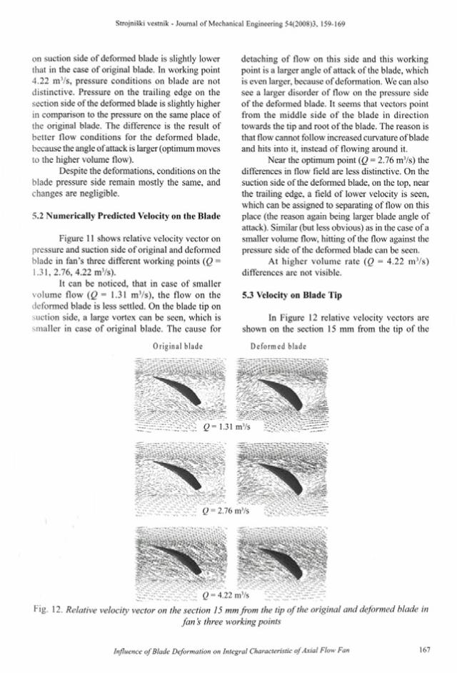
In Figure 12 relative velocity vectors are shown on the section 15 mm from the tip of the
Or i g i n a l b l a de D e f o r m e d b l a de
f i= 1.31
Fig. 12. Relative velocity vector on the section 15 mm from the tip o f the original and deformed blade infan s three working points

original and deformed blade in fan’s three working points (Q= 1.31, 2.76, 4.22 m3/s).
Images show velocity conditions at the most critical place (at the tip of the blade). Separating of flow on this place causes the efficiency and power drop and generation of aerodynamic noise.
At the lower and optimal flow (Q = 2.76 m3/s) the separating of flow is obviously larger in case o f deformed blade, which is the result o f inappropriate (larger) blade angle o f attack. In case o f h igher volum e flow (Q = 4.22 m 3/s) the aggressiveness o f separating between the blades is comparable, which is the result o f shifting the optimum towards higher volume flow, because of blade deformation.
5.4 Predictions and Measurements of Integral Characteristics
Figure 13 shows measured and numerical (for original and deformed geometry) integral characteristic o f standardized efficiency and pressure increase in dependence o f volume flow.
N um erica l m odel w ith o rig inal blade geometry agrees with measurement results near the optimum working point, otherwise deviations are higher. It is different with the results obtained from num erica l m odel w ith the deform ed b lade geometry, which match with experimental results in wider range. Higher deviation can be seen at lower volume flow, which is probably the result of
overestimated prediction o f flow separation o f trailing edge o f the blade and incorrect estimation of blade deformation (for every case, measured deform ation in optim um w orking point was considered - in chapter 3).
Suitableness consideration o f actual (deformed) shape of the blade is obvious, because there is an option for better prediction of actual flow field and easier optimization of blade geometry.
6 CONCLUSION
This paper presented the influence of blade deformation on fan integral and local characteristic. W ith com puter aided v isualization blade tip deformations were defined. Measurement results w ere used to determ ine the variab le b lade formation, which was in continuation used for num erical modeling for the same fan integral working parameters. Considering to use actual (deformed) shape of the blade would be suitable in this case, because it enables better prediction of actual flow field and easier optimization of blade geometry.
Acknowledgement
Research was founded by European fund for regional development in project frame entitledResearch o f Slovenian industry innovative environment fo r air-conditioning, heating and
l0,9
0,8
0,7
0,6
0.5
0,4
0,3
0,2
0,1
0
CT
p f e x p ) p f orig.) /^(deform) r\ (exp) 7j(orig.) r\ (deform)
Fig. 13. Comparison between the experimental results and numerical model fo r cases o f original anddeformed geometry
cooling; Research o f elements ofpower saving and environmental friendly CHC systems.
7 REFERENCES
[l jP iv k , S., M agajne, A ., Tom inec, U. Measurements o f integral properties o f axial flow fan with 630 mm radius. Sp. Idrija: Hidria Rotomatika, d.o.o., July 2006. (In Slovenian).
[2] Wallis, R. A. Axial flow fans and ducts. John Wiley & sons, 1983.
[3] Eberlinc, M., Hočevar, M., Pivk, S., Širok, B. V isualization m ethod for m easuring the deformation of axial-flow fan blades, Ventil, 13, 2007, no. 2, p. 94-101.
[4] F erziger, J.H ., P erič , M. Computational Methods fo r Fluid Dynamics, 3rd Edition. Springer, 2002
[5] Širok, B„ Bajcar, T., Dular, M. Reverse flow phenomenon in a rotating diffuser. J. flow vis. image process, 2002, voi. 9, no. 2/3, p. 193- 210.
[6] Širok, B., Hočevar, M., Zupan, S., Prebil, I. Study of radial rotor and bearing arrangement dynamic properties of the combat vehicles M 84 and 72 cooling system fan. Stroj, vestn. - J. Mech. E., 1999, voi. 45, no. 11, p. 432-441.
[7] Širok, B., Potočar, E., Novak, M. Analysis of the flow kinematics behind a pulsating adaptive airfoil using com puter-aided visualisation. Stroj, vestn. - J. Mech. E., 2000, voi. 46, no. 6, p. 330-341.
[8] ISO 5151:1994: Non-ducted air conditioners and heat pumps - Testing and rating fo r performance
[9] ISO 5801:2006: Industrial fans