A SINGLE STAGE AXIAL COMPRESSOR BLADE TEST ...
51
At KtKtAKUH AMU UtVtLUrmtni trunI A SINGLE STAGE AXIAL COMPRESSOR BLADE TEST FACILITY AUTHOR: G. G. Fee UNI&iv CARBIDE I ""1 Operating the OAK RIDGE GASEOUS DIFFUSION PLANT * OAK RIDGE NATIONAL LABORATORY OAK RIDGE Y-12 PLANT For the Atomic Energy Commission Under U.S. Government Contract W7405 eng 26 * PADUCAH GASEOUS DIFFUSION PLANT fltduc303881
-
Upload
khangminh22 -
Category
Documents
-
view
5 -
download
0
Transcript of A SINGLE STAGE AXIAL COMPRESSOR BLADE TEST ...

At KtKtAKUH AMU UtVtLUrmtni trunI
A SINGLE STAGE AXIAL COMPRESSOR
BLADE TEST FACILITY
AUTHOR:
G. G. Fee
UNI&ivCARBIDE
I ""1
Operating the
OAK RIDGE GASEOUS DIFFUSION PLANT * OAK RIDGE NATIONAL LABORATORY
OAK RIDGE Y-12 PLANT
For the Atomic Energy Commission
Under U.S. Government Contract W7405 eng 26
* PADUCAH GASEOUS DIFFUSION PLANT
fltduc303881

Printed in USA. Price: $1.25 Available from the
Office of Technical Services
U. S. Department of Commerce
Washington 25, D. C.
LEGAL NOTICE
This report was prepared as an account of Government sponsored work. Neither the United States,nor the Commission, nor any person acting on behalf of the Commission:
A. Makes any warranty or representation, expressed or implied, with respect to the accuracy,completeness, or usefulness of the information contained in this report, or that the use of
any information, apparatus, method, or process disclosed in this report may not infringe
privately owned rights; or
B. Assumes any liabilities with respect to the use of, or for damages resulting from the use of
any information, apparatus, method, or process disclosed in this report.
As used in the above, "person acting on behalf of the Commission" includes any employee or
contractor of the Commission, or employee of such contractor, to the extent that such employee
or contractor of the Commission, or employee of such contractor prepares, disseminates, or
provides access to, any information pursuant to his employment or contract with the Commission,
or his employment with such contractor.

1
Date of Issue: January 13, 1964 Report Number: K-1568
SUBJECT CATEGORY: ENGINEERING ANDEQUIPMENT(TID-4.500, 26th Ed.)
A SINGLE STAGE AXIAL COMPRESSOR BLADE TEST FACILITY
G. G. FeeMechanical Development Department
Technical Division
UNION CARBIDE CORPORATIONNUCLEAR DIVISION
Oak Ridge Gaseous Diffusion PlantOak Ridge, Tennessee

2
Report Number: K-15 68 Subject Category: ENGINEERING ANDEQUIPMENT
Title: A SINGLE STAGE AXIALCOMPRESSOR BLADE TESTFACILITY
Author: G. G. Fee
A B S T R A C T
This report gives a general description of the single stage axialcompressor blade test facility located at the Oak Ridge Gaseous DiffusionPlant, Oak Ridge, Tennessee. This facility, formally known as theResearch Compressor Test Facility, has the instrumentation and equipmentrequired to evaluate the performance of axial blades requiring maximumpower inputs of 2500 hp. and rotational speeds up to 23,000 rpm. in a14-5-inch diameter test section.
Covered in this report are building layout, instrumentation, utilities,drive train and blade inspection equipment.

3 K-1568
A SINGLE STAGE AXIAL COMPRESSOR BLADE TEST FACILITY
Table of Contents
Page
INTRODUCTION 5
SUMMARY 7
GENERAL DESCRIPTION OF FACILITY AND TEST SECTION 7
INSTRUMENTATION 16
UTILITIES 34
BLADE INSPECTION AND SETTING EQUIPMENT 36
APPENDIX A AVAILABLE PRESSURE TRANSDUCERS 41
APPENDIX B PORTABLE INSTRUMENTATION AVAILABLE 42
APPENDIX C RESEARCH COMPRESSOR TEST FACILITY DRAWING LIST 44
K-1568
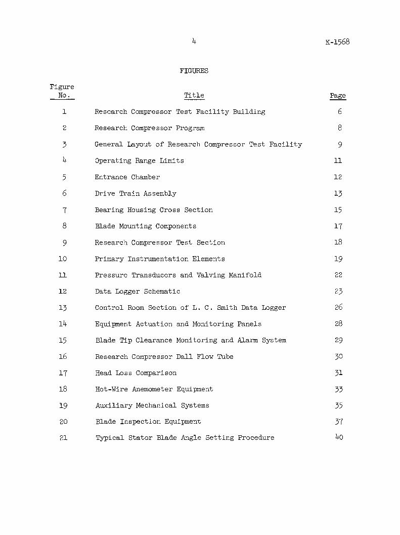
FIGURES
FigureNo. Title Page
1 Research Compressor Test Facility Building 6
2 Research Compressor Program 8
3 General Layout of Research Compressor Test Facility 9
4 Operating Range Limits 11
5 Entrance Chamber 12
6 Drive Train Assembly 13
7 Bearing Housing Cross Section 15
8 Blade Mounting Components 17
9 Research Compressor Test Section 18
10 Primary Instrumentation Elements 19
11 Pressure Transducers and Valving Manifold 22
12 Data Logger Schematic 23
13 Control Room Section of L. C. Smith Data Logger 26
14 Equipment Actuation and Monitoring Panels 28
15 Blade Tip Clearance Monitoring and Alarm System 29
16 Research Compressor Dall Flow Tube 30
17 Head Loss Comparison 31
18 Hot-Wire Anemometer Equipment 33
19 Auxiliary Mechanical Systems 35
20 Blade Inspection Equipment 37
21 Typical Stator Blade Angle Setting Procedure 40

5 K-1568
A SINGLE STAGE AXIAL COMPRESSOR BLADE TEST FACILITY
INTRODUCTION
The atomic energy program of the United States requires large quantitiesof uranium enriched in the 235 isotope. To obtain this material, the"as-mined" ore, which contains principally the 235 and 238 isotopes, isconverted to uranium hexafluoride gas and processed in a gaseous diffusionplant. This processing consists of passing the gas over a porous medium,commonly referred to as barrier, containing many millions of very smallholes or capillaries. As this gas passes over the barrier, some of themolecules diffuse through the tiny pores. The rate of their effusion isinversely proportional to the molecular weight of the gas molecules; i.e.,the lighter 235 molecules will pass through the barrier at a faster ratethan the heavier 238 molecules. Thus, the gas passing through the barrierbecomes enriched in uranium 235. Since the mol fraction of uranium 235in normally occurring ore is very low, the gas must be passed over theporous medium many times before it becomes highly enriched. Therefore,in the gaseous diffusion process large quantities of uranium hexafluoridegas must be transported through hundreds of miles of piping. In additionto centrifugal blowers, many multistage axial flow compressors are usedfor this pumping.
One of the primary responsibilities of the technical personnel employedby Union Carbide Nuclear Company at the Oak Ridge Gaseous Diffusion Plant,Oak Ridge, Tennessee, is to improve the over-all efficiency of thesemachines with a resultant decrease in the cost of enriched uranium. Inorder to carry out this responsibility and to maintain the United Stateslead in gaseous diffusion technology, a vigorous experimental program isnow under way to study the detailed performance of axial blading. Themajor tool used in this program is the axial compressor blade aerodynamictest facility. This facility, known formally as the Research CompressorTest Facility, is located in the K-1303 building of the Oak Ridge GaseousDiffusion Plant (see figure 1). Here is a complete aeronautical laboratorywherein the performance of single stages of axial compressor blades can beevaluated in air over a wide range of operating conditions. Although thetest section itself was designed primarily for this work, the instrumenta-tion, utilities, and blowers available in the facility could be readilyadapted to other types of flow system studies. It is the purpose of thisreport to describe in brief detail the features incorporated in this axialcompressor blade aerodynamic test facility. For clarity, it has been sub-divided into chapters, one of which is used to cover each of the following
items: (1) general description, (2) instrumentation, (3) utilities, and(4) blade inspection and setting equipment.

r w
F,
- hIFf
RESEARCH COMPRESSOR TEST FACILITYK-1303 BUILDING, OAK RIDGE GASEOUS DIFFUSION PLANT
Figure 1
ON
A
K-1568
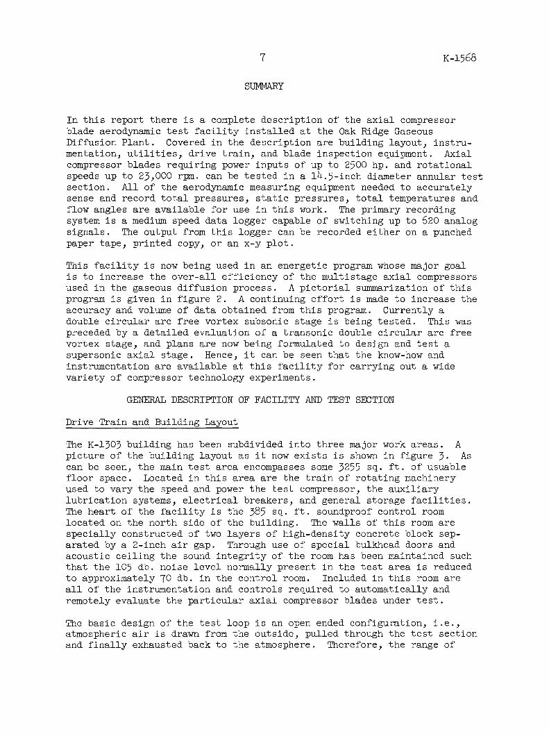
SUMMARY
In this report there is a complete description of the axial compressorblade aerodynamic test facility installed at the Oak Ridge GaseousDiffusion Plant. Covered in the description are building layout, instru-mentation, utilities, drive train, and blade inspection equipment. Axialcompressor blades requiring power inputs of up to 2500 hp. and rotationalspeeds up to 23,000 rpm. can be tested in a 14.5-inch diameter annular testsection. All of the aerodynamic measuring equipment needed to accuratelysense and record total pressures, static pressures, total temperatures andflow angles are available for use in this work. The primary recordingsystem is a medium speed data logger capable of switching up to 620 analogsignals. The output from this logger can be recorded either on a punchedpaper tape, printed copy, or an x-y plot.
This facility is now being used in an energetic program whose major goalis to increase the over-all efficiency of the multistage axial compressorsused in the gaseous diffusion process. A pictorial summarization of thisprogram is given in figure 2. A continuing effort is made to increase theaccuracy and volume of data obtained from this program. Currently adouble circular arc free vortex subsonic stage is being tested. This waspreceded by a detailed evaluation of a transonic double circular arc freevortex stage, and plans are now being formulated to design and test asupersonic axial stage. Hence, it can be seen that the know-how andinstrumentation are available at this facility for carrying out a widevariety of compressor technology experiments.
GENERAL DESCRIPTION OF FACILITY AND TEST SECTION
Drive Train and Building Layout
The K-1303 building has been subdivided into three major work areas. Apicture of the building layout as it now exists is shown in figure 3. Ascan be seen, the main test area encompasses some 3255 sq. ft. of usuablefloor space. Located in this area are the train of rotating machineryused to vary the speed and power the test compressor, the auxiliarylubrication systems, electrical breakers, and general storage facilities.The heart of the facility is the 385 sq. ft. soundproof control roomlocated on the north side of the building. The walls of this room arespecially constructed of two layers of high-density concrete block sep-arated by a 2-inch air gap. Through use of special bulkhead doors andacoustic ceiling the sound integrity of the room has been maintained suchthat the 105 db. noise level normally present in the test area is reducedto approximately 70 db. in the control room. Included in this room areall of the instrumentation and controls required to automatically and
remotely evaluate the particular axial compressor blades under test.
The basic design of the test loop is an open ended configuration, i.e.,atmospheric air is drawn from the outside, pulled through the test sectionand finally exhausted back to the atmosphere. Therefore, the range of
7

8
000 SIZE UF 6 AXIALFLOW COMPRESSOR
CROSS SECTION VIEW OFSINGLE STAGE EXPERIMENTAL
COMPRESSOR TEST SECTION
ICOMPARISON OF FULL SIZEUF6 BLADES AND THEIR AIR
MODELS
SPECIFIC WEIGHT FLOW
OVER-ALL SINGLE STAGEOPERATING CHARACTERISTICS
EXPERIMENTAL COMPRESSORTEST FACILITY
RESEARCH COMPRESSOR PROGRAM
In the research compressor program particular stages of a multistage uranium hexafluoride com-pressor are selected for comprehensive study and evaluation in air with the objective of increas-ing the over-all efficiency. Starting in the upper left hand corner and following the arrows wefind a pictorial diagram of the program. First is the selection of a high loss stage; next, airblades for this stage are designed, procured, and tested in the experimental compressor; andfinally, a complete map of the operating characteristics is obtained. These data are then usedto redesign the uranium hexafluoride stage.
Figure 2
K-1568
U-
w
4,,
a

9
B
BOUON
RE MC
CONTROL ROOM385 SO. FT.
H--I
5.5:1 SPEED DISCHARGE CASINGINCREASER
VARIABLE 3.5:1 SPEED I TEST SECTION
200HPC.UPEEDG INCREASER
O STAGNATION
BELUBE OILSCAVENGER UNIT
WORK AREA3255 SQ. FT.
IDARY LAYEROVAL BLOWER
MENSROOM
LADIESROOM
El
CUBICLE NO.6 CUBICLE NO.5 CUBICLE NO.4 CUBICLE NO.3 CUBICLE NO.2 CUBICLE NO.1
DALL FLOW TUBEMEASURING STATION
CONTROLVALVE
FLOW
HYDRAULICSYSTEM FORCONTROL VALVE
AXIt 0 FLOW ENTRANCE CHAMBER
CUBICLE NO.12 CUBICLE NO.11 CUBICLE NO.10 CUBICLE NO.9 CUBICLE NO.8 CUBICLE NO.7
PRINCIPAL LUBE OIL SYSTEM
I L
DISCHARGEPIPE
+--FLOW
ii L
II
I TEST SECTION ELEVATION-787-9
FLOW
SECTION AA
GENERAL LAYOUT OF RESEARCH COMPRESSOR TEST FACILITY
Figure 3
2000 HP MOTORVENTILATION FAN
K-1568
L0
0
_i
A
FURNACE ROOM
INLET PIPE Ic: DUAL BANKAIR FILTER
SECTION BB
I
- '
i
i
I
Fr-

K-1568
conditions over which any blade stage can be tested is limited by theresistance of the piping and flow passages utilized in this open loop.This system resistance has been theoretically calculated and verified bya limited number of experimental points. Figure 4 shows the systemresistance plotted as a function of mass flow. Even though in the orig-inal construction each of the piping components were designed so as tominimize this system resistance, experience has shown that exceptionallypoor stage performance can cause this resistance to be considerably higherthan that shown in the figure for the minimum case.
Atmospheric air is drawn from an entrance chamber through the low-lossintake nozzle pictured in figure 5. It then travels through some 30 ft.of straight 24-inch diameter pipe before encountering a Dall flow tubemeasuring station, expands in a 100 conical diffuser into a 30-inchdiameter pipe, passes through a hydraulically controlled throttlingbutterfly valve, expands in a second 10* conical diffuser to 42 inchesand then abruptly expands to 72 inches in the large stagnation or set-tling chamber. In the center of this chamber is a series of five screensof varying mesh where any eddies or vortices are further stilled before theflow contracts into the 14.5-inch diameter test section. The actual flowpassage in the test section is annular in shape; the annular height beingadjusted to fit the particular blades under test. Once through the testsection, the flow is turned at right angles and exhausted into twin 16-inchpipes. These pipes are joined on the roof of the building where theyconverge into a 30-inch pipe. Before finally exhausting through another100 conical diffuser whose outer diameter is 42 inches, the flow must passthrough a 30-inch air controlled butterfly valve. This flow stream canbe better visualized by examining figure 3 again. As the system exists,the upper limit to the range of total pressure head available is strictlya function of the compressor configuration which is installed. The upperlimit curve shown in figure 4 is only given as an indication of that whichcould be obtained by using the blading currently available at the facility.This would be of importance if one were to consider using the loop forevaluating other types of flow systems. Since, as was mentioned above,the loop is open ended and draws atmospheric air from the outside,seasonal variations in weather conditions influence the temperature,humidity, and suction pressure of the test fluid. Dry bulb temperaturesvary from a low of 0 F. in the early morning midwinter hours to a rarehigh of 95 F. in the late summer afternoons. The mean winter dry bulbtemperature is 40 F. while the mean summer dry bulb temperature is 78*F.The year-round average humidity is 48% and barometric pressure variesover the range of 14.0 psia. to 14.6 psia.
In addition to the capability of varying the mass flow by throttling, thetest compressor can be operated over a wide range of speeds and powerrequirements. The compressor drive train, as shown in figure 6, consistsof an electrical motor, an eddy current variable speed coupling, and twofixed ratio speed increasers, one 3.5 to 1 and the other 5.5 to 1.
The motor is a standard Westinghouse induction unit having a rated capac-ity of 2000 hp. at a speed of 1193 rpm. However, experimental data froma limited number of similar units, have shown that they can be operated
10

K-1568
10 20 30 40CORRECTED WEIGHT FLOW, lbs. per. sec.
(STD. CONDITIONS: PA=14. 6 9 7 psi., TA= 59 *F.)
OPERATING RANGE LIMITS
Figure 4
1.5
1.4
0
I-
w
U)U)wCr
-J
0I-
Estimated Upper Limit
Estimated Minimum System Resistance
1.3
1.2
I.1
1.00 5CD
11

12 K-1568
u,,
Air is drawn into the research compressor through this 24-inch entrance pipe. A
smooth highly polished leminscate has been mounted on it to reduce the pres-sure losses associated with the system. The protective screen is closed to
prevent personnel from being drawn against the entrance, and appropriate filters
are mounted here to decrease the intake of dirt particles.
ENTRANCE CHAMBER
Figure 5

51 Speed Increase
Var able Speed Coupl ng
aid J RTTPSh* e
3sc -
I *Sh
F ncreasenur'r'
Casino
11
DRIVE TRAIN ASSEMBLY
Figure 6
H'PH
YN
H\-flrnOD
aE~iise

K-1568
for at least three hours up to 130% of this rated capacity without statorcooling. The upper limit is presently restricted by the insulation whichwill break down at temperatures over 220 F.
Next to the motor, the most important piece of equipment in the drivetrain is the variable speed coupling. This unit is a water-cooled,stationary field, eddy current machine, model WCS-230, built by theDynamatic Division of the Eaton Manufacturing Company. The coupling iscomposed of a stationary field assembly, a rotating drum attached di-rectly to the shaft of the prime mover, and a rotor connected to the out-put shaft. As current is applied to the field coil, magnetic lines offorce flow from the field assembly through the drum into the rotor poles.These lines of force converge at the drum inner surface causing areas ofhigh flux density adjacent to the rotor poles. As the rotor revolves inrelation to the drum, the flux density at any given point on the druminner surface varies alternately with the poles and grooves of the rotor.Eddy currents are generated at the inner surface of the drum by this fluxvariation, and the magnetic field established by these currents has apolarity opposite to that of the field generated by the driving fieldcoil. Torque is transmitted from the drum to the rotor by the magneticattraction created.
By varying the flux density, and hence this magnetic attraction, the out-put speed can be set at any point in the range from 1193 rpm., the primemover shaft speed, down to approximately 60 rpm. The 60 rpm. minimum isimposed by the drag created by the cooling water. The set point speed isaccurately controlled through the use of a timing belt and an associatedfeed-back circuitry to within 2 rpm. at all levels. This variable speedcoupling is capable of transmitting 2000 hp. during continuous operationand 2500 hp. for limited periods of approximately four hours in length.
The first speed increaser in the train is a Westinghouse 3.54 to 1 gearedunit having its own forced feed lubrication system. This increaser israted at 2100 hp. for continuous operation. However, it can also beextended to 2500 hp. for limited periods of four hours duration.
The second speed increaser is a 5.52 to 1 geared unit manufactured by theFalk Corporation. Lubrication for this machine is supplied by a centralauxiliary pumping system to be described under the utilities section ofthis report. This unit is rated at 1500 hp. with a recommended maximum
of 2300 hp. for periods of four hours. Therefore, the speed of thecompressor itself can be set at any point between 1180 rpm. and 23,450rpm.
This entire train is used only to drive the test compressor. It is cur-rent practice to leave the same compressor shaft and bearing housingpermanently installed and to change only the blade configurations. Across-section drawing of the bearing housing, lubrication nozzles,bearings, and seals for this test compressor is shown in figure 7. Theentire drive train and test compressor have now seen over 1000 hours ofintermittent operation without any major mechanical difficulties. The

15
9 f
4'
'3
J2
44
1
4 /V IC /f 1 6 70 2/ /31! 7/ It
776
~I--
J9 / /2 7 10 20 2 /1 b /6 17 1O I Y-/
Ie2W3
-se
,s
31
60WO /AS//
- - 67
--
75
!d e 6
K-1568
76 s X/ 4. ---247 H &A ,/k'7&S
75 % /_. P-2A7 /C&A., 2/ -77 _2__6__ 4
74 L0C- COPL//NG CA-4736/ sE//0-/030 5
7- (0C 2/C0UP(/N CA-4 736 / SAE/0/O-/030 5
72 -08 L.0C MASN/2_/
7/ /0 32Alf-2i x/ 8/LG. ,C NO. 4CM 5t. SCe.'LCwam4 __--
70 /- 2-2 4 % - GX 23.20 3MACS. C 04OCE'ASH 8
6/0 4 x /4 x*/ 4&. ,LE
Gg DoAP'//4AGO -cOUPAl/G C-47352 NE peEA/ /
6 7 /0 -32 NA -2
x6A0G#E/N.CAPS25. 0 4t4KMAM _
56 %a| -28 /NE Zx RG. /6X. NO2 CAP SCE1 __/
65/ /O 32t/-2A/( G. NE2. .C4PSCO /0CC084SA 6
G4 //q-28 N2-2- CG_. / 8//AOCAPC. 1 0C842//28 /0
G5' -24 Nf2Lr /-CA'A// - CAP Sct.f4 t 4N716s G
G2 '4-836-' x/~LG-N// 1,*8C /Nat N'!/tX42o4 NN /2
6/ '4 -28N-2K'//t CG.NC1N. CAPSL0CANWe2 /0
60 %4 -2N{2 6G6 NExhDc//P s . __ _/O
59 '/ -2 //-Z x/a% G.NA'6P3C C4P C6 1C25AN68 8G '4 28 A/1- /14/656/5150. CAP C20. 4-00KW4&N9E 8
57 /4-5 Zuf-/ x L'o. soc6r ND. CAP c. / OC4986J2856 /'2 2f0 x /6CG .3A/0. CAP Sc. .0Ce-4',AN6 30
05 %-20N-2 r /G 4/X.ND. CAP SCE./' /Ac'A5NE/2 20
54 /!'-2 N{f-- ,x/'2o 4'/A//.9X AP SeC,. CC8/ArE25 _
3 3 g2NF-?/"CG.! !EX/1/0 CAP SC. /2C0/AL /2' 20
32 2-2?b-2-x/teCG 1/x. Nx / CAP . 60C0f[AS/E/285/357 L6-6eC fx76eA(. 264,A/G 1/2*//9 '/17-820 -es __
49 P/N - SOU23NA ,6A'/Cr CA-4734-79 (e1t2 200 /
47 A/-06 COCKt/7UT _/
46 D/,02184G43 -/6-7-- C'-47024 s25/c/-/030 /
45 g/jG -O/e ,EL __ __CA-'7322 42E//0-/.030 /
4 ,e/AG - 1/12 , P1/ CA- 473 2 / 546/20/-/O30 /
49t/'/G - /N4/S /AP/140M 4ETA/Ne C/s - 473- 2 - SAE /00-130 /
2 Co-4/24 9/ fAl / 467 N/. 305074
40 6-P-SP//16- Cer/Pe'/o CA-47348 SA4340 /
39 2/A/Cr -CO/'PA/C (/16,) C4 -473 50 AE /O/0-/0-0 /
38 2/110 - Cov/P4/N (O-r&e) CA-4735/ SAE/0/0 -/0.30
77 CP -SP/NE C0PL/NCr C297833 5 54/4:340 /6AD PT5I - 6-2/16&- C/P(/AG 06(6' ,24 CC- 479335 AE 43 40 /
35 C0-2 -COUP1 /1N0 C-47 347 4E/0/0-/0- /
34 SPOOL -SPA/Ne CO/l7 0- CA-4733 6 At///M /591 A24,70 - SP /NE CO/YP'/C 0-43'7539 246,310 1
32 9C/P-SPC/NEc //NG- C8-9715 d541 4340 /3/ 5C/-6-'P -P'E42//NG 1, gA/gf'e CC-,Z 7-55 54E/0/0-/030 /30 5647 - 75//T578'G4'6 (/5/Acd6-G A/9/ CC - 7328 -4E /021010 /
29 /64X/10 -5PNE/CRC (D02C/1CO0SE E40) CC-47329 #012l6 /28 COA 42 - 7W2//7T C -4733/ 5-45'd40 /
27 3'541'A/$ -S6-/P5e/CA (L/ T 6,) CC -47530 ,20A/sEE /
26 5047 -7NUST 9 6X/V6 (/NCeT~ -//12) CC -473 2 7 54E /020-/10 /
2J S 0X,/4//l -/A/N42 CC -47398 AE4/O/O-/030 /
24 N'o(0' E -C GeVA A e/ V C8-4734/ S /6/-/030 /
23 P/A - /'NA/ ,3A1/NG-0.4 C - 4 7/09 02/L A /72 S47 -,/0U2A/4L 5Ae/N 0/SC04GE~ 0847340 S#//0-/030 /
2/ COC - SE AL (o/sC/426e) C0-47346 C/0,~/-/0 0 /
19 i/OCt - 541 (/#267) 0,5-57/155 5AE,'/0G-/63/' /
7 - (/114/Al-1/2/46) / CC2-47348 544-/0/-103 /7 QA/--/VN
CA- 47343 Z4/Q3M3
/6 SSA7T-d0//PiA/ ,$'4A/4G /4/1.5 C'-9 7539 S/4/0-/00 // /100/1G0 -2A 2 CC-17354- 4W/i0-/36 /
4/2 C 04e / 55770,0 NO./ 0/J0-/2 47.
/2 4/2 C . A8412070,2 .101 /ED-1/248 -3
/1 A//SA 8AD6'44E0 25702 A/91 _ E --- /25/-/ /5/- 430 /10 5W57~ -20708 CC-47357 54--430 /
9 /J/SCA4' f -4/A/Z/0 (P42 2) D-5D-/8/ -/ AL/M/,/A_ /
8 /SCNAlAE 6A/2/40 (PSTr/ L-ED-/376-/ //M/#/'4 /
7 056' COA/E - -E -/A8 421/8/AUM 1G 110E CV ,/2-E0-/884 A /M/N/M /
3 2 e00- /e7 SUPPOeT ED-/Z4/,5&66.U LtE-7I,9-Pt/6-27/4 744/C 6-64A/7C'
-/O/US/G -D/cC/AG CO 2 CTo'C
F7 A/A A14
S- 0 7 - --- - -
08-578W SCS/0A7
-/030 1 /
J- -- ---- sf" ^~ Lr-aEaA-/339-2 S I 4e -
BEARING HOUSING CROSS SECTION
Figure 7
I_,
-
-i
4_3
C-E/--Z40 4'At/kNVtrF-/71-1E-,- 60ro7 7
s/an-./30C2 -4973 241
afMW as AV. Me7ZIA &a

K-1568
test compressor rotational speed for approximately 90% of this time was16,000 rpm.
In order to decrease the probability of oil droplets being released intothe blade test section from around the rotating shaft, a scavenging systemhas been tied to the cavity between the two carbon seals (see figure 7).This cavity is automatically evacuated to 2 psid. below the test sectionstatic pressure.
Each of the bearings in the test compressor, as well as those in the drivetrain, have been instrumented with copper constantan thermocouples. Thesecouples are in turn fed to a monitoring system. If a bearing shouldfreeze or wear such that its temperature exceeds 200 F., this monitoringsystem would alarm and automatically stop the drive motor.
Design of Test Rotors and Stator Casings
In designing the blade test section components, every effort was made tobuild in a certain amount of flexibility. For example, the hub formounting rotor blades, as shown in figure 8, was constructed so that theblade setting angles can be infinitely varied. Thus, the effect ofvarying this parameter can be easily investigated. In addition, thestator casings, one of which is also shown in figure 8, were designed soas to permit evaluation of different axial clearances between guide vanesand rotor blades or between the rotating and stationary blade rows.Through the use of an assortment of spacer rings, the axial clearance be-tween guide vanes and rotor blades can be varied from 7/64 to 1-1/32inches while the distance between the rotating and stationary blades canbe varied from 7/64 to 2-1/16 inches. Most of the present components weredesigned to evaluate blades having a hub-to-tip ratio of 0.67 and an inletdiameter of 14.5 inches. However, the shape of this annular flow passagecould be easily altered by machining new parts. The minimum hub-to-tipratio which can be tested is 0.55.
In addition to supplying the necessary mounting for the stator blades, thetest casing or stator casing has been adapted to hold the majority of theinstrumentation used in performance evaluations. Several different viewsof the assembled test section are shown in figure 9. The external viewof the entire test section shows the necessary instrumentation requiredto evaluate a stage, consisting of a rotating and stationary row, atthree different axial planes.
INSTRUMENTATION
In order to obtain detailed evaluation of the aerodynamic performance ofa given blade over its entire height, annular profiles of total and staticpressure, total temperature, and flow angle must be obtained. Each of themotorized actuators shown attached to the casing in figure 9 is used toremotely traverse and yaw a specific aerodynamic measuring probe. Aclose-up view of one of these actuators is shown in figure 10. In addi-tion to the necessary motors required to drive the probe in two dimensions,
16

'7
3
b
S
R
R
f
Adjustable Blade Angle Rotor Hub Assembly
't 4
Rotor Hub Split To Show Sockets
for Mounting Rotor Blades
Outside View of Compressor Stator CasingShowing Stator Blade Shanks, Holding Nuts
and Probe Mounts
BLADE MOUNTING COMPONENTS
Figure 8
K-1568

K-1568
Sectional View
Iw
Outside View
View of Compressor Test Section from InsideStagnation Chamber
RESEARCH COMPRESSOR TEST SECTION
Figure 9
18

19
fTRAVNRIE SELMETING SASS
YAW TELEMESESING SYSTEM
iN %1 I 'k ' [ U I
-,.5GS
L. C. Smith Probe Actuator
Aerodynamic Measuring Probes. Reading from left toright: (1) total pressure rake probe, (2) static pressurewedge probe, (3) long stem static pressure wedge probe,(4) straight stem static pressure wedge probe, (5) and(6) two sizes of Kiel total pressure probed, (7) combina-tion total pressure, total temperature and yaw angleprobe, (8) boundary layer total pressure survey probe,(9) Pitot tube.
PRIMARY INSTRUMENTATION ELEMENTS
Figure 10
K-1568
f'RUbi SlR1
k
1

20 K-1568
a simple telemetering system has been incorporated so that an accurateindication of the radial and angular position of a given probe is alwaysavailable in the control room. The actuators currently used have amaximum range of 3 inches traverse and 1800 yaw. However, several longerranged units are available including a 7 inch, two 15 inch, and one 30inch. Also shown in figure 10 are a collection of aerodynamic measuringprobes each of which has been designed for a specific task. Any of theseprobes can be mounted in one of the actuators; the only restriction beingthat the stem must be 0.25 inch in diameter.
Many of these probes have inherent errors, which are a function of thefree stream Mach number at the location of the measuring head. In thecase of temperature measurements, the picture is further complicated bythe errors introduced due to the nonuniformity of the type wire used.
Each of the aerodynamic measuring probes used in the Research CompressorFacility is routinely calibrated to compensate for all types of errors.The majority of this work is done in the Oak Ridge Gaseous DiffusionPlant's wind tunnel. This is a nozzle-type tunnel where any Mach numberin the range of 0.2 to 0.8 can be duplicated and accurately controlledin air. In the case of pressures, the data from tests in this tunnelare usually presented in terms of the error function P Err where
P Err = .T P x 100Velocity Head
and PT = true pressure, psia., and
P = probe indicated pressure, psia.
An experimental evaluation of the nozzle itself has shown that thisP Err function can be determined to within 0.1%.
In the case of temperatures, the data are usually presented in terms ofthe standard recovery factor. Although this is basically a measure ofthe ability of a given probe to completely stagnate the gas, calibrationsobtained in the wind tunnel could also include other types of inexplain-able errors. The recovery factor (a) is defined as
T. - t
Tt - tt
where t = true static temperature, OR,
T. = probe indicated total temperature, OR and
Tt = true total temperature, OR.

K-1568
Since the instrumentation incorporated into the tunnel has the capabilityof accurately measuring temperatures to within 0.1, a can be determinedto within 0.1%. In addition to this type calibration, each temperaturemeasuring probe is statically evaluated in an oil bath to determine wirecharacteristics. This calibration is done in the facility so as to com-pensate for all types of nonuniformities, both in the primary couple andany lead wire which may be utilized. Current capabilities permit accuratedeterminations of these characteristics to within 0.50. Copper constan-tan wire is used in all temperature measuring circuitry.
Pressures sensed by either the aerodynamic measuring probes mentionedearlier or standard wall taps are transferred to Statham strain gaugetransducers (see figure 11) via 1/4-inch plastic tubing. The standardaccuracy of this type transducer is 0.25% of full range for any givenmodel. Each of these is automatically compensated to allow for changesin the ambient temperature surrounding them. In addition, appropriatesteps have been taken to shock mount individual transducers and the rackwhich holds them so as to minimize any transmission of vibrations. Therather standard bridge circuitry used in these instruments is also shownin figure 11, along with a picture of the rack wherein all transducersand their associated solenoid valving systems are housed. As would beexpected this valving system is used to permit the measurement of morethan one pressure on any given transducer. A complete list of thetransducers available at the facility is given in appendix A.
All of the sensing devices required to measure pressures and temperatures,along with the probe actuators, are remotely controlled and/or selectedby a data logging system located in the control room. This system wasdesigned by the L. C. Smith Company of Westlake, Ohio. A schematic ofthe entire logging system is shown in figure 12. Basically, this systemis capable of selecting and recording 620 different analog signals. Thesesignals can originate from any one of the following sources: (1) 18 copperconstantan thermocouples, 15 of which are designed to measure absolutetemperatures and three for differential temperatures, (2) 9 differentStatham strain gauge transducers, or (3) angular or radial position fromany of six different probe actuators. The system may be operated in anyof the following three modes: (1) automatic--in this mode the logger willproceed to record in order all 620 inputs, (2) point selection--in thismode any one of the 620 inputs can be selected and recorded individually,or finally, (3) semiautomatic--in this mode any one of 19 different sub-groups of input signals can be recorded. Each of these subgroupings hasbeen designed to carry out a specific task. A brief summary of theirdesign and present utilization is given below.
Group 01 Total Number of Points - 7
The first six points of this group are valved to a common transducer.They are currently used to measure the absolute static pressure aroundthe circumference of the inlet stagnation chamber. The seventh point isvalved to a second bidirectional differential transducer. This singlepoint is used to measure the differential across a Dall flow measuringtube.
21

22
w
t ( I
C
fl, 711-"-
r.
r
Statham Model PM6TC Pressure Transducer
Solenoid Valve Manifold andPressure Transducer Rack
Power Supply I
I ~ I
IEnergizinglVo/toge (
L _ _ _ --
ZeroAdjustCircuit
L____
I
I
I
I
I
I
J
Calibroling--
Ircu Transducer
I I Cable
L ----- J /
* I
e a
Voltmeter
Transducer Circuit Schematic Diagram
PRESSURE TRANSDUCERS AND VALVING MANIFOLD
Figure 11
K-1568
-1
s
r ,F

SCHEMAIC DIARAM O AALGE
A(P
yH
p . T E F 12sER
SCHEMATIC DIAGRAM OF DATA LOGGER
Figure 12 c

K-1568
Group 02 Total Number of Points - 15
This group is composed of the 15 signals from copper constantan thermo-couples mentioned earlier. Each of these signals is bucked against acouple located in a controlled 150 F. reference temperature. Thisreference temperature zone is incorporated in a Pace model BRJR-14-20TP-632 oven and is constantly maintained at 150 F. 0.2 F. These thermo-couples are used to survey the inlet temperature profile across thestagnation chamber.
Groups 03, 04, 05 Total Number of Points - 33 each
These three groups, although similar in structure, are each individuallycontrollable. Each controls a probe actuator such that it automaticallytraverses a given flow passage. The logging system has been preprogrammedso that each probe will stop at 11 different positions and record data.These positions are located at 3, 5, 7, 10, 30, 50, 70, 90, 93, 95, and97% of the set total traverse distance of the probes. Controls have beenincorporated so that this total traverse distance can be varied from 50
to 100% of the range of the particular actuator being employed.
In addition to the traversing controls, an automatic yawing system isbuilt into the logger. This system utilizes the null balancing principleto seek the direction of a given fluid streamline. The sensing device is
a 0.1 psid. Pace inductance transducer and through its use the differentialpressures across a given probe can be balanced to within 0.3 inch ofwater.
Once a given probe reaches one of the 11 traversing stops, and the probehas been yawed, the logger will record a pressure, a traverse position,and an angular location. These probes are currently used to survey flowangle and static pressure profiles across the annular test section atvarious axial planes.
Groups 06 and 07 Total Number of Points - 44 each
These groups are identical to 03, 04, and 05 except that in addition to apressure, angle and traverse distance measurement at each traverse stop,a differential total temperature is also recorded. This temperature dif-ference is taken between a thermocouple mounted on a probe and one of thestationary couples in the stagnation chamber.
Groups 08 through 18 Total Number of Points - 33 each
These groups were designed to operate and record the data from a pressurerake having up to 30 points. Each of the groups is preset to stop at oneparticular traverse position. For example, Group 08 stops at 97% of thetraverse range of the actuator, Group 09 stops at the 95% point, etc. Inaddition to the thirty pressures, which are each valved to a common trans-ducer, traverse position, angular position and a differential total tem-perature are also recorded.
24

K-1568
Group 19 Total Number of Points - 48
Group 19 is composed of 48 pressure inputs all valved to a common trans-ducer. Its principal use is to record the signals sensed by static pres-sure wall taps.
A full view of the control room portion of the logging system is shown infigure 13. In addition, there is a close-up picture of the inside of theswitching and logic circuitry rack. In comparison to other data loggingsystems, this is a relatively unsophisticated unit employing electricstepping switches as opposed to transistors. There are several choicesof output devices which can be utilized with the system. First, the datafield of the particular point being recorded is always displayed on adigital voltmeter. The operator then has the choice of either printingthese data on a typewritten copy, at which time a punched paper tape can
also be generated, or plotting immediately on a Moseley x-y recorder.Both types of output devices are pictured in figure 13.
The punched paper tape uses standard IBM 610 code and is converted in theCentral Data Processing Facility to punched cards which are ultimatelyfed to the IBM 7090 for data reduction and analysis. It should be pointedout that all of the variables recorded through the logger are in terms ofrelative millivoltages, i.e., there is no internal conversion circuitryto change these millivoltages to F. or inches, this must be done offline on the IBM 7090. Each data field on the tape or typewritten copyis accompanied by an identification field.
Immediately preceding the digital voltmeter input, all of the signals arepassed through a Kintel amplifier which has amplification factors of 10,30, 100, 300, or 1000.
In addition to the automatic yaw and traverse controls mentioned brieflyabove, the necessary components have been included so that manual controlof all probe actuators is possible. Therefore, any probe can be moved toany angle or traverse position within its range.
One final feature of the logging system which deserves mention is thetiming circuitry. A mechanical clock has been built into the system sothat the rate at which data are recorded may be varied independently foreach data group. This rate can vary from a high of one point every 3seconds to a low of one point every 30 seconds.
This logger, as designed, has a maximum capacity of controlling up to sixprobe actuators. However, portable controls are available in the facility
so that an additional four could be used if the situation required it.
Although the majority of the data necessary to define compressor perform-ance characteristics are obtained through the data logging system, severalparameters are measured independently. One of these is speed. The actualnumber of revolutions per minute is counted on the rear end of the high-
speed shaft of the 5.5 to 1 speed increaser with a magnetic pick-up head.
25

K-1568
01
hem.
A,.,
I p.,
0 * 1~I
0
I
eo "
Entire Logger Rack Assembly
tr w
ra
Switching and Logic Unit
Output Components
CONTROL ROOM SECTION OF L. C. SMITH DATA LOGGER
Figure 13
---..
s
Li
I
r.a
26
J
A
1
i!
r[FY Al Tn;PAF XY PLOTTER
Atv "01 + Y
k
s3 y a

K-1568
These signals are fed to a Hewlett Packard Model 521 E (see figure 14)electronic counter whose display reads directly in rpm. The accuracy ofthis counting system is estimated at 1 rpm. A permanent record of thespeed variations can be maintained by feeding the output of the electroniccounter to a digital printer.
Several monitoring and auxiliary instrumentation racks have been incor-porated into the control room. The first of these, also shown in figure14, is the electrical and temperature monitoring panel. From this panelall of the electrical motors, pumps, and exhausters can be remotely ac-tivated. The row of lights, shown in the middle of this panel, signal anyabnormal condition such as low or high oil pressure, breaker outages, orhigh temperatures. Over thirty-five temperatures are monitored on twospeedomax recorders. As was mentioned earlier, these are the temperaturesof all the bearings in the drive chain along with those in the oil used tolubricate them and the water used to cool this oil. If any of these tem-peratures should exceed 200 F., the alarm system will automatically shutoff the main drive motor.
The second monitoring system located in the control room is a unique onewhich senses the actual amount of clearance between each of the rotatingblades and the casing wall (see figure 15). This system uses a capac-itance type probe, also shown in figure 15, and is capable of measuringclearances in the order of 0.003 to 0.030 inch to within 0.0005 inch.These data are presented as a display on an oscilloscope and must beconverted from electrical millivoltages to distance through the use ofa calibration curve. This system will alarm if the blade clearance atany time should decrease below a preset minimum, usually 0.006 inch.Thus, it serves the dual purpose of acting as a safety device as wellas giving a record of the absolute clearance which can be used to evaluatethe effects of blade clearance on performance.
Through the use of the aforementioned instrumentation, all of the param-eters needed to completely evaluate the performance of an axial compressorconfiguration can be measured. One of the most important of these is themass flow rate. In addition to those values of this quantity which areroutinely obtained from profiles of pressure and temperature across theannular test section, a separate and independent measurement is obtainedfrom a Dall flow tube. This is a model DFT-PI tube manufactured by theBuilders-Providence Corporation, Providence, Rhode Island. It is locatedin the 24-inch inlet pipe approximately 75 ft. upstream of the compressortest section. Pertinent details concerning its physical size and construc-tion are shown in figure 16. This type of flow nozzle was selected be-cause of its extremely low nonrecoverable pressure loss or head loss. Ascan be seen in figure 17, in this respect, this type of primary element isconsiderably better than a Venturi. However, there is an inherent insta-bility associated with all low loss meters of this type. Records of thedifferential pressure across this tube showed fluctuations whose magnitudeexceeded 100% of the differential. After consultations with the seller,a fairly steady system for measuring this pressure difference was devised.It consists of a 1/2-inch glass U tube, acetylene tetrabromide filled,
27

K-1568
" "
T o BAKER CONTROL
Electrical Control and Alarm Systems
a t , ,
l
TkOI 4lra1,1 ".I
]
fj
I
1-
i~: ~~:, 1
Speed and Flow Control
EQUIPMENT ACTUATION AND MONITORING PANELS
Figure 14
/ 1L.-. -J'
TEMPERATURE
RE ORRFO
28
k-A

K-1568
4
RACK ASSEMBLY
0f
PROBE
SECTION OFAXIAL FLOW COMPRESSOR
OUTERSTATOR SHELL
EACH BLADE TIP PASSING THEPROBE PRODUCES A "SPIKE"IN THE OUTPUT SIGNAL. THESPIKE HEIGHT IS A FUNCTIONOF THE TIP CLEARANCE.
ROTOR HUB
GAS SEAL
OSCILLATOR MEECO
OSCILLOSCOPE
PROBE IS MOUNTED FLUSHWITH STATOR WALL.
SCHEMATIC DIAGRAM OF INDICATING SYSTEM
BLADE TIP CLEARANCE MONITORING AND ALARM SYSTEM
Figure 15
29
6

K-1568
Liner-
C
A---j | B
J
r--- E NPT Low PressureConnection
Mounting Ring
I
ICJnLi
Line(SizA
Cone
E NPT High PressureConnection
LINE SIZE THROAT SIZE, T CLEARANCE C D EA B
23.246" 11.381" 9" 31" 28-L" 3 +6 _I4 16 -o 4
CONES - Fiberglass Reinforced Polyester PlasticMOUNTING RING - Carbon Steel ASTM Des. A7-58T
LINER -Bronze Asarcon 773 or ASTM Des. B62-52FINISH - One Coat Washed Primer and 2 Coats D. E. Long
A78 Vinyl Gray Paint on Carbon Steel Mtg. Ring.
RESEARCH COMPRESSOR DALL FLOW TUBE
Figure 16
30
;w
- -rT

K-1568
16
14
J4
~2 12wwLL~
U-
0 1
0~
084rwI
0.4 0.5 0.6 0.7
VENTURI TUBE DIAMETER RATIO
HEAD LOSS COMPARISON
Figure 17
Herschel Venturi
Tube Short Form
Herschel VenturiTube Long Form
DalI F/ow Tube With DiameterRatio The Some As VenturiTube Diameter Ratio
Dali F/ow Tube With DifferentialThe Some As Venturi TubeDifferential R0>350,000
2
O
0.3 0.8 0.9
31

K-1568
manometer connected by 60 ft. of 0.25-inch polyflow tubing to the Dalltube pressure taps. Although, because of this instability, the absoluteaccuracy of the mass flow rate as obtained by this instrument is open toquestion, it has been estimated to be within 1.5%.
Some of the problems associated with the evaluation of axial compressorsare of such a nature that a knowledge of the instantaneous flow patternsis of considerable importance. These measurements in many cases arebeyond the range of conventional instruments because of the limitationsof frequency response. Experimental measurements of this type, i.e.,compressor surge and rotating stall, blade wake velocity profiles, vortexshedding frequencies, and boundary layer associated phenomena are mostreadily made by means of hot-wire anemometers. Three separate systemsare available in the Research Compressor Facility. All of these systemsare constant temperature as opposed to constant current. The first systemshown in figure 18 has relatively low frequency response characteristics,a maximum of 2000 cycles per second, but is capable of monitoring threeseparate probes at one time. This system was manufactured by The FlowCorporation of Arlington, Massachusetts. In all, twelve independentprobes can be controlled and switched to any of three different outputcircuits. The signal generated by these probes is recorded on aMinneapolis Honeywell Visicorder and/or displayed on an oscilloscope.The two additional units shown in figure 18 have much higher frequencyresponse characteristics. Their top response is approximately 40,000cycles per second which permits pickup of the harmonics of blade wakepassage fluctuations. Each of these units, however, can control only oneprobe. A complete description of their circuitry is given in reference1.* In most cases, 0.001-inch diameter nickel wiere is used as thesensing element in the fluid stream. A typical probe is shown in figure18. However, wires as small as 0.00025 inch have been utilized.
Many additional portable instruments which are applicable for specialrequirements are immediately available to the facility. A complete listof the more common items is given in appendix B.
From the above description, it can be seen that the Research CompressorTest Facility has the necessary instrumentation to completely and ac-curately evaluate many different types of fluid flow systems. A contin-uing effort is being made to improve this instrumentation, both from thestandpoint of accuracy and the amount of time required to do a given job.At the present, a study has been initiated to determine the feasibilityof installing an on-line digital computer to further enhance datarecording.
*1 Laurence, James C., and Landes, L. Gene, "Auxiliary Equipment and
Techniques for Adapting the Constant-Temperature Hot-Wire Anemometerto Specific Problems in Air-Flow Measurements," National AdvisoryCommittee for Aeronautics, Technical Note 2843 (November 1952)
32

33
* ,
4,, 9 9~
*~ 0
* ,
e* e* esamm1
I lip
FLOW CORPORATION 12 PROBE CONSTANT-TEMPERATURE, HOT-WIRE ANEMOMETER SYSTEM
K-1568
000il
H
00
0
So c a
SINGLE PROBE NASA DESIGNED HIGH-FREQUENCY,CONSTANT-TEMPERATURE, HOT-WIRE ANEMOMETER SYSTEMS
HOT-WIRE ANEMOMETER EQUIPMENT
Figure 18
_ - e te or e + ee s >r+ eeeeaesee
3 -<
1
~ ~ b- ~ e
TYICL ROEUSNG0.01ICHNIKE WR
4
Y
M
4
34 K-1568
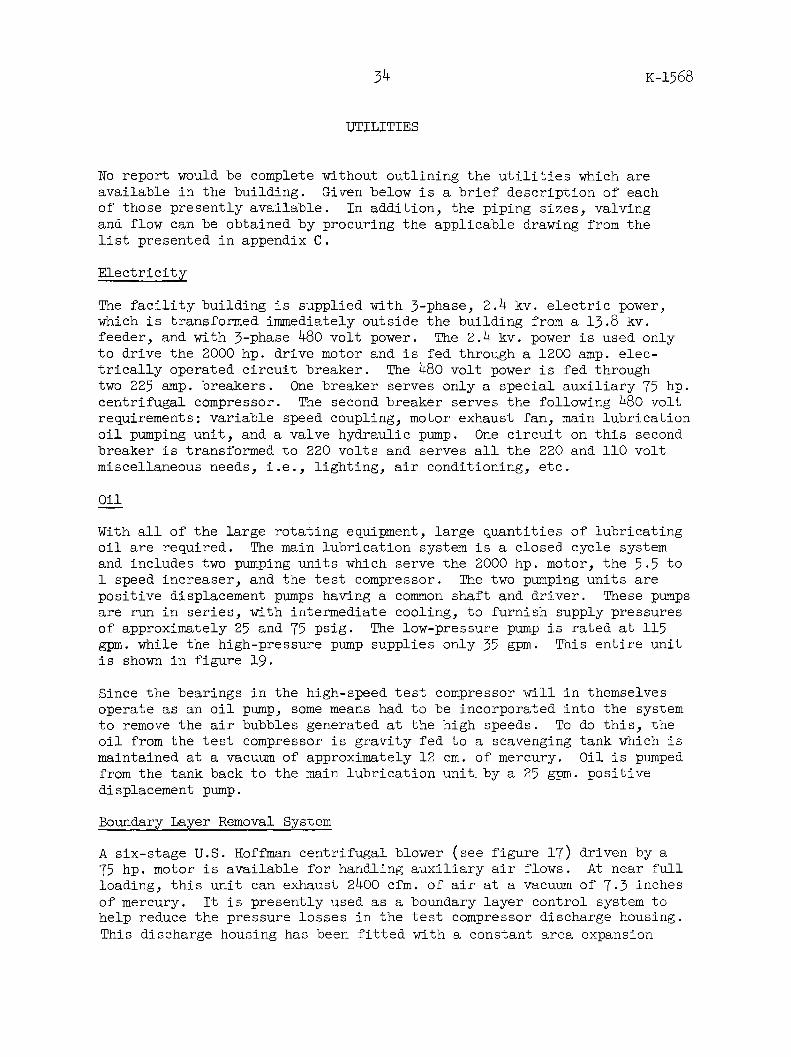
UTILITIES
No report would be complete without outlining the utilities which areavailable in the building. Given below is a brief description of eachof those presently available. In addition, the piping sizes, valvingand flow can be obtained by procuring the applicable drawing from thelist presented in appendix C.
Electricity
The facility building is supplied with 3-phase, 2.4 kv. electric power,which is transformed immediately outside the building from a 13.8 kv.feeder, and with 3-phase 480 volt power. The 2.4 kv. power is used onlyto drive the 2000 hp. drive motor and is fed through a 1200 amp. elec-trically operated circuit breaker. The 480 volt power is fed throughtwo 225 amp. breakers. One breaker serves only a special auxiliary 75 hp.centrifugal compressor. The second breaker serves the following 480 voltrequirements: variable speed coupling, motor exhaust fan, main lubricationoil pumping unit, and a valve hydraulic pump. One circuit on this secondbreaker is transformed to 220 volts and serves all the 220 and 110 voltmiscellaneous needs, i.e., lighting, air conditioning, etc.
Oil
With all of the large rotating equipment, large quantities of lubricatingoil are required. The main lubrication system is a closed cycle systemand includes two pumping units which serve the 2000 hp. motor, the 5.5 to1 speed increaser, and the test compressor. The two pumping units arepositive displacement pumps having a common shaft and driver. These pumpsare run in series, with intermediate cooling, to furnish supply pressuresof approximately 25 and 75 psig. The low-pressure pump is rated at 115gpm. while the high-pressure pump supplies only 35 gpm. This entire unitis shown in figure 19.
Since the bearings in the high-speed test compressor will in themselvesoperate as an oil pump, some means had to be incorporated into the systemto remove the air bubbles generated at the high speeds. To do this, theoil from the test compressor is gravity fed to a scavenging tank which ismaintained at a vacuum of approximately 12 cm. of mercury. Oil is pumpedfrom the tank back to the main lubrication unit.by a 25 gpm. positivedisplacement pump.
Boundary Layer Removal System
A six-stage U.S. Hoffman centrifugal blower (see figure 17) driven by a75 hp. motor is available for handling auxiliary air flows. At near fullloading, this unit can exhaust 2400 cfm. of air at a vacuum of 7.3 inchesof mercury. It is presently used as a boundary layer control system tohelp reduce the pressure losses in the test compressor discharge housing.This discharge housing has been fitted with a constant area expansion

35
I
H;F PRF lz hllrS
LOW PHLSSURL I'dMl .
- HIGH PRESSURE SUPPLY
INTER-PUMP RESERVOIR
PRINCIPAL LUBE OIL UNIT
I#
BOUNDARY LAYER REMOVAL PUMP
AUXILIARY MECHANICAL SYSTEMS
Figure 19
K-1568

36 K-1568
turning block which has two seven eighths of an inch wide slots around itscircumference. The Hoffman pump is used to pull about 2% of the mainstream flow through these slots. This in turn helps to keep the boundarylayer attached and as a result reduces the total pressure loss in thisexpansion by approximately 70%. This permits a wider operating range forthe particular compressor under test.
Recirculating Water
Recirculating treated water which is used to cool the oil used in thedrive train is supplied to the building through a 6-inch supply line* ata temperature of 95 F. and a pressure of approximately 48 psig. Lessthan 200 gpm. are required at peak demand for present operations. Noprovisions have been made to recirculate this water.
Sanitary Water
Although used only incidentally in present operations, sanitary water isavailable from a 1-1/2-inch supply line. This water is at a pressure ofapproximately 35 psig. Its temperature varies seasonally from 35 to 65 F.
Steam
Steam at a nominal pressure of 100 psig. is supplied to the facilitybuilding through a 2-inch line. This steam is used for heating and asa motive fluid for a steam jet utilized to maintain the vacuum in theoil scavenging tank mentioned above.
Compressed Air
Dry compressed air, required for many instruments, is available at 100psig. through a 2-inch header. Locally mounted pressure reducing stationsfurnish lower pressures as required.
Fluorine
Fluorine, although not used in present operations, is supplied to thebuilding through a 2-inch header at approximately 75 psig.
BLADE INSPECTION AND SETTING EQUIPMENT
One of the requisites of any experimental investigation of compressorblade performance is adequate verification that the blade shape beingtested is that called for by the design. All of the blading evaluatedin the Research Compressor Test Facility is inspected on a Vizo-Grafprofile measuring machine. This machine, see figure 20, produces an
* For operator reference - this line is attached to the ORGDP "A" loop.

3T K-1568
VIZO-GRAF AIRFOIL PROFILE INSPECTION MACHINE
BLADE MOUNTED FOR TRACING
i- -- i--+---i---v'i--+- I I I I I I I r r rI
TYPICAL TRACING RECORD
BLADE INSPECTION EQUIPMENT
Figure 20
I 1 rT
I I I l I I I i I -
r

K-1568
accurate and permanent dimensional record of the blade section contours.As can be seen in the close-up view, figure 20, the blade is passed be-tween two movable probes which, as they travel over the two surfaces ofthe blade, produce proportional motions in two light beams. The reflec-tions of the moving light beams are recorded on photographic paper whichmoves in synchronization with the blade travel. A thickness magnificationof 20 to 1 is standardly produced. However, by a slight modification inthe machine, this could be increased to 60 to 1. The length or chord-wise magnefication is variable, with three different settings possible,namely, 5 to 1, 10 to 1 and 20 to 1. As the photographic paper movespast the camera iris a grid is automatically superimposed on it by asystem of light beams produced by a metal grid or comb. The horizontalor thickness scale is graduated in increments of 0.006 inch, while eachvertical or lengthwise division represents 0.025 inch. Neither of thesegrids is linear. Tests of a similar machine at the Air Force WrightPatterson Field Aeronautical Laboratory showed that the Vizo-Graf willassure repeated results within 0.0003 to 0.0005 inch of the actual size.With this machine, contour shapes up to 1.000 inch in thickness can beinspected. An example of a typical profile is shown in figure 20.
Present practice calls for each of the blades tested in the researchcompressor to be inspected at five different profile cross sections. Inaddition to the ability to produce magnified tracings of the airfoilprofiles, a precision rotary fixture on which the blades are mountedpermits a determination of the amount of twist between blade sections.Prior to tracing, each blade section is oriented such that the traversingtable moves exactly parallel to the blade chord line. The difference inangle shown on the rotary fixture for the various blade section heightsis then indicative of the twist in the blade. The vernier on this fixturecan be read to one minute. Experience has shown that a blade can berepeatedly oriented for traversing within 4 minutes.
Through the use of the Vizo-Graf profile measuring machine, an accuratephotographic picture of the actual shape of each compressor blade examinedis obtained. An evaluation as to whether or not this shape lies withinthe tolerances set forth on the applicable drawings can then be made byoverlaying a master screen upon which the minimum and maximum tolerancebands have been drawn.
Blade Angle Setting
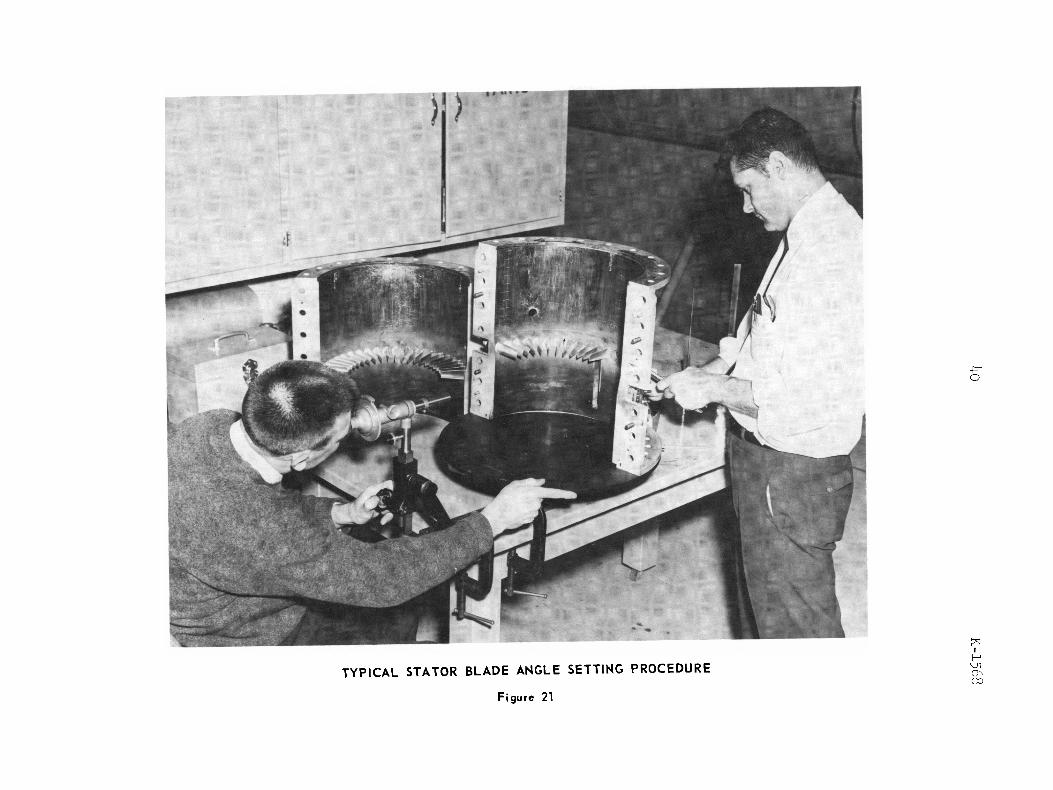
Of equal importance with the assurance that blade shapes are correct istheir mounting in proper relation to the compressor axis, i.e., settingthe proper stagger angle. In the research compressor, the alignment ofboth stator and rotor blades is determined with the aid of a special low-power telescope whose hairlines are synchronized with an external anglescale. The blade is adjusted until an imaginary chord line through thetip of the blade coincides with the telescope hairline which has beenpreset to the correct angle. This requires that the line of sight bein the same meridional (axial-radial) plane as the blade stacking line
38

39 K-1568
and also in a circumferential-radial plane parallel to that of the bladestacking line. A special fixture which permits this relative alignmentfor both stator and rotor has been made and a typical stator blade adjust-ment is pictured in figure 21. The angle scale vernier can be read to3 minutes and experience has shown that any blade stagger angle can berepeatedly measured to within 3 minutes.
p0
%H
1kf
TYPICAL STATOR BLADE ANGLE SETTING PROCEDURE F r
Figure 2

K-1568
APPENDIX A
AVAILABLE TRANSDUCERS (TYPE - STATHAM STRAIN GAUGE)
Model Designation
PA295TC -15-350
PA24TC -15-350
Pi31a 12.50-350
PM6TC 10-350
PM6TC + 5-350
PM6TC + 5-350
PM6TC + 5-350
PM6TC + 5-350
PM6TC + 5-350
PM6TC 2.5-350
PM6TC 2.5-350
PM6TC 2.5-350
PM6TC 2.5-350
PM6TC 2.5-350
PM6TC 2.5-350
PM6TC + 1-350
PM6TC + 1-350
PM6TC 1-350
PM6TC + 1-350
PM6TC + 1-350
PM5TC 0.5-350
PM5TC 0.3-350
PM5TC 0.3-350
PM5TC 0.3-350
Pressure Range
0-15 psia.
0-15 psia.
12.5 psid.
10 psid.
5 psid.
5 psid.
5 psid.
5 psid.
5 psid.
2.5 psid.
2.5 psid.
2.5 psid.
2.5 psid.
2.5 psid.
2.5 psid.
1.0 psid.
1.0 psid.
1.0 psid.
1.0 psid.
1.0 psid.
0.5 psid.
0.3 psid.
0.3 psid.
0.3 psid.
Serial Number
526
6146
1982
10313
10432
6772
10437
10161
1105010143
10182
10146
10181
10194
10144
11345
11338
11117
11284
11286
10174
10134
1464
11072
41

K-1568
APPENDIX B
PORTABLE
Item Qt
Actuator Control System(Single Probe)
Amplifier (Differential)Amplifier (Carrier)
Amplifier (Universal)Amplifier (DC)
Capacitor (Decade)
Condenser (Variable Air)
Distance Detector Energizer
Distance Meter
Keyboard Plotter
Manometer Panel(Multitube Photographic)
Moisture Analyzer
Multirange Tester(Vacuum Tube)
Ohmmeter
OscillatorOscillator (Audio)
Oscillograph (1 Channel)Oscillograph (2 Channel)Oscillograph (14 Channel)
OscilloscopeOscilloscopeOscilloscopeOscilloscopeOscilloscope (Dual Beam)
INSTRUMENTATION AVAILABLE
wantity Manufacturer
1 L. C. Smith Company
21
3
1
1
1
1
5
1
1
1
2
1
11
211
11211
Kintel Model 114AConsolidated ElectrodynamicCorporation Type 1-127Brush Model BL-320Brush Model BL-932
Cornell-Dubilier Model CDA 5
General Radio Type 539B
Bentley Corporation Model E-30
Wayne Kerr Type DM-lOO
F. L. Moseley Company Model 40A
Dynametrics CorporationModel MW-20-lOO
Manufacturers Engineering andEquipment Corporation Model W
Precision Apparatus CompanySeries EV-10-S
Superior Instruments CompanyModel 610-E
Hewlett Packard Model 200CHewlett Packard Model 200AB
Brush Corporation Model BL-201Brush Corporation Type BL-202Consolidated Electronics
Type 5-116-P4-14
Dumont Type 164ERCARCA Model WO-33ADumont Model 403Analab Type 1120-R
42

K-1568
APPENDIX B (Cont.)
Item
Oscilloscope Camera
Plotter (2 Axis)
Potentiometer (Decade)
Strobotac
Strobotac
Strobotac
Tube Tester
Vacuum Tube VoltmeterVacuum Tube V tmeterVacuum Tube tmeterVacuum Tube ltmeter
Vibration Analyzer
Vibration Pickup
Voltmeter (AC and DC)Voltmeter (AC)
Volt - Ohmmeter
Quantity
1
2
1
1
2
3
1
2211
1
1
11
1
_
Manufacturer
Polaroid Model F-286
F. L. Moseley Company Model 2S
Shallcross Model 835
General Radio CompanyModel No. 1531A
General Radio CompanyModel No. 631B
General Radio CompanyModel No. 648A
Precision Apparatus CompanySeries 910E
Hewlett Packard Model 4OODRCA Volt Ohmyst Jr .Radio City Products Model 664Hewlett Packard Model 410B
International Research andDevelopment Corporation Model 600
Brush Corporation Model DP-l
Weston Model 341Weston Model 433
Weston Model 772
43

K-1568
APPENDIX C
Drawing No.
Civil
A-S-25961K
E-S-25961D
E-S-25961E
E-S-25961F
E-S-25961G
E-S-25961H
E-S-25961J
E-S-25961L
A-S-23663L
Mechanical
E-P-25961B
E-P-25961C1
E-P-25961C2
E-P-25961C3
D-P-25961E
RESEARCH COMPRESSOR DRAWING LIST
Revision Title
0
2
0
1
0
0
0
0
1
2
1
1
1
0
Research Compressor Test FacilitySeller's Working Area
Research Compressor Test FacilitySite Work and Substation Details
Research Compressor Test FacilityBuilding Plan and Details
Research Compressor Test FacilityControl Room and Miscellaneous Details
Research Compressor Test FacilityEquipment Supports, Plan and Sections
Research Compressor Test FacilityEquipment Supports, Sections and Details
Research Compressor Test FacilityStack and Pipe Support Details
Research Compressor Test FacilityCable Duct and Bus Bar Housing
Seller's Working Area for PipeCleaning Facilities in K-1401
Research Compressor Test Facility -Equipment Layout and Compressor Piping
Research Compressor Test Facility -Auxiliary Piping Plans
Research Compressor Test Facility -Auxiliary Piping - Sections
Research Compressor Test Facility -Auxiliary Piping Sections
Research Compressor Test Facility -Hydraulic Oil Reservoir

K-1568
APPENDIX C (Cant.)
Drawing No.
Electrical
E-E-25961D
E-E-25961E
E-E-25961F
E-E-25961G
E-E-25961H
E-E-25961J
E-E-25961K
E-E-25961L
B-E-25961M
Instrument
D-I-25961C
E-I-25961D
D-I-25961E
C-I-25961F
D-I-25961G
Revision
0
1
1
1
1
1
0
1
1
1
1
1
0
Title
Research Compressor Test FacilityBreaker Details
Research Compressor Test FacilityBreaker Wiring
Research Compressor Test FacilityPanel Wiring and Details
Research Compressor Test FacilityLighting Layout
Research Compressor Test FacilityConduit Plan
Research Compressor Test FacilityDiagrams
Research Compressor Test FacilityWiring Diagrams
Research Compressor Test FacilityHigh Resistance Grounding Details
Research Compressor Test FacilityCable Routing Schedule
Research Compressor Test Facility,Auxiliary Temperature InstrumentationDetails
Research Compressor Test FacilityInstrumentation Plan
Research Compressor Test FacilityControl Cabinet Fabrication Details
Research Compressor Test FacilityDischarge Valve Installation Details
Steam Metering Installation ResearchCompressor Test Facility
45

K-1568
APPENDIX C (Cont.)
Drawing No. Revision Title
B-ID-2032
Mechanical
8 Standard Pipe to Tubing Connector for1/4"1 to 3/4" O.D. Tubing
Equipment
0
Reference
Research Compressor General Layout
Drawings - for Information Only
Mechanical
E-P-25961A
Electrical
29-B-9797
2 Research Compressor Test Facility -Flow Diagram
Westinghouse Electric Corporation
"CS" Motor Sleeve Brgs. FR No. 6-44-1/2 - 28
Instrumentation
C-I-25961A1 0 Research Compressor Test Facility OilSystems Instrument Application
Mechanical Equipment
D-M-25961A1
D-M-25961A2
D-M-25961A3
D-M-25961A4
D-M-25961A5
0
0
0
0
0
Research Compressor Flange Ends for ModifiedK-33 Coupling for Variable Speed Coupling
Research Compressor Flange End for ModifiedK-33 Coupling to fit Input Shaft ofWestinghouse Gear Unit
Research Compressor Flange End for ModifiedK-33 Coupling to fit Output Shaft ofWestinghouse Gear Unit
Research Compressor Flange End for ModifiedK-33 Coupling to fit Input Shaft of Falk GearUnit
Research Compressor - Falk Gear Unit InputShaft Oil Seal Assembly and Details
E-M-25961A
y L.

K-1568
APPENDIX a (Cont.)
Drawing No.
D-M-25961A6
E-M-25961A7
E-M-25961A8
B-32850
C -46331
C-46364
Dimension S6770 - Page 5
500829
CR 47319
Revision Title
O Research Compressor - Falk Gear Unit InputShaft Oil Seal Details
O Research Compressor Thomas Coupling Guard
0 Research Compressor Thomas Coupling Guard
Dynamatic Corporation
Alnico Generator "G 2T"
Water Cooled Coupling
Automatic Water Piping
Westinghouse Electric CorporationGearing Division
heet Unit No. SU-21-10
The Falk Corporation
Layout of 17.485 x 8-1/2 Face-SpeedIncreaser Model No. M0160-4O1
National Advisory Committee ForAeronautics - Lewis Flight Propulsion
Laboratory
Compressor Assembly 14" DiameterInlet Stage
47


i
r