Erosion on R0 Compressor Blade Leading Edge - CiteSeerX
10
1 Copyright © 2007 by ASME ON LINE COMPRESSOR WASHING ON LARGE FRAME 9-FA GAS TURBINES EROSION ON R0 COMPRESSOR BLADE LEADING EDGE FIELD PERFORMANCE WITH A NOVEL ON LINE WASH SYSTEM Jos Oosting Klaas Boonstra Annemarie de Haan Dick van der Vecht Electrabel Nederland nv Eems Centrale, The Netherlands www.electrabel.nl Jean-Pierre Stalder Urs Eicher Turbotect Ltd. Baden, Switzerland www.turbotect.com ABSTRACT On line compressor washing is an established practice amid gas turbine operators. Among these operators is the Netherlands Division of Electrabel who is operating at Eemshaven 5 x GE Frame 9-FA units since 1995. The plant operator used to perform routinely a daily on line wash and a single off line wash every year at shut down of the units for the annual inspection or maintenance outage. The on line water wash (OLWW) systems installed on these 5 engines are of the Turbotect Mk1 nozzle design and were originally procured and supplied by the OEM. To our knowledge, all other manufactured gas turbines in the 7/9-FA fleet are equipped with the OEMs’ own engineered OLWW nozzle systems. The OLWW regime of washing was reduced in June 2001 upon receipt of a recommendation by the OEM to inspect the first stages of the compressor for erosion marks. This recommendation was issued because some events have lead to investigation on erosion issues which materialized in the R0 (first stage rotor) compressor blades in some engines of the 7/9- FA fleet operating with the OEM OLWW system and resulting from frequent compressor wash routine, and/or from water ingestion used in power augmentation. Likewise, during the same time, some gas turbines at Eemscentrale had undergone their first major overhaul which allowed the compressor first row blading to be examined for signs of erosion. It was found that only minor erosion at the R0 blade leading edge had occurred over more than seven years of operation, during which period a daily on line wash had been performed. However, because of the erosion concerns among the 7/9-FA fleet and the OEM-recommended frequent inspections and measures to mitigate the rate of erosion due to droplet impingement, Electrabel investigated independently for a way of further reducing the erosion rate while maintaining on line washing over the lifetime of the gas turbine and improving the cleaning efficiency. To this effect, the OLWW system on unit EC-6 was upgraded in June 2004 with a new on line nozzle system specifically developed for use in large gas turbines. This paper presents the investigation results after some 24 months of operation and routine on line compressor washing. The Turbotect Mk3 OLWW nozzle system demonstrated and confirmed that it is contributing to mitigate the erosion risk on the R0 compressor blade leading edge, and in turn to decrease the number of blending operations over the life time of the R0 compressor blades. This nozzle designed for on line compressor cleaning of large gas turbines achieved a substantially improved cleaning effectiveness, respectively a lower rate in power degradation, by approx. 30 to 40% as compared to the current in use Mk1 OLWW nozzle system. INTRODUCTION The events surrounding the R0 compressor blades must be complex in nature and possibly a combination of many factors. Incremental roughness, as a result of OLWW which, according to the technical instruction letters from the OEM is part of the equation for incidents in the fleet, are under control at the Eems combined cycle power plant. The investigation and evaluation on the R0 compressor blade leading edge erosion presented and discussed in this paper is specific to the Frame 7-FA and 9-FA gas turbines. The potential risk of erosion from droplets generated under certain conditions by foggers, evaporative coolers or during wet compression is not discussed in this paper. Proceedings of GT2007 ASME Turbo Expo 2007: Power for Land, Sea and Air May 14-17, 2007, Montreal, Canada GT2007-28227
-
Upload
khangminh22 -
Category
Documents
-
view
1 -
download
0
Transcript of Erosion on R0 Compressor Blade Leading Edge - CiteSeerX
Downl
ON LINE COMPRESSOR WASHING ON LARGE FRAME 9-FA GAS TURBINES EROSION ON R0 COMPRESSOR BLADE LEADING EDGE
FIELD PERFORMANCE WITH A NOVEL ON LINE WASH SYSTEM
Jos Oosting Klaas Boonstra
Annemarie de Haan Dick van der Vecht
Electrabel Nederland nv Eems Centrale, The Netherlands
www.electrabel.nl
Jean-Pierre Stalder Urs Eicher
Turbotect Ltd. Baden, Switzerland www.turbotect.com
Proceedings of GT2007 ASME Turbo Expo 2007: Power for Land, Sea and Air
May 14-17, 2007, Montreal, Canada
GT2007-28227
ABSTRACT On line compressor washing is an established practice amid
gas turbine operators. Among these operators is the Netherlands Division of Electrabel who is operating at Eemshaven 5 x GE Frame 9-FA units since 1995. The plant operator used to perform routinely a daily on line wash and a single off line wash every year at shut down of the units for the annual inspection or maintenance outage. The on line water wash (OLWW) systems installed on these 5 engines are of the Turbotect Mk1 nozzle design and were originally procured and supplied by the OEM. To our knowledge, all other manufactured gas turbines in the 7/9-FA fleet are equipped with the OEMs’ own engineered OLWW nozzle systems.
The OLWW regime of washing was reduced in June 2001 upon receipt of a recommendation by the OEM to inspect the first stages of the compressor for erosion marks. This recommendation was issued because some events have lead to investigation on erosion issues which materialized in the R0 (first stage rotor) compressor blades in some engines of the 7/9-FA fleet operating with the OEM OLWW system and resulting from frequent compressor wash routine, and/or from water ingestion used in power augmentation. Likewise, during the same time, some gas turbines at Eemscentrale had undergone their first major overhaul which allowed the compressor first row blading to be examined for signs of erosion. It was found that only minor erosion at the R0 blade leading edge had occurred over more than seven years of operation, during which period a daily on line wash had been performed. However, because of the erosion concerns among the 7/9-FA fleet and the OEM-recommended frequent inspections and measures to mitigate the rate of erosion due to droplet impingement, Electrabel investigated independently for a way of further
1
oaded From: http://proceedings.asmedigitalcollection.asme.org/ on 02/19/2016
reducing the erosion rate while maintaining on line washing over the lifetime of the gas turbine and improving the cleaning efficiency. To this effect, the OLWW system on unit EC-6 was upgraded in June 2004 with a new on line nozzle system specifically developed for use in large gas turbines.
This paper presents the investigation results after some 24 months of operation and routine on line compressor washing. The Turbotect Mk3 OLWW nozzle system demonstrated and confirmed that it is contributing to mitigate the erosion risk on the R0 compressor blade leading edge, and in turn to decrease the number of blending operations over the life time of the R0 compressor blades. This nozzle designed for on line compressor cleaning of large gas turbines achieved a substantially improved cleaning effectiveness, respectively a lower rate in power degradation, by approx. 30 to 40% as compared to the current in use Mk1 OLWW nozzle system.
INTRODUCTION The events surrounding the R0 compressor blades must be
complex in nature and possibly a combination of many factors. Incremental roughness, as a result of OLWW which, according to the technical instruction letters from the OEM is part of the equation for incidents in the fleet, are under control at the Eems combined cycle power plant. The investigation and evaluation on the R0 compressor blade leading edge erosion presented and discussed in this paper is specific to the Frame 7-FA and 9-FA gas turbines. The potential risk of erosion from droplets generated under certain conditions by foggers, evaporative coolers or during wet compression is not discussed in this paper.
Copyright © 2007 by ASME
Terms of Use: http://www.asme.org/about-asme/terms-of-use

PLANT DESCRIPTION The 2,470 MW Eemshaven power plant complex is located
in the North East part of The Netherlands, and is owned and operated by Electrabel Netherlands. The site comprises two different plants: The first one is operational since 1977 and is a steam turbine power plant which was upgraded with a Siemens V 94.2 gas turbine to give a combined total output of 697 MW. An extension with a new combined cycle plant of 1,775 MW started commercial operation in 1995. It comprises 5 x Frame 9-FA engines each of 225 MW, and each with a heat recovery boiler and one steam turbine on the same shaft. The total combined output per unit is 355 MW. The plant is fired with natural gas from the Groningen field, see Pfleger [1]. The Eems gas turbines are among the fleet leaders in the Frame 9-FA engine population. Until 2000 the plant used to be operated at base load. However, because of recent natural gas price increases the plant is now operated in cycling mode with many more starts and shut downs. As of September 2006 the units have logged the following fired hours and starts:
Unit EC-3 EC-4 EC-5 EC-6 EC-7 Fired hours 78,191 77,086 80,222 76,737 71,274 Fired starts 744 834 636 599 702
Table 1. Fired hours and starts as of September 25th, 2006.
Fig. 1. Picture of the Eemshaven combined cycle power plant.
PLANT ENVIRONMENT & AIR FILTRATION SYSTEM The Eemshaven power plant is located directly on the shore
of the North Sea. At the beginning of operation back in the mid 90’s the surrounding land was very sandy and air pollution by sand dust was the main issue at the time. Meanwhile the area developed into an agricultural environment. Other than the port facilities which are located about 4 km North of the plant, there were no local industries nor motorways in the vicinity. Nowadays the main issues for the air inlet filtration system are to care for the coastal marine atmosphere with salt-laden winds and humidity, as well as seasonal dust concentrations due to agricultural activities. However, in the last six months some new industries involving earth- and sand-moving have settled approx. 2 km North of the plant. These new activities were already felt by higher fouling deposition rates on compressor blades. Upon this observation the compressor off line washing
2
Downloaded From: http://proceedings.asmedigitalcollection.asme.org/ on 02/19/2016
strategy has been reviewed very recently. Overall it can be said that the judicious selection of the gas turbine plant location resulted so far in relatively favorable conditions concerning power degradation issues as compared with many other plants operated in a combined urban, industrial, coastal marine, high humidity and high ambient temperature environment.
The two-stage air filtration system installed in a concrete housing on the roof of the plant building was supplied by AAF. It consists of an Aluminum grilled weather louver and coalescer in front of the 1st stage G3 class coarse filter, and a 2nd fine filtration stage which used to be a F9 class filter. However, and as a result of a cost optimization program it was changed some two years ago to the F8 filtration class. According to the EN 779 European Standard, the G3 Class is for coarse filters for a final pressure drop of 250 Pa and an average arrestance rating for synthetic dust between 80 to 90%. Whereas the F class is for fine filters with a final pressure drop of 450 Pa with an average dust spot efficiency for 0.4 micron particles, between 90 to 95% for the F8 class and above 95% for the F9 class filters.
Both filter stages have 440 pocket filter elements (60 x 60 cm) for an air flow rate of approx. 640 kg/s per gas turbine. The coarse filter elements are replaced on average 2 times per year and the fine filter elements on average every 3 years. Air flows vertically down and splits into two air conduits with entries horizontally on both sides of the bell mouth plenum. A FOD security screen with large mesh is located in both horizontal sections of the air conduits before the plenum.
For compressor anti-icing purpose there is a glycol water heat exchanger located in front of the coalescer. No fogging or evaporative cooling systems are installed in the air inlet.
COMPRESSOR CLEANING REGIME Since the beginning of commercial operation in 1995 and
until June 2001 all gas turbine compressors at Eems were washed on line, daily in summer and 3 times per week in winter for approx. 30 to 40 minutes. The anti-icing heat exchanger is started for on line compressor wash when the ambient temperature is below +15°C. Additionally an antifreeze agent is added to the cleaning solution when the ambient temperature is below +10°C. Thus, and based on the ambient temperature profile at site, the winterized OLWW period covers on average approx. 7 months and the summer period approx. 5 months of each calendar year.
As a result of the first recommendation received from the OEM in June 2001 to inspect at first opportunity and after that annually for erosion on the R0 compressor blades, the on line washing regime was reduced in a first step to 3 times per week for 10 minutes during summer and winter. Later in 2001 the OEM recommended to wash on line only up to 5 minutes daily (total 35 min. weekly) until 100 OLWW hours are reached. However, in September 2002 after inspection results from two rotors showed no unexpected roughness on the R0 blades, measured by molds as instructed by the OEM, the washing regime was extended again to 3 times per week for 17 minutes in summer and two times per week for 17 minutes during
Copyright © 2007 by ASME
Terms of Use: http://www.asme.org/about-asme/terms-of-use

Do
winter; see Table 2 below. With this revised OLWW interval and duration, a total 100 hours OLWW operation are achieved between two hot gas path inspections scheduled at 3-year intervals (i.e. approx. 24,000 op. hrs.), as recommended in the OEMs’ Technical Information Letter (TIL letter). In this respect the OEM stated the following in the TIL issued in December 2001: “… Experience based on fleet operational data has shown that the elimination of water washing increases the rate of fouling build-up, which accelerates performance degradation, and daily water washes are more effective in mitigating performance loss than extended interval washes”. This statement is clearly supporting the need for on line washing for compressor fouling control.
About off line compressor washing: Until 2001 a single compressor off line wash used to be made on average every year on each engine, when it is shut down for the annual inspection or for maintenance outage. For instance, a performance drop of about 4 to 5 MW was measured prior to the June 2001 outage on unit EC-3 after some 10,000 operating hours. Interestingly, a higher power drop due to compressor fouling resulted after reducing the on line cleaning regime, as recommended in the TIL letters in 2001; see Boonstra [2]. The consequence of this reduced OLWW regime was that the number of off line compressor washes was doubled to two per year. As mentioned above, the new strategy for compressor off line cleaning recently introduced is to wash off line when the CC (GT + ST) has reached a combined 4 MW power degradation (approx. 1.1%), or at first opportunity when a unit is shut down.
Unit EC-6 was upgraded during the major inspection in June 2004 with the Mk3 on line compressor washing nozzle system, which is further discussed on page 6 of this paper.
From visual inspection it can generally be stated that after some 8,000 operating hours the compressor blading is always in a relative good condition. Throughout the compressor rotor stages, only a thin layer of deposits is covering the blade surfaces. The deposits are smooth, slightly oily/sooty, not sticky, and can be cleaned off easily. Time period Summer Winter 1995 up to June 2001 Daily 35 min. 3 x 35 min/week June 2001 to Aug 2002 3 x 10 min/week 3 x 10 min /week Sept. 2002 onwards 3 x 17 min/week 2 x 17 min /week
Table 2. On line water wash, frequency and duration.
COST OF FOULING As an example, a gas turbine engine of 255.6 MW with a
corresponding air inlet mass flow of 640 kg/s will ingest some 18.4 million tons of air over 8,000 op. hours. Assuming 10 ppm dust concentration in ambient air, a total of 184 tons of foulant will enter the air filtration system. Despite the high filtration efficiency a minor portion of foulant will still pass the air filtration system and deposit on compressor blades.
wnloaded From: http://proceedings.asmedigitalcollection.asme.org/ on 02/19/20
For this same gas turbine and assuming a net heat rate of 9,250 BTU/kWh, cost of electricity of 0.07 USD/kWh and 7.0 USD/MBTU for cost of natural gas fuel (approx. current US prices), then the yearly cost for performance deterioration is amounting to 5,578,000 USD for a period of 8,000 operating hours when assuming a yearly average of 3% in power degradation and 1% increase in heat rate. Typically recoverable losses account for 70 to 85% of performance losses. Thus, the yearly cost for performance losses due to compressor fouling is amounting between 3,904,000 and 4,741,000 USD in the same period. For the calculation model see Diakunchak [3]. Additional detailed discussion on the cause and effect of compressor fouling can be found in Balevic, et al [4], Tarabrin, et al [5], and Meher-Homji & Bromley [6].
ORIGINAL OLWW SYSTEMS DESIGN DATA As mentioned above the Eems engines were originally
supplied with the Mk1 OLWW systems. Both the OEM and the Mk1 OLWW nozzle systems are of the low pressure type. GE Frame 9-FA OEM OLWW Mk1 No. of nozzles 18 38 Water mass flow 38gpm / 144 l/min 7.7 gpm / 29.3 l/min Water pressure 100 psi / 6.9 bar 58 psi / 4 bar Table 3. OLWW nozzle systems comparison of design data.
The design philosophy of Turbotect is to position a relatively large number of nozzles in the air inlet casing, in both the up-stream side around the cone and on the down-stream side around or above the bell mouth. This ensures a better spatial distribution of the injected droplets and consequently provides improved wetting and cleaning characteristics. The principle of positioning the OLWW nozzles by the OEM is to some extent the same. However, the OEM OLWW system as originally installed on other 7/9-FA fleet units has only half the number of nozzles and is approx. 5 times higher in mass flow as compared to the Mk1 nozzle system and arrangement; see Stalder and van Oosten [7]. Figure 2. The Mk1 on line injection nozzle (patented) allowing orientation of the spray.
3 Copyright © 2007 by ASME
16 Terms of Use: http://www.asme.org/about-asme/terms-of-use
TIL LETTERS AND MEASURES RECOMMENDED BY THE OEM TO F-CLASS GT USERS
The plant operator was recommended by the OEM the first time in June 2001 to inspect by the first opportunity and thereafter annually the R0 compressor blades for erosion. This measure was prompted after inspections on other engines in the 7/9-FA fleet revealed distressed blades with significant erosion on the leading edge, and a liberated blade in at least one case. The next TIL letter was issued in August 2001 recommending operators of F class engines to detect and measure erosion by taking molds. Such inspections being recommended after each 100 hours of cumulative on line washing. Later in 2001 the OEM recommended to wash on line only up to 5 minutes daily.
To reduce the erosion potential on R0 blades from OLWW operation, a further TIL letter recommended users of all F class gas turbines to isolate and blank the inner water manifold supplying cleaning fluid to the OEM OLWW nozzles located around the cone. Further, to decrease the water pressure in the manifold for the down-stream nozzles located around the bell mouth from 100 psig (6.9 bar) to 40 psig (2.8 bar). After these modifications, the total mass flow with the OEM OLWW system is estimated to be approx. 1/3 of the original mass flow, i.e. approx. 13 GPM (49 l/min). This same TIL letter also alerted users to the possibility of R0 leading edge erosion caused by evaporative cooler and inlet foggers, etc. Later, it was also recommended to the users to perform inspections at every 100 hours cumulative OLWW and fogger/evaporative cooler operation.
Statistical data on erosion measurements from the 7/9-FA fleet were collected by the OEM. It was recommended to the users to blend or polish the eroded area on the leading edge when erosion exceeds 10 mils (254 micron).
The impingement of droplets during OLWW and/or from fogger, evaporative cooler operation under certain conditions, on the leading edge at the R0 blade root area, can lead to erosion and when sufficiently developed it will reduce blade fatigue strength and in case a crack develops, it can result in a blade failure. The simultaneous combination with pitting initiated by the presence of salt embedded in blade deposits and high humidity can accelerate crack formation and its propagation (erosion – corrosion), see Stalder and Sire [8].
To date some R0 blade failures occurred in the 7/9-FA fleet. In response and to mitigate the problem a series of measures and design changes were recommended by the OEM to the users, see EPRI [9]: Such as but not limited to frequent inspection and regular polishing of the eroded area on the R0 leading edge if needed, changing the material of the blade from C450 to Inconel 718 with better erosion resistance, together with the introduction of an undercut (P-cut) in the root of the blade to reduce the stress at the blade root - leading edge foil area. Also a modified or new OLWW nozzle system design was mentioned to some users. As of to date comprehensive investigations on the failure mechanism and testing by the OEM are still underway to resolve this problem.
4
Downloaded From: http://proceedings.asmedigitalcollection.asme.org/ on 02/19/2016
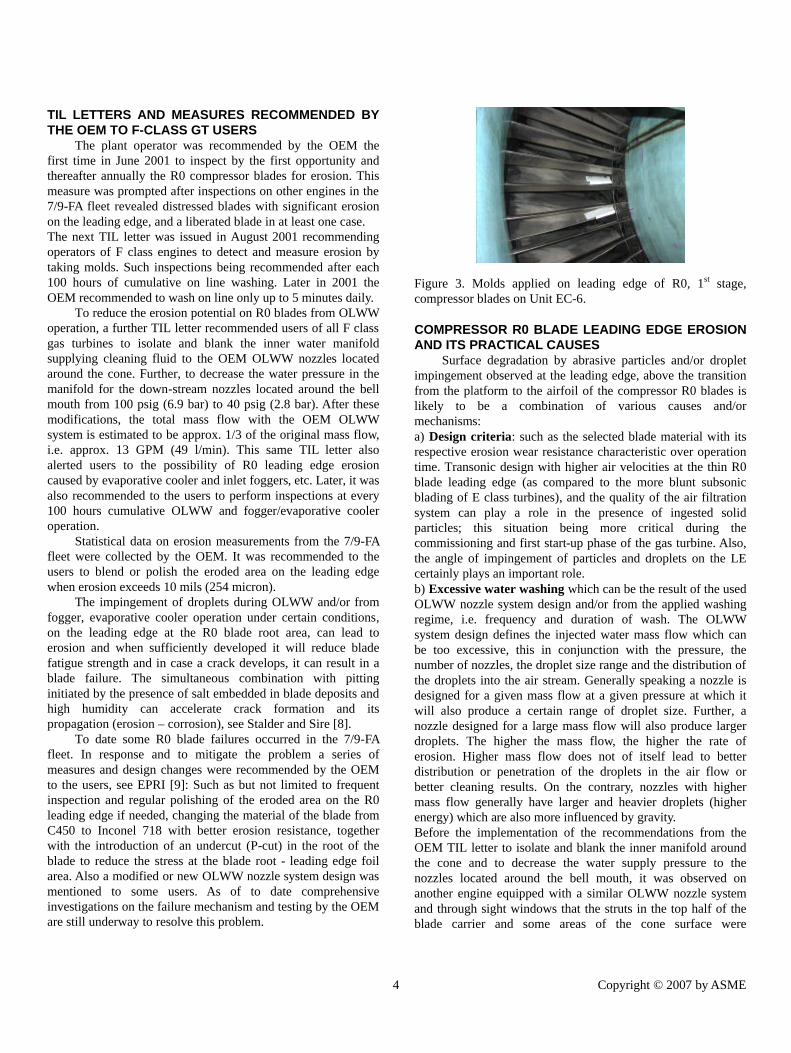
Figure 3. Molds applied on leading edge of R0, 1st stage, compressor blades on Unit EC-6.
COMPRESSOR R0 BLADE LEADING EDGE EROSION AND ITS PRACTICAL CAUSES
Surface degradation by abrasive particles and/or droplet impingement observed at the leading edge, above the transition from the platform to the airfoil of the compressor R0 blades is likely to be a combination of various causes and/or mechanisms: a) Design criteria: such as the selected blade material with its respective erosion wear resistance characteristic over operation time. Transonic design with higher air velocities at the thin R0 blade leading edge (as compared to the more blunt subsonic blading of E class turbines), and the quality of the air filtration system can play a role in the presence of ingested solid particles; this situation being more critical during the commissioning and first start-up phase of the gas turbine. Also, the angle of impingement of particles and droplets on the LE certainly plays an important role. b) Excessive water washing which can be the result of the used OLWW nozzle system design and/or from the applied washing regime, i.e. frequency and duration of wash. The OLWW system design defines the injected water mass flow which can be too excessive, this in conjunction with the pressure, the number of nozzles, the droplet size range and the distribution of the droplets into the air stream. Generally speaking a nozzle is designed for a given mass flow at a given pressure at which it will also produce a certain range of droplet size. Further, a nozzle designed for a large mass flow will also produce larger droplets. The higher the mass flow, the higher the rate of erosion. Higher mass flow does not of itself lead to better distribution or penetration of the droplets in the air flow or better cleaning results. On the contrary, nozzles with higher mass flow generally have larger and heavier droplets (higher energy) which are also more influenced by gravity. Before the implementation of the recommendations from the OEM TIL letter to isolate and blank the inner manifold around the cone and to decrease the water supply pressure to the nozzles located around the bell mouth, it was observed on another engine equipped with a similar OLWW nozzle system and through sight windows that the struts in the top half of the blade carrier and some areas of the cone surface were
Copyright © 2007 by ASME
Terms of Use: http://www.asme.org/about-asme/terms-of-use

D
considerably wetted by spray deflection. Too much water collected on the struts and formed continuous streamlets which broke away from the struts trailing edges close to and around the hub region. These water streamlets were then running around the IGVs’ foil profile close to the root, before impinging on the leading edge of the rotating R0 compressor blades in the root area. Thus, too much water was concentrated at the same area of the R0 blade roots and leading edges respectively. c) Another potential phenomena which is not negligible can be caused during normal operation through the action of condensed and coalescing water droplets in the air inlet plenum at high humidity. See Stalder [10]. Statistical data on LE roughness measurements from units not undergoing any wet operation (OLWW, fogging, wet compression) could be helpful to assess comparative erosion rates to determine if this potential risk of erosion is of any significance. d) From non-evaporated droplets present at - or carried over to - the IGVs’ and generated under certain conditions by foggers, evaporative coolers, or during wet compression for power augmentation. This subject is not discussed in this paper.
ROUGHNESS AFTER 7 YEARS OLWW ON UNIT EC-7 Boonstra [2] presented in 2003 the plant experience made
between 1995 and 2002 with OLWW and measured R0 compressor blade roughness on Unit EC-7. Mold measurements of the R0 leading edge were made at the major inspection after 51,936 operating hours. The measured roughness mean value was 8.9 mils (226 micron).
Based on the washing regime practiced over this time period, the number of compressor on line washes was 1,500 for a combined total of 790 wash hours. The average wash time was approx. 31 minutes per wash. The total cleaning solution injected with the Mk1 OLWW system over this time period was 1,389 m3. The roughness measurements made on the other Eems gas turbine engines were in the same range.
R0 COMPRESSOR BLADE P-CUT MODIFICATION AND OLWW REGIME ON UNIT EC-7
Unit EC-7 started operation in March 2005 with the modified R0 compressor blade with a P-cut in the blade root while keeping the original C450 blade material. The OEM proposed the P-cut modification to operators of 7/9-FA gas turbines for stress relief, and to prevent fatigue failure which was initiated on some engines in the leading edge area near the platform of the root. With this modification, the operator was allowed to increase the OLWW regime back again to a daily 20 minutes on line water wash and roughness measurements on the R0 compressor blades have been discontinued. The Mk1 OLWW nozzle system is installed on that unit.
INITIAL R0 COMPRESSOR BLADE LEADING EDGE ROUGHNESS AFTER BLENDING OPERATION
A blending operation means a polishing of the roughness followed by shot peening. A mold measurement was made to
ownloaded From: http://proceedings.asmedigitalcollection.asme.org/ on 02/19/201
establish initial surface roughness on R0 compressor blades after blending and after shot peening. Thus, a freshly blended R0 compressor blade can have an average initial roughness of up to 2.6 mils (65 micron) before entering service.
Avg. measured roughness on R0 blade leading edge
After polishing 25 micron / 1 mils After shot peening 65 micron / 2.6 mils
Table 4. Initial roughness on blended R0 compressor blades. The logistics encompass mainly regular mold measurements to be taken and roughness evaluation with special optical apparatus, scheduling, blade disassembling, refurbishing operation and re-blading. Factors such as overall costs for blending, non-availability, personnel involvement and time spent are significant.
RECENT MEASURED LEADING EDGE ROUGHNESS AFTER BLENDING OF R0 COMPRESSOR BLADES As instructed by the OEM, the R0 compressor blade roughness was measured by taking molds at 100 OLWW hours which corresponds, acc. to the practiced OLWW regime (frequency and duration), to the interval between two hot gas path inspections (HGPI). The R0 compressor blades are uncoated. The results are tabulated for Unit EC-3 to EC-6 in table 5 below. Unit EC-3 EC-4 EC-5 EC-6 OLWW Mk1 Mk1 Mk1 Mk1 Date 17 Oct 05 29Nov 04 20. Jan 05 11 May 04 Op. hours 21,900 17,869 20,821 23,352 Meas. avg. roughness
182 µm 7.2 mils
170 µm 6.7 mils
147 µm 5.8 mils
199 µm 7.8 mils
OLWW Hrs. 92 Hrs. 73 Hrs. 82 Hrs. 107 Hrs. Table 5. Measured roughness on R0 blades after blending.
The roughness measurements are the average of 3 measurements made per mold and from 12 blades selected evenly over the circumference. Roughness measurements were also made at the fillet radius of the blades and their results were always lower than the ones measured at the leading edge near the root. Averages of all performed leading edge roughness measurements were below the OEM criterion of 10 mils (254 micron). New mold measurements are planned by the next coming HGPI; that is in approx. 24,000 operating hours i.e. after approx. 100 OLWW hours. There is a limit on how many times the blades can be blended, this being based on the amount of material removed each time.
5 Copyright © 2007 by ASME
6 Terms of Use: http://www.asme.org/about-asme/terms-of-use
UNIT EC-6: OLWW UPGRADE FROM THE MK1 TO THE MK3 NOZZLES (JUNE 2004)
In a move to further reduce the erosion rate by OLWW and to improve the cleaning efficiency, the OLWW system on unit EC-6 was upgraded with the Mk3 on line wash nozzle system (US Patented), specifically designed for use in large gas turbines. This system is designed with the same fitting assembly as the Mk1 nozzle, so that easy retrofits can be performed. The same original nozzle locations were used. Two sight glasses with illumination were installed in the walls of the air inlet plenum in the right side above and below the split line. In addition, hand valves were installed in the water supply pipe to six selected nozzle locations around the cone to enable isolating and viewing their sprays individually. The system was successfully commissioned on June 10th 2004 at base load. The spray pattern appeared to be very good, as was the droplet spatial distribution and droplet density in the sectors that were visible through the viewing windows. The droplets were wetting the complete exposed IGV length. No apparent impact of droplets with the struts caused by deflection could be observed and no accumulation of water on struts was visible. No water droplets could be seen dripping at the trailing edges of the struts.
OLWW System Mk1 Mk3 No. of nozzles 38 30 Water mass flow 7.7 gpm / 29.3 l/min 4.6 gpm / 17.6 l/min Water pressure 58 psi / 4 bar 58 psi / 4 bar Air pressure - 58 psi / 4 bar
Air mass flow - 6.12 Nm3/min 216 ft3/min
Table 6. Design data comparison of the OLWW nozzle systems for the Frame 9-FA at the Eems combined cycle power plant.
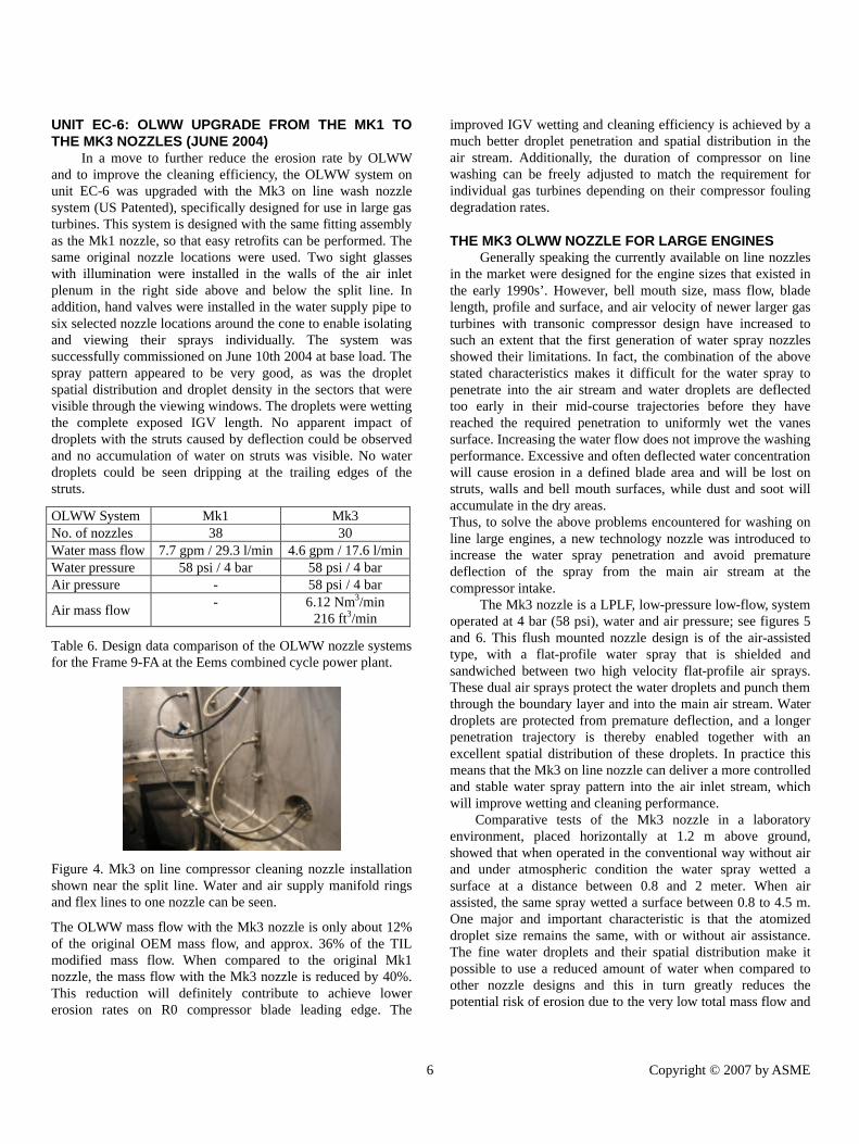
Figure 4. Mk3 on line compressor cleaning nozzle installation shown near the split line. Water and air supply manifold rings and flex lines to one nozzle can be seen.
The OLWW mass flow with the Mk3 nozzle is only about 12% of the original OEM mass flow, and approx. 36% of the TIL modified mass flow. When compared to the original Mk1 nozzle, the mass flow with the Mk3 nozzle is reduced by 40%. This reduction will definitely contribute to achieve lower erosion rates on R0 compressor blade leading edge. The
6
Downloaded From: http://proceedings.asmedigitalcollection.asme.org/ on 02/19/2016
improved IGV wetting and cleaning efficiency is achieved by a much better droplet penetration and spatial distribution in the air stream. Additionally, the duration of compressor on line washing can be freely adjusted to match the requirement for individual gas turbines depending on their compressor fouling degradation rates.
THE MK3 OLWW NOZZLE FOR LARGE ENGINES Generally speaking the currently available on line nozzles
in the market were designed for the engine sizes that existed in the early 1990s’. However, bell mouth size, mass flow, blade length, profile and surface, and air velocity of newer larger gas turbines with transonic compressor design have increased to such an extent that the first generation of water spray nozzles showed their limitations. In fact, the combination of the above stated characteristics makes it difficult for the water spray to penetrate into the air stream and water droplets are deflected too early in their mid-course trajectories before they have reached the required penetration to uniformly wet the vanes surface. Increasing the water flow does not improve the washing performance. Excessive and often deflected water concentration will cause erosion in a defined blade area and will be lost on struts, walls and bell mouth surfaces, while dust and soot will accumulate in the dry areas. Thus, to solve the above problems encountered for washing on line large engines, a new technology nozzle was introduced to increase the water spray penetration and avoid premature deflection of the spray from the main air stream at the compressor intake.
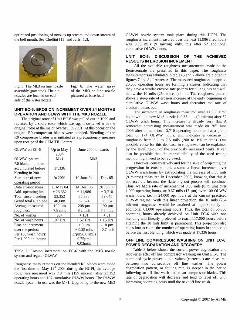
The Mk3 nozzle is a LPLF, low-pressure low-flow, system operated at 4 bar (58 psi), water and air pressure; see figures 5 and 6. This flush mounted nozzle design is of the air-assisted type, with a flat-profile water spray that is shielded and sandwiched between two high velocity flat-profile air sprays. These dual air sprays protect the water droplets and punch them through the boundary layer and into the main air stream. Water droplets are protected from premature deflection, and a longer penetration trajectory is thereby enabled together with an excellent spatial distribution of these droplets. In practice this means that the Mk3 on line nozzle can deliver a more controlled and stable water spray pattern into the air inlet stream, which will improve wetting and cleaning performance.
Comparative tests of the Mk3 nozzle in a laboratory environment, placed horizontally at 1.2 m above ground, showed that when operated in the conventional way without air and under atmospheric condition the water spray wetted a surface at a distance between 0.8 and 2 meter. When air assisted, the same spray wetted a surface between 0.8 to 4.5 m. One major and important characteristic is that the atomized droplet size remains the same, with or without air assistance. The fine water droplets and their spatial distribution make it possible to use a reduced amount of water when compared to other nozzle designs and this in turn greatly reduces the potential risk of erosion due to the very low total mass flow and
Copyright © 2007 by ASME
Terms of Use: http://www.asme.org/about-asme/terms-of-use
D
optimized positioning of nozzles up-stream and down-stream of the bell mouth. See Chellini [11] and Jeffs [12].
Fig. 5. The Mk3 on line nozzle Fig. 6. The water spray assembly (patented). The air of the Mk3 on line nozzle nozzles are located on each pictured at base load. side of the water nozzle.
UNIT EC-6: EROSION INCREMENT OVER 24 MONTHS OPERATION AND OLWW WITH THE MK3 NOZZLE
The original rotor of Unit EC-6 was pulled out in 1999 and replaced by a spare rotor which was again switched with the original rotor at the major overhaul in 2001. At this occasion the original R0 compressor blades were blended. Blending of the R0 compressor blades was initiated as a precautionary measure upon receipt of the OEM TIL Letters.
OLWW on EC-6 OLWW system:
Up to May 2004 Mk1
June 2004 onwards
Mk3 R0 blade; op. hours accumulated before blending in 2001
17,336
Start date of new operating period
In 2001 10 June 04 Dec. 05
Date erosion meas. Add. operating hrs. Total since blending Grand total R0 blade
11 May 04 + 23,352 23,352 40,688
14 Dec. 05 + 11,986 35,338 52,674
30 Jun 06 + 3,710 39,048 56,384
Average measured roughness
199 µm 7.8 mils
208 µm 8.2 mils
190 µm 7.5 mils
No. of washes 384 + 181 + 51 No. of wash hours 107 Hrs. + 52 Hrs. + 15 Hrs. Erosion increment over the period: Per 100 wash hours: Per 1,000 op. hours:
+ 9 µm + 0.35 mils
17µm/0.67mils 0.75µm/ 0.03mils
- 18 µm - 0.7 mils
Table 7. Erosion increment on EC-6 with the Mk3 nozzle system and regular OLWW. Roughness measurements on the blended R0 blades were made the first time on May 11th 2004 during the HGPI, the average roughness measured was 7.8 mils (199 micron) after 23,352 operating hours and 107 cumulative OLWW hours. The OLWW nozzle system in use was the Mk1. Upgrading to the new Mk3
7
ownloaded From: http://proceedings.asmedigitalcollection.asme.org/ on 02/19/2016
OLWW nozzle system took place during this HGPI. The roughness increment measured over the next 11,986 fired hours was 0.35 mils (9 micron) only, this after 52 additional cumulative OLWW hours.
UNIT EC-6: DISCUSSION OF THE ACHIEVED RESULTS IN EROSION INCREMENT
All the available roughness measurements made at the Eemscentrale are presented in this paper. The roughness measurements as tabulated in tables 5 and 7 above are plotted in figures 7 and 8 of Annex A. The measured roughness at approx. 20,000 operating hours are forming a cluster, indicating that they have a similar erosion rate pattern for all engines and well below the 10 mils (254 micron) limit. The roughness pattern shows a steep rate of erosion increase at the early beginning of cumulative OLWW wash hours and thereafter the rate of erosion flattens out.
The increment in roughness measured over 11,986 fired hours with the new Mk3 nozzle is 0.35 mils (9 micron) after 52 OLWW wash hours. This increase is already very flat. A somewhat contrasting measurement was made on 30th June 2006 after an additional 3,710 operating hours and at a grand total of 174 OLWW hours, and indicates a decrease in roughness from 8.2 to 7.5 mils (208 to 190 micron). One possible cause for this decrease in roughness can be explained by the levelling-out of the previously measured peaks. It can also be possible that the reproducibility of the used testing method might need to be reviewed.
However, conservatively and for the sake of projecting the progression in erosion, let’s assume a linear increment over OLWW wash hours by extrapolating the increase of 0.35 mils (9 micron) measured in December 2005, knowing that this is not accurate because the flattening out process will continue. Thus, we had a rate of increment of 0.03 mils (0.75 µm) over 1,000 operating hours, or 0.67 mils (17 µm) over 100 OLWW wash hours; i.e. in 24,000 op. hours at the current practiced OLWW regime. With this linear projection, the 10 mils (254 micron) roughness would be attained at approximately an additional 61,000 operating hours. Thus, the total of 56,000 operating hours already achieved on Unit EC-6 with one blending and linearly projected to reach 117,000 hours before attaining the 10 mils limit, is paramount. This projection also takes into account the number of operating hours in the period before the first blending, which was made at 17,336 hours.
OFF LINE COMPRESSOR WASHING ON UNIT EC-6, POWER DEGRADATION AND RECOVERY
Table 8 below shows the current power degradation and recoveries after off line compressor washing on Unit EC-6. The combined cycle power output values (corrected) are measured between two consecutive off line washes. The power degradation pattern, or fouling rate, is steeper in the period following an off line wash and clean compressor blades. This rate of degradation will decrease and tend to level off with increasing operating hours until the next off line wash.
Copyright © 2007 by ASME
Terms of Use: http://www.asme.org/about-asme/terms-of-use

Do
Period Oper. Hrs.
P[MW] cor. clean
P[MW] cor. fouled
Power degradation
Jun 04-Jun 05 7,902 359 MW 343 MW 16 MW 4.4% Jun 05-Dec 05 4,083 357 MW 348 MW 9 MW 2.5% Dec 05-Mar 06 1,922 353 MW 343 MW 10 MW 2.8% Table 8. Power degradation and recovery after off line compressor washing.
The main factors affecting power degradation are the site location, the environmental and climatic conditions and the season. The air ambient humidity also can have an important impact on fouling by the amount of water condensation taking place in the air inlet. If the mass flow of condensing water droplets is high, it can have a self-cleaning effect. On the other hand if the condensed water mass flow is low it can enhance stickiness of particles on the blade surfaces and contribute to more fouling. Also the fact that some new earth- and sand- moving industries have entered the vicinity in the last 6 months may have an impact on power degradation.
ON LINE COMPRESSOR WASHING ON UNIT EC-6, IMPROVED NOZZLE SYSTEM PERFORMANCE
To enable a comparison in performance effectiveness between the Mk1 OLWW nozzle system and the new Mk3 OLWW nozzle system, specially developed for large gas turbines, let’s compare the rate of performance degradation over a 1,300 to 1,600 operating hour period after an off line wash made at approx. the same time in the spring/summer of 2006. In this way the comparative data periods have no anti-icing system in operation, and approx. similar atmospheric ambient conditions exist for all three gas turbines. Exact comparison for the same time period and same operating hours could not be made for all three engines because of some technical issues with the weather station signal for EC-5, EC-6 & EC-7 between July 24th and August 25th. Note also that units EC-5 and EC-6 have been washed on line 3 times per week for 17 minutes and unit EC-7 has been washed daily for 20 minutes.
Unit No. OLWW System
EC-5 Mk1
EC-6 Mk3
EC-7 Mk1
No. of nozzles 38 30 38 Mass flow 29.3 l/min 17.6 l/min 29.3 l/min Weekly wash regime 3 x 17 min 3 x 17 min daily 20 min Op. hrs. in the period 1,283 Hrs. 1,683 Hrs. 1,686 Hrs. Power drop in period 14.3 MW 10.9 MW 11 MW Rate of degradation MW per 1,000 Hrs.
11.1 MW 6.5 MW 6.5 MW
Table 9. OLWW system performance comparison between the Mk1 and the novel Mk3 nozzle systems. The above table is very interesting and three important observations can be made:
8
wnloaded From: http://proceedings.asmedigitalcollection.asme.org/ on 02/19/2016
a) Comparing units EC-5 and EC-6, both with the same wash regime - the rate of power degradation with the novel Mk3 nozzle system is about 30 to 40% less than with the Mk1 nozzle system.
b) Comparing units EC-6 and EC-7 - the rate of power degradation is virtually the same for both machines, even though EC-7 with the Mk1 nozzle system has been washed more frequently and at a higher mass flow rate.
c) Comparing units EC-5 and EC-7, both with Mk1 nozzles - the rate of power degradation is almost halved when daily on line washing is performed. This result confirms the comment made by the OEM, that daily water washes are more effective in mitigating performance loss than extended interval washes. It should be noted that when the Mk3 nozzle system was
retro-fitted on unit EC-6 in June 2004 the number of nozzles and total mass flow was selected to mitigate erosion, and to be on the “safe side” because of on-going R0 blade erosion issues on F-class engines. However, in view of the low R0 erosion rates that have been measured on all 5 of the 9-FA units at Eems, there would be in principle room for increasing the injected mass flow and/or to go for a daily and longer on line wash with the Mk3 nozzle; i.e. to achieve even better wash results and further reduced power degradation rate. It is also expected that the observed difference in favor of the Mk3 nozzle would further increase under a more severe fouling scenario.
These results indicate that the novel Mk3 nozzle system is more efficient in washing and removing deposits from compressor blades than the Mk1 nozzle system. Furthermore, the improved performance and reduced risk of erosion confirm that the development objective for the Mk3 nozzle for use in large gas turbines has been accomplished.
CONCLUSIONS It can be stated that roughness and erosion increment on
the R0 blades by compressor on line washing are under control at the Eemshaven combined cycle power plant. The investigation on the R0 compressor blades in Unit EC-6 shows that the erosion increment has flattened out at around 24,000 operating hours at a roughness of 7.8 mils (199 micron) and has remained flat in that range up to the last mold measurement taken at some 39,000 hours after blending of the leading edge and at a grand total of 174 OLWW hours; i.e. at about 56,000 in-service hours of the original blades. This, with substantially increased OLWW cleaning efficiency. Further, and by a conservative projection of the measured increment, this R0 compressor row would reach the 10 mils (254 micron) limitation in roughness at about 117,000 in-service hours with the current practiced wash regime. However, it is expected that the increment in roughness would actually remain flat below that figure.
Copyright © 2007 by ASME
Terms of Use: http://www.asme.org/about-asme/terms-of-use

Furthermore, the evolution of the R0 compressor blade roughness on Unit EC-6 shows also that there would be room for optimisation and in increasing the wash duration without exceeding the 10 mils limitation set by the OEM. However, such measures would need to be pondered with the recommendations issued by the OEM.
The significantly lower rate in power degradation by approx. 30 to 40% with the novel Mk3 as compared to the Mk1 OLWW nozzle system confirms the improved cleaning effectiveness achieved with this new technology for compressor cleaning of large gas turbines.
With this result the Mk3 OLWW system demonstrated and confirmed that it is contributing in mitigating the erosion risk, and that it is much more efficient at placing the cleaning fluid where it does the most good. This in turn is also an important contribution in decreasing the number of necessary blending operations over the life time of the R0 compressor blades. The average unit combined cycle power loss in the range of 2 to 3% over a period of about 4,000 operating hours is the result of the practiced and combined measures of (1) a good and well maintained air filtration system, (2) the implemented but presently reduced regime of on line compressor washing in frequency and duration, (3) an off line compressor washing strategy at earliest opportunity and (4) a well engineered compressor cleaning system which allows Electrabel to achieve the best possible plant performance by mitigating loss of production due to compressor fouling.
ACKNOWLEDGMENTS The authors wish to acknowledge and thank Laborelec and
their specialists and staff involved in all the compressor R0 leading edge mold measurements and their evaluations. See www.laborelec.com. The data collected represent an important contribution for this paper.
Downloaded From: http://proceedings.asmedigitalcollection.asme.org/ on 02/19/20
REFERENCES [1] Pfleger, D., 1998, "Operation Record Of The Large 9-FA
Based CCGTs Built In Europe”, Powergen 1998, Milano, Italy.
[2] Boonstra, K., 2003, "Panel Presentation On Gas Turbine Compressor Washing, Eems Power Plant”, ASME 2003, Atlanta, USA.
[3] Diakunchak, I.S., 1991, "Performance Deterioration In Industrial Gas Turbines," ASME Paper No. 91-GT-228.
[4] Balevic, D., Burger, R., and Forry, D., 2004, “Heavy-Duty Gas Turbine Operating And Maintenance Considerations”, GE Publication GER-3620K.
[5] Tarabrin A. P., Schurovsky V. A., Bodrov A. I., Stalder J. P., 1998, "Influence Of Axial Compressor Fouling On Gas Turbine Unit Performance Based On Different Schemes And With Different Initial Parameters", ASME Paper No. 98-GT-416.
[6] Meher-Homji, C.,B., and Bromley, A., F., 2004, “Gas Turbine Axial Compressor Fouling And Washing”, Proceedings of the 33rd Turbomachinery Symposium, Texas A&M University, pp. 163 to 191.
[7] Stalder, J. P., and van Oosten, P., 1994, “Compressor Washing Maintains Plant Performance and Reduces Cost Of Energy Production”, ASME Paper No. 94-GT-436.
[8] Stalder, J. P., and Sire, J., 2001, “Salt Percolation Through Gas Turbine Air Filtration Systems And Its Contribution To Total Contaminant Level”, ASME Paper JPGC 2001/PWR-19148.
[9] www.epriweb.com/public/ (doc. 1012861.pdf), 2006, “Field Measurement and Root Cause Analysis Dedicated to Investigating GE 7FA/9FA R0 Compressor Blades”, Electric Power Research Institute, July 2006.
[10] Stalder, J. P., 2001, “Gas Turbine Compressor Washing State Of The Art: Field Experiences”, Journal of Engineering for Gas Turbines and Power, April 2001, Vol. 123, pages 363 to 370.
[11] Chellini, R., 2004, “Wash Nozzles Designed For Larger Gas Turbines”, Diesel and Gas Turbine Worldwide Magazine, May 2004.
[12] Jeffs, E., 2003, "Innovative On-Line Wash Nozzle for Large Gas turbines", Turbomachinery International Magazine, May/June 2003.
[13] Tarabrin A. P., Schurovsky V. A., Bodrov A. I., Stalder J. P., 1996, "An Analysis Of Axial Compressor Fouling And A Cleaning Method Of Their Blading", ASME Paper No. 96-GT-363.
ANNEXES Annex A, Figures 7 and 8, Plots with measured R0 compressor blade roughness on leading edge versus OLWW hours and GT operating hours.
9 Copyright © 2007 by ASME
16 Terms of Use: http://www.asme.org/about-asme/terms-of-use

Downl
ANNEX A
MEASURED R0 COMPRESSOR BLADE ROUGHNESS ON LEADING EDGE VERSUS OLWW HOURS AND GT OPERATING HOURS
Figures 7 and 8. Plots for the measured R0 compressor blade roughness on leading edge versus OLWW hours and GT operating hours.
10 Copyright © 2007 by ASME
oaded From: http://proceedings.asmedigitalcollection.asme.org/ on 02/19/2016 Terms of Use: http://www.asme.org/about-asme/terms-of-use