A network-based meta-population approach to model Rift Valley fever epidemics
Upload
technicaluniCategory
view
2download
0
.
i
RIFT VALLEY INSTITUTE OF SCIENCE AND TECHNOLOGY
DEPARTMENT OF ELECTRICAL AND ELECTRONIC
ENGINEERING
(CEE)
INDUSTRIAL MACHINE CONTROL
(IMC)
Lecture Notes
By
Dr. Cliff Orori Mosiori
©2015
.
ii
Contents INTRODUCTION ................................................................................................................................... 1
ELECTRIC MACHINES ........................................................................................................................ 1
Electric Motor ..................................................................................................................................... 1
Principle and Working of Electric Motor .................................................................................................. 2
TOPIC ONE ........................................................................................................................................ 2
D.C MACHINES................................................................................................................................. 2
Principles of D.C machines .................................................................................................................. 2
Construction of D.C machines ............................................................................................................. 2
Frame .................................................................................................................................................. 3
Main poles ........................................................................................................................................... 2
Armature ............................................................................................................................................. 2
Field windings ..................................................................................................................................... 2
Commutator ........................................................................................................................................ 3
Brush and brush holders ...................................................................................................................... 4
Generator E.M.F Equation ................................................................................................................... 1
Methods of Excitation.......................................................................................................................... 1
Torque and power ................................................................................................................................ 2
Voltage and current ............................................................................................................................. 2
Generator Characteristics ..................................................................................................................... 2
Characteristics Series of DC generator ................................................................................................. 6
Characteristics Shunt DC generator...................................................................................................... 7
Characteristics compound generator..................................................................................................... 8
The Efficiency of the DC Motor Increases by: ................................................................................... 10
Motor Characteristics......................................................................................................................... 10
Torque Speed Curves ......................................................................................................................... 10
Direct on line starter ............................................................................................................................ 1
TOPIC TWO: AC MACHINES ............................................................................................................... 2
Induction Motor................................................................................................................................... 2
Principle of operation and comparison to synchronous motors ............................................................. 2
Construction ........................................................................................................................................ 2
Types of rotors .................................................................................................................................... 2

.
iii
Slip ring rotor ...................................................................................................................................... 2
Solid core rotor .................................................................................................................................... 3
Starting of induction motors................................................................................................................. 3
Direct-on-line starting .......................................................................................................................... 3
Wye-Delta starters ............................................................................................................................... 4
Variable-frequency drives .................................................................................................................... 4
Resistance starters ............................................................................................................................... 4
Series Reactor starters.......................................................................................................................... 5
Single Phase induction motor ............................................................................................................... 5
Rotating magnetic field ........................................................................................................................ 6
Description of magnetic field ............................................................................................................... 6
Permanent-split capacitor motor........................................................................................................... 1
Capacitor-start induction motor............................................................................................................ 2
Capacitor-run induction motor ............................................................................................................. 2
Resistance split-phase induction motor ................................................................................................ 3
THREE PHASE INDUCTION MOTOR ................................................................................................. 1
Working Principle of Three Phase Induction Motor ................................................................................. 1
Production of Rotating Magnetic Field ............................................................................................. 1
What is the operating principle of a 3ph induction motor? .................................................................... 2
Production of a rotating magnetic field ................................................................................................ 3
Production of magnetic flux ................................................................................................................. 3
SPEED CONTROL OF THREE PHASE INDUCTION MOTOR ............................................................ 5
The Speed of Induction Motor is changed from Both Stator and Rotor Side .............................. 2
Speed Control from Stator Side .................................................................................................... 2
Speed Control from Rotor Side ..................................................................................................... 4
Electric Motor Controls ....................................................................................................................... 2
Motor Starting ..................................................................................................................................... 2
Motor Protection.................................................................................................................................. 5
Other Motor Protection Devices ........................................................................................................... 6
TOPIC THREE: CONTACTORS ............................................................................................................ 2
CONTACTORS .................................................................................................................................. 2
Applications of Contactors................................................................................................................... 2
.
iv
1. Lighting control ....................................................................................................................... 2
2. Magnetic starter ....................................................................................................................... 3
3. Vacuum contactor .................................................................................................................... 3
How Contactor Controls an Electric Motor .......................................................................................... 3
Topic four ............................................................................................................................................... 1
Preventive Maintenance........................................................................................................................... 1
Controlling Maintenance Hazards ........................................................................................................ 3
Instrumentation systems ......................................................................... Error! Bookmark not defined.
Assemble a simple instrumentation ......................................................... Error! Bookmark not defined.
Signal processing methods ...................................................................... Error! Bookmark not defined.
Data processing elements ........................................................................ Error! Bookmark not defined.

.
1
INTRODUCTION
ELECTRIC MACHINES Electric Motor An electric motor is an electric machine that converts electrical energy into mechanical energy.
In normal motoring mode, most electric motors operate through the interaction between an
electric motor's magnetic field and winding currents to generate force within the motor.
In certain applications, such as in the
transportation industry with traction motors,
electric motors can operate in both motoring
and generating or braking modes to also
produce electrical energy from mechanical
energy.
Found in applications as diverse as industrial
fans, blowers and pumps, machine tools,
household appliances, power tools, and disk
drives, electric motors can be powered by
direct current (DC) sources, such as from
batteries, motor vehicles or rectifiers, or by
alternating current (AC) sources, such as
from the power grid, inverters or generators.
Small motors may be found in electric
watches. The largest of electric motors are
used for ship propulsion, pipeline
compression and pumped-storage
applications with ratings reaching 100
megawatts. Electric motors may be
classified by electric power source type,
internal construction, application, type of
motion output, and so on
Application of electric motors
revolutionized industry. Industrial processes
were no longer limited by power
transmission using line shafts, belts,
compressed air or hydraulic pressure.
Instead every machine could be equipped
with its own electric motor, providing easy
control at the point of use, and improving
power transmission efficiency. Electric
motors applied in agriculture eliminated
human and animal muscle power from such
tasks as handling grain or pumping water.

.
2
Household uses of electric motors reduced
heavy labor in the home and made higher
standards of convenience, comfort and
safety possible.
Working Principle of Electric Motor
An electric motor is a device which converts
electrical energy into mechanical energy. A
common motor works on direct current. So,
it is also called DC motor. When a
rectangular coil carrying current is placed in
a magnetic field, a torque acts on the coil
which rotates it continuously. When the coil
rotates, the shaft attached to it also rotates
and thus it is able to do mechanical work.
.
2
TOPIC ONE
D.C MACHINES
Principles of D.C machines
D.C machines are the electro mechanical energy converters which work from a D.C source and
generate mechanical power or convert mechanical power into a D.C power. In any electric
motor, operation is based on simple electromagnetism. A current-carrying conductor generates a
magnetic field; when this is then placed in an external magnetic field, it will experience a force
proportional to the current in the conductor, and to the strength of the external magnetic field.
Magnetic field in motor
As you are well aware of from playing with magnets as a kid, opposite (North and South)
polarities attract, while like polarities (North and North, South and South) repel. The internal
.
3
configuration of a DC motor is designed to harness the magnetic interaction between a current-
carrying conductor and an external magnetic field to generate rotational motion.
Direction of rotation
Let's start by looking at a simple 2-pole DC
electric motor (here red represents a magnet
or winding with a "North" polarization,
while green represents a magnet or winding
with a "South" polarization). Every DC
motor has six basic parts -- axle, rotor
(armature), stator, commutator, field
magnet(s), and brushes. In most common
DC motors, the external magnetic field is
produced by high-strength permanent
magnets. The stator is the stationary part of
the motor -- this includes the motor casing,
as well as two or more permanent magnet
pole pieces. The rotor (together with the
axle, and attached commutator) rotate with
respect to the stator. The rotor consists of
windings (generally on a core), the windings
being electrically connected to the
commutator.

.
1
Torque in motor
The geometry of the brushes, commutator
contacts, and rotor windings are such that
when power is applied, the polarities of the
energized winding and the stator magnet(s)
are misaligned, and the rotor will rotate until
it is almost aligned with the stator's field
magnets. As the rotor reaches alignment, the
brushes move to the next commutator
contacts, and energize the next winding.
Given our example two-pole motor, the
rotation reverses the direction of current
through the rotor winding, leading to a "flip"
of the rotor's magnetic field, driving it to
continue rotating.DC motors will always
have more than two poles. This avoids "dead
spots" in the commutator. With a two-pole
motor, there is a moment where the
commutator shorts out the power supply.

.
2
This would be bad for the power supply,
waste energy, and damage motor
components as well. Yet another
disadvantage of such a simple motor is that
it would exhibit a high amount of torque
"ripple".
Current in Motor
Force in Motor
.
2
You'll notice that one pole is fully energized
at a time (but two others are "partially"
energized). As each brush transitions from
one commutator contact to the next, one
coil's field will rapidly collapse, as the next
coil's field will rapidly charge up. You can
see that this is a direct result of the coil
windings' series wiring. There's probably no
better way to see how an average DC motor
is put together, than by just opening one up.
This is a basic 3-pole DC motor, with 2
brushes and three commutator contacts. The
use of an iron core armature is quite
common, and has a number of advantages.
First off, the iron core provides a strong,
rigid support for the windings -- a
particularly important consideration for
high-torque motors. The core also conducts
heat away from the rotor windings, allowing
the motor to be driven harder than might
otherwise be the case. Iron core construction
is also relatively inexpensive compared with
other construction types.
But iron core construction also has several
disadvantages. The iron armature has a
relatively high inertia which limits motor
acceleration. This construction also results
in high winding inductances which limit
brush and commutator life.
In small motors, an alternative design is
often used which features a 'coreless'
armature winding. This design depends upon
the coil wire itself for structural integrity. As
a result, the armature is hollow, and the
permanent magnet can be mounted inside
the rotor coil. Coreless DC motors have
much lower armature inductance than iron-
core motors of comparable size, extending
brush and commutator life. DC motors have
been used in industrial applications for
years. Coupled with a DC drive, DC motors
provide very precise control DC motors can
be used with conveyors, elevators, extruders,
marine applications, material handling,
paper, plastics, rubber, steel, and textile
applications to name a few.

.
1
Figure 1 - DC motor in schematic form
Standard DC motors are readily available in
one of two main forms:
Wound-field - where the magnetic flux in
the motor is controlled by the current
flowing in a field or excitation winding,
usually located on the stator.
Permanent magnet - where the magnetic
flux in the motor is created by permanent
magnets which have a curved face to create
a constant air-gap to the conventional
armature, located on the rotor. These are
commonly used at powers up to
approximately 3 kW.
Torque in a DC motor is produced by the
product of the magnetic field created by the
field winding or magnets and the current
flowing in the armature winding. The action
of a mechanical commutator switches the
armature current from one winding to
another to maintain the relative position of
the current to the field, thereby producing
torque independent of rotor position.

.
2
The circuit of a shunt-wound DC motor
(Fig. 2 below) shows the armature M, the
armature resistance Ra and the field
winding. The armature supply voltage Va is
supplied typically from a controlled thyristor
system and the field voltage Vf from a
separate bridge rectifier.
Figure 2 -Shunt wound DC motor
As the armature rotates, an electromotive
force (emf ) Ea is induced in the armature
circuit and is called the back-emf since it
opposes the applied voltage Va (according to
Lenz’s Law). The Ea is related to armature
speed and main field flux, φ by:
Ea = k1nφ (1)
where n is the speed of rotation, φ is the
field flux and k1 is a motor constant. From
Figure 1 it is seen that the terminal armature
voltage Va is given by:
Va = Ea + IaRa (2)
Multiplying each side of eqn 2 by Ia gives:
VaIa = EaIa + Ia2Ra (3)
(or total power supplied = power output +
armature losses). The interaction of the field
flux and armature flux produces an armature
torque as given in below equation 4.
Torque M = k2IfIa (4)
where k2 is a motor constant and If is the
field current. This confirms the straight-
forward and linear characteristic of the DC
motor and consideration of these simple
equations will show its controllability and
inherent stability. The characteristic of a
motor is represented by curves of speed
against input current or torque and its shape
can be derived from eqns 1 and 2:
k1nφ = Va – (IaRa) (5)
If the flux is held constant by holding the
field current constant in a properly
compensated motor then:
n = k2[Va – (IaRa)] (6)
From eqns 4 and 6, it follows that full
control of the DC motor can be achieved
through control of the field current and the
armature current. In the DC shunt wound
motor shown in Figure 2 these currents can
be controlled independently. Most industrial

.
3
DC motor controllers or drives are voltage
fed and the current is controlled by
measuring the current and adjusting the
voltage to give the desired current. This
basic arrangement is shown in Figure 3.
The series DC motor shown in Figure 4 has
the field and armature windings connected
in series. In this case the field current and
armature current are equal and show
characteristically different performance
results, though still defined by eqns. 4 and 6.
In the shunt motor the field flux φ is only
slightly affected by armature current, and
the value of IaRa at full load rarely exceeds
5 per cent of Va, giving a torque - speed
curve shown as a in Figure 6, where speed
remains constant over a wide range of load
torque.
The compound-wound DC motor shown in
Figure 5 combines both shunt and series
characteristics. The shape of the torque–
speed characteristic is determined by the
resistance values of the shunt and series
fields. The slightly drooping characteristic
(curve b in Figure 6) has the advantage in
many applications of reducing the
mechanical effects of shock loading.
Figure 3 - Control structure for a shunt wound DC motor

.
2
The series DC motor curve (in Figure 6) shows that the initial flux increases in proportion to
current, falling away due to magnetic saturation. In addition the armature circuit includes the
resistance of the field winding and the speed becomes roughly inversely proportional to the
current. If the load falls to a low value the speed increases dramatically, which may be
hazardous, so, the series motor should not normally be used where there is a possibility of load
loss.
Figure 4 - Schematic of series DC motor
But because it produces high values of torque at low speed and its characteristic is falling speed
with load increase, it is useful in applications such as traction and hoisting, and some mixing
duties where initial stiction is dominant. Under semiconductor converter control with speed
feedback from a tachogenerator, the shape of the speed–load curve is determined within the
controller. It has become standard to use a shunt DC motor with converter control even though
the speed-load curve, when under open-loop control is often slightly drooping. The power-speed
limit for the DC motor is approximately 3 × 10⁶ kW rev/min, due to restrictions imposed by the
commutator.
Construction of D.C machines A D.C machine consists mainly of two part the stationary part called stator and the rotating part
called rotor. The stator consists of main poles used to produce magnetic flux ,commutating poles
or interpoles in between the main poles to avoid sparking at the commutator but in the case of
small machines sometimes the interpoles are avoided and finally the frame or yoke which forms
the supporting structure of the machine. The rotor consist of an armature a cylindrical metallic
body or core with slots in it to place armature windings or bars, a commutator and brush gears
.
3
The magnetic flux path in a motor or generator is show below and it is called the magnetic
structure of generator or motor. The major parts can be identified as,
1. Frame
2. Yoke
3. Poles Institute of Technology Madras
4. Armature
5. Commutator and brush gear
6. Commutating poles
7. Compensating winding
8. Other mechanical parts
Frame Frame is the stationary part of a machine on
which the main poles and commutator poles
are bolted and it forms the supporting
structure by connecting the frame to the bed
plate. The ring shaped body portion of the
frame which makes the magnetic path for the
magnetic fluxes from the main poles and
interpoles is called Yoke.
Why we use cast steel instead of cast iron
for the construction of Yoke?
In early days Yoke was made up of cast iron
but now it is replaced by cast steel. This is
because cast iron is saturated by a flux density
of 0.8 Wb/sq.m whereas saturation with cast
iron steel is about 1.5 Wb/sq.m. So for the
same magnetic flux density the cross section
area needed for cast steel is less than cast iron
hence the weight of the machine too. If we use
cast iron there may be chances of blow holes
in it while casting.so now rolled steels are
developed and these have consistent magnetic
and mechanical properties.

.
2
End Shields or Bearings
If the armature diameter does not exceed 35
to 45 cm then in addition to poles end shields
or frame head with bearing are attached to
the frame. If the armature diameter is greater
than 1m pedestals type bearings are mounted
on the machine bed plate outside the frame.
These bearings could be ball or roller type
but generally plain pedestals bearings are
employed. If the diameter of the armature is
large a brush holder yoke is generally fixed
to the frame.
Main poles Solid poles of fabricated steel with
separate/integral pole shoes are fastened to
the frame by means of bolts. Pole shoes are
generally laminated. Sometimes pole body
and pole shoe are formed from the same
laminations. The pole shoes are shaped so as
to have a slightly increased air gap at the tips.
Inter-poles are small additional poles located
in between the main poles. These can be
solid, or laminated just as the main poles.
These are also fastened to the yoke by bolts.
Sometimes the yoke may be slotted to receive
these poles. The inter poles could be of
tapered section or of uniform cross section.
These are also called as commutating poles
or com poles. The width of the tip of the com
pole can be about a rotor slot pitch.
Armature The armature is where the moving
conductors are located. The armature is
constructed by stacking laminated sheets of
silicon steel. Thickness of these lamination is
kept low to reduce eddy current losses. As
the laminations carry alternating flux the
choice of suitable material, insulation coating
on the laminations, stacking it etc are to be
done more carefully. The core is divided into
packets to facilitate ventilation. The winding
cannot be placed on the surface of the rotor
due to the mechanical forces coming on the
same. Open parallel sided equally spaced
slots are normally punched in the rotor
laminations. These slots house the armature
winding. Large sized machines employ a
spider on which the laminations are stacked
in segments. End plates are suitably shaped
so as to serve as ’Winding supporters’.
Armature construction process must ensure
provision of sufficient axial and radial ducts
to facilitate easy removal of heat from the
armature winding.
Field windings In the case of wound field machines (as
against permanent magnet excited machines)
the field winding takes the form of a
concentric coil wound around the main poles.
These carry the excitation current and

.
3
produce the main field in the machine. Thus
the poles are created electromagnetically.
Two types of windings are generally
employed. In shunt winding large number of
turns of small section copper conductor isof
Technology Madras used. The resistance of
such winding would be an order of
magnitude larger than the armature winding
resistance. In the case of series winding a few
turns of heavy cross section conductor is
used. The resistance of such windings is low
and is comparable to armature resistance.
Some machines may have both the windings
on the poles. The total ampere turns required
to establish the necessary flux under the poles
is calculated from the magnetic circuit
calculations. The total mmf required is
divided equally between north and south
poles as the poles are produced in pairs. The
mmf required to be shared between shunt and
series windings are apportioned as per the
design requirements. As these work on the
same magnetic system they are in the form of
concentric coils. Mmf ’per pole’ is normally
used in these calculations. Armature winding
As mentioned earlier, if the armature coils
are wound on the surface ofthe armature,
such construction becomes mechanically
weak. The conductors may fly away when
the armature starts rotating. Hence the
armature windings are in general pre-formed,
taped and lowered into the open slots on the
armature. In the case of small machines, they
can be hand wound. The coils are prevented
from flying out due to the centrifugal forces
by means of bands of steel wire on the
surface of the rotor in small groves cut into it.
In the case of large machines slot wedges are
additionally used to restrain the coils from
flying away. The end portion of the windings
are taped at the free end and bound to the
winding carrier ring of the armature at the
commutator end. The armature must be
dynamically balanced to reduce the
centrifugal forces at the operating speeds.
Compensating winding One may find a bar
winding housed in the slots on the pole shoes.
This is mostly found in D.C machines of very
large rating. Such winding is called
compensating winding. In smaller machines,
they may be absent.
Commutator Commutator is the key element which made
the D.C machine of the present day possible.
It consists of copper segments tightly
fastened together with mica/micanite
insulating separators on an insulated base.
The whole commutator forms a rigid and
solid assembly of insulated copper strips and
can rotate at high speeds. Each com mutator

.
4
segment is provided with a ’riser’ where the
ends of the armature coils get connected. The
surface of the commutator is machined and
surface is made concentric with the shaft and
the current collecting brushes rest on the
same. Under-cutting the mica insulators that
are between these commutator segments has
to be done periodi- cally to avoid fouling of
the surface of the commutator by mica when
the commutator gets worn out.
Brush and brush holders Brushes rest on the surface of the
commutator. Normally electro-graphite is
used as brush material. The actual
composition of the brush depends on the
peripheral speed of the commutator and the
working voltage. The hardness of the
graphite brush is selected to be lower than
that of the commutator. When the brush
wears out the graphite works as a solid
lubricant reducing frictional coefficient.
More number of relatively smaller width
brushes is preferred in place of large broad
brushes. The brush holders provide slots for
the brushes to be placed. The connection
Brush holder with a Brush and Positioning of
the brush on the commutator from the brush
is taken out by means of flexible pigtail. The
brushes are kept pressed on the commutator
with the help of springs. This is to ensure
proper contact between the brushes and the
commutator even under high speeds of
operation. Jumping of brushes must be
avoided to ensure arc free current collection
and to keep the brush contact drop low. Other
mechanical parts End covers, fan and shaft
bearings form other important me- chanical
parts. End covers are completely solid or
have opening for ventilation. They support
the bearings which are on the shaft. Proper
machining is to be ensured for easy
assembly. Fans can be external or internal. In
most machines the fan is on the non-
commutator end sucking the air from the
commutator end and throwing the same out.
Adequate quantity of hot air removal has to
be ensured.
Bearings Small machines employ ball
bearings at both ends. For larger machines
roller bearings are used especially at the
driving end. The bearings are mounted press-
fit on the shaft. They are housed inside the
end shield in such a manner that it is not
necessary to remove the bearings from the
shaft for dismantling.

.
1
Generator E.M.F Equation Let Φ = flux/pole in weber Z = total number
of armture conductors = No.of slots x No.of
conductors/slot P = No.of generator poles A
= No.of parallel paths in armature N =
armature rotation in revolutions per minute
(r.p.m) E = e.m.f induced in any parallel path
in armature Generated e.m.f Eg = e.m.f
generated in any one of the parallel paths i.e
E. Average e.m.f geneated /conductor =
dΦ/dt volt (n=1) Now, flux cut/conductor in
one revolution dΦ = ΦP Wb No. of
revolutions/second = N/60 Time for one
revolution, dt = 60/N second Hence,
according to Faraday's Laws of
Electromagnetic Induction, E.M.F
generated/conductor is
For a simplex wave-wound generator No.
of parallel paths = 2 No. of conductors (in
series) in one path = Z/2 E.M.F.
generated/path is
For a simplex lap-wound generator
No.of parallel paths = P No.of conductors (in
series) in one path = Z/P
E.M.F.generated/path
In general generated e.m.f
where A = 2 - for simplex wave-winding A
= P - for simplex lap-winding
Methods of Excitation Various methods of excitation of the field windings are shown in Fig.

.
2
Figure shows Field-circuit connections of dc machines: (a) separate excitation, (b) series, (c) shunt, (d) compound.
Consider first dc generators.
Separately-excited generators and Self-
excited generators: series generators, shunt
generators, compound generators.
With self-excited generators, residual
magnetism must be present in the machine
iron to get the self-excitation process started.
o N.B.: long- and short-shunt, cumulatively
and differentially compound.
Typical steady-state volt-ampere
characteristics are shown in Fig.7.5,
constant-speed operation being assumed.
The relation between the steady-state
generated emf Ea and the armature terminal
voltage Va is Va =Ea −IaRa (7.10)
Figure Volt-ampere characteristics of dc
generators. Any of the methods of excitation
used for generators can also be used for
motors.
Typical steady-state dc-motor speed-
torque characteristics are shown in Fig.7.6,
in which it is assumed that the motor
terminals are supplied from a constant-
voltage source.

.
2
In a motor the relation between the emf
Ea generated in the armature and and the
armature terminal voltage Va is
Va=Ea+IaRa (7.11)
The application advantages of dc
machines lie in the variety of performance
characteristics offered by the possibilities of
shunt, series, and compound excitation.
Figure Speed-torque characteristics of dc
motors.
Torque and power The electromagnetic torque Tmech,
Tmech =KaΦdIa
The generated voltage, Ea
Ea =KaΦdωm
Voltage and current Va: the terminal voltage of the armature
winding Vt: the terminal voltage of the dc
machine, including the voltage drop across
the series connected field winding,
Va = Vt
if there is no series field winding Ra: the
resistance of armature, Rs: the resistance of
the series field,
Va =Ea ± IaRa
Vt=Ea ± Ia( Ra+Rs) IL
=Ia±If
Generator Characteristics The three most important characteristics or curves of a d.c generator are;
1. Open Circuit Characteristic (O.C.C.)
This curve shows the relation between the
generated e.m.f. at no-load (E0) and the field
current (If) at constant speed. It is also
known as magnetic characteristic or no-load
saturation curve. Its shape is practically the
same for all generators whether separately or
self-excited. The data for O.C.C. curve are
obtained experimentally by operating the
generator at no load and constant speed and
recording the change in terminal voltage as
the field current is varied.

.
2
2. Internal or Total characteristic (E/Ia)
This curve shows the relation between the
generated e.m.f. on load (E) and the
armature current (Ia). The e.m.f. E is less
than E0 due to the demagnetizing effect of
armature reaction. Therefore, this curve will
lie below the open circuit characteristic
(O.C.C.). The internal characteristic is of
interest chiefly to the designer. It cannot be
obtained directly by experiment. It is
because a voltmeter cannot read the e.m.f.
generated on load due to the voltage drop in
armature resistance. The internal
characteristic can be obtained from external
characteristic if winding resistances are
known because armature reaction effect is
included in both characteristics.
3. External characteristic (V/IL)
This curve shows the relation between the
terminal voltage (V) and load current (IL).
The terminal voltage V will be less than E
due to voltage drop in the armature circuit.
Therefore, this curve will lie below the
internal characteristic. This characteristic is
very important in determining the suitability
of a generator for a given purpose. It can be
obtained by making simultaneous;
1. No-load saturation characteristic
(E0/If)
It is also know as Magnetic
characteristic or Open circuit
Characteristic (O.C.C). It shows the
relation between the no-load
generated e.m.f in armature, E0 and
the field or exciting current If at a
given fixed speed. It is just the
magnetisation curve for the material
of the electromagnets. Its shape is
practically the same for all
generators whether separately-
excited or self-excited.
A typical no load saturation curve is shown
in Figure. It has generator output voltage
plotted against field current. The lower
straight line portion of the curve represents
the air gap because the magnetic parts are
not saturated. When the magnetic parts start
to saturate, the curve bends over until

.
3
complete saturation is reached. Then the
curve becomes a straight line again.
2. Separately-excited Generator
The No-load saturation curve of a separately
excited generator will be as shown in the
above figure. It is obvous that when If is
increased from its initial small value, the
flux and hence generated e.m.f Eg increase
directly as current so long as the poles are
unsaturated. This is represented by straight
portion in figure. But as the flux density
increases, the poles become saturated, so a
greater increase If is required to produce a
given increase in voltage than on the lower
part of the curve. That is why the upper
portion of the curve bends.
The O.C.C curve for self-excited generators
whether shunt or series wound is shown in
above figure. Due to the residual magnetism
in the poles, some e.m.f (= OA) is generated
even when If =0.Hence, the curve starts a
little way up. The slight curvature at the
lower end is due to magnetic inertia. It is
seen that the first part of the curve is
practically straight. This is due to fact that at
low flux densities reluctance of iron path
being negligible, total reluctance is given by
the air gap reluctance which is constant.
Hence, the flux and consequently, the
generated e.m.f is directly proportional to
the exciting current. However, at high flux
densities, where μ is small, iron path
reluctance becomes appreciable and straight
relation between E and If no longer holds
good. In other words, after point B,
saturation of pole starts. However, the initial
slope of the curve is determined by air-gap
width. O.C.C for higher speed would lie
above this curve and for lower speed, would
lie below it.
Separately-excited Generator Let us
consider a separately-excited generator
giving its rated no-load voltage of E0 for a
certain constant field current. If there were
no armature reaction and armature voltage
drop, then this voltage would have remained
constant as shown in figure by the horizontal
line 1. But when the generator is loaded, the
voltage falls due to these two causes,

.
4
thereby giving slightly dropping
characteristics. If we subtract from E0 the
values of voltage drops due to armature
reaction for different loads, then we get the
value of E-the e.m.f actually induced in the
armature under load conditions. Curve 2 is
plotted in this way and is known as the
internal characteristic.
Series Generator
In this generator, because field windings are
in series with the armature, they carry full
armature current Ia. As Ia is increased, flux
and hence generated e.m.f. is also increased
as shown by the curve. Curve Oa is the
O.C.C. The extra exciting current necessary
to neutralize the weakening effect of
armature reaction at full load is given by the
horizontal distance ab. Hence, point b is on
the internal characteristic. 3. External
characteristic (V/I) It is also referred to as
performance characteristic or sometimes
voltage-regulating curve. It gives relation
between the terminal voltage V and the load
current I. This curve lies below the internal
characteristic because it takes in to account
the voltage drop over the armature circuit
resistance.
The values of V are obtained by subtracting
IaRa from corresponding values of E. This
characteristic is of great importance in
judging the suitability of a generator for a
particular purpose. It may be obtained in two
ways (i) by making simultaneous
measurements with a suitable voltmeter and
an ammeter on a loaded generator or (ii)
graphically from the O.C.C provided the
armature and field resistances are known
and also if the demagnetizing effect or the
armature reaction is known.
.
5
Figure above shows the external
characteristic curves for generators with
various types of excitation. If a generator,
which is separately excited, is driven at
constant speed and has a fixed field current,
the output voltage will decrease with
increased load current as shown. This
decrease is due to the armature resistance
and armature reaction effects. If the field
flux remained constant, the generated
voltage would tend to remain constant and
the output voltage would be equal to the
generated voltage minus the IR drop of the
armature circuit.
However, the demagnetizing component of
armature reactions tends to decrease the
flux, thus adding an additional factor, which
decreases the output voltage. In a shunt
excited generator, it can be seen that the
output voltage decreases faster than with
separate excitation. This is due to the fact
that, since the output voltage is reduced
because of the armature reaction effect and
armature IR drop, the field voltage is also
reduced which further reduces the flux. It
can also be seen that beyond a certain
critical value, the shunt generator shows a
reversal in trend of current values with
decreasing voltages. This point of maximum
current output is known as the breakdown
point. At the short circuit condition, the only
flux available to produce current is the
residual magnetism of the armature.
To build up the voltage on a series
generator, the external circuit must be
connected and its resistance reduced to a
comparatively low value. Since the armature
is in series with the field, load current must
be flowing to obtain flux in the field. As the
voltage and current rise the load resistance
may be increased to its normal value. As the
external characteristic curve shows, the
voltage output starts at zero, reaches a peak,
and then falls back to zero.
The combination of a shunt field and a series
field gives the best external characteristic as
illustrated in Figure. The voltage drop,
which occurs in the shunt machine, is
compensated for by the voltage rise, which
.
6
occurs in the series machine. The addition of
a sufficient number of series turns offsets
the armature IR drop and armature reaction
effect, resulting in a flat-compound
generator, which has a nearly constant
voltage. If more series turns are added, the
voltage may rise with load and the machine
is known as an over-compound generator.
The speed of a D.C machine operated as a
generator is fixed by the prime mover.
For general-purpose operation, the prime
mover is equipped with a speed governor so
that the speed of the generator is practically
constant. Under such condition, the
generator performance deals primarily with
the relation between excitation, terminal
voltage and load. These relations can be best
exhibited graphically by means of curves
known as generator characteristics. These
characteristics show at a glance the
behaviour of the generator under different
load conditions.
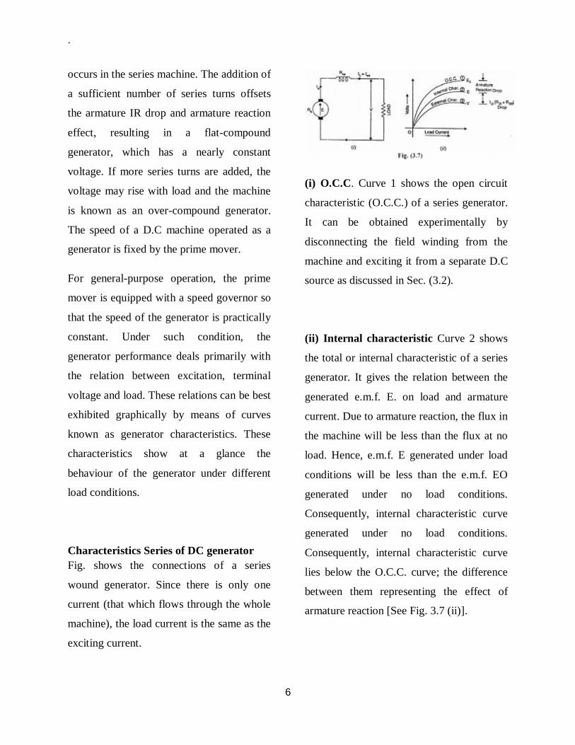
Characteristics Series of DC generator Fig. shows the connections of a series
wound generator. Since there is only one
current (that which flows through the whole
machine), the load current is the same as the
exciting current.
(i) O.C.C. Curve 1 shows the open circuit
characteristic (O.C.C.) of a series generator.
It can be obtained experimentally by
disconnecting the field winding from the
machine and exciting it from a separate D.C
source as discussed in Sec. (3.2).
(ii) Internal characteristic Curve 2 shows
the total or internal characteristic of a series
generator. It gives the relation between the
generated e.m.f. E. on load and armature
current. Due to armature reaction, the flux in
the machine will be less than the flux at no
load. Hence, e.m.f. E generated under load
conditions will be less than the e.m.f. EO
generated under no load conditions.
Consequently, internal characteristic curve
generated under no load conditions.
Consequently, internal characteristic curve
lies below the O.C.C. curve; the difference
between them representing the effect of
armature reaction [See Fig. 3.7 (ii)].

.
7
(iii)External characteristic Curve 3 shows
the external characteristic of a series
generator. It gives the relation between
terminal voltage and load current IL.
V= E-Ia(Ra+Rse)
Therefore, external characteristic curve will
lie below internal characteristic curve by an
amount equal to ohmic drop [i.e.,
Ia(Ra+Rse)] in the machine as shown in Fig.
(3.7) (ii). The internal and external
characteristics of a D.C series generator can
be plotted from one another as shown in Fig.
(3.8). Suppose we are given the internal
characteristic of the generator. Let the line
OC represent the resistance of the whole
machine i.e. Ra+Rse.If the load current is
OB, drop in the machine is AB i.e.
AB = Ohmic drop in the machine =
OB(Ra+Rse)
Now raise a perpendicular from point B and
mark a point b on this line such that ab =
AB. Then point b will lie on the external
characteristic of the generator. Following
similar procedure, other points of external
characteristic can be located. It is easy to see
that we can also plot internal characteristic
from the external characteristic.
Characteristics Shunt DC generator Fig (3.9) (i) shows the connections of a
shunt wound generator. The armature
current Ia splits up into two parts; a small
fraction Ish flowing through shunt field
winding while the major part IL goes to the
external load.
I. O.C.C. The O.C.C. of a shunt
generator is similar in shape to that of a
series generator as shown in Fig. (3.9)
(ii). The line OA represents the shunt
field circuit resistance. When the
generator is run at normal speed, it will
build up a voltage OM. At no-load, the
terminal voltage of the generator will be
.
8
constant (= OM) represented by the
horizontal dotted line MC.
II) Internal characteristic When the
generator is loaded, flux per pole is reduced
due to armature reaction. Therefore, e.m.f. E
generated on load is less than the e.m.f.
generated at no load.As a result, the internal
characteristic (E/Ia) drops down slightly as
shown in Fig.(3.9) (ii).
(iii)External characteristic Curve 2 shows
the external characteristic of a shunt
generator. It gives the relation between
terminal voltage V and load current IL. V =
E – IaRa = E -(IL +Ish)Ra Therefore,
external characteristic curve will lie below
the internal characteristic curve by an
amount equal to drop in the armature circuit
[i.e., (IL +Ish)Ra ] as shown in Fig. (3.9)
(ii). Note. It may be seen from the external
characteristic that change in terminal voltage
from no-load to full load is small. The
terminal voltage can always be maintained
constant by adjusting the field rheostat R
automatically
External Resistance for Shunt Generator
f the load resistance across the terminals of a
shunt generator is decreased, then load
current increase? However, there is a limit to
the increase in load current with the
decrease of load resistance. Any decrease of
load resistance beyond this point, instead of
increasing the current, ultimately results in
reduced current. Consequently, the external
characteristic turns back (dotted curve) as
shown in Fig. (3.10). The tangent OA to the
curve represents the minimum external
resistance required to excite the shunt
generator on load and is called critical
external resistance. If the resistance of the
external circuit is less than the critical
external resistance (represented by tangent
OA in Fig. 3.10), the machine will refuse to
excite or will de-excite if already running
This means that external resistance is so low
as virtually to short circuit the machine and
so doing away with its excitation.
Note. There are two critical resistances for a
shunt generator viz., (i) critical field
resistance (ii) critical external resistance. For
the shunt generator to build up voltage, the
former should not be exceeded and the latter
must not be gone below
Characteristics compound generator In a compound generator, both series and
shunt excitation are combined as shown in
Fig. (3.13). The shunt winding can be
connected either across the armature only

.
9
(short-shunt connection S) or across
armature plus series field (long-shunt
connection G). The compound generator can
be cumulatively compounded or
differentially compounded generator. The
latter is rarely used in practice. Therefore,
we shall discuss the characteristics of
cumulatively compounded generator. It may
be noted that external characteristics of long
and short shunt compound generators are
almost identical.
External characteristic
Fig. (3.14) shows the external characteristics
of a cumulatively compounded generator.
The series excitation aids the shunt
excitation. The degree of compounding
depends upon the increase in series
excitation with the increase in load current.
(i).If series winding turns are so adjusted
that with the increase in load current the
terminal voltage increases, it is called over-
compounded generator. In such a case, as
the load current increases, the series field
m.m.f. increases and tends to increase the
flux and hence the generated voltage. The
increase in generated voltage is greater than
the IaRa drop so that instead of decreasing,
the terminal voltage increases as shown by
curve A in Fig. (3.14).
(ii) If series winding turns are so
adjusted that with the increase in load
current, the terminal voltage
substantially remains constant, it is
called flat-compounded generator. The
series winding of such a machine has
lesser number of turns than the one in
over-compounded machine and,
therefore, does not increase the flux as
much for a given load current.
Consequently, the full-load voltage is
nearly equal to the no-load voltage as
indicated by curve B in Fig (3.14).
(iii) If series field winding has lesser
number of turns than for a flat
compounded machine, the terminal
voltage falls with increase in load
current as indicated by curve C m Fig.
(3.14). Such a machine is called under-
compounded generator.

.
10
Voltage Regulation
The change in terminal voltage of a
generator between full and no load (at
constant speed) is called the voltage
regulation, usually expressed as a percentage
of the voltage at full-load. % Voltage
regulation= [(VNL-VFL)/VFL] × 100 where
VNL = Terminal voltage of generator at no
load VFL = Terminal voltage of generator at
full load Note that voltage regulation of a
generator is determined with field circuit
and speed held constant. If the voltage
regulation of a generator is 10%, it means
that terminal voltage increases 10% as the
load is changed from full load to no load.
The Efficiency of the DC Motor Increases
by:
Increasing number of turns in the coil
Increasing the strength of the current
Increasing X-section area of of the coil
Increasing the strength of the radial
magnetic field
Motor Characteristics
Torque Speed Curves In order to effectively design with D.C
motors, it is necessary to understand their
characteristic curves. For every motor, there
is a specific Torque/Speed curve and Power
curve.
The graph above shows a torque/speed curve
of a typical D.C motor. Note that torque is
inversely proportional to the speed of the
output shaft. In other words, there is a
tradeoff between how much torque a motor
delivers, and how fast the output shaft spins.
Motor characteristics are frequently given as
two points on this graph:
The stall torque,, represents the point on
the graph at which the torque is a maximum,
but the shaft is not rotating.
The no load speed,, is the maximum
output speed of the motor (when no torque is
applied to the output shaft).
The linear model of a D.C motor
torque/speed curve is a very good
approximation. The torque/speed curves
shown below are actual curves for the green
maxon motor (pictured at right) used by

.
11
students in 2.007. One is a plot of empirical
data, and the other was plotted mechanically
using a device developed at MIT. Note that
the characteristic torque/speed curve for this
motor is quite linear.
This is generally true as long as the curve
represents the direct output of the motor, or
a simple gear reduced output. If the
specifications are given as two points, it is
safe to assume a linear curve.
Recall that earlier we defined power as the
product of torque and angular velocity. This
corresponds to the area of a rectangle under
the torque/speed curve with one corner at
the origin and another corner at a point on
the curve. Due to the linear inverse
relationship between torque and speed, the
maximum power occurs at the point where τ
= ½ , and = ½ .

.
12
By substituting equations 3. and 4. into equation 2 above, we see that the power curves for a D.C
motor with respect to both speed and torque are quadratics, as shown in equations 5. and 6. From
these equations, we again find that maximum output power occurs at = ½, and = ½ respectively.

.
1
Direct on line starter In electrical engineering, a direct on line
(DOL) or across the line starter starts
electric motors by applying the full line
voltage to the motor terminals. This is the
simplest type of motor starter. A DOL motor
starter also contain protection devices, and
in some cases, condition monitoring.
Smaller sizes of direct on-line starters are
manually operated; larger sizes use an
electromechanical contactor (relay) to
switch the motor circuit. Solid-state direct
on line starters also exist.
A direct on line starter can be used if the
high inrush current of the motor does not
cause excessive voltage drop in the supply
circuit. The maximum size of a motor
allowed on a direct on line starter may be
limited by the supply utility for this reason.
For example, a utility may require rural
customers to use reduced-voltage starters for
motors larger than 10 kW.
DOL starting is sometimes used to start
small water pumps, compressors, fans and
conveyor belts. In the case of an
asynchronous motor, such as the 3-phase
squirrel-cage motor, the motor will draw a
high starting current until it has run up to
full speed. This starting current is commonly
around six times the full load current, but
may as high as 12 times the full load current.

.
2
TOPIC TWO
AC MACHINES
Induction Motor An induction motor or asynchronous motor is a type of alternating current motor where power
is supplied to the rotor by means of electromagnetic induction.
An electric motor converts electrical power
to mechanical power in its rotor (rotating
part). There are several ways to supply
power to the rotor. In a DC motor this power
is supplied to the armature directly from a
DC source, while in an induction motor this
power is induced in the rotating device. An
induction motor is sometimes called a
rotating transformer because the stator
(stationary part) is essentially the primary
side of the transformer and the rotor
(rotating part) is the secondary side.
Unlike the normal transformer which
changes the current by using time varying
flux, induction motors use rotating magnetic
fields to transform the voltage. The primary
side's current creates an electromagnetic
field which interacts with the secondary
side's electromagnetic field to produce a
resultant torque, thereby transforming the
electrical energy into mechanical energy.
Induction motors are widely used, especially
polyphase induction motors, which are
frequently used in industrial drives.
Induction motors are now the preferred
choice for industrial motors due to their
rugged construction, absence of brushes
(which are required in most DC motors)
and—thanks to modern power electronics—
the ability to control the speed of the motor.
Principle of operation and comparison to synchronous motors 3-phase power supply provides a rotating
magnetic field in an induction motor. The
basic difference between an induction motor
and a synchronous AC motor is that in the
latter a current is supplied into the rotor
which in turn creates a magnetic field
around the rotor. The rotating magnetic field
of the stator will impose an electromagnetic
torque on the still magnetic field of the rotor
causing it to move (about a shaft) and
rotation of the rotor is produced. It is called
synchronous because at steady state the

.
2
speed of the rotor is the same as the speed of the rotating magnetic field in the stator.
By way of contrast, the induction motor
does not have any direct supply onto the
rotor; instead, a secondary current is induced
in the rotor. To achieve this, stator windings
are arranged around the rotor so that when
energized with a polyphase supply they
create a rotating magnetic field pattern
which sweeps past the rotor. This changing
magnetic field pattern induces current in the
rotor conductors. These currents interact
with the rotating magnetic field created by
the stator and in effect cause a rotational
motion on the rotor. However, for these
currents to be induced, the speed of the
physical rotor must be less than the speed of
the rotating magnetic field in the stator, or
else the magnetic field will not be moving
relative to the rotor conductors and no
currents will be induced. If by some chance
this happens, the rotor typically slows
slightly until a current is re-induced and then
the rotor continues as before. This difference
between the speed of the rotor and speed of
the rotating magnetic field in the stator is
called slip. It is unitless and is the ratio
between the relative speed of the magnetic
field as seen by the rotor (the slip speed) to
the speed of the rotating stator field. Due to
this an induction motor is sometimes
referred to as an asynchronous machine.
Construction The stator consists of wound 'poles' that
carry the supply current to induce a
magnetic field that penetrates the rotor. In a
very simple motor, there would be a single
.
2
projecting piece of the stator (a salient pole)
for each pole, with windings around it; in
fact, to optimize the distribution of the
magnetic field, the windings are distributed
in many slots located around the stator, but
the magnetic field still has the same number
of north-south alternations. The number of
'poles' can vary between motor types but the
poles are always in pairs (i.e. 2, 4, 6, etc.).
Induction motors are most commonly built
to run on single-phase or three-phase power,
but two-phase motors also exist. In theory,
two-phase and more than three phase
induction motors are possible; many single-
phase motors having two windings and
requiring a capacitor can actually be viewed
as two-phase motors, since the capacitor
generates a second power phase 90 degrees
from the single-phase supply and feeds it to
a separate motor winding. Single-phase
power is more widely available in residential
buildings, but cannot produce a rotating
field in the motor (the field merely oscillates
back and forth), so single-phase induction
motors must incorporate some kind of
starting mechanism to produce a rotating
field. They would, using the simplified
analogy of salient poles, have one salient
pole per pole number; a four-pole motor
would have four salient poles. Three-phase
motors have three salient poles per pole
number, so a four-pole motor would have
twelve salient poles. This allows the motor
to produce a rotating field, allowing the
motor to start with no extra equipment and
run more efficiently than a similar single-
phase motor.
Types of rotors There are three types of rotor:
Squirrel-cage rotor
The most common rotor is a squirrel-cage
rotor. It is made up of bars of either solid
copper (most common) or aluminum that
span the length of the rotor, and those solid
copper or aluminum strips can be shorted or
connected by a ring or sometimes not, i.e.
the rotor can be closed or semi closed type.
The rotor bars in squirrel-cage induction
motors are not straight, but have some skew
to reduce noise and harmonics.
Slip ring rotor
A slip ring rotor replaces the bars of the
squirrel-cage rotor with windings that are
connected to slip rings. When these slip
rings are shorted, the rotor behaves similarly
to a squirrel-cage rotor; they can also be
connected to resistors to produce a high-
resistance rotor circuit, which can be
beneficial in starting.

.
3
Solid core rotor A rotor can be made from solid mild steel.
The induced current causes the rotation.
Speed control
The synchronous rotational speed of the
rotor (i.e. the theoretical unloaded speed
with no slip) is controlled by the number of
pole pairs (number of windings in the stator)
and by the frequency of the supply voltage.
Under load, the induction motor's speed
varies according to size of the load. As the
load is increased the speed of the motor
decreases increasing the slip which increases
the rotor's field strength to bear the extra
load.
Before the development of economical
semiconductor power electronics, it was
difficult to vary the frequency to the motor
and induction motors were mainly used in
fixed speed applications. As an induction
motor has no brushes and is easy to control,
many older DC motors are now being
replaced with induction motors and
accompanying inverters in industrial
applications.
Starting of induction motors
Direct-on-line starting The simplest way to start a three-phase
induction motor is to connect its terminals to
the line. This method is often called "direct
on line" and abbreviated DOL. In an
induction motor, the magnitude of the
induced emf in the rotor circuit is
proportional to the stator field and the slip
speed of the motor, and the rotor current
depends on this emf. When the motor is
started, the rotor speed is zero. The
synchronous speed is constant, based on the
frequency of the supplied AC voltage.
So the slip speed is equal to the synchronous
speed, the slip ratio is 1, and the induced
emf in the rotor is large. As a result, a very
high current flows through the rotor. This is
similar to a transformer with the secondary
coil short circuited, which causes the
primary coil to draw a high current from the
mains. When an induction motor starts
DOL, a very high current is drawn by the
stator, in the order of 5 to 9 times the full
load current. This high current can, in some
motors, damage the windings; in addition,
because it causes heavy line voltage drop,
other appliances connected to the same line
may be affected by the voltage fluctuation.

.
4
To avoid such effects, several other
strategies are employed for starting motors.
Wye-Delta starters An induction motor's windings can be
connected to a 3-phase AC line in two
different ways:
i. wye in U.S, star in Europe,
where the windings are
connected from phases of the
supply to the neutral;
ii. delta (sometimes mesh in
Europe), where the windings are
connected between phases of the
supply.
A delta connection of the machine winding
results in a higher voltage at each winding
compared to a wye connection. A wye-delta
starter initially connects the motor in wye,
which produces a lower starting current than
delta, then switches to delta when the motor
has reached a set speed.
Disadvantages of this method over DOL
starting are:
i. Lower starting torque, which
may be a serious issue with
pumps or any devices with
significant breakaway torque
ii. Increased complexity, as more
contactors and some sort of
speed switch or timers are
needed
iii. Two shocks to the motor (one for
the initial start and another when
the motor switches from wye to
delta)
Variable-frequency drives Variable-frequency drives (VFD) can be of
considerable use in starting as well as
running motors. A VFD can easily start a
motor at a lower frequency than the AC line,
as well as a lower voltage, so that the motor
starts with full rated torque and with no
inrush of current. The rotor circuit's
impedance increases with slip frequency,
which is equal to supply frequency for a
stationary rotor, so running at a lower
frequency actually increases torque.
Resistance starters This method is used with slip ring motors
where the rotor poles can be accessed by
way of the slip rings. Using brushes,
variable power resistors are connected in
series with the poles. During start-up the
resistance is large and then reduced to zero
at full speed. At start-up the resistance

.
5
directly reduces the rotor current and so
rotor heating is reduced. Another important
advantage is the start-up torque can be
controlled. As well, the resistors generate a
phase shift in the field resulting in the
magnetic force acting on the rotor having a
favorable angle.
Series Reactor starters In series reactor starter technology, an
impedance in the form of a reactor is
introduced in series with the motor
terminals, which as a result reduces the
motor terminal voltage resulting in a
reduction of the starting current; the
impedance of the reactor, a function of the
current passing through it, gradually reduces
as the motor accelerates, and at 95 % speed
the reactors are bypassed by a suitable
bypass method which enables the motor to
run at full voltage and full speed. Air core
series reactor starters or a series reactor soft
starter is the most common and
recommended method for fixed speed motor
starting. The applicable standards are [IEC
289] AND [IS 5553 (PART 3)].
Single Phase induction motor In a single phase induction motor, it is
necessary to provide a starting circuit to start
rotation of the rotor. If this is not done,
rotation may be commenced by manually
giving a slight turn to the rotor. The single
phase induction motor may rotate in either
direction and it is only the starting circuit
which determines rotational direction.
For small motors of a few watts the start
rotation is done by means of a single turn of
heavy copper wire around one corner of the
pole. The current induced in the single turn
is out of phase with the supply current and
so causes an out-of-phase component in the
magnetic field, which imparts to the field
sufficient rotational character to start the
motor. Starting torque is very low and
efficiency is also reduced.
Such shaded-pole motors are typically used
in low-power applications with low or zero
starting torque requirements, such as desk
fans and record players. Larger motors are
provided with a second stator winding which
is fed with an out-of-phase current to create
a rotating magnetic field. The out-of-phase
current may be derived by feeding the
winding through a capacitor, or it may
derive from the winding having different
values of inductance and resistance from the
main winding.
In some designs the second winding is
disconnected once the motor is up to speed,

.
6
usually either by means of a switch operated
by centrifugal force acting on weights on the
motor shaft, or by a positive temperature
coefficient thermistor which after a few
seconds of operation heats up and increases
its resistance to a high value, reducing the
current through the second winding to an
insignificant level. Other designs keep the
second winding continuously energized
during running, which improves torque.
Control of speed in induction motor can be
obtained in 3 ways:
1. Scalar control
2. Vector control
3. Direct torque control
Rotating magnetic field
Description of magnetic field A symmetric rotating magnetic field can be
produced with as few as three coils. The
three coils will have to be driven by a
symmetric 3-phase AC sine current system,
thus each phase will be shifted 120 degrees
in phase from the others. For the purpose of
this example, the magnetic field is taken to
be the linear function of the coil's current
Sine wave current in each of the coils
produces sine varying magnetic field on the
rotation axis. Magnetic fields add as vectors.
Vector sum of the magnetic field vectors of
the stator coils produces a single rotating
vector of resulting rotating magnetic field.
The result of adding three 120-degrees
phased sine waves on the axis of the motor
is a single rotating vector. The rotor has a
constant magnetic field. The N pole of the
rotor will move toward the S pole of the
magnetic field of the stator, and vice versa.
This magneto-mechanical attraction creates
a force which will drive rotor to follow the
rotating magnetic field in a synchronous
manner.
.
7
A permanent magnet in such a field will
rotate so as to maintain its alignment with
the external field. This effect was utilized in
early alternating current electric motors. A
rotating magnetic field can be constructed
using two orthogonal coils with a 90 degree
phase difference in their AC currents.
However, in practice such a system would
be supplied through a three-wire
arrangement with unequal currents. This
inequality would cause serious problems in
the standardization of the conductor size.
In order to overcome this, three-phase
systems are used where the three currents
are equal in magnitude and have a 120
degree phase difference. Three similar coils
having mutual geometrical angles of 120
degrees will create the rotating magnetic
field in this case. The ability of the three
phase system to create the rotating field
utilized in electric motors is one of the main
reasons why three phase systems dominate
in the world electric power supply systems.
Rotating magnetic fields are also used in
induction motors. Because magnets degrade
with time, induction motors use short-
circuited rotors (instead of a magnet) which
follow the rotating magnetic field of a multi-
coiled stator.
In these motors, the short circuited turns of
the rotor develop eddy currents in the
rotating field of stator which in turn move
the rotor by Lorentz force. These types of
motors are not usually synchronous, but
instead necessarily involve a degree of 'slip'
in order that the current may be produced
due to the relative movement of the field and
the rotor.
3-φmotor runs from 1-φ power, but does not start

.
1
The single coil of a single phase induction
motor does not produce a rotating magnetic
field, but a pulsating field reaching
maximum intensity at 0o and 180o
electrical. Another view is that the single
coil excited by a single phase current
produces two counter rotating magnetic field
phasors, coinciding twice per revolution at
0o and 180o. When the phasors rotate to 90o
and -90o they cancel in figure b. At 45o and
-45o (figure c) they are partially additive
along the +x axis and cancel along the y
axis. An analogous situation exists in figure
d. The sum of these two phasors is a phasor
stationary in space, but alternating polarity
in time. Thus, no starting torque is
developed.
However, if the rotor is rotated forward at a
bit less than the synchronous speed, it will
develop maximum torque at 10% slip with
respect to the forward rotating phasor. Less
torque will be developed above or below
10% slip. The rotor will see 200% - 10%
slip with respect to the counter rotating
magnetic field phasor. Little torque (see
torque vs slip curve) other than a double
freqency ripple is developed from the
counter rotating phasor. Thus, the single
phase coil will develop torque, once the
rotor is started. If the rotor is started in the
reverse direction, it will develop a similar
large torque as it nears the speed of the
backward rotating phasor. Single phase
induction motors have a copper or aluminum
squirrel cage embedded in a cylinder of steel
laminations, typical of poly-phase induction
motors.
Permanent-split capacitor motor One way to solve the single phase problem
is to build a 2-phase motor, deriving 2-phase
power from single phase. This requires a
motor with two windings spaced apart 90o
electrical, fed with two phases of current
displaced 90o in time. This is called a
permanent-split capacitor motor in Figure
below,
Permanent-split capacitor induction motor.
This type of motor suffers increased current
magnitude and backward time shift as the
motor comes up to speed, with torque
pulsations at full speed. The solution is to
keep the capacitor (impedance) small to
minimize losses. The losses are less than for

.
2
a shaded pole motor. This motor
configuration works well up to 1/4
horsepower (200watt), though, usually
applied to smaller motors. The direction of
the motor is easily reversed by switching the
capacitor in series with the other winding.
Capacitor-start induction motor In Figure below a larger capacitor may be
used to start a single phase induction motor
via the auxiliary winding if it is switched out
by a centrifugal switch once the motor is up
to speed. Moreover, the auxiliary winding
may be many more turns of heavier wire
than used in a resistance split-phase motor to
mitigate excessive temperature rise. The
result is that more starting torque is
available for heavy loads like air
conditioning compressors. This motor
configuration works so well that it is
available in multi-horsepower (multi-
kilowatt) sizes.
Capacitor-start induction motor.
Capacitor-run induction motor A variation of the capacitor-start motor
(Figure below) is to start the motor with a
relatively large capacitor for high starting
torque, but leave a smaller value capacitor in
place after starting to improve running
characteristics while not drawing excessive
current. The additional complexity of the
capacitor-run motor is justified for larger
size motors.
Capacitor-run motor induction motor
A motor starting capacitor may be a double-
anode non-polar electrolytic capacitor which
could be two + to + (or - to -) series
connected polarized electrolytic capacitors.
Such AC rated electrolytic capacitors have
such high losses that they can only be used
for intermittent duty (1 second on, 60
seconds off) like motor starting. A capacitor
for motor running must not be of electrolytic
construction, but a lower loss polymer type.

.
3
Resistance split-phase induction motor If an auxiliary winding of much fewer turns
of smaller wire is placed at 90o electrical to
the main winding, it can start a single phase
induction motor. (Figure below) With lower
inductance and higher resistance, the current
will experience less phase shift than the
main winding. About 30o of phase
difference may be obtained. This coil
produces a moderate starting torque, which
is disconnected by a centrifugal switch at
3/4 of synchronous speed. This simple (no
capacitor) arrangement serves well for
motors up to 1/3 horsepower (250 watts)
driving easily started loads.
This motor has more starting torque than a
shaded pole motor (next section), but not as
much as a two phase motor built from the
same parts. The current density in the
auxiliary winding is so high during starting
that the consequent rapid temperature rise
precludes frequent restarting or slow starting
loads.
Resistance split-phase motor induction motor

.
1
TOPIC FOUR
THREE PHASE INDUCTION MOTOR
Working Principle of Three Phase Induction Motor
An electrical motor is such an electromechanical device which converts electrical energy into a
mechanical energy.
In case of three phase AC operation, most
widely used motor is Three phase induction
motor as this type of motor does not require
any starting device or we can say they are
self starting induction motor. For better
understanding the principle of three phase
induction motor, the basic constructional
feature of this motor must be known to us.
This Motor consists of two major parts:
Stator: Stator of three phase induction
motor is made up of numbers of slots to
construct a 3 phase winding circuit which is
connected to 3 phase AC source. The three
phase winding are arranged in such a
manner in the slots that they produce a
rotating magnetic field after AC is given to
them.
Rotor: Rotor of three phase induction
motor consists of cylindrical laminated core
with parallel slots that can carry conductors.
Conductors are heavy copper or aluminum
bars which fits in each slots & they are short
circuited by the end rings. The slots are not
exactly made parallel to the axis of the shaft
but are slotted a little skewed because this
arrangement reduces magnetic humming
noise & can avoid stalling of motor.
Production of Rotating Magnetic Field
The stator of the motor consists of
overlapping winding offset by an electrical
angle of 120°. When the primary winding or
the stator is connected to a 3 phase AC
source, it establishes a rotating magnetic
field which rotates at the synchronous speed.
Secrets behind the rotation:
According to Faraday’s law an e.m.f
induced in any circuit is due to the rate of
change of magnetic flux linkage through the
circuit. As the rotor winding in an induction
motor are either closed through an external
resistance or directly shorted by end ring,
.
2
and cut the stator rotating magnetic field, an
e.m.f is induced in the rotor copper bar and
due to this e.m.f a current flows through the
rotor conductor.
Here the relative velocity between the
rotating flux and static rotor conductor is the
cause of electric current generation; hence as
per Lenz's law the rotor will rotate in the
same direction to reduce the cause i.e. the
relative velocity.
Thus from the working principle of three
phase induction motor it may observed that
the rotor speed should not reach the
synchronous speed produced by the stator. If
the speeds equals, there would be no such
relative velocity, so no emf induction in the
rotor, & no current would be flowing, and
therefore no torque would be generated.
Consequently the rotor cannot reach at the
synchronous speed. The difference between
the stator (synchronous speed) and rotor
speeds is called the slip. The rotation of the
magnetic field in an induction motor has the
advantage that no electrical connections
need to be made to the rotor.
Thus the three phase induction motor is:
• Self-starting.
• Less armature reaction and brush sparking
because of the absence of commutators and
brushes that may cause sparks.
• Robust in construction.
• Economical.
• Easier to maintain.
What is the operating principle of a 3ph
induction motor?
An electric motor converts electrical energy
into a mechanical energy which is then
supplied to different types of loads. A.C.
motors operate on an A.C. supply, and they
are classified into synchronous, single phase
and 3 phase induction, and special purpose
motors. Out of all types, 3 phase induction
motors are most widely used for industrial
applications mainly because they do not
require a starting device.
A 3 phase induction motor derives its
name from the fact that the rotor current is
induced by the magnetic field, instead of
electrical connections. The operating
principle of a 3 phase induction motor is
based on the production of rmf.
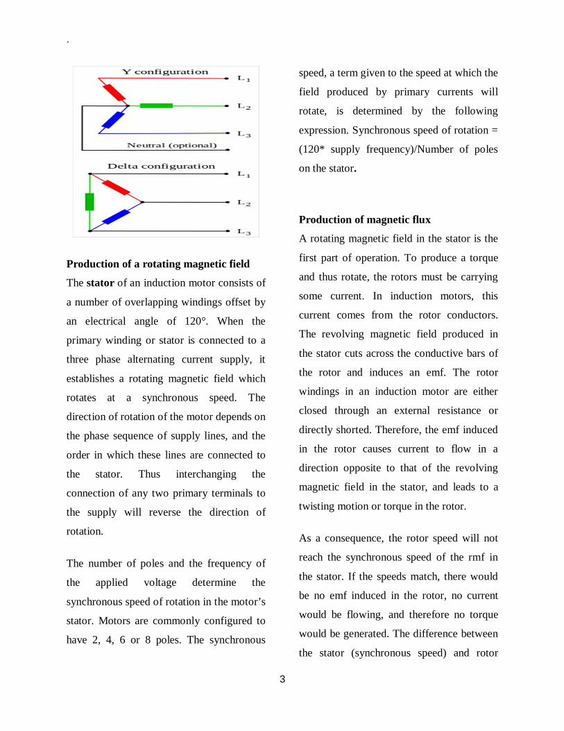
.
3
Production of a rotating magnetic field
The stator of an induction motor consists of
a number of overlapping windings offset by
an electrical angle of 120°. When the
primary winding or stator is connected to a
three phase alternating current supply, it
establishes a rotating magnetic field which
rotates at a synchronous speed. The
direction of rotation of the motor depends on
the phase sequence of supply lines, and the
order in which these lines are connected to
the stator. Thus interchanging the
connection of any two primary terminals to
the supply will reverse the direction of
rotation.
The number of poles and the frequency of
the applied voltage determine the
synchronous speed of rotation in the motor’s
stator. Motors are commonly configured to
have 2, 4, 6 or 8 poles. The synchronous
speed, a term given to the speed at which the
field produced by primary currents will
rotate, is determined by the following
expression. Synchronous speed of rotation =
(120* supply frequency)/Number of poles
on the stator.
Production of magnetic flux
A rotating magnetic field in the stator is the
first part of operation. To produce a torque
and thus rotate, the rotors must be carrying
some current. In induction motors, this
current comes from the rotor conductors.
The revolving magnetic field produced in
the stator cuts across the conductive bars of
the rotor and induces an emf. The rotor
windings in an induction motor are either
closed through an external resistance or
directly shorted. Therefore, the emf induced
in the rotor causes current to flow in a
direction opposite to that of the revolving
magnetic field in the stator, and leads to a
twisting motion or torque in the rotor.
As a consequence, the rotor speed will not
reach the synchronous speed of the rmf in
the stator. If the speeds match, there would
be no emf induced in the rotor, no current
would be flowing, and therefore no torque
would be generated. The difference between
the stator (synchronous speed) and rotor

.
4
speeds is called the slip. The rotation of the
magnetic field in an induction motor has the
advantage that no electrical connections
need to be made to the rotor.
What results is a motor that is:
Self-starting
Explosion proofed (because of the
absence of slip rings or commutators
and brushes that may cause sparks)
Robust in construction
Inexpensive
Easier to maintain
Production of rotating magnetic field in a
three phase induction motor
In a three-phase system, three circuit
conductors carry three alternating currents
(of the same frequency) which reach their
instantaneous peak values at one third of a
cycle from each other. Taking one current as
the reference, the other two currents are
delayed in time by one third and two thirds
of one cycle of the electric current. This
delay between phases causes an effect of
giving constant power transfer over each
cycle of the current and also makes it
possible to produce a rotating magnetic field
in an electric motor.
The sum of the currents is always zero and
each line returns the current from the other
two. Thus a three-phase system can operate
with only three wires.[3] Three-phase
systems may also have a fourth wire,
particularly in low-voltage distribution,
which is the neutral wire. The neutral allows
three separate single-phase supplies to be
provided at a constant voltage and is
commonly used for supplying groups of
domestic properties which are each single-
phase loads. The connections are arranged
so that as far as possible in each group equal
power is drawn from each phase. Further up
the supply chain in high-voltage distribution
the currents are usually well balanced and it
is therefore normal to omit the neutral wire.
Three-phase has properties that make it very
desirable in electric power systems:
The phase currents tend to cancel out
one another, summing to zero in the
case of a linear balanced load. This
makes it possible to reduce the size

.
5
of the neutral conductor because it
carries little to no current; all the
phase conductors carry the same
current and so can be the same size,
for a balanced load.
Power transfer into a linear balanced
load is constant, which helps to
reduce generator and motor
vibrations.
Three-phase systems can produce a
rotating magnetic field with a
specified direction and constant
magnitude, which simplifies the
design of electric motors.
Most household loads are single-phase. In
North American residences, three-phase
power might feed a multiple-unit apartment
block, but the household loads are connected
only as single phase. In lower-density areas,
only a single phase might be used for
distribution. Some large European
appliances may be powered by three-phase
power, such as electric stoves and clothes
dryers.
Wiring for the three phases is typically
identified by color codes which vary by
country. Connection of the phases in the
right order is required to ensure the intended
direction of rotation of three-phase motors.
For example, pumps and fans may not work
in reverse. Maintaining the identity of
phases is required if there is any possibility
two sources can be connected at the same
time; a direct interconnection between two
different phases is a short-circuit.
SPEED CONTROL OF THREE PHASE INDUCTION MOTOR
A three phase induction motor is basically a constant speed motor so it’s somewhat difficult to
control its speed.
The speed control of induction motor is
done at the cost of decrease in efficiency and
low electrical power factor. Before
discussing the methods to control the speed
of three phase induction motor one should
know the basic formulas of speed and torque
of three phase induction motor as the
methods of speed control depends upon
these formulas. Synchronous speed

.
2
Where f = frequency and P is the number of
poles
• The speed of induction motor is given by,
Where N is the speed of rotor of induction
motor, Ns is the synchronous speed, S is the
slip.
• The torque produced by three phase
induction motor is given by,
When rotor is at sand-still slip, s is one. So
the equation of torque is,
Where E2 is the rotor emf
Ns is the synchronous speed
R2 is the rotor resistance
X2 is the rotor inductive
reactance
The Speed of Induction Motor is changed from Both Stator and Rotor Side
The speed control of three phase induction
motor from stator side are further classified
as:
1. V / f control or frequency control
2. changing the number of stator poles
3. controlling supply voltage
4. adding rheostat in the stator circuit
The speed controls of three phase induction
motor from rotor side are further classified
as:
1. Adding external resistance on rotor side
2. Cascade control method
3. Injecting slip frequency emf into rotor
side
Speed Control from Stator Side
1. V / f control or frequency control -
Whenever three phase supply is given to
three phase induction motor rotating
magnetic field is produced which rotates at
synchronous speed given by
In three phase induction motor emf is
induced by induction similar to that of
transformer which is given by
.
2
Where K is the winding constant, T is the
number of turns per phase and f is
frequency. Now if we change frequency
synchronous speed changes but with
decrease in frequency flux will increase and
this change in value of flux causes saturation
of rotor and stator cores which will further
cause increase in no load current of the
motor . So, its important to maintain flux, φ
constant and it is only possible if we change
voltage i.e if we decrease frequency flux
increases but at the same time if we decrease
voltage flux will also decease causing no
change in flux and hence it remains
constant. So, here we are keeping the ratio
of V/ f as constant. Hence its name is V/ f
method. For controlling the speed of three
phase induction motor by V/ f method we
have to supply variable voltage and
frequency which is easily obtained by using
converter and inverter set.
2. Controlling supply voltage: The torque
produced by running three phase induction
motor is given by;
In low slip region (sX)2 is very very small as
compared to R2 . So, it can be neglected. So
torque becomes;
Since rotor resistance, R2 is constant so the
equation of torque further reduces to
We know that rotor induced emf E2 ∝ V.
So, T ∝ sV2.
From the equation above it is clear that if we
decrease supply voltage torque will also
decrease. But for supplying the same load,
the torque must remains the same and it is
only possible if we increase the slip and if
the slip increases the motor will run at
reduced speed . This method of speed
control is rarely used because small change
in speed requires large reduction in voltage,
and hence the current drawn by motor
increases, which cause over heating of
induction motor.
3. Changing the number of stator poles : The
stator poles can be changed by two methods
• Multiple stator winding
method

.
3
• Pole amplitude modulation
method (PAM)
• Multiple stator winding method –
In this method of speed control of three
phase induction motor, the stator is provided
by two separate winding . These two stator
windings are electrically isolated from each
other and are wound for two different pole
numbers. Using switching arrangement, at a
time, supply is given to one winding only
and hence speed control is possible.
Disadvantages of this method are that the
smooth speed control is not possible. This
method is more costly and less efficient as
two different stator winding are required.
This method of speed control can only be
applied for squirrel cage motor
• Pole amplitude modulation method
(PAM) –
In this method of speed control of three
phase induction motor the original
sinusoidal mmf wave is modulated by
another sinusoidal mmf wave having
different number of poles.
Let f1(θ) be the original mmf wave of
induction motor whose speed is to be
controlled f2(θ) be the modulation mmf
wave P1 be the number of poles of induction
motor whose speed is to be controlled P2 be
the number of poles of modulation wave
After modulation resultant mmf wave;
So we get, resultant mmf wave
Therefore the resultant mmf wave will have
two different number of poles
Therefore by changing the number of poles
we can easily change the speed of three
phase induction motor
4. Adding rheostat in the stator circuit - In
this method of speed control of three phase
induction motor rheostat is added in the

.
4
stator circuit due to this voltage gets
dropped .In case of three phase induction
motor torque produced is given by T ∝ sV22.
If we decrease supply voltage torque will
also decrease. But for supplying the same
load , the torque must remains the same and
it is only possible if we increase the slip and
if the slip increase motor will run reduced
speed.
Speed Control from Rotor Side
1. Adding external resistance on rotor
side – In this method of speed control of
three phase induction motor external
resistance are added on rotor side. The
equation of torque for three phase induction
motor is
The three phase induction motor operates in
low slip region .In low slip region term
(sX)2 becomes very very small as compared
to R2. So, it can be neglected . and also E2 is
constant. So the equation of torque after
simplification becomes,
Now if we increase rotor resistance, R2
torque decreases but to supply the same load
torque must remains constant. So, we
increase slip, which will further results in
decrease in rotor speed. Thus by adding
additional resistance in rotor circuit we can
decrease the speed of three phase induction
motor.
The main advantage of this method is that
with addition of external resistance starting
torque increases but this method of speed
control of three phase induction motor also
suffers from some disadvantages:
.The speed above the normal value is not
possible
• Large speed change requires large value of
resistance and if such large value of
resistance is added in the circuit it will cause
large copper loss and hence reduction in
efficiency
• Presence of resistance causes more losses
• This method cannot be used for squirrel
cage induction motor
2. Cascade control method – In this
method of speed control of three phase
induction motor, the two three phase
induction motor are connected on common
shaft and hence called cascaded motor. One
motor is the called the main motor and
another motor is called the auxiliary motor.
The three phase supply is given to the stator

.
5
of the main motor while the auxiliary motor
is derived at a slip frequency from the slip
ring of main motor.
Let NS1 be the synchronous speed of main
motor; NS2 be the synchronous speed of
auxiliary motor; P1 be the number of poles
of the main motor; P2 be the number of
poles of the auxiliary motor; F is the supply
frequency; F1 is the frequency of rotor
induced emf of main motor
N is the speed of set and it remains same for
both the main and auxiliary motor as both
the motors are mounted on common shaft
S1 is the slip of main motor;
The auxiliary motor is supplied with same
frequency as the main motor i.e
Now put the value of;
;
Now at no load , the speed of auxiliary rotor
is almost same as its synchronous speed i.e;
N = NS2
Now rearrange the above equation and find
out the value of N, we get,
This cascaded set of two motors will now
run at new speed having number of poles (P1
+ P2). In the above method the torque
produced by the main and auxiliary motor
will act in same direction, resulting in
number of poles (P1 + P2). Such type of
cascading is called cumulative cascading.
There is one more type of cascading in
which the torque produced by the main
motor is in opposite direction to that of
auxiliary motor. Such type of is called
differential cascading; resulting in speed
corresponds to number of poles (P1 - P2).In
this method of speed control of three phase

.
6
induction motor, four different speeds can
be obtained;
1. when only main induction motor work,
having speed corresponds to
NS1 = 120 F / P1
2. when only auxiliary induction motor
work, having speed corresponds to
NS2 = 120 F / P2
3. when cumulative cascading is done, then
the complete set runs at a speed of
N = 120F / (P1 + P2)
4. when differential cascading is done, then
the complete set runs at a speed of
N = 120F / (P1 - P2)
3. Injecting slip frequency emf into rotor
side - when the speed control of three phase
induction motor is done by adding resistance
in rotor circuit, some part of power called,
the slip power is lost as I2R losses.
Therefore the efficiency of three phase
induction motor is reduced by this method
of speed control. This slip power loss can be
recovered and supplied back in order to
improve the overall efficiency of three phase
induction motor and this scheme of
recovering the power is called slip power
recovery scheme and this is done by
connecting an external source of emf of slip
frequency to the rotor circuit. The injected
emf can either oppose the rotor induced emf
or aids the rotor induced emf. If it oppose
the rotor induced emf, the total rotor
resistance increases and hence speed
decreases and if the injected emf aids the
main rotor emf the total resistance decreases
and hence speed increases. Therefore by
injecting induced emf in rotor circuit the
speed can be easily controlled. The main
advantage of this type of speed control of
three phase induction motor is that wide
range of speed control is possible whether
its above normal or below normal speed.
.
2
TOPIC FIVE
MOTOR ENCLOSURES
The enclosures of electrical motors are standardized by NEMA (National Electrical
Manufacturers Association) as:
1. Open Drip Proof (ODP)
An open motor in which the ventilating
openings are so constructed that drops of
liquid or solid particles falling on it, at any
angle not greater than 15 degrees for the
vertical, cannot enter either directly or by
striking and running along a surface of the
motor. Designed for reasonably dry, clean,
and well ventilated (usually indoors) areas.
Outdoor installations require the motor to be
protected with a cover that does not restrict
the flow of air to the motor. Ventilation
openings in shield and/or frame prevent
drops of liquid from falling into motor
within up to 15 degree angle from vertical.
Designed for reasonably dry, clean, and well
ventilated (usually indoors) areas. Outdoors
installation requires the motor to be
protected with a cover that does not restrict
the flow of air to the motor.
2. Totally Enclosed Fan Cooled
(TEFC)
A motor so enclosed as to prevent the free
exchange of air between the inside and
outside of the case, but not sufficiently
enclosed to be termed air-tight, and dust
does not enter in sufficient quantity to
interfere with satisfactory operation.
Cooling is by means of an external fan as an
integral part of the motor. The fan provides
cooling by blowing air on the outside of the
motor. Suitable where the motor is exposed
to dirt or dampness. Not suited in very moist
humid or hazardous (explosive) locations.
Same as TENV with an external fan as an
integral part of the motor. The fan provides
cooling by blowing air on the outside of the
motor.
3. Totally Enclosed Non Ventilated
(TENV)
A motor so enclosed as to prevent the free
exchange of air between the inside and
outside of the case but not sufficiently

.
2
enclosed to be termed air-tight, and dust
does not enter in sufficient quantity to
interfere with satisfactory operation.
Cooling is only by convection and radiation
from the enclosure. Suitable where the
motor is exposed to dirt or dampness. Not
suited in very moist humid or hazardous
(explosive) locations. No ventilation
openings, enclosed to prevent free exchange
of air (not airtight). No external cooling fan,
relies on convection cooling. Suitable where
the motor is exposed to dirt or dampness.
Not suited in very moist humid or hazardous
(explosive) air.
4. Totally Enclosed Air Over (TEAO)
A motor so enclosed as to prevent the free
exchange of air between the inside and
outside of the case. A dust-tight enclosure
used on fan and blower motors for shaft
mounted fans or belt driven fans. The motor
must be mounted within the airflow of the
fan for cooling. Dust-tight fan and blower
motors for shaft mounted fans or belt driven
fans. The motors mounted within the airflow
of the fan.
5. Totally Enclosed Blower Cooled
(TEBC)
A motor so enclosed as to prevent the free
exchange of air between the inside and
outside of the case, but not sufficiently
enclosed to be termed air-tight, and dust
does not enter in sufficient quantity to
interfere with satisfactory operation. Used
on inverter duty motors. Cooled with
external fan on a power supply independent
of the inverter output. Provides full cooling
even at lower motor speeds.
6. Explosion Proof
A totally enclosed motor whose enclosure is
designed and constructed to withstand an
explosion of a specified gas or vapor which
may occur within it and to prevent the
ignition of the specified gas or vapor
surrounding the motor by sparks, flashes, or
explosions of the gas or vapor which may
occur within the motor housing.
7. Explosion-Proof Non Ventilated
(EPNV)
A non-ventilated explosion proof motor.
See TENV and Explosion-Proof above for
more information.

.
3
8. Explosion-Proof Fan Cooled
(EPFC)
A fan cooled explosion-proof motor. See
TEFC and Explosion- Proof above for more
information. The motor ambient temperature
shall not exceed +40oC.

.
2
TOPIC SEVEN
ELECTRIC MOTOR CONTROLS
Once the proper motor is selected, understanding the many various control devices available and
their uses and limitations becomes an important part related to reliable operation and protection
of the motor and the personnel using the motor. There are four major motor control topics or
categories to consider. Each of these has several subcategories and sometimes the subcategories
overlap to some extent. Certain pieces of motor control equipment can accomplish multiple
functions from each of the topics or categories.
The four categories include:
1) Starting the Motor
Disconnecting Means
Across the Line Starting
Reduced Voltage Starting
2) Motor Protection
Overcurrent Protection
Overload Protection
Other Protection (voltage, phase, etc)
Environment
3) Stopping the Motor
Coasting
Electrical Braking
Mechanical Braking
4) Motor Operational Control
Speed Control
Reversing
Jogging
Sequence Control
An understanding of each of these areas is
necessary to effectively apply motor control
principles and equipment to effectively
operate and protect a motor.
Motor Starting All motors must have a control device to
start and stop the motor called a “motor
controller”.

.
2
The above are some motor starters
a. Motor Controller
A motor controller is the actual device that
energizes and de-energizes the circuit to the
motor so that it can start and stop. Motor
controllers may include some or all of the
following motor control functions: S
starting, stopping, over-current protection,
overload protection, reversing, speed
changing, jogging, plugging, sequence
control, and pilot light indication.
S Controllers range from simple to complex
and can provide control for one motor,
groups of motors, or auxiliary equipment
such as brakes, clutches, solenoids, heaters,
or other signals.
b. Motor Starter
The starting mechanism that energizes the
circuit to an induction motor is called the
“starter” and must supply the motor with
sufficient current to provide adequate
starting torque under worst case line voltage
and load conditions when the motor is
energized. There are several different types
of equipment suitable for use as “motor
starters” but only two types of starting
methods for induction motors:
i) Across the Line Starting
ii). Reduced Voltage Starting

.
3
c. Across the Line Starting of Motors
Across the Line starting connects the motor
windings/terminals directly to the circuit
voltage “across the line” for a “full voltage
start”. This is the simplest method of starting
a motor. Motors connected across the line
are capable of drawing full in-rush current
and developing maximum starting torque to
accelerate the load to speed in the shortest
possible time.
All NEMA induction motors up to 200
horsepower, and many larger ones, can
withstand full voltage starts. (The electric
distribution system or processing operation
may not though, even if the motor will).
d. Across the Line Starters
i) Manual Starter
There are two different types of common
“across the line” starters including:
1. Manual Motor Starters
2. Magnetic Motor Starters
1. Manual Motor Starters
A manual motor starter is package
consisting of a horsepower rated switch with
one set of contacts for each phase and
corresponding thermal overload devices to
provide motor overload protection. The
main advantage of a manual motor starter is
lower cost than a magnetic motor starter
with equivalent motor protection but less
motor control capability.
Manual motor starters are often used for
smaller motors - typically fractional
horsepower motors but the National
Electrical Code allows their use up to 10
Horsepower. Since the switch contacts
remain closed if power is removed from the
circuit without operating the switch, the
motor restarts when power is reapplied
which can be a safety concern. They do not
allow the use of remote control or auxiliary
control equipment like a magnetic starter
does.
2. Magnetic Motor Starters
A magnetic motor starter is a package
consisting of a contactor capable of opening
and closing a set of contacts that energize
and de-energize the circuit to the motor
along with additional motor

.
4
overload protection equipment. Magnetic
starters are used with larger motors (required
above 10 horsepower) or where greater
motor control is desired. The main element
of the magnetic motor starter is the
contactor, a set of contacts operated by an
electromagnetic coil. Energizing the coil
causes the contacts (A) to close allowing
large currents to be initiated and interrupted
by a smaller voltage control signal.
The control voltage need not be the same as
the motor supply voltage and is often low
voltage allowing start/stop controls to be
located remotely from the power circuit.
Closing the Start button contact energizes
the contactor coil. An auxiliary contact on
the contactor is wired to seal in the coil
circuit. The contactor de-energizes if the
control circuit is interrupted, the Stop button
is operated, or if power is lost. The overload
contacts are arranged so an overload trip on
any phase will cause the contactor to open
and de-energize all phases.
Reduced Voltage Starting of Motors
Reduced Voltage Starting connects the
motor windings/terminals at lower than
normal line voltage during the initial starting
period to reduce the inrush current when the
motor starts. Reduced voltage starting may
be required when: The current in-rush form
the motor starting adversely affects the
voltage drop on the electrical system;
needed to reduce the mechanical “starting
shock” on drive-lines and equipment when
the motor starts. Reducing the voltage
reduces the current in-rush to the motor and
also reduces the starting torque available
when the motor starts.
All NEMA induction motors can accept
reduced voltage starting however it may not
provide enough starting torque in some
situations to drive certain specific loads. If
the driven load or the power distribution
system cannot accept a full voltage start,
some type of reduced voltage or "soft"
starting scheme must be used. Typical
reduced voltage starter types include:
1. Solid State (Electronic) Starters
2. Primary Resistance Starters
3. Autotransformer Starters
4. Part Winding Starters
5. Wye-Delta Starters
Reduced voltage starters can only be used
where low starting torque is acceptable or a
means exists to remove the load from the
motor or application before it is stopped.

.
5
Motor Protection Motor protection safeguards the motor, the
supply system and personnel from various
operating conditions of the driven load, the
supply system or the motor itself.
Motor protection categories include:
i. Overcurrent Protection
ii. Overload Protection
iii. Other Types of Protection.
The National Electrical Code requires that
motors and their conductors be protected
from both overcurrent and overload
conditions.
i. Overcurrent Protection
Overcurrent protection interrupts the
electrical circuit to the motor upon excessive
current demand on the supply system from
either short circuits or ground faults.
Overcurrent protection is required to protect
personnel, the motor branch circuit
conductors, control equipment, and motor
from these high currents. Overcurrent
protection is usually provided in the form of
fuses or circuit breakers. These devices
operate when a short circuit, ground fault or
an extremely heavy overload occurs. Most
overcurrent sources produce extremely large
currents very quickly.
ii. Overload Protection
Overload protection is installed in the motor
circuit and/or motor to protect the motor
from damage from mechanical overload
conditions when it is operating/running. The
effect of an overload is an excessive rise in
temperature in the motor windings due to
current higher than full load current.
Properly sized overload protection
disconnects the motor from the power
supply when the heat generated in the motor
circuit or windings approaches a damaging
level for any reason.
The larger the overload, the more quickly
the temperature will increase to a point that
is damaging to the insulation and lubrication
of the motor. Unlike common instantaneous
type fuses and breakers, overload devices
are designed to allow high currents to flow
briefly in the motor to allow for:
Typical motor starting currents
of 6 to 8 times normal running
current when starting.

.
6
Short duration overloads such
as a slug of product going
through a system.
If the motor inlets and outlets
are covered by a blanket of lint
or if a bearing should begin to
lock, excessive heating of the
motor windings will “overload”
the motors insulation which
could damage the motor.
The overcurrent device will not react to this
low level overload. The motor overload
device prevents this type of problem from
severely damaging the motor and also
provides protection for the circuit
conductors since it is rated for the same or
less current as the conductors. Overload
protection trips when an overload exists for
more than a short time. The time it takes for
an overload to trip depends on the type of
overload device, length of time the overload
exists, and the ambient temperature in which
the overloads are located.
Other Motor Protection Devices i. Low Voltage Protection
Low Voltage Disconnects - Protection
device operates to disconnect the motor
when the supply
voltage drops below a preset value. The
motor must be manually restarted upon
resumption of normal supply voltage.
Low Voltage Release - Protection device
interrupts the circuit when the supply
voltage drops below a preset value and re-
establishes the circuit when the supply
voltage returns to normal.
ii. Phase Failure Protection
Interrupts the power in all phases of a three-
phase circuit upon failure of any one phase.
Normal fusing and overload protection may
not adequately protect a polyphase motor
from damaging single phase operation.
Without this protection, the motor will
continue to operate if one phase is lost.
Large currents can be developed in the
remaining stator circuits which eventually
burn out. Phase failure protection is the only
effective way to protect a motor properly
from single phasing.
iii. Phase Reversal Protection
Used where running a motor backwards
(opposite direction from normal) would
cause operational or safety problems. Most
three phase motors will run the opposite
direction by switching the connections of
any two of the three phases. The device
interrupts the power to the motor upon
.
7
detection of a phase reversal in the three-
phase supply circuit. This type of protection
is used in applications like elevators where it
would be damaging or dangerous for the
motor to inadvertently run in reverse.
iv. Ground Fault Protection
Operates when one phase of a motor shorts
to ground preventing high currents from
damaging the stator windings and the iron
core.

.
1

.
2
TOPIC EIGHT: CONTACTORS
CONTACTORS
A contactor is an electrically controlled switch used for switching a power circuit, similar to a
relay except with higher current ratings. A contactor is controlled by a circuit which has a much
lower power level than the switched circuit
.
Some contactors
Contactors come in many forms with
varying capacities and features. Unlike a
circuit breaker, a contactor is not intended to
interrupt a short circuit current. Contactors
range from those having a breaking current
of several amperes to thousands of amperes
and 24 V DC to many kilovolts. The
physical size of contactors ranges from a
device small enough to pick up with one
hand, to large devices approximately a meter
(yard) on a side. Contactors are used to
control electric motors, lighting, heating,
capacitor banks, thermal evaporators, and
other electrical loads.
A contactor has three components. The
contacts are the current carrying part of the
contactor. This includes power contacts,
auxiliary contacts, and contact springs. The
electromagnet (or "coil") provides the
driving force to close the contacts. The
enclosure is a frame housing the contact and
the electromagnet. Enclosures are made of
insulating materials like Bakelite, Nylon 6,
and thermosetting plastics to protect and
insulate the contacts and to provide some
measure of protection against personnel
.
2
touching the contacts. Open-frame
contactors may have a further enclosure to
protect against dust, oil, explosion hazards
and weather.
Magnetic blowouts use blowout coils to
lengthen and move the electric arc. These
are especially useful in DC power circuits.
AC arcs have periods of low current, during
which the arc can be extinguished with
relative ease, but DC arcs have continuous
high current, so blowing them out requires
the arc to be stretched further than an AC
arc of the same current. The magnetic
blowouts in the pictured Albright contactor
(which is designed for DC currents) more
than double the current it can break,
increasing it from 600 A to 1,500 A.
Sometimes an economizer circuit is also
installed to reduce the power required to
keep a contactor closed; an auxiliary contact
reduces coil current after the contactor
closes. A somewhat greater amount of
power is required to initially close a
contactor than is required to keep it closed.
Such a circuit can save a substantial amount
of power and allow the energized coil to stay
cooler. Economizer circuits are nearly
always applied on direct-current contactor
coils and on large alternating current
contactor coils.
A basic contactor will have a coil input
(which may be driven by either an AC or
DC supply depending on the contactor
design). The coil may be energized at the
same voltage as a motor the contactor is
controlling, or may be separately controlled
with a lower coil voltage better suited to
control by programmable controllers and
lower-voltage pilot devices. Certain
contactors have series coils connected in the
motor circuit; these are used, for example,
for automatic acceleration control, where the
next stage of resistance is not cut out until
the motor current has dropped.
Applications of Contactors
1. Lighting control
Contactors are often used to provide central
control of large lighting installations, such
as an office building or retail building. To
reduce power consumption in the contactor
coils, latching contactors are used, which
have two operating coils. One coil,
momentarily energized, closes the power
circuit contacts, which are then
mechanically held closed; the second coil
opens the contacts.
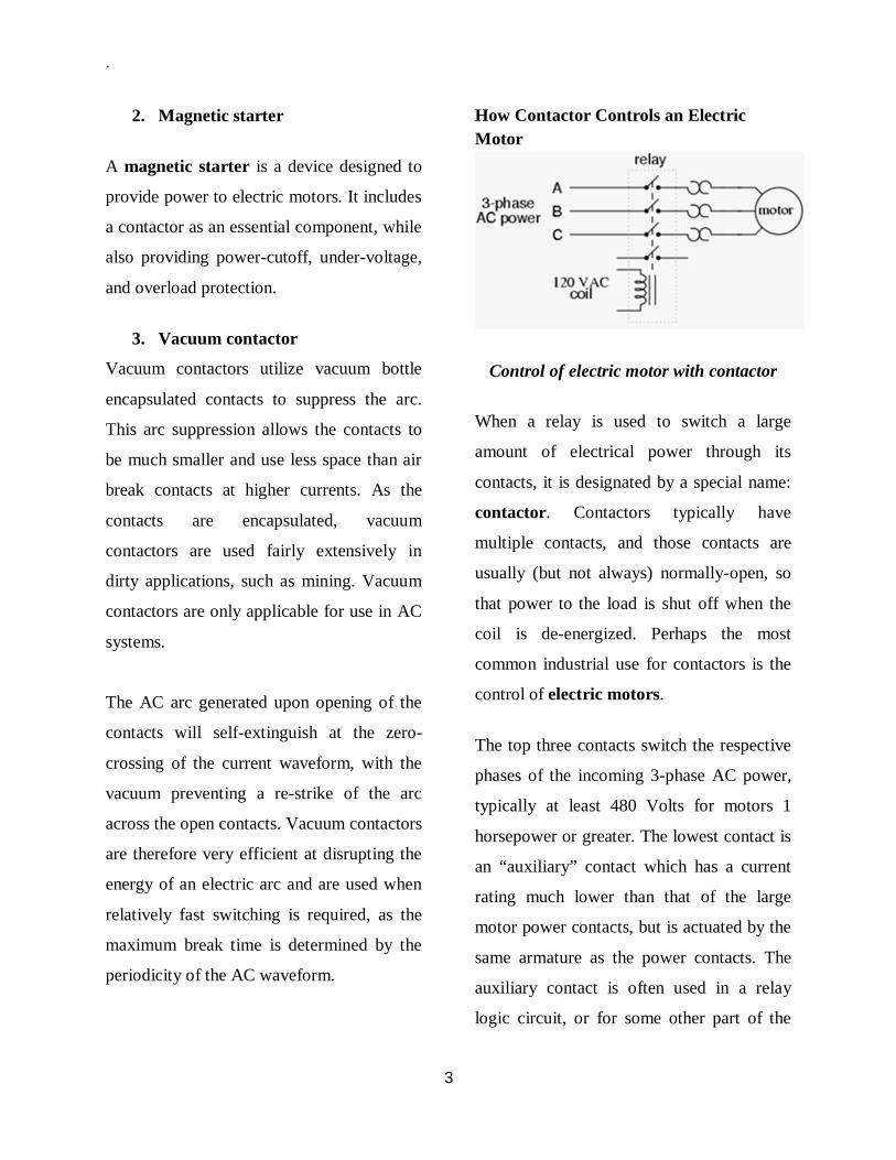
.
3
2. Magnetic starter
A magnetic starter is a device designed to
provide power to electric motors. It includes
a contactor as an essential component, while
also providing power-cutoff, under-voltage,
and overload protection.
3. Vacuum contactor
Vacuum contactors utilize vacuum bottle
encapsulated contacts to suppress the arc.
This arc suppression allows the contacts to
be much smaller and use less space than air
break contacts at higher currents. As the
contacts are encapsulated, vacuum
contactors are used fairly extensively in
dirty applications, such as mining. Vacuum
contactors are only applicable for use in AC
systems.
The AC arc generated upon opening of the
contacts will self-extinguish at the zero-
crossing of the current waveform, with the
vacuum preventing a re-strike of the arc
across the open contacts. Vacuum contactors
are therefore very efficient at disrupting the
energy of an electric arc and are used when
relatively fast switching is required, as the
maximum break time is determined by the
periodicity of the AC waveform.
How Contactor Controls an Electric Motor
Control of electric motor with contactor
When a relay is used to switch a large
amount of electrical power through its
contacts, it is designated by a special name:
contactor. Contactors typically have
multiple contacts, and those contacts are
usually (but not always) normally-open, so
that power to the load is shut off when the
coil is de-energized. Perhaps the most
common industrial use for contactors is the
control of electric motors.
The top three contacts switch the respective
phases of the incoming 3-phase AC power,
typically at least 480 Volts for motors 1
horsepower or greater. The lowest contact is
an “auxiliary” contact which has a current
rating much lower than that of the large
motor power contacts, but is actuated by the
same armature as the power contacts. The
auxiliary contact is often used in a relay
logic circuit, or for some other part of the

.
4
motor control scheme, typically switching
120 Volt AC power instead of the motor
voltage.
One contactor may have several auxiliary
contacts, either normally-open or normally-
closed, if required. The three “opposed-
question-mark” shaped devices in series
with each phase going to the motor are
called overload heaters. Each “heater”
element is a low-resistance strip of metal
intended to heat up as the motor draws
current. If the temperature of any of these
heater elements reaches a critical point
(equivalent to a moderate overloading of the
motor), a normally-closed switch contact
(not shown in the diagram) will spring open.
This normally-closed contact is usually
connected in series with the relay coil, so
that when it opens the relay will
automatically de-energize, thereby shutting
off power to the motor.
Overload heaters are intended to provide
overcurrent protection for large electric
motors, unlike circuit breakers and fuses
which serve the primary purpose of
providing overcurrent protection for power
conductors. Overload heater function is
often misunderstood. They are not fuses;
that is, it is not their function to burn open
and directly break the circuit as a fuse is
designed to do.
Rather, overload heaters are designed to
thermally mimic the heating characteristic of
the particular electric motor to be protected.
All motors have thermal characteristics,
including the amount of heat energy
generated by resistive dissipation (I2R), the
thermal transfer characteristics of heat
“conducted” to the cooling medium through
the metal frame of the motor, the physical
mass and specific heat of the materials
constituting the motor, etc.
These characteristics are mimicked by the
overload heater on a miniature scale: when
the motor heats up toward its critical
temperature, so will the heater toward its
critical temperature, ideally at the same rate
and approach curve. Thus, the overload
contact, in sensing heater temperature with a
thermo-mechanical mechanism, will sense
an analogue of the real motor. If the
overload contact trips due to excessive
heater temperature, it will be an indication
that the real motor has reached its critical
temperature (or, would have done so in a
short while). After tripping, the heaters are
supposed to cool down at the same rate and
approach curve as the real motor, so that
they indicate an accurate proportion of the

.
5
motor’s thermal condition, and will not
allow power to be re-applied until the motor
is truly ready for start-up again.
Shown here below is a contactor for a three-
phase electric motor, installed on a panel as
part of an electrical control system at a
municipal water treatment plant. Three-
phase, 480 volt AC power comes in to the
three normally-open contacts at the top of
the contactor via screw terminals labeled
“L1,” “L2,” and “L3″ (The “L2″ terminal is
hidden behind a square-shaped “snubber”
circuit connected across the contactor’s coil
terminals). Power to the motor exits the
overload heater assembly at the bottom of
this device via screw terminals labeled “T1,”
“T2,” and “T3.”
The overload heater units themselves are
black, square-shaped blocks with the label
“W34,” indicating a particular thermal
response for a certain horsepower and
temperature rating of electric motor. If an
electric motor of differing power and/or
temperature ratings were to be substituted
for the one presently in service, the overload
heater units would have to be replaced with
units having a thermal response suitable for
the new motor. The motor manufacturer can
provide information on the appropriate
heater units to use.
A white pushbutton located between the
“T1″ and “T2″ line heaters serves as a way
to manually re-set the normally-closed
switch contact back to its normal state after
having been tripped by excessive heater
temperature. Wire connections to the
“overload” switch contact may be seen at
the lower-right of the photograph, near a
label reading “NC” (normally-closed). On
this particular overload unit, a small
“window” with the label “Tripped” indicates
a tripped condition by means of a colored
flag. In this photograph, there is no
“tripped” condition, and the indicator
appears clear
Contactor for a three-phase electric motor
installed on a panel as part of an electrical
control system
.
1
TOPIC FOUR
PREVENTIVE MAINTENANCE
WHY PREVENTIVE MAINTENANCE?
Preventive maintenance is predetermined work performed to a schedule with the aim of
preventing the wear and tear or sudden failure of equipment components.
Preventive maintenance helps to:
Protect assets and prolong the
useful life of production equipment
Improve system reliability
Decrease cost of replacement
Decreases system downtime
Reduce injury
Mechanical, process or control
equipment failure can have adverse
results in both human and economic
terms. In addition to down time and
the costs involved to repair and/or
replace equipment parts or
components, there is the risk of injury
to operators, and of acute exposures to
chemical and/ or physical agents.
Preventive maintenance, therefore, is a
very
important ongoing accident prevention
activity, which you should integrate
into your operations/ product
manufacturing process. To be
effective, your preventive maintenance
function should incorporate the
following elements:
1. Planned replacements
Planned replacements of components
designed around the following:
Reliability of components
(equipment failure is caused by its
least reliable component)
- check manufacturer’s information
- check accepted industry best
practices
Maintaining equipment service
records
Scheduling replacement of
components at the end of their
useful service life
Acquiring and maintaining
inventories of:
- east reliable components
- critical components
- components scheduled for
replacements

.
2
Replacing service-prone equipment
with more reliable performers
By introducing the element of planning
into your maintenance function, you
are likely to reduce your repair and
manpower requirements.
2. Exploratory maintenance
Exploratory maintenance is to
anticipate and prevent breakdowns.
Diagnostic measures to
analyze your plant requirements
include:
Operating and performing
specifications of equipment
Past experience with components:
- inspection records
- servicing records
- replacement frequency
- inspected component failures
Regularly scheduled lubrication
program:
- identify lubrication points on
equipment
- colour code in order to identify
lubrication frequency
- consult manufacturer and accepted
industry best practices to establish
schedule
Preventive Maintenance
Identifying Maintenance Hazards
The hazards associated with
maintenance activities can be
classified as follows:
Safety Hazards
Mechanical
equipment
tools
Electrical
live equipment
Pneumatic
Hydraulic
Thermal
Combustion
Falls
slippery floors
working at heights
Health Hazards
Chemical Agents
process chemicals
cleaning solvents
unexpected reaction
products
dusts
other chemical agents
Physical Agents
noise
vibration
other
Ergonomic Hazards
.
3
Biomechanical
lifting, pushing, pulling
(manual handling)
stretching, ending (to reach
hard to access areas)
Work/process design
poorly designed tools
hard to access work locations
ill-fitting personal protective
equipment
complex procedures
Many of these hazards are interrelated.
Examine your process, the layout of
your process area, and the process
equipment used, to determine the exact
nature of the hazards likely to be
encountered during your maintenance
activities. For example, maintenance
work carried out in confined spaces
carries a greater risk of critical injuries
and acute exposures to chemical and
physical agents. These risks are
associated with equipment and
materials in the space itself and from
nearby operations. Fatalities are quite
common.
Controlling Maintenance Hazards Ideally, the hazards likely to occur
during maintenance activities should
be addressed in the
planning stage.
Process Selection
Depending on the nature of the
process, special precautions may be
needed to protect workers when
disassembling and cleaning equipment.
Consider this factor when you make a
decision to select one process over
another. Also consider the following
factors which contribute to the level of
risk of your maintenance activities:
How easy temporary structures
are to erect
How easy they are to access
Support and reassembly of
components of large scale
equipment
Use of hoists and mobile
working platforms
Safe use of ladders especially
near live electrical equipment
How much disassembly is
required to access affected
equipment
Need for temporary hoisting
equipment

.
4
Need for personal protective
equipment
Housekeeping hazards created
at floor level by the presence of
dismantled components
Equipment Selection
The process you select will determine
the type of equipment you will be
using. However, consider the
following:
Reliability:
manufacturer’s data
in-plant operating experience
trade association data
Ease of access to serviceable parts
Ease of disassembly
Complexity of repair procedures
Ease of frequency of required
lubrication
Manufacturer/supplier follow-up:
availability of parts
availability of service time
Developing Procedures
When servicing equipment, hazards
not related to your process operation
are likely to be introduced. For this
reason, it is important to prepare
written servicing procedures that
include the following:
A clear, step-by-step procedure, in
checklist form, for controlling
hazardous energy:
1. Preparing for shutdown
2. Shutting down machine, process or
equipment
3. Isolating energy to the machine,
process or equipment
4. Applying lockout devices
5. Controlling stored energy
6. Verification of isolation
7. Release from lockout control
Hazards identification
Selection and specification of personal
protective equipment:
appropriate for the hazard
proper fit
Selection and specification of tools to
be used:
right tool for the job
in good condition
appropriate for the environment
(non-sparking tools in flammable
atmospheres)
ergonomic design
Step-by-step procedure for
disassembly
Step-by-step checklist for inspection of
components (to establish a baseline for
reliability)
.
5
Identification of hazards associated
with sub-procedures:
entering and working in confined
spaces
welding in open and confined
spaces
removing insulation
cleaning
handling and using solvents
erecting temporary structures
using portable equipment
using ladders
abrasive blasting
painting
Erection and disassembly of
scaffolding and other temporary
platforms
Disassembly of small-scale equipment
Reassembly of small-scale equipment
Support and disassembly of large scale
equipment
Examine each procedure thoroughly to
ensure that the least hazardous method
is selected, and that all precautions
necessary to complete the job safely
are taken. Keep records of all your
maintenance activities, indicating the
machine(s) involved, the part(s)
involved, type of maintenance and date
on which performed.
Training
Maintenance personnel are often
involved in a complex and changing
set of problems. Therefore, they need
more thorough training in accident
prevention than regular workers.
Serious consequences to maintenance
and other workers can result from not
following established maintenance
procedures (e.g., use of work permits,
lockout procedures, confined space
entry procedures). Ensure that your
maintenance personnel are well trained
in, and can demonstrate that they
understand, all relevant procedures.
Also provide training in:
Hazard identification
Selection, use, and care of
equipment, machine tools, personal
protective clothing/equipment, etc.,
required to be used
First-aid and life-saving techniques
The hazards of and control
methods for substances which may
be encountered in the workplace,
such as:
irritating, toxic or corrosive dusts
gases
vapours
fluids

.
6
How to inspect chains, blocks, fall
protection devices and ropes
How to secure loads
Understanding stresses
It is a good practice to call the
maintenance crew together at the start
of each job, in order to discuss the
hazards involved and the method of
doing it safely. In the course of their
daily work, members of the
maintenance crew travel throughout
the plant, becoming familiar with
every machine and process. If properly
selected and trained, they can do much
to identify and correct unsafe
conditions. In small companies, the
maintenance staff may also be
responsible for inspecting and
maintaining portable power tools,
extension cords, and the like. If so,
special procedures and training are
needed. Train equipment operators to
recognize the signs of impending
failure, such as abnormal noise,
excessive vibration, declining or
abnormal output, and to report these
immediately to their supervisor.
Legislation
The following Regulations made under
the Occupational Health and Safety
Act contain provisions that deal with
maintenance:
Industrial Establishments
(R.R.O. 851/90)
Control of Exposure to
Biological or Chemical Agents
(R.R.O. 833/90)
Workplace Hazardous
Materials Information System
(R.R.O. 860/90)
Designated Substances
Copyright © 2022 FDOKUMEN