![Quad 240[1737]](https://static.fdokumen.com/doc/165x107/633b2fc5c007a38db701fb49/quad-2401737.jpg)
Independent Clock Quad HOTLink II™ Transceiver with Reclocker
43
PRELIMINARY Independent Clock Quad HOTLink II™ Transceiver with Reclocker CYV15G0404DXB Cypress Semiconductor Corporation • 3901 North First Street • San Jose, CA 95134 • 408-943-2600 Document #: 38-02097 Rev. ** Revised June 04, 2004 Features • Quad channel transceiver for 195- to 1500-MBaud serial signaling rate — Aggregate throughput of up to 12 Gbits/second • Second-generation HOTLink ® technology • Compliant to multiple standards — SMPTE-292M, SMPTE-259M, DVB-ASI, Fibre Channel, ESCON and Gigabit Ethernet (IEEE802.3z) — 10 bit uncoded data or 8B/10B coded data • Truly independent channels — Each channel can perform reclocker function — Each channel can operate at a different signaling rate — Each channel can transport a different data format • Internal phase-locked loops (PLLs) with no external PLL components • Selectable differential PECL-compatible serial inputs per channel — Internal DC-restoration • Redundant differential PECL-compatible serial outputs per channel — No external bias resistors required — Signaling-rate controlled edge-rates — Source matched for 50Ω transmission lines • MultiFrame™ Receive Framer provides alignment options — Comma or Full K28.5 detect — Single or Multi-byte Framer for byte alignment — Low-latency option • Selectable input/output clocking options • Synchronous LVTTL parallel interface • JTAG boundary scan • Built-In Self-Test (BIST) for at-speed link testing • Per-channel Link Quality Indicator — Analog signal detect — Digital signal detect • Low-power 3W @ 3.3V typical • Single 3.3V supply • 256-ball thermally enhanced BGA • 0.25µ BiCMOS technology • JTAG device ID ‘0C811069’x Functional Description The CYV15G0404DXB Independent Clock Quad HOTLink II™ Transceiver is a point-to-point or point-to-multipoint communi- cations building block enabling transfer of data over a variety of high-speed serial links including SMPTE 292, SMPTE 259 and DVB-ASI video applications. The signaling rate can be anywhere in the range of 195 to 1500 MBaud per serial link. Each channel operates independently with its own reference clock allowing different rates. Each transmit channel accepts parallel characters in an Input Register, encodes each character for transport, and then converts it to serial data. Each receive channel accepts serial data and converts it to parallel data, decodes the data into characters, and presents these characters to an Output Register. The received serial data can also be reclocked and retransmitted through the serial outputs. Figure 1 illustrates typical connections between independent video co-processors and corresponding CYV15G0404DXB chips. Figure 1. HOTLink II™ System Connections Video Coprocessor Serial Links 10 10 10 10 10 10 10 10 Video Coprocessor 10 10 10 10 10 10 10 10 Serial Links Serial Links Serial Links Cable Connections Independent CYV15G0404DXB Independent Reclocker Reclocker Channel CYV15G0404DXB Channel
-
Upload
khangminh22 -
Category
Documents
-
view
1 -
download
0
Transcript of Independent Clock Quad HOTLink II™ Transceiver with Reclocker

PRELIMINARY
Independent Clock Quad HOTLink II™ Transceiverwith Reclocker
CYV15G0404DXB
Cypress Semiconductor Corporation • 3901 North First Street • San Jose, CA 95134 • 408-943-2600Document #: 38-02097 Rev. ** Revised June 04, 2004
Features• Quad channel transceiver for 195- to 1500-MBaud serial
signaling rate— Aggregate throughput of up to 12 Gbits/second
• Second-generation HOTLink® technology• Compliant to multiple standards
— SMPTE-292M, SMPTE-259M, DVB-ASI, Fibre Channel, ESCON and Gigabit Ethernet (IEEE802.3z)
— 10 bit uncoded data or 8B/10B coded data• Truly independent channels
— Each channel can perform reclocker function— Each channel can operate at a different signaling
rate— Each channel can transport a different data format
• Internal phase-locked loops (PLLs) with no external PLL components
• Selectable differential PECL-compatible serial inputs per channel— Internal DC-restoration
• Redundant differential PECL-compatible serial outputs per channel— No external bias resistors required— Signaling-rate controlled edge-rates— Source matched for 50Ω transmission lines
• MultiFrame™ Receive Framer provides alignment options— Comma or Full K28.5 detect— Single or Multi-byte Framer for byte alignment— Low-latency option
• Selectable input/output clocking options• Synchronous LVTTL parallel interface• JTAG boundary scan• Built-In Self-Test (BIST) for at-speed link testing• Per-channel Link Quality Indicator
— Analog signal detect— Digital signal detect
• Low-power 3W @ 3.3V typical• Single 3.3V supply• 256-ball thermally enhanced BGA• 0.25µ BiCMOS technology• JTAG device ID ‘0C811069’x
Functional DescriptionThe CYV15G0404DXB Independent Clock Quad HOTLink II™Transceiver is a point-to-point or point-to-multipoint communi-cations building block enabling transfer of data over a varietyof high-speed serial links including SMPTE 292, SMPTE 259and DVB-ASI video applications. The signaling rate can beanywhere in the range of 195 to 1500 MBaud per serial link.Each channel operates independently with its own referenceclock allowing different rates. Each transmit channel acceptsparallel characters in an Input Register, encodes eachcharacter for transport, and then converts it to serial data.Each receive channel accepts serial data and converts it toparallel data, decodes the data into characters, and presentsthese characters to an Output Register. The received serialdata can also be reclocked and retransmitted through theserial outputs. Figure 1 illustrates typical connections betweenindependent video co-processors and correspondingCYV15G0404DXB chips.
Figure 1. HOTLink II™ System Connections
Vide
o Co
proc
esso
r
Serial Links
10
10
10
10
10
10
10
10
Video Coprocessor
10
10
10
10
10
10
10
10 Serial Links
Serial Links
Serial Links
Cable Connections
Independent
CYV15G0404DXB
Independent
Reclocker Reclocker
ChannelCYV15G0404DXB Channel

PRELIMINARY CYV15G0404DXB
Document #: 38-02097 Rev. ** Page 2 of 43
The CYV15G0404DXB satisfies the SMPTE-259M andSMPTE-292M compliance as per SMPTE EG34-1999 Patho-logical Test Requirements. As a second-generation HOTLink device, the CYV15G0404DXBextends the HOTLink family with enhanced levels of integrationand faster data rates, while maintaining serial-link compatibility(data, command, and BIST) with other HOTLink devices. Thetransmit (TX) section of the CYV15G0404DXB Quad HOTLink IIconsists of four independent byte-wide channels. Each channelcan accept either 8-bit data characters or preencoded 10-bittransmission characters. Data characters may be passed fromthe Transmit Input Register to an integrated 8B/10B Encoderto improve their serial transmission characteristics. Theseencoded characters are then serialized and output from dualPositive ECL (PECL) compatible differential transmission-linedrivers at a bit-rate of either 10- or 20-times the input referenceclock for that channel.The receive (RX) section of the CYV15G0404DXB QuadHOTLink II consists of four independent byte-wide channels.Each channel accepts a serial bit-stream from one of twoPECL-compatible differential line receivers, and using acompletely integrated Clock and Data Recovery PLL, recoversthe timing information necessary for data reconstruction. Eachrecovered bit-stream is deserialized and framed into
characters, 8B/10B decoded, and checked for transmissionerrors. Recovered decoded characters are then written to aninternal Elasticity Buffer, and presented to the destination hostsystem. The integrated 8B/10B encoder/decoder may be bypassed forsystems that present externally encoded or scrambled data atthe parallel interface.The parallel I/O interface may be configured for numerousforms of clocking to provide the highest flexibility in systemarchitecture. In addition to clocking the transmit path with alocal reference clock, the receive interface may also beconfigured to present data relative to a recovered clock or to alocal reference clock.Each transmit and receive channel contains an independentBIST pattern generator and checker. This BIST hardwareallows at-speed testing of the high-speed serial data paths ineach transmit and receive section, and across the intercon-necting links.The CYV15G0404DXB is ideal for port applications wheredifferent data rates and serial interface standards arenecessary for each channel. Some applications include multi-format routers and switchers.
CYV15G0404DXB Transceiver Logic Block Diagram
x10
Serializer
Phase
Encoder8B/10B
Decoder8B/10B
x11
Framer
Deserializer
TX RX
x10
Serializer
Encoder8B/10B
Decoder8B/10B
x11
Framer
Deserializer
TX RX
x10
Serializer
Encoder8B/10B
Decoder8B/10B
x11
Framer
Deserializer
TX RX
x10
Serializer
Encoder8B/10B
Decoder8B/10B
x11
Framer
Deserializer
TX RX
TXD
A[7
:0]
RXD
A[7
:0]
TXD
B[7
:0]
RXD
B[7
:0]
TXD
C[7
:0]
RXD
C[7
:0]
TXD
D[7
:0]
RXD
D[7
:0]
OU
TA1±
OU
TA2±
INA
1±IN
A2±
OU
TB1±
OU
TB2±
INB
1±IN
B2±
OU
TC1±
OU
TC2±
INC
1±IN
C2±
OU
TD1±
OU
TD2±
IND
1±IN
D2±
AlignBuffer
PhaseAlignBuffer
PhaseAlignBuffer
PhaseAlignBuffer
ElasticityBuffer
ElasticityBuffer
ElasticityBuffer
ElasticityBuffer
TXC
TA[1
:0]
RXS
TA[2
:0]
TXC
TB[1
:0]
RXS
TB[2
:0]
TXC
TC[1
:0]
RXS
TC[2
:0]
TXC
TD[1
:0]
RXS
TD[2
:0]
RE
FCLK
A±
RE
FCLK
B±
RE
FCLK
C±
RE
FCLK
D±

PRELIMINARY CYV15G0404DXB
Document #: 38-02097 Rev. ** Page 3 of 43
Shifte
r
TXLBA
TXLBC
Transmit Path Block Diagram
TXRATEA
Inpu
tRe
giste
r
Phas
e-Alig
nBu
ffer
Enco
der
BIST
LFS
R
SPDSELA
REFCLKA+REFCLKA– Transmit PLL
Clock Multiplier
TXCLKA
Bit-Rate Clock
Character-Rate Clock A
OUTA1+OUTA1–
OUTA2+OUTA2–
8
TXRATEB
Inpu
tRe
giste
r
Phas
e-Alig
nBu
ffer
Enco
der
BIST
LFS
R
Shifte
r
SPDSELB
REFCLKB+
REFCLKB–Bit-Rate Clock
Character-Rate Clock B
OUTB1+OUTB1–
OUTB2+OUTB2–
Inpu
tRe
giste
r
Phas
e-Alig
nBu
ffer
8B/1
0B
BIST
LFS
R
Transmit PLLClock Multiplier A
Inpu
tRe
giste
r
Phas
e-Alig
nBu
ffer
8B/1
0B
BIST
LFS
R
Shifte
r
TXCLKB
TXRATEC
Inpu
tRe
giste
r
Phas
e-Alig
nBu
ffer
8B/1
0B
BIST
LFS
R
SPDSELC
REFCLKC+REFCLKC–
TXCLKC
Bit-Rate Clock
Character-Rate Clock C
TXRATED
Inpu
tRe
giste
r
Phas
e-Alig
nBu
ffer
8B/1
0B
BIST
LFS
R
Shifte
r
SPDSELD
REFCLKD+
REFCLKD–Transmit PLL
Clock Multiplier D
TXCLKD
Bit-Rate Clock
Character-Rate Clock D
OUTD1+OUTD1–
OUTD2+OUTD2–
OUTC1+OUTC1–
OUTC2+OUTC2–
TXCTA[1:0]
TXDD[7:0]
OEA[2..1]TXBIST
ENCBYPA
TXCKSELA
= Internal Signal
TXERRA
TXERRB
TXERRD
TXERRC
TXCLKOA
TXCLKOB
TXCLKOC
TXCLKOD
TXDA[7:0]2
TXDB[7:0]8
2TXCTB[1:0]
8
2TXDC[7:0]
TXCTC[1:0]
8
2TXCTD[1:0]
10 10 10 10
10 10 10 10
10 10 10 10
10 10 10 10
A
ENCBYPB
ENCBYPC
ENCBYPD
TXBISTB
TXBISTC
TXBISTD
OEB[2..1]
OEC[2..1]
OED[2..1]
PABRSTA
PABRSTB
PABRSTC
PABRSTD
OEA[2..1]
OEB[2..1]
OEC[2..1]
OED[2..1]
TXLBD
Shifte
rTXLBB
Transmit PLLClock Multiplier B
Transmit PLLClock Multiplier C
10
TXCKSELB0
TXCKSELC10
TXCKSELD10
RECLCK[A..D] are Internal Reclocker Signals
Enco
der
Enco
der
Enco
der
Enco
der
1
RECLCKA
RECLCKB
RECLCKC
RECLCKD
TXLB[A..D] are Internal Serial Loopback Signals

PRELIMINARY CYV15G0404DXB
Document #: 38-02097 Rev. ** Page 4 of 43
INA1+INA1–
INA2+INA2–
INSELA
INB1+INB1–
INB2+INB2–
INSELB
INC1+INC1–
INC2+INC2–
INSELC
IND1+IND1–
IND2+IND2–
INSELD
Clock &Data
RecoveryPLL
Shift
er
Clock &Data
RecoveryPLL
Shift
er
Clock &Data
RecoveryPLL
Shi
fter
Clock &Data
RecoveryPLL
Shift
er
LFID
LFIC
LFIB
LFIA
8
RXSTC[2:0]
RXDC[7:0]
3
8
RXSTB[2:0]
RXDB[7:0]
3
8
RXSTD[2:0]
RXDD[7:0]
3
8
RXSTA[2:0]
RXDA[7:0]
3
ReceiveSignalMonitor
ReceiveSignalMonitor
ReceiveSignalMonitor
ReceiveSignalMonitor
Out
put
Reg
iste
rO
utpu
tR
egis
ter
Out
put
Reg
iste
rO
utpu
tR
egis
ter
Elas
ticity
Buffe
r
Fram
er
RXCLKD+RXCLKD–
10B
/8B
BIS
T
Elas
ticity
Buffe
r
10B
/8B
BIS
T
Fram
er
Elas
ticity
Buffe
r
10B/
8BBI
ST
Fram
er
Elas
ticity
Buffe
r
10B/
8BBI
ST
Fram
er
÷2
RXCLKC+RXCLKC–
÷2
RXCLKB+RXCLKB–
÷2
RXCLKA+RXCLKA–
÷2
RXRATE[A..D]
FRAMCHAR[A..D]RFEN[A..D]
JTAG Boundary
ScanController
TDO
TMSTCLKTDI
ClockSelect
ClockSelect
ClockSelect
ClockSelect
RXCKSEL[A..D]
RESET
Receive Path Block Diagram = Internal Signal
RXPLLPDA
RFMODE[A..D][1:0]
LPENA
RXBIST[A..D]DECMODE[A..D]
LPENB
LPENC
LPEND
TRST
RXPLLPDB
RXPLLPDC
RCLKENDRXPLLPDD
DECBYP[A..D]
SPDSELA
SPDSELB
SPDSELC
SPDSELD
ULCB
ULCA
ULCC
ULCD
LDTDEN
TXLBD
TXLBC
TXLBB
TXLBA
RECLCK[A..D] are Internal Reclocker Signals
SDASEL[A..D][1:0]
RCLKENC
RCLKENB
RCLKENA
RECLCKD
RECLCKC
RECLCKB
RECLCKA
TXLB[A..D] are Internal Serial Loopback Signals

PRELIMINARY CYV15G0404DXB
Document #: 38-02097 Rev. ** Page 5 of 43
WREN
ADDR[3:0]
DATA[7:0]
Device Configuration and Control Block Diagram = Internal Signal
RXRATE[A..D]
FRAMCHAR[A..D]RFEN[A..D]
RXCKSEL[A..D]
RFMODE[A..D][1:0]
RXBIST[A..D]DECMODE[A..D]
DECBYP[A..D]
SDASEL[A..D][1:0]RXPLLPD[A..D]TXRATE[A..D]TXCLKSEL[A..D]
TXBIST[A..D]OE[A..D][2..1]
PABRST[A..D]
ENCBYP[A..D]GLEN[11..0]FLEN[2..0]
Device Configuration and Control Interface

PRELIMINARY CYV15G0404DXB
Document #: 38-02097 Rev. ** Page 6 of 43
Pin Configuration (Top View)
1 2 3 4 5 6 7 8 9 10 11 12 13 14 15 16 17 18 19 20
AIN
C1–OUTC1–
INC2–
OUTC2–
VCC IND1–
OUTD1–
GND IND2–
OUTD2–
INA1–
OUTA1–
GND INA2–
OUTA2–
VCC INB1–
OUTB1–
INB2–
OUTB2–
BIN
C1+OUTC1+
INC2+
OUTC2+
VCC IND1+
OUTD1+
GND IND2+
OUTD2+
INA1+
OUTA1+
GND INA2+
OUTA2+
VCC INB1+
OUTB1+
INB2+
OUTB2+
CTDI TMS INSELC INSELB VCC ULCD ULCC GND DATA
[7]DATA
[5]DATA
[3]DATA
[1]GND RCLK
ENBSPD
SELDVCC LDTD
ENTRST LPEND TDO
DTCLK RESET INSELD INSELA VCC ULCA SPD
SELCGND DATA
[6]DATA
[4]DATA
[2]DATA
[0]GND LPENB ULCB VCC LPENA VCC SCAN
EN2TMEN3
EVCC VCC VCC VCC VCC VCC VCC VCC
FRX
DC[6]RX
DC[7]TX
DC[0]RCLK END
RCLK ENA
RXSTB[1]
TXCLKOB
RXSTB[0]
GTX
DC[7]WREN TX
DC[4]TX
DC[1]SPDSELB
LPENC
PDSELA
RXDB[1]
HGND GND GND GND GND GND GND GND
JTX
CTC[1]TX
DC[5]TX
DC[2]TX
DC[3]RX
STB[2]RX
DB[0]RX
DB[5]RX
DB[2]
KRX
DC[2]REF
CLKC–TX
CTC[0]TX
CLKCRX
DB[3]RX
DB[4]RX
DB[7]LFIB
LRX
DC[3]REF
CLKC+LFIC TX
DC[6]RX
DB[6]RX
CLKB+RX
CLKB–TX
DB[6]
MRX
DC[4]RX
DC[5]RCLK ENC
TXERRC
REF CLKB+
REF CLKB–
TXERRB
TXCLKB
NGND GND GND GND GND GND GND GND
PRX
DC[1]RX
DC[0]RX
STC[0]RX
STC[1]TX
DB[5]TX
DB[4]TX
DB[3]TX
DB[2]
RRX
STC[2]TX
CLKOCRX
CLKC+RX
CLKC–TX
DB[1]TX
DB[0]TX
CTB[1]TX
DB[7]
TVCC VCC VCC VCC VCC VCC VCC VCC
UTX
DD[0]TX
DD[1]TX
DD[2]TX
CTD[1]VCC RX
DD[2]RX
DD[1]GND TX
CTA[1]ADDR
[0]REF
CLKD–TX
DA[1]GND TX
DA[4]TX
CTA[0]VCC RX
DA[2]TX
CTB[0]RX
STA[2]RX
STA[1]
VTX
DD[3]TX
DD[4]TX
CTD[0]RX
DD[6]VCC RX
DD[3]RX
STD[0]GND RX
STD[2]ADDR
[2]REF
CLKD+TX
CLKOAGND TX
DA[3]TX
DA[7]VCC RX
DA[7]RX
DA[3]RX
DA[0]RX
STA[0]
WTX
DD[5]TX
DD[7]LFID RX
CLKD–VCC RX
DD[4]RX
STD[1]GND ADDR
[3]ADDR
[1]RX
CLKA+TX
ERRAGND TX
DA[2]TX
DA[6]VCC LFIA REF
CLKA+RX
DA[4]RX
DA[1]
YTX
DD[6]TX
CLKDRX
DD[7]RX
CLKD+VCC RX
DD[5]RX
DD[0]GND TX
CLKODNC[1] TX
CLKARX
CLKA–GND TX
DA[0]TX
DA[5]VCC TX
ERRDREF
CLKA–RX
DA[6]RX
DA[5]

PRELIMINARY CYV15G0404DXB
Document #: 38-02097 Rev. ** Page 7 of 43
Pin Configuration (Bottom View)
20 19 18 17 16 15 14 13 12 11 10 9 8 7 6 5 4 3 2 1
A OUTB2–
INB2–
OUTB1–
INB1–
VCC OUTA2–
INA2–
GND OUTA1–
INA1–
OUTD2–
IND2–
GND OUTD1–
IND1–
VCC OUTC2–
INC2–
OUTC1–
INC1–
B OUTB2+
INB2+
OUTB1+
INB1+
VCC OUTA2+
INA2+
GND OUTA1+
INA1+
OUTD2+
IND2+
GND OUTD1+
IND1+
VCC OUTC2+
IN2+
OUTC1+
INC1+
C TDO LPEND
TRST LDTD EN
VCC SPDSELD
RCLK ENB
GND DATA [1]
DATA [3]
DATA [5]
DATA [7]
GND ULCC ULCD VCC INSELB
INSELC
TMS TDI
D TMEN3 SCANEN2
VCC LPENA
VCC ULCB LPENB
GND DATA [0]
DATA [2]
DATA [4]
DATA [6]
GND SPDSELC
ULCA VCC INSELA
INSELD
RESET TCLK
E VCC VCC VCC VCC VCC VCC VCC VCC
F RXSTB[0]
TXCLKOB
RXSTB[1]
RCLK ENA
RCLK END
TXDC[0]
RXDC[7]
RxDC[6]
G RXDB[1]
SPDSELA
LPENC
SPDSELB
TXDC[1]
TXDC[4]
WREN TXDC[7]
H GND GND GND GND GND GND GND GND
J RXDB[2]
RXDB[5]
RXDB[0]
RXSTB[2]
TXDC[3]
TXDC[2]
TXDC[5]
TXCTC[1]
K LFIB RXDB[7]
RXDB[4]
RXDB[3]
TXCLKC
TXCTC[0]
REFCLKC–
RXDC[2]
L TXDB[6]
RXCLKB–
RXCLKB+
RXDB[6]
TXDC[6]
LFIC REFCLKC+
RXDC[3]
M TXCLKB
TXERRB
REFCLKB–
REFCLKB+
TXERRC
RCLK ENC
RXDC[5]
RXDC[4]
N GND GND GND GND GND GND GND GND
P TXDB[2]
TXDB[3]
TXDB[4]
TXDB[5]
RXSTC[1]
RXSTC[0]
RXDC[0]
RXDC[1]
R TXDB[7]
TXCTB[1]
TXDB[0]
TXDB[1]
RXCLKC–
RXCLKC+
TXCLKOC
RXSTC[2]
T VCC VCC VCC VCC VCC VCC VCC VCC
U RXSTA[1]
RXSTA[2]
TXCTB[0]
RXDA[2]
VCC TXCTA[0]
TXDA[4]
GND TXDA[1]
REFCLKD–
ADDR [0]
TXCTA[1]
GND RXDD[1]
RXDD[2]
VCC TXCTD[1]
TXDD[2]
TXDD[1]
TXDD[0]
V RXSTA[0]
RXDA[0]
RXDA[3]
RXDA[7]
VCC TXDA[7]
TXDA[3]
GND TXCLKOA
REFCLKD+
ADDR [2]
RXSTD[2]
GND RXSTD[0]
RXDD[3]
VCC RXDD[6]
TXCTD[0]
TXDD[4]
TXDD[3]
W RXDA[1]
RXDA[4]
REFCLKA+
LFIA VCC TXDA[6]
TXDA[2]
GND TXERRA
RXCLKA+
ADDR [1]
ADDR [3]
GND RXSTD[1]
RXDD[4]
VCC RXCLKD–
LFID TXDD[7]
TXDD[5]
Y RXDA[5]
RXDA[6]
REFCLKA–
TXERRD
VCC TXDA[5]
TXDA[0]
GND RXCLKA–
TXCLKA
NC[1] TXCLKOD
GND RXDD[0]
RXDD[5]
VCC RXCLKD+
RXDD[7]
TXCLKD
TXDD[6]
Note:1. NC=Do Not Connect

PRELIMINARY CYV15G0404DXB
Document #: 38-02097 Rev. ** Page 8 of 43
Pin DefinitionsCYV15G0404DXB Quad HOTLink II Transceiver
Name I/O Characteristics Signal DescriptionTransmit Path Data and Status Signals
TXDA[7:0]TXDB[7:0]TXDC[7:0]TXDD[7:0]
LVTTL Input, synchronous, sampled by the associated TXCLKx↑ or REFCLKx↑[2]
Transmit Data Inputs. TXDx[7:0] data inputs are captured on the rising edge ofthe transmit interface clock. The transmit interface clock is selected by theTXCLKSELx latch via the device configuration interface, and passed to theencoder or Transmit Shifter. When the Encoder is enabled, TXDx[7:0] specifiesthe specific data or command character sent.
TXCTA[1:0]TXCTB[1:0]TXCTC[1:0]TXCTD[1:0]
LVTTL Input, synchronous, sampled by the associated TXCLKx↑ or REFCLKx↑ [2]
Transmit Control. TXCTx[1:0] inputs are captured on the rising edge of thetransmit interface clock. The transmit interface clock is selected by theTXCLKSELx latch via the device configuration interface, and passed to theEncoder or Transmit Shifter. The TXCTA[1:0] inputs identify how the associatedTXDx[7:0] characters are interpreted. When the Encoder is bypassed, theseinputs are interpreted as data bits. When the Encoder is enabled, these inputsdetermine if the TXDx[7:0] character is encoded as Data, a Special Charactercode, or replaced with other Special Character codes. See Table 3 for details.
TXERRATXERRBTXERRCTXERRD
LVTTL Output, synchronous to REFCLKx↑ [3], synchronous to RXCLKx when selected as REFCLKx, asynchronous to transmit channel enable / disable, asynchronous to loss or return of REFCLKx±
Transmit Path Error. TXERRx is asserted HIGH to indicate detection of atransmit Phase-Align Buffer underflow or overflow. If an underflow or overflowcondition is detected, TXERRx, for the channel in error, is asserted HIGH andremains asserted until either a Word Sync Sequence is transmitted on thatchannel, or the transmit Phase-Align Buffer is re-centered with the PABRSTx latchvia the device configuration interface. When TXBISTx = 0, the BIST progress ispresented on the associated TXERRx output. The TXERRx signal pulses HIGHfor one transmit-character clock period to indicate a pass through the BISTsequence once every 511 or 527 (depending on RXCKSELx) character times. IfRXCKSELx = 1, a one character pulse occurs every 527 character times. IfRXCKSELx = 0, a one character pulse occurs every 511 character times. TXERRx is also asserted HIGH, when any of the following conditions is true: • The TXPLL for the associated channel is powered down. This occurs when
OE2x and OE1x for a given channel are simultaneous disabled by setting OE2x = 0 and OE1x = 0.
• The absence of the REFCLKx± signal.Transmit Path Clock Signals
REFCLKA±REFCLKB±REFCLKC±REFCLKD±
Differential LVPECL or single-ended LVTTL input clock
Reference Clock. REFCLKx± clock inputs are used as the timing references forthe transmit and receive PLLs. These input clocks may also be selected to clockthe transmit and receive parallel interfaces. When driven by a single-endedLVCMOS or LVTTL clock source, connect the clock source to either the true orcomplement REFCLKx input, and leave the alternate REFCLKx input open(floating). When driven by an LVPECL clock source, the clock must be a differ-ential clock, using both inputs.
TXCLKATXCLKBTXCLKCTXCLKD
LVTTL Clock Input, internal pull-down
Transmit Path Input Clock. When configuration latch TXCKSELx = 0, theassociated TXCLKx input is selected as the character-rate input clock for theTXDx[7:0] and TXCTx[1:0] inputs. In this mode, the TXCLKx input must befrequency-coherent to its associated TXCLKOx output clock, but may be offset inphase by any amount. Once initialized, TXCLKx is allowed to drift in phase asmuch as ±180 degrees. If the input phase of TXCLKx drifts beyond the handlingcapacity of the Phase Align Buffer, TXERRx is asserted to indicate the loss of data,and remains asserted until the Phase Align Buffer is initialized. The phase of theTXCLKx input clock relative to its associated REFCLKx± is initialized when theconfiguration latch PABRSTx is written as 0. When the associated TXERRx isdeasserted, the Phase Align Buffer is initialized and input characters are correctlycaptured.
Notes:2. When REFCLKx± is configured for half-rate operation, these inputs are sampled relative to both the rising and falling edges of the associated REFCLKx±.3. When REFCLKx± is configured for half-rate operation, these outputs are presented relative to both the rising and falling edges of the associated REFCLKx±.

PRELIMINARY CYV15G0404DXB
Document #: 38-02097 Rev. ** Page 9 of 43
TXCLKOATXCLKOBTXCLKOCTXCLKOD
LVTTL Output Transmit Clock Output. TXCLKOx output clock is synthesized by each channel’stransmit PLL and operates synchronous to the internal transmit character clock.TXCLKOx operates at either the same frequency as REFCLKx± (TXRATE = 0),or at twice the frequency of REFCLKx± (TXRATE = 1). The transmit clock outputshave no fixed phase relationship to REFCLKx±.
Receive Path Data and Status SignalsRXDA[7:0]RXDB[7:0]RXDC[7:0]RXDD[7:0]
LVTTL Output, synchronous to the selected RXCLK± output or REFCLKx± input
Parallel Data Output. RXDx[7:0] parallel data outputs change relative to thereceive interface clock. The receive interface clock is selected by the RXCKSELxlatch. If RXCLKx± is a full-rate clock, the RXCLKx± clock outputs are comple-mentary clocks operating at the character rate. The RXDx[7:0] outputs for theassociated receive channels follow rising edge of RXCLKx+ or falling edge ofRXCLKx–. If RXCLKx± is a half-rate clock, the RXCLKx± clock outputs arecomplementary clocks operating at half the character rate. The RXDx[7:0] outputsfor the associated receive channels follow both the falling and rising edges of theassociated RXCLKx± clock outputs.
RXSTA[2:0]RXSTB[2:0]RXSTC[2:0]RXSTD[2:0]
LVTTL Output, synchronous to the selected RXCLK± output or REFCLKx± input
Parallel Status Output. RXSTA[2:0] status outputs change relative to the receiveinterface clock. The receive interface clock is selected by the RXCKSELx latch. IfRXCLKx± is a full-rate clock, the RXCLKx± clock outputs are complementaryclocks operating at the character rate. The RXSTAx[2:0] outputs for theassociated receive channels follow rising edge of RXCLKx+ or falling edge ofRXCLKx–. If RXCLKx± is a half-rate clock, the RXCLKx± clock outputs arecomplementary clocks operating at half the character rate. The RXSTAx[2:0]outputs for the associated receive channels follow both the falling and rising edgesof the associated RXCLKx± clock outputs. When the decoder is bypassed,RXSTx[1:0] become the two low-order bits of the 10-bit received character.RXSTx[2] = HIGH indicates the presence of a Comma character in the OutputRegister. When the decoder is enabled, RXSTx[2:0] provide status of the receivedsignal. See Table 11 for a list of received character status.
Receive Path Clock SignalsRXCLKA±RXCLKB±RXCLKC±RXCLKD±
LVTTL Output Clock Receive Clock Output. RXCLKx± is the receive interface clock used to controltiming of the RXDx[7:0] and RXSTA[2:0] parallel outputs. The source of theRXCLKx± outputs is selected by the RXCKSELx latch via the device configurationinterface. These true and complement clocks are used to control timing of dataoutput transfers. These clocks are output continuously at either the dual-characterrate (1/20th the serial bit-rate) or character rate (1/10th the serial bit-rate) of thedata being received, as selected by RXRATEx. When configured such that theoutput data path is clocked by the REFCLKx± instead of a recovered clock, theRXCLKx± output drivers present a buffered or divided form (depending onRXRATEx) of the associated REFCLKx± that are delayed in phase to align withthe data. This phase difference allows the user to select the optimal clock(REFCLKx± or RXCLK±) for setup/hold timing for their specific system. When REFCLKx± is a full-rate clock, the RXCLKx± rate depends on the value ofRXRATEx.When REFCLKx± is a half-rate clock and RXCKSELx = 0, the RXCLKx± ratedepends on the value of RXRATEx.When REFCLKx± is a half-rate clock and RXCKSELx=1, the RXCLKx± rate doesnot depend on the value of RXRATEx and operates at the same rate asREFCLKx±.
Device Control SignalsRESET LVTTL Input,
asynchronous,internal pull-up
Asynchronous Device Reset. RESET initializes all state machines, counters,and configuration latches in the device to a known state. RESET must be assertedLOW for a minimum pulse width. When the reset is removed, all state machines,counters and configuration latches are at an initial state. See Table 9 for theinitialize values of the device configuration latches.
Pin Definitions (continued)CYV15G0404DXB Quad HOTLink II Transceiver
Name I/O Characteristics Signal Description

PRELIMINARY CYV15G0404DXB
Document #: 38-02097 Rev. ** Page 10 of 43
LDTDEN LVTTL Input, internal pull-up
Level Detect Transition Density Enable. When LDTDEN is HIGH, the SignalLevel Detector, Range Controller, and Transition Density Detector are all enabledto determine if the RXPLL tracks REFCLKx± or the selected input serial datastream. If the Signal Level Detector, Range Controller, or Transition DensityDetector are out of their respective limits while LDTDEN is HIGH, the RXPLL locksto REFCLK± until such a time they become valid. The (SDASEL[A..D][1:0]) areused to configure the trip level of the Signal Level Detector. The Transition DensityDetector limit is one transition in every 60 consecutive bits. When LDTDEN isLOW, only the Range Controller is used to determine if the RXPLL tracksREFCLKx± or the selected input serial data stream. For the cases whenRXCKSELx = 0 (recovered clock), it is recommended to set LDTDEN = HIGH.
RCLKENARCLKENB RCLKENC RCLKEND
LVTTL Input, internal pull-down
Reclocker Enable. When RCLKENx is HIGH, the RXPLL performs Clock andData Recovery functions on the input serial data stream and routes the deseri-alized data to the RXDx[7:0] and RXSTA[2:0] parallel data outputs as configuredby DECBYPx, as well as presenting the reclocked serial data to the enabled Differ-ential Serial Outputs. When RCLKENx is LOW, the receive reclocker is disabled and the TXDx[7:0]parallel data inputs and TXCTx[1:0] inputs are interpreted (as configured byENCBYPx) to generate appropriate 10-bit characters that are presented to theDifferential Serial Outputs. The reclocker feature is optimized to be used for SMPTE video applications.
ULCAULCBULCCULCD
LVTTL Input, internal pull-up
Use Local Clock. When ULCx is LOW, the RXPLL is forced to lock to REFCLKx±instead of the received serial data stream. While ULCx is LOW, the LFIx for theassociated channel is LOW indicating a link fault.When ULCx is HIGH, the RXPLL performs Clock and Data Recovery functions onthe input data streams. This function is used in applications in which a stableRXCLKx± is needed. In cases when there is an absence of valid data transitionsfor a long period of time, or the high-gain differential serial inputs (INx±) are leftfloating, there may be brief frequency excursions of the RXCLKx± outputs fromREFCLKx±.
SPDSELASPDSELBSPDSELCSPDSELD
3-Level Select[4] static control input
Serial Rate Select. The SPDSELx inputs specify the operating signaling-raterange of each channel’s transmit and receive PLL.LOW = 195 – 400 MBdMID = 400 – 800 MBdHIGH = 800 – 1500 MBd.
INSELAINSELBINSELCINSELD
LVTTL Input,asynchronous
Receive Input Selector. The INSELx input determines which external serial bitstream is passed to the receiver’s Clock and Data Recovery circuit. When INSELxis HIGH, the Primary Differential Serial Data Input, INx1±, is selected for theassociated receive channel. When INSELx is LOW, the Secondary DifferentialSerial Data Input, INx2±, is selected for the associated receive channel.
LPENALPENBLPENCLPEND
LVTTL Input, asynchronous, internal pull-down
Loop-Back-Enable. The LPENx input enables the internal serial loop-back for theassociated channel. When LPENx is HIGH, the transmit serial data from theassociated channel is internally routed to the associated receive Clock and DataRecovery (CDR) circuit. All enabled serial drivers on the channel are forced todifferential logic-1, and the serial data inputs are ignored. When LPENx is LOW,the internal serial loop-back function is disabled.
Notes:4. 3-Level Select inputs are used for static configuration. These are ternary inputs that make use of logic levels of LOW, MID, and HIGH. The LOW level is usually
implemented by direct connection to VSS (ground). The HIGH level is usually implemented by direct connection to VCC (power). The MID level is usually implemented by not connecting the input (left floating), which allows it to self bias to the proper level.
5. See Device Configuration and Control Interface for detailed information on the operation of the Configuration Interface.
Pin Definitions (continued)CYV15G0404DXB Quad HOTLink II Transceiver
Name I/O Characteristics Signal Description

PRELIMINARY CYV15G0404DXB
Document #: 38-02097 Rev. ** Page 11 of 43
LFIALFIBLFICLFID
LVTTL Output, asynchronous
Link Fault Indication Output. LFIx is an output status indicator signal. LFIx is thelogical OR of five internal conditions. LFIx is asserted LOW when any of thefollowing conditions is true: • Received serial data rate outside expected range• Analog amplitude below expected levels• Transition density lower than expected• Receive channel disabled• ULCx is LOW• Absence of REFCLKx±.
Device Configuration and Control Bus SignalsWREN LVTTL input,
asynchronous, internal pull-up
Control Write Enable. The WREN input writes the values of the DATA[7:0] businto the latch specified by the address location on the ADDR[3:0] bus.[5]
ADDR[3:0] LVTTL inputasynchronous, internal pull-up
Control Addressing Bus. The ADDR[3:0] bus is the input address bus used toconfigure the device. The WREN input writes the values of the DATA[7:0] bus intothe latch specified by the address location on the ADDR[3:0] bus.[5] Table 9 liststhe configuration latches within the device, and the initialization value of thelatches upon the assertion of RESET. Table 10 shows how the latches aremapped in the device.
DATA[7:0] LVTTL inputasynchronous, internal pull-up
Control Data Bus. The DATA[7:0] bus is the input data bus used to configure thedevice. The WREN input writes the values of the DATA[7:0] bus into the latchspecified by address location on the ADDR[3:0] bus.[5 ] Table 9 lists the configu-ration latches within the device, and the initialization value of the latches upon theassertion of RESET. Table 10 shows how the latches are mapped in the device.
Internal Device Configuration LatchesRFMODE[A..D][1:0] Internal Latch[6] Reframe Mode Select.FRAMCHAR[A..D] Internal Latch[6] Framing Character Select. DECMODE[A..D] Internal Latch[6] Receiver Decoder Mode Select.DECBYP[A..D] Internal Latch[6] Receiver Decoder Bypass.RXCKSEL[A..D] Internal Latch[6] Receive Clock Select.RXRATE[A..D] Internal Latch[6] Receive Clock Rate Select. SDASEL[A..D][1:0] Internal Latch[6] Signal Detect Amplitude Select.ENCBYP[A..D] Internal Latch[6] Transmit Encoder Bypassed.TXCKSEL[A..D] Internal Latch[6] Transmit Clock Select.TXRATE[A..D] Internal Latch[6] Transmit PLL Clock Rate Select.RFEN[A..D] Internal Latch[6] Reframe Enable.RXPLLPD[A..D] Internal Latch[6] Receive Channel Power Control.RXBIST[A..D] Internal Latch[6] Receive Bist Disabled.TXBIST[A..D] Internal Latch[6] Transmit Bist Disabled.OE2[A..D] Internal Latch[6] Differential Serial Output Driver 2 Enable.OE1[A..D] Internal Latch[6] Differential Serial Output Driver 1 Enable.PABRST[A..D] Internal Latch[6] Transmit Clock Phase Alignment Buffer Reset.GLEN[11..0] Internal Latch[6] Global Latch Enable.FGLEN[2..0] Internal Latch[6] Force Global Latch Enable.Factory Test ModesNote:6. See Device Configuration and Control Interface for detailed information on the internal latches.
Pin Definitions (continued)CYV15G0404DXB Quad HOTLink II Transceiver
Name I/O Characteristics Signal Description

PRELIMINARY CYV15G0404DXB
Document #: 38-02097 Rev. ** Page 12 of 43
CYV15G0404DXB HOTLink II OperationThe CYV15G0404DXB is a highly configurable, independentclocking, quad-channel transceiver designed to supportreliable transfer of large quantities of data, using high-speedserial links from multiple sources to multiple destinations. Thisdevice supports four single-byte channels.
CYV15G0404DXB Transmit Data Path
Input RegisterThe bits in the Input Register for each channel supportdifferent assignments, based on if the input data is encoded orunencoded. These assignments are shown in Table 1. When the ENCODER is enabled, each input register captureseight data bits and two control bits on each input clock cycle.When the Encoder is bypassed, the control bits are part of thepre-encoded 10-bit character.
When the Encoder is enabled, the TXCTx[1:0] bits are inter-preted along with the associated TXDx[7:0] character togenerate a specific 10-bit transmission character.
Phase-Align BufferData from each Input Register is passed to the associatedPhase-Align Buffer, when the TXDx[7:0] and TXCTx[1:0] inputregisters are clocked using TXCLKx¦ (TXCKSELx = 0 andTXRATEx = 0). When the TXDx[7:0] and TXCTx[1:0] inputregisters are clocked using REFCLKx± (TXCKSELx = 1) andREFCLKx± is a full-rate clock, the associated PhaseAlignment Buffer in the transmit path is bypassed. Thesebuffers are used to absorb clock phase differences betweenthe TXCLKx input clock and the internal character clock forthat channel.
SCANEN2 LVTTL input, internal pull-down
Factory Test 2. SCANEN2 input is for factory testing only. This input may be leftas a NO CONNECT, or GND only.
TMEN3 LVTTL input, internal pull-down
Factory Test 3. TMEN3 input is for factory testing only. This input may be left asa NO CONNECT, or GND only.
Analog I/O OUTA1±OUTB1±OUTC1±OUTD1±
CML Differential Output
Primary Differential Serial Data Output. The OUTx1± PECL-compatible CMLoutputs (+3.3V referenced) are capable of driving terminated transmission linesor standard fiber-optic transmitter modules, and must be AC-coupled for PECL-compatible connections.
OUTA2±OUTB2±OUTC2±OUTD2±
CML Differential Output
Secondary Differential Serial Data Output. The OUTx2± PECL-compatible CMLoutputs (+3.3V referenced) are capable of driving terminated transmission lines orstandard fiber-optic transmitter modules, and must be AC-coupled for PECL-compatibleconnections.
INA1±INB1±INC1±IND1±
Differential Input Primary Differential Serial Data Input. The INx1± input accepts the serial datastream for deserialization and decoding. The INx1± serial stream is passed to thereceive CDR circuit to extract the data content when INSELx = HIGH.
INA2±INB2±INC2±IND2±
Differential Input Secondary Differential Serial Data Input. The INx2± input accepts the serialdata stream for deserialization and decoding. The INx2± serial stream is passedto the receiver CDR circuit to extract the data content when INSELx = LOW.
JTAG InterfaceTMS LVTTL Input,
internal pull-upTest Mode Select. Used to control access to the JTAG Test Modes. If maintainedhigh for ≥5 TCLK cycles, the JTAG test controller is reset.
TCLK LVTTL Input, internal pull-down
JTAG Test Clock.
TDO 3-State LVTTL Output Test Data Out. JTAG data output buffer. High-Z while JTAG test mode is notselected.
TDI LVTTL Input, internal pull-up
Test Data In. JTAG data input port.
TRST LVTTL Input, internal pull-up
JTAG reset signal. When asserted (LOW), this input asynchronously resets theJTAG test access port controller.
PowerVCC +3.3V Power.GND Signal and Power Ground for all internal circuits.
Pin Definitions (continued)CYV15G0404DXB Quad HOTLink II Transceiver
Name I/O Characteristics Signal Description

PRELIMINARY CYV15G0404DXB
Document #: 38-02097 Rev. ** Page 13 of 43
Once initialized, TXCLKx is allowed to drift in phase as muchas ±180 degrees. If the input phase of TXCLKx drifts beyondthe handling capacity of the Phase Align Buffer, TXERRx isasserted to indicate the loss of data, and remains asserteduntil the Phase Align Buffer is initialized. The phase of theTXCLKx relative to its associated internal character rate clockis initialized when the configuration latch PABRSTx is writtenas 0. When the associated TXERRx is deasserted, the PhaseAlign Buffer is initialized and input characters are correctlycaptured.
If the phase offset, between the initialized location of the inputclock and REFCLKx, exceeds the skew handling capabilitiesof the Phase-Align Buffer, an error is reported on thatchannel’s TXERRx output. This output indicates an errorcontinuously until the Phase-Align Buffer for that channel isreset. While the error remains active, the transmitter for thatchannel outputs a continuous C0.7 character to indicate to theremote receiver that an error condition is present in the link.Each Phase-Align Buffer may be individually reset withminimal disruption of the serial data stream. When a Phase-Align Buffer error is present, the transmission of a Word SyncSequence re-centers the Phase-Align Buffer and clears theerror indication. Note. K28.5 characters may be added or removed from thedata stream during the Phase Align Buffer reset operation.When used with non-Cypress devices that require a complete16-character Word Sync Sequence for proper receiveElasticity Buffer Operation, it is recommend that the PhaseAlignment Buffer reset be followed by a Word Sync Sequenceto ensure proper operation.
EncoderEach character received from the Input Register or Phase-Align Buffer is passed to the Encoder logic. This block inter-prets each character and any associated control bits, andoutputs a 10-bit transmission character.Depending on the operational mode, the generated trans-mission character may be• the 10-bit pre-encoded character accepted in the Input
Register.• the 10-bit equivalent of the 8-bit Data character accepted in
the Input Register.
• the 10-bit equivalent of the 8-bit Special Character code accepted in the Input Register.
• the 10-bit equivalent of the C0.7 violation character if a Phase-Align Buffer overflow or underflow error is present.
• a character that is part of the 511-character BIST sequence.• a K28.5 character generated as an individual character or
as part of the 16-character Word Sync Sequence.
Data EncodingRaw data, as received directly from the Transmit InputRegister, is seldom in a form suitable for transmission acrossa serial link. The characters must usually be processed ortransformed to guarantee• a minimum transition density (to allow the receive PLL to
extract a clock from the serial data stream).• a DC-balance in the signaling (to prevent baseline wander).• run-length limits in the serial data (to limit the bandwidth
requirements of the serial link).• the remote receiver a way of determining the correct
character boundaries (framing).When the Encoder is enabled (ENCBYPx = 1), the characterstransmitted are converted from Data or Special Charactercodes to 10-bit transmission characters, using an integrated8B/10B encoder. When directed to encode the character as aSpecial Character code, the encoder uses the SpecialCharacter encoding rules listed in Table 16. When directed toencode the character as a Data character, it is encoded usingthe Data Character encoding rules in Table 15.The 8B/10B encoder is standards compliant with ANSI/NCITSASC X3.230-1994 Fibre Channel, IEEE 802.3z GigabitEthernet, the IBM® ESCON® and FICON™ channels, ETSIDVB-ASI, and ATM Forum standards for data transport. Many of the Special Character codes listed in Table 16 may begenerated by more than one input character. TheCYV15G0404DXB is designed to support two independent(but non-overlapping) Special Character code tables. Thisallows the CYV15G0404DXB to operate in mixed environ-ments with other Cypress HOTLink devices using theenhanced Cypress command code set, and the reducedcommand sets of other non-Cypress devices. Even when usedin an environment that normally uses non-Cypress SpecialCharacter codes, the selective use of Cypress commandcodes can permit operation where running disparity and errorhandling must be managed.Following conversion of each input character from eight bits toa 10-bit transmission character, it is passed to the TransmitShifter and is shifted out LSB first, as required by ANSI andIEEE standards for 8B/10B coded serial data streams.
Transmit Modes
Encoder BypassWhen the Encoder is bypassed, the character captured fromthe TXDx[7:0] and TXCTx[1:0] input register is passed directlyto the transmit shifter without modification. With the encoderbypassed, the TXCTx[1:0] inputs are considered part of thedata character and do not perform a control function that wouldotherwise modify the interpretation of the TXDx[7:0] bits. Thebit usage and mapping of these control bits when the Encoderis bypassed is shown in Table 2.
Note:7. LSB shifted out first.
Table 1. Input Register Bit Assignments[7]
Signal Name Unencoded EncodedTXDx[0] (LSB) DINx[0] TXDx[0]
TXDx[1] DINx[1] TXDx[1]TXDx[2] DINx[2] TXDx[2]TXDx[3] DINx[3] TXDx[3]TXDx[4] DINx[4] TXDx[4]TXDx[5] DINx[5] TXDx[5]TXDx[6] DINx[6] TXDx[6]TXDx[7] DINx[7] TXDx[7]
TXCTx[0] DINx[8] TXCTx[0]TXCTx[1] (MSB) DINx[9] TXCTx[1]

PRELIMINARY CYV15G0404DXB
Document #: 38-02097 Rev. ** Page 14 of 43
When the encoder is enabled, the TXCTx[1:0] data control bitscontrol the interpretation of the TXDx[7:0] bits and thecharacters generated by them. These bits are interpreted aslisted in Table 3.
Word Sync SequenceWhen TXCTx[1:0] = 11, a 16-character sequence of K28.5characters, known as a Word Sync Sequence, is generated onthe associated channel. This sequence of K28.5 charactersmay start with either a positive or negative disparity K28.5 (asdetermined by the current running disparity and the 8B/10Bcoding rules). The disparity of the second and third K28.5characters in this sequence are reversed from what normal8B/10B coding rules would generate. The remaining K28.5characters in the sequence follow all 8B/10B coding rules. Thedisparity of the generated K28.5 characters in this sequencefollow a pattern of either ++––+–+–+–+–+–+– or––++–+–+–+–+–+–+.The generation of this sequence, once started, cannot bestopped until all 16 characters have been sent. The content ofthe associated input registers are ignored for the duration ofthis sequence. At the end of this sequence, if the TXCTx[1:0]= 11 condition is sampled again, the sequence restarts andremains uninterruptible for the following 15 character clocks.
Transmit BISTEach transmit channel contains an internal pattern generatorthat can be used to validate both the link and device operation.These generators are enabled by the associated TXBISTxlatch via the device configuration interface. When enabled, aregister in the associated transmit channel becomes asignature pattern generator by logically converting to a LinearFeedback Shift Register (LFSR). This LFSR generates a 511-character (or 526-character) sequence that includes all Dataand Special Character codes, including the explicit violation
symbols. This provides a predictable yet pseudo-randomsequence that can be matched to an identical LFSR in theattached Receiver(s). A device reset (RESET sampled LOW) presets the BISTEnable Latches to disable BIST on all channels.All data and data-control information present at the associatedTXDx[7:0] and TXCTx[1:0] inputs are ignored when BIST isactive on that channel. If the receive channels are configuredfor reference clock operation, each pass is preceded by a 16-character Word Sync Sequence to allow Elasticity Bufferalignment and management of clock-frequency variations.
Transmit PLL Clock MultiplierEach Transmit PLL Clock Multiplier accepts a character-rateor half-character-rate external clock at the associatedREFCLKx± input, and that clock is multiplied by 10 or 20 (asselected by TXRATEx) to generate a bit-rate clock for use bythe transmit shifter. It also provides a character-rate clock usedby the transmit paths, and outputs this character rate clock asTXCLKOx.Each clock multiplier PLL can accept a REFCLKx± inputbetween 19.5 MHz and 150 MHz, however, this clock range islimited by the operating mode of the CYV15G0404DXB clockmultiplier (TXRATEx) and by the level on the associatedSPDSELx input. SPDSELx are 3-level select[4] inputs that select one of threeoperating ranges for the serial data outputs and inputs of theassociated channel. The operating serial signaling-rate andallowable range of REFCLKx± frequencies are listed inTable 4.
The REFCLKx± inputs are differential inputs with each inputinternally biased to 1.4V. If the REFCLKx+ input is connectedto a TTL, LVTTL, or LVCMOS clock source, the input signal isrecognized when it passes through the internally biasedreference point. When driven by a single-ended TTL, LVTTL,or LVCMOS clock source, connect the clock source to eitherthe true or complement REFCLKx input, and leave thealternate REFCLKx input open (floating).When both the REFCLKx+ and REFCLKx– inputs areconnected, the clock source must be a differential clock. Thiscan either be a differential LVPECL clock that is DC-or AC-coupled or a differential LVTTL or LVCMOS clock.By connecting the REFCLKx– input to an external voltagesource, it is possible to adjust the reference point of theREFCLKx+ input for alternate logic levels. When doing so it isnecessary to ensure that the input differential crossing pointremains within the parametric range supported by the input.
Table 2. Encoder Bypass Mode
Signal Name Bus Weight 10B NameTXDx[0] (LSB) 20 a[7]
TXDx[1] 21 bTXDx[2] 22 cTXDx[3] 23 dTXDx[4] 24 eTXDx[5] 25 iTXDx[6] 26 fTXDx[7] 27 g
TXCTx[0] 28 hTXCTx[1] (MSB) 29 j
Table 3. Transmit Modes
TXCTx[1]TX-CTx[0] Characters Generated
0 0 Encoded data character0 1 K28.5 fill character1 0 Special character code1 1 16-character Word Sync Sequence
Table 4. Operating Speed Settings
SPDSELx TXRATE
REFCLKx±Frequency
(MHz)
Signaling Rate
(MBaud)LOW 1 reserved 195 – 400
0 19.5 – 40MID (Open) 1 20 – 40 400 – 800
0 40 – 80HIGH 1 40 – 75 800 – 1500
0 80 – 150

PRELIMINARY CYV15G0404DXB
Document #: 38-02097 Rev. ** Page 15 of 43
Serial Output DriversThe serial output interface drivers use differential CurrentMode Logic (CML) drivers to provide source-matched driversfor transmission lines. These drivers accept data from theTransmit Shifters. These drivers have signal swings equivalentto that of standard PECL drivers, and are capable of drivingAC-coupled optical modules or transmission lines. Whenconfigured for local loopback (LPENx = HIGH), all enabledserial drivers are configured to drive a static differential logic 1.
Transmit Channels EnabledEach driver can be enabled or disabled separately via thedevice configuration interface.When a driver is disabled via the configuration interface, it isinternally powered down to reduce device power. If both serialdrivers for a channel are in this disabled state, the associatedinternal logic for that channel is also powered down. A devicereset (RESET sampled LOW) disables all output drivers.
CYV15G0404DXB Receive Data PathSerial Line ReceiversTwo differential Line Receivers, INx1± and INx2±, areavailable on each channel for accepting serial data streams.The active Serial Line Receiver on a channel is selected usingthe associated INSELx input. The Serial Line Receiver inputsare differential, and can accommodate wire interconnect andfiltering losses or transmission line attenuation greater than16 dB. For normal operation, these inputs should receive asignal of at least VIDIFF > 100 mV, or 200 mV peak-to-peakdifferential. Each Line Receiver can be DC- or AC-coupled to+3.3V powered fiber-optic interface modules (any ECL/PECLfamily, not limited to 100K PECL) or AC-coupled to +5Vpowered optical modules. The common-mode tolerance ofthese line receivers accommodates a wide range of signaltermination voltages. Each receiver provides internal DC-restoration, to the center of the receiver’s common moderange, for AC-coupled signals.The local internal loopback (LPENx) allows the serial transmitdata outputs to be routed internally back to the Clock and DataRecovery circuit associated with each channel. Whenconfigured for local loopback, the associated transmit serialdriver outputs are forced to output a differential logic-1. Thisprevents local diagnostic patterns from being broadcast toattached remote receivers.
Signal Detect/Link FaultEach selected Line Receiver (i.e., that routed to the clock anddata recovery PLL) is simultaneously monitored for• analog amplitude above amplitude level selected by
SDASELx• transition density above the specified limit• range controls report the received data stream inside
normal frequency range (±1500 ppm)• receive channel enabled• Presence of reference clock• ULCx is not asserted.
All of these conditions must be valid for the Signal Detect blockto indicate a valid signal is present. This status is presented onthe LFIx (Link Fault Indicator) output associated with eachreceive channel, which changes synchronous to the selectedreceive interface clock.
Analog AmplitudeWhile most signal monitors are based on fixed constants, theanalog amplitude level detection is adjustable to allowoperation with highly attenuated signals, or in high-noiseenvironments. The analog amplitude level detection is set bythe SDASELx latch via device configuration interface. TheSDASELx latch sets the trip point for the detection of a validsignal at one of three levels, as listed in Table 5. This controlinput affects the analog monitors for all receive channels.
The Analog Signal Detect monitors are active for the LineReceiver as selected by the associated INSELx input. Whenconfigured for local loopback, no input receivers are selected,and the LFIx output for each channel reports only the receiveVCO frequency out-of-range and transition density status ofthe associated transmit signal. When local loopback is active,the associated Analog Signal Detect Monitor is disabled.
Transition DensityThe Transition Detection logic checks for the absence oftransitions spanning greater than six transmission characters(60 bits). If no transitions are present in the data received, theDetection logic for that channel asserts LFIx.
Range ControlsThe CDR circuit includes logic to monitor the frequency of thePLL Voltage Controlled Oscillator (VCO) used to sample theincoming data stream. This logic ensures that the VCOoperates at, or near the rate of the incoming data stream fortwo primary cases: • when the incoming data stream resumes after a time in
which it has been “missing.”• when the incoming data stream is outside the acceptable
signaling rate range.To perform this function, the frequency of the RXPLL VCO isperiodically compared to the frequency of the REFCLKx±input.If the VCO is running at a frequency beyond ±1500ppm asdefined by the REFCLKx± frequency, it is periodically forcedto the correct frequency (as defined by REFCLKx±, SPDSELx,and TXRATEx) and then released in an attempt to lock to theinput data stream.
Note:8. When a disabled transmit channel (i.e., both outputs disabled) is re-enabled, the data on the serial outputs may not meet all timing specifications for up to 250 ms. 9. The peak amplitudes listed in this table are for typical waveforms that have generally 3 – 4 transitions for every ten bits. In a worse case environment the signals
may have a sign-wave appearance (highest transition density with repeating 0101...). Signal peak amplitudes levels within this environment type could increase the values in the table above by approximately 100 mV.
Table 5. Analog Amplitude Detect Valid Signal Levels[9]
SDASEL Typical Signal with Peak Amplitudes Above00 Analog Signal Detector is disabled01 140 mV p-p differential10 280 mV p-p differential11 420 mV p-p differential

PRELIMINARY CYV15G0404DXB
Document #: 38-02097 Rev. ** Page 16 of 43
The sampling and relock period of the Range Control is calcu-lated as follows: RANGE_CONTROL_ SAMPLING_PERIOD= (RECOVERED BYTE CLOCK PERIOD) * (4096).During the time that the Range Control forces the RXPLL VCOto track REFCLKx±, the LFIx output is asserted LOW. After avalid serial data stream is applied, it may take up to oneRANGE CONTROL SAMPLING PERIOD before the PLLlocks to the input data stream, after which LFIx should beHIGH.
Receive Channel EnabledThe CYV15G0404DXB contains four receive channels thatcan be independently enabled and disabled. Each channelcan be enabled or disabled separately through the RXPLLPDxinput latch as controlled by the device configuration interface.When the RXPLLPDx latch = 0, the associated PLL andanalog circuitry of the channel is disabled. Any disabledchannel indicates a constant link fault condition on the LFIxoutput. When RXPLLPDx = 1, the associated PLL and receivechannel is enabled to receive and decode a serial stream. Note. When a disabled receive channel is reenabled, thestatus of the associated LFIx output and data on the paralleloutputs for the associated channel may be indeterminate forup to 2 ms.
Clock/Data RecoveryThe extraction of a bit-rate clock and recovery of bits from eachreceived serial stream is performed by a separate CDR blockwithin each receive channel. The clock extraction function isperformed by an integrated PLL that tracks the frequency ofthe transitions in the incoming bit stream and align the phaseof the internal bit-rate clock to the transitions in the selectedserial data stream.Each CDR accepts a character-rate (bit-rate ÷ 10) or half-character-rate (bit-rate ÷ 20) reference clock from theassociated REFCLKx± input. This REFCLKx± input is used to• ensure that the VCO (within the CDR) is operating at the
correct frequency (rather than a harmonic of the bit-rate)• reduce PLL acquisition time• limit unlocked frequency excursions of the CDR VCO when
there is no input data present at the selected Serial Line Receiver.
Regardless of the type of signal present, the CDR attempts torecover a data stream from it. If the signalling rate of therecovered data stream is outside the limits set by the rangecontrol monitors, the CDR tracks REFCLKx± instead of thedata stream. Once the CDR output (RXCLK±) frequencyreturns back close to REFCLKx± frequency, the CDR input isswitched back to the input data stream. If no data is present atthe selected line receiver, this switching behavior may resultin brief RXCLK± frequency excursions from REFCLKx±.However, the validity of the input data stream is indicated bythe LFIx output. The frequency of REFCLKx± is required to bewithin ±1500 ppm of the frequency of the clock that drives theREFCLKx± input of the remote transmitter to ensure a lock tothe incoming data stream.For systems using multiple or redundant connections, the LFIxoutput can be used to select an alternate data stream. Whenan LFIx indication is detected, external logic can toggle
selection of the associated INx1± and INx2± input through theassociated INSELx input. When a port switch takes place, it isnecessary for the receive PLL for that channel to reacquire thenew serial stream and frame to the incoming character bound-aries.
ReclockerThe CYV15G0404DXB contains a reclocker mode on eachreceive channel which can be independently enabled anddisabled. When the reclocker mode is enabled by RCLKENx,the received serial data is reclocked and transmitted throughthe enabled differential serial outputs of the selected channel.In the reclocker mode, the RXPLL performs Clock and DataRecovery functions on the input serial data stream and thereclocked serial data is routed to the enabled Differential SerialOutputs. The serial data is also routed to the deserializer andthe deserialized data is presented to the RXDx[7:0] andRXSTA[2:0] parallel data outputs as configured by DECBYPx.When the reclocker is enabled, the data on the TXDx[7:0] andTXCT[1:0] is ignored and not transmitted through the enabledserial outputs.
Deserializer/FramerEach CDR circuit extracts bits from the associated serial datastream and clocks these bits into the Shifter/Framer at the bit-clock rate. When enabled, the Framer examines the datastream looking for one or more COMMA or K28.5 charactersat all possible bit positions. The location of this character in thedata stream is used to determine the character boundaries ofall following characters.
Framing CharacterThe CYV15G0404DXB allows selection of different framingcharacters on each channel. Two combinations of framingcharacters are supported to meet the requirements of differentinterfaces. The selection of the framing character is madethrough the FRAMCHARx latches via the configurationinterface.The specific bit combinations of these framing characters arelisted in Table 6. When the specific bit combination of theselected framing character is detected by the framer, theboundaries of the characters present in the received datastream are known.
FramerThe framer on each channel operates in one of three differentmodes. Each framer may be enabled or disabled using theRFENx latches via the configuration interface. When theframer is disabled (RFENx = 0), no combination of receivedbits alters the frame information.
Note:10. The standard definition of a Comma contains only seven bits. However, since all valid Comma characters within the 8B/10B character set also have the eighth
bit as an inversion of the seventh bit, the compare pattern is extended to a full eight bits to reduce the possibility of a framing error.
Table 6. Framing Character Selector
FRAMCHARxBits detected in framer
Character Name Bits Detected0 COMMA+
COMMA–00111110XX[10]
or 11000001XX1 -K28.5
+K28.50011111010 or1100000101

PRELIMINARY CYV15G0404DXB
Document #: 38-02097 Rev. ** Page 17 of 43
When the Low-Latency framer is selected (RFMODEx[1:0] =00), the framer operates by stretching the recovered characterclock until it aligns with the received character boundaries. Inthis mode the framer starts its alignment process on the firstdetection of the selected framing character. To reduce theimpact on external circuits that use the recovered clock, theclock period is not stretched by more than two bit-periods inany one clock cycle. When operated with a character-rateoutput clock, the output of properly framed characters may bedelayed by up to nine character-clock cycles from thedetection of the selected framing character. When operatedwith a half-character-rate output clock, the output of properlyframed characters may be delayed by up to 14 character-clockcycles from the detection of the framing character.When RFMODEx[1:0] = 10, the Cypress-Mode Multi-Byteframer is selected. The required detection of multiple framingcharacters makes the associated link much more robust toincorrect framing due to aliased SYNC characters in the datastream. In this mode, the framer does not adjust the characterclock boundary, but instead aligns the character to the alreadyrecovered character clock. This ensures that the recoveredclock does not contain any significant phase changes or hopsduring normal operation or framing, and allows the recoveredclock to be replicated and distributed to other external circuitsor components using PLL-based clock distribution elements.In this framing mode the character boundaries are onlyadjusted if the selected framing character is detected at leasttwice within a span of 50 bits, with both instances on identical10-bit character boundaries.When RFMODEx[1:0] = 01, the Alternate-mode Multi-ByteFramer is enabled. Like the Cypress-mode Multi-Byte Framer,multiple framing characters must be detected before thecharacter boundary is adjusted. In this mode, the data streammust contain a minimum of four of the selected framingcharacters, received as consecutive characters, on identical10-bit boundaries, before character framing is adjusted.
10B/8B Decoder BlockThe decoder logic block performs two primary functions: • decoding the received transmission characters to Data and
Special Character codes• comparing generated BIST patterns with received
characters to permit at-speed link and device testing.The framed parallel output of each deserializer shifter ispassed to its associated 10B/8B Decoder where, if thedecoder is enabled, the input data is transformed from a 10-bittransmission character back to the original Data or SpecialCharacter code. This block uses the 10B/8B decoder patternsin Table 15 and Table 16. Received Special Code charactersare decoded using Table 16. Valid data characters areindicated by a 000b bit-combination on the associatedRXSTx[2:0] status bits, and Special Character codes areindicated by a 001b bit-combination of these status outputs.Framing characters, Invalid patterns, disparity errors, andsynchronization status are presented as alternate combina-tions of these status bits.When DECBYPx = 0 and DECMODEx = 1, the 10B/8Bdecoder is bypassed via the configuration interface. Whenbypassed, raw 10-bit characters are passed through the
receiver and presented at the RXDx[7:0] and the RXSTA[1:0]outputs as 10-bit wide characters. When the decoder is enabled by setting DECBYPx = 1 via theconfiguration interface, the 10-bit transmission characters aredecoded using Table 15 and Table 16. Received Specialcharacters are decoded using Table 16. The columns used inTable 16 are determined by the DECMODEx latch via thedevice configuration interface. When DECMODEx = 0 theALTERNATE table is used and when DECMODEx = 1 theCYPRESS table is used.
Receive BIST OperationThe receiver channel contains an internal pattern checker thatcan be used to validate both device and link operation. Thesepattern checkers are enabled by the associated RXBISTxlatch via the device configuration interface. When enabled, aregister in the associated receive channel becomes asignature pattern generator and checker by logicallyconverting to a Linear Feedback Shift Register (LFSR). ThisLFSR generates a 511-character or 526-character sequencethat includes all Data and Special Character codes, includingthe explicit violation symbols. This provides a predictable yetpseudo-random sequence that can be matched to an identicalLFSR in the attached Transmitter(s). When synchronized withthe received data stream, the associated Receiver checkseach character in the Decoder with each character generatedby the LFSR and indicates compare errors and BIST status atthe RXSTx[2:0] bits of the Output Register.When BIST is first recognized as being enabled in theReceiver, the LFSR is preset to the BIST-loop start-code ofD0.0. This code D0.0 is sent only once per BIST loop. Thestatus of the BIST progress and any character mismatches arepresented on the RXSTx[2:0] status outputs.Code rule violations or running disparity errors that occur aspart of the BIST loop do not cause an error indication.RXSTx[2:0] indicates 010b or 100b for one character periodper BIST loop to indicate loop completion. This status can beused to check test pattern progress. These same status valuesare presented when the decoder is bypassed and BIST isenabled on a receive channel.The specific status reported by the BIST state machine arelisted in Table 11. These same codes are reported on thereceive status outputs.The specific patterns checked by each receiver are describedin detail in the Cypress application note “HOTLink Built-In Self-Test.” The sequence compared by the CYV15G0404DXB isidentical to that in the CY7B933, CY7C924DX, andCYP(V)15G0401DXB, allowing interoperable systems to bebuilt when used at compatible serial signaling rates.If the number of invalid characters received ever exceeds thenumber of valid characters by 16, the receive BIST statemachine aborts the compare operations and resets the LFSRto the D0.0 state to look for the start of the BIST sequenceagain.When Receive BIST is enabled on a channel, the Low-LatencyFramer must not be enabled. The BIST sequence contains analiased K28.5 framing character, which causes the Receiverto update its character boundaries incorrectly.
Note:11. When the receive paths are configured for REFCLKx± operation, each pass must be preceded by a 16-character Word Sync Sequence to allow management
of clock frequency variations.

PRELIMINARY CYV15G0404DXB
Document #: 38-02097 Rev. ** Page 18 of 43
The receive BIST state machine requires the characters to becorrectly framed for it to detect the BIST sequence. If the LowLatency Framer is enabled, the Framer misaligns to an aliasedSYNC character within the BIST sequence. If the AlternateMulti-Byte Framer is enabled and the Receiver outputs areclocked relative to a recovered clock, it is generally necessaryto frame the receiver before BIST is enabled. If the receiveoutputs are clocked relative to REFCLKx±, the transmitterprecedes every 511 character BIST sequence with a 16character-character Word Sync Sequence.A device reset (RESET sampled LOW) presets the BISTEnable Latches to disable BIST on all channels.
Receive Elasticity BufferEach receive channel contains an Elasticity Buffer that isdesigned to support multiple clocking modes. These buffersallow data to be read using a clock that is asynchronous in bothfrequency and phase from the Elasticity Buffer write clock, orto be read using a clock that is frequency coherent but withuncontrolled phase relative to the Elasticity Buffer write clock. If the chip is configured for operation with a recovered clock,the Elasticity Buffer is bypassed. Each Elasticity Buffer is 10 characters deep, and supports andan 11 bit wide data path. It is capable of supporting a decodedcharacter and three status bits for each character present inthe buffer. The write clock for these buffers is always therecovered clock for the associated read channel.
Receive ModesWhen the receive channel is clocked by REFCLKx±, theRXCLKx± outputs present a buffered or divided (depending onRXRATEx) and delayed form of REFCLKx±. In this mode, thereceive Elasticity Buffers are enabled. For REFCLKx±clocking, the Elasticity Buffers must be able to insert K28.5characters and delete framing characters as appropriate.The insertion of a K28.5 or deletion of a framing character canoccur at any time on any channel, however, the actual timingof these insertions and deletions is controlled in part by howthe transmitter sends its data. Insertion of a K28.5 charactercan only occur when the receiver has a framing character inthe Elasticity Buffer. Likewise, to delete a framing character,one must also be in the Elasticity Buffer. To prevent a bufferoverflow or underflow on a receive channel, a minimumdensity of framing characters must be present in the receiveddata streams.When the receive channel Output Register is clocked by arecovered clock, no characters are added or deleted and thereceiver Elasticity Buffer is bypassed.
Power ControlThe CYV15G0404DXB supports user control of the poweredup or down state of each transmit and receive channel. Thereceive channels are controlled by the RXPLLPDx latch via thedevice configuration interface. When RXPLLPDx = 0, theassociated PLL and analog circuitry of the channel is disabled.The transmit channels are controlled by the OE1x and theOE2x latches via the device configuration interface. When adriver is disabled via the configuration interface, it is internallypowered down to reduce device power. If both serial driversfor a channel are in this disabled state, the associated internallogic for that channel is also powered down.
Device Reset StateWhen the CYV15G0404DXB is reset by assertion of RESET,all state machines, counters, and configuration latches in thedevice are initialized to a reset state, and the Elasticity Bufferpointers are set to a nominal offset. See Table 9 for theinitialize values of the configuration latches. Following a device reset, it is necessary to enable the transmitand receive channels used for normal operation. This can bedone by sequencing the appropriate values on the deviceconfiguration interface.[5]
Output BusEach receive channel presents an 11-signal output busconsisting of • an 8-bit data bus • a 3-bit status bus.
The signals present on this output bus are modified by thepresent operating mode of the CYV15G0404DXB as selectedby the DECBYPx and DECMODEx configuration latch. Thismapping is shown in Table 7.
When the 10B/8B decoder is bypassed, the framed 10-bitvalue is presented to the associated Output Register, alongwith a status output signal indicating if the character in theOutput Register is one of the selected framing characters. Thebit usage and mapping of the external signals to the raw 10Btransmission character is shown in Table 8. The COMDETx status output operates the same regardless ofthe bit combination selected for character framing by theFRAMCHARx latch. COMDETx is HIGH when the character inthe output register contains the selected framing character atthe proper character boundary, and LOW for all other bitcombinations.When the low-latency framer and half-rate receive portclocking are also enabled, the framer stretches the recoveredclock to the nearest 20-bit boundary such that the rising edgeof RXCLKx+ occurs when COMDETx is present on theassociated output bus. When the Cypress or Alternate Mode Framer is enabled andhalf-rate receive port clocking is also enabled, the output clockis not modified when framing is detected, but a single pipeline
Table 7. Output Register Bit Assignments
Signal Name
BYPASS ACTIVE (DECBYPx = 0 and DECMODEx = 1)
DECODER(DECBYP = 1)
RXSTx[2] (LSB) COMDETx RXSTx[2]RXSTx[1] DOUTx[0] RXSTx[1]RXSTx[0] DOUTx[1] RXSTx[0]RXDx[0] DOUTx[2] RXDx[0]RXDx[1] DOUTx[3] RXDx[1]RXDx[2] DOUTx[4] RXDx[2]RXDx[3] DOUTx[5] RXDx[3]RXDx[4] DOUTx[6] RXDx[4]RXDx[5] DOUTx[7] RXDx[5]RXDx[6] DOUTx[8] RXDx[6]
RXDx[7] (MSB) DOUTx[9] RXDx[7]

PRELIMINARY CYV15G0404DXB
Document #: 38-02097 Rev. ** Page 19 of 43
stage may be added or subtracted from the data stream by theframer logic such that the rising edge of RXCLKx+ occurswhen COMDETx is present on the associated output bus. This adjustment only occurs when the framer is enabled.When the framer is disabled, the clock boundaries are notadjusted, and COMDETx may be asserted during the risingedge of RXCLKx– (if an odd number of characters werereceived following the initial framing).
Receive Status BitsWhen the 10B/8B decoder is enabled, each characterpresented at the Output Register includes three associatedstatus bits. These bits are used to identify • if the contents of the data bus are valid,• the type of character present,• the state of receive BIST operations,• character violations.
These conditions often overlap; e.g. a valid data characterreceived with incorrect running disparity is not reported as avalid data character. It is instead reported as a decoderviolation of some specific type. This implies a hierarchy orpriority level to the various status bit combinations. Thehierarchy and value of each status are listed in Table 11. A second status mapping, listed in Table 11, is used when thereceive channel is configured for BIST operation. This statusis used to report receive BIST status and progress.
BIST Status State MachineWhen a receive path is enabled to look for and compare thereceived data stream with the BIST pattern, the RXSTx[2:0]bits identify the present state of the BIST compare operation.The BIST state machine has multiple states, as shown inFigure 2 and Table 11. When the receive PLL detects an out-of-lock condition, the BIST state is forced to the Start-of-BISTstate, regardless of the present state of the BIST statemachine. If the number of detected errors ever exceeds thenumber of valid matches by greater than 16, the state machineis forced to the WAIT_FOR_BIST state where it monitors thereceive path for the first character of the next BIST sequence(D0.0). Also, if the Elasticity Buffer ever hits anoverflow/underflow condition, the status is forced to theBIST_START until the buffer is re-centered (approximatelynine character periods).
To ensure compatibility between the source and destinationsystems when operating in BIST modes, the sending andreceiving ends of the link must use the same receive clockconfiguration.
Device Configuration and Control InterfaceThe CYP(V)15G0404DX is highly configurable via the config-uration interface. The configuration interface allows the deviceto be configured globally or allows each channel to beconfigured independently. Table 9 lists the configurationlatches within the device including the initialization value of thelatches upon the assertion of RESET. Table 10 shows how thelatches are mapped in the device. Each row in the Table 10maps to a 8-bit latch bank. There are 16 such write-only latchbanks. When WREN = 0, the logic value in the DATA[7:0] islatched to the latch bank specified by the values in ADDR[3:0].The second column of Table 10 specifies the channelsassociated with the corresponding latch bank. For example,the first three latch banks (0,1 and 2) consist of configurationbits for channel A. The latch banks 12, 13 and 14 consist ofGlobal configuration bits and the last latch bank (15) is theMask latch bank that can be configured to perform bit-by-bitconfiguration.
Global Enable FunctionThe global enable function, controlled by the GLENx bits, is afeature that can be used to reduce the number of write opera-tions needed to setup the latch banks. This function isbeneficial in systems that use a common configuration inmultiple channels. The GLENx bit is present in bit 0 of latchbanks 0 through 11 only. Its default value (1) enables the globalupdate of the latch bank's contents. Setting the GLENx bit to0 disables this functionality.Latch Banks 12, 13, and 14 are used to load values in therelated latch banks in a global manner. A write operation tolatch bank 12 could do a global write to latch banks 0, 3, 6, and9 depending on the value of GLENx in these latch banks; latchbank 13 could do a global write to latch banks 1, 4, 7 and 10;and latch banks 14 could do a global write to latch banks 2, 5,8 and 11. The GLENx bit cannot be modified by a global writeoperation.
Force Global Enable FunctionFGLENx forces the global update of the target latch banks, butdoes not change the contents of the GLENx bits. If FGLENx =1 for the associated global channel, FGLENx forces the globalupdate of the target latch banks.
Mask FunctionAn additional latch bank (15) is used as a global mask vectorto control the update of the configuration latch banks on a bit-by-bit basis. A logic 1 in a bit location allows for the update ofthat same location of the target latch bank(s), whereas a logic0 disables it. The reset value of this latch bank is FFh, therebymaking its use optional by default. The mask latch bank is notmaskable. The FGLEN functionality is not affected by the bit 0value of the mask latch bank.Latch TypesThere are two types of latch banks: static (S) and dynamic (D).Each channel is configured by 2 static and 1 dynamic latchbanks. The S type contain those settings that normally do notchange for a given application, whereas the D type controlsthe settings that could change dynamically during the appli-
Table 8. Decoder Bypass Mode
Signal Name Bus Weight 10 Bit NameRXSTx[2] (LSB) COMDETx
RXSTx[1] 20 aRXSTx[0] 21 bRXDx[0] 22 cRXDx[1] 23 dRXDx[2] 24 eRXDx[3] 25 iRXDx[4] 26 fRXDx[5] 27 gRXDx[6] 28 h
RXDx[7] (MSB) 29 j

PRELIMINARY CYV15G0404DXB
Document #: 38-02097 Rev. ** Page 20 of 43
cation's lifetime.The first row of latches for each channel(address numbers 0, 3, 7, and 10) are the static receivercontrol latches. The second row of latches for each channel(address numbers 1, 4, 8, and 11) are the static transmittercontrol latches. The third row of latches for each channel(address numbers 2, 5, 9, and 12) are the dynamic controllatches that are associated with enabling dynamic functionswithin the device.
Latch Bank 14 is also useful for those users that do not needthe latch-based programmable feature of the device. Thislatch bank could be used in those applications that do not needto modify the default value of the static latch banks, and thatcan afford a global (i.e., not independent) control of thedynamic signals. In this case, this feature becomes availablewhen ADDR[3:0] is left unchanged with a value of “1110” andWREN is left asserted. The signals present in DATA[7:0] effec-tively become global control pins, and for the latch banks 2, 5,8 and 11.
Table 9. Device Configuration and Control Latch Descriptions
Name Signal DescriptionRFMODEA[1:0]RFMODEB[1:0]RFMODEC[1:0]RFMODED[1:0]
Reframe Mode Select. The initialization value of the RFMODEx [1:0] latches = 10. RFMODEx is used to select the operating mode of the framer. When RFMODEx[1:0] = 00, the low-latency framer is selected. This frames on each occurrence of the selected framing character(s) in the received data stream. This mode of framing stretches the recovered clock for one or multiple cycles to align that clock with the recovered data. When RFMODEx[1:0] = 01, the alternate mode Multi-Byte parallel framer is selected. This requires detection of the selected framing character(s) in the received serial bit stream, on identical 10-bit boundaries, on four directly adjacent characters. The recovered character clock remains in the same phasing regardless of character offset. When RFMODEx[1:0] =10, the Cypress-mode Multi-Byte parallel framer is selected. This requires a pair of the selected framing character(s), on identical 10-bit boundaries, within a span of 50 bits, before the character boundaries are adjusted. The recovered character clock remains in the same phasing regardless of character offset. RFMODEx[1:0] = 11 is reserved for test.
FRAMCHARAFRAMCHARBFRAMCHARCFRAMCHARD
Framing Character Select. The initialization value of the FRAMCHARx latch = 1. FRAMCHARx is used to select the character or portion of a character used for framing of each channel’s received data stream. When FRAMCHARx = 1, the framer looks for either disparity of the K28.5 character. When FRAMCHARx = 0, the framer looks for either disparity of the 8-bit Comma characters. The specific bit combinations of these framing characters are listed in Table 6.
DECMODEADECMODEBDECMODECDECMODED
Receiver Decoder Mode Select. The initialization value of the DECMODEx latch = 1. DECMODEx selects the Decoder Mode used for the associated channel. When DECMODEx = 1 and decoder is enabled, the Cypress Decoding Mode is used. When DECMODEx = 0 and decoder is enabled, the Alternate Decoding mode is used. When the decoder is enabled (DECBYPx = 1), the 10-bit transmission characters are decoded using Table 15 and Table 16. The column used in the Special Characters Table 16 is determined by the DECMODEx latch.
DECBYPADECBYPBDECBYPCDECBYPD
Receiver Decoder Bypass. The initialization value of the DECBYPx latch = 1. DECBYPx selects if the Receiver Decoder is enabled or bypassed. When DECBYPx = 1, the decoder is enabled and the Decoder Mode is selected by DECMODEx. When DECBYPx = 0 and DECMODEx = 1, the decoder is bypassed and raw 10-bit characters are passed through the receiver.
RXCKSELARXCKSELBRXCKSELCRXCKSELD
Receive Clock Select. The initialization value of the RXCKSELx latch = 1. RXCKSELx selects the receive clock source used to transfer data to the Output Registers and the clock source for the RXCLK± output. When RXCKSELx = 1, the associated Output Registers, are clocked by REFCLKx± at the associated RXCLKx± output buffer. When RXCKSELx = 0, the associated Output Registers, are clocked by the Recovered Byte clock at the associated RXCLKx± output buffer. These output clocks may operate at the character-rate or half the character-rate as selected by RXRATEx.

PRELIMINARY CYV15G0404DXB
Document #: 38-02097 Rev. ** Page 21 of 43
RXRATEARXRATEBRXRATECRXRATED
Receive Clock Rate Select. The initialization value of the RXRATEx latch = 1. RXRATEx is used to select the rate of the RXCLKx± clock output.
When RXRATEx = 1 and RXCKSELx = 0, the RXCLKx± clock outputs are complementary clocks that follow the recovered clock operating at half the character rate. Data for the associated receive channels should be latched alternately on the rising edge of RXCLKx+ and RXCLKx–.
When RXRATEx = 0 and RXCKSELx = 0, the RXCLKx± clock outputs are complementary clocks that follow the recovered clock operating at the character rate. Data for the associated receive channels should be latched on the rising edge of RXCLKx+ or falling edge of RXCLKx–.
When RXRATEx = 1 with RXCKSELx = 1 and REFCLKx± is a full-rate clock, the RXCLKx± clock outputs are complementary clocks that follow the reference clock operating at half the character rate. Data for the associated receive channels should be latched alternately on the rising edge of RXCLKx+ and RXCLKx–.
When RXRATEx = 0 with RXCKSELx = 1 and REFCLKx± is a full-rate clock, the RXCLKx± clock outputs are complementary clocks that follow the reference clock operating at the character rate. Data for the associated receive channels should be latched on the rising edge of RXCLKx+ or falling edge of RXCLKx–.
When RXCKSELx = 1 and REFCLKx± is a half-rate clock, the value of RXRATEx is not interpreted and the RXCLKx± clock outputs are complementary clocks that follow the reference clock operating at half the character rate. Data for the associated receive channels should be latched alternately on the rising edge of RXCLKx+ and RXCLKx–.
SDASEL1A[1:0]SDASEL1B[1:0]SDASEL1C[1:0]SDASEL1D[1:0]
Primary Serial Data Input Signal Detector Amplitude Select. The initialization value of the SDASEL1x[1:0] latch = 10. SDASEL1x[1:0] selects the trip point for the detection of a valid signal for the INx1± Primary Differential Serial Data Inputs.When SDASEL1x[1:0] = 00, the Analog Signal Detector is disabled.When SDASEL1x[1:0] = 01, the typical p-p differential voltage threshold level is 140mV.When SDASEL1x[1:0] = 10, the typical p-p differential voltage threshold level is 280mV.When SDASEL1x[1:0] = 11, the typical p-p differential voltage threshold level is 420mV.
SDASEL2A[1:0]SDASEL2B[1:0]SDASEL2C[1:0]SDASEL2D[1:0]
Secondary Serial Data Input Signal Detector Amplitude Select. The initialization value of the SDASEL2x[1:0] latch = 10. SDASEL2x[1:0] selects the trip point for the detection of a valid signal for the INx2± Secondary Differential Serial Data Inputs.When SDASEL2x[1:0] = 00, the Analog Signal Detector is disabledWhen SDASEL2x[1:0] = 01, the typical p-p differential voltage threshold level is 140mV.When SDASEL2x[1:0] = 10, the typical p-p differential voltage threshold level is 280mV.When SDASEL2x[1:0] = 11, the typical p-p differential voltage threshold level is 420mV.
ENCBYPAENCBYPBENCBYPCENCBYPD
Transmit Encoder Bypassed. The initialization value of the ENCBYPx latch = 1. ENCBYPx selects if the Transmit Encoder is enabled or bypassed. When ENCBYPx = 1, the Transmit encoder is enabled. When ENCBYPx = 0, the Transmit Encoder is bypassed and raw 10-bit characters are transmitted.
TXCKSELATXCKSELBTXCKSELCTXCKSELD
Transmit Clock Select. The initialization value of the TXCKSELx latch = 1. TXCKSELx selects the clock source used to write data into the Transmit Input Register. When TXCKSELx = 1, the associated input register, TXDx[7:0] and TXCTx[1:0], is clocked by REFCLKx↑. In this mode, the phase alignment buffer in the transmit path is bypassed. When TXCKSELx = 0, the associated TXCLKx↑ is used to clock in the input registers, TXDx[7:0] and TXCTx[1:0].
TXRATEATXRATEBTXRATECTXRATED
Transmit PLL Clock Rate Select. The initialization value of the TXRATEx latch = 0. TXRATEx is used to select the clock multiplier for the Transmit PLL. When TXRATEx = 0, each transmit PLL multiples the associated REFCLKx± input by 10 to generate the serial bit-rate clock. When TXRATEx = 0, the TXCLKOx output clocks are full-rate clocks and follow the frequency and duty cycle of the associated REFCLKx± input. When TXRATEx = 1, each Transmit PLL multiplies the associated REFCLKx± input by 20 to generate the serial bit-rate clock. When TXRATEx = 1, the TXCLKOx output clocks are twice the frequency rate of the REFCLKx± input. When TXCLKSELx = 1 and TXRATEx = 1, the Transmit Data Inputs are captured using both the rising and falling edges of REFCLKx. TXRATEx = 1 and SPDSELx is LOW, is an invalid state and this combination is reserved.
RFENARFENBRFENCRFEND
Reframe Enable. The initialization value of the RFENx latch = 1. RFENx selects if the receiver framer is enabled or disabled. When RFENx = 1, the associated channel’s framer is enabled to frame per the presently enabled framing mode and selected framing character. When RFENx = 0, the associated channel’s framer is disabled, and no received bits alters the frame offset.
Table 9. Device Configuration and Control Latch Descriptions (continued)

PRELIMINARY CYV15G0404DXB
Document #: 38-02097 Rev. ** Page 22 of 43
Device Configuration StrategyThe following is a series of ordered events needed to load theconfiguration latches on a per channel basis:1. Pulse RESET Low after device power-up. This operation
resets all four channels.2. Set the static receiver latch bank for the target channel. May
be performed using a global operation, if the application permits it. [Optional step if the default settings match the desired configuration.]
3. Set the static transmitter latch bank for the target channel. May be performed using a global operation, if the appli-cation permits it. [Optional step if the default settings match the desired configuration.]
4. Set the dynamic bank of latches for the target channel. Enable the Receive PLLs and transmit channels. May be performed using a global operation, if the application permits it. [Required step.]
5. Reset the Phase Alignment Buffer for the target channel. May be performed using a global operation, if the appli-cation permits it. [Optional if phase align buffer is bypassed.]
When a receive channel is configured with the decoderbypassed and the receive clock selected as recovered clockin half-rate mode (DECBYPx = 0, DECMODEx = 1, RXRATEx= 0, RXCKSELx = 0), the channel cannot be dynamicallyreconfigured to enable the decoder with RXCLKx selected asthe REFCLKx (DECBYPx = 1, RXCKSELx = 1). If such achange is desired, a global reset should be performed and allchannels should be reconfigured to the desired settings.
RXPLLPDARXPLLPDBRXPLLPDCRXPLLPDD
Receive Channel Enable. The initialization value of the RXPLLPDx latch = 0. RXPLLPDx selects if the associated receive channel is enabled or powered-down. When RXPLLPDx = 0, the associated PLL and analog circuitry is powered-down. When RXPLLPDx = 1, the associated PLL and analog circuitry is enabled.
RXBISTARXBISTBRXBISTCRXBISTD
Receive Bist Disabled. The initialization value of the RXBISTx latch = 1. RXBISTx selects if receive BIST is disabled or enabled. When RXBISTx = 1, the receiver BIST function is disabled. When RXBISTx = 0, the receive BIST function is enabled.
TXBISTATXBISTBTXBISTCTXBISTD
Transmit Bist Disabled. The initialization value of the TXBISTx latch = 1. TXBISTx selects if the transmit BIST is disabled or enabled. When TXBISTx = 1, the transmit BIST function is disabled. When TXBISTx = 0, the transmit BIST function is enabled.
OE2AOE2BOE2COE2D
Secondary Differential Serial Data Output Driver Enable. The initialization value of the OE2x latch = 0. OE2x selects if the OUT2± secondary differential output drivers are enabled or disabled. When OE2x = 1, the associated serial data output driver is enabled allowing data to be transmitted from the transmit shifter. When OE2x = 0, the associated serial data output driver is disabled. When a driver is disabled via the configuration interface, it is internally powered down to reduce device power. If both serial drivers for a channel are in this disabled state, the associated internal logic for that channel is also powered down. A device reset (RESET sampled LOW) disables all output drivers.
OE1AOE1BOE1COE1D
Primary Differential Serial Data Output Driver Enable. The initialization value of the OE1x latch = 0. OE1x selects if the OUT1± primary differential output drivers are enabled or disabled. When OE1x = 1, the associated serial data output driver is enabled allowing data to be transmitted from the transmit shifter. When OE1x = 0, the associated serial data output driver is disabled. When a driver is disabled via the configuration interface, it is internally powered down to reduce device power. If both serial drivers for a channel are in this disabled state, the associated internal logic for that channel is also powered down. A device reset (RESET sampled LOW) disables all output drivers.
PABRSTAPABRSTBPABRSTCPABRSTD
Transmit Clock Phase Alignment Buffer Reset. The initialization value of the PABRSTx latch = 1. The PABRSTx is used to re-center the Transmit Phase Align Buffer. When the configuration latch PABRSTx is written as a 0, the phase of the TXCLKx input clock relative to its associated REFCLKx+/- is initialized. PABRST is an asynchronous input, but is sampled by each TXCLKx↑ to synchronize it to the internal clock domain. PABRSTx is a self clearing latch. This eliminates the requirement of writing a 1 to complete the initialization of the Phase Alignment Buffer.
GLEN[11..0] Global Enable. The initialization value of the GLENx latch = 1. The GLENx is used to reconfigure several channels simultaneously in applications where several channels may have the same configuration. When GLENx = 1 for a given address, that address is allowed to participate in a global configuration. When GLENx = 0 for a given address, that address is disabled from participating in a global configuration.
FGLEN[2..0] Force Global Enable. The initialization value of the FGLENx latch is NA. The FGLENx latch forces a GLobal ENable no matter what the setting is on the GLENx latch. If FGLENx = 1 for the associated Global channel, FGLEN forces the global update of the target latch banks.
Table 9. Device Configuration and Control Latch Descriptions (continued)

PRELIMINARY CYV15G0404DXB
Document #: 38-02097 Rev. ** Page 23 of 43
JTAG SupportThe CYV15G0404DXB contains a JTAG port to allow systemlevel diagnosis of device interconnect. Of the available JTAGmodes, boundary scan, and bypass are supported. Thiscapability is present only on the LVTTL inputs and outputs andthe REFCLKx± clock input. The high-speed serial inputs andoutputs are not part of the JTAG test chain.
3-Level Select InputsEach 3-Level select inputs reports as two bits in the scanregister. These bits report the LOW, MID, and HIGH state ofthe associated input as 00, 10, and 11 respectively
JTAG IDThe JTAG device ID for the CYV15G0404DXB is ‘0C811069’x.
Table 10. Device Control Latch Configuration Table
ADDR Channel Type DATA7 DATA6 DATA5 DATA4 DATA3 DATA2 DATA1 DATA0Reset Value
0(0000b)
A S RFMODEA[1] RFMODEA[0] FRAMCHARA DECMODEA DECBYPA RXCKSELA RXRATEA GLEN0 10111111
1(0001b)
A S SDASEL2A[1] SDASEL2A[0] SDASEL1A[1] SDASEL1A[0] ENCBYPA TXCKSELA TXRATEA GLEN1 10101101
2(0010b)
A D RFENA RXPLLPDA RXBISTA TXBISTA OE2A OE1A PABRSTA GLEN2 10110011
3(0011b)
B S RFMODEB[1] RFMODEB[0] FRAMCHARB DECMODEB DECBYPB RXCKSELB RXRATEB GLEN3 10111111
4(0100b)
B S SDASEL2B[1] SDASEL2B[0] SDASEL1B[1] SDASEL1B[0] ENCBYPB TXCKSELB TXRATEB GLEN4 10101101
5(0101b)
B D RFENB RXPLLPDB RXBISTB TXBISTB OE2B OE1B PABRSTB GLEN5 10110011
6(0110b)
C S RFMODEC[1] RFMODEC[0] FRAMCHARC DECMODEC DECBYPC RXCKSELC RXRATEC GLEN6 10111111
7(0111b)
C S SDASEL2C[1] SDASEL2C[0] SDASEL1C[1] SDASEL1C[0] ENCBYPC TXCKSELC TXRATEC GLEN7 10101101
8(1000b)
C D RFENC RXPLLPDC RXBISTC TXBISTC OE2C OE1C PABRSTC GLEN8 10110011
9(1001b)
D S RFMODED[1] RFMODED[0] FRAMCHARD DECMODED DECBYPD RXCKSELD RXRATE D GLEN9 10111111
10(1010b)
D S SDASEL2D[1] SDASEL2D[0] SDASEL1D[1] SDASEL1D[0] ENCBYPD TXCKSELD TXRATED GLEN10 10101101
11(1011b)
D D RFEND RXPLLPDD RXBISTD TXBISTD OE2D OE1D PABRSTD GLEN11 10110011
12(1100b)
GLOBAL S RFMODEGL[1] RFMODE GL[0]
FRAMCHARGL DECMODEGL DECBYPGL RXCKSELGL RXRATEGL
FGLEN0 N/A
13(1101b)
GLOBAL S SDASEL2GL[1] SDASEL2GL[0]
SDASEL1GL[1] SDASEL1GL[0]
ENCBPGL TXCKSELGL TXRATEGL
FGLEN1 N/A
14(1110b)
GLOBAL D RFENGL RXPLLPDGL RXBISTGL TXBISTGL OE2GL OE1GL PABRSTGL
FGLEN2 N/A
15(1111b)
MASK D D7 D6 D5 D4 D3 D2 D1 D0 11111111

PRELIMINARY CYV15G0404DXB
Document #: 38-02097 Rev. ** Page 24 of 43
Table 11. Receive Character Status Bits
RX-STx[2:0] Priority
Description
Normal StatusReceive BIST Status
(Receive BIST = Enabled)000 7 Normal character received. The valid Data
character on the output bus meets all theformatting requirements of Data characterslisted in Table 15.
BIST Data Compare. Character compared correctly.
001 7 Special code detected. The valid specialcharacter on the output bus meets all theformatting requirements of Special Codecharacters listed in Table 16, but is not thepresently selected framing character or adecoder violation indication.
BIST Command Compare. Character comparedcorrectly.
010 2 Receive Elasticity buffer underrun/overrunerror. The receive buffer was not able toadd/drop a K28.5 or framing character
BIST Last Good. Last Character of BIST sequencedetected and valid.
011 5 Framing character detected. This indicatesthat a character matching the patternsidentified as a framing character (as selectedby FRAMCHARx) was detected. The decodedvalue of this character is present in theassociated output bus.
100 4 Codeword violation. The character on theoutput bus is a C0.7. This indicates that thereceived character cannot be decoded into anyvalid character.
BIST Last Bad. Last Character of BIST sequencedetected invalid.
101 1 Loss of sync. This indicates a PLL Out of Lockcondition
BIST Start. Receive BIST is enabled on this channel,but character compares have not yet commenced.This also indicates a PLL Out of Lock condition, andElasticity Buffer overflow/underflow conditions.
110 6 Running disparity error. The character on theoutput bus is a C4.7, C1.7, or C2.7.
BIST Error. While comparing characters, a mismatchwas found in one or more of the decoded characterbits.
111 3 Reserved BIST Wait. The receiver is comparing characters. buthas not yet found the start of BIST character to enablethe LFSR.

PRELIMINARY CYV15G0404DXB
Document #: 38-02097 Rev. ** Page 25 of 43
Receive BISTDetected LOW
Monitor DataReceived RXSTx =
BIST_START (101)
No
RX PLLOut of Lock
Yes, RXSTx = BIST_DATA_COMPARE (000) / BIST_COMMAND_COMPARE (001)
CompareNext Character
Auto-AbortCondition
Mismatch
End-of-BISTState
Yes, RXSTx = BIST_LAST_BAD (100)
Yes
No
No, RXSTx = BIST_ERROR (110)
Data orCommand
Match
Command
RXSTx = BIST_COMMAND_COMPARE (001)
End-of-BISTState
Data
Yes, RXSTx = BIST_LAST_GOOD (010)
No
RXSTx = BIST_DATA_COMPARE (000)
Figure 2. Receive BIST State Machine
ElasticityBuffer Error
Start ofBIST Detected
RXSTx = BIST_WAIT (111)
Yes
RXSTx = BIST_START (101)
No
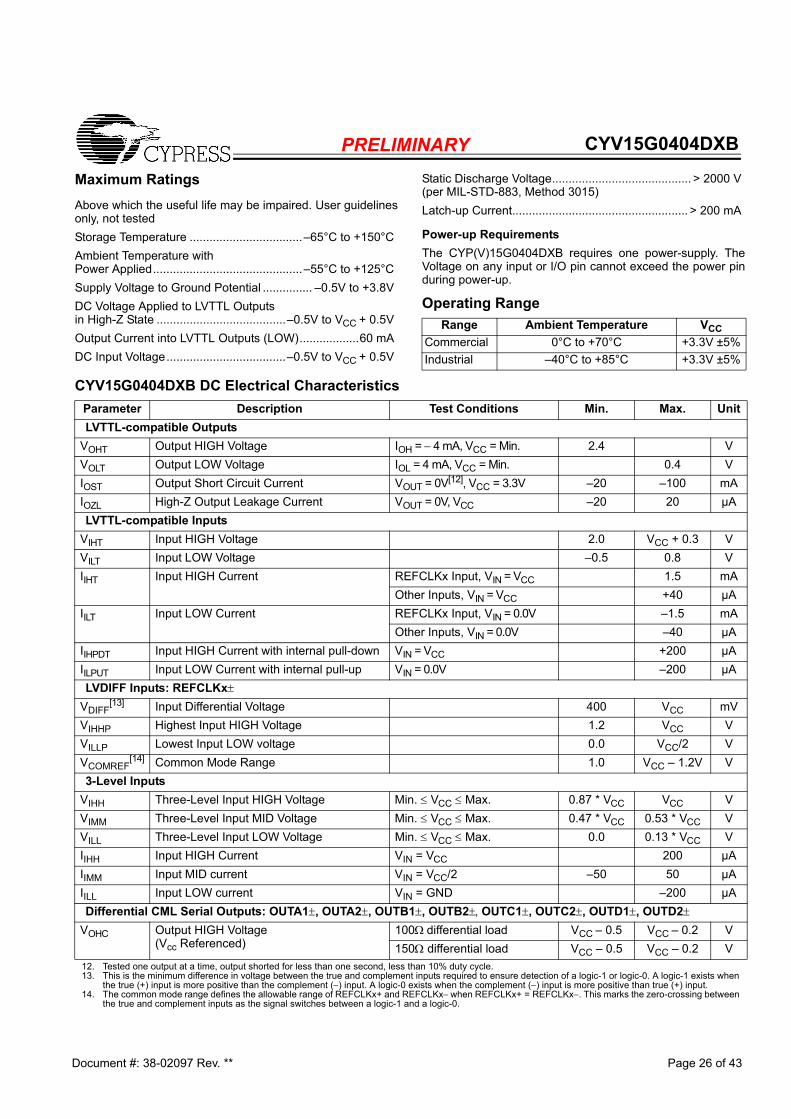
PRELIMINARY CYV15G0404DXB
Document #: 38-02097 Rev. ** Page 26 of 43
Maximum RatingsAbove which the useful life may be impaired. User guidelinesonly, not testedStorage Temperature ..................................–65°C to +150°CAmbient Temperature withPower Applied.............................................–55°C to +125°CSupply Voltage to Ground Potential ............... –0.5V to +3.8VDC Voltage Applied to LVTTL Outputsin High-Z State .......................................–0.5V to VCC + 0.5VOutput Current into LVTTL Outputs (LOW)..................60 mADC Input Voltage....................................–0.5V to VCC + 0.5V
Static Discharge Voltage.......................................... > 2000 V(per MIL-STD-883, Method 3015)Latch-up Current..................................................... > 200 mA
Power-up RequirementsThe CYP(V)15G0404DXB requires one power-supply. TheVoltage on any input or I/O pin cannot exceed the power pinduring power-up.
Operating RangeRange Ambient Temperature VCC
Commercial 0°C to +70°C +3.3V ±5%Industrial –40°C to +85°C +3.3V ±5%
CYV15G0404DXB DC Electrical Characteristics
Parameter Description Test Conditions Min. Max. UnitLVTTL-compatible Outputs
VOHT Output HIGH Voltage IOH = − 4 mA, VCC = Min. 2.4 VVOLT Output LOW Voltage IOL = 4 mA, VCC = Min. 0.4 VIOST Output Short Circuit Current VOUT = 0V[12], VCC = 3.3V –20 –100 mAIOZL High-Z Output Leakage Current VOUT = 0V, VCC –20 20 µALVTTL-compatible Inputs
VIHT Input HIGH Voltage 2.0 VCC + 0.3 VVILT Input LOW Voltage –0.5 0.8 VIIHT Input HIGH Current REFCLKx Input, VIN = VCC 1.5 mA
Other Inputs, VIN = VCC +40 µAIILT Input LOW Current REFCLKx Input, VIN = 0.0V –1.5 mA
Other Inputs, VIN = 0.0V –40 µAIIHPDT Input HIGH Current with internal pull-down VIN = VCC +200 µAIILPUT Input LOW Current with internal pull-up VIN = 0.0V –200 µALVDIFF Inputs: REFCLKx±
VDIFF[13] Input Differential Voltage 400 VCC mV
VIHHP Highest Input HIGH Voltage 1.2 VCC VVILLP Lowest Input LOW voltage 0.0 VCC/2 VVCOMREF
[14] Common Mode Range 1.0 VCC – 1.2V V3-Level Inputs
VIHH Three-Level Input HIGH Voltage Min. ≤ VCC ≤ Max. 0.87 * VCC VCC VVIMM Three-Level Input MID Voltage Min. ≤ VCC ≤ Max. 0.47 * VCC 0.53 * VCC VVILL Three-Level Input LOW Voltage Min. ≤ VCC ≤ Max. 0.0 0.13 * VCC VIIHH Input HIGH Current VIN = VCC 200 µAIIMM Input MID current VIN = VCC/2 –50 50 µAIILL Input LOW current VIN = GND –200 µADifferential CML Serial Outputs: OUTA1±, OUTA2±, OUTB1±, OUTB2±, OUTC1±, OUTC2±, OUTD1±, OUTD2±
VOHC Output HIGH Voltage (Vcc Referenced)
100Ω differential load VCC – 0.5 VCC – 0.2 V150Ω differential load VCC – 0.5 VCC – 0.2 V
12. Tested one output at a time, output shorted for less than one second, less than 10% duty cycle.13. This is the minimum difference in voltage between the true and complement inputs required to ensure detection of a logic-1 or logic-0. A logic-1 exists when
the true (+) input is more positive than the complement (−) input. A logic-0 exists when the complement (−) input is more positive than true (+) input.14. The common mode range defines the allowable range of REFCLKx+ and REFCLKx− when REFCLKx+ = REFCLKx−. This marks the zero-crossing between
the true and complement inputs as the signal switches between a logic-1 and a logic-0.

PRELIMINARY CYV15G0404DXB
Document #: 38-02097 Rev. ** Page 27 of 43
VOLC Output LOW Voltage (VCC Referenced)
100Ω differential load VCC – 1.4 VCC – 0.7 V150Ω differential load VCC – 1.4 VCC – 0.7 V
VODIF Output Differential Voltage|(OUT+) − (OUT−)|
100Ω differential load 450 900 mV150Ω differential load 560 1000 mV
Differential Serial Line Receiver Inputs: INA1±, INA2±, INB1±, INB2±, INC1±, INC2±, IND1±, IND2±
VDIFFs[13] Input Differential Voltage |(IN+) − (IN−)| 100 1200 mV
VIHE Highest Input HIGH Voltage VCC VVILE Lowest Input LOW Voltage VCC – 2.0 VIIHE Input HIGH Current VIN = VIHE Max. 1350 µAIILE Input LOW Current VIN = VILE Min. –700 µAVICOM
[15] Common Mode input range ((VCC – 2.0V)+0.5)min,(VCC – 0.5V) max.
+1.25 +3.1 V
Power Supply Typ. Max.ICC
[16,17] Max Power Supply Current REFCLKx = MAX
Commercial 910 1270 mAIndustrial 1320 mA
ICC [16,17] Typical Power Supply Current REFCLKx
= 125 MHzCommercial 900 1270 mAIndustrial 1320 mA
CYV15G0404DXB DC Electrical Characteristics (continued)
Parameter Description Test Conditions Min. Max. Unit
AC Test Loads and Waveforms
2.0V
0.8VGND
2.0V0.8V
80%20%
80%20%
RL
(Includes fixture andprobe capacitance)
3.0V
Vth = 1.4V
≤ 270 ps ≤ 270 ps
Note 19
Vth = 1.4V
3.3V
R1
R2
R1 = 590ΩR2 = 435Ω
(Includes fixture andprobe capacitance)
CL ≤ 7 pF
(a) LVTTL Output Test Load
RL = 100Ω
(b) CML Output Test Load
CL
(c) LVTTL Input Test Waveform (d) CML/LVPECL Input Test Waveform
≤ 1 ns ≤ 1 ns
VIHE
VILE
VIHE
VILE
Note 18
Note 18

PRELIMINARY CYV15G0404DXB
Document #: 38-02097 Rev. ** Page 28 of 43
CYV15G0404DXB AC Electrical Characteristics Parameter Description Min. Max Unit
CYV15G0404DXB Transmitter LVTTL Switching Characteristics Over the Operating RangefTS TXCLKx Clock Cycle Frequency 19.5 150 MHztTXCLK TXCLKx Period=1/fTS 6.66 51.28 nstTXCLKH
[20] TXCLKx HIGH Time 2.2 nstTXCLKL
[20] TXCLKx LOW Time 2.2 nstTXCLKR
[20, 21, 22] TXCLKx Rise Time 0.2 1.7 nstTXCLKF
[20, 21, 22] TXCLKx Fall Time 0.2 1.7 nstTXDS Transmit Data Set-up Time to TXCLKx↑ (TXCKSELx ≠ 0) 1.7 nstTXDH Transmit Data Hold Time from TXCLKx↑ (TXCKSELx ≠ 0) 0.8 nsfTOS TXCLKOx Clock Frequency = 1x or 2x REFCLKx Frequency 19.5 150 MHztTXCLKO TXCLKOx Period=1/fTOS 6.66 51.28 nstTXCLKOD TXCLKO Duty Cycle centered at 60% HIGH time -1 0 nsCYV15G0404DXB Receiver LVTTL Switching Characteristics Over the Operating RangefRS RXCLKx± Clock Output Frequency 9.75 150 MHztRXCLKP RXCLKx± Period = 1/fRS 6.66 102.56 nstRXCLKD RXCLKx± Duty Cycle Centered at 50% (Full Rate and Half Rate when
RXCKSELx = 0)–1.0 +1.0 ns
tRXCLKR [20] RXCLKx± Rise Time 0.3 1.2 ns
tRXCLKF [20] RXCLKx± Fall Time 0.3 1.2 ns
tRXDv–[23] Status and Data Valid Time to RXCLKx± (RXRATEx = 0, RXCKSELx = 0)
(Full Rate)5UI–1.5[24] ns
Status and Data Valid Time to RXCLKx± (RXRATEx = 1, RXCKSELx = 0) (Half Rate)
5UI–1.0[24] ns
tRXDv+[23] Status and Data Valid Time to RXCLKx± (RXRATEx = 0, RXCKSELx = 0) 5UI–1.8[24] ns
Status and Data Valid Time to RXCLKx± (RXRATEx = 1, RXCKSELx =0) 5UI–2.3[24] nsCYV15G0404DXB REFCLKx Switching Characteristics Over the Operating RangefREF REFCLKx Clock Frequency 19.5 150 MHztREFCLK REFCLKx Period = 1/fREF 6.6 51.28 nstREFH REFCLKx HIGH Time (TXRATEx = 1)(Half Rate) 5.9 ns
REFCLKx HIGH Time (TXRATEx = 0)(Full Rate) 2.9[20] nstREFL REFCLKx LOW Time (TXRATEx = 1)(Half Rate) 5.9 ns
REFCLKx LOW Time (TXRATEx = 0)(Full Rate) 2.9[20] nstREFD
[25] REFCLKx Duty Cycle 30 70 %tREFR
[20, 21, 22] REFCLKx Rise Time (20%–80%) 2 nstREFF
[20, 21, 22] REFCLKx Fall Time (20%–80%) 2 nstTREFDS Transmit Data Set-up Time to REFCLKx (TXCKSELx = 1) 1.7 nsNotes:15. The common mode range defines the allowable range of INPUT+ and INPUT− when INPUT+ = INPUT−. This marks the zero-crossing between the true and
complement inputs as the signal switches between a logic-1 and a logic-0.16. Maximum ICC is measured with VCC = MAX, RFENx = 0,TA = 25°C, with all channels and Serial Line Drivers enabled, sending a continuous alternating 01
pattern, and outputs unloaded. 17. Typical ICC is measured under similar conditions except with VCC = 3.3V, TA = 25°C, RFENx = 0, with all channels enabled and one Serial Line Driver per
transmit channel sending a continuous alternating 01 pattern. The redundant outputs on each channel are powered down and the parallel outputs are unloaded.18. Cypress uses constant current (ATE) load configurations and forcing functions. This figure is for reference only.19. The LVTTL switching threshold is 1.4V. All timing references are made relative to where the signal edges cross the threshold voltage.20. Tested initially and after any design or process changes that may affect these parameters, but not 100% tested.21. The ratio of rise time to falling time must not vary by greater than 2:1.22. For a given operating frequency, neither rise or fall specification can be greater than 20% of the clock-cycle period or the data sheet maximum time.23. Parallel data output specifications are only valid if all outputs are loaded with similar DC and AC loads.24. Receiver UI (Unit Interval) is calculated as 1/(fREF * 20) (when TXRATEx = 1) or 1/(fREF * 10) (when TXRATEx = 0). In an operating link this is equivalent to tB.25. The duty cycle specification is a simultaneous condition with the tREFH and tREFL parameters. This means that at faster character rates the REFCLKx± duty
cycle cannot be as large as 30%–70%.

PRELIMINARY CYV15G0404DXB
Document #: 38-02097 Rev. ** Page 29 of 43
tTREFDH Transmit Data Hold Time from REFCLKx (TXCKSELx = 1) 0.8 nstRREFDA Receive Data Access Time to REFCLKx (RXCKSELx = 1) 9.7[26] nstRREFDW Receive Data Valid Time Window (RXCKSELx = 1) 10UI-5.8 nstREFxDV– Received Data Valid Time to RXCLK (RXCKSELx = 1) 10UI[24] –
5.2ns
tREFxDV+ Received Data valid Time from RXCLK (RXCKSELx = 1) 1.5 nstREFRX
[27] REFCLKx Frequency Referenced to Received Clock Period –0.15 +0.15 %CYV15G0404DXB Bus Configuration Write Timing Characteristics Over the Operating RangetDATAH Bus Configuration Data Hold 0 nstDATAS Bus Configuration Data Setup 10 nstWRENP Bus Configuration WREN Pulse Width 10 nsCYV15G0404DXB JTAG Test Clock Characteristics Over the Operating RangefTCLK JTAG Test Clock Frequency 20 MHztTCLK JTAG Test Clock Period 50 nsCYV15G0404DXB Device RESET Characteristics Over the Operating RangetRST Device RESET Pulse Width 15 nsCYV15G0404DXB Transmit Serial Outputs and TX PLL Characteristics Over the Operating Range
Parameter Description Condition Min. Max. UnittB Bit Time 5128 660 pstRISE
[20] CML Output Rise Time 20−80% (CML Test Load) SPDSELx = HIGH 50 270 psSPDSELx = MID 100 500 psSPDSELx =LOW 180 1000 ps
tFALL[20] CML Output Fall Time 80−20% (CML Test Load) SPDSELx = HIGH 50 270 ps
SPDSELx = MID 100 500 psSPDSELx =LOW 180 1000 ps
tDJ [20, 28, 30] Deterministic Jitter (peak-peak)[31] IEEE 802.3z 25 ps
tRJ[20, 29, 30] Random Jitter (σ)[31] IEEE 802.3z 11 ps
tREFJ[20] REFCLKx jitter tolerance / Phase noise limits TBD
tTXLOCK Transmit PLLx lock to REFCLKx± 200 µsCYV15G0404DXB Receive Serial Inputs and CDR PLL Characteristics Over the Operating RangetRXLOCK Receive PLL lock to input data stream (cold start) 376k UI
Receive PLL lock to input data stream 376k UItRXUNLOCK Receive PLL Unlock Rate 46 UItJTOL
[20] Total Jitter Tolerance[31] IEEE 802.3z 600 pstDJTOL
[20] Deterministic Jitter Tolerance[31] IEEE 802.3z 370 psNotes:26. Since this timing parameter is greater than the minimum time period of REFCLK it sets an upper limit to the frequency in which REFCLKx can be used to clock
the receive data out of the output register. For predictable timing, users can use this parameter only if REFCLK period is greater than sum of tRREFDA and set-up time of the upstream device. When this condition is not true, RXCLKx± (a buffered or divided version of REFCLK when RXCKSELx = 1) could be used to clock the receive data out of the device.
27. REFCLKx± has no phase or frequency relationship with the recovered clock(s) and only acts as a centering reference to reduce clock synchronization time. REFCLKx± must be within ±1500 PPM (±0.15%) of the transmitter PLL reference (REFCLKx±) frequency. Although transmitting to a HOTLink II receiver necessitates the frequency difference between the transmitter and receiver reference clocks to be within ±1500-PPM, the stability of the crystal needs to be within the limits specified by the appropriate standard when transmitting to a remote receiver that is compliant to that standard. For example, to be IEEE 802.3z Gigabit Ethernet compliant, the frequency stability of the crystal needs to be within ±100 PPM.l.
28. While sending continuous K28.5s, outputs loaded to a balanced 100Ω load, measured at the cross point of differential outputs, over the operating range. 29. While sending continuous K28.7s, after 100,000 samples measured at the cross point of differential outputs, time referenced to REFCLKx± input, over the
operating range.30. Total jitter is calculated at an assumed BER of 1E −12. Hence: Total Jitter (tJ) = (tRJ * 14) + tDJ.31. Also meets all Jitter Generation and Jitter Tolerance requirements as specified by SMPTE 259, SMPTE 292, ESCON, FICON, Fibre Channel, and DVB-ASI.
CYV15G0404DXB AC Electrical Characteristics (continued)
Parameter Description Min. Max Unit

PRELIMINARY CYV15G0404DXB
Document #: 38-02097 Rev. ** Page 30 of 43
Capacitance [20]
Parameter Description Test Conditions Max. UnitCINTTL TTL Input Capacitance TA = 25°C, f0 = 1 MHz, VCC = 3.3V 7 pFCINPECL PECL input Capacitance TA = 25°C, f0 = 1 MHz, VCC = 3.3V 4 pF
CYV15G0404DXB HOTLink II Transmitter Switching Waveforms
Notes:32. When REFCLKx± is configured for half-rate operation (TXRATE = 1) and data is captured using REFCLKx instead of a TXCLKx clock. Data is captured using
both the rising and falling edges of REFCLKx.33. The TXCLKOx output remains at the character rate regardless of the state of TXRATE and does not follow the duty cycle of REFCLKx±.34. The rising edge of TXCLKOx output has no direct phase relationship to the REFCLKx± input.
TXCLKx
TXDx[7:0],TXCTx[1:0],
tTXDHtTXDS
tTXCLKtTXCLKH tTXCLKL
Transmit InterfaceWrite TimingTXCLKx selected
REFCLKx
Transmit InterfacetREFCLK
tREFH tREFL
tTREFDS tTREFDH
Write Timing
TXRATEx = 0
TXDx[7:0],TXCTx[1:0],
REFCLKx selected
tTREFDH
Transmit InterfaceWrite Timing
TXRATEx = 1
REFCLKx
tREFCLK
tREFLtREFH
Note 32
TXDx[7:0],TXCTx[1:0],
tTREFDS tTREFDS tTREFDH
REFCLKx selected
TXCLKOx
tTXCLKO
Transmit InterfaceTXCLKOx Timing
TXRATEx = 1
(internal)
REFCLKx
tREFCLK
tREFLtREFH
Note 33
Note 34

PRELIMINARY CYV15G0404DXB
Document #: 38-02097 Rev. ** Page 31 of 43
CYV15G0404DXB HOTLink II Transmitter Switching Waveforms (continued)
TXCLKOx
tTXCLKOtTXOH tTXOL
Transmit InterfaceTXCLKOx Timing
REFCLKxNote33
Note34
tREFCLKtREFH tREFL
TXRATEx = 0
Switching Waveforms for the CYV15G0404DXB HOTLink II Receiver
Note:35. When operated with a half-rate REFCLKx±, the setup and hold specifications for data relative to RXCLKx are relative to both rising and falling edges of the
respective clock output36. TXERRx is synchronous to RXCLKx only when RXCLKx is selected as REFCLK.
REFCLKx
RXDx[7:0],RXSTx[2:0],
tREFCLKtREFH tREFL
Receive InterfaceRead Timing
Full-rate RXCLKx±
RXCLKx
tREFxDV+tREFxDV–
tRREFDA
REFCLKx Selected
tRREFDW tRREFDW
TXERRx[36]
REFCLKx
RXDx[7:0],RXSTx[2:0],
tREFCLKtREFH tREFL
Receive InterfaceRead Timing
Half-rate RXCLKx±
tRREFDA
RXCLKx
tREFxDV+ tREFxDV–
Note 35
tRREFDA
REFCLKx Selected
tRREFDW tRREFDW
TXERRx[36]

PRELIMINARY CYV15G0404DXB
Document #: 38-02097 Rev. ** Page 32 of 43
Switching Waveforms for the CYV15G0404DXB HOTLink II Receiver
RXCLKx+
RXDx[7:0],RXSTx[2:0],
tRXDV+
tRXCLKPReceive InterfaceRead Timing
RXRATEx = 0
RXCLKx-
tRXDV–
Recovered Clock selected
RXCLKx+
RXDx[7:0],RXSTx[2:0]
tRXDV+
tRXDV–
tRXCLKPReceive InterfaceRead Timing
RXRATEx = 1
RXCLKx-
Recovered Clock selected
ADDR[3:0]
tDATAS
Bus Configuration Write Timing
DATA[7:0]
WRENtDATAH
tWRENP

PRELIMINARY CYV15G0404DXB
Document #: 38-02097 Rev. ** Page 33 of 43
Table 12. Package Coordinate Signal Allocation
Ball ID Signal Name Signal Type
Ball ID Signal Name Signal Type
Ball ID Signal Name Signal Type
A01 INC1– CML IN C07 ULCC LVTTL IN PU F17 RCLKENA LVTTL IN PDA02 OUTC1– CML OUT C08 GND GROUND F18 RXSTB[1] LVTTL OUTA03 INC2– CML IN C09 DATA[7] LVTTL IN PU F19 TXCLKOB LVTTL OUTA04 OUTC2– CML OUT C10 DATA[5] LVTTL IN PU F20 RXSTB[0] LVTTL OUTA05 VCC POWER C11 DATA[3] LVTTL IN PU G01 TXDC[7] LVTTL INA06 IND1– CML IN C12 DATA[1] LVTTL IN PU G02 WREN LVTTL IN PUA07 OUTD1– CML OUT C13 GND GROUND G03 TXDC[4] LVTTL INA08 GND GROUND C14 RCLKENB LVTTL IN PD G04 TXDC[1] LVTTL INA09 IND2– CML IN C15 SPDSELD 3-LEVEL SEL G17 SPDSELB 3-LEVEL SELA10 OUTD2– CML OUT C16 VCC POWER G18 LPENC LVTTL IN PDA11 INA1– CML IN C17 LDTDEN LVTTL IN PU G19 SPDSELA 3-LEVEL SELA12 OUTA1– CML OUT C18 TRST LVTTL IN PU G20 RXDB[1] LVTTL OUTA13 GND GROUND C19 LPEND LVTTL IN PD H01 GND GROUNDA14 INA2– CML IN C20 TDO LVTTL 3-S OUT H02 GND GROUNDA15 OUTA2– CML OUT D01 TCLK LVTTL IN PD H03 GND GROUNDA16 VCC POWER D02 RESET LVTTL IN PU H04 GND GROUNDA17 INB1– CML IN D03 INSELD LVTTL IN H17 GND GROUNDA18 OUTB1– CML OUT D04 INSELA LVTTL IN H18 GND GROUNDA19 INB2– CML IN D05 VCC POWER H19 GND GROUNDA20 OUTB2– CML OUT D06 ULCA LVTTL IN PU H20 GND GROUNDB01 INC1+ CML IN D07 SPDSELC 3-LEVEL SEL J01 TXCTC[1] LVTTL INB02 OUTC1+ CML OUT D08 GND GROUND J02 TXDC[5] LVTTL INB03 INC2+ CML IN D09 DATA[6] LVTTL IN PU J03 TXDC[2] LVTTL INB04 OUTC2+ CML OUT D10 DATA[4] LVTTL IN PU J04 TXDC[3] LVTTL INB05 VCC POWER D11 DATA[2] LVTTL IN PU J17 RXSTB[2] LVTTL OUTB06 IND1+ CML IN D12 DATA[0] LVTTL IN PU J18 RXDB[0] LVTTL OUTB07 OUTD1+ CML OUT D13 GND GROUND J19 RXDB[5] LVTTL OUTB08 GND GROUND D14 LPENB LVTTL IN PD J20 RXDB[2] LVTTL OUTB09 IND2+ CML IN D15 ULCB LVTTL IN PU K01 RXDC[2] LVTTL OUTB10 OUTD2+ CML OUT D16 VCC POWER K02 REFCLKC– PECL INB11 INA1+ CML IN D17 LPENA LVTTL IN PD K03 TXCTC[0] LVTTL INB12 OUTA1+ CML OUT D18 VCC POWER K04 TXCLKC LVTTL IN PDB13 GND GROUND D19 SCANEN2 LVTTL IN PD K17 RXDB[3] LVTTL OUTB14 INA2+ CML IN D20 TMEN3 LVTTL IN PD K18 RXDB[4] LVTTL OUTB15 OUTA2+ CML OUT E01 VCC POWER K19 RXDB[7] LVTTL OUTB16 VCC POWER E02 VCC POWER K20 LFIB LVTTL OUTB17 INB1+ CML IN E03 VCC POWER L01 RXDC[3] LVTTL OUTB18 OUTB1+ CML OUT E04 VCC POWER L02 REFCLKC+ PECL INB19 INB2+ CML IN E17 VCC POWER L03 LFIC LVTTL OUT B20 OUTB2+ CML OUT E18 VCC POWER L04 TXDC[6] LVTTL INC01 TDI LVTTL IN PU E19 VCC POWER L17 RXDB[6] LVTTL OUTC02 TMS LVTTL IN PU E20 VCC POWER L18 RXCLKB+ LVTTL OUTC03 INSELC LVTTL IN F01 RXDC[6] LVTTL OUT L19 RXCLKB– LVTTL OUT

PRELIMINARY CYV15G0404DXB
Document #: 38-02097 Rev. ** Page 34 of 43
C04 INSELB LVTTL IN F02 RXDC[7] LVTTL OUT L20 TXDB[6] LVTTL INC05 VCC POWER F03 TXDC[0] LVTTL IN M01 RXDC[4] LVTTL OUTC06 ULCD LVTTL IN PU F04 RCLKEND LVTTL IN PD M02 RXDC[5] LVTTL OUTM03 RCLKENC LVTTL IN PD U03 TXDD[2] LVTTL IN W03 LFID LVTTL OUTM04 TXERRC LVTTL OUT U04 TXCTD[1] LVTTL IN W04 RXCLKD– LVTTL OUTM17 REFCLKB+ PECL IN U05 VCC POWER W05 VCC POWERM18 REFCLKB– PECL IN U06 RXDD[2] LVTTL OUT W06 RXDD[4] LVTTL OUTM19 TXERRB LVTTL OUT U07 RXDD[1] LVTTL OUT W07 RXSTD[1] LVTTL OUTM20 TXCLKB LVTTL IN PD U08 GND GROUND W08 GND GROUNDN01 GND GROUND U09 TXCTA[1] LVTTL IN W09 ADDR [3] LVTTL IN PUN02 GND GROUND U10 ADDR [0] LVTTL IN PU W10 ADDR [1] LVTTL IN PUN03 GND GROUND U11 REFCLKD– PECL IN W11 RXCLKA+ LVTTL OUTN04 GND GROUND U12 TXDA[1] LVTTL IN W12 TXERRA LVTTL OUTN17 GND GROUND U13 GND GROUND W13 GND GROUNDN18 GND GROUND U14 TXDA[4] LVTTL IN W14 TXDA[2] LVTTL INN19 GND GROUND U15 TXCTA[0] LVTTL IN W15 TXDA[6] LVTTL INN20 GND GROUND U16 VCC POWER W16 VCC POWERP01 RXDC[1] LVTTL OUT U17 RXDA[2] LVTTL OUT W17 LFIA LVTTL OUTP02 RXDC[0] LVTTL OUT U18 TXCTB[0] LVTTL IN W18 REFCLKA+ PECL INP03 RXSTC[0] LVTTL OUT U19 RXSTA[2] LVTTL OUT W19 RXDA[4] LVTTL OUTP04 RXSTC[1] LVTTL OUT U20 RXSTA[1] LVTTL OUT W20 RXDA[1] LVTTL OUTP17 TXDB[5] LVTTL IN V01 TXDD[3] LVTTL IN Y01 TXDD[6] LVTTL INP18 TXDB[4] LVTTL IN V02 TXDD[4] LVTTL IN Y02 TXCLKD LVTTL IN PDP19 TXDB[3] LVTTL IN V03 TXCTD[0] LVTTL IN Y03 RXDD[7] LVTTL OUTP20 TXDB[2] LVTTL IN V04 RXDD[6] LVTTL OUT Y04 RXCLKD+ LVTTL OUTR01 RXSTC[2] LVTTL OUT V05 VCC POWER Y05 VCC POWERR02 TXCLKOC LVTTL OUT V06 RXDD[3] LVTTL OUT Y06 RXDD[5] LVTTL OUTR03 RXCLKC+ LVTTL OUT V07 RXSTD[0] LVTTL OUT Y07 RXDD[0] LVTTL OUTR04 RXCLKC– LVTTL OUT V08 GND GROUND Y08 GND GROUNDR17 TXDB[1] LVTTL IN V09 RXSTD[2] LVTTL OUT Y09 TXCLKOD LVTTL OUTR18 TXDB[0] LVTTL IN V10 ADDR [2] LVTTL IN PU Y10 NC NO CONNECTR19 TXCTB[1] LVTTL IN V11 REFCLKD+ PECL IN Y11 TXCLKA LVTTL IN PDR20 TXDB[7] LVTTL IN V12 TXCLKOA LVTTL OUT Y12 RXCLKA– LVTTL OUTT01 VCC POWER V13 GND GROUND Y13 GND GROUNDT02 VCC POWER V14 TXDA[3] LVTTL IN Y14 TXDA[0] LVTTL INT03 VCC POWER V15 TXDA[7] LVTTL IN Y15 TXDA[5] LVTTL INT04 VCC POWER V16 VCC POWER Y16 VCC POWERT17 VCC POWER V17 RXDA[7] LVTTL OUT Y17 TXERRD LVTTL OUTT18 VCC POWER V18 RXDA[3] LVTTL OUT Y18 REFCLKA– PECL INT19 VCC POWER V19 RXDA[0] LVTTL OUT Y19 RXDA[6] LVTTL OUTT20 VCC POWER V20 RXSTA[0] LVTTL OUT Y20 RXDA[5] LVTTL OUTU01 TXDD[0] LVTTL IN W01 TXDD[5] LVTTL INU02 TXDD[1] LVTTL IN W02 TXDD[7] LVTTL IN
Table 12. Package Coordinate Signal Allocation (continued)
Ball ID Signal Name Signal Type
Ball ID Signal Name Signal Type
Ball ID Signal Name Signal Type

PRELIMINARY CYV15G0404DXB
Document #: 38-02097 Rev. ** Page 35 of 43
X3.230 Codes and Notation ConventionsInformation transmitted over a serial link is encoded eight bitsat a time into a 10-bit Transmission Character and then sentserially, bit by bit. Information received over a serial link iscollected ten bits at a time, and those TransmissionCharacters that are used for data characters are decoded intothe correct eight-bit codes. The 10-bit Transmission Codesupports all 256 8-bit combinations. Some of the remainingTransmission Characters (Special Characters) are used forfunctions other than data transmission.The primary use of a Transmission Code is to improve thetransmission characteristics of a serial link. The encodingdefined by the Transmission Code ensures that sufficienttransitions are present in the serial bit stream to make clockrecovery possible at the Receiver. Such encoding also greatlyincreases the likelihood of detecting any single or multiple biterrors that may occur during transmission and reception ofinformation. In addition, some Special Characters of the Trans-mission Code selected by Fibre Channel Standard contain adistinct and easily recognizable bit pattern that assists thereceiver in achieving character alignment on the incoming bitstream.
Notation ConventionsThe documentation for the 8B/10B Transmission Code usesletter notation for the bits in an 8-bit byte. Fibre ChannelStandard notation uses a bit notation of A, B, C, D, E, F, G, Hfor the 8-bit byte for the raw 8-bit data, and the letters a, b, c,d, e, i, f, g, h, j for encoded 10-bit data. There is a correspon-dence between bit A and bit a, B and b, C and c, D and d, Eand e, F and f, G and g, and H and h. Bits i and j are derived,respectively, from (A,B,C,D,E) and (F,G,H).The bit labeled A in the description of the 8B/10B TransmissionCode corresponds to bit 0 in the numbering scheme of the FC-2 specification, B corresponds to bit 1, as shown below.
FC-2 bit designation— 7 6 5 4 3 2 1 0HOTLink D/Q designation— 7 6 5 4 3 2 1 08B/10B bit designation— H G F E D C B A
To clarify this correspondence, the following example showsthe conversion from an FC-2 Valid Data Byte to a TransmissionCharacter.
FC-2 45HBits: 7654 3210
0100 0101Converted to 8B/10B notation, note that the order of bits hasbeen reversed):
Data Byte Name D5.2Bits: ABCDE FGH
10100 010Translated to a transmission Character in the 8B/10B Trans-mission Code:
Bits: abcdei fghj101001 0101
Each valid Transmission Character of the 8B/10B Trans-mission Code has been given a name using the followingconvention: cxx.y, where c is used to show whether the Trans-mission Character is a Data Character (c is set to D, and SC/D= LOW) or a Special Character (c is set to K, and SC/D =HIGH). When c is set to D, xx is the decimal value of the binary
number composed of the bits E, D, C, B, and A in that order,and the y is the decimal value of the binary number composedof the bits H, G, and F in that order. When c is set to K, xx andy are derived by comparing the encoded bit patterns of theSpecial Character to those patterns derived from encodedValid Data bytes and selecting the names of the patterns mostsimilar to the encoded bit patterns of the Special Character.Under the above conventions, the Transmission Characterused for the examples above, is referred to by the name D5.2.The Special Character K29.7 is so named because the first sixbits (abcdei) of this character make up a bit pattern similar tothat resulting from the encoding of the unencoded 11101pattern (29), and because the second four bits (fghj) make upa bit pattern similar to that resulting from the encoding of theunencoded 111 pattern (7).Note. This definition of the 10-bit Transmission Code is basedon the following references, which describe the same 10-bittransmission code.A.X. Widmer and P.A. Franaszek. “A DC-Balanced, Parti-tioned-Block, 8B/10B Transmission Code” IBM Journal ofResearch and Development, 27, No. 5: 440-451 (September,1983).U.S. Patent 4,486,739. Peter A. Franaszek and Albert X.Widmer. “Byte-Oriented DC Balanced (0.4) 8B/10B Parti-tioned Block Transmission Code” (December 4, 1984).Fibre Channel Physical and Signaling Interface (ANS X3.230-1994 ANSI FC-PH Standard).IBM Enterprise Systems Architecture/390 ESCON I/OInterface (document number SA22-7202).
8B/10B Transmission CodeThe following information describes how the tables are usedfor both generating valid Transmission Characters (encoding)and checking the validity of received Transmission Characters(decoding). It also specifies the ordering rules followed whentransmitting the bits within a character and the characterswithin any higher-level constructs specified by a standard.
Transmission OrderWithin the definition of the 8B/10B Transmission Code, the bitpositions of the Transmission Characters are labeled a, b, c,d, e, i, f, g, h, j. Bit “a” is transmitted first followed by bits b, c,d, e, i, f, g, h, and j in that order. Note that bit i is transmitted between bit e and bit f, rather thanin alphabetical order.
Valid and Invalid Transmission CharactersThe following tables define the valid Data Characters and validSpecial Characters (K characters), respectively. The tablesare used for both generating valid Transmission Charactersand checking the validity of received TransmissionCharacters. In the tables, each Valid-Data-byte or Special-Character-code entry has two columns that represent twoTransmission Characters. The two columns correspond to thecurrent value of the running disparity. Running disparity is abinary parameter with either a negative (–) or positive (+)value.After powering on, the Transmitter may assume either apositive or negative value for its initial running disparity. Upontransmission of any Transmission Character, the transmitterselects the proper version of the Transmission Character

PRELIMINARY CYV15G0404DXB
Document #: 38-02097 Rev. ** Page 36 of 43
based on the current running disparity value, and the Trans-mitter calculates a new value for its running disparity based onthe contents of the transmitted character. Special Charactercodes C1.7 and C2.7 can be used to force the transmission ofa specific Special Character with a specific running disparityas required for some special sequences in X3.230.After powering on, the Receiver may assume either a positiveor negative value for its initial running disparity. Upon receptionof any Transmission Character, the Receiver decides whetherthe Transmission Character is valid or invalid according to thefollowing rules and tables and calculates a new value for itsRunning Disparity based on the contents of the receivedcharacter.The following rules for running disparity are used to calculatethe new running-disparity value for Transmission Charactersthat have been transmitted and received.Running disparity for a Transmission Character is calculatedfrom sub-blocks, where the first six bits (abcdei) form one sub-block and the second four bits (fghj) form the other sub-block.Running disparity at the beginning of the 6-bit sub-block is therunning disparity at the end of the previous TransmissionCharacter. Running disparity at the beginning of the 4-bit sub-block is the running disparity at the end of the 6-bit sub-block.Running disparity at the end of the Transmission Character isthe running disparity at the end of the 4-bit sub-block.Running disparity for the sub-blocks is calculated as follows:1. Running disparity at the end of any sub-block is positive if
the sub-block contains more ones than zeros. It is also positive at the end of the 6-bit sub-block if the 6-bit sub-block is 000111, and it is positive at the end of the 4-bit sub-block if the 4-bit sub-block is 0011.
2. Running disparity at the end of any sub-block is negative if the sub-block contains more zeros than ones. It is also negative at the end of the 6-bit sub-block if the 6-bit sub-block is 111000, and it is negative at the end of the 4-bit sub-block if the 4-bit sub-block is 1100.
3. Otherwise, running disparity at the end of the sub-block is the same as at the beginning of the sub-block.
Use of the Tables for Generating Transmission CharactersThe appropriate entry in Table 15 for the Valid Data byte orTable 16 for Special Character byte identify which Trans-mission Character is generated. The current value of theTransmitter’s running disparity is used to select the Trans-mission Character from its corresponding column. For eachTransmission Character transmitted, a new value of therunning disparity is calculated. This new value is used as theTransmitter’s current running disparity for the next Valid Data
byte or Special Character byte encoded and transmitted.Table 13 shows naming notations and examples of valid trans-mission characters.
Use of the Tables for Checking the Validity of Received Transmission CharactersThe column corresponding to the current value of theReceiver’s running disparity is searched for the receivedTransmission Character. If the received TransmissionCharacter is found in the proper column, then the Trans-mission Character is valid and the associated Data byte orSpecial Character code is determined (decoded). If thereceived Transmission Character is not found in that column,then the Transmission Character is invalid. This is called acode violation. Independent of the Transmission Character’svalidity, the received Transmission Character is used tocalculate a new value of running disparity. The new value isused as the Receiver’s current running disparity for the nextreceived Transmission Character.
Detection of a code violation does not necessarily show thatthe Transmission Character in which the code violation wasdetected is in error. Code violations may result from a priorerror that altered the running disparity of the bit stream whichdid not result in a detectable error at the TransmissionCharacter in which the error occurred. Table 14 shows anexample of this behavior.
Table 13. Valid Transmission Characters
Data
Byte NameDIN or QOUT
Hex Value765 43210
D0.0 000 00000 00
D1.0 000 00001 01
D2.0 000 00010 02
.
...
.
...
D5.2 010 00101 45
.
...
.
...
D30.7 111 11110 FE
D31.7 111 11111 FF
Table 14. Code Violations Resulting from Prior Errors
RD Character RD Character RD Character RDTransmitted data character – D21.1 – D10.2 – D23.5 +Transmitted bit stream – 101010 1001 – 010101 0101 – 111010 1010 +Bit stream after error – 101010 1011 + 010101 0101 + 111010 1010 +Decoded data character – D21.0 + D10.2 + Code Violation +

PRELIMINARY CYV15G0404DXB
Document #: 38-02097 Rev. ** Page 37 of 43
Table 15. Valid Data Characters (TXCTx[0] = 0, RXSTx[2:0] = 000)
Data Byte
NameBits Current RD− Current RD+ Data
Byte Name
Bits Current RD− Current RD+HGF EDCBA abcdei fghj abcdei fghj HGF EDCBA abcdei fghj abcdei fghj
D0.0 000 00000 100111 0100 011000 1011 D0.1 001 00000 100111 1001 011000 1001
D1.0 000 00001 011101 0100 100010 1011 D1.1 001 00001 011101 1001 100010 1001
D2.0 000 00010 101101 0100 010010 1011 D2.1 001 00010 101101 1001 010010 1001
D3.0 000 00011 110001 1011 110001 0100 D3.1 001 00011 110001 1001 110001 1001
D4.0 000 00100 110101 0100 001010 1011 D4.1 001 00100 110101 1001 001010 1001
D5.0 000 00101 101001 1011 101001 0100 D5.1 001 00101 101001 1001 101001 1001
D6.0 000 00110 011001 1011 011001 0100 D6.1 001 00110 011001 1001 011001 1001
D7.0 000 00111 111000 1011 000111 0100 D7.1 001 00111 111000 1001 000111 1001
D8.0 000 01000 111001 0100 000110 1011 D8.1 001 01000 111001 1001 000110 1001
D9.0 000 01001 100101 1011 100101 0100 D9.1 001 01001 100101 1001 100101 1001
D10.0 000 01010 010101 1011 010101 0100 D10.1 001 01010 010101 1001 010101 1001
D11.0 000 01011 110100 1011 110100 0100 D11.1 001 01011 110100 1001 110100 1001
D12.0 000 01100 001101 1011 001101 0100 D12.1 001 01100 001101 1001 001101 1001
D13.0 000 01101 101100 1011 101100 0100 D13.1 001 01101 101100 1001 101100 1001
D14.0 000 01110 011100 1011 011100 0100 D14.1 001 01110 011100 1001 011100 1001
D15.0 000 01111 010111 0100 101000 1011 D15.1 001 01111 010111 1001 101000 1001
D16.0 000 10000 011011 0100 100100 1011 D16.1 001 10000 011011 1001 100100 1001
D17.0 000 10001 100011 1011 100011 0100 D17.1 001 10001 100011 1001 100011 1001
D18.0 000 10010 010011 1011 010011 0100 D18.1 001 10010 010011 1001 010011 1001
D19.0 000 10011 110010 1011 110010 0100 D19.1 001 10011 110010 1001 110010 1001
D20.0 000 10100 001011 1011 001011 0100 D20.1 001 10100 001011 1001 001011 1001
D21.0 000 10101 101010 1011 101010 0100 D21.1 001 10101 101010 1001 101010 1001
D22.0 000 10110 011010 1011 011010 0100 D22.1 001 10110 011010 1001 011010 1001
D23.0 000 10111 111010 0100 000101 1011 D23.1 001 10111 111010 1001 000101 1001
D24.0 000 11000 110011 0100 001100 1011 D24.1 001 11000 110011 1001 001100 1001
D25.0 000 11001 100110 1011 100110 0100 D25.1 001 11001 100110 1001 100110 1001
D26.0 000 11010 010110 1011 010110 0100 D26.1 001 11010 010110 1001 010110 1001
D27.0 000 11011 110110 0100 001001 1011 D27.1 001 11011 110110 1001 001001 1001
D28.0 000 11100 001110 1011 001110 0100 D28.1 001 11100 001110 1001 001110 1001
D29.0 000 11101 101110 0100 010001 1011 D29.1 001 11101 101110 1001 010001 1001
D30.0 000 11110 011110 0100 100001 1011 D30.1 001 11110 011110 1001 100001 1001
D31.0 000 11111 101011 0100 010100 1011 D31.1 001 11111 101011 1001 010100 1001

PRELIMINARY CYV15G0404DXB
Document #: 38-02097 Rev. ** Page 38 of 43
D0.2 010 00000 100111 0101 011000 0101 D0.3 011 00000 100111 0011 011000 1100
D1.2 010 00001 011101 0101 100010 0101 D1.3 011 00001 011101 0011 100010 1100
D2.2 010 00010 101101 0101 010010 0101 D2.3 011 00010 101101 0011 010010 1100
D3.2 010 00011 110001 0101 110001 0101 D3.3 011 00011 110001 1100 110001 0011
D4.2 010 00100 110101 0101 001010 0101 D4.3 011 00100 110101 0011 001010 1100
D5.2 010 00101 101001 0101 101001 0101 D5.3 011 00101 101001 1100 101001 0011
D6.2 010 00110 011001 0101 011001 0101 D6.3 011 00110 011001 1100 011001 0011
D7.2 010 00111 111000 0101 000111 0101 D7.3 011 00111 111000 1100 000111 0011
D8.2 010 01000 111001 0101 000110 0101 D8.3 011 01000 111001 0011 000110 1100
D9.2 010 01001 100101 0101 100101 0101 D9.3 011 01001 100101 1100 100101 0011
D10.2 010 01010 010101 0101 010101 0101 D10.3 011 01010 010101 1100 010101 0011
D11.2 010 01011 110100 0101 110100 0101 D11.3 011 01011 110100 1100 110100 0011
D12.2 010 01100 001101 0101 001101 0101 D12.3 011 01100 001101 1100 001101 0011
D13.2 010 01101 101100 0101 101100 0101 D13.3 011 01101 101100 1100 101100 0011
D14.2 010 01110 011100 0101 011100 0101 D14.3 011 01110 011100 1100 011100 0011
D15.2 010 01111 010111 0101 101000 0101 D15.3 011 01111 010111 0011 101000 1100
D16.2 010 10000 011011 0101 100100 0101 D16.3 011 10000 011011 0011 100100 1100
D17.2 010 10001 100011 0101 100011 0101 D17.3 011 10001 100011 1100 100011 0011
D18.2 010 10010 010011 0101 010011 0101 D18.3 011 10010 010011 1100 010011 0011
D19.2 010 10011 110010 0101 110010 0101 D19.3 011 10011 110010 1100 110010 0011
D20.2 010 10100 001011 0101 001011 0101 D20.3 011 10100 001011 1100 001011 0011
D21.2 010 10101 101010 0101 101010 0101 D21.3 011 10101 101010 1100 101010 0011
D22.2 010 10110 011010 0101 011010 0101 D22.3 011 10110 011010 1100 011010 0011
D23.2 010 10111 111010 0101 000101 0101 D23.3 011 10111 111010 0011 000101 1100
D24.2 010 11000 110011 0101 001100 0101 D24.3 011 11000 110011 0011 001100 1100
D25.2 010 11001 100110 0101 100110 0101 D25.3 011 11001 100110 1100 100110 0011
D26.2 010 11010 010110 0101 010110 0101 D26.3 011 11010 010110 1100 010110 0011
D27.2 010 11011 110110 0101 001001 0101 D27.3 011 11011 110110 0011 001001 1100
D28.2 010 11100 001110 0101 001110 0101 D28.3 011 11100 001110 1100 001110 0011
D29.2 010 11101 101110 0101 010001 0101 D29.3 011 11101 101110 0011 010001 1100
D30.2 010 11110 011110 0101 100001 0101 D30.3 011 11110 011110 0011 100001 1100
D31.2 010 11111 101011 0101 010100 0101 D31.3 011 11111 101011 0011 010100 1100
Table 15. Valid Data Characters (TXCTx[0] = 0, RXSTx[2:0] = 000) (continued)
Data Byte
NameBits Current RD− Current RD+ Data
Byte Name
Bits Current RD− Current RD+HGF EDCBA abcdei fghj abcdei fghj HGF EDCBA abcdei fghj abcdei fghj

PRELIMINARY CYV15G0404DXB
Document #: 38-02097 Rev. ** Page 39 of 43
D0.4 100 00000 100111 0010 011000 1101 D0.5 101 00000 100111 1010 011000 1010
D1.4 100 00001 011101 0010 100010 1101 D1.5 101 00001 011101 1010 100010 1010
D2.4 100 00010 101101 0010 010010 1101 D2.5 101 00010 101101 1010 010010 1010
D3.4 100 00011 110001 1101 110001 0010 D3.5 101 00011 110001 1010 110001 1010
D4.4 100 00100 110101 0010 001010 1101 D4.5 101 00100 110101 1010 001010 1010
D5.4 100 00101 101001 1101 101001 0010 D5.5 101 00101 101001 1010 101001 1010
D6.4 100 00110 011001 1101 011001 0010 D6.5 101 00110 011001 1010 011001 1010
D7.4 100 00111 111000 1101 000111 0010 D7.5 101 00111 111000 1010 000111 1010
D8.4 100 01000 111001 0010 000110 1101 D8.5 101 01000 111001 1010 000110 1010
D9.4 100 01001 100101 1101 100101 0010 D9.5 101 01001 100101 1010 100101 1010
D10.4 100 01010 010101 1101 010101 0010 D10.5 101 01010 010101 1010 010101 1010
D11.4 100 01011 110100 1101 110100 0010 D11.5 101 01011 110100 1010 110100 1010
D12.4 100 01100 001101 1101 001101 0010 D12.5 101 01100 001101 1010 001101 1010
D13.4 100 01101 101100 1101 101100 0010 D13.5 101 01101 101100 1010 101100 1010
D14.4 100 01110 011100 1101 011100 0010 D14.5 101 01110 011100 1010 011100 1010
D15.4 100 01111 010111 0010 101000 1101 D15.5 101 01111 010111 1010 101000 1010
D16.4 100 10000 011011 0010 100100 1101 D16.5 101 10000 011011 1010 100100 1010
D17.4 100 10001 100011 1101 100011 0010 D17.5 101 10001 100011 1010 100011 1010
D18.4 100 10010 010011 1101 010011 0010 D18.5 101 10010 010011 1010 010011 1010
D19.4 100 10011 110010 1101 110010 0010 D19.5 101 10011 110010 1010 110010 1010
D20.4 100 10100 001011 1101 001011 0010 D20.5 101 10100 001011 1010 001011 1010
D21.4 100 10101 101010 1101 101010 0010 D21.5 101 10101 101010 1010 101010 1010
D22.4 100 10110 011010 1101 011010 0010 D22.5 101 10110 011010 1010 011010 1010
D23.4 100 10111 111010 0010 000101 1101 D23.5 101 10111 111010 1010 000101 1010
D24.4 100 11000 110011 0010 001100 1101 D24.5 101 11000 110011 1010 001100 1010
D25.4 100 11001 100110 1101 100110 0010 D25.5 101 11001 100110 1010 100110 1010
D26.4 100 11010 010110 1101 010110 0010 D26.5 101 11010 010110 1010 010110 1010
D27.4 100 11011 110110 0010 001001 1101 D27.5 101 11011 110110 1010 001001 1010
D28.4 100 11100 001110 1101 001110 0010 D28.5 101 11100 001110 1010 001110 1010
D29.4 100 11101 101110 0010 010001 1101 D29.5 101 11101 101110 1010 010001 1010
D30.4 100 11110 011110 0010 100001 1101 D30.5 101 11110 011110 1010 100001 1010
D31.4 100 11111 101011 0010 010100 1101 D31.5 101 11111 101011 1010 010100 1010
Table 15. Valid Data Characters (TXCTx[0] = 0, RXSTx[2:0] = 000) (continued)
Data Byte
NameBits Current RD− Current RD+ Data
Byte Name
Bits Current RD− Current RD+HGF EDCBA abcdei fghj abcdei fghj HGF EDCBA abcdei fghj abcdei fghj

PRELIMINARY CYV15G0404DXB
Document #: 38-02097 Rev. ** Page 40 of 43
D0.6 110 00000 100111 0110 011000 0110 D0.7 111 00000 100111 0001 011000 1110
D1.6 110 00001 011101 0110 100010 0110 D1.7 111 00001 011101 0001 100010 1110
D2.6 110 00010 101101 0110 010010 0110 D2.7 111 00010 101101 0001 010010 1110
D3.6 110 00011 110001 0110 110001 0110 D3.7 111 00011 110001 1110 110001 0001
D4.6 110 00100 110101 0110 001010 0110 D4.7 111 00100 110101 0001 001010 1110
D5.6 110 00101 101001 0110 101001 0110 D5.7 111 00101 101001 1110 101001 0001
D6.6 110 00110 011001 0110 011001 0110 D6.7 111 00110 011001 1110 011001 0001
D7.6 110 00111 111000 0110 000111 0110 D7.7 111 00111 111000 1110 000111 0001
D8.6 110 01000 111001 0110 000110 0110 D8.7 111 01000 111001 0001 000110 1110
D9.6 110 01001 100101 0110 100101 0110 D9.7 111 01001 100101 1110 100101 0001
D10.6 110 01010 010101 0110 010101 0110 D10.7 111 01010 010101 1110 010101 0001
D11.6 110 01011 110100 0110 110100 0110 D11.7 111 01011 110100 1110 110100 1000
D12.6 110 01100 001101 0110 001101 0110 D12.7 111 01100 001101 1110 001101 0001
D13.6 110 01101 101100 0110 101100 0110 D13.7 111 01101 101100 1110 101100 1000
D14.6 110 01110 011100 0110 011100 0110 D14.7 111 01110 011100 1110 011100 1000
D15.6 110 01111 010111 0110 101000 0110 D15.7 111 01111 010111 0001 101000 1110
D16.6 110 10000 011011 0110 100100 0110 D16.7 111 10000 011011 0001 100100 1110
D17.6 110 10001 100011 0110 100011 0110 D17.7 111 10001 100011 0111 100011 0001
D18.6 110 10010 010011 0110 010011 0110 D18.7 111 10010 010011 0111 010011 0001
D19.6 110 10011 110010 0110 110010 0110 D19.7 111 10011 110010 1110 110010 0001
D20.6 110 10100 001011 0110 001011 0110 D20.7 111 10100 001011 0111 001011 0001
D21.6 110 10101 101010 0110 101010 0110 D21.7 111 10101 101010 1110 101010 0001
D22.6 110 10110 011010 0110 011010 0110 D22.7 111 10110 011010 1110 011010 0001
D23.6 110 10111 111010 0110 000101 0110 D23.7 111 10111 111010 0001 000101 1110
D24.6 110 11000 110011 0110 001100 0110 D24.7 111 11000 110011 0001 001100 1110
D25.6 110 11001 100110 0110 100110 0110 D25.7 111 11001 100110 1110 100110 0001
D26.6 110 11010 010110 0110 010110 0110 D26.7 111 11010 010110 1110 010110 0001
D27.6 110 11011 110110 0110 001001 0110 D27.7 111 11011 110110 0001 001001 1110
D28.6 110 11100 001110 0110 001110 0110 D28.7 111 11100 001110 1110 001110 0001
D29.6 110 11101 101110 0110 010001 0110 D29.7 111 11101 101110 0001 010001 1110
D30.6 110 11110 011110 0110 100001 0110 D30.7 111 11110 011110 0001 100001 1110
D31.6 110 11111 101011 0110 010100 0110 D31.7 111 11111 101011 0001 010100 1110
Table 15. Valid Data Characters (TXCTx[0] = 0, RXSTx[2:0] = 000) (continued)
Data Byte
NameBits Current RD− Current RD+ Data
Byte Name
Bits Current RD− Current RD+HGF EDCBA abcdei fghj abcdei fghj HGF EDCBA abcdei fghj abcdei fghj

PRELIMINARY CYV15G0404DXB
Document #: 38-02097 Rev. ** Page 41 of 43
Table 16. Valid Special Character Codes and Sequences (TXCTx = special character code or RXSTx[2:0] = 001)[37, 38]
S.C. Code Name
S.C. Byte Name
Current RD−abcdei fghj
Current RD+abcdei fghj
Cypress Alternate
S.C. Byte Name [39]
BitsHGF EDCB
AS.C. Byte Name
[39]Bits
HGF EDCBAK28.0 C0.0 (C00) 000 00000 C28.0 (C1C) 000 11100 001111 0100 110000 1011K28.1[40] C1.0 (C01) 000 00001 C28.1 (C3C) 001 11100 001111 1001 110000 0110K28.2[40] C2.0 (C02) 000 00010 C28.2 (C5C) 010 11100 001111 0101 110000 1010K28.3 C3.0 (C03) 000 00011 C28.3 (C7C) 011 11100 001111 0011 110000 1100K28.4[40] C4.0 (C04) 000 00100 C28.4 (C9C) 100 11100 001111 0010 110000 1101K28.5[40, 41] C5.0 (C05) 000 00101 C28.5 (CBC) 101 11100 001111 1010 110000 0101K28.6[40] C6.0 (C06) 000 00110 C28.6 (CDC) 110 11100 001111 0110 110000 1001K28.7[40, 42] C7.0 (C07) 000 00111 C28.7 (CFC) 111 11100 001111 1000 110000 0111K23.7 C8.0 (C08) 000 01000 C23.7 (CF7) 111 10111 111010 1000 000101 0111K27.7 C9.0 (C09) 000 01001 C27.7 (CFB) 111 11011 110110 1000 001001 0111K29.7 C10.0 (C0A) 000 01010 C29.7 (CFD) 111 11101 101110 1000 010001 0111K30.7 C11.0 (C0B) 000 01011 C30.7 (CFE) 111 11110 011110 1000 100001 0111End of Frame Sequence
EOFxx C2.1 (C22) 001 00010 C2.1 (C22) 001 00010 −K28.5,Dn.xxx0[43]
+K28.5,Dn.xxx1[43]
Code Rule Violation and SVS Tx PatternException[42, 44] C0.7 (CE0) 111 00000 C0.7 (CE0) 111 00000 100111 1000 011000 0111−K28.5[45] C1.7 (CE1) 111 00001 C1.7 (CE1) 111 00001 001111 1010 001111 1010+K28.5[46] C2.7 (CE2) 111 00010 C2.7 (CE2) 111 00010 110000 0101 110000 0101Running Disparity Violation Pattern
Exception[47] C4.7 (CE4) 111 00100 C4.7 (CE4) 111 00100 110111 0101 001000 1010Notes:37. All codes not shown are reserved.38. Notation for Special Character Code Name is consistent with Fibre Channel and ESCON naming conventions. Special Character Code Name is intended to
describe binary information present on I/O pins. Common usage for the name can either be in the form used for describing Data patterns (i.e., C0.0 through C31.7), or in hex notation (i.e., Cnn where nn = the specified value between 00 and FF).
39. Both the Cypress and alternate encodings may be used for data transmission to generate specific Special Character Codes. The decoding process for received characters generates Cypress codes or Alternate codes as selected by the BOE[7:0] configuration inputs.
40. These characters are used for control of ESCON interfaces. They can be sent as embedded commands or other markers when not operating using ESCON protocols.
41. The K28.5 character is used for framing operations by the receiver. It is also the pad or fill character transmitted to maintain the serial link when no user data is available.
42. Care must be taken when using this Special Character code. When a C7.0 or a C0.7 is followed by a D11.x or D20.x, an alias K28.5 sync character is created. These sequences can cause erroneous framing and should be avoided while RFENx = 1.
43. C2.1 = Transmit either –K28.5+ or +K28.5– as determined by Current RD and modify the Transmission Character that follows, by setting its least significant bit to 1 or 0. If Current RD at the start of the following character is plus (+) the LSB is set to 0, and if Current RD is minus (–) the LSB becomes 1. This modification allows construction of X3.230 “EOF” frame delimiters wherein the second data byte is determined by the Current RD. For example, to send “EOFdt” the controller could issue the sequence C2.1–D21.4– D21.4–D21.4, and the HOTLink Transmitter sends either K28.5–D21.4–D21.4–D21.4 or K28.5–D21.5– D21.4–D21.4 based on Current RD. Likewise to send “EOFdti” the controller could issue the sequence C2.1–D10.4–D21.4–D21.4, and the HOTLink Transmitter sends either K28.5–D10.4–D21.4– D21.4 or K28.5–D10.5–D21.4–D21.4 based on Current RD.The receiver never outputs this Special Character, since K28.5 is decoded as C5.0, C1.7, or C2.7, and the subsequent bytes are decoded as data.
44. C0.7 = Transmit a deliberate code rule violation. The code chosen for this function follows the normal Running Disparity rules. Transmission of this Special Character has the same effect as asserting TXSVS = HIGH. The receiver only outputs this Special Character if the Transmission Character being decoded is not found in the tables.
45. C1.7 = Transmit Negative K28.5 (−K28.5+) disregarding Current RD. The receiver only outputs this Special Character if K28.5 is received with the wrong running disparity. The receiver outputs C1.7 if −K28.5 is received with RD+, otherwise K28.5 is decoded as C5.0 or C2.7.
46. C2.7 = Transmit Positive K28.5 (+K28.5−) disregarding Current RD. The receiver only outputs this Special Character if K28.5 is received with the wrong running disparity. The receiver outputs C2.7 if +K28.5 is received with RD−, otherwise K28.5 is decoded as C5.0 or C1.7.
47. C4.7 = Transmit a deliberate code rule violation to indicate a Running Disparity violation. The receiver only outputs this Special Character if the Transmission Character being decoded is found in the tables, but Running Disparity does not match. This might indicate that an error occurred in a prior byte.

PRELIMINARY CYV15G0404DXB
Document #: 38-02097 Rev. ** Page 42 of 43© Cypress Semiconductor Corporation, 2004. The information contained herein is subject to change without notice. Cypress Semiconductor Corporation assumes no responsibility for the useof any circuitry other than circuitry embodied in a Cypress product. Nor does it convey or imply any license under patent or other rights. Cypress products are not warranted nor intended to beused for medical, life support, life saving, critical control or safety applications, unless pursuant to an express written agreement with Cypress. Furthermore, Cypress does not authorize itsproducts for use as critical components in life-support systems where a malfunction or failure may reasonably be expected to result in significant injury to the user. The inclusion of Cypressproducts in life-support systems application implies that the manufacturer assumes all risk of such use and in doing so indemnifies Cypress against all charges.
IBM and ESCON are registered trademarks, and FICON is a trademark, of International Business Machines. HOTLink is aregistered trademark and HOTLink II and MultiFrame are trademarks of Cypress Semiconductor. All product and company namesmentioned in this document may be the trademarks of their respective holders.
Ordering Information
Speed Ordering Code Package Name Package TypeOperating
RangeStandard CYV15G0404DXB-BGC BL256 256-Ball Thermally Enhanced Ball Grid Array CommercialStandard CYV15G0404DXB-BGI BL256 256-Ball Thermally Enhanced Ball Grid Array Industrial
Package Diagram 256-Lead L2 Ball Grid Array (27 x 27 x 1.57 mm) BL256
51-85123-*E

PRELIMINARY CYV15G0404DXB
Document #: 38-02097 Rev. ** Page 43 of 43
Document History Page
Document Title: CYV15G0404DXB Independent Clock Quad HOTLink II™ Transceiver Document Number: 38-02097
REV. ECN NO.ISSUE DATE
ORIG. OF CHANGE DESCRIPTION OF CHANGE
** 231494 SEE ECN BCD New Data Sheet