
A waveform inversion including tilt: method and simple tests
Upload
independentCategory
view
1download
0
IEEE TRANSACTIONS ON INDUSTRIAL ELECTRONICS, VOL. 57, NO. 6, JUNE 2010 2101
Improved Waveform Quality in the Direct TorqueControl of Matrix-Converter-Fed PMSM Drives
Carlos Ortega, Member, IEEE, Antoni Arias, Member, IEEE, Cedric Caruana, Member, IEEE,Josep Balcells, Senior Member, IEEE, and Greg M. Asher, Fellow, IEEE
Abstract—Despite the ability of matrix converters (MCs) to gen-erate a higher number of voltage vectors compared with standardvoltage-source inverters, most of the applications reported in theliterature utilize only those having larger amplitudes. This paperinvestigates the use of MC input voltages with different ampli-tudes in order to reduce the inherent torque ripple that appearswhen direct torque control (DTC) is used to drive ac machines,particularly permanent-magnet synchronous motors, as its statorinductance is typically half of that of an induction machine ofsimilar ratings. Utilizing a wider range of input voltage vectors forthe MC, but not using the rotating vectors, a new lookup table thatdistinguishes between small and large torque errors is developed,leading to an enhanced MC-fed DTC. The enhancement enablesa reduction in the electromagnetic torque ripple and output-current total harmonic distortion. Furthermore, the proposedcontrol strategy improves the MC voltage transfer ratio up to86.6% compared with 50% achieved by the conventional DTCusing MCs at the expense, however, of slightly decreasing the inputpower factor control capability. The proposed enhanced MC DTCwas tested experimentally, and results comparing its performancewith MC DTC using an adapted lookup table are shown.
Index Terms—Direct torque control (DTC), matrix converters(MCs), torque ripple, waveform quality.
I. INTRODUCTION
D IRECT TORQUE control (DTC) [1] and direct self-control [2] were introduced for voltage-source-inverter
(VSI)-fed drives in 1986 and 1988, respectively. As the nameindicates, DTC directly controls both the torque and flux of anelectrical machine, selecting convenient space voltage vectorsfrom the power converter, taking into account the error ofthe variables under control and the sector in which the flux
Manuscript received March 7, 2009; revised June 5, 2009 and July 16,2009; accepted August 6, 2009. Date of publication October 2, 2009; dateof current version May 12, 2010. This work was supported in part by theEuropean Commission through the Marie Curie Research Training Networkunder Research Project MEST-CT-2004-504243 and in part by the “Ministeriode Ciencia y Tecnología de España” under Research Projects ENE2007-67033-C03-01 and TEC2007-61582-MIC.
C. Ortega is with the Electronics Engineering Department, Escola Univer-sitària Salesiana de Sarrià, 08017 Barcelona, Spain (e-mail: [email protected]).
A. Arias is with the Electronics Engineering Department, Universitat Politèc-nica de Catalunya, 08034 Barcelona, Spain (e-mail: [email protected]).
C. Caruana is with the Faculty of Engineering, University of Malta, MsidaMSD06, Malta (e-mail: [email protected]).
J. Balcells is with the Electronics Engineering Department, UniversitatPolitècnica de Catalunya, 08034 Barcelona, Spain, and also with CIRCUTOR,S.A., 08232 Viladecavalls, Spain (e-mail: [email protected]).
G. M. Asher is with the Department of Electrical and Electronic Engineering,Faculty of Engineering, University of Nottingham, NG7 2RD Nottingham,U.K. (e-mail: [email protected]).
Color versions of one or more of the figures in this paper are available onlineat http://ieeexplore.ieee.org.
Digital Object Identifier 10.1109/TIE.2009.2033084
vector lies. The main advantage of this control strategy is itsstructure simplicity and robustness, since it does not depend onthe motor parameters other than the stator resistance [3]. Whenhigh accuracy flux observers are implemented [4], [5], otherparameters will play an important role.
Although its numerous advantages have made the DTC oneof the most popular control methods for ac machines, intensiveresearch is still being done to reduce the inherent torque ripplewhich is one of its main drawbacks [6]. The use of space vectormodulation (SVM) using both VSI [6]–[8] and matrix converter(MC) [9], which is shown to maintain a small torque ripple,has been proposed for DTC drives. A variety of methods tocalculate the voltage space vector reference has been presentedin the literature; these include fuzzy logic, neuro–fuzzy logiccontrollers [6], and variable structure regulators [10]. Otherapproaches, based on torque predictive methods [11], [12]using simple active-zero vector modulation strategies have beenproposed to reduce the torque ripple. However, the simplicity ofthe DTC seems to be compromised with such methods.
The limited number of voltage vectors available from tra-ditional power converters makes the torque-ripple problemmore challenging. This has prompted a number of researchersto utilize improved multilevel converters that allow a highernumber of voltage vectors [13]–[15]. Recently, MCs haveemerged to become an attractive alternative to the conventionalVSI [16]–[18]. Unity input power factor (pf) and the lack ofbulky capacitors are significant advantages of such converters[16]. The MC also has a higher number of voltage vectorsavailable for modulation so that approaches similar to that ofmultilevel converters can be applied. Modulation strategies forMCs are reviewed in [19], which also proposes a double-sidedSVM employing minimum line-to-line input voltages, or smallvectors, to reduce switching losses (but at the expense of bothinput and output current waveform quality deterioration). TheseMC advantages can be exploited in applications such as militaryand aerospace systems [20], mobile utility supply [21], andany industrial application where a compact design is mandatory[18], [22].
The use of MCs in DTC for induction machines (IMs) wasproposed in [23]. The approach implements the conventionalDTC [1] adapting the lookup table to be employed with MCswhile keeping the input pf close to unity. However, no addi-tional benefits were introduced at the output side of the MC.A new 12-sector division of the input voltage vector path wasdefined in [24], allowing the use of short voltage vectors ofMCs, without the introduction of SVM techniques, to reducethe torque ripple of an IM DTC drive.
0278-0046/$26.00 © 2010 IEEE

2102 IEEE TRANSACTIONS ON INDUSTRIAL ELECTRONICS, VOL. 57, NO. 6, JUNE 2010
Fig. 1. 3 × 3 MC.
Permanent-magnet synchronous motors (PMSMs) are gain-ing interest in variable-speed drives, including applicationsas electric propulsion systems, paper and textile mills, wind-generation systems, etc. Since PMSMs do not carry rotor cur-rents, the efficiency is increased with respect to IM. Moreover,eliminating copper in the rotor allows the design of machineswith smaller rotor diameters, actually resulting in smaller ma-chine size with higher power density and lower rotor inertia[25]. In the last decade, a number of publications in the field ofVSI-fed DTC-PMSM drives have been appearing [12], [26].
This paper starts by reviewing the use of MCs in DTCdrives following the approach proposed in [23] (standard DTC),replacing the IM by a PMSM. In order to assist the reduction oftorque ripple, the sector division of the input voltage vector pathproposed in [24] is modified, and a new lookup table containinga higher number of small voltage vectors is developed. Inaddition to the torque-ripple improvement, the voltage transferratio is also increased with respect to the approaches proposedin [23] and [24], achieving a significant reduction of the torquesteady-state error. The experimental performance of both thestandard and the proposed DTCs are investigated on a PMSMrig, and the results are compared.
II. MCs
A MC is an ac–ac converter, with m × n bidirectionalswitches, which connects an m-phase voltage source to ann-phase load. The most widely used configuration is the three-phase 3 × 3-switch MC shown in Fig. 1. For simplicity, startupand overvoltage protection circuits [16], [20], [27] have beenomitted.
The state of the converter switches can be represented bymeans of the so-called transfer matrix T which has the follow-ing form:
T =
⎡⎣ SAa(t) SBa(t) SCa(t)
SAb(t) SBb(t) SCb(t)SAc(t) SBc(t) SCc(t)
⎤⎦ . (1)
Due to the instantaneous power transfer of MCs, voltages andcurrents in one side may be reconstructed, at any instant, bymeans of the corresponding voltages and currents in the other
side [28]. Because the MC is connected to the grid, the inputline-to-neutral voltages are known; therefore, the output line-to-neutral output voltages are found as follows:
�vo = T · �vi. (2)
The output currents result from applying these output volt-ages to a given load. By measuring the output currents, the inputcurrents can be easily found as
�ii = TT · �io (3)
where TT is the transpose of the transfer matrix T .The input and output voltages can be expressed in its space
phasor form as
�vi =23
(vA + vB · ej2π/3 + vC · ej4π/3
)= vimax · ejαi (4)
�vo =23
(vaN + vbN · ej2π/3 + vcN · ej4π/3
)= vomax · ejαo
(5)
where vimax and vomax are the magnitudes of the input andoutput voltage vectors, respectively, and αi and αo are the phaseangles of the input and output voltage vectors, respectively.
In the same way, the input and output currents can be writtenas follows:
�ii =23
(iA + iB · ej2π/3 + iC · ej4π/3
)= iimax · ejβi (6)
�io =23
(ia + ib · ej2π/3 + ic · ej4π/3
)= iomax · ejβo (7)
where iimax and iomax are the magnitudes of the input andoutput current vectors, respectively, and βi and βo are the phaseangles of the input and output voltage vectors, respectively.
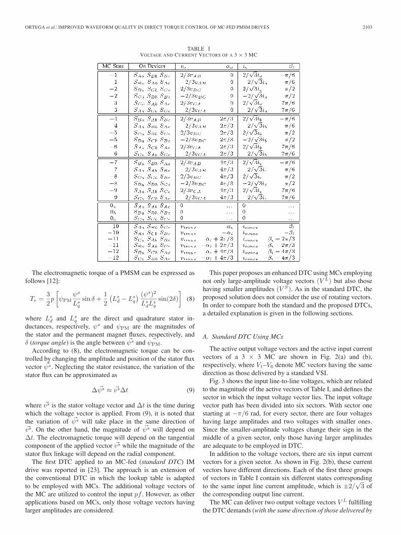
The permitted switching states of a 3 × 3 MC are shownin Table I and have been classified in groups. The first threegroups containing the states (±1, ±2, ±3), (±4, ±5, ±6), and(±7, ±8, ±9) produces active vectors of variable amplitude,depending on the input voltages, but at a stationary position(pulsating or active vectors). States 0a, 0b, and 0c (correspond-ing to group 4), connecting all the output lines to the sameinput line, are the corresponding zero vectors. The last six states(group 5), providing a direct connection of each output line to adifferent input line, are known as rotating vectors. The approachpresented in this paper considers all the MC voltage vectorsof Table I except the rotating ones. The active voltage vectorsare divided into small and large, depending on their amplitudes.Since the amplitude of the active voltage vectors depends on theinput voltages, the input voltage vector path can be sectioned indifferent ways, allowing different criteria to determine whethera voltage vector can be considered small or large. Two differentways to make such sectioning are analyzed and compared in thefollowing section.
III. DTC USING MCs
The conventional VSI-fed DTC is based on the control of themagnitude and position of the stator flux vector.
ORTEGA et al.: IMPROVED WAVEFORM QUALITY IN DIRECT TORQUE CONTROL OF MC-FED PMSM DRIVES 2103
TABLE IVOLTAGE AND CURRENT VECTORS OF A 3 × 3 MC
The electromagnetic torque of a PMSM can be expressed asfollows [12]:
Te =32p
[ψPM
ψs
Lsq
sin δ +12
(Ls
d − Lsq
) (ψs)2
LsdL
sq
sin(2δ)]
(8)
where Lsd and Ls
q are the direct and quadrature stator in-ductances, respectively, ψs and ψPM are the magnitudes ofthe stator and the permanent magnet fluxes, respectively, andδ (torque angle) is the angle between �ψs and �ψPM.
According to (8), the electromagnetic torque can be con-trolled by changing the amplitude and position of the stator fluxvector �ψs. Neglecting the stator resistance, the variation of thestator flux can be approximated as
Δ �ψs ≈ �vsΔt (9)
where �vs is the stator voltage vector and Δt is the time duringwhich the voltage vector is applied. From (9), it is noted thatthe variation of �ψs will take place in the same direction of�vs. On the other hand, the magnitude of �ψs will depend onΔt. The electromagnetic torque will depend on the tangentialcomponent of the applied vector �vs while the magnitude of thestator flux linkage will depend on the radial component.
The first DTC applied to an MC-fed (standard DTC) IMdrive was reported in [23]. The approach is an extension ofthe conventional DTC in which the lookup table is adaptedto be employed with MCs. The additional voltage vectors ofthe MC are utilized to control the input pf . However, as otherapplications based on MCs, only those voltage vectors havinglarger amplitudes are considered.
This paper proposes an enhanced DTC using MCs employingnot only large-amplitude voltage vectors (V L) but also thosehaving smaller amplitudes (V S). As in the standard DTC, theproposed solution does not consider the use of rotating vectors.In order to compare both the standard and the proposed DTCs,a detailed explanation is given in the following sections.
A. Standard DTC Using MCs
The active output voltage vectors and the active input currentvectors of a 3 × 3 MC are shown in Fig. 2(a) and (b),respectively, where V1–V6 denote MC vectors having the samedirection as those delivered by a standard VSI.
Fig. 3 shows the input line-to-line voltages, which are relatedto the magnitude of the active vectors of Table I, and defines thesector in which the input voltage vector lies. The input voltagevector path has been divided into six sectors. With sector onestarting at −π/6 rad, for every sector, there are four voltageshaving large amplitudes and two voltages with smaller ones.Since the smaller-amplitude voltages change their sign in themiddle of a given sector, only those having larger amplitudesare adequate to be employed in DTC.
In addition to the voltage vectors, there are six input currentvectors for a given sector. As shown in Fig. 2(b), these currentvectors have different directions. Each of the first three groupsof vectors in Table I contain six different states correspondingto the same input line current amplitude, which is ±2/
√3 of
the corresponding output line current.The MC can deliver two output voltage vectors V L fulfilling
the DTC demands (with the same direction of those delivered by

2104 IEEE TRANSACTIONS ON INDUSTRIAL ELECTRONICS, VOL. 57, NO. 6, JUNE 2010
Fig. 2. MC vectors. (a) Output voltage vectors. (b) Input current vectors.
Fig. 3. Amplitude variation of the input voltages. Six-sector division.
a VSI). These two MC states impose two input current vectorswith different directions, as shown in Fig. 2(b). Proper selectionof the voltage vector will contribute to a leading/lagging pf .
This extra degree of freedom can be exploited by introducinga third control variable such as the average value of the sine ofthe displacement angle φ between the input current vector andinput voltage vector, to keep the input pf under control. Thisrequirement (pf = 1) is accomplished if this third variable iskept close to zero 〈sin φ〉 ≈ 0. The average value of sin φ can
Fig. 4. Standard DTC. Block diagram.
Fig. 5. Amplitude variation of the input voltages. Six-sector division withsector 1 starting at 0 rad.
be obtained by applying a low-pass filter to its instantaneousvalue, as shown in Fig. 4. In order to control this new variable,a new hysteresis controller, also shown in Fig. 4, is introducedin [23].
B. Proposed DTC Using MCs
In the standard DTC discussed previously, the input voltagevector path was divided into six sectors. With the first sectorstarting at −π/6 rad, it was shown in Fig. 3 that, for a givensector, those vectors having smaller amplitudes (small voltagevectors V S) could not be used for DTC due to their change ofsign in the middle of the sector.
In order to use the small voltage vectors in DTC, it is possibleto organize the sector division in such a way that no vectorchanges its sign in the middle of a sector, as proposed in [24].However, the method can be enhanced by allowing four inputvoltages with small amplitudes rather than the two proposed in[24]. Moreover, the sector division can be organized in sucha way that the voltage transfer ratio is also increased. This ispossible by making the first sector start at 0 rad, as shownin Fig. 5.
Now, for a given sector, there will be two input voltageswith large amplitudes (contributing to large output voltagevectors V L) and four input voltages with small amplitudes(contributing to small output voltage vectors V S). Since none ofthe input voltages change their sign in the middle of the sector,all six input voltages can be used to implement the DTC. TheDTC algorithm is now able to apply small and large voltagevectors at the output, and hence, it can be made to distinguishbetween small and large torque errors.

ORTEGA et al.: IMPROVED WAVEFORM QUALITY IN DIRECT TORQUE CONTROL OF MC-FED PMSM DRIVES 2105
Fig. 6. Torque slope contribution of applied voltage vectors.
As it has been explained, for a given vector direction imposedby the DTC algorithm and a determined sector in which theinput voltage vector lies, there will be three vectors that can beselected. In the proposed DTC, these three vectors are dividedin a large vector and two small ones.
In order to make the proposed DTC able to distinguishbetween small and large positive and negative torque errors,the electromagnetic torque hysteresis controller is replaced bya five-level one. Considering, for simplicity, a surface-mountedPMSM (i.e., Ls
d = Lsq), the second term in (8) is eliminated,
and the torque expression is reduced to
Te =32pψPM
ψs
Lsq
sin δ. (10)
Assuming that the permanent-magnet flux ψPM remains con-stant, the stator flux is changed incrementally by the statorvoltage �vs, and the corresponding change of δ is Δδ, theincremental torque expression is given as
ΔTe =32pψPM
ψs + Δψs
Lsq
sin Δδ. (11)
Since the incremental stator flux can be approximated byΔ �ψs ≈ �vsΔt, for a fixed sampling period Ts = Δt, the incre-mental torque in (11), it is shown to depend on the amplitude ofthe applied vector �vs only.
The criteria to select large, small, or zero vectors, whichare similar to the one proposed in [13], are shown in Fig. 6.The enhanced DTC algorithm will select the proper vectordepending on the zone in which the torque error lies.
The inner torque hysteresis bands in the proposed DTC canbe set to a lower value of the torque hysteresis bands in thestandard DTC. The outer bands in the proposed DTC can beseen as security limits above which large vectors are used inorder to quickly force the torque toward its reference value.
Based on the aforementioned considerations, a new switch-ing table, shown in Table II, is developed. The first columncontains the vectors delivered by the conventional DTC fed bya VSI. However, these vectors are divided into small and largevectors V S
VSI and V LVSI, respectively. The rest of the columns
corresponds to the sector in which the input line-to-neutral volt-age vector lies. Depending on the output of the pf hysteresiscontroller Hφ, each vector is divided into two different MCstates (subcolumns). When the torque error is within the inner
bands of the five-level hysteresis controller, a zero vector isdelivered by the MC. Since an MC can deliver three differentzero vectors (see Table I), the one which minimizes the numberof commutations is selected as proposed in [23]. An alternativestrategy to select zero vectors which reduces the common modevoltage is proposed in [29].
In addition to the ability to deliver small and large voltagevectors, the proposed input voltage sector division also im-proves the voltage transfer ratio compared with the standardDTC. Fig. 7(a) and (b) shows a zoomed area of Figs. 3 and 5,respectively. In the standard DTC shown in Fig. 7(a), the largevoltage vectors vary their amplitude from 50% up to the peakvalue. On the other hand, the proposed DTC shown in Fig. 7(b)employs large voltage vectors with amplitude variations goingfrom 86.6% up to the peak value. The large voltage drop,present in the standard DTC, can be undesirable when the driveruns at the rated conditions. Under such conditions, the DTCneeds to deliver “true” large voltage vectors; otherwise, thedrive could not reach the desired rated conditions.
IV. EXPERIMENTAL RESULTS
Experimental tests have been carried out at several operatingpoints of the machine to compare the performance of both thestandard and the proposed DTCs. The speed is varied from 100up to 3000 r/min (rated speed), whereas the torque referenceis varied from 0.1 up to 0.64 N · m (rated torque). The DTCsettings to carry out the experimental tests are as follows:
1) sampling period Ts = 50 μs;2) torque reference T ∗
e = 100% of rated torque;
3) flux reference |ψs∗|=√
[ψ2PM+((2/3)(T ∗
e Lsq/pψPM))2];
4) torque hysteresis bands BTe = ±2.5% of rated torque(standard DTC only);
5) torque hysteresis outer bands BTLe = ±2.5% of rated
torque (proposed DTC only);6) torque hysteresis inner bands BTS
e = ±1.8% of ratedtorque (proposed DTC only);
7) flux hysteresis bands Bψs = ±2.5% of the permanent-magnet flux.
The experimental rig is shown in Fig. 8, where a 7.5-kWMC prototype based on a EUPEC ECONOMAC (400-V/35-A)module has been employed. The PMSM under test has beencoupled to a hysteresis brake, providing a load torque whichis speed independent and is set to give a constant torque, whilethe PMSM is torque controlled by means of the DTC algorithm.The constant torque developed by the hysteresis brake will de-termine the rotating speed. The machine parameters are shownin Table III.
The switching frequency of DTC drives is a variable quantitythat depends not only on the controller hysteresis bands butalso on the slope of the developed torque. Owing to the useof voltage vectors with different amplitudes, different torqueslopes are achieved in the proposed method, leading to simi-lar average switching frequency to that of the standard DTC(fs(std) = 2340 Hz and fs(prop) = 2420 Hz) despite setting theinner torque bands to a lower value in the proposed solution.

2106 IEEE TRANSACTIONS ON INDUSTRIAL ELECTRONICS, VOL. 57, NO. 6, JUNE 2010
TABLE IIDTC VOLTAGE VECTOR SELECTION TABLE USING SMALL AND LARGE VOLTAGE VECTORS OF MC
Fig. 7. Voltage transfer ratio. (a) Standard DTC. (b) Proposed DTC.
Fig. 8. Experimental rig.
For both the standard and the proposed DTCs running at100 r/min, the electromagnetic torque Te, the stator flux linkagemodulus |ψs| and its α–β components are shown in Figs. 9and 10, respectively. It is noted how both variables Te and |ψs|follow their respective reference values T ∗
e and |ψs∗| with aconsiderable ripple reduction in the proposed DTC.
The dynamic performances of the standard and the proposedDTCs are shown in Figs. 11 and 12, respectively, where a steptorque command, going from the positive rated torque to thenegative rated torque, has been introduced at t = 0.25 s. A
TABLE IIIPMSM PARAMETERS
Fig. 9. Steady-state performance (T ∗e = 0.64 N · m and |ψs∗| =
0.0498 Wb). Standard DTC.
Fig. 10. Steady-state performance (T ∗e = 0.64 N · m and |ψs∗| =
0.0498 Wb). Proposed DTC.

ORTEGA et al.: IMPROVED WAVEFORM QUALITY IN DIRECT TORQUE CONTROL OF MC-FED PMSM DRIVES 2107
Fig. 11. Transient performance (T ∗e = ±0.64 N · m and |ψs∗| =
0.0498 Wb). Standard DTC.
Fig. 12. Transient performance (T ∗e = ±0.64 N · m and |ψs∗| =
0.0498 Wb). Proposed DTC.
very fast electromagnetic torque response can be seen whilethe stator flux modulus remains constant during the torquestep, corroborating the effective decoupled control capabilityof both methods. However, a remarkable ripple reduction canbe observed in the proposed method.
Similar results were obtained with three-level inverters in[13] and [14]. Although these works employed similar ap-proaches to the one presented in this paper, the machine op-erating conditions were also taken into consideration, makingthese approaches a bit more complicated. Better performanceusing predictive algorithms were reported in [11] and [12] butat the cost of high computing demand.
The input voltage vsA, the unfiltered input current iA, thefiltered input current iA, and the pf control variable 〈sin φ〉 areshown in Figs. 13 and 14 for the standard and the proposedDTCs, respectively. The parameters of the input filter in Fig. 1are shown in Table IV. From Table II, it can be seen that, whenlarge output vectors V L have to be applied, the same MC statewill be selected regardless of the output of the pf hysteresiscontroller Hφ. Although the pf is controlled in the proposedDTC, the 〈sin φ〉 error is larger than in the standard solution,degrading the input current waveforms as shown in Fig. 14.
Fig. 13. Power factor control capability. Standard method.
Fig. 14. Power factor control capability. Proposed method.
TABLE IVINPUT FILTER PARAMETERS
A. Torque and Flux Ripples
In order to assess the performances of both the standard andthe proposed DTCs, the electromagnetic torque and stator fluxripples are evaluated by means of their respective standard-deviation values. The following expression for the standarddeviation of a generic variable x has been employed:
σx =
√√√√ 1n − 1
n∑i=1
(xi − x̂)2, x̂ =1n
n∑i=1
xi (12)
where n is the number of samples and xi is the actual sample.The standard deviation of the electromagnetic torque is
shown in Fig. 15, in which the results of the method proposedin [24] have been included to confirm the better performance ofthe proposed DTC. The difference between the methods as therated speed is approached should be emphasized. As it has beenmentioned in Section III, this is due to the low voltage transfer

2108 IEEE TRANSACTIONS ON INDUSTRIAL ELECTRONICS, VOL. 57, NO. 6, JUNE 2010
Fig. 15. Torque ripple using (top graph) the standard DTC, (middle graph) themethod proposed in [22], and (bottom graph) the proposed DTC.
Fig. 16. Torque ripple under rated conditions using (top graph) the standardDTC, (middle graph) the method proposed in [22], and (bottom graph) theproposed DTC.
ratio of the standard DTC. Since [24] uses large voltage vectorswith the same amplitude variation as those of the standard DTC,the voltage transfer ratio will be the same, leading to similarperformance in the high speed range.
Fig. 16 shows the performances of the three methods workingunder rated conditions (Te = 0.64 Nm and ω = 3000 r/min).
As the back EMF increases with the speed, the use of largevectors contributing to a torque in the same direction to thatimposed by the back EMF will lead to large errors in the actualtorque. In the standard DTC, only large vectors are taken intoconsideration. When these vectors are applied then, the torquevariation will have a large slope due to the combined effectsof the back EMF (even when the back EMF is assisting thechange of torque) and the applied large vector. This can lead tolarge torque errors. The worse case, shown inside a red circlein Fig. 16, will be when a large voltage vector coinciding withthe peak value of the input voltage is selected at instant k anda vector coinciding with 50% of the input voltage peak valueis delivered at instant k + 1. Due to the large error introducedby the vector applied at instant k, the amplitude of the voltagevector applied at instant k + 1 will not be enough to reach the
Fig. 17. Torque steady-state error using the (top graph) standard DTC and(bottom graph) the proposed DTC.
torque reference value. This fact makes the standard DTC havenot only a larger torque ripple at high speed but also a largesteady-state error.
In order to evaluate the dependence of this phenomena withspeed and torque, the relative error of the torque mean value iscalculated as follows:
T̂ errore (in percent) = 100
(T ∗
e − T̂e
)T ∗
e
. (13)
The ability of both methods to reach the reference torquevalue can be analyzed from Fig. 17, which shows the relativeerror of the torque mean value over all the machine operatingpoints.
As expected, a performance deterioration is observed as therated speed is approached. Although the voltage transfer ratiois increased by 36.6% with the proposed DTC, the performancestill deteriorates at high speed. However, it should be noted thatthe effect is 37% larger in the standard DTC. The high valuesof torque steady-state error under low load conditions can bepartly explained due to the low inertia of the experimentalsystem used.
The stator flux ripple of the standard and the proposed DTCsover all the machine operating points is shown in Fig. 18. Forboth cases, there is no significant change for a particular opera-tion range. The proposed DTC shows improved performance atlow-speed high-torque operation.
B. Stator-Current THD Performance
The performance of the stator current have been assessedby means of the total harmonic distortion (THD). The THD isdefined as follows:
THD =Ih
If, Ih =
√I22 + I2
3 + · · · + I2n (14)
where In is the rms value of the nth harmonic and If is the rmsvalue of the fundamental current.
Fig. 19 shows the stator-current THD, of both the standardand the proposed DTCs. A better performance of the proposed

ORTEGA et al.: IMPROVED WAVEFORM QUALITY IN DIRECT TORQUE CONTROL OF MC-FED PMSM DRIVES 2109
Fig. 18. Flux ripple using (top graph) the standard DTC and (bottom graph)the proposed DTC.
Fig. 19. Stator-current THD using (top graph) the standard DTC and (bottomgraph) the proposed DTC.
TABLE VIMPROVEMENTS OF THE PROPOSED DTC
DTC is observed over all the machine operating points, with theaverage improvement being 21%.
Table V summarizes the improvements achieved by the pro-posed DTC in terms of stator flux and electromagnetic torqueripples, relative error of the torque mean value, and the stator-current THD. The maximum, minimum, and the average im-provement in, percentage, are calculated for every improvementvariable.
It is noted that higher improvements are achieved in terms ofelectromagnetic torque ripple. However, it is shown in Fig. 15and Figs. 17–19 that higher improvements can be achieved byother variables, depending on the machine operating point.
V. CONCLUSION
An enhanced MC-fed DTC drive, considering a higher num-ber of voltage vectors, has been proposed in this paper. A newlookup table that takes into account not only the large voltage
vectors of MCs but also the uncommonly used small ones hasbeen developed. The new lookup table, based on a differentinput voltage vector path sector definition, allows the DTCalgorithm to apply large, small, or zero voltage vectors, de-pending on the torque requirements. Although the input powerfactor control capability is affected in the proposed strategy,a remarkable torque and flux-ripple reduction, i.e., 50% and21%, respectively, has been achieved. Moreover, the proposedDTC has been shown to increase the voltage transfer ratio upto 87%, allowing the drive to reach its rated operating pointwhile significantly reducing the torque steady-state error incomparison to the standard DTC.
REFERENCES
[1] I. Takahashi and T. Nogushi, “A new quick-response and high-efficiency control strategy of an induction motor,” IEEE Trans. Ind. Appl.,vol. IA-22, no. 5, pp. 820–827, Sep. 1986.
[2] M. Depenbrock, “Direct self-control (DSC) of inverter-fed inductionmachine,” IEEE Trans. Power Electron., vol. 3, no. 4, pp. 420–429,Oct. 1988.
[3] G. Buja and R. Menis, “Steady-state performance degradation of aDTC IM drive under parameter and transduction errors,” IEEE Trans. Ind.Electron., vol. 55, no. 4, pp. 1749–1760, Apr. 2008.
[4] C. Lascu and G.-D. Andreescu, “Sliding-mode observer and improvedintegrator with dc-offset compensation for flux estimation in sensorless-controlled induction motors,” IEEE Trans. Ind. Electron., vol. 53, no. 3,pp. 785–794, Jun. 2006.
[5] F. Alonge, F. D’Ippolito, G. Giardina, and T. Scaffidi, “Design andlow-cost implementation of an optimally robust reduced-order rotor fluxobserver for induction motor control,” IEEE Trans. Ind. Electron., vol. 54,no. 6, pp. 3205–3216, Dec. 2007.
[6] G. S. Buja and M. P. Kazmierkowski, “Direct torque control of PWMinverter-fed ac motors: A survey,” IEEE Trans. Ind. Electron., vol. 51,no. 4, pp. 744–758, Aug. 2004.
[7] D. Casadei and G. Serra, “Implementation of a direct torque control al-gorithm for induction motors based on discrete space vector modulation,”IEEE Trans. Power Electron., vol. 15, no. 4, pp. 769–777, Jul. 2000.
[8] C. Lascu, I. Boldea, and F. Blaabjerg, “A modified direct torque controlfor induction motor sensorless drive,” IEEE Trans. Ind. Appl., vol. 36,no. 1, pp. 122–130, Jan./Feb. 2000.
[9] K.-B. Lee and F. Blaabjerg, “An improved DTC-SVM method for sen-sorless matrix converter drives using an overmodulation strategy and asimple nonlinearity compensation,” IEEE Trans. Ind. Electron., vol. 54,no. 6, pp. 3155–3166, Dec. 2007.
[10] Z. Xu and M. F. Rahman, “Direct torque and flux regulation of an IPMsynchronous motor drive using variable structure control approach,” IEEETrans. Power Electron., vol. 22, no. 6, pp. 2487–2498, Nov. 2007.
[11] J.-K. Kang and S.-K. Sul, “New direct torque control of induction mo-tors for minimum torque ripple and constant switching frequency,” IEEETrans. Ind. Appl., vol. 35, no. 5, pp. 1076–1082, Sep./Oct. 1999.
[12] M. Pacas and J. Weber, “Predictive direct torque control for the PM syn-chronous machine,” IEEE Trans. Ind. Electron., vol. 52, no. 5, pp. 1350–1356, Oct. 2005.
[13] K. B. Lee, J. H. Song, J. H. I. Choy, and J. Y. Yoo, “Torque ripplereduction in DTC of induction motor driven by three-level inverter withlow switching frequency,” IEEE Trans. Power Electron., vol. 17, no. 2,pp. 255–264, Mar. 2000.
[14] V. Perelmuter, “Three-level inverters with direct torque control,” in Conf.Rec. IEEE IAS Annu. Meeting, Oct. 2000, vol. 3, pp. 1368–1374.
[15] A. Sapin, P. K. Steimer, and J. J. Simond, “Modeling, simulation, and testof a three-level voltage-source inverter with output LC filter and directtorque control,” IEEE Trans. Ind. Appl., vol. 43, no. 2, pp. 469–475,Mar./Apr. 2008.
[16] P. Wheeler, J. Rodriguez, J. Clare, L. Empringham, and A. Weinstein,“Matrix converters: A technology review,” IEEE Trans. Ind. Electron.,vol. 49, no. 2, pp. 276–288, Apr. 2002.
[17] P. Wheeler, J. Clare, M. Apap, and K. J. Bradley, “Harmonic loss dueto operation of induction machines from matrix converters,” IEEE Trans.Ind. Electron., vol. 55, no. 2, pp. 809–816, Feb. 2008.
[18] P. Correa, J. Rodríguez, M. Rivera, J. R. Espinoza, and J. W. Kolar,“Predictive control of an indirect matrix converter,” IEEE Trans. Ind.Electron., vol. 56, no. 6, pp. 1847–1853, Jun. 2009.

2110 IEEE TRANSACTIONS ON INDUSTRIAL ELECTRONICS, VOL. 57, NO. 6, JUNE 2010
[19] L. Helle, K. B. Larsen, A. H. Jorgensen, S. M. Nielsen, and F. Blaabjerb,“Evaluation of modulation schemes for three-phase to three-phase matrixconverters,” IEEE Trans. Ind. Electron., vol. 51, no. 1, pp. 158–170,Feb. 2004.
[20] C. Klumpner, F. Blaabjerg, and P. Nielsen, “Speeding-up the matura-tion process of the matrix converter technology,” in Proc. IEEE PESC,Jun. 2001, vol. 2, pp. 1083–1088.
[21] P. Zanchetta, P. Wheeler, J. Clare, M. Bland, L. Empringham, andD. Katsis, “Control design of a three-phase matrix-converter-basedAC–AC mobile utility power supply,” IEEE Trans. Ind. Electron., vol. 55,no. 1, pp. 209–217, Jan. 2008.
[22] D. Casadei, G. Serra, A. Tani, and L. Zarri, “Optimal use of zero vectorsfor minimizing the output current distortion in matrix converters,” IEEETrans. Ind. Electron., vol. 56, no. 2, pp. 326–336, Feb. 2009.
[23] D. Casadei, G. Serra, and A. Tani, “The use of matrix converters in directtorque control of induction machines,” IEEE Trans. Ind. Electron., vol. 48,no. 6, pp. 1057–1064, Dec. 2001.
[24] C. Ortega, A. Arias, X. del Toro, E. Aldabas, and J. Balcells, “Novel directtorque control for induction motors using short voltage vectors of matrixconverters,” in Proc. IECON, Nov. 2005, vol. 1, pp. 1353–1358.
[25] J.-Y. Chai, Y.-H. Ho, Y.-C. Chang, and C.-M. Liaw, “On acoustic-noise-reduction control using random switching technique for switch-moderectifiers in PMSM drive,” IEEE Trans. Ind. Electron., vol. 55, no. 3,pp. 1295–1309, Mar. 2008.
[26] L. Zhong, M. F. Rahman, W. Y. Hu, and K. W. Lim, “Analysis of directtorque control in permanent magnet synchronous motor drives,” IEEETrans. Power Electron., vol. 12, no. 3, pp. 528–536, May 1997.
[27] J. Andreu, J. M. de Diego, I. M. de Alegría, I. Kortabarria, J. L. Martín,and S. Ceballos, “New protection circuit for high-speed switching andstart-up of a practical matrix converter,” IEEE Trans. Ind. Electron.,vol. 55, no. 8, pp. 3100–3114, Aug. 2008.
[28] L. Empringham, P. Wheeler, and J. L. Clare, “Intelligent commutationof matrix converter bi-directional switch cells using novel gate drivetechniques,” in Proc. IEEE PESC, Jun./Jul. 1998, vol. 1, pp. 707–713.
[29] C. Ortega, A. Arias, C. Caruana, and M. Apap, “Reducing the commonmode voltage in a DTC-PMSM drive using matrix converters,” in Proc.ISIE, Jun./Jul. 2008, vol. 1, pp. 526–531.
Carlos Ortega (S’05–M’08) received the B.Eng.degree in electronics engineering from the EscolaUniversitària Salesiana de Sarrià (EUSS), Barcelona,Spain, in 1998 and the M.Eng. and Ph.D. degreesfrom the Universitat Politècnica de Catalunya (UPC),Barcelona, in 2003 and 2008, respectively.
From 1998 to 2001, he was with the Technol-ogy Transfer Department, EUSS, where he has beena Lecturer in electrical and electronic engineeringsince 2002 with the Electronics Engineering Depart-ment. In 2005, he joined the Power Electronics and
Control Department, University of Malta, Msida, Malta, as a Researcher andpart-time Lecturer. He is currently collaborating with the Terrassa IndustrialElectronics Group, Department of Electronics Engineering, UPC. His currentresearch interests include modeling and control of ac drives, electrical powerconversion, and renewable energy systems.
Dr. Ortega is a member of the IEEE Industrial Electronics Society.
Antoni Arias (M’03) received the B.Eng. de-gree in electrical engineering and the M.Eng. andPh.D. degrees in control and electronic engineer-ing from the Universitat Politècnica de Catalunya,Barcelona, Spain, in 1993, 1997, and 2001,respectively.
Since 1996, he has been a Lecturer with theUniversitat Politècnica de Catalunya, where he wasappointed as an Associate Professor in 2002. In1999, he was a Visiting Research Assistant and apart-time Lecturer with the University of Glamorgan,
Glamorgan, U.K. In 2003 and 2004, he joined the Power Electronics, Machinesand Control Group, University of Nottingham, Nottingham, U.K., as a VisitingFellow. His research interests are variable-speed drive systems, power electron-ics converters, and control strategies.
Cedric Caruana (S’01–M’05) received the Ph.D.degree in electrical engineering from the Universityof Nottingham, Nottingham, U.K., in 2003.
He was with Carlo Gavazzi Ltd., Malta, andST Microelectronics Ltd., Malta, where he was aProcess Engineer and a Senior Test Engineer, respec-tively. After his Ph.D., he joined the Faculty of En-gineering, University of Malta, Msida, Malta, wherehe is currently a Lecturer. His main research interestsare the control of ac drives, renewable energy conver-sion, electrical power systems, and energy efficiency.
Dr. Caruana is a member of the Institution of Engineering and Technology.
Josep Balcells (M’95–SM’06) was born in Spain in1949. He received the M.S. and Ph.D. degrees in in-dustrial engineering from the Universitat Politècnicade Catalunya (UPC), Barcelona, Spain, in 1975 and1983, respectively.
From 1978 to 1986, he was the Head of R&Dwith Agut, S.A. (currently a General Electric Groupcompany). Since 1986, he has been a Professorwith the Electronics Engineering Department, UPC,and a Technical Consultant with CIRCUTOR, S.A.,Viladecavalls, Spain. His research interests include
electromagnetic compatibility (EMC) in power systems, renewable energysystems, and design of power converters. He is the author of several booksand papers related with EMC in power systems, power quality measurement,and filtering and has been responsible for several research projects funded bythe Spanish Ministries of Science and Technology and Industry and by theEuropean Union.
Dr. Balcells has been an Associate Editor for the IEEE TRANSACTIONS ON
INDUSTRIAL ELECTRONICS since 2004.
Greg M. Asher (M’98–SM’05–F’07) received theB.Sc. degree in electrical and electronic engineer-ing and the Ph.D. degree in bond graph structuresand general dynamic systems from Bath University,Bath, U.K., in 1976 and 1979, respectively.
In 1984, he was appointed a Lecturer in controlwith the Department of Electrical and ElectronicEngineering, Faculty of Engineering, University ofNottingham, Nottingham, U.K., where he developedan interest in motor drive systems, particularly thecontrol of ac machines. He was appointed as a
Professor of electrical drives in 2000 and as the Head of the Departmentof Electrical and Electronic Engineering, in 2004, where he is currently theAssociate Dean for Teaching and Learning. He has published over 240 researchpapers and has received over $5 million in research contracts.
Dr. Asher was a member of the Executive Committee of the European PowerElectronics Association until 2003 and the Chair of the Power ElectronicsTechnical Committee for the Industrial Electronics Society until 2008. He iscurrently an Associate Editor for the IEEE Industrial Electronics Society.
Copyright © 2022 FDOKUMEN