Immediate Implant Placement and Provisionalization in ... - MDPI
21
applied sciences Case Report Immediate Implant Placement and Provisionalization in the Esthetic Zone Revisited: The Marginal Migration Concept (MMC) Konstantinos Valavanis 1,2, *, Ioannis Vergoullis 3,4 , Michalis Papastamos 5 and Henry Salama 6,7 1 Oral Surgery Department, University of Naples Federico II, 80138 Napoli, Italy 2 Private Practice, 15123 Athens, Greece 3 Periodontics Department, School of Dentistry, Louisiana State University, New Orleans, LA 70119, USA; [email protected] 4 Private Practice, 85100 Rhodes, Greece 5 Private Dental Lab, 17343 Athens, Greece; [email protected] 6 School of Dental Medicine, University of Pennsylvania, Philadelphia, PA 19104, USA; [email protected] 7 Private Practice, Atlanta, GA 30339, USA * Correspondence: [email protected]; Tel.: +30-693-701-8755 Received: 22 November 2020; Accepted: 10 December 2020; Published: 15 December 2020 Abstract: Immediate implant placement and provisionalization in the esthetic zone is a desirable approach that presents several advantages but at the same time embosses several risk factors that can lead to severe esthetic complications. The purpose of this article was to propose a new protocol that could allow for the maintenance and even the improvement of the hard and soft tissue topography, leading to superior esthetic results. The proposed protocol, when certain criteria are met, could be applied even for cases where the extraction socket morphology is currently proposed as a contra-indication for immediate implant placement and provisionalization. Keywords: extraction socket; immediate implant; provisional; esthetic zone 1. Introduction Immediate implant placement and provisionalization at the time of extraction in the esthetic zone is today a common treatment modality [1]. The literature outlines the non-interventionist healing process of a post-extraction socket, or in combination with a socket preservation technique, including bone and/or soft tissue grafting, as well as with or without simultaneous implant placement [2–7]. While many protocols have been suggested to achieve the establishment of an esthetic and natural result post extraction in the anterior region, challenges persist [8–10]. Primary among the challenges faced by clinicians are predictability and reproducibility of esthetic outcomes. Especially, as they relate to the volumetric changes that occur to the labial plate of the socket housing post-extraction, both in the bucco-lingual and apico-coronal aspect. These volumetric osseous changes in turn often result in labial gingival recession, as well as negative optical manifestations of the soft tissue due to concavities. Studies have also shown successful results in intact type I sockets, ideal bone and soft tissue profiles (Salama and Salama 1993) at onset, utilizing a combination of bone replacement graft (BRG) and a temporary prosthesis at the time of extraction and implant placement [11–13]. In addition, simultaneous connective tissue grafting grafting in order to increase the stability and predictability of an esthetic outcome have also been suggested [14,15]. Furthermore, there is also evidence that in type I, the labial root fragment can be maintained to biologically stabilize the labial osseous and soft tissue (Partial extraction therapy) [16,17]. However, most immediate implant treatment protocols specifically address only type I sockets, where no hard or soft tissue deficiencies exist prior to extraction [18,19]. Appl. Sci. 2020, 10, 8944; doi:10.3390/app10248944 www.mdpi.com/journal/applsci
-
Upload
khangminh22 -
Category
Documents
-
view
1 -
download
0
Transcript of Immediate Implant Placement and Provisionalization in ... - MDPI

applied sciences
Case Report
Immediate Implant Placement and Provisionalizationin the Esthetic Zone Revisited: The MarginalMigration Concept (MMC)
Konstantinos Valavanis 1,2,*, Ioannis Vergoullis 3,4, Michalis Papastamos 5 and Henry Salama 6,7
1 Oral Surgery Department, University of Naples Federico II, 80138 Napoli, Italy2 Private Practice, 15123 Athens, Greece3 Periodontics Department, School of Dentistry, Louisiana State University, New Orleans, LA 70119, USA;
[email protected] Private Practice, 85100 Rhodes, Greece5 Private Dental Lab, 17343 Athens, Greece; [email protected] School of Dental Medicine, University of Pennsylvania, Philadelphia, PA 19104, USA; [email protected] Private Practice, Atlanta, GA 30339, USA* Correspondence: [email protected]; Tel.: +30-693-701-8755
Received: 22 November 2020; Accepted: 10 December 2020; Published: 15 December 2020 �����������������
Abstract: Immediate implant placement and provisionalization in the esthetic zone is a desirableapproach that presents several advantages but at the same time embosses several risk factorsthat can lead to severe esthetic complications. The purpose of this article was to propose a newprotocol that could allow for the maintenance and even the improvement of the hard and soft tissuetopography, leading to superior esthetic results. The proposed protocol, when certain criteria are met,could be applied even for cases where the extraction socket morphology is currently proposed as acontra-indication for immediate implant placement and provisionalization.
Keywords: extraction socket; immediate implant; provisional; esthetic zone
1. Introduction
Immediate implant placement and provisionalization at the time of extraction in the esthetic zoneis today a common treatment modality [1]. The literature outlines the non-interventionist healingprocess of a post-extraction socket, or in combination with a socket preservation technique, includingbone and/or soft tissue grafting, as well as with or without simultaneous implant placement [2–7].While many protocols have been suggested to achieve the establishment of an esthetic and naturalresult post extraction in the anterior region, challenges persist [8–10]. Primary among the challengesfaced by clinicians are predictability and reproducibility of esthetic outcomes. Especially, as theyrelate to the volumetric changes that occur to the labial plate of the socket housing post-extraction,both in the bucco-lingual and apico-coronal aspect. These volumetric osseous changes in turn oftenresult in labial gingival recession, as well as negative optical manifestations of the soft tissue due toconcavities. Studies have also shown successful results in intact type I sockets, ideal bone and softtissue profiles (Salama and Salama 1993) at onset, utilizing a combination of bone replacement graft(BRG) and a temporary prosthesis at the time of extraction and implant placement [11–13]. In addition,simultaneous connective tissue grafting grafting in order to increase the stability and predictability ofan esthetic outcome have also been suggested [14,15]. Furthermore, there is also evidence that in typeI, the labial root fragment can be maintained to biologically stabilize the labial osseous and soft tissue(Partial extraction therapy) [16,17]. However, most immediate implant treatment protocols specificallyaddress only type I sockets, where no hard or soft tissue deficiencies exist prior to extraction [18,19].
Appl. Sci. 2020, 10, 8944; doi:10.3390/app10248944 www.mdpi.com/journal/applsci

Appl. Sci. 2020, 10, 8944 2 of 21
Through two case reports, the purpose of this article is to present a new esthetic zone protocolfor immediate placement and provisionalized of implants in both class I sockets, as well as class IIsockets with a Miller Class I recession deficiencies. Novel steps are introduced and existing clinicalprotocols are modified, for both the surgical and restorative interventions, with the goal of predictablyachieving an optimal result utilizing simpler and less invasive therapeutic protocols 18, includingthe step-by-step description and application of the Marginal Migration Concept (MMC) in a Class IIsite [18].
2. Case 1
2.1. “Report and Protocol”
A 40-year-old male presented in the clinic of one of the authors (K.V.) in order to replace a hopelessupper right central incisor. The patient was non-smoker, with a clear medical history, no active dentaldisease, and no contra-indications present for implant therapy [20]. After clinical and radiographicevaluation, the site was classified as a socket class I, with thin soft tissue biotype and marginal soft tissueapical mislocation at the mid-buccal area (Figures 1–3) [18]. The marginal migration concept protocolof treatment (MMC) was selected as suitable for this case. The proposed treatment protocol wasthoroughly explained to the patient along with any alternative treatment options. The requirements ofthe Helsinki Declaration were observed, and the patient gave informed consent for all surgical andrestorative procedures.
Appl. Sci. 2020, 10, x FOR PEER REVIEW 2 of 21
(Salama and Salama 1993), where both soft and hard tissue are in ideal condition prior to extraction
and no improvements need to be established [18,19].
The purpose of this article was to present a new protocol for immediately placed and
provisionalized implants in the esthetic zone, for implant sites categorized as socket class I and socket
class II with a Miller class I recession defect, where novel steps are introduced and known steps are
modified for both the surgical and restorative stage of the procedure, in an effort to predictably
achieve an optimal result in a less invasive and more simple manner [18]. The proposed protocol was
presented step by step with a case report, while a second case involving the application of the
marginal migration concept protocol in a socket class II site was also provided.
2. Case 1
2.1. “Report and Protocol”
A 40-year-old male presented in the clinic of one of the authors (K.V.) in order to replace a
hopeless upper right central incisor. The patient was non-smoker, with a clear medical history, no
active dental disease, and no contra-indications present for implant therapy [20]. After clinical and
radiographic evaluation, the site was classified as a socket class I, with thin soft tissue biotype and
marginal soft tissue apical mislocation at the mid-buccal area (Figures 1–3) [18]. The marginal
migration concept protocol of treatment (MMC) was selected as suitable for this case. The proposed
treatment protocol was thoroughly explained to the patient along with any alternative treatment
options. The requirements of the Helsinki Declaration were observed, and the patient gave informed
consent for all surgical and restorative procedures.
Figure 1. Pre-operative clinical conditions; thin gingival biotype and marginal apical dislocation of
free gingival margin on tooth #1.1.
Figure 2. Pre-operative Cone-beam computed tomography systems (CBCT) images; evident resorption of
tooth #1.1 and thin buccal plate.
Figure 1. Pre-operative clinical conditions; thin gingival biotype and marginal apical dislocation of freegingival margin on tooth #1.1.
Appl. Sci. 2020, 10, x FOR PEER REVIEW 2 of 21
(Salama and Salama 1993), where both soft and hard tissue are in ideal condition prior to extraction
and no improvements need to be established [18,19].
The purpose of this article was to present a new protocol for immediately placed and
provisionalized implants in the esthetic zone, for implant sites categorized as socket class I and socket
class II with a Miller class I recession defect, where novel steps are introduced and known steps are
modified for both the surgical and restorative stage of the procedure, in an effort to predictably
achieve an optimal result in a less invasive and more simple manner [18]. The proposed protocol was
presented step by step with a case report, while a second case involving the application of the
marginal migration concept protocol in a socket class II site was also provided.
2. Case 1
2.1. “Report and Protocol”
A 40-year-old male presented in the clinic of one of the authors (K.V.) in order to replace a
hopeless upper right central incisor. The patient was non-smoker, with a clear medical history, no
active dental disease, and no contra-indications present for implant therapy [20]. After clinical and
radiographic evaluation, the site was classified as a socket class I, with thin soft tissue biotype and
marginal soft tissue apical mislocation at the mid-buccal area (Figures 1–3) [18]. The marginal
migration concept protocol of treatment (MMC) was selected as suitable for this case. The proposed
treatment protocol was thoroughly explained to the patient along with any alternative treatment
options. The requirements of the Helsinki Declaration were observed, and the patient gave informed
consent for all surgical and restorative procedures.
Figure 1. Pre-operative clinical conditions; thin gingival biotype and marginal apical dislocation of
free gingival margin on tooth #1.1.
Figure 2. Pre-operative Cone-beam computed tomography systems (CBCT) images; evident resorption of
tooth #1.1 and thin buccal plate.
Figure 2. Pre-operative Cone-beam computed tomography systems (CBCT) images; evident resorptionof tooth #1.1 and thin buccal plate.

Appl. Sci. 2020, 10, 8944 3 of 21
Appl. Sci. 2020, 10, x FOR PEER REVIEW 3 of 21
Figure 3. Pre-operative clinical conditions; buccal dislocation of tooth #1.1 is evident.
2.2. Pre-Surgical Stage
First, the initial impressions were taken. Then a diagnostic wax up was performed if necessary
and a silicone index was fabricated to be used for the fabrication of the temporary prosthesis at the
time of surgery (Figure 1). Alternatively, a prefabricated temporary cell could be used for the same
purpose.
2.3. Surgical Stage
The patient received 1 gr of amoxicillin one hour prior to surgery. At the time of surgery, he
rinsed for 1 min with chlorhexidine solution 0.12% (Froiplak, Froika, Greece) and the area of interest
was anesthetized locally with articaine 4%, epi 1:200k (Septanest, Greece).
Step 1.
A flap-less extraction was performed, taking care to prevent any damage to the soft and hard
tissue (Scheme 1A, Figure 4) [21].
Figure 4. Atraumatic extraction of affected tooth with the use of periotomes and generation of partial
thickness pouch flap with a micro-blade.
Scheme 1. Cross sectional views of the critical steps incorporated into marginal migration concept
(MMC) protocol.
(A) Extraction socket presentation, where the red line represents the supra-periosteal pouch flap.
Figure 3. Pre-operative clinical conditions; buccal dislocation of tooth #1.1 is evident.
2.2. Pre-Surgical Stage
First, the initial impressions were taken. Then a diagnostic wax up was performed if necessaryand a silicone index was fabricated to be used for the fabrication of the temporary prosthesis at the timeof surgery (Figure 1). Alternatively, a prefabricated temporary cell could be used for the same purpose.
2.3. Surgical Stage
The patient received 1 gr of amoxicillin one hour prior to surgery. At the time of surgery, he rinsedfor 1 min with chlorhexidine solution 0.12% (Froiplak, Froika, Greece) and the area of interest wasanesthetized locally with articaine 4%, epi 1:200k (Septanest, Greece).
Step 1.A flap-less extraction was performed, taking care to prevent any damage to the soft and hard
tissue (Scheme 1A, Figure 4) [21].
(A) Extraction socket presentation, where the red line represents the supra-periosteal pouch flap.(B) Three-dimensional implant positioning, where different locations of the implant axis can achieve
the desired location of the platform and neck of the implant.(C) Fits abutment selection, where the shoulder is located 0.5 mm apically to the cervical
gingival margin.(D) Membrane adaptation, being in contact with the internal wall of the socket.(E) Bone replacement graft BRG introduction into the available space present within the socket,
occupying both the soft and hard tissue zones present below the abutment’s shoulder.(F) Membrane adaptation and suturing with vertical mattress sutures.(G) Temporary prosthesis delivery, where the cervical margin is located supra-gingivally and
comprises a 90′ emergence angle in relation to the abutment.
Appl. Sci. 2020, 10, x FOR PEER REVIEW 3 of 21
Figure 3. Pre-operative clinical conditions; buccal dislocation of tooth #1.1 is evident.
2.2. Pre-Surgical Stage
First, the initial impressions were taken. Then a diagnostic wax up was performed if necessary
and a silicone index was fabricated to be used for the fabrication of the temporary prosthesis at the
time of surgery (Figure 1). Alternatively, a prefabricated temporary cell could be used for the same
purpose.
2.3. Surgical Stage
The patient received 1 gr of amoxicillin one hour prior to surgery. At the time of surgery, he
rinsed for 1 min with chlorhexidine solution 0.12% (Froiplak, Froika, Greece) and the area of interest
was anesthetized locally with articaine 4%, epi 1:200k (Septanest, Greece).
Step 1.
A flap-less extraction was performed, taking care to prevent any damage to the soft and hard
tissue (Scheme 1A, Figure 4) [21].
Figure 4. Atraumatic extraction of affected tooth with the use of periotomes and generation of partial
thickness pouch flap with a micro-blade.
Scheme 1. Cross sectional views of the critical steps incorporated into marginal migration concept
(MMC) protocol.
(A) Extraction socket presentation, where the red line represents the supra-periosteal pouch flap.
Scheme 1. Cross sectional views of the critical steps incorporated into marginal migration concept(MMC) protocol.

Appl. Sci. 2020, 10, 8944 4 of 21
Appl. Sci. 2020, 10, x FOR PEER REVIEW 3 of 21
Figure 3. Pre-operative clinical conditions; buccal dislocation of tooth #1.1 is evident.
2.2. Pre-Surgical Stage
First, the initial impressions were taken. Then a diagnostic wax up was performed if necessary
and a silicone index was fabricated to be used for the fabrication of the temporary prosthesis at the
time of surgery (Figure 1). Alternatively, a prefabricated temporary cell could be used for the same
purpose.
2.3. Surgical Stage
The patient received 1 gr of amoxicillin one hour prior to surgery. At the time of surgery, he
rinsed for 1 min with chlorhexidine solution 0.12% (Froiplak, Froika, Greece) and the area of interest
was anesthetized locally with articaine 4%, epi 1:200k (Septanest, Greece).
Step 1.
A flap-less extraction was performed, taking care to prevent any damage to the soft and hard
tissue (Scheme 1A, Figure 4) [21].
Figure 4. Atraumatic extraction of affected tooth with the use of periotomes and generation of partial
thickness pouch flap with a micro-blade.
Scheme 1. Cross sectional views of the critical steps incorporated into marginal migration concept
(MMC) protocol.
(A) Extraction socket presentation, where the red line represents the supra-periosteal pouch flap.
Figure 4. Atraumatic extraction of affected tooth with the use of periotomes and generation of partialthickness pouch flap with a micro-blade.
Step 2.A partial thickness, supra-periosteal, trapezoidal-shaped pouch with a suitable blade on the
buccal aspect only was created, without involving the adjacent papillae. The pouch was extendedapically, further than the mucogingival junction, and laterally at least one root mesio-distally, in orderto increase the lateral dimensions of the base of the pouch and adequately mobilize the facial tissue.(Schemes 1B and 2A, Figure 4)
(A) Supra-periosteal pouch design, demonstrating proper lateral and vertical extensions. The redlines demonstrate the pouch, while the yellow line demonstrates the mucogingival junction.
(B) First abutment in place and membrane adaptation prior to BRG introduction.(C) Final relationship between first temporary prosthesis, abutment, and cervical gingival tissue.
Appl. Sci. 2020, 10, x FOR PEER REVIEW 4 of 21
(B) Three-dimensional implant positioning, where different locations of the implant axis can
achieve the desired location of the platform and neck of the implant.
(C) Fits abutment selection, where the shoulder is located 0.5 mm apically to the cervical gingival
margin.
(D) Membrane adaptation, being in contact with the internal wall of the socket.
(E) Bone replacement graft BRG introduction into the available space present within the socket,
occupying both the soft and hard tissue zones present below the abutment’s shoulder.
(F) Membrane adaptation and suturing with vertical mattress sutures.
(G) Temporary prosthesis delivery, where the cervical margin is located supra-gingivally and
comprises a 90′ emergence angle in relation to the abutment.
Step 2.
A partial thickness, supra-periosteal, trapezoidal-shaped pouch with a suitable blade on the
buccal aspect only was created, without involving the adjacent papillae. The pouch was extended
apically, further than the mucogingival junction, and laterally at least one root mesio-distally, in order
to increase the lateral dimensions of the base of the pouch and adequately mobilize the facial tissue.
(Schemes 1B and 2A, Figure 4)
Scheme 2. Frontal view of some of the critical steps of the MMC protocol.
(A) Supra-periosteal pouch design, demonstrating proper lateral and vertical extensions. The
red lines demonstrate the pouch, while the yellow line demonstrates the mucogingival
junction.
(B) First abutment in place and membrane adaptation prior to BRG introduction.
(C) Final relationship between first temporary prosthesis, abutment, and cervical gingival
tissue.
Step 3.
The osteotomy as per the implant manufacturer’s recommendation was generated and a narrow
diameter implant was placed, which preferably comprised a stable conical connection and platform
switching features (Anyridge, Megagen, South Korea) [22]. The implant had to be placed in a way
that the platform and neck of the implant body presented at least 2 mm horizontal distance from the
coronal part of the buccal plate. With regards to depth, the position the implant platform had to be
at least 3 mm apical to the zenith of the future prosthesis [16,23–25]. (Scheme 1B, Figure 5)
Scheme 2. Frontal view of some of the critical steps of the MMC protocol.
Step 3.The osteotomy as per the implant manufacturer’s recommendation was generated and a narrow
diameter implant was placed, which preferably comprised a stable conical connection and platformswitching features (Anyridge, Megagen, South Korea) [22]. The implant had to be placed in a waythat the platform and neck of the implant body presented at least 2 mm horizontal distance from thecoronal part of the buccal plate. With regards to depth, the position the implant platform had to be atleast 3 mm apical to the zenith of the future prosthesis [16,23–25]. (Scheme 1B, Figure 5).

Appl. Sci. 2020, 10, 8944 5 of 21
Appl. Sci. 2020, 10, x FOR PEER REVIEW 5 of 21
Figure 5. Osteotomy, occlusal view of the implant position, abutment adjustment, and connection.
Step 4.
The implant was connected to a temporary abutment comprising a shoulder with tulip shape
and lateral dimensions that restrict it from being in touch with the buccal soft tissue [26]. The height
of the shoulder had to be such that would allow its coronal margin to be located 0.5 mm apical to the
existing free gingival margin. (Scheme 1C, Figure 5)
Step 5.
A resorbable membrane was utilized that could maintain its function for at least 12 weeks (Jason,
Botiss, Germany), after properly trimming it, to adequately fit the lateral dimensions of the buccal
side of the socket [27]. The membrane was placed within the socket, being in contact with the internal
wall of the buccal plate (socket type I) and/or the periosteum in case the buccal plate was partially or
completely absent (socket type II). The coronal part of the membrane was to be extending coronally
to the free gingival margin, providing a “supra-socket” portion. Two vertical cuts were performed to
the supra-socket portion of the membrane only, so that the latter was separated in approximately
three equal parts. (Schemes 1D and 2B, Figure 6).
Figure 6. Slow absorbable membrane shaping and placement in the alveolus in contact with the
internal wall of the buccal plate prior to BRG introduction.
Step 6.
A slowly absorbable BRG material was introduced, e.g., xenograft (Bioss, Geistlich, Swtzerland),
within the socket in order to fill any gaps present around the implant body and the abutment
shoulder [28]. The BRG had to fill all spaces in both the hard tissue and soft tissue zone, while not
extending above the coronal margin of the shoulder that would receive the prosthesis. Following, the
supra-socket parts of the membrane were folded inwards on top of the BRG and around the
abutment, without applying any tension (Scheme 1E, Figures 6 and 7).
Figure 5. Osteotomy, occlusal view of the implant position, abutment adjustment, and connection.
Step 4.The implant was connected to a temporary abutment comprising a shoulder with tulip shape and
lateral dimensions that restrict it from being in touch with the buccal soft tissue [26]. The height of theshoulder had to be such that would allow its coronal margin to be located 0.5 mm apical to the existingfree gingival margin. (Scheme 1C, Figure 5)
Step 5.A resorbable membrane was utilized that could maintain its function for at least 12 weeks (Jason,
Botiss, Germany), after properly trimming it, to adequately fit the lateral dimensions of the buccalside of the socket [27]. The membrane was placed within the socket, being in contact with the internalwall of the buccal plate (socket type I) and/or the periosteum in case the buccal plate was partially orcompletely absent (socket type II). The coronal part of the membrane was to be extending coronally tothe free gingival margin, providing a “supra-socket” portion. Two vertical cuts were performed to thesupra-socket portion of the membrane only, so that the latter was separated in approximately threeequal parts. (Schemes 1D and 2B, Figure 6).
Appl. Sci. 2020, 10, x FOR PEER REVIEW 5 of 21
Figure 5. Osteotomy, occlusal view of the implant position, abutment adjustment, and connection.
Step 4.
The implant was connected to a temporary abutment comprising a shoulder with tulip shape
and lateral dimensions that restrict it from being in touch with the buccal soft tissue [26]. The height
of the shoulder had to be such that would allow its coronal margin to be located 0.5 mm apical to the
existing free gingival margin. (Scheme 1C, Figure 5)
Step 5.
A resorbable membrane was utilized that could maintain its function for at least 12 weeks (Jason,
Botiss, Germany), after properly trimming it, to adequately fit the lateral dimensions of the buccal
side of the socket [27]. The membrane was placed within the socket, being in contact with the internal
wall of the buccal plate (socket type I) and/or the periosteum in case the buccal plate was partially or
completely absent (socket type II). The coronal part of the membrane was to be extending coronally
to the free gingival margin, providing a “supra-socket” portion. Two vertical cuts were performed to
the supra-socket portion of the membrane only, so that the latter was separated in approximately
three equal parts. (Schemes 1D and 2B, Figure 6).
Figure 6. Slow absorbable membrane shaping and placement in the alveolus in contact with the
internal wall of the buccal plate prior to BRG introduction.
Step 6.
A slowly absorbable BRG material was introduced, e.g., xenograft (Bioss, Geistlich, Swtzerland),
within the socket in order to fill any gaps present around the implant body and the abutment
shoulder [28]. The BRG had to fill all spaces in both the hard tissue and soft tissue zone, while not
extending above the coronal margin of the shoulder that would receive the prosthesis. Following, the
supra-socket parts of the membrane were folded inwards on top of the BRG and around the
abutment, without applying any tension (Scheme 1E, Figures 6 and 7).
Figure 6. Slow absorbable membrane shaping and placement in the alveolus in contact with the internalwall of the buccal plate prior to BRG introduction.
Step 6.A slowly absorbable BRG material was introduced, e.g., xenograft (Bioss, Geistlich, Swtzerland),
within the socket in order to fill any gaps present around the implant body and the abutmentshoulder [28]. The BRG had to fill all spaces in both the hard tissue and soft tissue zone, while notextending above the coronal margin of the shoulder that would receive the prosthesis. Following, thesupra-socket parts of the membrane were folded inwards on top of the BRG and around the abutment,without applying any tension (Scheme 1E, Figures 6 and 7).

Appl. Sci. 2020, 10, 8944 6 of 21
Appl. Sci. 2020, 10, x FOR PEER REVIEW 6 of 21
Figure 7. Slow absorbable bone substitute material is packed to fill the gap and membrane adaptation.
Step 7.
Two vertical mattress sutures were placed in a bucco-lingual direction; one at the mesial and
one at the distal line angle of the socket, making sure that the coronal border of the suture was located
at least 3 mm apical to the free gingival margin, at the buccal aspect of the site. In addition, the
distance between the suture’s coronal and apical points on the buccal site had to be smaller than the
one of palatal side (Schemes 1F and 2C, Figure 8). These sutures would now apply a coronal pull
force to the tissue, while at the same time providing lateral borders aiming to constrain the blood clot
present underneath the supra-periosteal buccal flap from migrating laterally to the site.
Figure 8. Vertical mattress sutures and radiographic control.
Step 8. (Provisional restoration)
A trapezoidal shape piece of sterile rubber dam was installed around the pillar of the temporary
abutment, making sure it fully covered the sutures (Figure 9).
Figure 9. Rubber dam adaptation and fabrication of the first provisional restoration so that its cervical
portion is limited supra-gingivally after connection.
Step 9.
Figure 7. Slow absorbable bone substitute material is packed to fill the gap and membrane adaptation.
Step 7.Two vertical mattress sutures were placed in a bucco-lingual direction; one at the mesial and one
at the distal line angle of the socket, making sure that the coronal border of the suture was located atleast 3 mm apical to the free gingival margin, at the buccal aspect of the site. In addition, the distancebetween the suture’s coronal and apical points on the buccal site had to be smaller than the one ofpalatal side (Schemes 1F and 2C, Figure 8). These sutures would now apply a coronal pull force tothe tissue, while at the same time providing lateral borders aiming to constrain the blood clot presentunderneath the supra-periosteal buccal flap from migrating laterally to the site.
Appl. Sci. 2020, 10, x FOR PEER REVIEW 6 of 21
Figure 7. Slow absorbable bone substitute material is packed to fill the gap and membrane adaptation.
Step 7.
Two vertical mattress sutures were placed in a bucco-lingual direction; one at the mesial and
one at the distal line angle of the socket, making sure that the coronal border of the suture was located
at least 3 mm apical to the free gingival margin, at the buccal aspect of the site. In addition, the
distance between the suture’s coronal and apical points on the buccal site had to be smaller than the
one of palatal side (Schemes 1F and 2C, Figure 8). These sutures would now apply a coronal pull
force to the tissue, while at the same time providing lateral borders aiming to constrain the blood clot
present underneath the supra-periosteal buccal flap from migrating laterally to the site.
Figure 8. Vertical mattress sutures and radiographic control.
Step 8. (Provisional restoration)
A trapezoidal shape piece of sterile rubber dam was installed around the pillar of the temporary
abutment, making sure it fully covered the sutures (Figure 9).
Figure 9. Rubber dam adaptation and fabrication of the first provisional restoration so that its cervical
portion is limited supra-gingivally after connection.
Step 9.
Figure 8. Vertical mattress sutures and radiographic control.
Step 8. (Provisional restoration)A trapezoidal shape piece of sterile rubber dam was installed around the pillar of the temporary
abutment, making sure it fully covered the sutures (Figure 9).
Appl. Sci. 2020, 10, x FOR PEER REVIEW 6 of 21
Figure 7. Slow absorbable bone substitute material is packed to fill the gap and membrane adaptation.
Step 7.
Two vertical mattress sutures were placed in a bucco-lingual direction; one at the mesial and
one at the distal line angle of the socket, making sure that the coronal border of the suture was located
at least 3 mm apical to the free gingival margin, at the buccal aspect of the site. In addition, the
distance between the suture’s coronal and apical points on the buccal site had to be smaller than the
one of palatal side (Schemes 1F and 2C, Figure 8). These sutures would now apply a coronal pull
force to the tissue, while at the same time providing lateral borders aiming to constrain the blood clot
present underneath the supra-periosteal buccal flap from migrating laterally to the site.
Figure 8. Vertical mattress sutures and radiographic control.
Step 8. (Provisional restoration)
A trapezoidal shape piece of sterile rubber dam was installed around the pillar of the temporary
abutment, making sure it fully covered the sutures (Figure 9).
Figure 9. Rubber dam adaptation and fabrication of the first provisional restoration so that its cervical
portion is limited supra-gingivally after connection.
Step 9.
Figure 9. Rubber dam adaptation and fabrication of the first provisional restoration so that its cervicalportion is limited supra-gingivally after connection.
Appl. Sci. 2020, 10, 8944 7 of 21
Step 9.The area of interest of the silicone index, which was pre-surgically fabricated, was filled with
suitable acrylic resin material and properly installed in the patient’s arch. The material was allowedto set and then the silicone index was removed from the mouth and subsequently the provisionalrestoration from the silicone index was removed [29]. The same process could be applied with the useof a prefabricated temporary cell instead of the index.
Step 10.The prosthesis was modified by adding or removing acrylic resin material, so that its cervical
portion comprised a straight line with 90′ emergence angle. This cervical portion had to be locatedat least 1 mm supra-gingivally once connected with the implant, leaving adequate space for the softtissue to migrate coronally (Schemes 1G and 2C, Figure 10).
Appl. Sci. 2020, 10, x FOR PEER REVIEW 7 of 21
The area of interest of the silicone index, which was pre-surgically fabricated, was filled with
suitable acrylic resin material and properly installed in the patient’s arch. The material was allowed
to set and then the silicone index was removed from the mouth and subsequently the provisional
restoration from the silicone index was removed [29]. The same process could be applied with the
use of a prefabricated temporary cell instead of the index.
Step 10.
The prosthesis was modified by adding or removing acrylic resin material, so that its cervical
portion comprised a straight line with 90′ emergence angle. This cervical portion had to be located at
least 1 mm supra-gingivally once connected with the implant, leaving adequate space for the soft
tissue to migrate coronally (Schemes 1G and 2C, Figure 10).
Figure 10. Different views of the available space between the marginal tissue and the provisional
restoration.
Step 11.
The provisional restoration was cemented, supra-gingivally, on the temporary abutment with a
suitable permanent cement and any necessary occlusal adjustments were performed so that the
prosthesis was out of contact in occlusion, protrusion, and lateral excursions [30] (Figure 10).
Step 12.
The patient was provided with all necessary post-operative instructions and medication as per
standard of care for immediately-loaded implant cases. (Soft diet for 6 weeks, oral hygiene
instructions, Ibuprofen 600 mg TID for four days and then as needed) [31].
Step 13.
The patient was re-evaluated at 10 days and the sutures were removed (Figure 11).
Figure 11. First re-evaluation. Comparison of pre-op and current adaptation of the soft tissue, where
marginal migration in a coronal direction is evident.
Step 14.
The patient was re-evaluated at 4 weeks and at 3 months to ensure proper healing (Figure 12).
Figure 10. Different views of the available space between the marginal tissue and theprovisional restoration.
Step 11.The provisional restoration was cemented, supra-gingivally, on the temporary abutment with
a suitable permanent cement and any necessary occlusal adjustments were performed so that theprosthesis was out of contact in occlusion, protrusion, and lateral excursions [30] (Figure 10).
Step 12.The patient was provided with all necessary post-operative instructions and medication as per
standard of care for immediately-loaded implant cases. (Soft diet for 6 weeks, oral hygiene instructions,Ibuprofen 600 mg TID for four days and then as needed) [31].
Step 13.The patient was re-evaluated at 10 days and the sutures were removed (Figure 11).
Appl. Sci. 2020, 10, x FOR PEER REVIEW 7 of 21
The area of interest of the silicone index, which was pre-surgically fabricated, was filled with
suitable acrylic resin material and properly installed in the patient’s arch. The material was allowed
to set and then the silicone index was removed from the mouth and subsequently the provisional
restoration from the silicone index was removed [29]. The same process could be applied with the
use of a prefabricated temporary cell instead of the index.
Step 10.
The prosthesis was modified by adding or removing acrylic resin material, so that its cervical
portion comprised a straight line with 90′ emergence angle. This cervical portion had to be located at
least 1 mm supra-gingivally once connected with the implant, leaving adequate space for the soft
tissue to migrate coronally (Schemes 1G and 2C, Figure 10).
Figure 10. Different views of the available space between the marginal tissue and the provisional
restoration.
Step 11.
The provisional restoration was cemented, supra-gingivally, on the temporary abutment with a
suitable permanent cement and any necessary occlusal adjustments were performed so that the
prosthesis was out of contact in occlusion, protrusion, and lateral excursions [30] (Figure 10).
Step 12.
The patient was provided with all necessary post-operative instructions and medication as per
standard of care for immediately-loaded implant cases. (Soft diet for 6 weeks, oral hygiene
instructions, Ibuprofen 600 mg TID for four days and then as needed) [31].
Step 13.
The patient was re-evaluated at 10 days and the sutures were removed (Figure 11).
Figure 11. First re-evaluation. Comparison of pre-op and current adaptation of the soft tissue, where
marginal migration in a coronal direction is evident.
Step 14.
The patient was re-evaluated at 4 weeks and at 3 months to ensure proper healing (Figure 12).
Figure 11. First re-evaluation. Comparison of pre-op and current adaptation of the soft tissue, wheremarginal migration in a coronal direction is evident.

Appl. Sci. 2020, 10, 8944 8 of 21
Step 14.The patient was re-evaluated at 4 weeks and at 3 months to ensure proper healing (Figure 12).Appl. Sci. 2020, 10, x FOR PEER REVIEW 8 of 21
Figure 12. Second re-evaluation at 4 weeks. Clinical image immediately after suture removal.
2.4. Transitional Restoration Stage
After proper healing time for the completion of the osseointegration process passed (3 months
for the presented case), the clinical evaluation of the site revealed a successful migration of the facial
soft tissue in a coronal location (Figure 13).
Figure 13. Three months post-op re-evaluation. Soft tissue conditions at time of removal of the first
provisional restoration.
At this stage, the first provisional restoration needed to be removed and be replaced by a second
provisional/transitional restoration [32]. The goal for the transitional restoration was to condition the
peri-implant soft tissue to the desired architecture and allow it to mature in this final shape [8,33,34]
(Figure 13).
Step 1.
The provisional restoration was removed and the implant was evaluated clinically and
radiographically for successful osseointegration [35] (Figure 13).
Step 2.
A new temporary abutment was installed onto the implant, which comprised a shoulder of the
same shape and lateral dimensions, as per the first temporary abutment used in the previous stage.
However, the margin of the second temporary abutment had to be located 0.5 mm below the zenith
margin of the future prosthesis, irrespectively of the location of the existing free gingival margin
(Figure 14).
Figure 12. Second re-evaluation at 4 weeks. Clinical image immediately after suture removal.
2.4. Transitional Restoration Stage
After proper healing time for the completion of the osseointegration process passed (3 months forthe presented case), the clinical evaluation of the site revealed a successful migration of the facial softtissue in a coronal location (Figure 13).
Appl. Sci. 2020, 10, x FOR PEER REVIEW 8 of 21
Figure 12. Second re-evaluation at 4 weeks. Clinical image immediately after suture removal.
2.4. Transitional Restoration Stage
After proper healing time for the completion of the osseointegration process passed (3 months
for the presented case), the clinical evaluation of the site revealed a successful migration of the facial
soft tissue in a coronal location (Figure 13).
Figure 13. Three months post-op re-evaluation. Soft tissue conditions at time of removal of the first
provisional restoration.
At this stage, the first provisional restoration needed to be removed and be replaced by a second
provisional/transitional restoration [32]. The goal for the transitional restoration was to condition the
peri-implant soft tissue to the desired architecture and allow it to mature in this final shape [8,33,34]
(Figure 13).
Step 1.
The provisional restoration was removed and the implant was evaluated clinically and
radiographically for successful osseointegration [35] (Figure 13).
Step 2.
A new temporary abutment was installed onto the implant, which comprised a shoulder of the
same shape and lateral dimensions, as per the first temporary abutment used in the previous stage.
However, the margin of the second temporary abutment had to be located 0.5 mm below the zenith
margin of the future prosthesis, irrespectively of the location of the existing free gingival margin
(Figure 14).
Figure 13. Three months post-op re-evaluation. Soft tissue conditions at time of removal of the firstprovisional restoration.
At this stage, the first provisional restoration needed to be removed and be replaced by a secondprovisional/transitional restoration [32]. The goal for the transitional restoration was to condition theperi-implant soft tissue to the desired architecture and allow it to mature in this final shape [8,33,34](Figure 13).
Step 1.The provisional restoration was removed and the implant was evaluated clinically and
radiographically for successful osseointegration [35] (Figure 13).Step 2.A new temporary abutment was installed onto the implant, which comprised a shoulder of the
same shape and lateral dimensions, as per the first temporary abutment used in the previous stage.However, the margin of the second temporary abutment had to be located 0.5 mm below the zenithmargin of the future prosthesis, irrespectively of the location of the existing free gingival margin(Figure 14).

Appl. Sci. 2020, 10, 8944 9 of 21
Appl. Sci. 2020, 10, x FOR PEER REVIEW 9 of 21
Figure 14. Installation of new abutment and try in of transitional prosthesis.
Step 3.
The cervical contouring concept was utilized in order to modify the cervical and sub-gingival
portion of the transitional temporary prosthesis [8]. More specifically, the crown portion of the
transitional prosthesis along with its cervical margin now comprised dimensions equal to the ones of
the contra-lateral tooth (exact replica). The transitional prosthesis was installed onto the implant as
one piece with the new temporary abutment (screw-cemented), or in two pieces (cemented), applying
lateral pressure to the soft tissue (Figures 15 and 16).
Figure 15. Fabrication and relining of the second provisional (transitional) restoration in order to
guide the maturation of the per implant soft tissue to the desired architecture.
Figure 16. Facial view of the transitional restoration after cementation.
2.5. Impression Stage
Approximately 4 weeks later, the soft tissue was conditioned and matured enough to proceed
with the impression stage [30] (Figure 17). The transitional restoration was replaced by a scan body
or an impression post, and a digital or analogic impression was taken [36,37] (Figure 17). An
impression of the opposing arch along with bite registration was also taken, as per standard practice.
Finally, intra-oral and extra-oral pictures were taken with and without a color shade guide and
Figure 14. Installation of new abutment and try in of transitional prosthesis.
Step 3.The cervical contouring concept was utilized in order to modify the cervical and sub-gingival
portion of the transitional temporary prosthesis [8]. More specifically, the crown portion of thetransitional prosthesis along with its cervical margin now comprised dimensions equal to the ones ofthe contra-lateral tooth (exact replica). The transitional prosthesis was installed onto the implant asone piece with the new temporary abutment (screw-cemented), or in two pieces (cemented), applyinglateral pressure to the soft tissue (Figures 15 and 16).
Appl. Sci. 2020, 10, x FOR PEER REVIEW 9 of 21
Figure 14. Installation of new abutment and try in of transitional prosthesis.
Step 3.
The cervical contouring concept was utilized in order to modify the cervical and sub-gingival
portion of the transitional temporary prosthesis [8]. More specifically, the crown portion of the
transitional prosthesis along with its cervical margin now comprised dimensions equal to the ones of
the contra-lateral tooth (exact replica). The transitional prosthesis was installed onto the implant as
one piece with the new temporary abutment (screw-cemented), or in two pieces (cemented), applying
lateral pressure to the soft tissue (Figures 15 and 16).
Figure 15. Fabrication and relining of the second provisional (transitional) restoration in order to
guide the maturation of the per implant soft tissue to the desired architecture.
Figure 16. Facial view of the transitional restoration after cementation.
2.5. Impression Stage
Approximately 4 weeks later, the soft tissue was conditioned and matured enough to proceed
with the impression stage [30] (Figure 17). The transitional restoration was replaced by a scan body
or an impression post, and a digital or analogic impression was taken [36,37] (Figure 17). An
impression of the opposing arch along with bite registration was also taken, as per standard practice.
Finally, intra-oral and extra-oral pictures were taken with and without a color shade guide and
Figure 15. Fabrication and relining of the second provisional (transitional) restoration in order to guidethe maturation of the per implant soft tissue to the desired architecture.
Appl. Sci. 2020, 10, x FOR PEER REVIEW 9 of 21
Figure 14. Installation of new abutment and try in of transitional prosthesis.
Step 3.
The cervical contouring concept was utilized in order to modify the cervical and sub-gingival
portion of the transitional temporary prosthesis [8]. More specifically, the crown portion of the
transitional prosthesis along with its cervical margin now comprised dimensions equal to the ones of
the contra-lateral tooth (exact replica). The transitional prosthesis was installed onto the implant as
one piece with the new temporary abutment (screw-cemented), or in two pieces (cemented), applying
lateral pressure to the soft tissue (Figures 15 and 16).
Figure 15. Fabrication and relining of the second provisional (transitional) restoration in order to
guide the maturation of the per implant soft tissue to the desired architecture.
Figure 16. Facial view of the transitional restoration after cementation.
2.5. Impression Stage
Approximately 4 weeks later, the soft tissue was conditioned and matured enough to proceed
with the impression stage [30] (Figure 17). The transitional restoration was replaced by a scan body
or an impression post, and a digital or analogic impression was taken [36,37] (Figure 17). An
impression of the opposing arch along with bite registration was also taken, as per standard practice.
Finally, intra-oral and extra-oral pictures were taken with and without a color shade guide and
Figure 16. Facial view of the transitional restoration after cementation.
2.5. Impression Stage
Approximately 4 weeks later, the soft tissue was conditioned and matured enough to proceedwith the impression stage [30] (Figure 17). The transitional restoration was replaced by a scan body oran impression post, and a digital or analogic impression was taken [36,37] (Figure 17). An impressionof the opposing arch along with bite registration was also taken, as per standard practice. Finally,

Appl. Sci. 2020, 10, 8944 10 of 21
intra-oral and extra-oral pictures were taken with and without a color shade guide and suitable filters,in order to provide as much information as possible to the dental technician that would design andfabricate the final prosthesis [38].
Appl. Sci. 2020, 10, x FOR PEER REVIEW 10 of 21
suitable filters, in order to provide as much information as possible to the dental technician that
would design and fabricate the final prosthesis [38].
Figure 17. Impression stage. Comparison of soft tissue topography at time of transitional restoration
installation and removal 4 weeks later. Digital impression with scan post is taken.
2.6. Lab Stage
The dental technician, based on the impressions, bite registration, silicone index, clinical pictures
and x-rays and all the information he had now available, proceeded with final prosthesis fabrication
(Ivoclar, Vivadent, Swtitzerland). However, the final abutment that the dental technician utilized had
to comprise a shoulder with the exact same dimensions as per the second abutment used to support
the transitional restoration (Figure 18).
Figure 18. Prosthesis design and clinical installation. Two veneers cemented on both implant
abutment and adjacent tooth #21 have been utilized to enhance the esthetic result.
2.7. Prosthesis Delivery
The provisional restoration was un-installed and the final one installed. The proper fit of
components was evaluated clinically and radiographically, along with esthetics and phonetics.
Occlusal contacts were evaluated in functional occlusion and excursions and adjusted if necessary.
The prosthesis was delivered, and oral hygiene was re-enforced to the patient [39,40] (Figure 19).
Clinical and radiographical re-evaluation of the patient, two years later, presented soft and hard
tissue stability of the treated site (Figure 20).
Figure 17. Impression stage. Comparison of soft tissue topography at time of transitional restorationinstallation and removal 4 weeks later. Digital impression with scan post is taken.
2.6. Lab Stage
The dental technician, based on the impressions, bite registration, silicone index, clinical picturesand x-rays and all the information he had now available, proceeded with final prosthesis fabrication(Ivoclar, Vivadent, Swtitzerland). However, the final abutment that the dental technician utilized hadto comprise a shoulder with the exact same dimensions as per the second abutment used to supportthe transitional restoration (Figure 18).
Appl. Sci. 2020, 10, x FOR PEER REVIEW 10 of 21
suitable filters, in order to provide as much information as possible to the dental technician that
would design and fabricate the final prosthesis [38].
Figure 17. Impression stage. Comparison of soft tissue topography at time of transitional restoration
installation and removal 4 weeks later. Digital impression with scan post is taken.
2.6. Lab Stage
The dental technician, based on the impressions, bite registration, silicone index, clinical pictures
and x-rays and all the information he had now available, proceeded with final prosthesis fabrication
(Ivoclar, Vivadent, Swtitzerland). However, the final abutment that the dental technician utilized had
to comprise a shoulder with the exact same dimensions as per the second abutment used to support
the transitional restoration (Figure 18).
Figure 18. Prosthesis design and clinical installation. Two veneers cemented on both implant
abutment and adjacent tooth #21 have been utilized to enhance the esthetic result.
2.7. Prosthesis Delivery
The provisional restoration was un-installed and the final one installed. The proper fit of
components was evaluated clinically and radiographically, along with esthetics and phonetics.
Occlusal contacts were evaluated in functional occlusion and excursions and adjusted if necessary.
The prosthesis was delivered, and oral hygiene was re-enforced to the patient [39,40] (Figure 19).
Clinical and radiographical re-evaluation of the patient, two years later, presented soft and hard
tissue stability of the treated site (Figure 20).
Figure 18. Prosthesis design and clinical installation. Two veneers cemented on both implant abutmentand adjacent tooth #21 have been utilized to enhance the esthetic result.
2.7. Prosthesis Delivery
The provisional restoration was un-installed and the final one installed. The proper fit ofcomponents was evaluated clinically and radiographically, along with esthetics and phonetics. Occlusalcontacts were evaluated in functional occlusion and excursions and adjusted if necessary. The prosthesiswas delivered, and oral hygiene was re-enforced to the patient [39,40] (Figure 19).
Clinical and radiographical re-evaluation of the patient, two years later, presented soft and hardtissue stability of the treated site (Figure 20).

Appl. Sci. 2020, 10, 8944 11 of 21
Appl. Sci. 2020, 10, x FOR PEER REVIEW 11 of 21
Figure 19. Final prostheses installed.
Figure 20. Clinical and radiographic re-evaluation 2 years post loading.
3. Case 2
A healthy 35-year-old woman presented for replacement of tooth #2.2 with an implant. The
clinical and radiographic evaluation revealed that tooth #2.2 presented with sever buccal bone loss
and class I Miller recession defect. The affected tooth was extracted, an appropriate size implant was
placed (In-Kone, GlobalD, France) and the rest of the steps of the MMC protocol were utilized
following the same methodology as described in the previous case. The one-year post-operative
evaluation of this second patient presented a satisfactory result with stable soft and hard tissue
(Figures 21–29).
Figure 21. Pre-operative clinical conditions. Hopeless tooth #2.2 presents with Miller class I recession.
Figure 19. Final prostheses installed.
Appl. Sci. 2020, 10, x FOR PEER REVIEW 11 of 21
Figure 19. Final prostheses installed.
Figure 20. Clinical and radiographic re-evaluation 2 years post loading.
3. Case 2
A healthy 35-year-old woman presented for replacement of tooth #2.2 with an implant. The
clinical and radiographic evaluation revealed that tooth #2.2 presented with sever buccal bone loss
and class I Miller recession defect. The affected tooth was extracted, an appropriate size implant was
placed (In-Kone, GlobalD, France) and the rest of the steps of the MMC protocol were utilized
following the same methodology as described in the previous case. The one-year post-operative
evaluation of this second patient presented a satisfactory result with stable soft and hard tissue
(Figures 21–29).
Figure 21. Pre-operative clinical conditions. Hopeless tooth #2.2 presents with Miller class I recession.
Figure 20. Clinical and radiographic re-evaluation 2 years post loading.
3. Case 2
A healthy 35-year-old woman presented for replacement of tooth #2.2 with an implant. The clinicaland radiographic evaluation revealed that tooth #2.2 presented with sever buccal bone loss and classI Miller recession defect. The affected tooth was extracted, an appropriate size implant was placed(In-Kone, GlobalD, France) and the rest of the steps of the MMC protocol were utilized following thesame methodology as described in the previous case. The one-year post-operative evaluation of thissecond patient presented a satisfactory result with stable soft and hard tissue (Figures 21–29).
Appl. Sci. 2020, 10, x FOR PEER REVIEW 11 of 21
Figure 19. Final prostheses installed.
Figure 20. Clinical and radiographic re-evaluation 2 years post loading.
3. Case 2
A healthy 35-year-old woman presented for replacement of tooth #2.2 with an implant. The
clinical and radiographic evaluation revealed that tooth #2.2 presented with sever buccal bone loss
and class I Miller recession defect. The affected tooth was extracted, an appropriate size implant was
placed (In-Kone, GlobalD, France) and the rest of the steps of the MMC protocol were utilized
following the same methodology as described in the previous case. The one-year post-operative
evaluation of this second patient presented a satisfactory result with stable soft and hard tissue
(Figures 21–29).
Figure 21. Pre-operative clinical conditions. Hopeless tooth #2.2 presents with Miller class I recession. Figure 21. Pre-operative clinical conditions. Hopeless tooth #2.2 presents with Miller class I recession.

Appl. Sci. 2020, 10, 8944 12 of 21
Appl. Sci. 2020, 10, x FOR PEER REVIEW 12 of 21
Figure 22. Gingival display upon smiling. Radiographic evaluation reveals severe bone loss both on
buccal and lingual aspect.
Figure 23. Pre-operative clinical conditions. Hopeless tooth #2.2 presents with Miller class I recession
and thin tissue biotype.
Figure 24. MMC protocol involving atraumatic extraction, supra-periosteal pouch flap, abutment,
membrane and BRG instalment, and suturing.
Figure 25. Immediate post-op view and clinical images at time of suture removal where the coronal
marginal migration of the soft tissue is evident.
Figure 22. Gingival display upon smiling. Radiographic evaluation reveals severe bone loss both onbuccal and lingual aspect.
Appl. Sci. 2020, 10, x FOR PEER REVIEW 12 of 21
Figure 22. Gingival display upon smiling. Radiographic evaluation reveals severe bone loss both on
buccal and lingual aspect.
Figure 23. Pre-operative clinical conditions. Hopeless tooth #2.2 presents with Miller class I recession
and thin tissue biotype.
Figure 24. MMC protocol involving atraumatic extraction, supra-periosteal pouch flap, abutment,
membrane and BRG instalment, and suturing.
Figure 25. Immediate post-op view and clinical images at time of suture removal where the coronal
marginal migration of the soft tissue is evident.
Figure 23. Pre-operative clinical conditions. Hopeless tooth #2.2 presents with Miller class I recessionand thin tissue biotype.
Appl. Sci. 2020, 10, x FOR PEER REVIEW 12 of 21
Figure 22. Gingival display upon smiling. Radiographic evaluation reveals severe bone loss both on
buccal and lingual aspect.
Figure 23. Pre-operative clinical conditions. Hopeless tooth #2.2 presents with Miller class I recession
and thin tissue biotype.
Figure 24. MMC protocol involving atraumatic extraction, supra-periosteal pouch flap, abutment,
membrane and BRG instalment, and suturing.
Figure 25. Immediate post-op view and clinical images at time of suture removal where the coronal
marginal migration of the soft tissue is evident.
Figure 24. MMC protocol involving atraumatic extraction, supra-periosteal pouch flap, abutment,membrane and BRG instalment, and suturing.
Appl. Sci. 2020, 10, x FOR PEER REVIEW 12 of 21
Figure 22. Gingival display upon smiling. Radiographic evaluation reveals severe bone loss both on
buccal and lingual aspect.
Figure 23. Pre-operative clinical conditions. Hopeless tooth #2.2 presents with Miller class I recession
and thin tissue biotype.
Figure 24. MMC protocol involving atraumatic extraction, supra-periosteal pouch flap, abutment,
membrane and BRG instalment, and suturing.
Figure 25. Immediate post-op view and clinical images at time of suture removal where the coronal
marginal migration of the soft tissue is evident.
Figure 25. Immediate post-op view and clinical images at time of suture removal where the coronalmarginal migration of the soft tissue is evident.
Appl. Sci. 2020, 10, 8944 13 of 21
Appl. Sci. 2020, 10, x FOR PEER REVIEW 13 of 21
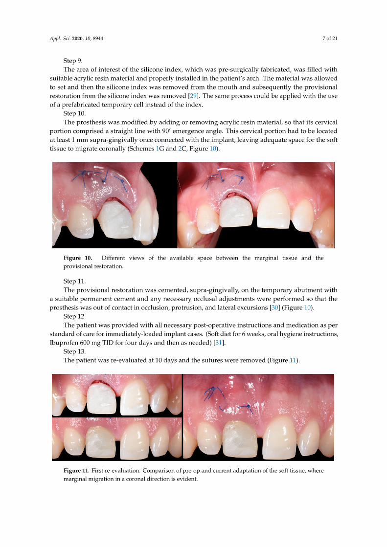
Figure 26. Clinical images at time of first temporary prosthesis removal and at time of transitional
prosthesis removal, demonstrating the soft tissue cervical contouring achieved.
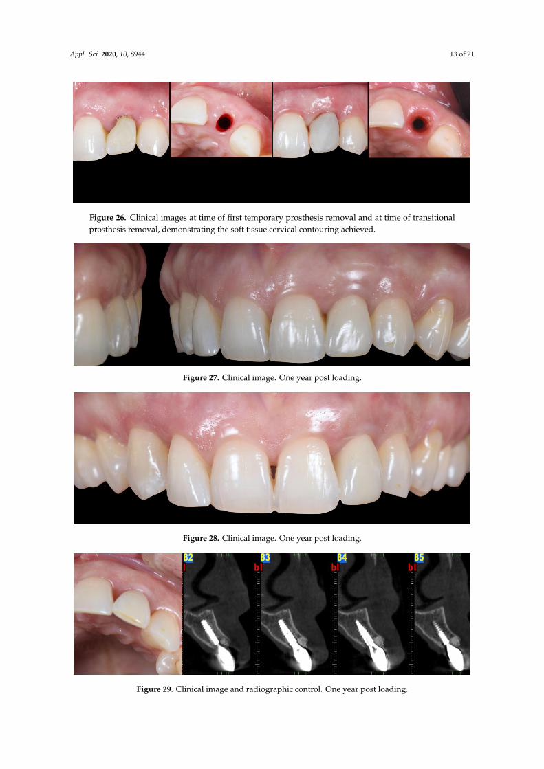
Figure 27. Clinical image. One year post loading.
Figure 28. Clinical image. One year post loading.
Figure 29. Clinical image and radiographic control. One year post loading.
Figure 26. Clinical images at time of first temporary prosthesis removal and at time of transitionalprosthesis removal, demonstrating the soft tissue cervical contouring achieved.
Appl. Sci. 2020, 10, x FOR PEER REVIEW 13 of 21
Figure 26. Clinical images at time of first temporary prosthesis removal and at time of transitional
prosthesis removal, demonstrating the soft tissue cervical contouring achieved.
Figure 27. Clinical image. One year post loading.
Figure 28. Clinical image. One year post loading.
Figure 29. Clinical image and radiographic control. One year post loading.
Figure 27. Clinical image. One year post loading.
Appl. Sci. 2020, 10, x FOR PEER REVIEW 13 of 21
Figure 26. Clinical images at time of first temporary prosthesis removal and at time of transitional
prosthesis removal, demonstrating the soft tissue cervical contouring achieved.
Figure 27. Clinical image. One year post loading.
Figure 28. Clinical image. One year post loading.
Figure 29. Clinical image and radiographic control. One year post loading.
Figure 28. Clinical image. One year post loading.
Appl. Sci. 2020, 10, x FOR PEER REVIEW 13 of 21
Figure 26. Clinical images at time of first temporary prosthesis removal and at time of transitional
prosthesis removal, demonstrating the soft tissue cervical contouring achieved.
Figure 27. Clinical image. One year post loading.
Figure 28. Clinical image. One year post loading.
Figure 29. Clinical image and radiographic control. One year post loading.
Figure 29. Clinical image and radiographic control. One year post loading.

Appl. Sci. 2020, 10, 8944 14 of 21
4. Discussion
Implants immediately placed and provisionalized in fresh extraction sockets in the esthetic zoneare well documented with survival rates similar to traditional delayed protocols [27]. However,the lack of long-term tissue stability resulting in less predictability of esthetic results, has limited theutilization of this protocol to ideal Type I extraction sites [11]. Even in Type I sites, the inclusion ofbone and/or soft tissue grafting techniques are often necessary to minimize less than optimal outcomes.The MMC protocol utilizes biologically sound steps in order to further enhance the predictabilityof the treatment outcomes for both type I sockets as well as type II sites, comprising a thick or thintissue biotype (Sketch 1 and 2) (Schemes 1 and 2) [18]. In this article, the authors utilized a socketclassification proposed in by Salama and Salama 1993, as we considered it to be the most suitableone [18]. According to more recent classifications, the MMC can be utilized also in Class III socketsthat do not present interproximal bone loss and, or class II or III Miller soft tissue recession [19,41].The MMC protocol does not utilize any vertical incisions. Instead, the surgical design utilizes apartial thickness, supra-periosteal, to create an envelope pouch on the labial aspect of the socket. It isbelieved that a partial thickness flap is more advantageous relative to a full thickness flap for the MMCtechnique as it minimizes any compromise to the blood supply originating with the supra-periostealvascular complex. In addition, a partial thickness flap allows for greater tension-free mobilization ofthe labial soft tissue. Unlike other techniques which utilize similar partial-thickness labial pouches asreceptors of soft tissue grafts, however, the novel aspect of the MMC protocol is this envelope pouch isdesigned to initiate a control trauma to the periosteum that will lead in the formation of a blood clot,and potentially stimulate osteoprogenitor cells coming from the periosteum to occupy the area [42–44].In combination with the proposed vertical mattress suturing technique, the protocol’s design allowsthe application of a vertical pull-force at the line angles instead of a horizontal pressure-force to the midbuccal side of the treatment site. Moreover, the location of the vertical mattress sutures constrains theblood clot in a mesio-distal direction between the lateral line angles, allowing it to form and expand inan apico-coronal direction just on the buccal portion of the site without expanding towards the areas ofthe adjacent teeth [45]. The mobilized buccal tissue with the support of the blood clot is guided by thepull-force to migrate coronally, improving at the same time its vertical location and thickness [45,46].As the healing process progresses and the inflammation moderates, the coronally migrated soft tissueremains supported, supra-crestally, by portions of the low turnover BRG and resorbable membranethat are purposefully located supra-crestally to provide for a scaffold at the supra-crestal zone ofthe healing socket [42,47]. Specifically, the membrane is critical to maintaining the graft particles inplace and minimizing the popcorn effect often seen in bone grafted cases with thin soft tissue biotype.Moreover, due to the modification and adaptation of its supra-socket portion, the membrane is placedtension free and does not apply any lateral force to the BRG. Similar approaches that tag and/or suturethe membrane at the lingual aspect of the socket, can apply pressure on the BRG during the steps ofadaptation, moving part of the BRG away from the buccal side, where most of the socket remodelingwill take place and thus the BRG is mostly needed [48]. There are several studies that support theutilization of a connective tissue graft within a partial thickness pouch on the buccal aspect of thesocket [49,50]. Although this approach appears to improve the stability of the soft tissue, it is a commonclinical observation that the addition of the connective tissue graft (CTG) can potentially affect the colorand volume of the tissue, making it look different than that of the adjacent sites. The color changesobserved are strongly related with the origin of the CTG and the time that has lapsed from the time ofsurgery [51,52]. The MMC protocol does not induce any such problems, since no CTG or any othermaterial is introduced into the pouch, but instead the generated blood clot is the foundation behindthe changes that occur [42]. The ideal position of an immediately placed implant in the esthetic zonehas been well documented and is generally described as the “palatal position” [18]. However, the term“palatally-placed implant”, generates some misconceptions. It is important to note that the sockets inthe esthetic zone present different anatomies [26]. A fundamental goal that the clinician needs to fulfilin order to be able to immediately load the implant is to achieve high primary stability by engaging an

Appl. Sci. 2020, 10, 8944 15 of 21
adequate amount of native bone [53]. Thus, based on the socket’s anatomy and the implant’s size andmacro-geometry, the position of the implant body can be located palatally, centered, or even buccally,in order to achieve high primary stability (Scheme 1B). As long as the platform and the neck of theimplant (3–4 mm of the coronal part of the implant body) are located a minimum distance of 2 mmfrom the buccal wall of the socket, the needed conditions for a positive esthetic outcome are met,since this coronal area of the socket is the one mostly affected by the physiologic changes/remodelingthat occurs during and after the initial healing period of the socket [5,19]. Thus, we believe that aterm such as “palatally-positioned implant neck” is more suitable when describing ideal implantpositioning in immediate extraction cases. As far as the depth of the implant is concerned, againseveral factors can affect the final decision for ideal depth. The size and the horizontal location of theimplant platform along with the size of the cervical margin of the prosthesis, in combination, dictatethe necessary room for proper emergence angle of the prosthesis and thus need to be accounted forwhen deciding the ideal depth position for the implant [54]. This depth in reality will be anywherebetween 3 to 5 mm from the zenith point of the final prosthesis for the majority of the clinical cases.At the stage of provisionalization, the first provisional restoration is designed with two factors inmind. The first refers to the esthetic appearance of the patient and it is related to the design, texture,and color of its supra-gingival portion. The second factor refers to the healing process of the socketand, in particular, its soft tissue zone. More specifically, the abutment shoulder with its tulip shapeand restricted lateral dimensions provides a surface to contain the membrane and the BRG within thesoft tissue zone of the socket, while at the same time providing space for the soft issue adaptation andintegration [21]. The cervical margin of the prosthesis being located at least 1 mm supra-gingivally andcomprising a 90◦ emergence angle, provides necessary room vertically for the soft tissue to migratecoronally. It is understood that in the case of type II sockets where a gingival recession is present,the margin of the prosthesis should be located 1 mm coronal to the future zenith point of the finalprosthesis. Thus, in these cases, the cervical margin of the temporary prosthesis can be located 2, 3,or even more millimeters supra-gingivally at the mid-buccal portion. Other published protocols installa temporary prosthesis with a submergence profile that is identical to the emergence profile of thesocket. These protocols aim for the prosthesis to fully occupy and support the existing emergenceprofile of the soft tissue [55]. However, these protocols allow no room for soft tissue improvement andpose possible risks for the final outcome. In case the prosthesis applies any pressure to the buccal softtissue and/or the gingival biotype is thin, there is a risk for soft tissue recession, compromising theend result [56]. On the contrary, with MMC, all the support of the supra-crestal soft tissue is providednot by the prosthesis, but instead by the BRG and the membrane. The only prosthetic material that ispresent sub-gingivally is a narrow portion of the titanium abutment which provides the necessaryspace and a biocompatible surface that enhance the soft tissue adaptation in a more favorable andpredictable way [57]. The MMC protocol involves the use of a second temporary restoration, whichwe call transitional restoration. The latter is used in order to take advantage of the improved softtissue quantity and quality achieved by the first phase of treatment and condition of the soft tissueby utilizing the principles of proper cervical tissue conditioning [8,58]. The transitional restoration atthis stage comprises an anatomically shaped submergence profile, which applies lateral pressure tothe soft tissue, forcing the gingival fibers to obtain an oblique orientation [59]. This lateral pressurealso leads the coronally migrated buccal tissue to its final vertical location. This vertical location islevel with the zenith of the transitional prosthesis, which mimics the desired final prosthesis, and it islocated more apically. This apically forced shift of the marginal, matured soft tissue is accompanied byan increase of its thickness [8]. These two factors increase the marginal tissue thickness and obliqueorientation of gingival fibers, in combination, improving the tone and color appearance of the softtissue [8]. The conditioning of the tissue per se also allows the fabrication of a prosthesis with propercervical contour that achieves ideal esthetic appearance [29]. The process of the final impression caninvolve any technique, either digital or analogic. It is important, at this stage, to capture the tissuetopography accurately and thus, if needed, it is recommended to utilize proper protocols of impression

Appl. Sci. 2020, 10, 8944 16 of 21
post customization [60]. During the lab stage, the most critical factor refers to proper communicationbetween the clinician and the lab technician as per standard practice. The only restriction that theMMC proposes is the use of a final abutment that comprises a shoulder that is identical to the one ofthe temporary abutment used for the support of the transitional restoration. It is understood that anintermediate abutment or a CAD abutment milled in-office can also be utilized in order to serve moreoptions of final abutment-prosthesis assembly, as long as these abutments respect the aforementionedrequirements with regards to their design and are used at all involved restorative stages. The differencebetween the temporary abutments used for the support of the temporary (first) restoration and thetransitional restoration refers to their margin. The margin of the temporary restoration extends upto 0.5 mm apical to the existing free gingival margin, while the one of the transitional restorationextends 0.5 mm apical to the future zenith point of the prosthesis. The reason behind this difference isthat the first supra-structure is designed in order to allow space for gain in soft tissue height, whilethe second (transitional) supra-structure is designed in order to condition the soft tissue at the idealheight for the final prosthesis. Since the MMC allows the soft tissue to migrate coronal to the zenithpoint of the future prosthesis, the transitional prosthesis will now condition/push this tissue laterallyand apically and this way will further improve its thickness. The MMC has been tested for sitespresenting limited soft tissue recession. Further investigation is required to evaluate the efficiency ofthe technique in cases involving more severe recessions. All of the prostheses utilized in MMC protocolcould be screw-retained, cemented, or screw-cemented [61]. However, since proper cement control canpotentially be inadequate and result in biologic complications, a screw-cemented prosthesis design isrecommended whenever possible [62,63]. A possible complication a clinician might encounter withthe proposed protocol is the accidental tear of the buccal flap when the supra-periosteal pouch isprepared. Since the tear will now be exposing part of the resorbable membrane, it is advisable toavoid suturing of the area, rather leaving the site exposed. In this event meticulous care by the patientis advised with the use of effective anti-microbial rinses or gels, and additionally the clinician mustperform frequent monitoring during the initial stages of healing and until complete epithelialization ofthe area is achieved [64].
5. Conclusions
The proposed protocol presents an alternative approach for cases involving immediate implantplacement and provisionalization in type I and type II sockets with Miller class I gingival recessionin the esthetic zone. The technique is applicable for cases involving both thick and thin soft tissuephenotypes (Figure 30) [18]. Implant sites that fall into the category of type II sockets and/or theirsoft tissue biotype are identified as thin, and are associated with high risk for the development of softtissue recession. Thus, currently available guidelines recommend avoiding the treatment of these siteswith immediate implant placement and provisionalization protocols [26,65,66]. This case series reportshowed that the proposed protocol can be proven effective in achieving an esthetically sound result inthese types of sites (Figure 29). In the case of class III sockets, an orthodontic extrusion of the affectedtooth can precede in order to enhance the proximal bone and soft tissue levels before MMC can beutilized [18,67]. Table 1 summarizes the potential of the application of the MMC protocol based ondifferent available socket classifications. The MMC protocol has been tested by the authors on morethan 25 cases involving both type I and II sockets (with Miller class I recession defects) and a follow-upperiod of up to 3 years, showing consistent results. A new case series study that evaluates volumetricchanges with the MMC protocol in both types of sockets is undergoing. Prospective randomized,controlled clinical trials are needed in order to thoroughly evaluate the efficiency and validity of theproposed protocol before its application on a regular basis can be recommended.

Appl. Sci. 2020, 10, 8944 17 of 21
Appl. Sci. 2020, 10, x FOR PEER REVIEW 17 of 21
Figure 30. Pre-op (top row) and post-op (bottom row) images of three cases, demonstrating the
marginal migration of soft tissue effect achieved with the MMC protocol.
Table 1. Summary of different socket classifications available and potential applicability of the MMC
protocol.
Salama H, Salama M [18] CLASS I CLASS II CLASS III
MMC + + −
Chu SJ et al. [68] TYPE A TYPE B TYPE C
MMC + + +
(If recession defect is class I Miller)
Ellian N et al. [19]. TYPE I TYPE II TYPE III
MMC + + +
(If recession defect is class I Miller)
El Chaar E et al. [69] GRADE I GRADE II GRADE III
MMC + + −
Author Contributions: Conceptualization K.V.; writing–original draft preparation I.V.; review and editing H.S.
and M.P. All authors have read and agreed to the published version of the manuscript.
Funding: This research received no external funding.
Conflicts of Interest: The authors declare no conflicts of interest.
References
1. Avila, G.; Galindo, P.; Rios, H.; Wang, H.L. Immediate implant loading: Current status from available
literature. Implant Dent. 2007, 16, 235–245.
2. Amler, M.H. The time sequence of tissue regeneration in human extraction wounds. Oral Surg. Oral Med.
Oral Pathol. 1969, 27, 309–318.
3. Cardaropoli; G.; Araújo; M.; Lindhe; J. Dynamics of bone tissue formation in tooth extraction sites. An
experimental study in dogs. J. Clin. Periodontol. 2003, 30, 809–818.
4. Araújo, M.G.; Sukekava, F.; Wennström, J.L.; Lindhe, J. Ridge alterations following implant placement in
fresh extraction sockets; an experimental study in the dog. J. Clin. Periodontol. 2005, 32, 645–665.
5. Araujo, M.G.; Sukekava, F.; Wennstrom, J.L.; Lindhe, J. Tissue modeling following implant placement in
fresh extraction sockets. Clin. Oral Implant. Res. 2006, 17, 615–624.
6. Araujo, M.G.; Wennstrom, J.L.; Lindhe, J. Modeling of the buccal and lingual bone walls of fresh extraction
sites following implant installation. Clin. Oral Implant. Res. 2006, 17, 606–614.
7. Araújo, M.G.; Lindhe, J. Dimensional ridge alterations following tooth extraction. An experimental study
in the dog. J. Clin. Periodontol. 2005, 32, 212–218.
Figure 30. Pre-op (top row) and post-op (bottom row) images of three cases, demonstrating themarginal migration of soft tissue effect achieved with the MMC protocol.
Table 1. Summary of different socket classifications available and potential applicability of theMMC protocol.
Salama H, Salama M [18] CLASS I CLASS II CLASS III
MMC + + −
Chu SJ et al. [68] TYPE A TYPE B TYPE C
MMC + ++
(If recession defect is class I Miller)
Ellian N et al. [19]. TYPE I TYPE II TYPE III
MMC + ++
(If recession defect is class I Miller)
El Chaar E et al. [69] GRADE I GRADE II GRADE III
MMC + + −
Author Contributions: Conceptualization K.V.; writing—original draft preparation I.V.; review and editing H.S.and M.P. All authors have read and agreed to the published version of the manuscript.
Funding: This research received no external funding.
Conflicts of Interest: The authors declare no conflict of interest.
References
1. Avila, G.; Galindo, P.; Rios, H.; Wang, H.L. Immediate implant loading: Current status from availableliterature. Implant Dent. 2007, 16, 235–245. [CrossRef] [PubMed]
2. Amler, M.H. The time sequence of tissue regeneration in human extraction wounds. Oral Surg. Oral Med.Oral Pathol. 1969, 27, 309–318. [CrossRef]
3. Cardaropoli, G.; Araújo, M.; Lindhe, J. Dynamics of bone tissue formation in tooth extraction sites.An experimental study in dogs. J. Clin. Periodontol. 2003, 30, 809–818. [CrossRef] [PubMed]
4. Araújo, M.G.; Sukekava, F.; Wennström, J.L.; Lindhe, J. Ridge alterations following implant placement infresh extraction sockets; an experimental study in the dog. J. Clin. Periodontol. 2005, 32, 645–665. [CrossRef]
5. Araujo, M.G.; Sukekava, F.; Wennstrom, J.L.; Lindhe, J. Tissue modeling following implant placement infresh extraction sockets. Clin. Oral Implant. Res. 2006, 17, 615–624. [CrossRef]
Appl. Sci. 2020, 10, 8944 18 of 21
6. Araujo, M.G.; Wennstrom, J.L.; Lindhe, J. Modeling of the buccal and lingual bone walls of fresh extractionsites following implant installation. Clin. Oral Implant. Res. 2006, 17, 606–614. [CrossRef]
7. Araújo, M.G.; Lindhe, J. Dimensional ridge alterations following tooth extraction. An experimental study inthe dog. J. Clin. Periodontol. 2005, 32, 212–218. [CrossRef]
8. Landsberg, C.J.; Bichacho, N. A modified surgical/prosthetic approach for optimal single implant supportedcrown. Part I–The socket seal surgery. Pract. Periodontics Aesthet Dent. 1994, 6, 11–17.
9. Hurzeler, M.B.; Zuhr, O.; Schupbach, P.; Rebele, S.F.; Emmanouilidis, N.; Fickl, S. The socket-shield technique:A proof-of-principle report. J. Clin. Periodontol. 2010, 37, 855–862. [CrossRef]
10. Chu, S.J.; Hochman, M.N.; Tan-Chu, J.H.; Mieleszko, A.J.; Tarnow, D.P. A Novel Prosthetic Device andMethod for Guided Tissue Preservation of Immediate Postextraction Socket Implants. Int. J. PeriodonticsRestor. Dent. 2014, 34, S9–S17.
11. Waki, T.; Kan, J.Y. Immediate placement and provisionalization of maxillary anterior single implant withguided bone regeneration, connective tissue graft, and coronally positioned flap procedures. Int. J. Esthet Dent.2016, 11, 174–185.
12. Chen, S.T.; Buser, D. Esthetic outcomes following immediate and early implant placement in the anteriormaxilla–a systematic review. Int. J. Oral Maxillofac Implant. 2014, 29, 186–215. [CrossRef]
13. Tarnow, D.; Chu, S.; Salama, M.; Stappert, C.; Salama, H.; Garber, D.; Sarnachiaro, G.; Sarnachiaro, E.;Gotta, S.; Saito, H. Flapless postextraction socket implant placement in the esthetic zone: Part 1. The effectof bone grafting and/or provisional restoration on facial-palatal ridge dimensional change-a retrospectivecohort study. Int. J. Periodontics Restor. Dent. 2014, 34, 323–331. [CrossRef]
14. Chu, S.; Salama, M.; Garber, D.; Salama, H.; Sarnachiaro, G.; Sarnachiaro, E.; Gotta, S.; Reynolds, M.; Saito, H.;Tarnow, D. Flapless Postextraction Socket Implant Placement, Part 2: The Effects of Bone Grafting andProvisional Restoration on Peri-implant Soft Tissue Height and Thickness—A Retrospective Study. Int. J.Periodontics Restor. Dent. 2015, 35, 803–809. [CrossRef]
15. Amato, F.; Polara, G.; Spedicato, G.A. Tissue Dimensional Changes in Single-Tooth Immediate ExtractionImplant Placement in the Esthetic Zone: A Retrospective Clinical Study. Int. J. Oral Maxillofac Implant. 2018,33, 439–447. [CrossRef]
16. Mitsias, M.M.; Bratos, M.; Siormpas, K.; Pikos, M.A.; Kotsakis, G.A.; Root Membrane Group. LongitudinalSoft Tissue Changes during Periodontal Ligament-Mediated Immediate Implant Placement with theRoot-Membrane Technique. Int. J. Oral Maxillofac Implant. 2020, 35, 379–385. [CrossRef]
17. Gluckman, H.; Salama, M.; Du Toit, J. A retrospective evaluation of 128 socket-shield cases in the estheticzone and posterior sites: Partial extraction therapy with up to 4 years follow-up. Clin. Implant Dent Relat. Res.2018, 20, 122–129. [CrossRef]
18. Salama, H.; Salama, M. The role of orthodontic extrusive remodeling in the enhancement of soft and hardtissue profiles prior to implant placement: A systematic approach to the management of extraction sitedefects. Int. J. Periodontics Restor. Dent. 1993, 13, 312–333.
19. Elian, N.; Cho, S.C.; Froum, S.; Smith, R.B.; Tarnow, D.P. A simplified socket classification and repairtechnique. Pract. Proced Aesthet Dent. 2007, 19, 99–104.
20. De Jong, K.J.; Abraham-Inpijn, L. A risk-related patient-administered medical questionnaire for dentalpractice. Int. Dent. J. 1994, 44, 471–479.
21. Blanco, J.; Carral, C.; Argibay, O.; Liñares, A. Implant placement in fresh extraction sockets. Periodontology 20002019, 79, 151–167. [CrossRef] [PubMed]
22. Fiorillo, L.; Cicciù, M.; D’Amico, C.; Mauceri, R.; Oteri, G.; Cervino, G. Finite Element Method and VonMises Investigation on Bone Response to Dynamic Stress with a Novel Conical Dental Implant Connection.BioMed Res. Int. 2020, 2020, 2976067. [CrossRef] [PubMed]
23. Covani, U.; Cornelini, R.; Calvo-Guirado, J.L.; Tonelli, P.; Barone, A. Bone remodeling around implantsplaced in fresh extraction sockets. Int. J. Periodonticsrestorative Dent. 2010, 30, 601–607.
24. Rojas-Vizcaya, F. Biological aspects as a rule for single implant placement. The 3A-2B rule: A clinical report.J. Prosthodont. 2013, 22, 575–580. [CrossRef]
25. Canullo, L.; Fedele, G.R.; Iannello, G.; Jepsen, S. Platform switching and marginal bone-level alterations:The results of a randomized-controlled trial. Clin. Oral Implant. Res. 2010, 21, 115–121. [CrossRef] [PubMed]

Appl. Sci. 2020, 10, 8944 19 of 21
26. Canullo, L.; Pesce, P.; Patini, R.; Antonacci, D.; Tommasato, G. What Are the Effect of Different AbutmentMorphologies on Peri-implant Hard and Soft Tissue Behavior? A Systematic Review and Meta-Analysis.Int. J. Prosthodont. 2020, 33, 297–306. [CrossRef]
27. Iasella, J.M.; Greenwell, H.; Miller, R.L.; Hill, M.; Drisko, C.; Bohra, A.A.; Scheetz, J.P. Ridge preservationwith freeze-dried bone allograft and a collagen membrane compared to extraction alone for implant sitedevelopment: A clinical and histologic study in humans. J. Periodontol. 2003, 74, 990–999. [CrossRef][PubMed]
28. Horowitz, R.; Holtzclaw, D.; Rosen, P.S. A review on alveolar ridge preservation following tooth extraction.J. Evid. Based Dent. Pract. 2012, 12 (Suppl. 3), 149–160. [CrossRef]
29. Castellon, P.; Casadaban, M.; Block, M.S. Techniques to facilitate provisionalization of implant restorations.J. Oral Maxillofac Surg. 2005, 63, 72–79. [CrossRef] [PubMed]
30. Kan, J.Y.K.; Rungcharassaeng, K.; Deflorian, M.; Weinstein, T.; Wang, H.L.; Testori, T. Immediate implantplacement and provisionalization of maxillary anterior single implants. Periodontology 2000 2018, 77, 197–212.[CrossRef]
31. Chung, S.; McCullagh, A.; Irinakis, T. Immediate loading in the maxillary arch: Evidence-based guidelines toimprove success rates: A review. J. Oral Implant. 2011, 37, 610–621. [CrossRef] [PubMed]
32. Buser, D.; Sennerby, L.; De Bruyn, H. Modern implant dentistry based on osseointegration: 50 years ofprogress, current trends and open questions. Periodontology 2000 2017, 73, 7–21. [CrossRef] [PubMed]
33. Wittneben, J.G.; Buser, D.; Belser, U.C.; Brägger, U. Peri-implant soft tissue conditioning with provisionalrestorations in the esthetic zone: The dynamic compression technique. Int. J. Periodontics Restor. Dent. 2013,33, 447–455. [CrossRef]
34. Furze, D.; Byrne, A.; Alam, S.; Wittneben, J.G. Esthetic Outcome of Implant Supported Crowns with andWithout Peri-Implant Conditioning Using Provisional Fixed Prosthesis: A Random-ized Controlled ClinicalTrial. Clin. Implant. Dent Relat. Res. 2016, 18, 1153–1162. [CrossRef] [PubMed]
35. Chen, M.H.; Lyons, K.; Tawse-Smith, A.; Ma, S. Resonance Frequency Analysis in Assessing Implant Stability:A Retrospective Analysis. Int. J. Prosthodont. 2019, 32, 317–326. [CrossRef]
36. Lee, S.J.; Gallucci, G.O. Digital vs. conventional implant impressions: Efficiency outcomes. Clin. Oral Implant.Res. 2013, 24, 111–115. [CrossRef]
37. Donovan, T.E.; Chee, W.W. A review of contemporary impression materials and techniques. Dent. Clin.N. Am. 2004, 48, 445–470. [CrossRef]
38. Terry, D.A.; Snow, S.R.; McLaren, E.A. Contemporary dental photography: Selection and application.Compend. Contin. Educ. Dent. 2008, 29, 440.
39. Rösing, C.K.; Fiorini, T.; Haas, A.N.; Muniz, F.W.M.G.; Oppermann, R.V.; Susin, C. The impact of maintenanceon peri-implant health. Braz. Oral Res. 2019, 33, e074. [CrossRef]
40. Sheridan, R.A.; Decker, A.M.; Plonka, A.B.; Wang, H.L. The Role of Occlusion in Implant Therapy:A Comprehensive Updated Review. Implant Dent. 2016, 25, 829–838. [CrossRef]
41. Miller, P.D., Jr. A classification of marginal tissue recession. Int. J. Periodontics Restor. Dent. 1985, 5, 8–13.42. Ballini, A.; Scacco, S.; Coletti, D.; Pluchino, S.; Tatullo, M. Mesenchymal Stem Cells as Promoters, Enhancers,
and Playmakers of the Translational Regenerative Medicine. Stem Cells Int. 2017, 2017, 3292810. [CrossRef][PubMed]
43. Porcaro, G.; Busa, A.; Bianco, E.; Caccianiga, G.; Maddalone, M. Use of aPartial-thickness Flap for GuidedBone Regeneration in the Upper Jaw. J. Contemp. Dent. Pract. 2017, 18, 1117–1121. [PubMed]
44. Lin, Z.; Fateh, A.; Salem, D.M.; Intini, G. Periosteum: Biology and applications in craniofacial boneregeneration. J. Dent. Res. 2014, 93, 109–116. [CrossRef] [PubMed]
45. Lassere, B. The vertical mattress suture in periodontal flap surgery. Inf. Dent. 1983, 65, 3825–3830. [PubMed]46. Kumar, K.; Sharma, R.K.; Tewari, S.; Narula, S.C. Use of modified vertical internal mattress suture
versus simple loop interrupted suture in modified Widman flap surgery: A randomized clinical study.Quintessence Int. 2019, 50, 732–740.
47. Chu, S.J.; Salama, M.A.; Salama, H.; Garber, D.A.; Saito, H.; Sarnachiaro, G.O.; Tarnow, D.P. The dual-zonetherapeutic concept of managing immediate implant placement and provisional restoration in anteriorextraction sockets. Compend. Contin. Educ. Dent. 2012, 33, 524–534.

Appl. Sci. 2020, 10, 8944 20 of 21
48. Tan-Chu, J.H.; Tuminelli, F.J.; Kurtz, K.S.; Tarnow, D.P. Analysis of buccolingual dimensional changes of theextraction socket using the “ice cream cone” flapless grafting technique. Int. J. Periodontics Restor. Dent. 2014,34, 399–403. [CrossRef]
49. Atieh, M.A.; Alsabeeha, N.H.M. Soft tissue changes after connective tissue grafts around immediately placedand restored dental implants in the esthetic zone: A systematic review and meta-analysis. J. Esthet. Restor.Dent. 2020, 32, 280–290. [CrossRef]
50. Grunder, U. Crestal ridge width changes when placing implants at the time of tooth extraction with andwithout soft tissue augmentation after a healing period of 6 months: Report of 24 consecutive cases. Int. J.Periodontics Restor. Dent. 2011, 31, 9–17.
51. Zucchelli, G.; Tavelli, L.; McGuire, M.K.; Rasperini, G.; Feinberg, S.E.; Wang, H.L.; Giannobile, W.V.Autogenous soft tissue grafting for periodontal and peri-implant plastic surgical reconstruction. J. Periodontol.2020, 91, 9–16. [CrossRef] [PubMed]
52. Gluckman, H.; Du Toit, J.; Pontes, C.C.; Hille, J. Hyperplastic Response Following Soft Tissue Augmentationin the Esthetic Zone. Clin. Adv. Periodontics 2019, 9, 50–54. [CrossRef] [PubMed]
53. Tettamanti, L.; Andrisani, C.; Bassi, M.A.; Vinci, R.; Silvestre-Rangil, J.; Tagliabue, A. Immediate loadingimplants: Review of the critical aspects. Oral Implant. 2017, 10, 129–139. [CrossRef] [PubMed]
54. Saadoun, A.P.; LeGall, M.; Touati, B. Selection and ideal tridimensional implant position for soft tissueaesthetics. Pract Periodontics Aesthet Dent. 1999, 11, 1063–1072. [PubMed]
55. de Siqueira, R.A.C.; Cabral, B.L.; de Siqueira, G.R.; Mendonça, G.; Wang, H.L. Using Digital Technique toObtain the Ideal Soft Tissue Contour in Immediate Implants with Provisionalization. Implant Dent. 2019, 28,411–416. [CrossRef]
56. Lee, C.T.; Sanz-Miralles, E.; Zhu, L.; Glick, J.; Heath, A.; Stoupel, J. Predicting bone and soft tissue alterationsof immediate implant sites in the esthetic zone using clinical parameters. Clin. Implant Dent. Relat. Res. 2020,22, 325–332. [CrossRef]
57. Vela, X.; Rodríguez, X. The State of the Art of the Implant-Abutment Design to Maximize the Peri-ImplantTissue Potential. In Implants in the Aesthetic Zone; Schoenbaum, T., Ed.; Springer: Cham, Switzerland, 2019.
58. González-Martín, O.; Lee, E.; Weisgold, A.; Veltri, M.; Su, H. Contour Management of Implant Restorationsfor Optimal Emergence Profiles: Guidelines for Immediate andDelayed Provisional Restorations. Int. J.Periodontics Restor. Dent. 2020, 40, 61–70. [CrossRef]
59. López-López, P.J.; Mareque-Bueno, J.; Boquete-Castro, A.; Raya, A.A.-S.; Martínez-González, J.M.;Calvo-Guirado, J.L. The effects of healing abutments of different size and anatomic shape placed immediatelyin extraction sockets on peri-implant hard and soft tissues. A pilot study in foxhound dogs. Clin. OralimplantsRes. 2016, 27, 90–96. [CrossRef]
60. Vergoullis, I.; DDS, M.S.; Valavanis, K.D.D.S.; Badell, C.D.D.S.; Papadopoulos, G.C.D.T. The one functionalposition, implant level, indirect impression technique: Description of the technique and a case report. JIACD2019, 11, 14–23.
61. Wittneben, J.G.; Millen, C.; Brägger, U. Clinical performance of screw- versus cement-retained fixedimplant-supported reconstructions–a systematic review. Int. J. Oral Maxillofac Implant. 2014, 29, 84–98.[CrossRef]
62. Linkevicius, T.; Vindasiute, E.; Puisys, A.; Linkeviciene, L.; Maslova, N.; Puriene, A. The influence of thecementation margin position on the amount of undetected cement. A prospective clinical study. Clin. OralImplant. Res. 2013, 24, 71–76. [CrossRef] [PubMed]
63. Helvey, G.A. A Simple Technique for Fabricating a Screw-Retained/Cemented Implant-Supported Crown.Compend. Contin. Educ. Dent. 2017, 38, 153–159. [PubMed]
64. Cantore, S.; Ballini, A.; Mori, G.; Dibello, V.; Marrelli, M.; Mirgaldi, R.; De Vito, D.; Tatullo, M. Anti-plaqueand antimicrobial efficiency of different oral rinses in a 3-day plaque accumulation model. J. Biol. Regul.Homeost Agents. 2016, 30, 1173–1178. [PubMed]
65. Sicilia-Felechosa, A.; Pereira-Fernández, A.; García-Lareu, J.; Bernardo-González, J.; Sicilia-Blanco, P.;Cuesta-Fernández, I. Flapless immediate implant placement and provisionalization in periodontal patients:A retrospective consecutive case-series study of single-tooth sites with dehiscence-type osseous defects. Clin.Oral Implant. Res. 2020, 31, 229–238. [CrossRef]
66. Buser, D.; Chappuis, V.; Belser, U.C.; Chen, S. Implant placement post extraction in esthetic single tooth sites:When immediate, when early, when late? Periodontol 2000 2017, 73, 84–102. [CrossRef]

Appl. Sci. 2020, 10, 8944 21 of 21
67. Salama, H.; Salama, M.A.; Garber, D.; Adar, P. The interproximal height of bone: A guidepost to predictableaesthetic strategies and soft tissue contours in anterior tooth replacement. Pract. Periodontics Aesthet Dent.1998, 10, 1131–1141.
68. Chu, S.J.; Sarnachiaro, G.O.; Hochman, M.N.; Tarnow, D.P. Subclassification and Clinical Management ofExtraction Sockets with Labial Dentoalveolar Dehiscence Defects. Compend. Contin. Educ. Dent. 2015, 36,518–520.
69. El Chaar, E.; Oshman, S.; Fallah Abed, P. Single-Rooted Extraction Sockets: Classification and TreatmentProtocol. Compend. Contin. Educ. Dent. 2016, 37, 537–541.
Publisher’s Note: MDPI stays neutral with regard to jurisdictional claims in published maps and institutionalaffiliations.
© 2020 by the authors. Licensee MDPI, Basel, Switzerland. This article is an open accessarticle distributed under the terms and conditions of the Creative Commons Attribution(CC BY) license (http://creativecommons.org/licenses/by/4.0/).