IMF SCREWS SYSTEM SURGICAL TECHNIQUE - Ortho Max
15
IMF SCREWS SYSTEM SURGICAL TECHNIQUE Doc. No. Issue No/Rev No Dated Page No F/CMF/ST/05 01/00 24-04-2019 Page 1 of 15
-
Upload
khangminh22 -
Category
Documents
-
view
1 -
download
0
Transcript of IMF SCREWS SYSTEM SURGICAL TECHNIQUE - Ortho Max

IMF SCREWS SYSTEM
SURGICAL TECHNIQUE
Doc. No. Issue No/Rev No Dated Page No F/CMF/ST/05 01/00 24-04-2019 Page 1 of 15

IMF SCREWS SYSTEM
SURGICAL TECHNIQUE
Doc. No. Issue No/Rev No Dated Page No F/CMF/ST/05 01/00 24-04-2019 Page 2 of 15
Screw Features:
– 316L stainless steel or Titanium Gr.5 for maximum strength
– Self- Tapping screws for easy insertion
– Groove under screw head secures wires or elastics
– Cross Drive screw or slotted head
Intended use
Temporary, perioperative stabilization of the occlusion in adults Indications
– Simple nondisplaced mandibular and maxillary fractures
– Orthognatic procedures
– For temporary use during bone healing
Contraindications
– Severely comminuted and/or displaced fractures
– Unstable, segmented maxillary or mandibular arches
– Combined maxillary and mandibular fractures
– Paediatric
IMF- Surgical Technique Note: The following surgical technique assumes that the first screw is placed in the maxilla. However, screw placement, number of screws, and order of insertion are dependent on the fracture type, location and the surgeon’s preference. The screws must be positioned superior to the maxillary tooth roots and inferior to the mandibular tooth roots and be inserted either medial or lateral to the long axis of the canine roots. The advantages of the lateral approach include increased lateral stability and greater control over posterior open bite.

IMF SCREWS SYSTEM
SURGICAL TECHNIQUE
Doc. No. Issue No/Rev No Dated Page No F/CMF/ST/05 01/00 24-04-2019 Page 3 of 15
1. Determine number and position of screws: Determine the number and the position of the IMF screws to be inserted, based on the fracture type and location. 2. Locate Maxillary Tooth roots Locate and identify the maxillary tooth roots, paying particular attention to the canine roots which are the longest of the tooth roots. It is important to avoid the existing dentition as well as infraorbital and mental nerves. A helpful guide to es-timating the length of the dentition from radiographs can be found in this figure.
Average tooth lengths (mm) including a 20% magnification associated with the radiograph.
Precautions:
– Supernumerary, unerupted and developing teeth may be present and should be confirmed or refuted with appropriate x-rays. The maxillary screws should be placed 5 mm superior to the tooth roots. – Special care must be employed to identify and avoid canine roots and the dental nerve.
20.4
21.6 24.6 26.8
26.4
32.4 32.4 28.2 28.2
25.8
27.0
25.8
24.0 21.6
Lateral to canine roots
Locate maxillary tooth roots

IMF SCREWS SYSTEM
SURGICAL TECHNIQUE
Doc. No. Issue No/Rev No Dated Page No F/CMF/ST/05 01/00 24-04-2019 Page 4 of 15
3. Insert screw into maxilla
Pick up an IMF Screw 2mmx 8mm using the 2mm Cross Drive Screwdriver with Holding Sleeve Or Self Holding Screw Driver for slotted head. Insert the screw into the maxilla and advance it making sure that the screw head does not compress the gingiva.
Precaution: In dense cortical bone, it may be necessary to predrill with a 1.5 mmx8mm short flute drill bit. 4. Insert screw into mandible Before inserting the mandibular screw, identify the important anatomic structures. Again, special attention should be paid to the canine roots and the mental nerve.
Insert the second screw into the mandible 5mm inferior and medial or lateral to the canine root. If placing these Screws inferior and lateral to the canine root in the mandible, greater care must be employed to identify and avoid the mental nerve.
IMF SCREWS SYSTEM
SURGICAL TECHNIQUE
Doc. No. Issue No/Rev No Dated Page No F/CMF/ST/05 01/00 24-04-2019 Page 5 of 15
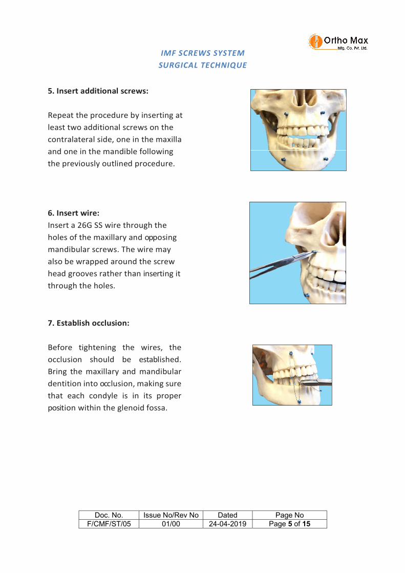
5. Insert additional screws: Repeat the procedure by inserting at least two additional screws on the contralateral side, one in the maxilla and one in the mandible following the previously outlined procedure.
6. Insert wire: Insert a 26G SS wire through the holes of the maxillary and opposing mandibular screws. The wire may also be wrapped around the screw head grooves rather than inserting it through the holes.
7. Establish occlusion: Before tightening the wires, the occlusion should be established. Bring the maxillary and mandibular dentition into occlusion, making sure that each condyle is in its proper position within the glenoid fossa.

IMF SCREWS SYSTEM
SURGICAL TECHNIQUE
Doc. No. Issue No/Rev No Dated Page No F/CMF/ST/05 01/00 24-04-2019 Page 6 of 15
8. Tighten wires: Clamp the free ends of the wires into the Wire Twisting Forceps. Pull the wires taut to hold the jaws in occlusion and then twist the wires to tension. Cut the wires with the Wire Cutter and bend the cut wire end under to prevent soft tissue irritation. In order to consolidate the segments it is important to secure the wire in an X-pattern in addition to the vertical pattern that provides maxilla-mandibular stabilisation and reduces lateral excursion.
Precaution: Due to the tension placed on the wires, there is a potential for loosening of the wire or the screw if left in postoperatively. The wire and screw should be carefully monitored for this condition during postsurgical evaluations and tightened as necessary.
9. Check stability: Check to ensure that no posterior open bite is produced during tensioning of the wires. The placement of additional IMF screws, Ernst ligatures or Ivy loops on the posterior dentition may be used to prevent or correct this condition.

IMF SCREWS SYSTEM
SURGICAL TECHNIQUE
Doc. No. Issue No/Rev No Dated Page No F/CMF/ST/05 01/00 24-04-2019 Page 7 of 15
Precaution: Overtightening of the wires could lead to rotation of the segments and interference with the reduction. Verify that the fracture is adequately reduced at the inferior border.
Warnings, Precautions, General Adverse Events: Warnings: • Using an internal fixation system on patients with active or latent infection may cause potential risks which may include construct failure and deterioration of infection. It is at the physician’s discretion to evaluate the patient’s medical conditions and select a fixation device most appropriate for the individual patient. It is also at the physician’s discretion to consider all other necessary treatment methods to effectively manage the infection. • Confirm the quality of bone at the selected screw / plate position. Using an internal fixation system on patients with insufficient quantity or quality of bone may cause potential risks which may include device loosening and construct failure. It is at the physician’s discretion to evaluate the patient’s Medical conditions and select a fixation device most appropriate for the individual patient. • These devices can break during use (when subjected to excessive forces or outside the recommended surgical technique). While the surgeon must make the final decision on removal of the broken part based on associated risk in doing so, we recommend that whenever possible and practical for the individual patient, the broken part should be removed. Be aware that implants are not as strong as native bone. Implants subjected to substantial loads may fail. • Instruments, screws and cut plates may have sharp edges or moving joints that may pinch or tear user’s glove or skin. • Take care to remove all fragments that are not fixated during the surgery. • While the surgeon must make the final decision on implant removal, we recommend that whenever possible and practical for the individual patient, fixation devices should be removed once their service as an aid to healing is accomplished. Implant removal should be followed by adequate post-operative management to avoid refracture.

IMF SCREWS SYSTEM
SURGICAL TECHNIQUE
Doc. No. Issue No/Rev No Dated Page No F/CMF/ST/05 01/00 24-04-2019 Page 8 of 15
Precautions: • Confirm functionality of instruments and check for wear during reprocessing. Replace worn or damaged instruments prior to use. • It is recommended to only use the instruments identified for use within the Wiring System of Ortho Max based on the surgical techniques recommended for implants. • Always irrigate and apply suction for removal of debris potentially generated during implantation or removal. General Adverse Events As with all major surgical procedures, risks, side effects and adverse events can occur. While many possible reactions may occur, some of the most common include: Problems resulting from anesthesia and patient positioning (e.g. nausea, vomiting, dental injuries, neurological impairments, etc.), thrombosis, embolism, infection, nerve and/or tooth root damage or injury of other critical structures including blood vessels, excessive bleeding, damage to soft tissues incl. swelling, abnormal scar formation, functional impairment of the musculoskeletal system, pain, discomfort or abnormal sensation due to the presence of the device, allergy or hypersensitivity reactions, side effects associated with hardware prominence, loosening, bending, or breakage of the device, mal-union, non-union or delayed union which may lead to break age of the implant, reoperation. Device-specific Adverse Events Device-specific adverse events include but are not limited to: – Malunion/ non-union that may be associated with: – Implant inappropriately dimensioned for the intended use – Construct failure due to inadequate strength design – Construct strength too weak for post-operative loading forces – Wrong implant material/design – Misleading/incorrect label – Information provided to the end-user (i.e. IFU)is insufficient, incorrect or imprecise – Reverse and repeated bending applied - Adverse Tissue Reaction that may be associated with: – Instruments debris/particle created during cutting – Instruments debris/particle created during implantation and/or removal

IMF SCREWS SYSTEM
SURGICAL TECHNIQUE
Doc. No. Issue No/Rev No Dated Page No F/CMF/ST/05 01/00 24-04-2019 Page 9 of 15
– Incorrect label i.e. wrong data provided on the LMD i.e. wrong text, missing symbols, wrong Mfg. date • Damage to vital organs / surrounding structures that may be associated with: – Insufficient structure – Screw placement into nerve, tooth buds/roots and or any other critical structures – Screw core diameter is too small leading to screw breakage post-operatively – Screw deforms or breaks during insertion with generation of fragments that the surgeon is unaware of or unable to retrieve, potentially resulting in fragment migration – Screw recess strips due to blade cam-out – Burrs/sharp edges on edge of plate – Screw breaks during insertion and fragments are not retrieved – Screw break age post-operatively – Blade comes-out of screw recess – Screw passes completely through plate – Generation of particle debris during surgical procedure – Screw strips bone post-operatively – Screw not safely retained resulting in loss of screw intra-operatively – Screw or plate migrates or deforms post-operatively – Implant loses functionality post-operatively – Improper use of implant resulting in treatment failure – Wrong screw or wire selection – Incorrect screw position resulting in irreversible damage – Inappropriate use of screws or drill bits – Overheating of drill bit causing thermal necrosis of bone • Loosening that may be associated with: – Insufficient implant fixation – Screw breakage post-operatively – Inappropriate screw used • Peripheral Nerve that may be associated with: – Screws inserted into nerve, tooth buds/roots and or any other critical structures • Soft Tissue Damage that may be associated with: – Premature plate/mesh failure – Screw breakage post-operatively – Burrs/sharp edges on edge of plate
IMF SCREWS SYSTEM
SURGICAL TECHNIQUE
Doc. No. Issue No/Rev No Dated Page No F/CMF/ST/05 01/00 24-04-2019 Page 10 of 15
– Implant loses its function post-operatively • Systemic Infection that may be associated with: – Incomplete/incorrect processing leading to implantation of a non-sterile product – Sterile barrier compromised leading to implantation of a non-sterile product – Implantation of non-sterile product – Implantation of non-sterile unclean product due to incorrect label – Reuse of single use implant

IMF SCREWS SYSTEM
SURGICAL TECHNIQUE
Doc. No. Issue No/Rev No Dated Page No F/CMF/ST/05 01/00 24-04-2019 Page 11 of 15
IMPLANTS REMOVAL: The IMF Screws should first be removed by following screw removal technique of cortical screws. Take care while removing the screws, first cut the wire to unlock all the screws with respective Screw Driver of single slotted or Cross Drive recess of 2mm then remove the screws completely from the bone. Ensure that the tip of the screw driver sits fully into the head of the screws. Partial engagement may lead to wear out of screw head or screw driver tip. Don’t use high torque while removing the screws. Note: The final decision of removing the implants shall be taken by the operating surgeon only. It is recommended that the implant used as an aid for healing should be removed once its service is over after proper consultation and examination by the operating surgeon in final follow up, particularly in younger and more active patients. Implant removal should be followed by adequate post-operative management to avoid refracture. MRI Information: It is recommended to pay particular attention to the following points: – It is recommended to thoroughly monitor patients undergoing MR scanning for perceived temperature and/or pain sensations. – Patients with impaired thermoregulation or temperature sensation should be excluded from MR scanning procedures. – Generally, it is recommended to use an MRI system with low field strength in the presence of conductive implants. The employed specific absorption rate (SAR) should be reduced as far as possible. – Using the ventilation system may further contribute to reduce temperature increase in the body CAUTION: Used Implants : Used implants which appear un-damaged may have internal and/or external defects. It is possible that individual stress analysis of each part fail to reveal the accumulated stress on the metals as a result of use within the body. This may lead ultimately to implant failure after certain point of time due to metal fatigue. Therefore the reuse of implants are strictly not recommended.

IMF SCREWS SYSTEM
SURGICAL TECHNIQUE
Doc. No. Issue No/Rev No Dated Page No F/CMF/ST/05 01/00 24-04-2019 Page 12 of 15
Disposal of Used Implants: Every used or removed implant must be discarded after use and must never be re- used. It should be bent or scratched & then disposed off properly so that it becomes unfit for reuse. While disposing it off, it should be ensured that the discarded implant does not pose any threat to children, stray animals and environment. Dispose off the implants as per applicable medical practices and local, state and country specific regulatory requirement of Bio Medical Waste rules. PACKAGING MATERIAL DISPOSAL: The packaging material of this device is made of LDPE and therefore if swallowed, may cause choking Hazards. Therefore, it should be disposed of in such a way that keeps out of reach of children and stray animals. SINGLE BRAND USAGE: Implant components from one manufacture should not be used with those of another. Implants from each manufacture may have metal, dimensions and design differences so that the use in conjunction with different brands of devices may lead to inadequate fixation or adverse performances of the devices

IMF SCREWS SYSTEM
SURGICAL TECHNIQUE
Doc. No. Issue No/Rev No Dated Page No F/CMF/ST/05 01/00 24-04-2019 Page 13 of 15
Product Details:

IMF SCREWS SYSTEM
SURGICAL TECHNIQUE
Doc. No. Issue No/Rev No Dated Page No F/CMF/ST/05 01/00 24-04-2019 Page 14 of 15

IMF SCREWS SYSTEM
SURGICAL TECHNIQUE
Doc. No. Issue No/Rev No Dated Page No F/CMF/ST/05 01/00 24-04-2019 Page 15 of 15
Implants Certified by ITC : Instruments Certified by Self Declaration :
MFG. UNIT & REGD. OFFICE C-1-B/886/4, G.I.D.C. ESTATE MAKARPURA, VADODARA – 390 010 GUJ. INDIA Tel : +91-89800 15555
+91-89800 25555 E-mail : [email protected] [email protected]