Precision rolled ball screws catalogue - Medialibrary - Ewellix
70
Precision rolled ball screws catalogue
-
Upload
khangminh22 -
Category
Documents
-
view
1 -
download
0
Transcript of Precision rolled ball screws catalogue - Medialibrary - Ewellix

Precision rolledball screwscatalogue


Contents
Introduction ..........................................................................4Product description ...............................................................5Product overview ...................................................................6
Selection guide ....................................................................8Technical concepts ................................................................9
Introduction to Ewellix ball screws .....................................9Basic dynamic load carrying capacity (Ca) ........................9Nominal fatigue life L10 ........................................................9Service life ..........................................................................9Equivalent dynamic load .................................................. 10Basic static load carrying capacity (Coa) .......................... 10Critical rotating speed for screw shafts ........................... 10Permissible speed limit .................................................... 10Screw shaft buckling ........................................................ 11Lubrication ........................................................................ 11Efficiency and back-driving .............................................. 11Axial play and preload ...................................................... 11Static axial stiffness of a complete assembly .................. 12Materials, heat treatment and coatings .......................... 12Operating temperature ..................................................... 13Ball screw support bearings ............................................ 13Designing the screw shaft ends ....................................... 13Critical applications .......................................................... 13Working environment ....................................................... 13Calculation formulae......................................................... 14Calculation example for a ball screw ............................... 17
Lead precision ..................................................................... 19Manufacturing precision................................................... 19Ewellix high precision rolled ball screws.......................... 19Lead precision .................................................................. 19
Product range ....................................................................21SD/BD/SH miniature screws ............................................22SDS/BDS/SHS miniature screws in stainless steel .........24SP/BP high-performance miniature screws ....................26SX/BX universal screws ...................................................28Dedicated flanges for SX/BX nuts....................................30SND/BND precision screws, DIN standard 69051 ..........32PND preloaded screws, DIN standard 69051 ..................34SN/BN precision screws ..................................................36PN preloaded screws .......................................................38SL/TL long lead screws ....................................................40SLT/TLT rotating nut .........................................................42Shaft end combinations ...................................................44Standard machine ends ...................................................45FLBU ball screw support bearings ..................................50PLBU ball screw support bearings ..................................52BUF ball screw support bearings ....................................54Examples of customized nuts ..........................................56Manufacturing tolerances ................................................57Ordering key .....................................................................58
Mounting instructions and support ................................60Assembly procedure ............................................................61
Storage .............................................................................61Alignment ..........................................................................61Lubrication ........................................................................61Removing the nut / assembling the nut on the shaft .......62Wiper assembly ................................................................62Starting–up the screw ......................................................62
Service range .......................................................................63Design calculation and inquiry form ....................................64

Technology leadership Our journey began over 50 years ago as part of the SKF Group, a leading global technology provider, with the world’s first precision ball and roller screw factories. Our history with SKF provided us with the expertise to continuously develop new technologies and use them to create cutting edge prod-ucts that offer our customers a competitive advantage.In 2019, we became independent from SKF and changed our name to Ewellix. We are proud of our heritage. This gives us a unique foundation on which to build an agile busi-ness with engineering excellence and innovation as our core strengths.
Global presence and local support With our global presence, we are uniquely positioned to deliver standard components and custom-engineered solutions, with full technical and applications support around the world. The long lasting relationships with our dis-tributor partners allow us to support customers in a variety of different industries. At Ewellix, we don’t just provide prod-ucts; we engineer integrated solutions that help custom-ers realise their ambitions.
The heritage of innovation
Ewellix is a global innovator and manufacturer of linear motion and actuation solutions used in industrial automation, automotive assembly, medical applications and mobile machinery. Formerly part of SKF Group, the Ewellix Group consists of 16 sales units and eight factories. External net sales are approximately 2.3 SEK billion and we employ around 1 200 people. Ewellix is headquartered in Gothenburg, Sweden and is owned by Triton.
1 200 employees
8 factories
16 sales units
Armada
Toronto
Taouyan
Philadelphia
TurinLiestal
Steyr
Sofia
BudapestMeckesheim
Sales Unit
Manufacturing Unit
Countries supported by Sales Unit
UtrechtMilton Keynes
Gothenburg
Schweinfurt
ChambéryGuyancourt
Pinghu
ShanghaiSeoul
Pune

Actuation systems Ball and roller screws Linear guides and systems
Trusted engineering expertise
Engineering for the futureWe work in a wide range of industries, where our solutions provide key functionality for business critical applications.For the medical industry, we provide precision components for use in core medical equipment. Our unparalleled understanding of industrial automation systems is based on decades of research into advanced au-tomation components and techniquesOur deep knowledge of mobile machinery provides power-ful and reliable electromechanical solutions for the harshest conditions. In an industrial distribution setting, we supply linear expertise to our partners, empowering them to serve customers with greater efficiency
We offer excellenceWe have a unique understanding of linear equipment and how it’s integrated in customers’ applications to provide the best performance and machine efficiency.We assist our customers by creating equipment that runs faster, longer and safer and that is sustainable. We provide a wide variety of linear motion components and electromechanical actuators for equipping any auto-mation application, helping our customers reduce its foot-print, energy use and maintenance.We push for lower energy consumption that increases pro-ductivity and reduces the environmental impact.
Our industry is in motion; pushing towards solutions that reduce environmental impact and leverage new technology. We provide technical and manufacturing expertise to overcome our customers’ challenges.

1Introduction

5
1
Introduction
Product description
This catalogue describes Ewellix expertise, technology and solutions related to precision rolled ball screws. Thanks to our lengthy experience with manufacturing ball screws and continuous product and process development, Ewellix pro-vides customers with precision rolled ball screw solutions that fulfil their most demanding applications in terms of effi-ciency, precision, durability and value. In many cases, these ball screws can replace ground ball screws, offering a similar level of performance and precision at a lower cost.The high quality of Ewellix rolled ball screws is achieved through our dedicated manufacturing processes, including precision rolling and specific heat-treatment.

6
Precis ion ro l led ba l l screws
Screw assembly Type of recirculation
SD/BD – SDS/BDS
SP/BP
SH – SHS
SX/BX
SND/BND/PND, DIN 69051
Internal, by inserts Stainless steel optional 1)
Internal, by inserts
External, by integrated tube Stainless steel optional 2)
Internal, by inserts
Internal, by inserts1) except 10×4 R and 16×10 R2) 6×2 R only.
Designation Paged0 Phmm mm
SD/BD/SDS/BDS 2,5 22, 24SD/BD/SDS/BDS 10 2 22, 24SD/BD 10 4 22SD/BD/SDS/BDS 12 2–4–5 22, 24SD/BD/SDS/BDS 14 4 22, 24SD/BD/SDS/BDS 16 2–5 22, 24SD/BD 16 10 22
SH/SHS 6 2 22, 24SH 10 3 22SH 12,7 12,7 22
SP/BP 8 2,5 26SP/BP 10 4–5 26SP/BP 12 2–4–5 26SP/BP 16 5 26
SX/BX 28SX/BX 20 5 28SX/BX 25 5–10 28SX/BX 32 5–10 28SX/BX 40 5–10 28SX/BX 50 10 28SX/BX 63 10 28
SND/BND/PND 16 5–10 32, 34SND/BND/PND 20 5 32, 34SND/BND/PND 25 5–10 32, 34SND/BND/PND 32 5–10 32, 34SND/BND/PND 40 5–10 32, 34SND/BND/PND 50 10 32, 34SND/BND/PND 63 10 32, 34
Product overview

7
1
Introduction
Designation Paged0 Phmm mm
SN/BN/PN 16 5 36, 38SN/BN/PN 20 5 36, 38SN/BN/PN 25 5–10 36, 38SN/BN/PN 32 5–10 36, 38SN/BN/PN 40 5–10 36, 38SN/BN/PN 50 10 36, 38SN/BN/PN 63 10 36, 38
Screw assembly Type of recirculation
SN/BN/PN
SL/TL – SLD/TLD
SLT/TLT rotating nuts By faces
Ball screw support bearings FLBU, PLBU, BUF
Complete ball screw assembly with support bearing
Internal, by inserts
By faces
FLBU/PLBU/BUF 16 50, 54FLBU/PLBU/BUF 20 50, 54FLBU/PLBU/BUF 25 50, 54FLBU/PLBU/BUF 32 50, 54FLBU/PLBU/BUF 40 50, 54FLBU/PLBU/BUF 50 50, 54FLBU/PLBU/BUF 63 50, 54
SLT/TLT 25 20–25 42SLT/TLT 32 20–32–40 42SLT/TLT 40 20–40 42SLT/TLT 50 50 42
SL/TL 25 20–25 40SL/TL 32 20–32–40 40SLD/TLD 32 32 40SL/TL 40 20–40 40SL/TL 50 50 40

Selection guide
2

9
Selection gu ide
2
9
Technical concepts
Introduction to Ewellix ball screwsBall screws convert rotary motion into linear motion, and vice-versa, and loads are transferred from the screw shaft to the nut through a ball set: in this sense, ball screws relate to general bearing technology. Various types of bearing steel are used to attain the hardness and material fatigue proper-ties required for carrying heavy application loads over ex-tended periods of service. Some bearing concepts such as load ratings, load cycles, nominal and service life, stiffness, speed ratings, lubrication requirements, etc. are explained below to guide customers through the ball screw selection process.Only basic selection parameters are included in this chapter. To make the very best selection of a ball screw, the designer should consider critical parameters such as the load cycle, the linear or rotational speed, the rates of acceleration and deceleration, the cycle rate, the environment, the required life, the lead accuracy, the stiffness, and any other special requirements. If in doubt, please consult the Ewellix ball screw assembly specialists who will assist you in the selec-tion process.
Basic dynamic load carrying capacity (C
a)
The dynamic load rating capacity is used to compute the nominal fatigue life of ball screws. It results from the axial load, constant in magnitude and direction, which acts along the central axis of the ball screw, resulting in the calculated nominal life as defined by ISO of one million revolutions.With a given combination of nominal diameter and lead, a ball screw’s dynamic and static load carrying capacities are determined by the number of ball turns supporting the load.For each product family, the type and number of circuits generate a specific number of ball turns. For example, the SH type nut with external tube recirculation typically pre-sents 2,5 turns of balls within a circuit. The standard SD type nut has 3 circuits covering 0,9 turns each.
Nominal fatigue life L10
Nominal fatigue life is, according to the ISO definition, the life achieved or exceeded by 90% of a large-enough group of apparently identical ball screws, working under identical conditions (alignment, axially and centrally applied load, speed, acceleration, lubrication, temperature and cleanliness).The nominal life of a ball screw is the statistical number of revolutions which the ball screw is capable of reaching be-fore the first signs of material fatigue by flaking occur on one of the rolling surfaces.
Service lifeThe actual life achieved by a specific ball screw before it fails is known as “service life.” Failure is due not only to ma-terial fatigue by flaking, but also to inadequate lubrication, wear of the recirculation system, corrosion, contamination and, more generally, loss of the functional characteristics re-quired by the application. Experience acquired with similar applications will help in se-lecting the right screw to obtain the necessary service life. Structural requirements such as the strength of screw ends and nut attachments should be considered.To attain L10 life performance, a mean working load of up to 60% of Ca (to limit the Hertz pressure at the balls / raceways contacts) and a stroke higher than 4 leads (to avoid false-brinelling which could occur with very short strokes or oscillation movements) are required.

10
Precis ion ro l led ba l l screws
10
Yes No
Axials loads Radials loadsMoments
Equivalent dynamic loadThe loads acting on the screw can be calculated according to the laws of mechanics if the external forces (e.g. power transmission, work, rotary and linear inertia forces) are known or can be calculated. It is necessary to calculate the equivalent dynamic load.Radial and moment loads must be taken up by linear bear-ing systems. It is extremely important to resolve these prob-lems at the earliest possible design stage. These forces are detrimental to the life and the expected performance of the screw (⮑ fig. 1).When the load fluctuates during the working cycle, it is nec-essary to calculate the equivalent dynamic load: this load is defined as the hypothetical load, constant in magnitude and direction, acting axially and centrally on the screw, which if applied, would have the same influence on the screw life as the actual loads which the screw is subjected to.If misalignment, uneven loading, shocks, etc. cannot be avoided in the application, they must be taken in account during the sizing of the ball screw.Their influence on the screw’s nominal life can generally be estimated1).
Basic static load carrying capacity (C
oa)
Ball screws should be selected considering the basic static load capacity Coa, rather than the basic dynamic load ca-pacity, when they are subjected to continuous or intermittent shock loads while stationary or rotating at very low speed for short periods of time. The permissible load is determined by the permanent deformation caused by the load acting at the contact points. The static load carrying capacity is, according to ISO stand-ards, the purely axially and centrally applied static load which creates, by calculation, a total (rolling element + threaded surface) permanent deformation equal to 0,0001 times the diameter of the rolling element (⮑ fig. 2).A ball screw basic static load rating must be, at a minimum, equal to the product of the maximum axial static load ap-plied and a safety factor “s0.” Past experience with similar applications and requirements of running smoothness and noise level will guide the selection of “s0”1).
Critical rotating speed for screw shaftsFor this calculation, the shaft is equated to a cylinder, with an external diameter equal to the root diameter of the thread. The formulae use a parameter whose value is dic-tated by the mounting of the screw shaft, whether it is sim-ply supported or fixed. As a general rule, the nut is not considered to be a support of the screw shaft. Because of the potential inaccuracies in the mounting of the screw assembly, a safety factor of 0,8 is applied to the calculated critical speed.Calculations which consider the nut to be a support for the shaft, or which reduce the safety factor, require practical tests and possibly optimization of the design.
Permissible speed limitThe permissible speed limit is the speed which a screw can-not reliably exceed at any time. It is generally the limiting speed of the recirculation system in the nut. It is expressed as the product of maximum rotational speed (in rpm) and the nominal dia meter of the screw shaft (expressed in mm).The speed limits quoted in this catalogue are the maximum speeds that may be applied for very short periods of time and with optimized running conditions of alignment, light ex-ternal load and preload with monitored lubrication. Running a screw continuously at the permissible speed limit may lead to a reduction of the calculated life of the nut mechanism.
1) Ewellix can help you make these calculations with consideration to the actual conditions of service.
Fig. 2
Fig. 1
δ
Load Coa

11
Selection gu ide
2
11
Important!High speed associated with high load requires a large input power and yields a relatively short nominal life1).In the case of high acceleration and deceleration, we recommend either working under a nominal external load or applying a light preload to the nut to avoid internal sliding during reversal of movement.The preload for screws subjected to high velocity must be calculated to ensure that the rolling elements do not slide1).Excessive preload will create an unaccep table increase in the internal temperature.
Screw shaft bucklingThe column loading of the screw shaft must be checked when it is subjected to dynamic or static compression loading. The maximum permissible compressive load is calculated using the Euler formulae, with a safety factor of 3 to 5, de-pending on the application.The type of shaft end mounting is critical to select the proper coefficients to be used in the Euler formulae.When the screw shaft has a single diameter along its total length, the root diameter of the threaded shaft is used for the calculation. When the screw comprises different sec-tions with varying diameters, calculation becomes more complex1).
LubricationProper quantities and quality of lubrication must be selected if ball screws are to ope rate correctly and to maximize their service life. Greater care is required for operation at high speed, as the lubricant spread on the surface of the screw shaft may be thrown off by centrifugal forces. It is important to monitor this phenomenon during the first run at high speed and, if necessary, to adapt the frequency of re-lubrication or the flow of lubricant, or to select a lubricant with a different viscosity. Monitoring the steady temperature reached by the nut al-lows for the optimization of the frequency of re-lubrication or the oil flow rate.
Efficiency and back-drivingScrew performance primarily depends on the geometry of the contact surfaces and their finish and the helix angle of the thread. It also depends on the working conditions (load, speed, lubrication, preload, alignment, etc.).“Direct efficiency” is used to define the input torque required to transform the rotation of one component into the transla-tion of the other. Conversely, “indirect efficiency” is used to define the axial load required to transform the translation of one component into the rotation of the other one. It is also used to define the braking torque required to prevent that rotation.
It is safe to assume that ball screws are reversible or back-driveable under almost all circumstances. A braking mechanism (gear reducers or brake) must be part of the de-sign, if back-driving is to be avoided.
Preload torqueScrews with internal preload exhibit a certain amount of fric-tion torque. This torque still exists when ball screws are not externally loaded. Preload torque is measured with ISO grade 64 oil.
Starting torqueThis is the amount of torque required to overcome the fol-lowing forces to start rotation:a the total inertia of all moving parts acce lerated by the source
of power (including rotational and linear movements);b the internal friction of the screw / nut assembly, bearings
and associated guiding devices.
In general, the torque required to overcome the inertia (a) is greater than the friction torque (b). The friction coefficient of the high efficiency screw when starting moving (µs) is esti-mated to reach up to double the amount of the dynamic co-efficient µ, under normal conditions of usage.
Axial play and preloadEwellix products are available with a range of versions of ax-ial play. Standard axial play is intended for transport screws, when the product is not subject to vibrations, high accelerations, and when positioning accuracy under load is not critical (e.g.: SN type).Reduced play (e.g.: SN type with reduced play) and back-lash elimination by oversized balls (e.g.: BN type) are recom-mended to increase assembly precision (⮑ fig. 3). For optimum stiffness and positioning accuracy under load, internally preloaded nuts are recommended (e.g.: PN type) (⮑ fig. 4). When subjected to external loading, preloaded nuts exhibit a much lower elastic deformation than non-preloaded nuts.Preload is the amount of force applied to a set of two half-nuts necessary to either press them together or to push them apart with the purpose of eliminating backlash or in-creasing the stiffness of the assembly. The preload is meas-ured by the value of the preload torque (see explanations in the previous paragraph). For a given amount of preload (ex-pressed in Newton), the friction torque varies with different types of nuts and with the preloading method. The friction torque due to preload is indicated in product tables.

12
Precis ion ro l led ba l l screws
12
Static axial stiffness of a complete assemblyThe static axial stiffness of a complete ball screw assembly is the ratio of the external axial load applied to the system and the axial displacement of the face of the nut in relation to the fixed (anchored) end of the screw shaft. Please see calculation formulae (⮑ pages 14 to 15).
Nut stiffness: Rn
When a preload is applied to a split nut, the internal play is eliminated. Additionally, the Hertzian elastic deformation in-creases with increased preload and increased stiffness.The theoretical elastic deformation at the contact points does not take into account machining inaccuracies, actual sharing of the load between the different contact surfaces, or elasticity of the nut and of the screw shaft. For this rea-son, the practical stiffness values given in the catalogue are lower than the theoretical values. They are determined by Ewellix assuming a preload of 8,5% Ca for screws with di-ameter up to 40 mm, and a preload of 7% Ca for screws with diameter greater than 40 mm, when applying an exter-nal axial load centred on the screw shaft and equal to twice the amount of preload.
Shaft stiffness: Rs
The elastic deformation of the screw shaft is proportional to its length and inversely proportional to the square of the root diameter.According to the relative importance of the screw deforma-tion, an excessive increase of nut preload and of the sup-porting bearings yields a limited increase of stiffness and noticeably increases the preload torque and therefore the running temperature. Consequently, the preload stated in the catalogue for each screw dimension is optimum and should not be exceeded.Please see calculation formulae (⮑ pages 14 to 15).
Materials, heat treatment and coatings Standard screw shafts are manufactured from carbon steel which is surface hardened by induction. For standard screws, rolling surface hardness is 56 to 60 HRc, depending on di-ameter (for very small diameter screws, the temperature dur-ing the hardening process is slightly lowered to avoid the through-hardening of the screw shaft, therefore resulting in lower surface hardness).Standard nuts are machined from steel which is through-hardened (100 Cr6–NFA 35.565 or equivalent for di-ameters ≥ 20 mm, and carbon steel for diameters < 20 mm).Most stainless steel screws have a surface hardness ranging from 50 to 58 HRc, depending on the type of stainless steel being used and the screw diameter (note the effect of re-duced hardening temperature on small diameter screws, as previously mentioned). The load ratings provided in the cat-alogue are given for standard screws only.Ewellix offers various types of surface coating for improved ball screw performance:
• Manganese phosphate coating is standard for the SX/BX universal nuts. This coating can also be applied to most ranges of precision rolled ball screws to improve the re-sistance to corrosion
• Low friction coating or chrome coating are available on re-quest. Please contact Ewellix.
Fig. 3

13
Selection gu ide
2
13
Operating temperatureScrews made from standard steel and screws operating un-der normal loads can operate from –20 to +110 °C.Between 110 °C and 130 °C, Ewellix must be notified for ad-aptation of the annealing procedure and for review of the ap-plication with hardness below the standard minimum value.Above 130 °C, steel adapted to the temperature of the appli-cation should be selected (100Cr6, special steel, etc.). Please consult Ewellix for advice.Operation at high temperatures will lower the steel hardness, alter the thread accuracy, may increase the oxidation of the materials and change the lubricant properties.
Ball screw support bearingsTo assist the customer design and machi nery assembly pro-cess, Ewellix has developed a range of support bearings specifically designed for ball screws with nominal diameter starting from 16 mm. These support bearings can easily be mounted on the screw shaft ends, following Ewellix recom-mendations for ends machining (⮑ pages 45 to 49). Three types of support bearings available for fixed axial mounting (FLBU type in pages 50 to 51), for fixed radial mounting (PLBU type in pages 52 to 53) and for pure radial support (BUF type in pages 54 to 55), all fitted with SKF premium bearings, greased and sealed for life. Ewellix stocks these support bearings for quick delivery.
Fig. 4
Lead + Shift
Lead Lead
Nut
Screw
Designing the screw shaft endsGenerally speaking, when the ends of the screw shaft are specified by the customer’s engineering staff, it is their re-sponsibility to check the strength of these ends. However, we offer and recommend a choice of stan dard machined ends (⮑ pages 45 to 49).Please bear in mind that no dimension on the shaft ends can exceed d2. Otherwise, traces of the root of the thread will appear. If the application requires a shaft end with a smooth surface of diameter greater than d2, it is advisable to add an additional part attached to the machined shaft end.A minimum shoulder should be sufficient to maintain the bearing inner ring. Please follow bearing mounting recommendations.
Critical applicationsThe standard products have been fitted with composite ball recirculation inserts.If the ball screws are used in severe applications, or if the in-serts are used to prevent system collapse (especially in the case of vertical applications), optional steel inserts are avail-able. For critical applications, Ewellix also offers optional safety rings for miniature ball screws, and safety nuts for larger ball screws.In such cases, the customer should consult Ewellix to define the optimum solution.
Working environmentOur products have not been developed for use in an explo-sive environment. Consequently, Ewellix cannot take any re-sponsibility for the use of ball screws in such applications.

14
Precis ion ro l led ba l l screws
14
Calculation formulaeBasic life rating
Required load rating
Creq = Fm (L10)1/3req
whereL10 = life [million revolutions]Ca = basic dynamic load rating [N]Creq = required dynamic load rating [N]Fm = cubic mean load [N]
Equivalent mean load
• Duty cycle with step loading
whereLn = load period n (⮑ diagram 2)Fn = load during period n (⮑ diagram 2)Fn can be a fixed value, or Fn can be calculated using the following formulae for Fm
• Duty cycle with continuous load variation
whereFmin = minimum load (⮑ diagram 3)Fmax = maximum load (⮑ diagram 3)
Critical speed of screw shaft (no safety factor)
wherencr = critical speed [rpm]d2 = root diameter [mm]l = free length, or distance between the two support
bearings [mm]f1 = mounting correction factor 0,9 fixed, free 3,8 fixed, radial support 5,6 fixed, fixed
L10= ( )3 Ca
Fm
Fm=(F1
3 L1 + F2
3 L2 + F33 L3 + ...)1/3
(L1 + L2 + L3 + ...)1/3
Fm= Fmin + 2Fmax
3
ncr= 49 × 106 f1 d2
ι2
Note: it is generally recommended to apply a safety factor of 0,8 to the calculated value of the critical speed ncr of the screw shaft.
Speed limit of the mechanism (maximal speed applied through very short periods)With recirculation by inserts / tubes (SD/BD/SH-SDS/BDS/SHS-SX/BX-SND/BND/PND-SN/BN/PN):
n d0 < 50 000
With recirculation through flange (SL/TL-SLD/TLD):
n d0 < 90 000
If n d0 > 50 000 or 90 000 respectively, please consult Ewellix
With high-speed insertrecirculation (SP-BP):
n d0 < 120 000
wheren = rotational speed [rpm]d0 = screw shaft nominal diameter [mm]Maximum admissible acceleration is 4 000 rad/s2
F1F2
F3
L1 L2 L3
Fmax
Fmin
Diagram 2Equivalent mean load
Diagram 3Equivalent mean load
15
Selection gu ide
2
15
Fig. 11
Fig. 12
Rotation Translation
resultmotor
Rotation
Buckling strength, with safety factor 3
whereFc = buckling strength [N]d2 = root diameter [mm]l = free length, or distance between the two support
bearings [mm]f3 = mounting correction factor 0,25 fixed, free 2 fixed, radial support 4 fixed, fixed
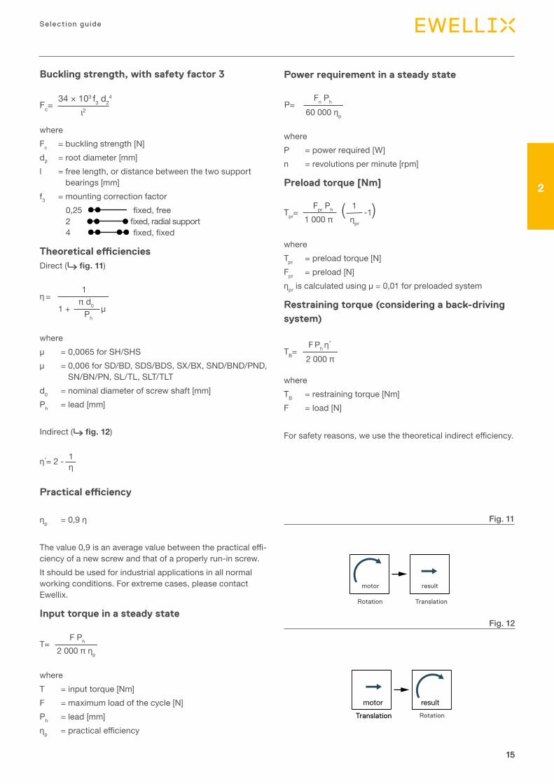
Theoretical efficienciesDirect (⮑ fig. 11)
whereµ = 0,0065 for SH/SHSµ = 0,006 for SD/BD, SDS/BDS, SX/BX, SND/BND/PND,
SN/BN/PN, SL/TL, SLT/TLTd0 = nominal diameter of screw shaft [mm]Ph = lead [mm]
Indirect (⮑ fig. 12)
Practical efficiency
ηp = 0,9 η
The value 0,9 is an average value between the practical effi-ciency of a new screw and that of a properly run-in screw. It should be used for industrial applications in all normal working conditions. For extreme cases, please contact Ewellix.
Input torque in a steady state
whereT = input torque [Nm]F = maximum load of the cycle [N]Ph = lead [mm]ηp = practical efficiency
Fc= 34 × 103 f3 d2
4
ι2
π d0
Ph
η = 1
1 + µ
η´= 2 - 1η
T= F Ph
2 000 π ηp
Power requirement in a steady state
whereP = power required [W]n = revolutions per minute [rpm]
Preload torque [Nm]
whereTpr = preload torque [N]Fpr = preload [N]ηpr is calculated using µ = 0,01 for preloaded system
Restraining torque (considering a back-driving system)
whereTB = restraining torque [Nm]F = load [N]
For safety reasons, we use the theoretical indirect efficiency.
P= Fn Ph
60 000 ηp
Tpr= ( -1) Fpr Ph
1 000 π1ηpr
TB= F Ph η´ 2 000 π
16
Precis ion ro l led ba l l screws
16
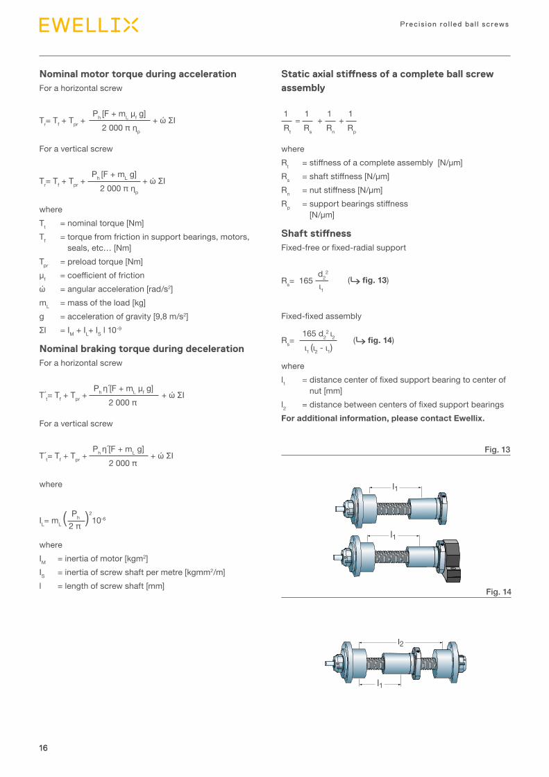
Static axial stiffness of a complete ball screw assembly
where Rt = stiffness of a complete assembly [N/µm]Rs = shaft stiffness [N/µm] Rn = nut stiffness [N/µm] Rp = support bearings stiffness
[N/µm]
Shaft stiffnessFixed-free or fixed-radial support
Fixed-fixed assembly
Rs= 165 d2
2 ι2
ι1 (ι2 - ι1)
where l1 = distance center of fixed support bearing to center of
nut [mm]l2 = distance between centers of fixed support bearingsFor additional information, please contact Ewellix.
= + + 1
Rt 1Rs
1Rn
1Rp
Rs= d2
2
ι1 165
Nominal motor torque during acceleration For a horizontal screw
For a vertical screw
whereTt = nominal torque [Nm]Tf = torque from friction in support bearings, motors,
seals, etc… [Nm]Tpr = preload torque [Nm]μf = coefficient of frictionώ = angular acceleration [rad/s2]mL = mass of the load [kg]g = acceleration of gravity [9,8 m/s2]ƩІ = ІM + ІL+ ІS l 10-9
Nominal braking torque during decelerationFor a horizontal screw
For a vertical screw
where
whereІM = inertia of motor [kgm2]ІS = inertia of screw shaft per metre [kgmm2/m]l = length of screw shaft [mm]
Tr= Tf + Tpr + + ώ ΣΙ Ph [F + mL µf g]
2 000 π ηp
Tr= Tf + Tpr + + ώ ΣΙ Ph [F + mL g]
2 000 π ηp
T´t= Tf + Tpr + + ώ ΣΙ Ph η´[F + mL µf g]
2 000 π
T´t= Tf + Tpr + + ώ ΣΙ Ph η´[F + mL g]
2 000 π
ΙL= mL ( )210-6
Ph 2 π
Fig. 13
Fig. 14
l2
l1
l1
l1
(⮑ fig. 13)
(⮑ fig. 14)

17
Selection gu ide
2
17
0 500 900 1 000 1 500 2 000
76543210
F [kN]
Displacement [mm]
6622
134,5 1,1
21,7
Fig. 16Shaft end 4A for PND 25×5
Fig. 15Shaft end 2A for PND 25×5
F1 = 3 000 N
F3 = 2 000 N
Maximum application load = 7 kN, while 60% of Ca = 60% × 12,7 = 7,6 kN OK
Number of nut revolutions per one complete cycle= (2 × 1 000) / 5 = 400 revolutions
Or (81,1 × 10⁶) / 400 = 202 750 complete cycles
One complete cycle lasts (9 + 10 +10 + 31) = 60 seconds
Or life rating of (202 750 × 60) / (3 600 × 7 × 5 × 50) = 1,9 years with 90% reliability
= 81,1 millions revolutions
= 2 934 NFm=
3
3 0003 × 900 + 5 6673 × 100 + 2 0003 × 1 000900 + 100 + 1 000
L10= ( )3 12 7002 934
Calculation of basic life rating L10
Calculation of equivalent mean loadFirst, we check that the maximum load from the duty cycle does not create an excessive loading condition that would be detrimental to service life. Please refer to explanation in paragraph “Service life” (⮑ page 9).
F2= = 5 667 N 3 000 + 2 × 7 000
3on L2 = 1 000 mm
on L1 = 900 mm
on L3 = 1 000 mm
Calculation example for a ball screwDescription of customer application:
• Ball screw type PND 25 × 5. Ball screw is described (⮑ page 34): Nut with internal preload, 2 × 3 circuits, dy-namic carrying capacity Ca = 12,7 kN, and static carrying capacity Coa = 22,7 kN
• Screw shaft is horizontally mounted and supported by two support bearings of types PLBU25 and BUF25
• Load cycle as follows: - Phase 1: Steady axial load of 3 kN, on travel of 900 mm, with lin-ear speed 100 mm/s, or phase duration of 9 seconds
- Phase 2: Regular load increase from 3 kN to 7 kN, on travel of 100 mm, with linear speed 10 mm/s, or phase duration of 10 seconds
- Phase 3: Nut return to initial position, with steady load of 2 kN, on travel of 1 000 mm, with linear speed 100 mm/s, or phase duration of 10 seconds
- Then period of 31 seconds with zero load, no displacement
- Operation during 7 hours per day, 5 days per week, 50 weeks per year.

18
Precis ion ro l led ba l l screws
18
So total threaded length = 1 082 mm
ηp = 0,9 × 0,914 = 0,823
l = 1 082 + 22 + 11 = 1 115 mm
n × d0 = 1 200 x 25 = 30 000 < 50 000 OK
(B1 – G1) / 2 = (66 – 22) / 2 = 22 mm from the end of the threaded shaft (⮑ fig. 15).
B7 + ((B5 – m) / 2) = 4,5 + ((13 – 1,1) / 2) = 11 mm from the end of the threaded shaft (⮑ fig. 16).
Vmax= × 60 = 1 200 rpm 100
5
ncr= 49 × 106 = 3, 250 rpm > Vmax OK 3,8 × 21,7
1 1152
Fc= = 12,1 kN > Fmax = 7 kN OK 34,103 × 2 × 21,74
1 1152
η = = 0,914 1
1 + × 0,006π × 25
5
T= = 6,8 Nm 7 000 × 52 000 π × 0,823
Phase 1: P = = 365 W 3 000 × 1 200 × 5
60 000 × 0,823
Phase 2: P = = 85 W 7 000 × 1 200 × 5
60 000 × 0,823
Phase 3: P = = 243 W 3 000 × 1 200 × 5
60 000 × 0,823
= 0,906 1
0,914η´= 2-
Speed limit
Buckling strength
Theoretical direct efficiency
Theoretical indirect efficiency
Practical efficiency
Input torque in a steady state
Power requirement in a steady state
The free length between the two support bearings is:
The root diameter of the threaded shaft is:
Calculation of critical speed:
The shaft threaded length is calculated with considering the total nut travel (1 000 mm), plus the nut length (62 mm), plus extra free length at each shaft end equal to two leads (2 × 2 × 5 = 20 mm).
Screw assembly is horizontally mounted. End machining is 2A for support bearing PLBU25, and end machining is type 4A for support bearing BUF25. The combination of 2A + 4A ends machining is called HA when ordering the screw (⮑ page 44).
For end type 2A, with screw nominal diameter d0 = 25 mm, the central axial position of the bearings is calculated with data from pages 45 and 46:For end type 4A, with screw nominal diameter d0 = 25 mm, the central axial position of the bearing is calculated with data from pages 45 and 46:
d2 = 21,7 mm (⮑ page 35 or 44).
Critical speed of screw shaftThe critical speed must be checked, especially when the nut travel is long compared to the shaft diameter. Maximum speed during the duty cycle:

19
Selection gu ide
2
19
Lead precision
Manufacturing precisionGenerally speaking, the precision indicated defines the lead precision that complies with ISO standards, e.g. G5, G7, etc. (⮑ table 1).Parameters other than lead precision correspond to Ewellix internal standards, generally based on ISO class 7. If the ap-plication requires special tolerances, for example class 5, please specify these requirements in the inquiry.
Ewellix high precision rolled ball screwsHigh technology machinery associated with precise control of the cold forming and me tallurgical processes results in screw production that virtually offers the same accuracy and performance level of ground ball screws, but at a lower cost (⮑ diagram 1). Standard lead precision is G9, which com-plies with ISO 286-2:1988. Ewellix production meets G7 lead precision for screw shaft diameters starting from d0 = 20 mm. On request, Ewellix can deliver ball screws with G5 lead precision which are in accordance with ISO 3408-3:2006, defined for positioning screws and matching the lead precision of G5 ground ball screws.
Lead precisionLead precision is measured at 20 °C on the useful stroke lu. At Ewellix lu is the threaded length of the shaft minus twice the length le equal to the screw nominal diameter (⮑ table 1 and fig. 7).Some customer applications require a travel compensation c to account for the effect of operating temperature on the lead precision:
• Standard case with c = 0 (⮑ fig. 8)• Case with specific value of c (⮑ fig. 9).
Ewellix high precision rolled screws G7
ISO standard rolled screws G7
Ground screws G3
Ewellix high precision rolled screws G5
0 500 1 000
200
100
0
Lead error [µm]
Length [mm]
Diagram 1
G5 G7 G9V300p µm 23 35 87lu ep vup ep vup ep vup
mm µm
0 – 315 23 23 52 35 130 87(315) – 400 25 25 57 40 140 100(400) – 500 27 26 63 46 155 115(500) – 630 32 29 70 52 175 130(630) – 800 36 31 80 57 200 140(800) – 1 000 40 34 90 63 230 155(1 000) – 1 250 47 39 105 70 260 175(1 250) – 1 600 55 44 125 80 310 200(1 600) – 2 000 65 51 150 90 370 230(2 000) – 2 500 78 59 175 105 440 260(2 500) – 3 150 96 69 210 125 530 310(3 150) – 4 000 115 82 260 150 640 370(4 000) – 5 000 140 99 320 175 790 440(5 000) – 6 000 170 119 390 210 960 530
Table 1
Lead precision measurement

20
Precis ion ro l led ba l l screws
20
Symbols used in figs. 7 to 9lu = useful travelle = excess travel (no lead precision required)l0 = nominal travells = specified travel c = travel compensation (difference between ls and l0
to be defined by the customer)ep = tolerance over the specified travelV = travel variation (or permissible band width)V300p = maximum permitted travel variation over 300 mmVup = maximum permitted travel variation over the
useful travel luV300a = measured travel variation over 300 mmVua = measured travel variation over lu
-
+
le lelu
l0 [mm]vup
ep
ep
Threaded length
+
le le
l0 [mm]
vua vup
lmv300a
v300p
300 mm
lu
Mean travel:the line which fitsthe curve best bymethod of leastsquares
Threaded length
Fig. 8
Fig. 7
-
+
le lelu
l0 [mm]
Threaded length
ep
ep
vup
c
lmls
Fig. 9

Product range
3

22
Precis ion ro l led ba l l screws
22
SD/BD/SH miniature screwsRolled thread miniature ball screw, nut with threaded nose
Features
• Nominal diameter from 6 to 16 mm• Lead from 2 to 12,7 mm• Recirculation with inserts (SD/BD) or with tube (SH)• Optional surface coating on shaft and nut• Optional safety ring1)
• Optional wipers2) except 6×2 R – 10×3 R.
Benefits
• Excellent repeatability with high positioning accuracy• Smooth running• Extremely compact nut design with threaded nose for easy as-
sembly • Backlash elimination by oversized balls on request
(BD designation), over maximum length of 1 000 mm.
Recirculation SD/BD
Standard SD/BD Standard SH
Customised SD
Nominal Lead Nut Screw Designationdiam eter (right Basic load ratings Number Std play Reduced Inertia Grease Weight Mass Inertia Grease
hand) dynamic static of cir cuits play onof balls request
d0 Ph Ca Coamm mm kN – mm kgmm2 cm3 kg kg/m kgmm2/m cm3/m –
6 2 1,9 2,2 1×2,5 0,05 0,02 7,7 0,1 0,025 0,18 0,7 0,7 SH 6×2 R
8 2,5 2,2 2,7 3 0,07 0,03 1,12 0,1 0,025 0,32 2,1 1,1 SD/BD 8×2.5 R
10 2 2,5 3,6 3 0,07 0,03 1,7 0,1 0,03 0,51 5,2 1,4 SD/BD 10×2 R3 2,6 3,3 1×2,5 0,07 0,03 2,9 0,3 0,05 0,5 5,1 1,3 SH 10×3 R4 4,5 5,5 3 0,07 0,03 2,7 0,3 0,04 0,43 3,8 1,3 SD/BD 10×4 R
12 2 2,9 4,7 3 0,07 0,03 1,5 0,1 0,023 0,67 10 1,7 SD/BD 12×2 R4 4,9 6,6 3 0,07 0,03 7 0,4 0,066 0,71 10,8 1,6 SD/BD 12×4 R5 4,2 5,4 3 0,07 0,03 5 0,6 0,058 0,71 10,1 1,4 SD/BD 12×5 R
12,7 12,7 6,6 8,9 2×1,5 0,07 0,03 20 1,1 0,15 0,71 16,2 1,6 SH 12,7×12,7 R
14 4 6 9,1 3 0,07 0,03 8 0,6 0,083 1,05 22 1,7 SD/BD 14×4 R
16 2 3,3 6,2 3 0,07 0,03 9,2 0,6 0,1 1,4 39,7 1,7 SD/BD 16×2 R5 7,6 10,7 3 0,07 0,03 22,7 0,9 0,135 1,3 33,9 2,1 SD/BD 16×5 R10 10,7 17,2 2×1,8 0,07 0,03 24,4 1 0,16 1,21 30,7 1,9 SD/BD 16×10 R
1) Available for 12×4 R – 12,7×12,7 R – 14×4 R – 16×5 R – 16×10 R2) It is not possible to supply safety ring and wipers in the same nut
Technical data

23
Product range
3
23
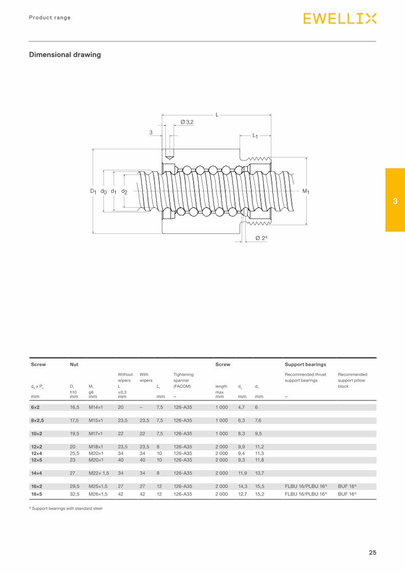
6×2 16,5 M14×1 20 – 7,5 126-A35 1 000 4,7 6
8×2,5 17,5 M15×1 23,5 23,5 7,5 126-A35 1 000 6,3 7,6
10×2 19,5 M17×1 22 22 7,5 126-A35 1 000 8,3 9,510×3 21 M18×1 29 – 9 126-A35 1 000 7,9 9,910×4 21 M18×1 28 31 8 126-A35 1 000 7,4 8,9
12×2 20 M18×1 20 23,5 8 126-A35 2 000 9,9 11,212×4 25,5 M20×1 34 34 10 126-A35 2 000 9,4 11,312×5 23 M20×1 36 40 10 126-A35 2 000 9,3 11,8
12,7×12,7 29,5 M25×1,5 50 50 12 126-A35 2 000 10,2 13
14×4 27 M22×1,5 30 34 8 126-A35 2 000 11,9 13,7
16×2 29,5 M25×1,5 27 27 12 126-A35 2 000 14,3 15,5 FLBU 16/PLBU 16 BUF 1616×5 32,5 M26×1,5 42 42 12 126-A35 2 000 12,7 15,2 FLBU 16/PLBU 16 BUF 1616×10 32 M26×1,5 46 46 12 126-A35 2 000 12,6 15,2 FLBU 16/PLBU 16 BUF 16
Screw Nut Screw Support bearings
Without With Tightening Recommended thrust Rec om mend edwipers wipers spanner support bearings sup port pillow
d0 × Ph D1 M1 L L1 (FACOM) length d2 d1 blockh10 g6 ±0,3 max
mm mm mm mm mm – mm mm mm –
LØ 3,2
L13
d2d1d0D1 M1
Ø 23)
Dimensional drawing

24
Precis ion ro l led ba l l screws
24
SDS/BDS/SHS miniature screws in stainless steelRolled thread miniature ball screw, nut with threaded nose
Features
• Nominal diameter from 6 to 16 mm• Lead from 2 to 5 mm• Standard lead precision G7 and G9• Material for shaft and nut is X30Cr13 (similar to AISI 420) • Balls are made of stainless steel type X105CrMo17 (similar to AISI
440C)1)
• Optional safety ring2)
• Optional wipers3) except for SHS 2 R.
Benefits
• Excellent repeatability with high positioning accuracy • Smooth running• Extremely compact nut design with threaded nose for easy as-
sembly• Backlash elimination by oversized balls on request (BDS designa-
tion), over maximum length of 1 000 mm• Suitable for long storage periods before customer usage, or for
applications with extremely long service life• Adapted for operation in clean environment.
Nominal Lead Nut Screw Designationdiam eter (right Basic load ratings Number Std play Reduced Inertia Grease Weight Mass Inertia Grease
hand) dynamic static of cir cuits play onof balls request
d0 Ph Ca Coa
mm mm kN – mm kgmm2 cm3 kg kg/m kgmm2/m cm3/m –
6 2 1,2 1,1 1×2.5 0,05 0,02 7,7 0,1 0,025 0,18 0,7 0,7 SHS 6×2 R
8 2,5 1,4 1,3 3 0,07 0,03 1,12 0,1 0,025 0,32 2,1 1,1 SDS/BDS 8×2,5 R
10 2 1,6 1,8 3 0,07 0,03 1,7 0,1 0,03 0,51 5,2 1,4 SDS/BDS 10×2 R
12 2 1,9 2,3 3 0,07 0,03 1,5 0,1 0,023 0,67 10 1,7 SDS/BDS 12×2 R4 3,1 3,3 3 0,07 0,03 7 0,4 0,066 0,71 10,8 1,6 SDS/BDS 12×4 R5 2,7 2,7 3 0,07 0,03 5 0,6 0,058 0,71 10,1 1,4 SDS/BDS 12×5 R
14 4 3,8 4,6 3 0,07 0,03 8 0,6 0,083 1,05 22 1,7 SDS/BDS 14×4 R
16 2 2,1 3,1 3 0,07 0,03 9,2 0,6 0,1 1,4 39,7 1,7 SDS/BDS 16×2 R5 4,8 5,4 3 0,07 0,03 22,7 0,9 0,135 1,3 33,9 2,1 SDS/BDS 16×5 R
Standard SDS/BDS Standard SHS
Customised SDS
1) Except for size SDS/BDS 16x5 R using steel type 100 Cr6 (similar to AISI 52100)2) Available for 12x4 R – 14x4 R – 16x5 R3) It is not possible to supply safety ring and wipers in the same nut
Recirculation SD/BD
Technical data
25
Product range
3
25
Screw Nut Screw Support bearings
Without With Tightening Recommended thrust Rec om mend edwipers wipers spanner support bearings sup port pillow
d0 x Ph D1 M1 L L1 (FACOM) length d2 d1 blockh10 g6 ±0,3 max
mm mm mm mm mm – mm mm mm –
6×2 16,5 M14×1 20 – 7,5 126-A35 1 000 4,7 6
8×2,5 17,5 M15×1 23,5 23,5 7,5 126-A35 1 000 6,3 7,6
10×2 19,5 M17×1 22 22 7,5 126-A35 1 000 8,3 9,5
12×2 20 M18×1 23,5 23,5 8 126-A35 2 000 9,9 11,212×4 25,5 M20×1 34 34 10 126-A35 2 000 9,4 11,312×5 23 M20×1 40 40 10 126-A35 2 000 9,3 11,8
14×4 27 M22× 1,5 34 34 8 126-A35 2 000 11,9 13,7
16×2 29,5 M25×1,5 27 27 12 126-A35 2 000 14,3 15,5 FLBU 16/PLBU 164) BUF 164)
16×5 32,5 M26×1,5 42 42 12 126-A35 2 000 12,7 15,2 FLBU 16/PLBU 164) BUF 164)
LØ 3,2
L13
d2d1d0D1 M1
Ø 23)
4) Support bearings with standard steel
Dimensional drawing

26
Precis ion ro l led ba l l screws
26
SP/BP high-performance miniature screwsRolled thread miniature ball screw, nut with threaded nose
Features
• Nominal diameter from 8 to 16 mm• Lead from 2 to 5 mm• Standard lead precision G7 and G9• Reduces tangential efforts on the recirculating balls• Enables up to 2.4 times higher speed limits
(ndo < 120 000)• Reduces noise levels• Enables smoother running• Provides much longer service life• Interchangeable with most existing standard solutions• Lubrication hole and wiper housings are standard• Customized axial play and backlash elimination available• Same attachment as existing series SD
Benefits
• Smooth running• Low noise levels• High speed capability• Provides longer service• Easy nut assembly• Excellent repeatability• High positioning accuracy
Nominal Lead Nut Screw Designationdiam eter (right Basic load ratings Number Std play Reduced Inertia Grease Weight Mass Inertia Grease
hand) dynamic static of cir cuits play onof balls request
d0 Ph Ca Coamm mm kN – mm kgmm2 cm3 kg kg/m kgmm2/m cm3/m –
8 2,5 2,2 2,7 1×2,7 0,07 0,03 1,14 0,1 0,024 0,32 2,1 1.1 SP/BP 8×2,5 R10 4 4,5 5,5 1×2,7 0,07 0,03 4,53 0,3 0,056 0,43 3,8 1,3 SP/BP 10×4 R
5 4,6 5,9 1×2,7 0,07 0,03 5,9 0,5 0,070 0,43 4,0 1,3 SP/BP 10×5 R12 2 2,9 4,7 1×2,7 0,07 0,03 2,25 0,1 0,031 0,67 10 1,7 SP/BP 12×2 R
4 4,9 6,6 1×2,7 0,07 0,03 7,13 0,4 0,070 0,71 10,8 1,6 SP/BP 12×4 R5 4,2 5,4 1×2,7 0,07 0,03 8,02 0,6 0,078 0,71 10,1 1,4 SP/BP 12×5 R
16 5 7,6 10,7 1×2,7 0,07 0,03 24,02 0,9 0,14 1,3 33,9 2,1 SP/BP 16×5 R
SP/BP SP/BP
Technical data

27
Product range
3
27
Screw Nut Screw Support bearings
Without With Tightening Recommended thrust Rec om mend edwipers wipers spanner support bearings sup port pillow
d0 × Ph D1 M1 L L1 (FACOM) length d2 d1 blockh10 g6 ±0,3 max
mm mm mm mm mm – mm mm mm –
8×2,5 17,5 M15×1 23,5 23,5 7,5 126-A35 1000 6,3 7,610×4 23 M18×1 33 33 8 126-A35 1000 7,4 8,910×5 23 M18×1 39,5 – 10 126-A35 2000 7,4 8,912×2 21 M18×1 23,5 23,5 8 126-A35 2000 9,9 11,212×4 25,5 M20×1 34 34 10 126-A35 2000 9,4 11,312×5 25,5 M20×1 40 40 10 126-A35 2000 9,3 11,816×5 32,5 M26×1,5 42 42 12 126-A35 2000 12,7 15,2 FLBU 16/PLBU 16 BUF 16
Dimensional drawing
3 L2
d2d1 M1d0D1
L
Ø 3.2
Ø 23)

28
Precis ion ro l led ba l l screws
28
SX/BX universal screwsRolled thread ball screw with recirculation through inserts, nut with threaded nose
Features
• Nominal diameter from 20 to 63 mm• Lead from 5 to 40 mm• Standard composite recirculation inserts• Optional steel recirculation inserts• Lubrication hole for grease nipple or for automatic
lubrication kit• Phosphate coating on nut• Optional shaft surface coating• Optional safety nuts. Please contact Ewellix for selection and us-
age of this option• Optional nut flanges (⮑ pages 30 to 31)• Optional wipers.
Benefits
• Minimum nut outside diameter and threaded nose for easy as-sembly
• Nut design well suited and economical for transport screw appli-cations
• Optional steel recirculation inserts can act as a safety device for severe or vertical applications. Please contact Ewellix for such applications
• Backlash elimination by oversized balls on request (BX designation) for applications with vibrations / changes of di-rection, over maximum length of 1 000 mm.
Nominal Lead Nut Screw Designationdiam eter (right Basic load ratings Number Std play Reduced Preload Inertia Grease Weight Mass Inertia Grease
hand) dynamic static of cir cuits play on torqueof balls request zero play
d0 Ph Ca Coa Tpr
mm mm kN – mm Nm kgmm2 cm3 kg kg/m kgmm2/m cm3/m –
20 5 14 23,8 4 0,1 0,05 0,1 60 1,3 0,24 2 85 2,7 SX/BX 20×5 R
25 5 19 37,8 5 0,1 0,05 0,17 125 2,5 0,39 3,3 224 3,4 SX/BX 25×5 R10 23,5 39 4 0,12 0,08 0,23 135 4,6 0,4 3,2 255 3,2 SX/BX 25×10 R
32 5 22 51,6 5 0,1 0,05 0,25 230 2,6 0,48 5,6 641 4,4 SX/BX 32×5 R10 27,1 52 4 0,12 0,08 0,32 400 5,9 0,77 5,6 639 3,7 SX/BX 32×10 R
40 5 24,3 65,6 5 0,1 0,05 0,34 390 3,3 0,58 9 1 639 5,6 SX/BX 40×5 R10 61,5 124,1 5 0,12 0,08 0,64 840 12,4 1,25 8,4 1 437 5 SX/BX 40×10 R
50 10 80,4 188,8 6 0,12 0,08 1,02 2 400 19,9 2,4 13,6 3 736 6,3 SX/BX 50×10 R
63 10 91,2 248,3 6 0,12 0,08 1,44 4 620 25,4 3,1 22 9 913 8,1 SX/BX 63×10 R
Standard
Recirculation
Customised
Technical data

29
Product range
3
29
Screw Nut Screw Support bearings
Tightening Recommended thrust Rec om mend edspanner support bearings sup port pillow
d0 × Ph D1 M1 L L1 L2 L4 M21) length d2 d1 blockh10 g6 max
mm mm mm – mm mm mm –
L
L1L2
d2d1d0D1 M1
Ø8
L4
M2
20×5 38 M35×1,5 54 14 8 8 M6×1 HN5 3 700 16,7 19,4 PLBU 20/FLBU 202) BUF 20
25×5 43 M40×1,5 69 19 8 8 M6×1 HN6 4 700 21,7 24,6 PLBU 25/FLBU 25 BUF 2525×10 43 M40×1,5 84 19 12 12 M6×1 HN6 4 700 20,5 24,6 PLBU 25/FLBU 25 BUF 25
32×5 52 M48×1,5 64 19 8 8 M6×1 HN7 5 700 28,7 31,6 PLBU 32/FLBU 32 BUF 3232×10 54 M48×1,5 95 19 15 15 M6×1 HN7 5 700 27,8 32 PLBU 32/FLBU 32/FLRBU 33) BUF 32
40×5 60 M56×1,5 65 19 8 8 M6×1 HN9 5 700 36,7 39,6 PLBU 40/FLBU 40 BUF 4040×10 65 M60×2 105 24 15 13 M8×1 HN9 5 700 34 39,4 PLBU 40/FLBU 40/FLRBU 43) BUF 40
50×10 78 M72×2 135 29 15 15 M8×1 HN12 5 700 44 49,7 PLBU 50/FLBU 50/FLRBU 53) BUF 50
63×10 93 M85×2 135 29 15 15 M8×1 HN14 5 700 57 62,8 PLBU 63/FLBU 63 BUF 63
Dimensional drawing
1) Threaded lubrication hole M2 indexed to ISO thread M12) For high load application, please contact Ewellix3) For high load application, use FLRBU type. Please refer to roller screws catalogue for end shaft and support bearings definitions
30
Precis ion ro l led ba l l screws
30
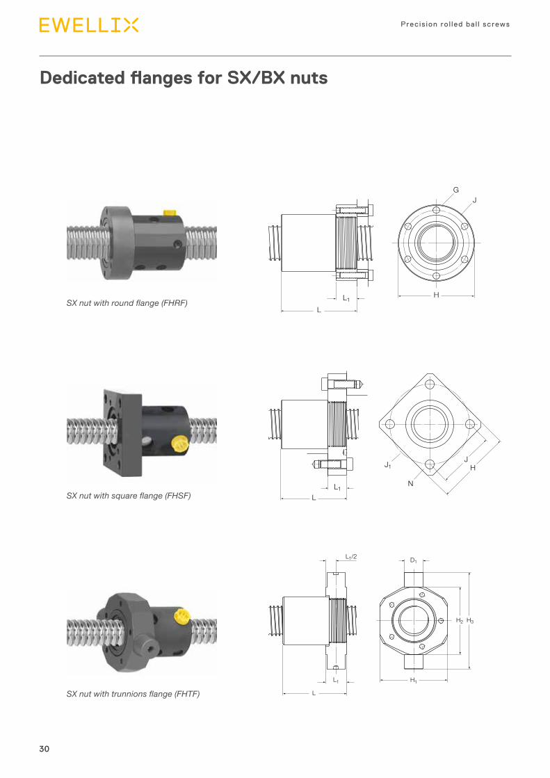
SX nut with square flange (FHSF)
SX nut with trunnions flange (FHTF)
Dedicated flanges for SX/BX nuts
SX nut with round flange (FHRF)
GJ
L1
L
H
HJ
NL1
J1
L
H2 H3
L1/2 D1
L1
L
H1

31
Product range
3
31
Nominal diam eter
Lead Dimensions Designation
d0 Ph L L1 H J J1 Nh14 h14 js12
mm mm mm –
20 5 55 15 60 45 63,6 6,6 FHSF 20
25 5 70 20 70 52 73,5 9 FHSF 2510 85 20 70 52 73,5 9 FHSF 25
32 5 65 20 80 60 84,8 9 FHSF 3210 96 20 80 60 84,8 9 FHSF 32
40 5 66 20 90 70 99 11 FHSF 40×510 106 25 100 78 110,3 13 FHSF 40×10
50 10 136 30 120 94 133 15 FHSF 50
63 10 136 30 130 104 147 15 FHSF 63
Nominal diam eter
Lead Dimensions Designation Bushing designation1)
d0 Ph L L1 H1 H2 H3 D1
js16 h12 h12 h8 mm mm mm –
20 5 57 17 55 56 80 15 FHTF 20 151710A
25 5 71 21 60 65 97 18 FHTF 25 182015A10 86 21 60 65 97 18 FHTF 25 182015A
32 5 68 23 73 73 105 20 FHTF 32 202315A10 99 23 73 73 105 20 FHTF 32 202315A
40 5 69 23 85 85 117 20 FHTF 40×5 202315A10 108,5 27,5 98 98 140 25 FHTF 40×10 252820A
50 10 139 33 120 120 162 30 FHTF 50 303420A
63 10 139 33 135 135 177 30 FHTF 63 303420A
Nominal diam eter
Lead Dimensions Designation
d0 Ph L L1 G H Jh14 h12 js12
mm mm mm –
20 5 55 15 M5 52 44 FHRF 20
25 5 70 20 M6 60 50 FHRF 2510 85 20 M6 60 50 FHRF 25
32 5 65 20 M6 69 59 FHRF 3210 96 20 M6 69 59 FHRF 32
40 5 66 20 M8 82 69 FHRF 40×510 106 25 M10 92 76 FHRF 40×10
50 10 136 30 M12 110 91 FHRF 50
63 10 136 30 M12 125 106 FHRF 63
1) Recommended bushing to be mounted on the trunnions

32
Precis ion ro l led ba l l screws
32
Features
• Nominal diameter from 16 to 63 mm• Lead from 5 to 10 mm• Standard composite recirculation inserts• Optional steel recirculation inserts• Standard lead precision G5, G7 and G9• Nut ground outside diameter / flange face• Precision ground nut thread1) • Lubrication hole for grease nipple or for automatic
lubrication kit• Optional surface coating on shaft and nut• Optional safety nuts. Please contact Ewellix for selection and us-
age of this option• Optional wipers.
Benefits
• Compact nut / integral flange for easy assembly• Design well suited for positioning screws. G5 lead precision of
ground ball screws• Optional steel recirculation inserts can act as a safety device for
severe or vertical applications. Please contact Ewellix for such applications
• Backlash elimination by oversized balls on request (BND designation), over maximum length of 1 000 mm.
SND/BND precision screws, DIN standard 69051Rolled thread ball screw with recirculation through inserts, DIN nut
Standard
Recirculation
Assembly with flanged support bearing
Nominal Lead Nut Screw Designationdiam eter (right Basic load ratings Number Std
playReduced Preload Inertia Grease Weight Mass Inertia Grease
hand) dynamic static of cir cuits play on torqueof balls request zero play
d0 Ph Ca Coa Tprmm mm kN – mm kgmm2 cm3 kg kg/m kgmm2/m cm3/m –
16 5 7,8 10,7 3 0,08 0,05 0,05 40 0,9 0,17 1,3 33 2,1 SND/BND 16×5 R10 10,7 17,2 2×1,8 0,07 0,03 0,06 41 1,6 0,18 1,21 30,7 2,1 SND/BND 16×10 R
20 5 11,3 17,9 3 0,1 0,05 0,08 86 1,1 0,24 2 85 2,7 SND/BND 20×5 R
25 5 12,7 22,7 3 0,1 0,05 0,11 117 1,6 0,29 3,3 224 3,4 SND/BND 25×5 R10 24,1 39 4 0,12 0,08 0,23 144 4,5 0,38 3,2 255 3,2 SND/BND 25×10 R
32 5 19 41,3 4 0,1 0,05 0,21 364 2,1 0,54 5,6 641 4,5 SND/BND 32×5 R10 21,9 39 3 0,12 0,08 0,25 384 4,6 0,58 5,6 639 4,2 SND/BND 32×10 R
40 5 25,6 65,6 5 0,1 0,05 0,25 855 3,1 0,92 9 1 639 5,6 SND/BND 40×5 R10 63,3 124,1 5 0,12 0,08 0,64 1 010 10,7 1,3 8,4 1 437 5,1 SND/BND 40×10 R
50 10 71,3 157,3 5 0,12 0,08 0,88 2 130 13,1 1,8 13,6 3 736 6,5 SND/BND 50×10 R
63 10 81,5 206,9 5 0,12 0,08 1,23 4 075 16,1 2,4 22 9 913 8,4 SND/BND 63×10 R
1) Except 16×10 R: nut thread is not ground
Technical data
33
Product range
3
33
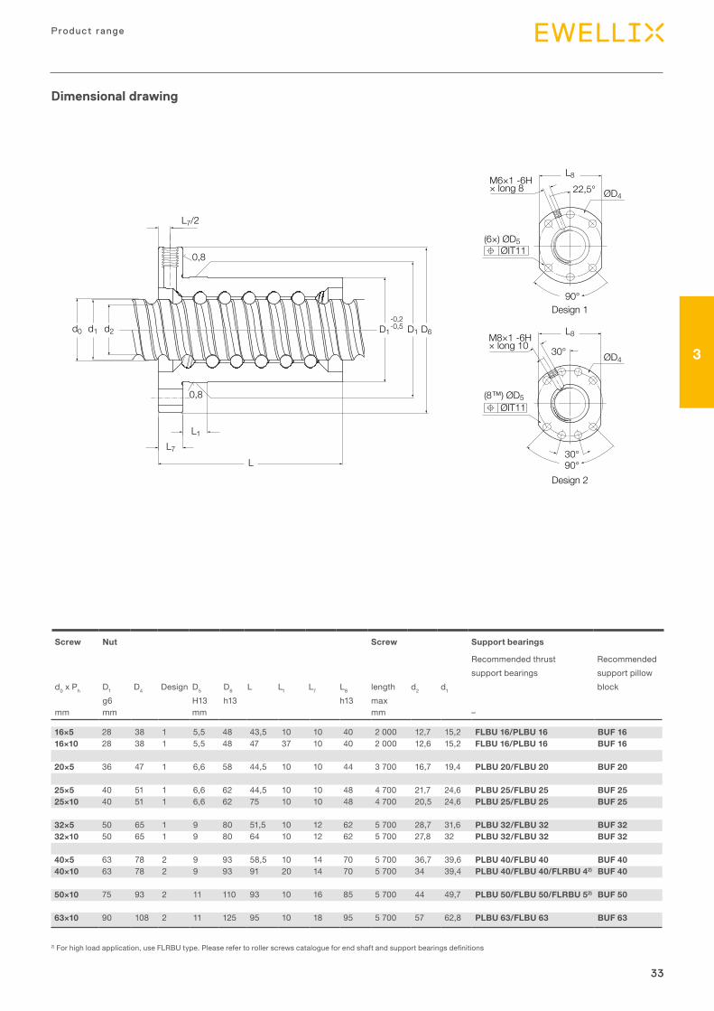
D1 D6D1-0,2-0,5
L
d2d1d0
L7
L7/2
L1
M6×1 -6H× long 8 22,5°
90°
(6×) ØD5ØIT11
ØD4
L8
Design 1
Design 2
30°
30°90°
(8™) ØD5 ØIT11
M8×1 -6H× long 10
ØD4
L8
0,8
0,8
16×5 28 38 1 5,5 48 43,5 10 10 40 2 000 12,7 15,2 FLBU 16/PLBU 16 BUF 1616×10 28 38 1 5,5 48 47 37 10 40 2 000 12,6 15,2 FLBU 16/PLBU 16 BUF 16
20×5 36 47 1 6,6 58 44,5 10 10 44 3 700 16,7 19,4 PLBU 20/FLBU 20 BUF 20
25×5 40 51 1 6,6 62 44,5 10 10 48 4 700 21,7 24,6 PLBU 25/FLBU 25 BUF 2525×10 40 51 1 6,6 62 75 10 10 48 4 700 20,5 24,6 PLBU 25/FLBU 25 BUF 25
32×5 50 65 1 9 80 51,5 10 12 62 5 700 28,7 31,6 PLBU 32/FLBU 32 BUF 3232×10 50 65 1 9 80 64 10 12 62 5 700 27,8 32 PLBU 32/FLBU 32 BUF 32
40×5 63 78 2 9 93 58,5 10 14 70 5 700 36,7 39,6 PLBU 40/FLBU 40 BUF 4040×10 63 78 2 9 93 91 20 14 70 5 700 34 39,4 PLBU 40/FLBU 40/FLRBU 42) BUF 40
50×10 75 93 2 11 110 93 10 16 85 5 700 44 49,7 PLBU 50/FLBU 50/FLRBU 52) BUF 50
63×10 90 108 2 11 125 95 10 18 95 5 700 57 62,8 PLBU 63/FLBU 63 BUF 63
Screw Nut Screw Support bearings
Recommended thrust Rec om mend edsupport bearings sup port pillow
d0 x Ph D1 D4 Design D5 D6 L L1 L7 L8 length d2 d1 blockg6 H13 h13 h13 max
mm mm mm mm –
2) For high load application, use FLRBU type. Please refer to roller screws catalogue for end shaft and support bearings definitions
Dimensional drawing

34
Precis ion ro l led ba l l screws
34
PND preloaded screws, DIN standard 69051Rolled thread ball screw with recirculation through inserts, DIN nut
PND
Standard
Recirculation
Assembly with pillow block
Features
• Nominal diameter from 16 to 63 mm• Lead from 5 to 10 mm• Standard composite recirculation inserts• Optional steel recirculation inserts• Standard lead precision G5, G7 and G9• Nut ground outside diameter / flange face• Precision ground nut thread1)
• Standard preload 7% to 8,5% of ball screw Ca value, depending on ball screw size
• Lubrication hole for grease nipple or for automatic lubrication kit• Optional surface coating on shaft and nut• Optional safety nuts. Please contact Ewellix for selection and us-
age of this option• Optional wipers.
Benefits
• Compact nut / integral flange for easy assembly• One-piece nut1) with internal preload for compactness and opti-
mum rigidity• Design well suited for positioning screws. G5 lead precision of
ground ball screws• Optional steel recirculation inserts can act as a safety device for
severe or vertical applications. Please contact Ewellix for such applications.
Nominal Lead Nut Screw Designationdiam eter (right Basic load ratings Number Preload
torque average
Stiffness Inertia Grease Weight Mass Inertia Greasehand) dynamic static of cir cuits
of balls
d0 Ph Ca Coa Tpr Rnmm mm kN – Nm N/µm kgmm2 cm3 kg kg/m kgmm2/m cm3/m –
16 5 5,5 7,1 2×2 0,08 147 46 1 0,19 1,3 33 2,1 PND 16×5 R10 10,7 17,2 2×2×1,8 0,15 263 56 2,7 0,28 1,21 30,7 1,9 PND 16×10 R1)
20 5 8 11,9 2×2 0,14 248 91 1,3 0,26 2 85 2,7 PND 20×5 R
25 5 12,7 22,7 2×3 0,28 436 405 2 0,4 3,3 224 3,4 PND 25×5 R10 13,3 19,5 2×2 0,3 264 245 4,5 0,53 3,2 255 3,2 PND 25×10 R
32 5 19 41,3 2×4 0,52 734 453 3,2 0,715 5,6 641 3,2 PND 32×5 R10 21,9 39 2×3 0,61 490 490 7,6 0,81 5,6 639 4,1 PND 32×10 R
40 5 25,6 65,6 2×5 0,71 968 1 110 4,8 1,3 9 1 639 5,5 PND 40×5 R10 52,2 99,3 2×4 1,47 793 1 290 15,5 1,8 8,4 1 437 4,9 PND 40×10 R
50 10 71,3 157,3 2×5 2,47 1 222 2 940 27,5 2,6 13,6 3 736 7,9 PND 50×10 R
63 10 81,5 206,9 2×5 3,46 1 448 5 290 26,8 3,2 22 9 913 7,9 PND 63×10 R
1) Except 16×10 R: nut thread is not ground, double nut design
Technical data

35
Product range
3
35
D1 D6D1-0,2-0,5
L
d2d1d0
L7
L7/2
L1
M6×1 -6H× long 8 22,5°
90°
(6×) ØD5ØIT11
ØD4
L8
Design 1
Design 2
30°
30°90°
(8™) ØD5 ØIT11
M8×1 -6H× long 10
ØD4
L8
0,8
0,8
16×5 28 38 1 5,5 48 48 10 10 40 2 000 12,7 15,2 FLBU 16/PLBU 16 BUF 1616×10 28 38 1 5,5 48 87 77 10 40 2 000 12,6 15,2 FLBU 16/PLBU 16 BUF 16
20×5 36 47 1 6,6 58 50 10 10 44 3 700 16,7 19,4 PLBU 20/FLBU 20 BUF 20
25×5 40 51 1 6,6 62 62 10 10 48 4 700 21,7 24,6 PLBU 25/FLBU 25 BUF 2525×10 40 51 1 6,6 62 75 10 10 48 4 700 20,5 24,6 PLBU 25/FLBU 25 BUF 25
32×5 50 65 1 9 80 74 10 12 62 5 700 28,7 31,6 PLBU 32/FLBU 32 BUF 3232×10 50 65 1 9 80 100 10 12 62 5 700 27,8 32 PLBU 32/FLBU 32 BUF 32
40×5 63 78 2 9 93 88 10 14 70 5 700 36,7 39,6 PLBU 40/FLBU 40 BUF 4040×10 63 78 2 9 93 130 20 14 70 5 700 34 39,4 PLBU 40/FLBU 40/FLRBU 42) BUF 40
50×10 75 93 2 11 110 151 10 16 85 5 700 44 49,7 PLBU 50/FLBU 50/FLRBU 52) BUF 50
63×10 90 108 2 11 125 153 10 18 95 5 700 57 62,8 PLBU 63/FLBU 63 BUF 63
Screw Nut Screw Support bearingsRecommended thrust Rec om mend edsupport bearings sup port pillow
d0 x Ph D1 D4 Design D5 D6 L L1 L7 L8 length d2 d1 blockg6 js12 H13 h13 h13 max
mm mm mm –
2) For high load application, use FLRBU type. Please refer to roller screws catalogue for end shaft and support bearings definitions
Dimensional drawing

36
Precis ion ro l led ba l l screws
36
SN/BN precision screwsRolled thread ball screw with recirculation through inserts, cylindrical flange
Features
• Nominal diameter from 16 to 63 mm• Lead from 5 to 10 mm• Standard composite recirculation inserts• Optional steel recirculation inserts• Standard lead precision G5, G7 and G9• Nut ground outside diameter / flange face• Precision ground nut thread• Lubrication hole for grease nipple or for automatic lubrication kit• Optional surface coating on shaft and nut• Optional safety nuts. Please contact Ewellix for selection and us-
age of this option• Optional wipers.
Benefits
• Economical compact nut / integral flange for easy assembly• Design well suited for positioning screws. G5 lead precision of
ground ball screws• Optional steel recirculation inserts can act as a safety device for
severe or vertical applications. Please contact Ewellix for such applications
• Backlash elimination by oversized balls on request (BN designation), over maximum length of 1 000mm.
Nominal Lead Nut Screw Designation
diam eter (right Basic load ratings Number Std play Reduced Preload Inertia Grease Weight Mass Inertia Greasehand) dynamic static of cir cuits play on torque
of balls request zero playd0 Ph Ca Coa Tpr
mm mm kN – mm kgmm2 cm3 kg kg/m kgmm2/m cm3/m –
16 5 7,8 10,7 3 0,08 0,05 0,05 45 0,9 0,18 1,3 33 2,1 SN/BN 16×5 R
20 5 11,3 17,9 3 0,1 0,05 0,08 88 1,2 0,24 2 85 2,7 SN/BN 20×5 R
25 5 12,7 22,7 3 0,1 0,05 0,11 127 1,6 0,28 3,3 224 3,4 SN/BN 25×5 R10 24,1 39 4 0,12 0,08 0,23 244 4,5 0,53 3,2 255 3,2 SN/BN 25×10 R
32 5 19 41,3 4 0,1 0,05 0,21 250 2,1 0,4 5,6 641 4,5 SN/BN 32×5 R10 21,9 39 3 0,12 0,08 0,25 673 4,6 0,83 5,6 639 4,2 SN/BN 32×10 R
40 5 25,6 65,6 5 0,1 0,05 0,25 495 3,1 0,58 9 1 639 5,6 SN/BN 40×5 R10 63,3 124,1 5 0,12 0,08 0,64 1 285 10,7 1,4 8,4 1437 5,1 SN/BN 40×10 R
50 10 71,3 157,3 5 0,12 0,08 0,88 1 305 13,1 1,8 13,6 3 736 6,5 SN/BN 50×10 R
63 10 81,5 206,9 5 0,12 0,08 1,23 4 180 16,1 2,25 22 9 913 8,4 SN/BN 63×10 R
Standard
Recirculation
Customised
Technical data

37
Product range
3
37
D1-0,2-0,5
L
d2
L10
d1d0
L7
L7/2
L1
D1 D6
M2
60°
ØD4
30°
(6x) ØD5ØIT11
0,8
0,8
16×5 28 38 6×5.5 48 43,5 10 10 8 M6 2 000 12,7 15,2 FLBU 16 / PLBU 16 BUF 16
20×5 33 45 6×6.6 57 44,5 10 10 8 M6 3 700 16,7 19,4 PLBU 20 / FLBU 20 BUF 20
25×5 38 50 6×6.6 62 44,5 10 10 8 M6 4 700 21,7 24,6 PLBU 25 / FLBU 25 BUF 2525×10 43 55 6×6.6 67 75 10 10 8 M6 4 700 20,5 24,6 PLBU 25 / FLBU 25 BUF 25
32×5 45 58 6×6.6 70 51,5 10 12 8 M6 5 700 28,7 31,6 PLBU 32 / FLBU 32 BUF 3232×10 54 70 6×9 87 64 10 12 10 M8×1 5 700 27,8 32 PLBU 32 / FLBU 32 BUF 32
40×5 53 68 6×6.6 80 58,5 10 14 8 M6 5 700 36,7 39,6 PLBU 40 / FLBU 40 BUF 4040×10 63 78 6×9 95 91 20 14 10 M8×1 5 700 34 39,4 PLBU 40 / FLBU 40 / FLRBU 41) BUF 40
50×10 72 90 6×11 110 93 10 16 10 M8×1 5 700 44 49,7 PLBU 50 / FLBU 50 / FLRBU 51) BUF 50
63×10 85 105 6×11 125 95 10 18 10 M8×1 5 700 57 62,8 PLBU 63 / FLBU 63 BUF 63
Screw Nut Screw Support bearings
Recommended thrust Rec om mend edsupport bearings sup port pillow
d0 x Ph D1 D4 D5 D6 L L1 L7 L10 M2 length d2 d1 blockg6 H13 h13 6H max
mm mm mm –
1) For high load application, use FLRBU type. Please refer to roller screws catalogue for end shaft and support bearings definitions
Dimensional drawing

38
Precis ion ro l led ba l l screws
38
PN preloaded screwsRolled thread ball screw with recirculation through inserts, cylindrical flange
Features
• Nominal diameter from 16 to 63 mm• Nominal diameter from 16 to 63 mm• Lead from 5 to 10 mm• Standard composite recirculation inserts• Optional steel recirculation inserts• Standard lead precision G5, G7 and G9• Nut ground outside diameter / flange face• Precision ground nut thread• Standard preload 7% to 8,5% of ball screw Ca value, depending
on ball screw size• Lubrication hole for grease nipple or for automatic
ubrication kit• Optional surface coating on shaft and nut• Optional safety nuts. Please contact Ewellix for selection and us-
age of this option• Optional wipers.
Benefits
• Economical compact nut / integral flange for easy assembly• One-piece nut with internal preload for compactness and opti-
mum rigidity• Design well suited for positioning screws. G5 lead precision of
ground ball screws• Optional steel recirculation inserts can act as a safety device for
severe or vertical applications. Please contact Ewellix for such applications.Backlash elimination by oversized balls on request (BN designation), over maximum length of 1 000 mm.
Nominal Lead Nut Screw Designation
diam eter (right Basic load ratings Number Preload Stiffness Inertia Grease Weight Mass Inertia Greasehand) dynamic static of cir cuits torque
of balls zero playd0 Ph Ca Coa Tpr Rn
mm mm kN – N/µm kgmm2 cm3 kg kg/m kgmm2/m cm3/m –
16 5 5,5 7,1 2×2 0,08 147 46 1 0,19 1,3 33 2,1 PN 16×5 R
20 5 8 11,9 2×2 0,14 248 91 1,1 0,26 2 85 2,4 PN 20×5 R
25 5 17,7 22,7 2×3 0,28 436 400 2,1 0,39 3,3 224 3,4 PN 25×5 R10 13,3 19,5 2×2 0,3 264 245 4,1 0,53 3,2 255 2,8 PN 25×10 R
32 5 19 41,3 2×4 0,52 734 390 3,2 0,5 5,6 641 4,4 PN 32×5 R10 21,9 39 2×3 0,61 490 830 7,6 1,13 5,6 639 4,1 PN 32×10 R
40 5 25,6 65,6 2×5 0,71 968 585 4,8 0,74 9 1 639 5,5 PN 40×5 R10 52,2 99,3 2×4 1,47 793 1 530 14,6 1,8 8,4 1 437 4,9 PN 40×10 R
50 10 71,3 157,3 2×5 2,47 1 222 2 930 27,5 2,6 13,6 3 736 7,9 PN 50×10 R
63 10 81,5 206,9 2×5 3,46 1 448 5 980 26,8 3,2 22 9 913 7,9 PN 63×10 R
PND
Standard
Recirculation
Customised
Technical data

39
Product range
3
39
Screw Nut Screw Support bearings
Recommended thrust Rec om mend edsupport bearings sup port pillow
d0 x Ph D1 D4 D5 D6 L L1 L7 L10 M2 length d2 d1 blockg6 H13 h13 6H max
mm mm mm –
D1-0,2-0,5
L
d2
L10
d1d0
L7
L7/2
L1
D1 D6
M2
60°
ØD4
30°
(6x) ØD5ØIT11
0,8
0,8
16×5 28 38 6×5,5 48 48 10 10 8 M6 2 000 12,7 15,2 FLBU 16/PLBU 16 BUF 16
20×5 33 45 6×6,6 57 50 10 10 8 M6 3 700 16,7 19,4 PLBU 20/FLBU 20 BUF 20
25×5 38 50 6×6,6 62 62 10 10 8 M6 4 700 21,7 24,6 PLBU 25/FLBU 25 BUF 2525×10 43 55 6×6,6 67 75 10 10 8 M6 4 700 20,5 24,6 PLBU 25/FLBU 25 BUF 25
32×5 45 58 6×6,6 70 74 10 12 8 M6 5 700 28,7 31,6 PLBU 32/FLBU 32 BUF 3232×10 54 70 6×9 87 100 10 12 10 M8×1 5 700 27,8 32 PLBU 32/FLBU 32 BUF 32
40×5 53 68 6×6,6 80 88 10 14 8 M6 5 700 36,7 39,6 PLBU 40/FLBU 40 BUF 4040×10 63 78 6×9 95 126 20 14 10 M8×1 5 700 34 39,4 PLBU 40/FLBU 40/FLRBU 41) BUF 40
50×10 72 90 6×11 110 151 10 16 10 M8×1 5 700 44 49,7 PLBU 50/FLBU 50/FLRBU 51) BUF 50
63×10 85 105 6×11 125 153 10 18 10 M8×1 5 700 57 62,8 PLBU 63/FLBU 63 BUF 63
1) For high load application, use FLRBU type. Please refer to roller screws catalogue for end shaft and support bearings definitions
Dimensional drawing

40
Precis ion ro l led ba l l screws
40
SL/TL long lead screwsRolled thread ball screw for high linear speed
Features
• Nominal diameter from 25 to 50 mm• Lead from 20 to 50 mm• Lubrication hole for grease nipple or for automatic
lubrication kit• Standard protection at each end of the nut with composite wipers
integrated into recirculation caps (NOWPR)• Optional double protection at each end of the nut with additional
brush wipers fitted into recirculation caps (WPR)• Optional surface coating on shaft and nut• Optional safety nuts. Please contact Ewellix for selection and us-
age of this option.
Benefits
• High rotational speed up to nd0 = 90 000, resulting in high linear speed up to 110 m/min
• Nut design well suited for transport and positioning screw appli-cations requiring high velocity such as woodworking, some func-tions in plastic injection presses, pick–&–place, etc.
• Backlash elimination (TL designation).
Nominal Lead Nut Screw Designation
diam eter (right SL (with play)Basic load ratingsdynamic static
Std play
TL (with backlash elimination) Number of cir cuits of balls
Inertia Grease Weight Mass Inertia Greasehand) Basic load ratings Preload torque
zero play dynamic staticd0 Ph Ca Coa Ca Coa Tpr
mm mm kN mm – – kgmm2 cm3 kg kg/m kgmm2/m cm3/m –
25 20 22,8 51,5 0,08 12,6 25,8 0,04-0,36 4×1,7 480 3 0,57 3,3 215 3,4 SL/TL 25×20 R25 22,3 50,6 0,08 12,3 25,3 0,04-0,36 4×1,7 400 3,6 0,66 3,2 210 3,3 SL/TL 25×25 R
32 20 25,4 65,2 0,08 14 32,6 0,05-0,45 4×1,7 550 3,4 0,7 5,1 530 4,4 SL/TL 32×20 R32 26,1 69,3 0,08 14,4 34,7 0,05-0,50 4×1,8 450 4,5 0,7 5,4 600 4,3 SL/TL 32×32 R32 26,1 69,3 0,08 14,4 34,7 0,05-0,50 4×1,8 450 4,5 0,7 5,4 600 4,3 SLD/TLD 32×32 R40 12,6 29,8 0,08 6,9 14,9 0,05-0,50 4×0,8 515 3 0,65 4,9 490 4,4 SL/TL 32×40 R
40 20 41,3 128,8 0,08 22,8 64,4 0,05-0,55 4×2,7 1 420 6,6 1,2 8,2 1 380 5,5 SL/TL 40×20 R40 51,7 130,5 0,1 28,5 65,3 0,05-0,55 4×1,7 3 300 12,5 2,4 8,1 1 330 5,2 SL/TL 40×40 R
50 50 92,9 235,1 0,12 51,2 117,6 0,1-0,9 4×1,7 6 060 19,4 3,3 13,2 3 560 6,4 SL/TL 50×50 R
Standard
Recirculation
Customised
Optional double protection
Technical data

41
Product range
3
41
M2
60°
30°
M6×1 -6H× long 8 22,5°
90°
(6×) ØD5ØIT11
(6×) ØD5ØIT11
L8
ØD4
ØD4
L
L1L7L3L7/2
d2d1d0D1
-0,2
-0,5D1 D6
-0,2
-0,5D1
0,8
0,8
Design 1
Design 2
25×20 48 60 1 6×6,6 73 66,8 18 17,6 15 N / A 8 M6 4 700 21,7 24,3 PLBU 25/FLBU 25 BUF 2525×25 48 60 1 6×6,6 73 78,2 27 18,7 15 N / A 8 M6 4 700 21,5 24,4 PLBU 25/FLBU 25 BUF 25
32×20 56 68 1 6×6,6 80 67,4 18 17,9 15 N / A 8 M6 5 700 27,5 30 PLBU 32/FLBU 32/FLRBU31) BUF 3232×32 56 68 1 6×6,6 80 80,3 41 13 15 N / A 8 M6 5 700 28,4 31,1 PLBU 32/FLBU 32/FLRBU31) BUF 3232×32 50 g6 65 2 6×9 80 80,3 41 13 15 62 8 M6 5 700 28,4 31,1 PLBU 32/FLBU 32/FLRBU31) BUF 3232×40 53 g6 68 1 6×6,6 80 54,8 17 12,2 15 N / A 8 M6 5 700 26,9 29,6 PLBU 32/FLBU 32 BUF 32
40×20 63 78 1 6×9 95 87,3 38 18 15 N / A 8 M6 5 700 35,2 37,7 PLBU 40/FLBU 40 BUF 4040×40 72 90 1 6×11 110 110,8 44 21,6 25 N / A 10 M8×1 5 700 34,2 38,3 PLBU 40/FLBU 40/FLRBU 41) BUF 40
50×50 85 105 1 6×11 125 134 60 25,5 25 N / A 10 M8×1 5 700 43,5 49,1 PLBU 50/FLBU 50/FLRBU 51) BUF 50
Screw Nut Screw Support bearings
Recommended thrust Rec om mend edsupport bearings sup port pillow
d0 x Ph D1 D4 Design D5 D6 L L1 L3 L7 L8 L10 M2 length d2 d1 blockg9 js12 H13 h13 max
mm mm – mm mm –
1) For high load application, use FLRBU type. Please refer to roller screws catalogue for end shaft and support bearings definitions
Dimensional drawing

42
Precis ion ro l led ba l l screws
42
SLT/TLT rotating nutLong lead rolled ball screw with rotating nut
ConceptThe main purpose of this solution is to minimize the inertia phenomenon associated with long rotating shafts.The long lead screw shaft is rigidly fixed to the machine frame. The ball nut, rotating inside a bearing housing and driven via a tension belt, moves along the screw shaft. The customers are responsible for the sourcing and assem-bly of the electric motor, belt, pulleys and frame holding the bearing housing.
Features
• Nominal diameter from 25 to 50 mm• Lead from 20 to 50 mm• 72 series angular contact bearings are directly mounted on the
nut outer diameter• Bearings are preloaded in back-to-back arrangement in order to
fully support the moment created by the belt tension
• 2 Nilos rings protect the bearings against pollution and permit lu-brication for life
• Brush wipers are mounted at each end of the nut in the standard configuration for better protection against contamination
• The ball screw assembly is lubricated through a nipple mounted on the housing external diameter in the standard version
• Standard grease is Ewellix LGMT2. Other lubricants are available on request.
Nominal Lead Ball screw capacities Bearing Rotating nut Designation
diam eter (right SL TL Max trans-missibletorque
Max trans-missibleaxial load
Inertia with pulley support
Masshand) Basic load ratings Basic load ratings Basic load ratings
d0 Ph Ca Coa Ca Coa Ca Coamm mm kN kN Nm kN kgmm2 kg –
25 20 39,2 97,0 21,6 48,5 61,8 56 180 68,3 1 012 4,5 SLT/TLT 25×20 R25 33,2 80,4 18,3 40,2 61,8 56 180 68,3 1 023 4,6 SLT/TLT 25×25 R
32 20 49,6 141,8 27,3 70,9 78 76,5 209 107 1 935 7,2 SLT/TLT 32×20 R32 32,2 88,6 17,7 44,3 78 76,5 209 87,3 1 919 7,1 SLT/TLT 32×32 R40 25,3 67,0 13,9 33,5 78 76,5 209 81,7 1 949 7,1 SLT/TLT 32×40 R
40 20 54,2 176,5 29,8 88,3 93,6 91,5 240 116 3 095 7,5 SLT/TLT 40×20 R40 51,7 130,5 28,5 65,3 114 118 246 93,3 3 784 8,4 SLT/TLT 40×40 R
50 50 92,9 235,1 51,2 117,6 156 166 803 162 1 1482 15,5 SLT/TLT 50×50 R
Technical data

43
Product range
3
43
Benefits
• High rotational speed up to nd0 = 90 000, resulting in high linear speed up to 110 m/min
• Compact, easy and simple solution to incorporate into application• Fixed screw shaft for simplified mounting into application• Inertia is considerably reduced, for
example: 3 800 kgmm2 instead of 6 000 kgmm2 for a screw shaft 40x40 with 4,5 m stroke
• Lower motor power requirements resul ting from lower system inertia
• Backlash elimination (TLT designation).
25×20 40 72,5 100 133 100 65 48 0,8 116 55 6×Ø9 6×M6×20 M6 1 25×25 40 72,5 100 133 100 65 48 0,8 116 55 6×Ø9 6×M6×20 M6×1
32×20 50 82 119,5 150 120 76 56 0,8 135 68 6×Ø9 6×M6×20 M6×1 32×32 50 82 119,5 150 120 76 50 0,8 135 68 6×Ø9 6×M6×20 M6×132×40 50 82 119,5 150 120 76 53 0,8 135 68 6×Ø9 6×M6×20 M6×1
40×20 58 93 125 159 125 80 63 0,8 142 75 8×Ø9 6×M6×20 M8×1 40×40 60 93 137 168 137 N/A 72 1,6 153 80 8×Ø9 6×M6×20 M8×1
50×50 70 120 170 210 170 110 85 1,6 190 106 8×Ø11 6×M8×30 M8×1
Screw Dimension
d0 x Ph D1 D2 D3 D4 D5 D6 D7 R J1 J2 Z1 x H1 Z2 x H2 x H3
h8 g6 max. useful depthmm
Screw Dimensiond0 x Ph L L1 L2 L3 L4 L5 L6 L7 L8 L9mm
25x20 121,2 15 12,4 19,9 74 2,9 16,9 12,4 15 1525x25 126,3 15 12,4 19,9 74 2,9 22 12,4 15 15
32x20 132,9 20 3,8 27,5 89 2,2 17,9 20 15 2032x32 126,8 20 3,8 27,5 89 2,2 11,8 20 15 2032x40 125,9 20 3,8 27,5 89 2,2 10,9 20 15 20
40x20 136,7 20 9,3 22,5 85 4,7 17,7 15 15 2040x40 159,6 47 8,8 19 83 0 20,8 11,5 15 20
50x50 163,5 20 15,5 25,4 100 4,5 23,5 15,7 20 25
Z2 x H2
J2 J1
Z1 x H1
L
D7 D6D3 D2 D1 D5
L7L2
L1 L6
L9
L8
D4
R
H3
L3L5
L4
R0,8
0,8
All tolerances js13 if not specified.
Dimensional drawing

44
Precis ion ro l led ba l l screws
44
Shaft end combinations
• In the ordering code, shaft ends machi ning is defined by: - One letter for nominal diameter - d0 < 16 mm - Two letters for nominal diameter - d0 ≥ 16 mm,
detailing the combination of two machined ends (Ordering key ⮑ page 60)
• Machined ends are detailed for nominal diameter < 16 mm (⮑ page 45)
• Machined ends are detailed for nominal diameter ≥ 16 mm (⮑ page 46).
d3d2
Fig. 10
1) Attention! This mounting requires the greatest care. Please contact Ewellix.
Dimensionsd2 d3
mm
6×2 4,7
8×2,5 6,3
10×2 8,310×3 7,810×4 7,4
12×2 9,912×4 9,412×5 9,3
12,7×12,7 10,2
14×4 11,9
16×2 14,3 1216×5 12,7 916×10 12,6 9
20×5 16,7 14
25×5 21,7 1925×10 20,5 1825×20 21,7 1925×25 21,5 18
32×5 28,7 2632×10 27,8 2532×20 27,4 2432×32 28,4 2632×40 26,9 24
40×5 36,7 3440×10 34,0 3140×20 35,1 3240×40 34,2 31
50×10 44,0 4150×50 43,4 40
63×10 57,0 54
Diameter < 16 mm Diameter ≥ 16 mm
Order code Two machined ends Order code Two machined ends
A (without length indication)
cut only AA (without length indication)
cut only
A (+ length) cut + annealedB 1 + 2 BA 1A + 2AF 1) 2 + 2 FA 1) 2A + 2AG 1) 2 + 3 GA 1) 2A + 3AH 2 + 4 HA 2A + 4AJ 2 + 5 JA 2A + 5AM 3 + 5 MA 3A + 5AS*) (+ length) end machined to
root diameter d2, any length
SA*) (+ length)
UA*) (+ length)
end machined to root diameter d2, any length
diameter d3 under induction hardening, any length
K keyway K keyway
Z
end machined according to customer drawing on request
Z
end machined according to customer drawing on request
S, SA and UA end machining types*) S and SA: end is machined to thread root diameter d2. It is available for all screw shaft nominal diameters (⮑ fig. 10)*) UA: end is machined to diameter d3 under induction hard-ened layer. Any length can be used. UA end machining is available for ball screws with nominal diameter d0 starting from 16 mm (⮑ fig. 10).

45
Product range
3
45
Standard machine endsStandard end machining for nominal diameter < 16 mm
For SD/BD/SH–SDS/BDS/SHS
d0
ch × 45° ch × 45°ba × d7G1
B1 (B2)B4
d5 d4G
a N9
be
A
AS
d4G
ch × 45°ba × d7G1
B1
m × d6B5
ch × 45°
B3
d4
(B2)B6
d5
m × d6B5
ch × 45° ch × 45°
B3
d4
undercut
Type 1 Type 2 Keyway on request
Type 3 Type 4 Type 5
undercut undercut undercut
t
t
t
t
t
--
Size
d0 d5 d41) B1 B2 B3 B4 B5 B6 G G1 m d6 ch ba d7 a b e j S Keyway
h7 js7 js12 js12 js12 H11 js12 g6 +0,14 h11/ h11 N9 +0,5 DIN 6885
0 h12 0mm
6 3 4 22 10 7 32 5,4 17 M4×0,7 7 0,5 3,8 0,5 1,2 2,9 – – – – – –
8 4 5 24 12 7 36 5,6 19 M5×0,8 7,2 0,7 4,8 0,5 1,2 3,7 – – – – – –
10 5 6 26 12 9 38 6,7 21 M6×1 7,5 0,8 5,7 0,5 1,5 4,5 – – – – – –
12/12,7 6 8 38 12 10 50 7,8 22 M8×1 12,5 0,9 7,6 0,5 1,5 6,5 2 8 3 4,8 0,1 A2×2×8
14 8 10 40 16 12 56 9 28 M10×1,5 13,3 1,1 9,6 0,5 2,3 7,8 2 10 3 6,8 0,1 A2×2×10
End of threaded screw length
1) For applications with radial loads on support bearings, please consult Ewellix for best selection of tolerance on diameter d4

46
Precis ion ro l led ba l l screws
46
Standard end machining for shaft nominal diameter ≥ 16 mm
For SD/BD–SDS/BDS–SX/BX–SND/BND/PND–SN/BN/PN
d0
ch1 × 45° ch1 × 45°ba × d7
G1
B1 (B2)B4
d5 d4G
undercut
Type 1A
Type 2A
d0
ch1 × 45° ch1 × 45°ba × d7
G1
B1 (B2)B4
d5 d4G
undercut
Type 1A
Type 2A
Standard shaft ends for ball screws with nominal diameter d0 ≥ 16 mm have been developed to fit with the Ewellix sup-port bearings FLBU, PLBU and BUF.
Support bearing Machined end typeFLBU 2A or 3APLBU 2A or 3ABUF 4A or 5A For these types of machined ends, the maximum permissi-ble dynamic load is 75% of the ball screw dynamic load car-rying capacity.
Size
d0 d5 d41) d11 d12 B1 B2 B3 B4 B5 B6 B7 d8
– h7 h6 h6 h7 js12 js12 js12 H11 js12mm
16 8 10 10 8 53 16 13 69 10 29 2 12,5
20 10 12 10 8 58 17 13 75 10 29 2 14,5
251) 15 17 17 15 66 30 16 96 13 46 4,5 20
321) 17 20 17 15 69 30 16 99 13 46 4,5 28,7
401) 25 30 30 25 76 45 22 121 17,5 67 4,5 33,5
501) 30 35 30 25 84 55 22 139 17,5 67 4,5 35,2
63 40 50 45 40 114 65 28 179 20,75 93 3 54
1) For applications with radial loads on support bearings, please consult Ewellix for best selection of tolerance on diameter d4
Technical data

47
Product range
3
47
d4G
ch1 × 45°ba × d7
G1
B1 B6
d12 d11
B7 × d8 m × d6B5
ch2 × 45°ch1 × 45° ch1 × 45°
B3
B7 × d8
ch2 × 45°
m × d6B5
ch1 × 45°
B3
d11
a N9
// //b
Type 3A
undercut
undercut
undercut
Type 5A
Type 4A Keyway on request
Size Keyway to DIN 6885
aN9 × l × bd0 G G1 m d6 ch1 ch2 ba d7
g6 +0,14 h11 h12 fixed end fixed end0 h11 (type 2A) (type 5A)
mm
16 M10×0,75 17 1,1 9,6 0,5 0,5 1,2 8,8 A2×2×12 A2×2×12
20 M12×1 18 1,1 9,6 0,5 0,5 1,5 10,5 A3×3×12 A2×2×12
25 M17×1 22 1,1 16,2 0,5 0,5 1,5 15,5 A5×5×25 A5×5×25
32 M20×1 22 1,1 16,2 0,5 0,5 1,5 18,5 A5×5×25 A5×5×25
40 M30×1,5 25 1,6 28,6 1 0,5 2,3 27,8 A8×7×40 A8×7×40
50 M35×1,5 27 1,6 28,6 1 0,5 2,3 32,8 A8×7×45 A8×7×40
63 M50×1,5 32 1,85 42,5 1,5 1 2,3 47,8 A12×8×50 A12×8×50
Dimensional drawing
End of threaded screw length

48
Precis ion ro l led ba l l screws
48
Standard shaft ends for SL/TL ball screws have been devel-oped to fit with the Ewellix support bearings FLBU, PLBU and BUF. For the SL/TL long lead screw, an additional centering diam-eter, part of the threaded length, will be machined at both ends of the screw shaft to facilitate the nut assembly. Support bearing Machined end typeFLBU 2A or 3APLBU 2A or 3ABUF 4A or 5A
For these types of machined ends, the maximum permissi-ble dynamic load is 75% of the ball screw dynamic load car-rying capacity, except for size 50×50 for which the dynamic load must not exceed 40 kN.
Standard end machining for SL/TL only
B7 × d8
ch2 × 45°30°
B7 × d8
d5 d4G
ch1 × 45° ch1 × 45°ba × d7
G1
B1 (B2)B4
ch2 × 45°30°
Type 1A
Type 2A
undercut
B7 × d8
ch2 × 45°30°
B7 × d8
d5 d4G
ch1 × 45° ch1 × 45°ba × d7
G1
B1 (B2)B4
ch2 × 45°30°
Type 1A
Type 2A
undercut
1) For applications with radial loads on support bearings, please consult Ewellix for best selection of tolerance on diameter d4
Size
d0 d5 d41) d10 d11 d12 B1 B2 B3 B4 B5 B6 B7 B9 d8
– h7 h6 h6 h7 js12 js12 js12 H11 js12
mm
25×20 15 17 – 17 15 66 30 16 96 13 46 4,5 0 21,6
25×25 15 17 – 17 15 66 30 16 96 13 46 4,5 0 21,4
32×20 17 20 21,5 17 15 69 30 16 99 13 46 4,5 2 27,3
32×32 17 20 21,5 17 15 69 30 16 99 13 46 4,5 2 28,3
32×40 17 20 21,5 17 15 69 30 16 99 13 46 4,5 2 26,8
40×20 25 30 – 30 25 76 45 22 121 17,5 67 6,5 0 35,140×40 25 30 – 30 25 76 45 22 121 17,5 67 6,5 0 34,1
50×50 30 35 37 30 25 84 55 22 139 17,5 67 9 3 43,3
Technical data

49
Product range
3
49
25×20 M17×1 22 1,1 16,2 – 0,5 0,5 1,5 15,5 A5×5×25 A5×5×25
25×25 M17×1 22 1,1 16,2 – 0,5 0,5 1,5 15,5 A5×5×25 A5×5×25
32×20 M20×1 22 1,1 16,2 – 0,5 0,5 1,5 18,5 A5×5×25 A5×5×25
32×32 M20×1 22 1,1 16,2 – 0,5 0,5 1,5 18,5 A5×5×25 A5×5×25
32×40 M20×1 22 1,1 16,2 – 0,5 0,5 1,5 18,5 A5×5×25 A5×5×25
40×20 M30×1,5 25 1,6 – 28,6 1 0,5 2,3 27,8 A8×7×40 A8×7×4040×40 M30×1,5 25 1,6 – 28,6 1 0,5 2,3 27,8 A8×7×40 A8×7×40
50×50 M35×1,5 27 1,6 – 28,6 1 0,5 2,3 32,8 A8×7×45 A8×7×40
Type 3A Type 5A
Type 4A Keyway on request
undercut
undercut
undercut
a N9
// //b
B7 × d8
d4G
ch1 × 45°ba × d7
G1
B1
ch2 × 45°30°
B9 × d10B6
d12 d11
B7 × d8 m × d6B5
30°
ch1 × 45° ch1 × 45°
B3ch2 × 45°
30°
B9 × d10
B7 × d8
ch2 × 45°
m × d6B5
ch1 × 45°
B3
d11
Size Keyway to DIN 6885
aN9 × l × bd0 G G1 m d6 ch1 ch2 ba d7
g6 +0,14 h11 h12 fixed end fixed end0 h11 (type 2A) (type 5A)
mm
End of threaded screw length
Dimensional drawing

50
Precis ion ro l led ba l l screws
50
FLBU ball screw support bearingsAxially locating flanged housings fitted with SKF angular contact ball bearings
Features
• Precision machined housing made of burnished steel• Two SKF preloaded angular contact ball bearings, 72 or 73 series,
in back-to-back arrangement• Two garter seals• Standard self-locking Nylstop nut or high precision KMT nut upon
request.
Benefits
• Complete support bearing ready to use, simplified application de-sign, easy orde ring process
• Quick assembly onto shaft end• Elimination of most technical risks with bearings and seals as-
sembly• Support bearing dimensions and load carrying capacity matched
to the ball screw characteristics• Bearings back-to-back assembly with preload for stiff and accu-
rate ball screw positioning• Greased for life / maintenance-free.
Nom in al diam-eter
Angular contact ball bearing (40°) Lock nut Flanged support bearing designation
Basic load rating (axial) Axial SKF bearing designation
Self-locking nut High precision nut3)
dynamic static stiffness Des ign a tion Hook spanner
Des ign a-tion
Hook spanner
Tightening torque
Grub screwssize tightening
torque max.d0 Ca Coa
mm kN N/µm – – – Nm – Nm –
16 12,2 12,8 play 7200 BECB1) CN 70-10 HN 1 KMT 0 HN 2/3 4 M5 4,5 FLBU 16
20 13,3 14,7 125 7201 BEGA2) CN 70-12 HN 1 KMT 1 HN 3 8 M5 4,5 FLBU 20
25 27,9 31,9 150 7303 BEGA2) CN 70-17 HN3 KMT 3 HN 4 15 M6 8 FLBU 25
32 24,6 31,9 176 7204 BEGA2) CN 70-20 HN 4 KMT 4 HN 5 18 M6 8 FLBU 32
40 41,9 59,6 222 7206 BEGA2) CN 70-30 HN 6 KMT 6 HN 6 32 M6 8 FLBU 40
50 54,5 79,8 250 7207 BEGA2) CN 70-35 HN 7 KMT 7 HN 7 40 M6 8 FLBU 50
63 128 196,1 353 7310 BEGA2) CN 70-50 HN 10 KMT 10 HN 10/11 60 M8 18 FLBU 63
1) No backlash elimination2) Light preload3) Optional
Technical data

51
Product range
3
51
16 37 10 22 12 7 18 14 28 76 50 47 63 6,6 26 M6×30
20 42 10 25 12 7,5 21 14 30 76 50 47 63 6,6 27 M6×30
25 46 10 32 18 8,3 28 18 37 90 62 60 76 6,6 32 M6×30
32 49 13 32 18 8,3 32 18 40 90 59 60 74 9 32 M8×40
40 53 16 32 18 11 44 20 49 120 80 80 100 11 44 M10×45
50 59 20 32 18 11 50 22 54 130 89 90 110 13 49 M12×60
63 85 25 43,5 22 11,7 68 25 75 165 124 124 146 13 64 M12×60
d0
60° (4 ×)
D3
1,6
1,6
D3D2 D5D4 D1
45°
E
15°
(5 ×) S1Ø 0,2L3
L4
L1
L2L5
-0,2-0,3
Screw Support bearing
Self-locking nut High pre ci sion nut4) Fixing screws
d0 L1 L2 L3 L4 L5 D5 L5 D5 D1 D2 D3 D4 S1 Eh7 H13
mm mm –
4) Optional
Dimensional drawing
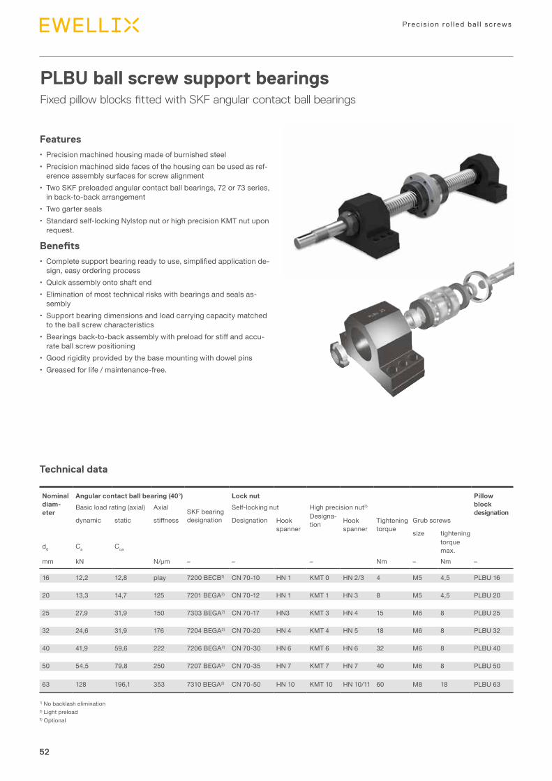
52
Precis ion ro l led ba l l screws
52
PLBU ball screw support bearingsFixed pillow blocks fitted with SKF angular contact ball bearings
1) No backlash elimination2) Light preload3) Optional
Features
• Precision machined housing made of burnished steel• Precision machined side faces of the housing can be used as ref-
erence assembly surfaces for screw alignment• Two SKF preloaded angular contact ball bearings, 72 or 73 series,
in back-to-back arrangement• Two garter seals• Standard self-locking Nylstop nut or high precision KMT nut upon
request.
Benefits
• Complete support bearing ready to use, simplified application de-sign, easy orde ring process
• Quick assembly onto shaft end• Elimination of most technical risks with bearings and seals as-
sembly• Support bearing dimensions and load carrying capacity matched
to the ball screw characteristics• Bearings back-to-back assembly with preload for stiff and accu-
rate ball screw positioning• Good rigidity provided by the base mounting with dowel pins• Greased for life / maintenance-free.
Nom in al diam-eter
Angular contact ball bearing (40°) Lock nut Pillow block designation
Basic load rating (axial) Axial SKF bearing designation
Self-locking nut High precision nut3)
dynamic static stiffness Des ign a tion Hook spanner
Des ign a-tion Hook
spannerTightening torque
Grub screws
size tightening
d0 Ca Coatorque max.
mm kN N/µm – – – Nm – Nm –
16 12,2 12,8 play 7200 BECB1) CN 70-10 HN 1 KMT 0 HN 2/3 4 M5 4,5 PLBU 16
20 13,3 14,7 125 7201 BEGA2) CN 70-12 HN 1 KMT 1 HN 3 8 M5 4,5 PLBU 20
25 27,9 31,9 150 7303 BEGA2) CN 70-17 HN3 KMT 3 HN 4 15 M6 8 PLBU 25
32 24,6 31,9 176 7204 BEGA2) CN 70-20 HN 4 KMT 4 HN 5 18 M6 8 PLBU 32
40 41,9 59,6 222 7206 BEGA2) CN 70-30 HN 6 KMT 6 HN 6 32 M6 8 PLBU 40
50 54,5 79,8 250 7207 BEGA2) CN 70-35 HN 7 KMT 7 HN 7 40 M6 8 PLBU 50
63 128 196,1 353 7310 BEGA2) CN 70-50 HN 10 KMT 10 HN 10/11 60 M8 18 PLBU 63
Technical data

53
Product range
3
53
16 86 52 52 68 43 37 23 7,0 18 14 28 58 32 22 15 8 9 0,15 7,7 M8×35 8×40
20 94 52 60 77 47 42 25 7,5 21 14 30 64 34 22 17 8 9 0,15 7,7 M8×35 8×40
25 108 65 66 88 54 46 29 8,3 28 18 37 72 39 27 19 10 11 0,20 9,7 M10×40 10×50
32 112 65 70 92 56 49 29 8,3 32 18 40 77 45 27 20 10 11 0,20 9,7 M10×40 10×50
40 126 82 80 105 63 53 32 11,0 44 20 49 98 58 32 23 12 13 0,20 9,7 M12×50 10×50
50 144 80 92 118 72 59 35 11,0 50 22 54 112 65 38 25 12 13 0,20 9,7 M12×55 10×55
63 190 110 130 160 95 85 40 11,7 68 25 75 130 65 49 35 15 13 0,20 9,7 M12×65 10×65
45°
M
1.6
1.6
H3
L2
H2
D1 H1
H5
L3
4 S1ØP
2 S2ØP
B1B3
B2
L4
L1
1,61,6
4) Optional
Screw Support bearing
Self-locking nut
High pre ci-sion nut4)
Fixing screws
Tapered pin (hardened) or straight pin (DIN6325)
d0 L1 L2 L3 L4 M B1 B2 B3 D1 B3 D1 H1 H2 H3 H4 H5 S1 P S2
js8 js8 H12
mm mm –
Dimensional drawing

54
Precis ion ro l led ba l l screws
54
BUF ball screw support bearingsAxially free pillow blocks fitted with SKF deep groove ball bearing
Features
• Precision machined housing made of burnished steel• Precision machined side faces of the housing can be used as ref-
erence assembly surfaces for screw alignment• One SKF deep groove ball bearing of type 62…2RS1• Bearing is sealed and greased for life• Retaining ring is supplied with the BUF assembly.
Benefits
• Complete support bearing ready to use, simplified application de-sign, easy orde ring process
• Quick assembly onto shaft end• Elimination of most technical risks with bearings and seals as-
sembly• Greased for life / maintenance-free.
Nom in al diam eter
Deep groove ball bearing Retaining ring (DIN 471)
Pillow block designation
Basic load rating SKF bearing designation
Dimensionsradial
d0 C Co d D B
mm kN kN – mm mm mm – –
16 5,07 2,36 6200.2RS1 10 30 9 10×1 BUF 16
20 5,07 2,36 6200.2RS1 10 30 9 10×1 BUF 20
25 9,56 4,75 6203.2RS1 17 40 12 17×1 BUF 25
32 9,56 4,75 6203.2RS1 17 40 12 17×1 BUF 32
40 19,5 11,2 6206.2RS1 30 62 16 30×1,5 BUF 40
50 19,5 11,2 6206.2RS1 30 62 16 30×1,5 BUF 50
63 33,2 21,6 6209.2RS1 45 85 19 45×1,75 BUF 63
Technical data

55
Product range
3
55
16 86 52 52 68 43 24 58 32 22 15 8 9 M8×35
20 94 52 60 77 47 26 64 34 22 17 8 9 M8×35
25 108 65 66 88 54 28 72 39 27 19 10 11 M10×40
32 112 65 70 92 56 34 77 45 27 20 10 11 M10×40
40 126 82 80 105 63 38 98 58 32 23 12 13 M12×50
50 144 80 92 118 72 39 112 65 38 25 12 13 M12×55
63 190 110 130 160 95 38 130 65 49 35 15 13 M12×65
L3
H3
H4
H2
H1
45°
M
1.6 L2
H5
L4
L1
B1
d0
S1
1,61,6
Screw Support bearing
Fixing screws
d0 L1 L2 L3 L4 M B1 H1 H2 H3 H4 H5 S1js8 js8 H12
mm –
Dimensional drawing
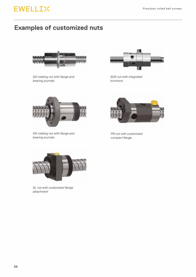
56
Precis ion ro l led ba l l screws
56
Examples of customized nuts
SD rotating nut with flange and bearing journals
SDS nut with integrated trunnions
SN rotating nut with flange and bearing journals
PN nut with customized compact flange
SL nut with customized flange attachment

57
Product range
3
57
Manufacturing tolerances
Value for t6
if La ≤ La ref t6 = t6p
if La > La ref t6 = (La/La ref) t6p
Value for t7
if Lb ≤ Lb ref t7 = t7p
if Lb > Lb ref t7 = (Lb / Lb ref) t7p
Value for t5
if Lf ≤ Lf ref t5 = t5p
if Lf > Lf ref t5
6 12 80 80 40 40 12 6
12 16 160 80 40 40 12 6 20 20
16 20 160 80 40 40 12 6 20 25
20 25 160 125 40 50 16 6 20 25
25 40 315 125 40 50 16 6 25 25
40 50 315 125 40 50 16 6 25 32
50 63 630 200 40 63 20 6 25 32
- 40 80
40 60 120
60 80 200
80 100 320
Nom in al diam eter
Reference lengths
Tolerances
d0 Lf ref La ref t5p t6p t7p t8 t9 t10> ≤ and Lb refmm µm
Ratio Tolerances
Lf/d0
> ≤ t5
– µm
Lb LbLa
2d0 2d02d0 2d0
E F
A
La
D BC
LfLt
t5 AB
t8 E
t7 E
t6 AB
t9 CD t10 CD
t5 AB
t8 E
t7 E
t6 AB
G
0,1 G

5858
Nut typeSD = Miniature screw, axial play, recirculation by insertsBD = Miniature screw, backlash elimination, recirculation by inserts SH = Miniature screw, axial play, recirculation by integrated tubeSDS = Miniature screw, axial play, stainless steelBDS = Miniature screw, backlash elimination, stainless steelSHS = Miniature screw, axial play, stainless steel, recirculation by integrated tubeSP = High performance miniature screw, axial playBP = High performance miniature screw, backlash eliminationSX = Universal screw, axial playBX = Universal screw, backlash eliminationSND = Precision screw, axial play, DIN nutBND = Precision screw, backlash elimination, DIN nutPND = Precision screw, preloaded, DIN nutSN = Precision screw, axial play, cylindrical flangeBN = Precision screw, backlash elimination, cylindrical flangePN = Precision screw, preloaded, cylindrical flangeSL = Long lead screw, axial playTL = Long lead screw, backlash eliminationSLD = Long lead screw, axial play, DIN nutTLD = Long lead screw, backlash elimination, DIN nutSLT = Rotating nut, axial playTLT = Rotating nut, backlash elimination
Nominal diameter × Lead [mm]
HandR = RightL = Left (on request)
Threaded length / Total length [mm]
Lead precision G5, G7, G9
Nut orientation Nut threaded nose or nut flange towards shorter machined end of shaft (S)Nut threaded nose or nut flange towards longer machined end of shaft (L)In case of identical machining at both shaft ends (–)
Machined end combinationSee page 44
Required lengths for AA, SA, UA (both ends)See page 44
OptionsWPR = with wipersNOWPR = without wipersRING = safety ring (for miniature ball screws only)REDPLAY = reduced axial play
Ordering keyBall screws
SN 32×5 R 330/445 G7 L – HA + K **/** WPR


Introduction
4Mounting instructions and support

61
Mounting introduction and support
4
Assembly procedure
Ball screw assemblies are precision components and should be handled with care to avoid damaging shocks, contamination or corrosion.
StorageStorage location must ensure that ball screw assemblies are not exposed to contamination, shocks, humidity and other detrimental actions.When stored out of the shipping crate, ball screw assem-blies must lie on wooden or plastic V-shaped blocks and should not be allowed to bounce. The assembly must not be supported on the shelf by the nut body.During shipping, ball screw assemblies are wrapped in heavy gauge plastic bags, which protect them from foreign material and possible contamination. They should remain wrapped until they are used.
AlignmentAfter assembly, any radial load or moment loading on the nut will overload some of the contact surfaces, thus signifi-cantly reducing the service life (⮑ fig. 1).Ewellix linear guidance components should be used to en-sure correct alignment and to avoid non-axial loading. The parallelism of the screw shaft with the guiding devices must be checked carefully. If external linear guidance proves im-practical, we suggest mounting the nut on trunnions or gim-bals, and mounting the screw shaft on self-aligning bearings. Mounting the screw in tension helps to align it properly and eliminates buckling.
LubricationGood lubrication is essential for the proper operation and long term reliability of the ball screw assembly. If necessary, please consult Ewellix.Before shipping, the complete ball screw assembly is coated with a protective fluid that dries to a film. This protective film is not a lubricant. Depending on the lubricant selected for the application, it may be necessary to remove the protec-tive film before applying the lubricant in order to eliminate any risk of incompatibility. In such cases, we recommend the following procedure:
4.2.1. Dip the ball screw assembly into a solvent 4.2.2. Shake and rotate the assembly to allow the
solvent to penetrate4.2.3. Remove the assembly from the solvent and al-
low the solvent to drain.

62
Precis ion ro l led ba l l screws
Removing the nut / assembling the nut on the shaftRemoving the nut from the screw shaft If possible, do not remove the nut from the shaft, especially for preloaded assemblies. If the nut must be removed from the shaft, i.e. for shaft end machining, check the nut orientation before disassembly.Never unscrew the nut from the shaft without a mandrel or sleeve to prevent the balls from falling off the nut (⮑ fig. 6).Once the nut is engaged on the sleeve, use a tie wrap to se-cure the nut assembly (⮑ fig. 5).
Fitting sleeved nut onto screw shaftSleeved nuts should not be removed from the sleeve until fi-nal assembly.
4.2.1. Remove the retaining strap (⮑ fig. 5)4.2.2. Check the assembly drawing to confirm the
nut orientation4.2.3. Hold the sleeve against the ball track of the
screw shaft and smoothly engage the ball nut (⮑ fig. 6) If the sleeve does not cover the diameter next to the ball track (for example, the sleeve bore diameter is smaller than the screw shaft end), then adhesive tape can be used to match the shaft end to the sleeve outer diameter. Otherwise, the sleeve can be held against the un-machined end, if available, with extreme care to prevent the balls from falling off the nut
4.2.4. Without using force, completely engage the nut in the screw thread, and run the nut to full engagement on the screw shaft.
Wiper assemblyIf optional wipers have been ordered, please refer to the fit-ting instructions enclosed with the shipment.
Starting–up the screwAfter the assembly has been cleaned, fitted and lubricated, allow the nut to make several full strokes at low speed (< 50 rpm) and light load (not to exceed 5% of the ball screw dynamic carrying capacity) in order to check the proper po-sitioning of the limit switches or reversing mechanism. Then, normal load and speed can be applied.
Note:Instructions for most operations such as fitting a nut onto a screw shaft, a wiper onto a nut, etc. are available in separate sheets delivered with the product. Please refer to them be-fore assembling the screw.
Fig. 5
Fig. 6
nut
sleevescrew

63
Mounting introduction and support
4
For reduced delivery time, Ewellix operates quick service facilities in Europe and in North America, where standard screw shafts, nuts and accessories are stocked.
Service rangeQuick service for precision rolled ball screws
• Stock items of screws shafts and nuts, without machined ends. Nuts with axial play mounted on screw shaft, or on sleeve. Nuts with backlash elimination or with preload mounted on shaft
• Ball screw assemblies with shaft ends machined according to standard ends as defined in this catalogue• Ball screw assemblies with shaft ends machined according to customer requirements: In this case, please send a
drawing with all dimensional and tolerance requirements, and with all specifications written in English• Complete ball screw assemblies, including accessories presented in this catalogue. Accessories already mounted
on nut or shaft, or delivered separately.
Customers can order ball screws with the following options:
Ball screw orders
General rules
• From a couple of days to maximum two weeks is possible for orders fulfilling the following conditions• Maximum 5 pieces for types SX/BX – SND/BND/PND – SN/BN/PN – SL/TL – SLD/TLD (delivered with wipers)
• Maximum 15 pieces for types SD/BD/SH
• Both shaft and nut should be made of standard steel, as stated in the present catalogue
• Standard nuts, including DIN nuts• Screw shafts machined according to customer drawing• Backlash elimination by oversized balls available for BD – BX – BND/BN• Preload available for PND/PN – TL/TLD• General precision on tolerances ISO IT7 (ISO 3408-3:2006)• One nut per screw shaft
• Rotating nut SLT/TLT types are excluded from this program• Stainless steel or special treatments, including annealed shaft ends, splines are excluded from this program• Material certificates, special reports, or orders that require special procedure and approval by the French authori-
ties are excluded for this program.
Delivery time
Quantity
Materials
Capabilities
Other condi-tions for quick delivery
Diameter Lead Nut types Lead precision Accessories
From 6 to 63 mm From 2 to 50 mm Cylindrical and flanged nuts with axial play, backlash elimination, or preload, Ewellix designs or DIN designs
G5 – G7 – G9 Flanges for nuts, and ball screw support bearings
Available range

64
Precis ion ro l led ba l l screws
Design calculation and inquiry form
Customer and project information
Ball screw data
Company name .........................................................................................................................................................................................................
Address .....................................................................................................................................................................................................................
Contact name ...................................................................................... Phone number .....................................................................................
Email ..................................................................................................... Website ...............................................................................................
Project name ..............................................................................................................................................................................................................
Application type ........................................................................................................................................................................................................
Short description of application (please attach a sketch if possible) ..........................................................................................................................................................................
Annual ball screw requirements and start of production date ....................................................................................................................................................................................
Prototype requirementsand suitable delivery date ........................................................................................................................................................................................
For existing or modified application, type of ball screw already used ...............................................................................................................................................................................
Design parameter Value
Maximum stroke [mm] ..........................................................
Threaded length [mm] ..........................................................
Total length [mm] ..........................................................
Pre-selection of screw shaft nominal
diameter d0 [mm] ..........................................................
Pre-selection of lead Ph [mm] ..........................................................
Pre-selection of nut type ..........................................................
Lead precision grade according to ISO 3408 ....................................................
Pre-selection of axial play, backlash elimination or preload ..........................................................
If axial play is selected, preferred min/max range [µm] ..........................................................
Request for accessories (flanges, support bearings, etc.) ..........................................................
Other pertinent information ..........................................................
Max. strokeThreaded length
Total length

65
Mounting introduction and support
4
Operating conditions
Duty cycle description
Mounting conditions
• Maximum static load or shock load [N] • Maximum dynamic load in tension [N] • Maximum dynamic load in compression [N]
• Average linear speed [m/min] • Maximum linear speed [m/min] • Maximum acceleration [m/s²]
• Brand name • Type • Viscosity at average operating temperature [cSt]
• Minimum [°C] • Average [°C] • Maximum [°C] • Travel [m] • Or revolutions [rev] • Or duration [hours]
Position of the screw ¨ Vertical ¨ HorizontalRotating part ¨ Screw ¨ NutScrew end fixing conditions N (fixed, free) N (fixed, radial support) N (fixed, fixed)
.......................................................................
.......................................................................
.......................................................................
.......................................................................
.......................................................................
.......................................................................
.......................................................................
.......................................................................
.......................................................................
.......................................................................
.......................................................................
.......................................................................
.......................................................................
.......................................................................
.......................................................................
Maximum loads
Lubrication
Operating temperature
Required service life
Step Axial force [N] Speed, either rotational speed [rpm] Travel [mm] or linear speed [m/minute]
1 ................................................... ....................................................................... ........................................................................2 ................................................... ....................................................................... ........................................................................3 ................................................... ....................................................................... ........................................................................4 ................................................... ....................................................................... ........................................................................5 ................................................... ....................................................................... ........................................................................Etc. ................................................... ....................................................................... ........................................................................
Other pertinent information
...........................................................................................................................................................................................................
...........................................................................................................................................................................................................
...........................................................................................................................................................................................................
...........................................................................................................................................................................................................
Ball screw catalogue, ball screw 2D prints and 3D models are available on www.ewellix.comPlease send inquiry form to your Ewellix sales office. For contact information, please visit www.ewellix.com


ewellix.com© Ewellix
All contents of this publication are the property of Ewellix, and may not be
reproduced or given to third parties (even extracts) without permission.
Although great care has been taken in the production of this catalog, Ewellix
does not take any responsibility for damage or other loss resulting from
omissions or typographical errors. The photo may differ slightly in appearance
from the actual product. Due to continuous improvements being made in our
products, the product’s appearance and specifications are subject to change
without notice.
PUB IL-05004/2-EN-December 2020
Certain image(s) used under license from Shutterstock.com.
SKF and SKF logo are trademarks of the SKF Group