Hydrogen storage behavior of ZrNi 70/30 and ZrNi 30/70 composites
8
Journal of Alloys and Compounds 458 (2008) 223–230 Hydrogen storage behavior of ZrNi 70/30 and ZrNi 30/70 composites Diego Escobar, Sesha Srinivasan ∗ , Yogi Goswami, Elias Stefanakos Clean Energy Research Center, College of Engineering, University of South Florida, Tampa, FL 33620, USA Received 9 March 2007; received in revised form 30 March 2007; accepted 2 April 2007 Available online 6 April 2007 Abstract The Zr–Ni compositional alloys, namely (i) ZrNi 70/30 and (ii) ZrNi 30/70 (both by weight) have been investigated for the reversible hydrogenation behavior. These composites show Zr–Ni intermetallic multi-phase formation as explored by X-ray diffraction studies. The sorption kinetics of ZrNi 70/30 seems much faster (∼3–4 times) than that of ZrNi 30/70 alloys. The initial desorption rate increasing with an increase in temperature. A well-defined plateau region was obtained for the ZrNi 70/30 with an equilibrium pressure range from <1 bar (300 ◦ C) to 10 bars (390 ◦ C). For ZrNi 30/70, the sloppy plateau region extends to higher equilibrium pressures. It is estimated that the total effective hydrogen concentration for ZrNi 70/30 (∼1.0 wt.%) is at least 2 times that of ZrNi 30/70 (∼0.5 wt.%) composites. From the PCT isotherms, the enthalpy of reaction (H) has been calculated to be ∼39 kJ/mol H 2 for the ZrNi 70/30. The surface morphologies of the hydrogenated materials exhibit the presence of cracks and particle size pulverization in comparison to the pristine alloys. © 2007 Elsevier B.V. All rights reserved. Keywords: Hydrogen storage; Zr–Ni intermetallics; Thermogravimetric analysis; PCT isotherms; Desorption kinetics 1. Introduction Hydrogen is a highly reactive element and has been studied to form hydrides and solid solutions with thousands of metals and alloys [1]. The majority of the 91 natural elements below the H element in the periodic table will hydride under appropriate conditions such as: VH 2 , NaH, LaH 2 , ZrH 2 , etc. Unfortunately, the pressure–composition–temperature (PCT) properties are not very convenient relative to the 1–10 atm, 0–100 ◦ C range of util- ity used for practical hydrogen storage applications or a good content of hydrogen for device applications. For practical applications of reversible hydrides, it is required to combine strong hydride forming elements A with weak hydriding elements B to form alloys (especially intermetallic compounds) that have the desired intermediate thermody- namic affinities for hydrogen. A good example to show this characteristic is the combination of La (forming LaH 2 at 25 ◦ C, P d =3 × 10 −29 atm and H f = −208 kJ mol −1 H 2 ) with Ni (NiH, 25 ◦ C, P d = 3400 atm, H f = −8.8 kJ mol −1 H 2 ) to form the intermetallic compound LaNi 5 (LaNi 5 H 6 , 25 ◦ C, P d = 1.6 atm, H f = −30.9 kJ mol −1 H 2 ). This incredible abil- ∗ Corresponding author. Tel.: +1 813 974 0759; fax: +1 813 974 2050. E-mail address: [email protected] (S. Srinivasan). ity to ‘interpolate’ between the extremes of elemental hydriding behaviour has opened the door to the modern world of reversible hydrides. Intermetallic alloys such as AB 5 (e.g. LaNi 5 ), AB (e.g. FeTi, ZrNi, etc.), AB 2 (e.g. ZrFe 2 ) and A 2 B (e.g. Mg 2 Ni) have been explored in the past for their effective hydrogen sorption behavior [2–4]. In recent years, many new and novel hydrogen storage systems are being investigated, namely, (i) Mg-transition metal hydrides (e.g. Mg 2 FeH 6 ) [5,6]; complex hydrides such as (ii) alanates [7–9], (iii) borohydrides [10] and (iv) amides [11,12], (v) amino-boranes [13]; physisorbed sys- tems such as (vi) fullerenes [14], (vii) carbon nanotubes [15,16] (viii) graphitic nanofibres [17] (ix) metal organic frameworks [18,19] and (x) polymer nanocomposite matrices [20,21], etc. However, none of the hydride systems typified above satisfy all of the desired characteristics of hydrogen storage such as high volumetric and gravimetric hydrogen density, low temperature, rapid desorption kinetics, tolerance hysteresis, insensitivity to impurities, cost and weight, etc. The first example of a reversible intermetallic hydride was demonstrated with the AB compound, ZrNi [22]. The hydride ZrNiH 3 has a 1 atm desorption temperature of about 300 ◦ C, too high for hydrogen storage applications, whereas it is significant for hydrogen compression. These intermetallic alloys show good volumetric and gravimetric reversible H-capacities, competitive 0925-8388/$ – see front matter © 2007 Elsevier B.V. All rights reserved. doi:10.1016/j.jallcom.2007.04.012
-
Upload
floridapolytechnic -
Category
Documents
-
view
1 -
download
0
Transcript of Hydrogen storage behavior of ZrNi 70/30 and ZrNi 30/70 composites

A
bZAZZba©
K
1
taHctvic
thcnc2NfP
0d
Journal of Alloys and Compounds 458 (2008) 223–230
Hydrogen storage behavior of ZrNi 70/30 and ZrNi 30/70 composites
Diego Escobar, Sesha Srinivasan ∗, Yogi Goswami, Elias StefanakosClean Energy Research Center, College of Engineering, University of South Florida, Tampa, FL 33620, USA
Received 9 March 2007; received in revised form 30 March 2007; accepted 2 April 2007Available online 6 April 2007
bstract
The Zr–Ni compositional alloys, namely (i) ZrNi 70/30 and (ii) ZrNi 30/70 (both by weight) have been investigated for the reversible hydrogenationehavior. These composites show Zr–Ni intermetallic multi-phase formation as explored by X-ray diffraction studies. The sorption kinetics ofrNi 70/30 seems much faster (∼3–4 times) than that of ZrNi 30/70 alloys. The initial desorption rate increasing with an increase in temperature.well-defined plateau region was obtained for the ZrNi 70/30 with an equilibrium pressure range from <1 bar (300 ◦C) to 10 bars (390 ◦C). For
rNi 30/70, the sloppy plateau region extends to higher equilibrium pressures. It is estimated that the total effective hydrogen concentration forrNi 70/30 (∼1.0 wt.%) is at least 2 times that of ZrNi 30/70 (∼0.5 wt.%) composites. From the PCT isotherms, the enthalpy of reaction (�H) haseen calculated to be ∼39 kJ/mol H2 for the ZrNi 70/30. The surface morphologies of the hydrogenated materials exhibit the presence of cracksnd particle size pulverization in comparison to the pristine alloys.
2007 Elsevier B.V. All rights reserved.
is; PC
ibh
FhshMh(t([Hovr
eywords: Hydrogen storage; Zr–Ni intermetallics; Thermogravimetric analys
. Introduction
Hydrogen is a highly reactive element and has been studiedo form hydrides and solid solutions with thousands of metalsnd alloys [1]. The majority of the 91 natural elements below the
element in the periodic table will hydride under appropriateonditions such as: VH2, NaH, LaH2, ZrH2, etc. Unfortunately,he pressure–composition–temperature (PCT) properties are notery convenient relative to the 1–10 atm, 0–100 ◦C range of util-ty used for practical hydrogen storage applications or a goodontent of hydrogen for device applications.
For practical applications of reversible hydrides, it is requiredo combine strong hydride forming elements A with weakydriding elements B to form alloys (especially intermetallicompounds) that have the desired intermediate thermody-amic affinities for hydrogen. A good example to show thisharacteristic is the combination of La (forming LaH2 at5 ◦C, Pd = 3 × 10⁻²⁹ atm and �Hf = −208 kJ mol−1 H2) with
i (NiH, 25 ◦C, Pd = 3400 atm, �Hf = −8.8 kJ mol−1 H2) toorm the intermetallic compound LaNi5 (LaNi5H6, 25 ◦C,d = 1.6 atm, �Hf = −30.9 kJ mol−1 H2). This incredible abil-
∗ Corresponding author. Tel.: +1 813 974 0759; fax: +1 813 974 2050.E-mail address: [email protected] (S. Srinivasan).
i
dZhfv
925-8388/$ – see front matter © 2007 Elsevier B.V. All rights reserved.oi:10.1016/j.jallcom.2007.04.012
T isotherms; Desorption kinetics
ty to ‘interpolate’ between the extremes of elemental hydridingehaviour has opened the door to the modern world of reversibleydrides.
Intermetallic alloys such as AB5 (e.g. LaNi5), AB (e.g.eTi, ZrNi, etc.), AB2 (e.g. ZrFe2) and A2B (e.g. Mg2Ni)ave been explored in the past for their effective hydrogenorption behavior [2–4]. In recent years, many new and novelydrogen storage systems are being investigated, namely, (i)g-transition metal hydrides (e.g. Mg2FeH6) [5,6]; complex
ydrides such as (ii) alanates [7–9], (iii) borohydrides [10] andiv) amides [11,12], (v) amino-boranes [13]; physisorbed sys-ems such as (vi) fullerenes [14], (vii) carbon nanotubes [15,16]viii) graphitic nanofibres [17] (ix) metal organic frameworks18,19] and (x) polymer nanocomposite matrices [20,21], etc.owever, none of the hydride systems typified above satisfy allf the desired characteristics of hydrogen storage such as higholumetric and gravimetric hydrogen density, low temperature,apid desorption kinetics, tolerance hysteresis, insensitivity tompurities, cost and weight, etc.
The first example of a reversible intermetallic hydride wasemonstrated with the AB compound, ZrNi [22]. The hydride
rNiH3 has a 1 atm desorption temperature of about 300 ◦C, tooigh for hydrogen storage applications, whereas it is significantor hydrogen compression. These intermetallic alloys show goodolumetric and gravimetric reversible H-capacities, competitive
224 D. Escobar et al. / Journal of Alloys and Compounds 458 (2008) 223–230
ion pa
wadpdHst
ZhtbZrdfdtatwsostshliSfiw
a
Z[bcmh
2
cwhUtca
twlasb2
acwsspalp
Fig. 1. X-ray diffract
ith the best of the AB5s and AB2s. Activation is pretty slownd hard for the ZrNi-based alloys. In any event, it may take aay or so and high pressures (>50 atm) for total activation. Theassive oxide films that can form on ZrNi (and its derivatives)o not have a high degree of sensitivity to gaseous impurities in2; hence, these alloys are resistant to impurities [23]. Cyclic
tability of the lower plateau is great, but the upper plateau tendso drift higher and higher with H/D cycling.
Hydride induced disproportionation and reproportation ofr–TM (TM = transition metals, Fe, Co, Ni) intermetallicsave been studied by means of volumetric hydrogen absorp-ion/desorption measurements [24] and the stability was found toe in the order of Zr2Ni > Zr2Co > Zr2Fe. The free energy of therNi compound was reduced by mechanically milling the mate-
ials under different hydrogen partial pressures [25]. It was alsoemonstrated that a fast amorphization reaction was achievedor the ZrNi system by the mechanical milling process with timeuration of less than 5 h [26]. An extensive thermal characteriza-ion for the Zr1−xNix has been found to behave rather remarkablyt limited concentrations of x < 0.4 [27]. An unusual hydrogena-ion behavior was obtained for the solid solution of hydrogenith the intermetallic Zr7Ni10 phase [28]. The thermodynamic
tability and phase equilibria for ZrNi were explored on the basisf a liquid to amorphous state transition model [29]. Yet anothertudy related to thermodynamic properties of ZrNiH3 disproveshe earlier proposed phase diagram [30] at higher temperatures,ay 700 K [31]. A precise measurements and modeling of theeat flux calorimetry of the ZrNi–H2 system was demonstrated atow-pressures [32]. The structural and microstructural character-zation of ZrNi–Hx has been thoroughly investigated using XRD,EM and TEM techniques [33]. According to this study, for the
rst time, the monohydride/trihydride morphological changesere analyzed.Although there is vast information available about ZrNilloys, the intermediate compositional alloys ZrNi 70/30 and
asQw
ttern of ZrNi 30/70.
rNi 30/70 have been sparsely reported for hydrogen storage34]. In the present paper, we have studied the hydrogenationehavior of these composites by high-pressure sorption pro-edures and thermo gravimetric analysis. The structural andicrostructural characterizations before and after hydrogenation
ave been analyzed for the effective hydrogen sorption behavior.
. Experimental details
Zr/Ni 70/30 and Zr/Ni 30/70 powders with a purity of 99.99% and parti-le sizes of 325 mesh were procured from Sigma Aldrich, USA. These alloysere used without further purification. All sample handling and manipulationave been carried out inside a N2 filled glove box (Innovative Technologies Inc.,SA). The oxygen and moisture level inside the box are controlled and main-
ained at <1 ppm by continuously blowing the nitrogen gas. The molecular sieveatalyst is being used for the incoming purging nitrogen gas and it continuouslybsorbs the contaminants so that it keeps the glove box in a dry condition.
X-ray diffraction (XRD) patterns were collected on a Philips X’pert diffrac-ometer with Cu K� radiation of λ = 5.4060 A. The incident and diffraction slitidth used for the measurements are 1◦ and 2◦, respectively. The incident col-
imating mask of 10 mm was used throughout the analysis. Phase identificationnd particle size calculation has been carried out using PANalytical X’pert High-core software, Version 1.0f. The samples were protected from air and moisturey wrapping it with thin foil, which shows diffraction peaks in the 2θ range of1–24◦.
The isothermal volumetric sorption measurements have been carried out bySievert’s type PCTPro 2000 (HyEnergy LLC, USA) instrument. The volume
alibration without and with the sample is performed at a constant temperatureith an accuracy of ±1 ◦C. The hydrogen absorption and desorption parameters
uch as pressure and temperature have been optimized for the efficient hydrogentorage characteristics. During sorption, the sample temperature and appliedressure were monitored and recorded by a Lab View software program. Thenalysis of the measurements, such as full absorption/desorption kinetics, cycleife and PCT, were calculated using Hy-Analysis macros in the Igor softwareackage.
For the heat flow and weight loss analysis, samples were loaded in aluminumnd alumina pans, respectively, in the nitrogen gas filled glove box. The mea-urements have been performed using a DSC Q10P (aluminum pan) and a SDT600 (alumina pan) model from TA Instruments. The thermal measurementsere analyzed using Universal Analysis software tool.

D. Escobar et al. / Journal of Alloys and Compounds 458 (2008) 223–230 225
ion pa
hsdws
3
3c
taosXirdtcSscocs
3
(wla
o3iw
acitad(
hddIi
3
adepicted in Fig. 6. The absence of a well-defined plateau pressurefor the absorption and desorption curves at various temperaturesis an indication of low hydrogen being absorbed by the mixtureat these temperatures. Very high pressures are needed (∼60 bars)
Table 1Desorption rate with temperature for ZrNi 70/30
Temperature (◦C) Desorption completion time (min)
300 130
Fig. 2. X-ray diffract
The microstructures of the samples in the different stages (before and afterydrogen sorption) were observed by Hitachi S800 scanning electron micro-cope (SEM) and the local phase composition was determined in the energyispersive X-ray spectrometry (EDS) mode using the same instrument. A fixedorking distance of 5 mm and a voltage of 20 kV were used. EDAX Genesis
oftware was used to analyze the SEM images and EDS mappings.
. Results and discussion
.1. Structural characterization of as-received ZrNiomposites
Figs. 1 and 2 shows the representative X-ray diffraction pat-erns of the “as-received” ZrNi 30/70 and ZrNi 70/30 alloys,ll the peaks were indexed and matched by both the literaturene-to-one peak matching [23,25,34] and also by the High-core algorithm of profile fitting [35]. For the ZrNi 30/70, theRD profiles are indexed and matched with the known ZrNi5
ntermetallic phase. Whereas for the ZrNi 70/30, the number ofeflections are comparatively increased with the ZrNi phase asepicted in Fig. 2. In addition to ZrNi, few peaks correspondingo Zirconium Hydride are also present. Moreover, the averagerystallite sizes of these composites have been calculated fromcherrer’s formula. The ZrNi 70/30 possesses the smaller grainize of ∼28 nm which is at least 6–7 times smaller than therystallite sizes of ZrNi 30/70 (∼226 nm). Based on these XRDbservations, it is necessary to compare and contrast these twoomposites for the effective hydrogen storage (discussed in nextections).
.2. Desorption kinetics
Before the kinetics and PCT measurements, both the samples
ZrNi 30/70 and ZrNi 70/30) were evacuated at 300 ◦C for 4 hith the intention of removing O2 and moisture, after that, cycle-ife kinetics at 300 ◦C for 5 h have been followed in order toctivate the samples. Fig. 3 represents the desorption kinetics
3333
ttern of ZrNi 70/30.
f ZrNi 30/70 at three different temperatures say 300, 350 and90 ◦C, respectively. Complete hydrogen desorption is achievedn less than 2 h and a hydrogen concentration of 0.37–0.4 wt.%as obtained in the temperature range of 300–390 ◦C.Fig. 4 represents desorption kinetic curves of ZrNi 70/30
t various operating temperatures (say 300–390 ◦C). Hydrogenontent in the range of 0.5–0.72 wt.% has been observed whichs at least 2 times higher than that of ZrNi 30/70. An averageotal desorption time at these temperatures is less than 0.1 hs shown in Fig. 4. As it can be seen, dehydriding kineticsepends strongly on the temperature of the reacting materialmetal–metal hydride).
For the quantitative analysis of the desorption rate, the dataave been plotted in terms of hydrogen pressure at differentesorption temperatures (see Fig. 5). The desorption rates atifferent temperatures obtained from Fig. 5 are given in Table 1.t is inferred from this table that the rate of desorption at 390 ◦Cs about 5–6 times faster than the sample desorbed at 300 ◦C.
.3. Absorption and desorption PCT
The pressure–composition isotherms (PCT) of the ZrNi 30/70lloy both in the hydrogen absorption and desorption phase is
25 11050 9075 3090 20

226 D. Escobar et al. / Journal of Alloys and Compounds 458 (2008) 223–230
Fig. 3. Desorption kinetics of ZrNi 30/70 at 300, 350 and 390 ◦C.
Fig. 4. Desorption kinetics of ZrNi 70/30 at 300, 325, 350, 375 and 390 ◦C.
Fig. 5. Desorption kinetics of ZrNi 70/30 at 300, 325, 350, 375 and 390 ◦C in desorbed H2 pressure units.

D. Escobar et al. / Journal of Alloys and Compounds 458 (2008) 223–230 227
T of
fiapwtatMasm
re3arta
3
o
f
l
�
ttollitHe
3
Fig. 6. Absorption and desorption PC
or getting a total H2 absorption–desorption of 0.39 wt.%. Fig. 7llustrates the absorption–desorption PCT for the ZrNi 70/30lloy, giving evidence of a typical metal hydride behavior. Thelateau region is the most important segment of a PCT plot,hich represents the pressure of hydrogen in equilibrium with
he metal–metal hydride (� + �) phases, representing the dissoci-tion pressure of the metal hydride at the desired temperature; theemperature indicates the thermal stability of the metal hydride.
oreover, when the temperature goes from 300, 325, 350, 375nd 390 ◦C, it causes the plateau pressure to increase and, at theame time, reduces the width of the plateau which represents theiscibility regime of the � and � phase.As an example, at 375 ◦C a hydrogen content of 1 wt.% is
eached at 13 bars. The enthalpy calculation from the Van’t Hoffquation, based on the PCT desorption plots is given in Section.4. According to the investigations, ZrNi 70/30 alloy presentsmetal hydride behaviour, low kinetics, moderate high equilib-
ium pressures, and moderate high hydrogen content, conditionshat make this alloy most convenient for hydrogen compressionpplications.
.4. Enthalpy calculation of ZrNi 70/30
The ZrNi 70/30 enthalpy (�H) is evaluated from the slopef the straight-line plot of ln PH2 versus 1/T according to the
fhbA
Fig. 7. Absorption and desorption PCT of ZrNi
ZrNi 30/70 at 300, 350 and 390 ◦C.
ollowing equations (Van’t Hoff equation).
nP2
P1= ln P2 − ln P1 = −�H
R
[1
T2− 1
T1
](1)
H = −R(ln P2 − ln P1)
[1/T2 − 1/T1](2)
The PCT desorption plateau pressures from Fig. 6 at differentemperatures is tabulated in Table 2. In Table 3, the inverse ofhe temperature of the plateau pressures and the natural log (ln)f the pressures in which the plateau occurs are tabulated. Ainear approximation was made to approximate the 1/T versusn pressure (Table 3) into a linear plot and is shown in Fig. 8. As its shown, the slope of the linear approximation in Fig. 8 is equalo �H/R, therefore �H is equal to 19.4215 kJ/mol, in terms of
2 release, and it must be multiplied by two, the remaining �Hquals to 38.84 kJ/mol H2.
.5. TGA analysis for ZrNi 30/70 and ZrNi 70/30
The gravimetric weight loss due to hydrogen decomposition
rom ZrNi 30/70 is shown in Fig. 9. The sample powder has beenydrogenated in the PCT apparatus at 390 ◦C for 4 h. As it cane seen, the gravimetric weight loss is around 0.09% at 350 ◦C.gain the TGA profile exhibits weight loss with a single step70/30 at 300, 325, 350, 375 and 390 ◦C.

228 D. Escobar et al. / Journal of Alloys and Compounds 458 (2008) 223–230
Table 2Plateau pressures at different desorption temperatures for ZrNi 70/30
Temp. (C) T (K) Pressure (bar) Pressure (atm)
300 573 1.5 1.48038325 598 3 2.96076350 623 5 4.9346375 648 7.2 7.105824395 668 10.08 9.948154
Table 3Inversed of the temperature and ln P at different plateau pressures
1/T (K−1) ln(pressure)
0.003333333 0.3922988120.003076923 1.0854459920.002857143 1.59627161600
r
2
0pait0O
37
tcpth
Fi
Zs
3
tpubP∼dctaa
3
.002666667 1.960914729
.002531646 2.297386966
eaction according to the well-known metal hydride equation,
ZrNiH3 ↔ ZrNi + 3H2 (3)
Hydrogen decomposition from ZrNi 70/30 reaches a value of.62 wt.% at 300 ◦C (Fig. 10), making the hydrogen desorptionroperty almost 7 times greater compared with the ZrNi 30/70lloy. In the same graph (Fig. 10), the TGA profile of ZrNi 70/30s compared with the same hydride alloy after being exposedo air for 30 min at room temperature, showing a reduction of.2% hydrogen decomposition at 300 ◦C due to the influence of2/moisture picked up by the sample.
.6. XRD analysis before and after hydrogenation of ZrNi0/30
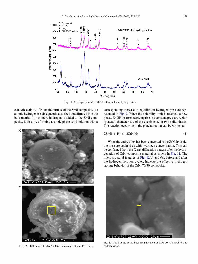
The XRD analysis of ZrNi 70/30 before and after hydrogena-ion is shown in Fig. 11. The XRD spectra shows a significant
hange in the intensity of the peaks in ZrNi 70/30 hydride com-ared with the unhydrided sample (33.2, 34.2, 36.5 and 43◦) andhe presence of a new peak (36.7◦) attributed to the ZrNi 70/30ydride phase. The crystallite sizes of the ZrNiH3 (∼48 nm) andig. 8. Result and linear approximation of the natural log of the pressure vs.nversed of temperature.
aam
F
Fig. 9. TGA profile of ZrNi 30/70 after hydrogenation.
rH2 (∼39 nm) are calculated and compare with the unhydridedample.
.7. SEM imaging of ZrNi 70/30
Fig. 12 shows the SEM images of ZrNi 70/30 powder par-icles before and after PCT hydrogenation cycles. Initially, theowder particles present inhomogeneous distribution with irreg-lar morphology. Larger size particles are present in the sampleefore PCT hydrogen absorption in the order of 20–25 �m. AfterCT hydrogenation runs, the particle average size is reduced to12 �m. It was also found that cracks were formed after PCT
ue to the interaction of hydrogen with the metal lattice thusausing lattice expansion by an appreciable amount. A zoom inhe crack area (see inside the square of Fig. 12(b)) of the particlefter PCT is shown in Fig. 13, the image was magnified 30,000×nd the crack width (marked by an arrow) is about 0.1 �m.
.8. Hydrogenation mechanism
An interpretation of the isothermal volumetric measurementsnd the associated phase changes during hydrogen absorptionnd desorption of ZrNi 70/30 can be given as follows: (i)olecular hydrogen dissociates into hydrogen atoms, due to the
ig. 10. TGA profile of ZrNi 70/30 after hydrogenation and after air exposition.
D. Escobar et al. / Journal of Alloys and Compounds 458 (2008) 223–230 229
0/30 b
cabp
Fig. 11. XRD spectra of ZrNi 7
atalytic activity of Ni on the surface of the ZrNi composite, (ii)tomic hydrogen is subsequently adsorbed and diffused into theulk matrix, (iii) as more hydrogen is added to the ZrNi com-osite, it dissolves forming a single phase solid solution with a
Fig. 12. SEM image of ZrNi 70/30 (a) before and (b) after PCT runs.
crp(T
2
tbgmts
Fh
efore and after hydrogenation.
orresponding increase in equilibrium hydrogen pressure rep-esented in Fig. 7. When the solubility limit is reached, a newhase, ZrNiHx is formed giving rise to a constant pressure regionplateau) characteristic of the coexistence of two solid phases.he reaction occurring in the plateau region can be written as
ZrNi + H2 ↔ 2ZrNiH3 (4)
When the entire alloy has been converted to the ZrNi hydride,he pressure again rises with hydrogen concentration. This cane confirmed from the X-ray diffraction pattern after the hydro-enation of ZrNi composite material as shown in Fig. 11. The
icrostructural features of Fig. 12(a) and (b), before and afterhe hydrogen sorption cycles, indicate the effective hydrogentorage behavior of the ZrNi 70/30 composite.
ig. 13. SEM image at the large magnification of ZrNi 70/30’s crack due toydrogenation.

2 s and
4
bZTacspttrpeaFcmoptcp
A
Efi
R
[
[
[[
[
[[[
[[
[
[
[
[
[
[[[
[
[
[[
[
30 D. Escobar et al. / Journal of Alloy
. Conclusions
The ZrNi 70/30 compositional alloy shows comparativelyetter hydrogen absorption–desorption characteristics than therNi 30/70,even though both are too low for a practical use.he alloy ZrNi 70/30 holds promise for hydrogen storage, suchs low cost of acquisition, no pretreatment necessary, goodyclic stability, respectable gravimetric density, low hystere-is, good hydriding/dehydriding kinetics and reasonable plateauressures. Some of the conclusive features of ZrNi 70/30 are (1)he sorption kinetics of ZrNi 70/30 seems much faster (∼3–4imes) than that of ZrNi 30/70 alloys; (ii) a well-defined plateauegion was obtained for the ZrNi 70/30 with an equilibriumressure from <1 bar (300 ◦C) to 10 bars (390 ◦C); (iii) the totalffective hydrogen concentration for ZrNi 70/30 (∼1.0 wt.%) ist least 2 times that of the ZrNi 30/70 (∼0.5 wt.%) composites.rom the PCT isotherms, the enthalpy of reaction (�H) has beenalculated to be ∼39 kJ/mol H2 for the ZrNi 70/30. The surfaceorphologies of the hydrogenated materials exhibit the presence
f cracks and particle size pulverization in comparison to theristine alloys. A new approach of mechanochemically millinghe composites of ZrNi 30/70 and ZrNi 70/30 is presently beingarried out and the results will be published in the forthcomingapers.
cknowledgements
The authors wish to acknowledge the US Department ofnergy (Hydrogen Fuel Initiative code: DE-FG36-04G014224)
or funding this research and the USF NanoTech Research Facil-ty for the analytical studies.
eferences
[1] G. Sandrock, J. Alloys Compd. 293–295 (1999) 877–888.[2] A. Zuttel, Mater. Today (September) (2003) 24–33.[3] M.V.C. Sastri, B. Vismanathan, S. Srinivasa Murthy, Metal Hydrides,
Narosa Publishing House, 1998, p. 1.[4] J.H.N. van Vucht, F.A. Kuipers, H.C.A.M. Bruning, Reversible room-
temperature absorption of large quantities of hydrogen by intermetallic
compounds, Phillips Research Reports, 1970, p. 25.[5] S.S. Srinivasan, S. Dumbris, L. McElwee-White, E. Stefanakos, Y.Goswami, Mater. Res. Soc. Symp. Proc. 885 (2006) 169.
[6] R.A. Varin, S. Li, Ch. Chiu, L. Guo, O. Morozova, T. Khomenko, Z.Wronski, J. Alloys Compd. 404–406 (2005) 494.
[
[
[
Compounds 458 (2008) 223–230
[7] B. Bogdanovic, U. Eberle, M. Felderhoff, F. Schueth, Scr. Mater. 56 (10)(2007) 813.
[8] J. Wang, A.D. Ebner, J.A. Ritter, J. Phys. Chem. B 110 (35) (2006)17353.
[9] S.S. Srinivasan, C.M. Jensen, Mater. Res. Soc. Symp. Proc. 837 (2005)101.
10] J.J. Vajo, S.L. Skeith, F. Mertens, J. Phys. Chem. B 109 (9) (2005)3719.
11] W.I.F. David, M.O. Jones, D.H. Gregory, C.M. Jewell, S. Johnson, A.Walton, P.P. Edwards, J. Am. Chem. Soc. 129 (6) (2007) 1594.
12] W. Luo, S. Sickafoose, J. Alloys Compd. 407 (1–2) (2006) 274.13] T. Autrey, M. Gutowski, A. Gutowska, Y. Shin, L. Li, J. Linehan, World
Renewable Energy Congress VIII: Linking the World with RenewableEnergy, 8th, Denver, CO, United States, August 29–September 3, 2004,pp. 316–320.
14] W.H. Shin, S.H. Yang, W.A. Goddard III, J.K. Kang, Appl. Phys. Lett. 88(5) (2006) 053111/1.
15] E.-S. Yim, D-h. Yoon, S. Rim, C.H. So, Sae Mulli. 53 (5) (2006) 393.16] Z. Huang, Xiyou Jinshu 29 (6) (2005) 890.17] S.E. Hong, D.-K. Kim, S.M. Jo, D.Y. Kim, B.D. Chin, D.W. Lee, Catal.
Today 120 (3–4) (2007) 413.18] T. Yildirim, M.R. Hartman, Phys. Rev. Lett. 95 (21) (2005) 2155041.19] B. Panella, M. Hirscher, H. Puetter, U. Mueller, Adv. Funct. Mater. 16 (4)
(2006) 520.20] M.J. Jurcyzk, A. Kumar, S.S. Srinivasan, E. Stefanakos, Int. J. Hydrogen
Energy, in press.21] N.B. McKeown, B. Gahnem, K.J. Msayib, P.M. Budd, C.E. Tattershall, K.
Mahmood, S. Tan, D. Book, H.W. Langmi, A. Walton, Angew. Chem. Int.Ed. 45 (2006) 1804.
22] G.G. Libowitz, F.H. Herbert, T.R.P. Gibb Jr., J. Chem. Phys. 27 (1957)514.
23] M. Hara, Y. Hatano, T. Abe, K. Watanabe, T. Naitoh, S. Ikeno, Y. Honda,J. Nucl. Mater. 320 (2003) 265–271.
24] M. Hara, R. Hayakawa, Y. Kaneko, K. Watanabe, J. Alloys Compd. 352(2003) 218–225.
25] S. Orimo, H. Fujii, J. Alloys Compd. 217 (1995) 287–294.26] A. Al-Hajry, Mater. Res. Bull. 35 (2000) 1989–1998.27] K.H.J. Buschow, B.H. Verbeek, A.G. Dirks, J. Appl. Phys. 14 (1981)
1087–1097.28] H.T. Takeshita, N. Fujiwara, T. Oishi, D. Noreus, N. Takeichi, N. Kuriyama,
J. Alloys Compd. 360 (2003) 250–255.29] A.I. Zaitsev, N.E. Zaitseva, E.K. Shakhpazov, A.A. Kodentsov, Chem. Phys.
4 (2002) 6047–6058.30] R. Kronski, T. Schober, J. Alloys Compd. 205 (1994) 175.31] J.S. Cantrell, R.C. Bowman Jr., L.A. Wade, S. Luo, J.D. Clewley, T.B.
Flanagan, J. Alloys Compd. 231 (1995) 518–523.32] P. Dantzer, P. Millet, Thermochim. Acta 370 (2001) 1–14.
33] N. Michel, S. Poulat, L. Priester, P. Dantzer, Mater. Sci. Eng. A 384 (2004)224–231.34] L.E.A. Berlouis, N. Comisso, G. Mengoli, J. Electroanal. Chem. 586 (2006)
105–111.35] PANalytical X’pert HighScore (PW3209) Software, Version 1.0f, 2004.