CR 30-X, CR 30-Xm
98
CR 30-X, CR 30-Xm 5175/200 5175/205 5179/100 User Manual 2386I EN 20151020 1518
-
Upload
khangminh22 -
Category
Documents
-
view
1 -
download
0
Transcript of CR 30-X, CR 30-Xm

CR 30-X, CR 30-Xm5175/2005175/2055179/100
User Manual
2386I EN 20151020 1518

ContentsLegal Notice ..........................................................................4Introduction to this Manual ................................................... 5
Scope .........................................................................6About the safety notices in this document .................. 7Disclaimer ................................................................. 8
Introduction to CR 30-X/CR 30-Xm ....................................... 9Intended Use ........................................................... 10Intended User .......................................................... 10System Configuration .............................................. 10
Main System Configuration ......................... 11Configuration with Fast ID ...........................12Configuration with ID Tablet ....................... 13Optional System Components ......................14
Equipment Classification ......................................... 15System Documentation ............................................16Training ...................................................................17Product Complaints ................................................. 18Compatibility ...........................................................19Compliance ............................................................. 20
General ........................................................21Safety .......................................................... 21Laser Safety ................................................. 21Electromagnetic Compatibility .....................21Harmonization ............................................ 21
Connectivity ............................................................ 22Installation .............................................................. 23
Mobile Use Installation ................................ 24Image quality check after transport ..............25
Product Identification ..............................................27Labels ...................................................................... 28
General ........................................................29Safety Instructions for Laser Products .......... 32
Cleaning and Disinfection ........................................33System components ..................................... 33
Patient data security ................................................ 34Maintenance ............................................................35
Preventive Maintenance .............................. 36Cleaning the optical unit ..............................37
Recurrent safety tests ...............................................39Environmental protection ........................................ 40Safety Directions ......................................................41
General safety instructions ...........................42Quality Control ........................................................44
Getting started .....................................................................45Basic Features ..........................................................46
2 | CR 30-X, CR 30-Xm | Contents
2386I EN 20151020 1518

CR 30-X/CR 30-Xm Features ........................47Operating Modes ......................................... 48The User Interface ....................................... 49
Starting the device ...................................................51Basic Workflow using Fast ID ...................................53
Select a patient and start the exam ...............54Insert the Cassette in the Digitizer ................55Identify and Digitize the Image .................... 56Check the image .......................................... 57Remove the cassette and insert the next one ....58
Basic Workflow using ID Tablet ............................... 59Select a patient and start the exam ...............60Identify the cassette ..................................... 61Insert the Cassette in the Digitizer ................62Digitize the Image ........................................63Check the image .......................................... 64Remove the cassette and insert the next one ....65
Stopping the Device .................................................66Before Switching Off ....................................67Switching Off ...............................................68
Operating CR 30-X/CR 30-Xm ............................................. 70Reading an Emergency Image Plate ......................... 71Re-erasing an Image Plate ........................................72Reading the Initialization Data of an Image Plate .....74
Reading the Initialization Data in a Configurationwith Fast ID ................................................. 75Reading the Initialization Data in a Configurationwith ID Tablet ..............................................77
Troubleshooting ...................................................... 78Digitizer Remote Display ............................. 79Troubleshooting Checklist ........................... 80Removing a Jammed Image Plate ................ 84Behavior in Case of Power Failure ................86
Technical Data .....................................................................87Specifications .......................................................... 88Pixel matrix size .......................................................92
Remarks for HF-emission and immunity .............................. 93Remarks for HF-emission and immunity .................. 93
CR 30-X, CR 30-Xm | Contents | 3
2386I EN 20151020 1518

Legal Notice
0413
Agfa HealthCare NV, Septestraat 27, B-2640 Mortsel - Belgium
For more information on Agfa products and Agfa HealthCare products, pleasevisit www.agfa.com.
Agfa and the Agfa rhombus are trademarks of Agfa-Gevaert N.V., Belgium orits affiliates. CR 30-X/CR 30-Xm, NX, ADC QS and ADC VIPS are trademarksof Agfa HealthCare N.V., Belgium or one of its affiliates. All other trademarksare held by their respective owners and are used in an editorial fashion withno intention of infringement.
Agfa HealthCare N.V. makes no warranties or representation, expressed orimplied, with respect to the accuracy, completeness or usefulness of theinformation contained in this document and specifically disclaims warrantiesof suitability for any particular purpose. Products and services may not beavailable for your local area. Please contact your local sales representative foravailability information. Agfa HealthCare N.V. diligently strives to provide asaccurate information as possible, but shall not be responsible for anytypographical error. Agfa HealthCare N.V. shall under no circumstances beliable for any damage arising from the use or inability to use any information,apparatus, method or process disclosed in this document. Agfa HealthCareN.V. reserves the right to make changes to this document without prior notice.The original version of this document is in English.
Copyright 2015 Agfa HealthCare N.V
All rights reserved.
Published by Agfa HealthCare N.V.
B-2640 Mortsel - Belgium.
No part of this document may be reproduced, copied, adapted or transmittedin any form or by any means without the written permission of AgfaHealthCare N.V.
4 | CR 30-X, CR 30-Xm | Legal Notice
2386I EN 20151020 1518

Introduction to this Manual
Topics:
• Scope• About the safety notices in this document• Disclaimer
CR 30-X, CR 30-Xm | Introduction to this Manual | 5
2386I EN 20151020 1518

ScopeThis manual contains information for safe and effective operation of theCR 30-XTM and CR 30-XmTM digitizer.
6 | CR 30-X, CR 30-Xm | Introduction to this Manual
2386I EN 20151020 1518

About the safety notices in this documentThe following samples show how warnings, cautions, instructions and notesappear in this document. The text explains their intended use.
DANGER:A danger safety notice indicates a hazardous situation of direct,immediate danger for a potential serious injury to a user,engineer, patient or any other person.
WARNING:A warning safety notice indicates a hazardous situation whichcan lead to a potential serious injury to a user, engineer, patientor any other person.
CAUTION:A caution safety notice indicates a hazardous situation whichcan lead to a potential minor injury to a user, engineer, patientor any other person.
An instruction is a direction which, if it is not followed, cancause damage to the equipment described in this manual or anyother equipment or goods and can cause environmentalpollution.
A prohibition is a direction which, if it is not followed, can causedamage to the equipment described in this manual or any otherequipment or goods and can cause environmental pollution.
Note: Notes provide advice and highlight unusual points. A note isnot intended as an instruction.
CR 30-X, CR 30-Xm | Introduction to this Manual | 7
2386I EN 20151020 1518

DisclaimerAgfa assumes no liability for use of this document if any unauthorized changesto the content or format have been made.
Every care has been taken to ensure the accuracy of the information in thisdocument. However, Agfa assumes no responsibility or liability for errors,inaccuracies or omissions that may appear in this document. To improvereliability, function or design Agfa reserves the right to change the productwithout further notice. This manual is provided without warranty of any kind,implied or expressed, including, but not limited to, the implied warranties ofmerchantability and fitness for a particular purpose.
Note: In the United States, Federal law restricts this device to saleby or on the order of a physician.
8 | CR 30-X, CR 30-Xm | Introduction to this Manual
2386I EN 20151020 1518

Introduction to CR 30-X/CR 30-Xm
Topics:
• Intended Use• Intended User• System Configuration• Equipment Classification• System Documentation• Training• Product Complaints• Compatibility• Compliance• Connectivity• Installation• Product Identification• Labels• Cleaning and Disinfection• Patient data security• Maintenance• Recurrent safety tests• Environmental protection• Safety Directions• Quality Control
CR 30-X, CR 30-Xm | Introduction to CR 30-X/CR 30-Xm | 9
2386I EN 20151020 1518

Intended UseThis digitizer must only be used to scan exposed X-ray cassettes, containing anerasable image plate (IP). The digitizer is part of a system, consisting of X-raycassettes with erasable phosphor image plates and a workstation where the X-ray cassettes are identified.
The CR system is used in a radiological environment by qualified staff to read-out, process and route static X-ray radiographic images.
Intended UserThis manual has been written for trained users of Agfa products and traineddiagnostic X–Ray clinical personnel who have received proper training.
Users are those persons who actually handle the equipment and those whohave authority over the equipment.
Before attempting to work with this equipment, the user must read,understand, note and strictly observe all warnings, cautions and safetymarkings on the equipment.
System ConfigurationTopics:
• Main System Configuration• Configuration with Fast ID• Configuration with ID Tablet• Optional System Components
10 | CR 30-X, CR 30-Xm | Introduction to CR 30-X/CR 30-Xm
2386I EN 20151020 1518

Main System ConfigurationThe system has the following configuration:
• The CR 30-X or CR 30-Xm digitizer, a digitizer for image plates retaininglatent X-ray images. The digitizer accepts one cassette containing oneimage plate at a time.
• The NX workstation, either a dedicated CR workstation or two CRworkstations with ID Tablet, for cassette identification, image processingand image transmission of digitized images received from the digitizer.
• Cassette and plate system: CR MD4.0T General and CR MD4.0T FLFS.• For CR 30-Xm additionally: CR MM3.0T Mammo and CR MM3.0T
Extremities.
CR 30-X, CR 30-Xm | Introduction to CR 30-X/CR 30-Xm | 11
2386I EN 20151020 1518

Configuration with Fast IDThe digitizer is dedicated to a single workstation, on which the identificationsoftware as well as the image processing software is running. Theidentification data are transmitted from the workstation to the digitizer viaDICOM Ethernet. For more information, refer to the workstation’s On-lineHelp manuals or contact your local service organization.
1
2
1. Digitizer2. Control PC
The digitizer must not be connected to any version of the AgfaADC QSTM or ADC VIPSTM software.
12 | CR 30-X, CR 30-Xm | Introduction to CR 30-X/CR 30-Xm
2386I EN 20151020 1518

Configuration with ID TabletTwo workstations can serve a shared digitizer, provided that each workstationhas an ID Tablet. There is no physical link required between the workstationand the digitizer.
In this configuration, a cassette can be identified using any of theworkstations. The patient demographic data and examination data areentered via the identification software and stored on the RF-tag of the cassettevia the ID Tablet.
The image is sent to the workstation where the cassette has been identified.The image can not be rerouted to the other workstation.
CR 30-X, CR 30-Xm | Introduction to CR 30-X/CR 30-Xm | 13
2386I EN 20151020 1518
Optional System ComponentsTopics:
• Powerware 5115 UPS• Full Leg Full Spine Application Components
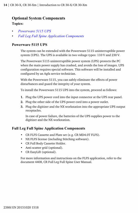
Powerware 5115 UPSThe system can be extended with the Powerware 5115 uninterruptible powersystem (UPS). The UPS is available in two voltage types: 110 V and 230 V.
The Powerware 5115 uninterruptible power system (UPS) protects the PCwhen the main power supply has crashed, and avoids the loss of images. UPSconfiguration requires special software. This software will be installed andconfigured by an Agfa service technician.
With the Powerware 5115, you can safely eliminate the effects of powerdisturbances and guard the integrity of your system.
To install the Powerware 5115 UPS into the system, proceed as follows:
1. Plug the UPS power cord into the input connector at the UPS rear panel.
2. Plug the other side of the UPS power cord into a power outlet.
3. Plug the digitizer and the NX workstation into the appropriate UPS outputreceptacles.
In case of power failure, the batteries of the UPS supplies power to thedigitizer and the NX workstation.
Full Leg Full Spine Application Components• CR FLFS Cassette and Plate set (e.g. CR MD4.0T FLFS).• NX FLFS license (including Stitching software).• CR Full Body Cassette Holder.• Anti-scatter grid (optional).• CR EasyLift (optional).
For more information and instructions on the FLFS application, refer to thedocument 4408, CR Full Leg Full Spine User Manual.
14 | CR 30-X, CR 30-Xm | Introduction to CR 30-X/CR 30-Xm
2386I EN 20151020 1518

Equipment ClassificationThis device is classified as following:
Table 1: Equipment classification
Class I equipment Equipment in which protection against electricshock does not relay on basic insulation only, butincludes a power supply cord with protective earthconductor. For earth reliability always plug themain power cord into an earthed mains poweroutlet.
Type B equipment Not classified.
The patient does not get in contact with any part ofthe equipment.
Water ingress This device does not have protection againstingress of water.
Cleaning See section on cleaning and disinfecting.
Disinfection See section on cleaning and disinfecting.
Flammable anesthetics This device is not suitable for use in the presence ofa flammable anesthetic mixture with air, or inpresence of a flammable anesthetic mixture withoxygen or nitrous oxide.
Operation Continuous operation.
CR 30-X, CR 30-Xm | Introduction to CR 30-X/CR 30-Xm | 15
2386I EN 20151020 1518

System DocumentationThe documentation shall be kept with the system for easy reference. The mostextensive configuration is described within this manual, including themaximum number of options and accessories. Not every function, option oraccessory described may have been purchased or licensed on a particularpiece of equipment.
Technical documentation is available in the product service documentationwhich is available from your local support organization.
For safety precautions on stitching FLFS (Full Leg Full Spine) images, refer tothe “Safety Directions” section of the NX User Manual and the CR Full Leg FullSpine User Manual.
The user documentation consists of:
• CR 30-X/CR 30-Xm User Documentation CD (digital media)• NX User Documentation CD (digital media)
The CR 30-X/CR 30-Xm user documentation:
• CR 30-X/CR 30-Xm User Manual, (this document)• CR 30-X/CR 30-Xm Plates and Cassettes User Manual, document 2387• Getting Started with the ID Tablet, document 2287
The NX user documentation:
• NX User Manual, document 4420 and NX Key User Manual, document4421
• CR Full Leg Full Spine User Manual, document 4408• CR Mammography System User Manual, document 2344
16 | CR 30-X, CR 30-Xm | Introduction to CR 30-X/CR 30-Xm
2386I EN 20151020 1518

TrainingThe user must have received adequate training on the safe and effective use ofthe system before attempting to work with it. Training requirements may varyfrom country to country. The user must make sure that training is received inaccordance with local laws or regulations that have the force of law. Yourlocal Agfa or dealer representative can provide further information ontraining.
The user must note the following information in the system documentation:
• Intended Use.• Intended User.• Safety Directions.
CR 30-X, CR 30-Xm | Introduction to CR 30-X/CR 30-Xm | 17
2386I EN 20151020 1518

Product ComplaintsAny health care professional (for example a customer or a user) who has anycomplaints or has experienced any dissatisfaction with the quality, durability,reliability, safety, effectiveness, or performance of this product must notifyAgfa.
If the device malfunctions and may have caused or contributed to a seriousinjury, Agfa must be notified immediately by telephone, fax or writtencorrespondence to the following address:
Agfa Service Support - local support addresses and phone numbers are listedon www.agfa.com
Agfa - Septestraat 27, 2640 Mortsel, Belgium
Agfa - Fax +32 3 444 7094
18 | CR 30-X, CR 30-Xm | Introduction to CR 30-X/CR 30-Xm
2386I EN 20151020 1518

CompatibilityThe equipment must only be used in combination with other equipment orcomponents if these are expressly recognized by Agfa as compatible. A list ofsuch equipment and components is available from Agfa service on request.
Changes or additions to the equipment must only be carried out by personsauthorized to do so by Agfa. Such changes must comply with best engineeringpractices and all applicable laws and regulations that have the force of lawwithin the jurisdiction of the hospital.
Accessory equipment connected to any interfaces must be certified accordingto the respective IEC standards (e.g. IEC 60950 for data processing equipmentor IEC 60601-1 for medical equipment). Furthermore all configurations shallcomply with the requirements for ME systems according to IEC 60601-1.Everybody who connects additional equipment to the signal input part orsignal output part configures a medical system, and is therefore responsiblethat the system complies with the requirements for ME systems according toIEC 60601-1. If in doubt, consult your local service organization.
CR 30-X, CR 30-Xm | Introduction to CR 30-X/CR 30-Xm | 19
2386I EN 20151020 1518

ComplianceTopics:
• General• Safety• Laser Safety• Electromagnetic Compatibility• Harmonization
20 | CR 30-X, CR 30-Xm | Introduction to CR 30-X/CR 30-Xm
2386I EN 20151020 1518

General• The product has been designed in accordance with the MEDDEV
Guidelines relating to the application of Medical Devices and have beentested as part of the conformity assessment procedures required by93/42/EEC Medical Device Directive (European Council Directive93/42/EEC on Medical Devices).
• ISO 13485:2003 + Cor. 1:2009• IEC 62366:2008• ISO 14971:2009
Safety• IEC 60601-1, EN 60601-1• IEC 60601-1: 2005• IEC 60601-1-1:2000, EN 60601-1-1:2001• IEC 60601-1-6:2006, EN 60601-1-6:2007• UL 60601-1:2003• AAMI ES 60601-1:2005 + A2:2010• CSA C 22.2 No.601.1:1990 + S1:1994 + A2:1998• CSA C 22.2 No.60601-1:2008 + COR 2:2011
Laser Safety• IEC 60825-1:2001, EN 60825-1:1994 + A1:2002 + A2:2001• IEC 60825-1:2007, EN 60825-1:2007• DHHS/FDA 21 CFR, Parts 1040.10 and 1040.11
Electromagnetic Compatibility• IEC 60601-1-2:2007, EN 60601-1-2:2007
HarmonizationThis document has been prepared to comply with the Study Group 1 guidancedocument of the Global Harmonization Task Force (GHTF) (www.ghtf.org).To assist development of a consistent, harmonized definition for a medicaldevice that could be used within a global regulatory model would offersignificant benefits to the manufacturer, user, patient or consumer, and toRegulatory Authorities and support global convergence of regulatory systems.
CR 30-X, CR 30-Xm | Introduction to CR 30-X/CR 30-Xm | 21
2386I EN 20151020 1518

ConnectivityThe digitizer is connected to the workstation via Ethernet connection and usesthe DICOM protocol to communicate with the workstation.
22 | CR 30-X, CR 30-Xm | Introduction to CR 30-X/CR 30-Xm
2386I EN 20151020 1518

InstallationWARNING:When installing the digitizer, care must be taken to ensure thatthere is either a mains plug or an all-cable disconnecting devicein the internal installation fitted near the digitizer and that it iseasily accessible.
WARNING:
The digitizer is equipped with 2 handles at the bottom leftand right sides to move the device easily to anotherlocation. It is recommended to have at least two persons liftthe digitizer.
WARNING:The digitizer and the cassette storage shall be protected againstdirect radiation in such a way, that the annual dose equivalentat the place of installation will not exceed 1 mSv/a.
WARNING:Do not lift the device by holding the input tray.
WARNING:If the digitizer is installed inside an X-ray room it must beprotected from stray radiation by proper shielding.
WARNING:The device is a table-top digitizer. The structure and stability ofthe table used, need to be suitable in relation with the size andweight of the system. The table should not be subject toexcessive shock and vibrations from other sources, as this maydisturb the operation of the digitizer.
Topics:
• Mobile Use Installation• Image quality check after transport
CR 30-X, CR 30-Xm | Introduction to CR 30-X/CR 30-Xm | 23
2386I EN 20151020 1518

Mobile Use InstallationIn case of an installation in a mobile environment, such as a bus, van, etc, themanufacturer of the vehicle should ensure that all components of the systemare fixed or can be fixed safely for transport.
If the digitizer is installed in a mobile environment, it has to be securedagainst moving. The optional earthquake kit for wall fixation should be used.
WARNING:
Do not use the digitizer during transport.
24 | CR 30-X, CR 30-Xm | Introduction to CR 30-X/CR 30-Xm
2386I EN 20151020 1518

Image quality check after transportWARNING:
The image quality check must be performed afterinstallation of the digitizer in a mobile environment and isrecommended to be repeated after transport.
The check is done with a flat field exposure and should be performed with acassette of the largest format used at customer site.
X-Ray source Exposure conditions
General radiography It is recommended to expose the cassette with 2exposures of 10 µGy or 1 mR each. Rotate thecassette 180° after the first exposure to compensatefor the heel effect.
Typical settings for 10 µGy or 1 mR are:
• 75 kV• 12 mAs• 130 cm SID• large focus• 1.5 mm Copper filter
Identify the cassette as System Diagnosis GenRad -Flat Field.
Mammography For Mammography only 1 exposure is needed and norotation of the cassette.
Remove the compression paddle before the exposure.
Tape an Aluminum filter at the tube exit.
Insert the cassette in the bucky and make anexposure with the following settings:
• 28 kV• 200 mAs• Mo/Mo• large focus• 2.0 mm Aluminum filter
If this leads to an overexposure, the mAs setting canbe reduced, but it should not be lower than 50 mAs.
Identify the cassette as System Diagnosis Mammo -Flat Field Mammo.
CR 30-X, CR 30-Xm | Introduction to CR 30-X/CR 30-Xm | 25
2386I EN 20151020 1518

Check the flat field image on the NX workstation for homogeneity and stripeartifacts. In case of problems, please inform your local Agfa servicerepresentative.
26 | CR 30-X, CR 30-Xm | Introduction to CR 30-X/CR 30-Xm
2386I EN 20151020 1518

Product Identification
CR 30-X product description
Type of product Table-top digitizer
Commercial name CR 30-X
Model number 5175/200
5175/205
Original seller / manufacturer Agfa HealthCare N.V.
Septestraat 27
2640 Mortsel
Belgium
CR 30-Xm product description
Type of product Table-top digitizer
Commercial name CR 30-Xm
Model number 5179/100
Original seller / manufacturer Agfa HealthCare N.V.
Septestraat 27
2640 Mortsel
Belgium
CR 30-X, CR 30-Xm | Introduction to CR 30-X/CR 30-Xm | 27
2386I EN 20151020 1518

LabelsTopics:
• General• Safety Instructions for Laser Products
28 | CR 30-X, CR 30-Xm | Introduction to CR 30-X/CR 30-Xm
2386I EN 20151020 1518

GeneralAlways take into account the markings and labels provided on the inside andoutside of the machine. A brief overview of these markings and labels andtheir meaning is given below.
Safety warning, indicating that the manuals should beconsulted before making any connections to otherequipment. The use of accessory equipment notcomplying with the equivalent safety requirements ofthis digitizer may lead to a reduced level of safety of theresulting system. Consideration relating to the choice ofaccessory equipment shall include:
• Use of the accessory equipment in the patientvicinity,
• Evidence that the safety certification of theaccessory equipment has been performed inaccordance with respective IEC standards (e.g. IEC60950 for data processing equipment or IEC60601-1 for medical equipment).
In addition all configurations must comply with therequirements for medical electrical systems accordingto IEC 60601-1. The party that makes the connectionsacts as system configurator and is responsible forcomplying with the systems standard.
If required contact your local service organization.
In order to reduce the risk of electric shock, do notremove any covers.
Caution hot:
Keep hands clear from the erasure unit.
Supplementary protective earth connector:
Provides a connection between the digitizer and thepotential equalization busbar of the electrical system asfound in medical environments. This plug should neverbe unplugged before the power is turned off and thepower plug has been removed.
It is recommended to use the supplementary protectiveearth connection as additional safety measure.
CR 30-X, CR 30-Xm | Introduction to CR 30-X/CR 30-Xm | 29
2386I EN 20151020 1518

Do not put your fingers in the input slot of the digitizer,they can get hurt when caught between the cassetteand the fixation.
Insert the cassette as described in the basic workflowchapter.
Cassette positioning.
Insert the cassette as described in the basic workflowchapter.
Off (power: disconnection from the mains)
On (power: connection to the mains)
Type label
Date of manufacture
Manufacturer
Serial number
WEEE symbol
Device contains a transmitter module
30 | CR 30-X, CR 30-Xm | Introduction to CR 30-X/CR 30-Xm
2386I EN 20151020 1518

Laser Warning
Indicates the presence of a laser device.
Note: The type label of the CR 30-Xm digitizer is placed at thechassis in the upper left corner when opening the front cover.
CR 30-X, CR 30-Xm | Introduction to CR 30-X/CR 30-Xm | 31
2386I EN 20151020 1518

Safety Instructions for Laser Products
CLASS 1 LASER PRODUCT
APPAREIL A LASER DE CLASSE 1
LASERKLASSE 1
CAUTION!
CLASS 3B LASER RADIATION:WHEN OPEN AVOID DIRECTEXPOSURE TO THE BEAM!
CUIDADO!
RAYO LASER CLASE 3B:EVITAR LA EXPOSICIÓN AL HAZ
CUANDO LA TAPA EST Á ABIERTA.
VORSICHT !
LASERSTRAHLUNG KLASSE 3B:WENN ABDECKUNG GEÖFFNET
NICHT DEM STRAHL AUSSETZEN!
ATTENTION!
FAISCEAU LASER CLASSE 3B:QUAND CAPOT OUVERT ÉVITER
DE S´EXPOSER AU RAYÓN!
The digitizer is a Class 1 Laser Product. It uses one laser diode of a 80 mWtype, classification class IIIb, wavelength 640-670 nm. The laser beam’sdeflection frequency is 120 1/s up to 170 1/s. The laser beam divergence is12 mrad.
Under normal operating conditions - device with all covers - there can be nolaser radiation outside the digitizer.
The technical concept does not allow the user to remove the top cover. Theconcept provides maximum reliability that no image plate jam can occur inthe post scan area.
However, the user is allowed to open the front cover, e.g. to solve cassette orimage plate jams at the front side. When opening the front panel, all motordriven system movements will be stopped (including the laser).
CAUTION:User interventions other than those described in thismanual can be hazardous with regard to laser radiation.
32 | CR 30-X, CR 30-Xm | Introduction to CR 30-X/CR 30-Xm
2386I EN 20151020 1518

Cleaning and DisinfectionAll appropriate policies and procedures should be followed to avoidcontamination of the staff, patients and device. All existing universalprecautions should be taken to avoid that the digitizer and its accessoriescome into contact with potential contaminations. Details about cleaning canbe found in the following pages.
To clean the exterior of the digitizer:
1. Switch off the digitizer.
2. Remove the power plug from the socket.
CAUTION:Damage or deterioration of safety provisions can causeinjury of the operator.
Remove the power plug from the socket before cleaning theexterior of the device.
Switch off the UPS, if installed.
3. Wipe the exterior of the digitizer with a clean, soft, damp cloth.
Use a mild soap or detergent if required but never use ammonia-basedcleaner.
CAUTION:Make sure no liquid gets in the digitizer.
Note: Do not open the digitizer for cleaning. No componentsinside the digitizer require cleaning by the user.
4. Plug the power plug into the socket.
Switch on the UPS, if installed.
System componentsFor cleaning and disinfection instructions of the plates and cassettes, refer tothe CR 30-X/CR 30-Xm Plates and Cassettes User Manual.
For cleaning and disinfection instructions of the ID Tablet, refer to thedocument Getting Started with the ID Tablet.
CR 30-X, CR 30-Xm | Introduction to CR 30-X/CR 30-Xm | 33
2386I EN 20151020 1518

Patient data securityThe user must ensure that the patients’ legal requirements are met and thatthe security of the patient data is guarded.
The user must define who can access patient data in which situations.
The user must have a strategy available on what to do with patient data incase of a disaster.
34 | CR 30-X, CR 30-Xm | Introduction to CR 30-X/CR 30-Xm
2386I EN 20151020 1518

MaintenanceTopics:
• Preventive Maintenance• Cleaning the optical unit
CR 30-X, CR 30-Xm | Introduction to CR 30-X/CR 30-Xm | 35
2386I EN 20151020 1518

Preventive MaintenanceRegular preventive maintenance needs to be done once a year or after 12000cycles (whatever comes first). This maintenance can not be done by the userbut has to be done by an Agfa certified field service engineer. Not performingthe regular maintenance by appropriately certified people can have impact onwarranty commitments.
36 | CR 30-X, CR 30-Xm | Introduction to CR 30-X/CR 30-Xm
2386I EN 20151020 1518

Cleaning the optical unitThe only maintenance action which you must perform is checking the imagequality. Refer to the User Manual of the NXTM Software.
Cleaning the optic unit is required if stripes parallel to the image platemovement can be seen in the image. When you recognize this type of artefact,when using the digitizer, clean the optic unit using the cleaning brush.
To clean the optic unit, proceed as follows:
1. Open the cassette unit.
2. Take out the cleaning brush.
3. Open the lid positioned at the right side.
CR 30-X, CR 30-Xm | Introduction to CR 30-X/CR 30-Xm | 37
2386I EN 20151020 1518

1
1. Open lid
4. Clean the scan line. Your last movement must be continuous from the rearto the front.
5. Re-insert the cleaning brush.
6. Close the cassette unit
CAUTION:Misuse of the bowden wire leads to bending, which causes acomplicated replacement of the cleaning brush.
38 | CR 30-X, CR 30-Xm | Introduction to CR 30-X/CR 30-Xm
2386I EN 20151020 1518
Recurrent safety testsThe device shall be tested according to IEC 62353* in a time interval of atleast 36 months or less if local regulations are different.
* Medical electrical equipment – Recurrent test and test after repair of medicalelectrical equipment.
CR 30-X, CR 30-Xm | Introduction to CR 30-X/CR 30-Xm | 39
2386I EN 20151020 1518

Environmental protection
Figure 1: WEEE symbol
LiFigure 2: Battery symbol
WEEE end user notice
The directive on Waste Electrical and Electronic Equipment (WEEE) aims toprevent the generation of electric and electronic waste and to promote thereuse, recycling and other forms of recovery. It therefore requires thecollection of WEEE, recovery and reuse or recycling.
Due to the implementation into national law, specific requirements can bedifferent within the European Member States. The WEEE symbol on theproducts, and/or accompanying documents means that used electrical andelectronic products should not be treated as, or mixed with general householdwaste For more detailed information about take-back and recycling of thisproduct please contact your local service organization and/or dealer. Byensuring this product is disposed of correctly, you will help prevent potentialnegative consequences for the environment and human health, which couldotherwise be caused by inappropriate waste handling of this product. Therecycling of materials will help to conserve natural resources.
Battery notice
The battery symbol on the products, and/or accompanying documents meansthat the used batteries should not be treated as, or mixed with generalhousehold waste. The battery symbol on batteries or its packaging may beused in combination with a chemical symbol. In cases where a chemicalsymbol is available it indicates the presence of respective chemical substances.If your equipment or replaced spare parts contain batteries or accumulatorsplease dispose of them separately according to local regulations.
For battery replacements please contact your local sales organization.
40 | CR 30-X, CR 30-Xm | Introduction to CR 30-X/CR 30-Xm
2386I EN 20151020 1518

Safety DirectionsWARNING:Safety is only guaranteed when an Agfa certified field serviceengineer has installed the product.
WARNING:The user is responsible for judging image quality and controllingenvironmental conditions for diagnostic softcopy or printviewing.
WARNING:The user must follow the hospital quality assurance proceduresfor covering the risks resulting from errors in the imageprocessing
WARNING:To avoid risk of electric shock, this equipment must only beconnected to a supply mains with protective earth.
WARNING:Position the digitizer so that it is possible to disconnect it fromthe mains power if required.
WARNING:The following actions may lead to serious risk of injury anddamage to the equipment as well as making the warrantyvoid:
Changes, additions or maintenance to the Agfa products carriedout by persons without appropriate qualifications and training.
Using unapproved spare parts
WARNING:To avoid images being lost due to a power failure, theworkstation and the digitizer have to be connected to anuninterruptable power supply (UPS) or an institutional standbygenerator.
WARNING:Operation outside of the specified environmental conditionsmay lead to deterioration of image quality. For best results, keepthe environmental conditions within these specifications.
CR 30-X, CR 30-Xm | Introduction to CR 30-X/CR 30-Xm | 41
2386I EN 20151020 1518

CAUTION:Strictly observe all warnings, cautions, notes and safetymarkings within this document and on the product.
CAUTION:All Agfa medical products must be used by trained and qualifiedpersonnel.
CAUTION:The user must be aware that any error (crash / lock up) leadingto an image processing failure can cause loss of diagnosticinformation.
CAUTION:The digitizer is not suitable for scanning imaging plates (IPs)exposed with a dose higher than 5000 µG.
CAUTION:Bad image quality can cause a need to retake the image orcause delayed diagnosis.
Do not operate the device in direct sunlight, max. 2500 lux.
CAUTION:While every care has been taken, it is possible that minor errorsstill exist in the product. It is unlikely that a minor error couldresult in incorrect (unexpected) device operation.
General safety instructions• Make sure that the digitizer is constantly monitored in order to avoid
inappropriate handling, especially by children.• Only trained service personnel must make repairs. Only authorized service
personnel must make changes to the digitizer.• If there is any visible damage to the machine casing, do not start nor use
the digitizer.• Do not override or disconnect the integrated safety features.• Do not apply excessive shock or vibration to the digitizer during operation
(e.g. putting cassettes on top of the device). This may decrease the imagequality. Neither should the device be moved during operation.
• Switch off the device before performing any maintenance work or repairs.Disconnect the digitizer from the mains before making repairs orperforming any maintenance activities during which live electricalcomponents may be exposed.
• As is the case for all technical devices, the digitizer must be operated,cared for and serviced correctly. A regular quality control isrecommended.
42 | CR 30-X, CR 30-Xm | Introduction to CR 30-X/CR 30-Xm
2386I EN 20151020 1518

• If you don’t operate the digitizer correctly or if you don’t have it servicedcorrectly, Agfa is not liable for resulting disturbances, damages or injuries.
• If you notice conspicuous noise or smoke, disconnect the digitizerimmediately.
• Do not pour water or any other liquid over the device.• The digitizer complies with the EN 60601-1 and UL 60601-1 standards for
Medical Electrical Equipment. This means that, although it is absolutelysafe, patients may not come in direct contact with the equipment.Therefore the operator console must be placed outside a radius of 1.5 m(EN) or 1.83 m (UL) around the patient (according to the local validregulation).
1
2
1. Patient environment: R = 1.5 m (1.83 m)2. Patient environment: h = 2.5 m (2.29 m)
• Position the digitizer in a way, that it could be easily unplugged in order toachieve separation from mains.
• Perform no other operations on the digitizer than those described in thisdocument.
• Switch the system off before moving it. When reaching the new position,switch the system on again.
CR 30-X, CR 30-Xm | Introduction to CR 30-X/CR 30-Xm | 43
2386I EN 20151020 1518

Quality ControlWARNING:Unnoticed image quality degradation can cause falsenegative diagnosis.
Apply regular quality control according local regulations.
If no specific regulations are valid, a regular quality control by means of theAgfa Auto QC2 tool is required at least once a month to maintain a safe andeffective system.
For mammography, Agfa recommends to use the “Routine Quality ControlTests for Full Field Digital Mammography Systems” document, created by theNHSBSP (National Health Service Breast Screening Program, UK).
44 | CR 30-X, CR 30-Xm | Introduction to CR 30-X/CR 30-Xm
2386I EN 20151020 1518

Getting started
Topics:
• Basic Features• Starting the device• Basic Workflow using Fast ID• Basic Workflow using ID Tablet• Stopping the Device
CR 30-X, CR 30-Xm | Getting started | 45
2386I EN 20151020 1518

Basic FeaturesTopics:
• CR 30-X/CR 30-Xm Features• Operating Modes• The User Interface
46 | CR 30-X, CR 30-Xm | Getting started
2386I EN 20151020 1518

CR 30-X/CR 30-Xm FeaturesThe digitizer reads out the latent X-ray images on image plates and sendsthem to the workstation.
• The digitizer accepts one cassette containing one image plate at a time.The digitizer:
• locks the cassette containing the image plate in the cassette slot,• removes the image plate from the cassette,• scans the image plate,• converts the information of the latent image to digital data,• transmits the image data to the preview station,• erases the image plate and re-inserts it into the cassette,• gives the image plate ID data the status 'erased',• unlocks the cassette,• transmits the digital image data to an image processing station
(‘destination’).• The digitizer permits assigning the status ‘emergency’ to an image.• The digitizer permits re-erasing an image plate before reusing it. In
specific cases, this is necessary to prevent ghost images caused by previousexposures or stray radiation from interfering with the image of interest.
• With the dedicated ID station of the CR 30-X/CR 30-Xm, the followingfeatures are available:
• quickly identifying cassettes without the need for an ID Tablet,• reading the identification data of a cassette.
CR 30-X, CR 30-Xm | Getting started | 47
2386I EN 20151020 1518

Operating ModesThe digitizer can be operated in two modes: operator mode and service mode.
Topics:
• Operator Mode• Service Mode
Operator ModeThe operator mode groups all basic functions which are aimed atradiographers:
• Reading an image plate,• Reading an emergency image plate,• Re-erasing an image plate,• Reading the identification data of a cassette.
All functions of the operator mode are described in this manual.
Service ModeThe service mode functions are reserved for trained service personnel. Theyare password protected, and they are described in a separate document.
48 | CR 30-X, CR 30-Xm | Getting started
2386I EN 20151020 1518

The User InterfaceThe digitizer interfaces with the user via:
• an erase button,• a status indicator,• a main switch.
12
3
4
1. Status indicator2. Erase button3. Main switch4. DICOM Ethernet connection
Topics:
• The Erase Button• Status Indicator
The Erase Button
Press the erase button to start the erasing cycle of an image plate. Afterpressing the erase button, the upper part of the status indicator iscontinuously lighting up in blue and the digitizer starts erasing the image
CR 30-X, CR 30-Xm | Getting started | 49
2386I EN 20151020 1518

plate of the cassette inserted next. If no cassette with image plate has beeninserted after 60 seconds, the system automatically returns to standby mode.
Status IndicatorThe indicator informs the user by light signals about the status of the digitizer.It is positioned at the front of the digitizer, so that it is visible from a distance.
The indicator is divided in two parts. The upper part is used to inform theoperator about the image plate erasing cycle progress and is only then lit. Thelower part is used for all other operational indications.
2
1
1. Blue2. Green or red
Color Constant/Blinking
Status Action
Blue Constant Activating the erasingcycle
Green
Constant
• Standby mode(Ready)
• Cassette is ready forremoval
• Proceed.• Remove cassette.
FlashingBusy with scanning,erasing and return ofthe IP into cassette
Wait.
Red
Constant Service mode
Check workstation forfurther information anddetailed instructions.Blinking
• Warm up / Self-test• Processing Software
down• Error
Blinking fast Digitizer not connectedto Digitizer RemoteDisplay UI
Refer to section‘Troubleshooting’.
Blinking - 3pulses
Digitizer not connectedto control PC
Related LinksTroubleshooting Checklist on page 80
50 | CR 30-X, CR 30-Xm | Getting started
2386I EN 20151020 1518

Starting the device1. Turn on the UPS (optional accessory) to supply electricity to the control
PC and the digitizer.
Check whether the UPS is connected to a power outlet.
Press and hold the On button approximately one second until you hear theUPS beep.
Note: Step 1 is only applicable if your system is extended withan uninterruptible power supply (UPS).
2. Switch on the digitizer by pressing the main switch.
1
1. Main switch
The machine starts the following operation sequence:
• initialization of all components,• functional test of all components,• check for presence of cassettes and/or IPs,• establish connection to the control PC.
During the self-test, which may take up to 60 seconds, the digitizer statusindicator is flashing red.
Note: During the self-test, you cannot activate any functions.
If the digitizer has completed the self-test successfully, the digitizer entersthe operator mode and the status indicator is continuously lighting up ingreen.
CR 30-X, CR 30-Xm | Getting started | 51
2386I EN 20151020 1518

3. Switch on the ID Tablet.
Only in a configuration with ID Tablet.
For more information, refer to the document Getting Started with the IDTablet.
4. Make sure the digitizer is connected to the control PC and that the controlPC is running the appropriate NX software.For more information, refer to the NX User Manual.
5. Start NX.
For detailed information about starting up NX, refer to the NX UserManual, document 4420.
52 | CR 30-X, CR 30-Xm | Getting started
2386I EN 20151020 1518

Basic Workflow using Fast IDTopics:
• Select a patient and start the exam• Insert the Cassette in the Digitizer• Identify and Digitize the Image• Check the image• Remove the cassette and insert the next one
CR 30-X, CR 30-Xm | Getting started | 53
2386I EN 20151020 1518

Select a patient and start the examAt the NX workstation:
1. Open the Worklist window of NX.
In the Worklist window, you can view and manage the exams that arescheduled via the Worklist pane.
Note: When starting the NX software, the Worklist window isthe first window that appears after the NX Splash screen.
Note: Start the NX software on the NX workstation. Refer to theNX User Manual, document 4420.
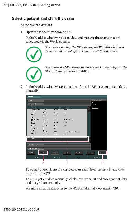
2. In the Worklist window, open a patient from the RIS or enter patient datamanually.
3 21
To open a patient from the RIS, select an Exam from the list (1) and clickon Start Exam (2).
To enter patient data manually, click New Exam (3) and enter patient dataand image data manually.
For more information, refer to the NX User Manual, document 4420.
54 | CR 30-X, CR 30-Xm | Getting started
2386I EN 20151020 1518
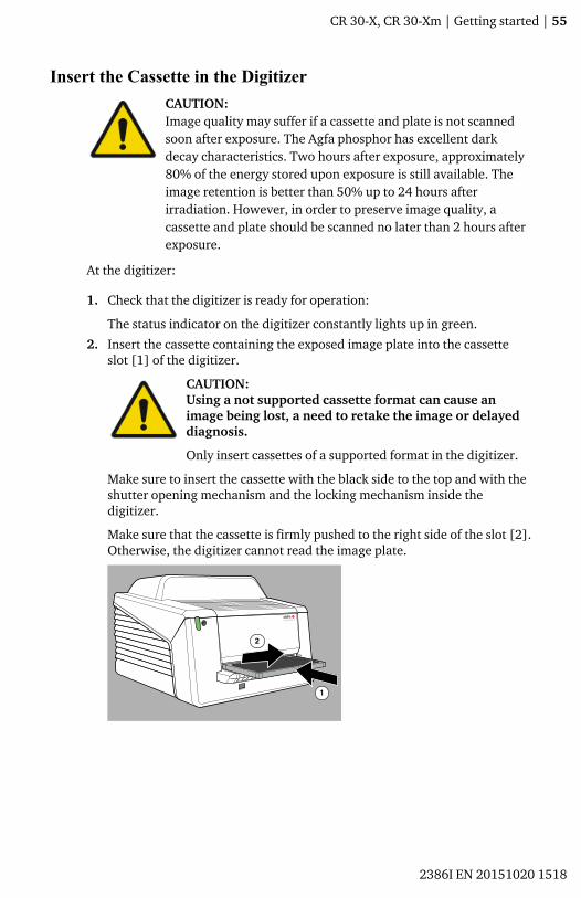
Insert the Cassette in the DigitizerCAUTION:Image quality may suffer if a cassette and plate is not scannedsoon after exposure. The Agfa phosphor has excellent darkdecay characteristics. Two hours after exposure, approximately80% of the energy stored upon exposure is still available. Theimage retention is better than 50% up to 24 hours afterirradiation. However, in order to preserve image quality, acassette and plate should be scanned no later than 2 hours afterexposure.
At the digitizer:
1. Check that the digitizer is ready for operation:
The status indicator on the digitizer constantly lights up in green.
2. Insert the cassette containing the exposed image plate into the cassetteslot [1] of the digitizer.
CAUTION:Using a not supported cassette format can cause animage being lost, a need to retake the image or delayeddiagnosis.
Only insert cassettes of a supported format in the digitizer.
Make sure to insert the cassette with the black side to the top and with theshutter opening mechanism and the locking mechanism inside thedigitizer.
Make sure that the cassette is firmly pushed to the right side of the slot [2].Otherwise, the digitizer cannot read the image plate.
CR 30-X, CR 30-Xm | Getting started | 55
2386I EN 20151020 1518

Identify and Digitize the ImageAn unidentified cassette is inserted in the digitizer. The NX software must beoperational, otherwise the digitizer is locked and the status indicator isflashing red.
At the NX workstation:
1. Click ID in the examination window of NX.
In the Examination window, select the thumbnail in the Image overviewpane and click on ID to send the data to the digitizer.
2. As soon as the digitizer has received the complete identification data fromthe NX workstation (via Ethernet) it will start digitizing the image plate.
The digitizer converts the information of the latent image to digital data.
3. After digitizing, the digitizer:
• Transmits the digital image data to the image processing station(‘destination’).
• Erases the image plate and re-inserts it into the cassette.• Gives the cassette ID data the status 'erased'.• Unlocks the cassette.
56 | CR 30-X, CR 30-Xm | Getting started
2386I EN 20151020 1518

Check the imageAt the NX workstation:
1. Select the relevant image on which quality control is to be performed.
2. Prepare the image for diagnosis by using e.g. L/R markers or annotations.
3. If the image is OK, send the image to a hardcopy printer and/or PACS(Picture Archiving and Communication System).
CR 30-X, CR 30-Xm | Getting started | 57
2386I EN 20151020 1518

Remove the cassette and insert the next oneAt the digitizer:
1. When the digitizer has finished treating the cassette, the status indicatorconstantly lights up in green.
2. Remove the cassette from the cassette slot.
When the digitizer unlocks the cassette, it is ready to be re-usedimmediately.
WARNING:When CR MD4.xT plates and cassettes have not been usedfor 48 hours, they must be erased manually. When CRMM3.xT plates and cassettes have not been used for 24hours, they must be erased manually.
Related LinksRe-erasing an Image Plate on page 72
58 | CR 30-X, CR 30-Xm | Getting started
2386I EN 20151020 1518

Basic Workflow using ID TabletTopics:
• Select a patient and start the exam• Identify the cassette• Insert the Cassette in the Digitizer• Digitize the Image• Check the image• Remove the cassette and insert the next one
CR 30-X, CR 30-Xm | Getting started | 59
2386I EN 20151020 1518
Select a patient and start the examAt the NX workstation:
1. Open the Worklist window of NX.
In the Worklist window, you can view and manage the exams that arescheduled via the Worklist pane.
Note: When starting the NX software, the Worklist window isthe first window that appears after the NX Splash screen.
Note: Start the NX software on the NX workstation. Refer to theNX User Manual, document 4420.
2. In the Worklist window, open a patient from the RIS or enter patient datamanually.
3 21
To open a patient from the RIS, select an Exam from the list (1) and clickon Start Exam (2).
To enter patient data manually, click New Exam (3) and enter patient dataand image data manually.
For more information, refer to the NX User Manual, document 4420.
60 | CR 30-X, CR 30-Xm | Getting started
2386I EN 20151020 1518

Identify the cassetteAt the NX workstation:
1. Insert a cassette in the ID Tablet.
2. In the Examination window, select the right thumbnail in the ImageOverview.
3. Click ID or press F2.
The thumbnail is labelled with the code ‘ID’. The patient data is written to thecassette.
CR 30-X, CR 30-Xm | Getting started | 61
2386I EN 20151020 1518

Insert the Cassette in the DigitizerCAUTION:Image quality may suffer if a cassette and plate is not scannedsoon after exposure. The Agfa phosphor has excellent darkdecay characteristics. Two hours after exposure, approximately80% of the energy stored upon exposure is still available. Theimage retention is better than 50% up to 24 hours afterirradiation. However, in order to preserve image quality, acassette and plate should be scanned no later than 2 hours afterexposure.
At the digitizer:
1. Check that the digitizer is ready for operation:
The status indicator on the digitizer constantly lights up in green.
2. Insert the cassette containing the exposed image plate into the cassetteslot [1] of the digitizer.
CAUTION:Using a not supported cassette format can cause animage being lost, a need to retake the image or delayeddiagnosis.
Only insert cassettes of a supported format in the digitizer.
Make sure to insert the cassette with the black side to the top and with theshutter opening mechanism and the locking mechanism inside thedigitizer.
Make sure that the cassette is firmly pushed to the right side of the slot [2].Otherwise, the digitizer cannot read the image plate.
62 | CR 30-X, CR 30-Xm | Getting started
2386I EN 20151020 1518

Digitize the Image
1. The digitizer will start digitizing the image plate.
The digitizer converts the information of the latent image to digital data.
2. After digitizing, the digitizer:
• Transmits the digital image data to the image processing station(‘destination’).
• Erases the image plate and re-inserts it into the cassette.• Gives the cassette ID data the status 'erased'.• Unlocks the cassette.
CR 30-X, CR 30-Xm | Getting started | 63
2386I EN 20151020 1518

Check the imageAt the NX workstation:
1. Select the relevant image on which quality control is to be performed.
2. Prepare the image for diagnosis by using e.g. L/R markers or annotations.
3. If the image is OK, send the image to a hardcopy printer and/or PACS(Picture Archiving and Communication System).
64 | CR 30-X, CR 30-Xm | Getting started
2386I EN 20151020 1518

Remove the cassette and insert the next oneAt the digitizer:
1. When the digitizer has finished treating the cassette, the status indicatorconstantly lights up in green.
2. Remove the cassette from the cassette slot.
When the digitizer unlocks the cassette, it is ready to be re-usedimmediately.
WARNING:When CR MD4.xT plates and cassettes have not been usedfor 48 hours, they must be erased manually. When CRMM3.xT plates and cassettes have not been used for 24hours, they must be erased manually.
Related LinksRe-erasing an Image Plate on page 72
CR 30-X, CR 30-Xm | Getting started | 65
2386I EN 20151020 1518

Stopping the DeviceTopics:
• Before Switching Off• Switching Off
66 | CR 30-X, CR 30-Xm | Getting started
2386I EN 20151020 1518

Before Switching OffCheck that the digitizer is not scanning an image plate. If the digitizer isscanning an image plate, the status indicator is flashing green.
CR 30-X, CR 30-Xm | Getting started | 67
2386I EN 20151020 1518

Switching OffIt is recommended to switch off the digitizer at the end of the day.
Note: Only switch off the digitizer if you do not intend to digitizeemergency image plates overnight. Switching on the digitizer takesapproximately 60 seconds. During this time emergency digitizing isnot possible!
Note: After switch off, the device is still in stand-by mode. Toremove the device from the mains supply disconnect the mainsplug.
To stop the system:
1. Switch off the digitizer by pressing the main switch.
1
1. Main switch
2. Switch off the ID Tablet.
Only in a configuration with ID Tablet.
For more information, refer to the document Getting Started with the IDTablet.
3. Stop NX.
NX can be stopped in two ways:, either by logging out of Windows or byusing the Exit NX action button.
For detailed information about stopping NX, refer to the NX User Manual,document 4420.
4. Turn off the UPS (optional accessory) to disconnect the control PC and thedigitizer.
Press and hold the Off button until the long beep ceases (approximatelyfive seconds).
68 | CR 30-X, CR 30-Xm | Getting started
2386I EN 20151020 1518

Note: Step 3 is only applicable if your system is extended withan uninterruptible power supply (UPS).
CR 30-X, CR 30-Xm | Getting started | 69
2386I EN 20151020 1518

Operating CR 30-X/CR 30-Xm
This chapter provides information about functions that are available inoperator mode. Finally you will find some preventive maintenance andtroubleshooting guidelines.
Topics:
• Reading an Emergency Image Plate• Re-erasing an Image Plate• Reading the Initialization Data of an Image Plate• Troubleshooting
70 | CR 30-X, CR 30-Xm | Operating CR 30-X/CR 30-Xm
2386I EN 20151020 1518

Reading an Emergency Image PlateNote: Reading an emergency image plate is a licensedfunctionality, necessary to facilitate the emergency cases and toimprove the workflow.
In emergency situations, it is possible to open an emergency exam at the NXworkstation without patient details and to digitize the image plate withouthaving identified the cassette.
For detailed information about the emergency license, refer to the NXmanuals.
CR 30-X, CR 30-Xm | Operating CR 30-X/CR 30-Xm | 71
2386I EN 20151020 1518

Re-erasing an Image PlateAt the end of a normal or emergency digitizing cycle, the digitizer returns anerased image plate. However, in the following cases, you must re-erase theimage plate before re-using it in order to prevent ghost images frominterfering with the image of interest:
• GenRad: If the image plate has not been used for more than 48 hours.• Mammography: If the image plate has not been used for more than 24
hours.• If an image plate has been exposed to an exceptionally high X-ray dose. In
this case, deep layers of the image plate may still retain a latent imageafter standard erasure. Leave the image plate to rest at least one daybefore re-erasing it.
Note: To re-erase an image plate, you must push the Erase buttonat the front side before you insert the cassette. After that, you have1 minute to enter a cassette. If you do not, the digitizer returns tothe standby mode.
To re-erase an image plate:
1. Check that the digitizer is ready for operation:
The status indicator is continuously lighting up in green.2. Press the erase button at the front side.
The upper part of the status indicator is continuously lighting up in blue.
The lower part of the status indicator is continuously lighting up in green.3. Insert the cassette containing the image plate into the cassette slot [1] as
shown below.
Make sure to insert the cassette with the black side to the top and with theshutter opening mechanism and the locking mechanism inside thedigitizer.
Make sure that the cassette is firmly pushed up to the right side of the slot[2]. Otherwise, the digitizer cannot read the image plate.
72 | CR 30-X, CR 30-Xm | Operating CR 30-X/CR 30-Xm
2386I EN 20151020 1518

As a result, the digitizer starts erasing the image plate:
• The upper part of the status indicator is continuously lighting up inblue.
• The lower part of the status indicator is flashing green.
When the digitizer has finished erasing the cassette, the upper part of thestatus indicator is not lit and the lower part is constantly lit in green.
4. Remove the cassette from the cassette slot.
5. To erase a second cassette, the erase mode has to be accessed again.
CR 30-X, CR 30-Xm | Operating CR 30-X/CR 30-Xm | 73
2386I EN 20151020 1518

Reading the Initialization Data of an Image PlateThe initialization data stored in the RF-tag of the tray can be read via the NXworkstation.
Reading the initialization data of an image plate can be necessary in thefollowing cases:
• to find a specific cassette,• to check if the IP sensitivity code (printed on the rear side of the IP) is
corresponding with the initialized data on the chip,• to check if the correct IP was inserted after cleaning (in case of doubt),• to check the cycle counter of the cassette,
Topics:
• Reading the Initialization Data in a Configuration with Fast ID• Reading the Initialization Data in a Configuration with ID Tablet
74 | CR 30-X, CR 30-Xm | Operating CR 30-X/CR 30-Xm
2386I EN 20151020 1518

Reading the Initialization Data in a Configuration with Fast ID
1. Check that the system is ready for operation:
The status indicator on the digitizer constantly lights up in green.
2. Click on Read and Initialize Cassette (1) in the Functionality Overviewpane of the Main Menu window of the NX station.
The Read and Initialize Cassette pane (2) is opened in the middle sectionof the Main Menu window:
1 2
For more information, refer to the NX Key User Manual, document 4421.
3. Click on the Read button at the NX workstation.
The digitizer waits for the cassette and the status indicator constantlylights up in green.
4. Insert the cassette containing the image plate into the cassette slot [1] ofthe digitizer as shown below.
Make sure to insert the cassette with the black side to the top and with theshutter opening mechanism and the locking mechanism inside thedigitizer.
Make sure that the cassette is firmly pushed up to the right side of the slot[2]. Otherwise, the digitizer can not read the image plate.
CR 30-X, CR 30-Xm | Operating CR 30-X/CR 30-Xm | 75
2386I EN 20151020 1518

Once the cassette is locked, the status indicator on the digitizer is flashinggreen.
The digitizer starts reading the initialization data.
5. When the digitizer has finished reading the initialization data, the cassetteis unlocked.
Once the cassette is unlocked, the status indicator constantly lights up ingreen.
6. Remove the cassette from the cassette slot.
Note: You can only remove the cassette from the cassette slotwhen the cassette is unlocked.
76 | CR 30-X, CR 30-Xm | Operating CR 30-X/CR 30-Xm
2386I EN 20151020 1518

Reading the Initialization Data in a Configuration with IDTablet
1. Click on Read and Initialize Cassette (1) in the Functionality Overviewpane of the Main Menu window of the NX station.
The Read and Initialize Cassette pane (2) is opened in the middle sectionof the Main Menu window:
1 2
For more information, refer to the NX Key User Manual, document 4421.
2. Insert a cassette in the ID Tablet.
3. Click on the Read button at the NX workstation.
CR 30-X, CR 30-Xm | Operating CR 30-X/CR 30-Xm | 77
2386I EN 20151020 1518

TroubleshootingTopics:
• Digitizer Remote Display• Troubleshooting Checklist• Removing a Jammed Image Plate• Behavior in Case of Power Failure
78 | CR 30-X, CR 30-Xm | Operating CR 30-X/CR 30-Xm
2386I EN 20151020 1518

Digitizer Remote DisplayDigitizer Remote Display is an application running on the NX PC.
To verify if Digitizer Remote Display is running, check if the Digitizer RemoteDisplay icon is present in the Windows taskbar:
To start the Digitizer Remote Display, go to the Windows Start menu >Startup and click DigitizerRemoteDisplay.
The Digitizer Remote Display dialog contains information about the status ofthe digitizer.
1
23
4
5
1. Error message2. Error code3. Date and time of error4. Confirm button5. Connection status and IP address
Digitizer Remote Display in a configuration with ID TabletIf two workstations serve a shared digitizer, the Digitizer Remote Display isavailable on only one of the workstations. In order to view the messages or toperform an action required by an error condition, this workstation must bestarted.
CR 30-X, CR 30-Xm | Operating CR 30-X/CR 30-Xm | 79
2386I EN 20151020 1518

Troubleshooting ChecklistThe troubleshooting for a malfunction of the digitizer consists of two parts:
• The first is always to check the status indicator on the digitizer.• Other errors need more detailed information and instructions to repair the
malfunction, or they can only be fixed by a Service engineer. In this case,consult the Digitizer Remote Display messages on the control PC.
Related LinksStatus Indicator on page 50
Topics:
• General Errors• Connection Problems• Errors During Operation
General Errors
Error Action
The digitizer doesnot start up.
Check the power supply. If the power supply is ok, callyour local Service engineer.
Connection ProblemsCAUTION:Operation failure of the device can cause delayed diagnosis.
Check if Digitizer Remote Display is running.
In case the status indicator of the digitizer is blinking red, the user should lookat the “status” of the Digitizer Remote Display to decide whether digitizerinternal problems or connection problems occurred.
If an error message is displayed on the NX PC, the user is informed whichactions to perform to solve the problem.
In case no error message is displayed on the screen, a connection problemoccurred.
80 | CR 30-X, CR 30-Xm | Operating CR 30-X/CR 30-Xm
2386I EN 20151020 1518

Condition Message atDigitizerRemoteDisplay
Statusindicator
Action
Connectionproblembetweendigitizer andthe DigitizerRemoteDisplay.
No errormessage on NXPC.
Red blinkingfast
Check if DigitizerRemote Display isrunning. Start/restartDigitizer RemoteDisplay.
Connectionproblembetweendigitizer andNX PC.
Red blinking -3 pulses
Check the Ethernetcables. If the errorremains, restart PC anddigitizer or call service.
Errors During OperationIf errors occur during operation, you can consult the Digitizer Remote Displaymessages on the control PC. The Digitizer Remote Display is independentfrom the NX Software.
Condition Control PC messageStatus
indicatorAction
Cassette error
Emptycassette (noimage plate incassette)
“Empty cassettefound at start-up.Remove cassette.”
Red,flashing Remove the cassette
Emptycassette (noimage plate incassette) orimage platejam.
“Open digitizer tocheck for image platejam or check for anempty cassette andrestart the digitizer.”
Red,constant
Switch off the digitizerand open the frontcover. If there is noimage plate visible inthe transport unitclose and switch onthe digitizer. Afterrestart remove thecassette from thedigitizer and check ifthere is an image plateinside the cassette.
In case of an imageplate jam remove the
CR 30-X, CR 30-Xm | Operating CR 30-X/CR 30-Xm | 81
2386I EN 20151020 1518

Condition Control PC messageStatus
indicatorAction
plate from thetransport unitmanually and closethe digitizer. Switchon the digitizer. Afterrestart remove thecassette and put theimage plate back intothe cassette.
Errors concerning Identification
Error duringread-out ofthe ID data
“Error during read-out of cassette chipdata. Removecassette.”
Red,flashing.
Afterunlocking:green,constant
Confirm the messagewith the OK buttonand re-identify thecassette.
Error duringwriting on RF-tag afterscanningprocess
“Error during writingon cassette chip aftersuccessful scan. Erasethe image plateagain.”
Red,flashing.
Afterunlocking:green,constant
Confirm the messagewith the OK button onPC, remove thecassette, push theerase button on thedigitizer and re-enterthe cassette for amanual erase cycle.
Digitizer errors
Erasure lampfailed duringscanning cycle
“Failure at erasuremodule. Pleaserestart digitizer. Iferror remains, pleasecontact service.Image plate must beerased after repairagain.”
Red,constant
Restart the digitizer orcall service.
Image platedetected inthe digitizerduring self-test
“Image plate duringself-test in thedigitizer detected.The image plate wasmoved back into thecassette. Please checkwhether the image is
Red,flashing.
Afterunlocking:green,constant
After power failure aremaining imageplate, in the digitizer,will be detected andthe forementionederror message will bedisplayed.
82 | CR 30-X, CR 30-Xm | Operating CR 30-X/CR 30-Xm
2386I EN 20151020 1518

Condition Control PC messageStatus
indicatorAction
present at the PC andre-scan the cassette, ifnecessary. If theimage is present, thecassette was noterased possibly. Erasethe cassette again inany case.”
In order to release thecassette, confirm themessage.
Digitizercannot detectthe cassettechip on theimage platetray e.g. trayis missing orwas notinsertedcorrectly.
“Cassette chip notreadable or cassettetray is missing.Remove cassette.”
Red,flashing
Afterunlocking:green,constant
Open the cassette andcheck if the tray isinserted correctly oruse another cassetteand call service.
Communication error,Ethernet cableis not pluggedin
“Image transmissionfailed. System isretrying. If imagedoes not appear,please restart thePC.”
Red,flashing
Check if Ethernetcable is plugged in atPC and digitizer.Visually check if theEthernet cable isdamaged. If the errorremains restart PC anddigitizer or callservice.
Time-out after5 minutes ifthe ID buttonof the imageprocessingsoftware wasnot pressed.
“ID button notpressed within thetimeout period.Image plate was notscanned. Cassettestays clamped untilID data are suppliedby the operator.”
After IDbutton hasbeenpressed:green,flashing
Confirm the messageon the PC and pressthe ID button of theimage processingsoftware.
Messages will stay active until the problem is solved or the dialog box messageon the control PC is confirmed by clicking the confirm button.
Note: For error messages not listed in the table above, please referto the instructions within the displayed error message text.
CR 30-X, CR 30-Xm | Operating CR 30-X/CR 30-Xm | 83
2386I EN 20151020 1518

Removing a Jammed Image PlateThe user is allowed to open the front cover, e.g. to solve image plate jams atthe front side. When opening the front panel, all motor driven systemmovements will be stopped (including the laser).
Note: The technical concept does not allow the user to remove thetop cover. The concept provides maximum reliability that no imageplate jam can occur in the post scan area.
Note: The digitizer always reads and digitizes the plate first, thenerases it and transports it back into the cassette. If a plate jamoccurs before the plate is scanned, there is a fair chance that youcan recover the image by putting the image plate back into thecassette and digitizing it again. While handling the image plate,prevent exposing it to daylight as much as possible.
To open the front cover:
1. Simultaneously press the two buttons positioned underneath the feedtable.
2. Slide out the front cover.
3. Remove the jammed image plate.
84 | CR 30-X, CR 30-Xm | Operating CR 30-X/CR 30-Xm
2386I EN 20151020 1518

Note: Never use force to clear the jammed image plate. If it isnot possible to gently remove the image plate, call your localservice organization.
Note: After a jam, the image plate can be used again if notdamaged.
4. Close the front cover.
CR 30-X, CR 30-Xm | Operating CR 30-X/CR 30-Xm | 85
2386I EN 20151020 1518

Behavior in Case of Power FailureNote: The description below is only applicable if an uninterruptiblepower supply (UPS) is put into the CR 30-X/CR 30-Xm Systemconfiguration.
In case of a power failure, the system is still connected to the UPS. Twosituations are possible:
• Power failure after cassette insertion and before identification with the NXworkstation. The digitizer pushes the image plate back in the cassettewithout scanning and releases the cassette. After the power supplyreturns, the cassette must be inserted into the digitizer and identifiedagain to read out the image.
• Power failure after identification with the NX workstation. The imageplate is scanned and erased as usual. The scan cycle finishes when thecassette is released. If the power supply is still not available, the digitizerwill refuse scanning other cassettes.
86 | CR 30-X, CR 30-Xm | Operating CR 30-X/CR 30-Xm
2386I EN 20151020 1518

Technical Data
Topics:
• Specifications• Pixel matrix size
CR 30-X, CR 30-Xm | Technical Data | 87
2386I EN 20151020 1518

SpecificationsLabelling
CE 93/42 EEC 'Medical Devices'(Europe), EN 60601-1
c ETL usETL us certified, UL 60601-1 SecondEdition (North America), AAMI ES60601-1:2005 + A2:2010
c ETL usc ETL certified, CSA C 22.2 No 601.1,CSA C 22.2 No.60601-1:2008 + COR2:2011
Dimensions
Length 786 mm
Width 693 mm
Height 525 mm
Weight
Unpacked approximately 72 kg (158.73 lb)
Electrical connection
Operating voltage
Autoranging power supply from:100 V to 240 V, ac ± 10%
Class I with protection earth
Connect to earthed supply circuitryonly.
Mains frequency 50-60 Hz
Current rating 1A 2A
Mains fuse protectionEurope: min. 10 A, max. 16 A
USA & Japan: min. 10 A, max. 15 A
Operating current 2 A (100-120 V), 1 A (220-240 V)
Network connectivity
Ethernet connector RJ45 female, 10/100 Mbit/sautosensing, shielding CAT5
Power consumption
88 | CR 30-X, CR 30-Xm | Technical Data
2386I EN 20151020 1518

Standby
• 220 V - 240 V / 50-60 Hzconfiguration 60 W
• 100 V - 120 V / 50-60 Hzconfiguration 60 W
During operation
• 220 V - 240 V / 50-60 Hzconfiguration
CR 30-X: max. 190 W
CR 30-Xm: max. 220 W
• 100 V - 120 V / 50-60 Hzconfiguration
CR 30-X: max. 190 W
CR 30-Xm: max. 220 W
Uninterruptible power supply (optional)
UPS Powerware 5115120 V
ABC ordering code: EGPSE
UPS Powerware 5115230 V
ABC ordering code: EGPTG
Environmental conditions
Room temperaturerecommended: 20 °C to 25 °C
allowed: 15 °C to 30 °C
Maximum temperature change 0.5 °C/min.
Relative humidityrecommended: 30 % to 60 %
allowed: 15 % to 75 % (non-condensing)
Magnetic field compliant with EN 61000-4-8, Level 2
Sunlight exposure not to be operated in direct sunlight,max. 2500 lux
Barometric pressure duringoperation 70 kPa to 106 kPa
Related altitude on site 3000 m to 0 m
Environmental conditions (during storage)
In line with IEC721-3-1: 1K2 (CR 30-X) / 1K4 (CR 30-Xm) and 1M2
CR 30-X, CR 30-Xm | Technical Data | 89
2386I EN 20151020 1518

Temperature -25 °C to +55 °C
Environmental conditions (during transport)
In line with IEC721-3-2: 2K2 and 2M2 with following restrictions:
Temperature -25 °C to +60 °C
Vibration 5-200 Hz (vertical, longitudinal,transversal axis)
Environmental conditions for mobile installation (during transport)
In line with IEC721-3-5: 5K2 and 5M2 with following restrictions:
Vibration 5-150 Hz (all axis), 1m/s², sinusoidalvibration
Environmental conditions for mobile installation (during operation)
In line with IEC721-3-3: 3K2 and 3M1 with following restrictions:
Temperature +15 °C to +30 °C
Relative Humidity 15% to 75% (non-condensing)
Vibration 40-200 Hz; 1m/s²; sinusoidalvibration
Warming-up time
Cold start fully operational after max. 30 min.
Warm start
fully operational after self-test, oncondition that the digitizer:
• has not been switched off for morethan 3 minutes.
• has been operational for at least30 minutes.
Throughput
CR MD4.0T 35 x 43 cm 60 plates/hour
CR MD4.0T 35 x 35 cm 60 plates/hour
CR MD4.0T 24 x 30 cm 71 plates/hour
CR MD4.0T 18 x 24 cm 76 plates/hour
CR MD4.0T 15 x 30 cm 82 plates/hour
CR MM3.0T 24 x 30 cm 32 plates/hour
CR MM3.0T 18 x 24 cm 38 plates/hour
90 | CR 30-X, CR 30-Xm | Technical Data
2386I EN 20151020 1518

Physical emissions
Noise emission (sound power level according to ISO 7779)
• During scanning max. 65 dB(A)
• Standby max. 55 dB(A)
Heat emission
• Standby 60 W ≈ 204 BTU/h1
• Average power consumptionduring scanning
CR 30-X: 85 W ≈ 290 BTU/h1
CR 30-Xm: 103 W ≈ 351 BTU/h1
• Peak power consumption duringscanning
CR 30-X: 190 W ≈ 648 BTU/h1
CR 30Xm: 220 W ≈ 751 BTU/h1
End of Life
Estimated product life (if regularlyserviced and maintained accordingto Agfa instructions)
7 yrs.
Preventive maintenance
Preventive maintenance frequency.
Note: Needs to be done by an Agfacertified field service engineer.
Once a year or 12000 cycles, whatevercomes first.
CR 30-X, CR 30-Xm | Technical Data | 91
2386I EN 20151020 1518

Pixel matrix sizeCassette type Format
(cm)Resolution(pixel/mm)
Width xLength(pixels)
Width xLength(mm)
CR MD4.0TGeneral
35x43 10 3480 x 4248 348,0 x424,8
CR MD4.0TGeneral
35x35 10 3480 x 3480 348,0 x348,0
CR MD4.0TGeneral
24x30 10 2328 x 2928 232,8 x292,8
CR MD4.0TGeneral
18x24 10 1728 x 2328 172,8 x232,8
CR MD4.0TGeneral
15x30 10 1440 x 2928 144,0 x292,8
CR MD4.0TGenrad + FLFS
35x43 10 3480 x 4406 348,0 x440,6
CR MM3.0TMammo
24x30 20 4710 x 5844 235,5 x292,2
CR MM3.0TMammo
18x24 20 3510 x 4644 175,5 x232,2
CR MM3.0TExtremities
24x30 20 4656 x 5856 232,8 x292,8
CR MM3.0TExtremities
18x24 20 3456 x 4656 172,8 x232,8
92 | CR 30-X, CR 30-Xm | Technical Data
2386I EN 20151020 1518

Remarks for HF-emission and immunity
Remarks for HF-emission and immunityIt is hereby certified that the digitizer has interference suppression accordingto the EN 55011 Class A as well as the FCC Rules CR47 Part 15 Class A.
This device was tested for a normal hospital environment as described above.
The user of the device should ensure that it is used in such an environment.
This equipment has been tested and found to comply with the limits for aClass A digital device, pursuant to part 15 of the FCC Rules. These limits aredesigned to provide reasonable protection against harmful interference whenthe equipment is operated in a commercial environment. This equipmentgenerates, uses and can radiate radio frequency energy and, if not installedand used in accordance with the instruction manual, may cause harmfulinterference to radio communications. Operation of this equipment in aresidential area is likely to cause harmful interference in which case the userwill be required to correct the interference at his own expense.
This device is intended for use by healthcare professionals only.This device may cause radio interference or may disrupt theoperation of nearby equipment. It may be necessary to takemitigation measures, such as re-orienting or relocating thedevice or shielding the location.
CAUTION:The HF-emission and immunity can be influenced by connecteddata cables depending on length and the manner of installation.
TransmissionMeasurements
Agreement Electromagnetic EnvironmentGuidelines
RF emissions in accordancewith CISPR 11
Group 1 The device uses RF energy onlyfor its internal function.Therefore, its RF emissions arevery low and are not likely tocause any interference in nearbyelectronic equipment.
CR 30-X, CR 30-Xm | Remarks for HF-emission and immunity | 93
2386I EN 20151020 1518

RF emissions in accordancewith CISPR 11
Class A The device is suitable for use inall establishments other thandomestic, and may be used indomestic establishments andthose directly connected to thepublic low-voltage power supplynetwork that supplies buildingsused for domestic purposes,provided the following warningis heeded.
Harmonic emissions inaccordance with IEC61000-3-2
Class A
Voltage fluctuations /
flicker emissions inaccordance withIEC 61000-3-3
Complies
This device is intended for operation in the electromagnetic environmentgiven below. The user of the device should ensure that it is used in such anenvironment.
Resistance toJamming
Test
IEC 60601 TestLevel
Level ofAgreement
ElectromagneticEnvironment
Guidelines
Discharge ofstaticelectricity inaccordancewith IEC61000-4-2
± 6 kV contactdischarge
± 8 kV airdischarge
± 6 kV contactdischarge
± 8 kV airdischarge
Floors should consistof wood, concrete orceramic tiles. Therelative humiditymust be at least 30%,if the floor is made ofsynthetic material.
Fast transientelectricaldisturbancevariables /bursts inaccordancewith IEC61000-4-4
± 2 kV fornetwork leads
± 1 kV for entryand outlet leads
± 2 kV fornetwork leads
± 1 kV for entryand outlet leads
The quality of thevoltage suppliedshould correspond toa typical commercialor clinicalenvironment.
Impulsevoltages(surges) inaccordancewith IEC61000-4-5
± 1 kV push-pullvoltage
± 2 kV commonmode voltage
± 1 kV push-pullvoltage
± 2 kV commonmode voltage
The quality of thevoltage suppliedshould correspond tothat of a typicalcommercial or clinicalenvironment.
94 | CR 30-X, CR 30-Xm | Remarks for HF-emission and immunity
2386I EN 20151020 1518

Voltagebreakthroughs, short terminterruptionsand variationsin the voltagesupplied inaccordancewith IEC61000-4-11
• < 5% Ur
(> 95%breakthrough of Ur) for ½period
• 40% Ur (>60%breakthrough of Ur) for 5periods
• 70% Ur (30%breakthrough of Ur) for25 periods
• < 5% Ur
(95%breakthrough of Ur) for 5s
• < 5% Ur
(> 95%breakthrough of Ur) for ½period
• 40% Ur (>60%breakthrough of Ur) for 5periods
• 70% Ur (30%breakthrough of Ur) for25 periods
• < 5% Ur
(95%breakthrough of Ur) for 5s
The quality of thevoltage supply shouldcorrespond to that ofa typical commercialor clinicalenvironment. If theuser wants the deviceto work continuously,even when the energysupply is interrupted,it is recommended touse an energy supplyfree of interruptionsor a battery.
Magnetic fieldat the supplyfrequency(50/60 Hz) inaccordancewith IEC61000-4-8
3 A/m 3 A/m Magnetic field at thenetwork frequencyshould correspond tothe typical values asthey are in acommercial andclinical environment.
• REMARK : Ur is the alternating current in the network before theapplication of the test level.
Tests ofResistance to
Disruption
IEC 60601Test Level
Level ofAgreement
Electromagnetic Environment
Use portable and mobile radiosets at a safe distance from thedevice (including the leads) notcloser than the recommendedprotective distance, which iscalculated according to theequation suitable for thetransmission frequency.
CR 30-X, CR 30-Xm | Remarks for HF-emission and immunity | 95
2386I EN 20151020 1518

Recommended protectivedistance:
Conductedhigh frequencydisturbancevariables inaccordancewithIEC 61000-4-6
3 Veff
150 kHz to80 MHz
3 Veffd = 1.2
Radiated highfrequencydisturbancevariables inaccordancewithIEC 61000-4-3
3 V/m
80 MHz to2.5 GHz
3 V/md = 1.2 80 MHz to 800MHz
d = 2.3 800 MHz to 2.5GHz
With P as the rated power ofthe transmitter in watts (W) inaccordance with themanufacturer information onthe transmitter and d as therecommended protectivedistance in metres (m).
The field strength of stationaryradio transmitters is lower thanthe level of the agreement at allfrequencies in accordance withan on-site investigation.
Disruptions are possible neardevices that carry the followingsymbol:
The field strength of stationary transmitters, such as base stations of radiotelephones, mobile broadcasts for rural areas, amateur stations, and AM andFM radio transmitters, cannot be precisely predetermined theoretically. An
96 | CR 30-X, CR 30-Xm | Remarks for HF-emission and immunity
2386I EN 20151020 1518

investigation of the location is recommended, to ascertain theelectromagnetic environment as a result of stationary high frequencytransmitters. If the field strength of the device exceeds the level ofagreement given above, the device must be observed with regard to itsnormal operation at each place of use. In case of unusual performancecharacteristics, it can be necessary to take additional measures, such as there-orientation of the device, for example.
The field strength will be lower than 3 V/m above the frequency range from150 kHz to 80 MHz.
• REMARK 1: The higher value will apply at 80 MHz and 800 MHz.• REMARK 2: These Guidelines may not apply to all situations. The
dispersion of electromagnetic waves is influenced by absorption andreflections from buildings, objects and people.
Radio frequency communications equipment can effect medical electricalequipment.
This device is intended for operation in an electromagnetic environment inwhich the radiated high frequency disturbance variables are monitored. Theuser of the device can help to prevent electromagnetic disruptions bymaintaining the minimum distances between portable and mobile highfrequency communication equipment (transmitters) and the device asrecommended below, in accordance with the maximum output power of thecommunications equipment.
Recommended Protective Distances between Portable and Mobile HighFrequency Communication Equipment and the Device
Rated Powerof the
Transmitter
W
Protective Distance in accordance with TransmissionFrequency
m
150 kHz to 80MHz
d = 1.2
80 MHz to 800MHz
d = 1.2
800 MHz to 2.5GHz
d = 2.3
0.01 0.12 0.12 0.23
0.1 0.38 0.38 0.73
1 1.2 1.2 2.3
CR 30-X, CR 30-Xm | Remarks for HF-emission and immunity | 97
2386I EN 20151020 1518

10 3.8 3.8 7.3
100 12 12 23
The distance can be determined through the equation for each respectivecolumn. P is the rated power of the transmitter in watts (W) according to themanufacturer information on the transmitter, only for transmitters wherethe rated power is not mentioned in the above table.
• REMARK 1 : An additional factor of 10/3 has been used to calculate therecommended protective distance of transmitters in the frequency rangefrom 80 MHz to 2.5 GHz, to reduce the probability that mobile portablecommunication equipment unintentionally brought into the area of thepatients will lead to a disruption.
• REMARK 2 : These Guidelines may not be relevant in all situations. Thedispersion of electromagnetic waves is influenced by absorption andreflections from buildings, objects and people.
98 | CR 30-X, CR 30-Xm | Remarks for HF-emission and immunity
2386I EN 20151020 1518