HYDRAULIC INTERACTION OF THE PERFORATED SEAWALL AND SMOOTH SUBMERGED BREAKWATER
20
13 th International Symposium on Water Management and Hydraulic Engineering, September 9 - 12, 2013 Bratislava, Slovakia HYDRAULIC INTERACTION OF THE PERFORATED SEAWALL AND SMOOTH SUBMERGED BREAKWATER D. Carevic 1 , G. Loncar 2 , M. Paladin 3 Abstract Coastal structures are used for transition of people and goods between sea and land and for protection of coast and internal waters. With an aim to provide safe transition of people and goods, calm sea should be ensured in front of coastline in order to achieve vessels without large movements and no-overtopping coastline. This work deals with special type of coastal structure which consists of two common types of structures: perforated seawall and submerged breakwater positioned in front of it. A new mathematical model was developed based on the experimental measurements of wave parameters between such tandem. Experimental investigations were conducted in wave channel for monochromatic and spectral waves varying length between constructions (1,2m, 2,4m i 6,2m) and submergence of breakwater (0,06m and 0,1m). The total of 54 hydraulic tests were achieved varying wave and geometrical parameters. Using a new developed mathematical models for monochromatic and spectral waves the analyse of hydraulic behaviour of such construction is presented and comparison with some other coastal constructions (only solid seawall, solid seawall in tandem with submerged smooth breakwater). 1 Dr. D. Carevic, Kaciceva 26, +385915008005, [email protected] 2 Prof. G. Loncar, Kaciceva 26, +38514864 448, [email protected]. 3 M. Paladin, Kaciceva 26, +38514864 451, [email protected].
Transcript of HYDRAULIC INTERACTION OF THE PERFORATED SEAWALL AND SMOOTH SUBMERGED BREAKWATER

13th International Symposium on Water Management and Hydraulic Engineering, September 9 - 12, 2013 Bratislava, Slovakia
HYDRAULIC INTERACTION OF THE PERFORATED SEAWALLAND SMOOTH SUBMERGED BREAKWATER
D. Carevic1, G. Loncar2, M. Paladin3
Abstract
Coastal structures are used for transition of people and goods between sea and landand for protection of coast and internal waters. With an aim to provide safetransition of people and goods, calm sea should be ensured in front of coastline inorder to achieve vessels without large movements and no-overtopping coastline.This work deals with special type of coastal structure which consists of two commontypes of structures: perforated seawall and submerged breakwater positioned infront of it. A new mathematical model was developed based on the experimentalmeasurements of wave parameters between such tandem. Experimentalinvestigations were conducted in wave channel for monochromatic and spectralwaves varying length between constructions (1,2m, 2,4m i 6,2m) and submergence ofbreakwater (0,06m and 0,1m). The total of 54 hydraulic tests were achieved varyingwave and geometrical parameters.Using a new developed mathematical models for monochromatic and spectral wavesthe analyse of hydraulic behaviour of such construction is presented and comparisonwith some other coastal constructions (only solid seawall, solid seawall in tandemwith submerged smooth breakwater).
1 Dr. D. Carevic, Kaciceva 26, +385915008005, [email protected] Prof. G. Loncar, Kaciceva 26, +38514864 448, [email protected] M. Paladin, Kaciceva 26, +38514864 451, [email protected].

WMHE 2013, September 9 - 12, 2013 Bratislava, Slovakia 2
Keywordshydraulic interaction, submerged breakwater, perforated seawall.
1 INTRODUCTION
Perforated seawall is sea defence construction whichattenuates reflected waves and reduces amount of overtopping.Submerged breakwater causes wave breaking in front of the sealine and reduces wave energy which approach to seawall (inthis work perforated seawall). Combination of this twostructures provide attenuation of wave heights between themand consequently reduction of the seawall toe erosion, calmsea for berthed vessels and lower seawall crown.The original descriptions of the perforated seawall hydraulicbehaviour, based on heuristic approach, have been published inwork [1]. A theoretical model, based on long wave theory, wasdeveloped in paper [2], for transmission and reflectioncoefficient calculation. The model assumed two parallelperforated walls without back wall, and superposition oflinear incident and reflected waves. In work [3], a simpleanalytical model for regular waves was developed predicted forthe calculation of the perforated wall reflection coefficientsconsisted of one perforated and one solid wall. Deriving aseveral mathematical models in [4], [5] and [6], forreflection characteristics estimation, authors have includedcomplex caisson geometry, influence of foundation embankmentand irregular waves. Some other works which deal withperforated structures are [7] and [8].
WMHE 2013, September 9 - 12, 2013 Bratislava, Slovakia 3
Fig. 1 Perforated seawall and submerged breakwater
LCS (low crested structure) is a type of rubble moundstructure with emerged, submerged or zero freeboard causingthe wave breaking and the dissipation of wave energy. LCS-swith rubble mound armour are usually used and their functionalcharacteristics (transmission and reflection) are described inthe works [9], [10], [11], [12], [13] and [14]. This paperdeals with LCS with smooth armour, the type of structurerarely used. The possibility of generalizing the results ofthis work to be applied for rubble mound structures isobviously limited, so results of this work are mainly intendedas basic research of such tandem hydraulic performance.The defence of rubble mound breakwater with LCS positioned infront of it was investigated in paper [16], where the authorsconcluded that the run up and run down for the breakwaterdefenced by submerged LCS are reduced up to 30 and 60%. Thedamage of the optimally defenced breakwater is reduced by 40–100% compared to a non-defenced (single) breakwater.
The combination of smooth low crested structure and perforatedseawall is the main objective of this paper, respectively, thewave attenuation caused by submerged breakwater and perforatedseawall.
2 THEORETICAL MODEL
2.1 Theoretical Model for the Calculation of Wave Heightsbetween Perforated Seawall and Smooth Submerged LowCrested Structure
The hydraulic interaction of the submerged LCS and theperforated seawall implies the following: 1. the influence of

WMHE 2013, September 9 - 12, 2013 Bratislava, Slovakia 4
LCS on the wave heights, and 2. the influence of theperforated seawall on the wave heights. Part of the wave energy is transmitted over the submergedbreakwater in the form of the transmitted wave height Ht, (Fig.2). Those waves travel toward perforated breakwater andreflect as reflected wave heights Htr. Maximum wave heightswhich occur between LSC and perforated seawall are equal tosummation of transmitted and reflected wave heights forregular waves (as it is indicated on Fig. 2).
Fig. 2. Definition sketch of smooth submerged LCS andperforated seawall interaction for regular waves
Irregular waves are usually described by spectral andstatistical methods. Short-term wave situation is defined bywave energy spectral density function Sh(f). In the case ofopposite direction traveling waves, the superposed significantwave height (Hs-sup) could be calculated according to [18] as itis indicated on Fig. 3.

WMHE 2013, September 9 - 12, 2013 Bratislava, Slovakia 5
Fig. 3 Definition sketch of smooth submerged LCS andperforated seawall interaction for irregular waves
Transmission over the breakwater and reflection from seawalldepend on geometrical characteristics and incident wavesparameters. Both phenomena are well described by existingmathematical models. In this work, existing mathematicalmodels for submerged breakwater (chapter 2.3) and perforatedseawall (chapter 2.2) will be used for a new mathematicalmodel development, with the aim of the description of thehydraulic performance of such tandem. A new formedmathematical model will allow calculation of wave heightsbetween submerged breakwater and perforated seawall fordifferent incident wave parameters and geometries ofstructures.
2.2 Theoretical Model for Perforated Seawall ReflectionCoefficient Calculation
Regular waves
In the paper [3] authors have derived analytical model forreflection coefficient calculation based on assumption ofregular long-crested waves and constant depth of the water indissipation chamber and in front of the perforated wall.

WMHE 2013, September 9 - 12, 2013 Bratislava, Slovakia 6
Fig. 4 Sketch of the perforated seawall
They separated domain in two regions, one in dissipationchamber and second one at the outer side. In each region theyassumed incident and reflected wave velocity potential. Totalpotential was assumed as sum of potentials for incident andreflected waves. They solved system of differential equationswith assumption that loss of potential energy on theperforated wall is according to [2], [19]:
()
where are: p porosity of perforated wall,CC contraction coefficient of the jet from the perforationhole, CC=0,4-0,8 according to [19] and equation according to [20].Solving differential equations they have got system ofindependent linear equations which give:
()
where are:()

WMHE 2013, September 9 - 12, 2013 Bratislava, Slovakia 7
()
()
()
()
()
Reflected wave height can then be defined as:
()
Irregular waves
Mathematical model for reflection coefficient calculation ofirregular waves was developed in paper [21]. Model is based onabove described model for regular waves. Methodology is basedon application of regular wave’s model on each spectralcomponent independently. Dissipation coefficient b iscalculated for each component with a same wave height Hrms-rootmean square wave height. Each component of wave spectrum isdenoted with subscript „n“:
()
()

WMHE 2013, September 9 - 12, 2013 Bratislava, Slovakia 8
()
()
()
()
()
where is:
m0 zero momenth of incident wave spectrum, [m2]
If discrete distribution KRn is transformed to continuous curveKR(w), the reflected wave spectrum can be solved as:
()
2.3 Theoretical Model for Calculation of TransmissionCoefficients over Smooth LCSs
Fig. 5 Definition of symbols for smooth LCS theoretical model
LCS need not be necessarily covered with rock fill. Sometimessmooth and impermeable LCS can be covered with asphalt orconcrete armour. The slopes of these LCSs are sometimes more

WMHE 2013, September 9 - 12, 2013 Bratislava, Slovakia 9
gentle (1:3 or 1:4) than it is the case with the LCS with thestone armour, mostly due to construction reasons. The asphalt and concrete LCSs are mostly built in dryconditions, and not under the water. The presence of tidesenables the building of such structure in dry conditions. Since the smooth LCSs are different in the process ofhydraulic functioning than the breakwaters covered with rock,there are different formulas for the transmission coefficient.The wave transmission can be calculated according to the paper[15]:
KT = [-0.3F/Hsi+0.75[1-exp(-0.5)]]cos2/3β ()
with the minimum KT=0.075 and the maximum KT=0.8, and with thefollowing limitations: 1 < ξ < 3, 0° ≤ β ≤ 70°, 1 < Bv/Hsi < 4.The symbols are :
F -water depth at the crown, [m],Hsi -significant wave height in front of LCS (
), [m], -Irribaren number, , ,
Bv -crown width, [m]
Eq.(18) takes the angle wave transmission into considerationby means of the expression cos2/3β.
3 PHYSICAL MODEL
3.1 Wave Channel and Measurement Equipment
The experimental research was made in the Laboratory of theFaculty of Civil Engineering in Zagreb. The wave channel widthwas 1m, the height was 1.1 m, and the depth of water in thechannel was d=0.5 m.The measuring equipment includes the piston wave generatorwith the installed AWACS system, and the data collectionsystem (sampling frequency 40Hz) produced by DHI (Horsholm,Denmark). Capacitive gauges (DHI) G1-G8 (Fig. 6) were used for

WMHE 2013, September 9 - 12, 2013 Bratislava, Slovakia 10
measuring the surface elevation. The analysis of the collecteddata was made by means of the system DHI Wave Synthesizer. Theincident wave parameters in front of LCS were determined inthe spectral domain by means of the WS Wave ReflectionAnalysis. The spectral analyses were performed with thefollowing parameters: size of FFT block: 512, overlap: 0.667,Number of subseries: 68, lower cut-off frequency: 0.0 Hz,higher cut-off frequency: 20.0 Hz, Data window: Hanningmethod, frequency step: 0.078 Hz.
3.1.1 Physical Model of the Perforated Seawall (inter 0)
A wooden model of the perforated seawall was placed into thewave channel at the distance of 15.7m from the wave generator.The model of the perforated seawall was made of wood with theporosity of p=30% (p-ratio of the opening and the totalsurface of the wall) and with vertical longitudinal openings,and with the width of dissipation chamber of B=0.18m.
Fig. 6. Longitudinal section of wave channel with capacitivegauges (G1-G8) and perforated seawall (Model) positions (Inter
0)
Tab. 1 Wave parameters used in experiments without LCS (inter0) and with LCS (inter 1-6)

WMHE 2013, September 9 - 12, 2013 Bratislava, Slovakia 11
3.1.2 Physical Model of the Perforated Seawall andSubmerged Smooth LCS Interaction (inter 1-6)
The model of the smooth submerged breakwater was made of woodwith the crown width of Bv=0,16m, the slopes of 1:2 and thepossibility to change the submergence depth so that two depths0.055m and 0.101m can be achieved (Fig. 7).
Fig. 7. Photographs of submerged low crested structure (LCS)positioned in channel for crown submergence F=0.055m
During the testing the distance of the LCS from the perforatedseawall Lpl and seawall submergence F varied. There were threedistances of the breakwater from the seawall Lpl=1.2m, 2.4m and6.2m used, as well as two submergences F=0.055m and F=0.101m.In this way the total of 6 combinations was obtained. Thecombinations are called inter1, inter2, inter3, inter4, inter5and inter6 (Fig. 8).

WMHE 2013, September 9 - 12, 2013 Bratislava, Slovakia 12
There were altogether 9 testing procedures for irregular wavesconducted according to the Tab. 1. For regular wave the samevalues as in Tab. 1 have been used: T=Tp, H=Hs and L=Lp.The wave parameters from Tab. 1 were used to performexperimental testing for each single interaction, (inter1÷6).Thus, altoghether 54 testing procedures were conducted.
Fig. 8. Longitudinal section of wave channel with thepositions of submerged LCS and perforated seawall for threedifferent pool distances, Lpl=1.2m, 2.4m and 6.2m and two LCSsubmergence F=0.055m and F=0.101m, (inter1÷6)
The gauges G2-G4 were used to measure the oscillations of thewater surface in front of the submerged breakwater and gaugesG5-G7 between breakwater and seawall. The separation ofincident and reflected spectra from the records on the gaugesG2-G4 was undertaken by means of the method defined in the[22]. The incident Hsi, reflected Hsr and superposed Hs-sup
significant wave heights can be obtained from the incident andreflected spectra.The time duration for an experiment amounts to ~5 min., whichis approx. three hundred waves per an experiment, pursuant tothe recommendations from the paper [23]The calibration of the mathematical model presented in chapter2.2 was conducted using calibration coefficient Cc and initialmeasurements on model with only perforated seawall (Fig. 6).The calibration of the mathematical model presented in chapter2.3 was conducted only for regular waves with aim to getsatisfactory agreement of the Eq. 18 with measurementsconducted in wave channel only with submerged breakwater. Theagreement of the measurements and Eq. 18 for irregular waveswas satisfactory.

WMHE 2013, September 9 - 12, 2013 Bratislava, Slovakia 13
4 RESULTS
Verification of a new formed mathematical models wereconducted by comparison of Hsup for regular waves and Hs-sup forirregular waves (Fig. 2 and Fig. 3.) obtained experimentallyand theoretically (chapter Error: Reference source not found).Verification is presented on the Fig. 9 and Fig. 10.
Fig. 9 Verification of the newly formed mathematical model forregular waves by results from wave channel measurements
WMHE 2013, September 9 - 12, 2013 Bratislava, Slovakia 14
Fig. 10 Verification of the newly formed mathematical modelfor irregular waves by results from wave channel measurements
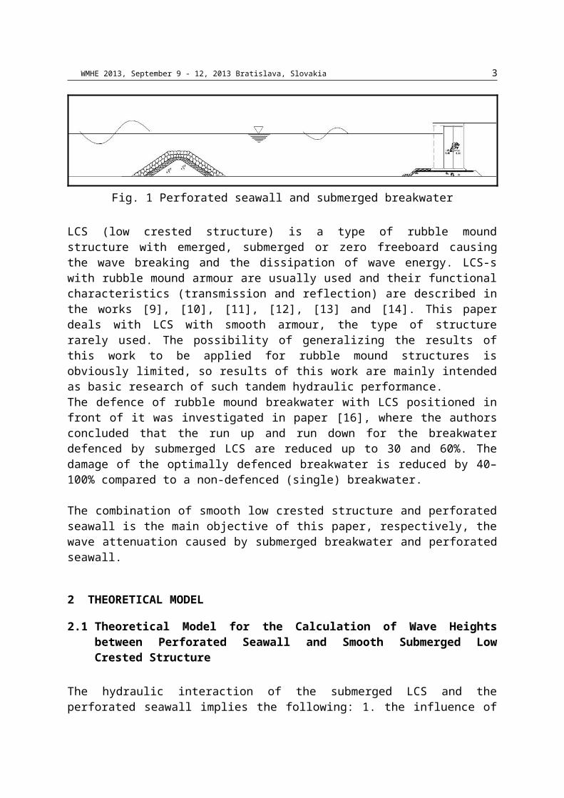
It could be concluded that a newly formed mathematical modelsrepresent well experimental results and they can be used ingeometrical and wave parameters limits of the verificationprocess.Fig. 11 shows examples of the theoretical and experimentalwave spectra reflected from perforated seawall. The agreementis satisfactory because mathematical model represents wellenergy around peak period as well as occurrence of the energyon higher harmonics.
Fig. 11 Examples of theoretical and measured wave spectrareflected from perforated seawall
The variation of the pool length Lpl is involved inexperimental research with aim to investigate the influence ofLpl on the hydraulic performance of such tandem, especially onsuperposed significant wave height Hsup and Hs-sup. Generalconclusion is that there are no obvious confirmations of poollength influence on Hsup and Hs-sup.
5 DISCUSSION
Further will be presented the comparison of the hydraulicbehaviour of:

WMHE 2013, September 9 - 12, 2013 Bratislava, Slovakia 15
1. tandem submerged breakwater+perforated seawall(breakw+perf),
2. tandem submerged breakwater+solid seawall (breakw+solid)and
3. only solid seawall.
Superposed wave heights Hsup for only solid wall were calculatedas superposition of incident and reflected wave heights withreflection coefficient KR=1. Hsup for submerged breakwater andsolid seawall were calculated as superposition of wave heightstransmitted across submerged breakwater and waves reflectedfrom solid seawall with reflection coefficient KR=1. Hsup forsubmerged breakwater and perforated seawall were calculatedaccording to new mathematical model presented in chapterError: Reference source not found.Fig. 12 shows relationship of parameter Hsup/Hi and relativesubmergence F/Hi. This way is possible to analyse the influenceof different types of coastal defence constructions on waveheight Hsup.Black dotted line presents theoretical Hsup in front of the onlysolid wall. In that case all wave energy is reflected whatgives Hsup/Hi=2 (Hsup=2 Hi) and it is independent of the parameterF/Hi.
The other lines are separated according to the wave steepness(H/L=1/12, 1/17 and 1/25).Lines “breakw+solid” presents the amount of energy dissipatedby submerged breakwater in comparison to the situation withoutbreakwater (“solid wall”). Curves “breakw+perf” are positionedlower than “breakw+solid” which represents additional energydissipated by perforated wall.Lines “breakw+solid” have breakpoints when they reach valueHsup/Hi =2. In those points breakwater transmits all incidentenergy and for greater values of relative submergences F/Hi thetandem “breakw+solid” behaves like only solid wall. The samebreakpoints are visible on curves “breakw+perf”. Curvature ofthe curves “breakw+perf” is resulted because the reflectioncoefficients of the perforated seawall depend on the incomingwave lengths. The function of the reflection coefficient inrelationship to incoming wave height (and length) hasparabolic shape.

WMHE 2013, September 9 - 12, 2013 Bratislava, Slovakia 16
Colored dotted curves represent limits of the parameter Hsup/Hi
for the variation of the input wave heights within Hi1.1 = 1.1 ·Hi and Hi0.9 = 0.9 · Hi.The agreement between measurements and curves “breakw+perf”are satisfactory and it can be concluded that newly formedmathematical model describe well hydraulic behaviour of thesubmerged smooth breakwater and perforated seawall. The same presentation as those on Fig. 12 could be producedbut for submergence F=0.1m. Because of similarity with Fig. 12this presentation is omitted.
Fig. 12 Comparison of the parameter Hsup/Hi for only solidseawall, tandem submerged breakwater and solid seawall
(breakw+solid), tandem submerged breakwater and perforatedseawall (breakw+perf), F=0.06m, regular waves, “o”-
measurements, “∙∙∙∙”- upper limit for 1.1∙Hi and lower limitfor 0.9∙Hi
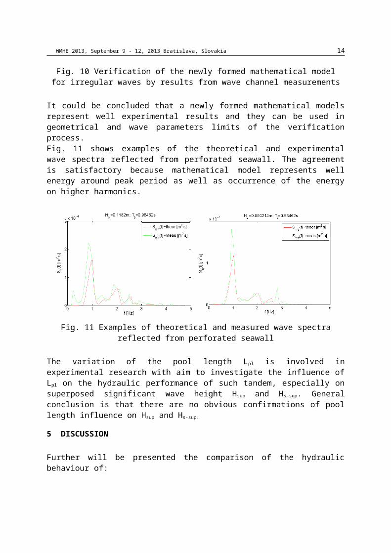
Fig. 13 shows the same as previous figure but for irregularwaves. It is visible that in case of irregular waves parameterHs-sup/Hsi can be maximum 1.41 what is in accordance tomeasurements presented in [18]. In the case of the irregularwaves the assumption of the superposition of wave energies is
WMHE 2013, September 9 - 12, 2013 Bratislava, Slovakia 17
valid (Fig. 3) unlike in case of the regular waves where theassumption of the summation of the wave heights is valid (Fig.2.) In case of the irregular waves the influence of the perforatedseawall on the energy dissipation is less than in the case ofthe regular waves. That is visible from fact that curves for“breakw+perf” are at lower position from “breakw+solid” incase of the regular waves. The main reason is in fact thatpresentation with spectral parameters as significant waveheights, includes all components from wave spectra whichreflects with different reflection coefficient, which finallygives smaller influence of the perforated seawall.
Fig. 13 Comparison of the parameter Hs-sup/Hsi for only solidseawall, tandem submerged breakwater and solid seawall
(breakw+solid), tandem submerged breakwater and perforatedseawall (breakw+perf), F=0.06m, irregular waves, “o”-
measurements, “∙∙∙∙”- upper limit for 1.1∙Hsi and lower limitfor 0.9∙Hsi
6 CONCLUSION

WMHE 2013, September 9 - 12, 2013 Bratislava, Slovakia 18
The experimental investigation, in wave channel, of the smoothsubmerged breakwater and perforated seawall is conducted withaim to form the mathematical model for calculation of thesuperposed wave heights between them. The mathematical modelis formed from existing models for each type of construction.The verification of a newly formed mathematical model isconducted using results from measurements in wave channel.Generally, the influence of the submerged breakwater on theenergy dissipation is greater than the influence of theperforated seawall, if submergence F is small enough. Thesubmerged breakwaters are cheap rubble mound constructionsunlike reinforced concrete perforated seawalls. This leads toconclusion that the application of the submerged breakwaterwith the crown close to the zero water level in combinationwith solid seawall is better solution. Only in special caseswith great tide oscillations and specific requests onsubmerged crown, the application of submerged breakwater andperforated seawall is acceptable.

WMHE 2013, September 9 - 12, 2013 Bratislava, Slovakia 19
References[1]Marks, M.; Jarlan, G. E.: Experimental study on a fixed perforated
breakwater, Proc. 11th Coastal Engineering Conference, III,(1968), ASCE, 1121-1140
[2]Kondo, H. Analysis of breakwater having two porous walls. CoastalStructures '79., II, ASCE, (1979).; 962-977.
[3]Fugazza, M.; Natale, L.: Hydraulic design of perforated breakwaters,Journal of Waterway, Port, Coastal, and Ocean Engineering,vol. 118, No. 1, (1992)
[4]Suh, Kyumg-Duck; Park, Jae Kil; Park, Woo Sun: Wavereflection from partially perforated-wall caissonbreakwater; Ocean Engineering 33 (2006), 264-280.
[5]Suh, Kyung Doug; Choi, Jae Chun; Kim, Bum Hyoung; Park, WooSun; Lee, Kil Seong: Reflection of irregular waves from perforated-wallcaisson breakwaters; Coastal Engineering 44 (2001); 141-151
[6]Suh, K. D., Park, W. S., Wave reflection from perforated-wall caissonbreakwaters, Coastal Engineering 26, (1995), 177–193
[7]Sawaragi, T.; Iwata, K.: Irregular wave attenuation due to a verticalbarrier with air chamber Coastal Structures 79, ASCE, (1979); 29-47
[8]Allsop, N.W.H; Hettiarachichi S. S. L.: Wave reflections inharbours: design, construction and performance of wave absorbing structures;Report OD 89, HR Wallingford, (1989)
[9]D’Angremond, K., Van der Meer, de Jong, R.J. Wave transsmisionat low-crested structure; ASCE, Proc. ICCE, Orlando, (1996),Florida, 3305-3318.
[10] Seabrook, S. R., Hall, K. R.: Wave transsmision at submergedrubble mound breakwaters; Proc. 26TH Int. Conf. on Coast.Engineering, (1998), ASCE, 2000-2013.
[11] Buccino, M., Calabrese, M.: Conceptual approach for prediction ofwave transmission at low-crested breakwaters; Journal of waterway,port, coastal, and ocean engineering , (2007),ASCE,May/June.
[12] Van der Meer, J.W., Wang, B., Wolters, A., Zanuttigh, B.,Kramer, M.: Oblique wave transmission over low-crested structures, ASCE,Proc. Coastal Structures, Portland, Oregon, (2003).

WMHE 2013, September 9 - 12, 2013 Bratislava, Slovakia 20
[13] Van der Meer, J.W., Regeling, H.J., de Waal, J.P.: Wavetransmission: spectral changes and its effect on run-up and overtopping,ASCE, Proc.ICCE, , Sydney, Australia,2156-2168, (2000).
[14] Briganti, R., Van der Meer, J.W., Buccino, M., Calabrese,M.: Wave transmission behind low crested structures, ASCE, Proc.Coastal Structures, Portland, Oregon (2003).
[15] Van der Meer, J.W., Wang, B., Wolters, A., Zanuttigh, B.,Kramer, M.: Oblique wave transmission over low-crestedstructures, ASCE, Proc. Coastal Structures, Portland,Oregon, (2003).
[16] Shirlal, K. G., Rao, S., Ganesh, V., Manu: Stability ofbreakwater defencedby a seaward submerged reef. Ocean Engineering,33. (2006) 829–846
[17] Hughes, S. A.: Physical models and laboratory techniques in coastalengineering, Advanced Series on Ocean Engineering-Volume7,World Scientific, 1993, pp. 502-506.
[18] Goda, Y., Random seas and design of maritime structures, (2ndEdition), World Scientific Publishing, (2000), 103-105.
[19] Hattori, M.: Transmission of waves through perforated wall, CoastalEngineering in Japan, 15, (1972),69-79
[20] Mei, C. C., Liu, P.L.-F., Ippen, A.T.: ''QUADRATIC LOSSAND SCATTERING OF LONG WAVES'', Journal of Waterways,Harbours Coastal Engineering Division, ASCE, (1974), 100,217-239
[21] Suh, Kyung Doug; Son, Sang Young; Lee, Jong In; Lee, TaeHwan: ''CALCULATION OF IRREGULAR WAVE REFLECTION FROMPERFORATED-WALL CAISSON BREAKWATERS USING A REGULAR WAVEMODEL'', Coastal Engineering, (2002): Solving CoastalConundrums: Proceedings of the 28th InternationalConference : 7-12 July 2002, Cardiff Hall, Cardiff Wales,Jan Smith McKee
[22] Zelt, J. A., Skjelbreia, J. E.: ''ESTIMATING INCIDENT ANDREFLECTED WAVE FIELDS USING AN ARBITRARY NUMBER OF WAVEGAUGES'', Coastal Engineering, (2002)
[23] Journée, J.M.J., Massie, W.W., 2001. OffshoreHydromechanics, First Edition, Delft University ofTechnology, http://www.shipmotions.nl, 5-43,