Wheeler Method for Evaluation of Antennas Submerged in ...
10
applied sciences Article Wheeler Method for Evaluation of Antennas Submerged in Lossy Media Yerim Oh, Dongkwon Choi , Jae-Yeong Lee and Wonbin Hong * Citation: Oh, Y.; Choi, D.; Lee, J.-Y.; Hong, W. Wheeler Method for Evaluation of Antennas Submerged in Lossy Media. Appl. Sci. 2021, 11, 1862. https://doi.org/10.3390/ app11041862 Academic Editors: Costantino De Angelis and Hosung Choo Received: 18 January 2021 Accepted: 18 February 2021 Published: 20 February 2021 Publisher’s Note: MDPI stays neutral with regard to jurisdictional claims in published maps and institutional affil- iations. Copyright: © 2021 by the authors. Licensee MDPI, Basel, Switzerland. This article is an open access article distributed under the terms and conditions of the Creative Commons Attribution (CC BY) license (https:// creativecommons.org/licenses/by/ 4.0/). Department of Electrical Engineering, Pohang University of Science and Technology, Pohang 37673, Korea; [email protected] (Y.O.); [email protected] (D.C.); [email protected] (J.-Y.L.) * Correspondence: [email protected]; Tel.: +82-54-279-5935 Abstract: A Wheeler method for the evaluation of the radiation efficiency of submerged antennas within lossy media is presented and demonstrated for the first time in the literature. Extensive investigations have been devised by empirical and simulation methods. Normal-mode helical antenna (NMHA) was first designed and fabricated to exemplify a real-life application at the UHF band (0.3 to 3 GHz). The antenna under test (AUT) was evaluated within an artificial lossy material using a series of Wheeler caps featuring different radii to study the validity of this method. The error between the experimental and simulation radiation efficiency is below 3% near the theoretical radian length. The presented measurement method of radiation efficiency without any essential measurement facilities or accessories could be a promising candidate for fast and accurate evaluation for any wire-type antenna submerged within lossy media. Keywords: radiation efficiency evaluation; radiation resistance measurement; Wheeler method; lossy media; submerged antennas 1. Introduction Antenna radiation efficiency is an important parameter for calculating the wireless link budget and optimizing antenna structures. This can be controlled and improved by modifying the antenna topology in the case of the constant antenna volume [1–4]. Currently, various methods such as pattern integration method, the Wheeler method [5–8], radiometric method [9], and the Q–factor method [10] have been reported for measuring radiation efficiency in free-space. For some applications, such as in underwater, underground, and in-body scenarios, wireless signals propagate through lossy media [11–15]. These usually have short-range communication systems due to the high attenuation of electromagnetic (EM) waves in the lossy medium. Meanwhile, the antenna characteristics are significantly different from those in free space. In this respect, antennas submerged in lossy media has been analytically and numerically studied using ideal dipole antennas. These studies include modified parameters such as radiation efficiency, directivity, gain and effective area [16,17], and the effects of the insulation layer of submerged antennas and the equivalent circuit model of uninsulated antenna [18,19]. Since the conventional radiation efficiency [20] is only useful for lossless media, studies of radiation efficiency in lossy media have been in demand. The radiation characteristics of submerged antennas in lossy media have been mostly measured using the gain comparison method which employs standard gain reference antennas [21–24]. The recently reported measurement technology using a reverberation chamber was conducted to measure the radiation efficiency in consideration of the spurious radiation effect of the feed cable [25]. However, the attenuation area is different depending on the conditions of the lossy medium, such as shape, size, and antenna location [21]. In addition, it is difficult to apply this approach for applications such as establishing a wireless link between implanted devices. To resolve these drawbacks, a modified radiation efficiency is introduced based on the Appl. Sci. 2021, 11, 1862. https://doi.org/10.3390/app11041862 https://www.mdpi.com/journal/applsci
-
Upload
khangminh22 -
Category
Documents
-
view
3 -
download
0
Transcript of Wheeler Method for Evaluation of Antennas Submerged in ...

applied sciences
Article
Wheeler Method for Evaluation of Antennas Submerged inLossy Media
Yerim Oh, Dongkwon Choi , Jae-Yeong Lee and Wonbin Hong *
�����������������
Citation: Oh, Y.; Choi, D.; Lee, J.-Y.;
Hong, W. Wheeler Method for
Evaluation of Antennas Submerged
in Lossy Media. Appl. Sci. 2021, 11,
1862. https://doi.org/10.3390/
app11041862
Academic Editors: Costantino
De Angelis and Hosung Choo
Received: 18 January 2021
Accepted: 18 February 2021
Published: 20 February 2021
Publisher’s Note: MDPI stays neutral
with regard to jurisdictional claims in
published maps and institutional affil-
iations.
Copyright: © 2021 by the authors.
Licensee MDPI, Basel, Switzerland.
This article is an open access article
distributed under the terms and
conditions of the Creative Commons
Attribution (CC BY) license (https://
creativecommons.org/licenses/by/
4.0/).
Department of Electrical Engineering, Pohang University of Science and Technology, Pohang 37673, Korea;[email protected] (Y.O.); [email protected] (D.C.); [email protected] (J.-Y.L.)* Correspondence: [email protected]; Tel.: +82-54-279-5935
Abstract: A Wheeler method for the evaluation of the radiation efficiency of submerged antennaswithin lossy media is presented and demonstrated for the first time in the literature. Extensiveinvestigations have been devised by empirical and simulation methods. Normal-mode helicalantenna (NMHA) was first designed and fabricated to exemplify a real-life application at the UHFband (0.3 to 3 GHz). The antenna under test (AUT) was evaluated within an artificial lossy materialusing a series of Wheeler caps featuring different radii to study the validity of this method. Theerror between the experimental and simulation radiation efficiency is below 3% near the theoreticalradian length. The presented measurement method of radiation efficiency without any essentialmeasurement facilities or accessories could be a promising candidate for fast and accurate evaluationfor any wire-type antenna submerged within lossy media.
Keywords: radiation efficiency evaluation; radiation resistance measurement; Wheeler method; lossymedia; submerged antennas
1. Introduction
Antenna radiation efficiency is an important parameter for calculating the wirelesslink budget and optimizing antenna structures. This can be controlled and improvedby modifying the antenna topology in the case of the constant antenna volume [1–4].Currently, various methods such as pattern integration method, the Wheeler method [5–8],radiometric method [9], and the Q–factor method [10] have been reported for measuringradiation efficiency in free-space.
For some applications, such as in underwater, underground, and in-body scenarios,wireless signals propagate through lossy media [11–15]. These usually have short-rangecommunication systems due to the high attenuation of electromagnetic (EM) waves in thelossy medium. Meanwhile, the antenna characteristics are significantly different from thosein free space. In this respect, antennas submerged in lossy media has been analyticallyand numerically studied using ideal dipole antennas. These studies include modifiedparameters such as radiation efficiency, directivity, gain and effective area [16,17], and theeffects of the insulation layer of submerged antennas and the equivalent circuit model ofuninsulated antenna [18,19].
Since the conventional radiation efficiency [20] is only useful for lossless media, studiesof radiation efficiency in lossy media have been in demand. The radiation characteristics ofsubmerged antennas in lossy media have been mostly measured using the gain comparisonmethod which employs standard gain reference antennas [21–24]. The recently reportedmeasurement technology using a reverberation chamber was conducted to measure theradiation efficiency in consideration of the spurious radiation effect of the feed cable [25].However, the attenuation area is different depending on the conditions of the lossy medium,such as shape, size, and antenna location [21]. In addition, it is difficult to apply thisapproach for applications such as establishing a wireless link between implanted devices.To resolve these drawbacks, a modified radiation efficiency is introduced based on the
Appl. Sci. 2021, 11, 1862. https://doi.org/10.3390/app11041862 https://www.mdpi.com/journal/applsci

Appl. Sci. 2021, 11, 1862 2 of 10
total power of the radiated field through the spherical surface with a radius of propagationdistance [16,17,26,27]. However, the modified radiation efficiency method still exhibits aninverse proportion between measurement data accuracy and testing time to obtain totalradiated power in all spherical surfaces.
This paper introduces and demonstrates an efficient evaluation method for the ra-diation efficiency of submerged antennas in lossy media by using the Wheeler method.Without the required measurement facilities or essential accessories to obtain electric fieldintensity or power density, the presented Wheeler cap method has been devised featuringa short testing time and high accuracy using only the Wheeler metallic cavity. This paper isorganized as follows: Section 2 introduces the antenna radiation efficiency for lossy media;in Section 3, the evaluation method of radiation efficiency in media with various dielectricconstant and loss tangent has been demonstrated by using the Wheeler method, and themeasured efficiency of a wire antenna within the artificial lossy material [28] at the UHFband (0.3 to 3 GHz) is concluded to be in good agreement with the measured efficiencies;Section 4 concludes the paper.
2. Antenna Radiation Efficiency for Lossy Media
Measurement using the gain comparison method in lossy media is presented inFigure 1. The propagation region between Tx and Rx is divided into two physical layers:lossy medium and air. Inevitably, the radiated field is scattered at the boundary. Atten-uation region R1 is different depending on the conditions of the lossy medium such asshape, size, and antenna location. In this case, the radiation efficiency based on combiningradiated power in all directions cannot be specified [21].
Appl. Sci. 2021, 11, x 2 of 10
to apply this approach for applications such as establishing a wireless link between im-planted devices. To resolve these drawbacks, a modified radiation efficiency is introduced based on the total power of the radiated field through the spherical surface with a radius of propagation distance [16,17,26,27]. However, the modified radiation efficiency method still exhibits an inverse proportion between measurement data accuracy and testing time to obtain total radiated power in all spherical surfaces.
This paper introduces and demonstrates an efficient evaluation method for the radi-ation efficiency of submerged antennas in lossy media by using the Wheeler method. Without the required measurement facilities or essential accessories to obtain electric field intensity or power density, the presented Wheeler cap method has been devised featuring a short testing time and high accuracy using only the Wheeler metallic cavity. This paper is organized as follows: Section 2 introduces the antenna radiation efficiency for lossy me-dia; in Section 3, the evaluation method of radiation efficiency in media with various die-lectric constant and loss tangent has been demonstrated by using the Wheeler method, and the measured efficiency of a wire antenna within the artificial lossy material [28] at the UHF band (0.3 to 3 GHz) is concluded to be in good agreement with the measured efficiencies; Section 4 concludes the paper.
2. Antenna Radiation Efficiency for Lossy Media Measurement using the gain comparison method in lossy media is presented in Fig-
ure 1. The propagation region between Tx and Rx is divided into two physical layers: lossy medium and air. Inevitably, the radiated field is scattered at the boundary. Attenuation region R1 is different depending on the conditions of the lossy medium such as shape, size, and antenna location. In this case, the radiation efficiency based on combining radi-ated power in all directions cannot be specified [21].
Figure 1. Illustration of conventional gain comparison method which evaluates radiation charac-teristics for antenna in lossy media.
A modified radiation efficiency 𝜂 of the antenna for lossy media is defined as fol-lows: 𝜂 𝑑 𝑃 𝑑 /𝑃 𝑃 𝑑 / 𝑃 1 |𝑆 | , (1)
where 𝑃 is the total radiated power related to the propagation distance due to the path loss in the lossy media (Figure 2), 𝑃 is the incident power, and 𝑃 is the power inci-dent to the antenna terminals. It is calculated by integrating the power flow normal to the virtual sphere surface according to the radial distance from the antenna center [4]. How-ever, all previously reported works related to the modified radiation efficiency have been demonstrated and verified without experimental results [16,17,26,27].
Figure 1. Illustration of conventional gain comparison method which evaluates radiation characteris-tics for antenna in lossy media.
A modified radiation efficiency ηMR of the antenna for lossy media is defined asfollows:
ηMR(dr) = Prad(dr)/Pacc = Prad(dr)/(
Pin
(1− |S11|2
)), (1)
where Prad is the total radiated power related to the propagation distance due to thepath loss in the lossy media (Figure 2), Pin is the incident power, and Prad is the powerincident to the antenna terminals. It is calculated by integrating the power flow normalto the virtual sphere surface according to the radial distance from the antenna center [4].However, all previously reported works related to the modified radiation efficiency havebeen demonstrated and verified without experimental results [16,17,26,27].
Appl. Sci. 2021, 11, 1862 3 of 10Appl. Sci. 2021, 11, x 3 of 10
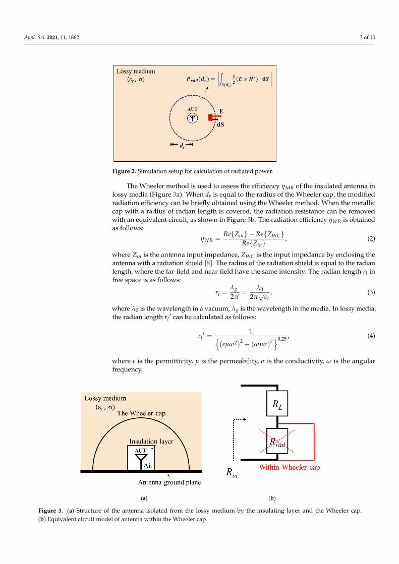
Figure 2. Simulation setup for calculation of radiated power.
The Wheeler method is used to assess the efficiency 𝜂 of the insulated antenna in lossy media (Figure 3a). When 𝑑 is equal to the radius of the Wheeler cap, the modified radiation efficiency can be briefly obtained using the Wheeler method. When the metallic cap with a radius of radian length is covered, the radiation resistance can be removed with an equivalent circuit, as shown in Figure 3b. The radiation efficiency 𝜂 is obtained as follows: 𝜂 , (2)
where 𝑍 is the antenna input impedance, 𝑍 is the input impedance by enclosing the antenna with a radiation shield [8]. The radius of the radiation shield is equal to the radian length, where the far-field and near-field have the same intensity. The radian length 𝑟 in free space is as follows: 𝑟 √ , (3)
where 𝜆 is the wavelength in a vacuum, 𝜆 is the wavelength in the media. In lossy media, the radian length 𝑟 ′ can be calculated as follows: 𝑟 ′ . , (4)
where 𝜀 is the permittivity, 𝜇 is the permeability, 𝜎 is the conductivity, 𝜔 is the angu-lar frequency.
(a) (b)
Figure 3. (a) Structure of the antenna isolated from the lossy medium by the insulating layer and the Wheeler cap. (b) Equivalent circuit model of antenna within the Wheeler cap.
Figure 2. Simulation setup for calculation of radiated power.
The Wheeler method is used to assess the efficiency ηMR of the insulated antenna inlossy media (Figure 3a). When dr is equal to the radius of the Wheeler cap, the modifiedradiation efficiency can be briefly obtained using the Wheeler method. When the metalliccap with a radius of radian length is covered, the radiation resistance can be removedwith an equivalent circuit, as shown in Figure 3b. The radiation efficiency ηWR is obtainedas follows:
ηWR =Re{Zin} − Re{ZWC}
Re{Zin}, (2)
where Zin is the antenna input impedance, ZWC is the input impedance by enclosing theantenna with a radiation shield [8]. The radius of the radiation shield is equal to the radianlength, where the far-field and near-field have the same intensity. The radian length rl infree space is as follows:
rl =λg
2π=
λ0
2π√
εr, (3)
where λ0 is the wavelength in a vacuum, λg is the wavelength in the media. In lossy media,the radian length rl
′ can be calculated as follows:
rl′ =
1{(εµω2)
2 + (ωµσ)2}0.25 , (4)
where ε is the permittivity, µ is the permeability, σ is the conductivity, ω is the angularfrequency.
Appl. Sci. 2021, 11, x 3 of 10
Figure 2. Simulation setup for calculation of radiated power.
The Wheeler method is used to assess the efficiency 𝜂 of the insulated antenna in lossy media (Figure 3a). When 𝑑 is equal to the radius of the Wheeler cap, the modified radiation efficiency can be briefly obtained using the Wheeler method. When the metallic cap with a radius of radian length is covered, the radiation resistance can be removed with an equivalent circuit, as shown in Figure 3b. The radiation efficiency 𝜂 is obtained as follows: 𝜂 , (2)
where 𝑍 is the antenna input impedance, 𝑍 is the input impedance by enclosing the antenna with a radiation shield [8]. The radius of the radiation shield is equal to the radian length, where the far-field and near-field have the same intensity. The radian length 𝑟 in free space is as follows: 𝑟 √ , (3)
where 𝜆 is the wavelength in a vacuum, 𝜆 is the wavelength in the media. In lossy media, the radian length 𝑟 ′ can be calculated as follows: 𝑟 ′ . , (4)
where 𝜀 is the permittivity, 𝜇 is the permeability, 𝜎 is the conductivity, 𝜔 is the angu-lar frequency.
(a) (b)
Figure 3. (a) Structure of the antenna isolated from the lossy medium by the insulating layer and the Wheeler cap. (b) Equivalent circuit model of antenna within the Wheeler cap.
Figure 3. (a) Structure of the antenna isolated from the lossy medium by the insulating layer and the Wheeler cap.(b) Equivalent circuit model of antenna within the Wheeler cap.

Appl. Sci. 2021, 11, 1862 4 of 10
3. Analysis of the Wheeler Cap Method of Antenna Surrounded by the Lossy Media3.1. Simulation3.1.1. Simulation Setup
The radiation efficiency evaluation method is validated by stepwise analysis accordingto the change in the dielectric constant and conductivity of the medium encompassingthe antenna. The radiation efficiency analysis using the Wheeler method is conductedthrough ANSYS HFSS. A normal-mode helical antenna (NMHA) resonating at a frequencyof 172 MHz in air and an insulation layer are designed using copper wire and Teflon (εr =2.1, tanδ = 0.001), respectively. The detailed dimensions of the antenna are illustrated(Figure 4a). The metallic cavity is designed as a hemisphere consisting of PEC (Figure 4b).The space inside the insulation layer is modeled as air and remained identical across allexperiments. The simulation setup is presented in Figure 4c. The size of the lossy mediumis 1000 mm × 1000 mm × 500 mm.
Appl. Sci. 2021, 11, x 4 of 10
3. Analysis of the Wheeler Cap Method of Antenna Surrounded by the Lossy Media 3.1. Simulation 3.1.1. Simulation Setup
The radiation efficiency evaluation method is validated by stepwise analysis accord-ing to the change in the dielectric constant and conductivity of the medium encompassing the antenna. The radiation efficiency analysis using the Wheeler method is conducted through ANSYS HFSS. A normal-mode helical antenna (NMHA) resonating at a fre-quency of 172 MHz in air and an insulation layer are designed using copper wire and Teflon (𝜀 = 2.1, tanδ = 0.001), respectively. The detailed dimensions of the antenna are illustrated (Figure 4a). The metallic cavity is designed as a hemisphere consisting of PEC (Figure 4b). The space inside the insulation layer is modeled as air and remained identical across all experiments. The simulation setup is presented in Figure 4c. The size of the lossy medium is 1000 mm × 1000 mm × 500 mm.
Figure 4. Geometry of simulation setup: (a) cross-sectional view of NMHA and (b) with metallic cavity, (c) perspective view. (𝑑 = 20, 𝑝 = 3, ℎ = 6.4, 𝑡 = 0.8, 𝑟 = 15, ℎ = 40, 𝑡 = 1, 𝑟 = 500, 𝑡 = 1, 𝑡 = 5. Unit: mm.
3.1.2. Radiation Efficiency in Media with Dielectric Constant The radiation efficiency is analyzed for a medium with a high dielectric constant in a
lossless state. In this scenario, only the dielectric constant of the material is controlled. The results are sampled at a single frequency at which a resonance occurs at each medium. The cavity length 𝑟 is expressed as a ratio of length-to-wavelength.
The efficiency 𝜂 calculated according to the metallic cavity radius 𝑟 is compared with the efficiency 𝜂 calculated based on the field computation (Figure 2). The radia-tion resistance can be extracted using a radiation shield with a radius equal to the radian length. The comparison shows that the same radiation efficiency can be obtained when the cavity radius 𝑟 is equal to the radian length 𝑟 for each medium (Figure 5). This as-certains that the Wheeler method is applicable even for media featuring a dielectric con-stant other than 1. The radiation efficiency is maintained over the radian length range.
Figure 4. Geometry of simulation setup: (a) cross-sectional view of NMHA and (b) with metalliccavity, (c) perspective view. (da = 20, pa = 3, ha = 6.4, ta = 0.8, ri = 15, hi = 40, ti = 1, rg = 500, tg = 1,tw = 5. Unit: mm.
3.1.2. Radiation Efficiency in Media with Dielectric Constant
The radiation efficiency is analyzed for a medium with a high dielectric constant in alossless state. In this scenario, only the dielectric constant of the material is controlled. Theresults are sampled at a single frequency at which a resonance occurs at each medium. Thecavity length rw is expressed as a ratio of length-to-wavelength.
The efficiency ηWR calculated according to the metallic cavity radius rw is comparedwith the efficiency ηMR calculated based on the field computation (Figure 2). The radiationresistance can be extracted using a radiation shield with a radius equal to the radian length.The comparison shows that the same radiation efficiency can be obtained when the cavityradius rw is equal to the radian length rl for each medium (Figure 5). This ascertains thatthe Wheeler method is applicable even for media featuring a dielectric constant other than1. The radiation efficiency is maintained over the radian length range.

Appl. Sci. 2021, 11, 1862 5 of 10Appl. Sci. 2021, 11, x 5 of 10
Figure 5. The radiation efficiency 𝜂 versus cavity radius 𝑟 with changes in the dielectric con-stant. 𝜂 is marked with a dash for the same color line. The radian length 𝑟 is marked with black lines.
3.1.3. Radiation Efficiency in Lossy Media The dielectric constant of the material is fixed at 1 and the conductivity is set as a
variable. The results are sampled at a single frequency at which resonance occurs at each medium. The efficiency 𝜂 calculated according to the metallic cavity radius 𝑟 is com-pared with the efficiency 𝜂 calculated based on the field computation (Figure 2). As mentioned above, 𝜂 can obtain the uniform radiation efficiency in lossless media (Fig-ure 5), but it cannot be applicable in lossy media. As radial distance 𝑑 increases, the propagation loss increases and the radiation efficiency 𝜂 decreases rapidly (Figure 6).
When the conductivity is as low as 0.01 S/m, the efficiency 𝜂 is almost similar to the radiation efficiency 𝜂 calculated by the field calculator (Figure 2) in a short propa-gation distance range. Additionally, the radiation efficiency of 𝜂 and 𝜂 show good agreement when the cavity radius 𝑟 is equal to the radian length 𝑟 ′ of each medium. This clearly confirms that the Wheeler method can be applicable to lossy media.
However, when the conductivity is relatively high, the error is significantly increased as 𝑟 becomes larger than the radian length 𝑟 ′. The coupling resistance between the an-tenna and the cavity mode of the radiation shield causes errors in the efficiency measure-ment [29,30]. When the cavity resonator is filled with lossy material, the quality factor is lowered [31]. Therefore, the increased 𝑍 due to the cavity mode causes errors over a wide range. A radiation shield should be selected in an appropriate shape.
Figure 6. The radiation efficiency 𝜂 versus cavity radius 𝑟 with changes in the conductivity and 𝜂 versus radial distance 𝑑 is marked with a dash for the same color line. The radian length 𝑟 ′ is marked with black lines.
Figure 5. The radiation efficiency ηWR versus cavity radius rw with changes in the dielectric constant.ηMR is marked with a dash for the same color line. The radian length rl is marked with black lines.
3.1.3. Radiation Efficiency in Lossy Media
The dielectric constant of the material is fixed at 1 and the conductivity is set asa variable. The results are sampled at a single frequency at which resonance occurs ateach medium. The efficiency ηWR calculated according to the metallic cavity radius rw iscompared with the efficiency ηMR calculated based on the field computation (Figure 2).As mentioned above, ηMR can obtain the uniform radiation efficiency in lossless media(Figure 5), but it cannot be applicable in lossy media. As radial distance dr increases, thepropagation loss increases and the radiation efficiency ηMR decreases rapidly (Figure 6).
Appl. Sci. 2021, 11, x 5 of 10
Figure 5. The radiation efficiency 𝜂 versus cavity radius 𝑟 with changes in the dielectric con-stant. 𝜂 is marked with a dash for the same color line. The radian length 𝑟 is marked with black lines.
3.1.3. Radiation Efficiency in Lossy Media The dielectric constant of the material is fixed at 1 and the conductivity is set as a
variable. The results are sampled at a single frequency at which resonance occurs at each medium. The efficiency 𝜂 calculated according to the metallic cavity radius 𝑟 is com-pared with the efficiency 𝜂 calculated based on the field computation (Figure 2). As mentioned above, 𝜂 can obtain the uniform radiation efficiency in lossless media (Fig-ure 5), but it cannot be applicable in lossy media. As radial distance 𝑑 increases, the propagation loss increases and the radiation efficiency 𝜂 decreases rapidly (Figure 6).
When the conductivity is as low as 0.01 S/m, the efficiency 𝜂 is almost similar to the radiation efficiency 𝜂 calculated by the field calculator (Figure 2) in a short propa-gation distance range. Additionally, the radiation efficiency of 𝜂 and 𝜂 show good agreement when the cavity radius 𝑟 is equal to the radian length 𝑟 ′ of each medium. This clearly confirms that the Wheeler method can be applicable to lossy media.
However, when the conductivity is relatively high, the error is significantly increased as 𝑟 becomes larger than the radian length 𝑟 ′. The coupling resistance between the an-tenna and the cavity mode of the radiation shield causes errors in the efficiency measure-ment [29,30]. When the cavity resonator is filled with lossy material, the quality factor is lowered [31]. Therefore, the increased 𝑍 due to the cavity mode causes errors over a wide range. A radiation shield should be selected in an appropriate shape.
Figure 6. The radiation efficiency 𝜂 versus cavity radius 𝑟 with changes in the conductivity and 𝜂 versus radial distance 𝑑 is marked with a dash for the same color line. The radian length 𝑟 ′ is marked with black lines.
Figure 6. The radiation efficiency ηWR versus cavity radius rw with changes in the conductivity andηMR versus radial distance dr is marked with a dash for the same color line. The radian length rl
′ ismarked with black lines.
When the conductivity is as low as 0.01 S/m, the efficiency ηWR is almost similar to theradiation efficiency ηMR calculated by the field calculator (Figure 2) in a short propagationdistance range. Additionally, the radiation efficiency of ηWR and ηMR show good agreementwhen the cavity radius rw is equal to the radian length rl
′ of each medium. This clearlyconfirms that the Wheeler method can be applicable to lossy media.
However, when the conductivity is relatively high, the error is significantly increasedas rw becomes larger than the radian length rl
′. The coupling resistance between theantenna and the cavity mode of the radiation shield causes errors in the efficiency measure-ment [29,30]. When the cavity resonator is filled with lossy material, the quality factor islowered [31]. Therefore, the increased ZWC due to the cavity mode causes errors over awide range. A radiation shield should be selected in an appropriate shape.

Appl. Sci. 2021, 11, 1862 6 of 10
3.2. Measurement3.2.1. Measurement Setup
A UHF band antenna was devised and the radiation efficiency was measured whenthe antenna was submerged within an artificial lossy material. The detailed measurementsetup is introduced in Figures 7 and 8. The AUT was made of NMHA type and was blockedfrom the medium by a capsule-shaped polyimide (εr = 3.5, tanδ = 0.008) insulation layer(Figure 7a). Antenna in the UHF band within the lossy medium are described in Table 1.Radiation shields with three radii (20, 30, 70. Unit: mm) were designed for demonstration.It was fabricated by covering a copper sheet on a hemisphere model using a 3D printingmethodology (Figure 7b).
Appl. Sci. 2021, 11, x 6 of 10
3.2. Measurement 3.2.1. Measurement Setup
A UHF band antenna was devised and the radiation efficiency was measured when the antenna was submerged within an artificial lossy material. The detailed measurement setup is introduced in Figures 7 and 8. The AUT was made of NMHA type and was blocked from the medium by a capsule-shaped polyimide (𝜀 = 3.5, tanδ = 0.008) insulation layer (Figure 7a). Antenna in the UHF band within the lossy medium are described in Table 1. Radiation shields with three radii (20, 30, 70. Unit: mm) were designed for demon-stration. It was fabricated by covering a copper sheet on a hemisphere model using a 3D printing methodology (Figure 7b).
(a) (b)
Figure 7. Illustration of (a) normal-mode helical antenna and capsule-shaped insulation layer, (b) hemisphere-shaped radiation shield.
Figure 8. Measurement system for evaluating the radiation efficiency of a submerged antenna.
Table 1. Fabricated Antenna Parameter.
Parameter 𝒅𝒂 𝒑𝒂 𝒉𝒂 𝒕𝒂 𝒓𝒊 Value (mm) 9 3 2 0.8 5 Parameter 𝒉𝒊 𝒕𝒊 𝒓𝒈 𝒕𝒈 𝒕𝒘
Value (mm) 13 1 100 0.07 0.07
The overall measurement system, including a lossy medium and container, is de-scribed in Figure 8. The material with the electrical properties (𝜀 = 58, 𝜎 = 0.82 S/m) at 400 MHz was composed of deionized water (51.16%), sodium chloride (1.49%), sugar (46.78%), bactericide (0.05%), and hydroxyethyl cellulose (0.52%) [28]. The lossy medium
Figure 7. Illustration of (a) normal-mode helical antenna and capsule-shaped insulation layer, (b) hemisphere-shapedradiation shield.
Appl. Sci. 2021, 11, x 6 of 10
3.2. Measurement 3.2.1. Measurement Setup
A UHF band antenna was devised and the radiation efficiency was measured when the antenna was submerged within an artificial lossy material. The detailed measurement setup is introduced in Figures 7 and 8. The AUT was made of NMHA type and was blocked from the medium by a capsule-shaped polyimide (𝜀 = 3.5, tanδ = 0.008) insulation layer (Figure 7a). Antenna in the UHF band within the lossy medium are described in Table 1. Radiation shields with three radii (20, 30, 70. Unit: mm) were designed for demon-stration. It was fabricated by covering a copper sheet on a hemisphere model using a 3D printing methodology (Figure 7b).
(a) (b)
Figure 7. Illustration of (a) normal-mode helical antenna and capsule-shaped insulation layer, (b) hemisphere-shaped radiation shield.
Figure 8. Measurement system for evaluating the radiation efficiency of a submerged antenna.
Table 1. Fabricated Antenna Parameter.
Parameter 𝒅𝒂 𝒑𝒂 𝒉𝒂 𝒕𝒂 𝒓𝒊 Value (mm) 9 3 2 0.8 5 Parameter 𝒉𝒊 𝒕𝒊 𝒓𝒈 𝒕𝒈 𝒕𝒘
Value (mm) 13 1 100 0.07 0.07
The overall measurement system, including a lossy medium and container, is de-scribed in Figure 8. The material with the electrical properties (𝜀 = 58, 𝜎 = 0.82 S/m) at 400 MHz was composed of deionized water (51.16%), sodium chloride (1.49%), sugar (46.78%), bactericide (0.05%), and hydroxyethyl cellulose (0.52%) [28]. The lossy medium
Figure 8. Measurement system for evaluating the radiation efficiency of a submerged antenna.
Table 1. Fabricated Antenna Parameter.
Parameter da pa ha ta ri
Value (mm) 9 3 2 0.8 5
Parameter hi ti rg tg tw
Value (mm) 13 1 100 0.07 0.07
The overall measurement system, including a lossy medium and container, is de-scribed in Figure 8. The material with the electrical properties (εr = 58, σ = 0.82 S/m)at 400 MHz was composed of deionized water (51.16%), sodium chloride (1.49%), sugar(46.78%), bactericide (0.05%), and hydroxyethyl cellulose (0.52%) [28]. The lossy medium

Appl. Sci. 2021, 11, 1862 7 of 10
filled a 200 mm × 200 mm × 100 mm container. The antenna was placed in the center ofthe ground.
3.2.2. Measurement Result
The reflection characteristics measurement of the antenna was carried out with a vectornetwork analyzer (VNA). The antenna radiation efficiency measurement was conductedusing three different radiation shields to measure the resistance of the antenna in each case.The radiation efficiency ηWR measured at 400 MHz is compared with the two simulationresults in Figure 9. As the cavity radius becomes larger than the radian length, the error dueto the cavity mode of the shield itself [30] is similarly confirmed in the measurement andsimulation. The measurement results are in good agreement with the simulation resultsusing the Wheeler method.
Appl. Sci. 2021, 11, x 7 of 10
filled a 200 mm × 200 mm × 100 mm container. The antenna was placed in the center of the ground.
3.2.2. Measurement Result The reflection characteristics measurement of the antenna was carried out with a vec-
tor network analyzer (VNA). The antenna radiation efficiency measurement was con-ducted using three different radiation shields to measure the resistance of the antenna in each case. The radiation efficiency 𝜂 measured at 400 MHz is compared with the two simulation results in Figure 9. As the cavity radius becomes larger than the radian length, the error due to the cavity mode of the shield itself [30] is similarly confirmed in the meas-urement and simulation. The measurement results are in good agreement with the simu-lation results using the Wheeler method.
Figure 9. The measured and simulation radiation efficiency 𝜂 versus cavity radius 𝑟 and simulation 𝜂 versus radial distance 𝑑 . The radian length 𝑟 ′ is marked with black lines.
The efficiency values measured with a radiation shield having a radius (20 mm) close to the radian length 𝑟 ′ (14.4 mm) is compared with the simulated values in Figure 10. The calculated error from 300 to 600 MHz is less than 3%.
Figure 10. The measured and simulated radiation efficiency (𝑑 = 𝑟 = 20 mm).
This study is the first to experimentally validate the Wheeler method for the condi-tion of lossy media. In previous studies of modified radiation efficiency, an ideal dipole or source was used or limited only to numerical analysis. In comparison, we designed and measured a practical UHF band NMHA that is applicable for submerged scenarios using
300 400 500 600Frequency [MHz]
0
0.1
0.2
0.3
0.4
Figure 9. The measured and simulation radiation efficiency ηMR versus cavity radius rw and simula-tion ηMR versus radial distance dr. The radian length rl
′ is marked with black lines.
The efficiency values measured with a radiation shield having a radius (20 mm) closeto the radian length rl
′ (14.4 mm) is compared with the simulated values in Figure 10. Thecalculated error from 300 to 600 MHz is less than 3%.
Appl. Sci. 2021, 11, x 7 of 10
filled a 200 mm × 200 mm × 100 mm container. The antenna was placed in the center of the ground.
3.2.2. Measurement Result The reflection characteristics measurement of the antenna was carried out with a vec-
tor network analyzer (VNA). The antenna radiation efficiency measurement was con-ducted using three different radiation shields to measure the resistance of the antenna in each case. The radiation efficiency 𝜂 measured at 400 MHz is compared with the two simulation results in Figure 9. As the cavity radius becomes larger than the radian length, the error due to the cavity mode of the shield itself [30] is similarly confirmed in the meas-urement and simulation. The measurement results are in good agreement with the simu-lation results using the Wheeler method.
Figure 9. The measured and simulation radiation efficiency 𝜂 versus cavity radius 𝑟 and simulation 𝜂 versus radial distance 𝑑 . The radian length 𝑟 ′ is marked with black lines.
The efficiency values measured with a radiation shield having a radius (20 mm) close to the radian length 𝑟 ′ (14.4 mm) is compared with the simulated values in Figure 10. The calculated error from 300 to 600 MHz is less than 3%.
Figure 10. The measured and simulated radiation efficiency (𝑑 = 𝑟 = 20 mm).
This study is the first to experimentally validate the Wheeler method for the condi-tion of lossy media. In previous studies of modified radiation efficiency, an ideal dipole or source was used or limited only to numerical analysis. In comparison, we designed and measured a practical UHF band NMHA that is applicable for submerged scenarios using
300 400 500 600Frequency [MHz]
0
0.1
0.2
0.3
0.4
Figure 10. The measured and simulated radiation efficiency (dr = rw = 20 mm).
This study is the first to experimentally validate the Wheeler method for the conditionof lossy media. In previous studies of modified radiation efficiency, an ideal dipole orsource was used or limited only to numerical analysis. In comparison, we designed andmeasured a practical UHF band NMHA that is applicable for submerged scenarios using

Appl. Sci. 2021, 11, 1862 8 of 10
an artificial lossy material. The radiation efficiency measured at the theoretical radianlength is in good agreement with that proposed in a previous study [16].
Table 2 summarizes the performance comparisons between the proposed methodand the state-of-the-art method. The proposed method uses the change in the resistancecharacteristic inside the cavity, whereas the principle of the other methods is based onthe power of the electromagnetic field. It is noted that the proposed method measuredthe radiation efficiency only via the Wheeler cap, whereas [32] requires a lot of spaceand chambers for the measurement, including a shielded room. Therefore, the proposedmethod measures radiation efficiency in a fast and inexpensive way.
Table 2. Comparison of the proposed method with other works.
Ref.Required Measurement
Facilities or EssentialAccessories
Acquisition Method forRadiation Efficiency
Error BetweenSimulation andMeasurement
[32] 2.4 × 2.4 × 2.4 m (Shieldroom), reference antenna
Average static powertransfer function atdifferent 3 position
<4.5%
[26] - Power integral normalto the sphere Only simulation
This work Lossy medium, Wheeler cap Variation of the inputresistance <3%
4. Conclusions
We propose the Wheeler method to measure the radiation efficiency of an antennasubmerged in lossy media as an alternative to gain comparison methods which are carriedout in the far-field. The concept of modified radiation efficiency in lossy media has beenstudied but is still limited to theory and simulation [16,17,26,27]. This work empiricallystudies the application method of the Wheeler method to achieve a breakthrough in thelimitations of previous studies. Also, the radiation efficiency measured at the theoreticalradian length is highly correlated with that proposed in a previous study [16], indicatingthat this method can be further applied to different frequencies and scenarios in the future.
The proposed method achieves very fast and inexpensive efficiency measurementswithout the need for other antennas or an expensive chamber. Additionally, the modifiedradiation efficiency can be used as a new figure of merit for evaluating submerged antennasfor applications such as underwater, underground, and in-body communication systems.Furthermore, since the antenna radiation efficiency and propagation loss can be separatedusing the method presented in [26], it is expected to be useful for calculating the link budgetof submerged channel modeling scenarios.
Author Contributions: Research conceptualization and methodology, D.C. and W.H.; Design andsimulation, Y.O. and D.C.; Fabrication and measurement, Y.O. and D.C.; Writing-original draft,Y.O. and D.C.; Writing-review and editing, Y.O., J.-Y.L., and W.H. For other cases, all authors haveparticipated. All authors have read and agreed to the published version of the manuscript.
Funding: This work was supported in part by the National Research Foundation of Korea (NRF)grant funded by the Korean Government (MSIT) under Grant 2018R1A4A1025679, in part by theBasic Science Research Program through the NRF of Korea funded by the Ministry of Educationunder Grant 2018R1A6A3A01013261.
Institutional Review Board Statement: Not applicable.
Informed Consent Statement: Not applicable.
Data Availability Statement: Not applicable.
Acknowledgments: The authors would like to thank ANSYS Korea for their generous support.
Conflicts of Interest: The authors declare no conflict of interest.

Appl. Sci. 2021, 11, 1862 9 of 10
References1. Wheeler, H. Fundamental limitations of small antennas. Proc. IRE 1947, 35, 1479–1484. [CrossRef]2. Chu, L.J. Physical limitations of omni-directional antennas. J. Appl. Phys. 1948, 19, 1163–1175. [CrossRef]3. Gustafsson, M.; Sohl, C.; Kristensson, G. Physical limitations on antennas of arbitrary shape. Proc. R. Soc. A 2007, 463, 2589–2607.
[CrossRef]4. Sievenpiper, D.F.; Dawson, D.C.; Jacob, M.M.; Kanar, T.; Kim, S.; Long, J.; Quarfoth, R.G. Experimental validation of performance
limits and design guidelines for small antennas. IEEE Trans. Antennas Propag. 2012, 60, 8–19. [CrossRef]5. Wheeler, H.A. The radiansphere around a small antenna. Proc. IRE 1959, 47, 1325–1331. [CrossRef]6. McKinzie, W. A modified Wheeler cap method for measuring antenna efficiency. In Proceedings of the IEEE Antennas and
Propagation Society International Symposium 1997. Digest, Montreal, QC, Canada, 13–18 July 1997; Volume 1, pp. 542–545.[CrossRef]
7. Johnston, R.H.; McRory, J.G. An improved small antenna radiation-efficiency measurement method. IEEE Antennas Propag. Mag.1998, 40, 40–48. [CrossRef]
8. Smith, G. An analysis of the Wheeler method for measuring the radiating efficiency of antennas. IRE Trans. Antennas Propag.1977, 25, 552–556. [CrossRef]
9. Ashkenazy, J.; Levine, E.; Treves, D. Radiometric measurement of antenna efficiency. Electron. Lett. 1985, 21, 111. [CrossRef]10. Newman, E.; Bohley, P.; Walter, C. Two methods for the measurement of antenna efficiency. IRE Trans. Antennas Propag. 1975, 23,
457–461. [CrossRef]11. Tan, H.-P.; Diamant, R.; Seah, W.K.; Waldmeyer, M. A survey of techniques and challenges in underwater localization. Ocean Eng.
2011, 38, 1663–1676. [CrossRef]12. Chong, C.-Y.; Kumar, S. Sensor networks: Evolution, opportunities, and challenges. Proc. IEEE 2003, 91, 1247–1256. [CrossRef]13. FitzGerrell, R.; Haidle, L. Design and performance of four buried UHF antennas. IRE Trans. Antennas Propag. 1972, 20, 56–62.
[CrossRef]14. Vuran, M.C.; Silva, A.R. Communication through soil in wireless underground sensor networks—Theory and practice. In
Distributed Cooperative Laboratories: Networking, Instrumentation, and Measurements; Springer Science and Business Media LLC:Berlin/Heidelberg, Germany, 2009; pp. 309–347.
15. Abbasi, Q.H.; Qaraqe, K.; Rehman, M.U.; Alomainy, A. Advances in Body-Centric Wireless Communication: Applications andState-of-the-Art; IET: London, UK, 2016.
16. Karlsson, A. Physical limitations of antennas in a lossy medium. IEEE Trans. Antennas Propag. 2004, 52, 2027–2033. [CrossRef]17. Lee, J.; Nam, S. Effective area of a receiving antenna in a lossy medium. IEEE Trans. Antennas Propag. 2009, 57, 1843–1845.
[CrossRef]18. Merli, F.; Fuchs, B.; Mosig, J.R.; Skrivervik, A.K. The effect of insulating layers on the performance of implanted antennas. IEEE
Trans. Antennas Propag. 2011, 59, 21–31. [CrossRef]19. Liao, Y.; Hubing, T.H.; Su, D. Equivalent circuit for dipole antennas in a lossy medium. IEEE Trans. Antennas Propag. 2012, 60,
3950–3953. [CrossRef]20. IEEE. IEEE standard for definitions of terms for antennas. In IEEE Std 145-2013 (Revision of IEEE Std 145-1993); IEEE: Piscataway
Township, NJ, USA, 2014; pp. 1–50.21. Miah, S.; Khan, A.N.; Icheln, C.; Haneda, K.; Takizawa, K.-I. Antenna system design for improved wireless capsule endoscope
links at 433 MHz. IEEE Trans. Antennas Propag. 2019, 67, 2687–2699. [CrossRef]22. Bao, Z.; Guo, Y.-X.; Mittra, R. An ultrawideband conformal capsule antenna with stable impedance matching. IEEE Trans.
Antennas Propag. 2017, 65, 5086–5094. [CrossRef]23. Kim, S.; Shin, H. An ultra-wideband conformal meandered loop antenna for wireless capsule endoscopy. J. Electromagn. Eng. Sci.
2019, 19, 101–106. [CrossRef]24. Kaim, V.; Kanaujia, B.K.; Kumar, S.; Choi, H.C.; Kim, K.W.; Rambabu, K. Ultra-miniature circularly polarized CPW-fed implantable
antenna design and its validation for biotelem-etry applications. Sci. Rep. 2020, 10, 6795. [CrossRef]25. Holloway, C.L.; Shah, H.A.; Pirkl, R.J.; Young, W.F.; Hill, D.A.; Ladbury, J. Reverberation chamber techniques for determining the
radiation and total efficiency of antennas. IEEE Trans. Antennas Propag. 2012, 60, 1758–1770. [CrossRef]26. El-Saboni, Y.; Zelenchuk, D.E.; Conway, G.A.; Scanlon, W.G. Assessing the intrinsic radiation efficiency of tissue-implanted UHF
antennas. IEEE Trans. Antennas Propag. 2020, 68, 491–499. [CrossRef]27. Manteghi, M.; Ibraheem, A.A.Y. On the study of the near-fields of electric and magnetic small antennas in lossy media. IEEE
Trans. Antennas Propag. 2014, 62, 6491–6495. [CrossRef]28. Cheng, X.; Wu, J.; Blank, R.; Senior, D.E.; Yoon, Y.-K. An omnidirectional wrappable compact patch antenna for wireless endoscope
applications. IEEE Antennas Wirel. Propag. Lett. 2012, 11, 1667–1670. [CrossRef]29. Huang, Y.; Narayanan, R.; Kadambi, G. Electromagnetic coupling effects on the cavity measurement of antenna efficiency. IEEE
Trans. Antennas Propag. 2003, 51, 3064–3071. [CrossRef]30. Choo, H.; Rogers, R.; Ling, H. On the Wheeler cap measurement of the efficiency of microstrip antennas. IEEE Trans. Antennas
Propag. 2005, 53, 2328–2332. [CrossRef]

Appl. Sci. 2021, 11, 1862 10 of 10
31. Groiss, S.; Bardi, I.; Biro, O.; Preis, K.; Richter, K. Parameters of lossy cavity resonators calculated by the finite element method.IEEE Trans. Magn. 1996, 32, 894–897. [CrossRef]
32. Conway, G.A.; Scanlon, W.G.; Orlenius, C.; Walker, C. In situ measurement of UHF wearable antenna radiation efficiency using areverberation chamber. IEEE Antennas Wirel. Propag. Lett. 2008, 7, 271–274. [CrossRef]