technical considerations for submerged sea water lift pumps ...
23
Copyright© 2019 by Turbomachinery Laboratory, Texas A&M Engineering Experiment Station TECHNICAL CONSIDERATIONS FOR SUBMERGED SEA WATER LIFT PUMPS SPECIFICATION AND SELECTION Stefano Porta Lead Engineer – Rotating Equipment TechnipFMC Paris, France Pierrick Rosenplac Rotating Equipment Specialist TechnipFMC Paris, France Mounir Mossolly PhD CEng. Technical Advisor/ Lead Engineer TechnipFMC Paris, France Stefano Porta is a Rotating Equipment Lead Engineer in TechnipFMC, in Paris. Mr. Porta is working for 20 years with Rotating Equipment for the Oil & Gas Industry. He is graduated from the “Escola Politécnica de São Paulo”, Brazil and has a Master in “Refining, Petrochemical and Gas Engineering” from “Ecole Nationale Supérieure du Pétrole et des Moteurs”, France. Pierrick Rosenplac graduated from ENSMA (Engineering school for Mechanical and Aeronautics) and has been working for TechnipFMC since 2008 as Rotating equipment engineer. Involved in the design, the selection and purchase of rotating machinery equipment for onshore and offshore oil & gas plants, he is now Technical advisor in the rotating equipment department of TechnipFMC, based in Paris. Mounir Mossolly is an engineering team leader and a technical advisor on turbomachinery packages for oil and gas projects. His experience was sculpted through many years of contributions in notable LNG projects within TechnipFMC. Mounir holds ME in Mechanical Engineering and a PhD in Project Management. He has been a certified manager of Quality & Organizational Excellence by ASQ, Lean Six Sigma Black Belt and an associate in Value Engineering. Mounir is currently the chairman of IMECHE - Groupe France. ABSTRACT Sea Water Lift (SWL) Pumps are applied in offshore units for cooling and fire water services. The specification of the SWL pump operating conditions is an iterative process where proper alignment between the supplier and the detailed engineering contractor should be achieved. This paper explains the design criteria for pump selection and elaborates on the methods to determine various pump operating characteristics such as the pump submergence/ suction level requirement, total dynamic head (TDH) and maximum allowable shut-off head. The aim of this paper is to provide a description of the workflow that should be followed during the project execution. Specifying numerical values for design criteria is not the intent of this paper, as these are project dependent, although examples are given for illustration purpose.
-
Upload
khangminh22 -
Category
Documents
-
view
0 -
download
0
Transcript of technical considerations for submerged sea water lift pumps ...

Copyright© 2019 by Turbomachinery Laboratory, Texas A&M Engineering Experiment Station
TECHNICAL CONSIDERATIONS FOR SUBMERGED SEA WATER LIFT PUMPS SPECIFICATION AND SELECTION
Stefano Porta Lead Engineer – Rotating Equipment TechnipFMC Paris, France Pierrick Rosenplac Rotating Equipment Specialist TechnipFMC Paris, France
Mounir Mossolly PhD CEng. Technical Advisor/ Lead Engineer TechnipFMC Paris, France
Stefano Porta is a Rotating Equipment Lead Engineer in TechnipFMC, in Paris. Mr. Porta is working for 20 years with Rotating Equipment for the Oil & Gas Industry. He is graduated from the “Escola Politécnica de São Paulo”, Brazil and has a Master in “Refining, Petrochemical and Gas Engineering” from “Ecole Nationale Supérieure du Pétrole et des Moteurs”, France.
Pierrick Rosenplac graduated from ENSMA (Engineering school for Mechanical and Aeronautics) and has been working for TechnipFMC since 2008 as Rotating equipment engineer. Involved in the design, the selection and purchase of rotating machinery equipment for onshore and offshore oil & gas plants, he is now Technical advisor in the rotating equipment department of TechnipFMC, based in Paris. Mounir Mossolly is an engineering team leader and a technical advisor on turbomachinery packages for oil and gas projects. His experience was sculpted through many years of contributions in notable LNG projects within TechnipFMC. Mounir holds ME in Mechanical Engineering and a PhD in Project Management. He has been a certified manager of Quality & Organizational Excellence by ASQ, Lean Six Sigma Black Belt and an associate in Value Engineering. Mounir is currently the chairman of IMECHE - Groupe France.
ABSTRACT Sea Water Lift (SWL) Pumps are applied in offshore units for cooling and fire water services. The specification of the SWL pump operating conditions is an iterative process where proper alignment between the supplier and the detailed engineering contractor should be achieved. This paper explains the design criteria for pump selection and elaborates on the methods to determine various pump operating characteristics such as the pump submergence/ suction level requirement, total dynamic head (TDH) and maximum allowable shut-off head. The aim of this paper is to provide a description of the workflow that should be followed during the project execution. Specifying numerical values for design criteria is not the intent of this paper, as these are project dependent, although examples are given for illustration purpose.

Copyright© 2019 by Turbomachinery Laboratory, Texas A&M Engineering Experiment Station
INTRODUCTION When discussing SWL pumps, the definition of terms (nomenclature) and system of references shall be consistent between the parties involved, i.e.: Contractor, original equipment manufacturer (OEM) and Operator. For instance, TDH value is referred to the pump datum without considering the pipe stack static height and not including dynamic friction losses. At the rated (or normal operating) conditions, this is the pump guaranteed “Head” that will be verified during the pump performance test. However, for the detailed engineering contractor, the valuable figure is not the pump TDH, but rather the discharge pressure available at Reference Discharge Elevation (as shown in Figure 9) (located at a height which is several decks above the caisson-submerged pump). The discharge pressure is achieved by the pump TDH and influenced by other factors such as the suction level (variable mainly with draft/ heave motion (Figure 1) in floating unit applications or tide in fixed structure applications) and the friction losses in the sea water riser assembly and discharge pipe stack. The friction losses in sea water riser assembly are due to the friction throughout the length of the sea water riser pipe and sea water riser strainer, and also due to the considerable pressure drop across the riser hanger assembly (if applied in the design).
Figure 1 - Sea Motions
This paper will illustrate the SWL Pump arrangements & the definition (nomenclature) of the different levels/ elevations. In addition, the system equations will be presented, and criteria for TDH, Net Positive Suction Head (NPSH) and shut-off pressure will be discussed. The work flow steps are narrated as well. SWL PUMP ARRANGEMENT A sea water lift system is composed of two parts: 1) Sea Water Riser (below datum -Figure 3) and 2) Submerged Pump & Stack Column (above datum - Figure 4).
Sea Water Riser (Figure 3) Usually more than 300 ft (100 m) long, to catch seawater in depths where sea water temperature is colder (compared to sea water temperature at sea surface level) and more stable than close to the surface (not affected by the varying weather conditions). In tropical latitudes the surface sea water temperature could be around ≈ 80°F (≈ 27°C), while the sea water temperature in the same geographical spot at a depth of 300ft (100m) could be 5°C less (around 72°F (22°C)). Figure 2 provides an example of Seawater Temperature Gradient. The advantages of receiving cooler water in the offshore facility is very significant, leading to improved overall efficiency of the operating units, and reduced pumps operating costs (less OPEX) due to the reduction in circulating cooling water flow rate. In addition to savings in capital cost (CAPEX) due to less piping and heat exchangers size. In floating liquefied natural gas facilities (FLNG) the effect of reduced cooling water temperature on LNG production rate is evident. For Firewater pumps, the intake riser assembly is not applied because water temperature does not really matter for the fire extinguishing service.

Copyright© 2019 by Turbomachinery Laboratory, Texas A&M Engineering Experiment Station
Figure 2 - Illustration of Seawater Temperature Gradient
Submerged Pump & Stack Column (Figure 4) The SWL pump unit is composed of a submerged centrifugal pump, which pumps sea water upwards into the pipe stack column. The SWL pump driver can be an electric motor or hydraulic motor, submerged or mounted on top (long shaft configuration - Figure 7). VENDORS propose configurations with motors installed above or below the pump (Figure 5 and Figure 6 respectively) .Seawater suction is made through a strainer, with a purpose of protecting the pump from marine elements (which were not captured by the main riser strainer) or contaminations in the caisson. The SWL pump and pipe stack column are mounted and centralized in a caisson inside the hull, or externally attached to the offshore facility. Cathodic protection is applied to decrease the corrosion potential to acceptable corrosion rate using sacrificial anodes. This is to protect the metal surfaces under sea water by inducing them as an electrical cathode following ISO 15589. Sacrificial anodes are distributed along the discharge pipe stack column. Replacement of anodes shall be made after a period of several years (to be pre-calculated for each application). Super Duplex stainless steel is with high chromium and molybdenum content is selected for the different parts of the pump (e.g.: impeller/ diffuser) according to D-2 classification referring to Appendix H of API 610. Pipe stack column are made of stainless steel. The submerged pump unit discharges seawater inside the pipe stack column that will bring the seawater up to the required elevation and at the required pressure for the sea water cooling circuit. In addition, the pipe stack column can be used to support auxiliary pipe, cables & connections to feed the submerged motor with electrical power, hydraulic (or lube) oil. The centralizers, regularly spaced all along the pipe stack column, are used for guiding the pump assembly inside the caisson. The top plate is matched with the caisson flange and supports the discharge elbow, plus all the necessary connections for the interface of pump itself (instrumentation, electrical feeding, oil connections).

Copyright© 2019 by Turbomachinery Laboratory, Texas A&M Engineering Experiment Station
Figure 3 – Seawater Intake Riser Pipes (subsea)
Figure 4 – Seawater Discharge Stack Column
(In blue)
Figure 5 – E-motor above pump (Courtesy of Framo)
Figure 6 – E-motor below pump (Courtesy of Clyde)
Figure 7 – Long Shaft with external electric motor
(Courtesy of Bjorge Eureka)

Copyright© 2019 by Turbomachinery Laboratory, Texas A&M Engineering Experiment Station
Depending on the project requirements and constraints, the caissons might be located externally on the side of the offshore facilities (Figure 8) or inside the hull.
Figure 8 – Example of SWL pumps located externally (Courtesy AKPO FPSO)
ELEVATIONS To perform a correct sea water lift pump design, one of the key steps is to align all parties on a common and consistent definition of all the various elevations as shown in Figure 9.
- Caisson Bottom: In general, the bottom of the hull for floating units;
- Datum plane: Is an arbitrary fixed reference elevation (e.g.: for a floating unit, hull bottom can be considered as Datum plan). All elevations will be measured considering this plane as reference;
- Submerged Pump Bottom: lowest part of submerged pump unit;
- 1st Impeller Inlet [ZPI]: Corresponds to the physical pump suction (1st impeller eye elevation);
- Submerged Pump Discharge [ZPD]: Highest part of submerged pump unit / interface with pipe stack column;
- Min. Sea Level [ZMin Sea Level]: Minimum possible Sea Level to datum plane reference. Correspond to Min. Draft (or LAT) and wave effect for a certain return period (e.g. 100 years);
- Min. Draft (for floating unit) [ZMin Draft]: Minimum sea level in “calm sea” condition. This is defined considering lightest weight of the floating unit (e.g. after a complete offloading);
- LAT (for fixed platform [ZLAT]: LAT is the Lowest Astronomical Tide. The lowest level that can be expected to occur under average meteorological conditions and under any combination of astronomical conditions. This level is based on a “calm sea level” and is relevant for fixed offshore platform;
- Max Draft (for floating unit) [ZMax Draft]: Maximum sea level in “calm sea” condition. This is defined considering heaviest weight of the floating unit (e.g. storage tanks full);
- HAT (for fixed platform) [ZHAT]: HAT is the Highest Astronomical Tide. The highest level that can be expected to occur under average meteorological conditions and under any combination of astronomical conditions. This level is based on a “calm sea level” and is relevant for fixed offshore platform;
- Max Sea Level [ZMax Sea Level]: Maximum possible Sea Level to datum plane reference. Correspond to Max. Draft (or HAT) and wave effect for a certain return period (e.g. 100 years);
- Flange Discharge Elbow [ZFDE]: Flange Discharge Elbow Centerline;
- Reference Discharge [ZRD]: Corresponds to the elevation where a CONTRATOR calculate the SWLP total head requested.

Copyright© 2019 by Turbomachinery Laboratory, Texas A&M Engineering Experiment Station
Figure 9 – Schematic of Elevations Definition
SYSTEM ARRANGEMENT & SYSTEM TOTAL ENERGY At right side of Figure 10 below a typical Sea Water Lift arrangement is shown within a floating unit: the suction hose, the caisson with submerged pump unit + pipe stack and the caisson top plate, discharge elbow flange and also the Reference Discharge Elevation (ZRD). SYSTEM TOTAL ENEGRY At the left side, the System Total Energy is represented. The initial energy is the Sea Level elevation head (Z1), as the fluid flow inside the suction hose the Total Energy decreases due to hose friction losses. Additional losses are generated by the pump strainer. The pump will then provide energy to the system required to achieve the desired pressure at discharge elbow flange considering also the friction losses on the pipe stack downstream the pump. The Reference Discharge Elevation (ZRD) is also indicated. To be noted that Total energy between Flange Discharge Elbow (ZFDE) and ZRD is constant as this is just a reference change.

Copyright© 2019 by Turbomachinery Laboratory, Texas A&M Engineering Experiment Station
Figure 10 – System Arrangement & System Total Energy
Pump Total Dynamic Head Pump TDH may be found by measuring the energy difference between two points in the pumping system, one on each side of the pump, providing all losses between these points are credited to the pump and added to the energy head difference. Therefore, between any two points in a pumping system where the energy is added only by the pump and the specific weight of the liquid does not change, the following equation for determining the pump total head applies:

Copyright© 2019 by Turbomachinery Laboratory, Texas A&M Engineering Experiment Station
2 2
Equation 1: Energy Balance for Pumping Systems
Where the subscripts 1 and 2 denote the points in the pumping system anyplace upstream and downstream from the pump, respectively, and
totalheadofthesystem, or ft m gage velocity,ft/s m/s pressure, or ‐ psi N/m gage elevationabove orbelow ‐ datumplane,ft m specifcweightofliquid,lb/ft N/m accelerationofgravity,32.17ft/s2 9.807m/s
sumofpipinglossesbetweenpoints, ft m
This equation will be developed considering:
Index (1): Sea Level
Index (2) Reference Discharge Elevation
V1 = 0 (Sea Water surface) From Equation 1 the Pump Total Head is:
2 2
2
2 ∆
Equation 2: Total Differentail Head (TDH)
∆
HeightfromSeaWaterSurfacetoDischargeReference,ft m
suctionhosepipinglosses,ft m pumpsuctionstrainerlosses,ft m
pipestacklosses,ft m
Pressure equivalence downstream the pump
Equation 1 can be used also have the pressure equivalence between two different elevations downstream the pump, such as
submerged pump discharge ZPD, and reference discharge ZRD, as per Figure 11 below:

Copyright© 2019 by Turbomachinery Laboratory, Texas A&M Engineering Experiment Station
Figure 11 – Pressure equivalence downstream the pump
Considering: V1 = V2 (assuming same pipe diameter) TDH =0 (no energy is provided to the system from ZPD to ZRD
2 2
∆ Equation 3: Pressure Equivalence
PUMP SUBMERGENCE Submerged centrifugal pumps must be submerged deeply enough to provide:
1. A pressure sufficient to prevent excessive cavitation in pump first-stage impellers, referred to as Required Net Positive Suction Head (NPSHr);
2. Prevention of vortex and associated flow problems detrimental to pump operation;
A pump may have adequate submergence from a pressure standpoint (NPSH margin maintained) but still be lacking the sufficient depth to prevent surface air being drawn to the impeller (vortex issue). The NPSH is a statement of the minimum suction conditions required to prevent excessive cavitation in a pump. The required NPSH (referred as NPSHr) is defined by the pump manufacturer based on pump specific characteristics (at a certain flow associated with for a certain pump rotational speed). The available system NPSH (referred as NPSHa) must be greater than NPSHr if damaging cavitation is to be avoided. Increasing the NPSHa provides a safety margin against the onset of excessive cavitation. The available NPSH for the sea water lift pump system shown in Figure 10 is given by:

Copyright© 2019 by Turbomachinery Laboratory, Texas A&M Engineering Experiment Station
∆
Equation 4: Available Net Positive Suction Head
AvailableNetPositiveSuctionHead, ft m
atmosphericpressure,psi N/m pressurevaporpressureofliquidbeingpumped,psi N/m
∆
heightbetweenseawatersurfaceandpumpfirstimpellerelevation,ft m hosepipinglosses,ft m
specifcweightofliquid,lb/ft N/m The most stringent value between NPSH margins requirement (will be discussed later) and submergence linked to vortexing (provided by OEM) shall be considered for the submerged pump installation. DESIGN CRITERIA Prior to the definition of pump performance characteristics, the design criteria to be considered for TDH, NPSH and Shut-off pressure shall be defined and agreed between all the parties. Note 1: Consideration of Sea Surface Conditions
The intention of this article is to show that different sea levels shall be considered for definition of TDH, NPSHa & shut-off pressure. It has not the intention to define the effects of the sea state (waves height and heave) on the water level inside the caisson or on the suction pressure at submerged pump impeller. Nevertheless, it shall be highlighted that in the case of a SWL pump with a sea water riser of hundreds of meters, the sea state effects can be reasonably considered negligible, however for the fire water application (FWP) the effects are for sure more significant due to intake level being relatively close to sea surface level The discussion below should be used as a first approach, as for the NPSHa and shut off pressure, the sea state effects are considered either for SWL and FWP applications. If the design criteria are not fulfilled with this conservative approach, then further studies of the dynamics of the sea state effects may be justified. Whatever the sea state effects on pump suction pressure are finally considered, the criteria to be checked and the methodology described remains applicable.
Note 2:
Following Design criteria #1 and #2 are applicable to both SWL cooling pump and SWL fire water pump. For what concerns Design criteria #3, SWL cooling pump and FWP cases will be discussed separately.
1. Sea Level for Pump RATED TDH
Process requirements will define the required pressure at Reference Discharge Elevation (ZRD). The centrifugal pump at a given flow will provide a constant TDH (assuming fixed speed). For a floating unit (or fixed structure subject to tide), the maximum height between the RD elevation and sea elevation shall be considered to assure that the pressure will be at least the Process required pressure at any floating unit draft (or any tide for fixed structure). This means the unit minimum draft (or LAT) shall be considered. For example, a magnitude of 30 ft (~10 m) difference between maximum and minimum draft can normally be present for floating units (production tanks loaded and unloaded). Tide magnitudes depends on the installation area but can be also of the same magnitude as draft differences. Influence of wave effects should also be analyzed. Sea level will not be the same if the wave effect is added to the minimum draft (or LAT). For example, additional 9 ft (~3 m) would be added to the pump TDH for tropical non-cyclonic areas. This value could be higher for different geographic regions.

Copyright© 2019 by Turbomachinery Laboratory, Texas A&M Engineering Experiment Station
In practical, it is reasonable to not consider the wave effect for pump TDH definition as the wave effect inside the caisson is dampened by suction riser pipe depth (and air volume inside the caisson). The margin considered in the design on discharge pressure can cope with eventual slight cyclic pressure variations. In conclusion, as a general guideline for definition of submerged pump RATED TDH, the minimum draft (or minimum low tide) elevation is considered & wave effect is neglected , and the terms to be used in Equation 2 are:
∆
∆.
ElevationDifferencebetweenReferenceDischargeandMinimumdraftseallevel ; ; & termsareallrelatedtocentrifugalpumpRATEDflow.
is the required pressure at Refence Discharge Elevation (ZRD).
2. Sea Level Shut off pressure
Consequence of draft (or tide) variation is that the discharge pressure of the pump will be affected by the differential height between the flange discharge elbow elevation (ZFDE) (fixed to the datum plane shown on Figure 9 – Schematic of Elevations Definition) and the sea water to the datum plan (not fixed). System downstream of the pump FDE is normally designed to 150# piping Class. GRP piping may be used for the piping downstream the SWL pump, due to its economic benefits compared with steel grade solutions required to cope with sea water corrosion. In this case the system downstream Maximum Allowable Working Pressure (MAWP) can be limited to 203 psig (14.0 barg). The shut off pressure of the pump shall be checked to assure that pump downstream system design pressure is not exceeded. The wave effect has not been considered for the pump TDH as discussed above, but for the shut off pressure calculation, if the wave effect is responsible to exceed the system design pressure, it cannot be excluded without a technical justification. The study of the real influence of the wave on the suction pressure at submerged pump inlet is not economically justified in a first approach. In this analysis, the worst case is then considered: maximum draft (or maximum High Tide) and the crest of the highest wave of the Return Period considered on the pump design. Considering Equation 2, the Shut off pressure at pump discharge elbow flange elevation (ZFDE) is:
2 ∆
.
2∆ .
Considering that at Shut-off, pump has no flow, then:
VFDE=0
hf hose ;hf strainer ;hf pipestack =0
2
∆.
p
γH ∆
. Equation 5: Shut-off Pressure
Copyright© 2019 by Turbomachinery Laboratory, Texas A&M Engineering Experiment Station
Combined effect of sea level at TDH calculation, head increase at shut off and no friction losses will have an effect on shut-off pressure that should not be disregarded on the verification. For example, considering a SWL pump with a rated flow of 14000 gpm (3200 m3/h): Differential Sea Level from Minimum Draft to Max. Sea Level: ~ + 36 ft (~ 12 m) Head increase to shut off from rated point: ~ + 90 ft (~ 30 m) Friction losses at rated point (hose + strainer + pipe stack): ~ +15 ft (~ 5 m) Shut off pressure in this case is approx. 72 psi (5 bar) higher than Rated pressure at discharge flange.
3. Seal Level for NPSHa & NPSH margins
As per pump TDH and shut off pressure, the sea water elevations to be considered for NPSHa definition will be discussed in this section. On this section, SWLP and FWP application will be discussed separately:
NPSHa for sea water lift application
Worst condition for NPSHa is the minimum draft conditions (or LAT). Considering that sea water lift is a continuous service that needs to be assured on all project defined return period conditions, the wave effect cannot be just ignored (as per previously Sea Level for Shut off Pressure discussion). Considering also that NPSHr will increase towards pump performance end of curve, the following criteria can be considered as guideline: Based on Minimum Sea Water level (i.e.: min. draft [or tide] + wave effect)
NPSH margin at rated flow > 1.65 ft (~ 0.5 m) NPSH margin at EOC > 0 ft (0 m)
To be noted that for most of the operating time, while the floating unit is not at minimum draft (or at minimum tide for fixed structures) the margin will be higher.
NPSHa for fire water application
FWP shall be sized for 150% flow (NFPA 20 requirement for periodical tests purposes). The NPSHr at this flow may be much higher than the NPSHr at rated flow (for example considering FWP of 15850 gpm (3600 m3/h), the NPSHr at rated flow is: 33 ft (11.0 m) and at 150% flow is 63 ft (19.2 m). Using the same criteria as sea water lift pumps may be too conservative: the fire water pump is not a continuous service contrary to the sea water lift pump and the 100% flow covers the designed firefighting water flow requirements. Considering the requirement of having a positive NPSH margin at 150% flow with minimum sea water level is equivalent to state that the fire water pump shall deliver 150% NFPA 20 test condition flow while the floating unit is in minimum draft configuration (or at minimum low tide for fixed structures) and with worst project applicable sea conditions. The criteria that can be proposed for agreement with owner is:
- NPSH margin > 3.3 ft (~ 1.0 m), at rated flow, with Minimum Sea Water level (i.e.: min. draft [or min. low tide] + wave effect)
- NPSH margin > 3.3 ft (~ 1.0 m), at 150% rated flow, with Minimum Draft level (wave effect not considered)
Equation 4 is then used to calculate the NPSHa for RATED and EOC or 150% flow conditions.

Copyright© 2019 by Turbomachinery Laboratory, Texas A&M Engineering Experiment Station
PROJECT DEVELOPMENT
NO
YES
Supplier Pump Selection
Inquiry with Preliminary Data:
- ZFDE : Estimated - ZPI : Estimated - hstrainer + hhose : Pump
Supplier data
YES
Is Shut off pressure
Criterium satisfied?
Submergence & NPSH Criteria check ZPI elevation shall be
modified?
ZPI to be adjusted
Is Proposed
TDH Equivalent to required p2?
YES
NO
Shut off pressure Criterium shall be satisfied by
pump reselection?
YES
NO
Shut off pressure criteria satisfied by system Design
Modification.
NO
Are the draft values
changed?
PURCHASE ORDER
Pump Selection & ZPI finalized
1
2
3
Reference Discharge pressure x Supplier
TDH Check
4
5
6
Figure 12 – Pump Selection Flow Chart

Copyright© 2019 by Turbomachinery Laboratory, Texas A&M Engineering Experiment Station
Figure 12 shows a Flow Chart for pump selection check during a project development. At the start of Inquiry phase - Step 1 - the data required to define the SWL selection and Pump Impeller Inlet elevation (ZPII) is related to each specific pump characteristic (NPSHr, pump suction strainer pressure losses, pump pipe stack pressure losses, etc) and need to be estimated. At least 1 iteration is required to achieve the final pump design and elevation as described in the flow chart above. At step 2, SWL pump supplier will provide a preliminary pump selection and confirm its characteristics (submergence, NPSHr curve, shut off head, strainer & pump pipe stack pressure losses curves or values at significant flows and flange Discharge Elbow elevation (ZFDE). With this preliminary selection, it is important to check (using Equation 2) that pump TDH proposed by Supplier corresponds to pressure at Reference Discharge elevation (ZRD)(Figure 10) requested by system process requirements. Any gap that may be present at this moment shall be clarified with OEM in order that a common understanding of the references & losses considered is achieved. The gap will come from a wrong discharge elevation level / missing or wrong pressure losses value, etc... Analyzing each term of Equation 2 with OEM will be sufficient to identify the gap. At step 3, the NPSHr & submergence criteria will be checked according Project requirement as discussed above. Check shall be done for rated and EOC (or 150% flow for FWP). It is also important to check that pump bottom will not extend outside the caisson. If ZPI shall be changed, OEM shall update its quotation. Once step 3 is passed, Pump Impeller elevation (ZPI) is defined. At step 4, the same check done on the first supplier selection correspondence of TDH and Reference Discharge (ZRD) elevation using Equation 2 is done again. As the elevations and pressure drops to be considered have been already clarified on step 2, a gap at this step 4 indicate that pump TDH is not correct. OEM would need to review the pump selection. At step 5, pump is installed at the correct elevation and with the correct TDH. Shut off pressure criteria as discussed above will be checked. If this criterium is not satisfied and shut off pressure is higher than discharge system design pressure a solution shall be defined either on changing the pump selection to reduce to head rise to shut off or by a design change on the system without impacting the pump selection. When step 5 is satisfied, the Inquiry Phase clarifications are completed, and the Purchase Order can be placed. An additional step 6 is shown after Purchase Order, as it is possible that draft values used before Purchase Order were not finalized, and further Engineering development may result in modification of this data. If it happens, checks done prior to Purchase Order will be re done. In general, this uncertainty has been considered at Inquiry phase as a margin on ZPI elevation. SEAWATER LIFT PUMP SHOP TESTING The pump shop testing is an important part of the VENDOR activities. In particular, mechanical run test and performance test allows to validate the design of the pump unit. While the mechanical run test is performed to check parameters like temperatures and vibrations, the performance test aims at validating the performances curves: Head versus Flow, NPSHr versus Flow, Power Consumption versus Flow and Efficiency versus Flow. The major concern with SLW pump performance testing is their size. Indeed, it is basically impossible to test the real full assembly, including strainer(s), suction hose, pipe stacks, etc. The first reason is the size of this assembly, which can reach more than a hundred meters, and cannot match a test bench dimensions. The second reason is the fact that some parts (e.g. suction hose) are not part of the SWLP VENDOR and may not be available at the time of the test. Depending on the selected VENDOR test bench capacity, two options can be considered:
the pump is installed vertically in pressurized tank

Copyright© 2019 by Turbomachinery Laboratory, Texas A&M Engineering Experiment Station
the pump is installed vertically in a test pit not pressurized with several pipe stacks
In both cases, the suction hose in not mounted and the pump is tested with a reduced length configuration, involving for instance only one pipe stack section. The purpose is to reproduce or simulate the pump submergence and measure pump NPSHR. Then, based on the performance test results, calculations are performed to be compared with site conditions with regards to static height and losses. The guaranteed TDH given by VENDOR at order is the same that will be measured at test bench conditions. It does not consider the suction hose (which is not part of SWL pump Vendor) and neither the complete length of the discharge pipe stack. During the performance test, the main process parameter to be recorded are (refer to Figure 13):
(1) The pump suction pressure (2) The discharge flow
(3) The discharge pressure (4) The fluid characteristics (e.g. temperature, properties)
Figure 13 – Head versus Flow: Test data and Site calculation
For the performance test, strainer is used during the test: Losses introduced by the inlet strainer are known (by experience or by calculation). Based on the test results, the pump VENDOR is able to calculate the actual pump assembly differential head. If the fluid properties (e.g. density, viscosity) or the test speed are different from site conditions during the test, corrective factors shall be introduced as follow:
Equation 6: Data conversion from Test conditions to Site conditions
∆ ∆
Copyright© 2019 by Turbomachinery Laboratory, Texas A&M Engineering Experiment Station
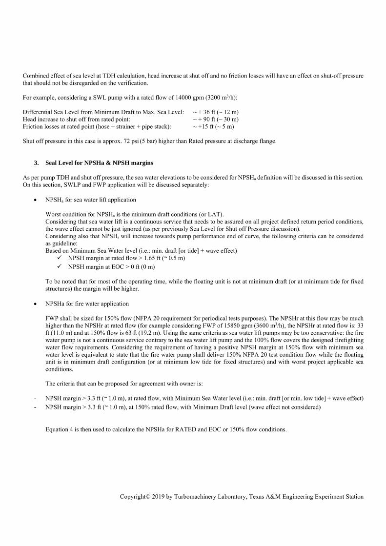
Q = Flowrate, ft3/s (m3/s) N = Pump speed, rpm This provide the blue curve (refer to Figure 14). Once corrections done, pump VENDOR is able to compute the corrected data available from the test to extrapolate the actual discharge Head at a certain Elevation from Sea level (at ZFDE): this corresponds to the orange curve (refer to Figure 14). The yellow curve (refer to Figure 14) shows the variation of the difference between the corrected test data and the calculated site data. This highlights the effect of the pressure losses due to the real pipe stacks.
+
Figure 14 – Head versus Flow: Test data and Site calculation
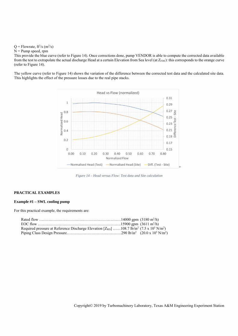
PRACTICAL EXAMPLES Example #1 – SWL cooling pump For this practical example, the requirements are:
Rated flow ………………………………………………………14000 gpm (3180 m3/h) EOC flow ……………………………………………………….15900 gpm (3611 m3/h) Required pressure at Reference Discharge Elevation [ZRD] ……108.7 lb/in2 (7.5 x 10⁵ N/m2) Piping Class Design Pressure……………………………………290 lb/in2 (20.0 x 10⁵ N/m2)

Copyright© 2019 by Turbomachinery Laboratory, Texas A&M Engineering Experiment Station
STEP 1: Inquiry with Preliminary 1st impeller inlet Elevation (ZPI) Inquiry is issued with following elevations (considering hull bottom as Datum Plane):
SWL (USCS) SWL (SI)
ELEVATIONS (refer to Figure 9)
Reference Discharge Elevation [ZRD] ft - (m) 106.3 32.400
Pump Discharge Flange Elevation [ZFDE] ft - (m) 105.1 32.036
Z Max Sea Level ft - (m) 80.4 24.500
Z Max Draft ft - (m) 74.7 22.760
Z Min Draft ft - (m) 38.3 11.670
Z Min Sea Level ft - (m) 28.3 8.640
1st Pump Impeller inlet [ZPI] ft - (m) - PRELIMINARY 13.0 4.0
STEP 2: Supplier Pump Selection Pump TDH @ rated point: 327.4 ft (99.8 m) NPSHr @ rated flow: 41.7 ft (12.7 m) NPSHr @ at EOC: 43.3 ft (13.2 m) Minimum Submergence: 11.5 ft (3.5 m) STEP 3: Submergence and NPSH criteria
SWL (USCS) SWL (SI)
SUBMERGENCE & NPSH CHECKS
NPSHa @ Min. Sea level / rated flow ft - (m) 38.5 11.7
NPSHa @ Min. Sea level / EOC flow ft - (m) 35.9 10.9
NPSHr @ rated flow ft - (m) 41.7 12.7
NPSHr @ EOC flow ft - (m) 43.3 13.2
NPSH margin @ Min. Sea level/ rated flow ft - (m) -3.2 -1.0
NPSH margin @ Min. Sea level/ EOC ft - (m) -7.4 -2.3
Submergence ft - (m) 15.2 4.6
Submergence criterion is fulfilled (>11.5 ft - 3.5m) but the NPSH ones are not. ZPI is adjusted to satisfy NPSH criteria, ie:
NPSH margin at rated flow > 1.65 ft (0,5 m) ZPi to be decreased by at least 3.2+1.65 = 4.85 ft (1.0 + 0.5=1.5 m) NPSH margin at EOC > 0 ft (0 m) ZPi to be decreased by at least 7.4+0=7.4 ft (2.3 + 0 =2.3 m)
To satisfy the most stringent of criteria above, ZPI is adjusted from 13.0 – 7.4= 5.6 ft (4.0 – 2.3=1.7 m).

Copyright© 2019 by Turbomachinery Laboratory, Texas A&M Engineering Experiment Station
STEP 3bis: NPSH Check with ZPI adjustment
SWL (USCS) SWL (SI)
NPSH CHECK
NPSHa @ Min. Sea level / rated flow ft - (m) 46.0 14.0
NPSHa @ Min. Sea level / EOC flow ft - (m) 43.4 13.2
NPSHr @ rated flow ft - (m) 41.7 12.7
NPSHr @ EOC flow ft - (m) 43.3 13.2
NPSH margin @ Min. Sea level/ rated flow ft - (m) 4.4 1.3
NPSH margin @ Min. Sea level/ EOC ft - (m) 0 0
STEPS 4 & 5: TDH & SHUT OFF CHECKS Check
SWL (USCS) SWL (SI)
PUMP &
OPERATING DATA
Max. specific gravity lb/ft3 - (N/m3) 64.0 10 055
Suction Pressure at ZPI / Max. Sea Level lb/in2 – (10^5 N/m2) [g]
33.3 2.29
Pump TDH @ rated point ft - (m)
327.4 99.8
Pump Differential pressure @ rated point lb/in2 - (10^5 N/m2)
145.5 10.0
Pump TDH @ shut off ft - (m) 436.0 132.9
Suction friction head losses at RATED flow [hf(hose) + hf(strainer)] ft - (m)
6.53 1.99
Discharge friction losses head at rated flow [hf(pipe stack)] ft - (m)
8.33 2.54
TDH CHECK @ RATED FLOW
DESIGN CRITERIA FOR RATED PRESSURE Min. Draft Min. Draft
Discharge Head at ZFDE @ rated flow / Min. Draft ft - (m) [g]
245.8 74.9
Discharge Head at ZRD @ rated flow / Min. Draft ft - (m) [g]
244.6 74.5
Discharge Pressure at ZFDE @ rated flow / Min. Draft lb/in2 - (10^5 N/m2) [g]
109.2 7.53
Discharge Pressure at ZRD @ rated flow/ Min. Draft lb/in2 - (10^5 N/m2) [g]
108.7 7.50
SHUTOFF PRESSURE
Max. Discharge Head at ZFDE (Shut off/Max. SW Level) ft - (m) [g]
411.3 125.4
Max. Discharge Pressure at ZFDE (Shut off/Max. SW Level) lb/in2 - (10^5 N/m2) [g]
182.8 12.6
Required pressure at Reference Discharge Elevation [ZRD]: 108.7 lb/in2 (7.5 x 10⁵ N/m2) is satisfied Piping Class Design Pressure: 290 lb/in2 (20.0 x 10⁵ N/m2) is above 182.8 lb/in2 (12.6 x 10⁵ N/m2) Max. Discharge
Pressure: OK To be noted that TDH has been checked at ZRD (CONTRATOR Reference for total head requested) & Shut off pressure at ZFDE (battery limit with discharge piping). Conclusion of the Example #1: ALL SELECTION CRITERIA ARE SATISFIED / PUMP SELECTION IS CORRECT.

Copyright© 2019 by Turbomachinery Laboratory, Texas A&M Engineering Experiment Station
Example #2 – FWP For this practical example, the requirements are:
Rated flow………………………………………………………13560 gpm (3080 m3/h) 150% flow………………………………………………………20165 gpm (4580 m3/h) Required pressure at Reference Discharge Elevation [ZRD]........174.0 lb/in2 (11.9 x 10⁵ N/m2) Piping Class Design Pressure…………………………………..203 lb/in2 (14.0x 10⁵ N/m2)
STEP 1: Inquiry with Preliminary 1st impeller inlet Elevation (ZPI) Inquiry is issued with following elevations (considering hull bottom as Datum Plane):
FWP (USCS) FWP (SI)
ELEVATIONS (refer to Figure 9)
Reference Discharge Elevation [ZRD] ft - (m) 106.3 32.400
Pump Discharge Flange Elevation [ZFDE] ft - (m) 105.1 32.036
Z Max Sea Level ft - (m) 80.4 24.500
Z Max Draft ft - (m) 74.7 22.760
Z Min Draft ft - (m) 38.3 11.670
Z Min Sea Level ft - (m) 28.3 8.640
1st Pump Impeller inlet [ZPI] ft - (m) PRELIMINARY 5.6 1.700
Same elevations as per SWL pump example final selection (after ZPI correction) are considered at this step). STEP 2: Supplier Pump Selection Pump TDH @ rated point: 486.9 ft (148.4m) NPSHr @ rated flow: 36.1 ft (11.0 m) NPSHr @ at 150% rated flow: 63.0 ft (19.2 m) Minimum Submergence: 14.8 ft (4.5 m) STEP 3: Submergence and NPSH criteria
FWP (USCS) FWP (SI)
SUBMERGENCE & NPSH CHECKS
NPSHa @ Min. Sea level/ rated flow ft - (m) 49.3 15.0
NPSHa @ Min. Draft / 150% rated flow ft - (m) 52.7 16.1
NPSHr @ rated flow ft - (m) 36.1 11.0
NPSHr @ 150% rated flow ft - (m) 63.0 19.2
NPSH margin @ Min. Sea Level /rated flow ft - (m) 11.1 3.4
NPSH margin @ Min. Draft / 150% rated flow ft - (m) -10.3 -3.1
Submergence ft - (m) 22.8 6.94
Submergence criterion is fulfilled.
Copyright© 2019 by Turbomachinery Laboratory, Texas A&M Engineering Experiment Station
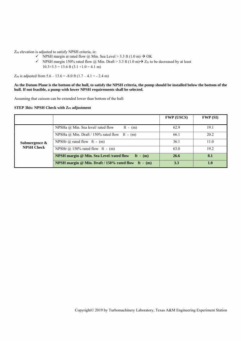
ZPI elevation is adjusted to satisfy NPSH criteria, ie:
NPSH margin at rated flow @ Min. Sea Level > 3.3 ft (1.0 m) OK NPSH margin 150% rated flow @ Min. Draft > 3.3 ft (1.0 m) ZPi to be decreased by at least
10.3+3.3 = 13.6 ft (3.1 +1.0 = 4.1 m)
ZPI is adjusted from 5.6 – 13.6 = -8.0 ft (1.7 – 4.1 = - 2.4 m) As the Datum Plane is the bottom of the hull, to satisfy the NPSH criteria, the pump should be installed below the bottom of the hull. If not feasible, a pump with lower NPSH requirements shall be selected. Assuming that caisson can be extended lower than bottom of the hull: STEP 3bis: NPSH Check with ZPI adjustment
FWP (USCS) FWP (SI)
Submergence & NPSH Check
NPSHa @ Min. Sea level/ rated flow ft - (m) 62.9 19.1
NPSHa @ Min. Draft / 150% rated flow ft - (m) 66.1 20.2
NPSHr @ rated flow ft - (m) 36.1 11.0
NPSHr @ 150% rated flow ft - (m) 63.0 19.2
NPSH margin @ Min. Sea Level /rated flow ft - (m) 26.6 8.1
NPSH margin @ Min. Draft / 150% rated flow ft - (m) 3.3 1.0

Copyright© 2019 by Turbomachinery Laboratory, Texas A&M Engineering Experiment Station
STEPS 4 & 5: TDH & SHUT OFF CHECKS
FWP (USCS) FWP (SI)
PUMP
&
OPERATING
DATA
Max. specific gravity lb/ft3 - (N/m3) 64.1 10 065
Suction Pressure at ZPI / Max. Sea Level
lb/in2 - (10^5 N/m2) [g]
39.27 2.71
Pump TDH @ rated point ft - (m) 486.9 148.4
Pump Differential pressure @ rated point lb/in2 - (10^5 N/m2) 216.6 14.9
Pump TDH @ shut off ft - (m) 639.8 195.0
Suction friction head losses at RATED flow [hf(hose) + hf(strainer)] ft - (m)
3.26 0.99
Discharge friction losses head at rated flow [hf(pipe stack)] ft - (m)
7.22 2.20
TDH CHECK @ RATED FLOW
DESIGN CRITERIA FOR RATED PRESSURE Min. Draft Min. Draft
Discharge Head at ZFDE @ rated flow / Min. Draft
ft - (m) [gage]
409.6 124.8
Discharge Head at ZRD @ rated flow / Min. Draft
ft - (m) [gage]
408.4 124.5
Discharge Pressure at ZFDE @ rated flow/ Min. Draft
lb/in2 - (10^5 N/m2) [g]
182.2 12.6
Discharge Pressure at ZRD @ rated flow/ Min. Draft
lb/in2 - (10^5 N/m2) [g]
181.7 12.5
SHUTOFF
Max. Discharge Head at ZFDE (Shut off/Max. SW Level) ft - (m) [gage]
615.0 187.5
Max. Discharge Pressure at ZFDE (Shut off/Max. SW Level) lb/in2 - (10^5 N/m2) [g]
273.1 18.9
Required pressure at Reference Discharge Elevation [ZRD]: 174 lb/in2 (12 x 105 N/m2) is NOT satisfied. Piping Class Design Pressure: 290 lb/in2 (20.0x10⁵ N/m2) is above 273.1.0 lb/in2 (18.9 x10⁵ N/m2) Max.
Discharge Pressure : OK SHUT OFF PRESSURE CRITERION IS SATISFIED. PUMP IS DELIVERING HIGHER PRESSURE THAN PROCESS REQUIREMENTS: PUMP TDH to be corrected.

Copyright© 2019 by Turbomachinery Laboratory, Texas A&M Engineering Experiment Station
STEPS 4 & 5 bis: TDH & SHUT OFF CHECKS (repeated following to pump TDH adjustment): Pump TDH at rated point reduced to 469.2 ft (143.0 m) :
FWP (USCS) FWP (SI)
PUMP &
OPERATING DATA
Max. specific gravity lb/ft3 - (N/m3) 64.1 10 065
Suction Pressure at ZPI / Max. Sea Level
lb/in2 - (10^5 N/m2) [g]
39.27 2.71
Pump TDH @ rated point ft - (m) 469.2 143.0
Pump Differential pressure @ rated point lb/in2 - (10^5 N/m2) 208.8 14.4
Pump TDH @ shut off ft - (m) 622 189.6
Suction friction head losses at RATED flow [hf(hose) + hf(strainer)] ft - (m)
3.26 0.99
Discharge friction losses head at rated flow [hf(pipe stack)] ft - (m)
7.22 2.20
TDH CHECK @ RATED FLOW
DESIGN CRITERIA FOR RATED PRESSURE Min. Draft Min. Draft
Discharge Head at ZFDE @ rated flow / Min. Draft
ft - (m) [g]
391.9 119.4
Discharge Head at ZRD @ rated flow / Min. Draft
ft - (m) [g]
390.7 119.1
Discharge Pressure at ZFDE @ rated flow/ Min. Draft
lb/in2 - (10^5 N/m2) [g]
174.4 12.0
Discharge Pressure at ZRD @ rated flow/ Min. Draft
lb/in2 - (10^5 N/m2) [g]
174.0 11.9
SHUTOFF
Discharge Head at ZFDE @ rated flow / Min. Draft ft - (m) [g]
596.1 182.1
Discharge Pressure at ZFDE @ rated flow/ Min. Draft lb/in2 - (10^5 N/m2) [g]
265.2 18.3
Conclusion of the Example #2: ALL SELECTION CRITERIA ARE SATISFIED / PUMP SELECTION IS CORRECT. CONCLUSION The proper specification operating conditions and eventually selection of SWL pumps requires several steps to be followed. Initially the detailed engineering contractor and the SWL pump suppliers shall be aligned on consistent definitions of the various technical terms especially those defining various elevations in the pumping system. Then the detailed engineering contractor shall be clearly aware of the factors that define/ influence boundaries of operation of the SWL pump. This is followed by detailed analysis to quantify the operational design criteria and eventually the proper selection of the SWL pump alongside with the SWL supplier/ bidder. This paper elaborated on the equations and steps that would guide the detailed engineering engineer to have proper assessment of the requirements, quantify the right operational design criteria and collaborate with the supplier to ensure the right selection of the SWL pump.

Copyright© 2019 by Turbomachinery Laboratory, Texas A&M Engineering Experiment Station
NOMENCLATURE
EOC End of Curve FDE Flange Discharge Elbow FLNG Floating Liquefied Natural Gas FWP Fire Water Pumps HAT Highest Astronomical Tide LAT Lowest Astronomical Tide MAWP Maximum Allowable Working PressureNPSHa Net Positive Suction Head available NPSHr Net Positive Suction Head required OEM Original Equipment Manufacturer PI Pump Impeller Inlet RD Reference Discharge SWL Sea Water Lift TDH Total Differential Head SWLP Sea Water Lift Pump
FIGURES Figure 1 - Sea Motions Figure 2 - Illustration of Seawater Temperature Gradient Figure 3 – Seawater Intake Riser Pipes (subsea) Figure 4 – Seawater Discharge Stack Column (In blue) Figure 5 – E-motor above pump Figure 6 – E-motor below pump Figure 7 – Long Shaft with external electric motor Figure 8 – Example of SWL pumps located externally (Courtesy AKPO FPSO) Figure 9 – Schematic of Elevations Definition Figure 10 – System Arrangement & System Total Energy Figure 11 – Pressure equivalence downstream the pump Figure 12 – Pump Selection Flow Chart Figure 13 – Head versus Flow: Test data and Site calculation Figure 14 – Head versus Flow: Test data and Site calculation EQUATIONS Equation 1: Energy Balance for Pumping Systems Equation 2: Total Differentail Head (TDH) Equation 3: Pressure Equivalence Equation 4: Available Net Positive Suction Head Equation 5: Shut-off Pressure Equation 6: Data conversion from Test conditions to Site conditions REFERENCES Karassik, I. J.,Krutzsch, W. C., Fraser W. H. and Messina J. P.,1986, Pump Handbook, McGraw Hill http://geomatix.net/tides/tidal_levels.htm https://www.framo.com/oil-and-gas-pumping-systems/products/seawater-lift-pumps/ https://subsea-umbilicals-risers-flowlines.com/products/water-intake-riser-pump-water-as-deep-as-1000m-by-bardot-group