Hydraulic fracturing of hard top coal and roof for controlling ...
15
Hydraulic fracturing of hard top coal and roof for controlling gas during the initial mining stages in longwall top coal caving: a case study Bingxiang Huang 1 , Qingying Cheng 2 , Xinglong Zhao 1 and Chao Kang 1 1 State Key Laboratory of Coal Resources and Safe Mining, China University of Mining and Technology, Xuzhou, 221116, People’s Republic of China 2 School of Safety Engineering, China University of Mining and Technology, Xuzhou, Jiangsu 221116, People’s Republic of China E-mail: [email protected] Received 3 February 2018, revised 25 July 2018 Accepted for publication 1 August 2018 Published 20 August 2018 Abstract Due to the poor cavability of top coal, the connection between the high-level gas drainage lane and the gob is not sufficient during the initial mining stage in a extra-thick coal seam with hard roof and hard coal in longwall top coal caving. The gases gathering in the gob area will suddenly release and cause extrusion when the upper roof first collapses and falls, which will result in gas overrunning and affecting the safety production. Based on the propagation law of hydraulic fractures and the cause of gas overrunning, a new technology was put forward to solve the gas overrunning during the initial mining stage in longwall top coal caving operations. A method for designing the drilling hole parameters for hydraulic fracturing was formed. Hydraulic fracturing was carried out in the measure lane to weaken the top coal and roof and induce the mining pressure to break coal; through this the cavability of the top coal and roof could be improved. Simultaneously, the connection between the gob and the high-level gas drainage lane, and the permeability of the coal seam, could be improved; moreover, the gas drainage effect could be enhanced. The field test in the Tashan Coal Mine indicated that the high-level gas drainage lane was completely connected with the gob after hydraulic fracturing when the working face advanced 15 m, and the gas concentration at the upper corner of the working face was maintained at a level of 0.3% during the initial mining stage. Furthermore, the gas overrunning during the initial mining stages was avoided, and safety was guaranteed. Keywords: gas overrunning, hard top coal and hard roof, initial mining stage, hydraulic fracturing, gas control (Some figures may appear in colour only in the online journal) 1. Introduction There are many extra-thick coal seams in China, and the primary mining method is fully mechanized top coal caving (Yasitli and Unver 2005, Huang et al 2007, 2011). Because the top coal is thick, and the amount of gas emissions in the working face is large, the ‘U+I’ ventilation method is usually applied, i.e. setting a high-level gas drainage lane parallel to and near the air return entry in the roof to extract gas from the gob. During normal recovery, the high-level gas drainage lane can be used for extracting gas from the gob efficiently, thereby eliminating gas overrunning. However, field practices indicated that the top coal did not cave quickly during the recovery of most working faces, especially in coal seams with a hard roof and hard coal, such as the Datong Mining Area. The conduction between the roof and the high- Journal of Geophysics and Engineering J. Geophys. Eng. 15 (2018) 2492–2506 (15pp) https://doi.org/10.1088/1742-2140/aad75c 1742-2132/18/0602492+15$33.00 © 2018 Sinopec Geophysical Research Institute Printed in the UK 2492 Downloaded from https://academic.oup.com/jge/article/15/6/2492/5209797 by guest on 04 July 2022
-
Upload
khangminh22 -
Category
Documents
-
view
1 -
download
0
Transcript of Hydraulic fracturing of hard top coal and roof for controlling ...

Hydraulic fracturing of hard top coal androof for controlling gas during the initialmining stages in longwall top coal caving: acase study
Bingxiang Huang1, Qingying Cheng2, Xinglong Zhao1 and Chao Kang1
1 State Key Laboratory of Coal Resources and Safe Mining, China University of Mining and Technology,Xuzhou, 221116, People’s Republic of China2 School of Safety Engineering, China University of Mining and Technology, Xuzhou, Jiangsu 221116,People’s Republic of China
E-mail: [email protected]
Received 3 February 2018, revised 25 July 2018Accepted for publication 1 August 2018Published 20 August 2018
AbstractDue to the poor cavability of top coal, the connection between the high-level gas drainage laneand the gob is not sufficient during the initial mining stage in a extra-thick coal seam with hardroof and hard coal in longwall top coal caving. The gases gathering in the gob area will suddenlyrelease and cause extrusion when the upper roof first collapses and falls, which will result in gasoverrunning and affecting the safety production. Based on the propagation law of hydraulicfractures and the cause of gas overrunning, a new technology was put forward to solve the gasoverrunning during the initial mining stage in longwall top coal caving operations. A method fordesigning the drilling hole parameters for hydraulic fracturing was formed. Hydraulic fracturingwas carried out in the measure lane to weaken the top coal and roof and induce the miningpressure to break coal; through this the cavability of the top coal and roof could be improved.Simultaneously, the connection between the gob and the high-level gas drainage lane, and thepermeability of the coal seam, could be improved; moreover, the gas drainage effect could beenhanced. The field test in the Tashan Coal Mine indicated that the high-level gas drainage lanewas completely connected with the gob after hydraulic fracturing when the working faceadvanced 15 m, and the gas concentration at the upper corner of the working face wasmaintained at a level of 0.3% during the initial mining stage. Furthermore, the gas overrunningduring the initial mining stages was avoided, and safety was guaranteed.
Keywords: gas overrunning, hard top coal and hard roof, initial mining stage, hydraulicfracturing, gas control
(Some figures may appear in colour only in the online journal)
1. Introduction
There are many extra-thick coal seams in China, and theprimary mining method is fully mechanized top coal caving(Yasitli and Unver 2005, Huang et al 2007, 2011). Becausethe top coal is thick, and the amount of gas emissions in theworking face is large, the ‘U+I’ ventilation method isusually applied, i.e. setting a high-level gas drainage lane
parallel to and near the air return entry in the roof to extractgas from the gob. During normal recovery, the high-level gasdrainage lane can be used for extracting gas from the gobefficiently, thereby eliminating gas overrunning. However,field practices indicated that the top coal did not cave quicklyduring the recovery of most working faces, especially in coalseams with a hard roof and hard coal, such as the DatongMining Area. The conduction between the roof and the high-
Journal of Geophysics and Engineering
J. Geophys. Eng. 15 (2018) 2492–2506 (15pp) https://doi.org/10.1088/1742-2140/aad75c
1742-2132/18/0602492+15$33.00 © 2018 Sinopec Geophysical Research Institute Printed in the UK2492
Dow
nloaded from https://academ
ic.oup.com/jge/article/15/6/2492/5209797 by guest on 04 July 2022

level gas drainage lane is not sufficient, and the effect of usinga high-level gas drainage lane to extract gas is not obvious,which leads to the overrunning of gas in the working face. Inaddition, a large area of the main roof caving and the suddenrelease of gas from the gob leads to gas overrunning in theworking face during the first weighting of a roof. As a result,the management of gas in the early mining stage is a veryimportant technical problem (Cheng et al 2003, Jianget al 2011). Gas overrunning occurs in several fullymechanized caving faces during the period of first weightingin the Datong Mine Area, which affects the safe recoveryof coal.
To solve the problem of gas overrunning in the workingface during the initial mining stage, it is necessary to weakenthe hard roof. The conventional method to weaken the hardcoal and hard roof is to use artificial blasting (Altounyan andTaljaard 2001, Banerjee et al 2003, Xie and Zhou 2008) tocause the roof to cave or fracture before mining. However, theeffect of roof fracturing is not sufficient to weaken the roof,and roof caving by blasting may lead to safety problems,especially in a highly gassy mine. Research studies andapplications for weakening the roof using water have alsobeen conducted, but these works only focused on softeningthe rock by increasing the moisture content through waterinjection.
Previous studies indicated that hydraulic fracturing caneffectively weaken coal–rock mass and transform its structure(Huang et al 2011, 2012, 2017, 2018). The top coal can beweakened by hydraulic fracturing before mining; meanwhile,roof hydraulic fracturing can induce a ground pressureincrease and strengthen the mining stress to break the top coaland enhance the top coal caving, and thus the caving ability ofthe top coal can be improved. Therefore, the abandoned coaland gas accumulation in gob can be reduced. The perme-ability of the coal seam can also be improved, which canenhance the gas drainage effect. Roof hydraulic fracturingbefore mining can enhance the roof caving in the gob, thusavoiding a large area of hanging roof appearing in the gob andreducing the first weighting intensity induced by the initialfracturing of the roof. Therefore, gases gathering in the gobwill not be released instantly and massively to the workingface by a large area of hanging roof caving. The gas over-running during the initial mining stages in a longwall top coalcaving can be controlled.
Hydraulic fracturing technology has been widely used inthe oil and natural gas industry. There have been many studieson the hydraulic fractures initiation and propagation, invol-ving experiments, numerical simulations, and field tests, andit has developed into a mature technology for oil and naturalgas exploitation (Hubbert and Willis 1957, Haimson andFairhurst 1969, Takatoshi 2008, Zeng and Yao 2016). Whilethe study and application of hydraulic fracturing in under-ground coal mines started late, the complicated structure ofthe coal–rock mass, soft texture of the coal seam, adsorptionand desorption of methane, development of natural fractures,serious heterogeneity, impact of mining, etc, cause thehydraulic fracturing of coal–rock mass to become compli-cated. This has been proved by the practice of hydraulic
fracturing in underground coal mines and coalbed methaneexploitation. Therefore, hydraulic fracturing in undergroundcoal mines cannot copy the theory and experience ofhydraulic fracturing in oil and gas reservoirs.
In this study, a new technology was put forward toeliminate the gas overrunning during the initial mining stagesin longwall top coal caving. Based on the propagation law ofthe hydraulic fractures and the cause of the gas overrunning, aprincipal to eliminate gas overrunning and a method fordesigning the drilling hole parameters for hydraulic fracturingwere formed. Hydraulic fracturing was carried out in themeasures lane to weaken the top coal and roof, and themining pressure was induced to break the top coal. Throughthis the cavability of the top coal and roof could be improved,and, simultaneously, the connection between the gob and thehigh-level gas drainage lane and the permeability of the coalseam could be improved. Therefore, the gas drainage effectcould be enhanced. This technology was applied in TashanCoal Mine. The caving effect of the top coal and roof, gasdrainage effect in the high-level gas drainage lane, and gasconcentration in the working face after hydraulic fracturingduring the initial mining stages in longwall top coal cavingwere analyzed.
This study provides a new idea for controlling gasoverrunning in underground coal mining. Compared to con-ventional blasting technology, hydraulic fracturing is a green,safe, and efficient technology that can be widely applied inunderground coal mines to eliminate the gas overrunningduring the initial mining stages in longwall top coal caving.
2. Analysis of gas overrunning in the working faceduring the initial mining stages
Gas overrunning occurred in several working faces includingthe 8201 and 8106 working faces in the Tashan Coal Mine ofDatong Mining Area. The 8012 working face is adjacent tothe 8212 working face, and the geological and technologicalconditions of the two faces are similar.
2.1. Geological conditions
The 8212 working face belongs to the #3∼5 Coal Seam,District 2 of the Tashan Coal Mine. The average thickness ofthe coal seam is 11.17 m. The stratigraphy of the 8212working face is shown in figure 1, and the mechanical para-meters of the coal seam and the roof rock are described intable 1. The ground elevation is +1408 to +1573.4 m, andthe working face elevation is +1050 to +950 m. The averageinclined length of the working face is 230.5 m, and the strikelength is 2725 m. The fully mechanized top coal cavingmethod is used to mine the total thickness of the coal. Thecutting height is 3.5 m and the caving height is 7.67 m, with amining and caving ratio of 1:2.19. The relative emission ofgas is 1.88 m3 t−1, and the absolute emission is71.3 m3 min−1. Therefore, the Tashan Coal Mine is classifiedas a highly gassy mine.
2493
J. Geophys. Eng. 15 (2018) 2492 B Huang et al
Dow
nloaded from https://academ
ic.oup.com/jge/article/15/6/2492/5209797 by guest on 04 July 2022

The advancement of the 8212 working face adopts athree-entry system (figure 2). The ventilation pattern is‘entry–return–extract’ (i.e. U+I). The 2212 entry is used forair intake, and the 5212 entry is used for air return. The 8212high-level gas drainage lane is also used for air return, whichis arranged along the roof of the #2 coal seam. The verticaldirection is 20 m away from the top surface of the air returnentry of the working surface, and the horizontal direction isalso 20 m away from the air return entry (figure 2).
2.2. The overrunning of gas during the initial mining stage andits effect on production
When the 8210 working face advanced 17 m from the open-off cut, the top coal caved for the first time. The gas con-centration at the upper corner of the working face wasmaintained at 0.19%, the gas concentration around the end ofthe back-scrapper was 0.18%, the gas concentration in the airreturn entry was 0.17%, and the gas concentration in the high-level gas drainage lane was 0.14%. The maximum absolutegas emission in the working face was 5.01 m3 min−1. Whenthe working face advanced 37.85 m, the immediate roof
Figure 1. The stratigraphy of the 8212 working face.
2494
J. Geophys. Eng. 15 (2018) 2492 B Huang et al
Dow
nloaded from https://academ
ic.oup.com/jge/article/15/6/2492/5209797 by guest on 04 July 2022

significantly caved for the first time, which resulted in gasoverrunning (figure 3). At that time, the gas concentration atthe upper corner of the working face was 1.94%, that in theair return entry was 0.45%, and that in the high-level gasdrainage lane was 3.2%, which slow down the speed of theworking face advancing. When the working face advanced47.6 m, the upper roof broke for the first time. The gasconcentration gradually became steady until the working faceadvanced 53 m (table 2).
There are three contributions to the gas overrunning: (1)the poor caving ability of the top coal leads to a large amountof coal left in the gob; (2) the top coal cannot cave in time,which results in insufficient connection between the high-level gas drainage lane and the gob, thus inhibiting thefunction of the high-level gas drainage lane; (3) before theroof caves, large voids or space form in the gob, where asignificant amount of gas accumulates. The accumulated gaswill be driven out from the gob at once when the upper roofbreaks on a large scale.
3. The principal of hydraulic fracturing to solve gasoverrunning
Hydraulic fracturing can transform the internal structure ofthe coal–rock mass and improve its permeability throughmain hydraulic cracks and airfoil branch fissures. Water
penetrates into the coal–rock mass through the cracks, whichleads to an increase in the water content and weakness in therock’s strength. The water pressure parameters and propaga-tion morphology of hydraulic fractures for the coal–rock massare determined by the stress field, mechanical properties, andstructural characteristics of the rock mass. Hydraulic fractur-ing can transform the coal–rock mass structure, weaken itsstrength, and improve its permeability through the extensionof the main hydraulic crack, airfoil branch fissures, andwetting ability (Huang et al 2011). Different projects haveemphasized these different factors.
There has been much research on the mechanism ofhydraulic fracturing in mining rocks (Fan et al 2012, 2014).The water pressure within the borehole will initially crack thehole wall because the tangential effective tensile stress of thehole wall exceeds the tensile strength of the rock. For thecrustal stress field, the orientation of maximal effective tensilestress tangential to the borehole wall is fixed (Hubbert andWillis 1957, Haimson and Fairhurst 1969). The propagatingdirection of the primary hydraulic fractures generated bytraditional hydraulic fracturing is controlled by the three-dimensional stress field and propagate perpendicular to thedirection of the minimum principle stress (Huanget al 2012, 2017).
Natural fractures have great influence on hydraulic frac-ture propagation. Due to the existence of original cracks,hydraulic cracks tend to form connections through rockbridges (Huang et al 2012). After the hydraulic fracturecontacts the pre-existing fracture, one of two phenomena isobserved: crossing the pre-existing fracture, or not crossingthe pre-existing fracture (Cheng et al 2015). A portion ofinjected fluid is lost into closed empty fractures that cut acrossthe main hydraulic fracture, and this delays the pressureincreases required for fracture growth past the crosscuttingfracture (Zhang et al 2009).
Based on the extension law of hydraulic fractures(Alekseenko et al 1997, Takatoshi 2008, Cheng et al 2012,Huang et al 2012, 2013, 2014) and the cause of the gasoverrunning, boreholes are drilled at the initial open-off cutbefore the first caving of the upper roof to weaken the top coaland the roof. During this process, the upper roof is cutthrough and the roof is weakened, and the caving ability of
Table 1. Mechanical parameters of the coal–rock.
Strata LithologyUniaxial compressivestrength (MPa)
Tensilestrength (MPa) Average fracture toughness (MPa·m1/2)
Main roof Pebbly mediumsandstone
33.67 3.83 58.63
Pebbly coarsesandstone
31.33 ∼ 59.50 3.63 ∼ 5.37
Coarse sandstone 40.67 ∼ 48.33 3.60 ∼ 4.80Very fine sandstone 49.67 ∼ 67.00 3.90 ∼ 6.10Medium sandstone 63.00 7.37
Immediate roof Sandy mudstone 45.33 5.87 —
Silicified coal — 2.37Igneous rock 86.67 6.77
Coal seam #3 ∼ 5 coal 27 ∼ 37 0.33 ∼ 1.8 —
Figure 2. Entry arrangement of the 8212 face.
2495
J. Geophys. Eng. 15 (2018) 2492 B Huang et al
Dow
nloaded from https://academ
ic.oup.com/jge/article/15/6/2492/5209797 by guest on 04 July 2022

roof is thus improved. Mining pressure is induced to break thetop coal. Hydraulic fracturing weakens the top coal andimproves its permeability, which can improve the cavabilityof the top coal and make it cave quickly. Therefore, the coaland gas content in the gob will be reduced, and the gob willbe filled with gangue as much as possible. Besides, the firstweighting strength of the working face can be weakened, theconduction between the gob and the high-level gas drainagelane can be enhanced, and the gas suddenly rushing out fromthe gob all at once can be avoided.
4. Test program of hydraulic fracturing for hard roofand top coal
4.1. Determination of the rock strata for hydraulic fracturing
The immediate roof consists of two layers of carbonaceousmudstone with a thickness of 10 m from the drillhole columnin the working face and the air return entry near the roofmeasure lane (figure 4). The main roof primarily consists ofsiltstone, fine sandstone, medium sandstone, coarse sand-stone, and pebbly sandstone. The total thickness of the mainroof is approximately 23 m, and its rock is hard and itscement is dense.
Referring to the situation of the site, hydraulic fracturingcan vertically control the roof 30 m away from the coal seam.
4.2. Layout of borehole
To conduct hydraulic fracturing and control the top coal androof, the roof measure lane is developed parallel to and nearthe open-off cut in the high-level gas-pumping lane (figure 5).The measure lane also contributes to solving the problem ofgas overrunning of the return air by importing the gas releasedwhen the roof weighting goes into the high-level gas-pump-ing lane.
(1) Parameters of the roof measure lane:The average first weighting interval of nine work-
ing faces of District 2 in Tashan Coal Mine is 50.31 m.The roof measure lane is implemented in the high-levelgas-pumping lane at a location 25 m away from the
open-off cut in the roof of the 8212 working face. Thelength of the roof measure lane is 150 m, whoseexcavation refers to a fault in the initial mining periodof the 8212 working face. The section and supportparameter of the measure lane are the same as the high-level gas-pumping lane.
(2) Layout of hydraulic fracturing boreholes.
In the measure lane, groups of boreholes are made every20 m from near the end of the 2212 entry in the roof measurelane, with each group including four boreholes. The para-meters of the boreholes are described in figures 5(a) and (b)and table 3. The angle of elevation and depression was usedto describe the borehole direction. The angle of elevation ofthe borehole refers to the angle between the horizontal and thedirection of the borehole, which is above the horizontal.Similarly, the angle of depression of the borehole refers to theangle between the horizontal and the direction of the bore-hole, which is below the horizontal. Boreholes #1, #2, and#3 are used to cut through and weaken the main roof. Thereis a ring groove at the bottom of every borehole. Borehole #4is used to fracture and weaken the top coal.
In the 8212 entry, two groups of boreholes are set, 15 mand 30 m away from the initial open-off cut. Each groupconsists of two boreholes (figures 5(a) and (c), and table 3). Aring groove is placed on the bottom wall of borehole #5 as aprefabricated fissure to form a crack that is vertical to the facestrike direction in the roof. Borehole #6 is used to fractureand weaken the top coal.
4.3. Hydraulic fracturing equipment and technology
The hydraulic fracturing area is located in the measure lanebelow the roof of the 8212 working face. The hydraulicfracturing equipment is set in the high-level gas drainage lanein the roof of the 8212 face. The normal pressure of thefracturing pump is 56 MPa, and the rated flow is 200 L min−1.Figure 6 shows the layout of the hydraulic fracturing equip-ment. The drill packer is set to the desired depth using a high-pressure sealing pipe, and then we turn on the pump and startfracturing. The drilling hole of hydraulic fracturing should beconducted from the bottom to the entrance of the roof mea-sure lane to ensure safety.
W
Figure 3. Changes in the gas concentration during the early mining stage of the 8210 working face.
2496
J. Geophys. Eng. 15 (2018) 2492 B Huang et al
Dow
nloaded from https://academ
ic.oup.com/jge/article/15/6/2492/5209797 by guest on 04 July 2022
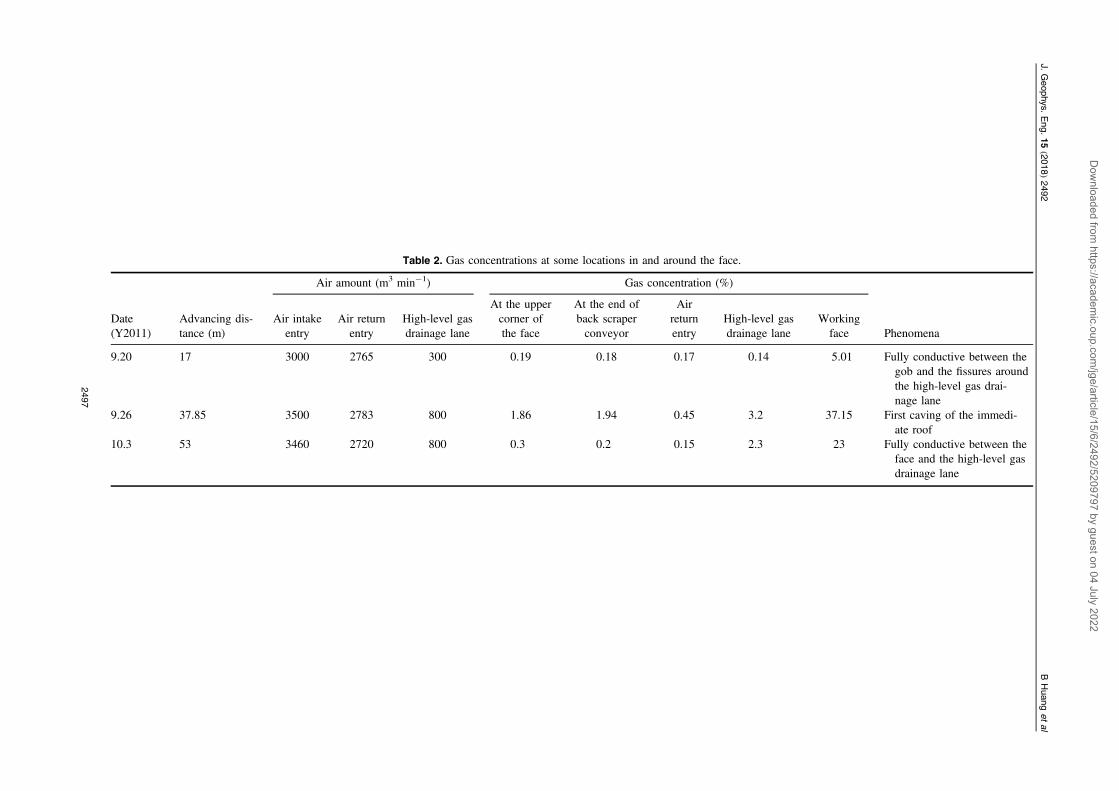
Table 2. Gas concentrations at some locations in and around the face.
Air amount (m3 min−1) Gas concentration (%)
Date(Y2011)
Advancing dis-tance (m)
Air intakeentry
Air returnentry
High-level gasdrainage lane
At the uppercorner ofthe face
At the end ofback scraperconveyor
Airreturnentry
High-level gasdrainage lane
Workingface Phenomena
9.20 17 3000 2765 300 0.19 0.18 0.17 0.14 5.01 Fully conductive between thegob and the fissures aroundthe high-level gas drai-nage lane
9.26 37.85 3500 2783 800 1.86 1.94 0.45 3.2 37.15 First caving of the immedi-ate roof
10.3 53 3460 2720 800 0.3 0.2 0.15 2.3 23 Fully conductive between theface and the high-level gasdrainage lane
2497
J.Geophys.
Eng.
15(2018)
2492BHuang
etal
Dow
nloaded from https://academ
ic.oup.com/jge/article/15/6/2492/5209797 by guest on 04 July 2022

Figure 4. Borehole columnar diagram for the roof prospect.
2498
J. Geophys. Eng. 15 (2018) 2492 B Huang et al
Dow
nloaded from https://academ
ic.oup.com/jge/article/15/6/2492/5209797 by guest on 04 July 2022

5. Analysis of the effect of field tests
5.1. Water pressure curve for hydraulic fracturing
Water is used as a fracturing fluid in the field test, with aviscosity of ´ - ·1.1404 10 Pa s3 and temperature of 15 °C.Therefore, the viscosity of the fracturing fluid is
´ - ·1.1404 10 Pa s3 . The magnitude of the maximum hor-izontal principal stress ranges from 12 ∼ 12.9 MPa, and theorientation is N (19° ∼ 26.7°) W. The magnitude of theminimum horizontal principal stress ranges from 6.4 ∼ 8.22
MPa, and the orientation is N (63.3° ∼ 71°) E. The verticalstress is 11.44 MPa.
Hydraulic fracturing tests were conducted in 28 drillingholes, including 20 roof fracturing holes and 8 top coalfracturing holes. The parameters of the drilling holes aredescribed in tables 4 and 5. The maximum pressure refers tothe maximum water pressure monitored in the pipeline sincethe pressure sensor was installed in the pipeline near theborehole (figure 6(a)). This pressure is larger than thebreakdown pressure. By the data monitored from the waterpressure monitoring device, the initial breakdown pressure of
Figure 5. Borehole layout for hydraulic fracturing.
Table 3. Parameters of boreholes for hydraulic fracturing.
Borehole No. Bit diameter (mm) Borehole depth (m) Angle (°) Quantity
Borehole #1 50 28 30 (angle of elevation) 8Borehole #2 50 15 70 (angle of elevation) 8Borehole #3 50 20 40 (angle of elevation) 8Borehole #4 65 25 35 (angle of depression) 8Borehole #5 50 20 45 (angle of elevation) 2Borehole #6 65 14 45 (angle of depression) 2
2499
J. Geophys. Eng. 15 (2018) 2492 B Huang et al
Dow
nloaded from https://academ
ic.oup.com/jge/article/15/6/2492/5209797 by guest on 04 July 2022

the roof is approximately 26.5 MPa, the maximum pressure isapproximately 28 MPa, and the average flow is approximately65 L min−1. The initial breakdown pressure of the top coal isapproximately 26 MPa, the maximum pressure is approxi-mately 26.7 MPa, and the average flow is approximately111 L min−1.
The typical hydraulic fracturing is as follows.The drilling depth of borehole #3 in Group 1 is 20 m,
and its sealing depth is 18 m. The hydraulic fracturing ofborehole #3 in Group 1 lasted 30 min, and its water pressurechanging with time is shown in figure 7. The hydraulicfracturing process can be divided into three stages. The firststage is from 0 s to the initial break of the rock, whichoccurred at 9 s, and the breakdown pressure of the rock is23.8 MPa. The second stage is from 9 to 120 s, during whichthe water pressure ranges between 19.6 MPa and 23.8 MPa.The third stage starts from 120 s, during which the range of
water pressure is less than before and remains stable atapproximately 23 MPa. The leak-off of the fracturing fluid inthe fracture system and the amount volume of water to createcracks are generally stable, which indicates that the cracks areextending in the broken strata or have already connected thegate road and the roof measure lane.
Water begins to leak out through the roof bolts and cablebolts between#117 and#134 steel bands after the end of thehydraulic fracturing, which indicates that the propagationradius of the hydraulic crack is at least 8 m.
Drillhole #5 drillhole of Group 1 in the 8212 high-levelgas drainage lane is located in the sealing area (used to pre-vent it from connecting to the working face) and is 25 m awayfrom the open-off cut. The drilling depth of borehole #5borehole is 20 m, and its sealing depth is 13 m with a sealingsegment length of 1.2 m. The hydraulic fracturing lasted49 min (figure 8). The water pressure increased to 22.6 MPa
Figure 6. Equipment layout and the sealing and installation of hydraulic fracturing.
2500
J. Geophys. Eng. 15 (2018) 2492 B Huang et al
Dow
nloaded from https://academ
ic.oup.com/jge/article/15/6/2492/5209797 by guest on 04 July 2022

at 11 s, and then remained constant at 22.6 MPa for 8 s.Afterward, the water pressure increased to 24.1 MPa, and therock was initially fractured. Subsequently, the water pressuredecreased to 24.1 MPa and ranged between 24.1 to 24.3 MPa,which was lower than the pressure before the initialfracturing.
Drillhole #5 drillhole is located in the high-level gasdrainage lane between #2733 to #2734 steel bands. Waterbegan to leak out through the drillhole near the #2715 steelband after 7 min. When hydraulic fracturing was completed,water leaked out through all the cable bolts between #2716and #2691 steel bands (but not the roof bolts) (figure 9),which indicated that the hydraulic crack extended at least38 m.
The drilling depth of borehole #4 of the first group is 27m, with a sealing depth of 20 m. The hydraulic fracturinglasted 13 min (figure 10). The water pressure increased to26.4 MPa at 11 s, and the coal was initially fractured. Sub-sequently, the water pressure decreased to 25 MPa immedi-ately, and then it remained nearly constant at 23.6 MPa aftervarying over a small range and decreasing slowly.
5.2. Factors affecting hydraulic fracture propagation
The hydraulic fracture propagation is mainly affected by thepumping rate, in situ stress, mining stress, natural fractures,fracture toughness heterogeneity, etc. Among these effectfactors, the fracture toughness heterogeneity plays a leadingrole. If the fracture toughness heterogeneity of the coal–rockmass is more serious, the prior propagation direction ofhydraulic fractures would not be obvious, the randomness ofthe hydraulic fractures’ propagation direction will increase,and crack reorientation will easily occur. As a result, thesurface roughness of the crack increases, and the phenomenonof crack bifurcation is obvious, which will result in a morecomplex fracture morphology. On the contrary, if the fracturetoughness of the coal–rock mass is relatively homogeneous,the fracture propagation is mainly controlled by the stressfield and the water pressure in the fracture, and the fracturemorphology is relatively simple.
The fracture toughness heterogeneity of coal is moreserious, which results in a complex fracture morphology inthe coal seam. Top coal hydraulic fracturing requires a multi-fracture network in the coal seam to fully weaken the top coal
Table 4. Records from borehole hydraulic fracturing in the roof.
Borehole No. Fracturing time (min) Maximum water pressure (MPa) Average flow rate (L min−1)
Group 1, borehole #1 20 28.0 —
Group 1, borehole #2 20 27.3 —
Group 1, borehole #3 30 23.8 —
Group 2, borehole #1 20 26.0 65Group 2, borehole #3 25 26.5 68Group 3, borehole #1 27 26.3 60Group 3, borehole #2 25 25.9 65Group 3, borehole #3 27 25.3 63Group 4, borehole #1 25 26.0 59Group 4, borehole #3 36 27.0 62Group 5, borehole #1 21 27.5 66Group 5, borehole #2 25 26.7 68Group 5, borehole #3 35 26.3 63Group 6, borehole #1 35 27.3 58Group 6, borehole #3 20 26.0 60Group 7, borehole #1 30 26.8 98Group 7, borehole #3 29 26.8 61Group 8, borehole #1 25 24.5 71Group 8, borehole #3 30 25.0 76Set 1, borehole #5 49 25.8 65
Table 5. Records from borehole hydraulic fracturing in the top coal.
Borehole No. Fracturing time (min) Maximum water pressure (MPa) Average flow rate (L min−1)
Group 1, borehole #4 13 26.4 113Group 2, borehole #4 30 26.0 115Group 3, borehole #4 19 25.5 109Group 4, borehole #4 39 26.7 108Group 5, borehole #4 35 26.5 111Group 6, borehole #4 31 26.6 103Group 7, borehole #4 30 26.2 108Group 8, borehole #4 86 26.6 120
2501
J. Geophys. Eng. 15 (2018) 2492 B Huang et al
Dow
nloaded from https://academ
ic.oup.com/jge/article/15/6/2492/5209797 by guest on 04 July 2022

and increase the permeability of the coal. The fracturetoughness of the rock is relatively homogeneous, whichresults in a simple fracture morphology in the roof. Roofhydraulic fracturing requires the roof to fall quickly.
Therefore, the directional hydraulic fracturing technology isadopted. The pre-splitting grooving at the bottom of theborehole guides the hydraulic fracture to propagate in thedirected direction, and induces the roof to fall promptly underthe effect of mining stress.
Hydraulic fracturing should be coordinated with miningwork in time and space. The implementation of hydraulicfracturing should consider the mining stress and its dynamicchange. Hydraulic fracturing is generally performed prior tomining, and artificial hydraulic fractures are generated in thecoal and rock seam to weaken the coal–rock mass. Based onthe distribution of abutment pressure and the weakeningcharacteristics by hydraulic fracturing, the reasonable distanceto advance the coal wall for hydraulic fracturing wasdetermined.
Figure 7. Water pressure curve for the hydraulic fracturing of borehole #3 borehole of Group 1.
Figure 8. Water pressure curve for borehole #5 hydraulic fracturing.
Figure 9. Water leaking out from an anchor cable bolt.
2502
J. Geophys. Eng. 15 (2018) 2492 B Huang et al
Dow
nloaded from https://academ
ic.oup.com/jge/article/15/6/2492/5209797 by guest on 04 July 2022

5.3. The effect of mine pressure, and the top coal caving abilityduring the initial mining stages
The ZF13000-25-38 hydraulic support with a four-propchock-shield, and low-order sublevel caving coal are used tosupport the roof at the 8212 longwall panel face. Figure 11shows the variation in average support resistance during theinitial mining stages. Because the strength of the top coal androof was weakened by hydraulic fracturing, the mine pres-sures were enhanced to break the top coal, which caused thetop coal and roof to quickly cave; moreover, the top coal atthe end of the longwall face broke uniformly and cavedsufficiently (figure 12). Because the top coal caved earlierthan before, the pressure of the back props graduallydecreased to a level lower than that of the front ones after topcoal caving occurred. Since the roof was weakened byhydraulic fracturing to cave quickly with the top coal caving,the space for gas accumulation in the gob reduced. During the
Figure 10. Water pressure curve of hydraulic fracturing for the top coal.
Figure 11. Support resistance after hydraulic fracturing in the initial mining period.
Figure 12. Top coal caving at the end of longwall mining withsublevel caving face.
2503
J. Geophys. Eng. 15 (2018) 2492 B Huang et al
Dow
nloaded from https://academ
ic.oup.com/jge/article/15/6/2492/5209797 by guest on 04 July 2022

initial mining period, the main roof activities became quiteintense, without any large and obvious periodic weighting.
5.4. The effect of gas drainage during the initial mining period
After the hydraulic fracturing of the top coal and roof in theroof measure lane, the gas concentration increased to 0.58%when the working face advanced 10 m, which indicated thatthe high-level gas drainage lane had connected with the gob.The gas concentration in the gas drainage lane increased to1.1% when the face advanced 15 m, and the high-level gasdrainage lane had completely connected with the gob throughfissures and cracks at this moment. Subsequently, the gasconcentration in the high-level gas drainage lane decreased toapproximately 0.8%. Later, two fluctuations in the gas con-centration appeared in the high-level gas drainage lane, whichmay have been caused by roof caving. When the faceadvanced 49 m, the gas concentration in the high-level gasdrainage lane increased to 1.37%. It is speculated that theincrease was caused by the first weighting of the upper hardrock. However, the support resistance did not rise sig-nificantly. When the face advanced 60 m, the gas con-centration in the high-level gas drainage lane decreased to0.72% and then became stable.
In the initial mining period, the gas concentration in theupper corner ranges between 0.21% and 0.3%, the gas con-centration in the air return entry ranges between 0.14% and0.18% (figure 13). The gas overrunning was completelyeliminated by the hydraulic fracturing, and safety wasensured.
5.5. The stress disturbance effect, and permeabilityimprovement
The local stress field at the front of fracture tips and two sidesof the main fracture is perturbed by the propagation ofhydraulic fractures; this is called the stress disturbance effect.Previous studies indicated that the stress disturbance is mostobvious in the direction perpendicular to the main fracture,and the stress disturbance in other directions is relativelysmall.
Hydraulic fractures not only provide many channels forgas flow in the coal seam, but also connect with the original
fractures and improve the connectivity of the fracture net-work, which can effectively improve the permeability of thecoal seam. There have been many studies on the permeabilityenhancement of oil and natural gas reservoirs by hydraulicfracturing. The results show that hydraulic fracturing caneffectively increase the permeability of oil and natural gasreservoirs. In this study, hydraulic fracturing was carried outin the coal seam at the measure lane before mining, andartificial hydraulic fractures were generated to provide manychannels for gas flow in the coal seam. Meanwhile, hydraulicfractures connected with the original fractures to improve theconnectivity of the fracture network, which can effectivelyimprove the permeability of the coal seam. After hydraulicfracturing, the gas concentration in the high-level gas drai-nage lane increased obviously. When the face advanced 49 m,the gas concentration in the high-level gas drainage laneincreased to 1.37%. This indicated that the permeability of thecoal seam was effectively improved by hydraulic fracturing.In addition, due to the quick and full caving of the top coal,the connection between the gob and the high-level gas drai-nage lane were also improved. The amount of gas drainagefrom the gob increased, which could also result in theincrement of gas concentration in the high-level gas drai-nage lane.
5.6. Optimal design of hydraulic fracturing in mining, andimplications for fracture treatment
Hydraulic fracturing should be coordinated with mining workin time and space. The implementation of hydraulic fracturingshould consider the mining stress and its dynamic change.Hydraulic fracturing is generally performed prior to mining,and artificial hydraulic fractures are generated in the coal androck seam to weaken the coal–rock mass. Based on the dis-tribution of abutment pressure and the weakening character-istics by hydraulic fracturing, the reasonable distance toadvance the coal wall for hydraulic fracturing wasdetermined.
By using hydraulic fracturing to weaken the coal–rockmass, some weak structural planes are created in the coal–rock seam through the propagation of hydraulic fracturing,and the overall strength of the coal–rock mass is reduced.With the advancing working face, the weakened coal–rock
Figure 13. Gas concentration after hydraulic fracturing during the initial mining period.
2504
J. Geophys. Eng. 15 (2018) 2492 B Huang et al
Dow
nloaded from https://academ
ic.oup.com/jge/article/15/6/2492/5209797 by guest on 04 July 2022

seam will break and cave quickly under the effect of miningstress.
6. Conclusions
(1) There are three main causes of gas overrunning in theworking face during the initial mining period: (A) thepoor top coal caving ability causes a significant amountof coal to remain in the gob; (B) the high-level gasdrainage lane and the gob are not connected suffi-ciently; and (C) the first weighting interval is large,which means that a large space is formed in the gob,thereby enabling the storage of a large amount of gas.The first weighting of the roof with a large area couldcause a stormy wind in the underground coal mine,leading to sudden gas release and emission.
(2) The principal of hydraulic fracturing to solve gasoverrunning involves two aspects: (A) to break andweaken the roof and to improve the roof caving abilityto induce the mine pressure to break the coal during theinitial mining stages; and (B) hydraulic fracturing canweaken the top coal, improve the permeability of thetop coal, and improve the top coal’s caving ability.
(3) The roof measure lane is set parallel to the open-off cutat a length half of the estimated first weighting interval.The high-level gas drainage lane was completelyconnected with the gob by fissures and cracks afterhydraulic fracturing when the working face advanced15 m.
(4) Hydraulic fracturing of the top coal and the roof in andaround the open-off cut entry increases the amount ofcracks in the top coal and the roof, causing the roof tobreak sufficiently. During the initial mining stages, theworking face support resistance is stable in general, andno obvious roof weighting is present. The gasconcentration remains under 0.3%.
(5) A complete set of equipment, including a high-pressuresealing device and an installation pipe, meet therequirements of high hydraulic pressure in the coalmine. Hydraulic fracturing in the area of the open-offcut entry can resolve the problem of gas overrunningduring the initial mining period.
Acknowledgments
Financial support for this work, provided by the NationalScience Fund for Excellent Young Scholars (No. 51522406),the National Natural Science Foundation of China (No.51704285), and the Fundamental Research Funds for theCentral Universities (China University of Mining and Tech-nology) (No. 2015XKZD04), is gratefully acknowledged.The authors confirm that any identifiable participants in thisstudy have given their consent for publication.
References
Alekseenko O P, Vaisman A M and Zazovsky A F 1997 A newapproach to fracturing test interpretation using the PKN modelInt. J. Rock Mech. Mining Sci. 34 356–68
Altounyan P and Taljaard D 2001 Developments in controlling theroof in South African coal mines—a smarter approach J. S.Afr. I. Min. Metall. 101 33–40
Banerjee G, Ray A K, Singh G S P and Yadava K P 2003 Hard roofmanagement - a key for high productivity in longwall coalmines J. Mines Metal. Fuel. 51 238–44
Cheng G M, Huang K, Yan F Z, Li W L and Wang S J 2003Methane control for mechanised longwall top-coal cavingfaces in high gas content mines T. I. Min. Metall. A 112 141–8
Cheng Q Y, Huang B X, Li Z H, Fu J H and Wang L F 2012Evolution law of the structure and permeability for coal undersolid-liquid coupling J. Min. Saf. Eng. 29 400–6
Cheng W, Jin Y, Lin Q, Chen M, Zhang Y K, Diao C and Hou B2015 Experimental investigation about influence of pre-existing fracture on hydraulic fracture propagation under tri-axial stresses Geotech. Geol. Eng. 33 467–73
Fan Z Q, Jin Z H and Johnson S E 2014 Oil-gas transformationinduced subcritical crack propagation and coalescence inpetroleum source rocks Int. J. Fract. 185 187–94
Fan Z Q, Jin Z H and Johnson S E 2012 Gas-driven subcritical crackpropagation during the conversion of oil to gas Petrol. Geosci.18 191–9
Haimson B and Fairhurst C 1969 Hydraulic fracturing in porous-permeable materials J. Pet. Technol. 21 811–7
Huang B X, Cheng Q Y, Liu C Y, Wei M T and Fu J H 2011Hydraulic fracturing theory of coal-rock mass and its technicalframework J. Min. Saf. Eng. 28 167–73
Huang B X, Cheng Q Y, Zhao X L, Xue W C and Scoble M 2018Using hydraulic fracturing to control caving of the hangingroof during the initial mining stages in a longwall coal mine: acase study Arab. J. Geosci. Accepted
Huang B X, Huang C M, Cheng Q Y, Huang C H and Xue W C2012 Hydraulic fracturing technology for improvingpermeability in gas-bearing coal seams in underground coalmines J. S. Afr. I. Min. Metall. 112 485–95
Huang B X, Li H T, Liu C Y, Xing S J and Xue W C 2011 Rationalcutting height for large cutting height fully mechanized top-coal caving Min. Sci. Tech. 21 457–62
Huang B X, Li P F, Ma J and Chen S L 2014 Experimentalinvestigation on the basic law of hydraulic fracturing afterwater pressure control blasting Rock Mech. Rock Eng. 471321–34
Huang B X, Liu C Y and Cheng Q Y 2007 Relation between top-coal drawing ratio and refuse content for fully mechanized top-coal caving J. China Coal Soc. 32 789–93
Huang B X, Yu B, Feng F, Li Z, Wang Y Z and Liu J R 2013 Fieldexperimental investigation on directional hydraulic fracturingfor hard roof in Tashan coal mine J. Coal Sci. Eng. 19 153–9
Huang B X, Zhao X L, Chen S L and Liu J W 2017 Theory andtechnology of hydraulic fracturing for controlling hard roof ofunderground mining J. Rock. Mech. Eng. 36 1–17
Huang J S, Griffiths D V and Wong S W 2012 Initiation pressure,location and orientation of hydraulic fracture Int. J. RockMech. Min. Sci. 49 59–67
Hubbert M K and Willis D G 1957 Mechanics of hydraulicfracturing Trans. AIME 210 153–66
Jiang F X, Kong L H and Liu C G 2011 Gas emission laws of fully-mechanized sublevel caving mining in extra-thick coal seamJ. China Coal Soc. 36 366–71
Takatoshi I 2008 Effect of pore pressure gradient on fractureinitiation in fluid saturated porous media Rock Eng. Fract.Mech. 75 1753–62
2505
J. Geophys. Eng. 15 (2018) 2492 B Huang et al
Dow
nloaded from https://academ
ic.oup.com/jge/article/15/6/2492/5209797 by guest on 04 July 2022

Xie H and Zhou H W 2008 Application of fractal theory to top-coalcaving Chaos Soliton. Fract. 36 797–807
Yasitli N E and Unver B 2005 3D numerical modeling of longwallmining with top-coal caving Int. J. Rock Mech. Mining Sci. 42219–35
Zeng Q and Yao J 2016 Numerical simulation of fracture networkgeneration in naturally fractured reservoirs J. Nat. Gas Sci.Eng. 30 430–43
Zhang X, Jeffrey R G and Thiercelin M 2009 Mechanics of fluid-driven fracture growth in naturally fractured reservoirs withsimple network geometries J. Geophys. Res.: Solid Earth 114B12406
2506
J. Geophys. Eng. 15 (2018) 2492 B Huang et al
Dow
nloaded from https://academ
ic.oup.com/jge/article/15/6/2492/5209797 by guest on 04 July 2022