Phase-field simulation of hydraulic fracturing with a revised ...

Int. J. Rock Mech. Min. Sri. Vol. 34, No. 5, pp. 121-739. 1997 0 1997 Elsevier Science Ltd. All rights rcservcd
Printed in Great Britain PII: so148-9062(--7 0148~9062/97 317.00 + 0.00
Fracturing at Contact Surfaces Subjected to Normal and Tangential Loads K. R. SHAHtf T.-F. WONGt
A variety of rock engineering problems including drilling, cutting, abrasion, and milling involve rock tool contact and indentation. The pattern of indentation fractures and the role of slip conditions, surface roughness, tool radius and initialJaw size for an arbitrarily loaded contact are not fully known. Thepresentpaper aims to identifv the elastic stressjieldfor a contact subjected to both normal and tangential loads, and evaluate the condition for the fracture initiation and propagation. Stress Jields within two spheres at contact are available when either only normal load is applied or when tangential load causes full-slip conditions. It is shown here that through appropriate superposition of the above two solutions, the stress $eld under partial-slip conditions, as well as during the unloading of tangential force may be determined. Maximum tensile stress increases significantly under partial-slip conditions as compared to the full-slip case even though the same magnitude of tangential force is applied. The location of maximum tensile stress moves inward from the trailing edge as the tangential force is unloaded. The stress-intensity factors for a penny-shaped crack which initiates at the contact periphery, andfollows the minimum principal stress trajectory are obtained and utilized to study indentation fracturing. The dependency of critical loads on initial jlaw size, indenter radius and slip conditions is quantified. The predictions offracture density and spacing under a sliding indenter are achieved through a simple estimate of shielding interaction between adjacent fractures. Relation of these evenly spaced fractures with the formation of wear grooves on sliding surfaces is discussed. 0 1997 Elsevier Science Ltd
1. INTRODUCTION
A wide range of shaping processes of brittle materials including cutting, drilling, abrasion and grinding involve indentation at difference scales [l]. A hard indenter, pressed against a material surface, applies both normal and tangential forces. As a first deviation from elasticity, existing initial flaws within a brittle material develop into fractures at certain critical loads. Hertz [2] observed the formation of ring and cone cracks in a glass specimen while pressing it with a hard sphere. A ring crack initiates at the contact periphery and propagates away from the contact forming a cone. If a spherical indenter is made to slide over the specimen surface, partial cone cracks initiate from the trailing edge of contact and form at regular intervals of distance [3]. The initiation and propagation of these Hertzian fractures have been
tDepartment of Earth and Space Sciences, State University of New York at Stony Brook, Stony Brook, New York 11794-2100, U.S.A.
fAddress for correspondence: Cornell Theory Center, 439 Frank Rhodes Bldg, Cornell University, Ithaca, New York 14853-3801, U.S.A.
well-explained through an elastic stress field under contact and linear fracture and mechanics with constant fracture toughness [4,5].
Such Hertzian fracture processes are operative in rocks in scales ranging from microscopic to macro- scopic. During laboratory indentation of hard rock, fractures initiating at the contact edges move away from the contact and often merge with the free surface forming a chip [6]. The formation of Hertzian fractures is followed by intense crushing and microcracking in the interior cone. The process of chipping is sensitively dependent upon the interaction of the inelastic core, fractures and indenter [7]. The under- standing of these interaction effects is pivotal in developing better and more energy efficient rock fragmentation techniques.
A global stress field when applied to a porous medium induces normal contact and tangential forces on the grain scale [8]. As the global stresses are increased, contact forces also increase and may lead to the fracturing of grains into smaller pieces, or grain crushing
727

128 SHAH and WONG: FRACTURING AT CONTACT SURFACES
[9, lo] and to the overall reduction of grain size, defined as comminution. Microstructural observations have identified Hertzian fracture at the contact of impinging grains to be the dominant comminution mechanism in elastic rocks [ 111. The crushing reduces the porosity and mechanical stiffness, and also blocks the fluid flow paths decreasing the permeability [ 12,131. Grain crushing also plays an important role in the behavior of granular media at elevated pressures such as for deep geological sediments and fault gouge zones [14,15], as well as having several engineering consequences, e.g. for the design of an efficient comminution process and oil well stimulation technique of perforation [ 161.
A sliding rough surface is covered with asperities which act as indenters and slide relative to the other surface under full-slip conditions. The stress intensity in the vicinity of the sliding asperities may be sufficiently high for the development of a trail of Hertzian chatter cracks (wear grooves). Microscopic wear grooves in laboratory sliding surfaces [ 17,181 have geometric attributes similar to macroscopic striations commonly observed in fault zones and glacial scour terrains [19]. It has been suggested that wear groove characteristics (depth and spacing) may provide useful information about the sliding history and paleoseismicity.
The boundary conditions and loading paths of interest in these rock mechanics problems can be very complex. The (microscopic or macroscopic) contacts may either be static (under partial-slip conditions) or sliding, and they may be subjected simultaneously to both normal and tangential loads. Many aspects of the fracture mechanics are not fully understood. In particular, the patterns of fracturing under partial-slip conditions and different loading paths are not well established [20]. The purpose of this paper is to model the indentation fracturing under both full- and partial-sliding conditions. We formulate a superposition technique by which the elastic contact stress field induced by a spherical indenter can be analytically determined. This allows us to perform a fairly complete analysis of the fracture initiation and propagation. The influences of initial flaw size, indenter radius, material parameters and loading paths on the Hertzian fracture process are explored, and the results are applied to pertinent rock mechanics problems of wear at sliding surfaces. The results for fracturing at grain contacts based on the present analysis will be published elsewhere [21].
2. INDENTATION STRESS FIELD
2.1. Normal loading Hertz [22] established the contact area and traction
distribution between two elastic spheres subjected to normal compression load, and also provided the stress fields. Assuming dimensions of the contact area to be much smaller than that of the bodies at contact and considering each body as an elastic half-space for the purpose of relating local deformations with contact
pressure, radius of the circular contact area a is
(1)
where P is the applied normal load, and R and E* are given by
1 1 - v: 1 - v: E* = E, + Ez ’ (3)
RI and Rz are the radii of two spheres, and El and vI are the elastic modulus and Poisson’s ratio, respectively, of the first sphere. E2 and v2 are similarly given for the second sphere. For the case of spherical indentation of a half-space, R2 is infinity and R becomes the same as the indenter radius RI. The variation of contact pressure, p, is axisymmetric:
p(r) = PO{ 1 - (r/a)‘}“* (4)
where r is the distance from the center of contact and p. is the maximum contact pressure at the center given by
3P Po=m.
The stresses in either spherical body may be obtained from the solution of an elastic half-space subjected to an above normal pressure distribution. These stresses are accurate only in the proximity of the contact since the effects of shape and finiteness of the body are disregarded. The stress field for normal load P and
0.
(4 0
1
2 (b)
Fig . 1. Contours of maximum principal stress (a) and of van Mises shear stress (b) in a half-space &ring normal indentation. Poisson’s ratio is assumed to be 0.25. Three minimum principal stress trajectories initiating at x = -0.8a, x = --a and x = 1.2a, along which the
penny-shaped fractures are assumed to grow, are also shown.

SHAH and WONG: FRACTURING AT CONTACT SURFACES 729
contact radius a is denoted as
bii = $(P, a) (6) where ey is a stress tensor and r$ is the stress field under normal contact first given by Huber [23]. In this paper, tensile stresses will be considered to be positive and the components of the above stress tensor are taken from Hamilton [24]. The maximum tensile stress which is radial and located at the edge of the contact circle at r = a [Fig. l(a)], is believed to be responsible for the formation of ring and cone cracks. The maximum principal stress contours on a vertical plane are shown in Fig. l(a); the tensile stress drops to zero at the depth of 0.05a under the contact edge. The von Mises shear stress defined as
JZ = [f& + a:, + fl;Z
+b{(o,, - a,,.)2 + (bxx - 611)2 + (a, - %J*)l”* (7) is also contoured on the vertical plane [Fig. l(b)]. The maximum value is 0.374~~ for vI = v2 = 0.25 and it occurs at the depth of 0.5a under the center of contact.
If the materials at contact are elastically dissimilar, self-equilibrating shear tractions arise at the contact [25]. The shear tractions reduce the maximum tensile stress and increase fracture load for the less compliant indenter [26]. They may be insignificant compared to the tractions generated due to a sliding force unless the mismatch in elastic constants is large [20]. Effects of these shear tractions on stress distribution will be disregarded, but the evaluation of contact area will be done based on actual dissimilar elastic parameters [equations (1) and (3)]. In subsequent discussions, the parameters E and v will be used to denote elastic modulus and Poisson’s ratio of the material in which failure is of interest.
2.2. Tangential loading: shear traction and loading path For elastically similar bodies, shear tractions are
present only when a tangential load is applied. Cattaneo [27] and Mindlin [28] independently obtained the distribution of shear tractions on the contact surface when a tangential force is also applied. They assumed the Poisson’s ratio to be zero for both the spheres and that shear tractions at the contact act in the same direction as the tangential force. The effects of Poisson’s ratio may be negligible if the spheres are elastically similar [29]. The contact area and normal pressure distribution are determined by normal load alone, and are given by equations (1) and (4).
Additional complexity is introduced by the tangential loading in that the solution is now path-dependent. The first results were for shear traction distributions corresponding to a loading path with P applied first and then Q increased [28]. As the tangential load is quasi-statically increased, shear tractions overcome friction near the contact edges and a slip annulus grows (Fig. 2). Shear tractions in a remaining region around the center are less than the friction coefficient f times normal pressure p and the region is denoted as the stick zone. When tangential load Q is equal to fP, the stick zone reduces to a point and the two bodies slide freely RMMS 34,L-B
Fig. 2. Distribution of contact shear tractions for different loading conditions from Mindlin and Deresiewicz [30]. For the full-slip case, the distribution is similar to the normal Hertz pressure. For partial-slip conditions, a slip annulus surrounds a central stick zone of radius s, whereas during unloading a reverse&p annulus initiating at the contact periphery surrounds the distribution similar to the partial-slip
case.
over each other. The shear traction distribution q is a function of radial distance r only and is given by [28]:
q(r) =fpO{ 1 - (r/a)*}‘12 s < r < a (8)
q(r) =fpO[{l - (r/a)2}“2 - 6 (1 - (r/s)2}“2] 0
r < s (9)
where s is the radius of the stick zone and is obtained by equilibrating the above shear tractions with the applied load Q:
( > Ii3
s=a l-8 .
Under the full-slip conditions of Q = fP, the stick zone radius becomes zero and distribution of q [equation (8)] is similar to that of normal pressure [equation (4)].
Mindlin and Deresiewicz [30] later extended the analysis to loadings involving an oblique force and a loading-unloading cycle. If both P and Q are simultaneously applied (oblique force) such that Q/P <f, then slip does not take place anywhere within the contact circle and shear traction distribution is
q(r) = $pO{ 1 - (r/a)2}“2 (11)
It can be seen that the distribution is the same as the full-slip case [equation (S)] with Q/P substituting the friction coefficient f.
The unloading case is when the tangential force Q is reduced from its peak value Q* which was applied after the normal load P. A zone of reverse slip emanates from the contact periphery and moves radially inward until it matches with the original slip annulus at Q = - Q*. The traction distribution for Q = -Q* is the same as Q = Q* with the sign reversed, but is rather complex for intermediate stages (Fig. 2).
q(r) = -fpO{l - (r/a)2)‘12 s2 G r < a
q(r) = -fp0{1 - (r/a)2}“2 (12)

730 SHAH and WONG: FRACTURING AT CONTACT SURFACES
-2fpo 0
; (1 - (r/.s#}“2 S, < r < s2 (13)
q(r) = -fpo[{ 1 - (t/u)*}“2 - 2 : 0
(1 - (r/s2)2}1’2]
-fpo 0 ; { 1 - (s&)2) ‘0 r < SI (14)
where sI is the radius of the original stick zone, and is given by equation (10) with Q substituted by Q* and s2 is the inner radius of the annulus of reverse-slip:
s2=o(l -Q$Q)“‘. (15)
2.3. Elastic stress jield: analytic results obtained by superposition
The stress field below the tangentially loaded contact surface was not known until Hamilton and Goodman [31] provided the complete solution for the case of full-slip or sliding contact. It requires the ratio of tangential to normal forces to be equal to the coefficient of friction of the contact surface which in turn implies that the shear traction distribution is obtained by just multiplying the Hertz pressure distribution [equation (4)] with the friction coefficient:
4(r) = 3 { 1 - (r/a)2}1’2 (16)
where 3Q/2rra2 is the same asfpo. The stress field for a tangential load Q distributed over a contact circle (of radius a) according to the above equation will be denoted as 0;:
cii = o;(Q, a). (17)
In a subsequent paper, Hamilton [24] provided more explicit expressions for this stress field, which is used in the present study.
To our knowledge, there have not been any previous attempts to generalize these analytic results from the full- to the partial-slip case. Numerical integration was used by Chiang and Evans [20] to evaluate the stress field. Since the indentation fracture behavior hinges on the stress intensity factor which has to be evaluated through a second numerical integration of the stresses, Chiang and Evans’ [20] approach requires the computation of a double integral which may involve considerable numeri- cal inaccuracy. In this study, we formulate an analytic approach by which the stress fields for the partial-slip and unloading cases can be explicitly obtained by superposition.
Our approach is based on the observation that the traction distributions for the partial-slip case [equations (8) and (911 and unloading case [equations (12)-(14)] can be considered as the superposition of the full-slip shear tractions of the form of equation (16) distributed over two or more concentric circles of contact. Since the materials in contact are elastic and the stress field
induced by the full-slip traction distribution over a contact circle of given radius is given by equation (17) the latter solution may be suitably superposed to obtain stresses for both the partial-slip and unloading cases. A careful observation of Mindlin and Deresiewicz [30] reveals that all the possible cases of contact under normal and tangential load may be treated in a similar manner to evaluate the stresses.
The complete stress field for the full-slip condition is the superposition of the Hertzian one and that due to tangential load [24]:
(TV = c;(P, a) + o;(Q, a) (18)
where Q must be equal to fP. This stress-field remains valid if P and Q are applied simultaneously with Q/P cf. For the partial-sliding case in which Q is applied after P and Q < fP, traction distribution is given by equation (8) and the stress field is obtained by superposing the field due to a negative tangential load Q - fP (over the stick zone of radius s) to the full-slip solution:
6, = o;(P, a) + o;(fP, a) + c$(Q - fP, s). (19)
The case of unloading the tangential force is more complicated [equation (12)], but the stress field can still be obtained by appropriately superposing positive and negative shear tractions over three concentric circles of contact:
Qu = f$(P, a) + o;< -fP, a)
+$(Q* - fP, s,) + c;<Q - Q* + 2fP, s2). (20)
To illustrate the influence of tangential loading and loading path, we consider three cases with the same normal force P and tangential force Q such that Q/P = 0.5. The first loading case is for full-slip for which f = 0.5. This case is also valid for oblique loading with Q/P = 0.5 given that f is greater than or equal to 0.5. The second case is when f = 1.0 and Q is applied after P, and so the contact is under partial-slip conditions. The last case is considered by subjecting the contact to full-slip for f = 1.0 and unloading only Q to 0.5P, and
0.80 , A I
Fig. 3. Variation of horizontal radial stress on the surface in the plane containing the applied loads. The distribution is symmetric for the normal loading case with its maximum at the contact periphery. For partial and full-slip cases, its maximum is at the trailing edge and compressive at the leading edge. Unloading shifts the location of the maximum inward, as well as inducing tensile stress at the leading edge.

SHAH and WONG: FRACTURING AT CONTACT SURFACES 731
(b) Fig. 4. Contours of maximum principal stress UI and minimum principal stress 6~ trajectories (a) and contours of von Mises shear stress (b) for the full-slip case with a friction coefficient of 0.5. Maximum tensile stress has the same value as maximum contact pressure PO. 03 trajectories near the trailing edge along which fractures
grow are also shown.
is denoted as an unloading case. The maximum principal stress and von Mises shear stress are normalized with respect to the maximum contact pressure po, and their contours are plotted on a vertical plane parallel to the applied tangential load cutting through the center of the contact circle.
The variation of radial stress c,,~ at the surface for all the four cases is shown in Fig. 3. The distribution is
symmetric around the center of the contact for the normal loading case. Higher values of radial stress for the full-sliding and partial-slip cases are evident. The value at the center is the same for all the cases and is approximately -0.8~~~. The unloading moves the maximum radial stress location inward and increases the compressive stress near the leading edge.
2.3.1. Full-slip case. The stress field for the full-slip case (Fig. 4) differs from the pure normal loading case (Fig. 1) in several important respects. First, the stress distribution is no longer axisymmetric. The maximum values of the tensile and von Mises shear stresses magnitudes are both attained at the trailing edge. The location of maximum shear stress shifts to be on the surface at approximately f = 0.25. Second, the maxi- mum values of the stresses are significantly higher. For the tensile stress it is more than 6.0 times the corresponding maximum for the normal loading case [Fig. 4(a)] and for the shear stress it is 1.5 times [Fig. W)l.
2.3.2. Partial-slip case. These qualitative features of
the sliding case are preserved for the partial-slip case (Fig. 5). However, the stress magnitudes are quite different from that in Fig. 4. In accordance with equation (lo), slip is limited to the annular region with 0.79 d r/a < 1. The size of compression zone is larger and the maximum value of the tensile stress is enhanced by a factor of 1.33 relative to the full-slip case. Nevertheless, the tensile stresses at a distance more than 0.25a are indistinguishable from the full-slip case. The von Mises shear stress is maximum at the trailing edge and has a 28% higher value than the full-slip case. In general, the partial-slip condition is effective in enhancing the tensile and shear stresses in the near vicinity of the contact which may promote the initiation of failure in both brittle and ductile modes.
2.3.3. Unloading case. For the unloading case shown in Fig. 6, the maximum tensile stress occurs inside the contact near the trailing edge at around x = -0.9a and is 27% more than the value for the full-slip case (Fig. 4). The location coincides with the inner boundary of the reverse slip annulus. The tensile stress may induce fracturing inside the contact circle and causes the surface damage within the reverse-slip annulus during repeated loading-unloading cycles, as was suggested by Mindlin [32]. The maximum shear stress occurred at the same location as the tensile stress and has a 56% higher value than the full-slip case.
+P -
2 . ,;&-=-++y Crock . , Tra3ectory
(a) 0,74Po
Fig. 5. Contours of maximum principal stress crl and minimum principal stress uj trajectories (a) and contours of von Mises shear stress (b) for the partial-slip case with a friction coefficient of 1.0 and ratio of tangential to normal loads of 0.5. Fractures initiate at the
trailing edge and follow Ed trajectories.

132 SHAH and WONG: FRACTURING AT CONTACT SURFACES
(b) Fig. 6. Contours of maximum principal stress UI and minimum principal stress UI trajectories (a) and contours of von Mises shear stress (b) for the unloading case with a friction coefficientfof 1.0 and ratio of tangential to normal loads of 0.5. The previously applied
maximum tangential load corresponds to full-sliding or Q =fP.
3. INDENTATION FRACTURING
The indentation of brittle materials through a hard sphere has been used to quantify the effects of surface damage by impacts, as well as to evaluate the fracture properties of the material [4,20, 33-361. There have been two key observations. First, Auerbach [33] found that the load required for the formation of Hertzian cone cracks is proportional to the radius of the indenter, known as Auerbach’s law. Second, Roesler [4] demonstrated that the cone crack is a stable fracture system and the length of cone crack is proportional to P *I3 This relation is referred to as . Roesler’s law.
The fracture mechanics of Hertzian fracture under normal loading were thoroughly analyzed by Frank and Lawn [34]. They evaluated the stress-intensity factor for a crack initiating at the contact edge and studied the stability behavior for the propagation of an initial flaw. They quantified the effects of initial flaw size and defined the range of the radius of the indenter in which Auerbach’s law may be valid. When an indenter is moved across the specimen surface, evenly spaced “partial” cone cracks form at the trailing edge of the contact circle [3]. Lawn [5] utilized the stress fields obtained by Hamilton and Goodman [31] to evaluate stress-intensity factors for a crack emanating from the trailing edge of a sliding indenter. For the partial- slip case, Chiang and Evans [20] evaluated the stress intensity factor by numerical computation of a double integral.
A key assumption in the work of Lawn [5] is that the fracture does not alter the contact radius a and that the Hertz-Mindlin formulae for contact traction distri- bution [equations (4), (8), (9), (12)-(14)] remain valid. When the fracture size is comparable to the contact radius, such nonlinear interaction effects are expected to be important, and significant deviations in the contact dimensions and the traction distribution may occur. The analysis of Lawn [5] allows the analytic evaluation of stress intensity factors and is useful in capturing the first-order effects of contact tractions on indentation fractures.
3. I. Stress intensity factor and strain energy release rate In this study, we have circumvented the intense
computation required for the double integral by first using superposition to derive the explicit results for the stress field. This allows us to map out the fine details of the stress field and to evaluate the fracture mechanics parameters for a relatively complex stress field, such as that due to unloading [Fig. 6 and equation (20)]. Following Frank and Lawn [34], we assume that a partial cone crack propagates along the minimum principal stress c3 trajectory. Our calculations show that the crack is expected to follow a curved trajectory [Figs l(a), 4(a) and 5(a)], in discrepancy with Chiang and Evans’ [20] assumption of a vertical trajectory. As we will discuss later, the three-dimensional geometry of the minimum principal stress trajectory is also different from the plane-strain configuration assumed by Lawn [5]. A better representation seems to be a penny-shaped crack which grows along the minimum principal stress o3 trajectory.
We shall assume that a half penny-shaped flaw initiates from the trailing edge. As shown in Figs l(a), 4(a) and 5(a), the trajectories which initiate near the contact periphery and move away from the contact circle are steeper when a tangential load is present. If a suitable flaw is not available at the trailing edge, a fracture may propagate from a nearby location and follow the other trajectories shown in these figures [37]. The analytical stress fields obtained in the previous section are used to find the g3 trajectory and evaluate normal stress gl along the trajectory. The stress intensity factor for a penny-shaped crack of length c along the trajectory is given by [38]:
(21)
where Kr is the mode I stress-intensity factor and b is the coordinate along the trajectory. The stress intensity factor can be normalized by pO&:
where 6, is a function of nondimensional length b/a and, hence, normalized stress-intensity factor K depends on c/a. The normalized stress-intensity factor would also

SHAH and WONG: FRACTURING AT CONTACT SURFACES 733
depend on loading parameters, such as on f for full-slip and on f and Q/P for partial-slip. The integrand in equation (22) has the l/d- term which is singular at b = fc and equal-weight abscissas, or roots of the first-order Chebyshev polynomial are used as the evaluation point to calculate the right hand side of equation (22) [39].
Strictly speaking, the above integral applies only to a planar penny-shaped crack in an infinite medium. For mathematical convenience, we have mapped the curved trajectory onto a planar surface. The assumption of axisymmetry ensures that the stress-intensity factor does not vary along the crack front. It is justified on the grounds that the normal stress is more or less the same as the principal stress along the trajectory for angles up to 45” with the plane containing the trajectory, and normal and tangential loads (Fig. 7). The crack-normal stress perpendicular to the trajectory or along the surface intersection is considerably higher, and implies that the stress-intensity factor would be higher for the crack front on the surface [40]. The actual crack-shape may be elliptical with its major axis lying on the surface. The axisymmetry is reasonable almost up to 60” and prediction of the depth of the crack would be more accurate than its surface trace. The intersection of the crack with the specimen surface is presumed to be straight, but in reality the crack may actually be curved and follow the intermediate stress trajectory on the surface [5].
To establish contact with Frank and Lawn’s [5] previous analysis, we consider the Hertzian fracture evolution in terms of the strain energy release rate G, defined by G(l - v*)/E. Results for the square of the normalized stress intensity fracture or normalized energy release rate GE/(1 - ~*)&a = K;?/p,$m for different full-slip, partial-slip and unloading conditions are shown in Fig. 8 as a function of normalized crack length c/a. In the absence of any tangential force, the variation shows two peaks similar to Frank and Lawn’s [34] calculation for plane strain crack. The first and second peak corresponds to the initiation, and propagation of a ring and cone crack, respectively. The
I
1.4
1.2
a” 1.0
% 0.8
B 0.6
0.4
B 0.2 d
0.0 0.0 0.5 1.0 1.5 2.0
DbtuIee ahmgtlle~sy/centaetradims
Fig. 7. Variation of crack-normal stress at different angles with the plane containing the applied loads and u3 trajectory. Stresses drop rapidly with distance and are insignificant for distances higher than 2.00. Stresses increase with the angle and are maximum when the
direction is perpendicular to the plane.
l.E-1
l.E-2
P b, l.E-3
A- d
l.E-4
l.E-5
l.E-6
l.JsE-4 LE-3 LEE-P l.F!r1 l&O l.R+l craeksizdeaIta~r8dias
Fig. 8. Normalized energy release rates or square of stress-intensity factors (4/&m) as a function of crack-length normalized by the contact radius for various cases of normal and tangential loadings. The variation has two peaks and unstable branches CO and CZ for the normal loading case. Stress intensity factors are increasing with tangential force and would reduce the required loads for fracture
initiation.
initial flaw of size c/ may grown when the condition K, = kc (or G = A$(1 - v2)/E) is met where k, is the fracture toughness of the material. The growth will be unstable if the slope of the G vs c curve is positive (branches Co and C2 in Fig. 8), otherwise it will be stable.
For the full-slip case, Lawn [5] showed that G as a function of c has only one peak unless the friction coefficient is anomalously low (J< 0.02). Our calcu- lations demonstrate that Lawn’s [5] conclusion is generally applicable for both partial- and full-slip conditions (Fig. 8). This implies that the formation of a partial cone crack is the preferred mode of failure in the presence of tangential loading. For a given crack length, tangential loading can significantly enhance the stress intensity and strain energy release rate, especially for crack dimensions smaller than the contact radius.
For the same normal and tangential loads, KI and G are higher for the partial-slip case before the peak, as can be seen by comparing the full-slip case off = 0.5 with partial-slip case off = 1.0 and Q/P = 0.5 in Fig. 8. This implies that initiation of unstable propagation of a cone crack occurs at a lower load for the partial-slip case. However, after the peak, K, and G values are higher for the full-slip case. The unstable propagation of a cone crack for the full-slip case will actually extend further before it can be arrested.
Variation of the square of stress intensity factor for the unloading case is also shown in Fig. 8. The crack is assumed to initiate inside the contact circle at the inner edge of the reverse slip annulus where tensile stress is maximum [Fig. 6(a)] and propagate along the minimum principal stress trajectory. The stress intensity factors are compared with the full- and partial-slip cases with Q/P = 0.5. K, is higher than the full-slip case and is comparable to the values for partial-slip case prior to the peak.

734 SHAH and WONG: FRACTURING AT CONTACT SURFACES
related to the stress-intensity factor: 3.2. Critical load
The critical load of brittle materials for cone cracks to criterion is obtained
during the spherical indentation is defined as the load required
form [5, 201. One of the simplest by equating the maximum value of
principal stress with the tensile strength of brittle materials [35]. For the full-slip or sliding case, the maximum value occurs at the trailing edge and acts in the x direction:
nf 1 = 0t (23)
where crI is the material tensile strength. Substituting for the contact radius [equation (l)] in the above equation and assuming the rigid indenter of radius R pressing on the elastic-brittle half-space gives
271’ PC, = 3[(1 - 2v)/3 + 7$(4 + v)/8]’
t1 - ‘*I* 03~2 (24)
E2 ’
where P,, is the critical normal load. For oblique loading such that Q/P <f, the above expression still applies if fis replaced by Q/P. The critical load is proportional to the square of the indenter radius R, contrary to Auerbach’s law and it decreases rapidly with increasing friction coefficient f. This type of criterion was adopted recently by Papamichos et al. [16] to model grain crushing and shear compaction in porous rocks.
A major shortcoming of the above criterion is related to the difficulty of unambiguously determining the parameter ct, which is sensitively dependent on the geometric attributes of pre-existing flaws in the material. A more realistic criterion should be based on fracture mechanics, by equating the stress-intensity factor of a typical flaw to the fracture toughness of the material. The equivalent approach will be to compare energy release rate G with twice the surface energy, since G is
LB+4 -. Basedonacurved
BasedonmaximumKfcr vatcal penny-shqred flaw
Basedonalong
with M.0 1
0.2 0.4 0.6 0.8 1.0 Ratio dtanges~tial to normal lesd
Fig. 9. Critical normal loads for indentation fracturing based on: (i) maximum KI for a vertical penny-shaped crack initiating at the trailing edge; (ii) a plane-strain crack growing along a curved u3 trajectory; (iii) maximum stress intensity factor; and (iv) a penny-shaped crack
propagating along a curved 03 trajectory.
G=J$+2y. (25)
Note that the surface energy y and fracture toughness are related: y = K;‘,(l - v2)/2E.
The critical loads for full- and partial-slip cases are shown in Fig. 9. The parameters were chosen to be E = 70 GPa, v = 0.25, K,, = 1 MPa ml”, R, = 1 mm and R2 = co. The pre-existing flaw length was assumed to be 1 pm. As expected, the application of tangential load significantly reduces the critical normal load. The effect of crack geometry is illustrated by comparison with Lawn’s [5] approach, which assumes a plane-strain configuration for the crack path. Our prediction for a penny-shaped crack is generally higher by a factor of 4, because the three-dimensional geometric constraint in our model acts to alleviate R and therefore a higher load is required to reach the critical stress intensity factor.
While the critical load should depend on the flaw size, an estimate of the critical load which is independent of the flaw size may be obtained if we assume the existence of a flaw with the most critical size corresponding to the peaks in the curves in Fig. 8 [20]. To the extent that the pre-existing flaws are shorter than the critical dimension, this approach will provide a lower bound on the critical load. If we identify from our computed curves the peak as
Cm,, = Pm,,po2~a 7 = l - v2 211 ,
where K,,,,, is the maximum normalized stress-intensity factor, then we can substitute from equations (5) and (1) into the above to obtain the lower bound:
P,, = g. Inax
(27)
The lower bound critical load is proportional to the indenter radius similar to Auerbach’s law and the slope of P,, vs R can be used to estimate the surface energy.
We have chosen, for the pre-existing flaw, a dimension which is probably appropriate for comminution processes at the grain scale. It can be seen from Fig. 9 that for this situation the lower bound may underesti- mate the critical load by a significant margin. The influence of geometric complexity is illustrated by comparing our approach with that of Chiang and Evans [20] who assumed a vertical trajectory. The discrepancy between the two estimates of the lower bound are primarily for small tangential load, for which the Chiang and Evans’ [20] estimates are higher by a factor of 4 when compared with the results of the present approach. The effects of slip-conditions and loading path on the critical load can also be seen in Fig. 9. The critical load for partial-slip with f = 1 .O is lower than the value for the full-slip case for the same Q/P. The reduction is maximum for Q/P = 0.2 by a factor of 5 and it decreases to approach the full-slip value at Q/P = 1.0.
SHAH and WONG: FRACTURING AT CONTACT SURFACES 135
350 Q a 300
i_
B
Z
250 i
150
100 0.0001 0.001 0.01 0.1 1
Crack-!&e(mln)
Fig. 10. Evolution of an initial flaw into a fracture during normal loading and dependency of critical load on flaw-size. Two unstable growths for flaw-size of 0.0007 mm are evident. When increasing or decreasing the flaw-size, only one unstable growth remains. The critical
load generally increases as the flaw-size is reduced.
3.3. Role offlaw size and indenter radius The stress and lower-bound criteria effectively
disregard the role of pre-existing flaw size. The influence of flaw size on critical load has been discussed by Lawn [5], and Cook and Pharr [36]. The variation of stress-intensity factor with crack length for normal indentation with stable and unstable branches is shown in Fig. 8. The C, branch corresponds to the stable growth of the Hertzian fracture and we will calculate the load required for an initial flaw to reach C,. Variation in crack-size with load is shown in Fig. 10 with two unstable growths indicated by increase in crack-size at the same load for normal indentation. If the flaw size is smaller, then load is higher and there would be only one unstable regime (Fig. 10). The first unstable growth disappears on increasing the flaw-size, but the critical load remains the same. If the flaw-size is such that it lies on branches C, or Cz, then critical load is independent of flaw-size. It also implies the proportionality of the critical load with the indenter radius as for the lower-bound criterion [equation (27)]. For tangential loading branches, C, and C2 are absent, and Auerbach’s
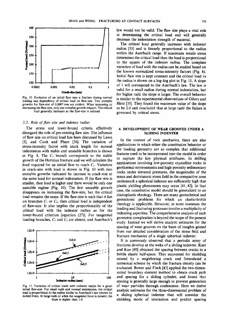
1J38 I-1
l.E+O -I I 1 100
Fig. 11. Variation of critical loads with indenter radius for a given initial flaw-size. For small radii and normal indentation, the critical load is proportional to the radius similar to Auerbach’s law (shown by dotted lines). At large radii or when the tangential force is present, the
slope is higher than 1.0.
law would not be valid. The flaw size plays a vital role in determining the critical load and will generally decrease the indentation strength of material.
The critical load generally increases with indenter radius [35) and is linearly proportional to the radius within the Auerbach range. If maximum tensile stress determines the critical load then the load is proportional to the square of the indenter radius. The complete variation of load with the radius can be studied based on the known normalized stress-intensity factors (Fig. 8). Initial flaw size is kept constant and the critical load vs the radius is shown on a log-log plot in Fig. 11. A slope of 1 will correspond to the Auerbach’s law. The law is valid for a small radius during normal indentation, but for higher radii the slope is larger. The overall behavior is similar to the experimental observations of Gilory and Hirst [35]. They found the maximum value of the slope to be 2.0 and concluded that at large radii the failure is governed by critical stress.
4. DEVELOPMENT OF WEAR GROOVES UNDER A SLIDING INDENTER
In the context of rock mechanics, there are also applications in which either the constitutive behavior or the loading geometry are so complex that additional features need to be incorporated into the model in order to capture the key physical attributes. In drilling applications involving low-porosity crystalline rocks in geothermal environments and high-porosity sedimentary rocks under elevated pressures, the magnitudes of the mean and deriviatoric stress field in the compactive zone underneath a spherical indenter are sufficiently high that plastic yielding phenomena may occur [41,42]. In that case, the constitutive model should be generalized to an elastoplastic rheology. There are many geotechnical and geotectonic problems for which an elastic-brittle rheology is applicable. However, in some instances the loading and fracturing processes involve a multiplicity of indenting asperities. The comprehensive analysis of such geometric complexities is beyond the scope of the present study. Instead we will derive analytic estimates for the spacing of wear grooves on the basis of insights gained from our detailed consideration of the stress field and fracture mechanics of a single spherical indenter.
It is commonly observed that a periodic array of fractures develop at the wake of a sliding indenter. Keer and Kuo [40] obtained the spacing between cracks in a brittle elastic half-space. They accounted for shielding caused by a neighboring crack and formulated a numerical scheme by which the fracture density can be evaluated. Bower and Fleck [43] applied the two-dimen- sional boundary element method to obtain crack path and spacing for a sliding cylinder, and found that spacing is generally large enough to prevent generation of wear particles through coalescence. Here we derive analytic estimates for the three-dimensional problem of a sliding spherical indenter that will consider the shielding mode of interaction and predict spacing

736 SHAH and WONG: FRACTURING AT CONTACT SURFACES
between neighboring cracks. The effects of the friction coefficient and of applied loads will be explained.
4.1. Spacing of fractures The analysis in previous sections allows us to study
initiation and propagation of individual fractures under an indenter. Initiation at critical load is generally unstable, but further propagation takes place in a stable manner. Critical normal load is extremely sensitive to the applied tangential load and slip conditions. Under full-slip conditions, a multiplicity of fractures initiate and propagate at even spacing [3]. Pre-existing flaws in the immediate vicinity of the already developed fracture are shielded by it and hence are inhibited from growth [40,43]. If the applied loads to the indenter are higher than the critical loads, then they would effectively negate the shielding effect at a certain distance away from the previously developed fracture. Beyond this critical spacing, a pre-existing flaw is not inhibited from growth. Thus, the spacing of fractures is determined by the trade-off between the supercritical applied loading and shielding.
The contribution of the two competing effects on the stress intensity factor of a pre-existing flaw (located at an arbitrary distance d away from a developed fracture) at the trailing end of a sliding indenter can be obtained by superposition. The first component is due to the indenter loading which is independent of the existing fractures and the same as given by equation (21).
The pre-existing flaw will be modeled as a penny- shaped vertical crack at a distance d from the already developed fracture. The stress-intensity factor of this crack due to indentation tractions can be evaluated from equation (21). For a fixed normal load and contact radius, the horizontal stress at the surface under Hertzian pressure varies inversely with (1 + d/a)2 [24]. Therefore, the stress-intensity factor at the tip of the developed fracture (G) can be estimated by:
K(d) = ,r’y,=,;; = (1 +f;,a)2. (28)
For d = 0, the fracture is at the trailing edge and its stress-intensity factor must have been the same as the fracture toughness. The variation of horizontal stress due to tangential tractions is more complex [24], but it also drops rapidly with d and may also be approximated by variation l/( 1 + d/a)2 similar to the Boussinesq stress field for a point-load on a half-space.
For the shielding component, we need to estimate the perturbation of the stress field around the pre-existing flaw due to the developed fracture. The dilation of the latter induces a compressive stress which tends to inhibit the extensive propagation of the former. If the pre-existing flaw size is much smaller than the fracture radius, then the horizontal component of this compres- sive stress at the location of flaw is proportional to the fracture stress intensity factor K(d) [44]:
v1 I 1
k
0.9
v) 0.8
- 0.02
4 - 0.015
1 - 0.01
I
~0.005
Fig. 12. Stress-intensity factor of a flaw as a function of spacing with the existing fracture. Ki increases with distance and exceeds fracture toughness at a critical distance which would determine the spacing of fractures under a sliding indentor. Final crack length at large spacing is the same as the size of the existing fracture, although at the critical
spacing its size is somewhat less due to the shielding effects.
where r is defined as the ratio of d to the radius of the previously developed fracture. The resultant stress-inten- sity factor K: is therefore given by the sum
Kxn=s+~J& where the first term g, is the stress-intensity factor of the flaw cf in the absence of the fracture [given by equation (2111 and the second term corresponds to the shielding effect from the compressive stress given by equation (29). The spacing of fractures can be determined by equating the above equation with the fracture toughness.
If the applied loads are the same as the critical ones, then the negative shielding effects cannot be balanced and only one fracture will form. However, if the indentation load is supercritical, then its effect will be dominant beyond a certain distance since the shielding effect decays rapidly and is negligible at distances larger than twice the fracture radius. Figure 12 shows the variation of stress-intensity factor with distance d when the applied load is 1.5 times the critical load and friction coefficient is 0.5. The flaw stress intensity factor increases
% O-* - OalOo i % 0.6 --
i -- 0.080 0.4 -- 1 I
% H 0.2 -- a m
0.0 I 0.050
1.0 1.2 1.4 1.6
I -Q=bww -~e=w 1 I m Cmcksise(f4.3) - - - Caa&sim(&O.s)
Fig. 13. Variation of spacing between fractures under a sliding indenter and the size of fractures with applied load and friction coefficient. Loads decrease the spacing, whereas friction increases it. Final crack size is less for higher friction for the same ratio of applied load with critical load primarily due to the reduced critical load. Crack size
increases with load.

SHAH and WONG: FRACTURING AT CONTACT SURFACES 137
gradually with d and exceeds fracture toughness at a critical distance, beyond which the flaw extends to attain a final length shown in Fig. 12. For very large spacing, the final length asymptotically approaches the size of the previously developed fracture size. However, the flaw which would grow at the critical spacing has a somewhat smaller final length. Consequently, one expects that the shielding effect of this second fracture would be less and therefore the third fracture will extend to a longer path. This is consistent with Graham’s [45] observation that the size of fracture varies and that fracture spacing is different with depth.
In Fig. 13, the critical spacing (solid curves) and corresponding final crack length (dashed curves) are plotted as functions of the normal load for two different coefficients of friction. The critical spacing decreases with increasing normal load and is higher for larger friction coefficients for the same ratio of applied loads to critical loads, similar to Bower and Fleck’s [43] results for the two-dimensional case. Final fracture sizes are smaller for higher friction coefficients due to the reduced critical loads. Shielding effects of smaller fractures would be less and hence the spacing increases with the friction coefficient. If the spacing is small with respect to fracture size, then the nearest neighbor interaction is not sufficient and shielding effects of several already formed fractures may have to be accounted for. This would increase the critical spacing distance from the values in Fig. 13. The surface density of cracks due to a sliding indenter would be inversely proportional to the spacing, and would increase with loads and decrease with friction coefficient.
4.2. Comparison with laboratory and jield observations Our results can be compared with observations on
experimental and natural sliding surfaces. Several recent studies were performed to characterize, quantitatively, the topography and roughness of fault surfaces [46,47]. In the laboratory samples, the asperities have radii in the range of 20-100 pm. With a normal stress in the range of 10-100 MPa and friction coefficient of 0.5, the contact patches would have a radii of 2-20 pm [46] and the fracture array would occur with periodic spacing of l-20 pm. The spacing being less than a typical grain-size, most of the cracks will be intragranular similar to the observations of Hundley-Goff and Moody [48] for orthoquartzite, with an average grain-size of 150 pm. In the field, asperity radii span several orders of magnitude and vary from several micrometers to several meters [47,49]. If fracture spacing is similar to grain-size, then nearby fractures may coalesce at grain boundaries to generate a wear particle. For a friction coefficient of 0.5 and fracture spacing equal to the grain diameter of 200 pm, an asperity with a radius of ca. 20 cm is required.
Our analysis suggests that if the stress level is sufficiently high, then a periodic array of fractures will be developed at the wake of a sliding asperity. Furthermore, the spacing between successive fractures is so close that one expects the cumulative fracturing RMMS Yi%c
process to be very effective in generating the wear grooves which are commonly observed in laboratory and field samples [17, 181. The width of wear groove and fracture density within it give quantitative information about the loads carried by an asperity and about its size, The knowledge of contact loads may also be useful in estimating the real area of contact. Total maximum distance that an asperity will slide is the amount of slip and hence the length of the wear groove cannot be larger than the slip. The interaction of repeated slip events may hinder the prediction of slip based on the groove-length measurements. The density of wear grooves will increase with normal stress since more contact forces will have exceeded the critical load. Engelder [17] reported that the number of grooves per slip event increased by three orders of magnitude for an order of magnitude increase in confining pressure.
It is also clear that since the sliding velocity does not enter the analysis, a groove will form independently of whether slip is seismic or not, unless the frictional stability behavior is sensitively dependent on the stress level. Wear grooves were observed primarily in Engelder’s [ 171 samples with stick-slip bahavior. Since his laboratory data showed frictional instability only under elevated normal stresses, indentation stress levels at many of the asperities are probably above the critical load for the development of Hertzian type fracturing. For further development of the theoretical analysis, it is desirable to have simultaneous measurements of asperity statistics of the sliding surface, as well as the wear groove geometry and statistics, which will place important constraints on the fracture mechanics parameters.
5. DISCUSSION
The present study identified the complete elastic stress fields in a half-space due to an arbitrarily loaded blunt indenter. The tangential contact force and its loading path alters the fields considerably, and determines failure of the contact in both brittle and plastic modes. The analytical results can be used to develop the first-order estimate for failure initiation loads, extent of plastic zone and size of fractures. Although such estimates disregard complex interaction of cracking, plastic deformations and contact tractions, they provide a basis for identifying the qualitative role of relevant parameters. Partial-slip conditions at a contact are more efficient in inducing failure or equivalently, it is easy to fail rough surfaces. The inelastic deformations underneath the contact may continue even during the unloading of tangential force.
We evaluated the stress concentration factors for the existing flaws located at the site where tensile stresses are maximum, and developed the condition for fracture initiation and propagation for ideally brittle materials. Although the fracture initiation may be unstable, its further propagation is stable. The tangential force which is just 10% of the normal force reduces the initiation load by an order of magnitude. The model shows the decreasing critical loads with the flaw size and predicts

738 SHAH and WONG: FRACTURING AT CONTACT SURFACES
the experimentally observed nonlinear dependency on 5. Lawn, B. R., Partial cone crack formation in a brittle material
the indenter results. The spacing of fractures under a loaded with a sliding spherical indenter. Proc. R. London A, 1967, 229. 307-3 16.
sliding indenter were estimated with a model and the 6. Cook, N. G. W., Hood, M. and Tsai, F., Observations of crack
results were consistent with the other numerical study, growth in hard rock loaded by an indenter. Int. J. Rock Mech.
and with the field and experimental observations of wear Min. Sci. & Geomech. Abstr. 1984, 21, 97-107.
7. Mishnaevsky, L. L. Jr, Physical mechanisms of hard rock grooves. fragmentation under mechanical loading: A review. Int. J. Rock,
The fundamental understanding of contact defor- Mech. Min. Sci. & Geomech. Absir., 1995, 32, 763-166.
mations and failure is relevant to many rock engineering 8. Deresiewicz, H., Mechanics of granular matter. Ado. Appl. Mech.
1958, 5, 2333305. and geological problems. The problem of fracturing at 9. Gallagher, J. J. Jr, Friedman, M., Handin, J. and Sowers, G. M., grain contacts is one in which the plastic deformations Experimental study relating to microfracture in sandstone.
may be negligible and brittle rheology is truly applicable. Tectonophys., 1974, 21, 203-247.
It is found that the model based on the Hertzian 10. Zhang, J., Wong, T.-F. and Davis, D. M., Micromechanics of
pressure-induced grain crushing in porous rocks. J. Geophys. Res.,
fracturing explains well the role of grain radius [lo], 1990, 95, 341-352.
cementation and global shear stresses in comminutive Il. Menendez, B., Zhu, W. and Wong, T.-F., Micromechanics of
processes [21]. The present analysis explains the brittle faulting and cataclastic flow in Berea sandstone. J. Strucr. Geol., 1996, 18, l-16.
initiation and stable growth of Hertzian cracks during 12. Zoback, M. D. and Byerlee, J. D., Effect of high-pressure
hard-rock indentation [6], and may allow us to obtain an deformation and permeability of Ottawa sand. Am. Assoc. Petrol. Geol. Bull., 1976, 60, 1531-1542.
indirect measure of fracture toughness and surface 13. David. C., Wong, T.-F., Zhu, W. and Zhang, J., Laboratory energy. measurement of compaction induced permeability changes in
porous rocks: Implication for the generation and maintenance of
6. CONCLUSIONS pore pressure excess in crust. Pure Appl. Geophys. 1994, 143, 425456.
The analytical stress fields within spherical bodies subjected to arbitrary normal and tangential loads were obtained through the suitable superposition of full-slip solutions. The partial-slip situation increases both tensile and shear stresses even though the contact is subject to the same forces, and shows the importance of the friction coefficient at the contact. During unloading of the tangential force, the location of maximum tensile stress moves away from the trailing edge towards the center and may be responsible for surface damage during cyclic loading. The critical fracture load required for the development of a Hertzian crack system is reduced significantly by the application of tangential load. The load is further reduced if the condition at the contact is a partial-slip or if the contact is unloading. The analytical stress fields with a simple estimate of shielding interaction between adjacent fractures were used to predict spacing between the fractures under a sliding indenter. The spacing, which is the inverse of surface fracture density, reduces with applied loads and also with friction coefficient.
Acknowledgements-This research was partially supported by the Office of Basic Energy Sciences, Department of Energy, under grant DEFG0294ERI4455. We thank two anonymous reviewers for several useful comments.
Accepied for publication 28 December 1996.
REFERENCES
1. Lawn, B. and Wilshaw, R., Indentation fracture: Principles and applications. J. Mafer. Sci. 1975, 10, 1049-1081.
2. Hertz, H., On the contact of rigid elastic solids and on hardness. Verhandlungen des Vereins zur Befarderung des Gewerbefeisses, 1882, 61, 449-469; English translation in Miscellaneous Papers (translated by D. E. Jones and G. A. Schott). MacMillan, London, 1896, pp. 163-183.
3. Preston, F. W., The structure of abraded glass surfaces. Trans. Opt. Sot., 1922, 23, 141-164.
4. Roesler, F. C., Indentation hardness of glass as an energy scaling law. Proc. Phys. Sot. Land. B 1956, 69, U-60.
14. Marone, C. and Scholz, C. H., Particle-size distribution and microfractures within simulated fault gouge. J. Struct. Geol., 1989, 11, 7999814.
15. Chester, F. M., Evans, J. P. and Biegel, R. L., Internal structure and weakening mechanisms of San Andreas fault. J. Geophys. Res., 1993, 98, 771-786.
16. Papamichos, E., Vardoulakis, I. and Oudafel, H., Permeability reduction due to grain crushing around a perforation. Int. J. Rock Mech. Min. Sci. & Geomech. Abstr., 1993, 30, 122331229.
17. Engelder, J. T., Microscopic wear grooves on slickenslides: Indicators of paleoseismicity. J. Geophys. Res., 1974, 79, 43874392.
18. LaFountain, L. J., Swain, M. V. and Jackson, R. E., Origin of microscopic wear grooves generated during sliding friction experiments. Int. J. Rock Mech. Min. Sci. & Geomech. Abstr., 1975, 12, 361-371.
19. Iverson, N. R., Morphology of glacial striae: Implications for abrasion of glacier beds and fault surfaces. Geol. Sot. Am. Bull., 1991, 103, 1308-1316.
20. Chiang, S. S. and Evans, A. G., Influence of a tangential force on the fracture of two contacting elastic bodies. J. Am. Ceram. Sot., 1982, 66, 4-10.
21. Shah, K. R. and Wong, T.-F., Onset of grain crushing and inelastic compaction in porous materials. J. Geophys. Res., to be submitted, 1996.
22. Hertz, H., On the contact of elastic solids. Zeitschrtft fur Reine and Angewandte Mathematik, 1882, 92, 156-171. English translations in Miscellaneous Papers (translated by D. E. Jones and G. A. Schott). MacMillan, London, 1896, pp. 146162.
23. Huber, M. T., Zur Theorie de Beriihrung Fester elastische K&per. Ann. der Phys., 1904, 14, 153-163.
24. Hamilton, G. M., Explicit equations for the stresses beneath a sliding contact. Proc. Instn. Mech. Engrs., 1983, 197, 371-396.
25. Goodman, L. E., Contact stress analysis of normally loaded rough spheres. J. Appl. Mech., Ser. E, 1962, 8, 515-519.
26. Johnson, K. L., O’Conner, J. J. and Woodward, A. C., The effect of indenter elasticity on the Hertzian fracture of brittle materials. Proc. R. Sot. Land. A, 1973, 223, 95-117.
27. Cattaneo, C., Sul contatto due corm elastici. Academia dei Lincei. Rendiconti, 1938, 27, 342-348, 43k436, 474478.
28. Mindlin, R. D., Compliance of elastic bodies in contact. J. Appl. Mech., 1949, 16, 159-169.
29. Munisamy, R. L., Hills, D. A. and Nowell, D., Static axisymmetric Hertzian contacts subject to shearing force. J. Appl. Mech., 1994, 61, 278-283.
30. Mindlin, R. D. and Deresiewicz, H., Elastic spheres in contact under varying oblique forces. J. Appl. Mech., 1953, 20, 327-344.
31. Hamilton, G. M. and Goodman, L. E., The stress field created by a circular sliding contact. J. Appl. Mech., 1966, 88, 371-376.
32. Mindlin, R. D., Mechanics of granular media. Proc. Second U.S. Nat. Cong. Appl. Mech., Ann Arbor, 1954, pp. 13-20.

SHAH and WONG: FRACTURING AT CONTACT SURFACES 739
33. Auerbach, F., Absolute hardness measurements. Ann. Phys. Chem., 1891, 43, 61-100.
34. Frank, F. C. and Lawn, B. R. On the theory of Hertzian fracture. Proc. R. Sot. London A, 1961, 229, 291-306.
35. Gilory, D. R. and Hirst, W. Brittle fracture of glass under normal and sliding loads. J. Phys. D, 1969, 3, 17841787.
36. Cook, R. F. and Pharr, G. M., Direct observation and analysis of indentation cracking in glasses and ceramics. J. Am. Cerum. Sot., 1990, 73, 787-817.
37. Mouginot, R. and Maugis, D., Fracture indentation beneath flat and spherical punches. J. Mater. Sci., 1985, 20, 4354-4376.
38. Bueckner, H. F., Weight functions and fundamental fields for the penny-shaped and half-plane crack in three-space. Int. J. Solids Siruct., 1987, 23, 57-93.
39. Davis, P. J. and Polonsky, I., Numerical interpolation, differentiation and integration. Handbook of Mathematical Functions with Formulas, Graphs and Mathematical Tables, ed. M. Abramowitz and A. Stegun. Dover Publications, New York, 1965, pp. 875-924.
40. Keer, L. M. and Kuo, C. H., Cracking in a loaded, brittle elastic half-space. Int. J. Solids Structures, 1992, 29, 1819-1826.
41. Miller, T. W. and Cheatham, J. B., Analysis of the indentation of
a compacting material by a perfectly rough wedge. Int. J. Rock Mech. Min. Sci., 1972, 9, 475-492.
42. Suarez-Rivera, F. R., Zheng, Z., Cook, N. G. W. and Cooper, G. A., Indentation by pore collapse in porous rocks. Proc. jJst US Sump. on Rock Mech.. ed. W. A. Hustrulid and G. A. Johnson. galiema, Rotterdam, .1990, pp. 671-678.
43. Bower, A. F. and Fleck, N. A.; Brittle fracture under a sliding line contact. .I. Mech. Phvs. Solids. 1994. 42. 1375-1396.
44. Kachanov, M., Elaitic solids’ with’ m&y cracks and related problems. Ado. AppJ. Mech., 1993, 30, 259-428.
45. Graham, J., Damage induced by a sliding diamond-an approach to hard rock drilling. Rock Mech., 1972, 4, 191-202.
46. Yoshioka, N. and Scholz, C. H., Elastic properties of contacting surfaces under normal and shear loads 1. Theory. J. Geophys. Res., 1989, 94, 17,681-17,690.
47. Power, W. L., Tullis, T. E. and Weeks, J. D., Roughness and wear during brittle faulting. J. Geophys. Res., 1988,93, 15,268-15,278.
48. Hundley-Goff, E. M. and Moody, J. B., Microscopic character- istics of orthoquartzite from sliding friction experiments I. Sliding surface. Tectonophys., 1980, 62, 279-299.
49. Brown, S. R. and Scholz, C. H., Broad bandwidth study of the topography of natural rock surfaces. J. Geophys. Res., 1985, 90, 12,575-12,582.
Copyright © 2022 FDOKUMEN