Freeze fracturing of elastic porous media: a mathematical model
20
rspa.royalsocietypublishing.org Research Cite this article: Vlahou I, Worster MG. 2015 Freeze fracturing of elastic porous media: a mathematical model. Proc. R. Soc. A 471: 20140741. http://dx.doi.org/10.1098/rspa.2014.0741 Received: 30 September 2014 Accepted: 9 January 2015 Subject Areas: fluid mechanics, geophysics, thermodynamics Keywords: freeze fracturing, premelting, frost heave Author for correspondence: I. Vlahou e-mail: [email protected] Freeze fracturing of elastic porous media: a mathematical model I. Vlahou and M. G. Worster Institute of Theoretical Geophysics, Department of Applied Mathematics and Theoretical Physics, University of Cambridge, CMS, Wilberforce Road, Cambridge CB3 0WA, UK We present a mathematical model of the fracturing of water-saturated rocks and other porous materials in cold climates. Ice growing inside porous rocks causes large pressures to develop that can significantly damage the rock. We study the growth of ice inside a penny-shaped cavity in a water-saturated porous rock and the consequent fracturing of the medium. Premelting of the ice against the rock, which results in thin films of unfrozen water forming between the ice and the rock, is one of the dominant processes of rock fracturing. We find that the fracture toughness of the rock, the size of pre-existing faults and the undercooling of the environment are the main parameters determining the susceptibility of a medium to fracturing. We also explore the dependence of the growth rates on the permeability and elasticity of the medium. Thin and fast-fracturing cracks are found for many types of rocks. We consider how the growth rate can be limited by the existence of pore ice, which decreases the permeability of a medium, and propose an expression for the effective ‘frozen’ permeability. 1. Introduction Large pressures can develop inside water-saturated porous media at sub-zero temperatures. These pressures occur owing to the solidification of water inside the pores and can cause fracturing of pre-existing faults, leading to the degradation of the rock. A similar process, called frost heave, occurs in soils, where segregated ice lenses form devoid of soil particles, causing upward movement of the ground above. This frost-induced deformation of material can destroy building foundations, damage roads and statues, and deform cooled gas pipelines laid 2015 The Authors. Published by the Royal Society under the terms of the Creative Commons Attribution License http://creativecommons.org/licenses/ by/4.0/, which permits unrestricted use, provided the original author and source are credited. on November 30, 2015 http://rspa.royalsocietypublishing.org/ Downloaded from
Transcript of Freeze fracturing of elastic porous media: a mathematical model
rspa.royalsocietypublishing.org
ResearchCite this article: Vlahou I, Worster MG. 2015Freeze fracturing of elastic porous media: amathematical model. Proc. R. Soc. A 471:20140741.http://dx.doi.org/10.1098/rspa.2014.0741
Received: 30 September 2014Accepted: 9 January 2015
Subject Areas:fluid mechanics, geophysics, thermodynamics
Keywords:freeze fracturing, premelting, frost heave
Author for correspondence:I. Vlahoue-mail: [email protected]
Freeze fracturing of elasticporous media: a mathematicalmodelI. Vlahou and M. G. Worster
Institute of Theoretical Geophysics, Department of AppliedMathematics and Theoretical Physics, University of Cambridge,CMS, Wilberforce Road, Cambridge CB3 0WA, UK
We present a mathematical model of the fracturingof water-saturated rocks and other porous materialsin cold climates. Ice growing inside porous rockscauses large pressures to develop that can significantlydamage the rock. We study the growth of ice insidea penny-shaped cavity in a water-saturated porousrock and the consequent fracturing of the medium.Premelting of the ice against the rock, which resultsin thin films of unfrozen water forming betweenthe ice and the rock, is one of the dominantprocesses of rock fracturing. We find that the fracturetoughness of the rock, the size of pre-existingfaults and the undercooling of the environment arethe main parameters determining the susceptibilityof a medium to fracturing. We also explore thedependence of the growth rates on the permeabilityand elasticity of the medium. Thin and fast-fracturingcracks are found for many types of rocks. We considerhow the growth rate can be limited by the existenceof pore ice, which decreases the permeability of amedium, and propose an expression for the effective‘frozen’ permeability.
1. IntroductionLarge pressures can develop inside water-saturatedporous media at sub-zero temperatures. These pressuresoccur owing to the solidification of water inside the poresand can cause fracturing of pre-existing faults, leadingto the degradation of the rock. A similar process, calledfrost heave, occurs in soils, where segregated ice lensesform devoid of soil particles, causing upward movementof the ground above. This frost-induced deformationof material can destroy building foundations, damageroads and statues, and deform cooled gas pipelines laid
2015 The Authors. Published by the Royal Society under the terms of theCreative Commons Attribution License http://creativecommons.org/licenses/by/4.0/, which permits unrestricted use, provided the original author andsource are credited.
on November 30, 2015http://rspa.royalsocietypublishing.org/Downloaded from
2
rspa.royalsocietypublishing.orgProc.R.Soc.A471:20140741
...................................................
in submarine sediments. Phenomena such as patterned ground, potholes, needle ice and pingosplay an important role in the development of landscapes [1].
The problem of frost fracturing of rocks is closely related to that of frost heave in soils, whichdescribes the upwards displacement of the ground surface caused by the formation of particle-free lenses within a soil. Frost heave has been studied extensively, starting with Taber [2,3], whoperformed experiments freezing benzene in a column of soil to demonstrate that the expansionof the freezing liquid is not an important contributor to the heaving, as benzene contracts uponfreezing.
The volumetric-expansion model is dependent on the idea that water is forced away from thesolidification front and raises the pressure inside the medium, as the space that can be occupied bywater is limited. This requires the medium to be completely (or, at least, considerably) saturatedwith water. If a large proportion of the pores were empty, the water would simply fill them and thepressure would be relaxed. In particular, as freezing water expands by 9%, a minimum saturationlevel of about 91% is required for fracturing to occur by this mechanism. However, experimentalstudies have shown otherwise, with fracturing being reported for saturation levels as low as65% [4] or 80% [5]. In addition to this, the volumetric-expansion model predicts fracturing inbursts, and only during the freezing cycle, which isn’t supported by experimental evidence [4].A scenario in which volumetric expansion would have an important role is that of a rock freezingrapidly from all sides. However, the applications of such a model are limited.
Taber’s studies suggested that thin films of melt exist between the ice and the solid particles,with liquid from the surrounding medium being drawn towards them. A lot of subsequentresearch was focused on exploring the nature of these films. Several studies [6–9] considered asurface-tension driven flow towards the freezing front, while Gilpin [10] simply assumed thatthe water in the thin films at solid–liquid interfaces experiences an attractive force from the solidboundary. Vignes-Adler [11] suggested that water in thin films has different properties to waterin bulk, but experimental work by Raviv & Klein [12] does not support this suggestion. A modelwas developed by Rempel et al. [13] based on the idea that repelling forces between the ice andthe soil particles create these premelted thin films, while pushing the two substrates apart. Thepressure in the water is lowered as a result of the forces tending to widen the gap, and more watergets sucked in.
The idea of the importance of this premelting regime versus the expansion mechanism canalso be used in the modelling of frost fracturing, as there are strong similarities between thetwo processes. As in soils, disjoining (intermolecular) forces between the ice and the rock lowerthe pressure in unfrozen water films adjacent to the ice surface, which draws water in fromthe surrounding saturated medium. These disjoining forces cause the ice-filled cracks to grow.The difference between the process in soils and rocks lies in the way each medium deformsunder the forces exerted by the ice: soil particles can be rejected from the solidification front ifthe freezing is slow enough; the cohesion of the rock means that the same is not possible. Instead,the pressure exerted on the rock deforms it elastically and can cause fracturing of the cavity if thestress at its tip is above a critical value. While in soils the pressure exerted by the ice is balancedby the overburden pressure, in rocks it is instead balanced by the elastic pressure of the medium.It is the relative magnitude of these two pressures that determines whether the cavity expandsand the ice continues to grow.
Walder & Hallet [14] and Murton et al. [4] used the concept of ice-filled cavities in rocks actingas ice lenses, and developed models which incorporate the concept of premelted films and flowtowards freezing regions. More specifically, Walder & Hallet [14] discussed how these films exertan ‘attractive force’ on the pore water (hence the flow towards the ice front) and a disjoiningpressure that pushes the ice and the rock apart. They showed that the fastest growth rate occursat temperatures in the range −4 to −15◦C as, in colder systems, the transport of water is limitedby the large amount of pore ice reducing the permeability of the rock.
The aim of this paper is to develop a complete model for rock fracturing during freezing,coupling linear elasticity and fracture mechanics with the fluid dynamics governing flowthrough the porous medium. A mathematical model is required to quantify the important
on November 30, 2015http://rspa.royalsocietypublishing.org/Downloaded from
3
rspa.royalsocietypublishing.orgProc.R.Soc.A471:20140741
...................................................
R(t)
z
r
2b(r, t)ice
water
porous medium
l(t)
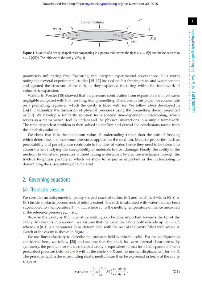
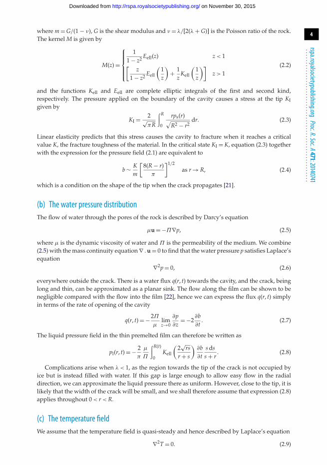
Figure 1. A sketch of a penny-shaped crack propagating in a porous rock, where the tip is at r = R(t) and the ice extends tor = λ(t)R(t). The thickness of the cavity is 2b(r, t).
parameters influencing frost fracturing and interpret experimental observations. It is worthnoting that several experimental studies [15–17] focused on fast freezing rates and water contentand ignored the structure of the rock, as they explained fracturing within the framework ofvolumetric expansion.
Vlahou & Worster [18] showed that the pressure contribution from expansion is in most casesnegligible compared with that resulting from premelting. Therefore, in this paper, we concentrateon a premelting regime in which the cavity is filled with ice. We follow ideas developed in[14] but formalize the discussion of physical processes using the premelting theory presentedin [19]. We develop a similarity solution for a specific time-dependent undercooling, whichserves as a mathematical tool to understand the physical interactions in a simple framework.The time-dependent problem is then solved to confirm and extend the conclusions found fromthe similarity solution.
We show that it is the maximum value of undercooling rather than the rate of freezingwhich determines the maximum pressures applied on the medium. Material properties such aspermeability and porosity also contribute to the flow of water, hence they need to be taken intoaccount when studying the susceptibility of materials to frost damage. Finally, the ability of themedium to withstand pressures without failing is described by fracture mechanics through thefracture toughness parameter, which we show to be just as important as the undercooling indetermining the susceptibility of a material.
2. Governing equations
(a) The elastic pressureWe consider an axisymmetric, penny-shaped crack of radius R(t) and small half-width b(r, t) �R(t) inside an elastic porous rock of infinite extent. The rock is saturated with water that has beensupercooled to a temperature T∞ < Tm, where Tm is the melting temperature of the ice measuredat the reference pressure pm = p∞.
Because the cavity is thin, curvature melting can become important towards the tip of thecavity. To take this into account, we assume that the ice in the cavity only extends up to r = λR,where λ ∈ [0, 1] is a parameter to be determined, with the rest of the cavity filled with water. Asketch of the cavity is shown in figure 1.
We use linear elasticity to describe the pressure field within the solid. For the configurationconsidered here, we follow [20] and assume that the crack has zero internal shear stress. Bysymmetry, the problem for the disc-shaped cavity is equivalent to that for a half space z > 0 withprescribed pressure field on z = 0 within the circle r < R and no normal displacement for r > R.The pressure field in the surrounding elastic medium can then be expressed in terms of the cavityshape as
ps(r, t) = − 2π
m−∫R(t)
0M( r
s
) ∂b∂s
dss
, (2.1)
on November 30, 2015http://rspa.royalsocietypublishing.org/Downloaded from
4
rspa.royalsocietypublishing.orgProc.R.Soc.A471:20140741
...................................................
where m = G/(1 − ν), G is the shear modulus and ν = λ/[2(λ + G)] is the Poisson ratio of the rock.The kernel M is given by
M(z) =
⎧⎪⎪⎪⎨⎪⎪⎪⎩
11 − z2 Eell(z) z < 1
[z
1 − z2 Eell
(1z
)+ 1
zKell
(1z
)]z > 1
(2.2)
and the functions Kell and Eell are complete elliptic integrals of the first and second kind,respectively. The pressure applied on the boundary of the cavity causes a stress at the tip KIgiven by
KI = 2√πR
∫R
0
rps(r)√R2 − r2
dr. (2.3)
Linear elasticity predicts that this stress causes the cavity to fracture when it reaches a criticalvalue K, the fracture toughness of the material. In the critical state KI = K, equation (2.3) togetherwith the expression for the pressure field (2.1) are equivalent to
b ∼ Km
[8(R − r)
π
]1/2as r → R, (2.4)
which is a condition on the shape of the tip when the crack propagates [21].
(b) The water pressure distributionThe flow of water through the pores of the rock is described by Darcy’s equation
μu = −Π∇p, (2.5)
where μ is the dynamic viscosity of water and Π is the permeability of the medium. We combine(2.5) with the mass continuity equation ∇ . u = 0 to find that the water pressure p satisfies Laplace’sequation
∇2p = 0, (2.6)
everywhere outside the crack. There is a water flux q(r, t) towards the cavity, and the crack, beinglong and thin, can be approximated as a planar sink. The flow along the film can be shown to benegligible compared with the flow into the film [22], hence we can express the flux q(r, t) simplyin terms of the rate of opening of the cavity
q(r, t) = −2Π
μlimz→0
∂p∂z
= −2∂b∂t
. (2.7)
The liquid pressure field in the thin premelted film can therefore be written as
pl(r, t) = − 2π
μ
Π
∫R(t)
0Kell
(2√
rsr + s
)∂b∂t
s dss + r
. (2.8)
Complications arise when λ < 1, as the region towards the tip of the crack is not occupied byice but is instead filled with water. If this gap is large enough to allow easy flow in the radialdirection, we can approximate the liquid pressure there as uniform. However, close to the tip, it islikely that the width of the crack will be small, and we shall therefore assume that expression (2.8)applies throughout 0 < r < R.
(c) The temperature fieldWe assume that the temperature field is quasi-steady and hence described by Laplace’s equation
∇2T = 0. (2.9)
on November 30, 2015http://rspa.royalsocietypublishing.org/Downloaded from
5
rspa.royalsocietypublishing.orgProc.R.Soc.A471:20140741
...................................................
Latent heat is released at the solidification front, which is described by the Stefan condition
ρsL∂b∂t
= −kl limz→0
∂T∂z
, (2.10)
where ρs is the density of ice, L the latent heat per unit mass and kl the thermal conductivityof water. We define the undercooling θ (r, z, t) = T(r, z, t) − T∞(t) > 0 which decays as r → ∞ andsatisfies the same equations as T, (2.9) and (2.10). By comparing equations (2.7) and (2.10), andnoting that both pl(r, t) = p(r, z ≈ 0, t) and θ I(r, t) = θ (r, z ≈ 0, t) satisfy Laplace’s equation and decayas r → ∞, we see that the interface undercooling θ I can be expressed in a similar way to pl as anintegral of ∂b/∂t
θ I(r, t) = 2π
ρsLkl
∫λR(t)
0K(
2√
rsr + s
)∂b∂t
s dss + r
. (2.11)
We note that in the special case λ = 1, the temperature field is simply proportional to the liquidpressure field
θ (r, z, t) = −ρsLkl
Π
μp(r, z, t). (2.12)
(d) The dynamics of the premelted filmWhen a solid is separated from a foreign substrate by a thin film of its melt, repellingintermolecular forces can develop between the two substances, pushing them apart. The resultingpressure pT is called disjoining pressure. The liquid pressure pl inside the thin film, together withthe disjoining pressure pT acting across the film, must balance the solid pressure ps in the ice [19]
ps = pl + pT. (2.13)
Owing to the disjoining pressure pT, the liquid and solid pressures across the freezing interfaceare not equal. This pressure difference affects the freezing temperature TI as described by theGibbs–Thompson relation
ps − pl = ρsL(Tm − TI)Tm
= ρsL(Tm − T∞)Tm
− ρsLθ I
Tm. (2.14)
Here, we have ignored the effect of pressure melting (proportional to pl − pm) as we take ρs = ρlapproximately. We also assume the contribution of curvature melting is negligible, except at theedge of the ice lens, where it determines λ.
(e) The ice extentUnlike the rest of the ice surface, the tip is highly curved and this can be important. Here, weassume that the main contribution to a solid–liquid pressure difference at the tip is because ofits curvature, i.e. we ignore pressure melting and disjoining forces. We can then use the Gibbs–Thompson equation above, evaluated at r = λR, to find an expression for the maximum possibletip curvature for a given undercooling. The ice tip is approximated as circular and hence thecurvature can be written as κ = 1/b(λR, t). The relation determining the ice extent λ is therefore
κγ = 2γ
b(λR(t), t)= ρsL(Tm − T∞)
Tm− ρsL
Tmθ I(λR(t), t), (2.15)
where γ is the surface energy of water per unit area.
3. Similarity solutionBefore considering the full time-dependent problem from a specific initial condition, we explorethe following special solution of the governing equations, from which significant insight can
on November 30, 2015http://rspa.royalsocietypublishing.org/Downloaded from
6
rspa.royalsocietypublishing.orgProc.R.Soc.A471:20140741
...................................................
be gained. If the far-field undercooling is described by Tm − T∞ = �T = Ht−1/4 then there is asimilarity solution in which the cavity propagates as
R(t) = kt1/2, (3.1)
for some constant k to be determined. In terms of the similarity variable η = r/kt1/2, the tipof the cavity is at η = 1, the ice extends to η = λ and the cavity thickness is B(η) = b(r, t)/kt1/4.Then, the similarity functions ps(η) = t1/4ps(r, t), pl(η) = t1/4pl(r, t) and Θ I(η) = t1/4θ I(r, t) satisfythe following system of equations
ps(η) = −∫ 1
0M( η
σ
)B′(σ )
dσ
σ, (3.2)
pl(η) = −k2∫ 1
0K(
2√
ησ
η + σ
)[14
B(σ ) − 12σB′(σ )
]σ dσ
η + σ, (3.3)
Θ I(η) = k2∫λ
0K(
2√
ησ
η + σ
)[14
B(σ ) − 12σB′(σ )
]σ dσ
η + σ, (3.4)
ps(η) ={
pl(η) − Π[Θ I(η) − C] if η ≤ λ,
pl(η) if η > λ,(3.5)
1kB(λ)
= KΠ [C − Θ I(λ)], (3.6)
and B(η) ∼ k−1/2√
1 − η as η → 1, (3.7)
where
C = H
Π3/4K, and Π = ρ2
s L2Π
μklTm, K = 4
π
K√2γ m
, H =√
π
2
(ρ2
s L2kl
γ 2mT3m
)1/4
H.
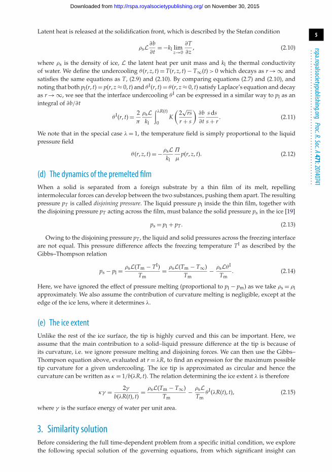
The last three parameters can be thought of as dimensionless permeability, fracture toughnessand undercooling, respectively. We find that two solutions exist for each set of parameters. Wedenote their propagation rates as k1 and k2, with k1 < k2, and refer to them as ‘slow’ and ‘fast’solutions, respectively. Figure 2 shows the cavity width and pressure distribution for a typicalfast solution. The difference in cavity thickness between the part of the cavity occupied by ice andthe tip is clear in the B(η) plot. The solid pressure features a step drop at η = λ, and a negativespike at η = 1. The latter agrees with the prediction of infinite solid pressure at the tip of the crack,caused by the assumption of a parabolic tip as predicted by linear elasticity. In practice, ps(1)remains finite due to the limitations of the discretized numerical scheme used, but its value isunimportant as it is not used to determine any characteristics of the cavity. Finally, a rise in theliquid pressure pl is seen towards the tip of the crack. This is most likely due to the fact that thecavity growth is driven by the ice-occupied region, where water continues to freeze, and hencethe flux of water is larger there.
(a) Stability analysisBefore continuing with the analysis of the different solution regimes, it is important to determinewhether the solutions are stable or unstable. We define a modified stress-intensity factor K∗ whichcorresponds to a propagation rate k of the tip
K∗ = KI
K= lim
η→1
√kB(η)√1 − η
. (3.8)
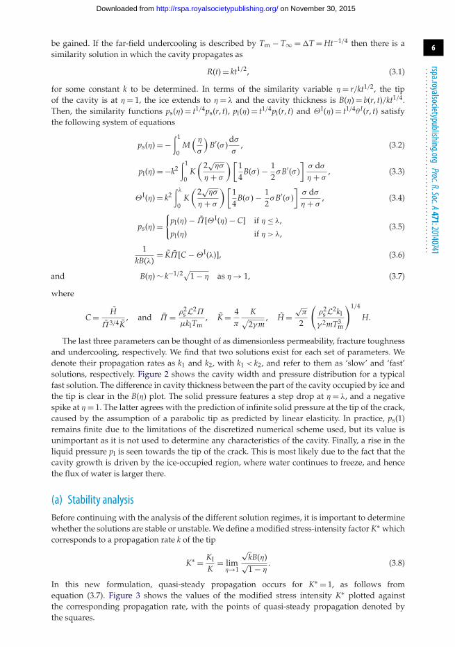
In this new formulation, quasi-steady propagation occurs for K∗ = 1, as follows fromequation (3.7). Figure 3 shows the values of the modified stress intensity K∗ plotted againstthe corresponding propagation rate, with the points of quasi-steady propagation denoted bythe squares.
on November 30, 2015http://rspa.royalsocietypublishing.org/Downloaded from
7
rspa.royalsocietypublishing.orgProc.R.Soc.A471:20140741
...................................................
0
1
2
3
B(h
)−20
−10
0
10
P s(h)
0 0.2 0.4 0.6h
0.8 1.0−4.0
−3.5
−3.0
−2.5
P l(h)
Figure 2. A plot of a fast solution with k = 1.2057: the three plots show the cavity width B(η), the solid pressure ps(η) and theliquid pressure pl(η) against the similarity variable η. (Online version in colour.)
0 0.5 1.0 1.5−1.0
−0.5
0
0.5
1.0
1.5
2.0
k
K*
–1
k2k1
Figure 3. A plot of K∗ against the propagation rate k, showing the unstable (slow) and stable (fast) solutions. (Online versionin colour.)
We can now understand how the two solutions react to small perturbations in propagationrates, therefore determining which solution is stable. We note that for k1 < k < k2 the stressintensity factor is higher than its critical value, and for k > k2 or k < k1 it is lower. Therefore, ifthe cavity propagates just faster than the slow solution, at k = k1 + ε (where ε > 0), the pressurebuilds up higher than the critical value. This forces the cavity to propagate even faster, makingthe solution unstable. For a propagation rate just slower than k1, we find K∗ < 1 therefore thepropagation slows even further. Conversely, for a cavity propagating at k = k2 + ε, the stress-intensity factor is lower than the critical value, causing the propagation to slow down and hencemaking the fast solution stable.
(b) Phase planesSolutions for (k1, λ1) and (k2, λ2) cannot be found for all values of K, H and Π . We investigate theexistence of propagating solutions by plotting phase planes of K versus H for a given value ofthe permeability Π . We concentrate on the stable (fast) solution, although similar phase planes
on November 30, 2015http://rspa.royalsocietypublishing.org/Downloaded from
8
rspa.royalsocietypublishing.orgProc.R.Soc.A471:20140741
...................................................
0 5 10 15 20
0.5
1.0
1.5
2.0
2.5
3.0
3.5(a) (b)
H H
K
medium too tough
not enough ice
l = 1l < 1analytic prediction
0 5 10 15 20
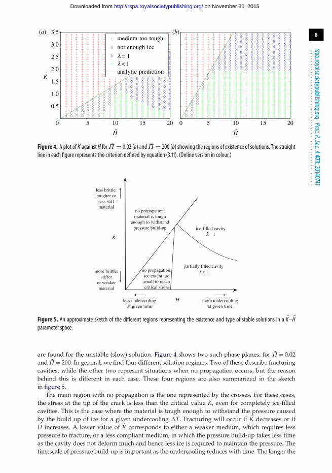
Figure 4. A plot of K against H for Π = 0.02 (a) and Π = 200 (b) showing the regions of existence of solutions. The straightline in each figure represents the criterion defined by equation (3.11). (Online version in colour.)
less brittle:tougher orless stiffmaterial
no propagation:material is tough
enough to withstandpressure build-up
more brittle:stiffer
or weakermaterial
less undercoolingat given time
no propagation:ice extent toosmall to reachcritical stress
more undercoolingat given time
partially filled cavityl < 1
ice-filled cavityl = 1
K˜
H˜
Figure 5. An approximate sketch of the different regions representing the existence and type of stable solutions in a K–Hparameter space.
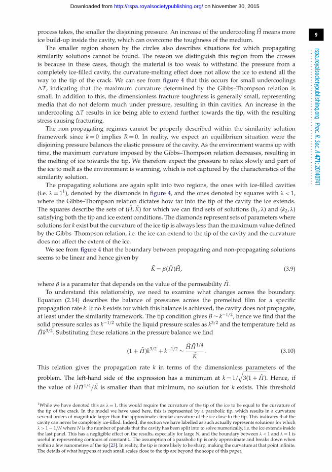
are found for the unstable (slow) solution. Figure 4 shows two such phase planes, for Π = 0.02and Π = 200. In general, we find four different solution regimes. Two of these describe fracturingcavities, while the other two represent situations when no propagation occurs, but the reasonbehind this is different in each case. These four regions are also summarized in the sketchin figure 5.
The main region with no propagation is the one represented by the crosses. For these cases,the stress at the tip of the crack is less than the critical value K, even for completely ice-filledcavities. This is the case where the material is tough enough to withstand the pressure causedby the build up of ice for a given undercooling �T. Fracturing will occur if K decreases or ifH increases. A lower value of K corresponds to either a weaker medium, which requires lesspressure to fracture, or a less compliant medium, in which the pressure build-up takes less timeas the cavity does not deform much and hence less ice is required to maintain the pressure. Thetimescale of pressure build-up is important as the undercooling reduces with time. The longer the
on November 30, 2015http://rspa.royalsocietypublishing.org/Downloaded from
9
rspa.royalsocietypublishing.orgProc.R.Soc.A471:20140741
...................................................
process takes, the smaller the disjoining pressure. An increase of the undercooling H means moreice build-up inside the cavity, which can overcome the toughness of the medium.
The smaller region shown by the circles also describes situations for which propagatingsimilarity solutions cannot be found. The reason we distinguish this region from the crossesis because in these cases, though the material is too weak to withstand the pressure from acompletely ice-filled cavity, the curvature-melting effect does not allow the ice to extend all theway to the tip of the crack. We can see from figure 4 that this occurs for small undercoolings�T, indicating that the maximum curvature determined by the Gibbs–Thompson relation issmall. In addition to this, the dimensionless fracture toughness is generally small, representingmedia that do not deform much under pressure, resulting in thin cavities. An increase in theundercooling �T results in ice being able to extend further towards the tip, with the resultingstress causing fracturing.
The non-propagating regimes cannot be properly described within the similarity solutionframework since k = 0 implies R = 0. In reality, we expect an equilibrium situation were thedisjoining pressure balances the elastic pressure of the cavity. As the environment warms up withtime, the maximum curvature imposed by the Gibbs–Thompson relation decreases, resulting inthe melting of ice towards the tip. We therefore expect the pressure to relax slowly and part ofthe ice to melt as the environment is warming, which is not captured by the characteristics of thesimilarity solution.
The propagating solutions are again split into two regions, the ones with ice-filled cavities(i.e. λ = 11), denoted by the diamonds in figure 4, and the ones denoted by squares with λ < 1,where the Gibbs–Thompson relation dictates how far into the tip of the cavity the ice extends.The squares describe the sets of (H, K) for which we can find sets of solutions (k1, λ) and (k2, λ)satisfying both the tip and ice extent conditions. The diamonds represent sets of parameters wheresolutions for k exist but the curvature of the ice tip is always less than the maximum value definedby the Gibbs–Thompson relation, i.e. the ice can extend to the tip of the cavity and the curvaturedoes not affect the extent of the ice.
We see from figure 4 that the boundary between propagating and non-propagating solutionsseems to be linear and hence given by
K = β(Π)H, (3.9)
where β is a parameter that depends on the value of the permeability Π .To understand this relationship, we need to examine what changes across the boundary.
Equation (2.14) describes the balance of pressures across the premelted film for a specificpropagation rate k. If no k exists for which this balance is achieved, the cavity does not propagate,at least under the similarity framework. The tip condition gives B ∼ k−1/2, hence we find that thesolid pressure scales as k−1/2 while the liquid pressure scales as k3/2 and the temperature field asΠk3/2. Substituting these relations in the pressure balance we find
(1 + Π )k3/2 + k−1/2 ∼ HΠ1/4
K. (3.10)
This relation gives the propagation rate k in terms of the dimensionless parameters of the
problem. The left-hand side of the expression has a minimum at k = 1/
√3(1 + Π ). Hence, if
the value of HΠ1/4/K is smaller than that minimum, no solution for k exists. This threshold
1While we have denoted this as λ = 1, this would require the curvature of the tip of the ice to be equal to the curvature ofthe tip of the crack. In the model we have used here, this is represented by a parabolic tip, which results in a curvatureseveral orders of magnitude larger than the approximate circular curvature of the ice close to the tip. This indicates that thecavity can never be completely ice-filled. Indeed, the section we have labelled as such actually represents solutions for whichλ > 1 − 1/N where N is the number of panels that the cavity has been split into to solve numerically, i.e. the ice extends insidethe last panel. This has a negligible effect on the results, especially for large N, and the boundary between λ < 1 and λ = 1 isuseful in representing contours of constant λ. The assumption of a parabolic tip is only approximate and breaks down whenwithin a few nanometres of the tip [23]. In reality, the tip is more likely to be sharp, making the curvature at that point infinite.The details of what happens at such small scales close to the tip are beyond the scope of this paper.
on November 30, 2015http://rspa.royalsocietypublishing.org/Downloaded from
10
rspa.royalsocietypublishing.orgProc.R.Soc.A471:20140741
...................................................
(a) (b)
5 10 15 200
0.2
0.4
0.6
0.8
1.0
5 10 15 200
0.5
1.0
1.5
2.0
kl
H H
K = 0.1K = 0.5K = 1K = 2
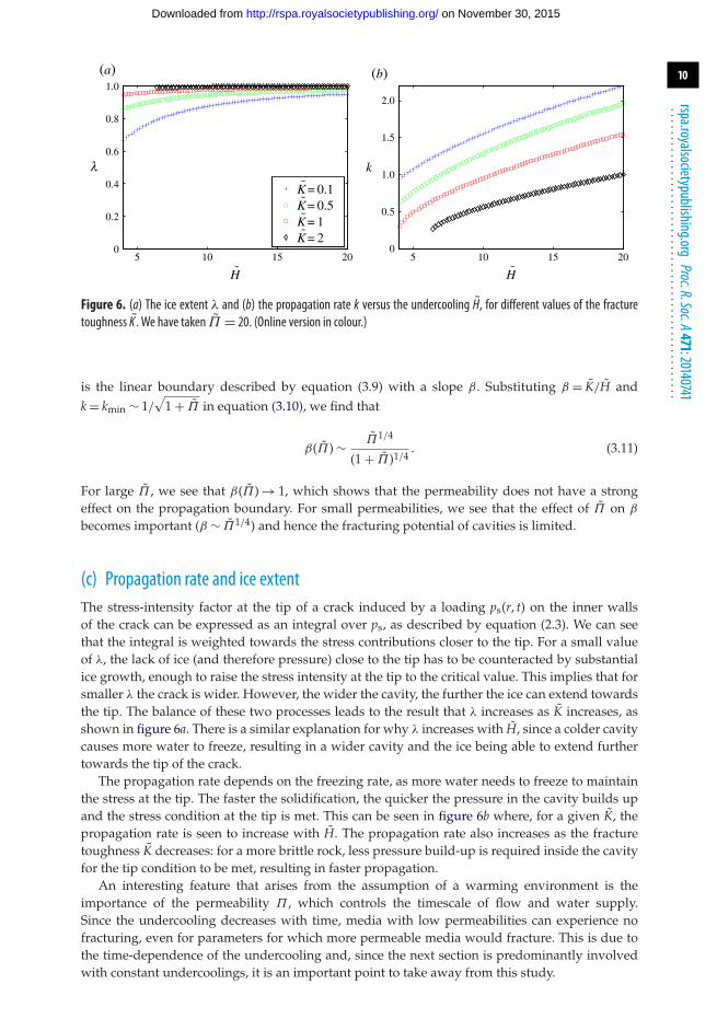
Figure 6. (a) The ice extent λ and (b) the propagation rate k versus the undercooling H, for different values of the fracturetoughness K . We have taken Π = 20. (Online version in colour.)
is the linear boundary described by equation (3.9) with a slope β. Substituting β = K/H andk = kmin ∼ 1/
√1 + Π in equation (3.10), we find that
β(Π) ∼ Π1/4
(1 + Π )1/4. (3.11)
For large Π , we see that β(Π) → 1, which shows that the permeability does not have a strongeffect on the propagation boundary. For small permeabilities, we see that the effect of Π on β
becomes important (β ∼ Π1/4) and hence the fracturing potential of cavities is limited.
(c) Propagation rate and ice extentThe stress-intensity factor at the tip of a crack induced by a loading ps(r, t) on the inner wallsof the crack can be expressed as an integral over ps, as described by equation (2.3). We can seethat the integral is weighted towards the stress contributions closer to the tip. For a small valueof λ, the lack of ice (and therefore pressure) close to the tip has to be counteracted by substantialice growth, enough to raise the stress intensity at the tip to the critical value. This implies that forsmaller λ the crack is wider. However, the wider the cavity, the further the ice can extend towardsthe tip. The balance of these two processes leads to the result that λ increases as K increases, asshown in figure 6a. There is a similar explanation for why λ increases with H, since a colder cavitycauses more water to freeze, resulting in a wider cavity and the ice being able to extend furthertowards the tip of the crack.
The propagation rate depends on the freezing rate, as more water needs to freeze to maintainthe stress at the tip. The faster the solidification, the quicker the pressure in the cavity builds upand the stress condition at the tip is met. This can be seen in figure 6b where, for a given K, thepropagation rate is seen to increase with H. The propagation rate also increases as the fracturetoughness K decreases: for a more brittle rock, less pressure build-up is required inside the cavityfor the tip condition to be met, resulting in faster propagation.
An interesting feature that arises from the assumption of a warming environment is theimportance of the permeability Π , which controls the timescale of flow and water supply.Since the undercooling decreases with time, media with low permeabilities can experience nofracturing, even for parameters for which more permeable media would fracture. This is due tothe time-dependence of the undercooling and, since the next section is predominantly involvedwith constant undercoolings, it is an important point to take away from this study.
on November 30, 2015http://rspa.royalsocietypublishing.org/Downloaded from
11
rspa.royalsocietypublishing.orgProc.R.Soc.A471:20140741
...................................................
4. Full time-dependent problemSo far, we have analysed similarity solutions which require specific far-field solutions. In order toinvestigate general boundary and initial conditions, as well as transient behaviour, we solve thefull time-dependent equations (2.1), (2.8), (2.11), (2.14) for r ≤ λR and ps = pl for r > λR, togetherwith the tip-extent condition (2.15) and the tip-propagation condition (2.4). This allows us tostudy not only the long-time behaviour of the crack, where the process has developed and thepressure build-up is causing the cavity to propagate, but also the initial stage of ice growth. Thisis characterized by the stress at the tip KI being below the critical value K and no fracturingoccurring. During this stage, the cavity thickness increases as a result of the ice formation andsubsequent pressure build-up, while the stress at the tip KI approaches the critical value K. The iceextent λ is a complicated function of the undercooling of the surrounding rock and the thicknessof the cavity, and this framework allows for it to vary with time.
We also find that the similarity solution can be reproduced by the time-dependent problemwith the appropriate temperature boundary condition, which serves as a useful check for ournumerical scheme.
(a) Initial conditionWe first consider the initial stages of ice formation and pressure build-up. A simple way ofthinking about how a situation like this can develop in nature is to imagine a pre-existing faultwith some ice growing inside it. Initially, the stress at the tip is sub-critical and hence no fracturingoccurs. Instead, water keeps freezing inside the non-propagating cavity, causing the cavity toincrease in thickness. This in turn increases the pressure applied on the rock, and subsequentlythe stress at the tip. When the critical value is reached, the fracturing begins.
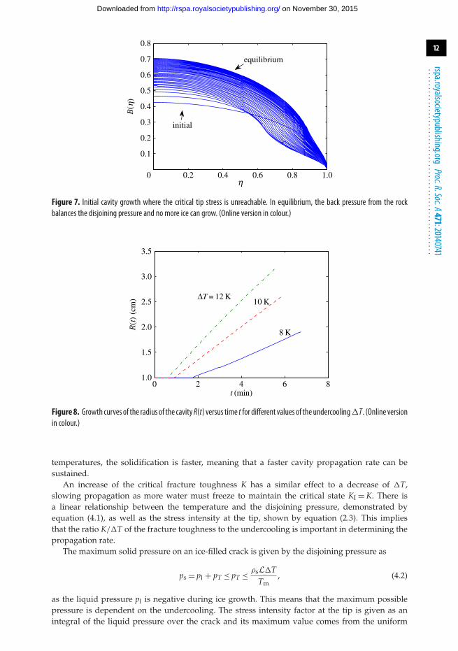
As we saw in the study of the similarity solution, depending on the properties of the porousmedium and the undercooling of the surroundings, cases exist in which the pressure induced bythe ice on the rock is not enough to make the cavity propagate. If the cavity is completely ice-filled,the ice growth is limited by the back pressure from the rock. In that case, the maximum pressurehas been achieved but the induced stress at the tip is not large enough to cause fracturing. In casesof small undercoolings or very inelastic rocks (hence very thin cavities), where the extent of the iceis dictated by the curvature-melting at the tip, the equilibrium is reached with the ice extent λ < 1.An example can be seen in figure 7 where the ice has reached the maximum extent it can achieveand the back pressure from the rock on the ice is preventing any further freezing. The stress at thetip for this example is about half the value of the critical fracture toughness K and therefore nopropagation occurs in this case. This effect is independent of the initial cavity thickness used andcorresponds to the ‘no propagation’ regions discussed in the similarity solution section.
(b) ResultsFaster propagation occurs for greater undercooling of the surroundings, which can be seen inthe growth curves R(t) versus t in figure 8. We see that the change in temperature affects boththe initial stage of pressure build-up inside the cavity and the propagation rate of the crack. Forsmaller undercoolings, it takes longer for the stress at the tip to reach the critical value and for thepropagation to begin. We note that the minimum value of the undercooling �T for propagationto occur is just below 8 K for this example. The maximum disjoining pressure acting between theice and the rock through the premelted film is a linear function of �T given by
pT = ρsL�TTm
. (4.1)
This shows how the maximum pressure exerted by the ice on the rock is limited by theundercooling. As the critical value of the stress at the tip is reached and the crack extends,more water must freeze to fill the now larger cavity, and build up the stress again. At lower
on November 30, 2015http://rspa.royalsocietypublishing.org/Downloaded from
12
rspa.royalsocietypublishing.orgProc.R.Soc.A471:20140741
...................................................
0 0.2 0.4h
0.6 0.8 1.0
0.1
0.2
0.3
0.4
0.5
0.6
0.7
0.8
B(h
)initial
equilibrium
Figure 7. Initial cavity growth where the critical tip stress is unreachable. In equilibrium, the back pressure from the rockbalances the disjoining pressure and no more ice can grow. (Online version in colour.)
0 2 4 6 81.0
1.5
2.0
2.5
3.0
3.5
t (min)
R(t
)(c
m) DT = 12 K
10 K
8 K
Figure8. Growth curves of the radius of the cavityR(t) versus time t for different values of theundercooling�T . (Online versionin colour.)
temperatures, the solidification is faster, meaning that a faster cavity propagation rate can besustained.
An increase of the critical fracture toughness K has a similar effect to a decrease of �T,slowing propagation as more water must freeze to maintain the critical state KI = K. There isa linear relationship between the temperature and the disjoining pressure, demonstrated byequation (4.1), as well as the stress intensity at the tip, shown by equation (2.3). This impliesthat the ratio K/�T of the fracture toughness to the undercooling is important in determining thepropagation rate.
The maximum solid pressure on an ice-filled crack is given by the disjoining pressure as
ps = pl + pT ≤ pT ≤ ρsL�TTm
, (4.2)
as the liquid pressure pl is negative during ice growth. This means that the maximum possiblepressure is dependent on the undercooling. The stress intensity factor at the tip is given as anintegral of the liquid pressure over the crack and its maximum value comes from the uniform
on November 30, 2015http://rspa.royalsocietypublishing.org/Downloaded from
13
rspa.royalsocietypublishing.orgProc.R.Soc.A471:20140741
...................................................
0 2 4 6 80.5
1.0
1.5
2.0
2.5
3.0
3.5
4.0
t (min)
R(t
)(c
m)
R0= 0.5 cm
R0= 1 cm
R0= 2 cm
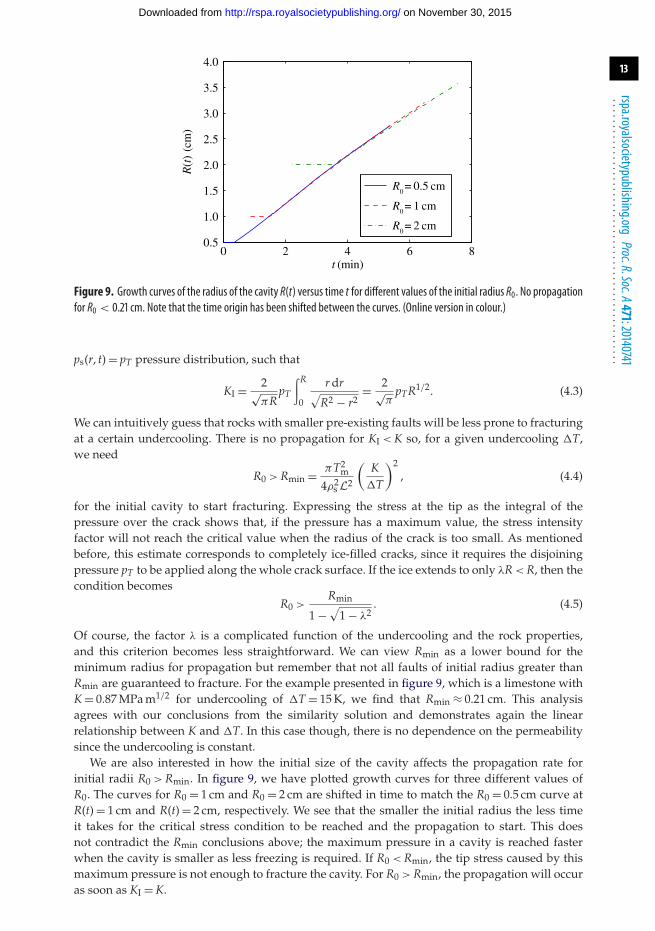
Figure 9. Growth curves of the radius of the cavity R(t) versus time t for different values of the initial radius R0. No propagationfor R0 < 0.21 cm. Note that the time origin has been shifted between the curves. (Online version in colour.)
ps(r, t) = pT pressure distribution, such that
KI = 2√πR
pT
∫R
0
r dr√R2 − r2
= 2√π
pTR1/2. (4.3)
We can intuitively guess that rocks with smaller pre-existing faults will be less prone to fracturingat a certain undercooling. There is no propagation for KI < K so, for a given undercooling �T,we need
R0 > Rmin = πT2m
4ρ2s L2
(K
�T
)2, (4.4)
for the initial cavity to start fracturing. Expressing the stress at the tip as the integral of thepressure over the crack shows that, if the pressure has a maximum value, the stress intensityfactor will not reach the critical value when the radius of the crack is too small. As mentionedbefore, this estimate corresponds to completely ice-filled cracks, since it requires the disjoiningpressure pT to be applied along the whole crack surface. If the ice extends to only λR < R, then thecondition becomes
R0 >Rmin
1 −√
1 − λ2. (4.5)
Of course, the factor λ is a complicated function of the undercooling and the rock properties,and this criterion becomes less straightforward. We can view Rmin as a lower bound for theminimum radius for propagation but remember that not all faults of initial radius greater thanRmin are guaranteed to fracture. For the example presented in figure 9, which is a limestone withK = 0.87 MPa m1/2 for undercooling of �T = 15 K, we find that Rmin ≈ 0.21 cm. This analysisagrees with our conclusions from the similarity solution and demonstrates again the linearrelationship between K and �T. In this case though, there is no dependence on the permeabilitysince the undercooling is constant.
We are also interested in how the initial size of the cavity affects the propagation rate forinitial radii R0 > Rmin. In figure 9, we have plotted growth curves for three different values ofR0. The curves for R0 = 1 cm and R0 = 2 cm are shifted in time to match the R0 = 0.5 cm curve atR(t) = 1 cm and R(t) = 2 cm, respectively. We see that the smaller the initial radius the less timeit takes for the critical stress condition to be reached and the propagation to start. This doesnot contradict the Rmin conclusions above; the maximum pressure in a cavity is reached fasterwhen the cavity is smaller as less freezing is required. If R0 < Rmin, the tip stress caused by thismaximum pressure is not enough to fracture the cavity. For R0 > Rmin, the propagation will occuras soon as KI = K.
on November 30, 2015http://rspa.royalsocietypublishing.org/Downloaded from
14
rspa.royalsocietypublishing.orgProc.R.Soc.A471:20140741
...................................................
0 10 20 30 40 501
2
3
4
5
6
7
8
9
t (min)
R(t
)(c
m)
0.1
1
P = 0.01
10
100
Figure 10. Growth curves of the radius of the cavityR(t) versus time t for different values of the permeabilityΠ . (Online versionin colour.)
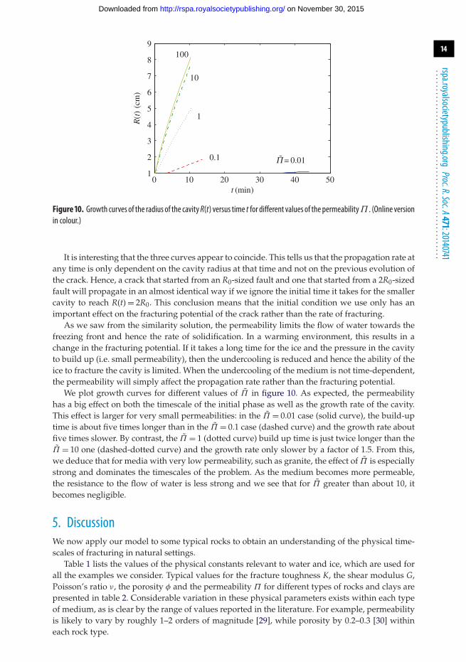
It is interesting that the three curves appear to coincide. This tells us that the propagation rate atany time is only dependent on the cavity radius at that time and not on the previous evolution ofthe crack. Hence, a crack that started from an R0-sized fault and one that started from a 2R0-sizedfault will propagate in an almost identical way if we ignore the initial time it takes for the smallercavity to reach R(t) = 2R0. This conclusion means that the initial condition we use only has animportant effect on the fracturing potential of the crack rather than the rate of fracturing.
As we saw from the similarity solution, the permeability limits the flow of water towards thefreezing front and hence the rate of solidification. In a warming environment, this results in achange in the fracturing potential. If it takes a long time for the ice and the pressure in the cavityto build up (i.e. small permeability), then the undercooling is reduced and hence the ability of theice to fracture the cavity is limited. When the undercooling of the medium is not time-dependent,the permeability will simply affect the propagation rate rather than the fracturing potential.
We plot growth curves for different values of Π in figure 10. As expected, the permeabilityhas a big effect on both the timescale of the initial phase as well as the growth rate of the cavity.This effect is larger for very small permeabilities: in the Π = 0.01 case (solid curve), the build-uptime is about five times longer than in the Π = 0.1 case (dashed curve) and the growth rate aboutfive times slower. By contrast, the Π = 1 (dotted curve) build up time is just twice longer than theΠ = 10 one (dashed-dotted curve) and the growth rate only slower by a factor of 1.5. From this,we deduce that for media with very low permeability, such as granite, the effect of Π is especiallystrong and dominates the timescales of the problem. As the medium becomes more permeable,the resistance to the flow of water is less strong and we see that for Π greater than about 10, itbecomes negligible.
5. DiscussionWe now apply our model to some typical rocks to obtain an understanding of the physical time-scales of fracturing in natural settings.
Table 1 lists the values of the physical constants relevant to water and ice, which are used forall the examples we consider. Typical values for the fracture toughness K, the shear modulus G,Poisson’s ratio ν, the porosity φ and the permeability Π for different types of rocks and clays arepresented in table 2. Considerable variation in these physical parameters exists within each typeof medium, as is clear by the range of values reported in the literature. For example, permeabilityis likely to vary by roughly 1–2 orders of magnitude [29], while porosity by 0.2–0.3 [30] withineach rock type.
on November 30, 2015http://rspa.royalsocietypublishing.org/Downloaded from
15
rspa.royalsocietypublishing.orgProc.R.Soc.A471:20140741
...................................................
2 4 6 8
100
200
t (min)
R(t
)(m
m)
0 2 4 6 80
5
10
ice
pres
sure
(M
Pa)
radius R(t)ice pressure
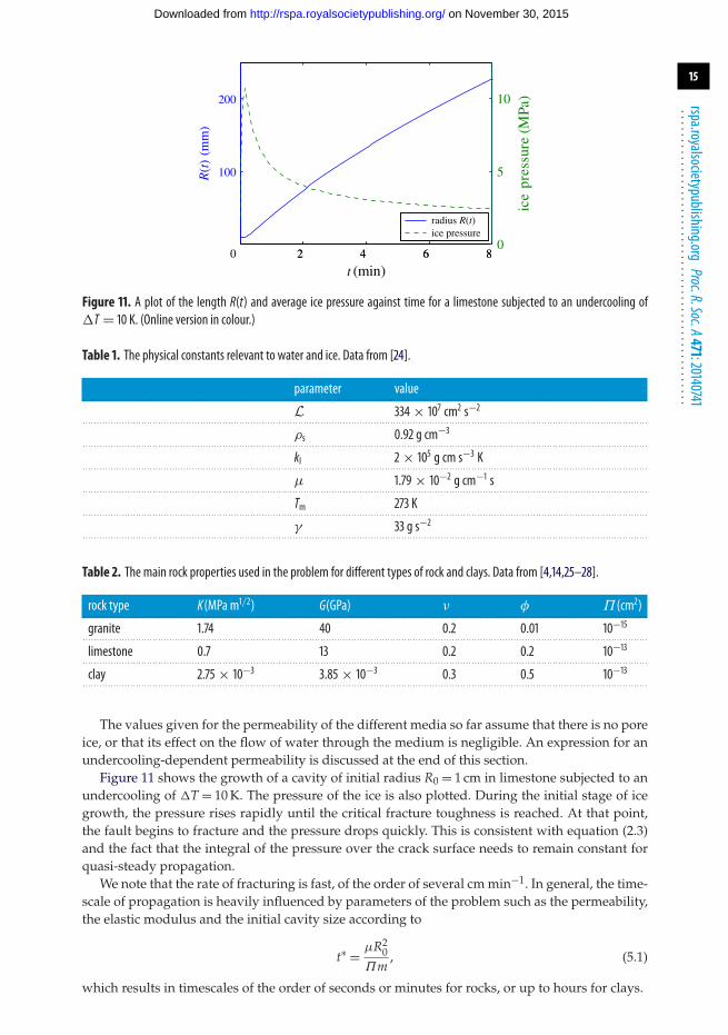
Figure 11. A plot of the length R(t) and average ice pressure against time for a limestone subjected to an undercooling of�T = 10 K. (Online version in colour.)
Table 1. The physical constants relevant to water and ice. Data from [24].
parameter value. . . . . . . . . . . . . . . . . . . . . . . . . . . . . . . . . . . . . . . . . . . . . . . . . . . . . . . . . . . . . . . . . . . . . . . . . . . . . . . . . . . . . . . . . . . . . . . . . . . . . . . . . . . . . . . . . . . . . . . . . . . . . . . . . . . . . . . . . . . . . . . . . . . . . . . . . . . . . . . . . . . . . . . . . . . . . . . . . . . . . . . . . . . . . . . . . . . . . . . . . .
L 334 × 107 cm2 s−2. . . . . . . . . . . . . . . . . . . . . . . . . . . . . . . . . . . . . . . . . . . . . . . . . . . . . . . . . . . . . . . . . . . . . . . . . . . . . . . . . . . . . . . . . . . . . . . . . . . . . . . . . . . . . . . . . . . . . . . . . . . . . . . . . . . . . . . . . . . . . . . . . . . . . . . . . . . . . . . . . . . . . . . . . . . . . . . . . . . . . . . . . . . . . . . . . . . . . . . . . .
ρs 0.92 g cm−3. . . . . . . . . . . . . . . . . . . . . . . . . . . . . . . . . . . . . . . . . . . . . . . . . . . . . . . . . . . . . . . . . . . . . . . . . . . . . . . . . . . . . . . . . . . . . . . . . . . . . . . . . . . . . . . . . . . . . . . . . . . . . . . . . . . . . . . . . . . . . . . . . . . . . . . . . . . . . . . . . . . . . . . . . . . . . . . . . . . . . . . . . . . . . . . . . . . . . . . . . .
kl 2 × 10⁵ g cm s−3 K. . . . . . . . . . . . . . . . . . . . . . . . . . . . . . . . . . . . . . . . . . . . . . . . . . . . . . . . . . . . . . . . . . . . . . . . . . . . . . . . . . . . . . . . . . . . . . . . . . . . . . . . . . . . . . . . . . . . . . . . . . . . . . . . . . . . . . . . . . . . . . . . . . . . . . . . . . . . . . . . . . . . . . . . . . . . . . . . . . . . . . . . . . . . . . . . . . . . . . . . . .
μ 1.79 × 10⁻² g cm−1 s. . . . . . . . . . . . . . . . . . . . . . . . . . . . . . . . . . . . . . . . . . . . . . . . . . . . . . . . . . . . . . . . . . . . . . . . . . . . . . . . . . . . . . . . . . . . . . . . . . . . . . . . . . . . . . . . . . . . . . . . . . . . . . . . . . . . . . . . . . . . . . . . . . . . . . . . . . . . . . . . . . . . . . . . . . . . . . . . . . . . . . . . . . . . . . . . . . . . . . . . . .
Tm 273 K. . . . . . . . . . . . . . . . . . . . . . . . . . . . . . . . . . . . . . . . . . . . . . . . . . . . . . . . . . . . . . . . . . . . . . . . . . . . . . . . . . . . . . . . . . . . . . . . . . . . . . . . . . . . . . . . . . . . . . . . . . . . . . . . . . . . . . . . . . . . . . . . . . . . . . . . . . . . . . . . . . . . . . . . . . . . . . . . . . . . . . . . . . . . . . . . . . . . . . . . . .
γ 33 g s−2. . . . . . . . . . . . . . . . . . . . . . . . . . . . . . . . . . . . . . . . . . . . . . . . . . . . . . . . . . . . . . . . . . . . . . . . . . . . . . . . . . . . . . . . . . . . . . . . . . . . . . . . . . . . . . . . . . . . . . . . . . . . . . . . . . . . . . . . . . . . . . . . . . . . . . . . . . . . . . . . . . . . . . . . . . . . . . . . . . . . . . . . . . . . . . . . . . . . . . . . . .
Table 2. The main rock properties used in the problem for different types of rock and clays. Data from [4,14,25–28].
rock type K(MPa m1/2) G(GPa) ν φ Π (cm2). . . . . . . . . . . . . . . . . . . . . . . . . . . . . . . . . . . . . . . . . . . . . . . . . . . . . . . . . . . . . . . . . . . . . . . . . . . . . . . . . . . . . . . . . . . . . . . . . . . . . . . . . . . . . . . . . . . . . . . . . . . . . . . . . . . . . . . . . . . . . . . . . . . . . . . . . . . . . . . . . . . . . . . . . . . . . . . . . . . . . . . . . . . . . . . . . . . . . . . . . .
granite 1.74 40 0.2 0.01 10−15. . . . . . . . . . . . . . . . . . . . . . . . . . . . . . . . . . . . . . . . . . . . . . . . . . . . . . . . . . . . . . . . . . . . . . . . . . . . . . . . . . . . . . . . . . . . . . . . . . . . . . . . . . . . . . . . . . . . . . . . . . . . . . . . . . . . . . . . . . . . . . . . . . . . . . . . . . . . . . . . . . . . . . . . . . . . . . . . . . . . . . . . . . . . . . . . . . . . . . . . . .
limestone 0.7 13 0.2 0.2 10−13. . . . . . . . . . . . . . . . . . . . . . . . . . . . . . . . . . . . . . . . . . . . . . . . . . . . . . . . . . . . . . . . . . . . . . . . . . . . . . . . . . . . . . . . . . . . . . . . . . . . . . . . . . . . . . . . . . . . . . . . . . . . . . . . . . . . . . . . . . . . . . . . . . . . . . . . . . . . . . . . . . . . . . . . . . . . . . . . . . . . . . . . . . . . . . . . . . . . . . . . . .
clay 2.75 × 10⁻³ 3.85 × 10⁻³ 0.3 0.5 10−13. . . . . . . . . . . . . . . . . . . . . . . . . . . . . . . . . . . . . . . . . . . . . . . . . . . . . . . . . . . . . . . . . . . . . . . . . . . . . . . . . . . . . . . . . . . . . . . . . . . . . . . . . . . . . . . . . . . . . . . . . . . . . . . . . . . . . . . . . . . . . . . . . . . . . . . . . . . . . . . . . . . . . . . . . . . . . . . . . . . . . . . . . . . . . . . . . . . . . . . . . .
The values given for the permeability of the different media so far assume that there is no poreice, or that its effect on the flow of water through the medium is negligible. An expression for anundercooling-dependent permeability is discussed at the end of this section.
Figure 11 shows the growth of a cavity of initial radius R0 = 1 cm in limestone subjected to anundercooling of �T = 10 K. The pressure of the ice is also plotted. During the initial stage of icegrowth, the pressure rises rapidly until the critical fracture toughness is reached. At that point,the fault begins to fracture and the pressure drops quickly. This is consistent with equation (2.3)and the fact that the integral of the pressure over the crack surface needs to remain constant forquasi-steady propagation.
We note that the rate of fracturing is fast, of the order of several cm min−1. In general, the time-scale of propagation is heavily influenced by parameters of the problem such as the permeability,the elastic modulus and the initial cavity size according to
t∗ = μR20
Πm, (5.1)
which results in timescales of the order of seconds or minutes for rocks, or up to hours for clays.
on November 30, 2015http://rspa.royalsocietypublishing.org/Downloaded from
16
rspa.royalsocietypublishing.orgProc.R.Soc.A471:20140741
...................................................
0 5 10 15 20
1
2
DT (K)
R(m
ms–1
) (×
10−
4 )
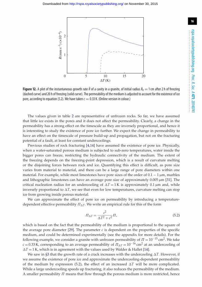
Figure 12. A plot of the instantaneous growth rate R of a cavity in a granite, of initial radius R0 = 1 cm after 2 h of freezing(dashed curve) and 20 h of freezing (solid curve). The permeability of the medium is adjusted to account for the existence of icepore, according to equation (5.2). We have taken c = 0.33 K. (Online version in colour.)
The values given in table 2 are representative of unfrozen rocks. So far, we have assumedthat little ice exists in the pores and it does not affect the permeability. Clearly, a change in thepermeability has a strong effect on the timescale as they are inversely proportional, and hence itis interesting to study the existence of pore ice further. We expect the change in permeability tohave an effect on the timescale of pressure build-up and propagation, but not on the fracturingpotential of a fault, at least for constant undercoolings.
Previous studies of rock fracturing [4,14] have assumed the existence of pore ice. Physically,when a water-saturated porous medium is subjected to sub-zero temperatures, water inside thebigger pores can freeze, restricting the hydraulic connectivity of the medium. The extent ofthe freezing depends on the freezing-point depression, which is a result of curvature meltingor the disjoining forces between rock and ice. Quantifying this effect is difficult, as pore sizevaries from material to material, and there can be a large range of pore diameters within onematerial. For example, while most limestones have pore sizes of the order of 0.1 − 1 µm, marblesand lithographic limestones can have an average pore size of approximately 0.005 µm [31]. Thecritical nucleation radius for an undercooling of �T = 1 K is approximately 0.1 µm and, whileinversely proportional to �T, we see that even for low temperatures, curvature melting can stopice from growing inside porous material.
We can approximate the effect of pore ice on permeability by introducing a temperature-dependent effective permeability Π�T. We write an empirical rule for this of the form
Π�T = c2
�T2 + c2 Π , (5.2)
which is based on the fact that the permeability of the medium is proportional to the square ofthe average pore diameter [29]. The parameter c is dependent on the properties of the specificmedium, and could be determined experimentally (see the appendix for more details). For thefollowing example, we consider a granite with unfrozen permeability of Π = 10−15 cm2. We takec = 0.33 K, corresponding to an average permeability of Π�T = 10−16 cm2 at an undercooling of�T = 1 K, which is in agreement with the values used by Walder & Hallet [14].
We saw in §3 that the growth rate of a crack increases with the undercooling �T. However, ifwe assume the existence of pore ice and approximate the undercooling-dependent permeabilityof the medium by expression (5.2), the effect of an increased �T will be more complicated.While a large undercooling speeds up fracturing, it also reduces the permeability of the medium.A smaller permeability Π means that flow through the porous medium is more restricted, hence
on November 30, 2015http://rspa.royalsocietypublishing.org/Downloaded from
17
rspa.royalsocietypublishing.orgProc.R.Soc.A471:20140741
...................................................
the propagation slows down. These two effects act in opposing ways and the balance of the twodetermines how an increase in �T changes the growth curves. This effect can be seen in figure 12,where we have plotted the instantaneous growth rate of a crack both after 2 h of freezing and20 h of freezing. We discover a similar behaviour to that found by Walder & Hallet [14], withthe most effective fracturing occurring at temperatures higher than −5◦C and the fracturing ratedecreasing for large values of the undercooling, as there is more pore ice restricting the flow ofthe water. The rates of freezing are of the order of 10−4 mm s−1 which is in agreement with the10−4 to 10−5 mm s−1 rates found by Walder & Hallet [14].
It should be pointed out that the effect of the permeability through the undercooling isdependent on the value of c. We have used c = 0.33 K here but a larger value would result inthe effect of Π�T being weaker and we could see the propagation rate increasing with �T evenwith the decreasing permeability. Experimental work could provide further useful insight here, inparticular in investigating the existence of pore ice, determining c and validating expression (5.2).
6. ConclusionIn conclusion, this study of a penny-shaped cavity has provided us with a mathematical modelcapable of explaining the physical processes governing fracturing, and establishing the relevanceof different parameters.
Phase planes of the different types of solutions were discussed in §3, and general patternsof dependence of the cavity growth curves on the different parameters of the problem wereestablished. The ratio of fracture toughness to undercooling not only determines the susceptibilityof a medium to fracturing but also strongly affects the propagation rate, with a larger K/�T ratioresulting in slower propagation. The growth rate is also proportional to the elastic modulus of themedium, hence very inelastic rocks are expected to fracture quickly.
We also established that when the surrounding environment is undercooled to a constant �T,the permeability of the medium does not affect the fracturing potential, but only the timescaleof cavity growth. In addition, the permeability must be smaller than about 10−12 cm2 in order tohave an important effect on either the fracturing potential or the fracturing rate.
We found a relation between the key parameters of the problem, given by equation (4.4), whichneeds to be satisfied for fracturing to occur. For example, for limestone undercooled by �T = 5 K,no faults smaller than R0 ≈ 1.2 cm will fracture. By contrast, a 1 cm-sized fault in granite willrequire undercoolings of at least 13 K to crack.
In the case where the condition above is not met, ice can still grow inside the cavity and deformit without fracturing it. The process continues, with the thickness of the cavity increasing, untilan equilibrium is reached where the disjoining pressure between the ice and the rock is balancedby the elastic response of the medium.
This discussion assumes that several flow paths to the fault exist, a reasonable assumptionfor initial fault sizes of millimetres which, for most rocks, is the order of magnitude required forfracturing to occur at undercoolings of a few degrees. For small faults in rocks with low flow-path connectivity (which will be reflected in the low permeability of the medium via equation(A 1)), different mechanisms might develop, especially at the initial stages of freezing. If the flowpaths to a pre-existing fault are restricted, it could instead be the expansion of the freezing watercausing large pressures to develop, as discussed in [18].
The discussion of the conditions for the existence of a frozen fringe and an undercooling-dependent permeability, as well as its effect on the fracturing, shows the variety and complexityof factors that influence the process. The time-dependent model can also incorporate differentbackground conditions, including time-varying far-field undercoolings. Another assumptionessential for the formulation of the integral equations is the spherical symmetry of thepressure fields, with the background conditions applied as r → ∞. Different geometries or finiteboundaries could be studied by using the appropriate solutions to the liquid and solid pressurefields. Our study provides a framework for modelling the important physical interactions of frostfracturing, and a base on which to incorporate further effects that are found to be important.
on November 30, 2015http://rspa.royalsocietypublishing.org/Downloaded from
18
rspa.royalsocietypublishing.orgProc.R.Soc.A471:20140741
...................................................
Data accessibility. The results of this paper are derived from a complete set of mathematical equations givenin the paper using a custom numerical algorithm described in the thesis by I.V. [22] and, as such, are fullyreproducible.Author contributions. I.V. conducted this research towards a PhD, supervised by M.G.W. Both authors gave finalapproval for publication.Funding statement. This research was supported by a PhD studentship from the EPSRC.Conflict of interests. We have no competing interests.
Appendix A. The dependence of permeability on undercoolingThe permeability is closely related to the size of the pores, and can be shown [29] to beproportional to the square of the average pore diameter
Π = Cd2, (A 1)
where C is a constant relating to the flow paths connecting the pores. If we consider the growth ofice in a small spherical pore, two effects contribute to the depression of the freezing temperature:the curvature-induced melting, and the disjoining forces which become important when the poreis almost ice-filled, as explained in §2d. It can be shown that, at first order, the smallest depressionof the freezing temperature is determined by curvature melting (dictated by the Gibbs–Thompsonrelation). In that case, the ice is close enough to the rock for the curvature to be approximatelygiven by κ = 1/d, where d is the diameter of the pore, but not close enough for the disjoiningforces to be important, hence causing further depression of the melting temperature.
For a given undercooling �T, pores that are larger than the corresponding diameter
d�T = γ Tm
ρsL�T(A 2)
will be almost completely ice-filled, reducing the overall average pore diameter of the mediumto d < d. We expect this new average diameter d to be a function of both the initial average porediameter d as well as the freezing pore diameter d�T. When �T = 0, hence d�T → ∞, no ice growsinside the pores and therefore the average diameter remains unchanged, d = d. As the temperaturedrops, d�T becomes smaller and hence some of the pores fill with ice. This reduces the averagepore size. This analysis implies a relationship between d, d and d�T of the form
1
d=√
1d2 + α
d2�T
, (A 3)
where α, to be determined, relates to the distribution of pore sizes of the medium.The effective permeability Π�T at an undercooling �T is proportional to d2, according to
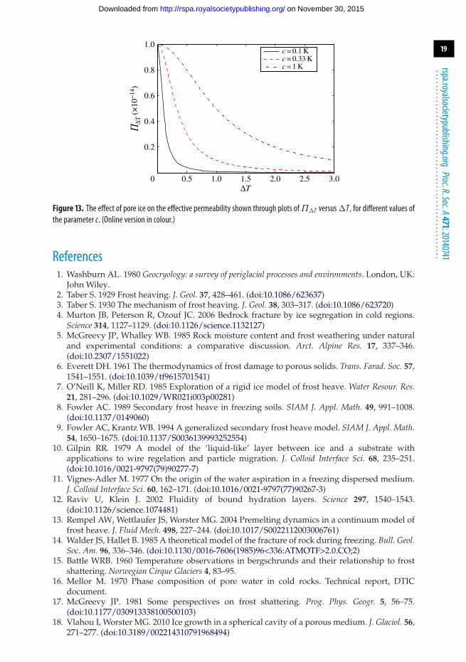
equation (A 1). We can then express the permeability of the medium Π�T in terms of theundercooling �T and the unfrozen permeability of the medium (figure 13)
Π�T = c1
�T2 + c22Π . (A 4)
The parameters c1 and c2 have units of K2 and K, respectively, and depend on the mediumcharacteristics, such as the pore size distribution. We note that the frozen permeability is inverselyproportional to �T2, as in [14]. One of the parameters c1 and c2 can be easily fixed by the conditionthat Π�T = Π for �T = 0, from which we deduce that c1 = c2
2 ≡ c2. To fix the second parameter, weneed to determine the effective permeability at a given undercooling. For example, if c = 0.1 K, anundercooling of just 1◦C will cause a permeability 100 times smaller than the permeability of theunfrozen medium, while c = 0.33 K means that, at �T = 1 K, the permeability is 10 times smallerthan the unfrozen value.
on November 30, 2015http://rspa.royalsocietypublishing.org/Downloaded from
19
rspa.royalsocietypublishing.orgProc.R.Soc.A471:20140741
...................................................
0 0.5 1.0 1.5 2.0 2.5 3.0
0.2
0.4
0.6
0.8
1.0
DT
’DT
(×10
−14
)
c = 0.1 Kc = 0.33 Kc = 1 K
Figure 13. The effect of pore ice on the effective permeability shown through plots of�T versus�T , for different values ofthe parameter c. (Online version in colour.)
References1. Washburn AL. 1980 Geocryology: a survey of periglacial processes and environments. London, UK:
John Wiley.2. Taber S. 1929 Frost heaving. J. Geol. 37, 428–461. (doi:10.1086/623637)3. Taber S. 1930 The mechanism of frost heaving. J. Geol. 38, 303–317. (doi:10.1086/623720)4. Murton JB, Peterson R, Ozouf JC. 2006 Bedrock fracture by ice segregation in cold regions.
Science 314, 1127–1129. (doi:10.1126/science.1132127)5. McGreevy JP, Whalley WB. 1985 Rock moisture content and frost weathering under natural
and experimental conditions: a comparative discussion. Arct. Alpine Res. 17, 337–346.(doi:10.2307/1551022)
6. Everett DH. 1961 The thermodynamics of frost damage to porous solids. Trans. Farad. Soc. 57,1541–1551. (doi:10.1039/tf9615701541)
7. O’Neill K, Miller RD. 1985 Exploration of a rigid ice model of frost heave. Water Resour. Res.21, 281–296. (doi:10.1029/WR021i003p00281)
8. Fowler AC. 1989 Secondary frost heave in freezing soils. SIAM J. Appl. Math. 49, 991–1008.(doi:10.1137/0149060)
9. Fowler AC, Krantz WB. 1994 A generalized secondary frost heave model. SIAM J. Appl. Math.54, 1650–1675. (doi:10.1137/S0036139993252554)
10. Gilpin RR. 1979 A model of the ‘liquid-like’ layer between ice and a substrate withapplications to wire regelation and particle migration. J. Colloid Interface Sci. 68, 235–251.(doi:10.1016/0021-9797(79)90277-7)
11. Vignes-Adler M. 1977 On the origin of the water aspiration in a freezing dispersed medium.J. Colloid Interface Sci. 60, 162–171. (doi:10.1016/0021-9797(77)90267-3)
12. Raviv U, Klein J. 2002 Fluidity of bound hydration layers. Science 297, 1540–1543.(doi:10.1126/science.1074481)
13. Rempel AW, Wettlaufer JS, Worster MG. 2004 Premelting dynamics in a continuum model offrost heave. J. Fluid Mech. 498, 227–244. (doi:10.1017/S0022112003006761)
14. Walder JS, Hallet B. 1985 A theoretical model of the fracture of rock during freezing. Bull. Geol.Soc. Am. 96, 336–346. (doi:10.1130/0016-7606(1985)96<336:ATMOTF>2.0.CO;2)
15. Battle WRB. 1960 Temperature observations in bergschrunds and their relationship to frostshattering. Norwegian Cirque Glaciers 4, 83–95.
16. Mellor M. 1970 Phase composition of pore water in cold rocks. Technical report, DTICdocument.
17. McGreevy JP. 1981 Some perspectives on frost shattering. Prog. Phys. Geogr. 5, 56–75.(doi:10.1177/030913338100500103)
18. Vlahou I, Worster MG. 2010 Ice growth in a spherical cavity of a porous medium. J. Glaciol. 56,271–277. (doi:10.3189/002214310791968494)
on November 30, 2015http://rspa.royalsocietypublishing.org/Downloaded from
20
rspa.royalsocietypublishing.orgProc.R.Soc.A471:20140741
...................................................
19. Wettlaufer JS, Worster MG. 2006 Premelting dynamics. Annu. Rev. Fluid Mech. 38, 427–452.(doi:10.1146/annurev.fluid.37.061903.175758)
20. Spence DA, Sharp P. 1985 Self-similar solutions for elastohydrodynamic cavity flow. Proc. R.Soc. Lond. A 400, 289–313. (doi:10.1098/rspa.1985.0081)
21. Rice JR. 1968 Mathematical analysis in the mechanics of fracture. Fracture 2, 191–311.22. Vlahou I. 2012 Freeze fracturing of elastic porous media. Ph.D. thesis, University of
Cambridge.23. Lawn BB. 1993 Fracture of brittle solids. Cambridge, UK: Cambridge University Press.24. SnowCrystalscom. 2011 Physical properties of ice. See http://www.its.caltech.edu/∼atomic/
snowcrystals/ice/ice.htm.25. Katz O, Reches Z, Roegiers JC. 2000 Evaluation of mechanical rock properties using a schmidt
hammer. Int. J. Rock Mech. Mining Sci. 37, 723–728. (doi:10.1016/S1365-1609(00)00004-6)26. Al-Shayea NA. 2004 Effects of testing methods and conditions on the elastic properties of
limestone rock. Eng. Geol. 74, 139–156. (doi:10.1016/j.enggeo.2004.03.007)27. Schmidt RA. 1976 Fracture-toughness testing of limestone. Exp. Mech. 16, 161–167.
(doi:10.1007/BF02327993)28. Konrad JM, Ayad R. 1997 A idealized framework for the analysis of cohesive soils undergoing
desiccation. Can. Geotech. J. 34, 477–488. (doi:10.1139/t97-015)29. Bear J. 1988 Dynamics of fluids in porous media. New York, NY: Dover Publications.30. Freeze RA, Cherry JA. 1979 Groundwater. Englewood Cliffs, NJ: Prentice-Hall.31. Lautridou JP, Ozouf JC. 1982 Experimental frost shattering. Prog. Phys. Geogr. 6, 215–232.
(doi:10.1177/030913338200600202)
on November 30, 2015http://rspa.royalsocietypublishing.org/Downloaded from