
HVDC Case study Gerus Station NAmibia
16
POLYTECHNIC OF NAMIBIA SCHOOL OF ENGINEERING INDUSTRIAL EXCURSION REPORT: Gerus HVDC Converter Station Prepared By: Shafa BH-200973924- [email protected] Prepared For: Mr. G. Gope Course : Power Systems Engineering 415(PSE810S) DATE: 17 th April 2012
-
Upload
independent -
Category
Documents
-
view
2 -
download
0
Transcript of HVDC Case study Gerus Station NAmibia
P O L Y T E C H N I C O F N AM I B I A
SCHOOL OF ENGINEERING
INDUSTRIAL EXCURSION REPORT: Gerus HVDC Converter Station
Prepared By:
Shafa BH-200973924- [email protected]
Prepared For:
Mr. G. Gope
Course : Power Systems Engineering 415(PSE810S)
DATE:
17th April 2012
HVDC Transmission Systems-Gerus Substation
BY Shafa BH 200973924 POLYTECHNIC OF NAMIBIA B.Eng: Electrical Power 2
1. ABSTRACT
This report presents information and data gathered during the site visit to the Gerus substation on 17th April 2012. The Gerus substation is part of the Caprivi HVDC link. It runs from the Zambezi to Otjiwarongo, for a secure long distance power transmission. The link is currently a monopole system; however the substation works both in inverter and rectifier mode.
2. INTRODUCTION
The advancement in the fabrication of high power electronic devices such as thyristors, Insulated Gate Bipolar Transistors (IGBTs) and other electronic switching devices has led to the development and expanded application of HVDC Schemes. Such schemes are used for bulk power transmission over long distances, inter-connections of AC systems and back-to-back arrangements for optimised power interchanges. In Namibia, the bulk generation is supplied from Ruacana hydropower station in the far north through a 520km 330kV transmission line. The Van Eck power station is also used during emergencies to supply the load centre near Windhoek. To cater for the fast growing economy and to provide a secure electric energy to the mining and mineral industry in Namibia, an HVDC link came into being as to transmit power over a long distance about 950km through overhead DC line, with the capability of transmitting 300MW with an ac voltage rating of 400Kv.
3. OBJECTIVES
The objectives of the paper are to:
Do a literature review on HVDC transmission.
Find problems being faced by the current Gerus HVDC link.
Find possible areas of study at the Gerus DC link.
4. AIM
The major aim of this paper is to give a lager and get a insight to the operational characteristics of an HVDC systems, by referring to the Gerus station.
5. HVDC THEORY
In today electricity industry, in view of the liberalisation and increased effects to conserve the environment, HVDC solutions have become more desirable for the following reasons:
Environmental advantages
Economical (cheapest solution)
Asynchronous interconnections
Power flow control
Added benefits to the transmission (stability, power quality etc.)
HVDC stands for High-Voltage-Direct-Current.
The development of high power thyristors and other electronic switching devices such as IGBT’s, has led to the development and expanded application of HVDC schemes.
HVDC schemes play a very big role in:
1. bulk power transmission over long distances
2. Inter-connection of ac systems
3. back-to-back arrangements for optimized power interchanges.
HVDC Transmission Systems-Gerus Substation
BY Shafa BH 200973924 POLYTECHNIC OF NAMIBIA B.Eng: Electrical Power 3
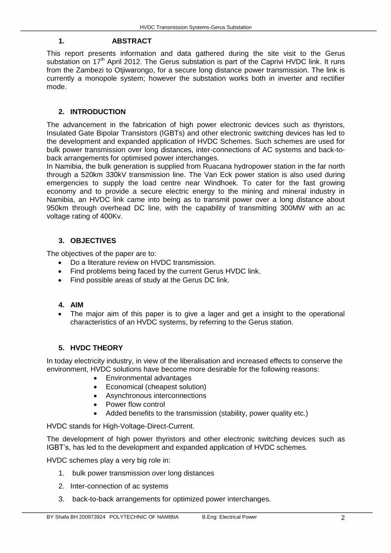
The Major Advantages of HVDC schemes:
1. Rapid power flow control including reverse power flow. Power in the mw range can be reversed in less than a second. This is useful for
Stability control of ac systems
Energy trading in an ac interconnected market (e.g. caprivi link , Namibia)
Limited short circuit currents during faults
2. No charging current requirements
Cable transmission over long distances is possible (e.g submarine transmission lines), across environmentally sensitive areas or densely populated areas
Power delivery to and from off-shore installations
3. No reactive voltage drops
Long distance transmission without the need of compensation
4. Interconnection of ac systems operating at different frequencies.
Back-to-back arrangements for optimal power flow and increased reliability of supply without transferring disturbances from one system to another.
Increasing system capacity without increasing fault levels.
5. Fewer conductors and supports.
Smaller right of way (row)
Lower capital costs (conductors and towers)
HVDC Transmission Systems-Gerus Substation
BY Shafa BH 200973924 POLYTECHNIC OF NAMIBIA B.Eng: Electrical Power 4
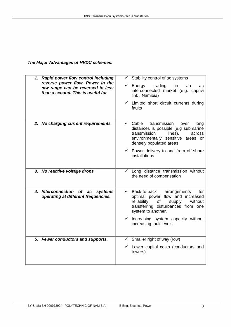
Transmission (HVDC)
Basically a three phase ac power is fed into a pulse converter for rectification into dc power, which is then transmitted over a 2 conductor line. At the end of the line, the dc power is inverted into 3 phase ac power. Both the inverter and converter are line commutated.
The below table contains the major components of an HVDC transmission line.
1. Inductors/reactors
Smoothen rectifier outputs
Limit line currents in case of a short circuit
2. Converter transformers
Supply stepped up voltage to the converters
Transformers are usually 3-phase (star-star or
star-delta. Tertiary winding is normally included
for connection of reactive power sources).
Have taps so as to keep e1 constant (against
variations in ac network
3. Dc harmonic filters
Limit harmonic currents from converters
(usually 6th and 12
th in a 6-pulse converter)
Harmonic currents generate noise in
communication systems
4. Reactive power sources
Reactive power absorbed by the converters is
supplied by the ac network.
Reactive power sources (e.g synchronous
HVDC Transmission Systems-Gerus Substation
BY Shafa BH 200973924 POLYTECHNIC OF NAMIBIA B.Eng: Electrical Power 5
condensers or static capacitors) supply
variable reactive power requirements of
converters.
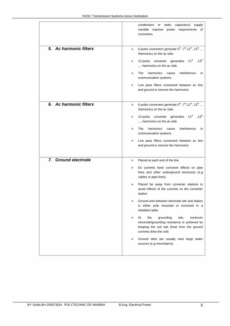
5. Ac harmonic filters
6 pulse converters generate 5th ,7
th,11
th, 13
th….
Harmonics on the ac side.
12-pulse converter generates 11th ,13
th
,....harmonics on the ac side.
The harmonics cause interference in
communication systems.
Low pass filters connected between ac line
and ground to remove the harmonics
6. Ac harmonic filters
6 pulse converters generate 5th ,7
th,11
th, 13
th….
Harmonics on the ac side.
12-pulse converter generates 11th ,13
th
,....harmonics on the ac side.
The harmonics cause interference in
communication systems.
Low pass filters connected between ac line
and ground to remove the harmonics
7. Ground electrode
Placed at each end of the line
Dc currents have corrosive effects on pipe
lines and other underground structures (e.g
cables or pipe lines)
Placed far away from converter stations to
avoid effects of the currents on the converter
station
Ground wire between electrode site and station
is either pole mounted or enclosed in a
shielded cable.
At the grounding site, minimum
electrode/grounding resistance is achieved by
keeping the soil wet (heat from the ground
currents dries the soil)
Ground sites are usually near large water
sources (e.g rivers/dams).
HVDC Transmission Systems-Gerus Substation
BY Shafa BH 200973924 POLYTECHNIC OF NAMIBIA B.Eng: Electrical Power 6
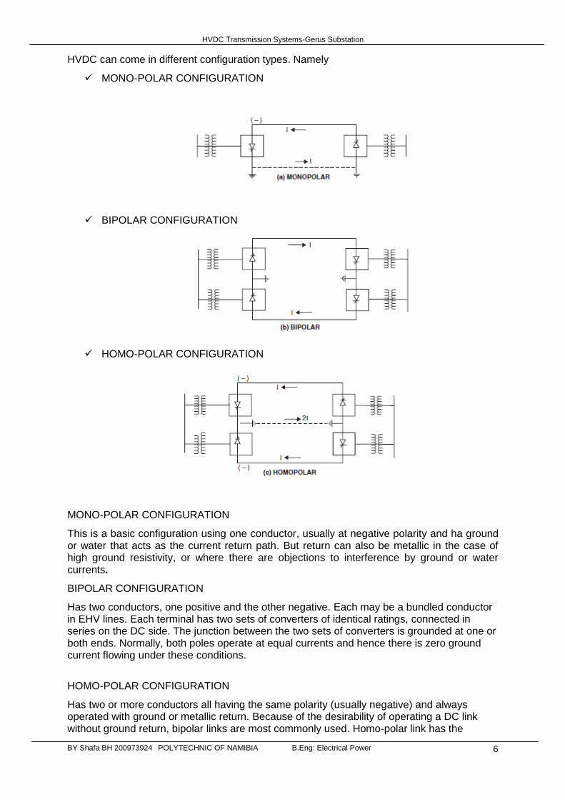
HVDC can come in different configuration types. Namely
MONO-POLAR CONFIGURATION
BIPOLAR CONFIGURATION
HOMO-POLAR CONFIGURATION
MONO-POLAR CONFIGURATION
This is a basic configuration using one conductor, usually at negative polarity and ha ground or water that acts as the current return path. But return can also be metallic in the case of high ground resistivity, or where there are objections to interference by ground or water currents.
BIPOLAR CONFIGURATION
Has two conductors, one positive and the other negative. Each may be a bundled conductor in EHV lines. Each terminal has two sets of converters of identical ratings, connected in series on the DC side. The junction between the two sets of converters is grounded at one or both ends. Normally, both poles operate at equal currents and hence there is zero ground current flowing under these conditions.
HOMO-POLAR CONFIGURATION
Has two or more conductors all having the same polarity (usually negative) and always operated with ground or metallic return. Because of the desirability of operating a DC link without ground return, bipolar links are most commonly used. Homo-polar link has the
HVDC Transmission Systems-Gerus Substation
BY Shafa BH 200973924 POLYTECHNIC OF NAMIBIA B.Eng: Electrical Power 7
advantage of reduced insulation costs, but the disadvantages of earth return outweigh the advantages. Incidentally, the corona effects in a DC line are substantially less with negative polarity of the conductor as compared to the positive polarity.
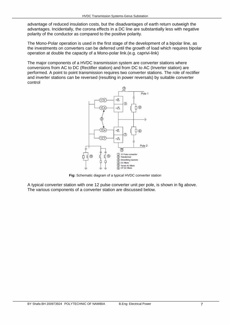
The Mono-Polar operation is used in the first stage of the development of a bipolar line, as the investments on converters can be deferred until the growth of load which requires bipolar operation at double the capacity of a Mono-polar link.(e.g. caprivi-link) The major components of a HVDC transmission system are converter stations where conversions from AC to DC (Rectifier station) and from DC to AC (Inverter station) are performed. A point to point transmission requires two converter stations. The role of rectifier and inverter stations can be reversed (resulting in power reversals) by suitable converter control
Fig: Schematic diagram of a typical HVDC converter station
A typical converter station with one 12 pulse converter unit per pole, is shown in fig above. The various components of a converter station are discussed below.
HVDC Transmission Systems-Gerus Substation
BY Shafa BH 200973924 POLYTECHNIC OF NAMIBIA B.Eng: Electrical Power 8
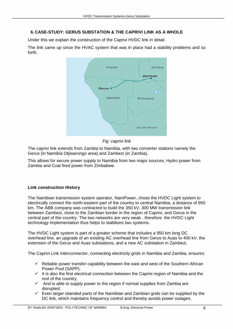
6. CASE-STUDY: GERUS SUBSTATION & THE CAPRIVI LINK AS A WHOLE
Under this we explain the construction of the Caprivi HVDC link in detail.
The link came up since the HVAC system that was in place had a stability problems and so forth.
Fig: caprivi link
The caprivi link extends from Zambia to Namibia, with two converter stations namely the Gerus (in Namibia Otjiwarongo area) and Zambezi (in Zambia).
This allows for secure power supply to Namibia from two major sources, Hydro power from Zambia and Coal fired power from Zimbabwe.
Link construction History
The Namibian transmission system operator, NamPower, chose the HVDC Light system to electrically connect the north-eastern part of the country to central Namibia, a distance of 950 km. The ABB company was contracted to build the 350 kV, 300 MW transmission link between Zambezi, close to the Zambian border in the region of Caprivi, and Gerus in the central part of the country. The two networks are very weak , therefore the HVDC Light technology implementation thus helps to stabilizes two systems.
The HVDC Light system is part of a greater scheme that includes a 950 km long DC overhead line, an upgrade of an existing AC overhead line from Gerus to Auas to 400 kV, the extension of the Gerus and Auas substations, and a new AC substation in Zambezi.
The Caprivi Link Interconnector, connecting electricity grids in Namibia and Zambia, ensures:
Reliable power transfer capability between the east and west of the Southern African Power Pool (SAPP).
It is also the first electrical connection between the Caprivi region of Namibia and the rest of the country,
And is able to supply power to the region if normal supplies from Zambia are disrupted.
Even larger islanded parts of the Namibian and Zambian grids can be supplied by the DC link, which maintains frequency control and thereby avoids power outages.
HVDC Transmission Systems-Gerus Substation
BY Shafa BH 200973924 POLYTECHNIC OF NAMIBIA B.Eng: Electrical Power 9
ABB was once again the company responsible for system engineering including design, supply and installation of the two converter stations and the ground electrodes. Something amazing is that this project extends the voltage rating for HVDC Light to 350 kV and has marked the first time the technology is used for overhead transmission.
Below is data table for the Caprivi Link.
HVDC Scheme-Main data
Commissioning year: 2010
Power rating: 300 MW
No. of poles: 1
AC voltage: Gerus: 400 kV Zambezi: 330 kV
DC voltage: 350 kV
Length of overhead DC line: 950 km
Main reason for choosing HVDC: Long distance, weak networks
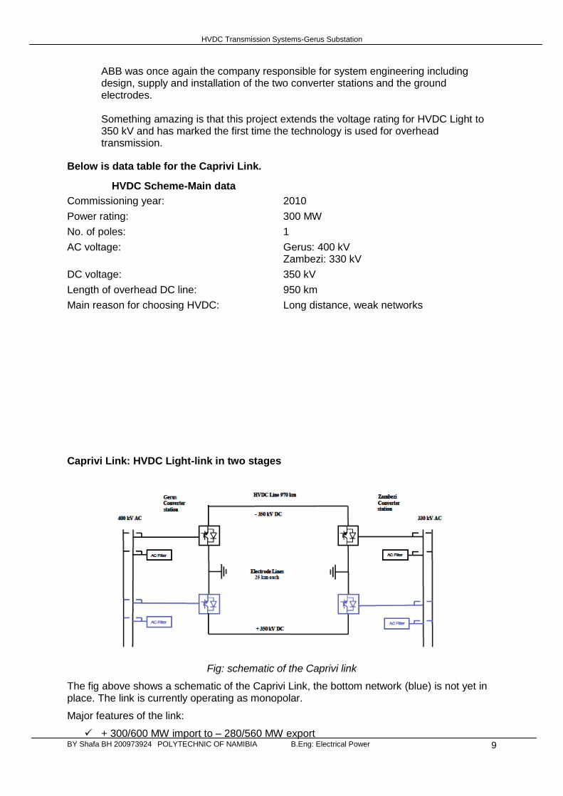
Caprivi Link: HVDC Light-link in two stages
Fig: schematic of the Caprivi link
The fig above shows a schematic of the Caprivi Link, the bottom network (blue) is not yet in place. The link is currently operating as monopolar.
Major features of the link:
+ 300/600 MW import to – 280/560 MW export
HVDC Transmission Systems-Gerus Substation
BY Shafa BH 200973924 POLYTECHNIC OF NAMIBIA B.Eng: Electrical Power 10
+/- 200 MVar at continuous AC voltage control of 400 kV/320 kV networks at Gerus/Zambezi
Stable and robust power transfer down to short circuit power levels of about 300 MVA, without synchronous compensators
Black start of Caprivi region at black outs Re-start after DC-line faults at lightning’s within 500 ms after fault clearance
7. HVDC POWER LINE FEATURES:
i. Conductors and Towers
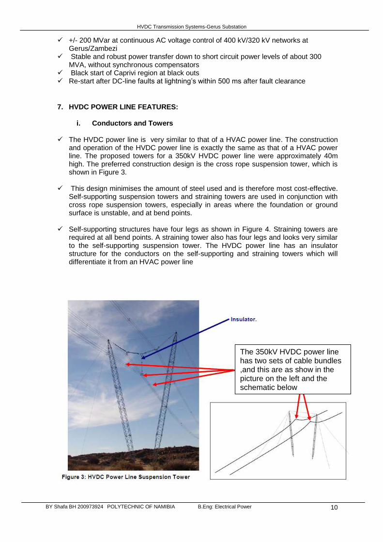
The HVDC power line is very similar to that of a HVAC power line. The construction and operation of the HVDC power line is exactly the same as that of a HVAC power line. The proposed towers for a 350kV HVDC power line were approximately 40m high. The preferred construction design is the cross rope suspension tower, which is shown in Figure 3.
This design minimises the amount of steel used and is therefore most cost-effective. Self-supporting suspension towers and straining towers are used in conjunction with cross rope suspension towers, especially in areas where the foundation or ground surface is unstable, and at bend points.
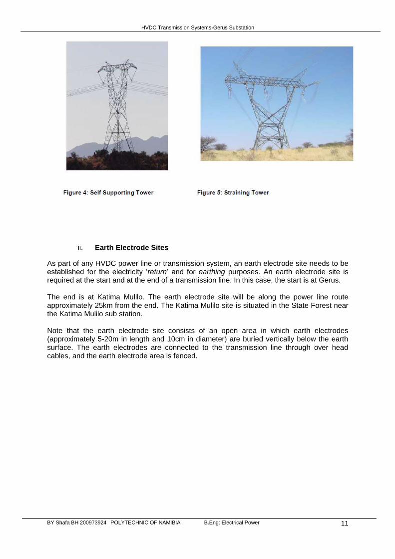
Self-supporting structures have four legs as shown in Figure 4. Straining towers are required at all bend points. A straining tower also has four legs and looks very similar to the self-supporting suspension tower. The HVDC power line has an insulator structure for the conductors on the self-supporting and straining towers which will differentiate it from an HVAC power line
The 350kV HVDC power line has two sets of cable bundles ,and this are as show in the picture on the left and the schematic below
HVDC Transmission Systems-Gerus Substation
BY Shafa BH 200973924 POLYTECHNIC OF NAMIBIA B.Eng: Electrical Power 11
ii. Earth Electrode Sites
As part of any HVDC power line or transmission system, an earth electrode site needs to be established for the electricity ‘return’ and for earthing purposes. An earth electrode site is required at the start and at the end of a transmission line. In this case, the start is at Gerus. The end is at Katima Mulilo. The earth electrode site will be along the power line route approximately 25km from the end. The Katima Mulilo site is situated in the State Forest near the Katima Mulilo sub station.
Note that the earth electrode site consists of an open area in which earth electrodes (approximately 5-20m in length and 10cm in diameter) are buried vertically below the earth surface. The earth electrodes are connected to the transmission line through over head cables, and the earth electrode area is fenced.

HVDC Transmission Systems-Gerus Substation
BY Shafa BH 200973924 POLYTECHNIC OF NAMIBIA B.Eng: Electrical Power 12
iii. Repeater Stations
Repeater stations for the HVDC transmission line are build at various intervals along the transmission line to restore and amplify ‘attenuated’ and time smeared signals in a typical signal carrying installation.
iv. Converter Stations
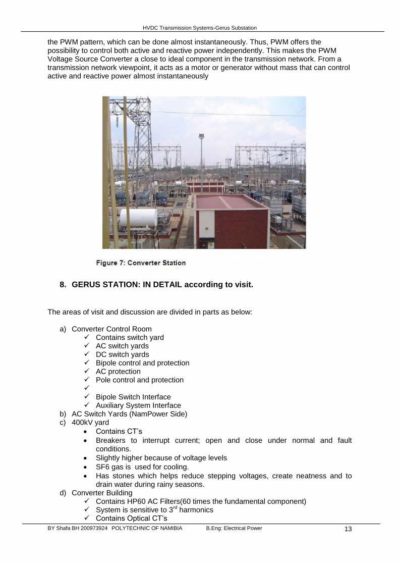
As part of any HVDC power line or transmission system, a Converter Station is required at the transition point between HVDC and HVAC, which will be utilised for domestic distribution or further transmission. The first conversion is from HVAC to HVDC is at Gerus and then the next conversion from HVDC back to HVAC is at Katima Mulilo. The Converters are forced Commutated. This type of converters introduces a spectrum of advantages, e.g. feed of passive networks (without generation), independent control of active and reactive power, power quality. The valves of these converters are built up with semiconductors with the ability not only to turn-on but also to turn-off. They are known as VSC (Voltage Source Converters). The type of semiconductor used in this voltage source converters are the IGBT (Insulated Gate Bipolar Transistor).The VSC commutates with high frequency (not with the net frequency). The operation of the converter is achieved by Pulse Width Modulation (PWM). With PWM it is possible to create any phase 3 angle and/or amplitude (up to a certain limit) by changing
HVDC Transmission Systems-Gerus Substation
BY Shafa BH 200973924 POLYTECHNIC OF NAMIBIA B.Eng: Electrical Power 13
the PWM pattern, which can be done almost instantaneously. Thus, PWM offers the possibility to control both active and reactive power independently. This makes the PWM Voltage Source Converter a close to ideal component in the transmission network. From a transmission network viewpoint, it acts as a motor or generator without mass that can control active and reactive power almost instantaneously
8. GERUS STATION: IN DETAIL according to visit. The areas of visit and discussion are divided in parts as below:
a) Converter Control Room Contains switch yard AC switch yards DC switch yards Bipole control and protection AC protection Pole control and protection Bipole Switch Interface Auxiliary System Interface
b) AC Switch Yards (NamPower Side) c) 400kV yard
Contains CT’s
Breakers to interrupt current; open and close under normal and fault conditions.
Slightly higher because of voltage levels
SF6 gas is used for cooling.
Has stones which helps reduce stepping voltages, create neatness and to drain water during rainy seasons.
d) Converter Building Contains HP60 AC Filters(60 times the fundamental component) System is sensitive to 3rd harmonics Contains Optical CT’s
HVDC Transmission Systems-Gerus Substation
BY Shafa BH 200973924 POLYTECHNIC OF NAMIBIA B.Eng: Electrical Power 14
e) Reactor Hall
Covered in cage-like structure due to EM1
Earthed is special way (ring-structure)
This is to prevent any closed loop paths f) IGBT Hall
Contains 2000 IGBTS They generate a lot of heat and hence cooling of the IGBT’s is very vital. Water pipes are integrated for cooling purposes Also contains optic fibres containing the pulse to fire the transistors. Firing is done at same time. IGBT’s have to be operated at very cold temperatures. Contains DC Capacitors to supply steady DC voltage. Most IGBT failure at the station are either due to it not being pulsed or due to
electrical failure. Redundancy helps overcome the above problems, 8 IGBTS can fail and
system can still work. Snubber circuits are used in series with diodes to energise IGBT. IGBT switching is light dependent
g) DC Side
Uses circuit high speed circuit breakers; of type HSS as switch gear.
HSS breakers help to get the forced oscillations for a zero crossing
Contains also:
Smoothing Reactor
HI-Speed Switch
Bus HF Filters
Line Trap
DC Pole Breaker
h) Cooling The station has cooling systems in place which include: Fans Valve cooling
i) DC Hall
This contained filters,
Surge Arrestors
DC resistor - Current Limiting j) Water Treatment Hall
In this hall water for Gerus station is recycle and treated. The water is 90% deionised and 10% Glycol content.
k) Reaper Station:
Two types; both using optic fibre types l) Protection Room
Contain batteries connected in series to provide a dc powering for the protection gear such as relays.
Type of batteries used are Ni-Cd and require high maintance
It is 200/300V plan
110V main and 110V backup system
Only feeds the substation equipment
m) Transmission Protocols
TCP/IP
Redundancy is considered
Power Line Carrier with high frequency of about 40kHz to 60kHz
HVDC Transmission Systems-Gerus Substation
BY Shafa BH 200973924 POLYTECHNIC OF NAMIBIA B.Eng: Electrical Power 15
Fibre optic cables are used for transmission of the SCADA systems in place.
9. HVDC LINK OPERATION MODES:
Reduce Voltage Scheme:
Occurs during lighting and field fire faults Compensates for reactive power onto the Gerus network 80% reduction in initial power rating
Island mode:
It is a condition of sustaining a passive network Power reversal depending on fault location
10. COMMUNICATION SYSTEMS 1) Fibre optic cables 2) Power Line Carrier 3) OPGW- Optical Ground Wire
11. PURPOSE OF HVDC SYSTEM REPLICA:
It is clearly understood that NamPower has ordered the Swedish company ABB to design a replica the HVDC System the built from Zambezi (Sesheko) to Otjiwarongo (Gerus) station. This is for the following purposes:
ARC-Automatic Restate Sequence Allows simulation of similar events to rectify bugs/problems. Allows future plans (testing of IO) Data recorded from the instant of fault is imported in the replica and means of bug
correction are made/solved.
12. CONCLUSION The HVDC system plays a big role in the Namibia power network; it is a further step in overcoming the power crisis the country is facing due to the growing mining industry and rural electrifications. NAMPOWER imports 50MW from Zambia into the Namibian network. Depending on demand the Gerus station is either in inverter or converter mode. But in most cases the Gerus station operates as an inverter. Gerus station is currently not operating according to required sequence, ABB is working on the problem. However the problem really lies in fault location and studies can still be done on fault locators to solve the problem. All in a nutshell the visit to Gerus station was a very big eye open as the student now had to see the practical side of the theory taught in class.
HVDC Transmission Systems-Gerus Substation
BY Shafa BH 200973924 POLYTECHNIC OF NAMIBIA B.Eng: Electrical Power 16
13. REFERENCES [1] Melvold, D.J. (1992) HVDC converter terminal maintenance/spare parts philosophy and comparison with performance. IEEE Transactions on Power Delivery, 7(2), 869–875.. [2] Baker, A.C., Zaffanella, L.E., Anzivino, L.D. et al. (1989) A comparison of HVAC and HVDC contamination Performance of station post insulators. IEEE Transactions on Power Delivery, 4(2), 1486–1491. [3] Kalra, P.K. (1987) Feasibility study for development of expert systems for power system control. Electric Power Systems Research, 12(2), 125–130. [4] www.nampower.com.na