hp-clj-ent-m575-troubleshooting-manual.pdf - Laser Express
476
LASERJET ENTERPRISE 500 COLOR MFP Troubleshooting Manual M575
-
Upload
khangminh22 -
Category
Documents
-
view
0 -
download
0
Transcript of hp-clj-ent-m575-troubleshooting-manual.pdf - Laser Express

LASERJET ENTERPRISE 500 COLOR MFP
Troubleshooting Manual
M575


HP LaserJet Enterprise 500 color MFPM575 Printers
Troubleshooting Manual

Copyright and License
© 2012 Copyright Hewlett-PackardDevelopment Company, L.P.
Reproduction, adaptation, or translationwithout prior written permission isprohibited, except as allowed under thecopyright laws.
The information contained herein is subjectto change without notice.
The only warranties for HP products andservices are set forth in the express warrantystatements accompanying such products andservices. Nothing herein should beconstrued as constituting an additionalwarranty. HP shall not be liable for technicalor editorial errors or omissions containedherein.
Part number: CD644-90967
Edition 1, 5/2012
Trademark Credits
Adobe®, Adobe Photoshop®, Acrobat®, andPostScript® are trademarks of AdobeSystems Incorporated.
Apple and the Apple logo are trademarks ofApple Computer, Inc., registered in the U.S.and other countries. iPod is a trademark ofApple Computer, Inc. iPod is for legal orrightholder-authorized copying only. Don'tsteal music.
Microsoft®, Windows®, Windows® XP,and Windows Vista® are U.S. registeredtrademarks of Microsoft Corporation.
PANTONE® is Pantone, Inc's check-standard trademark for color.
UNIX® is a registered trademark of TheOpen Group.

Conventions used in this guide
TIP: Tips provide helpful hints or shortcuts.
NOTE: Notes provide important information to explain a concept or to complete a task.
CAUTION: Cautions indicate procedures that you should follow to avoid losing data or damagingthe product.
WARNING! Warnings alert you to specific procedures that you should follow to avoid personalinjury, catastrophic loss of data, or extensive damage to the product.
ENWW iii

iv Conventions used in this guide ENWW

Table of contents
1 Theory of operation .......................................................................................................... 1
Basic operation ........................................................................................................................ 2Sequence of operation ............................................................................................... 3
Engine-control system ................................................................................................................ 4DC controller ............................................................................................................ 5
Solenoids .................................................................................................. 5Clutches .................................................................................................... 6Switches ................................................................................................... 6Sensors ..................................................................................................... 7Motors and fans ......................................................................................... 8
High-voltage power supply ......................................................................................... 9Low-voltage power supply ........................................................................................ 11
Overcurrent/overvoltage protection ............................................................ 12Safety ..................................................................................................... 13Voltage detection ..................................................................................... 13Sleep (powersave) mode ........................................................................... 13Power supply voltage detection .................................................................. 14Low-voltage power supply failure ............................................................... 14
Power Off condition ................................................................................................ 14Auto on/Auto off mode ............................................................................................ 14Fuser (fixing) control ................................................................................................ 16
Fuser (fixing) temperature-control circuit ...................................................... 17Fuser (fixing) over-temperature protection .................................................... 17Fuser (fixing)-failure detection .................................................................... 18
Laser/scanner system ............................................................................................................. 20Image formation system .......................................................................................................... 22
Image formation process .......................................................................................... 23Step 1: Pre-exposure ................................................................................. 24Step 2: Primary charging .......................................................................... 24Step 3: Laser-beam exposure ..................................................................... 25Step 4: Development ................................................................................ 25Step 5: Primary transfer ............................................................................ 26
ENWW v

Step 6: Secondary transfer ........................................................................ 26Step 7: Separation ................................................................................... 27Step 8: Fusing ......................................................................................... 27Step 9: ITB cleaning ................................................................................. 28Step 10: Drum cleaning ............................................................................ 28
Toner cartridge ....................................................................................................... 28Developing roller engagement and disengagement ..................................................... 30Intermediate transfer belt (ITB) unit ............................................................................. 32
Primary-transfer-roller engagement and disengagement ................................. 33ITB cleaning ............................................................................................ 35
Calibration ............................................................................................................. 36Color misregistration control ...................................................................... 36Image stabilization control ........................................................................ 37
Pickup, feed, and delivery system ............................................................................................. 38Pickup-and-feed unit ................................................................................................ 41
Tray pickup ............................................................................................. 42Tray-presence detection .............................................................. 43Tray lift operation ...................................................................... 43paper-presence detection ........................................................... 45Multifeed prevention .................................................................. 45
Multipurpose tray pickup ........................................................................... 46Paper feed .............................................................................................. 47
Skew-feed prevention ................................................................. 48OHT detection .......................................................................... 48
Fusing and delivery unit ........................................................................................... 49Loop control ............................................................................................ 49Pressure-roller pressurization control ........................................................... 51
Duplexing unit ........................................................................................................ 52Duplexing reverse and feed control ............................................................ 53Duplex pickup operation ........................................................................... 53
Jam detection ........................................................................................................................ 54Optional paper feeder ............................................................................................................ 56
Paper-feeder pickup and feed operation .................................................................... 58Paper size detection and presence detection .............................................................. 59Paper feeder lift operation ........................................................................................ 61Paper feeder presence detection ............................................................................... 62Paper-feeder multiple feed prevention ........................................................................ 62Paper feeder jam detection ....................................................................................... 64
Scanning/image capture system .............................................................................................. 65Control panel ......................................................................................................... 65Scanner ................................................................................................................. 65
vi ENWW

Automatic document feed system ............................................................................... 65Sensors in the ADF ................................................................................... 65ADF paper path ....................................................................................... 66Stapler (stapling models only) .................................................................... 67
2 Solve problems ............................................................................................................... 69
Solve problems checklist ......................................................................................................... 70Menu map ............................................................................................................................ 72Preboot menu options ............................................................................................................. 73Current settings pages ............................................................................................................ 80Troubleshooting process .......................................................................................................... 81
Determine the problem source ................................................................................... 81Troubleshooting flowchart ......................................................................... 81
Power subsystem ..................................................................................................... 82Power-on checks ...................................................................................... 82
Power-on troubleshooting overview .............................................. 82Control-panel checks ............................................................................................... 83Scanning subsystem ................................................................................................ 85
Tools for troubleshooting ......................................................................................................... 86Individual component diagnostics .............................................................................. 86
LED diagnostics ........................................................................................ 86Understand lights on the formatter ............................................... 86
Engine diagnostics ................................................................................... 91Defeating interlocks ................................................................... 91Disable cartridge check ............................................................. 93Engine test button ...................................................................... 94
Paper path test ......................................................................................... 95Paper path sensors test ............................................................................. 95Manual sensor test ................................................................................... 97
SW1 Front Door ....................................................................... 98SR8 Registration sensor ............................................................ 100SR14 Fuser Loop 1 and SR15 Fuser Loop 2 sensors ..................... 101SR7 Fuser Pressure Release sensor ............................................. 102SR5 Fuser Output sensor .......................................................... 103SR22 Duplexer Refeed sensor ................................................... 104SR6 Output Bin Full sensor ........................................................ 105SR11 Developer Alienation sensor ............................................. 106SR17 ITB Alienation sensor ....................................................... 107Tray/bin manual sensor test ..................................................... 109
Print/stop test ........................................................................................ 117Component tests ..................................................................................... 118
ENWW vii

Control-panel tests ................................................................... 118Component test (special-mode test) ............................................ 118
Diagrams ............................................................................................................. 120Block diagrams ...................................................................................... 120Location of connectors ............................................................................ 122
DC controller PCA ................................................................... 122Paper feeder driver PCA .......................................................... 123
Plug/jack locations ................................................................................. 124Locations of major components ................................................................ 124
Base product .......................................................................... 1251 x 500 paper feeder .............................................................. 131
General timing chart ............................................................................... 132Circuit diagrams .................................................................................... 133
Internal print-quality test pages ................................................................................ 137Print quality troubleshooting pages ........................................................... 137Print quality assessment page .................................................................. 140Cleaning page ....................................................................................... 142
Set up an auto cleaning page ................................................... 142Print configuration page .......................................................................... 143
Configuration page ................................................................. 143HP embedded Jetdirect page .................................................... 145Finding important information on the configuration pages ............ 146
Color band test ...................................................................................... 147Print quality troubleshooting tools ............................................................................ 147
Repetitive defects ruler ............................................................................ 147Calibrate the product to align the colors .................................................... 148
Control panel menus .............................................................................................. 149Administration menu ............................................................................... 149
Reports menu .......................................................................... 149General Settings menu ............................................................. 150Copy Settings menu ................................................................. 166Scan/Digital Send Settings menu .............................................. 175Fax Settings menu ................................................................... 186General Print Settings menu ...................................................... 200Default Print Options menu ....................................................... 202Display Settings menu .............................................................. 204Manage Supplies menu ........................................................... 206Manage Trays menu ................................................................ 212Network Settings menu ............................................................ 214Troubleshooting menu .............................................................. 228
Device Maintenance menu ...................................................................... 232
viii ENWW

Backup/Restore menu .............................................................. 232Calibration/Cleaning menu ...................................................... 233USB Firmware Upgrade menu ................................................... 236Service menu .......................................................................... 236
Interpret control-panel messages ............................................................................. 237Control-panel message types ................................................................... 237Control-panel messages .......................................................................... 237
Ready .................................................................................... 23710.0X.Y0 Supply memory error ................................................ 23710.23.50 ............................................................................... 23810.23.51 ............................................................................... 23810.23.52 ............................................................................... 23810.XX.34 Used supply in use .................................................... 23910.XX.40 Genuine HP supplies installed .................................... 23910.XX.41 Unsupported supply in use ......................................... 24010.XX.70 Printing past very low ................................................ 24010.YY.15 Install <supply> ........................................................ 24110.YY.25 Wrong cartridge in <color> slot ................................. 24210.YY.35 Incompatible <supply> .............................................. 24211.00.YY Internal clock error To continue, touch “OK” ................ 24313.A3.A3 .............................................................................. 24313.AD.D3 .............................................................................. 24413.B2.AD .............................................................................. 24413.B2.AZ ............................................................................... 24513.B2.D1 ............................................................................... 24513.B2.D2 ............................................................................... 24613.B2.D3 ............................................................................... 24613.B2.DD .............................................................................. 24713.B9.AZ ............................................................................... 24813.B9.CZ ............................................................................... 24813.B9.DD .............................................................................. 24913.B9.Dz ............................................................................... 24913.WX.EE .............................................................................. 25013.WX.FF .............................................................................. 25113.WX.YZ Fuser wrap jam ....................................................... 25113.WX.YZ Jam above output bin clear jam, then touch “OK” ....... 25213.WX.YZ Jam in right door ..................................................... 25213.WX.YZ Jam in Tray <X> ...................................................... 25213.WX.YZ Jam lower right door ............................................... 25320.00.00 Insufficient memory: <Device> To continue, touch “OK” 25321.00.00 Page too complex To continue, touch “OK” ................. 253
ENWW ix

30.01.23 Scanner calibration failure ........................................ 25330.01.36 Upgrade Error Try downloading upgrade again .......... 25430.01.43 Scan memory failure To continue turn off then on ......... 25430.01.YY Scanner failure To continue turn off then on ................. 25430.WX.YZ Scanner fan failure To continue turn off then on .......... 25531.01.03 Document feeder pick error ....................................... 25531.01.47 Document feeder not detected .................................... 25631.03.22 Scanner calibration failure ........................................ 25631.WX.10 Scanner failure To continue turn off then on ................ 25631.WX.15 Jam in document feeder ........................................... 25632.1C.XX ............................................................................... 25732.21.00 ............................................................................... 26133.02.01 ............................................................................... 26133.WX.YZ Used board/disk installed ........................................ 26240.00.01 USB I/O buffer overflow To continue, touch “OK” ........ 26240.00.02 Embedded I/O buffer overflow To continue, touch “OK” 26241.03.YZ Unexpected size in Tray <X> ..................................... 26241.03.YZ Unexpected size in Tray <X> To use another tray, touch"Options" ............................................................................... 26341.05.YZ Unexpected type in Tray <X> ..................................... 26341.05.YZ Unexpected type in Tray <X> To use another tray,touch "Options" ...................................................................... 26441.WX.YZ Error To use another tray, touch "Options" ................. 26642.XX.YY ............................................................................... 26747.FC.YZ Printer calibration failed To continue, touch “OK” ......... 26747.WX.YZ Printer calibration failed ........................................... 26848.01.XX Error ....................................................................... 26849.XX.YY Error To continue turn off then on ................................ 26850.WX.YZ Fuser error To continue turn off then on ...................... 26951.00.YY Error To continue turn off then on ................................ 27252.00.00 Error To continue turn off then on ............................... 27352.00.20 Error To continue turn off then on ............................... 27452.20.00 Error To continue turn off then on ............................... 27452.<XX>.00 Error To continue turn off then on ............................ 27554.XX.YY Error ....................................................................... 27555.XX.YY DC controller error To continue turn off then on ............ 27655.XX.YY DC controller error To continue turn off then on ............ 27756.00.01 Illegal Input Printer Error To continue turn off then on .... 27756.00.YY Error To continue turn off then on ................................ 27857.00.0X Error ....................................................................... 27858.00.04 Error To continue turn off then on ............................... 279
x ENWW
59.00.00 Error To continue turn off then on ............................... 27959.00.20 Error To continue turn off then on ............................... 28059.00.30 Error To continue turn off then on ............................... 28059.00.40 Error To continue turn off then on ............................... 28059.00.B0 Cleaning motor error Replace Toner Collection Unit ...... 28059.00.YY Error To continue turn off then on ................................ 28159.0X.50 Error To continue turn off then on ................................ 28259.0X.60 Error To continue turn off then on ................................ 28260.00.0Y Tray <Y> lifting error ................................................ 28361.00.01 ............................................................................... 28362.00.00 No system To continue turn off then on ........................ 28369.11.YY Error To continue, touch “OK” .................................... 28370.00.00 Error To continue turn off then on ............................... 28480.0X.YY Embedded JetDirect Error .......................................... 28481.WX.00 Wireless Network Error To continue turn off then on .. . . 28681.WX.YZ Embedded JetDirect Error To continue turn off then on . . 28698.00.0X Corrupt data in X volume ........................................... 286<Binname> full Remove all paper from bin ................................. 287<Supply> almost full ................................................................ 287<Supply> low ......................................................................... 287<Supply> low OR Supplies low ................................................. 288<Supply> very low .................................................................. 289<Supply> very low To continue, touch “OK” ............................... 289<Supply> very low OR Supplies very low ................................... 289A second USB wireless networking accessory has been detected . . 290Bad optional tray connection .................................................... 290Card slot device failure To clear touch “Clear” ........................... 291Card slot file operation failed To clear touch “Clear” ................... 291Card slot file system is full To clear touch “Clear” ........................ 291Card slot is write protected To clear touch “Clear” ...................... 291Card slot not initialized To clear touch “Clear” ........................... 291Cartridge ship mode ................................................................ 292Chosen personality not available To continue, touch “OK” ........... 292Clean the rollers ...................................................................... 292Cleaning disk <X>% complete Do not power off ......................... 292Clearing activity log ................................................................ 293Close front or right doors ......................................................... 293Close lower right door ............................................................. 293Close right door ...................................................................... 293Data received ......................................................................... 294Digital send communication error .............................................. 294
ENWW xi

Disk full Delete stored jobs ........................................................ 294Disk low Delete stored jobs ....................................................... 294Document feeder bin full .......................................................... 295Document feeder is empty ........................................................ 295Document Feeder Kit low .......................................................... 295Document Feeder Kit very low ................................................... 295Document Feeder Kit very low To continue, touch “OK” ............... 295Document feeder top cover open ............................................... 296Event log is empty ................................................................... 296Fax is disabled – ignoring call .................................................. 296Finishing process not functional ................................................. 296Flatbed cover open .................................................................. 296Fuser Kit Low .......................................................................... 296Fuser Kit very low .................................................................... 297Fuser Kit very low To continue, touch “OK” ................................ 297Incompatible <supply> ............................................................. 297Incompatible supplies .............................................................. 298Initializing scanner, please wait ................................................ 298Initializing... ........................................................................... 298Install <color> Cartridge .......................................................... 298Install Fuser Unit ...................................................................... 299Install supplies ........................................................................ 299Internal disk device failure To clear touch “Clear” ....................... 299Internal disk file operation failed To clear touch “Clear” ............... 299Internal disk file system is full To clear touch “Clear” .................... 300Internal disk is write protected To clear touch “Clear” .................. 300Internal disk not found ............................................................. 300Internal disk not functional ........................................................ 300Internal disk not initialized To clear touch “Clear” ....................... 300Internal disk spinning up .......................................................... 300Load Tray 1 [Type] [Size] ......................................................... 301Load Tray 1 [Type] [Size] To continue, touch “OK” ...................... 301Load Tray <X>: [Size] .............................................................. 301Load Tray <X>: [Size] To continue, touch “OK” .......................... 302Load Tray <X>: [Size] To use another tray, touch "Options" ......... 302Load Tray <X>: [Type], [Size] ................................................... 302Load Tray <X>: [Type], [Size] To use another tray, touch"Options" ............................................................................... 303Manually feed output stack Then touch "OK" to print second sides 303Manually feed: [Size] .............................................................. 303Manually feed: [Size] To continue, touch “OK” ........................... 303
xii ENWW

Manually feed: [Size] To use another tray, touch "Options" .......... 304Manually feed: [Type], [Size] To continue, touch “OK” ................ 304Manually feed: [Type], [Size] To use another tray, touch"Options" ............................................................................... 304Moving solenoid ..................................................................... 305Moving solenoid and motor ...................................................... 305No job to cancel ..................................................................... 305Output Bin full ......................................................................... 305Paperless mode ....................................................................... 305Paused ................................................................................... 305Performing Color Band Test… ................................................... 306Performing Paper Path Test… .................................................... 306Please wait… .......................................................................... 306Printing CMYK samples... ......................................................... 306Printing Color Usage Log... ...................................................... 306Printing Configuration... ........................................................... 307Printing Demo Page... .............................................................. 307Printing Diagnostics Page... ...................................................... 307Printing Engine Test... .............................................................. 307Printing Engine Test... .............................................................. 307Printing Event Log... ................................................................. 307Printing File Directory... ............................................................ 308Printing Font List... ................................................................... 308Printing Fuser Test Page... ......................................................... 308Printing Help Page... ............................................................... 308Printing Menu Map... ............................................................... 308Printing PQ Troubleshooting... .................................................. 309Printing Registration Page... ...................................................... 309Printing RGB Samples... ........................................................... 309Printing stopped To continue, touch “OK” ................................... 309Printing Supplies Status page... ................................................. 309Printing Usage Page... ............................................................. 309Processing digital send job ....................................................... 310Processing duplex job... Do not grab paper until job completes .... 310Processing job from tray <X>... Do not grab paper until jobcompletes ............................................................................... 310Processing... <filename> .......................................................... 310Processing... copy <X> of <Y> .................................................. 310RAM Disk device failure To clear touch “Clear” .......................... 311RAM Disk file operation failed To clear touch “Clear” .................. 311RAM Disk file system is full To clear touch “Clear” ....................... 311
ENWW xiii

RAM Disk is write protected To clear touch “Clear” ..................... 311RAM Disk not initialized To clear touch “Clear” .......................... 311Ready <IP Address> ................................................................ 312Remove all toner cartridges To exit press X ................................. 312Remove at least one toner cartridge To exit press X ..................... 312Remove shipping lock from Tray 2 ............................................. 312Replace <color> Cartridge ....................................................... 312Replace Document Feeder Kit ................................................... 313Replace Fuser Kit ..................................................................... 313Replace staple cartridge ........................................................... 314Replace supplies ..................................................................... 314Replace Toner Collection Unit ................................................... 314Restricted from printing in color ................................................. 315Roller cleaning is recommended ................................................ 315ROM disk device failed To clear touch “Clear” ........................... 315ROM disk file operation failed To clear touch “Clear” .................. 315ROM disk file system is full To clear touch “Clear” ....................... 316ROM disk is write protected To clear touch “Clear” ..................... 316ROM disk not initialized To clear touch “Clear” .......................... 316Rotating <color> motor To exit press X ....................................... 316Rotating Motor ........................................................................ 317Size mismatch in Tray <X> ....................................................... 317Sleep mode on ....................................................................... 317Standard top output bin full Remove all paper from bin ................ 317Staple Cartridge low ............................................................... 317Staple Cartridge very low To continue, touch “OK” ..................... 318Supplies in wrong positions ...................................................... 318Supplies low ........................................................................... 318Supplies very low To continue, touch “OK” ................................. 318Toner Collection Unit almost full ................................................ 319Toner Collection Unit full .......................................................... 319Toner Collection Unit full To continue, touch “OK” ....................... 319Tray <X> empty: [Size] ............................................................ 320Tray <X> empty: [Type], [Size] ................................................. 320Tray <X> open ........................................................................ 320Tray <X> overfilled Remove excess paper .................................. 320Tray <X> overfilled To use another tray, touch "Options" ............. 321Type mismatch Tray <X> .......................................................... 321Unable to cancel firmware update job ....................................... 321Unable to install the firmware ................................................... 321Unsupported drive installed ...................................................... 322
xiv ENWW

Unsupported supply in use ........................................................ 322Unsupported supply installed .................................................... 322Unsupported supply installed To continue, touch “OK” ................. 323Unsupported USB accessory detected Remove USB accessory ....... 323Upgrade complete To continue turn off then on ........................... 323USB accessory needs too much power Remove USB and turn offthen on .................................................................................. 323USB accessory not functional .................................................... 323USB hubs are not fully supported Some operations may not workproperly ................................................................................. 324USB is write protected To clear touch “Clear” ............................. 324USB needs too much power Remove USB and turn off then on ...... 324USB not initialized To clear touch “Clear” .................................. 324USB storage accessory removed Clearing any associated data ..... 324USB storage device failure To clear touch “Clear” ....................... 324USB storage file operation failed To clear touch “Clear” .............. 325USB storage file system is full To clear touch “Clear” ................... 325Used supply in use .................................................................. 325Used supply installed To continue, touch “OK” ............................ 325Warming up scanner ............................................................... 326Wireless Configuration Mode ................................................... 326Wireless is not configured ........................................................ 326Wrong cartridge in <color> slot ................................................ 326
Event log messages ............................................................................................... 327Print or view an event log ........................................................................ 328Clear an event log .................................................................................. 328Event log message table .......................................................................... 329
Clear jams .......................................................................................................................... 335Common causes of jams ........................................................................................ 335Auto-navigation for clearing jams ............................................................................ 336Jam locations ........................................................................................................ 336Clear jams in the document feeder .......................................................................... 337Clear jams in the output bin area ............................................................................ 339Clear jams in Tray 1 .............................................................................................. 340Clear jams in Tray 2 .............................................................................................. 342Clear jams in the right door .................................................................................... 343Clear jams in optional Tray 3 ................................................................................. 347Clear jams in the lower right door (Tray 3) ............................................................... 348Jam causes and solutions ....................................................................................... 349
Jams in the output bin ............................................................................. 349Jams in the fuser and transfer area ........................................................... 349
ENWW xv

Jams in the duplex area (duplex models) ................................................... 353Jams in Tray 1, Tray 2 and internal paper path .......................................... 354Jams in Tray 3 ....................................................................................... 356
Paper feeds incorrectly or becomes jammed ............................................................................ 358The product does not pick up paper ........................................................................ 358The product picks up multiple sheets of paper ........................................................... 358The document feeder jams, skews, or picks up multiple sheets of paper ....................... 359Prevent paper jams ................................................................................................ 359
Use manual print modes ....................................................................................................... 360Solve image quality problems ................................................................................................ 364
Image defects table ............................................................................................... 364Clean the product ................................................................................................................ 370
Print a cleaning page ............................................................................................ 370Check the scanner glass for dirt or smudges ............................................................. 370Clean the pickup rollers and separation pad in the document feeder ........................... 373
Solve performance problems ................................................................................................. 375Solve connectivity problems ................................................................................................... 376
Solve USB connection problems .............................................................................. 376Solve wired network problems ................................................................................ 376
The product has a poor physical connection. ............................................. 376The computer is using the incorrect IP address for the product ...................... 376The computer is unable to communicate with the product ............................ 377The product is using incorrect link and duplex settings for the network .......... 377New software programs might be causing compatibility problems ................ 377The computer or workstation might be set up incorrectly .............................. 377The product is disabled, or other network settings are incorrect .................... 377
Service mode functions ......................................................................................................... 378Service menu ........................................................................................................ 378Product resets ....................................................................................................... 381
Restore factory-set defaults ....................................................................... 381Restore the service ID .............................................................................. 382Product cold reset ................................................................................... 382
Format Disk and Partial Clean functions ................................................................... 383Active and repository firmware locations ................................................... 383Partial Clean ......................................................................................... 383
Execute a Partial Clean ............................................................ 384Format Disk ........................................................................................... 384
Execute a Format Disk .............................................................. 385Solve fax problems ............................................................................................................... 386
Checklist for solving fax problems ........................................................................... 386What type of phone line are you using? .................................................... 386
xvi ENWW

Are you using a surge-protection device? .................................................. 386Are you using a phone company voice-messaging service or an answeringmachine? .............................................................................................. 387Does your phone line have a call-waiting feature? ...................................... 387
Check fax accessory status ..................................................................................... 388General fax problems ............................................................................................ 389Use Fax over VoIP networks .................................................................................... 390Problems with receiving faxes ................................................................................. 391Problems with sending faxes ................................................................................... 393Fax error codes .................................................................................................... 395Fax error messages on the product control panel ...................................................... 395
Send-fax messages ................................................................................. 396Receive-fax messages ............................................................................. 397
Service settings ..................................................................................................... 398Settings in the Troubleshooting menu ........................................................ 398
Product upgrades ................................................................................................................. 399Determine the installed revision of firmware .............................................................. 399Perform a firmware upgrade ................................................................................... 399
Embedded Web Server ........................................................................... 399USB flash drive (Preboot menu) ................................................................ 400USB flash drive (control-panel menu) ......................................................... 401
Appendix A Service and support ..................................................................................... 403
Hewlett-Packard limited warranty statement ............................................................................. 404HP's Premium Protection Warranty: LaserJet toner cartridge limited warranty statement ................. 406HP policy on non-HP supplies ................................................................................................ 407HP anticounterfeit Web site ................................................................................................... 408Color LaserJet Fuser Kit, Transfer Kit, and Roller Kit Limited Warranty Statement ........................... 409Data stored on the toner cartridge .......................................................................................... 410End User License Agreement .................................................................................................. 411OpenSSL ............................................................................................................................. 414Customer self-repair warranty service ..................................................................................... 415Customer support ................................................................................................................. 416
Appendix B Product specifications ................................................................................... 417
Physical specifications .......................................................................................................... 418Power consumption, electrical specifications, and acoustic emissions .......................................... 418Environmental specifications .................................................................................................. 418
ENWW xvii

Appendix C Regulatory information ................................................................................. 419
FCC regulations ................................................................................................................... 420Environmental product stewardship program ........................................................................... 421
Protecting the environment ...................................................................................... 421Ozone production ................................................................................................. 421Power consumption ............................................................................................... 421Paper use ............................................................................................................. 421Plastics ................................................................................................................. 421HP LaserJet print supplies ....................................................................................... 421Return and recycling instructions ............................................................................. 422
United States and Puerto Rico .................................................................. 422Multiple returns (more than one cartridge) .................................. 422Single returns .......................................................................... 422Shipping ................................................................................ 422
Non-U.S. returns .................................................................................... 423Paper .................................................................................................................. 423Material restrictions ............................................................................................... 423Disposal of waste equipment by users ...................................................................... 424Electronic hardware recycling ................................................................................. 424Chemical substances ............................................................................................. 424Material Safety Data Sheet (MSDS) ......................................................................... 424For more information ............................................................................................. 424
Declaration of conformity ...................................................................................................... 425Declaration of conformity (fax models) .................................................................................... 427Certificate of Volatility .......................................................................................................... 429Safety statements ................................................................................................................. 431
Laser safety .......................................................................................................... 431Canadian DOC regulations .................................................................................... 431VCCI statement (Japan) .......................................................................................... 431Power cord instructions .......................................................................................... 431Power cord statement (Japan) ................................................................................. 431EMC statement (China) .......................................................................................... 432EMC statement (Korea) .......................................................................................... 432EMI statement (Taiwan) .......................................................................................... 432Laser statement for Finland ..................................................................................... 432GS statement (Germany) ........................................................................................ 434Substances Table (China) ....................................................................................... 434Restriction on Hazardous Substances statement (Turkey) ............................................. 434Restriction on Hazardous Substances statement (Ukraine) ........................................... 434
Additional statements for telecom (fax) products ....................................................................... 435EU Statement for Telecom Operation ....................................................................... 435
xviii ENWW

New Zealand Telecom Statements ........................................................................... 435Additional FCC statement for telecom products (US) .................................................. 435Telephone Consumer Protection Act (US) .................................................................. 436Industry Canada CS-03 requirements ...................................................................... 436Vietnam Telecom wired/wireless marking for ICTQC Type approved products ............. 437Japan Telecom Mark ............................................................................................. 437
Index ............................................................................................................................... 439
ENWW xix

xx ENWW

List of tables
Table 1-1 Sequence of operation ............................................................................................................ 3Table 1-2 Solenoids .............................................................................................................................. 5Table 1-3 Switches ................................................................................................................................ 6Table 1-4 Sensors ................................................................................................................................. 7Table 1-5 Motors .................................................................................................................................. 8Table 1-6 Fans ..................................................................................................................................... 9Table 1-7 High-voltage power supply circuits ......................................................................................... 10Table 1-8 Converted DC voltages ......................................................................................................... 12Table 1-9 Fuser (fixing) components ...................................................................................................... 16Table 1-10 Image formation process ..................................................................................................... 23Table 1-11 Primary-transfer-roller engagement states ............................................................................... 33Table 1-12 Image-stabilization controls .................................................................................................. 37Table 1-13 Switches and sensors for the pickup, feed, and delivery system ................................................ 38Table 1-14 Motors and solenoids for the pickup, feed, and delivery system ............................................... 39Table 1-15 Jams that the product detects ............................................................................................... 54Table 1-16 Electrical components for the paper feeder ............................................................................ 57Table 1-17 Paper size detection ........................................................................................................... 60Table 2-1 Preboot menu options (1 of 6) ................................................................................................ 73Table 2-2 Preboot menu options (2 of 6) ................................................................................................ 75Table 2-3 Preboot menu options (3 of 6) ................................................................................................ 76Table 2-4 Preboot menu options (4 of 6) ................................................................................................ 77Table 2-5 Preboot menu options (5 of 6) ................................................................................................ 77Table 2-6 Preboot menu options (6 of 6) ................................................................................................ 78Table 2-7 Troubleshooting flowchart ...................................................................................................... 81Table 2-8 Heartbeat LED, product initialization ....................................................................................... 87Table 2-9 Heartbeat LED, product operational ........................................................................................ 89Table 2-10 Paper-path sensors diagnostic tests ....................................................................................... 95Table 2-11 Manual sensor diagnostic tests ............................................................................................. 97Table 2-12 Tray/bin manual sensors ................................................................................................... 109Table 2-13 Component test details ...................................................................................................... 118Table 2-14 Sensors ........................................................................................................................... 121Table 2-15 DC controller connectors ................................................................................................... 122
ENWW xxi

Table 2-16 Paper feeder driver PCA connectors ................................................................................... 123Table 2-17 PCAs, motors, fans, switches, solenoids, and clutches ........................................................... 129Table 2-18 Important information on the configuration pages ................................................................. 146Table 2-19 Reports menu ................................................................................................................... 149Table 2-20 General Settings menu ...................................................................................................... 151Table 2-21 Copy Settings menu .......................................................................................................... 166Table 2-22 Scan/Digital Send Settings menu ....................................................................................... 175Table 2-23 Fax Settings menu ............................................................................................................ 187Table 2-24 General Print Settings menu ............................................................................................... 200Table 2-25 Default Print Options menu ................................................................................................ 202Table 2-26 Display Settings menu ....................................................................................................... 204Table 2-27 Manage Supplies menu .................................................................................................... 206Table 2-28 Manage Trays menu ......................................................................................................... 212Table 2-29 Network Settings menu ..................................................................................................... 214Table 2-30 Jetdirect Menu .................................................................................................................. 215Table 2-31 Troubleshooting menu ....................................................................................................... 228Table 2-32 Backup/Restore menu ....................................................................................................... 233Table 2-33 Calibration/Cleaning menu ............................................................................................... 233Table 2-34 Causes and solutions for delivery delay jam ........................................................................ 349Table 2-35 Causes and solutions for fuser delivery delay jams ............................................................... 349Table 2-36 Causes and solutions for wrapping jams ............................................................................. 350Table 2-37 Causes and solutions for fuser delivery stationary jams .......................................................... 350Table 2-38 Causes and solutions for residual paper jams ...................................................................... 350Table 2-39 Causes and solutions for pickup delay jams 2 ...................................................................... 351Table 2-40 Causes and solutions for pickup stationary jams ................................................................... 352Table 2-41 Causes and solutions for duplexing reverse jams .................................................................. 353Table 2-42 Causes and solutions for duplex repick jams ........................................................................ 353Table 2-43 Causes and solutions for residual media jams ...................................................................... 354Table 2-44 Causes and solutions for pickup delay jam 1: tray pickup ..................................................... 354Table 2-45 Causes and solutions for pickup stationary jams ................................................................... 355Table 2-46 Causes and solutions for pickup delay jam 1; MP tray pickup ................................................ 355Table 2-47 Causes and solutions for pickup delay and pickup stationary jams ......................................... 356Table 2-48 Print modes under the Adjust Paper Types sub menu ............................................................. 361Table 2-49 MP modes under the Optimize submenu ............................................................................. 362Table 2-50 Image defects table .......................................................................................................... 364Table 2-51 Solve performance problems .............................................................................................. 375Table 2-52 Send-fax messages ........................................................................................................... 396Table 2-53 Receive-fax messages ........................................................................................................ 397Table B-1 Physical specifications ......................................................................................................... 418Table B-2 Operating-environment specifications .................................................................................... 418
xxii ENWW

List of figures
Figure 1-1 Relationship between the main product systems ......................................................................... 2Figure 1-2 Engine-control system ............................................................................................................. 4Figure 1-3 DC controller block diagram ................................................................................................... 5Figure 1-4 High-voltage power supply circuits ........................................................................................ 10Figure 1-5 Low-voltage power-supply circuit ........................................................................................... 11Figure 1-6 Fuser (fixing) components ..................................................................................................... 16Figure 1-7 Fuser temperature-control circuit ............................................................................................ 17Figure 1-8 Laser/scanner system ........................................................................................................... 20Figure 1-9 Image formation system ........................................................................................................ 22Figure 1-10 Image formation process .................................................................................................... 23Figure 1-11 Pre-exposure ..................................................................................................................... 24Figure 1-12 Primary charging ............................................................................................................... 24Figure 1-13 Laser-beam exposure ......................................................................................................... 25Figure 1-14 Development ..................................................................................................................... 25Figure 1-15 Primary transfer ................................................................................................................. 26Figure 1-16 Secondary transfer ............................................................................................................ 26Figure 1-17 Separation ....................................................................................................................... 27Figure 1-18 Fusing .............................................................................................................................. 27Figure 1-19 ITB cleaning ...................................................................................................................... 28Figure 1-20 Drum cleaning .................................................................................................................. 28Figure 1-21 Toner-cartridge system ....................................................................................................... 29Figure 1-22 Developing-roller engagement and disengagement control ..................................................... 30Figure 1-23 ITB unit ............................................................................................................................. 32Figure 1-24 Three states of primary-transfer-roller engagement and disengagement ..................................... 33Figure 1-25 ITB cleaning process .......................................................................................................... 35Figure 1-26 Toner patterns for calibration .............................................................................................. 36Figure 1-27 Switches and sensors for the pickup, feed, and delivery system ............................................... 38Figure 1-28 Motors and solenoids for the pickup, feed, and delivery system .............................................. 39Figure 1-29 Three main units of the pickup, feed, and delivery system ....................................................... 40Figure 1-30 Pickup-and-feed unit ........................................................................................................... 41Figure 1-31 Tray-pickup mechanism ...................................................................................................... 42Figure 1-32 Tray presence sensor ......................................................................................................... 43
ENWW xxiii

Figure 1-33 Tray lift mechanism ............................................................................................................ 44Figure 1-34 Paper-level-detection mechanism .......................................................................................... 45Figure 1-35 Multifeed prevention .......................................................................................................... 45Figure 1-36 Multipurpose tray pickup mechanism ................................................................................... 46Figure 1-37 Paper-feed mechanism ....................................................................................................... 47Figure 1-38 Skew-feed prevention ......................................................................................................... 48Figure 1-39 Fuser and delivery unit ....................................................................................................... 49Figure 1-40 Loop-control mechanism ..................................................................................................... 50Figure 1-41 Pressure-roller pressurization control .................................................................................... 51Figure 1-42 Duplexing unit ................................................................................................................... 52Figure 1-43 Jam detection sensors ........................................................................................................ 54Figure 1-44 Optional paper feeder ....................................................................................................... 56Figure 1-45 Signals for the paper feeder ............................................................................................... 57Figure 1-46 Paper-feeder pickup and feed operation ............................................................................... 58Figure 1-47 Paper size detection .......................................................................................................... 59Figure 1-48 Paper-feeder lift ................................................................................................................. 61Figure 1-49 Paper-feeder multiple feed prevention .................................................................................. 62Figure 1-50 Jam detection .................................................................................................................... 64Figure 1-51 ADF path for single-sided documents ................................................................................... 66Figure 1-52 ADF path for two-sided documents ...................................................................................... 67Figure 2-1 Diagnostic test (1 of 3) ......................................................................................................... 92Figure 2-2 Diagnostic test (2 of 3) ......................................................................................................... 92Figure 2-3 Diagnostic test (3 of 3) ......................................................................................................... 93Figure 2-4 Engine-test button ................................................................................................................ 94Figure 2-5 Test the front door switch (1 of 4) .......................................................................................... 98Figure 2-6 Test the front door switch (2 of 4) .......................................................................................... 98Figure 2-7 Test the front door switch (3 of 4) .......................................................................................... 99Figure 2-8 Test the front door switch (4 of 4) .......................................................................................... 99Figure 2-9 Test the registration sensor .................................................................................................. 100Figure 2-10 Test the fuser loop sensors ................................................................................................ 101Figure 2-11 Test the fuser pressure-release sensor (1 of 2) ...................................................................... 102Figure 2-12 Test the fuser pressure-release sensor (2 of 2) ...................................................................... 102Figure 2-13 Test the fuser output sensor (1 of 2) .................................................................................... 103Figure 2-14 Test the fuser output sensor (2 of 2) .................................................................................... 103Figure 2-15 Test the duplexer refeed sensor ......................................................................................... 104Figure 2-16 Test the output-bin-full sensor ............................................................................................. 105Figure 2-17 Test the ITB alienation sensor (1 of 2) ................................................................................. 107Figure 2-18 Test the ITB alienation sensor (2 of 2) ................................................................................. 108Figure 2-19 Test the Tray 1 paper sensor ............................................................................................. 110Figure 2-20 Test the Tray 2 paper sensor ............................................................................................. 111Figure 2-21 Test the Tray 2 sensor (1 of 2) ........................................................................................... 112
xxiv ENWW

Figure 2-22 Test the Tray 2 sensor (2 of 2) ........................................................................................... 112Figure 2-23 Test the Tray 2 lifter sensor ............................................................................................... 113Figure 2-24 Test the optional Tray 3 paper sensor ................................................................................ 114Figure 2-25 Test the optional Tray 3 feed sensor ................................................................................... 115Figure 2-26 Test the optional Tray 3 paper surface sensor ..................................................................... 116Figure 2-27 Test the optional Tray 3 SW1 paper size sensors ................................................................ 117Figure 2-28 Sensors .......................................................................................................................... 120Figure 2-29 DC controller PCA ........................................................................................................... 122Figure 2-30 Paper feeder driver PCA ................................................................................................. 123Figure 2-31 Component locations (1 of 5) ............................................................................................ 125Figure 2-32 Component locations (2 of 5) ............................................................................................ 126Figure 2-33 Component locations (3 of 5) ............................................................................................ 127Figure 2-34 Component locations (4 of 5) ............................................................................................ 128Figure 2-35 Component locations (5 of 5) ............................................................................................ 129Figure 2-36 1 x 500 paper feeder ...................................................................................................... 131Figure 2-37 General timing chart ........................................................................................................ 132Figure 2-38 General circuit diagram (1 of 2) ....................................................................................... 133Figure 2-39 General circuit diagram (2 of 2) ....................................................................................... 134Figure 2-40 Product circuit block diagram ............................................................................................ 135Figure 2-41 Paper feeder circuit diagram ............................................................................................ 136Figure 2-42 Print-quality troubleshooting procedure ............................................................................... 137Figure 2-43 Yellow print-quality troubleshooting page ........................................................................... 138Figure 2-44 Yellow comparison page .................................................................................................. 138Figure 2-45 Black print-quality troubleshooting page ............................................................................. 139Figure 2-46 Configuration page ......................................................................................................... 143Figure 2-47 HP embedded Jetdirect page ............................................................................................ 145Figure 2-48 Repetitive defects ruler ..................................................................................................... 147Figure 2-49 Sample event log ............................................................................................................ 327Figure C-1 Certificate of Volatility (1 of 2) ............................................................................................ 429Figure C-2 Certificate of Volatility (2 of 2) ............................................................................................ 430
ENWW xxv

xxvi ENWW

1 Theory of operation
● Basic operation
● Engine-control system
● Laser/scanner system
● Image formation system
● Pickup, feed, and delivery system
● Jam detection
● Optional paper feeder
● Scanning/image capture system
ENWW 1

Basic operationThe product routes all high-level processes through the formatter, which stores font information,processes the print image, and communicates with the host computer.
The basic product operation comprises the following systems:
● The engine-control system, which includes the power supply and the DC controller printed circuitassembly (PCA)
● The laser/scanner system, which forms the latent image on the photosensitive drum
● The image-formation system, which transfers a toner image onto the paper
● The media feed system, which uses a system of rollers and belts to transport the paper through theproduct
● Option (optional paper feeder)
Figure 1-1 Relationship between the main product systems
Laser/scanner system
Image-formation system
Media-feed system
Option
Engine control system
2 Chapter 1 Theory of operation ENWW

Sequence of operation
The DC controller PCA controls the operating sequence, as described in the following table.
NOTE: The terms fusing and fixing are synonymous.
Table 1-1 Sequence of operation
Period Duration Description
Waiting From the time the power is turned on,the door is closed, or when the productexits Sleep mode until the product isready for printing
● Heats the fuser sleeve
● Pressurizes the fuser pressure roller
● Detects the toner cartridges
● Detects the home position for theprimary transfer roller and thedeveloping unit
● Cleans the secondary transfer roller
Standby From the end of the waiting sequence orthe last rotation until the formatterreceives a print command or until theproduct is turned off
● Is in the READY state
● Enters Sleep mode after thespecified length of time
● Calibrates if it is time for anautomatic calibration
Initial rotation From the time the formatter receives aprint command until the paper enters thepaper path
● Activates the high-voltage powersupply
● Prepares each laser/scanner unit
● Warms the fuser to the correcttemperature
Printing From the time the first sheet of paperenters the paper path until the last sheethas passed through the fuser
● Forms the image on thephotosensitive drums
● Transfers the toner to the paper
● Fuses the toner image onto thepaper
● Performs calibration after aspecified number of pages
Last rotation From the time the last sheet of paperexits the fuser until the motors stoprotating
● Moves the last printed sheet intothe output bin
● Stops each laser/scanner unit
● Discharges the bias from the high-voltage power supply
ENWW Basic operation 3

Engine-control systemThe engine-control system receives commands from the formatter and interacts with the other mainsystems to coordinate all product functions. The engine-control system consists of the followingcomponents:
● DC controller
● High-voltage power supply
● Low-voltage power supply
Figure 1-2 Engine-control system
+3.3VA
Protection circuit
24VRMT
Low-voltage power supply
AC input
Noise filter
Fuse
DC controller
Fusing controlcircuit
+24Vgeneration
circuit
+24VA
+5VASW2
+5VCSW1
+24VB
SW3
Protection circuit
/ZEROX
PSTYP100
+3.3VC
Rectifyingcircuit
Rectifyingcircuit
+5Vgeneration
circuit
+3.3Vgeneration
circuit
Fuse
PWRSWON
VC5VOFF
Formatter
ICB
+5VD
+5VB
+3.3VB
+3.3VA+5VB
VC3VOFF
PWRSAVE
Noise filter
+24VB
Switch
Switch
Switch
Switch
Switch
Zero crossingcircuit
Power switch
4 Chapter 1 Theory of operation ENWW
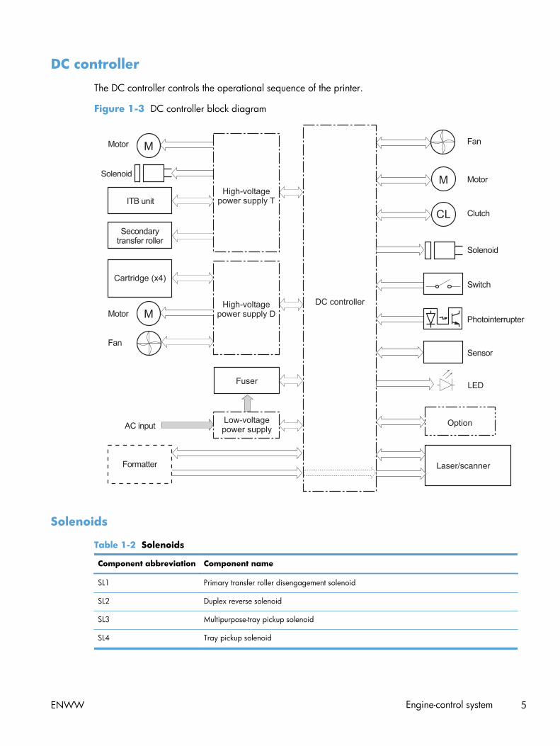
DC controller
The DC controller controls the operational sequence of the printer.
Figure 1-3 DC controller block diagram
Fuser
Laser/scanner
Solenoids
Table 1-2 Solenoids
Component abbreviation Component name
SL1 Primary transfer roller disengagement solenoid
SL2 Duplex reverse solenoid
SL3 Multipurpose-tray pickup solenoid
SL4 Tray pickup solenoid
ENWW Engine-control system 5

Clutches
Component abbreviation Component name
CL1 Duplex re-pickup clutch
Switches
Table 1-3 Switches
Component abbreviation Component name
SW1, SW2 5V interlock switch
SW3 24V interlock switch
SW4 Power switch
Test print switch
6 Chapter 1 Theory of operation ENWW

Sensors
Table 1-4 Sensors
Component abbreviation Component name
SR1 Drum home position sensor 1
SR2 Drum home position sensor 2
SR3 Drum home position sensor 3
SR5 Fuser (fixing) delivery sensor
SR6 Delivery tray media full sensor
SR7 Fuser (fixing) pressure release sensor
SR8 TOP (top of page) sensor
SR9 Tray-media-stack surface sensor
SR11 Developing home position sensor
SR13 Tray presence sensor
SR14 Loop sensor 1
SR15 Loop sensor 2
SR17 Primary-transfer-roller disengagement sensor
SR20 Tray-media presence sensor
SR21 MP-tray-media-presence sensor
SR22 Duplex re-pickup sensor
OHT sensor (in)
OHT sensor (out)
RD sensor (front)
RD sensor (rear)
Environmental sensor (temperature and humidity)
Yellow toner-level sensor
Magenta toner-level sensor
Cyan toner-level sensor
Black toner-level sensor
Toner collection-box-full sensor
Fuser (fixing) home-position sensor
ENWW Engine-control system 7

Motors and fans
The product has 11 motors and three fans. The motors drive the components in the paper-feed andimage-formation systems. The fan motors cool the inside of the product.
Table 1-5 Motors
Abbreviation Name Purpose Type Failure detection
M2 Fuser (fixing) motor Drives the fuser (fixing)roller, the deliveryroller, and the fuser(fixing) pressure roller
DC motor Yes
M3 Drum motor 1 Drives thephotosensitive drum(yellow/magenta),developing unit(yellow), and primarycharging roller(yellow/magenta)
DC motor Yes
M4 Drum motor 2 Drives thephotosensitive drum(cyan), developing unit(magenta/cyan), andprimary charging roller(cyan)
DC motor Yes
M5 Drum motor 3 Drives thephotosensitive drum(black), developing unit(black), and ITB driveroller, and secondarytransfer roller
DC motor Yes
M7 Lifter motor Drives the lifter for thetray
DC motor Yes
M8 Cyan/black scannermotor
Drives the scannermirror in the cyan/black laser scanner
DC motor Yes
M9 Yellow/magentascanner motor
Drives the scannermirror in the yellow/magenta laser scanner
DC motor Yes
M10 Developingdisengagement motor
Drives the developingunit disengagement
Stepping motor No
M11 Duplex reverse motor Drives the duplexreverse roller andduplex feed roller
Stepping motor No
8 Chapter 1 Theory of operation ENWW

Table 1-5 Motors (continued)
Abbreviation Name Purpose Type Failure detection
M12 Residual toner-feedmotor
Drives the residualtoner feed screw
DC motor Yes
M13 Pickup motor Drives the tray pickuproller, MP tray pickuproller, feed roller,registration roller, andre-pickup roller
Stepping motor No
Table 1-6 Fans
Abbreviation Name Cooling area Type Speed
FM1 Power supply fan Around the powersupply unit
Intake Full/half
FM2 Cartridge fan Around the cartridges Intake Full/half
FM3 Delivery fan Around the deliveryunit
Intake Full/half
High-voltage power supply
The high-voltage power supply delivers the high-voltage biases to the following components used totransfer toner during the image-formation process:
● Primary-charging roller (in the cartridge)
● Developing roller (in the cartridge)
ENWW Engine-control system 9

● Primary-transfer roller
● Secondary-transfer roller
Figure 1-4 High-voltage power supply circuits
YM
CK
The high-voltage power supply contains several separate circuits.
Table 1-7 High-voltage power supply circuits
Circuit Description
Primary-charging-bias generation DC negative bias is applied to the surface of the photosensitive drum to prepare itfor image formation.
Developing-bias generation DC negative bias adheres the toner to each photosensitive drum during the image-formation process.
Primary-transfer-bias generation DC positive bias transfers the latent toner image from each photosensitive drumonto the ITB.
Secondary-transfer-bias generation Two DC biases, one positive and one negative, transfer the toner from the ITB ontothe paper.
10 Chapter 1 Theory of operation ENWW

Low-voltage power supply
The low-voltage power-supply circuit converts the AC power from the wall receptacle into the DCvoltage that the product components use. The product has two low-voltage power-supplies for 110 Voltor 220 Volt input.
Figure 1-5 Low-voltage power-supply circuit
Fuser controlcircuit
The low-voltage power supply converts the AC power into three DC voltages, which it then subdivides,as described in the following table.
ENWW Engine-control system 11

Table 1-8 Converted DC voltages
Main DC voltage Sub-voltage Behavior
+24V +24VA Stopped during Sleep (powersave)mode
+24VB Interrupted when the front door or rightdoor open
Stopped during Sleep (powersave)mode
+5V +5VA Constantly supplied
3.3V is supplied during Sleep mode 2or Sleep mode 3
+5VB 3.3V is supplied during Sleep mode 2
Stopped during Sleep mode 3
Power for the formatter
+5VC 3.3V is supplied during Sleep mode 2or Sleep mode 3
Interrupted when the front door or rightdoor open (SW1/SW2)
+5VD Stopped during Sleep mode
Interrupted when the front door or rightdoor open (SW1/SW2)
+3.3 V 3.3VA Constantly supplied
3.3VB Stopped only when the power is off
Power for the formatter
3.3VC Stopped during Sleep mode 2 or Sleepmode 3
● 24V Power Supply (24VRMT) signal: Controls supply or interruption of +24VA
● 5V Power supply (VC5VOFF) signal: Controls supply or interruption of +5VB
● 3V Power supply (VC3VOFF) signal: Controls supply or interruption of +3.3VB
● Voltage conversion (PWRSAVE) signal: Converts output voltage of +5VA, +5VB and +5VC into+3.3V
Overcurrent/overvoltage protection
The low-voltage power supply stops supplying the DC voltage to the product components whenever itdetects excessive current or abnormal voltage from the power source.
12 Chapter 1 Theory of operation ENWW

The low voltage power supply has a protective circuit against overcurrent and overvoltage to preventfailures in the power supply circuit. If DC voltage is not being supplied from the low voltage powersupply, the protective function might be running. In this case, turn the power off and disconnect thepower cable. Do not connect and turn on the product until the root cause is found and corrected. Inadditon, the low voltage power supply has two fuses (FU100/FU101) to protect against overcurrent. Ifovercurrent flows into the AC line, the fuse blows to stop AC power.
Safety
For personal safety, the low-voltage power supply interrupts power to the fuser, the high-voltage powersupply, and the motors when the front door or right door open.
The product has AC power even when the power switch is turned off because the product uses a softpower switch. Be sure to disconnect the power cable before disassembling the product.
Voltage detection
The printer detects the power supply voltage that is connected to the printer. The DC controller monitorsthe input voltage from the power source so it can control the voltage to the fuser.
Sleep (powersave) mode
Sleep mode reduces the power consumption of the product. There are three sleep modes depending onthe power consumption. The DC controller stops or converts each power supply according to the sleepmode:
● Sleep mode 1: stops +24VA and +24VB
● Sleep mode 2: stops +24VA, +24VB and +5VD. Converts +5VA and +5VC into +3.3V
● Sleep mode 3: stops +24VA, +24VB, +5VB and +5VD. Converts +5VA and +5VC into +3.3V.
Powerconsumption
Status of powerbutton light
How to enablemode
How to disablemode (put inReady state)
Relative time toReady state
Off Less than 0.5W Off Manually: pressthe power button
Automatically:sleep timerexpires
Press the powerbutton
Longest
Auto off Less than 1W Blinks at 3 secondintervals
Sleep timerexpires
Printing or networkmaintenance tasks
Longer than Sleepmode
Sleep Approximately 6W Blinks at 3 secondintervals
Sleep timerexpires
Printing or networkmaintenance tasks
Shortest
ENWW Engine-control system 13

Power supply voltage detection
The product detects the power supply voltage that is connected to the product. The DC controllermonitors the POWER SUPPLY VOLTAGE (PSTYP100) signal and detects power supply voltage, whether100V or 200V, to control the fusing operation properly.
Low-voltage power supply failure
The DC controller determines a low-voltage power supply failure and notifies the formatter when thelow-voltage power supply does not supply +24V.
Power Off condition
The DC controller brings the product to a power off condition by 24V POWER SUPPLY (24VRMT)signal, 5V POWER SUPPLY (VC5VOFF) signal, 3V POWER SUPPLY (VC3VOFF) signal, and VOLTAGECONVERSION (PWRSAVE) signal.
The +5VA and +5VC signals which are converted into +3.3V and +3.3VA, are supplied under thepower off condition.
Auto on/Auto off mode
This feature conserves power after the product has been idle for an adjustable period of time. Whenthe product is in this mode, the control-panel backlight is turned off, but the product retains all settings,downloaded fonts, and macros. The setting is disabled by default. The product enters this mode after a60-minute idle time or by touching the sleep button.
Powerconsumption
Status ofpowerbutton light
How toenablemode
How todisable mode(put in Readystate)
Relative timeto Readystate
Control-panel term
Off Less than 0.5W Off Manually:press thepower button
Automatically:sleep timerexpires
Press the powerbutton
Longest
14 Chapter 1 Theory of operation ENWW

Powerconsumption
Status ofpowerbutton light
How toenablemode
How todisable mode(put in Readystate)
Relative timeto Readystate
Control-panel term
Auto off Less than 1W Blinks at 3second intervals
Sleep timerexpires
Printing ornetworkmaintenancetasks
Insert or removepaper from theADF
Open or closethe scanner
Open thecartridge door
Touch thecontrol paneltouchscreen
Press the powerbutton
Longer thanSleep mode
Network port
Sleep (A1W) Approximately6W
Blinks at 3second intervals
Sleep timerexpires
Printing ornetworkmaintenancetasks
Insert or removepaper from theADF
Open or closethe scanner
Open thecartridge door
Touch thecontrol paneltouchscreen
Press the powerbutton
Shortest All events
NOTE: Product error messages override the Sleep message. The product enters sleep mode at theappropriate time, but the error message continues to appear.
ENWW Engine-control system 15

Fuser (fixing) control
The fuser-control circuit controls the fuser temperature. The product uses an on-demand fusing method.
Figure 1-6 Fuser (fixing) components
Fuser controlcircuit
Fuser heatersafety circuit
Fuser sleeve
FUSER TEMPERATURE signal
FUSER HEATINGCONTROL signal
Table 1-9 Fuser (fixing) components
Type of component Abbreviation Name Function
Heaters H1 Fuser heater Heats the fuser sleeve.
Thermistors
(Contact type)
TH1 Main thermistor The thermistor detects the centertemperature of the fuser sleeve.
TH2
TH3
Sub thermistor Each thermistor detects the sidetemperature of the fuser heater.
Thermoswitches
(Non-contact type)
TP1 For the fuser heater Controls the fuser-roller mainheater
16 Chapter 1 Theory of operation ENWW

Fuser (fixing) temperature-control circuit
The temperatures of the two rollers in the fuser fluctuate according to the stage of the printing process.The DC controller sends commands to the fuser-control circuit to adjust temperatures.
Figure 1-7 Fuser temperature-control circuit
Fuser
Fuser sleeve unit
Fuser Fuser heater safety circuit
Fuser control circuit Fuser
Fuser heater safetycircuit
Fuser heater control circuit
Fuser (fixing) over-temperature protection
To protect the fuser from excessive temperatures, the product has four layers of protective functions. Ifone function fails, the subsequent functions should detect the problem.
● DC controller: When a thermistor or thermopile detects a temperature above a certain threshold,the DC controller interrupts power to the specific heater. Following are the thresholds for eachcomponent:
◦ TH1: 230° C (446° F) or higher
◦ TH2: 285° C (545° F) or higher
◦ TH3: 285° C (545° F) or higher
● Fuser (fixing)-heater safety circuit: If the DC controller fails to interrupt the power to theheaters at the prescribed temperatures, the fuser-heater safety circuit deactivates the triac-drive
ENWW Engine-control system 17

circuit and releases the relay, which causes the heaters to stop at slightly higher temperaturethresholds.
◦ TH2: 290° C (554° F) or higher
◦ TH3: 290° C (554° F) or higher
● Current-detection protection circuit: If current flowing in each triac exceeds a specific value,the current-detection protection circuit deactivates the triac-drive circuit and releases the relay,which interrupts the power supply to the heaters.
● Thermoswitch: If the temperature in the heaters is abnormally high, and the temperature in thethermoswitches exceeds a specified value, the contact to the thermoswitch breaks. Breaking thiscontact deactivates the triac-drive circuit and releases the relay, which interrupts the power supplyto the heaters. Following are the thresholds for each thermoswitch:
◦ TP1: 270° C (518° F) or higher
NOTE: When the thermoswitches reach this temperature, the temperature on the fuser rollers is about320° C (608° F).
Fuser (fixing)-failure detection
When the DC controller detects any of the following conditions, it determines that the fuser has failed.The DC controller then interrupts power to the fuser heaters and notifies the formatter.
● Abnormally high temperatures: Temperatures are too high for any of the followingcomponents, at any time:
◦ TH1: 230° C (446° F) or higher
◦ TH2: 285° C (545° F) or higher
◦ TH3: 285° C (545° F) or higher
● Abnormally low temperatures: Temperatures are too low at any of the followingcomponents after the product has initialized.
◦ TH1: 120° C (248° F) or lower
◦ TP2 or TP3: 100° C (212° F) or lower
Or, the temperature drops in either of the thermopiles (TP2 and TP3) by 30° C (86° F) or morewithin a specified length of time.
● Abnormal temperature rise: The DC controller determines an abnormal temperature rise ifthe detected temperature of TH1 does not rise 2° C within a specified time period after the fuser(fixing) motor is turned on, or if the detected temperature of the thermistors does not rise to aspecified temperature for a specified time after the fuser (fixing) motor is turned on.
18 Chapter 1 Theory of operation ENWW

● Thermistor open: The DC controller determines a thermistor open if:
◦ The detected temperature of TH1 is kept at 12° C (53° F) or lower for a specified time afterthe fuser (fixing) motor is turned on.
◦ The detected temperature of TH2 is kept at 4° C (39° F) or lower for a specified time.
◦ The detected temperature of TH3 is kept at 4° C (39° F) or lower for a specified time.
● Drive-circuit failure: The DC controller determines a drive-circuit failure:
◦ If the detected power supply frequency is out of a specified range when the printer is turnedon or during the standby period
◦ If the current detection circuit detects an out of specified current value
● Fuser (fixing) discrepancy: The DC controller determines a fuser type mismatch when itdetects an unexpected fuser (fixing) unit presence signal. The product has two fusers for 110 V or220 V input power.
ENWW Engine-control system 19

Laser/scanner systemThe laser/scanner system forms the latent electrostatic image on the photosensitive drums according tothe VIDEO signals sent from the formatter. The product has two laser/scanners: one for yellow andmagenta and the other for cyan and black.
The formatter sends the DC controller instructions for the image of the page to be printed. The DCcontroller signals the lasers to emit light, and the laser beams pass through lenses and onto the scannermirror, which rotates at a constant speed. The mirror reflects the beam onto the photosensitive drum inthe pattern necessary for the image, exposing the surface of the drum so it can receive toner.
Figure 1-8 Laser/scanner system
20 Chapter 1 Theory of operation ENWW

The DC controller determines that a laser/scanner has failed when any of the following conditionsoccurs:
● Laser failure: The detected laser intensity does not match a specified value when the productinitializes.
● Beam-detect (BD) failure: The BD interval is outside a specified range during printing.
● Scanner-motor failure: The scanner motor does not reach a specified rotation speed within acertain time after it begins rotating.
ENWW Laser/scanner system 21

Image formation systemThe image-formation system creates the printed image on the paper. The system consists of the laser/scanners, toner cartridges, imaging drums, ITB, and fuser.
Figure 1-9 Image formation system
Laser/scanner
Laser/scanner
Fuser
YM
CK
22 Chapter 1 Theory of operation ENWW

Image formation process
The image-formation system consists of ten steps divided into six functional blocks.
Figure 1-10 Image formation process
Fusing
Fuser
YM
CK
Table 1-10 Image formation process
Functional block Steps Description
Latent image formation 1. Pre-exposure
2. Primary charging
3. Laser-beam exposure
An invisible latent image forms on thesurface of the photosensitive drums.
Development 4. Development Toner adheres to the electrostatic latentimage on the photosensitive drums.
Transfer 5. Primary transfer
6. Secondary transfer
7. Separation
The toner image transfers to the ITB andsubsequently to the paper.
Fusing 8. Fusing The toner fuses to the paper to make apermanent image.
ITB cleaning 9. ITB cleaning Residual toner is removed from the ITB.
Drum cleaning 10. Drum cleaning Residual toner is removed from thephotosensitive drums.
ENWW Image formation system 23

Step 1: Pre-exposure
Light from the pre-exposure LED strikes the surface of the photosensitive drum to remove any residualelectrical charges from the drum surface.
Figure 1-11 Pre-exposure
Step 2: Primary charging
The primary-charging roller contacts the photosensitive drum and charges the drum with negativepotential.
Figure 1-12 Primary charging
24 Chapter 1 Theory of operation ENWW

Step 3: Laser-beam exposure
The laser beam strikes the surface of the photosensitive drum in the areas where the image will form.The negative charge neutralizes in those areas, which are then ready to accept toner.
Figure 1-13 Laser-beam exposure
Step 4: Development
Toner acquires a negative charge as the developing cylinder contacts the developing blade. Becausethe negatively charged surface of the photosensitive drums have been neutralized where they havebeen struck by the laser beam, the toner adheres to those areas on the drums. The latent imagebecomes visible on the surface of each drum.
Figure 1-14 Development
ENWW Image formation system 25

Step 5: Primary transfer
The positively charged primary-transfer rollers contact the ITB, giving the ITB a positive charge. The ITBattracts the negatively charged toner from the surface of each photosensitive drum, and the completetoner image transfers onto the ITB, beginning with yellow, followed by magenta, cyan, and black.
Figure 1-15 Primary transfer
Step 6: Secondary transfer
The paper acquires a positive charge from the secondary-transfer roller, and so it attracts the negativelycharged toner from the surface of the ITB. The complete toner image transfers onto the paper.
Figure 1-16 Secondary transfer
26 Chapter 1 Theory of operation ENWW

Step 7: Separation
The stiffness of the paper causes it to separate from the ITB as the ITB bends. The static-chargeeliminator removes excess charge from the paper to ensure that the toner fuses correctly.
Figure 1-17 Separation
Step 8: Fusing
To create the permanent image, the paper passes through heated, pressurized rollers to melt the toneronto the page.
Figure 1-18 Fusing
Fuser sleeve
Fuser heater
ENWW Image formation system 27

Step 9: ITB cleaning
The cleaning blade scrapes the residual toner off the surface of the ITB. The residual-toner-feed screwdeposits residual toner in the toner collection box.
Figure 1-19 ITB cleaning
Step 10: Drum cleaning
Inside the toner cartridge, the cleaning blade removes residual toner from the surface of the drum toprepare it for the next image. The waste toner falls into the hopper in the print cartridge.
Figure 1-20 Drum cleaning
Toner cartridge
The product has four toner cartridges, one for each color. Each toner cartridge contains a reservoir oftoner and the following components:
● Photosensitive drum
● Developing roller
● Primary-charging roller
28 Chapter 1 Theory of operation ENWW

The DC controller rotates the drum motor to drive the photosensitive drum, developing roller, and theprimary-charging roller.
Figure 1-21 Toner-cartridge system
The DC controller rotates the drum motor to drive the photosensitive drum, developing unit, and primarycharging roller.
The memory tag is a non-volatile memory chip that stores information about the usage for the tonercartridge.
ENWW Image formation system 29

The DC controller notifies the formatter of an error if any of the following conditions exist:
● The memory tag fails to either read to or write from the DC controller.
● The RD sensors detect a missing or incorrectly installed toner cartridge.
● The accumulated print time reaches a specified time period or the cartridge runs out of toner.
● The toner level in any of the toner cartridges drops below a certain level.
Developing roller engagement and disengagement
The product can print in full-color mode or in black-only mode. To print in black-only mode, the productdisengages the developing rollers in the cyan, magenta, and yellow toner cartridges. This maximizesthe life of the cartridges.
Figure 1-22 Developing-roller engagement and disengagement controlFour developing units engaged
Only the Bk developing unit engaged
Four developing units disengaged
YM
CK
YM
CK
YM
CK
Y
M
C
K
Y
M
C
K
Y
M
C
K
30 Chapter 1 Theory of operation ENWW

The DC controller rotates the developing disengagement motor and changes the direction of the camaccording to the instructions from the formatter for each print job.
When the product is turned on and at the end of each print job, all four of the developing rollersdisengage from the photosensitive drums. If the next print job is full-color mode, each of the developingrollers engage. If the next print job is black-only mode, only the black developing roller engages.
If the DC controller does not detect any output from the developing home-position sensor, it determinesthat the developing-disengagement motor has failed.
ENWW Image formation system 31

Intermediate transfer belt (ITB) unit
The ITB unit accepts the toner images from the photosensitive drums and transfers the completed imageto the paper. The ITB unit has these main components:
● ITB
● ITB drive roller
● ITB-driven roller
● Primary-transfer rollers
● ITB cleaner
The ITB motor drives the ITB drive roller, which rotates the ITB. The motion of the ITB causes the primarytransfer rollers to rotate. The ITB cleaner cleans the ITB surface.
Figure 1-23 ITB unit
YM
C K
32 Chapter 1 Theory of operation ENWW

Primary-transfer-roller engagement and disengagement
Depending on the requirements of the print job, the primary-transfer rollers engage with the ITB so itcan receive toner from the photosensitive drums.
Figure 1-24 Three states of primary-transfer-roller engagement and disengagement
Four colors are disengaged
Four colors are engaged
Only black is engaged
Y
M
C
K
Y
M
C
K
Y
M
C
K
Y
M
C
K
Y
M
C
K
Y
M
C
K
Fuser motor
FU
SE
R M
OTO
R C
ON
TR
OL
Table 1-11 Primary-transfer-roller engagement states
Roller state Product state
All rollers disengaged The home position for the ITB unit
All rollers engaged The state for a full-color print job
Black roller engaged The state for a black-only print job
ENWW Image formation system 33

The primary-transfer-roller disengagement motor rotates or reverses to place the primary-transfer-rollerdisengagement cam into one of three positions. The cam causes the transfer-roller slide plate to move tothe right or left. This movement causes the primary-transfer rollers to move up to engage the ITB with thephotosensitive drum or down to disengage it.
If the DC controller does not receive the expected signal from the ITB home-position sensor when theprimary-transfer-roller engages or disengages, but the primary-transfer-roller disengagement motor isrotating, the DC controller determines that the primary-transfer-disengagement mechanism has failed,and notifies the formatter.
34 Chapter 1 Theory of operation ENWW
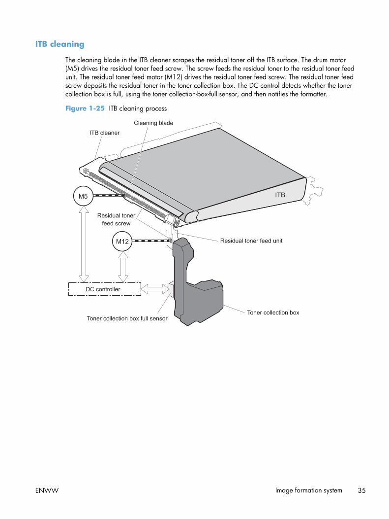
ITB cleaning
The cleaning blade in the ITB cleaner scrapes the residual toner off the ITB surface. The drum motor(M5) drives the residual toner feed screw. The screw feeds the residual toner to the residual toner feedunit. The residual toner feed motor (M12) drives the residual toner feed screw. The residual toner feedscrew deposits the residual toner in the toner collection box. The DC control detects whether the tonercollection box is full, using the toner collection-box-full sensor, and then notifies the formatter.
Figure 1-25 ITB cleaning process
ENWW Image formation system 35

Calibration
The product calibrates itself to maintain excellent print quality. Calibration corrects color-misregistrationand color-density variation.
During calibration, the product places a specific pattern of toner on the surface of the ITB. Sensors atthe end of the ITB read the toner pattern to determine if adjustments are necessary.
Figure 1-26 Toner patterns for calibration
Color misregistration control
Internal variations in the laser/scanners can cause the toner images to become misaligned. The color-misregistration control corrects the following problems:
● Horizontal scanning start position
● Horizontal scanning magnification
● Vertical scanning start position
The calibration occurs when any of the following occurs:
● A cartridge is replaced.
● The temperature of the sub thermistor is 50 C (122 F) or lower when the product recovers fromsleep mode after a specific number of pages print.
● A specified number of pages have printed.
● The formatter sends a command.
● The user requests a calibration by using the control-panel menus.
36 Chapter 1 Theory of operation ENWW

If data from the color-misregistration and image-density sensors is outside a specified range when theproduct is turned on or when it is beginning the calibration sequence, the DC controller determines thatthese sensors have failed, and it notifies the formatter.
Image stabilization control
Environmental changes or deterioration of the photosensitive drums and toner can cause variations inthe image density. The image-stabilization control reduces these fluctuations. There are three kinds ofimage stabilization controls.
The formatter control is performed by the formatter.
Table 1-12 Image-stabilization controls
Image stabilization control Description
Environment change control The environment change control calibrates each high-voltage bias to obtain anappropriate image according to the environment changes. The DC controllerdetermines the environment where the product is installed based on the surroundingtemperature and humidity data from the environment sensor, controls, and relatedbiases. This control occurs under the following circumstances:
● The toner cartridge is replaced.
The DC controller notifies the formatter when it encounters a communication errorwith the environmental sensor.
Image density control (DMAX) This control corrects variations in image density related to deterioration of thephotosensitive drum or the toner. The DC controller adjusts the high-voltage biasesto correct the problem under the following conditions:
● The sub thermistor detects a temperature that is too low when the product isturned on.
● After the print operation is completed for a specific period of the time.
● A toner cartridge is replaced.
● The ITB is replaced.
● A specified number of pages have printed.
● The formatter sends a command.
● The environment is relatively charged.
Image halftone control (DHALF) The image halftone control is performed by the formatter. The DC controllermeasures the halftone pattern according to the command from the formatter. Theformatter performs this control to calibrate the halftone, based on the halftone-density measurements, under the following conditions:
● The formatter sends a command.
● The DMAX is completed.
The DC controller determines an RD sensor failure and notifies the formatter if it detects an out-of-specified-data value from the RD sensor when the product is turned on or when the color misregistrationcontrol starts.
ENWW Image formation system 37
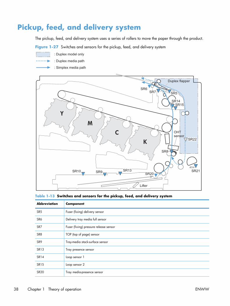
Pickup, feed, and delivery systemThe pickup, feed, and delivery system uses a series of rollers to move the paper through the product.
Figure 1-27 Switches and sensors for the pickup, feed, and delivery system
Y
MC
K
Table 1-13 Switches and sensors for the pickup, feed, and delivery system
Abbreviation Component
SR5 Fuser (fixing) delivery sensor
SR6 Delivery tray media full sensor
SR7 Fuser (fixing) pressure release sensor
SR8 TOP (top of page) sensor
SR9 Tray-media stack-surface sensor
SR13 Tray presence sensor
SR14 Loop sensor 1
SR15 Loop sensor 2
SR20 Tray media-presence sensor
38 Chapter 1 Theory of operation ENWW

Table 1-13 Switches and sensors for the pickup, feed, and delivery system (continued)
Abbreviation Component
SR21 MP tray media-presence sensor
SR22 Duplex re-pickup sensor (duplex models only)
Figure 1-28 Motors and solenoids for the pickup, feed, and delivery system
Y
MC
K
Table 1-14 Motors and solenoids for the pickup, feed, and delivery system
Abbreviation Component
M2 Fuser (fixing) motor
M5 Drum motor 3
M7 Lifter motor
M11 Duplex reverse motor (duplex models only)
ENWW Pickup, feed, and delivery system 39

Table 1-14 Motors and solenoids for the pickup, feed, and delivery system (continued)
Abbreviation Component
M13 Pickup motor
CL1 Duplex re-pickup clutch (duplex models only)
SL2 Duplex reverse solenoid (duplex models only)
SL3 Multipurpose tray pickup solenoid
SL4 Tray pickup solenoid
Figure 1-29 Three main units of the pickup, feed, and delivery systemFuser/delivery block Duplex block
Y
M
CK
40 Chapter 1 Theory of operation ENWW

Pickup-and-feed unit
The pickup-and-feed unit picks an individual sheet of paper from the multipurpose tray or the cassettes,carries it through the secondary-transfer unit, and feeds it into the fuser.
Figure 1-30 Pickup-and-feed unit
Y
M
CK
ENWW Pickup, feed, and delivery system 41

Tray pickup
The sequence of steps for the tray pickup operation is the following:
1. When the product starts or the tray closes, the lifting mechanism lifts the paper stack so it is ready.
2. After receiving a print command from the formatter, the DC controller rotates the pickup motor,which causes the tray pickup roller, tray feed roller, and tray separation roller to rotate.
3. The DC controller drives the tray pickup solenoid, which rotates the tray pickup cam. As thepickup cam rotates, the pickup arm moves down, and the tray pickup roller touches the surface ofthe paper stack. The tray pickup roller then picks up one sheet of paper.
Figure 1-31 Tray-pickup mechanism
Tray
Tray
Tray
NOTE: The lift-up operation lifts the lifting plate to keep the stack surface of the media at a pickupposition. The lifting spring helps support the lifting plate depending on the media size and amount.
42 Chapter 1 Theory of operation ENWW

Tray-presence detection
The tray presence sensor is in the lifter drive unit. The sensor detects the tray-presence sensor flag anddetermines whether the tray is installed correctly.
Figure 1-32 Tray presence sensor
Tray
Tray
Tray lift operation
The DC controller rotates the lifter motor (M7) and moves the lifter rack until the tray media stacksurface sensor (SR9) detects it. The lifter lifts, and the lifting plate moves up to the position where themedia can be picked up. The lift operation is performed by monitoring the media stack surface sensorwhen the printer is turned on, when the tray is installed, or as needed during a print operation.
If the paper-stack surface sensor does not detect the paper within a specified time after the lifter motorbegins rotating, the DC controller notifies the formatter that the lifter motor has failed.
ENWW Pickup, feed, and delivery system 43
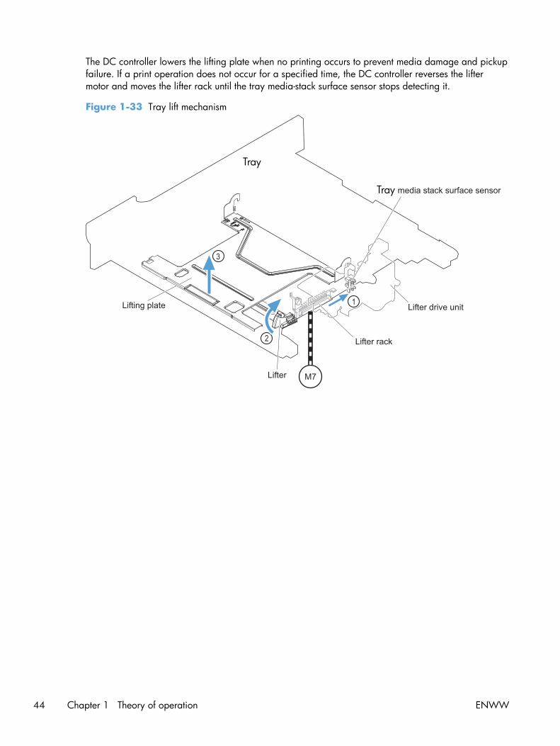
The DC controller lowers the lifting plate when no printing occurs to prevent media damage and pickupfailure. If a print operation does not occur for a specified time, the DC controller reverses the liftermotor and moves the lifter rack until the tray media-stack surface sensor stops detecting it.
Figure 1-33 Tray lift mechanism
Tray
Tray
44 Chapter 1 Theory of operation ENWW

paper-presence detection
The media presence sensor detects whether paper is in the .
Figure 1-34 Paper-level-detection mechanism
Tray
Tray
Tray
Multifeed prevention
In the , a separation roller prevents multiple sheets of paper from entering the paper path. The pickuproller drives the separation roller through a sheet of paper.
The low friction force between the sheets weakens the driving force from the pickup roller. Becausesome braking force is applied to the separation roller, the weak rotational force of the pickup roller isnot enough to rotate the separation roller. Therefore, the separation roller holds back any multiple-fedsheets, and one sheet of media is fed into the printer.
Figure 1-35 Multifeed prevention
Cassette pickuproller
Media
Lifting plate
Cassette separationroller
Normal feed Multiple feed
Separation roller does not rotate
ENWW Pickup, feed, and delivery system 45

Multipurpose tray pickup
The multipurpose tray (MP) paper-presence sensor detects whether paper is in the tray. If no paper ispresent, the DC controller notifies the formatter. Printing does not occur until paper is in the tray.
The sequence of steps for the multipurpose tray pickup operation as follows:
1. After receiving a print command from the formatter, the DC controller reverses the pickup motor,which causes the multipurpose tray separation roller to rotate.
2. The DC controller turns on the multipurpose tray pickup solenoid (SL3), causing the multipurposetray pickup roller to rotate.
3. The multipurpose tray separation roller isolates a single sheet of paper in case more than onesheet was picked. The single sheet of paper feeds into the product.
The MP-tray media-presence sensor (SR21) detects whether the media is present in the MP tray. Noprinting occurs if no media is loaded.
Figure 1-36 Multipurpose tray pickup mechanism
46 Chapter 1 Theory of operation ENWW

Paper feed
After the pickup operation, the paper feeds through the product and into the fuser.
1. The paper passes through the feed rollers. The registration shutter aligns the paper correctly toprevent skewed printing.
2. The DC controller detects the leading edge of paper by the Top sensor (SR8) and controls therotational speed of the pickup motor to align with the leading edge of image on the ITB.
3. The DC controller detects whether or not the media is overhead transparency, using the OHTsensor.
4. The toner image on the ITB transfers onto the media, which feeds to the fuser.
Figure 1-37 Paper-feed mechanism
ENWW Pickup, feed, and delivery system 47

Skew-feed prevention
The product can straighten the paper without slowing the feed operation.
1. As the paper enters the paper path, the leading edge strikes the registration shutter, whichstraightens the paper. The paper does not pass through the shutter.
2. The feed rollers keep pushing the paper, which creates a force on the leading edge against theregistration shutter.
3. When the force is great enough, the registration shutter opens and the paper passes through.
Figure 1-38 Skew-feed prevention
1
2
3
OHT detection
The OHT sensor detects overhead transparencies. The OHT sensor is a transmission sensor that uses anLED. The DC controller determines a media mismatch and notifies the formatter when the media typediffers from the media type detected by the OHT sensor. The DC controller turns the LED in the OHT
48 Chapter 1 Theory of operation ENWW

sensor on and off during the wait or initial rotation period. If the intensity of the light does not match thespecified value, the DC controller determines that the OHT sensor has failed.
Fusing and delivery unit
The fusing and delivery unit fuses the toner onto the paper and delivers the printed page into the outputbin. The following controls ensure optimum print quality:
● Loop control
● Pressure roller pressurization/depressurization control
A sensor detects when the output bin is full, and the DC controller notifies the formatter.
Figure 1-39 Fuser and delivery unit
Fuser/delivery block
Y
MC
K
Loop control
The loop control monitors the tension of the paper between the secondary-transfer roller and the fuser.
● If the fuser rollers rotate more slowly than the secondary transfer rollers, the paper warp increasesand an image defect or paper crease occurs.
● If the fuser rollers rotate faster than the secondary transfer rollers, the paper warp decreases andthe toner image fails to transfer to the paper correctly, causing color misregistration.
ENWW Pickup, feed, and delivery system 49

To prevent these problems, the loop sensors, which are located between the secondary transfer rollersand the fuser rollers, detect whether the paper is sagging or is too taut. The DC controller adjusts thespeed of the fuser motor.
Figure 1-40 Loop-control mechanism
50 Chapter 1 Theory of operation ENWW

Pressure-roller pressurization control
To prevent excessive wear on the pressure roller and help with jam-clearing procedures, the pressureroller pressurizes only during printing and standby. The DC controller reverses the fuser motor. Thefuser motor rotates the fuser pressure-release cam.
Figure 1-41 Pressure-roller pressurization control
Fuser motor
FU
SE
R P
RE
SS
UR
E R
ELE
AS
E s
igna
l
FU
SE
R M
OT
OR
CO
NT
RO
L
Fuser pressure release cam
Fuser sleeve
The pressure roller depressurizes under the following conditions:
● The product is turned off with the on/off switch
● Any failure occurs other than a fuser pressure-release mechanism failure
● During powersave mode
● When a paper jam is detected
If the DC controller does not sense the fuser pressure-release sensor for a specified period after itreverses the fuser motor, it notifies the formatter that a fuser pressure-release mechanism failure hasoccurred.
NOTE: The fuser remains pressurized if the power is interrupted when the power cord is removed orthe surge protector is turned off, or if the fuser is removed without turning off the product.
ENWW Pickup, feed, and delivery system 51

Duplexing unit
The duplexing unit reverses the paper and feeds it through the paper path to print the second side. Theduplexing unit consists of the following components:
● Duplexing-reverse unit: Installed on top of the product
● Duplexing-feed unit: Along the right side
The DC controller controls the operational sequence of the duplex block. The DC controller drives eachload, such as motors, solenoid, and clutch, depending on the duplex-reverse unit and duplex-feed unitcontrols.
Figure 1-42 Duplexing unit
52 Chapter 1 Theory of operation ENWW

Duplexing reverse and feed control
The duplexing reverse procedure pulls the paper into the duplexing unit after it exits the fuser. Theduplexing feed procedure moves the paper through the duplexer so it can enter the product paper pathto print the second side of the page.
1. After the first side has printed, the duplexing flapper solenoid opens, which creates a paper pathinto the duplexing-reverse unit.
2. After the paper has fully entered the duplexing-reverse unit, the duplexing-reverse motor reversesand directs the paper into the duplexing-feed unit.
3. The duplexing re-pickup motor and duplexing feed motor move the paper into the duplexing re-pickup unit.
4. To align the paper with the toner image on the ITB, the duplexing re-pickup motor stops and thepaper pauses.
5. The paper re-enters the paper path, and the second side prints.
Duplex pickup operation
The product has the following two duplex-media-feed modes depending on the media sizes:
● One-sheet mode: Prints one sheet that is printed on two sides in one duplex print operation
● Two-sheet mode: Prints two sheets that are printed on two-sides in one duplex print operation(maximum paper size is A4)
The formatter specifies the duplex-media-feed mode.
ENWW Pickup, feed, and delivery system 53

Jam detectionThe product uses the following sensors to detect the paper as it moves through the paper path and toreport to the DC controller if the paper has jammed.
● Fuser output sensor (SR5)
● Registration sensor (SR8)
● Fuser loop 1 (SR14)
● Fuser loop 2 (SR15)
● Duplexer refeed (SR22)
Figure 1-43 Jam detection sensors
Y
M
CK
The product determines that a jam has occurred if one of these sensors detects paper at aninappropriate time. The DC controller stops the print operation and notifies the formatter.
Table 1-15 Jams that the product detects
Jam Description
Pickup delay jam 1 pickup: The TOP sensor does not detect the leading edge of the paper within a specifiedperiod after the pickup solenoid has turned on.
Multipurpose tray pickup: The TOP sensor does not detect the leading edge of the paperwithin a specified period after the multipurpose tray solenoid has turned on.
Pickup stationary jam The TOP sensor does not detect the trailing edge of the paper within a specified time fromwhen it detects the leading edge.
54 Chapter 1 Theory of operation ENWW

Table 1-15 Jams that the product detects (continued)
Jam Description
Fuser delivery delay jam The fuser delivery paper-feed sensor does not detect the leading edge of the paper within aspecified period after the TOP sensor detects the leading edge.
Fuser delivery stationary jam The fuser delivery paper-feed sensor does not detect the trailing edge of the paper within aspecified period after it detects the leading edge.
Wrapping jam After detecting the leading edge of the paper, the fuser delivery paper-feed sensor detects theabsence of paper, and it has not yet detected the trailing edge.
Residual paper jam One of the following sensors detects paper presence during the initialization sequence:
● Fuser delivery paper-feed sensor
● TOP sensor
● Loop sensor 1
● Loop sensor 2
● Duplex re-feed
Door open jam A door is opened while paper is moving through the product.
Duplexing re-pickup jam 1 The duplex re-pickup sensor does not detect the leading edge of the paper within a specifiedperiod after the media reverse operation starts in the duplex-reverse unit.
Duplexing re-pickup jam 2 The TOP sensor does not detect the leading edge of the paper within a specified period afterthe paper is re-picked.
After a jam, some sheets of paper might remain inside the product. If the DC controller detects residualpaper after a door closes or after the product is turned on, the product automatically clears itself ofthose residual sheets.
ENWW Jam detection 55

Optional paper feederThe 1x500-sheet paper feeder is optionally installed underneath the product. The paper feeder picks upthe print media and feeds it to the printer.
NOTE: These optional trays are not identical to the main (Tray 2).
Figure 1-44 Optional paper feeder
Y
M
CK
The paper-deck drivers contain a microcomputer and control the paper feeder. The paper-deck driversreceive commands from the DC controller. If the DC controller is unable to communicate with a paper-deck driver, it notifies the formatter that the optional paper feeders are not connected correctly.
56 Chapter 1 Theory of operation ENWW

Figure 1-45 Signals for the paper feeder
The input trays contain several motors, solenoids, sensors, and switches, as described in the followingtable.
Table 1-16 Electrical components for the paper feeder
Componenttype
Abbreviation Component name
Motors M1 Paper feeder motor
M2 Paper feeder lift motor
Solenoids SL1 Paper feeder pickup solenoid
Sensors SR1 Tray 3 installed sensor
SR2 Tray 3 stack surface sensor 2
SR3 Tray 3 paper present sensor
SR4 Tray 3 feed sensor
Switches SW1 Paper feeder media-size switch
SW2 Paper-feeder door switch
ENWW Optional paper feeder 57

Paper-feeder pickup and feed operation
The paper feeder picks up one sheet from the paper-feeder and feeds it to the product.
Figure 1-46 Paper-feeder pickup and feed operation
58 Chapter 1 Theory of operation ENWW

Paper size detection and presence detection
The paper-feeder media-size switch (SW1) detects the size of paper loaded in the paper-feeder . Thepaper-feeder driver determines the media size by monitoring the combination of the switches.
Figure 1-47 Paper size detection
Tray
ENWW Optional paper feeder 59

Table 1-17 Paper size detection
Paper size Paper-feeder media-size switch settings
Top switch Center switch Bottom switch
Universal On On On
A5 On Off Off
B5 Off On On
Executive On Off On
Letter Off On Off
A4 Off Off On
Legal On On Off
No Off Off Off
The paper-feeder media size switch (SW1) detects whether the paper-feeder is installed correctly. Thepaper-feeder driver determines if a is absent when all three switches are turned off. The paper-feederdriver determines a presence when one of the switches is turned on.
60 Chapter 1 Theory of operation ENWW

Paper feeder lift operation
The lift operation keeps the stack surface of paper at a specified height to maintain stable mediafeeding. The paper-feeder driver controls the paper-feeder lifter motor (M2) and monitors the paper-feeder media stack surface sensors (SR1, SR2) to adjust the stack height when the printer is turned on,when the printer recovers from sleep mode, when the paper-feeder is installed or as needed during aprint operation. The paper feeder has two paper-feeder media-stack surface sensors. The paper-feedermedia stack surface sensor 1 detects the stack height during a print operation. The paper-feeder media-stack surface sensor 2 detects the stack height when the printer is turned on, when the printer recoversfrom sleep mode and when the paper-feeder is installed. The operational sequence of the lift operationis as follows:
1. The paper-feeder driver rotates the paper-feeder lifter motor to lift the lifting plate.
2. The paper-feeder driver stops the paper-feeder lifter motor when the paper-feeder media-stacksurface sensor 2 detects the stack surface.
3. The paper-feeder driver rotates the lifter motor again when paper-feeder media stack surface 1detects that the media surface is lowered during a print operation.
Figure 1-48 Paper-feeder lift
The paper-feeder driver notifies the formatter if either of the paper-feeder media-stack surface sensorsfails to detect the stack surface within a specified period from when a lift-up operation starts.
ENWW Optional paper feeder 61

Paper feeder presence detection
The Tray 3 paper present (SR3) detects whether the paper is present in the paper-feeder .
Paper-feeder multiple feed prevention
The paper-feeder uses a separation roller to prevent multiple sheets of paper from entering the printer.The separation roller prevents multiple feeds of paper by allowing the paper-feeder separation roller torotate in the same direction as the paper-feeder feed roller 1. The paper-feeder separation roller isequipped with the torque limiter. If multiple sheets of paper are picked up, the torque limiter takescontrol of the paper-feeder separation roller, and pushes the extra sheets back to the paper-feeder .That way, only the top sheet is fed to the printer.
Figure 1-49 Paper-feeder multiple feed prevention
No-load Rotational force for paper-feeder separation roller: Pushesback the media into the paper-feeder
Rotational force for paper-feeder feed roller 1: Feeds mediainto the printer
62 Chapter 1 Theory of operation ENWW

Normal feed Rotational force for paper-feeder separation roller: Pushesback the media into the paper-feeder
Rotational force for paper-feeder feed roller 1: Feeds mediainto the printer
Multiple-feed The low friction force between the sheets weakens therotational force from the paper-feeder feed roller 1.
The paper-feeder separation roller rotates by its ownrotational force and removes the extra sheet.
ENWW Optional paper feeder 63

Paper feeder jam detection
The paper feeder uses the Tray 3 feed (SR4) to detect the presence of paper and to check whetherpaper has jammed.
Figure 1-50 Jam detection
Y
M
CK
The paper-feeder driver identifies a jam if the sensor detects paper at a specified timing stored in thepaper-feeder driver. The paper-feeder driver stops printing and notifies the formatter through the DCcontroller of the jam. The paper feeder detects the following jams:
● Pickup delay jam: The paper-feeder media-feed sensor does not detect the leading edge of mediawithin a specified period from when the paper-feeder pickup solenoid is turned on.
● Pickup stationary jam: The paper-feeder media-feed sensor does not detect the trailing edge ofmedia within a specified time period from when the sensor detects the leading edge.
64 Chapter 1 Theory of operation ENWW

Scanning/image capture system
Control panel
The control panel is an 8 in full color SVGA (800 x 600 LCD) with capacitive touchscreen andadjustable viewing angle. The control panel includes a USB port for walk-up printing and a hardwareintegration pocket for third-party USB devices such as card readers.
The control panel has a diagnostic mode to allow testing of the touchscreen, home button, and speaker.The control panel does not require calibration.
Scanner
The scanner is a carriage-type platen scanner which includes the frame, glass, LED optics, and ascanner controller board (SCB) attached to the back of the assembly. The scanner has a sensor todetect legal-sized media and a switch to indicate when the ADF is opened.
The ADF and control-panel assembly are attached to the scanner assembly. If the scanner fails, it canbe replaced as a whole unit. The scanner replacement part does not include the ADF, SCB, or control-panel assembly.
Automatic document feed system
● Simplex single pass
● Duplex three pass
● Legal-sensing flag
● Pick and feed roller assembly with separation pad
● Mechanical deskew
● Step glass for ADF scanning
● Jam clearance door with sensing
● LED indication when original is placed on input tray
Sensors in the ADF
The ADF contains the following sensors:
● ADF-cover sensor: Detects whether the ADF cover is open or closed.
● Paper length sensor: Detects whether there is a legal-size original.
● Pick success sensor: Detects the top of the page before sending a page through the ADF andthe end of the page after feeding/scanning is complete.
● Paper-present sensor: Detects whether a document is present in the ADF. If paper is present inthe ADF when copies are made, the product scans the document using the ADF. If no paper ispresent when copies are made, the product scans the document using the scanner glass.
ENWW Scanning/image capture system 65

● Deskew sensor: Detects the top of the page as it enters the deskew. rollers
● Path sensor 1: Detects the top of the page as it approaches the ADF glass.
ADF paper path
The ADF feeds documents past the ADF glass for scanning.
Figure 1-51 ADF path for single-sided documents
1 Separation pad 5 ADF input tray
2 Pickup roller 6 Delivery/duplex-feed rollers
3 Stack stop 7 ADF glass
4 Pre-pick roller 8 ADF feed rollers
For two-sided documents, the delivery rollers reverse the direction of each page to feed the second sideof the document past the ADF glass.
66 Chapter 1 Theory of operation ENWW

Figure 1-52 ADF path for two-sided documents
1 23 4 5
6
78
NOTE: Callouts in Figure 1-52 ADF path for two-sided documents on page 67 are identical tocallouts in Figure 1-51 ADF path for single-sided documents on page 66 .
Stapler (stapling models only)
The product includes a stapler capable of stapling 20 sheets of (75 g/m2) (20 lb) paper. The stapler ispowered by a +24v connection from the DC controller. Because there are no logic connections to theproduct, error conditions or out-of-staples indications are not displayed on the control panel.
ENWW Scanning/image capture system 67

68 Chapter 1 Theory of operation ENWW

2 Solve problems
NOTE: To perform diagnostic and configuration procedures (for example, resetting page counts) forthe product, you must install the CP1210 Service Config Tool (available at your HP authorized repaircenter).
● Solve problems checklist
● Menu map
● Preboot menu options
● Current settings pages
● Troubleshooting process
● Tools for troubleshooting
● Clear jams
● Paper feeds incorrectly or becomes jammed
● Use manual print modes
● Solve image quality problems
● Clean the product
● Solve performance problems
● Solve connectivity problems
● Service mode functions
● Solve fax problems
● Product upgrades
ENWW 69

Solve problems checklistFollow these steps when trying to solve a problem with the product.
1. If the control panel is blank or black, complete these steps:
a. Check the power cable.
b. Check that the power is turned on.
c. Make sure that the line voltage is correct for the product power configuration. (See the labelthat is on the back of the product for voltage requirements.) If you are using a power stripand its voltage is not within specifications, connect the product directly into the electricaloutlet. If it is already connected into the outlet, try a different outlet.
2. The control panel should indicate a Ready status. If an error message displays, resolve the error.
3. Check the cabling.
a. Check the cable connection between the product and the computer or network port. Makesure that the connection is secure.
b. Make sure that the cable itself is not faulty by using a different cable, if possible.
c. Check the network connection.
4. Ensure that the selected paper size and type meet specifications. Also open the Trays menu on theproduct control panel and verify that the tray is configured correctly for the paper type and size.
5. Print a configuration page. If the product is connected to a network, an HP Jetdirect page alsoprints.
a. From the Home screen on the product control panel, scroll to and touch the Administrationbutton.
b. Open the following menus:
◦ Reports
◦ Configuration/Status Pages
◦ Configuration Page
c. Touch the Print button to print the page.
If the pages do not print, check that at least one tray contains paper.
If the page jams in the product, follow the instructions on the control panel to clear the jam.
If the page does not print correctly, the problem is with the product hardware.
If the page prints correctly, then the product hardware is working. The problem is with thecomputer you are using, with the print driver, or with the program.
6. Verify that you have installed the print driver for this product. Check the program to make sure thatyou are using the print driver for this product. The print driver is on the CD that came with the
70 Chapter 2 Solve problems ENWW

product. You can also download the print driver from this Web site: www.hp.com/go/lj500colorMFPM575_software.
7. Print a short document from a different program that has worked in the past. If this solution works,then the problem is with the program. If this solution does not work (the document does not print),complete these steps:
a. Try printing the job from another computer that has the product software installed.
b. If you connected the product to the network, connect the product directly to a computer witha USB cable. Redirect the product to the correct port, or reinstall the software, selecting thenew connection type that you are using.
ENWW Solve problems checklist 71

Menu mapYou can print a report of the complete Administration menu so you can more easily navigate to theindividual settings you need.
1. From the Home screen on the product control panel, scroll to and touch the Administration button.
2. Open the following menus:
● Reports
● Configuration/Status Pages
3. Select the Administration Menu Map option.
4. Touch the Print button to print the report.
72 Chapter 2 Solve problems ENWW

Preboot menu optionsIf an error occurs while the product is initializing, an error message displays on the control-paneldisplay. The user can open the Preboot menus. The error menu item will not be seen if an error didnot occur.
CAUTION: The Format Disk option performs a disk initialization for the entire disk. The operatingsystem, firmware files, and third party files (among other files) will be completely lost. HP does notrecommend this action.
Access the Preboot menu
1. Turn the product on.
2. The HP logo displays on the product control panel. When a "1/8" with an underscore displaysbelow the HP logo, touch the logo to open the Preboot menu.
3. Use the arrow buttons on the touchscreen to navigate the Preboot menu.
4. Touch the OK button to select a menu item.
Cold reset using the Preboot menu
1. Turn the product on.
2. The HP logo displays on the product control panel. When a "1/8" with an underscore displaysbelow the HP logo, touch the logo to open the Preboot menu.
3. Use the down arrow button to highlight Administrator, and then touch the OK button.
4. Use the down arrow button to highlight Startup Options item, and then touch the OK button.
5. Use the down arrow button to highlight the Cold Reset item, and then touch the OK button.
6. Touch the home button to highlight Continue, and then touch the OK button.
NOTE: The product will initialize.
Table 2-1 Preboot menu options (1 of 6)
Menu option First level Second level Third level Description
Continue Selecting the Continue item exits the Preboot menu andcontinues the normal boot process.
If a selection is not made in the initial menu within 30seconds, the product returns to a normal boot (the same asselecting Continue.
If the user navigates to another menu, the timeout does notapply.
Sign In Enter the administrator PIN or service PIN if one is requiredto open the Preboot menu.
ENWW Preboot menu options 73

Table 2-1 Preboot menu options (1 of 6) (continued)
Menu option First level Second level Third level Description
Administrator This item navigates to the Administrator sub menus.
If authentication is required (and the user is not alreadysigned in) the Sign In displays. The user is required to signin.
Download Network
USB
USBThumbdrive
This item initiates a preboot firmware download process. AUSB Thumbdrive option will work on all FutureSmartproducts. USB or Network connections are not currentlysupported.
Format Disk This item reinitializes the disk and cleans all disk partitions.
CAUTION: Selecting the Format Disk item removes alldata.
A delete confirmation prompt is not provided.
The system is not bootable after this action and a99.09.67 error will be presented on the control panel. Afirmware download must be performed to return the systemto a bootable state.
Partial Clean This item reinitializes the disk (removing all data except thefirmware repository where the master firmware bundle isdownloaded and saved).
CAUTION: Selecting the Partial Clean item removes alldata except the firmware repository.
A delete confirmation prompt is not provided.
This allows user to reformat the disk by removing thefirmware image from the active directory without having todownload new firmware code (product remains bootable).
ChangePassword
Select this item to set or change the administrator password.
Clear Password Select the Clear Password item to remove a password fromthe Administrator menu. Before the password is actuallycleared, a message will be shown asking to confirm that thepassword should be cleared. Press the OK button to confirmthe action.
When the confirmation prompt displays, press the OK buttonto clear the password.
74 Chapter 2 Solve problems ENWW

Table 2-2 Preboot menu options (2 of 6)
Menu option First level Second level Third level Description
Administrator
continued
Manage Disk Clear disk Select the Clear disk item to disable using an external devicefor job storage. Job storage is normally enabled only for theBoot device. This will be grayed out unless the 99.09.68error is displayed.
Lock Disk Select the Lock Disk item to lock (mate) a new secure disk tothis product.
The secure disk already locked to this product will remainaccessible to this product. Use this function to have morethen one encrypted disk accessible by the product whenusing them interchangeably.
The data stored on the secure disk locked to this productalways remains accessible to this product.
Leave Unlocked Select the Leave Unlocked item to use a new secure disk inan unlocked mode for single service event. The secure diskthat is already locked to this product will remain accessibleto this product and uses the old disk's encryption passwordwith the new disk.
The secure disk that is already locked to this product remainsaccessible to this product.
Clear Disk Pwd Select the Clear Disk Pwd item to continue using the non-secure disk and clear the password associated with the yetto be installed secure disk.
CAUTION: Data on the missing secure disk will bepermanently inaccessible.
Retain Password Select the Retain Password item to use the non-secure diskfor this session only, and then search for the missing securedisk in future sessions.
Boot Device Secure Erase Select the Secure Erase item to erase all of the data on thedisk and unlock it if required.
This might take a long time.
NOTE: The system will be unusable until the system filesare reinstalled. ATA secure-erase command one pass overwrite. Erases entire disk including firmware. The diskremains an encrypted disk.
Erase/Unlock Select the Erase/Unlock item to cryptographically erase alldata on disk and unlock the disk to allow access to it fromany product.
NOTE: The system will be unusable until the system filesare reinstalled. Erases the crypto key. The disk becomes anon-encrypted disk.
Get Status This item provides disk status information if any is available.
ENWW Preboot menu options 75

Table 2-3 Preboot menu options (3 of 6)
Menu option First level Second level Third level Description
Administrator
continued
Manage Disk
continued
Internal Device Select the Internal Device item to erase the internal device orget status about the internal device.
Secure Erase Select the Secure Erase item to erase all of the data on thedisk and unlock it if required.
This might take a long time.
NOTE: The system will be unusable until the system filesare reinstalled. ATA secure-erase command one pass overwrite. Erases the entire disk, including firmware. The diskremains an encrypted disk.
Erase/Unlock Select the Erase/Unlock item to cryptographically erase alldata on disk and unlock the disk to allow access to it fromany product.
NOTE: The system will be unusable until the system filesare reinstalled. Erases the HP HIgh Performance Secure HardDisk. The disk becomes a non-encrypted disk.
Get Status This item provides disk status information if any is available.
External Device Select the External Device item to erase the internal device orget status about the internal device.
Secure Erase Select the Secure Erase item to erase all of the data on thedisk and unlock it if required.
This might take a long time.
NOTE: The system will be unusable until the system filesare reinstalled.
The ATA secure-erase command erases the entire disk,including firmware. The disk remains an encrypted disk.
Erase/Unlock Select the Erase/Unlock item to cryptographically erase alldata on disk and unlock the disk to allow access to it fromany product.
NOTE: The system will be unusable until the system filesare reinstalled. Erases the crypto key. The disk becomes anon-encrypted disk.
Get Status This item provides disk status information if any is available.
76 Chapter 2 Solve problems ENWW

Table 2-4 Preboot menu options (4 of 6)
Menu option First level Second level Third level Description
Administrator
continued
Configure LAN Select the Configure LAN item to setup the network settingsfor the PreBoot menu firmware upgrade.
The network can be configured obtain the network settingsfrom a DHCP server or as static.
IP Mode[DHCP]
Use this item for automatic IP address acquisition from theDHCP server.
IP Mode[STATIC]
Use this item to manually assign the network addresses.
IP Address Use this item to manually enter the IP addresses.
Subnet Mask Use this item to manually enter the subnet mask.
DefaultGateway
Use this item to manually enter the default gateway.
Save Select the Save item to save the manual settings.
Table 2-5 Preboot menu options (5 of 6)
Menu option First level Second level Third level Description
Administrator
continued
StartupOptions
Select the Startup Options item to specify options that can beset for the next time the product is turned on and initializes tothe Ready state.
Show Revision Not currently functional: Check the Show Revision item to allowthe product to initialize and show the firmware version whenthe product reaches the Ready state.
Once the product power is turned on the next time, the ShowRevision item is unchecked so that the firmware revision is notshown.
Cold Reset Check the Cold Reset item to clear the IP address and allcustomer settings (this item also returns all settings to factorydefaults).
NOTE: Items in the Service menu are not reset.
Skip Disk Load Select the Skip Disk Load item to disable installed third-partyapplications.
Skip Cal Select the Skip Cal item to initialize the product the next timethe power is turned on without calibrating.
Lock Service CAUTION: Select the Lock Service item to lock the Servicemenu access (both in the preboot menu and the DeviceMaintenance menu).
Service personnel must have the administrator remove the LockService setting before they can open the Service menu.
Skip FSCK Select the Skip FSCK item to disable Chkdisk/ScanVolumeduring startup.
ENWW Preboot menu options 77

Table 2-5 Preboot menu options (5 of 6) (continued)
Menu option First level Second level Third level Description
Administrator
continued
StartupOptions
continued
First Power Not currently functional: This item allows the product toinitialize as if it is the first time it has been turned on.
For example, the user is prompted to configure first-time settingslike date/time, language, and other settings.
Check this item so that it is enabled for the next time theproduct power is turned on.
When the product power is turned on the next time, this item isunchecked so that the pre-configured settings are used duringconfiguration, and the first-time setting prompt is not used.
EmbeddedJetDirect Off
Check the Embedded JetDirect Off item to disable theembedded Jetdirect.
By default this item is unchecked so that Jetdirect is alwaysenabled.
WiFi Accessory Check the WiFi Accessory item to enable the WiFi accessory.
Table 2-6 Preboot menu options (6 of 6)
Menu option First level Second level Third level Description
Administrator
continued
Diagnostics Memory Do Not Run Diagnostic items are useful for troubleshooting formatterproblems. Use the options below the Do Not Run item tohelp troubleshoot formatter problems.
Short
Long
Disk Do Not Run
Short
Long
Optimized
Raw
Smart
ICB
CPB
InterconnectRun Selected
Remote Admin Start Telnet The Remote Admin item allows a service technician toaccess the product remotely to troubleshoot issues.
Stop Telnet
Refresh IP
78 Chapter 2 Solve problems ENWW

Table 2-6 Preboot menu options (6 of 6) (continued)
Menu option First level Second level Third level Description
System Triage Copy Logs If you cannot print the error logs, the System Triage itemallows you to copy the error logs to a flash drive on the nextstartup. The files can then be sent to HP to help determinethe problem.
Service Tools This item requires the service access code. If the productdoes not reach the Ready state, you can use this item toprint the error logs. The logs can be copied to a USBstorage accessory when the product is initialized, and thenthese files can be sent to HP to help determine what iscausing the problem.
Reset Password Use this item to reset the administrator password.
Subsystems For manufacturing use only. Do not change these values.
Developer Tools Netexec
ENWW Preboot menu options 79

Current settings pagesPrinting the current settings pages provides a map of the user configurable settings that might be helpfulin the troubleshooting process.
1. From the Home screen on the product control panel, scroll to and touch the Administration button.
2. Open the following menus:
● Reports
● Configuration/Status Pages
3. Select the Current Settings Page option.
4. Touch the Print button to print the report.
80 Chapter 2 Solve problems ENWW

Troubleshooting process
Determine the problem source
When the product malfunctions or encounters an unexpected situation, the product control panel alertsyou to the situation. This section contains a pre-troubleshooting checklist to filter out many possiblecauses of the problem. A troubleshooting flowchart helps you diagnose the root cause of the problem.The remainder of this chapter provides steps for correcting problems.
● Use the troubleshooting flowchart to pinpoint the root cause of hardware malfunctions. Theflowchart guides you to the section of this chapter that contains steps for correcting themalfunction.
Before beginning any troubleshooting procedure, check the following issues:
● Are supply items within their rated life?
● Does the configuration page reveal any configuration errors?
NOTE: The customer is responsible for checking supplies and for using supplies that are in goodcondition.
Troubleshooting flowchart
This flowchart highlights the general processes that you can follow to quickly isolate and solve producthardware problems.
Each row depicts a major troubleshooting step. A “yes” answer to a question allows you to proceed tothe next major step. A “no” answer indicates that more testing is needed. Go to the appropriate sectionin this chapter, and follow the instructions there. After completing the instructions, go to the next majorstep in this troubleshooting flowchart.
Table 2-7 Troubleshooting flowchart
1
Power on
Is the product on and does a readablemessage display?
Follow the power-on troubleshooting checks. See Power subsystemon page 82.
After the control panel display is functional, see step 2.Yes No
2
Control panelmessages
Does the message Ready display on thecontrol panel?
After the errors have been corrected, go to step 3.
Yes No
3
Event log
Open the Troubleshooting menu and print anevent log to see the history of errors with thisproduct.
Does the event log print?
If the event log does not print, check for error messages.
If paper jams inside the product, see the jams section of theproduct service manual.
If error messages display on the control panel when you try to printan event log, see the control panel message section of the servicemanual.
After successfully printing and evaluating the event log, see step 4.
Yes No
ENWW Troubleshooting process 81

Table 2-7 Troubleshooting flowchart (continued)
4
Informationpages
Open the Reports menu and print theconfiguration pages to verify that all theaccessories are installed.
Are all the accessories installed?
If accessories that are installed are not listed on the configurationpage, remove the accessory and reinstall it.
After evaluating the configuration pages, see step 5.
Yes No
5
Image quality
Does the print quality meet the customer'srequirements?
Compare the images with the sample defects in the image defecttables. See the images defects table in the product service manual.
After the print quality is acceptable, see step 6.Yes No
6
Interface
Can the customer print successfully from thehost computer?
Verify that all I/O cables are connected correctly and that a validIP address is listed on the Jetdirect configuration page.
If error messages display on the control panel when you try to printan event log, see the control panel message section of the servicemanual.
When the customer can print from the host computer, this is theend of the troubleshooting process.
Yes. This is the end ofthe troubleshootingprocess.
No
Power subsystem
Power-on checks
The basic product functions should start up when the product is connected into an electrical outlet andthe power switch is pushed to the on position. If the product does not start, use the information in thissection to isolate and solve the problem.
Power-on troubleshooting overview
Turn on the product power. If the control panel display remains blank, random patterns display, orasterisks remain on the control panel display, perform power-on checks to find the cause of theproblem.
During normal operation, the main cooling fan begins to spin briefly after the product power is turnedon. Place your hand over the holes in the left-side cover, near the formatter. If the fan is operating, youwill feel air passing out of the product. You can also lean close to the product and hear the fanoperating. You can also place your hand over the hole in the right-rear lower corner. If the fan isoperating, you should feel air being drawn into the product. When this fan is operational, the DC sideof the power supply is functioning correctly.
After the fan is operating, the main motor turns on (unless the right or front cover is open, a jamcondition is sensed, or the paper-path sensors are damaged). You might be able to visually andaudibly determine if the main motor is turned on.
If the fan and main motor are operating correctly, the next troubleshooting step is to isolate printengine, formatter, and control panel problems. Perform an engine test. If the formatter is damaged, itmight interfere with the engine test. If the engine-test page does not print, try removing the formatter
82 Chapter 2 Solve problems ENWW

and then performing the engine test again. If the engine test is then successful, the problem is almostcertainly with the formatter, the control panel, or the cable that connects them.
If the control panel is blank when you turn on the product, check the following items.
1. Make sure that the product is connected directly into an active electrical outlet (not a power strip)that delivers the correct voltage.
2. Make sure that the power switch is in the on position.
3. Make sure that the fan runs briefly, which indicates that the power supply is operational.
4. Make sure that the control panel display wire harness is connected.
5. Make sure that the formatter is seated and operating correctly. Turn off the product and removethe formatter. Reinstall the formatter, make sure the power switch is in the on position, and thenverify that the heartbeat LED is blinking.
6. Remove any external solutions, and then try to turn the product on again.
NOTE: If the control panel display is blank, but the main cooling fan runs briefly after the productpower is turned on, try printing an engine-test page to determine whether the problem is with thecontrol-panel display, formatter, or other product assemblies.
Control-panel checks
The product includes a diagnostic test mode for the control panel. This mode allows you to troubleshootissues with the touchscreen, speaker, and Home button.
Start diagnostic mode
▲ On the rear side of the control panel, use a paperclip to press the button inside the small hole inthe center of the control panel.
NOTE: Some of the diagnostic tests are for factory use only.
Exits a test
Selects test settings
ENWW Troubleshooting process 83

Verifies that all areas respond to a touch
Checks calibration
Selects a test pattern to view on the display.
Tests sounds
Shows the firmware version
Factory use only
Not applicable for this model
Adjusts the backlight
84 Chapter 2 Solve problems ENWW

Checks the ambient light sensor
Tests the home button
Exit diagnostic mode
Do one of the following:
● Touch the Cancel button.
● Wait 20 seconds and the control panel will return to the Home screen.
Scanning subsystem
Calibrate the scanner
Use this procedure to properly position the copied image on the page.
TIP: This adjustment might be required after the scanner or document feeder are replaced.
1. From the Home screen on the product control panel, scroll to and touch the Device Maintenancebutton.
2. Touch the Calibration/Cleaning button.
3. Touch the Calibrate Scanner button, and then follow the instructions provided on the screen.
ENWW Troubleshooting process 85

Tools for troubleshootingThe section describes the tools that can help you solve problems with your product.
Individual component diagnostics
LED diagnostics
LED, engine, and individual diagnostics can identify and troubleshoot product problems.
Understand lights on the formatter
Three LEDs on the formatter indicate that the product is functioning correctly.
2
1
3
1 Connectivity LED
2 Heartbeat LED
3 HP Jetdirect LEDs
Heartbeat LED
The heartbeat LED provides information about product operation. If a product error occurs, theformatter displays a message on the control-panel display. However, error situations can occur causingthe formatter to control panel communication to be interrupted.
NOTE: HP recommends fully troubleshooting the formatter and control panel before replacing eitherassembly. Use the heartbeat LED to troubleshoot formatter and control panel errors to avoidunnecessarily replacing these assemblies.
86 Chapter 2 Solve problems ENWW

Formatter to control panel communication interruptions
● The firmware does not fully initialize and configure the control panel interface.
● The control panel is not functioning (either a failed assembly or power problem).
● Interface cabling between the formatter and control panel is damaged or disconnected.
TIP: If the heartbeat LED is illuminated—by an error condition or normal operation—the formatter isfully seated and the power is on. The pins for the LED circuit in the formatter connector are recessed sothat this LED will not illuminate unless the formatter is fully seated.
The heartbeat LED operates according to the product state. When the product is initializing, seeHeartbeat LED, product initialization on page 87. When the product is in Ready mode, seeConnectivity LED, product operating on page 89.
Heartbeat LED, product initialization
The following table describes the heartbeat LED operation while the product is executing the firmwareboot process.
NOTE: When the initialization process completes the heartbeat LED should be illuminated solid green—the LED is off if the product is in Sleep Mode.
If after initialization the heartbeat LED is not solid green, see Connectivity LED, product operatingon page 89.
Table 2-8 Heartbeat LED, product initialization
Product initializingstate
Heartbeat LED, normal state Heartbeat LED, error state
No power (power cabledisconnected or powerswitch off)
Off Not applicable
Power on (immediatelyafter the power switchpressed)
Red, solid
● Duration should be 1 second or less
Red, solid
● Firmware error; problem finding hardwareand booting the serial peripheral interfaceflash memory
◦ Boot process halted
Replace the formatter.
Serial peripheralinterface (SPI) flashmemory boot
Green, solid Red, solid
● Firmware error; problem corrupt or missingSPI flash memory
◦ Boot process halted
Replace the formatter.
ENWW Tools for troubleshooting 87

Table 2-8 Heartbeat LED, product initialization (continued)
Product initializingstate
Heartbeat LED, normal state Heartbeat LED, error state
HW checks on boardDRAM
Green, solid Red, solid
● Power on self check failure
◦ Boot process halted
Replace the formatter.
Control panelconnection initializes
Green, solid
NOTE: Control panel communicationsuccessful. If an error occurs, a message shouldappear on the control-panel display.
Yellow, fast flash
● Formatter to control panel connection failed
◦ Boot process continues
Check the cables between the formatter andcontrol panel for damage. Make sure that thecables are fully seated.
Preboot menuavailable (includingdiagnostics)
Green, solid Red, solid
● Diagnostic failure
◦ Follow diagnostic instructions
Turn the power off, and then on again to restartthe initialization process.
Accessing disk forfirmware image
Green, solid
NOTE: If applicable, disk error messagesappear on the control-panel display.
Yellow, fast flash
● Control panel not connected
Firmware boot Green, solid
NOTE: If applicable, error messages appearon the control-panel display.
Yellow, fast flash
● Control panel not connected
Product operational Green, heartbeat blink
NOTE: If applicable, error messages appearon the control-panel display.
Yellow, fast flash
● Control panel not connected
49.XX.YY error orinitialization freezes
Not applicable LED off
NOTE: An error message (for example,49.XX.YY) might appear on the control-paneldisplay.
Eventually a formatter connection missingmessage will appear.
Turn the power off, and then on again to restartthe initialization process.
If the error persists, perform a firmware upgrade.
88 Chapter 2 Solve problems ENWW

Table 2-8 Heartbeat LED, product initialization (continued)
Product initializingstate
Heartbeat LED, normal state Heartbeat LED, error state
Control panelconnection interruptedafter the product isoperational
Not applicable Yellow, fast flash
● Control panel not connected
Sleep Mode Green, slow blink Not applicable
Approaching SleepMode
Green, slow blink Not applicable
Wake up from SleepMode
Follows initialization progression. Follows initialization progression.
Approaching wake upfrom Sleep Mode
Follows initialization progression. Follows initialization progression.
Connectivity LED, product operating
The following table describes the connectivity operation when the product completes the firmware bootprocess and is in the Ready state.
Table 2-9 Heartbeat LED, product operational
LED color Description
Green ● Normal operation
◦ Formatter is operating normally
◦ Firmware is operating normally
◦ Control panel is connected
Yellow ● Formatter cannot connect to the control panel
◦ Check control panel connections
◦ Verify control panel functionality
ENWW Tools for troubleshooting 89

Table 2-9 Heartbeat LED, product operational (continued)
LED color Description
Red ● Formatter error or failure
◦ Serial peripheral interface (SPI) flash memory boot error
◦ Power on self test (formatter) failed
◦ Diagnostic (formatter) failed
Off TIP: The connectivity LED is off if the power cable is disconnected, the product power switch is inthe off position, or the product is in Sleep Mode.
● Firmware or system freeze
◦ Check the control panel for an error message
◦ Control panel failure
NOTE: This condition is not usually caused by a formatter failure.
Turn the power off, and then on again.
If the error persists, perform a firmware upgrade.
Connectivity LED
The connectivity LED indicates that the formatter is functioning correctly. While the product is initializingafter you turn it on, the LED blinks rapidly, and then turns off. When the product has finished theinitialization sequence, the connectivity LED pulses on and off.
HP Jetdirect LEDs
The embedded HP Jetdirect print server has two LEDs. The yellow LED indicates network activity, andthe green LED indicates the link status. A blinking yellow LED indicates network traffic. If the green LEDis off, a link has failed.
For link failures, check all the network cable connections. In addition, you can try to manually configurethe link settings on the embedded print server by using the product control-panel menus.
1. From the Home screen on the product control panel, scroll to and touch the Administration button.
2. Open the following menus:
● Network Settings
● Embedded Jetdirect Menu
● Link Speed
3. Select the appropriate link speed, and then touch the OK button.
90 Chapter 2 Solve problems ENWW

Engine diagnostics
The product contains extensive internal engine diagnostics that help in troubleshooting print quality,paper path, noise, assembly, and timing issues.
Defeating interlocks
Different tests can be used to isolate different types of issues. For assembly or noise isolation, you canrun the diagnostic test when the front and right doors are open. To operate the product with the doorsopen, the door switch levers must be depressed to simulate a closed-door position.
WARNING! Be careful when performing product diagnostics to avoid risk of injury. Only trainedservice personnel should open and run the diagnostics with the covers removed. Never touch any of thepower supplies when the product is turned on.
1. Open the right and front doors.
ENWW Tools for troubleshooting 91

2. Locate the slots on the right and front of the product.
Figure 2-1 Diagnostic test (1 of 3)
Figure 2-2 Diagnostic test (2 of 3)
92 Chapter 2 Solve problems ENWW

3. Insert a folded piece of paper into each slot at the same time until the product is in a Ready state.
Figure 2-3 Diagnostic test (3 of 3)
Disable cartridge check
Use this diagnostic test to print internal pages or send an external job to the product when one or moretoner cartridges are removed or exchanged. Supply errors are ignored while the product is in thismode. When the product is in this mode, you can navigate the troubleshooting menus and print internalpages (the print quality pages will be the most useful). This test can be used isolate problems, such asnoise, and to isolate print-quality problems that are related to individual toner cartridges.
NOTE: Cartridges are not keyed and can be interchanged. An error will display on the control panelif a toner cartridge is installed in the wrong position. The Manage Supplies menu explains which tonercartridge is misplaced.
NOTE: Do not remove or exchange toner cartridges until after you start the disable cartridge checkdiagnostic.
1. From the Home screen on the product control panel, scroll to and touch the Administration button.
2. Open the following menus:
● Troubleshooting
● Diagnostic Tests
● Disable Cartridge Check
ENWW Tools for troubleshooting 93

Engine test button
To verify that the product engine is functioning, print an engine test page. Use a small pointed object todepress the test-page switch located on the rear of the product. The test page should have a series ofhorizontal lines. The test page can use only Tray 2 as the paper source, so make sure that paper isloaded in Tray 2.
Figure 2-4 Engine-test button
94 Chapter 2 Solve problems ENWW

Paper path test
This diagnostic test generates one or more test pages that you can use to isolate the cause of jams.
To isolate a problem, specify which input tray to use, specify whether to use the duplex path, andspecify the number of copies to print. Multiple copies can be printed to help isolate intermittentproblems. The following options become available after you start the diagnostic feature:
● Print Test Page. Run the paper-path test from the default settings: Tray 2, no duplex, and one copy.To specify other settings, scroll down the menu and select the setting, and then scroll back up andselect Print Test Page to start the test.
● Source Tray. Select Tray 1, Tray 2, or the optional tray.
● Test Duplex Path. Enable or disable two-sided printing.
● Number of Copies. Set the numbers of copies to be printed; the choices are 1,10, 50, 100, or500.
1. From the Home screen on the product control panel, scroll to and touch the Administration button.
2. Open the following menus:
● Troubleshooting
● Diagnostic Tests
● Paper Path Test
3. Select the paper-path test options for the test you want to run.
Paper path sensors test
This test displays the status of each paper-path sensor and allows viewing of sensor status while printinginternal pages.
1. From the Home screen on the product control panel, scroll to and touch the Administration button.
2. Open the following menus:
● Troubleshooting
● Diagnostic Tests
● Paper Path Sensors
NOTE: Exiting the Paper-path sensor test menu and then reentering it will clear the test values fromthe previous test.
Table 2-10 Paper-path sensors diagnostic tests
Sensor name Sensor/Switchnumber
Replacement partnumber
Descriptions Sensor test name
Tray 3 Feed SR4 CF084-67901 500 Sheet Feeder Kit(tray 3)
Paper Path Test
ENWW Tools for troubleshooting 95

Table 2-10 Paper-path sensors diagnostic tests (continued)
Sensor name Sensor/Switchnumber
Replacement partnumber
Descriptions Sensor test name
Registration SR8 RM1-4969-000CN Registration assy Paper Path Test
Fuser Loop 1 SR14 RM1-8154-000CN110V
RM1-8156-000CN220V
Fuser assy Paper Path Test
Fuser Loop 2 SR15 RM1-8154-000CN110V
RM1-8156-000CN220V
Fuser assy Paper Path Test
Fuser Pressure Release SR7 RM1-8178-000CN Sensor cable Assy Paper Path Test
Fuser Output SR5 W8G-5935-000CN Photointerrupter Paper Path Test
Duplexer Refeed SR22 RM1-8123-000CN Right door assy Paper Path Test
Developer Alienation SR11 RM1-8133-000CN Main drive assy Paper Path Test
ITB Alienation SR17 W8G-5935-000CN Photointerrupter Paper Path Test
Output Bin Full SR6 RM1-44970-060CN Delivery assy Paper Path Test
96 Chapter 2 Solve problems ENWW

Manual sensor test
Use this diagnostic test to manually test the product sensors and switches. Each sensor is represented bya letter and number on the control panel display.
1. From the Home screen on the product control panel, scroll to and touch the Administration button.
2. Open the following menus:
● Troubleshooting
● Diagnostic Tests
● Manual Sensor Test
Table 2-11 Manual sensor diagnostic tests
Sensor or switch name Sensor orswitch number
Replacement Partnumber
Descriptions Sensor test name
Front Door SW1 RC2-5120-000CN Interlock Switch SW1 Front door
Tray 3 Feed SR4 CF084-67901 500 Sheet Feeder Kit(tray 3)
Paper Path Test
Registration SR8 RM1-4969-000CN Registration assy SR8 Registration
Fuser Loop 1 SR14 RM-8154-000CN110V
RM1-8156-000CN220V
Fuser SR14 Fuser loop 1
Fuser Loop 2 SR15 RM-8154-000CN110V
RM1-8156-000CN220V
Fuser SR15 Fuser loop 2
Fuser Pressure Release SR7 RM1-8178-000CN Sensor cable assy SR7 Fuser PressureRelease
Fuser Output SR5 W8G-5935-000CN Photointerrupter SR5 Fuser output
Duplex Refeed SR22 RM1-8123-000CN Right door assy SR22 Duplex refeed
Developer Alienation SR11 RM1-8133-000CN Main drive assy SR11 DeveloperAlienation
ITB Alienation SR17 W8G-5935-000CN Photointerrupter SR17 ITB Alienation
Output Bin Full SR6 RM1-4970-060CN Paper delivery assy SR6 Output Bin full
ENWW Tools for troubleshooting 97

SW1 Front Door
1. Open the right door (callout 1) to disengage the right-door switch (callout 2).
Figure 2-5 Test the front door switch (1 of 4)
2
1
2. Close the right door and check the control panel on the product for sensor response.
3. Open the front door (callout 3) to disengage the front-door switch (callout 4).
Figure 2-6 Test the front door switch (2 of 4)
3
4
4. Close the front door and check the control panel on the product for sensor response.
5. If either interlock switch failed to respond, remove the upper-front cover and right-front cover. Byremoving the right-front cover, you can tell if the linkages are properly closing the switches.
98 Chapter 2 Solve problems ENWW

6. Close the right door and front door to verify that the switches close.
Figure 2-7 Test the front door switch (3 of 4)
7. Open the right door and front door to verify that the switches open.
Figure 2-8 Test the front door switch (4 of 4)
8. If the switches do not close, check the connectors on the DC controller PCA.
9. If the switches are opening/closing correctly when either door is open or closed, then check J118on the DC controller.
10. If the connectors are securely connected to the DC controller PCA and the switches still do notclose, replace the DC controller PCA.
ENWW Tools for troubleshooting 99

SR8 Registration sensor
1. Open the right door.
2. Open the registration shutter.
3. Insert a piece of paper to activate the TOP sensor.
Figure 2-9 Test the registration sensor
4. Check the control-panel display for sensor response.
5. If no response, replace the registration assembly.
100 Chapter 2 Solve problems ENWW

SR14 Fuser Loop 1 and SR15 Fuser Loop 2 sensors
1. Open the right door.
2. Lower the secondary transfer assembly.
3. Slowly insert a piece of paper to activate the fuser loop sensors underneath the fuser.
Figure 2-10 Test the fuser loop sensors
4. Check the control-panel display for a sensor response.
5. If there is no response, replace the fuser.
ENWW Tools for troubleshooting 101

SR7 Fuser Pressure Release sensor
1. Open the right door.
2. Lower the secondary transfer assembly.
3. Remove the fuser, and then rotate the gear (callout 1) to move the flag (callout 2). If the flag doesnot actuate, replace the fuser.
Figure 2-11 Test the fuser pressure-release sensor (1 of 2)
2 1
4. Insert a piece of paper to activate the fuser pressure-release sensor.
Figure 2-12 Test the fuser pressure-release sensor (2 of 2)
5. Check the control-panel display for sensor response.
6. If there is no response, replace fuser pressure-release sensor.
102 Chapter 2 Solve problems ENWW

SR5 Fuser Output sensor
1. Open the right door.
2. Lower the secondary transfer assembly.
3. Remove the fuser assembly, and then verify that the sensor flag on the fuser assembly movesfreely. If the sensor flag does not move freely, replace the fuser.
Figure 2-13 Test the fuser output sensor (1 of 2)
4. Insert a piece of paper to activate the sensor.
Figure 2-14 Test the fuser output sensor (2 of 2)
5. Check the control-panel display for a sensor response.
6. If there is no response, replace the fuser output sensor.
ENWW Tools for troubleshooting 103

SR22 Duplexer Refeed sensor
1. Open the right door.
2. Use the green handle to lift the duplex jam cover.
3. Insert a piece of paper to activate the sensor.
Figure 2-15 Test the duplexer refeed sensor
4. Check the control-panel display for sensor response.
5. If no response, replace the right door assembly.
104 Chapter 2 Solve problems ENWW

SR6 Output Bin Full sensor
NOTE: Upper-front cover has been removed for clarity.
1. Open the right door.
2. Lower the secondary transfer assembly.
3. Remove the fuser.
4. Move the output-bin full sensor flag.
Figure 2-16 Test the output-bin-full sensor
5. Check the control-panel display for sensor response.
6. If no response, remove the control panel and verify that the flag is moving. If not, replace thedelivery assembly. If the sensor is malfunctioning, replace the delivery assembly.
ENWW Tools for troubleshooting 105

SR11 Developer Alienation sensor
The normal status of sensor G is 0. Testing the sensor requires the following steps:
1. Turn off the product and then remove the formatter and left side cover.
2. Reinstall the formatter and turn on the product. Resume the manual sensor test.
3. Disconnect the 3–pin connector to the right of the power cord connection. Sensor G shouldchange to 1.
4. Reconnect the connector. Sensor G should change to 0.
5. If sensor G does not change, replace the main drive assembly. See the product repair manual.
106 Chapter 2 Solve problems ENWW

SR17 ITB Alienation sensor
1. Open the right door.
2. Lower the secondary transfer assembly.
3. Remove the ITB.
4. Rotate the gear (callout 1) to move the flag (callout 2). If the flag does not actuate, replace the ITB.
Figure 2-17 Test the ITB alienation sensor (1 of 2)
1
2
5. Remove all toner cartridges.
NOTE: Cover all removed toner cartridges with paper.
6. Locate the sensor behind the cyan OPC drum position.
ENWW Tools for troubleshooting 107

7. Insert a piece of paper to activate the ITB alienation sensor.
Figure 2-18 Test the ITB alienation sensor (2 of 2)
8. Check the control-panel display for sensor response.
9. If no response, replace the sensor.
108 Chapter 2 Solve problems ENWW

Tray/bin manual sensor test
Use this test to test paper-path sensors and the paper-size switches manually. The following illustrationsand table show the locations of these sensors.
1. From the Home screen on the product control panel, scroll to and touch the Administration button.
2. Open the following menus:
● Troubleshooting
● Diagnostic Tests
● Tray/Bin Manual Sensor Test
Table 2-12 Tray/bin manual sensors
Sensor or switchname
Sensor or switchnumber
Replacement partnumber
Descriptions Sensor Test Name
Tray 1 Paper present SR21 RM1-8123-000CN Right door assy SR21 Tray 1 paper
Tray 2 Paper present SR20 RM1-4967-040CN Cassette paper pick upassy
SR20 Tray 2 paper
Tray 2 Sensor SR13 RM1-4976-040CN Lifter drive assy SR13 Tray 2 Cassettesensor
Tray 2 Lifter SR9 RM1-4976-040CN Lifter drive assy SR9 Tray 2 Cassettelifter
Tray 3 Paper Surface SR2 CF084-67901 500 Sheet feeder kit(tray 3)
SR2 Tray 3 paper
Tray 3 Tray 3 PaperSize 1
SW1 RM1-5913-000CN Lifter base assy Tray 3 SW1 papersize sensors
Tray 3 Tray 3 PaperSize 2
Tray 3 Tray 3 PaperSize 3
Tray 3 Refeed SR4 CF084-67901 500 Sheet feeder kit(tray 3)
Paper Path Test
ENWW Tools for troubleshooting 109

SR21 Tray 1 Paper sensor
1. Open Tray 1.
2. Move the Tray 1 paper sensor flag.
Figure 2-19 Test the Tray 1 paper sensor
3. Check the control-panel display for sensor response.
4. If no response, replace Tray 1.
110 Chapter 2 Solve problems ENWW

SR20 Tray 2 Paper sensor
1. Remove Tray 2.
2. Move the Tray 2 paper sensor flag.
Figure 2-20 Test the Tray 2 paper sensor
3. Check the control-panel display for sensor response.
4. If there is no response, replace the Tray 2 paper-out sensor.
ENWW Tools for troubleshooting 111

SR13 Tray 2 sensor
1. Remove Tray 2.
NOTE: The Tray 2 sensor flag is on the back of Tray 2. Inspect the flag to verify that it is alignedcorrectly. If it is bent upward, it might miss the sensor when installed.
Figure 2-21 Test the Tray 2 sensor (1 of 2)
2. Insert a piece of paper in the Tray 2 sensor.
Figure 2-22 Test the Tray 2 sensor (2 of 2)
3. Check the control-panel display for sensor response.
4. If there is no response, replace the lifter-drive assembly.
112 Chapter 2 Solve problems ENWW

SR9 Tray 2 Lifter sensor
1. Remove Tray 2.
2. In the Tray 2 cavity, insert a piece of paper in the Tray 2 lifter sensor.
Figure 2-23 Test the Tray 2 lifter sensor
3. Check the control-panel display for sensor response.
4. If no response, replace the lifter-drive assembly.
ENWW Tools for troubleshooting 113

SR3 Tray 3 Paper
1. Remove the optional Tray 3.
2. Move the optional Tray 3 paper sensor flag.
Figure 2-24 Test the optional Tray 3 paper sensor
3. Check the control-panel display for sensor response.
4. If no response, replace the optional Tray 3.
114 Chapter 2 Solve problems ENWW
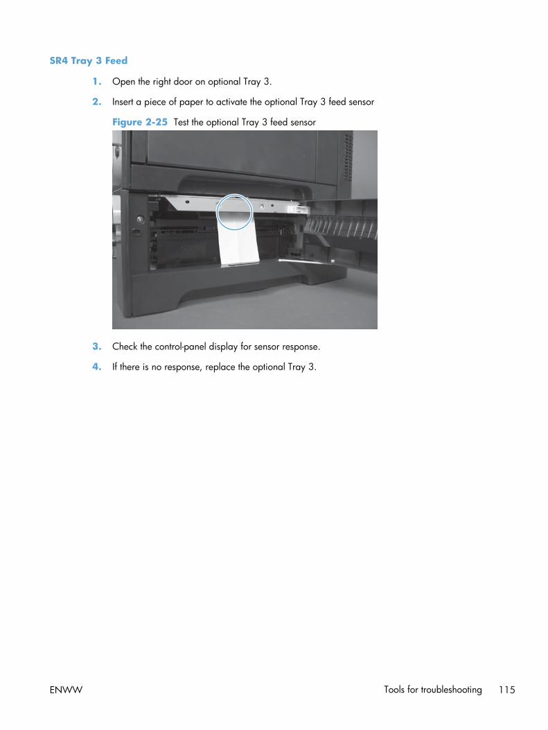
SR4 Tray 3 Feed
1. Open the right door on optional Tray 3.
2. Insert a piece of paper to activate the optional Tray 3 feed sensor
Figure 2-25 Test the optional Tray 3 feed sensor
3. Check the control-panel display for sensor response.
4. If there is no response, replace the optional Tray 3.
ENWW Tools for troubleshooting 115

SR2 Tray 3 paper surface
1. Remove the optional Tray 3.
2. Push the lever to activate the sensor arms.
Figure 2-26 Test the optional Tray 3 paper surface sensor
3. If there is no response, replace the optional Tray 3.
116 Chapter 2 Solve problems ENWW

Tray 3 SW1 paper size sensors
1. Push any of the three buttons to see if the control panel changes for sensors.
Figure 2-27 Test the optional Tray 3 SW1 paper size sensors
2. If any of the tests fail, replace the 500-sheet feeder.
Print/stop test
Use this diagnostic test to isolate the cause of problems such as image-formation defects and jamswithin the engine. During this test you can stop the paper anywhere along the product paper path. Thetest can be programmed to stop printing internal pages or an external print job when the paperreaches a certain position. The test can also be programmed to stop from 0 to 60,000 ms. If the timeris set to a value that is greater than the job-print time, you can recover the product in one of two ways.
1. From the Home screen, scroll to and touch the Administration button.
2. Touch the Troubleshooting button.
3. Touch the Diagnostic Tests button.
4. Scroll to and touch the Print/Stop Test button.
5. Enter a range, and then touch the OK button.
● After the print job is completed press OK button to return to the Troubleshooting menu before thetimer times out.
● After the timer times out, touch the Stop button. Activate the door switch to restart the engine andreturn it to a normal state.
NOTE: Do not try to perform a print/stop test while the product is calibrating, because you might berequired to restart the product. If a jam message displays on the control panel during testing, activatethe door switch.
ENWW Tools for troubleshooting 117

Component tests
Control-panel tests
Open the following menus:
● Administration
● Troubleshooting
● Diagnostic Tests
Available control-panel tests
● LEDs: test the LEDs on the control panel.
● Display: sequence through display tests.
● Buttons: tests the key pad and other buttons.
● Touchscreen: tests the control-panel touchscreen.
For more control-panel diagnostics, see Control-panel checks on page 83.
Component test (special-mode test)
This test activates individual parts independently to isolate problems.
Each component test can be performed once or repeatedly. If you turn on the Repeat option from thedrop-down menu, the test cycles the component on and off. This process continues for two minutes, andthen the test terminates.
NOTE: The front or side door interlocks must be defeated to run the component tests. Some testsmight require that the ITB and toner cartridges be removed. The control panel display prompts you toremove some or all cartridges during certain tests.
1. From the Home screen on the product control panel, scroll to and touch the Administration button.
2. Open the following menus:
● Troubleshooting
● Diagnostic Tests
● Component Test
3. Select the component test options for the test you want to run.
Table 2-13 Component test details
Component test Motor or solenoidnumber
Replacement partnumber
Comments
Transfer Motors M5 RM1-8105-000CN All motors related to cartridges and belts.
118 Chapter 2 Solve problems ENWW

Table 2-13 Component test details (continued)
Component test Motor or solenoidnumber
Replacement partnumber
Comments
Belt Only M10 RK2-2415-000CN Remove all toner cartridges to perform this test.Rotates the ITB belt. You can hear the auger motorrunning.
Cartridge Motors ● M3: yellow
● M4: magenta/cyan
● M5: black
RM-8105-000CN Activates three drum motors at a specified speedfor 10 seconds.
Fuser Motor M2 RM1-4983-000CN Activates the fuser motor at a specified speed for10 seconds.
Fuser PressureRelease Motor
M2 reverse RM1-4983-000CN Reverses the fuser motor and pressurizes ordepressurizes the pressure release motor.
Alienation Motor M10 RK2-2415-000CN Activates CMYK developer alienation in thefollowing sequence: All colors engaged, all colorsalienated, K-only engaged, and K alienated.
ITB Contact/Alienation
M2 RM1-4983-000CN Activates the ITB drive motor at a specified speedfor 10 seconds.
TCU Motor M12 Activates the motor at a specified speed for 10seconds.
Tray <X> PickupMotor
T2 SL4
Tray 3: M1 (paper feedmotor)
M2 (paper feeder liftmotor)
M1: RM1-5773-000CN
M2: RM1-4983-000CN
Activates the pickup motor, pickup roller,separation roller, and registration roller at aspecified speed for 10 seconds.
Duplex pick upsolenoid
M11: Duplex reversemotor
Activates the motor at a specified speed for 10seconds.
Tray <X> PickupSolenoid
Tray 1: SL3
Tray 2: SL4
Tray 3: SL1
"SL3:RM1-8124-000CN
SL4: RM1-5773-000CN
SL1 RM1-5914-000CN
Activates the solenoid for 10 seconds.
Duplex RefeedClutch Solenoid
● CL1: duplex re-pickup clutch
● SL2: duplex reversesolenoid
CL1:RM1-4973-000CN
SL2: RM1-4973-000CN
Activates the clutch and solenoid for 10 seconds.
Black LaserScanner
M8 Activates the black/cyan scanner motor for 10seconds.
Cyan LaserScanner
M8 Activates the black/cyan scanner motor for 10seconds.
ENWW Tools for troubleshooting 119

Table 2-13 Component test details (continued)
Component test Motor or solenoidnumber
Replacement partnumber
Comments
Magenta LaserScanner
M9 Activates the yellow/magenta scanner motor for10 seconds.
Yellow LaserScanner
M9 Activates the yellow/magenta scanner motor for10 seconds.
Diagrams
Block diagrams
Figure 2-28 Sensors
120 Chapter 2 Solve problems ENWW

Table 2-14 Sensors
Component abbreviation Component name
SR1 Tray 3 paper surface sensor 1
SR2 Tray 3 paper surface sensor 2
SR3 Tray 3 paper sensor
SR4 Tray 3 feed sensor
SR5 Fuser output
SR6 Output bin full
SR7 Fuser pressure release
SR8 Registration
SR9 Tray 2 lifter
SR10 Paper width 1
SR11 Developer alienation
SR13 Tray 2 sensor
SR14 Fuser loop 1
SR15 Fuser loop 2
SR17 ITB alienation
SR20 Tray 2 paper
SR21 Tray 1 paper
SR22 Duplexer refeed
ENWW Tools for troubleshooting 121
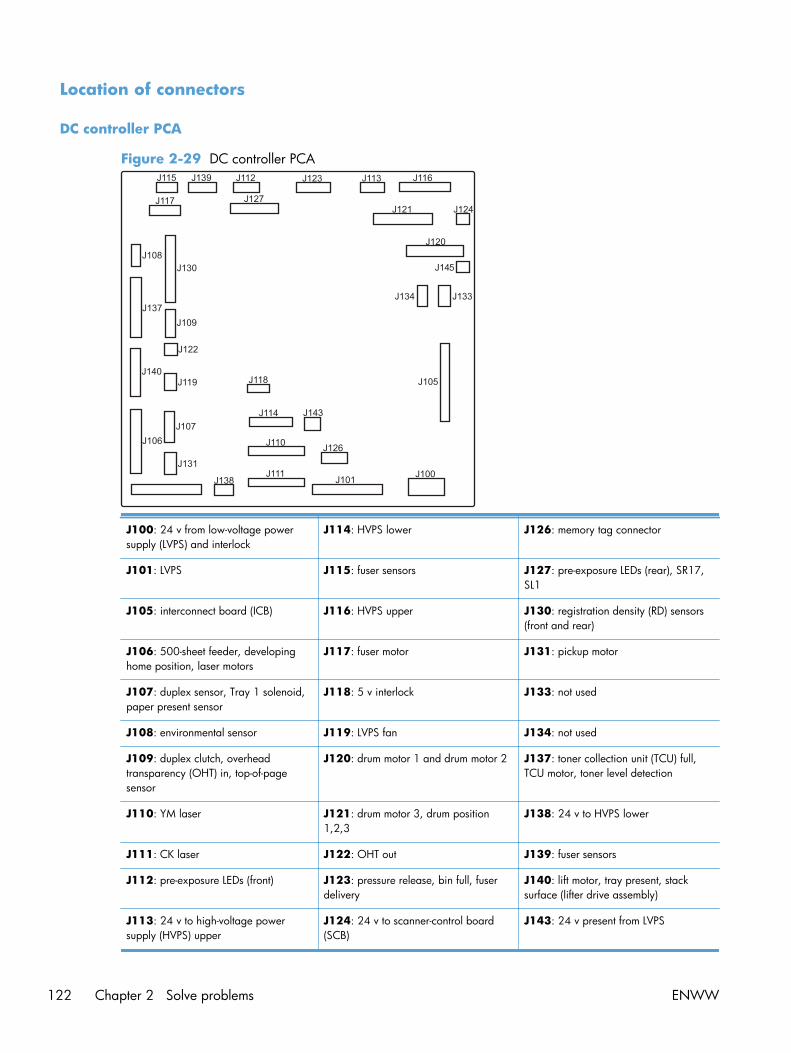
Location of connectors
DC controller PCA
Figure 2-29 DC controller PCA
J100: 24 v from low-voltage powersupply (LVPS) and interlock
J114: HVPS lower J126: memory tag connector
J101: LVPS J115: fuser sensors J127: pre-exposure LEDs (rear), SR17,SL1
J105: interconnect board (ICB) J116: HVPS upper J130: registration density (RD) sensors(front and rear)
J106: 500-sheet feeder, developinghome position, laser motors
J117: fuser motor J131: pickup motor
J107: duplex sensor, Tray 1 solenoid,paper present sensor
J118: 5 v interlock J133: not used
J108: environmental sensor J119: LVPS fan J134: not used
J109: duplex clutch, overheadtransparency (OHT) in, top-of-pagesensor
J120: drum motor 1 and drum motor 2 J137: toner collection unit (TCU) full,TCU motor, toner level detection
J110: YM laser J121: drum motor 3, drum position1,2,3
J138: 24 v to HVPS lower
J111: CK laser J122: OHT out J139: fuser sensors
J112: pre-exposure LEDs (front) J123: pressure release, bin full, fuserdelivery
J140: lift motor, tray present, stacksurface (lifter drive assembly)
J113: 24 v to high-voltage powersupply (HVPS) upper
J124: 24 v to scanner-control board(SCB)
J143: 24 v present from LVPS
122 Chapter 2 Solve problems ENWW

Paper feeder driver PCA
Figure 2-30 Paper feeder driver PCA
J401: engine connector
J402: not used
J404: SW1, SW2, lifter motor
J405: SR1, SR2, SR3, SR4, SL1
J406: feed motor
ENWW Tools for troubleshooting 123

Plug/jack locations
1
2
3
4
5
1 Fax port
2 USB port for connecting external USB devices
3 Hi-Speed USB 2.0 printing port
4 Local area network (LAN) Ethernet (RJ-45) network port
5 Foreign interface harness (for connecting external devices)
Locations of major components
Use the diagrams to locate components. For a list of components, see Table 2-17 PCAs, motors, fans,switches, solenoids, and clutches on page 129.
124 Chapter 2 Solve problems ENWW

Base product
Figure 2-31 Component locations (1 of 5)
1
ENWW Tools for troubleshooting 125

Figure 2-32 Component locations (2 of 5)
2
34
5
6
7
8
126 Chapter 2 Solve problems ENWW

Figure 2-33 Component locations (3 of 5)
10
9
11
12
13
14
ENWW Tools for troubleshooting 127

Figure 2-34 Component locations (4 of 5)
1617
15
18
128 Chapter 2 Solve problems ENWW

Figure 2-35 Component locations (5 of 5)
22 19
20
21
23
24
25
26
27
Table 2-17 PCAs, motors, fans, switches, solenoids, and clutches
Location Connector Componentabbreviation
Component name
1 J89 M12 Residual toner-feed motor
2 J26 FM2 Cartridge fan
3 J27 FM3 Delivery fan
4 J62 SW3 24V interlock switch
5 J118 SW1, SW2 5V interlock switch
6 J84 SL3 Multipurpose-tray pickup solenoid
7 J780 SW4 Power switch
ENWW Tools for troubleshooting 129

Table 2-17 PCAs, motors, fans, switches, solenoids, and clutches (continued)
Location Connector Componentabbreviation
Component name
8 J86 CL1 Duplex re-pick clutch
9 ICB Interconnect board (ICB)
10 LVPS Low-voltage power supply
11 HVPS (t) HVPS-T upper
12 DCC DC Controller
13 J119 FM1 Power-supply fan
14 HVPS (d) HVPS-D (lower)
15 J41 M3 Drum motor 1
RM1-8105-000CN
16 J40 M4 Drum motor 2
RM1-8105-000CN
17 J42 M5 Drum motor 3
RM1-8105-000CN
18 J25 M10 Development-disengagement motor
RK2-2415-000CN
19 J8 SL1 Primary transfer roller disengagement solenoid
20 J15 M2 Fuser motor
21 J55 M9 Yellow/magenta scanner motor
22 J56 M8 Cyan/black scanner motor
23 J20 M11 Duplex reverse motor (duplex models only)
24 J21 SL2 Duplex reverse solenoid (duplex models only)
25 J6 M13 Pickup motor
RM1-5773-000CN
26 J83 SL4 Tray-pickup solenoid
27 J78 M7 Tray 2 lifter motor
RM1-4976-000CN
130 Chapter 2 Solve problems ENWW

1 x 500 paper feeder
Figure 2-36 1 x 500 paper feeder
1
2
4
3
5
7
6
Location Connector Component abbreviation Component name
1 PF PCA Paper-feeder driver PCA
2/7 J18 SL1 Paper-feeder pickup solenoid
3 J21 SW2 Paper-feeder door switch
4 J16 SW1 Paper feeder tray media sizeswitch
5 J15 M2 Paper-feeder lifter motor
6 J14 M1 Paper-feeder motor
ENWW Tools for troubleshooting 131

General timing chart
Figure 2-37 General timing chart
Tim
ing
char
t is
tw
o co
nse
cuti
ve p
rin
t jo
bs o
n le
tter
-siz
e pa
per
(full
colo
r u
sin
g on
e-to
-on
e sp
eed
mod
e)
STB
YS
TBY
3Fi
xin
g de
liver
y se
nso
r
4Fi
xin
g m
otor
Prim
ary
tran
sfer
bia
s Y
10Pi
cku
p m
otor
15D
evel
opin
g bi
as Y
13Pr
imar
y ch
argi
ng
bias
C
18D
evel
opin
g bi
as B
k
TOP
sen
sor
23S
econ
dary
tra
nsf
er b
ias
6TO
P si
gnal
21Pr
imar
y tr
ansf
er b
ias
C
22Pr
imar
y tr
ansf
er b
ias
Bk
19 20Pr
imar
y tr
ansf
er b
ias
M
5S
can
ner
mot
or
11Pr
imar
y ch
argi
ng
bias
Y
14Pr
imar
y ch
argi
ng
bias
Bk
12Pr
imar
y ch
argi
ng
bias
M
Ope
rati
on
Dru
m m
otor
17
PRIN
TIN
TRLS
TR
1 2 8D
rum
mot
or 2
9D
rum
mot
or 3
16D
evel
opin
g bi
as M
17D
evel
opin
g bi
as C
Prin
t co
mm
and
Tray
pic
kup
sole
noid
132 Chapter 2 Solve problems ENWW

Circuit diagrams
Figure 2-38 General circuit diagram (1 of 2)6 5 4
M
SL
23
23
MM
M
17
7
23
23
SL
21
M
M SL
+5
VA
PR
EE
XP
2
+5
VA
PR
EE
XP
3
+5
VA
PR
EE
XP
4
+5
VA
PGND
SGND
SGND
SGND
SGND
PREEXP2
+5VA
PREEXP3
+5VA
PREEXP1
PREEXP4
DU
PS
L
DU
PM
PH
A
DU
PM
I0A
DU
PM
I1A
DU
PM
I1B
DU
PM
I0B
DU
PM
PH
B
2T
RN
CN
T
2T
RC
NT
2T
RS
HV
TC
LK
1T
R2
S
1T
R1
S
HV
DA
CL
K
HV
DA
LD
SG
ND
PGND
FAN1LK
SGND
PGND
C/K
la
ser
ass
’y
Scanner ass’y
SGND
I2CSDA
WTSSNS
SGND
SGND
SGND
SGND
VSS1
VSS2
VSS3
Duplex ass’y
Y M C K
MC
K
LD2CTRL2
LD2CTRL1
/VDO22
/VDO21
VDO22
VDO21
/BD2I
LD2CTRL0
LD2PDOUT
LD1PDOUT
SGND
/VDO120
VDO120
LD1CTRL2
LD1CTRL1
LD1CTRL0
/VDO110
VDO110
/VDO42
VDO42
LD4CTRL2
LD4CTRL1
LD4CTRL0
/VDO41
VDO41
/BD4I
LD4PDOUT
LD3PDOUT
/VDO32
VDO32
LD3CTRL2
LD3CTRL1
LD3CTRL0
/VDO31
500-sheet PF
DEVHP
HVTCLK
/SCN4ACC
/SCN4DEC
/HV
RE
SE
T
DU
PM
IDW
N
+2
4V
B
HVDALD
HVDACLK
HVDATA 1
DEV1CNT
DEV2CNT
DEV3CNT
PA
PO
UT
/SCN2ACC
/SCN2DEC
PGND
+24VA
+24VA
DEV4CNT
DEVMPHB
DEVMIOB
DEVMIOA
DEVMPHA
FAN2D
FAN2LK
FAN3D
VSS4
VIN1
VIN2
VIN3
VIN4
FAN1D
SGND
1TR1:JP801-JP802
1TR2:JP826-JP827
1TR3:JP851-JP852
FAN3LK
1TR4:JP876-JP877
PR
I1:JP
20
1-JP
20
2
PR
I2:JP
22
6-JP
22
7
PR
I4:JP
27
6-JP
27
7
PR
I3:JP
25
1-JP
25
2
BL
1 :JP
30
1-JP
30
2
BL
2 :JP
32
6-JP
32
7
BL
3 :JP
35
1-JP
35
2
BL
4 :JP
37
6-JP
37
7
RS
1 :JP
40
1-JP
40
2
RS
2 :JP
42
6-JP
42
7
RS
3 :JP
45
1-JP
45
2
RS
4 :JP
47
6-JP
47
7
DE
V1
:JP5
01
-JP5
02
DE
V2
:JP5
26
-JP5
27
DE
V3
:JP5
51
-JP5
52
DE
V4
:JP5
76
-JP5
77
+5VA
1T
R4
S
1T
R3
S
PG
ND
+24VB
PGND
+24VB
PGND
PGND
FAN2LK
FAN3D
FAN3LK
HV
DA
TA2
I2CSCK
/HVRESET
WTMON
WTMSNS
HV
T-D
INPOPIN
PGND
INPOPOT
INPOPCLK
INPOPTMG
+24VA
+5VA
DEVMOUT0B
DEVMOUT1B
DEVMOUT0A
DEVMOUT1A
FEEDMOUT0A
FEEDMOUT1A
FEEDMOUT0B
FEEDMOUT1B
RTSNS1
RTSNS2
RTSNS3
RTSNS4
Toner collectionbox full sensor
Y
M
C
K
E-label (Y)
FAN2D
SG
ND
SGND
1TRHP
24VAFU2
1TRSL
Y
Ton
er le
ve
l sen
sor
2T
RC
LK
DUP_SL
+24VB
DUPMPHAD
DUPMPHAND
DUPMPHBD
DUPMPHBND HVT-T 2TR :T901
SGND
SGND
+3.3VC
CHK24VB
+2
4V
B
PG
ND
SGND
+3.3VC
PR
EE
XP
1
+3
.3V
A
+3
.3V
C
+3
.3V
C
SG
ND
PA
PF
UL
L
+3
.3V
C
FS
PR
S
+3.3VA
CSTLUPS
CSTPEND
SGND
+3.3VC
+3.3VC
SGND
CSTSNS
SGND
+3.3VC
24VAFU2
CSTSL
PW
RS
WO
N
/SW
LE
D
LUPMOUT2B
+5VDFU1
+5VDFU1
+5VDFU1
+5VDFU1
VDO31
TONLED1
TONLED2
TONLED3
TONLED4
LUPMOUT1B
Tray pickupdrive ass’y
Lifter driveass’y
WTLED
21
J89LJ89LH
21
J89D
12
3
J79D
J82DH
12
34
J6
32
1
J71D
J76LH
J74H
J73H
32
1
J73D
32
1
J73L
12
3
J96D
J96LH
32
1
J96LJ72H
12
3
J72D
J71H
12
34
56
J76L
1 2 3 4 5 6 7 8
J92D
J92DH
12345678
J92L
J80DH
32
1
J80D
32
1
J80L
12
34
56
J76D
1 2 3 J780
1234
J113
1 2 3 4
J201
21
SL
4
12 J1
42
11
10
98
23
45
61
7 J14
0
12
3
J79LJ79LH
12
J83LJ83DH
21
J83D
32
1
J82L
12
3
J5
SR
20
M1
2
12
3
J82D
M1
3
SR
13
32
1
J3
12
3
J4
11 10 9 8 23457
J112
1 2 3 J95D
123
J95L
J95LH
9 8 23456 17
J123
J116
12
34
56
J20
2
12
J21DJ21DH
12
J21L
FM
1
SR
9
87
65
43
21
J12
64
32
1
J13
1
12
3
J74D
12
3
J71L
12
34
5
J75D
98
23
45
61
7
J97D
12
3
J74L
J98LH
12
34
J2
43
21
J98L
12
34
J10
8
43
21
J98D
71
65
43
28
9
J97L
J97DH
12
3
J70D
12
3
J91L
54
32
1
J75L
17
16
15
14
13
12
11
10
98
23
45
61
7
J77L
J91DH
71
65
43
28
91
01
1
J88L
12SL
1L
ED
5
12
3
J16
13
12
11
10
98
23
45
61
7
J12
7
J87DH
J88DH
11
10
98
23
45
61
7
J88D
12
J87D
J70LH
32
1
J1
321
J46
J75DH
32
1
J91D
J77LH
12
3
J70L
J57LH
J26DH
32
1
J26D
J27DH
12
3
J27D
32
1
J27L
12
3
J26L
FM
2
65
43
21
J26
2
32
1
J72L
J200
J25
0
LED4
71
65
43
28
91
01
11
21
31
41
51
61
7
J77D
17
16
15
14
13
12
11
10
98
23
45
61
7
J13
7
J58LH
12
34
J58L
J11
1J1
10
43
21
J58D
12
34
J57D
18
17
16
15
14
13
12
11
10
98
23
45
61
7
J10
6
12
34 J20
J11
4
12
34
J13
8
21
SW4SR7 LED2LED1
J55DA
SR
11
SR6 SR5
21
J87L
SR
17
LE
D7
LE
D6
LE
D8F
M3
M1
0
LED3
M8
M9
J50
3J5
01
12
3J11
9
321
J47
1 2 3
J48
21
SL
2
M1
1
12
34
J26
1
43
21
J57L
43
21
J56
12
34
J55
43
21
J25
17
4
1
2
3
5
6
7
8
9
10
11
12
13
14
15
16
17
18
19
20
21
22
23
4
1
2
3
5
6
7
8
9
10
11
12
13
14
15
16
17
18
19
20
21
22
23
4
1
2
3
5
6
7
8
9
10
11
12
13
14
15
16
18
19
20
21
22
23
4
1
2
3
5
6
7
8
9
10
11
12
13
14
15
16
17
18
19
20
21
22
23
41 2 3 5 6 7 8 9
10
11
12
13
14
15
16
17
18
19
20
21
21
20
19
18
17
16
15
14
13
12
11
10 9 8 7 6 5 3 24 1
4
1
2
3
5
6
7
4
1
2
3
5
6
7
8
9
10
11
12
13
14
15
16
17
4
1
2
3
5
6
7
8
9
10
11
12
13
14
15
16
17
43
21
J25
1E-label (M)
E-label (C)
E-label (K)
Environmentsensor
Y/M
la
ser
ass
’y
MM7
3
J78D
J78LJ78LH
21
12
ENWW Tools for troubleshooting 133

Figure 2-39 General circuit diagram (2 of 2)
A
3
B
C
D
B7
A5
B7
MM
M
SL
CL
A5
M
TP
35
SGND
SGND
Fuser ass’y
FSRSAFE2
FSRSAFE1
SGND
SGND
24VRMT
N.C.
PGND
PGND
+24VB
+24VB
SGND
DRMHP1
+24VB
/DRM3DEC
/DRM3ACC
SG
ND
CL
EI
/BD
3O
/BD
2O
/BD
1O
N.C.N.C.
/DRM3FG
SGND
Main driveass’y
MP tray ass’y
REFEEDS
SGND
SGND
MPTSL
RMCL
Registrationass’y
/FSMFG
/FSMDEC
/FSMACC
PGND
PGND
Inter connect board
OHT sensor(in)
+24VA
FSLP1
FSLP2
FSRTH3
SGND
FSRTH2
FSRTH1
N.C.
PGND
PGND
/VC
RS
T
SG
ND
/BD
4O
+24VB
+24VB
FSMFR
OHT_SNS
MPTPEND
+5VA
/ZEROX
+5VC
HEATERC
HEATER1
SG
ND
RD
sen
sor (fro
nt)
SGND
OHT_LED
+24VA
+24VA
PGND
PGND
DRMFR
/DRM2ACC
/DRM2DEC
/DRM2FG
+24VA
+24VA
PGND
PGND
DRMFR
/DRM1FG
/DRM1DEC
/DRM1ACC
DRMKFR
24VAFU3
24VAFU2
DRMHP2
DRMHP3
RDSRGAIN1
DSRSR
DSRDR
SGND
SGND
DSFDR
DSFSR
RDSFGAIN1
RDSFGAIN0
100V 200V
FSRSNS
RDSRGAIN0
RDSRLED
RDSFLED
N.C.
Power supplyass’y
LH
DC controller
SG
ND
SG
ND
WA
KE
EN
G
/VD
OE
N
CL
EO
VD
O1
1I
/VD
O1
1I
VD
O1
2I
/VD
O1
2I
VD
02
1
/VD
02
1
VD
02
2
/VD
02
2
VD
O3
1
/VD
O3
1
VD
O3
2
/VD
O3
2
VD
O4
1
/VD
O4
1
VD
O4
2
/VD
O4
2
SG
ND
SG
ND
/TO
PO
WA
KE
VC
VC
3V
OF
F
+3.3VC
+3.3VC
SGND
+3.3VC+5VD
+5VD
+3.3VC
TOPI
SGND
+3.3VC
+3.3VC
+3.3VC
+3.3VC
+3.3VC
+5VA
+5VA
+3.3VA
+3.3VA
SGND
PSTYP100
+24VB
/FSRMSTOP
CHK24VB
FSR_CURRMS
/RLD
Imagescannerass’y
+3
.3V
A
FSRD
+5
VB
PWRSAVE
VC5VOFF
SG
ND
SG
ND
12
3
J43
J93LH
87
65
43
21
J42
SR
2S
R1
SR
21
J105
J301
23
41
J30
4
TB
10
2
12
J61M
12
J61F
19
71
65
43
28
91
01
11
21
31
41
51
61
71
82
0
J60
0
14
13
12
11
10
98
23
45
61
7
J13
02
1
J12
21
23
45
67
J10
9
IL201
TB
21
1
TB
21
0
TB
11
0
TB
11
1
IL101
12
34
56
78
J51
11
23
45
67
J51
0
32
1
J93D
65
43
21
J94D
12
34
56
J94LJ94LH
12
3
J93L
12
3
J45
32
1
J44
J86DH
21
J86D
12
J86L
21S
W3
21
12
34
5
J85LJ85LH
21
J701
32
1
J9
12
J702
SR
8
12
34
5
J85D
12
3
J90LJ90LH
32
1
J8
32
1
J90D
87
65
43
21
J10
7
1 2TP1
M2
12
J51DS
R2
2
SW
2
23
41
J10
0
TB
60
1
TB
50
1
TB
50
2
TB104
TB
60
2
12
J60M
12
J60F
MT4
41
23
J50D
21
H1
17
16
15
14
13
12
11
10
98
23
45
61
7
J12
1
20
18
17
16
15
14
13
12
11
10
98
23
45
61
71
9
J10
1
J50
LA
CL
1
12
3
J7
SL
3
21
J84LJ84DH
12
J84D
SR
3M
5M
3M
4
87
65
43
21
J41
12
34
56
78J40
71
65
43
28
91
01
11
21
31
41
51
6
J12
0
12
34
5
J11
5
12
34
56
7
J13
9
J51DH
41
23
J50L
23
1
J11
8
12
34
56
7
J35
0
12
34
56
J35
2
J50
DB
TB
10
1
21J12
J50
DA
MT3
SW
1
87
65
43
21
J11
7
12
34
56
78
J15
J50
LB
21
J51L
32
1
J11
12
3
J10
SR
15
SR
14
21TH2
1 2TH1
21
TH
3
7
1
4
1
2
3
5
6
7
5
3
2
1
4
6
5
3
2
4
4
1
2
3
5
TB105
TB106
TB107
2 1
J351
4 1235678910
11
12
13
14
15
16
17
18
19
20
21
22
23
24
25
26
27
28
29
30
31
32
33
34
35
4 12356789
10
11
12
13
14
15
16
17
18
19
20
21
22
23
24
25
26
27
28
29
30
31
32
33
34
35
RD
sen
sor (re
ar)
OHT sensor(out)
Staplerass’y
123
J145
1 2 3
J98/I
NH
IBIT
GN
D
+2
4V
A
12
J124
2 1
J99
GN
D
+2
4V
A
J303: To operation panelJ306: To USB
J307: To SCB
134 Chapter 2 Solve problems ENWW

Figure 2-40 Product circuit block diagram
Control Panel
Motor
Size SensorHome position
Optics LED array
Cave light
ADF open/close switch
Scanner
ADF
FFC
SCB
Engine
Stapler
Formatter
ICB
DCC
LVPS
3.3v/5v
AC
110/220v
USB + 12v
5v
5v
FFC
Backplane
24v
PCI-E
12v to 5v
hub
24v
ENWW Tools for troubleshooting 135

Figure 2-41 Paper feeder circuit diagram
136 Chapter 2 Solve problems ENWW

Internal print-quality test pages
Print quality troubleshooting pages
Use the print-quality-troubleshooting pages to help diagnose and solve color print-quality problems.
1. From the Home screen on the product control panel, scroll to and touch the Administration button.
2. Open the following menus:
● Troubleshooting
● Print Quality Pages
● Print PQ Troubleshooting Page
3. Touch the Print button. The product prints several print-quality troubleshooting pages.
The product returns to the Ready state after printing the print-quality-troubleshooting pages. Follow theinstructions on the pages that print out.
Figure 2-42 Print-quality troubleshooting procedure
Print Quality Troubleshooting ProcedurePage 1
ENWW Tools for troubleshooting 137

Figure 2-43 Yellow print-quality troubleshooting page
Yellow
Green
Figure 2-44 Yellow comparison page
Green
Yellow
Yellow cannot be easily seen unless combined with cyan, so half of each page is yellow and the otherhalf is an amplified version of yellow problems (green half). Compare the yellow on page one with thecorresponding green on page two for defects. You can also check the cyan page for defects.
138 Chapter 2 Solve problems ENWW

Figure 2-45 Black print-quality troubleshooting page
1
3
2
1. Grids The grids are in inches and millimeters. They are label withletters and numbers so that defects can be described byposition and by distance between repeats.
2. Color plane registration (CPR) bars After printing, the box with no extra color in each area oneach page shows how far off the CPR of that color is. Eachpage has two process direction areas and three scandirection areas that are labeled x and y and 1–11. The pageshould be fed by the long edge. Each square from the centerequals 42 microns.
3. Color ramp patches Used to detect offset for the OPC or developer in the imagedrum or offset in the fuser.
NOTE: To get further assistance in print quality troubleshooting, go to www.hp.com/support/lj500colorMFPM575 and select PQ Troubleshooting Tools.
ENWW Tools for troubleshooting 139

Print quality assessment page
Use the diagnostics page to evaluate problems with color plane registration, EP parameters, and printquality.
1. From the Home screen on the product control panel, scroll to and touch the Administration button.
2. Open the following menus:
● Troubleshooting
● Print Quality Pages
● Diagnostics Page
3. Touch the Print button.
Diagnostics PagePage 1
5 6
1
2
3
4 4
87
1 Calibration information
2 Parameters
3 Color density
140 Chapter 2 Solve problems ENWW

4 Color plane registration
5 Primary colors
6 Secondary colors
7 Temperature values (21A)
8 Humidity values (21B)
ENWW Tools for troubleshooting 141

Cleaning page
1. From the Home screen on the product control panel, scroll to and touch the Device Maintenancebutton.
2. Open the following menus:
● Calibration/Cleaning
● Cleaning Page
3. Touch the Print button to print the page.
4. The cleaning process can take several minutes. When it is finished, discard the printed page.
Set up an auto cleaning page
Use the procedure in this section to set up an automatic cleaning page.
1. From the Home screen on the product control panel, scroll to and touch the Device Maintenancebutton.
2. Open the following menus:
● Calibration/Cleaning
● Cleaning Settings
3. Select the Auto Cleaning item, and then select values for the Cleaning Interval option and theCleaning Size option. Touch the OK button.
142 Chapter 2 Solve problems ENWW

Print configuration page
Depending on the model, up to three pages print when you print a configuration page. In addition tothe main configuration page, the embedded Jetdirect configuration pages print.
Configuration page
Use the configuration page to view current product settings, to help troubleshoot product problems, orto verify installation of optional accessories, such as memory (DIMMs), paper trays, and productlanguages.
1. From the Home screen on the product control panel, scroll to and touch the Administration button.
2. Open the following menus:
● Reports
● Configuration/Status Pages
3. Touch Configuration Page to select it.
4. Touch the View button to view the information on the control panel, or touch the Print button toprint the pages.
Figure 2-46 Configuration page
Configuration PagePage 1
1 567
8
9
2
34
1 Device information
2 Installed personalities and options
3 HP Web services
ENWW Tools for troubleshooting 143

4 Color density
5 Calibration information
6 Memory
7 Event log
8 Security
9 Paper trays and options
144 Chapter 2 Solve problems ENWW

HP embedded Jetdirect page
The second configuration page is the HP embedded Jetdirect page, which contains the followinginformation:
Always make sure the status line under the general information line indicates "I/O Card Ready."
Figure 2-47 HP embedded Jetdirect page
Embedded Jetdirect PagePage 1
2
3
1 4
5
6
1 General Information indicates the product status, model number, hardware firmware version, port select, portconfiguration, auto negotiation, manufacturing identification, and manufactured date.
2 Security Settings information
3 Network Statistics indicates the total packets received, unicast packets received, bad packets received, framingerrors received, total packets transmitted, unsendable packets, transmit collisions, and transmit late collisions.
4 TCP/IP information, including the IP address
5 IPv4 information
6 IPv6 information
ENWW Tools for troubleshooting 145
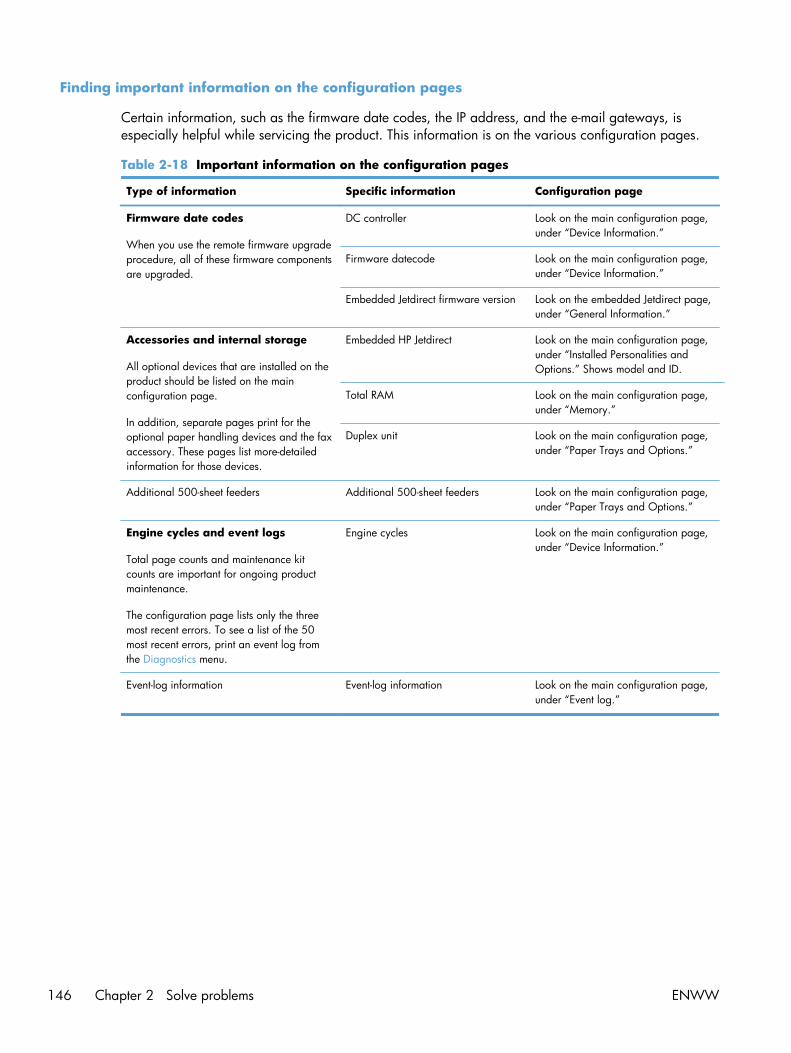
Finding important information on the configuration pages
Certain information, such as the firmware date codes, the IP address, and the e-mail gateways, isespecially helpful while servicing the product. This information is on the various configuration pages.
Table 2-18 Important information on the configuration pages
Type of information Specific information Configuration page
Firmware date codes
When you use the remote firmware upgradeprocedure, all of these firmware componentsare upgraded.
DC controller Look on the main configuration page,under “Device Information.”
Firmware datecode Look on the main configuration page,under “Device Information.”
Embedded Jetdirect firmware version Look on the embedded Jetdirect page,under “General Information.”
Accessories and internal storage
All optional devices that are installed on theproduct should be listed on the mainconfiguration page.
In addition, separate pages print for theoptional paper handling devices and the faxaccessory. These pages list more-detailedinformation for those devices.
Embedded HP Jetdirect Look on the main configuration page,under “Installed Personalities andOptions.” Shows model and ID.
Total RAM Look on the main configuration page,under “Memory.”
Duplex unit Look on the main configuration page,under “Paper Trays and Options.”
Additional 500-sheet feeders Additional 500-sheet feeders Look on the main configuration page,under “Paper Trays and Options.”
Engine cycles and event logs
Total page counts and maintenance kitcounts are important for ongoing productmaintenance.
The configuration page lists only the threemost recent errors. To see a list of the 50most recent errors, print an event log fromthe Diagnostics menu.
Engine cycles Look on the main configuration page,under “Device Information.”
Event-log information Event-log information Look on the main configuration page,under “Event log.”
146 Chapter 2 Solve problems ENWW

Color band test
The color-band test page shows bands of colors that can indicate whether the product is producingcolors correctly.
1. From the Home screen on the product control panel, scroll to and touch the Administration button.
2. Open the following menus:
● Troubleshooting
● Print Quality Pages
● Color Band Test
Print quality troubleshooting tools
Repetitive defects ruler
If defects repeat at regular intervals on the page, use this ruler to identify the cause of the defect. Placethe top of the ruler at the first defect. The marking that is beside the next occurrence of the defectindicates which component needs to be replaced.
NOTE: When printing this defect ruler, verify that any scaling options in the print driver are disabled.
Figure 2-48 Repetitive defects ruler0 mm
27 mm
32 mm
44 mm
66 mm63 mm
92 mm
105 mm
76 mm77 mm78 mm80 mm
49 mm
75.5 mm
50 mm
ENWW Tools for troubleshooting 147

Distance between defects Product components that cause the defect
27 mm Toner cartridge: primary charge roller
32 mm Toner cartridge: developer roller
44 mm Product: primary transfer roller
49 mm Toner cartridge: RS roller
50 mm Product: secondary transfer roller
63 mm ITB: secondary transfer backing roller
66 mm Product: distance from secondary transfer roller to fuser
75.5 mm Toner cartridge: OPC drum
76 mm ITB: driven roller
77 mm Fuser sleeve
78 mm Fuser pressure roller
80 mm Product: distance from primary transfer roller to secondary transfer roller for black
92 mm Toner cartridge station to station pitch: distance from the centerline of one OPC tothe centerline of the adjacent OPC
ITB: drive roller
105 mm Product: distance from registration to secondary transfer roller
Calibrate the product to align the colors
Calibration is a product function that optimizes print quality. If you experience any image-qualityproblems, calibrate the product.
1. From the Home screen on the product control panel, scroll to and touch the Device Maintenancebutton.
2. Open the following menus:
● Calibration/Cleaning
● Full Calibration
3. Touch the Start button to start the calibration process.
4. Wait while the product calibrates, and then try printing again.
148 Chapter 2 Solve problems ENWW

Control panel menus
Administration menu
You can perform basic product setup by using the Administration menu. Use the HP Embedded WebServer for more advanced product setup. To open the HP Embedded Web Server, enter the product IPaddress or host name in the address bar of a Web browser.
Reports menu
To display: At the product control panel, select the Administration menu, and then select the Reportsmenu.
Table 2-19 Reports menu
First level Second level Values Description
Configuration/Status Pages Administration Menu Map Print
View
Shows a map of the entireAdministration menu and theselected values for each setting.
Current Settings Page Print
View
Print a summary of the currentsettings for the product. Thismight be helpful if you plan tomake changes and need arecord of the presentconfiguration.
Configuration Page Print
View
Shows the product settings andinstalled accessories.
Supplies Status Page Print
View
Shows the approximateremaining life for the supplies;reports statistics on total numberof pages and jobs processed,serial number, page counts, andmaintenance information.
HP provides approximations ofthe remaining life for the suppliesas a customer convenience. Theactual remaining supply levelsmight be different than theapproximations provided.
Usage Page Print
View
Shows a count of all paper sizesthat have passed through theproduct; lists whether they weresimplex, duplex, monochrome,or color; and reports the pagecount.
File Directory Page Print
View
Shows the file name and foldername for files that are stored inthe product memory.
ENWW Tools for troubleshooting 149

Table 2-19 Reports menu (continued)
First level Second level Values Description
Web Services Status Page Print
View
Shows the detected WebServices for the product.
Color Usage Job Log Print Contains the number of colorand black and white pages thateach user has printed. It alsoindicates from which softwareprogram each of the jobs wasprinted.
Fax Reports Fax Activity Log Print
View
Contains a list of the faxes thathave been sent from or receivedby this product.
Billing Codes Report Print
View
Provides a list of billing codesthat have been used for outgoingfaxes. This report shows howmany sent faxes were billed toeach code.
Blocked Fax List Print
View
A list of phone numbers that areblocked from sending faxes tothis product.
Speed Dial List Print
View
Shows the speed dials that havebeen set up for this product.
Fax Call Report Print
View
A detailed report of the last faxoperation, either sent orreceived.
Other Pages Demonstration Page Print Prints a demonstration page.
RGB Samples Print Prints color samples for differentRGB values. Use the samples asa guide for matching printedcolors.
CMYK Samples Print Prints color samples for differentCMYK values. Use the samplesas a guide for matching printedcolors.
PCL Font List Print Prints the available PCL fonts.
PS Font List Print Prints the available PS fonts.
General Settings menu
To display: At the product control panel, select the Administration menu, and then select the GeneralSettings menu.
In the following table, asterisks (*) indicate the factory default setting.
150 Chapter 2 Solve problems ENWW

Table 2-20 General Settings menu
First level Second level Third level Fourth level Values Description
Date/Time Settings Date/Time Format Date Format DD/MMM/YYYY
MMM/DD/YYYY
YYYY/MMM/DD
Use the Date/TimeSettings menu tospecify the date andtime and to configuredate/time settings.
Time Format 12 hour (AM/PM)
24 hours
Select the format thatthe product uses toshow the date andtime, for example 12-hour format or 24-hour format.
Date/Time Time Zone Select the time zonefrom a list.
Date Select the date froma pop-up calendar.
Time Select the time froma pop-up keypad.
Adjust for DaylightSavings
Checkbox If you are in an areathat uses daylightsavings time, selectthe Adjust forDaylight Savingsbox.
Energy Settings Sleep Schedule A list of scheduledevents displays.
+ (Add)
Edit
Delete
Use to configure theproduct toautomatically wakeup or go to sleep atspecific times onspecific days. Usingthis feature savesenergy.
NOTE: You mustconfigure the dateand time settingsbefore you can usethe Sleep Schedulefeature.
Event Type Wake
Sleep
Select whether toadd or edit a Wakeevent or a Sleepevent, and thenselect the time andthe days for the wakeor sleep event.
Event Time
Event Days Select days of theweek from a list.
ENWW Tools for troubleshooting 151

Table 2-20 General Settings menu (continued)
First level Second level Third level Fourth level Values Description
Sleep Timer Settings Sleep Mode/AutoOff After
Range: 1 to 120minutes
Default = 60 minutes
Set the number ofminutes after whichthe product entersSleep or Auto Offmode. Use the arrowbuttons on the controlpanel to increase ordecrease the numberof minutes.
Wake/Auto On toThese Events
All Events*
Network port
Power button only
Optimum Speed/Energy Usage
Faster first page*
Save energy
Save more energy
Save most energy
Specifies how muchthe fuser cools downbetween print orcopy jobs. Tomaximize the productspeed, select theFaster first pageoption. To maximizeenergy conservation,select the Save mostenergy option. Or,select one of theother settings tocompromise betweenspeed and energyconservation.
152 Chapter 2 Solve problems ENWW

Table 2-20 General Settings menu (continued)
First level Second level Third level Fourth level Values Description
Print Quality Adjust Color Highlights Cyan
Magenta
Yellow
Black
Default
-5 to 5 Use to set the defaultprint-quality valuesand to triggercleaning actions foroptimum printquality. If you areusing specific typesof paper or placingthe product inextremeenvironments, youmight need to makeadjustments in thismenu.
Highlights are thebrightest color-valuesin an image. Foreach color, select asetting to adjust thedarkness or lightnessof highlights on theprinted page.Decrease the value tolighten the highlights.Increase the value todarken the highlights.
Default: Resets all thecolor-density settingsto the factory defaultvalues.
Midtones Cyan
Magenta
Yellow
Black
-5 to 5 Midtones are themiddle-range color-values in an image.For each color, selecta setting to adjust thedarkness or lightnessof midtones on theprinted page.Decrease the value tolighten the midtones.Increase the value todarken the midtones.
ENWW Tools for troubleshooting 153

Table 2-20 General Settings menu (continued)
First level Second level Third level Fourth level Values Description
Shadows Cyan
Magenta
Yellow
Black
-5 to 5 Shadows are thedarkest color-valuesin an image. Foreach color, select asetting to adjust thedarkness or lightnessof shadows on theprinted page.Decrease the value tolighten the shadows.Increase the value todarken the shadows.
Restore color valuesto default values.
NOTE: To restorecolor values tofactory defaultsettings, press theDefault button.
154 Chapter 2 Solve problems ENWW

Table 2-20 General Settings menu (continued)
First level Second level Third level Fourth level Values Description
Image Registration Adjust Tray <X> Print Test Page Shift the marginalignment to centerthe image on thepage from top tobottom and from leftto right. You can alsoalign the image onthe front with theimage printed on theback.
Use the Adjust Tray<X> menu to adjustthe registrationsettings for each tray.Before adjustingthese values, print aregistration testpage. It providesalignment guides inthe X and Ydirections so you candetermine whichadjustments arenecessary. You canadjust values for X1Shift, X2 Shift, Y1Shift, and Y2 Shift.
Use the Print TestPage option to printa page to test theimage registration. Itprovides alignmentguides in the X and Ydirections so you candetermine whichadjustments arenecessary.
ENWW Tools for troubleshooting 155

Table 2-20 General Settings menu (continued)
First level Second level Third level Fourth level Values Description
X1 Shift
Y1 Shift
X2 Shift
Y2 Shift
-5.00 mm to 5.00mm
The direction that isperpendicular to theway the paperpasses through theproduct is referred toas X. This is alsoknown as the scandirection. X1 is thescan direction for asingle-sided page orfor the second side ofa two-sided page. X2is the scan directionfor the first side of atwo-sided page.
The direction that thepaper feeds throughthe product isreferred to as Y. Y1is the feed directionfor a single-sidedpage or for thesecond side of a two-sided page. Y2 is thefeed direction for thefirst side of a two-sided page.
156 Chapter 2 Solve problems ENWW

Table 2-20 General Settings menu (continued)
First level Second level Third level Fourth level Values Description
Auto Sense Mode Tray 1 Sensing Full sensing
Expanded sensing*
Transparency Only
Use the Auto SenseMode feature toconfigure whichpaper types theproduct shouldautomatically sense.The following settingsare available:
Full sensing: Use thissetting if you don'twant media typemisprints and canaccept slowerperformance andpossible decreasedcartridge life.
Expanded sensing:The product sensesonly the first pageand assumes the restof the pages are thesame type.
Transparency Only:The product sensesonly the first page.The productdistinguishestransparencies fromother paper types.
Tray X Sensing Expanded sensing*
Transparency Only
When Configuringthe Auto Sense Modeoption for Tray 1 andTray 2 the <x>variable representsthe highest number oftrays installed on theproduct).
Adjust Paper Types Select from a list ofpaper types that theproduct supports.The availableoptions are the samefor each paper type.
Print Mode Select from a list ofprint modes.
Changing the PrintMode setting isusually the first thingto try to resolve print-quality problems.Problems can includetoner not stickingwell to the page, afaint image of thepage repeated onthe same or followingpage, incorrect glosslevel, etc.
ENWW Tools for troubleshooting 157

Table 2-20 General Settings menu (continued)
First level Second level Third level Fourth level Values Description
Resistance Mode Normal mode
Up
Down
Use this setting tocorrect print qualityproblems in low-humidityenvironments andhighly resistivepaper. Use the Upoption to solve printquality problems thatare related to poortoner-transfer. Usethe Down option inthe event that small,“pin-hole” defectsoccur.
Humidity Mode Normal
High
Use this setting tocorrect print qualityproblems in high-humidityenvironments. Usethe High setting ifyou are in a high-humidity environmentand you are seeingproblems with lowtoner density on thefirst page of a job.
Pre-Rotation Mode Off
On
Turn on if horizontallines appear onpages. Using thisfeature increases thefirst-page-out time bya few seconds.
Fuser Temp Mode Normal
Up
Down
If you continue to seeghost images on yourprint jobs afteradjusting the PrintMode setting, set thisfeature with the Upoption or Downoption. Using thismode increases wearon product parts andmight also slowdown the printingprocess.
158 Chapter 2 Solve problems ENWW

Table 2-20 General Settings menu (continued)
First level Second level Third level Fourth level Values Description
Paper Curl Mode Normal
Reduced
If excessive curling ofpaper occurs inwarm, high-humidityenvironments above23° C (73° F), usethe Reduced setting.Using this settingslows printing andincreases thefrequency ofconsumablereplacements.
Restore Modes
Optimize Normal Paper Standard*
Smooth
Use to optimizevarious print modesto address printquality issues.
Use the Smoothsetting to correctprint qualityproblems when usingvery smooth paper ofnormal weight.
Heavy Paper Standard*
Smooth
Use this setting tocorrect print qualityproblems when usingvery smooth heavyweight paper129-216 g/m2
(32-58 lb). TheSmooth settingshould be used if youare having printquality problems withvery smooth, heavypaper.
Envelope Control Normal*
Reduced Temp
If envelopes aresticking together inthe output bin, usethis setting to reducethe fusertemperature.
Environment Normal*
Low Temp
Enable if the productis operating in a lowtemperatureenvironment and youare having problemswith print qualitysuch as blisters in theprinted image.
ENWW Tools for troubleshooting 159

Table 2-20 General Settings menu (continued)
First level Second level Third level Fourth level Values Description
Line Voltage Normal*
Low Voltage
Enable if the productis operating in a lowvoltage environmentand you are havingproblems with printquality such asblisters in the printedimage.
Tray 1 Normal*
Alternate
Affects how often theproduct performs aninternal cleaningprocedure. Use theAlternate setting ifyou are havingproblems with extratoner on pages. Inthis mode, theproduct performs thecleaning procedureafter each job that isprinted from Tray 1.Using this modeincreases wear on allthe toner cartridges.
Background Normal*
Alternate 1
Alternate 2
Alternate 3
Use if pages areprinting with ashaded background.Using this featuremight reduce glosslevels. Use theAlternate 1 setting ifyou are seeing ashaded backgroundon the entire page.Use the Alternate 2setting if you areseeing thin verticallines on thebackground. TheAlternate 3 settingapplies the Alternate1 setting and theAlternate 2 setting atthe same time. Usethis setting if the firsttwo settings do notcorrect the problem.
160 Chapter 2 Solve problems ENWW

Table 2-20 General Settings menu (continued)
First level Second level Third level Fourth level Values Description
Uniformity Control Normal*
Alternate 1
Alternate 2
Alternate 3
This setting mighthelp correctuniformity in printquality issues, suchas a mottledappearance due topoor transfer of toneronto the page. TheAlternate 1 settingincreases the T1transfer bias and canbe used for anymedia type. TheAlternate 2 settingdecreases the fusertemperature andreduces thethroughput. Use thissetting if you areexperiencing mottledoutput due to poorfusing on normal orlight paper types.The Alternate 3setting applies theAlternate 1 settingand the Alternate 2setting at the sametime. Use this settingif the first two settingsdo not correct theproblem.
Tracking Control On*
Off
Normally, this settingshould be set to On.Tracking controlalgorithm is turnedON/OFF. It is notexpected that thecustomer will everneed to change thissetting.
Registration Normal*
Alternate
Use this setting if youare having troublewith color-planesshifting oroverlapping on thepage. Use theAlternate setting ifyou are seeing colormis-registrationproblems.
ENWW Tools for troubleshooting 161

Table 2-20 General Settings menu (continued)
First level Second level Third level Fourth level Values Description
Transfer Control Normal*
Alternate 1
Alternate 2
Alternate 3
Use this setting tocorrect transfer issuesin print jobs. Turn thisfeature on if green,mottled images areprinted on the page.Note that using thismode can increaseproblems with blurryimages or specks oftoner on the leadingor trailing edge ofthe paper. TheAlternate 1 settingreduces the T1 biasand should be usedwhen re-transferoccurs. The Alternate2 setting increasesthe inter-page gap.Using this settingreduces throughputand might decreasethe print-cartridgelife. The Alternate 3setting applies theAlternate 1 settingand the Alternate 2setting at the sametime. Use this settingif the first two settingsdo not correct theproblem.
Fuser Temp Normal*
Alternate
If you are seeing afaint image of thepage repeated at thebottom of the pageor on the followingpage, you shouldfirst make sure theAdjust Paper Typessetting and the PrintMode setting arecorrect for the type ofpaper you are using.If you continue to seeghost images on yourprint jobs, set theFuser Temp feature tothe Alternate setting.
162 Chapter 2 Solve problems ENWW

Table 2-20 General Settings menu (continued)
First level Second level Third level Fourth level Values Description
Restore Optimize Use to return all thesettings in theOptimize menu to thefactory-defaultvalues.
Resolution Image Ret 3600
1200 x 1200dpi
Sets the resolution atwhich the productprints.
Edge Control Off
Light
Normal*
Maximum
This settingdetermines howedges are rendered.Edge control has twocomponents:adaptive halftoningand trapping.Adaptive halftoningincreases edgesharpness. Trappingreduces the effect ofcolor-planemisregistration byoverlapping theedges of adjacentobjects slightly.Select one of thefollowing options:
Off: Turns off bothtrapping andadaptive halftoning.
Light: Sets trappingat a minimal level,and adaptivehalftoning is on.
Normal: Trapping isat a medium leveland adaptivehalftoning is on.
Maximum: Trappingis at the highest level,and adaptivehalftoning is on.
ENWW Tools for troubleshooting 163

Table 2-20 General Settings menu (continued)
First level Second level Third level Fourth level Values Description
Jam Recovery Auto*
Off
On
This product providesa jam recoveryfeature that reprintsjammed pages.Select one of thefollowing options:
Auto: The productattempts to reprintjammed pages whensufficient memory isavailable. This is thedefault setting.
Off: The productdoes not attempt toreprint jammedpages. Because nomemory is used tostore the most recentpages, performanceis optimal.
NOTE: Whenusing this option, ifthe product runs outof paper and the jobis being printed onboth sides, somepages can be lost.
On: The productalways reprintsjammed pages.Additional memory isallocated to store thelast few pagesprinted. This mightcause overallperformance tosuffer.
Auto Recovery Enabled
Disabled*
The product attemptsto reprint jammedpages when sufficientmemory is available.This is the defaultsetting.
Manage Stored Jobs Sort Stored Jobs By Job Name*
Date
This option allowsyou list the jobseither Alphabeticallyor Chronologically.
164 Chapter 2 Solve problems ENWW

Table 2-20 General Settings menu (continued)
First level Second level Third level Fourth level Values Description
Quick Copy Job HeldTimeout
Off*
1 Hour
4 Hours
1 Day
1 Week
Sets a maximumstorage-time limit forstored Quick Copyand Proof and Holdjobs. If a stored jobis not printed duringthis period, it isdeleted.
Quick Copy JobStorage Limit
1-100
Default = 32
Configure globalsettings for jobs thatare stored in theproduct memory.
The Quick Copy JobStorage Limit featurespecifies the numberof Quick Copy andProof and Hold jobsthat can be stored onthe product. Themaximum allowedvalue is 100.
Default Folder Name Type the name forthe stored jobs folderthat is accessible toall users.
Enable Retrieve fromUSB
Enabled
Disabled*
Enables the productto open a file from aUSB device.
ENWW Tools for troubleshooting 165

Table 2-20 General Settings menu (continued)
First level Second level Third level Fourth level Values Description
Hold Off Print Job Enabled*
Disabled
Enable this feature ifyou want to preventprint jobs fromstarting while a useris initiating a copyjob from the controlpanel. Held printjobs start printingafter the copy job isfinished, providedthat no other copyjob is in the printqueue.
Restore FactorySettings
Address Book
Calibration
Copy
Digital Send
Fax
General
Security
Use to restore allproduct settings totheir factory defaults.
Copy Settings menu
To display: At the product control panel, select the Administration menu, and then select the CopySettings menu.
In the following table, asterisks (*) indicate the factory default setting.
Table 2-21 Copy Settings menu
First level Second level Third level Values Description
Copies 1–9999
Default = 1
Configure the defaultoptions for copy jobs. Ifthe user does not specifythe job options whencreating the job, thedefault options are used.
166 Chapter 2 Solve problems ENWW

Table 2-21 Copy Settings menu (continued)
First level Second level Third level Values Description
Sides 1-sided original, 1-sidedoutput*
2-sided original, 2-sidedoutput
1-sided original, 2-sidedoutput
2-sided original, 1-sidedoutput
Use to indicate whetherthe original document isprinted on one or bothsides, and whether thecopies should be printedon one or both sides. Forexample, select 1-sidedoriginal, 2- sided outputwhen the original isprinted on one side, butyou want to make two-sided copies.
Orientation Portrait* Specify portrait orlandscape orientation andselect the way the secondsides are printed.
Portrait orientation meansthe short edge of the pageis along the top.
Landscape Landscape orientationmeans the long edge ofthe page is along the top.
ENWW Tools for troubleshooting 167

Table 2-21 Copy Settings menu (continued)
First level Second level Third level Values Description
Sides 1-sided original, 1-sidedoutput
2-sided original, 2-sidedoutput
1-sided original, 2-sidedoutput
2-sided original, 1-sidedoutput
Orientation Book-style
Flip-style
Book-style original; Flip-style copy
Flip-style original; Book-style copy
If you are making two-sided copies, select a 2-sided format option.
Book-style: The back sideof the original is printedright-side-up, and theback side of the copy isprinted the same way.Use this option fororiginals and copies thatare bound along the leftedge.
Flip-style: The back side ofthe original is printedupside-down, and theback side of the copy isprinted the same way.Use this option fororiginals and copies thatare to be bound along thetop edge.
Book-style original; Flip-style copy: The back sideof the original is printedright-side-up, but the backside of the copy is printedupside-down. Use thisoption when the originalis bound along the leftedge, but you want thecopies to be bound alongthe top edge.
Flip-style original; Book-style copy: The back sideof the original is printedupside-down, but the backside of the copy is printedright-side-up. Use thisoption when the originalis bound along the topedge, but you want thecopies to be bound alongthe left edge.
168 Chapter 2 Solve problems ENWW

Table 2-21 Copy Settings menu (continued)
First level Second level Third level Values Description
Color/Black Automatically detect*
Color
Black
Select how the copyshould be printed.
Automatically detect:Prints color documents incolor, and black andwhite documents in blackand white. For mixeddocuments, the productwill determine whether toprint in color or black andwhite.
Color: Prints documents incolor.
Black: Prints documents inblack and white.
Collate Collate on (Sets in pageorder)*
Collate off (Pagesgrouped)
If you are making morethan one copy, select theCollate on (Sets in pageorder) option to assemblethe pages in the correctorder in each set ofcopies.
Select the Collate off(Pages grouped) option togroup the same pagestogether. For example, ifyou are making fivecopies of an originaldocument that has twopages, all five first pageswould be groupedtogether and all fivesecond pages would begrouped together.
ENWW Tools for troubleshooting 169

Table 2-21 Copy Settings menu (continued)
First level Second level Third level Values Description
Reduce/Enlarge Scaling Auto*
100%
75%
50%
125%
150%
200%
Range X-Y (25-400%)
Use to scale the size ofthe document up or down.Select one of thepredefined percentages,or select the Scaling fieldand type a percentagebetween 25 and 400. TheAuto option automaticallyscales the image to fit thepaper size in the tray.
NOTE: To reduce theimage, select a scalingpercentage that is lessthan 100. To enlarge theimage, select a scalingpercentage that is greaterthan 100.
Auto Include Margins The product reduces theimage slightly to fit theentire scanned imagewithin the printable areaon the page.
Paper Selection Manually feed
Automatic Detect*
Tray 1: [Type], [Size]
Tray <X>: [Type], [Size]
For the best color andimage quality, select theappropriate paper typefrom the control panelmenu or from the printdriver.
Image Adjustment Darkness Select a value using theslide bar, or touchAutomatic.
Use to improve the overallquality of the copy.
Adjust the Darknesssetting to increase ordecrease the amount ofwhite and black in thecolors.
Contrast Select a value using theslide bar, or touchAutomatic.
Adjust the Contrast settingto increase or decreasethe difference between thelightest and darkest coloron the page.
Background Cleanup Select a value using theslide bar, or touchAutomatic.
Adjust the BackgroundCleanup setting if you arehaving trouble copying afaint image.
170 Chapter 2 Solve problems ENWW

Table 2-21 Copy Settings menu (continued)
First level Second level Third level Values Description
Sharpness Select a value using theslide bar, or touchAutomatic.
Adjust the Sharpnesssetting to clarify or softenthe image. For example,increasing the sharpnesscould make text appearcrisper, but decreasing itcould make photographsappear smoother.
Default Select this to make theselected ImageAdjustment setting thedefault value.
Content Orientation Orientation Portrait*
Landscape
For some features to workcorrectly, you must specifythe way the content of theoriginal document isplaced on the page.Portrait orientation meansthe short edge of the pageis along the top.Landscape orientationmeans the long edge ofthe page is along the top.
ENWW Tools for troubleshooting 171

Table 2-21 Copy Settings menu (continued)
First level Second level Third level Values Description
2-Sided Format Book-style
Flip-style
Book-style original; Flip-style copy
Flip-style original; Book-style copy
If you are making two-sided copies, select a 2-sided format option.
Book-style: The back sideof the original is printedright-side-up, and theback side of the copy isprinted the same way.Use this option fororiginals and copies thatare bound along the leftedge.
Flip-style: The back side ofthe original is printedupside-down, and theback side of the copy isprinted the same way.Use this option fororiginals and copies thatare to be bound along thetop edge.
Book-style original; Flip-style copy: The back sideof the original is printedright-side-up, but the backside of the copy is printedupside-down. Use thisoption when the originalis bound along the leftedge, but you want thecopies to be bound alongthe top edge.
Flip-style original; Book-style copy: The back sideof the original is printedupside-down, but the backside of the copy is printedright-side-up. Use thisoption when the originalis bound along the topedge, but you want thecopies to be bound alongthe left edge.
Optimize Text/Picture Manually adjust* Optimize For slider Use this setting tooptimize the output for aparticular type of content.
172 Chapter 2 Solve problems ENWW

Table 2-21 Copy Settings menu (continued)
First level Second level Third level Values Description
Text
Printed picture
Photograph
Manually adjust: Use tomanually optimize thesetting for each document.
Printed picture: Use forline drawings andpreprinted images, suchas magazine clippings orpages from books. If yousee bands of irregularcolor or intensity oncopies, try selecting thePrinted picture setting toimprove the quality.
Photograph: Use forphotographic prints.
Pages per Sheet One (1)*
Two (2)
Four (4)
Copies multiple pagesonto one sheet of paper.
NOTE: Before using thisscreen, use the ContentOrientation screen todescribe the originaldocument orientation.
Page Order Right, then down
Down, then right
If you are printing fourpages per sheet, selectthe page order. To printthe pages in rows, selectthe Right, then downoption. To print the pagesin columns, select theDown, then right option.
Add Page Borders If you are printing two ormore pages per sheet andyou want to print a borderaround each page, selectthe Add Page Bordersoption.
Original Size Select from a list of sizesthat the product supports.
Describes the page size ofthe original document.
ENWW Tools for troubleshooting 173

Table 2-21 Copy Settings menu (continued)
First level Second level Third level Values Description
Booklet Format Booklet Booklet off*
Booklet on
Use to copy two or morepages onto one sheet ofpaper so you can fold thesheets in the center toform a booklet. Theproduct arranges thepages in the correctorder. For example, if theoriginal document haseight pages, the productprints pages 1 and 8 onthe same sheet.
Original Sides 1-sided
2-sided
Select the 1-sided option ifthe original document isprinted on only one side.
Select the 2-sided option ifthe original document isprinted on two sides.
Borders on Each Page To print a border aroundeach page, select theBorders on Each Pageoption.
Edge-to-Edge Normal (recommended)*
Edge-to-Edge output
Use to avoid shadows thatcan appear along theedges of copies when theoriginal document isprinted close to the edges.Combine with theReduce/Enlarge feature toensure that the entirepage is printed on thecopies. When the Edge-to-Edge feature is turned on,the product minimizesmargins and prints asclose to the edge of thepaper as possible.
Job Build Job Build off*
Job Build on
Use to combine severaloriginal documents intoone job. Also use thisfeature to scan an originaldocument that has morepages than the documentfeeder can accommodateat one time. The producttemporarily saves all thescanned images. Afteryou have scanned all thepages for the job, touchthe Finish option to finishthe job.
174 Chapter 2 Solve problems ENWW

Scan/Digital Send Settings menu
To display: At the product control panel, select the Administration menu, and then select the Scan/Digital Send Settings menu.
In the following table, asterisks (*) indicate the factory default setting.
Table 2-22 Scan/Digital Send Settings menu
First level Second level Third level Fourth level Values Description
E-mail Settings
Default Save toNetwork FolderOptions
Default Save to USBOptions
NOTE: The sameoptions are availablefor each of thesefeatures, exceptwhere noted.
E-mail Setup
NOTE: EmailSettings only
E-mail Setup Wizard Use to configuresettings that apply tosending documentsthrough email orsaving documents toa folder on thenetwork or on a USBflash drive.
The E-mail SetupWizard featureconfigures theproduct to sendscanned images asemail attachments.To open the productHP Embedded WebServer and set up theemail notificationserver, enter theproduct networkaddress into a Webbrowser.
ENWW Tools for troubleshooting 175

Table 2-22 Scan/Digital Send Settings menu (continued)
First level Second level Third level Fourth level Values Description
Default Job Options Image Preview Make optional*
Require preview
Disable preview
Defines the defaultjob options for eachfunction. If you donot specify the joboptions whencreating the job, thedefault options areused. For completesetup, go to the HPEmbedded WebServer by typing thenetwork address ofthe product into aWeb browser.
Use the ImagePreview feature toscan a documentand display apreview beforecompleting the job.Select whether thisfeature is availableon the product.
Make optional: Thefeature is optional,depending on theuser who is signedin.
Require previewPreviews arerequired for all users.
Disable preview:Previews aredisabled for all users.
176 Chapter 2 Solve problems ENWW

Table 2-22 Scan/Digital Send Settings menu (continued)
First level Second level Third level Fourth level Values Description
Default File Name The product isshipped with afactory default filename of [Untitled] forany scanned filesthat are sent orsaved. Use thisfeature to specify adifferent default filename. If you aresaving a file to anetwork folder orUSB storage productand a file with thedefault file namealready exists, anumber is appendedto the file name, forexample,[Untitled]001.
ENWW Tools for troubleshooting 177

Table 2-22 Scan/Digital Send Settings menu (continued)
First level Second level Third level Fourth level Values Description
Document File Type Select from a list offile types.
PDF provides the bestoverall image andtext quality.
JPEG is a goodchoice for mostgraphics. Mostcomputers have abrowser that canview .JPEG files. Thisfile type producesone file per page.
TIFF is a standard fileformat that manygraphics programssupport. This file typeproduces one file perpage.
MTIFF stands formulti-page TIFF. Thisfile type savesmultiple scannedpages in a singlefile.
XPS (XML PaperSpecification) createsan XAML file thatpreserves the originalformatting of thedocument andsupports colorgraphics andembedded fonts.
NOTE: OCR filetypes are notsupported on thisproduct unlessattached to DSS.
178 Chapter 2 Solve problems ENWW

Table 2-22 Scan/Digital Send Settings menu (continued)
First level Second level Third level Fourth level Values Description
Optimize Text/Picture
Manually adjust*
Text
Printed picture
Photograph
Use to optimize theoutput for aparticular type ofcontent. You canoptimize the outputfor text, printedpictures, or amixture.
Manually adjust: Useto manually optimizethe setting for text orfor pictures.
Text: Use to optimizethe text portion of thecopy where textand/or pictures areon the original.
Printed picture: Usefor line drawingsand preprintedimages, such asmagazine clippingsor pages from books.
Photograph: Bestsuited for makingcopies of printedpictures.
Output Quality High (large file)
Medium*
Low (small file)
Use to select thequality for the output.Higher-qualityimages require alarger file size thanlower-quality images.Larger files take moretime to send, andsome recipientsmight have troublereceiving larger files.
ENWW Tools for troubleshooting 179

Table 2-22 Scan/Digital Send Settings menu (continued)
First level Second level Third level Fourth level Values Description
Original Sides 1-sided*
2-sided
Use to describe thelayout for each sideof the originaldocument. First selectwhether the originaldocument is printedon one side or bothsides. Then touch theOrientation setting toindicate whether theoriginal has portraitor landscapeorientation. If it isprinted on bothsides, also select the2-sided format thatmatches the originaldocument.
Orientation Automatically detect
Portrait*
Landscape
For some features towork correctly, youmust specify the waythe content of theoriginal document isplaced on the page.Portrait orientationmeans the short edgeof the page is alongthe top. Landscapeorientation means thelong edge of thepage is along thetop. In theOrientation area,select whether theoriginal documenthas a portrait orlandscapeorientation.
180 Chapter 2 Solve problems ENWW

Table 2-22 Scan/Digital Send Settings menu (continued)
First level Second level Third level Fourth level Values Description
2-Sided Format Book-style
Flip-style
Book-style: The backside of the original isprinted right-side-up,and the back side ofthe copy is printedthe same way. Usethis option fororiginals and copiesthat are bound alongthe left edge.
Flip-style: The backside of the original isprinted upside-down,and the back side ofthe copy is printedthe same way. Usethis option fororiginals and copiesthat are to be boundalong the top edge.
Resolution 400 dpi
300 dpi
200 dpi
150 dpi*
75 dpi
Sets the resolution forsent documents.Higher resolutionimages have moredots per inch (dpi),so they show moredetail. Lowerresolution imageshave fewer dots perinch and show lessdetail, but the filesize is smaller. Somefile types, forexample a file thatwill be processedwith OCR, require aspecific resolution.When these file typesare selected, theResolution settingmight automaticallychange to a validvalue.
ENWW Tools for troubleshooting 181

Table 2-22 Scan/Digital Send Settings menu (continued)
First level Second level Third level Fourth level Values Description
Content Orientation Orientation Automatically detect
Portrait*
Landscape
For some features towork correctly, youmust specify the waythe content of theoriginal document isplaced on the page.Portrait orientationmeans the short edgeof the page is alongthe top. Landscapeorientation means thelong edge of thepage is along thetop. In theOrientation area,select whether theoriginal documenthas a portrait orlandscapeorientation.
2-Sided Format Book-style*
Flip-style
Use to configure thedefault style for 2-sided print jobs. Ifthe Book-style optionis selected, the backside of the page isprinted the right wayup. This option is forprint jobs that arebound along the leftedge. If the Flip-styleoption is selected,the back side of thepage is printedupside-down. Thisoption is for printjobs that are boundalong the top edge.
182 Chapter 2 Solve problems ENWW

Table 2-22 Scan/Digital Send Settings menu (continued)
First level Second level Third level Fourth level Values Description
Color/Black Automaticallydetect*
Color
Black/Gray
Black
Use to enable ordisable colorscanning.
Automatically detect:Automatically scansdocuments in color ifat least one pagehas color.
Color: Scansdocuments in color.
Black/Gray: Scansdocuments ingrayscale.
Black: Scansdocuments in blackand white with acompressed file size.
Original Size Selelct from a list ofsupported sizes.
Use to describe thepage size of theoriginal document.
Notification Do not notify*
Notify when jobcompletes
Notify only if jobfails
Configure to receivenotification about thestatus of a sentdocument.
Do not notify: Turnsoff this feature.
Notify when jobcompletes: Select toreceive notificationfor this job only.
Notify only if jobfails: Select toreceive notificationonly if the job is notsent successfully.
Print: Select to printthe notification at thisproduct.
Include Thumbnail NOTE: Whensending an analogfax, select IncludeThumbnail to receivea thumbnail image ofthe first page of thefax in yournotification.
ENWW Tools for troubleshooting 183

Table 2-22 Scan/Digital Send Settings menu (continued)
First level Second level Third level Fourth level Values Description
Notification E-mailaddress
E-mail: Select toreceive thenotification in anemail. Touch the textbox following E-mailAddress:, and typethe email address forthe notification.
Image Adjustment Darkness Use to improve theoverall quality of thecopy.
Adjust the Darknesssetting to increase ordecrease the amountof white and black inthe colors.
Contrast Adjust the Contrastsetting to increase ordecrease thedifference betweenthe lightest anddarkest color on thepage.
Background Cleanup Adjust theBackground Cleanupsetting if you arehaving troublecopying a faintimage.
Sharpness Adjust the Sharpnesssetting to clarify orsoften the image. Forexample, increasingthe sharpness couldmake text appearcrisper, butdecreasing it couldmake photographsappear smoother.
Automatic Tone The productautomatically adjuststhe Darkness,Contrast, andBackground Cleanupsettings to the mostappropriate for thescanned document.
184 Chapter 2 Solve problems ENWW

Table 2-22 Scan/Digital Send Settings menu (continued)
First level Second level Third level Fourth level Values Description
Default Select this to makethe selected ImageAdjustment settingthe default value.
Job Build Job Build off*
Job Build on
Use to combineseveral originaldocuments into onejob. Also use to scanan original documentthat has more pagesthan the documentfeeder canaccommodate at onetime. The producttemporarily saves allthe scanned images.After you havescanned all thepages for the job,touch Finish to finishthe job.
Cropping Options Do not crop*
Crop to content
Use this menu item toautomatically cropthe scan for digitalsending. Use theCrop to contentoption to scan thesmallest possiblearea that hasdetectable content.
Erase Edges Use Inches
Back side erase
Front side erase
Use this menu item toremove blemishes,such as dark bordersor staple marks, bycleaning thespecified edges ofthe scanned image.In each of the textboxes enter themeasurements, inmillimeters or inches,for how much of thetop edge, bottomedge, left edge, andright edge to clean.
Blank PageSuppression
Disabled*
Enabled
Use to prevent blankpages in the originaldocument from beingincluded in the outputdocument.
ENWW Tools for troubleshooting 185

Table 2-22 Scan/Digital Send Settings menu (continued)
First level Second level Third level Fourth level Values Description
Digital Send ServiceSetup
Allow Usage ofDigital SendingSoftware (DSS)Server
Enabled*
Disabled
Configure how theproduct interacts withthe HP DigitalSending Software(DSS) server. HP DSShandles digitalsending tasks, suchas faxing, emailing,and sending scanneddocuments to anetwork folder orUSB storage device.
Use the Allow Usageof Digital SendingSoftware (DSS)Server option toconfigure the productto use HP DSS.
Allow Transfer toNew Digital SendingSoftware (DSS)Server
Enabled*
Disabled
Use the AllowTransfer to NewDigital SendingSoftware (DSS)Server option tospecify whether DSSmanagement of aproduct istransferable to adifferent DSS.
Fax Settings menu
To display: At the product control panel, select the Administration menu, and then select the FaxSettings menu.
In the following table, asterisks (*) indicate the factory default setting.
186 Chapter 2 Solve problems ENWW

Table 2-23 Fax Settings menu
First level Second level Third level Fourth level Values Description
Fax Send Settings Fax Send Setup Fax Setup Wizard Configure settings forsending faxes fromthe product.
Use the Fax SetupWizard feature to setup options forfaxing.
NOTE: To set upLAN fax or Internetfax, use the HPEmbedded WebServer. To open theHP Embedded WebServer, type theproduct networkaddress into a Webbrowser. Toconfigure the faxfeatures, select theFax tab.
Fax Dialing Settings Fax Dial Volume Off
Low*
High
These settings controlhow the fax modemdials the outgoingfax number whenfaxes are sent.
Dialing Mode Tone*
Pulse
Redial Interval 1 – 5 Minutes
Default = 5 minutes
Fax Send Speed Fast*
Medium
Slow
Dialing Prefix
Detect Dial Tone
Redial on Error Range: 0 – 9
Default = 2
Redial on NoAnswer
Range: 0 – 2
Default = 0
Redial on Busy Range: 0 – 9
Default = 3
ENWW Tools for troubleshooting 187

Table 2-23 Fax Settings menu (continued)
First level Second level Third level Fourth level Values Description
General Fax SendSettings
Fax NumberConfirmation
Enabled
Disabled*
If this feature isenabled, you mustenter the fax numbertwice.
PC Fax Send Enabled*
Disabled
Enables users whohave the correctdriver installed tosend faxes throughthe product from theircomputers.
JBIG Compression Enabled*
Disabled
The JBIGcompression reducesfax-transmission time,which can result inlower phonecharges. However,using JBIGcompressionsometimes causescompatibilityproblems with olderfax machines. If thisoccurs, turn off theJBIG compression.
Error CorrectionMode
Enabled*
Disabled
When error-correction mode isenabled and an erroroccurs during faxtransmission, theproduct sends orreceives the errorportion again.
Fax Header Prepend*
Overlay
Use to prepend oroverlay the faxheader page.
Fax Number SpeedDial Matching
Enabled
Disabled*
Use this item tomatch fax numberthat you type tonumbers that aresaved as a speeddial.
188 Chapter 2 Solve problems ENWW

Table 2-23 Fax Settings menu (continued)
First level Second level Third level Fourth level Values Description
Billing Codes Enable Billing Codes Off
On*
When billing codesare enabled, aprompt displays thatasks the user to enterthe billing code foran outgoing fax. Thisprompt does notappear if the Allowusers to edit billingcodes check box isnot checked.
You can also use theBilling Codes reportin the Reports menuto view the list of thebilling codes thathave been used forfaxes that have beensent from theproduct. The list isgrouped by billingcode and also showsfax details. Thisfeature can be usedfor billing or usagetracking.
Default Billing Code Specify a defaultbilling code forfaxing. If you specifya default billingcode, this codedisplays in the BillingCode field when theuser sends anoutgoing fax. If thisfield is blank, nodefault billing code isprovided for theuser.
Minimum Length Range: 1 – 16
Default = 1
Specify the requiredlength of the billingcode. Billing codescan be between 1and 16 characterslong.
Allow users to editbilling codes
Off
On*
ENWW Tools for troubleshooting 189

Table 2-23 Fax Settings menu (continued)
First level Second level Third level Fourth level Values Description
Default Job Options Image Preview Make optional*
Require preview
Disable preview
Use the ImagePreview feature toscan a documentand display apreview beforecompleting the job.Select whether thisfeature is availableon the product.
Make optional: Thefeature is optional,depending on theuser who is signedin.
Require previewPreviews arerequired for all users.
Disable preview:Previews aredisabled for all users.
Resolution Standard (100 x200dpi)*
Fine (200 x 200dpi)
Superfine (300 x300dpi)
Select the resolutionfor outgoing faxes. Ifyou increase theresolution, faxesmight be clearer butthey could transmitmore slowly. Somefile types, forexample a file thatwill be processedwith OCR, require aspecific resolution.When these file typesare selected, theResolution settingmight beautomaticallychanged to a validvalue.
190 Chapter 2 Solve problems ENWW

Table 2-23 Fax Settings menu (continued)
First level Second level Third level Fourth level Values Description
Original Sides 1-sided*
2-sided
Use to describe thelayout for each sideof the originaldocument. First selectwhether the originaldocument is printedon one side or bothsides. Then touch theOrientation setting toindicate whether theoriginal has portraitor landscapeorientation. If it isprinted on bothsides, also select the2-sided format thatmatches the originaldocument.
Orientation Portrait*
Landscape
For some features towork correctly, youmust specify the waythe content of theoriginal document isplaced on the page.
Portrait: This settingmeans the short edgeof the page is alongthe top.
Landscape: Thissetting means thelong edge of thepage is along thetop.
ENWW Tools for troubleshooting 191

Table 2-23 Fax Settings menu (continued)
First level Second level Third level Fourth level Values Description
2-Sided Format Book-style*
Flip-style
Book-style: The backside of the original isprinted right-side-up,and the back side ofthe copy is printedthe same way. Usethis option fororiginals and copiesthat are bound alongthe left edge.
Flip-style: The backside of the original isprinted upside-down,and the back side ofthe copy is printedthe same way. Usethis option fororiginals and copiesthat are to be boundalong the top edge.
Notification Do not notify*
Notify when jobcompletes
Notify only if jobfails
Use to receivenotification about thestatus of a sentdocument.
Do not notify: Turnsoff this feature.
Notify when jobcompletes: Select toreceive notificationfor this job only.
Notify only if jobfails: Select toreceive notificationonly if the job is notsent successfully.
Print: Select to printthe notification at thisproduct.
E-mail: Select toreceive thenotification in anemail. Touch the textbox following E-mailAddress: and enterthe email address forthe notification.
192 Chapter 2 Solve problems ENWW

Table 2-23 Fax Settings menu (continued)
First level Second level Third level Fourth level Values Description
Include Thumbnail When sending ananalog fax, selectInclude Thumbnail toreceive a thumbnailimage of the firstpage of the fax inyour notification.
Notification E-mailaddress
Provide the emailaddress that willreceive notifications.
Content Orientation Orientation Portrait*
Landscape
For some features towork correctly, youmust specify the waythe content of theoriginal document isplaced on the page.
Portrait: This settingmeans the short edgeof the page is alongthe top.
Landscape: Thissetting means thelong edge of thepage is along thetop.
2-Sided Format Book-style*
Flip-style
Use to configure thedefault style for 2-sided print jobs. Ifthe Book-style optionis selected, the backside of the page isprinted the right wayup. This option is forprint jobs that arebound along the leftedge. If the Flip-styleoption is selected,the back side of thepage is printedupside-down. Thisoption is for printjobs that are boundalong the top edge.
Original Size Select from a list ofsizes that the productsupports.
Use to describe thepage size of theoriginal document.
ENWW Tools for troubleshooting 193

Table 2-23 Fax Settings menu (continued)
First level Second level Third level Fourth level Values Description
Image Adjustment Darkness Use to improve theoverall quality of thecopy.
Adjust the Darknesssetting to increase ordecrease the amountof white and black inthe colors.
Contrast Adjust the Contrastsetting to increase ordecrease thedifference betweenthe lightest anddarkest color on thepage.
Background Cleanup AdjusttheBackgroundCleanup setting ifyou are havingtrouble copying afaint image.
Sharpness Adjust the Sharpnesssetting to clarify orsoften the image. Forexample, increasingthe sharpness couldmake text appearcrisper, butdecreasing it couldmake photographsappear smoother.
Automatic Tone
Default
194 Chapter 2 Solve problems ENWW

Table 2-23 Fax Settings menu (continued)
First level Second level Third level Fourth level Values Description
Optimize Text/Picture
Manually adjust* Optimize For
Text
Printed picture
Photograph
Optimizes the outputfor a particular typeof content. You canoptimize the outputfor text, printedpictures, or amixture.
Manually adjust: Useto manually optimizethe setting for text orfor pictures.
Text: Use to optimizethe text portion of thecopy where textand/or pictures areon the original.
Printed picture: Usefor line drawingsand preprintedimages, such asmagazine clippingsor pages from books.
Photograph: Bestsuited for makingcopies of printedpictures.
Job Build Job Build off*
Job Build on
Use to divide acomplex job intosmaller segments.This is useful whenyou are copying orscanning an originaldocument that hasmore pages than thedocument feeder canhold, or when youwant to combinepages that havedifferent sizes intoone job. You can useeither the glass or thedocument feeder toscan the originaldocuments.
Blank PageSuppression
Disabled*
Enabled
Prevents blank pagesin the originaldocument from beingincluded in the outputdocument.
ENWW Tools for troubleshooting 195

Table 2-23 Fax Settings menu (continued)
First level Second level Third level Fourth level Values Description
Fax Receive Settings Fax Receive Setup Ringer Volume Off
Low*
High
Use to configuresettings for receivingfaxes.
Rings To Answer Range: 1–6
Default = 1
Fax Receive Speed Fast*
Medium
Slow
Ring Interval Range: 220–600 ms
Default = 600 ms
Ring Frequency Range: 1–200
Default = 68hz
Fax Printing Schedule Always store faxes
Always print faxes*
Use Fax PrintingSchedule
If you have concernsabout the security ofprivate faxes, usethis feature to storefaxes rather thanhaving themautomatically print.Select Incoming FaxOptions, and thenyou can choose toalways store faxes,always print them, oryou can set up aschedule for eachday of the week.
Schedule
Touch this to set up afax printing scheduleif you selected theUse Fax PrintingSchedule option.
Add (plus sign)
Edit
Delete
Print incoming faxes
Store incoming faxes
Time
Event Days
If you are using a faxprinting schedule,use this menu toconfigure when toprint faxes.
196 Chapter 2 Solve problems ENWW

Table 2-23 Fax Settings menu (continued)
First level Second level Third level Fourth level Values Description
Blocked FaxNumbers
Fax Number to Block The blocked fax listcan contain up to 30numbers. When theproduct receives acall from one of theblocked fax numbers,it deletes theincoming fax. It alsologs the blocked faxin the activity logalong with job-accountinginformation.
Add blockednumbers: Enter a faxnumber into the FaxNumber to Blockfield and then touchthe arrow button toadd a new numberto the blocked faxlist.
Remove blockednumbers: Select anumber and touchthe Delete button todelete it from theblocked fax list.
Clear all blockednumbers: Touch theDelete All button toclear all of thenumbers from theblocked fax list.
You can also use theBlocked Fax Listreport in theInformation menu toview the list of thefax numbers thathave been blockedon this product.
ENWW Tools for troubleshooting 197

Table 2-23 Fax Settings menu (continued)
First level Second level Third level Fourth level Values Description
Default Job Options Notification Do not notify*
Notify when jobcompletes
Notify only if jobfails
Configure to receivenotification about thestatus of a sentdocument.
Do not notify: Turnsoff this feature.
Notify when jobcompletes: Select toreceive notificationfor this job only.
Notify only if jobfails: Select toreceive notificationonly if the job is notsent successfully.
E-mail*
E-mail: Select toreceive thenotification in anemail. Touch the textbox following E-mailAddress:, and enterthe email address forthe notification.
Include Thumbnail NOTE: Whensending an analogfax, select IncludeThumbnail to receivea thumbnail image ofthe first page of thefax in yournotification.
Notification E-mailaddress
Provide the emailaddress that willreceive notifications.
Stamp ReceivedFaxes
Enabled
Disabled*
Use this option toadd the date, time,sender’s phonenumber, and pagenumber to each pageof the faxes that thisproduct receives.
198 Chapter 2 Solve problems ENWW

Table 2-23 Fax Settings menu (continued)
First level Second level Third level Fourth level Values Description
Fit to Page Enabled*
Disabled
Use to shrink faxesthat are larger thanLetter-size or A4-sizeso that they can fitonto a Letter-size orA4-size page. If thisfeature set toDisabled, faxeslarger than Letter orA4 will flow acrossmultiple pages.
Paper Selection Automatic*
Select from a list ofthe trays.
Sides 1-sided*
2-sided
Use to describe thelayout for each sideof the originaldocument. First selectwhether the originaldocument is printedon one side or bothsides. Then touch theOrientation setting toindicate whether theoriginal has portraitor landscapeorientation. If it isprinted on bothsides, also select the2-sided format thatmatches the originaldocument.
Fax Forwarding Enable FaxForwarding
Disabled*
Enabled
Use to forwardreceived faxes toanother fax machine.
Type of Fax Job toForward
All faxes
Sent faxes
Received faxes
Fax ForwardingNumber
Clear Fax ActivityLog
Clears all eventsfrom the Fax ActivityLog list.
ENWW Tools for troubleshooting 199

General Print Settings menu
To display: At the product control panel, select the Administration menu, and then select the GeneralPrint Settings menu.
In the following table, asterisks (*) indicate the factory default setting.
Table 2-24 General Print Settings menu
First level Second level Values Description
Manual Feed Enabled
Disabled*
Use to enable or disable themanual-feed feature, whichallows the user to feed paperinto the product by hand. Whenthis feature is enabled, the usercan select manual feed from thecontrol panel as the papersource for a job. If a tray is notspecified as part of a job,manual feed is selected.
Courier Font Regular*
Dark
Select which version of theCourier font you want to use. Thefactory default setting is Regular,which uses an average strokewidth. The Dark setting can beused if a heavier Courier font isneeded.
Wide A4 Enabled
Disabled*
Changes the printable area ofA4-size paper. If you enable thisoption, eighty 10-pitchcharacters can be printed on asingle line of A4 paper.
Print PS Errors Enabled
Disabled*
Use this feature to select whethera PostScript (PS) error page isprinted when the productencounters a PS error.
Print PDF Errors Enabled
Disabled*
Selects whether a PDF error pageis printed when the productencounters a PDF error.
Personality Auto*
PCL
POSTSCRIPT
Configures the default printlanguage or personality for theproduct. Normally you shouldnot change the productlanguage. If you change thesetting to a specific productlanguage, the product does notautomatically switch from onelanguage to another unlessspecific software commands aresent to it.
200 Chapter 2 Solve problems ENWW

Table 2-24 General Print Settings menu (continued)
First level Second level Values Description
PCL Form Length Range: 5 – 128
Default = 60
Controls the PCL print-commandoptions. PCL is a set ofproductcommands that Hewlett-Packard developed to provideaccess to productfeatures.
Use the Form Length feature toselect the user-soft default verticalform length.
Orientation Portrait*
Landscape
Select the orientation that is mostoften used for copy or scanoriginals. Select the Portraitoption if the short edge is at thetop or select the Landscapeoption if the long edge is at thetop.
Font Source Internal*
Card slot 1
Card slot <X>
EIO <X> disk
USB
Selects the font source for theuser-soft default font. The list ofavailable options variesdepending on the installedproduct options.
Font Number Range: 0 – 110
Default = 0
Specifies the font number for theuser-soft default font using thesource that is specified in theFont Source menu. The productassigns a number to each fontand lists it on the PCL font list.The font number displays in theFont # column of the printout.
Font Pitch Range: 0.44 – 99.99
Default = 10
If the Font Source option and theFont Number setting indicate acontour font, then use this featureto select a default pitch (for afixed-spaced font).
Font Point Size Range: 4.00 – 999.75
Default = 12.00
If the Font Source option and theFont Number setting indicate acontour font, then use this featureto select a default point size (fora proportional-spaced font).
Symbol Set Select from a list of symbol sets. Select any one of severalavailable symbol sets from thecontrol panel. A symbol set is aunique grouping of all thecharacters in a font. The factorydefault value for this option isPC-8. Either PC-8 or PC-850 arerecommended for line-drawcharacters.
ENWW Tools for troubleshooting 201
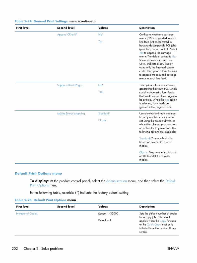
Table 2-24 General Print Settings menu (continued)
First level Second level Values Description
Append CR to LF No*
Yes
Configure whether a carriagereturn (CR) is appended to eachline feed (LF) encountered inbackwards-compatible PCL jobs(pure text, no job control). SelectYes to append the carriagereturn. The default setting is No.Some environments, such asUNIX, indicate a new line byusing only the line-feed controlcode. This option allows the userto append the required carriagereturn to each line feed.
Suppress Blank Pages No*
Yes
This option is for users who aregenerating their own PCL, whichcould include extra form feedsthat would cause blank pages tobe printed. When the Yes optionis selected, form feeds areignored if the page is blank.
Media Source Mapping Standard*
Classic
Use to select and maintain inputtrays by number when you arenot using the product driver, orwhen the software program hasno option for tray selection. Thefollowing options are available:
Standard: Tray numbering isbased on newer HP LaserJetmodels.
Classic: Tray numbering is basedon HP LaserJet 4 and oldermodels.
Default Print Options menu
To display: At the product control panel, select the Administration menu, and then select the DefaultPrint Options menu.
In the following table, asterisks (*) indicate the factory default setting.
Table 2-25 Default Print Options menu
First level Second level Values Description
Number of Copies Range: 1–32000
Default = 1
Sets the default number of copiesfor a copy job. This defaultapplies when the Copy functionor the Quick Copy function isinitiated from the product Homescreen.
202 Chapter 2 Solve problems ENWW

Table 2-25 Default Print Options menu (continued)
First level Second level Values Description
Default Paper Size Select from a list of sizes that theproduct supports.
Configures the default paper sizeused for print jobs.
Default Custom Paper Size X Dimension Range: 3– 8.5 inches
Default = 8.5 inches
Configures the default paper sizethat is used when the user selectsCustom as the paper size for aprint job.
Y Dimension Range: 5–14 inches
Default = 14 inches
Use Inches Enabled*
Disabled
Sides 1-sided*
2-sided
Use to indicate whether theoriginal document is printed onone or both sides, and whetherthe copies should be printed onone or both sides. For example:select the 1-sided original, 2-sided output option when theoriginal is printed on one side,but you want to make two-sidedcopies.
Select the Orientation setting tospecify portrait or landscapeorientation and to select the waythe second sides are printed.
2-Sided Format Book-style*
Flip-style
Configures the default style for 2-sided print jobs. If the Book-styleoption is selected, the back sideof the page is printed the rightway up. This option is for printjobs that are bound along the leftedge. If the Flip-style option isselected, the back side of thepage is printed upside-down.This option is for print jobs thatare bound along the top edge.
Edge-to-Edge Normal (recommended)*
Edge-to-Edge output
Use to avoid shadows that canappear along the edges ofcopies when the originaldocument is printed close to theedges.
ENWW Tools for troubleshooting 203

Display Settings menu
To display: At the product control panel, select the Administration menu, and then select the DisplaySettings menu.
In the following table, asterisks (*) indicate the factory default setting.
Table 2-26 Display Settings menu
First level Second level Values Description
Key Press Sound On*
Off
Use to specify whether you heara sound when you touch thescreen or press buttons on thecontrol panel.
Language Settings Language Select from a list of languagesthat the product supports.
Use to select a differentlanguage for control-panelmessages and specify the defaultkeyboard layout. When youselect a new language, thekeyboard layout automaticallychanges to match the factorydefault for the selectedlanguage.
Keyboard Layout Each language has a defaultkeyboard layout. To change it,select from a list of layouts.
Select the default keyboardlayout that matches the languageyou want to use.
How to Connect Button Display*
Hide
Use this menu item to display orhide the How to Connect Buttonon the Home screen.
Date and Time Show Date and Time*
Hide Date and Time
Select whether to display or hidethe date and time on the controlpanel Home screen.
Inactivity Timeout Range: 10 – 300 seconds
Default = 60 seconds
Specifies the amount of time thatelapses between any activity onthe control panel and when theproduct resets to the defaultsettings. When the timeoutexpires, the control-panel displayreturns to the Home menu, andany user signed in to the productis signed out.
204 Chapter 2 Solve problems ENWW

Table 2-26 Display Settings menu (continued)
First level Second level Values Description
Clearable Warnings On
Job*
Use this feature to set the periodthat a clearable warningdisplays on the control panel. Ifthe On setting is selected,clearable warnings appear untilthe Clearable Warnings button ispressed. If the Job setting isselected, clearable warnings stayon the display during the job thatgenerated the warning anddisappear from the display whenthe next job starts.
Continuable Events Auto-continue (10 seconds)*
Touch OK to continue
Use this option to configure theproduct behavior when theproduct encounters certainerrors. If the Auto-continue (10seconds) option is selected, thejob will continue after 10seconds. If the Touch OK tocontinue option is selected, thejob will stop and require the userto press the OK button beforecontinuing.
ENWW Tools for troubleshooting 205

Manage Supplies menu
To display: At the product control panel, select the Administration menu, and then select the ManageSupplies menu.
In the following table, asterisks (*) indicate the factory default setting.
Table 2-27 Manage Supplies menu
First level Second level Third level Fourth level Values Description
Supplies Status Print
View
Supply Settings Black Cartridge Low ThresholdSettings
1-100%
Default = 10%
Set the estimatedpercentage at whichthe product notifiesyou when the tonercartridge is very low.
Very Low Settings Stop
Prompt to continue*
Continue
Specifies how theproduct notifies youwhen the tonercartridge is very low.
Stop: The productstops until youreplace the tonercartridge.
Prompt to continue:The product stopsand prompts you toreplace the tonercartridge. You canacknowledge theprompt and continueprinting.
Continue: Theproduct alerts youthat a toner cartridgeis very low, but itcontinues printing.
Color Cartridges Low ThresholdSettings
Cyan
Magenta
Yellow
1-100%
Default = 10%
Set the estimatedpercentage at whichthe product notifiesyou when the tonercartridge is very low.You can specify adifferent percentagefor each color.
206 Chapter 2 Solve problems ENWW

Table 2-27 Manage Supplies menu (continued)
First level Second level Third level Fourth level Values Description
Very Low Settings Stop
Prompt to continue*
Continue
Specify how theproduct notifies youwhen the tonercartridge is very low.
Stop: The productstops until youreplace the tonercartridge.
Prompt to continue:The product stopsand prompts you toreplace the tonercartridge. You canacknowledge theprompt and continueprinting.
Continue: Theproduct alerts youthat a toner cartridgeis very low, but itcontinues printing.
ENWW Tools for troubleshooting 207

Table 2-27 Manage Supplies menu (continued)
First level Second level Third level Fourth level Values Description
Toner Collection Unit Very Low Settings Stop*
Prompt to continue
Continue
Configure how theproduct respondswhen the tonercollection unit isreaching the end ofits estimated life. Thiscondition isequivalent to thesupply life being verylow.
CAUTION:Continuing to printwithout replacing thetoner collection unitmight damage theproduct, cause tonerto spill, or cause anerror condition.
Stop: The productstops until youreplace the tonercollection unit.
Prompt to continue:The product stopsand prompts you toreplace the tonercollection unit. Youcan acknowledge theprompt and continueprinting.
Continue: Theproduct alerts youthat the tonercollection unit is verylow, but it continuesprinting.
Fuser Kit Low ThresholdSettings
1-100%
Default = 10%
Set the estimatedpercentage at whichthe product notifiesyou when the fuser isvery low.
208 Chapter 2 Solve problems ENWW

Table 2-27 Manage Supplies menu (continued)
First level Second level Third level Fourth level Values Description
Very Low Settings Stop
Prompt to continue*
Continue
Configure how theproduct respondswhen the fuser isreaching the end ofits estimated life.
Stop: The productstops until youreplace the fuser.
Prompt to continue:The product stopsand prompts you toreplace the fuser.You canacknowledge theprompt and continueprinting.
Continue: Theproduct alerts youthat the fuser is verylow, but it continuesprinting
Document Feeder Kit Low ThresholdSettings
1-100%
Default = 10%
Set the percentage atwhich the productnotifies you when thedocument feeder kitis very low.
ENWW Tools for troubleshooting 209

Table 2-27 Manage Supplies menu (continued)
First level Second level Third level Fourth level Values Description
Very Low Settings Stop
Prompt to continue*
Continue
Configure how theproduct respondswhen the documentfeeder kit is reachingthe end of itsestimated life.
Stop: The productstops until youreplace the documentfeeder kit.
Prompt to continue:The product stopsand prompts you toreplace the documentfeeder kit. You canacknowledge theprompt and continueprinting
Continue: Theproduct alerts youthat the documentfeeder kit is very low,but it continuesprinting.
Restrict Color Use Enable
Disable color
Color if allowed*
Use this feature toenable, restrict, ordisable color printingor copying.
210 Chapter 2 Solve problems ENWW

Table 2-27 Manage Supplies menu (continued)
First level Second level Third level Fourth level Values Description
Color/Black Mix Auto*
Mostly Color Pages
Mostly Black Pages
Instructs the productwhen to switchbetween color andmonochrome printingmodes for the bestoverall performance.
Auto: Uses the modethat is appropriatefor the first page ofthe job. If necessary,the product switchesmodes during themiddle of a job andthen stays in thatmode until the job isfinished.
Mostly Color Pages:The product usescolor mode for alljobs, even if the jobcontains no colorpages.
Mostly Black Pages:The product usesmonochrome modeuntil it detects a colorpage. The productswitches back tomonochrome modewhen it detects asequence of severalmonochrome pages.
Store Usage Data On supplies*
Not on supplies
The Store UsageData menu providesa way to suppressthe toner cartridgesfrom storing most ofthe informationgathered exclusivelyfor the purpose ofunderstanding theusage of the product.Select the Onsupplies setting tostore the data on thetoner cartridgememory chip. Selectthe Not on suppliessetting to suppressthe information frombeing stored on thememory chip.
ENWW Tools for troubleshooting 211
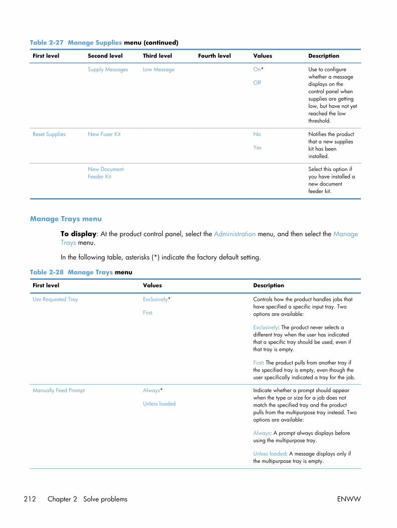
Table 2-27 Manage Supplies menu (continued)
First level Second level Third level Fourth level Values Description
Supply Messages Low Message On*
Off
Use to configurewhether a messagedisplays on thecontrol panel whensupplies are gettinglow, but have not yetreached the lowthreshold.
Reset Supplies New Fuser Kit No
Yes
Notifies the productthat a new supplieskit has beeninstalled.
New DocumentFeeder Kit
Select this option ifyou have installed anew documentfeeder kit.
Manage Trays menu
To display: At the product control panel, select the Administration menu, and then select the ManageTrays menu.
In the following table, asterisks (*) indicate the factory default setting.
Table 2-28 Manage Trays menu
First level Values Description
Use Requested Tray Exclusively*
First
Controls how the product handles jobs thathave specified a specific input tray. Twooptions are available:
Exclusively: The product never selects adifferent tray when the user has indicatedthat a specific tray should be used, even ifthat tray is empty.
First: The product pulls from another tray ifthe specified tray is empty, even though theuser specifically indicated a tray for the job.
Manually Feed Prompt Always*
Unless loaded
Indicate whether a prompt should appearwhen the type or size for a job does notmatch the specified tray and the productpulls from the multipurpose tray instead. Twooptions are available:
Always: A prompt always displays beforeusing the multipurpose tray.
Unless loaded: A message displays only ifthe multipurpose tray is empty.
212 Chapter 2 Solve problems ENWW

Table 2-28 Manage Trays menu (continued)
First level Values Description
Size/Type Prompt Display*
Do not display
Controls whether the tray configurationmessage displays whenever a tray is closed.Two options are available:
Display: This option shows the trayconfiguration message when a tray is closed.The user is able to configure the tray settingsdirectly from this message.
Do not display: This option prevents the trayconfiguration message from automaticallyappearing.
Use Another Tray Enabled*
Disabled
Use to turn on or off the control-panel promptto select another tray when the specified trayis empty. Two options are available:
Enabled: When this option is selected, theuser is prompted either to add paper to theselected tray or to choose a different tray.
Disabled: When this option is selected, theuser is not given the option of selecting adifferent tray. The product prompts the userto add paper to the tray that was initiallyselected.
Alternative Letterhead Mode Disabled*
Enabled
Use to load letterhead or preprinted paperinto the tray the same way for all print jobs,whether you are printing to one side of thesheet or to both sides of the sheet. When thisoption is selected, load the paper as youwould for printing on both sides. See theuser documentation that came with theproduct for instructions about loadingletterhead for printing on both sides. Whenthis option is selected, the product speedslows to the speed required for printing onboth sides.
ENWW Tools for troubleshooting 213

Table 2-28 Manage Trays menu (continued)
First level Values Description
Duplex Blank Pages Auto*
Yes
Control how the product handles two-sidedjobs (duplexing). Two options are available:
Auto: This option enables Smart Duplexing,which instructs the product not to processblank pages.
Yes: This option disables Smart Duplexingand forces the duplexer to flip the sheet ofpaper even if it is printed on only one side.This might be preferable for certain jobs thatuse paper types such as letterhead orprepunched paper.
Override A4/Letter Yes*
No
Prints on letter-size paper when an A4 job issent but no A4-size paper is loaded in theproduct (or to print on A4 paper when aletter-size job is sent but no letter-size paperis loaded). This option will also override A3with ledger-size paper and ledger with A3-size paper.
Network Settings menu
To display: At the product control panel, select the Administration menu, and then select the NetworkSettings menu.
In the following table, asterisks (*) indicate the factory default setting.
Table 2-29 Network Settings menu
First level Values Description
I/O Timeout Range: 5 – 300 sec
Default = 15
Use to set the I/O timeout period in seconds.I/O timeout refers to the elapsed time beforea print job fails. If the stream of data that theproduct receives for a print job getsinterrupted, this setting indicates how longthe product will wait before it reports that thejob has failed.
Jetdirect Menu See the table that follows for details. Thesemenus have the same structure. If anadditional HP Jetdirect network card isinstalled in the EIO slot, then both menus areavailable.
214 Chapter 2 Solve problems ENWW

Table 2-30 Jetdirect Menu
First level Second level Third level Fourth level Values Description
Information Print Sec Report Yes
No*
Yes: Prints a pagethat contains thecurrent securitysettings on theHP Jetdirect printserver.
No: A securitysettings page is notprinted.
TCP/IP Enable On*
Off
On: Enable the TCP/IP protocol.
Off: Disable theTCP/IP protocol.
Host Name Use the arrowbuttons to edit thehost name.
NPIXXXXXX*
An alphanumericstring, up to 32characters, used toidentify the product.This name is listed onthe HP Jetdirectconfiguration page.The default hostname is NPIxxxxxx,where xxxxxx is thelast six digits of theLAN hardware(MAC) address.
ENWW Tools for troubleshooting 215

Table 2-30 Jetdirect Menu (continued)
First level Second level Third level Fourth level Values Description
IPV4 Settings Config Method Bootp
DHCP*
Auto IP
Manual
Specifies the methodthat TCP/IPv4parameters will beconfigured on theHP Jetdirect printserver.
Bootp (BootstrapProtocol): Use forautomaticconfiguration from aBootP server.
DHCP (Dynamic HostConfigurationProtocol): Use forautomaticconfiguration from aDHCPv4 server. Ifselected and a DHCPlease exists, theDHCP Release menuand the DHCPRenew menu areavailable to setDHCP lease options.
Auto IP: Use forautomatic link-localIPv4 addressing. Anaddress in the form169.254.x.x isassignedautomatically.
If you set this optionto the Manualsetting, use theManual Settingsmenu to configureTCP/IPv4parameters.
Manual Settings
NOTE: This menuis available only ifyou select theManual option underthe Config Methodmenu.
IP Address Enter the address. (Available only if theConfig Methodoption is set to theManual option.)Configureparameters directlyfrom the productcontrol panel.
Subnet Mask Enter the address.
Default Gateway Enter the address.
216 Chapter 2 Solve problems ENWW

Table 2-30 Jetdirect Menu (continued)
First level Second level Third level Fourth level Values Description
Default IP Auto IP*
Legacy
Specify the IPaddress to default towhen the print serveris unable to obtainan IP address fromthe network during aforced TCP/IPreconfiguration (forexample, whenmanually configuredto use BootP orDHCP).
NOTE: This featureassigns a static IPaddress that mightinterfere with amanaged network.
Auto IP: A link-localIP address169.254.x.x is set.
Legacy: The address192.0.0.192 is set,consistent with olderHP Jetdirect products.
Primary DNS Range: 0 – 255
Default =xxx.xxx.xx.xx
Specify the IPaddress (n.n.n.n) ofa Primary DomainName System (DNS)Server.
Secondary DNS Range: 0 – 255
Default = 0.0.0.0
Specify the IPaddress (n.n.n.n) ofa Secondary DNSServer.
IPV6 Settings Enable Off
On*
Use this item toenable or disableIPv6 operation on theprint server.
Off: IPv6 is disabled.
On: IPv6 is enabled.
Address Manual Settings Enable
Address
Use this item toenable and manuallyconfigure a TCP/IPv6 address.
ENWW Tools for troubleshooting 217

Table 2-30 Jetdirect Menu (continued)
First level Second level Third level Fourth level Values Description
DHCPV6 Policy Router Specified
Router Unavailable*
Always
Router Specified: Thestateful auto-configuration methodto be used by theprint server isdetermined by arouter. The routerspecifies whether theprint server obtainsits address, itsconfigurationinformation, or bothfrom a DHCPv6server.
Router Unavailable:If a router is notavailable, the printserver should attemptto obtain its statefulconfiguration from aDHCPv6 server.
Always: Whether arouter is available,the print serveralways attempts toobtain its statefulconfiguration from aDHCPv6 server.
Primary DNS
Secondary DNS
218 Chapter 2 Solve problems ENWW

Table 2-30 Jetdirect Menu (continued)
First level Second level Third level Fourth level Values Description
Proxy Server Select from aprovided list.
Specifies the proxyserver to be used byembeddedapplications in theproduct. A proxyserver is typicallyused by networkclients for Internetaccess. It cachesWeb pages, andprovides a degree ofInternet security, forthose clients.
To specify a proxyserver, enter its IPv4address or fully-qualified domainname. The name canbe up to 255 octets.
For some networks,you might need tocontact your InternetService Provider (ISP)for the proxy serveraddress.
Proxy Port Default = 00080 Enter the portnumber used by theproxy server forclient support. Theport numberidentifies the portreserved for proxyactivity on yournetwork, and can bea value from 0 to65535.
Idle Timeout Default = 0270 The time period, inseconds, after whichan idle TCP printdata connection isclosed (default is270 seconds, 0disables the timeout).
ENWW Tools for troubleshooting 219

Table 2-30 Jetdirect Menu (continued)
First level Second level Third level Fourth level Values Description
Security Secure Web HTTPS Required*
HTTPS Optional
For configurationmanagement, specifywhether the HPEmbedded WebServer will acceptcommunicationsusing HTTPS (SecureHTTP) only, or bothHTTP and HTTPS.
HTTPS Required: Forsecure, encryptedcommunications,only HTTPS access isaccepted. The printserver will appear asa secure site.
IPSEC Keep
Disable*
Specify the IPSecstatus on the printserver.
Keep: IPSec statusremains the same ascurrently configured.
Disable: IPSecoperation on theprint server isdisabled.
802.1X Reset
Keep*
Specify whether the802.1X settings onthe print server arereset to the factorydefaults.
Reset: The 802.1Xsettings are reset tothe factory defaults.
Keep: The current802.1X settings aremaintained.
220 Chapter 2 Solve problems ENWW

Table 2-30 Jetdirect Menu (continued)
First level Second level Third level Fourth level Values Description
Reset Security Yes
No*
Specify whether thecurrent securitysettings on the printserver will be savedor reset to factorydefaults.
Yes: Security settingsare reset to factorydefaults.
No: The currentsecurity settings aremaintained.
ENWW Tools for troubleshooting 221

Table 2-30 Jetdirect Menu (continued)
First level Second level Third level Fourth level Values Description
Diagnostics Embedded Tests LAN HW Test Yes
No*
Provides tests to helpdiagnose networkhardware or TCP/IPnetwork connectionproblems.
Embedded tests helpto identify whether anetwork fault isinternal or external tothe product. Use anembedded test tocheck hardware andcommunication pathson the print server.After you select andenable a test and setthe execution time,you must select theExecute option toinitiate the test.
Depending on theexecution time, aselected test runscontinuously untileither the product isturned off, or anerror occurs and adiagnostic page isprinted.
CAUTION:Running thisembedded test willerase your TCP/IPconfiguration.
This test performs aninternal loopbacktest. An internalloopback test willsend and receivepackets only on theinternal networkhardware. There areno externaltransmissions on yournetwork.
222 Chapter 2 Solve problems ENWW

Table 2-30 Jetdirect Menu (continued)
First level Second level Third level Fourth level Values Description
HTTP Test Yes
No*
This test checksoperation of HTTP byretrieving predefinedpages from theproduct, and tests theHP Embedded WebServer.
Select the Yes optionto choose this test, orthe No option to notchoose it.
SNMP Test Yes
No*
This test checksoperation of SNMPcommunications byaccessing predefinedSNMP objects on theproduct.
Select the Yes optionto choose this test, orthe No option to notchoose it.
Data Path Test Yes
No*
This test helps toidentify data pathand corruptionproblems on an HPpostscript level 3emulation product. Itsends a predefinedPS file to the product,However, the test ispaperless; the filewill not print.
Select the Yes optionto choose this test, orthe No option to notchoose it.
Select All Tests Yes
No*
Use this item to selectall availableembedded tests.
Select the Yes optionto choose all tests.Select the No optionto select individualtests.
ENWW Tools for troubleshooting 223

Table 2-30 Jetdirect Menu (continued)
First level Second level Third level Fourth level Values Description
Execution Time [H] Range: 1 – 24 hours
Default = 1 hour
Specify the length oftime (in hours) thatan embedded testwill be run. If youselect zero (0), thetest runs indefinitelyuntil an error occursor the product isturned off.
Data gathered fromthe HTTP, SNMP,and Data Path tests isprinted after the testshave completed.
Execute No*
Yes
No: Do not initiatethe selected tests.
Yes: Initiate theselected tests.
Ping Test Dest Type IPv4
IPv6
This test is used tocheck networkcommunications. Thistest sends link-levelpackets to a remotenetwork host, thenwaits for anappropriateresponse. To run aping test, set thefollowing items:
Dest Type
Specify whether thetarget product is anIPv4 or IPv6 node.
Dest IPv4 Range: 0 – 255
Default =127.0.0.1
Enter the IPv4address.
Dest IPv6 Select from aprovided list.
Default = : : 1
Enter the IPv6address.
Packet Size Default = 64 Specify the size ofeach packet, inbytes, to be sent tothe remote host. Theminimum is 64(default) and themaximum is 2048.
224 Chapter 2 Solve problems ENWW

Table 2-30 Jetdirect Menu (continued)
First level Second level Third level Fourth level Values Description
Timeout Default = 001 Specify the length oftime, in seconds, towait for a responsefrom the remote host.The maximum is100.
Count Default = 004 Specify the numberof ping test packetsto send for this test.Select a value from 0to 100. To configurethe test to runcontinuously, select0.
Print Results Yes
No*
Execute Yes
No*
No: Do not initiatethe selected tests.
Yes: Initiate theselected tests.
Ping Results Packets Sent Default = 00000 Shows the number ofpackets (0 - 65535)sent to the remotehost since the mostrecent test wasinitiated orcompleted..
Packets Received Default = 00000 Shows the number ofpackets (0 - 65535)received from theremote host since themost recent test wasinitiated orcompleted. Thedefault is 0.
Percent Lost Default = 000 Shows the percent (0to 100) of ping testpackets that weresent with noresponse from theremote host since themost recent test wasinitiated orcompleted.
ENWW Tools for troubleshooting 225

Table 2-30 Jetdirect Menu (continued)
First level Second level Third level Fourth level Values Description
RTT Min Default = 0000 Shows the minimumdetected roundtrip-time (RTT), from 0 to4096 milliseconds,for packettransmission andresponse.
RTT Max Default = 0000 Shows the maximumdetected roundtrip-time (RTT), from 0 to4096 milliseconds,for packettransmission andresponse.
RTT Average Default = 0000 Shows the averageround-trip-time (RTT),from 0 to 4096milliseconds, forpacket transmissionand response.
Ping In Progress Yes
No*
Shows whether aping test is inprogress. Yes:Indicates a test inprogress. No:Indicates that a testcompleted or wasnot run.
Refresh Yes
No*
When viewing theping test results, thisitem upgrades theping test data withcurrent results. Selectthe Yes option toupgrade the data, orthe No option tomaintain the existingdata. However, arefresh automaticallyoccurs when themenu times out oryou manually returnto the main menu.
226 Chapter 2 Solve problems ENWW

Table 2-30 Jetdirect Menu (continued)
First level Second level Third level Fourth level Values Description
Link Speed Auto* The link speed andcommunication modeof the print servermust match thenetwork. Theavailable settingsdepend on theproduct and installedprint server. Selectone of the followinglink configurationsettings:
CAUTION: If youchange the linksetting, networkcommunications withthe print server andnetwork productmight be lost.
The print server usesauto-negotiation toconfigure itself withthe highest linkspeed andcommunication modeallowed. If auto-negotiation fails,either the 100TX Halffeature or the 10THalf feature is setdepending on thedetected link speedof the hub/switchport. (A 1000T half-duplex selection isnot supported.)
10T Half 10 Mbps, half-duplex operation.
10T Full 10 Mbps, full-duplexoperation.
10T Auto 100 Mbps, half-duplex operation.
100TX Half 100 Mbps, full-duplex operation.
ENWW Tools for troubleshooting 227
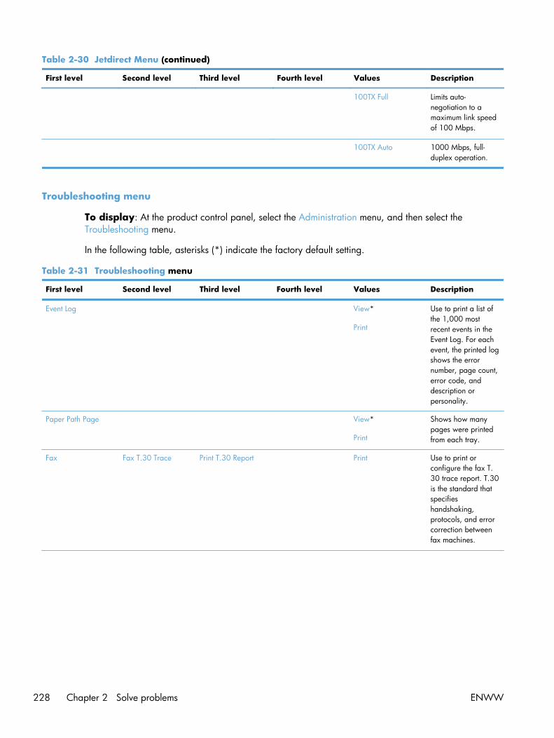
Table 2-30 Jetdirect Menu (continued)
First level Second level Third level Fourth level Values Description
100TX Full Limits auto-negotiation to amaximum link speedof 100 Mbps.
100TX Auto 1000 Mbps, full-duplex operation.
Troubleshooting menu
To display: At the product control panel, select the Administration menu, and then select theTroubleshooting menu.
In the following table, asterisks (*) indicate the factory default setting.
Table 2-31 Troubleshooting menu
First level Second level Third level Fourth level Values Description
Event Log View*
Use to print a list ofthe 1,000 mostrecent events in theEvent Log. For eachevent, the printed logshows the errornumber, page count,error code, anddescription orpersonality.
Paper Path Page View*
Shows how manypages were printedfrom each tray.
Fax Fax T.30 Trace Print T.30 Report Print Use to print orconfigure the fax T.30 trace report. T.30is the standard thatspecifieshandshaking,protocols, and errorcorrection betweenfax machines.
228 Chapter 2 Solve problems ENWW

Table 2-31 Troubleshooting menu (continued)
First level Second level Third level Fourth level Values Description
When to Print Report Never automaticallyprint*
Print after every fax
Print only after faxsend jobs
Print after any faxerror
Print only after faxsend errors
Print only after faxreceive errors
Configure the T.30report to print aftercertain events. Youcan choose to printthe report after everyfax job, every faxjob sent, every faxjob received, everysend error, or everyreceive error.
Fax V.34 Normal*
Off
Use to disable V.34modulations ifseveral fax failureshave occurred or ifphone line conditionsrequire it.
Fax Speaker Mode Normal*
Diagnostic
Used by a technicianto evaluate anddiagnose fax issuesby listening to thesounds of faxmodulations.
Fax Log Entries On
Off*
The standard fax logincludes basicinformation such asthe time and whetherthe fax wassuccessful. Thedetailed fax logshows theintermediate resultsof the redial processnot shown in thestandard fax log.
Print Quality Pages Print PQTroubleshootingPage
Print Use to print pagesthat help you resolveproblems with printquality.
Diagnostics Page Print Use to print adiagnostics page.The page includescolor swatches and atable of electro-photographic (EP)parameters.
ENWW Tools for troubleshooting 229

Table 2-31 Troubleshooting menu (continued)
First level Second level Third level Fourth level Values Description
Color Band Test Print Test Page Print Use to print a pageto help identifyarcing in the high-voltage powersupply for eachcolor. The pagecontains a series ofcolored bars. Ifstreaks appear on abar, the high-voltagepower supply for thecorresponding colormight have aproblem.
Copies Range: 1 – 30
Default = 1
Some problems withthe high-voltagepower supply do notappear until afterseveral pages havebeen printed, so thistest includes anoption to print up to30 pages.
Diagnostic Tests Disable CartridgeCheck
Used to put theproduct into aspecial mode inwhich you canremove a tonercartridge and stillprint internal pages.This can help youidentify the source ofa problem.
When you arefinished testing, pressthe OK button on theproduct control panelto return to theTroubleshootingmenu.
To return to normalproduct operation,press the OK buttonand reinstall thecartridge.
Paper Path Sensors Select from a list ofthe product sensors.
Initiates a test of thepaper path sensors.
230 Chapter 2 Solve problems ENWW

Table 2-31 Troubleshooting menu (continued)
First level Second level Third level Fourth level Values Description
Paper Path Test Source Tray Select from a list ofthe available trays.
Generates a testpage for testingpaper handlingfeatures. You candefine the path thatis used for the test inorder to test specificpaper paths.
Test Duplex Path Off*
On
Number of Copies Range: 1–500
Default = 1
Sets the defaultnumber of copies fora copy job. Thisdefault applies whenthe Copy or QuickCopy function isinitiated from theproduct Homescreen. The factorydefault setting is 1.
Manual Sensor Test Select from a list ofavailablecomponents.
Reset Sensors
Test the productsensors and switchesfor correct operation.Each sensor isdisplayed on thecontrol-panel screen,along with its status.Manually trip eachsensor and watch forit to change on thescreen. Press theStop button to abortthe test.
Tray/Bin ManualSensor Test
Select from a list ofavailablecomponents.
Reset Sensors
Test the sensors inthe trays and bins forcorrect operation.Each sensor isdisplayed on thecontrol-panel screen,along with its status.Manually trip eachsensor and watch forit to change on thescreen. Press theStop button to abortthe test.
ENWW Tools for troubleshooting 231

Table 2-31 Troubleshooting menu (continued)
First level Second level Third level Fourth level Values Description
Component Test Select from a list ofavailablecomponents.
Use to exerciseindividual partsindependently toisolate noise,leaking, or otherissues. To start thetest, select one of thecomponents. The testwill run the numberof times specified bythe Repeat option.You might beprompted to removeparts from theproduct during thetest. Press the Stopbutton to abort thetest.
Continuous Scan 2-sided
Scanner Tests Sensors
Retrieve DiagnosticData
Create device datafile
Create zipped debuginformation file
Include crash dumpfiles
Clean up debuginformation
Send to E-mail
Export to USB
Create files thatcontain informationabout the productthat can help identifythe cause ofproblems.
Generate DebugData
Start
Device Maintenance menu
Backup/Restore menu
To display: At the product control panel, select the Device Maintenance menu, and then select theBackup/Restore menu.
In the following table, asterisks (*) indicate the factory default setting.
232 Chapter 2 Solve problems ENWW

Table 2-32 Backup/Restore menu
First level Second level Third level Values Description
Backup Data Enable ScheduledBackups
Backup Time Enter a time
Days Between Backups Enter the number of days
Backup Now
Export Last Backup
Restore Data Insert a USB drive thatcontains the backup file.
Calibration/Cleaning menu
To display: At the product control panel, select the Device Maintenance menu, and then select theCalibration/Cleaning menu.
In the following table, asterisks (*) indicate the factory default setting.
Table 2-33 Calibration/Cleaning menu
First level Second level Values Description
Cleaning Settings Auto Cleaning Off*
On
Use to select the Auto Cleaningmenu or the Cleaning Intervalmenu.
Cleaning Interval Select from a list of cleaningintervals.
Use to set the interval when thecleaning page should be printed.The interval is measured by thenumber of pages printed.
Cleaning Size Select from a list of support sizes. Select the paper size to use forthe cleaning page.
Cleaning Page Print Use to process the cleaning pagethat was created by using theCreate Cleaning Page menu. Theprocess takes up to 1.5 minutes.
Quick Calibration Start The product automaticallycalibrates itself at various times.However, you can calibrate theproduct immediately if you seeproblems with print quality. Usethis feature to perform a partialcalibration. Use this calibration ifcolor density or tone seemsincorrect.
Before calibrating the product,make sure that the Readyindicator displays on the control-panel display. If a job is inprogress, the calibration occurswhen that job is complete.
ENWW Tools for troubleshooting 233

Table 2-33 Calibration/Cleaning menu (continued)
First level Second level Values Description
Full Calibration Start The product automaticallycalibrates itself at various times.However, you can calibrate theproduct immediately if you seeproblems with print quality. Usethis feature to perform a fullcalibration, which can take up tothree minutes. Use thiscalibration if the color layersseem to be shifted on the page.
Before calibrating the product,make sure that the Readyindicator displays on the control-panel display. If a job is inprogress, the calibration occurswhen that job is complete.
Delay Calibration at Wake/Power On
Disabled
Enabled*
Controls the timing of power-oncalibration when the productwakes up or is turned on.
Wake: Select if you are notusing the feature and want toprint jobs immediately when theproduct wakes up or is turnedon, before calibration begins.
No option: The product willcalibrate immediately when itwakes up or is turned on. Theproduct will not print any jobsuntil it finishes calibrating.
Yes: Enables the product that isasleep to accept print jobsbefore it calibrates. It might startcalibrating before it has printedall the jobs it has received. Thisoption allows quicker printingwhen coming out of sleep modeor when you turn the product on,but print quality might bereduced.
NOTE: For the best results,allow the product to calibratebefore printing. Print jobsperformed before calibrationmight not be of the highestquality.
Calibrate Scanner Touch Next to calibrate thedevice scanner. Messages on thecontrol panel display will leadyou through the calibrationprocess.
234 Chapter 2 Solve problems ENWW

Table 2-33 Calibration/Cleaning menu (continued)
First level Second level Values Description
Clean Rollers Reset
Cancel
Maintenance History screen isview only. There are two options:the reset option to reset the pagecount, or the cancel option to goback to the previous screen.
Clean Document Feeder Settings Low Threshold Settings Range: 0–100%
Default = 10%
Configure cleaning settings forthe document feeder.
Very Low Settings Stop
Prompt to continue*
Continue
ENWW Tools for troubleshooting 235

USB Firmware Upgrade menu
To display: At the product control panel, select the Device Maintenance menu, and then select theUSB Firmware Upgrade menu.
Insert a USB storage device with a firmware upgrade bundle into the USB port, and follow the on-screen instructions.
Service menu
To display: At the product control panel, select the Device Maintenance menu, and then select theService menu.
The Service menu is locked and requires a PIN for access. This menu is intended for use by authorizedservice personnel.
236 Chapter 2 Solve problems ENWW

Interpret control-panel messages
Control-panel message types
The control-panel messages and event code errors indicate the current product status or situations thatmight require action.
NOTE: Event log errors do not appear on the control-panel display. Access the event log to view orprint the event log errors.
Control-panel messages appear temporarily and might require that you acknowledge the message bytouching the OK button to resume printing or by touching the Stop button to cancel the job. Withcertain messages, the job might not finish printing or the print quality might be affected. If the messageis related to printing and the auto-continue feature is on, the product will attempt to resume printingafter the message has appeared for 10 seconds without acknowledgement.
For some messages, restarting the product might fix the problem. If a critical error persists, the productmight require service.
Control-panel messages
Ready
Description
The product is online and ready for data. No status or product attendance messages are pending at thedisplay.
Recommended action
No action is necessary.
10.0X.Y0 Supply memory error
Description
The product cannot read or write to at least one toner cartridge memory tag or a memory tag is missingfrom a toner cartridge.
Memory error
◦ 10.00.00 (event code): Black toner cartridge
◦ 10.01.00 (event code): Cyan toner cartridge
◦ 10.02.00 (event code): Magenta toner cartridge
◦ 10.03.00 (event code): Yellow toner cartridge
ENWW Tools for troubleshooting 237

E-label missing
◦ 10.00.10 (event code): Black toner cartridge
◦ 10.01.10 (event code): Cyan toner cartridge
◦ 10.02.10 (event code): Magenta toner cartridge
◦ 10.03.10 (event code): Yellow toner cartridge
Recommended action
1. Remove, and then reinstall the indicated toner cartridge.
2. If the error persists, turn the product off and then on.
3. Check the toner cartridge e-label. If it is damaged, replace the toner cartridge.
10.23.50
Description
The fuser kit life was reset above the order threshold.
A new ITB was installed.
Recommended action
No action necessary.
10.23.51
Description
The fuser kit life was reset above the replace threshold.
A new ITB was installed.
Recommended action
No action necessary.
10.23.52
Description
The fuser kit life was reset above the reset threshold.
A new ITB was installed.
Recommended action
No action necessary.
238 Chapter 2 Solve problems ENWW

10.XX.34 Used supply in use
Description
The indicated cartridge is used.
◦ 10.00.34 (event code)
Black print cartridge
◦ 10.01.34 (event code)
Cyan print cartridge
◦ 10.02.34 (event code)
Magenta print cartridge
◦ 10.03.34 (event code)
Yellow print cartridge
Recommended action
Make sure this is a genuine HP supply.
NOTE: Removing a cartridge from one product and then installing it in a different product (for testingfunctionality) will cause this event code.
10.XX.40 Genuine HP supplies installed
Description
More than one genuine HP print cartridge has been installed.
◦ 10.00.40 (event code)
Black print cartridge
◦ 10.01.40 (event code)
Cyan print cartridge
◦ 10.02.40 (event code)
Magenta print cartridge
◦ 10.03.40 (event code)
Yellow print cartridge
Recommended action
No action necessary.
ENWW Tools for troubleshooting 239

10.XX.41 Unsupported supply in use
Description
The indicated print cartridge is for a different product.
◦ 10.00.41 (event code)
Black print cartridge
◦ 10.01.41 (event code)
Cyan print cartridge
◦ 10.02.41 (event code)
Magenta print cartridge
◦ 10.03.41 (event code)
Yellow print cartridge
Recommended action
Remove the indicated print cartridge, and then install the correct cartridge for this product.
TIP: See the parts chapter in the service manual for the correct cartridge part number.
10.XX.70 Printing past very low
Description
The product indicates when fuser kit is very low. The actual remaining fuse kit life might vary.
You do not need to replace the fuser kit at this time unless print quality is no longer acceptable.
CAUTION: After an HP supply has reached the very low threshold, the HP premium protectionwarranty ends.
◦ 10.00.70 (event code)
Black print cartridge
◦ 10.01.70 (event code)
Cyan print cartridge
◦ 10.02.70 (event code)
Magenta print cartridge
◦ 10.03.70 (event code)
Yellow print cartridge
◦ 10.23.70 (event code)
The product indicates when fuser kit is very low. The actual remaining fuse kit life might vary.
240 Chapter 2 Solve problems ENWW

You do not need to replace the fuser kit at this time unless print quality is no longer acceptable.
Recommended action
If print quality is no longer acceptable, replace the indicated print cartridge or fuser kit. See the partschapter in the repair manual for the print cartridge or fuser kit part number.
TIP: Advise the customer that HP recommends that they have replacement supplies available to installwhen the print quality is no longer acceptable.
10.YY.15 Install <supply>
Description
The indicated supply has been removed or installed incorrectly.
◦ 10.00.15 (event code)
Black print cartridge
◦ 10.01.15 (event code)
Cyan print cartridge
◦ 10.02.15 (event code)
Magenta print cartridge
◦ 10.03.15 (event code)
Yellow print cartridge
◦ 10.23.15
fuser kit
◦ 10.31.15
TCU
Recommended action
Replace or install the indicated supply.
See the parts chapter in the service manual for the correct supply or kit part number.
ENWW Tools for troubleshooting 241

10.YY.25 Wrong cartridge in <color> slot
Description
The indicated cartridge is installed in the wrong position.
◦ 10.00.25 (event code)
Black print cartridge
◦ 10.01.25 (event code)
Cyan print cartridge
◦ 10.02.25 (event code)
Magenta print cartridge
◦ 10.03.25 (event code)
Yellow print cartridge
Recommended action
Install the indicated cartridge in the correct position.
From left to right, the correct cartridge order follows:
◦ Yellow
◦ Magenta
◦ Cyan
◦ Black
10.YY.35 Incompatible <supply>
Description
The indicated cartridge is not compatible with this product.
◦ 10.00.35 (event code)
Black print cartridge
◦ 10.01.35 (event code)
Cyan print cartridge
◦ 10.02.35 (event code)
Magenta print cartridge
◦ 10.03.35 (event code)
Yellow print cartridge
◦ 10.23.35 (event code)
242 Chapter 2 Solve problems ENWW

Fuser
CAUTION: The fuser might be hot. Be careful when removing the fuser.
Recommended action
Install a supply that is designed for this product.
See the parts chapter in the repair manual for the correct supply part number.
11.00.YY Internal clock error To continue, touch “OK”
Description
The product real-time clock has experienced an error.
◦ XX = 01: Clock battery failed
◦ XX = 02: Real-time clock failed
Recommended action
Whenever the product is turned off and then turned on again, set the time and date at the controlpanel.
If the error persists, replace the formatter.
13.A3.A3
Description
Print input stay jam 3. This paper stayed at the uppermost feed sensor of the optional paper feeder forthe designated amount of time after it has reached the sensor. This jam occurs when the paper is longerthan legal size by 40 mm, or more paper is detected as a result of the actual length detection.
Recommended action
Clear the jam
1. Open the lower right door and remove all paper.
2. Close the lower right door.
3. Open the right door and remove all paper.
4. Close the right door.
If the jam persists
1. Make sure the paper type is supported.
2. Open the lower right door and check for torn pieces of paper.
3. Open the right door and check for torn pieces of paper.
4. Make sure the rollers are installed correctly.
ENWW Tools for troubleshooting 243

5. Replace the rollers.
6. Replace the optional paper feeder.
13.AD.D3
Description
Print input delay jam 1. This paper did not reach the delivery sensor of the optional paper feeder intime.
Recommended action
Clear the jam
1. Open Tray 3.
2. Clear any jammed paper.
3. Verify that the Tray 3 paper guides are in the correct position.
4. Reload the paper and close the tray.
NOTE: To avoid jams, use Tray 1 to print with heavier paper.
If the jam persists
1. Remove the tray and check for pieces of paper. Check the lower right door for pieces of paper.
2. Replace the pickup roller.
3. Make sure the paper type is supported.
4. Replace the optional paper feeder.
13.B2.AD
Description
Print input stay jam 1. The paper stayed at the registration sensor for the designated amount of timeafter it reached the registration sensor. This jam occurs when the paper is longer than legal size by 40mm, or more paper is detected as a result of the actual length detection.
Recommended action
Clear the jam
1. Open the right door.
2. Remove any paper.
3. Remove any paper from the fuser area.
4. Lift the green guides to remove paper from the duplex area.
5. Close the right door.
244 Chapter 2 Solve problems ENWW

If the jam persists
1. Make sure the paper type is supported.
2. Print using manual duplex.
3. If the jams occur only when duplexing, replace the right door.
13.B2.AZ
Description
Print input stay jam 1. This paper stayed at the registration sensor for the designated amount of timeafter it reached the registration sensor. This jam occurs when the paper is longer than legal size by 40mm, or more paper is detected as a result of the actual length detection.
Recommended action
Clear the jam
1. Open the right door.
2. Remove any paper.
3. Remove all paper from the registration area.
4. Lift the green guides to locate the paper.
5. If you cannot access the paper, locate the rollers (covered by paper) and roll them back orforward to move the paper.
6. Close the right door.
If the jam persists
1. Make sure the paper type is supported.
2. Open Tray 2 and check for paper jams.
3. Check for torn pieces of paper in the paper path.
4. Remove any paper in the fuser area.
5. Make sure the rollers are installed correctly in the trays.
6. Lift the green guides to check the paper path.
7. Locate the rollers under the paper and roll them back to attempt to gain access to the top of thepage to prevent tearing of the paper.
13.B2.D1
Description
Print input delay jam 2. The paper did not reach the registration sensor in time.
ENWW Tools for troubleshooting 245

Recommended action
Clear the jam
1. Remove all paper from Tray 1.
2. Clear any jammed paper.
3. Reload paper in Tray 1.
4. Make sure the stack fits under the tabs on the guides and does not exceed the tray-full indicators.Make sure the paper guides are in the correct position.
If the jam persists
1. Make sure the paper was picked from Tray 1.
2. Check the page count by printing a usage page.
3. If the rollers are not engaging, replace the right door.
13.B2.D2
Description
Print input delay jam 2. The paper did not reach the registration sensor in time.
Recommended action
Clear the jam
1. Open Tray 2.
2. Clear any jammed paper.
3. Verify that the paper guides are in the correct position.
4. Reload the paper and close the tray.
NOTE: To avoid jams, use Tray 1 to print with heavier paper.
If the jam persists
1. Make sure the paper type is supported.
2. Open Tray 2 and check for paper jams.
3. Check for torn pieces of paper in the paper path.
4. Make sure the rollers are installed properly in Tray 2.
13.B2.D3
Description
Print input delay jam 2. The paper did not reach the registration sensor in time.
246 Chapter 2 Solve problems ENWW

Recommended action
Clear the jam
1. Open the lower right door and check for paper.
2. Close the lower right door.
3. Open the right door and remove all the paper.
4. Remove any paper found in the fuser area.
5. Close the right door.
If the jam persists
1. Check the lower right door for jammed paper.
2. Check for torn pieces of paper in the paper path.
3. Clear any obstructions or jams from the paper path.
4. Replace the rollers.
5. Replace the optional paper feeder.
13.B2.DD
Description
Duplexer refeed jam 1: The paper does not reach the duplex refeed sensor in time after it is switchedback during duplex printing.
Recommended action
Clear the jam
1. Open the right door and remove all paper.
2. Remove the fuser and any paper in the fuser area.
3. Close the right door.
If the jam persists
1. Make sure the paper type is supported.
2. Clear jams in the right door.
3. Remove the fuser and clear any jams in the paper path.
4. Clear any jams in the duplex paper path on the right door.
5. Test the duplex refeed sensor. If it fails, replace the right door.
ENWW Tools for troubleshooting 247

13.B9.AZ
Description
Fuser delivery stay in jam 1: The paper stays at the fuser output sensor for the designated amount oftime after it has reached the sensor.
Recommended action
Clear the jam
1. Open the right door and remove all paper.
2. Remove the fuser and any paper in the fuser area.
3. Remove any paper inside the fuser.
4. Reinstall the fuser.
5. Close the right door.
If the jam persists
1. Check paper type and fuser mode.
2. Check for a multi-feed. Replace the rollers if it consistently multi-feeds.
3. If the problem persists after replacing the rollers, replace the fuser.
13.B9.CZ
Description
Wrap jam 1: The paper leaves the fuser output sensor before a designated amount of time.
Recommended action
Clear the jam
1. Open the right door and remove all paper.
2. Remove the fuser and any paper in the fuser area.
3. Remove any paper in the fuser.
4. Reinstall the fuser.
5. Remove any other paper found.
6. Close the right door.
If the jam persists
1. Make sure the paper type is supported.
2. Test the fuser delivery sensor. If it fails, replace the fuser.
3. If the problem persists, replace the fuser.
248 Chapter 2 Solve problems ENWW

13.B9.DD
Description
Fuser delivery delay in jam 1: The paper does not reach the fuser output sensor in time.
Recommended action
Clear the jam
1. Open the right door.
CAUTION: The fuser might be hot.
2. Remove the fuser and any paper in the fuser area.
3. Remove any paper inside the fuser.
4. Reinstall the fuser.
5. Remove any paper in the duplex area.
6. Close the right door.
If the jam persists
1. Make sure the paper type is supported.
2. Print using plain paper.
3. Test the paper path sensors and replace any sensors that fail.
4. Replace the fuser.
13.B9.Dz
Description
Fuser delivery delay in jam 1: The paper does not reach the fuser output sensor in time.
Recommended action
Clear the jam
1. Open the right door.
CAUTION: The fuser might be hot.
2. Remove the fuser and any paper in the fuser area.
3. Remove any paper inside fuser.
4. Reinstall the fuser.
5. Remove any paper in the duplex area.
6. Close the right door.
ENWW Tools for troubleshooting 249

If the jam persists
1. Make sure the paper type is supported.
2. Print using plain paper.
3. Test the paper path sensors and replace any sensors that fail.
4. Replace the fuser.
13.WX.EE
Description
Door open jam 1: A door is opened during printing. The jam might occur at the following areas:
◦ Input media source 1 area
◦ Input media source 2 area
◦ Input media source 3 area
◦ Registration area
◦ Drum area
◦ Fuser area
◦ Paper output 1 area
◦ Duplex pick up area
◦ Duplex reversing area
Recommended action
Clear the jam
1. Open the right door and remove all paper.
2. Remove the fuser and any paper in the fuser area.
3. Remove any paper inside the fuser.
4. Reinstall the fuser.
5. Remove any other paper found.
6. Close the right door.
If the jam persists
1. Make sure all doors are closed.
2. Clear jams in the right door and lower right door.
3. View the event log: Look for 13.BA.EE right door or front door or 13.AA.EE lower right door.
250 Chapter 2 Solve problems ENWW

13.WX.FF
Description
Residual media in paper path jam. The paper exists at the fuser output sensor or the fuser loop sensor,or the duplexer refeed sensor when the power is turned on or the door is closed. This jam occurs whenthe paper stays for more than the designated amount of time continuously at any of the sensors whenexecuting the automatic media flush.
Recommended action
Clear the jam
1. Open the right door and remove all paper.
2. Remove the fuser and any paper in the fuser area.
3. Remove any paper inside the fuser.
4. Reinstall the fuser.
5. Remove any other paper found.
6. Close the right door.
If the jam persists
1. Clear jams in the right door and fuser area.
2. If possible, view the event log.
3. Conduct a manual sensor test to verify that the sensors are working correctly.
4. Replace any failed sensors or assemblies.
13.WX.YZ Fuser wrap jam
Description
This jam occurs when the paper disappears from the fuser output sensor before a designated amount oftime after the paper reached the fuser output sensor. (It is determined that the paper is being wrappedaround the fuser roller).
Z = Fuser mode
◦ 1 = Normal auto sense
◦ 2 = Normal non-auto sense
◦ 3 = Light 1 to 3
◦ 4 = Heavy 1
◦ 5= Heavy 2
◦ 6= Heavy 3
◦ 7 = Glossy
ENWW Tools for troubleshooting 251

◦ 8 = Glossy 2
◦ 9 = Glossy 3
◦ A = Glossy film
◦ B = Transparency
◦ C = Label
◦ D = Envelope 1 to 3
◦ O = Photo 1 to 3
CAUTION: The fuser can be hot while the product is in use.
Recommended action
Clear the jam. See the clear jams section in the repair manual.
13.WX.YZ Jam above output bin clear jam, then touch “OK”
Description
There is a paper jam above output bin.
Recommended action
Clear the jam. See the clear jams section in the repair manual.
13.WX.YZ Jam in right door
Description
There is a jam accessible from the right door.
Recommended action
CAUTION: The fuser might be hot.
Clear the jam. See the clear jams section in the repair manual.
13.WX.YZ Jam in Tray <X>
Description
A page is jammed in the indicated tray. The page did not reach the delivery sensor or registrationsensor in the designated amount of time after leaving the input source.
◦ 13.B2.D2 (event code): Misfeed jam from Tray 2
This jam occurs when the paper does not reach the registration (Registration; SR8) sensor indesignated amount of time from the start of paper pick-up at printing from Tray 2 and duplexprinting.
◦ 13.A3.D3 (event code): Misfeed jam from Tray 3
252 Chapter 2 Solve problems ENWW

This jam occurs when the paper does not reach the feed sensor of each tray in designated amountof time after the start of paper pickup.
Recommended action
Clear the jam. See the clear jams section in the service manual.
13.WX.YZ Jam lower right door
Description
There is a jam accessible from the lower right door.
Recommended action
Clear the jam. See the clear jams section in the service manual.
20.00.00 Insufficient memory: <Device> To continue, touch “OK”
Description
The product has experienced a memory error. You might have tried to transfer too many fonts ormacros.
Recommended action
Touch the OK button to print the transferred data. Some data might be lost. Reduce the pagecomplexity.
21.00.00 Page too complex To continue, touch “OK”
Description
The page decompression process was too slow for the product.
Recommended action
Touch the OK button to continue. There may be some data loss.
30.01.23 Scanner calibration failure
Description
The scanner calibration failed.
Recommended action
1. Turn the product off, then on again.
2. After the product warms up, repeat the calibration process.
3. If the error persists, replace the scanner.
ENWW Tools for troubleshooting 253

30.01.36 Upgrade Error Try downloading upgrade again
Description
Scanner firmware upgrade error.
Recommended action
1. Resend the scanner firmware upgrade.
2. If the error persists, replace the scanner control board.
30.01.43 Scan memory failure To continue turn off then on
Description
A scan memory error occurred.
Recommended action
1. Turn the product off and then on.
2. Remove the formatter, and then reinstall the formatter.
3. If the error persists, replace the formatter.
30.01.YY Scanner failure To continue turn off then on
Description
◦ 30.01.06 (event code): Scanner fan error.
◦ 30.01.41 (event code): Internal communication error involving the copy processor board (CPB)on the formatter.
◦ 30.01.42 (event code): Internal communication error.
254 Chapter 2 Solve problems ENWW

Recommended action
◦ 30.01.06 (event code)
1. Turn the product off and then on.
2. Check the fan, and reconnect any loose cables.
3. If the error persists, replace the fan or the scanner control board.
◦ 30.01.41 (event code)
1. Turn the product off and then on.
2. Reseat the formatter.
3. If the error persists, replace the formatter.
◦ 30.01.42 (event code)
1. Turn the product off and then on.
2. Check the cables connecting the scanner control board.
3. If this error occurs after a formatter, fax card or hard disk has been replaced, check that theformatter is fully seated and the "smiley face" is illuminated. Check the fax card for properseating on the formatter. If it is not properly seated, it can prevent the formatter from seatingproperly.
4. If the error persists, replace the scanner control board.
30.WX.YZ Scanner fan failure To continue turn off then on
Description
The product has detected a problem with the scanner. This error occurs when there is a CPB memoryfailure and the formatter needs to be replaced.
Recommended action
1. Turn power off then on.
2. If the error persists, replace the formatter.
31.01.03 Document feeder pick error
Description
The document feeder cannot pick up paper.
Recommended action
1. Open the document feeder top cover.
2. Remove all paper found.
3. Remove the remaining pages from the document feeder input tray.
ENWW Tools for troubleshooting 255

4. Close the document feeder top cover.
5. Place the jammed page on top of any remaining pages, and reinsert them into the documentfeeder.
6. Align the paper guides with both edges on the paper.
7. Touch the Start button to continue.
Check the paper guides, check and clean the rollers and separation pad, and test the registrationsensor.
If the error persists, replace pickup roller assembly, separation pad, or document feeder.
31.01.47 Document feeder not detected
Description
The document feeder was not detected, and might not be ADF connected. The flatbed glass is stillavailable for scanning.
Recommended action
Turn the product off and then on.
31.03.22 Scanner calibration failure
Description
The scanner calibration failed. This could affect scanning picture quality.
Recommended action
Remove any paper in document feeder. Turn the product off and then on.
31.WX.10 Scanner failure To continue turn off then on
Description
The product has detected a scanner ADF fan error.
Recommended action
1. Turn the product off and then on.
2. If the error persists, replace the ADF fan.
31.WX.15 Jam in document feeder
Description
Originals are jammed inside the document feeder top cover.
256 Chapter 2 Solve problems ENWW

Recommended action
1. Open the document feeder top cover.
2. Remove all paper found.
3. Rotate the green wheel to remove any additional paper.
4. Remove the remaining pages from the document feeder input tray.
5. Close the document feeder top cover.
6. Place the jammed page on top of any remaining pages, and reinsert them into the documentfeeder.
7. Align the paper guides with both edges of the paper.
8. Touch the Start button to continue.
32.1C.XX
Description
◦ 32.1C.01 (event code)
NVRAM backup/restore service backup started
◦ 32.1C.02 (event code)
NVRAM backup/restore service restore started
◦ 32.1C.03 (event code)
NVRAM backup/restore administrator backup started
◦ 32.1C.04 (event code)
NVRAM backup/restore administrator restore started
◦ 32.1C.05 (event code)
Backup/restore complete
◦ 32.1C.06 (event code)
Data model failed to clone job ticket
◦ 32.1C.07 (event code)
Backup restore permissions error
◦ 32.1C.08 (event code)
Not enough disk space to perform backup/restore or network share issue
◦ 32.1C.09 (event code)
Tried to restore a backup file that was not valid for this product
ENWW Tools for troubleshooting 257

◦ 32.1C.0A (event code)
Backup file is invalid
◦ 32.1C.0B (event code)
Backup is from newer version of FW than what is currently on the product
◦ 32.1C.0C (event code)
Backup cancelled from the HP Embedded Web Server
◦ 32.1C.0D (event code)
Backup/restore failed, auto-reboot failed, or the product might be busy
◦ 32.1C.0E (event code)
Backup/restore timeout while communicating with the formatter
◦ 32.1C.11 (event code)
Backup/restore timeout while communicating with the engine
◦ 32.1C.12 (event code)
Backup/restore timeout while communicating with the disk
◦ 32.1C.13 (event code)
Scheduled backup failure
◦ 32.1C.14 (event code)
NVRAM restore timeout while communicating with the formatter
◦ 32.1C.17 (event code)
NVRAM restore timeout while communicating with the engine
◦ 32.1C.1B (event code)
Backup of print subsystem failed
◦ 32.1C.1C (event code)
Backup of networking subsystem failed
◦ 32.1C.21 (event code)
Restore of print subsystem failed
◦ 32.1C.22 (event code)
Restore of networking subsystem failed
◦ 32.1C.24 (event code)
NVRAM backup/restore successful
258 Chapter 2 Solve problems ENWW

◦ 32.1C.28 (event code)
Reset of print subsystem failed
◦ 32.1C.29 (event code)
Reset of networking subsystem failed
◦ 32.1C.2B (event code)
Reset formatter timeout
◦ 32.1C.2E (event code)
Reset engine timeout
◦ 32.1C.2F (event code)
Reset failure
Recommended action
◦ 32.1C.01 (event code)
No action necessary
◦ 32.1C.02 (event code)
No action necessary
◦ 32.1C.03 (event code)
No action necessary
◦ 32.1C.04 (event code)
No action necessary
◦ 32.1C.05 (event code)
No action necessary
◦ 32.1C.06 (event code)
Retry
◦ 32.1C.07 (event code)
Retry
◦ 32.1C.08 (event code)
Remove stored jobs and retry
Use larger capacity storage device
Check network share
◦ 32.1C.09 (event code)
ENWW Tools for troubleshooting 259

Use a valid backup file
◦ 32.1C.0A (event code)
Use a valid backup file
Reboot and observe state of product
Do a partition clean using the Preboot menu
◦ 32.1C.0B (event code)
Use a valid backup file or put correct firmware version on the product
◦ 32.1C.0C (event code)
No action necessary
◦ 32.1C.0D (event code)
Reboot and then retry the backup/restore
◦ 32.1C.0E (event code)
Turn the product off then on and retry
◦ 32.1C.11 (event code)
Turn the product off then on and retry
◦ 32.1C.12 (event code)
Turn the product off then on and retry
◦ 32.1C.13 (event code)
Turn the product off then on and retry
◦ 32.1C.14 (event code)
Turn the product off then on and retry
◦ 32.1C.17 (event code)
Turn the product off then on and retry
◦ 32.1C.1B (event code)
Turn the product off then on and retry
◦ 32.1C.1C (event code)
Turn the product off then on and retry
◦ 32.1C.21 (event code)
Turn the product off then on and retry
260 Chapter 2 Solve problems ENWW

If the error persists, clear the firmware image from the active partition by using the Partial Cleanitem in the Preboot menu
◦ 32.1C.22 (event code)
Turn the product off then on and retry
If the error persists, clear the firmware image from the active partition by using the Partial Cleanitem in the Preboot menu
◦ 32.1C.24 (event code)
Turn the product off then on and retry
◦ 32.1C.28 (event code)
Turn the product off then on and retry
◦ 32.1C.29 (event code)
Turn the product off then on and retry
◦ 32.1C.2B (event code)
Turn the product off then on and retry
◦ 32.1C.2E (event code)
Turn the product off then on and retry
◦ 32.1C.2F (event code)
Turn the product off then on and retry
32.21.00
Description
Corrupt firmware in external accessory.
Recommended action
Turn the product off, then on, and retry.
If the error persists, clear the firmware image from the active partition by using the Partial Clean itemin the Preboot menu.
33.02.01
Description
Used board disk installed.
A used formatter or hard disk from an existing printer has been placed in this printer.
Recommended action
Reinstall the used board or disk back into its original printer.
ENWW Tools for troubleshooting 261

33.WX.YZ Used board/disk installed
Description
An encrypted board or disk with existing data previously locked to a different product has replaced theoriginal. If you continue, data is permanently lost.
Recommended action
◦ To save the data on the board or disk, turn the product off. Replace the board or disk with anotherboard or disk.
◦ To delete the data on the board or disk and continue, touch the OK button.
40.00.01 USB I/O buffer overflow To continue, touch “OK”
Description
The USB buffer overflowed during a busy state.
Recommended action
1. Touch the OK button to print the transferred data. Some data might be lost.
2. Check the host configuration.
40.00.02 Embedded I/O buffer overflow To continue, touch “OK”
Description
Too much data was sent to the embedded HP Jetdirect print server. An incorrect communicationsprotocol might be in use.
Recommended action
1. Touch the OK button to print the transferred data. Some data might be lost.
2. Check the host configuration.
41.03.YZ Unexpected size in Tray <X>
Description
The product detected a different paper size than expected.
Y = Size mismatch, Z = Source
◦ Y = 0: Detected paper is longer or shorter than expected
◦ Y = A: Detected paper too long
◦ Y = B: Detected paper too short
◦ Z = 1: Tray 1
262 Chapter 2 Solve problems ENWW

◦ Z = 2: Tray 2
◦ Z = 3: Tray 3
Recommended action
1. Make sure that the tray is loaded with the correct paper size and that the sliding paper guides arecorrectly adjusted.
2. Use the Tray/Bin Manual Sensor Test to verify that the tray paper switch is correctly functioning.
3. If the error persists, replace the lifter assembly.
41.03.YZ Unexpected size in Tray <X> To use another tray, touch "Options"
Description
The product detected a different paper size than expected.
Y = Size mismatch, Z = Source
◦ Y = 0: Detected paper is longer or shorter than expected
◦ Y = A: Detected paper too long
◦ Y = B: Detected paper too short
◦ Z = 1: Tray 1
◦ Z = 2: Tray 2
◦ Z = 3: Tray 3
Recommended action
1. Make sure that the tray is loaded with the correct paper size and that the sliding paper guides arecorrectly adjusted.
2. Use the Tray/Bin Manual Sensor Test to verify that the tray paper switch is correctly functioning.
3. If the error persists, replace the lifter assembly.
41.05.YZ Unexpected type in Tray <X>
Description
The product detected a different paper type than expected.
Y = Expected type, Z = Detected type
◦ Y = 0: Unknown
◦ Y = 1: Normal paper
◦ Y = 3: LBP transparency
◦ Y = 4 Glossy paper
ENWW Tools for troubleshooting 263

◦ Y = 5: Gloss film
◦ Y = 6: Non-assured transparency
◦ Y = 7: Heavy paper
◦ Y = 8: Light paper
◦ Y = 9: Rough paper
◦ Y = A: Extra heavy glossy paper (glossy paper 3)
◦ Y = B: Heavy glossy paper (glossy paper 2)
◦ Y = C: Heavy paper 3
◦ Y = D: Heavy paper 2
◦ Z = 1: Normal paper
◦ Z = 3: LBP transparency
◦ Z = 4: Glossy paper
◦ Z = 5: Gloss film
◦ Z = 6: Non-assured transparency
◦ Z = 7: Heavy paper
◦ Z = 8: Light paper
◦ Z = A: Extra heavy glossy paper (glossy paper 3)
◦ Z = B: Heavy glossy paper (glossy paper 2)
◦ Z = C: Heavy paper 3
◦ Z = D: Heavy paper 2
Recommended action
1. Load the tray with the size and type of paper indicated, or use another tray if available.
2. If this message appears and the tray is loaded with the correct paper type, check the print driversettings to make sure that they match the tray type settings.
3. Clean the paper sensor.
4. If the error persists, replace the paper pickup assembly.
41.05.YZ Unexpected type in Tray <X> To use another tray, touch "Options"
Description
The product detected a different paper type than expected and another tray is available for use.
264 Chapter 2 Solve problems ENWW

Y = Expected type, Z = Detected type
◦ Y = 0: Unknown
◦ Y = 1: Normal paper
◦ Y = 3: LBP transparency
◦ Y = 4 Glossy paper
◦ Y = 5: Gloss film
◦ Y = 6: Non-assured transparency
◦ Y = 7: Heavy paper
◦ Y = 8: Light paper
◦ Y = 9: Rough paper
◦ Y = A: Extra heavy glossy paper (glossy paper 3)
◦ Y = B: Heavy glossy paper (glossy paper 2)
◦ Y = C: Heavy paper 3
◦ Y = D: Heavy paper 2
◦ Z = 1: Normal paper
◦ Z = 3: LBP transparency
◦ Z = 4: Glossy paper
◦ Z = 5: Gloss film
◦ Z = 6: Non-assured transparency
◦ Z = 7: Heavy paper
◦ Z = 8: Light paper
◦ Z = A: Extra heavy glossy paper (glossy paper 3)
◦ Z = B: Heavy glossy paper (glossy paper 2)
◦ Z = C: Heavy paper 3
◦ Z = D: Heavy paper 2
Recommended action
1. Load the tray with the size and type of paper indicated, or use another tray if available.
2. If this message appears and the tray is loaded with the correct paper type, check the print driversettings to make sure that they match the tray type settings.
ENWW Tools for troubleshooting 265

3. Clean the paper sensor.
4. If the error persists, replace the paper pickup assembly.
41.WX.YZ Error To use another tray, touch "Options"
Description
A printer error has occurred.
WX =
◦ 02: Beam detected misprint error
◦ 06: ITB top detection error
◦ 07: Paper transportation error
◦ 08: Optional input source delay
◦ 09: Sub-thermistor abnormally high temperature
◦ 18: Scan line inclination adjustment request
◦ 19: T2 roller HV
◦ 20: Image drum HV
Y = fuser mode
◦ 0: Photo paper 1, Photo paper 2, Photo paper 3, Designated paper 2, Designated paper 3, orNA, typed or Autosense
◦ 1: Autosense (normal): special case distinguished from typed Normal
◦ 2: Normal, typed (not Autosense)
◦ 3: Light paper 1, 2, or 3, typed or Autosense
◦ 4: Heavy paper 1, typed or Autosense
◦ 5: Heavy paper 2, typed or Autosense
◦ 6: Heavy paper 3, typed or Autosense
◦ 7: Glossy paper 1, typed or Autosense
◦ 8: Glossy paper 2, typed or Autosense
◦ 9: Glossy paper 3, typed or Autosense
◦ A: Glossy film, typed or Autosense
◦ B: Transparency, typed or Autosense
◦ C: Label
◦ D: Envelope 1, Envelope 2, Envelope 3
266 Chapter 2 Solve problems ENWW

◦ E: Rough (designated paper 1), typed or Autosense
◦ F: reserved for future fuser mode
Z = source tray
◦ 1: Tray 1
◦ 2: Tray 2
◦ 3: Tray 3
◦ D: Duplexer
Recommended action
1. To clear message, touch the OK button.
2. If the message reappears, turn the product off and then on.
3. If the error persists, replace the DC controller PCA.
42.XX.YY
Description
Internal system failure.
Recommended action
Turn the product off, then on, and retry.
47.FC.YZ Printer calibration failed To continue, touch “OK”
Description
The product is unable to access or implement one of the image pattern files.
Y = calibration type, Z = event
◦ 47.FC.00: Color plane registration (CPR) image not found at system initialization
◦ 47.FC.01: CPR store image failure
◦ 47.FC.02: CPR image not found
◦ 47.FC.03: CPR print engine execution failure
◦ 47.FC.10: Consecutive Dmax Dhalf image not found at system initialization
◦ 47.FC.11: Consecutive Dmax Dhalf store image failure
◦ 47.FC.12: Consecutive Dmax Dhalf image not found
◦ 47.FC.13: Consecutive Dmax Dhalf print engine execution failure
◦ 47.FC.20: Error diffusion image not found at system initialization
ENWW Tools for troubleshooting 267

◦ 47.FC.21: Error diffusion store image failure
◦ 47.FC.22: Error diffusion image not found
◦ 47.FC.23: Error diffusion print engine execution failure
◦ 47.FC.30: Drum speed adjustment Image not found at system initialization
◦ 47.FC.31: Drum speed adjustment store image failure
◦ 47.FC.32: Drum speed adjustment image not found
◦ 47.FC.33: Drum speed adjustment print engine execution failure
◦ 47.FC.40: Pulse width modulation image not found at system initialization
◦ 47.FC.41: Pulse width modulation store image failure
◦ 47.FC.42: Pulse width modulation image not found
◦ 47.FC.43: Pulse width modulation print engine execution failure
Recommended action
1. Turn the product off and then on.
2. If the error persists, reload the firmware.
47.WX.YZ Printer calibration failed
Description
The print quality calibration failed. This message is for development and will not be seen by customers.
Recommended action
Turn the product off and then on.
48.01.XX Error
Description
A job framework internal error has occurred.
Recommended action
No action necessary.
49.XX.YY Error To continue turn off then on
Description
A firmware error has occurred. This error can be caused by corrupted print jobs, software applicationsissues, non-product specific print drivers, poor-quality USB or network cables, bad network connectionsor incorrect configurations, invalid firmware operations, or unsupported accessories.
268 Chapter 2 Solve problems ENWW

Recommended action
1. Turn the product off and then on.
2. If the error persists, check the following:
● The error might be caused by a network connectivity problem, such as a bad interface cable,a bad USB port, or an invalid network configuration setting.
● The error might be caused by the print job, such as an invalid print driver, a problem with thesoftware application, or a problem with the file you are printing.
● Upgrading the product firmware might help resolve the error. See the product user guide formore information.
50.WX.YZ Fuser error To continue turn off then on
Description
The product experienced a fuser error.
◦ W = fuser error code
◦ X = fuser mode
● 0: Photo paper 1, 2, 3, Designated paper 2, 3, or NA, typed or AutoSense
● 1: AutoSense (Normal special case distinguished from typed Normal)
● 2: Normal, typed (not AutoSense)
● 3: Light paper 1, 2, or 3, typed or AutoSense
● 4: Heavy paper 1, typed or AutoSense
● 5: Heavy paper 2, typed or AutoSense
● 6: Heavy paper 3, typed or AutoSense
● 7: Glossy paper 1, typed or AutoSense
● 8: Glossy paper 2, typed or AutoSense
● 9: Glossy paper 3, typed or AutoSense
● A: Glossy film, typed or AutoSense
● B: Transparency, typed or AutoSense
● C: Label
● D: Envelope1, Envelope2, or Envelope3
● E: Rough (designated paper 1), typed or AutoSense
● F: Reserved for future fuser mode
ENWW Tools for troubleshooting 269

◦ Y = previous printer sleep state
◦ Z = next printer sleep state
● 0: Printing
● 1: Standby level 1 (no temperature control)
● 2: Standby level 2 (high temperature control)
● 3: Standby level 3 (middle temperature control)
● 4: Standby level 4 (low temperature control)
● 5: Middle sleep
● 6: Deep sleep
● F: Off
Recommended action
W = A: High fuser temperature 2
1. Remove and then reseat the fuser. Make sure there is no residual paper in the fuser. Make sure theproduct is not located in front of a vent or window where cool air may interfere with the ability ofthe fuser to heat up.
2. Check the product power source. Make sure the power source meets product requirements. Makesure this is the only device using the circuit.
3. Check the connector (J50) between the fuser and the product. If it is damaged, replace the fuser.
4. If this product was previously serviced, check the connector (J50) on the DC controller PCA.
5. If the error persists, replace the fuser.
W = B: High fuser temperature 3
1. Remove and then reseat the fuser. Remove any residual paper in the product.
2. Check the paper type setting using the product menus and in the print driver. Making sure thatthey match and are correct for the type of paper being used.
3. If this product was previously serviced, check the connector (J50) on the DC controller PCA.
4. If the error persists, replace the fuser.
W = 1, Low fuser error temperature error
1. Remove and then reseat the fuser.
2. Check the paper type setting using the product menus and in the product driver. Make sure thatthey match and are correct for the type of paper being used.
3. If this product was previously serviced, check the connector (J50) on the DC controller PCA.
4. If the error persists, replace the fuser.
270 Chapter 2 Solve problems ENWW

W = 2, Fuser warm-up failure
1. Reconnect the connector (J50) between the fuser and the DC controller PCA.
2. Turn the product off. Remove the fuser, and then reinstall it.
3. Replace the fuser wire harness.
4. If the error persists, replace the fuser.
W = 3, High fuser temperature 1
1. Remove and then reseat the fuser.
2. Check the paper type setting using the product menus and in the product driver. Make sure thatthey match and are correct for the type of paper being used.
3. If this product was previously serviced, check the connector (J50) on the DC controller PCA.
4. If the error persists, replace the fuser.
W = 4, Fuser power supply driving circuit error
1. Remove and then reseat the fuser.
2. If this product was previously serviced, check the connector (J50) on the DC controller PCA.
3. If the error persists, replace the fuser.
W = 6, Open fuser, breaking of a heater wire
1. Check the power source. Make sure the power source meets product requirements.
NOTE: If the power source does not meet the power frequency requirement of 43 to 67Hz, thefuser temperature control does not work properly and causes this error.
2. If this product was previously serviced, check the connector (J101) on the DC controller PCA.
3. If the error persists, replace the low-voltage power supply.
W = 7, Fuser pressure-release mechanism failure
1. Remove and then reseat the fuser. Make sure there is no residual paper in the fuser.
2. Check the fuser pressure-release sensor flag. If it is damaged, replace the fuser.
3. Use the Manual Sensor Test to verify that the fuser pressure-release sensor (PS7) is properlyfunctioning. If it is not, replace the fuser.
4. Use the fuser pressure-release drive test in the component test to verify that the fuser motor (M2) isproperly functioning. If it is not, replace the fuser motor (M2).
5. If this product was previously serviced, check the connector (J117; J123) on the DC controllerPCA.
6. If the error persists, replace the fuser.
ENWW Tools for troubleshooting 271

W = 8, Low fuser temperature 2
1. Remove and then reseat the fuser. Make sure there is no residual paper in the fuser. Make sure theproduct is not located in front of a vent or window where cool air may interfere with the ability ofthe fuser to heat up.
2. Check the product power source. Make sure the power source meets product requirements. Makesure this is the only device using the circuit.
3. Check the connector (J50) between the fuser and the product. If it is damaged, replace the fuser.
4. If this product was previously serviced, check the connector (J50) on the DC controller PCA.
5. If the error persists, replace the fuser.
W = 9, High fuser temperature 2
1. Remove and then reseat the fuser. Make sure there is no residual paper in the fuser. Make sure theproduct is not located in front of a vent or window where cool air may interfere with the ability ofthe fuser to heat up.
2. Check the product power source. Make sure the power source meets product requirements. Makesure this is the only device using the circuit.
3. Check the connector (J50) between the fuser and the product. If it is damaged, replace the fuser.
4. If this product was previously serviced, check the connector (J50) on the DC controller PCA.
5. If the error persists, replace the fuser.
51.00.YY Error To continue turn off then on
Description
An error with the laser/scanner assembly has occurred in the product.
◦ YY = 10: Beam detect error
◦ YY = 19: Laser malfunction
◦ YY = 20: Black laser scanner error
◦ YY = 21: Cyan laser scanner error
◦ YY = 22: Magenta laser scanner error
◦ YY = 23: Yellow laser scanner error
Recommended action
51.00.10
1. Turn the product off and then on.
2. Check the flat flexible cable (FFC) connections to the laser scanners.
272 Chapter 2 Solve problems ENWW
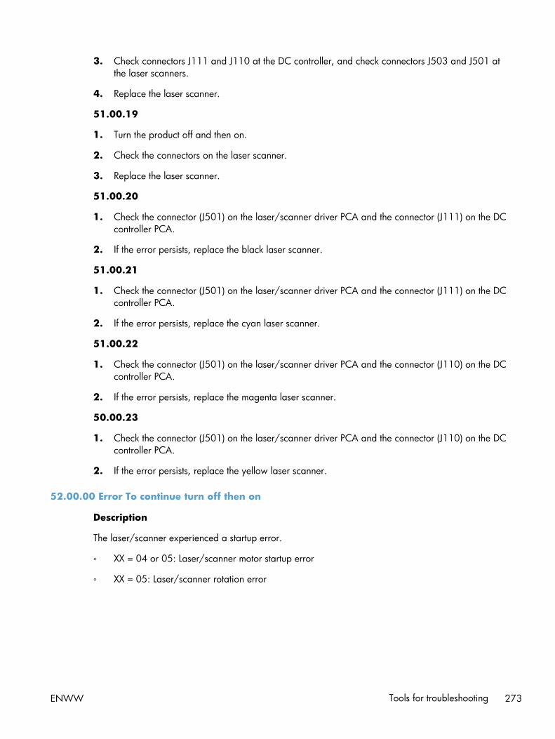
3. Check connectors J111 and J110 at the DC controller, and check connectors J503 and J501 atthe laser scanners.
4. Replace the laser scanner.
51.00.19
1. Turn the product off and then on.
2. Check the connectors on the laser scanner.
3. Replace the laser scanner.
51.00.20
1. Check the connector (J501) on the laser/scanner driver PCA and the connector (J111) on the DCcontroller PCA.
2. If the error persists, replace the black laser scanner.
51.00.21
1. Check the connector (J501) on the laser/scanner driver PCA and the connector (J111) on the DCcontroller PCA.
2. If the error persists, replace the cyan laser scanner.
51.00.22
1. Check the connector (J501) on the laser/scanner driver PCA and the connector (J110) on the DCcontroller PCA.
2. If the error persists, replace the magenta laser scanner.
50.00.23
1. Check the connector (J501) on the laser/scanner driver PCA and the connector (J110) on the DCcontroller PCA.
2. If the error persists, replace the yellow laser scanner.
52.00.00 Error To continue turn off then on
Description
The laser/scanner experienced a startup error.
◦ XX = 04 or 05: Laser/scanner motor startup error
◦ XX = 05: Laser/scanner rotation error
ENWW Tools for troubleshooting 273

Recommended action
XX = 04
1. Perform the laser scanner component tests in the Troubleshooting menu.
2. Check the connector (J501) on the laser/scanner driver PCA and the connector (J106) on the DCcontroller PCA.
3. If the error persists, replace the appropriate laser/scanner.
XX = 05
1. Perform the laser scanner component tests in the Troubleshooting menu.
2. Check the connector (J50-Y/K or J503-C/M) on the laser/scanner driver PCA and the connectors(J106; J110-C/K or J111-C/M) on the DC controller PCA.
3. If the error persists, replace the appropriate laser/scanner.
52.00.20 Error To continue turn off then on
Description
A scanner rotation error has occurred.
Recommended action
1. Turn the product off and then on.
2. Perform the laser scanner component tests in the Troubleshooting menu.
3. Depending on the test results, perform one of the following steps:
● If the cyan or black component tests showed a startup failure, reconnect the connectors of thecyan/black scanner motor (J56 and J58) and the DC controller PCA (J106).
● If the yellow or magenta component tests showed a startup failure, reconnect the connectorsof the yellow/magenta scanner motor (J55 and J57) and the DC controller PCA (J106).
4. Replace the cyan and black laser-scanner assembly or the yellow and magenta laser-scannerassembly.
52.20.00 Error To continue turn off then on
Description
The laser/scanner experienced a rotational error.
274 Chapter 2 Solve problems ENWW

Recommended action
1. Perform the laser/scanner component tests in the Troubleshooting menu.
2. Depending on the test results, perform one of the following steps:
● If the cyan or black component tests showed a rotational failure, reconnect the connectors ofthe cyan/black scanner motor (J41 and J72) and the DC controller PCA (J111).
● If the yellow or magenta component tests showed a rotational failure, reconnect theconnectors of the yellow/magenta scanner motor (J40 and J71) and the DC controller PCA(J110).
3. Replace the cyan and black laser-scanner assembly or the yellow and magenta laser-scannerassembly.
52.<XX>.00 Error To continue turn off then on
Description
A scanner rotation error has occurred.
Recommended action
1. Turn the product off and then on.
2. Perform the laser scanner component tests in the Troubleshooting menu.
3. Depending on the test results, perform one of the following steps:
● If the cyan or black component tests showed a startup failure, reconnect the connectors of thecyan/black scanner motor (J56 and J58) and the DC controller PCA (J106).
● If the yellow or magenta component tests showed a startup failure, reconnect the connectorsof the yellow/magenta scanner motor (J55 and J57) and the DC controller PCA (J106).
4. Replace the cyan and black laser-scanner assembly or the yellow and magenta laser-scannerassembly.
54.XX.YY Error
Description
A sensor error has occurred.
Recommended action
54.00.03: Environmental sensor failure
1. Turn the product off and then on.
2. If the environment sensor has been removed or replaced check the connector (J2) on theenvironment sensor and the connector (J108) on the DC controller PCA.
3. If the error persists, replace the environment sensor assembly.
ENWW Tools for troubleshooting 275

54.00.06 or 54.00.14 or 54.00.19: Registration density sensor failure
1. Open and close the right door (or turn on and then off the power switch) to perform the colorplane registration.
2. If the error persists, replace the registration density sensor assembly.
54.01.05: Paper sensor is out of calibration range
1. Turn the product off, and then clean the paper sensor with a lint-free cloth. Turn the product on.
2. If the error persists, replace the paper pickup assembly.
54.06.21: Primary laser/scanner beam detect abnormality
1. Turn the product off and then on.
2. If the error persists, replace the laser/scanner assembly.
3. If the product has had parts removed or replaced, check the connector (J110-C/M or J111-C/M)on the DC controller PCA.
54.0X.0B or 54.0X.0C: Density sensor out of range error or Dhalf calibration failure
X = 0 black, X = 1 cyan, X = 2 magenta, X = 3 yellow
1. Check the supplies status page to make sure the toner cartridges are not past their useful life.
2. Check the ITB for damage.
3. Make sure the CPR sensor is not contaminated with toner or paper dust. Clean the sensor withcompressed air and soft brush.
4. If error persists, replace the registration sensor assembly.
54.0X.0D or 54.0X.0E: Optical memory element abnormal or CPR sensor out ofrange
X = 0 black, X = 1 cyan, X = 2 magenta, X = 3 yellow
1. Check the supplies status page to make sure the toner cartridges are not past their useful life.
2. Check the ITB for damage.
3. Make sure the CPR sensor is not contaminated with toner or paper dust. Clean the sensor withcompressed air and soft brush.
4. If error persists, replace the registration sensor assembly.
55.XX.YY DC controller error To continue turn off then on
Description
The DC controller experienced a communication error.
◦ 55.00.01 (event code): DC controller memory error
◦ 55.00.02 (event code): DC controller no engine response
276 Chapter 2 Solve problems ENWW

◦ 55.00.07 (event code): DC controller communications timeout
◦ 55.01.06 (event code): NVRAM memory data error warning
◦ 55.02.06 (event code): NVRAM memory access error warning
Recommended action
1. Turn the product off and then on.
2. Perform an engine test.
3. Verify the connectors on the DC controller.
4. If the error persists, replace the DC controller PCA.
55.XX.YY DC controller error To continue turn off then on
Description
The communication link between the formatter and DC controller was lost.
◦ 55.00.00: Internal communication error
◦ 55.00.01: DC controller memory error
◦ 55.00.03: DC controller no engine response
◦ 55.00.04: DC controller communications timeout
Recommended action
1. Turn the product off and then on.
2. Perform an engine test.
3. Verify the connectors on the DC controller.
4. If the error persists, replace the DC controller.
56.00.01 Illegal Input Printer Error To continue turn off then on
Description
The product experienced an illegal input.
Recommended action
1. Turn the product off and then on.
2. Remove any third-party hardware.
3. Attempt the remote firmware update again.
4. If the error persists, replace the DC controller.
ENWW Tools for troubleshooting 277

56.00.YY Error To continue turn off then on
Description
The product experienced a communication error with the optional paper tray.
◦ 56.00.01: Selected paper input tray is unavailable
◦ 56.00.02: Selected paper output bin is unavailable
Recommended action
1. Turn the product off and then on.
2. Reseat the optional paper tray.
3. Check the input connectors for damage. If a connector is damaged, replace the connector.
57.00.0X Error
Description
A fan error has occurred.
Recommended action
57.00.01: Fan motor 1 malfunction
1. Turn the product off and then on. Listen for fan noise at the front lower-left corner of the product. Ifno noise is heard, replace the power supply fan (FM1).
2. If this part has been removed or replaced, check the connector (J119) on the DC controller PCA.
3. Measure the voltage between the connectors (J119-1 and J119-3) on the DC controller PCAimmediately after the product power is turned on. If the voltage changes from 0 VDC toapproximately 24 VDC, replace the fan (FM1).
57.00.02: Fan motor 2 malfunction
1. Turn the product off and then on. Listen for fan noise at the front lower-right corner of the product.If no noise is heard, replace the toner cartridge fan (FM2).
2. If this part has been removed or replace, check the connector (J26) on the toner cartridge fan,connector (J262) on the high-voltage power supply (lower), and the connector (J114) on the DCcontroller.
3. Measure the voltage between the connectors (J262-1 and J262-3) on the high-voltage powersupply (lower) immediately after the product power is turned on. If the voltage changes from 0VDC to approximately 24 VDC, replace the fan (FM2).
278 Chapter 2 Solve problems ENWW

57.00.03: Fan motor 3 malfunction
1. Turn the product off and then on. Listen for fan noise at the lower back-center of the product. If nonoise is heard, replace the delivery fan (FM3).
2. If this part has been removed or replace, check the connector on the intermediate connect board.
3. Measure the voltage between the connectors (J262-1 and J262-3) on the high-voltage powersupply (lower) immediately after the product power is turned on. If the voltage changes from 0VDC to approximately 24 VDC, replace the fan (FM3).
57.00.04: Fan motor 4 malfunction
1. Turn the product off and then on.
57.00.05: Fan motor 5 malfunction
1. Turn the product off and then on.
57.00.06: Fan motor 6 malfunction
1. Turn the product off and then on.
57.00.07: Fan motor 7 malfunction
1. Turn the product off and then on.
57.00.08: Fan motor 8 malfunction
1. Turn the product off and then on.
58.00.04 Error To continue turn off then on
Description
The low-voltage power supply is defective.
Recommended action
1. Turn the product off and then on.
2. Check the connector (J143) on the DC controller PCA.
3. If the error persists, replace the low voltage power supply.
59.00.00 Error To continue turn off then on
Description
A paper path malfunction error has occurred.
Recommended action
Turn the product off then on.
ENWW Tools for troubleshooting 279

59.00.20 Error To continue turn off then on
Description
A motor rotation error has occurred.
Recommended action
Turn the product off and then on.
59.00.30 Error To continue turn off then on
Description
A fuser motor startup error has occurred.
Recommended action
1. Turn the product off and then on.
2. Perform the fuser motor component test in the Troubleshooting menu.
3. Reconnect the connector J117 on the DC controller PCA.
4. Replace the fuser motor.
59.00.40 Error To continue turn off then on
Description
A fuser motor rotational error has occurred.
Recommended action
1. Turn the product off and then on.
2. Perform the fuser motor component test in the Troubleshooting menu.
3. Reconnect the connector J117 on the DC controller PCA.
4. Replace the fuser motor.
59.00.B0 Cleaning motor error Replace Toner Collection Unit
Description
The cleaning motor is stuck, the waste toner chute is clogged, or the TCU is full.
Recommended action
If the TCU is full, replace the TCU. If the TCU is not full, remove the TCU motor and check the rotation ofthe waste toner auger. Replace the TCU motor or the auger.
280 Chapter 2 Solve problems ENWW

59.00.YY Error To continue turn off then on
Description
The product experienced a printing error.
Recommended action
59.00.04 or 59.00.05: Fuser motor (M2) start up error or fuser motor (M2) rotational error—pressure roller, delivery roller, fuser pressurization, primary transfer roller disengagement
1. Use the fuser motor (M2) drive test in the component test to verify that the fuser motor is properlyfunctioning. If it is not, replace the fuser motor assembly.
2. If the product was previously serviced, check the connector (J15) on the fuser motor and theconnector (J17) on the DC controller PCA.
59.00.90 or 59.00.A0: ITB motor (M1) start up error or ITB motor (M1) abnormal rotationalerror
1. Remove the ITB and check for damage.
2. Use the ITB motor (M1) drive test in the component test to verify that the ITB motor is properlyfunctioning. If it is not, replace the ITB motor assembly.
3. If the product was previously serviced, check the connectors at the ITB motor assembly and the DCcontroller. See the circuit diagram for details.
59.00.C0: Developer alienation motor (M10) error
1. Use the developer engagement and disengagement drive test in the component test to verify thatthe disengagement mechanisms are properly functioning. If they are not, replace the developeralienation motor.
2. Use the Manual Sensor Test to verify that the developer disengagement sensor (SR11) is properlyfunctioning. The sensor is located inside the main drive assembly and cannot be reached fortesting. Disconnect the connector (J112) at the DC controller while in Manual Sensor Test mode toverify the sensor operation. If it is not operating, replace the main drive assembly.
3. If the product was previously serviced, check the intermediate connector (J87) of the developingdisengagement sensor, the connector (J112) on the DC controller PCA, the connector (J38) of thedeveloping disengagement motor, and the connector (J261) on the high-voltage power supply DPCA.
59.00.F0: T1 alienation mechanism failure
1. Make sure that the ITB is correctly installed.
2. Use the T1 roller alienation sensor (SR9) test in the Manual Sensor Test to verify that the sensor isproperly functioning. If it is not, replace the sensor assembly.
3. Use the T1 roller engagement and disengagement drive test in the component test to verify that theT1 roller disengagement mechanism is properly functioning. If it is not, remove the ITB and
ENWW Tools for troubleshooting 281

manually actuate the alienation mechanism. If it fails, replace the ITB. If the ITB is workingcorrectly, replace the fuser drive assembly.
4. If the product was previously serviced, check the connector (J128) on the DC controller PCA.
59.0X.50 Error To continue turn off then on
Description
The product experienced a drum motor startup error.
◦ X= 5: Black
◦ X = 6: Cyan
◦ X = 7: Magenta
◦ X = 8: Yellow
Recommended action
1. Perform the drum-motors component test in the Troubleshooting menu.
2. Each toner cartridge slot has a drum motor. Use the disable toner cartridge check and run thedrum motor component test with the toner cartridge removed. If the test passes, replace the tonercartridge. If the test fails, replace the drum motor.
3. If the product was previously serviced, check the connector at the drum motor assembly and theDC controller. See the circuit diagram for details.
59.0X.60 Error To continue turn off then on
Description
The product experienced a drum motor rotation error.
◦ X= 5: Black
◦ X = 6: Cyan
◦ X = 7: Magenta
◦ X = 8: Yellow
Recommended action
1. Perform the drum-motors component test in the Troubleshooting menu.
2. Each toner cartridge slot has a drum motor. Use the disable toner cartridge check and run thedrum motor component test with the toner cartridge removed. If the test passes, replace the tonercartridge. If the test fails, replace the drum motor.
3. If the product was previously serviced, check the connector at the drum motor assembly and theDC controller. See the circuit diagram for details.
282 Chapter 2 Solve problems ENWW

60.00.0Y Tray <Y> lifting error
Description
The indicated tray has not lifted into the paper feed position.
Recommended action
60.00.11: Lifter motor failure (M7)
1. Turn the product off and then on.
2. Check the connector (J141) on the DC controller PCA.
3. Check the connector (J78) on the lifter motor (M7).
4. Use the tray lifter sensor (SR9) test in the Tray/Bin Manual Sensor Test to verify that the sensor isproperly functioning. If it is not, replace the lifter drive assembly.
5. If the error persists, replace the lifter drive assembly.
61.00.01
Description
Color table read failure.
Recommended action
Turn the product off, and then on.
If the error persists, reload the firmware. If the error still persists, perform a firmware upgrade.
If the firmware upgrade does not resolve the problem, replace the hard disk.
62.00.00 No system To continue turn off then on
Description
The product experienced an internal system failure.
Recommended action
1. Turn the product off and then on.
2. Reload the firmware.
3. Perform a firmware upgrade.
4. If the error persists, replace the hard disk.
69.11.YY Error To continue, touch “OK”
Description
This message displays to indicate an error during a duplex operation.
ENWW Tools for troubleshooting 283

Recommended action
Turn the product off and then on.
70.00.00 Error To continue turn off then on
Description
The product experienced a DC controller failure.
Recommended action
1. Turn the product off and then on.
2. If the error persists, replace the DC controller.
80.0X.YY Embedded JetDirect Error
Description
Embedded HP JetDirect print server critical error.
◦ 80.01.80 (event code)
No heartbeat
◦ 80.01.81 (event code)
Reclaim timeout
◦ 80.01.82 (event code)
Invalid data length
◦ 80.01.8B (event code)
Invalid max outstanding packet header field
◦ 80.01.8C (event code)
Invalid channel mapping response
◦ 80.03.01 (event code)
No PGP buffers
◦ 80.03.02 (event code)
Channel table full
◦ 80.03.03 (event code)
Producer index not reset
◦ 80.03.04 (event code)
Consumer index not reset
284 Chapter 2 Solve problems ENWW

◦ 80.03.05 (event code)
Queue position size too small
◦ 80.03.06 (event code)
Transport overflow
◦ 80.03.07 (event code)
No overflow packets
◦ 80.03.08 (event code)
Invalid identify response
◦ 80.03.09 (event code)
Invalid channel map return status
◦ 80.03.10 (event code)
Invalid reclaim return status
◦ 80.03.12 (event code)
Datagram invalid buffer
◦ 80.03.13 (event code)
Max stream channels
◦ 80.03.14 (event code)
Max datagram channels
◦ 80.03.15 (event code)
Card reset failed
◦ 80.03.16 (event code)
Self test failure
◦ 80.03.17 (event code)
Unknown PGP packet
◦ 80.03.18 (event code)
Duplicate I/O channel
Recommended action
Turn the product off, and then on.
If the error persists, replace the formatter.
ENWW Tools for troubleshooting 285

81.WX.00 Wireless Network Error To continue turn off then on
Description
A wireless network component on the product has failed.
Recommended action
1. Turn the product off and then on.
2. Turn the product off, reseat the wireless network component, and then turn the product on.
3. If the error persists, replace the wireless network component.
81.WX.YZ Embedded JetDirect Error To continue turn off then on
Description
The product experienced an embedded HP Jetdirect print server critical error.
◦ 81.01.00 (event code): EIO Networking Event <UVWXYZ>
◦ 81.02.00 (event code): Wireless Networking Event <UVWXYZ>
◦ 81.03.00 (event code): Access Point Wireless Networking Event <UVWXYZ>
◦ 81.04.00 (event code): Jetdirect Inside Networking Event <UVWXYZ>
◦ 81.06.00 (event code): Internal EIO Networking Event <UVWXYZ>
◦ 81.07.00 (event code): Internal Wireless Networking Event <UVWXYZ>
◦ 81.08.00 (event code): Internal Access Point Wireless Networking Event <UVWXYZ>
◦ 81.09.00 (event code): Internal Jetdirect Inside Networking Event <UVWXYZ>
Recommended action
1. Turn the product off and then on.
2. Turn the product off, reseat the EIO accessory, and then turn the product on.
3. If the error persists, replace the formatter.
98.00.0X Corrupt data in X volume
Description
Data corruption has occurred in the firmware volume.
◦ 98.00.01 Corrupt data in firmware volume Reinstall firmware
◦ 98.00.02 Corrupt data in solutions volume Re-install accessory solutions
◦ 98.00.03 Corrupt data in configuration volume Re-configure the product
◦ 98.00.04 Corrupt data in job data volume All job data was erased
286 Chapter 2 Solve problems ENWW

Recommended action
98.00.01 or 98.00.02 or 98.00.03
1. Turn the product off and then on.
2. Use the Clean disk item in the Preboot menu.
3. Reload the firmware.
98.00.04
1. Turn the product off and then on.
2. Rerun the file erase function.
<Binname> full Remove all paper from bin
Description
The specified output bin is full.
Recommended action
Empty the bin to continue printing.
<Supply> almost full
Description
Toner Collection bottle is almost full.
◦ 10.31.60 (event code)
Toner collection unit
Recommended action
Replace the toner collection unit.
<Supply> low
Description
Toner cartridges are at the very low condition.
◦ Black toner cartridge
◦ Cyan toner cartridge
◦ Magenta toner cartridge
◦ Yellow toner cartridge
ENWW Tools for troubleshooting 287

Recommended action
Actual supply life remaining may vary. Consider having a replacement available to install when printquality is no longer acceptable. The supply does not need to be replaced now.
NOTE: When an HP supply has reached its approximated end of life, the HP Premium ProtectionWarranty ends.
<Supply> low OR Supplies low
Description
The product indicates when a supply level, or more than one supply, is low. Actual print cartridge lifemight vary. You do not need to replace the print cartridge at this time unless print quality is no longeracceptable.
When multiple supplies are low, more than one event code is recorded.
◦ 10.00.60 (event code)
Black print cartridge
◦ 10.01.60 (event code)
Cyan print cartridge
◦ 10.02.60 (event code)
Magenta print cartridge
◦ 10.03.60 (event code)
Yellow print cartridge
◦ 10.23.60 (event code)
Fuser kit
◦ 10.22.60 (event code)
Transfer kit
Recommended action
If print quality is no longer acceptable, replace the supply.
Hp recommends that the customer have a replacement supply available to install when print quality isno longer acceptable.
NOTE: When an HP supply has reached its approximated end of life, the HP Premium ProtectionWarranty ends.
288 Chapter 2 Solve problems ENWW

<Supply> very low
Description
A toner cartridge has reached the very low condition.
◦ Black toner cartridge
◦ Cyan toner cartridge
◦ Magenta toner cartridge
◦ Yellow toner cartridge
Recommended action
Actual supply life remaining may vary. Consider having a replacement available. The supply does notneed to be replaced now unless the print quality is no longer acceptable. Once an HP supply hasreached the very low condition, HP's warranty on that supply has ended.
NOTE: When an HP supply has reached its approximated end of life, the HP Premium ProtectionWarranty ends.
<Supply> very low To continue, touch “OK”
Description
A toner cartridge has reached the very low condition.
◦ Black toner cartridge
◦ Cyan toner cartridge
◦ Magenta toner cartridge
◦ Yellow toner cartridge
Recommended action
Actual supply life remaining may vary. Consider having a replacement available. The supply does notneed to be replaced now unless the print quality is no longer acceptable. Once an HP supply hasreached the very low condition, HP's warranty on that supply has ended.
NOTE: When an HP supply has reached its approximated end of life, the HP Premium ProtectionWarranty ends.
<Supply> very low OR Supplies very low
Description
The product indicates when a supply level, or more than one supply, is very low. Actual print cartridgelife might vary. You do not need to replace the print cartridge at this time unless print quality is nolonger acceptable.
ENWW Tools for troubleshooting 289

When multiple supplies are low, more than one event code is recorded.
◦ 10.00.70 (event code)
Black print cartridge
◦ 10.01.70 (event code)
Cyan print cartridge
◦ 10.02.70 (event code)
Magenta print cartridge
◦ 10.03.70 (event code)
Yellow print cartridge
◦ 10.23.70 (event code)
Fuser kit
◦ 10.22.70 (event code)
Transfer kit
Recommended action
If print quality is no longer acceptable, replace the supply.
Hp recommends that the customer have a replacement supply available to install when print quality isno longer acceptable.
NOTE: When an HP supply has reached its approximated end of life, the HP Premium ProtectionWarranty ends.
A second USB wireless networking accessory has been detected
Description
This message appears on the control panel when more than one USB wireless product is attached to theproduct.
Recommended action
The use of more than one wireless USB product is not supported. Remove one of the wireless USBproducts.
Bad optional tray connection
Description
The optional tray is not connected, not connected correctly, or a connection is not working correctly.
290 Chapter 2 Solve problems ENWW

Recommended action
1. Turn the product off.
2. Remove and reinstall the optional tray.
3. Reconnect connectors for the tray.
4. Turn the product on.
Card slot device failure To clear touch “Clear”
Description
The specified device has failed.
Recommended action
Touch the Clear button to clear the error.
Card slot file operation failed To clear touch “Clear”
Description
A PJL file system command attempted to perform an illogical operation.
Recommended action
Touch the Clear button to clear the error.
Card slot file system is full To clear touch “Clear”
Description
A PJL file system command could not store something on the file system because the file system was full.
Recommended action
Touch the Clear button to clear the error.
Card slot is write protected To clear touch “Clear”
Description
The file system device is protected and no new files can be written to it.
Recommended action
Touch the Clear button to clear the error.
Card slot not initialized To clear touch “Clear”
Description
This file-storage component must be initialized before use.
ENWW Tools for troubleshooting 291

Recommended action
Use the embedded Web server or HP Web Jetadmin to initialize the component.
Cartridge ship mode
Description
Manufacturing use only - should not be seen in field.
Recommended action
Contact HP support for steps to resolve this condition.
Chosen personality not available To continue, touch “OK”
Description
A print job requested a product language (personality) that is not available for this product. The job willnot print and will be cleared from memory.
Recommended action
Print the job by using a product driver for a different print language, or add the requested language tothe product (if possible). To see a list of available personalities, print a configuration page.
Clean the rollers
Description
The product has reached the roller cleaning very low count. Clean the ADF rollers to maintain imagequality.
Recommended action
1. Open document feeder top cover.
2. Remove any visible lint or dust from the feed rollers and the separation pad using compressed airor a clean lint-free cloth moistened with warm water.
3. Close the document feeder top cover.
4. On the product control panel, touch the Reset button.
Cleaning disk <X>% complete Do not power off
Description
A storage device is being sanitized or cleaned.
Recommended action
Do not turn off the product. The product's functions are unavailable. The product will automaticallyrestart when finished.
292 Chapter 2 Solve problems ENWW

Clearing activity log
Description
This message is displayed while the activity log is cleared. The product exits the menus when the loghas been cleared.
Recommended action
No action is necessary.
Close front or right doors
Description
The front and right door that share a sensor and the product cannot distinguish between the front andright doors. One or both of the doors needs to be closed.
Recommended action
1. Close the door.
2. Inspect the interlock on both the front and right doors.
3. Use the Manual Sensor Test to verify that the interlock switches are working correctly.
Close lower right door
Description
The optional paper feeder right door is open.
Recommended action
1. Open, and then close the door.
2. Use the right-door switch (SW1) test in the Tray/Bin Manual Sensor Test to verify that the switch isproperly functioning. If the switch fails the test, replace the switch.
3. Check the sensor flag on the right door assembly. If it is damaged, replace the lower right doorassembly.
Close right door
Description
A door on the right side of the product is open.
Recommended action
1. Close the right door.
2. If the error persists, run the Manual Sensor Test SP15 right door opening/closing sensor. If thesensor fails, replace the right door switch.
ENWW Tools for troubleshooting 293

3. Check the right door sensor flag. If it is damaged, replace the right door.
4. If this product was previously serviced, reconnect the connector (J708) on the 24V interlock switchand the connector (J181) on the DC controller PCA.
Data received
Description
The product is waiting for more data to continue the print job.
Recommended action
Touch the OK button to print the last page of the job. To print the existing data, touch the Print button.
Digital send communication error
Description
A digital send job failed and cannot be delivered.
Recommended action
Touch the Hide button to remove this message. Try to send the job again.
Disk full Delete stored jobs
Description
The disk is out of storage space and there is not enough space to process any jobs.
Recommended action
◦ Touch View Jobs to view and delete the stored jobs.
◦ Touch Print Faxes to print and delete stored fax jobs. Sign in might be required.
The error will automatically clear when there is enough disk space to process jobs.
Disk low Delete stored jobs
Description
The disk is running out of storage space. If the user does not delete stored jobs, the disk will run out ofspace and there will not be enough space to process any jobs. If the storage space goes lower, anerror condition will occur.
Recommended action
◦ Touch View Jobs to view and delete stored jobs.
◦ Touch Print Faxes to print and delete stored faxes. Sign in might be required.
To increase available disk space, go to Job Status to cancel scheduled jobs.
294 Chapter 2 Solve problems ENWW

Document feeder bin full
Description
Too many pages are in the document feeder.
Recommended action
Remove excess paper from the document feeder output bin.
Document feeder is empty
Description
This message displays when the user presses the Start button and there is nothing in the ADF or onthe glass and the ADF is closed.
Recommended action
Place originals in document feeder and touch the Start button.
Document Feeder Kit low
Description
The product indicates when a supply level is low.
Recommended action
Replace the document feeder kit.
Document Feeder Kit very low
Description
The product indicates when a supply level is very low.
NOTE: After an HP supply has reached the very low threshold, the HP Premium Protection Warrantyfor that supply has ended.
Recommended action
Replace the document feeder kit.
Document Feeder Kit very low To continue, touch “OK”
Description
The product indicates when a supply level is very low.
NOTE: After an HP supply has reached the very low threshold, the HP Premium Protection Warrantyfor that supply has ended.
Recommended action
Replace the document feeder kit.
ENWW Tools for troubleshooting 295

Document feeder top cover open
Description
The document feeder jam access cover is open.
Recommended action
Close the cover.
Event log is empty
Description
No product events are in the log.
Recommended action
No action is necessary.
Fax is disabled – ignoring call
Description
The product received a call, but the fax feature was not configured with the required settings (country/region, date/time, company name, fax number, etc.).
Recommended action
Configure the fax with the required settings from the Administration menu on the control panel.
Finishing process not functional
Description
The finishing device indicates it cannot perform the requested finishing action (like stapling or binding).
Recommended action
The job proceeds without the finishing action being performed.
Flatbed cover open
Description
The scanner cover has been opened to access the glass.
Recommended action
Close the scanner cover.
Fuser Kit Low
Description
The product indicates when a supply level is low.
296 Chapter 2 Solve problems ENWW

Recommended action
Replace the fuser kit.
NOTE: After replacing the fuser kit, reset the fuser page counter by selecting the New Fuser Kititem in the Reset Supplies sub-menu.
Fuser Kit very low
Description
The product indicates when a supply level is very low.
NOTE: After an HP supply has reached the very low threshold, the HP Premium Protection Warrantyfor that supply has ended.
Recommended action
Replace the fuser kit.
NOTE: After replacing the fuser kit, reset the fuser page counter by selecting the New Fuser Kititem in the Reset Supplies sub-menu.
Fuser Kit very low To continue, touch “OK”
Description
The product indicates when a supply level is very low.
NOTE: After an HP supply has reached the very low threshold, the HP Premium Protection Warrantyfor that supply has ended.
Recommended action
Replace the fuser kit.
NOTE: After replacing the fuser kit, reset the fuser page counter by selecting the New Fuser Kititem in the Reset Supplies sub-menu.
Incompatible <supply>
Description
The indicated <supply>is not compatible with this product.
◦ 10.00.35 (event code): Black toner cartridge
◦ 10.10.35 (event code): Cyan toner cartridge
◦ 10.02.35 (event code): Magenta toner cartridge
◦ 10.03.35 (event code): Yellow toner cartridge
◦ 10.23.35 (event code): Fuser kit
ENWW Tools for troubleshooting 297

Recommended action
Replace the incompatible supply.
Incompatible supplies
Description
Print cartridges or other supply items are installed that were not designed for this product. The productcannot print with these supplies installed.
Event codes are supply specific.
Recommended action
Touch the OK button to identify the incompatible supplies.
Replace the supplies with those that are designed for this product.
Initializing scanner, please wait
Description
The product is waiting for the scanner to initialize.
Recommended action
No action is necessary. Wait until the Ready message appears on the display.
Initializing...
Description
The product is starting.
Recommended action
No action is necessary. Wait until the Ready message appears on the display.
Install <color> Cartridge
Description
A supply is either not installed or not correctly installed in the product.
◦ 10.00.15 (event code): Black toner cartridge
◦ 10.01.15 (event code): Cyan toner cartridge
◦ 10.02.15 (event code): Magenta toner cartridge
◦ 10.03.15 (event code): Yellow toner cartridge
Recommended action
Replace or reinstall the toner cartridge correctly to continue printing.
298 Chapter 2 Solve problems ENWW

Install Fuser Unit
Description
The fuser is either not installed or not correctly installed in the product.
Recommended action
CAUTION: The fuser can be hot while the product is in use.
Reseat the fuser.
Install supplies
Description
More than one supply is missing or is installed incorrectly.
◦ 10.00.15 (event code): Black toner cartridge
◦ 10.01.15 (event code): Cyan toner cartridge
◦ 10.02.15 (event code): Magenta toner cartridge
◦ 10.03.15 (event code): Yellow toner cartridge
◦ 10.23.15 (event code): Fuser kit
◦ 10.31.15 (event code): Toner collection unit
Recommended action
1. Touch the OK button to identify which supplies need to be replaced.
2. Touch the OK button a second time for more information about the specific supply.
3. Insert the supply item or make sure the installed supply item is fully seated.
Internal disk device failure To clear touch “Clear”
Description
The specified device has failed.
Recommended action
Touch the Clear button to clear the message.
Internal disk file operation failed To clear touch “Clear”
Description
A PJL file system command attempted to perform an illogical operation.
Recommended action
Touch the Clear button to clear the message.
ENWW Tools for troubleshooting 299

Internal disk file system is full To clear touch “Clear”
Description
A PJL file system command could not store something on the file system because the file system was full.
Recommended action
Touch the Clear button to clear the error.
Internal disk is write protected To clear touch “Clear”
Description
The internal disk is protected and no new files can be written to it.
Recommended action
Touch the Clear button to clear the message.
Internal disk not found
Description
The product cannot find the hard drive.
Recommended action
Check the hard drive cable connections.
Internal disk not functional
Description
The product internal disk is not working correctly.
Recommended action
1. Turn off the product, and then remove and reinstall the disk. Turn on the product.
2. If the error persists, replace the internal hard drive.
Internal disk not initialized To clear touch “Clear”
Description
This file-storage component must be initialized before use.
Recommended action
Use the HP Embedded Web Server or HP Web Jetadmin to initialize the file system.
Internal disk spinning up
Description
Internal disk device is spinning up its platter. Jobs that require disk access must wait.
300 Chapter 2 Solve problems ENWW
Recommended action
No action is necessary.
Load Tray 1 [Type] [Size]
Description
Tray 1 is not loaded, but there is not another tray available for the user to use instead.
Recommended action
Load the tray with the requested paper.
Load Tray 1 [Type] [Size] To continue, touch “OK”
Description
Tray 1 is empty.
Recommended action
◦ Load Tray 1 with the requested paper. Or, if paper is already in Tray 1, touch the OK button toprint.
◦ If paper is in another tray, remove the paper and insert it in Tray 1, and then touch the OK button.
Load Tray <X>: [Size]
Description
This message appears even though there is paper loaded in the tray.
Recommended action
1. Load the tray with the requested paper or adjust the paper guides.
2. If the error persists, use the tray paper present sensor test in the Tray/Bin Manual Sensor Test toverify that the sensor is correctly functioning.
3. Use the tray paper present sensor test in the Tray/Bin Manual Sensor Test to verify that the sensoris correctly functioning.
4. Make sure that the sensor flag on the paper presence sensor is not damaged and moves freely.
5. Reconnect the corresponding connector:
● MP tray: Connector (J85, J90) on the MP tray paper out sensor and the connector (J107) onthe DC controller PCA.
● Input tray: Connectors (J6) on the tray paper out sensor and the connector (J131) on the DCcontroller PCA.
● 1 X 500-sheet paper tray: Connector (J55D) on the paper tray paper out sensor and theconnector (J106) on the paper feeder controller PCA.
ENWW Tools for troubleshooting 301

Load Tray <X>: [Size] To continue, touch “OK”
Description
This message appears when the indicated tray is selected but is not loaded, and other paper trays areavailable for use. It also appears when the tray is configured for a different paper type or size than theprint job requires.
Recommended action
1. Load the correct paper in the tray.
2. If prompted, confirm the size and type of paper loaded.
3. Otherwise, touch the OK button to select another tray.
Load Tray <X>: [Size] To use another tray, touch "Options"
Description
This message appears when the indicated tray is selected but is not loaded, and other paper trays areavailable for use. It also appears when the tray is configured for a different paper type or size than theprint job requires.
Recommended action
1. Load the correct paper in the tray.
2. If prompted, confirm the size and type of paper loaded.
3. Otherwise, touch the OK button to select another tray.
Load Tray <X>: [Type], [Size]
Description
This message appears even though there is paper loaded in the tray.
Recommended action
1. Load the tray with the requested paper or adjust the paper guides.
2. If the error persists, use the tray paper present sensor test in the Tray/Bin Manual Sensor Test toverify that the sensor is correctly functioning.
3. Make sure that the sensor flag on the paper presence sensor is not damaged and moves freely.
4. Reconnect the corresponding connector:
● MP tray: Connector (J85, J90) on the MP tray paper out sensor and the connector (J107) onthe DC controller PCA.
● Input tray: Connectors (J6) on the tray paper out sensor and the connector (J131) on the DCcontroller PCA.
● 1 X 500-sheet paper feeder tray: Connector (J55D) on the paper feeder tray paper outsensor and the connector (J106) on the paper feeder controller PCA.
302 Chapter 2 Solve problems ENWW

Load Tray <X>: [Type], [Size] To use another tray, touch "Options"
Description
This message appears when the indicated tray is selected but is not loaded, and other paper trays areavailable for use. It also appears when the tray is configured for a different paper type or size than theprint job requires.
Recommended action
1. Load the correct paper in the tray.
2. If prompted, confirm the size and type of paper loaded.
3. Otherwise, touch the OK button to select another tray.
Manually feed output stack Then touch "OK" to print second sides
Description
The product has printed the first side of a manual duplex job and is waiting for the user to insert theoutput stack to print the second side.
Recommended action
The even-numbered pages of the two-sided document have printed. Follow the next steps to print theodd-numbered pages.
1. Maintaining the same orientation, remove the document from the output bin. Do not discard blankpages.
2. Flip the document over so the printed side is up.
3. Load document in Tray 1.
4. Touch the OK button to print the second side of the job.
Manually feed: [Size]
Description
This message appears when manual feed is selected, Tray 1 is not loaded.
Recommended action
Load tray with requested paper.
Manually feed: [Size] To continue, touch “OK”
Description
This message appears when manual feed is selected, Tray 1 is not loaded, and other trays areavailable.
ENWW Tools for troubleshooting 303

Recommended action
◦ Load tray with requested paper.
◦ If paper is already in tray, touch the Help button to exit the message and then touch the OK buttonto print.
◦ To use another tray, clear paper from Tray 1, touch the Help button to exit the message and thentouch the OK button.
Manually feed: [Size] To use another tray, touch "Options"
Description
This message appears when manual feed is selected, Tray 1 is not loaded, and other trays areavailable.
Recommended action
◦ Load tray with requested paper.
◦ To use another tray, clear paper from Tray 1, touch Options to select a different tray.
Manually feed: [Type], [Size] To continue, touch “OK”
Description
This message appears when manual feed is selected, Tray 1 is not loaded, and other trays areavailable.
Recommended action
◦ Load tray with requested paper.
◦ If paper is already in tray, touch the Help button to exit the message and then touch the OK buttonto print.
◦ To use another tray, clear paper from Tray 1, touch the Help button to exit the message and thentouch the OK button.
Manually feed: [Type], [Size] To use another tray, touch "Options"
Description
This message appears when manual feed is selected, Tray 1 is not loaded, and other trays areavailable.
Recommended action
◦ Load tray with requested paper.
◦ To use another tray, clear paper from Tray 1, touch Options to select a different tray.
304 Chapter 2 Solve problems ENWW

Moving solenoid
Description
The solenoid is moving as part of a component test.
Recommended action
To exit press
Moving solenoid and motor
Description
The solenoid and a motor is moving as part of a component test.
Recommended action
To exit press
No job to cancel
Description
You have pressed the stop button but the product is not actively processing any jobs.
Recommended action
No action necessary.
Output Bin full
Description
The output bin is full and must be emptied for printing to continue.
Recommended action
Empty the bin to continue printing.
Paperless mode
Description
This is a test mode used in manufacturing and should not be seen on a normally operating product.
Recommended action
Contact HP support for steps to resolve this condition.
Paused
Description
The product is paused, and there are no error messages pending at the display. The I/O continuesreceiving data until memory is full.
ENWW Tools for troubleshooting 305

Recommended action
Press theStop button.
Performing Color Band Test…
Description
A color-band test is being performed.
Recommended action
No action necessary.
Performing Paper Path Test…
Description
A paper-path test is being performed.
Recommended action
No action necessary.
Please wait…
Description
The product is in the process of clearing data.
Recommended action
No action necessary.
Printing CMYK samples...
Description
The product is printing the CMYK Sample pages.
Recommended action
No action necessary.
Printing Color Usage Log...
Description
The product is printing the Color Usage log.
Recommended action
No action necessary.
306 Chapter 2 Solve problems ENWW

Printing Configuration...
Description
The product is printing the Configuration page.
Recommended action
No action necessary.
Printing Demo Page...
Description
The product is printing the Demo page.
Recommended action
No action necessary.
Printing Diagnostics Page...
Description
The product is printing the Diagnostics page.
Recommended action
No action necessary.
Printing Engine Test...
Description
The product is printing an Engine Test page.
Recommended action
No action necessary.
Printing Engine Test...
Description
The product is printing an engine test page.
Recommended action
No action is necessary.
Printing Event Log...
Description
The product is printing the Event Log page.
ENWW Tools for troubleshooting 307

Recommended action
No action necessary.
Printing File Directory...
Description
The product is printing the File Directory pages.
Recommended action
No action necessary.
Printing Font List...
Description
The product is printing the Font List pages.
Recommended action
No action necessary.
Printing Fuser Test Page...
Description
The product is printing the Fuser Test page.
Recommended action
No action necessary.
Printing Help Page...
Description
The product is printing the Help page.
Recommended action
No action necessary.
Printing Menu Map...
Description
The product is printing the Menu Map pages.
Recommended action
No action necessary.
308 Chapter 2 Solve problems ENWW

Printing PQ Troubleshooting...
Description
The product is printing the PQ Troubleshooting pages.
Recommended action
No action necessary.
Printing Registration Page...
Description
The product is printing the Registration pages.
Recommended action
No action necessary.
Printing RGB Samples...
Description
The product is printing the RGB Sample pages.
Recommended action
No action necessary.
Printing stopped To continue, touch “OK”
Description
Time has expired on the Print/Stop test.
Recommended action
Touch the OK button to continue.
Printing Supplies Status page...
Description
The product is printing the Supplies Status page.
Recommended action
No action necessary.
Printing Usage Page...
Description
The product is printing the Usage page.
ENWW Tools for troubleshooting 309

Recommended action
No action necessary.
Processing digital send job
Description
This message is displayed after the user sends an e-mail or fax.
Recommended action
No action is needed.
Processing duplex job... Do not grab paper until job completes
Description
Paper temporarily comes into the output bin while printing a duplex job.
CAUTION: Do not grab paper as it temporarily comes into the output bin. The message disappearswhen the job is finished.
Recommended action
No action necessary.
Processing job from tray <X>... Do not grab paper until job completes
Description
The product is actively processing a job from the designated tray.
Recommended action
No action necessary.
Processing... <filename>
Description
The product is currently processing a job but is not yet picking pages. When paper motion begins, thismessage is replaced by a message that indicates the tray the job is using.
Recommended action
No action necessary.
Processing... copy <X> of <Y>
Description
The product is currently processing or printing collated copies. The message indicates that copy number<X> of total copies <Y> is currently being processed.
310 Chapter 2 Solve problems ENWW

Recommended action
No action necessary.
RAM Disk device failure To clear touch “Clear”
Description
The specified device failed.
Recommended action
Touch the Clear button to clear the message.
RAM Disk file operation failed To clear touch “Clear”
Description
A PJL file system command attempted to perform an illogical operation.
Recommended action
Touch the Clear button to clear the message.
RAM Disk file system is full To clear touch “Clear”
Description
A PJL file system command could not store something on the file system because the file system was full.
Recommended action
Touch the Clear button to clear the error.
RAM Disk is write protected To clear touch “Clear”
Description
The product is protected and no new files can be written to it.
Recommended action
Touch the OK button to clear the message.
RAM Disk not initialized To clear touch “Clear”
Description
The RAM disk file system must be initialized before it can be used.
Recommended action
Use the HP Embedded Web Server or HP Web Jetadmin to initialize the file system.
ENWW Tools for troubleshooting 311

Ready <IP Address>
Description
The product is online and ready for data. No status or product attendance messages are pending at thedisplay. The product IP address displays.
Recommended action
No action is necessary.
Remove all toner cartridges To exit press X
Description
The product is testing the transfer unit assembly.
Recommended action
◦ To perform the test, remove all the print cartridges.
◦ To cancel the test, touch the Stop button.
Remove at least one toner cartridge To exit press X
Description
The product is testing the toner-cartridge motor.
Recommended action
◦ To perform the test, remove at least one toner cartridge.
◦ To cancel the test, touch the Stop button.
Remove shipping lock from Tray 2
Description
The Tray 2 shipping lock was not removed before you turned the product on.
Recommended action
Open Tray 2, and then remove the shipping lock.
Replace <color> Cartridge
Description
This alert appears only if the product is configured to stop when a supply reaches the very lowthreshold. The product indicates when a supply level is at its estimated end of life. The actual liferemaining might be different than estimated.
The supply does not need to be replaced now unless the print quality is no longer acceptable.
312 Chapter 2 Solve problems ENWW

HP recommends that the customer have a replacement supply available to install when print quality isno longer acceptable.
The product can be configured to stop when the supply level is very low. The supply might still be ableto produce acceptable print quality.
NOTE: When an HP supply has reached its approximated end of life, the HP Premium ProtectionWarranty on that supply ends.
◦ 10.00.70 (event code): Black toner cartridge
◦ 10.01.70 (event code): Cyan toner cartridge
◦ 10.02.70 (event code): Magenta toner cartridge
◦ 10.03.70 (event code): Yellow toner cartridge
◦ 10.23.70 (event code): Fuser Kit
◦ 10.31.70 (event code): Toner collection unit
◦ 10.22.70 (event code): Transfer kit
Recommended action
◦ Replace the specified supply.
◦ Configure the product to continue printing by using the Manage Supplies menu.
Replace Document Feeder Kit
Description
The document feeder kit is very low.
Recommended action
Install a new document feeder roller assembly and a separation pad assembly.
Replace Fuser Kit
Description
The product indicates when the fuser kit is at its estimated end of life. The actual life remaining might bedifferent than the estimation. Have a replacement fuser kit available to install when print quality is nolonger acceptable.
The fuser kit does not need to be replaced now unless the print quality is no longer acceptable.
NOTE: After the fuser kit reaches its approximated end of life, the HP Premium Protection Warrantyon that fuser kit ends.
Recommended action
Replace the fuser kit.
WARNING! The fuser can be hot while the product is in use.
ENWW Tools for troubleshooting 313

Replace staple cartridge
Description
The staple cartridge is empty.
Recommended action
Replace the staple cartridge located in the stapler/stacker.
Replace supplies
Description
This alert appears only if the product is configured to stop when a supplies reach the very lowthreshold. Two or more supplies have reached the estimated end of life. The product indicates when asupply level is at its estimated end of life. The actual life remaining might be different than estimated.
The supply does not need to be replaced now unless the print quality is no longer acceptable.
HP recommends that the customer have a replacement supply available to install when print quality isno longer acceptable.
NOTE: When an HP supply has reached its approximated end of life, the HP Premium ProtectionWarranty on that supply ends.
Recorded event codes depend on which supplies are at the end of life.
◦ 10.00.70 (event code): Black toner cartridge
◦ 10.01.70 (event code): Cyan toner cartridge
◦ 10.02.70 (event code): Magenta toner cartridge
◦ 10.03.70 (event code): Yellow toner cartridge
◦ 10.23.70 (event code): Fuser kit
◦ 10.31.70 (event code): Toner collection unit
◦ 10.22.70 (event code): Transfer kit
Recommended action
◦ Touch the OK button to find out which supplies need to be replaced.
◦ Configure the product to continue printing by using the Manage Supplies menu.
Replace Toner Collection Unit
Description
The product indicates when a toner collection unit is at its estimated end of life.
NOTE: After a toner collection unit has reached its end of life, the HP Premium Protection Warrantyon that toner collection unit ends.
314 Chapter 2 Solve problems ENWW

Recommended action
◦ Replace the toner collection unit.
◦ If you wish to have the toner collection unit operate past its estimated capacity, configure theproduct to continue printing by using the Manage Supplies menu.
NOTE: This is not a recommended option because of the risk of overfilling the toner collectionunit, which could result in the need to service the product.
Restricted from printing in color
Description
This message displays when color printing is disabled for the product or when it is disabled for aparticular user or print job.
Recommended action
To enable color printing for the product, change the Restrict color use setting in the ManageSupplies menu.
Roller cleaning is recommended
Description
The product has reached the roller cleaning low count. Clean the ADF rollers to maintain image quality.
Recommended action
1. Open document feeder top cover.
2. Remove any visible lint or dust from the feed rollers and the separation pad using compressed airor a clean lint-free cloth moistened with warm water.
3. Close the document feeder top cover.
4. On the product control panel, touch the Reset button.
ROM disk device failed To clear touch “Clear”
Description
The specified device failed.
Recommended action
Touch the Clear button to clear the message.
ROM disk file operation failed To clear touch “Clear”
Description
A PJL file system command attempted to perform an illogical operation.
ENWW Tools for troubleshooting 315

Recommended action
Touch the Clear button to clear the message.
ROM disk file system is full To clear touch “Clear”
Description
A PJL file system command could not store something on the file system because the file system was full.
Recommended action
Touch the Clear button to clear the error.
ROM disk is write protected To clear touch “Clear”
Description
The device is protected and no new files can be written to it.
Recommended action
Touch the Clear button to clear the message.
ROM disk not initialized To clear touch “Clear”
Description
The ROM disk file system must be initialized before it can be used.
Recommended action
Use the HP Embedded Web Server or HP Web Jetadmin to initialize the file system.
Rotating <color> motor To exit press X
Description
A component test is in progress. the component selected is the indicated <color> toner cartridge motor.
<color> =
◦ Black
◦ Cyan
◦ Magenta
◦ Yellow
Recommended action
Touch the Stop button when ready to stop this test.
316 Chapter 2 Solve problems ENWW
Rotating Motor
Description
The product is executing a component test and the component selected is a motor.
Recommended action
Press the Stop button when ready to stop this test.
To exit press
Size mismatch in Tray <X>
Description
The paper in the listed tray does not match the size specified for that tray.
Recommended action
1. Load the correct paper.
2. Verify that the paper is positioned correctly.
3. Close the tray and verify that the control panel lists the correct paper size and type. Reconfigurethe size and type if necessary.
4. If necessary, use the control-panel menus to reconfigure the size and type settings for the specifiedtray.
Sleep mode on
Description
The product is in sleep mode. Pressing a control-panel button, receiving of a print job, or an errorcondition clears this message.
Recommended action
No action necessary.
Standard top output bin full Remove all paper from bin
Description
The specified output bin is full and must be emptied for printing to continue.
Recommended action
Empty the specified output bin.
Staple Cartridge low
Description
The product indicates when a supply level is low.
ENWW Tools for troubleshooting 317

Recommended action
Replace the staple cartridge.
Staple Cartridge very low To continue, touch “OK”
Description
The product indicates when a supply level is very low.
NOTE: After an HP supply has reached the very low threshold, the HP Premium Protection Warrantyfor that supply has ended.
Recommended action
Replace the staple cartridge.
Supplies in wrong positions
Description
The product displays this message when two or more toner cartridges are installed in the wrong slots.
Recommended action
Install the correct color of toner cartridge in each slot.
Supplies low
Description
Multiple supplies on the product have reached the User Defined Low threshold.
Recommended action
Replace the supply when print quality is no longer acceptable.
NOTE: When an HP supply has reached its approximated end of life, the HP Premium ProtectionWarranty ends.
Supplies very low To continue, touch “OK”
Description
More than one color supply on the product has reached the very low condition.
Recommended action
◦ Replace the supply when print quality is no longer acceptable.
◦ To continue printing in color, either replace the supply or reconfigure the product by using theManage Supplies menu on the control panel.
NOTE: When an HP supply has reached its approximated end of life, the HP Premium ProtectionWarranty ends.
318 Chapter 2 Solve problems ENWW

Toner Collection Unit almost full
Description
Toner collection unit bottle is almost full.
Recommended action
Replace the toner collection unit.
Actual supply life remaining may vary. Continuing to print without replacing might cause productdamage, toner to spill or error conditions.
NOTE: Once an HP supply has reached the full level, HP's warranty on that supply has ended.
Toner Collection Unit full
Description
The toner collection unit has reached the out condition.
Recommended action
Replace the toner collection unit.
Actual supply life remaining may vary. Continuing to print without replacing might cause productdamage, toner to spill or error conditions.
NOTE: Once an HP supply has reached the full level, HP's warranty on that supply has ended.
1. Open the front door.
2. Grasp the top of the collection unit to pull it out.
3. Place the cap on the used collection unit.
4. Install the new collection unit bottom first.
5. Push the top into place.
6. Close the front door.
Toner Collection Unit full To continue, touch “OK”
Description
The toner collection unit has reached the out condition.
Recommended action
Replace the toner collection unit.
Actual supply life remaining may vary. Continuing to print without replacing might cause productdamage, toner to spill or error conditions.
NOTE: Once an HP supply has reached the full level, HP's warranty on that supply has ended.
ENWW Tools for troubleshooting 319

Tray <X> empty: [Size]
Description
The specified tray is empty and needs to be loaded.
Recommended action
Refill the tray.
NOTE: This could be a false message. If the tray is loaded without removing the shipping lock, theproduct does not sense that the paper is loaded. Remove the shipping lock and then load the tray.
Tray <X> empty: [Type], [Size]
Description
The specified tray is empty and needs to be loaded, but the current job does not need this tray to print.
Recommended action
Refill the tray at a convenient time.
NOTE: This could be a false message. If the tray is loaded without removing the shipping lock, theproduct does not sense that the paper is loaded. Remove the shipping lock and then load the tray.
Tray <X> open
Description
The specified tray is open or not closed completely.
Recommended action
1. Close the tray.
2. If this message appears and the lifter-base assembly was removed or replaced, make sure that theconnector on the assembly is correctly connected and fully seated.
3. If the error persists, use the paper size switches (SW2,3 - SW82,83 - SW92,93) test in the Tray/Bin Manual Sensor Test to test the switches. If they do not respond, replace associated the lifterdrive assembly.
Tray <X> overfilled Remove excess paper
Description
A tray in the product is overfilled with paper. Printing can continue from a different tray.
Recommended action
Remove enough paper so that the paper stack does not exceed the limit for the tray.
NOTE: If this message appears and the paper-pickup assembly was removed or replaced, make surethat the connector at the back of the assembly is correctly connected and fully seated.
320 Chapter 2 Solve problems ENWW

Tray <X> overfilled To use another tray, touch "Options"
Description
Too much paper was loaded into the indicated tray.
Recommended action
Remove enough paper so that the paper stack does not exceed the limit for the tray or touch the OKbutton to use another tray.
NOTE: If this message appears after lifter drive assembly was removed or replaced, make sure thatthe connector on the assembly is correctly connected and fully seated.
Type mismatch Tray <X>
Description
The specified tray contains a paper type that does not match the configured type.
Recommended action
The specified tray will not be used until this condition is addressed. Printing can continue from othertrays.
1. Load the correct paper in the specified tray.
2. At the control panel, verify the type configuration.
Unable to cancel firmware update job
Description
The product is processing of downloading a remote firmware upgrade and cannot cancel it.
Recommended action
Firmware updates cannot be canceled once started. The product will restart automatically to completethe firmware update.
Unable to install the firmware
Description
The product displays this message when one of the following conditions occurs during a firmwareupgrade.
◦ A file I/O error occurs when there is an interruption while reading the firmware upgrade file.
◦ A firmware installation is already in progress, possibly by a remote service application.
◦ A firmware installation is pending.
◦ An internal system failure has occurred while doing firmware upgrades.
◦ An unknown error occurs while doing firmware upgrades.
ENWW Tools for troubleshooting 321

◦ The memory is full when the user is doing firmware upgrades.
◦ The firmware upgrade file does not support this product.
◦ The upgrade file is invalid or corrupted while doing firmware upgrades.
Recommended action
Refer to the walk-up help for each of these error conditions for specific instructions on resolving theerror.
Unsupported drive installed
Description
A non-supported hard drive has been installed. The drive is unusable by this product.
Recommended action
Replace the unsupported drive.
Unsupported supply in use
Description
A non-supported supply has been installed.
Or, one of the print cartridges is for a different HP product.
◦ 10.00.41 (event code): Black toner cartridge
◦ 10.10.41 (event code): Cyan toner cartridge
◦ 10.02.41 (event code): Magenta toner cartridge
◦ 10.03.41 (event code): Yellow toner cartridge
Recommended action
Install the correct supplies for this product. See the parts chapter in the service manual for supply partnumbers.
Unsupported supply installed
Description
The product has one or more HP genuine supplies, designed for a different product, installed. Theproduct will either shut down or slow down unless the user acknowledges the condition.
Recommended action
Touch the OK button to continue.
322 Chapter 2 Solve problems ENWW

Unsupported supply installed To continue, touch “OK”
Description
One or more genuine HP supplies designed for a different product are installed. These supplies are notsupported by the product. The product may either shut down or slow down.
Recommended action
The installed supply was not designed for this product and is not supported. Results may vary whenused with this product. To continue printing with the unsupported supply touch the OK button.
Unsupported USB accessory detected Remove USB accessory
Description
A non-supported USB accessory has been installed.
Recommended action
Turn the product off, remove the USB accessory, and then turn the product on.
Upgrade complete To continue turn off then on
Description
The firmware upgrade is complete.
Recommended action
Turn the product off and then on.
USB accessory needs too much power Remove USB and turn off then on
Description
A USB accessory is drawing too much electrical current. Printing cannot continue.
Recommended action
Remove the USB accessory, and then turn the product off and then on.
Use a USB accessory that uses less power or that contains its own power supply.
USB accessory not functional
Description
A USB accessory is not working correctly.
Recommended action
1. Turn the product off.
2. Remove the USB accessory.
3. Insert a replacement USB accessory.
ENWW Tools for troubleshooting 323

USB hubs are not fully supported Some operations may not work properly
Description
Some USB hubs require more power than the product has available.
Recommended action
Remove the USB hub.
USB is write protected To clear touch “Clear”
Description
The device is protected and no new files can be written to it.
Recommended action
Touch the Clear button to clear the message.
USB needs too much power Remove USB and turn off then on
Description
A USB accessory is drawing too much electrical current. Printing cannot continue.
Recommended action
Turn the product off, remove the USB accessory, and then turn the product on.
Use a USB accessory that uses less power or that contains its own power supply.
USB not initialized To clear touch “Clear”
Description
The USB device file system must be initialized before it can be used.
Recommended action
Use the embedded Web server or HP Web Jetadmin to initialize the component.
USB storage accessory removed Clearing any associated data
Description
This message displays for six seconds after removal of the USB storage accessory.
Recommended action
Touch the Hide button to remove this message.
USB storage device failure To clear touch “Clear”
Description
The specified device failed.
324 Chapter 2 Solve problems ENWW

Recommended action
Touch the Clear button to clear the message.
USB storage file operation failed To clear touch “Clear”
Description
A PJL file system command attempted to perform an illogical operation.
Recommended action
Touch the Clear button to clear the message.
USB storage file system is full To clear touch “Clear”
Description
A PJL file system command could not store something on the file system because the file system was full.
Recommended action
Touch the Clear button to clear the error.
Used supply in use
Description
One or more used supplies have been installed.
Recommended action
◦ Install new supplies.
◦ If you believe you purchased a genuine HP supply, go to www.hp.com/go/anticounterfeit. Anyrepair required as a result of using used cartridges is not covered under warranty. Supply statusand features depending on supply status are not available.
Used supply installed To continue, touch “OK”
Description
The product displays this message when a used supply (a remanufactured or refilled genuine HP ornon-HP product) has been installed.
◦ 10.00.34 (event code): Black toner cartridge
◦ 10.01.34 (event code): Cyan toner cartridge
◦ 10.02.34 (event code): Magenta toner cartridge
◦ 10.03.34 (event code): Yellow toner cartridge
ENWW Tools for troubleshooting 325

Recommended action
◦ Install new supplies.
◦ If you believe you purchased a genuine HP supply, go to www.hp.com/go/anticounterfeit. Anyrepair required as a result of using used cartridges is not covered under warranty. Supply statusand features depending on supply status are not available.
Warming up scanner
Description
The scanner is warming up.
Recommended action
The product will enter the ready state when it is finished warming up.
Wireless Configuration Mode
Description
A USB wireless networking accessory was installed and is ready for configuration.
Recommended action
HP recommends using a computer and internet browser to configure this accessory. Enter the IP addressinto an internet browser to access the full range of configuration options. After wireless functionality hasbeen configured and the changes have been applied, turn the product off and then on to exit theWireless Configuration Mode.
Wireless is not configured
Description
A USB wireless networking accessory was attached to the product and was not configured.
Recommended action
To begin configuration, turn the product off and then on. The product will restart in the WirelessConfiguration Mode.
Wrong cartridge in <color> slot
Description
The indicated slot for a toner cartridge contains a toner cartridge that is not the correct color.
The indicated toner cartridge is installed in the wrong position:
◦ 10.00.25 (event code): Black toner cartridge
◦ 10.01.25 (event code): Cyan toner cartridge
326 Chapter 2 Solve problems ENWW

◦ 10.02.25 (event code): Magenta toner cartridge
◦ 10.03.25 (event code): Yellow toner cartridge
Recommended action
Remove the toner cartridge from that slot, and install a toner cartridge that is the correct color.
Event log messages
These messages appear only in the event log. For additional numeric messages, see the control-panelmessage section of this manual.
Figure 2-49 Sample event log
HP LaserJet 500 color m551Event LogPage 1
5 6
1
2 3 4 87
1 Product information
2 Event number
3 Date and time
4 Engine cycles
5 Event log code
6 Firmware version number
7 Description of personality
8 Consecutive Repeats
ENWW Tools for troubleshooting 327

Print or view an event log
NOTE: The event log in using the Administration menu shows only a subset of events. For a completeevent log, use the Service menu.
Print or view the event log from the Administration menu
1. From the Home screen on the product control panel, scroll to and touch the Administration button.
2. Open the following menus:
● Troubleshooting
● Event Log
3. The event log displays on the screen. To print it, touch the Print button.
Print or view the event log from the Service menu
1. From the Home screen on the product control panel, scroll to and touch the Device Maintenancebutton.
2. Open the Service menu.
3. On the sign-in screen, select the Service Access Code option from the drop-down list.
4. Enter the following service access code for this product: Specs Service Pin.
5. Open the Event Log menu.
6. The event log displays on the screen. To print it, touch the Print button.
Clear an event log
1. From the Home screen on the product control panel, scroll to and touch the Device Maintenancebutton.
2. Open the Service menu.
3. On the sign-in screen, select the Service Access Code option from the drop-down list.
4. Enter the following service access code for this product: Specs Service Pin.
5. Open the Event Log menu.
6. Select the Clear Event Log item, and then touch the OK button.
328 Chapter 2 Solve problems ENWW

Event log message table
Event log message Description Action
30.01.08 The flatbed optical assembly cannot find theorigin notch.
This is an informational message, and noaction is required. If the flatbed opticalassembly cannot find the origin notch on theflatbed scanner, the scanned image might beoffset on the copied page. The imagedisplacement will be less then 1 mm or pixeloff.
30.01.41 The formatter lost connections with thescanner control board or communication wascorrupted.
1. Turn the product off and then on.
2. Reseat the formatter.
3. Upgrade the firmware.
4. Verify that the PCI express cable isconnected to the product and to theinterconnect board/formatter andscanner control board.
5. Verify the scanner control board haspower.
6. Replace the scanner control board.
7. Replace the formatter.
8. Replace the interconnect board.
9. Replace the whole unit.
30.01.43 Copy processor board memory check failureduring the initial memory check. The copyprocessor board resides on the scannercontrol board or formatter depending on theproduct.
1. Turn the product off and then on.
2. Replace the scanner control board.
3. Replace the formatter.
30.01.44 Scanner firmware error 1. Turn the product off and then on.
2. Replace the scanner control board.
3. Replace the formatter.
30.01.45 General code assert error for the copyprocessor board firmware.
1. Turn the product off and then on.
2. Upgrade the firmware.
3. Replace the scanner control board.
4. Replace the scanner assembly.
30.01.46 The firmware cannot find the copy processorboard.
1. Reseat the formatter.
2. Replace the scanner control board orformatter depending on where copyprocessor board is located.
30.03.14 Non-fatal error This is an informational message, and noaction is required.
ENWW Tools for troubleshooting 329

Event log message Description Action
30.03.20 The copy processor board firmware cannotcommunicate with the PCA on the opticalassembly.
1. Turn the product off and then on.
2. Verify the FFC cables between scannerand scanner control board or formatterdepending on product are connected.
3. Replace the scanner.
30.03.22 The scan module cannot see the illuminationmodule, or marginal illumination. The opticalassembly is not parked under the calibrationstrip.
1. Turn the product off and then on.
2. Upgrade the firmware.
3. Check the service event log for otherscanner errors, and resolve those errors.
4. Check the scan module FFC connection.
5. Replace the scanner.
30.03.23 The calibration stitching label shifted or thereare bad sensors in the scan module.
1. Turn the product off and then on.
2. Upgrade the firmware.
3. Replace the scanner.
30.03.30 The scanner control board cannotcommunicate with the flatbed scanner motor.
1. Turn the product off and then on. As theproduct turns on, verify the scan headmoves.
2. Verify the drive belt is in the correctposition.
3. Check for a red LED illuminated on thescanner motor.
4. Check the cable connection to scannercontrol board or formatter.
5. Replace the scanner.
6. Replace the scanner control board.
30.03.45 The PCA firmware code controls the motor. 1. Turn the product off and then on.
2. Upgrade the firmware.
3. Replace the scanner control board.
4. Replace the scanner assembly.
31.01.47 ADF was not detected. Cable not attached. 1. Turn the product off and then on.
2. Upgrade the firmware.
3. Check the cables between the ADF andscanner control board or formatterdepending on the product.
4. Replace the ADF.
5. Replace the scanner control board orformatter depending on product.
330 Chapter 2 Solve problems ENWW

Event log message Description Action
31.03.30 ADF pick motor is not turning. 1. Verify the paper meets the productspecifications.
2. Make sure the input tray is notoverloaded.
3. Check the event log for ADF errors, andresolve any errors first.
4. Open and close the top cover to see ifthe pick motor turns without posting thiserror. If the motor turns, then the motor isgood.
5. Verify the motor cables are connected.
6. Reseat ADF to scanner control board orformatter cables.
7. Replace the ADF.
31.03.31 ADF feed motor is not turning. 1. Verify the paper meets the productspecifications.
2. Make sure the input tray is notoverloaded.
3. Check the event log for ADF errors, andresolve any errors first.
4. Verify the motor cables are connected.
5. Reseat ADF to scanner control board orformatter cables.
6. Replace the ADF.
31.03.32 ADF deskew motor is not turning. 1. Verify the paper meets the productspecifications.
2. Make sure the input tray is notoverloaded.
3. Check the event log for ADF errors, andresolve any errors first.
4. Verify the motor cables are connected.
5. Reseat ADF to scanner control board orformatter cables.
6. Replace the ADF.
ENWW Tools for troubleshooting 331

Event log message Description Action
31.13.01 Paper pick was initiated, but the page didn'tmake it to the pick success sensor.
1. Open the ADF lid, pull sheets back intoinput tray, and resume the job.
2. Check the paper guides and make surethey are set to the correct paper width.
3. Make sure the input tray is notoverloaded.
4. Check the ADF page count for roller life.
5. Verify the paper meets the productspecifications.
6. Make sure the ADF roller door iscompletely closed.
7. Check the event log for 31.03.30 errors,and resolve those errors first.
8. Clean the ADF roller.
9. Install a ADF maintenance kit.
31.13.02 The paper passed the pick success sensor andthen jammed in the ADF paper path.
1. Clear the paper path and try feeding thepage again.
2. Verify the paper meets the productspecifications.
3. Check the paper guides and make surethey are set to the correct paper width.
4. Verify the paper path is clear.
5. Check for motor stall 31.03.31 and31.03.32 errors.
6. Replace the ADF.
31.13.13 The jam access door is open. 1. Verify the jam access cover is closed.
2. Try feeding the paper again.
3. Verify the flag is not broken off.
4. With a piece of paper, check that thephoto sensor is working.
5. Replace the ADF.
332 Chapter 2 Solve problems ENWW

Event log message Description Action
31.13.14 This is a feed jam in the ADF, and the motoris not turning.
1. Verify the paper meets the productspecifications.
2. Make sure the ADF input tray is notoverloaded.
3. Check the event log for ADF errors, andresolve any errors first.
4. Open and close the right door to see ifthe pick motor turns without posting thiserror. If there is no error, then the motoris good.
5. Verify the motor cables are connected.
6. Reseat the ADF to scanner control boardor formatter cables.
7. Replace the ADF.
31.13.15 This is a duplex refeed jam in the ADF. Thepaper jam occurs on the back-side copy. Theduplex refeed does not make it to the deskewsensor.
1. Remove the jammed paper.
2. Verify there is nothing in the paper pathof the duplex refeed area.
3. Retry the copy job.
4. Replace the ADF.
99.00.01 Remote firmware upgrade (.bdl) was notperformed. The file is corrupt.
The firmware file is corrupt. Download thefirmware file and attempt the upgrade again.
99.00.02 Remote firmware upgrade (.bdl) was notperformed. Timeout during receipt.
The I/O timed out during the firmwaredownload. The most common cause is anissue with the network environment. Ensure agood connection to the product, and attemptthe upgrade again or upgrade using the USBwalk-up port.
99.00.03 Remote firmware upgrade (.bdl) was notperformed. An error occurred when writing tothe hard disk.
1. Download the firmware again.
2. If the error persists, perform the cleandisk/format disk process.
3. Download the firmware from thePreboot menu.
4. If the error persists, replace the harddisk.
99.00.04
99.00.05
Remote firmware upgrade (.bdl) was notperformed. There was a timeout during thedownload.
The I/O timed out during the firmwaredownload. The most common cause is anissue with the network environment. Ensurethere is a good connection to the product,and attempt the firmware upgrade again orupgrade the firmware using the USB walk-upport.
ENWW Tools for troubleshooting 333

Event log message Description Action
99.00.06
99.00.07
99.00.08
Remote firmware upgrade (.bdl) was notperformed. There was an error reading thefirmware file.
1. Download the firmware again.
2. If the error persists, perform the cleandisk/format disk process.
3. Download the firmware from thePreboot menu.
4. If the error persists, replace the harddisk.
99.00.09
99.00.10
The firmware upgrade was canceled by theuser.
Resend the firmware upgrade to the product.
99.00.11 The preboot partition is full. 1. Download the firmware again.
2. If the error persists, perform the cleandisk/format disk process.
3. Download the firmware from thePreboot menu.
99.00.12 Remote firmware upgrade (.bdl) was notperformed. An invalid file was sent.
The firmware file sent was not the correct file.Download the firmware file again, makingsure to download the file for the correctproduct model. Attempt the upgrade again.
99.00.13
99.00.14
Remote firmware upgrade (.bdl) was notperformed. An invalid file was sent.
The firmware file sent was not the correct file.Download the firmware file again, makingsure to download the file for the correctproduct model. Attempt the upgrade again.
99.00.20 The bundle is not for this product. Download the firmware file again, andattempt the upgrade again.
99.00.21 The bundle is not signed with the correctsignature, or the signature is invalid.
99.00.22 The bundle header version is not supportedby this firmware.
99.00.23 The package header version is not supportedby this firmware.
99.00.24
99.00.25
99.00.26
The format of the firmware bundle not correct.
334 Chapter 2 Solve problems ENWW

Clear jams
Common causes of jams
The product is jammed.
Cause Solution
The paper does not meet specifications. Use only paper that meets HP specifications.
A component is installed incorrectly. Verify that the transfer belt and transfer roller are correctlyinstalled.
You are using paper that has already passed through aproduct or copier.
Do not use paper that has been previously printed on orcopied.
An input tray is loaded incorrectly. Remove any excess paper from the input tray. Make sure thatthe stack is below the maximum stack height mark in the tray.
The paper is skewed. The input-tray guides are not adjusted correctly. Adjust themso they hold the stack firmly in place without bending it.
The ADF jam-access door is not completely closed. Press on the ADF jam-access door until it clicks to make surethat it is closed.
The paper is binding or sticking together. Remove the paper, flex it, rotate it 180°, or flip it over. Reloadthe paper into the input tray.
The paper is removed before it settles into the output bin. Reset the product. Wait until the page completely settles in theoutput bin before removing it.
During two-sided printing, you removed the paper before thesecond side of the document was printed.
Reset the product and print the document again. Wait until thepage completely settles in the output bin before removing it.
The paper is in poor condition. Replace the paper.
The internal tray rollers are not picking up the paper. If the paper is heavier than 220 g/m2 (58 lb), it might not bepicked from the tray.
The rollers are worn. Replace the rollers.
The paper has rough or jagged edges. Replace the paper.
The paper is perforated or embossed. Perforated or embossed paper does not separate easily. Feedsingle sheets from Tray 1.
Paper was not stored correctly. Replace the paper in the trays. Paper should be stored in theoriginal packaging in a controlled environment.
Not all product packing material was removed. Verify that the packing tape, cardboard, and plastic shippinglocks have been removed from the product.
If the product still continues to jam, contact HP Customer Support or your authorized HP serviceprovider.
ENWW Clear jams 335

Auto-navigation for clearing jams
The auto-navigation feature assists you in clearing jams by providing step-by-step instructions on thecontrol panel. When you complete a step, the product displays instructions for the next step until youhave completed all steps in the procedure.
Jam locations
Use this illustration to identify locations of jams. In addition, instructions display on the control panel todirect you to the location of jammed paper and how to clear it.
NOTE: Internal areas of the product that might need to be opened to clear jams have green handlesor green labels.
7
3
1
2
4
5
6
1 Output-bin area
2 Duplexing area
3 Tray 1 area
4 Optional Tray 3
5 Tray 2 pickup area
6 Fuser area
7 Document-feeder area
336 Chapter 2 Solve problems ENWW

Clear jams in the document feeder
1. Lift the latch to release the document-feedercover.
2. Open the document-feeder cover.
ENWW Clear jams 337

3. Lift the jam-access door, and remove anyjammed paper.
If necessary, rotate the green wheel at the frontof the document feeder to remove jammedpaper.
4. Close the document-feeder cover.
338 Chapter 2 Solve problems ENWW

Clear jams in the output bin area
1. If paper is visible from the output bin, graspthe leading edge and remove it.
2. If jammed paper is visible in the duplex outputarea, gently pull it to remove it.
ENWW Clear jams 339

Clear jams in Tray 1
1. If jammed paper is visible in Tray 1, clear thejam by gently pulling the paper straight out.
2. If you cannot remove the paper, or if nojammed paper is visible in Tray 1, close Tray1 and open the right door.
3. If paper is visible inside the right door, gentlypull the trailing edge to remove it.
340 Chapter 2 Solve problems ENWW

4. Gently pull the paper out of the pick up area.
5. Close the right door.
ENWW Clear jams 341

Clear jams in Tray 2
CAUTION: Opening a tray when paper is jammed can cause the paper to tear and leave pieces ofpaper in the tray, which might cause another jam. Be sure to clear jams before opening the tray.
1. Open Tray 2 and make sure that the paper isstacked correctly. Remove any jammed ordamaged sheets of paper.
2. Close the tray.
342 Chapter 2 Solve problems ENWW

Clear jams in the right door
CAUTION: The fuser can be hot while the product is in use. Wait for the fuser to cool before clearingjams.
1. Open the right door.
2. If paper is jammed as it enters the output bin,gently pull the paper downward to remove it.
3. If paper is jammed inside the right door, gentlypull the paper to remove it.
ENWW Clear jams 343
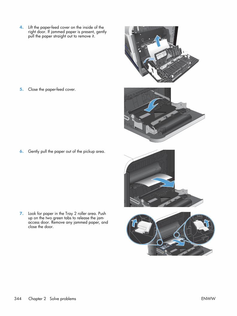
4. Lift the paper-feed cover on the inside of theright door. If jammed paper is present, gentlypull the paper straight out to remove it.
1
2
5. Close the paper-feed cover.
6. Gently pull the paper out of the pickup area.
7. Look for paper in the Tray 2 roller area. Pushup on the two green tabs to release the jam-access door. Remove any jammed paper, andclose the door.
344 Chapter 2 Solve problems ENWW

8. If paper is visible entering the bottom of thefuser, gently pull downward to remove it.
CAUTION: Do not touch the rollers on thetransfer roller. Contaminants can affect printquality.
9. Paper could be jammed inside the fuser whereit would not be visible. Grasp the fuserhandles, lift up slightly, and pull straight out toremove the fuser.
CAUTION: The fuser can be hot while theproduct is in use.
10. Open the jam-access door (callout 1). If paperis jammed inside the fuser, gently pull itstraight up to remove it (callout 2). If the papertears, remove all paper fragments.
CAUTION: Even if the body of the fuser hascooled, the rollers that are inside could still behot. Do not touch the fuser rollers until theyhave cooled.
1
2
ENWW Clear jams 345

11. Close the jam-access door, and push the fusercompletely into the product.
12. Close the right door.
346 Chapter 2 Solve problems ENWW

Clear jams in optional Tray 3
1. Open Tray 3 and make sure that the paper isstacked correctly. Remove any damaged orjammed sheets of paper.
2. Close Tray 3.
ENWW Clear jams 347

Clear jams in the lower right door (Tray 3)
1. Open the lower right door.
2. If paper is visible, gently pull the jammedpaper up or down to remove it.
3. Close the lower right door.
348 Chapter 2 Solve problems ENWW

Jam causes and solutions
Jams in the output bin
Table 2-34 Causes and solutions for delivery delay jam
Cause Solution
The output-bin media-full sensor lever isdamaged.
Replace the paper delivery assembly.
Poor contact of the output-bin media-fullsensor connector.
Reconnect the connectors of the output bin full sensor (SR6) (J47) to DCC PCA(J123).
The output-bin media-full sensor is defective. Check the output-bin full sensor (SR6) by using the manual sensor test. Togglethe sensor to determine if the value changes for "F." If the value does notchange, replace paper delivery assembly.
Poor contact of the fuser-motor (M2)connector.
Reconnect the connectors of the fuser motor (J117), (J15), and the DCcontroller PCA (J105).
The fuser motor (M2) is defective. Execute the fuser-motor driving test in the actuator-drive mode. If the motor isdefective, replace the fuser motor (M2).
Jams in the fuser and transfer area
Table 2-35 Causes and solutions for fuser delivery delay jams
Cause Solution
The lever for the loop-sensors (loop 1 andloop 2) is not set correctly.
Check the loop-sensor lever and place it in the correct position. If the jampersists, replace the fuser.
The spring of the fuser-delivery-sensor lever isunhooked.
Check the spring of the fuser and right-door sensor levers and place them inthe correct position. If the jam persists, replace the fuser.
The fuser-delivery-sensor lever is damaged. Replace the fuser.
Poor contact with the fuser-delivery connector. Reconnect the connectors of the fuser output sensor (SR5) (J45), intermediate(J95) and the DC controller PCA (J123).
The fuser-delivery sensor is defective. Check the fuser-delivery sensor with the sensor monitor mode. If the sensor isdefective, replace the sensor (SR5).
Poor contact of the fuser-motor connector(M2).
Reconnect the connectors of the fuser motor (J15) and the DC controller PCA(J117).
The fuser motor is defective. Execute the fuser-motor driving test in the actuator-drive mode. If the motor isdefective, replace the fuser motor (M2).
The fuser pressure release sensor (SR7) isdefective.
Execute a manual sensor test to verify the sensor is working by manuallytoggling the sensor. Check "H" to see if the value changes. If not, replace thesensor.
ENWW Clear jams 349

Table 2-36 Causes and solutions for wrapping jams
Cause Solution
The fuser roller or pressure roller is dirty. Execute a fuser roller cleaning.
The guide of the fuser delivery unit is dirty. Clean the guide.
The fuser roller or the pressure roller is wornor deformed.
Replace the fuser.
Table 2-37 Causes and solutions for fuser delivery stationary jams
Cause Solution
The fuser roller or pressure roller is worn ordeformed.
Replace the fuser.
The fuser delivery roller is deformed.
The gear of the fuser delivery roller isdamaged.
The fuser output sensor lever is set incorrectlyor damaged.
Check the sensor lever to make sure it is set correctly. If it is damaged, replacethe fuser.
The spring of the fuser output sensor lever isunhooked.
Check the spring and place it in correct position.
Poor contact of the fuser delivery sensorconnector.
Reconnect the intermediate connector (J95) of the fuser output sensor and theconnector (J123) on the DC controller PCA.
The fuser output sensor is defective. Run the sensor test to verify that the fuser output sensor is functioning properly.If it is not replace the fuser output sensor.
Table 2-38 Causes and solutions for residual paper jams
Cause Solution
The fuser loop sensor is defective. Check the fuser loop sensor using the sensor monitor mode. If the sensor isdefective, replace the fuser.
The spring of the fuser-delivery-sensor lever isunhooked.
Check the spring of the fuser and place it in the correct position.
The fuser-delivery-sensor lever is damaged. Replace the sensor (SR5).
Poor contact of the fuser-delivery-sensorconnector.
Reconnect the connectors of the fuser-delivery media-feed connector (J46),intermediate (J95) and the DC controller PCA (J123).
The fuser-output sensor is defective. Check the fuser output sensor using the sensor monitor mode. If the sensor isdefective, replace the sensor (SR5).
Poor contact of the duplexing repick sensorconnector.
Reconnect the connectors of the duplexing media-reverse sensor (J8 and J9)and the duplexing driver PCA (J107).
The duplexer re-feed is defective. Check the duplexer re-feed sensor. If the sensor is defective, replace the rightdoor.
350 Chapter 2 Solve problems ENWW

Table 2-38 Causes and solutions for residual paper jams (continued)
Cause Solution
The sensor detecting a residual media jam isset incorrectly or damaged.
Run the sensor test to verify which sensor detects the paper. Check the sensorlever to make sure it is set correctly. If it is damaged, replace the followingcorresponding part:
● Registration sensor (SR8): Replace the registration assembly.
● Fuser output sensor (SR5): Replace the fuser.
● Fuser loop sensor 1 or 2 (SR14 and SR15): Replace the fuser.
● Duplexer re-feed sensor (SR22): Replace the MP tray pickup assembly.
The spring of the residual media jam detectivesensor lever is unhooked.
Run the sensor test to verify which sensor detects the paper. Check the springof the sensor lever to make sure it is set correctly.
Poor contact of the residual media jamdetective sensor connector.
Run the sensor test to verify which sensor detects the paper. Reconnect thefollowing corresponding sensor connector:
● Registration sensor (SR8): Connector (J109) on the DC controller PCA.
● Fuser output sensor (SR5): Intermediate connector (J95) and connector(J123) on the DC controller PCA.
● Fuser loop sensor 1 or 2 (SR14 and SR15): Connector (J139) on the DCcontroller PCA.
● Duplexer re-feed sensor (SR22): Connector (J107) on the DC controllerPCA.
The residual media jam detective sensor isdefective.
Run the sensor test to verify which sensor detects the paper. Replace thefollowing corresponding part:
● Registration sensor (SR8): Replace the registration assembly.
● Fuser output sensor (SR5): Replace the fuser.
● Fuser loop sensor 1 or 2 (SR14 and SR15): Replace the fuser.
● Duplexer re-feed sensor (SR22): Replace the MP tray pickup assembly.
Table 2-39 Causes and solutions for pickup delay jams 2
Cause Solution
The registration roller is worn or deformed. Replace the secondary-transfer unit.
The spring of the registration shutter isunhooked.
Check the spring and place it in correct position.
Poor contact of the pickup motor driveconnector.
Reconnect the connectors of the registration motor (J6), intermediate, and theDC controller PCA (J131).
The pickup motor is defective. Execute the pickup-motor driving test in the actuator-drive mode. If the motor isdefective, replace the pickup motor.
The cassette pickup roller is worn ordeformed.
Replace the tray pickup roller.
ENWW Clear jams 351

Table 2-39 Causes and solutions for pickup delay jams 2 (continued)
Cause Solution
The tray separation roller is worn ordeformed.
Replace the tray separation roller.
Poor contact of the registration sensorconnector.
Reconnect the connector (J109) on the DC controller PCA.
The registration sensor is defective. Run the sensor test to verify that the registration sensor is functioning properly. Ifit is not, replace the registration assembly.
Poor contact of the tray pickup solenoiddrive connector.
Reconnect the connector (J140) on the DC controller PCA.
The tray pickup solenoid is defective. Run the solenoid drive test in the actuator drive mode to verify that the traypickup solenoid is functioning properly. If it is not, replace the tray-pickup driveassembly.
Poor contact of the pickup motor driveconnector.
Reconnect the connector (J131) on the DC controller PCA.
The pickup motor is defective. Run the pickup motor drive test in the actuator drive mode to verify that thepickup motor is functioning properly. If it is not, replace the pickup motor.
Table 2-40 Causes and solutions for pickup stationary jams
Cause Solution
Multiple feed of paper. Replace any worn or deformed parts (tray separation roller, tray feed roller,MP-tray pickup roller or MP-tray separation roller).
Check the separation roller and MP-tray separation roller to see if they arefirmly seated and coupled with the torque limiter.
Replace the separation roller and feed roller in Tray 2.
Replace the MP-tray pickup roller and MP-tray separation roller.
The secondary transfer roller is not setcorrectly.
Place the secondary-transfer-roller unit in the correct position.
The secondary transfer roller is worn ordeformed.
Replace the secondary-transfer-roller unit.
Poor contact of the drum motor 3 driveconnector.
Reconnect the connectors of the drum motor 3 (J42) and the DC controller PCA(J121).
The drum motor 3 is defective. Execute the drum motor 3 driving test in the actuator-drive mode. If the motoris defective, replace the drum motor 3.
The ITB does not rotate smoothly. Replace the ITB.
Multiple-feed of paper. If the Tray 2 pickup roller or separation roller are worn or deformed, replaceany defective parts. If the Tray 1 pickup roller or separation pad are worn ordeformed, replace any defective parts.
The registration sensor lever is set incorrectlyor damaged.
Check the sensor lever to make sure it is set correctly. If it is damaged, replacethe registration assembly.
352 Chapter 2 Solve problems ENWW

Table 2-40 Causes and solutions for pickup stationary jams (continued)
Cause Solution
The spring of the registration sensor lever isunhooked.
Check the spring and place it in correct position.
Poor contact of the registration sensorconnector.
Reconnect the connector (J109) on the DC controller PCA.
The registration sensor is defective. Run the sensor test to verify that the registration sensor is functioning properly.If it is not, replace the registration assembly.
Jams in the duplex area (duplex models)
Table 2-41 Causes and solutions for duplexing reverse jams
Cause Solution
The duplex reverse roller is worn or deformed. Replace the delivery assembly.
The duplex feed roller is worn or deformed. Replace the duplex feed unit.
Poor contact of the duplex reverse-motorconnector.
Reconnect the connectors (J202 and J201) on the high-voltage power supply(upper) PCA and connector (J113) on the DC controller PCA.
The duplex reverse motor is defective. Replace the duplex drive assembly.
Poor contact of the duplexing reverse-motorconnector.
Reconnect the connectors of the duplexing reverse motor (J20) and theduplexing driver PCA (J202).
The duplexing reverse motor is defective. Replace the right door assembly.
Table 2-42 Causes and solutions for duplex repick jams
Cause Solution
The duplexer re-feed sensor lever is setincorrectly or damaged.
Check the sensor lever to make sure it is set correctly. If it is damaged, replacethe right door assembly.
The spring of the duplexer re-feed sensor leveris unhooked.
Check the spring and place it in correct position.
Poor contact of the duplexer re-feed sensorconnector.
Reconnect the intermediate connector (J90) and connector (J107) on the DCcontroller PCA.
The duplexer re-feed sensor is defective. Run the sensor test to verify that the duplexer re-feed sensor is functioningproperly. If it is not, replace the right door assembly.
The spring of the duplexer-refeed-sensor leveris unhooked.
Check the spring and place it in the correct position.
The duplexer-refeed-sensor lever is damaged. Replace the duplexer re-feed sensor.
Poor contact of the duplexer-refeed-sensorconnector.
Reconnect the intermediate connector (J90) and connector (J107) on the DCcontroller PCA. If the problem persist, replace duplexer re-feed sensor.
The duplexer re-feed sensor is defective. Check the duplexer re-feed sensor. If the sensor is defective, replace theduplexer re-feed sensor.
ENWW Clear jams 353
Table 2-42 Causes and solutions for duplex repick jams (continued)
Cause Solution
Poor contact of the duplex reverse connector. Reconnect the connectors of the duplex repick motor (J20), intermediate (J202and J201) and the duplex driver PCA (J113).
The duplex-repick motor is defective. Replace the duplex drive assembly.
Table 2-43 Causes and solutions for residual media jams
Cause Solution
Poor contact of the loop-sensor connector andfuser loop sensors 1 and 2.
Reconnect the connectors of the fuser loop sensors (1 and 2):
● Loop 1 (J11, J352, J350, J50) and the DC controller (J139)
● Loop 2 (J10, J352, J350, J50) and the DC controller (J139)
The fuser loop sensor is defective. Check the fuser loop sensor. If the sensor is defective, replace fuser.
The spring of the fuser output sensor lever isunhooked.
Check the spring of the fuser and right door and place it in the correctposition.
The fuser-ouput-sensor lever is damaged. Replace the sensor (SR5).
Poor contact of the fuser-output sensorconnector.
Reconnect the connectors of the fuser-output sensor (J46), intermediate (J95)and the DC controller PCA (J123).
The fuser-output sensor is defective. Check the fuser-output sensor. If the sensor is defective, replace the fuser.
The spring of the duplexer re-feed sensor leveris unhooked.
Check the spring and place it in the correct position. The sensor is located inthe right door behind the cover close to the engine side.
The duplexer re-feed sensor lever is damaged. Replace the right door assembly.
Poor contact of the duplexing media-reverse-sensor connector.
Reconnect the connectors of the duplexing media-reverse sensor (J8) and (J90)and the duplexing driver PCA (J107).
The duplexer re-feed sensor is defective. Check the duplexer re-feed sensor. If the sensor is defective, replace theduplexer re-feed sensor.
NOTE: Even if jammed paper is visible in Tray 1, clear the jam from the inside of the product byopening the right door.
Jams in Tray 1, Tray 2 and internal paper path
Table 2-44 Causes and solutions for pickup delay jam 1: tray pickup
Cause Solution
The MP tray pick up roller or the MP trayseparation pad is worn or deformed.
Replace the MP tray pick up roller and separation pad.
Poor contact of the Tray 1 paper sensor. Reconnect the connectors of the tray media-feed sensor (J7), intermediate(J85), and DC controller (J107).
The Tray 1 paper sensor is defective (SR21). Check the Tray 1 paper sensor. If the sensor is defective, replace the rightdoor assembly.
354 Chapter 2 Solve problems ENWW

Table 2-44 Causes and solutions for pickup delay jam 1: tray pickup (continued)
Cause Solution
The arm spring of the MP pickup solenoid isunhooked.
Check the spring and place it in the correct position.
Poor contact of the MP-pickup-solenoid driveconnector.
Reconnect the connectors of the tray pickup solenoid (J84) and the DCcontroller PCA (J107).
The MP-pickup solenoid is defective. Execute the tray-pickup-solenoid driving test in the actuator-drive mode. If thesolenoid is defective, replace the right door assembly.
Poor contact of the pickup-motor driveconnector (M13).
Reconnect the connectors of the pickup motor (J1705), intermediate (J6) andthe DC controller PCA (J131).
The pickup motor (M13) is defective. Execute the pickup-motor driving test in the actuator-drive mode. If the motor isdefective, replace the pickup motor.
Table 2-45 Causes and solutions for pickup stationary jams
Cause Solution
Multiple feed of paper. Replace any worn or deformed parts (tray separation pad, tray feed roller, MPtray pickup roller or MP tray separation pad). If replacing the MP trayseparation pad, you must replace the right door assembly.
Check the separation pad and MP tray separation pad to see if they are firmlyseated and coupled with the torque limiter.
Replace the separation pad and feed roller for Tray 2 and Tray 3.
If the MP tray pickup roller if defective, replace the roller. If the MP trayseparation pad is defective, replace the right door assembly.
The secondary transfer roller is not setcorrectly.
Place the secondary-transfer-roller unit in the correct position.
The secondary-transfer roller is worn ordeformed.
Replace the secondary-transfer-roller assembly..
Poor contact of the drum 3 drive connector. Reconnect the connectors of the ITB motor (J42) and the DC controller PCA(J121).
The drum motor 3 is defective. Execute the drum 3 driving test in the actuator-drive mode. If the motor isdefective, replace the ITB motor.
The ITB does not rotate smoothly. Replace the ITB.
Table 2-46 Causes and solutions for pickup delay jam 1; MP tray pickup
Cause Solution
The MP tray pickup roller or MP trayseparation pad is worn or deformed.
If the MP tray pickup roller if defective, replace the roller. If the MP trayseparation pad is defective, replace the right door assembly.
Poor contact of the MP tray media-presence-sensor connector.
Reconnect the connectors of the MP tray media-presence sensor (J2007),intermediate (J85) and the DC controller PCA (J1071).
ENWW Clear jams 355
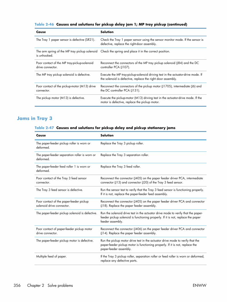
Table 2-46 Causes and solutions for pickup delay jam 1; MP tray pickup (continued)
Cause Solution
The Tray 1 paper sensor is defective (SR21). Check the Tray 1 paper sensor using the sensor monitor mode. If the sensor isdefective, replace the right-door assembly.
The arm spring of the MP tray pickup solenoidis unhooked.
Check the spring and place it in the correct position.
Poor contact of the MP tray-pickup-solenoiddrive connector.
Reconnect the connectors of the MP tray pickup solenoid (J84) and the DCcontroller PCA (J107).
The MP tray pickup solenoid is defective. Execute the MP tray-pickup-solenoid driving test in the actuator-drive mode. Ifthe solenoid is defective, replace the right door assembly.
Poor contact of the pickup-motor (M13) driveconnector.
Reconnect the connectors of the pickup motor (J1705), intermediate (J6) andthe DC controller PCA (J131).
The pickup motor (M13) is defective. Execute the pickup-motor (M13) driving test in the actuator-drive mode. If themotor is defective, replace the pickup motor.
Jams in Tray 3
Table 2-47 Causes and solutions for pickup delay and pickup stationary jams
Cause Solution
The paper-feeder pickup roller is worn ordeformed.
Replace the Tray 3 pickup roller.
The paper-feeder separation roller is worn ordeformed.
Replace the Tray 3 separation roller.
The paper-feeder feed roller 1 is worn ordeformed.
Replace the Tray 3 feed roller.
Poor contact of the Tray 3 feed sensorconnector.
Reconnect the connector (J405) on the paper feeder driver PCA, intermediateconnector (J13) and connector (J20) of the Tray 3 feed sensor.
The Tray 3 feed sensor is defective. Run the sensor test to verify that the Tray 3 feed sensor is functioning properly.If it is not, replace the paper-feeder feed assembly.
Poor contact of the paper-feeder pickupsolenoid drive connector.
Reconnect the connector (J405) on the paper feeder driver PCA and connector(J18). Replace the paper feeder assembly.
The paper-feeder pickup solenoid is defective. Run the solenoid drive test in the actuator drive mode to verify that the paper-feeder pickup solenoid is functioning properly. If it is not, replace the paperfeeder assembly.
Poor contact of paper-feeder pickup motordrive connector.
Reconnect the connector (J406) on the paper feeder driver PCA and connector(J14). Replace the paper feeder assembly.
The paper-feeder pickup motor is defective. Run the pickup motor drive test in the actuator drive mode to verify that thepaper-feeder pickup motor is functioning properly. If it is not, replace thepaper-feeder assembly.
Multiple feed of paper. If the Tray 3 pickup roller, separation roller or feed roller is worn or deformed,replace any defective parts.
356 Chapter 2 Solve problems ENWW

Table 2-47 Causes and solutions for pickup delay and pickup stationary jams (continued)
Cause Solution
The Tray 3 feed sensor lever is set incorrectlyor damaged.
Check the sensor lever to make sure it is set correctly. If it is damaged, replacethe paper-feeder assembly.
The spring of the Tray 3 feed sensor lever isunhooked.
Check the spring and place it in correct position.
Poor contact of the Tray 3 feed sensorconnector.
Reconnect the connector (J405) on the paper feeder driver PCA intermediateconnector (J13) and connector (J20) of the Tray 3 feed sensor.
The Tray 3 feed sensor is defective. Run a sensor test to verify that the Tray 3 feed sensor is functioning properly. Ifit is not, replace the paper-feeder assembly.
ENWW Clear jams 357

Paper feeds incorrectly or becomes jammed● The product does not pick up paper
● The product picks up multiple sheets of paper
● The document feeder jams, skews, or picks up multiple sheets of paper
● Prevent paper jams
The product does not pick up paper
If the product does not pick up paper from the tray, try these solutions.
1. Open the product and remove any jammed sheets of paper.
2. Load the tray with the correct size of paper for your job.
3. Make sure the paper size and type are set correctly on the product control panel.
4. Make sure the paper guides in the tray are adjusted correctly for the size of paper. Adjust theguides to the appropriate indentation in the tray.
5. Check the product control panel to see if the product is waiting for you to acknowledge a promptto feed the paper manually. Load paper, and continue.
6. The rollers above the tray might be contaminated. Clean the rollers with a lint-free cloth dampenedwith warm water.
The product picks up multiple sheets of paper
If the product picks up multiple sheets of paper from the tray, try these solutions.
1. Remove the stack of paper from the tray and flex it, rotate it 180 degrees, and flip it over. Do notfan the paper. Return the stack of paper to the tray.
2. Use only paper that meets HP specifications for this product.
3. Use paper that is not wrinkled, folded, or damaged. If necessary, use paper from a differentpackage.
4. Make sure the tray is not overfilled. If it is, remove the entire stack of paper from the tray,straighten the stack, and then return some of the paper to the tray.
5. Make sure the paper guides in the tray are adjusted correctly for the size of paper. Adjust theguides to the appropriate indentation in the tray.
6. Make sure the printing environment is within recommended specifications.
358 Chapter 2 Solve problems ENWW

The document feeder jams, skews, or picks up multiple sheets ofpaper
● The original might have something on it, such as staples or self-adhesive notes, that must beremoved.
● Check that all rollers are in place and that the roller-access cover inside the document feeder isclosed.
● Make sure that the top document-feeder cover is closed.
● The pages might not be placed correctly. Straighten the pages and adjust the paper guides tocenter the stack.
● The paper guides must be touching the sides of the paper stack to work correctly. Make sure thatthe paper stack is straight and the guides are against the paper stack.
● The document feeder input tray or output bin might contain more than the maximum number ofpages. Make sure the paper stack fits below the guides in the input tray, and remove pages fromthe output bin.
● Verify that there are no pieces of paper, staples, paper clips, or other debris in the paper path.
● Clean the document-feeder rollers and the separation pad. Use compressed air or a clean, lint-freecloth moistened with warm water. If misfeeds still occur, replace the rollers.
● From the Home screen on the product control panel, scroll to and touch the Supplies button. Checkthe status of the document-feeder kit, and replace it if necessary.
Prevent paper jams
To reduce the number of paper jams, try these solutions.
1. Use only paper that meets HP specifications for this product.
2. Use paper that is not wrinkled, folded, or damaged. If necessary, use paper from a differentpackage.
3. Use paper that has not previously been printed or copied on.
4. Make sure the tray is not overfilled. If it is, remove the entire stack of paper from the tray,straighten the stack, and then return some of the paper to the tray.
5. Make sure the paper guides in the tray are adjusted correctly for the size of paper. Adjust theguides so they are touching the paper stack without bending it.
6. Make sure that the tray is fully inserted in the product.
7. If you are printing on heavy, embossed, or perforated paper, use the manual feed feature andfeed sheets one at a time.
8. From the Home screen on the product control panel, scroll to and touch the Trays button. Verifythat the tray is configured correctly for the paper type and size.
9. Make sure the printing environment is within recommended specifications.
ENWW Paper feeds incorrectly or becomes jammed 359

Use manual print modesTry the following manual print modes to see if they solve the image-quality problems.
Select a manual print mode
1. From the Home screen on the product control panel, scroll to and touch the Administration button.
2. Open the following menus:
● General Settings
● Print Quality
● Adjust Paper Types
3. Select a paper type, and then select the mode to adjust.
4. Select a value for the mode, and then touch the Save button.
360 Chapter 2 Solve problems ENWW

Table 2-48 Print modes under the Adjust Paper Types sub menu
Print Mode● Auto Sense Mode
● Normal mode
● Light Mode
● Heavy Mode
● Card Stock Mode
● Transparency Mode
● Transparency 2 Mode
● Envelope Control
● Label Mode
● Tough Mode
● Extra tough mode
● Heavy Glossy Mode
● Extra Heavy Mode
● X-heavy glossy mode
● Rough Mode
● Card Glossy Mode
● 4 mm trans mode
● Light Rough Mode
● Mid-weight mode
● Mid-wt glossy mode
NOTE: Not all print modes are available for all papertypes.
Resistance Mode Set to Up to resolve print-quality issues caused by poorsecondary transfer in low-humidity environments with resistiveor rough surface paper.
Humidity Mode With glossy film, set to High when the product is in a high-humidity environment and print-quality defects occur on HPTough Paper or Opaque film.
With transparencies, set to High when the product is in ahigh-humidity environment and print-quality defects occur oncolor transparencies on the first page of a print job.
With all other paper types, set to High when the product is ina high-humidity environment and light density occurs on thefirst page of a print job.
Pre-Rotation Mode Set to On when horizontal banding occurs with the drumpitch.
ENWW Use manual print modes 361

Table 2-48 Print modes under the Adjust Paper Types sub menu (continued)
Fuser Temp Mode If you are seeing a faint image of the page repeated at thebottom of the page or on the following page, first make surethe paper type (Adjust Paper Types menu) and Print Modesettings are correct for the type of paper you are using. If youcontinue to see ghost images on your print jobs, set the FuserTemp feature to one of the settings.
Normal
Up
Down
Paper Curl Mode Use in high-humidity and high-temperature environments. TheReduced setting decreases fuser temperature and increasesthe interpage gap.
Table 2-49 MP modes under the Optimize submenu
Normal Paper Set to Smooth when printing on smooth paper of normalweight.
Heavy Paper Set to Smooth when printing on smooth, heavy paper types.
Envelop Control Use this mode if envelopes are sticking together due tomoisture in the envelope adhisive.
Normal
Reduced Temp
Environment Set to Low Temp if the product is operating in a low-temperature environment and you are having problems withprint quality such as blisters in the printed image.
Line Voltage Set to Low Voltage if the product is operating in a low-voltageenvironment and you are having problems with print qualitysuch as blisters in the printed image.
Tray 1 Set to Alternate if you are seeing marks on the back side ofthe paper when printing from Tray 1. This sets the product toinitiate a clean sequence every time a job finishes when theproduct is set for Any Size and Any Type for Tray 1.
Background Set to Alternate 1 when a background occurs all over thepage. Set to Alternate 2 when thin vertical lines appear on thepage. Set to Alternate 3 when the other alternatives do notcorrect the problem.
Uniformity Control Set to Alternate 1 to improve uniformity on any paper type.Set to Alternate 2 to improve uniformity on normal and lightpaper types. Set to Alternate 3 when the other alternatives donot correct the problem.
Tracking Control The default setting is On. This item is for manufacturing useonly.
Registration Set to Alternate when color misregistration occurs.
362 Chapter 2 Solve problems ENWW

Table 2-49 MP modes under the Optimize submenu (continued)
Transfer Control Set to Alternate 1 to reduce primary transfer bias and toresolve low density or blotchy images. Set to Alternate 2 toresolve ghosting outlines that look like a finger or fingers. Setto Alternate 3 when the other alternatives do not correct theproblem.
Fuser Temp The default setrting for this item is Normal. Use the Alternatesetting to reduce the occurance of first-page fuser wrinkle ortoner blister.
Restore Optimize Use this item to reset the menu defaults.
ENWW Use manual print modes 363

Solve image quality problemsOften print-quality problems can be resolved easily by making sure that the product is maintained,using paper that meets HP specifications, or running a cleaning page.
Image defects table
The following examples depict letter-size paper that has passed through the product short-edge first.These examples illustrate problems that would affect all the pages that you print, whether you print incolor or in black only.
Table 2-50 Image defects table
Problem Sample Cause Solution
Print is light or faded on entirepage.
Poor contacts exist on the ITBunit and the productgrounding unit.
Clean the grounding contacts. If theproblem remains after cleaning,check the contacts for damage.Replace any deformed or damagedparts.
Poor secondary transfercontacts exist on thesecondary transfer roller andthe ITB.
Clean the contacts. If the problemremains after cleaning, check thecontacts for damage. Replace anydeformed or damaged parts.
Print is light or faded in aparticular color.
Poor primary transfer biascontacts on the ITB unit andproduct.
Clean the contacts of the color thatproduces the light print. If theproblem remains after cleaning,check the contacts for damage.Replace any deformed or damagedparts.
Poor primary charging biascontacts with the tonercartridge and product.
Poor developing bias contactswith the toner cartridge andproduct.
Image is too dark. The RD sensor is defective. Replace the RD sensor.
Page is blank. The high-voltage power-supplylower is defective (nodeveloping bias output).
Replace the high-voltage power-supply lower.
364 Chapter 2 Solve problems ENWW

Table 2-50 Image defects table (continued)
Problem Sample Cause Solution
The page is all black or a solidcolor.
Poor contact exists in theprimary charging bias ordeveloping bias contactsbetween the toner cartridgeand the product.
Clean each contact of the color thatproduces the all black or solid color.If the problem remains aftercleaning, check the contacts fordamage. Replace any deformed ordamaged parts. Replace theaffected toner cartridge.
White spots appear in an image The primary transfer roller isdeformed or has deteriorated.
Replace the ITB.
The secondary transfer rolleris deformed or hasdeteriorated.
Replace the secondary-transfer-roller.
The back of the page is dirty. The secondary transfer rolleris dirty.
Replace the secondary transferroller.
The fuser inlet guide orseparation guide is dirty.
Clean the dirty parts. If the dirt doesnot come off, replace the guide.
The pressure roller is dirty. Run the cleaning page several times.If the issue persists, replace thefuser.
Vertical streaks or bands appearon the page.
Scratches are present on thecircumference of thephotosensitive drum.
Replace the toner cartridge of thecolor that matches the defect.
Scratches are present on thecircumference of the fuserroller.
Replace the fuser.
Scratches are present on thecircumference of the ITB.
Replace the ITB.
The ITB drive roller isdeformed or has deteriorated.
The ITB cleaning mechanism ismalfunctioning.
ENWW Solve image quality problems 365

Table 2-50 Image defects table (continued)
Problem Sample Cause Solution
Vertical white lines appear in aparticular color.
The laser beam window isdirty.
Clean the window and remove anyforeign substances.
Scratches are present on thecircumference of thedeveloping cylinder orphotosensitive drum.
White scratch down the pagecould mean the scanner glassneeds to be cleaned.
Remove the affected toner cartridgeand re-install it. The PGCs will cleanthe glass.
If the problem persists, replace theaffected toner cartridge.
The laser/scanner-unit mirroris dirty.
Replace the laser/scanner assembly.
Vertical white lines appear in allcolors.
Horizontal scratches on thefuser roller.
Replace the fuser.
Scratches are present on thecircumference of the ITB.
White scratch down the pagecould mean the scanner glassneeds to be cleaned.
Remove the affected toner cartridgeand re-install it. The PGCs will cleanthe glass.
Replace the ITB.
Horizontal lines appear on thepage.
Repetitive horizontal linesappear.
Use the repetitive defects ruler toidentify the dirty roller. Clean theroller. If the roller cannot becleaned, replace the fuser.
Horizontal scratches arepresent on the photosensitivedrum.
Replace the toner cartridge of thecolor that matches the defect.
Horizontal scratches arepresent on the fuser roller.
Replace the fuser.
A horizontal white line displayson the page.
Repetitive horizontal whitelines appear.
Use the repetitive defects ruler toidentify the dirty roller. Clean theroller. If the roller cannot becleaned, replace the roller.
Horizontal scratches arepresent on the photosensitivedrum.
Replace the toner cartridge of thecolor that matches the defect.
Scratches are present on thecircumference of the ITB.
Replace the ITB.
366 Chapter 2 Solve problems ENWW

Table 2-50 Image defects table (continued)
Problem Sample Cause Solution
Image in a particular color doesnot print in the correct color.
Poor contact exists in theprimary charging bias ordeveloping bias contactsbetween the toner cartridgeand the product.
Clean each contact of the color thatproduces the missing color. If theproblem remains after cleaning,check the contacts for damage.Replace any deformed or damagedparts.
The toner cartridge (primarycharging roller, developingroller, or photosensitive drum)is defective.
Replace the toner cartridge of thecolor that matches the defect.
The high-voltage power-supplylower is defective (no primarycharging bias or developingbias output).
Replace the high-voltage power-supply lower.
The laser/scanner unit isdefective.
Replace the laser/scanner assembly.
Dropouts appear. The secondary transfer rolleris deformed or hasdeteriorated.
Replace the secondary-transfer-roller.
The primary charging roller,developing roller, orphotosensitive drum isdeformed or has deteriorated.
Replace the toner cartridge of thecolor that matches the defect.
The fuser roller is deformed orhas deteriorated.
Replace the fuser.
The high-voltage power-supplyT PCA is defective (no transferbias output).
Replace the high-voltage power-supply upper.
The toner is not fully fused to thepaper.
The fuser roller or pressureroller is scarred or deformed.
Replace the fuser.
The thermistor is defective. Replace the fuser.
The fuser heater is defective.
ENWW Solve image quality problems 367

Table 2-50 Image defects table (continued)
Problem Sample Cause Solution
Some color is misregistered. The product is incorrectlycalibrated.
Calibrate the product.
The ITB unit is defective. If the ITB does not rotate smoothly ora cleaning malfunction occurs (ITB isdirty), replace the ITB.
The drive gear of the ITBmotor is worn or chipped.
Check each drive gear between theITB drive roller and the ITB motor. Ifthe gear is worn or chipped,replace the drive unit.
The RD sensor is defective. Open and close the front doorseveral times to clean the RD sensor.If the problem persists, replace theRD sensor.
The laser/scanner unit isdefective.
Replace the laser/scanner assembly.
The toner cartridge isdefective.
Replace the toner cartridge of theaffected color.
Toner smears appear on thepaper.
The product has residualpaper.
Remove the residual paper.
The fuser inlet guide is dirty. Clean the fuser inlet guide.
The printed page containsmisformed characters.
The product is experiencingpage skew.
See the “Text or graphics areskewed on the printed page” row inthis table.
The laser/scanner unit isdefective.
Replace the laser/scanner assembly.
Text or graphics are skewed onthe printed page.
The registration shutter springis unhooked.
Check the spring and place it in thecorrect position.
The registration shutter springis deformed.
Replace the secondary transferassembly.
The printed page containswrinkles or creases.
The roller or paper feed guideis dirty.
Clean any dirty components.
A feed roller is deformed orhas deteriorated.
Replace any deformed ordeteriorated rollers.
The paper feed guide isdamaged.
Replace the paper-feed-guide unit.
368 Chapter 2 Solve problems ENWW

Table 2-50 Image defects table (continued)
Problem Sample Cause Solution
The front of the page is dirty. The photosensitive drum isdirty.
Replace the toner cartridge.
The fuser roller or pressureroller is dirty.
Execute a Pressure roller cleanmode procedure. If the dirt doesnot come off, replace the fuser.
NOTE: Cleaning the fuser with HPtough paper provides better resultsthan with plain paper. You mightneed to execute the cleaningprocess several times to remove allcontaminants on the fuser.
Repetitive horizontal lines See repetitive image defect ruler.Clean the indicated roller. If thecontaminant does not come off,replace appropriate roller orassembly.
Pages have flecks of toner Execute a cleaning page to cleanthe contaminant off the fuser. Thecleaning page might need to be runseveral time to clean the fuser. Donot replace the fuser.
NOTE: Cleaning the fuser with HPtough paper provides better resultsthan with plain paper. You mightneed to execute the cleaningprocess several times to remove allcontaminants on the fuser.
Pages have one or more skewedcolor planes (can appear on theright or left side of the page)
Remove, and then reinstall the tonercartridge associated with the defect.
ENWW Solve image quality problems 369

Clean the productOver time, particles of toner and paper accumulate inside the product. This can cause print-qualityproblems during printing. Cleaning the product eliminates or reduces these problems.
Clean the paper path and print-cartridge areas every time that you change the toner cartridge orwhenever print-quality problems occur. As much as possible, keep the product free from dust anddebris.
To clean the product exterior, use a soft, water-moistened cloth.
Print a cleaning page
Print a cleaning page to remove dust and excess toner from the fuser if you are having any of thefollowing problems:
● Specks of toner are on the printed pages.
● Toner is smearing on the printed pages.
● Repeated marks occur on the printed pages.
Use the following procedure to print a cleaning page.
1. From the Home screen on the product control panel, scroll to and touch the Device Maintenancebutton.
2. Open the following menus:
● Calibration/Cleaning
● Cleaning Page
3. Touch the Print button to print the page.
4. The cleaning process can take several minutes. When it is finished, discard the printed page.
Check the scanner glass for dirt or smudges
Over time, specks of debris might collect on the scanner glass and white plastic backing which canaffect performance. Use the following procedure to clean the scanner glass and white plastic backing.
370 Chapter 2 Solve problems ENWW

1. Press the power button to turn off the product,and then disconnect the power cable from theelectrical outlet.
2. Open the scanner lid.
ENWW Clean the product 371

3. Clean the scanner glass and the white plasticbacking by using a soft cloth or sponge thathas been moistened with nonabrasive glasscleaner. Dry the glass and white plasticbacking by using a chamois or a cellulosesponge to prevent spotting.
CAUTION: Do not use abrasives, acetone,benzene, ammonia, ethyl alcohol, or carbontetrachloride on any part of the product; thesecan damage the product. Do not place liquidsdirectly on the glass or platen. They might seepand damage the product.
4. Connect the power cable to an outlet, andthen press the power button to turn on theproduct.
372 Chapter 2 Solve problems ENWW

Clean the pickup rollers and separation pad in the documentfeeder
1. Lift the document-feeder latch.
2. Open the document-feeder cover.
ENWW Clean the product 373

3. Remove any visible lint or dust from each ofthe feed rollers and the separation pad usingcompressed air or a clean lint-free clothmoistened with warm water.
NOTE: Lift up the roller assembly so you canclean the second roller.
4. Close the document-feeder cover.
374 Chapter 2 Solve problems ENWW

Solve performance problemsTable 2-51 Solve performance problems
Problem Cause Solution
Pages print but are totally blank. The document might contain blankpages.
Check the document that you areprinting to see if content displays on allof the pages.
The product might be malfunctioning. To check the product, print aConfiguration page.
Pages print very slowly. Heavier paper types can slow the printjob.
Print on a different type of paper.
Complex pages can print slowly. Proper fusing might require a slowerprint speed to ensure the best printquality.
Large batches, narrow paper, andspecial paper such as gloss,transparency, cardstock, and HP ToughPaper can slow the print job.
Print in smaller batches, on a differenttype of paper, or on a different size ofpaper.
Pages did not print. The product might not be pulling papercorrectly.
Make sure paper is loaded in the traycorrectly.
The paper is jamming in the product. Clear the jam.
The USB cable might be defective orincorrectly connected.
● Disconnect the USB cable at bothends and reconnect it.
● Try printing a job that has printedin the past.
● Try using a different USB cable.
Other devices are running on yourcomputer.
The product might not share a USB port.If you have an external hard drive ornetwork switchbox that is connected tothe same port as the product, the otherdevice might be interfering. To connectand use the product, you mustdisconnect the other device or you mustuse two USB ports on the computer.
ENWW Solve performance problems 375

Solve connectivity problems
Solve USB connection problems
If you have connected the product directly to a computer, check the cable.
● Verify that the cable is connected to the computer and to the product.
● Verify that the cable is not longer than 2 m (6.65 ft). Try using a shorter cable.
● Verify that the cable is working correctly by connecting it to another product. Replace the cable ifnecessary.
Solve wired network problems
Check the following items to verify that the product is communicating with the network. Beforebeginning, print a configuration page from the product control panel and locate the product IP addressthat is listed on this page.
● The product has a poor physical connection.
● The computer is using the incorrect IP address for the product
● The computer is unable to communicate with the product
● The product is using incorrect link and duplex settings for the network
● New software programs might be causing compatibility problems
● The computer or workstation might be set up incorrectly
● The product is disabled, or other network settings are incorrect
The product has a poor physical connection.
1. Verify that the product is attached to the correct network port using a cable of the correct length.
2. Verify that cable connections are secure.
3. Look at the network port connection on the back of the product, and verify that the amber activitylight and the green link-status light are lit.
4. If the problem continues, try a different cable or port on the hub.
The computer is using the incorrect IP address for the product
1. Open the printer properties and click the Ports tab. Verify that the current IP address for theproduct is selected. The product IP address is listed on the product configuration page.
2. If you installed the product using the HP standard TCP/IP port, select the box labeled Alwaysprint to this printer, even if its IP address changes.
376 Chapter 2 Solve problems ENWW

3. If you installed the product using a Microsoft standard TCP/IP port, use the hostname instead ofthe IP address.
4. If the IP address is correct, delete the product and then add it again.
The computer is unable to communicate with the product
1. Test network communication by pinging the product.
a. Open a command-line prompt on your computer. For Windows, click Start, click Run, andthen type cmd.
b. Type ping followed by the IP address for your product.
c. If the window displays round-trip times, the network is working.
2. If the ping command failed, verify that the network hubs are on, and then verify that the networksettings, the product, and the computer are all configured for the same network.
The product is using incorrect link and duplex settings for the network
Hewlett-Packard recommends leaving this setting in automatic mode (the default setting). If you changethese settings, you must also change them for your network.
New software programs might be causing compatibility problems
Verify that any new software programs are correctly installed and that they use the correct print driver.
The computer or workstation might be set up incorrectly
1. Check the network drivers, print drivers, and the network redirection.
2. Verify that the operating system is configured correctly.
The product is disabled, or other network settings are incorrect
1. Review the configuration page to check the status of the network protocol. Enable it if necessary.
2. Reconfigure the network settings if necessary.
ENWW Solve connectivity problems 377

Service mode functions
Service menu
The Service menu is PIN-protected for added security. Only authorized service people have access tothe Service menu. When you select Service from the list of menus, the product prompts you to type aneight-digit personal identification number (PIN).
NOTE: The product automatically exits the Service menu after about one minute if no items areselected or changed.
1. From the Home screen on the product control panel, scroll to and touch the Device Maintenancebutton.
2. Open the Service menu.
3. On the sign-in screen, select the Service Access Code option from the drop-down list.
4. Enter the following service access code for this product: 05057512.
The following menu items appear in the Service menu:
First level Second level Value Description
Event Log Allows you to print orview the product eventlog.
Clear Event Log Use this item to clearthe product event log.
Cycle Counts Total Engine Cycles
Mono Cycle Count The page count that isstored in NVRAM andprinted on theconfiguration pagerepresents the numberof pages that theformatter has formatted(not including engine-test prints).
Color Cycle Count The page count that isstored in NVRAM andprinted on theconfiguration pagerepresents the numberof pages that theformatter has formatted(not including engine-test prints).
Refurbish Cycle Count Use this item to recordthe page count whenthe product wasrefurbished.
378 Chapter 2 Solve problems ENWW
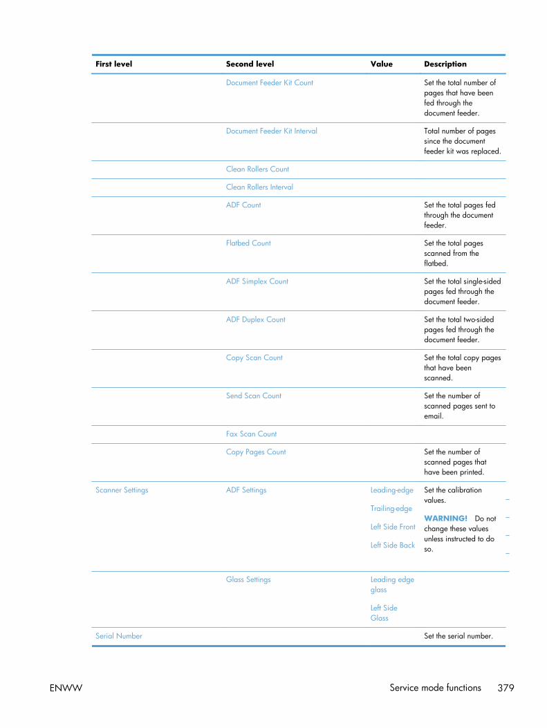
First level Second level Value Description
Document Feeder Kit Count Set the total number ofpages that have beenfed through thedocument feeder.
Document Feeder Kit Interval Total number of pagessince the documentfeeder kit was replaced.
Clean Rollers Count
Clean Rollers Interval
ADF Count Set the total pages fedthrough the documentfeeder.
Flatbed Count Set the total pagesscanned from theflatbed.
ADF Simplex Count Set the total single-sidedpages fed through thedocument feeder.
ADF Duplex Count Set the total two-sidedpages fed through thedocument feeder.
Copy Scan Count Set the total copy pagesthat have beenscanned.
Send Scan Count Set the number ofscanned pages sent toemail.
Fax Scan Count
Copy Pages Count Set the number ofscanned pages thathave been printed.
Scanner Settings ADF Settings Leading-edge
Trailing-edge
Left Side Front
Left Side Back
Set the calibrationvalues.
WARNING! Do notchange these valuesunless instructed to doso.
Glass Settings Leading edgeglass
Left SideGlass
Serial Number Set the serial number.
ENWW Service mode functions 379

First level Second level Value Description
Service ID Use this item to showthe date that theproduct was first usedon the control panel.This eliminates the needfor users to keep paperreceipts for proof ofwarranty.
Cold Reset Paper When you perform acold reset, the papersize that is stored inNVRAM is reset to thedefault factory setting. Ifyou replace a formatterboard in a country/region that uses A4 asthe standard papersize, use this menu toreset the default papersize to A4. LETTER andA4 are the onlyavailable values.
New Registration Roller Yes
No
Reset the counter for theregistration roller afterreplacing theregistration assembly.
PTT Test Mode (fax models only) Test the internal modemfor the analog faxaccessory.
Hook Operations Off Hook
On Hook
Generate Random Data Select a valuefrom the list.
Generate DTMF Tone Burst Select a valuefrom the list.
Generate DTMF Continuous Tone Select a valuefrom the list.
Generate Pulse Burst Select a valuefrom the list.
Generate Tone Dial Number Enter dialnumber.
Generate Pulse Dial Number Enter dialnumber.
380 Chapter 2 Solve problems ENWW
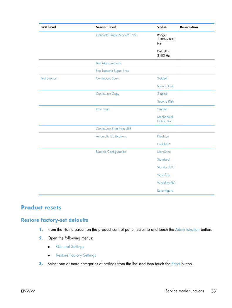
First level Second level Value Description
Generate Single Modem Tone Range:1100–2100Hz
Default =2100 Hz
Line Measurements
Fax Transmit Signal Loss
Test Support Continuous Scan 2-sided
Save to Disk
Continuous Copy 2-sided
Save to Disk
Raw Scan 2-sided
MechanicalCalibration
Continuous Print from USB
Automatic Calibrations Disabled
Enabled*
Runtime Configuration MercStine
Standard
StandardEIC
Workflow
WorkflowEIC
Reconfigure
Product resets
Restore factory-set defaults
1. From the Home screen on the product control panel, scroll to and touch the Administration button.
2. Open the following menus:
● General Settings
● Restore Factory Settings
3. Select one or more categories of settings from the list, and then touch the Reset button.
ENWW Service mode functions 381

Restore the service ID
Restore the service ID
If you replace the formatter, the date is lost. Use this menu item to reset the date to the original date thatthe product was first used. The date format is YYDDD. Use the following formula to calculate the dates:
1. To calculate YY, subtract 1990 from the calendar year. For instance, if the product was first usedin 2002, calculate YY as follows: 2002 - 1990 = 12. YY = 12.
2. Subtract 1 from 10 (October is the tenth month of the year): 10 - 1 = 9.
● Multiply 9 by 30: 9 x 30 = 270 or add 17 to 270: 270 + 17 = 287. Thus, DDD = 287.
Convert the service ID to an actual date
You can use the product Service ID number to determine whether the product is still under warranty.Use the following formula to convert the Service ID into the installation date as follows:
1. Add 1990 to YY to get the actual year that the product was installed.
2. Divide DDD by 30. If there is a remainder, add 1 to the result. This is the month.
3. The remainder from the calculation in step 2 is the date.
Using the Service ID 12287 as an example, the date conversion is as follows:
1. 12 + 1990 = 2002, so the year is 2002.
2. 287 divided by 30 = 9 with a remainder of 17. Because there is a remainder, add 1 to 9 to get10, which represents October.
3. The remainder in step 2 is 17, so that is the date.
4. The complete date is 17-October-2002.
NOTE: A six-day grace period is built into the date system.
Product cold reset
Cold reset using the Preboot menu
1. Turn the product on.
2. The HP logo displays on the product control panel. When an underscore displays below the HPlogo, touch the logo to open the Preboot menu.
3. Use the down arrow button to highlight Administrator, and then touch the OK button.
4. Use the down arrow button to highlight Startup Options item, and then touch the OK button.
382 Chapter 2 Solve problems ENWW

5. Use the down arrow button to highlight the Cold Reset item, and then touch the OK button.
6. Touch the home button to highlight Continue, and then touch the OK button.
NOTE: The product will initialize.
Format Disk and Partial Clean functions
Active and repository firmware locations
The firmware bundle consists of multiple parts. The main components are the Windows CE OperatingSystem and the product/peripheral firmware files.
There are two locations/partitions on the hard drive where the firmware components are stored:
● The Active – where the Operating System and firmware currently are executing.
● The Repository – the recovery location.
If the Active location is damaged, or a Partial Clean was performed, the product automatically copiesover the OS and firmware files from the Repository location and the product recovers.
If both the Active and Repository locations are damaged, or a Format Disk was performed, then bothlocations are gone and the error message 99.09.67 displays on the control-panel display. The usermust upload the firmware to the product in order for it to function again.
CAUTION: The Format Disk option performs a disk initialization for the entire disk. The operatingsystem, firmware files, and third party files (among other files) will be completely lost. HP does notrecommend this action.
Partial Clean
The Partial Clean option erases all partitions and data on the disk drive, except for the firmwarerepository where a backup copy of the firmware file is stored. This allows the disk drive to bereformatted without having to download a firmware upgrade file to return the product to a bootablestate.
Characteristics of a Partial Clean
● Customer-defined settings, third-party solutions, firmware files, and the operating system aredeleted.
● Rebooting the product restores the firmware files from the Repository location, but does not restoreany customer-defined settings.
● For previous HP products, a Hard Disk Initialization is similar to executing the Partial Cleanfunction for this product.
CAUTION: HP recommends backing-up product configuration data before executing a Partial Cleanif you need to retain customer-defined settings. See the Backup/Restore item in the Device Maintenancemenu.
ENWW Service mode functions 383

Reasons for performing Partial Clean
● The product continually boots up in an error state.
NOTE: Try clearing the error prior to executing a Partial Clean.
● The product will not respond to commands from the control panel.
● Executing the Partial Clean function is helpful for troubleshooting hard disk problems.
● To reset the product by deleting all solutions and customer-defined settings.
● The product default settings are not properly working.
Execute a Partial Clean
1. Turn the product on.
2. The HP logo displays on the product control panel. When an underscore displays below the HPlogo, touch the logo to open the Preboot menu.
3. Touch the down arrow button to highlight Administrator, and then touch the OK button.
4. Use the down arrow button to highlight Partial Clean, and then touch the OK button.
5. Touch the OK button again.
6. Touch the home button to highlight Continue, and then touch the OK button.
NOTE: The product initializes.
Format Disk
The Format Disk option erases the entire disk drive.
CAUTION: After executing a Format Disk option, the product is not bootable.
Characteristics of a Format Disk
● Customer-defined settings, third-party solutions, firmware files, and the operating system aredeleted.
NOTE: Rebooting the product does not restore the firmware files.
● Rebooting the product restores the firmware files from the Repository location, but does not restoreany customer-defined settings.
● After executing the Format Disk function, the message 99.09.67 displays on the control panel.
● After executing the Format Disk function, the product firmware must be reloaded.
384 Chapter 2 Solve problems ENWW

CAUTION: HP recommends that you do not use the Format Disk option unless an error occurs andthe solution in the product service manual recommends this solution. After executing the Format Diskfunction, the product is unusable.
HP recommends backing-up product configuration data before executing a Format Disk if you need toretain customer-defined settings. See the Backup/Restore item in the Device Maintenance menu.
Reasons for performing Format Disk
● The product continually boots up in an error state.
NOTE: Try clearing the error prior to executing a Format Disk.
● The product will not respond to commands from the control panel.
● Executing the Format Disk function is helpful for troubleshooting hard disk problems.
● To reset the product by deleting all solutions and customer-defined settings.
Execute a Format Disk
1. Turn the product on.
2. The HP logo displays on the product control panel. When an underscore displays below the HPlogo, touch the logo to open the Preboot menu.
3. Use the down arrow button to highlight Administrator, and then touch the OK button.
4. Use the down arrow button to highlight Format Disk, and then touch the OK button.
5. Touch the OK button again.
NOTE: When the Format Disk operation is complete, you will need to reload the productfirmware.
ENWW Service mode functions 385

Solve fax problems
Checklist for solving fax problems
Use the following checklist to help identify the cause of any fax-related problems you encounter:
● Are you using the fax cable supplied with the fax accessory? This fax accessory hasbeen tested with the supplied fax cable to meet RJ11 and functional specifications. Do notsubstitute another fax cable; the analog-fax accessory requires an analog-fax cable. It alsorequires an analog phone connection.
● Is the fax/phone line connector seated in the outlet on the fax accessory? Makesure that the phone jack is correctly seated in the outlet. Insert the connector into the outlet until it"clicks."
● Is the phone wall jack working properly? Verify that a dial tone exists by attaching aphone to the wall jack. Can you hear a dial tone, and can you make or receive a phone call?
What type of phone line are you using?
● Dedicated line: A standard analog fax/phone line assigned to receive or send faxes.
NOTE: The phone line should be for product fax use only and not shared with other types oftelephone devices. Examples include alarm systems that use the phone line for notifications to amonitoring company.
● PBX system: A business-environment phone system. Standard home phones and the faxaccessory use an analog phone signal. Some PBX systems are digital and might not be compatiblewith the fax accessory. You need to have access to a standard analog phone connection to beable to send and receive faxes.
● Roll-over lines: A phone system feature where a new call "rolls over" to the next available linewhen the first incoming line is busy. Try attaching the product to the first incoming phone line. Thefax accessory answers the phone after it rings the number of times set in the rings-to-answersetting.
NOTE: Roll-over lines can cause problems with receiving faxes. Using roll-over lines with thisproduct is not recommended.
NOTE: Roll-over lines can cause problems with receiving faxes. Using roll-over lines with this productis not recommended.
Are you using a surge-protection device?
A surge-protection device can be used between the wall jack and the fax accessory to protect the faxaccessory against electrical power passed through the phone lines. These devices can cause some faxcommunication problems by degrading the quality of the phone signal. If you are having problemssending or receiving faxes and are using one of these devices, connect the product directly to thephone jack on the wall to determine whether the problem is with the surge-protection device.
386 Chapter 2 Solve problems ENWW

Are you using a phone company voice-messaging service or an answeringmachine?
If the rings-to-answer setting for the messaging service is lower than the rings-to-answer setting for thefax accessory, the messaging service answers the call, and the fax accessory cannot receive faxes. Ifthe rings-to-answer setting for the fax accessory is lower than that of the messaging service, the faxaccessory answers all calls.
Does your phone line have a call-waiting feature?
If the fax telephone line has an activated call-waiting feature, a call-waiting notice can interrupt a faxcall in progress, which causes a communication error. Ensure that a call-waiting feature is not active onthe fax telephone line.
ENWW Solve fax problems 387

Check fax accessory status
If the analog-fax accessory does not appear to be functioning, print a Configuration Page report tocheck the status.
1. From the Home screen, scroll to and touch the Administration button.
2. Open the following menus:
● Reports
● Configuration/Status Pages
● Configuration Page
3. Touch the Print button to print the report, or touch the View button to view the report on the screen.The report consists of several pages.
NOTE: The product IP address or host name is listed on the Jetdirect Page.
On the Fax Accessory Page of the Configuration Page, under the Hardware Information heading,check the Modem Status. The following table identifies the status conditions and possible solutions.
NOTE: If the Fax Accessory Page does not print, there might be a problem with the analog faxaccessory. If you are using LAN fax or Internet fax, those configurations could be disabling the feature.
Operational / Enabled1 The analog-fax accessory is installed and ready.
Operational / Disabled1 The fax accessory is installed, but you have not configured therequired fax settings yet.
The fax accessory is installed and operational; however, theHP Digital Sending utility has either disabled the product faxfeature or has enabled LAN fax. When LAN fax is enabled,the analog-fax feature is disabled. Only one fax feature, eitherLAN fax or analog fax, can be enabled at a time.
NOTE: If LAN fax is enabled, the Fax feature is unavailableon the product control panel.
Non-Operational / Enabled/Disabled1 The product has detected a firmware failure. Upgrade thefirmware.
Damaged / Enabled/Disabled1 The fax accessory has failed. Reseat the fax accessory cardand check for bent pins. If the status is still DAMAGED,replace the analog-fax accessory card.
1 ENABLED indicates that the analog-fax accessory is enabled and turned on; DISABLED indicates that LAN fax is enabled(analog fax is turned off).
388 Chapter 2 Solve problems ENWW

General fax problems
Problem Cause Solution
The fax failed to send. JBIG is enabled, and the receiving faxmachine does not have JBIG capability.
Turn off the JBIG setting.
An "Out of Memory" status messagedisplays on the product control panel.
The product storage disk is full. Delete some stored jobs from the disk.From the Home screen on the productcontrol panel, touch the Retrieve fromDevice Memory button. Open the list ofstored jobs or stored faxes. Select a jobto delete, and then touch the Deletebutton.
Print quality of a photo is poor or printsas a gray box.
You are using the wrong page-contentsetting or the wrong resolution setting.
Try setting the Optimize Text/Pictureoption to Photograph setting.
You touched the Stop button on theproduct control panel to cancel a faxtransmission, but the fax was still sent.
If the job is too far along in the sendingprocess, you cannot cancel the job.
This is normal operation.
No fax address book button displays. The fax address book feature has notbeen enabled.
Use the HP MFP Digital SendingSoftware Configuration utility to enablethe fax address book feature.
Not able to locate the Fax settings inHP Web Jetadmin.
Fax settings in HP Web Jetadmin arelocated under the device's status pagedrop-down menu.
Select Digital Sending and Fax fromthe drop-down menu.
The header is appended to the top ofthe page when the overlay option isenabled.
For all forwarded faxes, the productappends the overlay header to the topof a page.
This is normal operation.
A mix of names and numbers is in therecipients box.
Names and numbers can both display,depending on where they are from. Thefax address book lists names, and allother databases list numbers.
This is normal operation.
A one-page fax prints as two pages. The fax header is being appended tothe top of the fax, pushing text to asecond page.
To print a one page fax on one page,set the overlay header to overlay mode,or adjust the fit-to-page setting.
A document stops in the documentfeeder in the middle of faxing.
A jam is in the document feeder. Clear the jam, and send the fax again.
The volume for sounds coming from thefax accessory is too high or too low.
The volume setting needs to be adjusted. Adjust the volume in the Fax SendSettings menu and the Fax ReceiveSettings menu.
ENWW Solve fax problems 389

Use Fax over VoIP networks
VoIP technology converts the analog phone signal into digital bits. These are then assembled intopackets which travel on the Internet. The packets are converted and transmitted back to analog signalsat or near the destination.
Transmission of information on the Internet is digital instead of analog. Therefore, there are differentconstraints on the fax transmission that might require different fax settings than the analog PublicSwitched Telephone Network (PSTN). Fax is very dependent upon timing and signal quality, so a faxtransmission is more sensitive to a VoIP environment.
The following are suggested changes in settings for the HP LaserJet Analog Fax Accessory500 when it is connected to a VoIP service:
● Begin with the fax speed set in Fast (V.34) mode and with Error Correction Mode (ECM) turnedon. The V.34 protocol handles any changes in transmission speed needed to accommodate VoIPnetworks.
● If numerous errors or retries occur with the fax speed set to Fast, set it to Medium (V.17).
● If errors and retries persist, set the fax speed to Slow (V.29) because some VoIP systems cannothandle the higher signal rates associated with fax.
● In rare cases, if errors persist, turn off ECM on the product. The image quality might decrease.Ensure that the image quality is acceptable with ECM off before using this setting.
● If the preceding setting changes have not improved the VoIP fax reliability, contact your VoIPprovider for help.
390 Chapter 2 Solve problems ENWW

Problems with receiving faxes
Problem Cause Solution
Incoming fax calls are not beinganswered by the fax accessory (no faxdetected).
The rings-to-answer setting might not beset correctly.
Check the rings-to-answer setting.
The fax cable might not be connectedcorrectly, or the fax cable is notworking.
Check the installation. Make sure youare using the fax cable that came withthe product or with the fax accessory.
The phone line might not be working. Disconnect the fax accessory from thephone jack, and then connect a phone.Try to make a phone call to ensure thephone line is working.
If you are using a PBX system, the ringsignals might not be configuredcorrectly.
Check the ring-signal configuration onthe PBX system.
A voice-messaging service might beinterfering with incoming faxes.
Do one of the following:
● Discontinue the messaging service.
● Use a phone line dedicated to faxcalls.
● Decrease the rings-to-answer for thefax accessory to a number less thanthe rings-to-answer for the voicemail.
Faxes are being received very slowly. You might be receiving a complex fax,such as one with many graphics.
Complex faxes take longer to transmit.
The sending fax machine might have aslow modem speed.
The fax accessory only receives the faxat the fastest modem speed the sendingfax machine can use. Wait for the faxtransmission to complete.
The resolution at which the fax was sentor is being received is very high. Ahigher resolution typically results inbetter quality, but also requires a longertransmission time.
Ask the sender to decrease the resolutionand resend the fax.
If there is a poor phone-line connection,the fax accessory and the sending faxmachine slow down the transmission toadjust for errors.
Ask the sender to resend the fax. Ask thephone company to check the phone line.
Faxes are not printing on the product. No paper is in the input tray. Load paper. Any faxes received whilethe input tray is empty are stored andwill print after the tray has paper.
The Fax Printing Schedule feature is inuse.
Faxes print according to the schedule.To print faxes immediately, disable theFax Printing Schedule feature.
ENWW Solve fax problems 391

Problem Cause Solution
The product is either low on toner or hasrun out of toner.
If configured, the product stops printingas soon as it is low on toner or runs outof toner. Any faxes received are storedin memory and print after the toner hasbeen replaced.
The incoming call might be a voice call. Incoming voice calls usually show up inthe call report as a No Fax Detectederror. Because these are voice calls andnot a fax error, no action is necessary.
The incoming fax was interrupted. Verify that the fax telephone line doesnot have an activated call-waitingfeature. A call-waiting notice caninterrupt a fax call in progress, whichcauses a communication error.
The Fax Printing Schedule feature is setto the Always store faxes option.
Change the Fax Printing Schedulesetting to the Always print faxes option.
392 Chapter 2 Solve problems ENWW

Problems with sending faxes
Problem Cause Solution
Faxes are transmitting very slowly. You might be sending a complex fax,such as one with many graphics.
Complex faxes take longer to transmit.
The receiving fax machine might have aslow modem speed.
The fax accessory only sends the fax atthe fastest modem speed the receivingfax machine can use. Wait for the faxtransmission to complete.
The resolution at which the fax was sentor is being received is very high. Ahigher resolution typically results inbetter quality, but also requires a longertransmission time.
Decrease the resolution and change theOptimize Text/Picture option.
If there is a poor phone-line connection,the fax accessory and the receiving faxmachine slow down the transmission toadjust for errors.
Cancel and resend the fax. Ask thephone company check the phone line.
The document might have a graybackground, which can increase faxtransmission time.
Use the Image Adjustment feature toclean up the background shading.
Faxes quit during sending. The receiving fax machine might bemalfunctioning.
Try sending to another fax machine.
The phone line might not be working. Disconnect the fax accessory from thephone jack, and connect a phone. Try tomake a phone call to ensure the phoneline is working.
The phone line might be noisy or poorquality.
Try using a slower fax speed to improvethe reliability of transmission. Use theFax Dialing Settings menu to set the faxspeed for sending faxes.
A call-waiting feature might be active. Verify that the fax telephone line doesnot have an activated call-waitingfeature. A call-waiting notice caninterrupt a fax call in progress, whichcauses a communication error.
The fax accessory is receiving faxes butis not sending them.
If the fax accessory is on a PBX system,the PBX system might be generating adial tone the fax accessory cannotdetect.
Disable the detect-dial-tone setting.
There might be a poor phoneconnection.
Try again later.
The receiving fax machine might bemalfunctioning.
Try sending to another fax machine.
The phone line might not be working. Disconnect the fax accessory from thephone jack, and connect a phone. Try tomake a phone call to ensure the phoneline is working.
ENWW Solve fax problems 393

Problem Cause Solution
Outgoing fax calls keep dialing. The fax accessory automatically redialsa fax number if the Redial on Busyoption is on or if the Redial on NoAnswer option is on.
This is normal operation. If you do notwant the fax to retry, set the Redial onBusy option to 0, set the Redial on NoAnswer option to 0, and set the Redialon Error option to 0.
Faxes you send are not arriving at thereceiving fax machine.
The receiving fax machine might beturned off or might have an errorcondition, such as being out of paper.
Ask the recipient to make sure the faxmachine is turned on and ready toreceive faxes.
A fax might be in memory because it iswaiting to redial a busy number, orthere are other jobs ahead of it waitingto be sent.
If a fax job is in memory for either ofthese reasons, an entry for the jobdisplays in the fax log. Print the faxactivity log, and check the Resultcolumn for jobs with a Pendingdesignation.
394 Chapter 2 Solve problems ENWW

Fax error codes
If a fax problem occurs which prevents or interrupts fax transmission, an error code is generated thatcan help in determining the cause of the problem. Error codes show up in the fax activity log, the faxcall report, and the T.30 Protocol Trace. Print one of these reports to obtain the error code. A detaileddescription of the error codes and the appropriate action is available at www.hp.com. Search forHP LaserJet Analog Fax Accessory 500.
Fax error messages on the product control panel
If the fax process is interrupted or an error occurs during a fax transmission or reception, a two-partstatus/error description is generated by the fax subsystem on the product. Normal or successful faxesalso generate messages indicating success. The message information consists of a text description anda numeric code (a few messages do not include numeric codes). Only the text part of the message isdisplayed on the product control panel; however, both the text message and numeric code are listed inthe Fax Activity Report, Fax Call Report, and the Fax T.30 Trace. The numeric code is shown inparentheses after the text part of the message in the reports.
The fax modem generates the numeric code. Usually a numeric code of (0) indicates a normal modemresponse. Some messages always display a numeric code of (0), other messages can have a range ofnumeric codes, and a few messages have no numeric code. Usually a numeric code of (0) indicates anerror was not associated with the fax modem, but occurred in another part of the fax system or otherproduct sytem such as the printing system. Non-zero error codes give further detail into the particularaction or process that the modem is executing, and they do not necessarily indicate that there is aproblem with the modem.
Persistent error messages with numeric codes different than those listed here require assistance ofcustomer support. Print a Fax T.30 Trace report before contacting customer support to help identify theproblem. This report contains details of the last fax call.
1. From the Home screen on the product control panel, scroll to and touch the Administration button.
2. Open the following menus:
● Troubleshooting
● Fax
● Fax T.30 Trace
3. Select the Print T.30 Report option to print the report.
ENWW Solve fax problems 395

Send-fax messages
Table 2-52 Send-fax messages
Message Error No. Description Action
Cancelled 0 Someone cancelled the fax at theproduct control panel.
None.
Success n/a The fax was sent successfully. None.
Fail Busy 0 The receiving fax machine isbusy.
The fax will be retiredautomatically (if configured),otherwise try resending fax later.
No Answer 0 or 17 The receiving fax machine is notanswering the call, or a personanswered the call.
The receiving fax machine mightbe disconnected or turned off;contact the receiver to check themachine. Try resending.
No Dial 0 No dial tone is detected whensending the fax.
Verify the phone line is active;set the sending fax to "not" todetect a dial tone.
Failed Any The fax might be corrupted ornot sent.
Try resending fax.
Failed 0 Incompatible page width, orpage had too many bad lines.
Try resending fax; if the errorpersists, contact service.
Failed 17 or 36 Lost telephone connectionbetween sender and receiver.The issue might be due to voicecalls interrupting the fax, or aperson answering the call.
Try resending the fax.
Failed or CommunicationError
Any besides 17 or 36 General communications issuewhere the fax transmission wasinterrupted or did not proceed asexpected.
Try resending fax; if the errorpersists, contact support.
Space Fail 0 Unable to read or write the faximage file to disk; could becorrupt product disk or no spaceavailable on the product's disk.
Try resending fax; if the errorpersists, contact support.
Memory Error 0 Out of memory on product. If the error persists, delete itemsfrom the product memory, suchas stored jobs or saved faxes.
Power Failure 0 A power failure occurred on thesending fax product during thefax transmission.
Try resending the fax.
396 Chapter 2 Solve problems ENWW

Receive-fax messages
Table 2-53 Receive-fax messages
Message Error No. Description Action
Success n/a The fax transmission wassuccessful.
None.
Blocked n/a The receiving fax machine isusing the blocked-number featureand is blocking this fax.
None.
Failed Any The fax might be corrupted ornot sent.
Ask the sender to resend the fax;if the error persists, contactsupport.
Failed 0 Incompatible page width orpage had too many bad lines.
Ask the sender to resend the fax;if the error persists, contactsupport.
Failed 17, 36 Lost telephone connection orinterruption between sender/receiver.
Ask the sender to resend the fax(if the sending machine does notautomatically retry).
Failed Any besides 17 or 36 General communications issuewhere the fax transmission wasinterrupted or did not proceed asexpected.
Ask the sender to resend the fax;if the error persists, contactsupport.
Space Fail 0 Unable to read or write imagefile to disk; could be corruptproduct disk or no space on disk.
Ask the sender to resend the fax;if the error persists, contactsupport.
Memory Error 0 Out of memory on product. If the error persists, delete itemsfrom the product memory, suchas stored jobs or saved faxes.
Print Fail 0 The received image file cannotbe decoded.
Ask the sender to resend the fax;enable Error Correction Mode ifit is not already enabled.
Power Failure 0 A power failure occurred duringthe fax reception.
Ask the sender to resend the fax.
No Fax Detected 17, 36 A voice call was made to thefax.
None
ENWW Solve fax problems 397

Service settings
These items in the control-panel menus are intended to be used when an HP service representative isassisting you.
Settings in the Troubleshooting menu
1. From the Home screen on the product control panel, scroll to and touch the Administration button.
2. Open the following menus:
● Troubleshooting
● Fax
Fax T.30 Trace This is a printed report of all the communications between the sending andreceiving fax machines for the last Fax transmission or reception. The reportcontains detailed error codes and other information that might be useful introubleshooting a particular problem related to sending or receiving a fax. Print thisreport before contacting HP customer support.
Fax V.34 This setting controls the modem's method of transmission. The Normal setting allowsthe modem to select any of the supported fax speeds up to 33,600 bps. The Offsetting sets the fax speed to 14,400 bps or lower, depending on the speed settingsfor sending and receiving.
Fax Speaker Mode In Normal mode, the modem speaker is turned on during dialing, through the initialconnection, and then it turns off. In Diagnostic mode, the speaker is turned on andremains on for all fax communications until the setting is returned to Normal mode.
Fax Log Entries The Standard fax log includes basic information such as the time and whether thefax was successful. The Detailed fax log shows the intermediate results of the redialprocess not shown in the Standard fax log.
398 Chapter 2 Solve problems ENWW

Product upgradesTo download the most recent firmware upgrade for the product, go to www.hp.com/go/lj500colorMFPM575_firmware.
Determine the installed revision of firmware
Print a configuration page to determine the installed revision of firmware.
On the configuration page, look in the section marked Device Information for the firmware datecodeand firmware revision.
Firmware datecode and firmware revision examples
● 20100831 (firmware datecode)
● 103067_104746 (firmware revision)
Perform a firmware upgrade
The firmware bundle is a xxxxxxx.bdl file. This file requires an interactive upgrade method. Youcannot upgrade the product using the traditional FTP, LPR or Port 9100 methods of upgrading. Use oneof the following methods to upgrade the firmware for this product.
Embedded Web Server
1. Open an browser window.
2. Enter the product IP address in the URL line.
3. Select the Firmware Upgrade link from within the Troubleshooting tab.
NOTE: If you get a warning screen, follow the instructions for setting an administrator passwordfrom the Security tab.
4. Browse to the location that the firmware upgrade file was downloaded to, and then select thefirmware file. Select the Install button to perform the upgrade.
NOTE: Do not close the browser window until the Embedded Web Server (EWS) displays theconfirmation page.
5. Select Restart Now from the EWS confirmation page, or turn the product off, and then on againusing the power switch.
ENWW Product upgrades 399

USB flash drive (Preboot menu)
1. Copy the xxxxxxx.bdl file to a portable USB flash drive.
2. Turn the product on.
3. The HP logo displays on the product control panel. When an underscore displays below the HPlogo, touch the logo to open the Preboot menu.
4. Touch the down arrow button to highlight Administrator, and then touch the OK button.
5. Touch the down arrow button to highlight Download, and then touch the OK button.
6. Insert the USB flash drive with the xxxxxxx.bdl file on it.
NOTE: If the error message No USB Thumbdrive Files Found displays on the control-paneldisplay, you might need to connect the storage device to the external USB connection on theformatter or try using a different portable storage device.
7. Touch the down arrow button to highlight USB Thumbdrive, and then touch the OK button.
8. Touch the down arrow button to highlight the xxxxxxx.bdl file, and then touch the OK button.
NOTE: The upgrade process can take up to 10 minutes to complete.
TIP: If there is more than one xxxxxxx.bdl file on the storage device, make sure that youselect the correct file for this product.
9. When the message Complete displays on the control-panel display, touch the back arrow button 3 times.
10. When the message Continue displays on the control-panel display, touch the OK button. Theproduct will initialize.
11. When the upgrade process is complete, print a configuration page and verify that the upgradefirmware version was installed.
400 Chapter 2 Solve problems ENWW
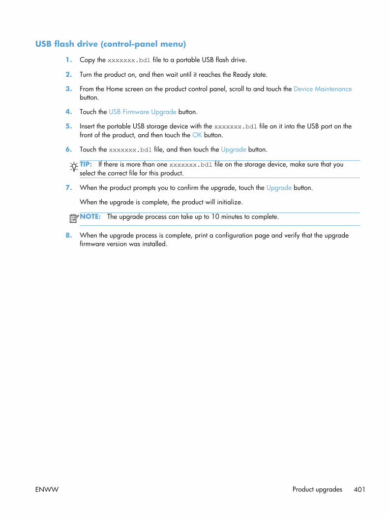
USB flash drive (control-panel menu)
1. Copy the xxxxxxx.bdl file to a portable USB flash drive.
2. Turn the product on, and then wait until it reaches the Ready state.
3. From the Home screen on the product control panel, scroll to and touch the Device Maintenancebutton.
4. Touch the USB Firmware Upgrade button.
5. Insert the portable USB storage device with the xxxxxxx.bdl file on it into the USB port on thefront of the product, and then touch the OK button.
6. Touch the xxxxxxx.bdl file, and then touch the Upgrade button.
TIP: If there is more than one xxxxxxx.bdl file on the storage device, make sure that youselect the correct file for this product.
7. When the product prompts you to confirm the upgrade, touch the Upgrade button.
When the upgrade is complete, the product will initialize.
NOTE: The upgrade process can take up to 10 minutes to complete.
8. When the upgrade process is complete, print a configuration page and verify that the upgradefirmware version was installed.
ENWW Product upgrades 401

402 Chapter 2 Solve problems ENWW

A Service and support
● Hewlett-Packard limited warranty statement
● HP's Premium Protection Warranty: LaserJet toner cartridge limited warranty statement
● HP policy on non-HP supplies
● HP anticounterfeit Web site
● Color LaserJet Fuser Kit, Transfer Kit, and Roller Kit Limited Warranty Statement
● Data stored on the toner cartridge
● End User License Agreement
● OpenSSL
● Customer self-repair warranty service
● Customer support
ENWW 403

Hewlett-Packard limited warranty statement
HP PRODUCT DURATION OF LIMITED WARRANTY
HP LaserJet Enterprise 500 color MFP M575dn, M575f One-year on-site warranty
HP warrants to you, the end-user customer, that HP hardware and accessories will be free from defectsin materials and workmanship after the date of purchase, for the period specified above. If HP receivesnotice of such defects during the warranty period, HP will, at its option, either repair or replaceproducts which prove to be defective. Replacement products may be either new or equivalent inperformance to new.
HP warrants to you that HP software will not fail to execute its programming instructions after the dateof purchase, for the period specified above, due to defects in material and workmanship whenproperly installed and used. If HP receives notice of such defects during the warranty period, HP willreplace software which does not execute its programming instructions due to such defects.
HP does not warrant that the operation of HP products will be uninterrupted or error free. If HP isunable, within a reasonable time, to repair or replace any product to a condition as warranted, youwill be entitled to a refund of the purchase price upon prompt return of the product.
HP products may contain remanufactured parts equivalent to new in performance or may have beensubject to incidental use.
Warranty does not apply to defects resulting from (a) improper or inadequate maintenance orcalibration, (b) software, interfacing, parts or supplies not supplied by HP, (c) unauthorizedmodification or misuse, (d) operation outside of the published environmental specifications for theproduct, or (e) improper site preparation or maintenance.
TO THE EXTENT ALLOWED BY LOCAL LAW, THE ABOVE WARRANTIES ARE EXCLUSIVE AND NOOTHER WARRANTY OR CONDITION, WHETHER WRITTEN OR ORAL, IS EXPRESSED OR IMPLIEDAND HP SPECIFICALLY DISCLAIMS ANY IMPLIED WARRANTIES OR CONDITIONS OFMERCHANTABILITY, SATISFACTORY QUALITY, AND FITNESS FOR A PARTICULAR PURPOSE. Somecountries/regions, states or provinces do not allow limitations on the duration of an implied warranty,so the above limitation or exclusion might not apply to you. This warranty gives you specific legal rightsand you might also have other rights that vary from country/region to country/region, state to state, orprovince to province.
HP's limited warranty is valid in any country/region or locality where HP has a support presence forthis product and where HP has marketed this product. The level of warranty service you receive mayvary according to local standards. HP will not alter form, fit or function of the product to make itoperate in a country/region for which it was never intended to function for legal or regulatory reasons.
TO THE EXTENT ALLOWED BY LOCAL LAW, THE REMEDIES IN THIS WARRANTY STATEMENT AREYOUR SOLE AND EXCLUSIVE REMEDIES. EXCEPT AS INDICATED ABOVE, IN NO EVENT WILL HP ORITS SUPPLIERS BE LIABLE FOR LOSS OF DATA OR FOR DIRECT, SPECIAL, INCIDENTAL,CONSEQUENTIAL (INCLUDING LOST PROFIT OR DATA), OR OTHER DAMAGE, WHETHER BASEDIN CONTRACT, TORT, OR OTHERWISE. Some countries/regions, states or provinces do not allow theexclusion or limitation of incidental or consequential damages, so the above limitation or exclusion maynot apply to you.
404 Appendix A Service and support ENWW

THE WARRANTY TERMS CONTAINED IN THIS STATEMENT, EXCEPT TO THE EXTENT LAWFULLYPERMITTED, DO NOT EXCLUDE, RESTRICT OR MODIFY AND ARE IN ADDITION TO THEMANDATORY STATUTORY RIGHTS APPLICABLE TO THE SALE OF THIS PRODUCT TO YOU.
ENWW Hewlett-Packard limited warranty statement 405

HP's Premium Protection Warranty: LaserJet tonercartridge limited warranty statement
This HP product is warranted to be free from defects in materials and workmanship.
This warranty does not apply to products that (a) have been refilled, refurbished, remanufactured ortampered with in any way, (b) experience problems resulting from misuse, improper storage, oroperation outside of the published environmental specifications for the printer product or (c) exhibitwear from ordinary use.
To obtain warranty service, please return the product to place of purchase (with a written description ofthe problem and print samples) or contact HP customer support. At HP's option, HP will either replaceproducts that prove to be defective or refund your purchase price.
TO THE EXTENT ALLOWED BY LOCAL LAW, THE ABOVE WARRANTY IS EXCLUSIVE AND NOOTHER WARRANTY OR CONDITION, WHETHER WRITTEN OR ORAL, IS EXPRESSED OR IMPLIEDAND HP SPECIFICALLY DISCLAIMS ANY IMPLIED WARRANTIES OR CONDITIONS OFMERCHANTABILITY, SATISFACTORY QUALITY, AND FITNESS FOR A PARTICULAR PURPOSE.
TO THE EXTENT ALLOWED BY LOCAL LAW, IN NO EVENT WILL HP OR ITS SUPPLIERS BE LIABLEFOR DIRECT, SPECIAL, INCIDENTAL, CONSEQUENTIAL (INCLUDING LOST PROFIT OR DATA), OROTHER DAMAGE, WHETHER BASED IN CONTRACT, TORT, OR OTHERWISE.
THE WARRANTY TERMS CONTAINED IN THIS STATEMENT, EXCEPT TO THE EXTENT LAWFULLYPERMITTED, DO NOT EXCLUDE, RESTRICT OR MODIFY AND ARE IN ADDITION TO THEMANDATORY STATUTORY RIGHTS APPLICABLE TO THE SALE OF THIS PRODUCT TO YOU.
406 Appendix A Service and support ENWW

HP policy on non-HP suppliesHewlett-Packard Company cannot recommend the use of non-HP toner cartridges, either new orremanufactured.
NOTE: For HP printer products, the use of a non-HP toner cartridge or a refilled toner cartridge doesnot affect either the warranty to the customer or any HP support contract with the customer. However, ifproduct failure or damage is attributable to the use of a non-HP toner cartridge or refilled tonercartridge, HP will charge its standard time and materials charges to service the product for theparticular failure or damage.
ENWW HP policy on non-HP supplies 407

HP anticounterfeit Web siteGo to www.hp.com/go/anticounterfeit when you install an HP toner cartridge and the control-panelmessage says the cartridge is non-HP. HP will help determine if the cartridge is genuine and take stepsto resolve the problem.
Your toner cartridge might not be a genuine HP toner cartridge if you notice the following:
● The supplies status page indicates that a non-HP supply is installed.
● You are experiencing a high number of problems with the cartridge.
● The cartridge does not look like it usually does (for example, the packaging differs fromHP packaging).
408 Appendix A Service and support ENWW

Color LaserJet Fuser Kit, Transfer Kit, and Roller KitLimited Warranty Statement
This HP product is warranted to be free from defects in materials and workmanship until the printerprovides a low-life indicator on the control panel.
This warranty does not apply to products that (a) have been refurbished, remanufactured or tamperedwith in any way, (b) experience problems resulting from misuse, improper storage, or operation outsideof the published environmental specifications for the printer product or (c) exhibit wear from ordinaryuse.
To obtain warranty service, please return the product to place of purchase (with a written description ofthe problem) or contact HP customer support. At HP’s option, HP will either replace products that proveto be defective or refund your purchase price.
TO THE EXTENT ALLOWED BY LOCAL LAW, THE ABOVE WARRANTY IS EXCLUSIVE AND NOOTHER WARRANTY OR CONDITION, WHETHER WRITTEN OR ORAL, IS EXPRESSED OR IMPLIEDAND HP SPECIFICALLY DISCLAIMS ANY IMPLIED WARRANTIES OR CONDITIONS OFMERCHANTABILITY, SATISFACTORY QUALITY, AND FITNESS FOR A PARTICULAR PURPOSE.
TO THE EXTENT ALLOWED BY LOCAL LAW, IN NO EVENT WILL HP OR ITS SUPPLIERS BE LIABLEFOR DIRECT, SPECIAL, INCIDENTAL, CONSEQUENTIAL (INCLUDING LOST PROFIT OR DATA), OROTHER DAMAGE, WHETHER BASED IN CONTRACT, TORT, OR OTHERWISE.
THE WARRANTY TERMS CONTAINED IN THIS STATEMENT, EXCEPT TO THE EXTENT LAWFULLYPERMITTED, DO NOT EXCLUDE, RESTRICT OR MODIFY AND ARE IN ADDITION TO THEMANDATORY STATUTORY RIGHTS APPLICABLE TO THE SALE OF THIS PRODUCT TO YOU.
ENWW Color LaserJet Fuser Kit, Transfer Kit, and Roller Kit Limited Warranty Statement 409

Data stored on the toner cartridgeThe HP toner cartridges used with this product contain a memory chip that assists in the operation of theproduct.
In addition, this memory chip collects a limited set of information about the usage of the product, whichmight include the following: the date when the toner cartridge was first installed, the date when thetoner cartridge was last used, the number of pages printed using the toner cartridge, the pagecoverage, the printing modes used, any printing errors that might have occurred, and the productmodel. This information helps HP design future products to meet our customers' printing needs.
The data collected from the toner cartridge memory chip does not contain information that can be usedto identify a customer or user of the toner cartridge or their product.
HP collects a sampling of the memory chips from toner cartridges returned to HP's free return andrecycling program (HP Planet Partners: www.hp.com/recycle). The memory chips from this samplingare read and studied in order to improve future HP products. HP partners who assist in recycling thistoner cartridge might have access to this data, as well.
Any third party possessing the toner cartridge might have access to the anonymous information on thememory chip.
410 Appendix A Service and support ENWW

End User License AgreementPLEASE READ CAREFULLY BEFORE USING THIS SOFTWARE PRODUCT: This End-User LicenseAgreement (“EULA”) is a contract between (a) you (either an individual or the entity you represent) and(b) Hewlett-Packard Company (“HP”) that governs your use of the software product (“Software”). ThisEULA does not apply if there is a separate license agreement between you and HP or its suppliers forthe Software, including a license agreement in online documentation. The term “Software” may include(i) associated media, (ii) a user guide and other printed materials, and (iii) “online” or electronicdocumentation (collectively “User Documentation”).
RIGHTS IN THE SOFTWARE ARE OFFERED ONLY ON THE CONDITION THAT YOU AGREE TO ALLTERMS AND CONDITIONS OF THIS EULA. BY INSTALLING, COPYING, DOWNLOADING, OROTHERWISE USING THE SOFTWARE, YOU AGREE TO BE BOUND BY THIS EULA. IF YOU DO NOTACCEPT THIS EULA, DO NOT INSTALL, DOWNLOAD, OR OTHERWISE USE THE SOFTWARE. IFYOU PURCHASED THE SOFTWARE BUT DO NOT AGREE TO THIS EULA, PLEASE RETURN THESOFTWARE TO YOUR PLACE OF PURCHASE WITHIN FOURTEEN DAYS FOR A REFUND OF THEPURCHASE PRICE; IF THE SOFTWARE IS INSTALLED ON OR MADE AVAILABLE WITH ANOTHERHP PRODUCT, YOU MAY RETURN THE ENTIRE UNUSED PRODUCT.
1. THIRD PARTY SOFTWARE. The Software may include, in addition to HP proprietary software (“HPSoftware”), software under licenses from third parties (“Third Party Software” and “Third PartyLicense”). Any Third Party Software is licensed to you subject to the terms and conditions of thecorresponding Third Party License. Generally, the Third Party License is in a file such as“license.txt” or a “readme” file. You should contact HP support if you cannot find a Third PartyLicense. If the Third Party Licenses include licenses that provide for the availability of source code(such as the GNU General Public License) and the corresponding source code is not included withthe Software, then check the product support pages of HP's website (hp.com) to learn how toobtain such source code.
2. LICENSE RIGHTS. You will have the following rights provided you comply with all terms andconditions of this EULA:
a. Use. HP grants you a license to Use one copy of the HP Software. “Use” means installing,copying, storing, loading, executing, displaying, or otherwise using the HP Software. Youmay not modify the HP Software or disable any licensing or control feature of theHP Software. If this Software is provided by HP for Use with an imaging or printing product(for example, if the Software is a printer driver, firmware, or add-on), the HP Software mayonly be used with such product (“HP Product”). Additional restrictions on Use may appear inthe User Documentation. You may not separate component parts of the HP Software for Use.You do not have the right to distribute the HP Software.
b. Copying. Your right to copy means you may make archival or back-up copies of theHP Software, provided each copy contains all the original HP Software’s proprietary noticesand is used only for back-up purposes.
3. UPGRADES. To Use HP Software provided by HP as an upgrade, update, or supplement(collectively “Upgrade”), you must first be licensed for the original HP Software identified by HP aseligible for the Upgrade. To the extent the Upgrade supersedes the original HP Software, you mayno longer use such HP Software. This EULA applies to each Upgrade unless HP provides otherterms with the Upgrade. In case of a conflict between this EULA and such other terms, the otherterms will prevail.
ENWW End User License Agreement 411

4. TRANSFER.
a. Third Party Transfer. The initial end user of the HP Software may make a one-time transfer ofthe HP Software to another end user. Any transfer will include all component parts, media,User Documentation, this EULA, and if applicable, the Certificate of Authenticity. The transfermay not be an indirect transfer, such as a consignment. Prior to the transfer, the end userreceiving the transferred Software will agree to this EULA. Upon transfer of the HP Software,your license is automatically terminated.
b. Restrictions. You may not rent, lease or lend the HP Software or Use the HP Software forcommercial timesharing or bureau use. You may not sublicense, assign or otherwise transferthe HP Software except as expressly provided in this EULA.
5. PROPRIETARY RIGHTS. All intellectual property rights in the Software and User Documentation areowned by HP or its suppliers and are protected by law, including applicable copyright, tradesecret, patent, and trademark laws. You will not remove any product identification, copyrightnotice, or proprietary restriction from the Software.
6. LIMITATION ON REVERSE ENGINEERING. You may not reverse engineer, decompile, ordisassemble the HP Software, except and only to the extent that the right to do so is allowed underapplicable law.
7. CONSENT TO USE OF DATA. HP and its affiliates may collect and use technical information youprovide in relation to (i) your Use of the Software or the HP Product, or (ii) the provision of supportservices related to the Software or the HP Product. All such information will be subject to HP’sprivacy policy. HP will not use such information in a form that personally identifies you except tothe extent necessary to enhance your Use or provide support services.
8. LIMITATION OF LIABILITY. Notwithstanding any damages that you might incur, the entire liabilityof HP and its suppliers under this EULA and your exclusive remedy under this EULA will be limitedto the greater of the amount actually paid by you for the Product or U.S. $5.00. TO THEMAXIMUM EXTENT PERMITTED BY APPLICABLE LAW, IN NO EVENT WILL HP OR ITS SUPPLIERSBE LIABLE FOR ANY SPECIAL, INCIDENTAL, INDIRECT, OR CONSEQUENTIAL DAMAGES(INCLUDING DAMAGES FOR LOST PROFITS, LOST DATA, BUSINESS INTERRUPTION,PERSONAL INJURY, OR LOSS OF PRIVACY) RELATED IN ANY WAY TO THE USE OF ORINABILITY TO USE THE SOFTWARE, EVEN IF HP OR ANY SUPPLIER HAS BEEN ADVISED OF THEPOSSIBILITY OF SUCH DAMAGES AND EVEN IF THE ABOVE REMEDY FAILS OF ITS ESSENTIALPURPOSE. Some states or other jurisdictions do not allow the exclusion or limitation of incidentalor consequential damages, so the above limitation or exclusion may not apply to you.
9. U.S. GOVERNMENT CUSTOMERS. Software was developed entirely at private expense. AllSoftware is commercial computer software within the meaning of the applicable acquisitionregulations. Accordingly, pursuant to US FAR 48 CFR 12.212 and DFAR 48 CFR 227.7202, use,duplication and disclosure of the Software by or for the U.S. Government or a U.S. Governmentsubcontractor is subject solely to the terms and conditions set forth in this End User LicenseAgreement, except for provisions which are contrary to applicable mandatory federal laws.
10. COMPLIANCE WITH EXPORT LAWS. You will comply with all laws, rules, and regulations (i)applicable to the export or import of the Software, or (ii) restricting the Use of the Software,including any restrictions on nuclear, chemical, or biological weapons proliferation.
11. RESERVATION OF RIGHTS. HP and its suppliers reserve all rights not expressly granted to you inthis EULA.
412 Appendix A Service and support ENWW

© 2009 Hewlett-Packard Development Company, L.P.
Rev. 04/09
ENWW End User License Agreement 413

OpenSSLThis product includes software developed by the OpenSSL Project for use in the OpenSSL Toolkit(http://www.openssl.org/)
THIS SOFTWARE IS PROVIDED BY THE OpenSSL PROJECT ``AS IS'' AND ANY EXPRESSED ORIMPLIED WARRANTIES, INCLUDING, BUT NOT LIMITED TO, THE IMPLIED WARRANTIES OFMERCHANTABILITY AND FITNESS FOR A PARTICULAR PURPOSE ARE DISCLAIMED. IN NO EVENTSHALL THE OpenSSL PROJECT OR ITS CONTRIBUTORS BE LIABLE FOR ANY DIRECT, INDIRECT,INCIDENTAL, SPECIAL, EXEMPLARY, OR CONSEQUENTIAL DAMAGES (INCLUDING, BUT NOTLIMITED TO, PROCUREMENT OF SUBSTITUTE GOODS OR SERVICES;
LOSS OF USE, DATA, OR PROFITS; OR BUSINESS INTERRUPTION) HOWEVER CAUSED AND ONANY THEORY OF LIABILITY, WHETHER IN CONTRACT, STRICT LIABILITY, OR TORT (INCLUDINGNEGLIGENCE OR OTHERWISE) ARISING IN ANY WAY OUT OF THE USE OF THIS SOFTWARE,EVEN IF ADVISED OF THE POSSIBILITY OF SUCH DAMAGE.
This product includes cryptographic software written by Eric Young ([email protected]). This productincludes software written by Tim Hudson ([email protected]).
414 Appendix A Service and support ENWW

Customer self-repair warranty serviceHP products are designed with many Customer Self Repair (CSR) parts to minimize repair time andallow for greater flexibility in performing defective parts replacement. If during the diagnosis period,HP identifies that the repair can be accomplished by the use of a CSR part, HP will ship that partdirectly to you for replacement. There are two categories of CSR parts: 1) Parts for which customer selfrepair is mandatory. If you request HP to replace these parts, you will be charged for the travel andlabor costs of this service. 2) Parts for which customer self repair is optional. These parts are alsodesigned for Customer Self Repair. If, however, you require that HP replace them for you, this may bedone at no additional charge under the type of warranty service designated for your product.
Based on availability and where geography permits, CSR parts will be shipped for next business daydelivery. Same-day or four-hour delivery may be offered at an additional charge where geographypermits. If assistance is required, you can call the HP Technical Support Center and a technician willhelp you over the phone. HP specifies in the materials shipped with a replacement CSR part whether adefective part must be returned to HP. In cases where it is required to return the defective part to HP,you must ship the defective part back to HP within a defined period of time, normally five (5) businessdays. The defective part must be returned with the associated documentation in the provided shippingmaterial. Failure to return the defective part may result in HP billing you for the replacement. With acustomer self repair, HP will pay all shipping and part return costs and determine the courier/carrier tobe used.
ENWW Customer self-repair warranty service 415

Customer support
Get telephone support for your country/region
Have the product name, serial number, date of purchase, andproblem description ready.
Country/region phone numbers are on the flyer that was inthe box with your product or at www.hp.com/support/.
Get 24-hour Internet support www.hp.com/support/lj500colorMFPM575
Download software utilities, drivers, and electronicinformation
www.hp.com/go/lj500colorMFPM575_software
Order additional HP service or maintenance agreements www.hp.com/go/carepack
Register your product www.register.hp.com
416 Appendix A Service and support ENWW

B Product specifications
● Physical specifications
● Power consumption, electrical specifications, and acoustic emissions
● Environmental specifications
ENWW 417

Physical specificationsTable B-1 Physical specifications
Product Height Depth Width Weight
M575dn 600 mm (23.6 in) 458 mm (18.0 in) 510 mm (20.0 in) 46.6 kg (102.7 lb)
M575f 600 mm (23.6 in) 458 mm (18.0 in) 545 mm (21.5 in) 46.6 kg (102.7 lb)
Power consumption, electrical specifications, andacoustic emissions
See www.hp.com/go/lj500colorMFPM575_regulatory for current information.
CAUTION: Power requirements are based on the country/region where the product is sold. Do notconvert operating voltages. This will damage the product and void the product warranty.
Environmental specificationsTable B-2 Operating-environment specifications
Environment Recommended Allowed
Temperature 17° to 25°C (62.6° to 77°F) 15° to 30°C (59° to 86°F)
Relative humidity 30% to 70% relative humidity (RH) 10% to 80% RH
Altitude Not applicable 0 to 3048 m (0 to 10,000 ft)
418 Appendix B Product specifications ENWW

C Regulatory information
● FCC regulations
● Environmental product stewardship program
● Declaration of conformity
● Declaration of conformity (fax models)
● Certificate of Volatility
● Safety statements
● Additional statements for telecom (fax) products
ENWW 419

FCC regulationsThis equipment has been tested and found to comply with the limits for a Class A digital device,pursuant to Part 15 of the FCC rules. These limits are designed to provide reasonable protectionagainst harmful interference when the equipment is operated in a commercial environment. Thisequipment generates, uses, and can radiate radio frequency energy, and if not installed and used inaccordance with the instruction manual, may cause harmful interference to radio communications.Operation of this equipment in a residential area is likely to cause harmful interference in which casethe user will be required to correct the interference at his own expense.
NOTE: Any changes or modifications to the printer that are not expressly approved by HP could voidthe user’s authority to operate this equipment.
Use of a shielded interface cable is required to comply with the Class A limits of Part 15 of FCC rules.
420 Appendix C Regulatory information ENWW

Environmental product stewardship program
Protecting the environment
Hewlett-Packard Company is committed to providing quality products in an environmentally soundmanner. This product has been designed with several attributes to minimize impacts on ourenvironment.
Ozone production
This product generates no appreciable ozone gas (O3).
Power consumption
Power usage drops significantly while in Ready or Sleep mode, which saves natural resources andsaves money without affecting the high performance of this product. Hewlett-Packard printing andimaging equipment marked with the ENERGY STAR® logo is qualified to the U.S. EnvironmentalProtection Agency's ENERGY STAR specifications for imaging equipment. The following mark willappear on ENERGY STAR qualified imaging products:
Additional ENERGY STAR qualified imaging product model information is listed at:
www.hp.com/go/energystar
Paper use
This product’s manual/automatic duplex feature (two-sided printing) and N-up printing (multiple pagesprinted on one page) capability can reduce paper usage and the resulting demands on naturalresources.
Plastics
Plastic parts over 25 grams are marked according to international standards that enhance the ability toidentify plastics for recycling purposes at the end of the product’s life.
HP LaserJet print supplies
It’s easy to return and recycle your HP LaserJet toner cartridges after use—free of charge—withHP Planet Partners. Multilingual program information and instructions are included in every newHP LaserJet toner cartridge and supplies package. You help reduce the toll on the environment furtherwhen you return multiple cartridges together rather than separately.
ENWW Environmental product stewardship program 421

HP is committed to providing inventive, high-quality products and services that are environmentallysound, from product design and manufacturing to distribution, customer use and recycling. When youparticipate in the HP Planet Partners program, we ensure your HP LaserJet toner cartridges are recycledproperly, processing them to recover plastics and metals for new products and diverting millions of tonsof waste from landfills. Since this cartridge is being recycled and used in new materials, it will not bereturned to you. Thank you for being environmentally responsible!
NOTE: Use the return label to return original HP LaserJet toner cartridges only. Please do not use thislabel for HP inkjet cartridges, non-HP cartridges, refilled or remanufactured cartridges or warrantyreturns. For information about recycling your HP inkjet cartridges please go to http://www.hp.com/recycle.
Return and recycling instructions
United States and Puerto Rico
The enclosed label in the HP LaserJet toner cartridge box is for the return and recycling of one or moreHP LaserJet toner cartridges after use. Please follow the applicable instructions below.
Multiple returns (more than one cartridge)
1. Package each HP LaserJet toner cartridge in its original box and bag.
2. Tape the boxes together using strapping or packaging tape. The package can weigh up to 31 kg(70 lb).
3. Use a single pre-paid shipping label.
OR
1. Use your own suitable box, or request a free bulk collection box from www.hp.com/recycle or1-800-340-2445 (holds up to 31 kg (70 lb) of HP LaserJet toner cartridges).
2. Use a single pre-paid shipping label.
Single returns
1. Package the HP LaserJet toner cartridge in its original bag and box.
2. Place the shipping label on the front of the box.
Shipping
For US and Puerto Rico HP LaserJet toner cartridge recycling returns, use the pre-paid, pre-addressedshipping label contained in the box. To use the UPS label, give the package to the UPS driver duringyour next delivery or pick-up, or take it to an authorized UPS drop-off center. (Requested UPS Groundpickup will be charged normal pick-up rates) For the location of your local UPS drop-off center, call1-800-PICKUPS or visit www.ups.com.
If you are returning the package with the FedEx label, give the package to either the U.S. Postal Servicecarrier or FedEx driver during your next pick-up or delivery. (Requested FedEx Ground pickup will becharged normal pick-up rates). Or, you can drop off your packaged toner cartridge(s) at any U.S. PostOffice or any FedEx shipping center or store. For the location of your nearest U.S. Post Office, please
422 Appendix C Regulatory information ENWW

call 1-800-ASK-USPS or visit www.usps.com. For the location of your nearest FedEx shipping center/store, please call 1-800-GOFEDEX or visit www.fedex.com.
For more information, or to order additional labels or boxes for bulk returns, visit www.hp.com/recycleor call 1-800-340-2445. Information subject to change without notice.
Residents of Alaska and Hawaii
Do not use the UPS label. Call 1-800-340-2445 for information and instructions. The U.S. PostalService provides no-cost cartridge return transportation services under an arrangement with HP forAlaska and Hawaii.
Non-U.S. returns
To participate in HP Planet Partners return and recycling program, just follow the simple directions inthe recycling guide (found inside the packaging of your new product supply item) or visitwww.hp.com/recycle. Select your country/region for information on how to return your HP LaserJetprinting supplies.
Paper
This product is capable of using recycled papers when the paper meets the guidelines outlined in theHP LaserJet Printer Family Print Media Guide. This product is suitable for the use of recycled paperaccording to EN12281:2002.
Material restrictions
This HP product does not contain added mercury.
This HP product contains a battery that might require special handling at end-of-life. The batteriescontained in or supplied by Hewlett-Packard for this product include the following:
HP LaserJet Enterprise 500 color MFP M575
Type Carbon monofluoride lithium
Weight 0.8 g
Location On formatter board
User-removable No
ENWW Environmental product stewardship program 423

For recycling information, you can go to www.hp.com/recycle, or contact your local authorities or theElectronics Industries Alliance: www.eiae.org.
Disposal of waste equipment by users
This symbol means do not dispose of your product with your other household waste. Instead, you shouldprotect human health and the environment by handing over your waste equipment to a designatedcollection point for the recycling of waste electrical and electronic equipment. For more information,please contact your household waste disposal service, or go to: www.hp.com/recycle.
Electronic hardware recycling
HP encourages customers to recycle used electronic hardware. For more information about recyclingprograms go to: www.hp.com/recycle.
Chemical substances
HP is committed to providing our customers with information about the chemical substances in ourproducts as needed to comply with legal requirements such as REACH (Regulation EC No 1907/2006of the European Parliament and the Council). A chemical information report for this product can befound at: www.hp.com/go/reach.
Material Safety Data Sheet (MSDS)
Material Safety Data Sheets (MSDS) for supplies containing chemical substances (for example, toner)can be obtained by accessing the HP Web site at www.hp.com/go/msds or www.hp.com/hpinfo/community/environment/productinfo/safety.
For more information
To obtain information about these environmental topics:
● Product environmental profile sheet for this and many related HP products
● HP’s commitment to the environment
● HP’s environmental management system
● HP’s end-of-life product return and recycling program
● Material Safety Data Sheets
Visit www.hp.com/go/environment or www.hp.com/hpinfo/globalcitizenship/environment.
424 Appendix C Regulatory information ENWW

Declaration of conformity
Declaration of Conformity
according to ISO/IEC 17050-1 and EN 17050-1
Manufacturer's Name: Hewlett-Packard Company DoC#: BOISB-0802-04 Rel.1.0
Manufacturer's Address: 11311 Chinden Boulevard
Boise, Idaho 83714-1021, USA
declares, that the product
Product Name: HP LaserJet Enterprise 500 MFP M575dn
Regulatory Model Numbers:2) BOISB-0802-04
Product Options: All
Toner Cartridges: CE400A, CE400X, CE401A, CE402A, CE403A
conforms to the following Product Specifications:
SAFETY: IEC 60950-1:2005 / EN60950-1: 2006 +A11 +A1
IEC 60825-1:2007 / EN 60825-1:2007 (Class 1 Laser/LED Product)
IEC 62479–2010 / EN62479–2010
GB4943-2001
EMC: CISPR22:2005 +A1/ EN55022:2006 +A1 - Class A1),3)
EN 61000-3-2:2006 +A1:2009 +A2:2009
EN 61000-3-3:2008
EN 55024:1998 +A1 +A2
FCC Title 47 CFR, Part 15 Class A / ICES-003, Issue 4
GB9254-2008, GB17625.1-2003
Supplementary Information:
The product herewith complies with the requirements of the R&TTE Directive 1999/5/EC Annex II and Annex IV, EMC Directive
2004/108/EC, the Low Voltage Directive 2006/95/EC, and carries the CE-Marking accordingly.
This Device complies with Part 15 of the FCC Rules. Operation is subject to the following two Conditions: (1) this device may not causeharmful interference, and (2) this device must accept any interference received, including interference that may cause undesired operation.
1. The product was tested in a typical configuration with Hewlett-Packard Personal Computer Systems.
2. For regulatory purposes, this product is assigned a Regulatory model number. This number should not be confused with the marketingnames or the product number(s).
3. The product meets the requirements of EN55022 & CNS13438 Class A in which case the following appleis: “Warning — This is aclass A product. In a domestic environment this product may cause radio interference in which case the user may be required to takeadequate measures.”.
ENWW Declaration of conformity 425

Boise, Idaho USA
July 27 2011
For Regulatory Topics only, contact:
European Contact: Your Local Hewlett-Packard Sales and Service Office or Hewlett-Packard Gmbh, Hewlett-PackardGmbH, HQ-TRE, Herrenberger Straße 140, 71034 Böblingen, Germany www.hp.eu/certificates
USA Contact: Product Regulations Manager, Hewlett-Packard Company, PO Box 15, Mail Stop 160, Boise, Idaho83707-0015 (Phone: 208-396-6000)
426 Appendix C Regulatory information ENWW

Declaration of conformity (fax models)
Declaration of Conformity
according to ISO/IEC 17050-1 and EN 17050-1
Manufacturer's Name: Hewlett-Packard Company DoC#: BOISB-0802–05–rel.1.0
Manufacturer's Address: 11311 Chinden Boulevard
Boise, Idaho 83714-1021, USA
declares, that the product
Product Name: HP LaserJet Enterprise 500 MFP M575f
Regulatory Model:2) BOISB-0802–05
BOISB-0703-00 – Fax Module
Product Options: All
Toner Cartridges: CE400A, CE400X, CE401A, CE402A, CE403A
conforms to the following Product Specifications:
SAFETY: IEC 60950-1:2005 / EN60950-1: 2006 +A11 +A1
IEC 60825-1:2007 / EN 60825-1:2007 (Class 1 Laser/LED Product)
IEC 62479–2010 / EN62479:2010
GB4943-2001
EMC: CISPR22:2005 +A1/ EN55022:2006 +A1 - Class A1),3)
EN 61000-3-2:2006+A1:2009+A2:2009
EN 61000-3-3:2008
EN 55024:1998 +A1 +A2
FCC Title 47 CFR, Part 15 Class A / ICES-003, Issue 4
GB9254-2008, GB17625.1-2003
TELECOM ES 203 021; FCC Title 47 CFR, Part 684)
Supplementary Information:
The product herewith complies with the requirements of the R&TTE Directive 1999/5/EC Annex II and Annex IV, EMC Directive
2004/108/EC, the Low Voltage Directive 2006/95/EC, and carries the CE-Marking accordingly.
ENWW Declaration of conformity (fax models) 427

This Device complies with Part 15 of the FCC Rules. Operation is subject to the following two Conditions: (1) this device may not causeharmful interference, and (2) this device must accept any interference received, including interference that may cause undesired operation.
1. The product was tested in a typical configuration with Hewlett-Packard Personal Computer Systems.
2. For regulatory purposes, this product is assigned a Regulatory model number. This number should not be confused with the productname or the product number(s).
3. The product meets the requirements of EN55022 & CNS13438 Class A in which case the following applies: “Warning — This is aclass A product. In a domestic environment this product may cause radio interference in which case the user may be required to takeadequate measures.”
4. Telecom approvals and standards appropriate for the target countries/regions have been applied to this product, in addition to thoselisted above.
5. This product uses an analog fax accessory module which Regulatory Model numbers are: BOISB-0703-00, as needed to meet technicalregulatory requirements for the countries/regions this product will be sold.
Boise, Idaho USA
July 27 2011
For Regulatory Topics only, contact:
European Contact: Your Local Hewlett-Packard Sales and Service Office or Hewlett-Packard Gmbh, Hewlett-PackardGmbH, HQ-TRE, Herrenberger Straße 140, 71034 Böblingen, Germany www.hp.eu/certificates
USA Contact: Product Regulations Manager, Hewlett-Packard Company, PO Box 15, Mail Stop 160, Boise, Idaho83707-0015 (Phone: 208-396-6000)
428 Appendix C Regulatory information ENWW

Certificate of VolatilityFigure C-1 Certificate of Volatility (1 of 2)
Hewlett-Packard Certificate of Volatility Model: Part Number: Address: HP LaserJet Enterprise 500 MFP M575 Series
M575dn=CD644A,fw=CD645A, cw=CD646A
Hewlett Packard Company 11311 Chinden Blvd Boise, ID 83714
Volatile Memory Does the device contain volatile memory (Memory whose contents are lost when power is removed)?
Yes No If Yes please describe the type, size, function, and steps to clear the memory below Type (SRAM, DRAM, etc): Size: User Modifiable: Function: Steps to clear memory: DDR2 - DRAM 1.5 GB Yes No Used for temporary storage
during the process of jobs, and for applications that are running on the OS.
When the printer is powered off, the memory is erased.
Type (SRAM, DRAM, etc): Size: User Modifiable: Function: Steps to clear memory: Yes No
Type (SRAM, DRAM, etc): Size: User Modifiable: Function: Steps to clear memory: Yes No
Non-Volatile Memory Does the device contain non-volatile memory (Memory whose contents are retained when power is removed)?
Yes No If Yes please describe the type, size, function, and steps to clear the memory below Type (Flash, EEPROM, etc): Size: User Modifiable: Function: Steps to clear memory: SPI Flash 4 MB Yes No Contains the boot code and
factory product configuration data required for the device to function. User modifications are limited to downloading digitally signed HP firmware images.
There are no steps to clear this data.
Type (Flash, EEPROM, etc): Size: User Modifiable: Function: Steps to clear memory: ICB EEPROM 32KB Yes No Backup device for critical
system counters and product configuration information.
There are no steps to clear this data.
Type (Flash, EEPROM, etc): Size: User Modifiable: Function: Steps to clear memory: None Yes No
Mass Storage Does the device contain mass storage memory (Hard Disk Drive, Tape Backup)?
Yes No If Yes please describe the type, size, function, and steps to clear the memory below Type (HDD, Tape, etc): Size: User Modifiable: Function: Steps to clear memory: Self Encrypting Hard Disk, SATA 1 and SATA 2
250 GB Yes No Stores customer data, OS, applications, digitally signed firmware images, persistent data, and temporary data used for processing and system functions.
There are several ways to erase this: 1. Erase and Unlock Encrypted Disk - This changes the encryption keys rendering all data unreadable. 2. Secure Storage Erase - Erases temporary files and job data by overwriting information one or three times 3. Secure Disk Erase - Industry standard ATA Secure Erase. Overwrites all data on the hard drive. 4. Secure File Erase - Erases files when jobs finish processing by overwriting them one or three times.
ENWW Certificate of Volatility 429

Figure C-2 Certificate of Volatility (2 of 2)USB
Does the item accept USB input and if so, for what purpose (i.e Print Jobs, device firmware updates, scan upload)? Yes No If Yes please describe below
Print jobs, HP digitally signed firmware upgrades, 3rd party application loading. USB ports can be disabled. Can any data other than scan upload be sent to the USB device)?
Yes No If Yes please describe below Diagnostic service logs can be uploaded. Print files can be printed via a USB thumb drive.
RF/RFID Does the item use RF or RFID for receive or transmit of any data including remote diagnostics. (e.g. Cellular phone, Bluetooth) Yes No If Yes please describe below Purpose: Frequency: Bandwidth: Modulation: Effective Radiate Power (ERP): Specifications:
Other Transmission Capabilities Does the device employ any other methods of non-wired access to transmit or receive any data whatsoever (e.g. anything other than standard hard wired TCP/IP, direct USB, or parallel connections)? Yes No If Yes please describe below: Purpose: Frequency: Bandwidth: Modulation: Effective Radiate Power (ERP): Specifications:
Other Capabilities Does the device employ any other method of communications such as a Modem to transmit or receive any data whatsoever? Yes No If Yes please describe below: Purpose: Specifications:
Author Information Name: Title: Email: Business Unit: Security Technical
Marketing Engineer IPG
Date Prepared: 04/24/12
430 Appendix C Regulatory information ENWW

Safety statements
Laser safety
The Center for Devices and Radiological Health (CDRH) of the U.S. Food and Drug Administration hasimplemented regulations for laser products manufactured since August 1, 1976. Compliance ismandatory for products marketed in the United States. The device is certified as a “Class 1” laserproduct under the U.S. Department of Health and Human Services (DHHS) Radiation PerformanceStandard according to the Radiation Control for Health and Safety Act of 1968. Since radiationemitted inside the device is completely confined within protective housings and external covers, thelaser beam cannot escape during any phase of normal user operation.
WARNING! Using controls, making adjustments, or performing procedures other than thosespecified in this user guide may result in exposure to hazardous radiation.
Canadian DOC regulations
Complies with Canadian EMC Class A requirements.
« Conforme à la classe A des normes canadiennes de compatibilité électromagnétiques. « CEM ». »
VCCI statement (Japan)
Power cord instructions
Make sure your power source is adequate for the product voltage rating. The voltage rating is on theproduct label. The product uses either 100-127 Vac or 220-240 Vac and 50/60 Hz.
Connect the power cord between the product and a grounded AC outlet.
CAUTION: To prevent damage to the product, use only the power cord that is provided with theproduct.
Power cord statement (Japan)
ENWW Safety statements 431

EMC statement (China)
EMC statement (Korea)
EMI statement (Taiwan)
Laser statement for Finland
Luokan 1 laserlaite
Klass 1 Laser Apparat
HP LaserJet Enterprise 500 color MFP M575dn, M575f, laserkirjoitin on käyttäjän kannalta turvallinenluokan 1 laserlaite. Normaalissa käytössä kirjoittimen suojakotelointi estää lasersäteen pääsyn laitteenulkopuolelle. Laitteen turvallisuusluokka on määritetty standardin EN 60825-1 (2007) mukaisesti.
VAROITUS !
Laitteen käyttäminen muulla kuin käyttöohjeessa mainitulla tavalla saattaa altistaa käyttäjänturvallisuusluokan 1 ylittävälle näkymättömälle lasersäteilylle.
VARNING !
Om apparaten används på annat sätt än i bruksanvisning specificerats, kan användaren utsättas förosynlig laserstrålning, som överskrider gränsen för laserklass 1.
HUOLTO
HP LaserJet Enterprise 500 color MFP M575dn, M575f - kirjoittimen sisällä ei ole käyttäjänhuollettavissa olevia kohteita. Laitteen saa avata ja huoltaa ainoastaan sen huoltamiseen koulutettuhenkilö. Tällaiseksi huoltotoimenpiteeksi ei katsota väriainekasetin vaihtamista, paperiradan puhdistusta
432 Appendix C Regulatory information ENWW

tai muita käyttäjän käsikirjassa lueteltuja, käyttäjän tehtäväksi tarkoitettuja ylläpitotoimia, jotka voidaansuorittaa ilman erikoistyökaluja.
VARO !
Mikäli kirjoittimen suojakotelo avataan, olet alttiina näkymättömällelasersäteilylle laitteen ollessatoiminnassa. Älä katso säteeseen.
VARNING !
Om laserprinterns skyddshölje öppnas då apparaten är i funktion, utsättas användaren för osynliglaserstrålning. Betrakta ej strålen.
Tiedot laitteessa käytettävän laserdiodin säteilyominaisuuksista: Aallonpituus 775-795 nm Teho 5 m WLuokan 3B laser.
ENWW Safety statements 433

GS statement (Germany)
Das Gerät ist nicht für die Benutzung im unmittelbaren Gesichtsfeld am Bildschirmarbeitsplatzvorgesehen. Um störende Reflexionen am Bildschirmarbeitsplatz zu vermeiden, darf dieses Produktnicht im unmittelbaren Gesichtsfeld platziert warden.
Das Gerät ist kein Bildschirmarbeitsplatz gemäß BildscharbV. Bei ungünstigen Lichtverhältnissen (z. B.direkte Sonneneinstrahlung) kann es zu Reflexionen auf dem Display und damit zu Einschränkungen derLesbarkeit der dargestellten Zeichen kommen.
Substances Table (China)
Restriction on Hazardous Substances statement (Turkey)
Türkiye Cumhuriyeti: EEE Yönetmeliğine Uygundur
Restriction on Hazardous Substances statement (Ukraine)
Обладнання відповідає вимогам Технічного регламенту щодо обмеження використання деякихнебезпечних речовин в електричному та електронному обладнанні, затвердженого постановоюКабінету Міністрів України від 3 грудня 2008 № 1057
434 Appendix C Regulatory information ENWW

Additional statements for telecom (fax) products
EU Statement for Telecom Operation
This product is intended to be connected to the analog Public Switched Telecommunication Networks(PSTN) of European Economic Area (EEA) countries/regions.
It meets requirements of EU R&TTE Directive 1999/5/EC (Annex II) and carries appropriate CEconformity marking.
For more details see Declaration of Conformity issued by the manufacturer in another section of thismanual.
However due to differences between individual national PSTNs the product may not guaranteeunconditional assurance of successful operation on every PSTN termination point. Networkcompatibility depends on the correct setting being selected by the customer in preparation of itsconnection to the PSTN. Please follow the instructions provided in the user manual.
If you experience network compatibility issues, please contact your equipment supplier or Hewlett-Packard help desk in the country/region of operation.
Connecting to a PSTN termination point may be the subject of additional requirements set out by thelocal PSTN operator.
New Zealand Telecom Statements
The grant of a Telepermit for any item of terminal equipment indicates only that Telecom has acceptedthat the item complies with minimum conditions for connection to its network. It indicates noendorsement of the product by Telecom, nor does it provide any sort of warranty. Above all, it providesno assurance that any item will work correctly in all respects with another item of Telepermittedequipment of a different make or model, nor does it imply that any product is compatible with all ofTelecom’s network services.
This equipment may not provide for the effective hand-over of a call to another device connected to thesame line.
This equipment shall not be set up to make automatic calls to the Telecom “111” Emergency Service.
This product has not been tested to ensure compatibility with the FaxAbility distinctive ring service forNew Zealand.
Additional FCC statement for telecom products (US)
This equipment complies with Part 68 of the FCC rules and the requirements adopted by the ACTA. Onthe back of this equipment is a label that contains, among other information, a product identifier in theformat US:AAAEQ##TXXXX. If requested, this number must be provided to the telephone company.
The REN is used to determine the quantity of devices, which may be connected to the telephone line.Excessive RENs on the telephone line may result in the devices not ringing in response to an incomingcall. In most, but not all, areas, the sum of the RENs should not exceed five (5.0). To be certain of the
ENWW Additional statements for telecom (fax) products 435

number of devices that may be connected to the line, as determined by the total RENs, contact thetelephone company to determine the maximum REN for the calling area.
This equipment uses the following USOC jacks: RJ11C.
An FCC-compliant telephone cord and modular plug is provided with this equipment. This equipment isdesigned to be connected to the telephone network or premises wiring using a compatible modularjack, which is Part 68 compliant. This equipment cannot be used on telephone company-provided coinservice. Connection to Party Line Service is subject to state tariffs.
If this equipment causes harm to the telephone network, the telephone company will notify you inadvance that temporary discontinuance of service may be required. If advance notice is not practical,the telephone company will notify the customer as soon as possible. Also, you will be advised of yourright to file a complaint with the FCC if you believe it is necessary.
The telephone company may make changes in its facilities, equipment, operations, or procedures thatcould affect the operation of the equipment. If this happens, the telephone company will provideadvance notice in order for you to make the necessary modifications in order to maintain uninterruptedservice.
If trouble is experienced with this equipment, please see the numbers in this manual for repair and (or)warranty information. If the trouble is causing harm to the telephone network, the telephone companymay request you remove the equipment from the network until the problem is resolved.
The customer can do the following repairs: Replace any original equipment that came with the device.This includes the toner cartridge, the supports for trays and bins, the power cord, and the telephonecord. It is recommended that the customer install an AC surge arrestor in the AC outlet to which thisdevice is connected. This is to avoid damage to the equipment caused by local lightning strikes andother electrical surges.
Telephone Consumer Protection Act (US)
The Telephone Consumer Protection Act of 1991 makes it unlawful for any person to use a computer orother electronic device, including fax machines, to send any message unless such message clearlycontains, in a margin at the top or bottom of each transmitted page or on the first page of thetransmission, the date and time it is sent and an identification of the business, other entity, or individualsending the message and the telephone number of the sending machine or such business, or otherentity, or individual. (The telephone number provided cannot be a 900 number or any other number forwhich charges exceed local or long distance transmission charges).
Industry Canada CS-03 requirements
Notice: The Industry Canada label identifies certified equipment. This certification means theequipment meets certain telecommunications network protective, operational, and safety requirementsas prescribed in the appropriate Terminal Equipment Technical Requirement document(s). TheDepartment does not guarantee the equipment will operate to the user’s satisfaction. Before installingthis equipment, users should ensure that it is permissible for the equipment to be connected to thefacilities of the local telecommunications company. The equipment must also be installed using anacceptable method of connection. The customer should be aware that compliance with the aboveconditions may not prevent degradation of service in some situations. Repairs to certified equipmentshould be coordinated by a representative designated by the supplier. Any repairs or alterations madeby the user to this equipment, or equipment malfunctions, may give the telecommunications company
436 Appendix C Regulatory information ENWW

cause to request the user to disconnect the equipment. Users should ensure for their own protection thatthe electrical ground connections of the power utility, telephone lines, and internal metallic water pipesystem, if present, are connected together. This precaution can be particularly important in rural areas.
CAUTION: Users should not attempt to make such connections themselves, but should contact theappropriate electric inspection authority, or electrician, as appropriate. The Ringer EquivalenceNumber (REN) of this device is 0.0B.
Notice: The Ringer Equivalence Number (REN) assigned to each terminal device provides an indicationof the maximum number of terminals allowed to be connected to a telephone interface. The terminationon an interface may consist of any combination of devices subject only to the requirement that the sumof the Ringer Equivalence Number of all the devices does not exceed five (5.0). The standardconnecting arrangement code (telephone jack type) for equipment with direct connections to thetelephone network is CA11A.
Vietnam Telecom wired/wireless marking for ICTQC Typeapproved products
Japan Telecom Mark
A08-0138004
ENWW Additional statements for telecom (fax) products 437

438 Appendix C Regulatory information ENWW

Index
AAC to DC conversion 11accessories installed, information
146acoustic specifications 418ADF
sensors 65Administration menu, control
panel 149anticounterfeit supplies 408
BBackup/Restore menu, control
panel 232bands, troubleshooting 365batteries included 423beam-detect (BD) failure 21bias generation
high-voltage power supply 10black-only printing mode
developing roller state 30primary transfer roller state 33
blank pagestroubleshooting 375
blank pages, troubleshooting 364buffer overflow errors 262
Ccables
USB, troubleshooting 375calibrate
colors 148Calibrate/Cleaning menu, control
panel 233calibration 36
information, printed 140Canadian DOC regulations 431cartridges
error messages 313
non-HP 407recycling 421replace message 313warranty 406
cassette 46lift operation 61paper-level detection 45paper-presence detection 45,
62presence detection 59See also trays
cautions iiicharacters, troubleshooting 368checklist
problems 70circuit diagrams
fuser temperature-control 17general 133high-voltage power supply 9low-voltage power supply 11
clean the paper pathcleaning page printing 142
cleaningpaper path 370product 370rollers 373scanner glass 370
cleaning page 233clock
error message 243clutches
DC controller 6cold reset 380color
calibration 36diagnostic test 147disengagement for black-only
printing 30misregistration control 36
page count, reset 378primary transfer roller state 33troubleshooting 140, 367
colorscalibrate 148
componentsDC controller 5diagnostic tests 118diagrams of 120duplexing unit 52engine-control system 4fuser 16image formation, use during
22intermediate transfer belt (ITB)
32paper feeder 57pickup, feed, and delivery 38protection for 12, 17toner cartridge 28
configuration page 86configuration pages
information 146printing 143
connectivity LED 90connectors
DC controller PCA 122control panel
Administration menu 149Backup/Restore menu 232Calibrate/Cleaning menu 233Copy Settings menu 166Display Settings menu 204Fax Settings menu 186General Settings menu 150Manage Supplies menu 206Manage Trays menu 212messages, numerical list 237messages, types of 237
ENWW Index 439

Network Settings menu 214Print Options menu 202Print Settings menu 200Reports menu 149Scan/Digital Send Settings
menu 175Service menu 236Troubleshooting menu 228troubleshooting tests 118USB Firmware Upgrade menu
236conventions, document iiicooling
areas and fans 9copy
improve quality 370Copy Settings menu, control
panel 166copying
quality, troubleshooting 364counterfeit supplies 408counts 378
color cycle 378copy pages 379copy scan 379document feeder 379document feeder duplex 379document feeder simplex 379flatbed cycle 379mono cycle 378page, reset 378refurbish cycle 378reset after replacing formatter
378send scan 379See also pages counts
creases, troubleshooting 368crooked pages
troubleshooting 368current-detection protection circuit
18customer support
online 416
Ddark image, troubleshooting 364date
codes for firmware 146manufacture 145product first used 380
DC controllerclutches 6components 5fans 8motors 8PCA, connectors 122sensors 7solenoids 5switches 6temperature controls 17voltage detection 13
DC motors 8DC voltages converted from AC
11defeating
interlocks 91defects, repeating 147demo page 86density control 37development process 25diagnostics 140
component 118control panel 118engine 91LED 86networks 222page, printing 140See also tests; troubleshooting
Display Settings menu, controlpanel 204
disposal, end-of-life 423document conventions iiidocument feeder
jams 337operations 65paper-feeding problems 359
document feeder countdocument feeder pages 379
document feeder interval 379drive circuit
power-supply frequency range19
duplexing unit 52components 52motors 8pickup operation 53See also pickup, feed, and
delivery
EEIO cards
buffer overflow 262electrical specifications 418electronic hardware recycling
424end-of-life disposal 423engine
diagnostics 91test page 94
engine-control systemcomponents 4
environment change control 37environmental stewardship
program 421error
codes 395error messages
event log, listed numerically329
numerical list 237types of 237
event log 86clear 328, 378information 146messages, listed numerically
329print 328view 328
event-log messages 327exhaust fans 9
Ffaded print 364failure detection 54
drive circuit 19fuser 18lasers and scanners 21low-voltage power supply 14motors 8See also jams
fansDC controller 8exhaust 9intake 9
faxfeeding problems 389
Fax Settings menu, control panel186
FCC regulations 420
440 Index ENWW

feed, paper. See pickup, feed, anddelivery
feeding problems 389Finnish laser safety statement 432firmware
date codes 146version information 145
firmware, downloading new 399fixing
definition 3flowcharts
troubleshooting 81formatter
operations 2resets after replacing 378
formatter lights 86fraud Web site 408fuser 16
components 16control-circuit function 16discrepancy detection 19failure detection 18jams 343temperature control 17See also fusing and delivery unit
fusingdefinition 3
fusing and delivery unit 49operations 49See also fuser; pickup, feed,
and delivery
GGeneral Settings menu, control
panel 150
Hhalftone control 37heat control for fuser 17heaters, fuser 16high-voltage power supply 9
bias generation 10circuits 10operations 9See also power supply
HP Customer Care 416HP fraud Web site 408HP Jetdirect print server
configuration page 145lights 86
Iimage quality issues
examples and solutions 364image stabilization controls 37image-formation process 22imaging drums
color drums disengagement30
diagnostic test 93initial rotation period 3input trays
optional, operations 56installation
date calculation 380verify for optional accessories
143intake fans 9interlocks
defeating 91intermediate transfer belt (ITB)
components 32home position 33operations 32
internal clock errors 243IPv4 information 145IPv6 information 145
Jjams
auto-navigation 336causes of 359common causes of 335detection in paper feeder 64detection sensors 54diagnostic test for 95document feeder 337fuser 343locations 336lower right door 348output bin 339right door 343Tray 1 340Tray 2 342Tray 3 347, 348types detected 54
Japanese VCCI statement 431Jetdirect print server
lights 86
KKorean EMC statement 432
Llaser safety statements 431, 432laser/scanner
failure conditions 21operations 20
last rotation period 3latent image formation 23LEDs. See lightslicense, software 411light print, troubleshooting 364lights
formatter 86troubleshooting with 86
lines, troubleshooting 365link speed settings 227log of events
messages, listed numerically329
loop control 49loose toner, troubleshooting 367low-voltage power supply 11
converted DC voltages 12failure detection 14operations 11protection for components 12safety provided by 13stops and interruptions 12See also power supply
lower right doorjams 348
MManage Supplies menu, control
panel 206Manage Trays menu, control
panel 212manual print modes 360material restrictions 423Material Safety Data Sheet
(MSDS) 424memory
information 143insufficient 253supply errors 237
memory chip, toner cartridgedescription 410
ENWW Index 441

menus, control panelAdministration 149Backup/Restore 232Calibrate/Cleaning 233Copy Settings 166Display Settings 204Fax Settings 186General Settings 150Manage Supplies 206Manage Trays 212Network Settings 214Print Options 202Print Settings 200Reports 149Scan/Digital Send Settings
175Service 236Troubleshooting 228USB Firmware Upgrade 236
mercury-free product 423messages
event log, listed numerically329
numerical list 237types of 237
model number 145modem speed 391motors
DC controller 8failure detection 8paper feeder 57pickup, feed, and delivery
0stepping 8
movement of paper throughproduct. See pickup, feed, anddelivery
multiple paper feed prevention45, 62
multipurpose tray. See trays
NNetwork Settings menu, control
panel 214networks
diagnostics 222HP embedded Jetdirect
configuration page 145link speed settings 227
non-HP supplies 407
notes iii
Oonline support 416operation sequence 3operations
document feeder 65scanner 65
output binjams 339
overcurrent or overvoltageprotection 12
overhead transparency (OHT)detection 48
Ppages
blank 375not printing 375printing slowly 375skewed 368
pages count 378from product copy 379from product copy scan count
379from product document feeder
379from product flatbed 379from product refurbish date
378from product send scan 379reset 378See also counts
papercassette-presence detection 59default size reset 380jam detection 64jams 359level detection 45movement sensors 0 , 54multifeed prevention 62presence detection 45, 62size detection 59stop in path for testing 117tray-presence detection 43type detection 48wrinkled 368
paper feeder 38cassette lift operation 61electrical components 57
feed operations 47jam detection 64multifeed prevention 45, 62optional 1 x 500-sheet 56pickup and feed operation 58skew feed prevention 48See also pickup, feed, and
deliverypaper jams. See jamspaper path
diagnostic test 95stop movement for testing 117
paper pickup problemssolving 358
paper-pathtest, sensors 95
parameters, EP, troubleshooting140
passwordService menu PIN 378
PBX systems troubleshooting 393periods of the operation
sequence 3phone lines troubleshooting 393physical specifications 418pickup, feed, and delivery 38,
49, 52components 38multipurpose tray pickup 46overview 38paper-feed operations 47paper-feeder pickup and feed
58pickup-and-feed unit
operations 41See also paper feeder; fusing
and delivery unit; duplexingunit
port configuration information145
powerconsumption 418
power off condition 14power supply 11
frequency range for drivecircuit 19
troubleshooting 82See also low-voltage power
supply; high-voltage powersupply
442 Index ENWW

power supply voltagefailure detection 14
power voltage detection 14power-save mode. See sleep
settingspressure-roller pressurization
control 51print cartridges
error messages 313replace message 313
Print Options menu, control panel202
print qualitybuilt-in troubleshooting pages
137color misregistration control
36image stabilization controls 37manual print modes 360test pages 137troubleshooting 364
Print Quality menu options 360Print Settings menu, control panel
200Print Test Page 155printing
modes, manual 360period in operation sequence
3process explained 22stop for testing 117troubleshooting 375
problem-solvingevent-log messages 327messages, types of 237networks 222
Process Cleaning Page 233
Qquality. See print quality
Rrecycling 421
electronic hardware 424HP printing supplies returns and
environmental program 422repeating defects,
troubleshooting 147replace supplies message 313Reports menu, control panel 149
resolutiontroubleshooting quality 364
restore factory settings 381reverse and feed control,
duplexer 53right door
jams 343rollers
cleaning 373ruler, repetitive defect 147
Ssafety features
when front door is open 13safety statements 431, 432Scan/Digital Send Settings menu,
control panel 175scanner
operations 65scanner glass
cleaning 370scanner settings 379scanner-motor failure 21security settings information 145sensor tests manual
developer alienation sensor106
door (front and right) interlockswitches sensor 98
duplexer refeed sensor 104fuser loop sensors 101fuser output sensor 103fuser pressure release sensor
102ITB alienation sensor 107output-bin full sensor 105registration sensor 100tray 1 paper sensor 110tray 2 lifter sensor 113tray 2 paper sensor 111tray 2 sensor 112tray 3 feed sensor 115tray 3 paper sensor 114tray 3 paper surface sensor
116tray 3 size sensors 117
sensorsADF 65DC controller 7diagnostic tests 95
jam detection 54paper feeder 57pickup, feed, and delivery
0tests, manual 97tests, manual tray/bin 109
sequence of operation 3serial number 379Service ID
convert to date 380restore 380
Service menu options 378Service menu, control panel 236service settings 398settings
restore factory 381size specifications, product 418skew-feed prevention 48skewed pages
troubleshooting 368sleep settings
voltage for 12voltage too high during 13
slow fax reception 391slow fax transmission 393smeared toner, troubleshooting
368software
software license agreement411
solenoidsDC controller 5paper feeder 57pickup, feed, and delivery
0solve problems 69solving
direct-connect problems 376network problems 376
specificationselectrical and acoustic 418physical 418
standby period 3status
messages, types of 237status page 86status, fax accessory page 388stepping motors 8stop printing for test 117streaks, troubleshooting 365
ENWW Index 443

subvoltagelow-voltage power supply
circuit 12supplies
counterfeit 408error messages 313memory errors 237non-HP 407recycling 421replace message 313
supportonline 416
switchesDC controller 6paper feeder 57, 59pickup, feed, and delivery
0
TT.30 Trace report 398Taiwan EMI statement 432TCP/IP information 145technical support
online 416temperature
control for fuser 17thresholds for fuser
components 17, 18tests
color band 147component tests list and
descriptions 118disable cartridge check 93engine 94manual sensor 97networks 222paper path 95paper-path sensors 95print/stop 117tray/bin manual sensor 109
text, troubleshooting 368thermistors
fuser 16, 17open detection 19
thermopilesfuser 17
thermoswitchesfuser 16, 17
thresholdspower-supply frequency, drive
circuit 19temperature, fuser
components 17, 18timing chart 132tips iiitoner
image formation, use during23
loose, troubleshooting 367patterns for calibration 36smeared, troubleshooting 368
toner cartridgescomponents 28diagnostic test 93error conditions 30memory chips 410non-HP 407operations 29recycling 421warranty 406
transfer processes 26tray
lift operation 43pickup operations 42presence detection 43
Tray 1jams 340
Tray 2jams 342
Tray 3jams 347, 348
tray selection - use requested tray212
trays 46multipurpose, pickup
operation 46See also cassette
triac-drive circuitdeactivation 18
troubleshooting 69, 140blank pages 375checklist 70clean the paper path 142color 140configuration page 86configuration pages for 143control panel 118
control panel messages,numerical 237
control-panel checks 83demo page 86direct-connect problems 376EP parameters 140event log 86event log messages, numerical
list 329flowchart 81jams 359lights, using 86lines, printed pages 365network problems 376pages not printing 375pages printing slowly 375paper feed problems 358PBX systems 393power 82print quality issues 364process 81repeating defects 147reports and tools 86scanner calibration 85scanning subsystem 85skewed pages 368slow fax reception 391slow fax transmission 393status page 86text 368toner smear 368USB cables 375wrinkles 368See also diagnostics
Troubleshooting menu, controlpanel 228
Uupgrades, downloading product
399USB Firmware Upgrade menu,
control panel 236USB port
troubleshooting 375Use Requested Tray 212
Vversion, hardware firmware 145vertical lines, troubleshooting 365VoIP 390
444 Index ENWW

voltage detectionDC controller 13
Wwaiting period 3warnings iiiwarranty
customer self repair 415license 411product 404toner cartridges 406
warranty date information 380waste disposal 424Web sites
customer support 416fraud reports 408Material Safety Data Sheet
(MSDS) 424white spots, troubleshooting 365wrinkles, troubleshooting 368
ENWW Index 445

446 Index ENWW


© 2012 Hewlett-Packard Development Company, L.P.
www.hp.com
*CD644-90967**CD644-90967*CD644-90967