How to simulate 1000 cores
11
How to Simulate 1000 Cores Matteo Monchiero, Jung Ho Ahn, Ayose Falcón, Daniel Ortega, and Paolo Faraboschi HP Laboratories HPL-2008-190 Keyword(s): simulation, multicore, manycore, chip multiprocessor, application scaling Abstract: This paper proposes a novel methodology to efficiently simulate shared-memory multiprocessors composed of hundreds of cores. The basic idea is to use thread-level parallelism in the software system and translate it into corelevel parallelism in the simulated world. To achieve this, we first augment an existing full-system simulator to identify and separate the instruction streams belonging to the different software threads. Then, the simulator dynamically maps each instruction flow to the corresponding core of the target multi-core architecture, taking into account the inherent thread synchronization of the running applications. Our simulator allows a user to execute any multithreaded application in a conventional full-system simulator and evaluate the performance of the application on a many-core hardware. We carried out extensive simulations on the SPLASH-2 benchmark suite and demonstrated the scalability up to 1024 cores with limited simulation speed degradation vs. the single-core case on a fixed workload. The results also show that the proposed technique captures the intrinsic behavior of the SPLASH-2 suite, even when we scale up the number of shared-memory cores beyond the thousand-core limit. External Posting Date: November 6, 2008 [Fulltext] Approved for External Publication Internal Posting Date: November 6, 2008 [Fulltext] To be presented at dasCMP 2008, como, Italy, November 9 2008. © Copyright dasCMP 2008
-
Upload
independent -
Category
Documents
-
view
4 -
download
0
Transcript of How to simulate 1000 cores

How to Simulate 1000 Cores Matteo Monchiero, Jung Ho Ahn, Ayose Falcón, Daniel Ortega, and Paolo Faraboschi HP Laboratories HPL-2008-190 Keyword(s): simulation, multicore, manycore, chip multiprocessor, application scaling Abstract: This paper proposes a novel methodology to efficiently simulate shared-memory multiprocessors composed of hundreds of cores. The basic idea is to use thread-level parallelism in the software system and translate it into corelevel parallelism in the simulated world. To achieve this, we first augment an existing full-system simulator to identify and separate the instruction streams belonging to the different software threads. Then, the simulator dynamically maps each instruction flow to the corresponding core of the target multi-core architecture, taking into account the inherent thread synchronization of the running applications. Our simulator allows a user to execute any multithreaded application in a conventional full-system simulator and evaluate the performance of the application on a many-core hardware. We carried out extensive simulations on the SPLASH-2 benchmark suite and demonstrated the scalability up to 1024 cores with limited simulation speed degradation vs. the single-core case on a fixed workload. The results also show that the proposed technique captures the intrinsic behavior of the SPLASH-2 suite, even when we scale up the number of shared-memory cores beyond the thousand-core limit.
External Posting Date: November 6, 2008 [Fulltext] Approved for External Publication
Internal Posting Date: November 6, 2008 [Fulltext]
To be presented at dasCMP 2008, como, Italy, November 9 2008.
© Copyright dasCMP 2008

How to Simulate 1000 Cores
Matteo Monchiero, Jung Ho Ahn, Ayose Falcon, Daniel Ortega, and Paolo FaraboschiHewlett-Packard Laboratories
{matteo.monchiero,jung-ho.ahn,ayose.falcon,daniel.ortega,paolo.faraboschi}@hp.com
Abstract
This paper proposes a novel methodology to efficientlysimulate shared-memory multiprocessors composed of hun-dreds of cores. The basic idea is to use thread-level par-allelism in the software system and translate it into core-level parallelism in the simulated world. To achieve this,we first augment an existing full-system simulator to iden-tify and separate the instruction streams belonging to thedifferent software threads. Then, the simulator dynami-cally maps each instruction flow to the corresponding coreof the target multi-core architecture, taking into accountthe inherent thread synchronization of the running appli-cations. Our simulator allows a user to execute any mul-tithreaded application in a conventional full-system simu-lator and evaluate the performance of the application on amany-core hardware. We carried out extensive simulationson the SPLASH-2 benchmark suite and demonstrated thescalability up to 1024 cores with limited simulation speeddegradation vs. the single-core case on a fixed workload.The results also show that the proposed technique capturesthe intrinsic behavior of the SPLASH-2 suite, even when wescale up the number of shared-memory cores beyond thethousand-core limit.
1 Introduction
Multi-core processors are here to stay [8, 12, 25, 26].Today, you can find general purpose components with 2to 16 cores and more dedicated parts with up to hun-dreds of cores [1, 5]. The architectural variability is ratherbroad: many lightweight cores versus few heavyweightcores, shared memory versus private memory, etc. Theseare only some of the architectural decisions that designershave to take and solve depending on their design goals andconstraints. It is clear that researchers and designers of thenext generation processors will have to extensively evaluatethe tradeoffs related to this huge design space.
The increase of the core count as projected by several in-dustrial and academic roadmaps [4] makes this process even
more difficult. Some many-core systems have already ar-rived [5, 9], and by simply applying Moore’s law it is likelythat hundreds or thousands of cores on a single die will be-come a commodity in the upcoming years.
Nevertheless, simulating such a large Chip Multiproces-sor (CMP) is an open problem for the computer architecturecommunity. Some existing simulators are able to simulatemoderately-sized multi-core processors, although their lowsimulation speed and scalability limit them to tens of cores.
This paper describes a methodology to efficiently simu-late a CMP of hundreds or thousands of cores using a full-system simulator. Our framework extracts threads from amulti-threaded application running in the full-system simu-lator and feeds them to a timing simulator of a many-corearchitecture. It correctly generates instruction streams foreach core, while respecting the timing constraints enforcedby the synchronization of the application, such as locks andbarriers. We show that we can predict the performance im-plications that are independent of detailed memory and in-terconnect models.
1.1 Background
Although detailed simulation studies of 1000-core pro-cessors have not been reported yet, the problem of simulat-ing shared memory processors is well known and previousresearch has already explored various techniques to addressit. Our approach has its roots in direct-execution simulatorslike the Wisconsin Wind Tunnel (WWT) [21] and the Stan-ford Tango-lite [11]. These simulators rely on the executionof the majority of an application on native hardware, withthe simulator paying special attention only to those eventsthat do not match the target architecture. For example, theWWT runs applications on a Thinking Machine CM-5, alarge message passing parallel computer, and traps on eachcache miss, which is simulated in a shared virtual memory.Tango-lite executes the applications on a single-processorhost and reschedules the threads to ensure that events aresimulated in the correct order.
We borrow many concepts from these early tools, butwe apply them in a different context: we run the appli-
cations on a full-system simulator that provides isolationand hardware independence. Since we want to simulate anumber of cores much larger than that available in the hostmachine, we designed techniques to reorder the threads, asgenerated by the full-system simulator, similar to Tango-lite. Our framework detects the synchronization and imple-ments the corresponding semantics by properly delaying thethreads that must wait. The synchronization is abstracted assuggested by Goldschmidt and Hennessy [11] to minimizetime-dependent simulation outcomes.
1.2 Contributions
The key contribution of this paper lies in how we trans-late thread-level parallelism from an application running ina full-system simulator into core-level parallelism to be ex-ploited by a many-core simulator back-end. These tech-niques make it feasible to simulate thousands of cores on acommodity hardware host. Because this approach can havea severe impact on the memory footprint of the simulatoritself as we describe later in Section 4, we also have im-plemented an instruction stream compression scheme andadded scheduling feedback to keep memory requirementsunder control. With these techniques, we can model large-scale future many-core systems on currently available hosts.
To achieve this goal, we retain some features of full-system simulation, but we give up some others. Our toolis capable of almost seamless execution of a multithreadedapplication, given that the source code is minimally anno-tated. It efficiently decouples functional and timing simula-tion, so that functional and timing modes can be interleaved.Nevertheless, we do not currently exploit I/O device emu-lation and we discard parts of OS activity. This latter lim-itation is in part because our simulator is based on an in-trinsic mismatch between the architecture emulated by thefull-system simulator and the target many-core architecture.We thus have to discard those parts of the execution thatare not meaningful for the target many-core architecture.On the other hand, we can faithfully mimic the behavior ofmultithreaded applications in a many-core architecture withsynchronization, since we actually re-implement the timingimplications of the synchronization in our simulator.
The rest of the paper is organized as follows. Thenext section discusses alternative simulation approaches re-searched in the community. Section 3 describes the pro-posed methodology and Section 4 shows the experimentalresults. Finally, Section 5 concludes the paper.
2 Related Work
Simulating many cores is an active research topicin the computer architecture community. Conventionalapplication-driven simulators can scale up to few tens of
cores (e.g., SESC [22] is reported to scale up to 64 cores).Nothing theoretically prevents these simulators from scal-ing up to thousands of cores. Nevertheless, application-driven simulators have other limitations. Since they typi-cally do not simulate any OS, they require special librariesto fake a subset of OS functionalities to support a minimalthreading system. Our solution is based on full-system sim-ulation, relies on native OS libraries, and only requires asimple annotation of the synchronization.
Trace-driven simulation is the base of many modern sim-ulators for multiprocessors [14, 22]. These simulators per-form functional emulation first and then feed instructionsto a timing engine to model the performance. In manycases, a binary instrumentor is used as trace generator. Bi-nary instrumentation tools like ATOM [24] or Pin [16] allowfor code profiling, microarchitectural simulation, and tracegeneration. Some recent simulators based on Pin [14, 20]have been used primarily for cache hierarchy studies, butfew details on how these tools are designed have been dis-closed.
Our approach is also based on trace-driven simulation.We use a full-system simulator based on virtualization tech-nology to generate instruction traces. Koldinger et al. [15]explore the validity of trace-driven simulation for multipro-cessors, concluding that correct instruction interleaving iscrucial to maximize simulation accuracy.
Recent studies on many-core systems (range of hun-dreds) introduce a methodology based on replicatingtraces [13, 30]. Traces are collected from a real system—composed of a limited number of cores—and then tweakedto approximately reflect actual data sharing. Unfortunately,this does not accurately simulate realistic data sharing [30].
Several research efforts [7,27,28] are directed at exploit-ing intrinsic hardware parallelism. The common idea isto map the target multi-core architecture onto one or moreFPGAs. Some approaches are more oriented towards se-lectively accelerating parts of a software simulation [7], ortowards the actual prototyping of the desired design [28].Even if we believe this is an interesting promise, several is-sues remain unsolved, especially regarding the flexibility ofthe models which may be limited by the available hardwarelibrary.
Recently, full-system simulation has gained further in-terest compared to application-driven approach within aresearch community. Full-system simulators [6, 17, 18]were successfully used to investigate small to medium scaleCMPs. Since full-system simulators emulate the wholesoftware stack, scaling up to thousands of cores is not assimple as changing a parameter. Both the OS and the BIOSneed to understand how to manage those cores efficiently,which may not be trivial to implement. Our approach is in-dependent of the actual configuration in terms of the numberof cores of the full-system simulator.

3 The Framework
This section describes our methodology for simulating amany-core system. We start by presenting the big picture ofthe framework. We then illustrate the communication inter-face used to make the full-system simulator and the guestOS communicate with the timing simulator. We also in-troduce the main principles and algorithms of the frame-work, describing how we extract threads from the runningapplication and map them to CPUs, and how we convey thesemantics of the synchronization from the application intothe simulator. Finally, we present techniques to control thememory usage of the framework.
3.1 Overview
Our simulation infrastructure uses a functional-first sim-ulation approach [19], in which a full-system functionalsimulator dynamically generates a trace of events that isconsumed by a timing simulator.
An overview of the proposed framework is shown in Fig-ure 1. It is composed of three main parts: a full-systemfunctional simulator, an interleaver module (framed be-tween the dashed lines), and a timing simulator. The func-tional simulator and the interleaver act as a front-end forthe timing simulator, which consists of a collection of tim-ing models for CPUs, caches, interconnect, and memories.We describe each of these parts in detail later in this section.
The functional simulator streams all executed instruc-tions, including OS activity to the interleaver. We choseto discard those OS instructions that do not meaningfullymatch the target architecture. For example, we filter theinstructions of the kernel scheduler, but we simulate all sys-tem calls except for I/O events. At the interleaver level,we separate instructions according to the thread they be-long to, and dispatch them to the appropriate CPU modelin the back-end. Apart from detecting context switches, wealso detect synchronization points such as barriers and spinlocks.
Any generic multithreaded application that functionallyexecutes on our full-system simulator can be analyzed anddecomposed into CPU cores with the technique presented inthis document. Moreover, nothing prevents this techniqueto be used for independent applications, as long as there areas many tasks as cores to simulate.
3.2 From Threads to Cores
The first step in the process of mapping applicationthreads to simulating cores is to identify the differentthreads running in the functional simulator. In the Linuxkernel (which is the OS we run as a guest in the func-tional simulator), both processes and threads are treated as
Figure 1: High level view of the simulator. The di-agram shows the main data structures of the inter-leaver, i.e., the global queue and the local queues.The arrows represent the dispatch and issue phase ofthe interleaver. Instructions of different colors belongto different threads.
tasks. The OS scheduler is responsible for deciding whichtask takes the CPU at any given time, according to the OSscheduling policy and task priority. When a task is assignedto a CPU, only instructions from this task can be executed,until the time slice finishes or an interrupt occurs. In anycase, the OS scheduler is then called to decide which taskexecutes next.
In order to identify the different threads, we modifythe context switch mechanism of the Linux kernel (version2.6.23). We insert a special instruction in the OS schedulercode ( switch to() function in the kernel code), tellingour simulator the processID (PID) and threadID (TID) ofthe next task. Other simulators like Simics [17] use similarhooks to allow communication from the emulated world tothe simulation infrastructure. The interleaver uses the PIDand TID to dispatch instructions to the appropriate queues.
This methodology is independent of the specific func-tional simulator. It may emulate an arbitrary number ofCPUs, but since we rely on the thread abstraction we donot care where threads are actually mapped in the func-tional simulator. Our methodology abstracts all mappingand scheduling done by the OS in the functional simulatorand exposes threads as instruction streams to the different

Algorithm 1 Instruction dispatchwhile global queue.size() > 0 do
cpu = to cpu(global queue.front().threadID)local queue[cpu].push(global queue.front())global queue.pop()
end while
Algorithm 2 Instruction issueif every local queue has at least one instruction then
for all non stalled local queues doexecute(local queue.front()) on cpu(local queue)local queue.pop()
end forcycles = cycles + 1
end if
CPU timers that model each core.The interleaver is the module that glues the functional
simulator and the timing models. This module separatesthe instructions belonging to different threads—we call thisphase dispatch—and schedules the instructions for execu-tion in the CPU models with the correct ordering—thisphase is called issue. This whole phase (dispatch and is-sue) is the key of our methodology. It properly decouplesthe functional simulation and the timing simulation.
Algorithm 1 shows the basic operations of the dispatchphase: instructions are moved from the global queueto the local queues of their assigned CPUs. This map-ping is done via the to cpu() function. In our case stud-ies, which involve high-performance computing applica-tions, this mapping is straightforward since these applica-tions tend to spawn the same number of threads as hardwarecontexts available. We use two special instructions to guidethe allocation and de-allocation of threads to CPUs, namelyTHREAD BEGIN and THREAD END.
Algorithm 2 illustrates the issue phase. The conditionof the if statement checks for availability of instructions forall CPUs. The forall loop does the actual scheduling ofinstructions to the local queues. In order to guarantee thatinstructions obey the execution flow, we buffer instructionsuntil every local queue has at least one instruction. Onlythe local queues whose CPUs are not stalled can executethe instructions in the given cycle. Synchronization slightlychanges this picture as we will see in the next section.
Figure 2 shows an example of a program spawn-ing a thread that is executed concurrently with the mas-ter thread. The beginning and end of each thread aremarked with the special instructions THREAD BEGIN andTHREAD END. Figure 3 explains how this code is executedby our simulation framework. The THREAD BEGIN callsactivate the mechanism. After that, the local queue[0]starts buffering instructions from the thread tid1.
work(...){THREAD_BEGIN;/* do some work */THREAD_END;
}...tid[0] = thread_create(&work,0);
work(1);
thread_join(tid[0]);
Figure 2: Fragment of code containing thread cre-ation (one thread is spawned other than the masterthread) and join
Figure 3: The basic execution flow of the framework(relative to the program in Figure 2): Two threads areexecuted concurrently. From left to right we show apictorial view of the program execution, the instruc-tion stream produced by the functional simulator, i.e.,the contents of the global queue, and some snap-shots of the contents of the local queues. The thingray arrows indicate the last instruction of the globalinstruction stream that is considered in the corre-sponding snapshot. The big arrows and the X indi-cate whether a local queue can issue instructions ornot.
Since no instructions from tid2 are present in thelocal queue[1], none of the local queues can issue in-structions (represented by the two Xs). As soon as instruc-tions from tid2 are dispatched to its local queue, the inter-leaver starts issuing instructions to both CPUs, and simula-tion time advances.
In the next subsection, we explain how we augment ourmechanism to deal with programs that contain locks andbarriers.
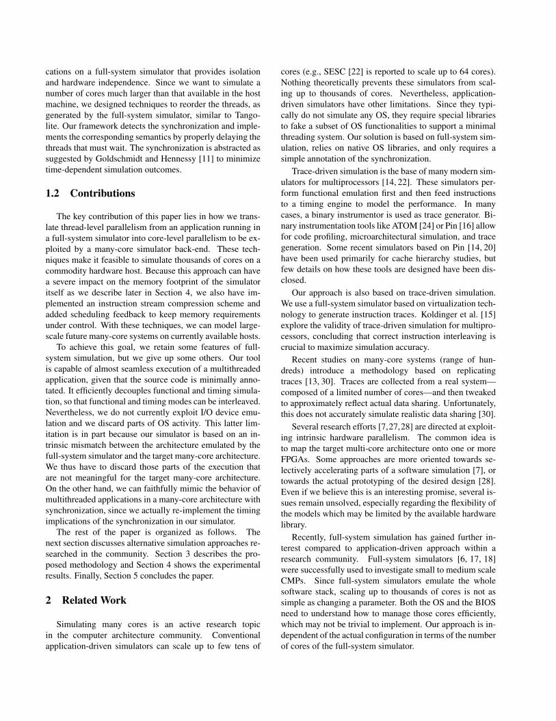
Table 1: Special instructions used for locks and bar-riers, and the behavior of the simulator
Special instruction Dispatch IssueBarriers
BARRIER BEGIN Dispatch wait until the head of each localand skip queue is BARRIER BEGIN
BARRIER END DispatchLocks
SLOCK BEGIN Dispatch Wait until the lock is releasedand skip
SLOCK END DispatchUNLOCK Dispatch Release the lock
3.3 Synchronization
Simulating synchronization between threads involvesseveral steps which change our dispatch and issue mech-anisms: (1) the synchronization event must be deliveredto the interleaver; (2) the simulator must abstract fromthe time-dependent patterns that may depend on the ma-chine emulated by the functional simulator; (3) the inter-leaver must respect the order imposed by the synchroniza-tion when issuing the instructions for execution.
To deliver a synchronization event, we annotate the syn-chronization points in the source code. The special instruc-tions we chose to mark locks and barriers are listed in Ta-ble 1. By having these special instructions at the beginningand end of any barrier and lock, the simulator can isolatethe effects of time-dependent patterns (spinning) which areused in the implementation of most threading libraries. Theinterleaver uses them to enforce the correct instruction or-dering as we will see shortly in this section. The simula-tion back-end will simulate the synchronization based onthe micro-architectural model of the particular experiment.
Figure 4(a) shows an example of how special instruc-tions are applied to a barrier. When a local queue hasa BARRIER BEGIN as the head element, it cannot is-sue instructions—other queues can go on consuming in-structions until they also reach a BARRIER BEGIN. TheBARRIER BEGIN also instructs the simulator to skip allinstructions until a BARRIER END is reached. Once allthreads reach the barrier, normal execution resumes. Thisway, we abstract the barrier so that the polling of the bar-rier variable is just discarded and can be potentially re-built by the timing simulator. The skip is implementedin the dispatch (Algorithm 1), while the semantics of theBARRIER BEGIN are implemented in a modified whilecondition of the issue (Algorithm 2).
Locks are implemented in a similar way. Figure 4(b)shows an example of a thread contending a lock that pro-tects a critical section. SLOCK BEGIN and SLOCK ENDdelimit a spin lock, while UNLOCK is placed soon after theactual unlock. All instructions between the SLOCK BEGIN
work(...){...BARRIER_BEGIN;barrier();BARRIER_END;...
}
(a)
work(...){...BEGIN_SLOCK(l);lock(l);END_SLOCK(l);/*critical section*/unlock(l);UNLOCK(l);...
}
(b)
Figure 4: Fragment of code containing (a) a barrier;and (b) a spin lock protecting a critical section
Figure 5: Diagram illustrating the execution of a bar-rier (code in Figure 4(a))
Figure 6: Diagram illustrating the execution of a lock(code in Figure 4(b))
and SLOCK END are skipped (spinning). A thread ac-quires the lock at the SLOCK BEGIN and releases it at theUNLOCK. Other threads trying to acquire the lock by per-forming another SLOCK BEGIN are stopped and cannot is-sue instructions till the lock is released.
Similarly to Figure 3, Figures 5 and 6 illustrate the ex-ecution of a barrier and a spin lock. The diagrams of thelocal queues (right part of the figures) show when the localqueues are stopped because a BARRIER BEGIN has beenreached or a lock has not been released yet.
3.4 Taming Memory Usage
The buffering of instructions in the local queues can eas-ily consume enormous amounts of memory. This is espe-cially evident for applications with heavy synchronizationand unbalanced threads. To keep memory usage under con-trol we have devised an instruction compression techniquein the local queues and a scheduling feedback mechanism.
The compression mechanism is implemented in the dis-patch phase. Since our memory back-end is cache-line ad-dressable, we perform an early branch prediction and en-code only possible misses. We perform address compres-sion techniques both on instruction and data memory ref-erences by storing only the necessary bits to address cachelines. Having a simple pipeline in-order model allows us toenhance compression by substituting the full opcode by abroad type identifier and not tracking register values.
The Linux scheduler in the guest OS may cause anunbalanced execution of threads, and this can be exacer-bated if the threads that run longer have already generated alarge number of instructions. All these instructions must bestored until we have instructions from all the threads readyfor being issued (recall Figure 1). In some cases, this maycause our memory usage to explode beyond reasonable lim-its (tens of GBs). To solve this, we have implemented afeedback mechanism to increase the priority of threads thatare in waiting state in the guest OS. When the interleaverdetects that one of the local queues has ran out of instruc-tions, it instructs the guest OS to increase the priority ofthe thread associated to this local queue. The kernel sched-uler then selects that thread for execution on the next timeslice, and the empty local queue is filled with new instruc-tions. Note that this does not affect measured performance,since the full-system emulator only acts as an instructionflow generator. Performance estimations are generated bythe timing models placed in the simulator back-end.
For example, Figure 2 also illustrates a typicalcase where the feedback path is useful to balancethread execution. Threads are created by calling thethread create() function, before the master thread iscreated by a subsequent call to work(). Since the guest OShas no visibility of the target architecture, we observed thatit tends to first execute all child threads and, subsequently,the master thread. Nevertheless, no instruction can leavethe local queues until the master thread has started execut-ing too. Our feedback path is able to raise the priority of themaster thread anticipating the execution and causing a morebalanced usage of the local queues.
4 Experimental Results
We applied our methodology to a full-system simulationenvironment based on HP Labs’ COTSon [3] and AMD’s
SimNow simulator [2]. The guest system runs Linux withkernel 2.6.23. We designed and implemented a modularinterleaver that interfaces the functional simulator and thetiming models, as described in the previous sections. Weused simple in-order cores and an ideal memory system forthe back-end timing simulator. Note that modeling morecomplex cores and memory systems is beyond the scope ofthis paper since our focus is on the fundamental character-istics of the simulation framework, and not on the specifictiming models.
We used the SPLASH-2 benchmark suite [29] to val-idate our approach. Table 2 reports the programs weuse and the corresponding datasets. We compiled eachapplication with gcc-4.2, options -O3 -m32 -msse2-mfpmath=sse. We use two datasets: DS1, the defaultdataset for SPLASH-2 [29] and DS2, a scaled up dataset.For DS2, we tried to scale up the dataset by 16 times.1 Thiswas possible for FFT, LU, Ocean, and Radix. We had toscale the dataset of Water-spatial by 64 times to providelarge enough data structure for 1024 threads, while we wereonly able to scale the datasets of Barnes and FMM by 4times to bound simulation time tractable. We could notfine-tune the datasets of other applications easily, so we ei-ther could find a suitably larger dataset (Cholesky, Raytrace,and Radiosity) available in the original benchmark suite, orwe had to take them out of our experiments. Table 2 re-ports the maximum number of CPUs we simulate for eachbenchmark.
We chose to keep the SPLASH-2 code largely unmod-ified: understanding the algorithmic implications in thecontext of a 1000-core processor would be an interestingstudy by itself [23], but is outside the scope of this pa-per. We adapted Radix by replacing implicit synchroniza-tion via semaphore variables with explicit synchronizationconstructs. We carefully analyzed each benchmark to iden-tify any possible time-dependent pattern, other than lockand barrier spinning. We found several polling loops (i.e.,implicit synchronization implemented by polling a sharedvariable) that affected the simulation substantially and wechose to skip these parts. The last column in Table 2 indi-cates the benchmarks we modified.
Table 2 also reports the number of instructions acrossall configurations (1–1024 cores). The variation in numberof instructions is quite large for some benchmarks, espe-cially for DS1, but drops for the larger DS2—except forLU. Given that we used the same dataset for different corecounts, the way the dataset is divided among the cores maydiffer. Some applications have to process more and largeroverlapping regions when the core count increases, thus fea-turing an increase of the number of instruction.
Due to the mismatch of the simulated architecture and
1Our target is 1024 cores, while the original SPLASH-2 paper used 64cores [29]. Hence, 1024/64 = 16×.

Table 2: BenchmarksDS1 (default) DS2 Polling Loops#instrs. (×109) max scaling #instrs. (×109) max scaling
Barnes 16 K particles 1.7-2.1 1024 64 K 9.5 1024 yesCholesky tk15.O 0.4-0.7 1024 tk29.O 1-1.9 1024 yesFFT 64 K points 0.03-0.04 256 1 M 0.6-0.7 1024FMM 16 K particles 2.9 128 64 K 10 1024 yesLU 512×512 0.35-0.7 1024 2048×2048 22-43 1024Ocean 258×258 0.45-0.7 1024 1026×1026 6.3-6.8 1024Radiosity room 1.5-1.6 1024 largeroom 4.0-4.7 512 yesRadix 1 M integers 0.07-0.1 1024 16 M 1.1-1.2 1024Raytrace car 0.7 1024 balls4 6.5 1024Volrend head 1-1.9 1024 - - - yesWater-spatial 512 molecules 0.6 64 32 K 37 1024
Table 3: Comparison with the original SPLASH-2 re-sults ((SPLASH-2 − our results)/our results)
Number of cores16 32 64
Barnes - - -15%Cholesky - - 20%FFT - - -FMM - - -20%LU - - -Ocean - - -7%Radix 10% 10% 10%Radiosity -30% -30% -30%Raytrace -50% -50% -55%Water-spatial - - 10%
the architecture emulated by the functional simulator, thosebenchmarks that feature dynamic job scheduling might in-cur higher accuracy loss with our approach. This sameproblem was observed by Goldschmidt and Hennessy [11]for the Tango-lite simulator. Nevertheless, they reportlimited inaccuracies for the applications they used (theSPLASH benchmarks). Similar conclusions were obtainedby Eggers and Kats [10] for trace-driven simulation.
Figure 7 replicates the results reported in the originalSPLASH-2 paper [29]. Table 3 shows the differences be-tween the two sets of results. Since we visually estimatedthe numbers, we only report those differences greater that5%. For less that 16 cores, our results almost perfectlymatch those in the SPLASH-2 paper, so we do not showthe numbers in the table.
As the simulation infrastructures used in both cases aredifferent, we obviously cannot expect a perfect match in thesimulation results, but ultimately the trend should be verysimilar. For example, the host platform, the OS, and theISA are completely different. While the SPLASH-2 paperuses MIPS, our simulator is based on x86 64.
By looking at the original graphs, the main differencesare for Raytrace and Radiosity, while for the other bench-marks we generally predict just a slightly worse scaling (dif-ferences bound to 20%). The mismatch is mainly because
we differently account for the initialization of these bench-marks.
Figure 8(a) shows the amount of synchronization cy-cles out of the execution time for each benchmark and eachconfiguration. Our predictions (32 cores) also match thosemade in the SPLASH-2 paper, with few exceptions.
In Figure 9(a), we report the results for the scaling upto 1024 threads. Note that most benchmarks do not scaledue to their small dataset, except for Barnes, which shows amoderate speedup (280× at 1024 cores). Figure 9(b) showsthe results we obtained by increasing the dataset. Somebenchmarks (FFT, Water-Spatial, Ocean, and Radix) scalemeaningfully (600× at 1024 cores); we could indeed scaleup the dataset of these benchmarks by at least 16×. LU isan exception, since it is limited by the synchronization—itscales up to 380× at 1024 cores. Other benchmarks scaleless clearly since dataset, synchronization, and algorithmproperties may interact. For example, Cholesky gains verylittle with respect to Figure 9(a), but besides the possiblysmall dataset, this benchmark is limited by fine-grain locksynchronization. Raytrace has a clear speedup by increas-ing the dataset (3×), but due to the fine-grain synchroniza-tion (similar to Cholesky), it does not scale with the numberof cores. These trends are confirmed by Figure 8 that showshow the synchronization fraction decreases for the bench-marks that scale up.
Figure 10(a) shows the simulation speed for all configu-rations. We run our experiments on a simulation farm com-posed of AMD Dual-Core Opteron at 2.8GHz and 8GB ofRAM. The average simulation speed is around 1M instruc-tions per second for 1 core. For 1024, simulation speed de-creases to 0.7M instructions per second (a 30% drop). Mostof the additional slowdown is due to the synchronization.For FMM and Cholesky, simulation speed drops by 50%.These indeed have the highest synchronization componentas shown in Figure 8.
Memory usage (reported in Figure 10(b)) is a critical as-pect of our simulation flow. The upper bound for all applica-tions and configurations is 8GB, corresponding to the mem-

12 4 8 16 32 64#cores
0
10
20
30
40
50
60
Speedup
idealBarnesFFTFMMRaytraceLUCholesky
(a)
12 4 8 16 32 64#cores
0
10
20
30
40
50
60
Speedup
idealWater-SpatialOceanRadixRadiosity
(b)
Figure 7: SPLASH-2 scaling on the default dataset (DS1) up to 64 cores
0
0.1
0.2
0.3
0.4
0.5
0.6
0.7
0.8
0.9
1
barn
es
choles
ky fftfm
m lu
ocea
n
radios
ityra
dix
raytra
ce
volre
nd
wat
ers
Syn
c. F
ractio
n
1
2
4
8
16
32
64
128
256
512
1024
(a) DS1
0
0.1
0.2
0.3
0.4
0.5
0.6
0.7
0.8
0.9
1
barn
es
choles
ky fftfm
m lu
ocea
n
radios
ityra
dix
raytra
ce
wat
ers
Syn
c. F
racti
on
1
2
4
8
16
32
64
128
256
512
1024
(b) DS2
Figure 8: Fraction of the execution time spent in synchronization
ory installed in the simulation host used for the experiments.Approximately ∼2GB of memory are used by the baselinefull-system simulator (HP Lab’s COTSon + AMD’s Sim-Now) itself. On top of that, many applications remain in the3–4GB range and only a few grow up to nearly 8GB.
5 Conclusions
Virtually all next-generation high-performance comput-ing systems will use multi-core parts. Looking at the tra-jectory of many-core roadmaps, we can easily envision afuture with hundreds or thousands of shared-memory coresin a single CPU. One of the challenges in designing these
systems is projecting their performance, but today no full-system simulator is capable of simulating such a large-scalemulti-core processor.
In this paper, we present an approach that represents animportant first step towards the simulation of chip multipro-cessors of an arbitrary number of cores. By converting time-multiplexed threads into space-multiplexed threads, we cre-ate a virtual chip multiprocessor in which software threadsthat were previously mapped to hardware threads are nowmapped to CPU models, each of them simulating one of theCMP cores.
Our approach is based on full-system simulation tech-nology which is used to run a many-thread application,whose threads are dynamically mapped into independent

1 64 128 256 512 1024#cores
0
200
400
600
800
1000
Speedup
idealBarnesFFTFMMRaytraceLUCholeskyWater-SpatialOceanRadixRadiosity
(a) DS1
1 64 128 256 512 1024#cores
0
200
400
600
800
1000
Speedup
idealBarnesFFTFMMRaytraceLUCholeskyWater-SpatialOceanRadixRadiosity
(b) DS2
Figure 9: SPLASH-2 scaling up to 1024 cores
1 64 128 256 512 1024#cores
0.0
0.2
0.4
0.6
0.8
1.0
1.2
1.4
1.6
1.8
Sim
. Speed [
M-i
nst
rs/s
ec]
BarnesFFTFMMRaytraceLUCholeskyWater-SpatialOceanRadixRadiosity
(a) Simulation speed
1 64 128 256 512 1024#cores
2
3
4
5
6
7
8M
em
ory
[G
B]
(b) Memory usage
Figure 10: Simulation speed and Memory usage (DS2)
cores. Our experiments show that the simulator can scaleup to 1024 cores with an average simulation speed over-head of only 30% with respect to the single-core simula-tion. We successfully used our approach on the SPLASH-2benchmark suite, giving meaningful insights on the intrin-sic scaling behavior of these applications. We also showedthat the original dataset of the SPLASH-2 limits the scal-ability of these applications for the large number of coreswe are targeting. By scaling up the dataset, we achieved aspeedup in the range of 600–700× for a subset of 4 out of10 benchmarks, while other applications are limited by ei-ther the synchronization or the poor scaling of the datasetitself.
This work highlights important directions in building
a comprehensive tool to simulate many-core architecturesthat might be very helpful for the future research in com-puter architecture. If we look beyond simple SPLASH-2-like benchmarks, the biggest challenge we envision is ad-dressing the simulation of applications whose behavior isheavily timing-dependent, especially those relying on im-plicit synchronization.
Finally, putting together full-system simulation and tim-ing simulation opens up new opportunities for system-levelanalysis. We plan to investigate the problems relative tothe faithful simulation of these aspects within our frame-work to eventually being able to evaluate the performanceimplication of the OS and I/O subsystem in the context ofmany-core architectures.

References
[1] Ambric. Massively Parallel Processor Array technology.http://www.ambric.com.
[2] AMD Developer Central. AMD SimNow simulator. http://developer.amd.com/simnow.aspx.
[3] E. Argollo, A. Falcon, P. Faraboschi, M. Monchiero, andD. Ortega. COTSon: Infrastructure for full system simula-tion. SIGOPS Operating Systems Review, Jan. 2009.
[4] K. Asanovic, R. Bodik, B. C. Catanzaro, J. J. Gebis, P. Hus-bands, K. Keutzer, D. A. Patterson, W. L. Plishker, J. Shalf,S. W. Williams, and K. A. Yelick. The landscape of parallelcomputing research: A view from Berkeley. Technical Re-port UCB/EECS-2006-183, EECS Department, Universityof California, Berkeley, Dec 2006.
[5] S. Bell, B. Edwards, J. Amann, R. Conlin, K. Joyce, V. Le-ung, J. MacKay, and M. Reif. TILE64 processor: A 64-coreSoC with mesh interconnect. In Proceedings of the Interna-tional Solid-State Circuits Conference (ISSCC 2008), Feb.2008.
[6] N. L. Binkert, R. G. Dreslinski, L. R. Hsu, K. T. Lim, A. G.Saidi, and S. K. Reinhardt. The M5 simulator: Modelingnetworked systems. IEEE Micro, 26(4):52–60, 2006.
[7] E. S. Chung, E. Nurvitadhi, J. C. Hoe, B. Falsafi, andK. Mai. A complexity-effective architecture for accelerat-ing full-system multiprocessor simulations using FPGAs. InProceedings of the 16th International Symposium on FieldProgrammable Gate Arrays, pages 77–86, Feb. 2008.
[8] J. Dorsey, S. Searles, M. Ciraula, S. Johnson, N. Bujanos,D. Wu, M. Braganza, S. Meyers, E. Fang, and R. Kumar.An integrated quad-core Opteron processor. In Proceedingsof the International Solid-State Circuits Conference (ISSCC2007), Feb. 2007.
[9] W. Eatherton. Keynote address: The push of network pro-cessing to the top of the pyramid. In Proceedings of theSymposium on Architecture for Networking and Communi-cations Systems (ANCS), Oct. 2005.
[10] S. J. Eggers and R. H. Katz. A characterization of sharingin parallel programs and its application to coherency pro-tocol evaluation. In Proceedings of the 15th Annual Inter-national Symposium on Computer architecture, pages 373–382, 1988.
[11] S. R. Goldschmidt and J. L. Hennessy. The accuracy oftrace-driven simulations of multiprocessors. SIGMETRICSPerform. Eval. Rev., 21(1):146–157, 1993.
[12] M. Gschwind, H. P. Hofstee, B. Flachs, M. Hopkins,Y. Watanabe, and T. Yamazaki. Synergistic processing inCell’s multicore architecture. IEEE Micro, 26(2):10–24,2006.
[13] L. Hsu, R. Iyer, S. Makineni, S. Reinhardt, and D. Newell.Exploring the cache design space for large scale CMPs.Comput. Archit. News, 33(4):24–33, 2005.
[14] A. Jaleel, R. S. Cohn, C.-K. Luk, and B. Jacob. CMP$im: APin-based on-the-fly multi-core cache simulator. In Proceed-ings of the Fourth Annual Workshop on Modeling, Bench-marking and Simulation (MOBS’08), 2008.
[15] E. J. Koldinger, S. J. Eggers, and H. M. Levy. On the validityof trace-driven simulation for multiprocessors. In Proceed-ings of the 18th Annual International Symposium on Com-puter Architecture, pages 244–253, 1991.
[16] C.-K. Luk, R. Cohn, R. Muth, H. Patil, A. Klauser,G. Lowney, S. Wallace, V. J. Reddi, and K. Hazelwood. Pin:building customized program analysis tools with dynamicinstrumentation. In Proceedings of the Conference on Pro-gramming Language Design and Implementation (PLDI),2005.
[17] P. S. Magnusson, M. Christensson, J. Eskilson, D. Fors-gren, G. Hallberg, J. Hogberg, F. Larsson, A. Moestedt, andB. Werner. Simics: A full system simulation platform. Com-puter, 35(2):50–58, Feb. 2002.
[18] M. M. K. Martin, D. J. Sorin, B. M. Beckmann, M. R. Marty,M. Xu, A. R. Alameldeen, K. E. Moore, M. D. Hill, andD. A. Wood. Multifacet’s general execution-driven multi-processor simulator (GEMS) toolset. Comput. Archit. News,33(4):92–99, 2005.
[19] C. J. Mauer, M. D. Hill, and D. A. Wood. Full-systemtiming-first simulation. SIGMETRICS Perform. Eval. Rev.,30(1):108–116, 2002.
[20] C. McCurdy and C. Fischer. Using Pin as a memory refer-ence generator for multiprocessor simulation. Comput. Ar-chit. News, 33(5):39–44, 2005.
[21] S. K. Reinhardt, M. D. Hill, J. R. Larus, A. R. Lebeck, J. C.Lewis, and D. A. Wood. The Wisconsin Wind Tunnel: Vir-tual prototyping of parallel computers. SIGMETRICS Per-form. Eval. Rev., 21(1):48–60, 1993.
[22] J. Renau, B. Fraguela, J. Tuck, W. Liu, M. Prvulovic,L. Ceze, S. Sarangi, P. Sack, K. Strauss, and P. Mon-tesinos. SESC simulator, January 2005. http://sesc.sourceforge.net.
[23] J. Singh, J. Hennessy, and A. Gupta. Scaling parallelprograms for multiprocessors: methodology and examples.Computer, 26(7):42–50, Jul 1993.
[24] A. Srivastava and A. Eustace. ATOM — a system for build-ing customized program analysis tools. In Proceedings ofthe Conference on Programming Language Design and Im-plementation (PLDI), 1994.
[25] B. Stackhouse. A 65nm 2-billion-transistor quad-core Ita-nium processor. In Proceedings of the International Solid-State Circuits Conference (ISSCC 2008), Feb. 2008.
[26] M. Tremblay and S. Chaudhry. A third-generation 65nm 16-core 32-thread plus 32-scout-thread CMT SPARC proces-sor. In Proceedings of the International Solid-State CircuitsConference (ISSCC 2008), Feb. 2008.
[27] J. Wawrzynek, D. Patterson, M. Oskin, S.-L. Lu, C. E.Kozyrakis, J. C. Hoe, D. Chiou, and K. Asanovic. RAMP:Research Accelerator for Multiple Processors. IEEE Micro,27(2):46–57, 2007.
[28] S. Wee, J. Casper, N. Njoroge, Y. Tesylar, D. Ge,C. Kozyrakis, and K. Olukotun. A practical FPGA-basedframework for novel CMP research. In Proceedings of the15th International Symposium on Field Programmable GateArrays, pages 116–125, 2007.
[29] S. C. Woo, M. Ohara, E. Torrie, J. P. Singh, and A. Gupta.The SPLASH-2 programs: Characterization and method-ological considerations. In Proceedings of the 22nd AnnualInternational Symposium on Computer Architecture, June1995.
[30] L. Zhao, R. Iyer, J. Moses, R. Illikkal, S. Makineni, andD. Newell. Exploring large-scale CMP architectures usingManySim. IEEE Micro, 27(4):21–33, 2007.