


Silicon steel cores - Co ntents 3. - semic.cz
35
1. 5. 6. Contents 3. 4. SU-series ED-series SG-, FA-, HWR-series 7. 10. 9. 8. 11. 12. 2. R Corऩ㤮ㄹ㔨 01 02-03 04-05 06 07-15 16-19 20 21 22-23 24-27 28-32 33-35 Content S3U-series HWE- / FA-series BSD-series SE-, SM-series HSD-series Silicon steel cores
-
Upload
khangminh22 -
Category
Documents
-
view
3 -
download
0
Transcript of Silicon steel cores - Co ntents 3. - semic.cz

1.
5.
6.
Co
nte
nts
3.
4.
SU-series
ED-series
SG-, FA-, HWR-series
7.
10.
9.
8.
11.
12.
2.
R Cor
01
02-03
04-05
06
07-15
16-19
20
21
22-23
24-27
28-32
33-35
Content
S3U-series HWE- / FA-seriesBSD-series
SE-, SM-series
HSD-series
Silicon steel cores

/ Advantages
/ Close flux path / Low magnetic leakage / Low humming / Compact dimensions / Light weight
Min. Inside Diameter :5mm
0.960.96
Stacking factor
≤160≤100 ±1.0
±1.0±1.0±0.5
Available process:
annealing / impregnattion / epoxy coating.
/ A-series Toroidal Core0.35/0.30/0.27/0.23/0.10/0.08/0.05mm 。
Available material:
0.35/0.30/0.27/0.23/0.10/0.08/0.05mm.
>800≤800≤500≤320≤200
0.230.270.300.35
0.860.880.900.950.95
Strip thickness and stacking factor
△DOD
≤50≤25≤10
Thickess mm
0.050.080.10
Tolerances (mm)
OD
±0.8±0.5±0.5±0.4±0.3±0.3△H
≤80
±7.5±5.0±3.5±2.5±2.5±2.0
±0.4
HID
>800≤800≤500≤320≤200≤160≤100≤80≤50≤25≤10
△dID
±5.00±3.50±2.50±2.00±1.50±1.30±0.80±0.75±0.50±0.40±0.30
±4.0±3.0±2.5±2.0±1.5
04
We can produces toroidal cores in many differentdimension to customer specifications.

/Dimension:/Min. Strip Width:10mm/Max. Strip Width:250mm/Min. ID:20mm/Max.:1200mm
±0.40
±1.50±2.00±2.50±3.00
±2.50±1.50
≤25 ±0.50±0.50±0.50±0.50±0.80±1.00
±0.80±0.75±0.50
≤500≤320≤200≤160≤100≤80
±3.50±3.00±2.00±1.50±1.50±1.00
△H
≤500≤320≤200≤160≤100≤80≤50≤25
±5.00
16000M5 [140] 15500
IDOD △D ID △d
±0.50
≤50
SB1(0.23)SB2(0.27)SB3(0.30)
Equal Grade Bm (Gauss)M3 [117] 16500M4 [124]
In order to satisfy the customers who are eager to minimize their cost, develoed the SB series toroidal cores, which are wound by a continous silicon steel strip, occasionally with joints.
/Available material:
0.20/0.23/0.27/0.30mm.
/Stacking factor:0.94~0.96
/Available process:
annealing / impregnation / epoxy coating.
The magnetic properties of SB cores are very closed to that of A series cores, the Bm values are relatively lower because itis recycle material
SB Tolerances (mm)OD H Grade
/SB series
05

manufactures rectangular cores to various specifications in high permeability electrical steels imported from Nippon Steel Corporation.
This core with rectangular cross-section, which is wound by a contimous electrical steel strip, there is no break in the magnetic path.
The rectangular cores are suitable for manufacturing current transformers and potential transformers ranging from 0.38kV to 330kV in electrical industry.
The cores with high permeability and linear fully meet the requirement of measuring current transformers with accuracy class 0.1, 0.2, 0.5, 1.3 and 5.
The cores can also meet requirements of protection current transformer with accuracy of 5P and 10P as well as that of transient current tranformers.
06
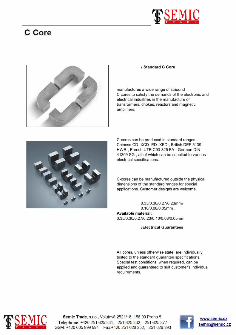
/Electrical Guarantees
All cores, unless otherwise state, are individually tested to the standard guarantee specifications. Special test conditions, when required, can be applied and guaranteed to suit customer's individual requirements.
/ Standard C Core
manufactures a wide range of striound C cores to satisfy the demands of the electronic and electrical industries in the manufacture of transformers, chokes, reactors and magnetic amplifiers.
C-cores can be produced in standard ranges - Chinese CD- XCD- ED- XED-, British DEF 5139 HWR-, French UTE C93-325 FA-, German DIN 41309 SG-, all of which can be supplied to various electrical specifications.
C-cores can be manufactured outside the physical dimensions of the standard ranges for special applications. Customer designs are welcome.
0.35/0.30/0.27/0.23mm;0.10/0.08/0.05mm。
Available material:
0.35/0.30/0.27/0.23/0.10/0.08/0.05mm.
07

-
-
M
min
50.0
-
Cross
section
-
-
-
64.0
43.0
42.0
47.0
54.0
40.0
-
-
-
20.0
-
-
-
25.0
-
-
-
-
32.0
-
100.0
120.0
160.0
50.0
60.0
80.0
100.0
200.0
10.0
-
-
-
12.5
-
65.0
65.0
80.0
Weight
CD40×80×160
CD40×80×200
80.0
100.0
120.0
80.0
100.0
130.0
160.0
Kg
min max min max
F A
max
Flux path
L(cm)
CD16×32×40
CD20×40×60
CD12.5×16×40
CD12.5×25×60
CD10×12.5×40
CD12.5×16×25
CD12.5×16×32
CD32×64×80
CD32×64×100
CD20×40×80
CD20×40×100
CD25×50×100
CD25×50×120
30.0
40.0
50.0
60.0
40.0
50.0
CD40×80×120
CD8×12.5×25
CD10×12.5×20
CD10×12.5×25
CD10×12.5×32
CD12.5×16×50
CD12.5×25×30
CD12.5×25×40
CD12.5×25×50
CD16×32×50
CD-series
CD32×64×130
CD32×64×160
CD40×80×100
CD16×32×65
CD16×32×80
CD20×40×50
25.0
16.0
20.0
25.0
20.0
CD25×50×65
CD25×50×80
32.0
40.0
25.0
32.0
40.0
50.0
GCode
min max max
12.5
8.0
10.0
12.5
16.0
8.0
-
-
-
-
-
-
-
-
16.0
-
23.0
25.0
27.5
31.0
30.5
34.0
38.0
63.0
54.0
61.0
69.0
79.0
59.0
69.0
79.0
89.0
76.0
86.0
101.0
116.0
96.0
106.0
126.0
146.0
121.0
136.0
156.0
176.0
152.0
172.0
202.0
232.0
188.0
208.0
248.0
288.0
22.4
-
-
-
27.4
-
-
-
34.0
-
-
-
42.7
-
-
-
46.8
-
-
-
58.8
-
-
-
74.2
-
-
-
92.2
-
-
-
116.6
-
-
-
146.8
-
-
-
12.3
-
-
-
12.3
-
-
-
12.3
-
-
-
15.8
-
-
-
24.8
-
-
-
31.8
-
-
-
39.8
-
-
-
49.8
-
-
-
63.8
-
-
-
79.8
-
-
-
12.9
-
-
-
12.9
-
-
-
12.9
-
-
-
16.4
-
-
-
25.5
-
-
-
32.6
-
-
-
40.6
-
-
-
50.6
-
-
-
64.7
-
-
-
80.7
-
-
-
6.3
-
-
-
7.8
-
-
-
9.8
-
-
-
12.2
-
-
-
12.2
-
-
-
15.7
-
-
-
19.7
-
-
-
24.7
-
-
-
31.7
-
-
-
39.7
-
-
-
6.90
-
-
-
8.45
-
-
-
10.40
-
-
-
13.00
-
-
-
13.00
-
-
-
16.50
-
-
-
20.60
-
-
-
25.60
-
-
-
32.80
-
-
-
40.80
-
-
-
1.5
-
-
-
1.5
-
-
-
-
2.0
-
-
1.5
-
-
-
2.0
-
-
2.0
-
-
-
-
-
2.0
3.0
-
3.0
-
-
-
-
-
-
3.0
-
-
B R
5.47
5.90
6.67
6.84
7.54
-
-
8.34
9.34
9.47
10.50
11.90
13.50
11.90
13.30
14.90
16.90
13.70
15.70
17.70
19.70
17.80
19.80
22.80
25.80
22.40
24.40
28.40
32.40
28.50
31.50
35.50
39.50
35.70
39.70
45.70
51.70
45.00
49.00
57.00
65.00
0.3mm 0.1mm
k (cm2)D D E E
min
5.07
1.2
-
-
-
1.92
-
-
-
3
-
-
-
4.92
-
-
-
7.68
-
-
-
12
-
-
-
19.66
-
-
-
30.72
-
-
-
0.747
-
-
-
0.920
-
-
-
1.150
-
-
-
1.840
-
-
-
2.880
-
-
-
4.710
-
-
-
7.360
-
-
-
11.500
-
-
-
18.840
-
-
-
29.440
-
-
-
0.3mm
0.087
0.096
0.109
0.124
0.175
0.195
0.219
0.248
0.314
0.360
0.406
0.452
0.670
0.745
0.858
0.971
1.316
1.436
1.669
1.904
2.616
2.892
3.259
3.626
5.369
5.972
6.873
7.776
10.575
11.515
13.395
15.576
0.1mm
0.029
0.031
0.034
0.038
0.048
0.053
0.059
0.066
0.083
0.092
0.105
0.119
0.168
0.187
0.210
0.238
0.302
0.346
0.390
0.434
0.641
0.713
0.822
0.930
1.261
1.374
1.599
1.824
2.507
2.771
3.123
3.475
5.145
5.721
6.587
7.451
10.135
11.036
12.837
14.639
0.3mm
50Hz
0.1mm
400Hz
2.4
3.4
4.9
6.67
10.7
14.7
19.6
25
31.2
43.9
54
63.2
89
111
143
171
199
231
306
375
448
540
659
776
1006
1213
1517
1843
2106
2521
3214
3912
9.69
12.6
16.6
20.4
25.8
33.3
42
51.4
56.6
71.7
91.2
112
119
148
813
950
181
221
222
286
344
398
7116
1224
1476
1595
1900
2293
2668
CD8×12.5×16
3197
3818
4711
5522
6152
470
571
711
840
CD8×12.5×20
8991
10737
Approx
V.A.Dimension(mm)
CD8×12.5×12.5
CD6.5×12.5×8
CD6.5×12.5×10
CD6.5×12.5×12.5
CD6.5×12.5×16
08

XCD-series
Code
Dimension(mm)
Flux path
Weight Approx
V.A.Kg
k (cm2) MG F A B
Cross
section
D E
min max
R L(cm)
20.5 9.7
max min
D E
min min max max min max
-
10.4 1.5 9.47XCD10×20×20 20 12.5 42 34.0 19.8
- - - 10.50XCD10×20×25 25 - 47 - -
- - - 11.90XCD10×20×32 32 - 54 - -
XCD10×20×40 40 - 62 -
-
- - - 13.50
12.2 13.0 1.5 11.9016.0 54 42.7 24.8
- -
XCD12.5×25×32 32 - 61 -
25.5
- -
XCD12.5×25×25 25
- 13.30
- - - 14.90- 69 - -
- -
XCD12.5×25×50 50 - 79 -
-
- -
XCD12.5×25×40 40
- - - 16.90
15.7 16.5 1.5 14.40 4.92XCD16×32×32 32 16.0 68 49.7
XCD16×32×40 40 - 76 -
32.531.8
-- - - - - 16.00
- - - 18.00 -XCD16×32×50 50 - 86 -
XCD16×32×64 64 - 100 -
--
-- - - - - 20.80
19.7 20.6 2.0 18.00 7.68XCD20×40×40 40 20.0 86 62.0
XCD20×40×50 50 - 96 -
40.639.8
-- - - - - 20.80
- - - 22.80 -XCD20×40×64 64 - 110 -
XCD20×40×80 80 - 126 -
--
-- - - - - 26.00
24.7 25.6 2.0 22.60 12.00XCD25×50×50 50 25.0 106 77.0
XCD25×50×64 64 - 120 -
50.649.8
-- - - - - 25.40
- - - 28.60 -XCD25×50×80 80 - 136 -
XCD25×50×100 100 - 156 -
--
-- - - - - 32.60
31.7 32.8 2.0 29.00 19.66XCD32×64×64 64 32.0 134 98.6
XCD32×64×80 80 - 150 -
64.763.8
-- - - - - 32.20
- - - 36.20 -XCD32×64×100 100 - 170 -
XCD32×64×125 125 - 195 -
--
-- - - - - 41.20
39.7 40.8 2.0 36.20 30.72XCD40×80×80 80 40.0 166 122.6
XCD40×80×100 100 - 186 -
80.779.8
-- - - - - 40.20
- - - 45.20 -XCD40×80×125 125 - 211 -
XCD40×80×160 160 - 246 -
--
-- - - - - 52.20
49.7 50.8 3.0 45.40 48.00XCD50×100×100 100 50.0 206 152.6
XCD50×100×125 125 - 231 -
100.799.8
-- - - - - 50.40
- - 57.40 -XCD50×100×160 160 - 266 - -
XCD50×100×200 200 - 306 -
-
0.273
0.305
-- - - - - 65.40
-
0.3mm 0.3mm
0.139
0.154
0.175
0.198
0.342
0.388
0.542
0.602
0.677
0.783
1.058
1.222
1.400
1.528
2.075
2.332
2.625
2.993
4.362
4.843
5.444
6.196
8.507
9.447
10.622
12.267
16.670
18.510
21.077
24.015
1.92
-
-
-
3.00
-
-
-
50Hz
0.3mm
5.2
7.4
10.8
14.2
21.9
29.8
37.0
46.4
45.6
58.8
74.6
94.3
111.0
133.0
176.0
220.0
263.0
322.0
398.0
484.0
634.0
741.0
3191.0
3837.0
4724.0
5681.0
918.0
1128.0
1437.0
1767.0
2154.0
2700.0
09

Cross
section
D D E E
ED-series
Code
Dimension (mm)
Flux path
Weight Approx
V.A.Kg
G F A B R L(cm) k (cm2) M 0.3mm 0.1mm
min min max max min max min max max min 0.3mm 0.1mm 0.3mm 0.1mm 50Hz 400Hz
ED6×6.5 15 6 23 25.6 6.3 6.8 2.8 3.2 1.5 4.97 0.36 0.014 7.5
ED6×8.0 - - - - 7.8 8.3 - - - - 0.44 0.017 9.5
ED6×10.0 - - - - 9.8 10.3 - - - - 0.55 0.021 12
ED6×12.5 - - - - 12.3 12.9 - - - - 0.69 0.026 15.4
ED8×8.0 20 8 30 33.8 7.8 8.3 3.8 4.2 1.5 6.68 0.59 0.030 19
ED8×10.0 - - - - 9.8 10.3 - - - - 0.73 0.038 23.5
ED8×12.5 - - - - 12.3 12.9 - - - - 0.92 0.047 29.2
ED8×16 - - - - 15.8 16.4 - - - - 1.18 0.060 36.3
ED10×10.0 25 10 37 41.8 9.8 10.3 4.7 5.2 1.5 8.40 0.96 0.92 0.062 0.059 1.5 40.7
ED10×12.5 - - - - 12.3 12.9 - - - - 1.20 1.15 0.077 0.074 2.3 49.3
ED10×16.0 - - - - 15.8 16.4 - - - - 1.53 1.47 0.099 0.095 3.5 60.7
ED10×20.0 - - - - 19.8 20.5 - - - - 1.92 1.84 0.123 0.118 4.9 72.2
ED12×12.5 30 12 44 50.2 12.3 12.9 5.7 6.2 1.5 10.10 1.44 1.38 0.111 0.107 5 69.3
ED12×16.0 - - - - 15.8 16.4 - - - - 1.84 1.76 0.142 0.136 7.5 83.3
ED12×20.0 - - - - 19.8 20.5 - - - - 2.30 2.21 0.178 0.171 10.7 98.1
ED12×25.0 - - - - 24.8 25.5 - - - - 2.88 2.76 0.223 0.213 15 113
ED16×16.0 40 16 58 66.6 15.8 16.4 7.7 8.3 1.5 13.50 2.46 2.35 0.254 0.243 23.7 184
ED16×20.0 - - - - 19.8 20.5 - - - - 3.07 2.94 0.317 0.304 33.6 214
ED16×25.0 - - - - 24.8 25.5 - - - - 3.84 3.68 0.397 0.380 42.9 248
ED16×32.0 - - - - 31.8 32.6 - - - - 4.91 4.71 0.508 0.486 57.1 293
ED20×20.0 50 20 72 82.4 19.8 20.5 9.7 10.3 1.5 17.00 3.84 3.68 0.499 0.479 62 327
ED20×25.0 - - - - 24.8 25.5 - - - - 4.80 4.60 0.624 0.598 80 378
ED20×32.0 - - - - 31.8 32.6 - - - - 6.14 5.88 0.799 0.766 104 445
ED20×40.0 - - - - 39.8 40.6 - - - - 7.68 7.36 0.999 0.957 132 516
ED25×25.0 63 25 92 102.8 24.8 25.5 12.2 12.8 2.0 21.30 6.00 5.75 0.978 0.937 141 614
ED25×32.0 - - - - 31.8 32.6 - - - - 7.68 7.36 1.251 1.199 183 722
ED25×40.0 - - - - 39.8 40.6 - - - - 9.60 9.20 1.564 1.499 230 836
ED25×50.0 - - - - 49.8 50.6 - - - - 12.00 11.50 1.955 1.874 287 969
ED32×32.0 80 32 116 131.2 31.8 32.6 15.7 16.3 2.0 27.20 9.83 9.42 2.045 1.960 337 1262
ED32×40.0 - - - - 39.8 40.6 - - - - 12.29 11.77 2.555 2.450 422 1461
ED32×50.0 - - - - 49.8 50.6 - - - - 15.36 14.72 3.196 3.063 522 1688
ED32×64.0 - - - - 63.8 64.7 - - - - 19.66 18.84 4.091 3.920 662 1984
ED40×40.0 100 40 146 163.6 39.8 40.6 19.7 20.4 2.0 34.00 15.36 14.72 3.995 3.829 737 2408
ED40×50.0 - - - - 49.8 50.6 - - - - 19.20 18.40 4.994 4.786 914 2795
ED40×64.0 - - - - 63.8 64.7 - - - - 24.57 23.55 6.392 6.126 1154 3290
30.72 29.44 7.990 7.657 1708ED40×80.0 - - - - 79.8 380080.7 - - - -
10
Cross
section
D D E E
- 8.789 1664.0- 37.40
1366.0
XED40×80×125 123 - 171 - - - - -
- - - 32.40 - 7.614
- 6.674 1054.0
XED40×80×100 100 - 146 - - -
- - - - - 28.40
2.0 25.20 30.72 5.992 870.0
XED40×80×80 80 - 126 -
714.0
XED40×80×64 64 32.0 110 147.6 79.8 80.7 19.7 20.4
- - - 29.80 - 4.482
- 3.880 605.0
XED32×64×100 100 - 136 - - -
- - - - - 25.80
- 22.60 - 3.399 505.0
XED32×64×80 80 - 116 -
405.0
XED32×64×64 64 - 100 - - - - -
15.7 16.3 2.0 19.80 19.66 2.978
- 2.176 314.0
XED32×64×50 50 25.0 86 116.8 63.8 64.7
- - - - - 23.70
- 20.50 - 1.882 264.0
XED25×50×80 80 - 109 -
211.0
XED25×50×64 64 - 93 - - - - -
- - - 17.70 - 1.625
12.00 1.441 172.0
XED25×50×50 50 - 79 - - -
49.8 50.6 12.2 12.8 1.5 15.70
- 18.90 - 1.110 142.0
XED25×50×40 40 20.0 69 92.8
114.0
XED20×40×64 64 - 86 - - - - -
- - - 16.10 - 0.946
- 0.828 89.9
XED20×40×50 50 - 72 - - -
- - - - - 14.10
1.5 12.50 7.68 0.734 74.0
XED20×40×40 40 - 62 -
62.6
XED20×40×32 32 16.0 54 74.6 39.8 40.6 9.7 10.3
- - - 14.80 - 0.556
- 0.481 51.6
XED16×32×50 50 - 68 - - -
- - - - - 12.80
- 11.20 - 0.421 42.6
XED16×32×40 40 - 58 -
33.1
XED16×32×32 32 - 50 - - - - -
7.7 8.3 1.5 9.84 4.91 0.370
- 0.258 24.9
XED16×32×25 25 12.5 43 59.6 31.8 32.6
- - - - - 11.70
- 10.10 - 0.223 17.7
XED12×25×40 40 - 54 -
12.6
XED12×25×32 32 - 46 - - - - -
- - - 8.71 - 0.192
2.88 0.170 8.7
XED12×25×25 25 - 39 - - -
24.8 25.5 5.7 6.2 1.5 7.71
- 9.40 - 0.138 6.2
XED12×25×20 20 10.0 34 45.8
4.3
XED10×20×32 32 - 44 - - - - -
- - - 8.00 - 0.118
- 0.103 3.0
XED10×20×25 25 - 37 - - -
- - - - - 7.00
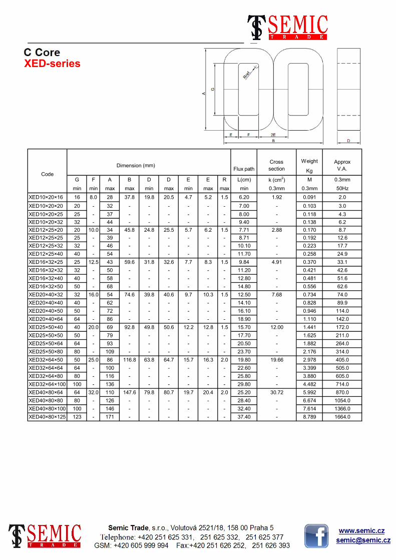
1.5 6.20 1.92 0.091 2.0
XED10×20×20 20 - 32 -
50Hz
XED10×20×16 16 8.0 28 37.8 19.8 20.5 4.7 5.2
min max max min 0.3mm 0.3mmmin min max max min max
MG F A B 0.3mm
XED-series
Code
Dimension (mm)
Flux path
Weight Approx
V.A.Kg
R L(cm) k (cm2)
11

6400
7800
10500
12900
EE
2370
3380
3620
5400
4560
6500
620
960
920
1440
1580
2370
82
122
200
306
387
630
3
6
12
20
30
48
83.20
21.881
17.066
21.358
25.598
26.851
38.471
50.091
-
-
k (cm2)
Cross
section
0.21
22.50
41.30
49.50
44.60
63.90
63.0
-
67.6
-
-
78.7
42.8
-
49.5
-
56.2
-
28.2
-
34.0
-
38.4
-
14.8
-
18.1
-
22.6
-
6.1
-
9.2
-
11.4
-
-
3.0
-
-
Code
Dimension(mm)
DD
3.0
-
3.0
-
3.0
-
3.0
-
3.0
-
3.0
-
2.0
-
2.0
-
3.0
-
1.5
-
1.5
-
1.5
-
-
-
+2.0
-
-
max
1.5
-
1.5
-
-
+1.5
-
+1.6
-
+1.8
-
+1.2
-
+1.3
-
+1.4
-
+0.9
-
+1.0
-
+1.1
-
-
67.6
-
-
+0.5
-
+0.6
-
+0.8
-
47.9
-
53.7
-
57.9
-
32.5
-
36.3
-
42.0
R
18.9
-
23.7
-
28.5
-
+0.8
-
+0.9
-
12.1
-
14.9
-
SU-series
Flux path
L(cm)Tolmin
4.4
-
7.3
-
9.1
+2.1
-
+1.4
-
+1.4
-
-
+2.2
-
-
+1.7
-
+1.7
-
+2
-
+1.7
-
+1.0
-
+1.1
-
+1.1
-
129.5
Tol
+0.4
-
+0.5
-
+0.6
-
+0.9
-
89.0
60.0
75.0
90.0
69.5
99.5
61.5
43.5
69.5
49.5
74.5
55.0
40.0
29.5
49.5
34.0
55.0
37.5
19.5
15.5
12.5
19.5
29.5
25.0
-
-
min
5.0
8.0
8.0
13.0
9.5
15.5
12.5
168.3
-
181.3
-
-
211.2
114.4
-
132.1
-
150.2
-
75.0
-
90.0
-
102.4
-
39.1
-
48.0
-
60.1
-
-
-
B
max
15.0
-
24.0
-
30.0
-
286.0
-
307.2
-
-
357.2
195.6
-
225.4
-
255.6
-
128.6
-
155.8
-
175.4
-
67.9
-
82.9
-
103.6
-
-
-
A
max
28.7
-
42.7
-
52.7
-
56
-
60
-
-
70
38
-
44
-
50
-
25
-
30
-
34
-
13
-
16
-
20
-
-
-
F
min
5
-
8
-
10
-
-
172.0
-
184.0
-
-
-
118.0
-
136.0
-
154.0
-
78.0
-
95.0
-
105.0
-
41.5
-
50.5
-
63.0
SU210a
SU210b
SU210c
214.0
G
min
18.5
-
26.5
-
SU150b
SU168a
SU168b
SU180a
SU180b
SU180c
SU102b
SU114a
SU114b
SU132a
SU132b
SU150a
27.70
SU30b
SU39a
SU39b
SU48a
SU48b
SU60a
SU60b
SU75a
SU75b
10.50
SU15a
SU15b
SU24a
SU24b
SU30a
SU90a
SU90b
SU102a
32.5
1.44
2.24
2.19
3.47
3.50
13.40
5.30
5.63
9.01
7.99
33.90
28.10
45.40
33.00
6.958
6.589
10.489
6.973
14.575
13.543
17.00
12.90
21.20
17.40
1.944
2.078
3.485
3.084
4.994
4.234
0.254
0.303
0.480
0.605
0.916
1.215
0.064
0.072
0.117
0.163
Approx
V.A.
0.3mm / 50Hz
-
-
-
-
0.33
0.56
0.95
0.82
1.34
Weight
Kg
0.010
0.016
0.040
12

,FA- ,HWR- SG-, FA-, HWR-series
min min max Tol maxSG- FA- HWR- IEC 329
G
Kg
A B D E R WeightF
min Tol min Tol mm
-2.4 21 7.2 -0.8 1.0-0.829.4
25.8
SG27/6 D06 3/4 Q 1.1 14.3 6.4 7.2 0.018
SG33/8 F08 4/5 Q 2.1 17.5 7.9 35.7 0.035
SG41/9 H10 5/6 Q 3.1 22.2 9.5 43.7 -
-
10.3 -0.8 10.3 - -
-8.7 -0.8 8.7 -
0.063
SG48/9 J10 7/6 Q 4.1 28.6 11.1 50 -
30.6
32.1 10.3 -0.8 10.3 - -
8.7 -0.8 1.5
0.073
SG54/13 Q13 10/8 Q 5.1 38.1 12.7
- -
30.6 13.5 -0.856.4 -2.1
-- 19.8 - - -
0.094
SG54/19 Q19 10/12 Q 5.2 - 0.141
- - 26.2SG54/25 Q25 10/16 Q 5.3 - -
-
-
SG54/38 Q38 10/24 Q 5.4 - - -
-
38.9 - -
- 0.187
- - 0.281
- -
SG70/13 T13 30/8 Q 6.1 50.8
- -
10.3 -0.8 1.5 0.14515.9 73 -3.2 36.9 13.5 -0.8
- 19.8 - -SG70/19 T19 30/12 Q 6.2 - - - - 0.218
SG70/25 T25 30/16 Q 6.3 -
- -
- - - 0.291- - - - 26.2 -
- 32.5 - -SG70/32 T32 30/20 Q 6.4 - - - - 0.363
SG76/19 U19 40/12 Q 7.1 57.2
- -
10.3 -0.8 3.0 0.23919 79.4 -3.2 40.1 19.8 -0.8
- 26.2 - -SG76/25 U25 40/16 Q 7.2 - - - - 0.319
SG76/32 U32 40/20 Q 7.3 -
- -
- - - 0.398- - - - 32.5 -
- 38.9 - -SG76/38 U38 40/24 Q 7.4 - - - - 0.478
SG89/22 V22 50/14 Q 8.1 63.5
- -
13.5 -0.8 3.0 0.43222.2 92.1 -3.2 49.6 23.0 -0.8
- 29.4 - -SG89/29 V29 50/18 Q 8.2 - - - - 0.553
SG89/38 V38 50/24 Q 8.3 -
- -
- - - 0.739- - - - 38.9 -
- 51.6 - -SG89/51 V51 50/32 Q 8.4 - - - - 0.989
SG108/19 X19 70/12 Q 9.1 76.2
- -
16.7 -0.8 3.0 0.56728.6 111.1 -3.2 62.3 19.8 -0.8
- 29.4 - -SG108/29 X29 70/18 Q 9.2 - - - - 0.898
SG108/38 X38 70/24 Q 9.3 -
- -
- - - 1.140- - - - 38.9 -
- 51.6 - -SG108/51 X51 70/32 Q 9.4 - - - - 1.520
SG127/25 Z25 90/16 Q 10.1 88.9
- -
19.8 -0.8 3.0 1.08034.9 130.2 -3.2 75 26.2 -0.8
- 38.9 - -SG127/38 Z38 90/24 Q 10.2 - - - - 1.620
SG127/51 Z51 90/32 Q 10.3 -
- -
- - - 2.160- - - - 51.6 -
- 71.4 - -SG127/70 Z70 90/44 Q 10.4 - - - - 2.970
SG165/32 AD32 110/20 Q 11.1 114.3
- -
26.2 -0.8 3.0 2.36044.4 169.9 -4.7 97.2 32.5
51.6 - -SG165/51 AD51 110/32 Q 11.2 - -
Code Dimension (mm)
- - 3.770- - -
-0.8
13
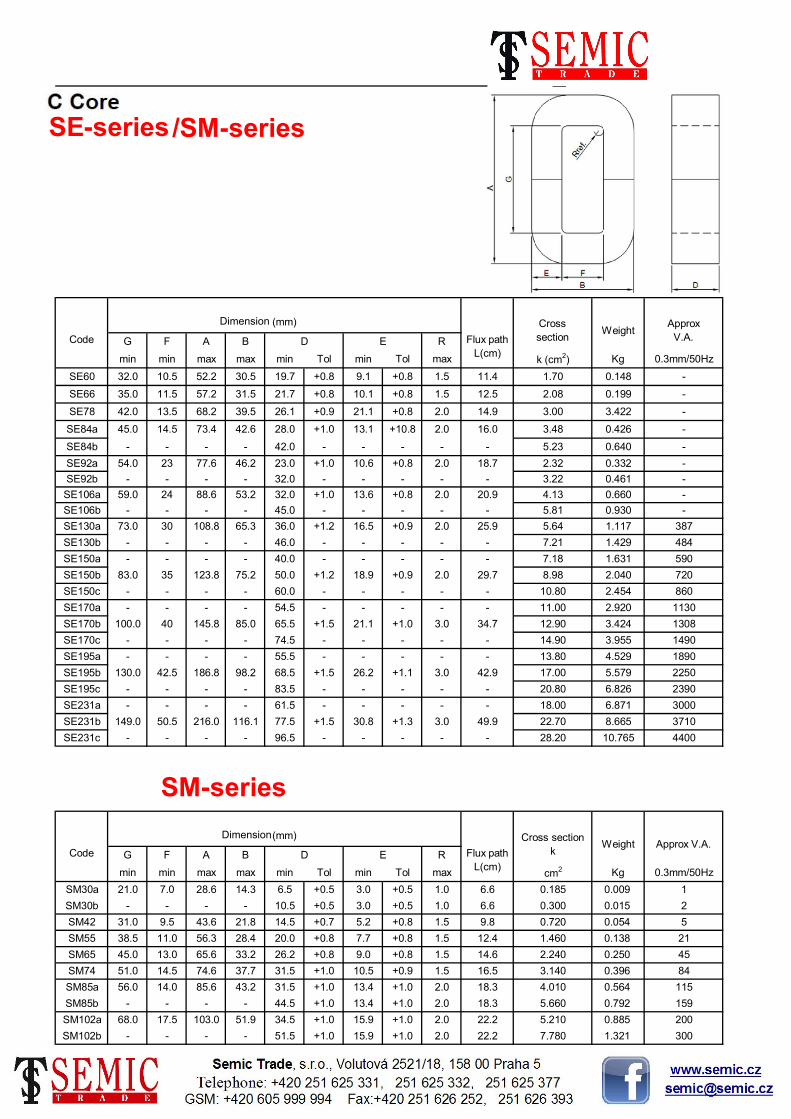
SE-series/SM-series
21.0 7.0 28.6 14.3 6.5 +0.5 3.0 +0.5 1.0 6.6 0.185 0.009
SM-series
1
- - - - 10.5 +0.5
SM30a
SM30b
SM42
SM55
Code B D
14.5 +0.7
3.0
31.0 9.5 43.6 21.8
Dimension(mm)
RG F A
SM65
SM74
SM85a
SM85b
SM102a
SM102b
E
min min max max min Tol min Tol max cm2 Kg 0.3mm/50Hz
Flux path
L(cm)
Cross section
kWeight Approx V.A.
+0.5 1.0 6.6 0.300 0.015 2
5.2 +0.8 1.5 9.8 0.720 0.054 5
38.5 11.0 56.3 28.4 20.0 +0.8 7.7 +0.8 1.5 12.4 1.460 0.138 21
45.0 13.0 65.6 33.2 26.2 +0.8 9.0 +0.8 1.5 14.6 2.240 0.250 45
51.0 14.5 74.6 37.7 31.5 +1.0 10.5 +0.9 1.5 16.5 3.140 0.396 84
56.0 14.0 85.6 43.2 31.5 +1.0 13.4 +1.0 2.0 18.3 4.010 0.564
- - - - 44.5 +1.0
68.0 17.5 103.0 51.9 34.5 +1.0 15.9 +1.0 2.0
18.3 5.660 0.79213.4 +1.0 2.0
- - - - 51.5 +1.0 1.321 300
10.765 4400
20022.2 5.210 0.885
159
115
- - - - 28.20
22.2 7.78015.9 +1.0 2.0
22.70 8.665 3710
SE231c - - - - 96.5 -
77.5 +1.5 30.8 +1.3 3.0 49.9
- - 18.00 6.871 3000
SE231b 149.0 50.5 216.0 116.1
2390
SE231a - - - - 61.5 - - -
- - - - 20.80 6.826
17.00 5.579 2250
SE195c - - - - 83.5 -
68.5 +1.5 26.2 +1.1 3.0 42.9
- - 13.80 4.529 1890
SE195b 130.0 42.5 186.8 98.2
1490
SE195a - - - - 55.5 - - -
- - - - 14.90 3.955
12.90 3.424 1308
SE170c - - - - 74.5 -
65.5 +1.5 21.1 +1.0 3.0 34.7
- - 11.00 2.920 1130
SE170b 100.0 40 145.8 85.0
860
SE170a - - - - 54.5 - - -
- - - - 10.80 2.454
8.98 2.040 720
SE150c - - - - 60.0 -
50.0 +1.2 18.9 +0.9 2.0 29.7
- - 7.18 1.631 590
SE150b 83.0 35 123.8 75.2
484
SE150a - - - - 40.0 - - -
- - - - 7.21 1.429
5.64 1.117 387
SE130b - - - - 46.0 -
36.0 +1.2 16.5 +0.9 2.0 25.9
- - 5.81 0.930 -
SE130a 73.0 30 108.8 65.3
-
SE106b - - - - 45.0 - - -
13.6 +0.8 2.0 20.9 4.13 0.660
3.22 0.461 -
SE106a 59.0 24 88.6 53.2 32.0 +1.0
32.0 - - - - -
2.0 18.7 2.32 0.332 -
SE92b - - - -
-
SE92a 54.0 23 77.6 46.2 23.0 +1.0 10.6 +0.8
- - - - 5.23 0.640
3.48 0.426 -
SE84b - - - - 42.0 -
28.0 +1.0 13.1 +10.8 2.0 16.0
2.0 14.9 3.00 3.422 -
SE84a 45.0 14.5 73.4 42.6
-
SE78 42.0 13.5 68.2 39.5 26.1 +0.9 21.1 +0.8
10.1 +0.8 1.5 12.5 2.08 0.199
1.70 0.148 -
SE66 35.0 11.5 57.2 31.5 21.7 +0.8
19.7 +0.8 9.1 +0.8 1.5 11.4
Tol max k (cm2) Kg 0.3mm/50Hz
SE60 32.0 10.5 52.2 30.5
D E R
min min max max min Tol min
Code
Dimension (mm)
Flux path
L(cm)
Cross
sectionWeight
Approx
V.A.G F A B
14

0.570 0.03210 10.4 6.4 6.8 0.8 7.4305BL10 21.8 6 36.6 20.1
Mini C Core (only 0.05mm GOSS)
Code
Dimension(mm)
Flux path
L(cm)
Cross section
kWeight Approx V.A.
G F A B D E R
min min max max min Tol min Tol max cm2 Kg
0.0066.8 3.2 3.6 0.8 4.53 0.18305BH6 12.3 6 20.7 13.7 6.4
3.6 0.8 3.57 0.183 0.005
0.003
05BD6 9.1 4.4 17.5 12.1 6.4 6.8 3.2
3.6 3.2 3.6 0.8 3.57 0.09105BD3 9.1 4.4 17.5 12.1 3.2
3.6 0.8 3.41 0.183 0.005
0.002
05BC6 9.1 3.6 17.5 11.3 6.4 6.8 3.2
3.6 3.2 3.6 0.8 3.25 0.091
2.74 0.046 0.001
05BB3 9.1 2.8 17.5 10.5 3.2
05BA3 9.1 2.8 14.3 7.3 3.2 3.6 1.6 2 0.8
52.7553.4 102 104.4 - 140.4 49.40HK51 - - 569 400 51
53.4 - 124.4 24.70 23.35
32.50
HJ51 356 190 647 298 51 53.4 51
40.4 100 102.4 - 118.5 36.10HG38 - - 519 336 38
62.4 - 106.0 21.70 17.45
19.20
HF38 310 130 439 256 38 40.4 60
53.4 - - - - 31.00HB51 - - - - 51
66.4 5 81.4 19.46 12.05
28.45
HB32 196 115 333 249 32 34.4 64
102.4 - - - - 47.50AS100 - - - - 100
- - - 33.20 19.90
14.50
AS70 - - - - 70 72.4 -
53.4 50 52.4 5 78.8 24.20AS51 230 90 337 194.5 51
- - - 19.38 9.10
5.70
AP51 - - - - 51 52.6 40
33.6 40 41.6 5 61.7 12.16AP32 180 70 265 153 32
- - 49.4 15.50 5.82
3.65
AJ51 - - - - 51 52.6 -
33.6 32 33.6 5 49.4 9.73AJ32 145 56 214 1213 32
min Tol max cm2 Kg
B D E R
min min max max min Tol
AJ-HK series
Code
Dimension(mm)
Flux path
L(cm)
Cross section
kWeight
Approx
V.A.G F A
15

28.7232.60
- -
- - -
- - 4283.00
5296.00
308 - - - -
-
79.8 80.7 38.40 23.43 3550.00
233 - - - -
- - - 14.42 2396.00
248 - - - -
1600.00
188 - - - - - -
168 224.4 63.8 64.7 24.58 11.89
- - - 7.22
39.7 40.8
1038.00
195 - - - - - 8.10 1275.00
720.00
150 - - - - - -
134 180.4 15.36 5.95
- - - 3.57- - 16.20 457.00
156 - - - - 18.20- -
-
302.00
120 - - - - - -
106 142.8 39.8 40.6 9.60 2.91
- - - 1.83
24.7 25.6
225.00
126 - - - - - 2.05 281.00
143.00
96 - - - - - -
86 113.4 6.14 1.49
- - - 1.14- - 10.20 93.40
100 - - - - 11.60- -
-
47.20
76 - - - - - -
68 91.1 31.8 32.6 4.92 0.95
- - - 0.55
15.7 16.5
26.40
79 - - - - - 0.62 35.40
13.90
61 - - - - - -
54 72.4 3.00 0.45
- - - 0.28- - 6.42 5.53
62 - - - - 7.22- -
-
0.23 2.53
47 - - - - - - 5.72
20 12.5 42 57.6 19.8 20.5 9.7
36.60 - 32.24 6366.00HSD50×80×200 200 -
- -HSD50×80×160
29.10 - 25.60
160 - 268 -
HSD50×80×125 125 -
49.7 50.8 3.0 26.60HSD50×80×100 100 64.0 208 282.8
29.10 - 16.40 3006.00HSD40×64×160 160 - - -
- - - 25.60HSD40×64×125
23.10
125 - 213 -
- 13.01 1963.00HSD40×64×100 100 -
3.0 21.10HSD40×64×80
22.90- -
80 50.0
HSD32×50×125 125 -
- - - 20.40HSD32×50×100
18.40
100 - 170 -
- 6.51 839.00HSD32×50×80 80 -
31.7 32.8 2.5 16.80HSD32×50×64 64 40.0
- 4.01 556.00HSD25×40×100 100 -
49.8 50.6
HSD25×40×80
14.60
80 - 136 -
- 3.22 370.00HSD25×40×64 64 -
3.0 13.20HSD25×40×50
14.50- -
50 32.0
HSD20×32×80 80 -
- - - 12.90HSD20×32×64
11.50
64 - 110 -
- 1.63 184.00HSD20×32×50 50 -
19.7 20.6 2.0 10.50HSD20×32×40 40 25.0
- 1.30 127.00HSD16×32×64 64 -
31.8 32.6
HSD16×32×50
9.16
50 - 86 -
- 1.03 67.70HSD16×32×40 40 -
2.0 8.36HSD16×32×32
9.05- -
32 20.0
HSD12.5×25×50 50 -
- - - 8.05HSD12.5×25×40
7.25
40 - 69 -
- 0.50 20.10HSD12.5×25×32 32 -
12.2 13.0 2.0 6.55HSD12.5×25×25 25 16.0
- 0.32 7.36HSD10×20×40 40 -
24.8 25.5
HSD10×20×32
-
32 - 54 -
0.25 3.69HSD10×20×25 25 -
10.4 1.5 5.22 1.92HSD10×20×20
min max max k (cm2) Kg 0.3mm/50Hz
B D E R
min min max max min max
Code
Dimension (mm)
Flux path
L(cm)
Cross
sectionWeight
Approx
V.A.G F A
16

160 - 268 - -
-
80 50.0 168 224.4 39.8
125 - 213 - -
64 40.0 136 180.4 31.8
100 - 172 - -
50 32.0 16 142.8 24.8
80 - 136 - -
40 25.0 86 113.4 19.8
64 - 110 - -
36.6
0.1mm
0.94 0.92
- -
-
32.6
-
-
BSD50×50×200 200 - 308 - - - -
- - - -
- -
-
1.18 1.15
BSD50×50×160
- -
- -
- -
1.468 1.44
-
- - 29.1
-
- -
- -
2.406 2.35
BSD50×50×125 125 - 233 -
9.625
15.04
- -
50.6 49.8 50.8
-
-
- - -
-
3.0 26.6
-
-
-
3.76
-
5.875
- -
BSD50×50×100
-
-
-
3.68
-
- -
-
-
- -
5.75
- -
- -
9.42
-
- -
- -
- -
16 10.0 34 46.3 12.3
25 - 43 - -
12.5 42 57.6 12.320
32 - 54 - -
25 16.0 54 72.4 12.3
40 - 69 - -
32 20.0 68 91.2 15.8
50 - 86 - -
400Hz
- - 29.1
23.5 23.00
- 23.1
0.109 0.107
248 - - - -
100 64.0 208 282.4 49.8
- 25.6
-
-
BSD40×40×125
-
-
BSD40×40×160 160 -
- -
0.1mm
0.090 0.088
0.098 0.096
0.194 0.190
0.304
0.125 0.128
0.140 0.137
0.154
21.1
0.151
0.173 0.170
14.70
BSD40×40×100 100 - 188 - - - -
40.6 39.8 40.8 3.0
-
20.4
0.908
0.995
BSD40×40×80
0.221 0.216
0.225 0.239
0.272 0.266
0.298
0.463
22.9
0.451
0.508 0.495
0.563 0.550
0.640 0.625
BSD32×32×125 125 - 197 - - - -
- - - -
- -
3.732 3.618
1.113
1.251
1.791
BSD32×32×100
1.091
1.220
1.739
1.982
- -
1.922
2.194 2.138
- - 18.4
2.470 2.400
BSD32×32×80 80 - 152 - -
BSD32×32×64
4.396
5.077 4.934
7.293 7.117
32.6 31.8 32.8 3.0
- 18.2
7.992 7.787
8.851 8.629
16.8
4.526
4.081 3.964
BSD25×25×100 100 - 150 - -
BSD25×25×80
9.806
14.416 14.040
- -
- - - -
15.794 15.336
- - 14.6
17.490 17.172
16.2
10.070
-
19.822 19.332
BSD25×25×64 64 - 120 - - - -
25.5 24.8 25.6 3.0 13.2
50Hz
22.2
36.3
51.3
67.0
BSD25×25×50
Approx
V.A.
0.1mm0.2mm
Cross section Weight
k (cm2) M (Kg)
22.0
35.8
14.5
55.5
68.2
65.1 67.3
80.0 82.6
106.0
0.884
0.969
BSD20×20×80 80 - 126 - - - -
- - - -
- -
12.9
109.0
132.0 135.0
114.0 123.0
10.5
537.0
10.2
8.36
BSD20×20×64
139.0 150.0
176.0 183.0
221.0 231.0
228.0 253.0
282.0
- - 11.5
301.0
344.0 382.0
442.0 488.0
432.0 498.0
BSD20×20×50 50 - 96 - -
948.0 1088.0
BSD20×20×40
614.0
660.0 744.0
780.0 891.0
- -
- - - 11.6
759.0 869.0
20.5 19.8 20.6 3.0
-
- - - -
BSD16×16×64 64 - 100 -
2155.0 2453.0
1185.0
BSD16×16×50
1343.0
1424.0 1616.0
1430.0 1626.0
-
16.5 2.0
BSD16×16×40 40 - 76 - - - -
BSD16×16×32
3001.0
2877.0 3314.0
3487.0 4006.0
- -
16.4 15.8
- 9.05
4240.0 4849.0
5744.0 6329.0
2651.0
9.16
1751.0 1996.0
BSD12.5×12.5×50 50 - 79 - -
BSD12.5×12.5×40
7193.0
8078.0 8974.0
- -
- - - -
9417.0 10664.0
- - 7.25
11530.0 13131.0
8.05
6306.0
-
BSD12.5×12.5×32 32 - 61 - - - -
12.9 12.3 13.0 2.0 6.55BSD12.5×12.5×25
- - 7.22BSD10×12.5×40 40 - 62 - - - -
- - - - 6.42BSD10×12.5×32
- - 5.72BSD10×12.5×25 25 - 47 - - - -
12.9 9.8 10.4 2.0 5.22BSD10×12.5×20
- - 5.72BSD8×12.5×32 32 - 50 - - - -
- - - - 5.06BSD8×12.5×25
- - 4.56BSD8×12.5×20 20 - 38 - - - -
12.9 7.8 8.4 1.5 4.16BSD8×12.5×16
min max maxmin min max
D E R
max min max
Code
Dimension(mm)
Flux
path
L(cm)G F A
0.2mm 0.2mm
B
17

Dimension (mm) Cross section WeightApprox
V.A.
G F A B D E R k (cm2) M (Kg) 0.3mm 0.1mm
min min max max min max min max 400Hzmax 0.3mm 0.1mm 0.3mm 0.1mm 50Hz
1.24 1.20 0.165 0.145- 16 17 - - -EA16 - - -
1.01 0.98 0.122 0.118- 13 14 - - -EA13 - - -
0.62 0.60 0.080 0.07354 8 9 8 9 1.6EA08 25 13 47
1.84 1.79 0.281 0.273- 19 20 - - -EB19 - - -
1.55 1.50 0.262 0.230- 16 17 - - -EB16 - - -
1.26 1.22 0.193 0.187- 13 14 - - -EB13 - - -
0.97 0.94 0.164 0.14366 10 11 10 11 1.6EB10 32 16 58
1.64 1.59 0.305 0.29581 13 14 13 14 1.6EC13 38 19 70
2.13 2.07 0.326 0.316- 22 23 - - -
0.446 0.432
EB22 - - -
20 - - - 2.40 2.32
0.363
EC19 - - - - 19
- - - 2.02 1.96 0.415- - - - 16 17
80
25 26 - - -
0.8 2.3038 2.2325 0.410 0.400 16
8 40
32 16 60 73.0 19.0 19.8 12.5 13.2
10.0 0.8 1.1457 1.1102 0.170 0.160
24.900 4000 20000
29 14 51 60.4 12.7 13.5 9.3
60 61 - 34.92 33.84 25.700140 7 266 324 60 61
28.29 27.41 18.500 17.950 2500 12500
8500
127 60 241 286 54 55 54 55 -
- 22.35 21.66 13.450 13.000 1700
1000 5000
121 54 223 256 48 49 48 49
42 - 16.31 15.80 8.620 8.350
6.470 700 3500
108 48 196 223 41 42 41
38 39 - 14.01 13.57 6.68095 44 177 203 38 39
9.93 9.63 4.200 4.075 400 2000
1350
89 38 159 176 32 - 32 33 -
- 7.76 7.52 2.790 2.705 250132 149 32 - 25 26
6.83 6.62 2.060 2.000 150 800
600
63 29 113 128 32 - 22 23 -
3.0 5.90 5.72 1.565 1.520 100101 111 32 33 19 20
4.50 4.36 1.060 1.025 60 350
250
51 22 89 96 29 30 16 17 -
1.6 3.88 3.76 0.840 0.813 45
30 150
44 21 82 94 25 26 16 17
- - 3.15 3.06 0.586 0.568
Code
14
- -
57 25
76 35
3Q12 12 EZ60
13
3Q10 10 EV48
3Q11 11 EX54
3Q8 8 ER38
3Q9 9 ET41
3Q6 6 EM32
3Q7 7 EP32
3Q4 4 EH32
3Q5 5 EK32
3Q2 2 ED25
3Q3 3 EF29
IEC329 HWE- FA-
3Q1 1 EC25
EC16
18

S3U-series
Code
Dimension (mm)
Flux path
L(cm)
Cross
sectionWeight
Approx
V.A.G F A B D E R
min min max max max Tol max Tol max k (cm2) Kg 0.3mm/50Hz
S3U30a 32.5 10.0 53.7 50.9 10.1 -0.6 9.9 -0.8 1.5 0.86 0.115 7
S3U30b - - - - 16.1 - - - - 1.41 0.189 15
S3U39a 41.5 13.0 70.9 66.0 13.4 -0.9 12.9 -0.8 1.5 1.51 0.262 20
S3U39b - - - - 204 - - - - 2.36 0.409 25
S3U48a 50.5 16.0 83.9 80.8 16.6 -1.0 15.8 -0.9 1.5 2.32 0.492 30
S3U48b - - - - 25.6 - - - - 3.67 0.779 40
S3U60a 63 20.0 104.6 100.9 20.6 -1.1 19.8 -0.9 2.0 3.69 0.959 60
S3U60b - - - - 30.6 - - - - 5.58 1.470 100
S3U75a 78 25.0 129.7 125.7 26.1 -1.1 24.7 -1.0 2.0 5.93 1.820 140
S3U75b - - - - 41.1 - - - - 9.48 2.930 180
S3U90a 95 30.0 156.8 150.6 30.9 -1.4 29.6 -1.1 3.0 8.41 3.330 270
S3U90b - - - - 50.9 - - - - 14.11 5.590 450
S3U102a 106 34.0 176.4 171.1 35.4 -1.4 33.7 -1.2 3.0 11.05 4.940 450
S3U102b - - - - 56.4 - - - - 17.88 8.000 700
S3U114a 118 38.0 196.2 191.0 39.2 -1.7 37.6 -1.3 3.0 13.54 6.780 650
S3U114b - - - - 63.2 - - - - 22.20 11.100 1000
S3U132a 136 44.0 226.4 220.5 45.2 -1.7 43.4 -1.4 3.0 18.27 10.500 1000
S3U132b - - - - 71.2 - - - - 29.19 16.800 1800
S3U150a 154 50.0 255.6 249.6 51.2 -1.7 49.4 -1.5 3.0 23.71 15.500 2000
S3U150b - - - - 76.2 - - - - 35.69 23.400 3000
S3U168a 172 56.0 286 279.6 57 -2.0 55.3 -1.6 3.0 29.54 21.700 3000
S3U168b - - - - 91 - - - - 47.49 35.100 4000
S3U180a 184 60.0 307.2 301.0 62 -2.0 59.7 -1.8 3.0 34.74 27.400 3500
S3U180b - - - - 77 - - - - 43.43 34.200 4500
S3U180c - - - - 92 - - - - 52.11 41.100 5000
S3U210a 214 70.0 357.2 350.8 71.7 -2.2 69.6 -2.0 3.0 46.98 43.100 6000
S3U210b - - - - 101.7 - - - - 67.26 61.700 8000
S3U210c - - - - 131.7 - - - - 87.54 80.400 10000
19

/Advantages/Compact dimension;/High efficiency;/Low magnetic leakage;
2000
30
40
50
80
100
120
500
600
150
。
Customized OA Core is welcome, maximum V.A. is upto 5KVA.
which is wound in Hi-B oriented electrical steels and no-load-losses are guaranteed.
Continuous flux path, no bobbins needed, save coppers due to round or oval shape cross-section minimizes length per turn.
Approx
V.A.
10
20
300
400
200
250
6.842
800
1000
1500
8.750
1.994
2.458
2.850
3.299
3.933
4.721
0.752
0.899
1.010
1.182
1.463
1.773
26.59
Weight
Kg
0.229
0.322
0.397
0.487
0.621
10.39
11.52
12.72
14.30
16.31
22.34
5.13
5.53
6.15
7.25
8.20
9.07
1.99
2.50
2.92
3.38
4.04
4.57
mm cmCode
Cross section
cm2
60.0 80 194 43.02
H d D
max min max
47.0 75 166 37.83
55.0 75 180 40.03
41.5 68 148 33.91
44.0 72 157 35.95
37.5 62 135 30.93
39.5 65 141 32.34
33.5 58 122 28.26
35.0 58 125 28.73
29.0 52 108 25.12
31.5 53 115 26.38
26.5 48 98 22.92
27.5 50 102 23.86
OA-600
OA-800
OA-1000
OA-1500
OA-2000
16.5
18.5
20.0
21.5
23.5
OA-100
OA-120
OA-150
OA-2000
OA-250
OA-300
OA-10
OA-20
OA-30
OA-40
OA-50
OA-80
OA-400
OA-500
32 64 15.07
35 72 16.80
38 17.74
40 80 18.84
42 86 20.10
25.0 45 92 51.51
Flux path
mm mm
75
20

/Advantages/Compact dimensions;/High efficiency;/Low magnetic leakage;
/Reliable safety;/Low humming etc.
1
Code
DimensionsApprox
V.A.
。
Customized R Core is welcome, maximum V.A. is upto 5KVA.
R-cores are wound in HiB electrical steels and no-load- losses are guaranteed.
Besides cores, bobbins and mounting bases for transformer unit can also be obtained a package.
1
17 1
44.5 18 80 53.5 17.5
44.5 15.5 78.5 50
min max max max max
44.5 15.5 77.5 48 16
R-1000
R-1500
G F A B
R-30
R-80
R-100
57
D R
min
R-260
R-320
R-600
R-10
R-15
R-20
R-25
R-35
R-40
R-50
R-65
R-160
45 18 84.5 57.5 19 1
56 20 95.5 59.5 19 1
21 97.5 61.5 20 1
55 20.5 97.5 63 20.5 1
54.5 22 100 67.5 22 1
59 23 104.5 68.5 23 1
75 23.5 121.5 70 23.5 1
72 29 121.5 78 25.5 1.5
84 31 132 85 27 1.5
95.5 33 152 90 29 1.5
101 37.4 161 97.4 30.5 1.5
109 37.5 182 110.5 37 1.5
135 44 220 128 43 2
135 48 245 158 54.5 2
160
10
15
20
25
30
35
260
320
600
1000
1500
40
50
65
80
100
21

Single & Three-phase stacked cores
/Advantages
1 / Reductoin in core losses;2 / Easy assembly.
/Available materials
single and three-hase distribution transformer stacked cores are operating in many thousands of tranformers in China and overseas.
No standard range of design exists due to the
diversity of design requirements. We produce single-
phase cores ranging from 10KVA to 5000KVA, and
three-phase cores ranging from 10KVA to 40MVA.
In the production of these M5/M4/M2H/M1H/M0H or
laser oriented electrical steel grades are used and
no-load-losses are guaranteed.
22

/SP Series stacked cores
/DP series stacked cores
In order to satisfy the customer who are eager to minimize their costs, stacked cores for distribution transformers ranging from 10KVA to 1500KVA.
The cores are produced in recycle materials from USA and Japan, cut by manual shearing machine with little burrs and high dimension accuracy.
stacked cores in new material with low core loss for distribution transformers ranging from 10KVA to 2500KVA. The cores are also cut by manual shearing machine with burrs less than 0.03mm, width tolerance ±0.1mm, length tolerance ±0.5mm.
23

Conventional silicon steels are widely used for electrical power apparatus, electrical components in industrial products and home electronics. However, most silicon steel strips are thicker than 0.20mm and applied only to apparatus operated at industrial frequencies.
On the other hand, thin-gauge silicon steel strips have advantage for use at higher frequencies. The thickness of the silicon steel strips have been reduced to the world's thinnest level so that the core loss caused by eddy currents is combined with the insulatioin coating technology of steel manufacturer, the lamination factor has been improved. Thin-gauge silicon steel strips assist saving energy and down-sizing high frequency reactors, transformers and motors.
Thin-gauge silicon steel strips allow superior cost saving as well as performance at high frequencies.
/Advantages/Low core loss
They have low core loss at high frequencies and allow improvements in effciency, and saves energy of reactors and transformers.
/High permeability
High permeability allows use for shields.
/High saturation flux density
They contribute to down-sizing of high frequency reactors and transformers due to high saturation flux density.
/Excellent insulation coating
The inorganic coating allows excellent insulation, which enables the best stress relief annealing (results).
24

Note:
Note:
Magnetic Pr tier ipr
17.2 14.2
ST-100 2.7 --- 11.0 34.1
10.2 7.1 5.3
ST-150 2.3 --- 11.6 39.4 30.0 21.5
Grade W1/10000
13.0GT-100
GT-050 1.7 5.0 7.3 17.0 13.0
W15/50 W15/100 W10/400 W10/1000 W5/2000 W2/5000 W0.5/200000
Table 1 C
Core Loss (W/kg)
1.2 3.0 6.1 21.3 18.0 15.2 10.4
25.3 17.0 12.9 10.2
ST-050 6.1 --- 25.4 65.8 40.8 21.4 11.6 6.7
Table 2 Permeability and magnetic flux ty rties
Core Loss (W/kg)
GT-050 7.65 90 387 11
μ10/400 μ10/1000 μ5/2000 μ1/10000 μ0.5/20000
48
B8 B25 B50
1.75GT-050 16.6 16.0 9.9 2.7 1.5 --- ---
ST-150 9.61 8.17 5.57 1.70 1.15 --- 1.56 1.66
ST-100 8.54 7.87 5.81 2.00 1.39 --- 1.55 1.65
1.
2. For ST series, the specimens are taken from the strips in both directions of parallel and transverse to the rolling direction. The measurements are in accordance with JIS C 2550.
ST-050 3.13 3.11 2.65 1.00 0.93
420 9 202*2
--- 1.47 1.58
For GT series, the specimens are taken from the strips parallel to the rolling direction. The measurements are in accordance with JIS C 2550 after stress relief annealing.
Hardness(Hv)
1. Tensile strength and elongation are measured parallel to the rolling direction.2.
Table 3 Mechanical and electric rties
Specific resistance(μΩcm)
Grade
GT-100 7.65 93
48
9.6 2.8
Tensile Strength
(N/mm2)
Elongation(%)
1.2 1.82 --- ---
Grade
Density
(g/cm3)
Space factor(%)
Alternating permeability x 10-3 (H/m) Magnetic flux density (T)
GT-100 20.4 16.2
ST-150 7.65 94 496 15 205*2
52
52
7.65 93 478 13 198*2ST-100
179*2
Hardness are measured by: *1:H=0.5kg;*2:H=0.3kg;*3:H=0.1kg;
52
ST-050 7.65 90 487 12 182*2
25
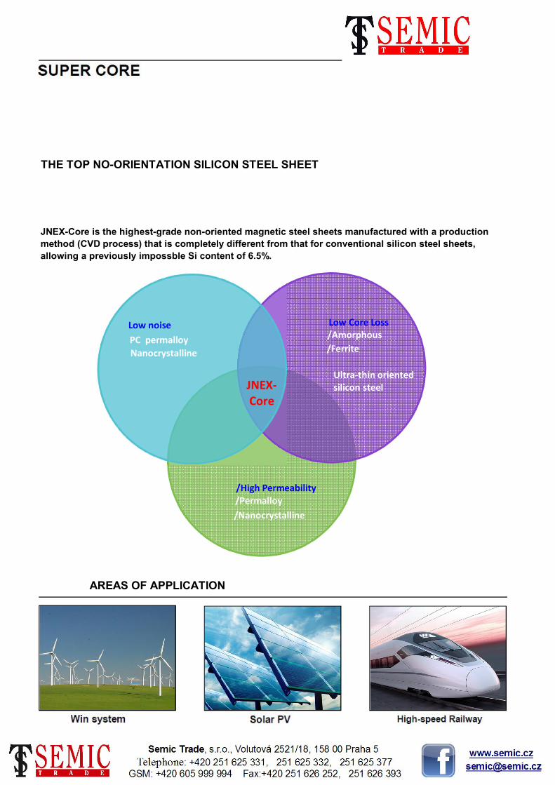
THE TOP NO-ORIENTATION SILICON STEEL SHEET
JNEX-Core is the highest-grade non-oriented magnetic steel sheets manufactured with a production
method (CVD process) that is completely different from that for conventional silicon steel sheets,
allowing a previously impossble Si content of 6.5%.
AREAS OF APPLICATION
28
/High Permeability/Permalloy
/Nanocrystalline
Low Core Loss/Amorphous
/Ferrite
Ultra-thin oriented silicon steel
Low noise
PC permalloy
Nanocrystalline
JNEX-Core

/ High Permeability
The permeability is extremly high across a wide range of frequencies, making it highly suitable for use in shield applications and CT.
/ Stable Quality
The high-temperature processing provides thermal stability. Since there is minimal deterioration of the properties due to machining, so stress relieving anneals are not required.
/ Non-oriented
There is virtually no difference in the characteristics between the rolling direction (L-direction) and the
/ REACTOR
Due to the high saturation magnetic flux density, the low core loss at high-frequency and the high-permeability of Super Core, it is ideal for application in high frequency reactors with high-frequency current superimposition over a broad range of frequencies.
Because Super Core meets all high frequency wave regulations and power factor improvements, demand is on the increase for its use in not only inverter output reactors but also in active filters and in PWM converter reactors in the market sectors from consumer electronics to industrial, renewable power generation and automotives.
Super Core meets a diverse range of customers needs since it can be formed into wound cores, such as C-Cores and toroidal cores, as well as into lamination cores and glued block cores of various shapes by cutting or pressing.
/ PERFORMANCE
/ Low Core Loss
Core loss in high frequency ranges is extremly low. This allows for low heat generation and size reductions for magnetic components such as high-frequency reactors and transformers.
/ Low Magnetostriction
Magnetostriction which causes noise and vibration is nearly zero. This enables significant noise reductions for magnetic components such as reactors and transformers.
29

After the steel is formed and annealed it is soaked in varnish and fixed, cut(if necessary). The sheet thickness is
0.1mm. Both standard & non-standard sizes C-Core are available.
Block cores are for small and medium sized reactors and transformers. Effectively cost reduction for mass-producing. Standard lamination fixing method is adhesive fixation.
A laminated core made in virtually the same shape as a cut
core, so that it is possible to use the same washers and
clamp bands.
/ TRANSFORMER
The low core loss characteristics at high-frequency of Super Core allow it to be effectively used for a wide range
of transformers,, driven from several hundred Hz to several tens o f kHz.
Super Core allo w the transformer to generate less heat, and provides higher design induction than conventional silicon steel sheets, enabling transformer size to be reduced. This then reduces the quantities of
other requried transformer materials, such as the copper wire, leading to overall cost reductions.
By taking full advantage of the low magnetostriction characteristics of JNEX-Core, it is also possible to reduce transformer noise dramatically.
These cores are used mainly with medium- and large-sized
transformers and reactors. The user stacks the strips and
affixes them using bolts.
30

● 10JNEX900 High-frequency core loss curve
● 10JNHF600 High-frequency core loss curve
Measurement: 25 cm Epstein testRolling direction, shear cross-section
Measurement: 25 cm Epstein testRolling direction, shear cross-section
/ CORE LOSS CURVES
31

Core loss (W/kg)
14.4 62.0
Amorphous
*W10/50 is the core loss at 50Hz, 1T(=10kG) when the magnetic flux sine wave is excited.
*B8 is the magnetic flux density at 800A/m.
0.35 18,000 1.96 1.45
● Comparison of magnetic characteristics: Rolling direction, shear cross-section
MaterialThickness
(mm)
DC max
relative
permeability
Saturation
magnetiza-
tion(T)
Magnetic
flux density
B8(T) W2/5k W1/10k W0.5/20k
Magnetic
flux density
B25(T)
11.3
1.56 0.7
0.10 24,000 2.03 1.84
3,500
18.0 14.0
1.401.291.8023,000
0.7
18.70.5
2.0
0.10JNEX-Core
W10/50 W10/400 W10/1k W5/2k
JNEX-Core
Ferrite Bulk --- ------ 0.37 --- --- ---
1.75
1.84
1.92
1.92
---
0.1
1.91
1.96 0.3
0.7
0.8
7.8
6.0
0.20
8.50
0.35
5.7 18.7
0.35
0.23
0.10
0.05
0.10
Fe-based
Amorphous0.025
Grain-
oriented
Silicon steel
Non-oriented
Silicon steel
3.3
*W10/50 is the core loss at 50Hz, 1T(=10kG) when the magnetic flux sine wave is excited.
*B8 is the magnetic flux density at 800A/m.
300,000 1.50 --- ---
23,000 1.80 1.29 1.40 0.5 6.913.7 11.3
24,000
’--- 6.4 5.2
14.0
9.2
20.02.03
1.96
92,000
--- 0.1
33.0
49.5
8.3
5.5 8.1 4.0 3.6
22.0
1.96
1.5 5.5 8.1 4.0
94,000 0.4 12.2
2.2
5.7
0.025 300,000 1.50 ---
0.10
18,000
15,000
12,500 2.05
0.10
3.6 3.3
32.0
49.0
17.2
22.7
35.0
55.0
13.5
1.8
33.0
49.5
11.00
14.40
50.2 38.0
16.5
26.2
38.0
W2/5k
33.0 ---
7.1
18.0
30.0
47.0
---
---
13.3
23.02.03
---1.45
1.44
1.58 ---
1.53
1.56 0.7
0.7
W1/10k
0.8 27.1
38.5
62.0
22.4
33.2
W5/2k
50.2
1.5
JNHF-Core
33.0
6.2 22.7 22.0 20.01.91
Magnetic
flux density
B25(T)
Core loss (W/kg)
W0.5/20k
Magnetic
flux density
B8(T)
Saturation
magnetiza-
tion(T)
DC max
relative
permeability
Thickness
(mm)Material
51.6
W10/1kW10/400W10/50
4,100 5.0
0.20 3,900 1.94 1.09 1.47
1.15 1.44 1.1 30.0
13.7
Non-oriented
Silicon steel
20.2 11.5 7.110.1
Grain-
oriented
Silicon steel
1.2 14.5
1.88
/ COMPARISON
● Comparison of magnetic characteristics: Rolling direction, shear cross-section
6.9
291.0 17.9 12.7 9.5
8.3
32

3409
3409
3407
3409
3407
3405
3407
3406
Russia
(NI&SCo)
3409
3407
3406
3408
35PH135
23PHD080
23PHD085
27PHD090
27PHD095
30PH110
30PH105
35PH115
35PH125
23PH090
23PH095
23PH100
27PH095
27PH100
30PG120
30PG130
30PG140
35PG145
35PG155
B27R090 27ZDKH90 27JGSD090 H090-27
Korea
(POSCO)
27PG120
27PG130
B23R085 23ZDKH85 23JGDS085 H085-23
B23R090 23ZDKH90 23JGDS090 H-0DR
B23R080 23ZDKH80 23JGDS080
B35P125 35ZH125 35JGH125
B27R095 27ZDKH95 27JGSD095 H-1DR
B35P135 35ZH135 35JGH135
B30P120 30ZH120
B35P115 35ZH115 35JGH115
30ZH100
30ZH105 30JGH105 H105-30
27ZH100 27JGH100 H103-27
27ZH110 27JGH110 H-1
23ZH100 23JGH100 H100-23 H-0
27ZH95
23ZH90 23JGH090 H090-23
23ZH95 23JGH095 H095-23
35Z145 35JG145
35Z155 35JG155
30Z140 30JG140 C140-30
35Z135 35JG135
B30P110 30ZH110 30JGH110 H111-30
27Z130 27JG130 C130-27
30Z120
B30P105
27Z120 27JG120 C120-27
30JG120
30Z130
B27P110
B30P100
C110-23
C120-23
30JG130 C130-30
B35G155
B23P090
B23P095
B23P100
B27P095
B27P100
Germany
(Thyssen)
U.S.A.
(AK Steel)
B30G130
B30G140
B35G135
B35G145
Japan
(NSC)
Japan
(JFE)
23Z110
China
(Baosteel)
B23G110
B23G120
B27G120
B27G130
B30G120
33

China
(Baosteel)
Japan
(NSC)
Japan
(JFE)
Germany
(Thyssen)
U.S.A.
(AK Steel)
Korea
(POSCO)
Russia
(NI&SCo)
35PN230
B35A210 35H210 35JN210 M210-35A 35PN210
35JN250 M250-35A M-15 35PN250
B35A230 35H230 35JN230 M235-35A
2413
B35A270 35H270 35JN270 M270-35A M-19 35PN270 2412
B35A250 35H250
35PN360
B35A300 35H300 35JN300 M300-35A M-22/M-27 35PN300
35JN440 35PN455
2411
B35A360 35H360 35JN360
B35A550 35PN560
B35A440 35H440
50PN250
B50A230 50H230 50JN230 M230-35A 50PN230
50JN270 M270-50A 50PN270
B50A250 50H250 50JN250 M250-35A
2414
B50A290 50H290 50JN290 M290-50A M-15 50PN290 2413
B50A270 50H270
50PN350
B50A310 50H310 50JN310 M310-50A M-19 50PN310
M400-50A M-27/M-36 50PN400
2412
B50A350 50H350 50JN350 M350-50A M-22
B50A470 50H470 50JN470 M470-50A 50PN445 2214
B50A400
50PN760
B50A600 50H600 50JN600 M600-50A 50PN595
50JN800 M800-50A 50PN890
2212
B50A700 50H700 50JN700 M700-50A M-47
2011
B50A1000 50H1000 50JN1000 M1000-50A 50PN1015
B50A800 50H800
B50A13000 50H13000 50JN13000 M1300-50A 50PN1270
34

M470-65A M-43 65PN470
China
(Baosteel)
Japan
(NSC)
Japan
(JFE)
Germany
(Thyssen)
U.S.A.
(AK Steel)
Korea
(POSCO)
Russia
(NI&SCo)
B65A600 M600-65A M-45 65PN595
B65A470
65PN890
B65A700 M700-65A 65PN760
65JN1000 M1000-65A 65PN1015
65JN1300 M13000-65A 65PN1270
B65A800 65JN800 M800-65A M-47
B65A1000
B35AH230 35JNE230
B65A1300
B35AH250 35JNE250
35JNE300
B50AH300 50JNE300
B35AH300
50JNE470
B50AH350 50JNE530
B50AH600
B50AH470
B50AH800
50JNA300
B35AR300
B50AR350 50JNA350
B50AR300
B20AT1200 20HTH1200 20JNEH1200
20HTH1500 20JNEH1500
B50AH1000
B20AT1500
35