Hovering Flight Improvement of a Quad-rotor Mini UAV Using Brushless DC Motors
17
J Intell Robot Syst (2011) 61:85–101 DOI 10.1007/s10846-010-9470-3 Hovering Flight Improvement of a Quad-rotor Mini UAV Using Brushless DC Motors A. Sanchez · L. R. García Carrillo · E. Rondon · R. Lozano · O. Garcia Received: 1 February 2010 / Accepted: 1 September 2010 / Published online: 12 October 2010 © Springer Science+Business Media B.V. 2010 Abstract This paper present the design of a novel embedded control system for improving attitude stabilization of a quad-rotor mini UAV. The control strategy uses low cost components and includes an extra control loop based on motor armature current feedback. This additional control loop significantly improves the perfor- mance of the quad-rotor attitude stability. This technique results in a controller that is robust with respect to external disturbances as has been observed experimentally. Keywords Embedded control system · Improving attitude stabilization · Quad-rotor UAV · Brushless DC motor · Motor armature current This work was partially supported by Mexico’s National Council of Science and Technology (CONACYT) and the Research Center for Advanced Studies—Cinvestav. A. Sanchez Robotics and Advanced Manufacturing Division, Research Center for Advanced Studies—Cinvestav, Carretera Saltillo-Monterrey km. 13.5, 25900 Ramos Arizpe, Coahuila, México e-mail: [email protected] L. R. García Carrillo (B ) · E. Rondon · R. Lozano UMR CNRS 6599, Université de Technologie de Compiègne Heudiasyc, Centre de Recherches de Royallieu B.P. 20529, 60205 Compiègne, France e-mail: [email protected] E. Rondon e-mail: [email protected] R. Lozano e-mail: [email protected], [email protected] R. Lozano · O. Garcia Franco-Mexican Laboratory on Computer Science and Control, UMI-CNRS 3175, Av. Instituto Politecnico Nacional No. 2508, San Pedro Zacatenco, 07360 México, DF, México O. Garcia e-mail: [email protected]
Transcript of Hovering Flight Improvement of a Quad-rotor Mini UAV Using Brushless DC Motors
J Intell Robot Syst (2011) 61:85–101DOI 10.1007/s10846-010-9470-3
Hovering Flight Improvement of a Quad-rotor MiniUAV Using Brushless DC Motors
A. Sanchez · L. R. García Carrillo ·E. Rondon · R. Lozano · O. Garcia
Received: 1 February 2010 / Accepted: 1 September 2010 / Published online: 12 October 2010© Springer Science+Business Media B.V. 2010
Abstract This paper present the design of a novel embedded control system forimproving attitude stabilization of a quad-rotor mini UAV. The control strategy useslow cost components and includes an extra control loop based on motor armaturecurrent feedback. This additional control loop significantly improves the perfor-mance of the quad-rotor attitude stability. This technique results in a controller thatis robust with respect to external disturbances as has been observed experimentally.
Keywords Embedded control system · Improving attitude stabilization ·Quad-rotor UAV · Brushless DC motor · Motor armature current
This work was partially supported by Mexico’s National Council of Science and Technology(CONACYT) and the Research Center for Advanced Studies—Cinvestav.
A. SanchezRobotics and Advanced Manufacturing Division, Research Center for AdvancedStudies—Cinvestav, Carretera Saltillo-Monterrey km. 13.5, 25900 Ramos Arizpe,Coahuila, Méxicoe-mail: [email protected]
L. R. García Carrillo (B) · E. Rondon · R. LozanoUMR CNRS 6599, Université de Technologie de Compiègne Heudiasyc,Centre de Recherches de Royallieu B.P. 20529, 60205 Compiègne, Francee-mail: [email protected]
E. Rondone-mail: [email protected]
R. Lozanoe-mail: [email protected], [email protected]
R. Lozano · O. GarciaFranco-Mexican Laboratory on Computer Science and Control, UMI-CNRS 3175,Av. Instituto Politecnico Nacional No. 2508, San Pedro Zacatenco, 07360 México, DF, México
O. Garciae-mail: [email protected]
86 J Intell Robot Syst (2011) 61:85–101
1 Introduction
We have witnessed in the last few years that the applications of autonomous mini-aerial vehicles have significantly increased. However, all the applications stronglydepend on the fact that the attitude of the aerial vehicle is satisfactorily stabilized.Indeed, if the pitch and roll angles are not controlled with a high degree of precision,drift will result and the Unmanned Aerial Vehicle (UAV) will move away from itsdesired position.
There are few studies with respect to the improvement of the attitude stabilizationfor aerial vehicles. Most of the main results have been developed for spacecraftsuch as satellites, [7]. In [10] and [11] the authors proposed a methodology forimproving attitude stability using a momentum wheel in a four rotor dual-spinvehicle. Another approach is presented in [9], where the authors propose a sensorfusion technique in order to improve the attitude of an UAV. The approach isbased on an extended Kalman filter using the information coming from an InertialMeasurement Unit (IMU) and a Global Positioning System (GPS). Improvement ofthe attitude stabilization in this paper is studied in a different context. This articlepresents a novel embedded control system for UAVs that uses, not only standardsensors as IMUs but also the motor armature current. This control strategy enables abetter stabilization of the UAV attitude around the origin. The improvement on theUAV attitude control increases the autonomy of the system and opens a new rangeof applications requiring higher performance of the attitude control.
We have noticed in standard quad-rotor control systems that the global per-formance strongly depends on the fact that all the four drivers have the samecharacteristics. In other words, that for a given control input signal, they producethe same rotor speed. This is in general not the case when using off the shelf low costcomponent. Therefore our contributions consists in including an extra control loopfor each driver in such a way that for any given control input, every driver producesalmost the same armature current which essentially produces the same rotor speed.This additional internal control loop significantly improves the performance of thequad-rotor attitude stability.
The body of the paper is organized as follows. Section 2 describes the functioningof Brushless Direct Current (BLDC) motors and their corresponding speed con-trollers. Section 3 presents the dynamical model of a quad-rotor. The control strategyis given in Section 4. Section 5 presents the embedded control system configuration.Section 6 describes the experimental results and finally the concluding remarks aregiven in Section 7.
2 Brushless DC Motor and Speed Controller
The BLDC motor, also known as trapezoidal back electromotive force (EMF) motor,is a permanent magnet synchronous machine where the magnetic fields are uniformlydistributed in the air gap such that when the motor is turning at constant speed,the back EMF has a trapezoidal shape in time [4, 5]. The BLDC motor with itspermanent magnet field excitation, replaces electromagnets which have windings andrequire an external electric energy source. Additionally, using an electronic commu-tator in the form of an inverter, replaces the mechanical commutator allowing the
J Intell Robot Syst (2011) 61:85–101 87
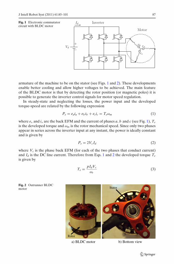
Fig. 1 Electronic commutatorcircuit with BLDC motor
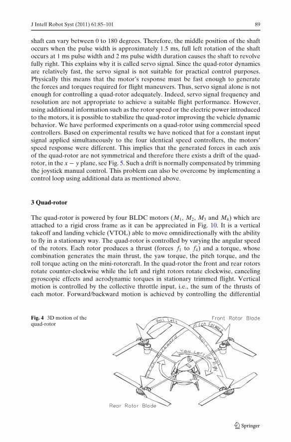
armature of the machine to be on the stator (see Figs. 1 and 2). These developmentsenable better cooling and allow higher voltages to be achieved. The main featureof the BLDC motor is that by detecting the rotor position (or magnetic poles) it ispossible to generate the inverter control signals for motor speed regulation.
In steady-state and neglecting the losses, the power input and the developedtorque-speed are related by the following expression
Pe = eaia + eb ib + ecic = Teωm (1)
where e∗ and i∗ are the back EFM and the current of phases a, b and c (see Fig. 1), Te
is the developed torque and ωm is the rotor mechanical speed. Since only two phasesappear in series across the inverter input at any instant, the power is ideally constantand is given by
Pe = 2Vc Id (2)
where Vc is the phase back EFM (for each of the two phases that conduct current)and Id is the DC line current. Therefore from Eqs. 1 and 2 the developed torque Te
is given by
Te = pIdVc
ωr(3)
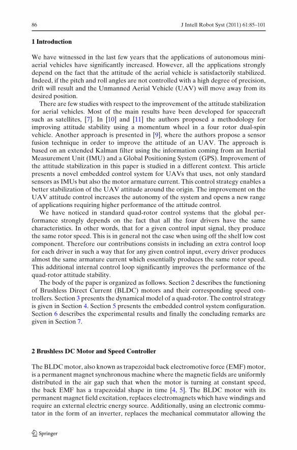
Fig. 2 Outrunner BLDCmotor Stator
Rotor
a) BLDC motor b) Bottom view

88 J Intell Robot Syst (2011) 61:85–101
where p is the number of poles and ωr is the rotor electrical speed with ωm = 2ωr/p.The back EFM is proportional to the speed as follows
Vc = KEωr (4)
where KE is the voltage constant depending on the winding number of turns and themagnetic flux which are constant.
Introducing Eq. 4 in Eq. 3 we obtain
Te = KT Id (5)
where KT is the torque constant with KT = pKE.Note that in view of Eqs. 1 and 2 the torque and speed of the rotor both depend
on the armature current Id and the voltage applied to the input terminals. Hence,the armature current gives information on the developed thrust which can be used toimprove the attitude performance of the quad-rotor as we will see in Section 4.
A commercial drive system in a RC aircraft essentially consists of a three-phaseinverter with rotor position feedback. The inverter is basically operating as a rotorposition-sensitive electronic commutator, similar to a mechanical commutator in aDC machine, which transforms power from the source to an appropriate form todrive the BLDC motor. Based on the rotor position and a speed control signal (in theform of servo signal) a microcontroller computes a control algorithm to determinethe gate signal for each transistor in the power electronic converter (see Figs. 3 and8). The rotor position of the BLDC motor is generally determined by using Hallsensors, resolvers or absolute position encoders. However, those sensors increasethe cost and the size of the motor. For this reason, sensorless control of small BLDCmotors is the most commonly used method in the commercially available drivers. Thesensorless control technique is based on the position sensing using back EMF of themotor. In the BLDC motor only two of the three phases are excited at any instant,leaving the third winding floating. The back EMF voltage in the floating winding canbe measured to establish a switching strategy to control the rotor speed.
Speed controllers of this kind are designed in such a way that the desired speedcontrol signal is measured using an external input. The speed control signal is a pulse-width modulation (PWM) signal, often called servo signal, which is used to driveservo devices. This signal has a period of 20 ms and varies from 1 to 2 ms (dependingon the manufacturer and type of servo). In a servo device, the angular motion of the
Fig. 3 RC Speed controller
Speed controller
Electronics
a) Top view
b) Bottom view
J Intell Robot Syst (2011) 61:85–101 89
shaft can vary between 0 to 180 degrees. Therefore, the middle position of the shaftoccurs when the pulse width is approximately 1.5 ms, full left rotation of the shaftoccurs at 1 ms pulse width and 2 ms pulse width duration causes the shaft to revolvefully right. This explains why it is called servo signal. Since the quad-rotor dynamicsare relatively fast, the servo signal is not suitable for practical control purposes.Physically this means that the motor’s response must be fast enough to generatethe forces and torques required for flight maneuvers. Thus, servo signal alone is notenough for controlling a quad-rotor adequately. Indeed, servo signal frequency andresolution are not appropriate to achieve a suitable flight performance. However,using additional information such as the rotor speed or the electric power introducedto the motors, it is possible to stabilize the quad-rotor improving the vehicle dynamicbehavior. We have performed experiments on a quad-rotor using commercial speedcontrollers. Based on experimental results we have noticed that for a constant inputsignal applied simultaneously to the four identical speed controllers, the motors’speed response were different. This implies that the generated forces in each axisof the quad-rotor are not symmetrical and therefore there exists a drift of the quad-rotor, in the x − y plane, see Fig. 5. Such a drift is normally compensated by trimmingthe joystick manual control. This problem can also be overcome by implementing acontrol loop using additional data as mentioned above.
3 Quad-rotor
The quad-rotor is powered by four BLDC motors (M1, M2, M3 and M4) which areattached to a rigid cross frame as it can be appreciated in Fig. 10. It is a verticaltakeoff and landing vehicle (VTOL) able to move omnidirectionally with the abilityto fly in a stationary way. The quad-rotor is controlled by varying the angular speedof the rotors. Each rotor produces a thrust (forces f1 to f4) and a torque, whosecombination generates the main thrust, the yaw torque, the pitch torque, and theroll torque acting on the mini-rotorcraft. In the quad-rotor the front and rear rotorsrotate counter-clockwise while the left and right rotors rotate clockwise, cancelinggyroscopic effects and aerodynamic torques in stationary trimmed flight. Verticalmotion is controlled by the collective throttle input, i.e., the sum of the thrusts ofeach motor. Forward/backward motion is achieved by controlling the differential
Fig. 4 3D motion of thequad-rotor
90 J Intell Robot Syst (2011) 61:85–101
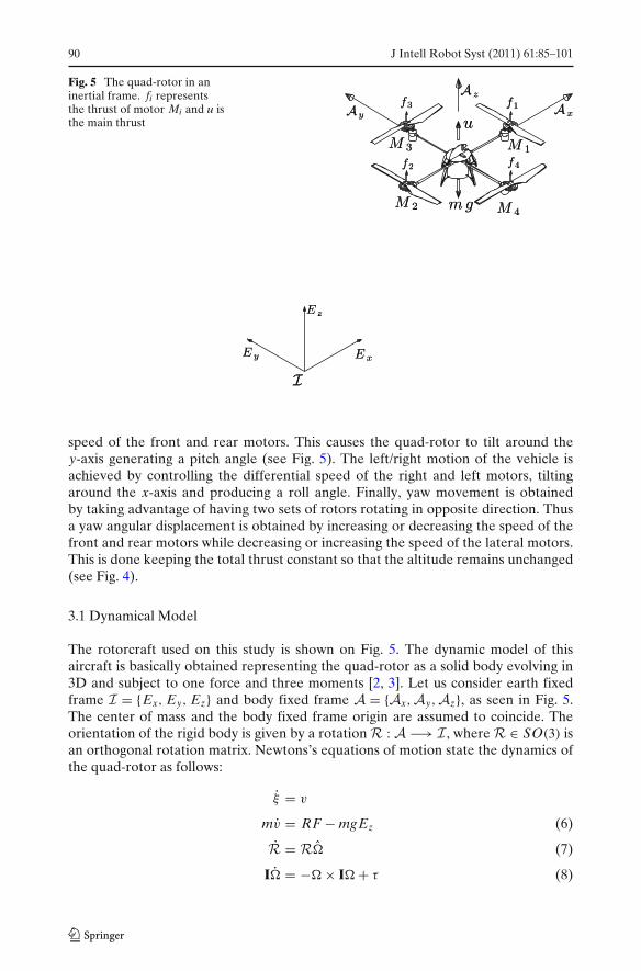
Fig. 5 The quad-rotor in aninertial frame. fi representsthe thrust of motor Mi and u isthe main thrust
speed of the front and rear motors. This causes the quad-rotor to tilt around they-axis generating a pitch angle (see Fig. 5). The left/right motion of the vehicle isachieved by controlling the differential speed of the right and left motors, tiltingaround the x-axis and producing a roll angle. Finally, yaw movement is obtainedby taking advantage of having two sets of rotors rotating in opposite direction. Thusa yaw angular displacement is obtained by increasing or decreasing the speed of thefront and rear motors while decreasing or increasing the speed of the lateral motors.This is done keeping the total thrust constant so that the altitude remains unchanged(see Fig. 4).
3.1 Dynamical Model
The rotorcraft used on this study is shown on Fig. 5. The dynamic model of thisaircraft is basically obtained representing the quad-rotor as a solid body evolving in3D and subject to one force and three moments [2, 3]. Let us consider earth fixedframe I = {Ex, Ey, Ez} and body fixed frame A = {Ax,Ay,Az}, as seen in Fig. 5.The center of mass and the body fixed frame origin are assumed to coincide. Theorientation of the rigid body is given by a rotation R : A −→ I , where R ∈ SO(3) isan orthogonal rotation matrix. Newtons’s equations of motion state the dynamics ofthe quad-rotor as follows:
ξ = v
mv = RF − mgEz (6)
R = R� (7)
I� = −� × I� + τ (8)

J Intell Robot Syst (2011) 61:85–101 91
where ξ = (x, y, z)T denotes the position of the center of mass of the airframe inthe frame I relative to a fixed origin, v ∈ I denotes the linear velocity expressedin the inertial frame, � ∈ A denotes the angular velocity of the airframe expressedin the body fixed frame. m denotes the mass of the rigid object and I ∈ R
3×3 denotesthe constant inertia matrix around the center of mass (expressed in the body fixedframe A). � denotes the skew-symmetric matrix of the vector �. F ∈ I representsthe vector of the principal non-conservative forces applied to the object; includingthrusts and drag terms associated with the rotors. τ ∈ A is derived from differentialthrust associated with pairs of rotors along with aerodynamic effects and gyroscopiceffects.
The approximated mathematical model that describes the dynamics of a quad-rotor aircraft assuming small angles (for more details, see [8]), is given by,
mx = u (sin φ sin ψ + cos φ cos ψ sin θ) (9)
my = u (cos φ sin θ sin ψ − cos ψ sin φ) (10)
mz = u cos θ cos φ − mg (11)
ψ = τψ (12)
θ = τθ (13)
φ = τφ (14)
where x and y are coordinates in the horizontal plane, and z is the vertical position.ψ is the yaw angle around the z-axis, θ is the pitch angle around the y-axis, and φ isthe roll angle around the x-axis. u is the thrust directed out the bottom of the aircraftand τψ , τθ and τφ are the moments (yawing moment, pitching moment and rollingmoment).
4 Control Strategy
In this section we present a control strategy to stabilize the attitude of the quad-rotor. We will first present the attitude control strategy which is based on the angularrate and position feedback. We then propose a control algorithm using the motors’armature current.
4.1 Attitude Control
In order to design the controller, let us consider the following state space represen-tation of the angular dynamics (12–14)
= A + Bτψ
= A + Bτθ
� = A� + Bτφ (15)

92 J Intell Robot Syst (2011) 61:85–101
where
=[
ψ
ψ
], =
[θ
θ
], � =
[φ
φ
], A =
[0 10 0
]and B =
[01
]
Then, we obtain the discrete-time system of Eq. 15 as follows [1]
(k + 1) = A (k) + Bτψ (k)
(k + 1) = A(k) + Bτθ (k)
� (k + 1) = A� (k) + Bτφ (k) (16)
where
A =[
1 Ts
0 1
], B =
⎡⎣ 1
2T2
s
Ts
⎤⎦
and Ts is the sampling period.Let us consider the following control algorithm [6]
τψ (k) = −K (k) (17)
τθ (k) = −K (k) (18)
τφ (k) = −K� (k) (19)
where
K = [k1 k2
]
is the state feedback gain,
(k) =[
ψ1 (k) − ψd
ψ2 (k)
]; (k) =
[θ1 (k) − θd
θ2 (k)
]; � (k) =
[φ1 (k) − φd
φ2 (k)
]
and ψd, θd, φd are the desired angular positions coming from the joystick manualcontrol.
Thus
(k + 1) =(
A − BK)
(k)
(k + 1) =(
A − BK)
(k)
� (k + 1) =(
A − BK)
� (k) (20)
Choosing K such that the eigenvalues of the matrix(
A − BK)
lie inside the unit
circle, then system (20) is asymptotically stable.It is important to point out that, gains K, for each state of the system (16), were
tuned experimentally as a classical PID controller.Figure 6 shows the block diagram representation of the attitude control system.

J Intell Robot Syst (2011) 61:85–101 93
Fig. 6 Attitude control system
The controllers (17), (18) and (19) are applied to each of the four speed controllersaccording to the following equations
TM1 (k) = G (k) + τθ (k) + τψ (k) (21)
TM2 (k) = G (k) − τθ (k) + τψ (k) (22)
TM3 (k) = G (k) − τφ (k) − τψ (k) (23)
TM4 (k) = G (k) + τφ (k) − τψ (k) (24)
where TMi is the control signal applied to each speed controller, for i = 1, . . . , 4, andG is the desired throttle input coming from the joystick (see Fig. 7).
Finally, for practical reasons, the desired signals for each motor (21–24) aremodified to produce the desired speed controls signals which are sent to the speedcontrollers. This is done by implementing a linear interpolation function, resulting ina servo signal that can be driven by the speed controller (see Fig. 8).
4.2 Armature Current Control
As was mentioned in Section 2, each speed controller has its own speed control loop,but there is no direct connection between the rotors’ speed and the main control ofthe system (attitude control). In other words, if we consider the rotors’ speed as theoutput of the system and without measuring it, then we have an open-loop control
Fig. 7 The quad-rotor controlinputs

94 J Intell Robot Syst (2011) 61:85–101
Linear Interpolation
Microcontroller
Inputcapture Control
algorithm
Inverter
Switchingsequence
Brushless
DC Motor
Desired speedservo signal
Speed controller
Rotor speed
Rotor position
Fig. 8 Control inputs applied to the speed controllers
system. The main contribution of this paper is to introduce a control loop using thepower measurement for controlling the torque-speed of the rotors.
In order to improve the attitude stabilization we have introduced an additionalcontroller using the DC line current that flows from the battery to the speedcontroller. This additional information not only improves the attitude stabilizationbut also provides robustness with respect to external perturbations. The main ideais to regulate the angular positions of the quad-rotor as well as the DC current ofeach speed controller. This is achieved by comparing the desired signals, from signals(21–24), with the actual value of DC current for each of the four speed controllers.By approximating the relationship between the attitude control signals and the DCcurrents, using a four degree polynomial, we have implemented a PD controller. Thepolynomial that fits the current data to an attitude control signal is given by
TMi (k) = a4 I4di
(k) + a3 I3di
(k) + a2 I2di
(k) + a1 Idi (k) + a0 (25)
where TMi is the conversion to an attitude control signal, Idi is the DC line current, fori = 1, . . . , 4 , (for each of the four speed controllers), and a0 to a4 are the coefficientsof the polynomial. After performing several experiments, this polynomial fitted wellthe attitude signal in a least-squares sense.
Then the control algorithm that stabilize the attitude dynamics including thetorque-speed regulation is given by
TMi (k) = kpi eMi (k) + kdi
(eMi (k) − eMi (k − 1)
Ts
)(26)
where TMi is the feedback control signal applied to each speed controller,
eMi (k) = TMi (k) − TMi (k)
is the error and kpi and kdi are the proportional and derivative gains respectively.The control diagram is shown in Fig. 9. These additional control parameters were
tuned together with the attitude control parameters.

J Intell Robot Syst (2011) 61:85–101 95
Linear Interpolation Speed controllerBrushless
DC Motor
Servo signal
Power supplyPolynomial
DC current
PD controller
Battery
Fig. 9 Closed-loop control system using the DC current
5 System Configuration
In this section we describe the experimental platform which consists of an aerialvehicle (four-rotor rotorcraft), a ground station and a HF video link (onboardtransmitter,on ground receiver).
5.1 Aerial Vehicle
The rotorcraft was developed in the University of Technology of Compiegne, France.The distance (center to center) between two rotors in the same axis is 40 cm, and itstotal weight is on the order of 750 g. Figure 10 shows the prototype.
The aerial vehicle is powered by a Li-Po battery which feeds the four brushlessmotors, allowing a flight autonomy of 15 min. The electronic embedded systemincludes two interconnected boards: the first board is the control unit, and the secondis devoted to the motors speed controllers and the motor current sensors. The controlunit contains the communication devices for the video link and the joystick. The
Fig. 10 The four-rotorrotorcraft experimentalplatform

96 J Intell Robot Syst (2011) 61:85–101
Fig. 11 The electronics onboard. Electronic card for theDSP, rate gyros, IMUconnections, pressure sensorand wireless modem
control unit includes also the inertial sensors to ensure the automatic stabilization ofthe engine during fly. This embedded control system is described as follows
The first board, shown in Fig. 11 contains:
– The Digital Signal Processor:A Texas Instruments TMS320F2812 DSP module is used to process the data com-ing from the different sensing devices (including the motors’s current monitor)and compute the PWM control input for each motor speed controller. The DSPalso takes care of the communication link with the ground station. The user canintroduce any external input using the joystick.
– The Inertial sensors:A MIDG II INS/GPS from Microbotics Inc. is used to measure the angularposition of the rotorcraft. In order to complete the inertial measurements, a setof three analog gyroscopes are used to sense the angular rate.
Fig. 12 Electronic card for themeasurement of currentspassing through each motor
J Intell Robot Syst (2011) 61:85–101 97
– Pressure sensor:The freescale MPX4115A pressure sensor is coupled with an amplifier to measurethe altitude of the engine on a appropriate sensing range.
– XBee ZB ZigBee PRO Radio Modem:The radio link between the base station and the aerial vehicle is made by a 2.45GHz IEEE 802.15.4 wireless sensor networks.
The second board contains:
– Signal Conditioner:Each motor control input is decoupled from the rest of the electronic system bythe signal conditioner. The measured motors current, which are used for feedbackcontrol, are also filtered and appropriately conditioned.
– Current Sensing:This circuit allows the measurement of the current passing through each one ofthe motors. Current measurement is achieved using a shunt resistor connectedto a current shunt monitor. The output signal of this shunt monitor is a voltagewhich is proportional to the current passing through the motor. This output signalis sent to the DSP analog to digital converters via the board’s interconnectionwire bus. As mentioned before, a PD control loop is used to reduce the errorbetween the desired current (attitude control input) and the actual motorcurrent. This avoids the need for trimming at the beginning of the experimentsor when the sensors temperature changes.
The second board is showed in Fig. 12.
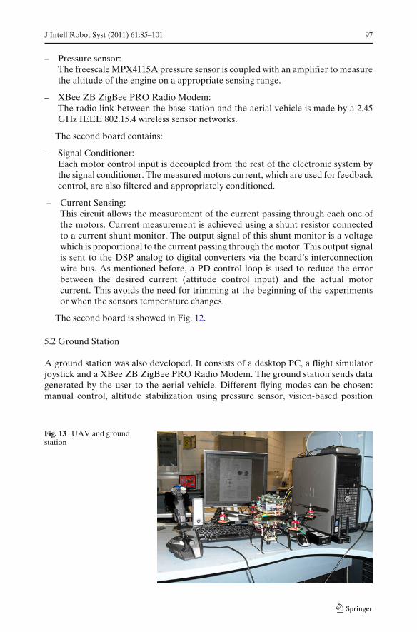
5.2 Ground Station
A ground station was also developed. It consists of a desktop PC, a flight simulatorjoystick and a XBee ZB ZigBee PRO Radio Modem. The ground station sends datagenerated by the user to the aerial vehicle. Different flying modes can be chosen:manual control, altitude stabilization using pressure sensor, vision-based position
Fig. 13 UAV and groundstation
98 J Intell Robot Syst (2011) 61:85–101
6 8 10 12 14 16 18-20
-15
-10
-5
0
5
10
15
20
Time (seconds)
Yaw
ang
le, ψ
(de
gree
s)
-20
-15
-10
-5
0
5
10
15
20
Yaw
ang
le, ψ
(de
gree
s)
a bwith current feedback
0 3 6 9 12 15 18 21Time (seconds)
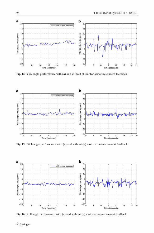
Fig. 14 Yaw angle performance with (a) and without (b) motor armature current feedback
0 3 6 9 12 15 18-20
-15
-10
-5
0
5
10
15
20
-20
-15
-10
-5
0
5
10
15
20
Time (seconds)
Pitc
h an
gle,
θ (
degr
ees)
Pitc
h an
gle,
θ (
degr
ees)
with current feedback
0 3 6 9 12 15 18 21Time (seconds)
a b
Fig. 15 Pitch angle performance with (a) and without (b) motor armature current feedback
0 3 6 9 12 15 18-20
-15
-10
-5
0
5
10
15
20
-20
-15
-10
-5
0
5
10
15
20
Time (seconds)
Pitc
h an
gle,
φ (
degr
ees)
Pitc
h an
gle,
φ (
degr
ees)
0 3 6 9 12 15 18 21Time (seconds)
with current feedback
a b
Fig. 16 Roll angle performance with (a) and without (b) motor armature current feedback
J Intell Robot Syst (2011) 61:85–101 99
21.5 22 22.5 23-10
-8
-6
-4
-2
0
2
4
6
8
10
Time (seconds)
Rol
l ang
le, φ
(de
gree
s)
Rol
l ang
le, φ
(de
gree
s)
with current feedback
Perturbations
27.5 28 28.5 29-10
-8
-6
-4
-2
0
2
4
6
8
10
12
Time (seconds)
Perturbation
ba
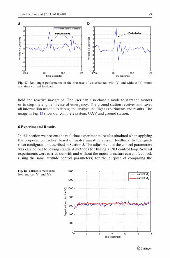
Fig. 17 Roll angle performance in the presence of disturbances, with (a) and without (b) motorarmature current feedback
hold and reactive navigation. The user can also chose a mode to start the motorsor to stop the engine in case of emergency. The ground station receives and savesall information needed to debug and analyze the flight experiments and results. Theimage in Fig. 13 show our complete system: UAV and ground station.
6 Experimental Results
In this section we present the real-time experimental results obtained when applyingthe proposed controller, based on motor armature current feedback, to the quad-rotor configuration described in Section 5. The adjustment of the control parameterswas carried out following standard methods for tuning a PID control loop. Severalexperiments were carried out with and without the motor armature current feedback(using the same attitude control parameters) for the purpose of comparing the
Fig. 18 Currents measuredfrom motors M1 and M2
0 3 6 9 12 15 180
200
400
600
800
1000
1200
1400
Time (seconds)
Dig
ital v
alue
(12-
bit A
DC
)
current M1current M2

100 J Intell Robot Syst (2011) 61:85–101
Fig. 19 Currents measuredfrom motors M3 and M4
0 3 6 9 12 15 180
200
400
600
800
1000
1200
1400
Time (seconds)
Dig
ital v
alue
(12-
bit A
DC
)
current M3current M4
hovering performance. This technique results in a controller that is robust with re-spect to aggressive external disturbances as has been observed experimentally (videoavailable online at http://www.hds.utc.fr/~asanchez and http://www.youtube.com/watch?v=eyPHxTJrTf0).
As can be seen from Figs. 14, 15, 16, and 17 the proposed controller performswell and improves in practice the attitude stabilization. Notice that in hovering, themotor armature current feedback provides better stability even in the presence ofaggressive disturbances. Note also that without disturbances, the armature currentsof motors M1 and M3 (and M2 and M4) tends to be the same as can be seen in Figs. 18and 19. Figure 20 shows the quad-rotor mini-aircraft hovering autonomously.
Fig. 20 The quad-rotormini-aircraft hoveringautonomously
J Intell Robot Syst (2011) 61:85–101 101
7 Conclusion
In this paper a novel attitude control algorithm based on the motor armature currentfeedback was proposed and applied to a quad-rotor speed controller. The controlstrategy is based on low cost components. The control structure consists on addingan internal control loop on each driver in such a way that for any given controlinput the four motors turn at almost the same speed. The proposed controller wassuccessfully tested in real-time experiments. The attitude stabilization performancehas been considerably improved avoiding drift of the UAV from its desired angularposition. In addition, robustness of the proposed controller with respect to externaldisturbances has been observed experimentally. Given that the quad-rotor Eulerangles are very close to the origin, the resulting UAV can be effectively combinedwith other sensors like GPS or vision systems to perform position or trajectorytracking tasks.
References
1. Chen, C.: Linear System Theory and Design. HRW Series in Electrical and Computer Engineer-ing. The University of Michigan. ISBN 0195115953 (1984)
2. Etkin, B., Reid, L.D.: Dynamics of Flight. Wiley, New York. ISBN 0471034185 (1959)3. Goldstein, H.: Classical Mechanics. Addison-Wesley. ISBN 0201029693 (1980)4. Krause, P.C., Wasynczuk, O., Sudhoff, S.D.: Analysis of Electric Machinery and Drive Systems.
IEEE Press Series on Power Engineering, vol. 10. IEEE Press. ISBN 9780471143260 (2002)5. Krishnan, R.: Electric Motor Drives: Modeling, Analysis, and Control. Prentice Hall. ISBN
0130910147 (2001)6. Ogata, K.: Discrete-time Control Systems. Prentice-Hall. ISBN 0132161028 (1987)7. Wertz, J.R.: Spacecraft Attitude Determination and Control. Kluwer Academic Publisher. ISBN
9027709599 (1978)8. Sanchez, A., Garcia, P., Castillo, P., Lozano, R.: Simple real-time stabilization of vertical takeoff
and landing aircraft with bounded signals. J. Guid. Control Dyn. 31(4), 1166–1176 (2008)9. Jarrell, J., Gu, Y., Seanor, B., Napolitano, M.: Aircraft attitude, position, and velocity determina-
tion using sensor fusion. In: AIAA Guidance, Navigation and Control Conference and Exhibit,pp. 18–21. Honolulu, Hawaii (2008)
10. Lim, K.B., Shin, J.-Y., Cooper, E.G., Moerder, D.D., Khong, T.H., Smith, M.F.: An overview ofthe NASA flying test platform research. In: AIAA Guidance, Navigation, and Control Confer-ence and Exhibit, pp. 11–14. Austin, Texas (2003)
11. Rothhaar, P.M., Moerder, D.D., Lim, K.B.: Hovering dual-spin vehicle groundwork for biasmomentum sizing validation experiment. In: AIAA Atmospheric Flight Mechanics Conferenceand Exhibit, pp. 18–21. Honolulu, Hawaii (2008)


![Quad 240[1737]](https://static.fdokumen.com/doc/165x107/633b2fc5c007a38db701fb49/quad-2401737.jpg)