
Holographic Optical Manipulation of Trapped Ions ... - UWSpace
Upload
uninsubriaCategory
view
1download
0
966 J. Opt. Soc. Am. B/Vol. 17, No. 6 /June 2000 Andreoni et al.
Holographic properties of the second-harmoniccross correlation of
object and reference optical wave fields
Alessandra Andreoni, Maria Bondani, and Marco A. C. Potenza
Dipartimento di Scienze Chimiche, Fisiche e Matematiche, Universita’ dell’Insubria, Via Lucini, 3, 22100 Como,Italy, and Istituto Nazionale di Fisica della Materia, Milano-Universita’, 20133 Milano, Italy
Yury N. Denisyuk
Ioffe Physico-Technical Institute, Politechnicheskaya Street, 26, 194021 St. Petersburg, Russia
Received August 19, 1999; revised manuscript received March 9, 2000
We show that second-harmonic cross correlation of the optical field that propagates from an illuminated objectwith the illuminating field is a process that shares many features with holography. The wave fronts of thedouble-frequency field are able to reconstruct holographic images of the object whose dimensions and positioncan be calculated by use of the holographic formalism. Our theory fits the experimental results obtained byuse of a Q-switched Nd:YAG laser as the illuminating source and a thin b-barium borate crystal in a noncol-linear type I phase-matching geometry for cross correlation. © 2000 Optical Society of America[S0740-3224(00)03306-3]
OCIS codes: 090.0090, 190.0190, 190.2620, 200.3050.
1. INTRODUCTIONWave-front reconstruction and transformation by holo-graphic methods, which are widely used nowadays in dif-ferent fields of science and technology, started to be devel-oped more than 50 years ago when holography wasdiscovered.1 At the early stage of these applications, ho-lograms were recorded on conventional photographicplates, but in the 1970’s the so-called dynamic holograms,which can be recorded and reconstructed in real time,started to be developed and employed. Holograms ofsuch a type are recorded in nonlinear sensitive materials,which are capable of changing their optical properties un-der the influence of the light interacting with them. Themajority of publications on dynamical holograms were de-voted to holograms that used the third-order nonlinearityof the materials for the recording.2,3 In this case it is therefractive index of the material that changes dependingon the intensity of the interacting light. The speed of theoptical response then achieves a nanosecond time scale.
In contrast to third-order nonlinearity, the second-order nonlinearity has never been used in holography.The only example of wave-front transformation by asecond-order nonlinearity is the generation of phase-conjugated wave fronts. In particular, it was used to cor-rect slight phase distortions to improve the spatial qualityof laser beams.4–7 It should be noted that wave-frontconjugation is an effect that is very close to holography.For instance, a wave front that is phase conjugated to theobject wave is reconstructed by a reference wave reversedin direction from that of propagation.8 The possibility ofusing the second-order nonlinearity for recording three-dimensional holographic images of arbitrary diffusing ob-jects has never been considered.
0740-3224/2000/060966-07$15.00 ©
Recently, we suggested a method of second-harmonic(SH) cross correlation of object and reference fields to de-tect opaque objects immersed in highly scatteringmedia.9,10 Studying the imaging properties of ourmethod by formalisms inherent to nonlinear optics wouldbe rather difficult. A different approach must be used todescribe the transformations upon SH cross correlation ofwave fronts characterized by a complicated spatial con-figuration. It was then important to realize that SHcross correlation is a substantially new method for wave-field transformation that shares many properties with ho-lographic methods.11 In this case the reconstructed wavefield is formed by the frequency-doubled radiation, whileboth fields impinging on the SH crystal, which acts as theholographic plate, are at the fundamental frequency. Byusing the holographic approach, we showed that SH crosscorrelation opens up the possibility of reconstructing thethree-dimensional holographic images of arbitrary ob-jects. This approach also permits us to determine the po-sition and the scale of the reconstructed images. Be-cause of these properties, we called the immaterialstructure that is formed in the nonlinear crystal a second-harmonic-generated (SHG) hologram. A special distinc-tive feature of the SHG hologram is its extremely fast op-tical response. In fact, SH cross correlation can operateover a bandwidth as broad as that of Fourier-transform-limited pulses of femtosecond duration.12 We thus sug-gest that a method for recording and reconstructing dy-namic holograms in real time with extremely fast opticalresponse could arise from our idea. In this paper we de-velop a theory by utilizing the formalism of holographyand prove all steps and results of our theory by critical ex-periments.
2000 Optical Society of America

Andreoni et al. Vol. 17, No. 6 /June 2000 /J. Opt. Soc. Am. B 967
2. THEORY OF THE SECOND-HARMONIC-GENERATED HOLOGRAMWith reference to Fig. 1 we consider SH cross correlationin a section S of a nonlinear crystal H of the wave field EOscattered by the object O and the spherical reference wave(field ER) emitted by the point source R. We write thetwo fields as
EO 5 AO~x, y !exp$i@k1LO~x, y ! 1 vt#%, (1)
ER 5 AR exp$i@k1LR~x, y ! 1 vt#%, (2)
where the amplitude AO depends on the spatial coordi-nates (x, y) on S, whereas the amplitude AR is taken asuniform on S. The iconals LO(x, y) and LR(x, y) repre-sent the distribution functions of the optical paths from Oand R to the plane S. In our experiments the SHG holo-grams are generated in a b-barium borate crystal in non-collinear phase matching I (BBO I) whose optical axis liesin the plane of Fig. 1. We will show that the SH crosscorrelation of these fields, which are at frequency v5 ck1 (c, vacuum speed of light), is a process analogousto the object-wave reconstruction by a conventional off-axis hologram whose scheme of recording is identical tothat shown in Fig. 1.
The sum of EO and ER , which represents the total elec-tric field Ev on the plane S inside the crystal, is
Ev 5 AO~x, y !exp$i@k1LO~x, y ! 1 vt#%
1 AR exp$i@k1LR~x, y ! 1 vt#%. (3)
For quasi-collinear interaction the frequency-doubledfield, E2v , in the nonlinear material H is given by
E2v } EvEv 5 AO2 ~x, y !exp$i@2k1LO~x, y ! 1 2vt#%
1 2AO~x, y !AR exp$i@k1~LO~x, y !
1 LR~x, y !! 1 2vt#%
1 AR2 exp$i@2k1LR~x, y ! 1 2vt#% (4)
when the phase-matching condition uk2u 5 2uk1u holds.The three terms appearing in Eq. (4) that we call E2v8 ,
Fig. 1. Optical scheme of a SHG hologram: O is the object, R isthe reference source, and S is an arbitrary flat section inside thevolume of a SHG hologram, H. The wave fronts EO and ER ofthe object and the reference fields at frequency v are sketched.The fields E2v8 , E2v9 , E2v- at frequency 2v are those generated bythe SHG hologram, among which E2v9 is the reconstructed objectwave.
E2v9 , and E2v- (see Fig. 1) describe waves that propagateat slightly different directions. Fields E2v8 and E2v- arenot important for our purposes and will be discussedlater. Field E2v9 represents the wave field reconstructedby what we call the SHG hologram. It is actually theonly one arising from the mutual interaction of the objectand the reference waves. Taking into account that uk2u5 2uk1u, we can write
E2v9 5 AO~x, y !AR
3 expH iFk2
LO~x, y ! 1 LR~x, y !
21 2vtG J .
(5)
The space- and time-dependent phase terms of E2v9 de-pend on the corresponding terms of both fields, EO andER , that interact in the process of SHG hologram record-ing. In particular, the space-dependent phase of the re-constructed wave is determined by an iconal, LH(x, y),which is linked to the iconals LO(x, y) and LR(x, y) bythe relation
LH~x, y ! 5LO~x, y !
21
LR~x, y !
2. (6)
We investigate here the properties of the wave frontsreconstructed by a SHG hologram for both plane andspherical wave-front reference waves, which are com-monly used for conventional hologram recording. Withthe help of Fig. 2, we first consider the simplest case of aSHG hologram when object and reference waves areplane waves. The stage of SHG hologram recording isdepicted in the upper part of Fig. 2 (for y . 0). Theplane phase fronts WO and WR and wave vectors kO andkR , before interacting in the thin crystal, have directionsdetermined by the iconals LO( y) and LR( y). The pro-
Fig. 2. Geometrical construction of the wave front WH gener-ated by a SHG hologram in the case in which both object and ref-erence wave fronts, WO and WR , are planar. See the text forthe relations among iconals (LH , LO , and LR) and among wavevectors (kH , kO , and kR).
968 J. Opt. Soc. Am. B/Vol. 17, No. 6 /June 2000 Andreoni et al.
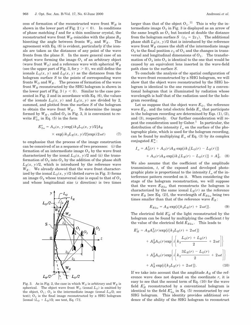
cess of formation of the reconstructed wave front WH isshown in the lower part of Fig. 2 ( y , 0). In conditionsof phase matching I and for a thin nonlinear crystal, thereconstructed wave front WH coincides with the plane BSbisecting the angle between fronts WO and WR . Theagreement with Eq. (6) is evident, particularly if the icon-als are taken as the distances of any point of the wavefronts from the plane S. In the more general case of anobject wave forming the image O1 of an arbitrary object(wave front WO) and a reference wave with spherical WR(see the upper part of Fig. 3, for y . 0), we still define theiconals LO(x, y) and LR(x, y) as the distances from thehologram surface S to the points of corresponding wavefronts WO and WR . The process of formation of the wavefront WH reconstructed by the SHG hologram is shown inthe lower part of Fig. 3 ( y , 0). Similar to the case pre-sented in Fig. 2 and in accordance with Eq. (6), the valuesof the iconals LO(x, y) and LR(x, y) are divided by 2,summed, and plotted from the surface S of the hologramto obtain the wave front WH . To determine the imageformed by WH , called O3 in Fig. 3, it is convenient to re-write E2v9 in Eq. (5) in the form
E2v9 5 AO~x, y !exp@ik2LO~x, y !/2#AR
3 exp@ik2LR~x, y !/2#exp~i2vt ! (7)
to emphasise that the process of the image constructioncan be conceived of as a sequence of two processes: (i) theformation of an intermediate image O2 by the wave frontcharacterized by the iconal LO(x, y)/2 and (ii) the trans-formation of O2 into O3 by the addition of the phase shiftLR(x, y)/2, which is introduced by the reference waveWR . We already showed that the wave front character-ized by the iconal LO(x, y)/2 (dotted curve in Fig. 3) formsan image O2 whose transversal size is equal to that of O1and whose longitudinal size (z direction) is two times
Fig. 3. As in Fig. 2, the case in which WO is arbitrary and WR isspherical. The object wave front WO (iconal LO) is emitted bythe object, O1 ; O2 is the intermediate image (iconal LO/2; seetext); O3 is the final image reconstructed by a SHG hologram[iconal (LO 1 LR)/2; see text, Eq. (7)].
larger than that of the object O1 .11 This is why the in-termediate image O2 in Fig. 3 is displayed as an arrow ofthe same length as O1 but located at double the distancefrom the hologram surface S (z2 5 2z1). The additionalphase shift LR(x, y)/2 that is introduced by the referencewave front WR causes the shift of the intermediate imageO2 to the final position z3 of O3 and the changes in trans-versal and longitudinal dimensions of O3 . The transfor-mation of O2 into O3 is identical to the one that would becaused by an equivalent lens inserted in the wave-fieldpath close to the surface S.
To conclude the analysis of the spatial configuration ofthe wave-front reconstructed by a SHG hologram, we willshow that the object wave reconstructed by the SHG ho-logram is identical to the one reconstructed by a conven-tional hologram that is illuminated by radiation whosewavelength is half that of the radiation used for the holo-gram recording.
Let us suppose that the object wave EO , the referencewave ER , and the total electric fields Ev that participatein the hologram recording are determined by Eqs. (1), (2),and (3), respectively. Our further consideration will re-peat the consideration used by Gabor.1 In particular, thedistribution of the intensity Iv on the surface of the pho-tographic plate, which is used for the hologram recording,can be found by multiplying Ev of Eq. (3) by its complexconjugated Ev* :
Iv 5 AO2 ~r ! 1 AO~r !AR exp$ik1@LO~r ! 2 LR~r !#%
1 AO~r !AR exp$ik1@LR~r ! 2 LO~r !#% 1 AR2 . (8)
We also assume that the coefficient of the amplitudetransmission, t, of the exposed and developed photo-graphic plate is proportional to the intensity Iv of the in-terference pattern recorded on it. When considering thestage of the hologram reconstruction, we will supposethat the wave ER2v that reconstructs the hologram ischaracterized by the same iconal LR(r) as the referencewave ER [see Eq. (2)], the wavelength of ER2v being twotimes smaller than that of the reference wave ER :
ER2v 5 AR exp$i@k2LR~r ! 1 2vt#%. (9)
The electrical field EH8 of the light reconstructed by thehologram can be found by multiplying the coefficient t bythe value of the electrical field ER2v . This leads to
EH8 5 ARAO2 ~r !exp$i@k2LR~r ! 1 2vt#%
1 AR2 AO~r !expH iFk2
LO~r ! 1 LR~r !
21 2vtG J
1 AR2 AO~r !expH iFk2
3LR~r ! 2 LO~r !
21 2vtG J
1 AR3 exp$i@k2LR~r ! 1 2vt#%. (10)
If we take into account that the amplitude AR of the ref-erence wave does not depend on the coordinate r, it iseasy to see that the second term of Eq. (10) for the wavefield EH8 reconstructed by a conventional hologram isidentical to the field E2v9 in Eq. (5) reconstructed by ourSHG hologram. This identity provides additional evi-dence of the ability of the SHG hologram to reconstruct

Andreoni et al. Vol. 17, No. 6 /June 2000 /J. Opt. Soc. Am. B 969
the image of the object. In fact, it is well known that aconventional hologram does reconstruct the image inde-pendently of the wavelength of the light used for the re-construction: only scale and position of the image changeaccording to the wavelength of the reconstructing light.Having this in mind and using methods of ray tracing ofconventional holography, we can easily determine the po-sition and the scale of the image reconstructed by a SHGhologram.
The meaning of the remaining two terms of the wavefield in Eq. (4) is very simple: The third term, which ischaracterized by the iconal LR(x, y), represents a spheri-cal wave, E2v- in Fig. 1, with the same radius of the cur-vature as the reference wave ER [see Eq. (2)]. The firstterm, E2v8 in Fig. 1, describes the picture of the autocor-relation of the object field EO .
3. EXPERIMENTAL RESULTS ANDDISCUSSIONThe ability of the SHG hologram to reconstruct the im-ages of objects was checked with experiments. As an ob-ject we have first chosen a pointlike source of light, whichprovides full information on the imaging properties of ouroptical system. To avoid the requirement of high pulseenergy from the laser, we chose to use the focal spot of alens as the object.
The optical scheme of the experimental setup is shownin Fig. 4. The output beam of a Q-switched amplifiedNd:YAG laser (Quanta-Ray GCR-4, Spectra-Physics, Inc.,Mountain View, Calif.) was spatially filtered so as to ob-tain a diffraction-limited beam p at 1.06 mm. Beam pwas split into two equal-power beams, r and o, by thesemitransparent mirror Z. Beam r propagates along the
Fig. 4. Scheme of the experimental setup for recording a SHGhologram: H, BBO I crystal; p, laser output beam; Z, 50%beam splitter; Z8, high-reflectivity mirror; o and r, beams thatpropagate along the object and the reference arms; WO , objectwave that forms the object (focal spot of lens L3, which is eitherspherical or cylindrical) to be recorded on the SHG hologram;CCD, camera used for recording the reconstructed image of theobject. Lenses L1 to L5 have focal distances f1 5 25 mm,f2 5 1100 mm, f3 5 130 mm (spherical lens) or f3 5 1210 mm(cylindrical lens), f4 5 220 mm, and f5 5 1150 mm. All dis-tances between optical elements are in millimeters. The valuesof distances d3 and d23 are given in the text.
reference arm of the setup, while beam o propagatesalong the object arm. Beam o is expanded by the systemof lenses L1 and L2 and then is focused by the lens L3.The focal spot beyond L3 plays the role of the pointlike ob-ject O8. The reference beam is transformed by lens L4into the spherical diverging wave WR centered at point R.The object and the reference waves that intersect theBBO I aperture (5 mm 3 5 mm, 0.3-mm thickness;Akadimpex, Budapest, Hungary) form the SHG holo-gram. The center of divergence of the emerging wavefront WH constitutes the reconstructed image of the ob-ject. The energy of the pulses (18-ns duration, 10-Hzrepetition rate) was in the range 50–100 mJ at the sur-face of the BBO I crystal. The focal distances of thelenses L1 to L5 included in the setup were as follows:f1 5 25 mm, f2 5 1100 mm, f3 5 130 mm for thespherical lens and f3 5 1210 mm for the cylindrical lens,f4 5 220 mm, and f5 5 1150 mm. The values of thedistances between the optical elements of the setup areshown in Fig. 4. The entire optical layout was designedso that its pupil was the crystal cross section.
The scheme of the paths of the beams inside the crystalis shown in Fig. 5. If, as in our case, the angle a betweenthe beams o and r impinging upon the BBO I crystal issufficiently small, it is easy to calculate the angle b be-tween the beams o and r when they propagate inside thecrystal: b > a/n, where n is the BBO index of refractionfor an ordinary wave at v. By simple calculations, it iseasy to show that in our experimental conditions (a5 0.074. rad, n 5 1.6, zc 5 300 mm) the value of phasemismatch between the waves generated on entrance ofthe crystal and exiting of it is equal to Dw 5 p/2, which isquite acceptable for the reconstructed-wave generation.
The measurements of location and shape of the imagereconstructed by the SHG hologram were performed with
Fig. 5. Optical scheme of the formation of the image recon-structed by an experimental SHG hologram. R is the referencesource emitting the reference wave WR ; WO is the object wavethat converges to the pointlike or 1D object O8; BS is the bisectorof the angle a between beams o and r; Oexp is the position of thereconstructed image observed in the experiment, its distancefrom BBO I being equal to dexp 5 205 mm; Oth is the calculatedposition of the reconstructed image, its distance from BBO I be-ing equal to dth 5 188 mm; other relevant distances from BBO Iare those of O8 (d8 5 138.8 mm), O9 (d9 5 2d8 5 277.6 mm),and R (dR 5 290 mm); kO , kR , and kH are the wave vectors ofobject, reference, and reconstructed waves, respectively.

970 J. Opt. Soc. Am. B/Vol. 17, No. 6 /June 2000 Andreoni et al.
the help of a CCD camera (Pulnix Europe, model PE2015,Basingstoke, UK), the image being projected onto its sen-sor with a lens (see Fig. 4, lens L5).
We first report on the SHG hologram of the pointlikesource O8 we obtained in the focal plane of a sphericallens (L3 in Fig. 4 with f3 5 130 mm) positioned atd23 5 12 mm from lens L2 and d3 5 165 mm from thecrystal. The reconstructed image Oexp was actually posi-tioned on the straight line Bs bisecting the angle betweenthe object and reference beams o and r (see Fig. 5).Therefore we interpreted this image as the one created byfield E2v9 [see Fig. 1 and discussion on Eq. (5)]. The pic-ture of this image when it was focused on the sensor ofthe CCD camera is shown in Fig. 6(a). As a preliminarydemonstration that what is displayed in Fig. 6(a) is a trueholographic image of the source O8, we shifted the cam-era by 2.87 mm along the optical axis of lens L5 and ac-tually obtained a defocused image that repeats to someextent the shape of the pupil. The corresponding pictureis shown in Fig. 6(b). Such a defocused picture provesthat an extended wave front WO contributes to the fre-quency upconverted light that forms the pointlike recon-structed image, Oexp . The image Oexp is located at a dis-tance dexp 5 205 mm from the BBO I crystal. As shownin Fig. 6(a), at the 50% intensity level the size of the im-age on the CCD is 20 mm in the vertical and 30 mm in thehorizontal direction.
Fig. 6. Intensity maps of the reconstructed pointlike image asthey were displayed by the CCD camera: (a) the image focusedon the sensor of a CCD camera and (b) a defocused image.
The distance dexp is mainly determined by the processof the image transformation caused by the frequency dou-bling of the wavelength forming the image. On the basisof Fig. 4 and taking into account the values of the focallengths of the lenses, one can calculate that lens L3 formsthe pointlike object image O8 at the distanced8 5 138.8 mm from the crystal (see Fig. 5). According tothe previous discussion on Fig. 3, the longitudinal scale ofthe intermediate image characterized by the iconalLO(x, y)/2 is doubled in comparison with that of the ob-ject. In our case that means that the intermediate imageO9 should be located at the distance d9 5 277.6 from thecrystal (see Fig. 5). To calculate the final position Oth ,we must take into account the additional shift introducedby the reference. Lens L4 forms the diverging wave WRwhose center R is located at a distance dR equal to 290mm from the crystal, as shown in Fig. 5. It is easy tocalculate the effect of the latter transformation becauseit can be imitated by a virtual lens Lv with a focal dis-tance equal to 2dR . This lens should be put at the en-trance of the BBO crystal. In our case this virtual lensLv is negative and characterized by a focal distancefv 5 2580 mm. Thus we can find the final position of thereconstructed image Oth as it was predicted by our theoryby projecting the image O9 through the lens Lv . The cal-culations lead to dth 5 188 mm, which is very close to theexperimental value dexp 5 205 mm.
We now examine the resolution of the image recon-structed by the SHG hologram. First, we compare theexperimental data on the resolution of the image Oexp inFig. 6(a) with what one would have obtained in the case ofdiffraction-limited propagation. In fact, it is well knownthat the smallest angle g that can be resolved by any op-tical system is given by g 5 l/a, where a is the size of thepupil. In our experiment, a 5 5 mm, the distance fromthe reconstructed image to the pupil was equal to D5 dexp 5 205 mm, and l was the second-harmonic wave-length (l 5 0.53 mm). We then calculate the linear sizes of the diffraction-limited image as s 5 gD 5 (l/a)D5 20 mm.
To compare this theoretical value with the experimen-tal result, we have to take into account that lens L5 scalesdown the size of the reconstructed image Oexp when pro-jecting it onto the sensor of the CCD camera (see Figs. 4and 5). Since the scaling factor is equal to the magnifi-cation m of lens L5 (m 5 0.43), the corresponding size onthe CCD is sCCD 5 ms 5 8.6 mm. Thus the vertical sizeof Oexp as measured in Fig. 6(a) exceeds the diffractionlimit sCCD by 2.3 times. We note that it would be not cor-rect to repeat this comparison for the size of the image inthe horizontal direction. In fact, a careful inspection ofthe pupil shape as revealed by the defocused picture inFig. 6(b) shows that the true pupil is narrower in the hori-zontal than in the vertical direction. This also confirmsthat vertical and horizontal directions are rather equal inrespect to the process of the image formation.
We finally note that a resolution equal to twice the dif-fraction limit, such as that of our reconstructed image, isvery high indeed: 20 mm on the CCD sensor correspondsto the angular resolution equal to the angular resolutionof the human eye (1 arcmin).
With this experiment we demonstrated the ability of
Andreoni et al. Vol. 17, No. 6 /June 2000 /J. Opt. Soc. Am. B 971
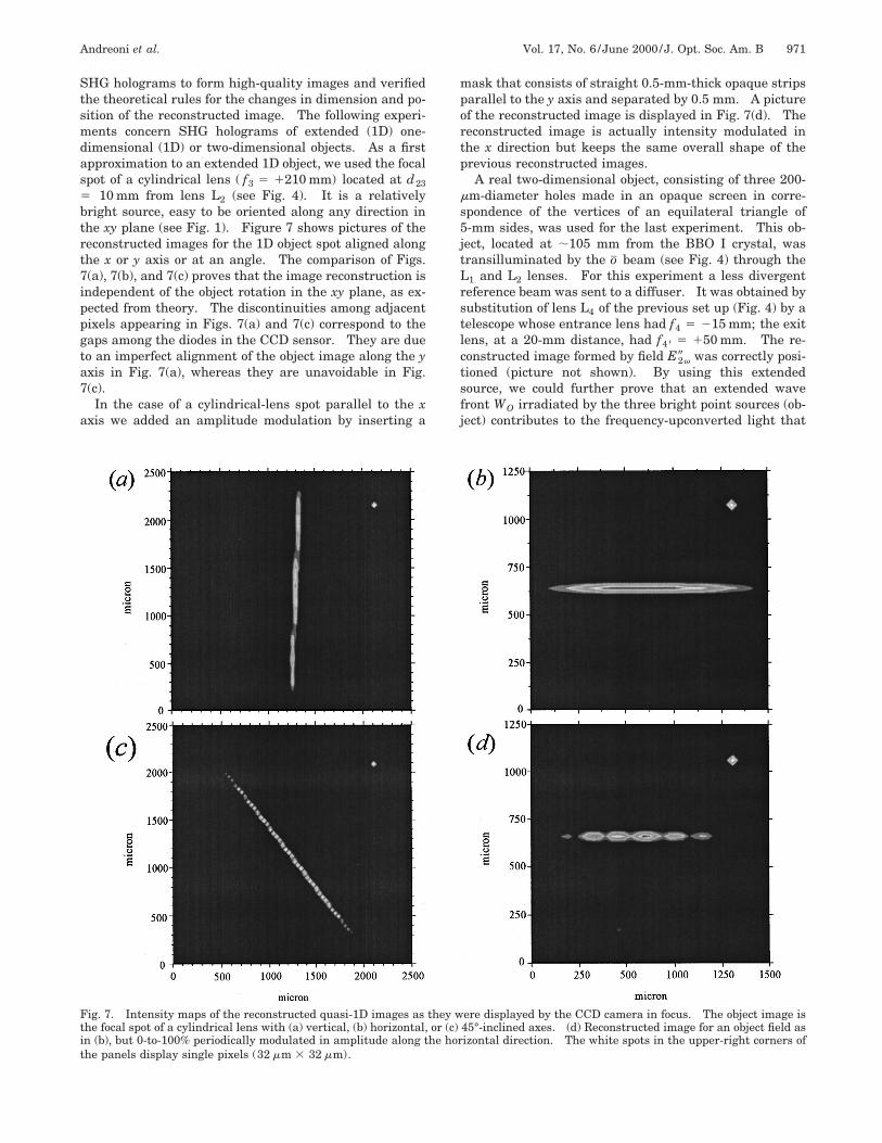
SHG holograms to form high-quality images and verifiedthe theoretical rules for the changes in dimension and po-sition of the reconstructed image. The following experi-ments concern SHG holograms of extended (1D) one-dimensional (1D) or two-dimensional objects. As a firstapproximation to an extended 1D object, we used the focalspot of a cylindrical lens ( f3 5 1210 mm) located at d235 10 mm from lens L2 (see Fig. 4). It is a relativelybright source, easy to be oriented along any direction inthe xy plane (see Fig. 1). Figure 7 shows pictures of thereconstructed images for the 1D object spot aligned alongthe x or y axis or at an angle. The comparison of Figs.7(a), 7(b), and 7(c) proves that the image reconstruction isindependent of the object rotation in the xy plane, as ex-pected from theory. The discontinuities among adjacentpixels appearing in Figs. 7(a) and 7(c) correspond to thegaps among the diodes in the CCD sensor. They are dueto an imperfect alignment of the object image along the yaxis in Fig. 7(a), whereas they are unavoidable in Fig.7(c).
In the case of a cylindrical-lens spot parallel to the xaxis we added an amplitude modulation by inserting a
mask that consists of straight 0.5-mm-thick opaque stripsparallel to the y axis and separated by 0.5 mm. A pictureof the reconstructed image is displayed in Fig. 7(d). Thereconstructed image is actually intensity modulated inthe x direction but keeps the same overall shape of theprevious reconstructed images.
A real two-dimensional object, consisting of three 200-mm-diameter holes made in an opaque screen in corre-spondence of the vertices of an equilateral triangle of5-mm sides, was used for the last experiment. This ob-ject, located at ;105 mm from the BBO I crystal, wastransilluminated by the o beam (see Fig. 4) through theL1 and L2 lenses. For this experiment a less divergentreference beam was sent to a diffuser. It was obtained bysubstitution of lens L4 of the previous set up (Fig. 4) by atelescope whose entrance lens had f4 5 215 mm; the exitlens, at a 20-mm distance, had f48 5 150 mm. The re-constructed image formed by field E2v9 was correctly posi-tioned (picture not shown). By using this extendedsource, we could further prove that an extended wavefront WO irradiated by the three bright point sources (ob-ject) contributes to the frequency-upconverted light that
Fig. 7. Intensity maps of the reconstructed quasi-1D images as they were displayed by the CCD camera in focus. The object image isthe focal spot of a cylindrical lens with (a) vertical, (b) horizontal, or (c) 45°-inclined axes. (d) Reconstructed image for an object field asin (b), but 0-to-100% periodically modulated in amplitude along the horizontal direction. The white spots in the upper-right corners ofthe panels display single pixels (32 mm 3 32 mm).
972 J. Opt. Soc. Am. B/Vol. 17, No. 6 /June 2000 Andreoni et al.
forms the reconstructed image. Our diffuser partiallytransmitted the zero order, but we blocked it by means ofa small metallic obstacle (1-mm-diameter needle) beforethe L5 lens (see Fig. 4), which focuses the reconstructedimage, Oexp , onto the CCD camera. The focused picturedid not show any localized dark region (shadow of theneedle) but simply became slightly less bright when theneedle was put next to one of the vertices of the recon-structed triangle. This fact demonstrates that Oexp is atrue holographic reconstructed image. With the previousresults we verified all the expected properties for the im-age reconstructed by field E2v9 [see Fig. 1 and the discus-sion on Eq. (5)].
4. CONCLUSIONSWe considered the properties of a new type of hologramthat is referred to as a second-harmonic-generated holo-gram (SHG hologram). A hologram of such a type is re-corded in a nonlinear light-sensitive material by exploit-ing its second-order nonlinearity. Unlike a conventionalhologram, a SHG hologram does not allow us to store theimage because only the holographic information existsduring the time of the interaction: a SHG hologram isable to perform the operation of mutual transformation ofthe wave fronts that participate in the hologram record-ing. The essence of this transformation is that the SHGhologram operates a summation of the interfering wavefronts phases and multiplies their amplitudes. As a re-sult of these operations, a new wave front is generated asa doubled-frequency field, directly forming the holo-graphic image in the space. We demonstrated that posi-tion and shape of the reconstructed image are perfectlycontrollable; moreover, the resolution is excellent. Ofcourse when this image is obtained with a relatively lowpeak-power (or a low-energy) source, it is hardly useful inimaging techniques. However, it is sufficient for the pro-jection of matrixes of luminous dots on the fiber entranceheads in optical communication lines, or on matrixes ofreceivers or other integrated optical-communication com-ponents. Being controlled by the interfering wave fronts,the images of such a type can switch on and off the signalsin the network of addressable interconnection lines. Oneof the main properties of a SHG hologram is the ability toperform the wave-front transformations when both par-ticipating wave fronts are not coherent and even differ intheir frequencies. By use of this property it is possible toprocess signals carried by light wave fields in the sameway as for the radio technique in the domain of radio fre-quencies. In particular, it is possible to introduce the
carrier frequency and to code signals by phase. In con-clusion, the SHG hologram can substantially contributeto solving the problem of completely optical computingbased on the principle of controlling light by light. Thedevelopment of this field will be substantially dependenton the development of the effective nonlinear light-sensitive materials endowed with second-order nonlinear-ity.
Please send correspondence to Marco A. C. Potenza, Di-partimento di Scienze Chimiche, Fisiche e Mate-matiche, Via Lucini, 3, 22100 Como, Italy. Telephone:39(031)326210. Fax: 39(031)326230. E-mail:[email protected].
REFERENCES1. D. Gabor, ‘‘Microscopy by reconstructed wavefronts,’’ Proc.
R. Soc. London Ser. A 197, 454–468 (1949).2. I. P. Woerdman, ‘‘Formation of transient free carrier holo-
gram in Si,’’ Opt. Commun. 2, 212–217 (1970).3. B. I. Stepanov, E. V. Ivakin, and A. S. Rubanov, ‘‘On record-
ing flat and volume dynamical holograms in bleaching ma-terials,’’ Dokl. Akad. Nauk SSSR 196, 567–570 (1971).
4. S. N. Shostko, Ya. G. Podoba, Yu. A. Ananiev, B. D. Vo-losov, and A. M. Gorlanov, ‘‘On one possibility of the com-pensation of optical inhomogeneities in laser devices (inRussian),’’ Pis’ma Zh. Tekh. Fiz. 5, 29–31 (1979).
5. A. M. Gorlanov, N. I. Grishmanova, N. A. Sventsitskaya,and V. D. Solov’yov, ‘‘Angular characteristics of radiationfrom neodymium laser with wavefront conjugation underthree-wave parametric interaction (in Russian),’’ Kvant.Elektron. (Moscow) 5, 415–417 (1982).
6. D. M. Pepper and A. Yariv, ‘‘Optical phase conjugation us-ing three-wave and four-wave mixing via elastic photonscattering in transparent media,’’ in Optical Phase Conju-gation, R. A. Fisher, ed. (Academic, New York, 1983), p. 23.
7. B. Zel’dovich, ‘‘Wave front conjugation by three-wave mix-ing,’’ in Wave Front Conjugation (Science, Moscow, 1985), p.194.
8. Yu. N. Denisyuk, ‘‘On reflection of the optical properties ofan object in the wave-field scattered by it,’’ Opt. Spectrosc.(USSR) 15, 522–532 (1963).
9. A. Andreoni, M. Bondani, M. A. C. Potenza, and F. Villani,‘‘Phase selection of image-bearing field components by fre-quency up-conversion in nonlinear crystals,’’ J. NonlinearOpt. Phys. Mater. 8, 55–77 (1999).
10. A. Andreoni, M. Bondani, M. A. C. Potenza, and F. Villani,‘‘Relevance of temporal coherence in the second-harmoniccross-correlation measurement of a multiply scattered laserpulse,’’ Eur. Phys. J. D 8, 111–116 (2000).
11. Yu. N. Denisyuk, A. Andreoni, and M. A. C. Potenza, ‘‘Ho-lographic properties of the effect of second-order harmoniccross-correlation of optical wavefields,’’ Opt. Mem. NeuralNetw. 8, 130–140 (1999).
12. A. Andreoni, M. Bondani, and M. A. C. Potenza, ‘‘Ultra-broadband and chirp-free frequency doubling in b-bariumborate,’’ Opt. Commun. 154, 376–382 (1998).
Copyright © 2022 FDOKUMEN