High velocity impact mitigation with gradient cellular solids
9
High velocity impact mitigation with gradient cellular solids Hongyuan Zhou a , Xiaojuan Wang b, * , Zhiye Zhao a, ** a School of Civil and Environmental Engineering, Nanyang Technological University, Singapore 639798, Singapore b Department of Civil and Environmental Engineering, National University of Singapore,117576, Singapore article info Article history: Received 9 November 2014 Received in revised form 11 April 2015 Accepted 19 September 2015 Available online xxx Keywords: A. Foams B. Impact behavior C. Analytical modeling Gradient foams abstract The dynamic behavior of gradient cellular solids subjected to high velocity impact is investigated, with shock theory and rigid-perfectly-plastic-locking idealization. The impact is induced by the fragments of a cased charge explosion in near field, sufficiently high to progressively crush the cellular solids from the loading part, regardless of the density variation of the cellular solids. The dynamic response and energy absorption are examined for different gradient cellular solid layers with the same mass and thickness, but different density variation. The cellular solids with larger density gradient lead to smaller crushed distance and higher energy absorption compared to those with smaller density gradients, when sub- jected to the same impact, provided that the cellular solid is not fully densified. However, when the cellular layer is fully crushed, the effect of density variation on energy absorption vanishes. © 2015 Elsevier Ltd. All rights reserved. 1. Introduction High velocity impact of fragments induced by explosions poses a major threat to structures and infrastructure. When a cased charge detonates, in addition to the blast load, the damaging effect of high velocity impact of debris is also remarkable. For a standard artillery M107 155 mm, 40% of the total energy generated from the charge explosion is released as kinetic energy of high velocity casing debris [1], whose speed is as high as around 1000e1200 m/s [2]. To resist such high velocity impact, the traditional approach is to strengthen the possible target buildings and infrastructure with thicker and stronger structural members. Generally, a structure will suffer certain damage under a close range blast, even with a strengthened design. Therefore the retrofit is always inevitable, which is expen- sive, labor-intensive and time-consuming, leading to low protec- tion resilience. Alternatively, a different impact protection strategy is to attach a foam layer (sometimes with a solid layer sandwiching the foam with the protected structural member) to the exterior of a building, shown in Fig. 1 . In so doing, the foam layer (sometimes combined with solid face plate) absorbs some energy, reducing the impact energy to the protected structure. After the event, replacing the damaged foam layer with a new one leads to a quick recovery of the protection capacity, whose protection resilience is high. Foam with uniform density under impact is well studied [3e11], providing useful guide for structural protection design against blast and impact (e.g. Ref. [12]). Based on a number of tests, when the crushing velocity is higher than a critical value, the foam densifies in a progressive collapse mode: the foam at the loading end is fully densified while the rest part remains undeformed [4,5]. The crushed and undeformed parts are separated by a fast propagating thin layer, termed as shock front. The stress in the undeformed part ahead of the shock front equals to the foam crushing strength or plateau stress which can be designed by varying the foam density. Therefore subjected to a high velocity impact, no matter how strong the load in the densified part is, the stress incident to the protected structure is limited to the controllable foam plateau stress, pro- vided that the foam is not fully densified. If homogeneous or sta- tistically homogeneous (random) foam is impacted at velocities lower than the “critical velocity”, the collapse may initiate and develop from the weakest locations then spread to the whole material/structure, which is similar to that under quasi-static load. Besides, transitional mode is reported for mediate velocity (lower than critical) crushing of regular honeycomb [5], which is in fact a combination of the progressive collapse and the localized collapse. With the development of manufacturing technology, foam with continuous density variation is possible [13], believed to have some merits over its counterpart of the same mass and thickness with uniform density, if properly designed. In practice, foam with continuous gradient density can also be approximately substituted with several homogeneous foam layers (or other cellular solids/ structures such as hollow spheres) of different densities stacked * Corresponding author. ** Corresponding author. E-mail addresses: [email protected] (X. Wang), [email protected] (Z. Zhao). Contents lists available at ScienceDirect Composites Part B journal homepage: www.elsevier.com/locate/compositesb http://dx.doi.org/10.1016/j.compositesb.2015.09.042 1359-8368/© 2015 Elsevier Ltd. All rights reserved. Composites Part B 85 (2016) 93e101
Transcript of High velocity impact mitigation with gradient cellular solids
lable at ScienceDirect
Composites Part B 85 (2016) 93e101
Contents lists avai
Composites Part B
journal homepage: www.elsevier .com/locate/compositesb
High velocity impact mitigation with gradient cellular solids
Hongyuan Zhou a, Xiaojuan Wang b, *, Zhiye Zhao a, **
a School of Civil and Environmental Engineering, Nanyang Technological University, Singapore 639798, Singaporeb Department of Civil and Environmental Engineering, National University of Singapore, 117576, Singapore
a r t i c l e i n f o
Article history:Received 9 November 2014Received in revised form11 April 2015Accepted 19 September 2015Available online xxx
Keywords:A. FoamsB. Impact behaviorC. Analytical modelingGradient foams
* Corresponding author.** Corresponding author.
E-mail addresses: [email protected] (X. Wang),
http://dx.doi.org/10.1016/j.compositesb.2015.09.0421359-8368/© 2015 Elsevier Ltd. All rights reserved.
a b s t r a c t
The dynamic behavior of gradient cellular solids subjected to high velocity impact is investigated, withshock theory and rigid-perfectly-plastic-locking idealization. The impact is induced by the fragments of acased charge explosion in near field, sufficiently high to progressively crush the cellular solids from theloading part, regardless of the density variation of the cellular solids. The dynamic response and energyabsorption are examined for different gradient cellular solid layers with the same mass and thickness,but different density variation. The cellular solids with larger density gradient lead to smaller crusheddistance and higher energy absorption compared to those with smaller density gradients, when sub-jected to the same impact, provided that the cellular solid is not fully densified. However, when thecellular layer is fully crushed, the effect of density variation on energy absorption vanishes.
© 2015 Elsevier Ltd. All rights reserved.
1. Introduction
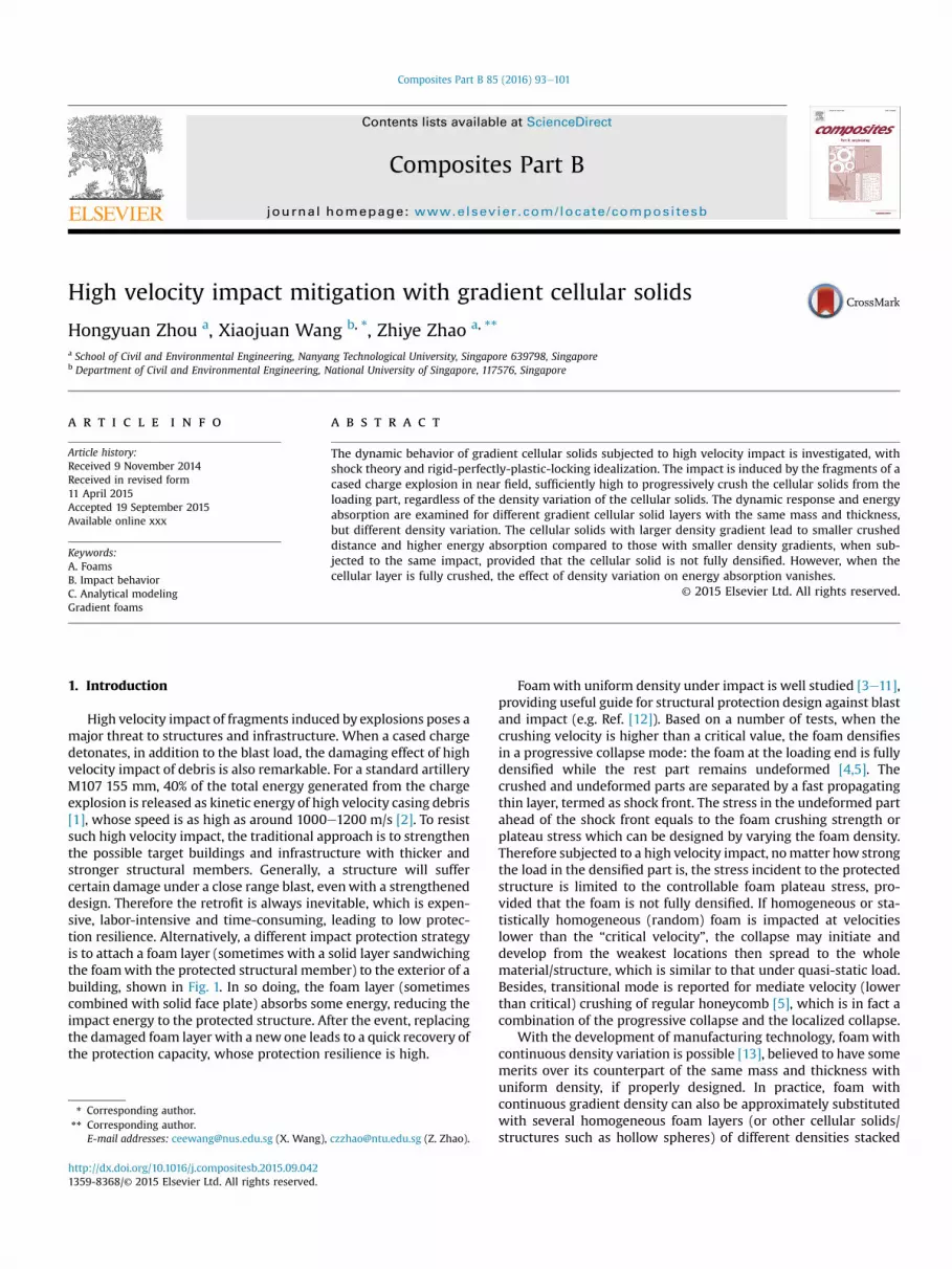
High velocity impact of fragments induced by explosions poses amajor threat to structures and infrastructure. When a cased chargedetonates, in addition to the blast load, the damaging effect of highvelocity impact of debris is also remarkable. For a standard artilleryM107 155 mm, 40% of the total energy generated from the chargeexplosion is released as kinetic energy of high velocity casing debris[1], whose speed is as high as around 1000e1200 m/s [2]. To resistsuch high velocity impact, the traditional approach is to strengthenthe possible target buildings and infrastructure with thicker andstronger structural members. Generally, a structure will suffercertain damage under a close range blast, evenwith a strengtheneddesign. Therefore the retrofit is always inevitable, which is expen-sive, labor-intensive and time-consuming, leading to low protec-tion resilience. Alternatively, a different impact protection strategyis to attach a foam layer (sometimes with a solid layer sandwichingthe foamwith the protected structural member) to the exterior of abuilding, shown in Fig. 1. In so doing, the foam layer (sometimescombined with solid face plate) absorbs some energy, reducing theimpact energy to the protected structure. After the event, replacingthe damaged foam layer with a new one leads to a quick recovery ofthe protection capacity, whose protection resilience is high.
[email protected] (Z. Zhao).
Foamwith uniform density under impact is well studied [3e11],providing useful guide for structural protection design against blastand impact (e.g. Ref. [12]). Based on a number of tests, when thecrushing velocity is higher than a critical value, the foam densifiesin a progressive collapse mode: the foam at the loading end is fullydensified while the rest part remains undeformed [4,5]. Thecrushed and undeformed parts are separated by a fast propagatingthin layer, termed as shock front. The stress in the undeformed partahead of the shock front equals to the foam crushing strength orplateau stress which can be designed by varying the foam density.Therefore subjected to a high velocity impact, nomatter how strongthe load in the densified part is, the stress incident to the protectedstructure is limited to the controllable foam plateau stress, pro-vided that the foam is not fully densified. If homogeneous or sta-tistically homogeneous (random) foam is impacted at velocitieslower than the “critical velocity”, the collapse may initiate anddevelop from the weakest locations then spread to the wholematerial/structure, which is similar to that under quasi-static load.Besides, transitional mode is reported for mediate velocity (lowerthan critical) crushing of regular honeycomb [5], which is in fact acombination of the progressive collapse and the localized collapse.
With the development of manufacturing technology, foamwithcontinuous density variation is possible [13], believed to have somemerits over its counterpart of the same mass and thickness withuniform density, if properly designed. In practice, foam withcontinuous gradient density can also be approximately substitutedwith several homogeneous foam layers (or other cellular solids/structures such as hollow spheres) of different densities stacked
Nomenclature
s shock front location, mL initial thickness of undeformed foam layer, mV0 initial impacting velocity, m s�1
u displacement of impacting plate, mx coordinate from initial interface location between
the impacting plate and undeformed foam core, mb gradient of foam density, dimensionlessrf foam density, kg m�3
r0 foam density at the impact end, kg m�3
rL foam density at the stationary end, kg m�3
rs density of the base material fromwhich the foam ismade, kg m�3
r* density of the crushed foam, kg m�3
sD densification stress of foam, Paspl plateau stress of foam, Pasys static yield strength of the basematerial fromwhich
the foam is made, PaεD densification strain of foam, dimensionlessl, C1 material constants of foam, dimensionless
Fig. 1. Illustration of the protection philosophy by attaching a cellular solid layer to theprotected structure.
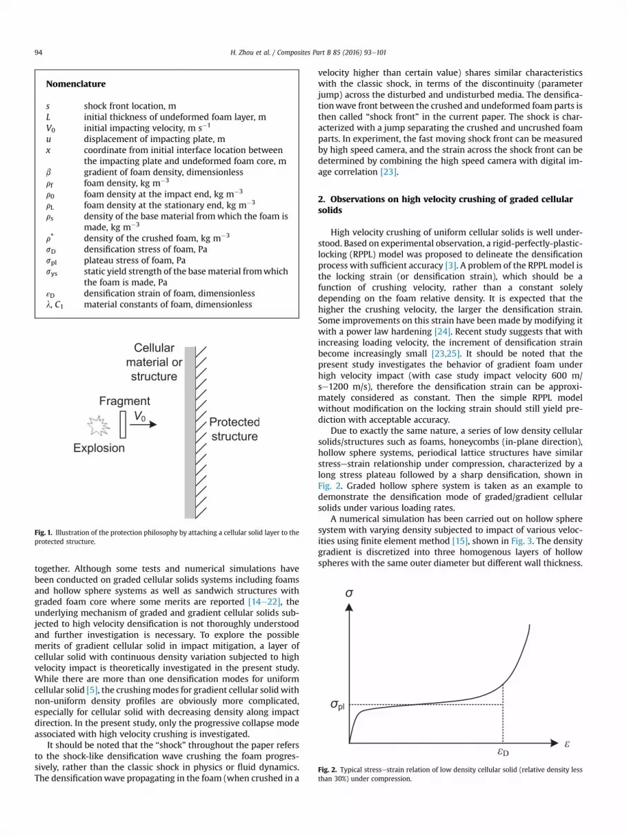
Fig. 2. Typical stressestrain relation of low density cellular solid (relative density lessthan 30%) under compression.
H. Zhou et al. / Composites Part B 85 (2016) 93e10194
together. Although some tests and numerical simulations havebeen conducted on graded cellular solids systems including foamsand hollow sphere systems as well as sandwich structures withgraded foam core where some merits are reported [14e22], theunderlying mechanism of graded and gradient cellular solids sub-jected to high velocity densification is not thoroughly understoodand further investigation is necessary. To explore the possiblemerits of gradient cellular solid in impact mitigation, a layer ofcellular solid with continuous density variation subjected to highvelocity impact is theoretically investigated in the present study.While there are more than one densification modes for uniformcellular solid [5], the crushingmodes for gradient cellular solid withnon-uniform density profiles are obviously more complicated,especially for cellular solid with decreasing density along impactdirection. In the present study, only the progressive collapse modeassociated with high velocity crushing is investigated.
It should be noted that the “shock” throughout the paper refersto the shock-like densification wave crushing the foam progres-sively, rather than the classic shock in physics or fluid dynamics.The densificationwave propagating in the foam (when crushed in a
velocity higher than certain value) shares similar characteristicswith the classic shock, in terms of the discontinuity (parameterjump) across the disturbed and undisturbed media. The densifica-tionwave front between the crushed and undeformed foam parts isthen called “shock front” in the current paper. The shock is char-acterized with a jump separating the crushed and uncrushed foamparts. In experiment, the fast moving shock front can be measuredby high speed camera, and the strain across the shock front can bedetermined by combining the high speed camera with digital im-age correlation [23].
2. Observations on high velocity crushing of graded cellularsolids
High velocity crushing of uniform cellular solids is well under-stood. Based on experimental observation, a rigid-perfectly-plastic-locking (RPPL) model was proposed to delineate the densificationprocess with sufficient accuracy [3]. A problem of the RPPLmodel isthe locking strain (or densification strain), which should be afunction of crushing velocity, rather than a constant solelydepending on the foam relative density. It is expected that thehigher the crushing velocity, the larger the densification strain.Some improvements on this strain have been made by modifying itwith a power law hardening [24]. Recent study suggests that withincreasing loading velocity, the increment of densification strainbecome increasingly small [23,25]. It should be noted that thepresent study investigates the behavior of gradient foam underhigh velocity impact (with case study impact velocity 600 m/se1200 m/s), therefore the densification strain can be approxi-mately considered as constant. Then the simple RPPL modelwithout modification on the locking strain should still yield pre-diction with acceptable accuracy.
Due to exactly the same nature, a series of low density cellularsolids/structures such as foams, honeycombs (in-plane direction),hollow sphere systems, periodical lattice structures have similarstressestrain relationship under compression, characterized by along stress plateau followed by a sharp densification, shown inFig. 2. Graded hollow sphere system is taken as an example todemonstrate the densification mode of graded/gradient cellularsolids under various loading rates.
A numerical simulation has been carried out on hollow spheresystem with varying density subjected to impact of various veloc-ities using finite element method [15], shown in Fig. 3. The densitygradient is discretized into three homogenous layers of hollowspheres with the same outer diameter but different wall thickness.
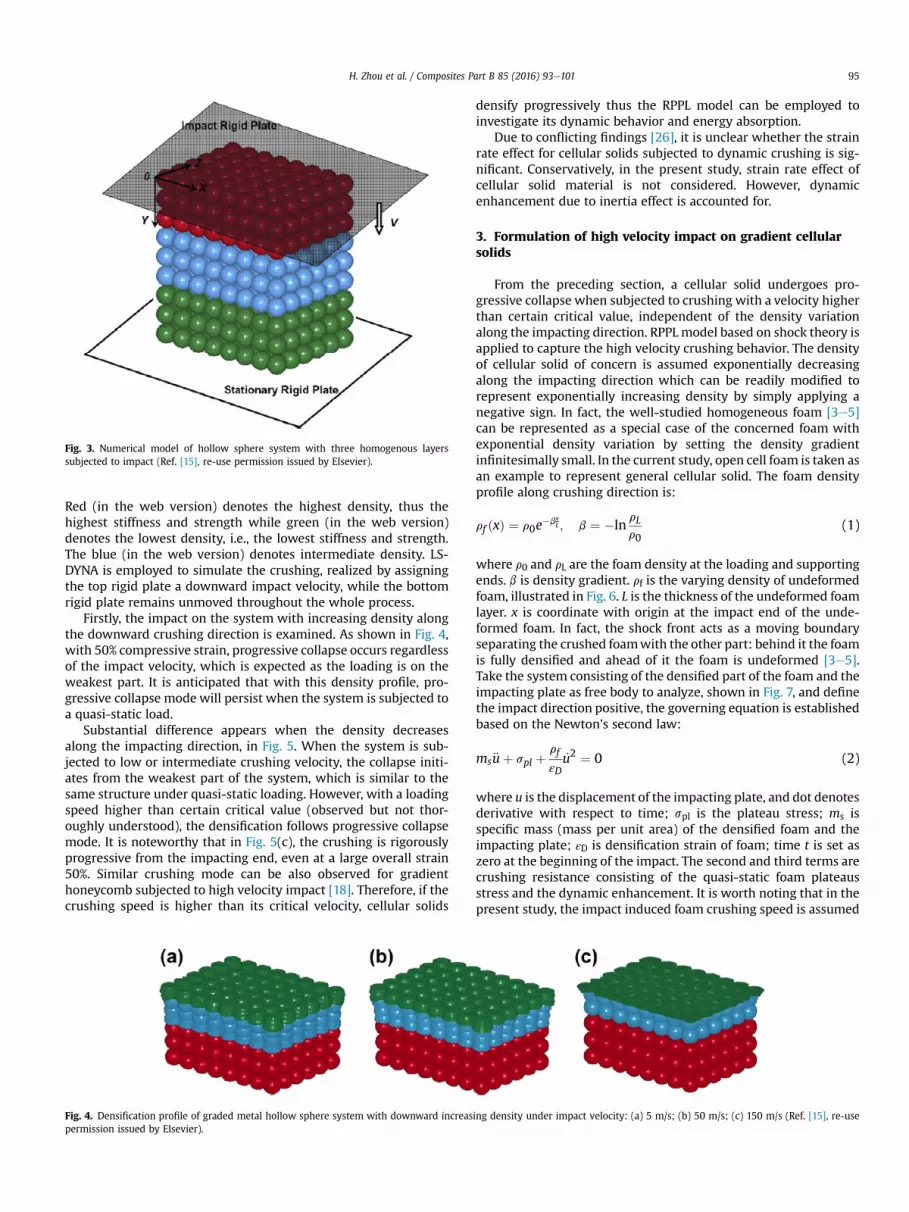
Fig. 3. Numerical model of hollow sphere system with three homogenous layerssubjected to impact (Ref. [15], re-use permission issued by Elsevier).
H. Zhou et al. / Composites Part B 85 (2016) 93e101 95
Red (in the web version) denotes the highest density, thus thehighest stiffness and strength while green (in the web version)denotes the lowest density, i.e., the lowest stiffness and strength.The blue (in the web version) denotes intermediate density. LS-DYNA is employed to simulate the crushing, realized by assigningthe top rigid plate a downward impact velocity, while the bottomrigid plate remains unmoved throughout the whole process.
Firstly, the impact on the system with increasing density alongthe downward crushing direction is examined. As shown in Fig. 4,with 50% compressive strain, progressive collapse occurs regardlessof the impact velocity, which is expected as the loading is on theweakest part. It is anticipated that with this density profile, pro-gressive collapse mode will persist when the system is subjected toa quasi-static load.
Substantial difference appears when the density decreasesalong the impacting direction, in Fig. 5. When the system is sub-jected to low or intermediate crushing velocity, the collapse initi-ates from the weakest part of the system, which is similar to thesame structure under quasi-static loading. However, with a loadingspeed higher than certain critical value (observed but not thor-oughly understood), the densification follows progressive collapsemode. It is noteworthy that in Fig. 5(c), the crushing is rigorouslyprogressive from the impacting end, even at a large overall strain50%. Similar crushing mode can be also observed for gradienthoneycomb subjected to high velocity impact [18]. Therefore, if thecrushing speed is higher than its critical velocity, cellular solids
Fig. 4. Densification profile of graded metal hollow sphere system with downward increaspermission issued by Elsevier).
densify progressively thus the RPPL model can be employed toinvestigate its dynamic behavior and energy absorption.
Due to conflicting findings [26], it is unclear whether the strainrate effect for cellular solids subjected to dynamic crushing is sig-nificant. Conservatively, in the present study, strain rate effect ofcellular solid material is not considered. However, dynamicenhancement due to inertia effect is accounted for.
3. Formulation of high velocity impact on gradient cellularsolids
From the preceding section, a cellular solid undergoes pro-gressive collapse when subjected to crushing with a velocity higherthan certain critical value, independent of the density variationalong the impacting direction. RPPL model based on shock theory isapplied to capture the high velocity crushing behavior. The densityof cellular solid of concern is assumed exponentially decreasingalong the impacting direction which can be readily modified torepresent exponentially increasing density by simply applying anegative sign. In fact, the well-studied homogeneous foam [3e5]can be represented as a special case of the concerned foam withexponential density variation by setting the density gradientinfinitesimally small. In the current study, open cell foam is taken asan example to represent general cellular solid. The foam densityprofile along crushing direction is:
rf ðxÞ ¼ r0e�bx
L; b ¼ �lnrL
r0(1)
where r0 and rL are the foam density at the loading and supportingends. b is density gradient. rf is the varying density of undeformedfoam, illustrated in Fig. 6. L is the thickness of the undeformed foamlayer. x is coordinate with origin at the impact end of the unde-formed foam. In fact, the shock front acts as a moving boundaryseparating the crushed foamwith the other part: behind it the foamis fully densified and ahead of it the foam is undeformed [3e5].Take the system consisting of the densified part of the foam and theimpacting plate as free body to analyze, shown in Fig. 7, and definethe impact direction positive, the governing equation is establishedbased on the Newton's second law:
ms€uþ spl þrf
εD_u2 ¼ 0 (2)
where u is the displacement of the impacting plate, and dot denotesderivative with respect to time; spl is the plateau stress; ms isspecific mass (mass per unit area) of the densified foam and theimpacting plate; εD is densification strain of foam; time t is set aszero at the beginning of the impact. The second and third terms arecrushing resistance consisting of the quasi-static foam plateausstress and the dynamic enhancement. It is worth noting that in thepresent study, the impact induced foam crushing speed is assumed
ing density under impact velocity: (a) 5 m/s; (b) 50 m/s; (c) 150 m/s (Ref. [15], re-use
Fig. 5. Densification profile of graded metal hollow sphere system with downward decreasing density subjected to 50% compressive strain under impact velocity: (a) 5 m/s; (b)50 m/s; (c) 150 m/s (Ref. [15], re-use permission issued by Elsevier).
Fig. 6. Illustration of the foam density variation.
Fig. 7. Free body diagram of the system consisting of the impacting plate and crushedfoam.
H. Zhou et al. / Composites Part B 85 (2016) 93e10196
greater than its critical velocity, thus this term is always present.Otherwise, a crushing velocity lower than the critical velocity willlead to insignificant dynamic enhancement, and different crushingmodes other than the progressive one will dominate, discussed indetail in the section that follows.
The density of the fully densified foam remains the same r*¼ rs/l, regardless of the original undeformed density, where rs is thedensity of base material from which the foam is made. l is a con-stant observed from tests, 1.4 for aluminum based foam [4]. The
specific mass can be conveniently calculated as the crushed foambetween the impacting plate and the shock front plus the platespecific mass:
ms ¼ rbhb þZs
u
rs
ldx ¼ rbhb þ
rs
lðs� uÞ (3)
where rb and hb are density and thickness of the impact plate,respectively; s is the location of the shock front, a function of time.The relation between the plate displacements u and shock front scan be obtained by equating the deformed and undeformed specificmass of the foam behind the shock front:
u ¼ s� lr0Lbrs
�1� e�bs
L
�(4)
The plateau stress of open-cell aluminum foam is [4]:
spl ¼ C1
�rf
rs
�32
sys (5)
where sys is the yield strength of the base material, 200 MPa foraluminum. C1 is a material constant ranging from 0.25 to 0.35 foraluminum [4], taken as 0.3 in the present study. The initial impactof the plate onto the gradient foam is realized by imposing an initialvelocity on the plat, whose initial condition can be realized as: attime zerowhen the impacting plate is just in contact with the foam,the plate displacement is zero and impacting velocity applies:
uð0Þ ¼ 0; _uð0Þ ¼ V0 (6)
Based on the relation between the displacement of theimpacting plate and shock front, the initial conditions can berewritten in term of shock front displacement:
sð0Þ ¼ 0; _sð0Þ ¼ V0=ð1� lr0=rsÞ (7)
With the governing equations and initial conditions, thebehavior of gradient foam subjected to high velocity impact can beobtained. A detailed examination of Eqs. (2) through (7) suggeststhat the governing equation based on the shock front displacementis a two order nonlinear differential equationwhich is difficult to besolved in close form. Thus, RungeeKutta method is employed tosolve the governing equation numerically in terms of shock frontdisplacement s.
4. Case study with discussions
A case study is conducted on a practical engineering application:to mitigate structure damage from high velocity fragment impact, alayer of low density aluminum foam is attached to the exterior of astructure. Formass efficiency, a typical foam layer of 5 cm is adopted.
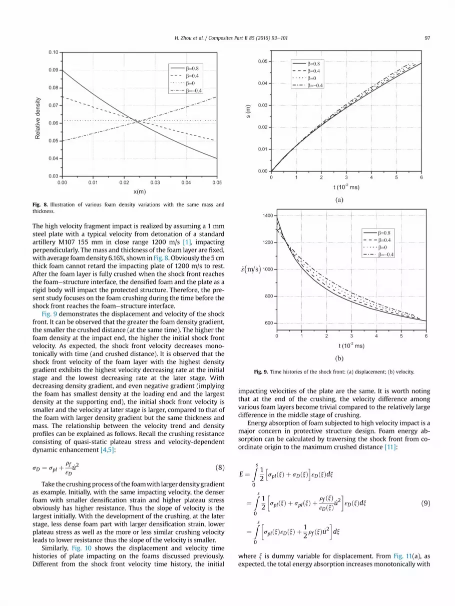
Fig. 8. Illustration of various foam density variations with the same mass andthickness.
Fig. 9. Time histories of the shock front: (a) displacement; (b) velocity.
H. Zhou et al. / Composites Part B 85 (2016) 93e101 97
The high velocity fragment impact is realized by assuming a 1 mmsteel plate with a typical velocity from detonation of a standardartillery M107 155 mm in close range 1200 m/s [1], impactingperpendicularly. Themass and thickness of the foam layer are fixed,with average foamdensity 6.16%, shown in Fig. 8. Obviously the 5 cmthick foam cannot retard the impacting plate of 1200 m/s to rest.After the foam layer is fully crushed when the shock front reachesthe foamestructure interface, the densified foam and the plate as arigid body will impact the protected structure. Therefore, the pre-sent study focuses on the foam crushing during the time before theshock front reaches the foamestructure interface.
Fig. 9 demonstrates the displacement and velocity of the shockfront. It can be observed that the greater the foam density gradient,the smaller the crushed distance (at the same time). The higher thefoam density at the impact end, the higher the initial shock frontvelocity. As expected, the shock front velocity decreases mono-tonically with time (and crushed distance). It is observed that theshock front velocity of the foam layer with the highest densitygradient exhibits the highest velocity decreasing rate at the initialstage and the lowest decreasing rate at the later stage. Withdecreasing density gradient, and even negative gradient (implyingthe foam has smallest density at the loading end and the largestdensity at the supporting end), the initial shock front velocity issmaller and the velocity at later stage is larger, compared to that ofthe foam with larger density gradient but the same thickness andmass. The relationship between the velocity trend and densityprofiles can be explained as follows. Recall the crushing resistanceconsisting of quasi-static plateau stress and velocity-dependentdynamic enhancement [4,5]:
sD ¼ spl þrf
εD_u2 (8)
Take the crushingprocess of the foamwith largerdensitygradientas example. Initially, with the same impacting velocity, the denserfoam with smaller densification strain and higher plateau stressobviously has higher resistance. Thus the slope of velocity is thelargest initially. With the development of the crushing, at the laterstage, less dense foam part with larger densification strain, lowerplateau stress as well as the more or less similar crushing velocityleads to lower resistance thus the slope of the velocity is smaller.
Similarly, Fig. 10 shows the displacement and velocity timehistories of plate impacting on the foams discussed previously.Different from the shock front velocity time history, the initial
impacting velocities of the plate are the same. It is worth notingthat at the end of the crushing, the velocity difference amongvarious foam layers become trivial compared to the relatively largedifference in the middle stage of crushing.
Energy absorption of foam subjected to high velocity impact is amajor concern in protective structure design. Foam energy ab-sorption can be calculated by traversing the shock front from co-ordinate origin to the maximum crushed distance [11]:
E ¼Zs
0
12
hsplðxÞ þ sDðxÞ
iεDðxÞdx
¼Zs
0
12
�splðxÞ þ splðxÞ þ
rf ðxÞεDðxÞ
_u2�εDðxÞdx
¼Zs
0
�splðxÞεDðxÞ þ
12rf ðxÞ _u2
�dx
(9)
where x is dummy variable for displacement. From Fig. 11(a), asexpected, the total energy absorption increases monotonically with
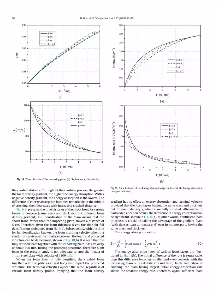
Fig. 10. Time histories of the impacting plate: (a) displacement; (b) velocity.
Fig. 11. Time histories of: (a) Energy absorption (per unit area); (b) Energy absorptionrate (per unit area).
H. Zhou et al. / Composites Part B 85 (2016) 93e10198
the crushed distance. Throughout the crushing process, the greaterthe foam density gradient, the higher the energy absorption. With anegative density gradient, the energy absorption is the lowest. Thedifference of energy absorption becomes remarkable in the middleof crushing, then decreases with increasing crushed distance.
Fig. 9(a) presents the time histories of the shock front for variousfoams of concern (same mass and thickness, but different foamdensity gradient). Full densification of the foam means that theshock front, rather than the impacting plate, travels a distance of5 cm. Therefore given the foam thickness 5 cm, the time for fulldensification is obtained from Fig. 9(a). Subsequently, with the timefor full densification known, the foam crushing velocity when theshock front arrives at the interface between the foam and protectedstructure can be determined, shown in Fig. 10(b). It is seen that thefully crushed foam together with the impacting plate, has a velocityof about 600 m/s, hitting the protected structure. Therefore 5 cmfoam in the present study is not adequate to stop the impact of1 mm steel plate with velocity of 1200 m/s.
When the foam layer is fully densified, the crushed foamtogether with the plate as a rigid body will impact the protectedstructure. The terminal velocities appear the same, regardless ofvarious foam density profile, implying that the foam density
gradient has no effect on energy absorption and terminal velocity,provided that the foam layers having the same mass and thicknessbut different density gradients are fully crushed. Alternative, ifpartial densification occurs, the difference in energy absorptionwillbe significant, shown in Fig. 11(a). In other words, a sufficient foamthickness is crucial in taking the advantage of the gradient foam(with densest part at impact end) over its counterparts having thesame mass and thickness.
The energy absorption rate is:
_E ¼ dEdt
¼�splðsÞεDðsÞ þ
12rf ðsÞ _u2
�_s (10)
The energy absorption rates of various foam layers are illus-trated in Fig. 11(b). The initial difference of the rate is remarkable,then this difference becomes smaller and even converts with theincreasing foam crushed distance (and time). In the later stage ofcrushing, the foam having largest initial energy absorption rateshows the smallest energy rate. Therefore, again, sufficient foam
H. Zhou et al. / Composites Part B 85 (2016) 93e101 99
layer thickness is recommended so that the high energy absorptionrate at the initial crushing stage dominates the impact mitigation.
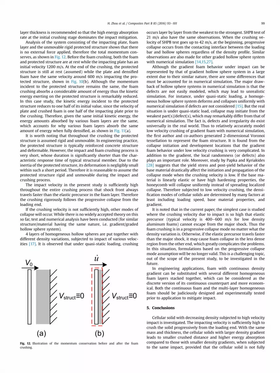
Analysis of the system consisting of the impacting plate, foamlayer and the unmovable rigid protected structure shows that thereis no external force applied, therefore the total momentum con-serves, as shown in Fig. 12. Before the foam crushing, both the foamand protected structure are at rest while the impacting plate has aninitial velocity 1200 m/s. At the end of the crushing, the protectedstructure is still at rest (assumed) while the plate and densifiedfoam have the same velocity around 600 m/s impacting the pro-tected structure, shown in Fig. 10(b). Although the momentumincident to the protected structure remains the same, the foamcrushing absorbs a considerable amount of energy thus the kineticenergy exerting on the protected structure is remarkably reduced.In this case study, the kinetic energy incident to the protectedstructure reduces to one half of its initial value, since the velocity ofplate and crushed foam is one half of the impacting plate prior tothe crushing. Therefore, given the same initial kinetic energy, theenergy amounts absorbed by various foam layers are the same,which accounts for why various foam layers absorb the sameamount of energy when fully densified, as shown in Fig. 11(a).
It is worth noting that throughout the crushing the protectedstructure is assumed rigid and unmovable. In engineering practice,the protected structure is typically reinforced concrete structureand deformable. However, the impact and foam crushing process isvery short, whose duration is significantly shorter than the char-acteristic response time of typical structural member. Due to theinertia of the protected structure, its deformation is negligibly smallwithin such a short period. Therefore it is reasonable to assume theprotected structure rigid and unmovable during the impact andcrushing process.
The impact velocity in the present study is sufficiently highthroughout the entire crushing process that shock front alwaystravels faster than the elastic precursor in the foam layer. Thereforethe crushing rigorously follows the progressive collapse from theloading end.
If the crushing velocity is not sufficiently high, other modes ofcollapsewill occur.While there is nowidely accepted theory on thisso far, test and numerical analysis have been conducted (for similarstructure/material having the same nature, i.e. gradient/gradedhollow sphere system).
4 layers of homogeneous hollow spheres are put together withdifferent density variations, subjected to impact of various veloc-ities [17]. It is observed that under quasi-static loading, crushing
Fig. 12. Illustration of the momentum conservation before and after the foamcrushing.
occurs layer by layer from theweakest to the strongest. SHPB test of21 m/s also have the same observations. When the crushing ve-locity of SHPB test goes up to 42 m/s, at the beginning, progressivecollapse occurs from the contacting interface between the loadingbar and hollow spheres regardless of the density profile. Similarobservations are also made for other graded hollow sphere systemwith numerical simulation [14,15,27].
Although the gradient foam behavior under impact can berepresented by that of gradient hollow sphere system in a largeextent due to their similar nature, there are some differences thatmust be accounted for in numerical simulation. The major draw-back of hollow sphere systems in numerical simulation is that thedefects are not easily modeled, which may lead to unrealisticsimulation. For instance, under quasi-static loading, a homoge-neous hollow sphere system deforms and collapses uniformly withnumerical simulation if defects are not considered [15]. But the realsituation is under quasi-static load, collapse may initiate from theweakest part(s)/defect(s), whichmay remarkably differ from that ofnumerical simulation. The fact is, defects and irregularity do existuniversally in the real world. Thus to relatively accurately modellow velocity crushing of gradient foam with numerical simulation,the first author and co-authors generated 2-dimensional Voronoitessellation to represent the foam structure. It is found from thecollapse initiation and development locations that the gradientfoam behavior under low velocity crushing is very complicated. Inaddition to the gradient, the local randomness (or defects) alsoplays an important role. Moreover, study by Papka and Kyriakides[28] suggests that the yield stress and post-yield behavior of thebase material drastically affect the initiation and propagation of thecollapse mode when the crushing velocity is low. If the base ma-terial is linearly elastic or have high hardening properties, thehoneycomb will collapse uniformly instead of spreading localizedcollapse. Therefore subjected to low velocity crushing, the densi-fication modes of cellular solids are determined by many factors atleast including loading speed, base material properties, andgradient.
It is noted that in the current paper, the simplest case is studiedwhere the crushing velocity due to impact is so high that elasticprecursor (typical velocity is 400e600 m/s for low densityaluminum foams) cannot escape from the major shock. Thus thefoam crushing is in a progressive collapse mode nomatter what thedensity variation is. Otherwise, if the elastic precursor travels fasterthan the major shock, it may cause foam collapse in the less denseregion from the other end, which greatly complicates the problems.In this situation, formulations based on the progressive collapsemode assumptionwill be no longer valid. This is a challenging topic,out of the scope of the present study, to be investigated in thefuture.
In engineering applications, foam with continuous densitygradient can be substituted with several different homogeneousfoam layers stacked together, which can be considered as thediscrete version of its continuous counterpart and more econom-ical. Both the continuous foam and the multi-layer homogeneousfoam should be judiciously designed and experimentally testedprior to application to mitigate impact.
5. Conclusions
Cellular solid with decreasing density subjected to high velocityimpact is investigated. The impacting velocity is sufficiently high tocrush the solid progressively from the loading end. With the samemass and thickness, the cellular solids with larger density gradientleads to smaller crushed distance and higher energy absorptioncompared to those with smaller density gradients, when subjectedto the same impact, provided that the cellular solid is not fully
H. Zhou et al. / Composites Part B 85 (2016) 93e101100
densified. However, when the cellular layer is fully crushed, theeffect of density variation on deformation and energy absorptionvanishes. Therefore an adequate thickness of cellular solid is rec-ommended to take the advantage of the density variation, if theimpacting object is expected to be stopped without cellular layerbeing fully densified. Otherwise, if full densification of the cellularsolid layer is inevitable, homogeneous cellular solid layer should beapplied, to be economical.
Appendix. Derive the governing equation of high velocityfoam crushing
Consider the foam parts separated by the shock front. After theshock front, the foam is assumed fully densified while ahead of theshock front, the foam is undeformed with approximately zero ve-locity and negligible strain.
Fig. A1. Illustration of the parameters behind and ahead of the shock front.
The density of the densified foam can be calculated by consid-ering conservation of mass before and after the shock traverses:
r* ¼ rf
1� εD(A1)
Conservation of mass across the shock front in a very shortperiod of time:
rf _sADt ¼rf
1� εDð _s� _uÞADt (A2)
Simplifying it yields:
_s ¼ _uεD
(A3)
Take a small mass unit across the shock front to analyze. Beforethe shock, the velocity is zero. Just immediate after the shock fronttraverses, the velocity becomes the same as the crushed foam part.According to the momentum theorem, the total resultant impulsefor this time duration should be equal to the momentum change:
�sD � spl
�ADt ¼ rf _sDtA _u� 0 (A4)
Combining Eq. (A3) with Eq. (A4) leads to:
sD ¼ spl þrf
εD_u2 (A5)
From Eq. (A5) the densification stress consists of two part, one isthe plateau stress (quasi-static part), the other is the dynamicenhancement (the part accounting for the inertia effect).
Now take the system consisting of the impacting plate and thecrushed foam to analysis, where the undeformed foam part aheadof the shock front is excluded. Assume shock front propagation
direction as positive (to the right). For the impact problem, theexternal load for the system from left is zero while the resistancefrom the right is the foam densification stress consisting of thefoam plateau stress and the dynamic enhancement:
��spl þ
rf
εD_u2�
(A6)
where the minus sign denotes the resistance is in the oppositedirection of the impact incident direction. From the Newton'ssecond law:
ms€u ¼ 0��spl þ
rf
εD_u2�
(A7)
which can be re-written as Eq. (2):
ms€uþ spl þrf
εD_u2 ¼ 0 (A8)
References
[1] Chong K, Seah CC, Zhou YX. Large scale tests-airblast, ground shock anddebris. In: International Symposium on Defence Construction. Singapore;April, 2002.
[2] US Army Engineers Waterways Experimental Station. Fundamentals of pro-tective design for conventional weapons. 1986. TM5-855-1. Vicksburg.
[3] Reid SR, Peng C. Dynamic uniaxial crushing of wood. Int J Impact Eng1997;19(5e6):531e70.
[4] Ashby MF, Evans A, Fleck NA, Gibson LJ, Hutchinson JW, Wadley HNG. Metalfoams: a design guide. Woburn, USA: Butterworth-Heinmann; 2000.
[5] Lu GX, Yu TX. Energy absorption of structures and materials. Boca Raton, USA:CRC Press; 2003.
[6] Gibson LJ, Ashby MF, Harley BA. Cellular materials in nature and medicine.Cambridge, UK: Cambridge University Press; 2010.
[7] Jing L, Wang ZH, Ning JG, Zhao LM. The dynamic response of sandwich beamswith open-cell metal foam cores. Compos Part B 2011;42:1e10.
[8] Xie QH, Jing L, Wang ZH, Zhao LM. Deformation and failure of clampedshallow sandwich arches with foam core subjected to projectile impact.Compos Part B 2013;44:330e8.
[9] Shen JH, Lu GX, Ruan D. Compressive behaviour of closed-cell aluminiumfoams at high strain rates. Compos Part B 2010;41:678e85.
[10] Jing L, Wang ZH, Zhao LM. An approximate theoretical analysis for clampedcylindrical sandwich shells with metallic foam cores subjected to impulsiveloading. Compos Part B 2014;60:150e7.
[11] Harrigan JJ, Reid SR, Yaghoubi AS. The correct analysis of shocks in a cellularmaterial. Int J Impact Eng 2010;37:918e27.
[12] Zhou HY, Ma GW, Li JD, Zhao ZY. Design of metal foam cladding subjected toclose-range blast. J Perform Constr Facil 2014:04014110. http://dx.doi.org/10.1061/(ASCE)CF.1943-5509.0000606.
[13] Zhou CC, Wang P, Li W. Fabrication of functionally graded porous polymer viasupercritical CO2 foaming. Compos Part B 2011;42:318e25.
[14] Liu Y, Wu HX, Lu GX, Wang B. Dynamic properties of density graded thin-walled metal hollow sphere arrays. Mech Adv Mat Struct 2013;20(6):478e88.
[15] Liu Y, Wu HX, Wang B. Gradient design of metal hollow sphere (MHS) foamswith density gradients. Compos Part B 2012;43:1346e52.
[16] Li JD, Ma GW, Zhou HY, Du XL. Energy absorption analysis of density gradedaluminium foam. Int J Prot Struct 2011;2(3):333e49.
[17] Zeng HB, Pattofatto S, Zhao H, Girard Y, Fascio V. Impact behaviour of hollowsphere agglomerates with density gradient. Int J Mech Sci 2010;52:680e8.
[18] Shen CJ, Lu GX, Yu TX. Dynamic behavior of graded honeycombsea finiteelement study. Compos Struct 2013;98:282e93.
[19] Liu XR, Tian XG, Lu TJ, Zhou DQ, Liang B. Blast resistance of sandwich-walledhollow cylinders with graded metallic foam cores. Compos Struct 2012;94(8):2485e93.
[20] Zeng HB, Pattofatto S, Zhao H, Girard Y, Fascio V. Perforation of sandwichplates with graded hollow sphere cores under impact loading. Int J Impact Eng2010;37:1083e91.
[21] Zhang XC, An LQ, Ding HM. Dynamic crushing behavior and energy absorptionof honeycombs with density gradient. J Sandw Struct Mater 2014;16(2):125e47.
[22] Zhou J, Guan ZW, Cantwell WJ. The impact response of graded foam sandwichstructures. Compos Struct 2013;97:370e7.
[23] Barnes AT, Ravi-Chandar K, Kyriakides S, Gaitanaros S. Dynamic crushing ofaluminum foams: part I-experiments. Int J Solids Struct 2014;51:1631e45.

H. Zhou et al. / Composites Part B 85 (2016) 93e101 101
[24] Pattofatto S, Elnasri I, Zhao H, Tsitsiris H, Hild F, Girard Y. Shock enhancementof cellular structures under impact loading: part II analysis. J Mech Phys Solids2007;55:2672e86.
[25] Gaitanaros S, Kyriakides S. Dynamic crushing of aluminum foams: part II-analysis. Int J Solids Struct 2014;51:1646e61.
[26] Ma GW, Ye ZQ, Shao ZS. Modeling loading rate effect on crushing stress ofmetallic cellular materials. Int J Impact Eng 2009;36(6):775e82.
[27] Fan JH, Zhang JJ, Wang ZH, Li ZQ, Zhao LM. Dynamic crushing behavior ofrandom and functionally graded metal hollow sphere foams. Mater Sci Eng A2013;561:352e61.
[28] Papka SD, Kyriakides S. In-plane compressive response and crushing of hon-eycomb. J Mech Phys Solids 1994;42(10):1499e532.


![chapter – 21 solids [surface area and volume of 3-d solids]](https://static.fdokumen.com/doc/165x107/632737f8051fac18490e22eb/chapter-21-solids-surface-area-and-volume-of-3-d-solids.jpg)