
High performance concentrating photovoltaic module designs for utility scale power generation
6
HIGH PERFORMANCE CONCENTRATING PHOTOVOLTAIC MODULE DESIGNS FOR UTILITY SCALE POWER GENERATION Adam Plesniak a , Russ Jones b , Joel Schwartz a , Guy Martins a , John Hall a , Authi Narayanan a , David Whelan a , Pablo Benítez c,d , Juan C. Miñano c,d , Aleksandra Cvetkovíc d , Maikel Hernandez c , Oliver Dross c , Roberto Alvarez c a The Boeing Company, 2800 Westminster, Seal Beach, CA 90740, USA; b Spectrolab, Inc., 12500 Gladstone Avenue, Sylmar, CA 91342, USA; c LPI-LLC, 2400 Lincoln Ave, Altadena, CA 91001, USA; d Universidad Politécnica de Madrid – Cedint, Campus de Montegancedo, 28223 Madrid, Spain ABSTRACT The Boeing Company Phantom Works has developed three different prototype photovoltaic concentrator arrays since March 2007. Identified as Prototype A, B and C, the experimentally proven technical characteristics of each design are presented. The concentrator designs utilize a 1 cm 2 multi-junction solar cell assembly in conjunction with SMS non-imaging optical designs [1, 2] manufactured with low-cost mass-producible technologies. Prototype A is an on-axis XR optical concentrator with a 733x geometrical concentration demonstrating a ± 1.73° acceptance angle and 23.7% conversion efficiency. Prototype B is an off-axis free-form XR optical concentrator with a 810x geometrical concentration demonstrating a ± 1.32° acceptance angle and 25.3% conversion efficiency. Prototype C is the most recent off-axis free-form XR optical concentrator with a 801x geometrical concentration and a theoretical ±1.80° acceptance angle demonstrating a conversion efficiency greater than 27.0%. Prototype C is also the basis for the Boeing Proof of Design (POD) module, demonstrating an acceptance angle of ±1.48° and a conversion efficiency of 29.4% (as of May 8, 2009). Manufacturability has been paramount during the design process, resulting in high performance concentrating photovoltaic modules using production quality components. 1. INTRODUCTION Concentrating photovoltaics (CPV) is characterized by the use of an optical system to concentrate incident solar radiation from an entrance aperture area onto a solar cell at an exit aperture of relatively smaller area in order to reduce the amount of semiconductor material needed per generated watt. Many optical designs are possible, each with its own set of advantages and disadvantages in form factor and optical performance. When looking for a successful optical design, it is important to discuss two factors, concentration ratio and acceptance angle. A system with a high concentration ratio needs less semiconductor material to generate the same amount of power as a system with a lower concentration ratio. A system with a wide acceptance angle means less structure is needed and looser manufacturing tolerance is allowed to generate the same amount of power as compared to a system with a narrow acceptance angle. Concentration ratio and acceptance angle are related to each other; it is well known [2] that the product of geometrical concentration Cg and acceptance half- angle α cannot exceed the limit defined by 2 2 2 sin sin g C n α β ≤ (1) where n is the refractive index of the medium in which the cell is immersed (generally a silicone encapsulant or air), and β is the maximum incidence angle of illumination of the cell. Traditional imaging and flat Fresnel lens optics, widely used in CPV designs today, are not able to practically combine the desire for both wide acceptance angle and high concentration ratio, as seen in Figure 1 [2]. Fig. 1. Geometrical concentration v.s. acceptance angle for various CPV optical designs [2]. The performance potential of numerous optical design forms suitable for CPV systems has been systematically investigated [2]. The XR design form (two optical elements, the first of which is a reflector and the Geometrical Concentration Half-Acceptance Angle (°) 0 2.0 2.5 3.0 200 300 400 500 600 700 800 900 Square Fresnel Lens + Reflective Secondary Parabolic Dish + Prism Two Aplanatic Mirrors + Prism XR square aperture Theoretical Limit (Cell Immersed in Glass) 1000 1.5 1.0 0.5 Keynote Paper High and Low Concentrator Systems for Solar Electric Applications IV, edited by Lori E. Greene, Proc. of SPIE Vol. 7407, 740704 · © 2009 SPIE · CCC code: 0277-786X/09/$18 · doi: 10.1117/12.827789 Proc. of SPIE Vol. 7407 740704-1
Transcript of High performance concentrating photovoltaic module designs for utility scale power generation

HIGH PERFORMANCE CONCENTRATING PHOTOVOLTAIC MODULE DESIGNS FOR UTILITY SCALE POWER GENERATION
Adam Plesniaka, Russ Jonesb, Joel Schwartza, Guy Martinsa, John Halla, Authi Narayanana, David Whelana, Pablo
Benítezc,d, Juan C. Miñanoc,d, Aleksandra Cvetkovícd, Maikel Hernandezc, Oliver Drossc, Roberto Alvarezc
a The Boeing Company, 2800 Westminster, Seal Beach, CA 90740, USA; b Spectrolab, Inc., 12500 Gladstone Avenue, Sylmar, CA 91342, USA; c LPI-LLC, 2400 Lincoln Ave, Altadena, CA 91001, USA; d Universidad Politécnica de Madrid –
Cedint, Campus de Montegancedo, 28223 Madrid, Spain
ABSTRACT
The Boeing Company Phantom Works has
developed three different prototype photovoltaic concentrator arrays since March 2007. Identified as Prototype A, B and C, the experimentally proven technical characteristics of each design are presented. The concentrator designs utilize a 1 cm2 multi-junction solar cell assembly in conjunction with SMS non-imaging optical designs [1, 2] manufactured with low-cost mass-producible technologies. Prototype A is an on-axis XR optical concentrator with a 733x geometrical concentration demonstrating a ± 1.73° acceptance angle and 23.7% conversion efficiency. Prototype B is an off-axis free-form XR optical concentrator with a 810x geometrical concentration demonstrating a ± 1.32° acceptance angle and 25.3% conversion efficiency. Prototype C is the most recent off-axis free-form XR optical concentrator with a 801x geometrical concentration and a theoretical ±1.80° acceptance angle demonstrating a conversion efficiency greater than 27.0%. Prototype C is also the basis for the Boeing Proof of Design (POD) module, demonstrating an acceptance angle of ±1.48° and a conversion efficiency of 29.4% (as of May 8, 2009). Manufacturability has been paramount during the design process, resulting in high performance concentrating photovoltaic modules using production quality components.
1. INTRODUCTION
Concentrating photovoltaics (CPV) is characterized
by the use of an optical system to concentrate incident solar radiation from an entrance aperture area onto a solar cell at an exit aperture of relatively smaller area in order to reduce the amount of semiconductor material needed per generated watt. Many optical designs are possible, each with its own set of advantages and disadvantages in form factor and optical performance. When looking for a successful optical design, it is important to discuss two factors, concentration ratio and acceptance angle. A system with a high concentration ratio needs less semiconductor material to generate the same amount of power as a system with a lower concentration ratio. A system with a wide acceptance angle means less structure is needed and looser manufacturing tolerance is
allowed to generate the same amount of power as compared to a system with a narrow acceptance angle.
Concentration ratio and acceptance angle are
related to each other; it is well known [2] that the product of geometrical concentration Cg and acceptance half-angle α cannot exceed the limit defined by
2 2 2sin singC nα β≤ (1)
where n is the refractive index of the medium in which the cell is immersed (generally a silicone encapsulant or air), and β is the maximum incidence angle of illumination of the cell.
Traditional imaging and flat Fresnel lens optics, widely used in CPV designs today, are not able to practically combine the desire for both wide acceptance angle and high concentration ratio, as seen in Figure 1 [2].
Fig. 1. Geometrical concentration v.s. acceptance angle for various CPV optical designs [2].
The performance potential of numerous optical design forms suitable for CPV systems has been systematically investigated [2]. The XR design form (two optical elements, the first of which is a reflector and the
Geometrical Concentration
Half-
Acce
ptan
ce A
ngle
(°)
0
2.0
2.5
3.0
200 300 400 500 600 700 800 900
Square Fresnel Lens + Reflective Secondary
Parabolic Dish + Prism
Two Aplanatic Mirrors + Prism
XR square aperture
Theoretical Limit(Cell Immersed in Glass)
1000
1.5
1.0
0.5
Keynote Paper
High and Low Concentrator Systems for Solar Electric Applications IV, edited by Lori E. Greene,Proc. of SPIE Vol. 7407, 740704 · © 2009 SPIE · CCC code: 0277-786X/09/$18 · doi: 10.1117/12.827789
Proc. of SPIE Vol. 7407 740704-1
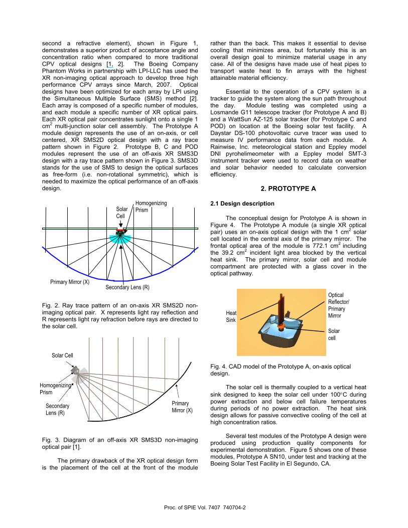
second a refractive element), shown in Figure 1, demonstrates a superior product of acceptance angle and concentration ratio when compared to more traditional CPV optical designs [1, 2]. The Boeing Company Phantom Works in partnership with LPI-LLC has used the XR non-imaging optical approach to develop three high performance CPV arrays since March, 2007. Optical designs have been optimized for each array by LPI using the Simultaneous Multiple Surface (SMS) method [2]. Each array is composed of a specific number of modules, and each module a specific number of XR optical pairs. Each XR optical pair concentrates sunlight onto a single 1 cm2 multi-junction solar cell assembly. The Prototype A module design represents the use of an on-axis, or cell centered, XR SMS2D optical design with a ray trace pattern shown in Figure 2. Prototype B, C and POD modules represent the use of an off-axis XR SMS3D design with a ray trace pattern shown in Figure 3. SMS3D stands for the use of SMS to design the optical surfaces as free-form (i.e. non-rotational symmetric), which is needed to maximize the optical performance of an off-axis design.
Fig. 2. Ray trace pattern of an on-axis XR SMS2D non-imaging optical pair. X represents light ray reflection and R represents light ray refraction before rays are directed to the solar cell.
Fig. 3. Diagram of an off-axis XR SMS3D non-imaging optical pair [1].
The primary drawback of the XR optical design form is the placement of the cell at the front of the module
rather than the back. This makes it essential to devise cooling that minimizes area, but fortunately this is an overall design goal to minimize material usage in any case. All of the designs have made use of heat pipes to transport waste heat to fin arrays with the highest attainable material efficiency.
Essential to the operation of a CPV system is a tracker to guide the system along the sun path throughout the day. Module testing was completed using a Losmande G11 telescope tracker (for Prototype A and B) and a WattSun AZ-125 solar tracker (for Prototype C and POD) on location at the Boeing solar test facility. A Daystar DS-100 photovoltaic curve tracer was used to measure IV performance data from each module. A Rainwise, Inc. meteorological station and Eppley model DNI pyrohelimeometer with a Eppley model SMT-3 instrument tracker were used to record data on weather and solar behavior needed to calculate conversion efficiency.
2. PROTOTYPE A
2.1 Design description
The conceptual design for Prototype A is shown in Figure 4. The Prototype A module (a single XR optical pair) uses an on-axis optical design with the 1 cm2 solar cell located in the central axis of the primary mirror. The frontal optical area of the module is 772.1 cm2 including the 39.2 cm2 incident light area blocked by the vertical heat sink. The primary mirror, solar cell and module compartment are protected with a glass cover in the optical pathway.
Fig. 4. CAD model of the Prototype A, on-axis optical design.
The solar cell is thermally coupled to a vertical heat sink designed to keep the solar cell under 100°C during power extraction and below cell failure temperatures during periods of no power extraction. The heat sink design allows for passive convective cooling of the cell at high concentration ratios.
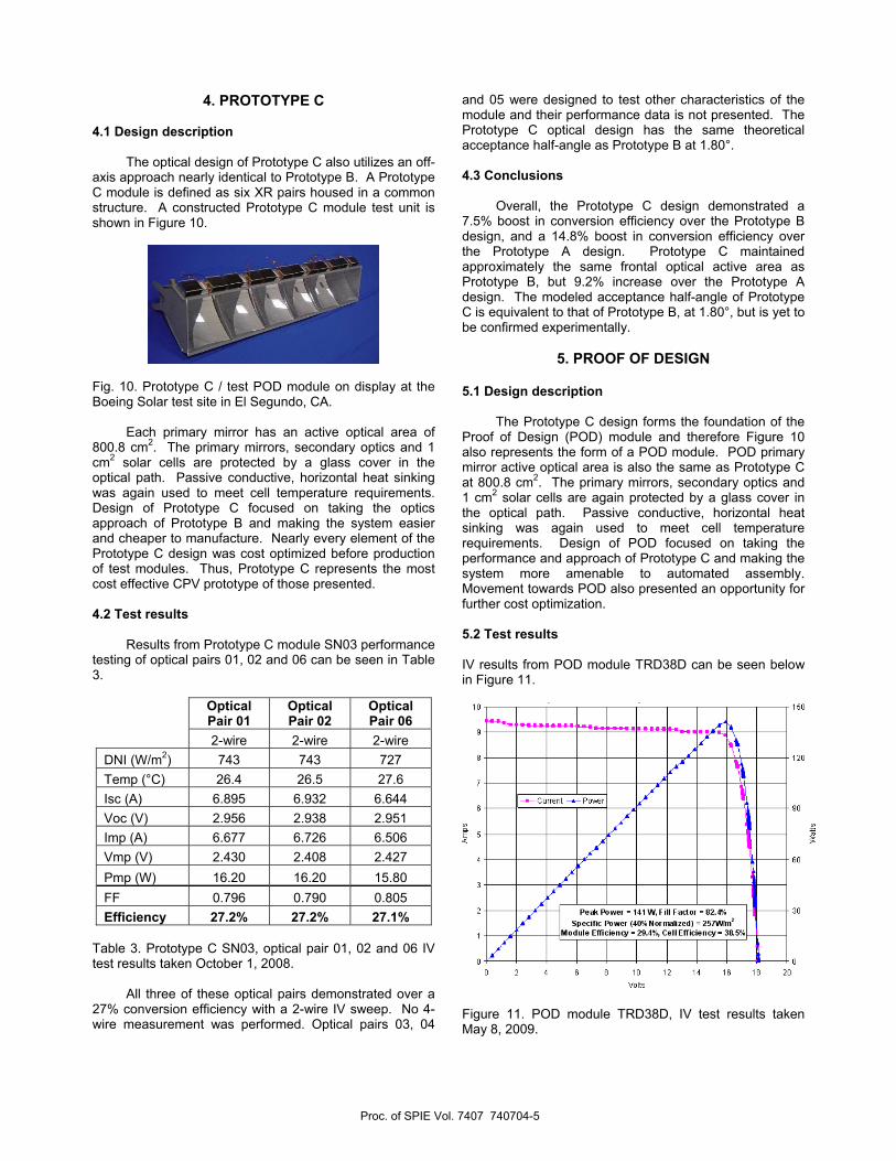
Several test modules of the Prototype A design were produced using production quality components for experimental demonstration. Figure 5 shows one of these modules, Prototype A SN10, under test and tracking at the Boeing Solar Test Facility in El Segundo, CA.
Solar cell
Optical Reflector/ Primary MirrorHeat
Sink
Solar Cell
HomogenizingPrism
Primary Mirror (X) Secondary Lens (R)
Secondary Lens (R)
Homogenizing Prism
Solar Cell
Primary Mirror (X)
Proc. of SPIE Vol. 7407 740704-2
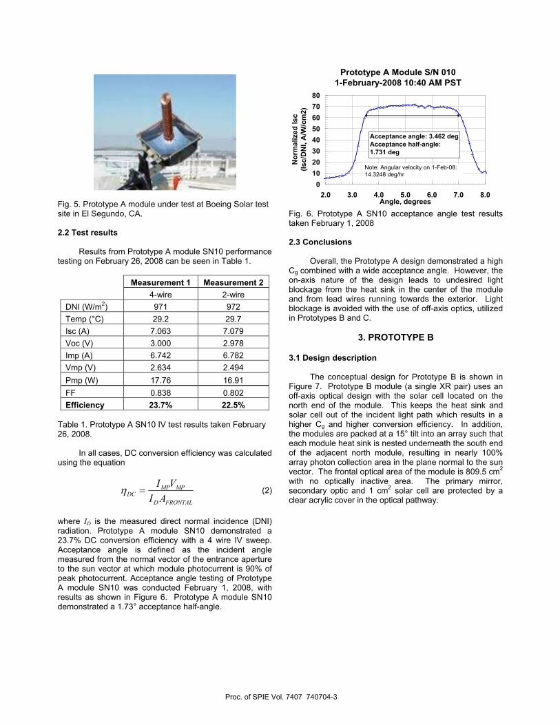
Fig. 5. Prototype A module under test at Boeing Solar test site in El Segundo, CA. 2.2 Test results
Results from Prototype A module SN10 performance testing on February 26, 2008 can be seen in Table 1.
Measurement 1 Measurement 2 4-wire 2-wire DNI (W/m2) 971 972 Temp (°C) 29.2 29.7 Isc (A) 7.063 7.079 Voc (V) 3.000 2.978 Imp (A) 6.742 6.782 Vmp (V) 2.634 2.494 Pmp (W) 17.76 16.91 FF 0.838 0.802 Efficiency 23.7% 22.5%
Table 1. Prototype A SN10 IV test results taken February 26, 2008.
In all cases, DC conversion efficiency was calculated using the equation
FRONTALD
MPMPDC AI
VI=η (2)
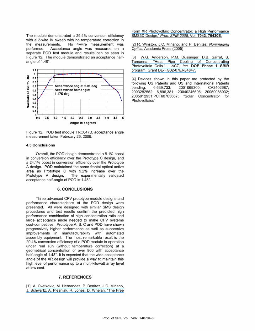
where ID is the measured direct normal incidence (DNI) radiation. Prototype A module SN10 demonstrated a 23.7% DC conversion efficiency with a 4 wire IV sweep. Acceptance angle is defined as the incident angle measured from the normal vector of the entrance aperture to the sun vector at which module photocurrent is 90% of peak photocurrent. Acceptance angle testing of Prototype A module SN10 was conducted February 1, 2008, with results as shown in Figure 6. Prototype A module SN10 demonstrated a 1.73° acceptance half-angle.
Fig. 6. Prototype A SN10 acceptance angle test results taken February 1, 2008 2.3 Conclusions
Overall, the Prototype A design demonstrated a high Cg combined with a wide acceptance angle. However, the on-axis nature of the design leads to undesired light blockage from the heat sink in the center of the module and from lead wires running towards the exterior. Light blockage is avoided with the use of off-axis optics, utilized in Prototypes B and C.
3. PROTOTYPE B
3.1 Design description
The conceptual design for Prototype B is shown in Figure 7. Prototype B module (a single XR pair) uses an off-axis optical design with the solar cell located on the north end of the module. This keeps the heat sink and solar cell out of the incident light path which results in a higher Cg and higher conversion efficiency. In addition, the modules are packed at a 15° tilt into an array such that each module heat sink is nested underneath the south end of the adjacent north module, resulting in nearly 100% array photon collection area in the plane normal to the sun vector. The frontal optical area of the module is 809.5 cm2 with no optically inactive area. The primary mirror, secondary optic and 1 cm2 solar cell are protected by a clear acrylic cover in the optical pathway.
Prototype A Module S/N 0101-February-2008 10:40 AM PST
01020304050607080
2.0 3.0 4.0 5.0 6.0 7.0 8.0Angle, degrees
Nor
mal
ized
Isc
(Isc/
DN
I, A
/W/c
m2)
Acceptance angle: 3.462 degAcceptance half-angle: 1.731 deg
Note: Angular velocity on 1-Feb-08: 14.3248 deg/hr
Proc. of SPIE Vol. 7407 740704-3

Fig. 7. CAD model of the Prototype B, off-axis optical design.
A passive convection, horizontally oriented heat sink is used to keep the solar cell within the same temperature ranges as the Prototype A heat sink design. Experimental testing of the design through collaboration with ACT, Inc. demonstrated successful operation within specified temperature ranges [3].
Several test modules of the Prototype B design were produced using production quality components for experimental demonstration. Figure 8 shows one of these modules, Prototype B SN05, under test and tracking at the Boeing Solar Test Facility in El Segundo, CA.
Fig. 8. Prototype B module under test at the Boeing Solar test site in El Segundo, CA. 3.2 Test results
Results from Prototype B module SN05 performance testing on April 21, 2008 can be seen in Table 2.
Measurement 1 Measurement 2 4-wire 2-wire DNI (W/m2) 893 833 Temp (°C) 18.2 16.3 Isc (A) 7.477 6.089 Voc (V) 2.924 2.958 Imp (A) 7.223 6.567 Vmp (V) 2.528 2.442 Pmp (W) 18.26 16.04 FF 0.835 0.796 Efficiency 25.3% 23.8%
Table 2. Prototype B SN05 IV test results taken April 21, 2008.
Prototype B module SN05 demonstrated a 25.3% DC conversion efficiency with a 4 wire IV sweep. Acceptance angle testing of Prototype B module SN05 was conducted April 10, 2008, as shown in Figure 9. The Prototype B module SN05 demonstrated a 1.32° acceptance half-angle. The theoretical acceptance angle of the Prototype B optical design was calculated and demonstrated with an aluminium primary mirror at 1.80°. Lower demonstrated acceptance angle in Prototype B module SN05 was later attributed to slight imperfections in the shape of the primary mirror, verified with a coordinate measuring machine.
Fig. 9. Prototype B acceptance angle measurements taken April 10, 2008. 3.3 Conclusions
Overall, the Prototype B design demonstrated an even higher conversion efficiency and concentration than Prototype A with larger theoretical acceptance angle, yet smaller demonstrated acceptance angle. However, the Prototype B design was successful in boosting demonstrated conversion efficiency by 6.8% and frontal optical active area by 11% over the Prototype A design.
Prototype B Module S/N 005 10-April-2008 11:55 AM PDT
0102030405060708090
0.0 1.0 2.0 3.0 4.0 5.0 6.0Angle in Degrees
Nor
mal
ized
Isc
(Isc/
DN
I, A
/W/c
m2)
Acceptance angle: 2.641 degAcceptance half-angle: 1.321 dNote: Angular velocity on 10-Apr-08: 14.8648 deg/hr
Solar Cell
Heat Sink
Optical reflector/ Primary Mirror
Proc. of SPIE Vol. 7407 740704-4
4. PROTOTYPE C 4.1 Design description
The optical design of Prototype C also utilizes an off-axis approach nearly identical to Prototype B. A Prototype C module is defined as six XR pairs housed in a common structure. A constructed Prototype C module test unit is shown in Figure 10.
Fig. 10. Prototype C / test POD module on display at the Boeing Solar test site in El Segundo, CA.
Each primary mirror has an active optical area of 800.8 cm2. The primary mirrors, secondary optics and 1 cm2 solar cells are protected by a glass cover in the optical path. Passive conductive, horizontal heat sinking was again used to meet cell temperature requirements. Design of Prototype C focused on taking the optics approach of Prototype B and making the system easier and cheaper to manufacture. Nearly every element of the Prototype C design was cost optimized before production of test modules. Thus, Prototype C represents the most cost effective CPV prototype of those presented. 4.2 Test results
Results from Prototype C module SN03 performance testing of optical pairs 01, 02 and 06 can be seen in Table 3.
Optical Pair 01
Optical Pair 02
Optical Pair 06
2-wire 2-wire 2-wire DNI (W/m2) 743 743 727 Temp (°C) 26.4 26.5 27.6 Isc (A) 6.895 6.932 6.644 Voc (V) 2.956 2.938 2.951 Imp (A) 6.677 6.726 6.506 Vmp (V) 2.430 2.408 2.427 Pmp (W) 16.20 16.20 15.80 FF 0.796 0.790 0.805 Efficiency 27.2% 27.2% 27.1%
Table 3. Prototype C SN03, optical pair 01, 02 and 06 IV test results taken October 1, 2008.
All three of these optical pairs demonstrated over a 27% conversion efficiency with a 2-wire IV sweep. No 4-wire measurement was performed. Optical pairs 03, 04
and 05 were designed to test other characteristics of the module and their performance data is not presented. The Prototype C optical design has the same theoretical acceptance half-angle as Prototype B at 1.80°. 4.3 Conclusions
Overall, the Prototype C design demonstrated a 7.5% boost in conversion efficiency over the Prototype B design, and a 14.8% boost in conversion efficiency over the Prototype A design. Prototype C maintained approximately the same frontal optical active area as Prototype B, but 9.2% increase over the Prototype A design. The modeled acceptance half-angle of Prototype C is equivalent to that of Prototype B, at 1.80°, but is yet to be confirmed experimentally.
5. PROOF OF DESIGN
5.1 Design description
The Prototype C design forms the foundation of the Proof of Design (POD) module and therefore Figure 10 also represents the form of a POD module. POD primary mirror active optical area is also the same as Prototype C at 800.8 cm2. The primary mirrors, secondary optics and 1 cm2 solar cells are again protected by a glass cover in the optical path. Passive conductive, horizontal heat sinking was again used to meet cell temperature requirements. Design of POD focused on taking the performance and approach of Prototype C and making the system more amenable to automated assembly. Movement towards POD also presented an opportunity for further cost optimization. 5.2 Test results IV results from POD module TRD38D can be seen below in Figure 11.
Figure 11. POD module TRD38D, IV test results taken May 8, 2009.
Proc. of SPIE Vol. 7407 740704-5
The module demonstrated a 29.4% conversion efficiency with a 2-wire IV sweep with no temperature correction in the measurements. No 4-wire measurement was performed. Acceptance angle was measured on a separate POD test module and results can be seen in Figure 12. The module demonstrated an acceptance half-angle of 1.48°.
Figure 12. POD test module TRC047B, acceptance angle measurement taken February 26, 2009. 4.3 Conclusions
Overall, the POD design demonstrated a 8.1% boost in conversion efficiency over the Prototype C design, and a 24.1% boost in conversion efficiency over the Prototype A design. POD maintained the same frontal optical active area as Prototype C with 9.2% increase over the Prototype A design. The experimentally validated acceptance half-angle of POD is 1.48°.
6. CONCLUSIONS
Three advanced CPV prototype module designs and
performance characteristics of the POD design were presented. All were designed with similar SMS design procedures and test results confirm the predicted high performance combination of high concentration ratio and large acceptance angle needed to make CPV systems cost-competitive. Prototype A, B, C and POD have shown progressively higher performance as well as successive improvements in manufacturability with automated assembly equipment. The most remarkable result is the 29.4% conversion efficiency of a POD module in operation under real sun (without temperature correction) at a geometrical concentration of over 800 with acceptance half-angle of 1.48°. It is expected that the wide acceptance angle of the XR design will provide a way to maintain this high level of performance up to a multi-kilowatt array level at low cost.
7. REFERENCES
[1] A. Cvetkovíc, M. Hernandez, P. Benítez, J.C. Miñano, J. Schwartz, A. Plesniak, R. Jones, D. Whelan, “The Free
Form XR Photovoltaic Concentrator: a High Performance SMS3D Design,” Proc. SPIE 2008, Vol. 7043, 70430E. [2] R. Winston, J.C. Miñano, and P. Benitez, Nonimaging Optics, Academic Press (2005) [3] W.G. Anderson, P.M. Dussinger, D.B. Sarraf, S. Tamanna, "Heat Pipe Cooling of Concentrating Photovoltaic Cells.". ACT, Inc. DOE Phase 1 SBIR program, Grant DE-FG02-07ER84847. [4] Devices shown in this paper are protected by the following US Patents and US and International Patents pending. 6,639,733; 2001069300; CA2402687; 2003282552; 6,896,381; 20040246606; 20050086032; 2005012951;PCT60703667; "Solar Concentrator for Photovoltaics"
Proc. of SPIE Vol. 7407 740704-6