High-efficiency MoRu Be multilayer-coated gratings operating near normal incidence in the 11.1...
10
High-efficiency MoRu–Be multilayer-coated gratings operating near normal incidence in the 11.1–12.0-nm wavelength range John F. Seely, Claude Montcalm, Sherry Baker, and Sas ˇ a Bajt MoRu–Be multilayer coatings were applied to two diffraction gratings for the purpose of enhancing their normal-incidence efficiency in the 11.1–12.0-nm wavelength range. The grating substrates were repli- cas of a holographic master grating that had a blazed groove profile with 2400 groovesmm and a 2-m radius of curvature. The relatively low average microroughness 0.8 nm of the grating surfaces con- tributed to the relatively high groove efficiency of the grating substrates and the reflectance of the MoRu–Be multilayer coatings. The peak efficiency, measured with synchrotron radiation, was 10.4% in the second diffraction order at a wavelength of 11.37 nm. OCIS codes: 050.1950, 310.6860, 340.7470. 1. Introduction Multilayer interference coatings with high reflec- tance in the extreme-ultraviolet EUV wavelength region can dramatically enhance the normal- incidence efficiencies of diffraction gratings. 1,2 The development of multilayer-coated gratings providing high efficiency and dispersion in the EUV and soft- x-ray regions is therefore important for high- resolution spectroscopic studies of laboratory, solar, and astrophysical radiation sources. 3 Most previous research has used multilayers con- sisting of alternating layers of Mo and Si, the scat- tering absorber material and the transmissive spacer material, respectively. 1,2 Mo–Si multilay- ers deposited onto flat superpolished substrates with very low microroughness 0.1 nm can have reflec- tances as high as 67.4% at wavelengths longer than the Si L absorption edge at 12.42 nm. 4 The multi- layer coating must be designed to have high reflec- tance at a wavelength for which the groove efficiency of the grating substrate is also high. In the case of a blazed grating substrate with flat facets, the optimal efficiency occurs in the diffraction order that satisfies the blaze condition, where the incident radiation is specularly reflected from the grating facets into the on-blaze order. 5 To achieve a high multilayer reflectance and a high grating groove efficiency, it is necessary that the mi- croroughness of the grating substrate be much smaller than the wavelength of the incident radia- tion. On the basis of the characterization of various grating substrates using atomic-force microscopy and of the measured efficiencies of multilayer-coated gratings, it has been determined that grating sub- strates produced by a holographic process are typi- cally superior to mechanically ruled gratings. 6 The superior performance of multilayer-coated holo- graphically produced gratings was attributed to the low microroughness and regular groove profile of the grating substrates. The holographic groove profiles of these gratings were shaped by ion-beam etching to produce a blazed approximately triangular groove profile or a laminar rectangular groove profile. 1,2 In this paper we report on the application of MoRu–Be multilayer interference reflection coatings to two replica gratings produced from a holographic, blazed master grating. A preliminary account of the efficiency performance of one of the gratings was given in Ref. 7. The use of Be as the transmissive spacer material permits the operation of the grating at wavelengths as short as the Be K absorption edge at 11.07 nm. In addition, the MoRu–Be multilayers have the beneficial property of smoothing the initial microroughness of the grating substrate. The effi- J. F. Seely [email protected] is with the Space Science Division, Naval Research Laboratory, Code 7674, Washington D.C. 20375. C. Montcalm, S. Baker, and S. Bajt are with the Depart- ment of Information Science and Technology, Lawrence Livermore National Laboratory, P.O. Box 808, L-395, Livermore, California 94551. Received 6 October 2000; revised manuscript received 15 June 2001. 1 November 2001 Vol. 40, No. 31 APPLIED OPTICS 5565
Transcript of High-efficiency MoRu Be multilayer-coated gratings operating near normal incidence in the 11.1...
High-efficiency MoRu–Be multilayer-coatedgratings operating near normal incidence in the11.1–12.0-nm wavelength range
John F. Seely, Claude Montcalm, Sherry Baker, and Sasa Bajt
MoRu–Be multilayer coatings were applied to two diffraction gratings for the purpose of enhancing theirnormal-incidence efficiency in the 11.1–12.0-nm wavelength range. The grating substrates were repli-cas of a holographic master grating that had a blazed groove profile with 2400 grooves�mm and a 2-mradius of curvature. The relatively low average microroughness �0.8 nm� of the grating surfaces con-tributed to the relatively high groove efficiency of the grating substrates and the reflectance of theMoRu–Be multilayer coatings. The peak efficiency, measured with synchrotron radiation, was 10.4% inthe second diffraction order at a wavelength of 11.37 nm.
OCIS codes: 050.1950, 310.6860, 340.7470.
1. Introduction
Multilayer interference coatings with high reflec-tance in the extreme-ultraviolet �EUV� wavelengthregion can dramatically enhance the normal-incidence efficiencies of diffraction gratings.1,2 Thedevelopment of multilayer-coated gratings providinghigh efficiency and dispersion in the EUV and soft-x-ray regions is therefore important for high-resolution spectroscopic studies of laboratory, solar,and astrophysical radiation sources.3
Most previous research has used multilayers con-sisting of alternating layers of Mo and Si, the scat-tering �absorber� material and the transmissive�spacer� material, respectively.1,2 Mo–Si multilay-ers deposited onto flat superpolished substrates withvery low microroughness ��0.1 nm� can have reflec-tances as high as 67.4% at wavelengths longer thanthe Si L absorption edge at 12.42 nm.4 The multi-layer coating must be designed to have high reflec-tance at a wavelength for which the groove efficiencyof the grating substrate is also high. In the case of ablazed grating substrate with flat facets, the optimal
efficiency occurs in the diffraction order that satisfiesthe blaze condition, where the incident radiation isspecularly reflected from the grating facets into theon-blaze order.5
To achieve a high multilayer reflectance and a highgrating groove efficiency, it is necessary that the mi-croroughness of the grating substrate be muchsmaller than the wavelength of the incident radia-tion. On the basis of the characterization of variousgrating substrates using atomic-force microscopy andof the measured efficiencies of multilayer-coatedgratings, it has been determined that grating sub-strates produced by a holographic process are typi-cally superior to mechanically ruled gratings.6 Thesuperior performance of multilayer-coated holo-graphically produced gratings was attributed to thelow microroughness and regular groove profile of thegrating substrates. The holographic groove profilesof these gratings were shaped by ion-beam etching toproduce a blazed �approximately triangular� grooveprofile or a laminar �rectangular� groove profile.1,2
In this paper we report on the application ofMoRu–Be multilayer interference reflection coatingsto two replica gratings produced from a holographic,blazed master grating. A preliminary account of theefficiency performance of one of the gratings wasgiven in Ref. 7. The use of Be as the transmissivespacer material permits the operation of the gratingat wavelengths as short as the Be K absorption edgeat 11.07 nm. In addition, the MoRu–Be multilayershave the beneficial property of smoothing the initialmicroroughness of the grating substrate. The effi-
J. F. Seely �[email protected]� is with the Space ScienceDivision, Naval Research Laboratory, Code 7674, Washington D.C.20375. C. Montcalm, S. Baker, and S. Bajt are with the Depart-ment of Information Science and Technology, Lawrence LivermoreNational Laboratory, P.O. Box 808, L-395, Livermore, California94551.
Received 6 October 2000; revised manuscript received 15 June2001.
1 November 2001 � Vol. 40, No. 31 � APPLIED OPTICS 5565
ciencies of the multilayer-coated gratings, greatly en-hanced by the high reflectance and smoothingproperties of the MoRu–Be multilayer coatings, weremeasured with synchrotron radiation in the 10.5–13.0-nm wavelength range. A peak efficiency of10.4% occurred in the second order at a wavelength of11.37 nm. The efficiencies were also measured inthe 25–50-nm wavelength range, where the reflec-tance occurred primarily from the topmost layers ofthe multilayer coatings. At the longer wavelengths,the first order had the highest efficiency. The mea-sured efficiencies were compared with the efficienciescalculated from first principles by use of the modifiedintegral method of Goray8 and Goray and Chernov.9The shape of the blazed holographic groove profilewas varied to achieve good overall agreement be-tween the calculated and the measured efficiencies.
2. Holographic Blazed Gratings
The master grating, having 2400 grooves�mm and a2-m concave radius of curvature, was produced bySpectrogon Inc., with a holographic technique. Theblazed groove profile was shaped by ion-beam etch-ing. The replica gratings were produced by Hyper-fine Inc. Since the master grating was concave, afirst-generation convex replica was produced, andconcave replicas were subsequently produced from
the convex replica. The surfaces of the replica grat-ings were oxidized aluminum. A thin overcoating ofSiO2 was applied to the final concave replicas for thepurpose of reducing the microroughness of the oxi-dized aluminum surface.10
The surfaces of the concave replica gratings werecharacterized before and after the application of theMoRu–Be coatings by use of a Digital Instrumentsatomic-force microscope �AFM�. The AFM was fit-ted with the following components: Dimension 5000equipped with an acoustic hood, type G scanner, anda Nanoscope IIIA controller with phase extender box.The measurements were performed with a tappingmode that measures topography in air by tapping thesurface with an oscillating probe tip. The probe tipswere etched Si with a nominal tip radius of 5–10 nm.The roughness values �Rq� derived from the AFMmeasurements are the root-mean-square �rms� aver-age of height deviations �z� taken from the mean dataplane, expressed as
Rq � �(z12 � z2
2 � z32 � � � � � zN
2)N �1/ 2
. (1)
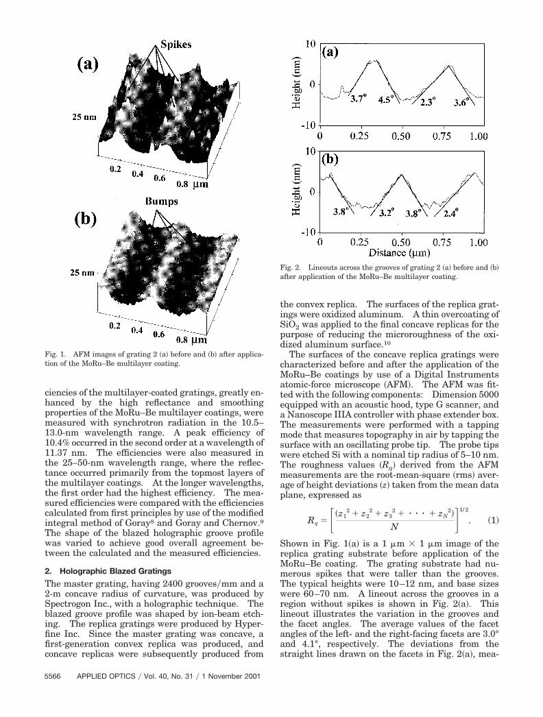
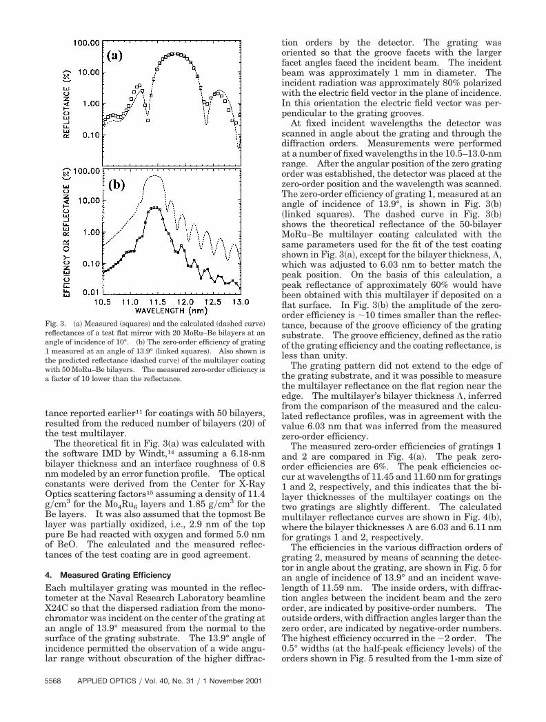
Shown in Fig. 1�a� is a 1 �m � 1 �m image of thereplica grating substrate before application of theMoRu–Be coating. The grating substrate had nu-merous spikes that were taller than the grooves.The typical heights were 10–12 nm, and base sizeswere 60–70 nm. A lineout across the grooves in aregion without spikes is shown in Fig. 2�a�. Thislineout illustrates the variation in the grooves andthe facet angles. The average values of the facetangles of the left- and the right-facing facets are 3.0°and 4.1°, respectively. The deviations from thestraight lines drawn on the facets in Fig. 2�a�, mea-
Fig. 1. AFM images of grating 2 �a� before and �b� after applica-tion of the MoRu–Be multilayer coating.
Fig. 2. Lineouts across the grooves of grating 2 �a� before and �b�after application of the MoRu–Be multilayer coating.
5566 APPLIED OPTICS � Vol. 40, No. 31 � 1 November 2001

sured near the centers of the facets, are in the 0.5–0.9-nm range. On the basis of the power spectraldistribution that was derived from the AFM imageshown in Fig. 1�a�, the value of the microroughness inthe 4–40-�m�1 spatial-frequency range was 1.35-nmrms. This range included the spikes that contrib-uted significantly to the microroughness value.
3. MoRu–Be Multilayer Coatings
MoRu–Be multilayer coatings have recently been de-veloped that have peak reflectances up to 69.3% at awavelength of 11.4 nm.11 The MoRu alloy materialis believed to have a composition of Mo4Ru6. Thelayers from this alloy remain amorphous in the mul-tilayers, whereas the Be layers are polycrystalline.Such MoRu–Be multilayer coatings were applied totwo replica grating substrates with a dc-magnetronsputtering system following a process described inRef. 11. In this deposition system the substrates areheld facedown by spinner assemblies mounted on arotating platter and are swept over rectangular sput-ter sources with a controlled rotation velocity of theplatter. The sputter chamber was typically cryo-pumped until the pressure was better than 1 � 10�7
Torr. Ultra-high-purity argon at a pressure of 0.9mTorr was used to sputter the targets at source pow-ers of 50–360 W. A perfect Mo4Ru6–Be multilayermirror would have a theoretical peak reflectance of76% at a wavelength of 11.4 nm. However, becauseof imperfections, such as the roughness and diffusionof the interfaces and the surface oxidation, the high-est achieved reflectance of an actual multilayer issomewhat lower.
Besides providing high reflectance, the MoRu–Bemultilayer system offers several other beneficialproperties.11 The multilayer’s stress, which is com-position dependent, varies between �30 MPa and�30 MPa and can be designed to be nearly zero.Also, owing to the amorphous nature of the alloylayers, the coating smooths the high-frequencyroughness of the substrate. For example, it hasbeen shown that a 50-bilayer MoRu–Be coating, de-posited on a substrate with 0.38-nm rms roughnesswith spatial frequencies between 4 and 40 �m�1,smoothed the substrate to 0.15-nm rms.11
Multilayer coatings with 50 MoRu–Be bilayerswere applied to the two grating substrates duringseparate deposition runs. Owing to a malfunctionduring the first deposition run, one grating was firstcoated with an incorrect multilayer with layers thatwere roughly ten times thicker than desired. Thisgrating was subsequently overcoated with an addi-tional 50 MoRu–Be bilayers with the proper layerthicknesses. Thus two multilayer gratings wereproduced, one with 50 MoRu–Be bilayers with theproper bilayer thickness �referred to as grating 1�,and one with 100 MoRu–Be bilayers �grating 2�where the topmost 50 bilayers had the proper bilayerthickness. Calculations indicated that the multi-layer interference reflection occurs primarily withinthe topmost 50 bilayers of each coating. Thus the
underlying 50 bilayers on grating 2 did not signifi-cantly affect the coating’s reflectance.
The total thicknesses of the coatings on gratings 1and 2 were 301.5 and �2000 nm, respectively.These coating thicknesses were much larger than thegrating groove depth, which ranged from 6 to 8 nm.Thus the availability of two gratings with differentcoating thicknesses enabled the investigation of theeffect of thick coatings on the grating efficiency.This is important because of previous evidence that athick multilayer coating partially filled in the groovesof a laminar grating substrate.2
The comparison of the AFM images of grating 2before and after application of the MoRu–Be coatingprovides striking evidence of the smoothing proper-ties of the coating. As shown in Fig. 1�b�, grating 2after coating had numerous small bumps withheights that were much lower than the grooves. Thebumps were also much smaller than the spikes seenbefore coating Fig. 1�a�.
A lineout across the grooves of the coated grating 2is shown in Fig. 2�b�. The average angles of the left-and the right-facing facets are 2.8° and 3.8°, respec-tively. Within the groove-to-groove variation of thefacet angles, the facet angles did not significantlychange after coating. Thus the MoRu–Be coatingtends to fill in around the tall �and high-spatial-frequency� spikes but not fill in the shallow �andlow-frequency� grooves. The value of the micro-roughness derived from the AFM image shown in Fig.1�b� in the 4–40-�m�1 spatial-frequency range, whichincludes the bumps, is 0.93-nm rms. This value issmaller than the 1.35-nm rms microroughness of thegrating before coating. Since the efficiency of themultilayer-coated grating in the short-wavelength re-gion is strongly dependent on the roughness, a multi-layer coating that can smooth the grating surface ishighly beneficial.
Prior to the deposition of the MoRu–Be multilayercoatings onto the two grating substrates, test coat-ings were deposited onto flat Si wafer substrates forthe purpose of optimizing the bilayer thickness. Thereflectances of the multilayer coatings, and the effi-ciencies of the multilayer gratings, were measuredwith the Naval Research Laboratory beamline X24Cat the National Synchrotron Light Source at theBrookhaven National Laboratory. The synchrotronradiation was dispersed by a monochromator thathad a resolving power of 600.12,13 Thin filters atten-uated the radiation from the monochromator in thehigher harmonics. The wavelength scale was estab-lished by the geometry of the monochromator and theabsorption edges of the filters.
Figure 3�a� shows the reflectance of a typical testcoating measured at an angle of incidence of 10°�squares� together with the best overall calculated fitto the measurements �dashed curve�. This test mul-tilayer coating had 20 bilayers instead of 50, a MoRuproportion of 0.42 relative to the total bilayer thick-ness, and a measured peak reflectance of 37.4% at awavelength of 11.81 nm. The lower reflectance forthis test multilayer, compared with the 69.3% reflec-
1 November 2001 � Vol. 40, No. 31 � APPLIED OPTICS 5567
tance reported earlier11 for coatings with 50 bilayers,resulted from the reduced number of bilayers �20� ofthe test multilayer.
The theoretical fit in Fig. 3�a� was calculated withthe software IMD by Windt,14 assuming a 6.18-nmbilayer thickness and an interface roughness of 0.8nm modeled by an error function profile. The opticalconstants were derived from the Center for X-RayOptics scattering factors15 assuming a density of 11.4g�cm3 for the Mo4Ru6 layers and 1.85 g�cm3 for theBe layers. It was also assumed that the topmost Belayer was partially oxidized, i.e., 2.9 nm of the toppure Be had reacted with oxygen and formed 5.0 nmof BeO. The calculated and the measured reflec-tances of the test coating are in good agreement.
4. Measured Grating Efficiency
Each multilayer grating was mounted in the reflec-tometer at the Naval Research Laboratory beamlineX24C so that the dispersed radiation from the mono-chromator was incident on the center of the grating atan angle of 13.9° measured from the normal to thesurface of the grating substrate. The 13.9° angle ofincidence permitted the observation of a wide angu-lar range without obscuration of the higher diffrac-
tion orders by the detector. The grating wasoriented so that the groove facets with the largerfacet angles faced the incident beam. The incidentbeam was approximately 1 mm in diameter. Theincident radiation was approximately 80% polarizedwith the electric field vector in the plane of incidence.In this orientation the electric field vector was per-pendicular to the grating grooves.
At fixed incident wavelengths the detector wasscanned in angle about the grating and through thediffraction orders. Measurements were performedat a number of fixed wavelengths in the 10.5–13.0-nmrange. After the angular position of the zero gratingorder was established, the detector was placed at thezero-order position and the wavelength was scanned.The zero-order efficiency of grating 1, measured at anangle of incidence of 13.9°, is shown in Fig. 3�b��linked squares�. The dashed curve in Fig. 3�b�shows the theoretical reflectance of the 50-bilayerMoRu–Be multilayer coating calculated with thesame parameters used for the fit of the test coatingshown in Fig. 3�a�, except for the bilayer thickness, �,which was adjusted to 6.03 nm to better match thepeak position. On the basis of this calculation, apeak reflectance of approximately 60% would havebeen obtained with this multilayer if deposited on aflat surface. In Fig. 3�b� the amplitude of the zero-order efficiency is �10 times smaller than the reflec-tance, because of the groove efficiency of the gratingsubstrate. The groove efficiency, defined as the ratioof the grating efficiency and the coating reflectance, isless than unity.
The grating pattern did not extend to the edge ofthe grating substrate, and it was possible to measurethe multilayer reflectance on the flat region near theedge. The multilayer’s bilayer thickness �, inferredfrom the comparison of the measured and the calcu-lated reflectance profiles, was in agreement with thevalue 6.03 nm that was inferred from the measuredzero-order efficiency.
The measured zero-order efficiencies of gratings 1and 2 are compared in Fig. 4�a�. The peak zero-order efficiencies are 6%. The peak efficiencies oc-cur at wavelengths of 11.45 and 11.60 nm for gratings1 and 2, respectively, and this indicates that the bi-layer thicknesses of the multilayer coatings on thetwo gratings are slightly different. The calculatedmultilayer reflectance curves are shown in Fig. 4�b�,where the bilayer thicknesses � are 6.03 and 6.11 nmfor gratings 1 and 2, respectively.
The efficiencies in the various diffraction orders ofgrating 2, measured by means of scanning the detec-tor in angle about the grating, are shown in Fig. 5 foran angle of incidence of 13.9° and an incident wave-length of 11.59 nm. The inside orders, with diffrac-tion angles between the incident beam and the zeroorder, are indicated by positive-order numbers. Theoutside orders, with diffraction angles larger than thezero order, are indicated by negative-order numbers.The highest efficiency occurred in the �2 order. The0.5° widths �at the half-peak efficiency levels� of theorders shown in Fig. 5 resulted from the 1-mm size of
Fig. 3. �a� Measured �squares� and the calculated �dashed curve�reflectances of a test flat mirror with 20 MoRu–Be bilayers at anangle of incidence of 10°. �b� The zero-order efficiency of grating1 measured at an angle of 13.9° �linked squares�. Also shown isthe predicted reflectance �dashed curve� of the multilayer coatingwith 50 MoRu–Be bilayers. The measured zero-order efficiency isa factor of 10 lower than the reflectance.
5568 APPLIED OPTICS � Vol. 40, No. 31 � 1 November 2001

the incident radiation beam and the 1-mm slit overthe detector.
As shown in Fig. 5, efficiencies as low as 0.02%could be accurately measured. This was made pos-sible by the relatively high reflectance of the multi-
layer and groove efficiency of the grating and by thehigh sensitivity and low background current �3 pA� ofthe Si photodiode detector used in these experiments�type AXUV-100G, provided by International Radia-tion Detectors Inc.�. The efficiencies of grating 1measured at an incident wavelength of 11.37 nm andgrating 2 at 11.48 nm are shown in Figs. 6�a� and 6�b�,respectively. The measured efficiencies of the twogratings are quite similar.
The measured peak efficiencies as functions of theincident wavelength are shown in Figs. 7�a� and 7�b�for gratings 1 and 2, respectively. The �2 order hasthe highest efficiency, peaking in the 11.4–11.5-nmwavelength region. The higher outside orders tendto have larger efficiencies at shorter wavelengths,and the inside orders have larger efficiencies atlonger wavelengths. The envelopes of the gratingefficiencies in the various orders are restricted inwavelength by the multilayer reflectance profilesshown in Fig. 4�b�.
Figures 7�a� and 7�b� indicate that the peak effi-ciencies of grating 1 occurred at a slightly shorterwavelength compared with grating 2. This resultedfrom the smaller bilayer thickness on grating 1 asindicated by the measured zero-order efficiencies andthe calculated multilayer reflectances shown in Fig.4.
To a first approximation, neglecting index-of-refraction corrections, a multilayer interference coat-
Fig. 4. �a� Solid and dashed curves are the measured zero-orderefficiencies of multilayer gratings 1 and 2, respectively, at angles ofincidence of 13.9°. �b� Solid and dashed curves are the calculatedreflectances of the MoRu–Be multilayer coatings on grating 1 �� 6.03 nm� and grating 2 �� 6.11 nm�, respectively. The angle ofincidence is 13.9°, and the number of MoRu–Be bilayers is 50.
Fig. 5. Efficiency of multilayer grating 2 measured at an angle ofincidence of 13.9° and for an incident wavelength of 11.59 nm.The inside orders �positive order numbers� and the outside orders�negative order numbers� are identified.
Fig. 6. Measured efficiencies of �a� grating 1 at a wavelength of11.37 nm and �b� grating 2 at 11.48 nm. The angle of incidencewas 13.9°.
1 November 2001 � Vol. 40, No. 31 � APPLIED OPTICS 5569

ing has peak reflectance at a wavelength thatsatisfies the Bragg condition � 2d sin �, where 2d istwice the bilayer thickness and � is the grazing angle.The multilayer grating efficiencies were measured atthree wavelengths �26.4, 35.4, and 49.6 nm� that aremuch larger than twice the bilayer thickness. Ow-ing to the large attenuation coefficients of MoRu andBe at these longer wavelengths, the reflectance isprimarily from the topmost few layers of the multi-layer coating, and the interference effect is minimalsince � is much greater than 2d sin �. The gratingefficiencies measured at a wavelength of 49.6 nm andat an angle of incidence of 13.9° are shown in Fig. 8�a�and 8�b� for grating 1 and grating 2, respectively.The peak efficiencies measured in the 25–50-nmwavelength range are shown in Figs. 9�a� and 9�b�.
The efficiencies are rather small because of the lownormal-incidence reflectance in the absence of themultilayer interference enhancement. The efficien-cies increase with wavelength primarily because thenormal-incidence reflectance increases with wave-length in this spectral range. As shown in Section 5,the zero diffraction order has the highest groove ef-ficiency in this wavelength region and results in highgrating efficiency. Of the dispersed orders, the firstorders have the highest efficiencies.
5. Calculated Grating Efficiency
The multilayer grating efficiency was calculated withthe computational model �PCGRATE� developed byGoray8 and Goray and Chernov.9 The computa-tional model implements the modified integralmethod to solve the boundary value problem of elec-tromagnetic radiation incident on a multilayer grat-ing. The calculation accounts for the groove profileof the grating substrate, the optical properties of thelayers of the multilayer coating, and the two polar-ization components of the incident radiation. Thecomputational model was previously used to analyzethe efficiency of the uncoated replica grating sub-strate, and the calculated and the measured efficien-cies were in good overall agreement.10
It was found that the calculated efficiencies of theMoRu–Be multilayer grating were sensitive to vari-ations in the groove profile. Small changes in the
Fig. 7. Peak efficiencies measured at an angle of incidence of13.9° for �a� grating 1 and �b� grating 2. �c� The calculated effi-ciencies at an angle of incidence of 13.9°.
Fig. 8. Measured efficiencies of �a� grating 1 and �b� grating 2 atan angle of incidence of 13.9° and an incident wavelength of49.6 nm.
5570 APPLIED OPTICS � Vol. 40, No. 31 � 1 November 2001
assumed groove shape, groove height, and facet an-gles resulted in significant changes in the calculatedefficiencies. To facilitate the systematic study of theeffect of the groove profile on the calculated efficien-cies, an analytical function was chosen that was sim-ilar to the average groove profile of the grating asdetermined by AFM. The analytical function hadparameters that allowed for variation of the grooveshape, groove height, and facet angles. In this man-ner, the groove profile could be easily changed toobtain the best overall agreement with the measuredefficiencies.
The analytical groove profile is defined as
f � x� � �0
x
sin tn dt (2)
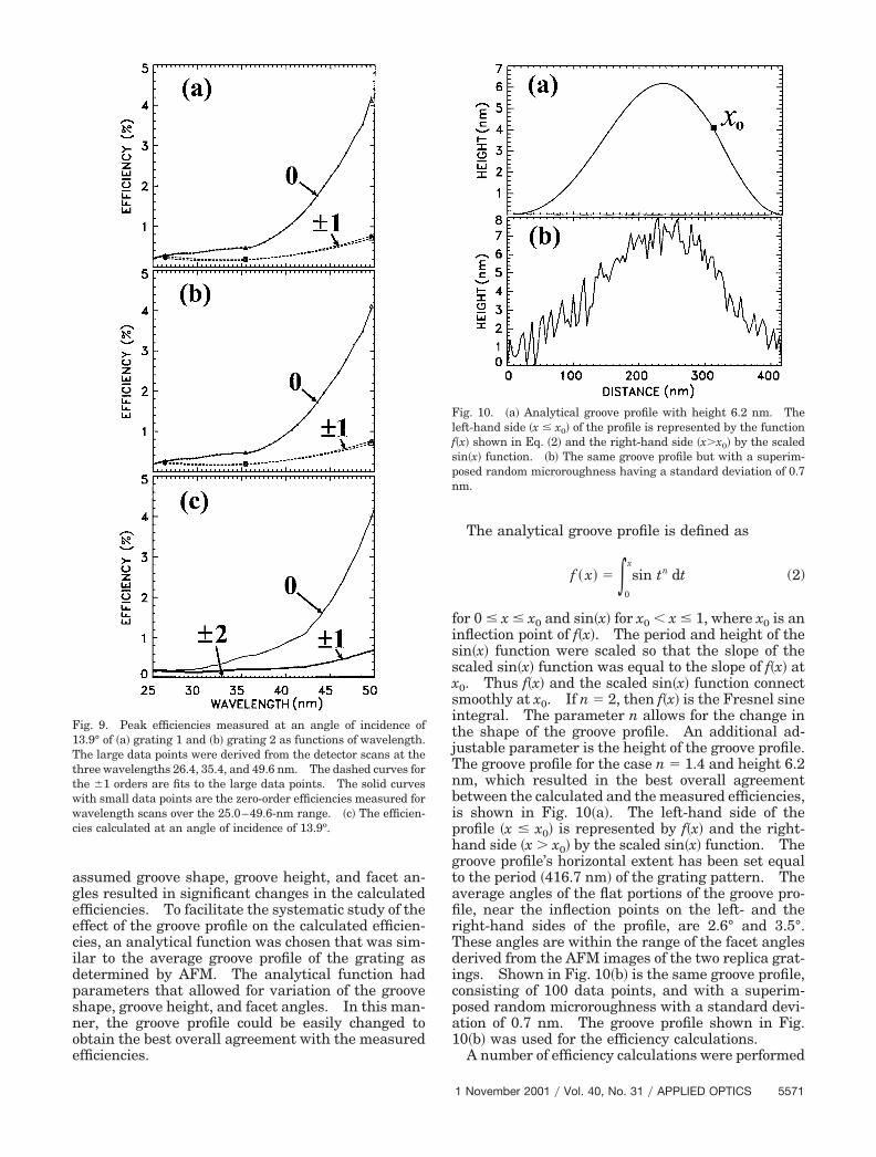
for 0 � x � x0 and sin�x� for x0 � x � 1, where x0 is aninflection point of f�x�. The period and height of thesin�x� function were scaled so that the slope of thescaled sin�x� function was equal to the slope of f�x� atx0. Thus f�x� and the scaled sin�x� function connectsmoothly at x0. If n 2, then f�x� is the Fresnel sineintegral. The parameter n allows for the change inthe shape of the groove profile. An additional ad-justable parameter is the height of the groove profile.The groove profile for the case n 1.4 and height 6.2nm, which resulted in the best overall agreementbetween the calculated and the measured efficiencies,is shown in Fig. 10�a�. The left-hand side of theprofile �x � x0� is represented by f�x� and the right-hand side �x � x0� by the scaled sin�x� function. Thegroove profile’s horizontal extent has been set equalto the period �416.7 nm� of the grating pattern. Theaverage angles of the flat portions of the groove pro-file, near the inflection points on the left- and theright-hand sides of the profile, are 2.6° and 3.5°.These angles are within the range of the facet anglesderived from the AFM images of the two replica grat-ings. Shown in Fig. 10�b� is the same groove profile,consisting of 100 data points, and with a superim-posed random microroughness with a standard devi-ation of 0.7 nm. The groove profile shown in Fig.10�b� was used for the efficiency calculations.
A number of efficiency calculations were performed
Fig. 9. Peak efficiencies measured at an angle of incidence of13.9° of �a� grating 1 and �b� grating 2 as functions of wavelength.The large data points were derived from the detector scans at thethree wavelengths 26.4, 35.4, and 49.6 nm. The dashed curves forthe �1 orders are fits to the large data points. The solid curveswith small data points are the zero-order efficiencies measured forwavelength scans over the 25.0–49.6-nm range. �c� The efficien-cies calculated at an angle of incidence of 13.9o.
Fig. 10. �a� Analytical groove profile with height 6.2 nm. Theleft-hand side �x � x0� of the profile is represented by the functionf�x� shown in Eq. �2� and the right-hand side �x�x0� by the scaledsin�x� function. �b� The same groove profile but with a superim-posed random microroughness having a standard deviation of 0.7nm.
1 November 2001 � Vol. 40, No. 31 � APPLIED OPTICS 5571

by use of groove profiles with different shapes �differ-ent values of n� and different heights. The efficien-cies changed significantly for changes in the shapeparameter n of �0.1 and changes in groove height of�0.5 nm. In general, smaller values of n resulted ina straighter and flatter left facet and a narrowertrough between the peaks of adjacent grooves. Inthis case, the narrow trough resulted in a lower zero-order efficiency and higher efficiencies in the dis-persed orders. Larger values of n had the oppositeeffect. The left facet was more curved, and thetrough was wider and flatter. The wider trough re-sulted in a higher zero-order efficiency and lowerdispersed-order efficiencies.
An increase in the groove height resulted in largerfacet angles, and the higher orders had increasedefficiencies. Conversely, a lower groove height re-sulted in smaller facet angles and decreased efficien-cies in the higher orders.
The calculated efficiencies, with a groove shape pa-rameter of n 1.4 and a groove height of 6.2 nm, areshown in Fig. 7�c� for the shorter-wavelength regionenhanced by the multilayer reflectance and in Fig.9�c� for the longer-wavelength region. In Fig. 7�c�the calculated peak efficiency �14%� in the �2 order islarger than measured �10.4% and 9.8%�, and differ-ences occur between the calculated and the measuredefficiencies in the other dispersed orders.
In calculating the efficiencies in the longer-wavelength region �25–50 nm�, it was found that us-ing the optical constants derived from Henke et al.15
for the MoRu and Be layers resulted in poor agree-ment between the calculated and the measured effi-ciencies. Other calculations were performed withthe optical constants from Refs. 16, 17, and 18 for Be,Mo, and Ru, respectively. The optical constants forMo4Ru6 were derived from the optical constants ofMo and Ru assuming a density of 11.4 g�cm3. Thetopmost layer was assumed to be BeO with a densityof 1.85 g�cm3. As seen in Fig. 9, the calculated andthe measured efficiencies are in excellent agreement.
The normal-incidence efficiency of the uncoatedreplica grating, previously measured in the 14–22-nm wavelength range,10 was in good overall agree-ment with the efficiency calculated with the PCGRATE
computer program. In general, considering the re-sults of Ref. 10 and the present results, the efficien-cies of blazed gratings that are calculated withPCGRATE are in good agreement at longer wavelengths��14 nm�, whereas significant differences occur atshorter wavelengths. The differences in the calcu-lated and the measured efficiencies can provide guid-ance for future improvements in the computationalmodel. For example, the differences at shorterwavelengths may indicate that the treatments of thegroove and multilayer microroughness may need im-provement.
6. Groove Efficiency
The groove efficiencies in the 5–20-nm wavelengthrange that were calculated with the optical constantsderived from Henke et al.15 are shown in Fig. 11 for
an angle of incidence of 13.9°. The outside-ordergroove efficiencies are shown in Fig. 11�a�, and theinside-order groove efficiencies are shown in Fig.11�b�. The peak groove efficiencies are in the range5–15% for wavelengths as short as 5 nm.
While differences between the calculated and themeasured grating efficiencies occur in the 11.1–12.0-nm wavelength region �Fig. 7�, the calculatedgroove efficiencies may be used as a guide for futureexperimental studies of the performance ofmultilayer-coated gratings at shorter wavelengths.These studies may be carried out by application ofhigh-reflectance multilayer coatings to replica grat-ing substrates of the same type used for the presentstudy. When deposited on superpolished mirrorsubstrates, multilayers with spacer layer materialssuch as C, B4C, and Y have peak reflectances in therange 10–20% for wavelengths as short as 4.5 nm.19
However, the reflectances would be somewhat lowerwhen deposited on a grating substrate with 0.8-nmmicroroughness. Since the grating efficiency is ap-proximately equal to the product of the multilayerreflectance and the groove efficiency, peak gratingefficiencies near 1–2% are expected. By comparison,the efficiency of the gold-coated grating on the Skylabspace station, which recorded numerous well-exposedsolar spectra, had a normal-incidence efficiency of0.05–2% in the 17–35-nm wavelength range.6,20,21
The calculated groove efficiencies shown in Fig. 11have interesting oscillatory behaviors at wavelengths
Fig. 11. Calculated groove efficiencies for �a� the outside ordersand �b� the inside orders for an angle of incidence of 13.9°.
5572 APPLIED OPTICS � Vol. 40, No. 31 � 1 November 2001
below 10 nm. The study of the grating performancewith high-reflectance multilayer coatings will resultin the experimental determination of the groove effi-ciency, which can be compared with the calculatedgroove efficiency. This information will be impor-tant for the improvement of the computational modelfor the groove efficiency in the short-wavelength re-gion.
The relatively large calculated groove efficienciesin the higher inside orders shown in Fig. 11�b� areinteresting. For example, the groove efficiency inthe �5-order peaks at a wavelength of 7.5 nm. Thissuggests that both large angular dispersion and rel-atively large efficiency may be achievable in the5–10-nm wavelength range. Large angular disper-sion generally results in higher spectral resolutionand higher spectral line to background detector sig-nal levels, which are necessary for the implementa-tion of spectroscopic diagnostic techniques.3,21
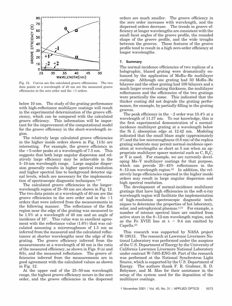
The calculated groove efficiencies in the longer-wavelength region of 25–50 nm are shown in Fig. 12.The two data points at a wavelength of 40 nm are thegroove efficiencies in the zero order and in the �1orders that were inferred from the measurements inthe following manner. The reflectance of the flatregion near the edge of the grating was measured tobe 1.5% at a wavelength of 40 nm and an angle ofincidence of 16°. This value was in excellent agree-ment with the reflectance value �1.6%� that was cal-culated assuming a microroughness of 1.3 nm asinferred from the measured and the calculated reflec-tances at shorter wavelengths near the edge of thegrating. The groove efficiency inferred from themeasurements at a wavelength of 40 nm is the ratioof the measured efficiency, as shown in Figs. 9 �a� and9�b�, and the measured reflectance. The groove ef-ficiencies inferred from the measurements are ingood agreement with the calculated values as shownin Fig. 12.
At the upper end of the 25–50-nm wavelengthrange, the highest groove efficiency occurs in the zeroorder, and the groove efficiencies in the dispersed
orders are much smaller. The groove efficiency inthe zero order increases with wavelength, and thedispersed orders decrease. The trends in groove ef-ficiency at longer wavelengths are consistent with thesmall facet angles of the groove profile, the roundedshape of the groove profile, and the wide troughsbetween the grooves. These features of the grooveprofile tend to result in a high zero-order efficiency atlonger wavelengths.
7. Summary
The normal-incidence efficiencies of two replicas of aholographic, blazed grating were dramatically en-hanced by the application of MoRu–Be multilayercoatings. Although one grating had 50 MoRu–Bebilayers and the other grating had 100 bilayers and amuch larger overall coating thickness, the multilayerreflectances and the efficiencies of the two gratingswere practically the same. This indicated that thethicker coating did not degrade the grating perfor-mance, for example, by partially filling in the gratinggrooves.
The peak efficiency in the �2 order was 10.4% at awavelength of 11.37 nm. To our knowledge, this isthe first experimental demonstration of a normal-incidence multilayer grating at a wavelength belowthe Si L absorption edge at 12.42 nm. Modelingindicated that the small blaze angle �approximately3o� and the low microroughness �0.8 nm� of the replicagrating substrate may permit normal-incidence oper-ation at wavelengths as short as 5 nm when an ap-propriate multilayer spacer material such as C, B4C,or Y is used. For example, we are currently devel-oping Mo–Y multilayer coatings for that purpose,which can provide 20–45% reflectances in the8–12-nm wavelength region.22 In addition, the rel-atively large efficiencies expected in the higher insideorders may result in large angular dispersion andhigh spectral resolution.
The development of normal-incidence multilayergratings that have high efficiencies in the soft-x-raywavelength region will facilitate the implementationof high-resolution spectroscopic diagnostic tech-niques to determine the properties of hot laboratory,solar, and astrophysical plasmas.3,21 For example, anumber of intense spectral lines are emitted fromactive stars in the 8–12-nm wavelength region, suchas the Fe XVIII line at � 9.4 nm emitted byCapella.23
This research was supported by NASA projectW-19513. The research at Lawrence Livermore Na-tional Laboratory was performed under the auspicesof the U.S. Department of Energy by the University ofCalifornia Lawrence Livermore National Laboratoryunder contract W-7405-ENG-48. Part of the researchwas performed at the National Synchrotron LightSource, which is supported by the U.S. Department ofEnergy. The authors thank F. R. Grabner, R. D.Behymer, and M. Mao for their assistance in thesetup of the system used for the deposition of themultilayer coatings.
Fig. 12. Curves are the calculated groove efficiencies. The twodata points at a wavelength of 40 nm are the measured grooveefficiencies in the zero order and the �1 orders.
1 November 2001 � Vol. 40, No. 31 � APPLIED OPTICS 5573
References1. J. F. Seely, R. G. Cruddace, M. P. Kowalski, W. R. Hunter,
T. W. Barbee, J. C. Rife, R. Ely, and K. G. Stilt, “Polarizationand efficiency of a concave multilayer grating in the 135–250-Åregion and in normal-incidence and Seya–Manioc mounts,”Appl. Opt. 34, 7347–7354 �1995�.
2. J. F. Seely, M. P. Kowalski, R. G. Cruddace, K. F. Heidemann,U. Heinzmann, U. Kleineberg, K. Osterried, D. Menke, J. C.Rife, and W. R. Hunter, “Multilayer-coated laminar gratingwith 16% normal-incidence efficiency in the 150-Å wavelengthregion,” Appl. Opt. 36, 8206–8213 �1997�.
3. U. Feldman, P. Mandelbaum, J. F. Seely, G. A. Doschek, andH. Gursky, “The potential for plasma diagnostics from stellarextreme-ultraviolet observations,” Astrophys. J. Suppl. 81,387–408 �1992�.
4. P. B. Mirkarimi, S. Bajt, and M. A. Wall, “Mo�Si and Mo�Bemultilayer thin films on Zerodur substrates for extreme-ultraviolet lithography,” Appl. Opt. 39, 1617–1625 �2000�.
5. J. F. Seely, M. P. Kowalski, W. R. Hunter, J. C. Rife, T. W.Barbee, G. E. Holland, C. N. Boyer, and C. M. Brown, “On-blaze operation of a Mo�Si multilayer-coated concave diffrac-tion grating in the 136–142-Å wavelength region and nearnormal incidence,” Appl. Opt. 32, 4890–4897 �1993�.
6. J. F. Seely, M. P. Kowalski, W. R. Hunter, T. W. Barbee, R. G.Cruddace, and J. C. Rife, “Normal-incidence efficiencies in the115–340-Å wavelength region of replicas of the Skylab 3600line�mm grating with multilayer and gold coatings,” Appl. Opt.34, 6453–6458 �1995�.
7. C. Montcalm, S. Bajt, and J. F. Seely, “MoRu–Be multilayer-coated grating with 10.4% normal-incidence efficiency near the11.4-nm wavelength,” Opt. Lett. 26, 125–127 �2001�.
8. L. I. Goray, “Numerical analysis for relief gratings working inthe soft x-ray and XUV region by the integral equation meth-od,” in X-Ray and UV Detectors, R. B. Hoover and M. W. Tate,eds., Proc. SPIE 2278, 168–172 �1994�.
9. L. I. Goray and B. C. Chernov, “Comparison of rigorous meth-ods for x-ray and XUV grating diffraction analysis,” in X-Rayand Extreme Ultraviolet Optics, R. B. Hoover and A. B. C.Walker, eds., Proc. SPIE 2515, 240–245 �1995�.
10. J. F. Seely, L. I. Goray, W. R. Hunter, and J. C. Rife, “Thin-filminterference effects on the efficiency of a normal-incidencegrating in the 100–350-Å wavelength region,” Appl. Opt. 38,1251–1258 �1999�.
11. S. Bajt, “Molybdenum-ruthenium�beryllium multilayer coat-ings,” J. Vac. Sci. Technol. A 18, 557–559 �2000�.
12. J. C. Rife, H. R. Sadeghi, and W. R. Hunter, “Upgrades andrecent performance of the grating�crystal monochromator,”Rev. Sci. Instrum. 60, 2064–2067 �1989�.
13. W. R. Hunter and J. C. Rife, “An ultrahigh vacuum reflecto-meter�goniometer for use with synchrotron radiation,” Nucl.Instrum. Methods A 246, 465–468 �1986�.
14. D. L. Windt, “IMD: software for modeling the optical proper-ties of multilayer films,” Comput. Phys. 12, 360–370 �1998�.A copy of the software can be downloaded at http:��cletus.phys.columbia.edu��windt�imd�.
15. B. L. Henke, E. M. Gullikson, and J. C. Davis, “X-ray interac-tions: photoabsorption, scattering, transmission, and reflec-tion at E 50–30,000 eV, Z 1–92,” At. Data Nucl. Data Tables54, 181–342 �1993�. Updated optical constants were obtainedat http:��www-cxro.lbl.gov�optical_constants�.
16. E. T. Arakawa, T. A. Callcott, and Y. C. Chang, “Beryllium�Be�,” in Handbook of Optical Constants of Solids II, E. D.Palik, ed. �Academic, New York, 1991�, pp. 421–433.
17. D. W. Lynch and W. R. Hunter, “Molybdenum �Mo�,” in Hand-book of Optical Constants of Solids, E. D. Palik, ed. �Academic,New York, 1985�, pp. 303–313.
18. D. W. Lynch and W. R. Hunter, “Ruthenium �Ru�,” in Hand-book of Optical Constants of Solids III, E. D. Palik, ed. �Aca-demic, New York, 1998�, pp. 253–261.
19. A tabulation of measured normal incidence reflectances can befound at the Center for X-Ray Optics Internet site, http:��www-cxro.lbl.gov�multilayer�survey.html.
20. R. Tousey, J.-D. Bartoe, G. E. Brueckner, and J. D. Purcell,“Extreme ultraviolet spectroheliograph ATM experimentSO82A,” Appl. Opt. 16, 870–878 �1977�.
21. U. Feldman, J. D. Purcell, and B. Dohne, An Atlas of ExtremeUltraviolet Spectroheliograms from 170 to 625 Å �E. O. HulburtCenter for Space Research, Naval Research Laboratory, Wash-ington, D.C., 1987�.
22. C. Montcalm, B. T. Sullivan, M. Ranger, and H. Pepin, “Ultra-high vacuum deposition-reflectometer system for the in situinvestigation of Y�Mo extreme-ultraviolet multilayer mirrors,”J. Vac. Sci. Technol. A 15, 3069–3081 �1997�.
23. A. K. Dupree, N. S. Brickhouse, and G. J. Hanson, in Astro-physics in the EUV, International Astronomical Union Collo-quium 152, S. Bowyer and R. Malina, eds. �Kluwer, Dordrecht,The Netherlands, 1996�, p. 141.
5574 APPLIED OPTICS � Vol. 40, No. 31 � 1 November 2001
All in-text references underlined in blue are linked to publications on ResearchGate, letting you access and read them immediately.