11.1 FlibeMoltenSaltResearchforTfifitunBreederApplicabons
10
JP0450440 JAERI-Conf 2004-006 11. Molten salt 11.1 FlibeMoltenSaltResearchforTfifitunBreederApplicabons R. A. Anderl', D. A. Pett?, G. R. Smolik', R. J. Pawelko', S. T. Schuetz', J. P. Sharpe', B. J. Merrill', M. F. d d Simpsonb, T. Teraic, S. Tanaka', H. Nishimura', Y. Oya', S. Fukada M. Nishikawa , K. Okuno', Y. Morimoto" Y. Hatanof I D. K. Sze' 'Idaho National Engineering and Envirom-nental Laboratory (INEEL), P.O. Box 1625, Idaho Falls, ID, 83415-7113, USA bEngineering Technology Division, Argonne National Laboratory, P.O. Box 2528, Idaho Falls, Idaho 83403, USA 'The University of Tokyo, Hongo, Bunkyo-ku, Tokyo 113-8656, Japan dKyushu University, Hakozaki, Higashi-ku, Fukuoka, 812-8581, Japan I 'Shizuoka University, 836 Ohya, Shizuoka 422-8529 Japan fToyama University, Gofuku, Toyama 930-8555, Japan gFusion Energy Research Program, 460 Engineering Bldg. 2, University of California-San Diego, San Diego, CA 92093-0417 This paper presents an overview of Flibe (2LiFeBeF2) molten salt research activities conducted at the INEEL as part of the Japan-US JUPITER-II joint research program. The research focuses on tritium/chemistry issues for self-cooled Flibe tritium breeder applications and includes the following activities: (1) Flibe preparation, purification, characterization and handling, 2 development and testing of REDOX strategies for containment material corrosion control, 3) tritium behavior and management in Flibe breeder systems, and 4) safety testing (e.g., mobilization of Flibe during accident scenarios). This paper describes the laboratory systems developed to support these research activities and summarizes key results of this work to date. 1 INTRODUCTION The corrosion potential for molten Flibe relates to The molten fluoride salt 2LiF*BeF2, commonly the presence of impurities in the salt and to free (or referred to as Flibe, has been proposed for use in excess) fluorine that is generated via nuclear self-cooled tritium breeders for both magnetic and transmutation reactions in the salt components 46]. inertial confinement fusion applications 1-6]. Flibe As demonstrated during development and operation has been considered for these applications because it of the Molten Salt Reactor Experiment, (MSRE), has good heat transfer properties, has low electrical corrosion control can be managed by suitable conductivity leading to small MHD effects, is REDOX (reduction/oxidation) chemistry in the salt relatively inert to air or water compared to liquid [7,8]. Based on prior measurements 9 the metals, and it has good neutron attenuation solubility of H2 and D2 is very low in pure Flibe, characteristics. However, it has several about a factor of 100 lower than that for HF and DF disadvantages that require attention and design in Flibe at 600'C [10]. Therefore with good mitigation, namely, the potential for high corrosion REDOX control in the Flibe, tritium will be released rates in containment materials, the potential for high in elemental phase to high-temperature containment tritium permeation losses through containment structures that can experience significant permeation structures, and the chemical toxicity of beryllium. unless mitigation measures are taken. Even though - 265 -
-
Upload
khangminh22 -
Category
Documents
-
view
4 -
download
0
Transcript of 11.1 FlibeMoltenSaltResearchforTfifitunBreederApplicabons
JP0450440JAERI-Conf 2004-006
11. Molten salt
11.1 FlibeMoltenSaltResearchforTfifitunBreederApplicabons
R. A. Anderl', D. A. Pett?, G. R. Smolik', R. J. Pawelko', S. T. Schuetz', J. P. Sharpe', B. J. Merrill', M. F.d dSimpsonb, T. Teraic, S. Tanaka', H. Nishimura', Y. Oya', S. Fukada M. Nishikawa , K. Okuno', Y. Morimoto"
Y. Hatanof I D. K. Sze'
'Idaho National Engineering and Envirom-nental Laboratory (INEEL),P.O. Box 1625, Idaho Falls, ID, 83415-7113, USA
bEngineering Technology Division, Argonne National Laboratory, P.O. Box 2528, Idaho Falls, Idaho 83403,USA
'The University of Tokyo, Hongo, Bunkyo-ku, Tokyo 113-8656, Japan
dKyushu University, Hakozaki, Higashi-ku, Fukuoka, 812-8581, JapanI
'Shizuoka University, 836 Ohya, Shizuoka 422-8529 Japan
fToyama University, Gofuku, Toyama 930-8555, Japan
gFusion Energy Research Program, 460 Engineering Bldg. 2,University of California-San Diego, San Diego, CA 92093-0417
This paper presents an overview of Flibe (2LiFeBeF2) molten salt research activities conducted at the INEELas part of the Japan-US JUPITER-II joint research program. The research focuses on tritium/chemistry issuesfor self-cooled Flibe tritium breeder applications and includes the following activities: (1) Flibe preparation,purification, characterization and handling, 2 development and testing of REDOX strategies for containmentmaterial corrosion control, 3) tritium behavior and management in Flibe breeder systems, and 4) safety testing(e.g., mobilization of Flibe during accident scenarios). This paper describes the laboratory systems developed tosupport these research activities and summarizes key results of this work to date.
1 INTRODUCTION The corrosion potential for molten Flibe relates toThe molten fluoride salt 2LiF*BeF2, commonly the presence of impurities in the salt and to free (or
referred to as Flibe, has been proposed for use in excess) fluorine that is generated via nuclearself-cooled tritium breeders for both magnetic and transmutation reactions in the salt components 46].inertial confinement fusion applications 1-6]. Flibe As demonstrated during development and operationhas been considered for these applications because it of the Molten Salt Reactor Experiment, (MSRE),has good heat transfer properties, has low electrical corrosion control can be managed by suitableconductivity leading to small MHD effects, is REDOX (reduction/oxidation) chemistry in the saltrelatively inert to air or water compared to liquid [7,8]. Based on prior measurements 9 themetals, and it has good neutron attenuation solubility of H2 and D2 is very low in pure Flibe,characteristics. However, it has several about a factor of 100 lower than that for HF and DFdisadvantages that require attention and design in Flibe at 600'C [10]. Therefore with goodmitigation, namely, the potential for high corrosion REDOX control in the Flibe, tritium will be releasedrates in containment materials, the potential for high in elemental phase to high-temperature containmenttritium permeation losses through containment structures that can experience significant permeationstructures, and the chemical toxicity of beryllium. unless mitigation measures are taken. Even though
- 265 -

JAEM�Conf 2004 006
Flibe is relatively inert, te high chemical toxicity of envirom-nental itegrity fo te material andling andberyllium warrants an investigation into to prevent the spread of Be-bearing particulate in temobilization behavior of Flibe under accident worker environment.conditions such as a breach of the containment Photos of some of the equipment used tostructures tat expose molten Flibe to air and prepare the Flibe are shown in Figures 12.moisture. Component materials are placed inside a crucible,
An international esearch effort has been either glassy carbon or nickel. The loaded cucibleestablished as part of the second Japan/TJS Program is placed inside a type-316 stainless steel pot that ison adiation Tests for Fusion Research UPITER- equipped with penetrations and isolation valves toII) with specific objectives to address te above enable inert gas purge through te pot duringtritium/chen-�stry and safety issues for Flibe use in thermal cycle teatments (see Figure 1). Tis worktritium breeders [II, 2 The goals of this research is done inside a glovebox that is purged with dry,are as follows: (1) development of the capabilities ultra-high-parity helium. The loaded pot isfor preparing, purifying, characterizing, and transferred to a second glovebox that is equippedhandling I-liter size quantities of Flibe for use in with pot beater assemblies capable of heating theexperiments, 2 development of a REDOX agent pots to 800'C and with a gas manifold to routeand demonstration of its ability to control corrosion purified inert gases or inei-t-hydrogen gas mixturesin a Flibe blanket, 3 characterization of tritium through the pots. A typical setup with twobehavior in REDOX-controlled Flibe and pot/heater assemblies is shown in Figure 2.development of a tritium control strategy for amolten Flibe blanket in a fusion power plant, and 4)characterization of physico-chernical forms ofmaterial mobilized during an accidental spill of Flibeand development of Flibe safe handling practices.Participants in this research come from variousJapanese universities, with much of the work done inthe Safety and Tritium Applied Research (STAR)Facility 13] at te Idaho National Engineering adEnvironmental Laboratory (INEEL).
The purpose of this paper is to provide anoverview of the esearch activities to date. Each ofthe goals stated above will be addressed by
describing laboratory systems developed to support Figure 1. Pot and crucible for Flibe preparation.the research activities and by summarizing keyresults of the work to date.
2. FLIBE PREPARATIONWe have established the capability at the INEEL
to prepare, purify and characterize approximately -liter quantities of Flibe per batch. The salt isprepared from reagent-grade LiF and BeF,.Typically, the component powders are dried in aninert environment at temperatures of about 250'Cbefore they are weighed and mixed to provide the2:1 mole ratio of Flibe. The powder mixture is thenmelted in an inert environment at temperatures of600 to 800'C, allowing the liquid to thoroughly ixbefore cooling to ambient temperatures. This work Figure 2 Glovebox setup with two pot/heateris done in inert gas gloveboxes to ensure assemblies and external cooling jackets.
- 266 -
JAERI - Conf 2004-006
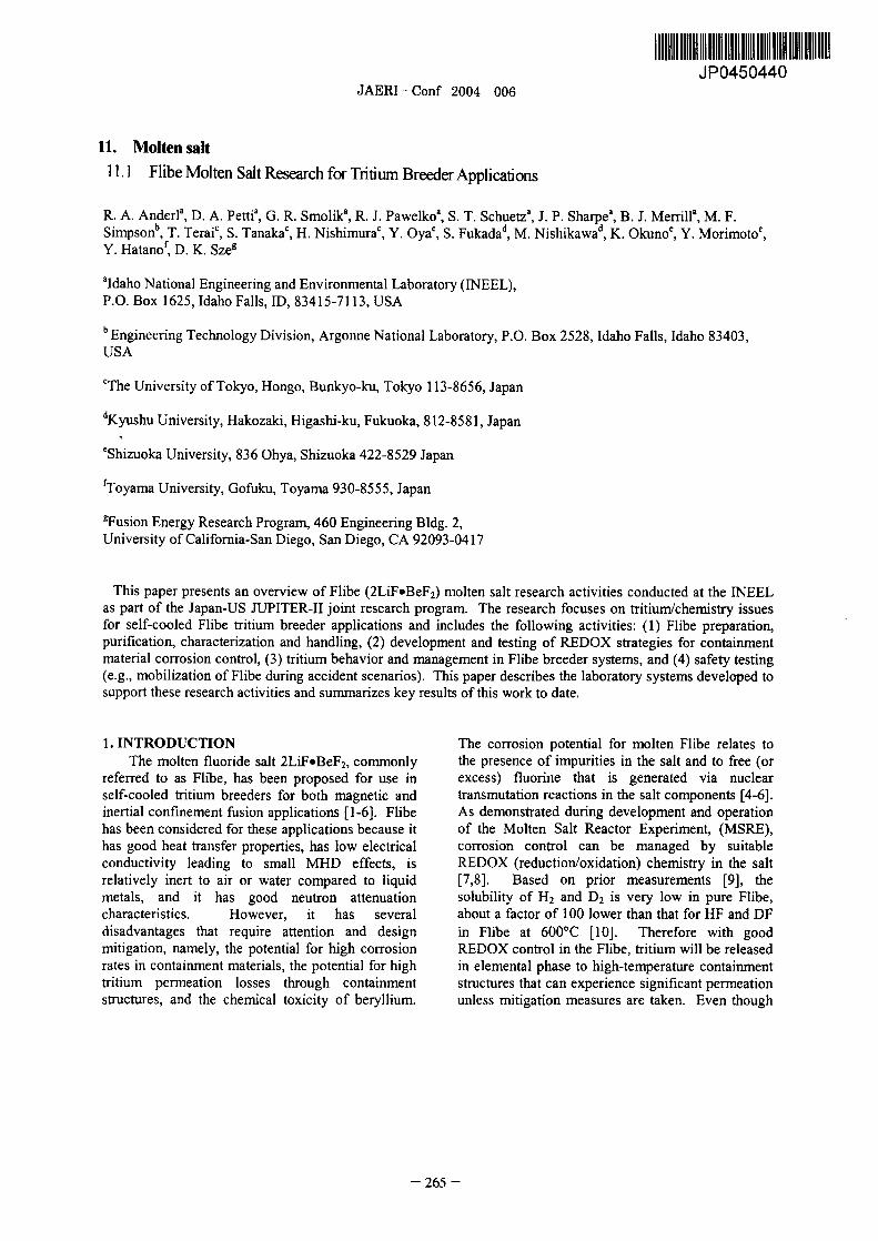
We have incorporated temperature sensors and water and HF increased with temperature.an on-line quadrupole mass spectrometer (QMS) to Experiments were conducted with purge gasesmonitor key parameters of the thermo-cycle process consisting of He and H, or D, to investigate isotopeduring heat-up and cool-down of the salt mixture A exchange reactions in the Flibe pot environment andtemperature sensor is inserted into a Ni sheath tube purge gas interactions with pot/Flibe materials 141.in the salt mixture and another is used to control the As shown in Figure 4 for tests at 600'C, hydrogenpot heater. The on-line QMS is used to measure the interactions with the stainless steel pot only weregas corriposition of the process stream that is flowing minimal. However, ydrogen interactions werethrough the pot during the tbermo-cycle. This more pronounced when the pot contained a blankanalysis provides a useful measure of off-gassing carbon crucible and they were especially pronouncedfrom the salt components before melting and during when the pot contained a carbon crucible with Flibe.the melt phase. An example of the data measured These tests demonstrated that even though carbon isfor an initial tbermo-cycle of Flibe components is suitable for many operations with molten Flibe, theshown in Figure 3 The pot was heated on a step potential for hydrocarbon generation couldprofile, with hold temperatures of 200, 400 and complicate the interpretation of planned tritium800'C during the heat-up. For this cycle, the Flibe behavior studies in Flibe. As a result, we selected Nicomponents were not individually degassed (the as the Flibe-facing material for tritium behaviorusual process) so we observed a significant increase studies.in te QMS mass-18 signal for pot temperatures lessthan 400'C, indicative of water release from thepowder material. As the pot temperature rose IM sus 316
El sus 316 + carbonthrough 600'C, the QMS mass- 1 8 peak was unstable ii F-1 sus3I6+carbon+Fhbe
but showed indications of additional water release as600'Cthe BeF2 melted. During the cool-down, there was a 0 107,
temperature arest at a measured temperature of459'C, indicative of the liquid to solid phasetransition for Flibe.
.. . . . . . . . . . 800 i 0'F�ift'ftt'l . . . . ..."
IT 0cy:Itel 700lo-,- p p 0 10i temp.I- 41
10-1459-C 500
> 10,M 400 J� 1 2
M 10.9 300 E 10 20 30 40 50a 0)Z 200 nVe
10-10 Figure 4. Comparison of QMS mass spectra for00experiments in environments with (a) type 3161 0 .1i . . . . . . . . . . . . . . . . . . . 0
0 100 200 300 400 500 600 stainless steel pot, (b) stainless steel pot and carbonElapsed time (min) crucible and (c) stainless steel pot, carbon crucible
and Flibe.Figure 3 Thermo-cycle data for initial heat-up of
Flibe components and cool-down of Flibe sample. A hydro-fluorination process, based on the early
work on the MSRE [15], is used to purify Flibe byThe on-line QMS was used in experiments to reducing metal oxide impurities and sulfur-bearing
measure gas release from molten Flibe pots in an compounds. Our implementation of this techniqueevaluation of He-bubble purge effectiveness and employed purging of the molten Flibe at a nominalpurge gas pot material interactions. Bubbling temperature of 520'C for several days with athrough the Flibe with high-purity helium enhanced mixture of He, H2 and HF in which the H,water release fi-om the salt, and the release rate of concentration is at least 10 times the HF
- 267 -
JAERI-Conf 2004-006
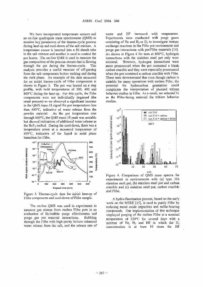
concentration. During the purification process, te A variety of analytical techniques are used toHF concentrations in the gas mixture flowing assay the irnpurity content of the chernical eagentthrough te molten salt are easured using titration feedstock for Flibe and the impurity content of thetechniques. Comparison of HF concentrations in the Flibe before and after the bydro-fluorinationpurge line downstream from the Flibe pot with those purification. Oxygen, nitrogen ad carbon wein the upstream gas povided an indication of the determined by methods using LECOO equipment.progress in oxide eduction interactions in te salt. Metals analyses were by measurements usingFor example, at the start of the purification un, HF inductively-coupled-plasina atoiriic en:iissionconcentration downstream is much less than spectroscopy (ICP-AES) and ICP-MS (massupstrean-4 and as the oxide content in the salt is spectroscopy). Results of these analyses for areduced, the downstream HF concentration rises to representative batch of Flibe and the feedstockapproach the upstream value. Currently a Schott ingredients are given in Table 1. Noting that BeF,auto-titrator is implemented to provide on-line comprises 13 of a molar fraction of Flibe, thesemeasurements of te pH i a titration cell that the results sow that the hydro-fluorination process hasgas stream is bubbled through. reduced the oxide content by a factor of 3 in the
processed material. Additional hydro-fluorinationprocessing can reduce the oxide content further.
Table 1. Measured ipurities in Flibe chemicalcomponents ad purified Flibe
0 C N Fe Ni Cr(ppm) (ppm) (ppm) (pp-) (ppm) (ppm)
BeF, 5700 <20 58 295 20 1 8LiF 60 <20 78 100 30 4
Flibe 560 0 32 260 5 6
3. REDOX CONTROLOur current strategy is to test the effectiveness
of beryllium metal as a REDOX control agent in aFlibe system that contains free fluorine ad TF. Theprimary basis for this choice is two-fold: (1) te
Figure 5. Control instrumentation and gas cabinet free-energies of formation for elements offor He-HF gas cylinders. importance to a Flibe system (see Table 2 idicate
that BeF, is more stable than most metal fluoridesand TF, ad 2 Be is needed for neutronmultiplication in the Flibe blanket to achieve asuitable tritium breeding ratio.
Table 2 Free energies of formation at 10000CFluoi Free energy
P, (kcal/g-atom of F)
MoF6(g) -50.84WF6(g) -56.84NiFAS) -60.02HF -66.55FeF,(s) -67.9CrF,(s) -77.04MnF,(s) -85.27
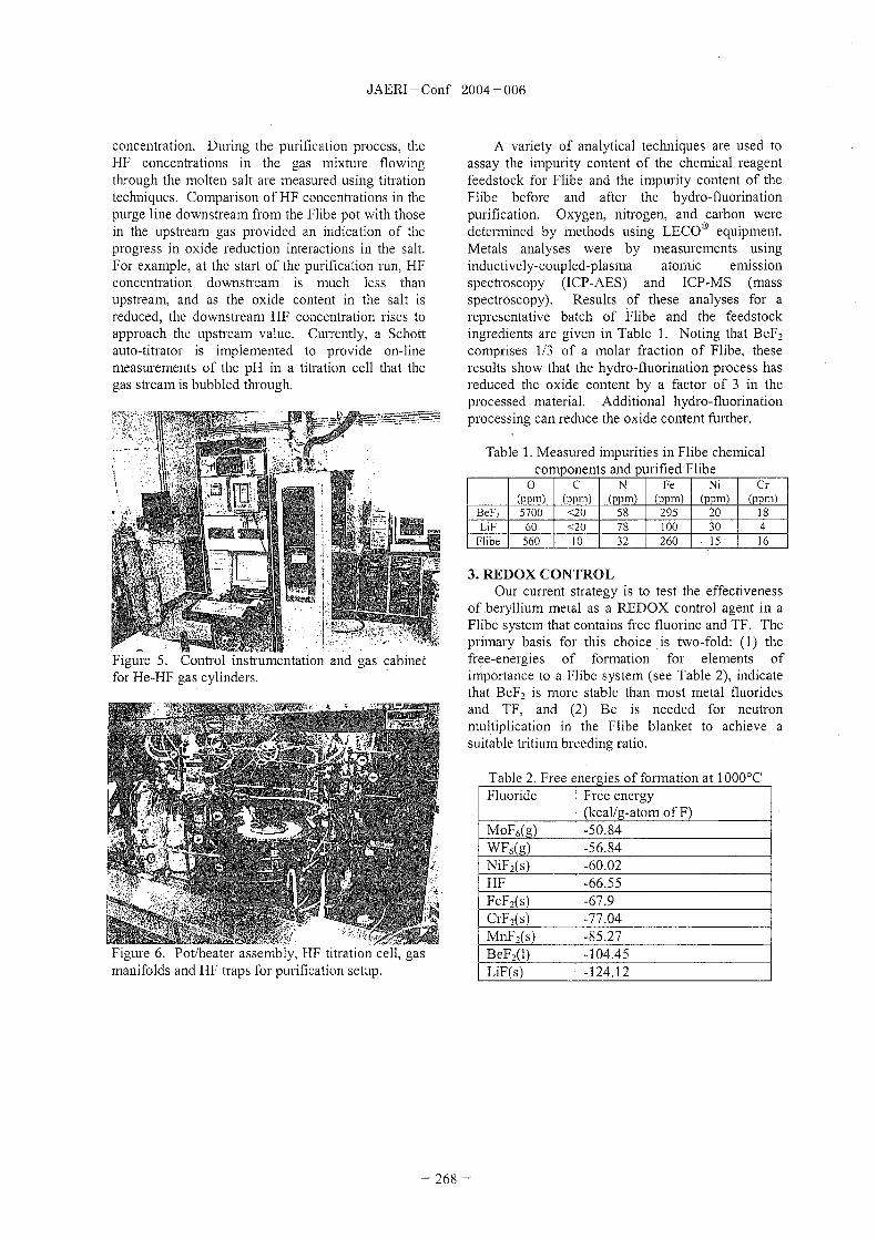
Figure 6 Pot/heater assembly, HF titration cell, gas BeF,(I) -104.45manifolds and HF traps or purification setup. LiF(s) -124.12
- 268 -

JAERI - Conf 2004-006
Previous studies have indicated that the use of influencing HF transport from the pot environmentmetallic Be in Flibe does significantly reduce (e.g., reduction in HF concentrations in the pot head-corrosion of type 316 stainless steel 16] and does space due to volurnetric sweep-out with only He, HFfacilitate the conversion of TF to HT in neutron- transport across the Flibe/gas-phase interface,irradiated Flibe 171. However, these experiments reactions of Be with HF in solution in the salt and ado not provide sufficient information regarding the consequent change in the rate of HF transport acrosskinetic behavior of the Be reactions with free the liquid/gas interface). Current tests are underwayfluorine (F2) and/or fluoride (HF) to produce BeF,. to establish the ultimate detection sensitivity of theOne of the initial goals of our research is to elucidate auto-titrator for this application.the kinetic behavior of Be in Flibe. This will entailmeasurements of the reaction rates of the relevant 4 TRITIUM BEHAVIOR IN FLIBEprocesses and the determination of the most The ultimate goal of this task is to characterizeeffective physical form for the REDOX agent (e.g. tritium behavior in Be-REDOX controlled Flibe.dissolved vs solid surface or coating). We know that interrelated transport processes and
Studies have been initiated to investigate the chemical interactions characterize the behavior ofreaction kinetic behavior of solid Be surfaces with hydrogen isotopes in molten fluoride salts, but theknown concentrations of HF in Flibe. These available results do not provide sufficientexperiments are based on an adaptation of the information to reliably quantify tritium behavior in apurification system and a REDOX reactor illustrated REDOX-controlled Flibe blanket system. Importantin Figure 7 The approach uses a pot-configuration results concerning tritium species in neutron-sirnilar to that for the purification experiments with irradiated Flibe have been reported previously 17]the adaptation to provide for controlled insertion of a and references therein. These studies indicated thatBe foil or solid cylinder in the molten salt. The tritium was pimarily present as TF in irradiatedinitial approach consists of. (1) purging the salt with Flibe, unless te molten Flibe was exposed to anHe-HF (HF concentrations of about 1000 ppm) to overpressure of H2 resulting in an increase in theestablish an equilibrium concentration of HF in the solution hydrogen that facilitated the change fromsalt, 2) stopping the HF purge while retaining a pure TF to HT. However, for a Flibe Blanket, use ofHe purge, 3) inserting a Be rod into the molten salt, hydrogen complicates and adds a significant burden(4) all the while, monitoring the HF concentration in to the tritium recovery and isotopic enrichmentthe outlet gas stream with the on-line auto-titrator. plant. Furthermore, as stated in Section 1, the
transport data for diffusion and solubility are derived
Ni it lie from a very limited data set.Ni 'rherniocouple 14" Because of this history, we proceeded on a plan1,4" r--O' MAW to investigate the deuterium transport properties in
ILI HIM 11 purified Flibe before we initiated work with tritium
0.75" L 11 1; 11 I I or proceeded to Be-REDOX-controlled F 1 e. This
research entailed the development of a dualpermeation probe system that could be accuratelymodeled and used in experiments to evaluate
Ni diffusion and solution properties of hydrogen1 2 isotopes in Flibe. Initial work in this development
has been reported previously 14, 18] and moreIle oil Ni 1:1116ble detailed updates of this work are presented at this3 x F Oil hle workshop [ 1 9] and at the CFRM- 1 1 meeting 20].
A brief summary of this work is included here.
Figure 7 Illustration of REDOX reactor. The basis of our experimental and analyticalapproach is illustrated in Figure 8. The heart of the
In principle, changes in the outlet stream HF experiment is a cylindrically-symmetric, dual probeconcentrations can be related to various processes permeation pot system that consists of a type-316
stainless-steel pot, a nickel crucible that contains
- 269 -

JAERI-Conf 2004-006
about 400-cc of Flibe, two pern-wation probes of Detailed model simulation calculations havethin-walled nickel, a gas anifold to provide Ar been done for this experimental system 14,18,19]purge gas flow through assembly volumes, and a with and without Flibe. Permeation experimentsquadrupole mass spectrometer for on-line without Flibe were done to demonstrate themeasurements of the flow-stream gas compositions. performance of the gas handling system and the on-Typically, wit te pot at a test temperature, probe-1 line QMS analysis approach and to benchmark theis pessurized with deuterium to about 09 atrn and model calculations against measured deuteriumQMS aalysis of Ar gas purging tough probe-2 permeation data. The analysis indicated excellentprovides a measure of the deuterium that has agreement with previously published data forperrneated tough probe-1 wall, the molten Flibe hydrogen transport in nickel 14,18]. Systematicbetween te probe walls ad through the wall of simulation calculations for the Ni/Flibe/D, systemprobe-2. Figure 9 shows the pot/heater assembly demonstrated that permeation through Flibe wasand associated gas-flow lines that are installed inside rate-limiting for conditions in our experiments. Thisa glovebox that is operated with an inert gas result is demonstrated in Figure 10 that comparesenvironment during experiments. measured deuterium transport data for experiments
D, at 600'C without Flibe (Exp, A) and with Flibe (Exp
Ar Ar+D, B) for comparable Ar purge flow rates toughAr Ar+D, probe-2. Two features of the Exp B data reflect the
Ar r+D, influence of Flibe on permeation in the Flibe. First,Ar Ar+D, there is significant time delay in the probc-2 D,
-41'. Ar+D,Ar F; permeation signal and in the buildup of deuterium
above the Flibe. Second, the maximum D2 partialpi robe 2 and above the salt are uch less
Barrier 4- 36ss pot than those observed in Exp, A. These results are duevolume .. ......
Ni Crucible to the low solubility and slow diffusivity of D, inNi Probe2 ...... ....... Flibe as pedicted by the simulation calculations.annulus N! Probe2
..... annulusThermocouple ......
- I ....... NI Probel 1000 100Flibe
< 900 Exp A: no Flibe Exp B: with Flibe go coCL
800 o XFigure 8. Schematic illustration of cylindrically f-Ot.100c.l.in
,j 700 70symmetric, permeation probe assembly. a- - 11
600 60'1, 'b.v.Fl- 50
500 A ib.(D,)
ip E.p 40400 A
300 30P.b.2(D�) Evu-t. PB1
IL 200 1 E.p B E�p B 20
loo II &-.I. PB1 10
E.pA
0 0
0 100 200 300 400 500 600 700 800
Elapsed time (min)-reference to PB1 pressurization
Figure 10. Comparison of measured deuterium datafor experiments with and without Flibe.
Diffusion coefficients were derived fi-om acylindrical model analysis of measured permeationrates for experiments at 600 and 650'C, Details ofthis analysis are reported lsewhere 19, 20].Results from these analyses are compared in Figure
Figure 9 Glovebox setup for permeation probe exp, I I with peviously published data for hydrogen
- 270 -

JAER - Conf 2004-006
isotope diffusion in Flibe. Our diffusion esults are a of tests in which molten Flibe was exposed to argon,little less than those reported by Oisbi et al. 2 for air ad moist air at temperatures from 500 to 8000V transport in molten Flibe, suggesting that and mobilization rates and products weredeuterium was also diffusing as the D4 species in our characterized. Detailed results of this work wereexperiments. Both of these results are somewhat reported at ICFRM-11 251. A summary of keygreater than those derived from te viscosity using features of this work is reported here.the Stokes-Einstein relation, D = kT/(6nRij), Mobilization tests were performed in aassuming a particle radius, R, of 2 Agstroms ad a transpiration setup similar to that described by Senseviscosity, q, reported by Cantor 22] for 2LiF*BeF2- et al. 26] for vapor pressure measurements. AThe diffusion activation energy for the Oishi et al. schematic of our test system is shown in Figure 12.data is consistent with the viscosity data. However, The system consisted of te following: (1) an inleta two-point fit to our diffusion coefficients (a gas manifold for introducing Ar air or moist air, 2)dangerous approach with such limited data) yields a a gas pre-heater, 3 a Ni tube exposure chamberdiffusion activation energy comparable to that for F- centered inside a tube furnace,(4) a theimiocouple forself diffusion reported by Ohmichi et al. 23]. Such test temperature measurements at the samplea result would suggest transport mechanisms similar location, (5) an Inconel-600 vapor-transfer tubeto that postulated by Ohmichi et al., namely ion-pair (probe) that is inserted inside the exposure chamberdiffusion or exchange processes that break Be-F with its entrance tip positioned near the sample, 6 abonds. Data are also shown in Figure 1 1 for collection tube that is directly connected to thediffusion of T' in solid Flibe. These diffusion probe, 7 a condenser for moisture removal duringresults, along with high values of solubility derived moist air experiments, and (8) an exhaust.line to afor our permeation probe experiments 19,20] hood. Samples were tested in either nickel or glassysuggest that deuterium transport in our experiments carbon crucibles, dependent on the exposurewas mediated by the presence of a bond between D' conditions. A quadrupole mass spectrometer wasand T- in the rnolten salt. used to verify leak tightness of the system prior to
initiation of an experiment.Temperature(IC)
800 700 600 500 40010 flow
onholle,Ohmichl at al IF self dffusion)
10 .1-1 E.= 128 W/rnol H20 h.42 X. I
Ois h i et a . T)10-a - - I
Z A
10 9 QfVfi'Q2 J U PIT ER-11 t h is work)
10 10 frornl).buildup
0 Stakes-Einstein in Probe2 %U Argon hefi-tfm
10-11 E,=31 W/mol mm.0 home Glove V.nt to hood
10 12
Figure 12. Illustration of transpiration setup for10-13 lV1oriyamaetal.(TinsolidFIibe)_-
E,=lllkJ/mol Flibe mobilization experiments.10 14 -
0.80 1.00 1.20 1.40 1.60 1.80
Inversetemperature(1000M)
Figure 1 1. Diffusion data for Flibe. P
5. SAFETY TESTS (FLIBE MOBILIZATION)A safety concern for a Flibe breeder blanket is
the potential mobilization of tritium and Flibe vaporsand aerosols due to an accidental breach of the Flibe Figure 13. Nickel test assembly for Flibecontainment structure. To address the issue of Flibe mobilization experimentsmobilization, we ave conducted a systematic series
- 271 -

JAERI-Conf 2004-006
Figure 13 shows the components of the ickel with Ni cucibles in Ar to evaluate mass balance.assembly that are installed in the tbe fnace for Such measurements were not useful for experimentseach test. The exposure chamber is at the top, the with glassy carbon crucibles in air.probe tube, nickel sample crucible, and Initial mobilization tests were performed withthermocouple ae located i the center of the photo. pure LiF at 875 and 10001C to validate theThe setup of te mobilization system, as it is experimental approach and system. Vapor pressuresconfigured inside an inert-gas glovebox, is sown in derived from these experiments were in reasonableFigure 14. agreement with results reported by Sense et al. 27]
indicating that our test geometry and flow rates
.......... provided reasonable conditions to maintainsaturation above the molten material.
Mobilization tests were performed with Flibethat was previously purified as described in Section2 of this paper. Tests in Ar and. air were conductedat 500, 600, 700 and 800' with flow rates of 25-100sccm. Tests i moist air were done at 600 to 8000Cat flow rates of 25 and 5 sem.
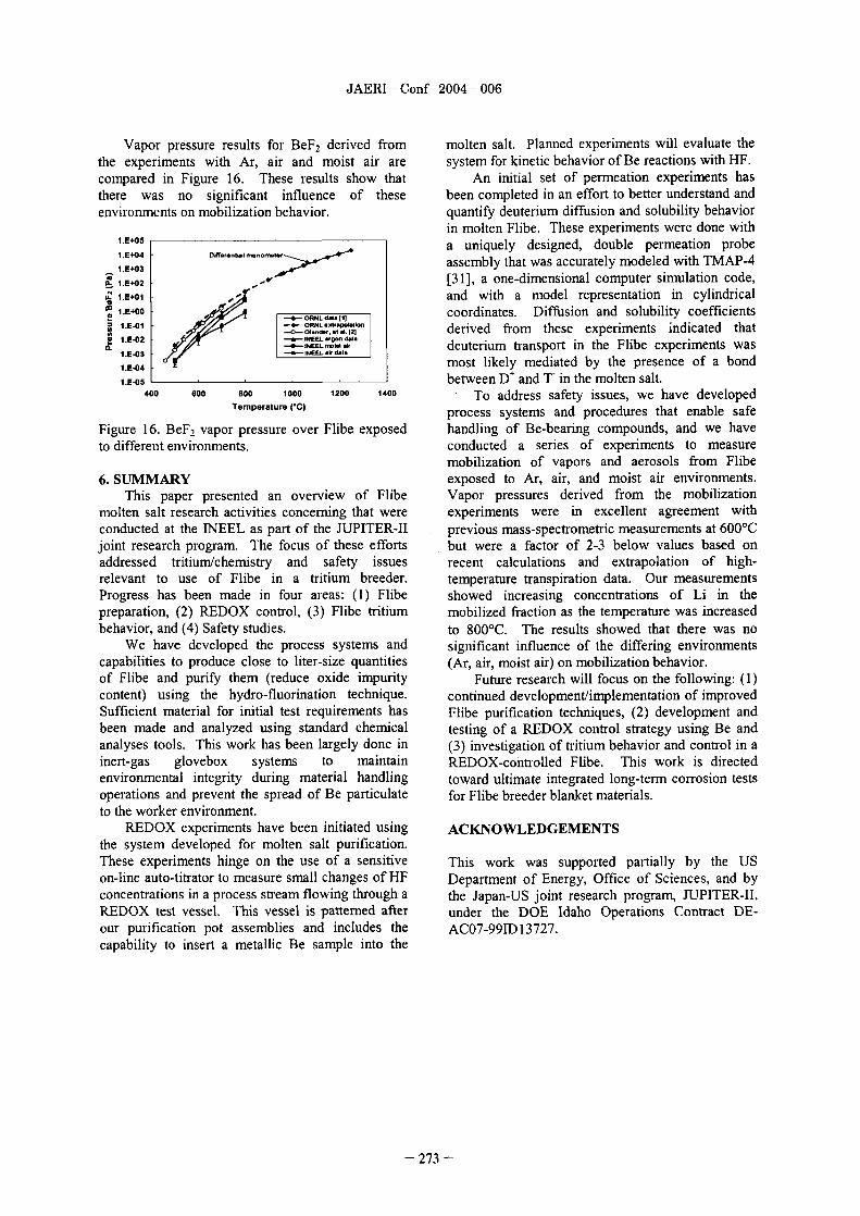
Partial vapor pressures foi- BeF2 and LiBeF adthe resultant total vapor pessures (sum of tepartials) were derived from the experiments for Flibein a pure Ar environment. Results are plotted inFigure 15, along with values from high temperaturetranspiration experiments (ORNL data(l) 28]), from
Figure 14. Setup of Flibe obilization experiment extrapolations of ORNL data (ORNL extrapolation),inside inert gas glovebox, from calculated vapor pressures based on
thermodynamic models and derived activityDetermination of te quantity and chemical coefficients 29], and from mass spectrometric
species of material tansported equired removal of measurements of the vapor species (BeF, andthe probe and stainless steel collection tube. The LiBeF3) above Flibe at 600'C [30]. The NEELinternal surface of the stainless steel tube and the results were in excellent agreement with te massinside and outside surfaces of the probe tube were spectrometric data but were a factor of 23 below theseparately rinsed with 10% nitric acid and the extrapolated or computed data. The INEEL resultssolutions were analyzed for Be and Li by ICP-AES. also showed increasing contribution from Li-bearingMeasurements from the internal probe surfaces were species at the higher temperatures a result consistentused for vapor pressure calculations. Deposits frorn with the mass spectrometric species determination.the external pobe surfaces were used to compare te 11+05
amounts and ratios of Be and Li on internal and 1.E+04 Differential manometer",
external surfaces. The Ni exposure chamber was 1.E+03
removed and cleaned after selected test series. 1.E+02
Both Ni ad glassy carbon crucibles were used1.E+01 --o- ORNL dta [11
-4- ORNL..tr.p.1.ticmin these experiments. The Ni was suitable for 0 1.E+00 __O_ 01,md., (2]e! D B.ch1.r'&"St.1'.ff.r 4)experiments in pure Ar but unsuitable for use in air 'L 1.E-01 --A- INEEL T.t.1 p......e
--I NEEL-B.F20 --o- INEEL IBeF3or moist air because it readily oxidized in the air. O- 1.E-02m
This created a surface tat was more easily wetted > 1.E-03 s Spectrometry
by te Flibe enabling it to flow out of te crucible. 1.E-04
Glassy carbon crucibles provided good containment 1.E.05
for Flibe under air and moist-air exposure conditions 400 600 goo 1000 1200 1400
but experienced mass loss because of oxidation. Temperature C)
Sample mass loss measurements were made for tests Figure 15. Total vapor pressure over Flibe.
272 -
JAERI-Conf 2004-006
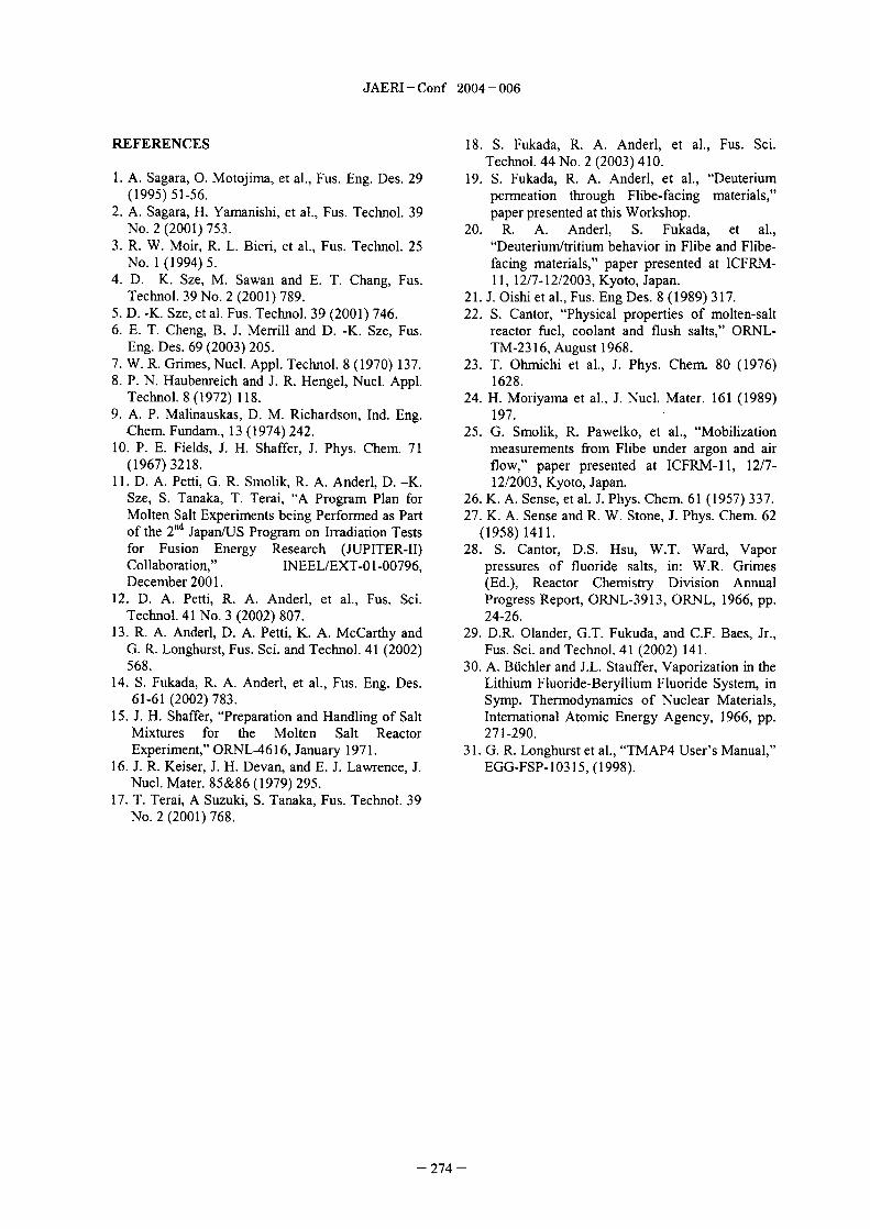
Vapor pressure results for BeF2 derived from molten salt. Planned experiments will evaluate thethe experiments with Ar, air and moist air are system for kinetic behavior of Be reactions with HF.compared in Figure 16. These results show that An initial set of permeation experiments hasthere was no significant influence of these been completed in an effort to better understand andenvironments on mobilization behavior. quantify deuterium diffusion and solubility behavior
in molten Flibe. These experiments were done withI.E+05 a uniquely designed, double permeation probeI.E+04 Diff...WI.E+03 assembly that was accurately modeled with TMAP-4
a' I.E+02 [3 1 ] a one-dimensional computer simulation code,Zm. I.E+01 and with a model representation in cylindrical
I.E+00 coordinates. Diffusion and solubility coefficientsORNL dM. (1)I.E-01 OPNL.Wp.W..--c-o'..�,.C.1.121 derived from these experiments indicated thatI.:-02 NEEL g.. dW.I --*--:NE L.10.k deuterium transport in the Flibe experiments was' -03 - EEL dl.
1.E-04 most likely mediated by the presence of a bond1.E-05 between D' and T- in the molten salt.
400 600 800 1000 1200 1400 . To address safety issues, we have developedTemperature C) process systems and procedures that enable safe
Figure 16. BeF, vapor pressure over Flibe exposed handling of Be-bearing compounds, and we haveto different environments. conducted a series of experiments to measure
mobilization of vapors and aerosols from Flibe6. SUMMARY exposed to A, air, and moist air environments.
This paper presented an overview of Flibe Vapor pressures derived from the mobilizationmolten salt research activities concerning that were experiments were in excellent agreement withconducted at the [NEEL as part of the JTITER-11 previous mass-spectrometric measurements at 600'Cjoint research program. The focus of these efforts but were a factor of 23 below values based onaddressed tritium/chemistry and safety issues recent calculations and extrapolation of high-relevant to use of Flibe in a tritium breeder, temperature transpiration data. Our measurementsProgress has been made in four areas: (1) Flibe showed increasing concentrations of Li in thepreparation, 2) REDOX control, 3) Flibe tritium mobilized fraction as the temperature was increasedbehavior, and 4) Safety studies. to 800'C. The results showed that there was no
We have developed the process systems and significant influence of the differing environmentscapabilities t produce close to liter-size quantities (Ar, air, moist air) on mobilization behavior.of Flibe and purify them (reduce oxide impurity Future research will focus on the following: (1)content) using the hydro-fluorination technique. continued development/implementation of improvedSufficient material for initial test requirements has Flibe purification techniques, 2) development andbeen made and analyzed using standard chemical testing of a REDOX control strategy using Be andanalyses tools. This work has been largely done in (3) investigation of tritium behavior and control in ainert-gas glovebox systems to maintain REDOX-controlled Flibe. This work is directedenvironmental integrity during material handling toward ultimate integrated long-term corrosion testsoperations and prevent the spread of Be particulate for Flibe breeder blanket materials.to the worker environment.
REDOX experiments have been initiated using ACKNOWLEDGEMENTSthe system developed for molten salt purification.These experiments hinge on the use of a sensitive This work was supported partially by the USon-line auto-titrator to measure small changes of HF Department of Energy, Office of Sciences, and byconcentrations in a process stream flowing through a the Japan-US joint research program, J-UPITER-11,REDOX test vessel. This vessel is patterned after under the DOE Idaho Operations Contract DE-our purification pot assemblies and includes the AC07-99ID13727.capability to insert a metallic Be sample into the
- 273 -
JAERI-Conf 2004-006
REFERENCES 18. S. Fukada, R. A. Anderl, et al., Fus. Sci.Technol. 44 No. 2 2003) 410.
1. A. Sagara, 0. Motojima, et al., Fus. Eng. Des. 29 19. S. Fukada, R. A. Anderl, et al., "Deuterium(1995) 51-56. permeation through Flibe-facing materials,"
2. A. Sagara, H. Yamanishi, et al., Fus. Technol. 39 paper presented at this Workshop.No. 2 2001) 753. 20. R. A. Anderl, S. Fukada, et al.,
3. R. W. Moir, R. L. Bieri, et al., Fus. Technol. 25 "Deuterium/tritium behavior in Flibe and Flibe-No. I (I 994) 5. facing materials," paper presented at ICFRM-
4. D. -K. Sze, M. Sawan and E. T. Chang, Fus. 11, 12/7-12/2003, Kyoto, Japan.Technol. 39 No. 2 2001) 789. 21. J. Oishi et al., Fus. Eng Des. 1989) 317.
5. D. -K. Sze, et al. Fus. Technol. 39 2001) 746. 22. S. Cantor, "Physical properties of molten-salt6. E. T. Cheng, B. J. Merrill and D. -K. Sze, Fus. reactor ftiel, coolant and flush salts," ORNL-
Eng. Des. 69 2003) 205. TM-2316, August 1968.7. W. R. Grimes, Nucl. Appl. Technol. 8 1970) 137. 23. T. Ohmichi et al., J. Phys. Chem. 80 1976)8. P. N. Haubenreich and J. R. Hengel, Nucl. Appl. 1628.
Technol. 8 1972) 118. 24. H. Moriyarna et al., J. Nucl. Mater. 161 1989)9. A. P. Malinauskas, D. M. Richardson, Ind. Eng. 197.
Chem. Fundam., 13 1974) 242. 25. G. Smolik, R. Pawelko, et al., "Mobilization10. P. E. Fields, J. H. Shaffer, J. Phys. Chem. 71 measurements from Flibe under argon and air
(1967)3218. flow," paper presented at ICFRM-11, 12/7-1 1. D. A. Petti, G. R. Smolik, R. A. Anderl, D. -K. 12/2003, Kyoto, Japan.
Sze, S. Tanaka, T. Terai, "A Program Plan for 26. K. A. Sense, et al. J. Phys. Chem. 61 1957) 337.Molten Salt Experiments being Performed as Part 27. K. A. Sense and R. W. Stone, J. Phys. Chem. 62of the 2nd Japan/US Program on Irradiation Tests (1958)1411.for Fusion Energy Research (JUPITER-11) 28. S. Cantor, D.S. Hsu, W.T. Ward, VaporCollaboration," INEEL/EXT-O 100796, pressures of fluoride salts, in: W.R. GrimesDecember 2001. (Ed.), Reactor Chemistry Division Annual
12. D. A. Petti, R. A. Anderl, et al., Fus. Sci. Progress Report, ORNL-3913, ORNL, 1966, pp.Technol. 41 No. 3 2002) 807. 24-26.
13. R. A. Anderl, D. A. Petti, K. A. McCarthy and 29. D.R. Olander, G.T. Fukuda, and C.F. Baes, Jr.,G. R. Longhurst, Fus. Sci. and Technol. 41 2002) Fus. Sci. and Technol. 41 2002) 141.568. 30. A. Bfichler and J.L. Stauffer, Vaporization in the
14. S. Fukada, R. A. Anderl, et al., Fus. Eng. Des. Lithium Fluoride-Beryllium Fluoride System, in61-61 2002) 783. Symp. Therrnodynarr&s of Nuclear Materials,
15. J. H. Shaffer, "Preparation and Handling of Salt International Atomic Energy Agency, 1966, pp.Mixtures for the Molten Salt Reactor 271-290.Experiment," ORNL-4616, January 1971, 3 1. G. R. Longhurst et al., "TMAP4 User's Manual,"
16. J. R. Keiser, J. H. Devan, and E. J. Lawrence, J. EGG-FSP- 1 0315, 1998).Nucl. Mater. 85&86 1979) 295.
17. T. Terai A Suzuki, S. Tanaka, Fus. Technol 39No. 2 2001) 768.
- 274 -