Harmonic characteristics of rectifier substations and ... - ROSA P
60
HE 1 8.5 .A3 7 no DOT- I SC— UMTA- 81-75 U M T A-M A-06-0025-81 -6 DOT-TSC-UMT A-81 -75 Harmonic Characteristics of Rectifier Substations and Their Impact on Audio Frequency Track Circuits Vilas D. Nene OAO Corporation 7500 Greenway Center Greenbelt MD 20770 May 1982 Final Report This document is available to the public through the National Technical Information Service, Springfield, Virginia 22161. US Deparfmenf of Transporfation Urban Mass Transportation Administration Office of Technical Assistance Office of Systems Engineering Washington DC 20590
-
Upload
khangminh22 -
Category
Documents
-
view
3 -
download
0
Transcript of Harmonic characteristics of rectifier substations and ... - ROSA P

HE1 8.5.A3 7
no
.
DOT-I SC—UMTA-81-75
U M TA-M A-06-0025-81 -6
DOT-TSC-UMT A-81 -75 Harmonic Characteristics of
Rectifier Substations andTheir Impact on AudioFrequency Track Circuits
Vilas D. Nene
OAO Corporation
7500 Greenway Center
Greenbelt MD 20770
May 1982
Final Report
This document is available to the public
through the National Technical Information
Service, Springfield, Virginia 22161.
US Deparfmenf of Transporfation
Urban Mass TransportationAdministration
Office of Technical Assistance
Office of Systems Engineering
Washington DC 20590

NOTICE
This document is disseminated under the sponsorship of the
Department of Transportation in the interest of information
exchange. The United States Government assumes no
liability for its contents or use thereof.
NOTICE
The United States Government does not endorse products or
manufacturers. Trade or manufacturers' names appear herein
solely because they are considered essential to the object of
this report.
ft 3 7
} 6T-
7sc-~
Technical Report Documentation Page
1 . Report No.
UMTA-MA-06-0025-81 -6
2. Government Accession No.
~ Title and Subtitle
Harmonic Characteristics of Rectifier Substationsand Their Impact on Audio Frequency Track Circuits
7. Author's)
Vilas D. Nene, Ph.D.department of
9. Performing Organization Name and Address
0A0 Corporation*7500 Greenway CenterGreenbelt, Maryland 20770
TRANSPORTATION
FIB 2 1983
12. Sponsoring Agency Name and Address
U.S. Department of TransportatioUrban Mass Transportation AdminiOffice of Technical AssistanceWashington DC 20590
i
stration
3. Recipient s Catalog No.
Ur
7
r
5. Report Date
May 1982
6. Performing Organization Code
DTS-722
8. Performing Organization Report No.
DOT-TSC-UMTA-81 -75
10. Work Unit No. (TRAIS)
UM204/R261
6
1 1 . Contract or Grant No.
DTRS-57-81 -C-0003313. Type of Report and Period Covered
Final Report1/15/1981 - 7/15/1981
14. Sponsoring Agency Code
URT-10
15. Supplementary Notes
*Under contract toU.S. Department of TransportationResearch and Special Programs AdministrationTransportation Systems CenterCambridg e MA 02112
16. Abstract
This report describes the basic operation of substation rectifier equipmentand the modes of possible interference with audio frequency track circuitsused for train detection, cab signalling and vehicle speed control. It alsoincludes methods of estimating EM noise received by track circuits fromsubstation operation.
17. Key Words
Rectifiers, Substation Harmonics,Electromagnetic Interference
19. Security Classif. (of this report)
UNCLASSIFIED
18. Distribution Statement
DOCUMENT IS AVAILABLE TO THE U.S. PUBLICTHROUGH THE NATIONAL TECHNICALINFORMATION SERVICE, SPRINGFIELD,VIRGINIA 22161
20. Security Classif. (of this page)
UNCLASSIFIED
21. No. of P ages
54
22. Price
Form DOT F 1700.7 (8-72) Reproduction of completed page authorized


PREFACE
This report was commissioned of 0A0 Corporation under contract to
the Transportation Systems Center (TSC) of the U.S. Department of Trans-
portation. Funding was provided under the Subsystem Technology Applications
to Rail Systems (STARS) Program of the Urban Mass Transportation Administra-
tion (UMTA).
The author wishes to thank Mr. Stephen S. Teel of the U.S. DOT/UMTA
and Mr. Lennart E. Long of the U.S. DOT/TSC for their strong support of
this work.
METRIC
CONVERSION
FACTORS
iv
•1in
2.54
loaactly).
Fur
other
enact
cunvoibums
end
more
detailed
tables,
see
NBS
Misc.
P«ibl.
280.
Umtb
ol
Weights
and
Measures.
Price
42.25.
SO
Catalog
No.
CI3.
10.286.
TABLE OF CONTENTS
EXECUTIVE SUMMARY vii
1. INTRODUCTION 1
2. THREE PHASE BRIDGE RECTIFIERS 2
2.1 Commutation Process 5
2.2 Output Voltage Waveform 9
2.3 Voltage Regulation 10
2.4 Operation with Unbalanced Voltage Input 10
2.5 Waveform of ac Network Current 13
2.6 Twelve Pulse Rectifier Circuits 16
2.7 A Controlled Rectif ier/Inverter Circuit 21
2.8 Rectifier Substations for Transit Application 27
3. SUBSTATION HARMONICS AND TRACK CIRCUITS 28
3.1 Substation Harmonics in Propulsion Current 28
3.2 Conducted Noise 31
3.3 Noise Induced from the Third Rail 33
3.4 Assessment of Potential for Interference 37
4. CONCLUSIONS 38
APPENDIX A - RECTIFIER OPERATION WITH UNBALANCED VOLTAGE INPUT 39
APPENDIX B - REPORT OF NEW TECHNOLOGY 46
REFERENCES 48
v

LIST OF FIGURES
FIGURE NO. TITLE PAGE NO.
2-1 Three Phase Bridge Rectifier 3
2-2 Balanced Three Phase Voltages 4
2-3 Line Current Waveforms 6
2-4 Transformer Secondary Phase Currents 6
2-5 Cormutation Process 7
2-6 Variation of Harmonic Components with Overlap Angle 11
2-7 Voltage Regulation 12
2-8 Operation with Unbalanced Voltage Input 14
2-9 AC Waveform 15
2-10 Effect of Commutation on ac Network Current 17
2-11 A 12-Pulse Rectifier (Series Connection) 18
2-12 Output Voltage of 12-Pulse Circuit 20
2-13 Currents in Different Windings 22
2-14 A 12-Pulse Rectifier (Parallel Connection) 23
2-15 Operating Modes of a Controlled Rectifier 24
2-
16 Harmonic Content of a Controlled Rectifier 26
3-
1 Substation Harmonics in Propulsion Current 29
3-2 Conducted Noise in Track Circuit 32
3-3 Noise Induction by the Third Rail 34
3-4 Track Circuit Configurations 36
A-l Phasor Diagram 40
A-2 Rectifier Operation with Unbalanced Voltage Input 41

EXECUTIVE SUMMARY
A typical transit substation has two or more diode rectifiers with a
combined power rating of 2-10 MW. With a very few exceptions, these are 3-
phase 12-pulse rectifier circuits. Under normal operating conditions with
balanced voltage inputs, these rectifiers cause harmonic currents in the
third rail with harmonic orders of multiples of 12. For example, with a
source frequency of 60 Hz as in the U.S., the third rail carries current
harmonics with frequencies of 720 Hz, 1440 Hz, 2160 Hz,..., etc. Because
of inherent unbalance in voltage inputs as well as some asymmetry in bridge
circuits, the third rail also carries current components with frequencies
of 60 Hz, 120 Hz, ... etc., although of reduced magnitudes.
These substation harmonics in the third rail cause electromagnetic
(EM) noise in the audio frequency track circuits, resulting in potential
circuit malfunction. This report describes the basic operation of
substation rectifier equipment and the modes of possible interference with
the track circuits. It also presents methods of estimating electromagnetic
noise levels in the track circuits caused by the substation rectifiers.
The substation harmonic frequencies are well defined and are
independent of other wayside and vehicle equipment. The amplitudes of
these harmonic currents in the third rail are highest when a train is near a
feeding point on the third rail. The EM noise levels in the track circuit
caused by rectifier harmonics are, however, minimum when the length of
running rails in the propulsion circuit is minimum. This is because the
propulsion return current is then likely to be shared equally by the two
vii

running rails in a two-rail circuit, and the induction from the third rail
is minimum, since the length of the exposed circuit is small. Protection
against substation harmonics is not necessary when rail lengths are short
and currents are small except in site-specific problem areas such as the
third rail switching sides at bonds, etc., or under abnormal conditions
such as loose connections, etc. These problems must then be investigated
on an individual basis.
1. INTRODUCTION
Research and development programs of the Urban Mass Transportation
Administration (UMTA) in the area of urban rail transit have been recently
restructured. These programs collectively known as STARS, Subsystem
Technology Applications to Rail Systems, include vehicle systems, wayside
equipment, operational aspects, etc., and now focus on the cost
effectiveness and near-term application of rail transit technology.
Study of electromagnetic interference (EMI) characteri sties of
propulsion and other solid state power conversion equipment is a part of
the STARS program. Various track circuit configurations and
electromagnetic compatibilities of chopper and inverter controlled
1-4propulsion systems have been investigated in earlier studies . The
reader is, therefore, assumed to be familiar with track circuits and
electromagnetic compatibility in general.
This report describes the basic operation of substation rectifier
equipment and the modes of possible interference with audio frequency
track circuits used for train detection, cab signalling and vehicle speed
control. It also includes methods of estimating EM noise received by track
circuits from substation operation.
1
2. THREE PHASE BRIDGE RECTIFIERS
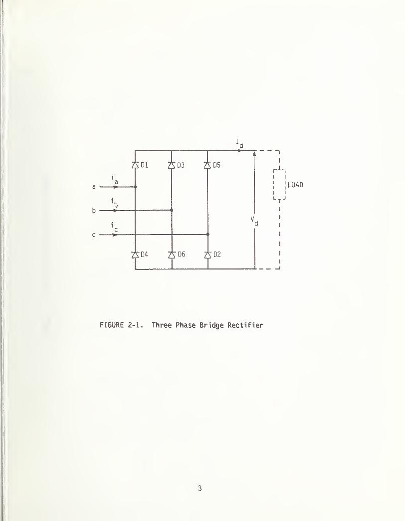
A three phase bridge rectifier shown in Figure 2-1 is one of the most
widely used converter connections. The three phase voltage input at a,b,c
may be obtained via a distribution transformer with star or delta connected
windings on the primary and secondary side. The rectifier operation and
the loading characteri Stic essentially are independent of transformer con-
nection. The waveform of line current in the ac network is, of course,
directly related to the type of transformer connection used.
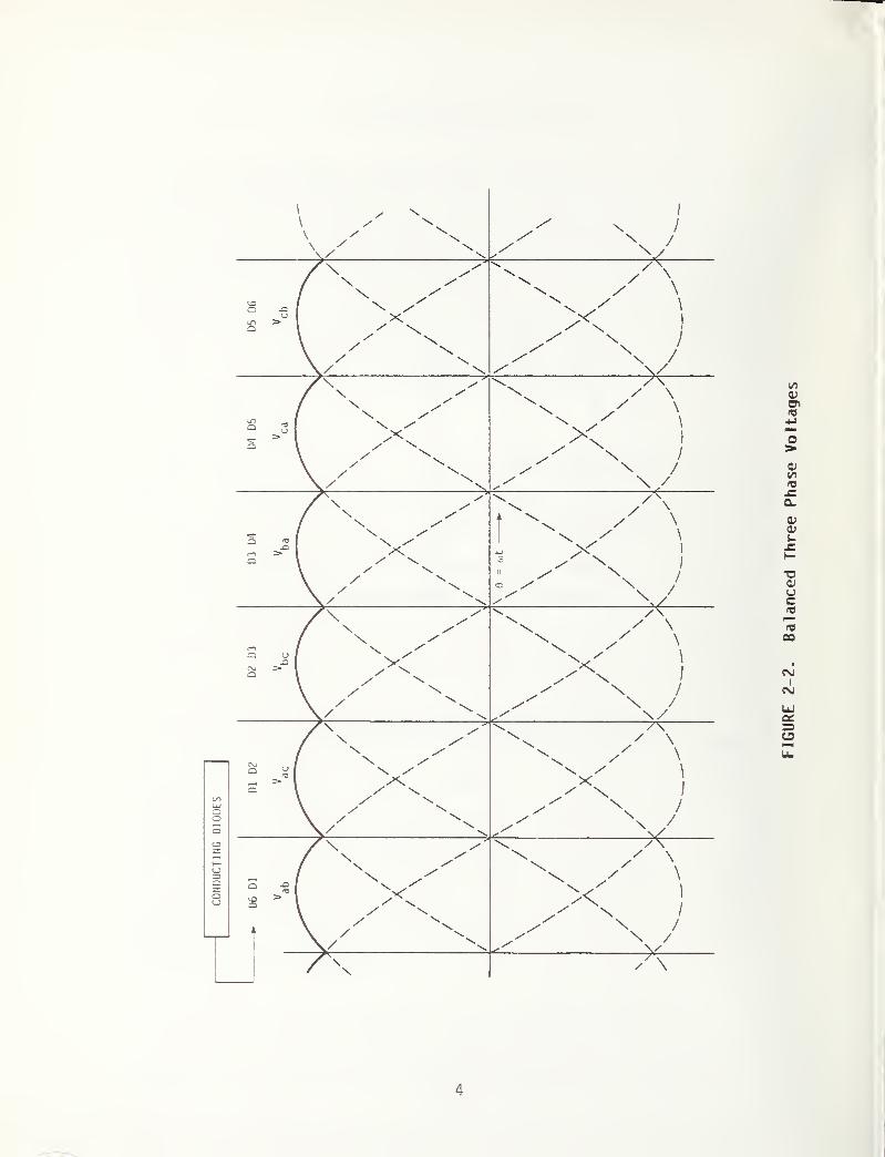
Now consider a balanced three phase voltage system connected at abc in
Figure 2-1. The load on the rectifier is highly inductive, causing current
Id
in the load to be constant generally. If the diodes Dl, D2, --D6 are
ideal, they conduct the load current when they are forward biased, and they
block it when they are reverse biased. With reference to the voltages of
Figure 2-2, when the voltage is positive and larger in magnitude than
V , and V ,the diodes D6 and Dl are forward biased and conduct the load
current; the voltage Vd
across the load is then identically equal to Vat)
.
When, however, V is positive and higher than V , and V,,the diodes Dl
ac aD dc
and D2 conduct and the voltage equals V . Thus each pair of diodes
conducts in turn for 60 electrical degrees, as shown in Figure 2-2. Each
diode conducts for 120 electrical degrees in each cycle of the input
voltages. In this bridge connection, current transfer from one diode to
another occurs six times every input cycle. This rectifier is, therefore,
called a six-pulse rectifier.
When the diode Dl conducts, i
a= I
d, but when D4 conducts i
fl
= -Id
;
therefore, the waveform of line currents i
a, i^, and i
cis defined by the
2
LOAD
FIGURE 2-1. Three Phase Bridge Rectifier
3
CONDUCTING
DIODES
4
FIGURE
2-2.
Balanced
Three
Phase
Voltages
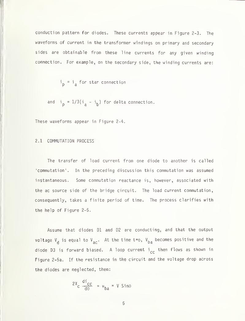
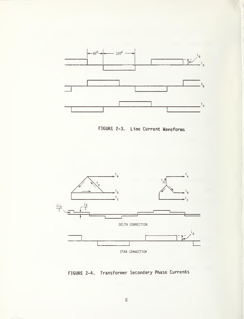
conduction pattern for diodes. These currents appear in Figure 2-3. The
waveforms of current in the transformer windings on primary and secondary
sides are obtainable from these line currents for any given winding
connection. For example, on the secondary side, the winding currents are:
i = i for star connectionK a
and ip = 1/ 3 (
i ^- i^) for delta connection.
These waveforms appear in Figure 2-4.
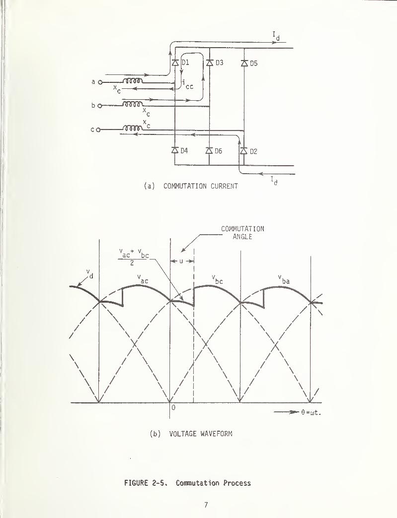
2.1 COMMUTATION PROCESS
The transfer of load current from one diode to another is called
'commutation 1
. In the preceding discussion this commutation was assumed
instantaneous. Some commutation reactance is, however, associated with
the ac source side of the bridge circuit. The load current commutation,
consequently, takes a finite period of time. The process clarifies with
the help of Figure 2-5.
Assume that diodes D1 and D2 are conducting, and that the output
voltage Vd
is equal to Va(
.. At the time t=o, Vba
becomes positive and the
diode D3 is forward biased. A loop current i'
ccthen flows as shown in
Figure 2-5a. If the resistance in the circuit and the voltage drop across
the diodes are neglected, then:
d©vba
= V Sine
5
f OrOO 120°
i
c
FIGURE 2-3. Line Current Waveforms
STAR CONNECTION
FIGURE 2-4. Transformer Secondary Phase Currents
6
COMMUTATION
FIGURE 2-5. Commutation Process
7
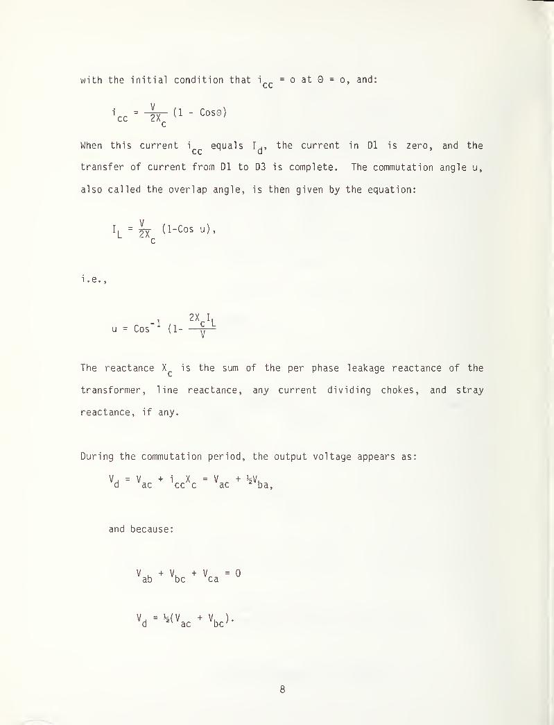
with the initial condition that i
cc= o at 0 = o, and:
n
cc=~rr ^ " Cos0 ^
c
When this current i equals I ., the current in D1 is zero, and thecc d
transfer of current from D1 to D3 is complete. The commutation angle u,
also called the overlap angle, is then given by the equation:
I
L
V_2X
c
( 1-Cos u)
,
i ,e. 5
u = Cos"1
(1-
2X I,c L
The reactance Xc
is the sum of the per phase leakage reactance of the
transformer, line reactance, any current dividing chokes, and stray
reactance, if any.
During the commutation period, the output voltage appears as:
'aVj = V.. + i X = V._ + !*V,
ba,ac cc c ac
and because:
V .+ V. + = 0
ab be ca
Vd
« Vac
+ Vbc>‘
8

2.2 OUTPUT VOLTAGE WAVEFORM
The output voltage of the rectifer is periodic over tt/3. The voltage
waveform now is formulated as:
vd V Cos© for o < 0 < u
= V Sin (0 + ) for u < 0 < ^
The average value of this output voltage is:
V ,
= -P- (1 + Cos u)d /if
If the commutation reactance is zero, u equals zero and maximum average
output voltage is:
Harmonic components of this waveform are also obtainable by standard
techniques. These are:
v,v,mc = -
/-
m-
23V
-,T • 4 . MAG C(1 - Cos u e
jmu)
- jm Sin u ejmu
3dm rms it (nr - 1) v2
where MAG(Z) is the absolute value of a complex variable Z, and m can only
be a multiple of six.
It can be seen that for u = o
V, 3V / „ /2dm rms = — (-2 r-
tt m - 1
9

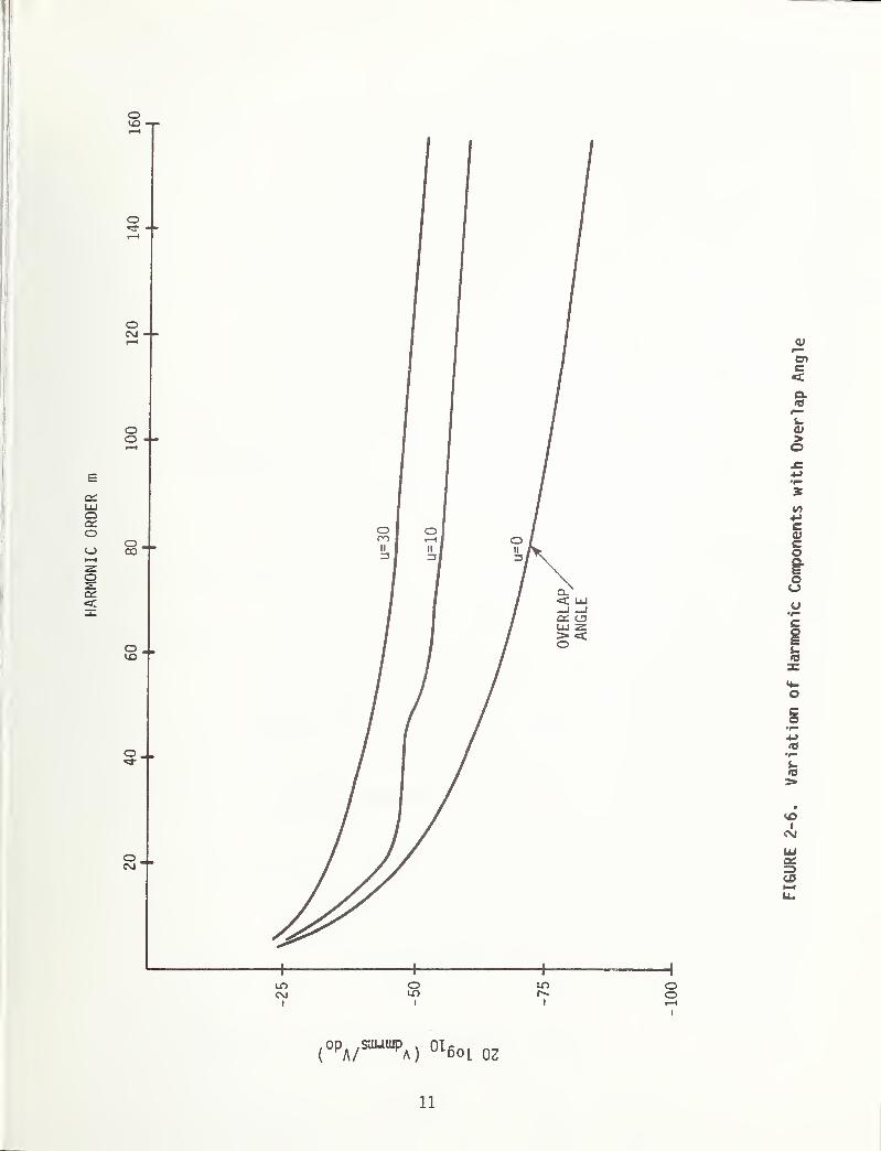
Fig. 2-6 presents relative rms values of harmonic components of the output
voltage for different commutation angles. The harmonic orders presented
here cover a broad range of frequency (0-10 kHz), to enable approximate
evaluation of any possible impact of these harmonics on audio frequency
track circuits used on the U.S. transit systems.
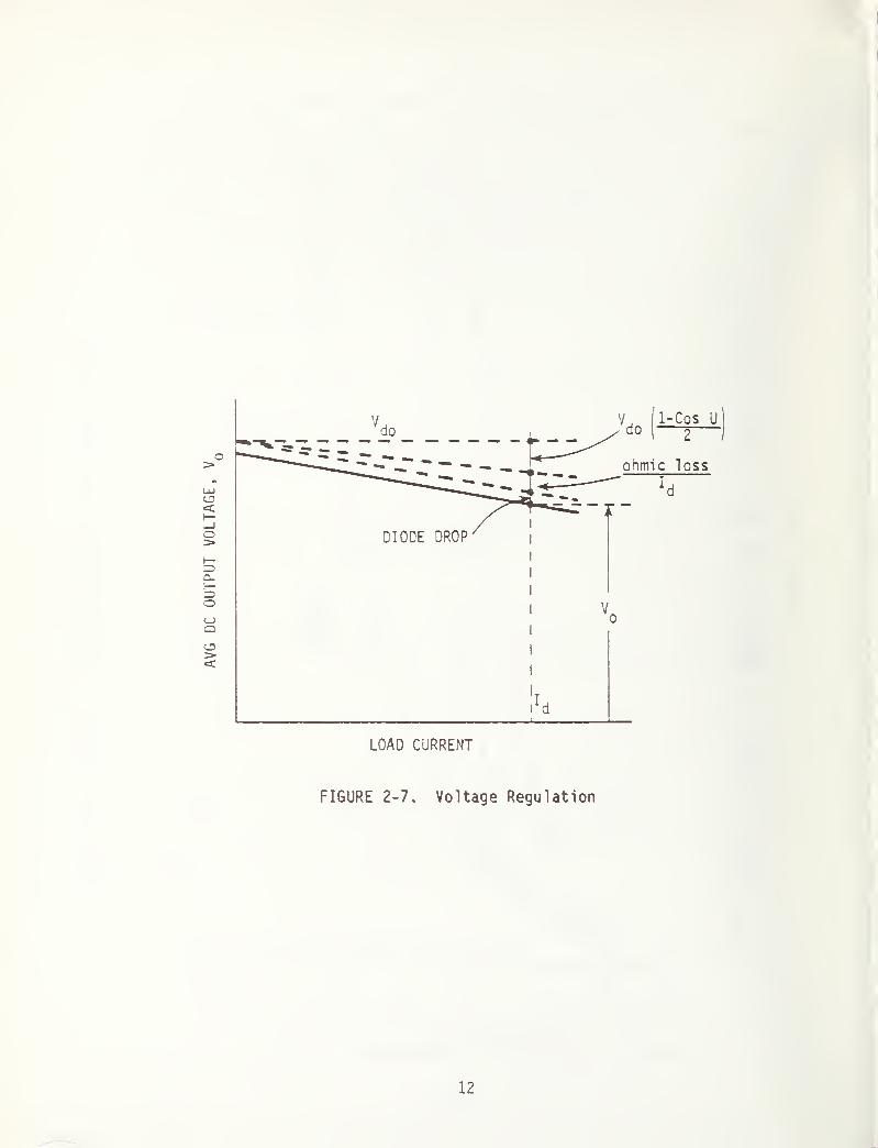
2.3 VOLTAGE REGULATION
The average dc output voltage of the rectifier reduces as the load
current is increased. Basically two components comprise this voltage
drop:
(a) commutation component: As the load current increases, the over-
lap angle u increases resulting in reduced output;
(b) ohmic loss component: With increased load current, the copper
losses in transformer, reactors and other components increase
and cause a drop in voltage output.
Any voltage drop across the conducting diode elements is quite
independent of the load current. It does not therefore, affect the
regulation characteri Stic of the rectifier, although the voltage output is
reduced by this voltage drop as in Figure 2-7.
2.4 OPERATION WITH UNBALANCED VOLTAGE INPUT
The earlier sections assumed that the rectifier was supplied with a
balanced three phase voltage source. The output voltage, therefore.
10
HARMONIC
ORDER
olO
11
FIGURE
2-6.
Variation
of
Harmonic
Components
with
Overlap
Angle
AVG
DC
OUTPUT
VOLTAGE,
FIGURE 2-7. Voltage Regulation
12

contained harmonic components only of the order 6, 12, 18 . . .6n of the
source frequency. The three phase voltages are, however, never perfectly
balanced. With unbalanced voltages, the dc output voltage contains
harmonic components of the order 2, 4, 6, 8, . . 2 n of the source frequency,
because the overlap angles and the resulting diode conduction patterns are
unsymmetrical , as shown in Figure 2-8; furthermore, if the six diode
elements D1 - D6 of the rectifier are not identical, i.e., if the voltage
drops across these elements for a given current are unequal, the output
voltage then contains all the harmonic components. The bridge rectifier
being a six pulse circuit, harmonic components of the order 6, 12, 18, ..6n
are, of course, quite predominant.
Such an analysis of the operation of the rectifier with unbalanced
input voltage appears in an Appendix to this report.
2.5 WAVEFORM OF AC NETWORK CURRENT
The line current waveforms of the rectifier appear in Figure 2-3.
the commutation process is considered, the current waveform can
represented as in Figure 2-9a, approximated by a trapezoidal waveform
Figure 2-9b. Mathematically the periodic function definition is:
f{0}=-jj(e+f + j) | - f “I +I
If
be
of
u_
2
“IP 3 9 ; '•tt u < n < IL + H3" 2
< 0 * 3 2
13

14
FIGURE
2-8.
Operation
with
Unbalanced
Voltage
Input

^ u ^
(b) APPROXIMATED
FIGURE 2-9. AC Waveform
15
t hThe amplitude of the m harmonic component of this current is given by
41I Sin ( 3 )
Sin ( 2 )
mu = —* m • ,nn
2(°T)
If the commutation process is ignored, u = o and then
41I
' A
dmo =
/JDZL\Sin'' 3 j
m
With these expressions some important conclusions can be drawn:
I
mo _ 1_
ho' m
with the harmonics of the order 5, 11, 17 . . .being out of phase with those
of the order 1, 7, 13 . . .etc.
Further
I
mu
*mo
/ mu
in1
2
mu2
f(m,u)
.
The function f(m,u), quite well known, is plotted in Figure 2-10.
The current presented here is the one in the lines directly feeding
the points a, b, c of the bridge circuit of Figure 2-1. If more than one
rectifier are supplied by the ac network, lower orders of harmonics are
effectively cancelled by properly phasing these rectifiers.
2.6 TWELVE PULSE RECTIFIER CIRCUITS
Higher pulse rectifier circuits are built by a series or parallel
connection of two or more six pulse circuits having appropriate phase
difference between the output voltages. A commonly used 12-pulse circuit
appears in Figure 2-11 where two six pulse rectifiers are connected in
16

oro
0111
I/nUJ
I ( n‘ m)^
17
FIGURE
210.
Effect
of
Commutation
on
AC
Network
Current

PRIMARYWINDINGS
SECONDARYWINDINGS
FIGURE 2-11. A 12-Pulse Rectifier (Series Connection)
18
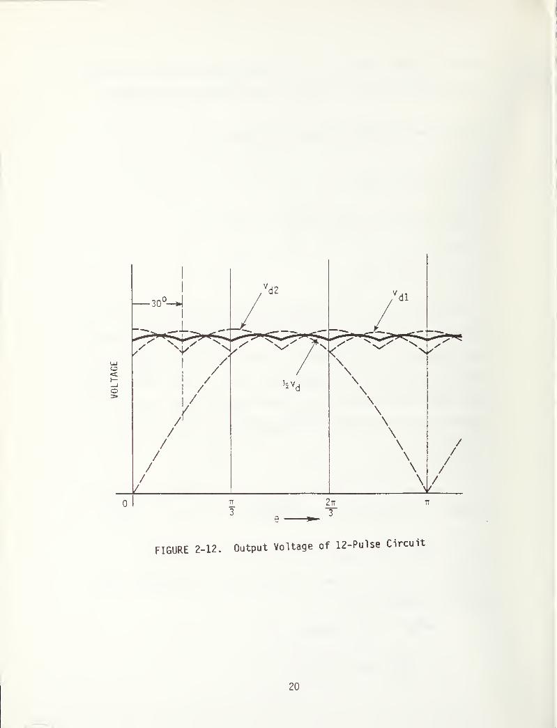
series. A phase difference of 30° appears when two sets of secondary
windings are used with one in delta and the other in a star connection.
The instantaneous output voltage of this circuit is:
The resulting dc average voltage then appears as:
Because V . and V , are shifted in phase by 30°, harmonic components°1 a
2
with harmonic orders that are odd multiples of six are out of phase and are
cancelled out. The output voltage V^, therefore, contains components with
harmonic orders that are multiples of 12. For a circuit supplied with
60Hz voltage source, therefore, the output contains harmonic components of
frequencies 720, 1440, 2160 . .Hz. The output voltage has a waveform shown
in Figure 2-12.
If the line-to-line voltages of the two secondary sections are equal,
the number of turns of the two sections must be related as
n«4 a\i' 1
One obtains the transformer winding current on the primary side by
equating the ampere-turns as:
*w7^w7 *wlNwl
+*w4^w4
Iw7-rr (lwl + * lw4)-
19
VOLTAGE
!
1
I
FIGURE 2-12. Output Voltage of 12-Pulse Circuit
20

The waveform of current through winding W^ and other currents appear as
shown in Figure 2-13. The rectifier circuit then appears as a 12-pulse
circuit to the ac network, as well as to the dc side load.
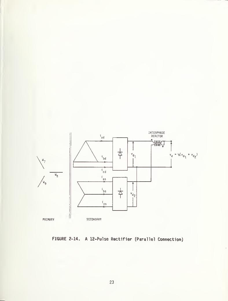
The two six pulse rectifiers may also be connected in parallel to
obtain a 12-pulse rectifier, as in Figure 2-14. Because the two output
voltages are not identically equal, some reactances are necessary in the
circuit to limit short circuit currents between the rectifiers. A
center-tapped reactor, known as an interphase reactor, is normally used as
shown. Any flux resulting from the dc component of the load current thus
cancels out, making a light reactor design possible.
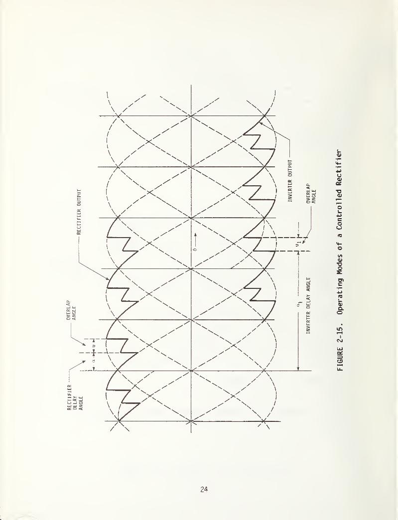
2.7 A CONTROLLED RECTIFIER/ INVERTER CIRCUIT
When thyristors replace all the diodes in the bridge circuit of Figure
2-15, the output voltage can be varied continuously from +V^o
to -V^ ,if
commutation is instantaneous. With a finite reactance in the circuit, this
range lessens, depending on the overlap angle.
One measures the firing angle a of the thyristors from the instant of
diode conduction (Figure 2-15). a is also called the delay angle because
the thyristor conduction is delayed by that angle. The commutation period,
i.e., the overlap angle for a given delay angle, is given by
2X I.
Cos (a + u) = Cos a n—
21

FIGURE 2-13. Currents in Different Windings
22
PRIMARY
FIGURE 2-14. A 12-Pulse Rectifier (Parallel Connection)
23
24
FIGURE
2-15.
Operating
Modes
of
a
Controlled
Rectifier
0 < 0 < - u
f- u<e<|
As the delay angle increases from o to tt, vdQ
goes from +Vdo
to -Vd .
When the output voltage of the circuit is negative, power flows from the dc
side to the ac side. One then speaks of the circuit as inverting. Figure
2-15 clearly illustrates these operating modes.
The harmonic components of this waveform are:
V 3V 1
^' mudm a rms = —
"l ) \/2a + e Cos (a + u)
jmu
-jm {Sin a + e Sin (a + u)} 3
and are plotted in Figure 2-16. For a = u = o, this expression reduces to
an earlier one:
V = 3V . /2amrms tt 2 ,
m -1
One must remember that '
m' is only a multiple of 6. Also, as the
delay angle increases, the total harmonic content of the output voltage
increases, although individual harmonic components may fluctuate over a
significant range.
The voltage output now is:
Vd
= V Sin (a + u + |+ 0 )
= *V Sin (a + u + |- + 0 ) . .
.
The average value of this voltage is
3VVda
=27
CCos a + Cos ( a + u ) ]
and with u = 0
3 V rVdaO
= ~ C0S “
25

DELAY
ANGLE
L
oCM
OCO
oCM
!N33d3d opA/
suutxnpA
CDUJQ
Cj.
<C
o
26
FIGURE
2-16.
Harmonic
Content
of
a
Controlled
Rectifier
Inverter circuits with higher pulse numbers are obtainable by series
or parallel connection of one or more six pulse circuits, as previously
explained.
2.8 RECTIFIER SUBSTATIONS FOR TRANSIT APPLICATION
A typical transit substation has two or more 6- or 12-pulse diode
rectifiers with a combined power rating of 2-10 MW. In the United States
two types of connections are widely used; one uses two separate 3 phase
transformers with 30° phase shift supplying two bridge rectifiers
connected in series or parallel, and the other uses a three winding
transformer supplying two bridge rectifiers in series or parallel as shown
in Figures 2-11 and 2-14. Both these connections result in a 12 pulse
rectifier circuit.
The Japanese, however, widely use 6 pulse circuits and are also
increasingly introducing inverter substations to ensure receptivity of the
third rai 1/catenary for regenerated power during vehicle braking. Such
inverter equipment is, however, not found in revenue service outside
Japan, although some experimental units were built in Europe earlier.
27
3. SUBSTATION HARMONICS AND TRACK CIRCUITS1,5, 6,
7
Two basic ways exist in which harmonic currents resulting from
operation of rectifier substations may cause potential interference with
audio frequency track circuits used for train detection, cab signalling,
and vehicle speed control. These are:
(a) conducted noise because of unbalance in propulsion return
current in running rails, and
(b) voltages induced in the track circuit by current carrying third
rai 1
,
One must, therefore, obtain components of propulsion current of
frequencies corresponding to substation harmonics.
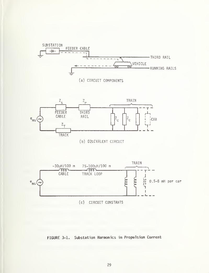
3.1 SUBSTATION HARMONICS IN PROPULSION CURRENT
Figure 3-1 presents a circuit that carries the propulsion current.
The equivalent circuit of the propulsion circuit also appears in the
J_ L.
figure. The voltage ems
is the rms value of the nrn
harmonic component of
the rectifier output at the substation. The impedances, Zs
, etc., are
the impedances of various components at the frequency under consideration.
The harmonic components e of six and twelve pulse rectifiers havems
been presented earlier. Note that the actual direct current drawn by the
train affects the value of ems
only indirectly, via the commutation overlap
angle.
28
SUBSTATION
_D -w-FEEDER CABLE
L
/ \VEHICLE2Bl 3SL
THIRD RAIL
RUNNING RAILS
(a) CIRCUIT COMPONENTS
TRACK
(b) EQUIVALENT CIRCUIT
TRAIN
FIGURE 3-1. Substation Harmonics in Propulsion Current

The actual values of the impedances Z$
, Zr
etc., are very 'site
specific*. However, the order of these impedances may be obtained as
follows:
(a) Feeder cable impedance Z - This cable usually is a 750-2000 MCM
cable with the impedances of the order of:
Rdc
* 4-2 mft/lOOm and L - 30 yH/100m
The effective ac resistance at any frequency increases because
of skin effect. For example, it may go up about 30 percent for
60 Hz, and for audio frequency range it may increase by a factor
as great as 5-7. The effective ac inductance, however, reduces
at higher frequencies, depending on the site topology. For
audio frequency range of interest (2-10 kHz), therefore, one may
consider the cable purely inductive.
(b) Third rail and running rail impedances - The dc resistance of
these rails is of the order of 1-2 m£2/100m, although the
effective ac resistance is possibly of the order of 15-30
mft/lOOm in the audio frequency range (2-10 kHz). The inductance
of these rails is in the range of 90-150 yH/lOOm for low
frequencies and drops by about 20 percent in the audio frequency
range. These rails are, however, electromagnetical ly linked,
and customarily one considers an equivalent inductance of a loop
formed by the third rail and the two running rails, instead of
the individual self inductances. This loop inductance could be
75-100 yH/lOOm, with the lower range applicable to high
30
frequencies. In the audio frequency range of interest, the
inductive reactance of these rails is 1-5 fl/lOOm, much larger
than the ohmic impedance.
(c) Car impedance - In chopper controlled or inverter controlled
cars, an L-C line filter isolates the third rail from the propul-
sion equipment. In the audio frequency range, therefore, a car
appears as a purely inductive impedance, in the range 0.5-8 mH
per car, depending on the filter design.
The equivalent circuit of Figure 3-lb now appears as in Figure 3-lc.
Considering the voltage unbalance on the ac side of the substation, the rms
harmonic component ems
of the rectifier output at rated load could be as
high as 3.0 - 0.5 percent of the dc output for audio frequency range of 1
kHz-6 kHz (see Appendix).
One can thus estimate with fair accuracy the substation harmonic
components of the third rail current.
3.2 CONDUCTED NOISE
Consider a track circuit as shown in Figure 3-2. The rails carry the
propulsion return current as shown. The voltage drops across the running
rails caused by the propulsion current appear as voltage sources for the
track circuit. The drops across the running rails, in addition, oppose
each other. The track circuit sees only the differential voltage as a
noise source. The noise current i
n$in the receiver is then given by:
31
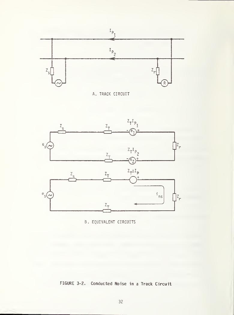
B. EQUIVALENT CIRCUITS
FIGURE 3-2. Conducted Noise in a Track Circuit
32
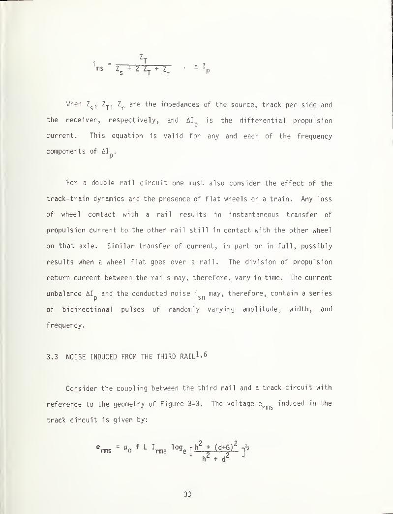
'ms=Tp-Z Z
T + zr
•4 ‘p
When Z , Zj, Zr
are the impedances of the source, track per side and
the receiver, respectively, and AI is the differential propulsionr
current. This equation is valid for any and each of the frequency
components of AI .
For a double rail circuit one must also consider the effect of the
track-train dynamics and the presence of flat wheels on a train. Any loss
of wheel contact with a rail results in instantaneous transfer of
propulsion current to the other rail still in contact with the other wheel
on that axle. Similar transfer of current, in part or in full, possibly
results when a wheel flat goes over a rail. The division of propulsion
return current between the rails may, therefore, vary in time. The current
unbalance AI and the conducted noise i „ may, therefore, contain a seriesp sn
of bidirectional pulses of randomly varying amplitude, width, and
frequency.
3.3 NOISE INDUCED FROM THE THIRD RAIL 1 * 6
Consider the coupling between the third rail and a track circuit with
reference to the geometry of Figure 3-3. The voltage erms
induced in the
track circuit is given by:
erms
*“o
f L*rms
lo9e[i>L+J£g}£ f
Iv +
33

\ \
\\
\
\
\
\
A, B -
C -
6 -
nb
NOISE AT
THE BOND
FIGURE 3-3. Noise Induction by the Third Rail
RAILSTHIRD RAILRAIL GAGE
34

where Irms
is the current in the third rail with a frequency f and L is the
length of the track circuit.
For long track circuits, the track impedance is quite large compared
to the bond impedance; therefore, if l_
uis the track circuit inductance per
unit length, the noise current ins
in the loop is:
rms
Vms 2ir f LuL Vms 2ttL
i°ge
ch2
+ (d GT
h2
+ d2
This ratio is independent of frequency and track circuit length. For
standard gage with G = 1.435 m and L = 1.3 pH/m, the ratio i /I is
about 22 percent for d = h = 0.3m and about 14 percent for d = h = 0.6m.
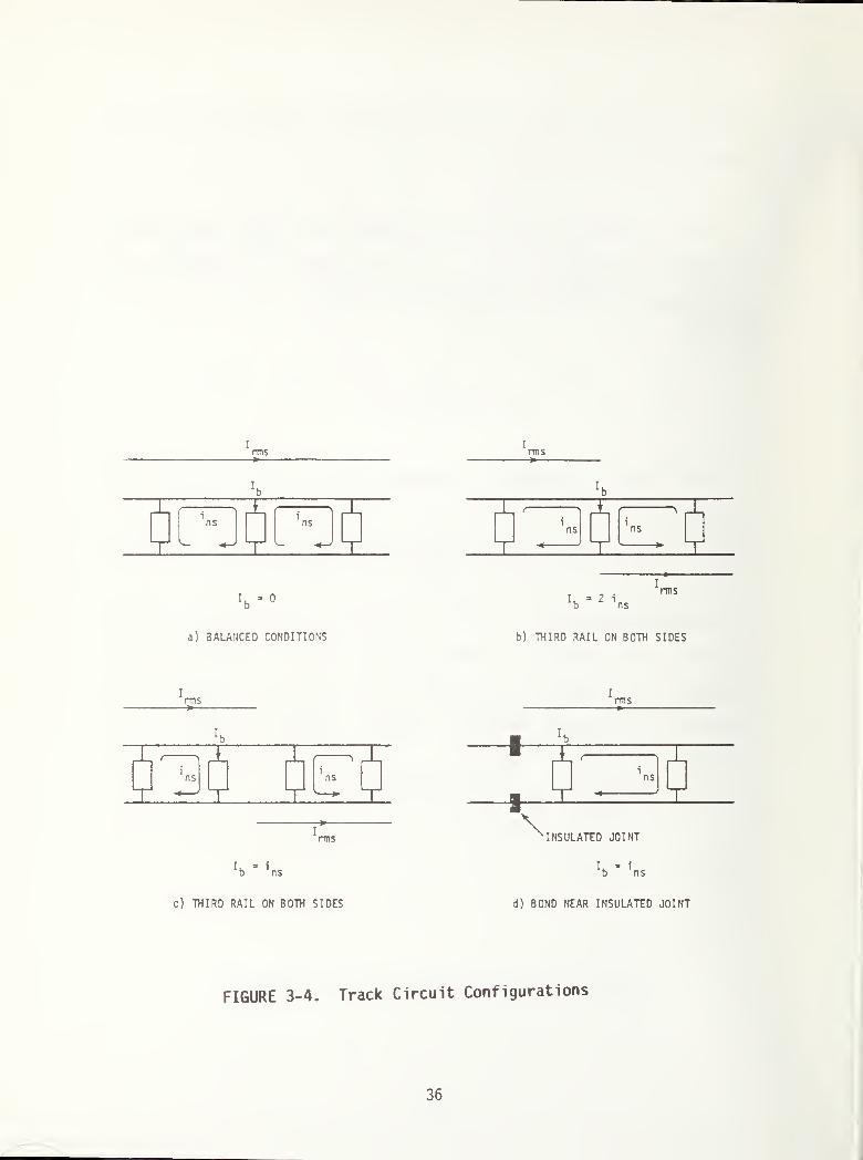
Because each bond is a part of more than one track circuit, the noise
current in the bond is not directly given by i . Figure 3-4 shows
different track circuit configurations, and for each configuration the
current in the bond is different. One can, however, estimate rather
accurately the current in the bond, as shown previously. Any possibility
of unwanted pick up or drop of a track relay depends on the characteristics
of the filter in the relay circuit, i.e., on the in-band component of the
current in the bond.
35
I
rmsI
rms
!b
- 2
Irms
a) 3ALANCED CONDITIONS b) THIRD RAIL ON BOTH SIDES
Irms
Irms
rms
Ib
1
ns
c) THIRD RAIL ON BOTH SIDES d) BOND NEAR INSULATED JOINT
FIGURE 3-4. Track Circuit Configurations
36

3.4 ASSESSMENT OF POTENTIAL FOR INTERFERENCE
Electromagnetic noise at substation harmonic frequencies present in
track circuits is caused by the basic rectifier operation and is
independent of the type of onboard propulsion control. For example, such
noise will be present in track circuits irrespective of whether the
vehicles use cam-controlled or chopper-controlled dc drive, or inverter
controlled ac drive. Each of this drive will, of course, cause additional
EM noise (with commutator frequency, chopper harmonic frequencies,
inverter harmonic frequencies, etc.), in track circuits according to its
operating characteristics. But the potential interference problems caused
by substation rectifier equipment can be investigated separately and inde-
pendently of other noise sources.
The substation harmonic frequencies are well defined - all are
multiples of the power source frequency (60 Hz in the U.S., 50 Hz and/or 60
Hz in Europe and Japan), although some are more predominant than the others
depending on the rectifier circuit configuration. Also, the amplitudes of
third rail harmonic currents are highest when a train is near a feeding
point on the third rail. When the length of running rail in propulsion
circuit is short, furthermore, the propulsion return current is more or
less shared equally between the two rails, unless an abnormally severe
imbalance between the two occurs because of loose connections or other
factors. Protecting against substation harmonics in general is easy,
except in site-specific problem areas, such as the third rail switching
sides at bonds, etc., where a high percentage of third rail harmonic
currents is induced in the track circuit. These must then be investigated
on an individual basis.
37
4. CONCLUSIONS
When a basic six pulse rectifier circuit is supplied with a balanced
three phase voltage source, the rectified output voltage contains harmonic
components with frequencies 6f, 12f, 18f. . .etc. Two such six pulse
circuits in series or parallel with a phase difference produce an effective
pulse number of 12. The voltage then contains frequencies of only 12f,
24f, 36f,..,. If, however, the input voltages are not balanced and the
bridge rectifier circuit is inherently unsymmetric, the output voltage has
all harmonics - f, 2f, 3f,..., although components with frequencies 6f,
12f, 18f,..., are predominant.
Currents of substation harmonic frequencies may flow through
impedance bonds of any track circuit either via a common ohmic path
(conducted noise due to propulsion unbalance in running rails) or because
of induction from the third rail. Any possibility of interference with
normal track circuit operation depends on the level of noise and
characteristics of track circuit receivers. The level of noise at
substation harmonic frequencies can, however, be estimated with fair
accuracy, and the track circuit protected, except under some site-specific
abnormal conditions.
38
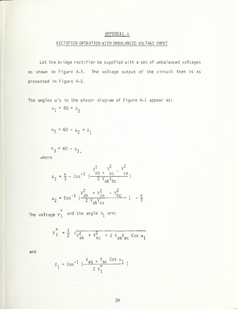
APPENDIX A
RECTIFIER OPERATION WITH UNBALANCED VOLTAGE INPUT
Let the bridge rectifier be supplied with a set of unbalanced voltages
as shown in Figure A-l. The voltage output of the circuit then is as
presented in Figure A-2.
The angles a's in the phasor diagram of Figure A-l appear as:
oi-^ = 60 + A£
= 60 - + Aj
a3
= 60 - 4
where
V2
V2
V2
a - 2L roc" 1 /ab + bc ca
N
3~ ^ os
' 2 V V'
ab bc
iV2
,+ V
2 - V2
-1 / ab ca bcAo = Cos
( o V VL * ab ca
The voltage anb the an 9^ e are:
* i
V , = I /T2 7721 2 v; h
+ V* +2 V a|V Cos a,
ab ac ab ac 1
and
i V , . V Cos a,~__-l / ab + ac 1 i
e1
= cos ( * j
2 V1
39

V * H(vab
Vac>
FIGURE A-l. Phasor Diagram
etc
.
40
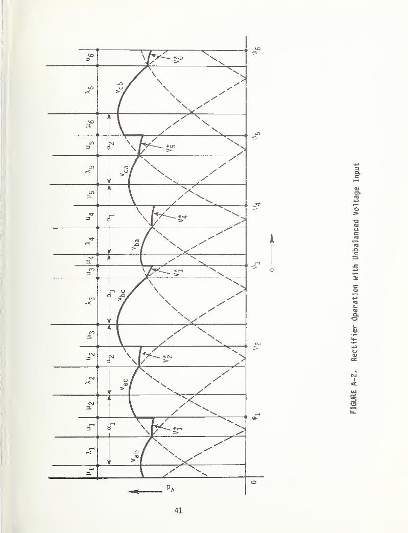
41
FIGURE
A-2,
Rectifier
Operation
with
Unbalanced
Voltage
Input
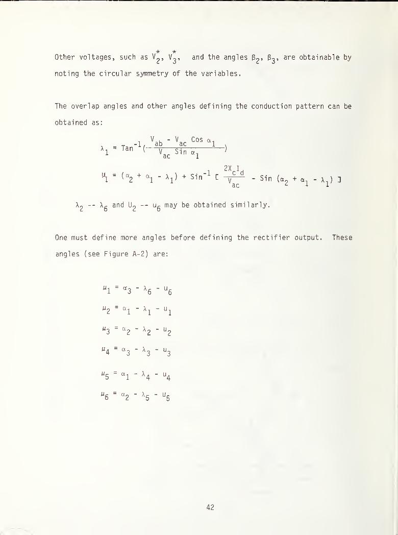
Other voltages, such as V^, V^, and the angles 83* are obtainable by
noting the circular symmetry of the variables.
The overlap angles and other angles defining the conduction pattern can be
obtained as:
X, =1
V K - \J Cos a.-r. -1, ab ac 1 \
Tan (
y c^rz )
acSin “1
, -1W1
=^a2
+ al
" xl)
+ Sin C
2 X I ,
c d
ac
- Sin (a2
+ 0^- Xj) ]
X2
~~ X6
anc^ ^2~~ u
6ma^ Gained similarly.
One must define more angles before defining the rectifier output. These
angles (see Figure A- 2 ) are:
42
T1
=“l
+ x!
+ ui
= Y.
T2
=‘‘'l
+ u2
+ X2
+ u2
' 1’l
+ ^2
f3 * h +
"3 + X3
+ u3
=*2 + fj
*4=
'•'a+ m
4+ X
4+ u
4= *
3+ ^
f5
= T4
+ h5
+ x5
+ U5
='*'4 +
T6
=*5 +
“6 + X6
+ U6
= ^ + f*
6
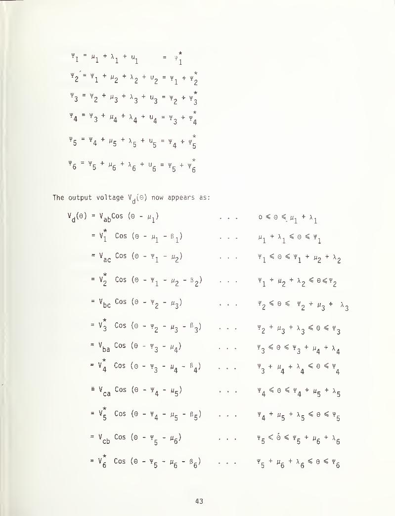
The output voltage V^(0) now appears as:
Vd
( 0 )= v
abCos (Q - U] )
V1
Cos (0 - ui-B
x)
’ Vac
Cos (0 - yi
‘ UZ
]
V2
Cos (0 - *1 - uz
= Vbc
Cos (0 - f2
- u3
]
= V3
Cos (0 - *2
' u3
Vba
Cos (0 - "3- V
*= V
4Cos (0 • f
3- w
4
* Vca
Cos (0 - *4 - ^V5
Cos (0 - "4 ' u5
= Vcb
Cos (0 -*5 - y6
}
*UD
>II Cos (0 - "5 ‘"6
'
0 < 0 <
+ Xj < 0 < ^T1< 0 < + U
2+ X
2
^ + p2
+ X2< 0<^
2
t2o< f
2+ U3+ x
3
t2
+ U3
+ *3< 0 < t
3
»3 < e < t3
+ „4+ x
4
"3
+ H4
+ "4 < 3 <%
t4< 0 < T
4+
"5 + X5
f4 + h
5+ X
5< 0 < t
5
»5< 0 < f
5+ „
6+ x
6
*5 + W6
+ X6< 9 < T
6
43
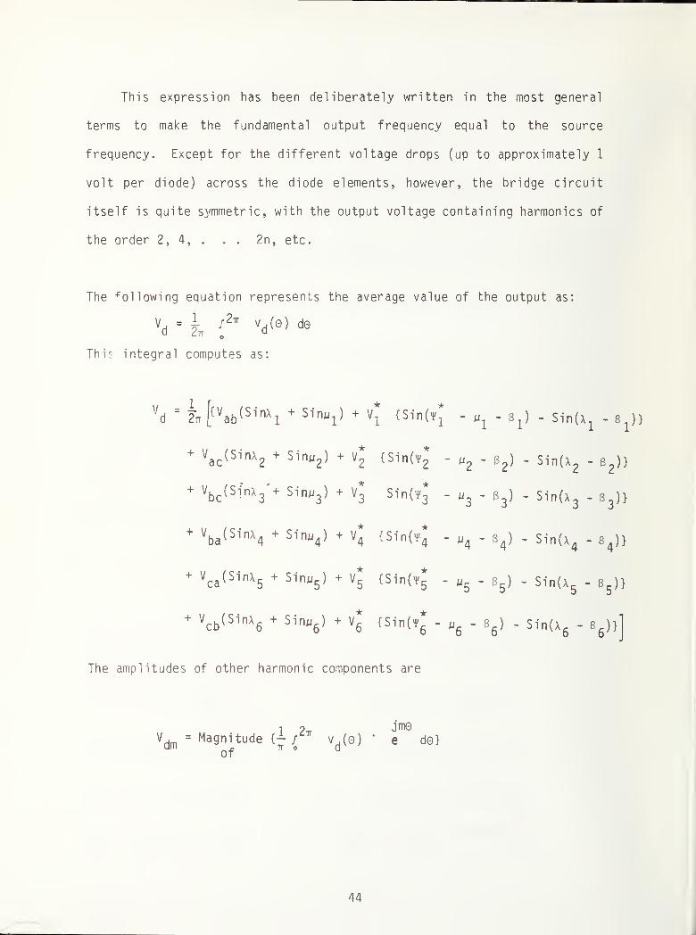
This expression has been deliberately written in the most general
terms to make the fundamental output frequency equal to the source
frequency. Except for the different voltage drops (up to approximately 1
volt per diode) across the diode elements, however, the bridge circuit
itself is quite symmetric, with the output voltage containing harmonics of
the order 2, 4, . . . 2n, etc.
The following equation represents the average value of the output as:
vd - i ^ V0 ) d®
This integral computes as:
The amplitudes of other harmonic components are
V .= Magnitude {- /
2tt
am _ if oof
jmovd(o) * e do}
44

This integral is very complex, but a typical integral of this type is
evaluated in the example below. All the components of the above integral
are obtainable similarly.
H jm©I = f Cos (0 - A) e do
L
1jmH jmL
~2 { -Sin(H-A) e + Sin(L-A)em - 1
jmH jmL- jmCos (H-A)e + jmCos(L-A)e }
for m ^ 1
H-L iJ(2H-A) j(2L-A)
=“T e '
4fe - e
• for m = 1
A computer program was prepared to compute the harmonic components of
the rectifier output as defined above. Computations were made for voltage
unbalance of up to 3 percent between the line voltages and an overlap
corresponding to ^c^^phrms ^ percent. The results indicate
that for audio frequency range of interest, i.e., harmonic orders between
18-100, the rms harmonic components can be as high as 0.5 - 3.0 percent,
with the higher percentage corresponding to the lower frequencies.
45

REFERENCES
1. Nene, V.D., "Electromagnetic Interference Characteristics of AdvancedPropulsion Systems for Urban Rail Vehicles", Urban Mass Transporta-tion Administration Report UMTA-VA-06-0075-81-1 , 1981.
2. Frasco, L., et al., "Electromagnetic Compatibility of Advanced Pro-pulsion Systems", Proc. of the International Conference on AdvancedPropulsion Systems, February 5-6, 1980. Urban Mass TransportationAdministration Report No. D0T-UMTA-VA-06-0053-80-1 , 1980. pp. 193-
213.
3. Holmstrom, F. Ross, "Chopper Induced Interference in Audio FrequencyTrack Circuits, "Urban Mass Transportation Administration Report No.UMTA-MA-06 -0025 -80-5 , 1980.
4. Holmstrom, F. Ross, "Comparisons of Inductive Chopper Interference
from MARTA, BART, and NYCTA," Presented at TSC Rail Transit EMI
meeting, San Francisco, California, June 1980.
5. Amler, J., "The Effects of the DC-Chopper Technology in Public RapidTransit Passenger Transport (PRTPT) - Summary," report by Verkehrs-Aktiengesel 1 schaf t, Nurnberg, Germany, 1978.
6. Hoelscher, J., "Electromagnetic Coupling between the Third Rail and
Track Circuits," - a private communication.
7. Rudich, R., "Conducted Emissions" Garrett AiResearch Mfg. Co. MemoNo. 81-17750, presented at Rail Transit EMI Technical Working Groupmeeting at Transportation Systems Center, Cambridge, Massachusetts,24 January 1981.
46
APPENDIX B
REPORT OF NEW TECHNOLOGY
This report develops a method for estimating electromagnetic noise
received by track circuits from rectifier substations. This method had not
previously been published.
200 copies U. S. GOVERNMENT PRINTING OFFICE: 1982--50 1-336 -52
47/48

ZC 2o o> cdCD "1 3 C0 3 CD S.c+ 3 * H
D >Hi h- <1M- O f—'•
CD H- oo"1 O 0)
—ZT Ln I
Xm
co•
m
j>LJ _

? 5= <s
a S
DOT LIBRARY
TJ 3) "U
§1
1
§^ ® 5 <o
3 a -n
5$ZU> i V)
j; J^ 03 03