Harmonic Analysis of a Synchronized Pulse-Width-Modulated Three-Phase Inverter
6
IEEE TRANSACTIONS ON INDUSTRY APPLICATIONS, VOL. IA-10, NO. 1, JANUARY/FEBRUARY 1974 Harmonic Analysis of a Synchronized Pulse- Width- Modulated Three- Phase Inverter SHASHI B. DEWAN, MEMBER, IEEE AND JAMES B. FORSYTHE, MEMBER, IEEE Abstract-In pulsewidth-modulated inverters used for variable-fre- quency applications, a number of harmonic control policies can be used. Most of these policies are complex to implement by hardware. The most simple and yet effective technique is synchronizing or the syn- chronized harmonic control policy. This paper uses double Fourier analysis techniques to obtain the output harmonics as a function of pulsewidth, pulsing frequency, and output frequency. The method obtains the harmonics as analytical functions and thus provides the necessary relationships for control studies and system optimization. The more significant theoretical results are provided and theoretical and experimental results obtained from a 25-kW three-phase pulsewidth- modulated inverter, are compared. INTRODUCTION A VARIETY of pulsewidth-modulated (PWM) inverter sys- l tems have been outlined in the literature [1]-[4] to control the speed of squirrel-cage induction motors. These systems are generally quite complex and very few experimental or theoretical results have been published concerning operating limitations and design techniques. Overall system design re- mains an art in many cases due to lack of practical design methods. To assist a designer, this paper provides the harmonic behavior of the synchronized PWM three-phase inverter. The synchronized policy is the easiest to achieve with simple con- trol hardware. This paper describes briefly the various harmonic control policies in pulsewidth-modulated inverters. A method of analysis is outlined to obtain the output voltages of syn- chronized PWM inverters as continuous functions of inverter control variables. The synchronized waveform harmonic be- havior is described and theoretical predictions are compared with experimental results obtained from a 25-kW three-phase PWM inverter [5 1. PWM HARMONIC CONTROL TECHNIQUES A brief sample of the variety of harmonic control policies available in PWM three-phase bridge inverters is listed below [1] -[5]: 1) integer pulse number per mode policy, 2) sinusoidal pulsewidth distribution policy, 3) constant-frequency unsynchronized policy, 4) constant-frequency synchronized policy. Paper TOD-72-33, approved by the Static Power Converter Committee of the IEEE Industry Applications Society for presentation at the 1971 IEEE Industry and General Applications Group Annual Meeting, Cleveland, Ohio, October 18-21. Manuscript released for publication May 2, 1972. S. B. Dewan is with the University of Toronto, Toronto, Ont., Canada. J. B. Forsythe was with the University of Toronto, Toronto, Ont., Canada. He is now with Garrett Corporation, AiResearch Division, Torrance, Calif. 90509. With the integer pulse number per mode policy, the pulse distribution for each mode remains constant, equal, and integer for a limited variation in the fundamental frequency. Voltage control is achieved by step increasing the number of pulses per mode as the fundamental frequency is changed through preselected ranges. Although this method requires a relatively low peak switching rate for the inverter components, the control logic is often complex. For resonant loads which may generate large transient currents due to step changes in excitation, a considerable degree of control logic is required to maintain smooth harmonic variation as the number of pulses per mode is step changed. The sinusoidal pulsewidth distribution policy offers excel- lent harmonic control in comparison with the other methods listed above. In order to provide this control, a relatively high peak switching rate for the inverter components is required to supply a large number of pulses per mode. In addition, the method is relatively difficult to implement and requires com- plex logic. If the output voltage envelope of Fig. l(a) is viewed as a modulation of a constant-frequency rectangular waveform, the pulses of which are all equal but have variable width, then the constant-frequency unsynchronized waveform of Fig. l(b) is generated. Voltage control is by pulsewidth modulation and reducing the fundamental frequency will automatically in- crease the number of pulses per mode for harmonic control. As shown, the waveform need not by symmetrical on a mode, half-cycle, or even several-cycle basis. It can be shown that in this method dc voltage levels will occur and subharmonic frequencies may exist in the output voltage waveform [5]. The analysis shows that the dc component may be reduced by using relatively large pulse frequencies. This method, however, is relatively easy to implement and fully utilizes the maximum switching capability of the inverter for all ranges of operation. To eliminate the dc component and possibility of subhar- monics, the start of each mode may be used to resynchronize the constant-frequency rectangular waveform as illustrated in Fig. l(c). With this constant-frequency synchronized policy, voltage control results from pulsewidth modulation, and as the fundamental frequency is decreased, the number of pulses per mode increases to provide harmonic control. The method is relatively easy to implement but does not utilize the inverter switching capability to its fullest extent. This latter method of harmonic control, the constant- frequency synchronized method, was selected for investigation since it is relatively easy to implement and provides a mechanism for smooth harmonic control. In Fig. l(c) the variables over which control is necessary to implement the harmonic control policy are illustrated. Referring to the pulses within a mode as 117
-
Upload
independent -
Category
Documents
-
view
1 -
download
0
Transcript of Harmonic Analysis of a Synchronized Pulse-Width-Modulated Three-Phase Inverter
IEEE TRANSACTIONS ON INDUSTRY APPLICATIONS, VOL. IA-10, NO. 1, JANUARY/FEBRUARY 1974
Harmonic Analysis of a Synchronized Pulse-Width-Modulated Three-Phase Inverter
SHASHI B. DEWAN, MEMBER, IEEE AND JAMES B. FORSYTHE, MEMBER, IEEE
Abstract-In pulsewidth-modulated inverters used for variable-fre-quency applications, a number of harmonic control policies can be used.Most of these policies are complex to implement by hardware. Themost simple and yet effective technique is synchronizing or the syn-chronized harmonic control policy. This paper uses double Fourieranalysis techniques to obtain the output harmonics as a function ofpulsewidth, pulsing frequency, and output frequency. The methodobtains the harmonics as analytical functions and thus provides thenecessary relationships for control studies and system optimization.The more significant theoretical results are provided and theoreticaland experimental results obtained from a 25-kW three-phase pulsewidth-modulated inverter, are compared.
INTRODUCTIONA VARIETY of pulsewidth-modulated (PWM) inverter sys-l tems have been outlined in the literature [1]-[4] tocontrol the speed of squirrel-cage induction motors. Thesesystems are generally quite complex and very few experimentalor theoretical results have been published concerning operatinglimitations and design techniques. Overall system design re-mains an art in many cases due to lack of practical designmethods. To assist a designer, this paper provides the harmonicbehavior of the synchronized PWM three-phase inverter. Thesynchronized policy is the easiest to achieve with simple con-trol hardware.This paper describes briefly the various harmonic control
policies in pulsewidth-modulated inverters. A method ofanalysis is outlined to obtain the output voltages of syn-chronized PWM inverters as continuous functions of invertercontrol variables. The synchronized waveform harmonic be-havior is described and theoretical predictions are comparedwith experimental results obtained from a 25-kW three-phasePWM inverter [5 1.
PWM HARMONIC CONTROL TECHNIQUESA brief sample of the variety of harmonic control policies
available in PWM three-phase bridge inverters is listed below[1] -[5]:1) integer pulse number per mode policy,2) sinusoidal pulsewidth distribution policy,3) constant-frequency unsynchronized policy,4) constant-frequency synchronized policy.
Paper TOD-72-33, approved by the Static Power Converter Committeeof the IEEE Industry Applications Society for presentation at the 1971IEEE Industry and General Applications Group Annual Meeting,Cleveland, Ohio, October 18-21. Manuscript released for publicationMay 2, 1972.
S. B. Dewan is with the University of Toronto, Toronto, Ont.,Canada.
J. B. Forsythe was with the University of Toronto, Toronto, Ont.,Canada. He is now with Garrett Corporation, AiResearch Division,Torrance, Calif. 90509.
With the integer pulse number per mode policy, the pulsedistribution for each mode remains constant, equal, andinteger for a limited variation in the fundamental frequency.Voltage control is achieved by step increasing the number ofpulses per mode as the fundamental frequency is changedthrough preselected ranges. Although this method requires arelatively low peak switching rate for the inverter components,the control logic is often complex. For resonant loads whichmay generate large transient currents due to step changes inexcitation, a considerable degree of control logic is required tomaintain smooth harmonic variation as the number of pulsesper mode is step changed.The sinusoidal pulsewidth distribution policy offers excel-
lent harmonic control in comparison with the other methodslisted above. In order to provide this control, a relatively highpeak switching rate for the inverter components is required tosupply a large number of pulses per mode. In addition, themethod is relatively difficult to implement and requires com-plex logic.
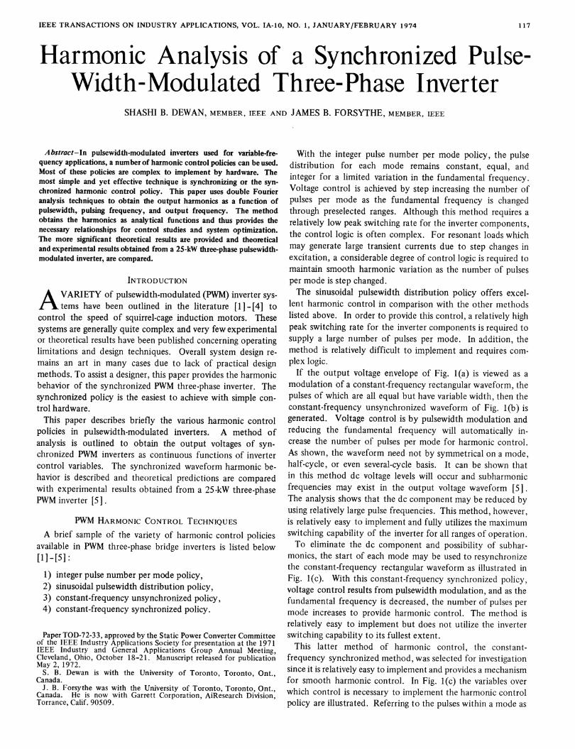
If the output voltage envelope of Fig. l(a) is viewed as amodulation of a constant-frequency rectangular waveform, thepulses of which are all equal but have variable width, then theconstant-frequency unsynchronized waveform of Fig. l(b) isgenerated. Voltage control is by pulsewidth modulation andreducing the fundamental frequency will automatically in-crease the number of pulses per mode for harmonic control.As shown, the waveform need not by symmetrical on a mode,half-cycle, or even several-cycle basis. It can be shown thatin this method dc voltage levels will occur and subharmonicfrequencies may exist in the output voltage waveform [5].The analysis shows that the dc component may be reduced byusing relatively large pulse frequencies. This method, however,is relatively easy to implement and fully utilizes the maximumswitching capability of the inverter for all ranges of operation.To eliminate the dc component and possibility of subhar-
monics, the start of each mode may be used to resynchronizethe constant-frequency rectangular waveform as illustrated inFig. l(c). With this constant-frequency synchronized policy,voltage control results from pulsewidth modulation, and as thefundamental frequency is decreased, the number of pulses permode increases to provide harmonic control. The method isrelatively easy to implement but does not utilize the inverterswitching capability to its fullest extent.This latter method of harmonic control, the constant-
frequency synchronized method, was selected for investigationsince it is relatively easy to implement and provides a mechanismfor smooth harmonic control. In Fig. l(c) the variables overwhich control is necessary to implement the harmonic controlpolicy are illustrated. Referring to the pulses within a mode as
117
IEEE TRANSACTIONS ON INDUSTRY APPLICATIONS, JANUARY/FEBRUARY 1974
(a) VC
(b) v;1
(c) V
VBC
VCA
1FFL,IIZInD 2 3 4 |5 6 I
I
I n n 1 I
InF iI u l0
LI IIIL. h IIjT
Fig. 1. (a) Line-to-line output voltage envelope. (b) Constant-frequencunsynchronized waveform. (c) Constant-frequency synchronizethree-phase voltage waveforms.
multipulses, definitions of the control variables are as follows:
T pulsewidth, secondsTp multipulse period, secondsTm mode period, seconds.
t The fundamental period T for constant fundamental frequencywill always equal six times Tm.
CCI OUTPUT VOLTAGES AS CONTiNUOUS FUNCTIONS OFINVERTER CONTROL VARIABLES
t Many methods of control system design and optimizationrequire a continuous function representation of the systemunder study. A double Fourier analysis method described in
t this section produces the desired information.In brief, the method of analysis proceeds as follows.
vlu(t) may be viewed as the product of the voltage envelopeVe(t) and a pulse operator PO(t)
v14(t) = Ve(t) * PO(t). (1)
Considering that vl,(t) has alternation symmetry and is alwayst zero for 27r/3 c < t <ar/l, then
vl4(t)= 1 Cq cos q cot + Dq sin qLot (2)q
"I where
E -
V(t)
-e E-ive (f )
-E-
-ft 2le*3 I I 2i
°hLnh nhnhnh rihnh
11/W
JrlW
Cq =2WIirf
2,lr/3^= 2C/t
J/Lr/
vl4(t) - cos qct - dt
3L)
Ve(t) PO(t) * cos qwt * dt
F3(A
ve(t) PO(t) * cos qwt - dt
J2 IrT3
+ ve(t) PO(t) * COS qwt * dt13w
(3)
tand
1.o-p(e)
n(d)
(e)1.0-
p(t- Y3,-)
t
Dq = 21/r
-i n n n n Fl Ji nI
In nrI ~ I
°. I I t
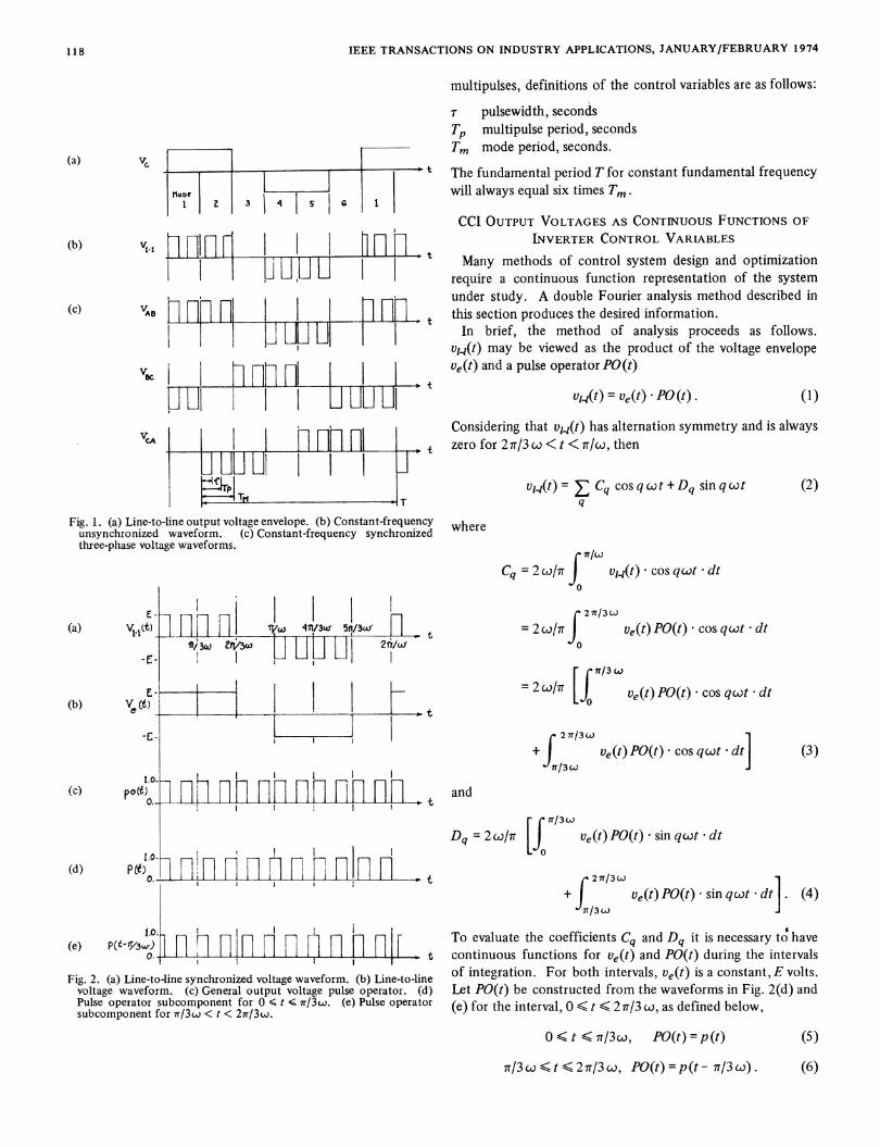
Fig. 2. (a) Line-to-line synchronized voltage waveform. (b) Line-to-linevoltage waveform. (c) General output voltage pulse operator. (d)Pulse operator subcomponent for 0 6 t S ir/33. (e) Pulse operatorsubcomponent for ir/3w < t < 2ir/3w.
ve(t) PO(t) * sin qcwt * dt
J2 7r/3 w+ Ve(t) PO(t) * sin qcot dt .
lr/3w
(4)
To evaluate the coefficients Cq and Dq it is necessary to havecontinuous functions for ve(t) and PO(t) during the intervalsof integration. For both intervals, ve(t) is a constant, E volts.Let PO(t) be constructed from the waveforms in Fig. 2(d) and(e) for the interval, 0 S t < 2 7r/3 co, as defined below,
0< t < r/3w, PO(t)= p(t) (5)
7r/3 coS t < 2 1r/3 o, PO(t) = p (t - 7r/3 w) . (6)
IT-Ti
(a)
(b)
(c) po(t
t
118
L
la
DEWAN AND FORSYTHE: PULSEWIDTH-MODULATED INVERTER
Substituting from (5) and (6) and for ve(t) into (3) and (4),
- [f7/3wCq = 2 wE1r p(t) * COS qcot - dt
+ p(t- ir13c).ocosqwt.dtl/3w
rl3wDq =2c2EIirf p(t) * sin qwt - dt
+ pp(t - 7T/3)* sin qcjt * dt . (8)
Since p (t) and p(t - rr/3 co) can be represented by Fourieranalysis as continuous functions of the control variables T, Tp,and Tm, then Cq, Dq, and therefore vlu4(t) can also be repre-sented as continuous functions of these variables.From the analysis [5], the normalized equations for Cq and
Dq are given by (Tp = l/fp = 2rr/lop, Tm = 1/6f = r/3co):
TCq TI 327 sin
whereq = 1,5,7,11,13, .These equations show that the harmonic amplitudes are
functions of the number of pulses per mode and the nor-malized pulsewidth only. From the constraints on q it can beshown that only integer-valued harmonics which are odd andnot triplen will exist in the output voltage waveform [51.
(7) The next section describes the general behavior of theseharmonics using data derived from (2), (12a), and (12b).
GENERAL DESCRIPTION OF THE SYNCHRONIZEDWAVEFORM HARMONIC BEHAVIOR
As the inverter control variables are varied over a wide range,the output voltage harmonics display characteristic patternswhich may be approximated by relatively simple figures. A setof empirical formulas and graphs, which are based on data ob-servation over wide ranges of normalized ratios P and T,, aredescribed in this section. Before proceeding, it is useful tointroduce the term "dominant harmonic" as it is a key todescribing the general harmonic behavior. A sample illustra-tion of the frequency spectrum is given in Fig. 3. In thisexample there are three pulses per mode in the output voltage
)__ (2 XrX (3ncp/cl) cos 6 + 2q sin (qrr/3) [- 2 sin (n 7Trp/3 + 6 ) + sin 6 ] ]) +E 1-Cos jX( )2 qJ
(9az
- Cos (2;nr)X (2nwcop/l) sin (q713) [- 2 cos (n 7Tpl3 + 6) + cos 6] - 3q sin 6] (9b
where q = 1, 5, 7,1l, 13, * * *, and
fp pulsing frequency in hertz, = l/Tpcop pulsing frequency in radians per second, = 2irfpf inverter frequency in hertz, = 1/T = I/Tmco inverter frequency in radians per second, = 2rrfr pulsewidth in seconds (Fig. 1)
6 tan1 sinnn c 1[1- cos n coprJ
Letn=T/TpT, O<.T l.0
P = fp/6f, P < 1.0 .
)
waveform, and each pulse has a normalized width of 0.2.Aq and AI are the rms amplitudes of the qth harmonic andfundamental voltages, respectively. The notation qdom(dominant harmonics) is used to refer to values of q which inthe frequency spectrum will locate relative maxima in theamplitude envelope.The general location formula for the dominant harmonics is
a function only of the number of pulses per mode P. Thisformula shows that for any P there will be an infinite series ofqdom values spaced at intervals of 6P. Since the only con-straint on P is that P > 1, then qdom may take on any value in
(10) the region 6P < qdom(11)
Equation (10) defines the pulsewidth normalized to the multi-pulse period and P represents the number of pulses in the out-put voltage waveform. Substituting these variables into (9a)and (9b), the equations for Cq and Dq become
Cq =r [ q sin (q3) + E 1, - cos (27rnTn) X
qd.0 = 6nP, n = 1, 2,3, -.
For the example of Fig. 3, P = 3, such that
qdom= 18n,n3= 1,2, 3,-l0 -
= 18,36, 54,72, 90, 108, -- - .
(13)
(14)
l8nPcos 6 + 2q sin (q7r/3) [-2 sin (27rnP+ 6) + sin 6]1(6nP)2 - q
( 2a)
1 3rn °° X 12nPsin (qir/3) [-2 cos (27rnP+ 6) + cos a] - 3q sin 6Dq =- -q E -n1 - cos(2rnT,X (6np)2 - qJ2
119
)1 3 -r 00 -v[2
Dq = + Ep n=l7r qT n7r
(I 2b)

IEEE TRANSACTIONS ON INDUSTRY APPLICATIONS, JANUARY/FEBRUARY 1974
",
I1 I, rT- )-I-I -
lo 20 30 40 50 Co 70 5o 9o0 16o
Fig. 3. Normalized frequency spectrum of synchronized waveform with three pulses per mode and 20 percent pulsewidth(P= 3, -rn = 0.2).
These values for q identify where the amplitude envelope mayhave relative maxima. It is apparent in the figure that theamplitude envelope does not have a relative maximum at the90th dominant harmonic. This is due to the fact that thedominant harmonic amplitudes are also functions of the pulse-width. Consequently, the dominant harmonics are consideredordered and are identified as the 1st, 2nd, 3rd, etc., in ac-
cordance with the generating value of n in (13). The domi-nant harmonic derived from the n = 2 locus for any value ofPis referred to as the 2nd dominant harmonic. To a first ap-
proximation, the amplitude function for each qd,0/6P is a
function of pulsewidth only.The normalized amplitude functions for the first two orders
of dominant harmonics are illustrated in Fig. 4. In Fig. 4(a),the first-order dominant harmonic amplitude (qdom/6P = 1.0)at 100 percent pulsewidth has a maximum value of 0.144.This maximum value is determined by the minimum value ofq for an existing output voltage harmonic which satisfies (13)for n = 1. As the pulsewidth is decreased, the normalizedamplitude increases to a value greater than 1.0 near zero pulse-width.
Fig. 4(b) illustrates the amplitude variation for the 2nd-order dominant harmonic. Similarly, loci for the higher orderdominant harmonic can be calculated [5].For values of q whiclh do not satisfy (13), the amplitude
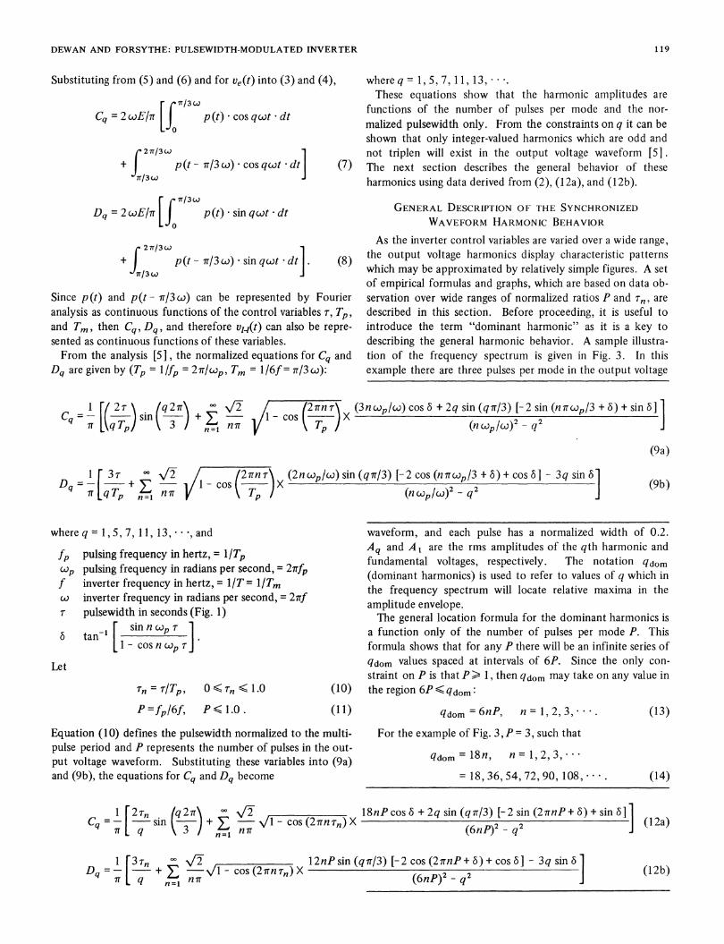
functions do not display approximate characteristic patterns.Fig. 5 illustrates amplitude functions for q/6P= 0.5. Thesefunctions cannot be approximated by a single function foreach value of q/6P. However, for each q/6P, a maximumamplitude boundary for q > 5 can be determined. Thisboundary represents amplitudes considerably less than the peakvalue of the dominant harmonics for q/6P = 0.5, 1.5, 2.5, 3.5,
As q/6P approaches qdom /6P, the maximum amplitudeboundary approaches the amplitude function for qdom/6P.For the boundary given by q/6P = 0, the number of pulses
per mode P must be infinite for the finite values of q. Theharmonic amplitudes for this condition are not functions ofthe pulsewidth and are given by [5]
Aq 1 (15)
A1 q
1.
Al/Ai
0.
(a)
AVAi
(b)
Fig. 4. (a) Theoretical and experimental comparison of first dominantharmonic amplitude function (q/6P = 1.0, rn-normalized pulse-width). (b) Theoretical and experimental comparison of 2nd domi-nant harmonic amplitude function (q/6P = 2.0).
Al/A1
0.
120
I.
11
1.
liiI
\1
- T
DEWAN AND FORSYTHE: PULSEWIDTH-MODULATED INVERTER
1. -
Ao/Al
-
1.
VG6PU 0-5
I IPRXDICTCD EXPERIMENTAL
5 I7 la
.1,_ __
0 - - a
0o fn J
I
Fig. 5. Theoretical and experimental comparison of nondominantharmonic amplitude functions.
APPROXIMATE SUMMARY OF COMPLETEHARMONIC BEHAVIOR
Although the harmonic amplitude functions of pulsewidthfor nondominant harmonics are not characterized by functionsof q/6P and Tn only, it is useful to construct a three-dimensional figure to provide general information for design or
control purposes. This information is summarized in Fig. 6.For integer values of q/6P, the harmonic amplitude functions
of pulsewidth will approximately correspond to the curves inFig. 4. With noninteger values of q/6P, the amplitude functionof pulsewidth may take on any value within the solid. Forspecific values of P and q, there will only be one single-valuedamplitude function of pulsewidth. The vertical planes forinteger values of q/6P in Fig. 6 indicate that the amplitudefunction takes on its maximum value.From (15) with q/6P= 0, the maximum value ofAqIAI for
any harmonic which exists in the output voltage will be givenby the lowest harmonic, which is the 5th. In Fig. 6 this valueof AqIA I = 0.2 represents the upper boundary of the solid atq/6P= 0.For Tn = 1.0, the harmonic content of the output voltage is
independent of P. The maximum values of AqIAI for theplane Tn = 1.0 in Fig. 5 occur for P= 1. It is this condition(P = 1) which locates the upper amplitude boundary of thesolid for Tr = 1.0 as shown in Fig. 6. For P. 1.0, the upper
amplitude boundary for r, = 1.0 will be less than or equal tothe boundary illustrated.The amplitude variation for a constant pulsewidth near
integer values of q/6P also depends on the specific values of qand P. Generally, for moderate or high values of q (q > 23),the slopes are greater than illustrated. For low values of q theslopes are approximately as shown in the figure.
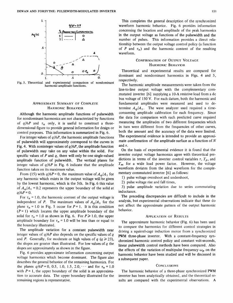
Fig. 6 provides approximate information concerning outputvoltage harmonics which become dominant. The figure alsodescribes the general behavior of the remaining harmonics. Forthe planes q/6P 0, 0.5, 1.0, 1.5, 2.0, * * and for T, = 1.0with P= 1, the upper boundary of the solid is an approxima-tion to accurate data. The upper boundary illustrated for theremaining regions is representative.
This completes the general description of the synchronizedwaveform harmonic behavior. Fig. 6 provides informationconcerning the location and amplitude of the peak harmonicsin the output voltage as functions of the pulsewidth and thenumber of pulses. This information provides a direct rela-tionship between the output voltage control policy (a functionof P and 'rn) and the harmonic content of the resultingwaveform.
CONFIRMATION OF OUTPUT VOLTAGEHARMONIC BEHAVIOR
Theoretical and experimental results are compared fordominant and nondominant harmonics in Figs. 4 and 5,respectively.The harmonic amplitude measurements were taken from the
line-to-line output voltage with the complementary com-mutated inverter [6] supplying a 10-A resistive load from a dcbus voltage of 150 V. For each datum, both the harmonic andfundamental amplitudes were measured and used to de-termine AqIAi. The wave analyzer used required a time-consuming amplitude calibration for each frequency. Sincethe data for comparison with each predicted curve requiredmeasuring the amplitudes of two different frequencies whichin turn were different from the frequencies of other curves,both the amount and the accuracy of the data were limited.The experimental evidence is intended to provide an approxi-mate confirmation of the amplitude surface as a function ofNand r.On the basis of experimental evidence it is found that the
inverter output voltage harmonics agree with theoretical pre-dictions in terms of the inverter control variables r, Tp, andTm for a wide load power factor. However, the voltagewaveform deviates from the ideal waveform for the comple-mentary commutated inverter [6] as follows:
1) pulse voltage overshoot and undershoot,2) pulse voltage rise and fall times,3) pulse amplitude variation due to series commutating
inductance.The preceding discrepancies are difficult to include in the
analysis, but experimental observations indicate that these donot affect the approximate pattern of the output harmonicbehavior.
APPLICATION OF RESULTSThe approximate harmonic behavior (Fig. 6) has been used
to compare the harmonics for different control strategies indriving a squirrel-cage induction motor from a synchronizedPWM three-phase inverter. With a constant-frequency syn-chronized harmonic control policy and constant volt-seconds,linear pulsewidth control methods have been compared. Alsothe effects of the variation of multipulse frequency cop on theharmonic behavior have been studied and will be discussed ina subsequent paper.
CONCLUSIONSThe harmonic behavior of a three-phase synchronized PWM
inverter has been analytically obtained, and the theoretical re-sults are compared with the experimental observations. A
121

IEEE TRANSACTIONS ON INDUSTRY APPLICATIONS, JANUARY/FEBRUARY 1974
1.
Al/Al
-s
1'n
1.o
Fig. 6. Approximate boundary for normalized harmonic amplitudes of synchronized three-phase voltage waveform.
three-dimensional figure summarizing the harmonic behaviorhas been obtained. This figure has been found extremely usefulin evaluating the control strategy for a squirrel-cage inductionmotor drive, and this will he discussed in a subsequent paper.
REFERENCES[1] B. Mokrytzki, "Pulse width modulated inverters for ac motor
drives," IEEE Trans. Ind. Gen. Appl., vol. IGA-3, pp. 493-503,Nov./Dec. 1967.
[2] B. D. Bedford and R. G. Hoft, Principles of Inverter Circuits. New
York: J. Wiley, 1964.[3] S. A. Rosenberg, "Pulse width control in pulse width modulated
inverters," M.A.Sc. thesis, University of Toronto, Ont., Canada,1970.
[4] S. B. Dewan and D. L. Duff, "Optimum design of an input-commutated inverter for ac motor control," IEEE Trans. Ind. Gen.Appl., vol. IGA-5, pp. 699-705, Nov./Dec. 1969.
[5] J. B. Forsythe, "Design considerations for a pulse width modulatedinverter induction motor drive," Ph.D. dissertation, University ofToronto, Ont., Canada, 1971.
[6] S. B. Dewan and J. B. Forsythe, "A pulse width modulated threephase complementary commutated inverter," in IEEE Conf Rec.1971 Sixth Annual Meeting of the IEEE Industry and GeneralApplications Group, pp. 327-332.
James B. Forsythe (M'71) was born in Toronto, Ont., Canada, on December 27, 1940. Hereceived the B.A.Sc. (Honors), M.A.Sc., and Ph.D. degrees from the University of Toronto in1965, 1967, and 1971, respectively.
* w From 1965 to 1966 he was employed by Computing Devices of Canada Ltd., Ottawa, Ont.,developing servo subsystems for naval fire control systems, aircraft range and velocity systems,and aircraft constant-frequency power supplies. During 1968-1971 he worked as a part-timeConsultant with Marathon Electrical Research Ltd., Oakville, Ont., developing PWM invertertechnology and with Carriere Technical Industries, developing automotive electronics. From1971 to 1972 he continued his solid-state drive studies as a Post-Doctoral Fellow at the Uni-versity of Toronto. He is the author of several papers on variable-frequency ac motor drives.In 1973 he joined the Garrett Corporation, AiResearch Division, Torrance, Calif., where he iscurrently a Senior Development Engineer in the Ground Transportation Department.Dr. Forsythe is a member of the Association of Professional Engineers of the Province of
Ontario.
Shashi B. Dewan (M'67) was born in Jampur, India, on April 16, 1941. He received the B.Sc.(Honors) degree from Punjab Engineering College, Chandigarh, India, in 1961, the M.S.E.E.degree from the University of Roorkee, Roorkee, India, in 1962, and the M.A.Sc. and Ph.D.degrees from the University of Toronto, Toronto, Ont., Canada, in 1964 and 1966, respectively. *From 1964 to 1965 he worked with Dehavilland Aircraft of Canada on the development of
aircraft solid-state power supplies and inverters. Since 1966 he has been with the University ofToronto as an Assistant Professor. Since 1965 he has been a Consultant with Ajax Magnether-mic, Warren, Ohio, working on high-frequency power supplies for induction heating applica- Xtions. During 1966-1967 he worked as a Consultant with Linear Alpha, Inc., Chicago, Ill., inthe development of vehicle drives. He was a Consultant with Marathon Electrical Research Ltd.,Oakville, Ont., for the development of thyristor supplies for ac and dc motor drives. E 4
Dr. Dewan is a member of the Association of Professional Engineers of the Province ofOntario.
122