Ham Radio Magazine 1980
100
/''?i37'7 radio OCTOBER 1980 long transmission lines 12 CW identifier 22 how to determine true north 38 voice-band equalizer 50 ' installing radials 56 for optimum antenna WWW.RADiOSCAMATORUL.Hi2.RO WWW.GiURUMELE.Hi2.RO
-
Upload
khangminh22 -
Category
Documents
-
view
0 -
download
0
Transcript of Ham Radio Magazine 1980

/''?i37'7 radio
OCTOBER 1980
long transmission lines 12
CW identifier 22
how to determine true north 38
voice-band equalizer 50 '
installing radials 56
for optimum antenna
WWW.RADiOSCAMATORUL.Hi2.RO
WWW.GiURUMELE.Hi2.RO

IT'S A FACT ... HENRY RADIO STILL PRODUCES THE BROADEST LINE OF SUPERIOR QUALITY AMPLIFIERS IN THE WORU),
WHETHER FOR AMATEUR RADIO, COMMERCIAL OR MILITARY USE, WE OFFER A CHOICE OF flELD PROVEN STATE- OF-THE-ART UNITS TO FIT THE REQUIREMENTS AND BUDGETS OF THE MOST DISCRIMINATING USER.
4% J-KD-5 ... the newesl member of the hmous Henry Radlo famlly of flm amplltlen. And we're stlll convinced that It's the world's flnesl Ilnear In
Ih class. The 1KD-5 was designed for the amateur who wants the quallty and dependablllty of tha 2KD-5 and 2K-4, who may prefer the smaller size, llghter welght and lower price and who wlll settia for a llttle less power. But make no mlstake, the 1KD-5 is no slouch. Its 1200 watt PEP lnput (700 watt PEP nomlnal output) along wlth its superb operatlng characterlstlcs wlll stlll punch out clean powerful slgnals ... signals you'll be proud of. Compare Its speclflcatlons, its features and Its flna components and we're sure you will agree that the 1KD-5 is a superb value at only 5695.
2Y9-5 We haw been suggesting that you look Indde any ampllfler befom you buy It. We hope that you wlll. If you "Im the lldw on a 2KD-5 you wlll sea
only the hlghest qwllty, heavy duty components and careful workmnshlp ... attributes thai promln a long life of contlnous operation in any mode at full legal power. The 2KD-5 is a 2000 wan PEP Input (1200 watt PEP nomlnal output) RF Ilnear ampllfler, coverlng the 80,40,20, and 15 metel amateur bands. It operates wlth two Elmac 3-5002 glass envelope trlodes and a PI-L plate clrculf wlth a rotary rllver plated tank coil. Prlce $945.
And don't forget the resl of the Henry famlly of amateur ampllflen ... the Tempo 2002 hlgh pow91 VHF ampllfler and the broad line of top quality solld state ampllflen. Henry Radio also offen the 3K-A and 4K-Ultm superb high power H.F. ampllflers and a broad llne of commercial FCC type accepted ampllfien for two way FM communlcatlons covering the range to 500 MHz.
NEW TOU FREE ORDER NUMBER: Im 421-0631 I
For al l states except Callfornla C a l ~ f res~dents plrase call collect on our regular numbers
931 N. E u c l ~ d , Anahe lm, Cal i f . 9 2 8 0 1 7141772 .9200 Bu t le r , M issou r1 6 4 7 3 0 8161679 .3127 d
m a r y r c * ~ ~ ~ .
WWW.RADiOSCAMATORUL.Hi2.RO
WWW.GiURUMELE.Hi2.RO

CUSTOM DESIGNED TO FIT WITH NO TROUBLE! 1 IT'S HERE NOW!
The question used to be, "When is lcom coming out with a hand-held?" ... Now that it's become one of the hottest two meter rigs a- round, the big question now is, "When will a sub- audible tone option be a- vailable for my IC-2A?" The answer is : Spectronics has it now!
FULLY TUNABLE!
We are proud to be first in offering you a fully tun- able miniature sub-audible tone deck specifically de- signed to fit the lcom IC- 2A hand-held transceiver. If you own one of the other synthesized hand helds. you'll be delighted to know that you can put it in your unit as well.
QUALITY TO LAST! This unit is manufac-
tured by Transcom, Inc., to their exacting stan- dards and is guaranteed to be stable to within f . l Hz, after proper tuning. All units are pre-set to your specified tone, and require no further adjustment for frequency.
ANOTHER
SPECTRONICS
FIRST!
TOP VlEW
SIDE VlEW Fits plain or TT.
Fully tunable! No tone elements to buy - ever!
Also fits other synthesized hand- helds as well.
Easy to install; no cutting, chopping, or remote parts!
Accurate to a . l Hz.
october 1980 1 More Details? CHECK-OFF Page 94
WWW.RADiOSCAMATORUL.Hi2.RO
WWW.GiURUMELE.Hi2.RO

Anoth
Mobile
5 4 .,
N I -
FJ-304 $598: ler M P J "first," these low cost mei
$7gg2 I1hH x VD tofir
mohile SWL converters provide new excite- anjwhere in your venicle (the 8-band version ment and variety for your drivindlistening is just 1" wider and I" deeper). Two dual-gate pleasure. MOSFETS give these converters excellent
exciting new ideas from the Two models to choose from. The 4-band sensitiritj? and selectivity when comhined world's leading manufacturer of "World Explorer I" (MFJ-304) offers com- with your automotive receiver.
amateur radio accessories plete 19. 2.5, 31 and 49 meter coverage (the Fasy to use, easy to install. Push a converter most popular HF bands due to their distance button to choose the hand, tune in stations capabilities at various times of the day and with your regular car r;iclio. To install. just
NEW MFJIBENCHER year). Hear countries from Eurnpe, Africa, plug the car antenna into the converter and
lsures just . .
Keyer-Paddle Combo - ~ i d d l e East, Asia, the lslands, ' ~ o r t h and k e r t the converter cable into your car radio "The Pacesetter" South America. The 8-hand "World antenna jack: connect the power le;itl to I2
Explorer 11" (MFJ-308 adds 13. 16, 41, and VDC. 60'meter hands) for even grcater listening Listen to the world on the road. Get the variet new MFJ mobile SWLconverten - "World Corn1 model Explorers I Kc 11."
NEW MFJ Active CWlSSBlNotch Filters
Y. ,act and sc ensitive. T
I MFJ422X Keyer only ' $69P,5!) The hest of all CW worlds - a deluxe MFJ keyer in a compact configuration that fits right on the BENCHER iamhic paddle! And you can huy the comhination or just the keyer to fit on your BENCHER. New MFJ keyer - small in size. hig in. features. Curtis 8044 IC. crdjusrahle n,eiaqht
Two new super-selective filters. The new MFJ-722 "Optimizer" offers rclzor shrrrp. no-rinp CW lilrerit~g with switch-selectable
- is OpltlfIlzl'(/ I'or reduced sldehand splatter and less Q R M (275 Hz highpass cutoff plus selectable lowpass cutoff at 2.5. 2.0, and 1 .5 kHz. 36 dU/octave rolloff). Size: 5x2~6". New model MFJ-723 is similar to the 722 hut is for CW only, has a 60 tlU notch tunahle fn)m 300-1200 Hz. and measures 2x4~6". Other models: MFJ-721. $59.95, like 722 hut less notch: 31FJ-720, 539.95, like 723 hut less notch.
and tone. front p:mel volutne .P'c(l handGidths (xo, I lij, 150, 180 Hz centered Versatile, ;ill models plug into the phone controls (8-5O dot-cfcr~k on 750 Hz),sreep-skirtedSSBfilrering, and a jack. provide 2 watts for speaker or can he mf'm0rie.y. speaker, sidetone. and push- .?NJ-~(~(KI H Z t~nahle 70 d R norchfilrer. used with headphones. All require 9-IX hutton selection of semi-automaticltune or The 8-pole (4-stage) active IC filter gives VDC. 300 rnA niax (or 110 VAC with automatic modes. CM'pe~;fi~r~nance tro runahle~filrer c ~ r r r tncrrch. optional AC adapter at $7.95 +$?I. Ultra-reliable solid-state keying: grid- (80 H7 handwidth gives -60 dB response Enjoy pleasant listening and improved hlock, cathode and solid-state trdnsmittefi one octave from center and up to 15 dB noise readahility with one o f these new MF'J ( -300 V. l 0 mA +30() V. lo() rnA reduction). The 8-pole SSR ulcrlio hn(1ntidth filter,. m a ) . FUN! shielde(1. Uses 9 V battery or optional AC- adapter ($7.95 +%2) Beautiful functional engineering. The NEW MFJ "Dry" 300W & 1 KW Dummy Loads keyer mounts on the paddle hahe to form a connectors; holh riitccl to I'ull load for 30 small (4IhWx2%H x s1/2"L) attractive corn- seconds; de-rating curves to 5 minutes hination that's a pleasure to look at and use. included. Just right for testsand fast tune up. The BENCHER paddle is a best seller. [,ow VSWR. .U)OW: I. I: I max to 20 MHz, Fully adjustable; gold-plated silver contacts: 1.5.1 m u . 30-IM)MHz. I kW: 1.5:l max to lucite paddles: chnme plated hrass: heavy Air Cooled, ~,ort-irrclrcc~rir*t~ SO-ohm resistors 30 MHz. MFJ-260 ( 300W) is just steel hase with non-skid feet. in perforated ~netal housings with SO-239
NEW MFJ Shortwave Accessories MFJ-1020 9-18 VDC, or 110 VAC with optional AC r-1 @- & .#$-i&
adapter. V . 9 S i - V . Model MFJ.1045, $69.95, is the same less For tech ~ n f o , order or repalr status, or calls
a. ...- ..@!. . . attenu;itor, hypuss, delay. p~q-, 1 antenna & outs~de continental U.S. and lnslde MISS.
I receiver. call 601-323-5869 MFJ-1040
$9gS?!) MFJ-1020 Indoor Active Antenna All MFJ produds unconditionally guarantd for one year ( c.\cr.pt M noCrI)
*'World grahher." rivaling or e~ceeding . muc+s kom MFJ are re(umbk MFJ-1040 Receiver Preselector reception of out5ide long wires. within .W days for full refund (kss shipping) Hmsts weak signals, reject4 out of hand Unique tuned circuitry with amplification Add shipping & handling charges in arnclunis sicnals. reduces I riiaces. Cor3er.s 1 3-54 MHz tnini~rrr,-ev itrrerrnocl tli.rtorrio~~. i~npror~cs shown in parentheses - . with up to 20 d ~ ' gain from low noise .selet.rivi!\, red1rc.r~ tloisr outside the tuned MOFET circuitrv. Works nith 2 antennus hand. even functions as apreseletror with an Write for FHEI.; catalc~. over 60 ~ , r t d u r b - - ...
atrrl 2 receivers ieven XCVRS to 350W external antenna. ~ o v e r . i 0.3-30 MHz in 5 input). hunds. Telescoping ant.; tune. hand. gain, MFJ ENTERPRISES Built-in 20 dB attenuator prevents receiver on-off-hypass; Uses 9 V battery. 9-18 VDC,
INCORPORATED
overload. Also includes auto-hypass, delay or 110 VAC. with optional AC adapter at Ik11 494; Jlississippi State. I S 39762 contrnl. PITjack. Operates on 9 V hattery, 57.95 +$2. 5x2~6".
WWW.RADiOSCAMATORUL.Hi2.RO
WWW.GiURUMELE.Hi2.RO

ham
Canada
-
magazine
contents 12 long transmission lines
for optimum antenna location Henry G. Elwell, Jr., N4UH
22 versatile CW identifier Michael J. Di Julio, WB2BWJ
26 three-element switchable quad for 40 meters William M. Kelsey, NSET
29 antenna design: ground effects James L. Lawson, W2PV
38 how t o determine true north for antenna orientation Donald C. Mead, K4DE
40 a phone patch using junkbox parts Lee Barrett, K7NM
44 folded end-fire radiator Worthie Doyle, N7WD
50 voice-band equalizer R. Bradley, WBZGCR
56 installing radials for vertical antennas H . Vance Mosser, K3ZAP
60 a CW keyboard using the Apple II computer W.S. Skeen, W6WR
64 CW regenerator for Amateur receivers F.T. Marcellino, W3BYM
68 geometry of Phase Ill spacecraft orbits C.R. MacCluer, WSMQW
94 advertisers index 4 observations 90 flea market comments 90 ham mart 8 presstop 72 ham notebook 94 reader servic 6 letters 78 short circuits
76 new products
and
e
october 1980
WWW.RADiOSCAMATORUL.Hi2.RO
WWW.GiURUMELE.Hi2.RO

servat ions & Comments
We receive many articles dealing with microprocessors and microcomputers. Only a few of these articles, however, are published in ham radio. Here's the explanation.
We are certainly interested in the digital world. Like it or not, digital technology is here to stay. A recent article in Ham Radio HORIZONS by Doug Blakeslee, NlRM, pretty well sums it up (HRH, October, 1980).
For ham radio magazine, our policy is to publish computer articles only if they are Amateur-Radio oriented. We don't publish fun-and-games articles. We're interested in articles that put the computer to work in the Amateurstation. These are the kinds of things we're interested in:
1. Dedicated or single-purpose microp ocessor-based circuits such as keyers, displays, decoders, and data bases, to name a few.
2. Interface of the popular microcompu/er systems, such as the TRS-80, APPLE II, or PET with Ama- teur Radio stations.
3. Use of newer, more sophisticated proQrammable calculators to solve Amateur Radio problems.
These criteria are not a change in our policy at ham radio but rather a clearer statement of our re- quirements.
Now for the bad news. If your computer or calculator article contains long program or output list- ings, these listings must be suitable for direct reproduction. This means that the printouts must be clean and clear enough so that photographic reproduction can be accomplished directly from your printouts. The task of setting your printouts in type is a formidable one; it is expensive, prone to type- setter errors, and requires extensive proofreading. With a long listing (and we have received quite a few), this problem can be really devastating from a publishing standpoint.
A case in point: suppose your article has a listing or output from a thermal printer. Most of these printouts, especially those from portable calculators, are worse than useless for direct photography. The print paper is fugitive; that is, the copy fades with time and exposure to light. If you must use this kind of printout, immediately get a photocopy before the original fades to oblivion. Send the clean, high-contrast copy with your article. Do not send the thermal printout.
A few tips for handling thermal printouts:
1. Do not allow the printout to be exposed to sunlight.
2. Especially avoid exposure to fluorescent lights.
3. Most paper is treated with polyvinyl alcohol. Do not store the tape in or near other vinyl material.
4. Do not mount printouts with any adhesive tape. A chemical action causes disastrous results. A recommended adhesive is "Glu Stic"TM from Faber Castell.
5. Try to use printing tape that prints out in black, not blue (publishing cameras have difficulty with blue).
A last tip: Please make certain you have copied the final program or output. A "bug" can remain hidden for months and become embarrasing for all. Ask a friend to do your program to see if it is "bomb" proof.
These recommendations were suggested by Dave Buren, N2GE, and associate editor Len Anderson.
Authors who keep these tips in mind will stand a better chance of having their work published in ham radio. There are all sorts of fascinating applications. Send 'em in!
Alf Wilson, W6NIF editor
4 october 1980
WWW.RADiOSCAMATORUL.Hi2.RO
WWW.GiURUMELE.Hi2.RO

The IC-251A is the newest IC-551 specifications. IC-251A 's Squelch S e n s m SSB/CW/AM addition to ICOM's all mode trans- speo are identical except where ceiver line. Like the matching noted (in bold).
1 PV FM* 0.4 pV (0.4pW
IC-5511 the IC-251A has dual digi- F'requen y Coverage: 50 --5MHz Se lew : SSB/w/hr\ ral MO's, three memories, scan- ning (even SSB), and many other
(1 43.6--148.19MHz) More than 21 .I KHz at -6dB(1.2)
features you only get from ICOM. RF Output Power: Less than lt2.2KHz at -6dB(2.4) SSB 10W PEP (When Pas Band Tuning Unit is
Both units include the no (1 -10W adjustable) (1OW) installed: less than
backlash, no delay light chopper, similar to the IC-701, as a standard C ' 1KHz at -6dB)
(1 -1 0W adjustable) (1OW) FM* More than 27.5KHz at -6dB 1 feature at no cost. Coupled to the i AM 4W Less than 215KHz at -608 I miaoporcessor, this provides split j frequency operation as well as (0-4W adjustable) ( - Dimensions: I I I mm (H)
completely variable offsets. FM* 10 x 241mm 0 x 311mm (Dl Check the spa, and you'll (1 adjustable) (1-10W) Weight 6.lkg (5kg)
agree, either way you go, ICOM is S e n s w : SSB/w/AM simply the best. Spurious Response Rejection Ratio:
L a than 0.5~Vfor 1 0 8 S+N/N More than 6 0 8 ! SPECIFICATIONS FM* More than 3 0 8 i Listed below are some of S+N+D/N+D at 1 pV
911P 116~Ave.,NE. I : Bellewe,WA98004 I I I---- - - - - 1 I Please send me: IC-551 spedflcotlw sheet IC-251A : e a l i o n s r- o ~ b t of ~uttmtzed ICOM ~salen. I I I
1 ICOM AMERICA, INCORPORATED I - I
I I -w I I
Sales Servke Centers located at: I 2119 116thAvenueNE 3331 Towerwooc! Dr., Suite 307 j mDREss I
Dalhs, lX 75934 I
BeIkwetWA98aY I Cm STATE ZIP I
I Phone (406) 454-8155 Phone (914) 6WP780 I I L-------I Y o o r n a y s e n d e m ~ h ~ n e ~ ~ ~ ~ o f thnfom --------J
1 All stated Specifications are subject to change without notlce. All ICOM radlor s~gnificantty exceed FCC regulations limiting spurious ernlsslons
WWW.RADiOSCAMATORUL.Hi2.RO
WWW.GiURUMELE.Hi2.RO

comments sealing coaxial connectors Dear HR:
Regarding the short article, "Seal- ing Coaxial Connectors," on page 64 of the March, 1980, issue of ham radio, I agree with Mr. Wheaton that silicone seal doesn't work well, but PVC electrical tape is by no means adequate either.
Here in Oregon, where weather is quite wet during the winter and cold
amateur band intruders temperatures with snow and ice pre- Dear HR: vail in the mountains (where I live),
I view with great alarm the ever in- better methods must be found. Also, creasing intrusions upon the Ama- coaxial cable tends to "breathe" from teur 20-meter CW band by Russian warm to cold weather and draws air and Soviet bloc military CW radio sta- into itself, including any moisture in tions, in direct violation of the ITU the air. rules and regulations. I have moni- The best way I have seen of pre- tored themon many occasions. These venting this is to use rubber, self-vul- stations use CW with the additional canizing Electrical Splicing Tape. A Russian characters, and their traffic is good seal is provided with one coat of transmitted in 5-character random tape; over this, to protect it from sun- groups normally associated with cy- light, should be a layer of PVC electri- phering. In addition, the operators cal tape (the rubber tape will decay if use international Q and Z signals re- exposed to sunlight). Cracking takes served for military use. one to two years, so allows plenty of
The transmitters I have monitored time for annual antenna maintenance exhibit the typical chirpldrift signals (which should be done anyway). usually associated with Russian Before installing electrical splicing transmitters. I have found the in- tape, stretch it to 1 '/z to 2 times its truding signals originate on a true original length. Then wrap the entire bearing between 010 and 030 degrees coaxial fitting, leaving no gaps or from my station, signal strength is open spaces. In winter, cover the between S-5 and S-7, and the fre- wrapped connector with your hand quencies are usually between 14,060 for three to four minutes to warm it and 14,095 kHz. and initiate vulcanizing action (not
I hope this letter will make more necessary during summer). Then Radio Amateurs aware of this impor- cover the rubber tape with one layer tant problem, and that the FCC and of PVC electrical tape. our ITU representatives will be suc- Working as a radioman here in Ore- cessful in preventing further illegal gon, I have radio base stations in use of the Amateur bands. some of the worst places for weather
Carl Spikes, W5SAD this side of Alaska1 At one site in Gulfport, Mississippi northern California, I have two anten-
nas treated with this tape. Conditions are such in winter that winds as high as 70-80 mph prevail, with ice as much as six inches thick on the tower and coaxial feedlines. Inspection dur- ing the summer shows only minor contamination of the coaxial fittings, and this can be quickly cleaned out with Print Coat Solvent.
Jim Foster, K7ZFG Klamath Falls, Oregon
auto-product detection Dear HR:
I was very interested in K4UD's auto-product detection article (ham radio, March 1980). Some six or seven years ago I supervised a stu- dent project on DSB at Southall Col- lege of Technology. We used an MC1496 as the squarer and regener- ated the double frequency carrier with a 567 phase locked loop. We ob- tained excellent results. One oper- ating hint for anyone who is prepared to transmit DSB is not to suppress the carrier too well. If you only reduce it to about 20-25 dB below peak enve- lope power it will help keep a PLL re- ceiver in lock during modulation pauses.
DSB certainly simplifies the design of transmitters - both in the areas of frequency stability and complexity - and, I think could have considerable application in VHF/UHF hand port- ables. (NBFM is wasteful of transmit- ter battery power as there is a full drain on the battery as soon as the press-to-talk switch is operated.
By the way, it isn't too difficult to modify old-style AM transmitters with parallel output tubes (like the DX100) for DSB and perhaps give them a new lease of life!
Joe Hill, G3JIP Gerrards Cross SL9 8NS. England
6 october 1980
WWW.RADiOSCAMATORUL.Hi2.RO
WWW.GiURUMELE.Hi2.RO

Amateur Radio Just getting started? This book is ideal for you. I t will help you get your first license. Or if you already have your ticket, the book will serve as your handy station manual. Written by Bill Lowry, WlVV, it includes a brief description of major activities, equipment and procedures to help the new ham decide where to begin, what equipment to buy initially, and how to make contacts with other hams after the station is assembled. Most importantly, this book tells the beginner how to study for the test, and presents the facts that must be learned in order to pass the written part of the exam. It in- cludes complete FCC rules and official study guide for all li- cense classes. Also included i s a colorful call-area wall map.
Amateur Radio Poster. Add this beautiful poster to your amateur radio station. Rich-in-color lithograph i s produced from artwork shown on Amateur Radio book. Suitable for framing.
Practical Antennas for the Radio Amateur
Brand new antenna book i n a new easy-to-read format w i t h b ig diagrams. You've never seen an antenna book qui te l ike this! Writ ten b y well-known author, Robert Myers. W l X T , i t tells y o u h o w t o choose, use and bui ld your antenna system. Here's what y o u get: H o w t o bui ld practical beams, quads and wire antennas . . . Computer- generated beam headings t o every known country i n the wor ld . . . Charts and tables t o eliminate tr icky calculations . . . Practical ideas for the newcomer. . . OSCAR antennas . . . Complete bibliography o f magazine articles o n antennas . . . Antenna safety . . .T r i ck antennas for portable work . . . Tips o n how t o keep your antenna up. Durable v iny l cover. Only S.95
r m m = = m m l m l ~ - m m ~ m ~ ~ w ~ ~ ~ ~ 1
Ham Radio's Bookstore I I ( Greenville, NH 03048 I
~ m a t e u r Radio Poster practical Antennas I I I
c i t y State Z i p I I I Please enclose proper amount for books plus $1 .OO shipping
I
Order NOW!! or credit card information. I C - - = - - - w w m m m - w m - w w w w m m m J
WWW.RADiOSCAMATORUL.Hi2.RO
WWW.GiURUMELE.Hi2.RO

presst Q p HAM RADIO MAGAZINE'S NEW EDITOR is Alf Wilson, W6NIF, who had joined the staff earlier
this summer as technical editor. Alf, who'd long been one of HAM RADIO'S principal assis- tant editors under former Editor in Chief WlHR, came to New Ham=h=o help out during the difficult period following Jim's death in April. Happily for HAM RADIO. he's now de- cided that he likes both the job and New Hampshire well enough to stayon.
Concurrent1 , Tom McMullen, WlSL, has been named editor of Ham Radio HORIZONS. Tom was promoted £:om managing editor in recognition of his fine w z m e recent redirec- tion of Ham Radio HORIZONS toward the mainstream of Amateur Radio.
"OPEN CHANNEL" IS THE NAME proposed for the "nited Kingdom's CB-type service, to be situated just above 900 MHz. Discussions have been going on for some time among Western European nations concerning a UHF CB service, and West Germany proposed assigning 928- 930 MHz to such a service in Geneva last year. As NATO frequency coordination also in- volves the United States and Canada, this British proposal could well indicate the spec- trum slot and direction for an internationally recognized UHF CB service.
What This Might Mean to the Amateur service isn't at all clear at this time. In the U.S., an ad hoc committee to prepare a proposal for a 900-MHz Amateur band was discussed and approved by the ARRL Directors at Seattle. The committee is to be made up of Amateurs with experience in UHF spectrum management. to be selected by League President WZHD.
A NEW 10-GHZ DX RECORD, 757 km, was set July 12 when IBSNY/7 worked IW3EHQ/3 and 13s Ten mi iwatt unnplexers and one-meter dishes were used at both ends, from Bri::iii on the :hth en: to Col Visentin in the Italian Alps on the north. The former 10-GHz record, 633 km. had also been held by Italians.
A New Meteor Scatter Record is reported to have been established on the night of Aug- ust 11, when VElASJ worked England during the Perseid meteor shower.
THREATS AND INDECENT LANGUAGE over the air have cost a Niap,ara Falls Amateur $2000 in fines. Conflicts with users of a Buffalo repeater over foul language first escalated in- to some incidents of window breaking and tire slashing, eventually culminating in over-the- air threats to several repeater operators and their families. At that point the FBI was called in, and on December 5 and 24, 1979, and January 16, 1980, they monitored WB2QHC mak- ing such threats over 2 meters. In addition, they heard him using obscene and indecent languaee on the air on December 19.
After Hearin The FBI's evidence. WB2ViC pleaded guilty on all four counts in Federal District Court.' Federar Magistrate Edmund Maxwell then fined him $500, the maximum pen- alty, on each count. In its news release on the case the government noted that close cooperation between the Amateur community and the FBI was largely responsible for the successful conclusion.
THE QUESTION OF A PROPOSED NATIONAL RADIO QUIET ZONE, hanging fire for over a year and a half. is now heatine UD aeain. Attornevs for the National Radio Astronomv Observa- tory and the Naval ~esearch Laboratory have j;st petitioned the FCC to act on iis long- stalled NPRM, SS Docket 78-352, originally released in November, 1978 (HRR 130). Both Amateur Radio and Class A CB-principally repeater operations-would beaffected to some degree by the proposed quiet area, which encompasses a large part of Virginia and West Virginia near Green Bank and Sugar Grove.
TWO PHONE-BAND EXPANSIONS, and 10 MHz for CWIRTTY only, will be sought from the FCC, ARRL directors voted at their recent Seattle meeting. Planned are petitions to give General, Advanced, and Extra class licensees 10.1-10.15 MHz for CW and RTTY. with a maxi- mum input of 250 watts. They'll also seek 20 meter phone expansion, with Extras to have 14150 up, Advanced 14175 up, and General all above 14225. On 40, a new slot for Extra class phone, 7075-7100, will also be suggested.
RECIPROCAL LICENSING WITH ITALY may become a reality in the very near future. W4YP, recentlv visitine Italv. discussed the issue with I4CMF. who is reci~rocal licensine: man- ager £0; ~ssociated ~ahiotechnica Italiano (ARI), and learned that the Italian telecom- munications people have been discussing the issue with U.S. embassy officials. As he was departing, W4YP learned that the signing of an agreement would soon be taking place.
PLAIN ENGLISH AMATEUR RULES continue to move along at the FCC, with a draft covering the Amateur satellite Service and RACES as well now circulating within the Commission. If this draft doesn't run into too much trouble, it's possible it could be out for public comment soon. Plain English rules for both the CB and VHF Marine Services are already in effect, and the final version of the Radio Control rules should be out before long.
8 a october 1980
WWW.RADiOSCAMATORUL.Hi2.RO
WWW.GiURUMELE.Hi2.RO

TEN cond .- a -
t ~r + HERCULES Solid -State KW Linea: .TEC SUPER RIG IS READY. For wery band. wery band Iltlon. Wlth the latest In solld-state hf technology. the latest --tures. To make communications easier. more rellable - rn real
super.
NI-C I ne new model in this famous series. With new coverage and new features to make it better than ever' All 9 HF Bands. From 160 through 10 meters. including the new 10, 18 and 24.5 MHz bands. Coverage you can live with-for years and years. 3-Mode. 2-Range Offeet Tunlng. Offset the recehrer section or the transmlner wctior~ or the entire transceiver1 In 2 ranges: 2500 tiz or 2 4 kHz. For complete flexrbrlity in fine tuning. a DX work. or net operations. Swan Responee Curves. Four for SSB, three for CW. With new swttchlng to wlect the standard 2.4 kHz filter, optional 1.8 kHz SSB filter, SIX) Hz or 250 Hz CW filters, and standard 450 and 150 Hz CW aalve audio filters. Clp to 16 poles of i-f filtering plus audio filtering to handle any situation. Built-In Notch Filter and Noise Blanker. Notch is variable from 200 H7 to 3 5 kHz with a depth of more than 50 dB. New noise blanker reduces ignihon and llne noise. Both standard equrpment. "Hang" AGC. New, smoother operation.
range. t 200 woi minutes Super ( rnnhnl .
Super Specs. Optimized sensitivity -a balance between dynamic range an<! wnsttimh, (2 pV on 160 to 0 3 pV on 10 meters) Greater dynam~c
xrter than 90 dB And a PIN d ~ o d e switchable 18 dB attenuator Is Input on all bands! 100% duty cycle on all bands for up to 2 0
Convenient Built-In VOX with 3 up-front controls. Built-in P77' ,,.. ...,,, at front and rear jacks. Built-In Zero-Beat switch puts you on exact frequeny. Ruih-In Adjustable Sidetone with variable pitch and level. Adrustoble ALC for full control from low power to full output. 2-Speed Break-In. fast or slow speeds to fit operating conditions. Built-In Speoker eltrnlnates desk duner. Automatlc Sidebond Selectron-reversible. S u p a Design. All Solid-state and Broodbonded-from the pioneer, Ten-Tec. Modulor plug-in circuit boards. Functional Styling with convenient controls. full shielding, easv-to-use size (5Y"h x 1 4 % " ~ x 14"d). Super Hercules Companion. Styled to match, plus separate receMng antenna caprhllity. plus transceiver front panel control of linear's bandswitching (one knob does it all). Full Accessory Wne including filters. remote M O , power supplies. kevers, microphones, speech processors, antenna tuners-all in matching color. Model 546 OMNI-Serles C . . . . $1189.
Expe~Ience SUPER RIG at your TEN-TEC d d a . a wrMe
HERCULES
f a f d d ~ . lrqFcN-rcc S I V I ~ I V I L L E . I.cl ylnr TENNESSEE I,c . X I .M. 37DEZ ,,*
solid-state
tt push-pun
4-TEC. For
mndnvitch n stepping
Amateur Radio's first fun break-in sotid-state kW linear amptifier. With the reliability you'd ex ct from the pioneer in high-power technology-TEN-TEF All Solld-State. No tubes. Instead. HERCULES uses two 500-waf solrd-stnte amplrfier modules with an output combiner. Super solid. Broadband Deelgn. No k n o b no tuning. From the pioneer. TElr trtst. effortins chancpng of bands Super w. Automatlc Bandnarltchlng when used with OMNI (the OMNI I also controls HERCULF-! bandswitching through a motor drivel w t c h ) . Super convenient.
Full Break-In. HERCULES puts the conversation back into lugh 1 V opt tor^-you can llear between every character you send. Full Coverage- 160 through 15 meters plus four "AUX" positions fa r conversron bv owner and future band additions Full Gallon. 1 0 0 watb input on all bands. 600 watts output typical. Built-in f o r c e d a cooling Driving power 50 watts, typical Adjmtable negative ALC volmge. 1009, duty cyde for SSB voice modulation. 5o'b dutv cyde for CW/RTTY (keydown hme: 5 minutes max) Conhnuous cnmier operation at reduced output Full Rottctlon. Sk LED s t a h indaators continuously monitor operating condihons and shut down the amplifier whenever any one exceeds set bmits (the exater automatically bypasses the amphfier under amplifier shut-down for barefoot operahn). The six parameters monitored are: 1) overdrive. 21 irn- propa control switch setting 3) heat ank temp.; 4) SWR 51 overvoltage/wer- cunent 6 ) rf output balance Tuo m d e n monltor coledor current voltalp, and fonuard/mverse power. And a highb efficient outomahc bne wltoge rorrebion arcuit (patent applied for) eliminates the need for selecting transformer bps, prwenb appkng too high a voltage to final amphfia ddeviws, becomes opemtive under low l~ne conditions Supa Power S ply. Provides a roximate 45 VDC lit 24 a m p e s . o p m t e s on 10513'~ VAC or 210& VAC. kp wound barnformer and choke reduce wdght (50 Ik) and sue (7%"h x 1 5 % " ~ x 134"d). !Sepamte endosure. Supa Styling. Designed to match OMM, the HERCULES har the same he~qht as OMM, plus matching baii and matching c o k The front panel a sirnphdty in rwlf with two push-button W c h a (power and mode) plus two k n o b (meter and h~ndnvitch). and a "black-out" monrtor panel (when unit is off. meters are unobhusiw). Amplifier stze LF 5G'h x 16"w x 1541"d Model 444. HERCULES arnpllfia 8 p o w supply . . . . $1575.
WWW.RADiOSCAMATORUL.Hi2.RO
WWW.GiURUMELE.Hi2.RO

WWW.RADiOSCAMATORUL.Hi2.RO
WWW.GiURUMELE.Hi2.RO

Food for thought. Our new Universal Tone Encoder lends it's versatility to all tastes. The menu includes all CTCSS, as well as Burst Tones, Touch Tones, and Test Tones. No counter or test equipment required to set frequency-just dial it in. While traveling, use it on your Amateur transceiver to access tone operated systems, or in your service van to check out your customers repeaters; also, as a piece of test equipment to modulate your Service Monitor A
or signal generator. It c even operate off an internal nine volt battery, and is available for one day delivery, backed by our one year warranty.
All tones in Group A and Group B are included. Output level flat to within 1.5db over entire range selected. Separate level adjust pots and output connections for each tone Group. Immune to RF Powered by 6-30vdc, unregulated at 8 ma. Low impedance, low distortion, adjustable sinewave output, 5v peak-to-peak. Instant start-up. Off position for no tone output. Reverse polarity protection built-in.
Group A
Frequency accuracy, + .I Hz maximum - 40°C to + 85OC Frequencies to 250 Hz available on special order Continuous tone
Group B TEST-TONES: TOUCH-TONES: BURST TONES:
697 1209 1600 1850 2150 2400 770 1336 1650 1900 2200 2450 852 1477 1700 1950 2250 2500
2175 941 1633 1750 2000 2300 2550 2805 1800 2100 2350
Frequency accuracy, + 1 Hz maximum - 40°C to + 85OC Tone length approximately 300 ms. May be lengthened, shortened or eliminated by changing value of resistor
Wired and tested: $79.95
* COMMUNlCA77ONS SPECIAUSTS 426 West Taft Avenue. Orange. California 92667 (800) 854-0547/ California: (7 14) 998-302 1
WWW.RADiOSCAMATORUL.Hi2.RO
WWW.GiURUMELE.Hi2.RO

long transmission lines for optimum transmitter and probably a 50-ohm input impedance
antenna location This article is for the Amateur who has located the ideal antenna site, but finds that it is too far from the transmitter to be reached in a technically accept- able fashion with coax-cable transmission line. An ideal site, of course, is that part of your property that slopes downward in all directions.
What is "technically acceptable?" Let's assume you have a three-element Yagi with traps that permit operation on 20, 15, and 10 meters. The Yagi has a nominal gain of 8 dB on these bands. As the coaxial transmission line is made longer, the antenna-system gain (antenna plus line) becomes lower. At 30 MHz, RGSIU line, for example, has a 1-dB loss1 for every 100 feet 00.5 meters) neglecting losses caused by standing waves (that is, standing-wave ratios greater than 1). If the ideal site is 500 feet (153 meters) from the operating position, a transmission loss of at least 5 dB can be expected. This leaves an antenna-sys- tem gain of 3 dB." A 5dB loss would be technically unacceptable.
open-wire line The solution would be either to locate the trans-
mitter at the antenna site or to reduce the transmis- sion line losses substantially by using an open-wire line, which has an attenuation of 0.1 dB per 100 feet (30.5 meters). Thus the antenna could be removed 1000 feet (305 meters) from the transmitter with the same loss as one fed by coax cable located 100 feet 130.5 meters) from the transmitter.
When discussing open-wire lines, one immediately thinks of a two-wire line that can be constructed with 2-inch (51-mm) to 6-inch (152-mm) spreaders using wire sizes of No. 8 to 22.3 With the various combina- tions permitted, line characteristics of 325-800 ohms can be constructed. However, 325 ohms impedance is higher than desired because, ultimately, the line must match a 50-ohm output impedance from the
'Reference 2 shows that 3 dB doesn't mean very much under actual oper- ating conditions. Editor.
to the antenna.
the four-wire line Although commercial high-frequency communi-
cators have used four-wire transmission lines exten- sively, little use of them has been made by Amateurs when open wire lines are needed. Their use in trans- mission-line runs, however, provides considerably lower characteristic impedances. A 200-ohm line using four No. 14 (1.6-mm) wires on a 0.9-inch (23- mm) diameter can be easily made.4 This type of balanced feeder has been extensively applied where feeder lengths exceed one-half mile (0.8 km). Its rela- tively low impedance makes this type less susceptible to the irregularities introduced by insulators and switching arrangements. It has high-power transmis- sion capacity for the amount of copper used, and its attenuation can be less than that of two wire feeders.
Four-wire lines may be either side connected or cross-connected, and such connections are made at both ends of the line. A common arrangement of the four wires provides a square when looking at the cross section of the line (fig. 1). Side-connection is shown in fig. 1A, where the two side wires are con- nected together vertically at each end of the line. Cross-connection is shown in fig. 16.
Cross-connected lines have a smaller external field than the equivalent side-connected line and therefore have lower pickup when used for receiving.5 This type of line was used extensively at the RCA overseas receiving station, Riverhead, Long Island. In a private communication with Marshall Etter, W2ER, chief engineer of that now inactive installation, I learned that a four-wire line, handled properly, can out per- form coaxial lines in terms of reduction of unwanted pickup.
Transmitting loss is not as low in four-wire line as in a two-wire line with large copper conductors, but the loss is probably negligible in relatively short lines, of say 500 feet (153 meters).
y Henry G. Elwell, Jr., N4UH, Route 2, Box )G, Cleveland, North Carolina 27013
12 october 1980
WWW.RADiOSCAMATORUL.Hi2.RO
WWW.GiURUMELE.Hi2.RO

r
* f kx - - --- I-- --- -
t04 @ I 1 -fig. 1. End view of a four-wire transmission iine. Side
connection is shown in (A) where the two side wires are connected together vertically. Cross connection is shown in IB). The (A) configuration was used in this proj- ect for reasons discussed in the text.
The insulation loss in a cross-connected, four-line would be about proportional to the relative charac- teristic impedances; but since more insulators are required in parallel in its construction than in the side- connected line, overall insulator losses are usually greater. It's therefore not as desirable for trans- mitting purposes as is the four-wire, side-connected line using the same amount of copper. Its principal use is for receiving, in which its performance is out- standing.
When a square cross section feeder with side-con- nections is used, the characteristic impedance is equal to that of a pair of two-wire feeders in parallel, each having a spacing equal to the diagonal of the four-wire line. Each diagonal pair is in the neutral plane of the other with no intercoupling. Double power rating is therefore obtained on one set of sup- ports and insulators, and the characteristic impe- dance is one-half that of one pair.
It's interesting to see the difference in impedance and attenuation between a side-connected and cross-connected line using the same insulators. Con- sider a four-wire line using the cross section of fig. 1. For the side-connected line, characteristic impe- dance, Zo is calculated from:
where a is the distance between wires (inches), and p is the radius of the wire (inches).
For the cross-connected line, the characteristic impedance is
For those wishing to design their own four-wire system, the equation for spacing for cross-connec- tion would be:
Table 1 shows the characteristic impedances for the two configurations using a spacing, a, of 1.28 inches (32.5 mm) and No. 14 (1.6-mm) bare copper wire, with a radius, p, of 0.032 inch (0.8 mm). These were the constants used in the construction of the four-wire line for this article.
table 1. Comparison of side and cross-connected four-wire transmission iine.
attenuation: input impedance d8llOOO feet (305 meters)
configuration [ohms) copper only total
side connected 242 1 .48 2.04 cross connected 200 1.79 2.48
The losses in a feeder are the sum of copper loss, earth return loss, insulation loss, and loss caused by direct radiation. Radiation loss from a matched feeder is usually so small as to be negligible for care- fully designed systems; the loss is always very small with respect to all other losses for almost any type of feeder. Insulation loss in a well-designed system is also a minor quantity, except in long feeders in the high-frequency range. Measurements made on two- and four-wire balanced lines5 show that, for a 550- ohm, two-wire line, insulation and other losses are about 70 per cent of the copper loss; for a 320-ohm, four-wire line, that number is about 22 per cent at 20 MHz.
n o L E ro PASS 3/8 19 Smml Dl1
4 HOLES TO PASS
fig. 2. Details of the four-wire insuletor, which is made of ceramic material and is secured by a lag bolt.
october 190 13
WWW.RADiOSCAMATORUL.Hi2.RO
WWW.GiURUMELE.Hi2.RO

The attenuation of a four-wire balanced line is:
(copper loss) att = 2.17(df-) p in inches (Zo)
and the approximate total attenuation for typical construction is:
(total loss) att z 3 (Jf inMHz)
p in inches (Zo) (51
If p dimensions are in millimeters instead of inches, the constants preceding the radical signs in the numerators of eqs. 4 and 5 should be replaced by 53.9 and 74.9 respectively. The attenuation for the two constructionsisalsoshown in table 1 for28 MHz.
The side-connected, four-wire transmission line was used in this project because I thought the trans- mitting characteristics were of greater importance than the receiving ones.
The dimensions of the four-wire insulator used in the project are shown in fig. 2." It's made of a ceramic material called lsolantite and is secured by a galvanized lag bolt. The insulator could also be made from Micarta or Lucite.
selecting the optimum site In some cases, an Amateur can look at his proper-
ty and say, "The beam goes on top of the hill." In most cases, the subtlety of the terrain requires that a survey be made of property elevations. By a survey, I mean studying the maps of your area available from the United States Department of the Interior Geolog- ical Survey.
using USGA charts The Geological Survey has a series of standard
topographic maps that cover the United States, Puerto Rico, Guam, American Samoa, and the Virgin Islands. Under the plan adopted, the unit of survey is a quadrangle bounded by parallels of latitude and rneridans of longitude. Quadrangles covering 7 % minutes of latitude and longitude are published at the scale of 1 :24,000. Quadrangles covering 15 minutes of latitude and longitude are published at the scale of 1 :62,500.
Each quadrangle is designated by the name of a city, town, or prominent natural feature within it. On the margins of the map are the names of adjoining published quadrangle maps. The maps are printed in three colors. Features such as roads, railroads, cities, and towns (as well as all lettering) are in black ink; water features are in blue, and features of relief, such as hills, mountains, and valleys, are shown by brown contour lines.
The contour interval varies with the scale of the map and the characteristics of the country. On maps
'Marshall Etter, W2ER, 16 Fairline Drive, East Quoque. New York 11942. has a limited number of insulators available at $1.00 each plus postage.
that contain supplemental information, additional colors are used, such as green for woodland areas and red for highway classification, urban areas, and U.S. land lines. A booklet describing topographic maps and symbols is available free upon request.
The extent of coverage of each map is shown on the index map. All quadrangles for which published maps are available have a quadrangle name, publish- ing agency (if other than the Geologocial Survey), and the date or dates of survey, also printed in black. Further information concerning maps may be ob- tained from the Map Information Office, Geological Survey, Washington, D.C. 20244.
An inquiry to the above address might request an "Index to Topographic Maps of (name your state)." You'll receive a folder which contains a chart of your state overprinted with all the available quadrangles, identified by name. The folder will also contain a description of other special charts you can purchase. Order the quadrangle featuring your property and perhaps those charts adjoining.
On the Cool Springs, North Carolina, quadrangle that I used, terrain elevations every 10 feet are sh0wn.t All roads and buildings, including individ- ual homes are shown, making it simple to identify the desired property and its boundaries; the scale is 1 inch = 1,000 feet. Fig. 3 shows a portion of the Cool Springs, North Carolina, quadrangle in the vicinity of my property.
It's desirable to enlarge the area of interest as much as possible. By making successive enlarge- ments of the chart, I obtained a copy in which 1 inch represented 500 feet (fig. 4). A commercial repro- duction office should be able to supply the same service.
My property boundaries, including the transmitter location, are placed on the topographical map and the best location for the antenna is then determined. It would appear that the best location for my tower would be directly to the northwest at the 800-foot (244-meter) level. Unfortunately a 2,200-volt line on 30-foot (9-meter)-high poles follows the course of the farm road, shown dotted, all the way to the house. I decided to place two towers to the rear of the house on or near the 790-foot (241-meter) eleva- tion. This provided my optimum location so far as terrain as well as distance between antenna and power lines was concerned.
transmission line poles With the location of the towers established on the
topographical map, a property survey drawing on a 1-inch = 200-foot (1 cm = 61 meters) scale was
'USGS hasn't yet provided charts with metric equivalents. But that will probably change. Editor.
14 october 1980
WWW.RADiOSCAMATORUL.Hi2.RO
WWW.GiURUMELE.Hi2.RO

fig. 5 (right). Property survey of author's location showing - V) - C
the relationship between house. transmission line runs. and rn w ? t
antenna tower locations. The USGS topographical charts 2 (fig. 3) also include elevation contour lines, which are 1 '1 helpful in determining best location for the antenna towers. -
october 1980 15
WWW.RADiOSCAMATORUL.Hi2.RO
WWW.GiURUMELE.Hi2.RO

made to obtain distances from house to towers (fig. 5). Then the number and spacing of transmission line supporting poles were determined. I found that the four-wire transmission lines would have to be 425 feet '(130 meters) to one tower and 400 feet (122 meters) to the other tower.
W2ER states that, in early lines, poles were all about 25 feet (7.6 meters) apart, but in later years a staggered spacing from 20-30 feet (6-9 meters) was used to prevent recurring discontinuity at poles from resonating at some certain discrete frequency. To minimize the discontinuities, a copper shield, shown in fig. 6, was placed to cover three sides of the line at egch insulator. (These shields were not used in this project.
Pole spacing. I decided on 70-foot (21-meter) pole spacing for economy. While not a mistake it required greater wire tension than originally used to prevent twisting under high wind conditions. The additional tension requirement was noted after I traced an antenna system malfunction to a tangle on the four- wire transmission line after a wind storm, The wider separation also produced a fluctuation of SWR read- ings with heavy wind. From an operational stand- point I've had no noticeable additional problem.
Height. Insulator height above ground was selected
4 1 1 0 2 m n )
c :::::: p flg. 6. A copper shield may be used at each pole insulator to minimize impedance discontinuities caused by the insulator.
to be 12 feet (3.7 meters) to permit farm equipment
fig. sion-line 7. Typical support transmis- show- -0- g7 -.-- - - - - -- -.
ing how to increase pole height if required.
-L/- I I I N S I A L L Y I N I Y U M
, , 2' ( 0 6 METER1 L--- .J IN GROUND
quantity description 1 318 in. (9.5 mm) diameter lag bolt 1 four-wire insulator
1 2 " x 4 " x 3' (51 x 102 mm x 0.9 meter) lumber 1 4"x 4 " x 12' (102 x 102 mm x 3.7 meters) lumber 2 318 in. (9.5 mm) machine bolts 4 318 in. (9.5 mm) flat washers 2 318 in. (9.5mm) nuts
Install minimum 2 feet (0.6 meter) in ground
piece if possible. To maintain the 12-foot (3.7-meter) height, it was necessary to use a 3-foot (0.9-meter) length of lumber cut as shown in fig. 8. The end pole must be guyed as shown and from the level at which the transmission line terminates. The objective is to minimize stresses on the pole and have the guy coun- teract the pull of the transmission line.
far-end physical termination Physical termination of the transmission lines is by
individual turnbuckles for each wire. Fig. 8 shows the details. Each wire actually terminates on an insu- lator attached to the turnbuckle by wire. The turn- buckle is connected to a hook on the pole.
The four lines are connected to eye bolts at the transmitter end and threaded through the many four- wire insulators to the terminating post. With the turnbuckle at maximum length, each transmission line is threaded through its end insulator and pulled as tightly as possible by hand. When all wires are installed, the turnbuckles are tightened for uniform tension on all wires.
to pass underneath. Twelve-foot-high (3.7 meters) house termination treated poles were used (fig. 7). A W-inch (12.5mm) lucite panel was used to tie Stress. Although there are no stresses on the inter- the transmitting end of the line (fig. 9). Eye bolts mediate poles, other than from wind, there are high were used to terminate the wires. The panel was stresses on the end pole. This pole should be a single secured to the house structure by lag bolts. It's very
16 october 1980
WWW.RADiOSCAMATORUL.Hi2.RO
WWW.GiURUMELE.Hi2.RO

TOP VIEW O F TERMINATING
ULATOR CLAMP
AMP
GUY WIRE
CONNECTION
METHOD TO INCREASE POLE HEIGHT
1 :;\ I I A T LEAST I / ' ' 2 ' ( 0 . 8 M E T E R 1 I N
I UNDER GROUND I / , I
I I , I
I I I I
L - - J <. ,'
quantity description 4 insulators
5 turnbuckles 5 hooks 4 cable clamps
1 14" x 4" (36 x 10 cm) wooden tray
1 insulator clamp, homemade
2 sets bolt, flat washer, nut
1 pole to suit application
fig. 8. Construction details of hardware used to termi- nate the antenna end of the transmission line. The end pole must be guyed as shown to minimize stress on the pole caused by the line.
important to use flat washers on the panel bolts to distribute the load and to be sure the house structure selected is a primary member; the pulling force at this point is very high.
To maintain proper spacing it's desirable for the wires to leave the termination at m0 to the panel; this is also the easiest way. If the wires must leave at a smaller angle because of the location of the house and antenna site, some trigonometry must be employed.
Tie-post displacement. Look at fig. 10A, which
shows a transmission line leaving at m0 and 4 5 O . It can be seen that if the wires are connected against the house, distance A becomes less as the angle approaches OO; that is, at O0 the wires are touching. It's necessary to move the left support out with respect to the right support to maintain the proper spacing. How do you determine how much to move the one support?
Moving the support "out" can mean in either of two directions. The left wire shown in fig. 10B will maintain the 1-inch (25.4-mm) spacing at 45' if the support point is placed at point A or point B. However, if point A is used, the left side of the transmission line will be slightly longer than the right wire. Since it's just as easy to use point B, this is the one to be pursued. It's necessary to solve the equa- tion y = mx + b, where y is the vertical distance from 0, m is the slope of the wire, x is the distance along the horizontal from 0, and b is the point on they axis where the left wire crosses it; that is, point B.
To simplify the calculation, find x where y = 0. Dimension m is known from trig tables since m is the tangent of the angle between the wire and the sup-
october 1980 17
. 1 0 ( Z 5 4 m m l . - 5 f l 2 7 m m l - 1 1 2 5 . 4 m m I - ~ I 125 4 m m l I - r / 4 132mmi = r
114 (6 5 n m l 014 . 8 HOLES
3 / B f 9 5 m n l 0 1 4 . 3 HOLES TRANSMISSION
L I N E
FLAT WASHER 121
c SUPPORTING STRUCTURE
F L A T WASHER -or
- 1 3 / 8 f 9 .Smml
- _ _ - _ - _ ----,' - - - - - - - - - - .
1 / 2 ( I 2 . smmJ L U C I T E MOUNTING BLOCK -
-
\
fig. 9. Terminating block at the end of the transmission line made from a W -inch (12.5mml thick piece of Lucite. Upper drawing shows drilling layout for two four-wire lines.
WWW.RADiOSCAMATORUL.Hi2.RO
WWW.GiURUMELE.Hi2.RO

port structure. For the left wire, x is the distance OA. We know the distance OC, which is the desired spac- ing, and we find CA by solving a right triangle CDA:
DC sin /A = A C
Thus AC = s i f F A , andx = OC- AC
Therefore we can say that
TRANSMISSION L I N E S ;_1;;< l l e m m l
/ /
/
I
45. SUPPORTING STRUCTURE
Q a fig. 10. Geometry for determining proper displacement of one tie post when angles less than 90 degrees are used for departure of the line from the transmitting and sup- porting structure.
Going back to y = mx + b and substituting m and x aty = 0 ,
DC finally: b = B = - tan & OC- sin ,A
Example. Let's say the angle to the antenna from the house is 70°, and a spacing of 1.25 inches (31.8 mm) is required,
B = -tan70° 1.25- Depending on your degree of purism in such mat- ( 7 0 ° ters, you may settle for a commercial balun; refer- = 0.22 inch (5.6 mm) ences 6 and 7 spell out the consequences. Their work
post dates my effort; I'd already gone commercial,
To calculate dimension B directly in millimeters, merely substitute the metric equivalent of 1.25 inches, or 31.8 mm, into the above equation. There- fore the eyebolts for the left pair of wires must be displaced 0.22 inch (5.6 mm) farther from the termi- nating panel than the right pair of wires to maintain proper wire spacing.
To complete the construction of the four-wire transmission line, solder each vertical pair of wires together at both ends to produce the arrangement shown in fig. 1A. If the design is for a cross-con- nected line, diagonal wires would be connected. I used the side-connected arrangement even though the transmission line impedance is 242 ohms for the reason mentioned earlier. Some day 1'11 revert to the cross-connected arrangement to provide the proper match but am accepting the 1.2:1 mismatch at this time.
impedance transformer - receiving and sending ends
It's safe to say that all popular modern transceivers and linear amplifiers have an output impedance of 50 ohms. Thus a 50-ohm-unbalanced-to-200-ohm balanced balun transformer is necessary: a 4: 1 ratio.
These are exciting times for those wanting to make their own baluns. After I constructed the system shown here, Joe Reisert, W1JR,6 and George Badger, W6TC,7 described highly efficient baluns in great detail that would be applicable for the design described in this article.
18 october 1980
with modifications. I purchased two kW 4:1 baluns from Caddell Coil
Corporation, Putney, Vermont. Each balun coil is wound on two stacked toroids with a total dimension of 2 inches (51 mm) diameter, and 2% inches (57 mm) in length. The two windings of the coil have fif- teen turns of No. 12 (2.1 mm) wire.
This was my first application of 4:1 baluns, and their characteristics were unknown to me. A test setup as in fig. 11 was used to measure some of the characteristics of the baluns.
Balun measurements. The station transceiver, a Kenwood TS520, was used for the signal generator, and an Allied Radio model A2516 all-band receiver was used as the null detector. The bridge was a
SIOUAL OCWERATOR N W L OETCTOR
1 ALLIEO RADIO I SldA YODEL AP5IO
ALL-BAWD RECEIVER1
LIALUN
fig. 11. Test setup for measuring balun impedances.
WWW.RADiOSCAMATORUL.Hi2.RO
WWW.GiURUMELE.Hi2.RO

General Radio Model 916A rf bridge. A carbon com- position resistor, measured on the bridge at 28.2 MHz, was 250+ j2.8 ohms. This was used as the load.
Impedance measurements were made on five fre- quencies, from 3.8-28.2 MHz on two of these baluns. Table 2 shows measurement results.
table 2. Balun characteristic versus frequency.
frequency Hygain Antennabal (MHz) balun1 balun2 balun balun
3.8 56 /200 59.1/18.60 54.2/21.10 55.4123' 7.2 55 .8 /150 57 /10.8. 60 /22.40 60.6/18.6'
14.2 50 .8 /180 55 /150 69.8/17.60 68 114' 21.2 42.8/39.70 4 3 . 9 / 3 8 0 79.9/15.60 74 116' 28.2 55 /730 64 /570 88.3/ 9.70 116O
Based on the 4:l ratio and a 250-ohm load resistor, the reflected impedance should be 62 ohms.
Having no real feel for the merit of the above readings, I measured a Hy-Gain 1:1 balun with a 50- ohm load, as well as a 1:1 Antennabal device that was on hand. These measurements are also shown in table 2.
The phase angle, indicative of balun reactance, seemed high, even in the commercial units, but far less than the 4:l baluns to be used. I wasn't inter- ested in the 80- and 40-meter bands for the transmis- sion line, so I removed turns from the existing baluns. A final value of ten turns produced the opti- mum impedance for the 20-, 15-, and 10-meter bands (table 3).
table 3. Final balun characteristics.
complete line frequency balun8 transmitter
(MHz) balun 1 balun 2 back-to-back to antenna
3.8 60.2/38.70 56 /44.40 62.6165' ----- 7.2 69.3/23.60 69.5/28.60 61.6146.6' -----
14.2 70.2- 73.5/17.80 89.7128.3' 83.4120.8O 21.2 63.9/17.20 68 /19.8a 88.4/10.2' 39.8l12.7O 28.2 60.4/26.60 63.7/26.50 46 1 O0 94.3147'
As expected, removing additional turns beyond five improved the 28-MHz readings but caused deteriora- tion of the 14-MHz impedance.
The next step was to connect the two baluns back- to-back and use a 50-ohm resistor for a load. Meas- urements on the input of the two baluns produced the readings shown in table 3.
I connected a 50-foot (15-meter) length of RG-81U coax between the transmitter location and the first balun. Then I connected a 100-foot (30.5-meter) piece of RGSIU coax between the end balun and antenna. Using a %-ohm resistor in place of the antenna produced readings as shown in table 3. Therefore, the complete 600-foot (183-meter) trans-
mission line provided standing-wave ratios varying between 1.25 and 1.9.
Attenuation characteristics. More important was the attenuation that such a line would produce. Attenuation equations were used8 based on coaxial cable characteristics. These equations were used, although a hybrid transmission line was being measured. My rationale was that the rf bridge was measuring the short-circuited and open-circuited resistances and reactances of what may be consid- ered a "black box," and didn't care what is in the box. The attenuation of the total line, from transmit- ter to antenna, is as shown in table 4.
table 4. Transmission-line attenuation. attenuation using
four-wire line frequency total line plus two balun8
(MHz) attenuation (dB1 (dB) 14.2 2.39 1.73 21.2 2.74 1.91 28.2 3.95 2.48
The difference in attenuation between the total line and the four-wire line plus balun is caused by the 150 feet (46 meters) of RG-8lU. W2ER had estimated a 1-dB loss per balun without knowledge of the actual loss, and his estimate is good. The baluns most likely account for the loss in the four-wire line. Use of baluns suggested by references 6 and 7 would undoubtedly minimize this loss. Minimum line loss. Minimum loss would be realized if a tuned line were used and eliminating the baluns altogether. This would require an antenna tuner and would lose the advantage of being able to change bands with minimum tunina. The o~en-wire could - end up in a two-wire polyethylene 200-ohm line for the loop to the rotary antenna.
Another suggestion by W2ER would be to run the four-wire line to the base of the tower, with an expo- nential line running up the tower, either a two- or four-wire line. The output impedance could be 50 ohms, balanced, and would directly connect to an antenna such as the balanced-input TH6DXX type. With a tower height greater than 30 feet (9 meters) the exponential line would be the minimum permitted length of a half wave on 14 MHz, and of course greater on the 21- and 28-MHz bands; see reference 5.
The use of four-wire lines for the reduction of line losses is wide open for experimenting in the Amateur bands, and the subject is especially pertinent to vhf, where the cost of super coax cable is getting out of hand.
A second tower and transmission line were con- structed, as discussed for the first arrangement. Results were almost identical.
october 1980 19
WWW.RADiOSCAMATORUL.Hi2.RO
WWW.GiURUMELE.Hi2.RO

results of transmission-line use
The antenna on each tower is a Hy-Gain THGDXX. The'antennas were adjusted using the rf bridge with the affects of the total transmission line subtracted from the measurements of the total system. The final SWR readings, as measured at the transmitter end, are acceptable for the three bands: less than 2: 1.
In review, two towers separated by 150 feet (46 meters) were located approximately 425 feet (129.6 meters) from the transmitter. The location was selected to provide an antenna site from which eleva- tions in all 3 6 0 O compass directions decreased and no other structures were close by. I used a four-wire transmission to minimize line loss with 4:1 baluns at each end to accept 50-ohm input and output match- ing. The two towers are 60 and 50 feet (18 and 15 meters) high.
Results exceeded all my expectations, with no dead spots in any directions. Perhaps a review of my contest activities since erecting the systems is indica- tive of its success:
1978 ARRL sweepstakes first place in North Carolina 1978 ARRL ten-meter tests first place in North Carolina 1979 ARRL DX contest winner, Roanoke Division,
high band 1979 ARRL Radiosport highest score, North
championship Carolina, phone only
The ARRL DXCC country total has changed from 285 to 320 confirmed during the period from October 1978 to June 1980.
final comments The expenditure of time and money has been well
worth the effort to get the antenna out where it can do the most good for my signal. It's time more Ama- teurs with ideal antenna sites not currently in use take advantage of them with a low loss four-wire transmission line.
references 1. The ARRL Antenna B w k . Table 3-1, Commonly Used Tmnmiston Lines, and Table 3-11, Standard Coaxial Cables, American Radio Relay League, Newington, Connecticut, 1964 edition, pages 84 and 85. 2. A. Wilson. WGNIF, "Trap Yagi Antennas," Ham Radio Horizons, June, 1980, page 13. 3. The ARRL Antenna B w k , Fig. 325, Characteristic Impedance vs. Con- ductor Size and Spacing for Psrellel-Conductor Line. American Radio Relay League, Newington. Connecticut, 1964 edition, page 81. 4. op cit, Fig. 3-26, page 82. 5. Edmund A. Laport, Radio Antenna Engineering, Chapter 4, Radio-Fre- quency Tmnsmission Lines. 6. Joe Reisert, W1 JR, "Simple and Efficient Broadband Balun." ham radio, 'September, 1978. 7. George Badger, WGTC, "New Class of Coaxial Line Transformers," ham radio, February and March, 1980. 8. Leonard H. Anderson, "Antenna Bridge Calculations," ham radio, May, 1978.
ham radio
'' y October Kitty's \
Suggestions #
I .
BARRY'S HAS HAND-HELDS Yaesu R-207R Tempo S-1.2.5 Icom IC-PAT Encornrn HT-1200
Come to BARRY'S for your YAESU transceivers and receivers.
The outstanding FT-707 or consider the FT-107 or the NEW 9-Band FT-101ZD
See the Yaesu FRG-7000 and the top rated' FRG-7 receivers.
BARRY has the exciting new ASTRO 150A and Miller DAIWA CN720 Wattmeters
See the SANTEC HT-1200 System from Encomm at Barry's.
It's Barry's for the Drake TR/DR-7 and R-7 CW Ops - we've got NYE keys and
Bencher paddles BARRY'S HAS TUBES -
LOTS OF TUBES!!! BARRY now carries the ALPHA 76PA
with three 8874 tubes, 2,000W PEP Our lines include: AEA DRAKE MOSLEY ALLIANCE ETO MURCH ANTENNA ElMAC ROBOT
SPECIALISTS ENCOMM ROHN ASTRON E-Z WAY SHURE B & W HUSTLER STANDARD BIRD H Y GAIN SWAN COLLINS ICOM TEMPO COMMUNICATIONS KDK TRl EX
SPECIALISTS KLM YAESU CUSHCRAFT KANTRONICS V H F ENGINEERING DSI MFJ AND MORE DENTRON MIRAGE 'Ask us for details
BUSINESSMEN: Ask about BARRY'S line of business-band equipment. We've got it!
Amateur Radio License Classes: Wednesday & Thursday: 7-9 p m Saturday 10 am-Noon
The Export Experts Invite Overseas orders
A Q U ~ S E 1 HABLA 1 - We Ship Worldwide ESPANOL
BARRY ELECTRONICS 512 BROADWAY, NEW YORK, N.Y. 1 0 0 1 2
\ TELEPHONE (212 ) 925-7000
20 october 1980 More Details? CHECK-OFF Page 94
WWW.RADiOSCAMATORUL.Hi2.RO
WWW.GiURUMELE.Hi2.RO

I ANNUAL LAS VEGAS PRESTIGE CONVENTION I
DUNES HOTEL & COUNTRY CLUB -
Las Vegas, Nevada JANUARY 1-2-34,1981
Y R P !
Cocktail Party hosted by Ham Radio Maga- zine, Friday evening, for all exhibitors and 1- registered guests. Ladies Bingo and Program Saturday. in- cluded with 1- registration. Dunes Hotel Breakfast/Brunch. Saturday and Sunday included with FT- reg- istration. Technical sessions and exhibits Saturday & Sunday. for 1-l registered guests. Saturday and Sunday Hourly awards. main drawing Sunday afternoon.
-1 advance registration is only $1 6.00 per person if received before Dec. 20. 1980.
Send check or money order t o -1 . P. 0. Box 945. Boulder City. NV 89005 Refunds will be made if requested in writ- ing and postmarked before January 1 , 1981. Special 1-1 Dunes Hotel & Country Club room rate is $35.50. plus room tax, includes telephone. Send deposit and re- quest direct t o RESERVATIONS MANAGER. Dunes Hotel & Country Club, 3650 Las Vegas Blvd. South. Las Vegas. NV 891 09 or call toll free 1 -800-634-697 1 Cl ip and m a i l t o 1-1 REGISTRATION, P. 0. Box 945. Boulder City. N V 89005 before December 20. 1980.
Enclosed is S check or money order (no cash) f o r advance Registration
Q $1 6.00 each, and extra main drawing t ickets @ $1 .OO each maximum o f ten.
OM C A L L C L A S S Please print
YL CALL CLASS Please print
ADDRESS CITY
STATE ZIP Telephone no. and A/C
I have attended times, I plan t o attend Friday Cocktail Party
I a m interested in: ARRL, Cocktail Party, CW. DX. FCC, FM. MARS, RTTY.
I receive: CQ. HAM RADIO MAGAZINE, HAM RADIO HORIZONS. HR REPORT, QCWA. QST. R'ITY. SPARKS/GAP,
73. WORLD RADIO. Publications. Please circle the ones received.
More Details? CHECK-OFF Page 94 october 1980 21
WWW.RADiOSCAMATORUL.Hi2.RO
WWW.GiURUMELE.Hi2.RO

versatile CW identifier Whether you like CW or not, it's still a useful mode for identifying a station, be it a repeater, RTTY, slow- scan TV, or as an anti-theft device. However, most devices that send preprogrammed CW messages are either bulky, complex, or expensive. I've designed a small, simple, and inexpensive CW identifier that will find many uses in your station.
programming logic In designing the identifier, I used the standard
ratios for sending international Morse code: one bit represents a dot, three bits a dash, one bit an ele- ment space, three bits a letter space, and seven bits a word space. As an example, the message "CQ D X would be represented, in a binary format, as: 111010111010001110111010111000000011101010001 1101010111. My scheme was to program this se- quence (or any message) into a PROM by sequentially programming the "ones" at the appropriate ad- dresses. I chose an 828126 PROM, which is a 1K de- vice arranged in four sections of 256 bits. Hence, eight bits are required to address each of the four sections of memory. With 256 bits, an average mes- sage will last about 15 seconds at 10 words per minute. Fig. 1 shows the circuit.
how it works The identifier plays back the message stored in the
R5
TRANSMIT
1/2 w
B IT SPACE LETTER SPACE WORD SPACE
9 1 AUDIO W T TO
c l a w l ttFcurnuc ~ I S C RE 410 KEYER C2,CJ 0.1 PF caramk disc RB 101 PC-mounl potentlometer OUTPUT CRI 5 roll % m t l z.0.r (.I reslslon % wall 10% udess oth*mlae 0 2 2N2222 no td l e -. 0 2 i ~ i G SI apst RI 470k s2 ?.pole ~.posltlon rotary swltcn ~2 101 ~c.mount pot.nt1omet.r U1 4011 R3 101 U2 4020 R4 I h UJ 8ZSl28, 82slZP. 82526 or 82S29 RS (121 watt (256X 4 PROM - araliablo program. RE 5 . a mad from rvrhor for $6.00 R7,RIO 4.7k p ~ ~ l f m l d . )
PROM by addressing it with eight address lines from a
I Not.: P r ln l .d .c~~~ I1 board1 a n .r#(hb(e fmm the aulhor for S7.W postpaid. Complete
4020 binary counter driven by an astable oscillator kits wlth one prognmmmi PROM am also .rmli.ble for $25.00 po8lfmld.
formed from one-half of a 401 1. A particular 256-bit fig. 1. Schematic diagram of the CW identifier. With 256
section is selected by S2, which serves as a message bits of preprogrammed memory, an average CW mes- selector. This output is NANDED with the clock sig- sage lasts about 15 seconds at a CW speed of ten words nal, giving an output available at R10 consisting of per minute.
bursts of tone whenever a "one" is encountered in the PROM memory. Tone level is controlled by R9, so that signal deviation may be adjusted in an fm trans- By Michael J. Di Julio, WBZBWJ, 97 Wood- mitter. The PROM output also is applied to a keying side Road, Maplewood, New Jersey 07040
22 october 1980
WWW.RADiOSCAMATORUL.Hi2.RO
WWW.GiURUMELE.Hi2.RO

WB2BWJ
T LNDlCATES P!N YOER I ON CMIPS
fig. 2. PC board layout and parts placement of the CW identifier. Kits are avaibble (see text).
network composed of Q1, Q2, R6, R7 and R8, which a clock and a tone generator. The identifier sends the provides an output compatible with the grid-block message only once for each S1 closure because the keying used in most hf transmitters. clock is disabled after a count of 256 is reached by
Resistor R2 controls the clock rate, which not only the 4020 IC. The 4020 is reset each time power is ap- determines CW speed but also changes output-fre- plied through the differentiator formed by C2 and R3. quency tone, since the oscillator does double duty as The identifier is designed to operate on 12 volts, as
october 1980 23
WWW.RADiOSCAMATORUL.Hi2.RO
WWW.GiURUMELE.Hi2.RO

VCC
15v TO ZENER DIODE I
lev
VCC
0 * 3 o v - 3 5 v
12V TO 14V FUNCTION
ONE Jm' - 7<121 SHOTI * FROM K C CONTRLX
+5V-12.5V
SHOT ~ m s
7 . - 3 m s i
DELAY
IZV TO 14V 74123 SHOT 3 FUSE CURRENT
GENERATOR 0 +15V-lev
SHOT 4 Ims i b z:yF DELAY
74123 ONE SHOT 5
ONE "- FROM CE
fig. 3. Suggested programmer using the Signetics 828126 n~lrnemory device. (Reprinted courtery of Signetics, Inc.)
24 october 1980
WWW.RADiOSCAMATORUL.Hi2.RO
WWW.GiURUMELE.Hi2.RO

its primary use will be with mobile type equipment. That's why CR1 and R5 are needed to reduce the supply to 5 volts so that the ICs will function proper- ly. If 5 volts are available you can eliminate the regu- lator network. Fig. 2 shows the PC-board layout and parts placement.'
Fig. 3 is a schematic diagram of a suggested pro- grammer for the 828126. (The schematic is reprinted from the Signetics Integrated Circuits Manual.) After the messages have been decided upon, a table of the binary sequence that must be programmed in the PROM should be made. For each "one" in the table, address its location using the eight address switches, then depress the appropriate program switch de- pending on whether you're programming message 1, 2,3, or 4.
suggested uses and installation As mentioned, the identifier can be used for re-
peaters, slow-scan TV, or RTTY identification. Other uses are as a contest keyer, a beacon ID, or an anti- theft device. To use it as an anti-theft device, one of the messages that could be programmed into the identifier to protect your rig, is "STOLEN DE (your call letters) ."
Install the unit in your mobile rig, replacing S1 with a magnetic reed switch. Install the switch as closely as possible to the cover of the radio. Connect the + 12-volt line to a point of the switched 12 volts with- in the radio that is available only when in the transmit mode. (This voltage can usually be found on the transmitter strip.) As an alternative, isolate the identi- fier from ground and connect the ground wire from the identifier to the microphone PTT switch. In this case, connect the + 12 volt line to a constant source of 12 volts in the radio. Now, every time the reed switch is closed and you're transmitting, the mes- sage will be sent with your voice. The reed switch will close only when a magnet is held close to it. Hence, when you're using the rig, don't put a mag- net near the reed switch!
When the radio is unattended leave a magnet on the cover, about where the reed switch is located, and the identifier will activate when the radio trans- mits, telling all your friends on the repeater that your radio has been stolen (unknown to the felon operat- ing it).
Many of these identifiers are in operation and are performing reliably. The design is simple and effective.
ham radio
'As a n a l t e r n a t i v e to building t h e p r o g r a m m e r , I'm o f f e r i n g t h e b e n e f i t s o f a s o p h i s t i c a t e d , a u t o m a t e d p r o g r a m m e r t h a t I ' v e c o n s t r u c t e d . I'll p r o g r a m
a n y PROM t h a t a r e a d e r s e n d s m e f o r $1.00 to c o v e r p o s t a g e a n d handling. P l e a s e be s u r e t h a t t h e t o t a l n u m b e r of b i t s , t h a t is , "ones" a n d "zeros," in your m e s s a g e d o e s n ' t e x c e e d 256. S e e a l s o my n o t e in fig. 2 r e g a r d i n g P C b o a r d s a n d k i t s .
11C05 1 GHz, pre. Special $59.95 ATF 417 pre-amp. net Special $19.95 MRF 901 UHF transistor, 1 GHz Special $3.95 C O M P L E T E KITS: CONSISTING OF EVERY ESSENTIAL PART NEEDED TO MAKE YOUR COUNTER COMPLETE H A L . O o A 7-DIGIT COUNTER WlTH FREOUENCY RANGE OF ZERO TO 600 MHz. FEATURES TWO INPUTS: ONE FOR LOW FREOUENCY AN0 ONE FOR HIGH FREOUENCY: AUTOMATIC ZERO SUPPRESSION. TlME BASE IS 1 0 SEC OR .1 SEC GATE WlTH OPTIONAL 10 SEC GATE AVAILABLE. ACCURACY +.001%. UTILIZES 10-MHz CRYSTAL 5 PPM C O M P L E T E K I T $129 HAL-JOOA 7-DIGIT COUNTER (SIMILAR TO 600A) WlTH FREOUENCY RANGE OF 0- 300 MHz C O M P L E T E K I T S1OB H A L - 5 0 A 8-DIGIT COUNTER WlTH FREOUENCY RANGE OF ZERO TO 50 MHz OR BETTER AUTOMATIC DECIMAL POINT ZERO SUPPRESSION UPON DEMAND FEATURES TWO IN. PUTS ONE FOR LOW FREOUENCY INPUT AND ONE ON PANEL FOR USE WlTH ANY INTER. NALLY MOUNTED HALTRONIX PRE-SCALER FOR WHICH PROVISIONS HAVE ALREADY BEEN MADE 1 0 SEC AN0 1 SEC TlME GATES ACCURACY t 001% UTILIZES 10-MHz CRYSTAL 5 PPM C O M P L E T E K I T $109
FREE: HAL-79 CLOCK KIT PLUS AN INLINE RF PROBE WlTH PURCHASE OF ANY FRE- QUENCY COUNTER
PRE-SCALER KlTS H A L 300 P R E . . . . . (Pre -d r i l l ed 0 - 1 0 b o a r d a n d a l l c o m p o n e n t s ) . . . . . SlA.95 H A L 300 N P R E . . . . . . . . . ( S a m e a s a b o v e b u t w i t h p reamp) . . . . . . . . . $24.95 H A L 800 P R E . . . . . (Pre -d r i l l ed G - 1 0 b o a r d a n d a l l c o m p o n e n t s ) . . . . . $28.05 H A L 800 N P R E . . . . . . . . ( S a m e a s a b o v e b u t w i t h preamp). . . . . . . . . $39.85 . .
C HAL-1 GHZ PRESCALER VHF 8 UHF INPUT & OUT- PUT, DIVIDES BY 1000. OPERATES ON A SINELE 5 VOLT SUPPLY.
P R E B U I L T 6 T E S T E D $79.95
TOUCH TONE DECODER KIT HIGHLY STABLE DECODER KIT.COMESWITH2SIDED.PLATED THRU AND SOLDER FLOWED G-10 PC BOARO. 7.567'5, 2-7402, AN0 ALL ELECTRONIC COMPONENTS. BOARO MEAS- URES 3 -1 /2x 5 - l / 2 INCHES HAS 12 LINES OUT. ONLY $39.95 D E L U X E 12 .BUTTON T O U C H T O N E E N C O D E R K I T UTILIZING THE NEW ICM 7206 CHlP PROVIDES BOTH VISUAL AND AUDIO INDICATIONS! COMES WlTH ITS OWN TWO-TONE ANOOIZED ALUMINUM CABINET. MEASURES ONLY 2-3/4" x 3-3/4". COM- PLETE WlTH TOUCH-TONE PAD, BOARO, CRYSTAL. CHlP AND ALL NECESSARY COMPO- NENTS TO FINISH THE KIT. P R I C E D A T $29.95 FOR THOSE WHO WlSH TO MOUNT THE ENCODER IN A HAND-HELD UNIT, THE PC BOARO MEASURES ONLY 9/16" x 1-3/4". THIS PARTIAL KIT WlTH PC BOARO. CRYSTAL, CHlP AN0 COMPONENTS P R I C E D A T $14.95 A C C U K E Y E R (KIT) THlS ACCUKEYER IS A REVISED VERSION OF THE VERY POPULAR WB4VVF ACCUKEYER ORIGINALLY DESCRIBED BY JAMES GARRETT, IN OST MAGAZINE AND THE 1975 RADIO AMATEUR'S HANDBOOK. $16.95 A C C U K E Y E R - M E M O R Y O P T I O N K I T PROVIDES A SIMPLE. LOW COST METHOD OF ADDING MEMORY CAPABILITY TO THE WB4VVF ACCUKEYER WHILE DESIGNED FOR DIRECT ATTACHMENT TO THE ABOVE ACCUKEYER, IT CAN ALSO BE ATTACHED TO ANY STANDARD ACCUKEYER BOARD WITH LITTLE DIFFICULTY 518.95
PRE-AMPLIFIER HAL.PA.19 W I D E B A N D PRE.AMPLIF IER, 2-200 MHz BANDWIDTH ( - 3 6 0 POINTS), 19dB GAIN F U L L Y A S S E M B L E D A N D T E S T E D $8.95
CLOCK KIT - H A L 7 9 F O U R - D I G I T S P E C I A L - $7.95. OPERATES ON 12-VOLT AC (NOT SUPPLIED). PROVISIONS FOR DC AN0 ALARM OPERATION
6-DIGIT CLOCK 12/24 HOUR COMPLETE KIT CONSISTING OF 2 PC G-10 PRE-DRILLED PC BOARDS 1 CLOCK CHlP 6 FND COMM. CATH READOUTS, 13 TRANS., 3 CAPS. 9 RESISTORS. 5 DIODES, 3 PUSH- BUTTON SWITCHES, POWER TRANSFORMER AN0 INSTRUCTIONS. DON'T BE FOOLED BY PARTIAL KlTS WHERE YOU HAVE TO BUY EVERYTHING EXTRA. P R I C E D A T $12.95 C L O C K C A S E AVAILABLE AN0 WlLL FIT ANY ONE OF THE ABOVE CLOCKS. REGULAR PRICE $6.50 BUT ONLY $4.50 WHEN BOUGHT WlTH CLOCK. SIX.DIOIT A L A R M C L O C K K I T FOR HOME. CAMPER. RV, OR FIELD-DAY USE. OPER- ATES ON 12-VOLT AC OR DC, AND HAS ITS OWN 60-Hz TlME BASE ON THE BOARD. COM- PLETE WlTH ALL ELECTRONIC COMPONENTS AN0 TWO-PIECE, PRE-DRILLED PC BOARDS. BOARD SIZE 4" x 3". COMPLETE F I T H SPEAKER AND SWITCHES IF OPERATED ON OC, THERE IS NOTHING MORE TO BUY P R I C E D A T $16.95 'TWELVE-VOLT AC LINE CORD FOR THOSE WHO WlSH TO OPERATE THE CLOCK FROM 110-VOLT AC. $2.50 S H l P P l N Q I N F O R M A T I O N - ORDERS OVER $20.00 WlLL BE SHIPPED POSTPAID EXCEPT ON ITEMS WHERE ADDITIONAL CHARGES ARE REOUESTED. ON ORDERS LESS THAN $20.00 PLEASE INCLUDE ADDITIONAL $1 50 FOR HANDLING AND MAILING CHARGES. SEND SASE FOR FREE FLYER
D I S T R I B U T O R F O R ~ l u m a ~ o w i i * AP Products
1 (We hare the new Hobby-Blox System) m
P. 0. BOX 1101 HAROLD C. NOWLAND SOUTHGATE, MICH. 48195
WBZXH PHONE (313) 2851782
More Details? CHECK-OFF Page 94 october 1980 25
WWW.RADiOSCAMATORUL.Hi2.RO
WWW.GiURUMELE.Hi2.RO

three-element switchable quad meters) and to switch the parasitic elements 01 for 40 meters 1 (fig. I). The results were far better than expected.
Antenna direction can be changed
by switching reactances in the parasitic elements
At N8ET I've done quite a lot of serious contest operating. As a result the antenna system became quite extensive - five elements on 10 meters, four on 15, five on 20, dipoles on 40 and 80, and my 70- foot (21-meter) tower was gamma matched for 80 meters with 2000 feet (610 meters) of radials. Forty meters was the weak link as results in the contests verified. To improve my signal on 40, 1 began to look for better antennas with low-angle radiation. A bob- tail was the first antenna to be tried. It took as much space as an 80-meter dipole and was only 33 feet ( 10 meters) high. Results were encouraging. I almost missed two KL7s because they were so strong that I thought they were locals. The problem was that I still needed something for the European and ZLIVK paths.
the switchable quad While going through old QST articles I came
across one about a 40-meter switchable two-element quad.' It looked easy enough to erect, and quads are supposed to have excellent low-angle radiation, even when close to the ground. The spacing used in the OST article was 22 feet (6.7 meters), with the feed- line switched between elements. Since I just hap- pened to have a 40-foot (12-meter) boom, I decided to go with three elements spaced at 20 feet (6
As in the QS Tarticle, I found that the parasitic ele- ments could be tuned by a reactance some distance from the element by using the correct length of feed- line between the element and the reactance. The re- actance at the end of the feedline is transformed to the proper reactance at the element to tune the ele- ment either as a director or a reflector. By using a dpdt relay, I could switch reactances and change from reflector to director and vice versa.
) construction All three elements were cut to the same length
using the formula for a quad driven element: 1005
l = 7 - (11
where I is element length (feet)
f is frequency (MHz) In metric terms, eq. 1 is
= 'Y where 1 is element length (meters)
f is frequency (MHz)
Using a Smith chart, I determined the correct reac- tance at the end of a 450-ohm open-wire feedline to make a reflector and a director (about f 150 ohms of reactance is needed at the element). A variable ca- pacitor with a maximum value of 150 pF easily pro- vides the reactance at the end of a 16-foot (4.9- meter) section of the open-wire line. The line can be any multiple of '/i wavelength long plus 16 feet (4.9 meters). This allows the reactances to be placed at the operating position for optimum adjustment of any signal.
I adjustment I erected the quad at a height of about 60 feet (18
By William M. Kelsey, N8ET, 13 Southcote Way, Penn, Bucks., HP10 8JG, England
26 october 1980
WWW.RADiOSCAMATORUL.Hi2.RO
WWW.GiURUMELE.Hi2.RO

meters). Each element was in the form of a triangle with the peak at the top. The driven element was fed at the bottom center using a 1:l balun and 52-ohm coax. This element could have been fed directly, or through a wire gamma match, or even with open wire and a tuner. Don't make the same mistake I did by erecting and tuning the driven element and then erecting the parasitic elements! As the books say, they do interact, and I had to resolder all the wire I'd just cut out of the driven element to get a good match. Put up all three elements then adjust the driven-element length for the best match.
Next, adjust the antenna by bringing the receiver out to the antenna base, where you can see the S- meter. A distant station in the appropriate direction can be used as a signal source to adjust the parasitic elements. If a nearby station is used, be sure he's us- ing horizontal polarization. (During my initial check with station AD8P, I had the most gain off the back of the quad until AD8P switched from his vertical to his dipole. Then we obtained the expected results.)
Adjust the capacitors for best front-to-back ratio. This is a fairly critical adjustment (fig. 1) and corres- ponds very cosely to the point of maximum forward gain. The forward-gain adjustment is quite broad, so it's much better to adjust for maximum front-to-back ratio and accept the very small loss in forward gain.
The ratio I finally obtained was about 25-30 dB. I was able to get about 50 dB front-to-back ratio using a nearby oscillator as a signal source. This obviously was not right, so be very careful about using signal sources close to the antenna for adjustments. For- ward gain over a dipole was not measured, but with the quad I've heard and worked stations I'd never
M A X I M U M R A D I A T I O N - k, 6 M g L R S , 6 M i r E R S , 1
L I N E
C O A X F E E D T O
T R A N S M I T T E R
n I n I C 3 C 4
C1 350 pF, adjust for reflector operation C2 350 pF, adjust for director operation C3 350 pF, adjust for director operation C4 350 pF, adjust for reflector operation
fig. 1. Three-element quad adapted from data in reference 1. The parasitic elements can be switched from director to re- flector or vice versa.
C O A X F E E D T O
T R A N S M I T T E R
Directors: elements 1,2,6,7 Driven Element: 4 Switchable director1 reflector: 3,5
fig. 2. Proposed switchable quad using seven elements. Mechanical construction would pose a problem for a 40- meter array. Perhaps the antenna could be strung between several high trees. See reference 2 for ideas in erecting long antennas.
heard on 40 meters before with my dipole, which is up 60 feet (18 meters).
alternative supports For those who don't have a 70-foot (21-meter)
high tower and a 40-foot / 12-meter) boom, there are other ways to get the quad in the air. All you need are two supports at least 40 feet (12 meters) high, spaced at least 40 feet (12 meters) apart in the right direc- tion. The supports could probably even be less than 40 feet (12 meters) high. The triangular loops can be flattened to accommodate the lack of height. The loops don't have to be a perfect triangle. Of course, the higher the antenna, the better it will perform. In- stead of a 40-foot (12-meter) boom, a piece of line between supports can be used to hold up the ele- ments.
future work I hope to try another configuration, which will give
more forward gain, by using more than three ele- ments, feeding the center element, switching only the two closest parasitic elements, and making all the remaining parasitic elements as directors, fig. 2. The reflector should isolate the appropriate directors so they have a minimum effect on antenna perfor- mance.
I would be interested in hearing from anyone who tries this configuration since I am now living in a house with a very small lot and won't be able to try this idea for some time. Perhaps all the elements will have to be switched.
references 1. John E. Kaufmann, WAlCQW and Gary E. Kopec, WABWNU, "A Con- venient Stub-Tuning System for Quad Antennas," OST, May, 1975, pages 18-21. 2. G. E. Smith. W4AE0, and Paul A. Scholz, WGPYK. "Log-Periodic Fixed- Wire Beams for 40 Meters," ham radio, April, 1980, pages 26-30.
ham radio
october 1980 27
WWW.RADiOSCAMATORUL.Hi2.RO
WWW.GiURUMELE.Hi2.RO

WWW.RADiOSCAMATORUL.Hi2.RO
WWW.GiURUMELE.Hi2.RO

'agi antenna design: ground or earth effects
A discussion of ground effects
and performance
of real Yagi antennas above real ground
To this point, the antennas I've discussed were con- sidered in free-space conditions. In the real world, however, the performance of an antenna is pro- foundly affected by the proximity of the ground or earth. The ground can be beneficial in some circum- stances and detrimental in others; it is important to understand ground effects and how to use the pres- ence of ground advantageously.
Unfortunately, the ground or earth near an anten- na is not easily characterized; ordinarily, it is complex in shape with highly variable radio-frequency proper- ties. The ideal "ground" will consist of a flat plane of material with high electrical conductivity, usually ap- proximated quite well by the surface of the ocean. Actual ground, however, has a much lower conduc- tivity and lower dielectric constant than salt water and is ordinarily far from flat. Values of electrical con- ductivity, u, range from about 4 mhoslmeter for salt water to as low as 10-3 mhoslmeter for typical resi- dentid areas; corresponding values of dielectric con- stant, E , range from about 80 for water to 5 for typical residential areas.
The presence of ground alters antenna perfor- mance in two ways. First, it changes the normal free- space pattern (in the illuminated half sphere) by add- ing (vectorially) a reflected pattern. The combina- tion of direct and reflected radiation fields produces regions of enhanced gain, but at the expense of reduced gain in other regions. Second, it alters the antenna itself; currents that flow in the ground sur- face couple back into the antenna and change all ele- ment currents. In other words, an antenna becomes
I a somewhat different antenna when placed near the ground.
reflections from a plane ground Let us first consider the reflection from a plane
ground surface: the reflected wave can be character- ized by a reflected amplitude, K , and a reflected phase, 4. For horizontally polarized radiation, KH re- mains close to unity and 4H is close to a or 180° for all incoming (and therefore reflected) angles with respect to the surface, p. The phase change is due to the fact that if the conductivity of the surface is high, Maxwell's equations require the tangential E-field at the surface to vanish; this can only occur if KH is nearly unity and 4 is nearly T . The limiting values on- ly occur if the conductivity of the plane surface is in- finite; however, for all practical values of ground conductivity, KH and 4H remain reasonably close to the limiting values.
By contrast, the reflection of vertically polarized radiation is much more complicated. In this case, the limiting value of K V (for infinite conductivity where the electric field normal to the surface must be con- tinuous) is also unity and that of 4 v is zero. However, these values change drastically where ground has a finite conductivity and dielectric constant. Values of K V and 4V vary radically with the elevation angle relative to the surface, 0. As the surface, 0, is changed from zero to n/2 or 90 degrees, KV from unity down through a minimum at an angle called Brewster's an- gle and slowly back up to a value usually significantly less than unity. At the same time, 4vvaries from a or 180 degrees monotonically down to zero. Brewster's angle, P B , is a function of the dielectric constant of the surface, P B = cot -1 6 Note that for water PB = 6 degrees (already quite a low angle) and if E = 5 (poor ground), P B rises to only 24 degrees. Thus, it is easy to see that if one models flat real ground as an infinitely conducting plane, the result should be generally trusted for horizontal polariza- tion, but not for vertical polarization. It is significant that far-field radiation for vertical polariation over real
By James L. Lawson, W2PV. 2532 Troy Road, Schenectady, New York 12309
october 1980 29
WWW.RADiOSCAMATORUL.Hi2.RO
WWW.GiURUMELE.Hi2.RO

(finite conductivity) ground vanishes at grazing an- gles. Only when conductivity is truly infinite does grazing angle reflection add to direct antenna radia- tion.
Let me return briefly to the observation that the ground surface near an antenna is rarely flat. Even if this real ground surface were perfectly reflecting (in- finite conductivity), the pattern of reflected radiation would be exceedingly complicated. It is useful to im- agine a small optical model of the ground surface ter- rain made with a good shiny reflecting surface and il- luminated by a light source (replacing the antenna). From this it is easy to understand that the reflected pattern will show bright spots or glints where con- verging rays are focused from "dished" concave sur- faces; in fact, the brightness from such dished areas is potentially much higher than the direct light from the light source itself. If the dished surface is ideal, one can realize enormous brightness gains; the ideal surface is, of course, a parabolic reflector at the right distance from the source.
Excellent optical searchlights are made with such reflectors. A modern radiofrequency example is the large Arecibo dish, which started with a natural, roughly parabolic ground surface and was subse- quently improved by high-conductivity, accurately figured reflecting surfaces. To get effective cohesive radiation from the entire surface required the surface to maintain an accuracy of a fraction of a wave- length.
The shiny optical model produces a reflected pat- tern somewhat but not exactly, like the real ground. The principal difference is due to the very short wavelength of light compared with the size of the surface features of the model. The brightness gain of any well-configured dished area is theoretically pro- portional to the reflecting (concave) area, but in- versely proportional to X2. Thus, the optical glints will tend to be small, bright spots, whereas the real radio glints, occurring at the same angles, will be fuzzy, larger, and less bright. Note, however, that the broader radio glint will approximate the average val- ue of the optical glint over the radio glint angle.
Thus, we see that ground around an antenna can not only reflect, but it can focus (and defocus) radia- tion as well. To get much of a focusing effect, the concave surface must not only be large (compared with a wavelength) and of the correct focal length, but it must also have a surface accuracy of a fraction of a wavelength. This type of surface is not likely to occur naturally at wavelengths in the 10-to-100 meter range, especially if the antenna is situated in a region where the reflecting surface is quite complicated. Nevertheless, for those users fortunate enough to be able to locate their antennas on a relatively smooth,
concave slope of the right curvature, some signifi- cant focusing should take place.
ground model I shall model the ground surface in the convention-
al way; that is, as an equivalent to a perfectly con- ducting flat plane. This model should be valid for hor- izontally polarized radiation at antenna sites in which the actual ground is reasonably flat out to distances where specular reflection occurs at the lowest eleva- tion angles of interest. For high angles, the reflection takes place nearly under the antenna, and the ground must be flat in that area to a fraction of a wavelength for the model to apply; this is usually the case.
As the elevation angle is reduced, the reflection point recedes from the antenna location until, at very low angles, it is many wavelengths distant. Under this condition the real ground does not have to be very flat to reflect energy with amplitude and phase coherence; it can in fact be quite rough, with varia- tions in height of several wavelengths. This situation is analogous to the well-known optical reflection ob- served from surfaces that are rough in comparison with a wavelength; one can observe at grazing an- gles nearly specular reflection. A sheet of paper has roughness variations so large compared with the wavelength of light that, at normal incidence, no re- flected images can be seen; nevertheless, at grazing angles, one can easily observe specular reflection ef- fects - and even fair images. For these reasons, the model can be expected to be fairly valid for most hor- izontally polarized antenna systems.
One more point should be mentioned. Because of the finite conductivity of the real ground, the cur- rents which flow are not strictly at the physical sur- face of the ground but are distributed throughout the top "skin depth" of the ground. This skin depth is usually quite small; as an example, at a radio fre- quency of 14 MHz, where the free-space wavelength is 21 meters, this skin depth in salt water is less than 0.1 meter, and even for poor ground, where the con- ductivity is 10-3 mhoslmeter, the skin depth in- creases to a value of less than one meter. Therefore, the infinite conductivity plane model of the ground should give quite acceptable results.
Besides adding a reflected wave to the space pat- tern of an antenna, the presence of the highly con- ducting ground plane changes the properties of the antenna itself. Excitation of the antenna produces a current distribution in the nearby ground plane sur- face, which in turn couples mutual voltages back into all antenna elements; these mutual voltages will obvi- ously affect antenna currents in all of its elements.
To model this interaction, it is useful to replace the ground plane conducting surface by an antenna im-
30 october 1980
WWW.RADiOSCAMATORUL.Hi2.RO
WWW.GiURUMELE.Hi2.RO

age. This image is located just as far below the origi- nal ground plane as the real antenna is located above. For a horizontally polarized antenna, the im- age is excited equally with, but exactly out of phase with, the real antenna. Because of the geometrical symmetry of the antenna and its image around the original ground plane surface and the opposite exci- tation, it is easy to see that, at all points on the origi- nal ground plane surface, the tangential electric fields vanish (image field cancels the antenna field).
Thus, by means of the image model, we produce exactly the same tangential field at the ground plane coordinates as would be produced by currents flow- ing in the real conducting ground plane because of antenna excitation alone. The antenna itself cannot distinguish whether a real ground plane conductor or its oppositely excited image exists. Therefore, the ground interaction with the antenna is identical to the image interaction. One can therefore model all antenna properties over the real ground plane by us- ing the antenna and its oppositely excited image in free space.
Note, however, that there is one significant differ- ence between the image model in free space and the real ground plane. In the real ground plane case only a hemisphere is actually irradiated, while in the image model a full sphere is irradiated. Although all fields in the (common) half space will be exactly the same, it is obvious that the total radiated power of the image model will be just twice that of the real ground plane. Therefore, even though antenna element imped- ances are the same for both situations, gain calcula- tions for the image model must be multiplied by two to get gain for the real antenna over earth.
antenna over earth. Before I evaluate detailed antenna properties over
earth, I would like to briefly discuss the elevation angles that should be of paramount interest. It is well known that long-distance radio communications take place primarily by ionospheric F2 layer reflection (or, more properly, refraction). While the F2 layer can vary in (virtual) altitude over the earth 1250 to 400 km), it is instructive to make a very simple model of this layer as a reflecting shell at an altitude or height, H, of 300 km. A radiated wave at an elevation angle, 0, will bounce from this shell and return to earth at the same elevation angle, P, but at reat circle range, R. The relationship of R to @ depends only on simple geometry. For a single hop the maximum range on the earth is limited; thus, communications at very long distances will involve several hops.
Fig. 1 shows a plot of @ versus R for different num- bers of hops (up to 61, n. This diagram shows clearly that a given range can be reached with different dis-
crete elevation angles, or that a given elevation angle arrives back at the earth at discrete ranges. To cover all values of range requires a continuous spread in el- evation angle P , but the limits of this spread in @ can be narrowed somewhat by taking advantage of dif- ferent numbers of hops. As an example, all ranges beyond R = 1600 km can be accommodated by the heavy line in fig. 1; that is, /3 varying over a range of only 3 to 77 degrees.
GREAT C I R C L E RANGE IIOOOKMI
fig. 1. Diagram of the elevation angle required for propaga- tion over various great circle distances and number of hops.
It is generally desirable at the higher frequencies to use low angles to minimize attenuation resulting from multiple hops and reflection losses and to ensure ionospheric refraction at the highest frequency. For such frequencies (say 14 to 28 MHz) the range of ele- vation angles shown in fig. 1 seems quite appropri- ate. At lower frequencies, ( $ 7 MHz), however, if the propagation path at either end is in daylight (where absorption is high), a higher range of angles (using a greater number of hops) may give a lower overall absorption. The reasoning derived from this oversimplified model gives expected results not in- consistent with observations reported in the ARRL Antenna Book1 on page 18. However, real propaga- tion is clearly more complicated than is shown in fig. 1.
Kift2 has shown in an elegant way that long dis- tance propagation involves many propagation modes. He has shown, in measurements made be- tween Ascension Island and Slough, England, that measured arrival angles, when complete path iono- spheric soundings are known, correlate well with ray- tracing expectations. (Ray tracing can identify actual propagation modes.) His results indicate that eleva-
october lseO 31
WWW.RADiOSCAMATORUL.Hi2.RO
WWW.GiURUMELE.Hi2.RO

PO ELF Vd NOW
flg. 2. Angle of mdiotlan for thme-domont Yagls at M g h t l from 0.- to 2.W. above. At right, hoigt
- - -
WWW.RADiOSCAMATORUL.Hi2.RO
WWW.GiURUMELE.Hi2.RO

tion angles from 3 to 20 degrees are indeed quite im- portant. He also shows focusing effects of a given
1.75 13.77 20.52 8 15.98 -0.45 low antenna heights, and it is also responsible for the 2.0 13.85 26.24 7 15.42 0.33 2.5 13.84 25.70 6 15.47 0.26 relatively poorer gain at these heights. One would or-
3.0 13.85 25.34 5 15.51 0.22 dinarily expect the ground reflection to double the ra- Free space 7.86 23.60 0 15.70 0.00 diated field (or to add 6.01 dB to gain), but if it occurs
october 1980 33
mode and the great variety of results which can oc- cur in practice. Thus, in evaluating an antenna sys- tem over ground, it is most important to ensure good gain over all lower angles (say 3 to 17 degrees) and for the lower frequencies ( 1 7 MHz) over even higher angles (up to say 30 degrees). I shall therefore show, in all cases to be presented, a plot of H-plane gain as a function of elevation angle, 6.
antenna performance over ground
To illustrate typical Yagi antenna performances over ideal ground, I shall use as representative Yagi beams a three-element Yagi on a 0.25X boom and a six-element Yagi on a 0.75X boom; the basic charac- teristics are given in Table 1. I have made calcula- tions for each beam at a number of different eleva- tions over ground. The results for the three-element beam are shown in Table 2 and those for the six-ele- ment beam in Table 3. As a reference, the free-space performance for each beam is also listed in these
1 I t
I I
1 t
tables. Figs. 2 and 3 show the H-plane, or vertical, pattern of each of these cases at certain chosen ele-
table 1. Representative Yagi beams. All elements are cylin- vation% It is apparent these H-p'ane patterns drical with radius p = 0.0005260 (A). that maximum gain in the forward direction occurs at
three-element six-element an elevation angle which is an inverse function of the boom length 114 A boom length 314 A antenna height; this relationship is tabulated quanti-
boom boom tatively in Tables 2 and 3. length position length position These figures also show that the antenna gain has
element ( A ) 1x1 (A) (A) a number of lobes, the biggest lobe is the first one reflector 0.49801 0.000 0.49528 0.000 (lowest elevation angle). For each succeeding lobe, dr~ven 0.48963 0.150 0.48028 0.150
0.300 0.4481 1 0.300 the peak gain is somewhat lower. This reduction in
D l 0.46900 D2 0.4481 1 0.450 gain is caused by the natural free-space directivity of 03 0.4481 1 0.600 the antenna. The overall pattern is a series of lobes 04 0.4481 1 0.750 (produced by interference of the direct and reflected
waves) essentially modulated by the inherent free- space pattern of the antenna. Note that the relative gain reduction at high angles is greater for the (more
table 2. Thrw element beam (from table 1) over ground. directive) six-element beam than for the three-ele-
height driver ment beam. Moreover, a careful analysis of the lobes
over impedance shows that the maximum point on each lobe is slight- ground galn FIB angle (ohms) ly altered by the natural beam directivity. This is
(A) (dB11 (dB) (deg.1 R X shown in Tables 2 and 3 by the slightly lower eleva- 0.1 9.63 4.90 59 43.05 13.23 tion angles of the main lobe for the six- versus the 0.25 10.88 13.39 42 14.21 -4.25 three-element beam at a given height above ground. 0.5 12.96 42.94 27 14.76 1.49 0.75 13.46 17.13 19 16.18 - 1.25
Thus, we see that the main lobe of an antenna oc-
1 .o 13.68 29.42 14 15.15 0.70 curs at an angle primarily determined by its height 1.25 13.69 19.40 11 16.07 -0.66 over ground, but secondarily by the natural antenna 1.5 13.78 27.22 10 15.32 0.45 directivitv. This latter effect is most ~ronounced at
I -. - m
i * -
I . I
I
, , \ -- -- O Y - ' - ' 'I b
, .
WWW.RADiOSCAMATORUL.Hi2.RO
WWW.GiURUMELE.Hi2.RO

34 october 1980
Idon for r re. At right :, height 01
WWW.RADiOSCAMATORUL.Hi2.RO
WWW.GiURUMELE.Hi2.RO

30 1JON A M L r IDF
teble 3. Six-element beam (from table 1) over ground.
height driver over ' impedance
ground gain FIB angle (ohms) (XI (dB11 (dB) (dog.) R X
0.1 11.89 8.67 46 14.68 8.58 0.25 13.01 13.14 33 23.90 -7.98 0.5 14.86 34.31 24 21.62 - 1.73 0.75 15.59 21-52 18 21.24 -0.34 1.00 1.25 1.50 1.75 2.00 - 2.50 3.00
Free space
table 4. Specifications for six-element beam optimized by slight shifts in boom positions for D l and D3. Ail element radii are 0.000528[HX).
optimized optimizd for free space for 1.m over ground
boom boom length position length position
element (XI (A) (XI (A)
reflector 0.49528 0.000 0.49528 0.000 driven 0.48071 0.150 0.48028 0.150
D 1 0.44811 0.2991850 0.44811 0.3039068 02 0.44811 0.450 0.44811 0.450 D3 0.44811 0.5999658 0.44811 0.5958952 D4 0.44811 0.750 0.44811 0.750
at a high elevation angle (low antenna heights) the original antenna gain (free space) is significantly low- ered (at the same high angle).
The front-to-back ratio is also shown in Tables 2 and 3. Recall that the definition I use for F / B is the ratio of forward energy flux density at the best eleva- tion angle to the reverse energy flux density at the same reverse elevation angle. Tables 2 and 3 show this quantity to fluctuate rather widely with antenna height; the cause of these fluctuations is the altered antenna element complex currents that result from the mutual coupling of antenna and its image. These mutual effects are large when the antenna is low and relatively small when the antenna is high. Note, how- ever, that even when the antenna is three full wave- lengths above ground, enough interaction occurs to noticeably alter the free-space value.
Similarly, the antenna driving-point impedance fluctuates with antenna height. When the antenna is very low, for example, at a height of O.lA, driving- point resistance and reactance are far from their free- space values. This shows dramatically that if one adjusts an antenna near the ground (say at 0.1A) for best performance, it certainly will not be the best ad- justment at final operating height.
These ground mutual effects, which alter the an- tenna element currents, are present to some degree at all antenna heights likely to be used in practice. This is tantamount to saying that the antenna over ground is not the same as the antenna in free space. An antenna optimized for free space will therefore not generally be quite optimum over ground. Obvi- ously, one should really optimize the antenna over grou.nd at the desired height.
What is the best antenna height? Recall from fig. 1 that one should strive for a large gain over a range of angles, for example, 3 to 17 degrees. An inspection of figs. 2 and 3 shows that this occurs when the an- tenna height over ground is about 1 .%. For 14-MHz radiation, this height would be about 30 meters, or 100 feet. Practical operating experience does verify that such an antenna height gives excellent results. Note also that at a height of 3X a deep lobe null oc- curs at an elevation angle of 10 degrees; this angle is sometimes important, such as for a range of 4500 km using two F-layer hops. Such a high antenna, even though excellent as a band opener at very low angles, would not be expected to be a good overall performer. I have tried a large 14-MHz antenna at a height of 2.6A; from my location in New York State, the average European signals were found to be sub- stantially inferior to those received from an antenna at a height of 1 .%.
It is fortunate that an antenna at a height of l.% over ground is not seriously degraded from its free-
october 1980 35
WWW.RADiOSCAMATORUL.Hi2.RO
WWW.GiURUMELE.Hi2.RO

table 5. Performance of free-space optimized sixalement Yagi (specification in table 41.
driver impedance
gain FIB angle (ohms) frequency (dB11 (dB) (deg.) R X
0.996 10.59 26.59 0 22.42 -6.53 0.998 10.65 32.64 0 22.10 -3.50 1.000 10.70 120.18 0 21.80 -0.42 1.062 10.75 32.69 0 21.51 2.72 1.004 10.79 26.68 0 21.25 5.93
36 october 1980
Im that ha - . -
r v - vrrmr) TILT
s been tilted upward above th
2 0
IS
table 6. Six-element optimized Yagi at (specification in table 4).
-
- n
gain FIB angle frequency (dBi) (dB) (dog.)
0.996 16.50 26.45 9 0.998 16.56 32.52 9 1 .000 16.61 123.18 9 1.002 16.65 32.59 9 1 .004 16.69 26.60 9
JY ELSVA7ION AMULE
15. UPW4RD TILT
fig. 4. These graphs show the angle of radiation sment bee In
comvarison with fig. 3, the peak gain is reduced, as are the nulls between the lobes.
- -
e horizon.
1.a over ground
driver impedance
(ohms) R X
22.40 -6.12 22.17 -3.09 21.95 -0.00 21.75 3.14 21 .!3 6.33
WWW.RADiOSCAMATORUL.Hi2.RO
WWW.GiURUMELE.Hi2.RO

space performance. Table 3 shows that the F / B ratio (at central design frequency) for the six-element beam is a superb 57 dB in free space and degrades only to a still superb value of 38 dB when the beam is mounted at 1.5X over ground. In both cases, optimi- zation procedures described in a previous article3 can tune up the F / B ratio with only minor effects on oth- er performance features.
I have carried out such an optimization by varying the boom positions of Dl and 0 3 slightly; final beam specifications are shown in Table 4, and the perform- ance around the frequency of best F / B is shown in Tables 5 and 6. Note that optimization requires very delicate boom position adjustments. These boom po- sitions have been adjusted sufficiently well to give a F / B well over 100 dB at the central design frequency. It is interesting to note that different boom positions are needed for the free-space Yagi and for the Yagi to be mounted over ground. This is because they are really slightly different antennas because of ground interaction.
Let me stress, as I did in the previous article on op- timization, that although the Yagis are mathematical- ly optimized to give a very high (but narrowband) F / B ratio, the basic model cannot really be trusted to this level of accuracy. It should be quite possible in principle to carry out this type of optimization experi- mentally on a real Yagi; the basic behavior should be similar, but the final boom positions might be slightly different.
Note that when a Yagi is mounted over ground the lowest lobe of radiation has a maximum at an eleva- tion angle usually sufficiently high that the direct wave from the antenna is somewhat reduced from its peak free-space value. It is interesting to see if any improvement could be made by purposely tipping the antenna boom upwards to increase the direct wave.
Unfortunately, tipping the antenna upward auto- matically tips the image downward by the same an- gle; the net result is that, while the direct wave is in- creased, the reflected wave is decreased, and unfor- tunately by a greater amount. As an example, con- sider the six-element Yagi mounted 1 .OX over ground. The maximum gain of 16.36 dBi occurs at an angle of 14 degrees as shown in Table 3. Table 7 and fig. 4 show the result if the antenna is tipped up-
table 7. Six-element Yagi at 1.0 X over ground. Performance vs upward tipping angle.
tipping impedance angle gain FIB angle (ohms1 (deg.) (dBi) (dB) (deg.) R X
0 16.36 35.77 14 22.38 - 1.51 5 16.31 32.85 14 22.51 - 1.65
10 16.12 29.58 14 22.47 - 1.84 15 15.77 26.60 14 22.27 - 1.99
ward at angles of 5, 10, and 15 degrees. It is easy to see that maximum overall gain is actually best when the antenna is parallel to the ground plane; as one tips the antenna the peak lobe gain is reduced slightly and the deep nulls between lobes tend to become shallower. This is precisely the behavior expected from a consideration of the vectorial addition of di- rect and reflected waves.
summary 1. Although ground is difficult to characterize, there is reason to believe that for horizontal polarization a good model is an ideal, infinitely conducting plane. 2. The H-plane (vertical) pattern consists of a number of lobes caused by the interference of direct and ground-reflected waves. The first (lowest) lobe is the strongest; succeeding lobes are reduced somewhat in gain by the natural free-space directivity of the antenna. 3. Mutual effects between the antenna and ground cause antenna element currents to change; these changes cause significant alterations to the antenna properties. The most noticeable variations occur in F / B ratio, but there are also significant variations in gain and driving-point complex impedance. 4. Best overall antenna performance appears to oc- cur if the antenna height is about 1.5A. This is not a critical figure, but it is believed that 3X is probably too high. 5. Tuning or adjusting an antenna near the ground for best performance guarantees that the antenna will not be optimum at operating height. 6. Because of the significant mutual effects with the ground, the antenna should be optimized at its final operational height. Generally, this optimization will not be quite the same as the optimized free-space an- tenna. 7. Large antennas are more handicapped at low heights than small antennas; this is due to their high- er natural free-space directivity. 8. For best gain the boom of the antenna should in principle be parallel to the effective ground plane sur- face; however, the degree of parallelism required is not critical. Tipping the antenna upward to improve gain will, in actual fact, decrease maximum gain.
references 1. The ARRL Antenna Book, 1974, 13th edition, published by The American Radio Relay League, Newington, Connecticut. 2. F. Kift, "The Propagation of High-Frequency Radio Waves to Long Distances," Proc. IEE, 107 Part B, March 1960, page 127. 3. J.L. Lawson, "Yagi Antenna Design," hem radio, July, 1980, page 18.
ham radio
october 1980 37
WWW.RADiOSCAMATORUL.Hi2.RO
WWW.GiURUMELE.Hi2.RO

true north for antenna orientation
Simple procedure for establishing
a reference baseline to set up
your beam antenna
Whenever a rotary beam antenna is installed a question arises. Which way is north? This article describes a simple, accurate, and little-known meth- od of laying out a true north-south baseline using the sun for orienting a new installation or for checking the accuracy of an existing rotator direction indica- tor. The only equipment required is an accurate source of time.
description The procedure is based on the principle that, at
local noon, under certain conditions, the sun bears true south, so the shadow of your tower or other structure may be marked to create a permanent ref- erence baseline. Under most conditions, the time when the sun bears true south occurs at times other than noon. However, the exact time may be easily computed with the data included in this article.
Computing the time. The time correction has two parts: the first remains constant and depends on your location (longitude, actually); the second is vari- able and depends on the day of the year the observa- tion is made. Once the correction has been calcu- lated it's simply added or subtracted, as the case may be, from local noontime to determine the exact time of the observation.
Although the computation takes less time to per- form than to explain, an understanding of the factors composing the total correction is helpful in applying the correction.
Celestial dynamics. As is well known, the earth re- volves once every 24 hours. However, for ease of understanding, let's assume that the sun rotates around the earth's equator, from east to west, once every 24 hours. The earth's equator, a circle, is di- vided into 360 degrees with 0 degrees arbitrarily set at a point at the intersection of the equatorial circle and a line drawn due south from the Royal Navy Ob- servatory in Greenwich, England. Thus, the sun moves in an angular arc of 15 degrees in one hour. It is also equivalent to a movement of 1 degree of arc every four minutes of time or an arc of 1 minute (a degree being subdivided into 60 minutes of arc) every four seconds of time.
The location of a point on the earth may be defined in terms of latitude (degrees of arc north or south of the equator) and longtitude (degrees of arc east or west of the line through Greenwich). Longitude in North America is typically stated in degrees and min- utes of arc west of Greenwich. For example: Phila- delphia is 75 degrees, 0 minutes west; San Francisco is 122 degrees, 27 minutes west longitude. The longi- tude of your location may be taken from a map or obtained from local civil authorities (U.S. Coast and Geodetic Survey). Time zones. The earth has been divided into 24 standard time zones based on standard meridians spaced every 15 degrees. Eastern Standard Time is based on the 75th meridian, CST on the 90th, MST on the 105th, PST on the meridian at 120 degrees west, and so on. Each zone is designated by a letter of the alphabet. The Greenwich meridian, for example, is
By Donald C. Mead, K4DE, 5510 Rockingham Road East, Greensboro, North Carolina 27407
38 october 1980
WWW.RADiOSCAMATORUL.Hi2.RO
WWW.GiURUMELE.Hi2.RO
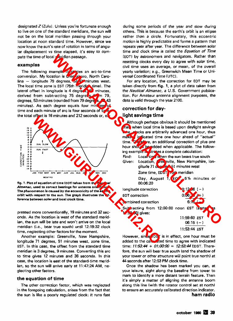
designated Z (Zulu). Unless you're fortunate enough to live on one of the standard meridians, the sun will not be on the local meridian passing through your location at noon standard time. However, since we now know the sun's rate of rotation in terms of angu- lar displacement vs time elapsed, it's easy to com- pute the time of local meridian passage.
examples The following example illustrates an arc-to-time
conversion. My location is Greensboro, North Caro- lina - longitude 79 degrees, 53.43 minutes west. The local time zone is EST (75th meridian time). The lateral offset in longitude is 4 degrees, 53 minutes, derived from subtracting 75 degrees from 79, degrees, 53 minutes (rounded from 79 degrees, 53.43 minutes). As each degree equals four minutes of time and each minute of arc is four seconds of time, the total offset is 16 minutes and 212 seconds or, ex-
I JAN F E B MAR 4PR MAY JUN JUL 4UG SEP OCT NOV OEC
MONTHS
fig. 1. Plot of equation of time (EOT) taken from the Nautical Almanac, used to correct bearings for antenna orientation. The phenomenon is caused by the eccentricity of the earth's orbit with respect to the sun. The graph illustrates the dif- ference between solar and local clock time.
pressed more conventionally, 19 minutes and 32 sec- onds. As the location is west of the standard merid- ian, the sun will be late and won't arrive on the local meridian (i.e., bear true south) until 12:19:32 clock time, neglecting other factors for the moment.
Another example: Greenville, New Hampshire, longitude 71 degrees, 51 minutes west, zone time, EST. In this case, the offset from the standard time meridian is 3 degrees, 9 minutes. Converting this arc to time gives 12 minutes and 36 seconds. In this case, the location is east of the standard-time merid- ian, so the sun will arrive early at 11:47:24 AM, ne- glecting other factors.
the equation of time The other correction factor, which was neglected
in the foregoing calculation, arises from the fact that the sun is like a poorly regulated clock: it runs fast
during some periods of the year and slow during others. This is because the earth's orbit is an ellipse rather than a circle. Fortunately, this eccentric motion is highly predictable and forms a pattern that repeats year after year. The difference between solar time and clock time is called the Equation of Time (EOT) by astronomers and navigators. Rather than resetting clocks every day to agree with solar time, civil time uses an average, or mean, of the overall yearly variation; e.g., Greenwich Mean Time or Uni- versal Coordinated Time (UTC).
For any location, the correction for EOT may be taken directly from fig. 1, a plot of data taken from the Nautical Almanac, a U.S. Government publica- tion. For Amateur antenna alignment purposes, the data is valid through the year 2100.
correction for day- light savings time
Although perhaps obvious it should be mentioned that, when local time is based upon daylight savings time, clocks are arbitrarily advanced one hour, thus making indicated time one hour ahead of "actual" time. Therefore, an additional correction of plus one hour should be added when applicable. The follow- ing example illustrates a complete calculation: Find: Local time when the sun bears true south Given: Location, Greenville, New Hampshire, lon-
gitude 71 degrees, 51 minutes west
Zone time, EDST, 75th meridian
Day, August 1, EOT, 6 % minutes or 00:06:20
longitude correction 0:12:36 ( - ) EOT correction 0:06:20 ( +
combined correction 6:16 ( - 1 Subtracting from 12:00:00 noon EST (stated as 11 :59:60) gives:
11:59:60 EST 06:16 ( - 1
11:53:44 EST
However, since EDST is in effect, one hour must be added to the calculated time to agree with indicated time: 71:53:44 + O7:W:W = 12:53:44 EDST. There- fore, the sun will bear true south (and the shadow of your tower or other structure will point true north) at 44 seconds after 12:s PM clock time.
Once the shadow has been marked you can, at your leisure, sight along the baseline from tower to mark to identify a more distant terrain feature. Then it's simply a matter of aligning the antenna boom along this line (with the rotator control set at north) to ensure an accurately calibrated direction indicator.
ham radio
october 1980 39
WWW.RADiOSCAMATORUL.Hi2.RO
WWW.GiURUMELE.Hi2.RO

aphonepat transforme using junk-box parts 1 Here.s
Old transformers used in tube-type radios
are put to use in this easy-to-build phone-patch circuit
Often I get the urge to upgrade my station with one accessory or another. In these days of inflation, how- ever, running out and buying accessories usually re- sults in a severe wallet-ache. This article describes how you can raid your junk box rather than rob a bank to build a reliable phone patch. The best part is that the patch takes only a couple of hours to put together.
theory The main problems to overcome in constructing
the phone patch are impedance matching and con- verting the balanced condition of the telephone line to the unbalanced audio condition of the Amateur transmitter and receiver. A transformer with proper impedance specifications offers the easiest solution.
Not long ago, before transistors or integrated cir- cuits were available, everyone used "field-effect transistors with heaters in them" - more commonly called tubes. Since the age of the inexpensive tran- sistor has arrived, more and more tube-circuit power
!rs have been retired to interesting application
the junk of these
box. com-
ponents. Examination of the specifications of one of these
transformers shows that it may be quite suitable for use in a phone patch. First, since power transformers are designed to operate at 60 Hz, there's little worry of audio distortion because of insufficient core mate- rial. Second, a review of the winding information shows good compatability between an Amateur rig and the telephone line.
Eq. (1) shows the relationship of winding voltages to the winding turns ratio.
where V I = voltage across winding 1 (primary)
V2 = voltage across winding 2 (secondary)
a = ratio of the number of turns of winding 2 with reference to winding 1
checking out the transformer
After blowing the dust off the old transformer, carefully determine which pair of wires constitutes the primary leads (usually the black pair). By measur- ing the voltages of the open windings while the pri- mary is connected across the 120-volt house current, enough informatiori may be obtained to calculate the turns ratio of the windings. (If your nerve is hardened to the idea of plugging a transformer into 120 Vac house current, a step-down transformer may be used to drive the winding.) I had a transformer with two windings in addition to the primary. The voltages
By Lee Barrett, K7NM, 1011 20th Street, Havre, Montana 59501
40 october 1980
WWW.RADiOSCAMATORUL.Hi2.RO
WWW.GiURUMELE.Hi2.RO
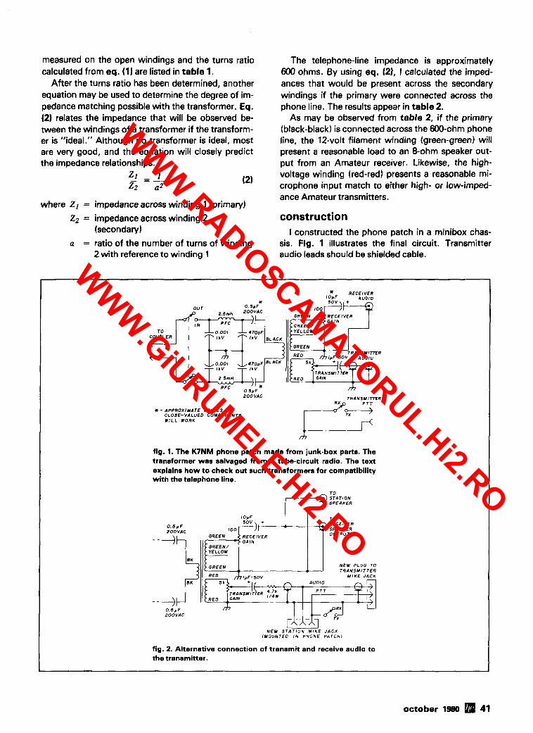
measured on the open windings and the turns ratio calculated from eq. (1) are listed in table 1.
After the turns ratio has been determined, another equation may be used to determine the degree of im- pedance matching possible with the transformer. Eq. (2) relates the impedance that will be observed be- tween the windings of a transformer if the transform- er is "ideal." Although no transformer is ideal, most are very good, and the equation will closely predict the impedance relationships.
3 =I z2 a2
(2)
where Z I = impedance across winding 1 (primary)
Z2 = impedance across winding 2 (secondary)
a = ratio of the number of turns of winding 2 with reference to winding 1
The telephone-line impedance is approximately 600 ohms. By using eq. (21, 1 calculated the imped- ances that would be present across the secondary windings if the primary were connected across the phone line. The results appear in table 2.
As may be observed from table 2, if the primary (black-black) is connected across the 600-ohm phone line, the 12-volt filament winding (green-green) will present a reasonable load to an &ohm speaker out- put from an Amateur receiver. Likewise, the high- voltage winding (red-red) presents a reasonable mi- crophone input match to either high- or low-imped- ance Amateur transmitters.
construction I constructed the phone patch in a minibox chas-
sis. Fig. 1 illustrates the final circuit. Transmitter audio leads should be shielded cable.
* RECEIVER lopF AUDIO
Y TRANSMITTER
TRANSMITTER
2OOVAC TRANSMITTER
* - APPROXIMATE VALUES - CLOSE-VALUED COMPONENTS W I L L WORK
fig. 1. The K7NM phone patch made from junk-box parts. The transformer was salvaged from a tube-circuit radio. The text explains how to check out such transformers for compatibility with the telephone line.
10pF TO
0 . 5 y F
NEW PLUG TO TRANSMITTER
NEW STAT ION MIKE JACK (MOUNTED I N PHONE PATCHJ
fig. 2. Alternative connection of transmit and receive audio to the transmitter.
october 1980 41
WWW.RADiOSCAMATORUL.Hi2.RO
WWW.GiURUMELE.Hi2.RO

table 1. Measured voltages from the power-transformer windings.
voltage turns ratio winding colors (Vac) (a)
black-black 120.0 1 .000 green-green 12.6 0.105 green-green/ yellow 6.3 0.052
(center-tap) red-red 240.0 2.000
table 2. Impedances across windings.
turns ratio impedance winding colors (a) (ohms) black-black 1.000 600 green-green 0.105 6.62 green-greenlyellow 0.052 1.62
(center-tap) red-red 2.000 2400
An rf filter was placed in the phone line to prevent rf from entering the transmitter audio through the patch from the phone line. This filter is only neces- sary if high power levels are used.
The coupling capacitors on the primary winding must be nonpolarized and have at least 200-Vac ratings. These capacitors prevent the primary trans- former winding from shorting any telephone-line dc voltages that may be present.
The phone patch is connected to the station tele- phone through an acoustic coupler (to be installed by the phone company). It provides a 1/4 inch (6.4 mm) phone jack for the phone-patch connection. On most desk telephones, a button on the receiver hook must be lifted to activate the coupler. Wall phones will probably have some method of activating the coupler also. I've used only desk phones in the phone patches installed to date.
The receiver audio is connected in parallel with the station receiver speaker, reducing the receiver speak- er load to about 4 ohms.
The transmitter input is connected to the phone- patch input jack on the rig. If no such input is provid- ed, fig. 2 illustrates an alternative method of connec- tion to the transmitter. The phone patch is con- nected permanently to the transmitter through the microphone input jack. A new jack is mounted in the phone patch chassis for connection to the station microphone. The transmitter patch audio is coupled through a 4.7-k resistor into the audio line.
operation When operating the phone patch, simply throw
the switch located in the transformer primary to the IN position. The telephone must remain off the hook,
with the coupler button activated, to maintain the phone connection to the phone patch. I've found it convenient to use the telephone exclusively for modulation and monitoring .during a phone-patch contact. The transmit switch is placed in the TX mode during transmit and returned to RX during re- ceive periods, facilitating standard push-to-talk oper- ation. When the patch is completed, the primary switch is returned to the OUT position.
Dual level adjustments exist for both receiver and transmitter levels to and from the phone patch. The receiver audio gains on both receiver and patch will affect the line level to the telephone. Also, both the transmitter level adjustment and the gain contol in the phone patch will affect transmitter modulation level. To set levels, I set the receiver audio gain to a comfortable speaker volume and the transmitter level for proper modulation from the station microphone. Next, the patch was switched IN and the telephone removed from the hook with the coupler button acti- vated. A single digit (other than 1) was dialed to re- move the dial tone. The receiver patch gain was ad- justed for a comfortable audio level in the telephone. Similarly, the patch transmitter level was adjusted for proper modulation of the transmitter while I counted into the telephone. If your city has a time number, this service could be used as a reliable source for the transmitter level adjustment. Once the patch levels are set, there should be no need for additional ad- justments.
conclusion Since the first phone patch, several others have
been built and work very well. Even though tables 1 and 2 show that a 6.3-volt filament winding has a very low impedance (about 2 ohms), I've successful- ly used transformers with this winding as a speaker winding.
Some tube-type transformers have dual 6.3-volt windings, while others may have both a 6.3-volt winding and a 5-volt winding. These transformer windings may be wired in series to improve speaker impedance matching.
Although this phone patch was not designed for VOX operation, some reports have been received that VOX has been used successfully. I've used this phone patch design on both the hf and vhf bands with ex- cellent reports of audio quality. Often Amateurs in- quire what kind of patch it is. It's simply a junk box special.
acknowledgement I would like to thank Rob Yaw (WA71AL) for his
assistance during the testing of these phone patches. ham radio
42 a october 19&0
WWW.RADiOSCAMATORUL.Hi2.RO
WWW.GiURUMELE.Hi2.RO

One setting provides total band coverage from 10 through 40 meters with SWR of 1.6:l or better
,. Easy to assemble and install. Features high
For the BIG difference in performance, it's the Hustler 5-BTV antenna.
Clearly the choice of those who know quality.
3275 North I3 Ave K~ss~mmee. Florida 32741
POWER-UP FOR ONLY $79.95 AMPLIFIER ONLY
FACTORY DIRECT ONLY
That's right - 90 watts of llnear power for 2 meters for only $79.95. checkout the VJ90SSB Power Chart, and you'll see the real value - 8 watts out for one watt drive, 16 out with two watts drive! Now you can put that new HT to mobile use, for only $79.95. As a special deal, we've designed a 19dB gain in-line preamp with integrated T/R relay. A $29.95 value, for only
VJ9OSSB $20.00 when purchased with the VJ90SSB Amplifler.
POWER MEASUREMENT
But that's not all! We've built a 15 amp [20 amp surge) 13.8VDC power supply just for this combo, the VJ15. When you buy the VJ9OSSB and Preamp, we'll sell you this super power supply for only $79.95. It all adds up to over $225.00 worth of gear for only $179.90. Don't wait. Order Today!
Each VJ Product component is hand wired and lndlvidually tuned tor maximum reliability and performance. VJ Products are guaranteed to be free of defects in parts or workmanship for1 year from the date of purchase. POWER TRANSISTORS ARE EXCLUDED. BUT WARRANTED
10 ,( FOR 90 DAYS. Visa accepted. Immediate shlpment guaranteed by VJ Products, Inc. r------"'-"'--'-"-"-'------------'---
3* 1 Pleaseshlp: VJ90SSB ( ( 1 $79.97 + $2.00shipping I
1 2 3 4 5 6 7 8 9 1 0 1 VJ90SSB/Preamp fir $99.95 + $3.50 shipping I
POWER INPUT IN WATTS I VJ15 P/S ( / I $79.95 + $2.50 shipplng I I
POWER CHART Name - - _ - I
I Street _ _ - I
I City -- - - - . _ - S t a t e - -- - - Zlp I I
I Send Check. M/O, or Visa # -. _. - - Exp. Date - I L,--------------------------------------J
SERVING THE ELECTRONICS INDUSTRY SINCE1965 V-J Products. Inc. 505 E. Shaw Street, Pasadena. Texas 77506 (n3) 477-0134
More Details? CHECK-OFF Page 94 O C ~ O ~ ~ T 1980 43
WWW.RADiOSCAMATORUL.Hi2.RO
WWW.GiURUMELE.Hi2.RO

a folded end-fire radiator
Introducing the "W8" - an antenna
with modest gain and interesting possibilities
for the experimenter
This antenna fits into an area approximately 1 110 by 116 wavelength and provides a compact, effective radiator for the lower-frequency bands. A slight re- shaping converts it into a horizontally polarized, om- nidirectional radiator for vhf. The antenna can be considered as a folded, series-connected, two- element, end-fire beam.
evolution Start with a two-element, bidirectional, end-fire
beam. If the feed is omitted, the essential elements are two half waves, closely spaced and excited equally but 180 degrees out of phase (fig. 1A). The arrows in fig. 1 indicate current flow, with the large arrows at current maxima. Spacing is usually 1120-115 wavelength. Gain can approach 4 dB over that of a halfwave antenna.' Radiation is maximum
to left and right in the plane of the figure. For illustra- tion, take spacing to be 1/10 wavelength.
Now fold each element into a rectangle 1/10 by 115 wavelength, as shown in fig. 10. Note that the wire ends labelled a are at the same rf potential; similarly, the ends labelled b are also at the same po- tential, opposite to that at a. These respective pairs of ends may therefore be joined without disturbing the current distribution as shown in fig. 1C. Note that the array now consists of one wavelength of wire folded into a sort of figure eight, accounting for its name, abbreviated "W8." At the center crossover point are two current nodes (voltage maxima). Fig. 1D is another possible arrangement with only one center crossover connected, about which more later.
There is nothing sacred about the 1/10 by 115 wavelength rectangle. For a low-frequency, vertically polarized array on a single pole the configuration of fig. 2 is appealing. The W8 can be squeezed or stretched, with directivity declining as the shape spreads horizontally (fig . 1).
feed methods and impedance Of the various possible feeds, I've tried only one,
balanced current feed, achieved by opening the W8 at a current maximum and attaching parallel-wire feeders, as in fig. 2. In December 1973 1 measured a &meter model built to the 1/10 by 115 wavelength pattern and obtained a driving-point impedence be- tween 400-500 ohms. Measurements were made
By Worthie Doyle, N'IWD, 1120 Bethel Avenue, Port Orchard, Washington 98366
44 october 1980
WWW.RADiOSCAMATORUL.Hi2.RO
WWW.GiURUMELE.Hi2.RO

4 A / I O + & A l l 0 + 1 . 1 G3.I /-J-j Q 0 0 (B
fig. 1. Evolution of the WB end-fire antenna. The arrows on the elements indicate current flow: the large arrows show current maxima. In A a basic radiator is shown consisting of two half-wave elements, closely spaced, and excited 180 degrees out of phase. Each element is then folded into a rectangle, B. Wire ends may be joined as shown in C or D. as explained in text.
with a crude resistance bridge driven by a grid-dip meter. I hope someone who can make more reliable measurements will look into this. For this feed method 450 ohm TV ladder line should do well.
The W8 could be voltage fed at the center cross- over point, using either tuned feeders or an open- wire matching transformer as in fig. 3. This might be convenient for the vertically polarized, one-pole con- figuration of fig. 2, particularly if you wish to run a line along the ground for some distance.
Finally, if the W8 is not broken at a current maxi- mum you should be able to drive it by any of the methods used for plumbers' delights, in particular the gamma match applied at a current maximum. This might be a convenient choice for the omnidirec- tional W8 mentioned later.
performance and application A reasonable guess at gain can be made by com-
paring fig. 1C and the basic, two-element endfire, fig. 1A. The center section, consisting of the folded ends of the original elements, is just a short section of open-wire line and can be expected to have negli- gible loss and radiation. Thus the only real waste rep- resented by the configuration of fig. 1C is that which results from radiation from the horizontal portions. However, these useless portions are only half the length of the useful radiating sections and, in addi- tion, contain portions of the current distribution far- thest from the two current maxima. This argument suggests that gain should still be perhaps 2 dB over a similarly placed halfwave. The 40-meter vertically po- larized version was used for a couple of years, but I have no way to make comparisons and can only hope this discussion will arouse some of the more ambitious experimenters.
An interesting comparison can be made with the quarter-wave vertical. If the configuration of fig. 2 is used and each radiating section makes a °ree
angle with the vertical, then the vertical extent of the array is somewhat less than a quarter wavelength. The mechanical disadvantage of the W8 is that guy cords are needed to position the two side corners of the diamond (I use nylon fish line). On the other hand, the W8 requires no radials or ground plane, and its current maxima are elevated to the array cen- ter. This should make it practically simpler to achieve low-angle radiation with a W8.
The small gain of the W8, though interesting, will be swamped by the effects of propagation and inter- ference. Its main advantage is relative simplicity and compactness. A 40-meter horizontal W8, for exam- ple, could be supported slightly above your roof in about the same space as a full-sized, two-element 8J K for 20 meters.
dimensions and adjustment The &meter model used 20 feet (6 meters) of wire
arranged in a 2 by 4 foot (0.6 by 1.2 meters) rec- tangle, with the center section of transposed line spaced about 314 inch (19 mm). With a small loop soldered across an opening at the center of one side, the grid dipper resonated at about 50 MHz.
When the 40-meter model was put together, 136 feet (41.5 meters) of wire were used at first in the an- tenna proper, with 68 feet (20.7 meters) of open wire line to the house. When this arrangement was grid- dipped at the sending end, the resonant frequency turned out to be 5.8 MHz. The explanation for this re- markable discrepancy is the capacitive loading effect of the W8 center section. On the 40-meter model, the spacing in wavelengths was closer by a factor of 7 than the spacing on the &meter model. As noted in the section describing the evolution of the W8, the center crossover point and most of the center section of line are at high rf potential, so capacitance here is very effective in loading to a lower frequency. The major advantage of the W8 is its compactness, how- ever, and this loading effect makes the antenna even more compact. Incidentally, a small lumped capaci- tance across the center crossover point is a conveni-
D R I V E
fig. 2. Diamond-configured W8 antenna with current feed. Thisarrangement may be used for a low-frequency, vertically polarized array mounted on a single support.
october 1980 45
WWW.RADiOSCAMATORUL.Hi2.RO
WWW.GiURUMELE.Hi2.RO

fig. 3. Feeding the m a t the center crossover point using tuned feeders or open-wire matching transformer.
ent way to tune a vhf W8 to a lower frequency. This was checked in the 6-meter model.
To adjust the 40-meter W8, two steps were taken. The center line section spacing was increased from 314 inch (19 mm) to about 3 inches (76 mm) to re- duce the loading effect. Then the lengths of the four vertical wires (two radiating portions and the center line section) were gradually rsduced from an original 28 feet (8.5 meters) to a final 21 feet (6.4 meters). At this point the antenna, crudely draped horizontally about 4 feet (1 meter) off the ground, grid-dipped at about 7.1 MHz. The full width across the top is 14 feet (4.3 meters). The vertical extend of this W8 is about 116 wavelength at the operating frequency.
A few years later the 40-meter W8 was replaced by a 75-meter version following fig. 2. Its slanting sides were 28 feet (8.5 meters) long, forming a square standing on one point, with the center vertical sec- tion of line 40 feet (12 meters) long. These dimen- sions were only a first guess based on experience with the 40-meter model, although the antenna worked about as expected. Although the main radia- tion was vertically polarized endfire, there was a sig- nificant horizontally polarized radiation broadside. Total length of wire in this version was 192 feet (58.7 meters) or about 0.76 wavelength. For the rectangu- lar 40-meter configuration, the total length of wire was 112 feet (34 meters) or about 0.82 wavelength. The diamond configuration produces more center loading, so the shorter length is reasonable, although resonant frequency is unknown for the 75-meter ver- sion.
node forcing An interesting question about the W8 or any other
electrical-full-wavelength continuous conductor, such as a quad loop, is, "What determines the loca- tion of the current maxima?" Presumably this is fixed by the feedpoint and by the actual loop resonant fre-
46 october 1980
quency. If a damped wave train were excited in an unattached loop at a frequency not exactly resonant, you'd expect the current maxima to chase around the loop as the wave train died away rather than re- main at fixed locations. However, if the loop were opened at one point, this point is compelled to be a current node.
This brings us to the variation of fig. ID, where one of the center crossover points is closed while the other remains open, forcing the array to produce a current node at the open ends. I've used the 40- meter W8 with both crossover points connected and with only one connected. As expected, I found no difference.
As an aside, it seems possible that some of the occasional disappointments with quads whose ele- ments are either mistuned or incorrectly coupled might be partly explained by the current distributions on the parasitic elements having "slipped" around the loop, so that the current maxima are not in line with those of the driven element. This may help to explain why quads occasionally "squint." Although I've never heard of anyone doing so, it should be similarly possible to ensure the current distribution on quad loops, particularly the parasitic elements, by opening one of the vertical sides a quarter wave- length from the driven-element feedpoint and at cor- responding points for the parasitic elements.
horizontally polarized omnidirectional radiator
When the current maxima are close together, as in fig. IC, the W8 should have a directivity in its own plane similar to that of the two-element 8JK beam: a figure-eight pattern with the nulls filled in a bit by the radiation from the short ends of the rectangle. As the shape is pulled out, so that the current maxima are farther apart and the center section of line is shorter, more of the current distribution contributes to radia- tion over the whole of the plane of the array.
It's clear that, if the shape is pulled out to some- thing like that in the sketches of fig. 4, the pattern in the plane of the array will be close to omnidirectional. In three dimensions the pattern should be roughly doughnut shaped. If the array is mounted in a hori- zontal plane, the result will be omnidirectional hori- zontal polarization. Because the current maxima pro-
m m fig. 4. W8 antenna shapes for an omnidirectional radia- tion pattern.
WWW.RADiOSCAMATORUL.Hi2.RO
WWW.GiURUMELE.Hi2.RO

vide greatest radiation, it's necessary to pull out the shape past the point where it's roughly square or cir- cular. For a start you might try an ellipse with about a 2: 1 axial ratio or a rectangle about 1 I4 by 1 I 8 wave- length, as suggested in fig. 4.1 hope some vhf exper- imenter will take a shot at this.
If rod or tubing is used for construction, a quarter- wave transformer can be used for combined support and symmetric center voltage feed, as shown in fig. 3. If you wish to force two current nodes, one of the crossover points can be left open and the corres- ponding end of the quarter-wave transformer also left free, resulting in a Zepp-fed arrangement. . At vhf, horizontal W8s could also be stacked to produce an omnidirectional array with gain and hori- zontal polarization. The optimum stacking distance for antennas with some gain of their own is greater than a half wavelength. A convenient choice with the W8 would be one wavelength interconnecting feed- lines, bent enough to accommodate the desired spacing.
odds and ends The W8 is essentially a one-band antenna because
the capacitive loading of the center section causes its natural modes not to be harmonically related. How- ever, it can be used at harmonics if one employs tuned, open wire feeders, as I do. Such use should be considered makeshift rather than desirable. I have used the 75meter version on 40 meters, where the pattern should be roughly omnidirectional with a slight bias toward broadside. On the third harmonic I'd expect a slight endfire directivity.
This may also be the place to point out that the W8 is a narrowband antenna compared to a halfwave an- tenna. This is a property it shares with the 8JK, al- though the W8 antenna bandwidth can be expected to be somewhat narrower than that of the 8JK be- cause of its smaller size and center loading. The cur- rent maxima are about a quarter wavelength apart, so I'd expect the omnidirectional version of the W8 to have somewhat greater bandwidth than that of the 8J K, however.
A major aim of this article is to interest people with access to facilities in carrying out gain and imped- ance measurements and in experimenting with the omnidirectional version. I've tried without success to find any hint of this simple but interesting configura- tion in the commonly available works on antennas.
reference 1. John D. Kraus, Antennas, McGraw-Hill. 1950. sections 11 -3 and 11-5.
ham radio
More Details? CHECK-OFF Page 94
The newest rig in Kenwood colors. Providing 15 memories, offset recall, scan, touch-tonem, 25 watts output and a priori- tyfeature. The touch-tonem pad is built-in foreasyfrequency selection or autopatch use, and the memories not only recall frequency, but the offset as well! Available soon. Call for quote.
1 For both mobile or base operations (with an external supply), here's the answer to your VHF dreams. Dual VFO's, RIT, five memories and scan, FM, SSB, and CW, plus lOOHz resolution on the dial, make oper- ating the TR-9000 both simple and exciting. OSCAR anyone? The retail price of $499.00 is great enough, but call for quote!
Not the first, but the best. Quality, with 1.5 watts output, full digital synthesis with visible LCD frequency display. The reputation that this rig is gaining is testimony enough to say here's the HT you've been dreaming about. $395.00 retail price, but call for quote!
lDUB8M Electronics Supply, Inc.
1508 McKinnsy Houston, Texas 77010 (713) 658-0268
WWW.RADiOSCAMATORUL.Hi2.RO
WWW.GiURUMELE.Hi2.RO

@UENWOQ~ . . . pnccsett.-r in amateur radio
"Small wonder':. . processor, NIW switch,. IF shift, DFC option The compact, all solid-state TS-130s runs 200 W PEP1160 HF SSBICW mobile or fixed W DC input on 80-15 meters stat~on TS-130 Series trans- and 160 W PEP1140 W DC on ceiver covers 3.5 to 29.7 MHz, 12 and 10 meters. TS-130V including the three new bands. runs 25 W PEP120 W DC
input on all bands. TS-130 SERIES FEATURES: Built-in sDeech
80-10 meters, including the ~arrowlhide fi~tkr selection on new 10.18, and 24-MHz both CW (500 Hz or 270 Hz) bands. Receives WWV. and SSB (1.8 kHz) with
optional filters.
Automatic selection of side- SP-120 external speaker. band mode (LSB on 40 VFO-120 remote VFO. meters and below, and US6 MB-100 mobile mounting on 30 meters and above). SSB bracket. REVERSE switch provided. PS-20 base-station power Built-in digital display. supply for TS-130V. Built-in RF attenuator. IF shift (passband tuning). Effective noise blanker.
OPTIONAL ACCESSORIES: PS-30 base-station power supply. YK-88C (500 Hz) and YK-88CN (270 Hz) CW filters. YK-88SN (1.8 kHz) narrow SSB filter. AT-130 compact antenna tuner
Optional DFC-230 Digital Frequency Controller Frequency control ~n 20-Hz steps w~th UPIDOWN micro- phone (supplied with DFC-230). Four memories and digital display. (Also operates with TS-120 and TS-830s.)
(80-10 meters, including three new bands).
WWW.RADiOSCAMATORUL.Hi2.RO
WWW.GiURUMELE.Hi2.RO

TRIO-KENWOOD COMMUNICATIONS INC. 1111 WEST WALNUT I COMPTON, CA 90220
m--nmm w w w . Three IF filters for optimum
AM, SSB. CW 12-kHz and "Hear there and everywhere'!. . and 6 - k ~ z 2 7 - k ~ z ) (adaptable for AM to 6 - k ~ z wlde and easy tuning, digital display narrow, and 2 7 - k ~ z filter for
hlgh-quallt SSB (USB and The R-1000 1s an amazingly . 30 bands, each 1 MHz wlde LSB) and ZW reception eas to operate, hlgh- Flve-dl ~t frequency dlsplay per&-rm-ance, communlcatlons wlth 1 -1H.z resolut~on and Effectlve nose blanker receiver, covering 200 kHz to analog dial with precise gear . Terminal for external tape 30 MHz ~n 30 bands Th~s PLL dial mechanism recorder synthesized recelver features a . ~ ~ ~ l t . . ~ ~ 12-hour quartz dlgltal dlgltal frequency dlsplay and clock with t~mer to turn on Tone control analog dlal, plus a quartz rad~o for scheduled llstenln Bulll-ln 4-lnch speaker dlgltal clock and tlmer or control a recorder throug\ R- lqOO FEATURES remote term~nal Dlmmer swltch to control
Covers 200 kHz to 30 MHz Step attenuator to prevent lntenslty of S-meter and other
cont~nuously overload panel llghts and dlgltal dlsplay
Digital world clock with two 24zhour displays, quartz time base The HC-10 dlgltal world clock wlth dual 24-hour dlsplay shows local tlme and the tlme In 10 preprogrammed plus two programmable tlme zones
Two 24-hour dlsplays wlth quartz tlme base. Rlght dlsplay shows local (or UTC) hour, mlnute, second, day Left dlsplay shows month, date. world tlme In varlous cltles.
memory tlme (QSO startlng time), and tlme difference (In hours from UTC). Pre~roarammed tlme In 10 cltles Gound the world, plus two pro rammable tlme zones. . "TOMO~ROW" and "YESTERDAY" lndlcators. Memorlzat~on of present tlme. Can be recalled later, for logglng purposes. . Hlgh accuracy (f 10 seconds1 month).
Wire antenna terminals for 200 kHz to 2 MHz and 2 MHz to 30 MHz. Coax termlnal for 2 MHz to 30 MHz. Voltage selector for 100. 120. 220. and 240 VAC. Also ada table to operate on 13.8 V ~ d ) w ~ t h optional DCK-1 klt.
OPTIONAL ACCESSORIES:
SP-100 matchlng external speaker. HS-5 and HS-4 headphones. DCK-1 modiflcatlon k ~ t for 12-VDC operation.
Dip meter performs many RF measurements The DM-81 d ~ p meter IS hlghly accurate and features. In addl- t~on to the tradltlonal lnductlve- coupllng technique, capac~tlve coupllng for measurlng metal- enclosed tolls and toroldal colls.
DM-81 FEATIYRES. Measuring range of 700 kHz- 250 MHz In seven bands. Bullt-ln storage compartment for all sevenco~ls, capacltlve probe, earphone, and ground clip lead . All solld-state and bullt-ln batter H c - ~ Y u and FT-243 sockets for checklng crystals and marker-generator functlon. Am l~tude modulat~on ~ ~ f f o r good sensltlvlty Absorption frequency meter functlon Earphone for monltorlng transm~tted slgnals Capacitance probe for measuring resonant frequen- cles wlthout removlng toll shlelds, and also for measurlng resonant frequenc~es of toroldal tolls
WWW.RADiOSCAMATORUL.Hi2.RO
WWW.GiURUMELE.Hi2.RO

the voicemband equalizer
LI b (I,
Q -
-
!i Y
Inside the voice-baed equal detaiis. A PC board is used 1 Control pots are mounted on the rninibox as sho.... .
This addition to your phone station
uses an LM324 quad op amp
Here is an equalizer for your microphone that plugs into the microphone jack. The voice-band equalizer (VBE) gives you control of your microphone frequency wsponse. Three adjustments allow you to balance the low, mid-range and high frequencies. The VBE uses three bandpass filters designed to work on the most important part of the vocal spectrum. The passband of your transmitter (2.4 kHz nominal) is the section of audio frequencies I call the "voice band." The VBE divides this important voice band in- to three parts: low, mid-range and high. By adjusting three controls you can change your audio character- istics. You can boost mid-range and high frequen- cies to add punch - or accentuate low frequencies for more bass - all without changing your micro- phone. You can easily build the VBE in a few hours.
This article shows how to work with and apply contemporary active circuits to an Amateur Radio design. Well-known passive tuned-circuit theory is reviewed, and newer tuned-circuit theory and design are introduced. The article also gives information on
izer showi for the srn,
applied to build the VBE. Also shown is how to use existing equipment and resources to test the VBE. The voice-band equalizer is a project that will impart a sense of pride and accomplishment to the Amateur W ~ O builds one.
BY R. Bradley, WB2GCR, BOX 144, Hanna-
ng constrt all cornpol
standard construction practices and how these are croix, New York 12087
~ct ion ients. urn
50 october 1980
WWW.RADiOSCAMATORUL.Hi2.RO
WWW.GiURUMELE.Hi2.RO

circuit design I built the circuit around an LM324 quad op amp.
The LM324 consists of four independent operational amplifiers in a 14-pin DIP package. Each amplifier is internally compensated. Three of the amplifiers oper- ate as tuned circuits; one combines the action of the three separate tuned circuits. Each of the three active tuned circuits acts like the passive tuned circuit of fig. 1. Using the active rather than passive tuned cir- cuits eliminates the need for bulky and expensive in- ductors. In fig. 1 L, C, and R are combined to form a series-resonant circuit. At resonance, the electrical energy presented to LCR is shunted to ground and the inductive reactance, XL, and capacitive reac- tance, Xc are equal. Also, at resonance, the impe- dance of the LC combination is theoretically zero (X,c = 0).
The inductive reactance creates a current lag of 90 degrees, while at the same time the capacitive reac- tance creates a current lead of 90 degrees. Since the two reactances ( X L + XC) are equal and opposite in phase, they cancel. In practice the impedance at res- onance is never actually zero. The Q of this series- resonant LC circuit is an expression of the ability of the circuit to reach "zero" impedance with respect to frequency:
where Q = quality factor F, = resonant frequency AF = excursion of frequency from F,
A Also, Q = x, where X = reactance (ohms) and
R = series resistance (ohms) for passive series- resonant circuits. The resonant frequency of the cir- cuit is:
The passive RLC circuit has low impedance at res- onance and high impedance at other frequencies. So energy entering the RLC circuits through the control pots (fig. 1) will be shunted to ground at resonant frequencies. As you move the pots toward the nonin- verting amplifier, input signal is deleted from this in- put and attenuation occurs within the bandwidth of RLC. Similarly, when the control pot is turned in the opposite direction (toward the inverting input), fre- quencies are deleted to the IC, causing gain within the bandwidth of RLC. Placing the control pot in the center of rotation causes equal effect on both invert- ing and noninverting inputs. The amplifier output is then flat.
active circuit The operation of the active circuit for the VBE, fig.
2, is similar to that of the passive design shown in fig. 1. Let's look at how the active circuit works. Am- plifiers U1 B, UlC, and U1 D are used in active tuned circuits.2 The active design eliminates the need for inductors.
Now, instead of the center (or resonant) frequency being controlled by LC values, C20 and 21 determine the center frequency. R21 and 22 also affect the ten-
ter frequency. I kept their value constant, since they
INPUT
table 1. Suggested values for the active tuned circuits. Center (resonant) frequencies have been determined using the equation in fig. 2.
resonant frequency capacitor value
filter (Hz) (fig. 2) (pF)
low 335 C2 1 0.2 frequencies C2 1 0.01
410 C20 0.15 C21 0.01
52 1 C20 0.15 C2 1 0.0062
1 299 C30 0.05 C31 0.003
mid-range 1412 C30 0.047 frequencies C31 0.0022
1959 C40 0.033 C41 0.002
high 2905 C40 0.033 frequencies C41 0.001
3558 C40 0.02 C4 1 0.001
october 1980 51
fig. 1. Passive series-resonant circuits using RLC compo- nents with an operational-amplifier IC. The voice-band equalizer active circuit (fig. 2) exhibits equivalent charac- teristics.
+ OUTPUT
R I F, = -
2 - m
/ I
; f 1; WWW.RADiOSCAMATORUL.Hi2.RO
WWW.GiURUMELE.Hi2.RO

also control the Q. The circuits of UIB, UIC, and U1D are identical except for the center frequencies, which are controlled by the capacitor values. The center (resonant) frequency, can be computed by the equation shown in fig. 2.
In table 1 I've provided some suggested compo- nent values and center frequencies for fig. 2. Use 10 per cent or better tolerance values of C to ensure that the center frequencies arrive at computed values.
calculator input Table 2 is an algorithm for TI30 or similar calcula-
NOTES I /j7 SIGNAL GROUND
2 1 CHASSIS GROUND
3 SEE TABLE I
,---\ POWER SUPPL r ,--\
I FB F B I I I I - - - I I 1 ° 1 - - 1 ° 1
P T 7 1 $ 5 0 ~ - f B I I I F 8 - - I I - I - - 1 I I 0 I ' l C - 1 ° 1 I I
O U T I I
IN I O 4 p d l
I-
-
1 ,' 6 21 . .I Fr - ' C 12 2 r J ~ ~ ~ 2 C ! C 2
1 8 0 p F
tors. If you decide to experiment with the formula in fig. 2, the calculator algorithm will save time and work. Whether you work longhand or use a calcula- tor, remember that the C values in the equation are in farads; the typical circuit values are in microfarads (FF). Remember also to divide the pF value by 106 to convert to farads before substituting into the equa- tion.
bandpass filters The VBE requires three bandpass filters. The prob-
lem is to generate a bandpass characteristic using
R Z O 50* :.
P O T
52 october 1980
<:, 6'30.' R 40 .L SO* :, 5 0 b :,
POT POT
(NOTE 31 (NOTE 31 (NOTE 31 L M 3 2 4 L M 3 2 4
U I B U I C U I O
R 2 2 R 3 2 R 4 2 l o o k l o o k
L 0 W RANGE MIDRANGE HIGH RANGE
C10 0.001 R20 50k pot C11 180pF R21 l k C12 180pF R22 l00k C13 0.001 R30 50kpot fig. 2. Schematic of the VBE. A single LM324 opera- C20.21, R31 l k tional amplifier IC is the active device. The equation is
30.31, see table 1 R32 lOOk used to determine the center (resonant) frequency of 41 R40 50k pot each active tuned circuit. Using active rather than
FB ferrite beads R41 I k passive tuned circuits eliminates the need for bulky A10 34k R42 lOOk and expensive inductors. R l l 470k S 1 4pdt switch R12 6.2k U 1 LM324 R13 300k bypass caps all 0.001
1
WWW.RADiOSCAMATORUL.Hi2.RO
WWW.GiURUMELE.Hi2.RO

only one op amp and a minimum number of related components. At first glance, the circuit of fig. 2 might appear to be a highpass and a lowpass section. A bandpass characteristic can be generated by the circuit of fig. 2 because, at sufficiently high Q, both low and highpass active circuits exhibit bandpass functions.3 The peaks shown in fig. 3 illustrate the similarity to a bandpass function that the lowpass and highpass functions can exhibit. The circuits of UlB, UIC, and UID (fig. 2) each generate a function similar to those of fig. 3 and fig. 1. To combine the three active circuits, I use each to independently con- trol the response of a master amplifier, UIA. Its output reflects the constant Q peak generated by U1 B, UIC, and U1 D. The characteristics of the three tuned circuits remain constant. Only the response of U1A is modified by the degree to which U1B. UlC, and U1D are inserted. The VBE circuit gives _+ 12 dB
10 n 9 - 0.10
8 -
7 -
FREQUENCY
fig. 3. Typical response curve of an active circuit. As Q increases, the circuit approaches bandpass-filter charac- teristics. (From reference 3.)
of adjustment with minimal interaction between con- the VBE if you follow the suggested layout. If you trols. choose to experiment with single or dual op amp construction packages, you'll have to duplicate plus and minus
Construction of the voice-band equalizer is divided power-supply lines as well as the ground connec- between the single PC board and the box that en- tions. closes it. Most of the components are mounted on Follow the general layout in either case to simplify the board. The layout shown in fig. 4 is compact and construction and ensure predictable results. Be sure contributes to easy assembly. Ample space is provid- to use good electronic and mechanical techniques. ed for components of many different sizes. The single Use a low wattage soldering iron, 60140 solder, and quad op amp (LM324) greatly simplifies layout and watch for solder bridges, especially near the IC parts placement. You'll have no difficulty building socket.
table 2. Algorithm for determining center (resonant) frequency of each VBE tuned cir- cuit. The algorithm is for a TI30 (or later) calculator.
enter R1 R 2
press
- - X
RCL
X
INV EE - -
display R 1
R1R2
notes R in terms of ohms the calculator has automatically converted to scientific notation place R1 R2 in memory check memory clear converting to scientific notation negative exponent C in terms of farads. (Don't press = yet.) converting again
C1C2 product in scientific notation
R1 R 2 from memory in scientific notation square root times two, times. . . pi Fo (center frequency) in scientific notation
convert back to Hz your answer
october 1980 53
WWW.RADiOSCAMATORUL.Hi2.RO
WWW.GiURUMELE.Hi2.RO

fig. 4. VBE circuit board show- ing foil side.
-,, - -% -
fig. 5. Component placement -for the VBE. Control pot jump- ers are mounted on the board but are shown off the board for clarity. Switch SW1 mounts onto the chassis as shown.
I started to build the VBE with the printed circuit board.4 Etch and drill the PC board. I drilled the nine control-pot connection points to accept small eye- lets. I used the three pots to provide a convenient way to mount the board in the box (the copper foil is not strong enough for this). The eyelets provide a strong mechanical connection for the pots. I found this method convenient, but you can use wires for mounting the pots and other means to mount the PC board. I used a good quality 1Cpin IC socket for the LM324 op amp. Molex pins or even direct soldering would work too. Next, I mounted the resistors and the jumper according to the parts placement shown in fig. 5. The jumper runs under C20.
Include ferrite beads on the legs of R10 and R13. I installed the capacitors next, and then the jumpers for the control pots. I did not mount the controls until after the holes were drilled into the box. Since I sol- dered the controls directly to the eyelets on the cir- cuit board, the holes in the box must line up exactly with the controls that have been soldered to the cir- cuit board.
Once the holes have been drilled for the controls, place the pots loosely into the holes, from the out- side of the box. Now solder the main board to the controls and they will line up for a good fit. Mount the foil side of the board toward the knob side of the controls so that clockwise rotation results in gain.
The smallest box I could find to fit the VBE was 5 x 3 x 1-314 inch (12.7 x 7.6 x 4 cm) minibox. The small box requires good construction techniques and a fair amount of care to make all the parts fit correctly. You can use a larger box for easier construction. A 5 1 /4
x 3 x 2-1/8 inch (13 x 7.6 x 5 cm) minibox is a good size. Before drilling the box, I placed all the parts in their relative positions to see how they fit together. Be sure to leave enough space for the batteries, switch, indicator LED and cables or connectors that you choose. Beware of the screws that hold the box together! Drill the required holes and mount the con- nectors, switch, and LED. This is a good time to at- tach labels to the box.
S1 controls the power and the input-output switching. When you turn on the VBE,, you're also placing it on line. In a pinch you can use two separate switches (dpdt) instead of one 4 pdt; just remember to use them both together1 I covered the tail of the switch with some electrical tape to prevent acciden- tal short circuits. Remember that the input and the output are connected to the switch at the front of the box. I forgot this and cut some of the wires too short before realizing it and making corrections. Also don't forget the wires for the PTT circuit. It's a good idea to keep as much rf energy as possible out of the active circuitry. Note the use of ferrite beads and bypass caps. I put some beads inside the connectors to and from the rig and microphone for good measure.
working with the circuit Two good-quality Svolt batteries will operate your
VBE for many hours. Current consumption is on the order of 30 mA at 15 volts for full rated output. Typi- cal quiescent current is less than 2 mA. The LED indi- cator can draw as much as several times the current of the circuit, so I chose a low-current LED to in- crease battery life. I used two batteries to supply
54 october 1980
WWW.RADiOSCAMATORUL.Hi2.RO
WWW.GiURUMELE.Hi2.RO

both plus and minus voltages to the LM324 op amp. The bipolar power supply simplifies circuit design and operation; many single-supply designs require additional components to create an artificial ground and to provide a low-impedance dc return for the in- put circuit. The minibox has enough space to include an ac power supply as an alternative to battery oper- ation.
Some of the newer solid-state transceivers require that the microphone ground return be separate from the chassis ground. Also, some rigs require a sepa- rate ground return for the PTT control lines. Be sure to follow your manufacturer's schematic and instruc- tions explicitly. Misconnecting these critical ground returns can often result in erratic operation or oscilla- tion without apparent cause.
An additional number of filters could be added to the VBE circuit by an enterprising builder. Simply add extra controls and extra active tuned circuits. Adjust their frequency centers by substituting C values ac- cording to the equation shown in fig. 2.
I used an audio sweep generator and scope to check the VBE. Even if you don't have this equipment available, all you need is a variable-frequency signal source and an output indicator.
If you don't have a signal generator you can use your SSB receiver as the signal source. Place the re- ceiver in the calibrate mode and use the audio output as your signal source. Disconnect the antenna to eliminate background noise and keep the af gain low. An oscilloscope is the best output indicator. You could use an ac V r V M or even a standard VOM in a pinch. The VOM will probably give only a relative indi- cation. The VOM is a linear voltage indicator and it doesn't have flat frequency response. Your tape re- corder RECORD meter is a good indicator. It has loga- rithmic calibration and is reasonably flat for the nar- row voice band. Sweep the frequencies and note the output on the indicator you're using. I found it useful to plot the levels onto a graph to get a visual feel for the way the controls work. If you monitor the output you'll hear the VBE operate.
using the VBE
The voice band equalizer low-, mid-, and high- range controls each have a total range of about 24 dB. Each control can boost to 12 dB. The same con- trol can also attenuate as much as 12 dB. A full 12 dB is a considerable amount of gain in a relatively nar- row bandwidth. Often the addition of gain will re- quire readjusting the transmitter microphone gain. I watch the ALC indicator on my rig to avoid over- driving.
I often find it more useful to use attenuation to produce the desired response. I try to balance the
boost then attenuate to keep an even average level. For example, I boost the mid and high ranges, but at the same time roll off the lows. Or sometimes I boost the lows but also roll off the highs. Turning up all three controls together offers no real advantage.
I've also found that listening to a tape recording of my station is a good way to hear the VBE work. The next best thing is to let a fellow ham borrow your VBE so you can hear how it sounds on the air. Reports from other hams can be misleading. On SSB the re- ceiver varies the pitch as you tune a signal. This ef- fect makes it difficult for others to describe the sound of the VBE. Keep in mind that the VBE doesn't add any distortion of its own, and most hams have come to expect some distortion from transmitting audio ac- cessories. Using the VBE is most like having several different microphones to choose from. When I heard a tape played of myself, 1 could hear the sound of the VBE right away. Hearing the VBE myself helped me know when and how to best make adjustments.
speech processors and the VBE
A normal speech pattern consists of highly varied peaks and valleys of rather low average level. Speech processing is a method of creating a more constant pattern with higher average level; this is why a speech processor seems to increase signal strength. Audio limiters, clippers, compressors and rf proces- sors are methods commonly used. Often speech pro- cessing will upset your normal tonal balance, impart- ing exaggerated qualities: too much bass, too many highs, not enough bass. If you already use a proces- sor, the VBE can give you extra control. By using both a processor and the VBE, you can make changes in the sound of the processed audio.
conclusion The voice-band equalizer offers a new dimension
in control and flexibility. Its straightforward design means that the average Amateur can build it suc- cessfully. To assist those who may have difficulty finding parts, I can supply many of them at a nominal cost. If you have any questions concerning the VBE or require information or parts, please send me a let- ter with a self-addressed stamped envelope for a prompt reply. I'll be glad to answer your questions if I can. The basic circuit of the VBE can be used in many applications limited only by your creative ability.
references 1. Radio Handbook, 20th edition, chapter 3, page 3.15. 2. LinearAppIications, Volume I, National Semiconductor Corporation, Ap- plication Note AN 31-14. 3. Larry Hutchinson, "Practical Photo Fabrication of Printed-Circuit Boards," ham radio, September, 1971, pages 6-18.
ham radio
october 1980 56
WWW.RADiOSCAMATORUL.Hi2.RO
WWW.GiURUMELE.Hi2.RO

installing radials for vertical antennas
A novel approach to the problem of
installing radial wires in a grass lawn
Antennas and propagation are always prime topics for discussion by hams. Each ham develops his favorite type of antenna and will readily champion it to any who are willing to listen. Most antenna dis- cussions are a combination of myth and reality, suc- cess and failure. I'd like to share my experience with a vertical antenna.
the vertical antenna The mention of vertical antennas brings many
thoughts to mind. How many have heard these or similar comments from time to time: "A vertical an- tenna radiates equally poorly in all directions." "You have to copperplate your backyard to make it work at all." "I just nailed it to my fence post and got DXCC in six months."
I'm neither going to make any fantastic claims, nor tell a tale of failure. I will describe a technique of stringing radials that I used as a solution to my verti- cal antenna installation problems.
The antenna I used was the Hustler 4BTV. This an- tenna can be used with or without radials when ground mounted. I preferred to use radials, but how many and how long? To answer these questions I re- searched the literature on vertical antennas. Most of this material indicated that many radials produced the best performancce. I was limited by my lot size in the length of radials I could run. Two articles were of
I
particular interest to me because of the problems I was attempting to s0lve.1~2 Using the information in these articles, I decided to use 14 radials each 25 feet (7.6 meters) long. Now I had to decide how to install them.
installation Installation of radials is another topic that has
many "best ways." One method is to bury the radi- i als, while another is to place the radials on top of the
earth. Burying the radials defeated my purpose, and placing them on top presented a safety hazard to neighborhood children. I needed something in be- Meen.
I derived my method from two completely different bits of information. The first was from an antenna ar-
By H. Vance Mosser. K3ZAP. 44 Sabino Circle, Las Vegas, Nevada 891 10
56 october 1980
WWW.RADiOSCAMATORUL.Hi2.RO
WWW.GiURUMELE.Hi2.RO

3/8" ( 9 . 5 m m J
6" t r 5 c m J
fig. 1. Threading tool made from a piece of wood dowel.
C OOWEL
1 1 1 CRADfAL ---7'
fig. 2. Method for securing radial wire to the wooden threading tool, or "needle."
I N T E N D E D D I R E C T I O N I N T E N D E D D I R E C T I O N F O R R A D I A L F O R R A D I A L
fig. 3. Preparing radials for threading into a grass surface. Each radial is uncoiled and laid on the ground in a direction opposite to that in which it is to be laid along the earth, (A). Sketch (B) shows how the wooden needle is pleced underneath the antenna base and pointed in the desired direction. These views are shown looking down on the anten- na base.
ticle in which the radials were laid on the ground and grass seed sown over them: when the grass grew, the radials were held under the grass so that you could walk on them, or even mow the lawn, and not disturb the radials. My lawn was in place and I didn't want to strip it out and replant it. However if I could place radial wires along the ground under the grass, perhaps the safety advantage was attainable.
The second piece of information was my memory of how I lost many arrows while an archery student many years ago. When I missed the target, the ar- rows struck the ground at a very shallow angle and traveled along the earth beneath the grass, some- times becoming completely buried. If I could fashion a tool to penetrate the grass like an arrow perhaps it could pull the radial wires behind it under the grass.
The tool I developed is similar to a large sewing needle. I used pieces of 3116-inch (4.75 mm) dia- meter hardwood dowel cut 6 inches (15 cm) long. I sharpened one end of each dowel in a pencil sharp- ener; then I drilled a 1116-inch (1.6 mm) diameter
hole through the dowel 318 inch (9.5 mm) from the end (fig. 1). I made 14 of these needles - and was then ready to begin laying the radials.
Each radial consisted of a length of No. 22 (0.6 mm) copper wire, wire obtained from a 50-foot (15- meter) spool of twisted antenna wire (Radio Shack catalog no. 278-1329). This twisted wire, which is made of seven strands of No. 22 (0.6-mm) wire, was cut in half, resulting in two 25-foot (7.6-meter) lengths. I soldered one end of each length to a spade lug for attachment to the antenna base. I then un- twisted each length into seven individual strands and coiled them to prevent tangles. I threaded the free end of each strand through the hole in the wooden needle, looped it back upon itself to form a bridle, then soldered, (fig. 2).
When all of the needles were attached, I connect- ed the spade lugs to the antenna base mount. I laid seven radials at a time to avoid congestion at the an- tenna base. This is the point of this article: threading the radials into the lawn.
laying the radials I began by uncoiling a strand of wire and laying it
on the ground in a direction opposite to that in which it is to be sewn, (fig. 3A). Double the strand back on itself so that the wooden needle is under the base of the antenna, (fig. 3B). Now push the needle through the grass and along the earth, making sure it points in the direction the radial is to lay. Work the wooden needle along under the grass with your fingers, and the wire will slowly follow behind it. (A helper is handy during this operation to prevent kinks from be- ing pulled into the wire as it loops back on itself.) When the entire length of the radial is threaded, simply raise the needle up far enough to turn it so that it points downward. Then push it into the earth, thus anchoring the radial.
some useful hints A little time spent in preparation of the lawn will
make the task of threading radials easier. Cut and rake the lawn before working with the radials. This will reduce the mass of grass through which you must work the needle. After installing the radials, rake the surface in line with the radials - not across them. My lawn mower is set for a cutting height of 2-112 inches (6.4 cm). None of the radials has been disturbed during mowing.
references 1. Sevick, "The Ground-Image Vertical Antenna," The ARRL Antenne An- thology, pages 22-24. 2. Stanley. "Optimum Ground Systems tor Vertical Antennas," QST, December, 1976.
ham radio
october 1980 PIP n
WWW.RADiOSCAMATORUL.Hi2.RO
WWW.GiURUMELE.Hi2.RO

I ASTRON POWER SUPPLIES I I HEAW DUTY HIGH QUALITY RUGGED RELIABLE I I SPECIAL FEATURES I
SOLID STATE ELECTRONICALLY REGULATED FOLD-BACK CURRENT LIMITING Protects Power Supply from excessive current 6 contlnuous shorted output. CROWBAR OVER VOLTAGE PROTECTION on Models RS-7A. RS-'IPA. RS-20~. RS-%A. RS-MM 6 RS-SM MAINTAIN REGULATION 6 LOW RIPPLE at low line input Voltage. HEAVY DUTY HEAT SINK CHASSIS MOUNT FUSE THREE CONDUCTOR POWER CORD ONE YEAR WARRANTY MADE IN U.S.A. . - -
VOLT 8 AMP METER ON MODELS RS-20M 6 RS-35M ASTRON 20 AMP REGULATED PERFORMANCE SPECIFICATIONS POWER SUPPLY Model US-2OM
INPUT VOLTAGE. 105 - 125 VAC 16 Amps cont~nuous
OUTPUT VOLTAGE: 13.8 VDC t0.05 volts 20 Amps ICS' (Internally Adlustable: 11-15 VDC) S (H) x Y(W) x 10.5' (D) RIPPLE. Less than 5mv peak to peak (full load 6 low line) Sh~pping We~ght 20 tbs.
. . . . . . . . . . . . . REGULATION: r 05 volts no load to full load 6 low line to high line hlce $117.95 OMr popular WWER SUPPLIES 8Ita ~8llablr: (Same features and spcc~l~cat~ons as above)
'ICS - Intermittent Communication Service (50% Duty Cycle) II noi rvrllrbla It y w r locrl dtrlar. plarra contact us dlraclly. l ns~de View -- RS-12A
1971 South Ritchey Street A ST Santa Ana. CA 92105 CORPORATION 17141835-0682
I PAY CASH for your military surplus electronics If you have or know of availability:
TT-98 TT-76 Teletypewriter phone me collect
Dave - (213) 760-1000
I COPY SATELLITE PHOTOS, WEATHER MAPS. PRESS1
The Faxs Are Clear - on our full sue (18-1/2" widnl recorders Free Fax Guide.
1 RTTY M A C H I N E S . PARTS. S U P P L I E S 1
\
HAVE A NEW NUMBER FOR YOU The P-3 SERIES is a Quality P IP0
9-3 C O M M U N I C A T I O N S T o u c h Tone' Encoder consisting o f a separate keyboard and 3 differ-
ent circuit board arrangements t o choose from. P-3, P-DA, and P -38 . . . . . . . . . . . . . . * The P-3 SERIES offers a variety o f installa- t ion possibilities for the custom bui lder and the0.E.M.. . . . . . . . . . . . . . . . . . . . . . .*
FEATURES: W i d e Voltage Range Immune t o RFI
............ C o l d Contacts N o t a K i t . Temperature Range - l S e F t o + l M e F .
1 2 K e y $ 3 9 . 0 0 16Key . . . . . . . . . . . . . . . . . . . . . . . . $43.00 1 6 Key Slim. . . . . . . . . . . . . . . . . . . . $48.00
(Tempo-S1, Wi lson M K IV)
DEALERS: LO5 ANCELES: H E N R Y RADIO (800) 421-6631
6 db INCREASE IN AVERAGE - " 4 MAINTAINS VOICE QUALITY IMPROVES INTELLIGIBILIN NO CABLES OR BENCH SPACE REQUIRED EXCELLENT FOR PHONE PATCH NO ADDITIONAL ADJUST-
Aiiit z:p MENTS - MIKE 6AIN ADJUSTS CLIPPING LEVEL UNIQUE PLUG-IN UNIT - NO MODIFICATIONS REQUIRED
This I s RF Envelope Clipping- the feature being used in new transmitter designs for amateur and mil i tary use.
I Models Now Available I ..... Collins 32S, KWM-2 $ 98.50 er.
Drake TR-3, TR-4, TR-6, TR-4C, T-4. T-4X. T-4XB. T4XC $12850 r. I postpa id - Calif. ~ e s i d e n t s
add 6% Tax I I watch tw other models later1 I
A complete line of QUALITY 50 thru 450 MHz TRANSMITTER AND RECEIVER KITS. Only two boards for a complete receiver. 4 pole crystal f i l ter is stan. dard. Use w i t h our CHAN. NELIZER o r your crystals. Priced from $69.95. Matching transmitter strips. Easy con- struction, clean spectrum, TWO WATTS output, unsurpassed audio quality and built In TONE PAD INTERFACE. Priced from $29.95.
SYNTHESIZER KITS from 50 to 450 MHz. Prices start at $119.95.
Now available In KIT FORM - GLB Model 200 MINI-SIZER.
Fits any HT. Only 3.5 mA current drain. Kit price 5159.95 Wired and tested. $239.95 Send for FREE 16 page catalog.
We welcome Mastercharge or V I S A
GLB ELECTRONICS 1 9 5 2 C l i n t o n St., Bu f fa lo , N. Y. 14206
58 october 1980 More Details? CHECK-OFF Page 94
WWW.RADiOSCAMATORUL.Hi2.RO
WWW.GiURUMELE.Hi2.RO

.o.o.o.m.m.o.o.o.-.-.m.~ I REPEATER I
i --TFIIL~~~CHOPPER --i
i -
SQUELCH TAlL ELIMINATOR
i I i 1 Better than 6db Sinad Sens. i i
Tone enable-disable.
: ---TIN-CHOPPER--- I
IRCUIT ELECTRONICS. INC. 621 Bishop, Sslina, KS 67401
I
24 HOUR ORDER LINE i CALL TOLL FREE i
i -
1-800-448-5523 or Hear TAIL CHOPPER in Action i i Call 913-827-4521 i
-.m.-.-.-.m.0.-.0.0.m.o.
MINIATURE AUTOMATIC MORSE CODE RADIO STATION IDENTIFIER
MODEL - 97813
REDUCED 40%, NOW $59.95 COMPLIES WITH NEW FCC RULES PARTS 89 91 93 95 MULTI.MODE OPERATION: MANUAL SEMI-AUTO AND AUTO MANUAL MODE - A pushbunon swtch triggers the Men- t~lter whlch keys Ma transmlner for the durat~on of the ID cycle SEMI-AUTO MODE - Ths PTT l l w actlvatas the ID'er ll the repeat Interval ttme has elapsed and keeps the transmmer keyed throughout the duratlon of the ID cycle AUTO MODE - he ~dentlt~er WIII key the transminer and ID every llme the repeat lnterval tlme has elapsed CONNECTS DIRECTLY T O MICROPHONE AND P l l INPUTS OF MOST TRANSMITTERS MINIATURE SlZE MAKES I T FEASIBLE TO MOUNT INSIDE THE TRANSMITTER PROQRAMMABLE C O D E SPEED. TONE. AND REPEAT TIME ADJUSTABLE CODE AUDIO LEVEL PREPROQRAMMED MEMORY ELEMENTS - 254 OH 510 BIT) (OPTIONAL) . SlZE - 1 X 4 INCHES INCLUDES SWITCHES. WIRING AND INSTRUCTION MANUAL
YODEL 97813 - NOW 0NLVtSO.OS assembled &tested MODEL 11765 - Beacon CW I 0 er wlth programmable code
speed great for 1750 meter band 254 bll memory. 510 b ~ l opllonal 1 3 x 2 0 PCB ~1s t PRICE 124 95/klt $34 95lasssmbled
All orders must bs rspald or C 0 D allow lour weeks dellvery CA res adtsales tax Addltlonal prspr rammed msmory elements available Include f 3 00 shpgla lg oa all orders One year warranty
Socurltron Co. P.O. Box 32145 8 San Jose, Ca. 95132
Phone (408) 294-8383
International's TV-4300 is a high performance satellite receiver that tunes all channels within the 3.7 - 4.2 GHz band. Standard dual audio output provided at 6.2 and 6.8 MHz. Others available.
The TV-4300 is a fully packaged and assembled receiver complete with a built-in LNA power supply, built-in AFC, tuner, control circuitry and power cable. All output levels compatible with video monitor and VTR input. Easy to use! Simple tuning!
Select These Options .... . . . . . . . . . . . . - Remote tuning control $99.50
Six frequency. crystal control, , audio with stereo output.
I (Factory installed 6.2 and 6.8 MHz . . . . . . . . . . . . . . . . . crystals supplied) $89.50
,,,,$ ,,, ,,. ,,,, r, 1 Other audio frequency crystals . . . . . . $9.50 ea.
. . . Model TV-4300A sipplied with remote control and six frequency, crystal control, audio with stereo output . . . . . . . . . . . . . . . . . . . . . $1,149.00
Write for information.
INTERNATIONAL CRYSTAL MANUFACTURING CO., INC. 10 N Lee. Oklahoma C ~ t y . Oklahoma 73102. 405-236-3741
More Details? CHECK-OFF Page 94 october 1980 59
WWW.RADiOSCAMATORUL.Hi2.RO
WWW.GiURUMELE.Hi2.RO

A CW keyboard using the APPLE II computer
Program listing and simple interface circuit
for using this popular computer with your Amateur station
The APPLE II computer has numerous possibilities for simplified interfacing to external devices. Four 74LS flip-flop outputs are available that are pro- grammed to set or reset. Three inputs sense whether the data is TTL zero or 1. Four other inputs return a number 0-255, depending upon the series resistance of a 150k pot.
As an example of what can be done, I drive an IDS IP-225 printer at 1200 baud from the GAME 110 socket, although the APPLE serial interface won't op- erate above 600 baud. The AN0 output provides serial data, while SW0 accepts "handshaking" or CTS sig- nals from the printer. With the four flip-flop outputs fed to a 4-bit decoder, up to 16 circuits can be con- trolled by the computer.
CW keyboard Converting the APPLE II to a CW keyboard is quite
simple. A program for this follows, with a circuit for interfacing to a relay driver (fig. 1). In the following discussion, $ denotes hexadecimal numbers, with decimal equivalents in parentheses (see program listing).
Subroutine SBR 5 forms a dash, SBR 6 forms a dot, SBR 7 provides a short space between dots and/or dashes, while SBR 8 inserts a long space after formation of each numeral or letter.
The keyboard is read in line 300 until a key is pressed. The test for numeral 0-9 or letter A-Z is in lines 376-418. Note that there's a relationship be- ' tween line numbers and the ASCII code read from the keyboard. For example, A = ASCII 193 (with bit 7 set). The test for "Is it an A?" is in line 393. If it is an A, the program jumps to line 193, where the dot, space, dash SBRs are called. The program then re- turns to line 300 to read the next key. That's all there
I is to it. The program sends numerals or letter only.
1 Obviously, punctuation and special characters for AR, SK, etc., could be included. (But see line 420.1
I String input, then reading ASC for each string character in turn at line 300, would be a simple modification. (See page 89 of the APPLE Basic Manual for an equivalent of MID$.) These refinements are not included in my program because I use a bug for serious CW work. However, if a good keying relay is used, the CW is quite acceptable. (See notes in fig. 1.)
A machine-language listing, resulting from the POKE statements in lines 10-23 follows the basic list- ing. The number selected for speed is loaded into $306 (7741, although this location is initially loaded with SFF (255). Note that a simple modification of LDA SC030, following 0308 D0 FD would provide for sidetone from the APPLE speaker (C030 is the speak- er address, of course). Follow this with 88 D0 F5 AD 58 Clb 60. Conversion to POKE statements is left as an exercise for the user.
1 interfacelrelay driver The interface comprises an emitter follower,
mounted directly on the 16-pin plug that plugs into the GAME I10 socket. Pins 1, 16 are toward the front of the computer, so the two-wire output cable is brought straight back from pins 8, 9 through one of
I the slots on rear wall.
By W. S. Skeen, WGWR, Route 1, Hornbrook Ager Road, Hornbrook, California 96044
60 october 1980
WWW.RADiOSCAMATORUL.Hi2.RO
WWW.GiURUMELE.Hi2.RO

The emitter-follower provides 0.8-volt output. The relay driver should be tested to confirm that the relay closes with not more than 0.75 volt. If marginal, the use of a Germanium NPN transistor for Q2 is sug- gested.
The Radio Shack relay is listed only because of ready availability. If you have a better relay with the same characteristics, by all means use it. The + 5 Vdc for the emitter follower is from the APPLE supply (pin 1). The driver uses 12 Vdc. Although this voltage is available at pin 50 of the peripheral sockets - or at the power-supply socket - it's not readily accessi- ble. Inclusion of a small 12-Vdc, 12-mA supply on the relay driver chassis is probably preferable.
For those not familiar with LS chips, do not plug anything in with power on. Do not reach inside the APPLE cabinet without first grounding yourself by touching the power supply shield.
radio-frequency interference Judging by what I hear on the ham bands from
other computer hobbyists, and by articles in other Amateur publications, there appears to be a real RFI, or "hash" problem with some computers. Fortu- nately, this is not the case with the APPLE computer. I operate mine within 6 inches (15 cm), or less of the receiver. No hash occurs on 80 or 40 meters except for weak subharmonics of the 14-MHz crystal oscilla- tor. (I also run a color TV set on rabbit ears within 6 feet (2 meters) of the computer. You can't do this with most computers. 1
& - P I N lC PLUG W I T H 01.02 2N2222 01 any 2 W mW NPN with SOLDER T E R M I N A L S HFe of SO or more.
Program listing for the CW keyboard using the APPLE II
+5V
GND
computer:
:LlS'I 1 G U T O 10 5 POKE 774rSP: CALL 760: RETURN
6 POKE 774rSF'/3: CALL 768: RETURN
(Use Germanrum NPN If operatlo" marginal.)
RVl 6-9 Vdc, 500 ohm, 12 mA relay. NC A Radio Shack RS275.004 will d o if
nothing better Is arsilabts.
A N 0 A11 rsristors % W
Note: NO more than 0.75 Vdc input should be requlrodat TBl toclose RVl.
- - - - - - - - - - - - - - - 1 I I I NORMALLY CLOSE0 I I NORMALLY OPEN I wo I
NC I I R I I
0 I I
+ 1 2 V I
1 . 16 7 0
TOP FROIYT VIEW
IC) 4 ,
7 F O R X = l TO SP/4: NEXT X : RETURN
3 3 0
0
0 3 3k
I IN914 I 1 I I I I 0 2 I
I I
8 FOR X = l TO SP/2: NEXT X: RETURN
15 0
0
10 POKE 768,173: PUKE 7 6 9 ~ 8 9 12 POKE 770,192: PUKE 771r160 1 3 POKE 772,255: POKE 773,162 1 4 POKE 7749255: POKE 7759202
R E M I (774) = speed selected.
1 6 POKE 776,208: POKE 777,253 18 POKt ?78 r l36 : POKE 7799208 20 POKE 780,248: POKE 781,173 22 POKE 7 0 7 ~ 8 8 : POKE 783,192 23 POKE 794996 25 GUT0 500
1.76 GUSUB 5: GOSUH 7: GOSUB 5: GOSUB 7: GOSUII 5: GUSUH 7: GOSUB '3: L;Ol;U3 7: GDSUB 5: GOSLJH 8: GU.Il1 300 REM 0
177 GUliUEl 6: GOSUH 7: GOSUH 5: GOSUH 7 : LOSUB 5 : GOSUH 7: GOSUH 5 : GOSUB 7 : GOSUH 5: GOSUB
I I
3; LUTIJ 300 1; t! GUSUH 6: GUSUr.1 7: GUSUH 6: GOSUH
0 D1 0
0 1 0
0 0
1 I - I -
7 : LOSULi 5 : GOSIJLI 7: GOSUB 5 : GUSULI 7 : GUSUH 5: GOSUH 8: GOTC) 300
1-TC; , , LD!ilJH 6 : GOSUB 7: GOSUH 6: GOSlJB
7 : GOSULI 6: GUEiUB 7: GOSUH 5 : 605UB 7 : GUSUB 5: GOSUH 3 : GO10 300
~ I J G LDSUB 6: GUSULI 7 : GOC;UH 6: GOSUB 7: GOSUB 6: GDSUB 7 : GOSUH L : GOSUU /: GOSUB 5: GOSUB 3: G O T U 390
i:.:J I;OSULi 5 : G;U5111~ 7 : GOSUH 6: GOSUB i I LUt,lJli 6 : GLIUI.JH 7 : GOSUB 6 : GUSLJU 7: OUSUB 6 : GOSUH 8 : L O I U 300
152 GD'JUb 5: G1)SLtEl 7: GOSIJB 6: GOSUR > ; GUSUU 5: GOSUH ': GOSUB L : GLiSUII /: GOSllR 6 : GOSUB b: G O T U 300
IS:', LtIiillLI :,: GOSLIT~ ': GOSUH 5: GOSUR 7: GOI.;llIi 5: CI)!iUTl 7: GOSUA t: LilSLJB 7: GC):iUB 6 : GOSUB t:; GO70 300
1E14 LOSUIi X GUCiULl 7 : GCISUB 5: GUSUB ? T GOSUB 5: GOSUE1 7: GOSUB 6 : GOSUB 7 : GUSUB 6: GOSUH t!: L07U 360
195 GOSUIi 5: GUSUH 7: GOSUB 5 : GOSUB 7: GOSUH 5: GUSU8 7: GOSUH '5: GC.I~UL{ 7 : GIISUH 6: GDSUH U: LO? U 300: REPI 9 REM 9
LV0 REM LETTERS FOLLOW 1 9 3 GOSUB 6 : GOSUB 7: GOSUB 5: GOSUH
8; GOT0 300 :REM A
I T 4 GUSUU 5: GOSUB 7: GOSUB 6: GOSUH 7 : GOSUli 6: GOSUB 7: GOSUH 6: GOSUS 8: GOTC 300: REM B
3,<?k; CUSUh 5: GOSUEI 7: GOSUH 6: GOSUH 7: GDSUB 5: GDSUH 7: GOSUH b ; GOSUH 8 : GOTO 300: HEM C
176 GD:iUB 5: GUSUB 7: GOSUH 6: 60SUH 7 : GOSUH 6: GDSUH 8: GOT0 300 : REtI Ll
ly; GOSUP 6: GOSUB 8: GOT0 300 171l GOSUH 6: GOSLJB 7: GOSUB 6: GOSUB
7: GOSIJH 5: GOSUN 7: GOSUB 6: GClSI.lkl 8 : G O T O 300: REH F
I -1PV I O I
october 1980 61
0
9
.
271
I I
I m I
I L ---------------- -r
fig. 1. Interface circuit for the APPLE II computer and a CW keyboard.
0
8 I* W-cO
WWW.RADiOSCAMATORUL.Hi2.RO
WWW.GiURUMELE.Hi2.RO

1.99 GUSUB 5 : GOSIJB J7: GOSUB 5: GOSUB 1197 I T Iitl=-197 THEN GOT0 197 7: SOSLJB 6: GOSUH 8: GOT0 300 3 9 8 IF- KB=178 THEN GOTO 198
395' I F I iB-193 THEN GCITD 199 200 GOSUB 6: GOSUB 7: GOSUH 6: GOSUH 4Q0 I F KB=200 THEN GOT0 200: HEM H
7: GOSUB 6: GOSUB 7: GOSUB 4 0 1 I T t<B=:.!01 THEN GOT0 201 6: GOSLJLi 3 9: GO7 0 300 : REM H 4 0 2 I F #B:-202 THEN GOT0 202
20: l GOSUH 6: GOSUB 7: GOSUB 6: GOSUB 403 I F KHz203 THEN GOT0 203 8 : LOTO 300 404 I F Kk=:.!04 THEN GOT0 204
202 GOSLIB 5: GOSUB 7 : GOSUB 5 : GOSUB 41.5 I F KB='!05 THEN GOTU 205 7: GOSUH 5: GOSUB 7: GOSUH 4 0 6 IF KB=:'O6 1HE:N GOT0 206 5 : GOSUB 8: GOT0 300: HEM J 4107 11' liF:=207 TtIEId GOTO 207
2 0 3 GOSUH 5: GOSUH 7: GOSUH 6: GOSUH 4 0 8 IT KH=208 THEN GOT0 208 7: GOSUB 5: GOSUH 8: GOT0 300 4 0 7 I F tiH=20? THEN GOT0 209 : REM K 410 I F t<B-210 THEN GOT0 210: REH R
20 Q GOSUH 6: GOSUH 7: GOSUH 5 : GOSUB 43 1 I F KF=211 THEN GOT0 211 7: GOSUB 6: GOSUH 7: GOSUH 4 1 2 1F KI!:-712 THEN GCITO 212 6: GOSUH 8: GOT0 300: REM L 413 I F KBz213 THEN GOTU 213
2 0 5 GOSUH 5: GOSUH 7: GDSUH 5: GOSUB 414 I F KB=:214 THEN GOT0 214 8: GOT0 300: KEM M 415 I F KH=215 THEN GOT0 215
2 0 6 GOSUH 5: GOSUU 7: GCISUII 6: GOSUB 4 1 6 I F KH=216 THEN GOT0 216 8: GOT0 300: KEM N 417 I F KB.217 THEN GOT0 217
207 GOSUH 5: GOSUB 7: GOSUH 5: GOSUB 4 1 8 TF KH=:?18 THEN GOT0 218 7: GUSIJH Ei: GUSUH 8: GOT0 300 420 I F t<Bi:176 OR K H I 2 1 8 THEN 300 : KEM 0
2 0 8 GOSUH 6: GOSUH 7: GOSUH 5: GOSUR 480 EidU 7: GOSUH 5: GOSUB 7: GOSUB 5 0 0 CAL.L - 9 3 6 6: GOSU~I 8: GOT0 300: HEM P 5 1 0 F ' K I N T : P F < I t . I T V CWKEYHOARD
2 0 9 GOSUB 5: GOSUH 7: GOSUB 5: GOSUB (RELAY DRIVER )" 7: GOSUB 6: GOSUH 7: GOSUB 520 F'F'INT : F'HINT " BY W6W 5: GOSlIB 8: GOT0 300: REM R FI "
2 1 0 GOSUB 6 : GUSUB 7: GOSUB 5 : GOSUB 530 PRINT : PRINT " SELECT SPEED HY 7: GOSUH 6: GOSUB 8: COT0 300 ENTERING" : REM R 540 PRINT : PRINT " A NUMHER 7 5 TO
211 GOSUH 6: GOSUB 7: GOSUB 6: GOSUB 255. 3,
7 : GOSUB 6: GOSUB 8: GOT0 300 550 PRINT : PRINT " 100 = APPROX. 2 : REM S 0 - 25 WPH"
2 1 2 GOSUB 5: GOSUR 8: GOT0 300: 560 PRINT : PRINT " 255 = VERY SLOW REM T
2 1 3 GOSUH 6: GCJSUB 7: GOSUR 6: GOSUB 500 PRINT : PRINT " 75 = FAST" 7: GOSUR 5 : GOSUR 8: GOT0 300 : HEM U 600 PRINT : INPUT " NOW PLEASE SELE
2 1 4 GOSUH 6: GOSUH 7 : GOSUH 6: GOSUB CT SPEEDH,SP 7: GOSUB 6: GOSUH 7: GOSUB 6 1 0 PRINT : PRINT " READY TO SEND" 5: GOSUB 8: GOT0 300: REM V
2 1 5 GOSUB 6: GOSUH 7: GOSUH 5: GOSUR 6 2 0 POKE 774rSP 7: GOSUH 5: GOSUB 8: GOT0 300 630 GOT0 300 : REM W
216 GOSUH 5: GOSUN 7: GOSUH 6: GOSUB :::.Machine-Language Program. 7: GOSUB 6: GOSUB 7: GOSUB 5: GOSUH 8: GOT0 300: REM X 83001.
2 1 7 GOSUB 5 : GOSUB 7: GOSUR 6: GOSUR 7: GOSllB 5: GOSUR 7: GOSUB 0 3 0 0 - AD 59 CO LDA CC059 5: GOSUB 8: GOT0 300: REM Y 0303. - A0 FF LDY #CFF REM
2 1 8 GOSUH 5: GOSUH 7: GOSUH 5: GOSUH 0305.- A? 64 LDX #$64 SetAN0 7: GOSUR 6: GOSUR 7: GOSUB 0307.- CA DEX DLY 2 6: GOSUB 8 : GOT0 300: REM Z 0 3 0 0 - DO FD HNE 40307 DLYI
300 KB:::. PEEK ( - - I 6 3 8 4 ) 030A-.. 88 ITEY DLYI 3 0 2 I F KH.::1.28 THEN 300 030El-- DO F8 EWE 40305 DLYZ
304 POKE -1636010 030D- AU 58 CO LDA %CO58 ResetAN0 310 REM HY W. S, SKEEN - W6WR FEH 7 0 3 1 0 - 60 HTS Return to Basic
Y 3 7 6 I F KB=-1.76 THEZN GOT0 176 :REM0 3 7 7 I F KH=177 THEN GOT0 177 3 7 8 I F t<B=178 THEN GOT0 178 3 7 9 I F K R ~ 1 7 9 THEN GOT0 179 380 I F KH-180 THEN GOT0 180 R E M A R K : In t h e e x a m p l e a b o v e , 564 3 8 1 I F KR-:I81 THEN GOT0 181 (Speed = 100) has been located in $306(774), in 3 8 2 I F KH=l82 THEN GOT0 182 3 8 3 I F K H r l 8 3 THEN GCITO 183 preparation for a dash.
3 8 4 I F KHz184 THE:N GOT0 184 3 8 5 I F KB=:185 THttN GOT0 185 :REF49 373 I F KH.;19:3 THEN GOT0 193: REM A 374 I F KH-134 TWEN GOT0 194 3 7 5 I F KB=195 THEN GOT0 195 3 8 6 I F KB=196 THEN GOT0 196
ham radio
62 october 1980
WWW.RADiOSCAMATORUL.Hi2.RO
WWW.GiURUMELE.Hi2.RO

RECT
COMMERCIAL BAND TYPE (151-159 M H z ) IS ALSO AVAILABLE.
CREDIT CARDSIMONEY ORDER OR A N Y COMMERCIAL GUARANTEED CHECK ... U.P.S. COD I
WANTED FOR CASH
490-1 Ant. Tunln Unlt 618-T Transceiver (Also known as !~1658 (Also known as MRC95. and CU1669) ARC94. ARC102 or VClO2)
4CX150 4CX250 4CX300A 4CX350A
4CX1000 4CX 1500 4CX3000 4CX10,OOO 4-65 4-250 4-1000 4CX5000 5CX1500 4-125A 4-400 304TL
Other tubes and Klystrons also wanted.
Highest price paid fortheseunits. Parts purchased. Phone Ted, W2KUW collect. We will trade for new amateur gear. GRC106, ARC105, ARC1 12, ARC1 14, ARC115, ARC1 16, and some aircraft units also required.
DCO, INC. 10 Schuyler Avenue No. Arlington, N. J. 07032 Call Toll Free (201) 998-4246 800.526-1 270 Evenings (201) 998-6475
More Details? CHECK-OFF Page 94
Introducing the new 2-pole 9 MHz Crystal Filter. The XF-910 crystal filter has been designed for use In modern re- ceiver IF systems uslng I.C. amplifiers. It is used between the IF amplifier and detector stages to suppress wideband I.C. noise and prevent noise overload of the detector.
1 XF9B I.C. IF XF910 DET. AMPL.
The XFQlO can also be used in place of ceramic fllters and tuned circuits in simple receivers when superior selectivity of the XFSB is not required, Prlce $16.35 plus shipping.
SPECIFICATION XFO10: CenterFrequency 9.OMHz Ultimateattenuation >40.0dB Bandwidth 15.0 kHz Terminations: eOOOohms Passband Rlpple < 1.0 dB zero pF Insertion Loss ~ 0 . 5 dB Mechanical 3-lead HclPJu can
1296 MHz EQUIPMENT Announcing the new 1296 MHz units by Microwave Modules.
Lou No,%? H I L i V [ C o n v ~ r t r ~ MMk1296.144 Low Nulrr Ht1;tlVk P ~ r d l l ~ ~ l l ~ r ! MMd12% LOW POW?, 1 l N t A R TRANSVLRTER MM11296.144
nu% *lea reovlar 12% Ynr nms. n(mnn. Imm. lm
TRANSVERTERS FOR ATV OSCARS 7,8 & PHASE 3
Transverters b M~crowave Modules and other manufacturers Can COnVerl your existing Low iand rig to operate on Ihe VHF 8 UHF bands. Models also ava~lable for 2M lo 70cm and lor ATV operators lrom Ch2lCh3 to 70CmS. Each transverter conta~ns both a Tx up-converter and a Rx down-converter. Wr~te for dela~ls of Ihe largest select~on available
Attention owners of the ori inal MMt432-28 models Updale your lransverter !o operats OSCAR 8 L PHA!E 3 by adding the 434 to 436 MHz range Mod k11 lncludlng full lnslructlons $26.50 plus $1 50 sh~pp~ng, etc
ANTENNAS (FOB CONCORD, VIA UPS) 144.148 MHz J-SLOTS 8 OVER 8 HORIZONTAL POL. + 12.3 dBd D812M S55.95 8 BY 8 VERTICAL POL. D812M-VERT. $65.60 8 + 8 TWIST 8XY12M $57.75
420-450 MHz MULTIBEAMS
For local. DX, OSCAR. and ATV use.
I 40 EL. GAIN + 15.7 dBd 701MBM48 $69.95 88 EL. GAIN + 18.5dBd 701MBM88 $95.95 UHF LOOP YAGlS 28 LOOPS GAIN + 20dB1 50-ohm. T pe N Connector 1250-1 340 MHz 129&LY 8 &. boom $59.70 1650-1750 MHz - --
1691-LY 6 ft. boom S64.7JO Send 30C I 2 stamDsl tor full deta~ls of KVG crystal praducls and all your VHF 6 UHF equlp.
I ment requirements Pre Selector F~l lers Arnpl~l~ls SSB Transveflers Varaclor Tr~plers Crystal F~llsrs FM Transveflers Decade Pre Scalers Frequency Fillers VHF Conveners [XI Antennas Osc~llator Crystals UHF Conveners
october 1980
mtlonal, I * Box 1(
WWW.RADiOSCAMATORUL.Hi2.RO
WWW.GiURUMELE.Hi2.RO

CW regenerator for Amateur receivers
Shake hands with the "Golden Articulator"
kick back, and enjoy near-perfect CW reception
Interference eliminated, superb audio, mes- merizing CW regeneration - these words are in the minds of every devoted CW operator. Well brace yourselves fellow Amateurs; these words are about to be realized. The Golden Articulator is here and you can prepare for a thrilling adventure in CW regenera- tion.
features No longer will your headphones be filled with mul-
tiple interfering signals, because this device contains useful features. These include:
1. A frequency acquisiton adjustment with a range of 400-1800 Hz.
2. A variable release tie between 1-20 seconds for various incoming code characteristics. The circuit will automatically return to normal audio after the conclusion of incoming CW (very useful when my tube-type transceiver was warming up). This feature can be aborted with the front-panel RELEASE control.
3. Adjustments for pitch and gain of the internal tone oscillator. The pitch control has a range of 280-800 Hz. This feature was included as an alternative to monotonous single-tone copying.
physical description Additional front-panel controls include a) power
ONIOFF switch with LED; b) a LED that operates in agreement with incoming CW when the PLL is locked; and c) an OUTPUT impedance selector giving a choice of either 8 ohms or 1 kilohms.
The rear panel supports the audio input jack and the two audio output connections. The power supply connection uses a twisted pair of insulated wires fed through the factory-produced opening in the chassis corner.
The internal layout can be seen in the photo. Am- ple space is provided for all components by using the low-profile, cut-down chassis design. Obvious in the photo is the absence of an internal power supply. My unit uses an external power source consisting of two batteries: a &volt lantern battery in series with a 1 H- volt D cell. (The additional D cell was required to pull in relay K1 .) An internal ac supply1 can be included if desired (fig. 1).
operation Operation of the Golden Articulator begins with re-
ceiver audio connected to its input jack (fig. 2). With headphones or a speaker plugged into the output jack, receiver audio can be monitored even if the unit is off. When the power is switched on, C1 feeds au- dio to the activated LM-567 PLL tone decoder; simul- taneously audio is connected to the output device through C2 and K1.A. By varying frequency control R2, you can select the particular CW signal you wish to regenerate. When the PLL is locked, the lock LED will operate in agreement with the chosen incoming signal. The resultant digital signal produced on pin 8 of the LM567 is applied to the 555 delay and 7413 in-
By F.T. Marcellino, W3BYM. 13806 Parkland Drive, Rockville, Maryland 20853
64 october 1980
WWW.RADiOSCAMATORUL.Hi2.RO
WWW.GiURUMELE.Hi2.RO

115 VAC INPUT 1' -:ii
CRI. CR4 lull ware brrdgo. 4A 50 V TI 12V300mA
fig. 1. Optional internal regulated ac power supply.
verter circuit inputs. The inverter is required because a positive trigger is needed by the 555 tone oscillator, which at this time is activated and output to the open contact of K1 A.
auto release You now have a decision to make. If auto-release
switch SW3 is momentarily depressed, relay K1 will energize and KIA contacts will transfer. This action
connects the internal tone oscillator to the output device and voila! - those dream words come true, producing tape-quality interference-free copy. In the auto-release mode, front-panel variable-release con- trol R8 must be adjusted for the incoming CW keying characterisics. This adjustment controls the holding time of K1 and should be set slightly longer than spaces or pauses, whichever is greater. Additionally, at the end of an incoming transmission, the 555 delay will begin its last timing cycle. At its conclusion it will automatically release K1, which returns the circuit to normal receiver audio. This transfer will usually occur during the early seconds of transmission.
incoming-signal drift The beauty of this feature lies in the fact that, if the
receiver is prone to drift, the signal can be first veri- fied as still on frequency, otherwise the headphones may be filled with emptiness. If the signal has drifted off frequency, as indicated by the extinguished lock LED, adjust the main tuning of the receiver - or bet- ter yet, slightly vary frequency control R4 while mon- itoring the lock LED for acquisition. Then depress the
october 1980 66
14 iZ 10 9
7413 ~ N Y E R T E R
rh ,,,
I k ohm srondary. 5. KI 1s a minhfu,. dtr.1,~. Cell
resls1.nca W o h m + currenil? mA.
fig. 2. Schematic of the Golden Articulator. Capacitor C7 was chosen to eliminate chatter from the LMW output at moderate-to-high code speeds. Capacitor C12 across K1 coil eliminates reley dropout during reception of criti- cal information. Caps C15, C18. and C19 tame the 666 oscillator leading-edge spikes to produce a pleasing CW tone.
I
I' I
) 4UOlO
C17
1 TONE OSCILLATOR 555 y ' R ! c +
GAIN X l d
HI Z OUTPUT
-- C14 f l - 0 1
OUTPUT OLO SELECTOR
A
Ti
41 - - Y o ! C19
,,, J7 Notes: 1. sW3 Is spdng refurn 11g.. 2.114 shown 1.7 norm*I~slfoon. 3. RI3 Is audlo~1,p.r Wl; aI1Ofh.R are !bear. 4. TI Is an audlo tnnlform.r. #.ohm primary;
WWW.RADiOSCAMATORUL.Hi2.RO
WWW.GiURUMELE.Hi2.RO

-
P ,r'
( Internal view or rne circuit. Ample space is available for an internal
&*A .. %%= -.,c -La-. power supply.
- 36 -
auto release and you're back in business. This pro- cess sounds time consuming, but in reality it takes only a few seconds.
manual release As mentioned earlier, you have a decision to make
in the selection of release modes. The second choice is manual operation. By switching manual release SW2, K1 is immediately connected to the power sup- ply. To use this feature the incoming signal must be frequency stable. This capability was additionally useful during checkout of the unit, thereby avoiding the repeated dropout of K1. Incidentally, while on the subject of checkout, I used the calibration signal from my transceiver as a very convenient variable audio source.
measurements The bandwidth of the tone decoder was measured
over its input frequency range of 400-1800 Hz. As shown in table 1, the bandwidth varied between 40-120 Hz over the range. The bandwidth can be shift- ed, if desired, by changing PLL loop filter capacitor C4. A smaller value will widen the bandwidth and vice versa.
Input sensitivity was measured for the same input frequency range. A value of 28 mV rms sine wave in- put was required for the LM567 to produce a stable lock and transfer its output state high to low.
precautionary notes The output circuit of the LM567 will develop chat-
ter2 when C3 is relatively small. This phenomenon is
a result of the output stage moving through its threshold more than once after lock. At moderate-to- high code speeds this chatter severely disrupted the input triggering for the 555 tone oscillator. To remedy this situation, capacitor C7 was connected between output pin 8 and output-filter pin 1 of the LM567. This eliminated the switching transient, thereby cleaning the trigger pulse to the tone oscil- lator.
One other critical component is capacitor C12 con- nected across K1 coil. This capacitor's charge holds the coil energized during periods when pin 1 of the 555 delay is positive and the delay has just timed out. Admittedly, this condition doesn't occur very often. But it becomes a nuisance when K1 drops out during reception of critical information. A value of 220 pF was sufficient to overcome this problem.
The 555 tone oscillator produced a displeasing square wave output, which needed some help to pro- duce a pleasant tone. With the addition of C15, C18, and C19, the annoying leading-edge spikes were re- moved and sufficient waveform rounding was induced to produce a pleasant tone.
construction Fabrication of the unit began with the modification
of a standard 5 x 10 x 3 inch (12.7 x 25.4 x 7.6 cm) aluminum chassis. The bottom of the chassis was re- moved, leaving an open box measuring 5 x 15 x 1 H inches (12.7 x 38.1 x 3.8 cm). This low-profile design gives a streamlined appearance to the unit, accom- panied by the cover and four graduated knobs. The switches are packaged with several different colored
Rear via dance 01 -. - -
lower ri(
'w showin utput jack! . - . .
g low- anc I and audil o-input jac . .
b . . .
10 1 MI 2
note mrstea-palr power-supply wtres 0) WIPUY e I - I
L A - - -- --- - . - .. - - 'T,yl,.sCyTr- - .-.,- Irct--...- --- %- -r.F
b -
~ h t corner.
AUDIO I N P V l
a
66 october 1980
WWW.RADiOSCAMATORUL.Hi2.RO
WWW.GiURUMELE.Hi2.RO

tmble 1. Tone-decoder bandwidth measurements.
F center Flow F high BW (Hz) (Hz) IHz) (Hz) 400 380 420 40 600 580 630 50 800 775 835 60 loo0 970 1040 70 1 200 1150 1230 80 1400 1370 1460 90 1600 1540 1650 110 1800 1750 1870 120
Notes: 1. Loop filter C4 10.0 pF. 2. Output filter C3 4.7 rF. 3. F low data taken when lock LED just energizes with increasing in- put frequency. 4. F high data taken when lock LED just de-energizes with increasing input frequency.
toggle slip-ons. To aid in switch identification I used one of each color.
Board layout, as seen in the lid-off photo, follows the circuit diagram with parts being ordered left to right. The board is spaced from the chassis bottom with ?4 inch (6.4 mm) spacers leaving adequate space above the highest part; that is, K1.
The right side of the board shows an empty sock- et. The original design used this socket with an audio-amplifier circuit. Experimentation indicated that this circuit was really not required because the 555 tone oscillator could drive either a speaker or headphones with more than enough audio. The only loss was the convenience of gain adjustment for nor- mal receiver audio, but the transceiver gain control served the same purpose.
concluding remarks Operation has been a pleasant experience in CW
copying. With the 7.5volt battery supply, total cur- rent drain is 150 mA. Obviously battery life will de- pend on use of the equipment, but a conservative es- timate would be 3-4 months.
The greatest obstacle I encountered in phasing this unit into my operating habits was the pronounced absence of anything but one signal in my head- phones. After all, some of us old timers will find it dif- ficult to accept the fact that there are other ways besides listening to headphones filled with ear- splitting interference and noise.
references 1. Voltage Reguletor Handbook, National Semiconductor, 1977 edition. 2. Howard M. Berlin, Design of Phase-Locked Loop Circuits with Exper- iments, Howard W . Sams b Co., Inc., Book No. 21545. lstedition, 1979.
ham radio
J - 1 GUF 2 Narrow l s l IF I r / I / ] + pcb w sw relavs sw
A;,.. Zgc4: :'na IF r / 1 I/ I PIUQ on type 1 / 1 S-,i
4 * 1 Glm P r m o r t ' n l e r t n r lab w .&a. double balanced m e SKI '
'DIODE SWrfCHlNG BOARDS available to permlt 1. 2 or more filters than those for whlch manufacturer prov~des room. SPECIFY make and model. Single-filter type: $12 Atrmail postpaid
Dual-filter type: $21 Airmail postpaid r d a e d e a 4 % I a (FOREIGN Am 13 Per filler)
BROCHURE ON REOUEST Dealer Inquiries Welcomed
2 1 s t Edition referred t o as the "California Hand-
on frequency synthesizers, IC design, HF and VHF linear amplifier construction and NBVM. Radio theory, construction projects, tests and measurements, and reference data are all here, under one cover. WGSAI and more than 20 other notable' Amateurs have combined their talents to produce one of the finest and mos t complete Amateur Radio reference sources ever put in print. 1080 pages. O
Hardbound 82 1.50
Please add $ 1 for shipping
More Details? CHECK-OFF Page 94 october 1980 67
WWW.RADiOSCAMATORUL.Hi2.RO
WWW.GiURUMELE.Hi2.RO

geometry of Phase Ill Spacecraft
orbits Despite the failure of AMSAT Phase Ill on May
23, 1980, AMSAT officials have urged publication of this article. Their thinking is that a vast majority of the Amateur fraternity was, at launch time, "too far down the learning curve" to have been effective users of the new satellite. We must begin now to prepare for the next satellite, scheduled for launch in 1982.
I have just completed a project for AMSAT in which I wrote a BASIC tracking program for the Phase-Ill Spacecraft elliptical orbits.* While this proj- ect is still fresh in mind I'd like to share some facts I've gleaned about the first of these satellites, Phase Ill-A, which was to be launched in May, 1980. My source for this data is Rich Zwirko, KlHTV, Vice President of Operations, AMSAT. This satellite, after the kick motor is fired, will have the following orbital characteristics:
a = 25028 km (length of the semi-major axis) e = 0.6852 (Eccentricity) i = 57 degrees (Inclination) P = 655 minutes (Period) w = 210 degrees (Argument of perigee)
"This program listing is available from ham radio on receipt of a self-
(The argument of perigee will increase about 0.08 degree per day.) These are the projected data if everything goes well. Now, for the uninitiated, I'll explain each one individually.
orbit with respect 1 to earth - definitions The orbit will be an ellipse (fig. 11, which lies in a
plane called the orbital plane. Once and for all let's agree to view the satellite from "above" from where the satellite appears to move counterclockwise. The Earth will be at one focus of the ellipse. The closest approach to the Earth is called perigee; the furthest approach apogee. The perigee, the two focii, the geometric center of the ellipse, and the apogee all lie on a line called the major axis. Exactly one half the distance from perigee to apogee, that is, the distance from the center of the ellipse to perigee (or apogee), is called the length of the semi-major axis, a.
The eccentricity, e , is a measure of ellipse elonga- tion. If e = 0, the ellipse is a circle. If e were, say, 0.99, the ellipse would be elongated and very flat.
In fig. 1, I've tried carefully to show an accurate drawing of the actual shape of Phase Ill-A orbit. If c is the distance from the ellipse center to either focus, e = c/a; so perigee will occur at a distance of a - c = a(1- e) and apogee at a distance of a + c = a(1 + e) from Earth center.
addressed, stamped, 8 x 11 envelope. AMSAT volunteers may make avail- able cassette duping for the PET, TRS-80, AIM65, APPLE, and others. By C. R. MacCluer, W8MQW, Post Office Box Watch the AMSAT newsletter, orbit. 1858, East Lansing, Michigan 48823
68 october 1980
WWW.RADiOSCAMATORUL.Hi2.RO
WWW.GiURUMELE.Hi2.RO

i
APOGEE MAJOR AXIS
PERIGEE
fig. 1. The Earth and the orbit of Phase Ill-A as drawn by a Tektronix 4051.
The orbital plane is inclined i degrees to the equatorialplane, the plane containing the equator of the Earth (fig. 2). The inclination, i, is the angle between the two upward-pointing normals: one per- pendicular to the orbital plane pointing upward and one perpendicular to the equatorial plane (along the axis of rotation) through the north pole.
The period, P, is the time in minutes needed for the satellite to complete one orbit from perigee to perigee.
The last of the orbital characteristics, the argu- ment of perigee, is not encountered in circular orbits. This angle, w, is measured counterclockwise in the orbital plane and is the angle between the line of the ascending node and perigee (see fig. 3). This is only one example of the "Lord Kelvinesque" language that seems to abound in this discipline.
The line of the ascending node is simply the line connecting the Earth's center with the equator cross- ing, EQX, of the ascending (northward-bound) pass. The northbound EQX is the ascending node. For instance, if a satellite had an argument of perigee of 180 degrees, apogee would occur in an EQX of the ascending pass, while perigee would occur at the EQX of the descending pass.
EOUATORIAL P L A N E
fig. 2. The inclination of the plane of the orbit to the equatorial plane.
argument of perigee - examples The argument of perigee of Phase Ill-A satellites
will be affected by the oblateness of the Earth. This will cause a precession of its orbit; that is, the argu- ment of perigee will increase daily at an estimated 0.07-0.08 degree. Thus the ellipse will slowly rotate counterclockwise in the orbital plane about the center of the Earth. A precession of 0.08 degree per day seems small until compared with Mercury's pre- cession of 574 seconds per century!
After launch, Phase Ill-A will have apogee only 30 degrees (true anomaly) past EQX, so that a signifi- cant portion of some passes will be at low elevation; thus antennas should be able to see to the horizon.
For example, suppose a pass begins with a longi- tude of perigee of 270 degrees. Then almost 7-314 hours of this 9-hour pass will be at elevation angles less than 15 degrees as seen from the Midwest. How-
N O R T H
&' ( A S C E N D I N G N O D E ) ' I I I
PERIGEE t ' * * .___-- fig. 3. The argument of perigee, w .
ever, after two years, Phase Ill-A will have an argu- ment of perigee equal to 270 degrees; thus apogee will occur at the maximum possible latitude of 57 degrees. The satellite will then, for most passes, hang high in the sky and will be accessible by small picnic-table-mounted arrays. At this writing it's esti- mated that a user will need, at apogee, a transmitting power of 700 watts ERP at 435.1 MHz and, for the average modern 2-meter receiver, an antenna with a gain of 13 dBd at 145.9 MHz with circular polariza- tion. Received signals will, at apogee, be 5-6 dB weaker than those of AMSAT-OSCAR-76.
In contrast with the past sun-synchronous satel- lites, there will be no "typical" passes with Phase Ill. For instance, if the longitude of perigee is 0 degrees, then at no time during such a pass will the satellite be visible from the midwestern U.S.A. On the other hand, if the longitude of perigee is 180 degrees, the satellite can be worked for 9 hours continuously with 6% hours of elevations exceeding 45 degrees.
Tracking will never be much of a problem. You'll be able to leave your beam at one setting, often for an hour at a time, without noticeable loss of signal.
ham radio
october 1980 69
WWW.RADiOSCAMATORUL.Hi2.RO
WWW.GiURUMELE.Hi2.RO

From RSGB the Fifth Edition of the
no other choice . . . RADIO it's simply the best Handbook available!
First published in 1938, the Radio Communication Handbook is the world's
CO M M U NI CATION largest and most comprehensive textbook on the theory and practice of amateur
HANDBOOK radio. The text has been completely revised and reset for this fifth edition. Chapters on image and satellite communication have been added which reflect the current interest in these fields. Although written primarily for the amateur radio ooerator. the authoritative treatment of the subject matter will also ensure
I that the book finds a place on the shelf of the professibna~ radio engineer.
Volume I 6. HF TRANSMITTERS 1. PRINCIPLES 7. VHF AND UHFTRANSMITTERS 2. ELECTRONIC TUBES AND VALVES 8. KEYING AND BREAK-IN 3. SEMICONDUCTORS 9. MODULATION SYSTEMS 4. HF RECEIVERS 10. RTTY 5. VHF AND UHF RECEIVERS Order RS-RCHI, 0 1976 $20.95
Volume II 17. INTERFERENCE . . . . . - - - - -
11. PROPAGATION 18. MEASUREMENTS 12. HF AERIALS 13. VHF AND UHF AERIALS
19. OPERATING TECHNIQUE AND STATION LAYOUT
14. AND 20. AMATEUR SATELLITE COMMUNICATION 15. NOISE 21. IMAGE COMMUNICATION 16. POWER SUPPLIES
Both volumes available Order RS-RCHP, O 1977 $18.50
Regularly $39.45 SAVE OVER 15% ~~~~~
FROM # Ham Radio's NOW Only $34.95 Bookstore ORDER RS-RCHIP Greenville, NH 03048
The new GaAs FET preamps improve dynamic range up to 10 times L over standard FET's, and up to 1000 times over bi-polar amps! I Designed especially by Louis N. Anciaux WB6NMT' for repeater operators and those working low noise, weak signal. I
INCREDIBLE LOW NF .5 dB TYPICAL 1181 pat crunched by extarnal signrls. By replacing your present front and preamp unit with a new Lunar PAC preamp. nolse generated by your PROVEN PERFORMANCE!
I \
' In addlllon to reducfng n o ~ s e flgura. the Close' new Lumr PA6 preamps provide high INSTALL A NEW PAG PREAMP
dynamic range 'bus \:lqho ?lo IN YOUR REPEATER
times lmprovernent in slpnal ban 10 1"reaSe YOUr ~ e ~ ~ ~ ~ ~ ~ ~ b and dllng levels over bl polar pre range and to reduce ~ntarmodulat~on 4 amps No longer can your s* problems
2785 Kurtz Street. Suite 10 San Diego. CA 92110
Telephone (714) 299-9740
- TYPICAL PERFORMANCE PA COMPARISONS
dB dB dBrn G NF 1 dB Comparlron
PA1 44 10dB 1 . 3 d B +1 dBm PAD1 44 22 dB 1.3 dB +I dBm PAG144 26 dB 0.2 dB +12 dBm PA220 9 d B 1 . 9 d B +1 dBm PAD220 19 dB 1.9 dB +1 dBm PAG220 24 dB 0.2 dB +11 dBm PA432-2 l 6 d B 1 . 5 d B -20 dBm PAE432-5 18 dB 0.95 dB -20 dBm PAG432 18 dB 0.50 dB +11 dBm Olhrr specis1 end cornmarclei preamps also available.
70 october 1980 More Details? CHECK- OFF Page 94
WWW.RADiOSCAMATORUL.Hi2.RO
WWW.GiURUMELE.Hi2.RO

If poss~ble let us know four to SIX weeks before you move and we will make sure your HAM RADIO Magazine arrlves on schedule. Just remove the mailing label from this magazine and affix below. Then complete your new address (or any other corrections) in the space provided and we'll take care of the rest.
ham AIIOW 4-6 weeks for
radio correction. Maaazine
Thanks for helping us to serve you better. - - r - -
I I I I I L-J
AFFIX
LABEL
HERE
Poem lour free col ,, rata&q C'II or W' "'
More Details? CHECK-OFF Page 94 october 1980 71
WWW.RADiOSCAMATORUL.Hi2.RO
WWW.GiURUMELE.Hi2.RO

tebook
using the Radio Shack ASCll keyboard encoder for microprocessor- controlled CW keyboard
I found that the Radio Shack 277-117 ASCll encoder will not inter- face with the microprocessor-con- trolled circuit by WBZDFA in ham radio, January, 1978, page 80, unless some minor modifications are made.
The problem is that the control key function designed in the Radio Shack encoder is not compatible with the microprocessor circuitry. To over- come this, I've installed an outboard, normally open, single-pole pushbut- ton switch, which is connected to a 7400 as shown in fig. 1. This circuit places the two most-significant out- puts of the keyboard in the LOW state
when the control button, SW2, or switch SW1 is activated.
I prefer to use my old trusty elec- tronic keyer for contest operating; however the memory in the CW key- board sure is a work saver for calling CQ. That's why I've installed SW1 in parallel with SW2, so that it's only necessary to press the letter T to send the message stored in the memory. The rest of the sending is done with the electronic keyer in such an opera- tion.
Frequently, when typing at higher speeds, letters would be missed. It turned out that the microprocessor chip did not like the strobe waveform produced by the keyboard. To over- come that problem I installed a 74LS13 Schmitt trigger to change the pulse into a nice, clean square wave, which eliminated the problem nicely.
It's been a good project, and I ex-
tend my thanks to Jim, WBZDFA, for his assistance in getting the PROMS programmed and getting on the right track in this project.
Frank Van der Zande, VE7AV
J I R S 2 7 7 - 1 1 7 MCS653 - 0 0 5
more quad variations The familiar cubical quad antenna
has been twisted into many shapes and variations, to the eminent pleas- ure of the twisters, and has per- formed quite well, nevertheless. Here are three more variations, two of which I've tried and found to be worthy of being added to the other modifications.
The first two variations were verti- cally polarized arrays for two-meter fm operation. First comes the double quad, which consists of two driven elements in the diamond configura- tion with a common apex (fig. 2). The two loops are operated in paral- lel, thus reducing the load impedance presented to the transmission line, which might be expected to more closely match the line. Note that the parasitic elements have a slightly dif- ferent configuration, with a cross- over of the wires rather than a junc- tion. The reflector was 5 per cent larger than the driven element and spaced a quarter wavelength from it. The two directors were 5 per cent smaller than the driven element and were spaced 0.15 wavelength from the driven element, and from each other.
This antenna was cut to size and assembled without any effort to max- imize tuning or dimensions. The VSWR was below 1.5. The antenna gave very good results until it suf-
-
-
72 october 1980
H
D
C
r
ASCII 1 - 4 4 + 5 v
3 4 S
S W 2
I -. 14 - + 5 v
2 I 3 - 3 I 2
I I 7 4 0 0
TO STROBE INPUT CAPACITOR 6 1 0 . 2 2 p F I 8
fig. 1
35 N
2 1 + 5 v
WWW.RADiOSCAMATORUL.Hi2.RO
WWW.GiURUMELE.Hi2.RO

fered mechanical damage because of violent weather.
This multiple-quad concept can probably be expanded, particularly as a fixed array for use on the lower-fre- quency bands. The configuration of the driven and parasitic elements would be something like fig. 3.
The second variation, which re- placed the double quad in an attempt to simplify the construction, was an adaptation of the bi-square beam, where the array measured a half wavelength on a side. Because this array is fed at a voltage point, a tuned stub was needed on the driven ele- ment. To bring the feed point nearer to the center of the structure, a half- wavelength open-wire stub was used, with a coaxial balun to obtain a bal- anced feed. Again, the reflector was 5 per cent larger than the driven ele- ment and spaced a quarter wave- length from it.
This was only a two-element beam, so no directors were used, although they should function as well with this configuration as with any other. The dimensions of the final arrangement are shown in fig. 4. After a careful adjustment, consisting of trimming the tuning stub and locating the feed points, it was possible to bring the VSWR below 1.05.
This antenna was somewhat small- er and easier to assemble than the other and has given a good account of itself. Not having an antenna test- ing range, I'm unable to give a meas- ured pattern of it, but the front-to- back ratio appears to be all that can be expected from a two-element affair, and the forward gain is very satisfactory.
The third variation suggests a means of building a balun into the driven element of a monoband quad. I haven't tried this one as yet, but it
looks very interesting. As seen in fig. 5, the driven element is composed entirely of coaxial line. The feed line is continuous all the way to the top cen- ter of the driven element, at which point the outer conductor ends. The center conductor connects to the other half of the driven element, which, in the interest of symmetry, is made of the outer conductor of the same-size coaxial line.
Back at top center, currents flow- ing on the outer conductor of the feed line reach the end of that con- ductor and flow back on the outside of the outer conductor, thus bal- ancing the currents on the other half of the driven element. The result should be a completely balanced feed, with minimum feedline radia- tion to complicate the problems of TVI and unwanted rf in the shack. Any takers?
Henry S. Keen, W5TRS
A = 2 3 -114" 159.1 crnl B = 1 4 - 1 / 2 " f 3 6 B e m l
PARASITIC ELEMENT ( F E E D WITH 4.1 I ELEMENT COAXIAL BALUN1
fig. 2
4LL SIDES 3 9 " f l METER1
DRIVEN ELEMENT /r - - - - - - - - 4
I
I , I I
I I
I
PARASIT IC ELEMENT
fig. 3
october 1980 73
WWW.RADiOSCAMATORUL.Hi2.RO
WWW.GiURUMELE.Hi2.RO

adio 's
# ! ! k f r e
)) ((Fall Book Sale , WORLD TIME C A L C U ~ T O R NEW! Here's a very handy operating a ~ d tor your ham shack To use 11, y w I m t e your lml tlrne, move the dlal to your local time zone and wlla - y w know the t l m anywhere around the world Bes~des determlnlng time. you get a lull explanallon of many contustng terms such as mean solar tlme, ephemeris tlme, atomlc tlme, and more lnd~spensable ald tor both the contester and DX'er 01980 OVG-TC $2.95
r*
SAVE TIME & MONEY! Shop By Mail RADIO FREQUENCY INTERFERENCE
by ARRL Flnallyl A new book that helps you understand RFI Here's a conm. ient, practlcal source that details sverylhlng lrom good nmghbor rela- tans to simple technical cures IM RFI SIX complete chapters take you trom RFI detlnltmn to good workable solutions The tlnal sectmn 1s an FCC reprlnt that presents a step-by-step procedure to ~dent~ty, IocallZe. and resolve specltlc rad~o-TV lnterterence problems 64 pages 01978 OAR-FI Softbound $3.00
P
OWNER REPAIR Of RADIO EQUIPMENT by Frank Glass, K6RQ
"The successtul repalr 01 any devlce resuns in restor~ng its operation at least to the level 11 had lust before 11 quit With thls baslc concept In mlnd. author Frank Glass glves you step by step lnstructlons on how to repalr all klnds of electronic equlpment Fourteen chapters cover eveN aspect ot repalr procedure from component use and fa~lure and how tr rerd xhematlc dlagrams to a most Important sublect, safety Thls book IS a must tor the amateur new to servlclng hls own equlpment 85 pages 01979 q RO-OR Softbound $7.95
1980 34th EDIT ION WORLD RADIO & TV HANDBOOK The world 5 only complete reference gu~de to lnternatnnral radb and t M - smn Thls 1980 edltlon has complete lntormat~on on each statlon lncludlng address frequency and scheduling Much add~t~onal tn tomt~on such as solar actlvlty and World Time Table 1s Included Unquestionably the leadlng book 01 th~s type 554 pages 01980
WR-TV Softbound $14.95
THEARRLANTENNAANTHOLOGY by the ARRL staff
This brand new book pulls together a wlde sele*m of antenna aRl~leS lrom OST Wrlnen tor Amateurs ot all lwels and Interests Included are phased arrays verticals Yagl s wen the VHF Ouagll Detailed lnstructlons and lull ~llustrat~ons make thls a really usetul book tor any Amateur 152 pages 0 1979 OAR-M Softbound $4.00
FM and REPEA~ERS for THE RADIO AMATEUR
by the ARRL staff Th~s complete1 new and updated ed i tm g ~ w s you the latest In FM technology anldeslgn theory Hlghllghts lnclude mlcro rocessor control clrcultry and a Phase Lock Loop 2 meter transceiver fhls moblle oper- ator s lavor~fe now has more to otter It you re Into FM and repeaters or just want to learn more, we have the book you re looking for 176 pages e l 9 7 8 OAR-FM Softbound $5.00
ARRL CODE KIT A good practlce kit lor upgradin your Nowce or Technlclan I~cense Two 60 mlnute cassetks mth 38 mlnutes each at speeds of 5 7-112. 10 and 13 wpm Also you II recelve an lnstructmn booklet mtaln lng hlnts and suggestlons on methods for mastertng code OAR-CK
L -
RADIOS THAT WORK FOR FREE by K. F. Edwards
It's not onen that you can gel something lor nothing In this world, but this book will tell you how to come as close to 11 as posslble "Rad~os that Work for Free tells you how to bu~ld several clrcults, each of whlch will prwlde you wlth muslc, news and entertainment wh~le uslng only the intercepted power of the stallon ltself The parts used are lnexpenslve or 11 you are a good scrounger and salvage expert you'll 11nd most of the parts lor free just as the s~gnals are Descr~pttons are amazingly complete You are led through some ot the mystery areas of radlo such as antennas grounds tolls capacitors earphones schematic d~agrams, and how to plan layout and wlre your projects More than lust a trlp Into nostalgia the book 1s a lesson In baslc radio prlnclples and techniques - and you can dance to the results 137 pages 01977 OHO-RWF Splrrlbound $5.00
PRACTICAL ANTENNAS From the folks at SCELBI. PRACTICAL ANTENNAS is not quite like any 01 the other ham antenna books Wrltten by a knowledgeable OX'er. thls new book IS chock-full of helpful hlnts and suggestlons on the how40 s of puttlng up a super antenna system Chapters Include ~nlor- matlon on des~gn and consfructlon of practtcal Yagls quads and wlre type antennas lns~de you II also llnd a complete blbllography of anten- na artlcles from the popular amateur publ~catlons Charts and tables are deslgned to el~m~nate all those trlcky calculat~ons And SCELBI has Included a llst of computer generated beam headlngs lrom major popu- lat~on centers to all the countries ot the world A new tormat lar e easy to read l e d and durable vlnyl cover make PRACTICAL A ~ T ? ~ N A S a must for every amateur l~brary Cr 1979 q SC-PA $9.95
GUIDE TO RTTY FREQUENCIES by Oliver P. Fenell
Fadloteletype to many hams and SWL's Is an sxotn, mpl icated form 01 electron~c communlcatlon The author IS a well known expert In thls lnterestlng tleld and brlngs to you a wealth ol knowledge and practlcal experience Flrst he covers the baslcs of RTTY ~dent~ltcat~on codes and equlpment Once you've mastered the baslcs, he glves you a complete rundown on how to recelve and understand what you II be seelng And - there are over 60 pages of worldw~de statlon llstlngs For your con- venlence llstln s are made by frequency w~th statlon locatlon and Sew- Ice 0 1 i 8 0 9: pages OGL-RF Softbound $8.95
WWW.RADiOSCAMATORUL.Hi2.RO
WWW.GiURUMELE.Hi2.RO

Order $30.00 or more and take a 5% dlscount adio's
KANTRONICS THEORY CASSETTE Here's a new, easy way to study theory for your Novice. General, Advanced or Extra class exam. Designed for folks on the run. All you have to do is drop in the cassette at home, work, or in the car and listen to an interview- style tape covering Novice, General, Advanced or Extra class theory. A great way to reinforce other study methods. OKT-NT Novice Class Theory Cassette One tape $4.95 OKT-GT General Class Theory Cassette TWO tapes $8.95 nKT-AT Advanced Class Theory Cassette One tap0 $4.95
KT-ET Extra Ciass Theory Cassette One tape $4.95
,
GOING SAILING WITH AMATEUR RADIO Are you into sailing? Then you need Going Sallln an extremely helpful book, especially for the boating and yachting entfusiast who wants to incorporate Amateur Radio in his shi 's gear Whether it is just for tun or safety measures, bringing Amateur ladio aboard makes a lot of sense. Next time you're headed for sea, take Amateur Radio and a copy of this great new book for long-range radio communications. 64 pages. 01978 .
HR-GS Softbound $3.95
SHORTWAVE PROPAGATION HANDBOOK Edited by George Jacobs, WBASK, and Theodore J. Cohen, N4XX
For many hams, bath new and old, radio wave propagallon is still a mys- tery. Realizing this, the authors went about the task of preparing a simpli- fied text that could be understwd by hams.,swl's and engineers alike. Stress has been glven to slmpllf~ed explanations and charts. The authors also detail a simplified method of do-it-yourself propagation forecasting. To assist your forecasting efforts, the book contains a complete listing of the 12 month smoothed sunspot numbers since 1749. Join those who know how to predict when the bands will open to specific areas of the world. 01979.
CO-PH $7.50
ARRL Q & A SERIES Each book is full of sample questions that cover just about every aspect of the FCC Amateur exam series. These handy study guides are a must for the soon-to-be or ready-to-upgrade Amateur. Convenient pocket size lets you take your study guide with you everywhere. Softbound. OAR-OA Novice 01979 $2.00 OAR-TG Technician. General 01979 $2.50 OAR-AE Advanced, Extra 0 1979 $3.00
RADIO HANDBOOK - 21st Edition by William I. Orr, W6SAI
This 21st edition includes 1080 easy to read pages on every- thing from oscillators to antennas. i n addition you'll find new and enlarged sections on frequency s nthesizers IC design. HF and VHF linear amplifier construction and ~ V M . ~ a d j o theory, construction projects, tests and measurements, and reference data - all here, under one cover. W6SAI and more than 20 other notable Amateurs have combined their talents to produce one of the finest and most complete Amateur Radio relerence sources in print. 1080 pages. 01978.
24034 Hardbound $21.50
GENERAL CLASS AMATEUR LICENSE STUDY GUIDE
by Phil Anderson, WlXl This book was written in simple laymen's language with uncomplicated explanations and examples used to present electronic radio concepts and ideas. Throughout each chapter, questions and answers are used to strengthen your understanding of the terms and concepts presented. This book also covers several methods that can be used to Improve code recep- tion skills. The final chapter is a sample FCC exam which the author feels he wwld ask if he were to give the FCC exam. 160 pages. 01979. 0 2 1 6 1 7 Softbound $6.50
I
ANTENNA BOOKS by Bill Orr, W6SAI
THE RADIO AMATEUR ANTENNA HANDBOOK by William I. Orr, W S A I and Stuart Cowan, W2LX
If you are pondering what new antennas to put up, we recommend you read this very popular book. it contains lots of well illustrated construction proj- ects tor vertical, long wire, and HFIVHF beam antennas. But, you'll also get information not usually found in antenna books. There is an honest judgment of antenna gain figures. information on the best and worst anten- na locations and heights, a long look at the quad vs. the yagi antenna. information on baluns and how to use them, and some new mformation on the ~ncreasingly popular Sioper and Delta Loop antennas. The text is based on proven data plus practical, on-the-air experience. We don't expect you'll agree with everything Orr and Cowan have to say, but we are conv~nced that The Radlo Amleur Antenna Handbook will make a valuable and often consulted addition to any Ham's library. 190 pages. 01978 . q RP-AH Softbound $6.95
ALL ABOUTCUBICALQUAD ANTENNAS The cubical quad antenna is considered by many to be the best DX antenna because of its simple, lightweight design and high performance. In Blll Orr's latest edition of this well known book, you II find quad designs for everything from the single element to the multl-element monster quad, plus a new, higher galn expanded quad (X-(I) des~gn. There's a wealth of sup- plementary data on construction, feeding, tuning, and mountin quad antennas. It's the most comprehensive single edition on the cutical quad available. 11 2 pages. 01977 . ORP-CO Softbound $4.75
SIMPLE LOW-COST WIRE ANTENNAS Learn how to build simple, economical wire antennas. Even if you don't know a feedline from a feed-through. W6SAi will get you on the air with an effective low-cost wire antenna. And, apartment dwellers lake note! Fool your landlord and your neighbors with some of the "invlslble" antennas found here. For the old-timer as well as the beginner. 11's a clearly wrltten. well diagramed. and even humorous antenna book. 192 pages. 01972. ORP-WA Softbound $6.95
BEAM ANTENNA HANDBOOK Here's recommended reading for anyone thinking about putting up a yagi beam thls year. It answers a lot of commonly asked questions like: What is the best element spacing? Can different yagl antennas be stacked without losing performance? Do monoband beams outperform tribanders? Lots of construction projects, diagrams, and photos make reading a pleasurable and informative experience. 198 pages. 01977. ORP-BA Softbound $5.95
THE WORKS. ALL FOUR BOOKS $22.60 VALUE - JUST $18.95
ORP-OL FOUR BOOKS $18.95
IN A HURRY? ORDER For orders less than $30,
TOLL FREE please: add $1 for shlpplng and handllng.
1-800-258-5353
Mail payment and order form to: Greenville, NH 03048
Ham Radio's Bookstore
WWW.RADiOSCAMATORUL.Hi2.RO
WWW.GiURUMELE.Hi2.RO
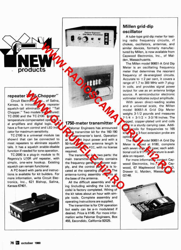
- products
repeater "Tail-Chopper" Circuit Electronics, Inc., of Salina,
Kansas, is introducing a repeater squelch-tail eliminator called "Tail Chopper." Two models are featured: TC-2000 and the TC-2100. Both use temperature-compensated operation- al amplifiers and digital logic, and have a five-turn control and LED indi- cator for maximum sensitivity.
TC-2100 is a universal module (as shown) that can be connected to most repeaters to eliminate squelch tails. It has a squelch enable-disable function if needed for tone operation.
TC-2000 is a plug-in module to fit Regency's UlOR uhf repeater, with simple, one-wire hookup. Existing squelch can remain functional.
A PC-board with parts and instruc- tions is available for kit builders. For more information, write Circuit Elec- tronics, Inc., 621 Bishop, Salina, Kansas 67401.
1750-meter transmitter Palomar Engineers has announced
a new transmitter kit for the 160-190 kHz experimenter's band. Operation at one watt input power and with a 50-foot maximum antenna length is permitted by the FCC, with no license required.
The transmitter is in two parts: the main transmitter assembly contains the frequency generator, power sup- ply, and the control panel. It is lo- cated at the operating position. The antenna-tuning assembly mounts at the base of the antenna.
All the difficult assembly and wir- ing (including winding the Litz wire coils) is factory completed. Wiring of the kit takes about an hour with sim- ple tools. Complete assembly and operating instructions are supplied.
The transmitter is for CW operation but easily can be a-m modulated if desired. Price is $145. For more infor- mation write Palomar Engineers, Box 455, Escondido, California 92025.
Millen grid-dip oscillator
A tube-type grid-dip meter for test- ing radio frequency circuits, rf chokes, oscillators, antennas, and similar devices, formerly manufac- tured by Millen, is now available from Caywood Electronics, Inc., of Mal- den, Massachusetts.
The Millen model 90651-A Grid Dip Meter is an oscillating frequency
, meter that determines the resonant frequency of de-energized circuits. Accurate to f 2 per cent, it covers a range of 1.7 to 300 MHz with 7 plug- in coils, and provides signal power output for use as an antenna bridge source. A semiconductor electronic voltmeter indicates output amplitude.
With seven direct-reading scales and a universal scale, the Millen model 90651-A Grid Dip Meter weighs 3-1 12 pounds and measures 7-114 x 3-112 x 3-3/16 inches. The rugged, copper-plated unit and coils store in a sturdy carrying case. Addi- tional coils for frequencies to 165 kHz, and a 3-foot extension probe are optional.
The Millen model 90651-A Grid Dip Meter is priced at $180, complete with seven coils ahd case; each addi- tional coil is $17.75. Literature is avail- able on request.
For more information contact Cay- wood Electronics, Inc., Wade Cay- wood, 67 Maplewood Street, P.O. Drawer U, Malden, Massachusetts 02148.
I I 1
76 october 1980
WWW.RADiOSCAMATORUL.Hi2.RO
WWW.GiURUMELE.Hi2.RO

ATV'downconverter P.C. Electronics has introduced a
new fast-scan ATV downconverter which converts the entire 420-450 MHz band down to N channel 2 or 3, or to a 45MHz i-f, with full band- width for color and computer video.
The standard model TVC-4 con- tains a new microstrip converter with a low-noise MRF901 preamp stage, 12 Vdc power supply, BNC antenna input connector, and type F output connector. The low-noise-figure pre- amp stage enables seeing sync bars down to as low as 0.3 microvolts. An ultra-low-noise NE64535 preamp stage is also available as an option to get sensitivity down to 0.2 microvolt in the TVC4L.
The TVC-4 downconverter comes in an attractive Ten-Tec JW-5 enclo- sure, and Ten-Tec has specially coated the Cycolac woodgrain side panels with a conductive coating for excellent shielding.
Pricing for the downconverters is $85 for the standard low-noise TVC-4, $1 15 for the ultra-low-noise NC-4L. Both prices include shipping in the U.S. For those who wish to build their own cabinet and power supply, the downconverter modules by themselves, wired and tested, are available (TVC-2 and TVC-2L) for $49.50 and $79.50 respectively, post- age paid. Write for a complete ATV catalog. Send a self-addressed, stamped envelope to P.C. Electron- ics, 2522 S. Paxson Lane, Arcadia, California 91006.
I The World's Greatest Sending Device
Adjustable to Any Desired Speed Now available from Palomar Engineers - the new Electronic IC KEY ER. Highly prized by professional operators because i t is EASIER, QUICKER, and MORE ACCURATE.
I It transmits with amazing ease CLEAR, CLEAN-CUT signals at any desired speed. Saves the arm. Prevents cramp, and enables anyone to send with the skill of an expert.
SPECIAL RADIO MODEL Equipped with large specially constructed contact points. Keys any amateur transmitter with ease. Sends Manual, Semi-Automatic, Full Automatic, Dot Memory, Dash Memory, Squeeze, and iambic - MORE FEATURES than any other keyer. Has built-in sidetone, speaker, speed and volume controls, BATTERY OPERATED, heavy shielded die-cast metal case. Fully ADJUSTABLE CONTACT SPACING AND PADDLE TENSION. The perfect paddle touch will AMAZE you.
Every amateur and licensed operator should know how to 1 send with the IC KEYER. EASY TO LEARN. Sent 1 anywhere on receipt of price. Free brochure sent on 1 request. lrn Ez
I Send check or money order. IC KEYER $117.50 in U. S. and Canada. Add $4.00 shippinglhandling. Add sales tax in California.
I Fully guaranteed by the world's oldest manufacturer of electronic keys. ORDER YOURS NOW!
More Details? CHECK-OFF Page 94 october 1980 77
WWW.RADiOSCAMATORUL.Hi2.RO
WWW.GiURUMELE.Hi2.RO

BARKER & WILLIAMSON
Model 370-10
Portable Antenna for 2, 6,10,15,20and
40 meters
Weighs Less than 2 Ibs.
Disassembled for packing or storage Only 22V2 inches long VSWR: 1.1 :1 Whip extends to only 57 inches Complete with 10 ft. coax; counterpoise and all coils.
AVAILABLE AT YOUR B 8 W DEALER OR WRITE:
Barker 8 Williamson. Inc. 10 Canal Street Bristol, PA. 19007
78 5 october 1980
Telrex 5-element beam ing radius, 7-square-foot wind sur- Telrex introduces the latest in its face area, weighs 49 pounds, and is
series of professionally engineered shipped via motor freight in a 13-foot antennas, a five-element, balun-fed long carton. 10, 15, and 20-meter tri-band beam, The half-power beamwidth is 60°, Model TB5ES. The TB5ES provides with 35 dB side nulls and a 1 kW peak optimum forward gain, front-to-back power rating. ratio, and signal-to-noise ratio, in an The price is right at $315.00 f.0.b. antenna which exhibits a clean and Asbury Park, New Jersey- precise pattern. For further information write Telrex
The quality of the TB5ES is also in Labs, P.0. Box 879, Asbury Park, keeping with its famous Telrex prede- New Jersey 07712, or phone bnswer cessors, the TB5EM and the TBGEM. phone available day or night, Satur- A precision-machined boom, hermet- days. Sundays, and holidays) 201- ically sealed, epoxied traps, stainless- 775-7252 and leave Your mailing steel electrical hardware, preformed address. gusset mounting straps, reinforced,
More Details? CHECK-OFF Page 94
extremely heavy-walled boom and elements, elements driven through the boom, high-strength, seamless, drawn-dural aluminum tubing, and a non-ferrite, coaxial high-performance Balun (provided with the antenna) are only a few of its many attributes.
Consistent with the workmanship normally associated with Telrex, the TB5ES is a hand-crafted, precision- machined antenna.
The TB5ES has an la foot boom, 36-foot longest element, 22-foot turn-
shorf circuit Yagi antenna design In W2PV's article, page 39 of the June, 1980, ham radio, the highest gain value on the graphs should read 15, not 0.5. The three graphs in the left-hand column should all read Boom = 0.75A; the three in the right- hand column should all read Boom = 1.25A.
WWW.RADiOSCAMATORUL.Hi2.RO
WWW.GiURUMELE.Hi2.RO

STUDY AIDS KANTRONICS
THEORY CASSETTE Here's a new, easy way to study theory for your Novice, General, Advanced or Extra class exam. Designed for folks on the run. All you have to do is drop in the cassette at home, work, or in the car and listen to an inter- view-style tape covering Novice, General, Advanced or Extra class theory. A great way to reinforce other study methods. UKT-NT One tape $4.95
Novice Class Theory Cassette OKT-GT Two tapes 58.95
General Class Theory Cassette KT-AT One tape 54.95
Advanced Class Theory Cassette KT-ET One tape 54.95
Extra Class Theory Cassette
Please add 51.00 to cover postage and handling.
Available from H A M RADIO'S BOOKSTORE
GREENVILLE, NH 03048
Coming Soon 198 1 HANDBOOK
1981 U.S. & FOREIGN
CALLBOOKS CALL TODAY TO
RESERVE YOUR COPY 1-800-258-5353
Ham Radio's Bookstore GREENVILLE, N. H. 03048
35w 2~ FM AMPLIFIER KIT
3 Watts In-35Wana Out
. -- MODEL 335-K
2648 NORTH ARAGON AVE. DAYTON, OHIO 45420
(513) 296.141 1 D
111 STEP UP TO TELREX 11 Professionally Engineered Antenna Systems Single transmission line "TRI-BAND" ARRAY"
r ILLUSTRATION BALUN
TWEM/4KWP
\ '.
By the only test that means anything.. . on the alr comoar~son . . . this array con- tinues to outoerform all comoetitibn . and has for'two decades. ere's why For technical data and prices on corn- . . . Telrex uses a unique trap .design plete Telrex line, write for Catalog PL 7 employ~na 20 H i0 7500V ceramlc con- - denseis per antenna. Telrex uses 3 ooti- ~w,,uw.md - mum-spaced, optimum-tuned ref~ectbrs to provide maximum gain and true F/B L=&IreX Tri-band performance. " i l i l l r P l l l . "In , , u \ , r 0,712 0 5 .
-.-.-.-.-.-.-.-.-.-.-.-.-.-. ! AFFORDABLE CW KEYBOARD!
I Transmits perfect Morse Code Bullt-in 16 . character buffer Internal speaker and slde- tone * Reed relay output elimlnates keylng 1 problems Al l solld state circuits and sockets . for rellabillty * Speed range 5--45 WPM * Perfect cornpanuon to our MORSE-A-WORD CW code I I reader.
MORSE-A-KEYER KIT, model MAK-K, Complete ki t of parts & manual . . . . . $159.95 I MORSE-A-KEYER, model MAK-F. Factory wired & tested . . . . . . . . . . . . . . $205.00 MORSE-A-KEYER ESSENTIAL PARTS KIT, model EPK-K.. . . . . . . . . . . . s 69.95
(Essential parts kit for home-brewers consists of pc board, board parts and manual. I You supply ASCII keyboard, cabinet, power supply & miscellaneous parts.) Send check or money order. Use your VISA or Mastercard. Add $5.00 shipping and
I handling for Continental U.S. Wlsconsln residents add 4% Wisconsin State Sales Tax. 1 I I
C o r p o r a t i o n Telephone: (414) 241-8144 - I P a t Office Box 513HR, Thiensville, Wisconsin 53092 1 * - . - . - . - . - . - . - . - m - m - m - . - . - m - .
I Featuring Kenwood. Yaesu. icom. Drake, Ten-Tec, Swan, Dentron. Alpha. Robot, MFJ, Tempo, Astron. KLM, Hy Gain, Mosley, Larsen, Cushcraft. Hustler, Mini Products. Bird. Miraae. Vibro~lex. Bencher. Info-Tech. Universal Towers. 1
allbook; ARRL, Astacc, Shure. ' w e service everything we sell! v Write or call for quote. You Won't Be Disappointed.
Weare iust a few minutes off the NYS Thruwav (1-90) Exit 32
EFFECTIVE JULV 1. 1880
More Details? CHECK-OFF Page 94 october 1980 79
WWW.RADiOSCAMATORUL.Hi2.RO
WWW.GiURUMELE.Hi2.RO

1900 MHz to 2500 MHz DOWN CONVERTER This receiver is tunable over a range of 1900 to 2500 mc and is intended for amateur radio use. The local oscillator is voltage controlled (i.e.) making the i-f range approximately 54 to 88 mc (Channels 2 to 7). PCBOARDWlTHCHlPCAPAClTORS13 . . . . . . . . . . . . . . . . . . . . . . . . . . . . . . . . . . . . . . . . . . . . . . . . . . . . . . . . . . . . . . . . . . . . . . . . . . . . . . . . . . . . . . . . $44.99
. . . . . . . . . . . . . . . . . . . . . . . . . . . . . . . . . . . . . . . . . . . . . . . . . . . . . . . . . . . . . . . . . . . . . . . . . . . . . . . . . . PCBOARDWITHALLPARTSFORASSEMBLY $79.99 . . . . . . . . . . . . . . . . . . . . . . . . . . . . . . . . . . . . . . . . . . . . . . . . . . . . . . . . . . . . . . . . . . . . . . . . . . . . . . . . . . . . . . . . PC BOARD ASSEMBLED ANDTESTED $120.00
POWERSUPPLYKIT . . . . . . . . . . . . . . . . . . . . . . . . . . . . . . . . . . . . . . . . . . . . . . . . . . . . . . . . . . . . . . . . . . . . . . . . . . . . . . . . . . . . . . . . . . . . . . . . . . . . . . . . . $44.99 POWERSUPPLYASSEMBLEDANDTESTED . . . . . . . . . . . . . . . . . . . . . . . . . . . . . . . . . . . . . . . . . . . . . . . . . . . . . . . . . . . . . . . . . . . . . . . . . . . . . . . . . . . . $59.99
. . . . . . . . . . . . . . . . . . . . . . . . . . . . . . . . . . . . . . . . . . . . . . . . . . . . . . . . . . . . . . . . . . . . . . . . . . . YAGl ANTENNA 4' LONG APPROX. 20 TO 23 dB GAIN. $59.99 . . . . . . . . . . . . . . . . . . . . . . . . . . . . . . . . . . . . . . . . . . . . . . . . . . . . . . . . . . . . . . . . . . . . . . . . . YAGl ANTENNA4' WITH TYPE(N. BNC. SMA Connector) $64.99
2300 MHz DOWN CONVERTER Includes converter mounted in antenna, power supply, antenna, 75' and 3 ' RG59cable with connectors, . . . . . . . . . . . . . . . . . . . . . . . . . . . . . . . . . . . . . . . . . . . . . . . . . . . . . . . . . . . . . . . . . . . . . . . . . . . . . . 75 to 300ohm adapter, Plus 90 DAY WARRANTY $299.99
. . . . . . . . . . . . . . . . . . . . . . . . . . . . . . . . . . . . . . . . . . . . . . . . . . . . . . . . . . . . . . . . . . . . . . . . . . . . . OPTION # I MRF902 in front end. (7dB noise figure). $349.99 . . . . . . . . . . . . . . . . . . . . . . . . . . . . . . . . . . . . . . . . . . . . . . . . . . . . . . . . . . . . . . . . . . . . . . . . . . . . . . OPTION W22N6603 in front end. (5dB noise figure) $400.00
2300 MHz D.0WN CONVERTER 0,NLY . . . . . . . . . . . . . . . . . . . . . . . . . . . . . . . . . . . . . . . . . . . . . . . . . . . . . . . . . . 10dB No~se F1gure23dBgaln !n box with N conn. Input Fconn. Output. $149.99 . . . . . . . . . . . . . . . . . . . . . . . . . . . . . . . . . . . . . . . . . . . . . . . . . . . . . 7dB Noise Flgure23dBgain ~n box with Nconn. Input Fconn. Out ut $169.99
. . . . . . . . . . . . . . . . . . . . . . . . . . . . . . . . . . . . . . . . . . . . . . . . . . . 5dB NoiseFigure23dBgain in box with SMAconn. Input Fconn. 8utb;i: : 1 . . $189.99 . . . . . . . . . . . . . . . . . . . . . . . . . . . . . . . . . . . . . . . . . . . . . . . . . . . . . . . . . . . . DATA IS INCLUDED WITH KITS OR MAY BE PURCHASED SEPARATELY $15.00
Shipping and Handllng Cost: Receiver Kits add $1.50, Power Supply add $2.00, Antennaadd $5.00, Option 112 add $3.00, For complete system add $7.50. . . .
Re lacement Parts: MF~FSOI $5.00 ,001 chip caps $2.00 2N6603 $12.00 PC Board only $25.00 with data MBDlOl $2.00
* INTRODUCING THE HOWARDICOLEMAN TVRO CIRCUIT BOARDS * ( Satellite Receiver Boards ) . ~- ~
DUALCONVERSIONBOARD ................................................................................................. $25.00 This board prov~des conversion from the 3.7-4.2 band first to 900 MHz where gain and bandpass filtering are provided and, second, to 70 MHz. The board contains both local oscillators. one fixed and the other variable, and the second mixer. Construction Is greatly slmpllfied by the use - - - - - - - of Hvbrid IC amolifiers for the gain staaes. Bare boards cost $25 and it is estimated that parts for construction will cost $270. (Note. The two ~ v a i t e k VTO's account for $225 of thiscost.)
..................................................................................................... 47 pF CHIP CAPACITORS $6.00 For use w ~ t h dual conversion board. Consists of 6 - 47 pF.
........................................................................................................... 70,MHzIFBOARD $25.00 Th~s clrcult rovldes about 43 dB gain with 50 ohm input and output impedance. It is des~ ned to drive the HOWARDICOLEMAN TVRO De- modulator. f h e on-board band pass filter can be tuned for bandwidths between 20 and 35 $2 with a passband ripple of less than 112 dB. Hy- brid ICs are used for the gain stages. Bare boards cost $25. It is estimated that parts for construction will cost less than $40.
A - .- .OIpFCHlPCAPAClTORS ..................................................................................................... $7.00 For use with 70 MHz IF Board. Consists of 7 - .O1 pF.
.................................................................................................... DEMODULATOR BOARD.. 40.00 This circu~t takes the 70 MHz center frequency satellite TV signals in the 10 to 200 millivolt range, detects them usin a phase locked loop, de- emphasizes an! filters the result and amplifies the result to produce standard NTSC video. Other outputs include tRe audio subcarrier. a DC voltage proport~onal to the strength of the 70 MHz signal, and AFC voltage centered at about 2 volts DC. The bare boards cost $40 and total parts cost less than $30. SlNGL,EAUDlO ............................................................................................................. $15.00 This clrcult recovers the audio signals from the 6.8 MHz frequency. The Miller 9051 coils are tuned to pass the 6.8 MHz subcarrier and the Miller 9052 coil tunes for recovery of the audio.
............................................................................................................... DUAL AUDIO $25.00 Dupl~cate of the single audio but also covers the 6.2 range.
.............................................................................................................. DC CONTROL $15.00 Th~s c~rcuit controls the VTO's, AFC and the S Meter. TOTAL COSTS Using the HOWARDICOLEMAN boards and the recommended parts, i t is easily possible to build the complete receiver (excluding LNA) for less than $600. Construction time is a few evenings and the tune up is minimal.
TERMS: WE REGRET WE NO LONGER ACCEPT BANK CARDS. PLEASE SEND POSTAL MONEY ORDER, CERTIFIED CHECK, CASHIER'S CHECK OR MONEY ORDER. PRICES SUBJECT TO CHANGE WITHOUT NOTICE. WE CHARGE 15% FOR RESTOCKING ON ANY ORDER. (602) 242-303 7 ALL CHECKS AND MONEY ORDERS IN US FUNDS ONLY. ALL ORDERS SENT FIRST CLASS OR UPS. ALL PARTS PRIME AND GUARANTEED.
(602) 242-8916 WE WILL ACCEPT COD ORDERS FOR $25.00 OR OVER, ADD $1.50 FOR COD CHARGE. PLEASE INCLUDE $1.50 MINIMUM FOR SHIPPING OR CALL FOR CHARGES. 21 1 1 W. Camelback -- - - -
WE ALSO ARE LOOKING FOR NEW AND USED TUBES, TEST EQUIPMENT. COMPONENTS, ETC. WE ALSO SWAP OR TRADE. Phoenix, Arizona 8501 5 FOR CATALOG SEE JANUARY, 1980,73 Magazine, 10 Pages.
NEW - TOLL-FREE NO. 800-528-01 80 - please, orders only!
80 october 1980 More Details? CHECK-OFF Page 94
WWW.RADiOSCAMATORUL.Hi2.RO
WWW.GiURUMELE.Hi2.RO

FAIRCHILD VHF AND UHF PRESCALER CHIPS 95H90DC 350 MHz Prescaler Divide by 10111 95H91DC 350 MHz Prescaler Divide by 9 6 11C90DC 650 MHz Prescaler Divide by 10111 11C9lDC 650 MHz Prescaler Divide by 516 11 C83DC 1 GHz Divide by 248/256 Prescaler 11C70DC 600 MHz FliolFloo with reset . . l lC58DC ECL VCM 4.53 llC44DClMC4044 Phase Frequency Detector 3.82 llC24DCIMC4024 Dual TTL VCM 3.82 11COGDC UHF Prescaler 750 MHz D Type FlipIFlop 12.30 llCO5DC 1 GHz Counter Divide bv 4 74.35 l lCOlFC High Speed Dual 5 4 input NOINOR Gate 15.40
WISPER FANS This fan is super quiet, efficient cooling where low acoustical disturbance is a must. Size 4.68" x 4.68" x 1.50". Impedance protected, 50160 Hz. 120 Vac.
$9.99
TRW BROADBAND AMPLIFIER MODEL CA615B Frequency response 40 MHz to 300 MHz Gain: 300 MHz 16 dB Min., 17.5dB Max.
50 MHzOto - 1 dBfrom300 MHz Voltage: 24 volts dc at 220 ma max. $19.99
CARBIDE - CIRCUIT BOARD DRILL BITS FOR PC BOARDS Size: 35,42, 47,49,51,52 $2.15 Size: 53, 54, 55, 56.57.58, 59,61,63, 64.65 1.85 Size: 66 1 .90 Size: 1.25mm, 1.45 mm 2.00 Size: 3.20 mm 3.58
CRYSTAL FILTERS: TYCO 001.19880 same as 2194F 10.7 MHz Narrow Band Crystal Filter 3 dB bandwidth 15 kHz min. 20 dB bandwidth 60 kHz mln. 40 dB bandwidth 150
kHz min. Ultimate 50 dB: Insertion loss 1.0 dB max. Ripple 1.0 dB max. Ct. O + I- 5 pf 3600
ohms. $5.95
MURATA CERAMIC FILTERS Models: SFD-455D 455 kHz $3.00
SFB-455D 455 kHz 2.00 CFM-455E 455 kHz 7.95 SFE-10.7 10.7 MHz 5.95
TEST EQUIPMENT - HEWLETT PACKARD - TEKTRONIX - ETC. Hewlett Packard: 491C TWTAmplitier 2 t o 4 Gc 1 watt 30 dB gain $1150.00 608D 10 to 420 rnc . l uV to .5 V into50 ohms Signal Generator 500.00 612A 450 to 1230 mc .l uV to .5 V into 50 ohms Signal Generator 750.00 614A 900 to 2100 mc Signal Generator 500.00 616B 1.8 to4.2 Gc Signal Generator 400.00 6180 3.8 to 7.2 Gc Signal Generator 400.00 620A 7 to 11 Gc Signal Generator 400.00 6238 MicrowaveTest Set 900.00 624C Microwave Test Set 950.00 695A 12.4 to 18 Gc Sweep Generator 900.00 1702A Storage Oscilloscope 1800.00 8691A 1 to 2 Gc Plug In For8690A Sweeper 800.00 8692A 2 to 4 Gc Plug In For 8690A Sweeper 800.00 8693A 4 to 8 Gc Plug In For8690A Sweeper 800.00 8742A Reflection Test Unit 2 to 12.4 Gc 1800.00 Alltach: 473 225 to 400 mc AMIFM Signal Generator 750.00 Singer: MF5lVR-4 Universal Spectrum Analyzer with 1 kHz to 27.5 mc Plug In 1200.00 Keltak: XR630-100 TWTAmplifier8 to 12.4 Gc 100 watts 40dB gain 9200.00 Polarad: 2038/2436/1102A
Calibrated Display with an SSB Analysis Module and a 10 to 40 mc Single Tone Synthesizer 1500.00
RF TRANSISTORS TYPE PRICE 2N1561 $15.00 2N1562 15.00 2N1692 15.00 2N1693 15.00 2N2632 45.00
We can supply any value chip capac- itors you may need.
PRICES 1 to 10 $1.99 11 - 5 0 1.49 51. 100 1.00 101 - 1,000 .75 1.001 up .50
TYPE 2N55W 2N5591 2N5637 2N5641 2N5642 2N5643 2N6545 2N5764 2N5842 21'15849 2N5862 2N5913 2N5922 2N5942 2N5944 2N5945 2N5946 2N6080 2N6081 2N6082 2N6083 2N6084 2N6094 2N6095 2N6096 2N6097 2N6136 2N6166 21'16265 2N6266 2N6439 2N64591PT9795 2N6603 2N6604
PRICE $8.15 11.85 22.15 6.00
10.05 15.82 12.38 27.00 8.78
21.29 51.91 3.25
10.00 46.00 8.92
12.38 14.69 7.74
10.05 11.30 13.23 14.66 7.15
11.77 20.77 29.54 20.15 38.60 75.00
100.00 45.77 18.00 12.00 12.00 25.00 5.00
25.00 25.00 15.00 4.95
11.30 29.88 9.95
19.90 24.95 11.34 2.56
50.00 32.20
CHIP CAPACITORS l p f 27pf
1.5pf 33pf 2.2pf 39pf 2.7pf 47pf 3.3pf 56pf 3.9pf 88pf 4.7pf 82pf 5.6pf 100pf 6.8pf 1 lOpf 8.2pf 120pf 10pf 130pf 12pf 150pf 15pf 160pf 18pf 180pf 22pf 200pf
TYPE MM1550 MM1552 MM1553 MM1601 MM1602I2N5842 MM1607 MM1661 MM1669 MM1943 MM2605 M M2606 MM8006 MMCM918 MMT72 MMT74 MMT2857 MRF304 MRF420 MRF450 MRF450A MRF454 MRF458 MRF475 MRF476 MRF502 MRF504 MRF509 MRF511 MRFWl MRF5177 MRF8004 PT4186B PT4571A PT4612 PT4628 PT4640 PT8659 PT9784 PT9790 SD1043 SD1116 S D l l l 6 SD1119 TA7993 TA7994 TRWMRA2023 1.5 40281 40282 40290
PRICE $10.00 50.00 56.50 5.50 7.50 8.65
15.00 17.50 3.00 3.00 5.00 2.23
20.00 1.17 1.17 2.63
43.45 20.00 11.85 11.85 21.83 20.68 5.00 5.00 1.08 6.95 4.90 8.15 3.00
21.62 1.60 3.00 1.50 5.00 5.00 5.00
10.72 24.30 41.70 5.00 3.00 5.00 3.00
75.00 100.00 42.50 10.90 11.90 2.48
HAMLIN SOLID STATE RELAYS ATLAS CRYSTAL FILTERS FOR ATLAS HAM GEAR
120 Vac a1 40 Amps. Input Voltage 3 to 32 Vdc.
240 Vac at 40 Amps. Input Voltage 3 to 32 Vdc.
Your Choice $4.99
YOUR CHOICE $24.95
NEW - TOLL-FREE NO. 800-528-01 80 - please. orders only!
More Details? CHECK-OFF Page 94 october 1980 81
WWW.RADiOSCAMATORUL.Hi2.RO
WWW.GiURUMELE.Hi2.RO

@) MOTOROLA Semiconductor The RF Line
NPN SILICON RF POWER TRANSISTORS
. . . designed for power amplifier applications in i n d u s t r i a l , c o m -
mercial and amateur radio equipment to 30 MHz. - 4 Specified 12.5 Volt. 30 MHz C h a r a c t e r i s t i c s -
Output Power = 80 Watts Minimum Gain = 12 dB Efficiency = 50%
NPN SILICON RF POWER TRANSISTOR . . . d e s i g n e d p r i m a r ~ l y for u s e In l a r g e - s ~ g n a l output ampllfler s t a g e s .
Intended for u s e in C l t l z e n - B a n d c o m m u n l c a t t o n s equlpment
MRf 472 operating a t 27 MHz. H~gh b r e a k d o w n v o l t a g e s a l l o w a h~gh percentage of u p - m o d u l a t i o n In AM c i r c u i t s .
$ 2 . 5 0 4 Specifled 12.5 V, 27 MHz Characteristics - Power Output = 4.0 W a t t s
Power Galn = 10 dB Min~mum Eff~ciency = 65% Typical
MRF475 NPN SILICON RF POWER TRANSISTOR
. . . d e s i g n e d primarily for u s e In s i n g l e sideband linear amplifier output applicaiions in citizens band and other communications A equipment operaiing to 30 MHz.
4 Characterized for Slngle Sideband a n d L a r g e - S i g n a l Amplifier
A p p l i c a t i o n s Utilizing L o w - L e v e l Modulation.
4 Spec~fied 13.6 V. 30 MHz Characteristics - Output Power = 12 W ( P E P )
Mlnimum Eff~ciency = 40% ISSB) Output Power = 4.0 W ( C W I
$5. 00 Min~mum Ef f i c~ency = 50% ( C W )
Minimum Power Gain = 10 dB ( P E P & C W )
4 Common Collector C h a r a c t e r i z a t i o n
NPN SILICON RF POWER TRANSISTOR
d e s ~ g n e d for power a m p l t f l e r a p p l ~ c a t ~ o n s I n ~ n d u s t r ~ a l .
commerlcal and amateur radlo equlpment to 30 MHz
4 S p e c l f ~ e d 12 5 Volt. 30 MHz C h a r a c t e r l s t l c s
Output Power = 80 W a t t s
Mlnlmum G a l n = 12 dB Efflclency = 50%
4 Capable of W l t h s t a n d l n g 30 1 L o a d VSWR @ Rated Pout a n d VCC
UHF POWER AMPLIFIER MODULE
. . d e s ~ g n e d for 12.5 volt UHF power amplif~er a p p l l c a t ~ o n s in l n d u s t r ~ a l and commercial FM e q u l p m e n t operating from 400 t o 512 MHz
S p e c l f l e d 12 5 Volt. UHF C h a r a c t e r ~ s t ~ c r -
Output Power = 13 Wat ts M l n l m u m G a l n = 19 4 dB Harmonics = 40 dB
4 50 11 I n p u t i O u t p u t I m p e d a n c e
4 G u a r a n t e e d S t a b ~ l ~ t y and R u g g e d n e s s
4 G a ~ n Control P l n for M a n u a l or Automat~c Output Level Control
4 T h t n F l l m H y b r l d Construction Glves Consistent Performance
and R e l ~ a b ~ l ~ t y
Tektronix Test Equipment Yldebdsd H lgh Gall\ P lug I n Dual T r d ~ e P l v g 11) Fast Rlse OC P lug 111
Sdmpl>ng P luq I n l r d n s l n t o r R l re t lme P lug I n High Gain O l f f e r e n t l a l Comparator Plug I n i e r t ~ o a d p l u g i n f o r 530/540/550 Maln ~ r a m e r Uldebdnd Oual l r d i e Plug I n Sampling U n l t U l t h 35OPS R i r e t l m r OC t o 1GHZ AC O l f f e r e n t l a l Plug I n Dual Trace Sampllng DC t o IGHZ P lug I n Oudl Trace SdmpIlnP OC t o 875HHZ P lug IN Sdmpi~nq Sweep P lvg I n Spectrum Analyzer I t o 36NHZ Plug IN h p l l f l e r P lug I n
51 Sweep P lug I n 538 UIdeband Hlgh Gdln P lug I n 531548 Yldeband H igh Gal" P lug I n 53154C Dual Trace P lug I n 531540 nrgh Galn DC O ~ f f e r e n t l a l P lug I n 531546 Yldeband DC D l f f e r e n t l a l P luq I n 53154L f a r 1 R l r e H lgh Gain P lvg I n 84 Test P lug I n f a r 5801581 Maln Framer 107 Square Wave Generator .4 t o 1HiZ RM122 P r e a n p l l f ~ e r 2Hz t o 4OKHZ 123 At Coupled P r e a n p l l f l e r 127 Power Supply For 2 P lug I n ' s 131 Current Probe h p l i f l e r 184 T i m & r k Generator R240 Program Cont ro l U n l t 280 Tr igger Countdown U n l t 455 Por tab le Dual Pace 50WZ Scope 465 Por tab le Oual Trace IOOnIZ Scope 503 OC t o 45OKHZ Scope Rack Mount 535A OC t o 15nlZ Scow Rack Mount 543 DC t o 33nIz Scope 561 OC t o IOMZ Scope Rack Mount 561A DC t o 1 W Z Scope Rack %unt
$ 51.00 150 on 63 00
200.00 116.00 283.00
50.00 216.00 730.00 133.00 250.00 250.00 250 00
1000.00 50.00 50.00 25.00 45.00
112.50 38 00 68.00 68.00 75.00 48.00 63.00 25.00
148.00 50.00
363.00 150.00 84.00
2000.00 2500.00
250.00 263.00 300.00 150.00 zoo. 00
Scopes with Plug- ins 567 O ~ g l t a l Readour Scope m t h a 6RlA O l g l t a l U n l t
and a 353 Dual Trace OC Lo ICH2 Sampl~nq P lug I n and a 3T77A Sweep Plug I n
561A DC t o IOMHZ Scope w l t h a 3816 Dual Trace OC t o R15MHZ Sampllnq P lug I n and a IT l7A Sueen P lug I n . Rack Mount
565 OC t o IOMHZ Dual Beam Scope w t h a ZA63 O l f f and a 2161 O l f f . Plug 1" ' s
581 OC t o 8OMH2 Scope ~ 7 t h a 82 Oual Trace Hlqh Gain P lug I n
661 Sdmpllng Scope w i t h a 513 Tlmlng P luq I n and a 452 Oual T race OC t o 3.5GHZ Sampllng Plug I n .
Tubes
NEW - TOLL-FREE NO. 800-528-01 80 - please, orders only! I
82 october 1980 More Details? CHECK-OFF Page 94
WWW.RADiOSCAMATORUL.Hi2.RO
WWW.GiURUMELE.Hi2.RO

More Details? CHECK-OFF Page 94
MICROWAVE COMPONENTS COMPUTER 1.C. SPECIALS
ARRA MEMORY DESCRIPTION PRICE 2416 V a r i a b l e A t tenua to r $ 50.00 3614-60 V a r i a b l e A t tenua to r 0 t o 6CdB 75.00 2708 1K x 8 EPROM 1 7.99 KU520A V a r i a b l e A t t e n u a t o r 18 t o 26.5 GHz 100.00 271612516 2K x 8 EPROM 5 V o l t S i n g l e Supply 20.00 4684-20C V a r i a b l e A t tenua to r 0 t o l 8 W 8 100.00 2114/9114 1K x 4 S t a t i c RAM 450ns 6.99 6684-20F V a r i a b l e A t tenua to r 0 t o l8Od8 100.00 2114L2 IK x 4 S t a t i c RAM 250ns 8.99
2114L3 IK x 4 S t a t i c RAM 350ns 7.99
General Microwave 4027 4060/2107 4~ 4~ x x 1 1 Dynamic Dynamic RAM RAM 3.99 3.99
D i r e c t i o n a l Coupler 2 t o 4GHz 20dB Type N 75,00 4050/9050 4K x 1 Dynamic RAM 3.99 2111A-2/8111 256 x 4 S t a t i c RAM 3.99 2112A-2 256 x 4 S t a t i c RAM 3.99
Hewlett Packard 2 1 1 5 ~ ~ - 2 1K x 1 S t a t i c RAM 5517s 4.99
6104-3/4104 4K x 1 S t a t i c RAM 320ns 14.99
H487B 100 ohms Neg Thermis to r Mount (NEW) 7142-2 4K x 1 S t a t i c RAM 200ns 14.99
H487B 100 ohms Neg Thermis to r Mount (USED) : MCM6641L20 4K x 2 S t a t i c RAM 200ns 14.99
4778 200 ohms Neg Thermis to r Mount (USED) 100.00 9131 1K x 1 S t a t i c RAM 300ns 10.99
X487A 100 ohms Neg. T h e n i s t o r Mount (USED) 100.00 X487B 100 ohms Neg. Thermis to r Mount (USED) 125.00
J468A 100 ohms Neg Thermis to r Mount (USED) 150.00 C.P.U.'s ECT.
478A 200 ohms Neg Thermis to r Mount (USED) 150.00 8478A 200 ohms Balanced Neg. Thermis to r Mount (USED) 175.00 Mc6800L Mic roprocessor 13.80 J382 5.85 t o 8.2 GHz V a r i a b l e A t tenua to r 0 t o 50dB 250.00 MCM6810AP 128 x 8 S t a t i c RAM 450ns 3.99 X382A 8.2 t o 12.4 GHz V a r i a b l e A t tenua to r 0 t o 50dB 250.00 MCM68AlOP 128 x 8 S t a t i c RAM 36011s 4.99
MCM688lOP 128 x 8 S t a t i c RAM 250ns 5.99 MC682(1P PIA 8.99
X885A 8 . 2 t o 12.4 GHz Phase S h i f t e r +/- 360" 250,00 MC682OL PIA 9.99 394A 1 t o 2 GHz V a r i a b l e A t tenua to r 6 t o 120dB 250.00 MC6821P PIA 8.99 NK292A Waveguide Adapter 65.00 MC68821P PI A 9.99 K422A 18 t o 26.5 GHz C r y s t a l De tec to r 250.00 MCM6830L7 Mi kbug 14.99
K375A 18 t o 26.5 GHz V a r i a b l e A t tenua to r 300.00 MC684OP PTM 8.99
8436A Bandpass F i l t e r 8 t o 12.4 GHz 75.00 MC6845P CRT C o n t r o l l e r 29.50 MC6845L CRT C o n t r o l l e r 33.00 MC685OL AClA 10.99
8439A 2 GHz Notch F i l t e r 75.00 MC6850P ACIA 4.99 8471A RF Detec to r 50.00 MC6852P SSDA 5.99 342R VHF No ise Source 100.00 MC6852L SSDA 11.99 X347A 8.2 t o 12.4 GHz Noise Source 250.00 MC6854P AOLC 22.00 H532A 7.05 t o 10 GHz Frequency Meter 300.00 MC6860CJCS 0-600 BPS Modem 29.00 G532A 3.95 t o 5.85 GHz Frequency Meter 300.00 MC6862L 2400 BPS Modem 14.99 J532A 5.85 t o 8.2 GHz Frequency Meter 300.00 MK3850N-3 FB Microprocessor 9.99
MK3852P F8 Memory I n t e r f a c e 16.99 MK3852N F8 Memory I n t e r f a c e 9.99
809A Car r iage w i t h a 444A S l o t t e d L i n e Untuned Detec to r Probe MK3854N FB O i r e c t Memory Access 9.99 and 8098 Coaxial S l o t t e d Sec t ion 2.6 t o 18 GHz 175.00 8008.1 Microprocessor 4.99
H09B Car r iage w i t h a 4428 Broadband Probe 2.6 t o 12.4 GHz 8080A Microprocessor 8.99 and a XBlOB S l o t t e d S e c t i o n 200.00 LBOCPU Microprocessor 14.99
8098 Car r iage w i t h a X810B S l o t t e d Sec t ion and a PRO 250A 6520 PIA 7.99 Detec to r Mount 2.4 t o 12.4 GHz 200.00 6530 Support For 6500 s e r i e s 15.99
2650 Microprocessor 10.99
Merrimac TMS1000NL Four B i t Microprocessor 9.99 TMS4024NC 9 x 64 D i g i t a l Storage B u f f e r (FIFO) 9.99 TMS60llNC UART 9.99
AU-25A/ 801115 V a r i a b l e A t tenua ta r 100.00 MC14411 801162 V a r i a b l e A t tenua to r
B i t Rate Generator AU-26Al
11.99 100.00 AY5-40070 Four D i g i t Coun te r /D isp lay D r i v e r s 8.99
AY5-9200 Repertory O i a l l e r 9.99
Microlab/FXR AY5-9100 Push Bu t ton Telephone D i a l l e r s 7.99 AY5-2376 Keyboard Encoder 19.99 AY 3-8500 TV Game Chip 5.99
Y410A Frequency Meter 12400 - 18000 MC 250.00 TR1402A UART 9.99 N414A Frequency Meter 3950 - 11000 MC 350.90 PR1472B UART 9.99 X638S Horn 8.2 - 12.4 GHz 60.00 PT1482B UART 9.99 601-818 X t o N Adapter 8.2 - 12.4 GHz 35.00 8257 OMA C o n t r o l l e r 9.99 Y6100 Coupler 75.00 8251 Comnunication I n t e r f a c e 9.99
8228 System C o n t r o l l e r 8 Bus D r i v e r 5.00
Narda 8212 8 B i t Inpu t /Outpu t P o r t 5.00 MC14410CP 2 o f 8 Tone Encoder 9.99 MC14412 Low Speed Modem 14.99
30911 22909 D i r e c t i o n a l Coupler 7 t o 12.4 GHz lOd6 Type N 250.00 MC14408 B inary t o Phone Pu lse Converter 12.99 4013C-101 22540A Directional Coupler 2 t o 4 GHz lOdb Type SMA 90.00 MC14409 B inary t o Phone Pu lse Converter 12.99 4014-I01 22538 D i r e c t i o n a l Coupler 3.85 t o 8 GHz lOdR Type SMA 90.00 MC1488L RS232 D r i v e r 40l4C-6/ 22876 D i r e c t i o n a l Coupler 3.85 t o 8 GHr 6dB Type SMA 90.00 MC1489L RS232 Receiver 1.00
1.00
4015C-10/ 22539 D i r e c t i o n a l Coupler 7.4 t o 12 GHz lOd8 Type SMA 95.00 MC1405L A/O Converter Subsystem 9.00 4015C-301 23105 D i r e c t i o n a l Coupler 7 t o 12.4 GHz 30dB Type SMA 95.00 MC1406L 6 B i t O/A Converter 3044-20 D i r e c t i o n a l Coupler 4 t o 8 GHz 2Od8 Type N
7.50 125.00 MC1408/6/7/8 8 B i t D/A Converter
3040-20 O i r e c i t o n a l Coupler 240 t o 500 MC 20dR Type N 125.00 MC1330P Low Level Video Detec to r 4.50
3041 -20 D i r e c t i o n a l Coupler 500 t o 1000 MC 20dR Type N 125.00 MC1349/50 Video I F A m p l i f i e r 1.50
3043-201 22006 D i r e c t i o n a l Coupler 1.7 t o 4 GHz 20dB Type N 125.00 MC1733L LM733 OP A m p l i f i e r 1.17
3003-10/ 22011 D i r e c t i o n a l Coupler 2 t o 4 GHz lOd8 Type N 75.00 2.40
3003-30/ 22012 D i r e c t i o n a l Coupler 2 t o 4 GHz 30dB Type N 75.00 LM565 Phase Lock Loop 2.50 3042-20 D i r e c t i o n a l Coupler 950 t o 2 GHz 2OdB Type N 125.00 3043-30/ 22007 D i r e c t i o n a l Coupler 1.7 t o 3 .5 GHz 30dB Type N 125.00 22574 D i r e c t i o n a l Coupler 2 t o 4 GHz lOdB Type N 125.00 3033 Coaxial H y b r i d 2 t o 4 GHz 3d8 Type N 3032 Coaxial H y b r i d 950 t o 2 GHz 3 dB Type N 784/ 22380 V a r i a b l e A t tenua to r 1 t o 90dB 2 t o 2.5 GHz Type SMA 550.00 2::: mq& 22377 Waveguide t o Type N Adapter 720-6 F ixed A t tenua to r 8 .2 t o 14.4 GHz 6 dB 50.00 3503 Waveguide 25.00
PRD electroTcs - ULOl 12.4 t o 18 GHz V a r i a b l e A t tenua to r 0 t o 60dB 300.00 XI01 8.2 t o 12.4 GNz V a r i a b l e A t tenua to r 0 t o 60dB 200.00 C lO l V a r i a b l e A t tenua to r 0 t o 6068 200.00 205A/367 S l o t t e d L i n e w i t h Type N Adapter 100.00
(602) 242-3037 1958 8.2 t o 12.4 GHz V a r i a b l e A t tenua to r 0 t o 50dB 100.00 185651 7.05 t o 10 GHz V a r i a b l e A t tenua to r 0 t o 40dB 100.00 196C 8.2 t o 12.4 GHz V a r i a b l e A t tenua to r 0 t o 45dB 100.00
(602) 242-89 16 1708 3.95 t o 5.85 GHz V a r i a b l e A t tenua to r 0 t o 45dB 100.00 588A Frequency Meter 5.3 t o 6.7 GHz 100.00 140A,C,D,E F ixed A t tenua to rs 25.00
21 1 1 W. Camelback 109J. I F ixed A t tenua to rs 25.00 WEINsCHEL ENG. 2692 V a r i a b l e A t tenua to r +30 to 60dB 1oo.oo Phoenix, Arizona 8501 5
NEW - TOLL-FREE NO. 800-528-01 80 - please, orders only!
october 1980 83
4
WWW.RADiOSCAMATORUL.Hi2.RO
WWW.GiURUMELE.Hi2.RO

Give HaIYLRadio this year and Save
One Year11 2 issues
First Gift
Save $3.00 Each Additional Gi
Save $5.00 SAVE 20 O/o
\ \
Giving Ham is both fun and thoughtful.
And at the receiving end of a Ham Radio gift sub- scription it's remembered all year long as a token of your friendship. We have a super busy year planned for 1981. Just take a look at a sampling of what your special amateur friend(s) will see in their 12 big gift issues next year:
Satellite tracking Rf power meter Improved single-sideband transceiver Fm transmitter speech processor Plus HR's giant annual Antenna & Receiver issues Much Much More!
There's never been a better time to give a gift of Ham Radio than now. Give now and SAVE!
WWW.RADiOSCAMATORUL.Hi2.RO
WWW.GiURUMELE.Hi2.RO

flea 1Y market RATES Non-commercial ads 10C per
word; commercial ads W per word both payable in advance. No cash discounts or agency commissions allowed.
HAMFESTS Sponsored by non-p ro f i t organizations rece ive one f r e e Flea Market ad (subject to our editing). Repeat inser- tions o f h a m f e s t ads pay the non- commercial rate.
COPY No special layout or ar- rangements available. Material should be typewritten or clearly printed (not all capitals) and must include f u l l name and address. We reserve the right to reject un- suitable copy. Ham Radio cannot check each advertiser and thus cannot be held responsible f o r claims made. Liability f o r correctness of material limited to cor- rected ad in next avai lab le issue.
DEADLINE 15th o f second preceding month.
SEND MATERIAL TO: Flea Market, Ham Radio, Greenville, N.H. 03048.
INTEORATED CIRCUITS TTL, CMOS, Linear. Many hard to flnd "S" and "LS" types, Reslstors. Capacitors, IC sockets, Dlodes and more. Send for free catalog. West- land Electronlcs, 34245 Ford Road, Westland, MI 48185 (313) 7280850.
MOBILE HF ANTENNA 3.2-30 MHz Inclusive, 750 watts PEP, center loaded, tuned from the base, eliminating coll changlng or removlng from mount. Less than 1.5 to 1 VSWR thru entlm coverage. $129.95 ea. plus shlpplng. Contact your local dealer, If none In your area order dlrect. Anteck, Inc.. Route One. Hansen. Idaho 83334. (208) 423-4100. Master Chg., and VISA accepted. Dealer and factory rep. lnqulrles Invlted.
NEED MANUALS for oscllloacopes: Tektronlx %A and Tektronlx 545-S. Barrv Ferauson. NBSY. 4715 Oakwood. . - Rlverslde. CA 92506.
VERY Irrt.r.nt.lngl Next 3 Issues $1. "The Ham Trader", Wheaton, lL00187.
COLLINS RECEIVER FOR SALE. 75A-3, 1411-1520-40 80-100 meters. All orlglnal. Very good condition, $375.00. P. J. Vassallo, 1117 Darby-Paoli Road, Berwyn, Pennsyl- vanla (14 mlles from Philadelphia) 215-847-2379.
Foreign Subscription Agents for Ham Radio Magazine
nun M I 0 Holland Hun F. Bul l YRL Ectronlcs H w I .tr5 Postbus W A.'Z@WI-r N.vs1.dl NL.2204 mII1 Auslflo Holl.nd
Hun W l o 8.lgbrn S1.ROhoum Hun M l o IIUy Brurwlmtunwsp 418 G. Vulpeltl 8-9218 0.nI P.O. Box 37 8.lplum !-?WE3 U n l u
Hun M I 0 Cuud. Italy Box 4Ca Godorloh 0ntulo:CM.do N7A 4C7 Hun W l o Swllzerlmd
Hun M l o Europe Box 444
POlllEh 2454
SlMM U p p l ~ d s Vnby ~ ~ Q ~ ~ h S d n
Hnn M I D F~Mc. - Mlo uK SM Elufmnlc m bl AW&S CI.rlons ;f&p~y&!yg; ~ & ~ u x a m F~Mc. E n p l ~ d
Hun M l o Gornuny M n U . b w Hollwd W l o h t f . c h 2454 143Qmnwoy ( 2 m L a n ~ h Gnmold.. Johmmoburp mnl G r m n y R.puMbotSouth A t W
FOR SALE: Yaesu FT-301S wl-kr and 150 watt Amp - S575.W; Autek QF-1A Fllter - $60.00; Heath VTVM IM 5218 - S55.W; Heath DMM IM 1210 - W.00; Tempo 2m FM 10180 Amp - 5100.00; WMKSP. (919) 793-4325.
THE SUPERMARKET OF ELECTRONICS - thousands of items for sale or trade each month. Free classified ad with subscrlptlon. Only S5.W to Nuts Volts. P.O. Box 1111-F, Placentla, California 92670.
RECONDITIONED TEST EQUIPMENT for sale. Catalog S.50. Walter. 2897 Nlckel. San Pablo. CA 84808.
WANTED: TS47AIAPR 40500 MHz Slgnal Generator Wesslund. WWJ, 2801 Wrlght, North Platte, NE89101.
MANUALS for most ham gear 193711970. Send 2% for "Manual Catalog." H.I., Inc., Box H W , Councll Bluffs. Iowa 51502.
IMPROVE speed, decode Morse automatlcally. Measure difficult signals. Microcomputer electronlcs, features unavailable commercially. SASE. Seastrom, Box 1185, East Dennis, MA02641.
ICOM. KENWOOD OWNERS - If you're not receiving our separate monthly newsletters, your equlpment Is not tuned Into a wealth of Information. Our second big year. Details: S.A.S.E., Usera International Radio Clubs, 806 Bmck Road, Ft. Plerce, FL 33450.
MOBILE IQNlTlON SHIELDINQ provldes more range wlth no noise. Available most engines. Many other sup- pression accessories. Llterature, Estes Engineering. 930 Marine Dr., Port Angeles, WA 88362.
FOR SALE: Power tubes 813.8148,4-125, and 4CX300A. Also BC610 complete wlth tubes 5150.00. Halllcrafters SR150 wlth power supply, speaker, and mlke in excellent condltion S300.00. Other mlscellaneous Items. Ollie - W4VPW, R. W3, Box46. Clayton, AL36016.1-2057758718 after 6:00.
BUY-SELL-TRADE. Send $1.00 for catalog. Glve name address and call letters. Complete stock ofmajor brands new and recondltloned amateur mdlo eauiDmen1. Call for best deals. We buy Collins, Drake, swan, etc. Ass* clated Radlo, 8012 Conser, Overland Park, KS 88204. (913) 381-5800.
FOR SALE: One table model 26 teletype, and one Typlng, prlntlng reperf wlth keyboard and a 28 TD. All 00 WPM wlth sync motors. Sell all for S300.00. Pick up only. GeorgeTate, 4 Homewood Avenue, Taylors, SC 29887.
CWlSSB FILTERS: IC audlo Install In any redlo, sharp CW, stagger tuned SSB - $15. $32. SASE Info: WBCBR, &I W. Mennonite, Aurora, OH 44202.
R l lY FOR SALE: Model 28KSR, M28 stand-alone TD, M28 recelveonly typlng reperf, M28 keyboard typing reperf, M28 trlple TD, M28 under-dome typlng reperf, M28 motorized paper wlnder, answerback, auto CR-LF klt for M28 prlnters. Model 33 and 35 machlnw. Gears. geamhlfts, parts and supplles for all Teletype machines. Send SASE for Ilst and prlces. Iawrence R. ffleger, KWJB, 2000 S. 14th Strwt, St. Cloud, MN 56301.
FREE HAMICOMPUTER NEWSLETTEA: Send self- addreesed stamped envelope for your Copy. W5YI; P.O. Box #10101; Dallas, Texas 75207.
SW QSL'a. 510. Catalogue. 743 Hsnnrd. St. Louls. MO 63130.
SATELLITE TELEVISION: Bulld or buy your own earth atatlon. Artlcle glves much hard to flnd, necessary Infor- mation. Send 53.00. Satellite Television, R.D. 3, Box 140, Oxford. NY 13830.
DX REAL ESTATE - Islands, waterfront, lots, houses. CarlbbeanlBnhamas. Sample Ilstlngs and sources. $4. D. J. Minor, P.O. Box 964, Allen, Texas 75002.
THE MOR-QAIN HD DIPOLES are most advanced, hlghest performance multl-band HF dlpole antennas avallable. Patented deslgn provides length onehalf of conventional dipolea. 50 ohm feed on all bands, no tuner or balun required. Can be InstalW as Inverted VEE. Thousando In use world wlde. 22 models avallable in- cludlng two models englnwred for optlmum perfor- mance for the novlce bands. The Mor-Oaln HD dlpoles NTT serles are the only commercial antennas speclflcally desl~ned to meet the operational requirements of the novice Ilcense. Our 1-year warranty Is backed by nearly 20 years of HD dlpole production exparlence. Wrlte or call today for our 5page brochure. (913) 882-3142. Mor- Galn. P.O. Box 329H. Leavenworth. KS 66048.
ANTIQUE TUBES, RIDER MANUALS. S.A.S.E. for quote. Maury Zlvltz, 11503 Atwell Dr.. Houston, TX 77035. - DX, YOU BETI THE DX BULLETIN - Best wwkly DX Info In the world. For FREE sample copy, send bualneskslze SASE to: The DX Bulletin, 308 V- Avenue. Vernon, Connecticut O(IQO(I.
PARTS I I lCLUDED ARE' 'TRANSFORMER 'PC BOARD *POT 6 R E S I S . 'HEAT SINK * L O O O U F ~ ~ ~ V D C 'DIODES 'REG.7805-7812 'HARDWARE
5 US83 14.95 LC1146 14.95
More Details? CHECK-OFF Page 94 october 198Q 86
WWW.RADiOSCAMATORUL.Hi2.RO
WWW.GiURUMELE.Hi2.RO

FOR SALE Shakespeare 2m fiberglass antenna, model M803, 6dB galn, $40.00, llka new. Cushcrafl AFMJD 2m, four pole array. 9dB galn. 1 kW, $50.00. ADC Audlo Equalizer, llke new. $45.00. TRS-80, system desk. $150.00 new. Mltchell Rakofl. 04-33 98th St., Rego Park. NY 11374. - HAM RAM0 REPAIR - Profesrlonal lab, personal wr. vlce. "Grld" Grldley. W4GJO. Aprll thru October: Rt. 2. Box 1388, Rlslng Fawn. Georgia 30738. (404) 857.7841. November thru March: 212 Martln Drlve. Brookevllle. Florlda 33512. (904) 7942769.
DRAKE C LINE T4XC wlth spare flnals. R4C wlth no lw blanker. WWV. AC4 P.S.. MS4 Spkr. Latest factory mods, orlglnal shlpplng cartons, manuals, etc.. excellent condl. tlon, $900.00. Hank, KlZDI, 2 Aglipay Dr., Amheret, NH 03031.603-882-8896.
N E W ! GaAs
WANTED: Mlcrowave Dlsh 8 f re t or larger. Wlllla. WBFGJ. 402 E. Cole St.. DuQuoln, 11. 82832. (818) 542. 2274.
Bind 'em TEN-TEC AROONAUl wanted In worklng condl- tlon. E. Fryer, Box 490. Bella Coola, B.C. Canada.
and STOP LOOKINO for a good deal on amateur mdlo equlp men1 - you've found It here - at your amateur mdlo headquarters In the heart of the Midwest. Now more than ever where you buy Is as Important as what you buy. We are factory-authorlzed dealers for Kenwood. Drake. Yaesu. Colllns. Wllaon, Ten-Tec. ICOM. DenTron, MFJ, Tempo. Regency, Hy-Galn. Mosley. Alpha. CushCraft. Swan and many more. Wrlte or call us today for our low
Find 'em FETS Keep those valuable issues of both Ham Radb and HORIZONS like new. Preventsmears,tears and dog ears. Bind 'em together and enjoy for years to come. You'll be happy you did!
MGF 1 4 0 0 NF 2.ODB AT 4GHZ MAG 1 SDB
S28.50
quote and try our personal and frlendly Hoosler Sewlce. HOOSIER ELECTRONICS. P.0 Box 2001. Terre Haute. lndlana 47802. (812) 2381456. * * *
HAM RADIO BINDERS Beautiful buckram binders complete with date labels. Available in our new large size to ac- commodate HAM RADIO'S hefty Issues. OHR-BDL Each Just $6.95
3 for $17.95
ESTATE SALE - Dovanon MPC-1000 Regenerative RTW Termlnal unlt - Scope. Betty Dawes. WB3AGP, Box 88, Trout Run. PA 17771. MGF1412NF.8DB
AT4GHZ MAG 1 806 s7s.00 CB TO 10 METER PROFESSIONALS: Your rlg or buy
oura - AMISSBICW. Cmlfled Communlwtlone. 4138 So. Fords. Fremont, Mlchlgan 494l2; (818)824-4561.
HAM RADIO MAGAZINE FILES Your collection ol HAM RADIO Magazines is a valuable resource. Here's a brand new, inex-
1 ensive way to store them. These sturdy card- oard magazlne files keep them clean, neat
and up front where you can use them for qu~ck and easv reference.
OSCS: No stock deelgnsl Your art of oum; photos. orlglnals, 5tX for samples & detalls (refundable). CerH- f led Communlcatlons. 4138 So. Ferrls. Fremont, Mlchlgan 4941 2. - NEED HELP for your Novlce or General ticket? Recorded audlo-vlsual theory Inslructlon. No electronic back- ground required. Frsa Informatlon. Amateur Llcenaa. P.O. Box 6015. Norfolk. VA 23508. OHR-HRMF $1.95 each
3 for $4.95 ANTIQUE ( P R G l W TELEVISION SETS WANTED. Wlll pay top dollar for unusual or preWWll sets. Arnold Chase, 0 Rushlelgh Road. West Hartford. Connecticut 06117(203) 521-5280.
HAM RADIO HORIZONS BINDERS Handsome washable binders complete with date labels.
HR-HRDL Each Just $6.95 3 for $17.95
HORIZONS MAGAZINE FILES Your collection of Ham Radio HORIZONS is a valuable resource. Here's a brand new, inex-
g ensive way to store them. These sturdy card- oard magazine files keep them clean, neat
and up front where you can use them for quick and easy reference. OHR-HRHF $1.95 each
3 for $4.95
WANTED: Early Halllcrafter receivers, transmlttar, accessorleu, parla, manuals for my wlloctlon. Spsclal Interest In sllver colored panel mcelvera and ones wlth "alrplane" dlals. Also need "ultra Skyrlder" SX.10, "Skyrlder Commenlal" SX.12 and others. Chuck Dachls. WDSEOO. 4500 Russell, Austln, TX 78745.
MBOlOl UHF-MICROWAVE NU4131 4GHZNF-5 75 DB 1 1 9 0 0
4GHZ NF- 6 5 D B S l o 2 00 I STOLEN EOUIPMENT: The following wae stolen June 22. 1Bg0: SRC 145A 2 Mtr. WalkleTalkle wlth Touchtone pad Ser. 1504279; SRC 432 450 MHz WalkleTalkle. Ser. 1408052; Mldland 13-509 220 MHz Transcelver. Ser. M1001738, lcom IC-320 Transcelver (450 MHz), Ser. 13803560. Slnce thls equlpment WM all obtalned In Japan and not Imported through normal dlstrlbutlon channels, It should be easy to ldentlty should anyone request Intormallon or order crystals. Any lnformatlon regarding thls equlpment, please contact the Houston Pollce Department (Caw aR79184).
ORDER TODAY Ham Radio's Bookstore GREENVILLE. NEW HAMPSHIRE 03048
SM4 CHASSIS MOUNT SQUARE FLANGt $ 5 90 S M 4 PLUG FOR R G - S R SM4 PLUG FOR RG-1 74 TYPE N CHASSIS MOUNT SOUARE FLANGE $ 3 20 TYPE N PLUG FOR RG-91RG-8 $ 3 69
Coming Events OR CALL TOLL FREE 1 (800) 258-5353
Owo: n e w of Ohlo'a 5th annual Hom Float. on October 29 at the Marlon County Fairground's Collaeum In Marlon, OH. Flea Market, prlzas. XYL dnwlng. Talk-In on 80130 and 52. Dealer space avallable. For more Info: Paul Kllzer, WBGAX, 393 Pole Ln. Rd., Marlon, OH 43302.
BINDERS FILES OHR-BDL $6.95 81. OHR-HRMF $1.95 @a. OHR-HRDL 3/$17.95 OHR-HRHF 3/$4.95
ENOUND: L.A.R.C. Swap and Shop on Sunday October 28 at Lord Dorchaster Hlgh School. F m parklng, Indoor dlsplay. food avallable, forums, hourly prlze dmwlngs and much more. Admlsslon: 12.00. Resewatlons: Dlck Relber. 417 Uspal Drlve. London. N5Y 1J8. Talk-In on 52 and 78118.
OCASH DCHARGE OMC OVlSA
Card Number
YOU wAnr AS
O R D E R S A R E POSTAOE P A I D
Address MARYLAND: Columbla Amateur Rodlo Asatxlatlon'a fourth annual Hamlest on October 12 at the Howard County Falrgmunds st 8 am. Admlaslon: $3.00, tall- gatlng and tables. $5.00. Food, prizes, and more. Talk4n on 147.7351135; 52/52; 146. Reaervatlons and Info: Dennls
Stale aP - -
COD-VISA-MASTERCHAROE Pano, 8855 Splnnlng Seed, Columbla. MD 21045.
86 october 1980 More Details? CHECK-OFF Page 94
WWW.RADiOSCAMATORUL.Hi2.RO
WWW.GiURUMELE.Hi2.RO

Varif ilter single audio filter Versatile 7 compact Easy la operation 1
S139.95
130th models feature: Variable frequency f rom less than 150 HZ to over 3000 Hz
Variable bandwidth f rom less than 30 Hz t o over 1000 HZ
Tuning eyes fo r fast, accurate tuning
Peak / ~ o t c h Modes t o maxlrnlze a slgnal, or mlnlrnlze Interference, or bo th with a Signal Enforcer
warranty one full-year
Signal Enforcer dual audio filter Two independent filters Demodulator o u t ~ u t
I Add S3.00 shippinglhandling
I EZ Kantronics ( 1202 E. 23rd Street (913) 842-7745
Lawrence, Kansas 66044 L = - = - r r r r r r
2
-HrHc
4sotron Antennas THE UL TlMA TE space savers. .
tor 80 and 40 meters
Designed Hear on and 7245 kHz
YD'EJ? at
3 8 5 PM MOT
00 M . t m 01 40 M e t m
4% ft Lengt 3 A 8 1bs Weight 4 Ibs. 1lOkHz' Bandwidth 250 kHz* 500 coax Feed 500 coax $59 95 Price $49 95
'Llmns fw 2 I SWR, center frequency adjustable lraran antmnn need no rad~als or matchlng dmes Feed w~th 500 ccda For tndoor or outdmr mountlng Excellent lor all amateur uses - - BILALCOMPANY 1ml
(303) 687-3219 STAR ROUTE FLORISSANT, CO. 80816
TUBESTERS '" Plug-~n. sol~d state tube replacements
S-l ine p e r f o r m a n c e - s o l i d state! H e a t d iss ipat ion reduced 60%
G o o d b y e ha rd - to - f ind tubes U n l i m i t e d e q u i p m e n t l i f e
TUBESTERS cost less t h a n t w o tubes,
a n d are guaranteed for so long as y o u own y o u r S-line.
SKv'I'Ec W r i t e or p h o n e for B o x 535 specs a n d prices. Talmage, CA 95481 (707) 462-6882
MASSACHUSETTS: T878 Repester Assoclatlon of Mal- den. Massachusetts, first annual flea market on October 19 at the Beachmont VFW Post, 150 Bennlngton Street. Revere. Massachusetts. Admlsslon: $1.00. Talk-In on 1979 at .52. More Info: P.O. Box 221. Malden. MA02148.
INDIANA: Marshall County A.R.C.'s Plymouth, Indians. Swap and Shop on October 12 at the National Guard Ar- mory In the west part of Plymouth. Tlckets: $2.00 advanc- ed and 52.50 at door. More Inlo: P.O. Box 151, Plymouth. IN 46563. - PENNSYLVANIA: Foothills A.R.C. of Greensburg. Annual swap and shop on Nov. 8 at the St. Bruno's Church In South Greensburg. 8:00 A.M.-5 P.M. Prlzes and much more. Talk-In on 148.07-.67 and .52 slmplex. Dealers welcome. Advanced table reaewatlons: Jlm Yex. WBJCQA, (412) 2553531. More Info: Chuck Hamman, WB3HZM (412) 837.9194. - TEXAS: El Paso Hamfest on October 11 and 12 at the Mlssle Inn. 9487 Dyer Street (U.S. 54). Talk-In on 148.28-38. Semlnars, swap tables, door prlzes, and more. Write El Paso Hamfest. P.O. Box 4573, El Paso. TX 79914 or call Mary Ann or Roy Gould. (915) 751.7838. - NEW ZEALAND: New Zealand Asmls t lon of Radlo Transmltten Inc. VWZL Oceanla DX contest 1880 from 1000 GMT Saturdsy. October 4, to 1000 GMT Sunday. October 5, Phone. 1000 GMT Saturday. October 11, to 1000 GMT Sunday. October 12. CW. - JAMBOREE.ON.THE.AIR: Starts: 0001 UTC October 18. Ends: 2400 UTC October 19. Sponsored by the World Scout Bureau. Not a contest. Just an opportunlty for all kids to talk about scouting. No logs requlred. Certlfl- cates available from WSGND, H. A. Harchar. 218 Maxwell Avenue. Hlghtstown. NJ 08520. Freqs. Phone: 3940. 7290, 14.290, 21.360, 28.990, 50.500. CW: 3590, 7030, 14.070,21.040, 28.190,50.050. Novice: 3750,7125, 21.140. All SSN. RlTY frequencies. - OREATER DELAWARE VALLEY - 00 HAMFEST will be held October 19, 1880, In Pennoauken, New Jersey, at the Nashville East Cotllllon Ballroom on Rt. 73 from 8 AM to 5 PM. Over 19.000 square leet of exhlblt space (no hallways). Semlnars, YUXYL actlvltles. and fllms. Door prlzes hourly untll 3:30. Talk-In 148.22182. Tallgatlng Is $3.00/10' space. Indoor tables are $5.00. Tlckets are $2.50 at the gate and $2.00 In advance. For reservatlons. maps or tickets wrlte GDV.80. 15 East Camden Avenue. Moorestown. New Jersey. 08057 or call EQ9-234-3926.
NEW YORK: Radlo Amateurs of Greater Syracuse Ham- fest on October 4 at the Arts and Home Center, New York State Falrgrounds. Exhlblta, Indoorloutdoor flea market, woman's program, door prlzes, food and more. Talk-In on 31191 and 90130. Tlckets: $2.00. More Info: R.A.G.S.. P.O. Box 88. Llverpool. NY 13088.
MASSACHUSETTS: Framlngham A.R.A. flea market. Sunday, November 9, 1980, at the Framlngham Pollce Statlon Drlll Shed. Doors open 9 A.M. Admlsslon 51; Sell- ers. Wtable. Talk-In on 147.751.15 and 148.52 simplex. In. formation - Ron Esalka. KlYHM. F.A.R.A.. P.O. Box 300.5, Saxonvllle. MA 01701; tel: (817)877-4520. - PENNSYLVANIA: Pack Rats fourth annual Mld-Atlmtlc States VHF Conference on October 4 at the Wanlngton Motor Lodge, Rte. 811, Wsnlngton, Pennsylvanla A 6 vanced reglstratlon: $3.00, $4.00 at the door. Includes ad- mlsslon to Hamarama 80 flea market at Bucks County Drive-In. Rt. 811. Warrlngton. Flea Market alone Is $2.00. Tallgatlng: $2.00 per space. Talk-In W3CCX on 52. lnfo lor both events: Ron Whltsel, WA3AXV, P.O. Box 353, Southampton. Pennsylvanla 18968. (215) 3555730.
NEW YORK: ARRL Hudson Dlvlslon convention on N e vember 7.9 at Plnes Resort Hotel In South Fallsburg, New York. Exhibtts, door prlzes and much more. More In. fo: Randy Gutentag. WA2RMZ, 88 Balch Ave.. Plscata- way. NJ W.
VlROlNlA STATE ARRL CONVENTION: The FlAh Annual Tldewater Hamfest and ARRL Vtralnla State Conmntlon wlll be In the great new Vlrglnla Biach, Vlrglnla Arts and Conference Center, October 4 and 5,1980. ARRL. Trafflc. DX Forums, XYL free blngo and lounge. Admlsslon $3.50. Advance admlsslon tlcket drawlng for Kenwood FM transceiver. Flea market spaces U.00 day. Tlcket and Information - TRC. P.O. Box 7101. Portsmouth. Vlrglnla 23707 SASE.
MICHIOAN: Oak Park Hlgh School Electronic Club's 11th annual SwapN-Shop on November 30 at the Oak Park Hlgh School, Oak Park, Mlchlgan. B:00 A.M. to 4:00 P.M. Door prlzes, refreshments and more. Admlsslon: $1.50 In advance and $2.00 at the door. More lnfo or tlckets: Herman Gardner. Oak Park Hlgh School. 13701 Oak Park Blvd., Oak Park. Mlchlgan 48237 or call Bruce at 313-5438569.
More Details? CHECK-OFF Page 94
ATTENTION HAMS! Earn a "FREE" Antenna, Tower
or BOTH!
If you are employed by a company that could use a high lift work plat- form, as shown below, you may earn a new antenna system FREE.
With today's inflationary times, this may be the perfect opportunity to upgrade your station with no drain on the family budget.
Contact Jerry Flatt at WILSON SYSTEMS for the details on this offer ... call Toll Free (800) 6344898.
Emu SYSTEMS, WILSON INC. 4286 Po la r~s Avenue
Las Vegas. Nevada 89103
(800) 634.6898
october 1980 87
4
WWW.RADiOSCAMATORUL.Hi2.RO
WWW.GiURUMELE.Hi2.RO

ERC Promises Up To The Minute State-Of-The-Art Design and Performance
-
Four Simultaneous Filters in One for Unparalleled QRM Free Reception (SSB & C W) * Plus a Special Patented CW Processor
The brand new SL-56 Audio Active Filter supercedes our SL-55 in both concept and performance. Consolidation of many components has allowed us to make 13 operational amplifiers (compared to 6 in the SL-55) into a filter guaranteed to out perform any other at a cost only slightly higher than the SL-55. The features of the -- SL-56 are so advanced from its predecessor that calling it the SL-55A is not justified. Unlike other SL-56
Audk Actlve Fllter filters that simply offer a choice of one or two filter (3.5 r 5.5 7.5 Inches) types at a time (notch, bandpass, etc.) SL56 provides what is really needed - thesimultaneousaction of a 6 pole 200 Hz fixed highpass filter and a 6 pole 1600 Hz fixed lowpass filter with a 60 dB notch which is tunable over the 200-1600 Hz range. This 3 filter combination is unbeatable for the ultimate in ORM free SSB reception. Adjacent channel ORM is eliminated on the high and low sides at the same time and does not introduce any hollowness to the desired signal. On CW the SL-56 is a dream. The lowpass, highpass and notch fiHers are engaged along with the tunable bandpass filter (40G1600 HZ) providing the needed action of 4 simultaneous filter types. The bandpass may be made as narrow as 14 Hz (348). Additionally, a special patented circuit follows the filter sections which allows only the peaked signal to "gate itself" through to the speaker or headphones (52000 OHMS). Receiver noise, ring and other signals are rejected. This is not a regenerator, but a modern new concept in CW reception. The SL-56 connects in series with the receiver speaker output and drives any speaker or headphones with one watt of audio power. Requires 115 VAC. Easily converted to 12 VDC operation. Coal black cabinet and wrinkle gray panel.
Warranted One Full Year Fully RFI Proof Fully Wlred and Tested Avallable Now $79.00 Postpaid In the USA and Canada V~rg~n~a Res~dents ~ d d 4% Sales Tax Attention SL-55 Owners: The Circuit Boardof theSL-56is Completely Compatable with the SL-55 Chassis. Our Retrofit Kit is Available at $40.00 Postpaid.
Electronic Research Corp. ot Virglnla P. 0. Box 2394 Vlrglnia Beach. Vtrgin~a 23452 Telephone: (804) 463-2669
NO COlL HEATING - RESmABLE TO EXACT FREQUENCY
ANTECK, Inc. 3 r Z
BOX 41 5, ROUTE 1 HANSEN, IDAHO 83334 E
m 5 VI
Y) -I PHONE (208) 423-41 00 I""] - m
CI
b MOBILE OPERATORS 5 I LOOKING FOR VALUE, HIGH PERFORMANCE. AND EASE OF OPERATION? r 0
I 0
3 The MT-1 MOBILE ANTENNA, GENERAL COVERAGE, 3.2 to 30 MHz. 750 1. % Watts C.W., 1500 P.E.P., CENTER LOADED, Tune to EXACT RESONANCE.
N O C O l L HEATING. 50 OHMS INPUT. F U L L OUTPUT from SOLID STATE g FINALS. BASE TUNED W I T H LOGGING SCALE A N D CORRELATION =: 6 CHART for ease o f resetting. Max. length 116 inches at 3.2 MHz, 92.5 inches at 30 =
MHz. FITS A N Y STD. MOUNT ( 3 4 X 24 THREAD.) Send for free brochure. MAX. DIA. O F COIL 1.125 INCH. m =
CI
8 Check with your LOCAL DEALER OR ORDER DIRECT $129.95 PLUS UPS MT-1A HEAVY DUTY STAINLESS STEEL MARINE UNIT $179.95 PLUS UPS
NO COILS TO CHANGE - POSITIVE TUNING LOCK - LESS THAN 1.5 VSWR
Covers 100 to 179.999 MHz In 1 kHz steps with thumb-wheel dial Accuracy .00001% at all Ire- quencies * Internal frequency modulation from 0 to wer 100 kHz at a 1 kHz rate Spurs and noise at least 60dB below carrler RF output adjustable from 50 to 500mv across 50 ohms Operates on Ibdc @ M amp Prlce $299.95 plus sh~pplng.
In stock for immediate shipp~ng. Overnight delivery available at extra cost. Phone: (212) 468-2720.
VANGUARD LABS 1-23 Jamacia Ave. Hollis, NY 11423
88 october 1980
COMM AUDIO PROCESSOR SCLECI 13 POLE VOICE-fILlfR OR PPOLE 100 Hz BYI f ( L I ( R wlrn S ~ L C C T A B L E rLnr SKIRTS. AoJus lAeLt TONE-TAG AND ANTI-PHASIC hHl lE NOtSt - A L L IN SYNTHESlZtD BINAURAL
5.. HR Jon.'W'COMPLITE SYSTEM,KITS.MIUDJ - BROCHLRES
Hildreth Engineering P.O. Box 60003 Sunnyvale. CA 94088
Operate Legally Without An FCC License in
the 160-190 kHz Band
9% '3&,
. .>, 3 LOW 6 MEDIUM FREQUENCY RADIO SCRAPBOOK (3rd Edition)
by Ken Cornell, WSlMB Here's your chance to get on the alr and have some legal I~cense-free excitement In the 160-190 kHz range Explore the entlclng world of the low frequen- cles and uncover some new lunl Complete detalls on assembl~ng homebrew to work these frequenc~es plus full Info on FCC rules and regulations A book you just can't afford to mlss 110 pages 01977 UHR-LF Saltbound 56.95
$fiJ '4* .I ADDENDUM '77/'78 for the Low 6 Medium Frequency Radio Scrapbook
by Ken Cornell, W2lMB Even more good~es from the 160-190 kHz reglon. Addendum '77/'78 IS deslgned to complement The Low 6 Medium Frequency Radk Scrapbook The technical data 1s excellent and will prov~de you "low- lers even more ~nformat~on, appltcatlons. and tech- nlques for these entlclng lrequenctes Latest revlsed FCC rules governing the non-ltcensed communtca- tlon bands 68 pages (~'1977 OHR-LFA Softbound $3.95
Be a LOWFER Join the fun and get on
160-190 kHz Send your order today or call
TOLL FREE 1 (800) 258-5353
C l i p 8 Mail Today!
q HR-LF $6.95 OHR-LFA $3.95 Rus shipping -- $1 .OO
Total enclosed- OCharge q MC OVlSA Expiration Card Number
Wm
Alhu
sm L
Ham Radio's Bookstore GREENVILLE. NEW HAMPSHIRE 03048
More Details? CHECK-OFF Page 94
WWW.RADiOSCAMATORUL.Hi2.RO
WWW.GiURUMELE.Hi2.RO

WWW.RADiOSCAMATORUL.Hi2.RO
WWW.GiURUMELE.Hi2.RO

Ham Radio's guide to help you find your loca
Arizona Kansas Delaware
ASSOCIATED RADIO 8012 CONSER, P. 0. BOX 4327 OVERLAND PARK, KS 66204 913-381 -5900 America's No. 1 Real Amateur Radio Store. Trade - Sell - Buy.
POWER COMMUNICATIONS COR WRATION 6012 N. 27TH AVE. PHOENIX, AZ 85017 602-242-6030 or 242-8990 Arizona's #1 "Ham" Store. Yaesu, Kenwood, lcom and more.
DELAWARE AMATEUR SUPPLY 7 1 MEADOW ROAD NEW CASTLE, DE 19720 302-328-7728 ICOM, Ten-Tec, Swan, DenTron, Tempo, Yaesu, Azden, and more. One mile off 1-95, no sales tax.
Maryland
California THE COMM CENTER, INC. LAUREL PLAZA, RT. 198 LAUREL, MD 20810 800-638-4486 Kenwood, Drake, Icom, Ten-Tec, Tempo, DenTron, Swan & Apple Computers.
Florida
C 8 A ELECTRONIC ENTERPRISES 2210 S. WlLMlNGTON AVE. SUITE 105 CARSON, CA 90745 213-834-5868 Not The Biggest, But The Best - Since 1962.
AGL ELECTRONICS, INC. 1898 DREW STREET CLEARWATER, FL 33515 813-461-HAMS West Coast's only full service Amateur Radio Store. Massachusetts
JUN'S ELECTRONICS 11656 W. PIC0 BLVD. LOS ANGELES, CA 90064 213-477-1824 Trades 714-463-1886 San Diego The Home of the One Year Warranty - Parts at Cost - Full Service.
AMATEUR RADIO CENTER, INC. 2805 N.E. 2ND AVENUE MIAMI, FL 33137 305-573-8383 The place for great deperldable names in Ham Radio.
TEL-COM, INC. 675 GREAT ROAD, RT. 119 LITTLETON, MA 01460 6 1 7-486-3040 The Ham Store of New England You Can Rely On.
RAY'S AMATEUR RADIO 1590 US HIGHWAY 19 SO. CLEARWATER, FL 33516 813-535-141 6 Atlas, B&W, Bird, Cushcraft, DenTron, Drake, Hustler, Hy-Gain, Icom, K.D.K., Kenwood, MFJ, Rohn, Swan, Ten-Tec, Wilson.
TUFTS RADIO ELECTRONICS 206 MYSTIC AVENUE MEDFORD, MA 02155 61 7-391 -3200 New England's friendliest ham store.
QUEMENT ELECTRONICS 1000 SO. BASCOM AVENUE SAN JOSE, CA 95128 408-998-5900 Serving the world's Radio Amateurs since 1933.
SHAVER RADIO, INC. 1378 S. BASCOM AVENUE SAN JOSE, CA 95128 408-998- 11 03 Atlas, Kenwood, Yaesu, KDK, Icom, Tempo, Wilson, Ten-Tec, VHF Engineering.
Minneso ta
PAL ELECTRONICS INC. 3452 FREMONT AVE. NO. MINNEAPOLIS, MN 55412 612-521-4662 Midwest's Fastest Growing Ham Store, Where Service Counts.
Illinois
AUREUS ELECTRONICS, INC. 1415 N. EAGLE STREET NAPERVILLE, IL 60540 3 1 2-420-8629 "Amateur Excellence" Connecticut New Hampshire ERICKSON COMMUNICATIONS, INC. 5456 N. MILWAUKEE AVE. CHICAGO, IL 60630 Chicago - 312-631-5181 Outside Illinois - 800-621-5802 Hours: 9:30-5:30 Mon, Tu, Wed & Fri.; 9:30-9:00 Thurs; 9:OO-3:00 Sat.
HATRY ELECTRONICS 500 LEDYARD ST. (SOUTH) HARTFORD, CT 06114 203-527-1881 Connecticut's Oldest Ham Radio Dealer.
EVANS RADIO, INC. BOX 893, RT. 3A BOW JUNCTION CONCORD, NH 03301 603-224-9961 Icom, DenTron & Yaesu dealer. We service what we sell.
YOUSHOULD BE HERE TOO! Dealers: c on tact Ham Radio now for complete details.
90 october 1980
WWW.RADiOSCAMATORUL.Hi2.RO
WWW.GiURUMELE.Hi2.RO

october 1980 91
. FREE! RADlO AMAf EURS
WORLD with purchase ATLAS of famous
CALLBOOK MAP LIBRARY!
Here's an offer you can't refuse! You receive three, information-packed, Ama- teur Callbook maps, folded, plus the World Atlas for only $4.50 plusrS1.50 shipping and handling. If purchased separately, total value of maplatlas offer would be $7.50 plus shipping. YOU save $3.00 and get these invaluable radio amateur aids! 1. Prefix Map of the World, folded.
World-wide prefixes. Shows 40-zone map on one side, 90-zone map on the other. Size 40" x 28 "
2. Map of North America, folded. Includes Central America and Carib- bean to the Equator. Shows call areas, zone boundaries, prefixes, etc. Size 30 " x 25 "
3. Great Circle Chart of World, folded Centered on 4 0 ON, 100" W. Shows cities, latitude, longitude, great circle bearings and more! Size 30 " x 25 "
Plus special FREE bonus! The Callbook's own Radio Amateur World Atlas, FREE with the purchase of the 3 maps. Contains eleven full color maps of the world, looking at things from the radio amateurs point of view.
Callbook Map Library $4.50 Shipping 1.50 --
Total $6.00
Great on jackets and caps. Sorry, no call
Order l rom your tavorlte eleclranlcs dealer or dlrecl l rom the publisher AII dlrect orders add $1 5 0 tor shlpplng l l l ~ n o ~ s res~dents add 5% Sales Tax
RADlO AMATEUR
Dept. FN 925 Shemood Drlve Lake Bluff. Ill 80044 aca"book . ,
4ma teur Radio Dealer
New Jersey
RADIOS UNLIMITED P. 0. BOX 347 1760 EASTON AVENUE SOMERSET, NJ 08873 20 1-469-4599 New Jersey's Fastest Growing Amateur Radio Center.
ROUTE ELECTRONICS 46 225 ROUTE 4 6 WEST TOTOWA, NJ 07512 201-256-8555 Drake, Swan, DenTron, Hy-Gain, Cushcraft, Hustler, Larsen, Etc.
WITTIE ELECTRONICS 384 LAKEVIEW AVENUE CLIFTON, NJ 07011 (201) 546-3000 Same location for 63 years. Full-line authorized Drake dealer. We stock most popular brands of Antennas and Towers.
New Mexico
PECOS VALLEY AMATEUR RADlO SUPPLY 112 W. FIRST STREET ROSWELL, NM 88201 505 - 623-7388 Now stocking Ten-Tec, Lunar, Icom, Morsematic, Bencher, Tempo, Hy-Gain, Avanti and more at low, low prices. Call for quote.
New York
BARRY ELECTRONICS 512 BROADWAY NEW YORK, NY 10012 2 12-925-7000 New York City's Largest Full Service Ham and Commercial Radio Store.
GRAND CENTRAL RADlO 124 EAST 44 STREET NEW YORK, NY 10017 212-599-2630 Drake, Kenwood, Yaesu, Atlas, Ten-Tec, Midland, DenTron, Hy-Gain, Mosley in stock.
HARRISON RADlO CORP. 20 SMITH STREET FARMINGDALE, NY 11735 51 6-293-7990 "Ham Headquarters USA" since 1925. Call toll free 800-645-9187.
RADlO WORLD ONEIDA COUNTY AIRPORT TERMINAL BLDG. ORISKANY, NY 13424 Toll Free 800-448-7914
NY 3 15-337-2622 Res. { 315-337-0203
New & Used Ham Equipment. See Warren K21XN or Bob WA2MSH.
Ohio
UNIVERSAL AMATEUR RADIO, INC. 1280 AlDA DRIVE COLUMBUS (REYNOLDSBURG)
OH 43068 614-866-4267 Complete Amateur Radio Sales and Service. All major brands - spacious store near 1-270.
Pennsylvania
HAMTRONICS, DIV. OF TREVOSE ELECTRONICS 4033 BROWNSVILLE ROAD TREVOSE, PA 19047 215-357-1400 Same Location for 30 Years.
LaRUE ELECTRONICS 1112 GRANDVIEW STREET SCRANTON, PENNSYLVANIA 18509 7 17-343-2 124 ICOM, Bird, Cushcraft, CDE, Ham-Keys, VHF Engineering, Antenna Specialists.
SPECIALTY COMMUNICATIONS 2523 PEACH STREET ERIE, PA 16502 814-455-7674 Service, Parts, & Experience For Your Atlas Radio.
Virginia
ELECTRONIC EQUIPMENT BANK 516 MILL ST., N.E. VIENNA, VA 22180 703-938-3350 Metropolitan D.C.'s One Stop Amateur Store. Largest
, Warehousing of Surplus Electronics.
WWW.RADiOSCAMATORUL.Hi2.RO
WWW.GiURUMELE.Hi2.RO

-
Yes! Please send my HORIZONS gift subscriptions as indicated. Also send a gift acknowledgement card . . .
$ i s enclosed for s u b s c r i p t i o n s . FROM: My Name Call
Address
City State Zip
Master Charae Account
1st GIFT New Subscription Renewal
SEND TO: Name Call
Address
City State Zip
2nd GIFT New Renewal Subscription
SEND TO: 7)) Expires I Name Call
xt: E:wOrmy HoRlzoNs hsubscripti~n.
\) Bill me after . - . . ...-A
Address
City State
For additional gifts give complete information on separate sheet of paper and return with above or-'
WWW.RADiOSCAMATORUL.Hi2.RO
WWW.GiURUMELE.Hi2.RO

*TELESCOPING (CRANK u p ) *GUYED (STACK-UP) * TILT-OVER MODELS Easy to Install. Low Prices.
Crank-ups to 100 (1.
FouOclkuI60n. Van Younkd Cnnk-Up
Abma
CONNECTOR M v E i r u ~ In0 11 dlwm c o n n m c f ~ ~ n.8 cos. SO 239 -her mo1d.d onlo gla9s 1111.6 p1a.11~ b m v to ~ c r p o C ~ X ~l ne plug on r a c m 0llpC.D WG+p3 CC+r I l l l l f i g l O W 4nllrvCflOnS In c l v ~ a atan an teal AI eanlsrs asn DO.lp.16 Con!Wnlon ,ns"l.lon I, 1Yp.
BUDWIG MFG. CO. 2 ~e2929p%~55~m35
RED HOT SPECIALS . . . . . . . . . . . AZDEN PCS2000,Z meters.. ,278.00
.............. ICOM W A , All Mode, 2m .415.00 ........ KANTRONICS CODE READER.. .360.00
............. ICOM 720 w PIS 8 MIKE.. .1140.00 ........ BEARCAT 220or 250 SCANNER. .269.00
............... ICOM IC 255A, 2 meters. .308.00 SWAN ASTRO 150. New Style.. ......... ,750.00
........... ICOM IC251A. 2m All Mode.. .568.00 .............. JANEL OSA 5,2m Pre Amp .36.50
ICOM 1C2A HANDHELD w Nlcad ........ .199.00 withTouchTonePad . . . . . . . . . . . . . . . . . 219.00
................... ICOM 551.6meters. .380.00 ............ ALL MFJ PRODUCTS.. 12% 011 List
Wrlte for our Large Speclals and Used Equlpment Lists
BEN FRANKLIN ELECTRONICS
115% N. Main Hlllsboro, KS 67063
31 6-947-2269
( R F Speech Processors for Drake TR-7, TR-4s. ~ 4 ~ s ) High intelligibility, unexcelled talkpower. Nocompromise I I . s ~ c ~ a l .pole IF crystal filtering. followad bv h i h l v NEW! RF CLIPPERS I
I effectiva active hard clipping (followed by rig filte;): -the keys to h~ghest prommtng efficiency. TR-7 and TR-4 unlts feature selectable 16-pole recetve, as well a automatic I transmitlrece~ve s w ~ t c h ~ n ~ . TR 7 oromssor orov~des mom 2 I
I for an extra accessory firer, allowing selection of up to SIX
d~fferent bandwtdths All soItd.state pln.di* swmhing. I Model 7-SP for TR-7: $265.00. Model 4-SP for T.4Xs: $285.00. Model D-SP for TR-4s: $295.00. -
Mike Equalizer Pre-Processor Companion to above units. but good between my mike and rig (with or without processing). Can reduce distoflion. improve crispness, intelligibility. Emily adjustable single control U~ilors both high and low frequencies to optimlze response of any m~crophone for varying cond~t~om. Coqtatns inlout. galn, equaltzation controls. Model SE.1: Wi.00.'
European amateurs plcr~r contact Ham Radno. Portlach 120. CH 5702. N#edcrtenr ,n Swltrcrtand and Inpolmpx. Polltach 24 48. D 8070. tnqalrladt. WWI Germany. far the m t of the contment
Sbrwood Engirw~ring Inc 1268 South O g d e n St. Denver . Co lo . 80210
(303) 722-2257 M o n e y back 11 no t sa l ts f led
Add $3 per order rh~pp#ng, $10 ovFrrcn atr
Dealer inquiries Welcome -
0 VHF THROUGH 12GHz 0 8 MITSUBISHI MGF1400 SERIES
O . S ~ B + 432 O . ~ ~ B + ~ G H Z 2.sde +IOGHZ 8 PRICED $24.30 to $75 1 - 9 PIECES
From the SOURCE for solid state state-of-the-art APPLIED INVENTION R D 2 RT.21
Digitrex Electronics P A - 1 9 W i d e b s n d P r e a m p l i f i e r
s 2 lo 100 MHz Bsndwldthl 368 Pomlst s 19 dR C.#n' . 50 Onmr Input L Output Irnpd.nc. l Tlny PC Board S8zsI118 x 1 518 I l Absolut.ly NO Tvnlnp Rwulmd l Eitrsmaly Stab* l Drerr only ZOYAel2VOC l Great Way to Incroaw SonslthHy
0"ly ol Aece#nrr Count*rs etc 8-95 Fully Arrembkd and 7*s1.4 + YIsht~p I Mar IIIW Inslructbns Prowled Full Wananty
-ble 600 MHz . I ,,, M,,, " ,, . Frequency Cou*.i KII, ,,, roo u, ~erottattatl
.Asw~mt~l~%I and Terlrd
.Fllll L I I I . ? ~ ~ Warranty
.b,, 5 L . 7 ;V a l . i l
.BNC Whlp Anlellnd 0111 58 %
S e B - B s E* ::,, I
c o I) ordrn W.lcom
Digitrer Elactronicm 44 17 6 ~ r n l . r Rtlyal Oab
-15 mV Sr~ns?l#u I Mctyan 48071 313€61 9247
GET YOUR COLLEGE DEGREE I N ELECTRONICS
at home in your spare time \'NOH )011 '.an train for ,I money-
? c', .. n1.tllnc ~.treer ln c l e c l r ~ ~ n l r ~ ant! act your C;)llcge Degree. N o need lo q u ~ t your ]oh. N u !line wa\ted on \uhject% you don't need.. .or travel~ng to cl;t\\. I.enrn eleclronlc measurenicnt\, circuitry. ;n*trumentailon -evcrvth~ng you need lo qualify for a de~rec in clec- tronicc. In\lructors ;ire a% clow ;IS your phone ... ant1 we pay the hill. Noohl~gation. Nosales- 'w man will call. MAIL COUPON TODAY. i.3 Cmlu lw L g n r Studha. m. WQ90 Elrtf-
ICS Colleoe Cenler Scranton. PA 18515
tr;lln for ;I c;llccr In c lcct t~~n~cs and grr m) c~)llegr ' I dcgrcc :,I hornc 111 spnrc ~tnie. 1 namm --
I AW - 1
The Best Got Bette\
MODEL 4381 RF P O W E R A N A L Y S T
mvgeneration RF Waltmeter wrth n~nemode sysremveMtility&
IN STOCK QUICK DELIVERY UJll+XIZA) rm MSTRIMm
a s s o c i a t e s 115 B E L L A R M I N E
ROCHESTER, MI 48063
CALL TOLL FREE
800-521 -2333 IN M I C H I G A N 313 - 375-0420
october 1980 93 More Details? CHECK-OFF Page 94
WWW.RADiOSCAMATORUL.Hi2.RO
WWW.GiURUMELE.Hi2.RO

Ad~erTisers v check-off
. . . for literature. in a hurry -- we'll rush your name to the companies whose names you "check-off" Place y o u r check m a r k i n t h e space e tween n a m e a n d n u m b e r . Ex: H a m Rad io 2/23?
Ace Comm - 850
Alaska Microwave - 826
Aluma - 589 Amidon - 005
Anteck - 733
Applied Inv . - 862
Astron - 734
Atlantic Surplus ' Barker - 015
Barry ' Ben Franklin 864
Bilal -- 817
Budwig - 233
Circuit Elec . - 863 Claywood Elec . - 865
Comm . Concepts - 797
Comrn . Spec . - 330
DCO - 324
DX Eng . - 222
Dave '
Digitrex - 823 ETCO - 856
E . T . 0 . ' Elec . Research Virginia ' Eng . Consulting ' Fox-Tango - 657
G b C Comm . - 754
GLB - 552
Hal-Tronix - 254
H . R . Bookstore - 150
Horizons ' H . R . Magazine ' Heath ' Henry - 062
Hildreth - 283
Hustler - 171
lcorn ' Int . Crystal - 066
Jameco 333
Jones 626
Kantronics ' Kenwood
Larsen - 078
Lunar 577
MFJ - 082
MHz Elec . - 415
Madison - 431
Microcraft - 774
National Education ' P.C. Elec . - 766
Palomar Eng . ' PIPO - 481
Callbook 100
Radio World ' Ramsey - 442
SAROC
Securitron - 461
Sherwood - 435
Skytec - 704
Spectronics - 191
Spec . Int . - 108
Telrex ' Ten-Tec ' V-J Products - 855
Vanguard - 716
Varian - 043
Webster Assoc . - 423
Western Elec . * Wilson Sys . - 787
Yaesu - 127
'Please contact this advertiser directly .
Limit 15inquiries per request .
October. 1980 Please use before November 30. 1980
Tear off and mail to H A M RADIO MAGAZINE . "check off" Greenville . N . H . 03048
NAME . . . . . . . . . . . . . . . . . . . . . . . . . . . . . . . . . . . .
CALL . . . . . . . . . . . . . . . . . .
. . . . . . . . . . . . . . . . . . . . . . . . . . . . STREET
CITY . . . . . . . . . . . . . . . . . . . . . . . . . . . . . . . . . . .
. . . . . . . . . . . . . . . . . . . STATE . . . . . . . . . . . . . . . . . . . ZIP
94 october 1980
TRICK or TREATS . . . . . . ALPHA 76.374. 78 in Stock Call
. . . . . . . . . . Cushcraft "boomer" 69.95 . . . . . . . OMNI-J2 Meter Antenna 39.95
Bird43andslugs. UPSpaid in USA stock Microwave Modules. Less 10% off list
stock . . . . . . . Telrex TB5EM. in stock 425.00
. . . . . . . . . . . . . . . Telrex TB6EM 540.00 . . . . Complete Line Monobanders stock
New Telrex TB5ES. 2KW . . . . . . . . . . . . . . . Pep version 315.00
. . . . . . . . . Robot 800 Keyboard 699.00 . . . . Bencher Paddles. Standard 39.95
. . . . . Bencher Paddles. Chrome 49.95 . . . . Vibroplex Paddles and bugs stock
Lunar 6M-2M-220 In-line Preamps stock . . . . . . . . . . . . . . . . . Janel QSA-5 41.95
. . . . . . HAM-X Tailtwister Rotor 239.00 . . . . . . . . . . . . . . . . HAM-4 Rotor 169.00
. . . . . . . . . Cetron or GE 572B 34.001ea GE. AMPEREX. Raytheon 61468 . 9.95
. . . . . . . . . . . . . . Motorola HEP170 0.29 Mallory 2.5N1000 PIV Epoxy diode 0.19
. . . Sprague 100MFDl450VDC Cap 2.00 Aerovox 1000PF1500V Feedt hru Cap1.95
. . . . . . . . . . . . . Adel Nibbling Tool 8.45 Technical books: Ameco. ARRL. Sams.
TAB. Rider. Radio Pub., Callbook. . . . . . . . . . . Cowan. WRTVH. etc Call
New Belden 9405 (2#16) (6#18) 8 wire Rotor cable. heavy duty for
. . . . . . . . . . . . . . . . . long runs 0.38lft . . . . . . . 8448 8 wire Rotor Cable 0.24lft
9888 Double Shield RG8 Foam . 0.56lft . . . . . . . . . . . . . 8214 RG8 Foam 0.321ft . . . . . . . . . . . . 8237 RG8 Regular 0.281ft
. . . . . . . . . . . . . . . . . 8267 RG213 0.361ft . . . . . . . . . . . . . . . 9251 RG8 N U 0.42lft
Belden #8000 14GA . . . . . Stranded Antenna wire 0.lOlft.
Amphenol Silverplate PL259 (831SP) 1 . 00
Belden Micro RG8U 52 OHM. KW 0.191ft.
Needa schematic? We've got'em - $2.00
ICOM IC 2A HANDHELD WITTP. battery pack. Rubber Duck and charger $229.00
Looking for antique parts? Write specific need to W5GJ .
THIS MONTH'S SPECIALS: New IC720. AC - Call
New ICOM. IC251A - 2M $599.00 IC551D - 6M-100W $599.00
IC551$399.00 Kenwood TS-180SIDFC - SSB
Call for quote . . . . . . . . . . . . . Bearcat 250.220 299.00
. . . . . . . . . . . . . . . . . Bearcat 300 399.00
MASTER CHARGE VISA All prices fob Houston except where indicated . Prices subject to change without notice. all items guaranteed . Some items subject prior sale . Texas residents add 6% tax . Please add postage estimate . $1.00 minimum .
lDO8OM Electronics Supply, Inc .
1508 McKinney Houston. Texas 77010 713/658-0268
/
. . . . . . . . . . . . . . . . . . . . . . . . . . Ace Communications Inc 63 . . . . . . . . . . . . . . . . . . . . . . . . . . Alaska Microwave Labs 86 . . . . . . . . . . . . . . . . . . . . . . . . . . Aluma Tower Company 93
. . . . . . . . . . . . . . . . . . . . . . . . . . . . . . Amidon Associates 95 Anteck.Inc . . . . . . . . . . . . . . . . . . . . . . . . . . . . . . . . . . . . 88
. . . . . . . . . . . . . . . . . . . . . . . . . . . . . . . Applied Invention 93 . . . . . . . . . . . . . . . . . . . . . . . . . . . . . Astron Corporation 58
. . . . . . . . . . . . . . . . . . . . . . . . . . . Atlantic Surplus Sales 58
. . . . . . . . . . . . . . . . . . . . . . . . . . Barker 8 Williamson. Inc 78
Barry Electronics . . . . . . . . . . . . . . . . . . . . . . . . . . . . . 20
. . . . . . . . . . . . . . . . . . . . . . . . . Ben Franklin Electronics 93 Bilal Company . . . . . . . . . . . . . . . . . . . . . . . . . . . . . . . . 87
. . . . . . . . . . . . . . . . . . . . . . . . . . . Budwig Mfg Company 93 Circuit Electronics . . . . . . . . . . . . . . . . . . . . . . . . . . . . . . 59
. . . . . . . . . . . . . . . . . . . . . Communication Concepts. Inc 79
. . . . . . . . . . . . . . . . . . . . . . Communications Specialists 10 11
DCO. inc . . . . . . . . . . . . . . . . . . . . . . . . . . . . . . . . . . . . . . 63
DX Engineering . . . . . . . . . . . . . . . . . . . . . . . . . . . . . . . . 58
. . . . . . . . . . . . . . . . . . . . . . . . . . . . . . . . . . . . . . . . . Dave 58
Digitrex Electronics . . . . . . . . . . . . . . . . . . . . . . . . . . . . . 93
ETCO . . . . . . . . . . . . . . . . . . . . . . . . . . . . . . . . . . . . . . . 93
Ehrhorn Technological Operations . . . . . . . . . . . . . . . . 71
Electronic Research Corp . of Virginia . . . . . . . . . . . . . . . 88
Engineering Consulting Services . . . . . . . . . . . . . . . . . . . . 95
. . . . . . . . . . . . . . . . . . . . . . . . . . . . . . . Fox-Tango Corp 67
G b C Communications . . . . . . . . . . . . . . . . . . . . . . . . . . 67
GLB Electronics . . . . . . . . . . . . . . . . . . . . . . . . . . . . . . . 58
Hal-Tronix . . . . . . . . . . . . . . . . . . . . . . . . . . . . . . . . . . . . 25
Ham Radio's Bookstore . . . . . . . . 7.70.74.75. 79.86. 88.95
. . . . . . . . . . . . . . . . . . . . . . . . . . . . . Ham Radio Horizons 92
. . . . . . . . . . . . . . . . . . . . . . . Ham Radio Magazine 71.84.95
Heath Company . . . . . . . . . . . . . . . . . . . . . . . . . . . . . . . . 89 Henry Radio Stores . . . . . . . . . . . . . . . . . . . . . . . . . . Cover ll
Hildreth Engineers . . . . . . . . . . . . . . . . . . . . . . . . . . . . . . 88 Hustler. Inc . . . . . . . . . . . . . . . . . . . . . . . . . . . . . . . . . . . . 43
lcorn America. Inc . . . . . . . . . . . . . . . . . . . . . . . . . . . . . . . 5
International Crystal Mfg . Co . . . . . . . . . . . . . . . . . . . . . . . 59 . . . . . . . . . . . . . . . . . . . . . . . . . . . . . Jameco Electronics 28
. . . . . . . . . . . . . . . . . . . . . . Jones. Marlin P b Associates 85
Kantronics . . . . . . . . . . . . . . . . . . . . . . . . . . . . . . . . . . 87
Trio-Kenwood Cornmun~cations . Inc . . . . . . . . . . . . . . 48.49
Larsen Antennas . . . . . . . . . . . . . . . . . . . . . . . . . . 71
Lunar . . . . . . . . . . . . . . . . . . . . . . . . . . . . . . . . . . . . . . . . 70
MFJ Enterprises . . . . . . . . . . . . . . . . . . . . . . . . . . . . . . . 2
MHz Electronics . . . . . . . . . . . . . . . . . . . . . 80.81.82.83
. . . . . . . . . . . . . . . . . . . . Madison Electronics Supply 47.94
. . . . . . . . . . . . . . . . . . . . . . . Microcraft Corporation 79
. . . . . . . . . . . . . . . . . . . National Education Corporation 93
P.C. Electronics . . . . . . . . . . . . . . . . . . . . . . . . . . . . . 95
. . . . . . . . . . . . . . . . . . . . . . . . . . . . . Palomar Engineers 77
. . . . . . . . . . . . . . . . . . . . . . . . . Pipo Communications 58
Radio Amateur Callbook . . . . . . . . . . . . . . . . . . . . . . . . 91
Radio World . . . . . . . . . . . . . . . . . . . . . . . . . . . . 79
Ramsey Electron~cs . . . . . . . . . . . . . . . . . . . . . . . . . . . 96
. . . . . . . . . . . . . . . . . . . . . . . . . . . . . . . . . . . . . SAROC 21
. . . . . . . . . . . . . . . . . . . . . . . . . . . . . . . . Securitron 59
. . . . . . . . . . . . . . . . . . . . . . . . . . Sherwood Engineering 93
Skytec . . . . . . . . . . . . . . . . . . . . . . . . . . . . . . . . . . . . . . 87
Spectronics . . . . . . . . . . . . . . . . . . . . . . . . . . . . . . 1
. . . . . . . . . . . . . . . . . . . . . . . . . . . Spectrum International 63
Telrex Laboratories . . . . . . . . . . . . . . . . . . . . . . . . . . . . 79
Ten-Tec . . . . . . . . . . . . . . . . . . . . . . . . . . . . 9
V-JProducts . . . . . . . . . . . . . . . . . . . . . . . . . . . . . . . . . 43
. . . . . . . . . . . . . . . . . . . . . . . . . . . . VanguardLabs 88
. . . . . . . . . . . . . . . . . . . . . . . Varian. Eimac Division Cover IV
Webster Associates . . . . . . . . . . . . . . . . . . . . . . . . . . . . . 93
Western Electronics . . . . . . . . . . . . . . . . . . . . . . . . . . . 95
Wilson Systems, lnc . . . . . . . . . . .. . . . . . . . . . . . . . . . . . 81 Yaesu Electronics C o r ~ . . . . . . . . . . . . . . . . . . . . . . Cover Ill
WWW.RADiOSCAMATORUL.Hi2.RO
WWW.GiURUMELE.Hi2.RO

4-Band trap vertical 10-40 m.. reg. $109.95.. .. Bumper mount, reg. $18.95 .................. Mast, fold-over, deck mounting, reg. $22.95.. . Mast, fold-over, bumper mount, reg. $22.95.. . Resonator. 75 meters. 400 watt, reg. $18.95.. . Resonator. 40 meters. 400 watt. reg. $16.95.. . Super resonator, 40 meters. KW, reg. $24.95.. . Resonator. 20 meters. 400 watt, reg. $14.95.. . Super resonator. 20 meters. KW. reg. $21.95. ... Resonator. 15 meters. 400 watt, reg. $10.95.. . Resonator. 10 meters. 400 watt, reg. $10.95.. . Mobile2 meter collnear, wlo mount, reg. $28.95. 2 meter colinear w/trunk mount, reg. $45.95.. . .
PALOMAR ENGINEERS Price
....................... R-X Noise bridge $ 55.00 VLF Converter .......................... 59.95 I K Toriod balun. 3KW SSB. 1:1 o r4 : l . . . . 32.50 2K Tor~od balun. 6 KW SSB. 1:1 or4: l . . .. 42.50 I c Keyer, battery operated ............. 11 7.50 Loop Antenna, p lug-~n units. 160/80. BCB, VLF. 47.50 Loop Amplifier . . . . . . . . . . . . . . . . . . . . . . . . . . . . . . . 67.50 Tuner - 10-60 meters, built-in noise bridge .... 299.95 CW Filter, 8 pole IC.. ......................... 39.95
A L S O IN S T O C K Antenna Components Larsen Antennas
Centurion International Rubber Duck Antennas
WRITE FOR A FREE COPY OF OUR CATALOG
MASTER CHARGE VISA Al l Items F.0.B Llncoln. $1 00 minlmum shipping. Prices subject lo w~thoul notlce Nebraska residents please add 3% lax.
WHY GET ON FAST SCAN ATV? You can send broadcas! quality video of home movies, video tapes, computer games, etc, at a cost that is less than sloscan. Really improves public service communications for parades, RACES, CAP searches, weather watch, etc. D X is about the same as 2 meter simplex -. 15 t o 100 miles.
ALL IN O N E B O X . . . . TC-1 TransrnitterIConverter
Plug i n camera. ant., mic, and TV and you are o n the air. Contains A C supply, T / R sw. 4 Modules
. . . . . . . . . . . . . $ 3 9 9 p p d
P U T Y O U R O W N S Y S T E M T O G E T H E R
T X A 5 A T V Exciter contains v ~ d e o modulator and xtal o n 434 o r 439.25 mHz. A l l modules
. . . . . wired and tested $ 8 4 p p d
P A 5 10 Watt Linear matches exclter fo r qood color and sound. T ~ I S and &I modules run o n
. . . . . . . . . . 13.8 vdc. $ 7 9 p p d TVC-1B Downconverter tunes 420 t o 4 5 0 mHz. Outputs T V ch 2 o r 3. Contains l o w noise
. . MRF901 preamp. $ 49.50 p p d
PACKAGE SPECIAL al l F M A 5 Aud io Subcarrier adds four modules s 2 2 5 ppd standard T V sound t o the . . . . . . . . . . . . picture $ 2 5 p p d
S E N D F O R O U R C A T A L O G , WE H A V E IT ALL Modules fo r the builder, complete uni ts fo r the operator, antennas, color cameras, repeaters, preamps, linears,video ider and clock, v ~ d e o monitors, computer interface, and more. 1 9 years i n A T V . Credit card orders call (213) 4474565 . Check, Money
1 YAESU FT-207R OWNERS 1 1 I ron P o w d e r and Ferr i te 1 AUTOMATIC SCAN MODULE
15 minutes to in- stall; scan restarts when carrier drops o f f ; busy switch controls automatic scan o n - o f f ; i n - cludes module and instructions. Model AS-1.
$25.00
ENGINEERING CONSULTING P. 0. BOX 94355
R I C H M O N D , 6. C. V6Y2A8, C A N A D A
TOROIDAL CORES Shielding Beads, Shielded Coi Ferrite Rods, Pot Cores, Balu
Small Orders Welcome Free 'Tech-Data' Flyer
A M " ? ? ~ ~ Since
12033 Otsego Street, North Hollywood. Calif. 91 607 1 In Germany Ele~lronlklaaen. Wtlhelm - Mell~es Slr 88 4930 Detmola I8 Wesl Germany In Jaoan Tayomura Elecrronlcs Comoany. L I ~ . 7.9. 2 Chome Sola-~anda Cn~yoda-KU. Tokyo. Japan I
PRETUNED - COMPLETELY ASSEMBLED - FOR ALL MAKES b. MODELS OF AMATEUR ONLY ONE NEAT SMALL ANTENNA FOR TRANSCEIVERS - TRANSMITTERS UP TO 7 BANDS! EXCELLENT FOR CON- GUARANTEED FOR 2000 WATTS SSB GESTED HOUSING AREAS - APARTMENTS 1000 WATTS CW. INPUT FOR NOVICE AND LIGHT - STRONG - ALMOST INVISIBLE! ALL CLASS AMATEURS!
COMPLETE AS SHOWN with 9 0 ft. ~ ~ 5 8 ~ - 6 2 \ h m reedllne, and PL259 connector. Insulators. 3 0 ft. 3 0 0 Ib. test dacron end supports center connector with bulk In llghtnlng arrester and stat lc dlsch.rge - molded, sealed, weatherproof, resbnant traps Is'X6"- you lust swkch t o band desired for excellent worldwlda operation - transmitting and reclevlngl LowSWR over all bands -Turas usualb NOT NEEDED! Can be used as Inverted V's - slaperr - ~n attlcs, on bulldlng tops or narrow lots. The ONLY ANTENNA YOU WlLL EVER NEED FOR ALL DESIRED BANDS -WITH ANY TRANSCEIVER - NEW - EXCLUSIVE! NO BALUNS NEEDED! .........
. . . . -..
I ... - .. 80-40-20-15-10-6 meter 2 trap 104 ft. wkh 9 0 It. RG5BU -connector -Model 998BUA $69.95
--- - . . . . . 40-20-15-10 meter 2 trap - - -54 ft. wlth 9 0 ft. RG58U connector - Model 100lBUA.. (568.95 20-15-10 meter 2 trap --- 26f t . wlth 9 0 ft. RG58U connector - Model 10078UA. (567.95 SEND FULL PRICE FOR POSTPAID INSURED. DEL. IN USA. (Canada h S5.00 extra for postage -clerical- customs etc)or order uslng VlSA - MASTER CHARGE - CARD - AMER. EXPRESS. Give number and ex. date. Ph 1-308-236-5333 9AM - 6PM week days. We shlp In 2-3days. ALL PRICES WlLL INCREASE.. SAVE -ORDER NOW1 All antennas guaranteed fw 1 year. 10 day money back trhl If returned In new condklonl Made In USA. FREE INFO. AVAILABLE ONLY FROM
hF4TFRN FI FCTRnNlCS Drot. AR-10 Keamev. Nebraska. 68847
More Details? C H E C K - O F F Page 94 october 1980 95
WWW.RADiOSCAMATORUL.Hi2.RO
WWW.GiURUMELE.Hi2.RO

9 DIGITS 600 MHz $129 95 SPECIFICATIONS: WIRED
The CT-90 is the moa v m a t i k feature packed counter avulabk f a leas Range 20 Hr lo600 MHI Sens~tivity. Less than I 0 MV to 150 MHz
1hanS300.00! Advanced design features include three aclwlnbk gate time% Less than 50 MV to 500 MHz
'%??d~,rur.nml ,1294 nine digits, y(c indicata ud a unique display hold function which holds che Rcsolutiorr 0. I Hz ( I 0 MHz range)
CT *,*,I*)*.P".'.'
M 1 Y lrn 4 displayed count after che input signal is removed Also, a IOmHz TCXO time 1.0 Hz (60 MHz range)
A( t A' -# J v? bue is used which enables e u y zero beat calibration checks against W W . 10.0 Hz (600 MHz range) IIP I N t r d prl LAC ~ d g l w ( hwr 11.5 Optionally. an internalnicdbanery pac4extemaltimcbaseinput d Micro
Display: 9 digits 0.4" LED "I I U,.rnr.-.. 0.m power high stability crysul oven time b e are available. The CT-90.
Time b u c Standd10.000 mHz. 1.0 ppn 2040T. Unr k.* .* P5 ~ . ~ ~ . r 8,- b~ ~ L I 1 4 PI performance y w can cwnt on'
Optional Micrrr poarer wmO. l ppn W C Power R I VAC a 250 ma
7 DIGITS 525 MHz $99= WIRED a!!llm. -
SPEClPLCATlONS The CT-70 breaks che pice burier on lab qualily frequency counten
PRICES Range 20 Hz lo 525 MKz
Deluxe lealures s u c h u three frequency m g e s - e~hwithpreamplif icat io~ CT-70 w~rcd, l yeuw.n.nly 599.95 - Scns~tivity: Less than SO MV to 150 MHz CT-70 Kik 90 day pans war-
Less than I50 MV to 500 MHz dual selectable m e times. and gate activity indicat~a make measuremenu a nntv R A O I .-.., . Resolution 1.0 Hz (5 MHz range) snap. The wide frequency nnge enables you to accurately measure s~gnals AT-l AC adapter 3.95
10.0 Hz (50 MHz range) liom a u d i o t h ~ UHF with 1.0 ppm accuracy- that'r.0001%! TheCT-70 is LIP-l Nicad pack + AC
100.0 Hz (500 MHz rmge) the answer to all ywr meuurement needs. in the f ~ l d lab a ham shack adapterlcharper 12.95
Display. 7 digits 0.4" LED Time b.sc 1.0 ppm TCXO 2040°C
, Power 12 VAC C 250 ma
7 DIGITS 500 MHz $79= WIRED
PRICES Here's a handy. gemnl pu-e counter that pmvides moat counter
MINI-100 wired I year funaiau a an unbelievable price The MlNClOO doesn't have che full SPECIFICATIONS
warranty 579.95 hquency range a input i m p d m e qualities found in higher price uni% but Range I M H z t o 5 W M H z
MINI-100 Kik 90 day pml for basic RF sigral measurements. it un't be beat Accunte meuurcmenu Sensltivity. Less than 25 MV
warranty 59.95 u n b e madefrom I MHzaII the way up10500 MHzwithexcelknt sensiliv~ly Rcrolution I00 Hz (slow y te )
AC-Z Ac adapter for Mml- thmu&wt Ihe mge. and the lu*o y t e times let you select the resolution I .(I KHz ( f u t gate)
100 3.95 Display: 7 diptts. 0.4" LED desired Add the nicad packoption md IheMMI-IOOmakesan ideal addition
BP-Z N i c d pack and AC Time baac 2.0 ppm 2040°C
adapledcharger 12.95 to your tool box for "irrtbfield' frequency checks and repairs Power 5 VDC B 200 ma
b 4
8 DIGITS 600 MHz $1 5995 WIRED SPECIFICATIONS: Range: 20 Hz to MX) MHz The CT-SO is a versatile lab bench counter that will meuure up to600 MHz . Sens~tivity. Leu than 25 mv to 130 MHz n t h (i digit pcisim ~d m e d i u be* featureS is the R H ~ ~ V C Frequency 0-50 - 1 ; ~ 1 * t u w ~ ~ ~ 5159.95
Less lhan 600 MHz Adapter, which turns the CT-SO into a digiUI readout f a any receiver. The :TBAIFIL 90 day parts 1 19.95 Resolution i ~ ~ ~ ~ ~ " , ' ~ ~ ~ I ) e , adapter is easily programmed for any n r e l r r and a simple c m e a i a to the r.ceiver 4,95
Display. 8 digits 0.4" LED rece~vefs VFO is all that is required for use. Addingthe receiver adapter in no RA.~ wimd~prepmsMF Time base 2.0 ppm 20-40 C way limill the operation of the CT-50. the adapter can be convenimlly med (send copy d receiver Power I I0 VAC or I2 VDC swltched on or OR The CT-SO. a counter that can work doubleduty' rchemat~c) 29.95
I DIGITAL MULTIMETER $99$,,,, SPECIFICATIONS DC!ACvolu: l 00uV to 1 KV. 5 m g e s DUAC
DM 7 0 0 KII. 90 day pans p l n m . overrnny indl
96 october 1980 More Details? CHECK-OFF Page 94
WWW.RADiOSCAMATORUL.Hi2.RO
WWW.GiURUMELE.Hi2.RO

Tomorrow's Technology A -Here Today! THE YAESU
FT-207R includes FT-207R
The "horse-and-buggy" days of crystal-controlled handies are gone! Yaesu's engineers have har-
NBP-9 BA7TERY PACK nessed the power of the microprocessor, bringing you 800 channels, digital display, memory, and NC-SB WAU CHARGER scanning from a hand-held package. Only with Yaesu ,can you get these big performance fea-
in such a compact packa! AND MINI EARPHONE
tures m auto Scan
m I Selector
ctor \
- Repeater mw swnch luelch Cor me Squelc
ihol and :h OnIOft
Audio Gal In Control Input
rsy Lamp
- Transml It Indicator
lrd Entry -
Display O n l m Keyboard Lodc
uPowerS ttom of Ca
lion Power Output: 2.5 watts minimum I200mW Dsvirtion: 3 5 kHz Splrlous radiation: -60 dB or better Mkoohone: Condenser h r ~ e
corn: 144-148 MHz %bar of channels: 800 rdon type: F3 mks: NiCd battery p a d age requirement: I( 136, maximum rent consumption: eceive: 35mAsqueld,,.,
Cireuit type: Doublc superherterodyne
lnlermediate frequencie! 1st IF= 10.7 MHz 2nd lF=455 kHz
SmsMvlty: 0.32 uVfor2u aaquleul SehctMty: ? 7.5 kHz at 60 dB dm Audio Output: 200 mW at 10% Tk .earner b a
Remote SpearcerIMia hed with n ice And SI vange With
YM-24 Tone s mcification!
out Notice ( s Subject 7 3r Obligatia I0 mA (ful
lone 68x.
: 680 gram
YAES IRONIC! CA 94123 (213) 6334 VAESU ELECTRONICS Eutbtn !3ewlcs Ctr..9812 PtlllCaonGlendak Rd.,Clncinnrti .OH lSaQ6 . 1
S CORP.
WWW.RADiOSCAMATORUL.Hi2.RO
WWW.GiURUMELE.Hi2.RO

EIMAC's new h i i m u triodeltavity combination. It takes the hassle
out of 10 kW VHF trammitter design. Relax. NOW EMAC offers YOU And there's more. Driving requirements are
' ..'9
the best triode available reduced; screen power supply and
-%\ screen circuitry are eliminated; and a cavitv that has '. , and cooling requirements are
been custom designed lessened. The result is ease of I
1 maintenance and substantial for it. All you have to cost reduction. do is design them in. I
I "+ There are two E IMAC cavities The advantages are impressive. I for your 10 kW combination, the E IMAC's ceramic-metal high-mu CV-2240 for channels 2-6, and triode (3CX10000U7) gives you peak the CV-2250 for channels 7-13. sync power output For further information contact stage gain of Varian, E IMAC Division, 14 dB. That's 301 Industrial Way, San 2 dB more Carlos, California 94070, (415) than with 592-1221. Or call any of the comparable more than 30 Varian Electron tetrodes. Device Group Sales Offices
throughout the world.
69 varian
WWW.RADiOSCAMATORUL.Hi2.RO
WWW.GiURUMELE.Hi2.RO