GSJ: Volume 8, Issue 4, April 2020, Online: ISSN 2320-9186
10
GSJ: Volume 8, Issue 4, April 2020, Online: ISSN 2320-9186 www.globalscientificjournal.com Design and Development of Product Sorter Using TSC3200 Color Sensor Authors: Md. Arman Reza Joy*, Bappa Sarkar*, Joyassree Sen*, Md. Alamgir Hossain* *Dept. of Computer Science and Engineering, Islamic University, Kushtia, Bangladesh. For editorial correspondence: [email protected] Abstract Sorting of products is a very difficult industrial process. Continuous manual sorting creates consistency issues. This paper describes a working prototype designed for the automatic sorting of objects based on the color. TCS3200 sensor was used to detect the color of the product and the Arduino uno was used to control the overall process. The identification of the color is based on the frequency analysis of the output of the TCS3200 sensor. A manually controlled tray is used for placing the product analyzed by the color sensor. The experimental results promise that the prototype will fulfill the needs for higher production and precise quality in the field of automation. Keyword: Servo motor, Arduino uno, Color Sensor. 1. Introduction Machines can perform highly repetitive tasks better than humans. Worker fatigue on assembly lines can result in reduced performance, and cause challenges in maintaining product quality. An employee who has been performing an inspection task over and over again may eventually fail to recognize the color of product. Automating many of the tasks in the industries may help to improve the efficiency of manufacturing system. The purpose of this model is to design and implement a system which automatically separates products based on their color. This machine consists of three parts: Arduino uno, color sensor, and servo motor. The output and input of sensor and servo motor was interfaced using Arduino uno. To reduce human efforts on mechanical maneuvering different types of sorting machines are being developed. These machines are too costly due to the complexity in the fabrication process. A common requirement in the field of color sorting is that of color sensing and identification. 1.1 Color Sensing and Identification Color sensor systems[1] are increasingly being used in automated applications to detect automation errors and monitor quality at the speed of production line. They are used in assembly lines to identify and classify products by color. The objectives of their usage include to check the quality of products, to facilitate sorting and packaging, to assess the equality of products in storage, and to monitor waste products. Consequently, there is an abundance of color sensors and the choice is often application-driven. Low cost and simple color sensors are preferred over sophisticated solutions for less demanding applications where the top priority is cost and power consumption. Color names can be used and conjure reasonably consistent perceptions. There have eleven basic color names that have been identified such as white, gray, black, red, yellow, green, blue, orange, purple, pink, and brown. Most or all colors can be described in terms of GSJ: Volume 8, Issue 4, April 2020 ISSN 2320-9186 1367 GSJ© 2020 www.globalscientificjournal.com
-
Upload
khangminh22 -
Category
Documents
-
view
0 -
download
0
Transcript of GSJ: Volume 8, Issue 4, April 2020, Online: ISSN 2320-9186

GSJ: Volume 8, Issue 4, April 2020, Online: ISSN 2320-9186 www.globalscientificjournal.com
Design and Development of Product Sorter Using TSC3200 Color Sensor Authors: Md. Arman Reza Joy*, Bappa Sarkar*, Joyassree Sen*, Md. Alamgir Hossain*
*Dept. of Computer Science and Engineering, Islamic University, Kushtia, Bangladesh.
For editorial correspondence: [email protected]
Abstract
Sorting of products is a very difficult industrial process. Continuous manual sorting creates consistency issues. This
paper describes a working prototype designed for the automatic sorting of objects based on the color. TCS3200 sensor
was used to detect the color of the product and the Arduino uno was used to control the overall process. The
identification of the color is based on the frequency analysis of the output of the TCS3200 sensor. A manually
controlled tray is used for placing the product analyzed by the color sensor. The experimental results promise that the
prototype will fulfill the needs for higher production and precise quality in the field of automation.
Keyword: Servo motor, Arduino uno, Color Sensor.
1. Introduction
Machines can perform highly repetitive tasks better than humans. Worker fatigue on assembly lines can result in
reduced performance, and cause challenges in maintaining product quality. An employee who has been performing an
inspection task over and over again may eventually fail to recognize the color of product. Automating many of the tasks
in the industries may help to improve the efficiency of manufacturing system. The purpose of this model is to design
and implement a system which automatically separates products based on their color. This machine consists of three
parts: Arduino uno, color sensor, and servo motor. The output and input of sensor and servo motor was interfaced using
Arduino uno. To reduce human efforts on mechanical maneuvering different types of sorting machines are being
developed. These machines are too costly due to the complexity in the fabrication process. A common requirement in
the field of color sorting is that of color sensing and identification.
1.1 Color Sensing and Identification
Color sensor systems[1] are increasingly being used in automated applications to detect automation errors and monitor
quality at the speed of production line. They are used in assembly lines to identify and classify products by color. The
objectives of their usage include to check the quality of products, to facilitate sorting and packaging, to assess the
equality of products in storage, and to monitor waste products. Consequently, there is an abundance of color sensors and
the choice is often application-driven. Low cost and simple color sensors are preferred over sophisticated solutions for
less demanding applications where the top priority is cost and power consumption. Color names can be used and
conjure reasonably consistent perceptions. There have eleven basic color names that have been identified such as white,
gray, black, red, yellow, green, blue, orange, purple, pink, and brown. Most or all colors can be described in terms of
GSJ: Volume 8, Issue 4, April 2020 ISSN 2320-9186 1367
GSJ© 2020 www.globalscientificjournal.com

variations and combinations of these colors. Due to the fact that human color vision is accomplished in part by three
different types of cone cells in the retina, it follows that three values are necessary and sufficient to define any color.
Color theory describes that there are three values that can be thought of as coordinates of a point in three-dimensional
space, giving rise to the concept of color space. Hue, saturation, luminance is one such color co-ordinate system, or
color space.
1.2 TCS3200 Color Sensor
The sensor [2] has four different types of filter covered diodes. In the 8 x 8 array of photodiodes, 16 photodiodes have
Red filters, 16 have Blue filters, 16 have Green filters and the rest 16 photodiodes are clear with no filters. Each type
can be activated using the S2, S3 selection inputs. Since each photodiodes are coated with different filters each of them
can detect the corresponding colours. For example, when choosing the red filter, only red incident light can get through,
blue and green will be prevented. By measuring the frequency, we get the red light intensity. Similarly, when choose
other filters we can get blue or green light. We can also set the frequency scaling option by using the S0, S1 select lines.
Normally, in Arduino 20% frequency scaling is used.
Figure 1: TCS3200 Color Sensor
1.2.1Brief Description
This Arduino compatible TCS3200 color sensor [2] module consist of a TAOS TCS3200 RGB sensor chip and 4 white
LEDs. The main part of the module is the TCS3200 chip which is a Color Light-to-Frequency Converter. The white
LEDs are used for providing proper lighting for the sensor to detect the object colour correctly. This chip can sense a
wide variety of colours and it gives the output in the form of corresponding frequency. This module can be used for
making colour sorting robots, test strip reading, colour matching tests etc. The TCS3200 chip consists of an 8 x 8 array
of photodiodes. Each photodiode have either a red, green, or blue filter, or no filter. The filters of each color are
distributed evenly throughout the array to eliminate location bias among the colors. Internal circuits include an
oscillator which produces a square-wave output whose frequency is proportional to the intensity of the chosen color.
1.2.2Features and Specifications
• Input voltage: (2.7V to 5.5V)
• Interface: Digital TTL
GSJ: Volume 8, Issue 4, April 2020 ISSN 2320-9186 1368
GSJ© 2020 www.globalscientificjournal.com
• High-resolution conversion of light intensity to frequency
• Programmable colour and full-scale output frequency
• No need of ADC(Can be directly connected to the digital pins of the microcontroller)
• Power down feature
• Working temperature: -40oC to 85oC
• Size: 28.4x28.4mm(1.12x1.12")
1.2.3Using the module
• TCS3200 color sensor module can be used to detect the colors with the help of a microcontroller. Actually, the
microcontroller is measuring the output frequency from the 6th pin.
• To determine the color of an object, we’ve to measure the frequency from 6th pin when each filter is activated.
• Set both S2 and S3 to LOW, measure the frequency. Now we get the intensity of RED component in the object.
• Set S2 to LOW and S3 to HIGH in order to get the intensity of BLUE component in the object.
• Set both S2 and S3 to HIGH and get the intensity of GREEN component in the object.
• Compare the frequencies of the three components to get the actual colour of the object.
1.2.4 Programming Logic
• First set the input pins as input and output pins as output. No need to use analog pins.
• Set S0 and S1 to high or low to set desired frequency scaling.
• In loop, activate each filters by setting S2 and S3 to HIGH or LOW and measure frequency ‘fo’ from 6th pin to
get corresponding colour intensity. Compare frequencies of each colour to determine the colour of the object.
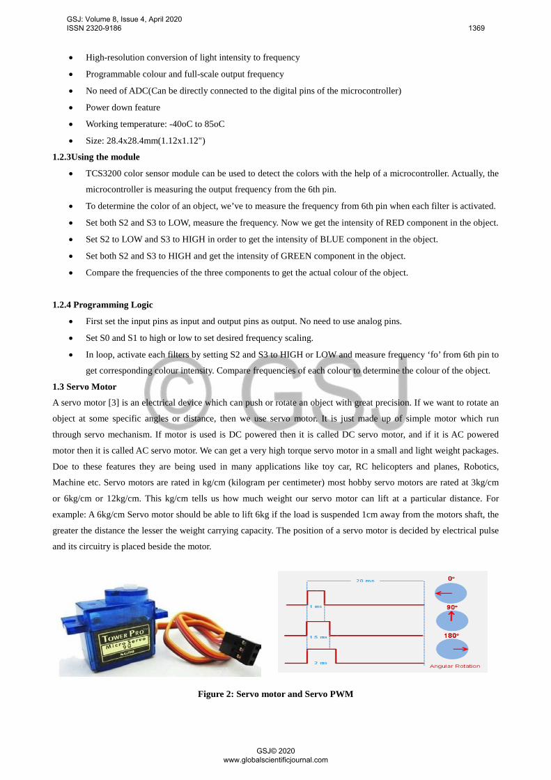
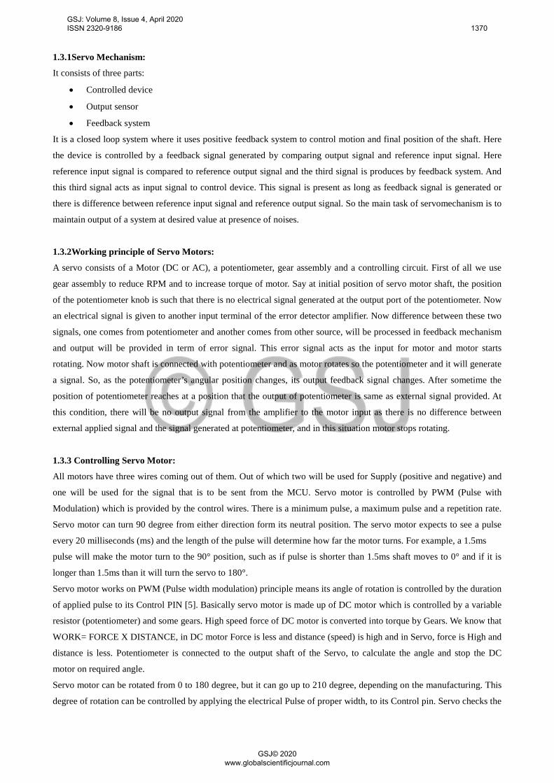
1.3 Servo Motor
A servo motor [3] is an electrical device which can push or rotate an object with great precision. If we want to rotate an
object at some specific angles or distance, then we use servo motor. It is just made up of simple motor which run
through servo mechanism. If motor is used is DC powered then it is called DC servo motor, and if it is AC powered
motor then it is called AC servo motor. We can get a very high torque servo motor in a small and light weight packages.
Doe to these features they are being used in many applications like toy car, RC helicopters and planes, Robotics,
Machine etc. Servo motors are rated in kg/cm (kilogram per centimeter) most hobby servo motors are rated at 3kg/cm
or 6kg/cm or 12kg/cm. This kg/cm tells us how much weight our servo motor can lift at a particular distance. For
example: A 6kg/cm Servo motor should be able to lift 6kg if the load is suspended 1cm away from the motors shaft, the
greater the distance the lesser the weight carrying capacity. The position of a servo motor is decided by electrical pulse
and its circuitry is placed beside the motor.
Figure 2: Servo motor and Servo PWM
GSJ: Volume 8, Issue 4, April 2020 ISSN 2320-9186 1369
GSJ© 2020 www.globalscientificjournal.com
1.3.1Servo Mechanism:
It consists of three parts:
• Controlled device
• Output sensor
• Feedback system
It is a closed loop system where it uses positive feedback system to control motion and final position of the shaft. Here
the device is controlled by a feedback signal generated by comparing output signal and reference input signal. Here
reference input signal is compared to reference output signal and the third signal is produces by feedback system. And
this third signal acts as input signal to control device. This signal is present as long as feedback signal is generated or
there is difference between reference input signal and reference output signal. So the main task of servomechanism is to
maintain output of a system at desired value at presence of noises.
1.3.2Working principle of Servo Motors:
A servo consists of a Motor (DC or AC), a potentiometer, gear assembly and a controlling circuit. First of all we use
gear assembly to reduce RPM and to increase torque of motor. Say at initial position of servo motor shaft, the position
of the potentiometer knob is such that there is no electrical signal generated at the output port of the potentiometer. Now
an electrical signal is given to another input terminal of the error detector amplifier. Now difference between these two
signals, one comes from potentiometer and another comes from other source, will be processed in feedback mechanism
and output will be provided in term of error signal. This error signal acts as the input for motor and motor starts
rotating. Now motor shaft is connected with potentiometer and as motor rotates so the potentiometer and it will generate
a signal. So, as the potentiometer’s angular position changes, its output feedback signal changes. After sometime the
position of potentiometer reaches at a position that the output of potentiometer is same as external signal provided. At
this condition, there will be no output signal from the amplifier to the motor input as there is no difference between
external applied signal and the signal generated at potentiometer, and in this situation motor stops rotating.
1.3.3 Controlling Servo Motor:
All motors have three wires coming out of them. Out of which two will be used for Supply (positive and negative) and
one will be used for the signal that is to be sent from the MCU. Servo motor is controlled by PWM (Pulse with
Modulation) which is provided by the control wires. There is a minimum pulse, a maximum pulse and a repetition rate.
Servo motor can turn 90 degree from either direction form its neutral position. The servo motor expects to see a pulse
every 20 milliseconds (ms) and the length of the pulse will determine how far the motor turns. For example, a 1.5ms
pulse will make the motor turn to the 90° position, such as if pulse is shorter than 1.5ms shaft moves to 0° and if it is
longer than 1.5ms than it will turn the servo to 180°.
Servo motor works on PWM (Pulse width modulation) principle means its angle of rotation is controlled by the duration
of applied pulse to its Control PIN [5]. Basically servo motor is made up of DC motor which is controlled by a variable
resistor (potentiometer) and some gears. High speed force of DC motor is converted into torque by Gears. We know that
WORK= FORCE X DISTANCE, in DC motor Force is less and distance (speed) is high and in Servo, force is High and
distance is less. Potentiometer is connected to the output shaft of the Servo, to calculate the angle and stop the DC
motor on required angle.
Servo motor can be rotated from 0 to 180 degree, but it can go up to 210 degree, depending on the manufacturing. This
degree of rotation can be controlled by applying the electrical Pulse of proper width, to its Control pin. Servo checks the
GSJ: Volume 8, Issue 4, April 2020 ISSN 2320-9186 1370
GSJ© 2020 www.globalscientificjournal.com

pulse in every 20 milliseconds. Pulse of 1 ms (1 millisecond) width can rotate servo to 0 degree, 1.5ms can rotate to 90
degree (neutral position) and 2 ms pulse can rotate it to 180 degree.
1.4 Arduino Uno
The Arduino Uno R3 is a microcontroller board based on a removable, dual-inline-package (DIP) ATmega328 AVR
microcontroller. It has 20 digital input/output pins (of which 6 can be used as PWM outputs and 6 can be used as analog
inputs). Programs can be loaded on to it from the easy-to-use Arduino computer program [3]. The Arduino has an
extensive support community, which makes it a very easy way to get started working with embedded electronics. The
R3 is the third, and latest, revision of the Arduino Uno.
Figure 3: Arduino Uno
Table 1: Pin Description
Pin Category Pin Name Details
Power Vin, 3.3V, 5V, GND
Vin: Input voltage to Arduino when using an external power
source.
5V: Regulated power supply used to power microcontroller and
other components on the board.
3.3V: 3.3V supply generated by on-board voltage regulator.
Maximum current draw is 50mA.
GND: ground pins.
Reset Reset Resets the microcontroller.
Analog Pins A0 – A5 Used to provide analog input in the range of 0-5V
Input/Output Pins Digital Pins 0 - 13 Can be used as input or output pins.
GSJ: Volume 8, Issue 4, April 2020 ISSN 2320-9186 1371
GSJ© 2020 www.globalscientificjournal.com
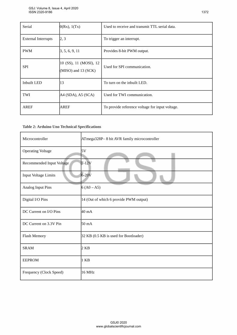
Serial 0(Rx), 1(Tx) Used to receive and transmit TTL serial data.
External Interrupts 2, 3 To trigger an interrupt.
PWM 3, 5, 6, 9, 11 Provides 8-bit PWM output.
SPI 10 (SS), 11 (MOSI), 12
(MISO) and 13 (SCK) Used for SPI communication.
Inbuilt LED 13 To turn on the inbuilt LED.
TWI A4 (SDA), A5 (SCA) Used for TWI communication.
AREF AREF To provide reference voltage for input voltage.
Table 2: Arduino Uno Technical Specifications
Microcontroller ATmega328P– 8 bit AVR family microcontroller
Operating Voltage 5V
Recommended Input Voltage 7-12V
Input Voltage Limits 6-20V
Analog Input Pins 6 (A0 – A5)
Digital I/O Pins 14 (Out of which 6 provide PWM output)
DC Current on I/O Pins 40 mA
DC Current on 3.3V Pin 50 mA
Flash Memory 32 KB (0.5 KB is used for Bootloader)
SRAM 2 KB
EEPROM 1 KB
Frequency (Clock Speed) 16 MHz
GSJ: Volume 8, Issue 4, April 2020 ISSN 2320-9186 1372
GSJ© 2020 www.globalscientificjournal.com

2. Methodology
Figure 4: Block Diagram of Product Sorter
2.1. Prototype Design Parameters
The proposed system is designed for automatic sorting of products. The prototype consists of Arduino uno, Servo motor
and a color sensing circuit using TCS3200 (Fig. 1). Servo motors are used to drop the product to the tray and moving
the tray into specific container position. After integrating the servo motor, TCS3200 and Arduino uno circuitry with the
structure of the model, we measure the frequency of signals corresponding to each color by observing them on a system
monitor of Arduino IDE. The timer delay value is adjusted by reprogramming the Arduino [7]. The time required for the
product to reach the corresponding container is also considered.
Figure 5: View of our prototype
2.2 Constraints on Object Dimensions
The test objects were candy with rectangular shape having 2.5cm diameter length 1.5cm width and 0.5cm height. The
distance between the top surface of the object and the color sensor, during the time of detection process, must always be
GSJ: Volume 8, Issue 4, April 2020 ISSN 2320-9186 1373
GSJ© 2020 www.globalscientificjournal.com
the same. The reason for such a constraint is owed to the fact that TCS3200 [1] produces output signals of different
frequencies while detecting the color of the same object kept at different distances from the sensor. We have suspend the
color sensor above the object candy so that a 3x2cm sized and 1cm high rectangular window is provided for the object
to move under it. In other words, deducting the height of our test object, the sensor and the top of the object is kept 5cm
apart.
2.4. Working of the Model
When a supply of 5V is given to the Arduino it starts to work. It will control the movement of the whole work. When
the light falls on the product it is reflected back to the color sensor. As mentioned before, color sensor TCS3200 has 4
color filters for green, red, blue and black (no color), which is opted by its select pins. Filters are selected by the
program saved in the microcontroller. Frequency output from color sensor depends on the color of the object as well as
the select pin configuration input from microcontroller [9]. Select pin can select one of the four photo diode filters
which can give output according to the color of the object. When there is no object in front of sensor it produces an
output of 330Hz range frequency and when there is an object it produces an output frequency of 7-14 Khz. The
microcontroller can find the frequency of the output from TCS3200 by counting falling or rising edge of sensor given to
its TOCK1 pin using pre-scalar settings set by option register configuration. The pre-scalar was set for 1:16
arrangement and the time for counting is 50ms. Hence PIC counts the frequency using its timer at the rate of one
increment for sixteen falling edges of input frequency given to TOCK1. When there is no object in front of sensor it
produces an output of 330Hz range frequency. Hence we set a break down value of 32H for deciding whether there is an
object on the set or not. Therefore the PIC can only proceed to the next step after checking this condition. If there is an
object the sensor produces an output frequency which is proportional to the color of the object and the selected photo
diode configuration in such a way that it provides maximum frequency for the respective color to the respective photo
diode. Hence sensor gives maximum frequency for red colored object when red filter is selected, and in the same way
other colored object are also sensed by corresponding filters. Frequency received during each filter selection is counted
and saved to separate registers and these values are examined for taking the greater one, in order to identify the color of
the object. The second servo motor is in contact with another tray, which can be positioned on the top of any container
in the set. The container has three sections; first section for Kopico candy, middle for Heart candy, and third for
Alpenlibe candy. According to the color, the tray will be moved in to the specific container top postion, which is made
possible by connecting the servo motor to Arduino pin 3. The products will finally fall to the corresponding sections in
the container. The Arduino [8] has 18 pins, out of which five pins are connected to TCS3200 color sensor, and two pins
are connected to servomotors.
3. Results and Conclusion
We have developed a sorting machine using Arduino for automatic color sorting.. Some of the application areas include
Agriculture Industry (Grain Sorting on the basis of color), Food Industry, Diamond and Mining Industry, Recycling etc.
The applications are not limited to this and can be further applied to different industries.
3.1 Dimensional Analysis
The prototype is designed for sorting objects of any shape but having sizes not more than 3cm by 2cm. But one may
note that it usually results in a change in the light ambiance forcing us to do further frequency analysis of the sensor
output for test colors. The prototype will get more complicated as we increase the number of colors that have to be
GSJ: Volume 8, Issue 4, April 2020 ISSN 2320-9186 1374
GSJ© 2020 www.globalscientificjournal.com

detected. The placement of the object on the first tray is very crucial. It must be so placed that the center of the object
and that of the sensor should be aligned with the same vertical plane, so that perfect detection takes place.
3.2Time Cost
The object once placed on the first tray takes less than half a second to reach the sensor. It takes another 200ms for the
sensor to detect the color. An additional 0.6secs is required if the color of the object is not black so s to position the
correct compartment in the sorting container, which implies that an additional 0.6secs will be consumed to reposition
the container back the normal position on the second tray.
3.3 Trails
As mentioned before we have used objects of standard size and having any of the three colors for testing our prototype.
We conducted a continuous trail with 5 different objects and we got 100% correct detection. As long as the colors of the
objects do not deviate from the preset values and as long as the placement on the tray is perfect, the detection process
seldom fails.
It is very useful in wide varieties of industries along with the help of PL and SCADA, especially in the packaging
section. Automatic sorting machine enhances efficiency, practicality, and safety of operators. It ensures remarkable
processing capacity as well as peerless performance including color detection. Of course we need to add high speed DC
motors and sensors with appreciable response to speed up the system for industrial application. The model can be
improved by making some changes in the program and components. The changes may be-
• We can add a load cell for measurement and control of weight of the product
• We can also add a counter for counting the number of products
• Speed of the system can be increased accounting to the speed of production
• The system can be used as a quality controller by adding more sensors
• The sensor can be changed according to the type of product
• The DC motor can be replaced with stepper motor
• The PIC can be replaced with PLC
5. References
[1] AL-shalah, Muhanned&Sharabaty, Hassan. (2016). Automatic Color Sorting Machine Using TCS3200 Color
Sensor and Arduino.
[2] Nguyen, Trong& Tat Thang, Nguyen & Nguyen, Van & Cao, Chi & Hua, Jun. (2019). Application of Arduino
Control Mainboard with Color Light Sensor TCS3200 in Color Recognition of Edge Banding In Laser Edge
Banding Machine. IOP Conference Series: Earth and Environmental Science. 252. 022130. 10.1088/1755-
1315/252/2/022130.
[3] T. Feng, H. Zhong, Color Detection System Based on Color Sensor TCS230. Microcontrollers & Embedded
Systems (2016).
[4] Sihombing, Poltak& Tommy, Faddly&Sembiring, Sajadin&Silitonga, Nogar. (2019). The Citrus Fruit Sorting
Device Automatically Based On Color Method By Using Tcs320 Color Sensor And Arduino Uno
Microcontroller. Journal of Physics: Conference Series. 1235. 012064. 10.1088/1742-6596/1235/1/012064.
[5] Sachdeva, Amitesha. (2017). Development Of Industrial Automatic Multi Colour Sorting and Counting Machine
Using Arduino Nano Microcontroller and TCS3200 Colour Sensor. The International Journal of Engineering and
Science. 06. 56-59. 10.9790/1813-0604025659.
GSJ: Volume 8, Issue 4, April 2020 ISSN 2320-9186 1375
GSJ© 2020 www.globalscientificjournal.com

[6] Najmurrokhman, Asep&Kusnandar, K &Maulana, F &Wibowo, B &Nurlina, E. (2019). Design of a prototype of
manipulator arm for implementing pick-and-place task in industrial robot system using TCS3200 color sensor
and ATmega2560 microcontroller. Journal of Physics: Conference Series. 1375. 012041. 10.1088/1742-
6596/1375/1/012041.
[7] "Arduino - Home", Arduino.cc, 2019. [Online]. Available: https://www.arduino.cc/. [Accessed: 18- Sep- 2019].
[8] C. Dummies and J. Nussey, Arduino for Dummies. Newark: John Wiley & Sons, Incorporated, 2018.
[9] E. Savasgard, Arduino: 101 Beginners Guide, 1st ed. Create Space Independent Publishing Platform, 2015.
GSJ: Volume 8, Issue 4, April 2020 ISSN 2320-9186 1376
GSJ© 2020 www.globalscientificjournal.com