ISSN: 2320-5407 Int. J. Adv. Res. 8(08), 141-150
10
ISSN: 2320-5407 Int. J. Adv. Res. 8(08), 141-150 141 Journal Homepage: -www.journalijar.com Article DOI:10.21474/IJAR01/11470 DOI URL: http://dx.doi.org/10.21474/IJAR01/11470 RESEARCH ARTICLE IMPLEMENTING AND TESTING OF A MOBILE JAMMER AT ESATIC Zamble Raoul, Dakouri Dogba Narcisse and N’drin Hugues Auguste Ecole Supérieure Africaine Des Technologies De l’Information et de la Communication (ESATIC) in Abidjan, Côted’Ivoire. …………………………………………………………………………………………………….... Manuscript Info Abstract ……………………. ……………………………………………………………… Manuscript History Received: 05 June 2020 Final Accepted: 10 July 2020 Published: August 2020 Key words:- Mobile Phone, Jammer Device, Signal- to-Noise Ratio, Mobile System The GSM, DCS, UMTS and LTE systems which constitute a very vast telecommunication world remain in continuous evolution with regard to the greatest number of regions and sites coverage in Côte d’Ivoire. All these cell phone systems use radio signal that can be completely interrupted for specific goals. Indeed, at ESATIC, a project has enabled the design and implementation of a simple and inexpensive mobile phone jammer that aims to provide a solution to the cheating problem through cell phones during students’ national exams. The Denial of Service (DOS) jamming technique which blocks communications absolutely has been used to implement this device. Here, the jamming principle consists in releasing an important noise at the same frequency as that used by the mobile operator in order to completely block the user signal. In fact, satisfactory jamming of the various mobile signals has been observed by blocking these signals in the jammer action areas. The experiment was carried out on the 2G, 3G and 4G networks operated by the three main national operators: ETISALAT, MTN and ORANGE. However, the general recommendation of this project is to use higher capacity power amplifiers to achieve the effective range of 50 meters, especially for DCS 1800, UMTS 2100 and LTE 2600 systems. Copy Right, IJAR, 2020, All rights reserved. …………………………………………………………………………………………………….... Introduction:- Today, cell phone jamming devices or software are becoming civilian products rather than devices designed for electronic warfare. They were developed and used initially by the military for the radio communications control during electronic warfare. Each side had an interest in stopping communications from the enemy side by adopting the signal jamming technique. However, the jamming devices development situation in the civil domain is due to the mobile phone users increasing number. Therefore, the need to disconnect mobile phones in some specific places where the cell phone ringing would be disruptive has increased. These places generally include places of worship, conference rooms, libraries, cinemas, meeting rooms or other places where silence is strongly recommended. Moreover, a mobile phone jammer is a device that transmits signal or noise at the same frequency and at the same power as those of the radio system to be jammed. Jamming succeeds when mobile phones stop receiving and transmitting signals. Paper [1] mainly reviews mobile phone jammer technologies and suggests improvement to existing design. This paper also presents possible approaches for smart design of jammers. In addition, it highlights a design allowing low energy consumption and taking into account health and cost issues. In fact, the present paper main objective is to define a project of a mobile jammer design and implementation at ESATIC, an Information and Corresponding Author:- Zamble Raoul Address:- Ecole Supérieure Africaine Des Technologies De l’Information et de la Communication (ESATIC) in Abidjan, Côted’Ivoire.
-
Upload
khangminh22 -
Category
Documents
-
view
0 -
download
0
Transcript of ISSN: 2320-5407 Int. J. Adv. Res. 8(08), 141-150

ISSN: 2320-5407 Int. J. Adv. Res. 8(08), 141-150
141
Journal Homepage: -www.journalijar.com
Article DOI:10.21474/IJAR01/11470
DOI URL: http://dx.doi.org/10.21474/IJAR01/11470
RESEARCH ARTICLE
IMPLEMENTING AND TESTING OF A MOBILE JAMMER AT ESATIC
Zamble Raoul, Dakouri Dogba Narcisse and N’drin Hugues Auguste
Ecole Supérieure Africaine Des Technologies De l’Information et de la Communication (ESATIC) in Abidjan,
Côted’Ivoire.
……………………………………………………………………………………………………....
Manuscript Info Abstract
……………………. ……………………………………………………………… Manuscript History
Received: 05 June 2020
Final Accepted: 10 July 2020
Published: August 2020
Key words:- Mobile Phone, Jammer Device, Signal-
to-Noise Ratio, Mobile System
The GSM, DCS, UMTS and LTE systems which constitute a very vast
telecommunication world remain in continuous evolution with regard
to the greatest number of regions and sites coverage in Côte d’Ivoire.
All these cell phone systems use radio signal that can be completely
interrupted for specific goals. Indeed, at ESATIC, a project has enabled
the design and implementation of a simple and inexpensive mobile
phone jammer that aims to provide a solution to the cheating problem
through cell phones during students’ national exams. The Denial of
Service (DOS) jamming technique which blocks communications
absolutely has been used to implement this device. Here, the jamming
principle consists in releasing an important noise at the same frequency
as that used by the mobile operator in order to completely block the
user signal. In fact, satisfactory jamming of the various mobile signals
has been observed by blocking these signals in the jammer action areas.
The experiment was carried out on the 2G, 3G and 4G networks
operated by the three main national operators: ETISALAT, MTN and
ORANGE. However, the general recommendation of this project is to
use higher capacity power amplifiers to achieve the effective range of
50 meters, especially for DCS 1800, UMTS 2100 and LTE 2600
systems.
Copy Right, IJAR, 2020, All rights reserved.
……………………………………………………………………………………………………....
Introduction:- Today, cell phone jamming devices or software are becoming civilian products rather than devices designed for
electronic warfare. They were developed and used initially by the military for the radio communications control
during electronic warfare. Each side had an interest in stopping communications from the enemy side by adopting
the signal jamming technique. However, the jamming devices development situation in the civil domain is due to the
mobile phone users increasing number. Therefore, the need to disconnect mobile phones in some specific places
where the cell phone ringing would be disruptive has increased. These places generally include places of worship,
conference rooms, libraries, cinemas, meeting rooms or other places where silence is strongly recommended.
Moreover, a mobile phone jammer is a device that transmits signal or noise at the same frequency and at the same
power as those of the radio system to be jammed. Jamming succeeds when mobile phones stop receiving and
transmitting signals. Paper [1] mainly reviews mobile phone jammer technologies and suggests improvement to
existing design. This paper also presents possible approaches for smart design of jammers. In addition, it highlights
a design allowing low energy consumption and taking into account health and cost issues. In fact, the present paper
main objective is to define a project of a mobile jammer design and implementation at ESATIC, an Information and
Corresponding Author:- Zamble Raoul
Address:- Ecole Supérieure Africaine Des Technologies De l’Information et de la Communication
(ESATIC) in Abidjan, Côted’Ivoire.

ISSN: 2320-5407 Int. J. Adv. Res. 8(08), 141-150
142
Communication Technologies (ICT) college in Côte d’Ivoire. The project will obviously rely on the existing
technologies to design and implement a simple and inexpensive jammer. It is conducted with a view of providing an
adequate solution to the cheating problem through mobile phones in the country. These cheating acts are the proof of
the mobile phone wrong utilization and they have taken now a very significant proportion and disrupt the smooth
running of state examination.
The rest of the paper is organized around five sections. The section 2 sets out the aim of this project while section 3
deals with the literary review of similar works. Section 4 focuses on the methodology adopted for the mobile phone
jammer implementation. Then, section 5 presents the project results and the underlying discussions, and finally, the
paper conclusion is given in section 6.
Project motivations:
It is important to be able to call anyone, at anytime and anywhere in the world. However, restaurants, cinemas,
malls, hospitals, banks, libraries and places of worship are all suffering today from the mobile phones proliferation.
This is due to the fact that some users do not make any restriction in their mobile phone use. People very often lose
the ability to manage the limit between proper and improper use of their cell phones. It is indeed a nuisance when a
mobile phone rings in a church, a mosque or at a private meeting. It is even more worrying and dangerous when
these mobile phones are used illegally by prisoners in jail to conduct and organize their criminal activities. In some
special places, to avoid constantly having to beg people to turn off their phones, a picture is displayed on the walls
showing the cell phone inside a red circle with a strike through as shown in figure 1. A radio frequency jammer
would therefore be useful in such situations.
Figure 1:- Prohibited use of mobile phone. (Source : internet)
To come back to the present project that implements and tests a mobile phone jammer, it should be noted that cases
of students who wrongly use mobile phones in the examinations are widespread and constantly increasing. This is
the situation unfortunately experienced in Côte d'Ivoire in recent years, especially during the national organization
of the baccalaureate exams. The cheating facts put forward by the national directorate in charge of examination
include social networks such asWhatsApp, emails, MMS, SMS or sometimes illicit telephone communications to
share the correcting tests. Some astute students still find ways to cheat, particularly with these more powerful tools
than ever available for them in this ICT world nowdays. Therefore, new more advanced solutions must be adopted
according to these realities. Cheating on exams through cell phones or their improper utilization could easily be
avoided if radio frequency jammers were used. This situation analysis motivated the national directorate in charge of
examinations to contact ESATIC for a jamming system implementation which will prevent mobile phones use
during the tests in the examination centres.
Literary survey:
This section provides a non-exhaustive literary review of the work done in the mobile phone signal jamming
systems context. Indeed, S. Madhuvanthi and R. Anitha deal in [2] with an advanced model design of mobile phone
signal jammer. This model uses particularly in its communication blocking system, a microcontroller, a regulator,
passwords and identifiers for GSM networks. The paper [3], titled "Intelligent Mobile Signal Jammer" provides
techniques for designing a mobile phone jamming device that have proven to be a complete success. Furthermore, in
[4], a low cost jammer is implemented through a new jamming unit, capable of blocking the cell phone operation
without however jamming the signal received from the base station. This jammer type uses the technologies FPGA
and RF. Chetan T. Sai and al, presented in [5], an efficient intelligent jammer design to jam 4G signal, mainly in
bands 3 and 40 used in India. Their jammer also incorporates a detection circuit and a trigger circuit which allows
jamming only if a signal is detected in order to save energy. The project achieved in [6], highlights the design of a

ISSN: 2320-5407 Int. J. Adv. Res. 8(08), 141-150
143
simple and inexpensive mobile phone jammer operating in 800 MHz to 1.4 GHz band. The project aims to present a
solution to the inappropriate use problem of cell phones in restricted areas. This jammer has been successfully tested
on 2G and 3G (UMTS / WCDMA) networks operated by service providers such as Safaricom, Airtell, Orange and
YU. Sharad B. Gholap and Harshal R. Patil in their paper [7] particularly discuss an android application designed for
an advanced jamming system. This system blocks communication by allowing incoming calls and messages
notification to a smartphone. This new system enabled smart mobile phones implementation and management. Paper
[8] discusses the design and development of a mobile phone presence detector that can be activated at 1.5 meters
through an interfering circuit. The circuit is able to detect both incoming and outgoing calls, SMS and video
transmission even if the mobile phone is in silent mode. Furthermore, the detection is accompanied by a beep
emission with an LED flashing until the signal transmission ends. As for [9], it deals with a cell phone signal
jammer device design and implementation for GSM and CDMA using a predetermined duration allowed by a
component named ARM7. The on and off times can be programmed with a microcontroller through a real time
clock chip referred to as DS1307. The paper [10] entitled "Design and Development of Mobile Phone Jammer",
presents a dual-band mobile phone jammer design, implementation and testing. This jammer works simultaneously
on GSM 900 and GSM 1800, and has been successfully tested on GSM networks in Nigeria (MTN, GLO, AITEL
and ETISALAT). With the aim of preventing accidents due to the mobile phone use while driving, paper [11]
proposes a very efficient automatic electronic system allowing the base station signal jamming inside a car. The
jamming area only covers the driver's seat. Finally, paper [12] focuses on a mobile phone jammer design to prevent
mobile communications in restricted areas without however interfering with communication channels beyond its
range.
Methodology:- Mathematical foundations of radio signal jamming:
The frequency jamming principle is to interfere with a useful signal in order to totally block it or significantly
deteriorate its quality of service (QoS) on a mobile network. In fact, the propagation loss between transmitter and
receiver is one of the common QoS degradation factor for a communication systemand can be expressed as
follows[12]:
The power at the transmitter side:
At the receiver side, the power received at the antenna is expressed by the thereafter formula:
Furthermore, the jamming effects depend on the noise-to-signal ratio ( ), the distance between the transmitter and
the receiver, the modulation scheme, the channel coding, the system interleaving, the transmitter and receiver
bandwidths.The noise-to-signal ratio can usually be given by the undermentionedformula:
In equations (1), (2) and (3), the parameters are defined as follows: and , respectively point out the power
emitted by the jammer and that of the transmitter. The antenna gains are respectively indicated by from jammer
to receiver, from receiver to jammer, from transmitter to receiver and from receiver to transmitter.
Then, the bandwidths are denoted by , for the receiver communication bandwidth and , for the jammer
transmitter bandwidth. The parameter denotes the distance between the communication transmitter and the
receiver, and , the distance between the jammer and the communication receiver. Meanwhile, the losses are
denoted by , for the transmission or communication signal loss and , for the free space loss between the
jammer and the receiver (including the loss due to the polarization shift). Thus, the jammer performance is a
function of the noise-to-signal ratio ( ) , espressed as follow:
The reciprocal of is commonly known as signal-to-noise ratio ( ) which makes it possible to assess the
signal quality received at a receiver.
ISSN: 2320-5407 Int. J. Adv. Res. 8(08), 141-150
144
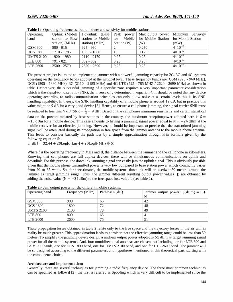
Table 1:- Operating frequencies, output power and sensivity for mobile stations.
Operating
band
Uplink (Mobile
station to Base
station) (MHz)
Downlink (Base
station to Mobile
station) (MHz)
Peak power
for Mobile
Station (W)
Max output power
for Mobile Station
(W)
Minimum Sensivity
for Mobile Station
(mW)
GSM 900 880 - 915 925 - 960 2 0,250 4×10-12
DCS 1800 1710 - 1785 1805 - 1880 1 0,125 4×10-12
UMTS 2100 1920 - 1980 2110 - 2170 0,25 0,25 4×10-12
LTE 800 791 - 821 832 - 862 0,25 0,25 4×10-12
LTE 2600 2500 - 2570 2620 - 2690 0,25 0,25 4×10-12
The present project is limited to implement a jammer with a powerful jamming capacity for 2G, 3G and 4G systems
operating on the frequency bands adopted at the national level. These frequency bands are: GSM (925 - 960 MHz),
DCS (1805 - 1880 MHz), 3G (2110 - 2185 MHz) and 4G LTE (725 - 785 MHZ / 2620 - 2690 MHz) as shown in
table 1.Moreover, the successful jamming of a specific zone requires a very important parameter consideration
which is the signal-to-noise ratio ( ), the inverse of determined in equation 4. It should be noted that any device
operating according to radio communication principles can only allow noise at a certain level: this is its SNR
handling capability. In theory, the SNR handling capability of a mobile phone is around , but in practice this
value might be for a very good device [3]. Hence, to ensure a cell phone jamming, the signal carrier SNR must
be reduced to less than (
). Based on the cell phones minimum sensitivity and certain statistical
data on the powers radiated by base stations in the country, the maximum receptionpower adopted here is for a mobile device. This case amounts to having a jamming signal power equal to at the
mobile receiver for an effective jamming. However, it should be important to precise that the transmitted jamming
signal will be attenuated during its propagation in free space from the jammer antenna to the mobile phone antenna.
This leads to consider basically the path loss by a simple approximation through Friis formula given by the
following equation 5:
Where is the operating frequency in MHz and , the distance between the jammer and the cell phone in kilometers.
Knowing that cell phones are full duplex devices, there will be simultaneous communications on uplink and
downlink. For this purpose, the downlink jamming signal can easily jam the uplink signal. This is obviously possible
given that the mobile phone transmitted power is very low compared to base station power which commonly varies
from 20 to 35 watts. So, for theestimates, the mobile systems downlink will be usedwith50 meters around the
jammer as target jamming range. Thus, the jammer different resulting output power values ( ) are obtained by
adding the noise value ( ) to the free space loss value (see table 2).
Table 2:- Jam output power for the different mobile systems.
Operating band Frequency (MHz) Pathloss Jammer output power :
GSM 900 900 66 42
DCS 1800 1800 72 48
UMTS 2100 2100 73 49
LTE 800 800 65 41
LTE 2600 2600 75 51
These propagation losses obtained in table 2 relate only to the free space and the trajectory losses in the air will in
reality be much greater. This approximation leads to consider that the effective jamming range could be less than 50
meters. To simplify the jamming device design, a uniform output power adopted is as target jamming signal
power for all the mobile systems. And, four omnidirectional antennas are chosen that including one for LTE 800 and
GSM 900 bands, one for DCS 1800 band, one for UMTS 2100 band, and one for LTE 2600 band. The jammer will
be so designed according to the different parameters and hypotheses mentioned in this theoretical part, starting with
the components choice.
Architecture and implementation:
Generally, there are several techniques for jamming a radio frequency device. The three most common techniques
can be specified as follows[12]: the first is referred as Spoofing which is very difficult to be implemented since the

ISSN: 2320-5407 Int. J. Adv. Res. 8(08), 141-150
145
jamming device first detects any mobile phone in a particular region, then the device sends a signal to deactivate the
cellphone. The second technique is referred as Shielding Attacks, known as TEMPEST or EMF shielding. This
technique necessitates closing off an area in conductive mesh faraday cage so that any device inside that cage cannot
transmit or receive RF signal from outside the cage. The third and final technique is the Denial of Service also
known by the acronym DOS. In the latter technique, the device transmits a noise signal at the same operating
frequency of the mobile phone in order to reduce the signal-to-noise ratio (SNR) of the mobile below its minimum
value.
Figure 2:- Block diagram of the jammer device.
After having analyzed these different jamming techniques, the technique adopted here for the jammer
implementation is the Denial of Service (DOS), because it is the simplest and the least expensive to implement. In
this technique, the jamming is obtained when the device transmits a high power signal in the same frequency band
used by the mobile phone, thus degrading its signal-to-noise ratio. The signal from the jammer is considered as noise
by the mobile device, thereby increasing the system noise threshold. To achieve the noise level at the required
frequency in order to jam the downlink signal, emphasis has been put on a certain number of design parameters to
establish the device specifications. These parameters are:the range to be jammed, the frequency bands, the noise-to-
signal ratio and the free space path loss. To do this, the jammer consists of a power section, a detection section, an
intermediate frequency (IF) section and a radio frequency (RF) section, as shown in figure 2. The power section
supplies power to the jamming device other sections. Here it consists ofatransformer with 24 volts, a rectifier made
up of two rectifying diodes, a filter and a 12 volts voltage regulator. The power section supplies 9 volts to the
detector section and 12 volts to the IF and RF sections. The jammer is also designed with a backup battery of 12
volts which takes over the power supply in power failure event. The detector section emits light through a LED of
10 mA to indicate the jamming device start-up and operation. The IF section behaves globally like a noise generator
and is a circuit that produces electrical noise which is a random and non-deterministic signal. Its circuit incorporates
basically atriangular waveform generator, a noise generator, a mixer and a clamper. And, the IF section mainly
generates a tuning voltage for the voltage controlled oscillator.In this project, four 1/4 waveform monopole antennas
areused with a gain of and an impedance of to match the transmission system. These antennas
respectively cover the four aforementioned frequency bands adopted in the country for 2G, 3G and 4G systems.
Results and Discussions:- Testing of the jammer:
The first test type carried out within the project framework is a simulation through the device assembled on
breadboards, a low frequency generator and an oscilloscope. Figure 3 shows the noise generation device assembly.

ISSN: 2320-5407 Int. J. Adv. Res. 8(08), 141-150
146
Figure 3:- Breadboard-Assembly of the jammer.
This simulation results were conclusive and are observed with the oscilloscope screenshot on figure 4. The jammer
first part is the tuning circuit namely the IF section and the second is the RF section which generates the jamming
signal. The output waveform after the device implementation can be compared with the IF section simulation that is
the noisy signal with the triangular waveform signal.The noises observed for the two outputs of the example on
figure 4 are much more intense because they underwent new amplifications. In the simulation, the signal considered
is triangular with a variation from 0 to 5 volts and a period of . But, it is important to specify that any periodic
signal would lead to the same results.
Figure 4:-Simulated triangular waveform of the jammer device output.
In situ measurements:
The second test type carried out in the framework of this project was the in situ power measurement performing.
Here, the power meter used is the Aronia HF60105 spectran, shown in figure 5. It is capable of measuring power
levels and electromagnetic fields for frequencies ranging from 10 MHz to 10 GHz. In addition, it can measure the
signal strength levels for different technologies such as GSM, CDMA, UMTS, LTE, etc. This device was used to
measure the base station power level for the target mobile systems and the jammer power level in the radiation zone
from its position to a distance of 50 meters around.
Figure 5:-Aronia Spectran HF60105used for in situ measurements.

ISSN: 2320-5407 Int. J. Adv. Res. 8(08), 141-150
147
Measurements were realized in several points with the aim of varying the jammer position comparatively to base
station positions. Moreover, for each jammer position, measurements are performed in outdoor environment every 5
meters from its position to 50 meters around. For the different radius, four measurement points have been selected as
shown in figure 6.
Figure 6:- Methodolgy for the in situ measurements.
For each point, two measurements were performed successively in a time interval not exceeding one minute. The
first measurement focused on the base station signal strength with the jammer in stopped state. The second was
carried out to measure the overall signal with the jammer device on. Furthermore, several series of measurements
are been carried out for the jammer positions at different distances from the base stations. These measurement series
made it possible to deduce the curves on figures 7, 8 and 9 which highlight the output powers delivered by the
jammer relatively to the different mobile systems.
(a) (b)
Figure 7:- Jammer output power curves for all the mobile systems (a) and LTE 2600 (b).

ISSN: 2320-5407 Int. J. Adv. Res. 8(08), 141-150
148
As a reminder, the target output power of was adopted for the jammer design in order to reach a range
equal to 50 meters for all the systems. It can be seen through figure 7 (a) that the target powerof has not
been reached for all the mobile systems. Indeed, after 35 meters, all the jammer output powers fell below .
(a) (b)
Figure 8:- Jammer output power curvesfor UMTS 2100 (a) and DCS 1800 (b).
On the other hand, it is noted that the output power objectives to obtain 50 meters as an circular action zone radius
have been achieved respectively for GSM 900 and LTE 800 compared to the values in table 2 (see figures 9). It is
therefore important to notice that the output powers for DCS 1800 and UMTS 2100 systems are slightly below their
target values (see figures 8). The DCS 1800 has an output power measured at 50 meters which is
instead of as real target value. For UMTS 2100, this measurement is instead of as
real target value. And, for LTE 2600 system, the measured output power is instead of as real
target value (see Figure 7 (b)). Indeed, these results have shown that increasing the target output power respectively
from 41 and to for GSM 900 and LTE 800, made it possible to easily reach the range of 50 meters.
(a) (b)
Figure 9:-Jammer output power curves for GSM 900 (a) and LTE 800 (b).

ISSN: 2320-5407 Int. J. Adv. Res. 8(08), 141-150
149
Discussions:- The mobile phone jammer implemented here transmits the signals without any modulation type. Furthrmore, only
the carrier waveform is generated by the jammer and radiated in all directions due to the omnidirectional antennas
used. The generated carrier reaches the mobile phones located in the action zone where the device can act with great
efficiency. Generally, it should be noted that the signal from the base station transmitted to the mobile station has a
very high power compared to the one delivered by the jammer. But the signal from the base station always follows a
long path to reach the receivers. This makes the base station signal small at the receiver, even smaller than the
mobile station signal. In this case, the jammer having a strong power in its radiation zone will be able to jam the
signal coming from the base stations once its power becomes close to or much greater than that of this signal. The
jammer once triggered, as mentioned above, has a LED which indicates the operation start. The jamming circuit is
triggered by a switch and contains an input that charges its battery when it becomes empty after approximately two
operation hours. Roughly speaking, the jamming circuit dissipates a total of 0.5 watts for a supply voltage of 5
volts.In its action area, the device was able to jam various mobile systems signals on the three main national
operators’ networks: ETISALAT, MTN and ORANGE. This was verified in particular by the absence of signal
reception for all the mobile phones placed in the action area. The effective jamming range is at least 50 meters for
GSM 900 and LTE 800 systems, but is around 47.5 meters for DCS 1800 and UMTS 2100, and approximately 35
meters for LTE 2600. It was also observed that as the distance between the cell phone and the base station increases,
the effective jamming range increases. This is certainly due to the fact that the amount of energy reaching the cell
phone from the base station decreases as the cell phone moves away from the base station. The jammer has therefore
been effectively tested and worked correctly on 2G, 3G and 4G networks. However, the jamming range turns out to
be smaller than the 50 meters for DCS 1800, UMTS 2100 and LTE 2600 systems. This could be explained by the
fact that the jammer effect can vary considerably in depending on factors such as proximity to base stations, indoor
and outdoor settings, buildings and vegatation presence, and even temperature and humidity play a role. Optionally,
a higher power RF amplifier can be used to improve the jammer range in the case of these systems. Therefore,
further studies are needed to ensure the success of this option.
Conclusion:- In this paper, the implemented jammer has ensured effective jamming in its action areas for GSM 900, DCS 1800,
UMTS 2100, LTE 800 and LTE 2600 bands currently adopted in Côte d'Ivoire. This device can be used a priori in
the examination centres of the country to prevent cheating through mobile phones. The effective jamming range is
not what was expected for some frequency bands. This is notably due to an insufficiency of the currents supplied to
the chosen power amplifiers and a more stable power supply necessary for robust operation. However, the mobile
services absolute disenabling effectiveness in the jammer action areas, allows here to consider the device mass
production.
References:- 1. S. Theivasigamani, J. Gladson, “Mobile Jammer.”Eurasian Journal of Analytical Chemistry, 2018, ISSN: 1306-
3057 OPEN ACCESS 2018 13 (3): pp. 1003-1010.
2. S.Madhuvanthi, R.Anitha, “Analyzing the Advanced Mobile Phone Signal Jammer for GSM and
CDMA.”Special Issue of Engineering and Scientific International Journal (ESIJ) ISSN 2394-187(Online)
Technical Seminar & Report Writing - Master of Computer Applications - S. A. Engineering College ISSN
2394-7179 (Print) (TSRW-MCA-SAEC) - May 2016, pp. 78 – 80.
3. Ibrahim Patel, Ashok Shigli, V Sripathi Raja, Raghavendra Kulkarni, “Intelligent Mobile Signal Jammer.”Asian
Journal of Computer Science Engineering 2017; 2(5):01-06.
4. M. Raveendranad, Mr. D.M.K. Chaitanya, “An Architecture Design of Novel Mobile Jammer using
FPGA.”IJESC September 2014 Issue, DOI 10.4010/2014.254, ISSN-2321 -3361, pp. 849 – 854.
5. T. Chetan Sai, A. G. Dinesh Kumar, V. Charan and S. Ramya, “Design of Automated Dual B and 4G Jammer
using MATLAB Simulink.” Indian Journal of Science and Technology, Vol 9(37), DOI:
10.17485/ijst/2016/v9i37/95125, October 2016, ISSN (Online) : 0974-5645, Vol 9 (37), pp. 1 – 6.
6. Diana Starovoytova Madara Edwin Ataro and Simiyu Sitati, “Design and Testing of a Mobile-Phone-Jammer.”
Innovative Systems Design and Engineering, ISSN 2222-1727 (Paper) ISSN 2222-2871 (Online), Vol.7, No.7,
2016.
7. Sharad B. Gholap, Harshal R. Patil, “Android application based advanced mobile jammer for smart
phones.”International Journal of Advanced Research in Electronics and Communication Engineering
(IJARECE) Volume 4, Issue 6, June 2015, ISSN: 2278 – 909X, pp. 1526 – 1529.

ISSN: 2320-5407 Int. J. Adv. Res. 8(08), 141-150
150
8. Sadixya Pradhan, Nikhil Rai, Tashi Rapden Wangchuk, “Design and Development of Mobile Bug with Jammer
Circuit.”International Journal of Engineering Trends and Technology – Volume 32 Number 4- February 2016,
ISSN: 2231-5381, pp. 199 – 203.
9. P.Naresh, P. Raveendra Babu, K.Satyaswathi, “Mobile Phone Signal Jammer for GSM, CDMA with Pre-
scheduled Time Duration using ARM7.”International Journal of Science, Engineering and Technology
Research, Volume 2, Issue 9, September 2013, ISSN: 2278 – 7798, pp. 1781 – 1784.
10. Oyediran Oyebode Olumide, Ogunwuyi Ogunmakinde Jimoh, Lawal Akeem Olaide, “Design and Development
of Mobile Phone Jammer.” American Journal of Engineering Research, 2016, e-ISSN: 2320-0847 p-ISSN :
2320-0936 Volume-5, Issue-2, pp-71-76.
11. Vishal U. Kanojiya, Jitendra B. Yadav,“Implementing Mobile Jammer in Automobiles.” International Journal
of Advance Research in Computer Science and Management Studies Volume 3, Issue 5, May 2015, ISSN:
2321-7782 (Online), pp. 508-512.
12. Nsikan Nkordeh, Iwu C. Lawson, Francis Idachaba, Ibinabo Bob-Manuel, “Design and Implementation of a
Dual Band Mobile Phone Jammer.” Proceedings of the World Congress on Engineering and Computer Science
2016 Vol I WCECS 2016, October 19-21, 2016, San Francisco, USA. ISBN: 978-988-14047-1-8 ISSN: 2078-
0958 (Print); ISSN: 2078-0966 (Online).