Groundwater Modeling System Linkage with the Framework ...
18
PNNL- 15654 Groundwater Modeling System Linkage with the Framework for Risk Analysis in Multimedia Environmental Systems G. Whelan K.J. Castleton February 2006 Prepared for the U.S. Nuclear Regulatory Commission Office of Nuclear Regulatory Research Division of Systems Analysis & Regulatory Effectiveness Rockville, Maryland 20852 under Contract DE-AC05-76RL01830
-
Upload
khangminh22 -
Category
Documents
-
view
0 -
download
0
Transcript of Groundwater Modeling System Linkage with the Framework ...

PNNL- 15654
Groundwater Modeling System Linkage with the Framework for Risk Analysis in Multimedia Environmental Systems G. Whelan K.J. Castleton February 2006 Prepared for the U.S. Nuclear Regulatory Commission Office of Nuclear Regulatory Research Division of Systems Analysis & Regulatory Effectiveness Rockville, Maryland 20852 under Contract DE-AC05-76RL01830

DISCLAIMER This report was prepared as an account of work sponsored by an agency of the United States Government. Neither the United States Government nor any agency thereof, nor Battelle Memorial Institute, nor any of their employees, makes any warranty, express or implied, or assumes any legal liability or responsibility for the accuracy, completeness, or usefulness of any information, apparatus, product, or process disclosed, or represents that its use would not infringe privately owned rights. Reference herein to any specific commercial product, process, or service by trade name, trademark, manufacturer, or otherwise does not necessarily constitute or imply its endorsement, recommendation, or favoring by the United States Government or any agency thereof, or Battelle Memorial Institute. The views and opinions of authors expressed herein do not necessarily state or reflect those of the United States Government or any agency thereof. PACIFIC NORTHWEST NATIONAL LABORATORY operated by BATTELLE for the UNITED STATES DEPARTMENT OF ENERGY under Contract DE-AC05-76RL01830 Printed in the United States of America Available to DOE and DOE contractors from the Office of Scientific and Technical Information,
P.O. Box 62, Oak Ridge, TN 37831-0062; ph: (865) 576-8401 fax: (865) 576-5728
email: [email protected] Available to the public from the National Technical Information Service, U.S. Department of Commerce, 5285 Port Royal Rd., Springfield, VA 22161
ph: (800) 553-6847 fax: (703) 605-6900
email: [email protected] online ordering: http://www.ntis.gov/ordering.htm
This document was printed on recycled paper.
(9/2003)

PNNL-15654 Groundwater Modeling System Linkage with the Framework for Risk Analysis in Multimedia Environmental Systems G. Whelan K.J. Castleton February 2006 Prepared for the U.S. Nuclear Regulatory Commission Office of Nuclear Regulatory Research Division of Systems Analysis & Regulatory Effectiveness Rockville, Maryland 20852 under Contract DE-AC05-76RL01830 Pacific Northwest National Laboratory Richland, Washington 99352

Contents 1.0 Introduction..........................................................................................................................................-4- 2.0 Groundwater Modeling System ............................................................................................................-5- 3.0 Framework for Risk Analysis in Multimedia Environmental Systems ...............................................-7- 4.0 Procedure for Accessing and Implementing a GMS Run in FRAMES ...............................................-8-
4.1 Establish a Baseline GMS Run......................................................................................................-9- 4.2 Register the GMSImport Tool in FRAMES-2 ............................................................................-10- 4.3 Register the GMS Project File as Representing a Module Choice .............................................-11- 4.4 Develop a Conceptual Site Model Within FRAMES..................................................................-13-
5.0 References..........................................................................................................................................-17-
Figures 2.1. Three-Dimensional Rendition of a Leachate Plume Migrating Through Heterogeneous Porous
Media using MT3DMS, as Part of the Groundwater Modeling System (GMS)...............................-6- 4.1. Schematic Illustrating the Linkage of Three Models of Differing Scale and Resolution Using
Frames as Middleware ......................................................................................................................-9- 4.2. Exporting FRAMES Boundary Conditions to GMS and Importing GMS Information to
FRAMES.........................................................................................................................................-10- 4.3. Steps for Registering the GMS Import Tool ...................................................................................-11- 4.4. Steps for Registering the GMS Project File ....................................................................................-12- 4.5. Steps for Defining How a GMS Module will Communicate with the User and FRAMES............-13- 4.6. Illustrative Example of Aquifer Contamination..............................................................................-14- 4.7. Illustrative Conceptual Site Model Example of Aquifer Contamination ........................................-14- 4.8. Illustration of the General Info User Interface ................................................................................-15- 4.9. Illustration of the User Input User Interface ...................................................................................-15-
-3-

1.0 Introduction The objective is to provide the U.S. Nuclear Regulatory Commission (NRC), Office of Nuclear Regulatory Research, Division of Systems Analysis & Regulatory Effectiveness with a dose-assessment tool for licensing decisions with sufficient power, flexibility, and utility that it can serve as their primary platform for analyzing the hazards associated with licensing actions at those "complex" sites at which the traditional dose-assessment tools are inappropriate. To meet this objective, this work will further the design and development of the evolving Framework for Risk Analysis in Multimedia Environmental Systems (FRAMES; Whelan et al. 1998; Buck et al. 2002) software to enable the integration of or linkage to models of complex domain-specific processes to evaluate the potential for human exposure to radioactive contaminants in complex natural environments. The U.S. Department of Energy (DOE) Pacific Northwest National Laboratory (PNNL), in conjunction with NRC, has developed a design for linking FRAMES Version 2 (FRAMES-2) and the Groundwater Modeling System (GMS). The objective of the linkage is to facilitate the exchange of model data (inputs/outputs) between the two modeling systems. Although the term GMS is used frequently and rather loosely in the context of this work, it specifically refers to the computer models housed within GMS. FRAMES is a software platform that allows users the ability to select and implement environmental software models for risk assessment and management problems. This program is a flexible and holistic approach to understanding how activities affect humans and the environment. It links models that integrate across scientific disciplines, allowing for tailored solutions to specific activities, and it provides meaningful information to business and technical managers. FRAMES is the key to identifying, analyzing, and managing potential environmental, safety, and health risks. The purpose of FRAMES is to assist users in developing environmental scenarios and to provide options for selecting the most appropriate computer codes to conduct human and environmental risk management analyses. GMS is one of the most sophisticated and comprehensive groundwater modeling packages, containing numerous numerical models and support features for modeling the groundwater environment. GMS provides tools for every phase of a groundwater simulation, including site characterization, model development, calibration, post-processing, and visualization. The information in this document summarizes the approach that is used to link FRAMES-2 with GMS. This linkage will provide the user with the ability to 1) send information to a specific model in GMS, thereby modifying the model’s input information, as allowed by the model developer, 2) run the executable of the numerical model contained in GMS, and 3) extract, from the appropriate GMS output, information required for consumption by downstream models, which are also linked with FRAMES-2. A summary will be provided that establishes a baseline GMS simulation, registers GMS tools within FRAMES-2, and develops a Conceptual Site Model within FRAMES-2 using GMS simulation results. It is assumed that the reader has some familiarity with both FRAMES-2 and GMS.
-4-

2.0 Groundwater Modeling Systema
The Groundwater Modeling System (GMS) is one of the most sophisticated and comprehensive groundwater modeling software available. GMS provides tools for every phase of a groundwater simulation, including site characterization, model development, calibration, post-processing, and visualization. GMS supports both finite-difference and finite-element models in two and three dimensions, including MODFLOW 2000, MODPATH, MT3DMS/RT3D, SEAM3D, ART3D, UTCHEM, FEMWATER, PEST, UCODE, MODAEM, and SEEP2D. The program’s modular design enables the user to select modules in custom combinations, allowing the user to choose only those groundwater modeling capabilities that are required. Additional GMS modules can be purchased and added at any time. The software will dynamically link to these subsequent modules at run time—automatically adding additional modeling capability to the software. The GMS approach for establishing the conceptual model makes it possible to build a conceptual model in the GMS Map Module using Geographical Information System (GIS) feature objects (points, arcs, and polygons). The conceptual model defines the boundary conditions, sources/sinks, and material property zones for a model. The model data can then be automatically discretized to the model grid or mesh. The conceptual model approach makes it possible to deal with large complex models in a simple and efficient manner. GMS provides tools for the creation of complex stratigraphy and the ability to translate 3-D objects directly to a finite-difference grid or finite-element mesh. GMS has a powerful graphical tool for model creation and visualization of results. Models can be built using digital maps and elevation models for reference and source data. During the model building process, the graphical representation of the model allows quick review and presentation of your work. Fully 3-D views, with contouring and shading, of your model allow anyone to see and understand the domain and parameters of your analysis. Figure 2.1 illustrates the 3-D rendition of a leachate plume migrating through heterogeneous porous media using MT3DMS. GMS features a suite of tools for performing stochastic simulations with MODFLOW and accompanying transport models. The Risk Analysis Wizard is a new tool associated with the stochastic modeling tools in GMS. Two types of analyses are currently supported: probabilistic threshold analysis and probabilistic capture zone delineation. This wizard allows you to quantify the risk of a contaminant exceeding critical levels in groundwater or the risk of a capture zone including key areas at a site. Such analysis helps determine appropriate action to be taken in design or remediation. GMS includes a suite of tools to assist in the process of calibrating a groundwater model to point and/or flux observations. Calibration is the process of modifying the input parameters to a groundwater model until the output from the model matches an observed set of data. When a computed solution is imported to GMS, the point and flux residual errors are plotted on a set of calibration targets, and a variety of plots can be generated showing overall calibration statistics. Most of the calibration tools can be used with any of the models in GMS. Automated parameter estimation is supported in GMS, using well known parameter estimation tools such as PEST and UCODE (i.e., sometimes called "inverse models").
I()To confirm accuracy, the text for this section is based on http://www.ems-i.com/GMS/GMS_Overview/gms_overview.html. -5-

Three-dimensional aquifer modeling of contaminant transport through heterogeneous porous media
GMS Using MT3DMS
Figure 2.1. Three-Dimensional Rendition of a Leachate Plume Migrating Through Heterogeneous Porous Media using MT3DMS, as Part of the Groundwater Modeling System (GMS)
-6-

3.0 Framework for Risk Analysis in Multimedia Environmental Systems
FRAMES (http://mepas.pnl.gov/FRAMESV1/index.html; http://mepas.pnl.gov/earth/), developed by PNNL and in conjunction with NRC, is a visual, object-oriented platform for linking disparate models and databases for conducting exposure and effects assessments. This object-oriented system design facilitates adding new objects and modules and provides a highly adaptive modeling environment for evaluating a wide array of exposure/risk scenarios. FRAMES follows the Environmental Software Systems Compatibility and Linkage guidelines, as outlined under the Interagency Steering Committee on Multimedia Environmental Models (ISCMEM; http://iscmem.org/Proceedings.htm). FRAMES seamlessly links user-defined disparate models, databases, and modeling systems to transfer data. FRAMES • represents a deployable system • provides a means to visually conceptualize the problem • allows the user to choose the most appropriate models and databases to address the problem • provides sensitivity/uncertainty analyses • provides tools to visualize and tabularize the results • provides a mechanism to document the results • increases credibility as it automatically provides a mechanism to reproduce the results. FRAMES provides the following major attributes: (1) PC Windows-based, (2) Plug&Play to allow users to import their own models into the system without the aid of a system developer, (3) Drag&Drop real-world icon objects to allow analysts to visually display the problem to be solved, (4) minimum data transfer requirements, so models only receive pertinent information, (5) system viewers (graphical & tabular) to provide managers with a means to view input/output, (6) Monte Carlo sensitivity/uncertainty wrapper to provide all models with a means to perform probabilistic analyses, (7) capability to begin the assessment at any point in the problem to eliminate unnecessary modeling, (8) new classes of models to enter into the system to seamlessly communicate with other models, (9) web accessibility to allow the user to link any model to any database at a remote location, (10) an aliasing capability to allow the user to define surrogates for chemicals and organisms for those databases that lack specific chemical and organism data of interest, (11) import spreadsheet data and user-supplied data to confirm that site-specific information is used, and (12) databases, including properties for chemical constituents and radionuclides, human exposure parameters and risk factors, aquatic and terrestrial toxicity reference values, biological species life-history profiles, food bioaccumulation factors, and biota sediment accumulation factors.
-7-

4.0 Procedure for Accessing and Implementing a GMS Run in FRAMES
FRAMES and GMS actually represent two different modeling frameworks, as Sections 2 and 3 clearly articulate. The purpose is to develop an approach that allows these two frameworks to continue to meet their necessary responsibilities without impacting their unique and powerful capabilities. In other words, the stand-alone functionality exhibited by GMS should not have to be compromised when it is linked to and accessed by FRAMES. This section reviews the procedure for linking FRAMES to GMS by providing the user with the ability to 1) send information to a specific model in GMS, thereby modifying the model’s input information, as allowed by the model developer, 2) run the executable of the numerical model contained in GMS, and 3) extract, from the appropriate GMS output, information required for consumption by downstream models, which are also linked with FRAMES. It is assumed that the reader has some familiarity with both FRAMES and GMS. Conceptually, GMS is a stand-alone modeling system containing a suite of groundwater models from which the user picks and chooses the model of choice. The GMS system is not designed to link multiple models. It is a system designed for a power-user and one specifically trained in the application of numerical groundwater models. GMS models are linked to FRAMES by way of a calibrated, baseline simulation. Once a baseline GMS application has been established, the linkage between FRAMES to GMS is actually a linkage to the model’s executable and not to the GMS wrapper and peripherals, which represent the true power of the GMS framework. Like FRAMES, GMS is just a functionality wrapper surrounding a number of models. Once GMS has been used to establish the baseline simulation, the GMS software is not required to operate with FRAMES. In fact, only the model’s executable is needed in the assessment. Conceptually, FRAMES acts as middleware to make sure there is seamless communication between modeling components, whether they be models or frameworks. No model exists inside of FRAMES; FRAMES merely acts as a portal to use that model. When dealing with GMS, the intent is to gain access to components within GMS. Because GMS does not contain or link multiple transport models together, its models would also benefit with a linkage to FRAMES. For example, if an analyst wanted to perform a risk assessment–using a number of source-term, aquifer, exposure, intake, and risk models with varying degrees of scale and resolution–FRAMES would allow the user to choose the most appropriate models and link them in the most appropriate manner for the assessment. Figure 4.1 illustrates how the middleware works. In this case, the user chooses and runs a source-term model and produces information (e.g., mass flux rates) that is consumed by FRAMES. FRAMES passes this information along to the user-defined aquifer model (e.g., RT3D in GMS), making sure that all appropriate unit and conceptual conversions are made for data consumption by the aquifer model. The aquifer model is run and produces information (e.g., concentrations) for consumption by FRAMES, which makes the necessary data conversions, and passes the information along to the exposure, intake, and risk models of choice. The linkage between FRAMES and GMS is actually a linkage between FRAMES and the individual models that are housed within GMS (e.g., RT3D, MT3DMS, MODFLOW, etc.). The protocol for linking FRAMES to the different GMS models is the same, but the linkage is specific to the model because each model has unique input and output (i.e., consumption and production, respectively) requirements. To gain access to and run a GMS model using FRAMES, the following steps are required and discussed:
-8-

• Run a stand-alone, calibrated GMS simulation which produces a standard GMS Project File and captures input and output associated with the simulation.
• Register an import tool that allows the FRAMES system to import and register the GMS Project File. • Register the Project File in FRAMES, as representing a module choice (e.g., Aquifer module). In
other words, FRAMES needs to know the model type (e.g., aquifer versus vadose zone) that is associated with the GMS model’s input, simulation, and output.
• Construct the CSM within the FRAMES workspace. Once the stand-alone version of GMS has been run (i.e., a calibrated, baseline run of RT3D) and once the GMS Project File has been registered and named within the system, the user constructs the CSM within the FRAMES workspace, including all icon connections.
• Choose the Project File, whose name has been aliased by the user, as representing the model icon, either vadose zone or aquifer icon.
When these steps have been completed, an assessment, using a GMS model, can be executed. A roadmap of the flow of information related to the application sequence and interaction between FRAMES and GMS is presented, using RT3D as an illustrative example. This description provides the mechanics of implementing an assessment from its initial interactions with FRAMES to and through its linkages with GMS. The mechanics of these linkages are pictorially illustrated in Figure 4.2 and will be explained in the following sections. 4.1 Establish a Baseline GMS Run Because GMS is a extremely complicated modeling framework, the system should only be run by a well-trained GMS power user. GMS is not a system that should be exercised by a typical risk assessor, unless well trained in its operation. As such, the linkages between FRAMES-2 and GMS have been constructed to confirm that the initial baseline run using GMS is implemented using the stand-alone version of GMS.
1
2
3
Simple
Medium
Complex
Model Type 1(e.g., Source Model)
3
1
2
Model Type 2(e.g., Aquifer from GMS )
FRAMES
= Data processor
= Modules
= Data processor
= Modules= Modules Model Type 3(e.g., Risk Model)
33 22 11
FRAMES
FigurDiffer
e 4.1. Schematic Illustrating the Linkage of Three Models of ing Scale and Resolution Using Frames as Middleware Figure 4.2. Exporting FRAMES Boundary Conditions to GMS and Importing GMS Information to FRAMES
• Aquifer° Analytical° Numerical° GMS
-- GMS Project File Name 1-- GMS Project File Name 2-- GMS Project File Name 3
••
Aquifer Module
Figure 2. Phase 2 - Exporting FRAMES Boundary Conditionsto GMS, Running GMS, Importing GMS Information to FRAMES
GMS
RunCalibrate
FRAMES
AquiferModule
ConsumingModule
ProducingModule
· Choose GMS Project File Name· Update Parameterization Table, including BoundaryConditions from Producing Module· Update Contents of GMS Project File
· Update Contents of GMS Project File· Implement Post-Processor in FRAMES to Convert GMS Output
to DIC-based Datasets for Consumption by Consuming Module
Execute the GMUI, providing User-Specified Information· Develop FRAMES-GMS-Wrapper File Set· Generate GMS Project File Name
• Aquifer° Analytical° Numerical° GMS
-- GMS Project File Name 1-- GMS Project File Name 2-- GMS Project File Name 3
••
Aquifer Module
Figure 2. Phase 2 - Exporting FRAMES Boundary Conditionsto GMS, Running GMS, Importing GMS Information to FRAMES
GMS
RunCalibrate
GMSGMS
RunCalibrate
FRAMES
AquiferModule
ConsumingModule
ProducingModule
· Choose GMS Project File Name· Update Parameterization Table, including BoundaryConditions from Producing Module· Update Contents of GMS Project File
· Update Contents of GMS Project File· Implement Post-Processor in FRAMES to Convert GMS Output
to DIC-based Datasets for Consumption by Consuming Module
Execute the GMUI, providing User-Specified Information· Develop FRAMES-GMS-Wrapper File Set· Generate GMS Project File Name
-9-

1. A trained GMS modeler builds a GMS baseline modeling scenario, runs RT3D, and calibrates RT3D
as a “stand-alone” GMS software package, modified to produce information for consumption by FRAMES. See the “GMS” box in Figure 4.2.
2. By constructing the modeling scenario in GMS, the GMS modeler implicitly defines where
concentrations are to be generated by the transport model RT3D. The location of the RT3D output (e.g., Row, Column, and Layer) is critical for FRAMES to consume the correct information.
3. When RT3D runs successfully, an output post-processor will take the output from RT3D and load it
into a GMS Project File (*.gpr) that can be accessed, understood, and read by a FRAMES DLL post-processor. The GMS Project File set and the PNNL-developed FRAMES-GMS-wrapper file set provide the documentation associated with an application of GMS. Both file sets represent the portal to import the GMS output results to FRAMES.
4.2 Register the GMSImport Tool in FRAMES-2 The GMSImport Tool allows FRAMES to import and register GMS Project Files. Using Figure 4.3 as a guide, the GMSImport Tool is registered as follows: 1. Start the FRAMES-2 Framework Development Environment (FDE). 2. If the system opens to the Simulation Editor (i.e., workspace where the CSM is defined), then exit the
Simulation Editor, by going to the Menu Bar, under File, and choosing Exit. 3. On the “Tools” Menu Bar, • Step 1: Choose “Editors,” choose “Module Editor” • Step 2: Click on “System,” “System” • Step 3: Choose “Open Module,” which opens to the C:\program files\FramesV2\GMS
directory and which is used to register existing modules • Step 4: Choose “GMSImport.mod,” which will place the GMSImport tool under the List of
Modules, as GMSImport, and will place it in the Menu Bar, under the “Tools” listing. More information on the technical requirements is documented in Castleton (2006).b
4.3 Register the GMS Project File as Representing a Module Choice Because each GMS application involves a specific GMS model, calibrated to a specific real-world problem, each application in effect represents a unique modeling scenario that needs to be uniquely identified and tracked within the FRAMES system. The results associated with calibrated-GMS-model runs are documented in GMS Project Files (*.gpr). These GMS Project Files, therefore, need to be registered in the FRAMES system so the user will have the opportunity to chose the appropriate GMS Project File when completing the CSM build. If unregistered, this step allows the user to import the GMS Project File (*.gpr), identify it as a “model” choice, and allow the user to select a unique name for this particular GMS Project File. The user-defined name represents the “model” name when the user eventually chooses “models” as part of the Conceptual Site Model (CSM) development using the
II() Castleton KJ. 2006. FRAMES-2.0 Software System: Groundwater Modeling System (GMS) Importer. Pacific Northwest National Laboratory, Richland, WA. (Draft). -10-

Simulation Editor. The wizard, which is used to register the GMS Project File name, also represents the User Interface for identifying input and output characteristics to and from GMS/RT3D and FRAMES. Using Figure 4.4 as a guide, the pre-defined GMS Project File can be chosen and completed using the following steps:
2
Choose “GMSImport.mod,”which will place the GMSImport tool under the “List of Modules,” as “GMSImport,”and will place it in the Menu Bar, under the “Tools” listing.
Choose “Open Module,”which 1) opens to the C:\program files\FramesV2\GMS directory and 2) is used to register existing modules
Click on “System,”“System”
Choose “Editors,”choose “Module Editor”
1
3
4
Figure 4.3. Steps for Registering the GMS Import Tool
-11-

1. Go to the Menu Bar and select “Tools” 2. Under “Tools,” select “GMSImport...” 3. Go to the directory that contains the *.gpr file (e.g., C:\program files\gms50\example\), and choose
the appropriate *.gpr file (see Figure 4.4). A User Interface will appear, providing the opportunity to document how the module will communicate with the user when chosen as the Aquifer module as part of the CSM in the Simulation Editor. Using Figure 4.5 as a guide, the user will need to select an item from the tree structure in the left-hand box, which has been designated by a Green “F2.” The Green F2 on the left side of the screen (see Figure 4.5) is very difficult to identify. It should be noted that this tree structure is very similar to the one contained in GMS, so those familiar with GMS will also feel comfortable when reviewing this tree structure. In this example, “BTEX” was chosen. The current version handles one contaminant at a time, although it is anticipated that the system will be able to eventually handle multiple contaminants. Continuing our use of Figure 4.5, the user 1. Identifies the Name of the Module in FRAMES-2, representing this particular calibrated, baseline
RT3D simulation. The name in Figure 4.5 is GWTest1. 2. Defines the RT3D input options.
Select the Pre-Defined GMS ProjectFile from the “Tools” Menu Bar
1. Select from the menu (not shown)2. Select (not shown)3. Go to the directory that contains the *.gpr file (e.g.,
C:\program files\gms50\example\), and choose the appropriate *.gpr file (e.g., Ex1_GMS5_project.gpr).
Tools GMSImport…
Figure 4.4. Steps for Registering the GMS Project File
-12-
3. Identifies the chemical. Because BTEX tends to reflect jet fuel waste (e.g., JP-4) and because it
represents four constituents (i.e., benzene, toluene, ethylbenzene, and xylene), JP-4 has been identified as a surrogate from the chemical database for BTEX.
4. Identifies the upstream boundary condition (i.e., input to RT3D) that will be changed by an upstream
module. In this case, dispersivities were chosen by the user as the upstream variable that the upstream module, which supplies input to RT3D, will modify.
5. Following the execution of RT3D, the user defines the location (by row, column, and layer)
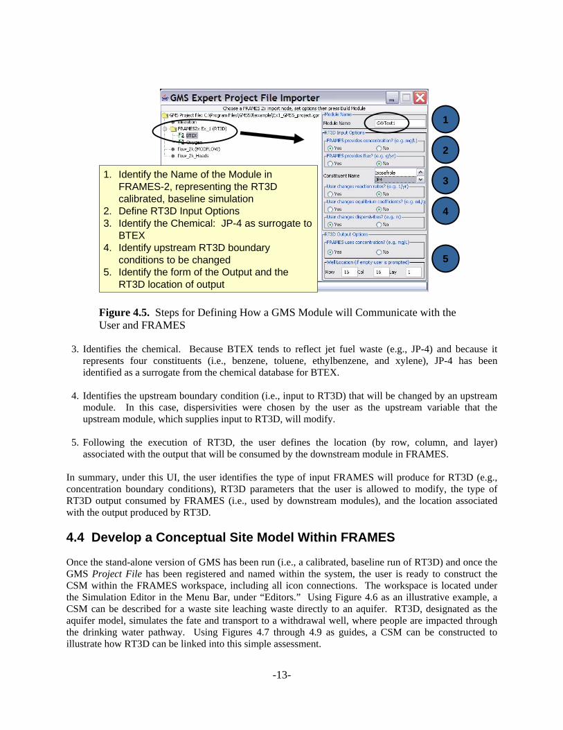
associated with the output that will be consumed by the downstream module in FRAMES. In summary, under this UI, the user identifies the type of input FRAMES will produce for RT3D (e.g., concentration boundary conditions), RT3D parameters that the user is allowed to modify, the type of RT3D output consumed by FRAMES (i.e., used by downstream modules), and the location associated with the output produced by RT3D. 4.4 Develop a Conceptual Site Model Within FRAMES Once the stand-alone version of GMS has been run (i.e., a calibrated, baseline run of RT3D) and once the GMS Project File has been registered and named within the system, the user is ready to construct the CSM within the FRAMES workspace, including all icon connections. The workspace is located under the Simulation Editor in the Menu Bar, under “Editors.” Using Figure 4.6 as an illustrative example, a CSM can be described for a waste site leaching waste directly to an aquifer. RT3D, designated as the aquifer model, simulates the fate and transport to a withdrawal well, where people are impacted through the drinking water pathway. Using Figures 4.7 through 4.9 as guides, a CSM can be constructed to illustrate how RT3D can be linked into this simple assessment.
Figure 4.5. Steps for Defining How a GMS Module will Communicate with the User and FRAMES
1. Identify the Name of the Module in FRAMES-2, representing the RT3D calibrated, baseline simulation
2. Define RT3D Input Options3. Identify the Chemical: JP-4 as surrogate to
BTEX4. Identify upstream RT3D boundary
conditions to be changed5. Identify the form of the Output and the
RT3D location of output
4
5
3
1
2
-13-

Illustrative ExampleIllustrative ExampleIllustrative Example
Figure 4.6. Illustrative Example of Aquifer Contamination
Figure 4.7. Illustrative Conceptual Site Model Example of Aquifer Contamination
Vadose Zone
Dose
Vadose Zone
Choose the RT3D GMS Run, representing the Aquifer Model
Hazard/RiskHuman
IntakeHumanExposure
Source
-14-

Right Click General Info
Figure 4.8. Illustration of the General Info User Interface
Right Click User Input
Meet User-Defined InputRequirements for Dispersivities
Figure 4.9. Illustration of the User Input User Interface
-15-

1. As illustrated by Figure 4.7, the FRAMES user chooses icons from the left-most icon pallette to
construct the CSM. 2. When the FRAMES user comes to the icon containing the GMS application choice (e.g, within the
Aquifer icon), the user will have the option of picking the GMS Project File name, which is now referred to as GWTest1, developed a priori by the GMS modeler. The GWTest1 name inherently refers to and identifies the calibrated, baseline RT3D simulation. To choose the GMS/RT3D run, named GWTest1, the user chooses “General Info,” under the Aquifer icon, and proceeds to choose GWTest1 as the most applicable module. The General Info User Interface is illustrated in Figure 4.8.
3. Upon exiting the General Info UI, the user chooses “User Input” to define the dispersivity boundary
conditions for RT3D. Figure 4.9 illustrates the Generic Module User Interface (GMUI) that is used to allow the user to define dispersivities in the longitudinal, lateral, and vertical directions for use in RT3D. Note that the user wanted to use FRAMES as a mechanism to change dispersivities in RT3D, as illustrated in Figure 4.5.
4. Once all of the User Interfaces have been filled out and completed, the models are run in sequential
order, starting with the upstream-most module. When the Aquifer module is reached, only the RT3D executable is run, and GMS is not required at this point. The output from RT3D is automatically captured, and its results are passed to the downstream module for consumption.
-16-

5.0 References Buck, JW, DA Tolle, G Whelan, TJ Mast, MS Peffers, DP Evers, RA Corley, MA Eslinger, JL Kirk, MA Pelton, CC Townsend, MG Nishioka, V Kogan, S Mahasenan, KE Dorow, RD Stenner, DL Strenge. 2002. Design of the Comprehensive Chemical Exposure Framework and Identification of Research Needs for American Chemistry Council. PNWD-3184. Battelle, Pacific Northwest Division, Richland, Washington. Environmental Modeling Systems, Inc. GMS 6.0 Overview. Available at: http://www.ems-i.com/GMS/GMS_Overview/gms_overview.html Framework for Risk Analysis in Multimedia Environmental Systems. Available at: http://mepas.pnl.gov/FRAMESV1/index.html Framework for Risk Analysis in Multimedia Environmental Systems. Available at: http://mepas.pnl.gov/earth/ Interagency Steering Committee on Multimedia Environmental Models. Available at: http://iscmem.org/Proceedings.htm Whelan, G, JW Buck, KJ Castleton, BL Hoopes, MA Pelton, JP McDonald, GM Gelston, and RYTaira. 1998. Framework for Risk Analysis in Multimedia Environmental Systems (FRAMES). TJ Nicholson and JD Parrott (eds). In: Proceedings on the Workshop on Review of Dose Modeling Methods for Demonstration of Compliance with the Radiological Criteria for License. NUREG/CP-0163. U.S. Nuclear Regulatory Commission, Washington, DC
-17-