Supercooled water relaxation dynamics probed with heterodyne transient grating experiments
Upload
khangminh22Category
view
2download
0
P&R Metals, Inc.4017 Richard Arrington Blvd N.Birmingham, AL 35212
Cat. # PR107
GRIP STRUT®
FIBERGLASS GRATING
BAR GRATING

P & R M e t a l s , I n c . - 1 - 8 7 7 - 8 8 0 - 3 3 1 9P&R METALS CALL TOLL-FREE: 1-877-880-3319
Project Pictures
Welded Wire Mesh and Gripstrut® Molded Fiberglass Floor Grating
Aluminum Swaged Locked Gratingused as security fencing
Molded Fiberglass Grating used as fencing
Contact InformationAddress:P & R Metals, Inc.4017 Richard Arrington Blvd. N.Birmingham, aL 35212
Local: 205-328-2290Toll-Free: 1-877-880-3319Fax: 205-328-3394
Monday - Friday7:30A.M. - 5:00 P.M. CST
Phone: Web Address: Business Hours:
About P&R Metals
Custom Fabrication of All Products
P&R Metals is a leading distributor
company was founded in 1999 to provide superior customer satisfaction, service and reliability. We are located in a 26,000 square foot facility in Birming-ham, Alabama. Located next to major interstates, as well as our galvanizers, we are focused on the highest possible
Our team atmosphere is our “secret” to success. From the moment we receive an order, until it arrives at our customer’s site, we
focused on customer satisfaction. Our mission statement is based on common sense principles, “Customer relationships are our foundation. If our customer is in need of service, we will do everything we can to help. Can’t is a word that we avoid at every possible turn. We must take care of our customers or someone else will!” From sales to engineering to production, our employees are motivated and compensated on the fact
-ferent level of service at P&R Metals, because we look forward to serving your needs.
-ing and fabrication services for all the products sold. Products purchased
-tions of your particular task and we are happy to help.
Our fabrication and engineering ser-vices include estimating, detailing, and custom engineering. We can send and receive drawings electronically to expe-dite your order. Our fabrication depart-
ment can cut to length or custom design areas that require piece marks and erection
ship the highest quality order in the least amount of time. After all, your project has
to help.
No request is too big or small. Please feel free to call us with your order requirements.
Table of Contents:
Welded Steel Bar Grating 1
Stair Treads 3
Heavy Duty Steel Grating 4
Safety Grating 6
Ladder Rungs 26
Aluminum Grating 27
SlipNOT® Patented Products 28
Pultruded F’Glass Grating 29
HD Fiberglass Grating 36
Molded Fiberglass Grating 40
EXTREN Fiberglass Series 46
SAFPLANK Plank System 47
Expanded Metal 48
Perforated Metals 50
Wire Mesh 52
“Customer relationships are our foundation. If our customer is in need of service, we will do everything we can to help. Can’t is a word that we avoid at every possible turn. We must take care of our customers or someone else will!”
- James Robinson, President
P&R METALS CALL TOLL-FREE: 1-877-880-3319

P&R METALS CALL TOLL-FREE: 1-877-880-3319
1
WELDED STEEL BAR GRATINGWelded steel bar grating is manufactured by a resistance-weld process. Cross-bars are fused to bearing bars to form a permanent joint. Economical, yet durable for most applications. Available in standard panel widths of 2’ or 3’ and lengths of 20’ or 24’. Material types include A569-carbon steel as well as stain-less steel. Finishes include mill, H. D. galvanized, painted black. Custom colors upon request. Surfaces include, smooth, serrated or SlipNOT® anti-slip coating.
P & R M e t a l s , I n c . - 1 - 8 7 7 - 8 8 0 - 3 3 1 9
1
2' - 0" 2' - 6" 3' - 0" 3' - 6" 4' - 0" 4' - 6" 5' - 0" 5' - 6" 6' - 0" 6' - 6" 7' - 0" 8' - 0"U 578 370 258 188 144 115D 0.095 0.151 0.215 0.295 0.374 0.486C 578 462 386 331 289 257D 0.076 0.119 0.173 0.234 0.308 0.389U 686 439 304 224 171 135 109 91 76D 0.072 0.111 0.159 0.219 0.288 0.366 0.451 0.547 0.673C 686 549 457 392 343 305 275 250 228D 0.057 0.09 0.129 0.176 0.231 0.293 0.36 0.434 0.518U 1029 659 459 338 257 203 164 135 114D 0.072 0.111 0.159 0.219 0.288 0.366 0.451 0.547 0.673C 1029 824 686 587 514 458 412 375 343D 0.057 0.09 0.129 0.176 0.231 0.293 0.36 0.434 0.518U 1027 686 476 350 268 212 172 142 119 101 87D 0.057 0.09 0.129 0.176 0.231 0.291 0.358 0.433 0.52 0.608 0.704C 1027 858 716 613 536 477 430 390 358 330 306D 0.046 0.072 0.104 0.141 0.183 0.233 0.288 0.349 0.416 0.487 0.565U 1608 1028 716 526 403 318 258 213 179 152 131D 0.057 0.09 0.129 0.176 0.231 0.291 0.358 0.433 0.52 0.608 0.704C 1608 1285 1073 918 803 716 644 585 536 495 459D 0.046 0.072 0.104 0.141 0.183 0.233 0.288 0.349 0.416 0.487 0.565U 1544 987 686 505 387 306 248 205 172 149 128 96D 0.047 0.075 0.106 0.147 0.192 0.243 0.3 0.365 0.433 0.506 0.587 0.774C 1544 1235 1029 883 772 687 619 563 515 475 441 386D 0.038 0.059 0.087 0.117 0.154 0.195 0.241 0.289 0.347 0.406 0.47 0.614U 2321 1485 1031 758 581 458 371 307 260 222 191 145D 0.047 0.072 0.106 0.147 0.192 0.243 0.3 0.365 0.433 0.506 0.587 0.774C 2321 1856 1547 1325 1159 1031 928 844 773 714 663 581D 0.038 0.059 0.087 0.117 0.154 0.195 0.241 0.289 0.347 0.406 0.47 0.614U 3151 2016 1401 1029 788 622 505 416 351 299 259 197D 0.042 0.064 0.092 0.126 0.165 0.208 0.258 0.31 0.371 0.435 0.506 0.664C 3151 2521 2100 1800 1575 1400 1260 1145 1049 969 899 786D 0.033 0.052 0.074 0.101 0.132 0.167 0.206 0.249 0.297 0.347 0.403 0.527U 4116 2633 1829 1344 1029 813 659 546 460 393 339 258D 0.036 0.056 0.081 0.111 0.144 0.183 0.226 0.273 0.325 0.384 0.447 0.58C 4116 3292 2745 2351 2058 1828 1646 1496 1370 1266 1175 1027D 0.029 0.045 0.064 0.088 0.115 0.145 0.18 0.217 0.259 0.303 0.353 0.46U 5209 3332 2314 1670 1302 1028 835 689 583 496 428 327D 0.032 0.05 0.072 0.098 0.127 0.162 0.199 0.241 0.287 0.338 0.393 0.512C 5209 4167 3472 2916 2604 2314 2082 1892 1733 1601 1487 1301D 0.026 0.039 0.057 0.079 0.102 0.129 0.16 0.194 0.23 0.27 0.314 0.41U 6432 4115 2858 2099 1609 1271 1029 850 720 613 529 405D 0.028 0.044 0.064 0.088 0.116 0.145 0.18 0.217 0.26 0.305 0.354 0.465C 6432 5147 4286 3673 3214 2858 2571 2338 2141 1977 1836 1607D 0.023 0.036 0.051 0.071 0.092 0.116 0.144 0.173 0.207 0.242 0.282 0.369
1 1/2 x 1/8 (19-4-7)
1 1/4 x 1/8 (19-4-5)
1 1/4 x 3/16 (19-4-6)
SIZE (Symbol)
1 x 1/8 (19-4-3)
Span (Length of Bearing Bar)
1x 3/16 (19-4-4)
Load & Deflections
3/4 x 3/16 (19-4-2)
2 1/2x 3/16 (19-4-12)
2 x 3/16 (19-4-10)
2 1/4x 3/16 (19-4-11)
1 1/2 x 3/16 (19-4-8)
1 3/4 x 3/16 (19-4-9)
Code:U = safe uniform load, lb/sq. ft.D = deflection in inchesC = safe concentrated load, lb/ft.
of grating width, at mid-span
Note (ALL LOAD TABLES):1/4” is recommended as the maximum deflectionconsistent with pedestrian comfort but can beexceeded for other loading conditions at the discretion of the engineer.
Type Multiplier9W4 2.0011W4 1.6415W4 1.18
Based on 11 bearing bars per foot of widthMaximum allowable stress 18,000 psi
Conversion Table
Bearing BarsCross Bars
Type 19W4
Type 19W2
Type 15W4
Type 15W2
3/4 x 1/8 1/4 3.99 4.63 4.95 5.59
3/4 x 3/16 1/4 5.67 6.31 7.11 7.75
1 x 1/8 1/4 5.15 5.79 6.44 7.08
1 x 3/16 1/4 7.35 7.99 9.27 9.91
1 1/4 x 1/8 1/4 6.2 6.84 7.79 8.43
1 1/4 x 3/16 1/4 9.03 9.67 11.43 12.07
1 1/2 x 1/8 1/4 7.35 7.99 9.27 9.91
1 1/2 x 3/16 5/16 10.94 11.8 13.82 14.68
1 3/4 x 3/16 5/16 12.62 13.48 15.98 16.84
2 x 3/16 5/16 14.3 15.16 18.14 19.00
2 1/4 x 3/16 5/16 15.87 16.74 20.16 21.03
2 1/2 x 3/16 5/16 17.55 18.42 22.32 23.19
WEIGHT IN POUNDS PER SQUARE FOOT
L I G H T D U T Y L O A D T A B L E
WELDED STEEL BAR GRATINGWelded steel bar grating is manufactured by a resistance-
weld process. Crossbars are fused to bearing bars to form apermanent joint. Economical, yet durable for most applica-tions. Available in standard panel widths of 2’ or 3’ andlengths of 20’ or 24’. Material types include A569-carbonsteel as well as stainless steel. Finishes include mill, H. D.galvanized, painted black. Custom colors upon request.Surfaces include, smooth, serrated or Slip-Not® anti-slip coat-ing.
smooth
serrated
TYPE 15W4 AND 15W2
TYPE 19W4 AND 19W2
Note: 9W & 11W grating use 5/16 cross rods. Consult salesperson for9W grating specifications & availability.
LIGHT DUTY LOAD TABLE
P & R M e t a l s , I n c . - 1 - 8 7 7 - 8 8 0 - 3 3 1 9
1
2' - 0" 2' - 6" 3' - 0" 3' - 6" 4' - 0" 4' - 6" 5' - 0" 5' - 6" 6' - 0" 6' - 6" 7' - 0" 8' - 0"U 578 370 258 188 144 115D 0.095 0.151 0.215 0.295 0.374 0.486C 578 462 386 331 289 257D 0.076 0.119 0.173 0.234 0.308 0.389U 686 439 304 224 171 135 109 91 76D 0.072 0.111 0.159 0.219 0.288 0.366 0.451 0.547 0.673C 686 549 457 392 343 305 275 250 228D 0.057 0.09 0.129 0.176 0.231 0.293 0.36 0.434 0.518U 1029 659 459 338 257 203 164 135 114D 0.072 0.111 0.159 0.219 0.288 0.366 0.451 0.547 0.673C 1029 824 686 587 514 458 412 375 343D 0.057 0.09 0.129 0.176 0.231 0.293 0.36 0.434 0.518U 1027 686 476 350 268 212 172 142 119 101 87D 0.057 0.09 0.129 0.176 0.231 0.291 0.358 0.433 0.52 0.608 0.704C 1027 858 716 613 536 477 430 390 358 330 306D 0.046 0.072 0.104 0.141 0.183 0.233 0.288 0.349 0.416 0.487 0.565U 1608 1028 716 526 403 318 258 213 179 152 131D 0.057 0.09 0.129 0.176 0.231 0.291 0.358 0.433 0.52 0.608 0.704C 1608 1285 1073 918 803 716 644 585 536 495 459D 0.046 0.072 0.104 0.141 0.183 0.233 0.288 0.349 0.416 0.487 0.565U 1544 987 686 505 387 306 248 205 172 149 128 96D 0.047 0.075 0.106 0.147 0.192 0.243 0.3 0.365 0.433 0.506 0.587 0.774C 1544 1235 1029 883 772 687 619 563 515 475 441 386D 0.038 0.059 0.087 0.117 0.154 0.195 0.241 0.289 0.347 0.406 0.47 0.614U 2321 1485 1031 758 581 458 371 307 260 222 191 145D 0.047 0.072 0.106 0.147 0.192 0.243 0.3 0.365 0.433 0.506 0.587 0.774C 2321 1856 1547 1325 1159 1031 928 844 773 714 663 581D 0.038 0.059 0.087 0.117 0.154 0.195 0.241 0.289 0.347 0.406 0.47 0.614U 3151 2016 1401 1029 788 622 505 416 351 299 259 197D 0.042 0.064 0.092 0.126 0.165 0.208 0.258 0.31 0.371 0.435 0.506 0.664C 3151 2521 2100 1800 1575 1400 1260 1145 1049 969 899 786D 0.033 0.052 0.074 0.101 0.132 0.167 0.206 0.249 0.297 0.347 0.403 0.527U 4116 2633 1829 1344 1029 813 659 546 460 393 339 258D 0.036 0.056 0.081 0.111 0.144 0.183 0.226 0.273 0.325 0.384 0.447 0.58C 4116 3292 2745 2351 2058 1828 1646 1496 1370 1266 1175 1027D 0.029 0.045 0.064 0.088 0.115 0.145 0.18 0.217 0.259 0.303 0.353 0.46U 5209 3332 2314 1670 1302 1028 835 689 583 496 428 327D 0.032 0.05 0.072 0.098 0.127 0.162 0.199 0.241 0.287 0.338 0.393 0.512C 5209 4167 3472 2916 2604 2314 2082 1892 1733 1601 1487 1301D 0.026 0.039 0.057 0.079 0.102 0.129 0.16 0.194 0.23 0.27 0.314 0.41U 6432 4115 2858 2099 1609 1271 1029 850 720 613 529 405D 0.028 0.044 0.064 0.088 0.116 0.145 0.18 0.217 0.26 0.305 0.354 0.465C 6432 5147 4286 3673 3214 2858 2571 2338 2141 1977 1836 1607D 0.023 0.036 0.051 0.071 0.092 0.116 0.144 0.173 0.207 0.242 0.282 0.369
1 1/2 x 1/8 (19-4-7)
1 1/4 x 1/8 (19-4-5)
1 1/4 x 3/16 (19-4-6)
SIZE (Symbol)
1 x 1/8 (19-4-3)
Span (Length of Bearing Bar)
1x 3/16 (19-4-4)
Load & Deflections
3/4 x 3/16 (19-4-2)
2 1/2x 3/16 (19-4-12)
2 x 3/16 (19-4-10)
2 1/4x 3/16 (19-4-11)
1 1/2 x 3/16 (19-4-8)
1 3/4 x 3/16 (19-4-9)
Code:U = safe uniform load, lb/sq. ft.D = deflection in inchesC = safe concentrated load, lb/ft.
of grating width, at mid-span
Note (ALL LOAD TABLES):1/4” is recommended as the maximum deflectionconsistent with pedestrian comfort but can beexceeded for other loading conditions at the discretion of the engineer.
Type Multiplier9W4 2.0011W4 1.6415W4 1.18
Based on 11 bearing bars per foot of widthMaximum allowable stress 18,000 psi
Conversion Table
Bearing BarsCross Bars
Type 19W4
Type 19W2
Type 15W4
Type 15W2
3/4 x 1/8 1/4 3.99 4.63 4.95 5.59
3/4 x 3/16 1/4 5.67 6.31 7.11 7.75
1 x 1/8 1/4 5.15 5.79 6.44 7.08
1 x 3/16 1/4 7.35 7.99 9.27 9.91
1 1/4 x 1/8 1/4 6.2 6.84 7.79 8.43
1 1/4 x 3/16 1/4 9.03 9.67 11.43 12.07
1 1/2 x 1/8 1/4 7.35 7.99 9.27 9.91
1 1/2 x 3/16 5/16 10.94 11.8 13.82 14.68
1 3/4 x 3/16 5/16 12.62 13.48 15.98 16.84
2 x 3/16 5/16 14.3 15.16 18.14 19.00
2 1/4 x 3/16 5/16 15.87 16.74 20.16 21.03
2 1/2 x 3/16 5/16 17.55 18.42 22.32 23.19
WEIGHT IN POUNDS PER SQUARE FOOT
L I G H T D U T Y L O A D T A B L E
WELDED STEEL BAR GRATINGWelded steel bar grating is manufactured by a resistance-
weld process. Crossbars are fused to bearing bars to form apermanent joint. Economical, yet durable for most applica-tions. Available in standard panel widths of 2’ or 3’ andlengths of 20’ or 24’. Material types include A569-carbonsteel as well as stainless steel. Finishes include mill, H. D.galvanized, painted black. Custom colors upon request.Surfaces include, smooth, serrated or Slip-Not® anti-slip coat-ing.
smooth
serrated
TYPE 15W4 AND 15W2
TYPE 19W4 AND 19W2
Note: 9W & 11W grating use 5/16 cross rods. Consult salesperson for9W grating specifications & availability.
P & R M e t a l s , I n c . - 1 - 8 7 7 - 8 8 0 - 3 3 1 9
2' - 0" 2' - 6" 3' - 0" 3' - 6" 4' - 0" 4' - 6" 5' - 0" 5' - 6" 6' - 0" 6' - 6" 7' - 0" 8' - 0"U 578 370 258 188 144 115D 0.095 0.151 0.215 0.295 0.374 0.486C 578 462 386 331 289 257D 0.076 0.119 0.173 0.234 0.308 0.389U 686 439 304 224 171 135 109 91 76D 0.072 0.111 0.159 0.219 0.288 0.366 0.451 0.547 0.673C 686 549 457 392 343 305 275 250 228D 0.057 0.09 0.129 0.176 0.231 0.293 0.36 0.434 0.518U 1029 659 459 338 257 203 164 135 114D 0.072 0.111 0.159 0.219 0.288 0.366 0.451 0.547 0.673C 1029 824 686 587 514 458 412 375 343D 0.057 0.09 0.129 0.176 0.231 0.293 0.36 0.434 0.518U 1027 686 476 350 268 212 172 142 119 101 87D 0.057 0.09 0.129 0.176 0.231 0.291 0.358 0.433 0.52 0.608 0.704C 1027 858 716 613 536 477 430 390 358 330 306D 0.046 0.072 0.104 0.141 0.183 0.233 0.288 0.349 0.416 0.487 0.565U 1608 1028 716 526 403 318 258 213 179 152 131D 0.057 0.09 0.129 0.176 0.231 0.291 0.358 0.433 0.52 0.608 0.704C 1608 1285 1073 918 803 716 644 585 536 495 459D 0.046 0.072 0.104 0.141 0.183 0.233 0.288 0.349 0.416 0.487 0.565U 1544 987 686 505 387 306 248 205 172 149 128 96D 0.047 0.075 0.106 0.147 0.192 0.243 0.3 0.365 0.433 0.506 0.587 0.774C 1544 1235 1029 883 772 687 619 563 515 475 441 386D 0.038 0.059 0.087 0.117 0.154 0.195 0.241 0.289 0.347 0.406 0.47 0.614U 2321 1485 1031 758 581 458 371 307 260 222 191 145D 0.047 0.072 0.106 0.147 0.192 0.243 0.3 0.365 0.433 0.506 0.587 0.774C 2321 1856 1547 1325 1159 1031 928 844 773 714 663 581D 0.038 0.059 0.087 0.117 0.154 0.195 0.241 0.289 0.347 0.406 0.47 0.614U 3151 2016 1401 1029 788 622 505 416 351 299 259 197D 0.042 0.064 0.092 0.126 0.165 0.208 0.258 0.31 0.371 0.435 0.506 0.664C 3151 2521 2100 1800 1575 1400 1260 1145 1049 969 899 786D 0.033 0.052 0.074 0.101 0.132 0.167 0.206 0.249 0.297 0.347 0.403 0.527U 4116 2633 1829 1344 1029 813 659 546 460 393 339 258D 0.036 0.056 0.081 0.111 0.144 0.183 0.226 0.273 0.325 0.384 0.447 0.58C 4116 3292 2745 2351 2058 1828 1646 1496 1370 1266 1175 1027D 0.029 0.045 0.064 0.088 0.115 0.145 0.18 0.217 0.259 0.303 0.353 0.46U 5209 3332 2314 1670 1302 1028 835 689 583 496 428 327D 0.032 0.05 0.072 0.098 0.127 0.162 0.199 0.241 0.287 0.338 0.393 0.512C 5209 4167 3472 2916 2604 2314 2082 1892 1733 1601 1487 1301D 0.026 0.039 0.057 0.079 0.102 0.129 0.16 0.194 0.23 0.27 0.314 0.41U 6432 4115 2858 2099 1609 1271 1029 850 720 613 529 405D 0.028 0.044 0.064 0.088 0.116 0.145 0.18 0.217 0.26 0.305 0.354 0.465C 6432 5147 4286 3673 3214 2858 2571 2338 2141 1977 1836 1607D 0.023 0.036 0.051 0.071 0.092 0.116 0.144 0.173 0.207 0.242 0.282 0.369
1 1/2 x 1/8 (19-4-7)
1 1/4 x 1/8 (19-4-5)
1 1/4 x 3/16 (19-4-6)
SIZE (Symbol)
1 x 1/8 (19-4-3)
Span (Length of Bearing Bar)
1x 3/16 (19-4-4)
Load & Deflections
3/4 x 3/16 (19-4-2)
2 1/2x 3/16 (19-4-12)
2 x 3/16 (19-4-10)
2 1/4x 3/16 (19-4-11)
1 1/2 x 3/16 (19-4-8)
1 3/4 x 3/16 (19-4-9)
Code:U = safe uniform load, lb/sq. ft.D = deflection in inchesC = safe concentrated load, lb/ft.
of grating width, at mid-span
Note (ALL LOAD TABLES):1/4” is recommended as the maximum deflectionconsistent with pedestrian comfort but can beexceeded for other loading conditions at the discretion of the engineer.
Type Multiplier9W4 2.0011W4 1.6415W4 1.18
Based on 11 bearing bars per foot of widthMaximum allowable stress 18,000 psi
Conversion Table
Bearing BarsCross Bars
Type 19W4
Type 19W2
Type 15W4
Type 15W2
3/4 x 1/8 1/4 3.99 4.63 4.95 5.59
3/4 x 3/16 1/4 5.67 6.31 7.11 7.75
1 x 1/8 1/4 5.15 5.79 6.44 7.08
1 x 3/16 1/4 7.35 7.99 9.27 9.91
1 1/4 x 1/8 1/4 6.2 6.84 7.79 8.43
1 1/4 x 3/16 1/4 9.03 9.67 11.43 12.07
1 1/2 x 1/8 1/4 7.35 7.99 9.27 9.91
1 1/2 x 3/16 5/16 10.94 11.8 13.82 14.68
1 3/4 x 3/16 5/16 12.62 13.48 15.98 16.84
2 x 3/16 5/16 14.3 15.16 18.14 19.00
2 1/4 x 3/16 5/16 15.87 16.74 20.16 21.03
WEIGHT IN POUNDS PER SQUARE FOOT
L I G H T D U T Y L O A D T A B L E
WELDED STEEL BAR GRATINGWelded steel bar grating is manufactured by a resistance-
weld process. Crossbars are fused to bearing bars to form apermanent joint. Economical, yet durable for most applica-tions. Available in standard panel widths of 2’ or 3’ andlengths of 20’ or 24’. Material types include A569-carbonsteel as well as stainless steel. Finishes include mill, H. D.galvanized, painted black. Custom colors upon request.Surfaces include, smooth, serrated or Slip-Not® anti-slip coat-ing.
smooth
serrated
TYPE 15W4 AND 15W2
TYPE 19W4 AND 19W2

2
P&R METALS CALL TOLL-FREE: 1-877-880-3319
19W4
# of bars 2 3 4 5 6 7 8 9 10 11 12 13 14 15 16
1/8” bar 1-5/16 2-1/2 3-11/16 4-7/8 6-1/16 7-1/4 8-7/16 9-5/8 10-13/16 12 13-3/16 14-3/8 15-9/16 16-3/4 17-15/16
3/16” bar 1-3/8 2-9/16 3-3/4 4-15/16 6-1/8 7-5/16 8-1/2 9-11/16 10-7/8 12-1/16 13-1/4 14-7/16 15-5/8 16-13/16 18
# of bars 17 18 19 20 21 22 23 24 25 26 27 28 29 30 31
1/8” bar 19-1/8 20-5/16 21-1/2 22-11/16 23-7/8 25-1/16 26-1/4 27-7/16 28-5/8 29-13/16 31 32-3/16 33-3/8 34-9/16 35-3/4
3/16” bar 19-3/16 20-3/8 21-9/16 22-3/4 23-15/16 25-1/8 26-5/16 27-1/2 28-11/16 29-7/8 31-1/16 32-1/4 33-7/16 34-5/8 35-13/16
15W4
# of bars 2 3 4 5 6 7 8 9 10 11 12 13 14 15 16 17 18 19 201/8” bar 1-1/16 2 2-15/16 3-7/8 4-13/16 5-3/4 6-11/16 7-5/8 8-9/16 9-1/2 10-7/16 11-3/8 12-5/16 13-1/4 14-3/16 15-1/8 16-1/16 17 17-15/16
3/16” bar 1-1/8 2-1/16 3 3-15/16 4-7/8 5-13/16 6-3/4 7-11/16 8-5/8 9-9/16 10-1/2 11-7/16 12-3/8 13-5/16 14-1/4 15-3/16 16-1/8 17-1/16 18
# of bars 21 22 23 24 25 26 27 28 29 30 31 32 33 34 35 36 37 38 39
1/8” bar 18-7/8 19-13/16 20-3/4 21-11/16 22-5/8 23-9/16 24-1/2 25-7/16 26-3/8 27-5/16 28-1/4 29-3/16 30-1/8 31-1/16 32 32-15/16 33-7/8 34-13/16 35-3/4
3/16” bar 18-15/16 19-7/8 20-13/16 21-3/4 22-11/16 23-5/8 24-9/16 25-1/2 26-7/16 27-3/8 28-5/16 29-1/4 30-3/16 31-1/8 32-1/16 33 33-15/16 34-7/8 35-13/16
11W4
# of bars 2 3 4 5 6 7 8 9 10 11 12 13 14 15 16 17 18 193/16” bar 7/8 1-9/16 2-1/4 2-15/16 3-5/8 4-5/16 5 5-11/16 6-3/8 7-1/16 7-3/4 8-7/16 9-1/8 9-13/16 10-1/2 11-3/16 11-7/8 12-9/16
# of bars 20 21 22 23 24 25 26 27 28 29 30 31 32 33 34 35 36
3/16” bar 13-1/4 13-15/16 14-5/8 15-5/16 16 16-11/16 17-3/8 18-1/16 18-3/4 19-7/16 20-1/8 20-13/16 21-1/2 22-3/16 22-7/8 23-9/16 24-1/4
BANDING BAR — A flat bar welded to the end of a panel of grating. The bar is mostly the same thickness and depth as the bearing bar.BEARING BAR — The main load carrying bar which runs the same direction as the span.CIRCULAR CUT-BAND — The circular cutting and banding of a panel to conform to a specific layout. Example: grating going around a tank or pipe.CROSS BARS — The connecting bars made from steel strip or rolled bars which extend across the bearing bars, usually perpendicular to them. They are welded, forget or mechanically locked.NOSING — An L-shaped section, usually made of checker plate or cast iron and cast alumi-num abrasive material.SERRATED GRATING — Grating which has that top surfaces of the bearing bar notched, which provides non-skid footing.SPAN — The distance between points of grating support. Mostly direction of bearing bar.STRAIGHT CUT — The cutting of grating along a straight edge. Mostly figured when cutting around columns or posts.TOE PLATE — A flat bar attached flat against the outer edge of grating and projecting above the top surface of grating to form lip or curve.
P & R M e t a l s , I n c . - 1 - 8 7 7 - 8 8 0 - 3 3 1 9
BANDING BAR — A flat bar welded to the end of a panel of grating. The bar is mostly the same thickness and depth as the bearing bar.
BEARING BAR — The main load carrying bar which runs the same direction as the span.
CIRCULAR CUT-BAND — The circular cutting and banding of a panel to conform to a specific layout. Example: grating going aropund a tank or pipe.
CROSS BARS — The connecting bars made from steel strip or rolled bars which extend across the bearing bars, usually perpendicular to them. Theyare welded, forget or mechanically locked.
NOSING — An L-shaped section, usually made of checker plate or cast iron and cast aluminumabrasive material.
SERRATED GRATING — Grating which has that top surfaces of the bearing bar notched, which pro-vides non-skid footing.
SPAN — The distance between points of grating support. Mostly direction of bearing bar.
STRAIGHT CUT — The cutting of grating along a straight edge. Mostly figured when cutting aroundcolumns or posts.
TOE PLATE — A flat bar attached flat against the outer edge of grating and projecting above the topsurface of grating to form lip or curve.
G R AT I N G G L O S S A RY
GRATING1. Specify type of grating (steel, aluminum, stainless steel)2. Bearing bar size and center to center of spacing.3. Span (Bearing Bar Direction)4. Drawing: Area to be covered, including all cutouts and
critical dimensions.
ORDER/SPECIFICATION INFORMATIONSTAIR TREADS
1. Type of grating and bearing bar size2. Nosing: Checkerplate or abrasive3. Finish: Mill, galvanized, or black paint
4. Surface: Smooth, serrated, or Slip-Not® antislip
SPAN
CROSS BAR
BEARING BAR
WELDED STEEL BAR GRATINGPANEL WIDTHS
PERCENTAGE OF FREE AREA
2
— A flat bar welded to the end of a panel of grating. The bar is mostly the same thickness and depth as the bearing bar.
— The main load carrying bar which runs the same direction as the span.
— The circular cutting and banding of a panel to conform to a specific layout. Example: grating going aropund a tank or pipe.
— The connecting bars made from steel strip or rolled bars which extend across the bearing bars, usually perpendicular to them. Theyare welded, forget or mechanically locked.
— An L-shaped section, usually made of checker plate or cast iron and cast aluminum
— Grating which has that top surfaces of the bearing bar notched, which pro-
— The distance between points of grating support. Mostly direction of bearing bar.
— The cutting of grating along a straight edge. Mostly figured when cutting around
— A flat bar attached flat against the outer edge of grating and projecting above the top
PERCENTAGE OF FREE AREA
3/16" 1/8" 3/16" 1/8"
4 15/16 4 7/8
6 1/8 6 1/16
7 5/16 7 1/4
5 6 3/4 6 11/16 8 1/2 8 7/16
9 5 11/16 7 11/16 7 5/8 9 11/16 9 5/8
10 6 3/8 8 5/8 8 9/16 10 7/8 10 13/16
11 7 1/16 9 9/16 9 1/2 12 1/16 12
12 7 3/4 10 1/2 10 7/16 13 1/4 13 3/16
13 8 7/16 11 7/16 11 3/8 14 7/16 14 3/8
14 9 1/8 12 3/8 12 5/16 15 5/8 15 9/16
15 9 13/16 13 5/16 13 1/4 16 13/16 16 3/4
16 10 1/2 14 1/4 14 3/16 18 17 15/16
17 11 3/16 15 3/16 15 1/8 19 3/16 19 1/8
18 11 7/8 16 1/8 16 1/16 20 3/8 20 5/16
19 12 9/16 17 1/16 17 21 9/16 21 1/2
20 13 1/4 18 17 15/16 22 3/4 22 11/16
21 13 15/16 18 15/16 18 7/8 23 15/16 23 7/8
22 14 5/8 19 7/8 19 13/16 25 1/8 25 1/16
23 15 5/16 20 13/16 20 3/4 26 5/16 26 1/4
16 21 3/4 21 11/16 27 1/2 27 7/16
25 16 11/16 22 11/16 22 5/8 28 11/16 28 5/8
26 17 3/8 23 5/8 23 9/16 29 7/8 29 13/16
27 18 1/16 24 9/16 24 1/2 31 1/16 31
28 18 3/4 25 1/2 25 7/16 32 1/4 32 3/16
29 19 7/16 26 7/16 26 3/8 33 7/16 33 3/8
30 20 1/8 27 3/8 27 5/16 34 5/8 34 9/16
31 20 13/16 28 5/16 28 1/4 35 13/16 35 3/4
19W4 and 19W2
1/8 3/16 1/4 5/16 3/8 1/8 3/16 1/4 5/16 3/83/4 W4 80.4 74.1 83.0 78.03/4 W2 74.5 68.6 76.9 72.3
1 W4 80.4 74.1 67.3 60.2 83.0 78.0 72.4 66.5 61.71 W2 74.5 68.6 61.7 54.3 76.9 72.3 66.4 60.6 55.71 1/4 W4 80.4 74.1 67.3 60.2 83.0 78.0 72.4 66.5 61.71 1/4 W2 74.5 68.6 61.7 54.3 76.9 72.3 66.4 60.6 55.71 1/2 W4 80.4 73.5 67.3 60.2 83.0 77.4 72.4 66.5 61.71 1/2 W2 74.5 67.4 61.7 54.3 76.9 71.0 66.4 60.6 55.71 3/4 W4 72.5 66.3 60.2 76.3 71.4 66.5 61.71 3/4 W2 65.4 59.9 54.3 68.9 64.4 60.6 55.72 W4 72.5 66.3 60.2 76.3 71.4 66.5 60.52 W2 65.4 59.9 54.3 68.9 64.4 60.6 53.32 1/4 W4 72.5 66.3 60.2 76.3 71.4 66.5 60.52 1/4 W2 65.4 59.9 54.3 68.9 64.4 60.6 58.32 1/2 W4 72.5 66.3 60.2 76.3 71.4 66.5 60.52 1/2 W2 65.4 59.9 54.3 68.9 64.4 60.6 53.32 3/4 W4 72.5 66.3 60.2 76.3 71.4 66.5 60.52 3/4 W2 65.4 59.9 54.3 68.9 64.4 60.6 53.33 W4 65 59 70 65.2 60.53 W2 57.3 52 61.6 57.4 53.33 1/4 W4 65 59 70 65.2 60.53 1/4 W2 57.3 52 61.6 57.4 53.33 1/2 W4 65 59 70 65.2 60.53 1/2 W2 57.3 52 61.6 57.4 53.33 3/4 W4 70 65.2 60.53 3/4 W2 61.6 57.4 53.3
4 W4 7 70.0 65.2 60.54 W2 61.6 57.4 53.3
15W 19WBar Hgt.
x-Rod Space
G R AT I N G G L O S S A RY
1. Specify type of grating (steel, aluminum, stainless steel)2. Bearing bar size and center to center of spacing.
4. Drawing: Area to be covered, including all cutouts and
5. Type of anchorage (welded, saddle clip, friction clip, others).
7. Surfaces: Smooth, serrated or Slip-Not® antislip coating.
ORDER/SPECIFICATION INFORMATIONSTAIR TREADS
1. Type of grating and bearing bar size2. Nosing: Checkerplate or abrasive3. Finish: Mill, galvanized, or black paint
4. Surface: Smooth, serrated, or Slip-Not® antislipcoating.
SPAN
CROSS BAR
BEARING BAR
ORDERING INFORMATION
GRATING1. Specify type of grating (steel, aluminum, stainless steel)2. Bearing bar size and center to center of spacing.3. Span (Bearing Bar Direction)4. Drawing: Area to be covered, including all cutouts and critical dimensions.5. Type of anchorage (welded, saddle clip, friction clip, others).6. Finish: Galvanized or black paint7. Surfaces: Smooth, serrated or Slip-Not® anti-slip coating.
STAIR TREADS1. Type of grating and bearing bar size2. Nosing: Checker-plate or abrasive3. Finish: Mill, galvanized, or black paint4. Surface: Smooth, serrated, or Slip-Not® anti-slip coating.
If you have any further questions, please let us know and we will be happy to help you!

3
P&R METALS CALL TOLL-FREE: 1-877-880-3319P & R M e t a l s , I n c . - 1 - 8 7 7 - 8 8 0 - 3 3 1 9
3
S TA I R T R E A D S
NOTE: When using 1/8” thick bearing bar,tread width is 1/16” less.
*Maximum tread length is based on a 300-lb concentrated load on nosing and 4 bearing bars at center oftread length. For maximum length under other loadings, consult your P & R Metals sales representative.
CROSS SECTION-CHECKER PLATE OR SLIP-NOT® NOSING
CROSS SECTION-CAST NOSING*For Treads With Grating 1-1/2” to 1-3/4” deep
3” Deep End Plates Are Required
*
GRATING ATTACHMENT METHODS
WeldedRecommended for permanentinstallation.
Saddle ClipMay be attched with self drillingTEK® screws or bolt and nut.Available galvanized steel, stainlesssteel or aluminum.
G-Clip®Friction Fastener that enables nowelding or drilling into support steel.Available galvanized or stainlesssteel.
STANDARD TREAD WIDTHSStandard Spacing
Width “A” Dim.6 3/16 2 1/27 3/8 4 1/2
8 9/16 4 1/29 3/4 7
10 15/16 712 1/8 7
MAXIMUM TREAD LENGTH (STEEL)*Bearing Bar Max. Tread Length*
Size Plain Serrated3/4 x 3/16 2-2 0-01 x 3/16 3-0 2-8
1 1/4 x 3/16 4-0 3-51 1/2 x 3/16 5-3 4-7
MAXIMUM TREAD LENGTH (ALUMINUM)*Bearing Bar Max. Tread Length*
Size Plain or I-Bar Serrated1 x 3/16 2-4 ----
1 1/4 x 3/16 2-10 2-71 1/2 x 3/16 3-6 3-21 3/4 x 3/16 4-3 3-10
CROSS SECTION:GRATING DEPTH UP TO 1-1/4”
CROSS SECTION:GRATING DEPTH FROM 1-1/2” TO 1-3/4”
AND ALL ALUMINUM TREADS
STAIR TREADS
NOSING
11/8”
11/8”
13/4” 2 1/2”
2 1/4” 3”
“A”
NOSING
“A”
7/16” DIAMETERHOLE & SLOT
7/16” DIAMETERHOLE & SLOT
NOSING
11/8”
11/8”
13/4” 2 1/2”
2 1/4” 3”
“A”
NOSING
“A”
7/16” DIAMETERHOLE & SLOT
7/16” DIAMETERHOLE & SLOT
Steel Treads Maximum Tread Length*Bearing Bar SizeIn Inches
19-4 (1-3/16”) On-Center 15-4 (15/16”) On-CenterPlain Serrated Plain Serrated
1” x 1/8” 2’ 7” 2’ 3” 3’ 0” 2’ 6”1” x 3/16” 3’ 5” 2’ 10” 4’ 0” 3’ 4”1-1/4” x 3/16” 4’ 8” 4’ 2” 5’ 1” 4’ 6”1-1/2” x 3/16” 5’ 6” 5’ 3” 5’ 6” 5’ 6”
Aluminum Treads Maximum Tread Length*Bearing Bar SizeIn Inches
19-4 (1-3/16”) On-Center 15-4 (15/16”) On-CenterPlain Serrated Plain Serrated
1” x 3/16” 2’ 4” N.R. 2’ 6” N.R.1-1/4” x 3/16” 2’ 10” 2’ 7” 3’ 1” 2’ 9”1-1/2” x 3/16” 3’ 6” 3’ 2” 3’ 10” 3’ 6”1-3/4” x 3/16” 4’ 3” 3’ 10” 4’ 8” 4’ 3”
Aluminum I-Bars Maximum Tread Length*Bearing Bar SizeIn Inches
19-4 (1-3/16”)On-Center
15-4 (15/16”)On-Center
1” I-Bar 2’ 4” 2’ 6”1-1/4” I-Bar 2’ 10” 3’ 1”1-1/2” I-Bar 3’ 6” 3’ 10”1-3/4” I-Bar 4’ 3” 4’ 8”
Standard Tread Widths DimensionBearing Bar Centers A
19-4(1-3/16”) 15-4(15/16”)6-3/16” 6-1/8” 2-1/2”7-3/8” 7-1/16” 4-1/2”
8-9/16” 8” 4-1/2”9-3/4” 8-15/16” 7”
10-15/16” 9-7/8” 7”12-1/8” 10-13/16” 7”
*Maximum tread length based on 300lb. Concentrated load on front 5” of tread at center of tread length and deflection limitation of 1/240 of length.

4
P&R METALS CALL TOLL-FREE: 1-877-880-3319
TYPE 19W4 - BEARING BARS 1 3/16” CENTER TO CENTER
P & R M e t a l s , I n c . - 1 - 8 7 7 - 8 8 0 - 3 3 1 9
H E A V Y D U T Y S T E E L G R A T I N G L O A D T A B L E S
Lbs. Per Sq. Ft19W4 19W2 2'-0" 2'-6" 3'-0" 3'-6" 4'-0" 4'-6" 5'-0" 5'-6" 6'-0" 6'-6" 7'-0" 7'-6" 8'-0" 8'-6" 9'-0" 9'-6" 10'-0"
U 3282 2101 1459 1072 820 648 526 434 364 311 268 233C 3282 2625 2188 1875 1641 1459 1313 1193 1094 1010 938 875U 4922 3150 2188 1607 1230 972 788 651 547 402 308C 4922 3938 3281 2813 2461 2188 1969 1790 1641 1406 1230U 5834 3734 2593 1905 1459 1152 933 771 648 552 477 414 364 323C 5834 4667 3890 3334 2917 2593 2334 2122 1944 1795 1667 1555 1459 1373U 8750 5600 3889 2857 2188 1726 1400 1157 972 714 547C 8750 7000 5833 5000 4357 3889 3500 3182 2917 2500 2188U 9116 5834 4052 2976 2279 1801 1459 1205 1013 863 744 648 570 504 450 404C 9116 7293 6077 5209 4668 4052 3646 3315 3039 2805 2604 2431 2279 2145 2025 1919U 13672 8750 6076 4464 3418 2701 2188 1808 1519 1116 854C 13672 10938 9115 7813 6836 6076 5469 4972 4557 3906 3418U 13128 8401 5834 4286 3282 2593 2101 1735 1459 1243 1072 933 820 727 648 582 526C 13128 10502 8751 7501 6564 5834 5251 4774 4376 4040 3751 3501 3282 3089 2917 2764 2625U 19688 12600 8750 6429 4922 3889 3150 2603 2188 1607 1230C 19688 15750 13125 11250 9844 8750 7875 7159 6563 5625 4922U 17865 11433 7940 5833 4466 3528 2858 2362 1985 1691 1458 1270 1116 989 882 792 715C 17865 14292 11910 10208 8932 7940 7146 6496 5955 5497 5105 4765 4467 4203 3970 3762 3573U 26797 17150 11910 8750 6699 5293 4288 3543 2977 2188 1675C 26797 21438 17865 15313 13398 11910 10719 9744 8932 7656 6699U 23338 14936 10372 7620 5834 4610 3734 3086 2593 2210 1905 1660 1459 1292 1152 1034 933C 23338 18670 16558 13335 11669 10372 9335 8486 7779 7180 6668 6223 5834 5491 5186 4913 4667U 35000 22400 15556 11429 8750 6914 5600 4628 3889 2857 2188C 35000 28000 23333 20000 17500 15556 14000 12727 11667 10000 8750
SPAN
1 1/2 X 1/4 14.3 15.5 0.984
LoadSec Mod
WeightBar Sizes
2 X 1/4 18.7 19.8 1.750
2 1/2 X 1/4 23.1 24.3 2.734
3 X 1/4 27.5 28.6 3.937
3 1/2 x 1/4 31.9 33 5.359
4 x 1/4 36.3 37.4 7.000
1 1/2 X 3/8 21.7 23.7 1.477
2 X 3/8 28.3 30.3 2.625
2 1/2 X 3/8 35.0 37.0 4.102
3 X 3/8 42.1 44.1 5.906
3 1/2 X 3/8 48.1 50.1 8.04
4 X 3/8 54.7 56.7 10.500
TYPE 19W4 AND 19W2
HEAVY-DUTY WELDED STEEL GRATING
TYPE 19W4 - BEARING BARS 1 3/16” CENTER TO CENTER
& R M e t a l s , I n c . - 1 - 8 7 7 - 8 8 0 - 3 3 1 9
S T E E L G R A T I N G L O A D T A B L E S
2'-0" 2'-6" 3'-0" 3'-6" 4'-0" 4'-6" 5'-0" 5'-6" 6'-0" 6'-6" 7'-0" 7'-6" 8'-0" 8'-6" 9'-0" 9'-6" 10'-0"U 3282 2101 1459 1072 820 648 526 434 364 311 268 233C 3282 2625 2188 1875 1641 1459 1313 1193 1094 1010 938 875U 4922 3150 2188 1607 1230 972 788 651 547 402 308C 4922 3938 3281 2813 2461 2188 1969 1790 1641 1406 1230U 5834 3734 2593 1905 1459 1152 933 771 648 552 477 414 364 323C 5834 4667 3890 3334 2917 2593 2334 2122 1944 1795 1667 1555 1459 1373U 8750 5600 3889 2857 2188 1726 1400 1157 972 714 547C 8750 7000 5833 5000 4357 3889 3500 3182 2917 2500 2188U 9116 5834 4052 2976 2279 1801 1459 1205 1013 863 744 648 570 504 450 404C 9116 7293 6077 5209 4668 4052 3646 3315 3039 2805 2604 2431 2279 2145 2025 1919U 13672 8750 6076 4464 3418 2701 2188 1808 1519 1116 854C 13672 10938 9115 7813 6836 6076 5469 4972 4557 3906 3418U 13128 8401 5834 4286 3282 2593 2101 1735 1459 1243 1072 933 820 727 648 582 526C 13128 10502 8751 7501 6564 5834 5251 4774 4376 4040 3751 3501 3282 3089 2917 2764 2625U 19688 12600 8750 6429 4922 3889 3150 2603 2188 1607 1230C 19688 15750 13125 11250 9844 8750 7875 7159 6563 5625 4922U 17865 11433 7940 5833 4466 3528 2858 2362 1985 1691 1458 1270 1116 989 882 792 715C 17865 14292 11910 10208 8932 7940 7146 6496 5955 5497 5105 4765 4467 4203 3970 3762 3573U 26797 17150 11910 8750 6699 5293 4288 3543 2977 2188 1675C 26797 21438 17865 15313 13398 11910 10719 9744 8932 7656 6699U 23338 14936 10372 7620 5834 4610 3734 3086 2593 2210 1905 1660 1459 1292 1152 1034 933C 23338 18670 16558 13335 11669 10372 9335 8486 7779 7180 6668 6223 5834 5491 5186 4913 4667U 35000 22400 15556 11429 8750 6914 5600 4628 3889 2857 2188C 35000 28000 23333 20000 17500 15556 14000 12727 11667 10000 8750
SPAN
4
Loadc d
0
4
7
9
0
7
5
2
6
4
00
TYPE 19W4 AND 19W2
LOAD TABLE
Heavy-duty welded grating is strong enough for extreme load areas, such as parking lots, highways, terminals, airports and heavy-duty industrial zones.
Panel Widths:Standard panel widths are 24” (36” available on certain sizes). Lengths up to 20’ & 24’ certain size. Call for availability.
Material types:Carbon Steel & Stainless Steel
Finishes Carbon Steel: Mill, Primed Black Paint & GalvanizedStainless Steel: Mill finish as fabricated; Sandblasted upon request
Surface Options:Smooth or Serrated
We Also Offer:Non-standard depths above 4”; ADA-approved heavy-duty grating for wheelchairs (& heels); Riveted grates; Grizzly grates
Additional Engineering Data & Information Available Upon
Request.

5
P&R METALS CALL TOLL-FREE: 1-877-880-3319
TYPE 38W4 - BEARING BARS 2 3/8” CENTER TO CENTER
P & R M e t a l s , I n c . - 1 - 8 7 7 - 8 8 0 - 3 3 1 9
Lbs. Per Sq. Ft38W4 38W2 2'-0" 2'-6" 3'-0" 3'-6" 4'-0" 4'-6" 5'-0" 5'-6" 6'-0" 6'-6" 7'-0" 7'-6" 8'-0" 8'-6" 9'-0" 9'-6" 10'-0"
U 1719 1100 764 561 430 340 275 227 191 163 140 122C 1719 1375 1146 982 859 764 688 625 573 529 491 458U 2578 1650 1146 842 645 509 413 341 286 210 161C 2578 2063 1719 1473 1289 1146 1031 938 859 737 645U 3056 1956 1358 998 764 604 489 404 340 289 249 217 191 169C 3056 2444 2037 1746 1528 1358 1222 1111 1019 940 873 815 764 719U 4583 2933 2037 1497 1146 905 733 606 509 374 286C 4583 3667 3056 2619 2292 2037 1833 1667 1528 1310 1146U 4774 3056 2122 1559 1194 943 764 631 530 452 390 340 298 264 236 212C 4774 3819 3183 2728 2387 2122 1910 1736 1591 1469 1364 1273 1194 1123 1061 1005U 7161 4583 3183 2338 1790 1415 1146 947 796 585 448C 7161 5729 4774 4092 3581 3183 2865 2604 2387 2046 1790U 6875 4400 3058 2245 1719 1358 1100 909 764 651 561 489 430 381 340 305 275C 6875 5500 4583 3929 3438 3056 2750 2500 2292 2115 1964 1833 1719 1618 1528 1447 1375U 10313 6600 4583 3367 2578 2037 1650 1384 1146 842 645C 10313 8250 6875 5893 5156 4583 4125 3750 3438 2946 2578U 9358 5989 4159 3056 2339 1848 1497 1237 1040 886 764 665 585 518 462 415 374C 9358 7486 6238 5347 4679 4159 3743 3403 3119 2879 2674 2495 2339 2202 2079 1970 1872U 14036 8983 6238 4583 3509 2773 2246 1856 1560 1146 877C 14036 11229 9358 8021 7018 6238 5615 5104 4679 4010 3509U 12222 7822 5432 3991 3056 2414 1956 1616 1358 1157 998 869 764 677 604 542 489C 12222 9778 8148 6984 6111 5432 4889 4444 4074 3761 3492 3259 3056 2876 2716 2573 2444U 18333 11733 8148 5986 4583 3621 2993 2424 2037 1497 1146C 18333 14667 12222 10476 9167 8148 7333 6667 6111 5238 4583
18.1 2.807
4 X 1/4 19.3 20.4 3.667
3 X 1/4 14.7 15.8 2.063
0.516
11.3 0.917
2 1/2 X 1/4 12.5 13.6 1.432
2 X 1/4 10.2
2 x 3/8
LoadSPAN
Bar SizesWeight
Sec Mod
4 x 3/8 29.2 31.2 5.500
1 1/2 x 3/8 12.2 14.2 0.773
1 1/2 X 1/4 8 9.1
17.6 1.375
2 1/2 x 3/8 19.0 21.0 2.148
15.6
22.7 24.7 3.094
3 1/2 x 3/8 25.8 27.8 4.211
3 3/8
3 1/2 X 1/4 17
H E A V Y D U T Y S T E E L G R A T I N G L O A D T A B L E S
P A N E L W I D T H S B E A R I N G B A R T H I C K N E S STYPE 19W4 TYPE 22W4 TYPE 38W
TYPE 38W4 AND 38W2
TYPE 38W4 - BEARING BARS 2 3/8” CENTER TO CENTER
P & R M e t a l s , I n c . - 1 - 8 7 7 - 8 8 0 - 3 3 1 9
Lbs. Per Sq. Ft38W4 38W2 2'-0" 2'-6" 3'-0" 3'-6" 4'-0" 4'-6" 5'-0" 5'-6" 6'-0" 6'-6" 7'-0" 7'-6" 8'-0" 8'-6" 9'-0" 9'-6" 10'-0"
U 1719 1100 764 561 430 340 275 227 191 163 140 122C 1719 1375 1146 982 859 764 688 625 573 529 491 458U 2578 1650 1146 842 645 509 413 341 286 210 161C 2578 2063 1719 1473 1289 1146 1031 938 859 737 645U 3056 1956 1358 998 764 604 489 404 340 289 249 217 191 169C 3056 2444 2037 1746 1528 1358 1222 1111 1019 940 873 815 764 719U 4583 2933 2037 1497 1146 905 733 606 509 374 286C 4583 3667 3056 2619 2292 2037 1833 1667 1528 1310 1146U 4774 3056 2122 1559 1194 943 764 631 530 452 390 340 298 264 236 212C 4774 3819 3183 2728 2387 2122 1910 1736 1591 1469 1364 1273 1194 1123 1061 1005U 7161 4583 3183 2338 1790 1415 1146 947 796 585 448C 7161 5729 4774 4092 3581 3183 2865 2604 2387 2046 1790U 6875 4400 3058 2245 1719 1358 1100 909 764 651 561 489 430 381 340 305 275C 6875 5500 4583 3929 3438 3056 2750 2500 2292 2115 1964 1833 1719 1618 1528 1447 1375U 10313 6600 4583 3367 2578 2037 1650 1384 1146 842 645C 10313 8250 6875 5893 5156 4583 4125 3750 3438 2946 2578U 9358 5989 4159 3056 2339 1848 1497 1237 1040 886 764 665 585 518 462 415 374C 9358 7486 6238 5347 4679 4159 3743 3403 3119 2879 2674 2495 2339 2202 2079 1970 1872U 14036 8983 6238 4583 3509 2773 2246 1856 1560 1146 877C 14036 11229 9358 8021 7018 6238 5615 5104 4679 4010 3509U 12222 7822 5432 3991 3056 2414 1956 1616 1358 1157 998 869 764 677 604 542 489C 12222 9778 8148 6984 6111 5432 4889 4444 4074 3761 3492 3259 3056 2876 2716 2573 2444U 18333 11733 8148 5986 4583 3621 2993 2424 2037 1497 1146C 18333 14667 12222 10476 9167 8148 7333 6667 6111 5238 4583
18.1 2.807
4 X 1/4 19.3 20.4 3.667
3 X 1/4 14.7 15.8 2.063
0.516
11.3 0.917
2 1/2 X 1/4 12.5 13.6 1.432
2 X 1/4 10.2
2 x 3/8
LoadSPAN
Bar SizesWeight
Sec Mod
4 x 3/8 29.2 31.2 5.500
1 1/2 x 3/8 12.2 14.2 0.773
1 1/2 X 1/4 8 9.1
17.6 1.375
2 1/2 x 3/8 19.0 21.0 2.148
15.6
22.7 24.7 3.094
3 1/2 x 3/8 25.8 27.8 4.211
3 3/8
3 1/2 X 1/4 17
H E A V Y D U T Y S T E E L G R A T I N G L O A D T A B L E S
P A N E L W I D T H S B E A R I N G B A R T H I C K N E S STYPE 19W4 TYPE 22W4 TYPE 38W4
TYPE 38W4 AND 38W2
38W4 38W2
2-3/8”
HEAVY-DUTY WELDED STEEL GRATING
TYPE 22W4- BEARING BARS 1 3/8” CENTER TO CENTER
4
Lbs. Per Sq. Ft22W4 22W2 2'-0" 2'-6" 3'-0" 3'-6" 4'-0" 4'-6" 5'-0" 5'-6" 6'-0" 6'-6" 7'-0" 7'-6" 8'-0" 8'-6" 9'-0" 9'-6" 10'-0"
U 2813 1800 1250 918 703 556 450 372 313 266 230 200C 2813 2250 1875 1607 1406 1250 1125 1023 938 865 804 750U 4219 2700 1875 1378 1055 833 675 558 469 344 264C 4219 3375 2813 2411 2109 1875 1688 1534 1406 1205 1055U 5000 3200 2222 1632 1250 988 800 661 556 473 408 356 313 277C 5000 4000 3333 2857 2500 2222 2000 1818 1667 1583 1429 1333 1250 1176U 7500 4800 3333 2449 1875 1481 1200 992 833 612 469C 7500 6000 5000 4286 3750 3333 3000 2727 2500 2143 1875U 7813 5000 3472 2551 1953 1543 1250 1033 868 740 638 556 488 433 385 346C 7813 6250 5208 4464 3906 3472 3125 2841 2604 2404 2232 2083 1953 1838 1736 1645U 11719 7500 5208 3827 2930 2315 1875 1550 1302 957 732C 11719 9375 7813 6696 5859 5208 4688 4261 3906 3348 2930U 11250 7200 5000 3673 2813 2222 1800 1487 1250 1065 918 800 703 623 556 499 450C 11250 9000 7500 6429 5625 5000 4500 4091 3750 3462 3214 3000 2813 2647 2500 2368 2250U 16875 10800 7500 5510 4219 3333 2700 2231 1875 1378 1055C 16875 13500 11250 9643 8438 7500 6750 6136 5625 4821 4219U 15313 9800 6806 5000 3828 3025 2450 2025 1701 1450 1250 1089 957 848 756 679 613C 15313 12250 10208 8750 7656 6806 6125 5568 5104 4712 4375 4083 3828 3603 3403 3224 3063U 22969 14700 10208 7500 5742 4537 3675 3037 2552 1875 1435C 22969 18375 15313 13125 11484 10208 9188 8352 7656 6563 5742U 20000 12800 8888 6531 5000 3950 3200 2645 2222 1893 1633 1422 1250 1107 988 856 800C 20000 16000 13333 11429 10000 8889 8000 7273 6667 6154 5714 5333 5000 4706 4444 4211 4000U 30000 19200 13333 9796 7500 5926 4800 3967 3333 2449 1875C 30000 24000 20000 17143 15000 13333 12000 10909 10000 8571 7500
4 X 1/4 31.7 32.8 6.000
4 X 3/8
3 1/2 X 1/4 27.9 29 4.594
3 X 1/4 24.1 25.2 3.375
2 1/2 X 1/4 20.3 21.4 2.344
2 x 1/4 16.4 17.5 1.500
SPAN
1 1/2 x 1/4 12.6 13.7 0.843
Bar SizesWeight
Sec Mod
Load
1 1/2 X 3/8 19.2 21.2 1.266
2 X 3/8 24.9 26.9 2.250
2 1/2 X 3/8 30.7 32.7 3.516
3 X 3/8 36.9 38.9 5.063
3 1/2 X 3/8 42.1 44.1 6.891
47.9 49.9 9.000
U 35000 22400 15556 11429 8750 6914 5600 4628 3889 2857 2188C 35000 28000 23333 20000 17500 15556 14000 12727 11667 10000 8750
4 X 3/8 54.7 56.7 10.500
TYPE 22W4 AND 22W2
TYPE 19W4 AND 19W2
TYPE 19W4 - BEARING BARS 1 3/16” CENTER TO CENTER
TYPE 22W4- BEARING BARS 1 3/8” CENTER TO CENTER
P & R M e t a l s , I n c . - 1 - 8 7 7 - 8 8 0 - 3 3 1 9
4
H E A V Y D U T Y S T E E L G R A T I N G L O A D T A B L E S
Lbs. Per Sq. Ft22W4 22W2 2'-0" 2'-6" 3'-0" 3'-6" 4'-0" 4'-6" 5'-0" 5'-6" 6'-0" 6'-6" 7'-0" 7'-6" 8'-0" 8'-6" 9'-0" 9'-6" 10'-0"
U 2813 1800 1250 918 703 556 450 372 313 266 230 200C 2813 2250 1875 1607 1406 1250 1125 1023 938 865 804 750U 4219 2700 1875 1378 1055 833 675 558 469 344 264C 4219 3375 2813 2411 2109 1875 1688 1534 1406 1205 1055U 5000 3200 2222 1632 1250 988 800 661 556 473 408 356 313 277C 5000 4000 3333 2857 2500 2222 2000 1818 1667 1583 1429 1333 1250 1176U 7500 4800 3333 2449 1875 1481 1200 992 833 612 469C 7500 6000 5000 4286 3750 3333 3000 2727 2500 2143 1875U 7813 5000 3472 2551 1953 1543 1250 1033 868 740 638 556 488 433 385 346C 7813 6250 5208 4464 3906 3472 3125 2841 2604 2404 2232 2083 1953 1838 1736 1645U 11719 7500 5208 3827 2930 2315 1875 1550 1302 957 732C 11719 9375 7813 6696 5859 5208 4688 4261 3906 3348 2930U 11250 7200 5000 3673 2813 2222 1800 1487 1250 1065 918 800 703 623 556 499 450C 11250 9000 7500 6429 5625 5000 4500 4091 3750 3462 3214 3000 2813 2647 2500 2368 2250U 16875 10800 7500 5510 4219 3333 2700 2231 1875 1378 1055C 16875 13500 11250 9643 8438 7500 6750 6136 5625 4821 4219U 15313 9800 6806 5000 3828 3025 2450 2025 1701 1450 1250 1089 957 848 756 679 613C 15313 12250 10208 8750 7656 6806 6125 5568 5104 4712 4375 4083 3828 3603 3403 3224 3063U 22969 14700 10208 7500 5742 4537 3675 3037 2552 1875 1435C 22969 18375 15313 13125 11484 10208 9188 8352 7656 6563 5742U 20000 12800 8888 6531 5000 3950 3200 2645 2222 1893 1633 1422 1250 1107 988 856 800C 20000 16000 13333 11429 10000 8889 8000 7273 6667 6154 5714 5333 5000 4706 4444 4211 4000U 30000 19200 13333 9796 7500 5926 4800 3967 3333 2449 1875C 30000 24000 20000 17143 15000 13333 12000 10909 10000 8571 7500
4 X 1/4 31.7 32.8 6.000
3 1/2 X 1/4 27.9 29 4.594
3 X 1/4 24.1 25.2 3.375
2 1/2 X 1/4 20.3 21.4 2.344
2 x 1/4 16.4 17.5 1.500
SPAN
1 1/2 x 1/4 12.6 13.7 0.843
WeightSec Mod
Load
1 1/2 X 3/8 19.2 21.2 1.266
2 X 3/8 24.9 26.9 2.250
2 1/2 X 3/8 30.7 32.7 3.516
3 X 3/8 36.9 38.9 5.063
3 1/2 X 3/8 42.1 44.1 6.891
47.9 49.9 9.000
Lbs. Per Sq. Ft19W4 19W2 2'-0" 2'-6" 3'-0" 3'-6" 4'-0" 4'-6" 5'-0" 5'-6" 6'-0" 6'-6" 7'-0" 7'-6" 8'-0" 8'-6" 9'-0" 9'-6" 10'-0"
U 3282 2101 1459 1072 820 648 526 434 364 311 268 233C 3282 2625 2188 1875 1641 1459 1313 1193 1094 1010 938 875U 4922 3150 2188 1607 1230 972 788 651 547 402 308C 4922 3938 3281 2813 2461 2188 1969 1790 1641 1406 1230U 5834 3734 2593 1905 1459 1152 933 771 648 552 477 414 364 323C 5834 4667 3890 3334 2917 2593 2334 2122 1944 1795 1667 1555 1459 1373U 8750 5600 3889 2857 2188 1726 1400 1157 972 714 547C 8750 7000 5833 5000 4357 3889 3500 3182 2917 2500 2188U 9116 5834 4052 2976 2279 1801 1459 1205 1013 863 744 648 570 504 450 404C 9116 7293 6077 5209 4668 4052 3646 3315 3039 2805 2604 2431 2279 2145 2025 1919U 13672 8750 6076 4464 3418 2701 2188 1808 1519 1116 854C 13672 10938 9115 7813 6836 6076 5469 4972 4557 3906 3418U 13128 8401 5834 4286 3282 2593 2101 1735 1459 1243 1072 933 820 727 648 582 526C 13128 10502 8751 7501 6564 5834 5251 4774 4376 4040 3751 3501 3282 3089 2917 2764 2625U 19688 12600 8750 6429 4922 3889 3150 2603 2188 1607 1230C 19688 15750 13125 11250 9844 8750 7875 7159 6563 5625 4922U 17865 11433 7940 5833 4466 3528 2858 2362 1985 1691 1458 1270 1116 989 882 792 715C 17865 14292 11910 10208 8932 7940 7146 6496 5955 5497 5105 4765 4467 4203 3970 3762 3573U 26797 17150 11910 8750 6699 5293 4288 3543 2977 2188 1675C 26797 21438 17865 15313 13398 11910 10719 9744 8932 7656 6699U 23338 14936 10372 7620 5834 4610 3734 3086 2593 2210 1905 1660 1459 1292 1152 1034 933C 23338 18670 16558 13335 11669 10372 9335 8486 7779 7180 6668 6223 5834 5491 5186 4913 4667U 35000 22400 15556 11429 8750 6914 5600 4628 3889 2857 2188C 35000 28000 23333 20000 17500 15556 14000 12727 11667 10000 8750
SPAN
1 1/2 X 1/4 14.3 15.5 0.984
LoadSec Mod
Weight
2 X 1/4 18.7 19.8 1.750
2 1/2 X 1/4 23.1 24.3 2.734
3 X 1/4 27.5 28.6 3.937
3 1/2 x 1/4 31.9 33 5.359
4 x 1/4 36.3 37.4 7.000
1 1/2 X 3/8 21.7 23.7 1.477
2 X 3/8 28.3 30.3 2.625
2 1/2 X 3/8 35.0 37.0 4.102
3 X 3/8 42.1 44.1 5.906
3 1/2 X 3/8 48.1 50.1 8.04
4 X 3/8 54.7 56.7 10.500
TYPE 22W4 AND 22W2
TYPE 19W4 AND 19W2
LOAD TABLES

6
P&R METALS CALL TOLL-FREE: 1-877-880-3319
PERF-O GRIP® SAFETY PLANKS
Allowable Loads and Deflections: U=Uniform Load (lb./ft. 2) C= Concentrated Load (lb.) D=Deflection (in.)
Channel Weight SpanMaterial Depth lb./lin.Gauge in. ft. Catalog
(mm) (kg/m) Number 2’-0” 2’-6” 3’-0’ 3’-6” 4’-0’ 4’-6” 5’-0’ 5’-6” 6’-0’ 6’-6” 7’-0’ 7’-6” 8’-0’ 9’-0 10’-0’ 11’-0” 12’-0”
U 2008 1287 895 659 505 400 325 269 227 194 168 146 130 103 85 70 6011/2” 2.6 P21513 * D .05 .08 .11 .15 .20 .25 .31 .38 .45 .53 .62 .71 .82 1.04 1.30 1.57 1.90
(38.1) (3.8) A21513 C 836 670 559 481 421 375 338 308 284 263 244 229 216 194 176 162 150Steel D .04 .06 .09 .12 .16 .20 .25 .30 .35 .43 .49 .57 .65 .83 1.04 1.27 1.52
13 ga. U 3035 1944 1352 994 762 603 490 405 341 292 253 221 194 155 126 105 892” 2.8 P22013 * D .04 .06 .09 .12 .15 .19 .24 .29 .34 .41 .47 .54 .62 .79 .98 1.20 1.43
(50.8) (4.1) A22013 C 1228 1003 845 725 635 566 510 465 427 395 368 344 324 290 263 240 223D .03 .05 .07 .09 .12 .15 .19 .23 .28 .32 .38 .43 .50 .63 .79 .96 1.15
U 2910 1863 1294 950 728 575 466 385 323 276 237 207 182 143 116 96 81Alum. 2” 1.3 P220125 * D .08 .12 .18 .24 .32 .40 .50 .60 .72 .84 .98 1.12 1.27 1.61 1.99 2.41 2.87
0.125” (50.8) (1.9) A220125 C 1213 970 809 693 606 539 485 441 404 373 346 323 303 270 243 221 202D .06 .10 .14 .20 .25 .32 .40 .48 .57 .67 .78 .90 1.02 1.29 1.60 1.93 2.29
Stainless U 2781 2049 1422 1046 800 632 512 424 355 303 262 227 200 159 128 106 89Steel 2” 2.1 P22016S * D .05 .08 .12 .16 .21 .26 .32 .39 .46 .54 .63 .72 .82 1.04 1.28 1.56 1.85
16 ga. (50.8) (3.1) A22016S C 1334 1066 889 761 666 593 534 485 445 410 381 355 334 296 267 243 223D .04 .06 .09 .13 .16 .21 .26 .31 .37 .43 .50 .58 .66 .83 1.03 1.25 1.48
Stainless U 3684 2410 1673 1230 942 744 602 498 418 357 307 267 235 186 151 125 105Steel 2” 2.1 P22014S * D .06 .08 .13 .17 .22 .27 .34 .41 .49 .57 .66 .77 .87 1.10 1.36 1.65 1.95
14 ga. (50.8) (3.1) A22014S C 1569 1255 1046 896 784 697 627 570 523 482 448 418 392 349 314 286 262D .05 .07 .10 .14 .17 .22 .27 .33 .39 .46 .54 .61 .70 .88 1.09 1.31 1.57
* Perf-O Grip : To order standard Perf-O Grip Grating use part number “Pxxxxx”.Perf-O Grip 2 : To order New Perf-O Grip 2™ Grating use part number “Axxxxx”. End margins are standard on new Perf-O Grip 2™ Grating
2-Hole through 6-Hole Plank only ( 5” through 12” widths). Standard lengths are 10’-0” and 12’-0”.Longer lengths of 20’-0” and 24’-0” are available on both Perf-O Grip and Perf-O Grip 2™. Consult factory.
Perf-O Grip® Grating Load Tables
Perf-O Grip — 2-Hole Plank — 5” Width
Plank Selection/Design Tables
11/2” or 2”± 1/16”
7/8” ± 1/8”
3/32”
7/8” ± 1/8”
415/16” ± 1/16”
90°
Perf-O-Grip Perf-O-Grip 2
2-HOLE PLANK - 5” WIDTH

PERF-O GRIP® SAFETY PLANKS
—
2-HOLE PLANK - 7” WIDTH
Allowable Loads and Deflections: U=Uniform Load (lb./ft.2) C= Concentrated Load (lb.) D=Deflection (in.)
napSthgieWlennahCMaterial Depth lb./lin.Gauge in. ft. Catalog
(mm) (kg/m) Number 2’-0” 2’-6” 3’-0’ 3’-6” 4’-0’ 4’-6” 5’-0’ 5’-6” 6’-0’ 6’-6” 7’-0’ 7’-6” 8’-0’ 9’-0 10’-0’ 11’-0” 12’-0”
U 1536 984 685 504 387 306 249 206 174 149 129 112 100 79 65 55 4611/2” 3.0 P31513* D .05 .07 .11 .14 .19 .24 .29 .36 .43 .50 .58 .67 .77 .98 1.22 1.51 1.81(38.1) (4.4) A31513 C 914 731 609 522 457 406 366 332 305 283 263 246 232 208 190 174 162
44.102.189.87.16.45.74.04.43.92.42.91.51.21.80.60.40.DleetS860869811741761291222952703173854875457420137415691U.ag 31
2” 3.3 P32013* D .03 .06 .08 .11 .14 .18 .23 .27 .33 .38 .44 .51 .58 .74 .92 1.13 1.36(50.8) (4.9) A32013 C 1369 1096 913 783 685 609 548 498 456 421 391 366 344 308 279 257 237
D .03 .05 .07 .09 .12 .15 .18 .22 .26 .31 .35 .41 .47 .59 .74 .90 1.08U 1981 1269 883 650 498 394 320 265 224 191 165 144 128 101 83 69 59
11/2” 4.2 P31511* D .05 .07 .11 .15 .19 .24 .30 .36 .43 .51 .59 .68 .78 .98 1.22 1.50 1.81(38.1) (6.2) A31511 C 1165 932 777 666 582 518 467 426 391 362 337 316 297 266 241 222 205
D .04 .06 .09 .12 .15 .19 .24 .29 .34 .40 .47 .54 .62 .79 .98 1.20 1.44U 2899 1978 1375 1012 776 614 498 411 347 302 261 228 201 160 130 108 92
Steel 2” 4.5 P32011* D .03 .06 .08 .11 .15 .19 .23 .28 .34 .40 .47 .54 .62 .78 .97 1.18 1.4211 ga. (50.8) (6.7) A32011 C 1762 1410 1175 1032 904 805 726 661 607 573 533 499 469 420 380 348 321
D .03 .05 .07 .09 .12 .15 .19 .23 .27 .32 .37 .43 .49 .63 .78 .95 1.14U 5806 3716 2581 1898 1454 1150 932 771 649 554 479 417 367 291 236 196 166
3” 4.8 P33011* D .03 .04 .06 .08 .11 .13 .17 .20 .24 .28 .33 .37 .43 .54 .67 .81 .98(76.2) (7.1) A33011 C 3188 2550 2125 1822 1594 1417 1275 1159 1132 1050 976 913 857 764 690 630 581
D .02 .03 .04 .06 .07 .10 .12 .15 .19 .22 .26 .30 .34 .43 .54 .65 .78U 2138 1491 1035 761 582 460 372 308 258 221 190 166 146 115 93 77 65
Alum. 2” 1.5 P320125* D .07 .14 .20 .27 .35 .44 .54 .66 .78 .92 1.07 1.23 1.39 1.76 2.18 2.64 3.140.125” (50.8) (2.2) A320125 C 1509 1207 1006 862 755 671 604 549 503 464 431 402 377 335 302 274 252
D .07 .11 .16 .21 .28 .35 .44 .53 .63 .74 .85 .98 1.12 1.41 1.74 2.11 2.5116278870173155187170234298205323464541717999319141UsselniatS
Steel 2” 2.4 P32016S* D .03 .07 .10 .13 .17 .22 .27 .33 .39 .46 .53 .61 .70 .88 1.09 1.31 1.5616 ga. (50.8) (3.6) A32016S C 1275 1021 850 729 638 567 510 464 425 392 365 341 319 283 255 232 213
D .03 .05 .08 .11 .14 .18 .22 .26 .31 .37 .43 .49 .56 .70 .87 1.05 1.25961889121351571002232372523393584416108190117519781UsselniatS
Steel 2” 2.8 P32014S* D .04 .07 .10 .14 .18 .22 .27 .33 .40 .47 .54 .62 .70 .89 1.10 1.33 1.5914 ga. (50.8) (4.1) A32014S C 1432 1145 954 818 715 637 573 521 478 440 409 382 358 318 287 261 239
D .04 .06 .08 .11 .14 .18 .22 .27 .32 .37 .43 .49 .56 .71 .88 1.06 1.27
* Perf-O Grip: To order standard Perf-O Grip Grating use part number “Pxxxxx”.Perf-O Grip 2: To order New Perf-O Grip 2™ Grating use part number “Axxxxx”. End margins are standard on new Perf-O Grip 2™ Grating
2-Hole through 6-Hole Plank only ( 5” through 12” widths). Standard lengths are 10’-0” and 12’-0”.Longer lengths of 20’-0” and 24’-0” are available on both Perf-O Grip and Perf-O Grip 2™. Consult factory.
Plank Selection/Design Tables
11/2”, 2” or 3”± 1/16”
7/8” ± 1/8” 7/8” ± 1/8”
615/16” ± 1/16”
90°
2 pirG-O-frePpirG-O-freP
3/32”
P&R METALS CALL TOLL-FREE: 1-877-880-3319

8
P&R METALS CALL TOLL-FREE: 1-877-880-3319
PERF-O GRIP® SAFETY PLANKS
8
Perf-O Grip® Grating Load Tables
Perf-O Grip — 5-Hole Plank — 10” Width
Allowable Loads and Deflections: U=Uniform Load (lb./ft.2) C= Concentrated Load (lb.) D=Deflection (in.)
Channel Weight SpanMaterial Depth lb./lin.Gauge in. ft. Catalog
(mm) (kg/m) Number 2’-0” 2’-6” 3’-0’ 3’-6” 4’-0’ 4’-6” 5’-0’ 5’-6” 6’-0’ 6’-6” 7’-0’ 7’-6” 8’-0’ 9’-0 10’-0’ 11’-0” 12’-0”
U 963 745 517 380 291 230 187 154 129 110 95 83 73 58 46 38 3211/2” 3.5 P51513 * D .04 .08 .11 .15 .19 .24 .30 .36 .43 .51 .59 .67 .77 .98 1.20 1.44 1.71(38.1) (5.2) A51513 C 855 684 645 554 485 431 388 353 323 298 277 259 242 216 191 176 162
Steel D .03 .05 .09 .12 .15 .19 .24 .29 .35 .41 .47 .54 .61 .78 .95 1.16 1.3913 ga. U 1735 1110 771 568 435 344 281 232 196 167 144 126 110 88 70 60 50
2” 3.9 P52013 * D .04 .06 .08 .11 .15 .18 .23 .28 .33. .39 .45 .52 .59 .75 .91 1.14 1.34(50.8) (5.8) A52013 C 1297 1038 865 741 648 645 584 532 489 453 422 392 368 327 297 267 245
D .02 .04 .05 .08 .10 .15 .18 .22 .26 .31 .36 .41 .47 .60 .79 .89 1.06U 1385 888 618 455 349 276 225 186 157 134 117 101 90 71 59 48 41
11/2” 4.5 P51511 * D .05 .07 .10 .14 .18 .23 .29 .35 .41 .49 .57 .65 .75 .95 1.20 1.45 1.74(38.1) (6.7) A51511 C 1086 888 772 663 582 518 467 426 392 363 338 318 299 268 244 225 205
D .03 .05 .08 .11 .15 .18 .23 .28 .33 .39 .45 .52 .60 .76 .96 1.17 1.39U 2261 1447 1005 739 567 449 364 300 253 216 186 162 142 112 91 75 63
Steel 2” 5.1 P52011 * D .04 .06 .08 .11 .15 .19 .23 .28 .33 .39 .45 .52 .59 .75 .92 1.12 1.3211 ga. (50.8) (7.6) A52011 C 1670 1336 1113 954 888 823 758 689 631 583 541 505 473 421 378 344 316
D .02 .04 .06 .08 .11 .14 .18 .22 .27 .31 .36 .42 .47 .60 .74 .89 1.06U 4214 2697 1873 1376 1053 832 674 557 468 399 344 300 263 208 168 139 117
3” 5.1 P53011 * D .03 .04 .06 .08 .10 .13 .16 .19 .23 .27 .31 .35 .41 .52 .64 .77 .92(76.2) (7.6) A53011 C 3095 2476 2064 1769 1548 1376 1238 1126 1032 952 927 902 878 781 702 638 585
D .02 .03 .04 .05 .07 .08 .11 .14 .16 .19 .24 .28 .33 .41 .51 .62 .74U 1048 1022 710 522 400 316 256 212 178 153 131 115 101 80 65 54 46
Alum. 2” 1.8 P520125 * D .05 .12 .18 .24 .31 .40 .49 .59 .71 .83 .96 1.10 1.26 1.59 1.96 2.37 2.830.125” (50.8) (2.7)A520125 C 1431 1145 954 818 715 636 572 520 477 440 409 382 358 318 286 260 238
D .06 .09 .13 .19 .25 .32 .39 .47 .57 .66 .77 .88 1.00 1.27 1.57 1.90 2.26
Stainless U 1418 907 630 463 354 280 226 187 158 134 115 101 88 70 57 47 39Steel 2” 2.7P52016S * D .04 .07 .10 .13 .17 .21 .26 .32 .38 .44 .52 .59 .67 .85 1.06 1.28 1.5016 ga. (50.8) (4.0)A52016S C 1148 918 765 656 574 510 459 430 393 363 337 315 295 263 237 215 197
D .03 .05 .07 .10 .13 .17 .21 .26 .30 .36 .41 .48 .54 .69 .85 1.02 1.22Stainless U 1296 1037 864 741 648 576 530 485 445 410 381 355 334 296 266 242 222Steel 2” 3.2P52014S * D .04 .07 .10 .13 .17 .22 .27 .32 .38 .45 .52 .60 .68 .86 1.07 1.28 1.5414 ga. (50.8) (4.7)A52014S C 1296 1037 864 741 648 576 530 485 445 410 381 355 334 296 266 242 222
D .03 .05 .07 .10 .13 .17 .21 .26 .31 .36 .42 .48 .55 .69 .85 1.03 1.22
* Perf-O Grip : To order standard Perf-O Grip Grating use part number “Pxxxxx”.Perf-O Grip 2 : To order New Perf-O Grip 2™ Grating use part number “Axxxxx”. End margins are standard on new Perf-O Grip 2™ Grating
2-Hole through 6-Hole Plank only ( 5” through 12” widths). Standard lengths are 10’-0” and 12’-0”.Longer lengths of 20’-0” and 24’-0” are available on both Perf-O Grip and Perf-O Grip 2™. Consult factory.
Plank Selection/Design Tables
11/2”, 2” or 3”± 1/16”
7/8” ±1/8” 7/8” ±1/8”
915/16” ±1/16”
90°
Perf-O-Grip Perf-O-Grip 2
3/32”
5-HOLE PLANK - 10” WIDTH

9
P&R METALS CALL TOLL-FREE: 1-877-880-3319
PERF-O GRIP® SAFETY PLANKS
9
Perf-O Grip® Grating Load Tables
Perf-O Grip — 6-Hole Plank — 12” Width
Allowable Loads and Deflections: U=Uniform Load (lb./ft. 2) C= Concentrated Load (lb.) D=Deflection (in.)
Channel Weight SpanMaterial Depth lb./lin.Gauge in. ft. Catalog
(mm) (kg/m) Number 2’-0” 2’-6” 3’-0’ 3’-6” 4’-0’ 4’-6” 5’-0’ 5’-6” 6’-0’ 6’-6” 7’-0’ 7’-6” 8’-0’ 9’-0 10’-0’ 11’-0” 12’-0”
U 669 655 456 336 258 204 166 138 117 100 87 76 67 54 44 37 3111/2” 4.3 P61513 * D .03 .07 .10 .13 .17 .22 .27 .33 .40 .47 .55 .63 .72 .92 1.16 1.43 1.68(38.1) (6.4) A61513 C 960 819 684 588 516 460 416 380 349 325 303 285 268 241 218 198 182
Steel D .03 .05 .08 .11 .14 .18 .22 .26 .32 .37 .44 .50 .58 .74 .91 1.11 1.3213 ga. U 1510 966 671 493 378 299 243 201 170 145 126 110 97 77 63 53 45
2” 4.6 P62013 * D .03 .05 .07 .10 .13 .16 .20 .25 .29 .35 .40 .46 .53 .68 .85 1.03 1.25(50.8) (6.8) A62013 C 1442 1154 961 862 756 673 608 555 509 472 440 413 388 349 317 291 270
D .02 .04 .06 .08 .10 .13 .16 .20 .23 .28 .32 .37 .42 .54 .67 .82 .99U 986 739 515 378 291 230 188 156 131 112 97 85 75 60 50 41 35
11/2” 5.3 P61511 * D .03 .06 .09 .12 .16 .21 .25 .31 .37 .43 .50 .57 .65 .82 1.02 1.25 1.50(38.1) (7.9) A61511 C 1231 985 821 703 615 547 492 448 410 379 352 328 308 274 246 227 210
D .03 .05 .07 .10 .13 .16 .20 .25 .29 .34 .40 .46 .52 .66 .81 1.00 1.20U 1937 1240 861 633 486 385 312 259 218 186 161 140 124 99 80 67 57
Steel 2” 5.5 P62011 * D .03 .05 .07 .10 .13 .16 .20 .24 .29 .34 .40 .46 .52 .67 .83 1.01 1.2211 ga. (50.8) (8.2) A62011 C 1881 1505 1292 1109 971 865 781 712 654 604 563 527 496 444 403 389 341
D .02 .04 .06 .08 .10 .13 .16 .20 .23 .27 .32 .37 .42 .54 .67 .81 .98U 3828 2450 1701 1250 957 757 614 507 427 365 315 274 242 192 156 130 108
3” 6.2 P63011 * D .02 .04 .05 .07 .10 .12 .15 .18 .22 .25 .29 .34 .39 .49 .61 .74 .87(76.2) (9.2) A63011 C 3448 2759 2299 1971 1724 1533 1405 1396 1282 1185 1102 1030 968 864 781 714 652
D .02 .02 .04 .05 .07 .09 .11 .14 .17 .20 .24 .27 .31 .39 .49 .59 .70U 1463 936 650 478 366 290 235 194 163 140 120 104 93 73 60 49 41
Alum. 2” 2.1 P620125 * D .08 .12 .17 .23 .30 .38 .47 .57 .68 .79 .92 1.05 1.20 1.52 1.88 2.27 2.700.125” (50.8) (3.1) A620125 C 1612 1290 1075 921 806 716 645 586 537 496 461 430 403 358 322 293 269
D .06 .09 .14 .18 .24 .30 .38 .45 .54 .63 .74 .84 .96 1.22 1.50 1.82 2.16
Stainless U 1289 825 573 421 322 255 206 170 143 122 105 91 80 64 51 42 35Steel 2” 3.2 P62016S * D .04 .07 .10 .13 .17 .22 .27 .33 .39 .46 .53 .61 .69 .88 1.08 1.30 1.54
16 ga. (50.8) (4.7) A62016S C 1252 1002 835 715 626 556 501 469 430 397 368 343 322 286 257 234 215D .03 .05 .07 .10 .13 .17 .21 .26 .31 .37 .42 .49 .55 .70 .86 1.05 1.25
Stainless U 1455 931 647 475 365 288 233 193 162 138 119 104 82 65 54 46 39Steel 2” 3.8 P62014S * D .04 .07 .10 .13 .17 .21 .26 .32 .38 .44 .51 .59 .65 .83 1.02 1.23 1.47
14 ga. (50.8) (5.6) A62014S C 1416 1133 944 809 708 629 583 529 486 448 416 389 365 323 291 265 242D .03 .05 07 .10 .13 .17 .21 .25 .30 .35 .41 .47 .54 .68 .84 1.02 1.21
* Perf-O Grip : To order standard Perf-O Grip Grating use part number “Pxxxxx”.Perf-O Grip 2 : To order New Perf-O Grip 2™ Grating use part number “Axxxxx”. End margins are standard on new Perf-O Grip 2™ Grating
2-Hole through 6-Hole Plank only ( 5” through 12” widths). Standard lengths are 10’-0” and 12’-0”.Longer lengths of 20’-0” and 24’-0” are available on both Perf-O Grip and Perf-O Grip 2™. Consult factory.
Plank Selection/Design Tables
11/2”, 2” or 3”± 1/16”
7/8” ± 1/8” 7/8” ± 1/8”
1115/16” ± 1/16”
90°
Perf-O-Grip Perf-O-Grip 2
3/32”
6-HOLE PLANK - 12” WIDTH

10
P&R METALS CALL TOLL-FREE: 1-877-880-3319
PERF-O GRIP® SAFETY PLANKS
10
Perf-O Grip® Grating Load Tables
Perf-O Grip — 10-Hole Plank — 18” Width
Allowable Loads and Deflections: U=Uniform Load (lb./ft. 2) C= Concentrated Load (lb.) D=Deflection (in.)
Channel Weight SpanMaterial Depth lb./lin.Gauge in. ft. Catalog
(mm) (kg/m) Number 2’-0” 2’-6” 3’-0’ 3’-6” 4’-0’ 4’-6” 5’-0’ 5’-6” 6’-0’ 6’-6” 7’-0’ 7’-6” 8’-0’ 9’-0 10’-0’ 11’-0” 12’-0”
U 714 457 317 233 179 142 116 96 82 69 60 52 45 36 29 24 2111/2” 5.7
P101513D .04 .07 .10 .13 .17 .21 .26 .32 .39 .45 .52 .60 .68 .86 1.05 1.27 1.56
(38.1) (8.5) C 964 771 642 551 495 481 434 397 366 337 314 293 274 243 220 199 183Steel D .03 .04 .07 .09 .12 .17 .21 .26 .31 .36 .42 .48 .55 .69 .85 1.03 1.23
13 ga. U 1072 686 476 350 268 212 173 143 121 103 90 78 69 55 44 36 312” 6.0
P102013D .03 .05 .07 .10 .13 .16 .20 .24 .29 .34 .40 .46 .53 .67 .82 .98 1.19
(50.8) (8.9) C 1452 1162 968 830 726 645 581 528 509 489 470 439 411 366 329 299 274D .02 .03 .05 .06 .09 .12 .14 .17 .22 .27 .32 .37 .42 .53 .65 .79 .94U 781 500 347 255 196 156 127 105 89 76 66 58 52 41 34 29 25
11/2” 6.8P101511
D .04 .06 .09 .12 .15 .19 .24 .29 .34 .40 .47 .53 .61 .77 .96 1.20 1.45(38.1) (10.1) C 1257 1006 838 718 629 559 503 457 419 387 359 335 314 279 253 234 219
D .03 .05 .07 .09 .12 .15 .19 .23 .27 .32 .37 .43 .49 .62 .76 .94 1.14U 1250 800 555 408 314 249 201 167 141 121 104 91 80 64 53 44 37
Steel 2” 7.1P102011
D .03 .05 .07 .09 .12 .15 .18 .22 .26 .31 .35 .41 .46 .59 .74 .91 1.0811 ga. (50.8) (10.5) C 1924 1539 1283 1099 962 855 770 700 641 592 550 514 484 434 395 363 337
D .02 .04 .05 .07 .09 .12 .14 .17 .21 .24 .28 .33 .37 .48 .59 .73 .87U 2675 1712 1189 873 669 528 428 354 297 254 219 190 167 132 107 89 74
3” 7.9P103011
D .02 .04 .05 .07 .09 .11 .14 .17 .20 .24 .28 .31 .36 .45 .56 .68 .81(76.2) (11.7) C 3531 2825 2354 2018 1766 1569 1412 1284 1177 1141 1106 1070 1003 892 802 730 669
D .01 .02 .03 .04 .06 .08 .10 .12 .14 .20 .23 .25 .29 .36 .45 .54 .65U 992 635 441 324 248 196 158 131 110 94 81 70 62 49 40 33 27
Alum. 2” 2.8P1020125
D .07 .10 .16 .21 .28 .35 .44 .53 .63 .74 .86 .98 1.12 1.42 1.75 2.11 2.520.125” (50.8) (4.1) C 1652 1322 1102 944 826 734 661 601 551 508 472 441 413 367 330 300 275
D .05 .08 .13 .17 .22 .28 .35 .42 .50 .59 .69 .79 .89 1.13 1.40 1.69 2.01
Perf-O Grip : To order standard Perf-O Grip Grating use part number “Pxxxxx”.Standard lengths are 10’-0” and 12’-0”. Longer lengths of 20’-0” and 24’-0” are available. Consult factory.
Plank Selection/Design Tables
11/2”, 2” or 3”± 1/16”
7/8” ± 1/8” 7/8” ± 1/8”
1715/16” ± 1/16”
90°
Perf-O-Grip
3/32”
10-HOLE PLANK - 18” WIDTH

11
P&R METALS CALL TOLL-FREE: 1-877-880-3319
PERF-O GRIP® SAFETY PLANKS
11
Allowable Loads and Deflections: U=Uniform Load (lb./ft.2) C= Concentrated Load (lb.) D=Deflection (in.)
Channel Weight SpanMaterial Depth lb./lin.Gauge in. ft. Catalog
(mm) (kg/m) Number 2’-0” 2’-6” 3’-0’ 3’-6” 4’-0’ 4’-6” 5’-0’ 5’-6” 6’-0’ 6’-6” 7’-0’ 7’-6” 8’-0’ 9’-0 10’-0’ 11’-0” 12’-0”
U 1094 700 486 357 273 216 175 145 123 105 91 79 70 56 45 38 332” 8.9
P132011D .03 .05 .06 .09 .12 .15 .18 .22 .26 .31 .36 .41 .47 .60 .75 .92 1.13
(50.8) (13.2) C 2092 1674 1395 1196 1046 930 837 761 697 644 598 558 540 504 459 423 393Steel D .02 .03 .05 .06 .09 .11 .14 .17 .20 .23 .27 .31 .37 .49 .61 .74 .90
11 ga. U 1971 1261 876 644 493 389 315 261 219 187 161 141 124 99 80 67 573” 9.8
P133011D .02 .03 .04 .06 .08 .10 .12 .15 .18 .21 .24 .28 .32 .40 .50 .61 .73
(76.2) (8.914.5) C 3792 3033 2528 2167 1896 1685 1517 1379 1264 1167 1083 1011 948 843 758 689 632D .01 .02 .03 .04 .05 .07 .09 .10 .12 .15 .17 .19 .22 .30 .38 .46 .54
Perf-O Grip: To order standard Perf-O Grip Grating use part number “Pxxxxx”.Standard lengths are 10’-0” and 12’-0”. Longer lengths of 20’-0” and 24’-0” are available. Consult factory.
Plank Selection/Design Tables
2” or 3”± 1/16”
7/8” ± 1/8” 7/8” ± 1/8”
2315/16” ± 1/16”
90°
Perf-O-Grip
3/32”
13-HOLE PLANK - 24” WIDTH
11
Allowable Loads and Deflections: U=Uniform Load (lb./ft.2) C= Concentrated Load (lb.) D=Deflection (in.)
Channel Weight SpanMaterial Depth lb./lin.Gauge in. ft. Catalog
(mm) (kg/m) Number 2’-0” 2’-6” 3’-0’ 3’-6” 4’-0’ 4’-6” 5’-0’ 5’-6” 6’-0’ 6’-6” 7’-0’ 7’-6” 8’-0’ 9’-0 10’-0’ 11’-0” 12’-0”
U 1094 700 486 357 273 216 175 145 123 105 91 79 70 56 45 38 332” 8.9
P132011D .03 .05 .06 .09 .12 .15 .18 .22 .26 .31 .36 .41 .47 .60 .75 .92 1.13
(50.8) (13.2) C 2092 1674 1395 1196 1046 930 837 761 697 644 598 558 540 504 459 423 393Steel D .02 .03 .05 .06 .09 .11 .14 .17 .20 .23 .27 .31 .37 .49 .61 .74 .90
11 ga. U 1971 1261 876 644 493 389 315 261 219 187 161 141 124 99 80 67 573” 9.8
P133011D .02 .03 .04 .06 .08 .10 .12 .15 .18 .21 .24 .28 .32 .40 .50 .61 .73
(76.2) (8.914.5) C 3792 3033 2528 2167 1896 1685 1517 1379 1264 1167 1083 1011 948 843 758 689 632D .01 .02 .03 .04 .05 .07 .09 .10 .12 .15 .17 .19 .22 .30 .38 .46 .54
Perf-O Grip: To order standard Perf-O Grip Grating use part number “Pxxxxx”.Standard lengths are 10’-0” and 12’-0”. Longer lengths of 20’-0” and 24’-0” are available. Consult factory.
Plank Selection/Design Tables
2” or 3”± 1/16”
7/8” ± 1/8” 7/8” ± 1/8”
2315/16” ± 1/16”
90°
Perf-O-Grip
3/32”
Perf-O Grip® Grating Load Tables
Perf-O Grip — 16-Hole Plank — 30” Width
Allowable Loads and Deflections: U=Uniform Load (lb./ft.2) C= Concentrated Load (lb.) D=Deflection (in.)
Channel Weight SpanMaterial Depth lb./lin.Gauge in. ft. Catalog
(mm) (kg/m) Number 2’-0” 2’-6” 3’-0’ 3’-6” 4’-0’ 4’-6” 5’-0’ 5’-6” 6’-0’ 6’-6” 7’-0’ 7’-6” 8’-0’ 9’-0 10’-0’ 11’-0” 12’-0”
U 956 612 425 312 239 189 153 126 106 91 77 68 60 47 38 32 272” 11.8
P162011D .02 .03 .04 .05 .07 .09 .11 .13 .16 .18 .21 .24 .28 .35 .43 .52 .62
(50.8) (17.5) C 2564 2051 1709 1465 1282 1140 1026 932 855 789 733 684 641 570 513 466 427D .01 .02 .03 .04 .06 .07 .09 .10 .12 .15 .17 .20 .22 ,28 .35 .42 .50U 1413 904 628 461 353 279 226 187 157 134 116 100 89 70 57 46 39
Steel 3” 12.7P163011
D .02 .03 .04 .06 .08 .10 .12 .14 .17 .20 .23 .26 .30 .38 .47 .57 .6711 ga. (76.2) (18.9) C 3802 3041 2534 2172 1901 1690 1521 1382 1267 1170 1086 1014 950 845 760 691 634
D .01 .02 .03 .04 .05 .07 .09 .10 .12 .14 .17 .19 .22 .28 .34 .41 .53
Plank Selection/Design Tables
2”, 3” or 4”± 1/16”
7/8” ± 1/8” 7/8” ± 1/8”
2915/16” ± 1/16”
90°
Perf-O-Grip
3/32”
16-HOLE PLANK - 30” WIDTH
Perf-O Grip® Grating Load Tables
Perf-O Grip — 16-Hole Plank — 30” Width
Allowable Loads and Deflections: U=Uniform Load (lb./ft.2) C= Concentrated Load (lb.) D=Deflection (in.)
Channel Weight SpanMaterial Depth lb./lin.Gauge in. ft. Catalog
(mm) (kg/m) Number 2’-0” 2’-6” 3’-0’ 3’-6” 4’-0’ 4’-6” 5’-0’ 5’-6” 6’-0’ 6’-6” 7’-0’ 7’-6” 8’-0’ 9’-0 10’-0’ 11’-0” 12’-0”
U 956 612 425 312 239 189 153 126 106 91 77 68 60 47 38 32 272” 11.8
P162011D .02 .03 .04 .05 .07 .09 .11 .13 .16 .18 .21 .24 .28 .35 .43 .52 .62
(50.8) (17.5) C 2564 2051 1709 1465 1282 1140 1026 932 855 789 733 684 641 570 513 466 427D .01 .02 .03 .04 .06 .07 .09 .10 .12 .15 .17 .20 .22 ,28 .35 .42 .50U 1413 904 628 461 353 279 226 187 157 134 116 100 89 70 57 46 39
Steel 3” 12.7P163011
D .02 .03 .04 .06 .08 .10 .12 .14 .17 .20 .23 .26 .30 .38 .47 .57 .6711 ga. (76.2) (18.9) C 3802 3041 2534 2172 1901 1690 1521 1382 1267 1170 1086 1014 950 845 760 691 634
D .01 .02 .03 .04 .05 .07 .09 .10 .12 .14 .17 .19 .22 .28 .34 .41 .53U 2240 1434 996 731 560 443 358 296 249 212 183 159 140 111 91 75 64
4” 13.5P164011
D .01 .02 .03 .04 .06 .07 .09 .11 .13 .15 .17 .20 .23 .29 .36 .44 .52(101.6) (20.1) C 5838 4670 3892 3336 2919 2595 2335 2123 1946 1796 1668 1557 1459 1297 1168 1061 973
D .01 .02 .02 .03 .04 .05 .07 .08 .09 .11 .13 .15 .17 .21 .26 .32 .38
Perf-O Grip: To order standard Perf-O Grip Grating use part number “Pxxxxx”.Standard lengths are 10’-0” and 12’-0”. Longer lengths of 20’-0” and 24’-0” are available. Consult factory.
Plank Selection/Design Tables
2”, 3” or 4”± 1/16”
7/8” ± 1/8” 7/8” ± 1/8”
2915/16” ± 1/16”
90°
Perf-O-Grip
3/32”

12
P&R METALS CALL TOLL-FREE: 1-877-880-3319
PERF-O GRIP® SAF
BOLT SEATS
ETY WALKWAYS
13
Perf-O Grip® Walkway Load Tables
Perf-O Grip — Walkway — 24”, 30” & 36” Widths
Allowable Loads and Deflections: U=Uniform Load (lb./ft.2) C= Concentrated Load (lb.) D=Deflection (in.)
Channel Weight SpanMaterial Depth lb./lin.Gauge in. ft. Catalog
(mm) (kg/m) Number 2’-0” 2’-6” 3’-0’ 3’-6” 4’-0’ 4’-6” 5’-0’ 5’-6” 6’-0’ 6’-6” 7’-0’ 7’-6” 8’-0’ 9’-0 10’-0’ 11’-0” 12’-0”
U 5751 3681 2556 1878 1438 1136 920 760 639 544 469 409 359 284 230 190 1605” 11.8
P135011WD .02 .02 .04 .05 .06 .08 .10 .12 .14 .16 .19 .22 .25 .31 .39 .47 .56
(127.0) (17.5) C 9504 7603 6336 5431 4752 4224 3802 3456 3168 2924 2715 2534 2376 2112 1901 1728 1584Steel D .01 .01 .02 .03 .04 .05 .06 .07 .08 .10 .11 .13 .15 .19 .23 .28 .34
11 ga. U 3868 2475 1719 1263 967 764 619 511 430 366 316 275 242 191 155 128 1075” 13.6
P165011WD .01 .02 .03 .04 .05 .06 .08 .10 .12 .13 .16 .18 .20 .26 .32 .39 .46
(127.0) (20.2) C 9534 7627 6356 5448 4767 4237 3813 3467 3178 2933 2724 2542 2383 2119 1907 1733 1589D .00 .01 .02 .03 .04 .05 .06 .07 .08 .10 .11 .13 .15 .19 .23 .28 .33
Perf-O Grip: To order standard Perf-O Grip Grating use part number “Pxxxxx”.Standard lengths are 10’-0” and 12’-0”. Longer lengths of 20’-0” and 24’-0” are available. Consult factory.
Walkway Selection/Design Tables (Note: Consult factory for data on 36” width)
5” ± 1/8”
24”30”36”
1”
1”
26”32”38”
90°Perf-O-Grip
3/32” 7/16”
WALKWAY - 24”, 30” & 36” WIDTHS
Perf-O-Grip Bolt Seats provide a secure anchor of the grating to structural supports. The standard bolt seat features oblong holes specifically designed to ensure a vertical anchor (with a 3/8” bolt) even if the hole is off concentrically by as much as 1/4”.
Available in mill-galvanized steel, aluminum and stainless steel. Hardware is not provided.

13
P&R METALS CALL TOLL-FREE: 1-877-880-3319
PERF-O GRIP® STAIR TREADS
17
Stair Treads & Carrier Plates
Perf-O-Grip Stair Treads (standard)
Specify original Perf-O-Grip or Perf-O-Grip 2 Stair Treads.All treads have welded ends for attachment to stringers.
• Mill-galvanized steel: 11 ga and 13 ga.• Hot rolled, pickled and oiled carbon steel: 11 ga. and 13 ga.• 24”, 30” and 36” lengths.• 5”, 7” 10” and 12” (nominal) widths.• 11/2” and 2” channel heights.
Stair Treads (custom)
Stair Treads are also available with Traction Tread™ and otheroptions. Consult factory with design questions.
Carrier Plates
Carrier Plates allow you to create your own custom stair treads.They are sold by the pair (2 plates = one pair).
NominalProduct Width “A” “B” “C” “D”
2-Hole Tread 5” (127mm)415/16” (125mm) 11/2” (38mm) 3/4” (19mm) 2” (51mm)
415/16” (125mm) 2” (51mm) 1” (25mm) 2” (51mm)
3-Hole Tread 7” (178mm)615/16” (176mm) 11/2” (38mm) 3/4” (19mm) 4” (102mm)
615/16” (176mm) 2” (51mm) 1” (25mm) 4” (102mm)
5-Hole Tread 10” (254mm)915/16” (254mm) 11/2” (38mm) 3/4” (19mm) 7” (178mm)
915/16” (254mm) 2” (51mm) 1” (25mm) 7” (178mm)
6-Hole Tread 12” (305mm)1115/16” (303mm) 11/2” (38mm) 3/4” (19mm) 9” (227mm)
1115/16” (303mm) 2” (51mm) 1” (25mm) 9” (227mm)
Perf-O-GripCarrier Plate
Tablefor
Perf-O-GripTreads
Traction Tread Carrier Plate
7/16” x 13/4” Slot 7/16” Dia. Hole
“A”
“B”
“C”
“D”

14
P&R METALS CALL TOLL-FREE: 1-877-880-3319
GRIP STRUT® STAIR TREADS
6
Stair Tread InformationSafe Loading — Stair Treads
Load data below takes eccentric loads into consideration. Although load values include allowances for normal impact conditions andusual pedestrian traffic, be sure to make provisions in the structural design for special uses and loads involving unusual impactforces or vibratory forces. Load-carrying capacity of stair treads increases as side channel height and gauge or material increase.
U=Uniform Load (lb./ft.2) C= Concentrated Load (lb.)
2-Diamond 3-Diamond 4-Diamond 5-Diamond43/4” Depth 7” Depth 91/2” Depth 113/4” Depth
Material Steel Steel Steel SteelGauge 14 12 14 12 14 12 14 12
ChannelSpan Depth - in. (mm) U C U C U C U C U C U C U C U C
2’-0”11/2” (38.1) 1191 472 1576 624 761 443 1006 587 549 435 750 595 434 425 575 563
2” (50.8) 1978 783 2513 995 1262 737 1604 936 911 604 1158 917 721 573 916 897
2’-6”11/2” (38.1) 764 378 1011 500 488 356 645 470 353 349 481 476 278 342 369 452
2” (50.8) 1268 611 1611 797 810 590 1029 750 584 578 742 734 463 566 587 719
3’-0”11/2” (38.1) 532 315 703 418 340 300 450 393 245 300 335 398 194 300 258 378
2” (50.8) 882 524 1121 665 563 492 716 626 407 483 517 614 322 473 409 601
4’-0” (1) 2” (50.8) 498 394 633 501 318 372 404 472 230 364 292 463 182 356 232 454
(1) Intermediate stringer is recommended for spans over 4”-0”.
2-Diamond 3-Diamond 4-Diamond 4-Diamond 5-Diamond 5-Diamond43/4” Depth 7” Depth 91/2” Depth 91/2” Depth 113/4” Depth 113/4” Depth
Material Aluminum Aluminum Aluminum Stainless Steel Aluminum Stainless SteelGauge .080” .100” .080” .100” .080” .100” 304 316L .080” .100” 304 316L
ChannelSpan Depth
in. (mm) U C U C U C U C U C U C U C U C U C U C U C U C
2’-0” 2” (50.8) 1328 526 1862 737 862 503 1208 705 607 481 867 687 610 483 525 416 396 388 607 595 394 386 338 3312’-6” 2” (50.8) 850 420 1191 590 551 402 773 564 388 392 555 550 390 387 336 336 253 388 388 540 252 381 216 3393’-0” 2” (50.8) 590 350 827 491 383 335 537 470 270 327 385 458 271 323 233 279 176 321 270 450 175 319 150 275
4’-0” (1) 2” (50.8) 332 263 465 369 215 252 302 353 152 245 216 344 152 244 131 210 99 241 151 338 98 241 84 221
(1) Intermediate stringer is recommended for spans over 4”-0”.

15
P&R METALS CALL TOLL-FREE: 1-877-880-3319
GRIP STRUT® STAIR TREADS
7
Stair Tread Information
Steel, Aluminum and Stainless Steel (1)
Standard With Abrasive Nosing
A B C D A B C D
43/4” 11/2” 3/4” 25/8” -- -- -- --(2-Diamond) 2” 1” 2 5/8” -- -- -- --
7” 11/2” 3/4” 33/8” 81/8” 11/2” 3/4” 41/2”(3-Diamond) 2” 1” 3 3/8” (3-Diamond) 2” 1” 4 1/2”
91/2” 11/2” 3/4” 57/8” 101/2” 11/2” 3/4” 67/8”(4-Diamond) 2” 1” 5 7/8” (4-Diamond) 2” 1” 6 7/8”
113/4” 11/2” 3/4” 81/8” -- -- -- --(5-Diamond) 2” 1” 8 1/8” -- -- -- --
(1 ) Stainless Steel not available in 2-Diamond or 3-Diamond widths.
Standard Sizes and Recommended Spans (1)
Steel Standard Stair Treads Stair Treads with Abrasive Nosing
Span Channel Catalog Size Catalog Sizein. Gauge Depth - in. Number in. Number in.
T-21514 2-Diamond - 4 3/4” -- --
Up to 30” 14 1 1/2” T-31514 3-Diamond - 7” T-31514-N 3-Diamond - 8 1/8”T-41514 4-Diamond - 9 1/2” T-41514-N 4-Diamond - 10 1/2”T-51514 5-Diamond - 11 3/4” -- --T-21514 2-Diamond - 4 3/4” -- --
30” to 36” 14 1 1/2” T-31514 3-Diamond - 7” T-31514-N 3-Diamond - 8 1/8”T-41514 4-Diamond - 9 1/2” T-41514-N 4-Diamond - 10 1/2”T-51514 5-Diamond - 11 3/4” -- --T-21514 2-Diamond - 4 3/4” -- --
36” to 42” 14 ga. 1 1/2” T-31514 3-Diamond - 7” T-31514-N 3-Diamond - 8 1/8”T-41514 4-Diamond - 9 1/2” T-41514-N 4-Diamond - 10 1/2”T-51514 5-Diamond - 11 3/4” -- --T-21514 2-Diamond - 4 3/4” -- --
42” to 48” 14 ga. 2” T-31514 3-Diamond - 7” T-31514-N 3-Diamond - 8 1/8”T-41514 4-Diamond - 9 1/2” T-41514-N 4-Diamond - 10 1/2”T-51514 5-Diamond - 11 3/4” -- --
AluminumT-22012-A 2-Diamond - 4 3/4” -- --
Up to 42” .080” 2” T-32012-A 3-Diamond - 7” T-32012-A-N 3-Diamond - 8 1/8”T-42012-A 4-Diamond - 9 1/2” T-42012-A-N 4-Diamond - 10 1/2”T-52012-A 5-Diamond - 11 3/4” -- --
T-22010-A * 2-Diamond - 4 3/4” -- --
Up to 48” .100” 2” T-32010-A * 3-Diamond - 7” T-32010-A-N 3-Diamond - 8 1/8”T-42010-A * 4-Diamond - 9 1/2” T-42010-A-N 4-Diamond - 10 1/2”T-52010-A * 5-Diamond - 11 3/4” -- --
Stainless Steel
Up to 30” Type 316L 2” T-42016-SL 4-Diamond - 9 1/2” -- --16 ga. T-52016-SL 5-Diamond - 11 3/4” -- --
Up to 36” Type 304 2” T-42012-A 4-Diamond - 9 1/2” -- --16 ga. T-52012-A 5-Diamond - 11 3/4” -- --
(1) Recommendations are based on approximate minimum loads of 300 lbs. concentrated; 100 lbs. uniform. Specific performance criteria may vary bymunicipality/building code body and should be locally checked prior to finalizing specifications.
* Available on special order.
7/16” Dia. Hole
7/16” Dia. Hole13/4” x 7/16” Slot 13/4” x 7/16” Slot
1/4” x 1” Self Tapping Screw5/16”
5/16”
27/32”27/32”
11/4”
A
BC
D
A
BC
D

16
P&R METALS CALL TOLL-FREE: 1-877-880-3319
GRIP STRUT® SAFETY PLANKS
14 19
Grip Strut® Safe Loading Tables Grip Strut® Safe Loading Tables4-Diamond Plank __ 91/2” Width cont.
Allowable Loads and Deflections: U=Uniform Load (lb./ft.2) C= Concentrated Load (lb.) D=Deflection (in.)Spans to the left of heavy red line produce a deflection of 1/4” or less under a uniform load of 100 lb./ft.2
Channel Weight SpanMaterial Depth lb./lin.Gauge in. ft. Catalog
(mm) (kg/m) Number 2’-0” 2’-6” 3’-0’ 3’-6” 4’-0’ 4’-6” 5’-0’ 5’-6” 6’-0’ 6’-6” 7’-0’ 7’-6” 8’-0’ 9’-0’ 10’-0’ 11’-0” 12’-0”
U 499 319 222 163 124 9811/2”* 1.28 41512-A D .10 .15 .22 .31 .40 .51(38.1) (1.90) C 395 316 263 226 197 175
D .08 .12 .18 .25 .32 .41Alum. U 732 468 325 239 183 145 117 97 81 69Alloy 2” 1.37 42012-A D .08 .13 .18 .25 .33 .42 .52 .63 .74 .875052 (50.8) (2.03) C 568 463 386 331 290 257 232 211 192 177.080” D .06 .10 .15 .20 .27 .34 .42 .51 .59 .69
U 1099 704 489 359 275 217 176 145 122 104 90 78 6921/2”* 1.46 42512-A D .07 .10 .15 .21 .28 .35 .43 .53 .63 .74 .85 .98 1.12(63.5) (2.17) C 568 568 568 497 435 387 348 316 290 268 249 232 218
D .05 .07 .12 .17 .22 .28 .35 .42 .50 .59 .68 .78 .89U 1350 864 600 441 338 267 216 179 150 128 110 96 84
3”* 1.55 43012-A D .06 .09 .14 .19 .25 .31 .39 .47 .56 .66 .77 .88 1.00(76.2) (2.30) C 568 568 568 568 535 475 428 389 356 329 305 285 267
D .02 .05 .09 .14 .20 .25 .31 .38 .45 .53 .61 .70 .80
U 568 364 253 186 142 11211/2”* 1.62 41510-A D .09 .15 .22 .30 .39 .50(38.1) (2.41) C 450 360 300 257 225 200
D .07 .12 .17 .24 .31 .40Alum. U 1025 656 455 335 256 202 164 136 114 97 84 73 64Alloy 2” 1.74 42010-A D .09 .14 .20 .28 .37 .46 .58 .70 .83 .98 1.13 1.30 1.485052 (50.8) (2.58) C 811 649 541 464 406 361 325 295 270 250 232 216 203.100” D .07 .11 .16 .22 .29 .37 .46 .56 .66 .78 .90 1.04 1.18
U 1410 902 627 460 352 278 226 186 157 133 115 100 8821/2”* 1.85 42510-A D .07 .11 .16 .22 .28 .36 .44 .54 .64 .76 .88 1.01 1.15(63.5) (2.75) C 886 886 744 638 558 496 446 406 372 343 319 298 279
D .05 .09 .12 .17 .23 .29 .36 .43 .51 .60 .70 .81 .92U 1820 1165 809 594 455 360 291 241 202 172 149 129 114
3”* 1.97 43010-A D .05 .08 .12 .17 .22 .28 .34 .42 .50 .59 .68 .78 .89(76.2) (2.93) C 886 886 886 823 720 640 576 524 480 443 412 384 360
D .02 .05 .09 .13 .17 .22 .27 .33 .40 .47 .54 .62 .71
Product Selection/Design Tables
* Available on special order.
Engineering Data For Both Channels
Material Channel Sx Ix E IGauge Depth-in. in.3 in.4 lb. x in.2
Steel 11/2” .174 .102 2.96 x 10⁶
14 ga. 2” .270 .193 5.60 x 10⁶
21/2 .307 .335 9.71 x 10⁶
11/2” .216 .125 3.62 x 10⁶
Steel 2” .342 .264 7.66 x 10⁶
12 ga. 21/2 .504 .488 14.09 x 10⁶
3 .625 .722 20.94 x 10⁶
11/2” .171 .137 1.40 x 10⁶
Aluminum 2” .251 .246 2.51 x 10⁶
.080” 21/2 .379 .441 4.50 x 10⁶
3 .464 .602 6.14 x 10⁶
11/2” .196 .156 1.59 x 10⁶
Aluminum 2” .352 .309 3.15 x 10⁶
.100” 21/2 .486 .544 5.55 x 10⁶
3 .627 .911 9.29 x 10⁶
Stainless 304 2” .165 .1425 4.13 x 10616 ga.
Stainless 316L 2” .165 .1425 4.13 x 10616 ga.
Strut LoadingMaterial Type DeflectionGauge Loading** Load in.
Steel U 1844 .1514 ga. Cs 730 .11
Steel U 3537 .1412 ga. Cs 1400 .11
Aluminum U 1435 .19.080” Cs 568 .15
Aluminum U 2238 .23.100” Cs 886 .15
Stainless 304 U 1450 .2916 ga. Cs 574 .19
Stainless 316L U 1243 .2016 ga. Cs 492 .16
** U = Allowable Uniform Load (lb./ft.2)Cs = Allowable Concentrated Load per ft. of length at
mid-width (lb./ft.)
2-Diamond Plank __ 43/4” Width
Allowable Loads and Deflections: U=Uniform Load (lb./ft.2) C= Concentrated Load (lb.) D=Deflection (in.)Spans to the left of heavy red line produce a deflection of 1/4” or less under a uniform load of 100 lb./ft.2
Channel Weight SpanMaterial Depth lb./lin.Gauge in. ft. Catalog
(mm) (kg/m) Number 2’-0” 2’-6” 3’-0’ 3’-6” 4’-0’ 4’-6” 5’-0’ 5’-6” 6’-0’ 6’-6” 7’-0’ 7’-6” 8’-0’ 9’-0’ 10’-0’ 11’-0” 12’-0”
U 1324 849 591 435 334 265 215 179 15111/2” 2.3 21514 D .06 .10 .14 .20 .26 .32 .40 .49 .58(38.1) (3.42) C 524 420 351 301 265 236 213 195 179
D .05 .08 .11 .16 .20 .26 .32 .39 .47
U 2198 1409 980 721 553 438 356 295 248 212 184 161 142 113 93Steel 2” 2.6 22014 D .06 .09 .13 .17 .23 .29. .35 .43 .51 .60 .70 .81 .92 1.18 1.47
14 ga. (50.8) (3.87) C 870 697 582 499 438 390 352 321 295 273 255 239 225 201 183D .04 .07 .10 .14 .18 .23 .28 .34 .41 .48 .56 .65 .74 .94 .1.18
U 2522 1616 1124 827 634 502 408 338 285 244 211 184 163 139 106 88 7521/2” 2.8 22514 D .04 .06 .08 .11 .14 .18 .23 .27 .33 .38 .45 .51 .59 .75 .94 1.14 1.38(63.5) (4.17) C 998 800 667 573 502 447 404 368 338 313 292 273 257 231 210 193 178
D .03 .04 .06 .09 .11 .15 .18 .22 .26 .31 .36 .41 .47 .60 .75 .92 1.10
U 1751 1123 782 576 443 351 286 237 200 172 149 131 11611/2” 3.2 21512 D .07 .11 .15 .21 .27 .35 .43 .52 .62 .74 .86 .99 1.14(38.1) (4.76) C 693 556 464 399 350 313 283 258 238 221 206 194 183
D .05 .08 .12 .17 .22 .28 .34 .42 .50 .59 .69 .79 .91
U 2792 1790 1245 917 703 557 453 375 317 271 235 205 181 145 119 99 85Steel 2” 3.6 22012 D .05 .08 .11 .16 .20 .26 .32 .39 .46 .55 .63 .73 .84 1.07 1.34 1.64 1.98
12 ga. (50.8) (5.36) C 1105 886 739 635 557 496 448 409 376 348 325 305 287 258 235 216 201D .04 .06 .09 .12 .16 .21 .26 .31 .37 .44 .51 .59 .67 .86 1.07 1.31 1.58
U 4179 2676 1860 1368 1049 830 673 557 469 400 346 302 266 211 172 143 12121/2” 4.0 22512 D .04 .06 .09 .13 .17 .21 .26 .32 .38 .44 .51 .59 .67 .86 1.07 1.30 1.55(63.5) (5.95) C 1654 1324 1104 948 830 739 666 606 557 515 479 448 421 376 341 312 288
D .03 .05 .07 .10 .13 .17 .21 .25 .30 .35 .41 .47 .54 .69 .85 1.04 1.24
Product Selection/Design Tables
5/16”5/8”
90° ±21/2°
Depth± 1/16”
7/8” ± 1/8”
9/16”11/16”
11/16”
7/16”
43/4” ± 1/16”
9/32” 9/32”
11/8”
17/8” 17/8”
18 15
Grip Strut® Safe Loading Tables Grip Strut® Safe Loading Tables4-Diamond Plank __ 91/2” Width (available in stainless steel)
Allowable Loads and Deflections: U=Uniform Load (lb./ft.2) C= Concentrated Load (lb.) D=Deflection (in.)Spans to the left of heavy red line produce a deflection of 1/4” or less under a uniform load of 100 lb./ft.2
Channel Weight SpanMaterial Depth lb./lin.Gauge in. ft. Catalog
(mm) (kg/m) Number 2’-0” 2’-6” 3’-0’ 3’-6” 4’-0’ 4’-6” 5’-0’ 5’-6” 6’-0’ 6’-6” 7’-0’ 7’-6” 8’-0’ 9’-0’ 10’-0’ 11’-0” 12’-0”
U 663 426 296 219 168 134 109 90 7711/2” 3.6 41514 D .06 .10 .14 .20 .26 .33 .41 .50 .59(38.1) (5.36) C 525 421 352 303 266 238 215 197 182
D .05 .08 .11 .16 .21 .26 .33 .40 .47
U 1100 705 491 362 278 220 179 148 125 107 93 81 72 58 47Steel 2” 3.8 42014 D .06 .09 .13 .17 .23 .29 .36 .43 .52 .61 .71 .82 .94 1.20 1.51
14 ga. (50.8) (5.65) C 730 698 583 501 440 392 354 323 298 276 258 242 228 205 187D .04 .07 .10 .14 .18 .23 .28 .35 .41 .49 .57 .66 .75 .96 1.20
U 1262 809 563 415 318 252 205 170 144 123 106 93 82 66 54 4521/2” 4.1 42514 D .04 .06 .08 .11 .14 .18 .23 .28 .33 .39 .45 .52 .60 .76 .95 1.17(63.5) (6.10) C 730 730 669 574 504 449 406 370 341 316 295 277 261 235 214 197
D .02 .04 .06 .09 .12 .15 .18 .22 .26 .31 .36 .42 .48 .61 .76 .94
U 906 581 405 298 229 182 148 123 104 89 77 67 6011/2” 5.0 41512 D .07 .11 .16 .21 .28 .36 .44 .54 .64 .76 .89 1.02 1.17(38.1) (7.44) C 718 575 481 413 363 324 292 267 246 228 213 200 189
D .06 .09 .13 .17 .23 .29 .35 .43 .52 .61 .71 .82 .94
U 1398 896 624 460 353 280 228 189 160 137 119 104 92 74 61 51 43Steel 2” 5.4 42012 D .05 .08 .11 .16 .20 .26 .32 .39 .47 .55 .65 .75 .85 1.10 1.38 1.69 2.03
12 ga. (50.8) (8.04) C 1107 887 741 637 559 499 451 412 380 353 329 309 292 264 241 222 206D .04 .06 .09 .12 .16 .21 .26 .31 .37 .44 .52 .60 .68 .88 1.10 1.35 1.63
U 2090 1339 931 685 525 416 338 280 236 201 174 152 134 107 87 73 6221/2” 5.7 42512 D .04 .06 .09 .13 .17 .21 .26 .32 .38 .44 .52 .60 .68 .87 1.08 1.32 1.58(63.5) (8.48) C 1400 1325 1106 949 832 741 668 609 559 518 482 452 425 380 345 316 293
D .03 .05 .07 .10 .13 .17 .21 .25 .30 .36 .41 .48 .54 .69 .86 1.05 1.27
U 2644 1694 1177 866 664 525 426 353 297 254 219 192 169 134 110 91 773” 6.1 43012 D .04 .06 .08 .11 .14 .18 .22 .27 .32 .38 .44 .51 .58 .74 .92 1.12 1.35
(76.2) (9.08) C 1400 1400 1398 1200 1051 936 844 769 706 653 608 569 535 478 434 397 367D .02 .04 .06 .09 .11 .15 .18 .22 .26 .31 .35 .41 .47 .59 .74 .90 1.08
Stain- U 720 462 322 238 183 145 118 98 83 71 59less 2” 3.2 42016-S D .05 .08 .11 .16 .20 .26 .32 .39 .47 .55 .61304 (50.8) (4.76) C 570 457 382 329 289 258 234 214 197 184 165
16 ga. D .04 .06 .09 .12 .16 .21 .26 .31 .38 .44 .49
Stain- U 626 400 278 204 156 123 100 82 69 59 51less 2” 3.2 42016-SL D .04 .06 .10 .13 .17 .22 .27 .32 .39 .45 .53316L (50.8) (4.76) C 492 397 330 283 248 220 198 180 165 152 14116 ga. D .03 .05 .08 .10 .14 .17 .22 .26 .31 .36 .42
Product Selection/Design Tables
5/16”5/8”
90° ±21/2°
Depth± 1/16”
7/8” ± 1/8”
9/16”11/16”
11/16”
7/16” 7/16”
91/2” ± 1/16”
11/32” 11/32”
11/8”
17/8” 17/8” 17/8”
2-Diamond Plank __ 43/4” Width cont.
Allowable Loads and Deflections: U=Uniform Load (lb./ft.2) C= Concentrated Load (lb.) D=Deflection (in.)Spans to the left of heavy red line produce a deflection of 1/4” or less under a uniform load of 100 lb./ft.2
Channel Weight SpanMaterial Depth lb./lin.Gauge in. ft. Catalog
(mm) (kg/m) Number 2’-0” 2’-6” 3’-0’ 3’-6” 4’-0’ 4’-6” 5’-0’ 5’-6” 6’-0’ 6’-6” 7’-0’ 7’-6” 8’-0’ 8’-6’ 9’-0’ 9’-6” 10’-0”
U 998 639 443 326 248 196 159 131 110 9411/2”* .85 21512-A D .10 .15 .22 .31 .40 .51 .63 .76 .90 1.08(38.1) (1.26) C 395 316 263 226 197 175 157 143 131 121
D .08 .12 .18 .25 .32 .41 .50 .61 .73 .85
Alum. U 1463 937 650 478 366 289 234 194 162 138 119Alloy 2” .92 22012-A D .08 .13 .18 .25 .33 .42 .52 .63 .74 .87 1.025052 (50.8) (1.37) C 579 463 386 331 290 257 232 211 192 177 165.080” D .06 .10 .15 .20 .27 .34 .42 .51 .59 .69 .80
U 2199 1407 977 718 550 434 352 291 244 208 179 156 13721/2”* 1.00 22512-A D .07 .10 .15 .21 .28 .35 .43 .53 .63 .74 .85 .98 1.12(63.5) (1.48) C 870 696 580 497 435 387 348 316 290 268 249 232 218
D .05 .08 .12 .17 .22 .28 .35 .42 .50 .59 .68 .78 .89
U 1136 727 505 371 284 224 181 149 125 10711/2”* 1.08 21510-A D .09 .15 .22 .30 .39 .50 .63 .76 .90 1.08(38.1) (1.60) C 450 360 300 257 225 200 179 162 149 137
D .07 .12 .17 .24 .31 .40 .51 .61 .73 .85
Alum. U 2049 1312 911 669 512 405 328 271 228 194 167 146 128Alloy 2” 1.20 22010-A D .09 .14 .20 .28 .37 .46 .58 .70 .83 .98 1.13 1.30 1.485052 (50.8) (1.78) C 811 649 541 464 406 361 325 295 270 250 232 216 203.100” D .07 .11 .16 .22 .29 .37 .46 .56 .66 .78 .90 1.04 1.18
U 2820 1805 1253 921 705 557 451 373 313 267 230 201 17621/2”* 1.31 22510-A D .07 .11 .16 .22 .28 .36 .45 .54 .64 .76 .88 1.01 1.15(63.5) (1.95) C 1116 893 744 638 558 496 446 406 372 343 319 298 279
D .05 .09 .12 .17 .23 .29 .36 .43 .51 .60 .70 .81 .92
Product Selection/Design Tables
* Available on special order.
Engineering Data For Both Channels
ChannelMaterial Depth- Sx Ix E IGauge in. in.3 in.4 lb. x in.2
Steel 11/2” .174 .102 2.96 x 10⁶
14 ga. 2” .270 .193 5.60 x 10⁶
21/2 .307 .335 9.71 x 10⁶
Steel 11/2” .216 .125 3.62 x 10⁶
12 ga. 2” .342 .264 7.66 x 10⁶
21/2 .504 .488 14.09 x 10⁶
Aluminum 11/2” .171 .137 1.40 x 10⁶
.080” 2” .251 .246 2.51 x 10⁶
21/2 .379 .441 4.50 x 10⁶
Aluminum 11/2” .196 .156 1.59 x 10⁶
.100” 2” .352 .309 3.15 x 10⁶
21/2 .456 .544 5.55 x 10⁶
Strut LoadingMaterial Type DeflectionGauge Loading** Load in.
Steel U 6268 .1014 ga. Cs 1240 .08
Steel U 8619 .1012 ga. Cs 1705 .08
Aluminum U 4677 .12.080” Cs 925 .10
Aluminum U 5847 .12.100” Cs 1157 .10
** U = Allowable Uniform Load (lb./ft.2)Cs = Allowable Concentrated Load per ft. of length at
mid-width (lb./ft.)
2-DIAMOND PLANK - 4 ¾” WIDTH
14 19
Grip Strut® Safe Loading Tables Grip Strut® Safe Loading Tables4-Diamond Plank __ 91/2” Width cont.
Allowable Loads and Deflections: U=Uniform Load (lb./ft.2) C= Concentrated Load (lb.) D=Deflection (in.)Spans to the left of heavy red line produce a deflection of 1/4” or less under a uniform load of 100 lb./ft.2
Channel Weight SpanMaterial Depth lb./lin.Gauge in. ft. Catalog
(mm) (kg/m) Number 2’-0” 2’-6” 3’-0’ 3’-6” 4’-0’ 4’-6” 5’-0’ 5’-6” 6’-0’ 6’-6” 7’-0’ 7’-6” 8’-0’ 9’-0’ 10’-0’ 11’-0” 12’-0”
U 499 319 222 163 124 9811/2”* 1.28 41512-A D .10 .15 .22 .31 .40 .51(38.1) (1.90) C 395 316 263 226 197 175
D .08 .12 .18 .25 .32 .41Alum. U 732 468 325 239 183 145 117 97 81 69Alloy 2” 1.37 42012-A D .08 .13 .18 .25 .33 .42 .52 .63 .74 .875052 (50.8) (2.03) C 568 463 386 331 290 257 232 211 192 177.080” D .06 .10 .15 .20 .27 .34 .42 .51 .59 .69
U 1099 704 489 359 275 217 176 145 122 104 90 78 6921/2”* 1.46 42512-A D .07 .10 .15 .21 .28 .35 .43 .53 .63 .74 .85 .98 1.12(63.5) (2.17) C 568 568 568 497 435 387 348 316 290 268 249 232 218
D .05 .07 .12 .17 .22 .28 .35 .42 .50 .59 .68 .78 .89U 1350 864 600 441 338 267 216 179 150 128 110 96 84
3”* 1.55 43012-A D .06 .09 .14 .19 .25 .31 .39 .47 .56 .66 .77 .88 1.00(76.2) (2.30) C 568 568 568 568 535 475 428 389 356 329 305 285 267
D .02 .05 .09 .14 .20 .25 .31 .38 .45 .53 .61 .70 .80
U 568 364 253 186 142 11211/2”* 1.62 41510-A D .09 .15 .22 .30 .39 .50(38.1) (2.41) C 450 360 300 257 225 200
D .07 .12 .17 .24 .31 .40Alum. U 1025 656 455 335 256 202 164 136 114 97 84 73 64Alloy 2” 1.74 42010-A D .09 .14 .20 .28 .37 .46 .58 .70 .83 .98 1.13 1.30 1.485052 (50.8) (2.58) C 811 649 541 464 406 361 325 295 270 250 232 216 203.100” D .07 .11 .16 .22 .29 .37 .46 .56 .66 .78 .90 1.04 1.18
U 1410 902 627 460 352 278 226 186 157 133 115 100 8821/2”* 1.85 42510-A D .07 .11 .16 .22 .28 .36 .44 .54 .64 .76 .88 1.01 1.15(63.5) (2.75) C 886 886 744 638 558 496 446 406 372 343 319 298 279
D .05 .09 .12 .17 .23 .29 .36 .43 .51 .60 .70 .81 .92U 1820 1165 809 594 455 360 291 241 202 172 149 129 114
3”* 1.97 43010-A D .05 .08 .12 .17 .22 .28 .34 .42 .50 .59 .68 .78 .89(76.2) (2.93) C 886 886 886 823 720 640 576 524 480 443 412 384 360
D .02 .05 .09 .13 .17 .22 .27 .33 .40 .47 .54 .62 .71
Product Selection/Design Tables
* Available on special order.
Engineering Data For Both Channels
Material Channel Sx Ix E IGauge Depth-in. in.3 in.4 lb. x in.2
Steel 11/2” .174 .102 2.96 x 10⁶
14 ga. 2” .270 .193 5.60 x 10⁶
21/2 .307 .335 9.71 x 10⁶
11/2” .216 .125 3.62 x 10⁶
Steel 2” .342 .264 7.66 x 10⁶
12 ga. 21/2 .504 .488 14.09 x 10⁶
3 .625 .722 20.94 x 10⁶
11/2” .171 .137 1.40 x 10⁶
Aluminum 2” .251 .246 2.51 x 10⁶
.080” 21/2 .379 .441 4.50 x 10⁶
3 .464 .602 6.14 x 10⁶
11/2” .196 .156 1.59 x 10⁶
Aluminum 2” .352 .309 3.15 x 10⁶
.100” 21/2 .486 .544 5.55 x 10⁶
3 .627 .911 9.29 x 10⁶
Stainless 304 2” .165 .1425 4.13 x 10616 ga.
Stainless 316L 2” .165 .1425 4.13 x 10616 ga.
Strut LoadingMaterial Type DeflectionGauge Loading** Load in.
Steel U 1844 .1514 ga. Cs 730 .11
Steel U 3537 .1412 ga. Cs 1400 .11
Aluminum U 1435 .19.080” Cs 568 .15
Aluminum U 2238 .23.100” Cs 886 .15
Stainless 304 U 1450 .2916 ga. Cs 574 .19
Stainless 316L U 1243 .2016 ga. Cs 492 .16
** U = Allowable Uniform Load (lb./ft.2)Cs = Allowable Concentrated Load per ft. of length at
mid-width (lb./ft.)
2-Diamond Plank __ 43/4” Width
Allowable Loads and Deflections: U=Uniform Load (lb./ft.2) C= Concentrated Load (lb.) D=Deflection (in.)Spans to the left of heavy red line produce a deflection of 1/4” or less under a uniform load of 100 lb./ft.2
Channel Weight SpanMaterial Depth lb./lin.Gauge in. ft. Catalog
(mm) (kg/m) Number 2’-0” 2’-6” 3’-0’ 3’-6” 4’-0’ 4’-6” 5’-0’ 5’-6” 6’-0’ 6’-6” 7’-0’ 7’-6” 8’-0’ 9’-0’ 10’-0’ 11’-0” 12’-0”
U 1324 849 591 435 334 265 215 179 15111/2” 2.3 21514 D .06 .10 .14 .20 .26 .32 .40 .49 .58(38.1) (3.42) C 524 420 351 301 265 236 213 195 179
D .05 .08 .11 .16 .20 .26 .32 .39 .47
U 2198 1409 980 721 553 438 356 295 248 212 184 161 142 113 93Steel 2” 2.6 22014 D .06 .09 .13 .17 .23 .29. .35 .43 .51 .60 .70 .81 .92 1.18 1.47
14 ga. (50.8) (3.87) C 870 697 582 499 438 390 352 321 295 273 255 239 225 201 183D .04 .07 .10 .14 .18 .23 .28 .34 .41 .48 .56 .65 .74 .94 .1.18
U 2522 1616 1124 827 634 502 408 338 285 244 211 184 163 139 106 88 7521/2” 2.8 22514 D .04 .06 .08 .11 .14 .18 .23 .27 .33 .38 .45 .51 .59 .75 .94 1.14 1.38(63.5) (4.17) C 998 800 667 573 502 447 404 368 338 313 292 273 257 231 210 193 178
D .03 .04 .06 .09 .11 .15 .18 .22 .26 .31 .36 .41 .47 .60 .75 .92 1.10
U 1751 1123 782 576 443 351 286 237 200 172 149 131 11611/2” 3.2 21512 D .07 .11 .15 .21 .27 .35 .43 .52 .62 .74 .86 .99 1.14(38.1) (4.76) C 693 556 464 399 350 313 283 258 238 221 206 194 183
D .05 .08 .12 .17 .22 .28 .34 .42 .50 .59 .69 .79 .91
U 2792 1790 1245 917 703 557 453 375 317 271 235 205 181 145 119 99 85Steel 2” 3.6 22012 D .05 .08 .11 .16 .20 .26 .32 .39 .46 .55 .63 .73 .84 1.07 1.34 1.64 1.98
12 ga. (50.8) (5.36) C 1105 886 739 635 557 496 448 409 376 348 325 305 287 258 235 216 201D .04 .06 .09 .12 .16 .21 .26 .31 .37 .44 .51 .59 .67 .86 1.07 1.31 1.58
U 4179 2676 1860 1368 1049 830 673 557 469 400 346 302 266 211 172 143 12121/2” 4.0 22512 D .04 .06 .09 .13 .17 .21 .26 .32 .38 .44 .51 .59 .67 .86 1.07 1.30 1.55(63.5) (5.95) C 1654 1324 1104 948 830 739 666 606 557 515 479 448 421 376 341 312 288
D .03 .05 .07 .10 .13 .17 .21 .25 .30 .35 .41 .47 .54 .69 .85 1.04 1.24
Product Selection/Design Tables
5/16”5/8”
90° ±21/2°
Depth± 1/16”
7/8” ± 1/8”
9/16”11/16”
11/16”
7/16”
43/4” ± 1/16”
9/32” 9/32”
11/8”
17/8” 17/8”

17
P&R METALS CALL TOLL-FREE: 1-877-880-3319
GRIP STRUT® SAFETY PLANKS
16
3-Diamond Plank __ 7” Width
Allowable Loads and Deflections: U=Uniform Load (lb./ft.2) C= Concentrated Load (lb.) D=Deflection (in.)Spans to the left of heavy red line produce a deflection of 1/4” or less under a uniform load of 100 lb./ft.2
Channel Weight SpanMaterial Depth lb./lin.Gauge in. ft. Catalog
(mm) (kg/m) Number 2’-0” 2’-6” 3’-0’ 3’-6” 4’-0’ 4’-6” 5’-0’ 5’-6” 6’-0’ 6’-6” 7’-0’ 7’-6” 8’-0’ 9’-0’ 10’-0’ 11’-0” 12’-0”
U 899 577 402 269 227 180 147 122 10311/2” 3.0 31514 D .06 .10 .14 .20 .26 .33 .40 .49 .59(38.1) (4.46) C 524 421 351 302 265 237 214 196 180
D .05 .08 .11 .16 .21 .26 .32 .39 .47
U 1492 957 665 490 376 298 242 201 169 145 125 110 97 77 63Steel 2” 3.2 32014 D .06 .09 .13 .17 .23 .29 .35 .43 .51 .61 .71 .81 .93 1.19 1.49
14 ga. (50.8) (4.76) C 871 697 582 500 439 391 353 322 296 275 256 240 226 203 185D .04 .07 .10 .14 .18 .23 .28 .34 .41 .48 .56 .65 .74 .95 1.19
U 1712 1097 763 562 431 342 277 230 194 166 144 126 111 89 73 61 5221/2” 3.5 32514 D .04 .06 .08 .11 .14 .18 .23 .27 .33 .39 .45 .52 .59 .76 .94 1.16 1.40(63.5) (5.21) C 999 800 668 574 503 448 405 369 340 315 293 275 259 233 212 195 181
D .03 .04 .06 .09 .11 .15 .18 .22 .26 .31 .36 .41 .47 .61 .76 .93 1.12
U 1189 763 532 392 301 239 195 162 137 118 102 90 7911/2” 4.1 31512 D .07 .11 .15 .21 .27 .35 .43 .52 .63 .74 .87 1.00 1.15(38.1) (6.10) C 694 556 465 400 352 314 284 260 240 223 208 196 185
D .05 .08 .12 .17 .22 .28 .34 .42 .50 .59 .69 .80 .92
U 1896 1216 846 623 478 379 308 256 216 185 160 140 124 99 82 68 58Steel 2” 4.5 32012 D .05 .08 .11 .16 .20 .26 .32 .39 .47 .55 .64 .74 .85 1.08 1.36 1.67 2.01
12 ga. (50.8) (6.70) C 1106 886 740 636 558 498 450 410 378 350 327 307 289 260 238 219 203D .04 .06 .09 .12 .16 .21 .26 .31 .37 .44 .51 .59 .68 .87 1.09 1.33 1.61
U 2836 1817 1263 929 712 564 457 379 319 272 235 206 181 144 118 98 8321/2” 4.9 32512 D .04 .06 .09 .13 .17 .21 .26 .32 .38 .44 .52 .59 .68 .86 1.07 1.31 1.57(63.5) (7.29) C 1654 1325 1105 948 831 740 667 608 558 516 481 450 423 378 343 314 290
D .03 .05 .07 .10 .13 .17 .21 .25 .30 .35 .41 .47 .54 .69 .86 1.05 1.25
U 3587 2298 1597 1174 900 712 578 478 403 344 297 259 228 181 148 123 10421/2” 5.2 33012 D .04 .06 .09 .13 .17 .21 .26 .32 .38 .44 .51 .59 .67 .86 1.07 1.30 1.55(63.5) (7.74) C 1868 1675 1397 1199 1050 935 843 767 705 652 606 567 533 476 431 395 364
D .03 .04 .06 .09 .11 .14 .18 .22 .26 .30 .35 .41 .46 .59 .73 .89 1.07
Product Selection/Design Tables
AllowableSpans to
MaterialGauge
Alum.Alloy5052.080”
Alum.Alloy5052.100”
Product
Engineering
MaterGaug
Steel14 ga.
Stee12 ga
Aluminu.080
Aluminu.100
5/16”5/8”
90° ±21/2°
Depth± 1/16”
7/8” ± 1/8”
9/16” 11/16”
11/16”
7/16” 7/16”
7” ± 1/16”
1/4” 1/4”
11/8”
17/8” 17/8” 17/8”
Grip Strut® Safe Loading Tables
12’-0”
521.401811.12
3-Diamond Plank __ 7” Width cont.
Allowable Loads and Deflections: U=Uniform Load (lb./ft.2) C= Concentrated Load (lb.) D=Deflection (in.)Spans to the left of heavy red line produce a deflection of 1/4” or less under a uniform load of 100 lb./ft.2
Channel Weight SpanMaterial Depth lb./lin.Gauge in. ft. Catalog
(mm) (kg/m) Number 2’-0” 2’-6” 3’-0’ 3’-6” 4’-0’ 4’-6” 5’-0’ 5’-6” 6’-0’ 6’-6” 7’-0’ 7’-6” 8’-0’ 8’-6’ 9’-0’ 9’-6” 10’-0”
U 667 443 301 221 168 133 10811/2”* 1.06 31512-A D .10 .15 .22 .31 .40 .51 .63(38.1) (1.58) C 395 316 263 226 197 175 157
D .08 .12 .18 .25 .32 .41 .50Alum. U 993 636 441 324 248 196 159 131 110 93 80Alloy 2” 1.15 32012-A D .08 .13 .18 .25 .33 .42 .52 .63 .74 .86 1.005052 (50.8) (1.71) C 579 463 386 331 290 257 232 211 192 177 165.080” D .06 .10 .15 .20 .27 .34 .42 .51 .59 .69 .80
U 1492 955 663 487 373 295 239 197 166 141 122 106 9321/2”* 1.24 32512-A D .07 .10 .15 .21 .28 .35 .43 .53 .63 .74 .85 .98 1.12(63.5) (1.85) C 812 696 580 497 435 387 348 316 290 268 249 232 218
D .05 .08 .12 .17 .22 .28 .35 .42 .50 .59 .68 .78 .89U 1833 1173 815 598 458 362 293 242 204 174 150 130 115
3”* 1.33 33012-A D .06 .09 .14 .19 .25 .31 .39 .47 .56 .66 .77 .88 1.00(76.2) (1.98) C 846 846 713 611 535 475 428 389 356 329 305 285 267
D .03 .07 .11 .15 .20 .25 .31 .38 .45 .53 .61 .70 .80
U 771 494 343 252 193 152 122 10111/2”* 1.34 31510-A D .09 .15 .22 .30 .39 .50 .63 .76(38.1) (1.99) C 450 360 300 257 225 200 179 162
D .07 .12 .17 .24 .31 .40 .51 .61Alum. U 1391 890 618 454 348 275 223 184 155 132 114 99 87Alloy 2” 1.46 32010-A D .09 .14 .20 .28 .37 .46 .58 .70 .83 .98 1.13 1.30 1.485052 (50.8) (2.38) C 811 649 541 464 406 361 325 295 270 250 232 216 203.100” D .07 .11 .16 .22 .29 .37 .46 .56 .66 .78 .90 1.04 1.18
U 1913 1225 850 625 478 378 306 253 213 181 156 136 12021/2”* 1.57 32510-A D .07 .11 .16 .22 .28 .36 .45 .54 .64 .76 .88 1.01 1.15(63.5) (2.34) C 1116 893 744 638 558 496 446 406 372 343 319 298 279
D .05 .09 .12 .17 .23 .29 .36 .43 .51 .60 .70 .81 .92U 2470 1581 1098 807 618 488 395 327 274 234 202 176 154
3”* 1.68 33010-A D .05 .08 .12 .17 .22 .28 .34 .42 .50 .59 .68 .78 .89(76.2) (2.50) C 1309 1153 961 823 720 640 576 524 480 443 412 384 360
D .04 .06 .10 .13 .17 .22 .27 .33 .40 .47 .54 .62 .71
Product Selection/Design Tables
* Available on special order.
Engineering Data For Both Channels
ChannelMaterial Depth- Sx Ix E IGauge in. in.3 in.4 lb. x in.2
Strut LoadingMaterial Type DeflectionGauge Loading** Load in.
Steel U 3535 .11
16”
3-DIAMOND PLANK - 7” WIDTH
16
Grip Strut® Safe Loading Tables3-Diamond Plank __ 7” Width
Allowable Loads and Deflections: U=Uniform Load (lb./ft.2) C= Concentrated Load (lb.) D=Deflection (in.)Spans to the left of heavy red line produce a deflection of 1/4” or less under a uniform load of 100 lb./ft.2
Channel Weight SpanMaterial Depth lb./lin.Gauge in. ft. Catalog
(mm) (kg/m) Number 2’-0” 2’-6” 3’-0’ 3’-6” 4’-0’ 4’-6” 5’-0’ 5’-6” 6’-0’ 6’-6” 7’-0’ 7’-6” 8’-0’ 9’-0’ 10’-0’ 11’-0” 12’-0”
U 899 577 402 269 227 180 147 122 10311/2” 3.0 31514 D .06 .10 .14 .20 .26 .33 .40 .49 .59(38.1) (4.46) C 524 421 351 302 265 237 214 196 180
D .05 .08 .11 .16 .21 .26 .32 .39 .47
U 1492 957 665 490 376 298 242 201 169 145 125 110 97 77 63Steel 2” 3.2 32014 D .06 .09 .13 .17 .23 .29 .35 .43 .51 .61 .71 .81 .93 1.19 1.49
14 ga. (50.8) (4.76) C 871 697 582 500 439 391 353 322 296 275 256 240 226 203 185D .04 .07 .10 .14 .18 .23 .28 .34 .41 .48 .56 .65 .74 .95 1.19
U 1712 1097 763 562 431 342 277 230 194 166 144 126 111 89 73 61 5221/2” 3.5 32514 D .04 .06 .08 .11 .14 .18 .23 .27 .33 .39 .45 .52 .59 .76 .94 1.16 1.40(63.5) (5.21) C 999 800 668 574 503 448 405 369 340 315 293 275 259 233 212 195 181
D .03 .04 .06 .09 .11 .15 .18 .22 .26 .31 .36 .41 .47 .61 .76 .93 1.12
U 1189 763 532 392 301 239 195 162 137 118 102 90 7911/2” 4.1 31512 D .07 .11 .15 .21 .27 .35 .43 .52 .63 .74 .87 1.00 1.15(38.1) (6.10) C 694 556 465 400 352 314 284 260 240 223 208 196 185
D .05 .08 .12 .17 .22 .28 .34 .42 .50 .59 .69 .80 .92
U 1896 1216 846 623 478 379 308 256 216 185 160 140 124 99 82 68 58Steel 2” 4.5 32012 D .05 .08 .11 .16 .20 .26 .32 .39 .47 .55 .64 .74 .85 1.08 1.36 1.67 2.01
12 ga. (50.8) (6.70) C 1106 886 740 636 558 498 450 410 378 350 327 307 289 260 238 219 203D .04 .06 .09 .12 .16 .21 .26 .31 .37 .44 .51 .59 .68 .87 1.09 1.33 1.61
U 2836 1817 1263 929 712 564 457 379 319 272 235 206 181 144 118 98 8321/2” 4.9 32512 D .04 .06 .09 .13 .17 .21 .26 .32 .38 .44 .52 .59 .68 .86 1.07 1.31 1.57(63.5) (7.29) C 1654 1325 1105 948 831 740 667 608 558 516 481 450 423 378 343 314 290
D .03 .05 .07 .10 .13 .17 .21 .25 .30 .35 .41 .47 .54 .69 .86 1.05 1.25
U 3587 2298 1597 1174 900 712 578 478 403 344 297 259 228 181 148 123 10421/2” 5.2 33012 D .04 .06 .09 .13 .17 .21 .26 .32 .38 .44 .51 .59 .67 .86 1.07 1.30 1.55(63.5) (7.74) C 1868 1675 1397 1199 1050 935 843 767 705 652 606 567 533 476 431 395 364
D .03 .04 .06 .09 .11 .14 .18 .22 .26 .30 .35 .41 .46 .59 .73 .89 1.07
Product Selection/Design Tables
AllowableSpans to
MaterialGauge
Alum.Alloy5052.080”
Alum.Alloy5052.100”
Product
Engineering
MateriGaug
Steel14 ga.
Stee12 ga
Aluminu.080
Aluminu.100
5/16”5/8”
90° ±21/2°
Depth± 1/16”
7/8” ± 1/8”
9/16” 11/16”
11/16”
7/16” 7/16”
7” ± 1/16”
1/4” 1/4”
11/8”
17/8” 17/8” 17/8”

18
P&R METALS CALL TOLL-FREE: 1-877-880-3319
GRIP STRUT® SAFETY PLANKS
18
Grip Strut® Safe Loading Tables4-Diamond Plank __ 91/2” Width (available in stainless steel)
Allowable Loads and Deflections: U=Uniform Load (lb./ft.2) C= Concentrated Load (lb.) D=Deflection (in.)Spans to the left of heavy red line produce a deflection of 1/4” or less under a uniform load of 100 lb./ft.2
Channel Weight SpanMaterial Depth lb./lin.Gauge in. ft. Catalog
(mm) (kg/m) Number 2’-0” 2’-6” 3’-0’ 3’-6” 4’-0’ 4’-6” 5’-0’ 5’-6” 6’-0’ 6’-6” 7’-0’ 7’-6” 8’-0’ 9’-0’ 10’-0’ 11’-0” 12’-0”
U 663 426 296 219 168 134 109 90 7711/2” 3.6 41514 D .06 .10 .14 .20 .26 .33 .41 .50 .59(38.1) (5.36) C 525 421 352 303 266 238 215 197 182
D .05 .08 .11 .16 .21 .26 .33 .40 .47
U 1100 705 491 362 278 220 179 148 125 107 93 81 72 58 47Steel 2” 3.8 42014 D .06 .09 .13 .17 .23 .29 .36 .43 .52 .61 .71 .82 .94 1.20 1.51
14 ga. (50.8) (5.65) C 730 698 583 501 440 392 354 323 298 276 258 242 228 205 187D .04 .07 .10 .14 .18 .23 .28 .35 .41 .49 .57 .66 .75 .96 1.20
U 1262 809 563 415 318 252 205 170 144 123 106 93 82 66 54 4521/2” 4.1 42514 D .04 .06 .08 .11 .14 .18 .23 .28 .33 .39 .45 .52 .60 .76 .95 1.17(63.5) (6.10) C 730 730 669 574 504 449 406 370 341 316 295 277 261 235 214 197
D .02 .04 .06 .09 .12 .15 .18 .22 .26 .31 .36 .42 .48 .61 .76 .94
U 906 581 405 298 229 182 148 123 104 89 77 67 6011/2” 5.0 41512 D .07 .11 .16 .21 .28 .36 .44 .54 .64 .76 .89 1.02 1.17(38.1) (7.44) C 718 575 481 413 363 324 292 267 246 228 213 200 189
D .06 .09 .13 .17 .23 .29 .35 .43 .52 .61 .71 .82 .94
U 1398 896 624 460 353 280 228 189 160 137 119 104 92 74 61 51 43Steel 2” 5.4 42012 D .05 .08 .11 .16 .20 .26 .32 .39 .47 .55 .65 .75 .85 1.10 1.38 1.69 2.03
12 ga. (50.8) (8.04) C 1107 887 741 637 559 499 451 412 380 353 329 309 292 264 241 222 206D .04 .06 .09 .12 .16 .21 .26 .31 .37 .44 .52 .60 .68 .88 1.10 1.35 1.63
U 2090 1339 931 685 525 416 338 280 236 201 174 152 134 107 87 73 6221/2” 5.7 42512 D .04 .06 .09 .13 .17 .21 .26 .32 .38 .44 .52 .60 .68 .87 1.08 1.32 1.58(63.5) (8.48) C 1400 1325 1106 949 832 741 668 609 559 518 482 452 425 380 345 316 293
D .03 .05 .07 .10 .13 .17 .21 .25 .30 .36 .41 .48 .54 .69 .86 1.05 1.27
U 2644 1694 1177 866 664 525 426 353 297 254 219 192 169 134 110 91 773” 6.1 43012 D .04 .06 .08 .11 .14 .18 .22 .27 .32 .38 .44 .51 .58 .74 .92 1.12 1.35
(76.2) (9.08) C 1400 1400 1398 1200 1051 936 844 769 706 653 608 569 535 478 434 397 367D .02 .04 .06 .09 .11 .15 .18 .22 .26 .31 .35 .41 .47 .59 .74 .90 1.08
Stain- U 720 462 322 238 183 145 118 98 83 71 59less 2” 3.2 42016-S D .05 .08 .11 .16 .20 .26 .32 .39 .47 .55 .61304 (50.8) (4.76) C 570 457 382 329 289 258 234 214 197 184 165
16 ga. D .04 .06 .09 .12 .16 .21 .26 .31 .38 .44 .49
Stain- U 626 400 278 204 156 123 100 82 69 59 51less 2” 3.2 42016-SL D .04 .06 .10 .13 .17 .22 .27 .32 .39 .45 .53316L (50.8) (4.76) C 492 397 330 283 248 220 198 180 165 152 14116 ga. D .03 .05 .08 .10 .14 .17 .22 .26 .31 .36 .42
Product Selection/Design Tables
5/16”5/8”
90° ±21/2°
Depth± 1/16”
7/8” ± 1/8”
9/16”11/16”
11/16”
7/16” 7/16”
91/2” ± 1/16”
11/32” 11/32”
11/8”
17/8” 17/8” 17/8”
Allowable Loads and Deflections:Spans to the left of heavy
Channel WeightMaterial Depth lb./lin.Gauge in. ft.
(mm) (kg/m) N
11/2”* .85 21512-A(38.1) (1.26)
Alum.Alloy 2” .92 22012-A5052 (50.8) (1.37).080”
21/2”* 1.00 22512-A(63.5) (1.48)
11/2”* 1.08 21510-A(38.1) (1.60)
Alum.Alloy 2” 1.20 22010-A5052 (50.8) (1.78).100”
21/2”* 1.31 22510-A(63.5) (1.95)
Product Selection/Design
* Available on
Engineering DataChannel
Material Depth-Gauge in.
Steel 11/2”
14 ga. 2”21/2
Steel 11/2”
12 ga. 2”21/2
Aluminum 11/2”
.080” 2”21/2
Aluminum 11/2”
.100” 2”21/2
Grip Strut® Safe Loading Tables4-Diamond Plank __ 91/2” Width cont.
Allowable Loads and Deflections: U=Uniform Load (lb./ft.2) C= Concentrated Load (lb.) D=Deflection (in.)Spans to the left of heavy red line produce a deflection of 1/4” or less under a uniform load of 100 lb./ft.2
Channel Weight SpanMaterial Depth lb./lin.Gauge in. ft. Catalog
(mm) (kg/m) Number 2’-0” 2’-6” 3’-0’ 3’-6” 4’-0’ 4’-6” 5’-0’ 5’-6” 6’-0’ 6’-6” 7’-0’ 7’-6” 8’-0’ 9’-0’ 10’-0’ 11’-0” 12’-0”
U 499 319 222 163 124 9811/2”* 1.28 41512-A D .10 .15 .22 .31 .40 .51(38.1) (1.90) C 395 316 263 226 197 175
D .08 .12 .18 .25 .32 .41Alum. U 732 468 325 239 183 145 117 97 81 69Alloy 2” 1.37 42012-A D .08 .13 .18 .25 .33 .42 .52 .63 .74 .875052 (50.8) (2.03) C 568 463 386 331 290 257 232 211 192 177.080” D .06 .10 .15 .20 .27 .34 .42 .51 .59 .69
U 1099 704 489 359 275 217 176 145 122 104 90 78 6921/2”* 1.46 42512-A D .07 .10 .15 .21 .28 .35 .43 .53 .63 .74 .85 .98 1.12(63.5) (2.17) C 568 568 568 497 435 387 348 316 290 268 249 232 218
D .05 .07 .12 .17 .22 .28 .35 .42 .50 .59 .68 .78 .89U 1350 864 600 441 338 267 216 179 150 128 110 96 84
3”* 1.55 43012-A D .06 .09 .14 .19 .25 .31 .39 .47 .56 .66 .77 .88 1.00(76.2) (2.30) C 568 568 568 568 535 475 428 389 356 329 305 285 267
D .02 .05 .09 .14 .20 .25 .31 .38 .45 .53 .61 .70 .80
U 568 364 253 186 142 11211/2”* 1.62 41510-A D .09 .15 .22 .30 .39 .50(38.1) (2.41) C 450 360 300 257 225 200
D .07 .12 .17 .24 .31 .40Alum. U 1025 656 455 335 256 202 164 136 114 97 84 73 64Alloy 2” 1.74 42010-A D .09 .14 .20 .28 .37 .46 .58 .70 .83 .98 1.13 1.30 1.485052 (50.8) (2.58) C 811 649 541 464 406 361 325 295 270 250 232 216 203.100” D .07 .11 .16 .22 .29 .37 .46 .56 .66 .78 .90 1.04 1.18
U 1410 902 627 460 352 278 226 186 157 133 115 100 8821/2”* 1.85 42510-A D .07 .11 .16 .22 .28 .36 .44 .54 .64 .76 .88 1.01 1.15(63.5) (2.75) C 886 886 744 638 558 496 446 406 372 343 319 298 279
D .05 .09 .12 .17 .23 .29 .36 .43 .51 .60 .70 .81 .92U 1820 1165 809 594 455 360 291 241 202 172 149 129 114
3”* 1.97 43010-A D .05 .08 .12 .17 .22 .28 .34 .42 .50 .59 .68 .78 .89(76.2) (2.93) C 886 886 886 823 720 640 576 524 480 443 412 384 360
D .02 .05 .09 .13 .17 .22 .27 .33 .40 .47 .54 .62 .71
Product Selection/Design Tables
* Available on special order.
Engineering Data For Both Channels
Material Channel Sx Ix E IGauge Depth-in. in.3 in.4 lb. x in.2
Steel 11/2” .174 .102 2.96 x 10⁶
2” .270 .193 5.60 x 10⁶
Strut LoadingMaterial Type DeflectionGauge Loading** Load in.
Steel U 1844 .15
9’-0’ 10’-0’ 11’-0” 12’-0”
113 931.18 1.47201 183.94 .1.18
5/16”
4-DIAMOND PLANK - 9 ½” WIDTH
18
Grip Strut® Safe Loading Tables4-Diamond Plank __ 91/2” Width (available in stainless steel)
Allowable Loads and Deflections: U=Uniform Load (lb./ft.2) C= Concentrated Load (lb.) D=Deflection (in.)Spans to the left of heavy red line produce a deflection of 1/4” or less under a uniform load of 100 lb./ft.2
Channel Weight SpanMaterial Depth lb./lin.Gauge in. ft. Catalog
(mm) (kg/m) Number 2’-0” 2’-6” 3’-0’ 3’-6” 4’-0’ 4’-6” 5’-0’ 5’-6” 6’-0’ 6’-6” 7’-0’ 7’-6” 8’-0’ 9’-0’ 10’-0’ 11’-0” 12’-0”
U 663 426 296 219 168 134 109 90 7711/2” 3.6 41514 D .06 .10 .14 .20 .26 .33 .41 .50 .59(38.1) (5.36) C 525 421 352 303 266 238 215 197 182
D .05 .08 .11 .16 .21 .26 .33 .40 .47
U 1100 705 491 362 278 220 179 148 125 107 93 81 72 58 47Steel 2” 3.8 42014 D .06 .09 .13 .17 .23 .29 .36 .43 .52 .61 .71 .82 .94 1.20 1.51
14 ga. (50.8) (5.65) C 730 698 583 501 440 392 354 323 298 276 258 242 228 205 187D .04 .07 .10 .14 .18 .23 .28 .35 .41 .49 .57 .66 .75 .96 1.20
U 1262 809 563 415 318 252 205 170 144 123 106 93 82 66 54 4521/2” 4.1 42514 D .04 .06 .08 .11 .14 .18 .23 .28 .33 .39 .45 .52 .60 .76 .95 1.17(63.5) (6.10) C 730 730 669 574 504 449 406 370 341 316 295 277 261 235 214 197
D .02 .04 .06 .09 .12 .15 .18 .22 .26 .31 .36 .42 .48 .61 .76 .94
U 906 581 405 298 229 182 148 123 104 89 77 67 6011/2” 5.0 41512 D .07 .11 .16 .21 .28 .36 .44 .54 .64 .76 .89 1.02 1.17(38.1) (7.44) C 718 575 481 413 363 324 292 267 246 228 213 200 189
D .06 .09 .13 .17 .23 .29 .35 .43 .52 .61 .71 .82 .94
U 1398 896 624 460 353 280 228 189 160 137 119 104 92 74 61 51 43Steel 2” 5.4 42012 D .05 .08 .11 .16 .20 .26 .32 .39 .47 .55 .65 .75 .85 1.10 1.38 1.69 2.03
12 ga. (50.8) (8.04) C 1107 887 741 637 559 499 451 412 380 353 329 309 292 264 241 222 206D .04 .06 .09 .12 .16 .21 .26 .31 .37 .44 .52 .60 .68 .88 1.10 1.35 1.63
U 2090 1339 931 685 525 416 338 280 236 201 174 152 134 107 87 73 6221/2” 5.7 42512 D .04 .06 .09 .13 .17 .21 .26 .32 .38 .44 .52 .60 .68 .87 1.08 1.32 1.58(63.5) (8.48) C 1400 1325 1106 949 832 741 668 609 559 518 482 452 425 380 345 316 293
D .03 .05 .07 .10 .13 .17 .21 .25 .30 .36 .41 .48 .54 .69 .86 1.05 1.27
U 2644 1694 1177 866 664 525 426 353 297 254 219 192 169 134 110 91 773” 6.1 43012 D .04 .06 .08 .11 .14 .18 .22 .27 .32 .38 .44 .51 .58 .74 .92 1.12 1.35
(76.2) (9.08) C 1400 1400 1398 1200 1051 936 844 769 706 653 608 569 535 478 434 397 367D .02 .04 .06 .09 .11 .15 .18 .22 .26 .31 .35 .41 .47 .59 .74 .90 1.08
Stain- U 720 462 322 238 183 145 118 98 83 71 59less 2” 3.2 42016-S D .05 .08 .11 .16 .20 .26 .32 .39 .47 .55 .61304 (50.8) (4.76) C 570 457 382 329 289 258 234 214 197 184 165
16 ga. D .04 .06 .09 .12 .16 .21 .26 .31 .38 .44 .49
Stain- U 626 400 278 204 156 123 100 82 69 59 51less 2” 3.2 42016-SL D .04 .06 .10 .13 .17 .22 .27 .32 .39 .45 .53316L (50.8) (4.76) C 492 397 330 283 248 220 198 180 165 152 14116 ga. D .03 .05 .08 .10 .14 .17 .22 .26 .31 .36 .42
Product Selection/Design Tables
5/16”5/8”
90° ±21/2°
Depth± 1/16”
7/8” ± 1/8”
9/16”11/16”
11/16”
7/16” 7/16”
91/2” ± 1/16”
11/32” 11/32”
11/8”
17/8” 17/8” 17/8”
AllowableSpans to
MaterialGauge
Alum.Alloy5052.080”
Alum.Alloy5052.100”
Product
Engineering
MaterGaug
Steel14 ga.
Steel12 ga.
Aluminum.080”
Aluminum.100”

19
P&R METALS CALL TOLL-FREE: 1-877-880-3319
GRIP STRUT® SAFETY PLANKS
20
Grip Strut® Safe Loading Tables5-Diamond Plank __ 113/4” Width (available in stainless steel)
Allowable Loads and Deflections: U=Uniform Load (lb./ft.2) C= Concentrated Load (lb.) D=Deflection (in.)Spans to the left of heavy red line produce a deflection of 1/4” or less under a uniform load of 100 lb./ft.2
Channel Weight SpanMaterial Depth lb./lin.Gauge in. ft. Catalog
(mm) (kg/m) Number 2’-0” 2’-6” 3’-0’ 3’-6” 4’-0’ 4’-6” 5’-0’ 5’-6” 6’-0’ 6’-6” 7’-0’ 7’-6” 8’-0’ 9’-0’ 10’-0’ 11’-0” 12’-0”
U 536 344 240 177 136 108 88 74 6211/2” 4.2 51514 D .06 .10 .14 .20 .26 .33 .41 .50 .60(38.1) (6.25) C 525 422 353 304 267 239 216 198 183
D .05 .08 .12 .16 .21 .26 .33 .40 .48
U 890 571 397 293 225 178 145 120 102 87 76 66 59 47Steel 2” 4.4 52014 D .06 .09 .13 .17 .23 .29 .36 .43 .52 .61 .71 .83 .95 1.21
14 ga. (50.8) (6.55) C 707 699 584 502 440 393 355 324 299 277 259 243 230 207D .04 .07 .10 .14 .18 .23 .29 .35 .42 .49 .57 .66 .76 .97
U 1021 655 456 336 258 204 166 138 116 100 86 76 67 54 4421/2” 4.7 52514 D .04 .06 .08 .11 .14 .18 .23 .28 .33 .39 .45 .52 .60 .77 .96(63.5) (6.99) C 707 707 669 575 505 450 407 371 342 317 296 278 262 236 216
D .02 .04 .06 .09 .12 .15 .18 .22 .26 .31 .36 .42 .48 .62 .77
U 710 456 318 235 181 144 117 98 83 71 62 55 4911/2” 5.9 51512 D .07 .11 .15 .21 .27 .35 .44 .53 .64 .76 .89 1.03 1.18(38.1) (8.78) C 695 558 467 402 354 317 287 263 244 227 213 201 190
D .05 .08 .12 .17 .22 .28 .35 .43 .51 .60 .71 .82 .95
U 1131 725 505 372 286 227 185 154 130 111 97 85 75 60 50 42Steel 2” 6.2 52012 D .05 .08 .11 .16 .20 .26 .32 .39 .47 .56 .65 .75 .86 1.11 1.39 1.70
12 ga. (50.8) (9.23) C 1107 888 742 638 561 501 453 414 382 355 332 312 295 266 243 224D .04 .06 .09 .12 .16 .21 .26 .31 .38 .44 .52 .60 .69 .89 1.11 1.36
U 1691 1083 753 554 425 337 273 226 151 141 123 109 87 71 59 59 5021/2” 6.6 52512 D .04 .06 .09 .13 .17 .21 .26 .32 .38 .45 .52 .60 .68 .87 1.09 1.33 1.60(63.5) (9.82) C 1115 1115 1106 950 833 742 669 610 561 519 484 453 426 382 347 319 295
D .02 .04 .07 .10 .13 .17 .21 .25 .30 .36 .41 .48 .55 .70 .87 1.06 1.28
U 2138 1370 952 701 537 425 345 286 241 206 178 155 137 109 89 74 633” 7.0 53012 D .04 .06 .08 .11 .14 .18 .22 .27 .32 .38 .44 .51 .58 .74 .93 1.13 1.36
(76.2) (10.40) C 1115 1115 1115 1115 1052 937 845 770 707 654 609 570 537 480 436 399 369D .02 .03 .05 .08 .11 .15 .18 .22 .26 .31 .36 .41 .47 .60 .74 .90 1.09
Stain- U 583 374 261 192 148 118 96 80 68 58 48less 2” 3.7 52016-S D .05 .08 .11 .16 .20 .26 .32 .39 .47 .56 .48304 (50.8) (5.51) C 464 458 323 330 290 259 235 215 199 185 165
16 ga. D .03 .06 .09 .12 .16 .21 .26 .32 .38 .45 .49
Stain- U 406 324 225 165 126 100 81 66 56 47less 2” 3.7 52016-SL D .04 .06 .10 .13 .17 .22 .27 .32 .39 .45316L (50.8) (5.51) C 398 397 330 283 248 220 198 180 165 15216 ga. D .03 .05 .08 .10 .14 .17 .22 .26 .31 .36
Product Selection/Design Tables
Load/Deflection Conversion Formulas
In the elastic range, deflection is proportionalto the applied load for both uniform andconcentrated loads. This relationship can beused to determine the deflection that any loadwhich is less than the allowable load willproduce, as shown in Example A. Also, ifdesired, the load which will produce a specificdeflection can also be determined if the load isin the elastic range as illustrated in Example B.
8- and 10-Diamond Allowable Load and Deflection TablesAs width increases, grating strut flexure becomes much moreimportant. 8- and 10-Diamond products are wide enough torequire a change in the assumptions used to prepare the2- through 5-Diamond Product Selection/Design Tables. Nolonger will it be assumed that both side channels are equallyeffective in supporting a concentrated load. In fact, to providea high level of safety, one side channel will be required tocarry 100% of a concentrated load.
Also strut deflection for 8- and 10-Diamond products may besignificant. The most critical case occurs when a concentratedload is located at mid-span and mid-width. To determine howthe struts perform under this loading, 3 foot long samples ofeach material and thickness were tested. For these tests theside channels were continuously supported and loads wereapplied using a 1 foot long and 1 inch wide bar placed parallelto the side channels at mid-width and at the longitudinal center.
Results of these tests, included in the 8- and 10-DiamondProduct Design Tables, proved the performance of thesematerials when a concentrated load is applied at mid-spanand mid-width. If a concentrated load is to be applied at mid-width at the end of a plank, consult the “strut loading” table.
The following values have been tabulated for 8- and 10-Diamond grating:
Figure 2a Strut Load
D
Load - Cs
5/16”5/8”
90° ±21/2°
Depth± 1/16”
7/8” ± 1/8”
9/16”11/16”
11/16”
7/16” 7/16”
113/4” ± 1/16”
5/16” 5/16”
11/8”
17/8” 17/8” 17/8”
Grip Strut® Safe Loading Tables5-Diamond Plank __ 113/4” Width cont.
Allowable Loads and Deflections: U=Uniform Load (lb./ft.2) C= Concentrated Load (lb.) D=Deflection (in.)Spans to the left of heavy red line produce a deflection of 1/4” or less under a uniform load of 100 lb./ft.2
Channel Weight SpanMaterial Depth lb./lin.Gauge in. ft. Catalog
(mm) (kg/m) Number 2’-0” 2’-6” 3’-0’ 3’-6” 4’-0’ 4’-6” 5’-0’ 5’-6” 6’-0’ 6’-6” 7’-0’ 7’-6” 8’-0’ 9’-0’ 10’-0’ 11’-0” 12’-0”
U 403 255 179 132 10011/2”* 1.49 51512-A D .10 .15 .22 .31 .40(38.1) (2.22) C 395 316 263 226 197
D .08 .12 .18 .25 .32Alum. U 592 379 263 193 148 117 95 78Alloy 2” 1.59 52012-A D .08 .13 .18 .25 .33 .42 .52 .635052 (50.8) (2.36) C 466 466 386 331 290 257 232 211.080” D .05 .10 .15 .20 .27 .34 .42 .51
U 889 569 395 290 222 176 142 118 99 84 73 6321/2”* 1.67 52512-A D .07 .10 .15 .21 .28 .35 .43 .53 .63 .74 .85 .98(63.5) (2.48) C 466 466 466 466 435 387 348 316 290 268 249 232
D .02 .05 .10 .16 .22 .28 .35 .42 .50 .59 .68 .78U 951 699 485 357 273 216 175 144 121 103 89 78 68
3”* 1.75 53012-A D .05 .09 .14 .19 .25 .31 .39 .47 .56 .66 .77 .88 1.00(76.2) (2.60) C 466 466 466 466 466 466 428 389 356 329 305 285 267
D .02 .04 .07 .11 .17 .24 .31 .38 .45 .53 .61 .70 .80
U 459 294 204 150 115 9111/2”* 1.88 51510-A D .09 .15 .22 .30 .39 .50(38.1) (2.79) C 450 360 300 257 225 200
D .07 .12 .17 .24 .31 .40Alum. U 829 530 368 271 207 164 133 110 92 78 68 59Alloy 2” 2.00 52010-A D .09 .14 .20 .28 .37 .46 .58 .70 .83 .98 1.13 1.305052 (50.8) (2.98) C 714 649 541 464 406 361 325 295 270 250 232 216.100” D .06 .11 .16 .22 .29 .37 .46 .56 .66 .78 .90 1.04
U 1140 730 507 372 285 225 182 151 127 105 93 81 7121/2”* 2.11 52510-A D .07 .11 .16 .22 .28 .36 .45 .54 .64 .76 .88 1.01 1.15(63.5) (3.14) C 714 714 714 638 558 496 446 406 372 343 319 298 279
D .03 .07 .12 .17 .23 .29 .36 .43 .51 .60 .70 .81 .92U 1458 942 654 481 368 291 235 195 164 139 120 105 92
3”* 2.22 53010-A D .05 .08 .12 .17 .22 .28 .34 .42 .50 .59 .68 .78 .89(76.2) (3.30) C 714 714 714 714 714 640 576 524 280 443 412 384 360
D .02 .04 .07 .12 .17 .22 .27 .33 .40 .47 .54 .62 .71
Product Selection/Design Tables
* Available on special order.
Engineering Data For Both Channels
Material Channel Sx Ix E IGauge Depth-in. in.3 in.4 lb. x in.2
Steel 11/2” .174 .102 2.96 x 10⁶
14 ga. 2” .270 .193 5.60 x 10⁶
21/ .307 .335 9.71 x 10⁶
Strut LoadingMaterial Type DeflectionGauge Loading** Load in.
Steel U 1444 .1814 ga. Cs 707 .15
flexure. This occurs when the channels at mid-span of the plankdeflect relative to support points. To verify the performance ofthe side channels, samples were loaded with concentrated anduniform loads at different spans (see Figures 1b/2b and 1c/2c).To approximate the most severe condition, there were noattachments between the channels and the supports. In caseswhere spans are shorter, channels deeper and planks wider,
2-, 3-, 4- and 5-Diamond Allowable Load and
Since 2- through 5-Diamond planks are relatively narrow (lessthan 1 foot wide), it can be assumed that both side channelseffectively support the concentrated load and that the gratingsurface deflection is negligible. Based upon these assumption,the values in the following Design Tables for 2- through 5-
Values indicated in the rows adjacent to “U” are the lowest ofthe (1) maximum allowable uniform loads considering channelflexure and (2) maximum grating surface flexure.
Deflection values are indicated below the uniform loads and arein the mid-span side channel deflections for the planks carryingthe allowable uniform loads (Figure 1c and 2c).
Values indicated in the rows labeled “C” are the lowest of the(1) maximum allowable concentrated load considering channelflexure (Figure 1b and 2b), with both channels effective, and (2)
s) for a 1 foot long sample
Deflection values indicated below “C” values in the tables arethe mid-span, side channel deflections produced when theallowable concentrated load is placed at mid-span.If grating surface deflection should be considered whenselecting a product to meet a particular specification, then thedeflection of the mid-width of the grating, relative to the sidechannels, can be calculated using both the data in the StrutLoading Tables and the Load/Deflection Conversion formula
Load data based on yield strength of 33,000 psi for steel,23,000 psi for aluminum, 35,000 psi for Type 304 stainlesssteel, and 30,000 psi for Type 316L stainless steel.
5-DIAMOND PLANK - 11 ¾” WIDTH
20
Grip Strut® Safe Loading Tables5-Diamond Plank __ 113/4” Width (available in stainless steel)
Allowable Loads and Deflections: U=Uniform Load (lb./ft.2) C= Concentrated Load (lb.) D=Deflection (in.)Spans to the left of heavy red line produce a deflection of 1/4” or less under a uniform load of 100 lb./ft.2
Channel Weight SpanMaterial Depth lb./lin.Gauge in. ft. Catalog
(mm) (kg/m) Number 2’-0” 2’-6” 3’-0’ 3’-6” 4’-0’ 4’-6” 5’-0’ 5’-6” 6’-0’ 6’-6” 7’-0’ 7’-6” 8’-0’ 9’-0’ 10’-0’ 11’-0” 12’-0”
U 536 344 240 177 136 108 88 74 6211/2” 4.2 51514 D .06 .10 .14 .20 .26 .33 .41 .50 .60(38.1) (6.25) C 525 422 353 304 267 239 216 198 183
D .05 .08 .12 .16 .21 .26 .33 .40 .48
U 890 571 397 293 225 178 145 120 102 87 76 66 59 47Steel 2” 4.4 52014 D .06 .09 .13 .17 .23 .29 .36 .43 .52 .61 .71 .83 .95 1.21
14 ga. (50.8) (6.55) C 707 699 584 502 440 393 355 324 299 277 259 243 230 207D .04 .07 .10 .14 .18 .23 .29 .35 .42 .49 .57 .66 .76 .97
U 1021 655 456 336 258 204 166 138 116 100 86 76 67 54 4421/2” 4.7 52514 D .04 .06 .08 .11 .14 .18 .23 .28 .33 .39 .45 .52 .60 .77 .96(63.5) (6.99) C 707 707 669 575 505 450 407 371 342 317 296 278 262 236 216
D .02 .04 .06 .09 .12 .15 .18 .22 .26 .31 .36 .42 .48 .62 .77
U 710 456 318 235 181 144 117 98 83 71 62 55 4911/2” 5.9 51512 D .07 .11 .15 .21 .27 .35 .44 .53 .64 .76 .89 1.03 1.18(38.1) (8.78) C 695 558 467 402 354 317 287 263 244 227 213 201 190
D .05 .08 .12 .17 .22 .28 .35 .43 .51 .60 .71 .82 .95
U 1131 725 505 372 286 227 185 154 130 111 97 85 75 60 50 42Steel 2” 6.2 52012 D .05 .08 .11 .16 .20 .26 .32 .39 .47 .56 .65 .75 .86 1.11 1.39 1.70
12 ga. (50.8) (9.23) C 1107 888 742 638 561 501 453 414 382 355 332 312 295 266 243 224D .04 .06 .09 .12 .16 .21 .26 .31 .38 .44 .52 .60 .69 .89 1.11 1.36
U 1691 1083 753 554 425 337 273 226 151 141 123 109 87 71 59 59 5021/2” 6.6 52512 D .04 .06 .09 .13 .17 .21 .26 .32 .38 .45 .52 .60 .68 .87 1.09 1.33 1.60(63.5) (9.82) C 1115 1115 1106 950 833 742 669 610 561 519 484 453 426 382 347 319 295
D .02 .04 .07 .10 .13 .17 .21 .25 .30 .36 .41 .48 .55 .70 .87 1.06 1.28
U 2138 1370 952 701 537 425 345 286 241 206 178 155 137 109 89 74 633” 7.0 53012 D .04 .06 .08 .11 .14 .18 .22 .27 .32 .38 .44 .51 .58 .74 .93 1.13 1.36
(76.2) (10.40) C 1115 1115 1115 1115 1052 937 845 770 707 654 609 570 537 480 436 399 369D .02 .03 .05 .08 .11 .15 .18 .22 .26 .31 .36 .41 .47 .60 .74 .90 1.09
Stain- U 583 374 261 192 148 118 96 80 68 58 48less 2” 3.7 52016-S D .05 .08 .11 .16 .20 .26 .32 .39 .47 .56 .48304 (50.8) (5.51) C 464 458 323 330 290 259 235 215 199 185 165
16 ga. D .03 .06 .09 .12 .16 .21 .26 .32 .38 .45 .49
Stain- U 406 324 225 165 126 100 81 66 56 47less 2” 3.7 52016-SL D .04 .06 .10 .13 .17 .22 .27 .32 .39 .45316L (50.8) (5.51) C 398 397 330 283 248 220 198 180 165 15216 ga. D .03 .05 .08 .10 .14 .17 .22 .26 .31 .36
Product Selection/Design Tables
Load/Deflection Conversion Formulas
In the elastic range, deflection is proportionalto the applied load for both uniform andconcentrated loads. This relationship can beused to determine the deflection that any loadwhich is less than the allowable load willproduce, as shown in Example A. Also, ifdesired, the load which will produce a specificdeflection can also be determined if the load isin the elastic range as illustrated in Example B.
8- and 10-Diamond Allowable Load and Deflection TablesAs width increases, grating strut flexure becomes much moreimportant. 8- and 10-Diamond products are wide enough torequire a change in the assumptions used to prepare the2- through 5-Diamond Product Selection/Design Tables. Nolonger will it be assumed that both side channels are equallyeffective in supporting a concentrated load. In fact, to providea high level of safety, one side channel will be required tocarry 100% of a concentrated load.
Also strut deflection for 8- and 10-Diamond products may besignificant. The most critical case occurs when a concentratedload is located at mid-span and mid-width. To determine howthe struts perform under this loading, 3 foot long samples ofeach material and thickness were tested. For these tests theside channels were continuously supported and loads wereapplied using a 1 foot long and 1 inch wide bar placed parallelto the side channels at mid-width and at the longitudinal center.
Results of these tests, included in the 8- and 10-DiamondProduct Design Tables, proved the performance of thesematerials when a concentrated load is applied at mid-spanand mid-width. If a concentrated load is to be applied at mid-width at the end of a plank, consult the “strut loading” table.
The following values have been tabulated for 8- and 10-Diamond grating:
Figure 2a Strut Load
D
5/16”5/8”
90° ±21/2°
Depth± 1/16”
7/8” ± 1/8”
9/16”11/16”
11/16”
7/16” 7/16”
113/4” ± 1/16”
5/16” 5/16”
11/8”
17/8” 17/8” 17/8”

20
P&R METALS CALL TOLL-FREE: 1-877-880-3319
GRIP STRUT® SAFETY PLANKS
22
8-Diamond Plank __ 183/4” Width
Allowable Loads and Deflections: U=Uniform Load (lb./ft.2) C= Concentrated Load (lb.) D=Deflection (in.)Spans to the left of heavy red line produce a deflection of 1/4” or less under a uniform load of 100 lb./ft.2
Channel Weight SpanMaterial Depth lb./lin.Gauge in. ft. Catalog
(mm) (kg/m) Number 2’-0” 2’-6” 3’-0’ 3’-6” 4’-0’ 4’-6” 5’-0’ 5’-6” 6’-0’ 6’-6” 7’-0’ 7’-6” 8’-0’ 9’-0’ 10’-0’ 11’-0” 12’-0”
U 337 217 151 112 86 69 56 4711/2” 6.1 81514 D .33 .27 .26 .29 .33 .38 .45 .55(38.1) (9.1) C 263 211 178 153 135 121 110 101
D .16 .15 .15 .16 .17 .19 .22 .25
U 540 358 250 184 142 113 92 76 65 55 48 42Steel 2” 6.3 82014 D .48 .37 .34 .32 .34 .38 .43 .50 .58 .66 .77 .87
14 ga. (50.8) (9.4) C 437 349 292 251 220 198 179 164 152 141 132 124D .24 .21 .20 .19 .20 .21 .23 .26 .29 .32 .36 .40
U 540 411 286 211 162 129 105 87 74 63 56 48 4321/2” 6.6 82514 D .46 .39 .35 .28 .27 .28 .31 .35 .39 .44 .50 .57 .64(63.5) (9.8) C 450 402 335 287 252 225 205 188 173 161 151 142 134
D .24 .22 .20 .19 .19 .19 .20 .21 .23 .24 .27 .29 .32
U 446 287 201 148 115 91 75 63 53 46 4011/2” 8.5 81512 D .27 .22 .22 .26 .32 .39 .47 .56 .67 .80 .92(38.1) (12.6) C 359 280 235 203 179 161 146 135 125 117 110
D .12 .12 .12 .14 .16 .19 .22 .26 .30 .35 .40
U 710 456 318 235 181 144 117 98 83 71 62 54 48Steel 2” 8.9 82012 D .31 .25 .23 .25 .28 .31 .37 .44 .51 .60 .68 .79 .90
12 ga. (50.8) (13.2) C 554 444 371 319 282 253 229 210 194 181 169 160 151D .17 .15 .14 .15 .16 .17 .19 .22 .25 .28 .32 .36 .40
U 810 680 473 348 267 212 172 143 120 103 89 78 69 55 4521/2” 9.2 82512 D .33 .31 .27 .26 .27 .29 .32 .37 .42 .49 .55 .63 .72 .90 1.12(63.5) (13.7) C 800 663 553 475 416 371 334 307 282 262 244 229 216 194 177
D .23 .20 .18 .18 .18 .18 .19 .21 .23 .25 .28 .31 .34 .41 .50
U 810 810 598 440 337 267 217 180 152 130 112 98 87 69 57 47 4021/2” 9.6 83012 D .32 .35 .30 .27 .26 .28 .31 .34 .39 .43 .49 .56 .62 .78 .96 1.17 1.40(63.5) (14.3) C 800 800 699 600 526 468 422 385 353 327 307 288 271 243 221 203 189
D .22 .23 .22 .20 .20 .20 .20 .21 .22 .24 .26 .28 .31 .37 .44 .52 .61
Product Selection/Design Tables
Splice Plate Package — 7 inchPackage (cat. no. SP-10DU-7) includes:Two (2) 8-hole 10 gauge 4” x 7” splice plates, and sixteen (16) each x 11/4” hex head cap screws (galv. S.A.E. Grade 5, lightly oiled), washersand hex nuts. Kit joins continuous sections together in a run only oversupports.
Note: Contact factory for information on pre-punched holes in grating.
Recommended Bolt Torque -
Splice Plate Kit — 30 inchPackage (cat. no. SP-10DU-30) includes:Two (2) 8-hole 12 gauge 41/2” x 30” C-channel splice plates, and sixteen(16) each sections together in a run over clear spans to act as one continuous unit.Any combination or 12’-0” and 10’-0” planks can be joined with spliceplate package.
Note: Contact factory for information on pre-punched holes in grating.
Recommended Bolt Torque -
5/16”5/8”
90° ±21/2°
Depth± 1/16”
7/8” ± 1/8”
9/16”11/16”
11/16”
7/16” 7/16”
183/4” ± 1/16”
11/32” 11/32”
11/8”
17/8” 17/8” 17/8”
Grip Strut® Safe Loading Tables
Allowable Loads and Deflections: U=Uniform Load (lb./ft.2) C= Concentrated Load (lb.) D=Deflection (in.)Spans to the left of heavy red line produce a deflection of 1/4” or less under a uniform load of 100 lb./ft.2
Channel Weight SpanMaterial Depth lb./lin.Gauge in. ft. Catalog
(mm) (kg/m) Number 2’-0” 2’-6” 3’-0’ 3’-6” 4’-0’ 4’-6” 5’-0’ 5’-6” 6’-0’ 6’-6” 7’-0’ 7’-6” 8’-0’ 9’-0’ 10’-0’ 11’-0” 12’-0”
U 253 162 112 8311/2”* 2.11 81512-A D .49 .40 .39 .44(38.1) (3.13) C 198 158 132 113
D .24 .22 .22 .24Alum. U 308 237 165 121 93 73 59 49Alloy 2” 2.20 82012-A D .54 .50 .44 .44 .47 .53 .61 .715052 (50.8) (3.27) C 290 232 193 166 145 129 116 106.080” D .32 .28 .27 .27 .28 .30 .32 .36
U 308 308 248 182 139 110 89 74 62 5321/2”* 2.29 82512-A D .51 .57 .54 .49 .50 .52 .57 .65 .73 .83(63.5) (3.40) C 350 348 290 249 218 194 174 158 145 134
D .37 .39 .35 .33 .33 .34 .35 .37 .40 .43U 308 308 308 223 171 135 109 90 76 65 56 49
3”* 2.39 83012-A D .50 .54 .62 .54 .52 .52 .56 .61 .68 .76 .86 .96(76.2) (3.55) C 350 350 350 306 268 238 214 195 178 165 153 143
D .37 .38 .41 .38 .37 .37 .37 .39 .40 .43 .46 .50
U 288 184 128 94 72 5711/2”* 2.68 81510-A D .41 .36 .36 .40 .47 .56(38.1) (3.98) C 225 180 150 129 113 100
D .18 .18 .19 21 .23 .27Alum. U 457 332 231 170 130 103 83 69 58 49Alloy 2” 2.79 82010-A D .59 .51 .46 .47 .52 .57 .67 .78 .89 1.035052 (50.8) (4.15) C 406 325 271 232 203 181 163 148 135 125.100” D .29 .26 .25 .26 .28 .30 .33 .37 .42 .47
U 457 457 317 233 179 141 114 94 79 68 58 51 4521/2”* 2.91 82510-A D .55 .62 .51 .48 .48 .52 .58 .64 .73 .84 .94 1.07 1.20(63.5) (4.33) C 550 447 372 319 279 248 223 203 186 172 160 149 140
D .37 .32 .30 .29 .29 .30 .32 .35 .38 .41 .46 .52 .55U 457 457 410 301 231 182 148 122 102 87 75 66 58
3”* 3.02 83010-A D .53 .57 .58 .51 .48 .48 .51 .56 .61 .69 .76 .85 .95(76.2) (4.50) C 550 550 481 412 360 320 288 262 240 222 206 192 180
D .37 .39 .37 .35 .34 .34 .36 .38 .41 .44 .48 .52 .57
Product Selection/Design Tables
* Available on special order.
Engineering Data For Both Channels
ChannelMaterial Depth- Sx Ix E IGauge in. in.3 in.4 lb. x in.2
Strut LoadingMaterial Type DeflectionGauge Loading** Load in.
8-Diamond Plank __ 183/4” Width cont.
Diamond Anchor cat. no. 12262 isshaped to fit in diamond opening.
” carriagehead bolt with square shank. Doesnot include bolts, nuts or washers.
galvanized before fabrication. Alsoavailable in 304 stainless steel.
8-DIAMOND PLANK - 18 ¾” WIDTH
22
Grip Strut® Safe Loading Tables8-Diamond Plank __ 183/4” Width
Allowable Loads and Deflections: U=Uniform Load (lb./ft.2) C= Concentrated Load (lb.) D=Deflection (in.)Spans to the left of heavy red line produce a deflection of 1/4” or less under a uniform load of 100 lb./ft.2
Channel Weight SpanMaterial Depth lb./lin.Gauge in. ft. Catalog
(mm) (kg/m) Number 2’-0” 2’-6” 3’-0’ 3’-6” 4’-0’ 4’-6” 5’-0’ 5’-6” 6’-0’ 6’-6” 7’-0’ 7’-6” 8’-0’ 9’-0’ 10’-0’ 11’-0” 12’-0”
U 337 217 151 112 86 69 56 4711/2” 6.1 81514 D .33 .27 .26 .29 .33 .38 .45 .55(38.1) (9.1) C 263 211 178 153 135 121 110 101
D .16 .15 .15 .16 .17 .19 .22 .25
U 540 358 250 184 142 113 92 76 65 55 48 42Steel 2” 6.3 82014 D .48 .37 .34 .32 .34 .38 .43 .50 .58 .66 .77 .87
14 ga. (50.8) (9.4) C 437 349 292 251 220 198 179 164 152 141 132 124D .24 .21 .20 .19 .20 .21 .23 .26 .29 .32 .36 .40
U 540 411 286 211 162 129 105 87 74 63 56 48 4321/2” 6.6 82514 D .46 .39 .35 .28 .27 .28 .31 .35 .39 .44 .50 .57 .64(63.5) (9.8) C 450 402 335 287 252 225 205 188 173 161 151 142 134
D .24 .22 .20 .19 .19 .19 .20 .21 .23 .24 .27 .29 .32
U 446 287 201 148 115 91 75 63 53 46 4011/2” 8.5 81512 D .27 .22 .22 .26 .32 .39 .47 .56 .67 .80 .92(38.1) (12.6) C 359 280 235 203 179 161 146 135 125 117 110
D .12 .12 .12 .14 .16 .19 .22 .26 .30 .35 .40
U 710 456 318 235 181 144 117 98 83 71 62 54 48Steel 2” 8.9 82012 D .31 .25 .23 .25 .28 .31 .37 .44 .51 .60 .68 .79 .90
12 ga. (50.8) (13.2) C 554 444 371 319 282 253 229 210 194 181 169 160 151D .17 .15 .14 .15 .16 .17 .19 .22 .25 .28 .32 .36 .40
U 810 680 473 348 267 212 172 143 120 103 89 78 69 55 4521/2” 9.2 82512 D .33 .31 .27 .26 .27 .29 .32 .37 .42 .49 .55 .63 .72 .90 1.12(63.5) (13.7) C 800 663 553 475 416 371 334 307 282 262 244 229 216 194 177
D .23 .20 .18 .18 .18 .18 .19 .21 .23 .25 .28 .31 .34 .41 .50
U 810 810 598 440 337 267 217 180 152 130 112 98 87 69 57 47 4021/2” 9.6 83012 D .32 .35 .30 .27 .26 .28 .31 .34 .39 .43 .49 .56 .62 .78 .96 1.17 1.40(63.5) (14.3) C 800 800 699 600 526 468 422 385 353 327 307 288 271 243 221 203 189
D .22 .23 .22 .20 .20 .20 .20 .21 .22 .24 .26 .28 .31 .37 .44 .52 .61
Product Selection/Design Tables
Splice Plate Package — 7 inchPackage (cat. no. SP-10DU-7) includes:Two (2) 8-hole 10 gauge 4” x 7” splice plates, and sixteen (16) each x 11/4and hex nuts. Kit joins continuous sections together in a run only oversupports.
Note: Contact factory for information on pre-punched holes in grating.
Recommended Bolt Torque -
Splice Plate Kit — 30 inchPackage (cat. no. SP-10DU-30) includes:Two (2) 8-hole 12 gauge 41/2” x 30” C-channel splice plates, and sixteen(16) each sections together in a run over clear spans to act as one continuous unit.Any combination or 12’-0” and 10’-0” planks can be joined with spliceplate package.
Note: Contact factory for information on pre-punched holes in grating.
Recommended Bolt Torque -
5/16”5/8”
90° ±21/2°
Depth± 1/16”
7/8” ± 1/8”
9/16”11/16”
11/16”
7/16” 7/16”
183/4” ± 1/16”
11/32” 11/32”
11/8”
17/8” 17/8” 17/8”

21
P&R METALS CALL TOLL-FREE: 1-877-880-3319
GRIP STRUT® SAFETY PLANKS
24
Allowable Loads and Deflections: U=Uniform Load (lb./ft.2) C= Concentrated Load (lb.) D=Deflection (in.)Spans to the left of heavy red line produce a deflection of 1/4” or less under a uniform load of 100 lb./ft.2
Channel Weight SpanMaterial Depth lb./lin.Gauge in. ft. Catalog
(mm) (kg/m) Number 2’-0” 2’-6” 3’-0’ 3’-6” 4’-0’ 4’-6” 5’-0’ 5’-6” 6’-0’ 6’-6” 7’-0’ 7’-6” 8’-0’ 9’-0’ 10’-0’ 11’-0” 12’-0”
U 300 300 228 168 128 102 82 68 57 49 422” 7.4 102014 D .46 .48 .42 .38 .38 .41 .44 .49 .55 .62 .70
(50.8) (11.0) C 400 400 343 294 257 229 206 187 172 158 147Steel D .34 .35 .32 .30 .29 .29 .30 .31 .33 .35 .37
14 ga. U 300 300 300 264 202 160 130 107 90 77 66 58 51 403” 7.9 103014 D .42 .43 .46 .44 .39 .36 .35 .36 .39 .44 .45 .49 .54 .65
(76.2) (11.8) C 400 400 400 400 400 360 324 295 270 249 232 216 203 180D .33 .33 .34 .35 .37 .35 .33 .33 .32 .32 .33 .34 .35 .38
U 475 416 289 212 162 128 104 86 72 62 53 462” 19.4 102012 D .40 .39 .33 .31 .31 .34 .38 .44 .48 .56 .63 .71
(50.8) (15.5) C 650 520 434 372 325 289 260 237 217 200 186 174Steel D .26 .22 .19 .20 .20 .21 .22 .23 .25 .28 .31 .34
12 ga. U 475 475 475 392 300 237 192 159 133 114 98 85 75 59 483” 11.1 103012 D .38 .39 .42 .38 .36 .34 .35 .37 .39 .43 .47 .52 .58 .70 .85
(76.2) (16.5) C 900 900 800 686 600 534 480 437 400 369 343 320 300 267 240D .34 .35 .33 .29 .27 .26 .26 .26 .26 .27 .29 .30 .32 .36 .41
Product Selection/Design Tables
Engineering Data For Both Channels
ChannelMaterial Depth- Sx Ix E IGauge in. in.3 in.4 lb. x in.2
Steel 2” .303 .232 6.73 x 10⁶
14 ga. 3” .484 .713 20.68 x 10⁶
Steel 2” .387 .346 10.03 x 10⁶
12 ga. 3” .715 .959 27.81 x 10⁶
Strut LoadingMaterial Type DeflectionGauge Loading** Load in.
Steel U 300 .4914 ga. Cs 300 .40
Steel U 475 .4512 ga. Cs 475 .36
** U = Allowable Uniform Load (lb./ft.2)Cs = Allowable Concentrated Load per ft. of length at mid-width (lb./ft.)
5/16”5/8”
90° ±21/2°
Depth± 1/16”
7/8” ± 1/8”
9/16”11/16”
11/16”
7/16” 7/16”
24” ± 1/16”
21/32” 21/32”
11/8”
17/8” 17/8” 17/8”
10-DIAMOND PLANK - 24” WIDTH
24
10-Diamond Plank __ 24” Width
Allowable Loads and Deflections: U=Uniform Load (lb./ft.2) C= Concentrated Load (lb.) D=Deflection (in.)Spans to the left of heavy red line produce a deflection of 1/4” or less under a uniform load of 100 lb./ft.2
Channel Weight SpanMaterial Depth lb./lin.Gauge in. ft. Catalog
(mm) (kg/m) Number 2’-0” 2’-6” 3’-0’ 3’-6” 4’-0’ 4’-6” 5’-0’ 5’-6” 6’-0’ 6’-6” 7’-0’ 7’-6” 8’-0’ 9’-0’ 10’-0’ 11’-0” 12’-0”
U 300 300 228 168 128 102 82 68 57 49 422” 7.4 102014 D .46 .48 .42 .38 .38 .41 .44 .49 .55 .62 .70
(50.8) (11.0) C 400 400 343 294 257 229 206 187 172 158 147Steel D .34 .35 .32 .30 .29 .29 .30 .31 .33 .35 .37
14 ga. U 300 300 300 264 202 160 130 107 90 77 66 58 51 403” 7.9 103014 D .42 .43 .46 .44 .39 .36 .35 .36 .39 .44 .45 .49 .54 .65
(76.2) (11.8) C 400 400 400 400 400 360 324 295 270 249 232 216 203 180D .33 .33 .34 .35 .37 .35 .33 .33 .32 .32 .33 .34 .35 .38
U 475 416 289 212 162 128 104 86 72 62 53 462” 19.4 102012 D .40 .39 .33 .31 .31 .34 .38 .44 .48 .56 .63 .71
(50.8) (15.5) C 650 520 434 372 325 289 260 237 217 200 186 174Steel D .26 .22 .19 .20 .20 .21 .22 .23 .25 .28 .31 .34
12 ga. U 475 475 475 392 300 237 192 159 133 114 98 85 75 59 483” 11.1 103012 D .38 .39 .42 .38 .36 .34 .35 .37 .39 .43 .47 .52 .58 .70 .85
(76.2) (16.5) C 900 900 800 686 600 534 480 437 400 369 343 320 300 267 240D .34 .35 .33 .29 .27 .26 .26 .26 .26 .27 .29 .30 .32 .36 .41
Product Selection/Design Tables
Engineering Data For Both Channels
ChannelMaterial Depth- Sx Ix E IGauge in. in.3 in.4 lb. x in.2
Steel 2” .303 .232 6.73 x 10⁶
14 ga. 3” .484 .713 20.68 x 10⁶
Steel 2” .387 .346 10.03 x 10⁶
12 ga. 3” .715 .959 27.81 x 10⁶
Strut LoadingMaterial Type DeflectionGauge Loading** Load in.
Steel U 300 .4914 ga. Cs 300 .40
Steel U 475 .4512 ga. Cs 475 .36
** U = Allowable Uniform Load (lb./ft.2)Cs = Allowable Concentrated Load per ft. of length at mid-width (lb./ft.)
5/16”5/8”
90° ±21/2°
Depth± 1/16”
7/8” ± 1/8”
9/16”11/16”
11/16”
7/16” 7/16”
24” ± 1/16”
21/32” 21/32”
11/8”
17/8” 17/8” 17/8”

22
P&R METALS CALL TOLL-FREE: 1-877-880-3319
GRIP STRUT® SAFETY WA
Anchoring Device Clip
LKWAYS
Grip Strut® Engineering & Strut Data Available Upon Request
25
Grip Strut® Safe Loading Tables10-Diamond Walkway __ 24” Width
Allowable Loads and Deflections: U=Uniform Load (lb./ft.2) C= Concentrated Load (lb.) D=Deflection (in.)Spans to the left of heavy red line produce a deflection of 1/4” or less under a uniform load of 100 lb./ft.2
Weight SpanMaterial lb./lin.Gauge ft. Catalog
(kg/m) Number 2’-0” 2’-6” 3’-0’ 3’-6” 4’-0’ 4’-6” 5’-0’ 5’-6” 6’-0’ 6’-6” 7’-0’ 7’-6” 8’-0’ 9’-0’ 10’-0’ 11’-0” 12’-0”
U 300 300 300 300 300 263 213 176 148 126 109 95 83 66 53 43Steel 8.9 104514-U D .41 .41 .42 .45 .48 .47 .42 .40 .40 .41 .43 .45 .47 .55 .64 .7514 ga (13.2) C 400 400 400 400 400 400 400 400 400 400 380 355 333 296 266 242
D .32 .33 .33 .33 .34 .35 .36 .38 .39 .41 .42 .41 .41 .42 .44 .47
U 475 475 475 475 475 420 340 281 236 201 173 151 133 105 85 70 59Steel 12.5 104512-U D .37 .37 .38 .40 .43 .43 .39 .37 .37 .37 .39 .41 .44 .51 .59 .69 .8012 ga (18.6) C 900 900 900 900 900 900 850 773 709 654 607 567 531 472 425 387 354
D .34 .34 .35 .35 .36 .37 .37 .35 .34 .33 .33 .33 .33 .35 .37 .40 .44
Product Selection/Design Tables
Engineering Data For Both Channels
ChannelMaterial Depth- Sx Ix E IGauge in. in.3 in.4 lb. x in.2
Steel 41/2” .806 1.43 41.47 x 10614 ga.
Steel 41/2” 1.290 2.42 10.03 x 10612 ga.
Strut LoadingMaterial Type DeflectionGauge Loading** Load in.
Steel U 300 .49
14 ga. Cs 300 .40
Steel U 475 .4512 ga. Cs 475 .36
** U = Allowable Uniform Load (lb./ft.2)Cs = Allowable Concentrated Load per ft. of length at mid-width (lb./ft.)
5/16”
5/8”90° ±21/2°
41/2”± 1/16”
1”
9/16”11/16”
11/16”
7/16” 7/16”
24” ± 1/16”
21/32” 21/32”
11/8”
17/8” 17/8” 17/8”
10-DIAMOND WALKWAY - 24” WIDTH
Diamond Anchor is shaped to in diamond opening.Punched to receive head bolt with square shank. Does not include bolts, nuts or washers. Standard �nish is hot-dippedgalvanized before fabrication. Also available in 304 stainless steel.

23
P&R METALS CALL TOLL-FREE: 1-877-880-3319
HEAVY-DUTY GRIP STRUT® SAFETY FLOORING
6
General Load Information
Heavy-Duty Grip Strut Planks — The Versatility of 91/4” to 36” Widths for Single- or Multi-WidthPlatforms, to Fit Every Job Requirement — And Many O.E.M.
Availability of Heavy-Duty Grip Strut Planks*
Walkway Width
Material Thickness 36” 273/4” 24” 133/4” 91/4”
11 ga.
Steel 10 ga.
9 ga.
Aluminum .125” -- -- --
* All in depths of 2”, 21/2”, 3” and 4”.
Universaldesigned(maximuminstallationtighteningBracketorderedfinish.to
ClipisPipe,mountedandlocated,inhothardwareHeavy-Duty
Heavy-Duty Grip Strut Safety Grating Planks are ideal for alltypes and sizes of platform applications with design loadrequirements beyond the capacities of regular Grip Strut SafetyGrating (fully described in Grip Strut Gratings and Stair Treadscatalog GSSGST-09). Four depths and five widths, each in steeland aluminum alloy 5052, provide versatility of load capacity forgreatest economy: adequate strength without over design. Eachwidth/side channel depth combination is available inmaterial/thickness combinations as shown above.
All can be used for single-plank applications, or in multi-plankcombinations for large-area platforms (see Multi-plank widthchart, opposite page). One combination of width/depth/metalthickness is certain to meet your requirements with exceptionaleconomy. For special job requirements, or the fine-tunedeconomies required by O.E.M. applications, other materials andmany special fabricating services are available from CooperB-Line (see page 22).
HandrailGripthoseWalkwayhandrailingrequiredsary
TheHandrailtion1910.23.
HEAVY-DUTY GRIP STRUT® PLANKSAVAILABLE IN LENGTHS UP TO 24’
General Load InformationHeavy-Duty GripStrut Walkways — The Safety Of OSHA-Required Toeboards, Built-In
Heavy-Duty Grip Strut Safety Grating Walkways, like Heavy-Duty Planks, offer additional strength for walkway applicationswith greater load requirements. Grating surface design isidentical. The walkway difference is in the side channels,which are turned up as 5 inch toeboards, exceeding OSHArequirements. Walkways offer all the slip-resistance andself-cleaning advantages of planks, and are available in the
Heavy-Duty Grip Strut Walkways incorporate 5 inch integraltoeboards, complying with OSHA regulations (appropriatesafety devices may also be necessary during use — consultapplicable safety regulations). Canadian compliant (OH&S)designs are also available in some sizes.
Handrail Brackets are available for application on Heavy-Duty
Availability of Heavy-Duty Grip Strut Walkways*
Walkway Width
Material Thickness 36” 30” 24”
11 ga.
Steel 10 ga.
9 ga.
Aluminum .125” --
* Standard toeboard depth of 5”.
specifications.construction.
public
local codeare
using
width
greater
drawings.
and shall
HEAVY-DUTY GRIP STRUT® WALKWAYSAVAILABLE IN LENGTHS UP TO 24’
Engineering & Load Data Provided Upon Request

24
P&R METALS CALL TOLL-FREE: 1-877-880-3319
TRACTION TREAD™ SAFETY FLOORING
18
Traction Tread™
Traction Tread Flooring
Traction Tread™ Flooring feature a surface with hundreds ofperforated buttons that provide slip-resistance in all directionsmaking it a practical choice for industrial applications. TractionTread is also appropriate for commercial applications wherepedestrian traffic is a consideration, perfectly suited for ADA-compliant requirements.
Traction Tread™ is available as shown above as a standard product, however, variations to the surface design can be producedaccording to your requirement (see examples illustrated below).
Traction Tread™ flooring is readily available in stock sheetsdesigned for secondary fabrication requirements:
Material Options:
• Hot rolled, pickled and oiled carbon steel:11 gauge (5.0 lbs./sq, ft.)13 gauge (3.8 lbs./sq, ft.)16 gauge (2.5 lbs./sq, ft.)
• Aluminum alloy 5052-H32:.125” (1.6 lbs./sq, ft.)
• Note: 14 ga. & 12 ga. carbon steel and 16 ga. 304 stainless steel are also available
Sheet Size:
• Standard 36” x 120”• Cut to order
Traction Tread is easily adapted for a multitude of applications,offering a safe walking-working surface for walkways, ramps,stair treads and equipment platforms. Traction Tread is ideal forthe manufacture of special and fabricated products, and is oftenused as a reconditioning material over existing surfaces that donot provide slip-resistance.
Standard Pattern
Star Pattern Square Pattern Rectangular Pattern
OEM Pattern Drain Hole Pattern Non-Perforated Pattern
Button Detail
3/32”
3/8” Dia.1/8” Dia. Hole
1/8” Radius

25
P&R METALS CALL TOLL-FREE: 1-877-880-3319
TRACTION TREAD™ SAFETY PLANKS
19
Traction Tread™
Traction Tread Planks
Traction Tread™ Planks feature a moderate slip-resistancesurface designed for maximum versatility. Planks are kind toknees and hands in commercial applications, includingscaffolding. Surface textures work well for cart and wheeledtraffic.
Material Options:
• Hot rolled, pickled and oiled carbon steel: 11 gauge and 13 gauge• Mill-galvanized steel: 11 gauge and 13 gauge• Aluminum alloy 5052-H32: .125”• Hot dipped galvanized after fabrication (HDGAF)• LH pattern
Plank Dimensions:
• 9” wide (nominal)• 120” and 144” lengths (nominal)• 11/2” minimum of 2” channel height
Material Options:
• Hot rolled, pickled and oiled carbon steel: 11 gauge and 13 gauge• Mill-galvanized steel: 11 gauge and 13 gauge• Aluminum alloy 5052-H32: .125”
Plank Dimensions:
• 7”, 10” and 12” widths (nominal)• 20” and 144” lengths (nominal)• 11/2” minimum of 2” channel height
Traction Tread Plank with LH Pattern
Traction Tread Plank
Rows ofProduct “A” “B” “C” Buttons
12” Wide 117/8” (301mm) 15/16” (24mm) 16” (406mm) 1710” Wide 97/8” (251mm) 7/8” (22mm) 13” (330mm) 147” Wide 67/8” (174mm) 15/16” (24mm) 8” (203mm) 9

26
P&R METALS CALL TOLL-FREE: 1-877-880-3319
TRACTION TREAD™ LADDER RUNGS
20
Traction Tread™
Traction Tread Ladder Rungs
Traction Tread™ Ladder Rungs feature a hand-over-handfriendly surface with moderate slip resistance. Products aresold in efficient lengths, well suited to fabricators of ladders. Vehicle applications are extensive.
• Hot rolled, pickled and oiled carbon steel: 13 gauge (1.2 lbs./ft.)• Aluminum alloy 5052-H32: .125” (0.5 lbs./ft.)• 11/4” wide x 11/2” high x 48” or 60” long
2-Hole Ladder Rung 2-Hole
3-Hole
4-Hole
• Hot rolled, pickled and oiled carbon steel: 13 gauge (1.3 lbs./ft.)• Aluminum alloy 5052-H32: .125” (0.5 lbs./ft.)• 15/8” wide x 11/8” high x 48” or 60” long
3-Hole Ladder Rung
• Hot rolled, pickled and oiled carbon steel: 13 gauge (1.5 lbs./ft.)• Aluminum alloy 5052-H32: .125” (0.7 lbs./ft.)• 21/4” wide x 11/2” high x 48” or 60” long
4-Hole Ladder Rung
Specifications shown are for standard products. Consult Cooper B-Line for other options.
2, 3 & 4-Hole Ladder Rungs Are Also Available In 16 Gauge 304 Stainless Steel.

27
P&R METALS CALL TOLL-FREE: 1-877-880-3319P & R M e t a l s , I n c . - 1 - 8 7 7 - 8 8 0 - 3 3 1 9
9
A L U M I N U M S W A G E D - L O C K E D G R A T I N G
Aluminum - Type 19-4Bearing Bars - 1-3/16” centers
2'-0" 2'-6" 3'-0" 3'-6" 4'-0" 4'-6" 5'-0" 5'-6" 6'-0" 6'-6" 7'-0" 8'-0"
U 458 293 203 149 114 90D .144 .224 .324 .440 .573 .723C 458 366 305 262 229 203D .115 .180 .260 .354 .482 .582U 688 441 306 225 172 136D .144 .224 .324 .440 .573 .723C 888 552 459 394 345 306D .115 .180 .260 .354 .482 .582U 718 459 318 234 180 137 114 95 80 68 58 45D .115 .180 .260 .354 .482 .582 .720 .868 1.032 .122 1.418 1.840C 718 575 479 410 359 319 288 261 240 221 206 179D .093 .144 .207 .282 .368 .487 .575 .695 .830 .975 1.131 1.475U 1075 688 477 351 269 212 172 142 119 102 88 67D .115 .180 .258 .354 .460 .580 .720 .868 1.032 1.220 1.418 1.840C 1075 858 714 613 537 477 428 390 357 330 307 268D .093 .144 .207 .282 .368 .467 .574 .695 .830 .975 1.131 1.475U 1032 662 480 337 258 204 165 136 115 98 84 65D .096 .151 .216 .295 .384 .487 .603 .724 .865 1.030 1.173 1.540C 1032 825 687 589 518 458 413 375 344 317 295 258D .077 .120 .172 .235 .307 .386 .479 .579 .690 .825 .939 1.228U 1550 990 687 505 387 306 248 204 172 146 126 97D .096 .151 .216 .295 .384 .487 .603 .724 .865 1.030 1.173 1.540C 1550 1238 1032 884 775 688 618 582 516 476 442 387D .077 .120 .172 .235 .30I7 .386 .479 .579 .690 .825 .939 1.228U 2110 1348 935 687 527 416 337 278 234 200 172 132D .082 .127 .185 .252 .329 .416 .515 .621 .740 .888 1.005 1.316C 2110 1690 1408 1205 1055 935 842 765 703 648 803 528D .066 .103 .148 .202 .264 .333 .412 .497 .595 .696 .809 1.060U 2750 1760 1223 898 687 543 440 364 306 260 224 172D .072 .113 .161 .222 .289 .366 .451 .547 .650 .760 .881 1.155C 2750 2200 1835 1570 1375 1223 1100 1002 917 845 786 688D .057 .090 .129 .178 .230 .292 .360 .436 .517 .606 .703 .923U 3482 2230 1549 1138 870 687 557 460 387 330 284 217D .064 .100 .144 .196 .256 .324 .400 .483 .577 .677 .783 1.020C 3482 2786 2320 1990 1740 1548 1393 1265 1160 1072 995 870D .051 .080 .115 .156 .204 .258 .319 .387 .460 .540 .627 .817U 4300 2753 1910 1405 1075 850 688 569 477 407 351 269D .057 .090 .130 .177 .230 .292 .360 .435 .515 .605 .704 .919C 4300 3440 2860 2455 2150 1910 1720 1562 1430 1320 1228 1075D .046 .072 .103 .141 .184 .234 .288 .348 .413 .485 .562 .735
1.299
1.644
2.029
SPAN
2-1/2" x 3/16" 6.28
Spans to the right of heavy line not recommended. Deflections shown based on tabulated loadings. For
lesser design loads reduce deflection in direct proportion. For serrated
surface increase depth by one size.
.216
.325
.339
.507
.488
.730
.994
2" X 3/16 2" I-Bar
5.08 3.43
2-1/4" x 3/16" 5.68
1-1/2" x 3/16" 1 1/2" I-Bar
3.89 2.72
1-3/4" X 3/16" 4.48
1 1/4" X 3/16" 1 1/4" I-Bar
3.31 2.35
1-1/2" x 1/8" 2.72
1" x 3/16" 1" I-Bar
2.72 1.95
1-1/4" x 1/8" 2.31
BEARING BAR SIZE
WEIGHT lbs/sq.ft.
Sec. Mod. Per Foot of Width
1" X 1/8" 1.92
2 1/2" I-Bar 4.10
Load Factors (Special Mesh Grating):Bearing Bars @11/16” centers - multiply tabulated load by 1.71Bearing Bars @15.16” centers - multiply tabulated load by 1.28Bearing Bars @1-7/8” centers - multiply tabulated load by .67Bearing Bars @2-3/8” centers - multiply tabulated load by .52
Table of Safe LoadsBearing Bars: 6063T6 - Cross Bars: 6063T5Max. allowable fibre stress: 12,000 P.S.I.U - Safe Uniform Load, in lbs. per sq. ft.C - Safe Concentrated Load, in lbs. per foot of grating width.D - Deflection in inches.Stock Mats 3’-0” nominal width x 24’-0” long
Rectangular Bar I-Bar
Corrosive resistant aluminum grating is ideal for appli-cations where a lightweight non-rusting grating is required.Manufactured by a swaging process that permanentlylocks cross roads between the bearing bars. Available inrectangular bar and the economical I-Bar. Standard panelsizes are 2’ and 3’ widths by 20’ and 24’ lengths. Bearingbar spacing is available in 1-3/16”; 15/16”; 13/16”; 3/4”;11/16”; 5/8”; 9/16”; and 1/2” center to center.
ALUMINUM SWAGED-LOCKED GRATINGCorrosive resistant aluminum grating is ideal for applica-tions where a l ightweight non-rusting grating is required. Manufactured by a swaging process that permanently locks cross rods between the bearing bars. Available in rectan-gular bar and economical I-Bar. Standard panel sizes are 2’ and 3’ widths by 20’ and 24’ lengths. Bearing bar spacing is available in 1-3/16”; 15/16”; 13/16”; 3/4”; 11/16”; 5/8”; 9/16”; and 1/2” center to center.

28
P&R METALS CALL TOLL-FREE: 1-877-880-3319
SLIPNOT® SAFETY FLOORING

29
P&R METALS CALL TOLL-FREE: 1-877-880-3319
P & R M e t a l s , I n c . - 1 - 8 7 7 - 8 8 0 - 3 3 1 9
11
What is DURADEK® and DURAGRID®?
DURADEK® and DURAGRID® are high strength pultruded bar type gratings thatcan be designed and used like traditional metal grates but with the inherent benefitsof fiberglass. These problem solving products are ideal replacements for steel oraluminum gratings in corrosive environments or anywhere frequent grating andwalkway replacement costs are unacceptable.
DURADEK® is a standard product stocked by P & R Metals. It is available with invididual bearing bars in either 1” or 1-1/2” “I” shapes or a 2” “T” shape. DURADEK®
is a flame retardant product utilizing a premium grade vinyl ester resin. The bearingbars are assembled into 12 panel sizes: 3-,4-, and 5-foot widths in each of 8-,10-,12-and 20-foot lengths. Standard panels come with cross-rod spacings of 6” or option-al 12” on center.
DURAGRID® custom grid or grating systems are designed to accomodate specificplant applications that cannot effectively be met by a standard fiberglass grating.DURAGRID® offers the customer options such as selection of open space, barshape, cross-rod placement, custom fabrication, custom resin or color.
Panel Sizes and Shape
Panels can be made to exact sizes to eliminate waste andfabrication costs in the field. The maximum panel weight is500 lbs. and the maximum panel size is 60” x 240”.
UV Coatings
Bearing bars can be UV coated for added protection andcolor stability for outdoor applications
Color
The two standard colors are gray and yellow. Other colorscan be quoted upon request. A small inventory is alsomaintained of 1” “I” and “T” bars in white non-fire retardantpolyester resin.
Resin Selection
The standard vinyl ester resin used in DURADEK® is fireretardant and meets the requirements for Class 1 flame rat-ing of 25 or less per ASTM E-84 and meets the self-extin-guishing requirements of ASTM D-635. It also contans aUV inhibitor.
DURAGRID® offers a wide selection of resin options includ-ing polyester, vinyl ester, phenolic, modar, etc. Otherchoices include fire retardant, UV inhibitors, colors, andspecialized additives.
Surface Texture
Girds can be ordered with or without an anti-skid grit sur-face. A variety of grit material and textures can beordered.
Three Piece Cross-Rod Assembly
The patented 3-piece cross rod assembly used in DURADEK® andDURAGRID® grating forms a strong unified panel that can be cut andfabricated like a solid sheet.
This unique system consists of two continuous, pultruded spacer barsand a center core wedge. The spacers are notched at each bearingbar so that the bars are both mechanically locked and chemicallybonded to the web of each bearing bar. This separates and affixesbearing bars firmly in position and distributes concentrated loads toadjacent bars. The resulting panel can be easily fabricated with stan-dard carpenters’ tools with abrasive cutting edges.
DURADEK® and DURAGRID® fiberglass grating provide safe, corrosion-resistantwalkways and work platforms around caustic chemical storage tanks in a broadrange of markets and industries.
STRONGWELL® PULTRUDED GRATING
P & R M e t a l s , I n c . - 1 - 8 7 7 - 8 8 0 - 3 3 1 9
What is DURADEK
DURADEKcan be designed and used like traditional metal grates but with the inherent benefitsof fiberglass. These problem solving products are ideal replacements for steel oraluminum gratings in corrosive environments or anywhere frequent grating andwalkway replacement costs are unacceptable.
DURADEKinvididual bearing bars in either 1” or 1-1/2” “I” shapes or a 2” “T” shape. DURADEKis a flame retardant product utilizing a premium grade vinyl ester resin. The bearingbars are assembled into 12 panel sizes: 3-,4-, and 5-foot widths in each of 8-,10-,12-and 20-foot lengths. Standard panels come with cross-rod spacings of 6” or option-al 12” on center.
DURAGRIDplant applications that cannot effectively be met by a standard fiberglass grating.DURAGRIDshape, cross-rod placement, custom fabrication, custom resin or color.
Panel Sizes and Shape
Panels can be made to exact sizes to eliminate waste andfabrication costs in the field. The maximum panel weight is500 lbs. and the maximum panel size is 60” x 240”.
UV Coatings
Bearing bars can be UV coated for added protection andcolor stability for outdoor applications
Color
The two standard colors are gray and yellow. Other colorscan be quoted upon request. A small inventory is alsomaintained of 1” “I” and “T” bars in white non-fire retardantpolyester resin.
Resin Selection
The standard vinyl ester resin used in DURADEK® is fireretardant and meets the requirements for Class 1 flame rat-ing of 25 or less per ASTM E-84 and meets the self-extin-guishing requirements of ASTM D-635. It also contans aUV inhibitor.
DURAGRID® offers a wide selection of resin options includ-ing polyester, vinyl ester, phenolic, modar, etc. Otherchoices include fire retardant, UV inhibitors, colors, andspecialized additives.
Surface Texture
DURADEK® and DURAGRID® fiberglass grating provide safe, corrosion-resistantwalkways and work platforms around caustic chemical storage tanks in a broadrange of markets and industries.
DURADEK® and DURAGRID® are high-strength pultruded bar type gratings that can be designed and used like traditional metal grates but have the inherent benefits of fiberglass. These problem solving products are ideal replacements for steel or aluminum gratings in corrosive environments or anywhere frequent grating and walkway replacement costs are unaccept-able.
DURADEK® is a standard product stocked by distributors nationwide. It is available with individual bearing bars in either 1” or 1-1/2” I-shapes or a 2” T-shape. DURADEK® is a flame retardant product utilizing a polyester or vinyl ester resin. The bearing bars are assembled into 12 panel sizes: 3-, 4-, and 5- foot widths in each of 8-, 10-, 12- and 20-foot lengths. Stan-dard panels are available with cross-rod spacings of 6” or12” on center.
DURAGRID® custom grid or grating systems are designed to accommodate specific applications that cannot effectively be met by a standard fiberglass grating. DURAGRID® offers the customer options such as selection of open space, bar shape, cross-rod placement, custom fabrication, custom resin or color. Why Use DURADEK® or DURAGRID® Grating?
DURADEK® and DURAGRID® are lightweight, which saves on freight and makes installation easier. The unique cross-bar construction of DURADEK® and DURAGRID® allows the grat-ing panels to be easily cut and modified to fit almost any plant requirement. A full listing of features are shown below.
Features• Corrosion Resistant• Structurally Strong• High Impact and Fatigue Strength• Lightweight• Fire Retardant• Easy to Fabricate and Install• Low Maintenance• Low Conductivity• Resistant to Chipping and Cracking• Aesthetically Pleasing Appearance• Skid Resistant• Rigid• Low Thermal Conductivity• Non-Sparking
Three-Piece Cross-Rod AssemblyThe 3-piece cross-rod assembly used in DU-RADEK® and DURAGRID® grating forms a strong, unified panel that can be cut and fabricated like a solid sheet.
This unique system consists of two continuous, pultruded spacer bars and a center core wedge. The spacers are notched at each bearing bar so that the bars are both mechanically locked and chemically bonded to the web of each bearing bar.This separates and affixes bearing bars firmly in position and distributes concentrated loads to adjacent bars. The resulting panel can be easily fabricated with standard carpenters’ tools with abrasive cutting edges.

30
P&R METALS CALL TOLL-FREE: 1-877-880-3319
STRONGWELL® DURADEK®
USING THE LOAD/DEFLECTION TABLES
7
12
18
24
30
36
42
48
54
SAFE LOAD 2:1 SAFETY E x 106
FACTOR DEFLECTION PSI SPANINCHES
LOAD 50 100 150 200 250 300 400 500 750 1000 2000 3000 4000 5000
∆u 0.001 0.002 0.003 0.004 0.005 0.005 0.007 0.009 0.014 0.018 0.036 0.054 0.073 0.091 10401 0.189 ∆c 0.001 0.003 0.004 0.006 0.007 0.009 0.012 0.015 0.022 0.029 0.058 0.087 0.116 0.145 5200 0.151
∆u 0.004 0.008 0.013 0.017 0.021 0.025 0.033 0.042 0.063 0.084 0.167 0.251 0.335 0.418 4954 0.415 ∆c 0.004 0.009 0.013 0.018 0.022 0.027 0.036 0.045 0.067 0.089 0.179 0.268 0.357 0.446 3716 0.332
∆u 0.012 0.025 0.037 0.050 0.062 0.075 0.100 0.124 0.187 0.249 0.498 2900 0.722 ∆c 0.010 0.020 0.030 0.040 0.050 0.060 0.080 0.100 0.149 0.199 0.398 0.597 2900 0.577
∆u 0.029 0.058 0.087 0.116 0.145 0.174 0.231 0.289 0.434 0.579 1856 1.074 ∆c 0.019 0.037 0.056 0.074 0.093 0.111 0.148 0.185 0.278 0.370 2320 0.859
∆u 0.058 0.115 0.173 0.230 0.288 0.345 0.460 0.575 1289 1.483 ∆c 0.031 0.061 0.092 0.123 0.153 0.184 0.245 0.307 0.460 0.614 1933 1.186
∆u 0.105 0.211 0.316 0.422 0.527 0.633 943 1.989 ∆c 0.048 0.096 0.145 0.193 0.241 0.289 0.386 0.482 1649 1.591
∆u 0.176 0.353 0.529 0.705 719 2.534 ∆c 0.071 0.141 0.212 0.282 0.353 0.423 0.564 1437 2.027
∆u 0.281 0.563 566 3.184 ∆c 0.100 0.200 0.300 0.400 0.500 0.600 1274 2.548
Using The Load/Deflection Tables
Load Table ValuesAll tables show typical values.
Load DataDeflection and safe load data were calculated by the Strongwell Test Lab. All tables show typical values.
c is Concentrated Load LBS/FT of width ∆c is Deflection under Concentrated Load u is Uniform Load LBS/FT2
∆u is Deflection under Uniform Load
cu
The modulus of elasticity will vary with span length due to the non-homogeneous make-up of composite material.
Typical Bearing Bar SpacingsStrongwell manufactures virtually any non-standard and non-stocked custom grid and grating. However, the following load tables are for the most popular bearing bar configurations. The physical properties are shown for the section.
To determine loading or physical properties for other bar spacings, use the multiplier shown on the tables.
Series DesignationThe series designation indicates the bar size and shape and the percent of open area. For example: T-1800 1" means 1" T-bar spaced to give an 18% open area.
Cross Rod SpacingsCross rod spacings must be 2", 4", 6", 8", 10", etc. Our standard spacings are 6" and 12" on center.
DURADEK® High Strength Fiberglass Grating
The following load tables are for standard DURADEK® fiberglass grating panels stocked by distributors: DURADEK® I-6000 1",
I-6000 1-1/2", and T-5000 2". Standard panels come with cross-rod spacings of 6" or optional 12" on center.
NOTE: When a 100 pounds per square foot uniform load is placed upon a 43" simple span, it will produce a deflection of 1/4" at midspan.
A = 2.496 IN2/FT OF WIDTH S = 0.656 IN3/FT OF WIDTH I = 0.328 IN4/FT OF WIDTH60% OPEN AREA APPROX. WT. = 2.4 LBS/SQ FT
DURADEK® I-6000 1" Bearing Bars Spaced 1-1/2" On Center
3.78
4.15
4.41
4.63
4.83
4.88
4.98
5.00

31
P&R METALS CALL TOLL-FREE: 1-877-880-3319
STRONGWELL® DURADEK®
8
∆u 0.000 0.000 0.001 0.001 0.001 0.001 0.001 0.002 0.003 0.004 0.007 0.011 0.014 0.018 0.021 0.025 0.028 11333 0.040 ∆c 0.000 0.001 0.001 0.001 0.001 0.002 0.002 0.003 0.004 0.006 0.011 0.017 0.023 0.028 0.034 0.040 0.045 5666 0.032
∆u 0.001 0.002 0.003 0.003 0.004 0.005 0.007 0.009 0.013 0.017 0.035 0.052 0.070 0.087 0.104 0.122 0.139 7536 0.131 ∆c 0.001 0.002 0.003 0.004 0.005 0.006 0.007 0.009 0.014 0.019 0.037 0.056 0.074 0.093 0.111 0.130 0.148 5666 0.105
∆u 0.003 0.005 0.008 0.011 0.013 0.016 0.021 0.027 0.040 0.054 0.107 0.161 0.214 0.268 0.321 0.375 0.429 5666 0.304 ∆c 0.002 0.004 0.006 0.009 0.011 0.013 0.017 0.021 0.032 0.043 0.086 0.129 0.171 0.214 0.257 0.300 0.343 5666 0.243
∆u 0.006 0.013 0.019 0.026 0.032 0.038 0.051 0.064 0.096 0.128 0.256 0.384 0.512 0.640 3626 0.464 ∆c 0.004 0.008 0.012 0.016 0.020 0.025 0.033 0.041 0.061 0.082 0.164 0.246 0.327 0.409 0.491 0.573 0.655 4534 0.371
∆u 0.013 0.026 0.039 0.052 0.065 0.078 0.104 0.130 0.195 0.260 0.520 2519 0.655 ∆c 0.007 0.014 0.021 0.028 0.035 0.042 0.055 0.069 0.104 0.139 0.277 0.416 0.555 0.694 3778 0.524
∆u 0.024 0.047 0.071 0.095 0.119 0.142 0.190 0.237 0.356 0.474 1850 0.877 ∆c 0.011 0.022 0.033 0.043 0.054 0.065 0.087 0.108 0.163 0.217 0.433 0.650 3238 0.702
∆u 0.040 0.079 0.119 0.158 0.198 0.238 0.317 0.396 0.594 1417 1.122 ∆c 0.016 0.032 0.048 0.063 0.079 0.095 0.127 0.158 0.238 0.317 0.634 2834 0.898
∆u 0.062 0.125 0.187 0.250 0.312 0.374 0.499 0.624 1120 1.398 ∆c 0.022 0.044 0.067 0.089 0.111 0.133 0.178 0.222 0.333 0.444 2519 1.118
∆u 0.094 0.188 0.282 0.375 0.469 0.563 0.751 907 1.702 ∆c 0.030 0.060 0.090 0.120 0.150 0.180 0.240 0.300 0.450 0.601 2267 1.361
∆u 0.136 0.272 0.408 0.544 0.679 749 2.036 ∆c 0.040 0.079 0.119 0.158 0.198 0.237 0.316 0.395 0.593 2060 1.629
∆u 0.190 0.380 0.570 629 2.390 ∆c 0.051 0.101 0.152 0.203 0.253 0.304 0.405 0.507 1889 1.914
∆u 0.260 0.520 536 2.788 ∆c 0.064 0.128 0.192 0.256 0.320 0.384 0.512 0.640 1744 2.231
∆u 0.347 0.693 463 3.208 ∆c 0.079 0.158 0.238 0.317 0.396 0.475 0.634 1619 2.566
12
18
24
30
36
42
48
54
60
66
72
78
84
SAFE LOAD 2:1 SAFETY E x 106
FACTOR DEFLECTION PSI SPANINCHES
LOAD 50 100 150 200 250 300 400 500 750 1000 2000 3000 4000 5000 6000 7000 8000
∆u 0.000 0.001 0.001 0.001 0.002 0.002 0.003 0.003 0.005 0.006 0.013 0.019 0.026 0.032 0.038 0.045 17601 0.113∆c 0.001 0.001 0.002 0.002 0.003 0.003 0.004 0.005 0.008 0.010 0.020 0.031 0.041 0.051 0.061 0.072 8800 0.090
∆u 0.002 0.003 0.005 0.006 0.008 0.009 0.012 0.015 0.023 0.030 0.061 0.091 0.121 0.152 0.182 0.212 7823 0.237 ∆c 0.002 0.003 0.005 0.006 0.008 0.010 0.013 0.016 0.024 0.032 0.065 0.097 0.129 0.162 0.194 0.226 5867 0.190
∆u 0.005 0.009 0.014 0.018 0.023 0.027 0.037 0.046 0.069 0.091 0.183 0.274 0.366 0.457 0.549 0.640 4400 0.403 ∆c 0.004 0.007 0.011 0.015 0.018 0.022 0.029 0.037 0.055 0.073 0.146 0.220 0.293 0.366 0.439 0.512 4400 0.322
∆u 0.011 0.022 0.032 0.043 0.054 0.065 0.086 0.108 0.161 0.215 0.430 0.646 2773 0.597 ∆c 0.007 0.014 0.021 0.028 0.034 0.041 0.055 0.069 0.103 0.138 0.276 0.413 0.551 3467 0.478
∆u 0.022 0.044 0.065 0.087 0.109 0.131 0.175 0.218 0.327 0.436 1896 0.827 ∆c 0.012 0.023 0.035 0.047 0.058 0.070 0.093 0.116 0.175 0.233 0.466 2845 0.662
∆u 0.040 0.079 0.119 0.159 0.198 0.238 0.317 0.396 0.595 1361 1.079 ∆c 0.018 0.036 0.054 0.072 0.091 0.109 0.145 0.181 0.272 0.362 2381 0.863
∆u 0.067 0.133 0.200 0.266 0.333 0.400 0.533 0.666 1017 1.354 ∆c 0.027 0.053 0.080 0.107 0.133 0.160 0.213 0.266 0.400 0.533 2033 1.083
∆u 0.106 0.211 0.317 0.422 0.528 0.633 777 1.640 ∆c 0.038 0.075 0.113 0.150 0.188 0.225 0.300 0.375 0.563 1748 1.312
∆u 0.160 0.320 0.480 0.639 608 1.944 ∆c 0.051 0.102 0.153 0.205 0.256 0.307 0.409 0.512 1520 1.555
∆u 0.233 0.466 485 2.259 ∆c 0.068 0.136 0.203 0.271 0.339 0.407 0.542 0.678 1333 1.808
SAFE LOAD 2:1 SAFETY E x 106
FACTOR DEFLECTION PSI SPANINCHES
LOAD 50 100 150 200 250 300 400 500 750 1000 2000 3000 4000 5000 6000 7000
12
18
24
30
36
42
48
54
60
66
DURADEK® T-5000 2" Bearing Bars Spaced 2" On CenterA = 3.252 IN2/FT OF WIDTH ST = 1.906 IN3/FT OF WIDTH SB = 1.495 IN3/FT OF WIDTH I = 1.676 IN4/FT OF WIDTH
50% OPEN AREA APPROX. WT. = 3.1 LBS/SQ FT
NOTE: When a 100 pounds per square foot uniform load is placed upon a 64" simple span, it will produce a deflection of 1/4" at midspan.
A = 3.136 IN2/FT OF WIDTH S = 1.240 IN3/FT OF WIDTH I = 0.928 IN4/FT OF WIDTH60% OPEN AREA APPROX. WT. = 3.0 LBS/SQ FT
DURADEK® I-6000 1-1/2" Bearing Bars Spaced 1-1/2" On Center
NOTE: When a 100 pounds per square foot uniform load is placed upon a 56" simple span, it will produce a deflection of 1/4" at midspan.
2.00.6 1.4
1.0 1.0
2 .0
0.16
3.79
4.05
4.24
4.40
4.50
4.59
4.66
4.71
4.74
4.76
3.80
3.91
4.01
4.10
4.18
4.25
4.34
4.41
4.47
4.52
4.58
4.61
4.65

32
P&R METALS CALL TOLL-FREE: 1-877-880-3319
STRONGWELL® DURAGRID®
9
∆u 0.000 0.001 0.001 0.002 0.002 0.002 0.003 0.004 0.006 0.008 0.016 0.023 0.031 0.039 0.047 0.054 21000 0.163 ∆c 0.001 0.001 0.002 0.002 0.003 0.004 0.005 0.006 0.009 0.012 0.025 0.037 0.050 0.062 0.075 0.087 10500 0.130
∆u 0.002 0.004 0.005 0.007 0.009 0.011 0.015 0.018 0.027 0.037 0.073 0.110 0.146 0.183 0.219 0.256 9582 0.350 ∆c 0.002 0.004 0.006 0.008 0.010 0.012 0.016 0.019 0.029 0.039 0.078 0.117 0.156 0.195 0.234 0.273 7187 0.280
∆u 0.005 0.011 0.016 0.022 0.027 0.033 0.044 0.054 0.082 0.109 0.218 0.327 0.436 0.545 0.654 5475 0.596 ∆c 0.004 0.009 0.013 0.017 0.022 0.026 0.035 0.044 0.065 0.087 0.174 0.261 0.349 0.436 0.523 0.610 5475 0.477
∆u 0.013 0.026 0.038 0.051 0.064 0.077 0.102 0.128 0.192 0.256 0.512 3472 0.888 ∆c 0.008 0.016 0.025 0.033 0.041 0.049 0.065 0.082 0.123 0.164 0.327 0.491 0.655 4340 0.711
∆u 0.026 0.051 0.077 0.103 0.128 0.154 0.205 0.257 0.385 0.513 2388 1.226 ∆c 0.014 0.027 0.041 0.055 0.068 0.082 0.110 0.137 0.205 0.274 0.548 3583 0.981
∆u 0.046 0.093 0.139 0.186 0.232 0.279 0.372 0.465 0.697 1727 1.606 ∆c 0.021 0.043 0.064 0.085 0.106 0.128 0.170 0.213 0.319 0.425 3023 1.285
∆u 0.078 0.155 0.233 0.310 0.388 0.465 0.621 1302 2.020 ∆c 0.031 0.062 0.093 0.124 0.155 0.186 0.248 0.310 0.465 0.621 2603 1.615
∆u 0.123 0.245 0.368 0.491 0.613 0.736 1007 2.470 ∆c 0.044 0.087 0.131 0.174 0.218 0.262 0.349 0.436 0.654 2267 1.977
∆u 0.185 0.370 0.555 0.740 796 2.944∆c 0.059 0.118 0.178 0.237 0.296 0.355 0.473 0.592 1990 2.355
12
18
24
30
36
42
48
54
60
SAFE LOAD 2:1 SAFETY E x 106
FACTOR DEFLECTION PSI
SPANINCHES
LOAD 50 100 150 200 250 300 400 500 750 1000 2000 3000 4000 5000 6000 7000
∆u 0.001 0.001 0.002 0.002 0.003 0.004 0.005 0.006 0.009 0.012 0.024 0.030 0.036 0.048 0.060 0.073 15600 0.189∆c 0.001 0.002 0.003 0.004 0.005 0.006 0.008 0.010 0.015 0.019 0.039 0.048 0.058 0.077 0.097 0.116 7800 0.151
∆u 0.003 0.006 0.008 0.011 0.014 0.017 0.022 0.028 0.042 0.056 0.112 0.139 0.167 0.223 0.279 0.335 7431 0.415 ∆c 0.003 0.006 0.009 0.012 0.015 0.018 0.024 0.030 0.045 0.060 0.119 0.149 0.179 0.238 0.298 0.357 5573 0.332
∆u 0.008 0.017 0.025 0.033 0.041 0.050 0.066 0.083 0.124 0.166 0.332 0.415 0.498 0.664 4350 0.722 ∆c 0.007 0.013 0.020 0.027 0.033 0.040 0.053 0.066 0.100 0.133 0.265 0.332 0.398 0.531 0.664 4350 0.577
∆u 0.019 0.039 0.058 0.077 0.096 0.116 0.154 0.193 0.289 0.386 2784 1.074 ∆c 0.012 0.025 0.037 0.049 0.062 0.074 0.099 0.123 0.185 0.247 0.494 0.617 3480 0.859
∆u 0.038 0.077 0.115 0.153 0.192 0.230 0.307 0.383 0.575 1933 1.482 ∆c 0.020 0.041 0.061 0.082 0.102 0.123 0.164 0.205 0.307 0.409 2900 1.186
∆u 0.070 0.141 0.211 0.281 0.352 0.422 0.563 0.703 1414 1.988 ∆c 0.032 0.064 0.096 0.129 0.161 0.193 0.257 0.321 0.482 0.643 2474 1.590
∆u 0.118 0.235 0.353 0.470 0.588 0.705 1078 2.534 ∆c 0.047 0.094 0.141 0.188 0.235 0.282 0.376 0.470 2155 2.026
12
18
24
30
36
42
48
SAFE LOAD 2:1 SAFETY E x 106
FACTOR DEFLECTION PSI
SPANINCHES
LOAD 50 100 150 200 250 300 400 500 750 1000 2000 2500 3000 4000 5000 6000
1-1/4" I BEARING BARS: VALUES PER FT OF WIDTH A = 4.224 IN2/FT OF WIDTH S = 1.306 IN3/FT OF WIDTH I = 0.816 IN4/FT OF WIDTH
WEIGHT/FOOT = .290 LBS/FT OF BAR WEIGHT/FOOT = .186 LBS/FT OF CROSS RODAPPROX. WEIGHT = 3.9 LBS/SQ. FT.
DURAGRID® I-4000 1-1/4" I Bearing Bars Spaced 1" On Center
*(M) - Multiplier for load table loads
DURAGRID® I-4000 1" I Bearing Bars Spaced 1" On Center
1" I BEARING BARS: VALUES PER FT OF WIDTHA = 3.744 IN2/FT OF WIDTH S = 0.984 IN3/FT OF WIDTH I = 0.492 IN4/FT OF WIDTH
WEIGHT/FOOT = .253 LBS/FT OF BAR WEIGHT/FOOT = .186 LBS/FT OF CROSS RODAPPROX. WEIGHT = 3.4 LBS/SQ. FT.
*(M) - Multiplier for load table loads
OTHER COMMON SERIES AND SPACING (X):SERIES (X) (M)*I-3000 0.850" 1.17 I-5000 1.200" 0.84I-7000 2.000" 0.50I-8000 3.000" 0.33OR MULTIPLES OF ABOVE
DURAGRID® - Custom grating systems are made to specific requirements. The following load tables are the most popular.
OTHER COMMON SERIES AND SPACING (X):SERIES (X) (M)*I-3000 0.850" 1.17 I-5000 1.200" 0.84I-6000 1.500" 0.67I-7000 2.000" 0.50OR MULTIPLES OF ABOVE
3.78
4.15
4.41
4.63
4.83
4.88
4.98
3.55
3.82
4.05
4.21
4.35
4.45
4.55
4.61
4.66

33
P&R METALS CALL TOLL-FREE: 1-877-880-3319
STRONGWELL® DURAGRID®
9
∆u 0.000 0.001 0.001 0.002 0.002 0.002 0.003 0.004 0.006 0.008 0.016 0.023 0.031 0.039 0.047 0.054 21000 0.163 ∆c 0.001 0.001 0.002 0.002 0.003 0.004 0.005 0.006 0.009 0.012 0.025 0.037 0.050 0.062 0.075 0.087 10500 0.130
∆u 0.002 0.004 0.005 0.007 0.009 0.011 0.015 0.018 0.027 0.037 0.073 0.110 0.146 0.183 0.219 0.256 9582 0.350 ∆c 0.002 0.004 0.006 0.008 0.010 0.012 0.016 0.019 0.029 0.039 0.078 0.117 0.156 0.195 0.234 0.273 7187 0.280
∆u 0.005 0.011 0.016 0.022 0.027 0.033 0.044 0.054 0.082 0.109 0.218 0.327 0.436 0.545 0.654 5475 0.596 ∆c 0.004 0.009 0.013 0.017 0.022 0.026 0.035 0.044 0.065 0.087 0.174 0.261 0.349 0.436 0.523 0.610 5475 0.477
∆u 0.013 0.026 0.038 0.051 0.064 0.077 0.102 0.128 0.192 0.256 0.512 3472 0.888 ∆c 0.008 0.016 0.025 0.033 0.041 0.049 0.065 0.082 0.123 0.164 0.327 0.491 0.655 4340 0.711
∆u 0.026 0.051 0.077 0.103 0.128 0.154 0.205 0.257 0.385 0.513 2388 1.226 ∆c 0.014 0.027 0.041 0.055 0.068 0.082 0.110 0.137 0.205 0.274 0.548 3583 0.981
∆u 0.046 0.093 0.139 0.186 0.232 0.279 0.372 0.465 0.697 1727 1.606 ∆c 0.021 0.043 0.064 0.085 0.106 0.128 0.170 0.213 0.319 0.425 3023 1.285
∆u 0.078 0.155 0.233 0.310 0.388 0.465 0.621 1302 2.020 ∆c 0.031 0.062 0.093 0.124 0.155 0.186 0.248 0.310 0.465 0.621 2603 1.615
∆u 0.123 0.245 0.368 0.491 0.613 0.736 1007 2.470 ∆c 0.044 0.087 0.131 0.174 0.218 0.262 0.349 0.436 0.654 2267 1.977
∆u 0.185 0.370 0.555 0.740 796 2.944 ∆c 0.059 0.118 0.178 0.237 0.296 0.355 0.473 0.592 1990 2.355
12
18
24
30
36
42
48
54
60
SAFE LOAD 2:1 SAFETY E x 106
FACTOR DEFLECTION PSI
SPANINCHES
LOAD 50 100 150 200 250 300 400 500 750 1000 2000 3000 4000 5000 6000 7000
∆u 0.001 0.001 0.002 0.002 0.003 0.004 0.005 0.006 0.009 0.012 0.024 0.030 0.036 0.048 0.060 0.073 15600 0.189 ∆c 0.001 0.002 0.003 0.004 0.005 0.006 0.008 0.010 0.015 0.019 0.039 0.048 0.058 0.077 0.097 0.116 7800 0.151
∆u 0.003 0.006 0.008 0.011 0.014 0.017 0.022 0.028 0.042 0.056 0.112 0.139 0.167 0.223 0.279 0.335 7431 0.415 ∆c 0.003 0.006 0.009 0.012 0.015 0.018 0.024 0.030 0.045 0.060 0.119 0.149 0.179 0.238 0.298 0.357 5573 0.332
∆u 0.008 0.017 0.025 0.033 0.041 0.050 0.066 0.083 0.124 0.166 0.332 0.415 0.498 0.664 4350 0.722 ∆c 0.007 0.013 0.020 0.027 0.033 0.040 0.053 0.066 0.100 0.133 0.265 0.332 0.398 0.531 0.664 4350 0.577
∆u 0.019 0.039 0.058 0.077 0.096 0.116 0.154 0.193 0.289 0.386 2784 1.074 ∆c 0.012 0.025 0.037 0.049 0.062 0.074 0.099 0.123 0.185 0.247 0.494 0.617 3480 0.859
∆u 0.038 0.077 0.115 0.153 0.192 0.230 0.307 0.383 0.575 1933 1.482 ∆c 0.020 0.041 0.061 0.082 0.102 0.123 0.164 0.205 0.307 0.409 2900 1.186
∆u 0.070 0.141 0.211 0.281 0.352 0.422 0.563 0.703 1414 1.988 ∆c 0.032 0.064 0.096 0.129 0.161 0.193 0.257 0.321 0.482 0.643 2474 1.590
∆u 0.118 0.235 0.353 0.470 0.588 0.705 1078 2.534 ∆c 0.047 0.094 0.141 0.188 0.235 0.282 0.376 0.470 2155 2.026
12
18
24
30
36
42
48
SAFE LOAD 2:1 SAFETY E x 106
FACTOR DEFLECTION PSI
SPANINCHES
LOAD 50 100 150 200 250 300 400 500 750 1000 2000 2500 3000 4000 5000 6000
1-1/4" I BEARING BARS: VALUES PER FT OF WIDTH A = 4.224 IN2/FT OF WIDTH S = 1.306 IN3/FT OF WIDTH I = 0.816 IN4/FT OF WIDTH
WEIGHT/FOOT = .290 LBS/FT OF BAR WEIGHT/FOOT = .186 LBS/FT OF CROSS RODAPPROX. WEIGHT = 3.9 LBS/SQ. FT.
DURAGRID® I-4000 1-1/4" I Bearing Bars Spaced 1" On Center
*(M) - Multiplier for load table loads
DURAGRID® I-4000 1" I Bearing Bars Spaced 1" On Center
1" I BEARING BARS: VALUES PER FT OF WIDTHA = 3.744 IN2/FT OF WIDTH S = 0.984 IN3/FT OF WIDTH I = 0.492 IN4/FT OF WIDTH
WEIGHT/FOOT = .253 LBS/FT OF BAR WEIGHT/FOOT = .186 LBS/FT OF CROSS RODAPPROX. WEIGHT = 3.4 LBS/SQ. FT.
*(M) - Multiplier for load table loads
OTHER COMMON SERIES AND SPACING (X):SERIES (X) (M)*I-3000 0.850" 1.17 I-5000 1.200" 0.84I-7000 2.000" 0.50I-8000 3.000" 0.33OR MULTIPLES OF ABOVE
DURAGRID® - Custom grating systems are made to specific requirements. The following load tables are the most popular.
OTHER COMMON SERIES AND SPACING (X):SERIES (X) (M)*I-3000 0.850" 1.17 I-5000 1.200" 0.84I-6000 1.500" 0.67I-7000 2.000" 0.50OR MULTIPLES OF ABOVE
3.78
4.15
4.41
4.63
4.83
4.88
4.98
3.55
3.82
4.05
4.21
4.35
4.45
4.55
4.61
4.66

34
P&R METALS CALL TOLL-FREE: 1-877-880-3319
STRONGWELL® DURAGRID®
10
∆u 0.000 0.000 0.001 0.001 0.001 0.001 0.002 0.002 0.003 0.004 0.009 0.013 0.017 0.021 0.026 0.030 0.034 0.038 26400 0.113 ∆c 0.000 0.001 0.001 0.001 0.002 0.002 0.003 0.003 0.005 0.007 0.014 0.020 0.027 0.034 0.041 0.048 0.055 0.061 13200 0.090
∆u 0.001 0.002 0.003 0.004 0.005 0.006 0.008 0.010 0.015 0.020 0.040 0.061 0.081 0.101 0.121 0.141 0.162 0.182 11734 0.237 ∆c 0.001 0.002 0.003 0.004 0.005 0.006 0.009 0.011 0.016 0.022 0.043 0.065 0.086 0.108 0.129 0.151 0.172 0.194 8800 0.190
∆u 0.003 0.006 0.009 0.012 0.015 0.018 0.024 0.030 0.046 0.061 0.122 0.183 0.244 0.305 0.366 0.427 0.488 0.549 6600 0.403 ∆c 0.002 0.005 0.007 0.010 0.012 0.015 0.020 0.024 0.037 0.049 0.098 0.146 0.195 0.244 0.293 0.342 0.390 0.439 6600 0.322
∆u 0.007 0.014 0.022 0.029 0.036 0.043 0.057 0.072 0.108 0.143 0.287 0.430 0.574 0.717 4160 0.597 ∆c 0.005 0.009 0.014 0.018 0.023 0.028 0.037 0.046 0.069 0.092 0.184 0.276 0.367 0.459 0.551 0.643 5200 0.478
∆u 0.015 0.029 0.044 0.058 0.073 0.087 0.116 0.145 0.218 0.291 0.582 2844 0.827 ∆c 0.008 0.016 0.023 0.031 0.039 0.047 0.062 0.078 0.116 0.155 0.310 0.466 0.621 4267 0.662
∆u 0.026 0.053 0.079 0.106 0.132 0.159 0.211 0.264 0.396 0.528 2041 1.079 ∆c 0.012 0.024 0.036 0.048 0.060 0.072 0.097 0.121 0.181 0.242 0.483 0.725 3571 0.863
∆u 0.044 0.089 0.133 0.178 0.222 0.266 0.355 0.444 0.666 1525 1.354 ∆c 0.018 0.036 0.053 0.071 0.089 0.107 0.142 0.178 0.266 0.355 3050 1.083
∆u 0.070 0.141 0.211 0.281 0.352 0.422 0.563 0.704 1165 1.639 ∆c 0.025 0.050 0.075 0.100 0.125 0.150 0.200 0.250 0.375 0.500 2622 1.312
∆u 0.107 0.213 0.320 0.426 0.533 0.639 912 1.944 ∆c 0.034 0.068 0.102 0.136 0.171 0.205 0.273 0.341 0.512 0.682 2280 1.555
∆u 0.155 0.311 0.466 0.621 727 2.259 ∆c 0.045 0.090 0.136 0.181 0.226 0.271 0.362 0.452 0.678 2000 1.808
12
18
24
30
36
42
48
54
60
66
SAFE LOAD 2:1 SAFETY E x 106
FACTOR DEFLECTION PSI SPAN
INCHES LOAD 50 100 150 200 250 300 400 500 750 1000 2000 3000 4000 5000 6000 7000 8000 9000
1-1/2" I BEARING BARS: VALUES PER FT OF WIDTHA = 4.704 IN2/FT OF WIDTH S = 1.860 IN3/FT OF WIDTH I = 1.392 IN4/FT OF WIDTH
WEIGHT/FOOT = .319 LBS/FT OF BAR WEIGHT/FOOT = .186 LBS/FT OF CROSS RODAPPROX. WEIGHT = 4.2 LBS/SQ. FT.
DURAGRID® I-4000 1-1/2" I Bearing Bars Spaced 1" On Center
*(M) - Multiplier for load table loads
OTHER COMMON SERIES AND SPACING (X):SERIES (X) (M)*I-3000 0.850" 1.17 I-5000 1.200" 0.84I-7000 2.000" 0.50I-8000 3.000" 0.33OR MULTIPLES OF ABOVE
1" T BEARING BARS: VALUES PER FT OF WIDTH
A = 2.850 IN2/FT OF WIDTH ST = 0.903 IN3/FT OF WIDTH
I = 0.306 IN4/FT OF WIDTH SB = 0.464 IN3/FT OF WIDTH
WEIGHT/FOOT = .373 LBS/FT OF BAR WEIGHT/FOOT = .186 LBS/FT OF CROSS RODAPPROX. WEIGHT = 2.6 LBS/SQ. FT.
OTHER COMMON SERIES AND SPACING (X):SERIES (X) (M)*
T-0000 1.625" 1.23T-1000 1.800" 1.11T-1200 1.850" 1.08T-2500 2.120" 0.94T-3500 2.400" 0.83T-3800 2.620" 0.76OR MULTIPLES OF ABOVE
Now available 1.5” T bar. Call for details.
DURAGRID® T-1800 1" T Bearing Bars Spaced 2" On Center
3.79
4.05
4.24
4.40
4.50
4.59
4.66
4.71
4.74
4.76
∆u 0.001 0.002 0.003 0.004 0.006 0.007 0.009 0.011 0.017 0.022 0.045 0.056 0.067 0.090 10680 0.240 ∆c 0.002 0.004 0.005 0.007 0.009 0.011 0.014 0.018 0.027 0.036 0.072 0.090 0.108 0.144 5340 0.192
∆u 0.005 0.010 0.016 0.021 0.026 0.031 0.041 0.052 0.078 0.104 0.207 0.259 0.311 0.415 4746 0.492 ∆c 0.006 0.011 0.017 0.022 0.028 0.033 0.044 0.055 0.083 0.111 0.221 0.277 0.332 0.442 3560 0.394
∆u 0.015 0.031 0.046 0.062 0.077 0.093 0.124 0.155 0.232 0.310 0.619 2670 0.827 ∆c 0.012 0.025 0.037 0.050 0.062 0.074 0.099 0.124 0.186 0.248 0.495 0.619 2670 0.661
∆u 0.036 0.072 0.108 0.144 0.180 0.215 0.287 0.359 0.539 0.718 1693 1.216 ∆c 0.023 0.046 0.069 0.092 0.115 0.138 0.184 0.230 0.345 0.460 2116 0.972
∆u 0.072 0.145 0.217 0.289 0.361 0.434 0.578 0.723 1157 1.673 ∆c 0.039 0.077 0.116 0.154 0.193 0.231 0.308 0.385 0.578 1736 1.338
∆u 0.129 0.257 0.386 0.514 0.643 833 2.143 ∆c 0.059 0.118 0.176 0.235 0.294 0.353 0.470 0.588 1458 1.714
∆u 0.215 0.431 0.646 625 2.692 ∆c 0.086 0.172 0.258 0.345 0.431 0.517 0.689 1250 2.154
12
18
24
30
36
42
48
SAFE LOAD 2:1 SAFETY E x 106
FACTOR DEFLECTION PSI SPANINCHES
LOAD 50 100 150 200 250 300 400 500 750 1000 2000 2500 3000 4000
*(M) - Multiplier for load table loads
2.00.5 1.5
1.625 0.375
1.0
0.18
3.27
3.59
3.80
4.00
4.12
4.29
4.37

35
P&R METALS CALL TOLL-FREE: 1-877-880-3319
STRONGWELL® DURAGRID®
11
∆u 0.000 0.000 0.000 0.001 0.001 0.001 0.001 0.001 0.002 0.003 0.005 0.007 0.008 0.011 0.013 0.016 0.019 0.021 15110 0.040 ∆c 0.000 0.000 0.001 0.001 0.001 0.001 0.002 0.002 0.003 0.004 0.008 0.011 0.013 0.017 0.021 0.025 0.030 0.034 7555 0.032
∆u 0.001 0.001 0.002 0.003 0.003 0.004 0.005 0.007 0.010 0.013 0.026 0.033 0.039 0.052 0.065 0.078 0.091 0.104 10048 0.131 ∆c 0.001 0.001 0.002 0.003 0.003 0.004 0.006 0.007 0.010 0.014 0.028 0.035 0.042 0.056 0.070 0.083 0.097 0.111 7555 0.105
∆u 0.002 0.004 0.006 0.008 0.010 0.012 0.016 0.020 0.030 0.040 0.080 0.100 0.121 0.161 0.201 0.241 0.281 0.321 7555 0.304 ∆c 0.002 0.003 0.005 0.006 0.008 0.010 0.013 0.016 0.024 0.032 0.064 0.080 0.096 0.129 0.161 0.193 0.225 0.257 7555 0.243
∆u 0.005 0.010 0.014 0.019 0.024 0.029 0.038 0.048 0.072 0.096 0.192 0.240 0.288 0.384 0.480 0.576 0.672 4835 0.464 ∆c 0.003 0.006 0.009 0.012 0.015 0.018 0.025 0.031 0.046 0.061 0.123 0.154 0.184 0.246 0.307 0.368 0.430 0.491 6045 0.371
∆u 0.010 0.020 0.029 0.039 0.049 0.059 0.078 0.098 0.146 0.195 0.390 0.488 0.586 3358 0.655 ∆c 0.005 0.010 0.016 0.021 0.026 0.031 0.042 0.052 0.078 0.104 0.208 0.260 0.312 0.416 0.520 0.625 5037 0.524
∆u 0.018 0.036 0.053 0.071 0.089 0.107 0.142 0.178 0.267 0.356 2467 0.877 ∆c 0.008 0.016 0.024 0.033 0.041 0.049 0.065 0.081 0.122 0.163 0.325 0.406 0.488 0.650 4317 0.702
∆u 0.030 0.059 0.089 0.119 0.149 0.178 0.238 0.297 0.446 0.594 1889 1.122 ∆c 0.012 0.024 0.036 0.048 0.059 0.071 0.095 0.119 0.178 0.238 0.475 0.594 3778 0.898
∆u 0.047 0.094 0.140 0.187 0.234 0.281 0.375 0.468 1493 1.398 ∆c 0.017 0.033 0.050 0.067 0.083 0.100 0.133 0.166 0.250 0.333 0.666 3358 1.118
∆u 0.070 0.141 0.211 0.282 0.352 0.422 0.563 1209 1.703 ∆c 0.023 0.045 0.068 0.090 0.113 0.135 0.180 0.225 0.338 0.451 3022 1.362
∆u 0.102 0.204 0.306 0.408 0.510 0.612 999 2.037 ∆c 0.030 0.059 0.089 0.119 0.148 0.178 0.237 0.297 0.445 0.593 2747 1.629
∆u 0.142 0.285 0.427 0.570 839 2.391 ∆c 0.038 0.076 0.114 0.152 0.190 0.228 0.304 0.380 0.570 2519 1.914
∆u 0.195 0.390 0.585 715 2.788 ∆c 0.048 0.096 0.144 0.192 0.240 0.288 0.384 0.480 2325 2.232
∆u 0.260 0.520 617 3.209 ∆c 0.059 0.119 0.178 0.238 0.297 0.357 0.475 0.594 2159 2.566
12
18
24
30
36
42
48
54
60
66
72
78
84
SAFE LOAD 2:1 SAFETY E x 106
FACTOR DEFLECTION PSI SPANINCHES
LOAD 50 100 150 200 250 300 400 500 750 1000 2000 2500 3000 4000 5000 6000 7000 8000
DURAGRID® ECONOMY 5000 1" T Bearing Bars Spaced 2" On Center
OTHER COMMON SERIES AND SPACING (X):SERIES (X) (M)*
ECONOMY 3300 1.500" 1.33OR MULTIPLES OF ABOVE
DURAGRID® T-3300 2" T Bearing Bars Spaced 1-1/2" On Center2" T BEARING BARS: VALUES PER FT OF WIDTH
A = 4.338 IN2/FT OF WIDTH ST = 2.541 IN3/FT OF WIDTH
I = 2.234 IN4/FT OF WIDTH SB = 1.994 IN3/FT OF WIDTH
WEIGHT/FOOT = .446 LBS/FT OF BAR WEIGHT/FOOT = .186 LBS/FT OF CROSS RODAPPROX. WEIGHT = 3.9 LBS/SQ. FT.
*(M) - Multiplier for load table loads
OTHER COMMON SERIES AND SPACING (X):SERIES (X) (M)*
T-1700 1.200" 1.25OR MULTIPLES OF ABOVE
1" T BEARING BAR: VALUES PER FT OF WIDTH
A = 1.596 IN2/FT OF WIDTH Sr = 0.530 IN3/FT OF WIDTH
I = 0.197 IN4/FT OF WIDTH SB = 0.314 IN3/FT OF WIDTH
WEIGHT/FOOT = .207 LBS/FT OF BAR WEIGHT/FOOT = .186 LBS/FT OF CROSS RODAPPROX. WEIGHT = 1.62 LBS/SQ. FT.
1.50.6 0.9
1.0 0.5
2 .0
0.16
12
18
24
30
36
42
∆u 0.002 0.004 0.006 0.008 0.010 0.011 0.015 0.019 0.029 0.038 0.076 4766 0.182 ∆c 0.003 0.006 0.009 0.012 0.015 0.018 0.024 0.031 0.046 0.061 0.122 2383 0.146
∆u 0.009 0.019 0.028 0.037 0.047 0.056 0.075 0.094 0.140 0.187 0.374 2144 0.401 ∆c 0.010 0.020 0.030 0.040 0.050 0.060 0.080 0.100 0.150 0.200 0.399 1609 0.321
∆u 0.029 0.057 0.086 0.114 0.143 0.171 0.228 0.286 0.428 0.571 1221 0.697 ∆c 0.023 0.046 0.069 0.091 0.114 0.137 0.183 0.228 0.343 0.457 1221 0.558
∆u 0.068 0.135 0.203 0.270 0.338 0.406 0.541 0.676 791 1.069 ∆c 0.043 0.087 0.130 0.173 0.216 0.260 0.346 0.433 0.649 989 0.856
∆u 0.136 0.272 0.408 0.544 0.680 556 1.513 ∆c 0.073 0.145 0.218 0.290 0.363 0.435 0.580 0.726 834 1.210
∆u 0.244 0.488 0.732 413 2.017 ∆c 0.112 0.223 0.335 0.446 0.558 0.670 723 1.614
SAFE LOAD 2:1 SAFETY E x 106
FACTOR DEFLECTION PSI SPANINCHES
LOAD 50 100 150 200 250 300 400 500 750 1000 2000
*(M) - Multiplier for load table loads2.00.375 1.625
1.0 1.0
1.0
0.125
2.99
3.09
3.20
3.30
3.40
3.51
3.80
3.91
4.01
4.10
4.18
4.25
4.34
4.41
4.47
4.52
4.58
4.61
4.65

36
P&R METALS CALL TOLL-FREE: 1-877-880-3319
STRONGWELL® DURAGRID®
12
∆u 0.001 0.001 0.002 0.003 0.003 0.004 0.006 0.007 0.010 0.014 0.028 0.034 0.041 0.055 0.069 10322 0.142 ∆c 0.001 0.002 0.003 0.004 0.006 0.007 0.009 0.011 0.017 0.022 0.044 0.055 0.066 0.088 0.110 5161 0.114
∆u 0.003 0.007 0.010 0.014 0.017 0.020 0.027 0.034 0.051 0.068 0.136 0.170 0.204 0.273 0.341 4643 0.316 ∆c 0.004 0.007 0.011 0.015 0.018 0.022 0.029 0.036 0.055 0.073 0.145 0.182 0.218 0.291 0.364 3482 0.253
∆u 0.011 0.021 0.032 0.042 0.053 0.063 0.084 0.105 0.158 0.211 0.421 0.526 0.632 2643 0.556 ∆c 0.008 0.017 0.025 0.034 0.042 0.051 0.067 0.084 0.126 0.168 0.337 0.421 0.505 0.674 2643 0.445
∆u 0.025 0.050 0.076 0.101 0.126 0.151 0.202 0.252 0.378 0.504 1712 0.863 ∆c 0.016 0.032 0.048 0.065 0.081 0.097 0.129 0.161 0.242 0.323 0.645 2139 0.690
∆u 0.051 0.102 0.153 0.204 0.256 0.307 0.409 0.511 0.767 1202 1.229 ∆c 0.027 0.055 0.082 0.109 0.136 0.164 0.218 0.273 0.409 0.545 1804 0.984
∆u 0.093 0.185 0.278 0.371 0.463 0.556 0.742 894 1.657 ∆c 0.042 0.085 0.127 0.169 0.212 0.254 0.339 0.424 0.636 1564 1.325
∆u 0.155 0.310 0.464 0.619 692 2.143 ∆c 0.062 0.124 0.186 0.248 0.310 0.372 0.495 0.619 1384 1.714
12
18
24
30
36
42
48
SAFE LOAD 2:1 SAFETY E x 106
FACTOR DEFLECTION PSI
SPANINCHES
LOAD 50 100 150 200 250 300 400 500 750 1000 2000 2500 3000 4000 5000
DURAGRID® ECONOMY 5000 1-1/2" T Bearing Bars Spaced 2" On Center
*(M) - Multiplier for load table loads
OTHER COMMON SERIES AND SPACING (X):SERIES (X) (M)*
ECONOMY 3300 1.500" 1.33OR MULTIPLES OF ABOVE
DURAGRID® Heavy Duty GratingThe following load tables are for the solid bar heavy duty grating designed to take heavy wheel traffic such as forklifts, tow motors and truck traffic. Because of the variety of wheel types and loading, it is recommended that you contact Strongwell to determine the series of heavy duty grating needed for your application.
1-1/2" T BEARING BAR: VALUES PER FT OF WIDTH
A = 1.968 IN2/FT OF WIDTH Sr = 0.950 IN3/FT OF WIDTH
I = 0.557 IN4/FT OF WIDTH SB = 0.609 IN3/FT OF WIDTH
WEIGHT/FOOT = .250 LBS/FT OF BAR WEIGHT/FOOT = .186 LBS./FT OF CROSS ROD
APPROX. WEIGHT = 1.9 LBS/SQ. FT.
2.00.375 1.625
1.0 1.0
1.5
0.125
2.93
3.00
3.07
3.13
3.20
3.27
3.34
12
18
24
30
36
42
48
54
SAFE LOAD 2:1 SAFETY E x 106
FACTOR DEFLECTION PSI
SPANINCHES
LOAD 100 200 300 500 1000 2000 3000 4000
∆u 0.001 0.002 0.003 0.006 0.011 0.022 0.033 0.044 4445 0.049 ∆c 0.002 0.004 0.005 0.009 0.018 0.035 0.053 0.071 4445 0.079
∆u 0.005 0.010 0.015 0.025 0.050 0.099 0.149 0.199 4285 0.213 ∆c 0.005 0.011 0.016 0.027 0.053 0.106 0.159 3857 0.204
∆u 0.015 0.031 0.046 0.077 0.154 0.309 2948 0.455 ∆c 0.012 0.025 0.037 0.062 0.123 0.247 2948 0.364
∆u 0.037 0.074 0.111 0.185 0.369 1543 0.570 ∆c 0.024 0.047 0.071 0.118 0.236 1928 0.456
∆u 0.076 0.152 0.228 0.380 1071 0.815 ∆c 0.041 0.081 0.122 0.203 0.406 1607 0.652
∆u 0.140 0.280 0.421 787 1.104 ∆c 0.064 0.128 0.192 0.320 0.641 1377 0.883
∆u 0.239 0.478 603 1.440 ∆c 0.096 0.191 0.287 0.478 1205 1.151
∆u 0.380 476 1.809 ∆c 0.135 0.270 0.405 0.676 1071 1.447
DURAGRID® HD-6000 1" Bearing Bar
1.5
0.6 0.9
1 .0
Series Bar Width Open Space % Open Area Approx Wt. I-in4/ft. of Width S-in3/ft. of Width
HD 6000 .60 .90 60 4.9 0.40 0.80HD 5000 .60 .60 50 5.9 0.50 1.00HD 4000 .60 .40 40 7.0 0.60 1.20
Multipliers for Series Other Than HD-6000HD 5000 - Multiply Load Table Deflection by 0.80HD 4000 - Multiply Load Table Deflection by 0.67
5.08
5.73
5.83
5.95
5.99
6.02
6.03
6.07
A = 4.8 in2/ft. of width I = 0.40 in4/ft. of width S = 0.80 in3/ft. of width

37
P&R METALS CALL TOLL-FREE: 1-877-880-3319
STRONGWELL® DURAGRID®
13
12
18
24
30
36
42
48
54
60
66
72
SAFE LOAD 2:1 SAFETY E x 10 6
FACTOR DEFLECTION PSI
SPANINCHES
LOAD 100 200 300 500 1000 2000 3000 4000 5000 6000 7000 8000
∆u 0.000 0.001 0.001 0.002 0.005 0.009 0.014 0.019 0.023 0.028 0.033 0.037 18880 0.088 ∆c 0.001 0.001 0.002 0.004 0.007 0.015 0.022 0.030 0.037 0.045 0.052 0.060 18880 0.141
∆u 0.002 0.004 0.005 0.009 0.018 0.035 0.053 0.070 0.088 0.106 0.123 0.141 9728 0.171 ∆c 0.002 0.004 0.006 0.009 0.019 0.038 0.056 0.075 0.094 0.113 0.132 0.150 9760 0.183
∆u 0.005 0.010 0.015 0.026 0.051 0.103 0.154 0.205 0.256 0.308 0.359 0.410 9500 0.487 ∆c 0.004 0.008 0.012 0.021 0.041 0.082 0.123 0.164 0.205 0.246 0.287 0.328 9500 0.390
∆u 0.012 0.024 0.036 0.060 0.120 0.240 0.360 0.480 0.599 0.719 6570 0.788 ∆c 0.008 0.015 0.023 0.038 0.077 0.153 0.230 0.307 0.384 0.460 0.537 0.614 8212 0.630
∆u 0.025 0.049 0.074 0.123 0.246 0.492 0.783 4562 1.122 ∆c 0.013 0.026 0.039 0.066 0.131 0.262 0.393 0.525 0.656 6843 0.897
∆u 0.045 0.090 0.135 0.225 0.449 3352 1.505 ∆c 0.021 0.041 0.062 0.103 0.205 0.411 0.616 5865 1.204
∆u 0.076 0.152 0.228 0.380 2566 1.952 ∆c 0.030 0.061 0.091 0.152 0.304 0.608 5132 1.561
∆u 0.121 0.242 0.364 0.606 2027 2.456 ∆c 0.043 0.086 0.129 0.215 0.431 4562 1.966
∆u 0.185 0.369 0.554 1642 2.033 ∆c 0.059 0.118 0.177 0.296 0.591 4106 2.427
∆u 0.269 0.537 1354 3.636 ∆c 0.078 0.156 0.234 0.391 3732 2.915
∆u 0.380 0.761 1140 4.335 ∆c 0.101 0.203 0.304 0.507 3422 3.470
12
18
24
30
36
42
48
54
60
∆u 0.001 0.001 0.002 0.003 0.006 0.013 0.019 0.025 0.032 0.038 0.044 0.051 13760 0.087 ∆c 0.001 0.002 0.003 0.005 0.010 0.020 0.030 0.040 0.051 0.061 0.071 0.081 13760 0.139
∆u 0.003 0.005 0.008 0.013 0.027 0.053 0.080 0.107 0.134 0.160 0.187 7684 0.205 ∆c 0.003 0.006 0.009 0.014 0.028 0.057 0.085 0.114 0.142 0.171 0.199 7200 0.205
∆u 0.008 0.016 0.024 0.040 0.080 0.161 0.241 0.322 0.402 0.483 0.563 7032 0.566 ∆c 0.006 0.013 0.019 0.032 0.064 0.129 0.193 0.257 0.322 0.386 0.450 7032 0.453
∆u 0.019 0.038 0.057 0.095 0.190 0.381 0.571 4504 0.858 ∆c 0.012 0.024 0.037 0.061 0.122 0.244 0.366 0.487 0.609 5626 0.686
∆u 0.039 0.078 0.117 0.196 0.392 3125 1.224 ∆c 0.021 0.042 0.063 0.104 0.209 0.418 0.626 4680 0.977
∆u 0.072 0.144 0.216 0.360 2296 1.652 ∆c 0.033 0.066 0.099 0.164 0.329 0.658 4018 1.321
∆u 0.122 0.243 0.365 0.609 1758 2.140 ∆c 0.049 0.097 0.146 0.243 0.487 3516 1.712
∆u 0.195 0.390 0.585 1389 2.708 ∆c 0.069 0.139 0.208 0.347 3125 2.166
∆u 0.296 0.591 1125 3.326 ∆c 0.095 0.189 0.284 0.473 2812 2.660
SAFE LOAD 2:1 SAFETY E x 10 6
FACTOR DEFLECTION PSI
SPANINCHES
LOAD 100 200 300 500 1000 2000 3000 4000 5000 6000 7000 8000
DURAGRID® HD-6000 1-1/4" Bearing Bar
Series Bar Width Open Space % Open Area Approx Wt. I-in4/ft. of Width S-in3/ft. of Width
HD 6000 .60 .90 60 7.0 1.35 1.80HD 5000 .60 .60 50 8.5 1.69 2.25HD 4000 .60 .40 40 10.1 2.02 2.70
DURAGRID® HD-6000 1-1/2" Bearing Bar
Multipliers for Series Other Than HD-6000HD 5000 - Multiply Load Table Deflection by 0.80HD 4000 - Multiply Load Table Deflection by 0.67
1.5
0.6 0.9
1 .25
Multipliers for Series Other Than HD-6000HD 5000 - Multiply Load Table Deflection by 0.80HD 4000 - Multiply Load Table Deflection by 0.67
Series Bar Width Open Space % Open Area Approx Wt. I-in4/ft. of Width S-in3/ft. of Width
HD 6000 .60 .90 60 5.9 .781 1.25HD 5000 .60 .60 50 7.2 .977 1.56HD 4000 .60 .40 40 8.5 1.172 1.88
1.5
0.6 0.9
1 .5
4.56
5.46
5.73
5.91
5.96
6.01
6.06
6.06
6.09
3.58
4.79
5.20
5.43
5.49
5.57
5.61
5.64
5.64
5.68
5.68
A = 6.0 in2/ft. of width I = 0.781 in4/ft. of width S = 1.24 in3/ft. of width
A = 7.2 in2/ft. of width I = 1.35 in4/ft. of width S = 1.80 in3/ft. of width

38
P&R METALS CALL TOLL-FREE: 1-877-880-3319
STRONGWELL® DURAGRID®
14
SAFE LOAD 2:1 SAFETY E x 106
FACTOR DEFLECTION PSI SPANINCHES
LOAD 100 200 300 500 1000 2000 3000 4000 5000 6000 7000 8000
12
18
24
30
36
42
48
54
60
66
72
78
84
∆u 0.000 0.001 0.001 0.002 0.003 0.006 0.009 0.012 0.015 0.018 0.021 0.024 15360 0.047 ∆c 0.000 0.001 0.001 0.002 0.005 0.010 0.015 0.019 0.024 0.029 0.034 0.039 15360 0.074
∆u 0.001 0.002 0.003 0.005 0.009 0.018 0.028 0.037 0.046 0.055 0.064 0.074 13500 0.124 ∆c 0.001 0.002 0.003 0.005 0.010 0.020 0.029 0.039 0.049 0.059 0.069 0.078 13500 0.132
∆u 0.002 0.005 0.007 0.012 0.024 0.049 0.073 0.098 0.122 0.146 0.171 0.195 13000 0.317 ∆c 0.002 0.004 0.006 0.010 0.020 0.039 0.059 0.078 0.098 0.117 0.137 0.156 13000 0.254 ∆u 0.005 0.011 0.016 0.027 0.054 0.108 0.162 0.215 0.269 0.323 0.377 0.431 9946 0.536 ∆c 0.003 0.007 0.010 0.017 0.034 0.069 0.103 0.138 0.172 0.207 0.241 0.276 12432 0.428 ∆u 0.011 0.022 0.032 0.054 0.108 0.216 0.324 0.431 0.539 0.647 6880 0.742 ∆c 0.006 0.012 0.017 0.029 0.058 0.115 0.173 0.230 0.288 0.345 0.403 0.460 10320 0.594
∆u 0.019 0.039 0.058 0.097 0.194 0.387 0.581 0.774 5112 0.990 ∆c 0.009 0.018 0.027 0.044 0.089 0.177 0.266 0.354 0.443 0.531 0.620 0.708 8880 1.786 ∆u 0.033 0.066 0.099 0.164 0.328 0.657 3860 1.268 ∆c 0.013 0.026 0.039 0.066 0.131 0.263 0.394 0.526 0.657 7770 1.021
∆u 0.052 0.104 0.156 0.259 0.519 3070 1.592 ∆c 0.018 0.037 0.055 0.092 0.184 0.369 0.553 6907 1.274 ∆u 0.079 0.158 0.236 0.394 2485 1.957 ∆c 0.025 0.050 0.076 0.126 0.252 0.504 6216 1.567 ∆u 0.114 0.228 0.342 0.570 2054 2.343 ∆c 0.033 0.066 0.100 0.166 0.332 0.664 5650 1.875
∆u 0.161 0.323 0.484 0.806 1726 2.784 ∆c 0.043 0.086 0.129 0.215 0.430 5180 2.228 ∆u 0.221 0.443 0.664 1471 3.256 ∆c 0.054 0.109 0.163 0.272 0.545 4781 2.605
∆u 0.296 0.592 1269 3.758 ∆c 0.068 0.135 0.203 0.338 0.677 4440 3.006
12
18
24
30
36
42
48
54
60
66
72
78
SAFE LOAD 2:1 SAFETY E x 106
FACTOR DEFLECTION PSI SPANINCHES
LOAD 100 200 300 500 1000 2000 3000 4000 5000 6000 7000 8000
∆u 0.000 0.001 0.001 0.002 0.004 0.007 0.011 0.014 0.018 0.021 0.025 0.029 19920 0.071 ∆c 0.000 0.001 0.002 0.003 0.006 0.011 0.017 0.023 0.029 0.034 0.040 0.046 19920 0.114
∆u 0.001 0.002 0.004 0.006 0.012 0.023 0.035 0.047 0.059 0.070 0.082 0.094 15926 0.187 ∆c 0.001 0.003 0.004 0.006 0.013 0.025 0.038 0.050 0.063 0.075 0.088 0.100 12400 0.155
∆u 0.003 0.007 0.010 0.016 0.033 0.065 0.098 0.131 0.164 0.196 0.229 0.262 12400 0.406 ∆c 0.003 0.005 0.008 0.013 0.026 0.052 0.079 0.105 0.131 0.157 0.183 0.209 12400 0.325
∆u 0.007 0.015 0.022 0.037 0.075 0.149 0.224 0.298 0.373 0.447 0.522 0.596 9062 0.675 ∆c 0.005 0.010 0.014 0.024 0.048 0.095 0.143 0.191 0.239 0.286 0.334 0.382 11328 0.540
∆u 0.015 0.030 0.045 0.076 0.151 0.303 0.454 0.605 0.756 0.908 6294 0.952 ∆c 0.008 0.016 0.024 0.040 0.081 0.161 0.242 0.323 0.403 0.484 0.565 0.645 9440 0.762
∆u 0.027 0.055 0.082 0.137 0.275 0.550 4623 1.271 ∆c 0.013 0.025 0.038 0.063 0.126 0.251 0.377 0.503 0.628 8091 1.017
∆u 0.046 0.093 0.139 0.232 0.464 3540 1.643 ∆c 0.019 0.037 0.056 0.093 0.186 0.371 0.557 7080 1.314
∆u 0.074 0.148 0.221 0.369 0.738 2796 2.064 ∆c 0.026 0.052 0.079 0.131 0.262 0.525 6293 1.652
∆u 0.113 0.225 0.338 0.563 2265 2.549 ∆c 0.036 0.072 0.108 0.180 0.360 5664 2.039
∆u 0.164 0.327 0.491 1872 3.063 ∆c 0.048 0.095 0.143 0.238 0.476 5149 2.451
∆u 0.231 0.463 0.694 1573 3.639 ∆c 0.062 0.123 0.185 0.308 0.617 4720 2.912
∆u 0.313 0.626 1340 4.192 ∆c 0.077 0.154 0.231 0.385 4356 3.355
DURAGRID® HD-6000 2" Bearing Bar
1.5
0.6 0.9
2 .0
DURAGRID® HD-6000 1-3/4" Bearing Bar
Series Bar Width Open Space % Open Area Approx Wt. I-in4/ft. of Width S-in3/ft. of Width
HD 6000 .60 .90 60 8.0 2.14 2.45HD 5000 .60 .60 50 9.8 2.68 3.06HD 4000 .60 .40 40 11.6 3.22 3.68
Multipliers for Series Other Than HD-6000HD 5000 - Multiply Load Table Deflection by 0.80HD 4000 - Multiply Load Table Deflection by 0.67
1.5
0.6 0.9
1 .75
Multipliers for Series Other Than HD-6000HD 5000 - Multiply Load Table Deflection by 0.80HD 4000 - Multiply Load Table Deflection by 0.67
Series Bar Width Open Space % Open Area Approx Wt. I-in4/ft. of Width S-in3/ft. of Width
HD 6000 .60 .90 60 9.0 3.20 3.20HD 5000 .60 .60 50 11.1 4.00 4.00HD 4000 .60 .40 40 14.4 4.80 4.80
2.95
4.53
5.14
5.51
5.63
5.74
5.80
5.84
5.84
5.88
5.89
6.00
2.32
3.87
4.61
5.10
5.28
5.45
5.48
5.56
5.58
5.64
5.65
5.67
5.70
A = 8.4 in2/ft. of width I = 2.14 in4/ft. of width S = 2.45 in3/ft. of width
A = 9.6 in2/ft. of width I = 3.2 in4/ft. of width S = 3.2 in3/ft. of width

39
P&R METALS CALL TOLL-FREE: 1-877-880-3319
STRONGWELL® DURAGRID®
15
12
18
24
30
36
42
48
54
60
66
72
78
84
90
96
∆u 0.000 0.000 0.001 0.001 0.002 0.005 0.007 0.010 0.012 0.015 0.017 0.019 20960 0.051 ∆c 0.000 0.001 0.001 0.002 0.004 0.008 0.012 0.016 0.019 0.023 0.027 0.031 20960 0.082 ∆u 0.001 0.001 0.002 0.004 0.007 0.014 0.021 0.028 0.035 0.042 0.050 0.057 16640 0.118 ∆c 0.001 0.002 0.002 0.004 0.008 0.015 0.023 0.030 0.038 0.045 0.053 0.060 16640 0.126
∆u 0.002 0.003 0.005 0.009 0.017 0.035 0.052 0.070 0.087 0.105 0.122 0.139 16000 0.279 ∆c 0.001 0.003 0.004 0.007 0.014 0.028 0.042 0.056 0.070 0.084 0.098 0.112 16000 0.223
∆u 0.004 0.008 0.011 0.019 0.038 0.076 0.114 0.152 0.190 0.228 0.266 0.304 12800 0.486 ∆c 0.002 0.005 0.007 0.012 0.024 0.049 0.073 0.097 0.121 0.146 0.170 0.194 16000 0.389
∆u 0.007 0.015 0.022 0.037 0.075 0.149 0.224 0.299 0.374 0.448 0.523 0.598 10720 0.801 ∆c 0.004 0.008 0.012 0.020 0.040 0.080 0.120 0.159 0.199 0.239 0.279 0.319 16000 0.637
∆u 0.013 0.027 0.040 0.067 0.134 0.268 0.402 0.536 0.669 7876 1.055 ∆c 0.006 0.012 0.018 0.031 0.061 0.122 0.184 0.245 0.306 0.367 0.428 0.490 13783 0.844 ∆u 0.022 0.045 0.067 0.112 0.224 0.447 0.671 6030 1.348 ∆c 0.009 0.018 0.027 0.045 0.089 0.179 0.268 0.358 0.447 0.537 0.626 12060 1.078
∆u 0.035 0.070 0.106 0.176 0.352 4764 1.679 ∆c 0.013 0.025 0.038 0.063 0.125 0.251 0.376 0.501 0.627 10720 1.344
∆u 0.053 0.107 0.160 0.267 0.534 3859 2.063 ∆c 0.017 0.034 0.051 0.086 0.171 0.342 0.513 0.684 9648 1.650
∆u 0.078 0.155 0.233 0.388 3789 2.939 ∆c 0.023 0.045 0.068 0.113 0.226 0.451 0.677 8771 1.979
∆u 0.109 0.219 0.328 0.547 2680 2.935 ∆c 0.029 0.058 0.088 0.146 0.292 0.584 8040 2.348
∆u 0.151 0.301 0.452 2283 3.437 ∆c 0.037 0.074 0.111 0.185 0.371 7421 2.750
∆u 0.201 0.403 0.604 1954 3.937 ∆c 0.046 0.092 0.138 0.230 0.461 6841 3.150
∆u 0.265 0.529 1715 4.538 ∆c 0.056 0.113 0.169 0.282 0.565 6432 3.631
∆u 0.341 0.683 1507 5.145 ∆c 0.068 0.137 0.205 0.341 0.683 6030 4.117
SAFE LOAD 2:1 SAFETY E x 10 6
FACTOR DEFLECTION PSI SPANINCHES
LOAD 100 200 300 500 1000 2000 3000 4000 5000 6000 7000 8000
DURAGRID® HD-6000 2-1/4" Bearing Bar
DURAGRID® HD-6000 2-1/2" Bearing Bar
1.5
0.6 0.9
2 .25
Multipliers for Series Other Than HD-6000HD 5000 - Multiply Load Table Deflection by 0.80HD 4000 - Multiply Load Table Deflection by 0.67
Series Bar Width Open Space % Open Area Approx Wt. I-in4/ft. of Width S-in3/ft. of Width
HD 6000 .60 .90 60 10.1 4.56 4.05HD 5000 .60 .60 50 12.4 5.70 5.06HD 4000 .60 .40 40 14.7 6.83 6.07
∆u 0.000 0.000 0.001 0.001 0.002 0.004 0.007 0.009 0.011 0.013 0.016 0.018 22400 0.050 ∆c 0.000 0.001 0.001 0.002 0.004 0.007 0.011 0.014 0.018 0.021 0.025 0.029 22400 0.080
∆u 0.001 0.001 0.002 0.003 0.006 0.012 0.018 0.023 0.029 0.035 0.041 0.047 17640 0.103 ∆c 0.001 0.001 0.002 0.003 0.006 0.013 0.019 0.025 0.031 0.038 0.044 0.050 19600 0.123
∆u 0.001 0.003 0.004 0.007 0.014 0.029 0.043 0.057 0.071 0.086 0.100 0.114 13716 0.196 ∆c 0.001 0.002 0.003 0.006 0.011 0.023 0.034 0.046 0.057 0.069 0.080 0.091 15240 0.174
∆u 0.003 0.006 0.009 0.015 0.030 0.060 0.091 0.121 0.151 0.181 0.211 0.241 11800 0.356 ∆c 0.002 0.004 0.006 0.010 0.019 0.039 0.058 0.077 0.097 0.116 0.135 0.155 14750 0.285
∆u 0.006 0.012 0.017 0.029 0.058 0.117 0.175 0.233 0.292 0.350 0.408 0.467 9493 0.554 ∆c 0.003 0.006 0.009 0.016 0.031 0.062 0.093 0.124 0.156 0.187 0.218 0.249 14240 0.443
∆u 0.010 0.021 0.031 0.051 0.103 0.206 0.309 0.412 0.515 0.617 6975 0.718 ∆c 0.005 0.009 0.014 0.024 0.047 0.094 0.141 0.188 0.235 0.282 0.329 0.376 12206 0.574
∆u 0.017 0.034 0.052 0.086 0.172 0.344 0.516 0.688 5340 0.918 ∆c 0.007 0.014 0.021 0.034 0.069 0.138 0.206 0.275 0.344 0.413 0.481 0.550 10680 0.735
∆u 0.027 0.054 0.081 0.135 0.270 0.541 4419 1.195 ∆c 0.010 0.019 0.029 0.048 0.096 0.192 0.288 0.385 0.481 0.577 0.673 9943 0.956
∆u 0.041 0.082 0.123 0.204 0.408 3417 1.395 ∆c 0.013 0.026 0.039 0.065 0.131 0.261 0.392 0.523 0.653 8544 1.116
∆u 0.059 0.119 0.178 0.297 0.594 2824 1.676 ∆c 0.017 0.035 0.052 0.086 0.173 0.345 0.518 0.691 7767 1.341
∆u 0.084 0.168 0.252 0.420 2374 1.992 ∆c 0.022 0.045 0.067 0.112 0.224 0.448 0.671 7120 1.593
∆u 0.115 0.230 0.345 0.575 2022 2.324 ∆c 0.028 0.057 0.085 0.141 0.283 0.566 0.849 6572 1.860
∆u 0.154 0.308 0.461 1744 2.682 ∆c 0.035 0.070 0.105 0.176 0.352 0.703 6103 2.145
∆u 0.202 0.404 0.606 1519 3.068 ∆c 0.043 0.086 0.129 0.215 0.431 5696 2.454
∆u 0.260 0.520 1335 3.472 ∆c 0.052 0.104 0.156 0.260 0.520 5340 2.777
∆u 0.330 0.659 1182 3.897 ∆c 0.062 0.124 0.186 0.310 0.621 5026 3.119
12
18
24
30
36
42
48
54
60
66
72
78
84
90
96
102
SAFE LOAD 2:1 SAFETY E x 10 6
FACTOR DEFLECTION PSI
SPANINCHES
LOAD 100 200 300 500 1000 2000 3000 4000 5000 6000 7000 8000
1.5
0.6 0.9
2 .5
Series Bar Width Open Space % Open Area Approx Wt. I-in4/ft. of Width S-in3/ft. of Width
HD 6000 .60 .90 60 11.1 6.25 5.00HD 5000 .60 .60 50 13.7 7.81 6.25HD 4000 .60 .40 40 16.3 9.38 7.50
Multipliers for Series Other Than HD-6000HD 5000 - Multiply Load Table Deflection by 0.80HD 4000 - Multiply Load Table Deflection by 0.67
2.03
3.53
4.53
5.08
5.35
5.53
5.65
5.74
5.77
5.82
5.84
5.85
5.88
5.90
5.92
1.61
3.11
4.03
4.66
5.00
5.25
5.36
5.46
5.51
5.55
5.56
5.59
5.62
5.64
5.67
5.70
A = 10.8 in2/ft. of width I = 4.56 in4/ft. of width S = 4.05 in3/ft. of width
A = 12.0 in2/ft. of width I = 6.25 in4/ft. of width S = 5.00 in3/ft. of width

40
P&R METALS CALL TOLL-FREE: 1-877-880-3319
STRONGWELL® MOLDED GRATING
P & R M e t a l s , I n c . - 1 - 8 7 7 - 8 8 0 - 3 3 1 9
20
THICKNESS MESH PATTERN PANEL SIZES
1" 1-1/2" Square 3' x 10', 4' x 8', 4' x 12'
1" 1" x 4" Rectangular 3' x 10', 44" x 8'1-1/2" 1-1/2" Square 3' x 10', 4' x 8', 4' x 12', 5' x 10'
2" 2" Square 4' x 12'
NOTE: All panel sizes available in VE, XVE, PP, GP or FF resin systems. Custom
panel sizes and resins available upon request.
Typical DURAGRATE™ PanelsTolerances: +/- 1/8” (+/-3mm) length and width
+/- 1/16” (+/-1.6mm) thickness
Shapes, Sizes and AvailabilityGRITTED SURFACES AVAILABLE UPON REQUEST.
What is DURAGRATE ®?DURAGRATE ® molded fiberglass grating is a strong mesh grating panel that is the chemical resistant flooring choice for many industrial applications. DURAGRATE ® panels are molded in one piece and feature a concave non-slip walking surface. The cost- effective panels allow for efficient on-site cutting to minimize grating waste and load bearing bars in both directions allow for use without continuous side support.
DURAGRATE ® molded fiberglass grating is significantly lighter in weight than metallic gratings and the high resin content provides excellent corrosion resistance and requires very little maintenance. A higher safety factor is achieved by designing in a higher glass content at the bottom of the grating for greater tensile strength.
DURAGRATE ® molded fiberglass grating is:
• Corrosion Resistant • Easy To Fabricate• Fire Retardant • Impact Resistant• Low in Maintenance • Low in Conductivity• Lightweight • Bidirectional Load Bearing• Easy To Install • Cost Effective• Uniform in Appearance
Molded Fiberglass Grating
Materials of ConstructionDURAGRATE ® molded fiberglass grating is composed of fiberglass rovings combined with a choice of five thermosetting resin systems. All of the resins contain a UV inhibitor.
Standard DURAGRATE ® grating has a concave profile on the upper surface for skid resistance. Grit tops are available upon request.
2
The Exide Battery Plant in Manchester, Iowa installed corrosion resistant DURAGRATE® around its tanks of sulfuric acid.
*Strongwell's Standard Colors are Dark Gray, Green, Yellow, Orange and Light Gray. Contact Customer Service for Resin System and Color Requirements. Custom Colors are Available upon Request.
** Flame Spread Rating per ASTM E-84 Tunnel Test
Resin Code Description Resin Base Corrossion
ResistanceFlame Spread
Rating**NSF-61
Approval
VE Chemical Proof Fire Retardant
Vinyl Ester Excellent Class 1 25 or less
NVE Chemical Proof Fire Retardant
Vinyl Ester Excellent Class 1 25 or less
Hot & Cold
XVE Chemical Proof Fire Retardant
Vinyl Ester Excellent Class 1 10 or less
PP Industrial Grade Fire Retardant
Isopthalic Very Good Class 1 25 or less
NPP Industrial Grade Fire Retardant
Isopthalic Very Good Class 1 25 or less
Hot & Cold
GP Architectural Grade Fire Retardant
Orthophthalic Good Class 1 25 or less
FF Food Grade Fire Retardant
Isopthalic Very Good Class 2 30 or less
Standard Resin Systems Available*
Technical Data
Shapes, Sizes and Availability
How to SpecifyThe molded fiberglass grating shall be DURAGRATE ® as supplied by Strongwell. Grating panels shall be (pick one from chart for thickness, mesh pattern, resin code) molded grid pattern. The grating shall be one-piece construction with the tops of the bearing bars and cross bars in the same plane. Color shall be (green) (orange) (yellow) (dark gray) (light gray). Surface shall be (concave top) (gritted).
Stair TreadsDURAGRATE ® molded fiberglass stair treads are available in a 1-1/2" thick 1-1/2" x 6" rectangular mesh pattern. The standard panel size is 22-1/2" x 10'. Stair treads can be produced in any of the standard DURAGRATE ® resin systems. The stair tread panel comes complete with anti-slip nosing.
DURAGRATE® Stair Tread
Stair Tread Panel Cutting Diagram
Thickness Mesh Panel Size Panel Weight Open Area
1-1/2" 1-1/2" x 6" 22-1/2" x 10' 31" 38" 60 lbs. 67%
Maximum Span for 300 lbs. at Mid-Span
1/8" or less 1/4" or less deflection deflection
24"
24"
24"
24"
24"
Typical DURAGRATE ® Panels
THICKNESS MESH PATTERN PANEL SIZES
1" 1-1/2" Square 3' x 10', 4' x 8', 4' x 12'
1" 1" x 4" Rectangular 3' x 10', 4' x 12'
1-1/2" 3/4" x 3/4" Mini-Grid TM 4' x 12'
1-1/2" 1-1/2" x 6" Rectangular 4' x 12'
1-1/2" 1-1/2" Square 3' x 10', 4' x 8', 4' x 12', 5' x 10'
2" 2" Square 4' x 12'
NOTE: All panel sizes available in VE, XVE, PP, GP or FF resin systems. NPP and NVE resin systems are available in most panel sizes. Custom panel sizes and resins available upon request.
SHAPES, SIZES &AVAILABILITY
How to SpecifyThe molded fiberglass grating shall be DURAGRATE® as supplied by Strongwell. Grating panels shall be (pick one from chart for thickness, mesh pattern, resin code) molded grid pattern. The grating shall be one-piece construction with the tops of the bearing bars and cross bars in the same plane. Color shall be (green) (orange) (yellow) (dark gray) (light gray). Surface shall be (con-cave top) (gritted).

41
P&R METALS CALL TOLL-FREE: 1-877-880-3319
STRONGWELL® DURAGRATE®
LOAD SAFE LOAD 5:1 SAFETY
FACTORSPAN
INCHES 50 100 150 200 250 300 400 500 DEFLECTION E x 106
PSI
12∆u <0.010 <0.010 <0.010 0.011 0.014 0.017 0.022 0.028 1960 0.108
1.85∆c <0.010 <0.010 0.013 0.018 0.022 0.027 0.035 0.044 980 0.087
18∆u 0.012 0.025 0.037 0.049 0.062 0.074 0.099 0.123 960 0.237
2.10∆c 0.013 0.026 0.039 0.053 0.066 0.079 0.105 0.131 720 0.189
24∆u 0.037 0.074 0.112 0.149 0.186 0.223 0.298 0.372 560 0.417
2.20∆c 0.030 0.060 0.089 0.119 0.149 0.179 0.238 0.298 560 0.333
30∆u 0.088 0.176 0.264 0.352 0.440 0.528 336 0.591
2.27∆c 0.056 0.113 0.169 0.225 0.282 0.338 0.451 0.563 420 0.473
36∆u 0.176 0.353 0.529 240 0.846
2.35∆c 0.094 0.188 0.282 0.376 0.470 0.564 360 0.677
42∆u 0.316 0.632 183 1.155
2.43∆c 0.144 0.289 0.433 0.577 320 0.924
1"
1-1/2"
1-1/2"Load Tables
c IS CONCENTRATED LOAD LBS/FT OF WIDTH ∆c IS DEFLECTION UNDER CONCENTRATED LOAD(in) u IS UNIFORM LOAD LBS/FT2
∆u IS DEFLECTION UNDER UNIFORM LOAD(in)
5
1" THICK 1-1/2" SQUARE MESH DURAGRATE®
A=1.71 in.2 /ft. of width 1" bearing bars: Values per foot of width I=0.14 in.4/ft. of width Open Space = 70% S=0.29 in.3/ft. of width Approx. Weight = 2.6 lbs/sq. ft.
Concentrated LoadUniform Load
SPAN (L) 12"
1/2 SPAN
LOAD
NOTE: ALL TABLE VALUES ARE TYPICAL
1" THICK 1" x 4" RECTANGULAR MESH DURAGRATE®
A=2.57 in.2/ft. of width 1" bearing bars: Values per foot of width I=0.22 in.4/ft. of width Open Space = 69% S=0.43 in.3/ft. of width Approx. Weight = 2.8 lbs/sq.ft.
NOTE: Rectangular grating tables are for loading in the crosswise orientation.
1"
1"
4"
LOAD SAFE LOAD 5:1 SAFETY
FACTORSPAN
INCHES 50 100 150 200 250 300 400 500 DEFLECTION E x 106
PSI
12∆u <0.010 <0.010 0.013 0.017 0.021 0.025 0.034 0.042 1360 0.115
1.90∆c <0.010 0.014 0.020 0.027 0.034 0.041 0.054 0.068 680 0.092
18∆u 0.021 0.041 0.062 0.082 0.103 0.123 0.164 0.205 666 0.274
1.98∆c 0.022 0.044 0.066 0.088 0.110 0.131 0.175 0.219 500 0.219
24∆u 0.064 0.128 0.192 0.256 0.320 0.384 0.512 0.640 380 0.486
2.01∆c 0.051 0.102 0.154 0.205 0.256 0.307 0.409 0.512 380 0.389
30∆u 0.155 0.309 0.464 0.619 240 0.742
2.03∆c 0.099 0.198 0.297 0.396 0.495 0.594 300 0.594
36∆u 0.318 0.635 160 1.016
2.05∆c 0.169 0.339 0.508 0.677 240 0.813

42
P&R METALS CALL TOLL-FREE: 1-877-880-3319
STRONGWELL® DURAGRATE®
Load Tables1-1/2" THICK 1-1/2" SQUARE MESH DURAGRATE®
A=2.85 in.2/ft. of width 1-1/2" bearing bars: Values per foot of width I=0.51 in.4/ft. of width Open Space = 70% S=0.65 in.3/ft. of width Approx. Weight = 3.8 lbs/sq.ft.
1-1/2"
1-1/2"
1-1/2"
1-1/2" THICK 3/4" MINI-GRIDTM DURAGRATE®
A=3.62 in.2/ft. of width 1-1/2" bearing bars: Values per foot of width I=0.73 in.4/ft. of width Open Space = 44% S=0.90 in.3/ft. of width Approx. Weight =4.4 lbs/sq.ft.
1-1/2"
1-1/2"
3/4"
LOAD SAFE LOAD 5:1 SAFETY
FACTORSPAN
INCHES 50 100 150 200 250 300 400 500 DEFLECTION E x 106
PSI
12∆u <0.010 <0.010 <0.010 <0.010 <0.010 0.011 0.014 0.018 3120 0.111
1.24∆c <0.010 <0.010 <0.010 0.011 0.014 0.017 0.023 0.028 1560 0.089
18∆u <0.010 0.014 0.021 0.028 0.036 0.043 0.057 0.071 1386 0.197
1.57∆c <0.010 0.015 0.023 0.030 0.038 0.046 0.061 0.076 1040 0.158
24∆u 0.021 0.042 0.063 0.084 0.104 0.125 0.167 0.209 780 0.326
1.69∆c 0.017 0.033 0.050 0.067 0.084 0.100 0.134 0.167 780 0.261
30∆u 0.047 0.094 0.141 0.188 0.235 0.283 0.377 0.471 496 0.467
1.83∆c 0.030 0.060 0.090 0.121 0.151 0.181 0.241 0.301 620 0.374
36∆u 0.096 0.192 0.288 0.384 0.480 0.576 347 0.666
1.86∆c 0.051 0.102 0.154 0.205 0.256 0.307 0.410 0.512 520 0.533
42∆u 0.175 0.350 0.525 251 0.881
1.89∆c 0.080 0.160 0.240 0.320 0.400 0.480 0.641 0.801 440 0.705
48∆u 0.287 0.573 170 0.975
1.97∆c 0.115 0.229 0.344 0.459 0.573 0.688 340 0.780
LOAD SAFE LOAD 5:1 SAFETY
FACTORSPAN
INCHES 50 100 150 200 250 300 400 500 DEFLECTION E x 106
PSI
12∆u <0.010 <0.010 0.011 0.014 0.017 0.021 0.028 0.035 3860 0.270
0.44∆c <0.010 0.011 0.017 0.022 0.028 0.034 0.045 0.056 1930 0.216
18∆u 0.013 0.026 0.039 0.052 0.065 0.078 0.104 0.130 1776 0.470
0.59∆c 0.014 0.028 0.042 0.056 0.070 0.084 0.112 0.139 1332 0.376
24∆u 0.025 0.050 0.075 0.100 0.126 0.151 0.201 0.251 1052 0.529
0.98∆c 0.020 0.040 0.060 0.080 0.101 0.121 0.161 0.201 1052 0.423
30∆u 0.055 0.110 0.165 0.219 0.274 0.329 0.439 0.548 632 0.692
1.10∆c 0.035 0.070 0.105 0.140 0.176 0.211 0.281 0.351 790 0.553
36∆u 0.087 0.173 0.260 0.346 0.433 0.520 0.692 456 0.796
1.43∆c 0.046 0.092 0.139 0.185 0.231 0.277 0.370 0.462 684 0.637
42∆u 0.150 0.300 0.450 0.600 332 1.005
1.53∆c 0.069 0.138 0.207 0.276 582 0.804
48∆u 0.245 0.490 0.735 215 1.054
1.61∆c 0.098 0.196 0.294 430 0.843

43
P&R METALS CALL TOLL-FREE: 1-877-880-3319
STRONGWELL® DURAGRATE®
Load Tables2" THICK 2" SQUARE MESH DURAGRATE®
A=2.88 in.2/ft. of width 2" bearing bars: Values per foot of width I=0.96 in.4/ft. of width Open Space = 72%S=0.94 in.3/ft. of width Approx. Weight = 4.0 lbs/sq.ft.
2"
2"
2"
7
1-1/2" THICK 1-1/2" x 6" RECTANGULAR DURAGRATE®
A=3.785 in.2/ft. of width 1-1/2" bearing bars: Values per foot of width I=0.56 in.4/ft. of width Open Space = 67% S=1.500 in.3/ft. of width Approx. Weight = 3.5 lbs/sq.ft.
1-1/2"
1-1/2"
6"
LOAD SAFE LOAD 5:1 SAFETY
FACTORSPAN
INCHES 50 100 150 200 250 300 400 500 DEFLECTION E x 106
PSI
12∆u <0.010 <0.010 <0.010 <0.010 <0.010 <0.010 <0.010 0.010 4000 0.081
1.15∆c <0.010 <0.010 <0.010 <0.010 <0.010 0.010 0.013 0.016 2000 0.065
18∆u <0.010 <0.010 0.012 0.016 0.020 0.024 0.032 0.040 1813 0.145
1.48∆c <0.010 <0.010 0.013 0.017 0.021 0.026 0.034 0.043 1360 0.116
24∆u 0.010 0.021 0.031 0.042 0.052 0.063 0.083 0.104 960 0.200
1.80∆c <0.010 0.017 0.025 0.033 0.042 0.050 0.067 0.083 960 0.160
30∆u 0.023 0.046 0.069 0.092 0.114 0.137 0.183 0.229 640 0.293
2.00∆c 0.015 0.029 0.044 0.059 0.073 0.088 0.117 0.146 800 0.234
36∆u 0.044 0.089 0.133 0.177 0.222 0.266 0.355 0.444 453 0.402
2.14∆c 0.024 0.047 0.071 0.095 0.118 0.142 0.189 0.237 680 0.322
42∆u 0.082 0.164 0.245 0.327 0.409 0.491 0.654 331 0.542
2.15∆c 0.037 0.075 0.112 0.150 0.187 0.224 0.299 0.374 580 0.434
48∆u 0.135 0.270 0.405 0.541 260 0.703
2.22∆c 0.054 0.108 0.162 0.216 0.270 0.324 0.432 0.541 520 0.562
54∆u 0.210 0.420 0.630 204 0.858
2.29∆c 0.075 0.149 0.224 0.298 0.373 0.448 0.597 460 0.686
LOAD SAFE LOAD 5:1 SAFETY
FACTORSPAN
INCHES 50 100 150 200 250 300 400 500 DEFLECTION E x 106
PSI
12∆u <0.010 <0.010 <0.010 <0.010 0.011 0.014 0.018 0.023 4272 0.195
0.88∆c <0.010 <0.010 0.011 0.015 0.018 0.022 0.029 0.037 2136 0.156
18∆u <0.010 0.018 0.027 0.035 0.044 0.053 0.071 0.089 1712 0.300
1.16∆c 0.010 0.019 0.028 0.038 0.047 0.057 0.076 0.095 1284 0.240
24∆u 0.019 0.038 0.056 0.075 0.094 0.112 0.150 0.188 956 0.359
1.71∆c 0.015 0.030 0.045 0.060 0.075 0.090 0.120 0.150 956 0.288
30∆u 0.039 0.078 0.117 0.156 0.195 0.233 0.311 0.389 587 0.458
2.01∆c 0.025 0.050 0.075 0.100 0.125 0.150 0.200 0.250 734 0.367
36∆u 0.071 0.143 0.214 0.285 0.357 0.428 385 0.550
2.28∆c 0.038 0.076 0.114 0.152 0.190 0.228 0.304 0.381 578 0.440
42∆u 0.126 0.252 0.378 0.504 0.630 370 0.680
2.39∆c 0.058 0.115 0.173 0.230 0.288 0.346 0.461 472 0.544
48∆u 0.207 0.414 0.621 184 0.760
2.49∆c 0.083 0.160 0.248 0.331 0.414 0.497 368 0.608

44
P&R METALS CALL TOLL-FREE: 1-877-880-3319
STRONGWELL® STAIR TREADS
The molded fiberglass grating shall be DURAGRATE® as supplied by Strongwell. Grating panels shall be (pick one from chart for thickness, mesh pattern, resin code) molded grid pattern. The grating shall be one-piece construction with the tops of the bearing bars and cross bars in the same plane. Color shall be (green) (orange) (yellow) (dark gray) (light gray). Surface shall be (concave top) (gritted).
Stair TreadsDURAGRATE® molded fiberglass stair treads are available in a 1-1/2" thick 1-1/2" x 6" rectangular mesh pattern. The standard panel size is 22-1/2" x 10'. Stair treads can be produced in any of the standard DURAGRATE® resin systems. The stair tread panel comes complete with anti-slip nosing.
DURAGRATE® Stair Tread
Stair Tread Panel Cutting Diagram
Thickness Mesh Panel Size Panel Weight Open Area
1-1/2" 1-1/2" x 6" 22-1/2" x 10' 31" 38" 60 lbs. 67%
Maximum Span for 300 lbs. at Mid-Span
1/8" or less 1/4" or less deflection deflection
3
12"
30"
24"
36"
36"
24"
30"
24"
36"
42"
30"
24"
24"
30"
36"
42"
10'-0[120"]
6" 6"
6"
9 1/8"10 5/8"
22 1/2"
TR
EA
DD
EP
TH
DIM
EN
SIO
N D
ETA
ILS10 - 24" W
IDE
TR
EA
DS
NO
WA
ST
E 8 - 30" W
IDE
TR
EA
DS
NO
WA
ST
E 6 - 36" W
IDE
TR
EA
DS
10% W
AS
TE
4 - 42" 2 - 36" W
IDE
TR
EA
DS
NO
WA
ST
E
Typical DURAGRATE PanelsTHICKNESS MESH PATTERN PANEL SIZES
1" 1-1/2" Square 3' x 10', 4' x 8', 4' x 12'
1" 1" x 4" Rectangular 3' x 10', 4' x 12'
1-1/2" 3/4" x 3/4" Mini-GridTM 4' x 12'
1-1/2" 1-1/2" x 6" Rectangular 4' x 12'
1-1/2" 1-1/2" Square 3' x 10', 4' x 8', 4' x 12', 5' x 10'
2" 2" Square 4' x 12'
NOTE: All panel sizes available in VE, XVE, PP, GP or FF resin systems. NPP and NVE resin systems are available in most panel sizes. Custom panel sizes and resins available upon request.
Accessories
Panel Hold Downs
Nosings for Stair Treads and LandingsStair treads and landings are produced by attaching a 2" deep nosing to the leading edge. This gives added strength and rigidity to the area that takes the most impact and abuse. In addition, the nosing provides more surface area for skid resistance, wear and better visibility. Gray stair treads with yellow nosing are available at additional cost.
STAINLESS STEEL SADDLE HOLD DOWN CLIP (4 PER TREAD)
EXISTING STRINGER
1 1/2" OR 1"STAIR TREAD
2 X 2 X 1/4 EXTREN® ANGLE
MAXIMUM SPAN FOR 300 LBS.AT MIDSPAN
TREAD WIDTH & COLOR
STAIR TREAD SERIES
1/8" OR LESSDEFLECTION
1/4" OR LESSDEFLECTION
11" Gray or Yellow I-6000 1" 29" 37"
11" Gray or Yellow I-6000 1-1/2" 40" 52"
12" Gray or Yellow T-5000 2" 47" 59"
DURADEK® & DURAGRID®
DURAGRATE®

45
P&R METALS CALL TOLL-FREE: 1-877-880-3319
STRONGWELL® ACCESSORIES
DURAGRATE®
Accessories
Panel Installation Elevated Floor SystemFixed and adjustable legs for molded grating are available to provide sturdy support for elevated flooring. Contact Strongwell with your exact requirements.
Sealing KitsTo maintain corrosion resistance and structural integrity, standard resin sealing kits are available to protect the exposed ends of cut panels and other components.
Curb AngleStrongwell's pultruded fiberglass Curb Angle provides a strong, firm base for bearing bars. Standard Curb Angle is produced us-ing a gray, fire retardant vinyl ester resin system and is available in three sizes.
Type J ClipsFor attaching grating to supports for moderate loads.
Type M ClipsFor attaching grating to supports.
Type C ClipsFor joining two unsupported edges if needed.
Solid SurfaceDURAGRATE® is available with an integral cover bonded to the top surface with a slip resistant grit surface.
4
6
Accessories
Weldable 316L stainless steel saddle clips are available for all grating series except T-1800 and T-3500.*Bolts are priced separately from the saddle clips.
Panel Hold Downs
Weldable 316L stainless steel insert clips are available for all grating series except T-1800 and T-3500.*Bolts are priced separately from the hold-down.
Weldable 316L stainless steel insert clips are available for series T-1800 and T-3500 only.
*Bolts are priced separately from the hold-down.(All bolts are 1/4-20 x 1-1/4", cap head, 316L stainless steel.)
316L stainless steel saddle clips are available as panel connectors for "I" and "HD" bar grating and T-bar grating except T-1800 and T-3500.
Panel Connectors
Insert clip hold-downs are available for I-bar grating and T-bar grating except for T-1800 and T-3500.
Insert clip hold-downs are available for T-1800 and T-3500 grating.
(All bolts are 1/4-20 x 1-1/4", cap head, 316L stainless steel.)
Panel Connectors are generally only used at midspan to assist in transferring load from section to section.
Nosings for Stair Treads and LandingsStair treads and landings are produced by attaching a 2" deep nosing to the leading edge. This gives added strength and rigidity to the area that takes the most impact and abuse. In addition, the nosing provides more surface area for skid resistance, wear and better visibility. Gray stair treads with yellow nosing are available at additional cost.
Curb AngleFiberglass Curb Angle provides a strong, firm base for bearing bars and is pultruded from the same material and in the same manner as other DURADEK® and DURAGRID® products. Corrosion resistant Fiberglass Curb Angles are available in four sizes in gray fire retardant vinyl ester.
Grating Support Grating Support Grating Support
S.S. Underbar S.S. Underbar S.S. Underbar
STAINLESS STEEL SADDLE HOLD DOWN CLIP (4 PER TREAD)
EXISTING STRINGER
1 1/2" OR 1"STAIR TREAD
2 X 2 X 1/4 EXTREN® ANGLE
MAXIMUM SPAN FOR 300 LBS.AT MIDSPAN
TREAD WIDTH & COLOR
STAIR TREAD SERIES
1/8" OR LESSDEFLECTION
1/4" OR LESSDEFLECTION
11" Gray or Yellow I-6000 1" 29" 37"
11" Gray or Yellow I-6000 1-1/2" 40" 52"
12" Gray or Yellow T-5000 2" 47" 59"
Accessories
Panel Installation Elevated Floor SystemFixed and adjustable legs for molded grating are available to provide sturdy support for elevated flooring. Contact Strongwell with your exact requirements.
Sealing KitsTo maintain corrosion resistance and structural integrity, standard resin sealing kits are available to protect the exposed ends of cut panels and other components.
Curb AngleStrongwell's pultruded fiberglass Curb Angle provides a strong, firm base for bearing bars. Standard Curb Angle is produced us-ing a gray, fire retardant vinyl ester resin system and is available in three sizes.
Type J ClipsFor attaching grating to supports for moderate loads.
Type M ClipsFor attaching grating to supports.
Type C ClipsFor joining two unsupported edges if needed.
Solid SurfaceDURAGRATE® is available with an integral cover bonded to the top surface with a slip resistant grit surface.
4
Sealing KitsTo maintain corrosion resistance and structural integrity, standard resin sealing kits are available to protect the exposed ends of cut panels and other components.
Curb AngleStrongwell's pultruded fiberglass Curb Angle provides a strong, firm base for bearing bars. Standard Curb Angle is produced us-ing a gray, fire retardant vinyl ester resin system and is available in three sizes.
Type C ClipsFor joining two unsupported edges if needed.
Solid SurfaceDURAGRATE® is available with an integral cover bonded to the top surface with a slip resistant grit surface.
4
Accessories
Panel Installation Elevated Floor SystemFixed and adjustable legs for molded grating are available to provide sturdy support for elevated flooring. Contact Strongwell with your exact requirements.
Sealing KitsTo maintain corrosion resistance and structural integrity, standard resin sealing kits are available to protect the exposed ends of cut panels and other components.
Curb AngleStrongwell's pultruded fiberglass Curb Angle provides a strong, firm base for bearing bars. Standard Curb Angle is produced us-ing a gray, fire retardant vinyl ester resin system and is available in three sizes.
Type J ClipsFor attaching grating to supports for moderate loads.
Type M ClipsFor attaching grating to supports.
Type C ClipsFor joining two unsupported edges if needed.
Solid SurfaceDURAGRATE® is available with an integral cover bonded to the top surface with a slip resistant grit surface.
4
DURADEK® & DURAGRID®
6
Accessories
Weldable 316L stainless steel saddle clips are available for all grating series except T-1800 and T-3500.*Bolts are priced separately from the saddle clips.
Panel Hold Downs
Weldable 316L stainless steel insert clips are available for all grating series except T-1800 and T-3500.*Bolts are priced separately from the hold-down.
Weldable 316L stainless steel insert clips are available for series T-1800 and T-3500 only.
*Bolts are priced separately from the hold-down.(All bolts are 1/4-20 x 1-1/4", cap head, 316L stainless steel.)
316L stainless steel saddle clips are available as panel connectors for "I" and "HD" bar grating and T-bar grating except T-1800 and T-3500.
Panel Connectors
Insert clip hold-downs are available for I-bar grating and T-bar grating except for T-1800 and T-3500.
Insert clip hold-downs are available for T-1800 and T-3500 grating.
(All bolts are 1/4-20 x 1-1/4", cap head, 316L stainless steel.)
Panel Connectors are generally only used at midspan to assist in transferring load from section to section.
Nosings for Stair Treads and LandingsStair treads and landings are produced by attaching a 2" deep nosing to the leading edge. This gives added strength and rigidity to the area that takes the most impact and abuse. In addition, the nosing provides more surface area for skid resistance, wear and better visibility. Gray stair treads with yellow nosing are available at additional cost.
Curb AngleFiberglass Curb Angle provides a strong, firm base for bearing bars and is pultruded from the same material and in the same manner as other DURADEK® and DURAGRID® products. Corrosion resistant Fiberglass Curb Angles are available in four sizes in gray fire retardant vinyl ester.
Grating Support Grating Support Grating Support
S.S. Underbar S.S. Underbar S.S. Underbar
STAINLESS STEEL SADDLE HOLD DOWN CLIP (4 PER TREAD)
EXISTING STRINGER
1 1/2" OR 1"STAIR TREAD
2 X 2 X 1/4 EXTREN® ANGLE
MAXIMUM SPAN FOR 300 LBS.AT MIDSPAN
TREAD WIDTH & COLOR
STAIR TREAD SERIES
1/8" OR LESSDEFLECTION
1/4" OR LESSDEFLECTION
11" Gray or Yellow I-6000 1" 29" 37"
11" Gray or Yellow I-6000 1-1/2" 40" 52"
12" Gray or Yellow T-5000 2" 47" 59"

46
P&R METALS CALL TOLL-FREE: 1-877-880-3319
P & R M e t a l s , I n c . - 1 - 8 7 7 - 8 8 0 - 3 3 1 9
25
EXTREN® is a proprietary combination of fiberglass reinforcements and thermosetting polyester or voinyl ester resin sys-tems. It is produced in more than 100 standard shapes. All EXTREN® shapes have a surface veil to protect against glassfibers penetrating the resin surface in service and to increase corrosion and UV resistance.EXTREN® is offered in three series designed for different environments and applications.
EXTREN® 500An all-purpose series utilizing an isophthalic polyester resinsystem with a UV inhibitor.Color: olive green
EXTREN® 525An all-purpose series utilizing a fire retardant isophthalic polyester resin system with a UV inhibitor.Color: slate gray (plus certain handrail and fixed-ladder components in yellow)
EXTREN® 625A premium series — both fire retardant and highly corrosionresistant — utilizing a vinyl ester resin system with a UV inhibitor.Color: beige
For special needs, contact your P & R Metals representative.
Additional Sections are frequently added andmodifications to existing sections may be possible.For special needs contact your EXTREN distributor.**1-3/4 x 1/8 and 1-3/4 x 1/4 Square Tubes are undersized to allow telescoping.
STRONGWELL® SHAPES & PLATES
EXTREN® FIBERGLASS SERIES
Availability List STOCKED
Equal Leg Angles
Unequal Leg Angles
Wide Flange Beams
FIBREBOLT®
Channels
PlateStuds and Nuts
Rectangular Tube
I-Beams Round Tube Square TubeCorner Post H-Section
Hat Section
Square Tubew/Round Hole
Stair Riser
Top Rail
Z-Section
Kick Plate
Slide Guide
Square Tube
Strut
Curb Angle
F-Section
Flat Bar
Flat Strips
Flight Channel
Foam Core Planks
Framing Angle
Custom Pultrusions
Square Bar -Thermal Cure Clear
Rod -Thermal Cure Clear
Special Pultruded Shapes
NONSTOCKED
strongwell produces custom pultrusions in manyshapes and materials for hundreds of cutomers. Thelisting on this page is only a partial listing of diesowned by Strongwell.
1 x 1/81-1/4 x 3/161-1/2 x 3/161-1/2 x 1/81-1/2 x 1/42 x 3/162 x 1/43 x 1/43 x 3/84 x 1/44 x 3/84 x 1/26 x 1/2
3 x 1-1/2 x 1/44 x 2 x 1/48 x 4 x 3/8
1 x 1/81-1-4 x 1/81-1/2 x 1/81-1/2 x 1/42 x 1/82 x 1/42-1/2 x 1/43 x 1/4
1 x 1/81-1/2 x 1/82 x 1/82 x 1/42 x 1/4(Yellow Series 525)2-1/2 x 1/4 (Yellow Series 525)3 x 1/44 x 1/4
3-1/4 x 1/8 3-1/2x 1-9/16x 1-1/2x 1/4
3-1/2 x 1-7/8 x 2 x 1/8
8 x 1-1/2 x 1/8
2 x 1/4 modified rd. tube
1-1/4 x 2-1/2 x 1/8
4 x 1/2 x 3/16
1-5/8 x 1-5/8 x 5/32
2-1/2 x 2-1/4 x 1/4
2 x .156 yellow
(Yellow; Series 525)
(White; Series 500)
(Gray; Series 525)
1” sq. with 3/4” round hole1” sq. with 5/8” round hole1-1/2” sq. with 1” round hole
1 x 1-1/21-1/2 x 1-1/22 x 1-1/2
5-1/4 x 1/8 x 2-1/2 x 3/167-1/8x 1/8 x 2-1/2 x 3/16
1 x 1/42 x 3/162 x 1/43 x 3/163 x 1/2
4 x 25 x 26 x 28 x 2
2 x 2 x 1/4
.25 x .25
.25 x .75
.25x .812
5-1/2 x 1-1/2 x 1/46 x 1-1/2 x 1/4
(stocked at Chatfield Division)
1-1/4 x 1/81-1/2 x 1/41-3/4 x 1/8**1-3/4 x 1/4 **2-1/2 x 143 x 1/86 x 3/8
1/2”5/8”3/4”1”1-1/4”1-1/2”
1/4”3/8”1/2”5/8”3/4”13/16”.7/8”1”1-1/8”1-1/4”1-1/2”1-7/8”2”
3/4 x 3/161-1/4 x 3/161-3/8 x 3/161-3/4 x 1/81-3/4 x 1/42-3/4 x 1/42-3/4 x 3/83 x 1/83-1/2 x .1404 x 1/84 x 1/45 x 1/85 x 1/46 x 1/86 x .1566 x 1/48 x 3/1610 x 3/16
2 x 1 x 1/86 x 3 x 1/46 x 3 x 3/88 x 4 x 1/210 x 5 x 3/810 x 5 x 1/212 x 6 x 1/218 x 3/8 x 4-1/2 x 1/224 x 3/8 x 7-1/2 x 3/4
3 x 1/44 x 1/46 x 1/46 x 3/88 x 3/810 x 3/8 (32’lg.)
2 x 1/88 x 1/210 x 1/212 x 1/2
1/8”3/16”1/4”3/8”1/2”3/4”
4 x 1/8 x 2 x 1/4
2-1/2 x 1-5/8 x 1/83-1/4 x 2-1/2 x .1606-1/2 x 1/4 x 2 x 1/27 x 4x 1/4
Stocked in 4’ lengthsSize: 3/8”, 1/2”, 5/8”, 3/4”, 1”
5/8”1”
1-1/4 x 1/82 x 1/85 x 1/26 x 1/4 (Stock Series 525)6 x 3/8
1-3/4 z 1-1/4 z 1/4
2 x 9/16 x 1/83 x 7/8 x 1/44 x 1-3/8 x 3/164 x 1-1/8 x 1/45 x 1-3/8 x 1/46 x 1-5/8 x 1/48 x 2-3/16 x 3/810 x 2-3/4 x 1/2 (24’ lg.)
1-1/2 x 1 x 3/161-1/2 x 1-1/2 x 1/42 x 7/8 x 1/42-5/8 x 1/8 x 1-1/4 x 3/163 x 1 x 3/163-1/2 x 2 x 7/324 x 1-1/16 x 1/86 x 1-11/16 x 3/8 (Stock S-500)
8 x 2-3/16 x 1/414 x 3-1/2 x 3/4018 x 2-3/16 x 3/16
®

47
P&R METALS CALL TOLL-FREE: 1-877-880-3319
FeaturesSAFPLANK® is a high strength system of fiberglass planks designed to interlock to form a continuous solid surface. SAF-PLANK® is intended to replace wood, aluminum or steel planks in environments where corrosion or rotting creates costly maintenance problems or unsafe conditions.
SAFPLANK® panels are:• Corrosion Resistant • Easy to Install• Strong • Lightweight• Easy to Maintain • Low in Conductivity• Non-sparking • Interlocking
Materials of ConstructionSAFPLANK® is a composite of fiberglass reinforcements (glass and mat) and a thermoset resin system. The pultrusion process is used to produce the panels. The standard resin system is a slate gray fire retardant polyester resin meeting the requirements of Class 1 flame spread rating of 25 or less per ASTM E-84 and the self-extinguishing requirements of ASTM D-635. The resin is UV inhibited and the composite includesa surface veil on all exposed surfaces for enhanced corrosion and UV protection. Other resins and colors are available upon request. The standard grit system for SAFPLANK® is a polyurethane based fine grit. This grit system is recommend-ed for light pedestrian traffic only. Other grit systems available include epoxy medium and epoxy coarse and may be more appropriate for applications with heavier traffic.
P & R M e t a l s , I n c . - 1 - 8 7 7 - 8 8 0 - 3 3 1 9
24
SAFPLANK ™ is a system of 12” wide fiberglasspanels designed to interlock for a continuous solidsurface. SAFPLANK™ is intended to replacewood, aluminum or steel planks in environmentswhere corrosion, or rotting creates costly mainte-nance problems or unsafe conditions. Non-con-ductive and non-sparking, SAFPLANK™ providessafe walkways in electrical applications.
AvailabilitySAFPLANK™ is available in a 2” deep by 12” wide section. The standard length is 20 feet. Other lengths are available upon req
The top of the SAFPLANK™ is supplied with a permanently bonded grit surface. Optional textures utilizing grit particles of difable for non-pedestrian applications. Routed or drilled top opening in surface are available by special order.
STRONGWELL® SAFPLANK®
AccessoriesTwo hold-down connections are available for installing SAFPLANK®. Both hold-downs can be used with either 12" or 24" wide SAFPLANK®.
1/4" x 1-1/4" CARRIAGE BOLT ASSEMBLY
316 S.S. INSERT HOLD DOWN
1/4" x 3" BOLT ASSEMBLY 316 S.S. SURFACE MOUNTED HOLD DOWN
SAFPLANK® Mechanical Properties
SAFPLANK® Load / Deflection Data
SPAN
12" SAFPLANK®
Ι12 = 1.69 in.4, wt = 2.6 lb/lin. ft. (gritted)24" SAFPLANK®
Ι 24 = 3.10 in.4, wt = 5.1 lb/lin.ft. (gritted) 50 100 200 300 500 1000 100 200 300 500 1000 u=2394 u=4788 u=9576 u=14364 u=23990 u=47888 u=4788 u=9576 u=14364 u=28990 u=47888 c= 730 c=1460 c=2920 c=4380 c=7300 c=14600 c=1460 c=2920 c=4380 c=7300 c=14600
∆u .006 .011 .023 .034 .057 .113 .015 .030 .045 .075 .15124" ∆u .152 .279 .584 .864 1.448 2.87 .381 .762 1.143 1.905 3.835 610 mm ∆c < .005 .009 .018 .027 .045 .091 .012 .024 .036 .060 .121 ∆c < .127 .229 .457 .686 1.143 2.311 .305 .610 .914 1.524 3.073
∆u .022 .043 .087 .130 .217 .046 .092 .138 .231 36" ∆u .559 1.092 2.210 3.302 5.512 1.168 2.337 3.505 5.867 914 mm ∆c .012 .023 .046 .070 .116 .232 .024 .049 .074 .123 .246 ∆c .305 .584 1.168 1.778 2.946 5.893 .610 1.245 1.870 3.124 6.248
∆u .062 .123 .247 .370 .133 .265 .398 48" ∆u 1.575 3.124 6.274 9.398 3.378 6.731 10.109 1219 mm ∆c .025 .049 .099 .148 .247 .494 .053 .106 .159 .265 ∆c .635 1.245 2.515 3.759 6.274 12.548 1.346 2.692 4.039 6.731
∆u .140 .281 .562 .302 .605 60" ∆u 3.556 7.137 14.275 7.671 15.367 1524 mm ∆c .045 .090 .180 .270 .450 .097 .193 .290 .484 ∆c 1.143 2.286 4.572 6.858 11.43 2.464 4.902 7.417 12.294
∆u .291 .583 .627 72" ∆u 7.391 14.808 15.926 1829 mm ∆c .078 .155 .311 .466 .167 .334 .501 ∆c 1.981 3.937 7.899 11.836 4.242 8.611 12.725
50 100 200 300 500 1000 100 200 300 500 1000 u=2394 u=4788 u=9576 u=14364 u=23990 u=47888 u=4788 u=9576 u=14364 u=28990 u=47888
12" SAFPLANK®
Ι12 = 1.69 in.4, wt = 2.6 lb/lin. ft. (gritted)24" SAFPLANK®
Ι 24 = 3.10 in.4, wt = 5.1 lb/lin.ft. (gritted)SPAN
SAFPLANK® Load / Deflection Data (Inverted)
SizesSAFPLANK® is available in 2” deep panels in 12” and 24” widths and in a slotted version to offer flexibility in design. Stock panels are available in 20’ and 24’ lengths. Other lengths are available upon request. SAFPLANK® may be ordered with a smooth sur-face for non-pedestrian applications.

48
P&R METALS CALL TOLL-FREE: 1-877-880-3319
P & R M e t a l s , I n c . - 1 - 8 7 7 - 8 8 0 - 3 3 1 9
width SWD
length SWD
SWD LWD SWO LWO WidthThick-ness SWD LWD
3.0 lb. 3.00 4 & 6 8,10 & 12 1.33 5.33 0.94 3.44 0.264 0.183 0.540 9 2.25 603.14 lb. 3.14 4-4&6 8-10 2.00 6.00 1.63 4.88 0.312 0.250 0.656 6 2 694.0 lb. 4.00 4-5&6 8 & 10 1.33 5.33 0.94 3.44 0.300 0.215 0.618 9 2.25 554.27 lb. 4.27 4 & 6 8 & 10 1.41 4.00 1.00 2.88 0.300 0.250 0.625 8.5 3 585.0 lb. 5.00 4-5&6 8 & 10 1.33 5.33 0.813 3.38 0.331 0.250 0.655 9 2.25 506.25 lb. 6.25 4 & 6 8 & 12 1.41 5.33 0.813 3.38 0.350 0.312 0.715 8.5 2.25 507.0 lb. 7.00 4 8 1.41 5.33 0.813 3.38 0.391 0.312 0.740 8.5 2.25 45
% Open Area
Lbs. Per sq. ft.STYLE
Opening Size (Inches)
Strand Size (Inches) Overall Thick-
ness (Inches)
No. of Designs Per
Ft.
Standard Sheet Size (Feet)
Design Size (Inches)
GRATING DATA - CARBON STEEL
ALUMINUM - TYPE 5052-H-32
2.0 lb. 2.0 5 12 1.33 5.33 0.940 3.44 0.387 0.250 0.730 9 2.25 48Above material meets all requirements of Military Specifications MIL-M-17194C (Metals, Expanded, Steel) and MIL-G 18015 (Ships) (Gratings, Metal, other than Bar Type) and the deflection requirements of Federal Specification RR-G-661-B.
Concentrated & Uniform Load Deflection Tables/Fixed Span
LOAD D LOAD D LOAD D LOAD D LOAD D LOAD D LOAD D LOAD DU 275 0.250 375 0.25 350 0.24 500 0.245 600 0.240 800 0.220 800 0.210C 275 0.250 375 0.25 440 0.25 400 0.250 540 0.245 800 0.220 800 0.220 250 0.250U 100 0.220 150 0.24 150 0.245 165 0.245 175 0.240 300 0.250 400 0.250C 165 0.250 155 0.25 220 0.25 225 0.240 310 0.250 300 0.240 350 0.240 100 0.250U 50 0.25 50 0.25 60 0.250 100 0.250 115 0.240 165 0.240C 75 0.250 75 0.25 100 0.25 100 0.250 140 0.250 150 0.240 175 0.250 50 0.250
3 3.14 4 4.27
36" SPAN
48" SPAN
CARBON STEEL ---------------------------------STYLE * (LBS. PER SQ. FT)---------------------------------- ALUMINUM
24" SPAN
5 6.25 7 2
U- Uniform Load in Lbs. Per Sq. Ft. * C-Concentrated Load in Lbs. Per Sq. Ft. * D- Deflection in inches
STYLE DIMENSION - Nominaldimension Short Way of Design(SWD).DESIGN SIZE - Actual dimensionSWD and LWD. Measured from apoint to a corresponding pointon the following design.(SWO) - Short Way of Opening.(LWO) - Long Way of OpeningSTRANDS - The sides of design.STRAND THICKNESS - Gaugethickness of metal expanded.STRAND WIDTH - Amount ofmetal fed under dies to produceone strand.
BOND - Where twostrands intersect.Eliminates prongs orjagged edges.TOLERANCE - Minus0 plus 1/2 the designsize, either SWD orLWD.RANDOM - This typeof shearing leavesprongs or jagged edgesTolerance: + or - 1/16”Grating: = or 1/4”
SHEARING TOLERANCESTERMINOLOGY
Selection Chart (Carbon Steel)
StyleWeight Opening Size (in
inches)Strand Size (in inches)
Approx.Open Area %lbs/Sq.Ft. SWO LWO Width Thick
A1/2” - 0.051R 27 0.375 0.937 0.096 0.051 65A1/2” - 0.081R 44 0.375 0.937 0.096 0.081 60A3/4” - 0.051R 17 0.812 1.75 0.109 0.051 78A3/4” - 0.081LR 32 0.75 1.68 0.129 0.081 76A3/4” - 0.081HR 41 0.75 1.68 0.165 0.081 69A3/4” - 0.125R 65 0.687 1.68 0.169 0.125 68A1 1/2” - 0.081R 22 1.187 2.5 0.128 0.081 85A1 1/2” - 0.125R 43 1.187 2.5 0.162 0.125 79
StyleWeight Opening Size (in
inches)Strand Size (in inches)
Approx.Open Area %lbs/Sq.Ft. SWO LWO Width Thick
1/2”- #20R 0.43 0.438 0.938 0.072 0.036 801/2”- #18R 0.7 0.44 0.938 0.088 0.048 721/2”- #16R 0.86 0.375 0.938 0.086 0.06 651/2”- #13R 1.47 0.312 0.938 0.096 0.092 571/2”- #13(.188)R 2.82 0.25 0.8 0.188 0.092 253/4”- #16R 0.54 0.813 1.75 0.099 0.06 783/4”- #13R 0.8 0.75 1.688 0.096 0.092 763/4”- #10 (13)R 1.2 0.75 1.625 0.144 0.092 723/4”- #9R 1.8 0.688 1.563 0.148 0.134 681” - #16R 0.44 1 2.063 0.096 0.06 821” - #14R 0.78 0.875 1.563 0.125 0.074 751” - #12R 1.02 0.907 1.563 0.109 0.105 781” - #10 (170)R 1.7 0.75 1.563 0.155 0.135 621” - #10HR 2 0.725 1.563 0.18 0.135 601” - #7R 4.12 0.576 1.563 0.275 0.183 451 1/2”- #18R 0.2 1.313 2.625 0.067 0.048 901 1/2”- #16R 0.4 1.25 2.625 0.107 0.06 851 1/2”- #13R 0.6 1.188 2.5 0.104 0.092 851 1/2”- #10 (13)R 0.79 1.188 2.5 0.137 0.092 801 1/2”- #10R 1.7 1 2.375 0.2 0.135 741 1/2”- #10HR 2 0.83 2.375 0.24 0.135 721 1/2”- #9R 1.2 1.125 2.375 0.142 0.134 761 1/2”- #6R 2.5 1 2.313 0.201 0.198 69
EXPANDED METAL SHEETS
STANDARD - ALUMINUM
STANDARD - CARBON STEEL
StyleWeight Opening Size (in
inches)Strand Size (in inches)
Approx.Open Area %lbs/Sq.Ft. SWO LWO Width Thick
A1/2” - 0.051F 26 0.312 1 0.104 0.04 61A1/2” - 0.081F 42 0.312 1 0.105 0.06 58A3/4” - 0.051F 16 0.75 1.812 0.122 0.04 72A3/4” - 0.081LF 30 0.687 1.75 0.143 0.07 70A3/4” - 0.081HF 39 0.687 1.75 0.181 0.07 63A3/4” - 0.125F 62 0.625 1.75 0.187 0.095 62A1 1/2” - 0.081F 21 1.062 2.75 0.143 0.055 77A1 1/2” - 0.125F 41 1 2.75 0.181 0.08 70
FLATTENED - ALUMINUM
FLATTENED - CARBON STEEL
StyleWeight Opening Size (in
inches)Strand Size (in inches)
Approx.Open Area %
lbs/100Plain SWO LWO Width Thick
1/2”- #20F 0.4 0.375 1 0.079 0.029 651/2”- #18F 0.66 0.312 1 0.097 0.039 601/2”- #16F 0.82 0.312 1 0.096 0.05 631/2”- #13F 1.4 0.265 1 0.107 0.07 523/4”- #16F 0.51 0.75 1.75 0.111 0.048 743/4”- #13F 0.75 0.688 1.781 0.106 0.07 743/4”- #10 (13)F 1.14 0.637 1.755 0.16 0.07 683/4”- #9F 1.71 0.563 1.688 0.165 0.12 631” - #16F 0.41 0.813 2.25 0.098 0.05 781” - #14F 0.63 0.79 2 0.125 0.07 801” - #12F 0.98 0.785 2 0.156 0.085 741” - #10F 1.65 0.75 1.9 0.16 0.11 581 1/2”- #16F 0.38 1.062 2.75 0.119 0.048 831 1/2”- #13F 0.57 1.062 2.75 0.116 0.07 801 1/2”- #10 F 1.65 0.9 2.56 0.188 0.11 631 1/2”- #9F 1.14 1 2.563 0.158 0.11 75

49
P&R METALS CALL TOLL-FREE: 1-877-880-3319
P & R M e t a l s , I n c . - 1 - 8 7 7 - 8 8 0 - 3 3 1 9
width SWD
length SWD
SWD LWD SWO LWO WidthThick-ness SWD LWD
3.0 lb. 3.00 4 & 6 8,10 & 12 1.33 5.33 0.94 3.44 0.264 0.183 0.540 9 2.25 603.14 lb. 3.14 4-4&6 8-10 2.00 6.00 1.63 4.88 0.312 0.250 0.656 6 2 694.0 lb. 4.00 4-5&6 8 & 10 1.33 5.33 0.94 3.44 0.300 0.215 0.618 9 2.25 554.27 lb. 4.27 4 & 6 8 & 10 1.41 4.00 1.00 2.88 0.300 0.250 0.625 8.5 3 585.0 lb. 5.00 4-5&6 8 & 10 1.33 5.33 0.813 3.38 0.331 0.250 0.655 9 2.25 506.25 lb. 6.25 4 & 6 8 & 12 1.41 5.33 0.813 3.38 0.350 0.312 0.715 8.5 2.25 507.0 lb. 7.00 4 8 1.41 5.33 0.813 3.38 0.391 0.312 0.740 8.5 2.25 45
% Open Area
Lbs. Per sq. ft.STYLE
Opening Size (Inches)
Strand Size (Inches) Overall Thick-
ness (Inches)
No. of Designs Per
Ft.
Standard Sheet Size (Feet)
Design Size (Inches)
GRATING DATA - CARBON STEEL
ALUMINUM - TYPE 5052-H-32
2.0 lb. 2.0 5 12 1.33 5.33 0.940 3.44 0.387 0.250 0.730 9 2.25 48Above material meets all requirements of Military Specifications MIL-M-17194C (Metals, Expanded, Steel) and MIL-G 18015 (Ships) (Gratings, Metal, other than Bar Type) and the deflection requirements of Federal Specification RR-G-661-B.
Concentrated & Uniform Load Deflection Tables/Fixed Span
LOAD D LOAD D LOAD D LOAD D LOAD D LOAD D LOAD D LOAD DU 275 0.250 375 0.25 350 0.24 500 0.245 600 0.240 800 0.220 800 0.210C 275 0.250 375 0.25 440 0.25 400 0.250 540 0.245 800 0.220 800 0.220 250 0.250U 100 0.220 150 0.24 150 0.245 165 0.245 175 0.240 300 0.250 400 0.250C 165 0.250 155 0.25 220 0.25 225 0.240 310 0.250 300 0.240 350 0.240 100 0.250U 50 0.25 50 0.25 60 0.250 100 0.250 115 0.240 165 0.240C 75 0.250 75 0.25 100 0.25 100 0.250 140 0.250 150 0.240 175 0.250 50 0.250
3 3.14 4 4.27
36" SPAN
48" SPAN
CARBON STEEL ---------------------------------STYLE * (LBS. PER SQ. FT)---------------------------------- ALUMINUM
24" SPAN
5 6.25 7 2
U- Uniform Load in Lbs. Per Sq. Ft. * C-Concentrated Load in Lbs. Per Sq. Ft. * D- Deflection in inches
STYLE DIMENSION - Nominaldimension Short Way of Design(SWD).DESIGN SIZE - Actual dimensionSWD and LWD. Measured from apoint to a corresponding pointon the following design.(SWO) - Short Way of Opening.(LWO) - Long Way of OpeningSTRANDS - The sides of design.STRAND THICKNESS - Gaugethickness of metal expanded.STRAND WIDTH - Amount ofmetal fed under dies to produceone strand.
BOND - Where twostrands intersect.Eliminates prongs orjagged edges.TOLERANCE - Minus0 plus 1/2 the designsize, either SWD orLWD.RANDOM - This typeof shearing leavesprongs or jagged edgesTolerance: + or - 1/16”Grating: = or 1/4”
SHEARING TOLERANCESTERMINOLOGY
Selection Chart (Carbon Steel)
P & R M e t a l s , I n c . - 1 - 8 7 7 - 8 8 0 - 3 3 1 9
28
width SWD
length SWD
SWD LWD SWO LWO WidthThick-ness SWD LWD
3.0 lb. 3.00 4 & 6 8,10 & 12 1.33 5.33 0.94 3.44 0.264 0.183 0.540 9 2.25 603.14 lb. 3.14 4-4&6 8-10 2.00 6.00 1.63 4.88 0.312 0.250 0.656 6 2 694.0 lb. 4.00 4-5&6 8 & 10 1.33 5.33 0.94 3.44 0.300 0.215 0.618 9 2.25 554.27 lb. 4.27 4 & 6 8 & 10 1.41 4.00 1.00 2.88 0.300 0.250 0.625 8.5 3 585.0 lb. 5.00 4-5&6 8 & 10 1.33 5.33 0.813 3.38 0.331 0.250 0.655 9 2.25 506.25 lb. 6.25 4 & 6 8 & 12 1.41 5.33 0.813 3.38 0.350 0.312 0.715 8.5 2.25 507.0 lb. 7.00 4 8 1.41 5.33 0.813 3.38 0.391 0.312 0.740 8.5 2.25 45
% Open Area
Lbs. Per sq. ft.STYLE
Opening Size (Inches)
Strand Size (Inches) Overall Thick-
ness (Inches)
No. of Designs Per
Ft.
Standard Sheet Size (Feet)
Design Size (Inches)
GRATING DATA - CARBON STEEL
ALUMINUM - TYPE 5052-H-32
2.0 lb. 2.0 5 12 1.33 5.33 0.940 3.44 0.387 0.250 0.730 9 2.25 48Above material meets all requirements of Military Specifications MIL-M-17194C (Metals, Expanded, Steel) and MIL-G 18015 (Ships) (Gratings, Metal, other than Bar Type) and the deflection requirements of Federal Specification RR-G-661-B.
Concentrated & Uniform Load Deflection Tables/Fixed Span
LOAD D LOAD D LOAD D LOAD D LOAD D LOAD D LOAD D LOAD DU 275 0.250 375 0.25 350 0.24 500 0.245 600 0.240 800 0.220 800 0.210C 275 0.250 375 0.25 440 0.25 400 0.250 540 0.245 800 0.220 800 0.220 250 0.250U 100 0.220 150 0.24 150 0.245 165 0.245 175 0.240 300 0.250 400 0.250C 165 0.250 155 0.25 220 0.25 225 0.240 310 0.250 300 0.240 350 0.240 100 0.250U 50 0.25 50 0.25 60 0.250 100 0.250 115 0.240 165 0.240C 75 0.250 75 0.25 100 0.25 100 0.250 140 0.250 150 0.240 175 0.250 50 0.250
3 3.14 4 4.27
36" SPAN
48" SPAN
CARBON STEEL ---------------------------------STYLE * (LBS. PER SQ. FT)---------------------------------- ALUMINUM
24" SPAN
5 6.25 7 2
U- Uniform Load in Lbs. Per Sq. Ft. * C-Concentrated Load in Lbs. Per Sq. Ft. * D- Deflection in inches
STYLE DIMENSION - Nominaldimension Short Way of Design(SWD).DESIGN SIZE - Actual dimensionSWD and LWD. Measured from apoint to a corresponding pointon the following design.(SWO) - Short Way of Opening.(LWO) - Long Way of OpeningSTRANDS - The sides of design.STRAND THICKNESS - Gaugethickness of metal expanded.STRAND WIDTH - Amount ofmetal fed under dies to produceone strand.
BOND - Where twostrands intersect.Eliminates prongs orjagged edges.TOLERANCE - Minus0 plus 1/2 the designsize, either SWD orLWD.RANDOM - This typeof shearing leavesprongs or jagged edgesTolerance: + or - 1/16”Grating: = or 1/4”
SHEARING TOLERANCESTERMINOLOGY
Selection Chart (Carbon Steel)
EXPANDED METAL GRATING
SELECTION CHART - CARBON STEEL
GRATING DATA - CARBON STEEL
P & R M e t a l s , I n c . - 1 - 8 7 7 - 8 8 0 - 3 3 1 9
width SWD
length SWD
SWD LWD SWO LWO WidthThick-ness SWD LWD
3.0 lb. 3.00 4 & 6 8,10 & 12 1.33 5.33 0.94 3.44 0.264 0.183 0.540 9 2.25 603.14 lb. 3.14 4-4&6 8-10 2.00 6.00 1.63 4.88 0.312 0.250 0.656 6 2 694.0 lb. 4.00 4-5&6 8 & 10 1.33 5.33 0.94 3.44 0.300 0.215 0.618 9 2.25 554.27 lb. 4.27 4 & 6 8 & 10 1.41 4.00 1.00 2.88 0.300 0.250 0.625 8.5 3 585.0 lb. 5.00 4-5&6 8 & 10 1.33 5.33 0.813 3.38 0.331 0.250 0.655 9 2.25 506.25 lb. 6.25 4 & 6 8 & 12 1.41 5.33 0.813 3.38 0.350 0.312 0.715 8.5 2.25 507.0 lb. 7.00 4 8 1.41 5.33 0.813 3.38 0.391 0.312 0.740 8.5 2.25 45
% Open Area
Lbs. Per sq. ft.STYLE
Opening Size (Inches)
Strand Size (Inches) Overall Thick-
ness (Inches)
No. of Designs Per
Ft.
Standard Sheet Size (Feet)
Design Size (Inches)
GRATING DATA - CARBON STEEL
ALUMINUM - TYPE 5052-H-32
2.0 lb. 2.0 5 12 1.33 5.33 0.940 3.44 0.387 0.250 0.730 9 2.25 48Above material meets all requirements of Military Specifications MIL-M-17194C (Metals, Expanded, Steel) and MIL-G 18015 (Ships) (Gratings, Metal, other than Bar Type) and the deflection requirements of Federal Specification RR-G-661-B.
Concentrated & Uniform Load Deflection Tables/Fixed Span
LOAD D LOAD D LOAD D LOAD D LOAD D LOAD D LOAD D LOAD DU 275 0.250 375 0.25 350 0.24 500 0.245 600 0.240 800 0.220 800 0.210C 275 0.250 375 0.25 440 0.25 400 0.250 540 0.245 800 0.220 800 0.220 250 0.250U 100 0.220 150 0.24 150 0.245 165 0.245 175 0.240 300 0.250 400 0.250C 165 0.250 155 0.25 220 0.25 225 0.240 310 0.250 300 0.240 350 0.240 100 0.250U 50 0.25 50 0.25 60 0.250 100 0.250 115 0.240 165 0.240C 75 0.250 75 0.25 100 0.25 100 0.250 140 0.250 150 0.240 175 0.250 50 0.250
3 3.14 4 4.27
36" SPAN
48" SPAN
CARBON STEEL ---------------------------------STYLE * (LBS. PER SQ. FT)---------------------------------- ALUMINUM
24" SPAN
5 6.25 7 2
U- Uniform Load in Lbs. Per Sq. Ft. * C-Concentrated Load in Lbs. Per Sq. Ft. * D- Deflection in inches
STYLE DIMENSION - Nominaldimension Short Way of Design(SWD).DESIGN SIZE - Actual dimensionSWD and LWD. Measured from apoint to a corresponding pointon the following design.(SWO) - Short Way of Opening.(LWO) - Long Way of OpeningSTRANDS - The sides of design.STRAND THICKNESS - Gaugethickness of metal expanded.STRAND WIDTH - Amount ofmetal fed under dies to produceone strand.
BOND - Where twostrands intersect.Eliminates prongs orjagged edges.TOLERANCE - Minus0 plus 1/2 the designsize, either SWD orLWD.RANDOM - This typeof shearing leavesprongs or jagged edgesTolerance: + or - 1/16”Grating: = or 1/4”
SHEARING TOLERANCESTERMINOLOGY
Selection Chart (Carbon Steel)
GRATING DATA - ALUMINUM (TYPE 5052-H-32)
P & R M e t a l s , I n c . - 1 - 8 7 7 - 8 8 0 - 3 3 1 9
width SWD
length SWD
SWD LWD SWO LWO WidthThick-ness SWD LWD
3.0 lb. 3.00 4 & 6 8,10 & 12 1.33 5.33 0.94 3.44 0.264 0.183 0.540 9 2.25 603.14 lb. 3.14 4-4&6 8-10 2.00 6.00 1.63 4.88 0.312 0.250 0.656 6 2 694.0 lb. 4.00 4-5&6 8 & 10 1.33 5.33 0.94 3.44 0.300 0.215 0.618 9 2.25 554.27 lb. 4.27 4 & 6 8 & 10 1.41 4.00 1.00 2.88 0.300 0.250 0.625 8.5 3 585.0 lb. 5.00 4-5&6 8 & 10 1.33 5.33 0.813 3.38 0.331 0.250 0.655 9 2.25 506.25 lb. 6.25 4 & 6 8 & 12 1.41 5.33 0.813 3.38 0.350 0.312 0.715 8.5 2.25 507.0 lb. 7.00 4 8 1.41 5.33 0.813 3.38 0.391 0.312 0.740 8.5 2.25 45
% Open Area
Lbs. Per sq. ft.STYLE
Opening Size (Inches)
Strand Size (Inches) Overall Thick-
ness (Inches)
No. of Designs Per
Ft.
Standard Sheet Size (Feet)
Design Size (Inches)
GRATING DATA - CARBON STEEL
ALUMINUM - TYPE 5052-H-32
2.0 lb. 2.0 5 12 1.33 5.33 0.940 3.44 0.387 0.250 0.730 9 2.25 48Above material meets all requirements of Military Specifications MIL-M-17194C (Metals, Expanded, Steel) and MIL-G 18015 (Ships) (Gratings, Metal, other than Bar Type) and the deflection requirements of Federal Specification RR-G-661-B.
Concentrated & Uniform Load Deflection Tables/Fixed Span
LOAD D LOAD D LOAD D LOAD D LOAD D LOAD D LOAD D LOAD DU 275 0.250 375 0.25 350 0.24 500 0.245 600 0.240 800 0.220 800 0.210C 275 0.250 375 0.25 440 0.25 400 0.250 540 0.245 800 0.220 800 0.220 250 0.250U 100 0.220 150 0.24 150 0.245 165 0.245 175 0.240 300 0.250 400 0.250C 165 0.250 155 0.25 220 0.25 225 0.240 310 0.250 300 0.240 350 0.240 100 0.250U 50 0.25 50 0.25 60 0.250 100 0.250 115 0.240 165 0.240C 75 0.250 75 0.25 100 0.25 100 0.250 140 0.250 150 0.240 175 0.250 50 0.250
3 3.14 4 4.27
36" SPAN
48" SPAN
CARBON STEEL ---------------------------------STYLE * (LBS. PER SQ. FT)---------------------------------- ALUMINUM
24" SPAN
5 6.25 7 2
U- Uniform Load in Lbs. Per Sq. Ft. * C-Concentrated Load in Lbs. Per Sq. Ft. * D- Deflection in inches
STYLE DIMENSION - Nominaldimension Short Way of Design(SWD).DESIGN SIZE - Actual dimensionSWD and LWD. Measured from apoint to a corresponding pointon the following design.(SWO) - Short Way of Opening.(LWO) - Long Way of OpeningSTRANDS - The sides of design.STRAND THICKNESS - Gaugethickness of metal expanded.STRAND WIDTH - Amount ofmetal fed under dies to produce
BOND - Where twostrands intersect.Eliminates prongs orjagged edges.TOLERANCE - Minus0 plus 1/2 the designsize, either SWD orLWD.RANDOM - This typeof shearing leavesprongs or jagged edgesTolerance: + or - 1/16”Grating: = or 1/4”
SHEARING TOLERANCESTERMINOLOGY
P & R M e t a l s , I n c . - 1 - 8 7 7 - 8 8 0 - 3 3 1 9
width SWD
length SWD
SWD LWD SWO LWO WidthThick-ness SWD LWD
3.0 lb. 3.00 4 & 6 8,10 & 12 1.33 5.33 0.94 3.44 0.264 0.183 0.540 9 2.25 603.14 lb. 3.14 4-4&6 8-10 2.00 6.00 1.63 4.88 0.312 0.250 0.656 6 2 694.0 lb. 4.00 4-5&6 8 & 10 1.33 5.33 0.94 3.44 0.300 0.215 0.618 9 2.25 554.27 lb. 4.27 4 & 6 8 & 10 1.41 4.00 1.00 2.88 0.300 0.250 0.625 8.5 3 585.0 lb. 5.00 4-5&6 8 & 10 1.33 5.33 0.813 3.38 0.331 0.250 0.655 9 2.25 506.25 lb. 6.25 4 & 6 8 & 12 1.41 5.33 0.813 3.38 0.350 0.312 0.715 8.5 2.25 507.0 lb. 7.00 4 8 1.41 5.33 0.813 3.38 0.391 0.312 0.740 8.5 2.25 45
% Open Area
Lbs. Per sq. ft.STYLE
Opening Size (Inches)
Strand Size (Inches) Overall Thick-
ness (Inches)
No. of Designs Per
Ft.
Standard Sheet Size (Feet)
Design Size (Inches)
GRATING DATA - CARBON STEEL
ALUMINUM - TYPE 5052-H-32
2.0 lb. 2.0 5 12 1.33 5.33 0.940 3.44 0.387 0.250 0.730 9 2.25 48Above material meets all requirements of Military Specifications MIL-M-17194C (Metals, Expanded, Steel) and MIL-G 18015 (Ships) (Gratings, Metal, other than Bar Type) and the deflection requirements of Federal Specification RR-G-661-B.
Concentrated & Uniform Load Deflection Tables/Fixed Span
LOAD D LOAD D LOAD D LOAD D LOAD D LOAD D LOAD D LOAD DU 275 0.250 375 0.25 350 0.24 500 0.245 600 0.240 800 0.220 800 0.210C 275 0.250 375 0.25 440 0.25 400 0.250 540 0.245 800 0.220 800 0.220 250 0.250U 100 0.220 150 0.24 150 0.245 165 0.245 175 0.240 300 0.250 400 0.250C 165 0.250 155 0.25 220 0.25 225 0.240 310 0.250 300 0.240 350 0.240 100 0.250U 50 0.25 50 0.25 60 0.250 100 0.250 115 0.240 165 0.240C 75 0.250 75 0.25 100 0.25 100 0.250 140 0.250 150 0.240 175 0.250 50 0.250
3 3.14 4 4.27
36" SPAN
48" SPAN
CARBON STEEL ---------------------------------STYLE * (LBS. PER SQ. FT)---------------------------------- ALUMINUM
24" SPAN
5 6.25 7 2
U- Uniform Load in Lbs. Per Sq. Ft. * C-Concentrated Load in Lbs. Per Sq. Ft. * D- Deflection in inches
STYLE DIMENSION - Nominaldimension Short Way of Design(SWD).DESIGN SIZE - Actual dimensionSWD and LWD. Measured from apoint to a corresponding pointon the following design.(SWO) - Short Way of Opening.(LWO) - Long Way of OpeningSTRANDS - The sides of design.STRAND THICKNESS - Gaugethickness of metal expanded.STRAND WIDTH - Amount ofmetal fed under dies to produceone strand.
BOND - Where twostrands intersect.Eliminates prongs orjagged edges.TOLERANCE - Minus0 plus 1/2 the designsize, either SWD orLWD.RANDOM - This typeof shearing leavesprongs or jagged edgesTolerance: + or - 1/16”Grating: = or 1/4”
SHEARING TOLERANCESTERMINOLOGY
Selection Chart (Carbon Steel)
CONCENTRATED & UNIFORM LOAD DEFLECTION / FIXED SPAN
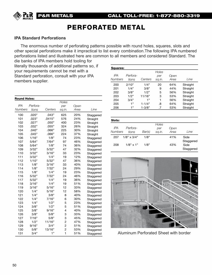
50
P&R METALS CALL TOLL-FREE: 1-877-880-3319P & R M e t a l s , I n c . - 1 - 8 7 7 - 8 8 0 - 3 3 1 9
IPA Standard Perforations
The enormous number of perforating patterns possible with round holes, squares, slots andother special perforations make it impractical to list every combination.The following IPA numberedperforations listed and illustrated here are common to all members and considered Standard. Thedie banks of IPA members hold tooling for literally thousands of additional patterns so, ifyour requirements cannot be met with aStandard perforation, consult with your IPAmembers supplier.
P E R F O R A T E D M E T A LPERFORATED METAL
Round Holes:
Squares:
Slots:
IPA Numbers
Perfora-tions Centers
Holesper
sq.in.OpenArea Line
IPA Numbers
Perfora-tions Centers
Holesper
sq.in.OpenArea Line
IPA Numbers
Perfora-tions Bar(s)
Holesper
sq.in.OpenArea Line
100101102103104105106107108109110111112113114115116117118119120121122123124125126127128129130131
200201202203204205206
209531.8.7
64%44%56%53%56%64%53%
41%
43%
StraightStraightStraightStraightStraightStraightStraight
Side StaggeredSide Staggered
2/10”1/4”3/8”1/2”3/4”
1”1”
1/8” x 3/4”
1/8” x 1”
1/4”3/8”1/2”
11/16”1”
1-1/4”1-3/8”
1/8”
1/8”
207
208
625576400324225224
749774473319473324192419191212
86554332221
20%24%23%26%30%37%23%46%36%32%23%12%36%40%29%23%46%36%51%33%58%40%30%23%51%40%33%45%47%51%53%51%
StaggeredStraight Straight Straight Straight Straight StaggeredStaggeredStaggeredStaggeredStaggeredStaggeredStaggeredStaggeredStaggeredStaggeredStaggeredStaggeredStaggeredStaggeredStaggeredStaggeredStaggeredStaggeredStaggeredStaggeredStaggeredStaggeredStaggeredStaggeredStaggeredStaggered
.020”
.023”
.027”
.032”
.040”
.045”1/16”5/64”5/64”3/32”3/32”3/32”1/10”
1/8”1/8”1/8”
5/32”5/32”3/16”3/16”
1/4”1/4”1/4”1/4”3/8”3/8”3/8”
7/16”1/2”
9/16”5/8”3/4”
.043”.0415”
.050”
.055”
.066”
.066”1/8”
7/64”1/8”
5/32”3/16”
1/4”5/32”3/16”7/32”
1/4”7/32”
1/4”1/4”
5/16”5/16”
3/8”7/16”
1/2”1/2”
9/16”5/8”5/8”
11/16”3/4”
13/16”1” Aluminum Perforated Sheet with border

51
P&R METALS CALL TOLL-FREE: 1-877-880-3319
P & R M e t a l s , I n c . - 1 - 8 7 7 - 8 8 0 - 3 3 1 9
30
Round Holes
PERFORATED METAL

P&R METALS CALL TOLL-FREE: 1-877-880-3319
52
P & R M e t a l s , I n c . - 1 - 8 7 7 - 8 8 0 - 3 3 1 9
Available in woven and welded. Full Rolls, panels, or cut to length
Materials: Plain SteelPre-GalvanizedHot Dipped GalvanizedStainless Steel
Available Square Openings:
WOVENOpening/Mesh Diameter Material
1/2" 0.120 Plain Steel/Stainless
5/8" 0.120 Plain Steel
3/4" 0.120 Plain Steel
1" .120;.135;.250 Plain Steel/Stainless
1-1/2" .120;.135;.250 Plain Steel
1-1/2" 0.120 Stainless Steel
2" .120;.135;.250 Plain Steel
2" .120;.250 Stainless Steel
3" 0.250 Plain Steel
4" 0.250 Plain Steel
1 Mesh .080;.105;.120 Plain Steel
1 Mesh 0.120 Stainless Steel
2 Mesh .063;.120;.135 Plain Steel/Stainless
3 Mesh .063;.105 Plain Steel
3 Mesh .047;.063;.080 Stainless Steel
4 Mesh .063;.080 Plain Steel
4 Mesh .063;.080;.120 Stainless Steel
6 Mesh .047;.063 Plain Steel/Stainless
8 Mesh .047;.063 Plain Steel/Stainless
10 Mesh 0.025 Plain Steel/Stainless
WELDEDOpening Diameter Material
1" x 1" 0.120 Pre-Galv.
1-1/2" x 1-1/2" 0.135 Plain Steel
2" x 2" 0.120 Stainless Steel
2" x 2" 0.250 Plain Steel
2" x 2" 0.105 Pre-Galv.
2" x 2" .100;.125;.188 Galv. After
2-1/2" x 2-1/2" 0.162 Plain Steel
3" 0.250 Plain Steel
3" 0.188 Galv. After
This listing denotes only a small amount of available sizes and materials. For additional information, contact your P & R Metals sales representative.
W I R E M E S H
SPACESpace is the actual “clearopening” or open spacebetween parallel wires.
MESHMesh denotes the numberof openings per linear inch.
WIRE MESH
Woven
Welded

P & R M e t a l s , I n c . - 1 - 8 7 7 - 8 8 0 - 3 3 1 9P&R METALS CALL TOLL-FREE: 1-877-880-3319
Project Pictures
Welded Wire Mesh and Gripstrut® Molded Fiberglass Floor Grating
Aluminum Swaged Locked Gratingused as security fencing
Molded Fiberglass Grating used as fencing
Contact InformationAddress:P & R Metals, Inc.4017 Richard Arrington Blvd. N.Birmingham, aL 35212
Local: 205-328-2290Toll-Free: 1-877-880-3319Fax: 205-328-3394
Monday - Friday7:30A.M. - 5:00 P.M. CST
Phone: Web Address: Business Hours:
About P&R Metals
Custom Fabrication of All Products
P&R Metals is a leading distributor
company was founded in 1999 to provide superior customer satisfaction, service and reliability. We are located in a 26,000 square foot facility in Birming-ham, Alabama. Located next to major interstates, as well as our galvanizers, we are focused on the highest possible
Our team atmosphere is our “secret” to success. From the moment we receive an order, until it arrives at our customer’s site, we
focused on customer satisfaction. Our mission statement is based on common sense principles, “Customer relationships are our foundation. If our customer is in need of service, we will do everything we can to help. Can’t is a word that we avoid at every possible turn. We must take care of our customers or someone else will!” From sales to engineering to production, our employees are motivated and compensated on the fact
-ferent level of service at P&R Metals, because we look forward to serving your needs.
-ing and fabrication services for all the products sold. Products purchased
-tions of your particular task and we are happy to help.
Our fabrication and engineering ser-vices include estimating, detailing, and custom engineering. We can send and receive drawings electronically to expe-dite your order. Our fabrication depart-
ment can cut to length or custom design areas that require piece marks and erection
ship the highest quality order in the least amount of time. After all, your project has
to help.
No request is too big or small. Please feel free to call us with your order requirements.
Table of Contents:
Welded Steel Bar Grating 1
Stair Treads 3
Heavy Duty Steel Grating 4
Safety Grating 6
Ladder Rungs 26
Aluminum Grating 27
SlipNOT® Patented Products 28
Pultruded F’Glass Grating 29
HD Fiberglass Grating 36
Molded Fiberglass Grating 40
EXTREN Fiberglass Series 46
SAFPLANK Plank System 47
Expanded Metal 48
Perforated Metals 50
Wire Mesh 52
“Customer relationships are our foundation. If our customer is in need of service, we will do everything we can to help. Can’t is a word that we avoid at every possible turn. We must take care of our customers or someone else will!”
- James Robinson, President
P&R METALS CALL TOLL-FREE: 1-877-880-3319

P&R Metals, Inc.4017 Richard Arrington Blvd N.Birmingham, AL 35212
Cat. # PR107
GRIP STRUT®
FIBERGLASS GRATING
BAR GRATING
Copyright © 2022 FDOKUMEN