gpes: a general process engineering system
644
GPES: A GENERAL PROCESS ENGINEERING SYSTEM by MOHAMMAD SHARIF ARAB-ISMAILI B.S., Abadan Institute (1971) of Technology SUBMITTED IN PARTIAL FULFILLMENT OF THE REQUIREMENTS FOR THE DEGREE OF DOCTOR OF PHILOSOPHY at the MASSACHUSETTS INSTITUTE OF TECHNOLOGY May 1978 Signature of Author:.A,................................................ Department of Chemical Engineering, May 12, 1978 Certified L.... ..... ........ .... J.H. Porter, Thesis Supervisor Accepted by..j ...........- G.C. Williams, Chairman, Department Committee on Graduate Theses
-
Upload
khangminh22 -
Category
Documents
-
view
0 -
download
0
Transcript of gpes: a general process engineering system
GPES: A GENERAL PROCESS ENGINEERING SYSTEM
by
MOHAMMAD SHARIF ARAB-ISMAILI
B.S., Abadan Institute(1971)
of Technology
SUBMITTED IN PARTIAL FULFILLMENTOF THE REQUIREMENTS FOR THE
DEGREE OF
DOCTOR OF PHILOSOPHY
at the
MASSACHUSETTS INSTITUTE OF TECHNOLOGY
May 1978
Signature of Author:.A,................................................Department of Chemical Engineering, May 12, 1978
Certified L.... ............. ....J.H. Porter, Thesis Supervisor
Accepted by..j ...........-
G.C. Williams, Chairman, Department Committee on Graduate Theses

GPES: A GENERAL PROCESS ENGINEERING SYSTEM
by
Mohammad Sharif Arab-Ismaili
Submitted to the Department of Chemical Engineeringon May 12,1978 in partial fulfillment of the requirements
for the Degree of Doctor of Philosophy
ABSTRACT
The General Process Engineering System (GPES) has been designed as ageneralized framework which can be used to create different kinds of sim-ulation systems for process engineering, each suited to the needs of aparticular set of users. This has been accomplished by having generalizeddata structures represent the elements of a chemical process flowsheet suchas units, streams, components, etc. However, to create a particularsimulation system, one must define these data structures and provide com-puter programs to perform process unit operations. The information setdefining a process element is called a template. Hence a system created byGPES is called a Template Based System (TBS). A language called TemplateDefinition Language (TDL) has been provided to enable the administrator ofthe TBS to -communicate with the system to define templates.
Once a TBS has been implemented (templates have been defined and computa-tional subroutines provided) a process designer may use that system to model,simulate, or design any arbitrary process configuration. A language calledProcess Engineering Language (PEL) has been provided to enable the designerto communicate with the TBS in terms very similar to those he might use todescribe the process to another designer. The system provides the user withsome other advanced features not usually found in other general purposeprocess simulators. It provides an environment wherein the designer and thecomputer can work as partners on the problem solving team, each performingthe job he does best, enhancing the capability of either partner workingalone.
The created systems (TBS's) are not limited to a particular class of pro-cesses. They are open-ended systems which can be easily modified, expan-ded, or updated.
This thesis describes the motivation and design of GPES and demonstrates itsapplication by developing a number of prototype TBS's. The system has beenimplemented in PL/1 on Multics, a time-sharing system by Honeywell.
Thesis Supervisor: James H. PorterLecturer, Department of Chemical Engineering

Department of Chemical EngineeringMassachusetts Institute of TechnologyCambridge, Massachusetts 02139May 12, 1978
Professor George C. Newton, Jr.Secretary of the FacultyMassachusetts Institute of TechnologyCambridge, Massachusetts 02139
Dear Professor Newton:
In accordance with the regulations of the Faculty, I hereby submit atheses entitled "GPES: A General process Engineering System," in partialfulfillment of the requirements for the Degree of Doctor of Philosophy inChemical Engineering at the Massachusetts Institute of Technology.
Respectfully submitted,
Mohammad Sharif Arab-Ismaili
ACKNOWLEDGMENTS
I wish to express my sincerest gratitude to my thesis supervisor,
Professor James H. Porter. His valuable guidance and timely suggestions
deserve appreciation of the highest kind. I am also grateful to
Professor L.B. Evans of the MIT Chemical Engineering Department, to
Professor S.E. Madnick of the MIT Sloan School of Management, and to
Professor W.D. Seider of the University of Pennsylvania, for their help
while serving on the thesis committee.
Acknowledgment is also due to Professor J.F. Louis, and Dr. J. D.
Teare of the MIT Energy Laboratory for their valuable suggestions and
comments concerning this work.
I am grateful to Dr. H. Cohen and Mr. B. Misra for their effort in
testing the system by implementing a prototype TBS for MHD process
studies.
I wish to thank Dollina Borella, Lana Krasner, Patricia Rynne, Alice
Sanderson, and Barbara Thomas for their effort and patience in typing
this manuscript.
Finally, I wish to express my indebtedness to my wife and my mother
who have patiently and lovingly encouraged me throughout my studies.
This work was supported by the MIT Energy Laboratory and the U.S.
Department of Energy.
Mohammad Sharif Arab-IsmailiCambridge, MassachusettsMay 1978
5
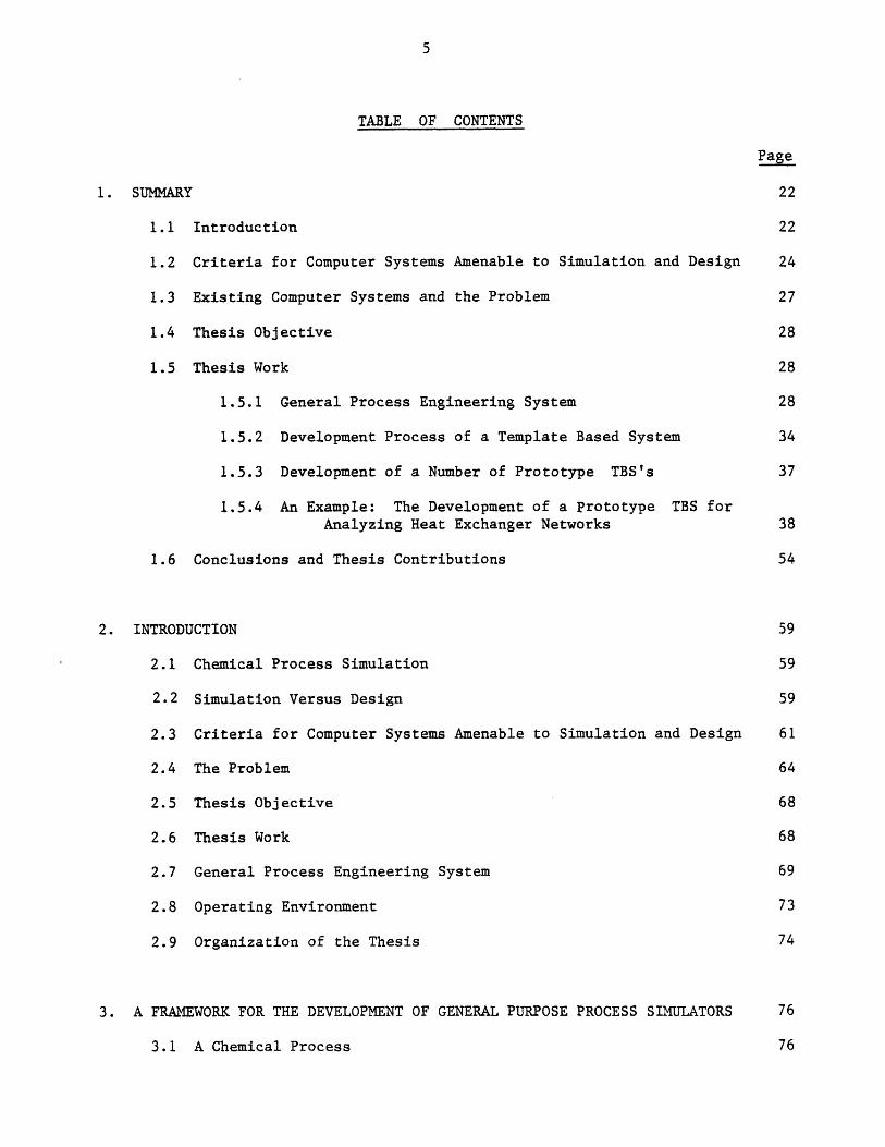
TABLE OF CONTENTS
Page
1. SUMMARY
1.1
1.2
1.3
1.4
1.5
Introduction
Criteria for Computer Systems Amenable to Simulation and Design
Existing Computer Systems and the Problem
Thesis Objective
Thesis Work
1.5.1 General Process Engineering System
1.5.2 Development Process of a Template Based System
1.5.3 Development of a Number of Prototype TBS's
1.5.4 An Example: The Development of a Prototype TBS forAnalyzing Heat Exchanger Networks
1.6 Conclusions and Thesis Contributions
2. INTRODUCTION
2.1 Chemical Process Simulation
2.2 Simulation Versus Design
2.3 Criteria for Computer Systems Amenable to Simulation and Design
2.4 The Problem
2.5 Thesis Objective
2.6 Thesis Work
2.7 General Process Engineering System
2.8 Operating Environment
2.9 Organization of the Thesis
3. A FRAMEWORK FOR THE DEVELOPMENT OF GENERAL PURPOSE PROCESS SIMULATORS 76
3.1 A Chemical Process 76
Page
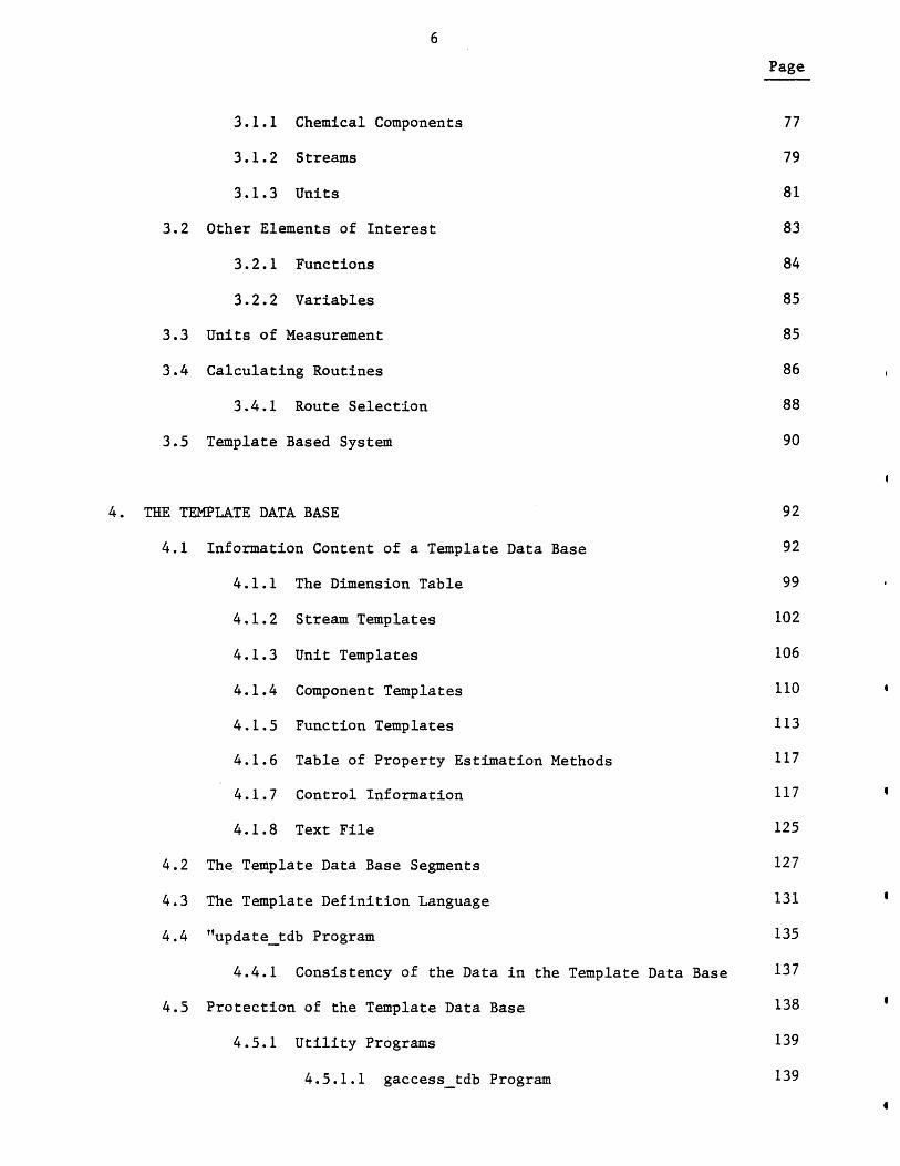
3.1.1 Chemical Components 77
3.1.2 Streams 79
3.1.3 Units 81
3.2 Other Elements of Interest 83
3.2.1 Functions 84
3.2.2 Variables 85
3.3 Units of Measurement 85
3.4 Calculating Routines 86
3.4.1 Route Selection 88
3.5 Template Based System 90
4. THE TEMPLATE DATA BASE 92
4.1 Information Content of a Template Data Base 92
4.1.1 The Dimension Table 99
4.1.2 Stream Templates 102
4.1.3 Unit Templates 106
4.1.4 Component Templates 110
4.1.5 Function Templates 113
4.1.6 Table of Property Estimation Methods 117
4.1.7 Control Information 117
4.1.8 Text File 125
4.2 The Template Data Base Segments 127
4.3 The Template Definition Language 131
4.4 "updatetdb Program 135
4.4.1 Consistency of the Data in the Template Data Base 137
4.5 Protection of the Template Data Base 138
4.5.1 Utility Programs 139
4.5.1.1 gaccesstdb Program 139
Page
4.5.1.2 taccesstdb Program 141
4.5.1.3 copy_tdb Program 142
4.5.1.4 copyseg Program 143
4.5.1.5 deletetdb Program
5. DATA STRUCTURES REPRESENTING A PROCESS FLOWSHEET 144
5.1 Memory Management 144
5.1.1 The Process Directory Data Structure 147
5.2 Data Structures Representing the Process Elements 149
5.2.1 Parameters Structure 149
5.2.2 The Unit Structure 152
5.2.3 The Component Structure 155
5.2.4 The Stream Structure 160
5.2.5 The Pre-Defined Function Structure 162
5.2.6 The User-Defined Function Structure 162
5.2.7 The Variable Structure 169
5.2.8 The Data Structure Containing the PropertyEstimation Methods in Use 169
5.3 Process Files 174
5.4 Component Files 177
6. TBS PROGRAMS 184
6.1 Primary Programs 184
6.1.1 Calculating Routines 184
6.1.2 Pre-Defined Function Evaluation Routines 187
6.2 Secondary Programs 187
6.3 Interaction between TBS Programs and the CPES Executive 187
6.4 Writing a TBS Program 197
Page
6.4.1 Input 197
6.4.2 Output 197
6.4.3 Error Detection 198
6.4.4 Convergence Routines 199
6.4.5 Writing an "all" Calculating Routine 201
6.5 Service Routines 202
7. PROCESS ENGINEERING LANGUAGE -- BASIC PRINCIPLES 212
7.1 Basic Concepts of PEL 212
7.1.1 Command Objects 212
7.1.2 Process Files 218
7.1.3 Component Files 218
7.1.4 Property Estimation Methods 218
7.1.5 Units of Measurement 220
7.1.6 Profile Parameters 220
7.1.7 Arithmetic Expressions 220
7.1.8 Command Elements 221
7.2 Classification of Commands 222
7.2.1 Configuration Commands 222
7.2.2 Value Assignment Commands 223
7.2.3 Output Commands 224
7.2.4 Input Commands 224
7.2.5 Clearing and Switching Commands 225
7.2.6 Commands for Component Files 225
7.2.7 Commands for Process Files 226
7.2.8 Continue Command 226
7.2.9 Iterative Commands 226
7.3 Using a TBS
7.4 Using the System
7.5 PEL Messages
7.5.1 Information Messages
7.5.2 Requesting Messages
7.5.3 Warning Messages
7.5.3.1 Informatory Warning Messages
7.5.3.2 Severe Warning Messages
7.5.4 Error Messages
7.5.4.1 Informatory Error Messages
7.5.4.2 Severe Error Messages
7.5.4.3 Calculate Error Messages
7.5.5 System Messages
7.5.5.1 Informatory System Messages
7.5.5.2 Severe System Messages
8. GPES ADMINISTRATION AND PROTECTION
8.1 The GPES Text File
8.2 The TBS Table
8.3 The Users Table
8.4 Various Copies of GPES Files
8.5 The GPES Organization
9. THE GPES EXECUTIVE
9.1 The Program Structure
9.2 Lexical Analysis Phase
9.3 Command Recognition Phase
9.4 Syntax Analysis Phase
Page
228
228
230
231
231
231
233
233
233
233
236
236
236
237
237
238
238
239
244
249
252
256
260
264
268
270
Page
9.4.1 Intermediate Form of Arithmetic Expressions 275
9.4.2 Intermediate Forms of Commands 292
9.5 Execution Phase 307
10. EXERCISE IN THE DEVELOPMENT OF TEMPLATE-BASED SYSTEMS 308
10.1 Development Process of a Template-Based System 309
10.2 Development of a Prototype TBS for Analyzing Heat ExchangerNetworks 312
10.3 A Prototype TBS for Hydrocarbon Processes 330
10.4 A Prototype TBS for Magnetohydrodynamic Processes 359
11. RECOMMENDATIONS AND CONCLUSIONS 364
11.1 Recommendations 364
11.2 Conclusions and Thesis Contributions 371
APPENDIX A: STATE OF THE ART 376
A.1 Structure of the Programs 381
A.2 Input Methods 383
A.3 Data Checking 383
A.4 The Storage of Data 383
A.5 Operating Modes 384
A.6 Available Unit Models 384
A.7 Physical Property Determination 384
A.8 Convergence Acceleration 384
APPENDIX B: TEMPLATE DEFINITION LANGUAGE 386
Reserved Words in TDL 386
Program interrupt 389
Page
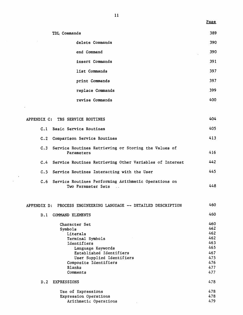
TDL Commands 389
delete Commands 390
end Command 390
insert Commands 391
list Commands 397
print Commands 397
replace Commands 399
revise Commands 400
APPENDIX C: TBS SERVICE ROUTINES 404
C.1 Basic Service Routines 405
C.2 Comparison Service Routines 413
C.3 Service Routines Retrieving or Storing the Values ofParameters 416
C.4 Service Routines Retrieving Other Variables of Interest 442
C.5 Service Routines Interacting with the User 445
C.6 Service Routines Performing Arithmetic Operations onTwo Parameter Sets . 448
APPENDIX D: PROCESS ENGINEERING LANGUAGE -- DETAILED DESCRIPTION 460
D.1 COMMAND ELEMENTS 460
Character Set 460Symbols 462
Literals 462Terminal Symbols 462Identifiers 463
Language Keywords 465Established Identifiers 467User Supplied Identifiers 475
Composite Identifiers 476Blanks 477Comments 477
D.2 EXPRESSIONS 478
Use of Expressions 478Expression Operations 478
Arithmetic Operations 479

Page
Boolean Operations 479Comparison Operations 480Combination of Operations 480
Priority of Operators 482Operands of an Expression 483
D.3 FUNCTIONS 484
Pre-defined Functions 484User-Defined Functions 485Built-In Functions 486
D.4 SEMI-FORMAL DEFINITION OF PEL SYNTAX 492
D.5 PEL COMMANDS 509
assume commands 509bugs command 509calculate commands 510clear command 514close command 514connect command 515continue command 517copy commands 517create commands 518delete commands 521deletef commands 524disconnect command 525end command 526escape command 526help command 526include command 528leave command 528let commands 529leta commands 533list commands 533listf commands 535listt commands 536load commands 536loop command 538news command 539open commands 539print commands 541printf commands 547printt commands 548profile command 549read commands 553reada commands 558repeat command 558save commands 565specify commands 566stop command 570terminate command 571unspecify commands 572use command 576
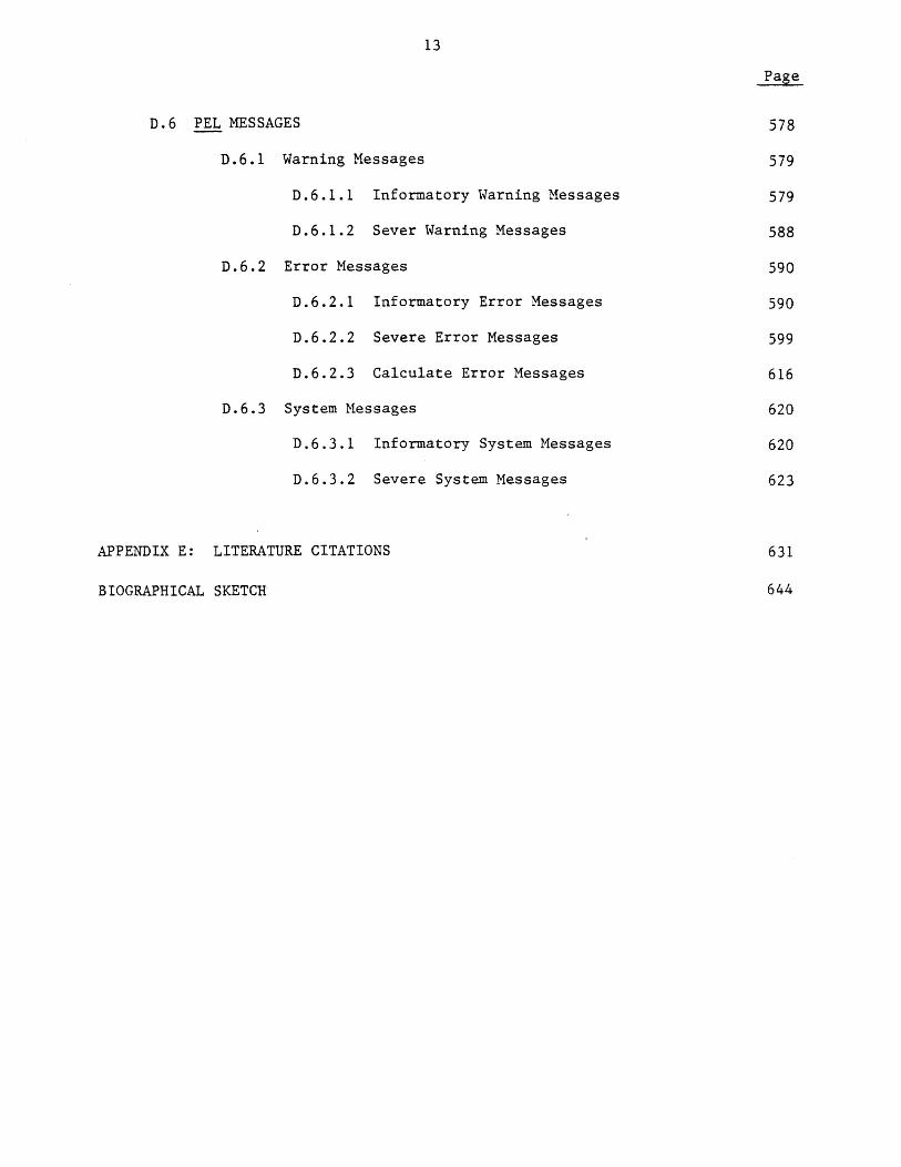
D.6 PEL MESSAGES
D.6.1 Warning Messages
D.6.1.1 Informatory Warning Messages
D.6.1.2 Sever Warning Messages
D.6.2 Error Messages
D.6.2.1 Informatory Error Messages
D.6.2.2 Severe Error Messages
D.6.2.3 Calculate Error Messages
D.6.3 System Messages
D.6.3.1 Informatory System Messages
D.6.3.2 Severe System Messages
APPENDIX E: LITERATURE CITATIONS
BIOGRAPHICAL SKETCH
Page
578
579
579
588
590
590
599
616
620
620
623
631
644
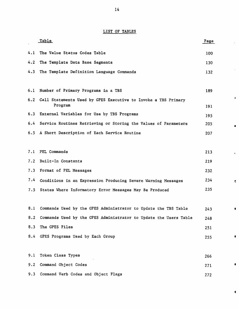
LIST OF TABLES
Table Page
4.1 The Value Status Codes Table 100
4.2 The Template Data Base Segments 130
4.3 The Template Definition Language Commands 132
6.1 Number of Primary Programs in a TBS 189
6.2 Call Statements Used by GPES Executive to Invoke a TBS PrimaryProgram 191
6.3 External Variables for Use by TBS Programs 195
6.4 Service Routines Retrieving or Storing the Values of Parameters 205
6.5 A Short Description of Each Service Routine 207
7.1 PEL Commands 213
7.2 Built-In Constants 219
7.3 Format of PEL Messages 232
7.4 Conditions in an Expression Producing Severe Warning Messages 234
7.5 States Where Informatory Error Messages May Be Produced 235
8.1 Commands Used by the GPES Administrator to Update the TBS Table 243
8.2 Commands Used by the GPES Administrator to Update the Users Table 248
8.3 The GPES Files 251
8.4 GPES Programs Used by Each Group 255
9.1 Token Class Types 266
9.2 Command Object Codes 271
9.3 Command Verb Codes and Object Flags 272
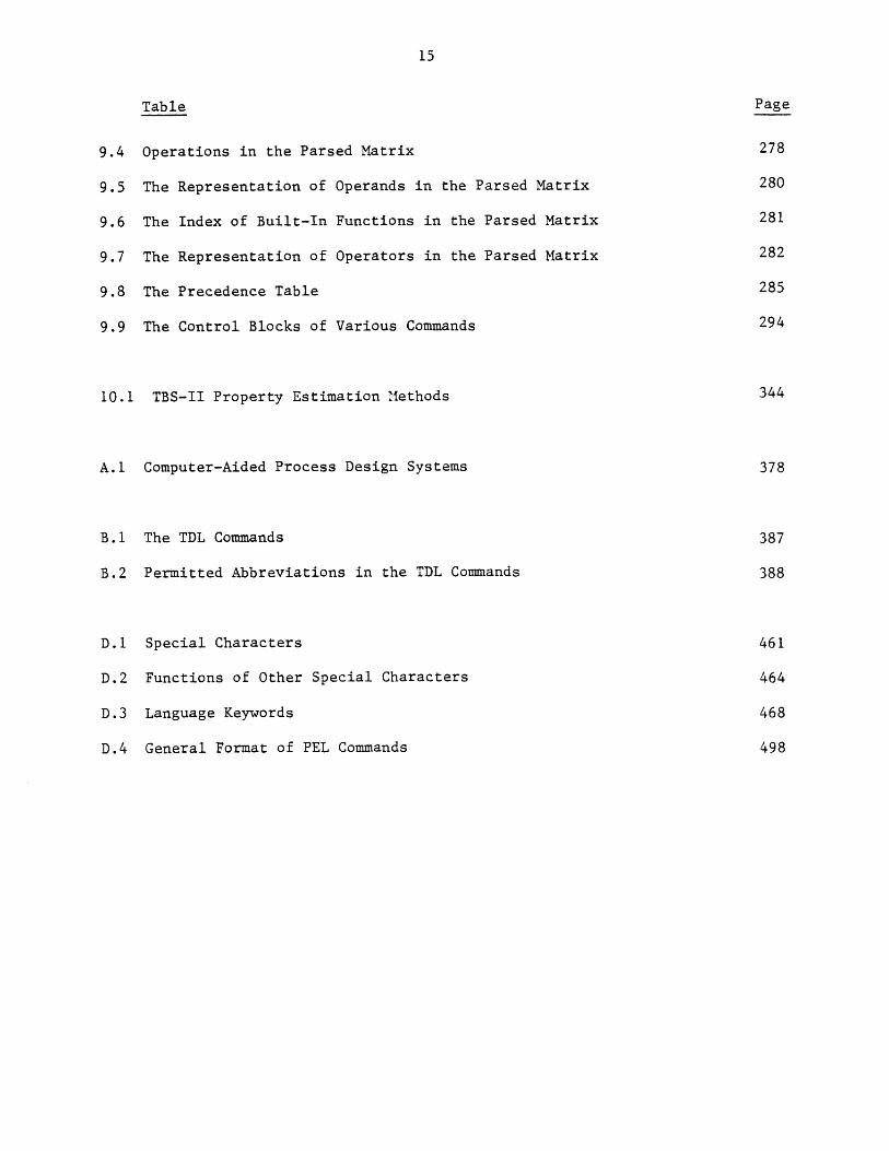
Table Page
9.4 Operations in the Parsed Matrix 278
9.5 The Representation of Operands in the Parsed Matrix 280
9.6 The Index of Built-In Functions in the Parsed Matrix 281
9.7 The Representation of Operators in the Parsed Matrix 282
9.8 The Precedence Table 285
9.9 The Control Blocks of Various Commands 294
10.1 TBS-II Property Estimation Methods 344
A.1 Computer-Aided Process Design Systems 378
B.1 The TDL Commands 387
B.2 Permitted Abbreviations in the TDL Commands 388
D.1 Special Characters 461
D.2 Functions of Other Special Characters 464
D.3 Language Keywords 468
D.4 General Format of PEL Commands 498
LIST OF FIGURES
1.1 The Hierarchical Structure of GPES Usage
1.2 Use of the GPES
1.3 The Development Process of a TBS
1.4 Heat Exchangers TBS -- Countercurrent Ex
1.5 Heat Exchangers TBS -- Mixer Model
1.6 Heat Exchangers TBS -- Divider Model
1.7 Heat Exchangers TBS -- Unit Coniergence
1.8 Heat Exchangers TBS -- Printout of Some
1.9 Heat Exchangers TBS -- Heatex Calculatin
1.10 Heat Exchangers TBS -- The Process Flow
1.11 Heat Exchangers TBS -- A PEL Computer S
1.12 Heat Exchangers TBS -- Another PEL CompExample Case
1.13 Heat Exchangers TBS -- Adjuster Model
3.1 An Example of Routing Problem
4.1
4.2
4.3
4.4
4.5
4.6
4.7
4.8
The Parameter Template Structure
The Parameter Value Status Structure
The Dimension Table Structure
An Example of a Dimension Table
The Stream Template Structures
An Example of a Stream Template
The Unit Template Structures
An Example of a Unit Template
Figure Page
94
98
101
103
104
107
108
.111
:hanger Model
Model
remplates
g Routine
sheet for the Example Case
ession for the Example Case
iter Session for the
Figure Page
4.9 The Component Template Structures 112
4.10 An Example of a Component Template 114
4.11 The Function Template Structures 115
4.12 An Example of a Function Template 118
4.13 The Property Estimation Methods Table Structure 119
4.14 An Example of a Property Estimation Methods Table 120
4.15 The Control Information Structure 121
4.16 An Example of a Control Information 126
4.17 Format of the Text File 128
4.18 An Example of a Text File 129
4.19 The Flow Chart for updatetdb Program 136
4.20 Information Flow Regarding the Template Data Base 140
5.1 The Process Directory Data Structure 148
5.2 An Example of a Process Directory Data Structure 150
5.3 The Parameters Structure 151
5.4 The Unit Structure 1535.5 An Example of a Unit Structure 1565.6 The Component Directory Structure 157
5.7 An Example of a Component Directory 159
5.8 The Stream Structure 161
5.9a An Example of a Stream Structure with No Components 163
5.9b An Example of a Stream Structure with Some Components 164
5.10 The Pre-Defined Function Structure 165
5.11 An Example of a Pre-Defined Structure 166
5.12 The User-Defined Function Structure 167
5.13 An Example of a User-Defined Function Structure 170
Figure Page
5.14 The Variable Structure 171
5.15 An Example of a Variable Structure 172
5.16 The Data Structure for Property Estimation Methods in Use 173
5.17 An Example of the Data Structure for Property EstimationMethods in Use 175
5.18 The Directory of a Process File 176
5.19 An Example of a Process File 178
5.20 The Component File Structure 180
5.21 The Structure of a Component in the Component File 181
5.22 An Example of a Component File 183
6.1 The Interaction between the GPES Executive and TBS Programs 185
6.2 Classification of TBS Programs 188
6.3 The Arguments Structure 193
6.4 Interaction between GPES Executive, a Unit Calculating Routine,and Service Routines 194
6.5 Classification of Service Routines Retrieving or Storing theValues of Parameters 203
8.1 Format of the GPES Text File 240
8.2 The TBS Table 241
8.3 TBS Registration Form 245
8.4 The Users Table 246
8.5 GPES User Registration Form 250
8.6 Information Flow Regarding GPES Files 253
8.7 The Hierarchical Structure of GPES Usage 254
9.1 The Flow Chart for System Initialization Phase 257

Figure Page
9.2 The Flow Chart for TBS Attachment Phase 258
9.3 The Flow Chart for Process Initialization Phase 259
9.4 The Layout of the "pel" Program 262
9.5 The Token Table 265
9.6 An Example to Demonstrate the Function of Lexical Analysis Phase 269
9.7 The Flow Chart for Command Recognition Phase 274
9.8 The Parsed Matrix Structure 276
9.9 An Example of a Parsed Matrix 283
9.10 The Stack Used in Parsing the Expressions 286
9.11 The Parser Algorithm 287
9.12 The Command Header Structure 293
9.13 The Cblock Structure 295
9.14 The Cblockl Structure 297
9.15 The Cblock2 Structure 298
9.16 The Cblock3 Structure 299
9.17 The Cblock4 Structure 301
9.18 The Cblock5 Structure 303
9.19 The Cblock6 Structure 304
9.20 The Cblock7 Structure 305
10.1 Development Process of a Template-Based System 310
10.2 Heat Exchangers TBS -- Countercurrent Exchanger Model 314
10.3 Heat Exchangers TBS -- Mixer Model 315
10.4 Heat Exchangers TBS -- Divider Model 316
10.5 Heat Exchangers TBS -- Unit Convergence Model 318
10.6 Heat Exchangers TBS -- Printout of Some Templates 320
Figure
10.7 Heat Exchangers TBS -- Heatex Calculating Routine
10.8 Heat Exchangers TBS -- Process Flowsheet for the Example Case
10.9 Heat Exchangers TBS -- A PEL Computer Session for the ExampleCase
10.10 Heat Exchangers TBS -- Another PEL Computer Session for theExample Case
10.11 Heat Exchangers TBS -- Adjuster Model
10.12 Heat Exchangers TBS -- Inserting a Template
10.13 TBS-II -- Templates for Control Information, Dimension Table,and Property Estimation Methods Table
10.14 TBS-II -- Stream Template
10.15 T-BS-II -- Component and Function Templates
10.16 TBS-II -- Isothermal Flash Unit Template
10.17 TBS-II -- Calculating Routines for Stream and Isothermal FlashUnit
10.18 TBS-II -- Distillation Unit Template
10.19 TBS-II -- Function Calculating and Evaluating Routines
10.20a TBS-II -- Process Flowsheet for the Example Case
10.20b TBS-II -- Computational Flowsheet for the Example Case
10.21 TBS-II -- A PEL Computer Session for the Example Case
10.22 TBS-II -- Another PEL Computer Session for the Example Case
10.23 MHD TBS -- Process Flowsheet of an Open Cycle MHD Topped Plant
10.24 MHD TBS -- A PEL Computer Session for the Example Case
10.25 MHD TBS -- Another PEL ComDuter Session for the Examle Case
C.1 Examples of the Use of Service Routines Related to Unit DataStructures
C.2 Examples of the Use of Service Routines Related to ComponentData Structures
Page
322
324
325
326
328
329
331
333
335
337
338
341
348
349
349
351
355
360
362
363
407
408
Figure Page
C.3 Examples of the Use of Service Routines Related to Function Data
Structures 411
C.4 Examples of the Use of Service Routines Related to Stream Data
Structures 412
C.5 Examples of the Use of Service Routines Related to Flow Parameters 414
C.6 Examples of the Use of Service Routines Directly Retrieving or
Storing the Values of Parameters 418
C.7 Example of the Use of the Service Routine Retrieving the Arguments 444
C.8 Example of the Use of the Service Routine Retrieving the PropertyEstimation Methods in Use 444
C.9 Examples of the Use of Service Routines Performing Arithmetic
Operations on Two Parameter Sets 450
C.10 Examples of the Use of Service Routines Performing Arithmetic
Operations on Flow Parameters of Two Streams 455
CHAPTER 1
SUMMARY
1.1 Introduction
Since the advent of large scale computers workers in almost every
professional discipline have attempted, in some degree, to formalize their
rules and analysis procedures to enhance the effectiveness of computers
within their discipline. For many professions, a large class of problems
exist which we shall call network analysis problems. These networks are
characterized by streams which transport items obeying the general laws of
conservation (i.e. Rate of Input - Rate of Output + Rate of Production -
Rate of Depletion = Rate of Accumulation) and by process units, which
collect these items from in-flowing streams and redistribute the items to
out-flowing streams. The rules that govern the proportion and rate of
distribution of each item type are usually defined as the Scienge of that
discipline.
Thus, in electrical engineering for instance, coulombs are conserved
and capacitors, resistors, conductor elements, etc. are process units in
electrical networks. Raw materials, finished goods, dollars are conserved
items and factories are process units in economic networks. Mass ofS
chemical species, energy and momentum are conserved items and distillation
columns, heat exchangers, pumps, etc. are process units in chemical process
networks. It is possible to continue almost indefinitely in this manner,
cataloging networks of single disciplines or combined networks of
multidisciplines.
Two questions are normally asked concerning networks. The first
question is, given a specified network, how will it respond under given
perturbations in stream item flows or in process unit parameters which
govern the distribution proportion or rate? This is normally called the
simulation problem. It is characterized as the analysis of fixed network
modules in a fixed configuration. Much time has been devoted to developing
procedures or methodology for solving problems of this type. The results
of these efforts have led to rules to govern simulation procedures. These
rules have been incorporated into computer systems which we shall classify
as General .urnose Process Simulators. Many such simulators are in
existence and they have characteristically required tens of man-years to
implement.
The second question normally asked concerning networks is, given a
specified response of items in out-flowing streams from the network and
given specified constraints on the parameters of process units or streams
within the network, which network will behave in the desired manner? This
is called the design problem. The design problem may have many solutions
but as the number of constraints on the system behavior is increased, the
number of solutions is diminished until there may be no solutions. These
problems are characterized by the fact that in arriving at a solution not
only the process units must be selected, but their configuration within the
overall process must also be chosen. Methodology for selecting process
units and units arrangement is not yet formalized although efforts have
been devoted to developing General.Purpose Process Synthesizers since the
early 1970's. At present computer aided design systems must include man in
the loop to carry out the important task of process unit selection and
arrangement to accomplish a stated objective. It has not yet been
established that these "creative" aspects of design, much of which are
developed through experience (design know-how), can be formalized to the
extent that they can be incorporated in a computer system which would
eliminate man from the loop. Serious doubts are entertained as to whether
this accomplishment is at all possible without subjecting the
computer to the impossible task of analyzing the doubly infinite set of
considering all possible process unit selections and configurations. Thus,
the current procedure to solve design problems is for man to propose the
process unit selection and arrangement, use a General Purpose Simulator to
analyze the proposed network, and then compare the proposed network's
response to the desired response and alter either network configuration or
process unit selection, or both, until a network is developed with the
desired characteristics. The process of design is necessarily iterative,
and having arrived at a solution one is usually not certain that other
solutions do not exist.
Considering the iterative nature of design problems, a general purpose
simulator to be effective as a design tool must use a mode of operation,
methods of input and calculation techniques that minimize the effort
required for designer-computer communication, so as to maximize effective
interaction between the designer and the computer. The time scale is
important in process design.
These characteristics not only enable the simulator to provide the
design atmosphere for process designers, but they also enhance the
capability and effectiveness of the system as a tool for simulation.
1.2 Criteria for Computer Systems Amenable to Simulation and Design
There are two basic modes of computer operation: the off-line batch
processing mode and the on-line interactive processing mode.
On-line processing enables the designer to speed up the design
process. However, replacing the batch mode by the interactive mode is not
sufficient. The interface between the human mind and the computer must
also be modified to make the job easier for the designer, as discussed by
Porter (133]. The essence of his discussion is that "it is necessary to
create an atmosphere wherein the design team and the computer as an added
partner are able to rapidly evaluate the effects of equipment arrangement
and process variable selection in chemical process design".
The basic question is, "How does the designer communicate with and
maintain control over the computer?" This is the area where most automated
design systems are inefficient. The designer is required to prepare some
sort of input forms specifying the process configuration, the operating
conditions of the units and the thermodynamic states of the streams. After
the input is fed, the computer takes over complete control and arrives at a
solution. Such a system is not very conductive to creative design. The
environment of process design is much more dynamic. A designer rarely
knows the entire plant configuation at the outset of a design. The
flowsheet is more likely to evolve from an initial concept to a final
design after various perturbations of the initial concept. He must have
more contact with and greater control over the computer. He must be
allowed to specify what the computer should do at each stage of the design
and receive feedback in terms of the intermediate results so that he can
decide upon the next action to be taken by the computer.
One method of achieving this interaction is to provide a process
design language which is more "natural" to the designer and can be
interpreted by the computer. The language must be such that he can
describe flowsheet structure, request unit calculations, provide input,
request output and have the computer carry out other instructions. Thus,
he may solve a full flowsheet or any of its parts that he desires. He
should also be able to change the flowsheet structure easily without
respecifying the whole flowsheet.
The language should permit choice of engineering units for input data
to speed up the man-machine communication. The language should accept
arithmetic expressions where numerical data are expected. The user should
have access to every piece of information about the process network and be
able to refer to them in arithmetic expressions. In this way the user can
relate different items of information about the process flowsheet. The
system should allow the repetitive execution of a group of commands to
enhance the designer's iterative search. The system should allow the user
to save the results of one analysis in a file to be used as input for
further analysis. This will save both the designer and the computer time
in not having to reinitiate the problem.
To perform process engineering effectively, the engineering data
necessary for design must be available. The computer can assist
engineers in analyzing, estimating, and retrieving these data. However, it
is not efficient to have many individual computer-aided systems for
simulation, design, physical property estimation, analyzing laboratory data
and so on. Therefore, such systems should be organized into an integrated
system with a common data base, so that the consistency of these data is
maintained throughout the various stages of process engineering.
The description of a flowsheet should be independent of the programs
for analysis. The same description should serve all analysis for which
that flowsheet is applicable. For example, it should be suitable for
steady state simulation, equipment sizing, and economic evaluation, as
noted by Evans and SiederC33] who discuss the requirements of an advanced
computer system which will be needed to solve the process engineering
problems of the 1980's. Such a system must be extendable and capable of
modification. It should be easy to add new types of process units, to
define new types of streams, species, etc. Hence, the system can be
expanded to analyze new types of processes. The inability of existing
systems to analyze new energy conversion processes such as the
magnetohydrodynamics (MHD) process has been due to the lack of this feature
in these systems.
1.3 The Problem
Despite the considerable effort expended by the chemical and petroleum
companies on development of computer-aided design programs, the process
engineering profession still lacks the computing tools needed by process
designers. The existing systems don't meet the criteria discussed earlier.
Hence, they don't provide the design atmosphere for process engineers. On
the other hand, existing systems are only applicable to those process
flowsheets having conventional vapor-liquid streams. This inflexibility
makes it either impossible or very difficult to expand present-day systems
to include other types of processes such as coal processing systems.
The difficulties may be traced to the following characteristics of
existing programs:
a. They are not interactive.
b. They are not integrated.
c. They do not provide a natural problem oriented languge.
d. They do not have the capability of dynamic modification of theprocess network.
e. They do not have the capability of storing the output model forfuture study.
f. They are mostly developed for simulation, not for design.
g. They are not flexible.
1.4 Thesis Obiective
The objective of the thesis was to develop a framework for the
development of general purpose process simulators that:
a) are applicable to all types of chemical processes,
b) are more adaptable to the design environment.
1.5 Thesis Work
A general framework for modeling of chemical processes has been found
and based upon this framework, a computer system called General Process
Engineering System (GPES) has been designed and implemented. GPES allows
any group or organization to create its own computer aided design system
for engineering of chemical processes. These systems will not have the
shortcomings of existing systems that were discussed earlier. These
systems could be very simple or very sophisticated depending on the
particular needs and applications of the group or organization. Such
systems meet the criteria discussed earlier and therefore, provide the
design atmosphere for process designers. These systems are not limited to
analyzing process flowsheets having only conventional vapor-liquid streams.
They are applicable for analyzing any type of process flowsheet including
energy conversion porcesses such as coal gasification and MHD. Such
systems could easily be modified, expanded, and updated. This thesis
describes the design and application of GPES. Using GPES several prototype
computer aided design systems have been created to demonstrate the
application and use of GPES and systems created by GPES.
1.5.1 General Process Engineering System
GPES is a computer system which enables the rapid production of user
oriented computer aided design systems for engineering of chemical
processes. In using GPES to create a computer aided design system, one has
to define different types of process elements (process units, streams,
etc.) which may be present in the flowsheets to be analyzed or designed by
the users of that system. The subroutines performing the computations for
these elements (process moduels, etc.) must also be provided.
The different types of process elements are defined by providing an
information set for each of them. Each such an information set is called a
template in GPES terminology. For example a template for a specific type
of a process unit contains such information as the number of inlet and
outlet streams, number of unit parameters, etc. Thus, a system created by
GPES is called a Template Based System (TBS). The templates for each TBS
reside on a set of files called template data base. Hence, the creation of
a TBS consists of creation of a Template Data Base and development of a
package of subroutines, mainly to represent the mathematical models of
process units defined in that template data base. These subroutines are
called TBS programs.
Each TBS is the responsibility of a system administrator. A TBS
administrator may be assisted by a group of programmers for development of
TBS programs. This group is known as TBS programmers. Once a TBS has been
implemented (Templates have been defined and computational subroutines
provided) a process designer (user) may use it to analyze any arbitarary
specified configuraton of process units which are already defined in that
TBS.
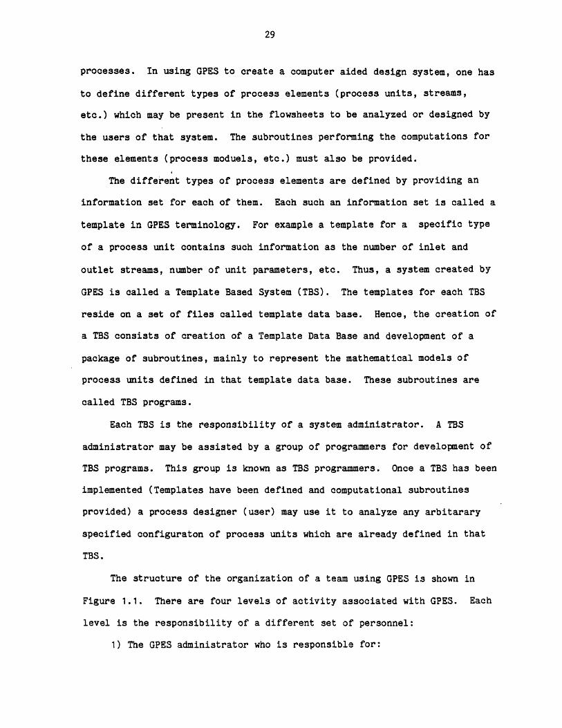
The structure of the organization of a team using GPES is shown in
Figure 1.1. There are four levels of activity associated with GPES. Each
level is the responsibility of a different set of personnel:
1) The GPES administrator who is responsible for:
USER
FIGURE 1.1 THE HIERARCHICAL STRUCTURE OFGPES USACE
USER
a) Maintenance of the GPES.
b) Protecting the system from unauthorized TBS administrators.
c) Protecing each TBS from Unauthorized users.
2) TBS administrators.
They are responsible for:
a) Implementation and maintenance of Template Based Systems.
b) Coordination of TBS Programmers.
c) Permitting a user to use a TBS.
3) TBS programmers.
They are responsible for development of TBS programs. A TBS may
contain the following programs:
a) Routines performing calculations for individual process
units (process modules).
b) Physical and thermodynamic property estimation routines.
c) Regression analysis programs.
d) Other programs which may be required for a particular TBS.
4) Users.
They are the ultimate users of the Template Based Systems, the
designers of chemical processes. A user may have access to one
or more of these systems.
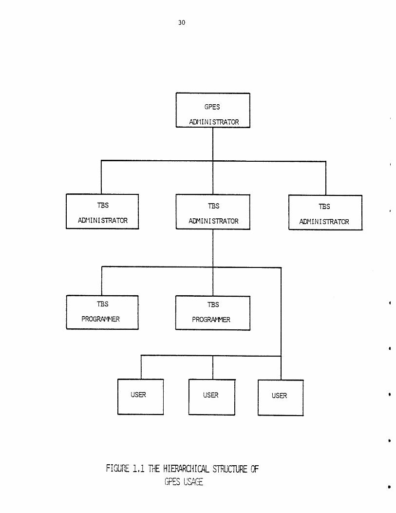
For each of these groups a set of tools and mechanisms (programs and
languages used to communicate with those programs) has been developed to
assist them in performing their responsibilities. GPES consists of these
tools. The use of the system is shown in Figure 1.2.
A TBS Administrator creates and manipulates his template data base by
an interactive program called "updatetdb". A language called lemplate
Pefinition Language (TDL) has been provided to enable him to easily
communicate with the "update_tdb" program to define his templates.
I12
TRINAL
TBS A
PROGRATIERS
TIS B
PROGRAMMERS
FIGUPE 1.2 USE OF GPES
TERM I NAL TERMINALTERM IINAL
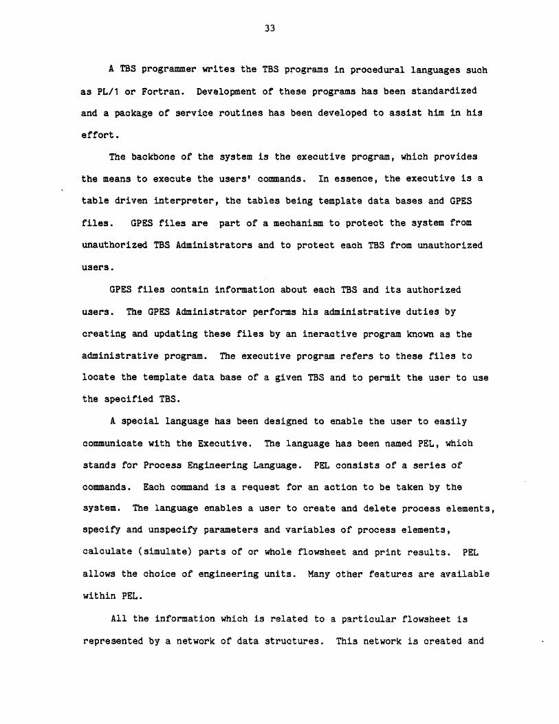
A TBS programmer writes the TBS programs in procedural languages such
as PL/1 or Fortran. Development of these programs has been standardized
and a package of service routines has been developed to assist him in his
effort.
The backbone of the system is the executive program, which provides
the means to execute the users' commands. In essence, the executive is a
table driven interpreter, the tables being template data bases and GPES
files. GPES files are part of a mechanism to protect the system from
unauthorized TBS Administrators and to protect each TBS from unauthorized
users.
GPES files contain information about each TBS and its authorized
users. The GPES Administrator performs his administrative duties by
creating and updating these files by an ineractive program known as the
administrative program. The executive program refers to these files to
locate the template data base of a given TBS and to permit the user to use
the specified TBS.
A special language has been designed to enable the user to easily
communicate with the Executive. The language has been named PEL, which
stands for Process Engineering Language. PEL consists of a series of
commands. Each command is a request for an action to be taken by the
system. The language enables a user to create and delete process elements,
specify and unspecify parameters and variables of process elements,
calculate (simulate) parts of or whole flowsheet and print results. PEL
allows the choice of engineering units. Many other features are available
within PEL.
All the information which is related to a particular flowsheet is
represented by a network of data structures. This network is created and

manipulated by the Executive Program in response to the user commands.
Changes in the flowsheet structure are reflected by changes in the network
structure, as the initial concept of the design evolves into a final
concept.
This network is located in an area of storage known as the working
area. The working area automatically expands as the need for more space is
recognized. Hence, there is no limitation on the size of the flowsheet
being analyzed. The user can save this network in a file and later,
retrieve it for further analysis.
This type of file is known as a process file. A user may have any
number of process files each of which may contain any number of processes.
The Executive Program creates and manipulates these files in response to
the user's commands. The users may share their process files. This will
promote team work on design and analysis of large process flowsheets. A
user may also have any number of another type of file known as component
files. A component file may contain the physical properties or constants
for estimating these properties for any number of chemical components. The
Executive Program also creates and manipulates these files in response to
the user's commands. Hence, the user may not be explicitly concerned about
the creation and maintenance of these files, outside the program. The
users may also share their component files. A TBS administrator may create
such files and make them accessable to all users of that TBS. Such files
are known as public component files.
1.5.2 Development Process of a Template Based System
Development process of a TBS in general is shown in Figure 1.3. It
consists of the following phases:

EXTERNALFACTORS
FACTORS
DEVELOPMENT PROCESS OF A TBSFIGURE 1. 3
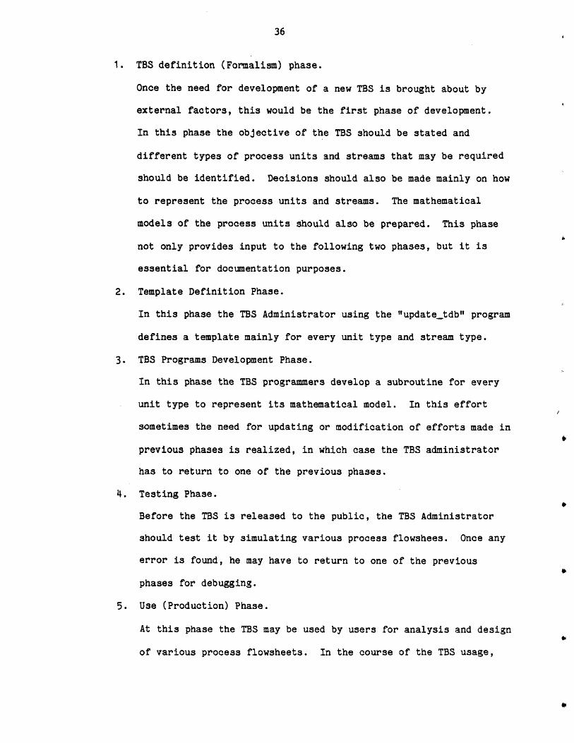
1. TBS definition (Formalism) phase.
Once the need for development of a new TBS is brought about by
external factors, this would be the first phase of development.
In this phase the objective of the TBS should be stated and
different types of process units and streams that may be required
should be identified. Decisions should also be made mainly on how
to represent the process units and streams. The mathematical
models of the process units should also be prepared. This phase
not only provides input to the following two phases, but it is
essential for documentation purposes.
2. Template Definition Phase.
In this phase the TBS Administrator using the "updatetdb" program
defines a template mainly for every unit type and stream type.
3. TBS Programs Development Phase.
In this phase the TBS programmers develop a subroutine for every
unit type to represent its mathematical model. In this effort
sometimes the need for updating or modification of efforts made in
previous phases is realized, in which case the TBS administrator
has to return to one of the previous phases.
4. Testing Phase.
Before the TBS is released to the public, the TBS Administrator
should test it by simulating various process flowshees. Once any
error is found, he may have to return to one of the previous
phases for debugging.
5. Use (Production) Phase.
At this phase the TBS may be used by users for analysis and design
of various process flowsheets. In the course of the TBS usage,
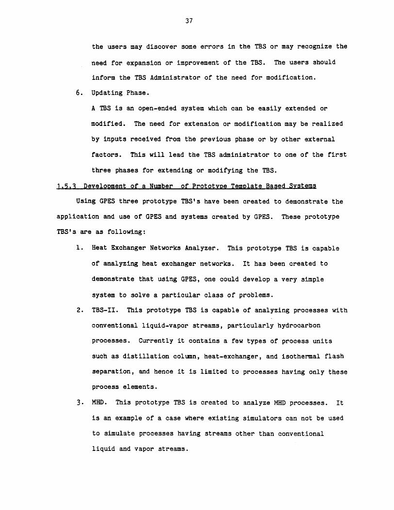
the users may discover some errors in the TBS or may recognize the
need for expansion or improvement of the TBS. The users should
inform the TBS Administrator of the need for modification.
6. Updating Phase.
A TBS is an open-ended system which can be easily extended or
modified. The need for extension or modification may be realized
by inputs received from the previous phase or by other external
factors. This will lead the TBS administrator to one of the first
three phases for extending or modifying the TBS.
1.5.3 Develooment of a Number of Prototvoe Temolate Based Systems
Using GPES three prototype TBS's have been created to demonstrate the
application and use of GPES and systems created by GPES. These prototype
TBS's are as following:
1. Heat Exchanger Networks Analyzer. This prototype TBS is capable
of analyzing heat exchanger networks. It has been created to
demonstrate that using GPES, one could develop a very simple
system to solve a particular class of problems.
2. TBS-II. This prototype TBS is capable of analyzing processes with
conventional liquid-vapor streams, particularly hydrocarbon
processes. Currently it contains a few types of process units
such as distillation column, heat-exchanger, and isothermal flash
separation, and hence it is limited to processes having only these
process elements.
3. MHD. This prototype TBS is created to analyze MHD processes. It
is an example of a case where existing simulators can not be used
to simulate processes having streams other than conventional
liquid and vapor streams.
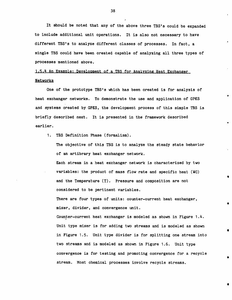
It should be noted that any of the above three TBS's could be expanded
to include additional unit operations. It is also not necessary to have
different TBS's to analyze different classes of processes. In fact, a
single TBS could have been created capable of analyzing all three types of
processes mentioned above.
1.5.4 An Example: Development of a TBS for Analyzing Heat Exchanger
Networks
One of the prototype TBS's which has been created is for analysis of
heat exchanger networks. To demonstrate the use and application of GPES
and systems created by GPES, the development process of this simple TBS is
briefly described next. It is presented in the framework described
earlier.
1. TBS Definition Phase (formalism).
The objective of this TBS is to analyze the steady state behavior
of an artibrary heat exchanger network.
Each stream in a heat exchanger network is characterized by two
variables: the product of mass flow rate and specific heat (WC)
and the Temperature (T). Pressure and composition are not
considered to be pertinent variables.
There are four types of units: counter-current heat exchanger,
mixer, divider, and convergence unit.
Counter-current heat exchanger is modeled as shown in Figure 1.4.
Unit type mixer is for adding two streams and is modeled as shown
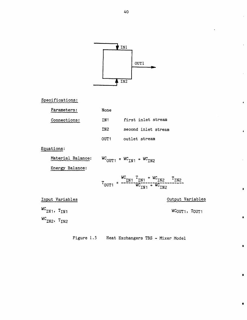
in Figure 1.5. Unit type divider is for splitting one stream into
two streams and is modeled as shown in Figure 1.6. Unit type
convergence is for testing and promoting convergence for a recycle
stream. Most chemical processes involve recycle streams.
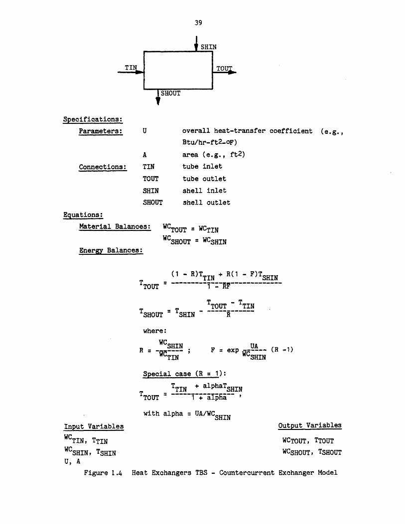
Specifications:
Parameters:
Connections: TIN
overall heat-transfer coefficient (e.g.,
Btu/hr-ft2-oF)
area (e.g., ft2)
tube inlet
tube outlet
shell inlet
shell outlet
Equations:
Material Balances: WCTOUT = WCTINWCSHOUT = WCSHIN
Energy Balances:
(1 - R)TTIN + R(1 - F)TSHIN
T TTOUT - TTINTSHOUT = SHIN R
where:
WCSHINR - C ---- ;
TINF = exp (R -1)
SHIN
Special case (R = 1):
TTIN + alphaTSHINTTOUT ~ 1 + alpha
with alpha = UA/WCSHINInput Variables
WCTIN, TTINWCSHIN, TSHINU, A
Output Variables
WCTOUT, TTOUT
WCSHOUT, TSHOUT
Figure 1.4 Heat Exchangers TBS - Countercurrent Exchanger Model
TOUT
SHIN
SHOUT
INI
OUT1
Specifications:
Parameters:
Connections:
None
IN1
IN2
OUT 1
first inlet stream
second inlet stream
outlet stream
Equations:
Material Balance:
Energy Balance:
WCOUT1 = WCIN1 + WCIN 2
WC T + WCT -C IN1 IN1 GIN 2 TIN 2OUT1 5~wC +~~
IN1 IN2
Input Variables Output Variables
WCINl, TIN1
WCIN2, TIN2
WCOUT1, TOUT1
Heat Exchangers TBS - Mixer ModelFigure 1 .5
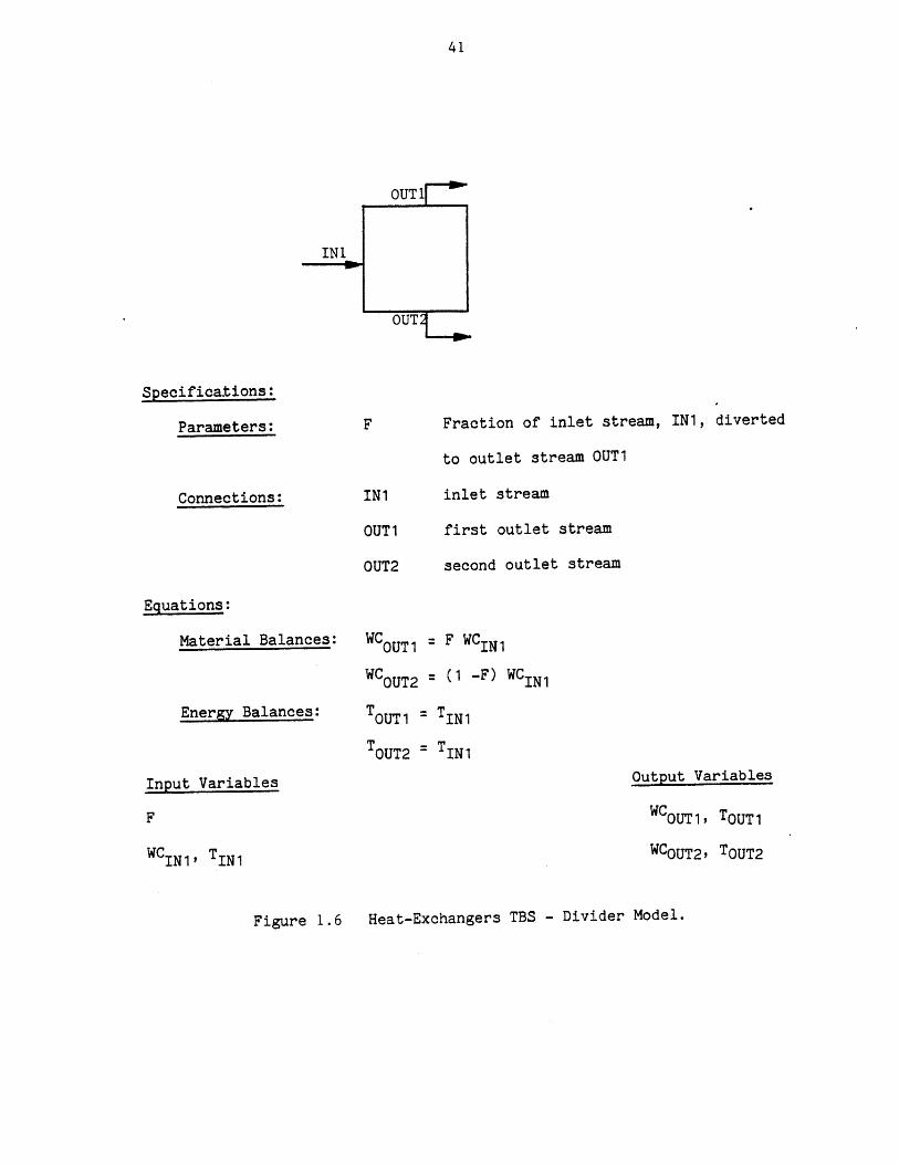
Specifications:
Parameters: Fraction of inlet stream, IN1, diverted
to outlet stream OUT1
Connections: IN1 inlet stream
OUT 1
OUT2
first outlet stream
second outlet stream
Equations:
Material Balances:
Energy Balances:
WCOUT1 F WCIN1
WCOUT2 (1 -F) WCIN1
TOUT1 - TIN1
TOUT2 - TIN1
Input Variables Output Variables
WCOUT1, TOUT1
WCOUT2, TOUT2WCIN1, TIN1
Heat-Exchangers TBS - Divider Model.Figure 1.-6
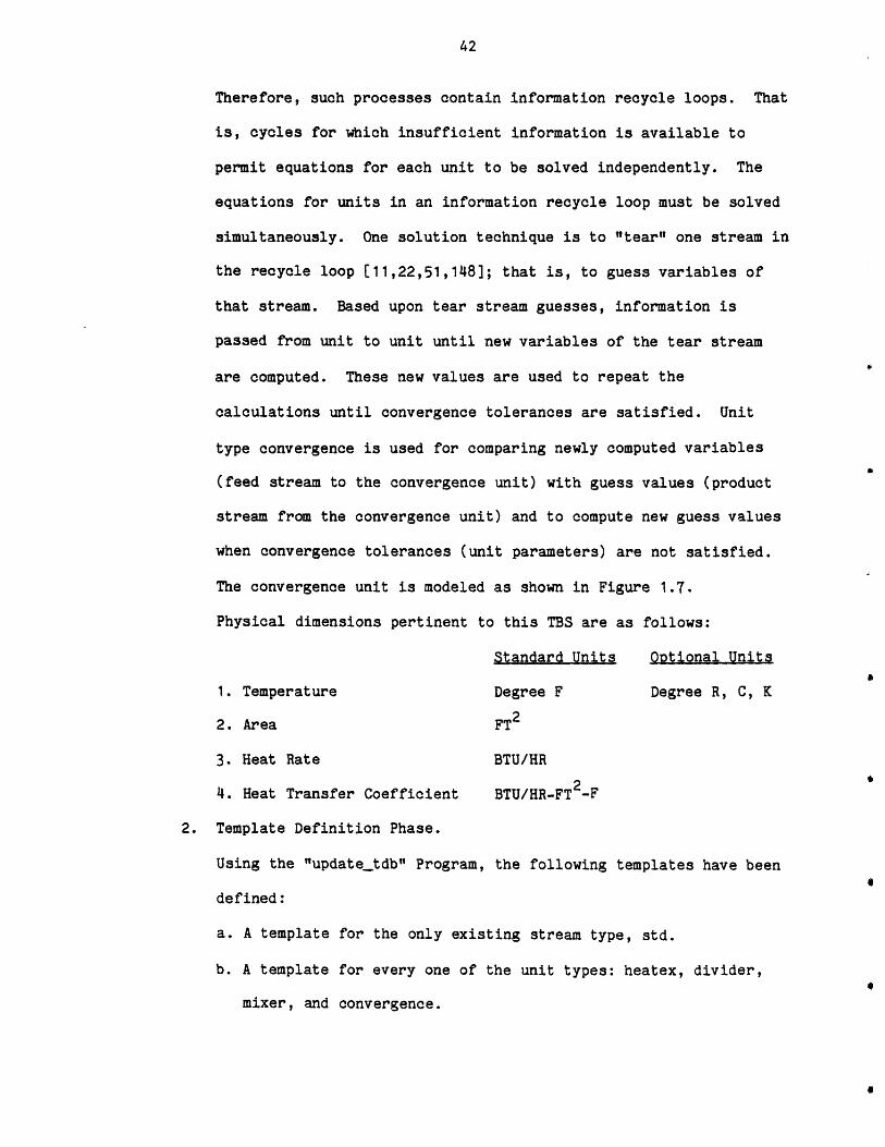
Therefore, such processes contain information recycle loops. That
is, cycles for which insufficient information is available to
permit equations for each unit to be solved independently. The
equations for units in an information recycle loop must be solved
simultaneously. One solution technique is to "tear" one stream in
the recycle loop [11,22,51,148]; that is, to guess variables of
that stream. Based upon tear stream guesses, information is
passed from unit to unit until new variables of the tear stream
are computed. These new values are used to repeat the
calculations until convergence tolerances are satisfied. Unit
type convergence is used for comparing newly computed variables
(feed stream to the convergence unit) with guess values (product
stream from the convergence unit) and to compute new guess values
when convergence tolerances (unit parameters) are not satisfied.
The convergence unit is modeled as shown in Figure 1.7.
Physical dimensions pertinent to this TBS are as follows:
Standard Units Optional Units
1. Temperature Degree F Degree R, C, K
2. Area FT2
3. Heat Rate BTU/HR
4. Heat Transfer Coefficient BTU/HR-FT 2-F
2. Template Definition Phase.
Using the "update_tdb" Program, the following templates have be
defined:
a. A template for the only existing stream type, std.
b. A template for every one of the unit types: heatex, divider,
mixer, and convergence.
en
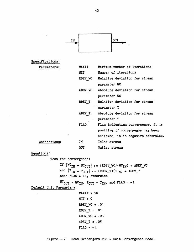
Specifications:
Parameters:
Connections:
MAXIT
NIT
RDEV WC
Maximum number of iterations
Number of iterations
Relative deviation for stream
parameter WC
ADEVWC Absolute deviation for stream
parameter WC
RDEV T Relative deviation for stream
parameter T
ADEVT Absolute deviation for stream
parameter T
FLAG Flag indicating convergence, it is
positive if convergence has been
achieved, it is negative otherwise.
IN Inlet stream
OUT Outlet stream
Equations:
Test for convergence:
If IWCIN - WCOUTI <= (RDEVWC)(WCIN) + ADEVWCand ITIN - TOUTI <= (RDEVT)(TIN) + ADEV_Tthen FLAG = +1, otherwiseWCOUT = WCIN, TOUT = TIN, and FLAG = -1.
Default Unit Parameters:
MAXIT = 50NIT = 0
RDEV WC = .01RDEV T = .01ADEVWC = .05
ADEV T = .05
FLAG = -1.
Figure 1.7 Heat Exchangers TBS - Unit Convergence Model
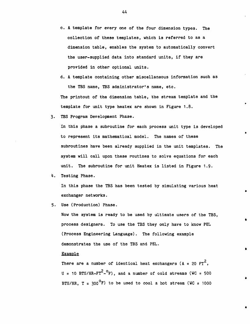
c. A template for every one of the four dimension types. The
collection of these templates, which is referred to as a
dimension table, enables the system to automatically convert
the user-supplied data into standard units, if they are
provided in other optional units.
d. A template containing other miscellaneous information such as
the TBS name, TBS administrator's name, etc.
The printout of the dimension table, the stream template and the
template for unit type heatex are shown in Figure 1.8.
3. TBS Program Development Phase.
In this phase a subroutine for each process unit type is developed
to represent its mathematical model. The names of these
subroutines have been already supplied in the unit templates. The
system will call upon these routines to solve equations for each
unit. The subroutine for unit Heatex is listed in Figure 1.9.
4. Testing Phase.
In this phase the TBS has been tested by simulating various heat
exchanger networks.
5. Use (Production) Phase.
Now the system is ready to be used by ultimate users of the TBS,
process designers. To use the TBS they only have to know PEL
(Process Engineering Language). The following example
demonstrates the use of the TBS and PEL.
Example
There are a number of identical heat exchangers (A = 20 FT2
U = 10 BTU/HR-FT2 _oF), and a number of cold streams (WC 500
BTU/HR, T = 300 0F to be used to cool a hot stream (WC 1000
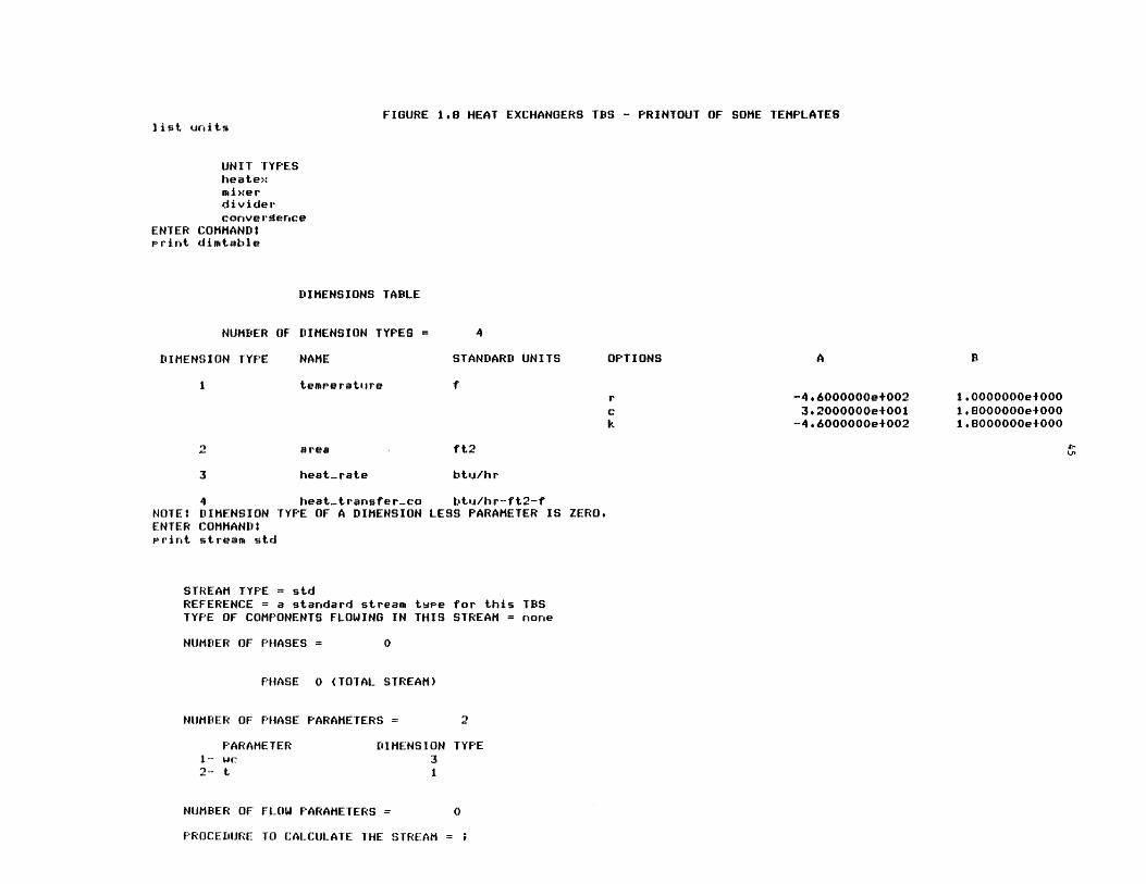
FIGURE 1.8 HEAT EXCHANGERS TBS - PRINTOUT OF SOME TEMPLATESlist units
UNIT TYPESheatexmi xe rdividerconvergence
ENTER COMMAND:Print dimtable
DIMENSIONS TABLE
NUMBER OF DIMENSION TYPES = 4
DIMENSION TYPE NAME STANDARD UNITS
temperature
a rea
heat-rate
-4.6000000e+0023.2000000e+001
-4*6000000e-002
1.0000000e-0001, 8000000e+-000I .8000000e+ 000
ft2
btu/hr
4 heat-transfer-co btu/hr-ft2-fNOTE? DIMENSION TYPE OF A DIMENSION LESS PARAMETER IS ZERO.ENTER COMMAND:Print stream std
STREAM TYPE = stdREFERENCE = a standard stream twee for this TBSTYPE OF COMPONENTS FLOWING IN THIS STREAM = none
NUMBER OF PHASES =
PHASE 0 (TOTAL STREAM)
NUMBER OF PHASE PARAMETERS = 2
PARAMETER DIMENSION TYPE1-- we 32- t 1
NUMBER OF FLOW PARAMETERS = 0
PROCEDURE TO CALCULATE THE STREAM =
OPTIONS
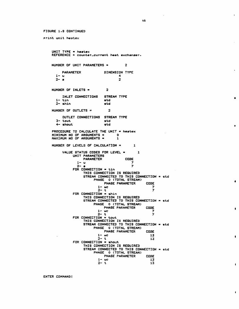
FIGURE 1.8 CONTINUED
Print unit heatex
UNIT TYPE = heatexREFERENCE = counter-current heat exchanger.
NUMBER OF UNIT PARAMETERS = 2
PARAMETER DIMENSION TYPE1-u 42- a 2
NUMBER OF INLETS = 2
INLET CONNECTIONS STREAM TYPE1- tin std2- shin std
NUMBER OF OUTLETS = 2
OUTLET CONNECTIONS STREAM TYPE3- tout std4- shout std
PROCEDURE TO CALCULATE THE UNIT = heatexMINIMUM NO OF ARGUMENTS = 0MAXIMUM NO OF ARGUMENTS a 1
NUMBER OF LEVELS OF CALCULATION = 1
VALUE STATUS CODES FOR LEVEL = 1UNIT PARAMETERS
PARAMETER CODE1- u 72- a 7
FOR CONNECTION = tinTHIS CONNECTION IS REQUIREDSTREAM CONNECTED TO THIS CONNECTION = std
PHASE 0 (TOTAL STREAM)PHASE PARAMETER CODE
1- we 72- t 7
FOR CONNECTION = shinTHIS CONNECTION IS REQUIREDSTREAM CONNECTED TO THIS CONNECTION = std
PHASE 0 (TOTAL STREAM)PHASE PARAMETER CODE
1- wc 72- t 7
FOR CONNECTION = toutTHIS CONNECTION IS REQUIREDSTREAM CONNECTED TO THIS CONNECTION = std
PHASE 0 (TOTAL STREAM)PHASE PARAMETER CODE
1- we 132- t 13
FOR CONNECTION = shoutTHIS CONNECTION IS REQUIREDSTREAM CONNECTED TO THIS CONNECTION = std
PHASE 0 (TOTAL STREAM)PHASE PARAMETER CODE
1- we 132- t 13
ENTER COMMAND:
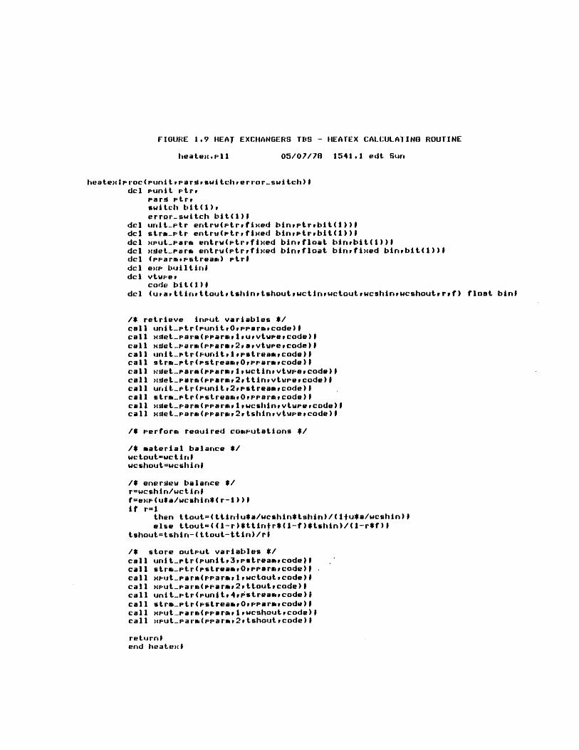
FIGURE 1,9 WEAY EXCHiANGERS TBS - 11EATEX CALCULATING ROUTINE
heatemsell 05/07/78 1541.1 edt Surn
heatex I rroc(punitup a r aswitchrerror-switch) Idcl Pkinit ptre
Pard rtrrswitch bit(i)perror..switch bit(1)
dcl unit-ptr ertrwiptrefixed binvptrrbit(1))#dcl strmr'tr entruirtrvtixed binptrvbit(1))1dcl xput-parm entrwe(ptrrfixed bintfloat binvbit(1))ldcl xsjet..parm entru(ptr~fixed binrfloat bitivfimed binvbit(1))ldcl (pparmpstream) rtridcl em bajiltinidcl vtwpeu
dcl (uvav ttirse ttoutu tshtinttshoutywctinvwctoutuwcshinvpwcshoutu t'f) float bint
/* retrieve input variables *call uritptr(punitr0,erarorcode)lcall xdet-..aem(rarm,1ruuvtwpeucode)Icall Hget-parm(pparme2uavvtupeucode) 9call unit-ptr(p-unitvlvpstreamucode)Icall strrn.rtr(stream,0,pF'amcode) Scall .-et..par^(Pparme1,wctinuvtupeucode)Icall ,tget-parm(prarmr2rttinpvtwj-evcode)IScall urit-ptr(punitp2ppstreamvcode) Scall strm-.ptr(pstreamw0rpparmvcode)1call maet-j'arm(pearm,1,wcshiintvtwpeucode)Icall xet-.parm(pearmv2v tshinivtupeecode) S
/* perform reauired computations #
/* material balance *wctaut'wctiugSwcshoutwcshis
1* energew balance *rweshin/wtisff=exp(u*a/wcshin*( r-1 )) Sif r=1
then ttout=(ttirmlu*a/wcshin*tshin)/(11-u*a/wcshin)Ielse ttout-((1-r)*ttirslr*(i-f)$tshin)/(1--r*f)S
tshout=tshis-( ttout-ttin)/ri
1* store output variables *1call unit-.ptr(unitp3pstreaecode)lcall strm..ptr(vpstreaum0ypparmrcode)Dcall xpmjt..parm(parmlwctoutecode)Dcall xiput-parm(prarmg2,ttoutpcode)Icall unit-.ptr(unitp4,pstreamecode) Scall strm-ptr(pstreamp0,pe-armpcode)Icall xput-iparm(pparmplvwcshoutucode)Scall )cp-ut-.anudppanu2tshouttcode) S
retuiirn$eend heatext
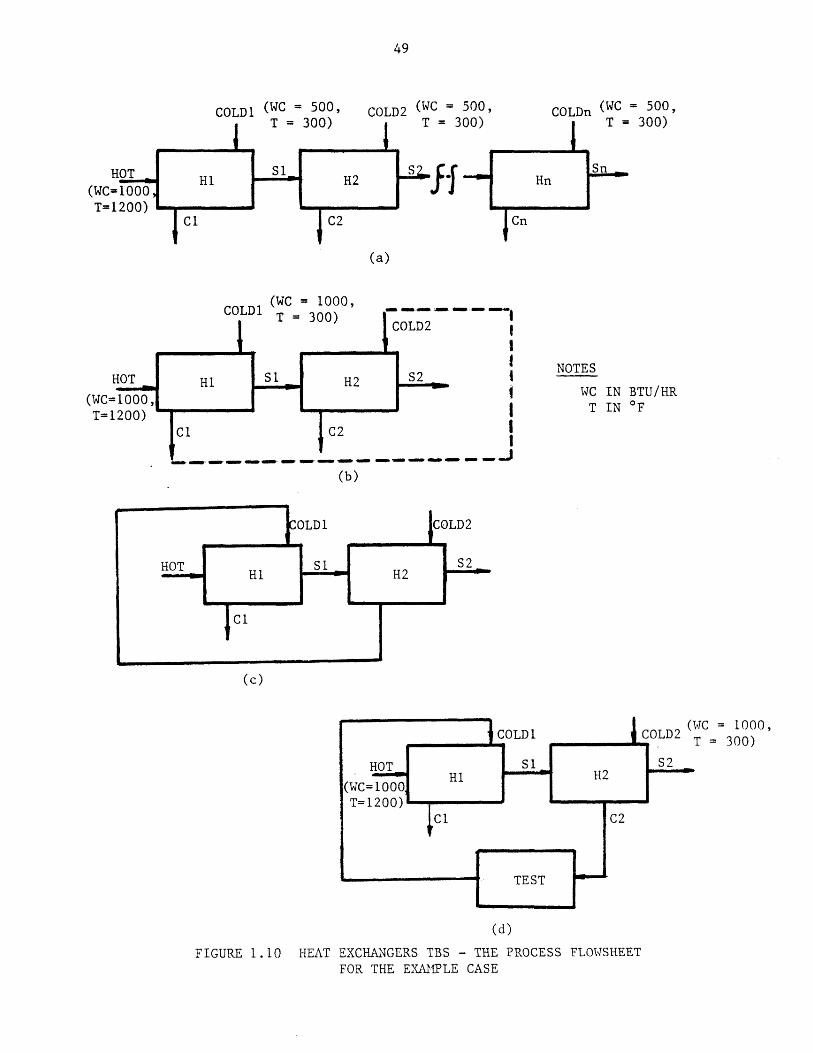
BTU/HR,T : 12000F) to below 9500F, as shown in Figure 1.10a. The
problem is determining the minimum number of required heat
exchanges. The PEL computer session for solving this problem is
shown in Figure 1.11. To solve this problem, one may start with
one heat exchanger and increase the number of heat exchangers
until the hot stream is cooled to the desired temperature. As can
be seen in Figure 1.11, two heat exchangers will bring the hot
stream temperature below the 950 0F. Before terminating the
session, the user has saved his process network, so that he may be
able to continue his design effort sometime in the future.
At a later session, the user wishes to investigate other design
alternatives, especially those shown in Figures 1.10b and 1.10d.
The PEL computer session is demonstrated in Figure 1.12. As can
be seen, the output temperature for process configuration shown in
Figure 1.10b is 9500F compared to 9450F for the first
configuration. To simulate the process flowsheet shown in Figure
1.10c, one observes that unit H1 and H2 cannot be calculated
independently. To calculate unit H1 stream coldi should be known.
To determine stream cold1 unit H2 should be calculated which
requires the stream S1 to be known. Therefore, to calculate unit
H1 stream S1 should be known, but on the other hand, to find the
stream S1 requires the calculation of Unit H1. Thus, it can be
seen that the process flow sheet contains an information recycle
loop; that is, too few stream variables are known to permit
equations for each unit to be solved independently. One solution
technique is to tear one stream in the recycle loop; that is, to
guess variables of that stream. Based upon tear stream guesses,
COLD1 (WC = 500,T =300)
COLD2 (WC = 500,1 T= 300)
COLDn (WC = 500,1 T= 300)
(WC=1000T=1200)
(a)
COLD1 (WC = 1000& T =300)
OLD2
NOTES
WC IN BTU/HRT IN *F
C2
(b)
COLD2 (WC = 1000,Co 2 T =300)
(d)
FIGURE 1.10 HEAT EXCHANGERS TBS - THE PROCESS FLOWSHEETFOR THE EXAMPLE CASE
HOT
(WC=1000,T=1200)
(c)
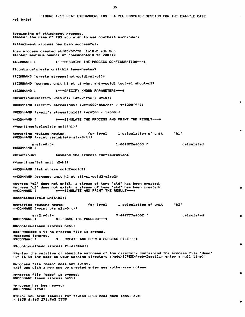
FIGURE 1.11 HEAT EXCHANGERS TBS - A PEL COMPUTER SESSION FOR THE EXAMPLE CASEPel brief
*beginning of attachment process.**enter the name of TBS wou wish to use nowtheat-exchangers
*attachment process has been successful.
*new process created at:05/07/78 1618.5 edt Sun**enter maximum number of components(O to 200)10
**COMMAND : $---DESCRIBE THE PROCESS CONFIGURATION---$
**continue create unit(hi) twpe=heatex'
**COMMAND *create streams(hotrcoldirs1ic1);
**COMMAND :connect unit hi at tin-hot shin=coldi tout=si shout=ci
**COMMAND : $---SPECIFY KNOWN PARAMETERS---$
**continue#specifw unit(hl) (a=20'ft2'i ui10);
**COMMAND ?specifw stream(hot) (wc-1000'btu/hr' , t=1200'f');
**COMMAND :specifw stream(coldi) (wc=500 , t=300);
**COMMAND : $---SIMULATE THE PROCESS AND PRINT THE RESULT---$
**continueacalculate unit(hi);
*entering routine heatex. for level 1 calculation of unit "h18**COMMAND :print variable(s.si.PO.t) .
s.s1.p0.t= 1.061892e+003 f calculated**COMMAND
**continue* $expand the process configurations
**continue let unit h2=hiJ
**COMMAND *let stream cold2=coldi;
**COMMAND Oconnect unit h2 at all=siscold2,s2tc2;
*stream "s2" does not exist. a stream of twee "std" has been created.*stream "c2" does not exist. a stream of twee 'std" has been created.**COMMAND : $---SIMULATE AND PRINT THE RESULT---$
**continue6calc unit.Ch2)1
*entering routine heatex for level 1 calculation of unit "h2"**COMMAND *Print v(s.s2.PO.t)D
sos2.pO.t- 9.449777e+002 f calculated**COMMAND : $---SAVE THE PROCESS---$
**continuetsave process netli
***ERROR*** s 91 no Process file is opened,*command ignored.**COMMAND : S--CREATE AND OPEN A PROCESS FILE---S
**continuetopen process file(demo)i
**enter the relative or absolute Pathname of the directorw containing the process file demo'(if it is the same as wour working directorw P>udd>ICPES>Arab-Ismaili, enter a null line):
*Process file "demo" does not exist.**if wou wish a new one be created enter wes ,otherwise notwes
*Process file "demo" is opened.**COMMAND :save process netl^
*Process has been saved.**COMMAND #end;
*thank wou Arab-Ismaili for trwing GPES come back soon, bwe!r 1638 6.163 271.965 5339
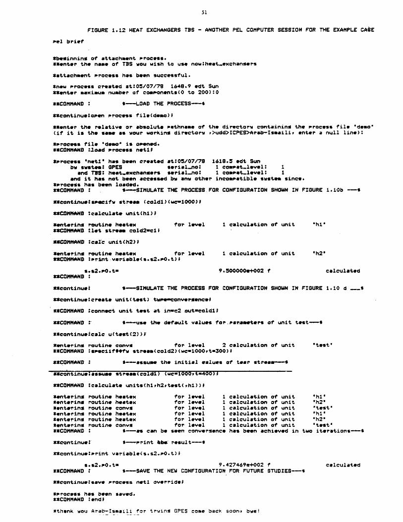
FIGURE 1.12 HEAT EXCHANGERS TBS - ANOTHER PEL COMPUTER SESSION FOR THE EXAMPLE CASE
Pel brief
*beginning of attachment process.**enter the name of TBS wou wish to use now heat-exchangers
*attachment process has been successful.
*new process created at:05/07/79 1648.9 edt Sun**enter maximum number of consonents(0 to 200):0
**COMMAND : ---LOAD THE PROCESS-$
**continuelosen process file(demo)0
**enter the relative or absolute Pethname of the directorw containing the process file "demo"(if it is the same as your working directors r>udd>ICPES>Arab-Ismaili, enter a null line):
*Process file *demo' is opened.**COMMAND :.load process netil
*Process "neti" has been created at:05/07/79 1618.5 edt Sunbw swstem: OPES serial-no: 1 comsat-level: 1
and TVS: heat-exchaniers serial-no: 1 compet-level: 1and it has not been accessed bw anw other incomsatible swstem since.
*SProcess has been loaded.**COMMAND : S-SIMULATE THE PROCESS FOR CONFIGURATION SHOWN IN FIGURE 1.10b --
**continue specify stream (coldi)(we-1000)9
**COMMAND :calculate unit(hi);
*entering routine heatex for level 1 calculation of unit "h1'**COMMAND :.let strea cold2=cl;
SSCOMMAND :calc unit(h2);
*entering routine heatex for level 1 calculation of unit "h2'**COMMAND :'rint variable(s.s2.P.t)1
s.s2.O.t= 9.500000e+002 f calculated**COMMAND *
**continueo S-SIMULATE THE PROCESS FOR CONFIGURATION SHOWN IN FIGURE 1.10 d ---.
**continue:create unit(test) tupeconversenceD
**COMMAND *connect unit test at in=c2 outucoldlF
**COMMAND S -- use the default values for.parameters of unit test-$
**continuetcalc u(test(2))t
*entering routine convg for level 2 calculation of unit *test'**COMMAND :sseciif#9fw strea*(cold2)(wcw1000,t=300)f
**COMMAND : 6-assume the initial ealues of tear stream---
**c'ntinueassume stream(coldu) (wcfid0Ot=400)i
**COMMAND *calculate units(hish2ptest(ph1))1
*entering routine heatex for level 1 calculation of unit "h1'tenterina routine heatex for level 1 calculation of unit "h2"Sentering routine convs for level 1 calculation of unit 'test'*entering routine heatex for level 1 calculation of unit 'hi"*entering routine heatex for level 1 calculation of unit 'h2**entering routine convs for level 1 calculation of unit "test'**COMMAND : S--as can be seen convergence has been achieved in two iterations--S
**continue: --print &be: result---$
**continuetsrint variable(s.s2.PO.t);
s.s2.O.t= 9.427469e+002 f calculated**COMMAND S--SAVE THE NEW CONFIGURATION FOR FUTURE STUDIES---
**continueisave Process neti overridei
*Process has been saved.**COMMAND *end;
*thank wou Arab-Ismaili for trwing GPES come back soon, bye!
information is passed from unit to unit until new values of the
variables of the tear stream are computed. These new values are
used to repeat the calculations until convergence tolerances are
satisfied. This has been done as shown in Figure 1.10d and
demonstrated in Figure 1.12.
As can be seen, convergence has been achieved in two iterations.
The output temperature is 943 F which is lower than the two
previous outcomes.
6. Updating Phase (TBS Administrator's Task).
A TBS is an open ended system which can easily be extended or
modified. Suppose a new unit type is to be added to the TBS. The
unit type is adjuster, which heats or cools a stream to a
specified temperature. The unit model is shown in Figure 1.13. A
new template defining this new unit type has been added to the
template based system and a subroutine representing the
mathematical model of the unit has been developed, and the updated
TBS has been tested. Now the users of the TBS may incorporate
units of this type in their process flowsheets when such a need
arises.
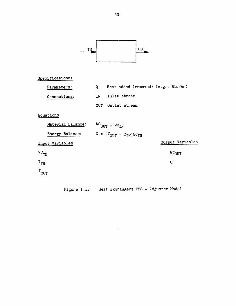
Specifications:
Parameters:
Connections:
Q Heat added (removed) (e.g., Btu/hr)
IN Inlet stream
OUT Outlet stream
Equations:
Material Balance:
Energy Balance:
Input Variables
WCIN
WCOUT = WCIN
Q = (TOUT - TIN)WCIN
Output Variables
WCOUT
TIN
TOUT
Heat Exchangers TBS - Adjuster ModelFigure 1. 13
1.6 CONCLUSIONS AND THESIS CONTRIBUTIONS
There are two basic problems with the existing general purpose
process simulators:
a) The existing systems are applicable to those process flowsheets
having only conventional vapor-liquid streams. This
inflexibility makes it either impossible or very difficult to
expand present-day systems to include other types of processes
such as coal processing or electric power generating systems.
b) The existing systems are mostly developed for simulation and do
not provide the design atmosphere for process engineers. A
general purpose simulator, to be effective as a design tool,
must use a mode of operation, methods of input and output, and
calculation techniques that minimize the effort required for
designer-computer communication so as to maximize effective
interaction between the designer and the computer. The time
scale is important in process design.
The objective of this thesis was to develop a framework for the
development of general purpose chemical process simulators that:
a) are applicable to all types of chemical processes, and
b) are more adaptable to the design environment.
In fulfillment of the above objective, the thesis has provided the
following contributions in the field of computer aided design for process
engineering:
1) Formulation of a general model for chemical proceses, to represent
the process flowsheet for any level of sophistication that may be used to
analyze that process. The introduction of the concept of a general
stream and flow parameters have been the major contributions for
achieving this result.
2) Identification of the issues involved in the design of a computer
system for process engineering. The work has distinguished two classes
of problems:
a) Those that are common to the design of any system,
b) Those that are related to a particular system.
3) Based upon the above findings, the work has led to the design and
implementation of a General Process Engineering System (GPES) which
allows any group or organization to easily and systematically build its
own system. These systems could be very simple or very sophisticated
depending on the particular needs and applications of the group.
The design and implementation of the GPES as a tool for creating
computer aided design systems for chemical process engineering provides
the following advantages:
a) Allows any group or organization to easily and systematically
build its own design system, thereby reducing the time and
effort required to produce such systems.
b) The created system may not be limited to a particular class of
processes. Such a system is open-ended and capable of
analyzing any type of process.
c) The created system is more adaptable to the design environment,
and provides the user with features not usually found in
existing general purpose simulators.
In summary, a system created by GPES (a TBS) has the following
characteristics:
a) Flexible. It is applicable for analyzing any type of process
flowsheets. It is not limited to process flowsheets having
only conventional vapor-liquid streams. The system can be
easily modified, expanded and updated.
b) The user communicates with the system by a problem oriented
language (PEL). The user may enter his input data in any
allowable units of measurement. Arithmetic expressions may be
used where numerical data is expected. The system performs
extensive types of error checking such as detection of over- or
under-specification of process units and streams. The system
produces over 200 easy-to-understand messages to detect the
user's negligence.
c) Interactive. Allowing the progressive design of a process.
d) Integrated. Capable of the following functions:
i) Simulating or designing a process for any required level
of sophistication such as: preliminary process
feasibility studies, plant design, equipment sizing, plant
modifications, debottlenecking studies, effects of
operational changes on plants, contractor checkout. The
appropriate programs should be provided in that TBS.
ii) Serving as a physical property data base system. It also
promotes sharing of data among users.
iii) Analyzing experimental data (regression analysis).
iv) Serving as a general purpose interpreter.
v) Serving as a desk calculator for arithmetic operations.
e) Dynamic creation and modification of process flowsheet.
Enabling the user to instruct the computer to alter process
configuration or operating parameters without having to
redescribe the problem.
f) The ability to save and retrieve user process models. This
will save both designer and computer time in not having to
reinitiate the problem. It also promotes sharing of process
models among users, and enhances teamwork.
g. It provides virtual memory. There is no limitation on the size
of the process flowsheet being analyzed by the user.
h. Ease of use in that no knowledge of programming and job control
language is required. All that is required is knowledge of PEL
(Process Engineering Language).
4) The work has provided a comprehensive example of the use of current
systems programming techniques (structured programming, dynamic storage
allocation, manipulation of arbitrary data structures, list processing,
etc.) and current computer technology (time sharing, virtual memory,
dynamic linking and loading) in a systems programming application of
interest to chemical engineering.
Using the GPES several prototype template based systems have been
created. The results of these efforts indicated that:

a) The GPES allows the creation of computer systems for different
types of processes.
b) The creation of such systems is simple and systematic.
c) The features provided by the system are very useful and
desirable for simulation and design of chemical processes.
In conclusion, the above studies and findings, and the availability
of such a GPES, will benefit the following groups:
a) Those interested in computer aided design for chemical
engineering applications.
b) Those planning to implement their own computer aided design
systems for chemical processes (by reducing the characteristic
20-100 man-years effort formerly required to produce such
systems). It allows them to focus their effort on the chemical
engineering side of the problem, which results in the
development of better process modules and comprehensive
physical and thermodynamic property calculation packages.
c) The process designers, by providing the ideal creative
environment for process design by computer.
d) Chemical engineering students in process design courses. By
allowing them to implement their own system or to use an
already developed educational one. They would be able to study
whole processes as carefully as we now study individual unit
operations.
CHAPTER 2
INTRODUCTION
2.1 Chemical Process Simulation
The simulation of chemical processing systems and the design of
computing systems that can be utilized for such simulations has been an
area of tremendous activity ever since the emergence of the general purpose
digital computer as a design tool for engineers. Process simulation, in
recent years, besides being accepted as a tool for the design and
understanding of chemical processes, has also become an important
requirement in the education of chemical engineers.
The simulation of any chemical process begins with the representation
of the process by a mathematical model. This model is then solved either
manually or, preferably, through the use of a computing aid to obtain
information about the performance of the process under a given set of
conditions. In most instances, the equations that constitute the
mathematical model of the process, under steady state, are numerous and
highly non-linear. The use of a digital computer for their solution
becomes almost mandatory.
2.2 Simulation Versus Design
Two questions are normally asked concerning chemical processes. The
first question is, given a specified flowsheet, how will it respond under
given perturbations in stream variables or process unit parameters. This
is normally called the simulation problem. It is characterized as the
analysis of a fixed network of modules in a fixed configuration. Much time
has been devoted to developing procedures or methodology for solving
problems of this type. The results of these efforts have led to rules to
govern simulation procedures. These rules have been incorporated into
computer systems which we shall classify as general purpose process
simulators. A host of these simulators are in existence which have
characteristically required tens of man-years to implement. A review of
the state of the art is presented in Appendix A. The second question
normally asked concerning chemical processes is, given a specified response
of items in out-flowing streams from a process and given specified
constraints on the parameters of the process units or streams within the
process, which flowsheet will behave in the appropriate manner. This is
called the design problem. The design problem may have many solutions, but
as the number of constraints on the system's behavior is increased, the
number of solutions is diminished until there may be no solutions. These
problems are characterized by the fact that in arriving at a solution, not
only process units must be selected, but the configuration of the process
units must also be selected. Methodology for selecting process units and
unit arrangement is not yet formalized, although efforts have been devoted
to developing General Purpose Process Synthesizers[134] since the early
1970's. At present, computer-aided design systems must include man in the
loop to carry out the important task of process unit selection and
arrangement to accomplish a stated objective. It has not yet been
established that these "creative" aspects of design, much of which are
developed through experience (design know-how), can be formalized to the
extent that they can be incorporated in a computer system which would
eliminate man from the loop. Serious doubts are entertained as to whether
this accomplishment is at all possible without subjecting the computer to
the impossible task of analyzing the doubly infinite set of considering all
possible process unit selections and configurations. Thus, the current
procedure to solve design problems is for man to propose process unit
selection and arrangement, use a General Purpose Simulator to analyze the
proposed network, and then compare the proposed network's response to the
desired response and alter either network configuration or process unit
selection, or both, until a network is developed with the desired
characteristics. The process of design is necessarily iterative and having
arrived at a solution, one is usually not certain that other solutions do
not exist.
Considering the iterative nature of design problems, a general purpose
simulator, to be effective as a design tool, must use a mode of operation,
methods of input and calculation techniques that minimize the effort
required for designer-computer communication so as to maximize effective
interaction between the designer and the computer. The time scale is
important in process design. A program with these characteristics can be
used as an effective design tool and an efficient simulator.
2.3 Criteria for Computer Systems Amenable to Simulation and Design
There are two basic modes of computer operation, the off-line batch
processing mode and the on-line interactive processing mode. In the
former, the time between runs is long and this is acceptable when the
results of one run are not critically important for the following run.
However, in problems where, say, modifications to a design are dependent on
results from a previous analysis, on-line processing is preferable.
Moreover, the reduced waiting time enables the designer to remember what
stage he had reached after the last processing and this continuity can
often lead to higher efficiency.
On-line processing enables the designer to speed up the design
process. However, replacing the batch mode by the interactive mode is not
sufficient. The interface between the human mind and the computer must
also be modified to make the job easier for the designer, as discussed by
Porter [133]. The essence of his discussion is that "it is necessary to
create an atmosphere wherein the design team and the computer as an added
partner are able to rapidly evaluate the effects of equipment arrangement
and process variable selection in chemical process design".
He states that the answers to the following two questions are
pertinent in determining the optimal use of the computer in such a design
environment, to establish the specifications for a computer system and to
establish the several unique concepts in programming that may be required
to meet the specifications of the computer system.
One is, "How should the design activities be split between the
designer and the computer?" The answer is fairly obvious. The designer's
primary task is that of selecting and arranging equipment and evaluating
the results of his efforts. The computer, therefore, should be used to
carry out all the required analyses such as calculations of individual unit
behavior and predictions of physical and thermodynamic properties required
to perform these calculations. This is what most systems do.
The second question is, "How does the designer communicate with and
maintain control over the computer?" This is the area where most automated
design systems are inefficient. The designer is required to prepare some
sort of input forms specifying the process configuation, the operating
conditions -of the units and the thermodynamic states of the streams.
After the input is fed, the computer takes over complete control and
arrives at a solution. Such a system is not very conducive to creative
design. The environment of process design is much more dynamic. A
designer rarely knows the entire plant configuration at the outset of a
design. The flowsheet is more likely to evolve from an initial concept to

a final design after various perturbations of the initial concept. He must
have more contact with and greater control over the computer. He must be
allowed to specify what the computer should do at each stage of the design
and receive feedback in terms of the intermediate results so that he can
decide upon the next action to be taken by the computer.
One method of achieving this interaction is to provide a process
design language which is more "natural" to the designer and can be
interpreted by the computer. The language must be such that the designer
can describe the flowsheet structure, request unit calculations, provide
input, request output and have the computer carry out other instructions.
Thus, he may solve a full flowsheet or any of its parts that he desires.
He should also be able to change the flowsheet structure easily without
respecifying the whole flowsheet.
The language should allow the choice of engineering units for input
data to speed up the process of man-computer communication. The language
should accept arithmetic expressions where numerical data are expected.
The user should have access to every single piece of information about the
process network and be able to refer to them in arithmetic expressions.
Hence, the user will be able to relate different items of information about
the process flowsheet. The system should allow the repetitive execution of
a group of commands, to enhance the designer's iterative search. The
system should allow the user to save the results of one analysis in a file
to be used as input for further analysis. This will save both the designer
and the computer time in not having to reinitiate the problem.
To perform process engineering effectively, the engineering data
necessary for design must be made available. The computer can assist
engineers in analyzing, estimating, and retrieving these data. However, it
64
is not efficient to have many individual computer-aided systems for
simulation, design, physical property estimation, analyzing laboratory
data, and so on. Therefore, such systems should be organized into an
integrated system with a common data base, so that the consistency of these
data are kept throughout the various stages of process engineering.
The description of a flowsheet should be independent of the programs
for analysis. The same description should serve all analysis for which
that flowsheet is applicable, for example, steady state simulation,
equipment sizing, and economic evaluation, as noted by Evans et. al. (331,
who discuss the requirements of an advanced computer system which will be
needed to solve the process engineering problems of the 1980's. Such a
system must be extendable and capable of modification. It should be easy
to add new types of process units, to define new types of streams, species,
etc. Hence, the system can be expanded to analyze new types of process.
The inability of'existing systems to analyze new energy conversion
processes such as the magnetohydrodynamic (MHD) process has been due to the
lack of this feature in these systems.
2.4 The Problem
There are two basic problems with the existing general purpose
simulators:
a. They are only applicable to those process flowsheets having
conventional vapor-liquid streams. This inflexibility makes it
either impossible or very difficult to expand present-day systems
to include other types of process such as MHD, or other coal
conversion processes.
b. They do not meet the criteria discussed earlier, and, therefore,
are not very useful as design tools.
The difficulties may be traced to following characteristics of
existing programs:
a. They are not interactive.
b. They are not integrated.
c. They do not provide natural problem oriented language.
d. They do not have the capability of dynamic modification of the
process network.
e. They do not have the capability of storing the output model for
future study.
f. They are mostly developed for simulation, not for design.
g. They are not flexible.
The implications of each shortcoming are examined next.
a. Existing Systems Are Not Interactive
The computer's role is as a tool that enables the designer to refine
his understanding of a process by interactive analysis. Computer-aided
design systems, to be effective, must permit the engineer to design
processes in a dynamic environment. To use the existing systems, one
prepares input forms, specifying process configuration, the operating
conditions of units, the stream variables, etc. This input is fed to the
program and the computer then takes over complete control, manipulating
input data to arrive at a solution.
This mode of operation is not compatible with the dynamic environment
of process design. The designer rarely knows the entire process
configuration at the outset of a design. More usual is the gradual
evolvement of the total design starting with the initial concept of the
plant and perturbing this concept by trying various process configurations
until a final concept emerges. Therefore, the designer really requires
more intimate contact with and greater control over the computer's
function, specifying at each stage of the design what the computer should
perform, and, based on the results, deciding upon the next action to be
taken by the computer.
b. The Existing Systems Are Not Integrated
Thermodynamic or transport properties that are not specified directly
must be calculated. The computer should also assist the engineer in
analyzing the laboratory data or in performing side calculations. However,
it is not efficient to have many individual computer-aided systems for
simulation, design, physical property estimation, analyzing the raw data,
arithmetic computation, and so on. Therefore, such systems should be
organized into an integrated system with a common data base, so that the
consistency of these data are kept throughout the various stages of process
engineering.
c. The Existing Systems Do Not Provide Natural Problem-Oriented Languages
Present systems generally require a rather rigid method of specifying
the problem statement. The engineer should be able to communicate with the
computer in terms that are familiar to him. Moreover, whatever language is
provided, it must have the capability to transmit a wide variety of
instructions to the computer.
d. Existing Systems Do Not Have the Capability of Dynamic Modification of
Process Networks
In the dynamic environment of design, the engineer is often required
to modify the process network. It is very desirable to be able to specify
to the computer an alteration in process configuration or in operating
parameters without having to redescribe the problem.
e. The Existing Systems Cannot Save The Results of Analysis
It is very useful to be able to save the results of analysis in a file
to be used as input for further analysis. This will save both designer and
computer time in not having to reinitiate the problem.
f. The Existing Systems are Mostly Developed for Simulation. Not for
Desigzn
For each process unit there is a set of equations of the form
f(inlet-streams, operating conditions, outlet-streams) = 0.
Simulation programs attempt to solve the equations in the form:
outlet-streams = f(inlet-streams, operating conditions).
Design programs must be capable of solving the former set of equations in
its general form. However, a general purpose process simulator could be
used as a trial-and-error tool to solve the design problem. Flowtran and
Design systems provide feed-back and feed-forward control blocks which
automate this trial-and-error process to some extent. But the control
block technique is not applicable in all cases.
Although it is not feasible to develop process unit models capable of
solving all possible forms of the design problem, models should be
developed which are capable of solving a limited set of problems and the
rest of the cases may be solved by iterative techniques. A system, in
order to permit this type of analysis, must use a mode of operation,
methods of input and calculation techniques that minimize the effort
required for designer-computer communication so as to maximize effective
interaction between the designer and the computer. The time scale is
important in process design.
a. Existing Systems Are Not Flexible
Adding new features or modifying some features to the existing systems
is either impossible or a very difficult task. The major limitation to
using a state-of-the-art, computer-aided design program to analyze energy
conversion processes such as those for coal gasification, oil from oil
shale, MHD, etc. is the inability of these systems to handle streams other
than conventional vapor-liquid streams. A system applicable to these
processes must permit analysis of flowsheets with different types of
streams. These include conventional vapor-liquid streams, multi-phase
streams containing solids, as well as energy streams and information
streams. The system should be sufficiently flexible to allow creation of
new stream types, each characterized by a different set of stream
variables.
2.5 Thesis Objective
The objective of the thesis was to develop a framework for the
development of general purpose chemical process simulators that:
a. are applicable to all types of chemical processes and
b. are more adaptable to the design environment.
2.6 Thesis Work
A general framework for modeling of chemical processes has been found
and, based upon this framework, a computer system called jeneral Process
Engineering system (GPES) has been designed and implemented. GPES allows
any group or organization to create its own computer aided design system
for engineering of chemical processes. These systems will not have the
shortcomings of existing systems that were discussed earlier. These
systems could be very simple or very sophisticated depending on the
particular needs and applications of the group or organization. Such
systems meet the criteria discussed earlier, and therefore provide the
design atmosphere for process designers. These systems are not limited to
analyzing process flowsheets having only conventional vapor-liquid streams.
They are applicable for analyzing any type of process flowsheet including
energy conversion processes such as coal gasification and MHD. Such
systems could easily be modified, expanded, and updated. This thesis
describes the design and application of GPES. Using GPES several prototype
computer aided design systems have been created to demonstrate the
application and use of GPES and systems created by GPES.
2.7 General Process Engineering System
GPES is a computer system which enables the rapid production of user-
oriented computer-aided design systems for engineering of chemical
processes. In using GPES to create a computer aided design system, one has
to define different types of process elements (process units, streams,
etc.) which may be present in the flowsheets to be analyzed or designed by
the users of that system. The subroutines performing the computations for
these elements (process modules, etc.) must also be provided. The
different types of process elements are defined by providing an information
set for each of them. Each such information set is called a template in
GPES terminology. For example, a template for a specific type of process
unit contains such information as the number of inlet and outlet streams,
number of unit parameters, etc. A system created by GPES is called a
Template _Rased System (TBS). The templates for each TBS reside on a set of
files called a template data base. Hence, the creation of a TBS consists
of creation of a template data base and development of a package of
subroutines mainly to represent the mathematical models of process units
defined in that template data base. Subroutines are called TBS programs.
Each TBS is the responsibility of a system administrator.

A TBS administrator may be assisted by a group of programmers for
development of TBS programs. This group is known as TBS programmers.
Once a TBS has been implemented (templates has been defined and
computational subroutines provided) a process designer (user) may utilize
it to analyze any arbitrary specified configuation of process units which
are already defined in the TBS.
The structure of the organization of a team using GPES is shown in
Figure 1.1. There are four levels of activity associated with GPES. Each
level is the responsibility of a different set of personnel:
1. The GPES administrator who is responsible for:
a. Maintenance of the GPES.
b. Protecting the system from unauthorized TBS administrators.
c. Protecting each TBS from unauthorized users.
2. TBS administrators who are responsible for:
a. Implementation and maintenace of template based systems.
b. Coordination of TBS programmers.
c. Permitting a user to use a TBS.
3. TBS programmers.
They are responsible for development of TBS programs.
4. Users.
They are the ultimate users of the template based systems, the
designers of chemical processes. A user may have access to one or
more of these systems.
For each of these groups a set of tools and mechanism (programs and
languages used to communicate with those programs) has been developed to
assist them in performing their responsibilities. GPES consists of these
tools.
The use of the system is shown in Figure 1.2. A TBS administrator
creates and manipulates his template data base by an interactive program
called "updatetdb". A language called lemplate Definition L4anguage (TDL)
has been provided to enable him to easily communicate with the "update_tdb"
program to define templates.
TBS programmers write the TBS programs in procedural languages such as
PL/1 or Fortran. Development of these programs has been standardized and a
package of service routines has been developed to assist them in their
efforts.
The backbone of the system is the executive program which provides the
means to execute the users' commands. In essence, the executive is a
table driven interpreter, the tables being Template Data Bases and GPES
files.
The GPES files are part of a mechanism to protect the system from
unauthorized TBS administrators and to protect each TBS from unauthorized
users. GPES files contain information about each TBS and its authorized
users. The GPES administrator performs his administrative duties by
creating and updating these files by an interactive program known as the
administrative program. The executive program refers to these files to
locate the Template Data Base of a specified TBS and to permit a user to
use a specified TBS.
A special language has been designed to enable the user to easily
communicate with the executive. The language has been named PEL, which
stands for Process Engineering Lanaguage. PEL consists of a series of
commands. Each command is a request for an action to be taken by the
system. The language enables a user to create and delete process elements,
specify and unspecify parameters and variables of process elements,
calculate (simulate) parts of or whole flowsheets, and print results. PEL
allows the choice of engineering units. Many other features are available
within PEL.
All information that is related to a particular flowsheet is
represented by a network of data structures. This network is created and
manipulated by the executive program in response to the user commands.
Changes in the flowsheet structure are reflected by changes in the network
structure, as the initial concept of the design evolves into a final
concept. The network is located in an area of storage known as the working
area. The working area automatically expands as the need for more space is
recognized. Hence, there is no limitation on the size of the flowsheet
being analyzed.
The user can save this network in a file and, later, retrieve it for
further analysis. This type of file is known as process file. A user may
have any number of process files, each of which may contain any number of
processes. The executive program creates and manipulates these files in
response to the user's commands. The users may share their process files.
This will promote team work on design and analysis of large process
flowsheets.
A user may also have any number of another type of files known as
component files. A component file may contain the physical properties or
constants for estimating these properties for any number of chemical
components. The executive program also creates and manipulates these files
in response to the user's commands, hence the user need not be explicitly
concerned about the creation and maintenance of these files, outside the
program. The users may share their component files. A TBS administrator
may create such files and make them accessible to all users of that TBS.
Such files are known as public component files.
Sharing of process or component files among users may be either
unrestricted or restricted depending on the discretion of the owner of the
file. Restricted access to a file means that only the information in the
file can be read and the contents of the file may not be changed.
Unrestricted access, on the other hand, enables one to read or modify the
contents of the file.
2.8 The.Qoeratina Environment
The system is being implemented in PL/1 on Multics (Multiplexed
Information and Computing Services), the time-sharing system by Honeywell
[53-59].
The two features of Multics which are of prime importance to the
design of GPES are virtual memory and dynamic linking. These are the most
significant differences between the Multics programming environment and
that of most other contemporary computer programming systems. The latter
usually have two sharply distinct environments: a resident file storage
system in which programs are created and object code and data are stored,
and an execution environment consisting of a central processing unit and a
"core image", which contains the instructions and data for the processor.
The programs must recognize the existence of and the distinction between
the two environments.
In Multics, the line between these two environments is not distinct.
Program construction can be simple without sacrificing capability.
Programs need be cognizant of only one environment rather than two. This
is accomplished by utilizing the concepts of virtual memory and dynamic
linking. The Multics' analog of the core image is called an address space.
It is different from the usual core image, since it is much larger and is
segmented.
A segment is a unit of storage of size up to 256K 36-bit words. User-
written programs, object codes, supervisor programs, command procedures,
data, etc. are all stored as segments. An address space may have up to
256K different segments. These segments do not reside in the main memory
at the same time but are fetched on demand by the operating system. This
is done automatically, thus giving the impression that the size of the
"core" is 262K million bytes! Hence, the name "virtual memory".
When a program already mapped into the current address space calls
another one which is not yet there, a "dynamic linking fault" occurs, the
supervisor locates the needed segment and maps it into the current address
space. Dynamic linking obviates load modules. Routines are "loaded" into
memory only when required.
2.9 Organization of the Thesis
This chapter describes the problems with existing systems and provides
the motives for the development of the system. It also provides an
overview of the system and its various components. Appendix A is devoted
to the review of the state of the art. Chapter 3 presents a framework upon
which the design of GPES is based. The design of the Template Data Base is
discussed in Chapter 4, while the communication mechanism by which the TBS
administrator creates and updates this data base is given in Appendix B.
Chapter 5 contains the design of various components of the network of data
structures which represent a process flowsheet.
The strategy for development of TBS programs is given in Chapter 6 and
the TBS programmer is referred to Appendix C for detailed description of
various service routines, which he may want to use in writing his TBS
programs. Chapter 7 is devoted to the discussion of the basic principles
of the Process Engineering Language (PEL), while Appendix D contains more
detailed description of PEL. The latter serves as the PEL Language
Reference Manual for the user. The design of the administrative management
aspects of the GPES is given in Chapter 8, which also describes how the
GPES administrator should carry out his duties. Chapter 9 is entirely
devoted to the design of GPES executive and its various components. The
development process of a TBS in general, and the development of three
prototype TBS's are described in Chapter 10, which also demonstrates the
use and application of these TBS's. Finally, the conclusions of this work,
and possible extension to the system and recommended areas for further
study are presented in Chapter 11.

CHAPTER 3
A FRAMEWORK FOR THE DEVELOPMENT OF GENERAL PURPOSE PROCESSSTMILATORS
A "framework" is a way of looking at a problem area. A framework
provides us with a set of labels which we can attach to things or concepts.
In and of themselves, such labels are of little interest, but if this task
is carefully and consistently done, we may find it to be of great help in
guiding future actions.
In this chapter we attempt to develop a framework for the development
of general purpose process simulators. A general purpose process simulator
is a computer tool by which the user can analyze and study chemical
processes. A systematic information analysis of a chemical process will
provide the framework upon which to develop these systems.
3.1 A Chemical Process
Broadly speaking, the function of every chemical process is to convert
materials into more useful products or to convert energy into more useful
forms by means.of some physico-chemical transformation. Most chemical
processes involve an arrangement of individual units of equipment, each of
which carries out some step in the overall process. The individual units
are interconnected with flow of materials and energy from one unit to the
next. Hence, a chemical process may be considered as a collection of
process units, and streams transporting chemical species, momenta and
energy between individual units.
In other words, a chemical process is a collection of some
inter-related entities. These entities fall into one of the following
classes: process units, streams, and chemical components. Every piece of
information regarding the process can be related to one of these entities.
The method of organizing this information will establish the desired
framework, and the following sections describe this methodology.
3.1.1 Chemical.Comoonents
Each chemical compound may be characterized by a set of pure-component
properties and property estimation constants which we shall refer to as
component parameters. The values of these parameters are required for
estimation of the thermodynamic and transport properties of streams
containing these components.
The values of these parameters may be known or may be estimated either
empirically or as a function of externally supplied laboratory data and
other component parameters. The estimating procedure, which will be
referred to as a comoonent calculating routine., depends on the component
type (e.g., hydrocarbon, coal), the laboratory data and the parameters to
be estimated. The choice of component parameters will depend upon the type
of chemical compound, the extent to which the compound has been studied
experimentally, the required accuracy of its properties, and the methods
being used to estimate these properties.
In general, comDonents can be classified into different tvaes. each
with a Darticular Darameter set and a calculating routine.
A parameter set is defined by the following information:
1)- The number of parameters.
2) The name and the physical dimension of each parameter. Note that
all parameters do not have the same physical dimensions. For
example, component parameters may have the physical dimensions of
temperature or pressure, or be dimensionless.
A component type may or may not require a calculating routine. A
component calculating routine may perform different functions or may employ
different mathematical models or estimation techniques. Each of these
could be characterized by a number, the level of calculation. A
calculating routine may perform different levels of calculation, each with
a different set of input/output parameters. In addition to input
parameters, a calculating routine may also require other input variables
which will be referred to as arguments. The arguments may be for
specifying the level of calculation, or they may provide additional data,
such as the maximum number of iterations to be used in an iterative search.
Therefore, a component calculating routine could be characterized by the
following information:
1. The name of the calculating routine.
2. Minimum and maximum number of arguments.
3. The number of levels of calculation.
4. For each level of calculation, the list of input and output
parameters. This information is required for controlling the
problem of under- or over-specification. In other words, this
assures that a value has been assigned to each input parameter and
that the values of output parameters have not been fixed by the
user before control is passed to the calculating routine.
Hence, a component may be characterized by the following information:
1. A name which identifies the component.
2. The type of the component.
3. The values of component parameters.
4. The value types of component parameters. The value type of a
parameter indicates whether the parameter has a value, or how a
value has been assigned to the parameter. It indicates whether
the parameter is unspecified, assumed, specified or calculated.
This information serves the following purposes:
a. To indicate whether a value has been assigned to a parameter.
b. To avoid calculating a parameter which has been fixed
(specified) by the user.
c. To facilitate error checking for under-or over-specification
of the input/output parameters.
d. To indicate which parameters are the output of a calculating
routine and, hence, to facilitate the debugging effort.
3.1.2 Streams
In general, a stream may represent the flow of material, momentum,
energy and/or information, from one unit in the process (or from the
environment) into another unit (or to the environment).
A common type of stream involves the material flow of a single-phased
fluid from one unit in the process into another unit. Such a stream might
be characterized by the temperature and mass flow rate of each component.
A stream that serves only as a heat transfer medium might be characterized
simply with two variables: temperature, and the product of mass flow rate
and heat capacity. Other types of streams may be defined to describe
multi-phase streams, streams contraining solids, energy streams, and
inforamtion streams, each characterized by a set of variables.
In general, each type of stream may be characterized by the following
information:
1. What types of components,if any, are allowed to flow in the
stream.
2. The number of phases.

3. Two sets of parameters for each phase. One set of parameters
represents those attributes of the phase which are independent of
the flow of any particular component in the phase. These are
called "phase parameters". Temperature, pressure, and total flow
rate are examples of phase parameters. Another set of parameters
represents those attributes of the phase that are specific to a
component in the phase. These component related parameters are
referred to as "flow parameters". Mole fraction, particle size
distribution, and diffusion coefficients are examples of flow
parameters. Each set of parameters, as described earlier in
Section 3.1.1, is characterized by: a) number of parameters, and
b) name and dimension type of each parameter.
4. The stream calculating routine. Associated with each stream type
there may be a calculating routine which performs calculations
such as dew point, bubble point, enthalpy, etc. As described
earlier in Section 3.1.1, other information associated with such a
calculating routine includes: a) minimum and maximum number of
arguments, b) number of levels of calculation, and c) for each
level of calculation the list of all phase and flow input/output
parameters.
One of the phases of the stream may represent the total stream. A
phase may correspond to a physical phase of the stream, such as vapor,
liquid or solid phases, or it may represent the grouping of certain
information about the stream.
All types of streams mentioned earlier can be represented within this
framework. For example, a single variable stream can be represented as a
stream with no component, one phase, and one phase parameter. The

framework can also represent a multi-phase stream, each phase of which has
a number of phase and flow parameters.
Therefore, a stream may be characterized by the following information:
1. A name which identifies the stream.
2. The type of the stream, which provides information on number of
phases, component types, etc., as discussed above.
3. Source of the stream which indicates whether it originates from
the environment or from a specific outlet port of a unit.
4. Destination of the stream which indicates whether it enters into
the environment or into a specific inlet port of a unit.
5. The list of the components present in the stream (if any).
6. For each phase of the stream, the values and value types of all
phase parameters.
7. For each phase of the stream, the values and value types of all
flow parameters of each component present in the stream.
3.1.3 Units
The most fundamental element in a chemical process flowsheet is the
process unit. A process unit may be described in terms of a model which
contains a set of mathematical relations between the output stream
variables and input stream variables as functions of the values of the
design and operating parameters of the unit. A unit type may be
characterized by the following information:
1. A set of parameters which represent the design and operating
parameters of the unit. As described earlier, each set of
parameters is defined by the following information:
a. The number of parameters, and,
b. The name and physical dimension of each parameter.
2. A description of inlet streams. This includes:
a. The number of inlets,
b. The name of each inlet port, and
c. The type of stream allowed to be connected to each inlet port.
3. A description of outlet streams. This includes:
a. The number of outlets,
b. The name of each outlet port, and
c. The type of stream allowed to be connected to each outlet
port.
4. The routine representing the mathematical model of the unit, which
is referred to as the unit calculating routine. A unit
calculating routine may perform different levels of calculation.
This may be due to:
a. Different sets of input/output variables. For example a unit
calculating routine may offer the following capabilities:
outlet streams f 1(inlet streams, unit parameters)
inlet streams f2(outlet streams, unit parameters)
unit parameters = f3 (inlet streams, outlet streams).
b. Different algorithms for calculation, and
c. Different levels of accuracy.
The following information is associated with each calculating
routine:
a. Minimum and maximum number of arguments,
b. Number of levels of calculation,
c. For each level of calculation the list of the unit input/output
parameters,
d. For each level of calculation and for each inlet or outlet port
whether a stream should or should not be connected to this
port, or whether such a stream is optional. For each stream
which is allowable, the list of all phase and flow input/output
parameters, and the status of the value of parameters of
components that are flowing in the stream, should also be
provided.
As described earlier in Section 3.1.1, the above information
regarding the calculating routine is required for detection of
the problem of under- or over-specification.
A unit, on the other hand, may be characterized by the following
information:
1. A name which identifies the unit.
2. The unit type, which associates all the information listed for the
unit type to this unit.
3. The values and value types of unit parameters.
4. For each inlet port, the name of the inlet stream (if any).
5. For each outlet port, the name of the outlet stream (if any).
3.2 Other Elements of Interest
A General Purpose Process Simulator, if it is to be effective as a
design tool, must also provide the user with the capability of analyzing
experimental data and performing side calculations. Therefore, in design
of these simulators, in addition to basic elements of a chemical process
(units, streams, and components), two other classes of entities, namely
functions and variables, should also be considered.
1.2.1 Functions
The purpose of functions is to enhance the user's calculating ability
and to provide him the capability of analyzing experimental data.
The user should be able to perform standard mathematical operations
such as SQRT, LOG, SIN, COS, ETC. These functions could be built in
(built-in functions) to the system and the user would be free to use them.
The user should also be able to define his own analytical functions to
improve his problem solving capability. These functions are called user-
defined functions. These two classes of functions do not provide the user
with any data analysis, capability, or the ability to evaluate
non-analytical functions. To overcome these shortcomings, we introduce
another class of functions called pre-defined functions. A pre-defined
function may be thought of as an entity with a set of parameters and a
calculating routine. The latter may calculate the function parameters as a
result of the analysis of some raw data. In addition, another routine may
be associated with a pre-defined function to evaluate the function. This
routine, which is referred to as a pre-defined function evaluating routine
may evaluate any analytical, non-analytical, or numerical function. Each
pre-defined function type may be characterized by the following
information:
1. A set of parameters presenting the coefficients of the function.
As described earlier, this includes: a) number of parameters and
b) name and physical dimension of each parameter.
2. The evaluating routine and its required number of arguments.
3. The calculating routine and its associated information: a) minimum
and maximum number of arguments, b) number of levels of
calculation, and c) input/output parameters for each level of
calculation.
Therefore, a pre-defined function may be characterized by the following
information:
1. The name which identifies the function.
2. The type which associates the above listed information for the
pre-defined function type to this function.
3. The value and value type of each function parameter.
3.2.2 Variables
A variable is an entity which represents a value. A variable may be
classified to the following groups:
1. Simple or user-supplied variables. Such a variable may be
characterized by a name and a value.
2. Qualified variables. A qualified variable is a variable referring
to a parameter of a unit, stream, component, or pre-defined
function.
3. Built-in variables or built-in constants. These are various
constants commonly used by chemical engineers, such as the gas
constant (R), Faraday's constant (F), Avogadro's constant (N),
etc. The value of these constants should be known by the system.
3.3 Units of Measurement
Every variable of a process flowsheet that can be represented with
numerical data is called a "parameter". There are five kinds of
parameters:
1. Unit Parameters
2. Stream Phase Parameters
3. Stream Flow Parameters
4. Component Parameters
5. Function Parameters
The number of stages in a distillation column would normally be defined as
a unit parameter of the column. The temperature of a stream would normally
be termed a stream phase parameter. The molar flow rate of a component in
a stream or its mole fraction would usually be a flow parameter. The
critical temperature of a component would be a component parameter.
Regression coefficients of a function can be defined as function
parameters.
All the parameters do not have the same physical dimensions.
The number of stages in a distillation column is dimensionless while the
critical temperature of a component has a physical dimension of
"temperature". A mechanism should be available to enable a user to provide
parameters in any units of measurement.
Such a mechanism requires the following information for each physical
dimension:
1. Standard units of measurement.
2. The number of other allowable options.
3. For each option, the units of measurement and some conversion
factors to enable the conversion of the optional units into
the standard units.
3.4 Calculating Routines
Calculating routines are the heart of any process simulator. As
mentioned earlier, there may exist a calculating routine for every type of
unit, stream, component and function.
The unit calculating routine is usually referred to as a "process
module" or "building block" in process simulation literature. The function
of a unit calculating routine is to simulate or design process units. The
concept of stream and component calculating routines is not often used in
other simulators.
A stream calculating routine may calculate some stream parameters as a
function of other parameters. Examples are calculation of dew point,
bubble point, enthalpy, viscosity, and phase equilibrium.
A component calculating routine may calculate a component's parameter
as a function of other parameters and experimental data. A function
calculating routine may perform regression analysis and other data analysis
functions.
As noted earlier, a calculating routine may perform different levels
of calculation. This may be due to:
1. Different sets of input/output variables.
2. Different algorithms for calculation.
3. Different mathematical models, or different levels of accuracy.
For each level of calculation there is a particular set of parameters
as the input to the routine, and another particular set of parameters as
the output from the routine. Each input parameter should have a value and
the values of output parameters should not have been fixed by the user.
Therefore, for each level of calculation the input and output parameters
should be checked for under- or over-specification. As noted earlier, a
calculating routine, in addition to input parameters, may also require
other input variables, usually computational variables which will be
referred to as arguments. The computational variables are data such as the
maximum number of iterations to be used if the routine is performing an
iterative search. These computational variables may also be considered as
a part of the input parameters. The arguments may also be used for
specifying the level of calculation, or specifying other options that a
calculating routine may provide.
3.4.1 Route Selection
A routing problem arises when a calculating routine calls upon another
routine, which in turn calls upon other routines, with choices existing at
each level. Seider, et. al. [151,166,321 discuss the problem of routing
and propose a method for implementing the routing capability (the ability
to specify the sequence of computations) in process simulators. The nature
of routing problems is illustrated through an example shown in Figure 3.1.
Consider the calculating routine "C1" which offers the choices of two
calculational methods: "C11" and "C12". Each calculational method will
call upon various physical property estimation routines (e.g., P1, P2),
which in turn call upon other physical property estimation routines (e.g.
P3, P4, P5). Consider also that each physical property estimation routine
offers the choice of different methods of estimation (e.g., P11, P12, P21,
P22, etc.). Seider's method allows the user to completely specify the
route of computation. For example, the user may specify the route as shown
by thick lines in Figure 3.1. Note that different methods of estimation
are used to estimate property P3. Method P31 is used for property P2,
while method P32 is used for property P1. A simpler approach could be used
which results in a more limited capability of route selection. That is to
allow the user only to specify the method to be used for each property
estimation, independent of the route of computation. With this approach
the method of estimation of property P3 may be either P31 or P32 for all
computations associated with calculating routine C1. Of course, the user
should always be able to alter his choices at any time, or to use default
options. In this approach there should be a global data base which
contains the methods currently being used for each property estimation.
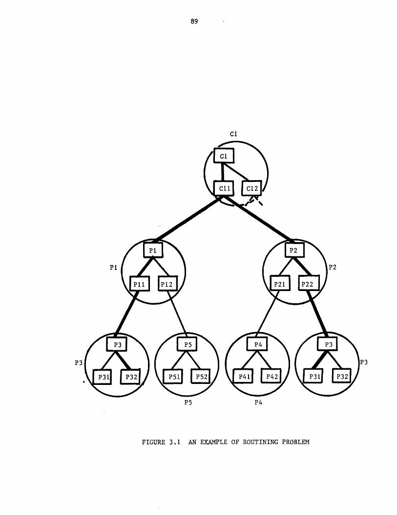
P5 P4
FIGURE 3.1 AN EXAMPLE OF ROUTINING PROBLEM
This data base should be updated as the user alters his choices. The
following information would be required to manange this mechanism:
1. number of properties to be estimated.
2. name of each property.
3. number of options available for each property estimation.
4. the default option for each property estimation.
The argument list mentioned earlier is also another mechanism to
supply the level of calculation and other computational variables to the
calculating routine.
3.5 Template Based System
The design of the GPES is based upon the framework established in this
chapter. GPES differs also from most computer simulation systems in its
representation of the process flowsheet. Process elements such as units,
streams, components, functions (pre-defined, user-defined), and variables
(user-supplied) are represented by data structures connected to form a
network. This network represents the process flowsheet and is manipulated
by the system in response to the user commands as the initial concept of
the design evolves into a final concept. This will permit the user to
retain an active model of the problem being solved. The resulting model
may be saved indefinitely for later consideration. GPES employs
generalized data structures to represent process elements. However, before
the system can utilize them to model a process configuration, it requires
certain information about the types of units, streams, components, etc.
This information about each type of each process element (unit, stream,
etc.) is stored in a data structure called a "Template" in GPES
terminology. As a drawing template enables one to draw any number of
diagrams represented in that template, a template data structure enables
the system to create other data structures representing the process
elements defined by that template. For example, a template of stream type
x enables the system to create data structures, each representing a stream
of type x. Templates also contain other information, such as information
regarding the calculating routines, error checking to be done before
control is passed to the calculating routine, etc. The collection of these
templates and associated calculating routines (TBS programs) is called a
template based system (TBS). The templates are stored in a set of files
called the template data base. The information in this data base is
controlled by the TBS administrator. To enable the the TBS administrator
to insert, update, or delete the information in the data base, an
interactive program called "updatetdb" (update template data base) has
been developed along with a set of commands to control the operations of
this subsystem. The set of commands is called Template Definition Language
(TDL). The design of the template data base and other issues related to
the template data base is given in the next chapter.
CHAPTER 4
THE TEMPLATE DATA BASE
As described earlier, GPES creates a network of data structures, to
represent a chemical process. To create this network, however, it requires
certain information about the types of units, streams, components, etc.
This information is stored in the form of "templates" in a data base called
the "Template Data Base". The information in this data base is controlled
by the TBS system administrator. To enable him or her to insert, update or
delete the information in the data base, an interactive program called
"updatetdb" has been developed along with a set of commands to control
program operations. The set of commands is called Template Definition
Language (TDL).
4.1 The Information Content of the Template Data Base
The information in the data base is stored in the form of PL/1-type
data structures. All information is related to one of the following:
1. The Unit Types
2. The Stream Types
3. The Component Types
4. The Function Types
5. The Property Estimation Methods
6. The Physical Quantity Dimensions (units) and Unit Conversions
7. System Control Information
8. Text Information
The following terms and structures need to be explained before
describing the above information categories.
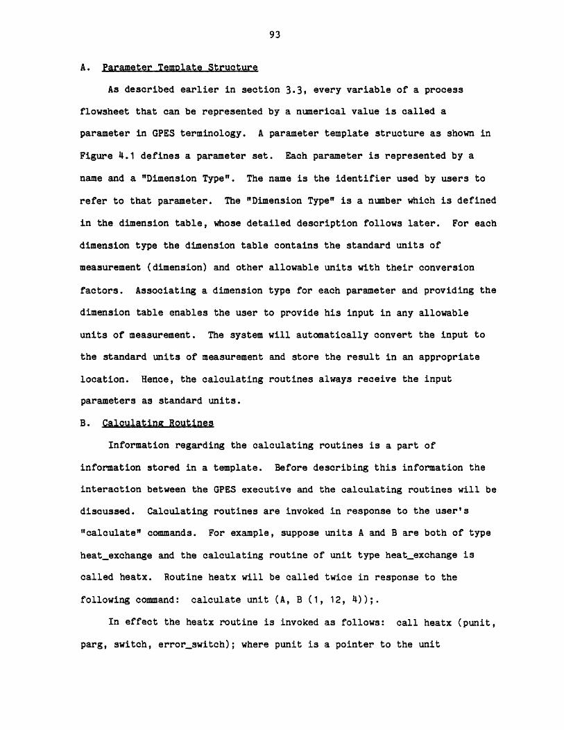
A. Parameter Template Structure
As described earlier in section 3.3, every variable of a process
flowsheet that can be represented by a numerical value is called a
parameter in GPES terminology. A parameter template structure as shown in
Figure 4.1 defines a parameter set. Each parameter is represented by a
name and a "Dimension Type". The name is the identifier used by users to
refer to that parameter. The "Dimension Type" is a number which is defined
in the dimension table, whose detailed description follows later. For each
dimension type the dimension table contains the standard units of
measurement (dimension) and other allowable units with their conversion
factors. Associating a dimension type for each parameter and providing the
dimension table enables the user to provide his input in any allowable
units of measurement. The system will automatically convert the input to
the standard units of measurement and store the result in an appropriate
location. Hence, the calculating routines always receive the input
parameters as standard units.
B. Calculatinx Routines
Information regarding the calculating routines is a part of
information stored in a template. Before describing this information the
interaction between the GPES executive and the calculating routines will be
discussed. Calculating routines are invoked in response to the user's
"calculate" commands. For example, suppose units A and B are both of type
heatexchange and the calculating routine of unit type heatexchange is
called heatx. Routine heatx will be called twice in response to the
following command: calculate unit (A, B (1, 12, 4));.
In effect the heatx routine is invoked as follows: call heatx (punit,
parg, switch, errorswitch); where punit is a pointer to the unit
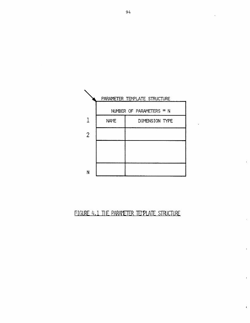
L PARAMETER TEMPLATE STRUCTURE
NUMBER OF PARAMETERS = N
NAME DIMENSION TYPE
FIGURE 4,1 TIE PAPRETER TEMPLATE STRUCTURE
____________________I ___________________________
structure. For the first call on routine heatx, punit points to the unit
"A" data structure, and on the second call it points to the unit B data
structure (unit data structures will be described in Chapter 5). The
variable parg is a pointer to a list of arguments in a data structure such
as shown in Figure 6.3. During the first call parg is null, for the second
call it points to an argument data structure containing the three supplied
arguments 1,12, and 4. The argument switch indicates whether convergence
has been achieved, and is only used for special types of calculating
routines known as convergence routines. The argument errorswitch
indicates whether a serious error has been detected in the routine. The
argument list, such as the one in the above command, may be used to specify
the calculation route or to provide additional input to the routine. In
any case, the interpretation of these arguments should be clear both to the
user and the calculating routine.
The first argument is always interpreted as the level of calculation.
If it is not provided the default level, i.e. level one, will be assumed.
As discussed in section 3.4, a calculating routine may perform different
levels of calculation. This may be due to different sets of input/output
variables, different algorithms for calculation, different mathematical
models, or different levels of accuracy.
The following information is stored in a template for a calculating
routine:
Procedure: Name of the calculating routine. If no
routine has been implemented or no routine is
needed a ";" is placed in this field and no
other information about the calculating
routine will be required.

Reference: A short description of the calculating routine
or the template; or a reference to a document
describing the calculating routine. It could
also contain information such as author, date,
etc.
Minimum Number of Arguments:
This is the minimum number of arguments that
the routine requires. It should be 0 or more.
It implies that the user should provide at
least this number of arguments in a calculate
command, invoking the routine.
Maximum Number of Arguments:
This is the maximum number of arguments that
can be passed to the routine. A negative
number in this field indicates that the
maximum number of arguments is unlimited.
This number must be at least 1; in effect this
always gives the user the option of specifying
the level of calculation (first argument).
Number of Levels of Calculation:
This is the number of levels of calculation
that the routine provides. It should be one
or more. Therefore, the first argument
provided by the user should not be greater
than this number. If no argument is provided
the level of calculation would be assumed to
be one.
The template provides also information regarding the error checking to
be done by the system for each level of calculation before control is
passed to the calculating routine. This checking is primarily for
detecting under- or over-specification for the calculating routine.
C. Value Status of Parameters
As will be described in Chapter 5, the numerical values of parameters
are stored in parameter data structures such as the one shown in Figure
5.3. With every parameter value is associated a value type. This is
entirely different from the dimension type mentioned previously and is
associated with a parameter value, not the parameter itself. The value
type of the parameter indicates how a value has been assigned to the
parameter. The value type can be one of the following:
1. Unspecified (value type = 0)
2. Assumed (value type = 1)
3. Specified (value type = 2)
4. Calculated (value type = 3)
When control is given to the calculating routine, for each level of
calculation it expects certain parameters to have one of certain types and
not others. The Value Status Template structure of Figure 4.2 is a way of
telling the GPES executive to check that the parameters have values only of
certain types. Each entry of this data base has four single "bit" flags.
If, for instance, flags 1 and 3 are turned on for a parameter value, GPES
executive will check to see that the associated type is either
"unspecified" or "specified" but neither "assumed" nor "calculated".
The four flags, when concatenated, form a 4-bit binary number ranging
form 0 to 15. This is called the "Value Status Code" and its only
significance is the convenience it offers the TBS administrator when he is
entering this information at the terminal.
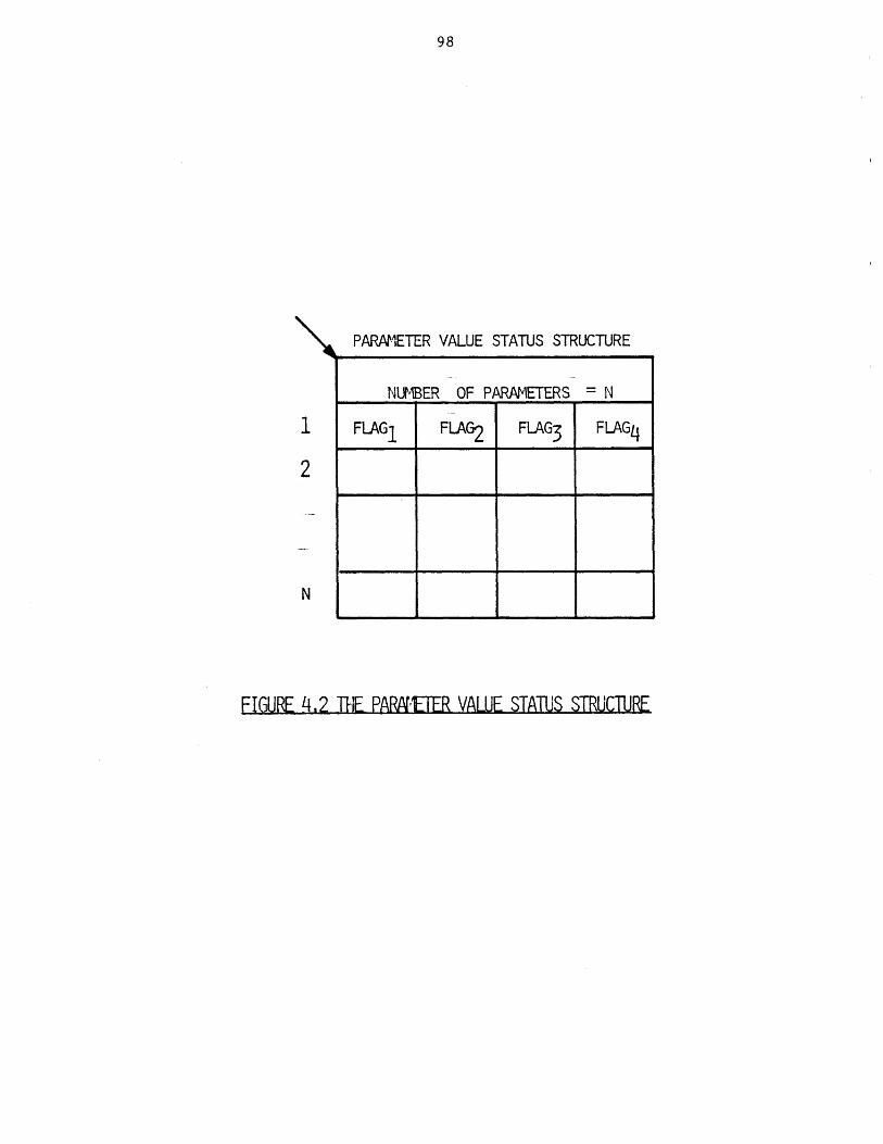
PARAMETER VALUE STATUS STRUCTURE
NUMER OF PARAMETERS = N
FLAG1 FLAG2 FLAG3 FLAG4
FIGURE 4,2 THE PARNETER VALUE STATUS STRUCTURE
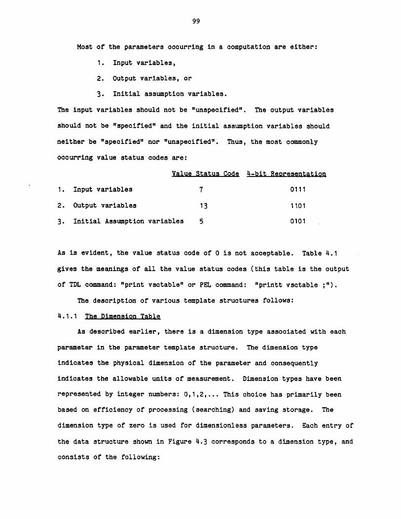
Most of the parameters occurring in a computation are either:
1. Input variables,
2. Output variables, or
3. Initial assumption variables.
The input variables should not be "unspecified". The output variables
should not be "specified" and the initial assumption variables should
neither be "specified" nor "unspecified". Thus, the most commonly
occurring value status codes are:
Value Status Code 4-bit Reoresentation
1. Input variables 7 0111
2. Output variables 13 1101
3. Initial Assumption variables 5 0101
As is evident, the value status code of 0 is not acceptable. Table 4.1
gives the meanings of all the value status codes (this table is the output
of TDL command: "print vsctable" or PEL command: "printt vsctable ;").
The description of various template structures follows:
4.1.1 The Dimension Table
As described earlier, there is a dimension type associated with each
parameter in the parameter template structure. The dimension type
indicates the physical dimension of the parameter and consequently
indicates the allowable units of measurement. Dimension types have been
represented by integer numbers: 0,1,2,... This choice has primarily been
based on efficiency of processing (searching) and saving storage. The
dimension type of zero is used for dimensionless parameters. Each entry of
the data structure shown in Figure 4.3 corresponds to a dimension type, and
consists of the following:
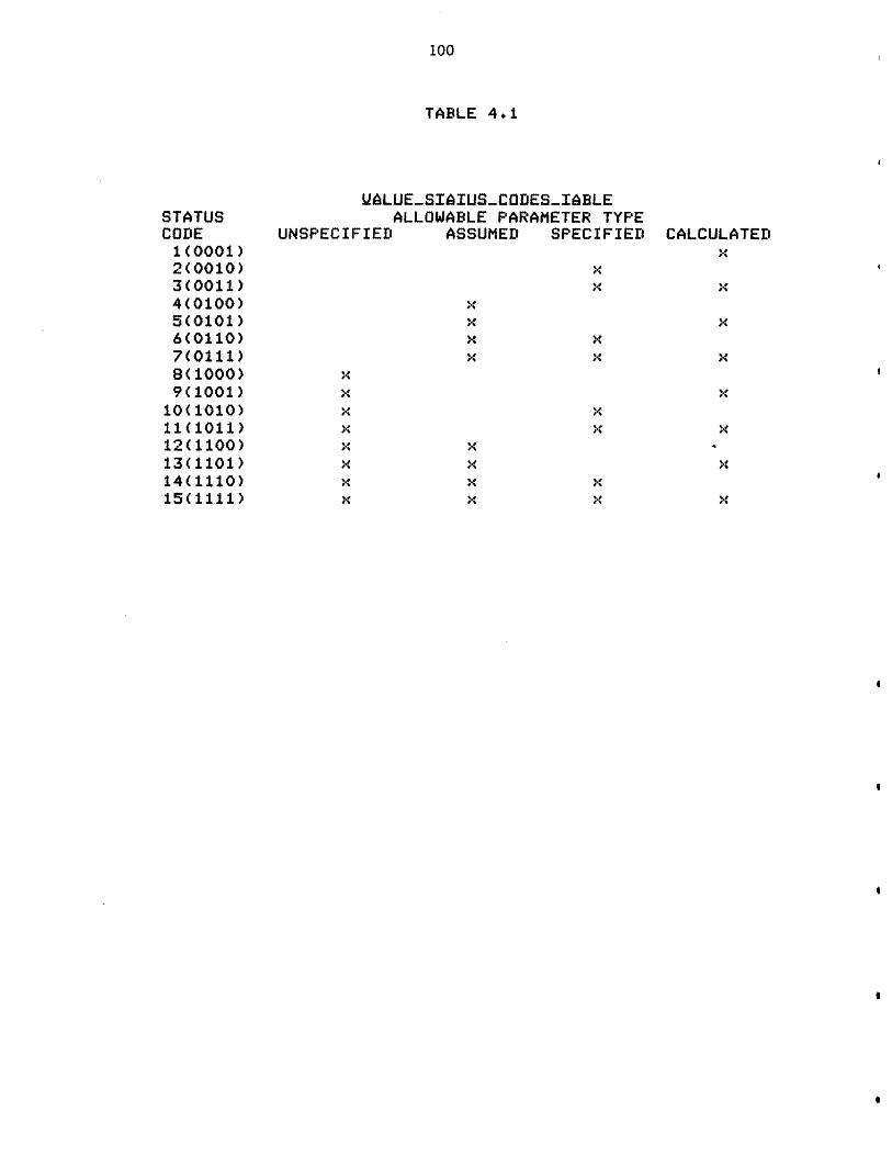
100
TABLE 4.1
STATUSCODE
1(0001)2(0010)3(0011)4(0100)5(0101)6(0110)7(0111)8(1000)9(1001)
10(1010)11(1011)12(1100)13(1101)14(1110)15(1111)
UALUE-SIAIUS-CODES-IeBLEALLOWABLE PARAMETER TYPE
UNSPECIFIED ASSUMED SPECIFIED CALCULATED
x x
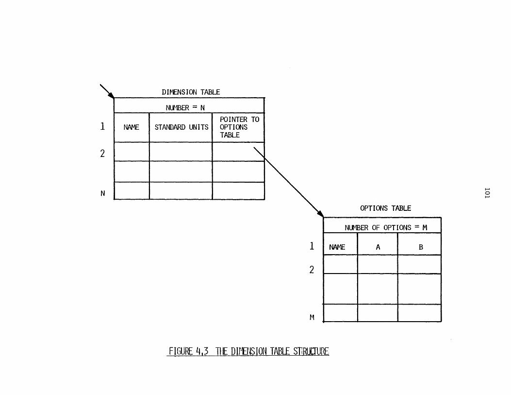
DIMENSION TABLE
_______ NUMBER = N _____
POINTER TONAME STANDARD UNITS OPTIONS
TABLE
OPTIONS TABLE
FIGURE '4,3 TIlE DII{J\ISION TABLE SliRLJJURE
NUMBER OF OPTIONS = M
NAME A B
FIGURE 4,3 TIE DIFBISION TABLE ST!RUR
102
a) name of the physical dimension (e.g., temperature, pressure, etc.)
b) standard units of measurement (e.g., DEGF)
c) a pointer to a data structure which contains other
options with their conversion factors.
There are two constants for converting a value in optional units to
the standard units. A linear relation is assumed such as
y= A + B x
where: y the value in standard units,
x the value in other allowable units, and
A and B are conversion factors.
When the user provides his input in optional units of measurement the
executive will automatically convert the input to the standard units of
measurement by using the above conversion formula. An example of a
dimension table is shown in Figure 4.4.
4.1.2 Stream Templates
A stream template contains a set of information defining a stream
type. All stream templates are placed in a directory to facilitate the
search for the template of a stream type. The directory is called "Stream
Template Directory" and is shown in Figure 4.5. Each entry of the
directory represents a stream template. The first entry represents the
template of the default stream type. Each entry contains the following
information:
a) stream type
b) the name of the calculating routine or a ";"
c) reference information
d) minimum number of arguments for the calculating routine
e) maximum number of arguments for the calculating routine
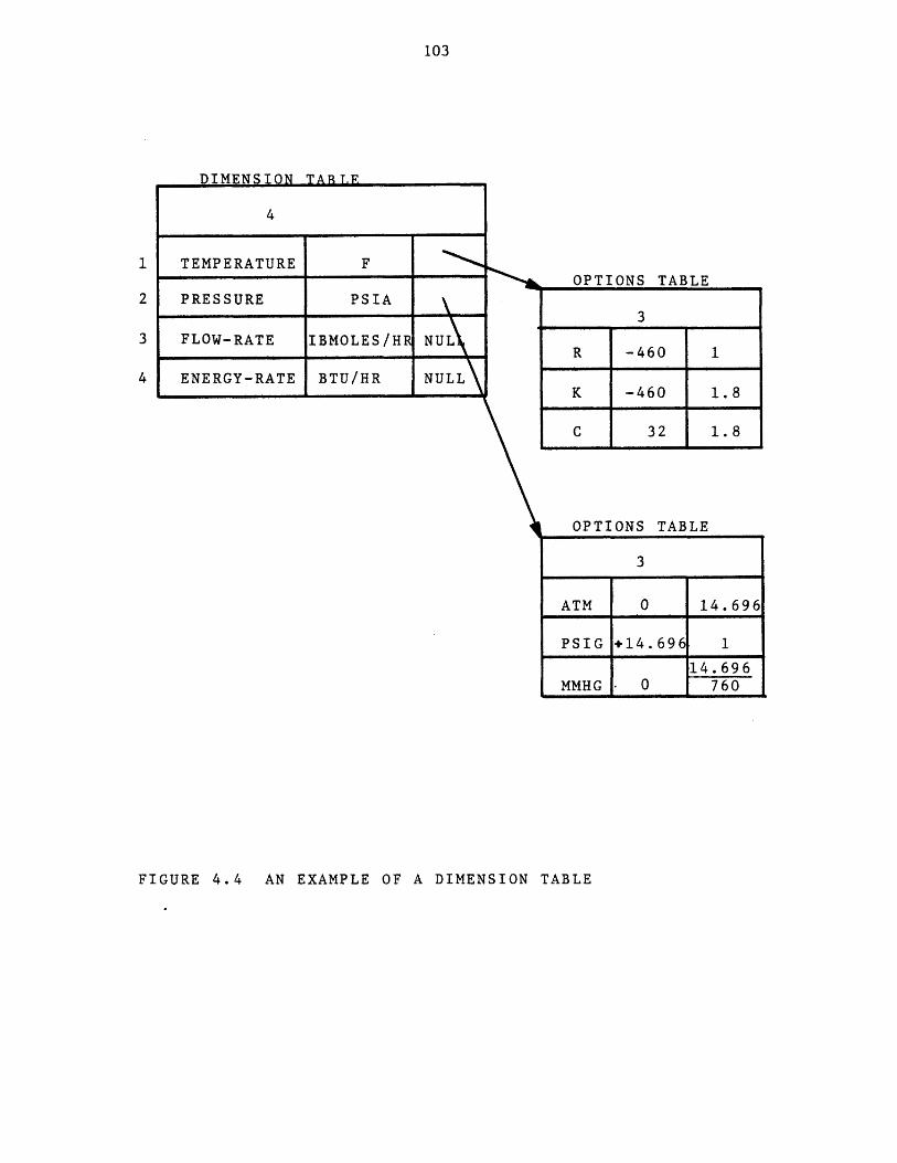
103
DIMENSION TABJF
4
TEMPERATURE F
PRESSURE PSIA
FLOW-RATE IBMOLES/H NUL
ENERGY-RATE BTU/HR NULL
OPTIONS TABLE
3
R -460 1
K -460 1.8
C 32 1.8
OPTIONS TABLE
3
ATM 0 14.696
PSIG +14.696 1
14.696MMHG - 0 760
FIGURE 4.4 AN EXAMPLE OF A DIMENSION TABLE
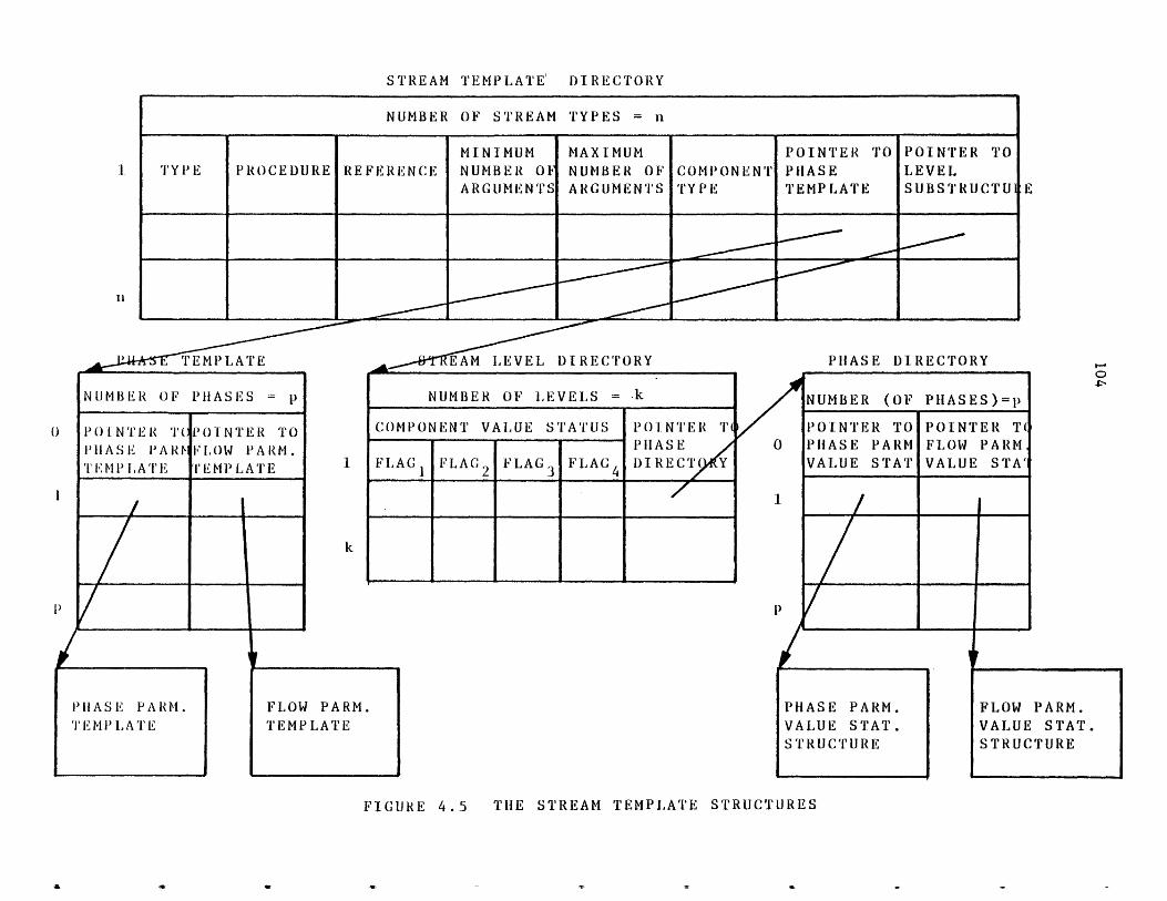
STREAM TEMPLATE DIRECTORY
NUMBER OF STREAM TYPES = n
PROCEDURE REFERENCEMINIMUMNUMBER OFARGUMENTS
MAXIMUMNUMBER OFARGUMENTS
COMPONENTTYPE
POINTER TOPHASETEMPLATE
POINTER TOLEVELSUBSTRUCTUI
0
PHASE PARM.TEM P LA TE
FLOW PARM.TEMPLATE
EAM LEVEL DIRECTORY
NUMBER OF LEVELS =k
COMPONENT VALUE STATUS PO1NTER TEP1 A SE
FLAG FLAG2 F'LAG3 FLAC4 DIRECT( Y0
PHASE DIRECTORY
p
PHASE PARM.VALUE STAT.STRUCTURE
FLOW PARM.VALUE STAT.STRUCTURE
FIGURE 4.5 THE STREAM TEMPLATE STRUCTURES
NU.MBER OF PHASES = p
POINTER T( POINTER TOPHASE PARt ILOW PARM.TEMPLATE l'EMPLATE
NUMBER (OF PHASES)=p
POINTER TO POINTER T(PHASE PARM FLOW PARMVALUE STAT VALUE STA'
105
f) type of components (chemical species) allowed to flow in the
stream. Using the symbol "none" in this field indicates that
no component is allowed to flow in the stream, and the symbol
"all" indicates that any type component is allowed to flow in
the stream.
g) a pointer to a data structure which describes the different
phases of the stream. The data structure is called "phase
template". Phase zero usually represents the total stream.
A stream may have any number of phases. The "phase template"
contains the number of phases and an entry for each phase.
Each entry contains two pointers; one pointer points to a
parameter template structure describing the phase parameters
and another pointer points to a template structure describing
the flow parameters. The phase parameter template structure
contains the number of phase parameters and the name and
dimension type of each parameter. The flow parameter template
structure contains the number of flow parameters and the name
and dimension type of each parameter.
h) a pointer to a data structure which contains the number of
levels of calculation and for each level the error checking to
be performed by the system before control is passed to the
calculating routine. For each level of calculation there is
an entry in this data structure. Each entry contains the
following:
i) four flags indicating the value status codes of all
parameters of all components flowing in the stream
(if any).
106
ii) a pointer to the data structure "phase directory",
which contains the value status codes of each phase
and flow parameters of each phase of the stream.
An example of a stream template directory which contains only one
stream type is shown in Figure 4.6. The stream has one phase (phase number
0), 5 phase parameters and 1 flow parameter. Phase parameters are:
tf - Total molar flow rate
t - Temperature
p - Pressure
h - Enthalpy flow rate, and
vf - Vapor fraction (molar).
The flow parameter is molar flow rate (f).
4.1.3 Unit Templates
A unit template contains the information defining a process unit type.
All unit templates are placed in a directory to facilitate search pro-
cedures. The directory is called the "Unit Template Directory" and is
shown in Figure 4.7. Each entry of this directory represents a unit
template. The first entry represents the default unit type. Each entry
contains the following:
a) unit type (e.g., heatexchanger)
b) name of the calculating routine or a ";"
c) reference information
d) minimum number of arguments
e) maximum number of arguments
f) a pointer to a parameter template structure describing the
unit parameters. The unit parameter template structure
contains the number of unit parameters, name and dimension
type of each parameter.
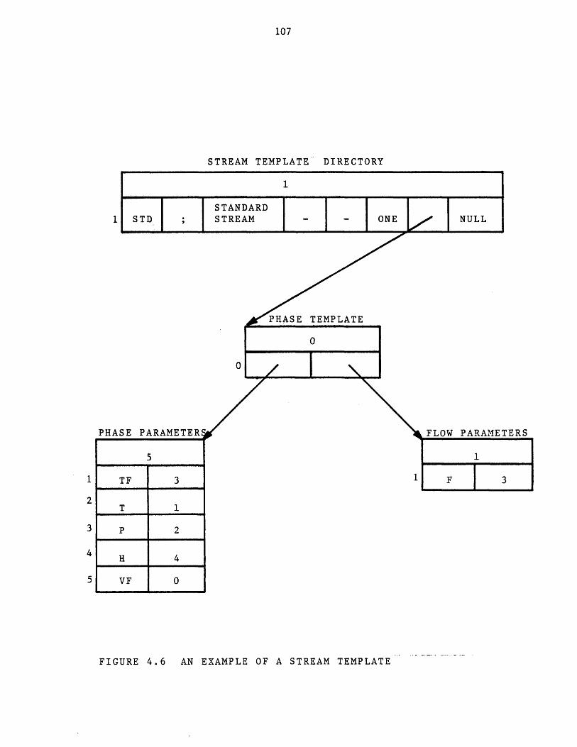
107
STREAM TEMPLATE DIRECTORY
STANDARD1 STD ; STREAM - - 0
PHASE TEMPLATE
0
0
PHASE PARAMETERE
5
1 TF 3
2T 1
3 P 2
4 H 4
5 VF 0
FLOW PARAMETERS
FIGURE 4.6 AN EXAMPLE OF A STREAM TEMPLATE
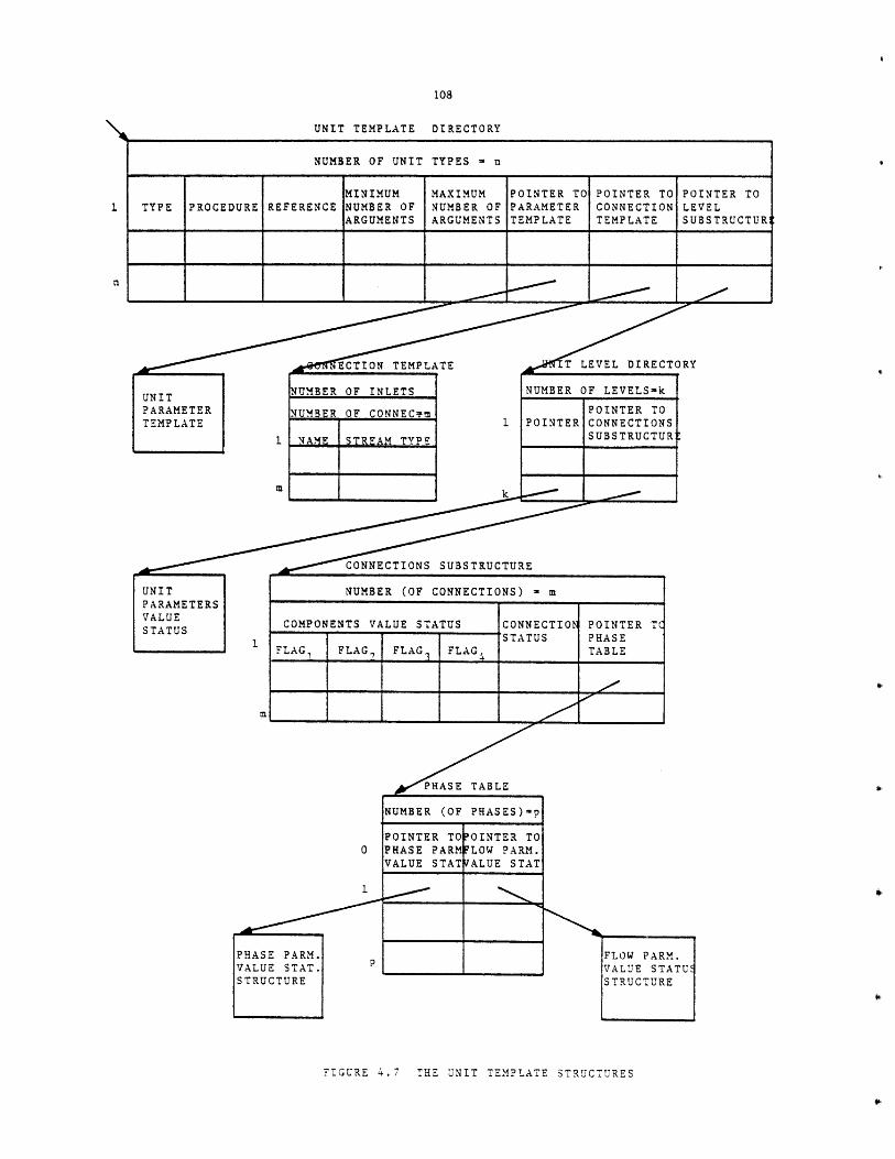
UNIT TEMPLATE DIRECTORY
NUMBER OF UNIT TYPES - n
MINIMUM MAXIMUM POINTER TO POINTER TO POINTER TOTYPE PROCEDURE REFERENCE NUMBER OF NUMBER OF PARAMETER CONNECTION LEVEL
ARGUMENTS ARGUMENTS TEMPLATE TEMPLATE SUBSTRUCTUR
T LEVEL DIRECTORY,,ECTIONf TEMPLATI
UNIT NUMBER OF INLETS
PARAMETER NUMBER OF CONNECemTEMPLATE
1 NAME STREAM TYPE
m
CONNECTIONS SUBSTRUCT
UNIT NUMBER (OF CONNECTIONPARAMETERSVALUE COMPONENTS VALUE STATUS CSTATUS A
NUMBER OF LEVELS-k
POINTER TOPOINTER CONNECTIONS
SUBSTRUCTURE'
URE
S) =m
ONNECTIOj POINTER TCTATUS PHASE
0
PHASE PARM.VALUE STAT.STRUCTURE
PHASE TABLE
NUMBER (OF PHASES)=p
POINTER TOOINTER TOPHASE PARMFLOW PARM.VALUE STAT/ALUE STAT
FLOW PARM.VALUE STATUSTRUCTURE
FIGURE 4.7 THE UNIT TEMPLATE STRUCTURES
FLA FLA FA F GTBL
109
g) a pointer to the connections template structure describing the
streams flowing into and out of the unit. The connections
template structure contains: the number of inlets (0 or
more), the number of connections (inlets and outlets), the
name of each connection, and the type of streams allowed to be
connected to each connection. The symbol "all" in the latter
field indicates that any type stream could be connected.
h) a pointer to a data structure which contains the number of
levels of calculation and for each level of calculation
specifies the error checking to be performed by the system,
before control is passed to the calculating routine. The
first entry of this data structure is associated with the
level one calculation and the second entry is associated with
the level two calculation, and so on. Each entry contains two
pointers: one points to a parameter value status structure
describing the status of each unit parameter's value; and
another one points to the connections substructure. The
connection substructure describes the checking procedures
for the unit connections. The connection substructure has as
many entries as the unit has connections. For each entry of
this structure there is a connection status. It is a number
indicating whether a stream should or should not be connected
to that connection. A connection status of 1 indicates that
such a stream is required. A connection status of 2 indicates
that such a stream is not permitted. A connection status of 3
indicates that such a stream is optional. If a specified
stream type can be connected to a connection (connection

110
status is one, or three and stream type of the connection is
not "all") then the entry contains the following additional
information:
i) value status of all parameters of all components (if
any) flowing in the connected stream.
ii) a pointer to a data structure describing the value
status of each phase or flow parameter of each phase
of the stream.
An example of a unit template is shown in Figure 4.8. The unit is a
splitter. It has 1 parameter, 1 inlet, and 2 outlets. The unit parameter
is the splitting ratio (R) and the inlet and outlet streams are of type
"STD" as defined earlier in Figure 4.6.
4.1.4 Component.Templates
A component template contains information defining a component type.
All component templates are placed in a directory to facilitate the search
for the template of a given component type. The directory is called
"Component Template Directory" and is shown in Figure 4.9. Each entry of
the directory represents a component template. The first entry represents
the template of the default component type. Each entry contains the
following information:
a) component type.
b) the name of the calculating routine or a ";".
c) reference information.
d) minimum number of arguments for the calculating
routine.
e) maximum number of arguments for the calculation
routine.
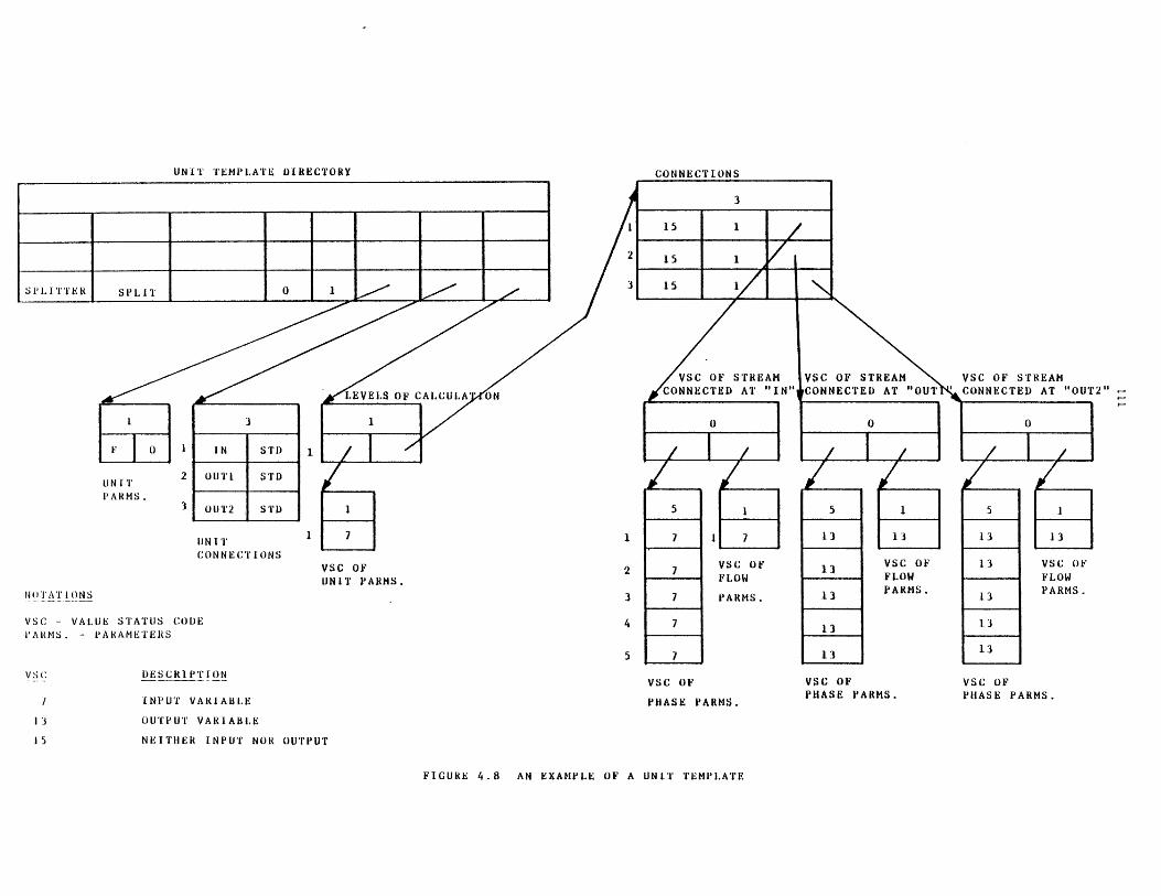
UNIT TEMPLATE DIRECTORY
UN ITPARMS.
UN ITCONNECTIONS
VSC OF STREAMCONNECTED AT "OUT2"
VSC OFUNIT PARMS.
N(TATIONS
VSC - VALUE STATUS CODEPARMS. - PARAMETERS
DESCRIPTIONVSC OF
PHASE PARMS.INPUT VARIABLE
OUTPUT VARIABLE
NEITHER INPUT NOR OUTPUT
VSC OFPHASE PARMS.
VSC OFPHASE PARMS.
FIGURE 4.8 AN EXAMPLE OF A UNIT TEMPLATE
VSC OFFLOWPARMS.
CONNECT
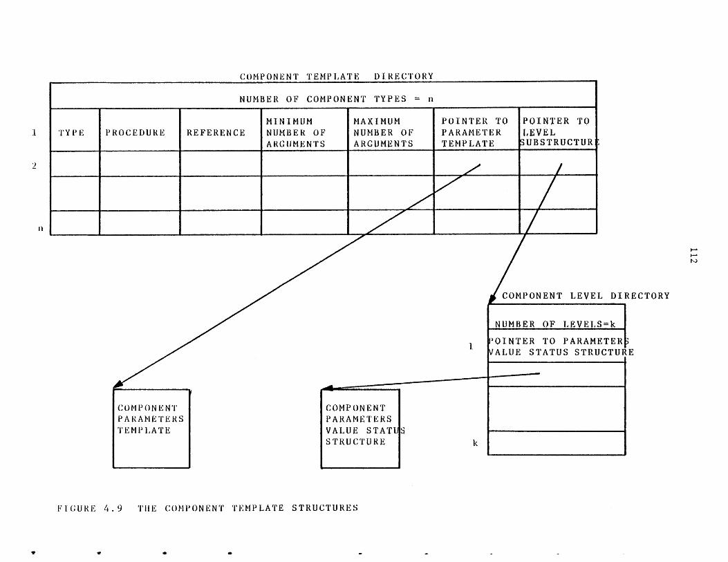
COMPONENT TEMPL[ATE DIRECTORY
NUMBER OF COMPONENT TYPES n
[MINIMUM MAXIMUM POINTER TO POINTER TOTYPE PROCEDURE REFERENCE NUMBER OF NUMBER OF PARAMETER LEVEL
ARGUMENTS ARGUMENTS TEMPLATE UBSTRUCTUR
*I.
COMPONENTPARAMETERSTEMPLATE
COMPONENTPARAMETERSVALUE STATUSTRUCTURE
COMPONENT LEVEL DIRECTORY
NUMBER OF LEVELS=k
TOINTER TO PARAMETER'VALUE STATUS STRUCTURE
I
FIGURE 4.9 THE COMPONENT TEMPLATE STRUCTURES
V V 9 7
113
f) a pointer to a parameters structure describing the
component parameters. The parameters structure
contains the number of component parameters, and the
name and dimension type of each parameter.
g) a pointer to a data structure containing the number
of levels of calculation and for each level of
calculation information regarding the error checking
to be carried out by the system, before control is
passed to the calculating routine. The first entry
of this data structure is associated with the level
one of calculation and the second entry is
associated with the level two and so on. Each entry
points to a parameters value status structure
describing the status of each component parameter's
value.
An example of a component template directory having only one component
type is shown in Figure 4.10. The component has 8 parameters. Molecular
Weight (MW), Normal Boiling Point (NBP), Critical Temperature (TC),
Critical Pressure (PC), Critical Compressibility Factor (ZC), and Antoine
Vapor Pressure Constants (A1,A2,A3).
4.1.5 Function Temulates
A function template contains information defining a function type.
All function templates are placed in a directory to facilitate the search
for the template of a given function type. The directory is called
"Function Template Directory" and is shown in Figure 4.11. The first entry
represents the default function type. Each entry contains the following
information:
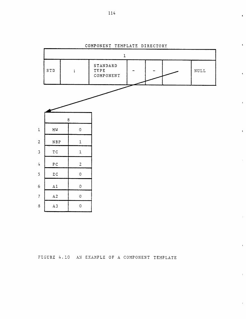
114
COMPONENT TEMPLATE DIRECTORY
STANDARDSTD ;TYPE NULL
COMPONENT
8
MW 0
NBP 1
TC 1
PC 2
ZC 0
Al 0
A2 0
A3 0
FIGURE 4.10 AN EXAMPLE OF A COMPONENT TEMPLATE
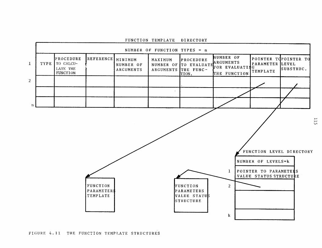
FUNCTION TEMPLATE DIRECTORY
NUMBER OF FUNCTION TYPES = n
PROCEDURE IREFERENCE MINIMUM MAXIMUM PROCEDURE NUMBER OF POINTER T POINTER TCTYPE TO CALCU- NUMBER OF NUMBER OF TO EVALUATEARGUMENTS PARAMETER LEVEL
LATE THE ARGUMENTS ARGUMENTS THE FUNC- FOR EVALUATI EMPLATE SUBSTRUC.FUNCTION TION. THE FUNCTION TEMPLATE
1
FUNCTIONPARAMETER!TEMPLATE
-~
FUNCTIONPARAMETERSVALUE STATUSTRUCTURE
I 2
FUNCTION LEVEL DIRECTORY
NUMBER OF LEVELS=k
POINTER TO PARAMETE SVALUE STATUS STRUCTU E
FIGURE 4.11 THE FUNCTION TEMPLATE STRUCTURES
116
a) function type,
b) name of the function calculating routine (e.g.,
Regression Analysis Program), or a "1;"1
c) reference information,
d) minimum number of arguments for the calculating
routine,
e) maximum number of arguments for the calculating
routine,
f) name of the procedure to evaluate the function value
or a "t;". This is the routine that will be called
when a pre-defined function appears in an arithmetic
expression,
g) the number of arguments for the above routine,
h) a pointer to a parameter template structure
describing the function parameters. The function
parameter template structure contains the number of
function parameters, the name and dimension type of
each parameter.
i) a pointer to a data structure containing the number
of levels of calculation and for each level the
specific checking procedures to be carried out by
the system, before control is passed to the
calculating routine. The first entry of this data
structure is associated with the level one of
calculation, and the second entry is associated with
the level two and so on. Each entry points to a
parameters value status structure describing the
status of each function parameter's value.

117
An example of a function template directory having only one function
type is given in Figure 4.12. The function is in the form: y = A+Bx. The
function parameters (coefficients) A and B may be calculated by routine
L1CALC. Routine L1EVAL evaluates the function for a given argument, x.
4.1.6 Table of Prooertv Estimation Methods
A calculating routine may call upon other routines, especially for
physical property computations. Usually there is more than one method for
estimating a physical property. A mechanism is provided to enable a user
to specify the particular methods to be used for estimation of
physical properties. The Table of Property Estimation Methods as shown in
Figure 4.13 is the essential part of this mechanism. Each entry of the
table corresponds to a property and contains the following:
a) the property name as known by the users.
b) the number of options available for estimating that
property.
c) the default option. This is the option that will be
in effect until the user chooses another option for
estimation of that property.
The entry number of the property in the table is called the property
number or property type. This is the number used by the physical property
estimation routine to retrieve its specified method of calculation. An
example of a property estimation methods table is shown in Figure 4.14.
4.1.7 Control Information
A set of miscellaneous information is associated with each TBS as
shown in Figure 4.15. It consists of:
a) the name of the Template Based System.
b) the serial number of the TBS, identifying the

118
CULATION
VSC OFFUNCTION PARAMETERS
FIGURE 4.12 AN EXAMPLE OF A FUNCTION TEMPLATE
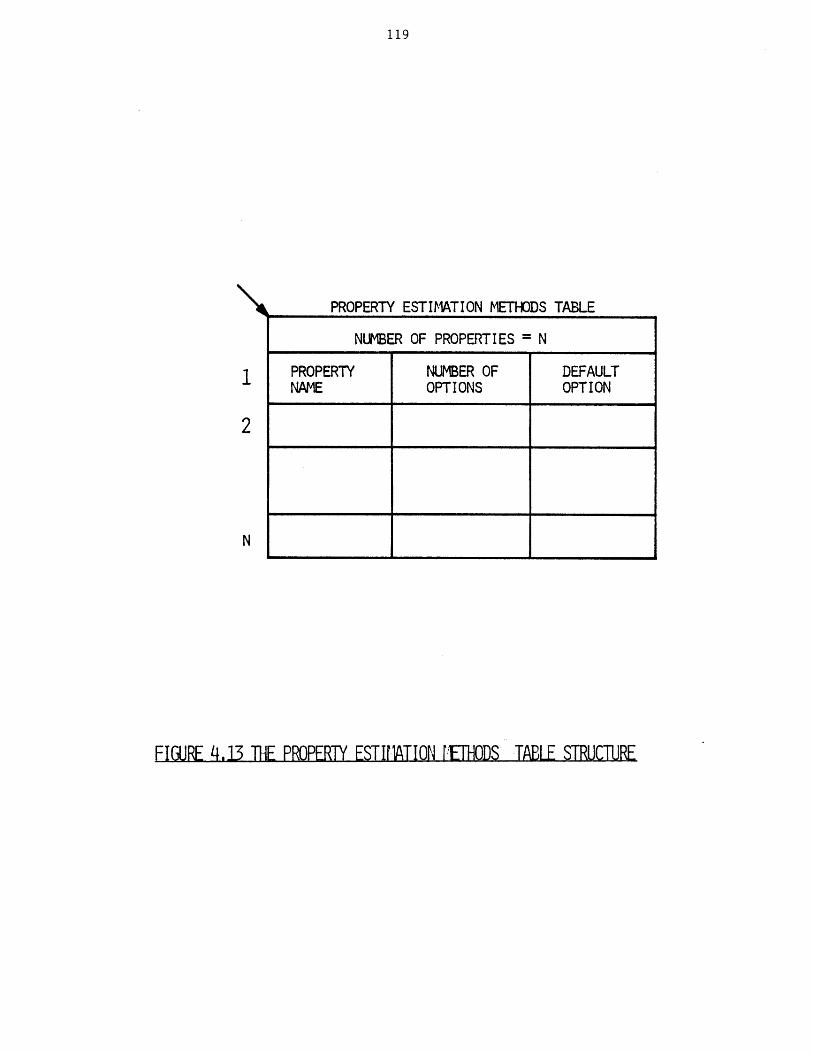
119
PROPERTY ESTIMATION METHODS TABLE
NUMBER OF PROPERTIES = N
PROPERTY NUMBER OF DEFAULTNAME OPTIONS OPTION
FIGURE 4.13 THE PROPERTY ESTIlATION EHODS TABLE STRUCTURE
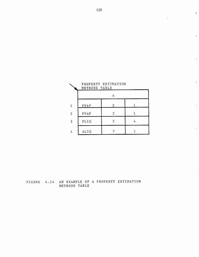
120
PROPERTY ESTIMATIONMETHODS TABLE
4
1 PVAP 2 1
2 FVAP 2 1
3 FLIQ 5 4
4 ALIQ 7 1
FIGURE 4.14 AN EXAMPLE OF A PROPERTY ESTIMATION
METHODS TABLE
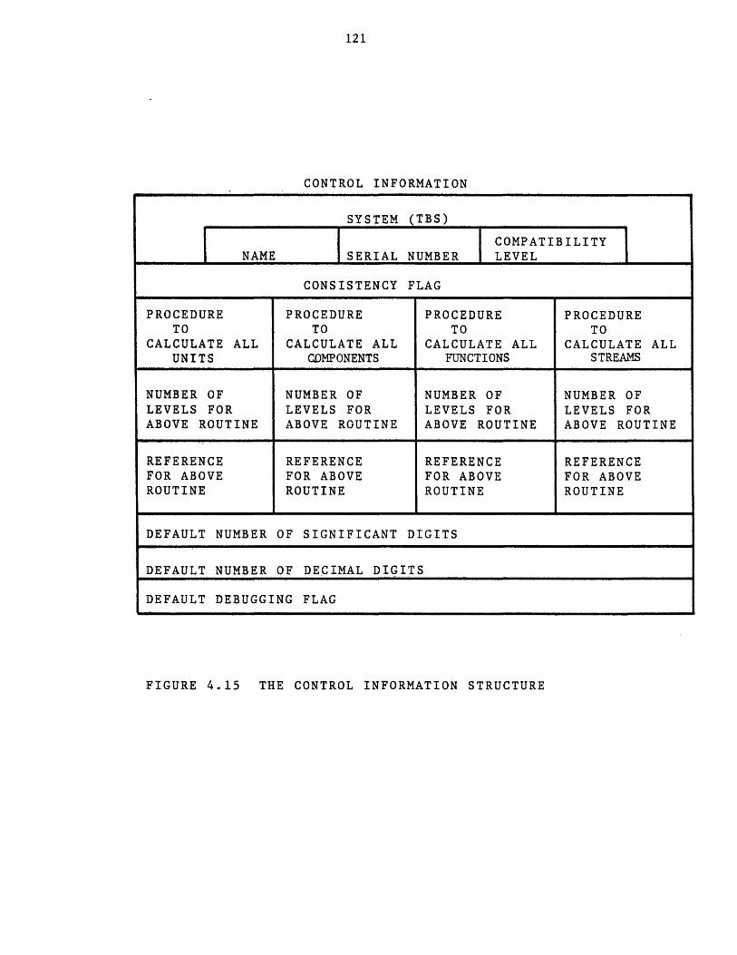
121
CONTROL INFORMATION
SYSTEM (TBS)
COMPATIBILITYNAME ISERIAL NUMBER LEVEL
CONSISTENCY FLAG
PROCEDURE PROCEDURE PROCEDURE PROCEDURETO TO TO TO
CALCULATE ALL CALCULATE ALL CALCULATE ALL CALCULATE ALLUNITS COMPONENTS FUNCTIONS STREAMS
NUMBER OF NUMBER OF NUMBER OF NUMBER OFLEVELS FOR LEVELS FOR LEVELS FOR LEVELS FORABOVE ROUTINE ABOVE ROUTINE ABOVE ROUTINE ABOVE ROUTINE
REFERENCE REFERENCE REFERENCE REFERENCEFOR ABOVE FOR ABOVE FOR ABOVE FOR ABOVEROUTINE ROUTINE ROUTINE ROUTINE
DEFAULT NUMBER OF SIGNIFICANT DIGITS
DEFAULT NUMBER OF DECIMAL DIGITS
DEFAULT DEBUGGING FLAG
FIGURE 4.15 THE CONTROL INFORMATION STRUCTURE
122
different generations of the TBS. This number
should be increased whenever the TBS is updated or
expanded.
c) the compatibility level of the TBS. There is such a
number associated with each generation of the TBS.
Those generations of a TBS having the same number
are said to be compatible. The incompatibility
problem may arise for a user dealing with two
generations of a TBS. An example will illustrate
the problem. Suppose a user of a TBS has created
and saved a process model having among other
elements streams of type "X". Then suppose that the
TBS administrator has updated the TBS and has
deleted the template of stream type "X". Now the
user attempts to retrieve his saved process under
the control of the updated TBS. Clearly his process
model is not compatible with the current generation
of the TBS. If this condition is not detected by
the system, serious problems may arise. Although
the above condition will be detected by the system,
there are other similar conditions which the system
either cannot detect or would require excessive
computer time for detection. The compatibilty level
is a way for solving this problem. The TBS
administrator should update the compatibility level
whenever the updated template data base is not
compatible with the previous generation. Extending
123
the data base (adding new templates) would not cause
incompatibility. Deleting an already defined
template as was the case in the above example will
result in an incompatible TBS. Updating a
previously defined template may or may not cause an
incompatibility problem. For example, changing the
number of phases of a stream type will result in an
incompatible TBS. Other examples are given in
Appendix B which describes the Template Definition
Language.
d) consistency flag indicating whether the template
data base is internally consistent or not. For
example,.if the template of a stream type mentioned
in a unit template is not defined, the data base is
said to be inconsistent. Only consistent data can
be said to define a TBS. The program "updatetdb"
will automatically check the data base and set the
flag, so that the inconsistent data base is not used
by the GPES executive, thus avoiding unpredictable
results.
e) procedure to calculate all units or a ";". If such
a routine has been implemented it would be called in
response to the following user command: calculate
unit all (optional argument list);
The routine should be able to determine the order in
which to calculate individual units. Such routines
are discussed in more detail in Chapter 6.
124
f) procedure to calculate all components or a ";".
g) procedure to calculate all functions or a ";".
h) procedure to calculate all streams or a ";".
i) number of levels of calculation for each of the
above routines.
j) reference information for each of the above
routines.
k) default number of significant digits (between 1 and
14).
1) default number of decimal digits (between 0 and 14).
m) default debugging flag (0 or 1).
The last three items are initial (default) values of three of the five
profile parameters. Profile parameters are those parameters that control
the operation of PEL input and output commands. The profile parameters
are:
sdigit: Significant number of digits to be used for printing numerical
values (1 to 14).
ddigit: Decimal number of digits to be used for printing numerical values
(0 to 14).
dflag: Debugging flag (between 0 and 3) which is used for debugging
purposes. Deflag of zero which is for normal operation indicates
that:
a) the GPES executive should write a message on the
user's terminal whenever it calls a calculating
routine, and
b) if a fatal error occurs in the calculating routine,
the GPES executive should take over control and
prevent the termination of the PEL session.
125
Dflag of one is a request for the latter only, and dflag
of two which may be used by the TBS administrator is a
request for the former only. The latter enables the TBS
administrator or TBS programmers using the Multics
debugging facilities to debug the TBS programs. Dflag
of three which may be used by the GPES administrator for
debugging the system is a request for additional
information regarding the internal operation of the
system. Default value of dflag can be set to either
zero or one by the TBS administrator.
output: It specifies the user's output file which could be either his
terminal or another file.
input: It specifies the user's input file which could be either his
terminal or another file.
The PEL "profile" command enables the user to specify the profile
parameters. The default values of the first three parameters
(sdigit,ddigit,dflag) are those given in the control information. The
default value of the input or output profile parameter is always the user's
terminal. An example of control information is shown in Figure 4.16.
4.1.8. Text File
The text file is created and updated by any available editor. It
contains the following information:
a) The TBS adminstrator's name.
b) Any reference about the TBS.
c) Any messages to the TBS users.
The above information (a,b,c) will be printed when the user
requests use of the TBS.
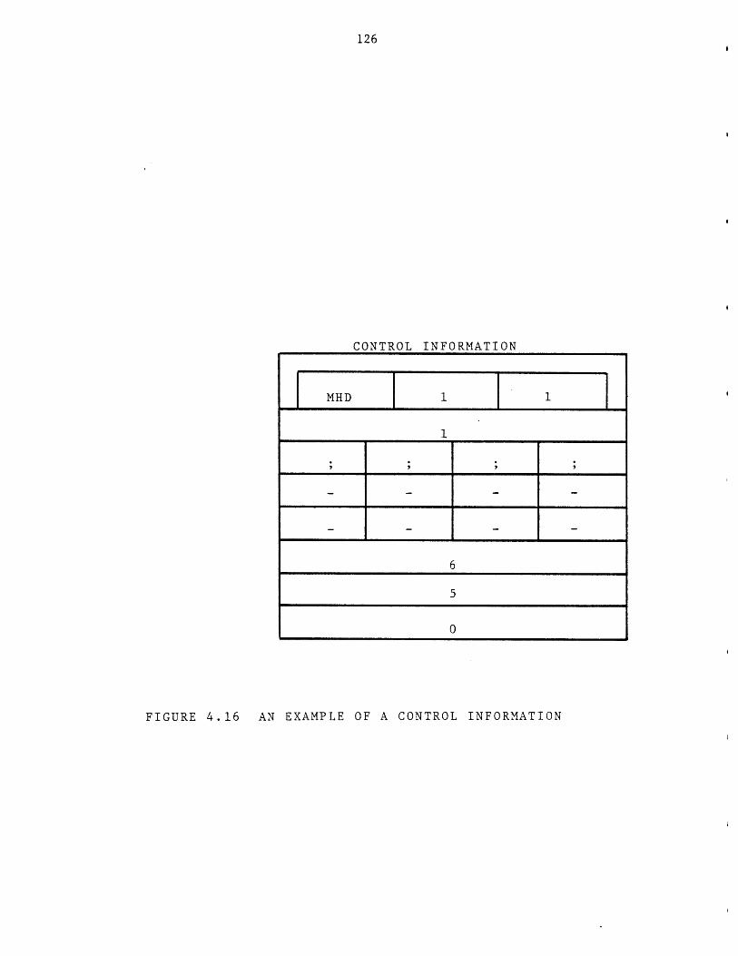
126
CONTROL INFORMATION
MHD
6
5
0
FIGURE 4.16 AN EXAMPLE OF A CONTROL INFORMATION
127
d) The TBS lock, which indicates whether the TBS can or cannot be
accessed by the users.
e) Any news about the TBS. This information, along with similar
information about the GPES will be printed in response to the
user's "news" command.
f) Any errors found or reported about the TBS. This information,
along with similar information about the GPES, will be printed
in response to the user's "bugs" command.
The format of the file is shown in Figure 4.17. Each of the above
items should start and terminate by a "%". "tbs-name" indicates the TBS
name. The format of each heading should be exactly as shown in the figure.
The notation ---- text--- indicates the text provided by the TBS system
administrator. It can be any number of characters or lines, and may
contain any character except "%", which terminates the text. The sequence
of providing the above items is immaterial. The "lock" item should have
one of the following formats:
%lock open%
%lock close%
If this item is not provided or it is as the first format, then the
system can be accessed by the users. The second form indicates that the
system cannot be accessed by the users. An example of a Text File is shown
in Figure 4.18.
4.2 The Temolate Data Base Seagments
The Template Data Base consists of a set of segments (files). These
segments accommodate various data structures that form the template data
base as listed in Table 4.2. Unit templates are stored in two segments:
one contains the unit template directory, and the other contains all the
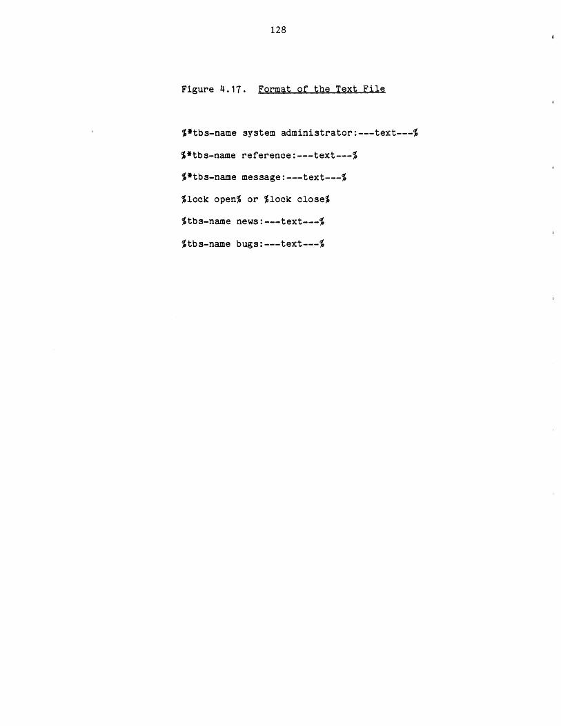
128
Figure 4.17. Format of the Text File
%*tbs-name system administrator:---text---%
%*tbs-name reference:---text---%
%*tbs-name message:---text---%
%lock open% or %lock close%
%tbs-name news:---text---%
%tbs-name bugs:---text---%
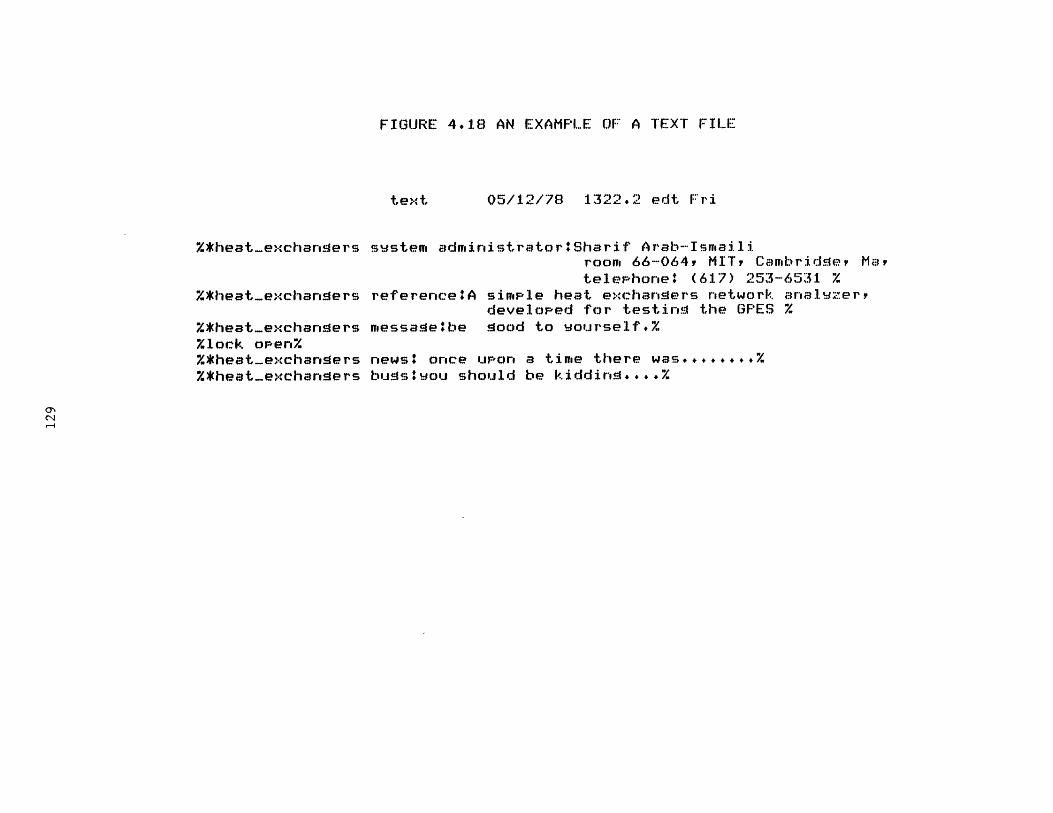
FIGURE 4.18 AN EXAMPLE OF:* A TEXT FILE
text 05/12/78 1322.2 edt Fri
%*heat-)exchangers swstem administrator: Sharif Arab-Ismailiroom 66-064, MIT, Cambridge, Maytelephone' (617) 253-6531 %
%*heat-exchangers reference*:A simple heat exchangers network anal zer,developed for testing the GPES %
%*heat-exchangers messagelbe good to Yourself.%%lock open%%*heat-exchaners news* once upon a time there was........%%*heat-exchangers busyou should be kiddin ... .

130
SEGMENT NAME
utemp_dr
stempdr
ctemp_dr
fntempdr
dimedr
estmethdr
unitarea
strmarea
comparea
funcarea
dimearea
ctl info
text
TABLE 4.2
THE TEMPLATE DATABASE SEGMENTS
SEGMENT CONTENTS
unit template directory
stream template directory
component template directory
function template directory
dimension directory
property estimation methods table
template substructures of unit types
template substructures of stream types
template substructures of component types
template substructures of function types
dimension substructures
system control information
system administrator, reference, message,
lock, bugs, news.
1.
2.
3.
4.
5.
6.
7.
8.
9.
10.
11.
12.
13.
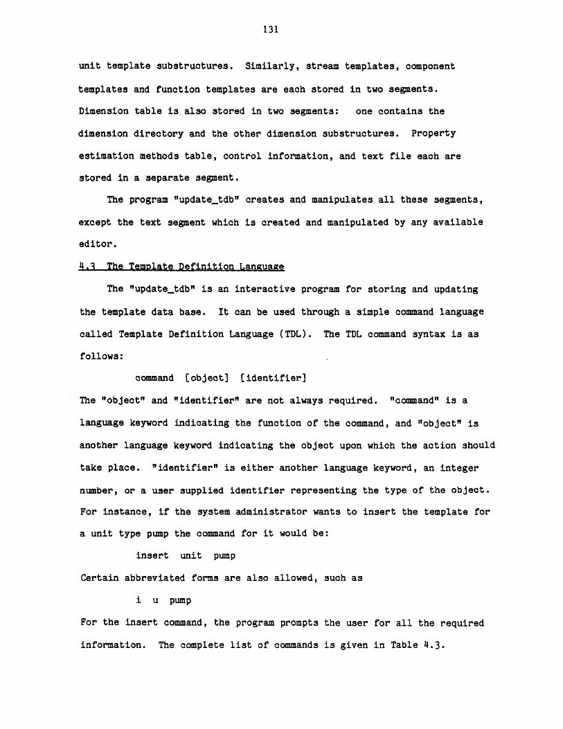
131
unit template substructures. Similarly, stream templates, component
templates and function templates are each stored in two segments.
Dimension table is also stored in two segments: one contains the
dimension directory and the other dimension substructures. Property
estimation methods table, control information, and text file each are
stored in a separate segment.
The program "1update-tdb"I creates and manipulates all these segments,
except the text segment which is created and manipulated by any available
editor.
4.3 The Temnlate Definition Language
The "updatetdb" is an interactive program for storing and updating
the template data base. It can be used through a simple command language
called Template Definition Language (TDL). The TDL command syntax is as
follows:
command [object] [identifier]
The "object" and "identifier" are not always required. "command" is a
language keyword indicating the function of the command, and "object" is
another language keyword indicating the object upon which the action should
take place. "identifier" is either another language keyword, an integer
number, or a user supplied identifier representing the type of the object.
For instance, if the system administrator wants to insert the template for
a unit type pump the command for it would be:
insert unit pump
Certain abbreviated forms are also allowed, such as
i u pump
For the insert command, the program prompts the user for all the required
information. The complete list of commands is given in Table 4.3.

132
TABLE 4.3
THE TEMPLATE DEFINITION LANGUAGE COMMANDS
COMMAND
1. insert
2. delete
OBJECT
unitstreamcomponentfunctiondimensionproperty
unitstreamcomponentfunctiondimentionproperty
unitlevelstreamlevelcomplevelfunclevel
unitstreamcomponentfunctiondimensionpropertydimtableproptablectlinfovsctableall
unitsstreamscomponentsfunctions
3. replace
4. print
5. list
6. revise ctlinfo
IDENTIFIER
" type ""type""type""type""number""number"
"type"
"type""type""type""number""number"
"type""type""type""type"
"type""type""type""type""number""number"
sysnameserialnocompatleveldefsdigitdefddigitdefdflagunitallstreamallcompallfuncall
7. end
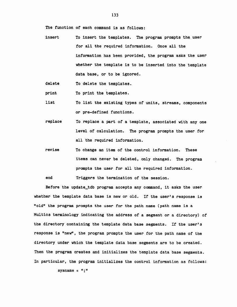
133
The function of each command is as follows:
insert To insert the templates. The program prompts the user
for all the required information. Once all the
information has been provided, the program asks the user
whether the template is to be inserted into the template
data base, or to be ignored.
delete To delete the templates.
print To print the templates.
list To list the existing types of units, streams, components
or pre-defined functions.
replace To replace a part of a template, associated with any one
level of calculation. The program prompts the user for
all the required information.
revise To change an item of the control information. These
items can never be deleted, only changed. The program
prompts the user for all the required information.
end Triggers the termination of the session.
Before the update_tdb program accepts any command, it asks the user
whether the template data base is new or old. If the user's response is
"old" the program prompts the user for the path name (path name is a
Multics terminology indicating the address of a segment or a directory) of
the directory containing the template data base segments. If the user's
response is "new", the program prompts the user for the path name of the
directory under which the template data base segments are to be created.
Then the program creates and initializes the template data base segments.
In particular, the program initializes the control information as follows:
sysname = "1;"1
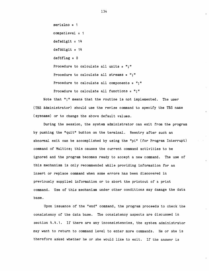
134
serialno = 1
compatlevel = 1
defsdigit = 14
defddigit = 14
defdflag = 0
Procedure to calculate all units
Procedure to calculate all streams = ";"
Procedure to calculate all components = ;"
Procedure to calculate all functions
Note that "t;I" means that the routine is not implemented. The user
(TBS Administrator) should use the revise command to specify the TBS name
(sysname) or to change the above default values.
During the session, the system administrator can exit from the program
by pushing the "quit" button on the terminal. Reentry after such an
abnormal exit can be accomplished by using the "pi" (for Program Interrupt)
command of Multics; this causes the current command activities to be
ignored and the program becomes ready to accept a new command. The use of
this mechanism is only recommended while providing information for an
insert or replace command when some errors has been discovered in
previously supplied information or to abort the printout of a print
command. Use of this mechanism under other conditions may damage the data
base.
Upon issuance of the "end" command, the program proceeds to check the
consistency of the data base. The consistency aspects are discussed in
section 4.4.1. If there are any inconsistencies, the system administrator
may want to return to command level to enter more commands. He or she is
therefore asked whether he or she would like to exit. If the answer is
135
"yes", the program asks for the default types of units, streams, components
and functions and these are made the first members of their respective
directories. When the GPES Executive wants a default type, it looks for
the first member of the corresponding directory.
The TDL language has been designed to be very simple. This
characteristic often makes it very inflexible. For example, to change an
item of information about a template one may have to delete that template
and insert a new one with the updated information. Only items of control
information can be changed directly. Information regarding any level of
calculation for a unit, stream, component, or function template can also be
replaced without deleting the entire template. A detailed description of
each TDL command is given in Appendix B. A sample computer session with
TDL is shown in Figure 10.12. The template printouts presented in Chapter
10 are also the result of TDL print commands.
4.4 "update tdb" Program
The sole purpose of the program is the management of data stored in
the template data base. The data stored in the data base must of course,
be internally consistent. The program "updatetdb" therefore, must check
for the consistency of the data, as will be described in the next section.
A schematic flowchart of the structure of the program is shown in
Figure 4.19. For a new data base the program creates and initializes the
data base segments. The program accepts one command at a time. The
command is processed either by an internal procedure, or by the external
procedure, print-temp, which is also used by the GPES executive for
printing information in the Template Data Base. The structure of the
program, in this sense, is modular, this is expected to facilitate the
maintenance of the program, which otherwise would have been difficult
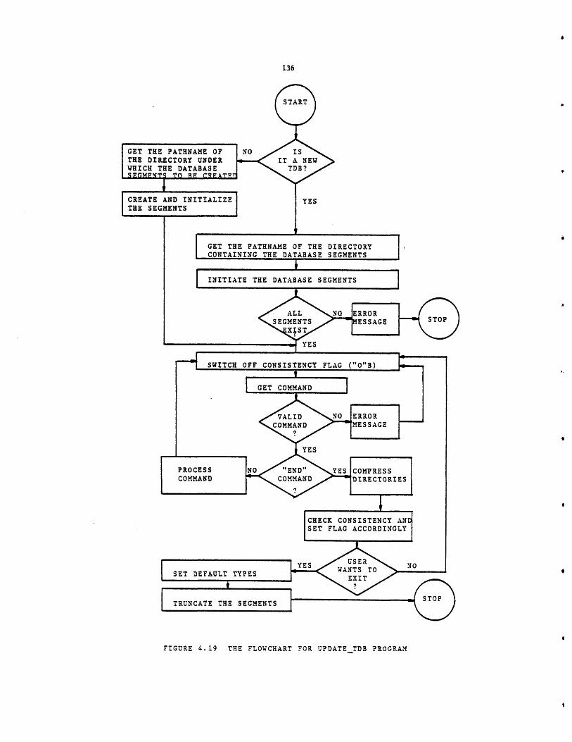
FIGURE 4.19 THE FLOWCHART FOR UPDATE TDB PROGRAM
137
considering its size. The program creates temporary structures to contain
information provided by the user for insert and replace commands. Once all
the information is provided and the user approves its correctness,
permanent structures will be created and filled by the supplied
information. The temporary structures are then deleted. The purpose of
the temporary structures is to improve the consistency aspect of the data
base, and to allow the implementation of the "quit" mechanism as described
earlier.
4.4.1 Consistency of the Data in the Template Data Base
The data stored in the data base must, of course, be internally
consistent. Only consistent data can be said to define a template-based
system. The program updatetdb, therefore, checks to see if the following
conditions are true:
1. All stream types mentioned in the unit templates must exist in the
stream template directory.
2. All component types mentioned in the stream templates must exist
in the component template directory.
3. All dimension types mentioned in all parameter templates must
exist in the dimension table.
4. There should be no undefined dimension number less than the
maximum defined number. For instance, if dimension number 9 is
defined, so should the numbers 1 to 8. This is to ensure that no
entry of the dimension table is empty.
5. The above also holds true for the property estimation methods
table.
6. The TBS should have a name.
7. Default number of decimal digits should not be greater than the
default number of significant digits.
138
These checks are made before the termination of the session. During
the session, while the data base is being updated, the program does not
allow clearly invalid data to be inserted. For instance, it will not allow
a character string where a number is required. It will not allow a value
status code to be less than 1 or greater than 15, and so on.
If there is any inconsistency, the consistency flag is turned off, so
that the data base is not used by the GPES Executive, thus avoiding
unpredictable results.
During the session, the system administrator can exit from the program
by pushing the "quit" button on the terminal. This abnormal exit can leave
the data base in an inconsistent state. To protect against this, the
consistency flag is turned off at the beginning of the command processing
loop. Reentry after an abnormal exit can be accomplished by using the "pi"
(for program interrupt) command of Multics, that returns control to the top
of the command processing loop.
4.5 Protection of the Template Data Base
Two copies of every Template Data Base are required and a third one is
recommended. The two required copies are:
1. The original, or primary copy accessible by the TBS
Administrator. This copy is created and manipulated
by the update_tdb program.
2. The system copy, accessible to the GPES Executive.
The segment names for this copy are the same as in
Table 4.2 except that they are suffixed by
".syscopy". The system copy can be used while the
primary copy is being updated. The users have
access to this copy only.
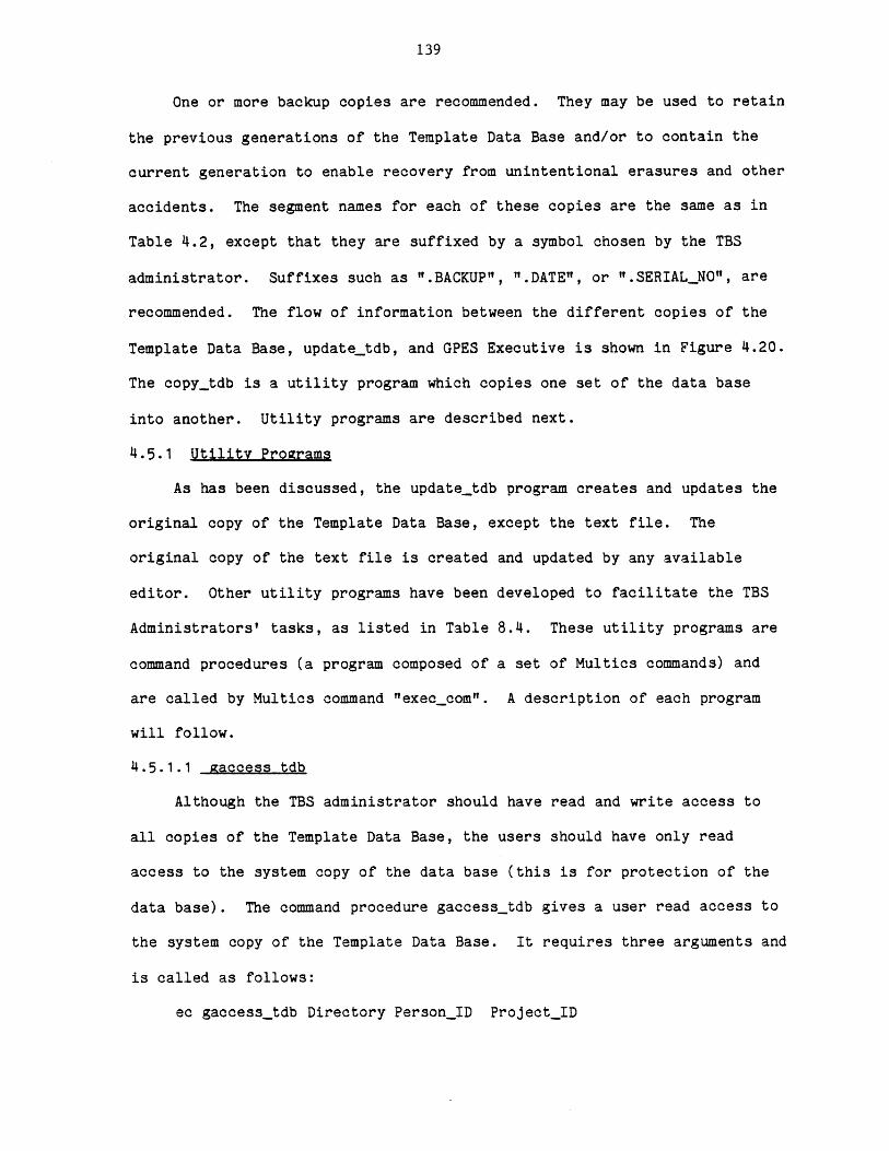
139
One or more backup copies are recommended. They may be used to retain
the previous generations of the Template Data Base and/or to contain the
current generation to enable recovery from unintentional erasures and other
accidents. The segment names for each of these copies are the same as in
Table 4.2, except that they are suffixed by a symbol chosen by the TBS
administrator. Suffixes such as ".BACKUP", ".DATE", or ".SERIAL_NO", are
recommended. The flow of information between the different copies of the
Template Data Base, updatetdb, and GPES Executive is shown in Figure 4.20.
The copytdb is a utility program which copies one set of the data base
into another. Utility programs are described next.
4.5.1 Utility Programs
As has been discussed, the updatetdb program creates and updates the
original copy of the Template Data Base, except the text file. The
original copy of the text file is created and updated by any available
editor. Other utility programs have been developed to facilitate the TBS
Administrators' tasks, as listed in Table 8.4. These utility programs are
command procedures (a program composed of a set of Multics commands) and
are called by Multics command "execcom". A description of each program
will follow.
4.5.1.1 Raccess tdb
Although the TBS administrator should have read and write access to
all copies of the Template Data Base, the users should have only read
access to the system copy of the data base (this is for protection of the
data base). The command procedure gaccesstdb gives a user read access to
the system copy of the Template Data Base. It requires three arguments and
is called as follows:
ec gaccesstdb Directory PersonID ProjectID
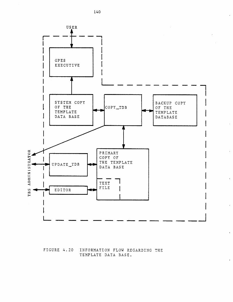
140
GPESEXECU
SYSTEOF THTEMPLDATA
TIVE
. - -. - - -.. -. -
FIGURE 4.20 INFORMATION FLOW REGARDING THETEMPLATE DATA BASE.
CPY BACKUP COPYC _TDB OF THE
TEMPLATEDATABASE
PRIMARYCOPY OFTHE TEMPLATEDATA BASE
.7 1TEXTFILE
M CcEATEBASE

141
Where:
Directory Is the relative or absolute path name of the directory
containing the Template Data Base segments.
PersonID Is the user's Multics Person ID. Using a "*" in this
field indicates all users of the given project.
Project_ID Is the user's Multics Project ID. Using a "*" in this
field indicates all projects for the given user.
Example
ec gaccesstdb >udd>ICPES>Arab-Ismaili>heatexchangers * MHD
will give read access to a system copy of the Template Data Base (located
under the specified directory) to all users of project MHD.
The TBS Administrator should write a similar command procedure to give
execute access to all TBS programs (calculating routines, etc.) to a user.
The TBS administrator should also register each user with the GPES
administrator by filling out the form shown in Figure 8.5, and sending it
to the GPES administator.
4.5.1.2 taccess tdb
This command procedure is used to remove user access to a Template
Data Base. IT is called as follows:
ec taccesstdb Directory PersonID Project_ID
Where the three arguments are the same as described for gaccesstdb. The
TBS administrator should write a similar command procedure to remove user
access to TBS programs (calculating routines, etc.). To remove a user from
the list of authorized users of the TBS, the TBS administrator should also
notify the GPES administrator by filling out and sending the form shown in
Figure 8.5.
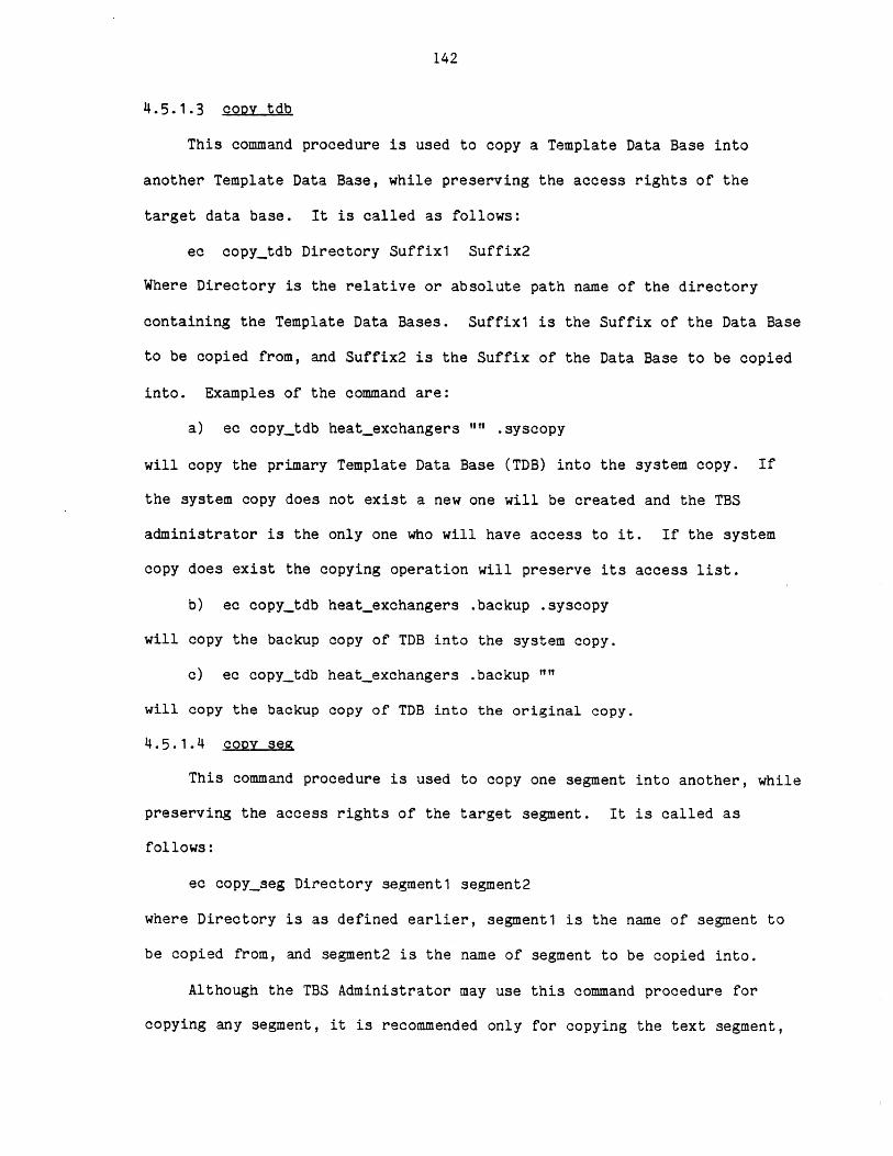
142
4.5.1.3 copy tdb
This command procedure is used to copy a Template Data Base into
another Template Data Base, while preserving the access rights of the
target data base. It is called as follows:
ec copytdb Directory Suffix1 Suffix2
Where Directory is the relative or absolute path name of the directory
containing the Template Data Bases. Suffix1 is the Suffix of the Data Base
to be copied from, and Suffix2 is the Suffix of the Data Base to be copied
into. Examples of the command are:
a) ec copy_tdb heatexchangers Il .syscopy
will copy the primary Template Data Base (TDB) into the system copy. If
the system copy does not exist a new one will be created and the TBS
administrator is the only one who will have access to it. If the system
copy does exist the copying operation will preserve its access list.
b) ec copy_tdb heatexchangers .backup .syscopy
will copy the backup copy of TDB into the system copy.
c) ec copy_tdb heatexchangers .backup ""
will copy the backup copy of TDB into the original copy.
4.5.1.4 copy seg
This command procedure is used to copy one segment into another, while
preserving the access rights of the target segment. It is called as
follows:
ec copyseg Directory segment1 segment2
where Directory is as defined earlier, segment1 is the name of segment to
be copied from, and segment2 is the name of segment to be copied into.
Although the TBS Administrator may use this command procedure for
copying any segment, it is recommended only for copying the text segment,
143
if that is the only segment in which some changes has been made. For
example, the following commmand will copy the primary text segment into the
system copy:
ec copyseg heatexchangers text text.syscopy
4.5.1.5 delete tdb
It is used to delete a TDB. It is called as follows:
ec delete_tdb Directory Suffix
where directory is as defined earlier, suffix is the suffix of the TDB to
be deleted. For example, to delete the backup copy of a Template Data
Base:
ec delete_tdb heat_exchangers .backup
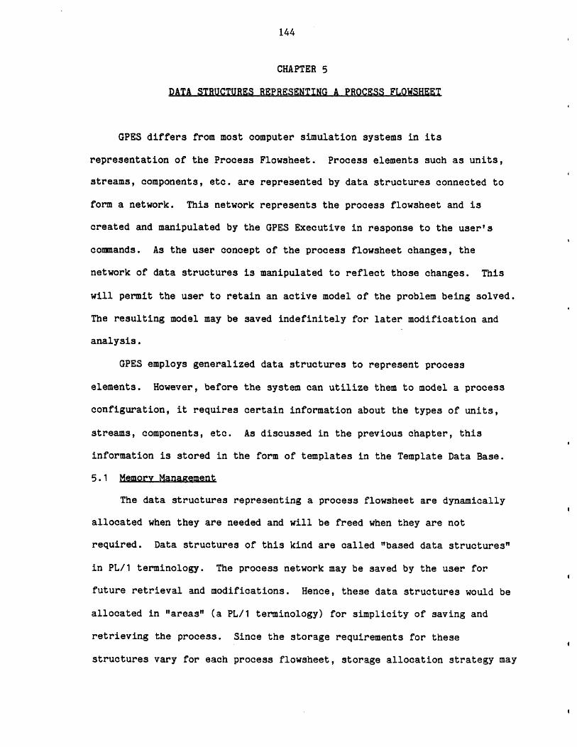
144
CHAPTER 5
DATA STRUCTURES REPRESENTING A PROCESS FLOWSHEET
GPES differs from most computer simulation systems in its
representation of the Process Flowsheet. Process elements such as units,
streams, components, etc. are represented by data structures connected to
form a network. This network represents the process flowsheet and is
created and manipulated by the GPES Executive in response to the user's
commands. As the user concept of the process flowsheet changes, the
network of data structures is manipulated to reflect those changes. This
will permit the user to retain an active model of the problem being solved.
The resulting model may be saved indefinitely for later modification and
analysis.
GPES employs generalized data structures to represent process
elements. However, before the system can utilize them to model a process
configuration, it requires certain information about the types of units,
streams, components, etc. As discussed in the previous chapter, this
information is stored in the form of templates in the Template Data Base.
5.1 Memory Management
The data structures representing a process flowsheet are dynamically
allocated when they are needed and will be freed when they are not
required. Data structures of this kind are called "based data structures"
in PL/1 terminology. The process network may be saved by the user for
future retrieval and modifications. Hence, these data structures would be
allocated in "areas" (a PL/1 terminology) for simplicity of saving and
retrieving the process. Since the storage requirements for these
structures vary for each process flowsheet, storage allocation strategy may
145
be influenced by the desire to increase user flexibility or system
efficiency. In this section several methods are presented.
A) Single partition allocation with fixed size: In this approach a
single fixed size storage area will be allocated for a process. Process
data structures will be allocated in this area and they are accessed by
offset locators (an offset locator designates the location of a data
structure within the storage area).
Advantages:
1 - Simple and efficient for the system.
Disadvantages:
1 - The size of the partition is fixed regardless of the space
needed by the problem being solved.
2 - The process size cannot exceed the size of the partition.
B) Single partition allocation with variable size: It is the same
approach as the first method with the exception that the size of the
partition should be specified by the user.
Advantages:
1 - Relatively simple and efficient for the system.
Disadvantages:
1 - User must provide the size of the partition he needs for his
model.
2 - The maximum partition size is limited (for IBM PL/1 it is
32,766 Bytes, for Multics it is about 1,048,000 Bytes).
C) Dynamic partition allocation: In this approach there may be more
than one partition made available. As the process grows and the need for
additional space is recognized, another partition will be allocated
dynamically. AREA CONDITION signals the need for additional space. In
146
this approach the addressibility is achieved by the pair of partition-
number and offset in that partition. The size of the partition should be
selected based on the system efficiency and storage requirement for average
jobs.
Advantages:
1 - Allocates partitions as needed.
2 - There is no limitation on the size of the problem being
solved.
Disadvantages:
1 - System overhead associated with two level addressing.
The latter approach meets the requirements of GPES and has been
implemented. To allocate data structures within partitions, the GPES
Executive starts from the last allocated partition and if AREA CONDITION is
raised it tries the previous partition. If the required storage is not
found in the available partitions a new partition will be allocated to meet
the requirements. The collection of these partitions is called the working
area. It should be noted that, once a partition is allocated, it will not
be freed before the end of a process analysis or the specification of the
"clear" instruction by the user. In this implementation of the system
(Multics Implementation) the size of the partition is varying. Initially,
when it is allocated it occupies only one page of storage (about 4,000
Bytes in Multics). As the need for additional storage is recognized the
partition size automatically grows until it reaches the maximum of 255
pages (about 1048,000 Bytes), then another partition is allocated. A
partition table keeps track of the locations of the partitions. A
partition table is a part of the process directory data structure which is
described next.

147
5.1.1 The Process Directory Data Structure
The directory data structure which is shown in Figure 5.1 contains
the following information:
a) The name, serial number and compatibility level of the system
(i.e., GPES) and TBS under which the process was first
created.
b) Purity Flag, indicating whether the process has or has not
been accessed by either an incompatible version of the system
or TBS, or by a different TBS.
c) The date and time the process was first created.
d) A pointer to the beginning of the unit structure's list.
e) A pointer to the component directory.
f) A pointer to the beginning of the pre-defined function
structure's list. There is no similar information in the
directory for the user-defined functions, because user-defined
functions are not allocated in the working area, as will be
described later in this chapter.
g) Two pointers to the beginning of the stream structure's list.
This redundancy is required due to the internal structure and
organization of the GPES executive.
h) A pointer to the beginning of the variable structure's list.
i) A pointer to the data structure containing the "property
estimation methods in use".
j) The current number of allocated partitions.
k) A pointer to each allocated partition.
148
DIRECTORY
SYSTEM
NAME SERIAL NO. COMPATIBILITYLEVEL
TBS
COMPATIBILITYNAME SERIAL NO. LEVEL
PURITY FLAG
DATE AND TIME
POINTER TO THE UNIT LIST
PARTITION # OFFSET
POINTER TO THE COMPONENT DIRECTORY
PARTITION # OFFSET
POINTER TO THE PRE-DEFINED FUNCTION LIST
PARTITION # OFFSET
POINTER TO THE STREAM LIST
PARTITION # OFFSET
POINTER TO THE STREAM LIST
PARTITION # OFFSET
POINTER TO THE VARIABLE LIST
PARTITION # OFFSET
POINTER TO THE DATA STRUCTURE CONTAININGTHE PROPERTY ESTIMATION METHODS IN USE
PARTITION # OFFSET
NUMBER OF PARTITIONS = n
POINTER TO lst PARTITION
POINTER TO nth PARTITION
FIGURE 5.1
THE PROCESSDIRECTORYDATA STRUCTURE
PARTITION
PDR
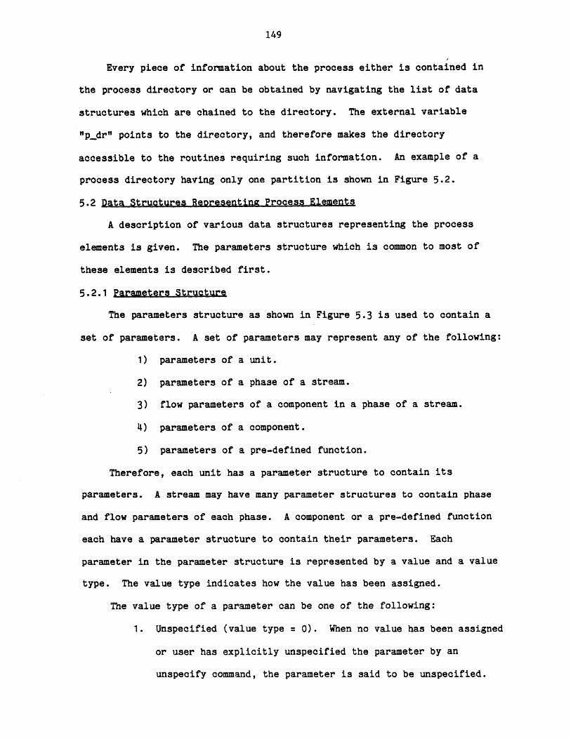
149
Every piece of information about the process either is contained in
the process directory or can be obtained by navigating the list of data
structures which are chained to the directory. The external variable
"pdr" points to the directory, and therefore makes the directory
accessible to the routines requiring such information. An example of a
process directory having only one partition is shown in Figure 5.2.
5.2 Data Structures Reoresentina Process Elements
A description of various data structures representing the process
elements is given. The parameters structure which is common to most of
these elements is described first.
5.2.1 Parameters Structure
The parameters structure as shown in Figure 5.3 is used to contain a
set of parameters. A set of parameters may represent any of the following:
1) parameters of a unit.
2) parameters of a phase of a stream.
3) flow parameters of a component in a phase of a stream.
4) parameters of a component.
5) parameters of a pre-defined function.
Therefore, each unit has a parameter structure to contain its
parameters. A stream may have many parameter structures to contain phase
and flow parameters of each phase. A component or a pre-defined function
each have a parameter structure to contain their parameters. Each
parameter in the parameter structure is represented by a value and a value
type. The value type indicates how the value has been assigned.
The value type of a parameter can be one of the following:
1. Unspecified (value type = 0). When no value has been assigned
or user has explicitly unspecified the parameter by an
unspecify command, the parameter is said to be unspecified.
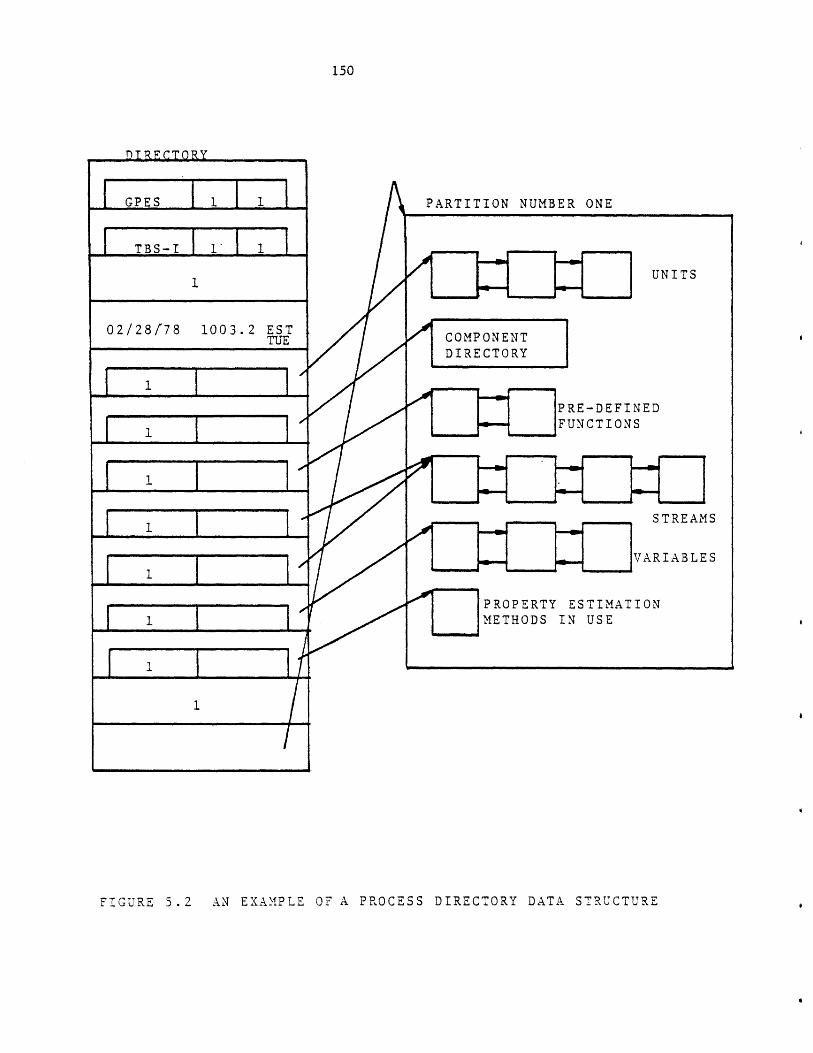
150
PARTITION NUMBER ONE
FIGURE 5.2 AN EXAMPLE OF A PROCESS DIRECTORY DATA STRUCTURE
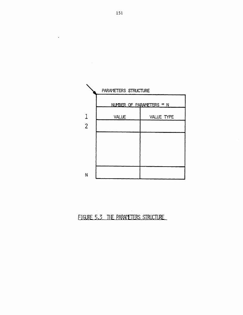
151
PARAMETERS STRUCTURE
NUMBER OF PA WAETERS = N
VALUE VALUE TYPE
FIGURE 5.3 THE PARNETERS STRUCTURE
152
2. Assumed (value type = 1). The value has been assigned by one
of the followig commands: assume, leta, or reada. The user
assumes a value for a parameter if the exact value of the
parameter is unknown, but a value is required to initiate
calculation.
3. Specified (value type = 2). The value has been assigned by
one of the following commands: specify, let, read, or repeat.
4. Calculated (value type = 3). The value has been assigned by a
calculating routine.
The value type serves the following purposes:
1. To indicate a value has been assigned to a parameter.
2. To avoid calculating a parameter which has been fixed
(specified) by the user.
3. To facilitate error checking for under- or over-specification
of the parameters for a calculating routine.
4. To indicate which parameters are the output of a calculating
routine, and hence facilitate the debugging effort.
5.2.2 The Unit Structure
The data structure representing a process unit is shown in Figure 5.4.
Unit data structures are linked together by two sets of pointers. Each
unit points to the succeeding unit and also points to the preceding unit.
The pointer to the beginning of the chain of units is kept in the process
directory data structure. The positions of the unit data structures in the
chain are not the same as the position of corresponding units in the
process flowsheet. When a new unit data structure is created, it would be
added to the beginning of the chain, and it will remain as the first unit
in the chain until a) it is deleted or b) another unit data structure is
created.
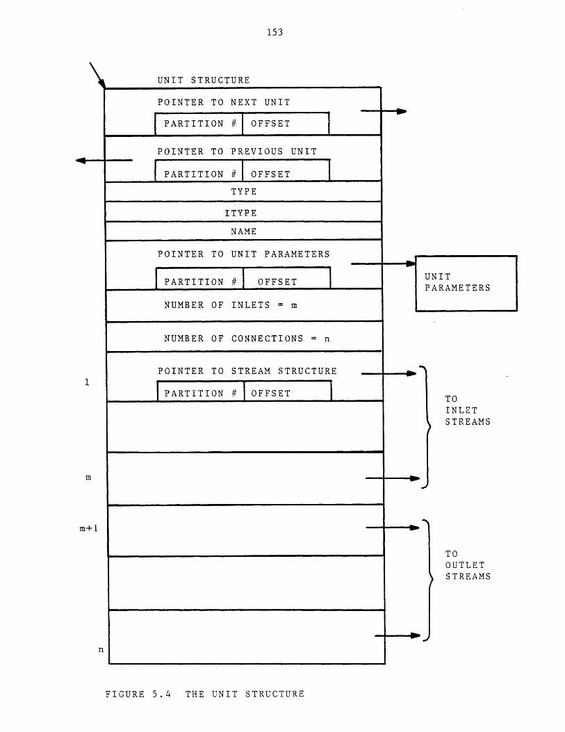
153
UNIT STRUCTURE
POINTER TO NEXT UNIT
PARTITION # OFFSET
POINTER TO PREVIOUS UNIT
PARTITION # I OFFSETTYPE
ITYPE
NAME
POINTER TO UNIT PARAMETERS
PARTITION # OFFSET ARAMETERS
NUMBER OF INLETS = m
NUMBER OF CONNECTIONS = n
POINTER TO STREAM STRUCTURE
PARTITION # OFFSET TOINLETSTREAMS
m
m+1
TOOUTLETSTREAMS
n
FIGURE 5.4 THE UNIT STRUCTURE
154
The unit data structure also contains:
a) Unit type (TYPE) and the index of the unit type in the unit
template directory(ITYPE). The ITYPE is provided to avoid
searching the unit template directory each time it is required
to access the unit's template. Whenever a process which is
saved earlier is retrieved, the system will update the ITYPE.
This is a necessary action because it is foreseeable that the
TBS system administrator may have updated the template data
base and consequently may have caused the reordering of the
unit templates in the directory. It is for this reason that
both TYPE and ITYPE have been provided.
b) Unit's name.
c) A pointer to a parameter structure which contains the unit
parameters. The parameter structure is created at the same
time the unit's structure is created. The value of each
parameter is unspecified until a value has been assigned by
the user or by a calculating routine.
d) Number of inlets. This number is taken from the unit
template.
e) Number of connections. This number is also taken from the
unit template. It is the total number of inlets and outlets.
f) For each connection a pointer to the corresponding stream's
structure. This pointer is null (partition_no =0) when no
stream is connected to the unit. These entries are updated in
response to the following user's requests:
i) Connect the unit to some streams,
ii) Disconnect the unit from some streams,
155
iii) Delete the streams which already have been connected to
the unit.
An example of a unit structure is shown in Figure 5.5. The unit
template was shown in Figure 4.8.
5.2.3 The.Comoonent Structure
The information regarding all components is stored in a data structure
called the component directory as shown in Figure 5.6. Each entry of the
directory corresponds to a chemical component. The number of entries of
the directory which is the maximum number of components that can be present
in the process is set by the user. Before the system accepts any command,
it prompts the user for this number and creates such a data structure. All
entries, of course, are empty at this time. When the user creates a
component or loads a component from a component file, the first non-empty
entry of the directory will accommodate that component. When the user
deletes a component, that entry again becomes empty and a possible location
for a new component that may be created later. Each entry contains the
following:
a) Component name.
b) Number of references. This is the number of streams that
contain the component. It is used to protect users from
deleting components which are present is some streams. This
number is initially zero. The number will be incremented by
one (1) whenever the component is said to be present in
another stream. Similarly, it will be decremented by one (1)
for each stream that no longer contains the component.
c) Component type.
d) Index of the component type in the component template
directory.
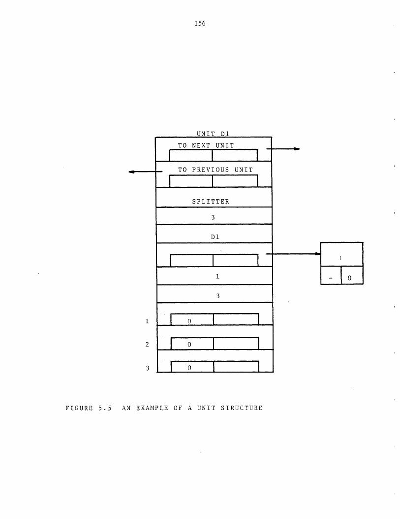
156
UNIT D1
TO NEXT UNIT
I .. I ITO PREVIOUS UNIT
I I ISPLITTER
3
Dl
3
1 0 -
2 0 -7
3 1 0
FIGURE 5.5 AN EXAMPLE OF A UNIT STRUCTURE
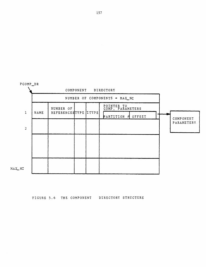
157
PCOMPDR
COMPONENT DIRI
NUMBER OF COMPOI
NUMBER OF1 NAME REFERENCESTYPE ITYPE
2
MAXLNC
FIGURE 5.6 THE COMPONENT DIRECTORY STRUCTURE
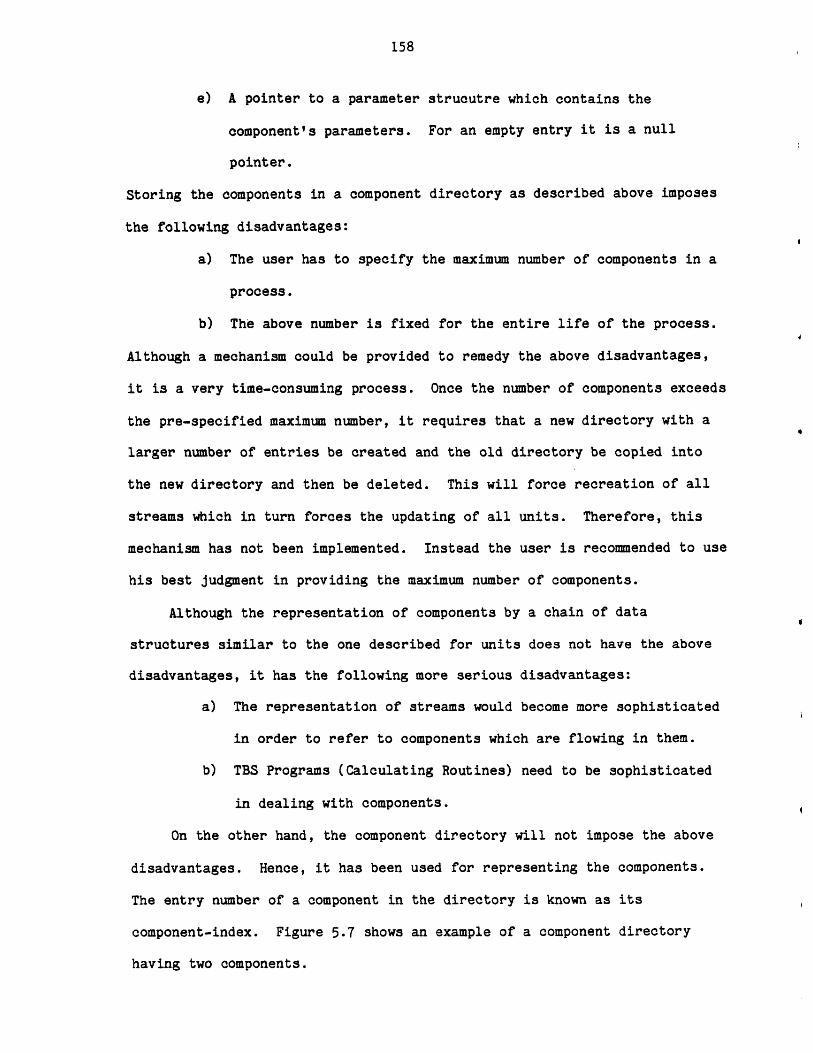
158
e) A pointer to a parameter strucutre which contains the
component's parameters. For an empty entry it is a null
pointer.
Storing the components in a component directory as described above imposes
the following disadvantages:
a) The user has to specify the maximum number of components in a
process.
b) The above number is fixed for the entire life of the process.
Although a mechanism could be provided to remedy the above disadvantages,
it is a very time-consuming process. Once the number of components exceeds
the pre-specified maximum number, it requires that a new directory with a
larger number of entries be created and the old directory be copied into
the new directory and then be deleted. This will force recreation of all
streams which in turn forces the updating of all units. Therefore, this
mechanism has not been implemented. Instead the user is recommended to use
his best judgment in providing the maximum number of components.
Although the representation of components by a chain of data
structures similar to the one described for units does not have the above
disadvantages, it has the following more serious disadvantages:
a) The representation of streams would become more sophisticated
in order to refer to components which are flowing in them.
b) TBS Programs (Calculating Routines) need to be sophisticated
in dealing with components.
On the other hand, the component directory will not impose the above
disadvantages. Hence, it has been used for representing the components.
The entry number of a component in the directory is known as its
component-index. Figure 5.7 shows an example of a component directory
having two components.

159
PCOMPDR
COMPONENT DIRECTORY
4
NC4 0 STD 1
NC5 0 STD 1
0
8
FIGURE 5.7 AN EXAMPLE OF A COMPONENT DIRECTORY
8
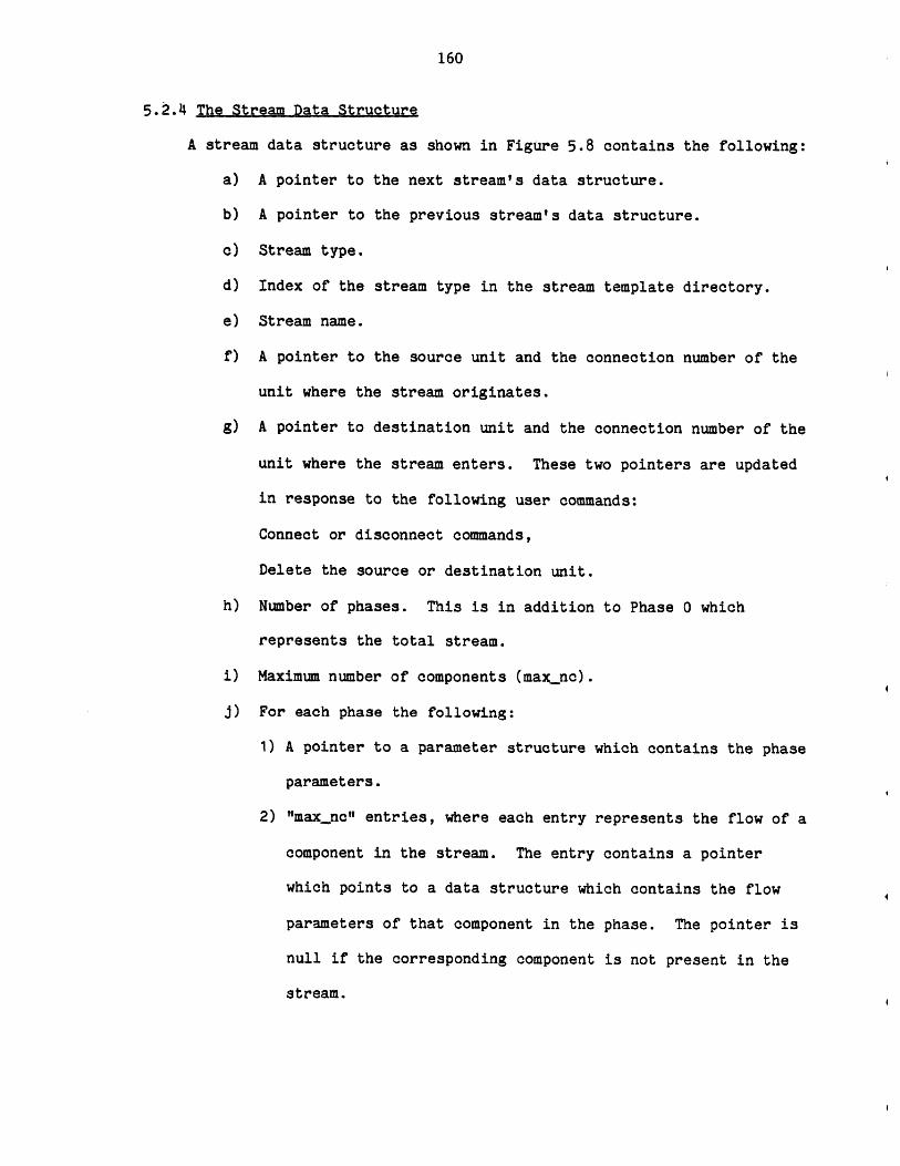
160
5.2.4 The Stream Data Structure
A stream data structure as shown in Figure 5.8 contains the following:
a) A pointer to the next stream's data structure.
b) A pointer to the previous stream's data structure.
c) Stream type.
d) Index of the stream type in the stream template directory.
e) Stream name.
f) A pointer to the source unit and the connection number of the
unit where the stream originates.
g) A pointer to destination unit and the connection number of the
unit where the stream enters. These two pointers are updated
in response to the following user commands:
Connect or disconnect commands,
Delete the source or destination unit.
h) Number of phases. This is in addition to Phase 0 which
represents the total stream.
i) Maximum number of components (max_nc).
j) For each phase the following:
1) A pointer to a parameter structure which contains the phase
parameters.
2) "maxnc" entries, where each entry represents the flow of a
component in the stream. The entry contains a pointer
which points to a data structure which contains the flow
parameters of that component in the phase. The pointer is
null if the corresponding component is not present in the
stream.
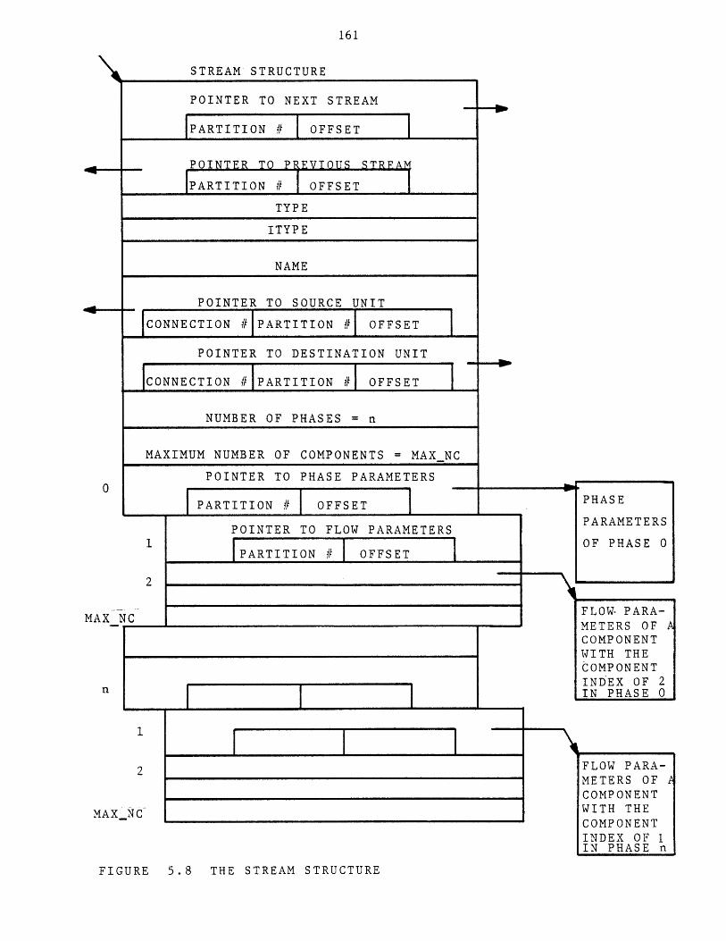
161
STREAM STRUCTURE
POINTER TO NEXT STREAM
[PARTITION # OFFSET
POINTER TO PPEVIOUS STRFA
1PARTITION # IOFFSET
TYPE
ITYPE
NAME
POINTER TO SOURCE UNIT
CONNECTION # PARTITION #I OFFSET
POINTER TO DESTINATION UNIT
CONNECTION #1PARTITION #1 OFFSET
NUMBER OF PHASES = n
MAXIMUM NUMBER OF COMPONENTS = MAXNC
POINTER TO PHASE PARAMETERS
PARTITION # OFFSET PHASE
POINTER TO FLOW PARAMETERSOF PHASE 0
1PARTITION # OFFSET
MAX NC FLOW- PARA-METERS OF ACOMPONENTWITH THE
COMPONENTINDEX OF 2
nIN PHASE 0
2 FLOW PARA-METERS OF ACOMPONENT
MAX NC WITH THE
COMPONENTINDEX OF 1IN PHASE n
FIGURE 5.8 THE STREAM STRUCTURE
162
Figure 5.9a shows a stream data structure of type "STD" which was defined
in Figure 4.6. Figure 5.9B shows the same stream containing components NC4
and NC5.
5.2.5 Pre-Defined Function Data Structure
The pre-defined function data structure is shown in Figure 5.10. It
contains the folloiwng:
a) A pointer to the next pre-defined function.
b) A pointer to the previous pre-defined function.
c) Function type.
d) Index of the function type in the function template directory.
e) Function name.
f) Number of references. This is the number of times the
' existing user-defined functions have referred to this
function. It is to protect users from deleting a pre-defined
function which is already referred to by the existing user
defined functions. In other words, a pre-defined function
having a positive number of references cannot be deleted.
g) A pointer to a parmeter structure which contains the function
parameters. These parameters are initially unspecified.
The data structure for a pre-defined function defined in Figure 4.12 is
shown in Figure 5.11.
5.2.6 Data Structures for a User-Defined Function
The general form of the data structure representing a user-defined
function is shown in Figure 5.12. It contains the following:
a) A pointer to the next user-defined function.
b) A pointer to the previous user-defined function.
c) Function name.
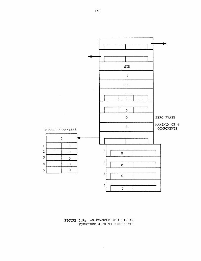
163
40-
PHASE PARAMETERS
5
1 0
2 0
3 0
4 0
5 0
STD
FEED
o
0 ZER
4 MAXCO
0
[ o I2
3 0
4 0
FIGURE 5.9a AN EXAMPLE OF A STREAMSTRUCTURE WITH NO COMPONENTS
0 PHASE
IMUM OF 4MPONENTS
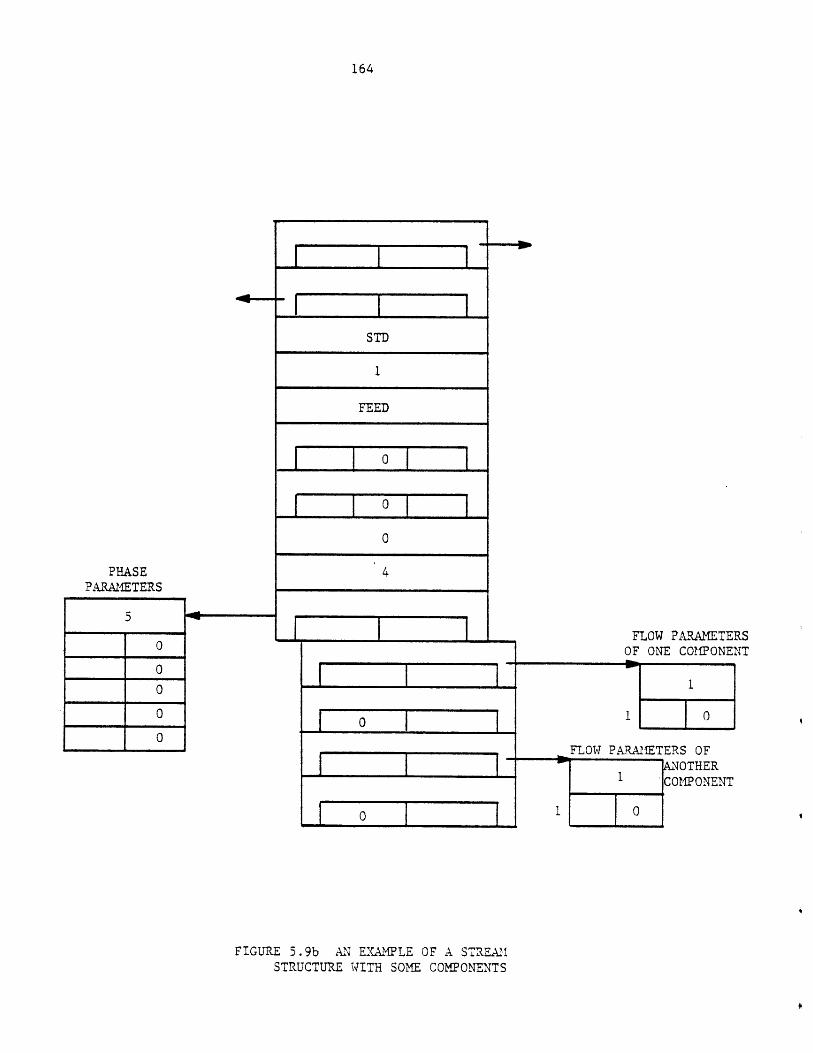
164
PHASEPARAMETERS
0
0
STD
1
FEED
0j
004
01
I I
FLOW PARAMETERSOF ONE COMPONENT
1 J 0
FLOW PARAMETERS OFANOTHER
1 COMPONENT
FIGURE 5.9b AN EXAMPLE OF A STREAMSTRUCTURE WITH SOME COMPONENTS
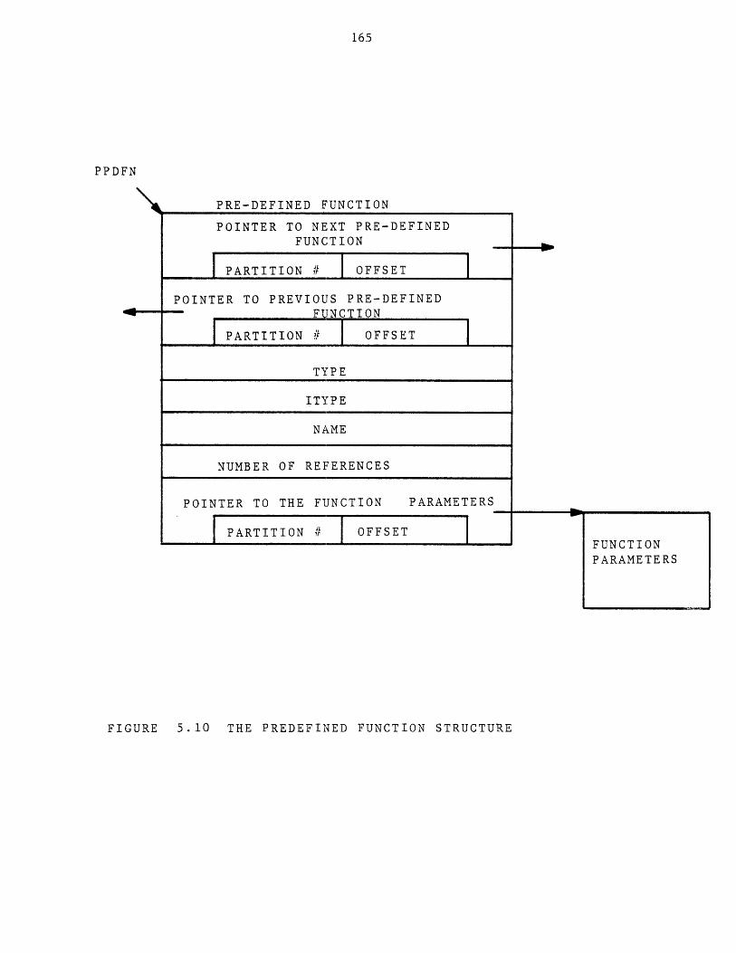
165
PPDFN
PRE-DEFINED FUNCTION
POINTER TO NEXT PRE-DEFINEDFUNCTION
PARTITION I OFFSETPOINTER TO PREVIOUS PRE-DEFINED
FUNCTION
PARTITION # OFFSET
TYPE
ITYPE
NAME
NUMBER OF REFERENCES
POINTER TO THE FUNCTION PARAMETERS
PARTITION # OFFSET
FIGURE 5.10 THE PREDEFINED FUNCTION STRUCTURE
FUNCTIONPARAMETERS
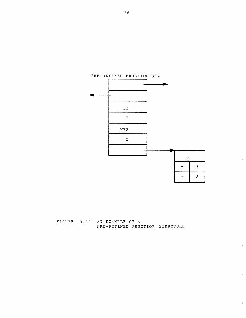
166
PRE-DEFINED FUNCTION XYZ
FIGURE 5.11 AN EXAMPLE OF APRE-DEFINED FUNCTION STRUCTURE
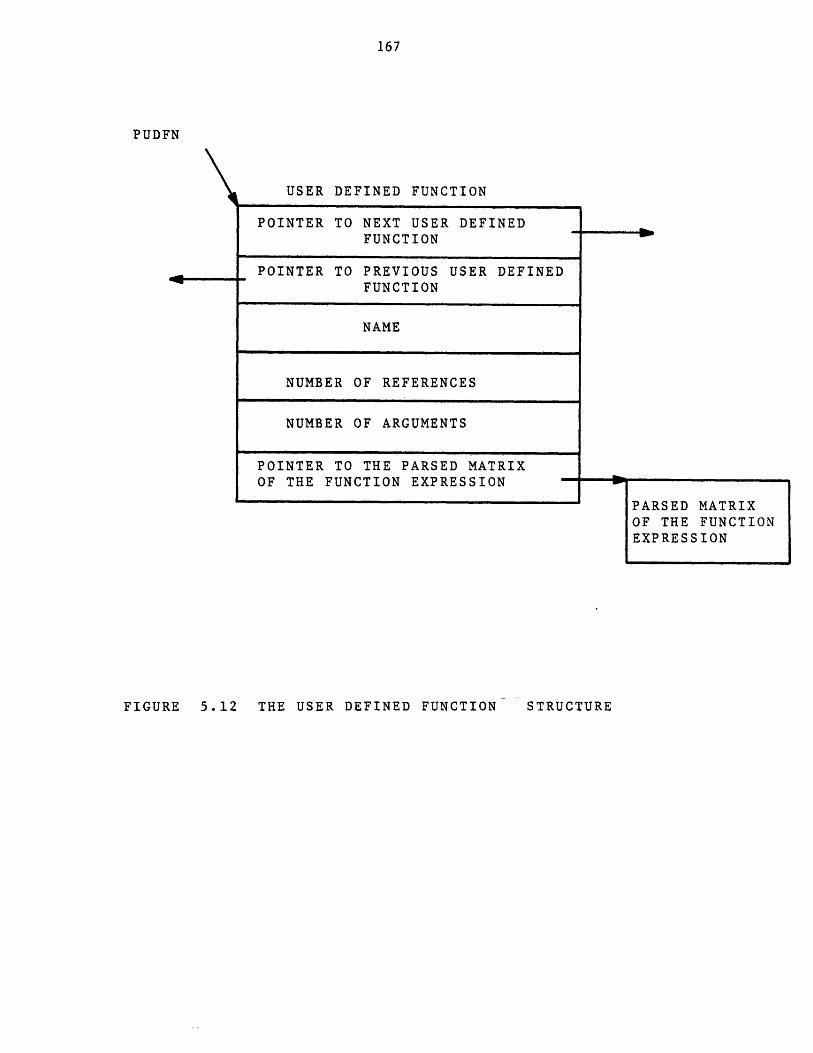
167
PUDFN
USER DEFINED FUNCTION
FIGURE 5.12 THE USER DEFINED FUNCTION
POINTER TO NEXT USER DEFINEDFUNCTION
POINTER TO PREVIOUS USER DEFINEDFUNCTION
NAME
NUMBER OF REFERENCES
NUMBER OF ARGUMENTS
POINTER TO THE PARSED MATRIXOF THE FUNCTION EXPRESSION
PARSED MATRIXOF THE FUNCTIONEXPRESSION
STRUCTURE
I NOW
168
d) Number of references. The number of times the function
is referred to by other existing user-defined functions. This
is to protect the users from deleting a function which is
referred to by other existing functions.
e) Number of arguments.
f) A pointer to a data structure which reprsents the arithmetic
expression used for defining the function. This data
structure is called a "Parsed Matrix". In this matrix,
operations of the expression are listed sequentially in the
order they would be executed to evaluate the expression. The
parsed matrix data structure is also used to represent any
arithmetic expression encountered in the user's commands as
will be discussed in Chapter 9. The full description of the
parsed matrix will be given in Chapter 9. Each matrix entry
has one operator and two operands. Operators are represented
by integer numbers. Each operand is represented by a set of
three items, one of them a pointer pointing to the data
structure representing the operand. For efficiency reasons,
these pointers are absolute pointers, opposed to the type of
pointers defined earlier in this chapter as a pair of
partition number and offset locator. Hence the user-defined
functions, unlike the other process elements (e.g., units,
streams, etc.), are not created inside the working area and
cannot be saved. They are only valid for the duration of the
active process. The variable "udfnhead" points to the
beginning of the user-defined function's list.

169
The data structure representing the function created by the following user
command: create function (y(X1, X2) = X1 + X2*4); is shown in Figure 5.13.
Suppose two other functions were earlier defined. For ease of reading the
operators and operands of the matrix are shown as character strings. ARG1
and ARG2 represent the first and second arguments, respectively. Mi
denotes the result of the ith matrix entry.
5.2.7 Variable Data Structure
The variable data structure is shown in Figure 5.14. It contains the
following:
a) A pointer to the next variable.
b) A pointer to the previous variable.
c) Variable's name.
d) Variable's value.
For example, in response to the following user command:
sp v (X=2*4,Z=12); the data structures shown in Figure 5.15
will be added to the beginning of the variable list.
5.2.8 Data Structure Containing the Property Estimation Methods in Use
This data structure is shown in Figure 5.16. It contains the
following:
a) number of properties.
b) An entry for each property containing the estimation method in
effect.
When a new process is created, the entries of this data structure are
initialized to the default options given in the template for property
estimation methods table. Entries are updated in response to the user's
"use" commands.
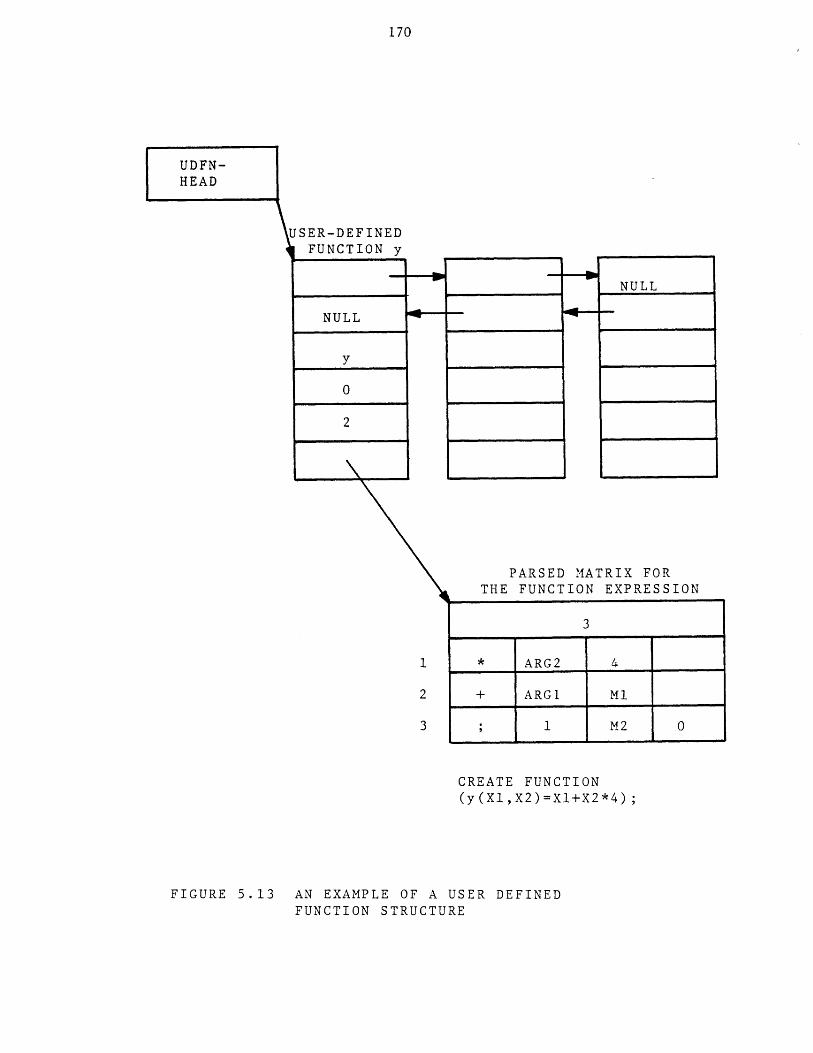
170
UDFN-HEAD
USER-DEFINEDFUNCTION y
NULL
y
0
2
I |
I
PARSED MATRIX FORTHE FUNCTION EXPRESSION
CREATE FUNCTION(y(X1,X2)=Xl+X2*4);
FIGURE 5.13 AN EXAMPLE OF A USER DEFINEDFUNCTION STRUCTURE
NULL
3
* ARG2 4
+ ARGI M1
1 M2 0
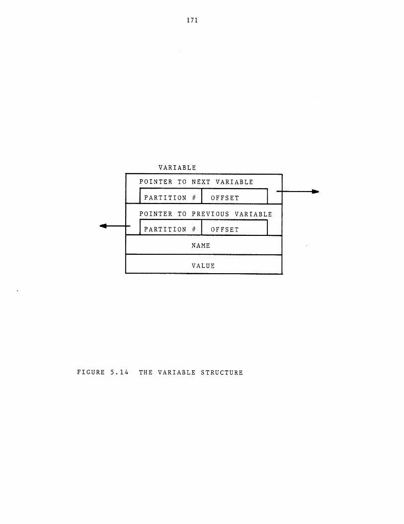
171
VARIABLE
POINTER TO NEXT VARIABLE
PARTITION # OFFSET
POINTER TO PREVIOUS VARIABLE
PARTITION # OFFSET
NAME
VALUE
FIGURE 5.14 THE VARIABLE STRUCTURE
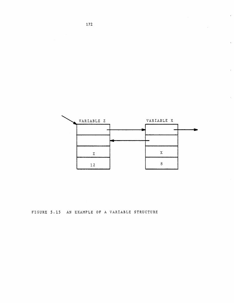
172
VARIABLE Z VARIABLE X
FIGURE 5.15 AN EXAMPLE OF A VARIABLE STRUCTURE
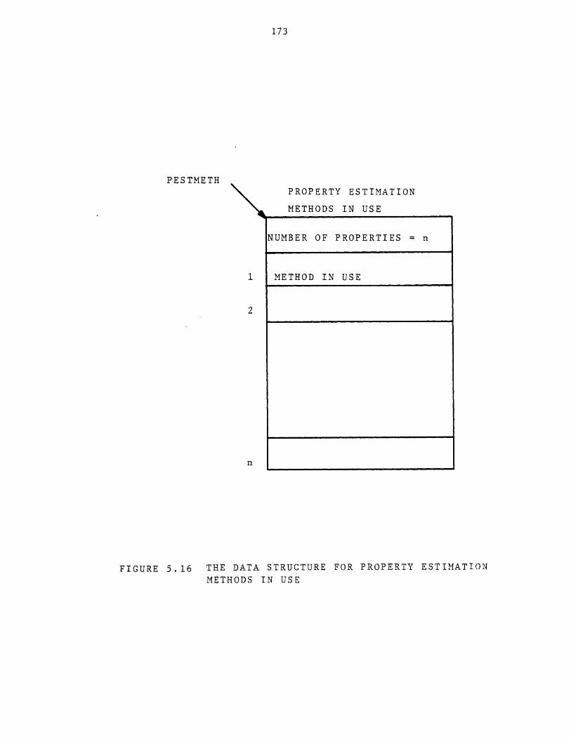
173
PESTMETHPROPERTY ESTIMATION
METHODS IN USE
NUMBER OF PROPERTIES = n
METHOD IN USE
FIGURE 5.16 THE DATA STRUCTURE FOR PROPERTY ESTIMATION
METHODS IN USE
174
For example, given the template in Figure 4.14, the data structure
shown in Figure 5.17a will be created. Figure 5.17b shows the data
structure after the following command:
use FVAP=2 ALIQ=5;
Associated with each process there is such a data structure which is
saved or retrieved along with other data structures constructing the
process, when the process is saved or retrieved. The external pointer
"pestmeth" contains the location of the data structure, enabling the
physical property estimation routines to access the data structure for
retrieving the specified methods of properties estimation.
The estimation routine will avoid requirement for this pointer by
using the following service routine to retrieve the methods to be used:
call get-meth (property__number, method, errrorcode);
The description of service routines is given in Chapter 6 and
Appendix C.
5.3 Process Files
A user may have any number of process files, each containing any
number of processes. A process file has a directory and a number of
processes. The process file directory resides on a single segment called
"Xdr.GPES" where X is the process file's name. Every partition of each
process resides on a separate segment, named XYn.GPES, where X is the
process file's name, Y is the process name, and n is the partition number.
All segments of a process file reside under one directory. The data
structure of the directory for a process file is shown in Figure 5.18. It
contains the name, serial number, and compatibility level of the system
under which the directory has been created and the current number of
entries. Each entry is either empty or represents a process.
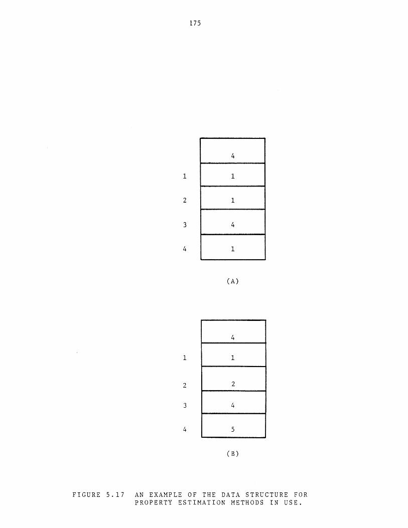
175
4
1
(A)
(B)
FIGURE 5.17 AN EXAMPLE OF THE DATA STRUCTURE FORPROPERTY ESTIMATION METHODS IN USE.
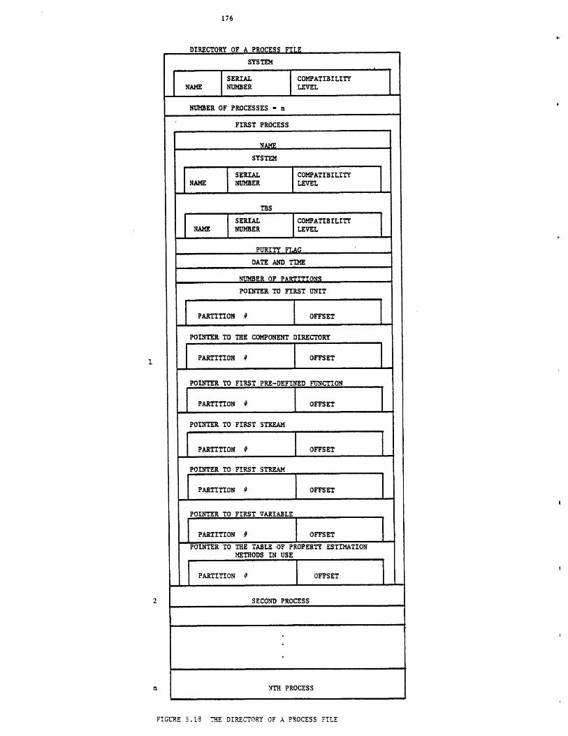
DIRECTORY OF A PROCESS FILE
SYSTEM
PARTITION # OFFSET
SECOND PROCESS
NTH PROCESS
FIGURE 3.18 THE DIRECTORY OF A PROCESS FILE
1 1
SERIAL COMPATIBILITYNAME NUMBER LEVEL
NUMBER OF PROCESSES n
FIRST PROCESS
NAME
SYSTEM
SERIAL COMPATIBILITYNAME NUMBER LEVEL
TBS
SERIAL COMPATIBILITYNAME NUMBER LEVEL
PURITY FLAG
DATE AND TIME
NUMBER OF PARTITIONS
POINTER TO FIRST UNIT
PARTITION # OFFSET
POINTER TO THE COMPONENT DIRECTORY
PARTITION # OFFSET
POINTER TO FIRST PRE-DEFINED FUNCTION
PARTITION # OFFSET
POINTER TO FIRST STREAM
PARTITION # OFFSET
POINTER TO FIRST STREAM
PARTITION # OFFSET
POINTER TO FIRST VARIABLE
PARTITION # OFFSET
POINTER TO THE TABLE OF PROPERTY ESTIMATIONMETHODS IN USE
177
Each entry contains the following:
a) Process name. For an empty entry this field is blank.
b) Name, serial number, and compatibility level of the system
under which the process has been first created.
c) Name, serial number, and compatibility level of the TBS under
which the process has been first created.
d) Purity flag. This flag is "off" if the process has ever been
accessed by any incompatible system or TBS. It is "on",
otherwise.
e) Date and time when the process was first created.
f) Number of partitions.
g) A pointer to the beginning of unit structure list.
h) A pointer to the component directory.
i) A pointer to the beginning of the pre-defined function
structure list.
j) Two pointers to the beginning of the stream structure list.
k) A pointer to the beginning of the variable structure list.
1) A pointer to the data structure of the property estimation
methods in use.
An example of a process file is shown in Figure 5.19.
5.4 Component Files
A user may have any number of component files, and each may contain
data for any number of components of many component types. The users may
share their component files. Users component files are called private
component files. The TBS administrator may create such component files and
make them available to all users. These files are called public component
files. A TBS may have any number of public component files which may be
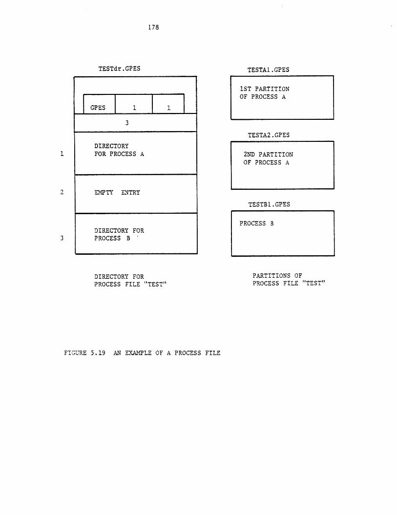
178
TESTdr.GPES
GPES 1 1
3
DIRECTORY1 FOR PROCESS A
2 EMPTY ENTRY
DIRECTORY FOR3 PROCESS B *
DIRECTORY FORPROCESS FILE "TEST"
TESTA1.GPES
TESTA2.GPES
2ND PARTITIONOF PROCESS A
TESTBl.GPES
PARTITIONS OFPROCESS FILE "TEST"
FIGURE 5.19 AN EXAMPLE OF A PROCESS FILE
1ST PARTITIONOF PROCESS A
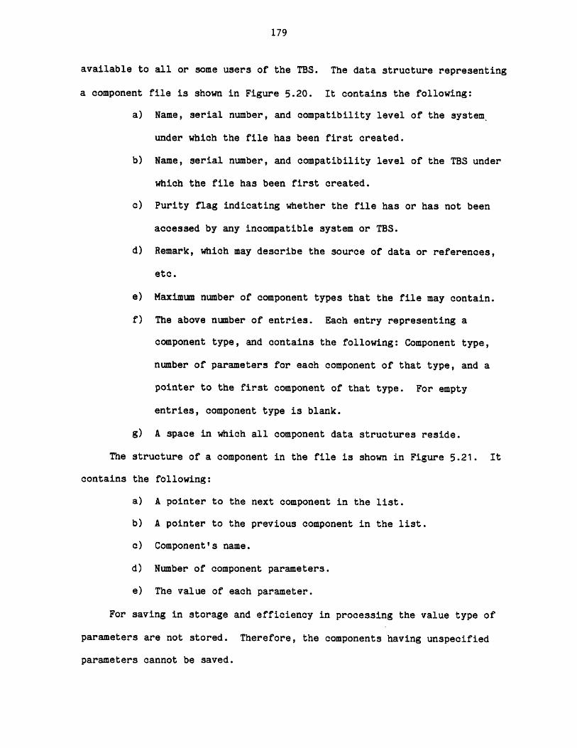
179
available to all or some users of the TBS. The data structure representing
a component file is shown in Figure 5.20. It contains the following:
a) Name, serial number, and compatibility level of the system_
under which the file has been first created.
b) Name, serial number, and compatibility level of the TBS under
which the file has been first created.
c) Purity flag indicating whether the file has or has not been
accessed by any incompatible system or TBS.
d) Remark, which may describe the source of data or references,
etc.
e) Maximum number of component types that the file may contain.
f) The above number of entries. Each entry representing a
component type, and contains the following: Component type,
number of parameters for each component of that type, and a
pointer to the first component of that type. For empty
entries, component type is blank.
g) A space in which all component data structures reside.
The structure of a component in the file is shown in Figure 5.21. It
contains the following:
a) A pointer to the next component in the list.
b) A pointer to the previous component in the list.
c) Component's name.
d) Number of component parameters.
e) The value of each parameter.
For saving in storage and efficiency in processing the value type of
parameters are not stored. Therefore, the components having unspecified
parameters cannot be saved.
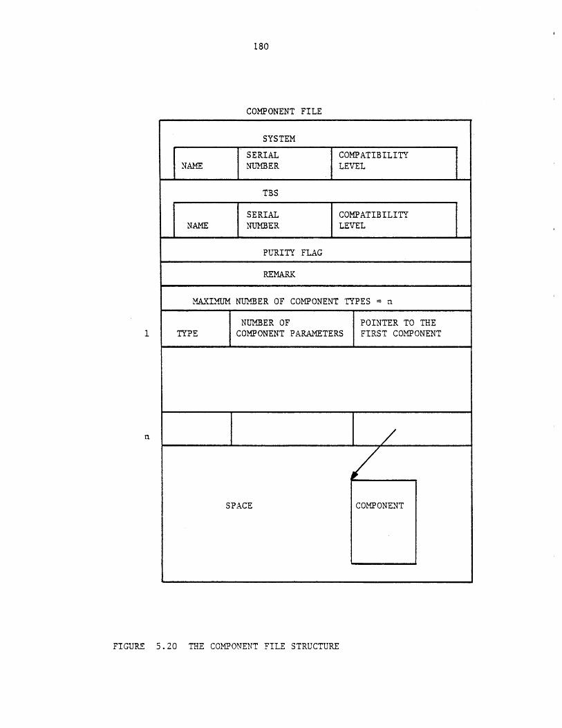
180
COMPONENT FILE
SYSTEM
SERIAL COMPATIBILITYNAME NUMBER LEVEL
TBS
SERIAL COMPATIBILITYNAME NUMBER LEVEL
PURITY FLAG
REMARK
MAXIMUM NUMBER OF COMPONENT TYPES = n
NUMBER OF POINTER TO THETYPE COMPONENT PARAMETERS FIRST COMPONENT
n
SPACE COMPONENT
FIGURE 5.20 THE COMPONENT FILE STRUCTURE
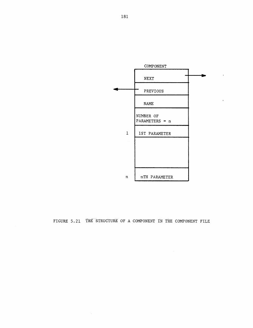
181
COMPONENT
NEXT
PREVIOUS
NAME
NUMBER OFPARAMETERS = n
1 1ST PARAMETER
n nTH PARAMETER
FIGURE 5.21 THE STRUCTURE OF A COMPONENT IN THE COMPONENT FILE
182
All components of each type are linked together by next and previous
pointers. Components in the list are in alphabetical order. Each
component file resides on a single segment, hence having a limited capacity
of about 106 bytes. The segment name is Xc.GPES where X is the component
file's name. An example of a component file is shown in Figure 5.22.
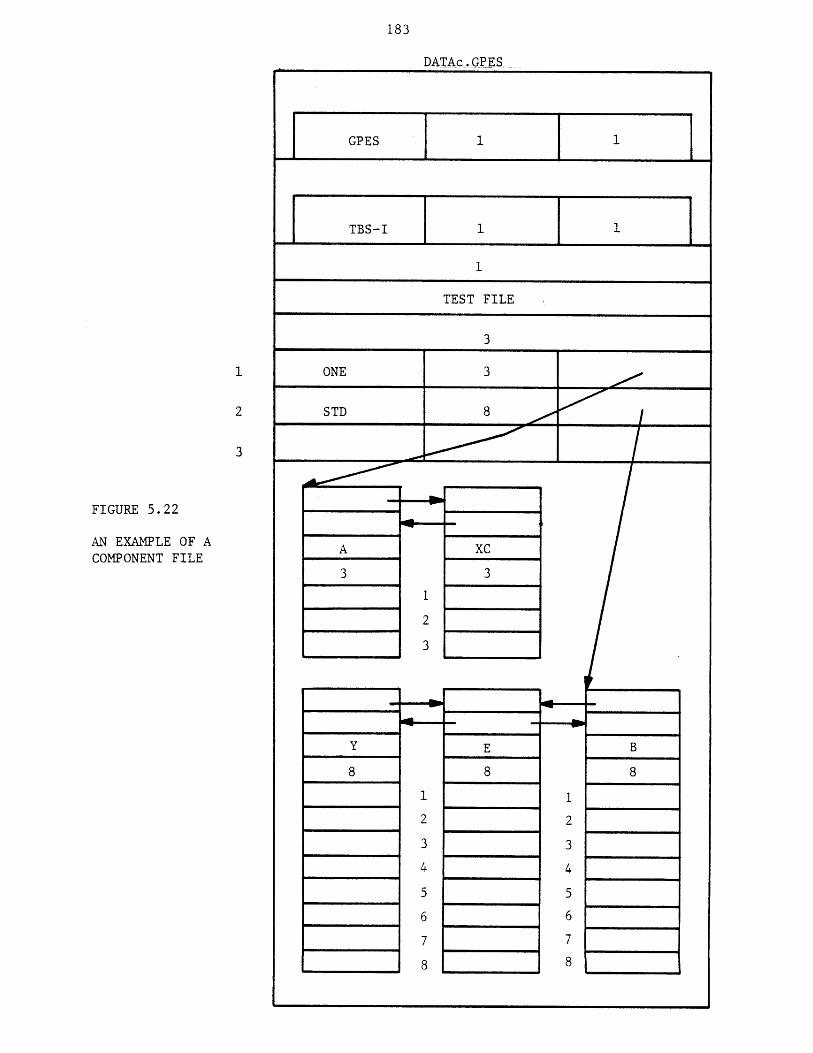
183
FIGURE 5.22
AN EXAMPLE OF ACOMPONENT FILE
DATAc GPES
GPES
TBS-I
TEST FILE
3
ONE 3
STD 8
Y
8
xC3
B
8
E
8
A
3
184
CHAPTER 6
TBS PROGRAMS
As discussed earlier a TBS consists of a set of definitions
(templates) and a package of subroutines (programs). TBS programs are the
heart of a TBS. TBS programs can be divided into two classes: Primary
programs and secondary programs. Primary programs are those programs that
are called directly by the GPES Executive. Secondary programs are those
programs that are called by primary programs as shown in Figure 6.1.
6.1 Primary Programs
Primary programs are called by the system either in response to the
user's calculate commands or in case of a pre-defined function for
evaluating the value of the function. Hence primary programs can be
further divided into two groups: calculating routines and pre-defined
function evaluating routines. The templates of a TBS contain the names and
other information regarding the primary programs.
6.1.1 Calculating Routines
Associated with each type of unit, stream, component, or function is
usually a calculating routine. Unit calculating routines which are
referred to in the literature as process modules, building blocks, etc. are
the essential part of a TBS. In general they represent the functional
relationship between inlet streams, unit parameters, and outlet streams.
Stream and component calculating routines are not commonly used. But in
general a stream calculating routine may calculate a number of phase or
flow parameters as a function of the thermodynamic state variables and
chemical composition of the phase or stream. Examples are calculating
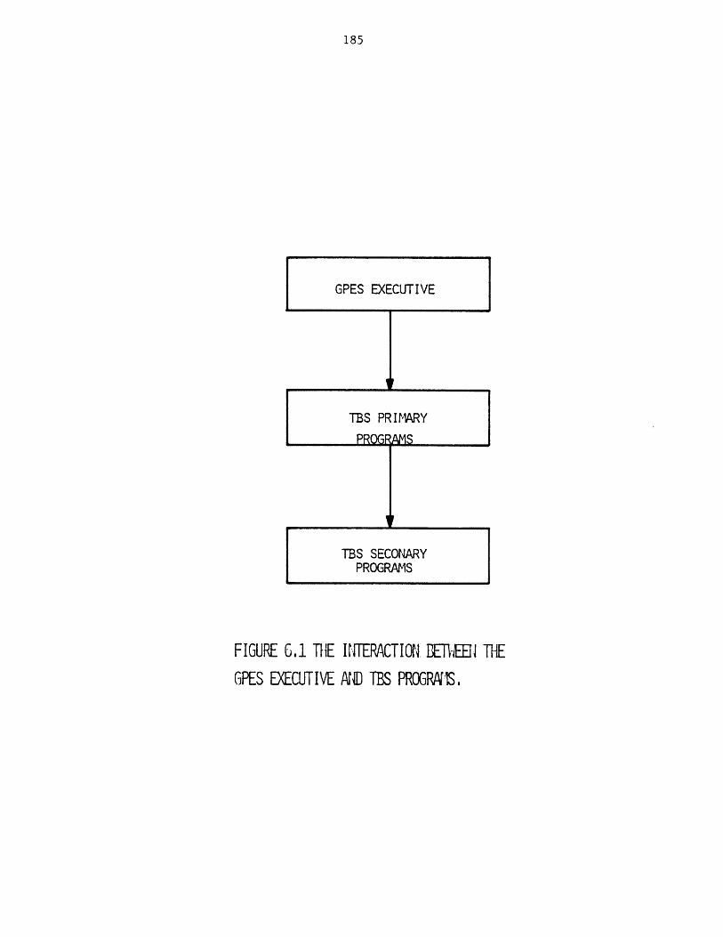
185
GPES EXECUTIVE
TBS PRIMARY
PROGFRAMS
TBS SECONARYPROGRAMS
FIGURE 6.1 THE INTERACTION EREJ THEGPES EXECUTIVE AN TBS PROGRAMS,
186
enthalpy and viscosity. Similarly a component calculating routine may
calculate a number of component parameters as a function of other
parameters, and/or some experimental data.
A function calculating routine may perform any algebraic, trans-
cendental, or integral operation or carry out such operations as regression
analysis on input data and calculate the function parameters (e.g.
regression coefficients).
It should be noted that not every unit, stream, component, or function
type need to have a calculating routine. Using a ";" as the calculating
routine's name in the template indicates that no calculating routine is
specified with that template.
The GPES design has been based on the assumption that for simulating a
process flowsheet the user of a TBS will provide the order in which
individual process units be calculated in his calculate command. However,
provision has also been made for implementing template based systems that
could simulate the entire process flowsheet without requiring the user to
provide the calculation order. Such a TBS should have a calculating
routine to perform this task. Therefore, in general a TBS in addition to
individual calculating routines for each unit type, stream type, etc. may
also have a calculating routine for all units, a calculating routine for
all streams, a calculating routine for all components, and/or a calculating
routine for all functions. These calculating routines, if any, will be
called in response to the following users commands:
calculate unit all (optional argument list);
calculate stream all (optional argument list);
calculate component all (optional argument list);
calculate function all (optional argument list);
187
Therefore, calculating routines can be divided to the following two
groups: Individual calculating routines and "all" calculating routines as
shown in Figure 6.2.
Each group may also be subdivided to the following four subgroups:
unit, stream, component, and function. Table 6.1 shows the number of
programs in each group for a TBS.
6.1.2 Pre-defined function evaluating routines
For each pre-defined function in addition to a calculating routine
there may be another routine known as an evaluating routine. When a pre-
defined function appears in an arithmetic expression in the user's command,
such a routine is called by the GPES executive. Its function is to
evaluate the function given the function parameters (coefficients) and the
function arguments.
6.2 Secondary Routines
Secondary programs are those routines that are called by primary
routines. Physical property estimation routines fall into this class of
routines. System-supplied service routines that are called by other
routines to perform various tasks also fall into this class of routines.
Service routines are described later.
6.3 Interaction Between TBS Programs and the GPES Executive
In a Fortran environment, in most chemical process simulation systems,
the process module is written as a subroutine with the transfer of
variables taking place through the parameter list of a call statement or
through common blocks of data. In GPES environment, the process of
transferring variables is more elaborate. The TBS program receives the
pointers to the data structures which contain the values of the variables.
Thus, before beginning the calculations, the program must retrieve these
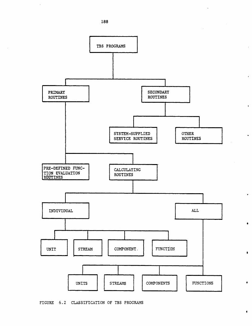
188
TBS PROGRAMS
_________________________________________________________________________________ I
SECONDARYROUTINES
SYSTEM-SUPPLIED OTHERSERVICE ROUTINES ROUTINES
PRE-DEFINED FUNC-TION EVALUATIONROUTINES
CALCULATINGROUTINES
INDIVIDUAL
UNIT STREAM COMPONENT FUNCTION
UNITS STREAMS COMPONENTS FUNCTIONS
FIGURE 6.2 CLASSIFICATION OF TBS PROGRAMS
PRIMARYROUTINES
AL L
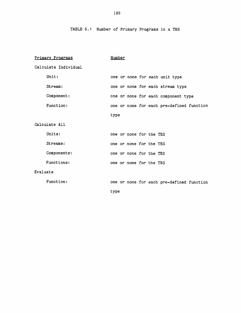
189
TABLE 6.1 Number of Primary Programs in a TBS
Primary Programs
Calculate Individual
Unit:
Stream:
Component:
Function:
Calculate All
Units:
Streams:
Components:
Functions:
Evaluate
Number
one or none for each unit type
one or none for each stream type
one or none for each component type
one or none for each pre-defined function
type
one or none
one or none
one or none
one or none
for
for
for
for
the TBS
the TBS
the TBS
the TBS
Function: one or none
type
for each pre-defined function
190
values from the data structures. This is done by reaching the variable
location through a series of pointers. The same must be done at the end of
the calculations to store the results into the data structures network.
This process of reaching the variable location in the network of data
structures is called "navigation". The TBS program calls upon some system-
supplied service routines to perform this process of naviagtion. The
service routines will be described later. This method of variable transfer
enables GPES to call every TBS program by a few generalized call statements
with standardized parameter lists, using the powerful means of dynamic
linking.
GPES will, in effect, call each group of TBS programs by the call
statements shown in Table 6.2.
The interaction between the GPES Executive and a unit calculating
routine (process module) is shown in Figure 6.4. Unit computations, which
are the heart of a unit calculating routine, can either be performed by the
calculating procedure or by a call on an already developed FORTRAN or PL/1
program (a secondary program).
Although a TBS program usually has access to all relevant information
through the pointers passed to it, some TBS programs (especially "all"
calculating routines) may require additional information which might not be
accessible through those pointers. A number of external variables have
been provided which enables those special routines to access any
information about the process flowsheet. These external variables are
listed in Table 6.3.
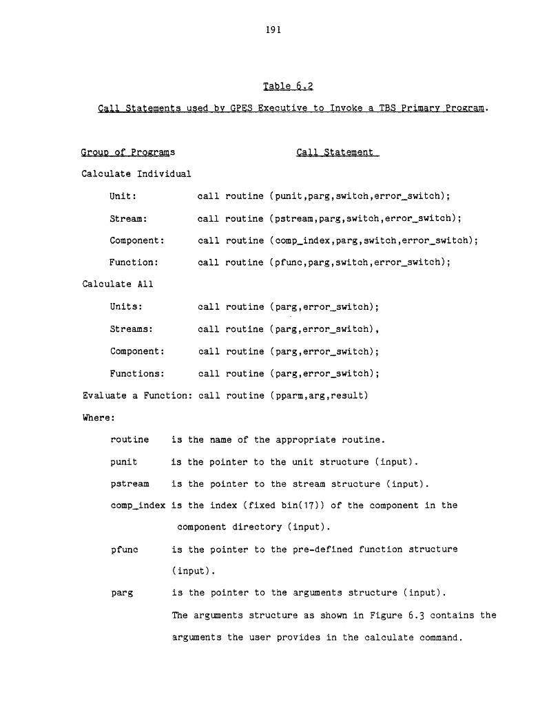
191
Table 6.2
Call Statements used by GPES Executive to Invoke a TBS Primary Program.
Group of Programs
Calculate Individual
Unit:
Stream:
Component:
Function:
Calculate All
Units:
Streams:
Component:
Functions:
Evaluate a Function:
Where:
routine
punit
pstream
comp_index
pfunc
parg
Call Statement
call
call
call
call
call
call
call
call
call
routine
routine
routine
routine
routine
routine
routine
routine
rout ine
(punit,parg,switch,errorswitch);
(pstream,parg,switch,error switch);
(compindex,parg,switch,error-switch);
(pfunc,parg,switch,errorswitch);
(parg,errorswitch);
(parg,errorswitch),
(parg,errorswitch);
(parg,errorswitch);
(pparm,arg,result)
is the name of the appropriate routine.
is the pointer to the unit structure (input).
is the pointer to the stream structure (input).
is the index (fixed bin(17)) of the component in the
component directory (input).
is the pointer to the pre-defined function structure
(input).
is the pointer to the arguments structure (input).
The arguments structure as shown in Figure 6.3 contains the
arguments the user provides in the calculate command.
192
Table 6.2 Contined
The first argument is always interpreted as the level of
calculation. The interpretation of other arguments, if
any, should be clear both to the user and to the
calculating routine. If no argument is provided (parg
null) the level of calculation is assumed to be one.
pparm is the pointer to the function's parameters structure
(input).
switch (bit(1)) Indicates whether convergence has been achieved
(output). It is only used for convergence routines which
are described in section 6.4.4
error_switch
(bit(1)) Indicates whether any severe error has been
detected by the routine (output).
arg (dim(*) float bin (63)) is the array of function arguments
(input).
result (float bin (63)) is the.result of the function evaluation
(output).
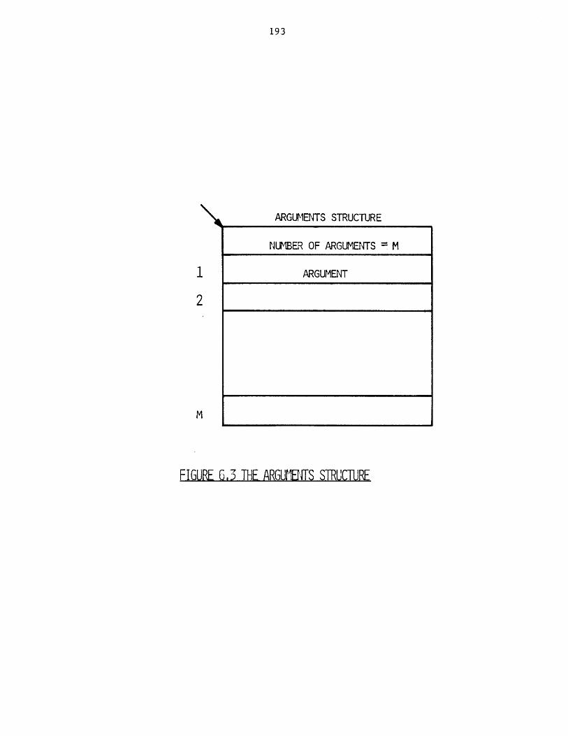
193
ARGUMENTS STRUCTURE
NUMBER OF ARGUMENTS M
ARGUMENT
2
M
FIGURE 6,3 THE ARGUMBITS STRUCTURE
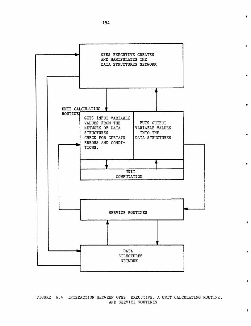
194
UNIT CAROUTINECULATING _I _GETS INPUT VARIABLEVALUES FROM THE PUTS OUTPUTNETWORK OF DATA VARIABLE VALUESSTRUCTURES INTO THECHECK FOR CERTAIN DATA STRUCTURESERRORS AND CONDI-TIONS.
UNITCOMPUTATION
SERVICE ROUTINES I
FIGURE 6.4 INTERACTION BETWEEN GPES EXECUTIVE, A UNIT CALCULATING ROUTINE,AND SERVICE ROUTINES
GPES EXECUTIVE CREATESAND MANIPULATES THEDATA STRUCTURES NETWORK
DATASTRUCTURES
NETWORK
-- - - - - a
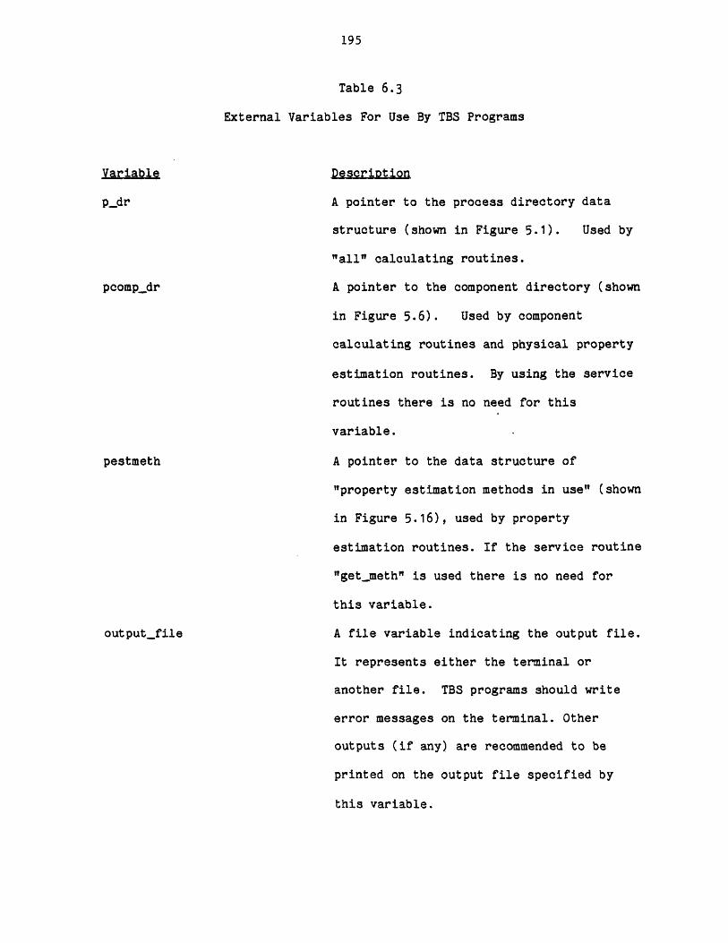
195
Table 6.3
External Variables For Use By TBS Programs
Variable
p_dOr
pcompdr
pestmeth
outputfile
Description
A pointer to the process directory data
structure (shown in Figure 5.1). Used by
"all" calculating routines.
A pointer to the component directory (shown
in Figure 5.6). Used by component
calculating routines and physical property
estimation routines. By using the service
routines there is no need for this
variable.
A pointer to the data structure of
"property estimation methods in use" (shown
in Figure 5.16), used by property
estimation routines. If the service routine
"getmeth" is used there is no need for
this variable.
A file variable indicating the output file.
It represents either the terminal or
another file. TBS programs should write
error messages on the terminal. Other
outputs (if any) are recommended to be
printed on the output file specified by
this variable.
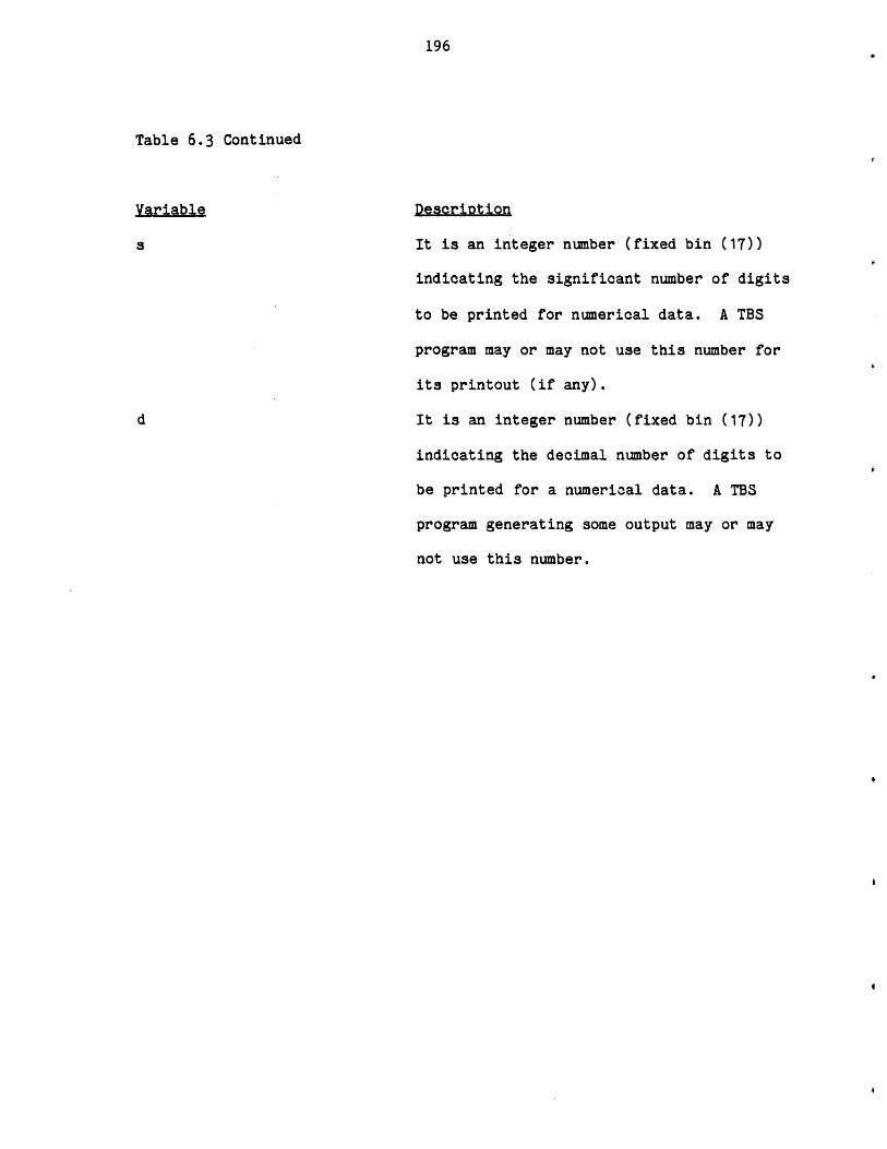
196
Table 6.3 Continued
Variable Description
s It is an integer number (fixed bin (17))
indicating the significant number of digits
to be printed for numerical data. A TBS
program may or may not use this number for
its printout (if any).
d It is an integer number (fixed bin (17))
indicating the decimal number of digits to
be printed for a numerical data. A TBS
program generating some output may or may
not use this number.
197
6.4 Writing a TBS Program
In this section some general considerations on writing a TBS program
are discussed. Examples in writing TBS programs is given in Chapter 10.
6.4.1 Input
Usually all the input data required by a TBS program are stored in the
process network. To retrieve these data, the TBS program may call upon
some service routines which in effect navigate through the process network.
Nevertheless a TBS program may also interact directly with the user for:
a) getting additional data, or b) asking user's preference where there is
more than one alternative available to the routine. In this case the TBS
program should write a message on the user's terminal requesting such data
and then call upon some other service routines for receiving the data.
6.4.2 OUtout,
Usually the TBS program will store the computed data into the process
network by calling upon the appropriate service routines. Nevertheless,
the TBS program may also write the intermediate or final results onto the
user's terminal or user's output file. The user's output file is either
the user's terminal or another file. The external file variable
"output_file" indicates the user's output file. Therefore, a TBS program
writing on this file should:
a) provide the following declaration:
declare outputfile file variable external;
b) The "put" statements should specify the file as follows:
put file (output-file)...;
198
6.4.3 Error Detection
Before the GPES executive passes control to a calculating routine for
a specific level of calculation, it performs the various types of error
checking requested in the associated template for that level of
calculation. This means that a calculating routine should not be concerned
about over- and under-specification of parameter values. In other words,
input data are provided (i.e., specified, assumed, or calculated), output
data are not fixed (i.e. not specified), and initial value assumptions (if
any) are provided and not fixed (i.e. assumed, or calculated). In the case
of a unit calculating routine, the necessary inlet and outlet streams are
also connected to the unit. In addition to the above types of error
checking which are performed by the GPES executive, there are numerous
other types of error checking which a TBS program may perform. The extent
of error checking that a program may undertake depends on the generality of
the program and the assumption about the user's knowledge of the program
and his common sense. The following are some examples of types of error
checking that a TBS program may perform:
a) unacceptable input data (e.g. negative numbers for flow rates,
mole fractions outside the range of 0 to 1, sum of mole fractions
more than one).
b) an internal algorithm fails to function (e.g. for a trial-and-
error calculation, convergence can not be achieved).
c) violating general laws of thermodynamics.
d) in the case of a unit calculating routine, if the unit is such
that only certain components are allowable in an inlet or outlet
stream, or if the components of one stream are required to be
identical as those in another stream, the routine should also
199
check for these conditions. Both of these checking procedures can
be accomplished easily using service routines.
Once a TBS program detects a serious error it should perform the
following:
a) write on the user's terminal a description of the detected error.
b) turn "on" the error switch: errorswitch = "1" b;
c) either return immediately to the calling program or continue
further error detection. In the latter case the program should
immediately return to the calling program after the error
detection task is completed.
The error detection task should be accomplished prior to writing the
computed results into the process network. Therefore, it is recommended
that. the transfering of the computed results into the process network be
performed as the last task of the routine.
6.4.4 Convergence Routines
Most chemical processes involve recycle streams. Therefore, such
flowsheets contain information recycle loops, that is, cycles for which too
few stream variables are known to permit equations for each unit to be
solved independently. The equations for units in an information recycle
loop must be solved simultaneously. One solution technique is to "tear"
one stream in the recycle loop [11,22,51,1481 that is, to guess variables
of that stream. Based upon tear stream guesses, information is passed from
unit-to-unit until new values of the variables of the tear stream are
computed. These new values are used to repeat the calculations until
convergence tolerances are satisfied. A TBS capable of analyzing
flowsheets with recycle streams should have one or more types of pseudo
units for testing and promoting convergence. This type of pseudo unit is

200
known as a convergence unit or convergence block. To define a unit of type
convergence, as in the definition of any other unit type, the TBS
administrator should create a template in the template data base and should
provide a calculating routine for it. Such a unit usually has one inlet
stream (containing the newly computed variables of the tear stream), one
outlet stream (containing the guess values of the tear stream) and a number
of parameters (convergence tolerances, etc.). Of course, such a unit is
not limited to one inlet and one outlet stream, but may have any number of
either. The calculating routine for such a unit is known as a convergence
routine. Such a routine should compare newly computed variables with guess
values, and compute new guess values when convergence tolerances are not
satisfied. In particular, it should perform the following:
a) Based on some pre-established criteria it should perform a
convergence test.
b) If convergence has been achieved turn "on" the "switch" argument.
This is the only required use of the "switch" argument which is one
of the arguments passed to each calculating routine.
c) If convergence has not been achieved it should estimate the
parameters of the output streams.
The information regarding the criteria for convergence could be either
part of a unit's parameters (this is usually the case), or part of the
parameters of a stream to be tested, or it could be provided by some
information streams input to the unit. The convergence acceleration
methods most commonly used in existing simulators are the following:
a) successive substitution,
b) bounded Wegstein,
c) dominant eigenvalue, and
d) quasi-Newton.
201
6.4.5 Writing an "all" Calculating Routine
Although writing an individual calculating routine is a very simple
and systematic task, writing an "all" calculating routine may not be quite
so simple. An "all" calculating routine should determine the order of
calculation and then monitor the execution of subsequent individual
calculating routines. This is a rather straightforward task when writing
an "all" calculating routine for streams, components, or functions, where
there is no interaction between individual elements. However, a unit "all"
calculating routine is more sophisticated, and such a routine should
perform the following:
a) Recognize the recycle streams.
b) Determine the loops and the order of calculation in each loop.
c) Either estimate the parameters of recycle streams or prompt the
user for this information.
d) Monitor the execution of individual calculating routines, and test
for convergence.
The use of the "calculate unit all;" command and consequently the
development of unit "all" calculating routines is not recommended for the
following reasons:
a) These routines require reasonable skill to develop.
b) The same objective; i.e., calculation of the entire process can be
achieved by having the user specify the order of calculation in the
calculate command.
c) The user may know something about the process that the unit "all"
calculating routine may not know. Hence, letting the user decide
on the order of calculation may result in faster convergence.
202
6.5 Service Routines
Service routines are developed to assist TBS programmers in conducting
various tasks, of which the most important is navigation of the network of
data structures. Although a TBS programmer using these service routines
in his program may not be concerned about the details of the data
structures representing process units, streams, or components, an
understanding of the existence of such data structures and their
interrelation will assure him of the proper usage of the service routines.
Although there are about 100 service routines, usually only a few of these
will be needed in writing a TBS program. Service routines perform various
tasks, and can be divided into the following six groups:
1) Routines performing basic operations: Given a pointer to a data
structure these routines return pointers to related data
structures.
2) Routines checking for the existence of some components in a given
stream.
3) Routines retrieving or storing the values of parameters from or
into the process network. 78 out of 101 existing service routines
fall in this group. Although using only two of them (getparm, and
putparm) in conjunction with the basic service routines would be
sufficient for accomplishing the above task, the other 76 routines
have been provided for greater user (TBS programmer) flexibility
and convenience. These routines can be divided into several
subgroups as shown in Figure 6.5. They are used either for
retrieving the values of parameters from the data structures (i.e.,
getparm) or for storing the values of parameters into the data
structures (i.e., putparm). The reference to parameters may be
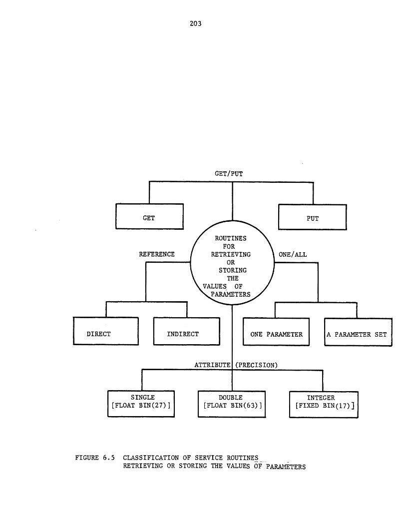
203
GET/PUT
GETE
ROUTINESFOR
REFERENCE RETRIEVING ONE/ALLOR
STORINGTHE
VALUES. OFPARAMETERS
DIRECT INDIRECT ONE PARAMETER
ATTRIBUTE (PRECISION)
SINGLE DOUBLE[FLOAT BIN(27)] [FLOAT BIN(63)] [FI
FIGURE 6.5 CLASSIFICATION OF SERVICE ROUTINESRETRIEVING OR STORING THE VALUES OF PARAMETERS
204
made by a pointer to the parameter structure (direct), or through a
pointer to a parent structure (indirect). For example, given
"pparm", the pointer to a unit parameter structure, the call
statement:
call getparm(pparm,2,value,valuetype, code);
will retrieve the value and valuetype of the second unit
parameter. The same result can be achieved by the call statement:
call get,_uparm (punit,2,value,value_type, code); where punit is the
pointer to the unit data structure. Service routines getparm and
get..._uparm are examples of direct and indirect service routines
respectively. The service routines may retrieve or store either a
single parameter (i.e. the above example) or all the parameters in
a set. Routines getparms and get.uparms are examples of the~
latter. Although the values of all parameters in all data
structures are stored as double precision (FORTRAN terminology), in
a TBS program the values of parameters may be supplied with other
attributes. Service routines which provide different attributes to
numerical data fall into one of three groups: those routines
considering the values of parameters as double precision (i.e.,
getparm), those considering the values of parameters as single
precision (i.e., xgetparm), and those considering the values of
parameters as integer numbers (i.e., iget.parm).
A list of service routines retrieving or storing the values of
parameters is shown in Table 6.4.
4) Routines retrieving other variables of interest. Two routines fall
in this group: one returns the values of user-supplied arguments,
and another returns the method currently being used to estimate a
physical property.
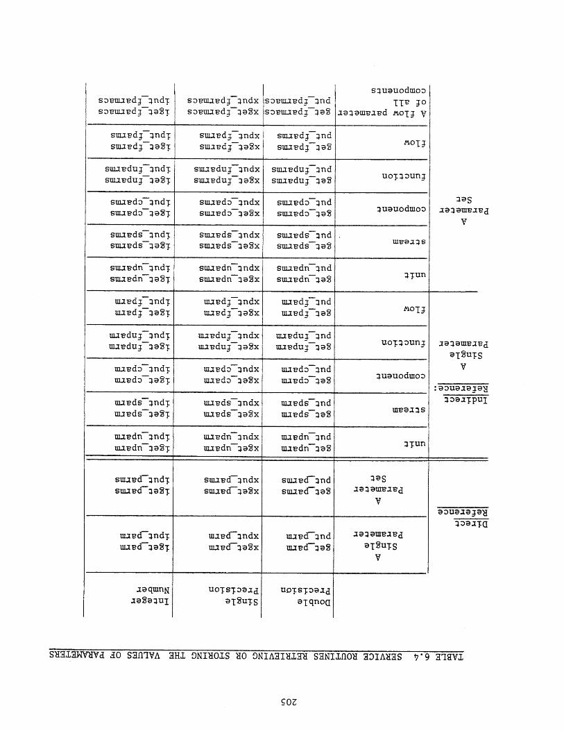
suupdg-andT suuudg-:Indxl smaLdj7:ind mOTJsmavdj7i9ST suiaLdj-:la2x suupdj7iaS
suuLduj-jndT smapdug - indx suupduj7jndsmapduj-:l;a2T smaLdug-qa2x smavduj--i9S uoTjDunj
suuLdj7:lndT suu-ed;5-:andx smaud:5-qnd quauodmoz)sm-iudz)7qaST smaL-d 5-qa2x suijvdz --492
suuvds7-and-E sma-pds-qndx suuvd -:ind Mva aq ssuuvds qa2T smavds-qa2x smavd -qa2
uuvdu -- qnd-r mavduj7jndx uupdug-:tnd uoTqoungmapdug-qaSE mavduj7-ja2x mapdug7 jaS
maudo7and-E ma-pdo-:jndx maudo7ind quauodmoomavdo7492-E mavdo-:i92x mjvdo7:iaS
mavds--:tnd-E ma-eds-:tndx mavds7andmipds-q92T mavds-q@2x maeds7:192 ML9:E:ls
uuL-cf-:tnd-r maL-cf-:indx mavcf-:md aq:jqmtjvcj
UUvd-:192T UULcf-:192X mavd-492 ;DT2u'.rSv
SUalaWMd dO SaflqVA alll ONIUOIS XO ONIAMM SaNIM011 MAUS *9 aqqVl
squauodmoo
TT'e JOaaq9mvapd MOTJ V
s:)-pmavdg qnd-E sDmapdg-qndxsz)-euuvdj-j;q2X
sz)vmavdj-:jndsz)vmaLdj :la2
:I;asxa-aam-ea-ecl
v
smav& -- andTsmapdr --aaST
smavdr -indxsuu-Pdfi--iaSx
smaLdn7:lndsmapdr -qa2 ITun
ULILdg-qndTuLipdj -49ST
ujjpdg-:tndxmavdj7:i;a2x
maLdj7andmaLdj7:la2
19:3am-eaucl
9T2u-ESv
:qoualpjay
lDaJTPUI
mavdr -ind-rmavdr -:ia2T
uupdr -:indxmavdr --aa2x
m-i-edn-Induuvdn-:ia2 'ITun
smi-ecl-qnd-csma-ecf-:19ST
smaucf-:indxsmavcT--qa2?x
smaLcf-:andsma-ecr-las
:19Saq:jqmvavcj
vgouglap-a
:lz)aaT(I
UDTSTDaad;aTqno(I
a;aqmnNJasequI
UOTST39adaT2u7[S
206
5) Routines directly interacting with the user. These routines are
called to receive input data not provided in the process network,
directly from the user.
6) Routines performing arithmetic operations on two parameter sets.
These routines are helpful in writing process module calculations
for separation processes and material balancing in general.
Table 6.5 contains a short description of each service routine. More
detailed descriptions are given in Appendix C. A TBS administrator may
provide TBS programmers with additional service routines especially
developed for their particular needs and applications.
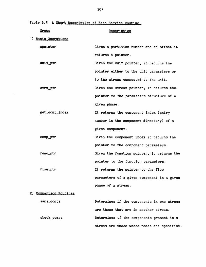
207
Table 6.5 A Shgrt Description of Each Service Routine
Group Descriotion
1) Basic Operations
spointer
unitptr
strmptr
get.comp.index
compptr
funcqptr
flow ptr
2) Comparison Routines
samecomps
checkcomps
Given a partition number and an offset it
returns a pointer.
Given the unit pointer, it returns the
pointer either to the unit parameters or
to the stream connected to the unit.
Given the stream pointer, it returns the
pointer to the parameters structure of a
given phase.
It returns the component index (entry
number in the component directory) of a
given component.
Given the component index it returns the
pointer to the component parameters.
Given the function pointer, it returns the
pointer to the function parameters.
It returns the pointer to the flow
parameters of a given component in a given
phase of a stream.
Determines if the components in one stream
are those that are in another stream.
Determines if the components present in a
stream are those whose names are specified.
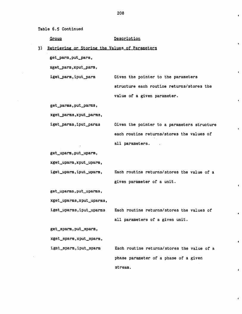
208
Table 6.5 Continued
Group Description
3) Retrieving or Storing the Values of Parameters
getparm,put_parm,
xgetparm,xputparm,
igetparm,iputparm
getparms, putparms,
xgetparms,xputparms,
igetparms,iputparms
get-uparm, putuparm,
xgetuparm,xputuparm,
igetuparm,iput-uparm,
get-uparms , put-uparms,
xgetuparms,xputuparms,
iget-uparms,iput-uparms
get,_sparm,putsparm,
xgetsparm,xputsparm,
igetsparm,iputsparm
Given the pointer to the parameters
structure each routine returns/stores the
value of a given parameter.
Given the pointer to a parameters structure
each routine returns/stores the values of
all parameters.
Each routine returns/stores the value of a
given parameter of a unit.
Each routine returns/stores the values of
all parameters of a given unit.
Each routine returns/stores the value of a
phase parameter of a phase of a given
stream.
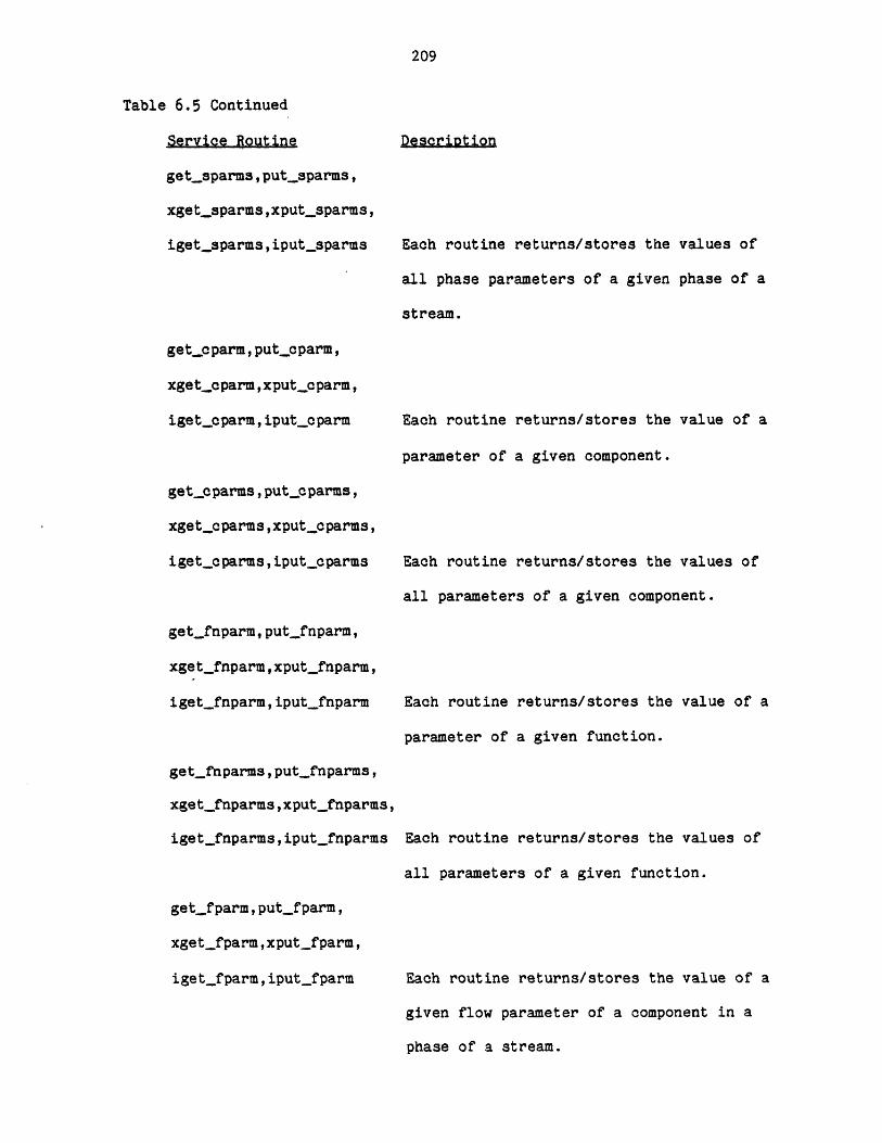
209
Table 6.5 Continued
Service Routine
getsparms , putsparms,
xgetsparms,xputsparms,
igetsparms , iput._sparms
get_.cparm, put.c parm,
xgetcparm ,xput_.o parm,
iget~cparm, iputopparm
get~cparms,put~cparms,
xgetcparms,xput.cparms,
iget.cparms,iput.oparms
getfnparm,putfnparm,
xget~fnparm,xputjfnparm,
igetfnparm,iput_fnparm
getfnparms, putfnparms,
xget._fnparms , xputjfnparms,
igetfnparms,iput_fnparms
get,_fparm, put_fparm,
xget_fparm,xputfparm,
igetfparm,iput_fparm
Description
Each routine returns/stores the values of
all phase parameters of a given phase of a
stream.
Each routine returns/stores the value of a
parameter of a given component.
Each routine returns/stores the values of
all parameters of a given component.
Each routine returns/stores the value of a
parameter of a given function.
Each routine returns/stores the values of
all parameters of a given function.
Each routine returns/stores the value of a
given flow parameter of a component in a
phase of a stream.
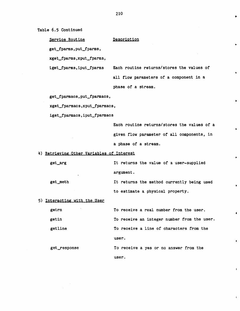
210
Table 6.5 Continued
Service Routine
getfparms,putfparms,
xgetfparms,xput_fparms,
igetfparms, iput_fparms Each routine returns/stores the values of
all flow parameters of a component in a
phase of a stream.
get_fparmacs,put_fparmacs,
xgetjfparmacs ,xputfparmacs,
iget_fparmacs,iput_fparmacs
4) Retrieving Other Variables
getarg
get_meth
Each routine returns/stores the values of a
given flow parameter of all components, in
a phase of a stream.
of Interest
It returns the value of a user-supplied
argument.
It returns the method currently being used
to estimate a physical property.
5) Interacting with the User
getrn
getin
getline
getresponse
To receive a real number from the user.
To receive an integer number from the user.
To receive a line of characters from the
user.
To receive a yes or no answer from the
user.
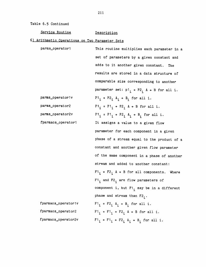
211
Table 6.5 Continued
Service Routine
6) Arithmetic Operations on Two
parmsoperator1
parmsoperator lv
parmsoperator2
parmspperator2v
fparmacs-operator1
fparmacsoperator lv
fparmacspperator2
fparmacsopperator2v
Description
Parameter Sets
This routine multiplies each parameter in a
set of parameters by a given constant and
adds to it another given constant. The
results are stored in a data structure of
comparable size corresponding to another
parameter set: p1. = P2. A + B for all i.1 1
P1. = P2 A + B. for all i.
P1. P1. + P2. A + B for all i.1 1 1
P1. =P1. + P2. A. +- B. for all i.1 1 1 1 1
It assigns a value to a given flow
parameter for each component in a given
phase of a stream equal to the product of a
constant and another given flow parameter
of the same component in a phase of another
stream and added to another constant:
F1 = F2. A + B for all components. Where
F1. and F2 are flow parameters of
component i, but F1. may be in a different
phase and stream than F2 .
F1. F2. A. + B. for all i.1 1 1 1
F1= F1. + F2. A + B for all i.
F1l= F1. + F2. A. + B. for all i.

212
Chapter 7
PROCESS ENGINEERING LANGUAGE - BASIC PRINCIPLES
7.1 Basic Conceots of PEL
PEL (Process Engineering Language) is a problem oriented-language by
which the user instructs and communicates with any template based system
(TBS) created using GPES.
The basic elements of the language are commands (statements). Each
command is a request for an action to be taken by the system. The system
accepts a command, interprets it, and accomplishes what the user intended
by that command. Then the system is ready to accept another command. The
system ignores and prints error messages for illegal commands. Each
command begins with a keyword called a command verb and may be followed by
another keyword called the command object and is followed by the command
body (if any) and will be terminated by a semicolon. The command verb
indicates the function of the command and the command object indicates the
object upon which the action should be taken. Table 7.1 shows the command
verbs, and the corresponding command objects. This table is the output of
PEL command: Help commands;. There is no reserved word in PEL.
Consequently there is no need for the user to remember a long list of
reserved names which he must learn to avoid, even if he does not know what
they mean.
7.1.1 Command ObJects
A process may be viewed as a collection of equipment units, and
streams containing masses of individual chemical species, momenta, and
energy which flow through the process. To model and design a process it is
necessary to represent these elements of the process. Some of these
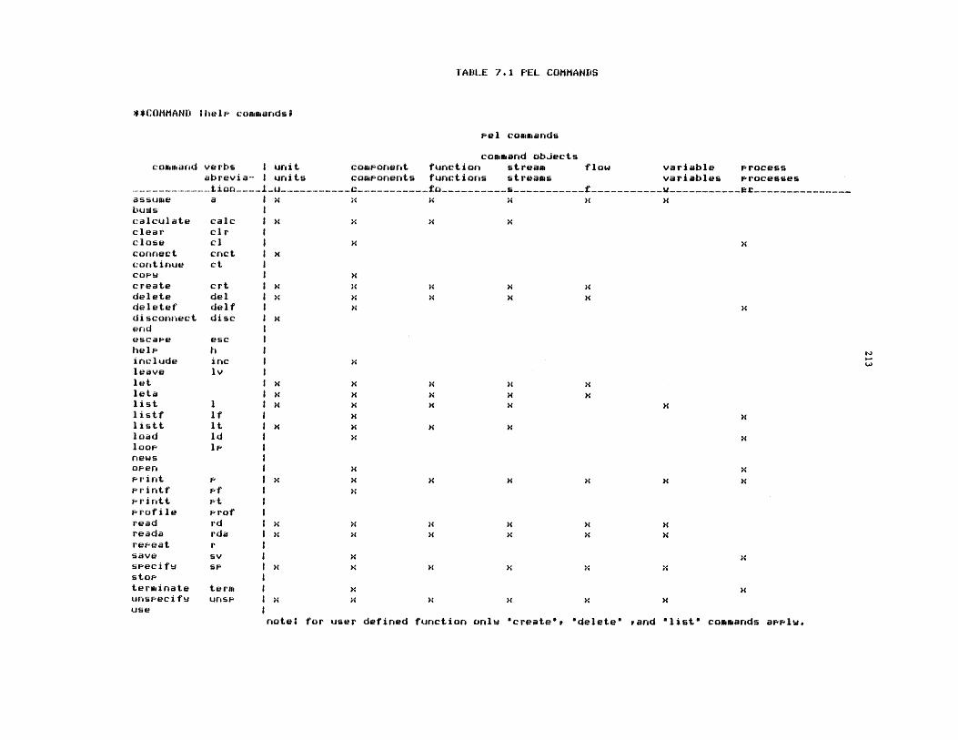
TABLE 7.1 PEL COMMANDS
**COMMANI :help commandsi
Fel commands
command obJectscommand verbs I unit coamonent function stream flow variable process
abrevia- I units coamponents functions streams variables Processes-- -- ----1-------------C-----------fo----------s-----------f-----------V-----------at--
assuae a I x x x x Xbugscalculate calc I x x x xclear cie Iclose cl I X xconnect cnct I xcontinue ct Icoes x H
create crt I . xX x 04delete del Ix x x x xdeletef delf I xdisconrect disc I xendescape eschelp hinclude inc I Hleave lvlet I x x x x xleta I x x H x Hlist 1 I x x xlistf if I xlistt it I x x H xload Id x xloop I Inewsopen xxPrint x H x X x x xprintf p f xFrintt ptProfile Prof Iread rd 1 x x H X xreada rda I h x x x X xrepeat r Isave sv I xXspecifu sP I x x X X xstopterminate term I x xunspecifu uns I x x x H x Huse
note* for user defined function onlu "create'r *delete" rand "list* commands apPlu.
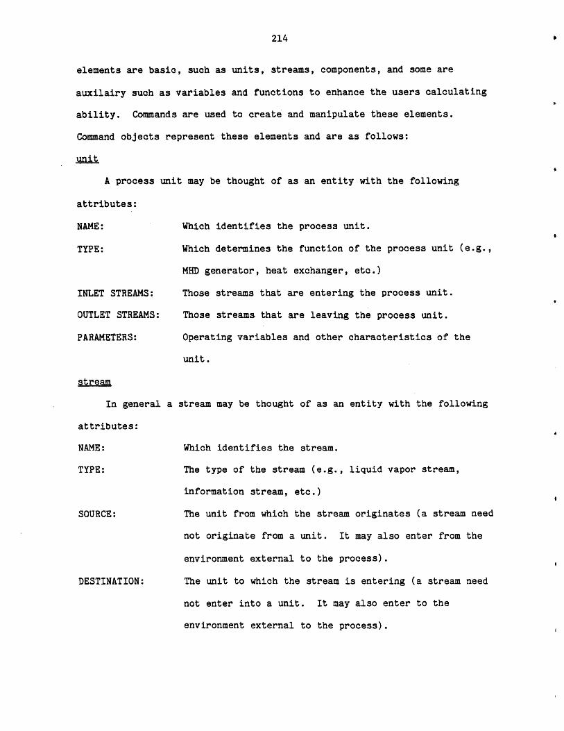
214
elements are basic, such as units, streams, components, and some are
auxilairy such as variables and functions to enhance the users calculating
ability. Commands are used to create and manipulate these elements.
Command objects represent these elements and are as follows:
Junit
A process unit may be thought of as an entity with the following
attributes:
NAME: Which identifies the process unit.
TYPE: Which determines the function of the process unit (e.g.
MHD generator, heat exchanger, etc.)
Those streams that are entering the process unit.
Those streams that are leaving the process unit.
Operating variables and other characteristics of the
unit.
stream
In general a
attributes:
NAME:
TYPE:
SOURCE:
DESTINATION:
stream may be thought of as an entity with the following
Which identifies the stream.
The type of the stream (e.g., liquid vapor stream,
information stream, etc.)
The unit from which the stream originates (a stream need
not originate from a unit. It may also enter from the
environment external to the process).
The unit to which the stream is entering (a stream need
not enter into a unit. It may also enter to the
environment external to the process).
INLET STREAMS:
OUTLET STREAMS:
PARAMETERS:
,
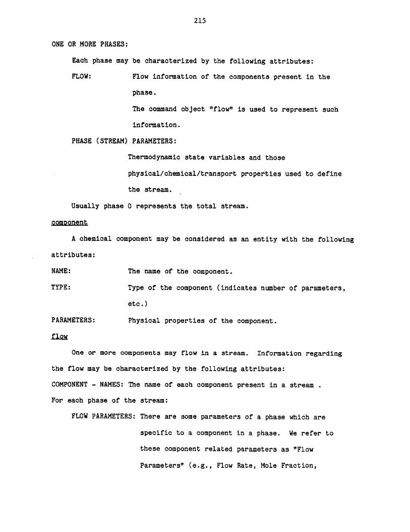
215
ONE OR MORE PHASES:
Each phase may be characterized by the following attributes:
FLOW: Flow information of the components present in the
phase.
The command object "flow" is used to represent such
information.
PHASE (STREAM) PARAMETERS:
Thermodynamic state variables and those
physical/chemical/transport properties used to define
the stream.
Usually phase 0 represents the total stream.
comDonent
A chemical component may be considered as an entity with the following
attributes:
NAME: The name of the component.
TYPE: Type of the component (indicates number of parameters,
etc.)
PARAMETERS: Physical properties of the component.
flow
One or more components may flow in a stream. Information regarding
the flow may be characterized by the following attributes:
COMPONENT - NAMES: The name of each component present in a stream
For each phase of the stream:
FLOW PARAMETERS: There are some parameters of a phase which are
specific to a component in a phase. We refer to
these component related parameters as "Flow
Parameters" (e.g., Flow Rate, Mole Fraction,
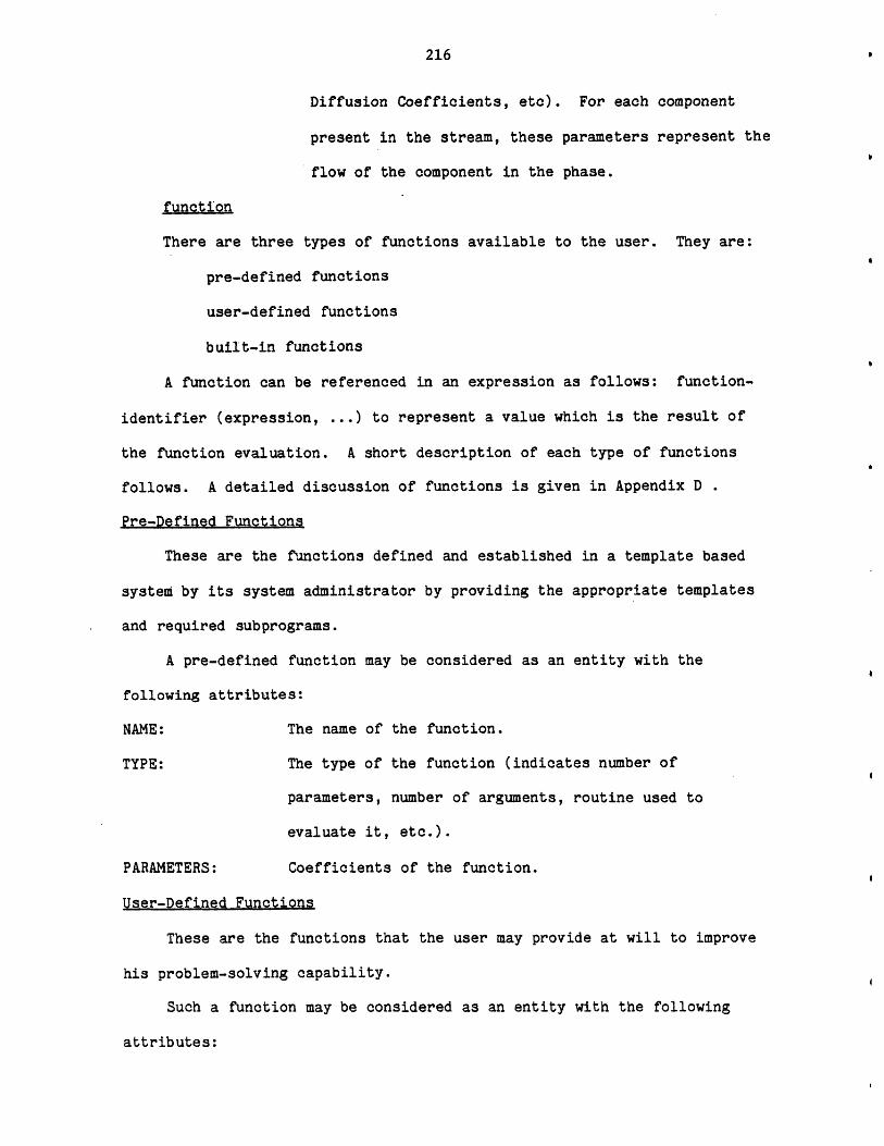
216
Diffusion Coefficients, etc). For each component
present in the stream, these parameters represent the
flow of the component in the phase.
function
There are three types of functions available to the user. They are:
pre-defined functions
user-defined functions
built-in functions
A function can be referenced in an expression as follows: function-
identifier (expression, ... ) to represent a value which is the result of
the function evaluation. A short description of each type of functions
follows. A detailed discussion of functions is given in Appendix D
Pre-Defined Functions
These are the functions defined and established in a template based
system by its system administrator by providing the appropriate templates
and required subprograms.
A pre-defined function may be considered as an entity with the
following attributes:
NAME: The name of the function.
TYPE: The type of the function (indicates number of
parameters, number of arguments, routine used to
evaluate it, etc.).
PARAMETERS: Coefficients of the function.
User-Defined Functions
These are the functions that the user may provide at will to improve
his problem-solving capability.
Such a function may be considered as an entity with the following
attributes:
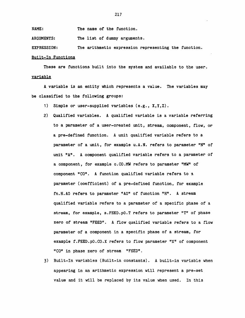
217
NAME: The name of the function.
ARGUMENTS: The list of dummy arguments.
EXPRESSION: The arithmetic expression representing the function.
Built-In Functions
These are functions built into the system and available to the user.
variable
A variable is an entity which represents a value. The variables may
be classified to the following groups:
1) Simple or user-supplied variables (e.g., X,Y,Z).
2) Qualified variables. A qualified variable is a variable referring
to a parameter of a user-created unit, stream, component, flow, or
a pre-defined function. A unit qualified variable refers to a
parameter of a unit, for example u.A.N. refers to parameter "N" of
unit "A". A component qualified variable refers to a parameter of
a component, for example c.CO.MW refers to parameter "MW" of
component "C0". A function qualified variable refers to a
parameter (coefficient) of a pre-defined function, for example
fn.H.AO refers to parameter "A0" of function "H". A stream
qualified variable refers to a parameter of a specific phase of a
stream, for example, s.FEED.pO.T refers to parameter "T" of phase
zero of stream "FEED". A flow qualified variable refers to a flow
parameter of a component in a specific phase of a stream, for
example f.FEED.pO.CO.X refers to flow parameter "X" of component
"CO" in phase zero of stream "FEED".
3) Built-In variables (Built-in constants). A built-in variable when
appearing in an arithmetic expression will represent a pre-set
value and it will be replaced by its value when used. In this
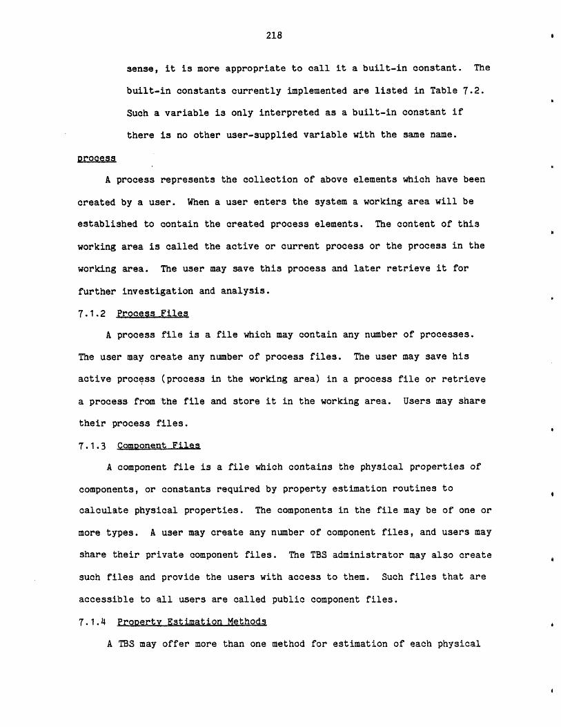
218
sense, it is more appropriate to call it a built-in constant. The
built-in constants currently implemented are listed in Table 7.2.
Such a variable is only interpreted as a built-in constant if
there is no other user-supplied variable with the same name.
process
A process represents the collection of above elements which have been
created by a user. When a user enters the system a working area will be
established to contain the created process elements. The content of this
working area is called the active or current process or the process in the
working area. The user may save this process and later retrieve it for
further investigation and analysis.
7.1.2 Process Files
A process file is a file which may contain any number of processes.
The user may create any number of process files. The user may save his
active process (process in the working area) in a process file or retrieve
a process from the file and store it in the working area. Users may share
their process files.
7.1.3 Component Files
A component file is a file which contains the physical properties of
components, or constants required by property estimation routines to
calculate physical properties. The components in the file may be of one or
more types. A user may create any number of component files, and users may
share their private component files. The TBS administrator may also create
such files and provide the users with access to them. Such files that are
accessible to all users are called public component files.
7.1.4 Property Estimation Methods
A TBS may offer more than one method for estimation of each physical
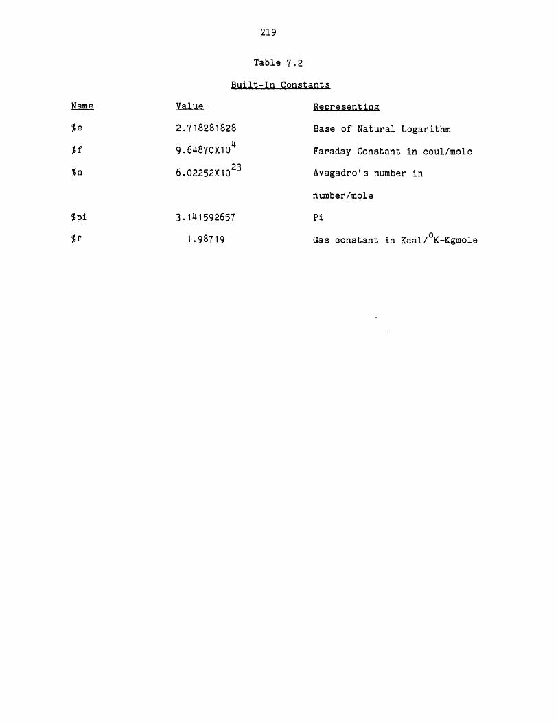
219
Table 7.2
Built-In Constants
Value Representing
2.718281828 Base of Natural Logarithm
9.6487OX104 Faraday Constant in coul/mole
6.02252X10 23 Avagadro's number in
number/mole
3.141592657
1.98719
Pi
Gas constant in Kcal/ K-Kgmole
%pi
%r

220
property. The user may choose the method to be used for one or more of
these properties. Default options will be used for those properties which
have not been specified by the user.
7.1.5 Units of Measurement
A TBS may allow the user to provide his data in one or more units of
measurement. The unit of measurement must be enclosed in a pair of
apostrophes and should immediately succeed the item of data to which it
refers. If no unit of measurement is provided for an item of data the
proper standard unit of measurement for that item of data will be assumed.
7.1.6 Profile Parameters
These parameters either control the format of output, or they specify
the input and output files to be used by the system. The TBS provides the
default values for these parameters. The user may change these parameters
at any time.
Profile parameters are as follows:
sdigit - Significant number of digits to be printed for numerical data.
ddigit - Decimal number of digits to be printed for numerical data.
dflag - Debugging flag indicates whether additional information regarding
command processing is to be printed.
output - Indicates the output file.
input - Indicates the input file.
7.1.7 Aritmetic Expressions
Arithmetic expressions may be used freely in a PEL command whenever a
numerical data is expected. An arithmetic expression is a representation
of a value. A number, a simple variable, or a qualified variable is an
expression. Combinations of numbers, simple variables, qualified variables
and/or functions, along with operators (e.g. + etc) are also
221
expressions. A full description of arithmetic expressions in PEL is given
in Appendix D.
7.1.8 Command Elements
There are very few restrictions in the format of PEL commands.
Consequently instructions can be written without consideration of special
coding forms. As long as each command is started on a new line and
terminated by a semicolon (;), the format is completely free. A command is
constructed from symbols. A symbol is the string of one or more characters
(up to 16 characters). There are three types of symbols: Literals,
Terminal Symbols (operators), and Identifiers.
Examples of Literals are 123, 123.475, and 12.3e+1. Examples of
Terminal Symbols are +, -, *, >, & , and = . Identifiers can be divided
into three groups: Language Keywords, Established Identifiers,
User-supplied Identifiers. A Language Keyword is an identifier that, when
used in proper context, has a specific meaning to the system. Established
Identifiers are the keywords of the TBS. These identifiers have been set
in the TBS by its responsible system adminstrator. User-supplied
identifiers are the identifiers provided by the user to identify the
objects he creates. Note that there is no reserved word in PEL. Language
Keywords and Established Identifiers will be interpreted as such only when
used in proper context.
For example the following command:
create unit (create,heatx) type = heatx; will create two units of type
"heatx". One unit is named "create" and another one is named "heatx".
Notice that only the first appearance of "create" is interpreted as a
Language Keyword. Similarly the second appearance of "heatx" is interpreted
as an Established Identifier.
A detailed description of command elements is given in Appendix D.

222
7.2 Classification of Commands
Each command is a request for an action to be taken by the system.
Commands enable a user to create process elements, specify parameters and
variables, calculate parts of or whole flowsheet, print results, etc. When
a user enters the system a working area will be established to contain the
created process elements. The content of the working area is called the
active process or the current process. The user can save this active
process in a process file and later retrieve it for further investigation.
In this section commands are classified according to their function. A
command may appear in more than one group. Each command is followed by a
short description. A more detailed description and command syntax is given
in Appendix D.
7.2.1 Configuration Commands
These commands may be used to specify the process configuration:
create To create units, components, functions (pre-defined and user-
defined), streams, or to specify what components are flowing in a
stream (flow).
delete To delete (remove) units, components, functions (pre-defined and
user-defined), streams, or to deny the flow of some components in
a stream (flow).
connect To connect a unit to streams.
disconnect To disconnect a unit from streams.
let,leta To duplicate or copy a unit, component, function (pre-defined
function), or stream.
load To copy the components from public files or user's private files
into the user's working area, or to copy an entire process from
a user's process files into his working area.
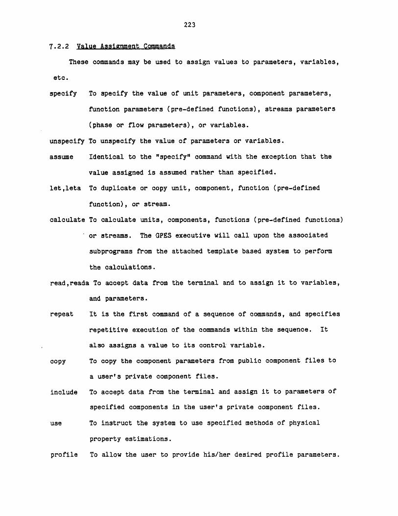
223
7.2.2 Value Assignment Commands
These commands may be used to assign values to parameters, variables,
etc.
specify To specify the value of unit parameters, component parameters,
function parameters (pre-defined functions), streams parameters
(phase or flow parameters), or variables.
unspecify To unspecify the value of parameters or variables.
assume Identical to the "specify" command with the exception that the
value assigned is assumed rather than specified.
let,leta To duplicate or copy unit, component, function (pre-defined
function), or stream.
calculate To calculate units, components, functions (pre-defined functions)
or streams. The GPES executive will call upon the associated
subprograms from the attached template based system to perform
the calculations.
read,reada To accept data from the terminal and to assign it to variables,
and parameters.
repeat It is the first command of a sequence of commands, and specifies
repetitive execution of the commands within the sequence. It
also assigns a value to its control variable.
copy To copy the component parameters from public component files to
a user's private component files.
include To accept data from the terminal and assign it to parameters of
specified components in the user's private component files.
use To instruct the system to use specified methods of physical
property estimations.
profile To allow the user to provide his/her desired profile parameters.
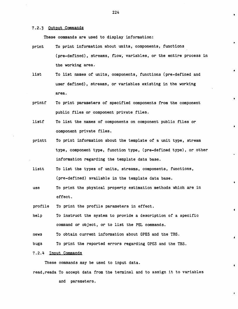
224
7.2.3 Output Commands
These commands are used to display information:
print To print information about units, components, functions
(pre-defined), streams, flow, variables, or the entire process in
the working area.
list To list names of units, components, functions (pre-defined and
user defined), streams, or variables existing in the working
area.
printf To print parameters of specified components from the component
public files or component private files.
listf To list the names of components on component public files or
component private files.
printt To print information about the template of a unit type, stream
type, component type, function type, (pre-defined type), or other
information regarding the template data base.
listt To list the types of units, streams, components, functions,
(pre-defined) available in the template data base.
use To print the physical property estimation methods which are in
effect.
profile To print the profile parameters in effect.
help To instruct the system to provide a description of a specific
command or object, or to list the PEL commands.
news To obtain current information about GPES and the TBS.
bugs To print the reported errors regarding GPES and the TBS.
7.2.4 Input Commands
These commands may be used to input data.
read,reada To accept data from the terminal and to assign it to variables
and parameters.
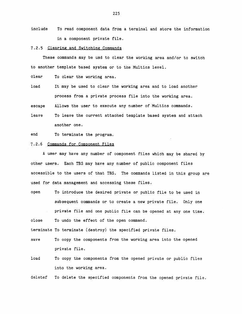
225
include To read component data from a terminal and store the information
in a component private file.
7.2.5 Clearing and Switching Commands
These commands may be usd to clear the working area and/or to switch
to another template based system or to the Multics level.
clear To clear the working area.
load It may be used to clear the working area and to load another
process from a private process file into the working area.
escape Allows the user to execute any number of Multics commands.
leave To leave the current attached template based system and attach
another one.
end To terminate the program.
7.2.6 Commands for Component Files
A user may have any number of component files which may be shared by
other users. Each TBS may have any number of public component files
accessible to the users of that TBS. The commands listed in this group are
used for data management and accessing these files.
open To introduce the desired private or public file to be used in
subsequent commands or to create a new private file. Only one
private file and one public file can be opened at any one time.
close To undo the effect of the open command.
terminate To terminate (destroy) the specified private files.
save To copy the components from the working area into the opened
private file.
load To copy the components from the opened private or public files
into the working area.
deletef To delete the specified components from the opened private file.
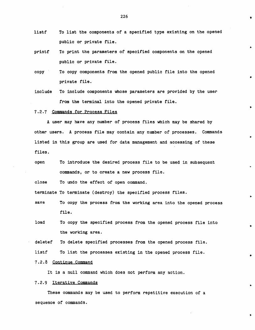
226
listf To list the components of a specified type existing on the opened
public or private file.
printf To print the parameters of specified components on the opened
public or private file.
copy To copy components from the opened public file into the opened
private file.
include To include components whose parameters are provided by the user
from the terminal into the opened private file.
7.2.7 Commands for Process Files
A user may have any number of process files which may be shared by
other users. A process file may contain any number of processes. Commands
listed in this group are used for data management and accessing of these
files.
open To introduce the desired process file to be used in subsequent
commands, or to create a new process file.
close To undo the effect of open command.
terminate To terminate (destroy) the specified process files.
save To copy the process from the working area into the opened process
file.
load To copy the specified process from the opened process file into
the working area.
deletef To delete specified processes from the opened process file.
listf To list the processes existing in the opened process file.
7.2.8 Continue Command
It is a null command which does not perform any action.
7.2.9 Iterative Commands
These commands may be used to perform repetitive execution of a
sequence of commands.
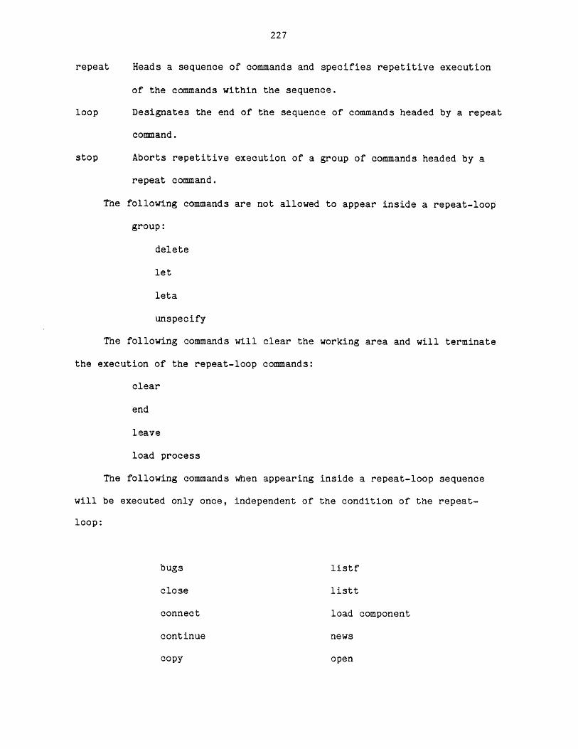
227
repeat Heads a sequence of commands and specifies repetitive execution
of the commands within the sequence.
loop Designates the end of the sequence of commands headed by a repeat
command.
stop Aborts repetitive execution of a group of commands headed by a
repeat command.
The following commands are not allowed to appear inside a repeat-loop
group:
delete
let
leta
unspecify
The following commands will clear the working area and will terminate
the execution of the repeat-loop commands:
clear
end
leave
load process
The following commands when appearing inside a repeat-loop sequence
will be executed only once, independent of the condition of the repeat-
loop:
bugs listf
close listt
connect load component
continue news
copy open
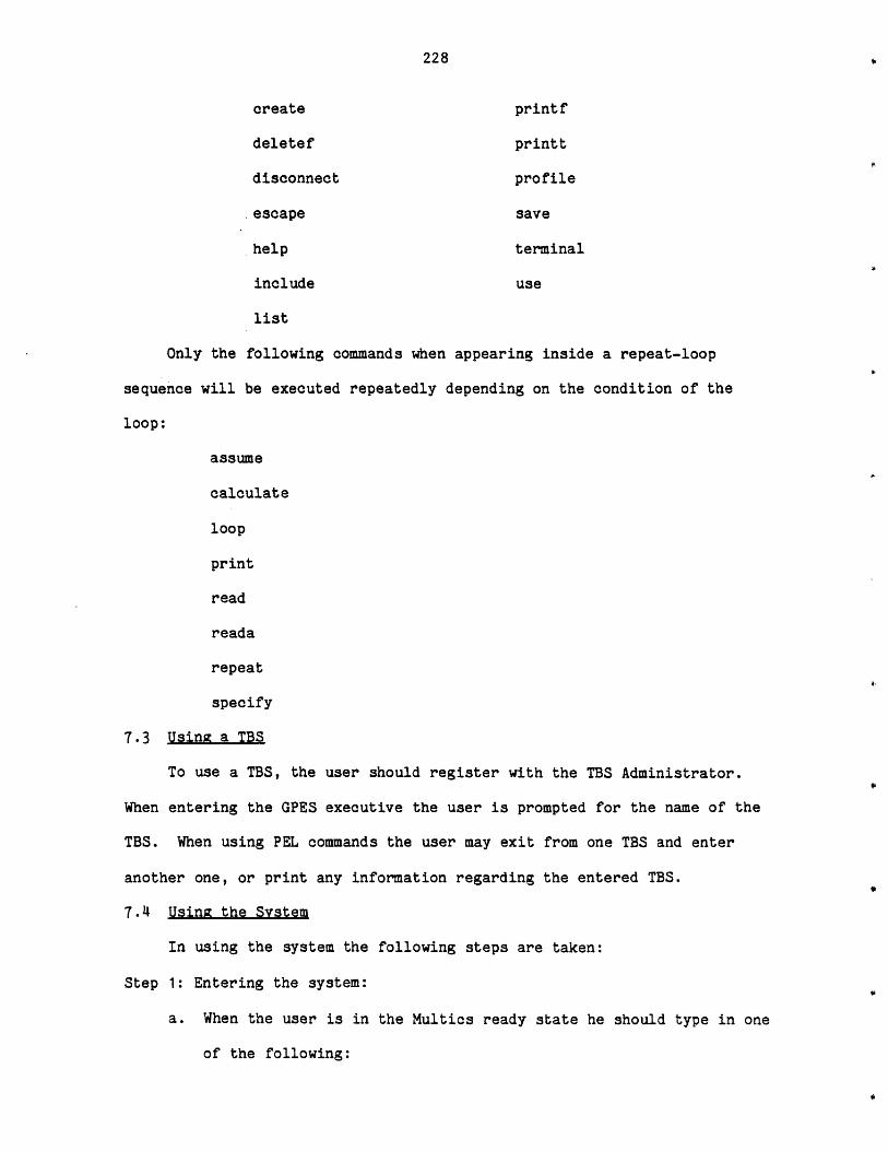
228
create printf
deletef printt
disconnect profile
.escape save
help terminal
include use
list
Only the following commands when appearing inside a repeat-loop
sequence will be executed repeatedly depending on the condition of the
loop:
assume
calculate
loop
read
reada
repeat
specify
7.3 Using a TBS
To use a TBS, the user should register with the TBS Administrator.
When entering the GPES executive the user is prompted for the name of the
TBS. When using PEL commands the user may exit from one TBS and enter
another one, or print any information regarding the entered TBS.
7.4 Using the System
In using the system the following steps are taken:
Step 1: Entering the system:
a. When the user is in the Multics ready state he should type in one
of the following:

229
pel
pel brief
pel bf
The function of the argument brief or bf is to inhibit the
printout of messages about the system and the attached TBS.
b. If the brief argument is not provided, some information about the
system will be printed.
c. If the GPES system administrator has locked the system, a system
message will be printed and the execution of the program will be
terminated.
Step 2: Attaching a TBS:
a. The user will be prompted to provide the name of the TBS he wishes
to use. To be able to use a TBS he should have been authorized by
that TBS system Administrator.
b. If the user is not an authorized user of the specified TBS or has
specified an unknown TBS, a system message will be printed and he
will be given the option of trying another TBS or leaving the
system.
c. If the brief argument was not provided in Step 1, some information
about the TBS will be printed.
d. If the TBS system administrator has locked the TBS, a message will
be printed and the user will be given the option of trying another
TBS or leaving the system.
e. If the TBS is inconsistent, a message will be printed and the user
will be given the choice of continuing to use the TBS or not using
it. If he chooses the latter he will be given the choice of
trying another TBS or leaving the system.
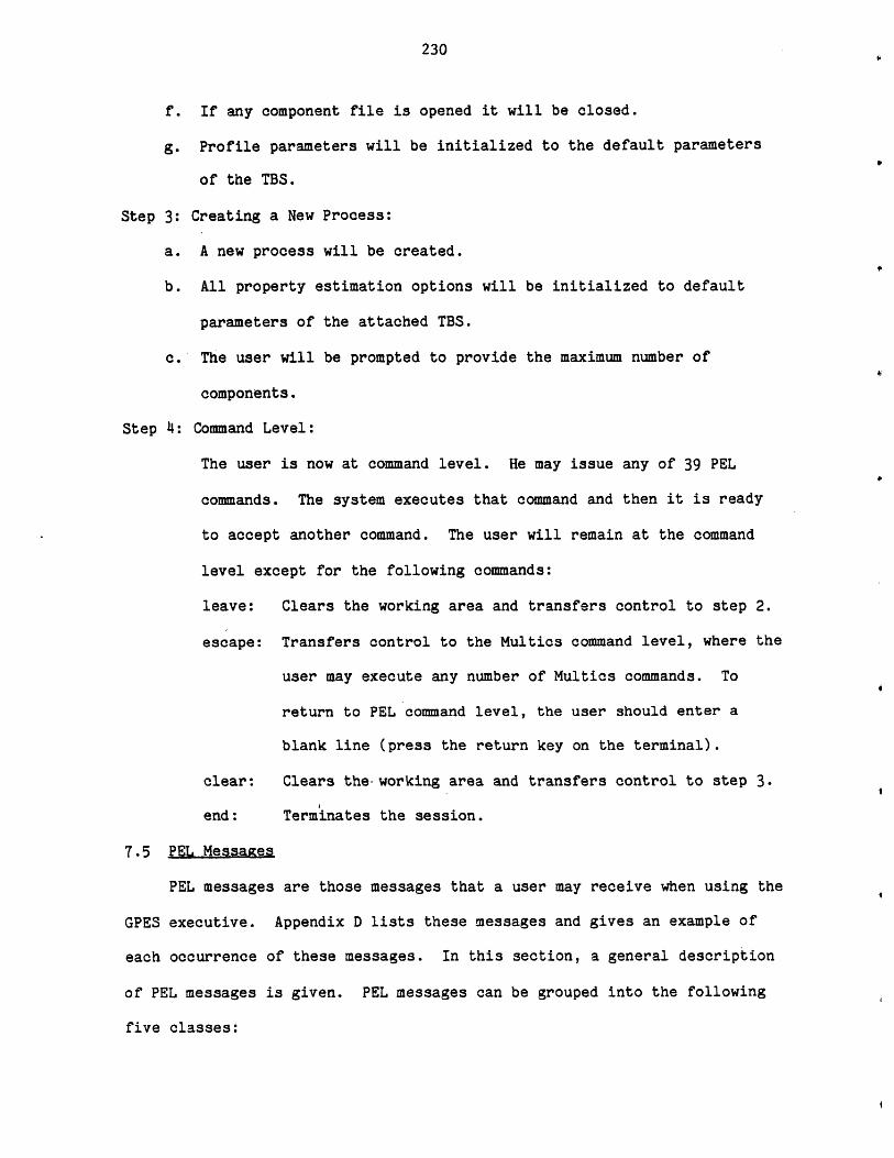
230
f. If any component file is opened it will be closed.
g. Profile parameters will be initialized to the default parameters
of the TBS.
Step 3: Creating a New Process:
a. A new process will be created.
b. All property estimation options will be initialized to default
parameters of the attached TBS.
c. The user will be prompted to provide the maximum number of
components.
Step 4: Command Level:
The user is now at command level. He may issue any of 39 PEL
commands. The system executes that command and then it is ready
to accept another command. The user will remain at the command
level except for the following commands:
leave: Clears the working area and transfers control to step 2.
escape: Transfers control to the Multics command level, where the
user may execute any number of Multics commands. To
return to PEL command level, the user should enter a
blank line (press the return key on the terminal).
clear: Clears the working area and transfers control to step 3.
end: Terminates the session.
7.5 PEL Messages
PEL messages are those messages that a user may receive when using the
GPES executive. Appendix D lists these messages and gives an example of
each occurrence of these messages. In this section, a general description
of PEL messages is given. PEL messages can be grouped into the following
five classes:
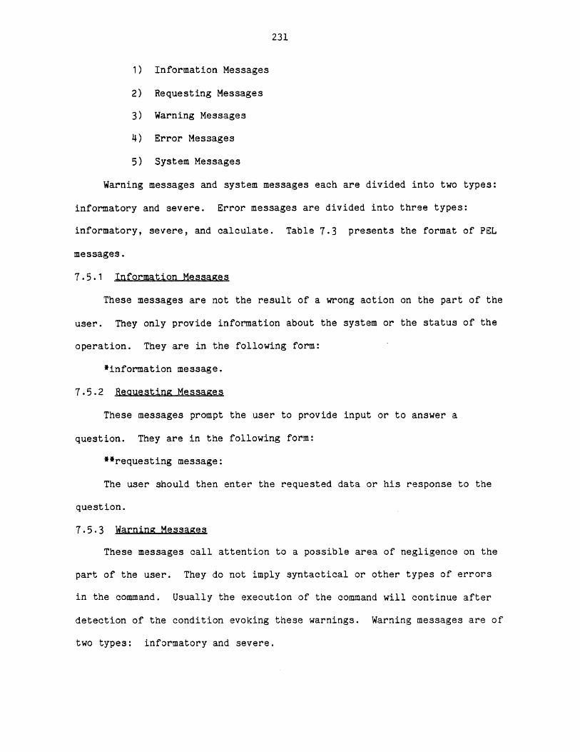
231
1) Information Messages
2) Requesting Messages
3) Warning Messages
4) Error Messages
5) System Messages
Warning messages and system messages each are divided into two types:
informatory and severe. Error messages are divided into three types:
informatory, severe, and calculate. Table 7.3 presents the format of PEL
messages.
7.5.1 Information Messages
These messages are not the result of a wrong action on the part of the
user. They only provide information about the system or the status of the
operation. They are in the following form:
*information message.
7.5.2 Reauesting Messages
These messages prompt the user to provide input or to answer a
question. They are in the following form:
**requesting message:
The user should then enter the requested data or his response to the
question.
7.5.3 Warning Messages
These messages call attention to a possible area of negligence on the
part of the user. They do not imply syntactical or other types of errors
in the command. Usually the execution of the command will continue after
detection of the condition evoking these warnings. Warning messages are of
two types: informatory and severe.
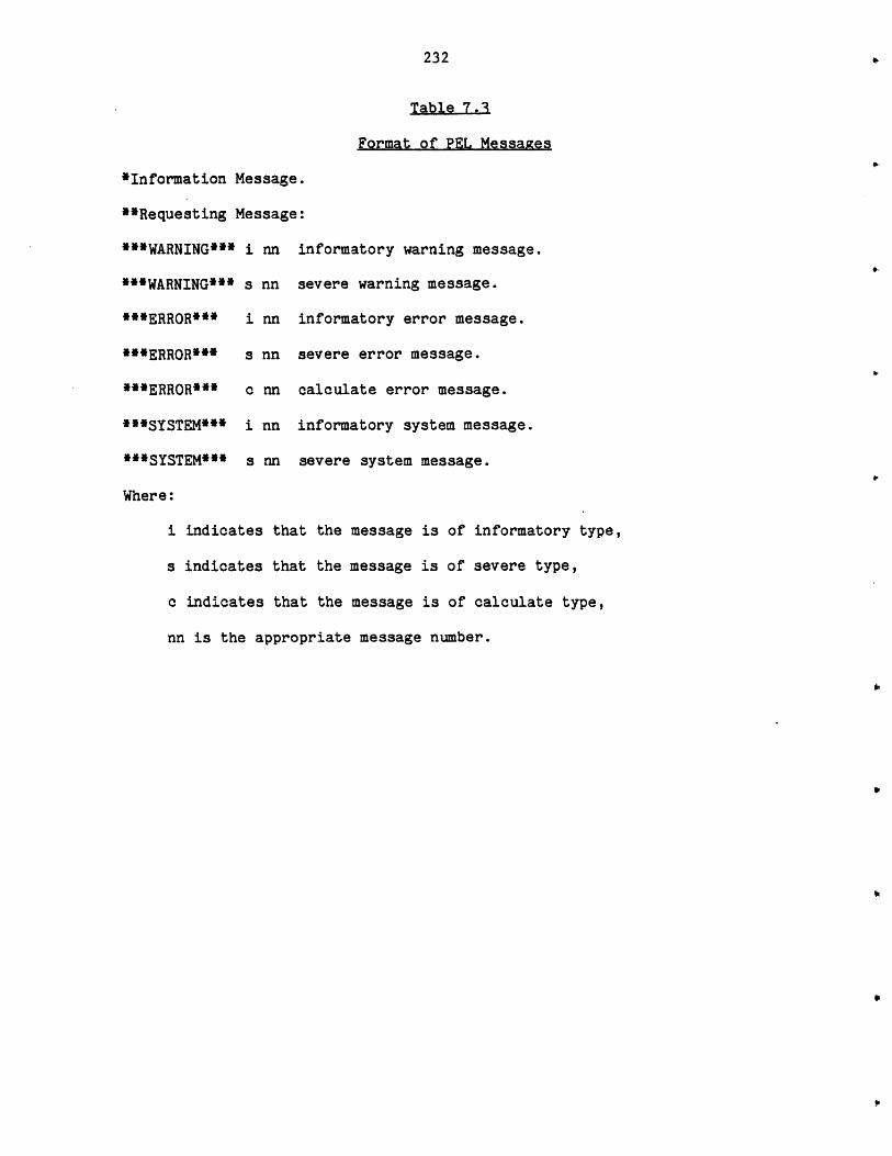
232
Table 7.3
Format of PEL Messages
*Information Message.
**Requesting Message:
***WARNING*** i nn i
***WARNING*** s nn s
***ERROR*** i nn i
***ERR0R*** s nn s
***ERROR*** c nn c
"*SYSTEM*** i nn i
***SYSTEM*** s nn s
Where:
nformatory warning message.
evere warning message.
nformatory error message.
evere error message.
alculate error message.
nformatory system message.
evere system message.
i indicates that the message is of informatory type,
s indicates that the message is of severe type,
c indicates that the message is of calculate type,
nn is the appropriate message number.
233
7.5.3.1 Informatory Warning Messages
These messages may be produced during the execution of a command. The
execution of the command will continue after the issuance of such warnings.
They usually do not require responsive actions. The presence of these
messages indicates that the command is not fully executed. The execution
of the parts skipped is not permitted, because it violates some
restrictions or the desired actions have already been accomplished.
7.5.3.2 Severe Warning Messages
These messages may be provided during the evaluation of an expression.
The conditions which cause these messages cannot usually be detected before
execution of the command. For this reason, a message will be printed and
the result of the expression will be assumed to be zero, and execution of
the command will be continued. Although the system does not require
responsive action, the user may want to undertake some corrective actions
once the execution of the command(s) has been completed. Table 7.4
presents the conditions in an expression producing severe warning messages.
7.5.4 Error Messages
These messages are the result of syntactical errors or other types of
errors made by the user. Error messages are of three types: Informatory,
Severe, and Calculate.
7.5.4.1 Informatory Error Messages
These are errors detected in the user's input. The system prints the
message and asks the user to reenter his input. Because these errors could
be corrected by the user the execution of the command will be continued.
They are the least severe type of errors. Table 7.5 indicates the
conditions under which these error messages may be produced.
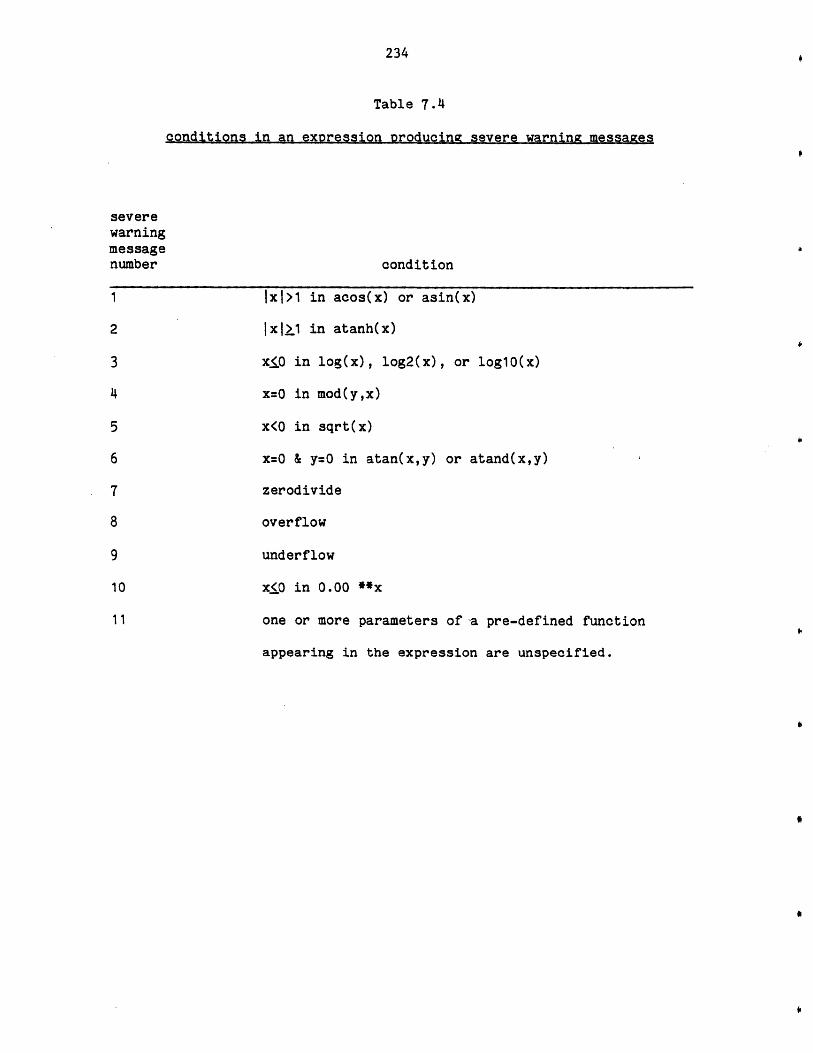
234
Table 7.4
conditions in an expression producing severe warning messages
severewarningmessagenumber
1
2
3
4
5
6
7
8
9
10
11
condition
IxI>1 in acos(x) or asin(x)
IxIl1 in atanh(x)
x<.O in log(x), log2(x), or logl(x)
x=0 in mod(y,x)
x<O in sqrt(x)
x=O & y=0 in atan(x,y) or atand(x,y)
zerodivide
overflow
underflow
x<0 in 0.00 **x
one or more parameters of 'a pre-defined function
appearing in the expression are unspecified.
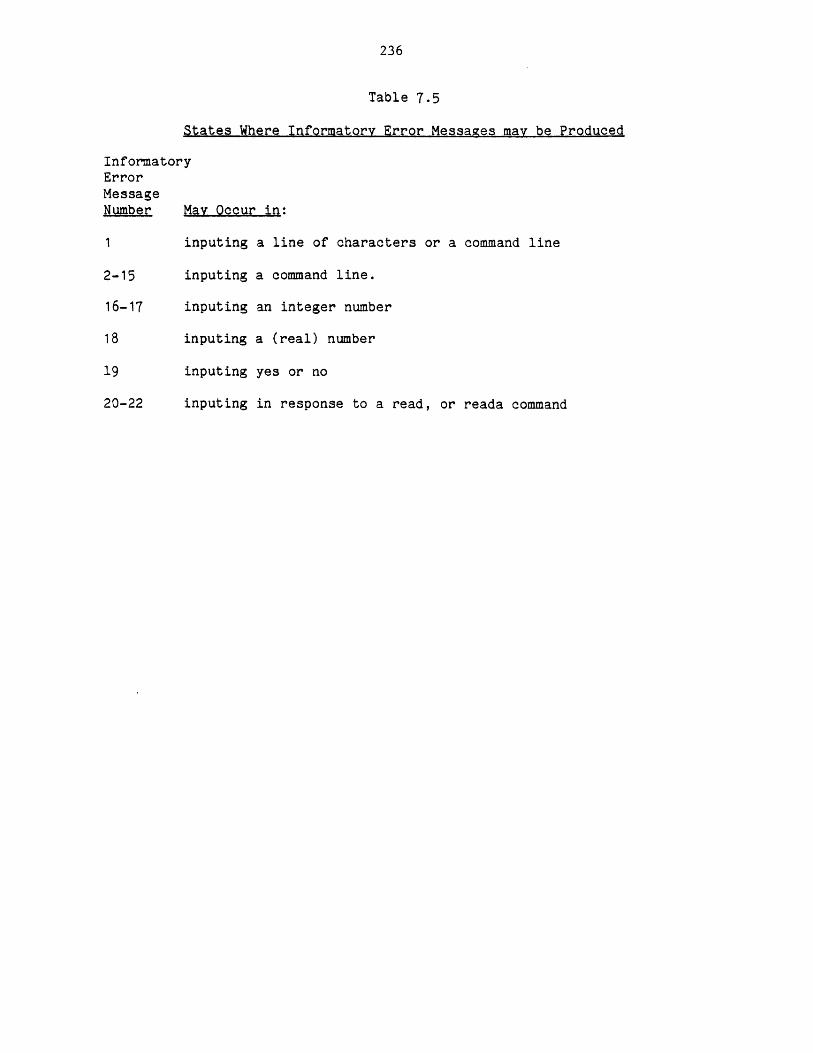
236
Table 7.5
States Where Informatory Error Messages may be Produced
InformatoryErrorMessageNumber May Occur in:
1 inputing a line of characters or a command line
2-15 inputing a command line.
16-17 inputing an integer number
18 inputing a (real) number
19 inputing yes or no
20-22 inputing in response to a read, or reada command
236
7.5.4.2 Severe Error Messages
Severe errors are the result of syntactical errors or other kinds of
errors that cannot be corrected. Upon the first detection of such an
error, the error-checking procedure will be discontinued and the execution
of the command will be ignored.
7.5.4.3 Calculate Error Messages
These errors are detected during the execution of a calculate command.
The system responds differently to this type of error. Errors of this type
are only detectable during the execution of the command while errors of
type "severe" are detected before the execution of the command. Once an
error of type "calculate" has been detected in a command the execution of
that command will be halted. If the command resides in a closed loop the
execution of all commands in the loop(s) will be stopped. If the command
is the last command typed by the user (e.g., not in a loop or in an open
loop) only the execution of that command will be stopped and preceding
commands if any will be unaffected.
7.5.5 System-Messages
System messages are issued in response to conditions which are not
necessarily attributable to the user's actions. They may be the result of
negligence on the part of the GPES Administrator, TBS Administrator, or the
user. These messages may be produced upon entering the system or attaching
a TBS or executing a command. They indicate conditions such as
incompatibility, improper access, presence or absence of some segments
(files). The user may be responsible in the following cases:
a) Attaching a TBS which is either:
Unknown, inconsistent, or inaccessible to the user.
b) Opening a process file, or opening a component file, or loading a
237
process which may not be compatible with the current version of the
system or the attached TBS.
c) Not having the required access for using a component or a process
file, or providing invalid path names for that purpose.
d) Intervening in the system file management by deleting or modifying
segments the system has created for him, or creating such segments
outside of the system. The names of these segements are always
suffixed by ".GPES".
e) Attempt to use a proprietary or an unknown routine.
System messages are of two types: informatory and severe.
7s5;5.l Informatory System Messages
inese messages may be produced upon entering the system, attaching a
TBS, or executing a command. The operation of the system or
execution of the command usually will continue after the issuance
of such messages. They usually do not require responsive actions.
When produced as a result of the execution of a command. They
indicate that the command is not fully executed. The execution of
the parts skipped is not, permitted because it violates some
restrictions or provides invalid information or refers to unknown
segments.
7.5.5.2 Severe System Messages
These messages may be produced upon entering the system, attaching a
TBS, or executing a command. If detected during entrance to the
system, admission will be denied. If detected during attachment of
a TBS, attachment of that TBS will be stopped. If detected during
the execution of a command, that command will be ignored.
238
CHAPTER 8
GPES ADMINISTRATION AND PROTECTION
GPES may contain any number of TBS's, each having any number of users.
To assist the GPES administrator in administrating and protecting the
system and each TBS from unauthorized users, a mechanism has been provided
as a part of GPES, to protect files and insure security. GPES has three
files for this purpose: Text file, TBS table, and users table. The text
file also serves other purposes as will be described next.
8.1 The GPES Text File
The GPES text file is created and updated by any available editor. It
contains the following information:
a) The GPES Administrator's name.
b) Any reference about the GPES.
c) Any message to the users.
The above information (a,b,c) will be printed when the user enters the
system.
d)The system lock which indicates whether the system can or cannot be
accessed by the users.
e) Any news about the GPES. This information along with similar
information about the attached TBS will be printed in response to the
user's "news" command.
f) Any errors found or reported about GPES. This information along with
similar information about the attached TBS will be printed in response to
the user' s "bugs" command.
g) Information describing the PEL commands which will be printed in
response to the user's "help" commands. It contains the following:
239
1) Syntax notation conventions.
2) A description of each of the seven objects: unit, component,
function, stream, flow, variable, and process.
3) A description of each PEL command followed by all its subgroups.
The format of the file is shown in Figure 8.1. Each item of
information should start and terminate by a %. The heading for each item
should be exactly as shown in Figure 8.1. Notation ---text--- indicates
that any number of characters or lines can be provided. Although the
sequence of providing the items of information is not important, the
sequence shown in Figure 8.1 is recommended. The format of "lock item"
should be one of the following:
%lock open%
%lock close%
If this item is not provided or it is as the first format, the system
can be accessed. The second format indicates that the system cannot be
accessed.
8.2 The TBS Table
This table contains information regarding every TBS, as shown in
Figure 8.2. Each entry of the table may be empty or contain information
regarding a TBS. Each entry contains the following information:
a) The date on which the TBS was added to the table.
b) The TBS's name.
c) The pathname of the directory containing the template data base.
This information enables the GPES executive to locate the template
data base once the user provides the TBS' name.
d) The TBS administrator's name, address and telephone number.

240
Figure 8.1
Format of The GPES Text File
%*GPES message ----Text----%
%*GPES reference ----Text----%
*GPES system administrator----Text----%
%lock open% or %lock close%
%GPES news----Text----%
%GPES bugs----Text----%
%syntax notation conventions----Text----%
%unit----Text----%
%component----Text----%
%function----Text----%
%stream----Text----%
%flow----Text----%
%variable----Text----%
%process----Text----%
%assume----Text----%
%assume unit----Text----%
%assume component---- Text----%
%assume function----Text----%
%assume stream----Text----%
%assume flow---Text---%
%assume variable---Text---%
%bugs---Text---%
%calculate---Text---%
%use---Text---%
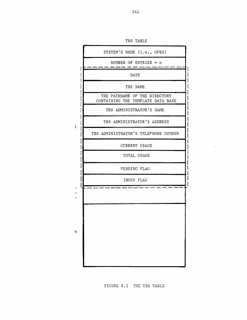
241
TBS TABLE
SYSTEM'S NAME (i.e., GPES)
NUMBER OF ENTRIES = n
DATE
TBS NAME
THE PATHNAME OF THE DIRECTORYCONTAINING THE TEMPLATE DATA BASE
TBS ADMINISTRATOR'S NAME
TBS ADMINISTRATOR'S ADDRESS
TBS ADMINISTRATOR'S TELEPHONE NUMBER
CURRENT USAGE
TOTAL USAGE
PENDING FLAG
INUSE FLAG
n
FIGURE 8.2 THE TBS TABLE
242
e) The TBS current and total usage. A mechanism for recording this
information has been proposed, but has not been implemented. It
will be described in Chapter 11.
g) The pending flag which indicates whether the TBS is not currently
operational, or could be used.
h) The inuse flag which indicates whether the entry is empty or not.
It is also a safety flag which is "on" when the entry contains
complete information about a TBS.
An interactive program called "updatetbstbl" has been developed to
create and update this file. The GPES Administrator communicates with this
program by a simple set of commands. The command syntax is as follows:
command ( tbs-name]
For instance, if the GPES Administrator wants to insert a TBS called "XYZ"
the command for it would be: insert XYZ, or in the abbreviated form: i
XYZ. Having received the insert command, the program prompts the user for
all the required information. The complete list of commands is given in
Table 8.1. Using an "e" as the tbsname indicates that the command must be
executed for each TBS in the Table. Before the program accepts any command
it would create a new table if one does not already exist.
The function of each command is as follows:
insert: To insert a new TBS into the table. The program prompts the GPES
Administrator for all the required information. If the TBS
Administrator is new (if he is not the administrator of an a
existing TBS), the program will also provide the TBS
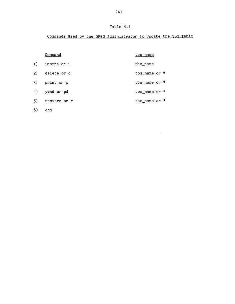
243
Table 8.1
Commands Used by the GPES Administrator to Update the TBS Table
Command
insert or i
delete or d
print or p
pend or pd
restore or r
end
tbs name
tbsname
tbs name or *
tbsname or *
tbsname or *
tbsname or *
244
Administrator access to programs he may need in performing his
duties (i.e., update-tdb program and other utility programs).
delete: To remove a TBS from the table. If the TBS Administrator is not
the Administrator of any other existing TBS, the program also
denies the access rights given earlier.
print: To print information regarding a TBS.
pend: To change the status of a TBS to pending, so that the TBS cannot
be accessed by its users.
restore: To undo the effect of the pend command.
end: To terminate the program.
The GPES administrator will add an entry to the table upon receiving
the TBS registration form shown in Figure 8.3.
8.3 The Users Table
This table contains information regarding every user of each TBS. As
shown in Figure 8.4, the table consists of a number of data structures
chained together. Each of these data structures represents a user of a
TBS. A user amy have access to one or more TBS. Therefore associated with
each user there are a number of such data structures, each corresponding to
a TBS for which the user has authorization for using the TBS. Each data
structure contains the following:
a) A pointer to the next data structure in the list.
b) A pointer to the previous data structure in the list.
c) Date on which entry was made.
d) User's name.
e) TBS name.
f) User's address, and telephone number.
g) User's current and total usage of the TBS. A mechanism for

245
FIGURE 8.3
TBS REGISTRATION FORM
TO: GPES ADMINISTRATOR FROM:
DATE
TBS NAME
REQUEST FOR: ADDING DELETING PENDING RESTORING
CHECK ONE: D DADDING
I I I I I I I I I I I I I I I _ I I I I | |TBS ADMINISTRATOR'S PERSONID
I I I I 1 1 1 1 1 1 I I I I I I I I I I I I I 1|TBS ADMINISTRATOR'S ADDRESS
I I I I I I I I I I I I I I I I I I I I I I
I A D I I I I I I l 111
PATHNAME OF THE DIRECTORY CONTAINING THE TEMPLATE DATA BASE
I I I I I I I I I I I I I I I I I I I I I I I
I I I I I I I I I I I I I I 1 1 I I I I I I I I
L I I I I I I l I I I I I | | | I I I I I I
I I I I 1 l I I I I I I I I I 1 I I I | | I I I
I I I I I I I I I I I I I I I I I I I I I I I I
I I I I I I I I I I I I I I I I I I I I I I I I
I I I I I I I I I I I I I I I I I I I I I I I IA BRIEF DEOSCRIPTION OF THE TBS:
APPROVED BY:
,
I

246
USERS TABLE
SYSTEM'S NAME (i.e., GPES)
POINTER TO FIRST USER IN THE TABLE
POINTER TO NEXT USER
POINTER TO PREVIOUS USER
DATE
USER'S NAME
TBS NAME
USER'S ADDRESS
USER'S TELEPHONE NUM1BER
CURRENT USAGE
TOTAL USAGE
PENDING FLAG
THE USERS TABLEFIGURE 8.4

247
recording this information is proposed, but has not been
implemented. It will be discussed in Chapter 11.
h) Pending flag which indicates the status of the user regarding the
usage of the TBS. When it is "on" the user can not use the TBS.
The data structures in the list are alphabetically ordered by users'
names. The data structures for the same user are ordered by TBS's names.
An interactive program called "update_userstbl" has been developed to
create and update this table. In fact, both updatetbstbl,
update_userstbl are entries of a single program, called the Administrative
Program. This program has also two other entries, used by the GPES
executive to obtain information about a TBS or to verify whether the user
is authorized to use the requested TBS.
The GPES Administrator communicates with the update-userstbl program
with a simple set of commands. The command syntax is as follows:
command (user name] [tbs name]
For example, if the GPES Administrator wants to authorize user "Smith" to
use the TBS "XYZ" he would give the command:
insert Smith XYZ
Having received the insert command, the program prompts the user for all
the required information. The complete list of commands is given in Table
8.2. Using an "*" as the tbsname or the username indicates that the
command must be executed for all TBS's or all users. Before the program
accepts any command it creates a new "users table" if one does not already
exist.
The function of each command is as follows:
insert: To make an entry in the table (to authorize a user for a TBS).
The program prompts the GPES Administrator for all the required
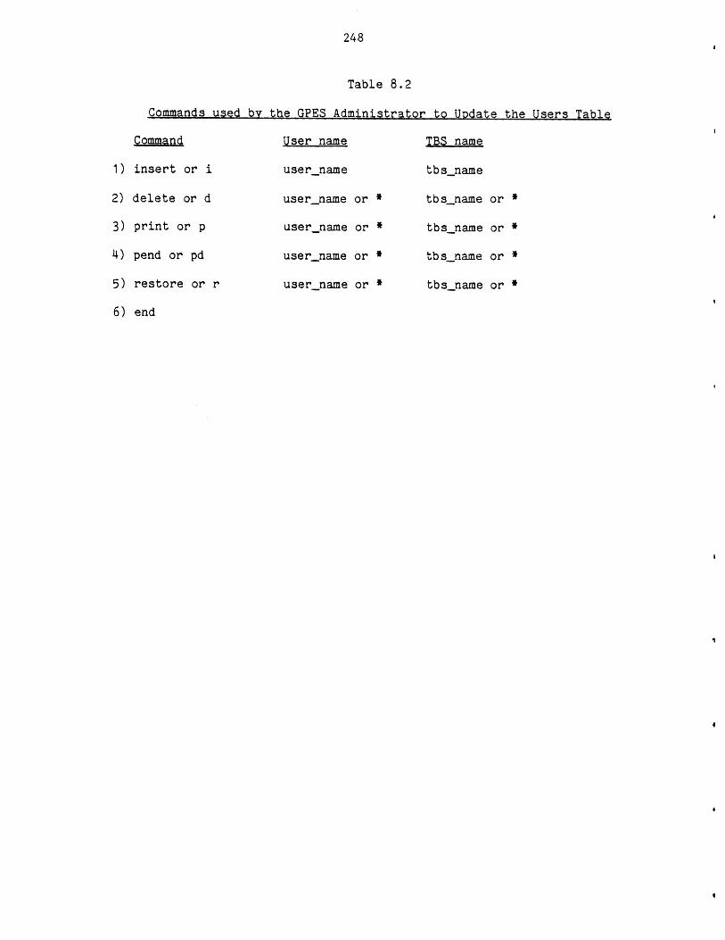
248
Table 8.2
Commands used by the GPES Administrator to Update the Users Table
Command User name TBS name
1) insert or i username tbsname
2) delete or d user-name or * tbs name or *
3) print or p username or * tbsname or *
4) pend or pd username or * tbsname or *
5) restore or r username or * tbsname or *
6) end
249
information. The program also gives the new user necessary
access to the GPES executive.
delete: To delete an entry in the table (to delete a user from the list
of authorized users of a TBS). If the user is not using any
other TBS, the program would also deny the access rights given
earlier, when the user was first inserted to the table.
print: To print information about a user of a TBS.
pend: To prevent the user from using the TBS, temporarily.
restore: To undo the effect of the above command.
end: To terminate the execution of the program.
The GPES Administrator will add an entry to the table upon receiving the
user registration form shown in Figure 8.5.
8.4 Various Copies of GPES Files
Two copies of each GPES file are required and a third one is
recommended. The two required copies are:
1) The original or primary copy accessible to the GPES Administrator only.
Table 8.3 lists the names of segments containing the primary copy of
GPES files.
2) The system copy accessible to the GPES Executive program. The segment
names for this copy are the same as in Table 8.3, except that they are
suffixed by ".syscopy". The system copy can be used while the primary
copy is being updated. The users have access to this copy only.
A backup copy is also recommended, to enable recovery from
unintentional erasures and other accidents. The segment names for the
backup copy are the same as shown in Table 8.3, except that they are
suffixed by ".backup". The flow of information between the different
copies of the GPES files, the GPES Executive, and other utility programs is
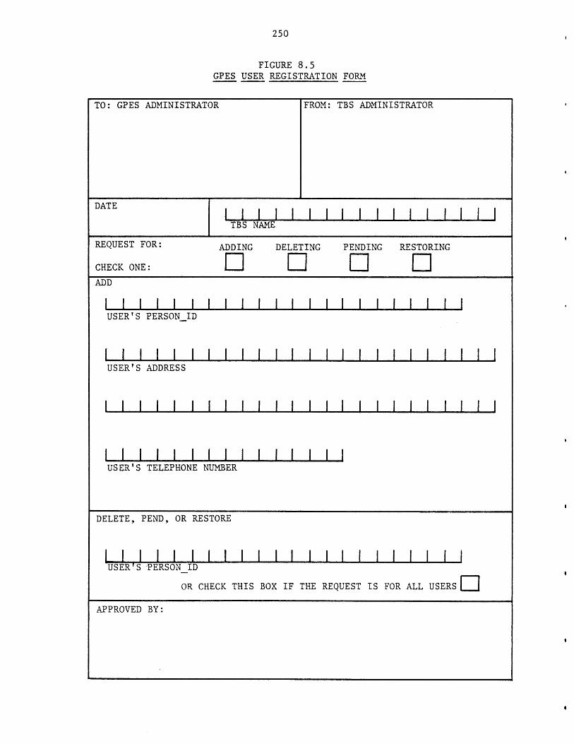
250
FIGURE 8.5GPES USER REGISTRATION FORM
TO: GPES ADMINISTRATOR FROM: TBS ADMINISTRATOR
DATE
TBS NAME
REQUEST FOR: ADDING DELETING PENDING RESTORING
CHECK ONE: D DDADD
I I I I I I I I I I I I I I I I I I I I |USER'S PERSONID
[ I I I I I I I I I I I I I I I I I l I I I I IUSER'S ADDRESS
I I I I I I I I I I I I I I I I I I I I
USER'S TELEPHONE NUMBER
DELETE, PEND, OR RESTORE
I I I I I I I I I I I I I I I I I I I I I IUSER'S PERSONID
OR CHECK THIS BOX IF THE REQUEST IS FOR ALL USERS DAPPROVED BY:
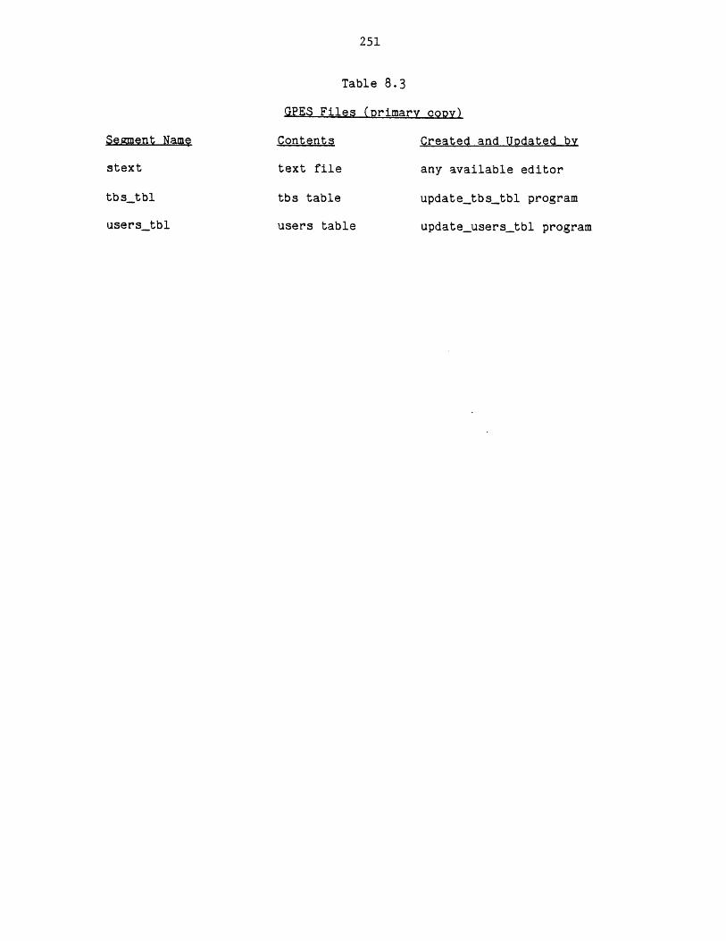
251
Segment Name
stext
tbstbl
userstbl
Table 8.3
GPES Files (primary copy)
Contents Created and Updated by
text file any available editor
tbs table update_tbstbl program
users table updateusers-tbl program
252
shown in Figure 8.6. The utility program "copyseg" copies one segment
into another, while preserving the access control list of the target
segment. Access control list of a segment contains the name of authorized
users of the segment. Utility programs are described in Chapter 4.
8.5 GPES Organization
There are four levels of activity associated with GPES. The hierarchy
is represented in Figure 8.7. Each level is the responsibility of a
different set of personnel:
1) The GPES Administrator who is responsible for:
a) Maintenance of the GPES.
b) Permitting a TBS Administrator to use the system.
c) Permitting the users introduced by a TBS Administrator to use the
system.
2) TBS Administrators are responsible for:
a) Implementation and maintenance of template based systems.
b) Coordination of TBS programmers.
c) Permitting a user to use a TBS.
3) TBS Programmers are responsible for development of TBS programs.
4) Users who are the ultimate users of the system, the designers of
chemical processes.
For each of these groups some tools have been developed to assist them
in performing their duties. The tools are a set of programs and languages
to be used to communicate with those programs.
Table 8.4 lists the various programs that an individual in each group
requires to perform his duties.

253USER
SYSTEM COPY BACKUP COPY
THE
GPES
EXECUTIVE
COPYSEG
PRIMARYCOPY
THE GPES ADMINISTRATOR
FIGURE 8.6 INFORMATION FLOW REGARDING GPES FILES
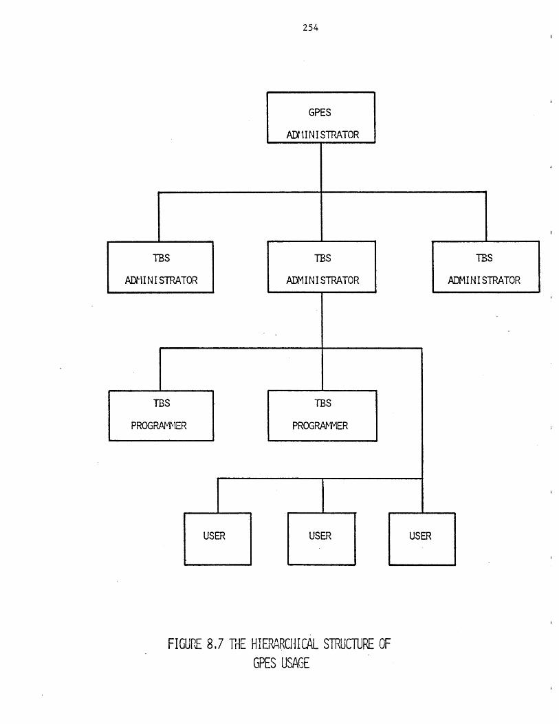
254
USER
FIGUPE 8.7 THE HIERARCHICAL STRUCTURE OFGPES USAGE
USER
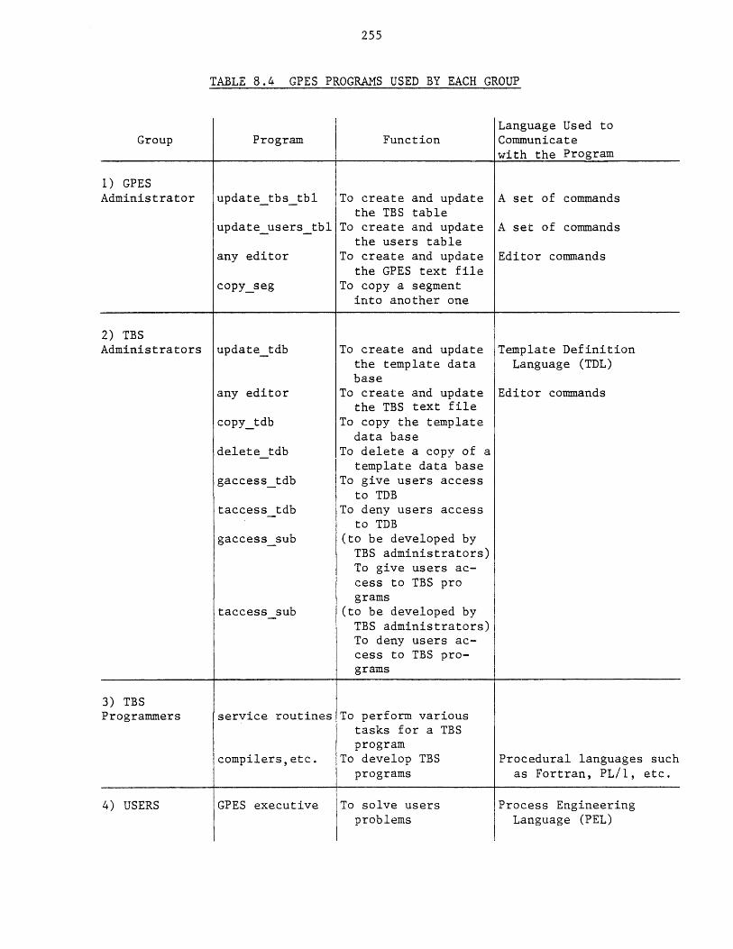
255
TABLE 8.4 GPES PROGRAMS USED BY EACH GROUP
Group Program FunctionLanguage Used toCommunicatewith the Program
1) GPESAdministrator update tbs tbl To create and update A set of commands
the TBS tableupdate userstbl To create and update A set of commands
the users tableany editor To create and update Editor commands
the GPES text filecopy_seg To copy a segment
into another one
2) TBSAdministrators updatetdb To create and update Template Definition
the template data Language (TDL)base
any editor To create and update Editor commandsthe TBS text file
copy_tdb To copy the templatedata base
delete tdb To delete a copy of atemplate data base
gaccesstdb To give users accessto TDB
taccess tdb To deny users accessto TDB
gaccess sub (to be developed byTBS administrators)To give users ac-cess to TBS programs
taccess sub (to be developed byTBS administrators)To deny users ac-cess to TBS pro-grams
3) TBSProgrammers service routines To perform various
tasks for a TBSprogram
compilers,etc. To develop TBS Procedural languages suchprograms as Fortran, PL/1, etc.
4) USERS GPES executive To solve usersproblems
Process EngineeringLanguage (PEL)
256
CHAPTER 9
THE GPES EXECUTIVE
The Executive is an interactive program which executes PEL commands.
It is the backbone of the system. In essence the executive is a table-
driven interpreter, the tables being the template data bases and GPES
files.
The program processes one user command at a time. Before the program
can process user commands, the working environment, within which the
commands must operate, must be prepared. Therefore, the program's task
consists of a) environment preparation and b) command processing.
The former consists of the following three phases:
1) System initialization phase. As shown in Figure 9.1, the user is
admitted to the system and a working area is established for him.
The token table which will be described later is also allocated.
2) TBS initialization or TBS attachment phase. In this phase the
user's desired TBS is initiated and attached to the system as shown
in Figure 9.2.
3) Process initialization phase. As shown in Figure 9.3, the Proces
Directory is initialized and the data structures for "Property
Estimation Methods in Use" and "Component Directory" are created.
The command processing loop consists of the four following phases:
1) Lexical analysis. In this phase a command (a string of characters)
is read and decomposed into recognizable symbols called tokens.
The tokens are placed into the token table.
2) Command recognition phase. In this phase the command is recognized
by its first two tokens.
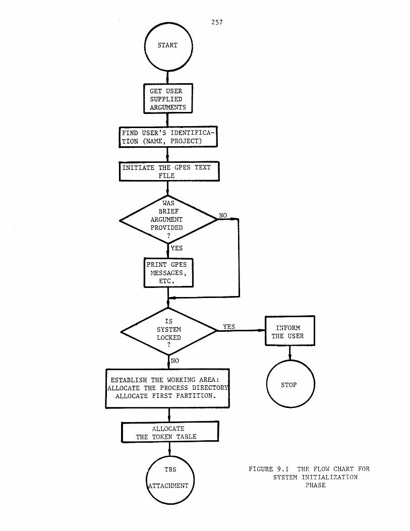
257
FIND USER'S IDENTIFICA-
TION (NAME, PROJECT)
ESTABLISH THE WORKING AREA:LLOCATE THE PROCESS DIRECTORALLOCATE FIRST PARTITION.
FIGURE 9.1 THE FLOW CHART FORSYSTEM INITIALIZATION
PHASE
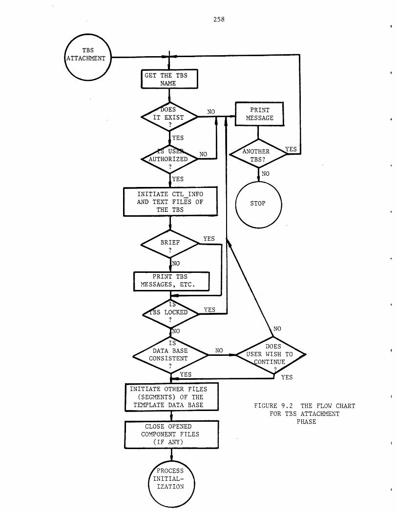
258
YES
INITIATE CTLINFOAND TEXT FILES OF
THE TBS
DATA BASECONSISTENT
YES
INITIATE OTHER FILES(SEGMENTS) OF THE
TEMPLATE DATA BASE
CLOSE OPENEDCOMPONENT FILES
(IF ANY)
YES
FIGURE 9.2 THE FLOW CHARTFOR TBS ATTACHMENT
PHASE
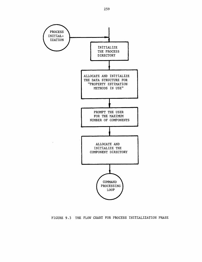
259
PROCESSINIT IAL-IZATION
FIGURE 9.3 THE FLOW CHART FOR PROCESS INITIALIZATION PHASE
INITIALIZETHE PROCESSDIRECTORY
ALLOCATE AND INITIALIZETHE DATA STRUCTURE FOR
"PROPERTY ESTIMATIONMETHODS IN USE"
PROMPT THE USER
FOR THE MAXIMUMNUMBER OF COMPONENTS
ALLOCATE ANDINITIALIZE THE
COMPONENT DIRECTORY
COMMANDPROCESSING
LOOP
260
3) Syntax analysis and interpretation phase. Once a command is
recognized it will be checked for its syntax and simultaneously its
meaning will be interpreted.- For some commands an intermediate
form representing the semantics of the command will be constructed.
4) Execution phase. In this phase the command is executed. The
execution phase being the last step in the command processing loop,
ensures that the command is only executed when it is syntactically
and semantically correct.
The program processes the user's commands one at a time. Therefore,
control remains in the command processing loop except for the following
commands:
a) end command which terminates the program.
b) clear command which clears the working area and
transfers control to the process initialization
phase.
c) leave command which transfers control to the TBS
attachment phase where a new TBS is attached.
d) escape command which transfers control to the
Multics command level where the user may execute any
number of Multics commands. To return to PEL
command processing loop the user should enter a
blank line.
9.1 The GPES Executive Structure
The executive consists of a main program called "pel" and a
number of other external programs. The structures of the "pel" program and
of each of these external programs are modular. This is expected to
facilitate the maintenance of the system, which otherwise would have been
261
difficult considering its size. The "pel" program consists of a main
section, over 60 internal routines, and a "begin block" for each command.
The "begin block" is a PL/1 terminology which refers to a group of PL/1
statements. A begin block is similar to an internal routine with the
exception of the way control is passed to it. Control is passed to a begin
block by a goto statement or through normal sequential execution. The
layout of the "pel" program is shown in Figure 9.4. The main section of
the "pel" program monitors the execution of other routines and begin
blocks. It calls upon the external program "lexical" to perform the first
phase of the command processing task. Then it performs the command
recognition phase. Once the command is recognized it passes control to the
associated begin block of the command. The begin block of a command
performs the syntax checking and interpretation of the command. These
begin blocks in turn will call upon various internal routines to perform
various functions. For some commands an intermediate form representing the
semantics of the command will be constructed to be passed to the execution
phase. The execution of a command is either performed in the same begin
block or an internal or external procedure is invoked to perform the task.
In addition to "pel" program, the GPES executive consists of the
following external programs:
1) The "tbsvalidation" and "tbsaccess" programs. These two
programs are called by the "pel" program in TBS
attachment phase to get information about a TBS.
In fact, both tbsvalidation and tbs access are
entries of a single program which also has two
other entries (updatetbstbl, updateusers_tbl)
by which the GPES administrator updates the TBS

262
GLOBAL DECLARATIONS
VARIOUS
INTERNAL
ROUTINES
SYSTEM INITIALIZATION PHASE
TBS- ATTACHMENT PHASE
MAIN PROCESS INITIALIZATION PHASE
SECTION READ: CALL LEXICAL(O); LEXICAL ANALYSIS PHASE
COMMAND RECOGNITION PHASE
GO TO APPROPRIATE BEGIN BLOCK
BEGIN GO TO READ;
BLOCKS
(ONE GO TO READ;
FOR
EACH
COMMAND)
BEGIN BLOCK FOR PRINTING ERROR MESSAGES
GO TO READ;
FIGURE 9.4 THE LAYOUT OF THE "pel" PROGRAM
263
Table and Users Table, as described in Chapter 8.
By refering to the TBS table the tbs_validation
program verifies if a given TBS is in existence or
operational and returns the address of the
associated template data base. The tbs__access
program verifies the access rights of the user
regarding the specified TBS by referring to the
Users Table.
2) The "lexical" program. The main purpose of this
program is the lexical analysis as will be
described later.
3) The "cdbsys" program. This program is called for
the execution of commands related to component
files. Its main function is the manipulation and
data management of component files.
4) The "pdbsys" program. This program is called for
the execution of commands related to process
files. Its main function is the manipulation and
data management of process files.
5) The "printtemp" program. This program which is
also used by "update_tdb" program prints
information about the templates. It is called in
the execution phase of "printt" and "listt"
commands.
6) The service routines getline, get-response, getin,
and getrn. These routines which are part of the
package of service routines developed for TBS

264
programmers are also used by "pel" and other
programs. The functions of these programs are as
follows:
getline
getresponse
getin
getrn
To receive a line of characters f
the user.
To receive a yes or no answer fro
the user.
To receive an integer number from
the-user.
To receive a real number from the
user.
rom
m
9.2 Lexical Analysis Phase
The action of parsing the command (a string of characters) into the
proper syntactic classes is known as Lexical Analysis. The operational
details for this step involve conceptually simple string processing
techniques. The input command (a string of characters) is scanned
sequentially. The basic elements or tokens are delimited by blanks and
operators, and thereby recognized as identifiers, special identifiers,
literals, or terminal symbols. The basic elements (tokens) are placed into
a table called a token table. The token table is shown in Figure 9.5. It
contains one command at a time. The table grows or shrinks automatically
to accommodate any size command. Each entry of the table contains a token.
The "symbol" contains the character representation of the token and "type"
indicates the syntactic class of the token. Each PEL command terminates
with a ";". Hence, the last entry of the token table is always a ";". The
types of each class of tokens are listed in Table 9.1. The comments are
discarded in the Lexical Phase, since they have no effect on the execution
of the command.
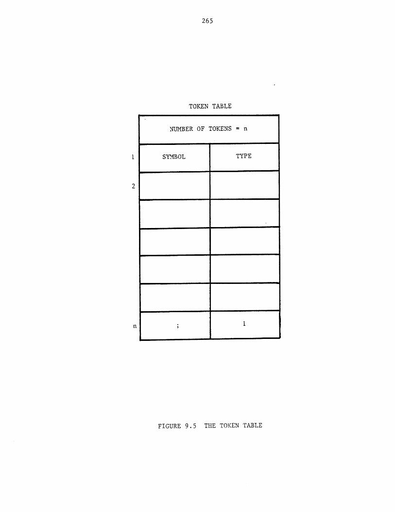
265
TOKEN TABLE
NUMBER OF TOKENS = n
SYMBOL TYPE
1
FIGURE 9.5 THE TOKEN TABLE
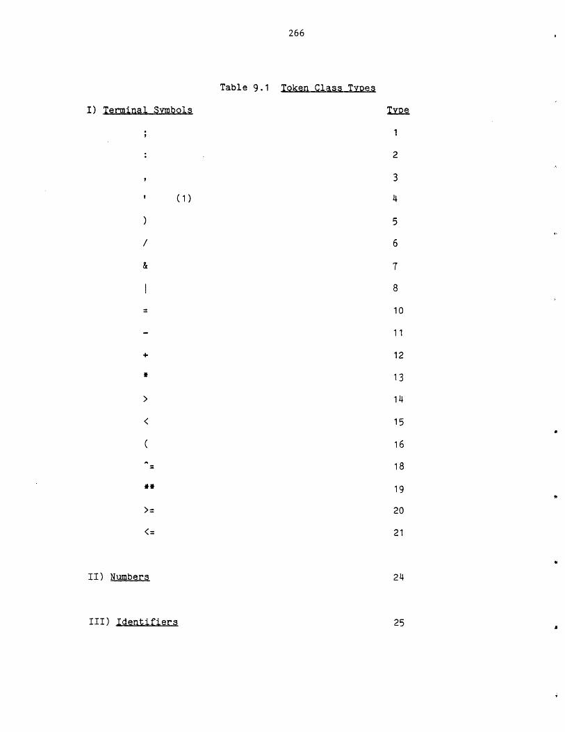
Token Class Types
I) Terminal Symbols
(1)
II) Numbers
III) Identifiers
266
Table 9.1
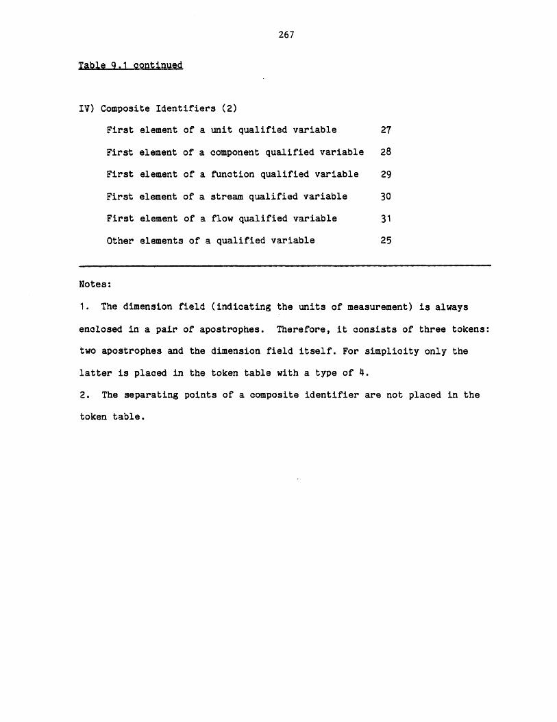
267
Table 9.1 continued
IV) Composite Identifiers (2)
First element of a unit qualified variable 27
First element of a component qualified variable 28
First element of a function qualified variable 29
First element of a stream qualified variable 30
First element of a flow qualified variable 31
Other elements of a qualified variable 25
Notes:
1. The dimension field (indicating the units of measurement) is always
enclosed in a pair of apostrophes. Therefore, it consists of three tokens:
two apostrophes and the dimension field itself. For simplicity only the
latter is placed in the token table with a type of 4.
2. The separating points of a composite identifier are not placed in the
token table.
268
The external program "lexical" is called to perform the lexical
analysis. The program prompts the user for a line of a command and then
performs lexical analysis on that line. The program detects lexical errors
(e.g. improper identifier, invalid composite identifiers, etc.) and prompts
the user to reenter the line in error. Then the program asks for a new
line and repeats the above process until the command terminator ";" is
received. Note that there is no limit on the size of a PEL command. A PEL
command may consists of any number of lines and each line may be up to 262
characters. The program also prints the contents of the token table if the
profile parameter dflag (debugging flag) is equal to three, as demonstrated
in Figure 9.6. The lexical porgram has also two other modes of operation:
1) In this mode of operation the program reads a line of characters (a
Multics command) and passes it to the Multics command processor to be
executed. This process is repeated until the input command is a blank line
when the program returns control to the caller (pel program). The lexical
is called with this mode of operation in response to the user's escape
command.
2) This mode of operation is like the original mode of operation with one
exception. The exception is that the program returns to the caller after
processing only one line of input. The program is called with this mode of
operation in execution phase of read and reada commands.
9.3 Command Recognition Phase
In this phase the first or the first and second toksns of the command
are examined to recognize the command. Each command begins with a keyword
called a command verb and may be followed by another keyword called the
command object. In this phase a verb-code and object-code are associated
with the command and for further analysis control is passed to the
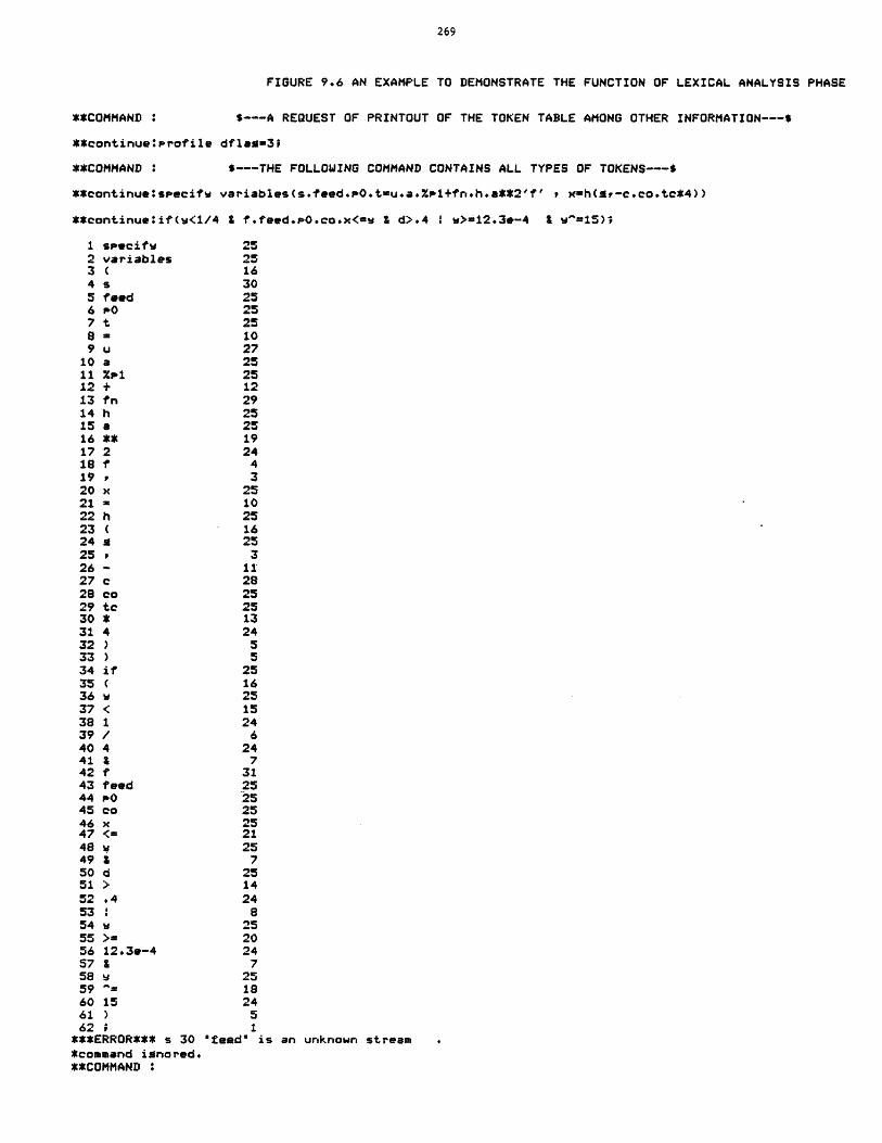
FIGURE 9.6 AN EXAMPLE TO DEMONSTRATE THE FUNCTION OF LEXICAL ANALYSIS PHASE
**COMMAND : S---A REQUEST OF PRINTOUT OF THE TOKEN TABLE AMONG OTHER INFORMATION---s
**continue:profile dflam=3;
**COMMAND : $---THE FOLLOWING COMMAND CONTAINS ALL TYPES OF TOKENS---$
**continue:specifw variables(s.feed.p0.t-u.a.%s1+fn.h.a**2'f' , x-h(a-c.co.tc*4))
**continue:if(w<1/4 Z f.feed.s0.co.x<=w I d>.4 I W>=12.3e-4 & w"=15)'
1 specifw 252 variables 253 ( 164 s 305 feed 256 P0 257 t 25a = 109 u 27
10 a 2511 %zp 2512 + 1213 fn 2914 h 2515 a 2516 ** 1917 2 241s f 419 r 320 x 2521 = 1022 h 2523( 1624a 2525 326- 1127 c 2828 co 2529 tc 2530 * 1331 4 2432 ) 533 ) 534 if 2535 ( 1636 w 2537 < 1538 1 2439 / 640 4 2441 1 742 f 3143 feed 2544 pO 2545 co 2546 x 2547 <- 2148 w 2549 & 750 d 2551 > 1452 .4 2453 : 854 w 2555 >- 2056 12.3e-4 2457 1 758 w 2559= 1860 15 2461 ) 562 1
***ERROR*** s 30 "feed" is an unknown stream*command ignored.**COMMAND '
270
associated begin block of the command. The verb-codes and object-codes are
integer numbers representing command verbs, and command objects
respectively. Table 9.2 lists the object codes. The data structure
"command object flag" indicates the acceptable objects for each command.
The data structure has an entry for each command which consists of seven
bits, one for each object. Each bit is "on" or "off" depending on whether
the corresponding object is acceptable for the command or not, as shown in
Table 9.3. The flowchart for command recognition phase is shown in
Figure 9.7.
9.4 Synatx Analysis and InterDretation Phase
The token table is scanned to check the syntax and interpret the
meaning of the command. The global variable "start" is used to point to
the current token under consideration. For each command there is a begin
block performing syntax checking and interpretation. Of course, these
blocks call upon various internal routines to perform various functions.
For some commands intermediate forms representing the semantics of the
commands will be constructed to be passed to the execution phase. This is
required for commands that appear inside a repeat-loop group and must
therefore be executed repetitively. The PEL commands can be classified
into three groups according to their appearance in a repeat-loop group:
1) Those that are not permitted in a repeat-loop. The commands in this
group are as follows: let,leta,delete, and unspecify. Note that let and
leta commands may impliciy unspecify a parameter.
2) Those that if appearing inside a repeat-loop only will be executed
once, independent of the condition of the repeat-loop. Some of these
commands even terminate one or all of the repeat-loops (e.g.
stop,clear,leave, and load process).
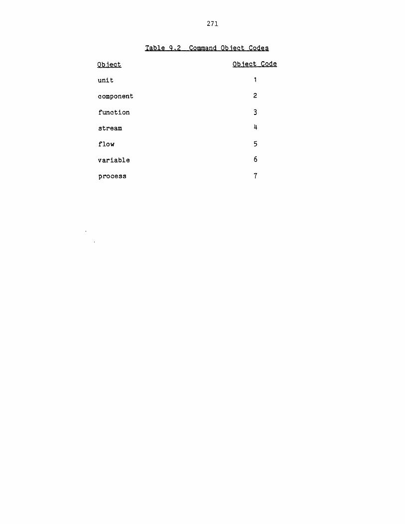
271
ObJect
unit
component
function
stream
flow
variable
process
Table 9.2 Command ObJect Codes
Object Code
1
2
3
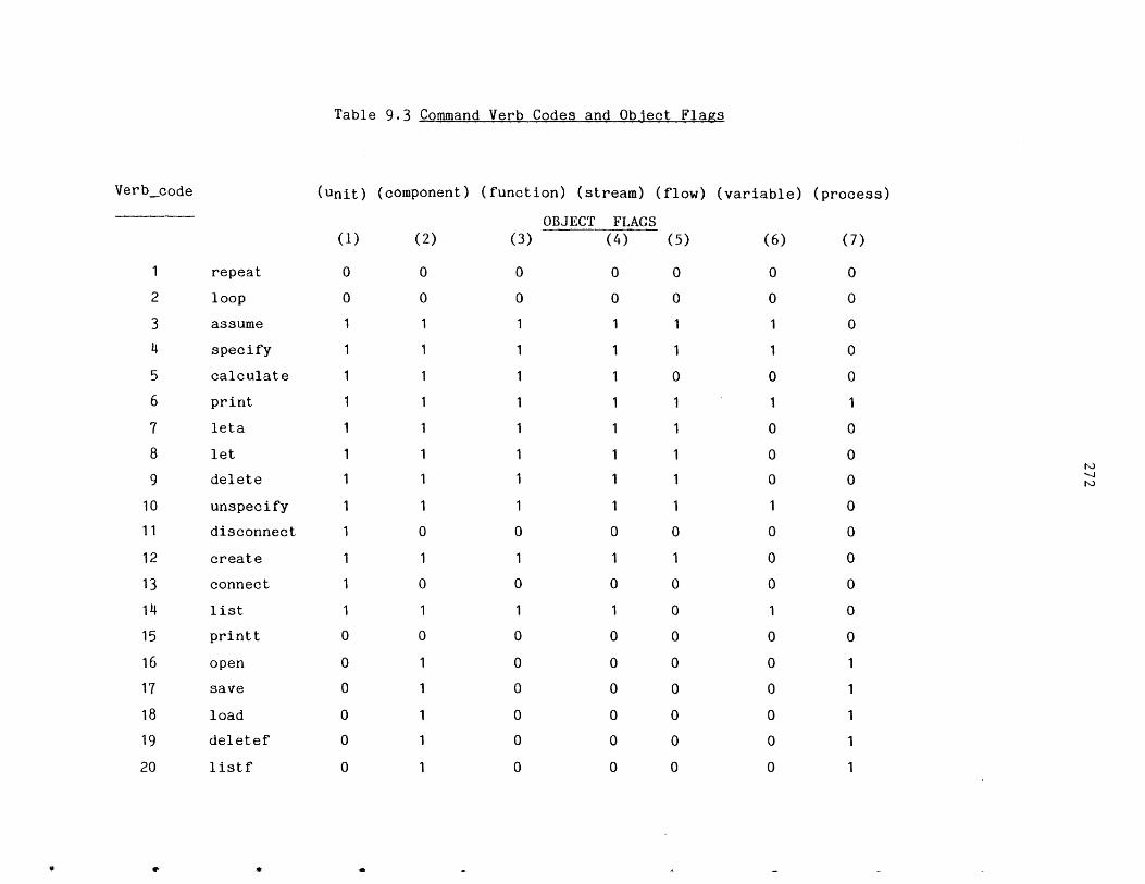
Table 9.3 Command Verb Codes and Object Flags
Verb-code (unit) (component) (function) (stream) (flow)
OBJECT FLAGS(1) (2) (3) (4) (5)
repeat
loop
assume
specify
calculate
leta
let
delete
unspecify
disconnect
create
connect
list
printt
open
save
load
deletef
listf
(variable) (process)
(6) (7)
0 0
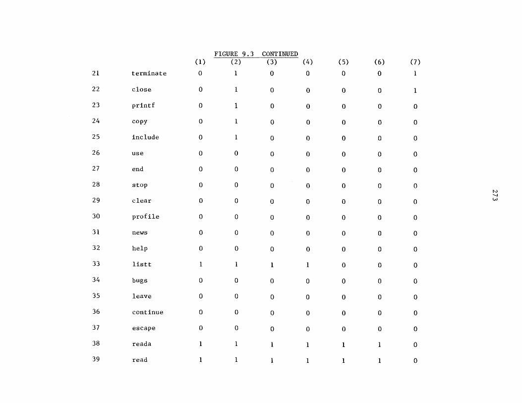
terminate
close
printf
copy
include
use
end
stop
clear
profile
news
help
listt
bugs
leave
continue
(1)
0
0
0
0
0
0
0
0
0
0
0
0
1
0
0
0
0
1
1
FIGURE 9.3(2)
1
1
1
1
1
0
0
0
0
0
0
0
1
0
0
0
0
1
1
CONTINUED
(3)
0
0
0
0
0
0
0
0
0
0
0
0
1
0
0
0
0
1
1
escape
reada
read
(4)
0
0
0
0
0
0
0
(5)
0
0
0
0
0
0
0
(6)
0
0
0
0
0
0
0
0
0
0
0
0
0
0
0
0
0
1
1
(7)
1
1
0
0
0
0
0
0
0
0
0
0
0
0
0
0
0
0
0
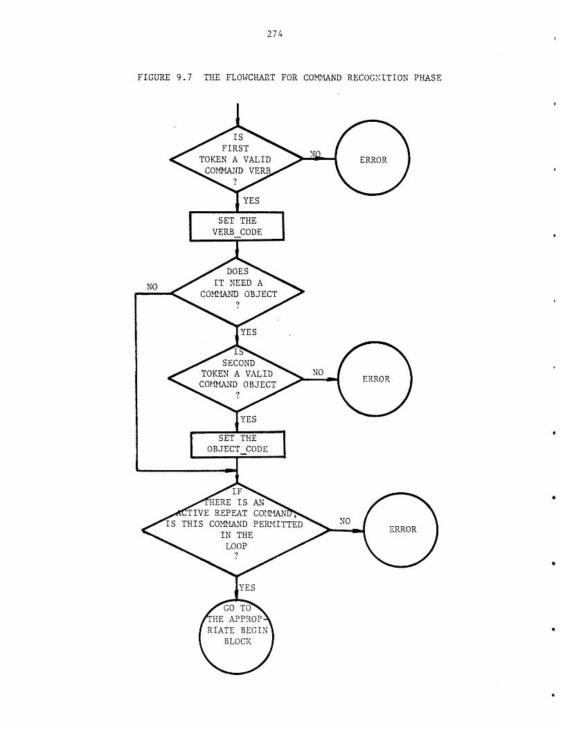
274
FIGURE 9.7 THE FLOWCHART FOR COMMAND RECOGNITION PHASE
' SECOND %%
TOKEN A VALIDCOMMAND OBJECT% ?
HERE IS ANOo TIVE REPEAT COMMANIS THIS COMMAND PERMITTED
IN THELOOP
275
3) Those that when appearing inside a repeat-loop will be executed
repeatedly depending on the condition of the repeat-loop and their "if-
clauses". The following commands fall in this group: repeat, loop,
assume, specify, read, reada, calculate, and print.
The syntax of most of the commands falling in the first two groups is
rather simple. Consequently the tasks of syntax analysis and
interpretation of these commands are straightforward. Once these commands
are analyzed and executed they are no longer needed. On the other hand the
syntax of commands falling in the third group is usually more sophisticated
and also they have to be executed repeatedly if appearing inside a repeat-
loop command. Therefore, the discussion in this section will be limited to
these commands.
An intermediate form for each of these commands will be constructed. The
intermediate form affords two advantages:
1) Simplifying the task of the execution phase by providing all the
relevant information for execution.
2) Representing the command in a repeat-loop.
Arithmetic expressions may appear in these commands and other
commands. Therefore, before describing the intermediate forms of these
commands the intermediate form of arithmetic expressions is described.
9.4.1 The Intermediate Form of Arithmetic Exoressions
The intermediate form of an arithmetic expression is placed in the
data structure "parsed matrix" shown in Figure 9.8.
In this matrix operations of the expression are listed sequentialy in the
order that they would be executed to evaluate the expression.
The parsed matrix data structure is also used to represent the mathematical
expression of the user defined functions as discussed in Chapter 5.
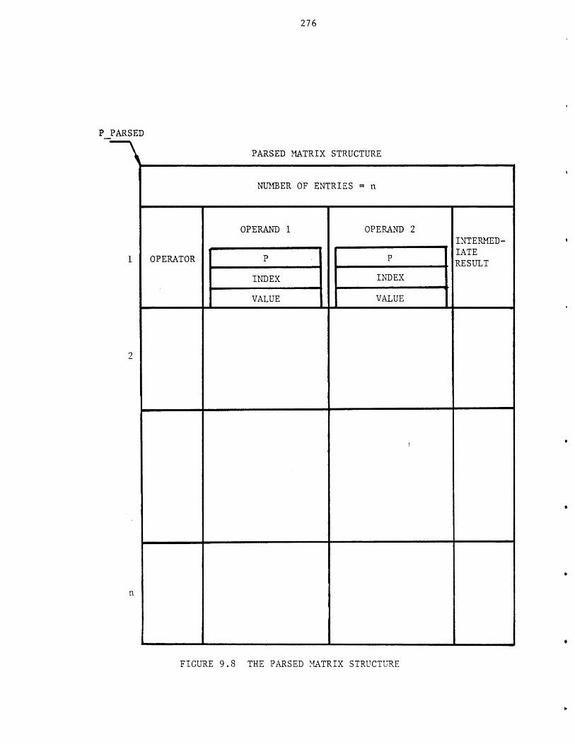
276
DP PARSE
1
2
FIGURE 9.8 THE PARSED MATRIX STRUCTURE
NUMBER OF ENTRIES = n
OPERAND 1 OPERAND 2INTERNED-
OPERATOR P P IATERESULT
INDEX INDEXI VALUE 11VALUE
PARSED MATRIX STRUCTURE
277
Each matrix entry has one operator, two operands, and a location to store
the result at the time of evaluation. The operator indicates the type of
operation to be performed on the operands. The different types of
operations in the parsed matrix are shown in the Table 9.4. The operator
"," indicates that the two operands are part of an argument list of a
function reference as will be demonstrated in the example that follows
later in this section. The end of matrix operation which is the last entry
of the matrix converts the result of the expression to the standard units
of measurement. For this entry operand 2 represents the result of the
expression before the conversion and operand 1 contains the "B"
coefficient. "A" coefficient is placed in the location of the intermediate
result. The result of operation and consequently the result of the
expression is A+B (operand 2). Coefficients "A" and "B" are always
supplied; even when the expression represents the value of a dimensionless
variable, "A" of zero and "B" of one are supplied.
An operand may be one of the following:
1) A number,
2) A simple variable,
3) A qualified variable,
4) The result of another entry (intermediate result),
5) A dummy argument which only appears for an expression representing
(defining) a user defined function. In such an expression, simple
variables and qualified variables are replaced with their values.
Built-in constants are always replaced by their values.
6) A pre-defined function,
7) A user-defined function,
8) A built-in function.
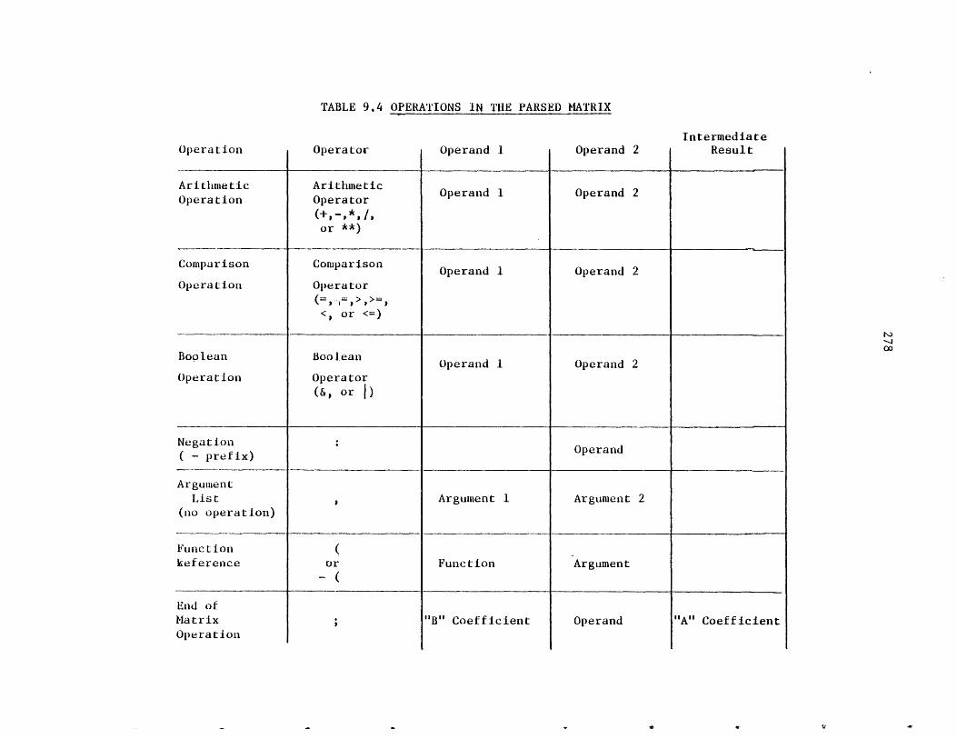
OPERATIONS IN THE PARSED MATRIX
Operand 1 Operand 2
Arithmetic ArithmeticOperation Operator
(+, -,*, /,or
Comparison Comparison Operand 1 Operand 2
Operation Operator
< or
Boolean Boolean Operand 1 Operand 2Operation Operator
or |)
Negation Operand( - prefix)
ArgumentList Argument 1 Argument 2
(no operation)
Functionkeference or Function Argument
"B" Coefficient Operand
IntermediateResult
"A" Coefficient
Operation
TABLE 9.4
Operator
End ofMatrixOperation
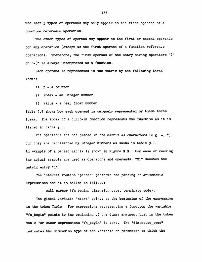
279
The last 3 types of operands may only appear as the first operand of a
function reference operation.
The other types of operand may appear as the first or second operands
for any operation (except as the first operand of a function reference
operation). Therefore, the first operand of the entry having operators "("
or "-(" is always interpreted as a function.
Each operand is represented in the matrix by the following three
items:
1) p - a pointer
2) index - an integer number
3) value - a real float number
Table 9.5 shows how each operand is uniquely represented by these three
items. The index of a built-in function represents the function as it is
listed in table 9.6.
The operators are not placed in the matrix as characters (e.g. +,
but they are represented by integer numbers as shown in table 9.7.
An example of a parsed matrix is shown in Figure 9.9. For ease of reading
the actual symbols are used as operators and operands. "Mi" denotes the
matrix entry "i".
The internal routine "parser" performs the parsing of arithmetic
expressions and it is called as follows:
call parser (fn_begin, dimension type, terminatecode);
The global variable "start" points to the beginning of the expression
in the token Table. For expressions representing a function the variable
"fnbegin" points to the beginning of the dummy argument list in the token
table for other expressions "fnbegin" is zero. The "dimension_type"
indicates the dimension type of the variable or parameter to which the
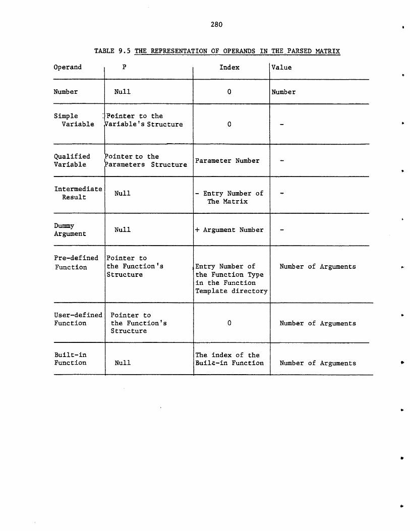
280
Operand
TABLE 9.5 THE REPRESENTATION
I P I
OF OPERANDS IN THE PARSED MATRIX
Index Value
Number Null 0 Number
Simple :Pointer to theVariable Variable's Structure 0 -
Qualified Lointer to theVariable arameters Structure Parameter Number -
Intermediate Null - Entry Number of -Result The Matrix
Dummy Null + Argument Number -Argument
Pre-defined Pointer toFunction the Function's Entry Number of Number of Arguments
Structure the Function Typein the FunctionTemplate directory
User-defined Pointer toFunction the Function's 0 Number of Arguments
Structure
Built-in The index of theFunction Null Built-in Function Number of Arguments
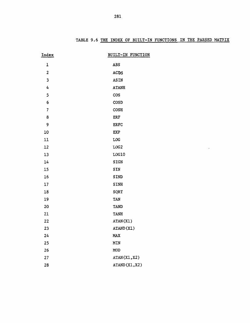
281
TABLE 9.6 THE INDEX OF BUILT-IN FUNCTIONS IN THE PARSED MATRIX
Index BUILT-IN FUNCTION
1 ABS
2 ACDS
3 ASIN
4 ATANH
5 COS
6 COSD
7 COSH
8 ERF
9 ERFC
10 EXP
11 LOG
12 LOG2
13 LOG10
14 SIGN
15 SIN
16 SIND
17 SINH
18 SQRT
19 TAN
20 TAND
21 TANH
22 ATAN (Xl)
23 ATAND (Xl)
24 MAX
25 MIN
26 MOD
27 ATAN(X1,X2)
28 ATAND (X1,X2)
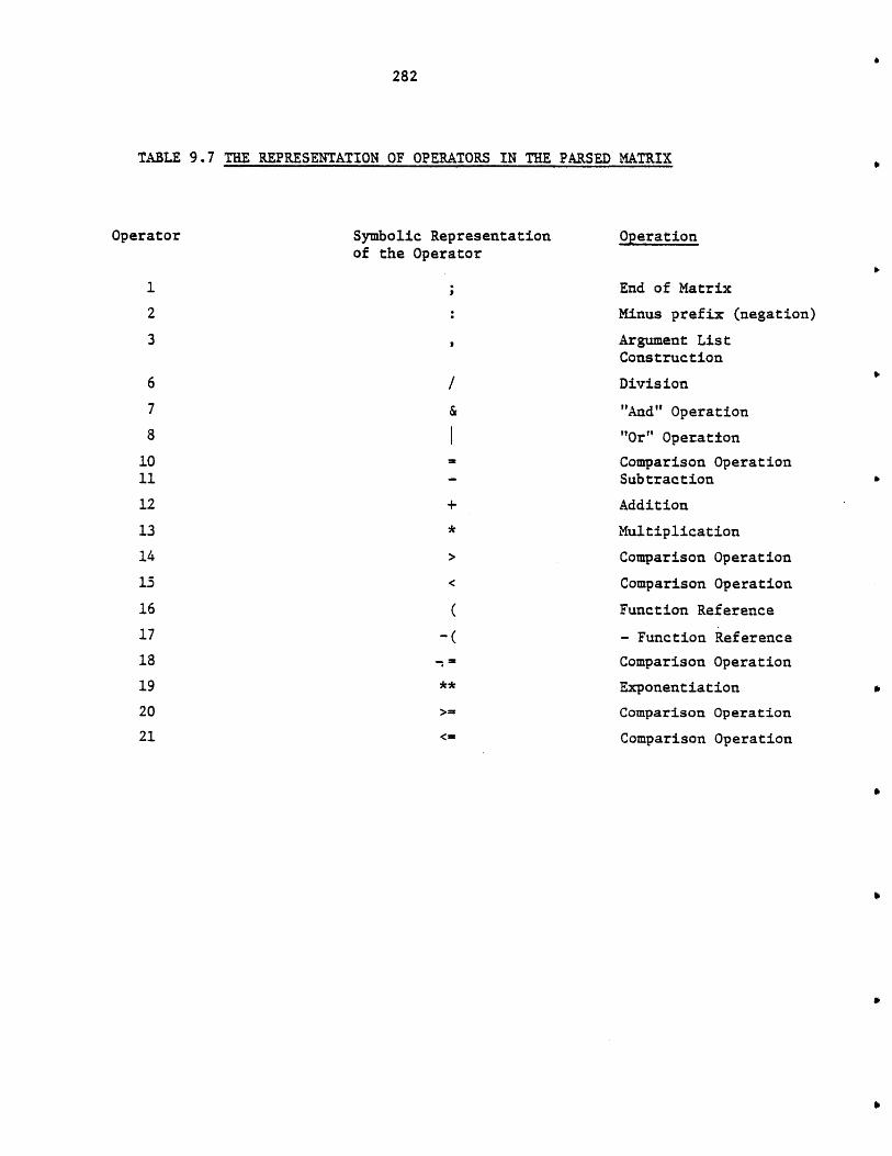
282
TABLE 9.7 THE REPRESENTATION OF OPERATORS IN THE PARSED MATRIX
Operator Symbolic Representation Operationof the Operator
1 End of Matrix
2 Minus prefix (negation)
3 Argument ListConstruction
6 Division
7 & "And" Operation
8 "Or" Operation
10 Comparison Operation11 Subtraction
12 + Addition
13 * Multiplication
14 > Comparison Operation
15 < Comparison Operation
16 ( Function Reference
17 -( - Function Reference
18 ,= Comparison Operation
19 ** Exponentiation
20 > Comparison Operation21 <= Comparison Operation

283
PARSED MATRIX FOR THE EXPRESSION:10+2*(-4+F(X+Y,X*Y,Z)/A),
11
4
+ X y
* X Y
M2 M3
M4 Z
( F M5
/M6 A
+ M1 M7
* 2 M8
+ 10 M9
1 M1O 0
FIGURE 9.9 AN EXAMPLE OF A PARSED MATRIX
284
value of the expression will be assigned. It is zero for dimensionless
parameters and variables. The dimension type allows the program to convert
the value of expression to the standard units of measurement, if it has
been provided in other units.
The "terminatecode" indicates the symbol designating the end of the
expression. In PEL commands an expression is terminated either by
(other than those separating the arguments of a function reference) or by a
")" (other than those matching the left parentheses of the expression).
The "terminate_code" of zero indicates that the expression can be
terminated either by "," or by ")". The terminate_code of one requires
termination by ")" only.
The parser program scans the expression (token-table) on two passes.
On the first pass.the terminating token is recognized and replaced by a
token which uniquely designates the end of expression ("," is replaced by
the token of type 9, ")" is replaced by the token of type 1). The size of
the expression and consequently the size of the parsed matrix are also
found in this pass. On the second pass, the expression is parsed and
placed in a parsed matrix structure. A modified operator precedence
algorithm is used as shown in Figure 9.11. Associated with each operator
there is a number called precedence. It indicates the priority of the
operator as listed in Table 9.8. The data structure stack contains the
tokens that are currently being worked on by the parser as shown in Figure
9.10. The tokens in the stack are represented by two integer numbers. One
indicates the location of the token in the token table and the other
indicates the type of the token. The reference to an entry of the matrix
is by location equal to minus matrix entry number, and type equal to 40, if
the matrix entry represents a value, or type equal to 41, if the matrix
entry does not represent a value (when representing an argument list).
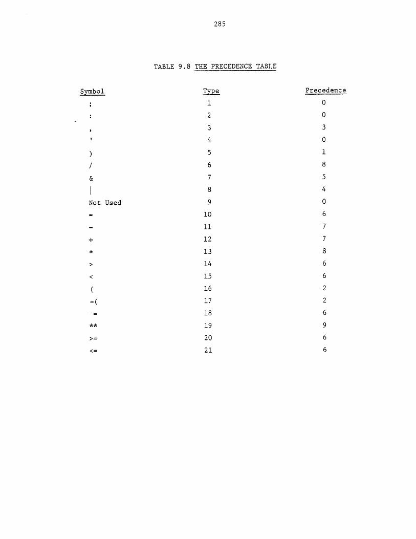
285
TABLE 9.8 THE PRECEDENCE TABLE
Symbol Type Precedence
1 0
2 0
3 3
4 0
) 5 1
6 8
& 7 5
8 4
Not Used 9 0
10 6
11 7
+ 12 7
* 13 8
> 14 6
15 6
16 2
-( 17 2
18 6
** 19 9
>= 20 6
<= 21 6
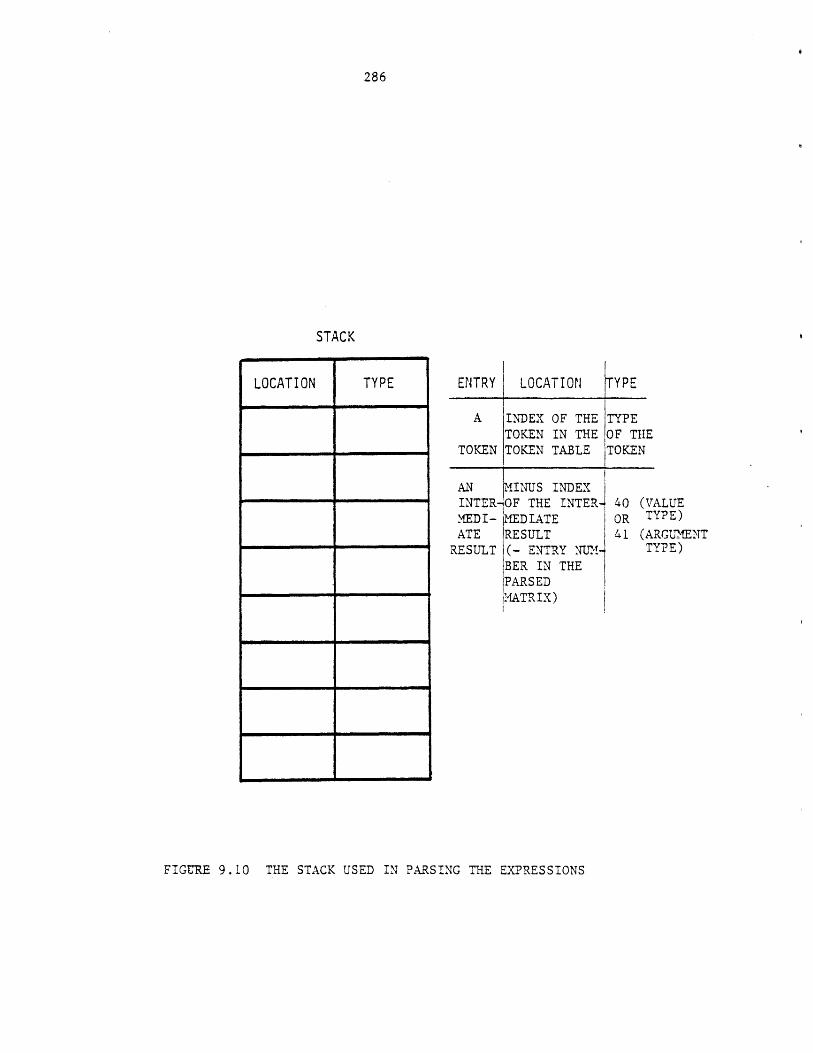
ENTRY LOCATION TYPE
A INDEX OF THE TYPETOKEN IN THE OF THE
TOKEN TOKEN TABLE TOKEN
AN ,MINUS INDEXINTERIOF THE INTER-MEDI- MEDIATEATE RESULT
RESULT (- ENTRY N.TM-BER IN THEPARSEDMATRIX)
FIGURE 9.10 THE STACK USED IN PARSING THE EXPRESSIONS
286
STACK
LOCATION TYPE
(VALUETYPE)
(ARGUMENTTYPE)
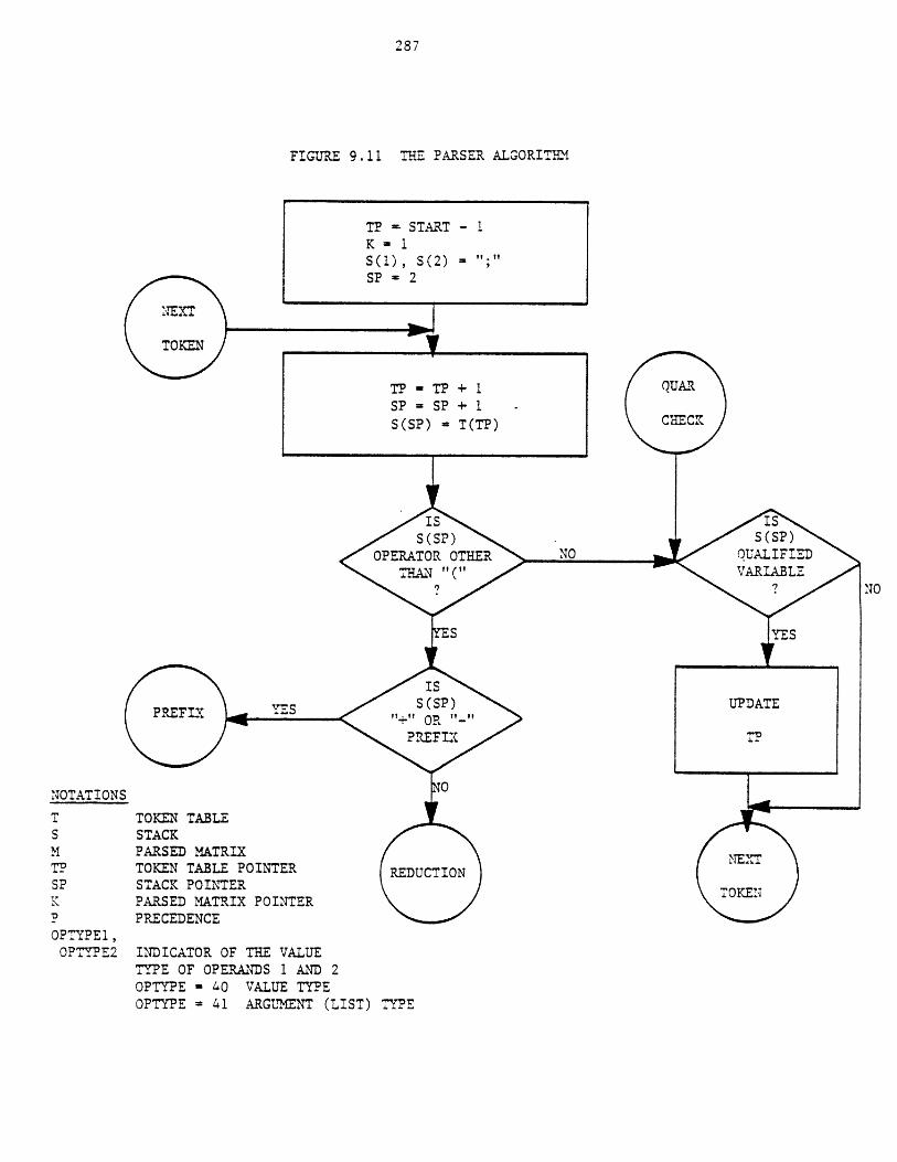
287
FIGURE 9.11 THE PARSER ALGORITEMI
NOTATIONS
T TOKEN TABLES STACKM PARSED MATRIXIP TOKEN TABLE POINTER REDSP STACK POINTERK PARSED MATRIX POINTERP PRECEDENCEOPTYPEl,
OPTYPE2 INDICATOR OF THE VALUETYPE OF OPERANDS 1 AND 2OPTYPE - 40 VALUE TYPEOPTYPE = 41 ARGLMNT (LIST) TYPE
UPDATE
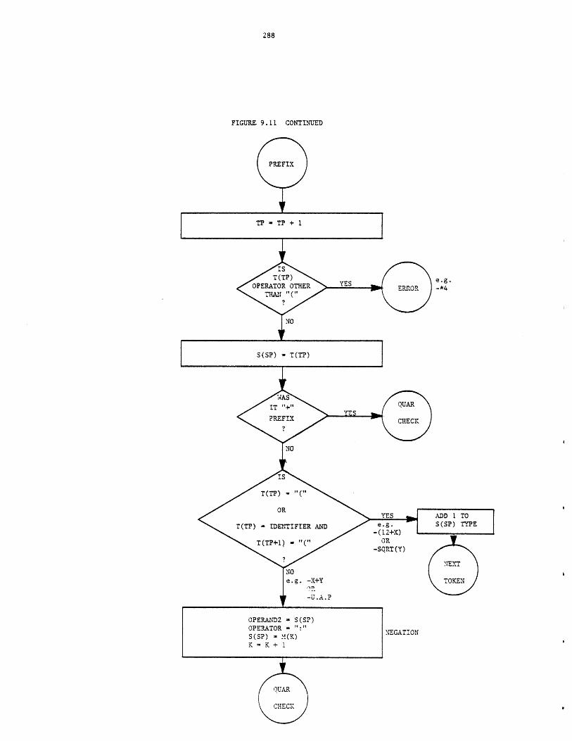
288
FIGURE. 9.11 CONTINUED
TP - TP + 1
e.g.-*4
S(SP) - T(TP)
OR-SQRT(Y)
NEGATION
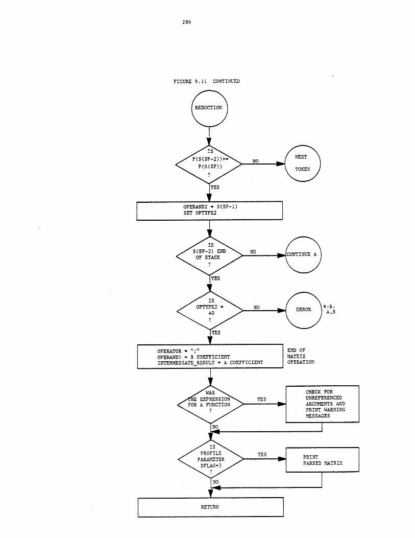
289
FIGURE 9.11 CONTINUED
e.g.A,B
END OFMATRIXOFERATION
RETURN
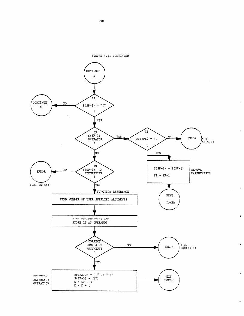
290
FIGURE 9.11 CONTINUED
[TINUE
A
IS
2) - "(
YES
IS ISSP-3) YES
'ERATOR OPTYPE2 - 40 - ERROR .g.X+(Y,Z)
1YES
y FUNCTION REFERENCE
FIND NUMBER OF USER SUPPLIED ARGUMENTS
REMOVE?ARENTHESIS
e.g.SORT(X,Y)
e.g. 46(X+Y)
FUNCTIONREFERENCEOPERATION
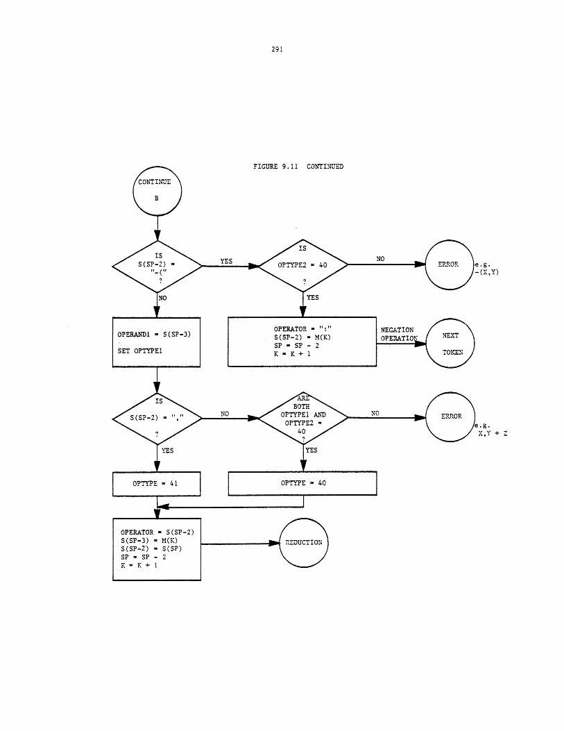
FIGURE 9.11 CONTINUED
e.g.-(X,Y)
.g.X,Y + Z
292
9.4.2 Intermediate Forms of Commands
Various data structures are used to represent the commands in the
third group. These data structures will be generally referred to as
"control blocks" (cblock), indicating the fact that they are controling the
execution of the commands. If a command is not in a loop its control block
will be deleted, once the command has been executed. But if a command is
in a loop, its control block is linked to the control block of the previous
command by the data structure shown in Figure 9.12. Therefore, there is
one such data structure for each command in the loop. These data
structures and associated control blocks will be deleted once the execution
of the loop has been completed. The control blocks for various commands
are listed in Table 9.9. Although the "unspecify" command does not belong
to this group of commands, its syntax is very similar to the "read"
command, and it is also represented by an intermediate form. Figures 9.13
to 9.20 show the control blocks and demonstrate their applications. The
following notations are generally used in describing the control blocks:
p_parsed - pointer to the parsed matrix of an arithmetic expression.
pparm - pointer to a parameters structure.
parm no - parameter number.
pvariable- pointer to a simple variable structure.
The notations used to describe the syntax of commands are defined in
Appendix D. Although a command may not always be executed (if the
condition in "if-clause" does not hold or if it is inside an unexecutable
loop), its syntax analysis and interpretation phase (and consequently the
construction of its control block) is always performed to detect its
syntactic and semantic errors.
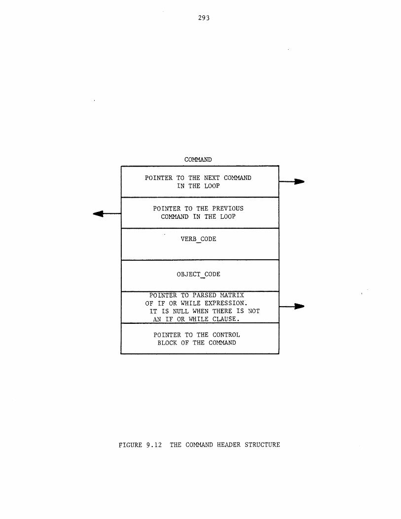
293
COMMAND
POINTER TO THE NEXT COMMANDIN THE LOOP
POINTER TO THE PREVIOUSCOMMAND IN THE LOOP
VERBCODE
OBJECTCODE
POINTER TO PARSED MATRIXOF IF OR WHILE EXPRESSION.IT IS NULL WHEN THERE IS NOTAN IF OR WHILE CLAUSE.
POINTER TO THE CONTROLBLOCK OF THE COMMAND
FIGURE 9.12 THE COMMAND HEADER STRUCTURE
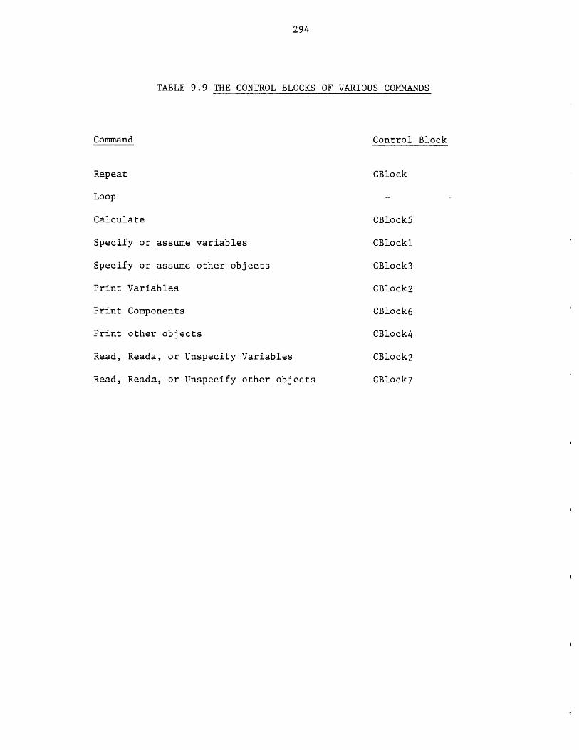
294
TABLE 9.9 THE CONTROL BLOCKS OF VARIOUS COMMANDS
Command Control Block
Repeat CBlock
Loop
Calculate CBlock5
Specify or assume variables CBlockl
Specify or assume other objects CBlock3
Print Variables CBlock2
Print Components CBlock6
Print other objects CBlock4
Read, Reada, or Unspecify Variables CBlock2
Read, Reada, or Unspecify other objects CBlock7
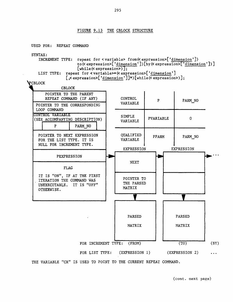
295
FIGURE 9..13 THE CBLOCK STRUCTURE
USED FOR: REPEAT COMMAND
SYNTAX:INCREMENT TYPE: repeat for <variable> from(<expression>['dimension'])
to(< expression>[ 'dimension']) [by(< expression>['dimension'])][while(< expression>) -;
LIST TYPE: repeat for <variable>=(<expression>['dimension'][,<expression>['dimension']]*)[while(<expression>)];
BLOCKCBLOCK
CONTROLVARIABLE
PARM NO
SIMPLEVARIABLE PVARIABLE 0
QUALIFIEDVARIABLE
EXPRESSION
POINTER TO THE PARENTREPEAT COMMAND (IF ANY)
POINTER TO THE CORRESPONDINGLOOP COMMAND
CONTROL VARIABLE(SEE ACCOMPANYING DESCRIPTION)
I P I PARMNO
POINTER TO NEXT EXPRESSIONFOR THE LIST TYPE. IT ISNULL FOR INCREMENT TYPE.
PEXPRESSION
FLAG
IT IS "ON", IF AT THE FIRSTITERATION THE COMMAND WASUNEXECUTABLE. IT IS "OFF"OTHERWISE.
FOR INCREMENT TYPE: (FROM)
PPARM PARM NO
EXPRESSION
PARSED
MATRIX
(TO)
FOR LIST TYPE: (EXPRESSION 1) (EXPRESSION 2)
THE VARIABLE "CR" IS USED TO POINT TO THE CURRENT REPEAT COMMAND.
(cont. next page)
NEXT
POINTER TOTHE PARSEDMATRIX
PARSED
MATRIX
(BY)

296
FIGURE 9.13 CONTINUED
EXAMPLE:repeat for x from (1) to (5);
specify variable (y = sqrt(x)) if (y<25);repeat for z = (10,27,18);print v(x,y,z);loop;news;
STATUS OF THE CONTROL BLOCKS AFTER THE ISSUANCE OF THE LAST COMMAND (e.g. NEWS);NOTICE THAT THE EXTERNAL REPEAT COMMAND IS NOT CLOSED YET.
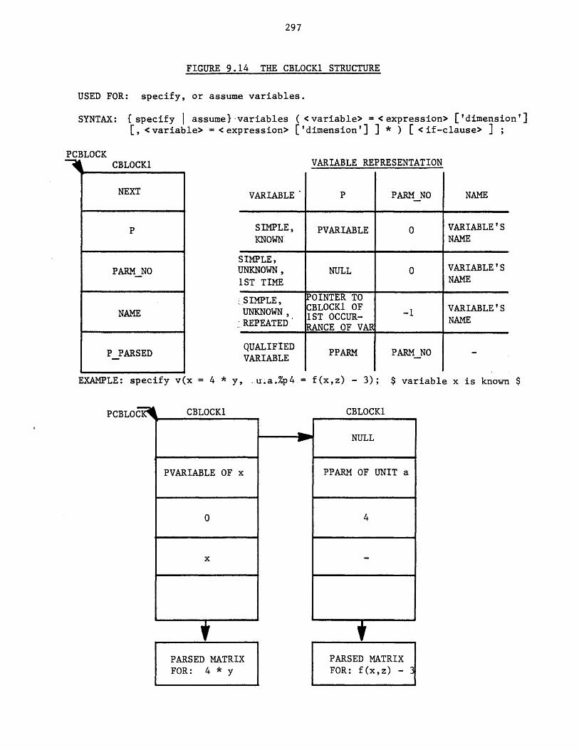
297
FIGURE 9.14 THE CBLOCK1 STRUCTURE
USED FOR: specify, or assume variables.
SYNTAX: {specify I assume} variables ( <variable> = <expression> ['dimension'][, <variable> = <expression> ['dimension'] I * ) [ <if-clause> I ;
PCBLOCKCBLOCK1
NEXT
P
PARM NO
NAME
P_PARSED
EXAMPLE: specify vk
PCBLOI
VARIABLE REPRESENTATION
VARIABLE' PARM NO NAME
SIMPLE, PVARIABLE 0 VARIABLE'S
KNOWN NAME
SIMPLE,UNKNOWN, NULL 0 VARIABLE' S
1ST TIME NAME
SIMPLE, POINTER TO
UNKNOWN CBLOCK1 OF -1 VARIABLE'SREPEATED 1ST OCCUR- NAMEREPEATEDRANCE OF VAR
QUALIFIEDVARIABLE
PPARM
x = 4 * y, .u.a.%p4 = f(x,z) - 3);
PARMNO -
$ variable x is known $
3
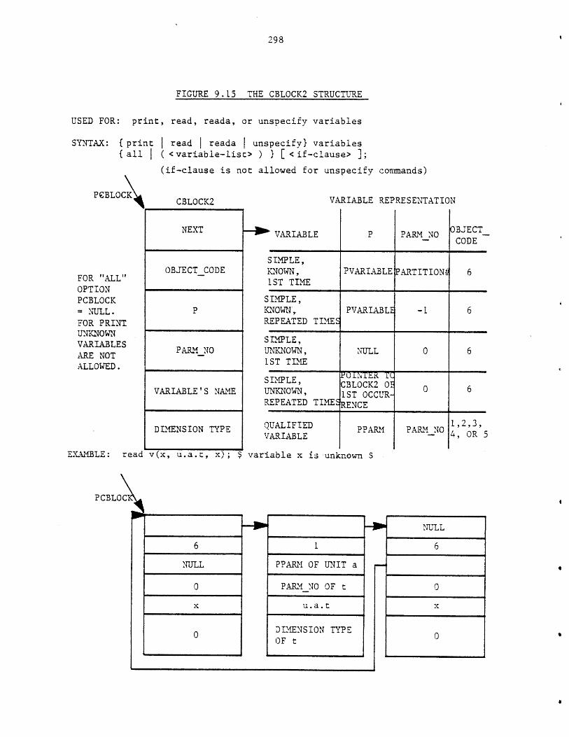
298
FIGURE 9.15 THE CBLOCK2 STRUCTURE
USED FOR: print, read, reada, or unspecify variables
SYNTAX: { pri{ all
PCBLOC\
FOR "ALL"OPTIONPCBLOCK= NULL.FOR PRINTUNKNOWNVARIABLESARE NOTALLOWED.
nt
*Iread | reada I unspecifyl variables
(<variable-list> ) } [ <if-clause> 1;(if-clause is not allowed for unspecify conmands)
CBLOCK2 VARIABLE REPRESENTATION
1 VARIABLE PARM NOOBJECT_
CODE
SIMXPLE,KNOWN, PVARIABLE PARTITION; 61ST TIME
3IMPLE,QTOWN, PVARIABLE - 6EPEATED TIMES
3IMPLE,JNKNOWN, NULL 0 6LST TIME
>IMPLE, CBLOCK2 01 6JNKNOWN, 1ST OCCUR-EPEATED TIMESENCE
NEXT
OBJECTCODE
P
PARMNO
VARIABLE'S NAME
DIMENSION TYPE PPARM
EXAMBLE: read v(x, u.a.t, x); $ variable x is -unknown $
PCBLOC\
6
NULL
0
x
0
PARI_ NO1,2,3,4, OR 5
QUALIFIEDVARIABLE
I
PPARM OF UNIT a
PARM NO OF t
u.a.t
DIMENSION TYPEOF t
NULL
6
0
x
0
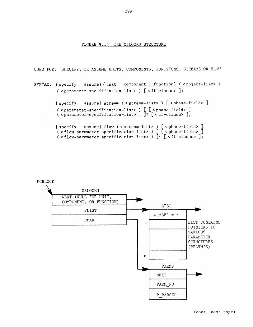
299
FIGURE 9.16 THE CBLOCK3 STRUCTURE
USED FOR: SPECIFY, OR ASSUME UNITS, COMPONENTS, FUNCTIONS, STREAMS OR FLOW
SYNTAX: {(specify | assume} {unit I component | function} (<object-list> )( <parameter-specification-list> ) [ <if-clause> ];
{ specify I assume} stream ( <stream-list> ) [ <phase-field> ]
( <parameter-specification-list> ) [ <phase-field> ]( <parameter-specification-list> ) ]* [ <if-clause> ];
(specify I assume} flow ( <stream-list> ) [ <phase-field> ]( <flow-parameter-specification-list> ) [ [ <phase-field> ]( <flow-parameter-specification-list> ) ]* [ <if-clause> ];
PCBLOCK
CBLOCK3
NEXT (NULL FOR UNIT,COMPONENT, OR FUNCTION)
PLIST
PPAR1
n
LIST
NUMBER = n
PARMS
NEXT
PARM NO
P PARSED
LIST CONTAINSPOINTERS TOVARIOUSPARAMETERSTRUCTURES(PPARM' S)
(cont. next page)
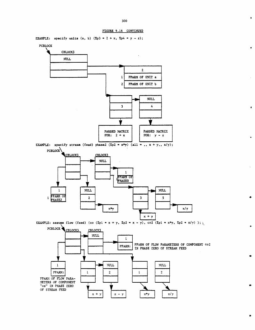
FIGURE 9.16 CONTINUED
EXAMPLE: specify units (a, b) (%p3 - 2 + x, %p4 - y - z);
PCBLOCK
2
1 PPARM OF UNIT a
2 PPARM OF UNIT b
EXAMPLE: specify stream (feed) phase2 (%pZ - x*y) (all - ,, x + y,, x/y);
%p2 - x/y) );
PPARM OF FLOW PARAMETERS OF COMPONENT Co2IN PHASE ZERO OF STREAM FEED

301
FIGURE 9.17 THE CBLOCK4 STRUCTURE
USED FOR: print units, functions, streams, flow, or process
SYNTAX: print (unit I function stream I flow} fall I ( <object-list> )<print-option> [ <if-clause> ];
print process f flowsheet I all} [ <if-clause> ];
PCBLOCK
CBLOCK4
PRINTCODE
NUMBER = n
POINTER TO UNIT,FUNCTION, OR STREAM
n = 0 FOR ALL OPTIONOR FOR PROCESS
(cont. next page)
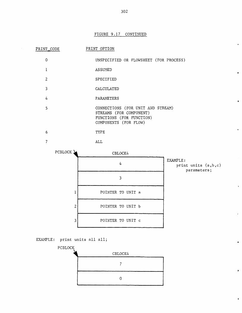
302
FIGURE 9.17 CONTINUED
PRINTCODE PRINT OPTION
UNSPECIFIED OR FLOWSHEET (FOR PROCESS)
ASSUMED
SPECIFIED
CALCULATED
PARAMETERS
CONNECTIONS (FOR UNIT AND STREAM)STREAMS (FOR COMPONENT)FUNCTIONS (FOR FUNCTION)COMPONENTS (FOR FLOW)
TYPE
ALL
PCBLOCK
1
2
3
CBTLCK4
EXAMPLE:print units (a,b,c)
parameters;
EXAMPLE: print units all all;
PCBLOCK
CBLOCK4
4
3
POINTER TO UNIT a
POINTER TO UNIT b
POINTER TO UNIT c
7
0
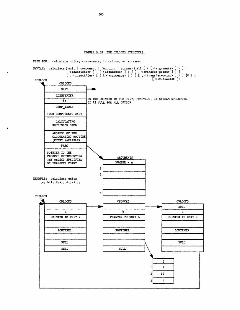
FIGURE 9.18 THE CBLOCK5 STRUCTURE
USED FOR: calculate units, components, functions, or streams.
SYNTAX: calculate (unit I component function | stream}( <identifier> C ( <arguments> ] ) ]
, <identifier> [ ( [ <arguments> I )PCBLOCK
4 CBLOCKS
{all C ( ( <arguments> I ) I |[ , <transfer-point> ] ) ]] [ , <transfer-point> ] ) ] ]* ) }
C <if-clause> ];
NEXT
IDENTIFIER
COMP INDEX
(FOR COMPONENTS ONLY)
CALCULATINGROUTINE'S NAME
ADDRESS OF THECALCULATING ROUTINE(ENTRY VARIABLE)
PARG
POINTER TO THECBLOCK5 REPRESENTINGTHE OBJECT SPECIFIEDBY TRANSFER POINT
EXAMPLE: calculate units(a, b(1,12,4), d(,a) );
IS THE POINTER TO THE UNIT, FUNCTION,IT IS NULL FOR ALL OPTION.
2
PCBLOCK
CBLOCK5
a
POINTER TO UNIT a
ROUTINEl
NULL
NULL
ARGUMENTS
NUMBER - n
CBLOCK5
b
POINTER TO UNIT b
ROUTINE2
NULL
OR STREAM STRUCTURE.
CBLOCK5
rNULL
d
POINTER TO UNIT d
ROUTINE3
NULL
3
1 1
2 12
3 4
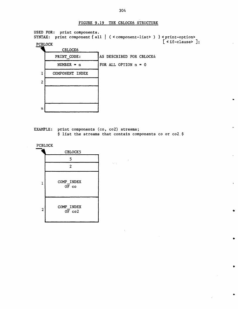
304
FIGURE 9.19 THE CBLOCK6 STRUCTURE
USED FOR: print components.SYNTAX: print component f all ( <component-list> )
PCBLOCK
CBLOCK6
} <print-option>[ <if-clause> ];
AS DESCRIBED FOR CBLOCK4
FOR ALL OPTION n = 0
EXAMPLE: print components (co, co2) streams;$ list the streams that contain components co or co2. $
PCBLOCK
CBLOCK5
5
2
1 COMPINDEXOF co
2 COMPINDEXOF co2
PRINT CODE:
NUMBER = n
COMPONENT INDEX

FIGURE 9.20 THE CBLOCK7 STRUCTURE
USED FOR: read, reada, or unspecify units, components, functions, streams, or flow.
SYNTAX: {read reada I unspecify)
(read reada unspecify}
{ read reada unspecify}
PCBLOCK
(unit component function} {all I (object-list> ){all | ( <parameter-list> ) } } [ <if-clause> ];
stream (all I ( <stream-list> ) [ < phase-field> ]f all (< parameter-list> ) f [ phase-f ield> ]{ all ( < parameter-list> ) } * } <if-clause> J;
flow { all ( <stream-list> ) C <phase-field> ] (all I( <flow-parameter-list> ) } E [< phase-field> ]{ all < ( flow-parameter-list> ) } ]* } [ <if-clause> ];
CBLOCK7
P (NULL FOR ALL OPTION)
PPARM TEMP OR PPHASE-TEMP
NUMBER - n
NAME PPARM OR PSTREAM
STREAM
PPARMTEMP: POINTER TOPARAMETERS TEMPLATESTRUCTURE.
PPHASE TEMP: POINTER TOPHASE TEMPLATESTRUCTURE.
FLOW
1
PARMN (PARAMETER NUMBERS)
NUMBER - m
PARM NOUNIT,
COMPONENT, OR
FUNCTION
(NULLFORALLOP-TION)
1
n
(cont. next paze)
XPHASE
NEXT
PHASE NO
PPARM TEMP OF PHASE PARAMETERS
P (NULL FOR ALL OPTION)
PARMN
PARAMETER NUMBER- OF SPECIFIEDPHASE PARAMETERS
XPHASE
NEXT
PHASE NO
PPARM TEMP OF FLOW PARAMETERS
P (NULL FOR ALL OPTION)
COMPONENT
NEXT
COMPONENT NAME
COMPONENT INDEX
P (NULL FOR ALL OPTION)
PARMN
PARAMETER NUMBER OF SPECIFIEDFLOW PARAMETERS
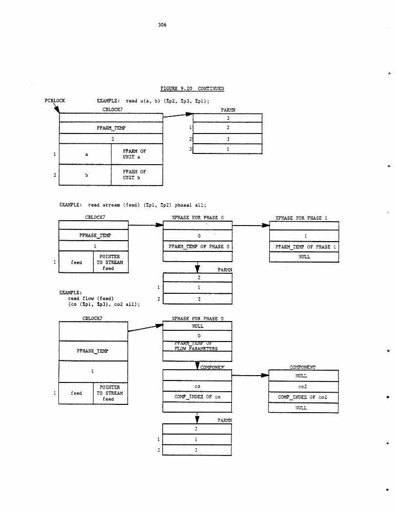
FIGURE 9.20 CONTINUED
EXAMPLE: read u(a, b) (%p2, %p3 , %pl);
CBLOCK7
PPARM TEMP
2
PPARM OFa UNIT a
PPAII OFb UNIT b
PARMN
3
1 2
2 3
3 1
EXAMPLE: read stream (feed) (%pl, /p2 ) phasel all;
CBLOCK7
PPHASE TEM
1
POINTERfeed TO STREAM
feed
EXAMPLE:read flow (feed)(co (Zpl, %p3), co2 all);
CBLOCK7
PPHASE TEMP
POINTERfeed TO STREAM
feed
XPHASE FOR PHASE 0
0
PPARM TEP OF PHASE 0
PARIN
2
1
2
XPHASE FOR PHASE 0
NULL
0k'ZAR T.ir U7FLOW PARAMETERS
COMPONE
co
COMP INDEX OF co
PARM.N
2
t 3
XPHASE FOR PHASE 1
PPARM TEMP OF PHASE I
NULL
CoMPONENT
NULL
co2
COMP_INDEX OF co2
NULL
PCBLOCK
307
9.5 Execution Phase
In this final phase the command is executed. As mentioned earlier
there is a begin block associated with each command performing the syntax
analysis and interpretation phase. The same begin block also monitors the
execution of the command. The execution may be performed in the same block
or another internal or external routine may be invoked. For commands
related to component files the external routine "cdbsys" (component data
base system) is called to execute the commands. The external routine
"pdbsys" (process data base system) is called for command related to
process files. The external routine "printtemp" is called to print
information about templates in response to "printt" and "listt" commands.
The execution of commands for which intermediate forms were
constructed is controlled by these intermediate forms, and monitored by
some internal routines. The intermediate forms will be deleted once the
execution of the command or commands within a loop is completed. The
execution of other commands is performed by their associated begin blocks.

308
CHAPTER 10
EXERCISE IN DEVELOPMENT OF TEMPLATE BASED SYSTEMS
In this chapter a general framework for the development of TBS's will
be presented and the development of a number of prototype TBS's will be
described.
Using GPES three prototype TBS's have been created to demonstrate the
application and use of GPES and systems created by GPES. These prototype
TBS's are as follows:
1. Heat Exchanger Networks Analyzer. This prototype TBS is capable
of analyzing heat exchanger networks. It has been created to
demonstrate that using GPES, one could develop a very simple
system to solve a particular class of problems.
2. TBS-II. This prototype TBS is capable of analyzing processes
with conventional liquid-vapor streams, particularly
hydrocarbon proceses. Currently it contains a few types of
process units such as distillation columns, heat-exchangers,
and isothermal flash separations, and hence it is limited to
processes having only these process elements.
3. MHD. This prototype TBS is created to study MHD processes. It
is an example of a case where existing simulators cannot be
used to analyze processes having streams other than
conventional liquid and vapor streams.
It should be noted that any of the above three TBS's could be expanded to
309
include additional unit operations. It is also not necessary to have
different TBS's to analyze different classes of processes. In fact, a
single TBS could have been created capable of analyzing all three types
of processes mentioned above.
10.1 Development Process of a Template Based System
Development process of a TBS in general is shown in Figure 10.1. It
consists of the following phases:
1. TBS definition (Formalism) phase.
Once the need for development of a new TBS is brought about by
external factors, this would be the first phase of
development. In this phase the objective of the TBS should be
stated and different types of process units, streams,
components, and pre-defined functions that may be required
should be identified. Decisions should also be made on how to
represent these elements. The mathematical models of the
process units should be prepared. The standard units of
measurement and other allowable options for each relevant
physical dimension should also be identified. This phase not
only provides input to the following two phases, but it is very
useful for documentation purposes.
2. Template Definition Phase.
In this phase the TBS Administrator using the "update tdb"
program defines the templates. As described in Chapter 4 these
templates are as follows:
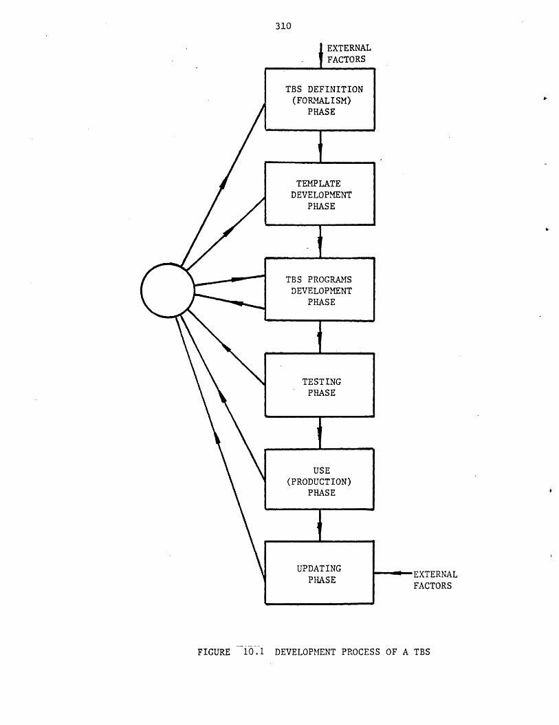
310
,EXTERNALFACTORS
FIGURE 10.1 DEVELOPMENT PROCESS OF A TBS

311
a) a template for every unit type.
b) a template for every stream type.
c) a template for every component type.
d) a template for every pre-defined function type.
e) a template for every physical dimension.
f) a template for every physical property where the user has
the option of selecting its method of estimation.
g) a template for system control information which includes
items of information such as the name of the TBS.
The TBS Administrator using any available editor should also
create a text file as described in Chapter 4. This file
includes items of information such as the name and address of
the TBS Administrator, reported errors, news, etc.
3. TBS Programs Development Phase.
In this phase the TBS programmers develop TBS programs as
described in Chapter 6. These programs mainly consist of a
calculating routine for each unit type. In this effort
sometimes the need for updating or modifications of efforts
made in previous phases is realized, in which case the TBS
Administrator has to return to one of the previous phases.
14. Testing Phase.
Before the TBS is released to the public, the TBS Administrator
should test it by simulating various process flowsheets. Once
312
any bug is found, he may have to return to one of the previous
phases for debugging.
5. Use (Production) Phase.
At this phase the TBS may be used by designers for analysis and
design of various process flowsheets. In the course of the TBS
usage, the users may discover some bugs in the TBS or may
recognize the need for expansion or improvement of the TBS.
The users should inform the TBS Administrator of the need for
modification.
6. Updating Phase.
A TBS is an open-ended system which can be easily extended or
modified. .The need for extension or modification may be
realized by inputs received from the previous phase or by other
external factors. This will lead the TBS Administrator to one
of the first three phases for extending or modifying the TBS.
10.2 Development of a Prototype TBS for Analyzing Heat Exchanger Networks
The development process of this simple TBS will be presented in the
above framework.
1. TBS Definition Phase (formalism).
The objective of this TBS is to analyze the steady state
behavior of an arbitrary heat exchanger network. Each stream
in a heat exchanger network is characterized by two variables:
the product of mass flow rate and specific heat (WC) and the
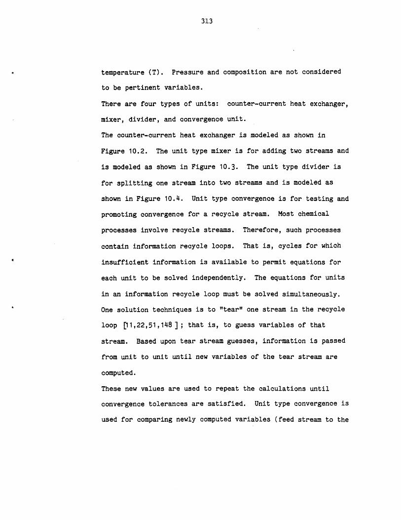
313
temperature (T). Pressure and composition are not considered
to be pertinent variables.
There are four types of units: counter-current heat exchanger,
mixer, divider, and convergence unit.
The counter-current heat exchanger is modeled as shown in
Figure 10.2. The unit type mixer is for adding two streams and
is modeled as shown in Figure 10.3. The unit type divider is
for splitting one stream into two streams and is modeled as
shown in Figure 10.4. Unit type convergence is for testing and
promoting convergence for a recycle stream. Most chemical
processes involve recycle streams. Therefore, such processes
contain information recycle loops. That is, cycles for which
insufficient information is available to permit equations for
each unit to be solved independently. The equations for units
in an information recycle loop must be solved simultaneously.
One solution techniques is to "tear" one stream in the recycle
loop 11,22,51,148 ]; that is, to guess variables of that
stream. Based upon tear stream guesses, information is passed
from unit to unit until new variables of the tear stream are
computed.
These new values are used to repeat the calculations until
convergence tolerances are satisfied. Unit type convergence is
used for comparing newly computed variables (feed stream to the
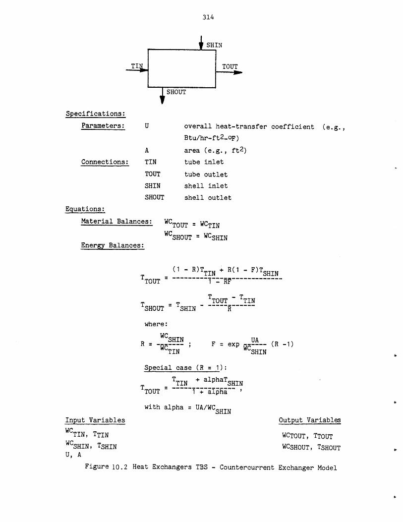
314
Specifications:
Parameters:
Connections: TIN
TOUT
SHIN
SHOUT
Equations:
Material Balances:
SHIN
TOUT
overall heat-transfer coefficient (e.g.,
Btu/hr-ft2 -oF)
area (e.g., ft 2 )
tube inlet
tube outlet
shell inlet
shell outlet
WCTOUT = WCTINWCSHOUT = WCSHIN
Energy Balances:
(1 - R)TTIN + R(1 - F)TSHINTTOUT =..~~~~~~~~~1~~-~.
T TTOUT - TINSHOUT TSHIN R
where:
WC UR -WSHIN F=exp UA
TIN SHIN
Special case (R = 1):
TTIN + alphaTSHINTTOUT T ~~I~~N l~
TOUT 1 + alpha
with alpha = UA/WCSHIN
(R -1)
Input Variables
WCTIN, TTINWCSHIN, TSHINU, A
Output Variables
WCTOUT, TTOUT
WCSHOUT, TSHOUT
Figure 10.2 Heat Exchangers TBS - Countercurrent Exchanger Model
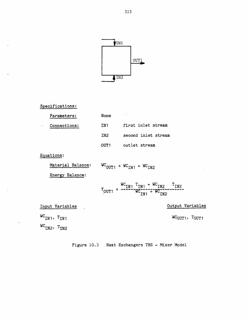
315
Specifications:
Parameters:
Connections:
None
IN1
IN2
OUT 1
first inlet stream
second inlet stream
outlet stream
Equations:
Material Balance:
Energy Balance:
WCOUT1 = WCIN1 + WCIN2
WCIN1 TIN1 + WCIN2 TIN2OUT1 ~~~2~~+9I IN1 IN2
Input Variables Output Variables
WCIN1, TIN1
W IN2, TIN2
WCOUT1, TOUT1
Heat Exchangers TBS - Mixer ModelFigure 10 .3
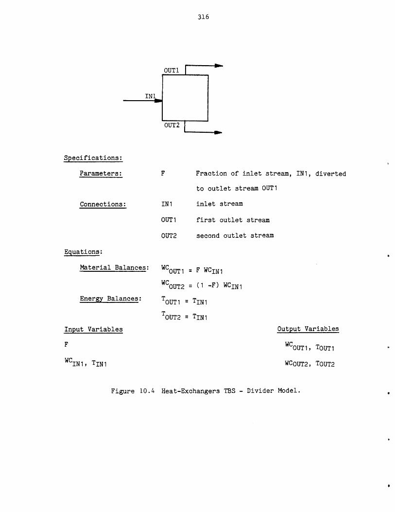
316
OUT 1
Specifications:
Parameters: Fraction of inlet stream, IN1, diverted
to outlet stream OUT1
Connections: IN1 inlet stream
OUT1
OUT2
first outlet stream
second outlet stream
Equations:
Material Balances:
Energy Balances:
WCOUT 1
WCOUT2
= F WCIN1
= (1 -F) WCIN1
TOUT1 = TIN1
TOUT2 = TIN1
Input Variables Output Variables
WCOUT1, TOUT1
WCOUT2, TOUT2WCINl, TIN1
Figure 10.4 Heat-Exchangers TBS - Divider Model.
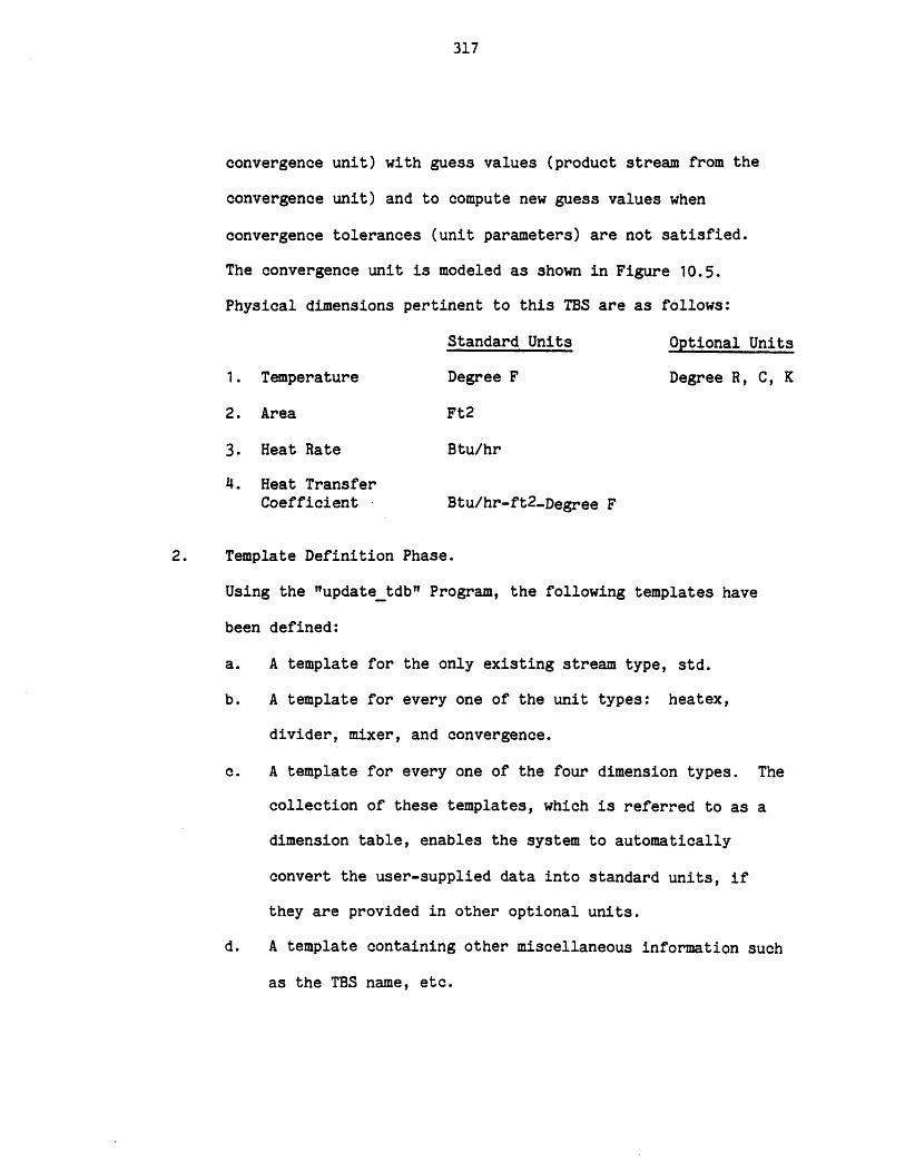
317
convergence unit) with guess values (product stream from the
convergence unit) and to compute new guess values when
convergence tolerances (unit parameters) are not satisfied.
The convergence unit is modeled as shown in Figure 10.5.
Physical dimensions pertinent to this TBS are as follows:
Standard Units Optional Units
1. Temperature Degree F Degree R, C, K
2. Area Ft2
3. Heat Rate Btu/hr
4. Heat TransferCoefficient Btu/hr-ft 2 -Degree F
2. Template Definition Phase.
Using the "update tdb" Program, the following templates have
been defined:
a. A template for the only existing stream type, std.
b. A template for every one of the unit types: heatex,
divider, mixer, and convergence.
c. A template for every one of the four dimension types. The
collection of these templates, which is referred to as a
dimension table, enables the system to automatically
convert the user-supplied data into standard units, if
they are provided in other optional units.
d. A template containing other miscellaneous information such
as the TBS name, etc.
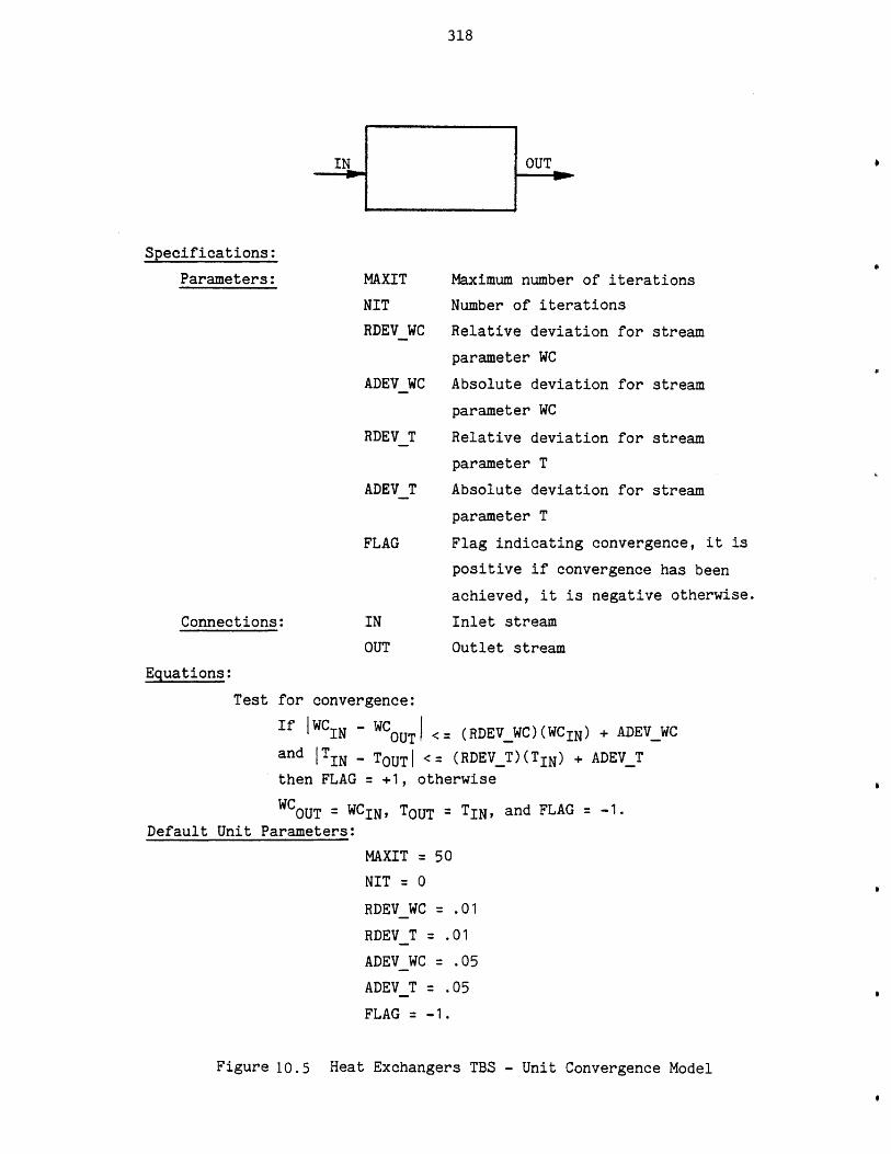
318
Specifications:
Parameters:
Connections:
MAXIT Maximum number of iterations
NIT Number of iterations
RDEVWC Relative deviation for stream
parameter WC
ADEV WC Absolute deviation for stream
parameter WC
RDEVT Relative deviation for stream
parameter T
ADEV T Absolute deviation for stream
parameter T
FLAG Flag indicating convergence, it is
positive if convergence has been
achieved, it is negative otherwise.
IN Inlet stream
OUT Outlet stream
Equations:
Test for convergence:
if |WC IN -WCOUTI <= (RDEVWC)(WCIN) + ADEV_WCand ITIN - TOUTi <= (RDEVT)(TIN) + ADEV T
then FLAG = +1, otherwise
WCOUT = WCIN, TOUT = TIN, and FLAG = -1.Default Unit Parameters:
MAXIT = 50
NIT = 0
RDEVWC = .01
RDEVT = .01
ADEVWC = .05ADEVT = .05
FLAG = -1.
Figure 10.5 Heat Exchangers TBS - Unit Convergence Model
319
The printout of the dimension table, the stream template and
the template for unit type heatex are shown in Figure 10.6.
Using the Multics editor, a text file, as described in Chapter
4, has also been created. It contains information such as the
TBS Administrator name and address, news, reported errors, etc.
3. TBS Program Development Phase.
In this phase a subroutine for each process unit type is
developed to represent its mathematical model. The names of
these subroutines have been already supplied in the unit
templates. The system will call upon these routines to solve
equations for each unit. The subroutine for unit Heatex is
listed in Figure 10.7.
4. Testing Phase.
In this phase the TBS has been tested by simulating various
heat exchanger networks.
5. Use (Production) Phase.
Now the system is ready to be used by ultimate users of the
TBS, process designers. To use the TBS they only have to know
PEL (Process Engineering Language). The following example
demonstrates the use of TBS and PEL.
Example
There are a number of identical heat exchangers (A = 20 ft2,
U = 10 Btu/hr-ft2 .OF), and a number of cold streams (WC =
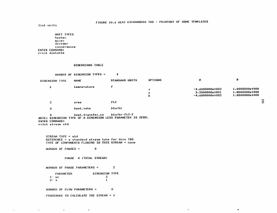
FIGURE 10.6 HEAT EXCHANGERS TBS - PRINTOUT OF SOME TEMPLATESlist units
UNIT TYPESheatexIii ,-xe rdividerconvergence
ENTER COMMAND:print dinitable
DIMENSIONS TABLE
NUMBER OF DIMENSION TYPES 4
DIMENSION TYPE NAME STANDARD UNITS
temperature
area
heat-rate
-4.6000000e+0023.2000000et001
-4.6000000e+002
1.0000000e+0001.8000000e+0001.8000000e+000
ft2
btu/hr
4 heat-transfer-co btu/hr-ft2-fNOTE; DIMENSION TYPE OF A DIMENSION LESS PARAMETER IS ZERO.
ENTER COMMAND:print stream std
STREAM TYPE = stdREFERENCE = a standard stream twee for this TBSTYPE OF COMPONENTS FLOWING IN THIS STREAM - none
NUMBER OF PHASES =
PHASE 0 (TOTAL STREAM)
NUMBER OF PHASE PARAMETERS = 2
PARAMETER DIMENSION TYPE1- wc 32-t 1
NUMBER OF FLOW PARAMETERS = 0
PROCEDURE TO CALCULATE THE STREAM = i
OPTIONS
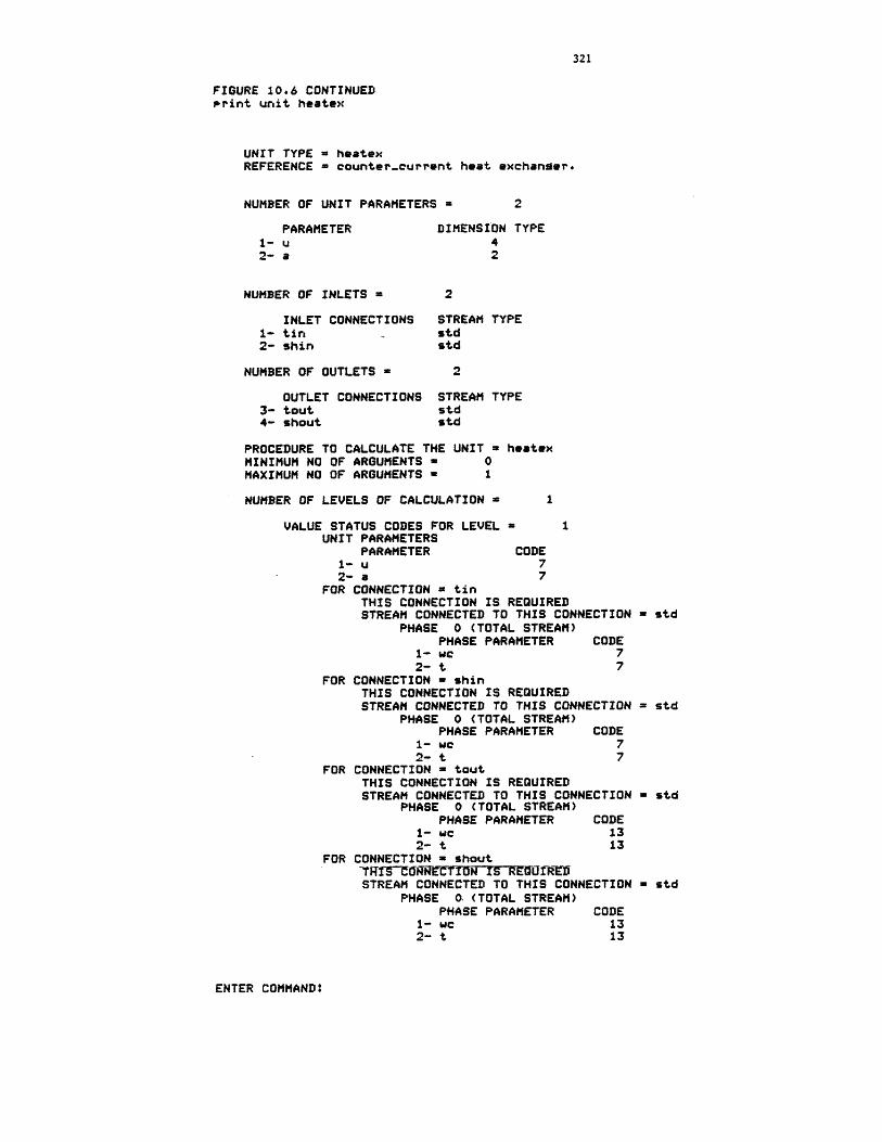
321
FIGURE 10.6 CONTINUEDPrint unit heatex
UNIT TYPE = heatexREFERENCE = counter-current heat exchanger.
NUMBER OF UNIT PARAMETERS a 2
PARAMETER1- u2- a
NUMBER OF INLETS =
INLET CONNECTIONS1- tin2- shin
NUMBER OF OUTLETS =
OUTLET CONNECTIONS3- tout4- shout
DIMENSION TYPE42
2
STREAM TYPEstdstd
STREAM TYPEstdstd
PROCEDURE TO CALCULATE THE UNIT = heatexMINIMUM NO OF ARGUMENTS = 0MAXIMUM NO OF ARGUMENTS 1
NUMBER OF LEVELS OF CALCULATION =
VALUE STATUS CODES FOR LEVEL =UNIT PARAMETERS
PARAMETER1- u
CODE7
2- a 7FOR CONNECTION = tin
THIS CONNECTION IS REQUIREDSTREAM CONNECTED TO THIS CONNECTION =
PHASE 0 (TOTAL STREAM)PHASE PARAMETER CODE
1- we 72- t 7
FOR CONNECTION - shinTHIS CONNECTION IS REQUIREDSTREAM CONNECTED TO THIS CONNECTION =
PHASE 0 (TOTAL STREAM)PHASE PARAMETER CODE
1- we 72- t 7
FOR CONNECTION = toutTHIS CONNECTION IS REQUIREDSTREAM CONNECTED TO THIS CONNECTION =
PHASE 0 (TOTAL STREAM)PHASE PARAMETER CODE
1- we 132- t 13
FOR CONNECTION w shout~TRf~CECT~~ON IS REUfRD15STREAM CONNECTED TO THIS CONNECTION =
PHASE 0. (TOTAL STREAM)PHASE PARAMETER CODE
1- wc2- t
1313
ENTER COMMAND:
std
std
std
std
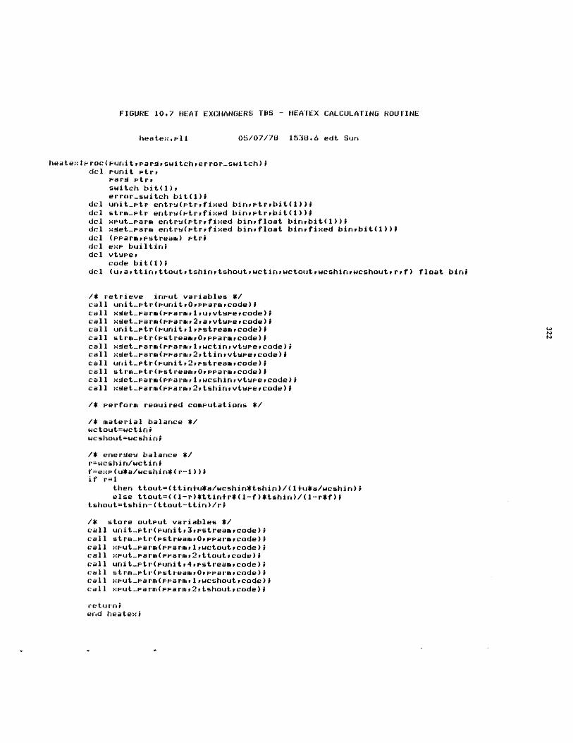
FIGURE 10.7 HEAT EXCHANGERS TBS - HEATEX CALCULATING ROUTINE
heatex.-11 05/07/78 1538.6 edt Sun
heatexteroc(puritvpargpswitcherror-switch)idel Funit Ftrr
Parg Ptrrswitch bit(1)perror-switch bit(l);
dcl unit-ptr eretrw(Ftrtfixed binretrpbit(1))Idel stre.ptr ertru(ptrfixed binreptrbit(1))9del xPut-.arm entrw(ptryfixed binrfloat binebit(1))Idcl xset-rarm entrw(ptrpfixed binrfloat binefixed binrbit(1))9del (-rarmeestream) ptr9del exe builtinidcl vtupe
code bit(l);del (urattinettoutvtshinvtshoutwctievwctoutrweshinewchouteruf) float bini
/* retrieve input variables */call unit-etr(punittOepparmycode)icall xget-varm(pparaeiururvtweercode)9call xset-pare(pprarar2avtuevecode)icall unit-ptr(reunitr Ipstreamevcode)#call strma-etr(pstreamrOppparmacade)9call xset-arm(prarmilrwctinevtweercode)icall xset-aruo(pearwy2vttinevtue#code) Icall urit-etr(unit2upstreamvcode)Icall stru-e...tr(strear 0OPparuPcode) Icall xet-Farm (earur IrwcshinevtwePcode)Icall xget-par(er-arar2ptshinevtu-ercode)9
/* -erformi reauired comuutations */
/* material balance */wctout=wctinwcshout=wcshini
/* enerseu balance */r=wcshin/wctinif=ex.(u*a/wcshin*(r-1))9if r=1
then ttout=(ttintu*a/wcshin*tshin)/(1+u*a/wcshin);else ttout=((1-r)*ttin+r*(1-f)*tshir)/(i-r*f)i
tshiout=tshtin-(ttout-ttins)/r;
/* store output variables */call urit-etr(punitv3vpstreamercode);call stra-etr(estreamOppararcode)9call xput--are(praraiewctoutpcode)!call xeut-e-arm(pearne,2pttoutPcode);call urit-ptr(purit4vpstreamycode);call strm-etr(pstreameaOpparmecode) icall xput-r-arn(pearur1weshoutrcode)Icall xput-parue(pearotP2,tshoutpcode)9
retu 'revend heatex I
323
500 Btu/hr, T 3000F) to be used to cool a hot stream (WC =
1000 Btu/hr, T 1200 0F) to below 950 0F, as shown in Figure
10.8a. The problem is determining the minimum number of
required heat exchangers. The computer session for solving
this problem is shown in Figure 10.9. To solve this problem,
one may start with one heat exchanger and increase the number
of heat exchangers until the hot stream is cooled to the
desired temperature. As can be seen in Figure 10.9, two heat
exchangers will bring the hot stream temperature below the
9500F. Before terminating the session, the user has saved
his process network, so that he may-be able to continue his
design effort sometime in the future. At a later session, the
user wishes to investigate other design alternatives,
especially those shown in Figures 10.8b and 10.8c. The PEL
computer session is demonstrated in Figure 10.10. As can be
seen, the output temperature for process configuration shown in
10.8b is 950OF compared to 945oF in the first configu-
ration. To simulate the process flowsheet shown in Figure
10.8c, one observes that unit H1 and H2 cannot be calculated
independently. To calculate unit H1 stream coldi should be
known. To determine stream cold1 unit H2 should be calculated
which requires the stream S1 to be known. Therefore, to
calculate unit H1 stream S1 should be known, but on the other

324
-COLD1 (WC - 500,a T 300)
COLD2 (WC = 500,3 T 300)
COLDn (WC 500,1 T= 300)
(WC-1000T=1200)
(a)
COLD1 ( = 1000,a T =300)L -2 m
OLD2
NOTES
WC IN BTU/HRT IN 0F
2
(b)
(c)
COLD2 (WC = 1000,-, . T = 300)
FIGURE 10.8
(d)
HEAT EXCHANGERS TBS - THE PROCESS FLOWSHEETFOR THE EXMIPLE CASE
(WC=1000,T=1200)
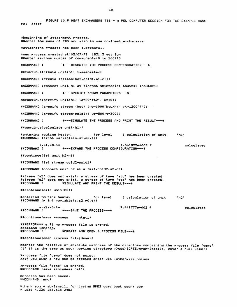
FIGURE 10.9 HEAT EXCHANGERS TBS - A PEL COMPUTER SESSION FOR THE EXAMPLE CASEPel brief
*beginning of attachment process.**enter the name of TBS wou wish to use nowtheat-exchangers
*attachment process has been successful.
*new process created at:05/07/78 1831.5 edt Sun**enter maximum number of components(O to 200)*0
**COMMAND : $---DESCRIBE THE PROCESS CONFIGURATION---$
**continueocreate unit(hi) tpeieheatex;
**COMMAND *create streams(hotrcold1,s1,ci)'
**COMMAND *connect unit hi at tin=hot shin-coldl tout=sl shout=cl;
**COMMAND : $---SPECIFY KNOWN PARAMETERS---$
**continueispecifw unit(hl) (a=20'ft2', u-10);
**COMMAND ispecifw stream (hot) (wc1000'btu/hr' rt=1200'f'); '
**COMMAND :specifv stream(coldl)( wc=500,t=300);
**COMMAND : $---SIMULATE THE PROCESS AND PRINT THE RESULT---$
**continue*calculate unit(hi);
*entering routine heatex for level 1 calculation of unit "h1"**COMMAND *Print variable(s.si.p0.t);
s.sl.pO.t= 1.061892e+003 f calculated**COMMAND , $---EXPAND THE PROCESS CONFIGURATION---$
**continuetlet unit h2=hi;
**COMMAND *let stream cold2=coldl;
**COMMAND #connect unit h2 at all=s1,cold2,s2,c2;
*stream "s2" does not exist. a stream of twee "std' has been created.*stream "c2" does not exist. a stream of twpe "std" has been created.**COMMAND 0*SIMULATE AND PRINT THE RESULT---$
**continue*calc unit(h2);
*entering routine heatex for level 1 calculation of unit "h2"**COMMAND :Print variable(s.s2.P.t),
s*s2*,.0t= 9.449777e+002 f calculated**COMMAND : $---SAVE THE PROCESS---t
**continue#save process ntati;
***ERROR*** s 91 no Process file is opened.*command ignored.**COMMAND CREA TE AND OPEN A.PROCESS FILE7-
**continue*open process file(demo)i
**enter the relative or absolute Pathname of the directorv containing the Process file "demo"(if it is the same as wour working directorw P>udd>ICPES>Arab-Ismaili, enter a null line):
*Process file "demo" does not exist.**if wou wish a new one be created enter wes Potherwise notves
*Process file "demo' is opened.**COMMAND :save Procv*ess netlt
*Process has been saved.**COMMAND 'end;
*thank wou Arab-Ismaili for trving GPES come back soon, bwe!r 1838 4.330 153.635 2482
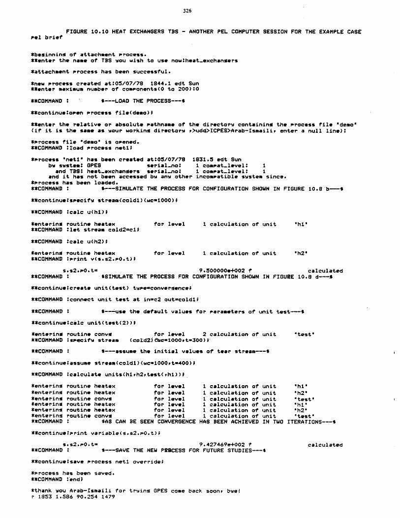
326
FIGURE 10.10 HEAT EXCHANGERS TBS - ANOTHER PEL COMPUTER SESSION FOR THE EXAMPLE CASEPel brief
*beginning of attachment process.**enter the name of TBS wou wish to use nowtheat-exchangers
*attachment process has been successful.
*new process created at:05/07/78 1844.1 edt Sun**enter maximum number of components(0 to 200)*0
**COMMAND : ' $---LOAD THE PROCESS---$
**continue:open Process file(demo)7P
**enter the relative or absolute Pathname of the directorw containing the process file "demo"(if it is the same as wour working directors ,>udd>ICPES>Arab-Ismaili, enter a null line):
*Process file "demo" is opened.**COMMAND 'load process netlP
*Process "netl* has been created at:05/07/78 1831.5 edt Sunbw sustemo GPES serial-no: 1 compat-level* 1
and TBS: heat-exchangers serial-no: 1 compat-level* 1and it has not been accessed bw anw other incompatible swstem since.
*Process has been loaded.**COMMAND : $---SIMULATE THE PROCESS FOR CONFIGURATION SHOWN IN FIGURE 10.8 b-$
**continuetspecifw stream(cold1)(wc=1000);
**COMMAND :calc u(hil)P
*entering routine heatex for level 1 calculation of unit "hi"**COMMAND let stream cold2=cl;
**COMMAND Ocalc u(h2);
*entering routine heatex for level 1 calculation of unit "h20**COMMAND :Print v(s.s2.PO.t);
s.s2.po.t= 9.500000e+002 f calculated**COMMAND : -$SIMULATE THE PROCESS FOR CONFIGURATION SHOWN IN FIGURE 10.8 d---4
**continueocreate unit(test) twpenconvergence;
**COMMAND *connect unit test at in-c2 outicold1l
**COMMAND : $---use the default values for parameters of unit test---$
**continue:calc unit(test(2));
*entering routine conv9 for level 2 calculation of unit "test"**COMMAND ispqcifu stream (col:dZj fc-1000,t-300);
**COMMAND : S---assume the initial values of tear stream---$
**continue*assume stream(coldl)(wc1000,t-400);
**COMMAND :calculate units(hih2,test(rhl));
*entering routine heatex for level 1 calculation of unit "hi"*entering routine heatex for level 1 calculation of unit "h2"*entering routine conv9 for level 1 calculation of unit "test"*entering routine heatex for level 1 calculation of unit "hi"*entering routine heatex for level 1 calculation of unit "h2"*entering routine convs for level 1 calculation of unit "test"**COMMAND $AS CAN BE SEEN CONVERGENCE HAS BEEN ACHIEVED IN TWO ITERATIONS---$
**continue:Print variable(s.s2.P0.t);
s*s2.p0.t= 9.427469e+002 f calculated**COMMAND * $---SAVE THE NEW PRBCESS FOR FUTURE STUDIES---$
**continueosave process neti override;
*Process has been saved.**COMMAND :end;
*thank wou Arab-Ismaili for truing GPES come back soon, bwe!r 1853 1.586 90.254 1479
327
hand, to find the stream S1 requires the calculation of unit
H1. Hence, it can be seen that the process flowsheet contains
an information recycle loop; that is, too few stream variables
are known to permit equations for each unit to be solved
independently. One solution technique is to tear one stream in
the recycle loop; that is, to guess variables of that stream.
Based upon tear stream guesses, information is passed from unit
to unit until new values of the variables of the tear stream
are computed. These new values are used to repeat the
calculations until convergence tolerances are satisfied. This
has been done as shown in Figure 10.8d and demonstrated in
Figure 10.10.
As can be seen, convergence has been achieved in two
iterations. The output temperature is 943 0F which is lower
than the two previous outcomes.
6. Updating Phase (TBS Administrator's Task)
A TBS is an open ended system which can easily be extended or
modified. Suppose a new unit type is to be added to the TBS.
The unit type is adjuster, which heats or cools a stream to a
specified temperature. The unit model is shown in Figure
10.11. A new template defining this new unit type has been
added to the template based system as shown in Figure 10.12 and
a subroutine representing the mathematical model of the unit
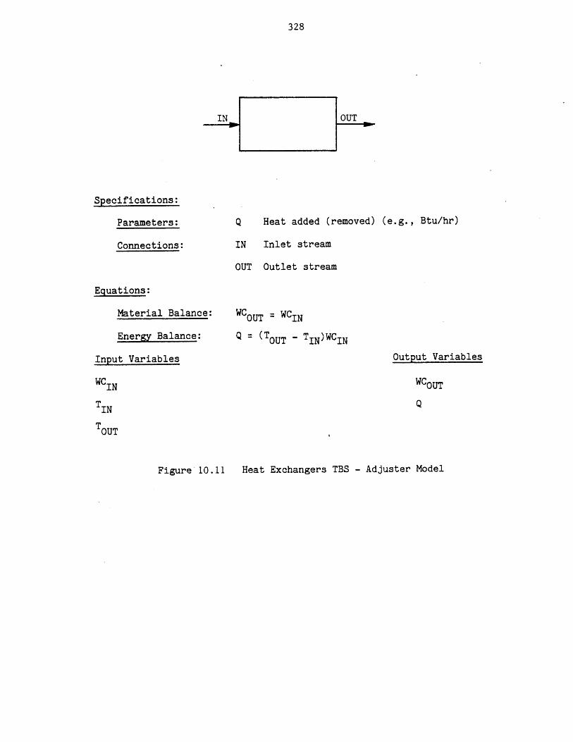
328
Specifications:
Parameters:
Connections:
Q
IN
OUT
Equations:
Material Balance:
Energy Balance:
Input Variables
Heat added (removed) (e.g., Btu/hr)
Inlet stream
Outlet stream
WCOUT = WCIN
Q = (TOUT - TIN)WCIN
Output Variables
WCIN
TIN
TOUT
WCOUT
Q
Heat Exchangers TBS - Adjuster ModelFigure 10.11
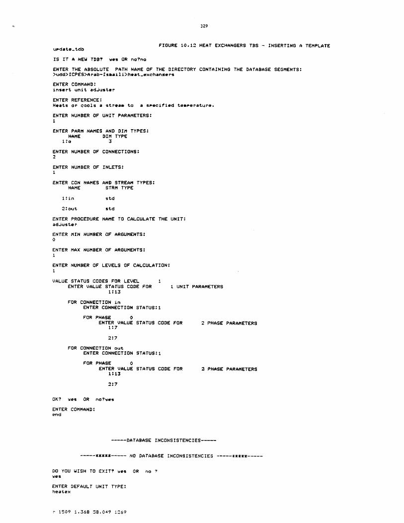
FIGURE 10.12 HEAT EXCHANGERS TBS - INSERTING A TEMPLATEupdate-.tdb
IS IT A NEW TDB? was OR no?no
ENTER THE ABSOLUTE PATH NAME OF THE DIRECTORY CONTAINING THE DATABASE SEGMENTS:>udd>ICPES>Arab-Ismaili>heat-exchangers
ENTER COMMAND:insert unit adjuster
ENTER REFERENCE:Heats or cools a stream to a specified temperature.
ENTER NUMBER OF UNIT PARAMETERS:1
ENTER PARM NAMES AND DIM TYPES:NAME DIM TYPE
1 00 3
ENTER NUMBER OF CONNECTIONS:2
ENTER NUMBER OF INLETS:1
ENTER CON NAMES AND STREAM TYPES:NAME STRM TYPE
l:in std
2: out std
ENTER PROCEDURE NAME TO CALCULATE THE UNIT:adjuster
ENTER MIN NUMBER OF ARGUMENTS:0
ENTER MAX NUMBER OF ARGUMENTS:1
ENTER NUMBER OF LEVELS OF CALCULATION:1
VALUE STATUS CODES FOR LEVEL IENTER VALUE STATUS CODE FOR 1 UNIT PARAMETERS
1:13
FOR CONNECTION inENTER CONNECTION STATUS:1
FOR PHASE 0ENTER VALUE STATUS CODE FOR 2 PHASE PARAMETERS
1:7
2:7
FOR CONNECTION outENTER CONNECTION STATUS:1
FOR PHASE 0ENTER VALUE STATUS CODE FOR 2 PHASE PARAMETERS
1:13
2:*7
OK? wes OR noies
ENTER COMMAND:end
----- DATABASE INCONSISTENCIES-
----- NO DATABASE INCONSISTENCIES
DO YOU WISH TO EXIT? was OR no ?was
ENTER DEFAULT UNIT TYPE:heatex
r 1509 1.368 58.049 1269
330
has been developed. The users of the TBS may now incorporate
units of this type in their process flowsheets when such a need
arises.
10.3 A Prototype TBS for Hydrocarbon Processes
The objective of this TBS is to analyze the steady state behavior of
hydrocarbon processes. One stream type, one component type, and a number
of unit types will be required for such a TBS. It should be clear that a
process flowsheet may contain any number of streams, components or units
of the specified types.
The stream type which is referred to as "std" (standard) stream is a
conventional vapor-liquid stream. This stream in addition to phase zero
which represents the total stream, has two more phases to represent the
vapor and liquid phases. Phase zero has five phase parameters and one
flow parameter. The phase parameters are:
1-t Temperature in degrees Kelvin
2-p Pressure in atmospheres
3-f Total molal flow rate in Kgmol/hr
5-h Molal enthalpy in Kcal/Kgmol
5-vf Vapor fraction.
The flow of components in the total stream is represented by their
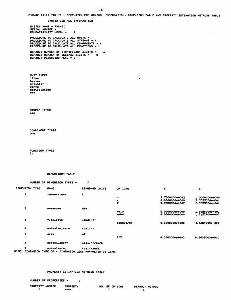
FIGURE 10.13 TS-I - TEMPLATES FOR CONTROL INFORMATION, DIMENSION TABLE AND PROPERTY ESTIMATION METHODS TABLE
SYSTEM CONTROL INFORMATION
SYSTEM NAME a TBS-IISERIAL NUMBER a 1COMPATIBILITY LEVEL a
PROCEDURE TOPROCEDURE TOPROCEDURE TOPROCEDURE TO
CALCULATECALCULATECALCULATECALCULATE
ALLALLALLALL
UNITS - ISTREAMS a ;COMPONENTS =FUNCTIONS =
DEFAULT NUMBER OF SIGNIFICANT DIGITS =DEFAULT NUMBER OF DECIMAL DIGITS = 5DEFAULT DEBUGGING FLAG = 0
UNIT TYPESiflashheatexsplitterconvudistillationadd
STREAM TYPESstd
COMPONENT TYPESone
FUNCTION TYPES11
DIMENSIONS TABLE
NUMBER OF DIMENSION TYPES =
DIMENSION TYPE NAME STANDARD UNITS
Pressure
flow.rate
enthapw.rate
area
heatex-coeff
at&
kamol/hr
kcal/hr
7 enthalsw/aol kcal/ksolNOTE: DIMENSION TYPE OF A DIMENSION LESS PARAMETER IS ZERO.
PROPERTY ESTIMATION METHODS TABLE
kcal/hr/a2/k
psiamahs
iboole/hr
2.7300000e+0020.0000000e+0002.55 556+002
0.0000000e+0000.0000000e+000
0.0000000e+000
0.0000000e+000tt2
1.0000000+0005.55555560-0015.555556e-001
6.8050000-0021.3157900&-003
4.5359000e-001
9.2903040a-002
NUMBER OF PROPERTIES a
PROPERTY NUMBER PROPERTYpvap
OPTIONS
NO. OF OPTIONS DEFAULT METHOD
332
.mole fractions. Thus, the only flow parameter of phase zero is the mole
fraction (z).
Phase one represents the vapor phase and has zero phase parameters
and one flow parameter. The latter is the mole fraction in the vapor
phase.
Phase two represents the liquid phase and similarly has zero phase
parameters and one flow parameter. The latter is the mole fraction in
liquid phase (x).
A calculating routine is associated with this stream type which has
two levels of calculation. Level one of calculation normalizes the total
stream mole fractions, and level two performs an equilibrium
calculation. Given the stream temperature (t), pressure (p), and total
stream mole fractions (z's), level two of calculation determines the
molal enthalpy (h), vapor fraction (vf), and compositions in each phase
(y's and x's). The template for the stream type is shown in Figure 10.14.
The component type "one" which is the only type component in this TBS
is represented by the following fifteen parameters:
1 - molwt molecular weight
2 - tb normal boiling point, K
3 - tc critical temperature, K
4 - pc critical pressure, K
5 - zc critical compressibility
6 - omega Pitzer's acentric factor
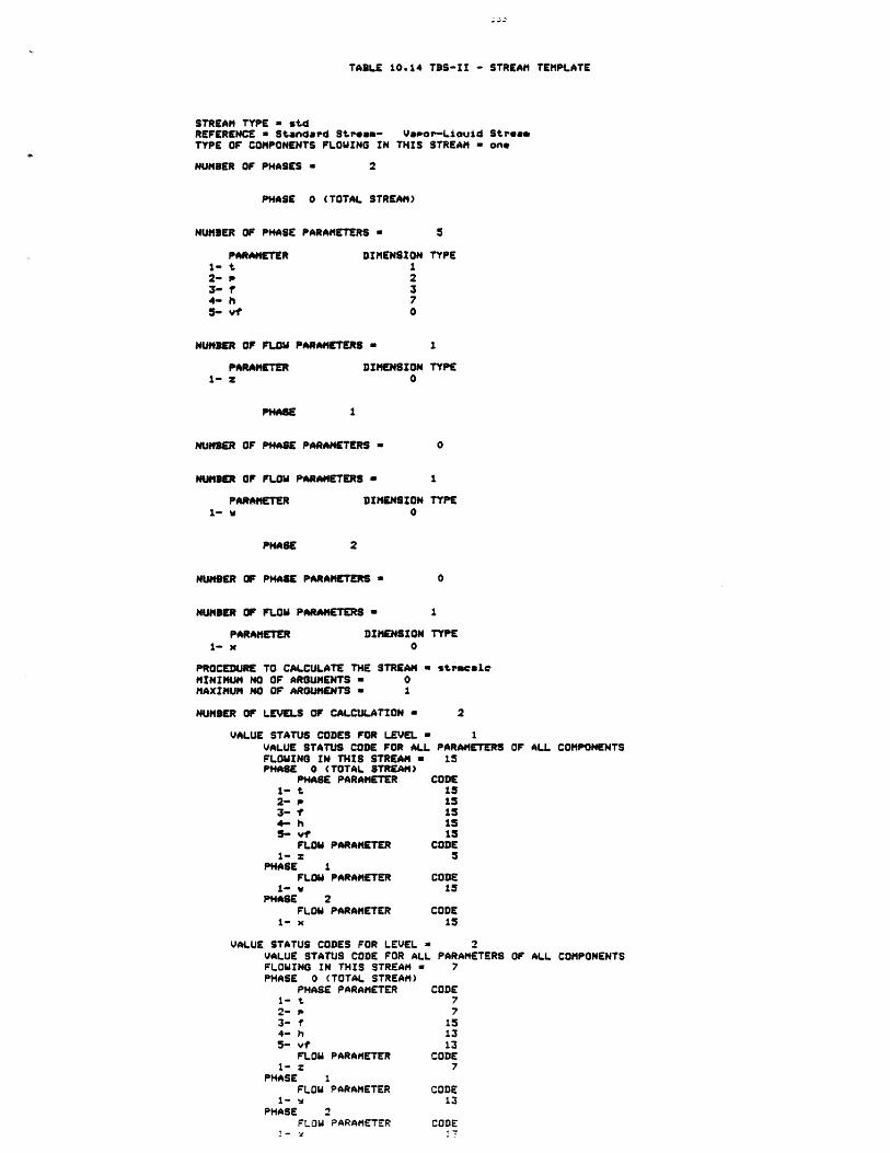
TABLE 10.14 TBS-II - STREAM TEMPLATE
STREAM TYPE - stdREFERENCE a Standard Streem- Vapor-Liauid StreafTYPE OF COMPONENTS FLOWING IN THIS STREAM - one
NUMBER OF PHASES a 2
PHASE 0 (TOTAL STREAM)
NUMBER OF PHASE PARAMETERS = 5
PARAMETER DIMENSION TYPE1- t 12- p 23- f 34- h 75- vf 0
NUMBER OF FLOW PARAMETERS 1
PARAMETER DIMENSION TYPE1- z 0
PHASE 1
NUMBER OF PHASE PARAMETERS = 0
NUMBER OF FLOW PARAMETERS = 1
PARAMETER DIMENSION TYPE1- w 0
PHASE 2
NUMBER OF PHASE PARAMETERS =
NUMBER OF FLOW PARAMETERS -
PARAMETER DIMENSION1- x 0
PROCEDURE TO CALCULATE THE STREAM =MINIMUM NO OF ARGUMENTS a 0MAXIMUM NO OF ARGUMENTS - 1
NUMBER OF LEVELS OF CALCULATION =
VALUE STATUS CODES FOR LEVEL =VALUE STATUS CODE FOR ALLFLOWING IN THIS STREAM =PHASE 0 (TOTAL STREAM)
PHASE PARAMETER1- t2- P,3- f4- h5- vf
FLOW PARAMETER1- z
PHASE IFLOW PARAMETER
1- vPHASE 2
FLOW PARAMETER1- x
VALUE STATUS CODES FOR LEVEL =VALUE STATUS CODE FOR ALLFLOWING IN THIS STREAM aPHASE 0 (TOTAL STREAM)
PHASE PARAMETER1- t2- p3- f4- h5- vt
FLOW PARAMETER1- z
PHASE 1FLOW PARAMETER
1- vPHASE 2
FLOW PARAMETER
0
1
TYPE
stracale
2
1PARAMETERS OF ALL COMPONENTS15
CODE1515151515
CODE5
CODE15
CODE15
2PARAMETERSOFALCMNET
7
CODE77
151313
CODE7
CODE13
CODE
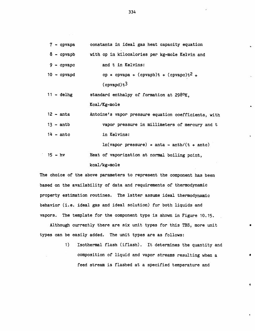
334
7 - cpvapa constants in ideal gas heat capacity equation
8 - cpvapb with cp in kilocalories per kg-mole Kelvin and
9 - cpvapc and t in Kelvins:
10 - cpvapd cp = cpvapa + (cpvapb)t + (cpvapc)t2 +
(cpvapd)t3
11 - delhg standard enthalpy of formation at 2980K,
Kcal/Kg-mole
12 - anta Antoine's vapor pressure equation coefficients, with
13 - antb vapor pressure in millimeters of mercury and t
14 - antc in Kelvins:
ln(vapor pressure) = anta - antb/(t + antc)
15 - hv Heat of vaporization at normal boiling point,
kcal/kg-mole
The choice of the above parameters to represent the component has been
based on the availability of data and requirements of thermodynamic
property estimation routines. The latter assume ideal thermodynamic
behavior (i.e. ideal gas and ideal solution) for both liquids and
vapors. The template for the component type is shown in Figure 10.15.
Although currently there are six unit types for this TBS, more unit
types can be easily added. The unit types are as follows:
1) Isothermal flash (iflash). It determines the quantity and
composition of liquid and vapor streams resulting when a
feed stream is flashed at a specified temperature and
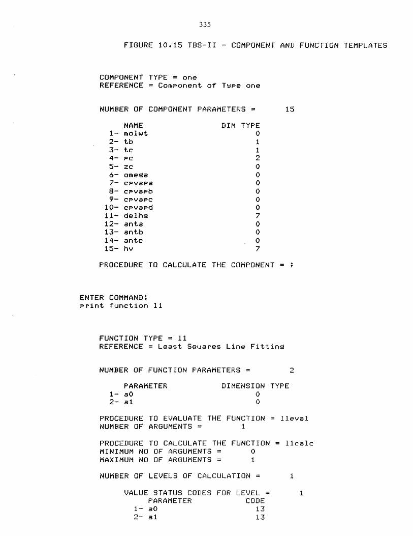
335
FIGURE 10.15 TBS-II - COMPONENT AND FUNCTION TEMPLATES
COMPONENT TYPE = oneREFERENCE = Component of Tvpe one
NUMBER OF COMPONENT PARAMETERS =
NAME1- molwt2- tb3- tc4- pc5- zC6- omesa7- cPvapa8- cavapb9- cpvasc
10- cpvapd11- delhg12- anta13- antb14-15-
DIM TYPE0
antchv
PROCEDURE TO CALCULATE THE COMPONENT = ?
ENTER COMMAND:Print function 11
FUNCTION TYPE = 11REFERENCE = Least Souares Line Fittins
NUMBER OF FUNCTION PARAMETERS
PARAMETER1- 3O
2- al
DIMENSION TYPE
PROCEDURE TO EVALUATE THE FUNCTION = 1levalNUMBER OF ARGUMENTS = 1
PROCEDURE TO CALCULATE THE FUNCTIONMINIMUM NO OF ARGUMENTS = 0MAXIMUM NO OF ARGUMENTS = 1
NUMBER OF LEVELS OF CALCULATION =
VALUE STATUS CODES FOR LEVEL =PARAMETER CODE
1- aO 132- al 13
lcalc
1
336
pressure. The template for this unit type is shown in
Figure 10.16. The calculating routine for this unit type
and the calculating routine for the stream type are both
entries of a single program which is listed in Figure
10.17.
2) Distillation. The rigorous multicomponent distillation
method of Thiele-Geddes was used in the calculating
routine of this unit. The detailed equations and
algorithms are. given in Perry [127] (equations 13-115 to
13-134). The convergence forcing procedure, the
theta-method, was also used.
The routine is rigorous in the sense that heat balances,
material balances, and equilibrium relations are applied
at each stage.
The following restrictions apply to this unit type:
a) single saturated liquid feed
b) total condenser
c) partial reboiler
d) top and bottom drawoffs only.
The template for this unit type is shown in Figure 10.18.
3) Heat Exchanger (heatex). It determines the stream outlet
temperatures and thermal duty for a counter-current one
shell and one tube heat exchanger involving single phase
fluids undergoing no phase change.

337
FIGURE 10-4 TBS-II - ISOTHERMAL FLASH UNIT TEMPLATE
UNIT TYPE - iflashREFERENCE = Isothrenal flash calculation
NUMBER OF UNIT PARAMETERS a 4
PARAMETER DIMENSION TYPE1- t.en I2- 23- mex.iter 04- tolerance
NUMBER OF INLETS 1
INLET CONNECTIONS STREAM TYPE1- in std
NUMBER OF OUTLETS a 2
OUTLET CONNECTIONS STREAM TYPE2- ovreead std3- bottom% std
PROCEDURE TO CALCULATE THE UNIT = iflashMINIMUm NO OF ARGUMENTS a 0MAXIMUM NO OF ARGUMENTS a I
NUMBER OF LEVELS OF CALCULATION a 1
VALUE STATUS CODES FOR LEVEL IUNIT PARAMETERS
PARAMETER CODE1- te" 72- pree 73- aauIter 74- tolerance 7
FOR CONNECTION a inTHIS CONNECTION IS REGUIREDSTREAM CONNECTED TO THIS CONNECTION a std
VALUE STATUS CODE OF ALL PARAMETERS OF ALL COMPONENTSFLOWING IN THIS STREAM a 7PHASE 0 (TOTAL STREAM)
PHASE PARAMETER CODE1- t 152- p 153- Y. 74-h 155-vf 15
FLOW PARAMETER CODEI- 7
PHASE IFLOW PARAMETER CODE
15PHASE 2
FLOW PARAMETER CODE1- x 15
FOR CONNECTION = overheadTHIS CONNECTION 13 REOUIREDSTREAM CONNECTED TO THIS CONNECTION std
VALUE STATUS CODE OF ALL PARAMETERS OF ALL COMPONENTSFLOWING IN THIS STREAM a 7PHASE 0 (TOTAL STREAM)
PHASE PARAMETER CODEI- t 132- 133-f 134- h 135vf .3
FLOW PARAMETER CODE1- = 13
PHASE IFLOW PARAMETER CODEv- 13
PHASE 2FLOW PARAMETER CODE
1- x 13FOR CONNECTION a bottoms
THIS CONNECTION IS REOUIREDSTREAM CONNECTED TO THIS CONNECTION a
VALUE STATUS CODE OF ALL PARAMETERS OF ALL COMPONENTSFLOWING IN THIS STREAM a 7PHASE 0 (TOTAL STREAM)
PHASE PARAMETER CODE
3- 13-- z
4- h 1
FLOW PARAMETER CODE1- : 13~HASE 1
--
PHASE
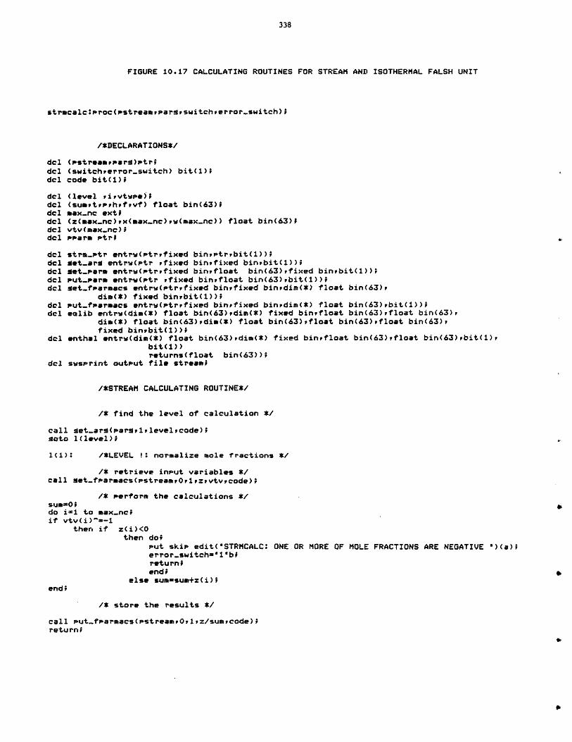
338
FIGURE 10.17 CALCULATING ROUTINES FOR STREAM AND ISOTHERMAL FALSH UNIT
strmcalc:proc(pstreampargswitcherror-switch);
/*DECLARATIONS*/
del (pstreamuParg)ptr;del (switchwerrorswitch) bit(1);del code bit(l);
del (level ,irvtwPe);del (sumptprhrfpvf) float bin(63);del max.nc extidel (z(max.nc),x(max-nc),w(max-nc)) float bin(63);del vtv(max-nc);dcl PParm Ptr;
del strm-ptr entrw(ptrefixed binptrrbit(1));del get-arg entrw(ptr ,fixed binfixed binbit(i));del met-Parm entrw(ptrpfixed binufloat bin(63),fixed binbit(1));del Put-parm entrw(Ptr rfixed binifloat bin(63),bit(1))rdel get.farmacs entrw(ptryfixed binfixed binedim(*) float bin(63),
dim(*) fixed binwbit(1));del Put-fparmacs entrw(ptrfixed binfixed binedim(*) float bin(63),bit(1));del ealib entrw(dim(*) float bin(63),dim(*) fixed binfloat bin(63),float bin(63),
dim(*) float bin(63),dim(*) float bin(63),float bin(63),float bin(63),fixed binrbit(1))i
del enthal entrw(dim(*) float bin(63),dim(*) fixed binfloat bin(63)vfloat bin(63),bit(1),bit(1))returns(float bin(63));
del swsprint output file streami
/*STREAM CALCULATING ROUTINE*/
/* find the level of calculation */
call get-arg(pargelplevelcode);goto 1(level)o;
IC1): /*LEVEL !* normalize mole fractions */
/* retrieve input variables */call get-fParmacs(stream,0,1,zvtvvcode);
/* Perform the calculations */sum=0;do i-1 to max.nceif vtv(i)"=-1
then if z(i)<Othen do;
Put skip edit("STRMCALC: ONE OR MORE OF MOLE FRACTIONS ARE NEGATIVE ")(a);error.switch="1"bereturn;end;
else sum-sum+z(i);end;
/* store the results */
call put-farmacs(stream,0,1ez/sumacode);returni
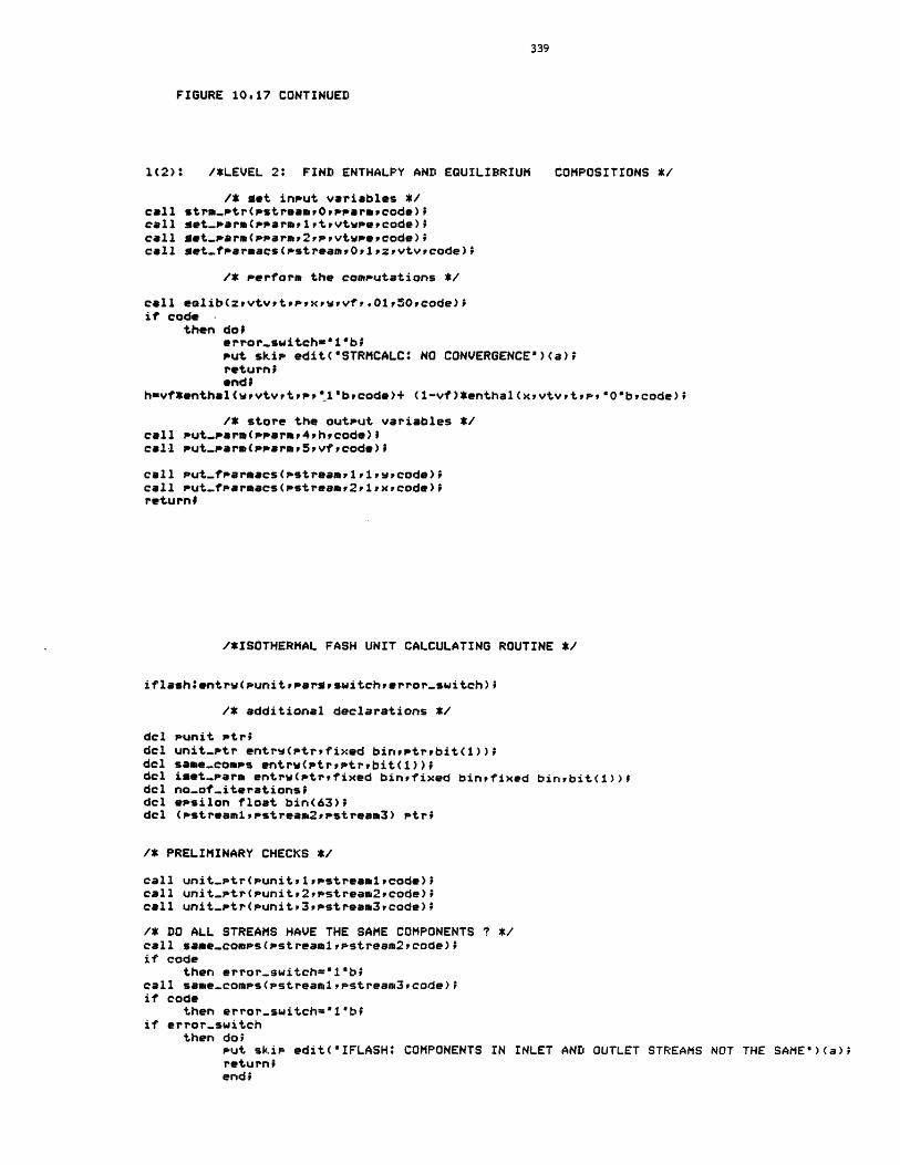
339
FIGURE 10.17 CONTINUED
1(2): /*LEVEL 2* FIND ENTHALPY AND EQUILIBRIUM COMPOSITIONS */
/* get input variables */call stem-ptr(pstreamp0pPraropcode);call get-Parm(pparm1rtrvtwpecode);call get-Parm(PParmr2rpyvtwPecode);call set-fparmacs(pstreamOplzpvtvecode);
/* Perform the computations */
call eolib(zpvtvetrpexrwryvF.01,5Ocode)$if code -
then doferror.switch="1"b;Put skip edit("STRMCALC: NO CONVERGENCE")(a);returnOend;
huvf*enthal(wevtvetpr".1"brcode)+ (1-vf)*enthal(xivtvrptp,*O"becode);
/* store the output variables */call Put-par(psarmr4rbrcode);call put-Parm(Pparmr5yvficode);
call Put-faracs(pstreamv1i,,wpcode);call put-farmas(pstrear2,1,xecode);return;
/*ISOTHERMAL FASH UNIT CALCULATING ROUTINE */
iflashientrw(punitrpargswitchterror-switch);
/* additional declarations */
dcl punit Ptridel unit-ptr entrw(ptrfixed binptrbit(1));del same.comps entrw(Ptreptrbit(1));dcl iset-parm entrw(ptrfixed bingfixed binfixed binbit(1));del no-of-iterations;dcl epsilon float bin(63);del (pstreamlpstream2ppstream3) Ptrf
/* PRELIMINARY CHECKS */
call unit-tr(unit,1ipstreamlrcode);call unit-ptr(punit,2,pstream2,code);call unit-ptr(punitt3,pstream3,code);
/* DO ALL STREAMS HAVE THE SAME COMPONENTS ? */call same-comps(streamlrpstream2,code);if code
then error.switch-"1"bycall same-comps(pstreamrpstream3rcode);if code
then error-switch="1"b;if error-switch
then do;Put skip edit("IFLASHi COMPONENTS IN INLET AND OUTLET STREAMS NOT THE SAME')(a);return;end;
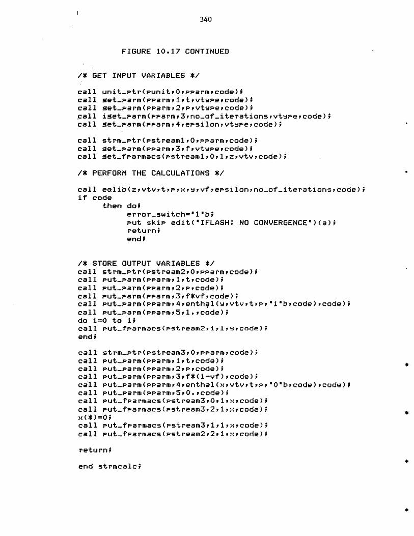
340
FIGURE 10*17 CONTINUED'
1* GET INPUT VARIABLES *
call uriit...tr(uritv~ypparrncode)fcall Met..parn(pparrn,1,trvtpepcode)^call ae-ampam~yptppoev
call get...parr(pparrn,4epsiloripvtvyi~code)p
call strrn..tr(pstream1,0,pp'arrnpcode)^call aet-parm(pparrn,3,fpvtypevcode)'call get...fparracs(pstrearn1,0,1zpvtvpcode)$'
1* PERFORM THE CALCULATIONS *1
call eolib(zpvtvtppxpvfeps~o~ion...of-.iterationspcode)'if code
then dol~error..switch=110brPut skip edit(OIFLASH* NO CONVERGENCE")(a)preturnPendp'
1* STORE OUTPUT VARIABLES *1call strm-..tr(pstream2,0,pparrnpcode)'call Put...parr(armlptycode)ycall Put...parw(pparrn2pycode)'call Put...parr(,arrn,3f*vfycode);call Put...parr(pparrn,4,erthal (vyvtvytp','call Put...parm(parrn,5,1*Pcode);do i=0 to 1;^call Put..fparmacs(pstream2,iriwcode)^endr
call strm-...tr(pstrear3,0,pparrnpcode)^call Put...Parr(PParr1t~code)1'call PuL..parr(pparp2pcode)p*call Put...parr(pparn~p3f*(-vf),code)pcall PuL..parm(pF'arrn4,erthal(,vtvptppcall Put-Parrn(pParrn,5,0+code)'call Put-fparniacs(pstrearn3,0,1,x.tcode)^call Put-fp'arracs(pstrearn3v2pl,,rcode)*P
call Put..fparnacs(pstrear3,1,1,x*.code)4call Put-..Tharnacs(pstrear22,1,xpcode)P
a
1 'bycode) ,code);
O'bvcode) ,code)v
return;
en~d strrncalc?'
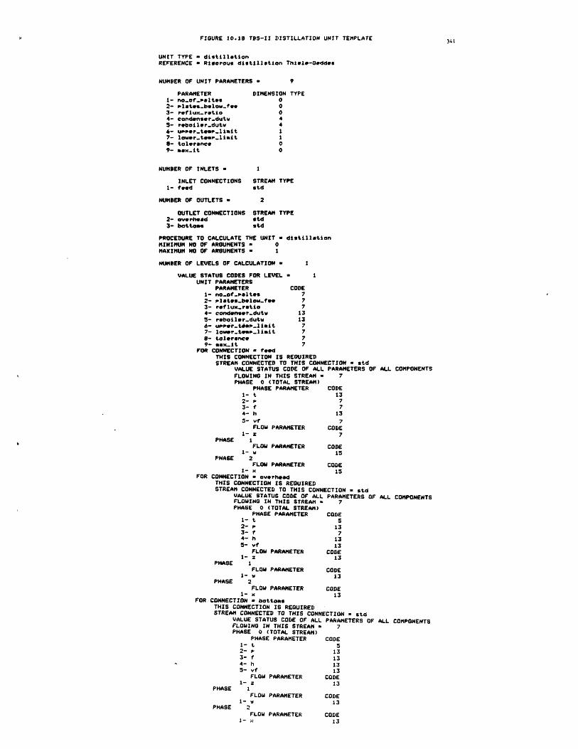
FIGURE 10.18 TFS-II DISTILLATION UNIT TEMPLATE
UNIT TYPE - distillationREFERENCE - Risorous distillation Thiele-Geddes
NUMBER OF UNIT PARAMETERS a 9
PARAMETER DIMENSION TYPE1- noof.altes 02- plates-below-fee 03- reflux-ratio 04- condenser-dutw 45- rebailer-dutv 46- u.er..teo.-limit 17- lower.team.limit 19- tolerance 09- mex-it 0
NUMBER OF INLETS I
INLET CONNECTIONS STREAM TYPE1- feed std
NUMBER OF OUTLETS = 2
OUTLET CONNECTIONS STREAM TYPE2- overhead std3- bottoms std
PROCEDURE TO CALCULATE THE UNIT = distillationMINIMUM NO OF ARGUMENTS a 0MAXIMUM NO OF ARGUMENTS - 1
NUMBER OF LEVELS OF CALCULATION a 1
VALUE STATUS CODES FOR LEVEL = 1UNIT PARAMETERS
PARAMETER CODE1- no-of-paltes 72- Plates-below.fee 73- reflux.ratio 74- condenser-dutw 135- reboiler.dut 136- uppr-t#ap-liait 77- lower.temp-limit 7a- tolerance 79- max-it 7
FOR CONNECTION - feedTHIS CONNECTION IS REQUIREDSTREAM CONNECTED TO THIS CONNECTION = std
VALUE STATUS CODE OF ALL PARAMETERS OF ALL COMPONENTSFLOWING IN THIS STREAM = 7PHASE 0 (TOTAL STREAM)
PHASE PARAMETER CODE1- t 132- p 73- f 74- h 135- vt 7
FLOW PARAMETER CODE1-z 7
PHASE 1FLOW PARAMETER CODE
I- w 15PNASE 2
FLOW PARAMETER CODE1- x 15
FOR CONNECTION - overheadTHIS CONNECTION IS REQUIREDSTREAM CONNECTED TO THIS CONNECTION s std
UALUE STATUS CODE OF ALL PARAMETERS OF ALL COMPONENTSFLOWING IN THIS STREAM = 7PHASE 0 (TOTAL STREAM)
PHASE PARAMETER CODE1- t 52- p 133- f 74- h 135- vt 13
FLOW PARAMETER CODE1- z 13
PHASE IFLOW PARAMETER CODE
I- w 13PHASE 2
FLOW PARAMETER CODE1- x 13
FOR CONNECTION - bottomsTHIS CONNECTION IS REQUIREDSTREAM CONNECTED TO THIS CONNECTION - std
VALUE STATUS CODE OF ALL PARAMETERS OF ALL COMPONENTSFLOWING IN THIS STREAM = 7PHASE 0 (TOTAL STREAM)
PHASE PARAMETER CODE1- t 52- p 133- f 134- h 135- vf 13
FLOW PARAMETER CODE1- z 13
PHASE IFLOW PARAMETER CODE
1-v 13PHASE 2
FLOW PARAMETER CODE1- x 1:
342
4t) Add. It adds two streams and determines the product
stream. It has two levels of calculation. Level one is
only for material balancing. Level two is for both
material and heat balancing. For level two of calculation
both inlet streams should be either vapor or liquid. The
outlet stream temperature is determined by a heat
balance. The output stream pressure is assumed to be
equal to the minimum of the inlet stream pressures.
5) Splitter. It separates an input stream into two output
streams, each having the same composition, temperature,
and pressure as the input. The distribution factor which
is the unit parameter specifies the flow rate of each
output stream as a fraction of the flow rate of the input
stream.
6) Convergence (convg). It is a psuedo unit type which is
used for stream convergence. Streams to be converged are
input and output to this unit. The test for convergence
is based on the total flow rate and composition. In other
words, the unit indicates convergence, if the following
relations are true:
in - fout 1 fin I <= tolerance
(zini - zout,i)/zin,il <= tolerance
for all components

343
If the above test fails then the output stream is set to
be equal to the input stream.
The calculating routine for this unit type can perform two
levels of calculation. In level one, given the unit
parameters (i.e. maximum number of iterations, tolerance,
etc.), and inlet and outlet streams, it tests for
convergence as described above. In level two it
initializes the unit parameters to the default values.
Some of the above calculating routines call upon physical and
thermodynamic property estimation routines, for various functions.
Although these property estimation routines have been based on simplified
assumptions regarding the thermodynamic behavior of liquid and vapor
mixtures, they could easily be replaced with more realistic models
without requiring any change in calculating routines. Table 10.1 lists
the property estimation methods currently implemented for this TBS.
There are two options for estimating vapor pressure: (1) Antoine's
equation, and (2) Riedel's equation [140] . The template of the property
estimation methods table which is shown in Figure 10.13 indicates that
the user of this TBS is allowed to choose either of these methods at any
time. If the user does not specify the method the default would be
Antoine's equation. The templates of the TBS control information and
dimension table are also shown in Figure 10.13.
A pre-defined function has been established for this TBS to
demonstrate the implementation and application of such functions. The
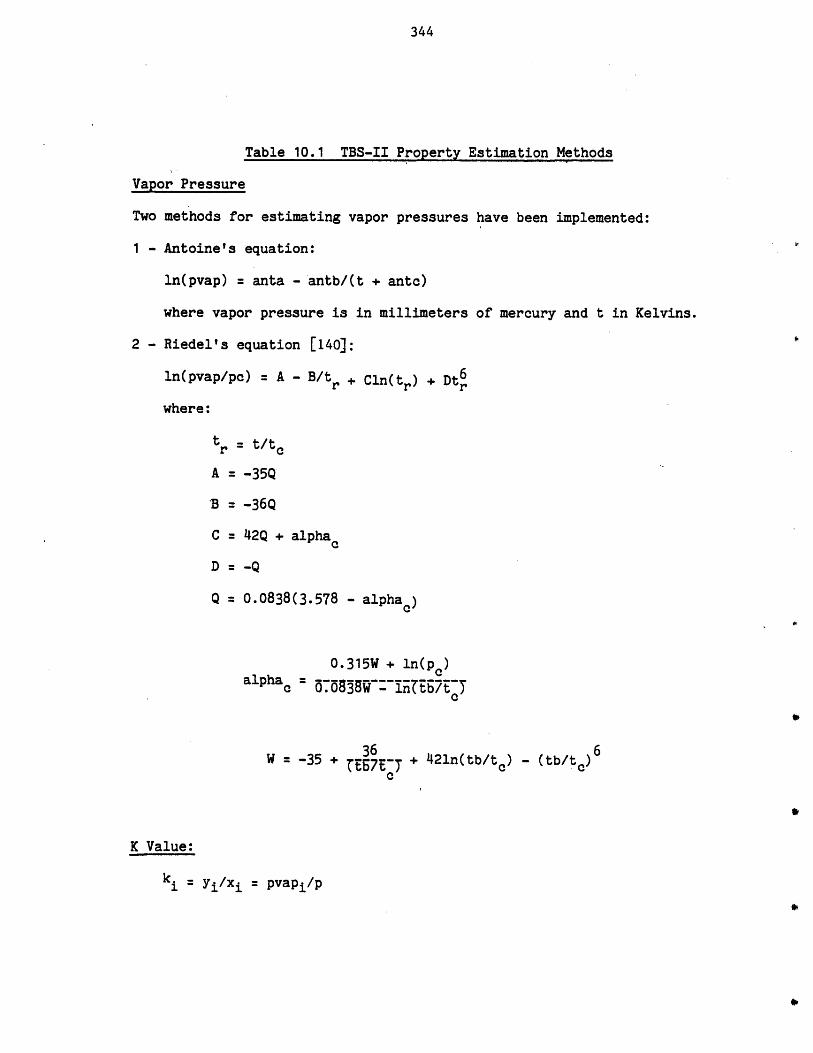
344
Table 10.1 TBS-II Property Estimation Methods
Vapor Pressure
Two methods for estimating vapor pressures have been implemented:
1 - Antoine's equation:
ln(pvap) = anta - antb/(t + antc)
where vapor pressure is in millimeters of mercury and t in Kelvins.
2 - Riedel's equation [140]:
ln(pvap/pc) = A - B/tr + Cln(tr) + Dt6
where:
tr t/tc
A = -35Q
'B = -36Q
C 42Q + alpha
D -Q
Q = 0.0838(3.578 - alpha.)
0.315W + ln(p )alphac = 5~5 ln~-Itb/7E-
cc
36 6W = -35 + 7 + 421n(tb/t) - (tb/t )
K Value:
k, = yi/xi = pvapi/p
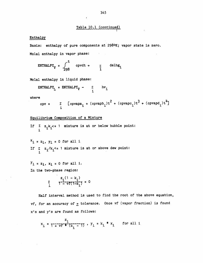
345
Table 10,1 (continued)
Enthalpy
Basis: enthalpy of pure components at 298oK; vapor state is zero.
Molal enthalpy in vapor phase:
t.ENTHALPY f cpvdt +-i delhg.
~298 1
Molal enthalpy in liquid phase:
ENTHALPYL ENTHALPYv - E hv.1
where
cpv Z [cpvapa + (cpvapb )t2 + (cpvapc )t3 + (cpvapd )t ]
Equilibrium Composition of a Mixture
If E z.k.<= 1 mixture is at or below bubble point:. 1 11
xi = zi, yi =0 for all i
If E z /k.<= 1 mixture is at or above dew point:
71 = zi, xi = 0 for all i.
In the two-phase region:
z.(1 - k.)1 1 - 0
Half interval method is used to find the root of the above equation,
vf, for an accuracy of + tolerance. Once vf (vapor fraction) is found
x's and y's are found as follows:
z=
x. = -~~----"--1 ~~i'i= k. * x for all i
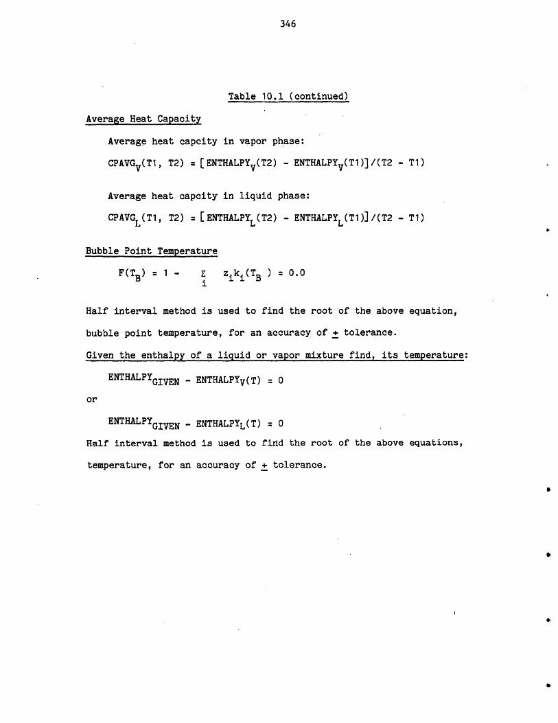
346
Table 10.1 (continued)
Average Heat Capacity
Average heat capcity in vapor phase:
CPAVGv(T1, T2) = [ENTHALPYV(T2) - ENTHALPYv(T1)]/(T2 - T1)
Average heat capcity in liquid phase:
CPAVGL(T1, T2) = [ENTHALPYL(T2) - ENTHALPYL T1)]/(T2 - T1)
Bubble Point Temperature
F(TB) = 1 - zk i(TB ) 0.0
Half interval method is used to find the root of the above equation,
bubble point temperature, for an accuracy of + tolerance.
Given the enthalpy of a liquid or vapor mixture find, its temperature:
ENTHALPYGIVEN - ENTHALPYV(T) = 0
or
ENTHALPYGIVEN - ENTHALPYL(T) = 0
Half interval method is used to find the root of the above equations,
temperature, for an accuracy of + tolerance.
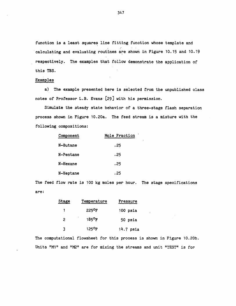
347
function is a least squares line fitting function whose template and
calculating and evaluating routines are shown in Figure 10.15 and 10.19
respectively. The examples that follow demonstrate the application of
this TBS.
Examples
a) The example presented here is selected from the unpublished class
notes of Professor L.B. Evans-[29] with his permission.
Simulate the steady state behavior of a three-stage flash separation
process shown in Figure 10.20a. The feed stream is a mixture with the
following compositions:
Component Mole Fraction
N-Butane .25
N-Pentane .25
N-Hexane .25
N-Heptane .25
The feed flow rate is 100 kg moles per hour. The stage specifications
are:
Stage Temperature Pressure
1 2250F 100 psia
2 185 0F 50 psia
3 125 0F 14.7 psia
The computational flowsheet for this process is shown in Figure 10.20b.
Units "M1" and "M2" are for mixing the streams and unit "TEST" is for
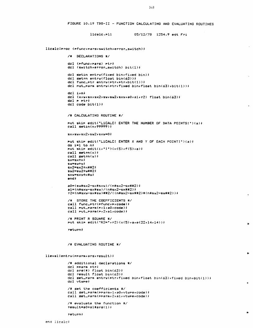
FIGURE 10.19 TBS-II - FUNCTION CALCULATING AND EVALUATING ROUTINES
05/12/78 1254.9 edt Fri
l1calciproc (Pfuncrpargswitcherror-switch);
/* DECLARATIONS */
dcl (Pfuncrpara) Ptridcl (switcherror-switch) bit(1);
dcl getin entrw(fixed bintfixed bin);dcl getrn entrw(float bin(63));dcl func-.tr entrw(ptryptrbit(1));del Put-parm entrw(ptryfixed binyfloat bin(63),bit(1));
del irn;del (xrwsxtsx2,swsw2psxwaOrarr2) float bin(63);dcl P Ptr;del code bit(1);
/* CALCULATING ROUTINE */
Put skip edit("L1CALCO ENTER THE NUMBERcall getin(nv99999);
OF DATA POINTS:")(a);
sxpswpsx2psw2,sxw-0;
Put skip sdit("L1CALC: ENTER X AND Y.OFdo im1 to n;Put skip edit(iy'*")(x(5),f(5),a);call getrn(x);call metrn(w);sx-sx+x;sw=sw+w;sx2=sx2+x**2;sw2=sw2+w**2;sxw=sxw+x*w;
end;
EACH POINT'")(a);
aO=(sw*sx2-sx*sxw)/(n*sx2-sx**2);a1=(n*sxw-sx*sw)/(n*sx2-sx**2);r2=(n*sxw-sx*sw)**2/((n*sx2-sx**2)*(n*ss2-sw**2));
/* STORE THE COEFFICIENTS */call func-ptr(pfuncrecode);call put-parm(P1riaOrcode);call Put-parm(pr2raircode);
/* PRINT R SQUARE */Put skip edit("R2=",r2)(x(5),ave(22,14,14));
return;
/* EVALUATING ROUTINE */
l1evalientrw(pparmargresult);
/* additional declarations */del Pparm Ptr;del arg(*) float bin(63);del result float bin(63);del set-parm entrw(ptrrfixed binpfloat bin(63),fixed binrbit(1));dcl vtwee;
/* get the coefficients */call set-parm(pearmrlpaOrvtwpecode);call get-Parm(pparmr2,saivtwyePcode);
/* evaluate the function */result=a0+a1*ars(1);
return;
end 11calc;
11calc.p11
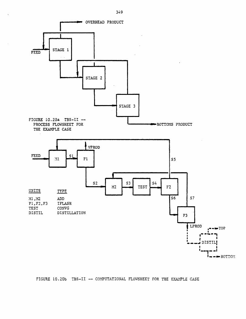
349
- OVERHEAD PRODUCT
FEED ~
FIGURE 10.20a TBS-II --PROCESS FLOWSHEET FORTHE EXAMPLE CASE
FEED
UNITS
M1 ,M2Fl,F2,F3TESTDISTIL
TYPE
ADDIFLASHCONVGDISTILLATION
.... SDISTILl
o S
i- -sm- BOT TOM
FIGURE 10.20b TBS-II -- COMPUTATIONAL FLOWSHEET FOR THE EXAMPLE CASE
PRODUCT
LPROD,--emTOPI
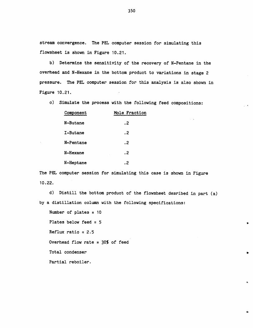
350
stream convergence. The PEL computer session for simulating this
flowsheet is shown in Figure 10.21.
b) Determine the sensitivity of the recovery of N-Pentane in the
overhead and N-Hexane in the bottom product to variations in stage 2
pressure. The PEL computer session for this analysis is also shown in
Figure 10.21.
c) Simulate the process with the following feed compositions:
Component Mole Fraction
N-Butane .2
I-Butane .2
N-Pentane .2
N-Hexane .2
N-Heptane .2
The PEL computer session for simulating this case is shown in Figure
10.22.
d) Distill the bottom product of the flowsheet desribed in part (a)
by a distillation column with the following specifications:
Number of plates 10
Plates below feed 5
Reflux ratio = 2.5
Overhead flow rate = 30% of feed
Total condenser
Partial reboiler.
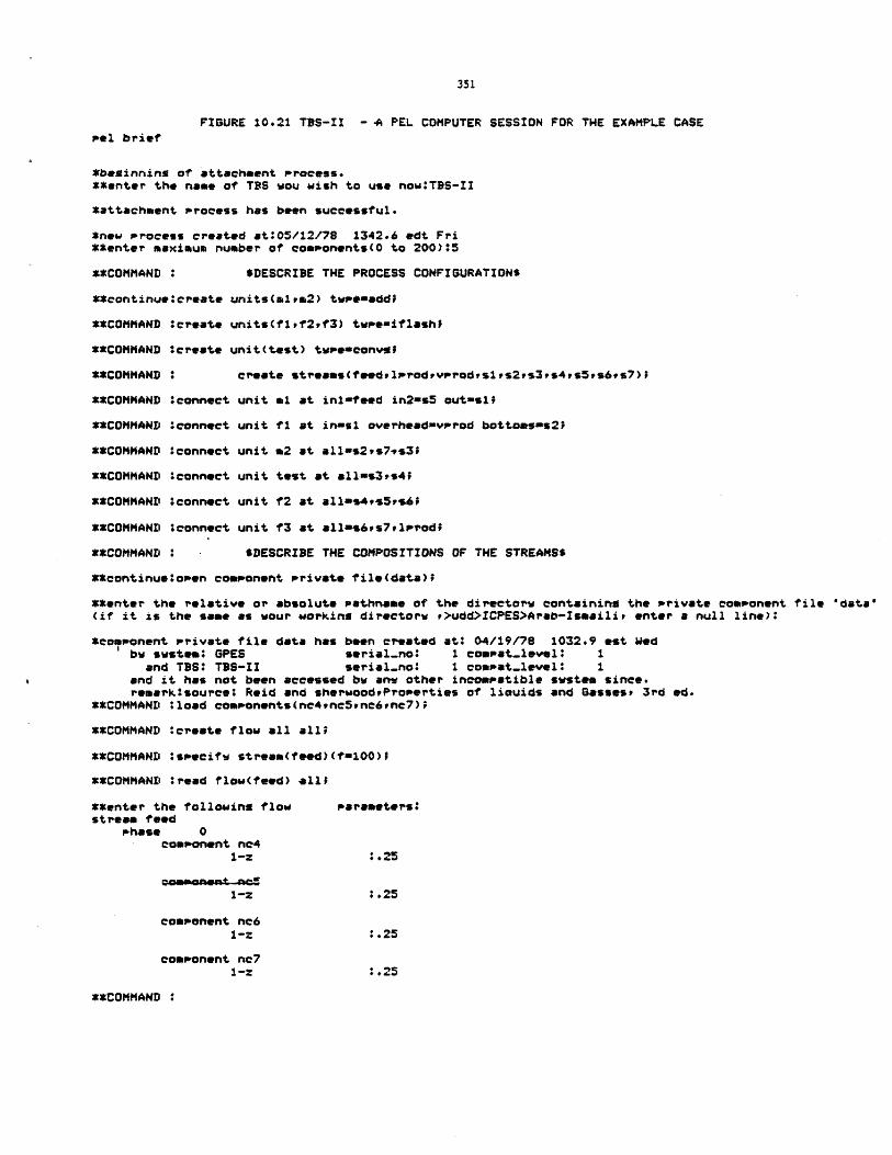
FIGURE 10.21 TBS-II - A PEL COMPUTER SESSION FOR THE EXAMPLE CASE
Pol brief
*beginning of attachment Process.**enter the name of TBS wou wish to use now:TBS-II
*attachment process has been successful.
*new Process created at:05/12/7S 1342.6 edt Fri**enter maximum number of comsonents(O to 200):5
**COMMAND : $DESCRIBE THE PROCESS CONFIGURATION$
**continue:create units(mlya2) tweinadd;
**COMMAND *create units(f1lf2,f3) tvpemiflashf
**COMMAND ereate unit(test) twPeeconvgi
**COMMAND : create streams(feedelprodpvprodvsirs2,s3,s4vs5,s6,s7);
**COMMAND connect unit al at inlfteed in2=s5 out-isl
**COMMAND *connect unit fi at in-si overheadnvprod bottosms2;
**COMMAND :connect unit m2 at allis2,s7vs3;
**COMMAND :connect unit test at all-s3rs4;
**COMMAND :connect unit f2 at alls4vs5ps6f
**COMMAND :connect unit f3 at allas6,s7,ilpod;
**COMMAND $DESCRIBE THE COMPOSITIONS OF THE STREAMS$
**continue*open component private file(data);
**enter the relative or absolute pathname of the directorw containing the Private component file "data"(if it is the same as wour working directorw ,>udd>ICPES>Arab-Ismaili, enter a null line):
*component private file data has been created at: 04/19/78 1032.9 est Wedbw swstem: OPES serial.no: 1 compat.level: I
and T9S: TBS-II serial.no* 1 compat.level: 1and it has not been accessed bw env other incompatible system since.remark*source: Reid and sherwoodProperties of liouids and Gassest 3rd ed.
**COMMAND **load components(nc49nc5rnc6,nc7);
**COMMAND :creete flow all all;
**COMMAND :ssecifw streem(feed) (f-100);
**COMMAND :read flow(feed) ll;
**enter the following flow parameters:stream feed
Phase 0component ne4
1-z :.25
1-z :.25
component nc61-Z 0.25
component nc71-2 :.25
**COMMAND :
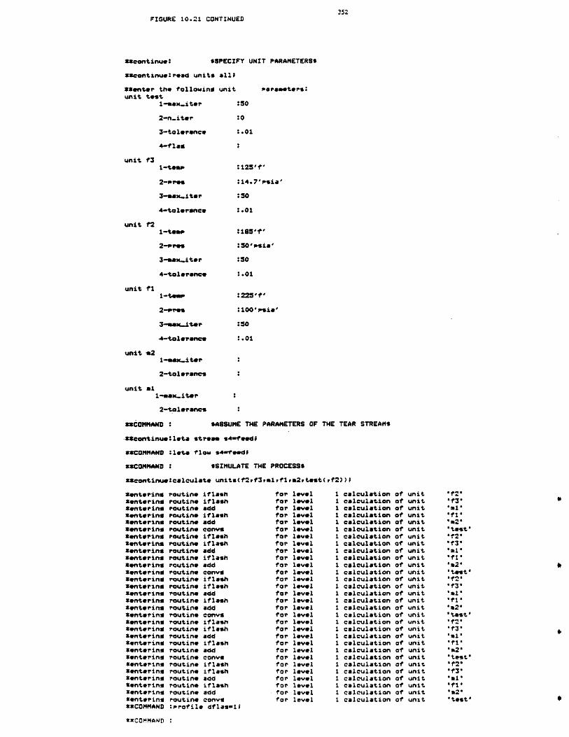
FIGURE 10.21 CONTINUED
**continue: sSPECIFY UNIT PARAMETERS$
**continue:read units all
**enter the following unitunit test
1-Sax-iter
2-n-iter
3-tolerance
4-flas
unit f31-teos
3-sax-iter
4-tolerance
unit f21-temp
3-sex..iter
4-tolerance
unit fi
4-tolerance
unit *21-max-iter
2-tolevranes
unit &l1-max-iter
2-tolerancs
**COMMAND:
peraeeters:
:50
:0
.01
:125'f'
:14.7'psia'
:50
:.01
:185'1'
:50'ps.ia'
:50
:.01
225'f'
:100'sia'
.01
SASSUME THE PARAMETERS OF THE TEAR STREAM$
**continue:leta stream s4=feedf
*CCOMMAND :Ita flow s4=feedf
*COMMAND : $SIMULATE THE PROCESS$
*Ccontinueocalculate units(f2rf3,mlflta2rtest(Cf2))I
routine iflashroutine iflashroutine addroutine iflashroutine addroutine convyroutine iflashroutine iflashroutine addroutine iflashroutine addroutine convsroutine iflashroutine iflashroutine addroutine iflashroutine addroutine convsroutine iflashroutine iflashroutine addroutine iflashroutine addroutine converoutine iflashroutine iflashroutine addroutine iflashroutine addroutine convi:Profile dflas-1;
for levelfor levelfor levelfor levelfor levelfor levelfor levelfor levelfor levelfor levelfor levelfor levelfor levelfor levelfor levelfor levelfor levelfor levelfor levelfor levelfor levelfor levelfor levelfor levelfor levelfor levelfor levelfor levelfor levelfor level
calculation of unitcalculation of unitcalculation of unitcalculation of unitcalculation of unitcalculation of unitcalculation of unitcalculation of unitcalculation of unitcalculation of unitcalculation of unitcalculation of unitcalculation of unitcalculation of unitcalculation of unitcalculation of unitcalculation of unitcalculation of unitcalculation of unitcalculation of unitcalculation of unitcalculation of unitcalculation of unitcalculation of unitcalculation of unitcalculation of unitcalculation of unitcalculation of unitcalculation of unitcalculation of unit
*entering*entering*entering*entering*entering*enteringCentering*entering,*entering*entering*entering*entering*entering*entering*enterinsCentering*entering*entering*entering*entering*entering*entering*entering*entering*entering*entering*enteringCentering*entering*entering**COMMAND
'f2"* f3'
*f1'
"test'*f2'sf3'
*fl*
'm2'"test'"f2'
"f3'
'al'
'a2*' test''f2'Of3'
"al''f 1"* a2"'test'"12"'f3'
"al'"ft''m2'0 test I
"ZCOMMAND :
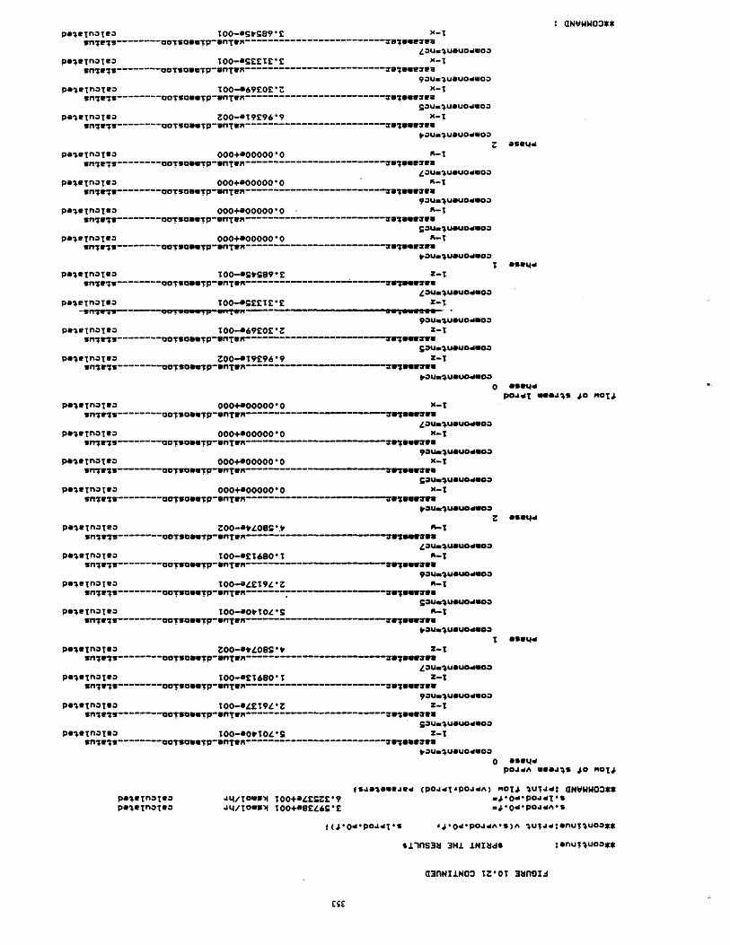
poen~aTOO-.sEETVC X-TSm~rlOO-------- cjTS-------------------------------------7urvesw
pae~aTeaT3 TOO-06?EO*Z x-Tsnww-------- OOsauwTp-wn~W------------------------------- W'361ufva
Gaumusuo~woaPelf~nOTOO zOO-*T?96969 X-T
avTsoSUTfl-W-------------------------------- Baza
Ps' EMOTQOO00+0000000 -3fl~ff~---------- aO!UOsUTp-vnTW--------------------------- --- Zv 899waW
ZOUMuOuo4Goa
snl7 -------- OOTIOUSTP6nTw------------------------------ 87"Wava
Ps'6TflaTsa OOO+*000000 1-Wn~~~~ffOUTTfl ---------- CTCNP*TR ------------------------- 6" S
PO1EfTnQTRQ 000+0000000O'O-unes-------- OOTUODUTP-NnTW------------------------------- Vewerme
POI&TnlsoT OO-svG89*E Z-Twn~~~r7OO W U nT----------CTCGPw~x ------------------------- 7fww~
Pb1eTnOTROTO*ET~ Z-1
po~e~nalea 1O-69EOE*SZ-snlaOSam~pflU----------a~cwpwTx ------------------ ----- arvahW
poe3nOTRO ZOO-SMY9609 Z-Tsnes---------CrOSurwP-lTW-------ou~mo
0
PGI*TnOTOD 000+0000000 -snrs-------- coruoeurp-Iw------------------- --- IlwalwaW
p~~aw 00+000000oo0 N-T
pale~naleao00+*000.0o-snOTOSTUfwW---------------cTcwP-f~n ----------- ---- VN7UU3wzUr
pela~na~taO00+0000000 -Wnrw-------- UCTSoIwTP-nTWX----- ---- w;vwauu
voungusuodwoo
P*ItTnQTeO z00-svzOes.v .~5fl$W----------- MOTSODU!P-onTR--- -U -----
ZaUw4u~uodUo*
pe-4alnOTOD O0-*ET690*1T-sn;.------O5OT fT---------CTCMPv~m --------------------- Tw~nwar
90UMIU@OU46
Psle~O~eD 00-0*ET9z zsilei;--------oor~ouwwTp-*nnwR fUsUWuwu~u~
POI&TnOTe* TOO-0VOVS 0LTsnjw7W e~pun~v---------OTCOP6Tn --------------------- welawivua
SnOg---- OTSONNTPD"T*R -W7EUW-W3ZOUMIUSU04000
pelv~naleaTOO-OET680O Z-sn~wl---------OCIoautp-nTw-------------------------vleww
pa1*TnQTOQ TO-04E~T9*Z Z-Tin~;-------O~O3~pflW------------------------------- N69o
QZUftUGuOdSOQPs*TOOD10-*00&iOzo Z-1
in;;-------oo~ou.p-3l~------------------------- WIIGWCVuvauftlusuedsoa
PO1WNflOTOOPSOTflOTIO
aNVWW03**
*5@L4d
OS04,d
POs&d ULSo O
O5@t4d
o &5344PO44A U94,4 jto M014
f5AeOeSSJ94 (POJdj4POJ4A) M01T4 lJT40 aNVWW03**Jt/TOUwwA 100O+4EZ9 W4*0aPO1jdUsJ4/TOU5W4 TOO+RBE469*E w4*04POJaA*S
(J04*PO4jdT d0*P.AdA*S)A ju;j:nut4uo***
*±fsiins 3H.L INI~4s :Onulluoo**
'33nNIINO Tz~oT 3mnifI
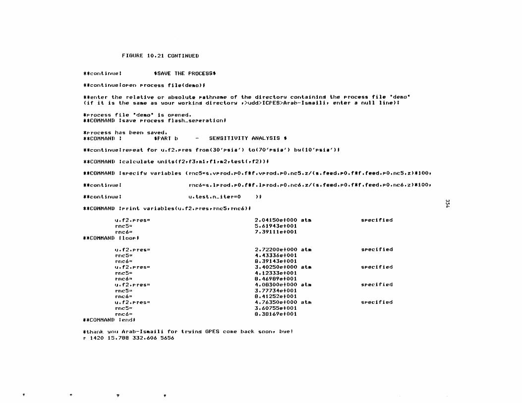
FIGURE 10.21 CONTINUED
**cont inue I $SAVE THE PROCESS$
**continue open Process file(demo)#
**enter the relative or absolute Pathname of the directorw containing the Process file 'demo"(if it is the same as sour working directorw r>udd>ICPES>Arab-Ismailir enter a null line)?
*Process file "demo" is opened.**COMMAND ?save Process flash-seerationl
*process has been saved.**COMMAND : $PART b - SENSITIVITY ANALYSIS $
**continuetrepeat for u.f2.Pres from(30'psia') to(70'psia') bw(i0'Psia')l
**COMMAND tcalculate units(f2vf3vmlflrm2rtest(vf2))
**COMMAND :specifv variables (rnc5=sevprodPO.f*fevprod.PO.nc5ez/(sofeedePO.f*fefeedePO~nc5ez)*100.
rnc6=s.lprod.POef*flprodPO.nc6ez/(sofeed.PO.f*fefeedeP0.nc6.z)*100**continue:
**continuel u.testen-iter=0
**COMMAND tPrint variables(uf2*Presrrnc5rrnc6)1
usf2*pres=rnc5=rnc6=
**COMMAND :loop$
u. f2 P res=rnc5=rnc6=u.f2.Pres=rnc5=rnc6=u.f2.Pres=
rnc5=rnc6=u*f2.pres=rnc5=rnc6=
**COMMAND :endf
2e04150e+0005e61943e+0017.39111e+001
2#72200e+0004.43336et0018.39143e+0013e40250e+0004.12333e+0018.46989e+0014#08300e+0003.77734e+0018.41252e+0014.76350et000)3e60755e+0018.38169et001
atm
atm
atm
atm
atm
specified
specified
specified
specified
sPecif ied
*thank you Arab-Ismaili for trwing GPES come back soony buelr 1420 15.788 332.606 5656
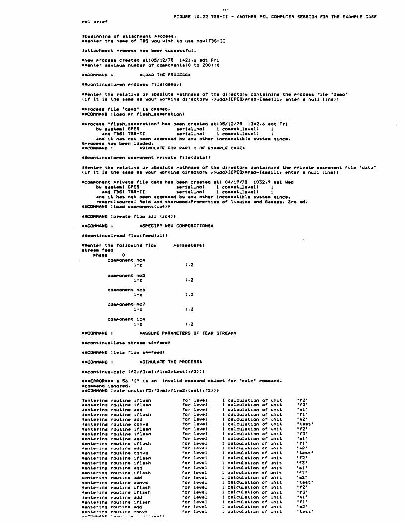
FIGURE 10.22 TBS-II - ANOTHER PEL COMPUTER SESSION FOR THE EXAMPLE CASEPel brief
*beginnins of attachment process.**enter the name of TBS wou wish to use now:TBS-II
*attachment process has been successful.
*new process created at:05/12/78 1421.6 edt Fri**enter maximum number of components(0 to 200):0
**COMMAND : $LOAD THE PROCESS$
**continueiopen Process file(demo)lI
**enter the relative or absolute Pathname of the directorw containing the Process file 'demo'(if it is the same as wour working directorw t>udd>ICPES>Arab-Isaaili, enter a null line)?
*Process file 'demo" is opened.**COMMAND ;load Pr flash-seserationi
*srocess "flash.seperation' has been created at:05/12/79 1342.6 edt Friby swstemS GPES serial-no I compet-level: 1
and TBSI TBS-II serial-no; 1 cospat-level: Iand it has not been accessed bw anu other incompatible swstem since.
*Process has been loaded.**COMMAND I $SIMULATE FOR PART c OF EXAMPLE CASES
*Ccontinualopen component Private file(data)f
**enter the relative or absolute pathname of the directorw containing the private component file "data'(if it is the same as wour working directorw ,>udd>ICPES>Arab-Ismaili enter a null line):
*component private file data has been created at: 04/19/78 1032.9 est Wedbw smstemS GPES serial.nos I cospat-level: 1
and TBS: TBS-II serialnot 1 comset-level: 1and it has not been accessed bw any other incompatible swotem since.resark:sourcel Reid and sherwoodiProperties of liouids and Gasses* 3rd ed.
**COMMAND Iload component(ic4)
**COMMAND :create flow all (ic4)I
**COMMAND : SSPECIFY NEW COMPOSITIONSS
**continuegread flow(feed)alli
**enter the following flowstream feed
shase 0component nc4
1-z
component nc51-Z
component nc6
perameterss
1.2
;.2
coeaat-.nc L-
1-z
component ic41-2
**COMMAND : SASSUME PARAMETERS OF TEAR STREAMS
**continuegleta stream s4mfeedf
**COMMAND :leta flow s4-feedi
**COMMAND : $SIMULATE THE.PROCESS6
**continuelcale (f2,f3,mlmfla2,testf2))D
***ERROR*** s 56 '' is an invalid command obJect*command ignored.**COMMAND scalc units(f2,f3,mlfiam2,test(,f2))0
*enterinsCenteringCentering*entering*entering*enteringCentering*enteringCentering$entering*enteringCentering*entering*entering*entering*entering*enterins*enteringCentering*entering*enteringCenteringCentering*enterinsk ErnmmANn
routineroutineroutineroutineroutineroutineroutineroutineroutineroutineroutineroutineroutineroutine
iflashif lashaddiflashaddcQnvgiflashiflashaddiflashaddconviflashiflash
forforforforforforforforforforforforforforforforforforforforforforforfor
routine addroutine iflashroutine addroutine convgroutine iflashroutine iflashroutine addroutine iflashroutine addroutine conv9
:P ,f , 11i'Ag=
levellevellevellevellevellevellevellevellevellevellevellevellevellevellevellevellevellevellevellevellevellevellevellevel
for 'calc" command.
calculationcalculationcalculationcalculationcalculationcalculationcalculationcalculationcalculationcalculationcalculationcalculationcalculationcalculationcalculationcalculationcalculationcalculationcalculationcalculationcalculationcalculationcalculationcalculation
unitunitunitunitunitunitunitunitunitunitunitunitunitunitunitunitunitunitunitunitunitunitunitunit
"12'"f3'"mi''fi"'m2''test'"f2''13''ml''fi''.2''test'"f2'
'f3''ml''fi''m2''test''12''f3'"ml'"f1''n2''test'
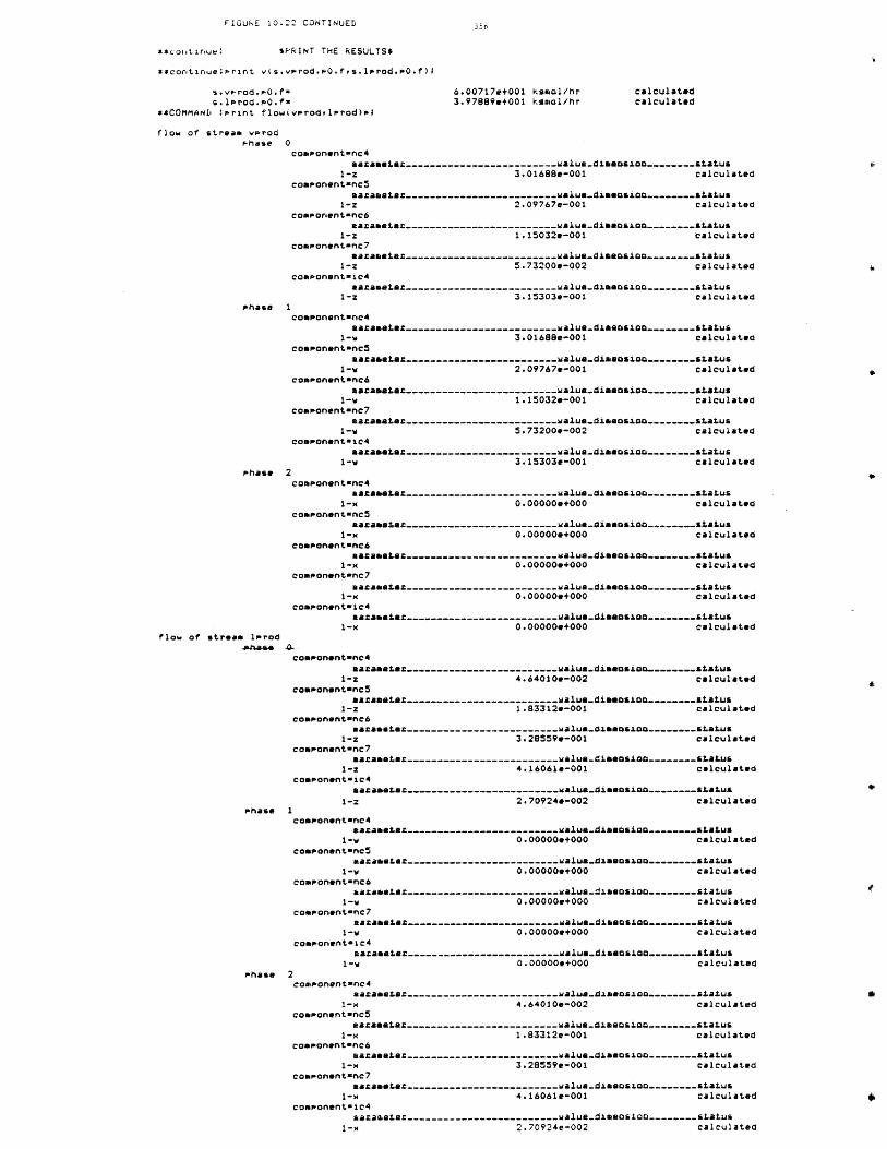
FIGURE 10.22 CONTINUED
**coletinue: sPRINT THE RESULTS$
**cortirue:Prirt v(s.vprod.PO.fvs.lprod.P0.f);
s.vprod.p0.f=s.lprod.po.fz
**COMMAND :Print flow(vprodplprod)si
flow of stream vprodPhase 0
6.00717e+001 ksmol/hr3.97889e+001 kaaol/hr
calculatedcalculated
componentanc4aamasate2-------------------------.alue.dianosiao--------status
1-z 3.01688e-001 calculatedcomponentanc5
arametaz-------------------------walue-disosion. ...... status1-z 2.09767e-001 calculated
comsonentonc6aamata -........................ walu..diamsio...--------status
1-z 1.15032e-001 calculatedcomponentanc7
nazaaater------------------------..walu-.dieosio.... status1-z 5.73200e-002 calculated
component-ic4a=amaax2-------------------------walua.diaasio--------status
1-z 3.15303e-001 calculatedPhase 1
comnonent-nc4aaametae ------------------------ walue.diaaasio ........ status
1-W 3.01688e-001 calculatedcomsonent-nc5
aaasieta.-------------------------..alue.disasio...--------status1-w 2.09767e-001 calculated
component-nc6nazameter.-------------------------walue.dieasio--------status
1-w 1.15032e-001 calculatedcomponent-nc7
aamter.------------.. -------------valua.dimaensio--------status1-W 5.73200e-002 calculated
componantnic4acamasta.-------------------------Ualue-diamosio.--------status
1-W 3.15303e-001 calculatedPhase 2
componentenc4aamasta.-------------------------ualue.diamosion--------status
1-x 0.000000+000 calculatedcomponent-nc5
aamaeter.-------------------------walue-dimaaosio--------status1-x 0.00000e+000 calculated
comsonent-nc6aamaate.-------------------------ualue-dinaosico--------status
1-x 0.00000e+000 calculatedcomponent-nc7
samasete.-------------------------walue-diaaosion--------status1-x 0.00000e+000 calculated
componentoic4aacameta.------------------------- walue-dimasio.--------status
1-x 0.00000e+000 calculatedflow of stream lprod
-prasa .componentwnc4
azaet.-------------------------.. walua.diaeasion--------status1-Z 4.64010e-002 calculated
coaponentenc5aaasate.-------------------------walua.diseasio--------status
1-z 1.83312e-001 calculatedcomponentnc6
amaranta-------------------------walu-diaasi... ..--------status1-z 3.28559e-001 calculated
component-nc7aasaete.-------------------------walue-diameasio.--------status
1-z 4.16061e-001 calculatedconsonent-ic4
aaaaster.-------------------------walu.diaeosion--------status1-2 2.70924e-002 calculated
Phase 1conponent-nc4
aamaaster.---- ---------------------walue.diaeasioa--------status1-w 0.00000e+000 calculated
conponentenc5aamastax--..-----------------------walua.diaos.o ..--------status
1-W 0.00000e+000 calculatedcomponent-nc6
azamasta.-------------------------walue-dsmosio.--------statusI-W 0.00000e+000 calculated
component-nc7nazaaete.-------------------------walu-.diaansio.--------status
1-W 0.00000e+000 calculatedcomsonentsic4
araeter.-------------------------... alu..diaosio.o.--------status1-W 0.00000e+000 calculated
phase 2component-nc4
gazamate-------------------------malue-dabosoo--------status1-x 4.64010e-002 calculated
component-nc5aamaast .------------------------- alua-diaeosion--------status
1-x 1.83312e-001 calculatedcomponent-nc6
aar2aate2-------------------------walue.diaaosio.--------status1-x 3.28559e-001 calculated
componnt-nc7aamasta.------------------------- alua-disaosio--------status
1-x 4.16061e-001 calculatedcomponentnic4
saxamater.-------------------------walue-diamosion--------status1-x 2.70924e-002 calculated
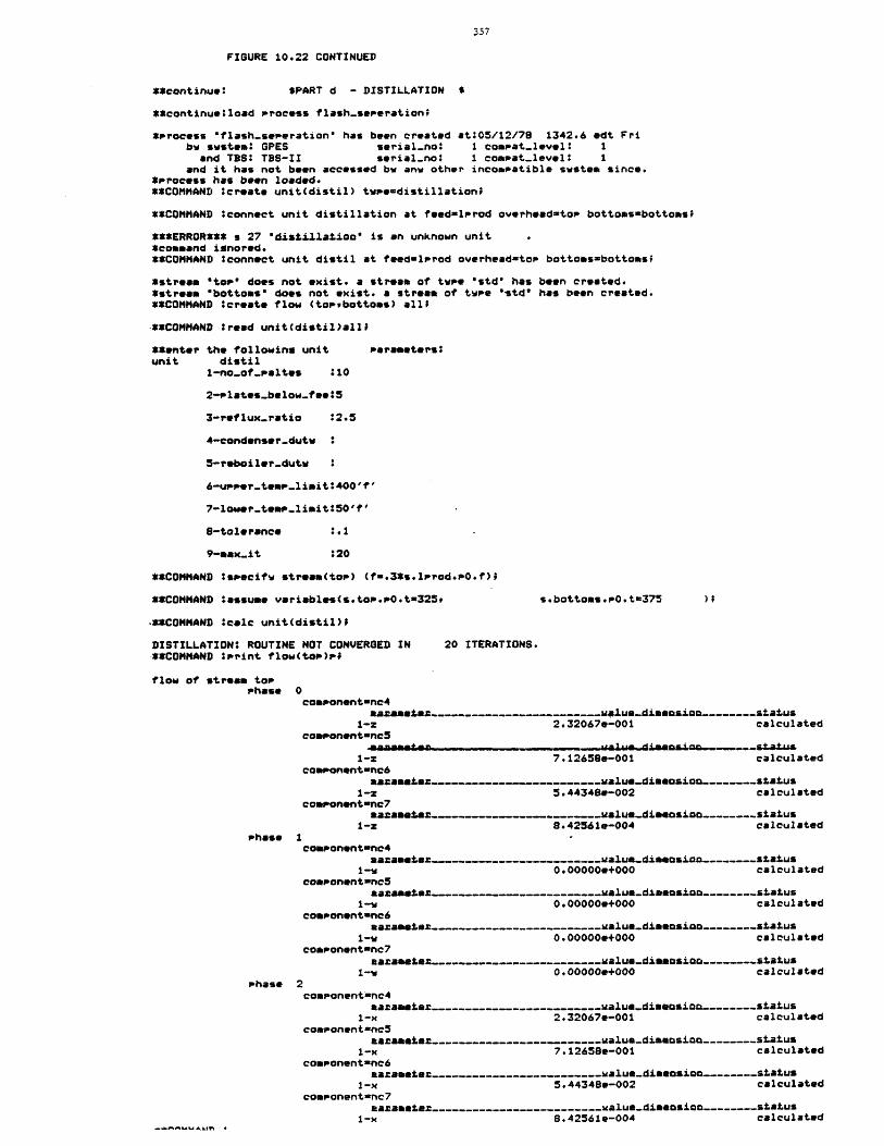
FIGURE 10.22 CONTINUED
**continue: *PART d - DISTILLATION s
**continue:load process flash-seperation;
*Process "flash-seperation" has been created at:05/12/78 1342.6 edt Fribw sWstem: GPES serial-no: compat-level: 1
and TBS: TBS-II serial-no: 1 compat-level: 1and it has not been accessed bw any other incompatible swstem since.
*Process has been loaded.**COMMAND :create unit(distil) twue-distillation;
**COMMAND :connect unit distillation at feednlprod overhead-top bottomsabottoas
***ERROR*** s 27 'distiA.1atio" is an unknown unit*command ignored.**COMMAND :connect unit distil at feed=lprod overheadntop bottoasmbottoss
*strea *toP" does not exist. a stream of twpe "std" has been created.*stream "bottoms" does not exist. a stream of twpe "std" has been created.**COMMAND :create flow (topebottoms) all;
-**COMMAND :read unit(distil)alli
**enter the followinm unit parameters:unit distil
1-no-of-paltes :10
2-plates-below-fee:5
3-reflux-ratio :2.5
4-condenser-dutw
5-reboiler-dutw
6-upper-temP.limit':400'If'
7-lower-te"s-limit:50'f'
8-tolerance :.1
9-ax.it :20
**COMMAND :specift stream(top) (f=.3*s.lProd.0.t);
**COMMAND *assume variables(s.top.s0.t=325, s.bottoms.P0.t=375
-**COMMAND icalc unit(distil)$
DISTILLATION: ROUTINE NOT CONVERGED IN 20 ITERATIONS.**COMMAND :Print flow(tao)pi
flow of stream topPhase 0
conponent=nc4aaaastaz-------------------------malue-dimosion--------status
1-Z 2.32067e-001 calculatedcoaponent-nc5
1-Z 7.12658e-001 calculatedcomonent-nc6
amaaetsm alus-dimmosioo--------status1-Z 5.44348e-002 calculated
comsonent-nc7aazama"am------------------------walue-diseasion--------status
1-: 8.42561e-004 calculatedPhase 1
componentenc4maxamtem------------------------ walue-dinmosioo--------status
1-W 0.00000e+000 calculatedcosponent-nc5
aaaametem----------------..walue-diamosion--------status1-W 0.000000+000 calculated
componentnc6nazametam-------------------------malue-.dimosion--------status
1-W 0.000000+000 calculatedcoaponent-nc7
aamantax-------------------------ialun.dimasioc--------status1-V 0.000000+000 calculated
phase 2component-nc4
aamamstem.-------------------------ualue-diaeosion--------status1-x 2.32067e-001 calculated
componentnc5aamamtmz..------------------------alue-dimansion--------status
1-x 7.12658e-001 calculatedcomponent-nc6
aamametem-------------------------walue-diaeosion--------status1-x 5.44348e-002 calculated
component-nc7aaametma-------------------------yalue-diaaosio.--------status
1-x 8.42561e-004 calculated
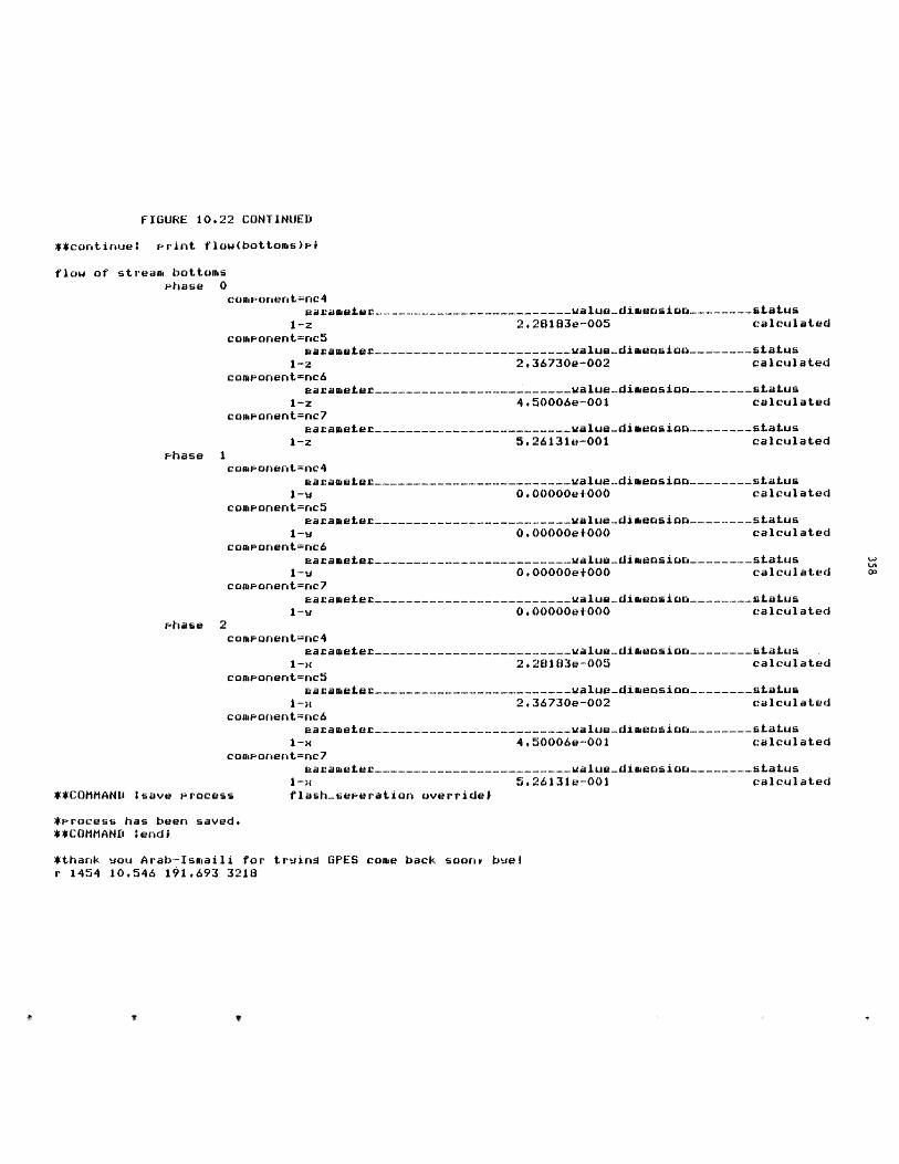
FIGURE 10.22 CONTINUED
**continue: Print flow(bottoms)pi
flow of stream bottomsphase 0
component=nc4parameter -------------- _-_-----ualuedimension------- status
1-z 2.26183e-005 calculatedcomponent=nc5
aavameter------------------------- alue-dimension------__status1-z 2,36730e-002 calculated
component=nc6earameLer ------------------------- alue-dimeasion------- status
1-z 4.50006e-001 calculatedcamponent=nc7
earameter ------------------------- ualue-dimeasion--------status1-z 5.26131e-001 calculated
phase 1component=nc4
uarameLer----_--------------------alue-dimeosion--------status1-w 0,00000et000 calculated
camponent=rc5arameter_--------------_-------value-dimension -------- status
1-W 0.000000e000 calculatedcomponent=nc6
earameta----------------------------ualue-dimension--------status1-W 0.00000e+000 calculated
comonent=nc7earameter -------------------------ualue-dimension--------status
1-V 0.00000et000 calculatedphase 2
component=nc4earameter----_--------------------value-dimension--------status
1-x 2.28103e-005 calculated
component=nc5earameter ------------------------- ualue-dimension---_____status
1-x 2.36730e-002 calculatedcomponent=nc6
earameter-------------------------ualue-dimension---------status1-x 4,50006e-001 calculated
camponent=nc7eaameter-------------------------value-dimension--------status
1-. 5.26131e-001 calculated**COMMAND :save process flash-seperation override#
*Krocess has been saved.**COMMAND tendi
*thank uou Arab-Ismaili for truing GPES come back soony buelr 1454 10.546 191.693 3218
If V
359
The PEL computer session for simulating this case is also shown in Figure
10.22.
10.4 A Prototype TBS for Magnetohydrodynamic (MHD) Processes
This TBS has been developed by Dr. H. Cohen and Mr. B. Misra from the
MIT Energy Laboratory. The purpose of this study was to test the GPES
independently, as well as to produce a useful system for the study of MHD
power plants. The discussion about MHD power generators and detailed
specification of this TBS is beyond the scope of this thesis and can be
found elsewhere [90,91,92,93 ,94,95 ,96,97,98, 99,100,101,102] The
process configuration of an open-cycle MHD-topped power plant is shown in
Figure 10.23. This process has eight unit types and six stream types.
The stream types are as follows: water, air, fuel, combustion gas,
power, and heat. The unit types are as follows: combustor, MHD
generator, inverter, diffuser, heat exchanger, steam plant, compressor,
and efficiency. The last mentioned unit is only a pseudo-unit; it
calculates the total power and the efficiency of the system. The
combustor has two inlet streams: one for air, through which air at a
prescribed pre-heat temperature is fed, and the other for fuel and seed.
The combustion gas from the combustor is fed to the MHD generator where
power is generated. The inverter serves to convert the power from the
generator to A.C. power. The diffuser receives the combustion gas from
the MHD generator and reduces the flow velocity to a prescribed value.
The heat exchangers are used to heat the air to specified temperatures,
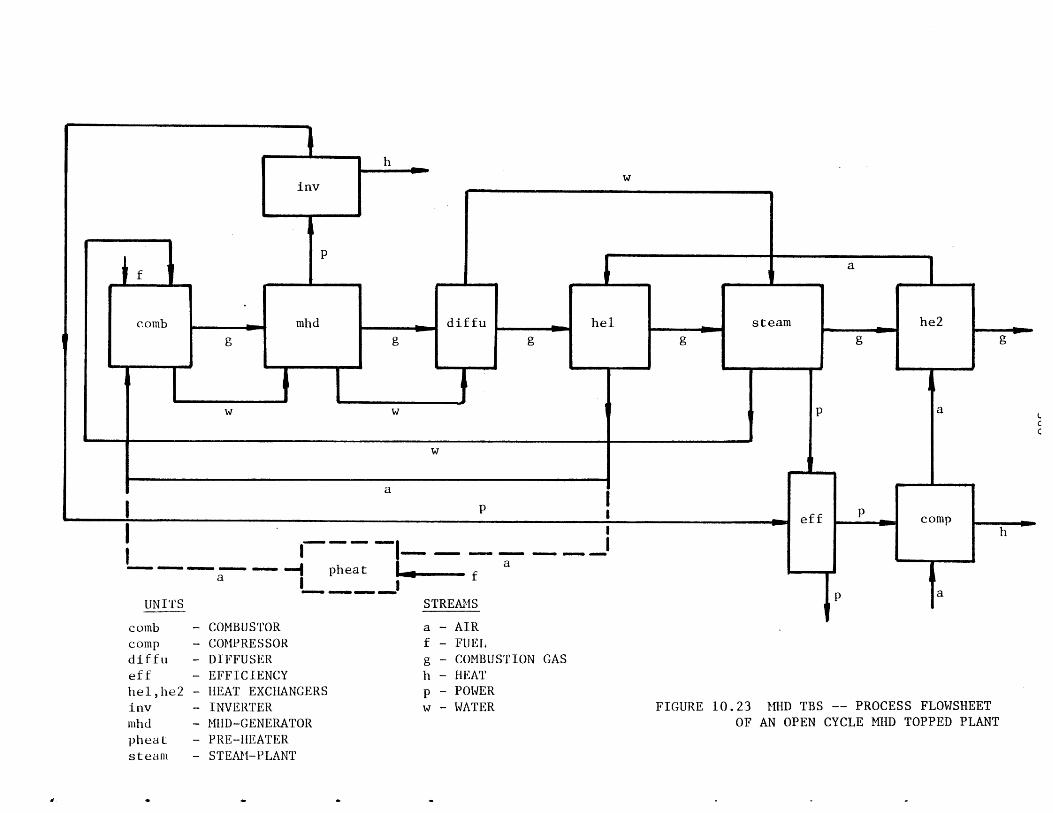
a - f ___II IawwoI pheatm ON"
- COMBUSTOR
- COMPRESSOR
- DIFFUSER
- EFFICIENCY
- HEAT EXCHANGERS
- INVERTER
- MHD-GENERATOR- PRE-H1EATER- STEAM-PLANT
a - AIR
f - FUEL
g - COMBUSTION GAS
h - HEAT
p - POWER
w - WATER FIGURE 10.23 MHD TBS -- PROCESS FLOWSHEET
OF AN OPEN CYCLE MHD TOPPED PLANT
combcompdi f ueffhel,he2invnh dpheatsteam
361
while the steam plant serves to generate power from the heat losses from
the combustor, the MHD generator, the diffuser, and the enthalpy of
combustion gas flowing within it. The compressor draws atmospheric air
and feeds it to the heat exchanger II, after a specified compression.
The power from the inverter and the steam plant is fed into the
pseudo-unit efficiency, from which the compressor draws the requisite
amount of power for its operation. It calculates the efficiency of the
system as the ratio of the net power output and the total energy supply
at the combustor. The application of this TBS will be illustrated by the
following examples.
Examples:
The model for the process flowsheet shown in Figure 10.23 has already
been saved.
a) Determine the sensitivity of the overall system efficiency to
variations in condensation pressure at the termination of the steam
cycle. The PEL computer session for this analysis is shown in Figure
10.24.
b) An externally fired pre-heater, as shown by the dashed lines in
Figure 10.23 may be used to raise the temperature of the air coming out
of the high temperature heat exchanger. Determine the effect of the
degrees of pre-heat on the overall system efficiency. The PEL computer
session for this case is shown in Figure 10.25.
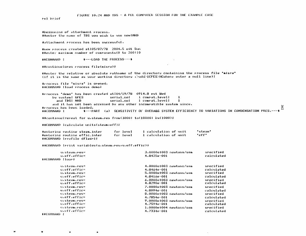
FIURE 10.24 M"D TBS - A PEL COMPUTER SESSION FOR THE EXAMPLE CASEPel brief
*beainnin of attachment process.**enter the name of TBS uou wish to use now1MHD
*attachment Process has been successful.
*new Process created atO05/07/78 2004.5 edt Sun**enter maximum number of components(0 to 200):0
**COMMAND i $---LOAD THE PROCESS--.$
**continue:apen Process file(misra);
**enter the relative or absolute Pathname of the directoru containing the process file "misra"(if it is the same as uour working director ,>udd>ICPES>HCohenr enter a null line):
*rocess file "misra" is opened.**COMMAND tload Process demaoi
*Process "demo" has been created at:04/19/78 0914.8 est Wedbu sustem GPES serial.no: 1 compat-level 1
and TBS; MHD serial-not 1 comat-level 1and it has not been accessed bu anu other incompatible sustem since.
*Process has been loaded.**COMMAND : $--- PART (a) SENSITIVITY OF OVERADS SYSTEM EFFICIENCY
**continueirepeat for u.steam.pes from(3000) to(10000) bQ(1000);
**COMMANID calculate units(steamreff)i
TO VARIATIONS IN CONDENSATION PRES.---$
*enterins routine steam-inter*enterinq routine effic-inter**COMMAND terofile dflaA=11
for levelfor level
1 calculation of unit1 calculation of unit
**COMMAND :print variables(u.steam.esvu.eff.effic);
u. steamt.ieesu.eff.effic=
**COMMAND :Iloop
u.steam.pes=
u.eff.effic=u*steame5*es=u.eff.effic=u.steam.pes=-u*eff.effic=u. s team. *pes=
u. eff'effic=u.steam.es=u.eff.effic=u.steam.Pes=u.eff.effic=u* team.pes=
**COMMANDI
3.0000e10034.8425e-001
4.0000ef0034*8464e-0015.0000e+0034.8416e-0016.0000e+0034.8290e-0017. 0000e+0034.8094e-0018.0000e10034.7854e-0019.0000eO10034.7594e-001
1.0000el004
4.7334e-001
newtons/sam
newtons/saom
newtons/sam
newtons/sam
newtons/som
newtons/sa (
newtons/sam
newtons/sa
"steam""eff"
specifiedcalculated
specifiedcalculatedspecifiedcalculatedspecifiedcalculatedspecif iedcalculatedspecif iedcalculatedspec if i edcalculatedspecifiedcalculated
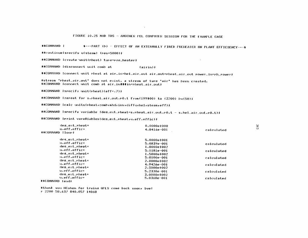
FIGURE 10.25 MHD TS - ANOTHER PEL COMPUTER SESSION FOR THE EXAMPLE CASE
**COMMAND : $*--- PART (b) - EFFECT OF AN EXTERNALLY FIRED PREHEA'IER ON PLANT EFFICIENCY--*
**continue seecifv u(steam) (res=5000)f
**COMMAND :create 'unit(pheat) tWeew're.heaterr
**COMMAND :disconnect unit comb at (airin);
**COMMAND Wconnect unit Fheat at air.in=he...airout air....out=Pheat.air.out Power.in=h-Power;
*stream "Pheat.air.out" does not exist. a stream of tWee 'air' has been created,**COMMAND :connect unit comb at air.in###in=heat.air..out;
**COMMAND :specifu unit(pheat)(eff=.7);
**COMMAND : repeat for sopheat....air-outPO.t from(199#00) to (2200) bw(50);
**COMMAND :calc units(pheatcombrmhdinvrdiffurhelsteameff);
**COMMAND :specifw variable (des-extpheat=spheat-air-out.PO.t - s.hel-airout.PO.t);
**COMMAND terint varatiables(des-ext-pheatru.eff.effic);
de.ext-pheat= 0,0000e+000u. eff . eff ic= 4.8416e-001 calculated
**COMMAND :loor;
de'.ext.pheat= 5.0000e4001u.eff.effic= 5.0839e-001 calculateddeg-ext-pheat= 1.0000e+002u.eff.effic= 5.11s1e-00l calculateddeg-ext_pheat= 1.5000e+002u.feffteffic= 5.0lOe-001 calculateddes-ext-Pheat= 2.0000e+002uieff.effic= 4#9426e-001 calculateddel-ext-pheat= 2.5000e+002u.eff.effic= 5.2330e-001 calculateddeN-ext-pheat= 3. OOOe+002
ef f eff i c= 5.0360e-001 calculated**COM.8AN10 lecadt
*thanrs wou "ICoheng for W~Iri tGhS comae bacV soar., bwe!r 2200 58.637 840.057 14068
364
Chapter 11
RECOMMENDATIONS AND CONCLUSIONS
11.1 Recommendations
There are many possible ways in which the GPES system could be
extended to provide more user flexibility. Such possible extensions are
discussed in this section, and are recommended for future work.
1) Drawing of Process Flowsheets
The system could be extended to draw a schematic diagram
representing the process flowsheet in response to the user's
command: print process flowsheet; the information required for this
task is stored in the network of data structures representing the
process. What is required is the development of an algorithm for
this function.
2) Optional Units of Measurement for Printout Variables
The user may provide his input in any allowable units of
measurement. The system automatically converts this input to the
standard units of measurement for that parameter and stores the
result in an appropriate location in the process network. Hence,
the calculating routines always receive their input parameters in
standard units, and should also compute their output parameters
which are stored in the process network in standard units. When theI
user requests for output the parameters are also printed in standard
units. It is desirable that the user be able to specify the units
365
of measurement for output parameters. The profile command can be
extended to allow the user-system communication. For example, the
following hypothetical command indicates that the printout of
parameters having physical dimensions of temperature or pressure
should be in degrees Centigrade and millimeters of mercury,
respectively: profile outputunits(temperature = C, pressure
mmHg). The dimension table described in Chapter 4 contains the
standard units of measurement for each physical dimension and other
allowable options with their conversion factors for each dimension
type. A temporary data structure is required to contain the current
output units of measurement for each physical dimension. The
entries of this data structure which are initially set to some
default values or standard units should be updated in response to
the profile commands specifying the output units. The print
routines should use this data structure and the dimension table in
converting the parameter values to the specified units of
measurements before printing them.
3) Graph Plotting Capability
In sensitivity analysis and other parametric studies of a process
flowsheet it is more desirable to present the results in graphs than
tables. This capability could be incorporated to the system. The
user could set up such graphs by the following hypothetical command:
graph graphname initialize ( specification of graph
parameters );
366
where graph parameters could be attributes such as x axis title, y
axis title, number of curves, character used in plotting each curve,
maximum number.of data points for each curve, length of x axis per
unit of x, length of y axis per unit of y, origin, etc. The user
could specify the data points on the curves by the following
hypothetical command:
graph graphname set (value or expression for x, value or
expression for yl, value or expression for y2, ...);
The graph can be plotted by the following hypothetical command:
graph graph name print;
The following examples illustrates the application of such
capability. In this example variations in steam plant efficiency
are plotted versus the feed stream temperature.
graph A initialize (xtitle = "temperature," ytitle
"efficiency," ncurves = 1, char "*", maxn = 10, ...);
repeat for s.feed.po.t from (100) to (200) by (10);
calculate units (..., steamplant, ...);
graph A set (s.feed.po.t, u.steamplant.eff);
loop;
graph A print;
4) Merging of Two-Process Models
A user may save his process model in a process file and retrieve it
later for further study. The user may also retrieve someone else's

367
process model with his permission. When retrieving a process the
process in the file replaces the current process in the working
area. This means that the process in the working area is lost if
the user has not saved it before loading a new process. It is
desirable to be able to merge two processes without having to build
one over the other. This capability is especially useful when a
team is analyzing a large process flowsheet and each member is
studying a section of the flowsheet. It allows the assembly of all
these sections to an integrated process model which enables the
study of the whole process.
The user could request such an operation by a merge command similar
to a load command.
Although the system could easily be extended to perform this
function, its payoff may be offset by excessive computer overhead
time. This is due to the effort required to make the two processes
compatible. The following are some conflicts that should be
resolved by the system before merging the two processes:
a) Name Duplication.
b) Addressability. The addressability of a process is by a
pair of partition number and offset. Therefore in merging two
processes, there will be address conflicts. This could be
resolved by either of the following:
a. to relocate one of the processes

368
b. to change the system's memory management scheme from
two-level addressability (partition number and offset) to
a three-level addressability: process number, partition
number and offset.
c) Merging of component directories. When merging two
component directories the entry number of components in the new
directory may not be the same as they were prior to merge.
This change must be reflected in all streams referring to these
components.
5) Choice of Calculating Routines
When a user requests for calculation the system will invoke the
appropriate calculating routines specified in the templates. If a
user wants to use different calculating routines, he would be able
to do so by using some Multics commands. But this requires
familiarity with the Multics system. Therefore it is recommended
that the calculate commands and consequently the system itself be
modified to allow the user to specify the calculating routines.
6) Extension of Templates
The function of calculating routines could be more simplified by
allocating more types of error checking to the system. This
requires extension of templates to convey the additional testing
criteria to the system. Some of the examples of types of error
checking that the system could be instructed to perform are as
follows:
369
a) same components should be present in inlet and outlet
streams.
b) upper and lower limits for parameter values.
Even the function of some calculating routines which represent
simple models could be completely eliminated by describing them in
templates and having the system carry out the calculations.
7) Billing and Statistics
It is desirable that the system be able to gather information
regarding the usage of each user of each TBS, and the usage of each
TBS by all users. This infomation may be used for billing,
statistics, or other managerial purposes. As described in Chapter
8, provisions have been made in designing the TBS table and user's
table for this information. Nevertheless, this information is not
recorded. To record this information directly on these tables
implies that the user should have write acesss to these files, which
is not acceptable for security reasons. The other alternative is
using the message segment facility of Multics. This involves the
following:
a) establish a message segment (a special file)
b) modify the system so that when the user enters the system
or leaves the system a message containing the required
information would be sent to the above "safe box"
c) modify the GPES administrative programs (updatetbstbl,
updateusertbl) to process these messages, update appropriate
entries in the users' and TBS tables, and generate reports.
370
8) Unsteady State Analysis
The system is designed primarily for the study of steady-state
operation of chemical processes. It is recommended that its
application for unsteady state operations be explored.
9) Computational Schemes
The basic computational scheme of the system is sequential modular
with user specifying the order of calculations. Although provisions
have been made for implementing template-based systems with other
computational schemes, the burden of such an effort is entirely on
the TBS Administrators. Further research in this area is required
to generalize and automate the process.
371
11.2 CONCLUSIONS AND THESIS CONTRIBUTIONS
There are two basic problems with the existing general purpose
process simulators:
a) The existing systems are applicable to those process flowsheets
having only conventional vapor-liquid streams. This
inflexibility makes it either impossible or very difficult to
expand present-day systems to include other types of processes
such as coal processing or electric power generating systems.
b) The existing systems are mostly developed for simulation and do
not provide the design atmosphere for process engineers. A
general purpose simulator, to be effective as a design tool,
must use a mode of operation, methods of input and output, and
calculation techniques that minimize the effort required for
designer-computer communication so as to maximize effective
interaction between the designer and the computer. The time
scale is important in process design.
The objective of this thesis was to develop a framework for the
development of general purpose chemical process simulators that:
a) are applicable to all types of chemical processes, and
b) are more adaptable to the design environment.
In fulfillment of the above objective, the thesis has provided the
following contributions in the field of computer aided design for process
engineering:
372
1) Formulation of a general model for chemical proceses, to represent
the'process flowsheet for any level of sophistication that may be used to
analyze that process. The introduction of the concept of a general
stream and flow parameters have been the major contributions for
achieving this result.
2) Identification of the issues involved in the design of a computer
system for process engineering. The work has distinguished two classes
of problems:
a) Those that are common to the design of any system,
b) Those that are related to a particular system.
3) Based upon the above findings, the work has led to the design and
implementation of a General Process Engineering System (GPES) which
allows any group or organization to easily and systematically build its
own system. These systems could be very simple or very sophisticated
depending on the particular needs and applications of the group.
The design and implementation of the GPES as a tool for creating
computer aided design systems for chemical process engineering provides
the following advantages:
a) Allows any group or organization to easily and systematically
build its own design system, thereby reducing the time and
effort required to produce such systems.
b) The created system may not be limited to a particular class of
processes. Such a system is open-ended and capable of
analyzing any type of process.
c) The created system is more adaptable to the design environment,
and provides the user with features not usually found in
existing general purpose simulators.
373
In summary, a system created by GPES (a TBS) has the following
characteristics:
a) Flexible. It is applicable for analyzing any type of process
flowsheets. It is not limited to process flowsheets having
only conventional vapor-liquid streams. The system can be
easily modified, expanded and updated.
b) The user communicates with the system by a problem oriented
language (PEL). The user may enter his input data in any
allowable units of measurement. Arithmetic expressions may be
used where numerical data is expected. The system performs
extensive types of error checking such as detection of over- or
under-specification of process units and streams. The system
produces over 200 easy-to-understand messages to detect the
user's negligence.
c) Interactive. Allowing the progressive design of a process.
d) Integrated. Capable of the following functigns:
i) Simulating or designing a process for any required level
of sophistication such as: preliminary process
feasibility studies, plant design, equipment sizing, plant
modifications, debottlenecking studies, effects of
operational changes on plants, contractor checkout. The
appropriate programs should be provided in that TBS.
ii) Serving as a physical property data base system. It also
promotes sharing of data among users.

374
iii) Analyzing experimental data (regression analysis).
iv) Serving as a general purpose interpreter.
v) Serving as a desk calculator for arithmetic operations.
e) Dynamic creation and modification of process flowsheet.
Enabling the user to instruct the computer to alter process
configuration or operating parameters without having to
redescribe the problem.
f) The ability to save and retrieve user process models. This
will save both designer and computer time in not having to
reinitiate the problem. It also promotes sharing of process
models among users, and enhances teamwork.
g. It provides virtual memory. There is no limitation on the size
of the process flowsheet being analyzed by the user.
h. Ease of use in that no knowledge of programming and job control
language is required. All that is required is knowledge of PEL
(Process Engineering Language).
4) The work has provided a comprehensive example of the use of current
systems programming techniques (structured programming, dynamic storage
allocation, manipulation of arbitrary data structures, list processing,
etc.) and current computer technology (time sharing, virtual memory,
dynamic linking and loading) in a systems programming application of
interest to chemical engineering.
Using the GPES several prototype template based systems have been
created. The results of these efforts indicated that:
375
a) The GPES allows the creation of computer systems for different
types of processes.
b) The creation of such systems is simple and systematic.
c) The features provided -by the system are very useful and
desirable for simulation and design of chemical processes.
In conclusion, the above studies and findings, and the availability
of such a GPES, will benefit the following groups:
a) Those interested in computer aided design for chemical
engineering applications.
b) Those planning to implement their own computer aided design
systems for chemical processes (by reducing the characteristic
20-100 man-years effort formerly required to produce such
systems). It allows them to focus their effort on the chemical
engineering side of the problem, which results in the
development of better process modules and comprehensive
physical and thermodynamic property calculation packages.
c) The process designers, by providing the ideal creative
environment for process design by computer.
d) Chemical engineering students in process design courses. By
allowing them to implement their own system or to use an
already developed educational one. They would be able to study
whole processes as carefully as we now study individual unit
operations.
376
APPENDIX A
STATE OF THE ART
Process simulation is the representation of a chemical process by a
mathematical model which is then solved to obtain information about the
performance of the chemical process. The mathematical model is usually
solved by a computer program. This computer program is generally known as
a chemical process simulation program. The chemical engineer mostly deals
with continuous deterministic system simulation. The simulation program
may be a specific one prepared to simulate a particular process with a
fixed plant layout or may be general to simulate any kind of process
configuration. General purpose simulators use the modular approach.
According to this method each chemical processing step is represented as a
separate mathematical model called a unit module or building block or
process unit. The unit modules are connected by data sets which represent
the streams of materials and energy flowing between the units of the plant.
An executive program supervises the information flow between the unit
modules.
A simulation program may be used for steady-state or dynamic
simulation. Although the aim of the process simulation program is to be a
tool for design, most of the simulation programs work in the
simulation/performance mode. It is characteristics of such a mode of
calculation that all stream inputs and design parameters for the units are
specified. The information flow in the simulation program is in the same
direction as the heat and material flow in the chemical plant. Ideally, in
the design mode of calculation the system inputs and/or design parameters
are calculated from specified outputs. Design calculations can be

377
performed by iterative simulation. Iterative simulation may take place
over an entire process with the user scheduling the cases to be computed,
or it may take place internal to the simulation through the use of control
blocks. Some process simulation programs perform optimization, equipment
sizing or economic evaluation. In many cases, the connection between the
programs which perform these tasks and the process simulation program is
weak, frequently ad-hoc.
Since the steady-state process simulation program is the most widely
used, the discussion is limited to this type of program. The important
systems of this type that have been publicly acknowledged are listed in
Table A.1. These systems have been developed by four types of
organizations: chemical process companies, academic institutions,
commercial computing services and consulting organizations, serving the
chemical process industries. Evans [33) classifies these systems into two
groups: first generation programs and second generation programs. He uses
the terms "first and second generation" in an evolutionary sense, in that
the development of the second generation programs has been based upon the
technology gained by the development of the first generation programs.
Kellog's flexible flow sheet, Chevron's material and energy balancing,
PACER and CHESS programs are examples of first generation systems and
Monsanto's FLOWTRAN, Dupont's CPES, and Union Carbide's IPES are examples
of the second generation systems.
Currently, a major research effort is underway at the Massachusetts
Institute of Technology to develop a third generation computer system for
chemical process engineering. The project, funded by the United States
Department of Energy and budgeted at over three million dollars, is one of
the greatest efforts of its kind. It is being directed by
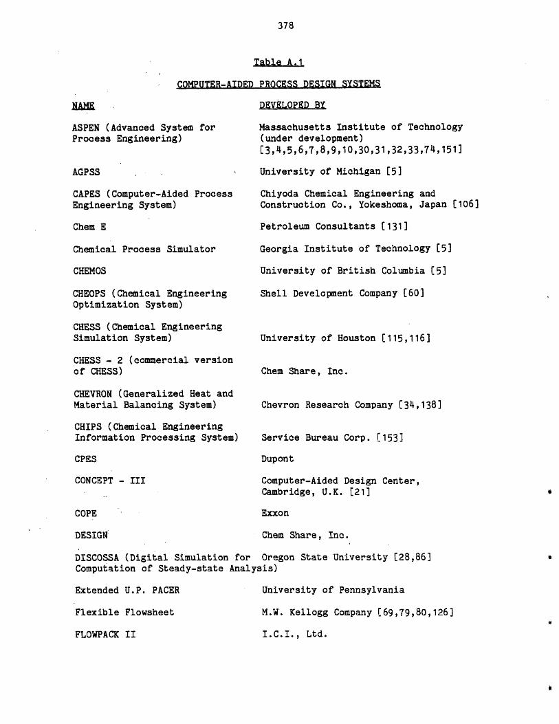
378
ASPEN (Advanced SysProcess Engineering
AGPSS
CAPES (Computer-AicEngineering System)
Chem E
Chemical Process Si
CHEMOS
CHEOPS (Chemical ErOptimization System
CHESS (Chemical EngSimulation System)
CHESS - 2 (commercof CHESS)
CHEVRON (GeneralizMaterial Balancing
CHIPS (Chemical Enj
Table A.1
COMPUTER-AIDED PROCESS DESIGN SYSTEMS
DEVELOPED By
tem for Massachusetts Institute of Technology(under development)[3,4,5,6,7,8,9,10,30,31,32,33,74,151]
University of Michigan [5]
ed Process Chiyoda Chemical Engineering andConstruction Co., Yokeshoma, Japan [1
Petroleum Consultants [131]
mulator Georgia Institute of Technology [5]
University of British Columbia [5]
igineering Shell Development Company £60]
ineering
Lal version
ed Heat andSystem)
gineering
06]
University of Houston [115,116]
Chem Share, Inc.
Chevron Research Company [34,138]
Information Processing System) Service Bureau Corp. [153]
CPES Dupont
CONCEPT - III Computer-Aided Design Center,Cambridge, U.K. [21]
COPE Exxon
DESIGN Chem Share, Inc.
DISCOSSA (Digital Simulation for Oregon State University [28,86]Computation of Steady-state Analysis)
Extended U.P. PACER University of Pennsylvania
Flexible Flowsheet M.W. Kellogg Company [69,79,80,
FLOWPACK II I.C.I., Ltd.
126]
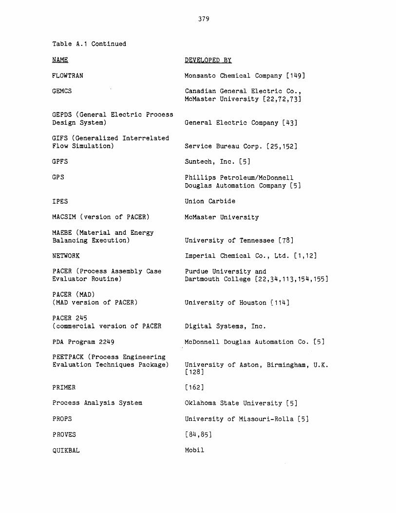
379
Table A.1 Continued
NAME
FLOWTRAN
GEMCS
GEPDS (General Electric ProcessDesign System)
GIFS (Generalized InterrelatedFlow Simulation)
GPFS
GPS
IPES
MACSIM (version of PACER)
MAEBE (Material and EnergyBalancing Execution)
NETWORK
PACER (Process Assembly CaseEvaluator Routine)
PACER (MAD)(MAD version of PACER)
PACER 245(commercial version of PACER
PDA Program 2249
PEETPACK (Process EngineeringEvaluation Techniques Package)
PRIMER
Process Analysis System
PROPS
PROVES
QUIKBAL
DEVELOPED BY
Monsanto Chemical Company [149]
Canadian General Electric Co.,McMaster University [22,72,73]
General Electric Company [43]
Service Bureau Corp. [25,152]
Suntech, Inc. [5]
Phillips Petroleum/McDonnellDouglas Automation Company [5]
Union Carbide
McMaster University
University of Tennessee [78]
Imperial Chemical Co., Ltd. [1,12]
Purdue University andDartmouth College [22,34,113,154,155]
University of Houston [114]
Digital Systems, Inc.
McDonnell Douglas Automation Co. [5]
University of Aston, Birmingham, U.K.[128]
[162]
Oklahoma State University [5]
University of Missouri-Rolla [5]
[ 814,85]
Mobil
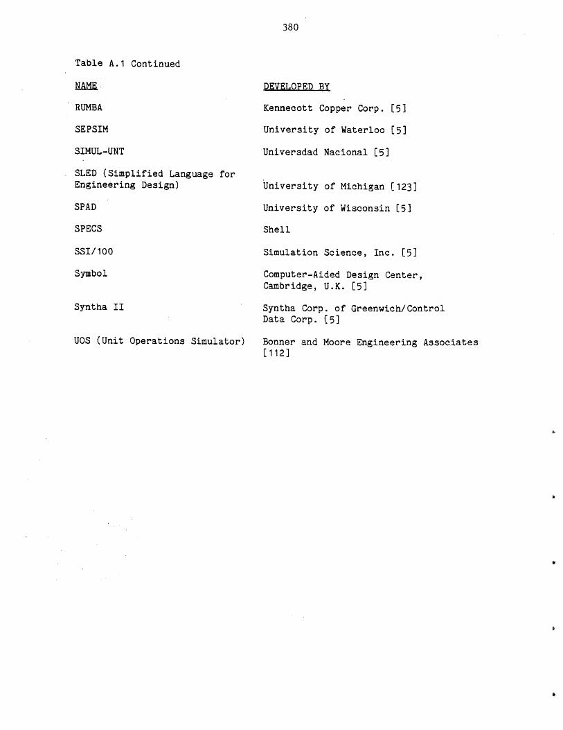
380
Table A.1 Continued
NAME.
RUMBA
SEPSIM
SIMUL-UNT
SLED (Simplified Language forEngineering Design)
SPAD
SPECS
SSI/100
Symbol
Syntha II
UOS (Unit Operations Simulator)
DEVELOPED BY
Kennecott Copper Corp. [5]
University of Waterloo [5]
Universdad Nacional [5]
University of Michigan [123]
University of Wisconsin [5]
Shell
Simulation Science, Inc. [5]
Computer-Aided Design Center,Cambridge, U.K. [5]
Syntha Corp. of Greenwich/ControlData Corp. [5]
Bonner and Moore Engineering Associates[112]
381
Professor Lawrence B. Evans of MIT and Professor Warren D. Seider of the
University of Pennsylvania. The system is named ASPEN (Advanced System for
Process Engineering) and is expected to meet the needs of the Chemical
Process Engineering profession in the 1980's. Those interested in
additional information on this effort are directed to Evans et. al.
13,4,5,6,7,8,9,10,30,31,32,33,74,151].
Different aspects of the first and second generation systems are
briefly discussed next. For an extensive review of the subject the reader
is referred to Evans et. al. [34], who describe the first generation
systems, and to Motard et. al. [117], who summarize recent work in steady-
state process simulation.
A.1 Structure of the Programs
Evans [29] has classified the approaches used in the development of
steady-state process simulation programs into three categories:
1. Development of a special-purpose computer program on an ad hoc
basis.
2. Use of a set of subroutines as building blocks to develop a
simulation of a process.
3. Use of a general-purpose executive program to simulate a
particular class of processes.
The first approach requires developing the program from scratch. It
requires the greatest programming effort and may be solved very efficiently
using sophisticated numerical methods since the equations and constraints
are fully defined prior to the effort of programming. However, it is
inflexible when it comes to evaluating different plant layouts. This
approach is almost never preferred.
382
In the second approach, the user writes his own main or executive
routine which calls a number of subroutines to simulate individual units,
to compute properties and to carry out other auxiliary functions. The
structure of the flowsheet is incorporated into the user's program. This
approach is, once again, not very flexible when it comes to evaluation of
different plant layouts.
In the third approach, there exists an executive program which is
available to the user. He simply has to provide a complete and unambiguous
description of his problem in the form of a set of data cards or statements
in a problem-oriented language (POL).
As noted by Motard, Shacham and Rosen [117], the general simulation
programs using the last approach can be viewed as having one of two basic
internal structures -- fixed structure or variable structure. In the
former, the executive program is invariant with respect to flowsheet
structure. The matching of streams to unit modules and the path of
calculations through the program is determined by data supplied by the
user.
In variable structure programs, a different executive program is
constructed for each different flowsheet structure. Such programs employ a
problem-oriented language which is interpreted directly into executable
code (the compiler approach), or the POL may in turn generate a program in
a procedure-oriented language, usually FORTRAN, which is then compiled,
linked and executed (the pre-compiler approach). In the latter case,
evaluation of different plant layouts can become quite expensive since the
cost of- compilation and linking is incurred every time. One disadvantage
of the fixed structure executive programs is that they require all unit
modules to be loaded into the computer memory regardless of whether a
383
particular unit module will actually be used. This can frequently lead to
load modules whose size is greater than the available main memory.
A.2 Input Methods
Methods for inputing process specifications may vary from fixed format
strings of words and numbers (e.g. Flexible Flowsheet, CHEVRON, PROVES) to
free-format problem oriented languages. Process descriptions are provided
in two forms. In the process oriented form, the user describes the
contents, configuration, and data for his process independent of the
calculation procedure. The user in later input or the program as part of
its function will determine how to compute the desired output (e.g. PACER,
CHEVRON).
In the calculation oriented form, the user describes the process as a
sequence of calculations that may include recycle loops to be converged,
each unit in the sequence receiving and transferring data to other units.
The program performs calculations as specified (e.g. DESIGN, CHIPS,
FLOWTRAN). This latter method gives the user control over calculations.
A.3 Data Checking
In most of the simulation programs the data checking must be done by
the user, which is often not sufficient and more checking must be done by
the simulator. It is often impossible to discover from the computer
results that the source of some errors is due to absured input data.
A.4 The Storage of the Data
The input data as well as calculated values are usually stored in
arrays with fixed boundaries. In fixed structure programs, due to the
limitation of the FORTRAN language, the storage space must always be
allocated according to the maximum capacity of the simulation program
without considering the actual problem size. Such use of storage space
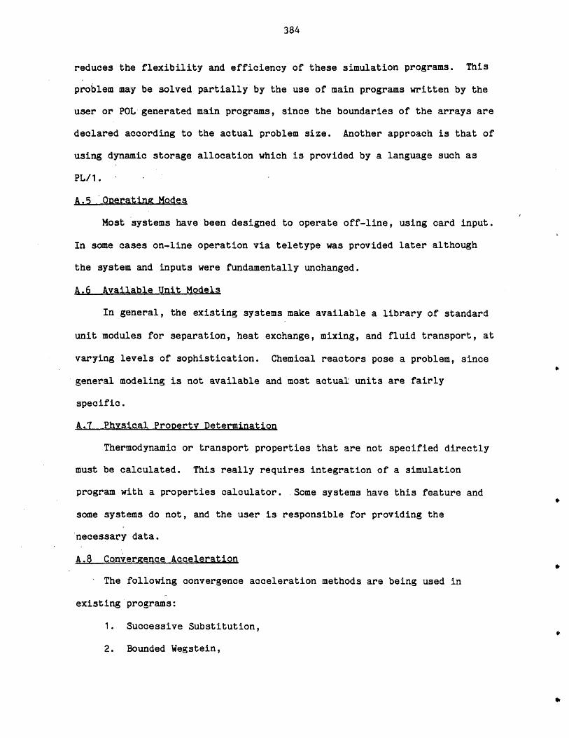
384
reduces the flexibility and efficiency of these simulation programs. This
problem may be solved partially by the use of main programs written by the
user or POL generated main programs, since the boundaries of the arrays are
declared according to the actual problem size. Another approach is that of
using dynamic storage allocation which is provided by a language such as
PL/1.
A.5 Operating Modes
Most systems have been designed to operate off-line, using card input.
In some cases on-line operation via teletype was provided later although
the system and inputs were fundamentally unchanged.
A.6 Available Unit Models
In general, the existing systems make available a library of standard
unit modules for separation, heat exchange, mixing, and fluid transport, at
varying levels of sophistication. Chemical reactors pose a problem, since
general modeling is not available and most actual units are fairly
specific.
A.7 Physical Property Determination
Thermodynamic or transport properties that are not specified directly
must be calculated. This really requires integration of a simulation
program with a properties calculator. Some systems have this feature and
some systems do not, and the user is responsible for providing the
necessary data.
A.8 Convergence Acceleration
The following convergence acceleration methods are being used in
existing programs:
1. Successive Substitution,
2. Bounded Wegstein,
385
3. Dominant Eigenvalue,
4. Quasi-Newton.
Some systems use only one of these methods (e.g., FLOWTRAN, CONCEPT
use Bounded Wegstein) while some other systems use more than one of these
methods (CAPES uses Bounded Wegstein, Dominant Eigenvalue and Quasi-
Newton).
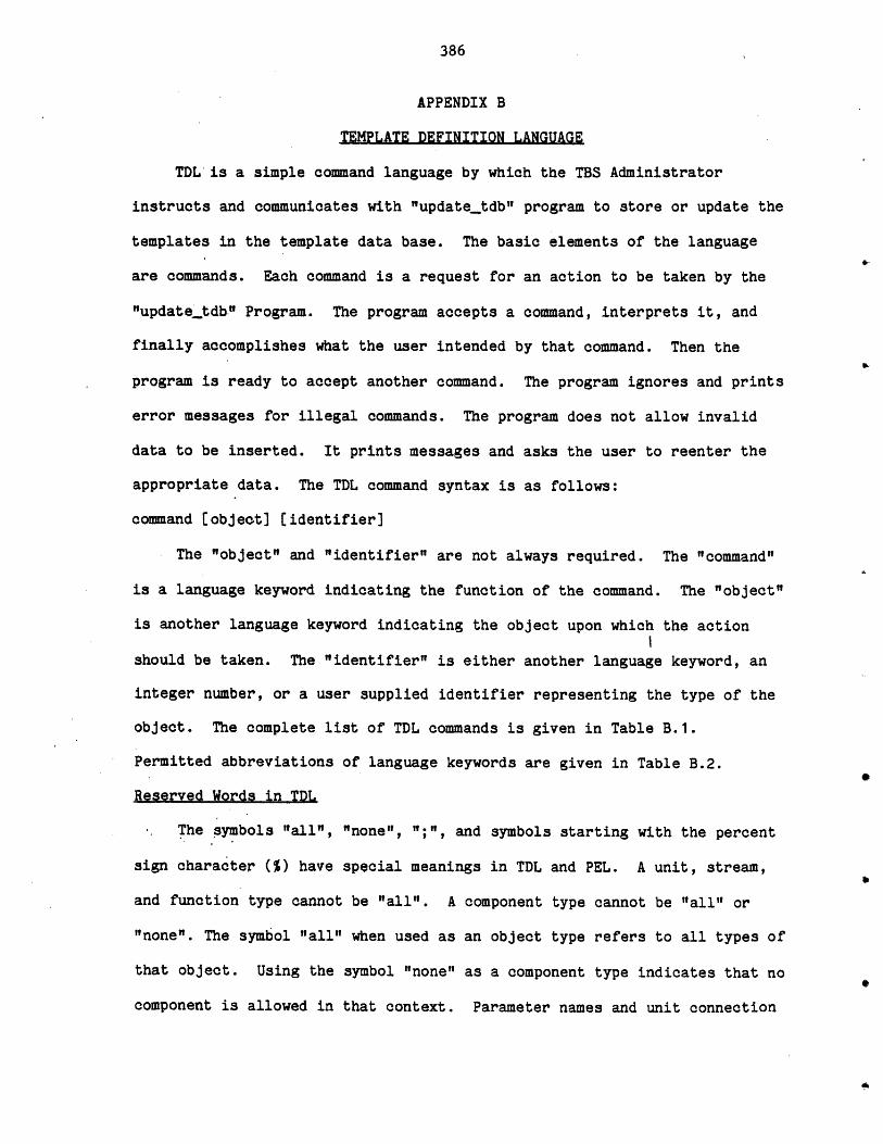
386
APPENDIX B
TEMPLATE DEFINITION LANGUAGE
TDL is a simple command language by which the TBS Administrator
instructs and communicates with "updatetdb" program to store or update the
templates in the template data base. The basic elements of the language
are commands. Each command is a request for an action to be taken by the
"updatetdb" Program. The program accepts a command, interprets it, and
finally accomplishes what the user intended by that command. Then the
program is ready to accept another command. The program ignores and prints
error messages for illegal commands. The program does not allow invalid
data to be inserted. It prints messages and asks the user to reenter the
appropriate data. The TDL command syntax is as follows:
command (object] [identifier]
The "object" and "identifier" are not always required. The "command"
is a language keyword indicating the function of the command. The "object"
is another language keyword indicating the object upon which the action
should be taken. The "identifier" is either another language keyword, an
integer number, or a user supplied identifier representing the type of the
object. The complete list of TDL commands is given in Table B.1.
Permitted abbreviations of language keywords are given in Table B.2.
Reserved Words in TDL
The symbols "all", "none", ";", and symbols starting with the percent
sign character (%) have special meanings in TDL and PEL. A unit, stream,
and function type cannot be "all". A component type cannot be "all" or
"none". The symbol "all" when used as an object type refers to all types of
that object. Using the symbol "none" as a component type indicates that no
component is allowed in that context. Parameter names and unit connection
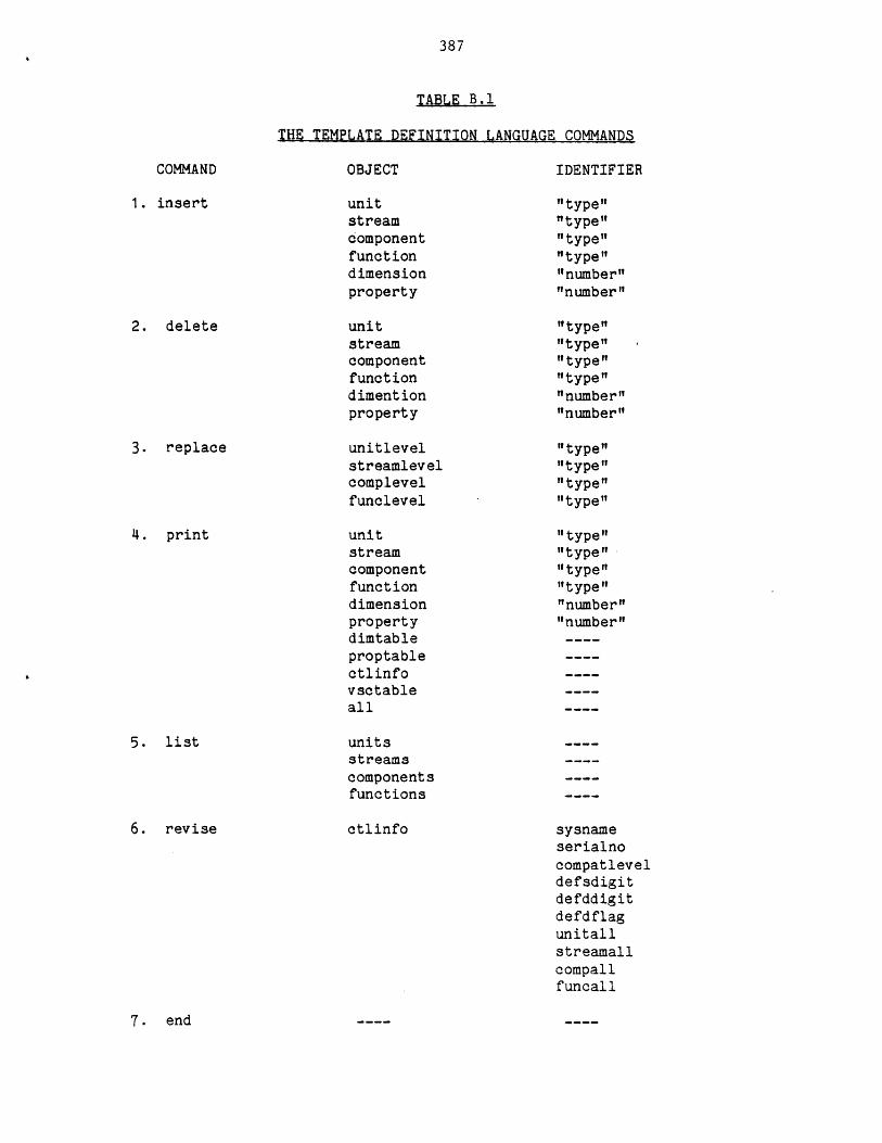
387
TABLE B.1
THE TEMPLATE DEFINITION LANGUAGE COMMANDS
COMMAND-
1. insert
2. delete
OBJECT IDENTIFIER
unitstreamcomponentfunctiondimensionproperty
unitstreamcomponentfunctiondimentionproperty
unitlevelstreamlevelcomplevelfunclevel
unitstreamcomponentfunctiondimensionpropertydimtableproptablectlinfovsctableall
unitsstreamscomponentsfunctions
3. replace
4. print
5. list
6. revise
"type""type""type""type""number""number"
"type""type""type""type""number""number"
"type""type""type""type"
"type""type""type""type""number""number"
ctlinfo sysnameserialnocompatleveldefsdigitdefddigitdefdflagunitallstreamallcompallfuncall
7. end
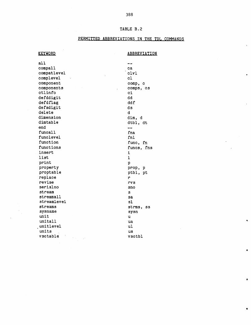
388
TABLE B.2
PERMITTED ABBREVIATIONS IN THE TDL COMMANDS
KEYWORD
allcompallcompatlevelcomplevelcomponentcomponentsctlinfodefddigitdefdflagdefsdigitdeletedimensiondimtableendfuncallfunclevelfunctionfunctionsinsertlistprintpropertyproptablereplacereviseserialnostreamstreamallstreamlevelstreamssysnameunitunitallunitlevelunitsvsctable
ABBREVIATION
caclvlclcomp, ccomps, csciddddfdsddim, ddtbl, dt
fnafnlfunc, fnfuncs, fns
1pprop, pptbl, ptrrvssnossasistrms, assysnu
uaulusvsctbl
389
names cannot be "all" or symbols starting with the percent sign character
(%). This restriction has been imposed to provide greater user flexibility
in referring to parameters and connections in PEL. In PEL a user may
refer to a parameter either by its name or, by the symbol %parametern (or
%parmn, or %pn), where n is the parameter number. Similarly, a unit
connection position is referred either by its name or by %cnctn (or %cn),
where n is the connection number. Also in PEL, the symbol "all" is used to
refer to all parameters or all unit connections. Another reserved word in
TDL is the character semicolon (;). Using a ";" as a routine's name
indicates that no routine is implemented. There is no other reserved word
in TDL. All symbols except the reserved words mentioned in this section
can be used in any context. All symbols used in TDL cannot be more than 16
characters.
Program Interrupt
During the TDL session, the user can exit from the program by pushing
the "QUIT" button on the terminal. This mechanism can be used for aborting
the printout of a print command, or, in the case of insert or replace
commands, for avoiding the need to enter additional information when the
user has detected some errors in previously supplied information. Reentry
after this abnormal exit can be accomplished by using the "pi" (Program
Interrupt) command of Multics. After the reentry the current command
activities will be ignored and the program is ready to accept a new
command.
Use of this mechanism for cases other than those mentioned above may
damage the data base, and should not be attempted.
TDL Commands
This section contains descriptions of TDL commands. The commands are
presented in alphabetical order.
390
Delete Commands
These commands are used to delete the templates. They are as follows:
delete unit "tvDe"
If the specified unit template exists, it will be deleted.
delete stream "type"
If the specified stream template exists, it will be deleted.
delete component "type"
-If the specified component template exists, it will be deleted.
delete function "tyDe"
If the specified function template exists, it will be deleted.
delete dimension "number"
The corresponding entry of the dimension table will be deleted.
delete property "number"
The corresponding entry of the property estimation table will be
deleted.
End Comsand
This command is used to terminate the session. The program checks the
consistency of the data base and will print any detected inconsistency.
The user-is then asked if he or she would like to exit. If the answer is
"yes", the program asks for the default types of unit, stream, component,
and function and these are made the first members of their respective
categories. Clearly the above inquiry only takes place for those
categories which contain more than one member. When the GPES Executive
wants a default type, it looks for the first member of the corresponding
directory.
391
Insert- Commands
These commands are used to insert the templates into the template data
base. The program prompts the user for all the required information. The
program then asks the user whether the template is to be inserted into the
template data base, or to be ignored. These commands are as follows:
insert unit "tye"
This command is used to define a new unit type. The template of the
specified unit type should not already exist. The program prompts the user
for the following information:
* Reference Information (48 characters).
* Number of Unit Parameter (0 or a positive number).
* Name and Dimension type of each parameter.
* Number of inlets (Zero or a positive number).
* Number of connections (A number not less than the above number).
* Connection name and stream type for each connection. Using the
symbol "all" as the stream type indicates that any type of stream
could be connected to the unit. Otherwise, the specified stream
type should have been already defined.
* Procedure to calculate the unit. This should be the name of the
calculating routine. If such a routine is not required or
implemented, a semicolon (;) should be used.
If the user's response is not a ";", the program prompts the user for
the following additional information regarding the calculating
routine:
* Minimum number of arguments (zero or a positive number).
* Maximum number of arguments. A negative number can be used to
indicate that the maximum number of arguments is unlimited. Otherwise
392
a positive number equal to or greater than the minimum number of
arguments should be provided.
* Number of Levels of calculation (a positive number).
For each level of calculation, the program asks for the value status
code of each unit parameter and information regarding the inlet and outlet
streams. The latter consists of the following information for each unit
connection:
* Connection status which should be 1, 2, or 3. The connection status
of 1 indicates that a stream must be connected to the connection
before the unit calculating routine could perform the specified
level of calculation. The connection status of 2 indicates that
such a stream is not permitted. The connection status of 3
indicates that such a stream is optional.
If the connection status is 1 or 3 and the stream type is not "all", the
following information would also be required:
* If the stream can have any component, a value status code for all
parameters of all components flowing in the stream.
* A value status code for each phase and flow parameter of each phase.
insert stream "type"
This command is used to define a new stream type. The template for
the specified stream type should not already exist. The program prompts
the user for the following information:
* Reference Information (up to 48 characters).
* Type of components flowing in the stream. Providing the symbol
"none" in this context indicates that no component is allowed to
flow in the stream. Providing the symbol "all" is the indication
that any type of component may flow in the stream. Providing any
393
other symbol is interpreted as allowing only the specified type of
components to flow in the stream.
* Number of phases. (Zero or a positive integer number).
The program asks for the following information for each phase:
* The number of phase parameters (0 or a positive integer number).
* Name and dimension type of each -phase parameter.
* The number of flow parameters (Zero or a positive integer number).
For a stream with no component (Component type : none) this number
should be zero.
* Name and dimension type of each flow parameter.
* Procedure to calculate the stream (Name of the calculating routine
or a ";".)
If the user's response is not a ";",. the program prompts the user for the
following additional information regarding the calculating routine:
* Minimum number of arguments (Zero or a positive integer number)
* Maximum number of arguments. A negative number may be used to
indicate that the maximum number of arguments is unlimited.
Otherwise a positive number equal to or greater than the minimum
number of arguments should be provided.
* Number of levels of calculations (a positive integer number).
The program also asks for the following information for each level of
calculation:
* If the stream can have any component, a value status code for all
parameters of all components flowing in the stream.
* A value status code for each phase and flow parameter of each phase.
394
Remarks
A unit template includes information about its inlet and outlet stream
types. Therefore, all such streams should be defined prior to the
definition of the unit. Updating these stream templates after the unit
template has been defined will impose some restrictions. To update a
template one has to delete the template and insert a new one (except for
replacing information regarding a level of calculation). To insert a
stream type which is already rooted in the existing unit templates, the
program forces the user to use the same number of phases as before, and for
each phase the same number of phase and flow parameters as before.
Therefore if the above restrictions will prevent the desired updatings, the
user has to delete the templates of all units referring to that stream
type. Once the stream has been updated, the unit templates which have been
deleted should be reinserted.
insert component "tyDe"
This command is used to define a new component type. The template of
the specified component type should not already exist. The program prompts
the user for the following information:
* Reference information (up to 48 characteres).
* Number of component parameters (Zero or a positive integer number).
Name- and dimension type of each parameter.
' * Procedure to calculate the component (name of the calculating
routine of a ";")
If the user's response is not a ";", the program prompts the user for the
following information regarding the calculating routine:
* Minimum number of arguments (Zero or a positive integer number).
395
e Maximum number of arguments. A negative number may be used to
indicate that the maximum number of arguments is unlimited.
Otherwise a positive integer number equal to or greater than the
minimum number of arguments should be provided.
* Number of levels of calculation (a positive integer number).
* A value status code for each component parameter for each level of
calculation.
All component types mentioned in defining the stream templates should
be defined prior to terminating the session.
insert function ."tvoe"
This command is used to define a new function type. The template for
the specified function type should not already exist. The program prompts
the user for the following information:
e Reference information (up to 48 characters).
* Number of function parameters (Zero or a positive integer number).
* Name and dimension type of each parameter.
* Procedure to evaluate the function, or a ";".
* Number of arguments for the above routine (if it is not a ";").
* Procedure to calculate the function (name of the calculating routine
or a ";"n).
If the user's response is not a ";", the user is prompted for the following
additional information:
* Minimum number of arguments. A negative number may be used to
indicate that the maximum number of arguments is unlimited.
Otherwise a positive integer number equal to or greater than the
minimum number of arguments should be provided.
* Number of levels of calculation (a positive integer number).
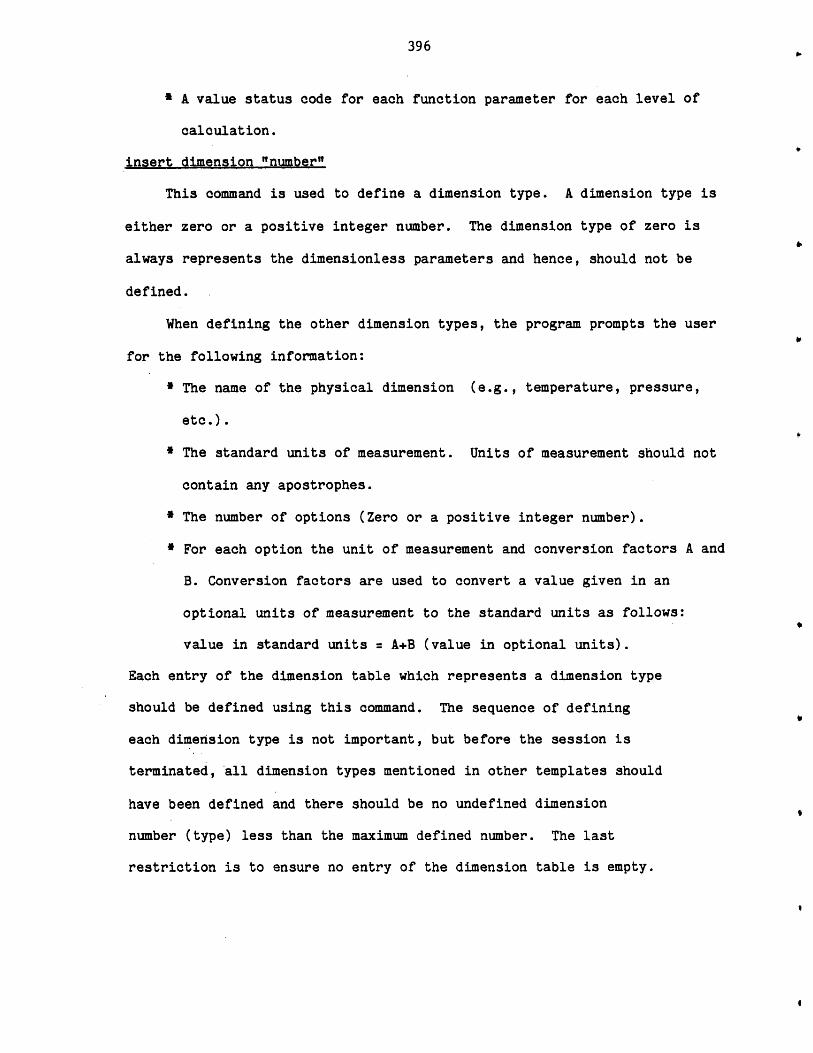
396
* A value status code for each function parameter for each level of
calculation.
insert dimension "number"
This command is used to define a dimension type. A dimension type is
either zero or a positive integer number. The dimension type of zero is
always represents the dimensionless parameters and hence, should not be
defined.
When defining the other dimension types, the program prompts the user
for the following information:
I The name of the physical dimension (e.g., temperature, pressure,
etc.).
* The standard units of measurement. Units of measurement should not
contain any apostrophes.
* The number of options (Zero or a positive integer number).
* For each option the unit of measurement and conversion factors A and
B. Conversion factors are used to convert a value given in an
optional units of measurement to the standard units as follows:
value in standard units = A+B (value in optional units).
Each entry of the dimension table which represents a dimension type
should be defined using this command. The sequence of defininge
each dimension type is not important, but before the session is
terminated, all dimension types mentioned in other templates should
have been defined and there should be no undefined dimension
number (type) less than the maximum defined number. The last
restriction is to ensure no entry of the dimension table is empty.
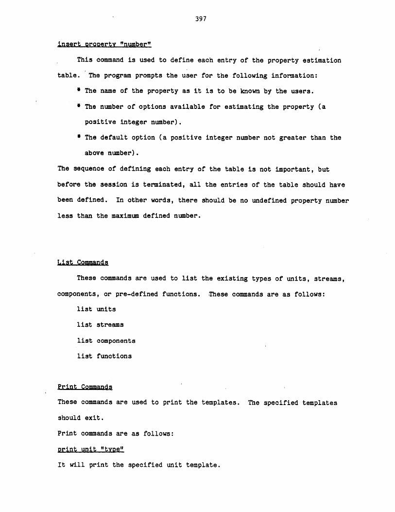
397
insert prooerty "number"
This command is used to define each entry of the property estimation
table. The program prompts the user for the following information:
* The name of the property as it is to be known by the users.
* The number of options available for estimating the property (a
positive integer number).
* The default option (a positive integer number not greater than the
above number).
The sequence of defining each entry of the table is not important, but
before the session is terminated, all the entries of the table should have
been defined. In other words, there should be no undefined property number
less than the maximum defined number.
List Commands
These commands are used to list the existing types of units, streams,
components, or pre-defined functions. These commands are as follows:
list units
list streams
list components
list functions
Print Commands
These commands are used to print the templates. The specified templates
should exit.
Print commands are as follows:
print unit "tvoe"
It will print the specified unit template.
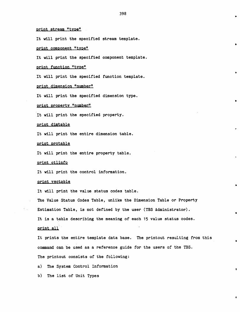
398
print stream "type"
It will print the specified stream template.
Drint comDonent "tvoe"
It will print the specified component template.
print function "tvpe"
It will print the specified function template.
print dimension "number"
It will print the specified dimension type.
print property "number"
It will print the specified property.
print dimtable
It will print the entire dimension table.
print protable
It will print the entire property table.
print ctlinfo
It will print the control information.
print vsctable
It will print the value status codes table.
The Value Status Codes Table, unlike the Dimension Table or Property
Estimation Table, is not defined by the user (TBS Administrator).
It is a table describing the meaning of each 15 value status codes.
print all
It prints the entire template data base. The printout resulting from this
command can be used as a reference guide for the users of the TBS.
The printout consists of the following:
a) The System Control Information
b) The list of Unit Types

399
c)- The list of Stream Types
A) The List of Component Types
e) The List of Function Types
f) The Dimension Table
g) The Property Estimation Table
h) The Value Status Codes Table
i) The Template for each Stream Type
j) The Template for each Component Type
k) The Template for each Unit Type
1) The Template for each Function Type
Reolace.Commands
These commands are used to replace a part of a template associated
with any one level of calculation. The program prompts the user for all
the required information. The program then asks the user whether the given
information is correct or not. If the new set of information is correct,
it will replace the old set. These commands are as follows:
reolace unit "tvoe"
If the unit type exists and there is a calculating routine associated
with it, the program prompts the user for the level of calculation to be
replaced. If the above number is a positive integer number less than or
equal to the number of levels of calculation for that unit type, the user
is prompted for the required information regarding the unit calculating
routine for the specified level of calculation. This information is
exactly the same as the user provides for each level of calculation when
inserting a new unit type.
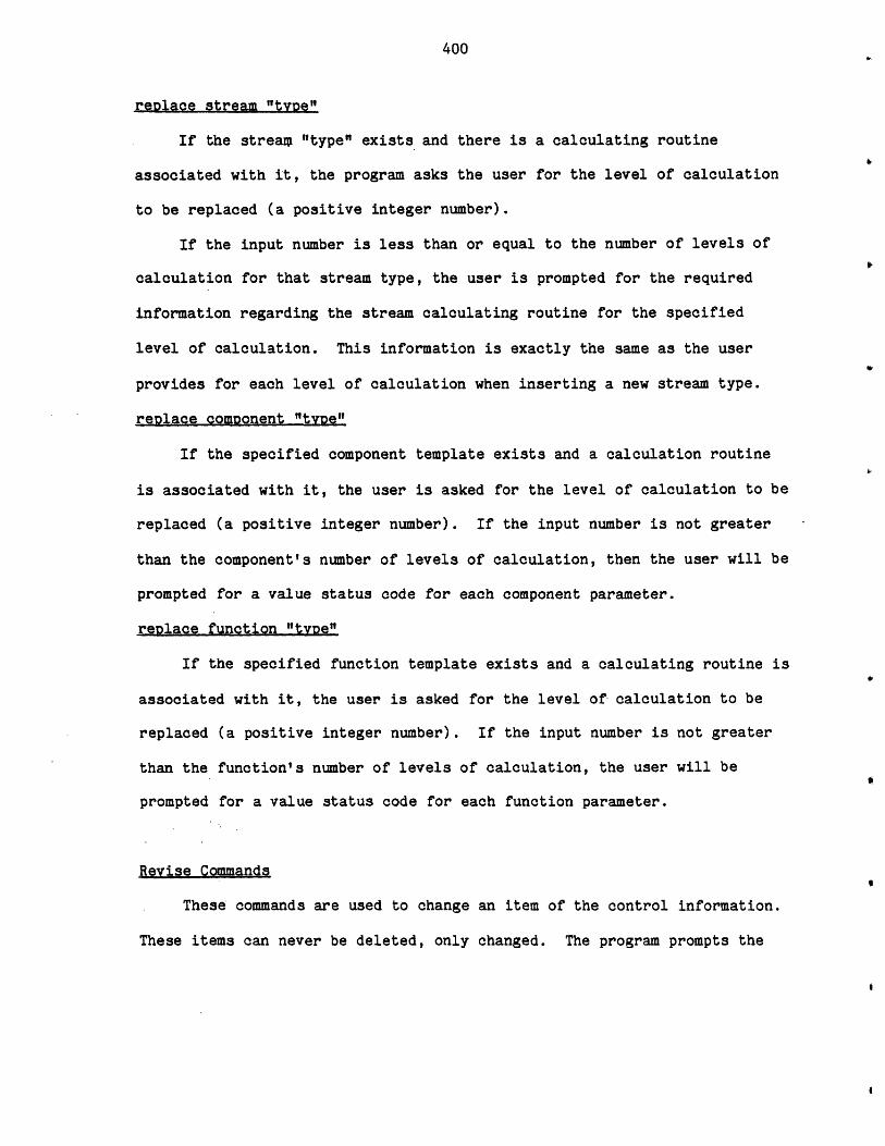
400
reDlace stream "tyoe"
If the stream "type" exists and there is a calculating routine
associated with it, the program asks the user for the level of calculation
to be replaced (a positive integer number).
If the input number is less than or equal to the number of levels of
calculation for that stream type, the user is prompted for the required
information regarding the stream calculating routine for the specified
level of calculation. This information is exactly the same as the user
provides for each level of calculation when inserting a new stream type.
replace component "type"
If the specified component template exists and a calculation routine
is associated with it, the user is asked for the level of calculation to be
replaced (a positive integer number). If the input number is not greater
than the component's number of levels of calculation, then the user will be
prompted for a value status code for each component parameter.
replace function "type"
If the specified function template exists and a calculating routine is
associated with it, the user is asked for the level of- calculation to be
replaced (a positive integer number). If the input number is not greater
than the function's number of levels of calculation, the user will be
prompted for a value status code for each function parameter.
Revise Commands
These commands are used to change an item of the control information.
These items can never be deleted, only changed. The program prompts the
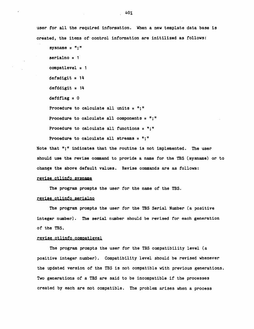
401
user for all the required information. When a new template data base is
created, the items of'control information are initilized as follows:
sysname =
serialno = 1
compatlevel = 1
defsdigit = 14
defddigit = 14
defdflag = 0
Procedure to calculate all units
Procedure to calculate all components :
Procedure to calculate all functions =
Procedure to calculate all streams =
Note that ";" indicates that the routine is not implemented. The user
should use the revise command to provide a name for the TBS (sysname) or to
change the above default values. Revise commands are as follows:
revise Otlinfo svsname
The program prompts the user for the name of the TBS.
revise ctlinfo serialno
The program prompts the user for the TBS Serial Number (a positive
integer number). The serial number should be revised for each generation
of the TBS.
revise ctlinfo compatlevel
The program prompts the user for the TBS compatibility level (a
positive integer number). Compatibility level should be revised whenever
the updated version of the TBS is not compatible with previous generations.
Two generations of a TBS are said to be incompatible if the processes
created by each are not compatible. The problem arises when a process
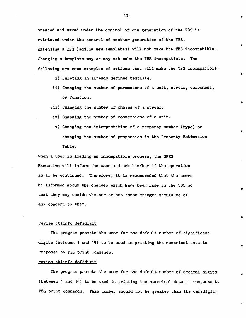
402
created and saved under the control of one generation of the TBS is
retrieved under the control of another generation of the TBS.
Extending a TBS (adding new templates) will not make the TBS incompatible.
Changing a template may or may not make the TBS incompatible. The
following are some examples of actions that will make the TBS incompatible:
i) Deleting an already defined template.
ii) Changing the number of parameters of a unit, stream, component,
or function.
iii) Changing the number of phases of a stream.
iv) Changing the number of connections of a unit.
v) Changing the interpretation of a property number (type) or
changing the number of properties in the Property Estimation
Table.
When a user is loading an incompatible process, the GPES
Executive will inform the user and ask him/her if the operation
is to be continued. Therefore, it is recommended that the users
be informed about the changes which have been made in the TBS so
that they may decide whether or not those changes should be of
any concern to them.
revise ctlinfo defsdigit
The program prompts'the user for the default number of significant.
digits (between 1 and 14) to be used in printing the numerical data in
response to PEL print commands.
revise ctlinfo defddigit
The program prompts the user for the default number of decimal digits
(between 1 and 14) to be used in printing the numerical data in response to
PEL print commands. This number should not be greater than the defsdigit.

403
revise ctlinfo defdflag
The program prompts the user for the default debugging flag (0 or 1).
The flag of 0 which is for normal operation is recommened.
revise ctlinfo unitall
The program prompts the user for the name of the routine to calculate
all units. If the user's response is not a "f;", the user also has to
provide the reference information and number of levels of calculation.
revise ctlinfo streamall
The program prompts the user for the name of the routine to calculate
all streams. If the user's response is not a ";", the reference
information and number of levels of calculation should also be provided.
revise ctlinfo comoall
The program prompts the user for the name of the routine to calculate
all components. If the user's response is not a ";", the reference
information and number of levels of calculation should also be provided.
revise ctlinfo funcall
The program prompts the user for the name of the routine to calculate
all functions. If the user's response is not a ";", the reference
information and number of levels of calculation should also be provided.
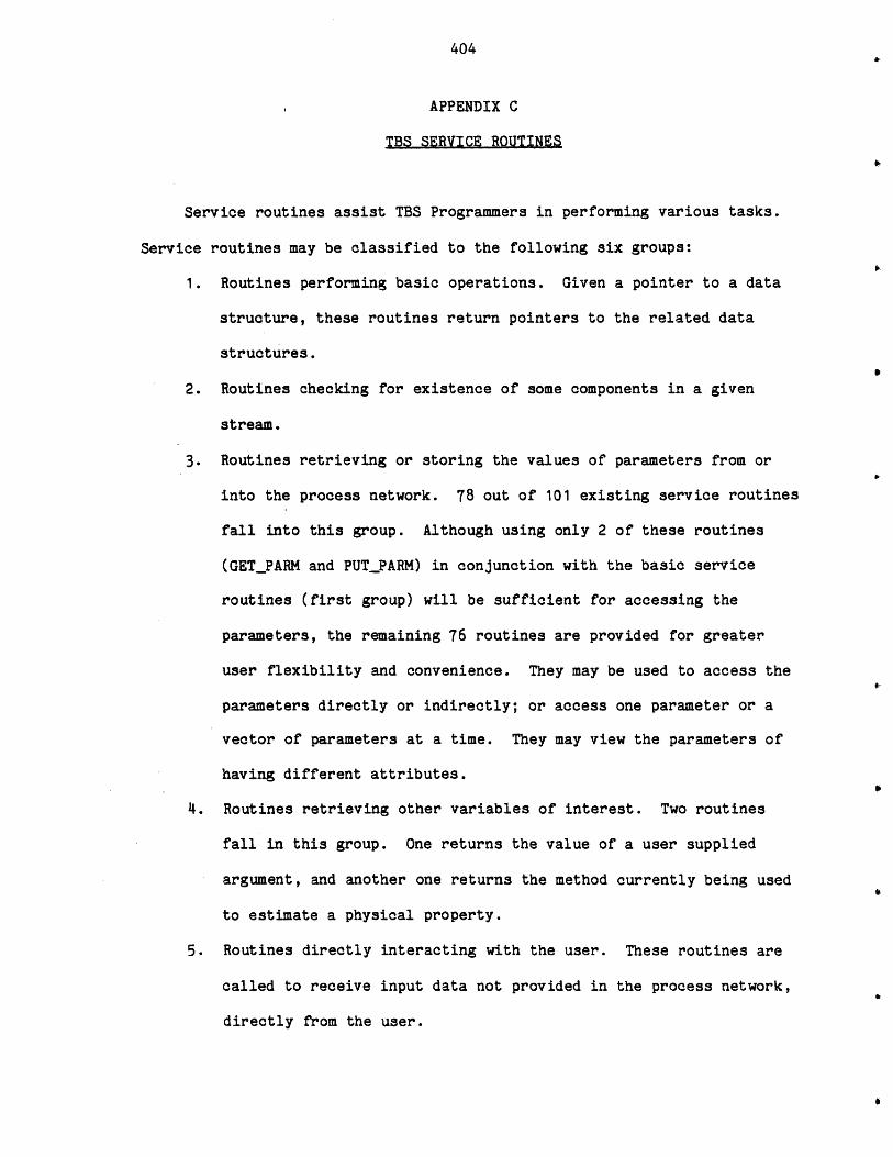
404
APPENDIX C
TBS SERVICE ROUTINES
Service routines assist TBS Programmers in performing various tasks.
Service routines may be classified to the following six groups:
1. Routines performing basic operations. Given a pointer to a data
structure, these routines return pointers to the related data
structures.
2. Routines checking for existence of some components in a given
stream.
3. Routines retrieving or storing the values of parameters from or
into the process network. 78 out of 101 existing service routines
fall into this group. Although using only 2 of these routines
(GET_PARM and PUTPARM) in conjunction with the basic service
routines (first group) will be sufficient for accessing the
parameters, the remaining 76 routines are provided for greater
user flexibility and convenience. They may be used to access the
parameters directly or indirectly; or access one parameter or a
vector of parameters at a time. They may view the parameters of
having different attributes.
4. Routines retrieving other variables of interest. Two routines
fall in this group. One returns the value of a user supplied
argument, and another one returns the method currently being used
to estimate a physical property.
5. Routines directly interacting with the user. These routines are
called to receive input data not provided in the process network,
directly from the user.
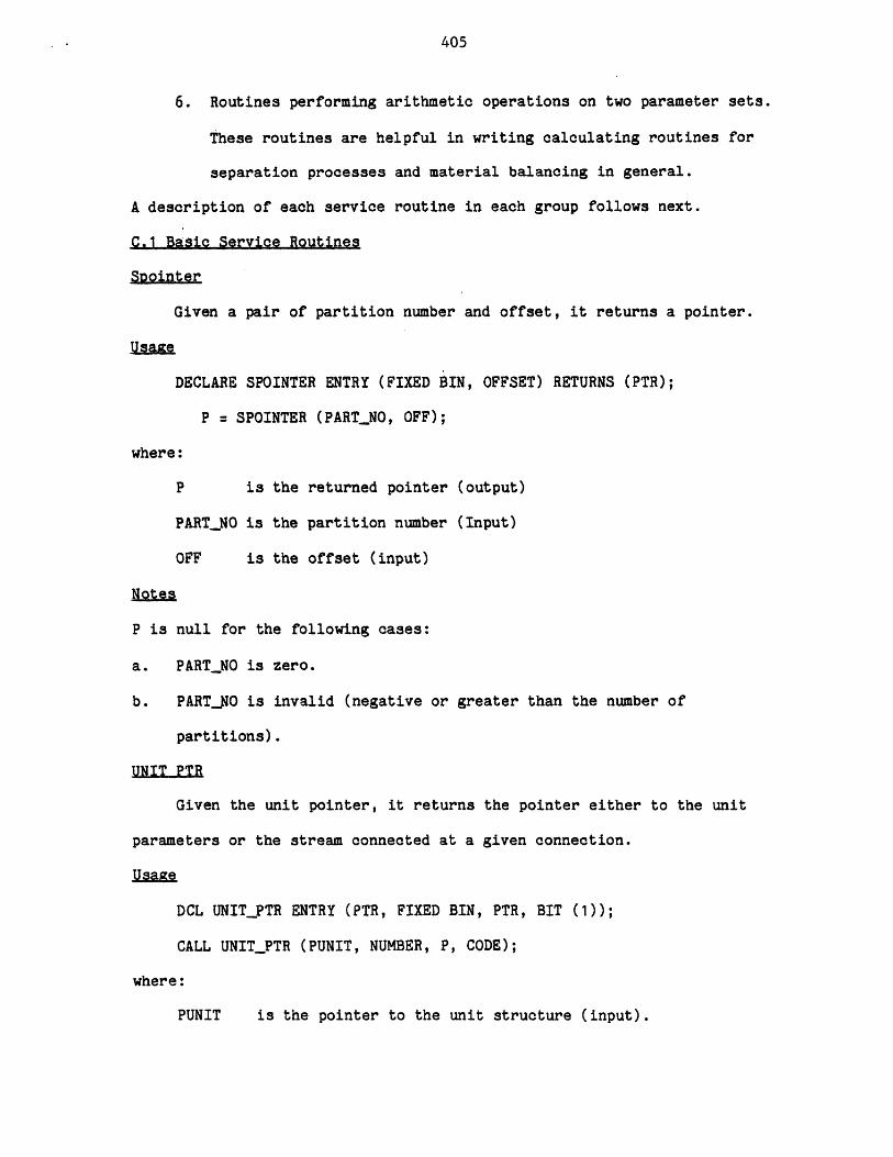
405
6. Routines performing arithmetic operations on two parameter sets.
These routines are helpful in writing calculating routines for
separation processes and material balancing in general.
A description of each service routine in each group follows next.
C.1 Basic Service Routines
Spointer
Given a pair of partition number and offset, it returns a pointer.
Usage
DECLARE SPOINTER ENTRY (FIXED BIN, OFFSET) RETURNS (PTR);
P = SPOINTER (PARTJNO, OFF);
where:
P is the returned pointer (output)
PART_NO is the partition number (Input)
OFF is the offset (input)
Notes
P is null for the following cases:
a. PART_NO is zero.
b. PART_NO is invalid (negative or greater than the number of
partitions).
UNIT PTR
Given the unit pointer, it returns the pointer either to the unit
parameters or the stream connected at a given connection.
Usage
DCL UNIT_PTR ENTRY (PTR, FIXED BIN, PTR, BIT (1));
CALL UNIT_PTR (PUNIT, NUMBER, P, CODE);
where:
PUNIT is the pointer to the unit structure (input).
406
NUMBER is zero or connection number (input).
P is the pointer to the unit parameters structure, if
NUMBER = 0. Otherwise, it is the pointer to the stream
connected at the given connection (output).
CODE is the error code (output).
Notes
CODE is turned "on" and P is null for the following cases:
a. PUNIT is null.
b. NUMBER is negative or greater than the number of unit
connections.
c. The unit is not connected at the given connection.
Example
See Figure C.1.
GET COMP INDEX
It returns the component index (entry number in the Component
Directory) of a given component.
Usage
DCL GET_COMP_INDEX ENTRY (CHAR (16), FIXED BIN, BIT (1));
CALL GET_COMP_INDEX (NAME, COMP_INDEX, CODE);
where:
NAME is the component's name (input).
COMP_INDEX is the component's index (output).
CODE is the Error Code (output).
Notes
CODE is turned "on" and COMPINDEX is zero if the component does not exist.
Example
See Figure C.2.
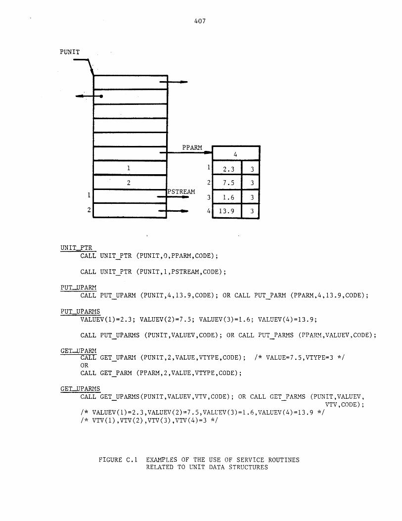
407
PUNIT
UNIT-PTRCALL UNITPTR (PUNIT,O,PPARM,CODE);
CALL UNIT PTR (PUNIT,1,PSTREAM,CODE);
PUT-UPARMCALL PUT UPARM (PUNIT,4,13.9,CODE); OR CALL PUT PARM (PPARM,4,13.9,CODE);
PUTUPARMSVALUEV(1)=2.3; VALUEV(2)=7.5; VALUEV(3)=1.6; VALUEV(4)=13.9;
CALL PUT UPARMS (PUNIT,VALUEV,CODE); OR CALL PUT PARMS (PPARM,VALUEV,CODE);
GET-UPARMCALL GET UPARM (PUNIT,2,VALUE,VTYPE,CODE); /* VALUE=7.5,VTYPE=3 */ORCALL GETPARM (PPARM,2,VALUE,VTYPE,CODE);
GET-UPARMSCALL GET UPARMS(PUNIT,VALUEV,VTV,CODE); OR CALL GET PARMS (PUNIT,VALUEV,
VTV,CODE);/* VALUEV(1)=2.3,VALUEV(2)=7.5,VALUEV(3)=1.6,VALUEV(4)=13.9 *//* VTV(1),VTV(2),VTV(3),VTV(4)=3 */
FIGURE C.1 EXAMPLES OF THE USE OF SERVICE ROUTINESRELATED TO UNIT DATA STRUCTURES
PPM
2?STREAM
4
2.3 3
7.53
1.6
13.9
1
2
3
4
3
3
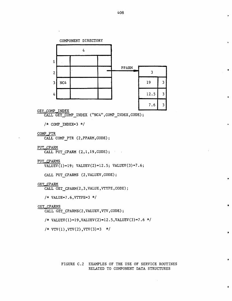
408
COMPONENT DIRECTORY
4
NC4
PPARM
19
12.5
7.6
GET-COMPINDEXCALL GET COMPINDEX ("NC4",COMP_INDEX, CODE);
3
3
3/* COMPINDEX=3 */
COMPPTRCALL CON? PTR (2,PPARM,CODE);
PUT-CPARMCALL PUTCPARM (2,1,19,CODE);
PUTC.PARMSVALUEV(1)=19; VALUEV(2)=12.5; VALUEV(3)=7.6;
CALL PUT CPARMS (2,VALUEV,CODE);
GETCPARMCALL GETCPARM(2,3,VALUE,VTYPECODE);
/* VALUE=7.6,VTYPE=3 */
GET-CPARMSCALL GETCPARMS(2,VALUEV,VTV,CODE);
/* VALUEV(1)=19,VALUEV(2)=12.5,VALUEV(3)=7.6 */
/* VTV(1),VTV(2),VTV(3)=3 */
FIGURE C.2 EXAMPLES OF THE USE OF SERVICE ROUTINESRELATED TO COMPONENT DATA STRUCTURES
409
COMP PTR
Given the component index, it returns the pointer to the component
paramters' structure.
Usageg
DCL COMP_PTR ENTRY (FIXED BIN, PTR, BIT (1));
CALL COMP_PTR (COMP_INDEX, PPARM, CODE);
where:
COMP_INDEX is the component index (input).
PPARM is the pointer to the parameters' structure (output).
CODE is the error code (output)
Notes2
CODE is turned "on" and P is null for the following cases:
a. COMP INDEX is negative or more than the maximum number of componen t~s
(MAXNC).
The component does not exist.b.
Example
See Figure
FUNC. PTR
Given
parameters
Usaize
DCL
CALL
where:
PFUNC
PPARM
CODE
C.2.
the function pointer, it returns the pointer to the function
structure.
FUNC_PTR ENTRY (PTR, PTR, BIT(1));
FUNC_PTR (PFUNC, PPARM, CODE);
is the pointer to the function structure (input).
is the pointer to the parameters' structure (output).
is the error code (output).
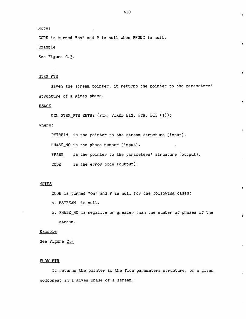
410
Notes
CODE is turned "on" and P is null when PFUNC is null.
Example
See Figure C.3.
STRM PTR
Given the stream pointer, it returns the pointer to the parameters'
structure of a given phase.
USAGE
DCL STRMPTR ENTRY (PTR, FIXED BIN, PTR, BIT (1));
where:
PSTREAM is the pointer to the stream structure (input).
PHASENO is the phase number (input).
PPARM is the pointer to the parameters' structure (output).
CODE is the error code (output).
NOTES
CODE is turned "on" and P is null for the following cases:
a. PSTREAM is null.
b. PHASENO is negative or greater than the number of phases of the
stream.
Example
See Figure C.4
FLOW PTR
It returns the pointer to the flow parameters structure, of a given
component in a given phase of a stream.
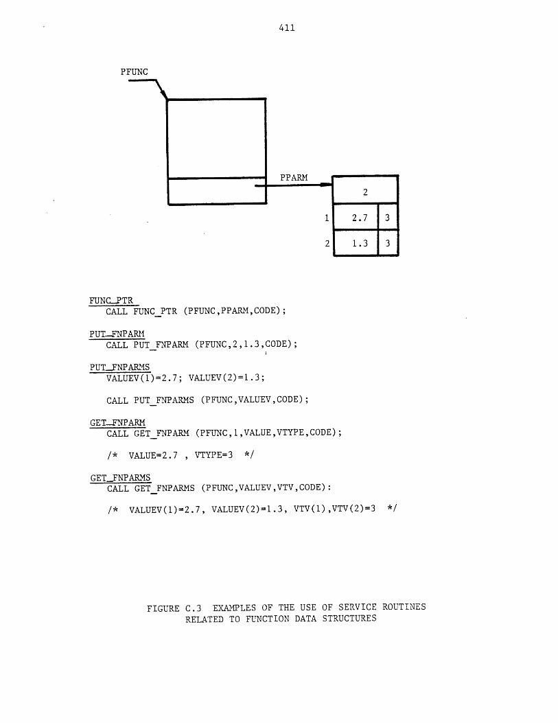
411
PFUNC
FUNC-PTRCALL FUNC PTR (PFUNC,PPARM,CODE);
PUT-FNPARMCALL PUTFNPARM (PFUNC,2,1.3,CODE);
PUT-FNPARMSVALUEV(1)=2.7; VALUEV(2)=1.3;
CALL PUTFNPARMS (PFUNC,VALUEV,CODE);
GET-FNPARMCALL GET FNPARM (PFUNC,1,VALUE,VTYPE,CODE);
/* VALUE=2.7 , VTYPE=3 */
GETFNPARMSCALL GET FNPARMS (PFUNC,VALUEV,VTV,CODE):
/* VALUEV(1)=2.7, VALUEV(2)=1.3, VTV(1),VTV(2)=3 */
FIGURE C.3 EXAMPLES OF THE USE OF SERVICE ROUTINES
RELATED TO FUNCTION DATA STRUCTURES
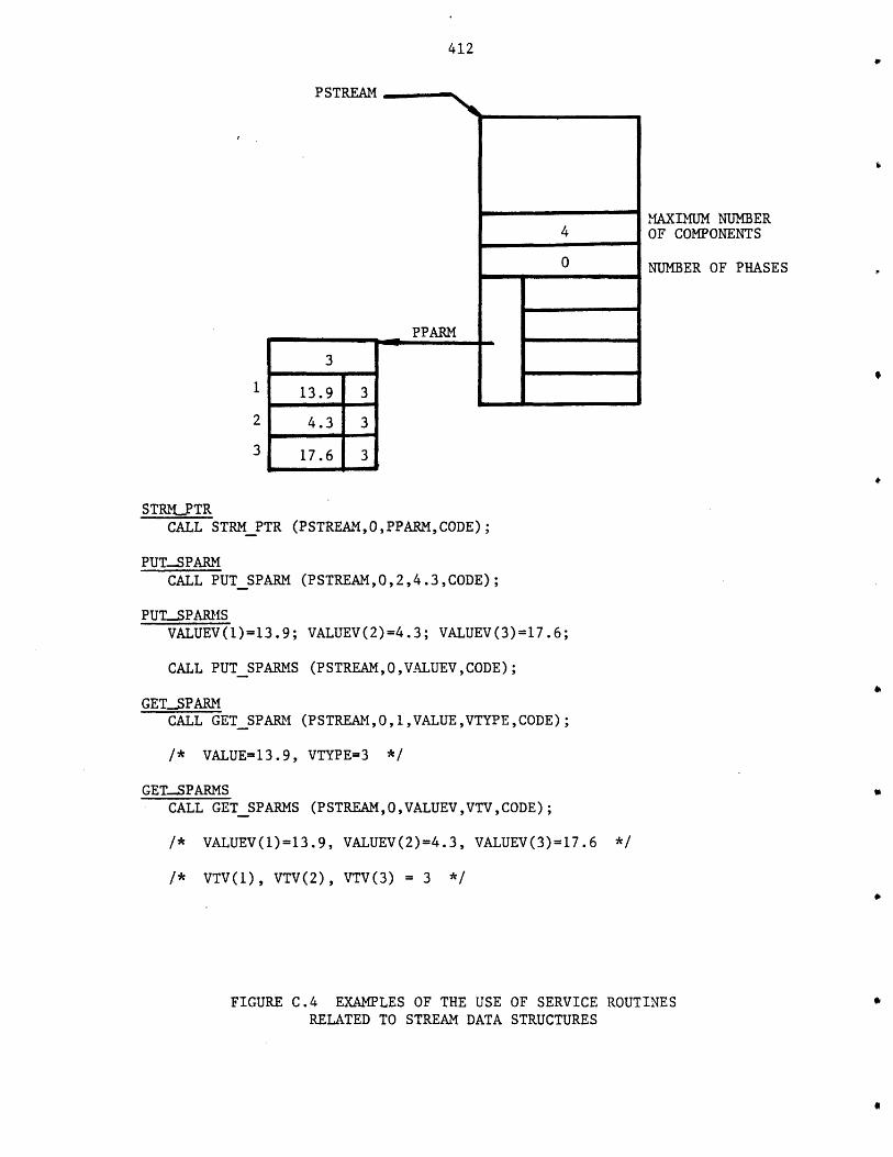
412
PSTREAM
3
13.9 3
4.3 3
17.6 3
PPARM L
MAXIMUM NUMBEROF COMPONENTS
NUMBER OF PHASES
STRMJPTRCALL STRMPTR (PSTREAM,O,PPARM,CODE);
PUT...SPARMCALL PUTSPARM (PSTREAM,O,2,4.3,CODE);
PUTSPARMSVALUEV()=13.9; VALUEV(2)=4.3; VALUEV(3)=17.6;
CALL PUTSPARMS (PSTREAM,0,VALUEV ,CODE);
GETSPARMCALL GETSPARM (PSTREAM,0,1,VALUE,VTYPE, CODE);
/* VALUE=13.9, VTYPE=3 */
GET.-SPARMSCALL GETSPARMS (PSTREAM,O ,VALUEV ,VTV ,CODE);
/* VALUEV(1)=13.9, VALUEV(2)=4.3, VALUEV(3)=17.6 */
/* VTV(1), VTV(2), VTV(3) = 3 */
FIGURE C.4 EXAMPLES OF THE USE OF SERVICE ROUTINESRELATED TO STREAM DATA STRUCTURES
4
0
-U
413
USAGE
FLOWPTR ENTRY (PTR, FIXED BIN, FIXED BIN, PTR, BIT (1));
FLOWPTR (PSTREAM, PHASE_NO COMP_INDEX, PPARM, CODE);
PSTREAM
PHASENO0
COMPINDEX
PPARM
CODE
is the pointer to the stream structure (input).
is the phase number (input).
is the component index (input).
is the pointer to the flow parameters' structure (output).
is the error code (output).
NOTES
CODE is turned "on" and P is null for the following cases:
a. PSTREAM is null.
b. PHASE_NO is invalid, negative or greater than the number of phases
of the stream.
c. COMP_INDEX is invalid or the component does not exist or does not
flow in the stream.
Examole_
See Figure QDa
C.2 Comoarison Service Routines
AME .CQMPS
Determines if the components in one stream are those that are in
another stream.
Usage2
DCL
CALL
SAMECOMPS ENTRY (PTR, PTR, BIT(1));
SAME_COMPS (PSTREAM1, PSTREAM2, CODE);
DCL
CALL
where:

414
PSTREAM
FIGURE C.5 EXAMPLES OF THE USE OFSERVICE ROUTINES RELATEDTO FLOW PARAMETERS
MAXIMUM NUMBER 4OF COMPONENTS
NUMBER OF 0PHASES
PARM
12 2
2
0 31 3.5 3 1 15.2 2
4 - 2 7.6 3 2 19.3 31
FLOW PTRCALL FLOWPTR (PSTREAM,0,1,PPARM,CODE);
PUTFPARMCALL PUT FPARM (PSTREAM,0,1,1,3.5,CODE);
PUTFPARMSVALUEV(1)=3.5; VALUEV(2)=7.6;
CALL PUTFPARMS (PSTREAM,0,1 ,VALUEV,CODE);
GET-FPARMCALL GETFPARM (PSTREAM,0,2,1,VALUE,VTYPE,CODE);
/* VALUE=15.2,VTYPE=2 */
GET FPARMSCALL GET FPARMS(PSTREAM,O,I,VALUEV,VTV,CODE);
/* VALUEV(1)=3.5,VALUEV(2)=7.6,VTV(1),VTV(2)=3 */
PUTFPARMACSVALUEV(1)=7.6; VALUEV(4)=19.3;
CALL PUTFPARMACS (PSTREAM,0,2,VALUEV,CODE);
GET.JPARMACSCALL GETFPARMACS (PSTREAM,O,2,VALUEV,VTV,CODE);
/* VALUEV(1)=7.6,VALUEV(4)=19.3,VTV(1),VTV(4)=3,VTV(2),VTV(3)=-1 */

415
where:
PSTREAM1 is the pointer to the 1st stream's structure (input).
PSTREAM2 is the pointer to the 2nd stream's structure (input).
CODE is the error code (output).
Notes
CODE is turned "on" for the following cases:
a. PSTREAM1 or PSTREAM2 is null.
b. The same components do not flow in both streams.
CHECK-COMPS
Determines if the components present in a stream are those whose names
are specified.
Usage
DCL CHECK_COMPS ENTRY (PTR, DIM(*)CHAR(16),BIT(1));
CALL CHECK.COMPS (PSTREAM, COMPJNAMES, CODE);
where:
PSTREAM is the pointer to the streams' structure (input).
COMP_NAMES is the array of component names (input).
CODE is the error code (output).
Notes
CODE is turned "on" for the following cases:
a. PSTREAM is null.
b. Components in the stream are not exactly those specified in the array
of component names.
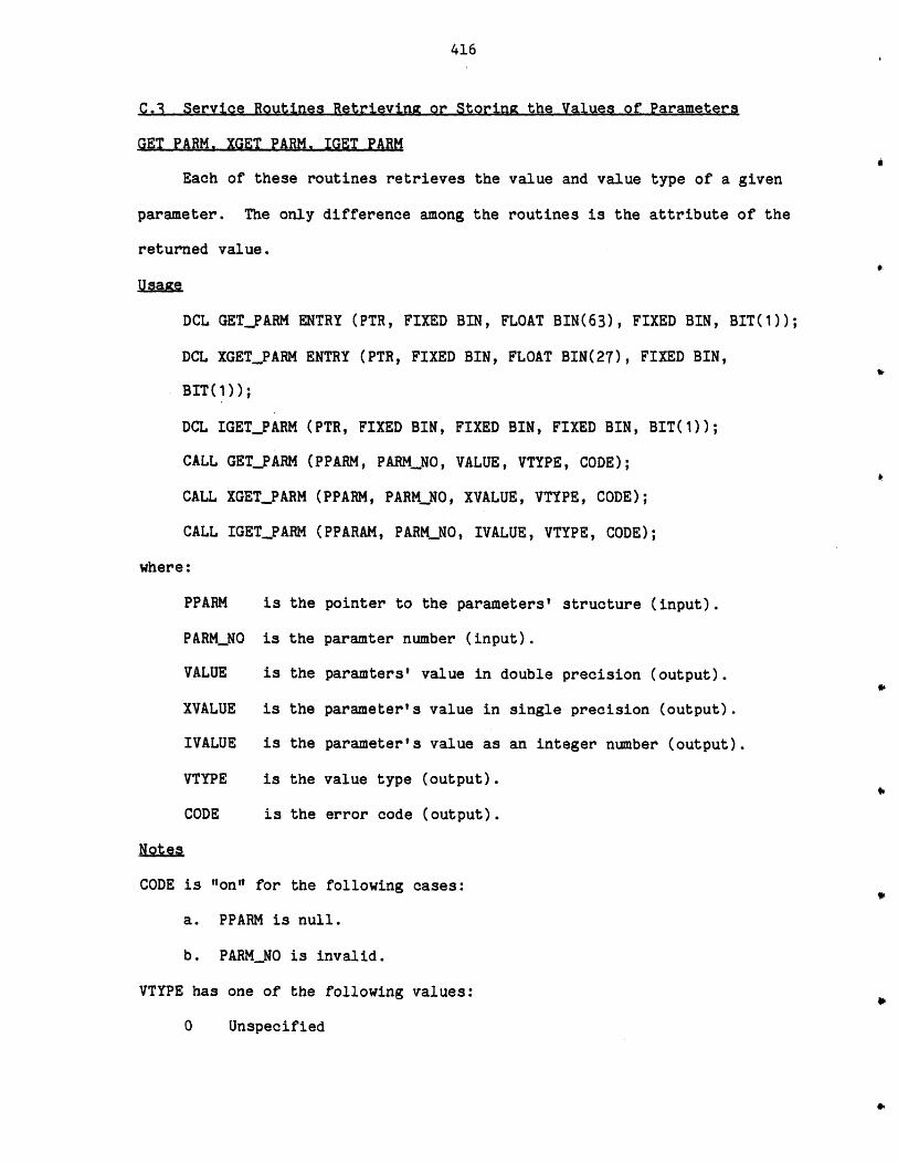
416
C.1 Service Routines Retrieving or Storing the Values of Parameters
GET PARM. XGET PARM. IGET PARM
Each of these routines retrieves the value and value type of a given
parameter. The only difference among the routines is the attribute of the
returned value.
Usaize
DCL GET_PARM ENTRY (PTR, FIXED BIN, FLOAT BIN(63), FIXED BIN, BIT(1));
DCL XGET_PARM ENTRY (PTR, FIXED BIN, FLOAT BIN(27), FIXED BIN,
BIT(1));
DCL IGET_PARM (PTR, FIXED BIN, FIXED BIN, FIXED BIN, BIT(1));
CALL GET_PARM (PPARM, PARMNO, VALUE, VTYPE, CODE);
CALL XGET_PARM (PPARM, PARMNO, XVALUE, VTYPE, CODE);
CALL IGETPARM (PPARAM, PARMNO, IVALUE, VTYPE, CODE);
where:
PPARM is the pointer to the parameters' structure (input).
PARM_NO is the paramter number (input).
VALUE is the paramters' value in double precision (output).
XVALUE is the parameter's value in single precision (output).
IVALUE is the parameter's value as an integer number (output).
VTYPE is the value type (output).
CODE is the error code (output).
Notes
CODE is "on" for the following cases:
a. PPARM is null.
b. PARMNO is invalid.
VTYPE has one of the following values:
0 Unspecified
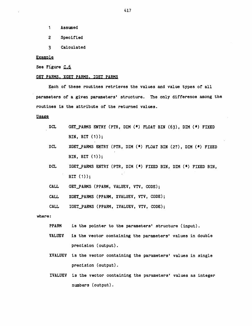
417
Assumed
Specified
Calculated
See Figure S.J
GET PARMS. XGET PARMS. IGET PARMS
Each of these routines retrieves the values and value types of all
parameters of a given parameters' structure. The only difference among the
routines is the attribute of the returned values.
Usaize
DCL
DCL
DCL
CALL
CALL
CALL
GETPARMS ENTRY (PTR, DIM (*) FLOAT BIN (63), DIM (*) FIXED
BIN, BIT (1));
XGETPARMS ENTRY (PTR, DIM (*) FLOAT BIN (27), DIM (*) FIXED
BIN, BIT (1));
IGET-PARMS ENTRY (PTR, DIM (*) FIXED BIN, DIM C*) FIXED BIN,
BIT (1));
GETPARMS (PPARM, VALUEV, VTV, CODE);
XGETPARMS (PPARM, XVALUEV, VTV, CODE);
IGETPARMS (PPARM, IVALUEV, VTV, CODE);
where:
PPARM is the pointer to the parameters' structure (input).
VALUEV is the vector containing the parameters' values in double
precision (output).
XVALUEV is the vector containing the parameters' values in single
precision (output).
IVALUEV is the vector containing the parameters' values as integer
numbers (output).
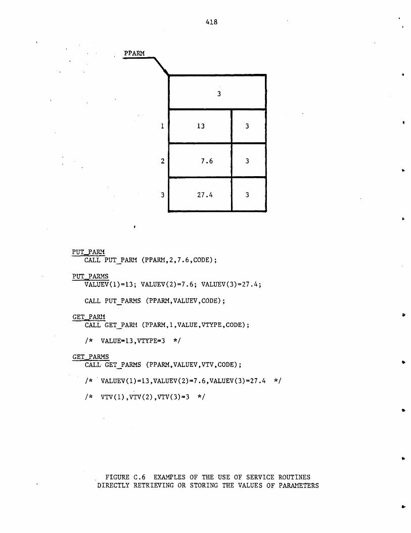
418
PPARM
3
1 13 3
2 7.6 3
3 27.4 3
PUT_PARMCALL PUTPARM (PPARM,2,7.6,CODE);
PUT PARMSVALUEV(1)=13; VALUEV(2)=7.6; VALUEV(3)=27.4;
CALL PUT PARMS (PPARM, VALUEV ,CODE);
GET PARMCALL GET PARM (PPARM, 1 ,VALUE,VTYPE,CODE);
/* VALUE=13,VTYPE=3 */
GET_PARMSCALL- GETPARMS (PPARM,VALUEV,VTV,CODE);
/* VALUEV(1)=13,VALUEV(2)=7.6,VALUEV(3)=27.4 */
/* VTV(1),VTV(2),VTV(3)=3 */
FIGURE C.6 EXAMPLES OF THE USE OF SERVICE ROUTINESDIRECTLY RETRIEVING OR STORING THE VALUES OF PARAMETERS
419
VTV is the vector containing the value types(output).
CODE is the error code(output).
Notes
CODE is "on" for the following cases:
a. PPARM is null.
b. The size of VALUEV, XVALUEV, IVALUEV, OR VTV is not equal to the
number of the parameters.
The Ith entry of VTV indicates the value type of the Ith parameter.
Each entry of VTV may be one of the following:
0 UNSPECIFIED
1 ASSUMED
2 SPECIFIED
3 CALCULATED
ExaMole
See Figure Qd
PUT PARM. XPUT PARM. IPUT PARM
Each of these routines stores the value of a given parameter. The
only difference among the routines is the attribute of the given value.
Usa CTe
DCL PUT_PARM ENTRY(PTR, FIXED BIN, FLOAT BIN (63), BIT (1));
DCL XPUT_PARM ENTRY (PTR, FIXED BIN, FLOAT BIN (27) BIT (1));
DCL IPUT_PARM ENTRY (PTR, FIXED BIN, FIXED BIN, BIT(1));
CALL PUT_PARM (PPARM, PARMNO, VALUE, CODE);
CALL XPUT_PARM (PPARM, PARMNO, XVALUE, CODE);
CALL IPUTPARM (PPARM, PARMNO, IVALUE, CODE);
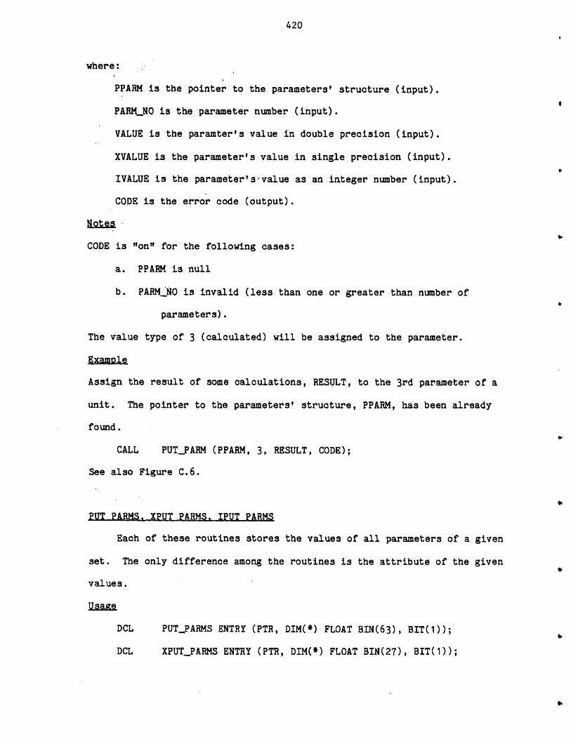
420
where:
PPARM is the pointer to the parameters' structure (input).
PARMNO is the parameter number (input).
VALUE is the paramter's value in double precision (input).
XVALUE is the parameter's value in single precision (input).
IVALUE is the parameter's--value as an integer number (input).
CODE is the error code (output).
Notes
CODE is "on" for the following cases:
a. PPARM is null
b. PAR._NO is invalid (less than one or greater than number of
parameters).
The value type of 3 (calculated) will be assigned to the parameter.
Examole
Assign the result of some calculations, RESULT, to the 3rd parameter of a
unit. The pointer to the parameters' structure, PPARM, has been already
found.
CALL PUT-FARM (PPARM, 3, RESULT, CODE);
See also Figure C.6.
PUT PARMS. XPUT PARMS. IPUT PARMS
Each of these routines stores the values of all parameters of a given
set. The only difference among the routines is the attribute of the given
values.
Usage
DCL PUT_PARMS ENTRY (PTR, DIM(*) FLOAT BIN(63), BIT(1));
DCL XPUT_PARMS ENTRY (PTR, DIM(*) FLOAT BIN(27), BIT(1));
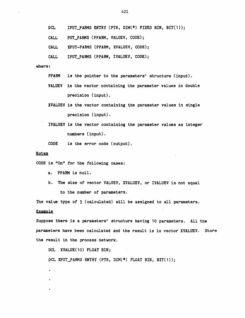
421
DCL IPUTPARMS ENTRY (PTR, DIM(*) FIXED BIN, BIT(1));
CALL PUT_PARMS (PPARM, VALUEV, CODE);
CALL XPUT-PARMS (PPARM, XVALUEV, CODE);
CALL IPUTPARMS (PPARM, IVALUEV, CODE);
where:
PPARM is the pointer to the parameters' structure (input).
VALUEV is the vector containing the parameter values in double
precision (input).
XVALUEV is the vector containing the parameter values in single
precision (input).
IVALUEV is the vector containing the parameter values as integer
numbers (input).
CODE is the error code (output).
Notes
CODE is "On" for the following cases:
a. PPARM is null.
b. The size of vector VALUEV, XVALUEV, or IVALUEV is not equal
to the number of parameters.
The value type of 3 (calculated) will be assigned to all parameters.
Excample
Suppose there is a parameters' structure having 10 parameters. All the
parameters have been calculated and the result is in vector XVALUEV. Store
the result in the process network.
DCL XVALUE(10) FLOAT BIN;
DCL XPUT_PARMS ENTRY (PTR, DIM(*) FLOAT BIN, BIT(1));
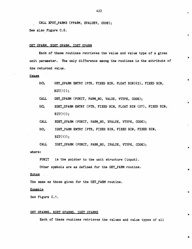
422
CALL. XPUT_PARMS (PPARM, XVALUEV, CODE);
See also Figure C.6.
GET UPARM. XGET UPARM. IGET UPARM
Each of these routines retrieves the value and value type of a given
unit parameter. The only difference among the routines is the attribute of
the returned value.
Usagxe
DCL GET_UPARM ENTRY (PTR, FIXED BIN, FLOAT BIN(63), FIXED BIN,
BIT(1));
CALL GETJPARM (PUNIT, PARM_NO, VALUE, VTYPE, CODE);
DCL XGET_UPARM ENTRY (PTR, FIXED BIN, FLOAT BIN (27), FIXED BIN,
BIT(1));
CALL XGETUPARM (PUNIT, PARM_NO, XVALUE, VTYPE, CODE);
DCL IGET_PARM ENTRY (PTR, FIXED BIN, FIXED BIN, FIXED BIN,
BIT(1));
CALL IGETUPARM (PUNIT, PARM_NO, IVALUE, VTYPE, CODE);
where:
PUNIT is the pointer to the unit structure (input).
Other symbols are as defined for the GET_PARM routine.
Notes
The same as those given for the GET_FARM routine.
ExamDle
See Figure C.1.
GET UPARMS. XGET UPARMS. IGET UPARMS
Each of these routines retrieves the values and value types of all
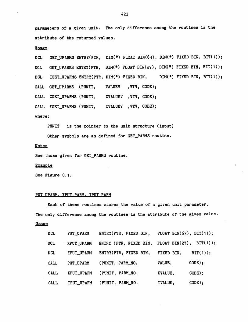
423
parameters of a given unit. The only difference among the routines is the
attribute of the returned values.
UaGe
DCL GET_UPARMS ENTRY(PTR,
DCL GET_UPARMS ENTRY(PTR,
DCL IGET_UPARMS ENTRY(PTR,
CALL GET_UPARMS (PUNIT,
CALL XGET_UPARMS (PUNIT,
CALL IGET_UPARMS (PUNIT,
where:
DIM(*) FLOAT BIN(63), DIM(*) FIXED BIN, BIT(1));
DIM(*) FLOAT BIN(27), DIM(*) FIXED BIN, BIT(1));
DIM(*) FIXED BIN, DIM(*) FIXED BIN, BIT(1));
VALUEV ,VTV, CODE);
XVALUEV ,VTV, CODE);
IVALUEV ,VTV, CODE);
PUNIT is the pointer to the unit structure (input)
Other symbols are as defined for GETPARMS routine.
Notes
See those given for GETPARMS routine.
Examnle
See Figure C.1.
PUT UPARM. IPUT PARM, IPUT PARM
Each of these routines stores the value of a given unit parameter.
The only difference among the routines is the attribute of the given value.
PUTUPARM
XPUTUPARM
IPUTUPARM
PUT_UPARM
XPUTUPARM
IPUT_UPARM
ENTRY(PTR, FIXED BIN,
ENTRY (PTR, FIXED BIN,
ENTRY(PTR, FIXED BIN,
(PUNIT, PARM_NO,
(PUNIT, PARM_NO,
(PUNIT, PARM_NO,
FLOAT BIN(63), BIT(1));
FLOAT BIN(27), BIT(1));
FIXED BIN, BIT(1));
VALUE, CODE);
XVALUE, CODE);
IVALUE, CODE);
DCL
DCL
DCL
CALL
CALL
CALL

424
where:
PUNIT is the pointer to the unit structure (input).
Other symbols are as defined for PUT.PARM routine.
Notes
See those given for PUTPARM routine.
Examole
See figure C.1.
PUT UPARMS. XPUT UPARMS. IPUT UPARMS
Each of these routines stores the values of all parameters of a given unit.
The only difference among the routines is the attribute of the given
values.
Usaxe-
PUTUPARMS
XPUT_UPARMS
IPUT_UPARMS
PUT_UPARMS
XPUTUPARMS
IPUT_UPARMS
ENTRY(PTR,
ENTRY (PTR,
ENTRY(PTR,
(PUNIT,
(PUNIT,
(PUNIT,
DIM(*) FLOAT BIN(63), BIT(1));
DIM(*) FLOAT BIN(27), BIT(1));
DIM(*) FIXED BIN, BIT(1));
VALUEV ,CODE);
XVALUEV ,CODE);
IVALUEV ,CODE);
PUNIT
Other symbols
is the pointer to the unit structure (input).
are as defined for PUT_PARMS routine.
Notes
See those given for PUT_PARMS routine.
Example
See Figure C.1.
DCL
DCL
DCL
CALL
CALL
CALL
where:
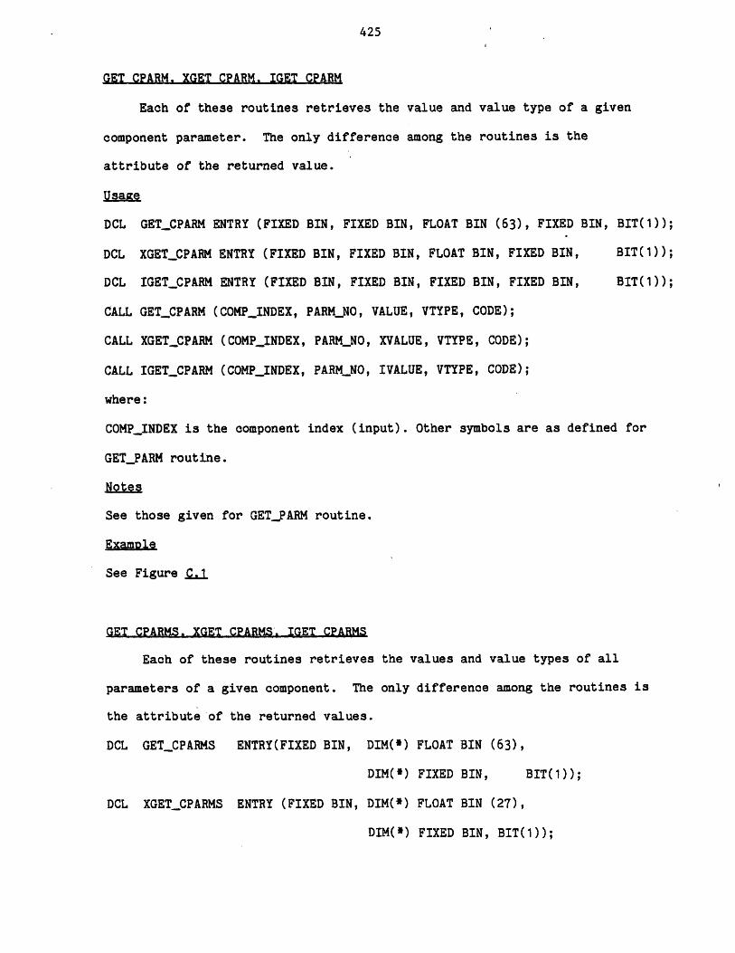
425
GET CPARM. IGET CPARM. IGET CPARM
Each of these routines retrieves the value and value type of a given
component parameter. The only difference among the routines is the
attribute of the returned value.
UsaGe
DCL GET_CPARM ENTRY (FIXED BIN, FIXED BIN, FLOAT BIN (63), FIXED BIN, BIT(1));
DCL XGET_CPARM ENTRY (FIXED BIN, FIXED BIN, FLOAT BIN, FIXED BIN, BIT(1));
DCL IGETCPARM ENTRY (FIXED BIN, FIXED BIN, FIXED BIN, FIXED BIN, BI ));
CALL GETCPARM (COMPINDEX, PARMNO, VALUE, VTYPE, CODE);
CALL IGETCPARM (COMPJ_INDEX, PARM_NO, XVALUE, VTYPE, CODE);
CALL IGET_CPARM (COMP._INDEX, PARMNO, IVALUE, VTYPE, CODE);
where:
COMP_INDEX is the component index (input). Other symbols are as defined for
GET_PARM routine.
Notes
See those given for GET.PARM routine.
Example
See Figure .C.1
GET CPARMS, XGET CPARMS. IGET CPARMS
Each of these routines retrieves the values and value types of all
parameters of a given component. The only difference among the routines is
the attribute of the returned values.
DCL GET_CPARMS ENTRY(FIXED BIN, DIM(*) FLOAT BIN (63),
DIM(*) FIXED BIN, BIT(1));
DCL XGET_CPARMS ENTRY (FIXED BIN, DIM(*) FLOAT BIN (27),
DIM(*) FIXED BIN, BIT(1));
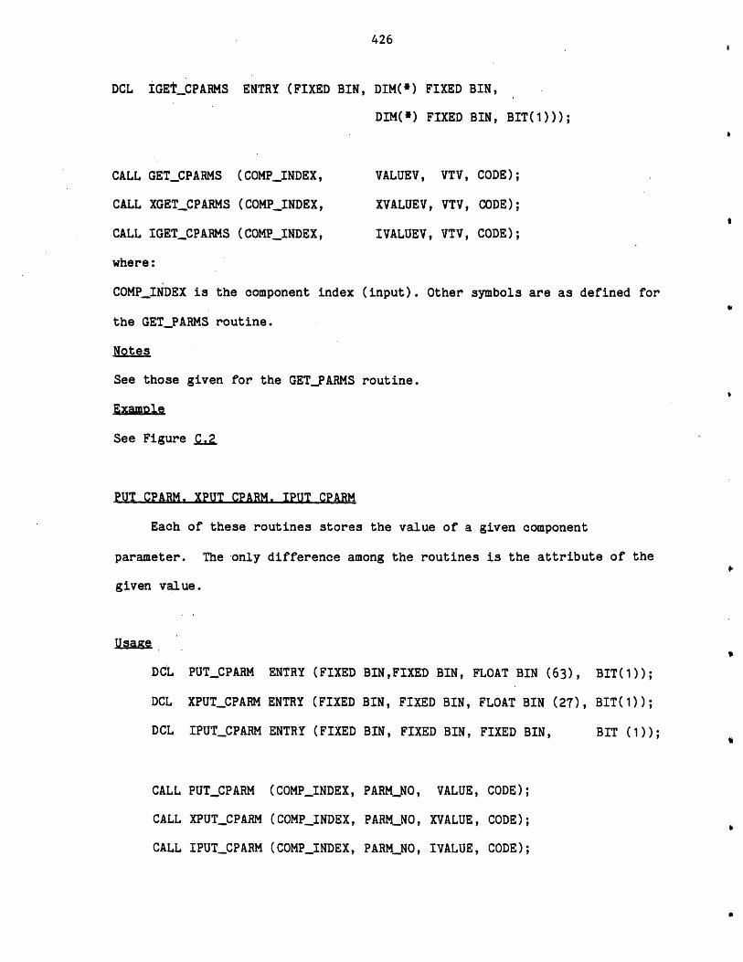
426
DCL IGEt_CPARMS ENTRY (FIXED BIN
CALL GET_CPARMS (COMPINDEX,
CALL XGET_CPARMS (COMPINDEX,
CALL IGETCPARMS (COMPINDEX,
where:
COMP_INDEX is the component index
the GET_PARMS routine.
Notes
See those given for the GET_PARMS
Example
See Figure _fQa
PUT CPARM. XPUT CPARM. IPUT CPARM
, DIM(*) FIXED BIN,
DIM(*) FIXED BIN, BIT(1)));
VALUEV, VTV, CODE);
XVALUEV, VTV, CODE);
IVALUEV, VTV, CODE);
(input). Other symbols are as defined for
Each of these routines stores the value of a given component
parameter. The -only difference among the routines is the attribute of the
given value.
UsaFe
DCL PUT_CPARM ENTRY (FIXED BINFIXED BIN, FLOAT BIN (63), BIT(1));
DCL XPUT_CPARM ENTRY (FIXED BIN, FIXED BIN, FLOAT BIN (27), BIT(1));
DCL IPUT_CPARM ENTRY (FIXED BIN, FIXED BIN, FIXED BIN, BIT (1));
CALL PUT_CPARM (COMPINDEX, PARMNO, XVALUE, CODE);
CALL XPUT_CPARM (COMP_INDEX, PARMNO, XVALUE, CODE);
CALL IPUTCPARM (COMPINDEX, PARM_NO, IVALUE, CODE);
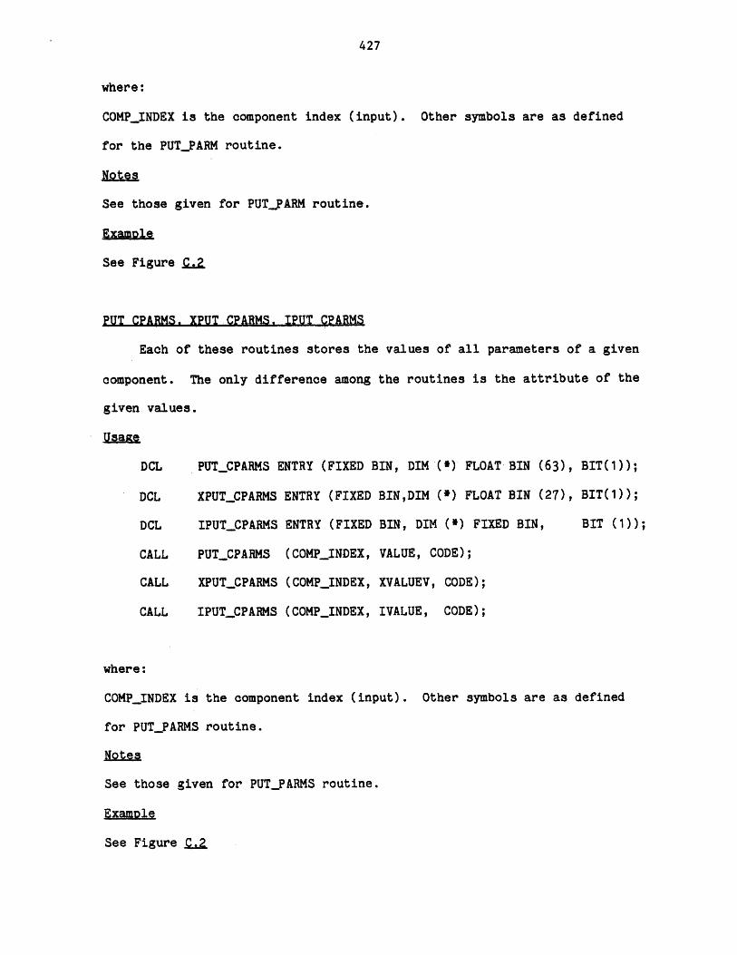
427
where:
COMP.INDEX is the component index (input). Other symbols are as defined
for the PUTPARM routine.
NoteQs
See those given for PUTPARM routine.
ExaMole
See Figure QaZ
PUT CPARMS. XPUT CPARMS. IPUT CPARMS
Each of these routines stores the values of all parameters of a given
component. The only difference among the routines is the attribute of the
given values.
Usage
DCL PUT_CPARMS ENTRY (FIXED BIN, DIM '(*) FLOAT- BIN (63), BIT(1));
DCL XPUT_CPARMS ENTRY (FIXED BINDIM (e) FLOAT BIN (27), BIT(1));
DCL IPUT_CPARMS ENTRY (FIXED BIN, DIM FIXED BIN, BIT (1));
CALL PUTCPARMS (COMP_INDEX, VALUE, CODE);
CALL XPUT_CPARMS (COMP_INDEX, XVALUE, CODE);
CALL IPUT_CPARMS (COMP_INDEX, IVALUE, CODE);
where:
COMP_INDEX is the component index (input). Other symbols are as defined
for PUT_PARMS routine.
Notes
See those given for PUT_PARMS routine.
Examle
See Figure L
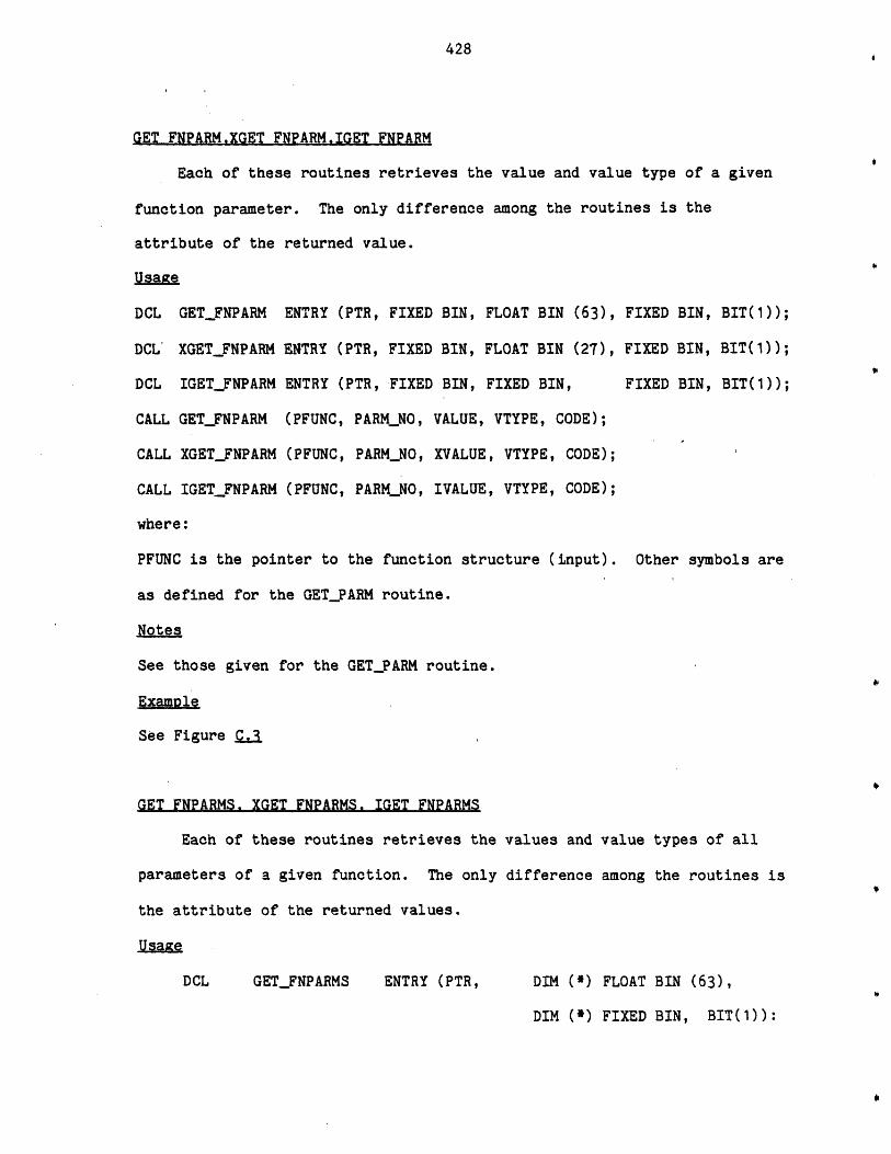
428
GET FNPARM.XGET FNPARM.IGET FNPARM
Each of these routines retrieves the value and value type of a given
function parameter. The only difference among the routines is the
attribute of the returned value.
Usage
DCL GET_FNPARM
DCL' XGETFNPARM
DCL IGETFNPARM
CALL GET_FNPARM
CALL XGET_FNPARM
CALL IGETFNPARM
where:
ENTRY (PTR, FIXED
ENTRY (PTR, FIXED
ENTRY (PTR, FIXED
(PFUNC, PARM_NO,
(PFUNC, PARMNO,
(PFUNC, PARMNO,
BIN,
BIN,
BIN,
VALUE,
XVALUE
IVALUE
FLOAT BIN (63), FIXED BIN, BIT(1));
FLOAT BIN (27), FIXED BIN, BIT(1));
FIXED BIN, FIXED BIN, BIT(1));
VTYPE, CODE);
, VTYPE, CODE);
, VTYPE, CODE);
PFUNC is the pointer to the function structure (input). Other symbols are
as defined for the GET_PARM routine.
Notes
See those given for the GET_PARM routine.
Examole
See Figure C.3
GET FNPARMS. XGET FNPARMS. IGET FNPARMS
Each of these routines retrieves the values and value types of all
parameters of a given function. The only difference among the routines is
the attribute of the returned values.
GET_FNPARMS ENTRY (PTR, DIM (*) FLOAT BIN (63),
DIM (*) FIXED BIN, BIT(1)):
DCL
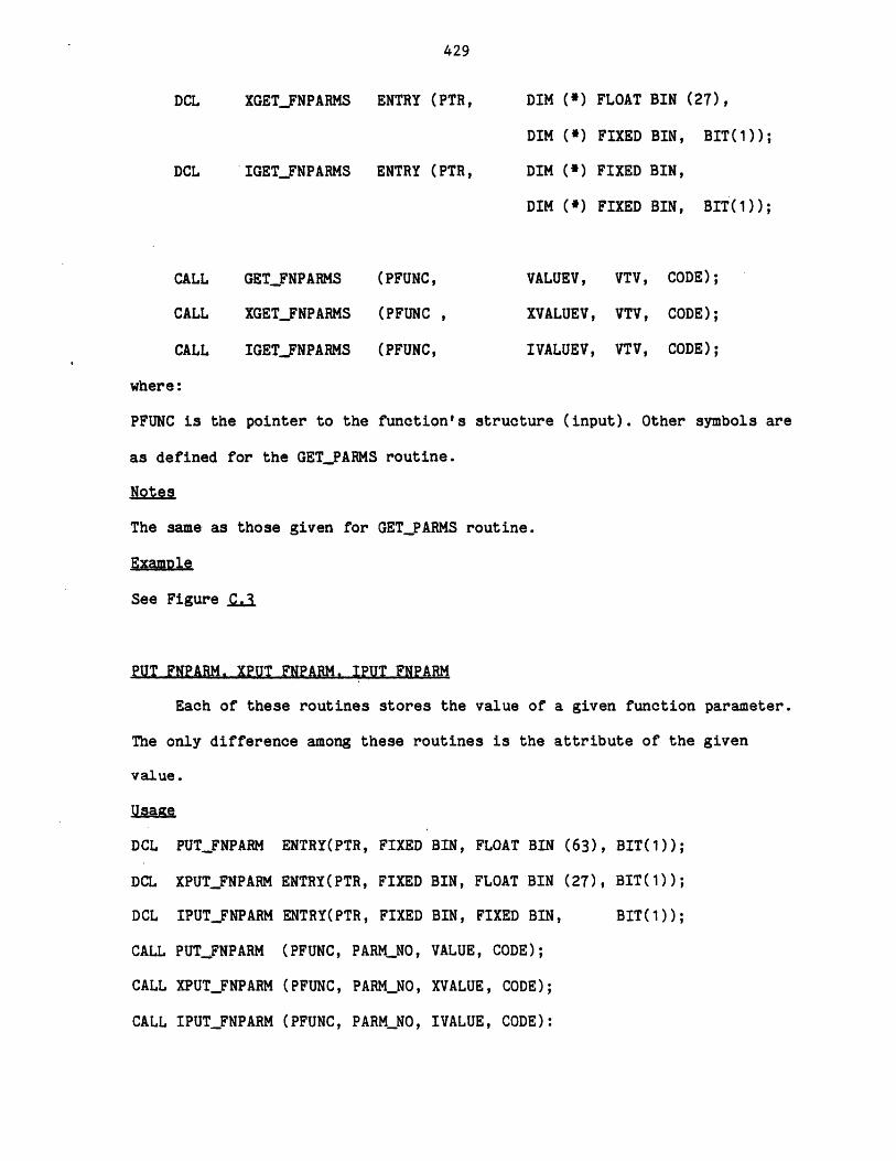
429
XGET_FNPARMS
IGETFNPARMS
ENTRY (PTR,
ENTRY (PTR,
DIM (*)
DIM (*)
DIM C*)
DIM C*)
FLOAT BIN (27),
FIXED BIN, BIT(1));
FIXED BIN,
FIXED BIN, BIT(1));
GETFNPARMS
XGETFNPARMS
IGET_FNPARMS
(PFUNC,
(PFUNC
(PFUNC,
VALUEV,
XVALUEV,
IVALUEV,
VTV, CODE);
VTV, CODE);
VTV, CODE);
where:
PFUNC is the pointer to the function's structure (input). Other symbols are
as defined for the GET_PARMS routine.
Notes
The same as those given for GETPARMS routine.
Example
See Figure _Q..
PUT FNPARM. XPUT FNPARM. IPUT FNPARM
Each of these routines stores the value of a given function parameter.
The only difference among these routines is the attribute of the given
value.
Usage
DCL PUT_FNPARM ENTRY(PTR, FIXED BIN, FLOAT BIN (63), BIT(1));
DCL XPUT FNPARM ENTRY(PTR, FIXED BIN, FLOAT BIN (27), BIT(1);
DCL IPUTFNPARM ENTRY(PTR, FIXED BIN, FIXED BIN, BIT(1));
CALL PUTFNPARM (PFUNC, PARMNO, VALUE, CODE);
CALL XPUT_FNPARM (PFUNC, PARM_NO, XVALUE, CODE);
CALL IPUTFNPARM (PFUNC, PARMNO, IVALUE, CODE):
DCL
DCL
CALL
CALL
CALL
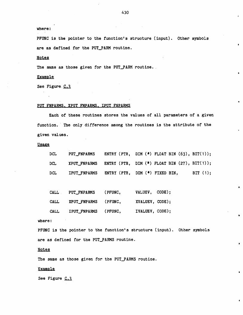
430
where:
PFUNC is the pointer to the function's structure (input). Other symbols
are as defined for the PUT_PARM routine.
Notes
The same as those given for the PUT_PARM routine.
ExamDle
See Figure.C..3,
PUT FNPARMS. XPUT FNPARMS. IPUT FNPARMS
Each of these routines stores the values of all parameters of a given
function. The only difference among the routines is the attribute of the
given values.
Usaje.
DCL PUT_FNPARMS ENTRY (PTR, DIM C*) FLOAT BIN (63), BIT(1));
DCL XPUTFNPARMS ENTRY (PTR, DIM (*) FLOAT BIN (27), BIT(1));
DCL IPUT_FNPARMS ENTRY (PTR, DIM (*) FIXED BIN, BIT (1);
CALL. PUT_FNPARMS (PFUNC, VALUEV, CODE);
CALL XPUTFNPARMS (PFUNC, XVALUEV, CODE);
CALL IPUT_FNPARMS (PFUNC, IVALUEV, CODE);
where:
PFUNC is the pointer to the function's structure (input). Other symbols
are as defined for the PUT_PARMS routine.
Notes
The same as those given for the PUTFARMS routine.
Example
See Figure C.3
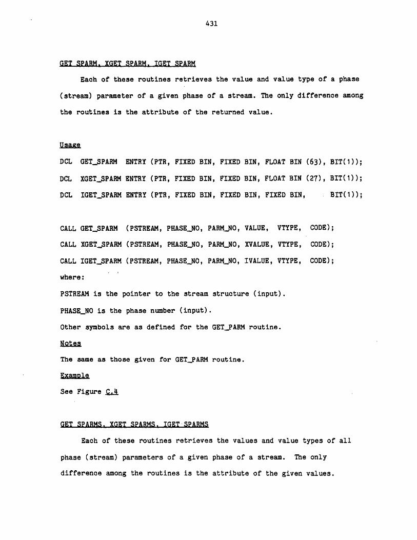
431
GET SPARM. XGET SPARM. IGET SPARM
Each of these routines retrieves the value and value type of a phase
(stream) parameter of a given phase of a stream. The only difference among
the routines is the attribute of the returned value.
UsaGTe
DCL GET.SPARM ENTRY (PTR, FIXED BIN, FIXED
DCL XGET_SPARM ENTRY (PTR, FIXED BIN, FIXED
DCL IGET_SPARM ENTRY (PTR, FIXED BIN, FIXED
BIN, FLOAT BIN (63), BIT(1));
BIN, FLOAT BIN (27), BIT(1));
BIN, FIXED BIN, BIT(1));
CALL GET.SPARM (PSTREAM, PHASENO, PARMNO, VALUE, VTYPE,
CALL XGET_SPARM (PSTREAM, PHASE_NO, PARMNO, XVALUE, VTYPE,
CALL IGET.SPARM (PSTREAM, PHASE_NO, PARMNO, IVALUE, VTYPE,
where:
PSTREAM is the pointer to the stream structure (input).
PHASE_NO is the phase number (input).
Other symbols are as defined for the GET.PARM routine.
Notes
The same as those given for GETPARM routine.
Examole
See Figure _QA
CODE);
CODE);
CODE);
GET SPARMS. XGET SPARMS. IGET-SPARMS
Each of these routines retrieves the values and value types of all
phase (stream) parameters of a given phase of a stream. The only
difference among the routines is the attribute of the given values.
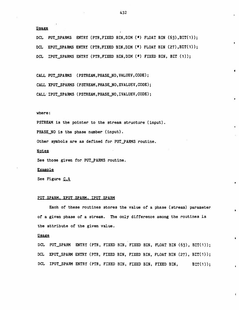
432
Usa e
DCL PUT_SPARMS ENTRY (PTR,FIXED BIN,DIM C*) FLOAT BIN (63),BIT(1));
DCL XPUT_SPARMS ENTRY (PTRFIXED BINDIM C') FLOAT BIN (27)BIT());
DCL IPUT_SPARMS ENTRY (PTR,FIXED BIN,DIM ()FIXED BIN, BIT ();
CALL PUT_SPARMS (PSTREAMPHASENO,VALUEVCODE);
CALL XPUT_SPARMS (PSTREAMPHASENO,XVALUEVCODE);
CALL- IPUT_SPARMS (PSTREAMPHASENOIVALUEVCODE);
where:
PSTREAM is the pointer to the stream structure (input).
PHASE_NO is the phase number (input).
Other symbols are as defined for PUT_PARMS routine.
Notes
See those given for PUT_PARMS routine.
Examole
See Figure CJ
PUT SPARM. XPUT SPARM. IPUT SPARM
Each of these routines stores the value of a phase (stream) parameter
of a given phase of a stream. The only difference among the routines is
the attribute of the given value.
Usage
DCL PUT_SPARM ENTRY (PTR, FIXED BIN, FIXED BIN, FLOAT BIN (63), BIT(1));
DCL XPUT_SPARM ENTRY (PTR, FIXED BIN, FIXED BIN, FLOAT BIN (27), BIT(1));
DCL IPUT_SPARM ENTRY (PTR, FIXED BIN, FIXED BIN, FIXED BIN, BIT(1));

433
CALL PUTSPARM (PSTREAM, PHASE_NO, PARMNO,
CALL XPUTSPARM (PSTREAM, PHASENO, PARMNO,
CALL IPUT.SPARM (PSTREAM, PHASENO, PARMNO,
VALUE, CODE);
XVALUE, CODE);
IVALUE, CODE);
where:
PSTREAM is the pointer to the stream structure (input).
PHASE_NO is the phase number (input).
Other symbols are as defined for the PUT_PARM routine.
Notes
The same as those given for PUTPARM routine.
ExaMple
See Figure CAl
PUT SPARMS. XPUT SPARMS. IPUT SPARMS
Each of these routines stores the values of all phase (stream)
parameters of a given phase of a stream. The only difference among the
routines is the attribute of the given values.
PUTSPARMS ENTRY (PTR, FIXED BIN, DIM(*)
XPUT_SPARMS ENTRY (PTR, FIXED BIN, DIM(*)
IPUTSPARMS ENTRY (PTR, FIXED BIN, DIM()
PUT_SPARMS (PSTREAM, PHASENO,
XPUTSPARMS (PSTREAM, PHASE-NO,
IPUTSPARMS (PSTREAM, PHASENO,
VALUEV,
XVALUEV,
IVALUEV,
FLOAT BIN (63), BIT(1));
FLOAT BIN (27), BIT(1));
FIXED BIN , BIT(1));
CODE);
CODE);
CODE);
Usage
DCL
DCL
DCLL
CALL
CALL
CALL

434
where:
PSTREAM is the pointer to the stream structure (input).
PHASE_NO is the phase number (input).
Other symbols are as defined for PUT_PARMS routine.
Notes
See those given for PUT_PARMS routine.
Example
See Figure CA.
GET FPARM. XGET FPARM. IGET FPARM
Each of these routines retrieves the value and value type of a flow
parameter of a component in a given phase of a stream. The only difference
among the routines is the attribute of the returned value.
Usage
DCL. GET_FPARM ENTRY (PTR,FIXED BINFIXED BINFIXED BIN,
FLOAT BIN (63),FIXED BINBIT(1));
DCL XGETFPARM ENTRY (PTR,FIXED BIN,FIXED BIN, FIXED BIN,
FLOAT BIN (27), FIXED BIN,BIT(1));
DCL IGETFPARM ENTRY (PTR,FIXED BINFIXED BIN, FIXED BIN,
FIXED BIN, FIXED BIN,BIT(1));
CALL GETFPARM (PSTREAM, PHASENO, COMPINDEX , PARMNO, VALUE , VTYPE, CODE);
CALL XGETFPARM (PSTREAM,PHASE_NO, COMP_INDEX, PARMNOXVALUEVTYPECODE);
CALL IGET_FPARM (PSTREAMPHASENO,COMP_INDEX,PARM_NO,IVALUEVTYPECODE);
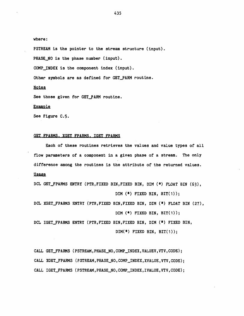
435
where:
PSTREAM is the pointer to the stream structure (input).
PHASE_NO is the phase number (input).
COMP_INDEX is the component index (input).
Other symbols are as defined for GET_PARM routine.
Notes
See those given for GETPARM routine.
ExaMole
See Figure C.5.
GET FPARMS. XGET FPARMS. IGET FPARMS
Each of these routines retrieves the values and value types of all
flow parameters of a component in a given phase of a stream. The only
difference among the routines is the attribute of the returned values.
usage
DCL GET.FPARMS ENTRY (PTR,FIXED BINFIXED BIN, DIM (*) FLOAT BIN (63),
DIM (*) FIXED BIN, BIT(1));
DCL XGETFPARMS ENTRY (PTRFIXED BIN,FIXED BIN, DIM (*) FLOAT BIN (27),
DIM (') FIXED BIN, BIT(1));
DCL IGET_FPARMS ENTRY (PTRFIXED BINFIXED BIN, DIM (*) FIXED BIN,
DIM(*) FIXED BIN, BIT(1));
CALL GET_FPARMS (PSTREAMPHASE_NOCOMPINDEXVALUEVVTVCODE);
CALL XGET_FPARMS (PSTREAMPHASENO,COMPINDEXXVALUE,VTV,CODE);
CALL IGET_FPARMS (PSTREAM,PHASE_NO,COMPINDEXIVALUEVTVCODE);
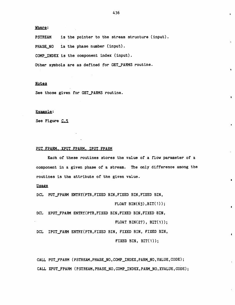
436
Where:
PSTREAM is the pointer to the stream structure (input).
PHASE_NO is the phase number (input).
COMP_INDEX is the component index (input).
Other symbols are as defined for GET_PARMS routine.
Notes
See those given for GETPARMS routine.
ExaMple:
See Figure ja*t
PUT FPARM. XPUT FPARM. IPUT FPARM
Each of these routines stores the value of a flow parameter of a
component in a given phase of a stream. The only difference among the
routines is the attribute of the given value.
Usage
DCL PUT_FPARM ENTRY(PTRFIXED BIN,FIXED BINFIXED BIN,
FLOAT BIN(63),BIT(1));
DCL XPUT_FPARM ENTRY(PTRFIXED BINFIXED BIN,FIXED BIN,
FLOAT BIN(27), BIT(1));
DCL IPUTFARM ENTRY(PTRFIXED BIN, FIXED BIN, FIXED BIN,
FIXED BIN, BIT(1));
CALL PUTFPARM (PSTREAM,PHASENO, COMPINDEXPARMNO,VALUE, CODE);
CALL XPUTFPARM (PSTREAM, PHASENO, COMPINDEX, PARM_NO, XVALUECODE);
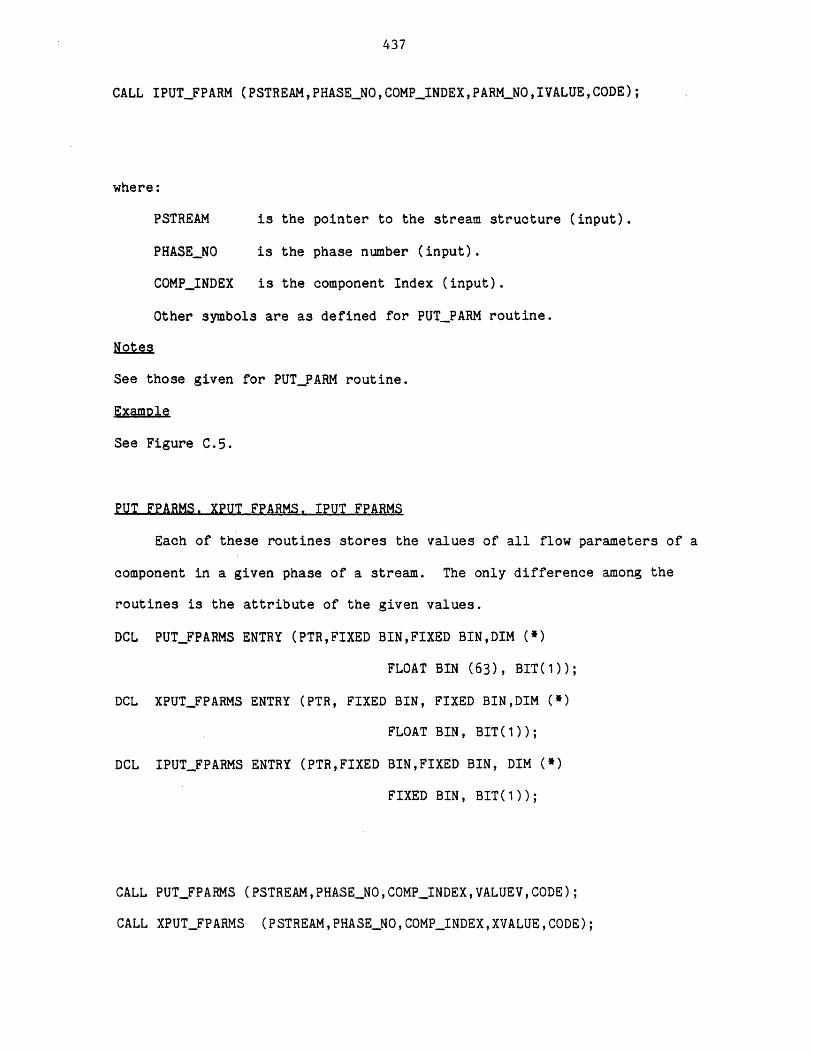
437
CALL IPUTFPARM (PSTREAMPHASENO,COMPINDEX,PARMNOIVALUECODE);
where:
PSTREAM is the pointer to the stream structure (input).
PHASE_NO is the phase number (input).
COMPINDEX is the component Index (input).
Other symbols are as defined for PUT_PARM routine.
Notes
See those given for PUT_PARM routine.
Example
See Figure C.5.
PUT FPARMS. XPUT FPARMS. IPUT FPARMS
Each of these routines stores the values of all flow parameters of a
component in a given phase of a stream. The only difference among the
routines is the attribute of the given values.
DCL PUTFPARMS ENTRY (PTR,FIXED BIN,FIXED BIN,DIM (*)
FLOAT BIN (63), BIT(1));
DCL XPUT_FPARMS ENTRY (PTR, FIXED BIN, FIXED BIN,DIM (*)
FLOAT BIN, BIT(1));
DCL IPUTFPARMS ENTRY (PTR,FIXED BINFIXED BIN, DIM (*)
FIXED BIN, BIT(1));
CALL PUTFPARMS (PSTREAM,PHASENO,COMPINDEX,VALUEV,CODE);
CALL XPUTFPARMS (PSTREAM,PHASENO,COMPINDEX,XVALUE,CODE);
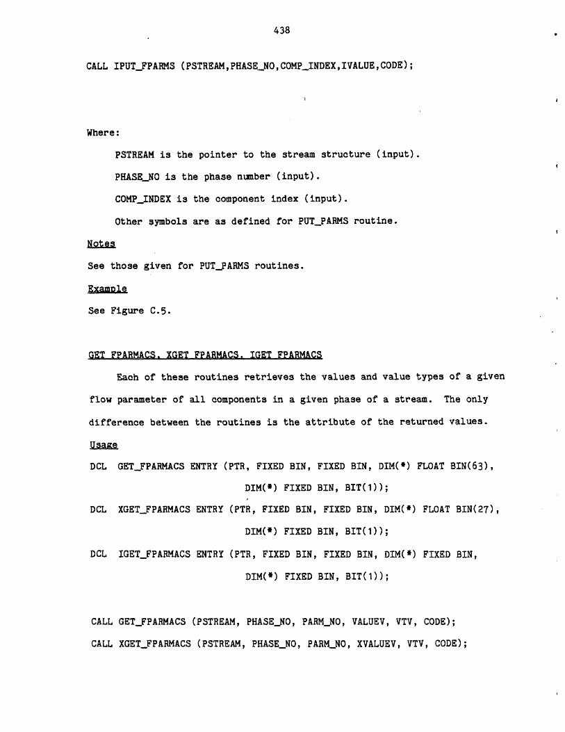
438
CALL IPUTFPARMS (PSTREAM,PHASENO,COMPINDEXIVALUECODE);
Where:
PSTREAM is the pointer to the stream structure (input).
PHASE_NO is the phase number (input).
COMP_INDEX is the component index (input).
Other symbols are as defined for PUT_PARMS routine.
Notes
See those given for PUT_PARMS routines.
Examle
See Figure C.5.
GET FPARMACS. XGET FPARMACS. IGET FPARMACS
Each of these routines retrieves the values and value types of a given
flow parameter of all components in a given phase of a stream. The only
difference between the routines is the attribute of the returned values.
Usage
DCL GET_FPARMACS ENTRY (PTR, FIXED BIN, FIXED BIN, DIM(*) FLOAT BIN(63),
DIM(*) FIXED BIN, BIT(1));
DCL XGETFPARMACS ENTRY (PTR, FIXED BIN, FIXED BIN, DIM(*) FLOAT BIN(27),
DIM(*) FIXED BIN, BIT(1));
DCL IGETFPARMACS ENTRY (PTR, FIXED BIN, FIXED BIN, DIM(*) FIXED BIN,
DIM(*) FIXED BIN, BIT(1));
CALL GET_FPARMACS (PSTREAM, PHASENO, PARMNO, VALUEV, VTV, CODE);
CALL XGET_FPARMACS (PSTREAM, PHASE_NO, PARMNO, XVALUEV, VTV, CODE);
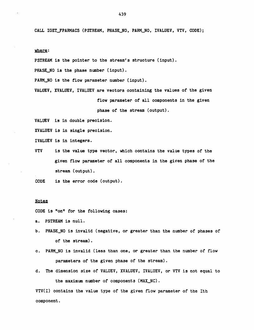
439
CALL IGET_FPARMACS (PSTREAM, PHASENO, PARMNO, IVALUEV, VTV, CODE);
where:
PSTREAM is the pointer to the stream's structure (input).
PHASE_NO is the phase number (input).
PARMNO is the flow parameter number (input).
VALUEV, XVALUEV, IVALUEV are vectors containing the values of the given
flow parameter of all components in the given
phase of the stream (output).
VALUEV is in double precision.
XVALUEV is in single precision.
IVALUEV is in integers.
VTV is the value type vector, which contains the value types of the
given flow parameter of all components in the given phase of the
stream (output).
CODE is the error code (output).
Notes
CODE is "on" for the following cases:
a. PSTREAM is null.
b. PHASE_NO is invalid (negative, or greater than the number of phases of
of the stream).
c. PARM_NO is invalid (less than one, or greater than the number of flow
parameters of the given phase of the stream).
d. The dimension size of VALUEV, XVALUEV, IVALUEV, or VTV is not equal to
the maximum number of components (MAX_NC).
VTV(I) contains the value type of the given flow parameter of the Ith
component.
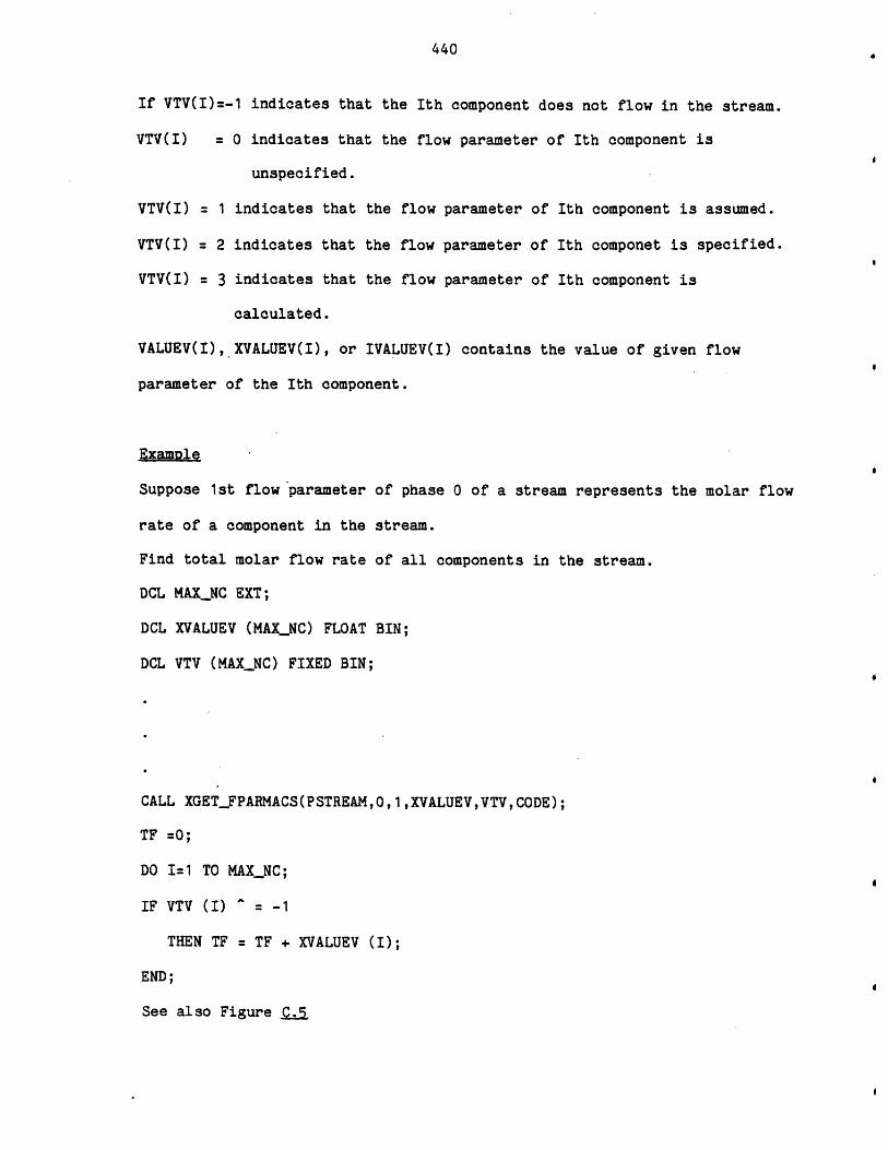
440
If VTV(I)=-1 indicates that the Ith component does not flow in the stream.
VTV(I) = 0 indicates that the flow parameter of Ith component is
unspecified.
VTV(I) = 1 indicates that the flow parameter of Ith component is assumed.
VTV(I) = 2 indicates that the flow parameter of Ith componet is specified.
VTV(I) = 3 indicates that the flow parameter of Ith component is
calculated.
VALUEV(I), XVALUEV(I), or IVALUEV(I) contains the value of given flow
parameter of the Ith component.
Examole
Suppose 1st flow parameter of phase 0 of a stream represents the molar flow
rate of a component in the stream.
Find total molar flow rate of all components in the stream.
DCL MAX_NC EXT;
DCL XVALUEV (MAX_NC) FLOAT BIN;
DCL VTV (MAXNC) FIXED BIN;
CALL XGETFPARMACS(PSTREAM,0,1,XVALUEV,VTV,CODE);
TF =0;
DO I=1 TO MAX_NC;
IF VTV (I) = -1
THEN TF TF + XVALUEV (I);
END;
See also Figure sj
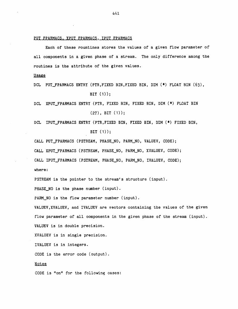
441
PUT FPARMACS. XPUT FPARMACS, IPUT FPARMACS
Each of these rountines stores the values of a given flow parameter of
all components in a given phase of a stream. The only difference among the
routines is the attribute of the given values.
Usge
DCL PUT_FPARMACS ENTRY (PTR,FIXED BINFIXED BIN, DIM (*) FLOAT BIN (63),
BIT (1));
DCL XPUTFPARMACS ENTRY (PTR, FIXED BIN, FIXED BIN, DIM (*) FLOAT BIN
(27), BIT (1));
DCL IPUT_FPARMACS ENTRY (PTR,FIXED BIN, FIXED BIN, DIM (*) FIXED BIN,
BIT (1));
CALL PUT_FPARMACS (PSTREAM, PHASENO, PARMNO, VALUEV, CODE);
CALL XPUT_FPARMACS (PSTREAM, PHASE_NO, PARMNO, XVALUEV, CODE);
CALL IPUTFPARMACS (PSTREAM, PHASENO, PARMNO, IVALUEV, CODE);
where:
PSTREAM is the pointer to the stream's structure (input).
PHASE_NO is the phase number (input).
PARMNO is the flow parameter number (input).
VALUEV,XVALUEV, and IVALUEV are vectors containing the values of the given
flow parameter of all components in the given phase of the stream (input).
VALUEV is in double precision.
XVALUEV is in single precision.
IVALUEV is in integers.
CODE is the error code (output).
Notes
CODE is "on" for the following cases:
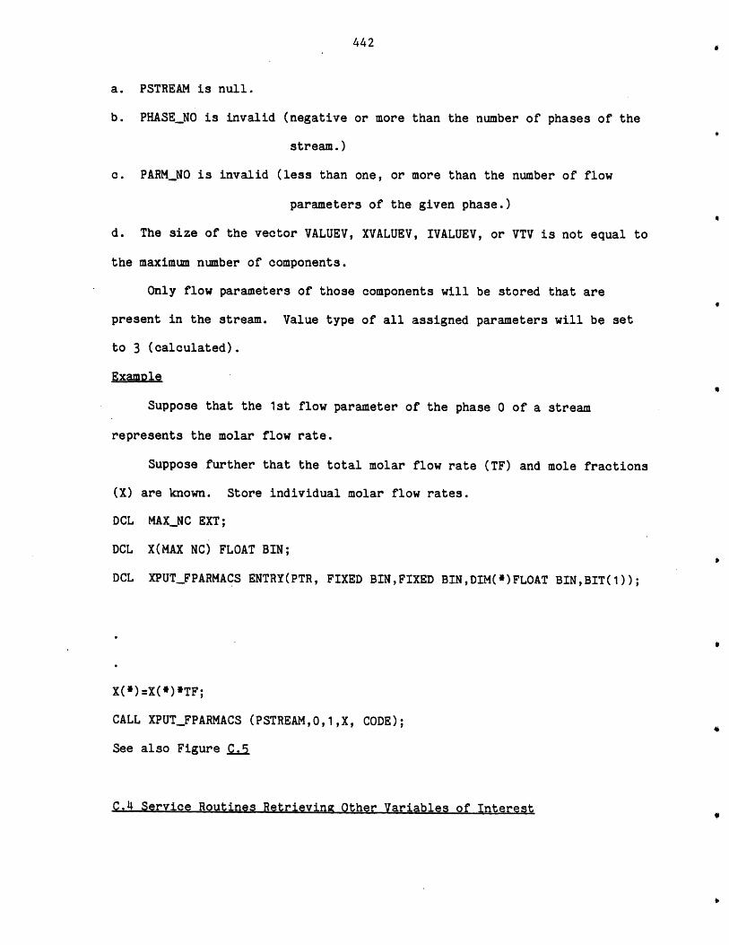
442
a. PSTREAM is null.
b. PHASE_NO is invalid (negative or more than the number of phases of the
stream.)
c. PARM_NO is invalid (less than one, or more than the number of flow
parameters of the given phase.)
d. The size of the vector VALUEV, XVALUEV, IVALUEV, or VTV is not equal to
the maximum number of components.
Only flow parameters of those components will be stored that are
present in the stream. Value type of all assigned parameters will be set
to 3 (calculated).
ExamDle
Suppose that the 1st flow parameter of the phase 0 of a stream
represents the molar flow rate.
Suppose further that the total molar flow rate (TF) and mole fractions
(X) are known. Store individual molar flow rates.
DCL MAX_NC EXT;
DCL X(MAX NC) FLOAT BIN;
DCL XPUT_FPARMACS ENTRY(PTR, FIXED BINFIXED BINDIM(*)FLOAT BIN,BIT(1));
XW) =X(*)*TF;
CALL XPUT_FPARMACS (PSTREAM,0,1,X, CODE);
See also Figure C.
C.4 Service Routines Retrieving Other Variables of Interest
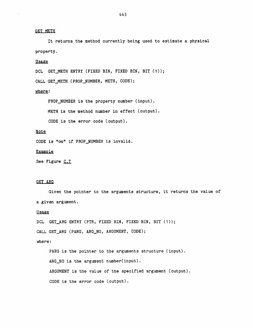
443
GET METH
It returns the method currently being used to estimate a physical
property.
Usage
DCL GETMETH ENTRY (FIXED BIN, FIXED BIN, BIT (1));
CALL GET_METH (PROP_NUMBER, METH, CODE);
where:
PROPNUMBER is the property number (input).
METH is the method number in effect (output).
CODE is the error code (output).
Note
CODE is "on" if PROPNUMBER is invalid.
Example
See Figure .7
GET ARG
Given the pointer to the arguments structure, it returns the value of
a given argument.
Usage
DCL GET_ARG ENTRY (PTR, FIXED BIN, FIXED BIN, BIT (1));
CALL GET_ARG (PARG, ARG_NO, ARGUMENT, CODE);
where:
PARG is the pointer to the arguments structure (input).
ARG_NO is the argument number(input).
ARGUMENT is the value of the specified argument (output).
CODE is the error code (output).
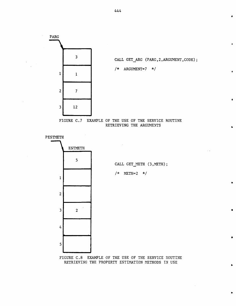
444
CALL GETARG (PARG,2,ARGUMENT,CODE);
/* ARGUMENT=7 */
2 7
3 12
FIGURE C.7 EXAMPLE OF THE USE OF THE SERVICE ROUTINERETRIEVING THE ARGUMENTS
PESTMETH
ESTMETH
5
1
2
3 2
4
5
CALL GET_METH (3,METH);
/* METH=2 */
FIGURE C.8 EXAMPLE OF THE USE OF THE SERVICE ROUTINERETRIEVING THE PROPERTY ESTIMATION METHODS IN USE
PARG
445
Notes
CODE is "on" for the following cases:
a. PARG is null
b. ARG_NO is zero or negative, or greater than the number of arguments.
Example
See Figure C.8
C.5 Service Routines Interacting with the User
GETIN
This routine receives an integer number from the user.
Usagze
DCL GETIN ENTRY (FIXED BIN, FIXED BIN);
CALL GETIN (NUMBER, LIMIT)
where:
NUMBER is the returned integer number (output).
LIMIT is the upper limit of the number (input).
Notes
The TBS program before calling this routine should write a message on
the user's terminal requesting the required INPUT. The GETIN routine then
receives and examines the user's response. If the user's response is valid
it returns to the caller, otherwise, informs the user and receives a new
response and repeats this process until the user's response is acceptable.
A valid response is an unsigned integer number up to five digits and less
than the specified upper limit.
Example
The TBS Program:
446
PUT SKIP EDIT("ENTER NUMBER OF ITERATIONS:")(A);
CALL GETIN (NIT, 300)
user's terminal session:
ENTER NUMBER OF ITERATIONS: 4A
***ERR0R*** i 16 "4A" is an invalid integer number.
A valid integer number consists of 1 to 5 decimal digits.
**reenter the number: 400
***ERROR*** i 17 the above number must not be greater than 300
**reenter the number: 40
GETLINE
This routine receives a line of characters from the user.
Usage
DCL GETLINE ENTRY (CHAR(*),FIXED BIN (21));
CALL GETLINE (LINENREAD);
where:
LINE is the returned response (output).
NREAD is the number of characters read (output).
Notes
This routine is not usually used for tbs programs.
Example
TBS program:
DCL TEXT CHAR(10);
PUT SKIP EDIT ("ENTER TEXT:")(A);
CALL GETLINE (TEXT, NREAD);
user's terminal session:
ENTER TEXT: Once upon a time
447
***ERROR*** i 1 bad input or line greater than 10 characters.
**reenter the line: AB E
GETRN
This routine receives a real number from the user.
Usage
DCL GETRN ENTRY (FLOAT BIN(63));
CALL GETRN(NUMBER);
where:
NUMBER is the returned number (output).
Notes
The TBS Program before calling this routine should write a message on
the user's terminal requesting the required input. The GETRN routine then
receives and examines the user's response. If the user's response is a
valid number it returns to the caller, otherwise it informs the user and
receives a new response and repeats this process until the user's response
is acceptable.
Example
The TBS Program:
PUT SKIP EDIT ("Enter an initial value for T:") (A);
CALL GETRN (TEMP);
User's Terminal Session:
Enter an initial value for T:23.4F2
***ERROR*** i 18 "23.4F2" is an invalid number.
**Reenter the Number: 23.4e2
GET RESPONSE
This routine receives a yes or no answer from the user.
448
Usage
DCL GET.RESPONSE RETURNS (BIT(1));
FLAG = GET_RESPONSE( );
where:
FLAG indicates the user's response (output). It is "on" if the user's
response is "yes", and it is "off" if the user's response is "no".
Examole
TBS Program:
PUT SKIP EDIT ("DO YOU WANT TO USE THE SHORTCUT METHOD?") (A);
IF GET_RESPONSE( )
THEN...
ELSE...
User's Terminal Session:
DO YOU WANT TO USE THE SHORTCUT METHOD? WHAT
***ERROR*** i 19 Your response should be yes or no.
**REENTER PLEASE: yes
C.6 Service Routines Performing Arithmetic Operations on Two Parameter Sets
PARMS OPERATOR1
This routine multiplies each parameter in a set of parameters by a
given constant and adds to it another given constant. The results are
stored in a data structure of comparable size corresponding to another
parameter set: P1 = P2. A+B for all i
~sa1e
DCL PARMS_0PERATOR1 ENTRY (PTR, PTR, FLOAT BIN(63), FLOAT BIN(63), BIT(1));
CALL PARMS_OPERATOR1 (PPARM1, PPARM2, A,B, CODE);
449
where:
PPARM1 is the pointer to the target parameters structure (input).
PPARM2 is the pointer to the other parameters structure (input).
A is the multiplication constant (input).
B is the addition constant (input).
CODE is the error code (output).
Notes
CODE is "on" for the following cases:
a. PPARM1, or PPARM2 is null.
b. The numbers of parameters of two parameters structure are not the
same.
c. One or more parameters of set pointed by PPARM2 are unspecified.
The value types of all assigned parameters will be set to 3 ("calculated").
ExaMple
See Figure Q.e
PARMS OPERATOR1V
This routine functions almost the same as PARMS_OPERATOR1 Routine.
The only difference is that the multiplication and addition constants are
vectors in this case: P1. = P2. A + B. for all i.
Usa11e
DCL PARMS_0PERATOR1V ENTRY (PTR, PTR, DIM(*) FLOAT BIN(63), DIM(*) FLOAT
BIN(63), BIT(1));
CALL PARMS_OPERATOR1V (PPARM1, PPARM2, AVEC, BVEC, CODE);
where:
AVEC is the vector of multiplication constants (input).
BVEC is the vector of addition constants (input).
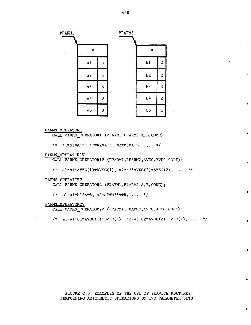
450
PPARM1
al
a2
a3
a4
3
3
3
3
PPARM2
bl
b2
b3
b4
b5
2
2
3
2
1
PARMS OPERATORICALL PARMSOPERATORI (PPARI1,PPARM2 ,A,B,CODE);
/* al=bl*A+B, a2=b2*A+B, a3=b3*A+B, ... */
PARMSOPERATOR1VCALL PARMS_OPERATORIV (PPARM1 ,PPARM2,AVEC ,BVEC ,CODE);
/* al=b1*AVEC(1)+BVEC(1), a2=b2*AVEC(2)+BVEC(2), */
PARMS.OPERATOR2CALL PARMSOPERATOR2 (PPARM1,PPARM2,A,B,CODE);
/* al=al+bl*A+B, a2=a2+b2*A+B, */
PARMS-OPERATOR2VCALL PARMS OPERATOR2V (PPARM 1,PPARM2,AVEC,BVEC,CODE);
/* al=al+bl*AVEC(1)+BVEC(1), a2=a2+b2*AVEC(2)+BVEC(2), */
FIGURE C.9 EXAMPLES OF THE USE OF SERVICE ROUTINESPERFORMING ARITHMETIC OPERATIONS ON TWO PARAMETER SETS
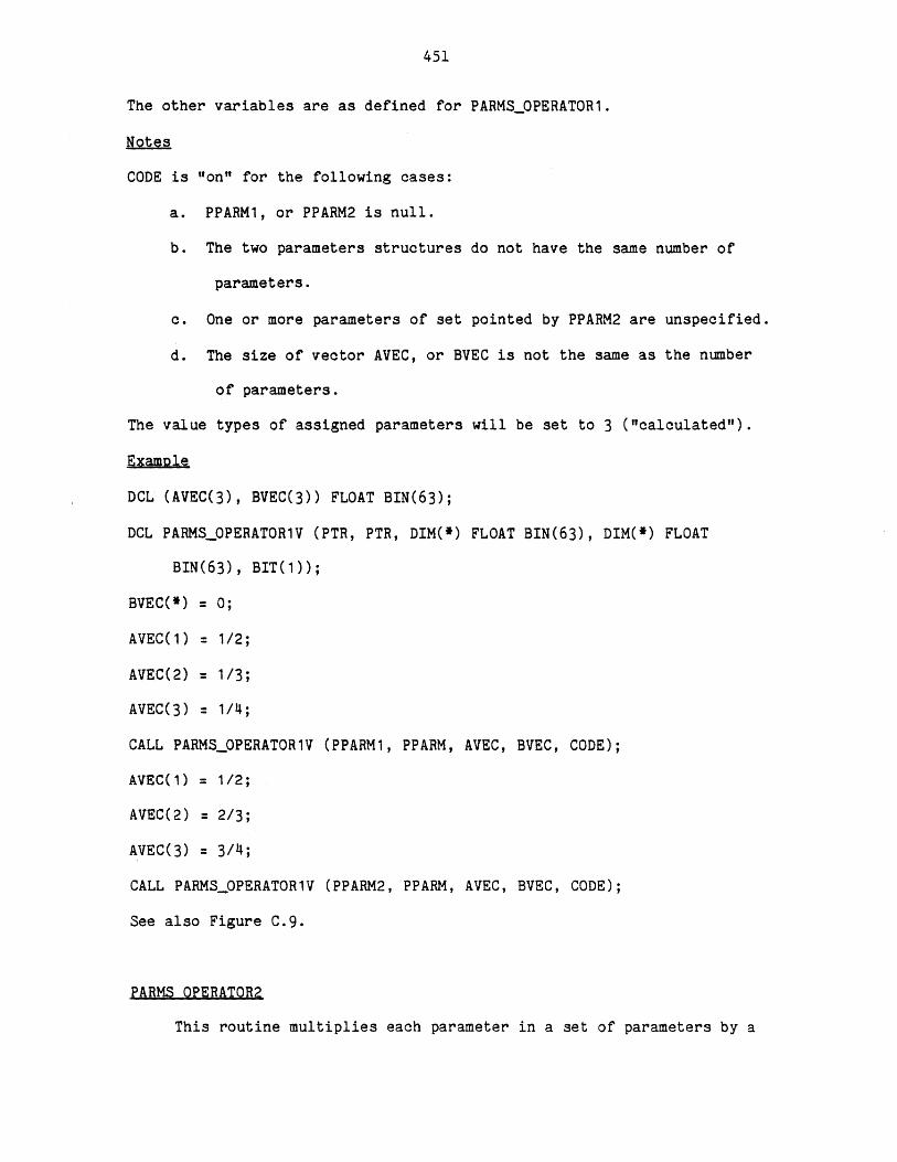
451
The other variables are as defined for PARMS_OPERATOR1.
Notes
CODE is "on" for the following cases:
a. PPARM1, or PPARM2 is null.
b. The two parameters structures do not have the same number of
parameters.
c. One or more parameters of set pointed by PPARM2 are unspecified.
d. The size of vector AVEC, or BVEC is not the same as the number
of parameters.
The value types of assigned parameters will be set to 3 ("calculated").
Example
DCL (AVEC(3), BVEC(3)) FLOAT BIN(63);
DCL PARMSOPERATOR1V (PTR, PTR, DIM(*) FLOAT BIN(63), DIM(*) FLOAT
BIN(63), BIT(1));
BVEC(*) = 0;
AVEC) = 1/2;
AVEC(2) = 1/3;
AVEC(3) = 1/4;
CALL PARMS_0PERATOR1V (PPARM1, PPARM, AVEC, BVEC, CODE);
AVEC(1) = 1/2;
AVEC(2) = 2/3;
AVEC(3) = 3/4;
CALL PARMS_OPERATOR1V (PPARM2, PPARM, AVEC, BVEC, CODE);
See also Figure C.9.
PARMS OPERATOR2
This routine multiplies each parameter in a set of parameters by a
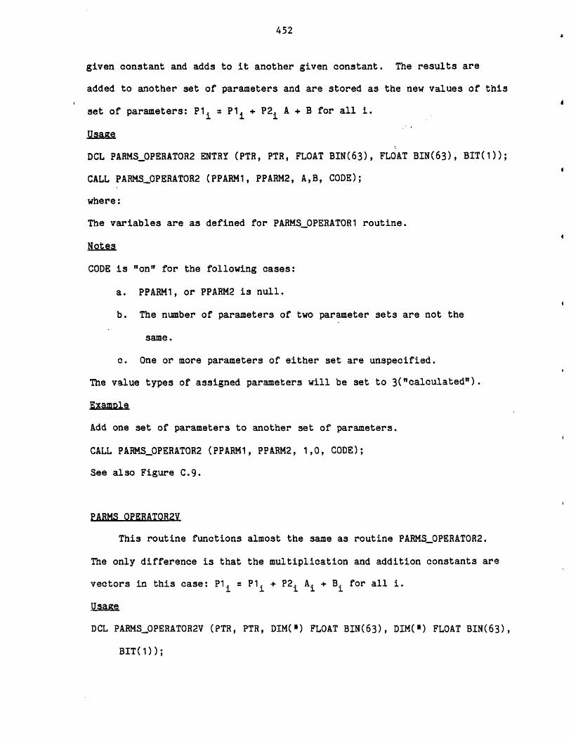
452
given constant and adds to it another given constant. The results are
added to another set of parameters and are stored as the new values of this
set of parameters: P1. = P1 + P2 A + B for all i.
Usage
DCL PARMS_OPERATOR2 ENTRY (PTR, PTR, FLOAT BIN(63), FLOAT BIN(63), BIT(1));
CALL PARMS_OPERATOR2 (PPARM1, PPARM2, A,B, CODE);
where:
The variables are as defined for PARMS_OPERATOR1 routine.
Notes
CODE is "on" for the following cases:
a. PPARM1, or PPARM2 is null.
b. The number of parameters of two parameter sets are not the
same.
c. One or more parameters of either set are unspecified.
The value types of assigned parameters will be set to 3("calculated").
Example
Add one set of parameters to another set of parameters.
CALL PARMS_OPERATOR2 (PPARM1, PPARM2, 1,0, CODE);
See also Figure C.9.
PARMS OPERATOR2V
This routine functions almost the same as routine PARMS_PPERATOR2.
The only difference is that the multiplication and addition constants are
vectors in this case: P1 = P1. + P2. A. + B for all i.
U1g1e
DCL PARMSOPERATOR2V (PTR, PTR, DIM(*) FLOAT BIN(63), DIM(*) FLOAT BIN(63),
BIT(1));
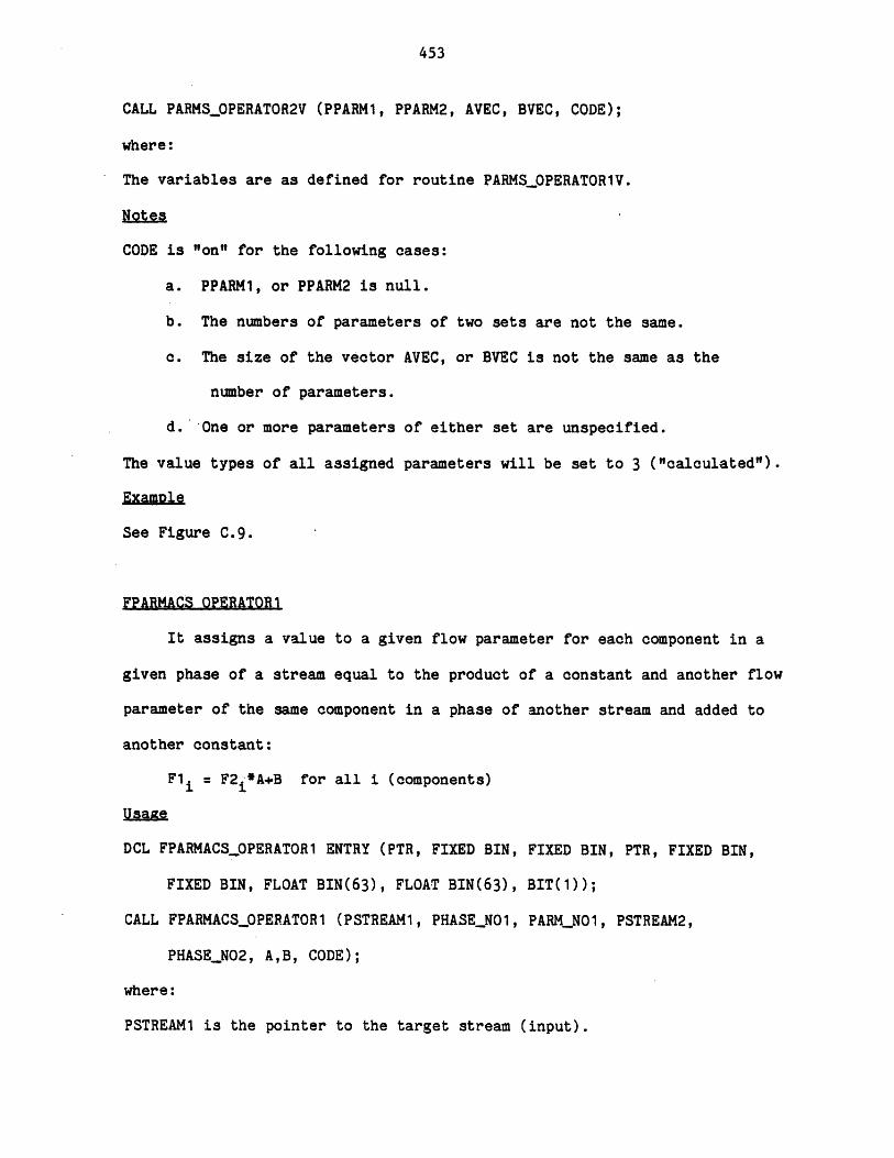
453
CALL PARMS_0PERATOR2V (PPARM1, PPARM2, AVEC, BVEC, CODE);
where:
The variables are as defined for routine PARMS_0PERATOR1V.
Notes
CODE is "on" for the following cases:
a. PPARM1, or PPARM2 is null.
b. The numbers of parameters of two sets are not the same.
C. The size of the vector AVEC, or BVEC is not the same as the
number of parameters.
d. One or more parameters of either set are unspecified.
The value types of all assigned parameters will be set to 3 ("calculated").
ExaMole
See Figure C.9.
FPARMACS OPERATOR1
It assigns a value to a given flow parameter for each component in a
given phase of a stream equal to the product of a constant and another flow
parameter of the same component in a phase of another stream and added to
another constant:
F1 = F2 *A+B for all i (components)
Usayte
DCL FPARMACSOPERATOR1 ENTRY (PTR, FIXED BIN, FIXED BIN, PTR, FIXED BIN,
FIXED BIN, FLOAT BIN(63), FLOAT BIN(63), BIT(1));
CALL FPARMACSOPERATOR1 (PSTREAM1, PHASEN01, PARM_NO1, PSTREAM2,
PHASENO2, A,B, CODE);
where:
PSTREAM1 is the pointer to the target stream (input).
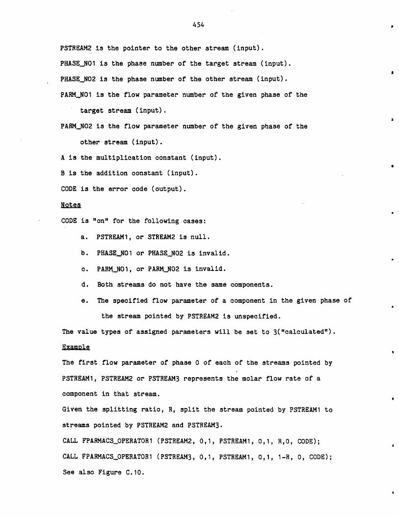
454
PSTREAM2 is the pointer to the other stream (input).
PHASE_N01 is the phase number of the target stream (input).
PHASE_N02 is the phase number of the other stream (input).
PARM_NO1 is the flow parameter number of the given phase of the
target stream (input).
PARM_N02 is the flow parameter number of the given phase of the
other stream (input).
A is the multiplication constant (input).
B is the addition constant (input).
CODE is the error code (output).
Notes
CODE j "on" for the following cases:
PSTREAM1, or STREAM2 is null.
PHASE_NO1 or PHASE_N02 is invalid.
PARM_NO1, or PARM_N02 is invalid.
Both streams do not have the same components.
The specified flow parameter of a component in the given phase of
the stream pointed by PSTREAM2 is unspecified.
The value types of assigned parameters will be set to 3("calculated")
Example
The first flow parameter of phase 0 of each of the streams pointed by
PSTREAM1, PSTREAM2 or PSTREAM3 represents the molar flow rate of a
component in that stream.
Given the splitting ratio, R, split the stream pointed by PSTREAM1 to
streams pointed by PSTREAM2 and PSTREAM3.
CALL FPARMACS_OPERATOR1 (PSTREAM2, 0,1, PSTREAM1, 0,1, R,O, CODE);
CALL FPARMACS_0PERATOR1 (PSTREAM3, 0,1, PSTREAM1, 0,1, 1-R, 0, CODE);
See also Figure C.10.
.
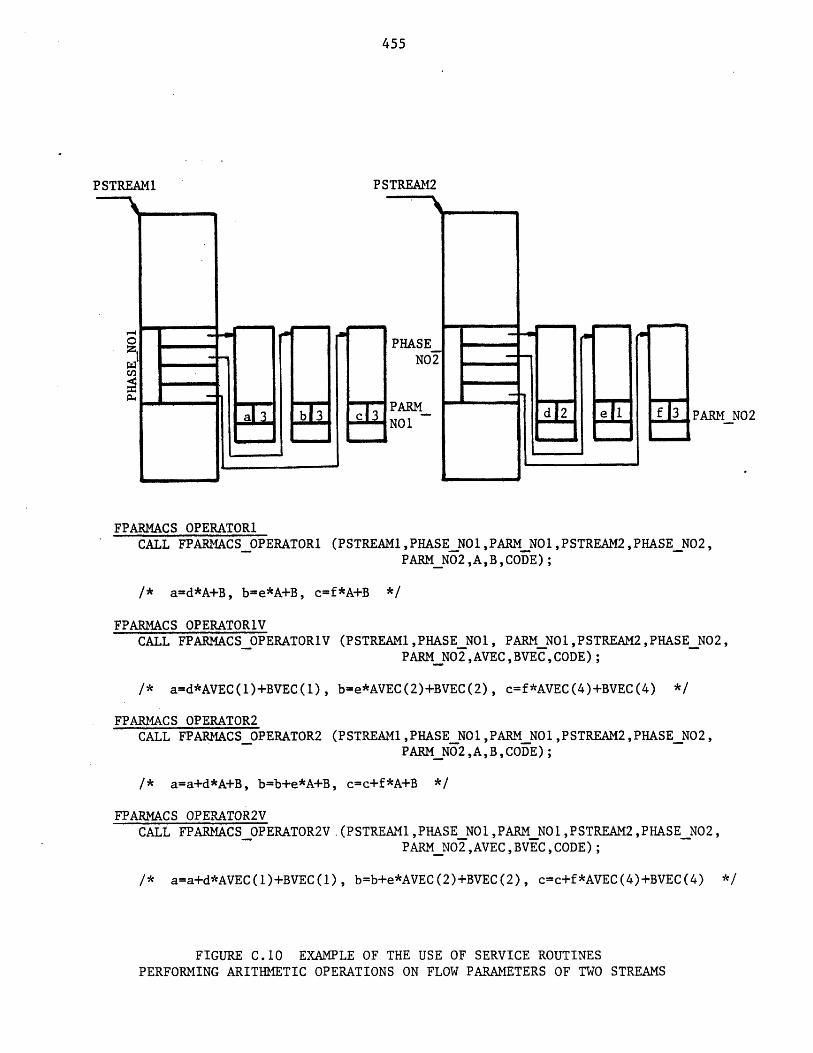
455
PSTREAM1 PSTREAM2
-= PHASEN02
- PRMNOa3 FARM d 2 e I 3 PARM N02
FPARMACS OPERATOR1CALL FPARMACS OPERATOR1 (PSTREAM1,PHASE_NO1,PARM_N01,PSTREAM2,PHASE N02,
PARM_N02,A,B,CODE);
/* a=d*A+B, b=e*A+B, c=f*A+B */
FPARMACS OPERATOR1VCALL FPARMACS OPERATORIV (PSTREAM1,PHASE_NO1, PARM_NOI,PSTREAM2,PHASE N02,
PARM_N02,AVEC,BVEC,CODE);
/* a=d*AVEC(1)+BVEC(1), b=e*AVEC(2)+BVEC(2), c=f*AVEC(4)+BVEC(4) */
FPARMACS OPERATOR2CALL FPARMACS OPERATOR2 (PSTREAM1,PHASE_N01,PARM_N01,PSTREAM2,PHASE_N02,
PARM_N02,A,B,CODE);
/* a=a+d*A+B, b=b+e*A+B, c=c+f*A+B */
FPARMACS OPERATOR2VCALL FPARMACSOPERATOR2V.(PSTREAM1,PHASEN01,PARM_N01,PSTREAM2,PHASE_N02,
PARM_N02,AVEC,BVEC,CODE);
/* a=a+d*AVEC(1)+BVEC(1), b=b+e*AVEC(2)+BVEC(2), c=c+f*AVEC(4)+BVEC(4) *1
FIGURE C.10 EXAMPLE OF THE USE OF SERVICE ROUTINESPERFORMING ARITHMETIC OPERATIONS ON FLOW PARAMETERS OF TWO STREAMS
456
FPARMACS OPERATOR1V
This routine functions almost the same as routine FPARMACS OPERATOR1.
The only difference is that the multiplication and addition constants are
vectors in this case:
F1= F2 *A +B. for all i (components).
Usage
DCL FPARMACS_0PERATOR1V ENTRY (PTR, FIXED BIN, FIXED BIN, PTR, FIXED BIN,
FIXED BIN, DIM(*) FLOAT BIN(63), DIM(*) FLOAT BIN(63), BIT(1));
CALL FPARMACS_0PERATOR1V (PSTREAM1, PHASEN01, PARMNO1, PSTREAM2,
PHASE-N02, PARM_N02, AVEC, BVEC, CODE);
where:
AVEC is the vector of the multiplication constants (input).
BVEC is the vector of the addition constants (input).
The other variables are as defined for routine FPARMACS_OPERATOR1.
Notes
CODE is "on" for the following casses:
a. PSTREAM1, or PSTREAM2 is null.
b. PHASE_NO1 or PHASENO2 is invalid.
c. PARM_NO1, or PARM_N02 is invalid.
d. Both streams do not have the same components.
e. The size of vector AVEC or BVEC is not equal to the maximum
number of components (MAXNC).
f. The given flow parameter of a component in the given phase of
the stream pointed by PSTREAM2 is unspecified.
The value types of assigned parameters will be set to 3("Calculated").
457
Example
Phase 1 is the vapor phase and Phase 2 is the liquid phase, and
the first flow parameter of each phase is the mole fraction. KVAL contains
K values. Liquid phase compositions are already set. Set vapor phase
compositions.
DCL KVAL(MAXNC) FLOAT BIN(63);
DCL BVEC(MAX_NC) FLOAT BIN(63);
BVEC(*) = 0;
CALL FPARMACSOPERATOR1V (PSTREAM1,1,1,PSTREAM1,2,1,KVALBVEC,CODE);
See also Figure C.10.
FPARMACS OPERATOR2
It adds to a given flow parameter of each component in a phase of a
stream a value equal to the product of a constant and another given flow
parameter of the same component in a phase of another stream and added to
another constant:
F1 i= F1 + F2. * A+B for all i (components)
Usaize
DCL FPARMACS_OPERATOR2 ENTRY (PTR, FIXED BIN, FIXED BIN, PTR, FIXED BIN,
FIXED BIN, FLOAT BIN(63), FLOAT BIN(63)., BIT(1));
CALL FPARMACS_OPERATOR2 (PSTREAM1, PHASE_NO1, PARMNO1, PSTREAM2,
PHASE_N02, PARM_N02, A, B, CODE);
where:
The variables are as defined for FPARMACS_OPERATOR1 routine.
Notes
CODE is "on" for the following cases:
a. PSTREAM1, or PSTREAM2 is null.

458
b. PHASE_NO1, or PHASE_N02 is invalid.
c. PARM_NO1, or PARM_N02 is invalid.
d. Both streams do not have the same components.
e. Flow parameter "PARM_N02" of a component in phase "PHASE_N02"
of the stream pointed by "PSTREAM2" is unspecified.
f. Flow parameter "PARM_NO1" of a component in phase "PHASE_NO1"
of the stream pointed by "PSTREAM1" is unspecified.
The value types of assigned parameters will be set to 3 ("calculated").
ExamDle
STREAM3 is the result of adding STREAM1 and STREAM2. All streams are of
the same type and the first flow parameter of Phase 0 represents the molar
flow rate of each component.
CALL FPARMACS_OPERATOR1 (PSTREAM3, 0, 1, PSTREAM1, 0, 1, 1.0, 0, CODE);
CALL FPARMACSOPERATOR2 (PSTREAM3, 0, 1, PSTREAM2, 0, 1, 1.0, 0, CODE);
See also Figure C.10.
FPARMACS OPERATOR2V
This routine functions the same as FPARMACS_0PERATOR2 with the exception of
the addition and multiplication constants that are vectors in this case:
F1 = F1 + F2 *A + B. for all i (component).
Usage
DCL FPARMACS_OPERATOR2V ENTRY (PTR, FIXED BIN, FIXED BIN, PTR, FIXED BIN,
FIXED BIN, DIM(*) FLOAT BIN(63), DIM(*) FLOAT BIN(63), BIT(1));
CALL FPARMACSOPERATOR2V (PSTREAM1, PHASEN01, PARM_NO1, PSTREAM2,
PHASE_N02, PARM_N02, AVEC, BVEC, CODE);
where:
The symbols are as described for FPARMACS_0PERATOR1V.

459
Notes
CODE is "on" for the following cases:
a. PSTREAM1, or PSTREAM2 is null.
b. PHASE_NO1, or PHASE_N02 is invalid.
c. PARMNO1, or PARM_N02 is invalid.
d. Both streams do not have the same components.
e. The size of vector AVEC or BVEC is not equal to MAXNC.
f. Flow parameter "PARMNO2" of a component in the phase
"PHASE_NO2" of the stream pointed by "PSTREAM2" is unspecified.
g. Any of the target flow parameters are unspecified.
The value types of assigned parameters will be set to 3("calculated").
Examle
See Figure C.10.
460
APPENDIX D
PROCESS ENGINEERING LANGUAGE - DETAILED DESCRIPTION
D.1 COMMAND ELEMENTS
There are very few restrictions in the format of PEL commands.
Consequently, instructions can be written without consideration of special
coding forms. As long as each command is started on a new line and
terminated by a semi-colon (;), the format is completely free. Characters
entered after the ";" are ignored.
A command is constructed from symbols.
A symbol is the string of one or more characters.
Character Set
Any character set may be used to write a PEL command. In PEL any
character set will be classified according to: Digits, extended alphabetic
characters, and special characters.
Digits
There are ten digits (0 through 9).
Special Characters
There are 21 special characters, as shown in Table D.1. These
characters perform special functions and all of them are delimeters
separating elements of a statement (break characters). The point (.) when
used as a part of a number is not treated as a delimeter. Special
characters are combined to create other symbols. For example, <= means
less than or equal to, ** means exponentiation. Blanks are not allowed in
such composite symbols.
Extended Alphabetic Characters
All other characters fall in this category.

461
TABLE D.1
SPECIAL CHARACTERS
NAME CHARACTER
Blank
Equal sign or assignment symbol
Plus sign +
Minus sign
Asterisk or multiply symbol *
Slash or divide symbol
Left parenthesis (
Right parenthesis )
Comma
Point or period
Single quotation mark or apostrophe
Double quotation marks "
Semicolon
Colon
"Not" symbol A
"And" symbol &
"Or" symbol
"Greater than" symbol >
"Less than" symbol <
Currency symbol or dollar sign $
Tab
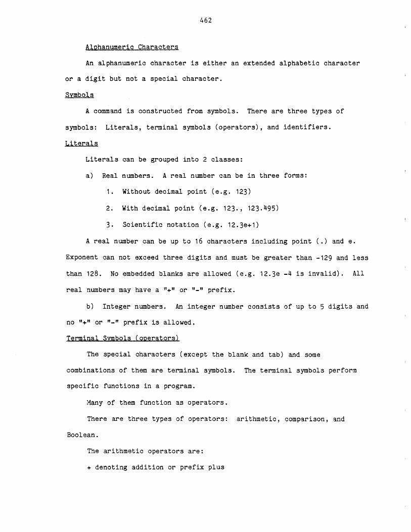
462
Alphanumeric Characters
An alphanumeric character is either an extended alphabetic character
or a digit but not a special character.
Symbols
A command is constructed from symbols. There are three types of
symbols: Literals, terminal symbols (operators), and identifiers.
Literals
Literals can be grouped into 2 classes:
a) Real numbers. A real number can be in three forms:
1. Without decimal point (e.g. 123)
2. With decimal point (e.g. 123., 123.495)
3. Scientific notation (e.g. 12.3e+1)
A real number can be up to 16 characters including point (.) and e.
Exponent can not exceed three digits and must be greater than -129 and less
than 128. No embedded blanks are allowed (e.g. 12.3e -4 is invalid). All
real numbers may have a "+" or "-"t prefix.
b) Integer numbers. An integer number consists of up to 5 digits and
no "+" or "-" prefix is allowed.
Terminal Symbols (operators)
The special characters (except the blank and tab) and some
combinations of them are terminal symbols. The terminal symbols perform
specific functions in a program.
Many of them function as operators.
There are three types of operators: arithmetic, comparison, and
Boolean.
The arithmetic operators are:
+ denoting addition or prefix plus
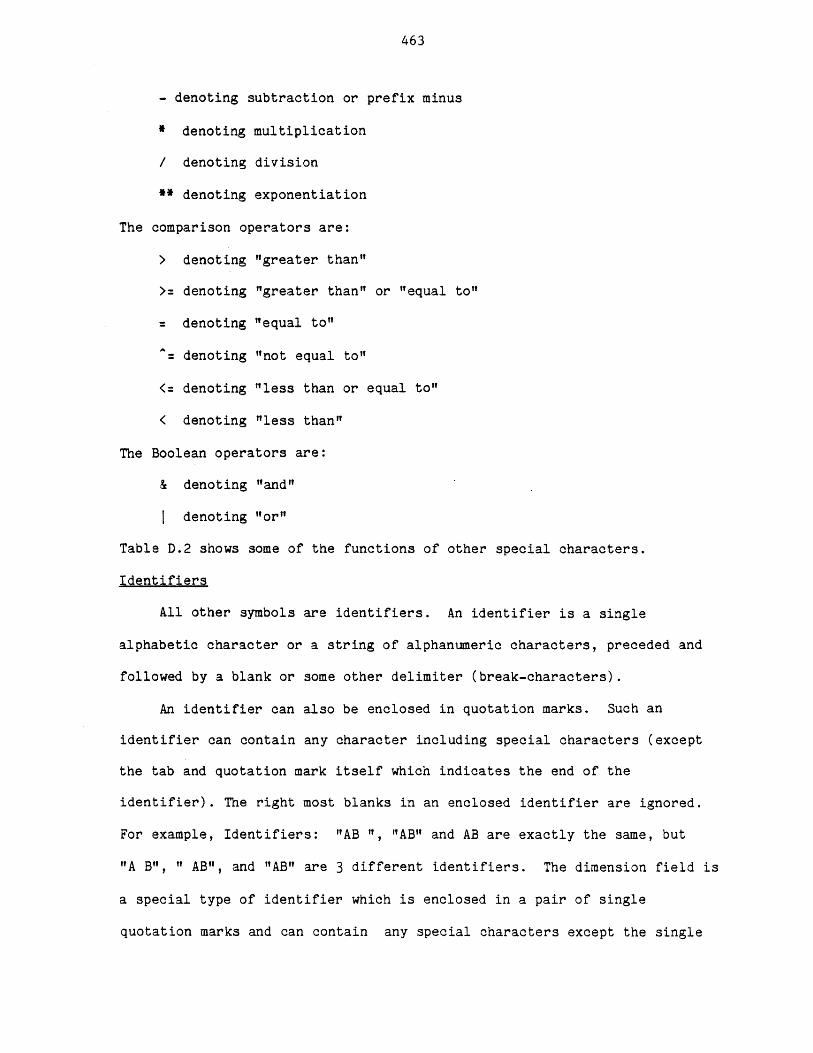
463
- denoting subtraction or prefix minus
* denoting multiplication
/ denoting division
** denoting exponentiation
The comparison operators are:
> denoting "greater than"
>= denoting "greater than" or "equal to"
denoting "equal to"
denoting "not equal to"
<= denoting "less than or equal to"
< denoting "less than"
The Boolean operators are:
& denoting "and"
I denoting "or"
Table D.2 shows some of the functions of other special characters.
Identifiers
All other symbols are identifiers. An identifier is a single
alphabetic character or a string of alphanumeric characters, preceded and
followed by a blank or some other delimiter (break-characters).
An identifier can also be enclosed in quotation marks. Such an
identifier can contain any character including special characters (except
the tab and quotation mark itself which indicates the end of the
identifier). The right most blanks in an enclosed identifier are ignored.
For example, Identifiers: "AB ", "AB" and AB are exactly the same, but
"A B", " AB", and "AB" are 3 different identifiers. The dimension field is
a special type of identifier which is enclosed in a pair of single
quotation marks and can contain any special characters except the single
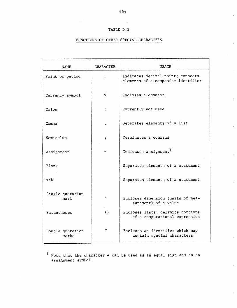
464
TABLE D.2
FUNCTIONS OF OTHER SPECIAL CHARACTERS
NAME CHARACTER USAGE
Point or period
Currency symbol
Colon
Comma
Semicolon
Assignment
Blank
Tab
Single quotationmark
Parentheses
Double quotationmarks
Indicates decimal point; connects
elements of a composite identifier
Encloses a comment
Currently not used
Separates elements of a list
Terminates a command
Indicates assignmenti
Separates elements of a statement
Separates elements of a statement
Encloses dimension (units of mea-surement) of a value
Encloses lists; delimits portionsof a computational expression
Encloses an identifier which maycontain special characters
1 Note that the character = can be used as an equal sign and as anassignment symbol.
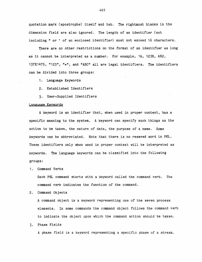
465
quotation mark (apostrophe) itself and tab. The rightmost blanks in the
dimension field are also ignored. The length of an identifier (not
including " or ' of an enclosed identifier) must not exceed 16 characters.
There are no other restrictions on the format of an identifier as long
as it cannot be interpreted as a number. For example, 1A, 123B, AB2,
137E1475, "123", "+", and "ABC" all are legal identifiers. The identifiers
can be divided into three groups:
1. Language Keywords
2. Established Identifiers
3. User-Supplied Identifiers
Language Keywords
A keyword is an identifier that, when used in proper context, has a
specific meaning to the system. A keyword can specify such things as the
action to be taken, the nature of data, the purpose of a name. Some
keywords can be abbreviated. Note that there is no reseved word in PEL.
These identifiers only when used in proper context will be interpreted as
keywords. The language keywords can be classified into the following
groups:
1. Command Verbs
Each PEL command starts with a keyword called the command verb. The
command verb indicates the function of the command.
2. Command Objects
A command object is a keyword representing one of the seven process
elements. In some commands the command object follows the command verb
to indicate the object upon which the command action should be taken.
3. Phase Fields
A phase field is a keyword representing a specific phase of a stream.
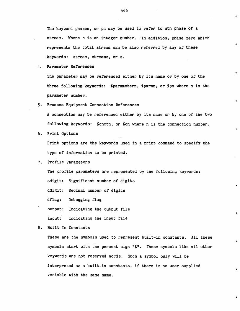
466
The keyword phasen, or pn may be used to refer to nth phase of a
stream. Where n is an integer number. -In addition, phase zero which
represents the total stream can be also referred by any of these
keywords: stream, streams, or s.
4. Parameter References
The parameter may be referenced either by its name or by one of the
three following keywords: %parametern, %parmn, or %pn where n is the
parameter number.
5. Process Equipment Connection References
A connection may be referenced either by its name or by one of the two
following keywords: %cnctn, or %cn where n is the connection number.
6. Print Options
Print options are the keywords used in a print command to specify the
type of information to be printed.
7. Profile Parameters
The profile parameters are represented by the following keywords:
sdigit: Significant number of digits
ddigit: Decimal number of digits
dflag: Debugging flag
output: Indicating the output file
input: Indicating the input file
8. Built-In Constants
These are the symbols used to represent built-in constants. All these
symbols start with the percent sign "%" These symbols like all other
keywords are not reserved words. Such a symbol only will be
interpreted as a built-in constants, if there is no user supplied
variable with the same name.
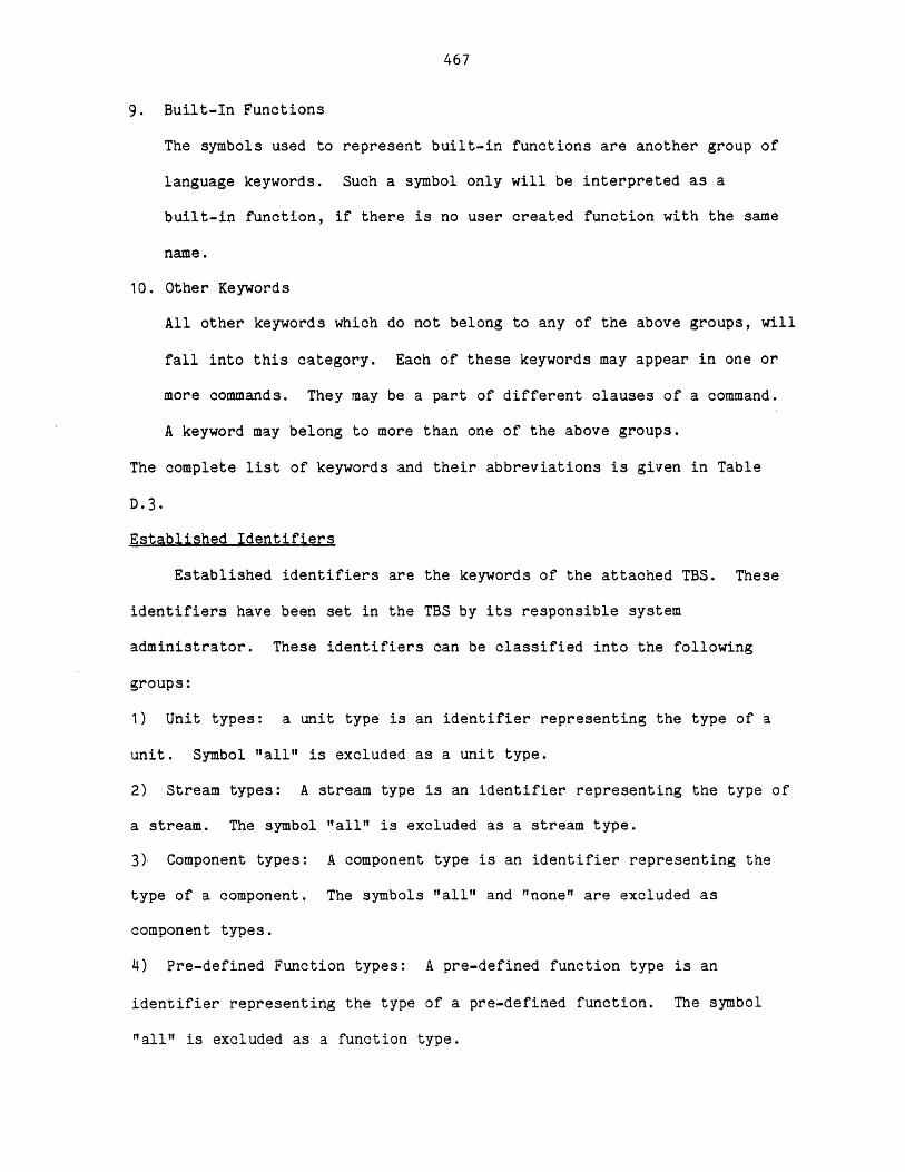
467
9. Built-In Functions
The symbols used to represent built-in functions are another group of
language keywords. Such a symbol only will be interpreted as a
built-in function, if there is no user created function with the same
name.
10. Other Keywords
All other keywords which do not belong to any of the above groups, will
fall into this category. Each of these keywords may appear in one or
more commands. They may be a part of different clauses of a command.
A keyword may belong to more than one of the above groups.
The complete list of keywords and their abbreviations is given in Table
D.3.
Established Identifiers
Established identifiers are the keywords of the attached TBS. These
identifiers have been set in the TBS by its responsible system
administrator. These identifiers can be classified into the following
groups:
1) Unit types: a unit type is an identifier representing the type of a
unit. Symbol "all" is excluded as a unit type.
2) Stream types: A stream type is an identifier representing the type of
a stream. The symbol "all" is excluded as a stream type.
3)- Component types: A component type is an identifier representing the
type of a component. The symbols "all" and "none" are excluded as
component types.
4) Pre-defined Function types: A pre-defined function type is an
identifier representing the type of a pre-defined function. The symbol
"all" is excluded as a function type.

468
Group
1) Command Verbs
Table D.3
Language Keywords
Keyword Alternative
assume
bugs
calculate
clear
close
connect
continue
copy
create
delete
deletef'
disconnect
end
escape
help
include
leave
let
leta
list
listf
listt
load
loop
Abbreviation
a
calc
clr
cl
cnc t
ct
crt
del
delf
disc
esc
h
inc
lv
1
i f
lt
ld
lp
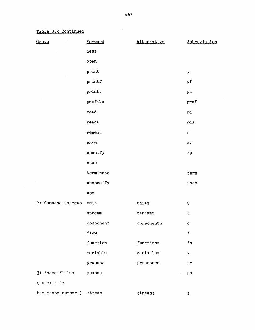
467
Table D.3 Continued
2) Command Objects
3) Phase Fields
(note: n is
the phase number.)
Keyword
news
open
printf
printt
profile
read
reada
repeat
save
specify
stop
terminate
unspecify
use
unit
stream
component
flow
function
variable
process
phasen
Alternative
units
streams
components
functions
variables
processes
Abbreviation
p
pf
pt
prof
rd
rda
r
av
sp
term
unsp
u
s
c
f
fn
v
pr
pn
stream streams
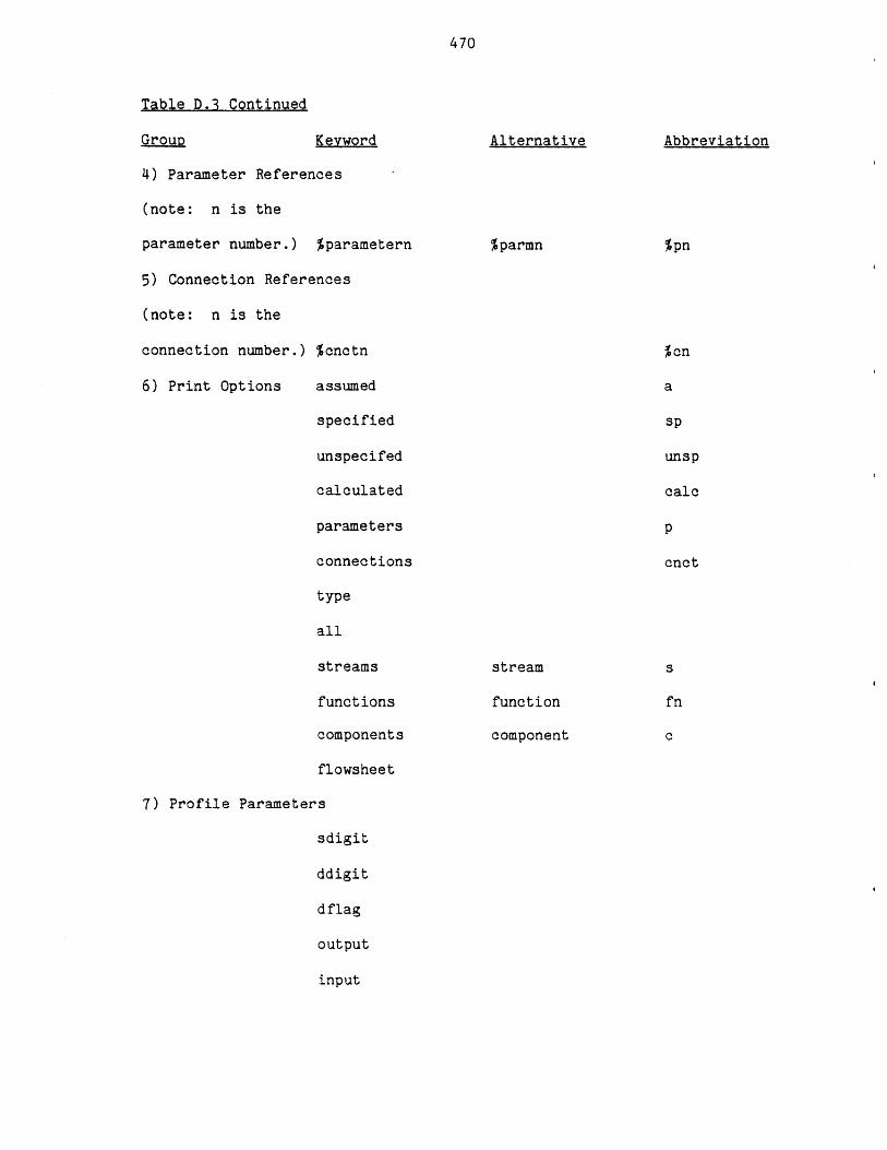
470
Table D.3 Continued
Grouo Keyword
4) Parameter References
(note: n is the
parameter number.) %parametern
5) Connection References
(note: n is the
connection number.) %cnctn
6) Print Options assumed
specified
unspecifed
calculated
parameters
connections
type
all
streams
functions
components
flowsheet
7) Profile Parameters
sdigit
ddigit
dflag
output
input
Alternative
%parmn
Abbreviation
%pn
%cn
a
sp
unsp
calc
p
cnct
stream
function
component
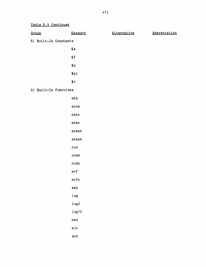
471
Table Q.3 Continued
Group Keyword
8) Built-In Constants
5e
%n
%pi
%r
9) Built-In Functions
abs
acos
asin
atan
atand
atanh
cos
cosd
cosh
erf
erfc
exp
log
log2
loglo
max
min
mod
Alternative Abbreviation
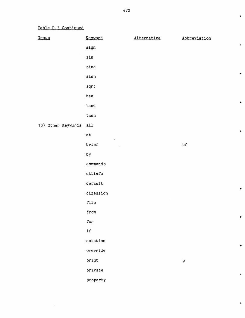
472
Table D.3 Continued
Group Keyword Alternative Abbreviation
sign
sin
sind
sinh
sqrt
tan
tand
tanh
10) Other Keywords all
at
brief bf
by
commands
otlinfo
default
dimension
file
from
for
if
notation
override
print p
private
property
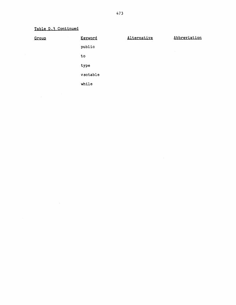
473
Table D.3 Continued
Group AlternativeKeyword
public
to
type
vsctable
while
Abbreviation
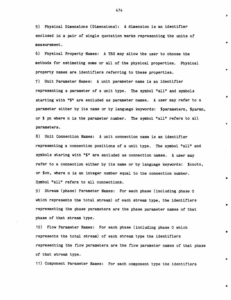
474
5) Physical Dimensions (Dimensions): A dimension is an identifier
enclosed in a pair of single quotation marks representing the units of
measurement.
6) Physical Property Names: A TBS may allow the user to choose the
methods for estimating some or all of the physical properties. Physical
property names are identifiers referring to these properties.
7) Unit Parameter Names: A unit parameter name is an identifier
representing a parameter of a unit type. The symbol "all" and symbols
starting with "%" are excluded as parameter names. A user may refer to a
parameter either by its name or by language keywords: %parametern, %parmn,
or % pn where n is the parameter number. The symbol "all" refers to all
parameters.
8) Unit Connection Names: A unit connection name is an identifier
representing a connection positions of a unit type. The symbol "all" and
symbols staring with "%" are excluded as connection names. A user may
refer to a connection either by its name or by language keywords: %cnctn,
or %cn, where n is an integer number equal to the connection number.
Symbol "all" refers to all connections.
9) Stream (phase) Parameter Names: For each phase (including phase 0
which represents the total stream) of each stream type, the identifiers
representing the phase parameters are the phase parameter names of that
phase of that stream type.
10) Flow Parameter Names: For each phase (including phase 0 which
represents the total stream) of each stream type the identifiers
representing the flow parameters are the flow parameter names of that phase
of that stream type.
11) Component Parameter Names: For each component type the identifiers
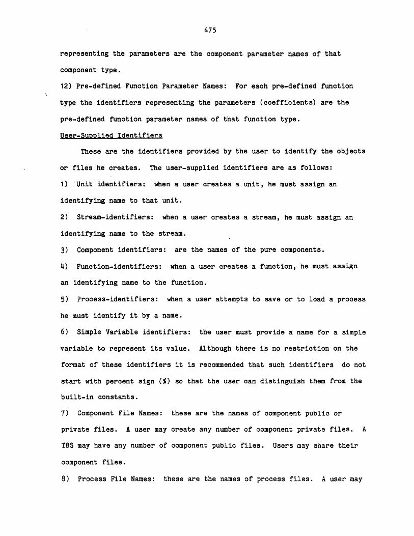
475
representing the parameters are the component parameter names of that
component type.
12) Pre-defined Function Parameter Names: For each pre-defined function
type the identifiers representing the parameters (coefficients) are the
pre-defined function parameter names of that function type.
User-Suoplied Identifiers
These are the identifiers provided by the user to identify the objects
or files he creates. The user-supplied identifiers are as follows:
1) Unit identifiers: when a user creates a unit, he must assign an
identifying name to that unit.
2) Stream-identifiers: when a user creates a stream, he must assign an
identifying name to the stream.
3) Component identifiers: are the names of the pure components.
4) Function-identifiers: when a user creates a function, he must assign
an identifying name to the function.
5) Process-identifiers: when a user attempts to save or to load a process
he must identify it by a name.
6) Simple Variable identifiers: the user must provide a name for a simple
variable to represent its value. Although there is no restriction on the
format of these identifiers it is recommended that such identifiers do not
start with percent sign (%) so that the user can distinguish them from the
built-in constants.
7) Component File Names: these are the names of component public or
private files. A user may create any number of component private files. A
TBS may have any number of component public files. Users may share their
component files.
8) Process File Names: these are the names of process files. A user may
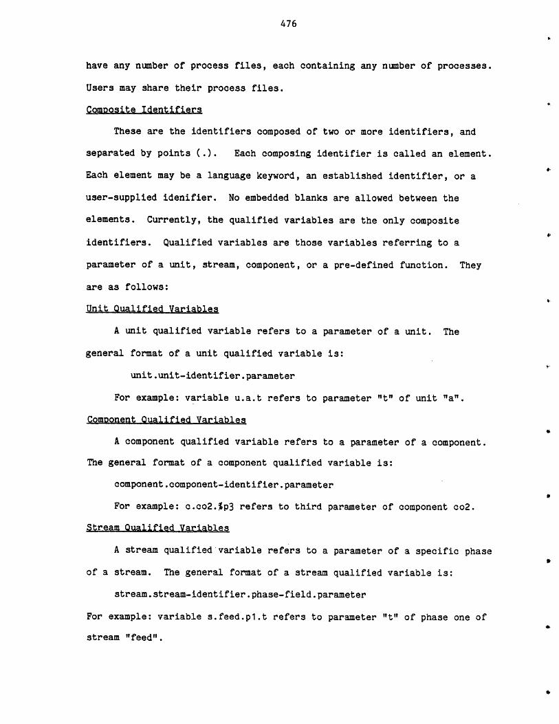
476
have any number of process files, each containing any number of processes.
Users may share their process files.
Composite Identifiers
These are the identifiers composed of two or more identifiers, and
separated by points C.). Each composing identifier is called an element.
Each element may be a language keyword, an established identifier, or a
user-supplied idenifier. No embedded blanks are allowed between the
elements. Currently, the qualified variables are the only composite
identifiers. Qualified variables are those variables referring to a
parameter of a unit, stream, component, or a pre-defined function. They
are as follows:
Unit Qualified Variables
A unit qualified variable refers to a parameter of a unit. The
general format of a unit qualified variable is:
unit.unit-identifier.parameter
For example: variable u.a.t refers to parameter "t" of unit "a".
Component Oualified Variables
A component qualified variable refers to a parameter of a component.
The general format of a component qualified variable is:
component.component-identifier.parameter
For example: c.co2.%p3 refers to third parameter of component co2.
Stream Qualified Variables
A stream qualified variable refers to a parameter of a specific phase
of a stream. The general format of a stream qualified variable is:
stream.stream-identifier.phase-field.parameter
For example: variable s.feed.pl.t refers to parameter "t" of phase one of
stream "feed".
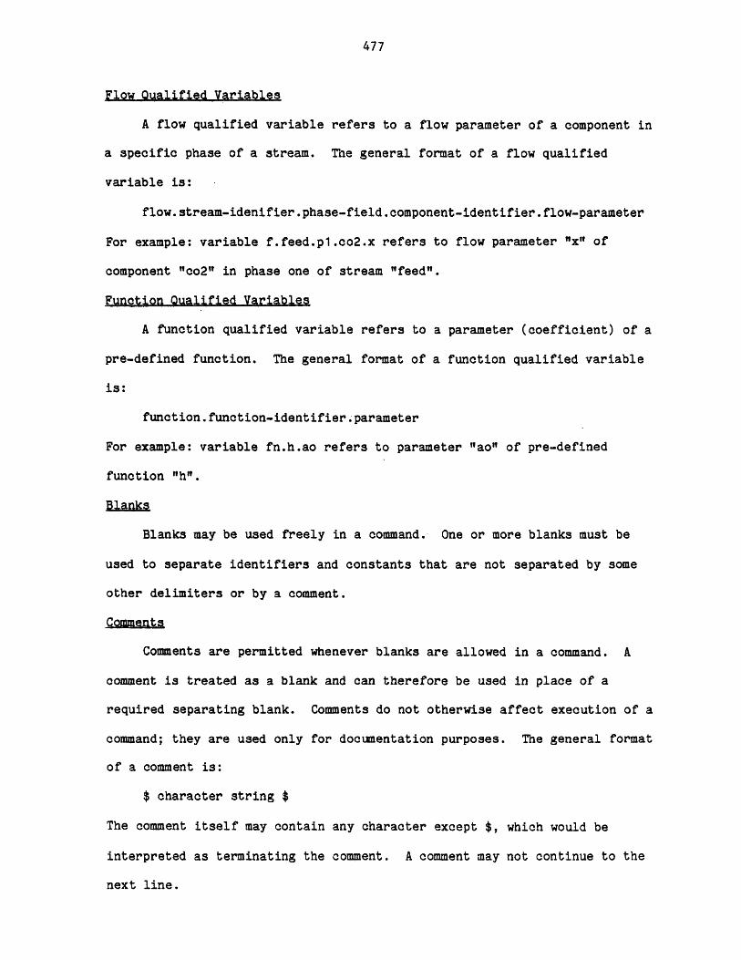
477
Flow Qualified Variables
A flow qualified variable refers to a flow parameter of a component in
a specific phase of a stream. The general format of a flow qualified
variable is:
flow.stream-idenifier.phase-field.component-identifier.flow-parameter
For example: variable f.feed.pl.co2.x refers to flow parameter "x" of
component "co2" in phase one of stream "feed".
Function Qualified Variables
A function qualified variable refers to a parameter (coefficient) of a
pre-defined function. The general format of a function qualified variable
is:
function.function-identifier.parameter
For example: variable fn.h.ao refers to parameter "ao" of pre-defined
function "h".
Blanks
Blanks may be used freely in a command. One or more blanks must be
used to separate identifiers and constants that are not separated by some
other delimiters or by a comment.
Comments
Comments are permitted whenever blanks are allowed in a command. A
comment is treated as a blank and can therefore be used in place of a
required separating blank. Comments do not otherwise affect execution of a
command; they are used only for documentation purposes. The general format
of a comment is:
$ character string $
The comment itself may contain any character except $, which would be
interpreted as terminating the comment. A comment may not continue to the
next line.
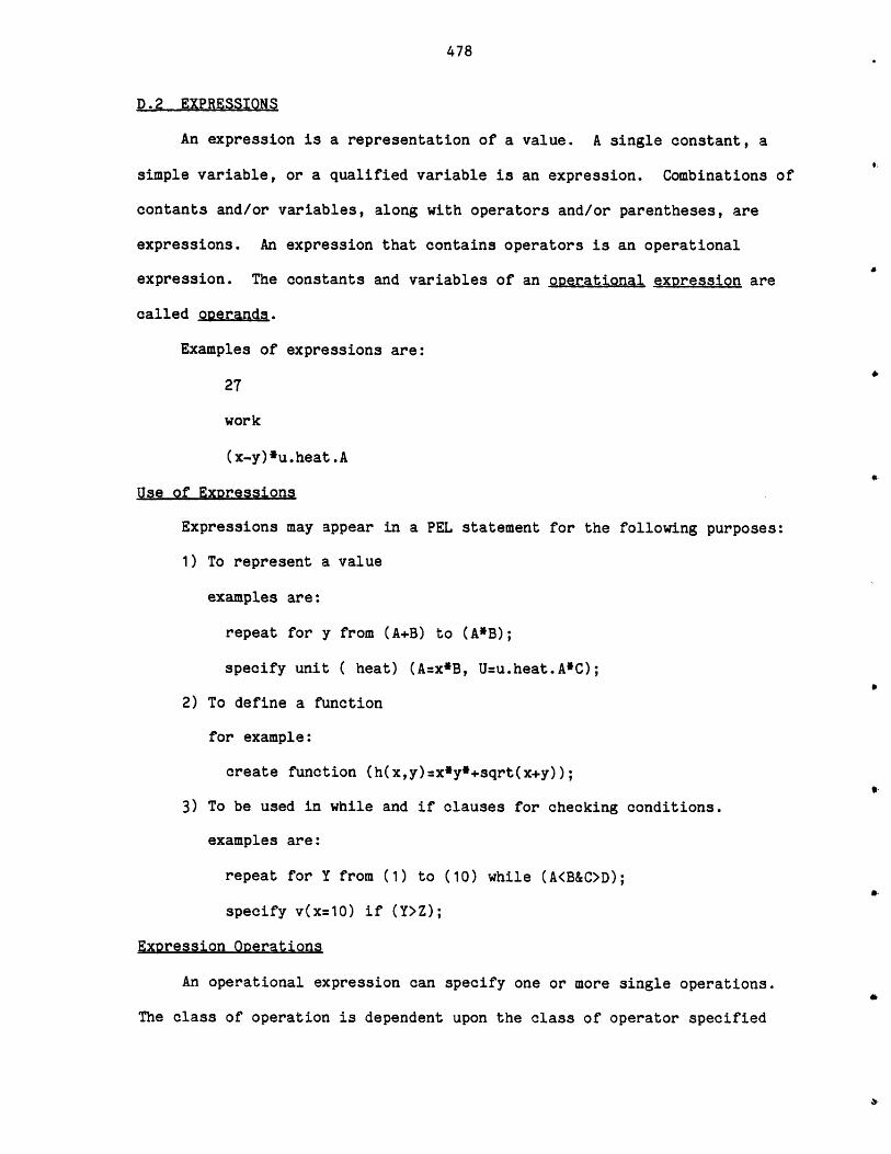
478
D.2 EXPRESSIONS
An expression is a representation of a value. A single constant, a
simple variable, or a qualified variable is an expression. Combinations of
contants and/or variables, along with operators and/or parentheses, are
expressions. An expression that contains operators is an operational
expression. The constants and variables of an operational expression are
called operands.
Examples of expressions are:
27
work
(x-y)*u.heat.A
Use of Expressions
Expressions may appear in a PEL statement for the following purposes:
1) To represent a value
examples are:
repeat for y from (A+B) to (A*B);
specify unit ( heat) (A=x*B, U=u.heat.A*C);
2) To define a function
for example:
create function (h(x,y)=x*y*+sqrt(x+y));
3) To be used in while and if clauses for checking conditions.
examples are:
repeat for Y from (1) to (10) while (A<B&C>D);
specify v(x=10) if (Y>Z);
Expression Operations
An operational expression can specify one or more single operations.
The class of operation is dependent upon the class of operator specified
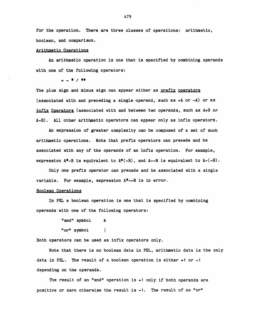
479
for the operation. There are three classes of operations: arithmetic,
boolean, and comparison.
Arithmetic Onerations
An arithmetic operation is one that is specified by combining operands
with one of the following operators:
+ - * / **
The plus sign and minus sign can appear either as prefix operators
(associated with and preceding a single operand, such as +A or -A) or as
infix Operators (associated with and between two operands, such as A+B or
A-B). All other arithmetic operators can appear only as infix operators.
An expression of greater complexity can be composed of a set of such
arithmetic operations. Note that prefix operators can precede and be
associated with any of the operands of an infix operation. For example,
expression A*-B is equivalent to A*(-B), and A--B is equivalent to A-(-B).
Only one prefix operator can precede and be associated with a single
variable. For example, expression A*--B is in error.
Boolean Operations
In PEL a boolean operation is one that is specified by combining
operands with one of the following operators:
"and" symbol &
"or" symbol |
Both operators can be used as infix operators only.
Note that there is no boolean data in PEL, arithmetic data is the only
data in PEL. The result of a boolean operation is either +1 or -1
depending on the operands.
The result of an "and" operation is +1 only if both operands are
positive or zero otherwise the result is -1. The result of an "or"
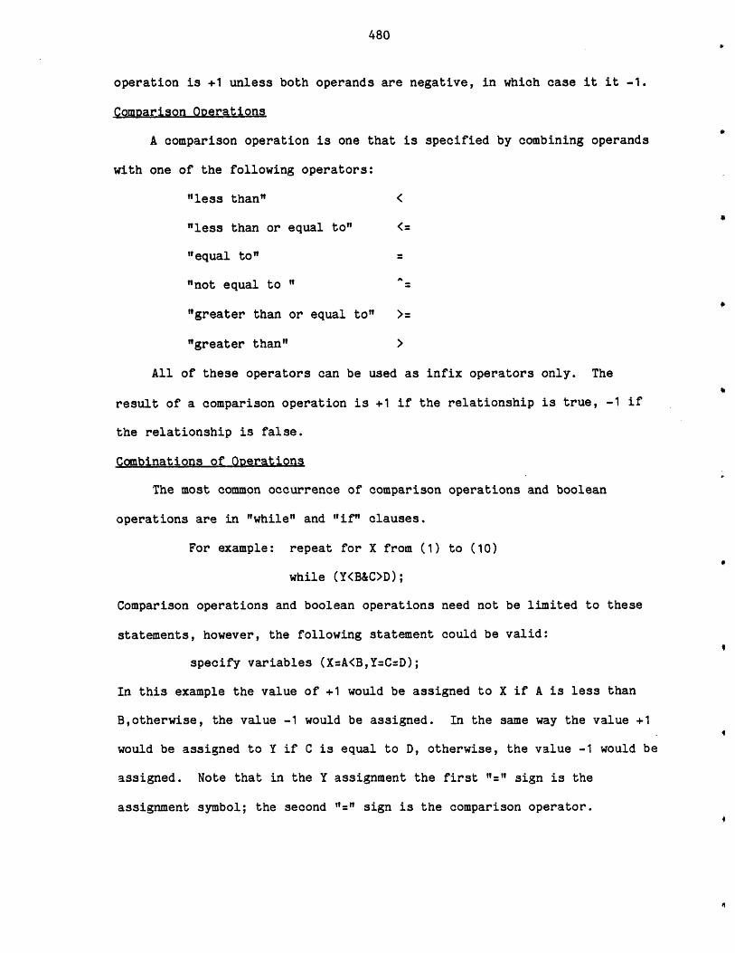
480
operation is +1 unless both operands are negative, in which case it it -1.
Comparison Operations
A comparison operation is one that is specified by combining operands
with one of the following operators:
"less than" <
"less than or equal to" <=
"equal to"
"not equal to "
"greater than or equal to" >=
"greater than" >
All of these operators can be used as infix operators only. The
result of a comparison operation is +1 if the relationship is true, -1 if
the relationship is false.
Combinations of Operations
The most common occurrence of comparison operations and boolean
operations are in "while" and "if" clauses.
For example: repeat for X from (1) to (10)
while (Y<B&C>D);
Comparison operations and boolean operations need not be limited to these
statements, however, the following statement could be valid:
specify variables (X=A<B,Y=C=D);
In this example the value of +1 would be assigned to X if A is less than
B,otherwise, the value -1 would be assigned. In the same way the value +1
would be assigned to Y if C is equal to D, otherwise, the value -1 would be
assigned. Note that in the Y assignment the first "=' sign is the
assignment symbol; the second "=" sign is the comparison operator.
481
Different types of operations can be combined within the same
operational expression. Any combination can be used. For example, the
expression shown in the following command is valid:
specify variables (A=6,B=-8,C=9,D=-1);
specify variable (X:A+B<C&D);
Each operation within the expression is evaluated according to the rules
for that kind of operation.
B would be added to A resulting in the value, -2.
-2 would be compared to C resulting in +1 since the relationship is
true.
An "and" operation would be performed as a result of the comparison
between (+1) & D resulting in -1.
The result of "and" operation (-1) would be assigned to X.
The expression in this example is described as being evaluated
operation-by-operation, from left to right. Such would be the case for
this particular expression. The order of evaluation, however, depends upon
the priority of the operators appearing in the expression.
Similarly, "while" and "if" expressions can have combined types of
operations. The "while" and "if" expressions would be evaluated like any
other expression. If the result of expression is positive or zero, the
relationship would be considered to be true (conditions hold). If the
result of the expression is negative, the relationship would be considered
false (conditions do not hold).
For example:
calculate units (heater, turbine) if (u.Heat.A<100);
If parameter A of unit Heat is less than 100, the result of expression
would be +1 and consequently the command would be executed. Similarly the
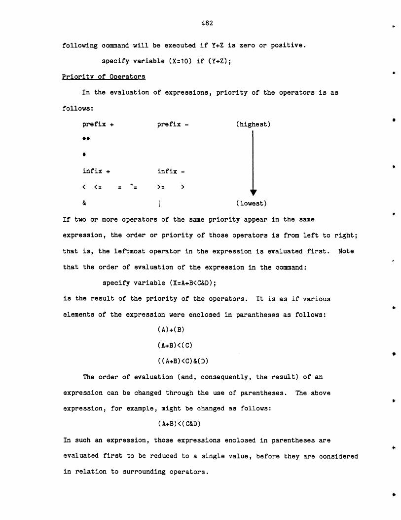
482
following command will be executed if Y+Z is zero or positive.
specify variable (X=10) if (Y+Z);
Priority of Operators
In the evaluation of expressions, priority of the operators is as
follows:
prefix + prefix - (highest)
**
*
infix + infix -
& (lowest)
If two or more operators of the same priority appear in the same
expression, the order or priority of those operators is from left to right;
that is, the leftmost operator in the expression is evaluated first. Note
that the order of evaluation of the expression in the command:
specify variable (X=A+B<C&D);
is the result of the priority of the operators. It is as if various
elements of the expression were enclosed in parantheses as follows:
(A)+(B)
(A+B)<(C)
((A+B)<C)&(D)
The order of evaluation (and, consequently, the result) of an
expression can be changed through the use of parentheses. The above
expression, for example, might be changed as follows:
(A+B)<(C&D)
In such an expression, those expressions enclosed in parentheses are
evaluated first to be reduced to a single value, before they are considered
in relation to surrounding operators.
483
Operands of an Expression
An operand of an expression can be a constant (number), a simple
variable, or a qualified variable. An operand can also be an expression
that represents a value that is the result of a computation, as shown in
the following expression:
B*sqrt(X)
In this example, the expression sqrt(X) represents a value that is equal to
the square root of the value X. Such an expression is called a function
reference.
The function sqrt is one of the PEL built-in functions. There are
other types of functions in PEL. A complete discussion of functions
follows.
484
D.1 FUNCTIONS
There are three types of functions available to the user. They are:
pre-defined functions
user-defined functions
built-in functions
The general form of a function reference is as follows:
function-indentifier (expression, expression, ... )
Pre-Defined Functions
These are the functions defined and established in the TBS by the
responsible system administrator, by providing the appropriate templates,
and required subprograms. The user incorporates these functions into his
problem solving capability by a "create" command. The coefficients of such
a function (if any) may be explicitly provided by a "specify" command or
may be assigned by a "calculate" command which in effect calls upon a
calculating routine. For example, suppose the TBS has a pre-defined
function of type I1 which is in the form:
X2 2F(Xl,X2)= Xl 3X2 dX
The following commands show how the user can use such a function type:
"COMMAND: create function (H) type=I1;
**COMMAND: specify variable (X=H(0,2));
**COMMAND: print variable (X);
X=8
Suppose there is another pre-defined function of type L1 which is in
the form: F(X)=AO+A1*X, where AO and Al are function parameters. Suppose
the calculating routine for this function when invoked will perform a least
square curve fitting on user supplied data to determine parameters

485
(coefficients) AO and Al of the function. The following commands show how
the user can use such a function:
**COMMAND: create function (P) type=Ll; $AO and Al are unspecified now $
**COMMAND: specify function (P)(AO=2,A1:4);
**COMMAND: specify variable (X=P(5)); $X=2+4*5=22$
**COMMAND: print v(X);
X=22
**COMMAND: calculate function (P);
*entering routine leasts for level 1 calculation of function "P"
**enter number of data: 4
**enter X and Y:
1: 2 10
2: 4 20
3: 6 30
4: 7 35
**COMMAND: specify variable (X=P(3));
**COMMAND: print variable (X);
X=15
The "delete" command can remove the function from the users working
area, if it is not referred to in any current user-defined function.
User-Defined Functions
These are the functions that the user may provide at will to improve
his problem solving capability. For example:
create function (XXX(X,Y,Z)=X**Y+sqrt(Z));
specify variable (A:XXX(2,1,4)); $A=2** 1+sqrt(4)=4$
The "delete" command will remove the function from the users working
area, if the function is not referred to in any other current user-defined
486
function:
delete function (XXX);
Built-In Functions
These are the functions built-in to the system and available to the
user. Each such function will only be interpreted as a built-in function,
if there is no other user created function with that name.
The built-in functions can be classified according to the features
they are intended to serve. These classes are:
Arithmetic
Mathematical
Arithmetic Built-in Functions
These functions allow the programmer to investigate simple properties
of arithmetic values. They are:
abs
max
min
mod
sign
Mathematical Built-In Functions
These functions provide standard mathematical operations. They are:
acos log
asin log2
atan log10
atand sin
atanh sind
cos sinh
cosd sqrt
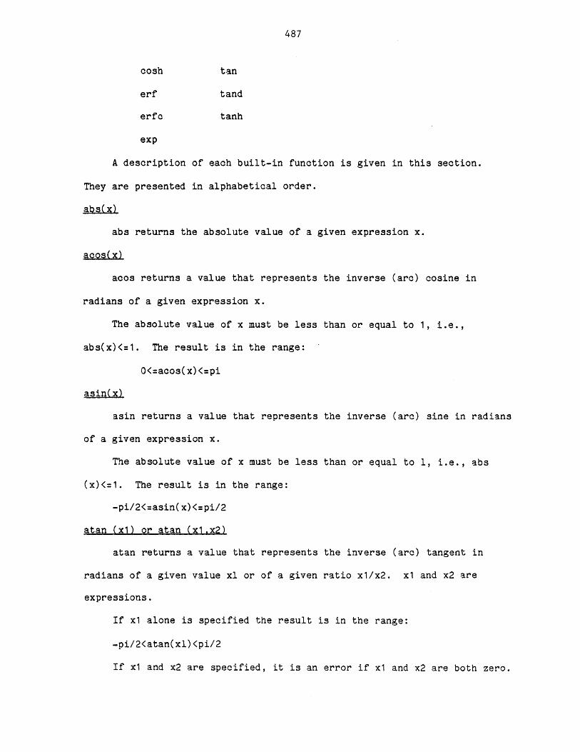
487
cosh tan
erf tand
erfc tanh
exp
A description of each built-in function is given in this section.
They are presented in alphabetical order.
abs(x)
abs returns the absolute value of a given expression x.
acosx
acos returns a value that represents the inverse (arc) cosine in
radians of a given expression x.
The absolute value of x must be less than or equal to 1, i.e.,
abs(x)<=1. The result is in the range:
0<=acos(x) <=pi
asin(x)-
asin returns a value that represents the inverse (arc) sine in radians
of a given expression x.
The absolute value of x must be less than or equal to 1, i.e., abs
(x)<=1. The result is in the range:
-pi/2<=asin(x)<=pi/2
atan (x1) or atan (x1,x2)
atan returns a value that represents the inverse (arc) tangent in
radians of a given value xl or of a given ratio xl/x2. x1 and x2 are
expressions.
If x1 alone is specified the result is in the range:
-pi/2<atan(xl)<pi/2
If x1 and x2 are specified, it is an error if x1 and x2 are both zero.
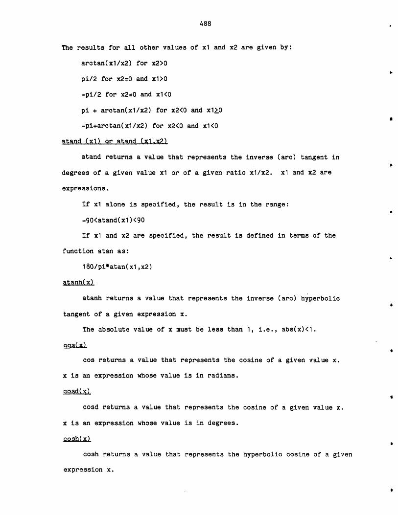
488
The results for all other values of x1 and x2 are given by:
arctan(x1/x2) for x2>0
pi/2 for x2=0 and x1>O
-pi/2 for x2=0 and x1<O
pi + arctan(x1/x2) for x2<0 and x1>0
-pi+arctan(xl/x2) for x2<0 and x1<O
atand (xl) or atand (xl.x2)
atand returns a value that represents the inverse (arc) tangent in
degrees of a given value x1 or of a given ratio x1/x2. x1 and x2 are
expressions.
If x1 alone is specified, the result is in the range:
-90<atand(xl)<90
If x1 and x2 are specified, the result is defined in terms of the
function atan as:
180/pi*atan(xl ,x2)
atanh(x)
atanh returns a value that represents the inverse (arc) hyperbolic
tangent of a given expression x.
The absolute value of x must be less than 1, i.e., abs(x)<1.
cos(x)
cos returns a value that represents the cosine of a given value x.
x is an expression whose value is in radians.
cosd(x)
cosd returns a value that represents the cosine of a given value x.
x is an expression whose value is in degrees.
cosh(x)
cosh returns a value that represents the hyperbolic cosine of a given
expression x.
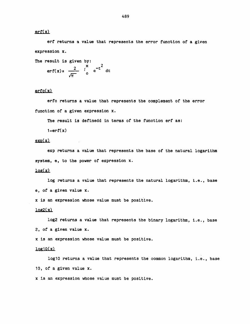
489
erf returns a value that represents the error function of a given
expression x.
The result is given by:
2 -t2erf(x)= - et dt
erfc(x)
erfc returns a value that represents the complement of the error
function of a given expression x.
The result is definedd in terms of the function erf as:
1-erf(x)
exp(-x)-
exp returns a value that represents the base of the natural logarithm
system, e, to the power of expression x.
lonz(x)
log returns a value that represents the natural logarithm, i.e., base
e, of a given value x.
x is an expression whose value must be positive.
log2(x)
log2 returns a value that represents the binary logarithm, i.e., base
2, of a given value x.
x is an expression whose value must be positive.
log1o(x)
log10 returns a value that represents the common logarithm, i.e., base
10, of a given value x.
x is an expression whose value must be positive.
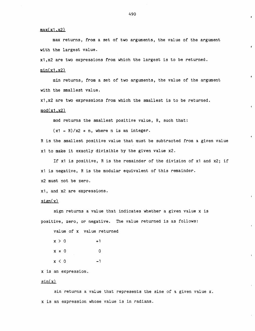
490
max(xl.x2)
max returns, from a set of two arguments, the value of the argument
with the largest value.
xl,x2 are two expressions from which the largest is to be returned.
min(xlx2)
min returns, from a set of two arguments, the value of the argument
with the smallest value.
xl,x2 are two expressions from which the smallest is to be returned.
mod(x1,-x2)
mod returns the smallest positive value, R, such that:
(xl - R)/x2 = n, where n is an integer.
R is the smallest positive value that must be subtracted from a given value
x1 to make it exactly divisible by the given value x2.
If x1 is positive, R is the remainder of the division of x1 and x2; if
x1 is negative, R is the modular equivalent of this remainder.
x2 must not be zero.
x1, and x2 are expressions.
sign(x)
sign returns a value that indicates whether a given value x is
positive, zero, or negative. The value returned is as follows:
value of x value returned
x > 0 +1
x = 0 0
x < 0 -1
x is an expression.
sin(x)
sin returns a value that represents the sine of a given value x.
x is an expression whose value is in radians.
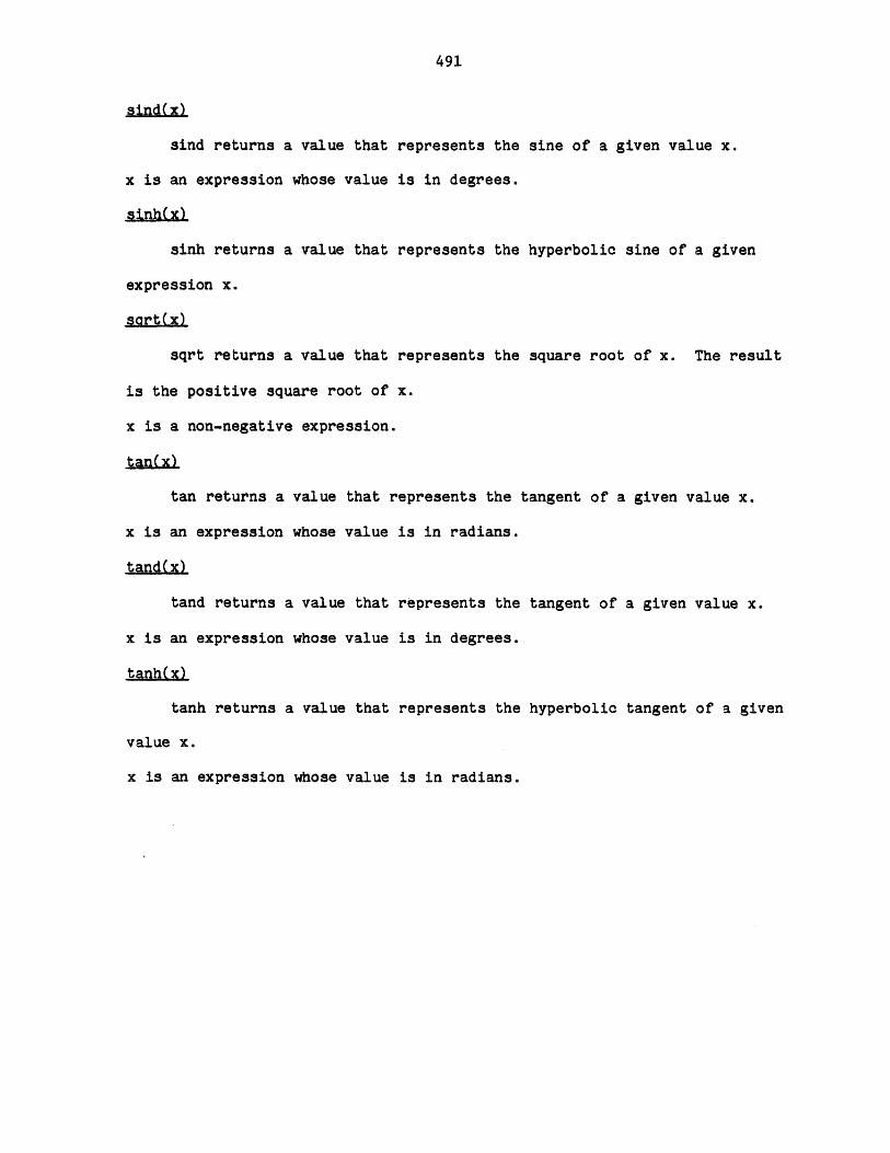
491
sind returns a value that represents the sine of a given value x.
x is an expression whose value is in degrees.
sinh~x)
sinh returns a value that represents the hyperbolic sine of a given
expression x.
sart(-x)
sqrt returns a value that represents the square root of x. The result
is the positive square root of x.
x is a non-negative expression.
tan(.x)
tan returns a value that represents the tangent of a given value x.
x is an expression whose value is in radians.
tand(x)
tand returns a value that represents the tangent of a given value x.
x is an expression whose value is in degrees.
tanh(x)
tanh returns a value that represents the hyperbolic tangent of a given
value x.
x is an expression whose value is in radians.
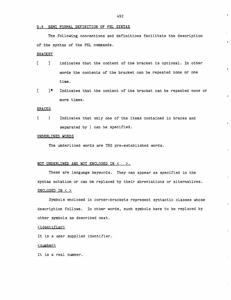
492
D.4 SEMI FORMAL DEFINITION OF PEL SYNTAX
The following conventions and definitions facilitate the description
of the syntax of the PEL commands.
BRACKET
indicates that the content of the bracket is optional. In other
words the contents of the bracket can be repeated none or one
time.
[ ]* Indicates that the content of the bracket can be repeated none or
more times.
BRACES
{ } Indicates that only one of the items contained in braces and
separated by I can be specified.
UNDERLINED WORDS
The underlined words are TBS pre-established words.
NOT UNDERLINED AND NOT ENCLOSED IN < >.
These are language keywords. They can appear as specified in the
syntax notation or can be replaced by their abreviations or alternatives.
ENCLOSED IN < >
Symbols enclosed in corner-brackets represent syntactic classes whose
description follows. In other words, such symbols have to be replaced by
other symbols as described next.
<identifier>
It is a user supplied identifier.
<number>
It is a real number.
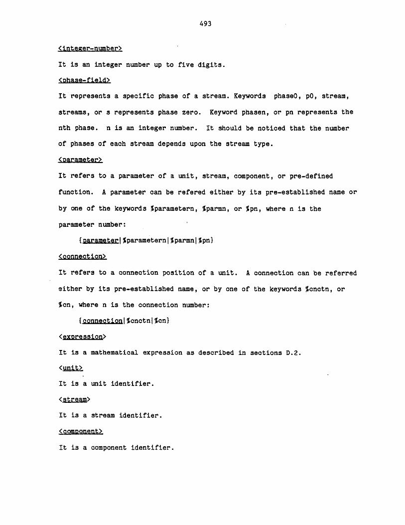
493
<inteaer-number>
It is an integer number up to five digits.
<Dhase-field>
It represents a specific phase of a stream. Keywords phaseO, p0, stream,
streams, or s represents phase zero. Keyword phasen, or pn represents the
nth phase. n is an integer number. It should be noticed that the number
of phases of each stream depends upon the stream type.
<parameter>
It refers to a parameter of a unit, stream, component, or pre-defined
function. A parameter can be refered either by its pre-established name or
by one of the keywords %parametern, %parmn, or %pn, where n is the
parameter number:
{Darameter|%parameternlparmnlpnl
<connection>
It refers to a connection position of a unit. A connection can be referred
either by its pre-established name, or by one of the keywords %cnctn, or
%cn, where n is the connection number:
{connection%cnctnjcn}
<exDre ssion>
It is a mathematical expression as described in sections D.2.
<unit>
It is a unit identifier.
<stream>
It is a stream identifier.
<component>
It is a component identifier.
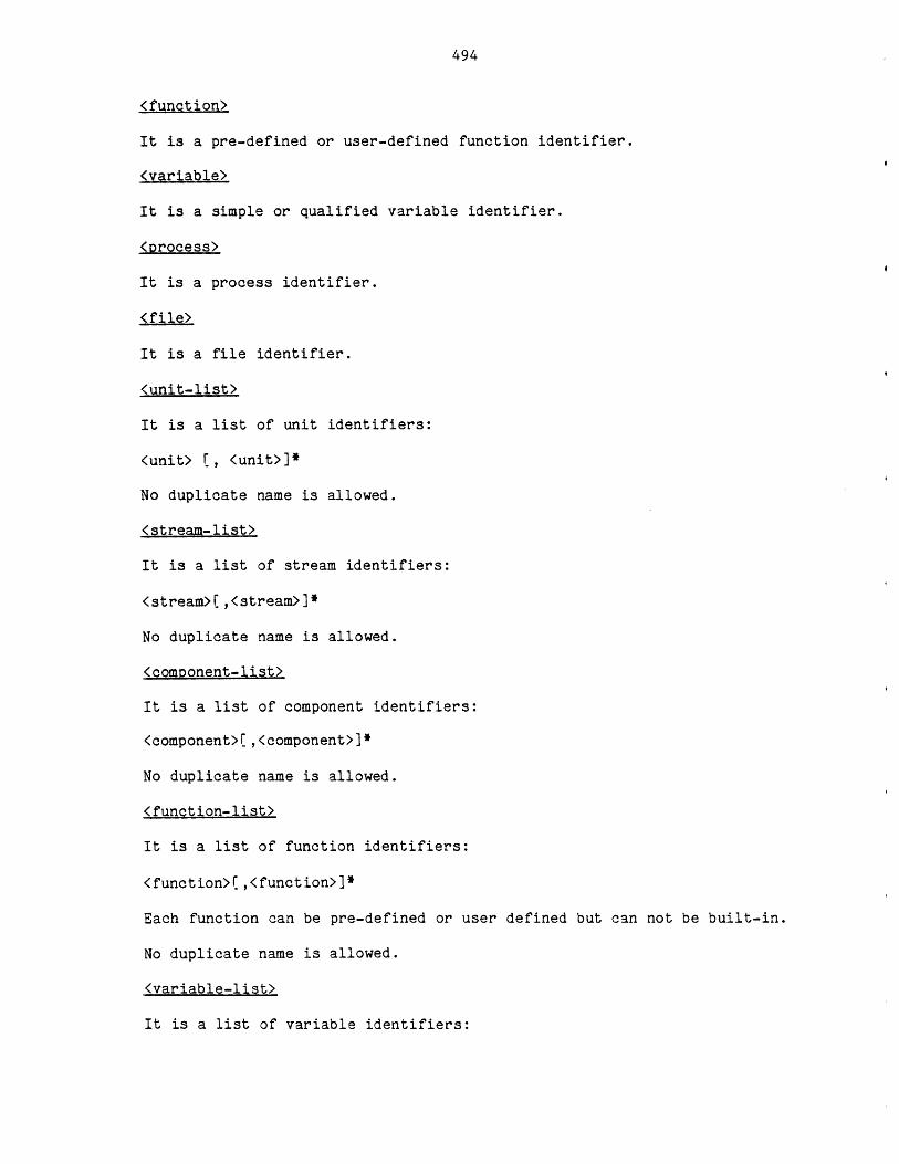
494
<function>
It is a pre-defined or user-defined function identifier.
<variable>
It is a simple or qualified variable identifier.
<process>
It is a process identifier.
(file>
It is a file identifier.
<unit-list>
It is a list of unit identifiers:
<unit> E, <unit>]*
No duplicate name is allowed.
<stream-list>
It is a list of stream identifiers:
<stream>(,<stream>]*
No duplicate name is allowed.
<component-list>
It is a list of component identifiers:
<component>[,<component>]*
No duplicate name is allowed.
<function-list>
It is a list of function identifiers:
<function>(,<function>]*
Each function can be pre-defined or user defined but can not be built-in.
No duplicate name is allowed.
<variable-list>
It is a list of variable identifiers:
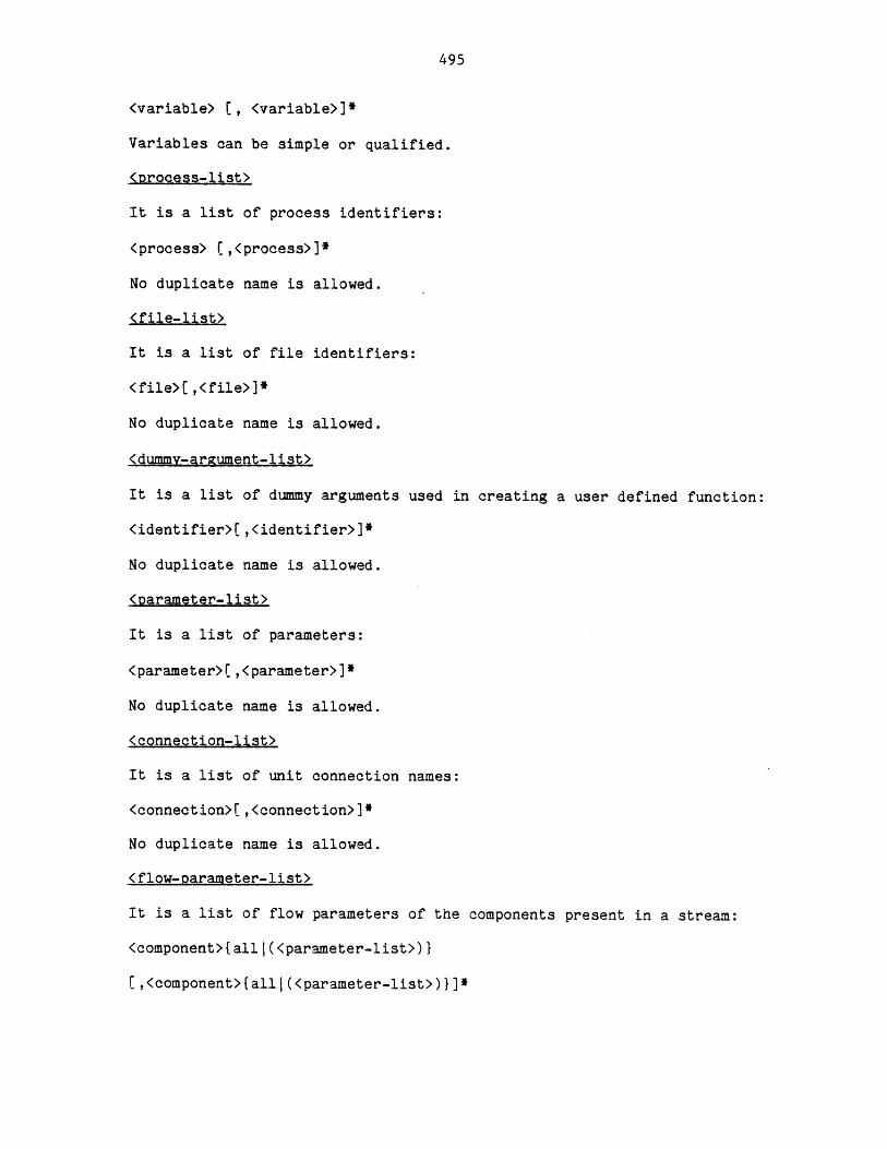
495
<variable> (, <variable>]*
Variables can be simple or qualified.
<process-list>
It is a list of process identifiers:
<process> ( ,<process>]*
No duplicate name is allowed.
<file-list>
It is a list of file identifiers:
<file> ,<file>]*
No duplicate name is allowed.
<dummv-argument-list>
It is a list of dummy arguments used in creating a user defined function:
<identifier>(,<identifier>]*
No duplicate name is allowed.
<parameter-list>
It is a list of parameters:
<parameter>(,<parameter>]*
No duplicate name is allowed.
<connection-list>
It is a list of unit connection names:
<connection>[,<connection>]*
No duplicate name is allowed.
<flow-parameter-list>
It is a list of flow parameters of the components present in a stream:
<component>{alll(<parameter-list>)I
(,<component>{alll(<parameter-list>)I]*
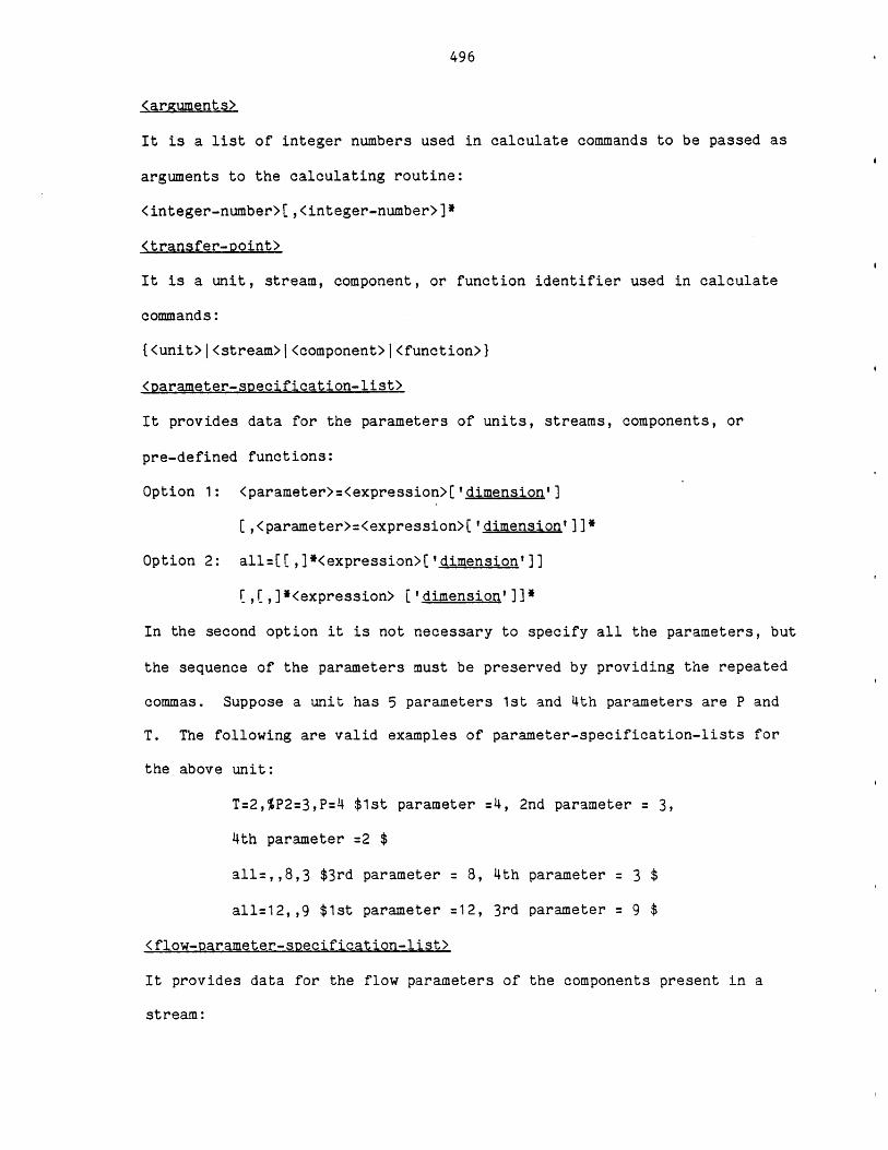
496
<arguments>
It is a list of integer numbers used in calculate commands to be passed as
arguments to the calculating routine:
<integer-number>[,<integer-number>]*
<transfer-point>
It is a unit, stream, component, or function identifier used in calculate
commands:
{<unit>j<stream>l<component>l<function>}
<parameter-specification-list>
It provides data for the parameters of units, streams, components, or
pre-defined functions:
Option 1: <parameter>=<expression>['dimension']
C,<parameter>=<expression>[I'dimension']]*
Option 2: all=[[,]*<expression>['dimension']]
, ,]*<expression> ['dimension']]*
In the second option it is not necessary to specify all the parameters, but
the sequence of the parameters must be preserved by providing the repeated
commas. Suppose a unit has 5 parameters 1st and 4th parameters are P and
T. The following are valid examples of parameter-specification-lists for
the above unit:
T=2,%P2=3,P=4 $1st parameter =4, 2nd parameter = 3,
4th parameter =2 $
all=,,8,3 $3rd parameter = 8, 4th parameter = 3 $
all=12,,9 $1st parameter =12, 3rd parameter = 9 $
<flow-parameter-specification-list>
It provides data for the flow parameters of the components present in a
stream:

497
<component>(<parameter-specification-list>)
(,<component>(<parameter-specification-list>)]*
<ob ect>
It is a keyword representing a class of objects (command objects):
{unitjstreamlcomponentjflowlfunctionivariablelprocess}
<verb>
It is a keyword indicating the action to be taken by a command (command
verb):
{assumelbugs calculatelclearlcloselconnecticontinuelcopylcreatedeleteI
deletefldisconnect IendlescapelhelplincludelleavelletiletallistllistfI
listt load loopinewslopenlprintlprintflprinttlprofilejreadireadarepeatI
savelspecifylstopiterminatelunspecifyluse}
<if-clause>
Some commands may have if-clause. The execution of such a command depends
on the conditions set in the if-clause. The if-clause is in the following
form:
if(<expression>)
The command having the if-clause will not be executed, if the result of the
expression is negative; it will be executed otherwise. Examples of valid
if-clauses are:
if(A>B)
if(A>B & C>D)
if(A&B)
if(-3)
Table D.4 lists the general format (syntax) of each command.
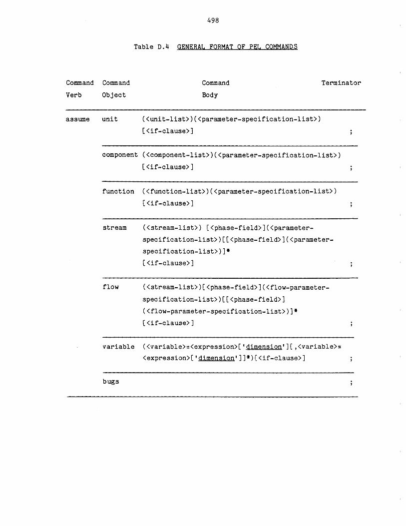
498
Table D.4 GENERAL FORMAT OF PEL COMMANDS
TerminatorCommand
Body
assume unit <unit-list>)(<parameter-specification-list>)
<if-clause>]
component (<component-list>)(<parameter-specification-list>)
C <if-clause>]
function (<function-list>)(<parameter-specification-list>)
[<if-clause>]
stream (<stream-list>) [<phase-field>](<parameter-
specification-list>)[[<phase-field>](<parameter-
specification-list>)]*
[<if-clause>]
flow (<stream-list>)[<phase-field>](<flow-parameter-
specification-list>)[[<phase-field>]
(<flow-parameter-specification-list>)]*
C <if-clause>]
variable (<variable>=<expression>['dimension'][,<variable>=
<expression>['dimension']]*)C<if-clause>]
bugs
Command
Verb
Command
Object
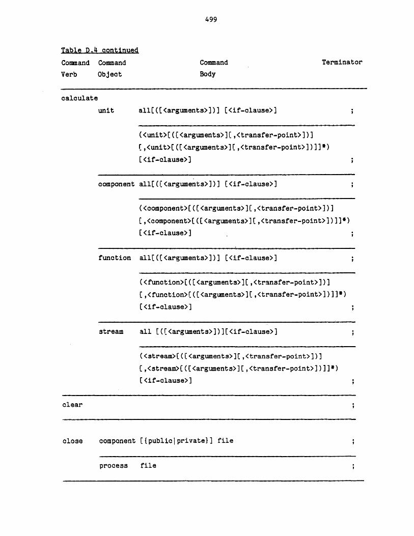
499
Table D.4.continued
Command
Verb
Command
Object
TerminatorCommand
Body
calculate
unit all(([<arguments>))] [<if-clause>]
(<unit>([C<arguments>](,<transfer-point>])]
C,<unit>[([<arguments>][,<transfer-point>])]]*)(<if-clause>]
component all[((<arguments>))] (<if-clause>]
(<component>((C<arguments>](,<transfer-point>])]
C,<component>((C<arguments>][,<transfer-point>])]]*)
(<if-clause>]
function all((<arguments>])] (<if-clause>]
(<function>(((<arguments>](,<transfer-point>])]
(,<function>(((<arguments>][,<transfer-point>])]]*)
(<if-clause>]
stream all [([<arguments>)][<if-clause>)
(<stream>((<arguments>][,<transfer-point>])]
(,<stream>(((<arguments>][,<transfer-point>])]]*)
[<if-clause>]
clear
close component C{publiciprivate}] file
process file
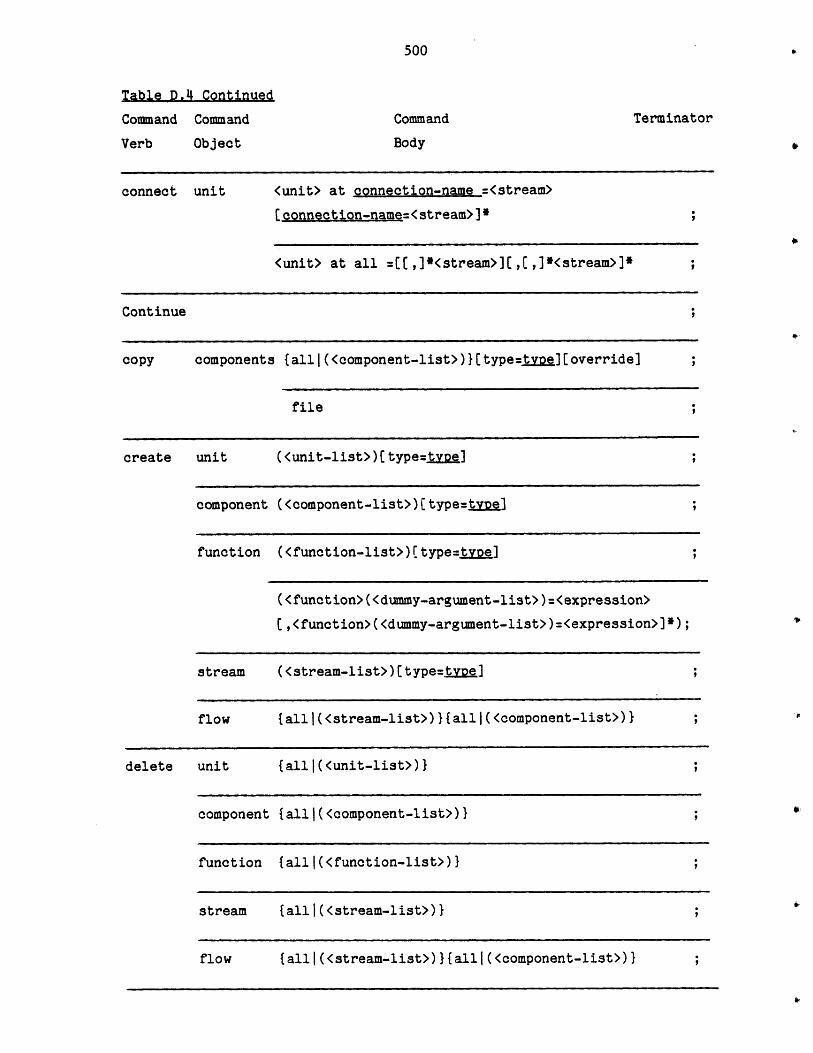
500
Table D.4 Continued
Command Command
Verb Object
TerminatorCommand
Body
connect unit <unit> at connection-name =<stream>
[connection-name=<stream>]*
<unit> at all =[(,]*<stream>][,(,]*<stream>]*
Continue
copy components {alll(<component-list>)}[type=t.] [override]
file
create unit (<unit-list>)(type=tvoe ];
component (<component-list>)[ type=tyDel
function (function-list>)[type=tye];
(<function>(<dummy-argument-list>)=<expression>
[,<function>(<dummy-argument-list>)=<expression>]*);
stream (<stream-list>)(type=tvDe)
flow {alll(<stream-list>)}{alll(<component-list>)}
delete unit {allI(<unit-list>)}
component tallJ(<component-list>)}
function tallJ(<function-list>)}
stream {alll(<stream-list>)}
flow {all|(<stream-list>)}{all|(<component-list>)}
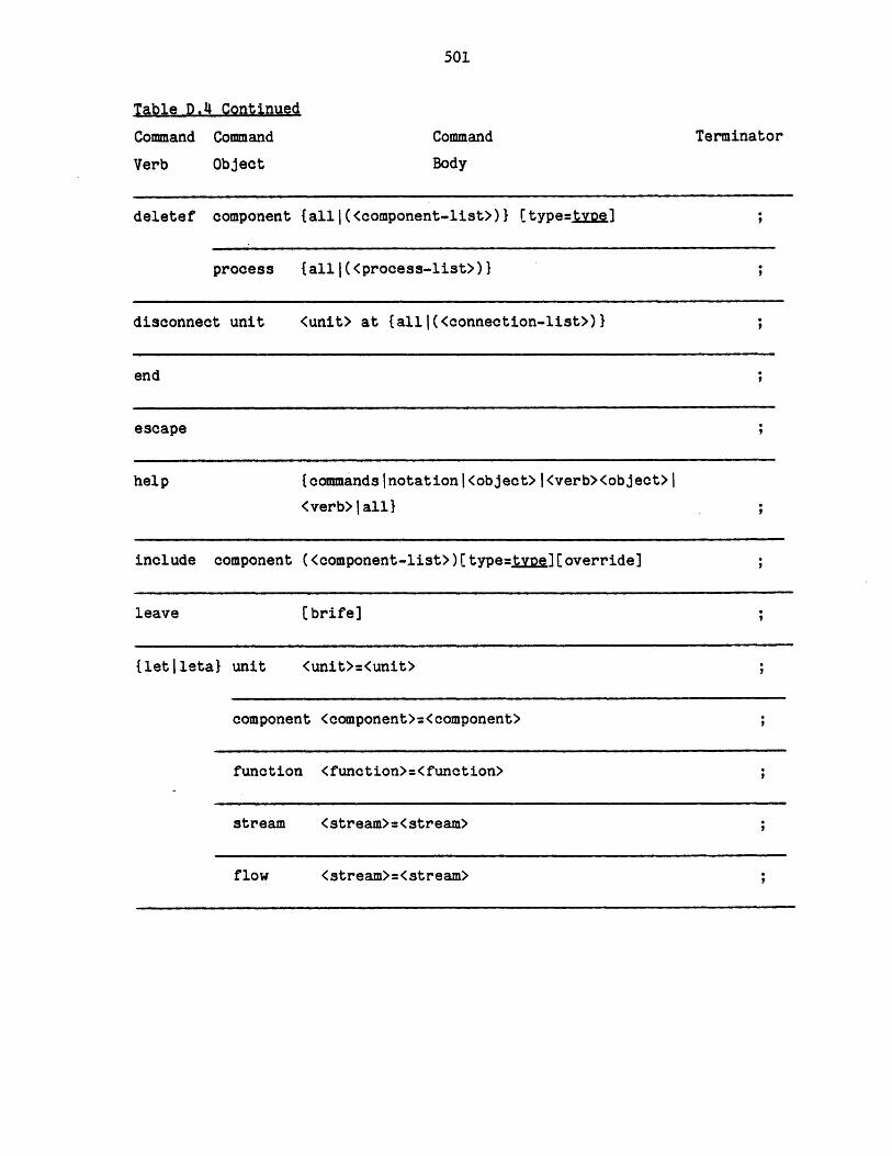
501
Table D.4 Continued
Command Command
Verb Object
TerminatorCommand
Body
deletef component {allI(<component-list>)} [type=tve];
process {allI(<process-list>) I
disconnect unit (unit> at {allJ(<connection-list>)}
end
escape
help {commandslnotationj<object>|<verb><object>I
<verb>tall)
include component (<component-list>) Ctype=j.]t [ Coverride]
leave [brife]
{letlleta} unit <unit>=<unit>
component <component>=<component>
function <function>=<function>
stream <stream>=<stream>
flow <stream>=<stream>
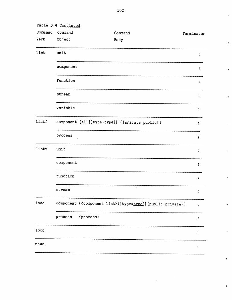
502
Table D.4 Continued
Command Command
Verb
list
Object
Command Terminator
Body
unit
component
function
stream
variable
listf component {all|(type=type]} [{privateipublicl]
process
listt unit
component
function
stream
load component (<component-list>)(type=tvpe][{publiclprivatel]
process (process>
loop
news

503
Table D.4 Continued
Command Command
Verb Object
open
Command
Body
Terminator
component [{publiciprivate}] file (<file>)
process file(<file>)
print unit {all I(<unit-list>) {unspecified I assumed I specified
calculated!parameterslconnectionsjtypelall}
[if-clause>]
component {all|(<component-list>)}{unspecifiedlassumed
specified calculated parameterslstreamstype all}
[<if-clause>]
function {alll(<function-list)>}{unspecifiedlassumedjspecified
calculated parameterslfunctions type all}
[<if-clause>]
stream talll(<stream-list>)}{unspecifiediassumedlspecifiedI
calculatedlparametersIconnectionstypeIall}
[ <if-clause>] ;
flow {alll(<stream-list>)}{unspecifiedlassumedspecified
calculatedjparametersIcomponentslall}
[<if-clause>] ;
variable tall|(<variable-list>)}[<if-clause>]
process {all!flowsheet} [<if-clause>]
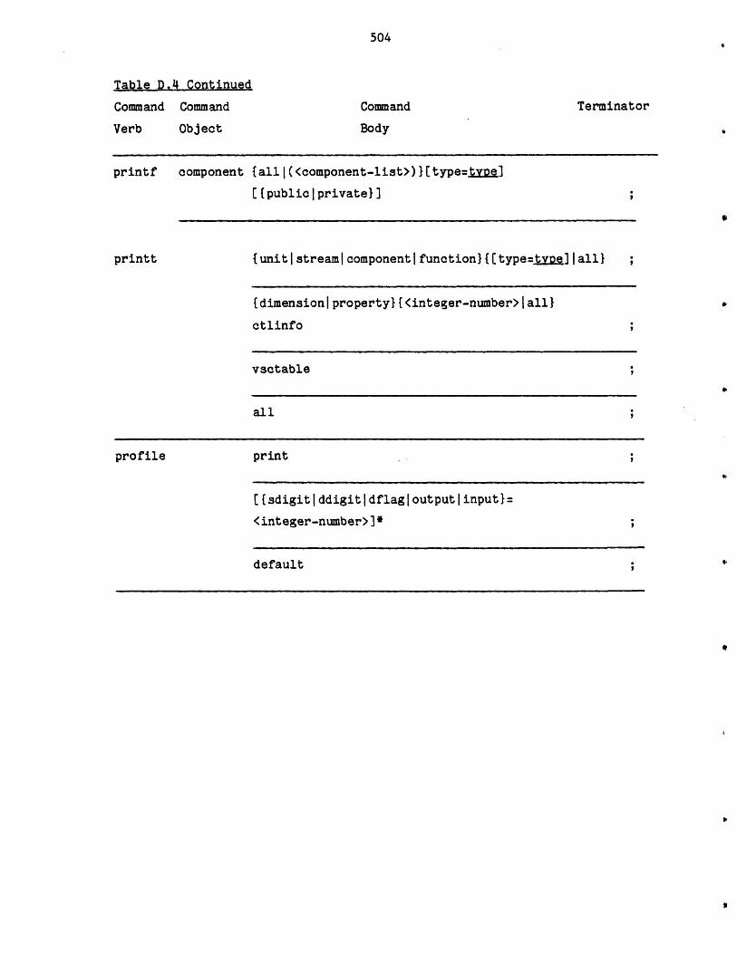
504
Table D.4 Continued
Command Command
Verb Object
TerminatorCommand
Body
printf component
printt
{alll(<component-list>)}(type=tve]
[{public private}]
{unitistreamIcomponentifunction}{[type=tvoe]Iall} ;
{dimension| property} {<integer-number>| all}
ctlinfo
vsctable
all
profile print
[{sdigitIddigitIdflagloutputlinput}=
<integer-number>]*
default

505
Table D.4 Continued
Command
Object
Command
Body
Terminator
{readIreada} unit (<unit-list>){alll(<parameter-list>)}(<if-clause>] ;
component
all [<if-clause>]
(<component-list>){alll(<parameter-list>)}
(<if-clause>]
all [<if-clause>]
function (<function-list>){alll(<parameter-list>)}
[<if-clause>]
all [<if-clause>]
stream (<stream-list>)[<phase-field>]{alll.(<parameter-
list>)}[[<phase-field>]{alll(<parameter-list>)}]e
[<if-clause>]
all [<if-clause>]
flow (<stream-list>)[<phase-field>]{alll(<flow-parameter-
list>)}(C(<phase-field>]{alli(<flow-parameter-
list>)}]e[<if-clause>)
all [<if-clause>]
variable {allJ(<variable-list>)} [<if-clause>]
Command
Verb
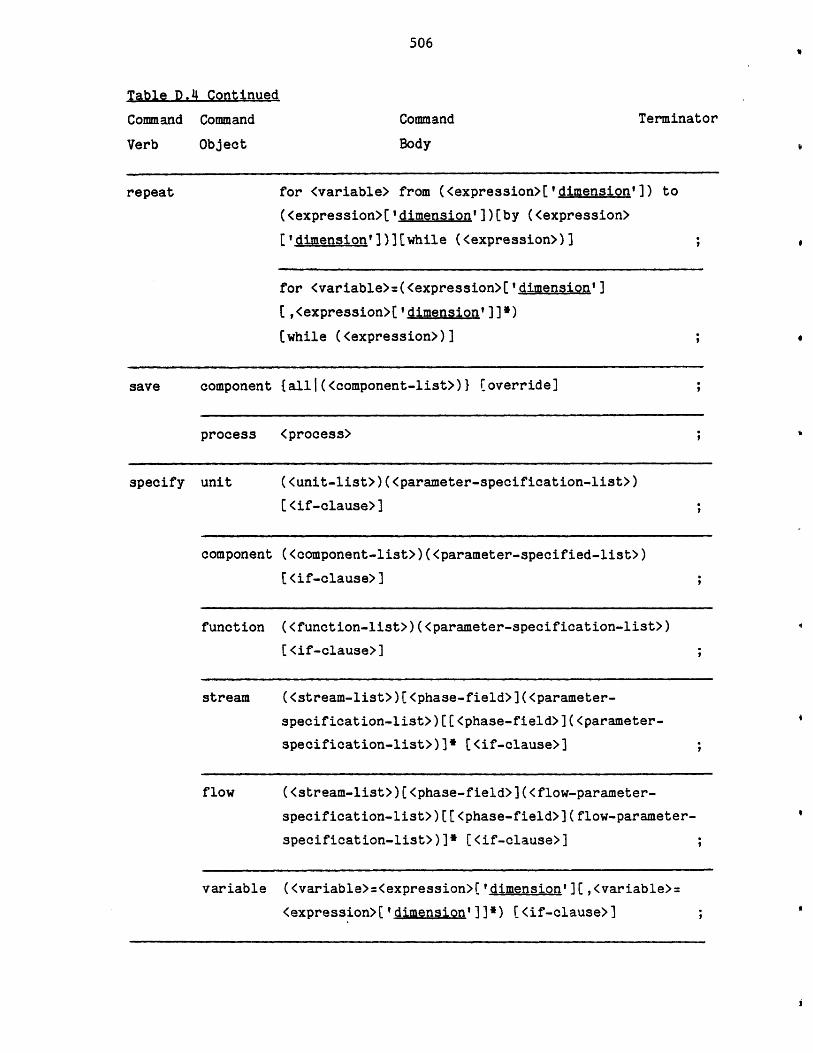
506
Table D.4 Continued
Command Command
Verb Object
repeat
TerminatorCommand
Body
for <variable> from (<expression>['dimension']) to
(<expression>('dimension'])[by (<expression>
('dimension'])][while (<expression>)]
for <variable>=(<expression>('dimension']
(,<expression>('dimension']]*)
(while (<expression>)]
save component {all|(<component-list>)} [override]
process <process>
specify unit (<unit-list>)(<parameter-specification-list>)
(<if-clause>];
component (<component-list>)(<parameter-specified-list>)
[<if-clause>]
function (<function-list>)(<parameter-specification-list>)
[<if-clause>]
stream (<stream-list>)(<phase-field>](<parameter-
specification-list>)[[<phase-field>](<parameter-
specification-list>)]* (<if-clause>]
flow (<stream-list>)[<phase-field>](<flow-parameter-
specification-list>)[(<phase-field>](flow-parameter-
specification-list>)]* [<if-clause>]
variable (<variable>:<expression>['dimension'](,<variable>=
<expression>['dimension']]*) [<if-clause>]
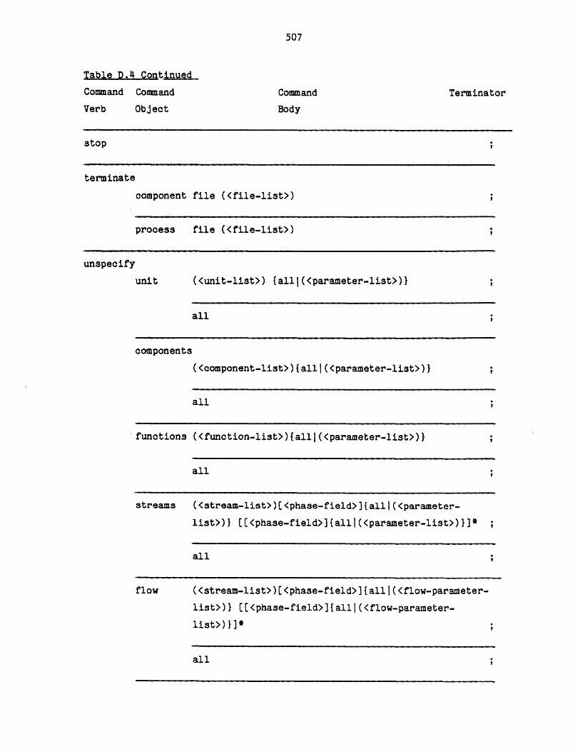
507
Table D.4 Continued
Command Command
Verb Object
Command
Body
Terminator
stop
terminate
component file (<file-list>)
process file (file-list>)
unspecify
unit (<unit-list>) {alli (<parameter-list>)}
all
components
(<component-list>){all|(<parameter-list>)}
all
functions (<function-list>){all|(<parameter-list>)}
all
streams (<stream-list>)[<phase-field>]{ all l (<parameter-
list>)} [E<phase-field>]{alll(<parameter-list>)}]*
all
flow (<stream-list>)[<phase-field>]{all l (<flow-parameter-
list>)} [[<phase-field>]{alll (<flow-parameter-
list>)]*
all
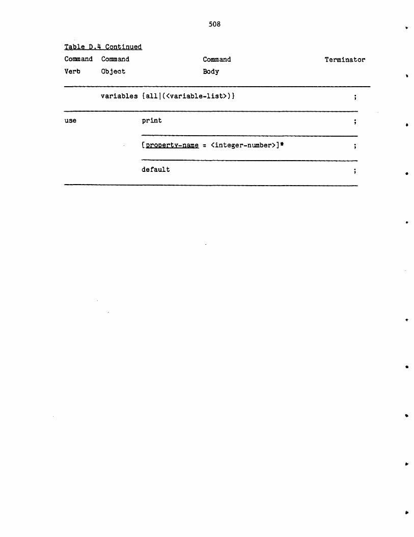
508
.4 Continued
Command
Object
Command
Body
Terminator
variables {all I (<variable-list>)}
use print
(roperty-name = <integer-number>]*
default
Tgble D
Command
Verb
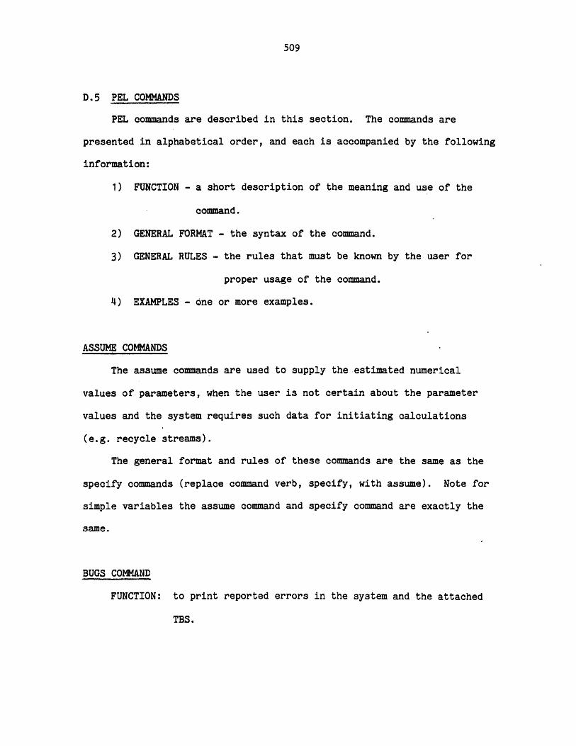
509
D.5 PEL COMMANDS
PEL commands are described in this section. The commands are
presented in alphabetical order, and each is accompanied by the following
information:
1) FUNCTION - a short description of the meaning and use of the
command.
2) GENERAL FORMAT - the syntax of the command.
3) GENERAL RULES - the rules that must be known by the user for
proper usage of the command.
4) EXAMPLES - one or more examples.
ASSUME COMMANDS
The assume commands are used to supply the estimated numerical
values of parameters, when the user is not certain about the parameter
values and the system requires such data for initiating calculations
(e.g. recycle streams).
The general format and rules of these commands are the same as the
specify commands (replace command verb, specify, with assume). Note for
simple variables the assume command and specify command are exactly the
same.
BUGS COMMAND
FUNCTION: to print reported errors in the system and the attached
TBS.
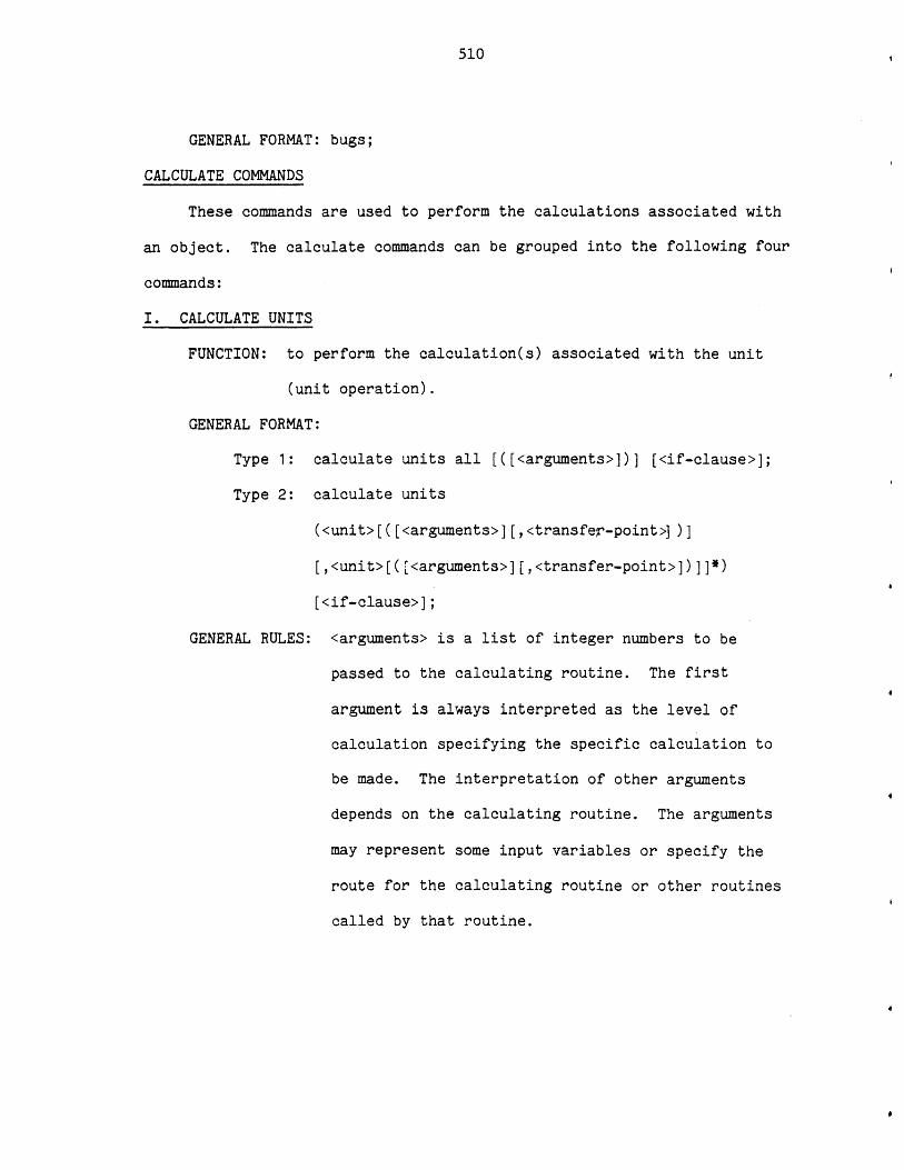
510
GENERAL FORMAT: bugs;
CALCULATE COMMANDS
These commands are used to perform the calculations associated with
an object. The calculate commands can be grouped into the following four
commands:
I. CALCULATE UNITS
FUNCTION: to perform the calculation(s) associated with the unit
(unit operation).
GENERAL FORMAT:
Type 1: calculate units all [([<arguments>])] [<if-clause>];
Type 2: calculate units
(<unit>[([<arguments>][,<transfer-point>] )]
[,<unit>[([<arguments>][,<transfer-point>])]]*)
[<if-clause>];
GENERAL RULES: <arguments> is a list of integer numbers to be
passed to the calculating routine. The first
argument is always interpreted as the level of
calculation specifying the specific calculation to
be made. The interpretation of other arguments
depends on the calculating routine. The arguments
may represent some input variables or specify the
route for the calculating routine or other routines
called by that routine.

511
Transfer-point is the name of the unit where
the calculation should start again if convergence
has not been achieved.
Other general rules for this command are as follows:
1) All units must exist.
2) Transfer-point must be the name of a unit
specified earlier in the list.
3) If level is not specified default level of one
will be assumed.
4) The number of arguments the user should provide
for each unit depends on the unit type. For
example, suppose unit type "x" has 2 levels of
calculations and minimum and maximum number of
arguments have been pre-set in the attached TBS
to 2 and 4 respectively. Then the following are
the only valid argument lists for calculating a
unit of type "x":
(ni,n2)
(n1,n2,n3)
(n1,n2,n3,n4)
Where n1 should be either 1 or 2. The other
arguments should be integer numbers between 0
and 99999.
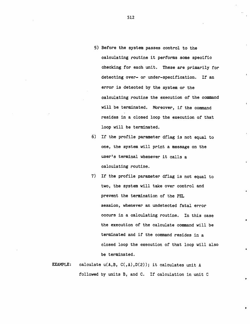
512
5) Before the system passes control to the
calculating routine it performs some specific
checking for each unit. These are primarily for
detecting over- or under-specification. If an
error is detected by the system or the
calculating routine the execution of the command
will be terminated. Moreover, if the command
resides in a closed loop the execution of that
loop will be terminated.
6) If the profile parameter dflag is not equal to
one, the system will print a message on the
user's terminal whenever it calls a
calculating routine.
7) If the profile parameter dflag is not equal to
two, the system will take over control and
prevent the termination of the PEL
session, whenever an undetected fatal error
occurs in a calculating routine. In this case
the execution of the calculate command will be
terminated and if the command resides in a
closed loop the execution of that loop will also
be terminated.
EXAMPLE: calculate u(A,B, C(,A),D(2)); it calculates unit A
followed by units B, and C. If calculation in unit C
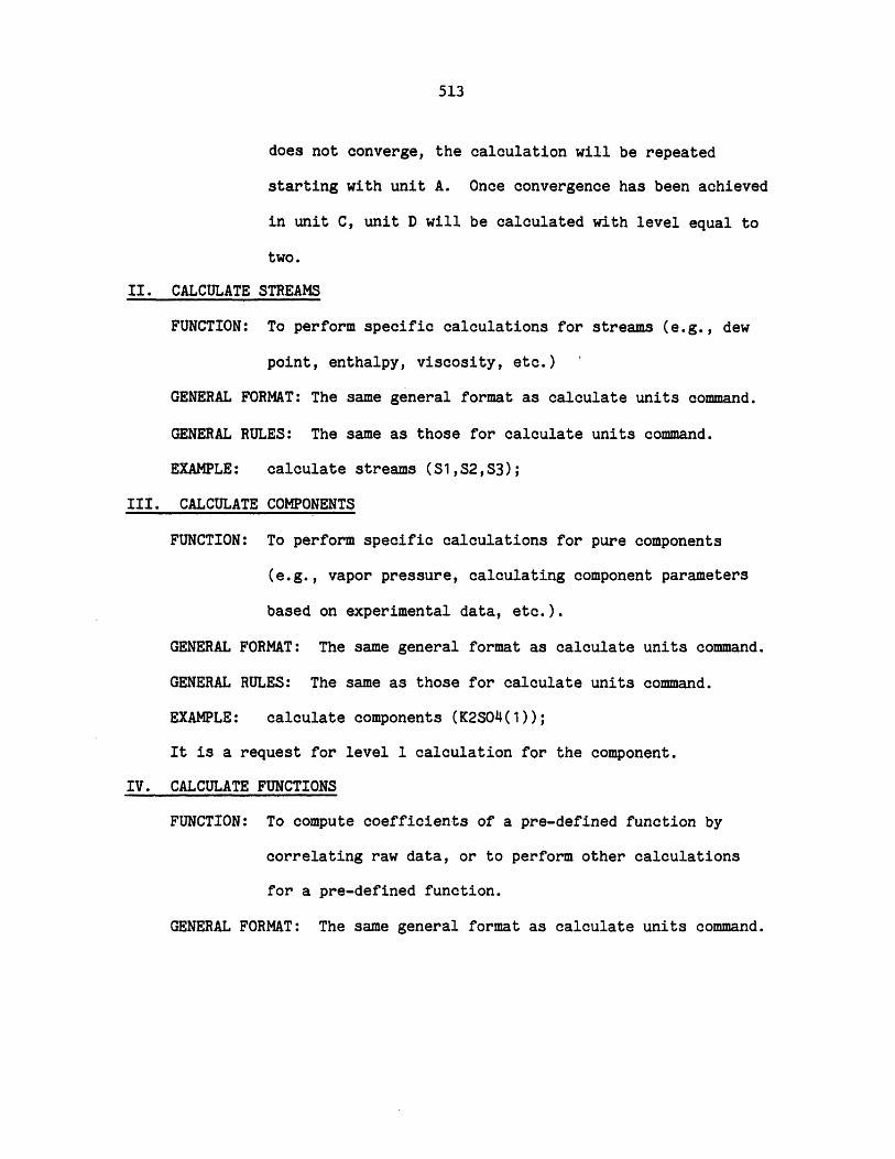
513
does not converge, the calculation will be repeated
starting with unit A. Once convergence has been achieved
in unit C, unit D will be calculated with level equal to
two.
II. CALCULATE STREAMS
FUNCTION: To perform specific calculations for streams (e.g., dew
point, enthalpy, viscosity, etc.) '
GENERAL FORMAT: The same general format as calculate units command.
GENERAL RULES: The same as those for calculate units command.
EXAMPLE: calculate streams (Si,S2,S3);
III. CALCULATE COMPONENTS
FUNCTION: To perform specific calculations for pure components
(e.g., vapor pressure, calculating component parameters
based on experimental data, etc.).
GENERAL FORMAT: The same general format as calculate units command.
GENERAL RULES: The same as those for calculate units command.
EXAMPLE: calculate components (K2SO4(1));
It is a request for level 1 calculation for the component.
IV. CALCULATE FUNCTIONS
FUNCTION: To compute coefficients of a pre-defined function by
correlating raw data, or to perform other calculations
for a pre-defined function.
GENERAL FORMAT: The same general format as calculate units command.

514
GENERAL RULES: The same as those for calculate units command. The
calculating routine may prompt the user for some
input such as the data to be correlated.
EXAMPLE: calculate function (enthalpy);
CLEAR COMMAND
FUNCTION: To clear the working area and to create a new process.
GENERAL FORMAT: clear;
GENERAL RULES:
1) The working area will be cleared. In other words,
all the existing units, components, functions,
streams, and variables will be deleted.
2) The execution of all repeat-loop groups will be
terminated (if any).
3) A new process will be created; property estimation
methods options will be initialized to default
options; and the user will be prompted to provide
the maximum number of components.
4) The opened process file (if any) and the opened
component fiels (if any) will remain opened.
5) Profile parameters will remain unchanged.
CLOSE COMMANDS
These commands are used to close a component file or a process
file. The close commands can be grouped to the following two commands:
I. CLOSE COMPONENT
FUNCTION: To close a component private or public file.
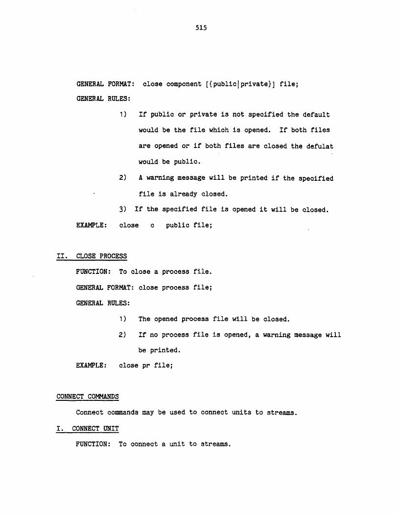
515
GENERAL FORMAT:
GENERAL RULES:
close component [{publiclprivate}] file;
1) If public or private is not specified the default
would be the file which is opened. If both files
are opened or if both files are closed the defulat
would be public.
2) A warning message will be printed if the specified
file is already closed.
3) If the specified file is opened it will be closed.
EXAMPLE: close c public file;
II. CLOSE PROCESS
FUNCTION: To close a process file.
GENERAL FORMAT: close process file;
GENERAL RULES:
1) The opened process file will be closed.
2) If no process file is opened, a warning message wi
be printed.
EXAMPLE: close pr file;
CONNECT COMMANDS
Connect commands may be used to connect units to streams.
I. CONNECT UNIT
FUNCTION: To connect a unit to streams.
11
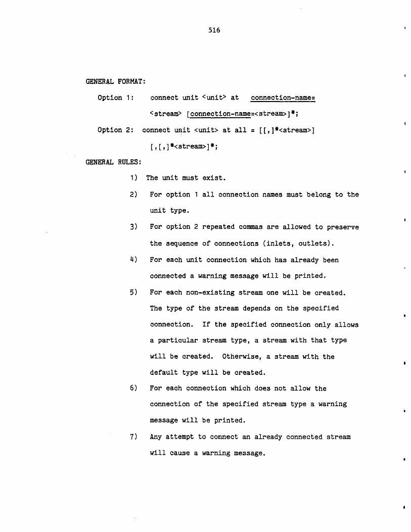
516
GENERAL FORMAT:
Option 1: connect unit <unit> at connection-name=
<stream> [connection-name=<stream>]*;
Option 2: connect unit <unit> at all = [[,]*<stream>]
[,[,]*<stream>]*;
GENERAL RULES:
1) The unit must exist.
2) For option 1 all connection names must belong to the
unit type.
3) For option 2 repeated commas are allowed to preserve
the sequence of connections (inlets, outlets).
4) For each unit connection which has already been
connected a warning message will be printed.
5) For each non-existing stream one will be created.
The type of the stream depends on the specified
connection. If the specified connection only allows
a particular stream type, a stream with that type
will be created. Otherwise, a stream with the
default type will be created.
6) For each connection which does not allow the
connection of the specified stream type a warning
message will be printed.
7) Any attempt to connect an already connected stream
will cause a warning message.
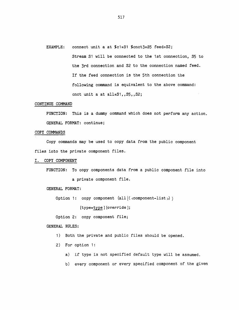
517
EXAMPLE: connect unit a at %c1=S1 %cnct3=S5 feed=S2;
Stream S1 will be connected to the 1st connection, S5 to
the 3rd connection and S2 to the connection named feed.
If the feed connection is the 5th connection the
following command is equivalent to the above command:
cnct unit a at all=S1,,S5,,S2;
CONTINUE COMMAND
FUNCTION: This is a dummy command which does not perform any action.
GENERAL FORMAT: continue;
COPY COMMANDS
Copy commands may be used to copy data from the public component
files into the private component files.
I. COPY COMPONENT
FUNCTION: To copy components data from a public component file into
a private component file.
GENERAL FORMAT:
Option 1: copy component {alll(<component-list>)}
[type=type ][override];
Option 2: copy component file;
GENERAL RULES:
1) Both the private and public files should be opened.
2) For option 1:
a) if type is not specified default type will be assumed.
b) every component or every specified component of the given
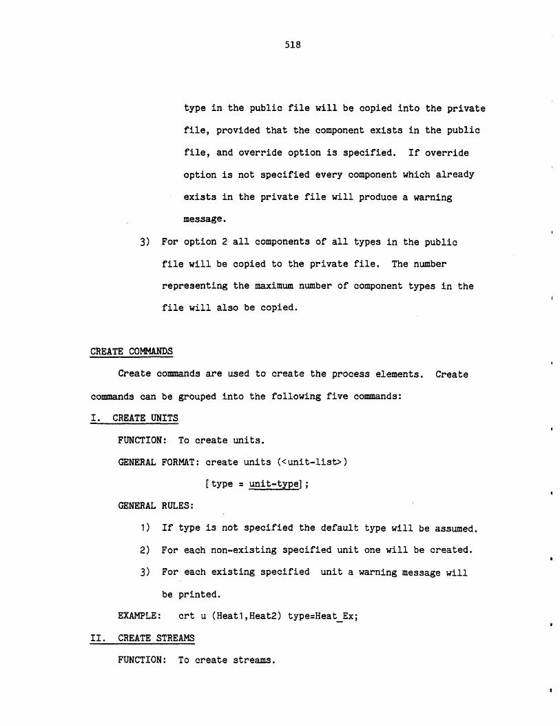
518
type in the public file will be copied into the private
file, provided that the component exists in the public
file, and override option is specified. If override
option is not specified every component which already
exists in the private file will produce a warning
message.
3) For option 2 all components of all types in the public
file will be copied to the private file. The number
representing the maximum number of component types in the
file will also be copied.
CREATE COMMANDS
Create commands are used to create the process elements. Create
commands can be grouped into the following five commands:
I. CREATE UNITS
FUNCTION: To create units.
GENERAL FORMAT: create units (<unit-list>)
[type = unit-type];
GENERAL RULES:
1) If type is not specified the default type will be assumed.
2) For each non-existing specified unit one will be created.
3) For each existing specified unit a warning message will
be printed.
EXAMPLE: crt u (Heatl,Heat2) type=HeatEx;
II. CREATE STREAMS
FUNCTION: To create streams.
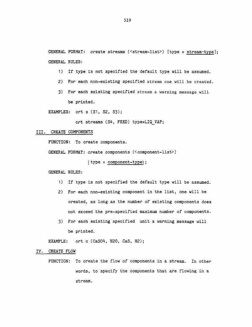
519
GENERAL FORMAT: create streams (<stream-list>) [type = stream-type];
GENERAL RULES:
1) If type is not specified the default type will be assumed.
2) For each non-existing specified stream one will be created.
3) For each existing specified stream a warning message will
be printed.
EXAMPLES: crt s (S1, S2, S3);
crt streams (S4, FEED) type=LIQVAP;
III. CREATE COMPONENTS
FUNCTION: To create components.
GENERAL FORMAT: create components (<component-list>)
[type = component-type ;
GENE
EXAM
RAL RULES:
1) If type is not specified the default type will be assumed.
2) For each non-existing component in the list, one will be
created, as long as the number of existing components does
not exceed the pre-specified maximum number of components.
3) For each existing specified unit a warning message will
be printed.
PLE: crt c (CaSO4, H20, CaS, H2);
IV. CREATE FLOW
FUNCTION: To create the flow of components in a stream. In other
words, to specify the components that are flowing in a
stream.
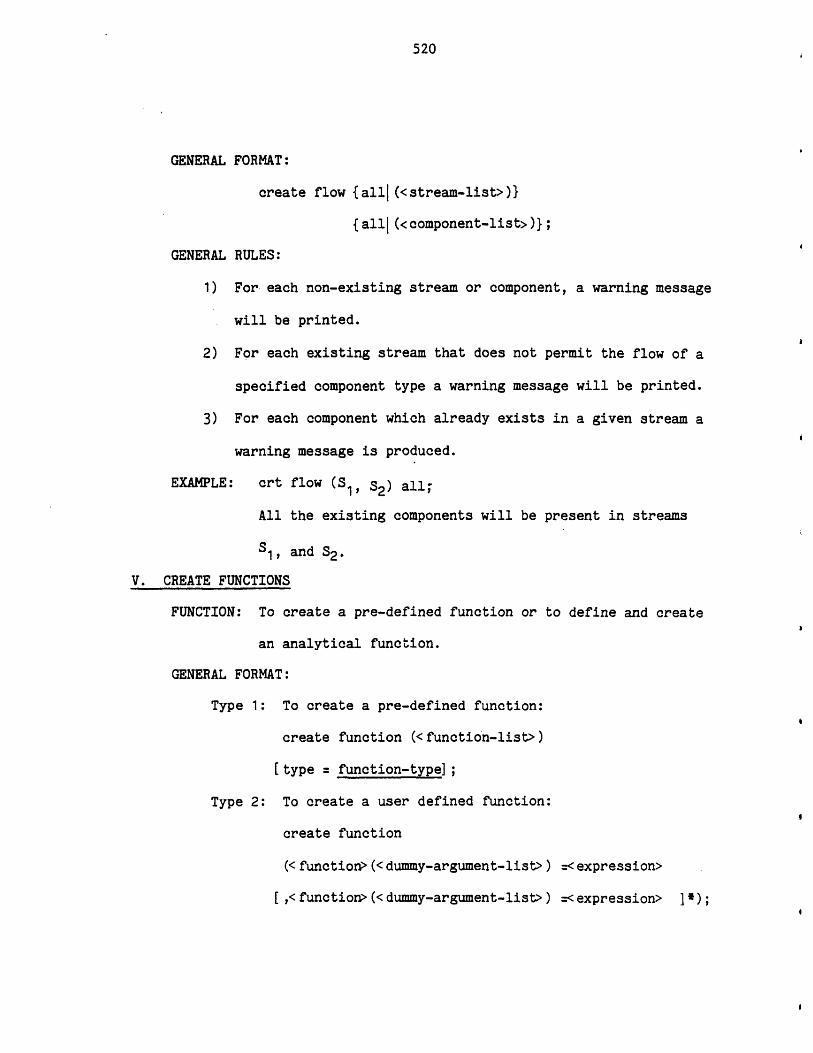
520
GENERAL FORMAT:
create flow {all (<stream-list>)}
{all (<component-list>)};
GENERAL RULES:
1) For each non-existing stream or component, a warning message
will be printed.
2) For each existing stream that does not permit the flow of a
specified component type a warning message will be printed.
3) For each component which already exists in a given stream a
warning message is produced.
EXAMPLE: crt flow (S , S2) all,
All the existing components will be present in streams
S1, and S2-
V. CREATE FUNCTIONS
FUNCTION: To create a pre-defined function or to define and create
an analytical function.
GENERAL FORMAT:
Type 1: To create a pre-defined function:
create function (<function-list>)
[type = function-type]
Type 2: To create a user defined function:
create function
(<function> (<dummy-argument-list>) =< expression>
[,<function> (<dummy-argument-list>) =<expression> }

521
GENERAL
EXAMP
RULES:
DELETE COMMANDS
Delete commands are used to delete an object from the working area.
Delete commands can be grouped into the five following commands:
I. DELETE UNITS
FUNCTION: To remove a unit data structure.
GENERAL FORMAT: delete units {allj(<unit-list>)};
1) For type 1:
a) If type is not specified, the default type will be
assumed.
b) For each existing function a warning message will be
printed.
c) For each non-existing function one with the specified
type will be created.
2) For type 2:
a) None of the functions must exist.
b) The expressions in addition to numbers and dummy
arguments could also refer to other functions and
variables. It should be noted that the other
variables referred to, would be substituted with
their values at that time and will remain unchanged.
LES: crt functions (H,S,CP) type=L2;
crt function (xxx(x,y)=x/y+h(s(cp(y))));
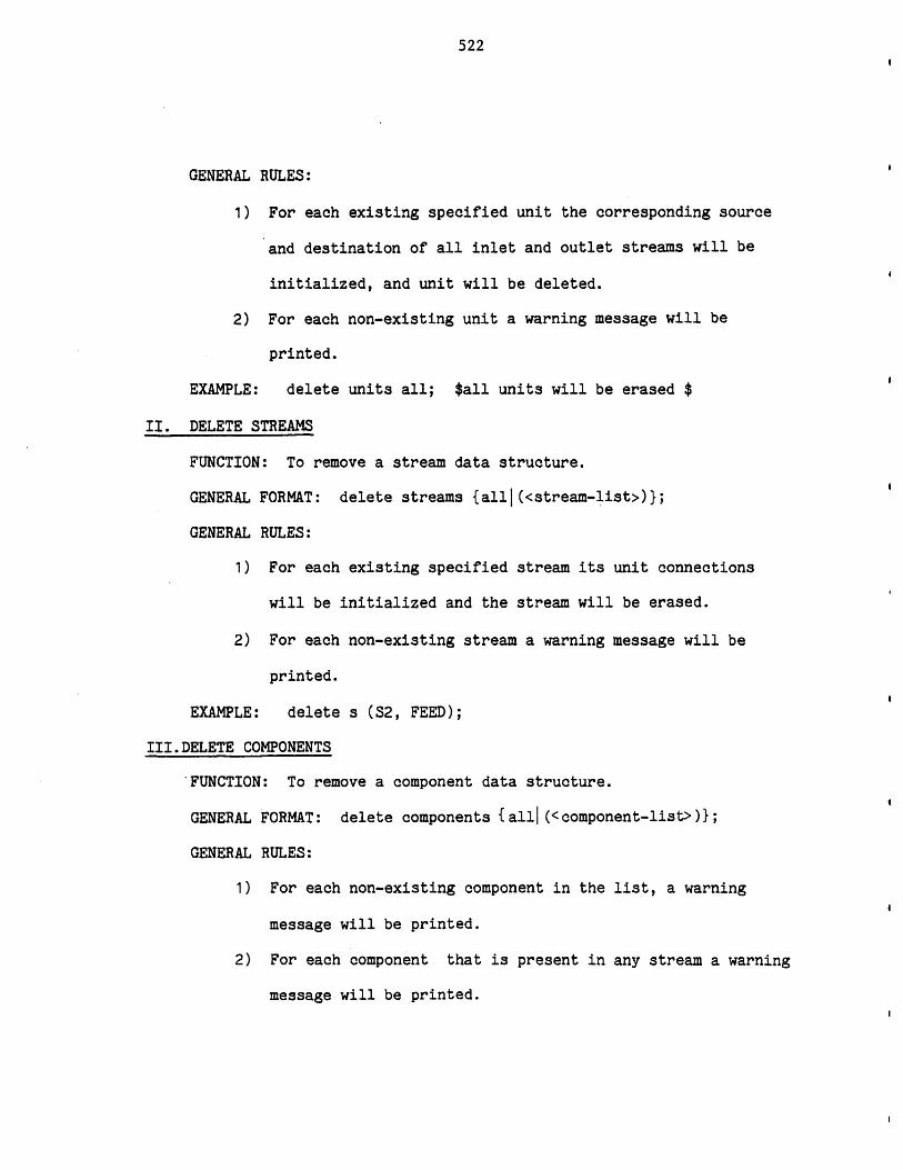
522
GENERAL RULES:
1) For each existing specified unit the corresponding source
and destination of all inlet and outlet streams will be
initialized, and unit will be deleted.
2) For each non-existing unit a warning message will be
printed.
EXAMPLE: delete units all; $all units will be erased $
II. DELETE STREAMS
FUNCTION: To remove a stream data structure.
GENERAL FORMAT: delete streams {all|(<stream-list>)};
GENERAL RULES:
1) For each existing specified stream its unit connections
will be initialized and the stream will be erased.
2) For each non-existing stream a warning message will be
printed.
EXAMPLE: delete s (S2, FEED);
III.DELETE COMPONENTS
FUNCTION: To remove a component data structure.
GENERAL FORMAT: delete components {all| (<component-list>)};
GENERAL RULES:
1) For each non-existing component in the list, a warning
message will be printed.
2) For each component that is present in any stream a warning
message will be printed.

523
3) Only those existing components which are not present in any
stream at that time, will be erased.
IV. DELETE FLOW
FUNCTION: To delete the flow information portion of streams. In
other words to indicate that some components are not
longer present in a stream.
GENERAL FORMAT: delete flow {allj(<stream-list>)}
{all|(<component-list>)};
GENERAL RULES:
1) For each non-existing stream or component a warning message
will be printed.
2) For each specified existing component which is not presnet
in a specified existing streams a warning message will be
printed.
3) Flow information of all specified existing components in all
specified existing streams which contain those components
will be erased.
EXAMPLE: del f all all
The flow information of all components in all streams
will be deleted. In other words, there would be no
component in any stream.
V. DELETE FUNCTIONS
FUNCTION: To delete user-created functions.
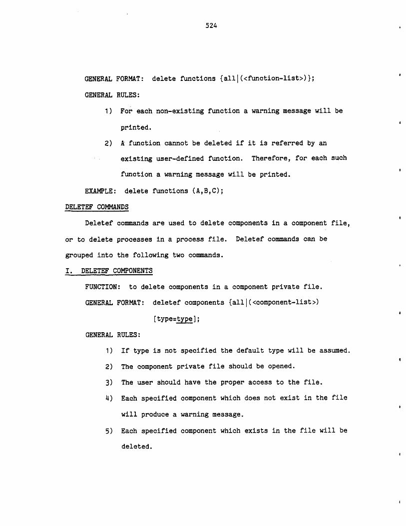
524
GENERAL FORMAT: delete functions {allI(<function-list>)};
GENERAL RULES:
1) For each non-existing function a warning message will be
printed.
2) A function cannot be deleted if it is referred by an
existing user-defined function. Therefore, for each such
function a warning message will be printed.
EXAMPLE: delete functions (A,B,C);
DELETEF COMMANDS
Deletef commands are used to delete components in a component file,
or to delete processes in a process file. Deletef commands can be
grouped into the following two commands.
I. DELETEF COMPONENTS
FUNCTION: to delete components in a component private file.
GENERAL FORMAT: deletef components {alll(<component-list>)
[type=type];
GENERAL RULES:
1) If type is not specified the default type will be assumed.
2) The component private file should be opened.
3) The user should have the proper access to the file.
4) Each specified component which does not exist in the file
will produce a warning message.
5) Each specified component which exists in the file will be
deleted.
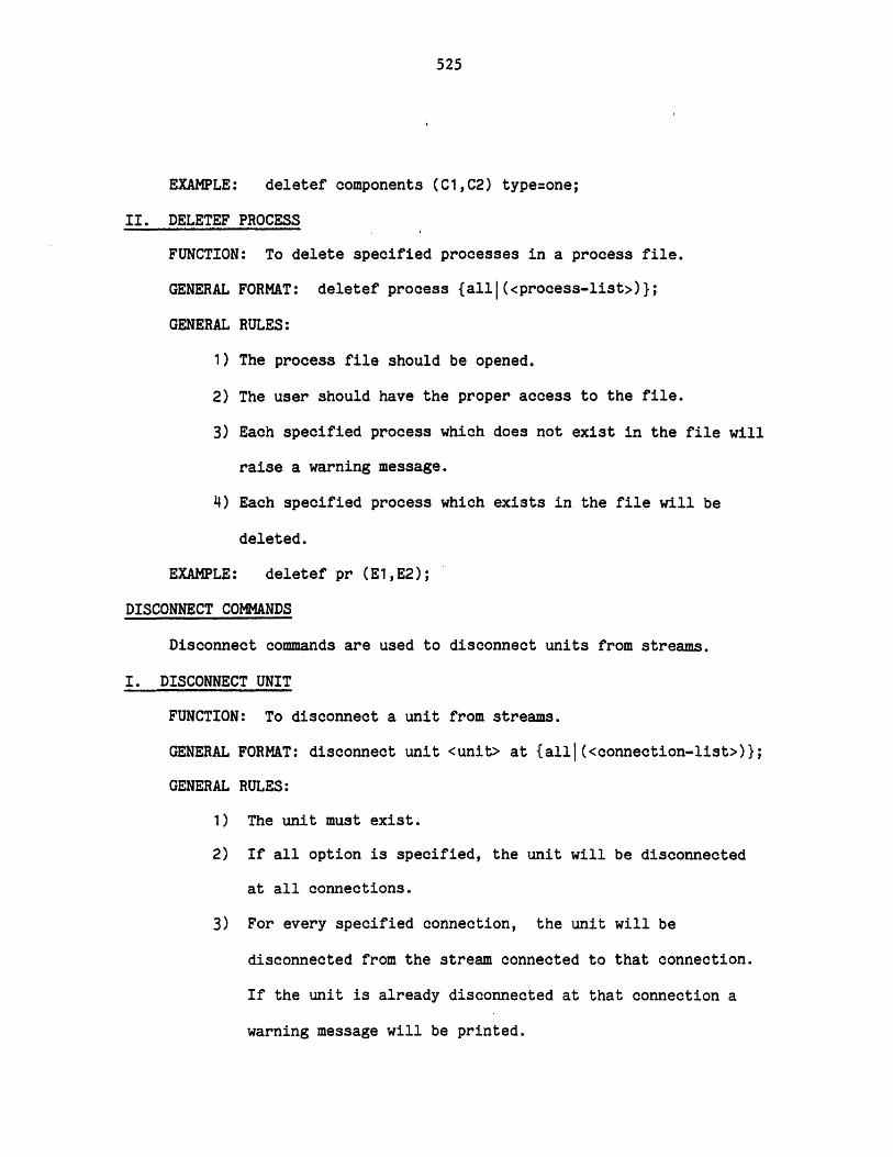
525
EXAMPLE: deletef components (C1,C2) type=one;
II. DELETEF PROCESS
FUNCTION: To delete specified processes in a process file.
GENERAL FORMAT: deletef process {allj(<process-list>)};
GENERAL RULES:
1) The process file should be opened.
2) The user should have the proper access to the file.
3) Each specified process which does not exist in the file will
raise a warning message.
4) Each specified process which exists in the file will be
deleted.
EXAMPLE: deletef pr (E1,E2);
DISCONNECT COMMANDS
Disconnect commands are used to disconnect units from streams.
I. DISCONNECT UNIT
FUNCTION: To disconnect a unit from streams.
GENERAL FORMAT: disconnect unit <unit> at {all|(<connection-list>)};
GENERAL RULES:
1) The unit must exist.
2) If all option is specified, the unit will be disconnected
at all connections.
3) For every specified connection, the unit will be
disconnected from the stream connected to that connection.
If the unit is already disconnected at that connection a
warning message will be printed.
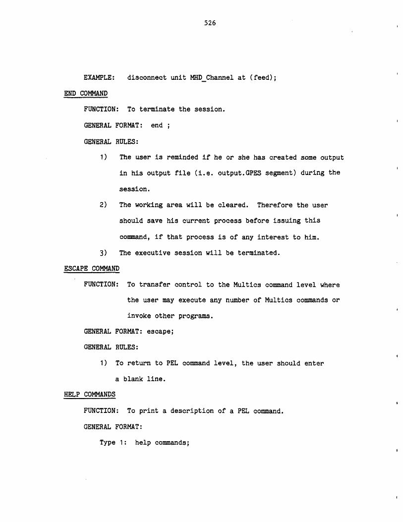
526
EXAMPLE: disconnect unit MHDChannel at (feed);
END COMMAND
FUNCTION: To terminate the session.
GENERAL FORMAT: end
GENERAL RULES:
1) The user is reminded if he or she has created some output
in his output file (i.e. output.GPES segment) during the
session.
2) The working area will be cleared. Therefore the user
should save his current process before issuing this
command, if that process is of any interest to him.
3) The executive session will be terminated.
ESCAPE COMMAND
FUNCTION: To transfer control to the Multics command level where
the user may execute any number of Multics commands or
invoke other programs.
GENERAL FORMAT: escape;
GENERAL RULES:
1) To return to PEL command level, the user should enter
a blank line.
HELP COMMANDS
FUNCTION: To print a description of a PEL command.
GENERAL FORMAT:
Type 1: help commands;
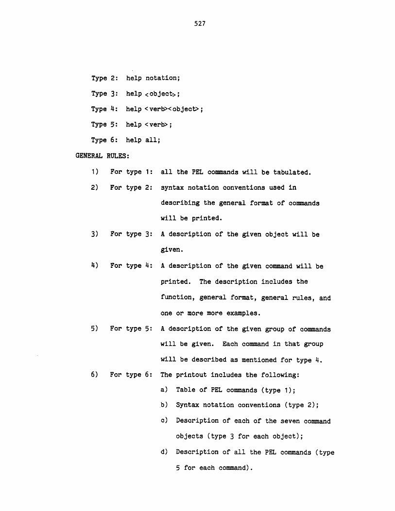
527
Type 2: help notation;
Type 3: help <object>;
Type 4: help <verb><object>;
Type 5: help <verb>;
Type 6: help all;
GENERAL RULES:
1) For type 1:
2) For type 2:
3) For type 3:
4) For type 4:
5) For type 5:
6) For type 6:
all the PEL commands will be tabulated.
syntax notation conventions used in
describing the general format of commands
will be printed.
A description of the given object will be
given.
A description of the given command will be
printed. The description includes the
function, general format, general rules, and
one or more more examples.
A description of the given group of commands
will be given. Each command in that group
will be described as mentioned for type 4.
The printout includes the following:
a) Table of PEL commands (type 1);
b) Syntax notation conventions (type 2);
c) Description of each of the seven command
objects (type 3 for each object);
d) Description of all the PEL commands (type
5 for each command).
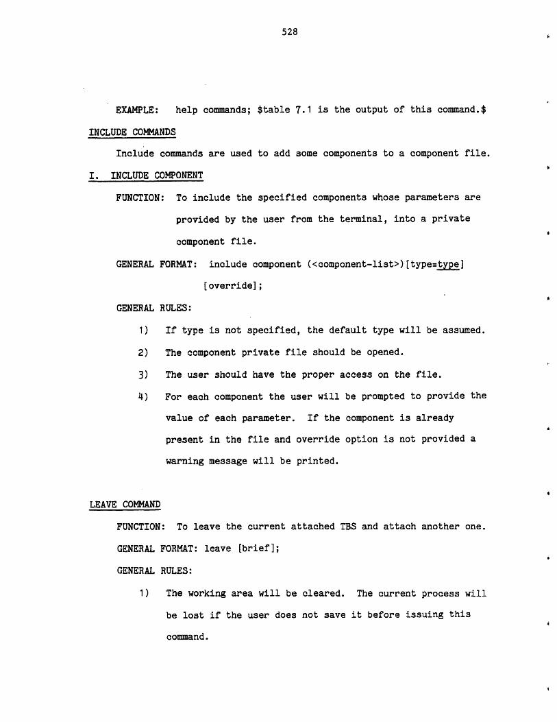
528
EXAMPLE: help commands; $table 7.1 is the output of this command.$
INCLUDE COMMANDS
Include commands are used to add some components to a component file.
I. INCLUDE COMPONENT
FUNCTION: To include the specified components whose parameters are
provided by the user from the terminal, into a private
component file.
GENERAL FORMAT: include component (<component-list>)[type=type]
[override];
GENERAL RULES:
1) If type is not specified, the default type will be assumed.
2) The component private file should be opened.
3) The user should have the proper access on the file.
4) For each component the user will be prompted to provide the
value of each parameter. If the component is already
present in the file and override option is not provided a
warning message will be printed.
LEAVE COMMAND
FUNCTION: To leave the current attached TBS and attach another one.
GENERAL FORMAT: leave [brief];
GENERAL RULES:
1) The working area will be cleared. The current process will
be lost if the user does not save it before issuing this
command.

529
2) The opened component files (if any) will be closed.
3) The user will be asked to provide the name of the new TBS.
The new TBS will be attached. If brief option is not
provided some information about the new TBS will also be
printed.
4) All profile parameters will be initialized to the TBS
default parameters.
5) A new process will be created; property estimation methods
option will be initialized to the TBS default options; and
the user will be prompted to provide the maximum number of
components.
6) The opened process files (if any) will remain opened.
EXAMPLE: leave bf;
A.5.9 LET COMMANDS
Let commands are used to duplicate or copy an object. The let
commands can be grouped into the following five commands:
I. LET UNIT
FUNCTION: To duplicate or copy a unit.
GENERAL FORMAT: let unit <unit>=<unit>;
GENERAL RULES:
1) The unit on the righthand side must exist.
2) If the unit on the lefthand side exists, it must be same
type as the unit on the righthand side.
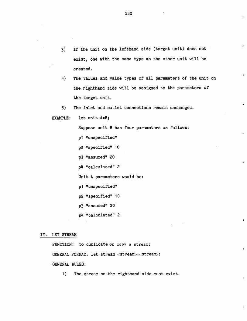
530
3) If the unit on the lefthand side (target unit) does not
exist, one with the same type as the other unit will be
created.
4) The values and value types of all parameters of the unit on
the righthand side will be assigned to the parameters of
the target unit.
5) The inlet and outlet connections remain unchanged.
EXAMPLE: let unit A=B;
Suppose unit B has four parameters as follows:
p1 "unspecified"
p2 "specified" 10
p3 "assumed" 20
p4 "calculated" 2
Unit A parameters would be:
p1 "unspecified"
p2 "specified" 10
p3 "assumed" 20
p4 "calculated" 2
II. LET STREAM
FUNCTION: To duplicate or copy a stream;
GENERAL FORMAT: let stream <stream>=<stream>;
GENERAL RULES:
1) The stream on the righthand side must exist.
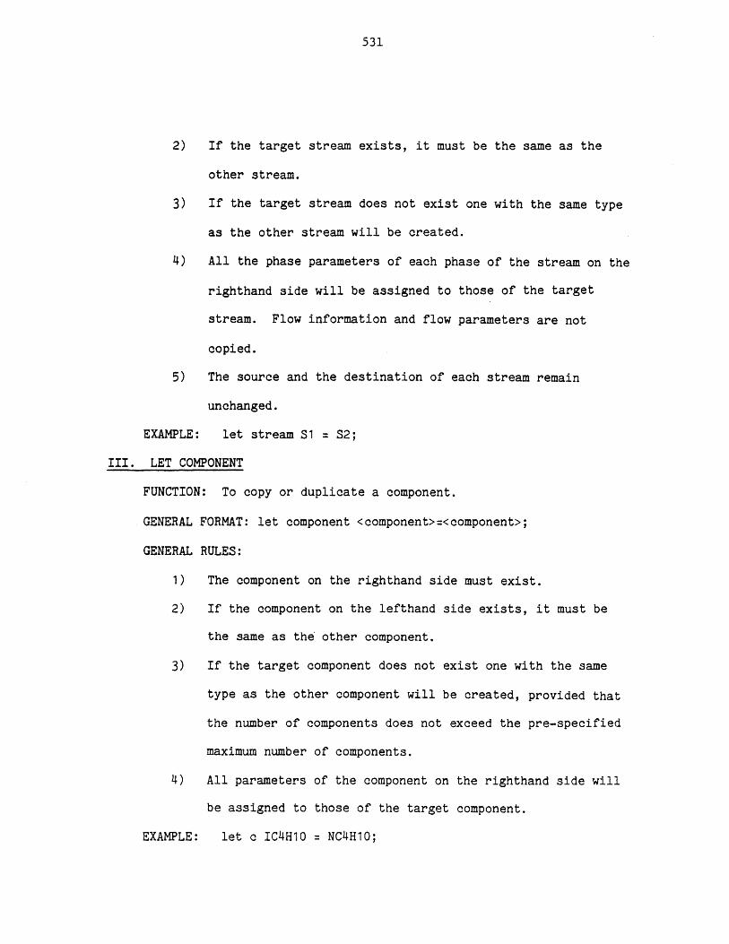
531
2) If the target stream exists, it must be the same as the
other stream.
3) If the target stream does not exist one with the same type
as the other stream will be created.
4) All the phase parameters of each phase of the stream on the
righthand side will be assigned to those of the target
stream. Flow information and flow parameters are not
copied.
5) The source and the destination of each stream remain
unchanged.
EXAMPLE: let stream S1 = S2;
III. LET COMPONENT
FUNCTION: To copy or duplicate a component.
GENERAL FORMAT: let component <component>=<component>;
GENERAL RULES:
1) The component on the righthand side must exist.
2) If the component on the lefthand side exists, it must be
the same as the other component.
3) If the target component does not exist one with the same
type as the other component will be created, provided that
the number of components does not exceed the pre-specified
maximum number of components.
4) All parameters of the component on the righthand side will
be assigned to those of the target component.
EXAMPLE: let c IC4H10 = NC4H10;
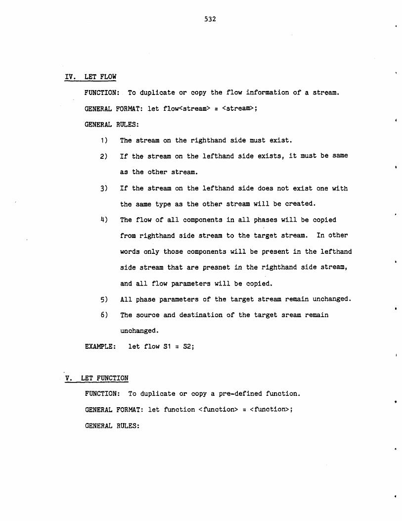
532
IV. LET FLOW
FUNCTION: To duplicate or copy the flow information of a stream.
GENERAL FORMAT: let flow<stream> = <stream>;
GENERAL RULES:
1) The stream on the righthand side must exist.
2) If the stream on the lefthand side exists, it must be same
as the other stream.
3) If the stream on the lefthand side does not exist one with
the same type as the other stream will be created.
4) The flow of all components in all phases will be copied
from righthand side stream to the target stream. In other
words only those components will be present in the lefthand
side stream that are presnet in the righthand side stream,
and all flow parameters will be copied.
5) All phase parameters of the target stream remain unchanged.
6) The source and destination of the target sream remain
unchanged.
EXAMPLE: let flow S1 = S2;
V. LET FUNCTION
FUNCTION: To duplicate or copy a pre-defined function.
GENERAL FORMAT: let function <function> = <function>;
GENERAL RULES:

533
1) The function on the righthand side must exist and must be a
pre-defined type.
2) If the function on the lefthand side (target function)
exists, it must be same type as the function on the
righthand side.
3) If the target function does not exist, one with the same
type as the other function will be created.
4) All parameters (coefficients) of the function on the
righthand side will be assigned to the parameters of the
target function.
EXAMPLE: let fn A = B;
LETA COMMANDS
These commands function exactly like the let commands with one
exception. In let commands both value and value type of each parameter
will be copied, whereas in leta commands only the value of each parameter
will be copied. The value type of all target parameters which are not
unspecified will be set to "assumed".
The general format and rules of these commands are the same as the
let commands (replace let with leta). The relationship between let and
leta commands is the same as the relationship between specify and assume
commands, or between read and reada commands.
LIST COMMANDS
List commands are used to list the process elements in the working
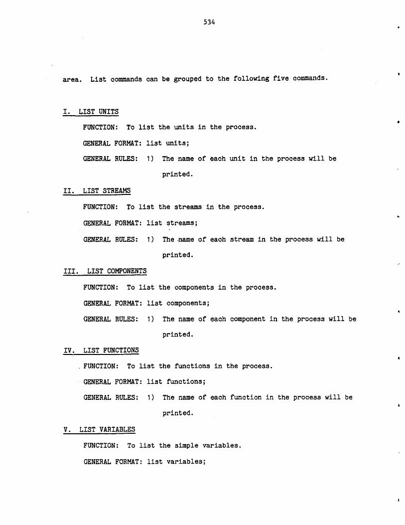
534
area. List commands can be grouped to the following five commands.
I. LIST UNITS
FUNCTION: To list the units in the process.
GENERAL FORMAT: list units;
GENERAL RULES: 1) The name of each unit in the process will be
printed.
II. LIST STREAMS
FUNCTION: To list the streams in the process.
GENERAL FORMAT: list streams;
GENERAL RULES: 1) The .name of each stream in the process will be
printed.
III. LIST COMPONENTS
FUNCTION: To list the components in the process.
GENERAL FORMAT: list components;
GENERAL RULES: 1) The name of each component in the process will be
printed.
IV. LIST FUNCTIONS
FUNCTION: To list the functions in the process.
GENERAL FORMAT: list functions;
GENERAL RULES: 1) The name of each function in the process will be
printed.
V. LIST VARIABLES
FUNCTION: To list the simple variables.
GENERAL FORMAT: list variables;
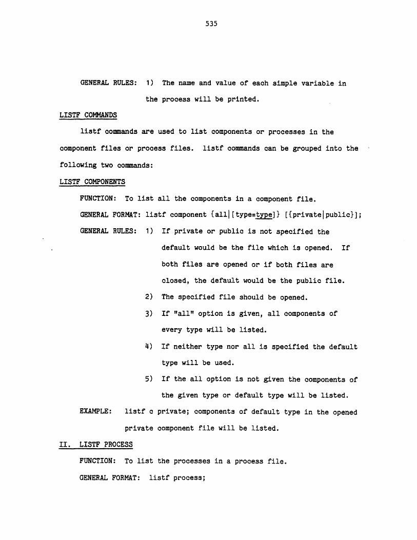
535
GENERAL RULES: 1) The name and value of each simple variable in
the process will be printed.
LISTF COMMANDS
listf commands are used to list components or processes in the
component files or process files. listf commands can be grouped into the
following two commands:
LISTF COMPONENTS
FUNCTION: To list all the components in a component file.
GENERAL FORMAT: listf component {all|[type=type]} [{privatejpublic}];
GENERAL RULES: 1) If private or public is not specified the
default would be the file which is opened. If
both files are opened or if both files are
closed, the default would be the public file.
2) The specified file should be opened.
3) If "all" option is given, all components of
every type will be listed.
4) If neither type nor all is specified the default
type will be used.
5) If the all option is not given the components of
the given type or default type will be listed.
EXAMPLE: listf c private; components of default type in the opened
private component file will be listed.
II. LISTF PROCESS
FUNCTION: To list the processes in a process file.
GENERAL FORMAT: listf process;
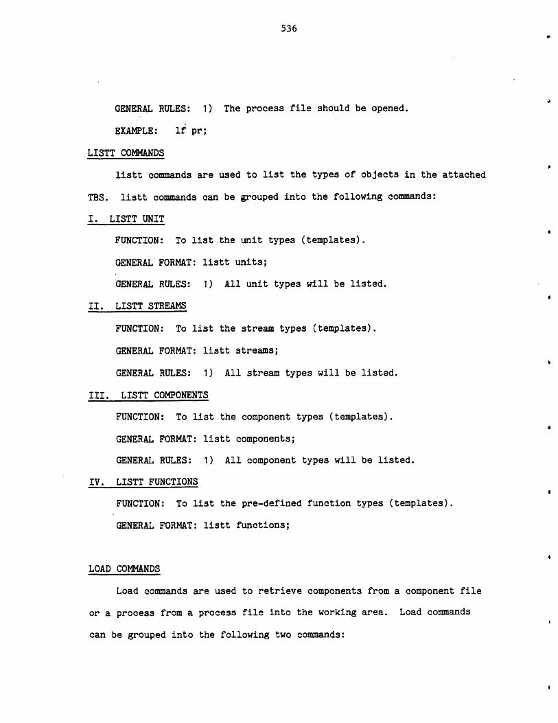
536
GENERAL RULES: 1) The process file should be opened.
EXAMPLE: lf pr;
LISTT COMMANDS
listt commands are used to list the types of objects in the attached
TBS. listt commands can be grouped into the following commands:
I. LISTT UNIT
FUNCTION: To list the unit types (templates).
GENERAL FORMAT: listt units;
GENERAL RULES: 1) All unit types will be listed.
II. LISTT STREAMS
FUNCTION: To list the stream types (templates).
GENERAL FORMAT: listt streams;
GENERAL RULES: 1) All stream types will be listed.
III. LISTT COMPONENTS
FUNCTION: To list the component types (templates).
GENERAL FORMAT: listt components;
GENERAL RULES: 1) All component types will be listed.
IV. LISTT FUNCTIONS
FUNCTION: To list the pre-defined function types (templates).
GENERAL FORMAT: listt functions;
LOAD COMMANDS
Load commands are used to retrieve components from a component file
or a process from a process file into the working area. Load commands
can be grouped into the following two commands:
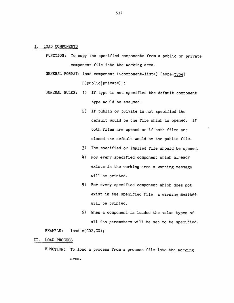
537
I. LOAD COMPONENTS
FUNCTION: To copy the specified components from a public or private
component file into the working area.
GENERAL FORMAT: load component (<component-list>) [type=type]
[{publicprivate}];
GENERAL RULES: 1) If type is not specified the default component
type would be assumed.
2) If public or private is not specified the
default would be the file which is opened. If
both files are opened or if both files are
closed the default would be the public file.
3) The specified or implied file should be opened.
4) For every specified component which already
exists in the working area a warning message
will be printed.
5) For every specified component which does not
exist in the specified file, a warning message
will be printed.
6) When a component is loaded the value types of
all its parameters will be set to be specified.
EXAMPLE: load c(C02,CO);
II. LOAD PROCESS
FUNCTION: To load a process from a process file into the working
area.
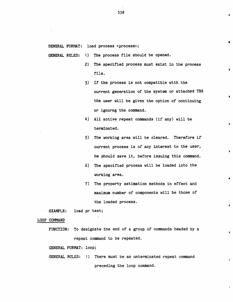
538
GENERAL FORMAT: load process <process>;
GENERAL RULES: 1) The process file should be opened.
2) The specified process must exist in the process
file.
3) If the process is not compatible with the
current generation of the system or attached TBS
the user will be given the option of continuing
or ignorng the command.
4) All active repeat commands (if any) will be
terminated.
5) The working area will be cleared. Therefore if
current process is of any interest to the user,
he should save it, before issuing this command.
6) The specified process will be loaded into the
working area.
7) The property estimation methods in effect and
maximum number of components will be those of
the loaded process.
EXAMPLE: load pr test;
LOOP COMMAND
FUNCTION: To designate the end of a group of commands headed by a
repeat command to be repeated.
GENERAL FORMAT: loop;
GENERAL RULES: 1) There must be an unterminated repeat command
preceding the loop command.
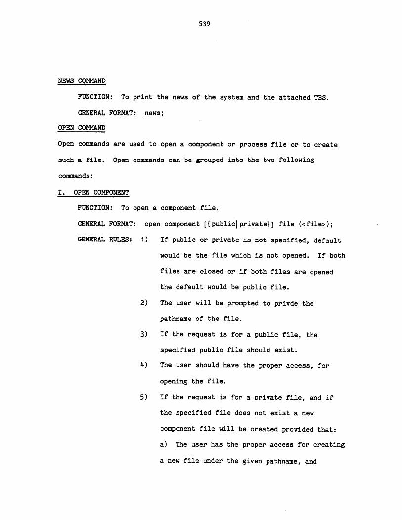
539
NEWS COMMAND
FUNCTION: To print the news of the system and the attached TBS.
GENERAL FORMAT: news;
OPEN COMMAND
Open commands are used to open a component or process file or to create
such a file. Open commands can be grouped into the two following
commands:
I. OPEN COMPONENT
FUNCTION: To open a component file.
GENERAL FORMAT: open component [{publiclprivate}] file (<file>);
GENERAL RULES: 1) If public or private is not specified, default
would be the file which is not opened. If both
files are closed or if both files are opened
the default would be public file.
2) The user will be prompted to privde the
pathname of the file.
3) If the request is for a public file, the
specified public file should exist.
4) The user should have the proper access, for
opening the file.
5) If the request is for a private file, and if
the specified file does not exist a new
component file will be created provided that:
a) The user has the proper access for creating
a new file under the given pathname, and

540
b) The user is willing to create a new one.
6) If the file is not compatible with the attached
TBS the user will be given the option of
continuing the opening or ignoring the command.
7) Public files are in fact the private file of
TBS system administrators. They are created
and updated by the TBS system administrators.
8) Once the user has opened a private (or public)
file it remains open until:
a) He closes the private (or public) file,
b) He opens another private (or public) file,
c) He terminates the file,
d) He leaves the TBS, or
e) He terminates the session.
EXAMPLE: open c file (A);
II. OPEN PROCESS
FUNCTION: To open or create a new process file.
GENERAL FORMAT: open process file (<file>);
GENERAL RULES: 1) The user will be prompted to provide the
pathname of the file.
2) If the file exists the user should have the
proper access for opening of the process file.
3) If the file does not exist a new one will be
created provided that:
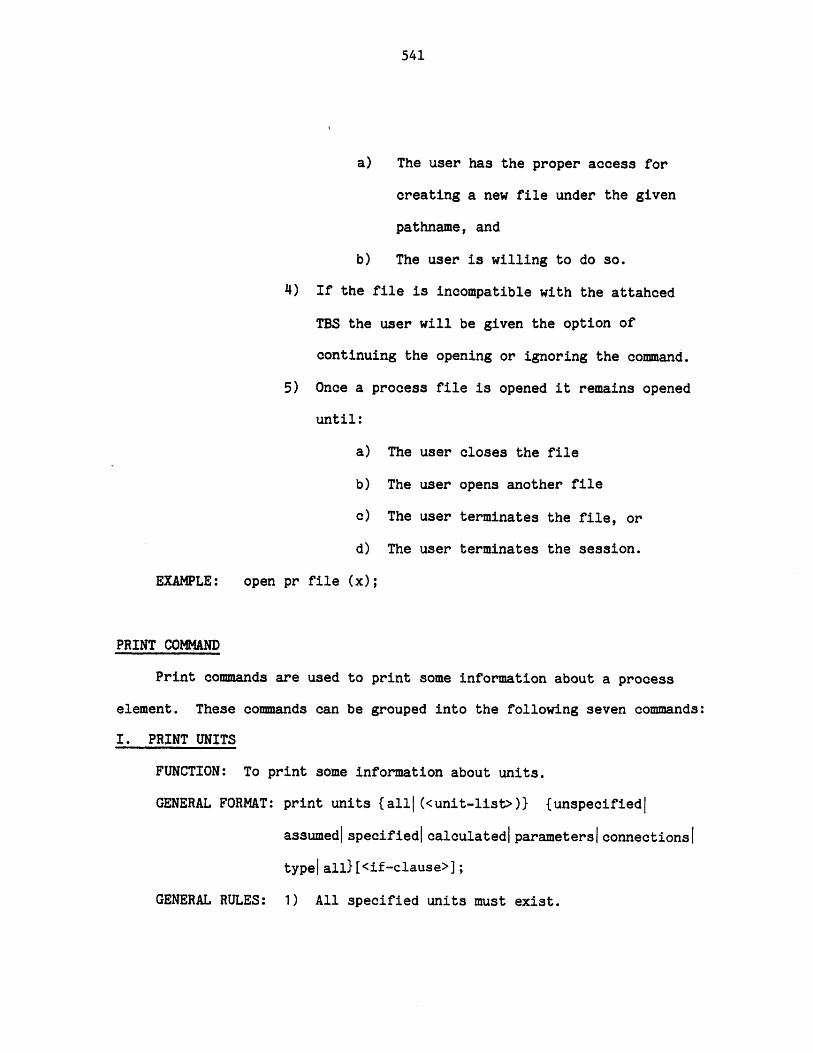
541
a) The user has the proper access for
creating a new file under the given
pathname, and
b) The user is willing to do so.
4) If the file is incompatible with the attahced
TBS the user will be given the option of
continuing the opening or ignoring the command.
5) Once a process file is opened it remains opened
until:
a) The user closes the file
b) The user opens another file
c) The user terminates the file, or
d) The user terminates the session.
EXAMPLE: open pr file (x);
PRINT COMMAND
Print commands are used to print some information about a process
element. These commands can be grouped into the following seven commands:
I. PRINT UNITS
FUNCTION: To print some information about units.
GENERAL FORMAT: print units {all|(<unit-list>)} {unspecified|
assumedlspecifiedicalculated parameters connectionsI
typeall}[<if-clause>];
GENERAL RULES: 1) All specified units must exist.
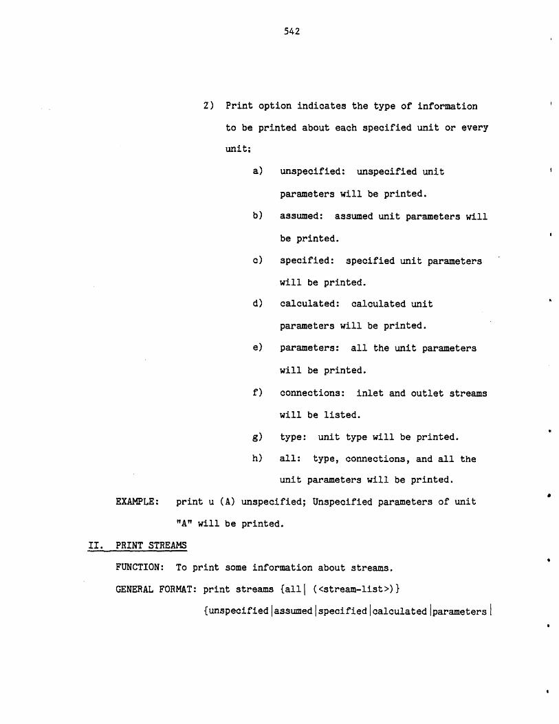
542
2) Print option indicates the type of information
to be printed about each specified unit or every
unit:
a) unspecified: unspecified unit
parameters will be printed.
b) assumed: assumed unit parameters will
be printed.
c) specified: specified unit parameters
will be printed.
d) calculated: calculated unit
parameters will be printed.
e) parameters: all the unit parameters
will be printed.
f) connections: inlet and outlet streams
will be listed.
g) type: unit type will be printed.
h) all: type, connections, and all the
unit parameters will be printed.
EXAMPLE: print u (A) unspecified; Unspecified parameters of unit
"A" will be printed.
II. PRINT STREAMS
FUNCTION: To print some information about streams.
GENERAL FORMAT: print streams {alli (<stream-list>)}
{unspecifiedlassumed specifiedicalculated iparametersI

543
connections typelall}[<if-clause> ;
GENERAL RULES: 1) All specified streams must exist.
2) Print option indicates the type of information
to be printed about each specified stream or
about every stream:
a) unspecified: unspecified phase
(stream) parameters will be printed.
b) assumed: assumed phase (stream)
parameters will be printed.
c) specified: specified phase (stream)
parameters will be printed.
d) calculated: calculated phase (stream)
parameters will be printed.
e) parameters: all the phase (stream)
parameters will be printed.
f) connections: source and destination
of the stream will be printed.
g) type: stream type will be printed.
h) all: type, connections, and all the
phase (stream) parameters will be
printed.
FUNCTION: print s all connections; Source and destination of each
stream will be printed.
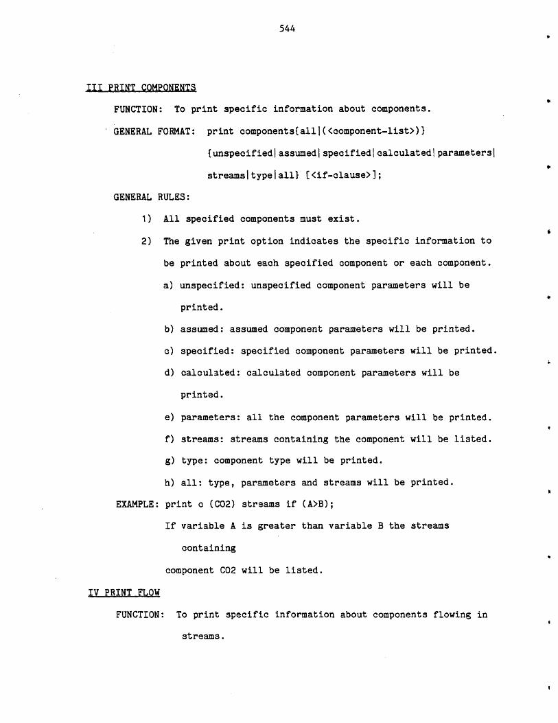
544
III PRINT COMPONENTS
FUNCTION: To print specific information about components.
GENERAL FORMAT: print components{alll(<component-list>)}
{unspecifiediassumedispecifiedIcalculatedIparametersI
streamsltypelall} (<if-clause>];
GENERAL RULES:
1) All specified components must exist.
2) The given print option indicates the specific information to
be printed about each specified component or each component.
a) unspecified: unspecified component parameters will be
printed.
b) assumed: assumed component parameters will be printed.
c) specified: specified component parameters will be printed.
d) calculated: calculated component parameters will be
printed.
e) parameters: all the component parameters will be printed.
f) streams: streams containing the component will be listed.
g) type: component type will be printed.
h) all: type, parameters and streams will be printed.
EXAMPLE: print c (C02) streams if (A>B);
If variable A is greater than variable B the streams
containing
component C02 will be listed.
IV PRINT FLOW
FUNCTION: To print specific information about components flowing in
streams.
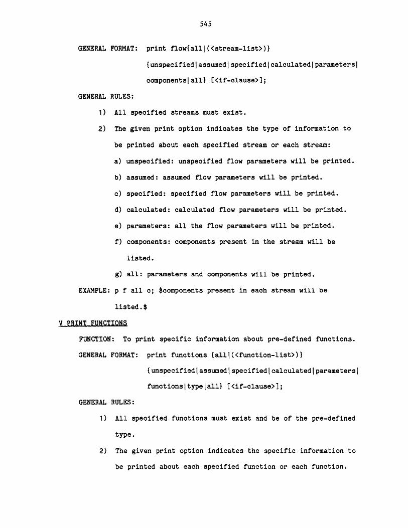
545
GENERAL FORMAT: print flowtallj(<stream-list>))
{unspecifiedassumedispecifiedcalculatediparametersI
componentsall} [<if-clause>];
GENERAL RULES:
1) All specified streams must exist.
2) The given print option indicates the type of information to
be printed about each specified stream or each stream:
a) unspecified: unspecified flow parameters will be printed.
b) assumed: assumed flow parameters will be printed.
c) specified: specified flow parameters will be printed.
d) calculated: calculated flow parameters will be printed.
e) parameters: all the flow parameters will be printed.
f) components: components present in the stream will be
listed.
g) all: parameters and components will be printed.
EXAMPLE: p f all c; $components present in each stream will be
listed.$
V PRINT.FUNCTIONS
FUNCTION: To print specific information about pre-defined functions.
GENERAL FORMAT: print functions (allj(<function-list>)}
{unspecifiedlassumedlspecifiedIcalculatedjparametersI
functionsjtypelall} [<if-clause>];
GENERAL RULES:
1) All specified functions must exist and be of the pre-defined
type.
2) The given print option indicates the specific information to
be printed about each specified function or each function.
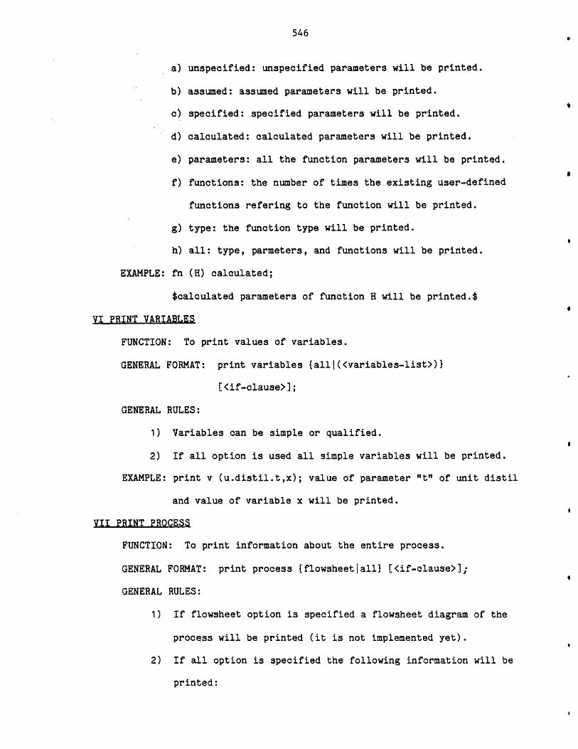
546
a) unspecified: unspecified parameters will be printed.
b) assumed: assumed parameters will be printed.
c) specified: specified parameters will be printed.
d) calculated: calculated parameters will be printed.
e) parameters: all the function parameters will be printed.
f) functions: the number of times the existing user-defined
functions refering to the function will be printed.
g) type: the function type will be printed.
h) all: type, parmeters, and functions will be printed.
EXAMPLE: fn (H) calculated;
$calculated parameters of function H will be printed.$0
VI PRINT VARIABLES
FUNCTION: To print values of variables.
GENERAL FORMAT: print variables {allj(<variables-list>)}
[<if-clause>];
GENERAL RULES:
1) Variables can be simple or qualified.
2) If all option is used all simple variables will be printed.
EXAMPLE: print v (u.distil.t,x); value of parameter "It" of unit distil
and value of variable x will be printed.
VII PRINT PROCESS
FUNCTION: To print information about the entire process.
GENERAL FORMAT: print process {flowsheetlall} [<if-clause>];
GENERAL RULES:
1) If flowsheet option is specified a flowsheet diagram of the
process will be printed (it is not implemented yet).
2) If all option is specified the following information will be
printed:
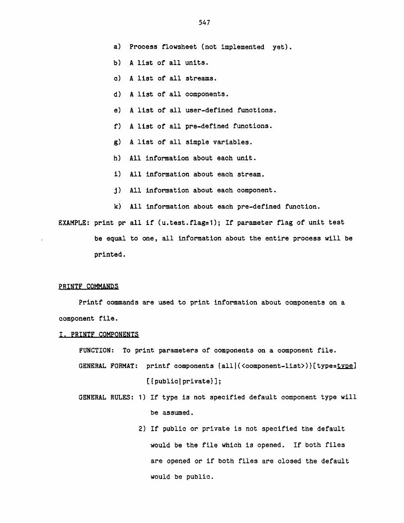
547
a)
b)
c)
d)
e)
f)
g)
h)
i)
j)
k)
EXAMPLE: print pr
be equal
printed.
Process flowsheet (not implemented yet).
A list of all units.
A list of all streams.
A list of all components.
A list of all user-defined functions.
A list of all pre-defined functions.
A list of all simple variables.
All information about each unit.
All information about each stream.
All information about each component.
All information about each pre-defined function.
all if (u.test.flag=1); If parameter flag of unit test
to one, all information about the entire process will be
PRINTF COMMANDS
Printf commands are used to print information about components on a
component file.
I. PRINTF COMPONENTS
FUNCTION: To print parameters of components on a component file.
GENERAL FORMAT: printf components {alll(<component-list>)}[type=tgpg]
[{public private}];
GENERAL RULES: 1) If type is not specified default component type will
be assumed.
2) If public or private is not specified the default
would be the file which is opened. If both files
are opened or if both files are closed the default
would be public.
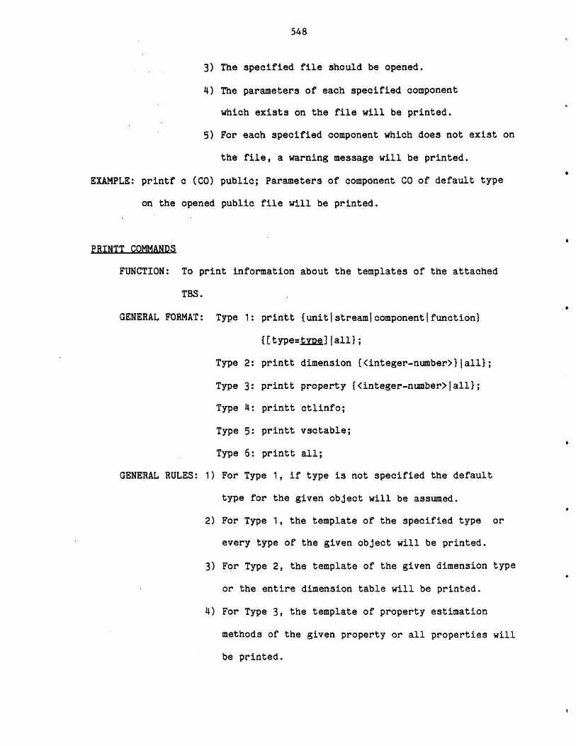
548
EXAMPLE: printf c (C
on the ope
PRINTT COMMANDS
FUNCTION: To p
TBS.
GENERAL FORMAT:
GENERAL RULES:
3) The specified file should be opened.
4) The parameters of each specified component
which exists on the file will be printed.
5) For each specified component which does not exist on
the file, a warning message will be printed.
0) public; Parameters of component CO of default type
ed public file will be printed.
rint information about the templates of the attached
Type 1: printt {unitlstreamicomponentifunction}
{[t e=ttype.] tall};
Type 2: printt dimension {<integer-number>}|all};
Type 3: printt property {<integer-number>jall};
Type 4: printt ctlinfo;
Type 5: printt vsctable;
Type 6: printt all;
1) For Type 1, if type is not specified the default
type for the given object will be assumed.
2) For Type 1, the template of the specified type or
every type of the given object will be printed.
3) For Type 2, the template of the given dimension type
or the entire dimension table will be printed.
4) For Type 3, the template of property estimation
methods of the given property or all properties will
be printed.
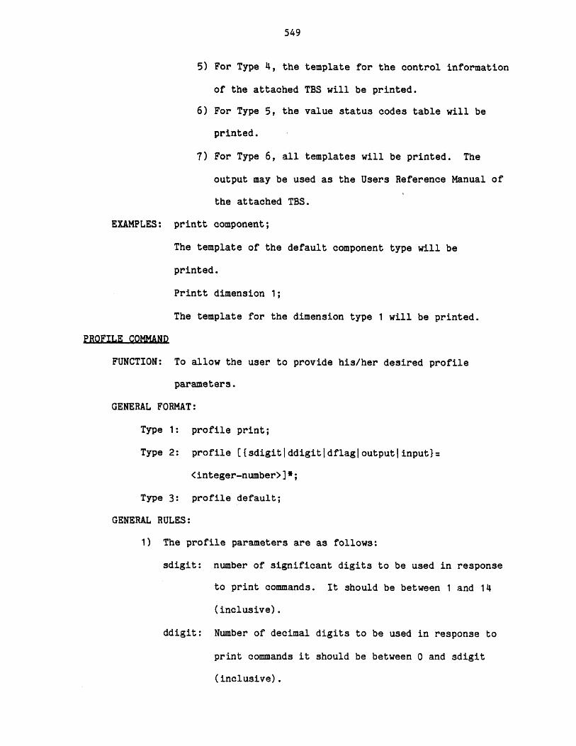
549
5) For Type 4, the template for the control information
of the attached TBS will be printed.
6) For Type 5, the value status codes table will be
printed.
7) For Type 6, all templates will be printed. The
output may be used as the Users Reference Manual of
the attached TBS.
EXAMPLES: printt component;
The template of the default component type will be
printed.
Printt dimension 1;
The template for the dimension type 1 will be printed.
PROFILE COMMAND
FUNCTION: To allow the user to provide his/her desired profile
parameters.
GENERAL FORMAT:
Type 1: profile print;
Type 2: profile {{sdigitlddigitjdflagloutputlinput}:
<integer-number>]*;
Type 3: profile default;
GENERAL RULES:
1) The profile parameters are as follows:
sdigit: number of significant digits to be used in response
to print commands. It should be between 1 and 14
(inclusive).
ddigit: Number of decimal digits to be used in response to
print commands it should be between 0 and sdigit
(inclusive).
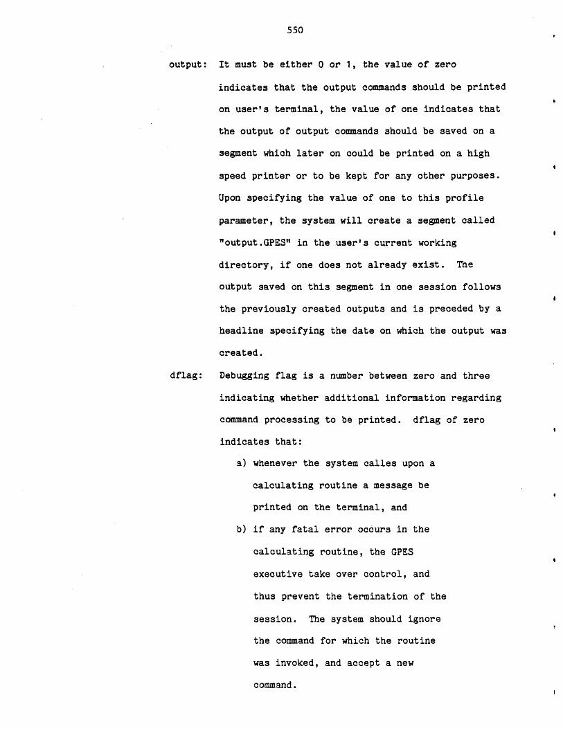
550
output: It must be either 0 or 1, the value of zero
indicates that the output commands should be printed
on user's terminal, the value of one indicates that
the output of output commands should be saved on a
segment which later on could be printed on a high
speed printer or to be kept for any other purposes.
Upon specifying the value of one to this profile
parameter, the system will create a segment called
"output.GPES" in the user's current working
directory, if one does not already exist. The
output saved on this segment in one session follows
the previously created outputs and is preceded by a
headline specifying the date on which the output was
created.
dflag: Debugging flag is a number between zero and three
indicating whether additional information regarding
command processing to be printed. dflag of zero
indicates that:
a) whenever the system calles upon a
calculating routine a message be
printed on the terminal, and
b) if any fatal error occurs in the
calculating routine, the GPES
executive take over control, and
thus prevent the termination of the
session. The system should ignore
the command for which the routine
was invoked, and accept a new
command.
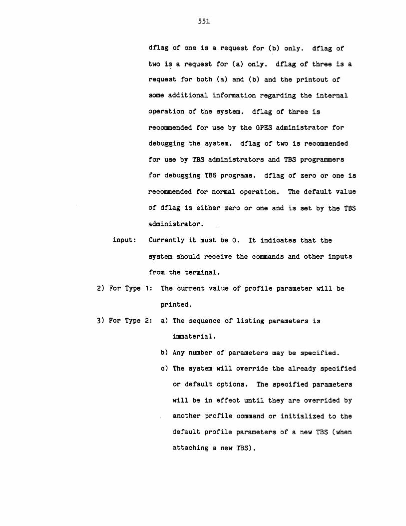
551
dflag of one is a request for (b) only. dflag of
two is a request for (a) only. dflag of three is a
request for both (a) and (b) and the printout of
some additional information regarding the internal
operation of the system. dflag of three is
recommended for use by the GPES administrator for
debugging the system. dflag of two is recommended
for use by TBS administrators and TBS programmers
for debugging TBS programs. dflag of zero or one is
recommended for normal operation. The default value
of dflag is either zero or one and is set by the TBS
administrator.
input: Currently it must be 0. It indicates that the
system should receive the commands and other inputs
from the terminal.
2) For Type 1: The current value of profile parameter will be
printed.
3) For Type 2: a) The sequence of listing parameters is
immaterial.
b) Any number of parameters may be specified.
c) The system will override the already specified
or default options. The specified parameters
will be in effect until they are overrided by
another profile command or initialized to the
default profile parameters of a new TBS (when
attaching a new TBS).
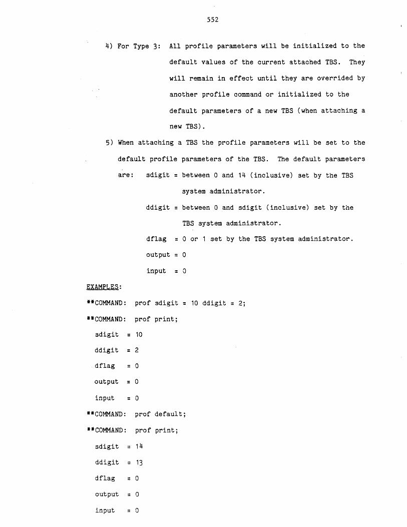
552
4) For Type 3: All profile parameters will be initialized to the
default values of the current attached TBS. They
will remain in effect until they are overrided by
another profile command or initialized to the
default parameters of a new TBS (when attaching a
new TBS).
5) When attaching a TBS the profile parameters will be set to the
default profile parameters of the TBS. The default parameters
are: sdigit = between 0 and 14 (inclusive) set by the TBS
system administrator.
ddigit = between 0 and sdigit (inclusive) set by the
TBS system administrator.
dflag = 0 or 1 set by the TBS system administrator.
output = 0
input = 0
EXAMPLES:
**COMMAND: prof sdigit =
**COMMAND: prof print;
sdigit = 10
ddigit = 2
dflag = 0
output = 0
input = 0
**COMMAND: prof default;
*COMMAND: prof print;
sdigit = 14
ddigit = 13
dflag = 0
output = 0
input = 0
10 ddigit = 2;
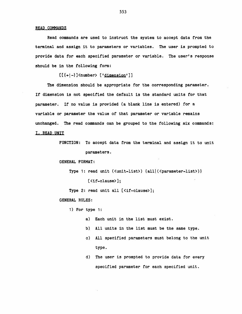
553
READ COMMANDS
Read commands are used to instruct the system to accept data from the
terminal and assign it to parameters or variables. The user is prompted to
provide data for each specified parameter or variable. The user's response
should be in the following form:
[[{+I-}]<number> ['dimension']]
The dimension should be appropriate for the corresponding parameter.
If dimension is not specified the default is the standard units for that
parameter. If no value is provided (a blank line is entered) for a
variable or parameter the value of that parameter or variable remains
unchanged. The read commands can be grouped to the following six commands:
I..READ..UNIT
FUNCTION: To accept data from the terminal and assign it to unit
parameters.
GENERAL FORMAT:
Type 1: read unit (<unit-list>) {allj(<parameter-list>)}
C <if-clause>];
Type 2: read unit all [<if-clause>];
GENERAL RULES:
1) For type 1:
a) Each unit in the list must exist.
b) All units in the list must be the same type.
c) All specified parameters must belong to the unit
type.
d) The user is prompted to provide data for every
specified parameter for each specified unit.
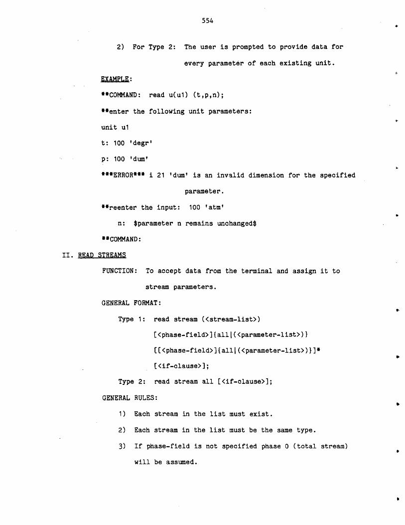
554
2) For Type 2: The user is prompted to provide data for
every parameter of each existing unit.
EXAMLE:
**COMMAND: read u(ul) (t,p,n);
**enter the following unit parameters:
unit ul
t: 100 'degr'
p: 100 'dum'
***ERROR*** i 21 'dum' is an invalid dimension for the specified
parameter.
**reenter the input: 100 'atm'
n: $parameter n remains unchanged$
**COMMAND:
II. READ STREAMS
FUNCTION: To accept data from the terminal and assign it to
stream parameters.
GENERAL FORMAT:
Type 1: read stream (<stream-list>)
[<phase-field>]falll(<parameter-list>)}
[[<phase-field>]{alll(<parameter-list>)}]*
[<if-clause>];
Type 2: read stream all [<if-clause>];
GENERAL RULES:
1) Each stream in the list must exist.
2) Each stream in the list must be the same type.
3) If phase-field is not specified phase 0 (total stream)
will be assumed.
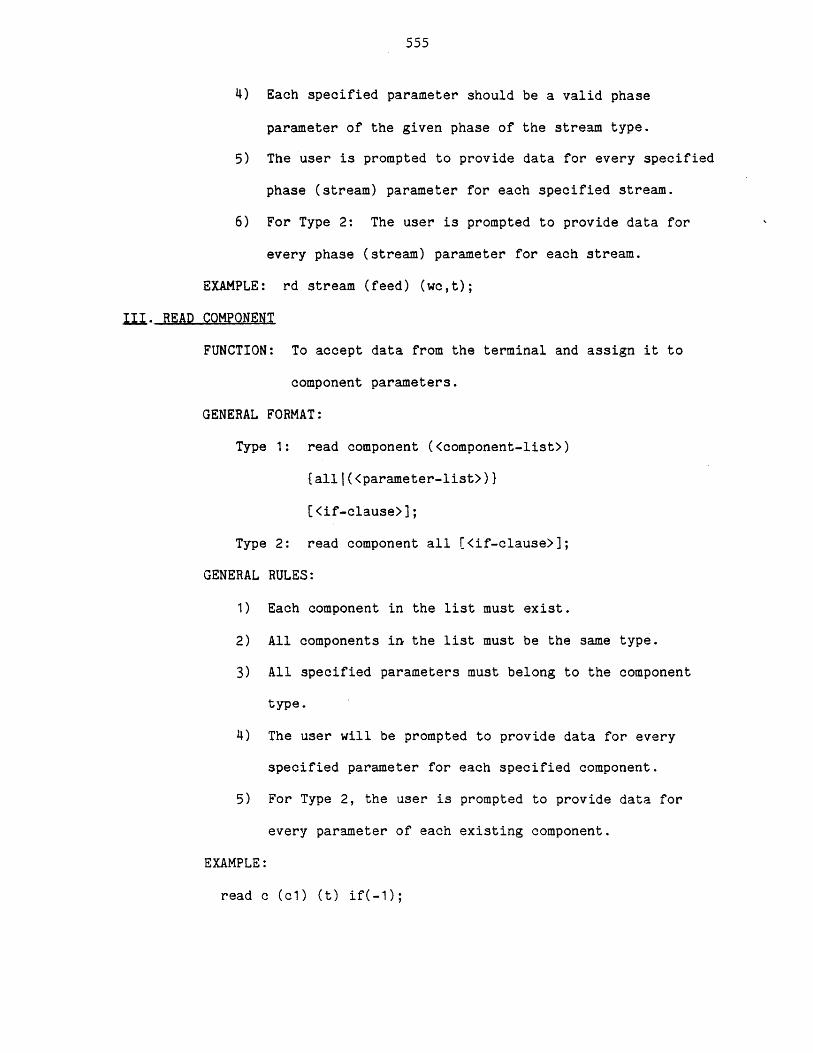
555
4) Each specified parameter should be a valid phase
parameter of the given phase of the stream type.
5) The user is prompted to provide data for every specified
phase (stream) parameter for each specified stream.
6) For Type 2: The user is prompted to provide data for
every phase (stream) parameter for each stream.
EXAMPLE: rd stream (feed) (wc,t);
II.. READ COMPONENT
FUNCTION: To accept data from the terminal and assign it to
component parameters.
GENERAL FORMAT:
Type 1: read component (<component-list>)
{alll(<parameter-list>)}
[<if-clause>];
Type 2: read component all [<if-clause>];
GENERAL RULES:
1) Each component in the list must exist.
2) All components in the list must be the same type.
3) All specified parameters must belong to the component
type.
4) The user will be prompted to provide data for every
specified parameter for each specified component.
5) For Type 2, the user is prompted to provide data for
every parameter of each existing component.
EXAMPLE:
read c (c1) (t) if(-l);

556
IV. READ FLOW
FUNCTION: To accept data from the terminal and assign it to flow
parameters.
GENERAL FORMAT:
Type 1: read flow (<stream-list>)
[<phase-field>]{alll(<flow-parameter-list>)I
[[<phase-field>]{all|(<flow-parameter-list>)}]*
[<if-clause>];
Type 2: read flow all [<if-clause>];
GENERAL RULES:
1) Each specified stream should exist.
2) All specified streams should be the same type.
3) If phase-field is not specified the default would be phase
0 (total stream).
4) Every specified parameter should be a valid flow parameter
of the given phase of the stream type.
5) The user is prompted to provide data for every specified
flow parameter for each stream.
6) For Type 2 user will be prompted to provide data for every
flow parameter of each existing stream.
EXAMPLE:
read flow (feed) all; $read all flow parameters of all
components in phase 0 of stream feed$
read flow (feed)(CO(f),(C02(f)); $read flow parameter "f" of
components CO and C02 in phase 0 of stream feed$.
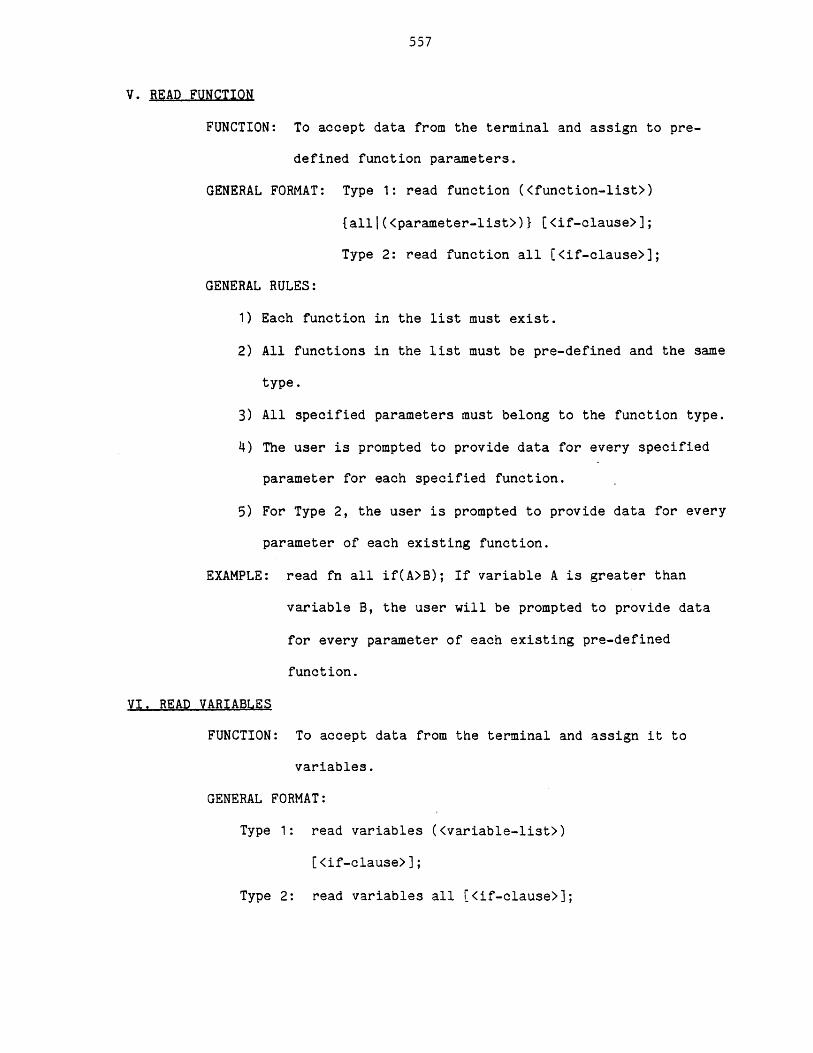
557
V. READ FUNCTION
FUNCTION: To accept data from the terminal and assign to pre-
defined function parameters.
GENERAL FORMAT: Type 1: read function (<function-list>)
{all|(<parameter-list>)} [<if-clause>];
Type 2: read function all [<if-clause>];
GENERAL RULES:
1) Each function in the list must exist.
2) All functions in the list must be pre-defined and the same
type.
3) All specified parameters must belong to the function type.
4) The user is prompted to provide data for every specified
parameter for each specified function.
5) For Type 2, the user is prompted to provide data for every
parameter of each existing function.
EXAMPLE: read fn all if(A>B); If variable A is greater than
variable B, the user will be prompted to provide data
for every parameter of each existing pre-defined
function.
VI. READ VARIABLES
FUNCTION: To accept data from the terminal and assign it to
variables.
GENERAL FORMAT:
Type 1: read variables (<variable-list>)
(<if-clause>];
Type 2: read variables all [(<if-clause>];
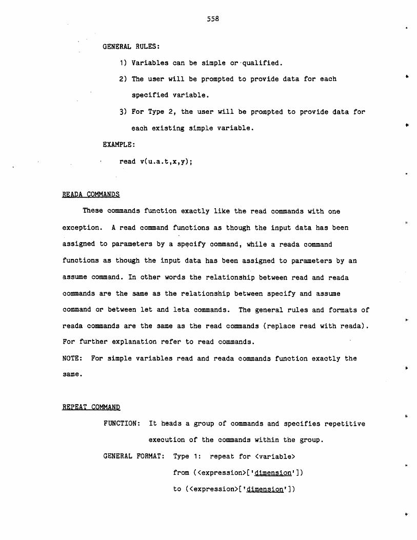
558
GENERAL RULES:
1) Variables can be simple or -qualified.
2) The user will be prompted to provide data for each
specified variable.
3) For Type 2, the user will be prompted to provide data for
each existing simple variable.
EXAMPLE:
read v(u.a.t,x,y);
READA 9OMMANDS
These commands function exactly like the read commands with one
exception. A read command functions as though the input data has been
assigned to parameters by a specify command, while a reada command
functions as though the input data has been assigned to parameters by an
assume command. In other words the relationship between read and reada
commands are the same as the relationship between specify and assume
command or between let and leta commands. The general rules and formats of
reada commands are the same as the read commands (replace read with reada).
For further explanation refer to read commands.
NOTE: For simple variables read and reada commands function exactly the
same.
REPEAT COMMAND
FUNCTION: It heads a group of commands and specifies repetitive
execution of the commands within the group.
GENERAL FORMAT: Type 1: repeat for <variable>
from (<expression>['dimension'])
to (<expression>['dimension'])
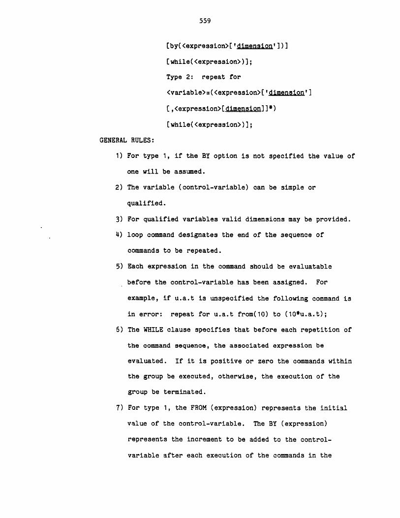
559
[by(<expression>['dimension'1)]
[while(<expression>)];
Type 2: repeat for
<variable>:(<expression>['dimension']
[,<expression>[dimension]]*)
(while(<expression>)];
GENERAL RULES:
1) For type 1, if the BY option is not specified the value of
one will be assumed.
2) The variable (control-variable) can be simple or
qualified.
3) For qualified variables valid dimensions may be provided.
4) loop command designates the end of the sequence of
commands to be repeated.
5) Each expression in the command should be evaluatable
before the control-variable has been assigned. For
example, if u.a.t is unspecified the following command is
in error: repeat for u.a.t from(10) to (10*u.a.t);
6) The WHILE clause specifies that before each repetition of
the command sequence, the associated expression be
evaluated. If it is positive or zero the commands within
the group be executed, otherwise, the execution of the
group be terminated.
7) For type 1, the FROM (expression) represents the initial
value of the control-variable. The BY (expression)
represents the increment to be added to the control-
variable after each execution of the commands in the
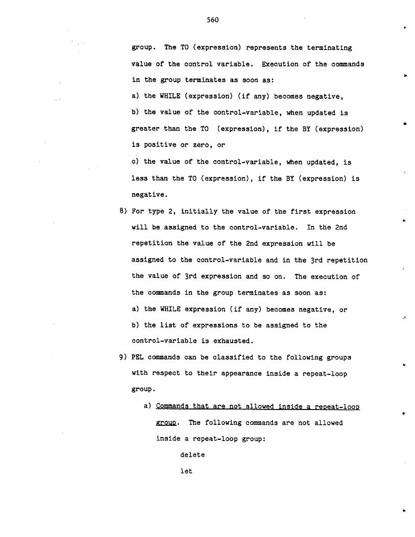
560
group. The TO (expression) represents the terminating
value of the control variable. Execution of the commands
in the group terminates as soon as:
a) the WHILE (expression) (if any) becomes negative,
b) the value of the control-variable, when updated is
greater than the TO (expression), if the BY (expression)
is positive or zero, or
c) the value of the control-variable, when updated, is
less than the TO (expression), if the BY (expression) is
negative.
8) For type 2, initially the value of the first expression
will be assigned to the control-variable. In the 2nd
repetition the value of the 2nd expression will be
assigned to the control-variable and in the 3rd repetition
the value of 3rd expression and so on. The execution of
the commands in the group terminates as soon as:
a) the WHILE expression (if any) becomes negative, or
b) the list of expressions to be assigned to the
control-variable is exhausted.
9) PEL commands can be classified to the following groups
with respect to their appearance inside a repeat-loop
group.
a) Commands that are not allowed inside a repeat-loop
grouD. The following commands are not allowed
inside a repeat-loop group:
delete
let
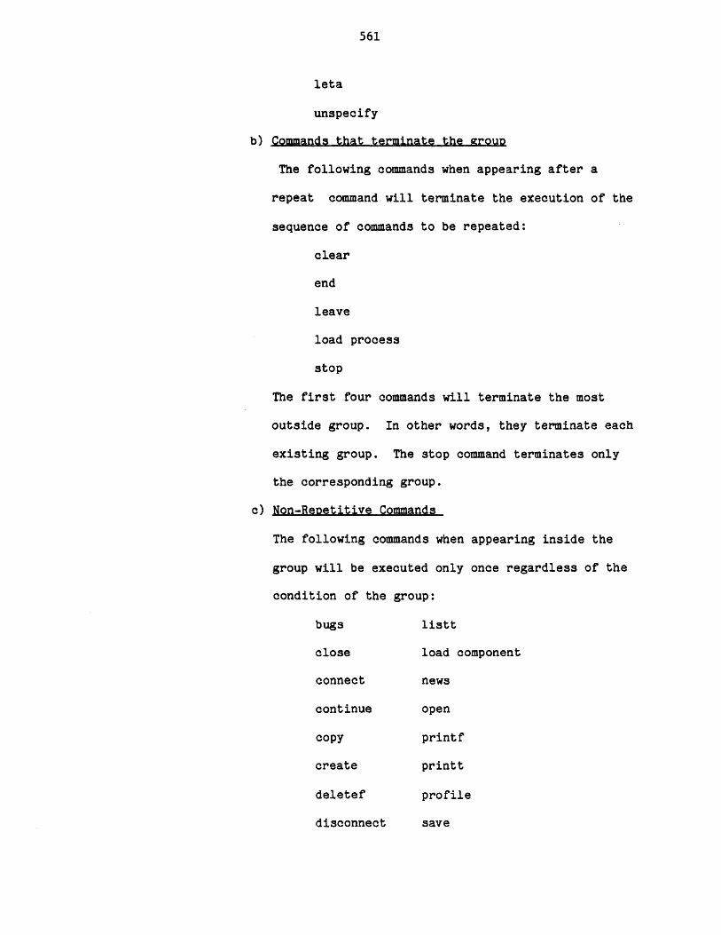
561
leta
unspecify
b) Commands that terminate the group
The following commands when appearing after a
repeat command will terminate the execution of the
sequence of commands to be repeated:
clear
end
leave
load process
stop
The first four commands will terminate the most
outside group. In other words, they terminate each
existing group. The stop command terminates only
the corresponding group.
c) Non-ReDetitive Commands
The following commands when appearing inside the
group will be executed only once regardless of the
condition of the group:
bugs listt
close load component
connect news
continue open
copy printf
create printt
deletef profile
disconnect save

562
escape terminate
help use
include
list
listf
d) Repetitive Commands
Only the following commands when appearing inside
the group can be executed, any number of times,
depending on the condition of the group:
assume
calculate
loop
read
reada
repeat
specify
10) A repeat command is called unexecutable when after the
control-variable has been initialized (the first
iteration), the WHILE expression is negative; or for type
1 the control variable is greater than the TO expression
and the BY expression is positive or zero; or the control
variable is less than the TO expression and the BY
expression is negative. If a repeat command is
unexecutable, non-repetitive commands that may follow
this command will be executed only once as usual.
Repetitive commands that may follow the command will be
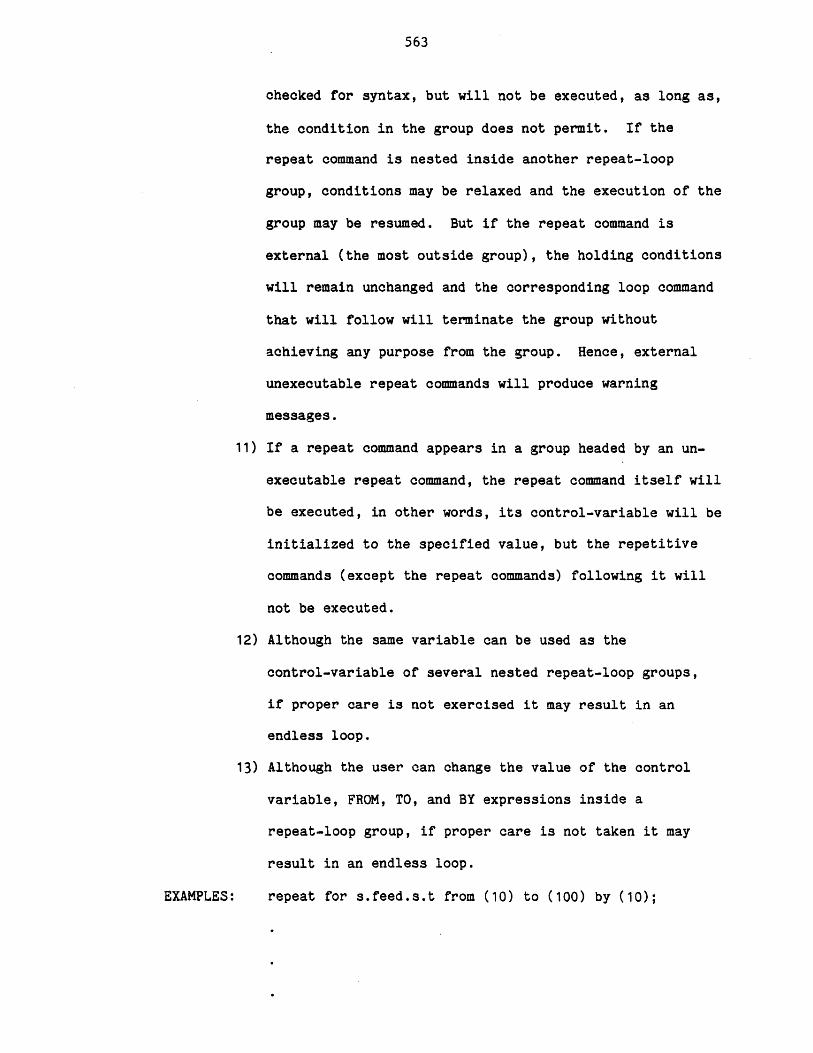
563
checked for syntax, but will not be executed, as long as,
the condition in the group does not permit. If the
repeat command is nested inside another repeat-loop
group, conditions may be relaxed and the execution of the
group may be resumed. But if the repeat command is
external (the most outside group), the holding conditions
will remain unchanged and the corresponding loop command
that will follow will terminate the group without
achieving any purpose from the group. Hence, external
unexecutable repeat commands will produce warning
messages.
11) If a repeat command appears in a group headed by an un-
executable repeat command, the repeat command itself will
be executed, in other words, its control-variable will be
initialized to the specified value, but the repetitive
commands (except the repeat commands) following it will
not be executed.
12) Although the same variable can be used as the
control-variable of several nested repeat-loop groups,
if proper care is not exercised it may result in an
endless loop.
13) Although the user can change the value of the control
variable, FROM, TO, and BY expressions inside a
repeat-loop group, if proper care is not taken it may
result in an endless loop.
EXAMPLES: repeat for s.feed.s.t from (10) to (100) by (10);
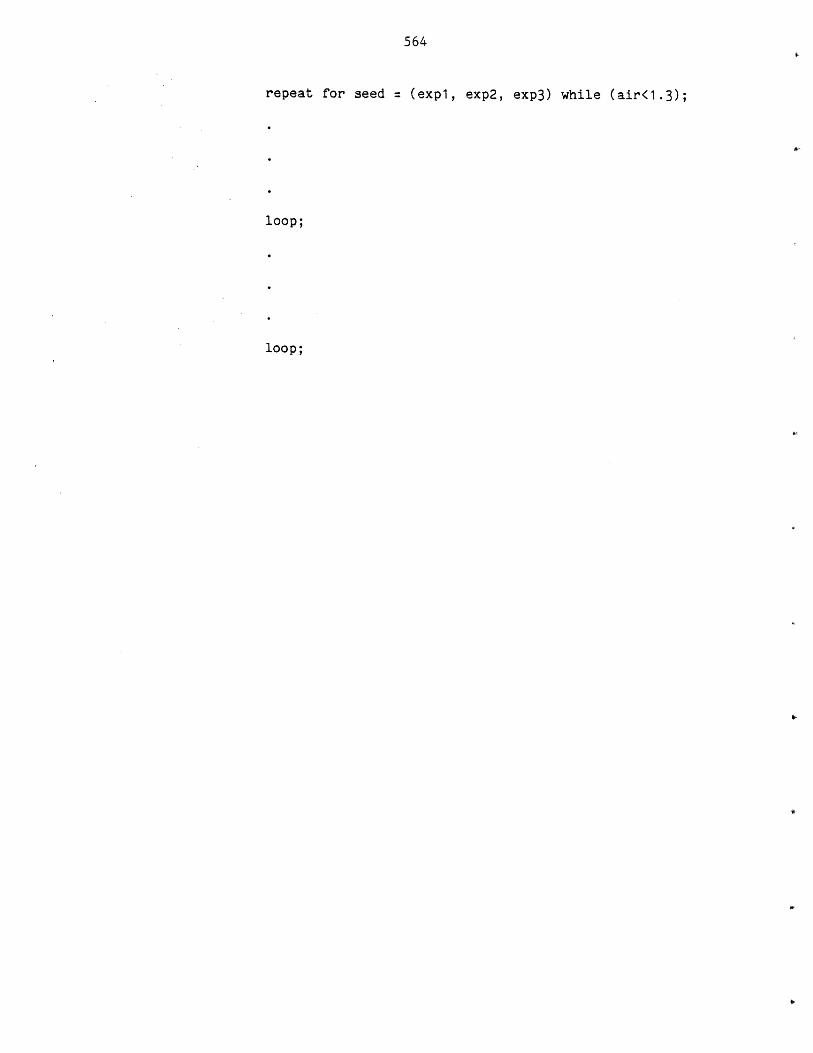
564
repeat for seed = (exp1, exp2, exp3) while (air<1.3);
loop;
loop;

565
SAVE COMMANDS
Save commands are used to store components in the working area into a
component file or to store the active process into a process file. Save
commands can be grouped into the following two commands:
I. SAVE COMPONENTS
FUNCTION: To copy the components data from the working area into
a private component file.
GENERAL FORMAT: save components { allI(<component-list>)}
[override];
GENERAL RULES: 1) For every non existing specified component a
warning message will be printed.
2) For every specified component whose one or
more parameters are unspecified a warning
message will be printed and the component
would not be saved.
3) The private component file should be opened
and the user should have the proper access.
4) If the override option is not provided, for
each specified component which already exists
in the private component file a warning
message will be printed.
5) Only the component parameters will be copied
into the private file, and the value types of
parameters will not be copied.
EXAMPLE: save c(C02,CO,Newcomp);
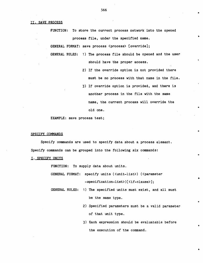
566
II. SAVE PROCESS
FUNCTION: To store the current process network into the opened
process file, under the specified name.
GENERAL FORMAT: save process <process> [override];
GENERAL RULES: 1) The process file should be opened and the user
should have the proper access.
2) If the override option is not provided there
must be no process with that name in the file.
3) If override option is provided, and there is
another process in the file with the same
name, the current process will override the
old one.
EXAMPLE: save process test;
SPECIFY COMMANDS
Specify commands are used to specify data about a process element.
Specify commands can be grouped into the following six commands:
I. SPECIFY UNITS
FUNCTION: To supply data about units.
GENERAL FORMAT: specify units (<unit-list>) (<parameter
-specification-list>)[<if-clause>];
GENERAL RULES: 1) The specified units must exist, and all must
be the same type.
2) Specified parameters must be a valid parameter
of that unit type.
3) Each expression should be evaluatable before
the execution of the command.
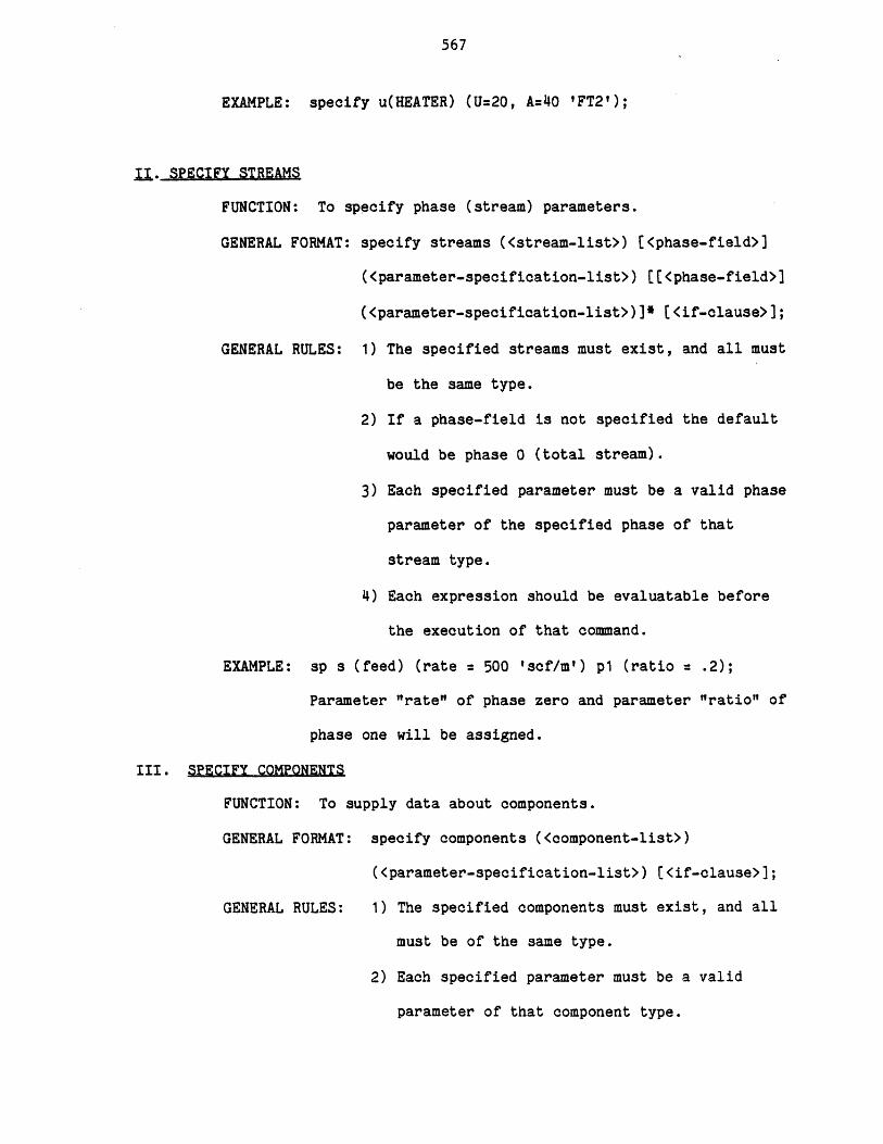
567
EXAMPLE: specify u(HEATER) (U=20, A=40 'FT2');
j.. SPECIFY STREAMS
FUNCTION: To specify phase (stream) parameters.
GENERAL FORMAT: specify streams (<stream-list>) [<phase-field>]
(<parameter-specification-list>) [[<phase-field>]
(<parameter-specification-list>)]e [<if-clause>];
GENERAL RULES: 1) The specified streams must exist, and all must
be the same type.
2) If a phase-field is not specified the default
would be phase 0 (total stream).
3) Each specified parameter must be a valid phase
parameter of the specified phase of that
stream type.
4) Each expression should be evaluatable before
the execution of that command.
EXAMPLE: sp s (feed) (rate = 500 'scf/m') p1 (ratio = .2);
Parameter "rate" of phase zero and parameter "ratio" of
phase one will be assigned.
III. SPECIFY COMPONENTS
FUNCTION: To supply data about components.
GENERAL FORMAT: specify components (<component-list>)
(<parameter-specification-list>) [<if-clause>];
GENERAL RULES: 1) The specified components must exist, and all
must be of the same type.
2) Each specified parameter must be a valid
parameter of that component type.
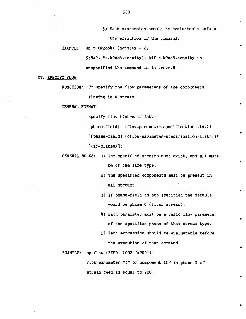
568
3) Each expression should be evaluatable before
the execution of the command.
EXAMPLE: sp c (k2so4) (density = 2,
%p4=2.4*c.k2so4.density); $if c.k2so4.density is
unspecified the command is in error.$
IV. SPECIFY FLOW
FUNCTION: To specify the flow parameters of the components
flowing in a stream.
GENERAL FORMAT:
specify flow (<stream-list>)
[phase-field] (<flow-parameter-specification-list>)
((phase-field] (<flow-parameter-specification-list>)]*
[<if-clause>];
GENERAL RULES: 1) The specified streams must exist, and all must
be of the same type.
2) The specified components must be present in
all streams.
3) If phase-field is not specified the default
would be phase 0 (total stream).
4) Each parameter must be a valid flow parameter
of the specified phase of that stream type.
5) Each expression should be evaluatable before
the execution of that command.
EXAMPLE: sp flow (FEED) (C02(f=200));
Flow parameter "f" of component C02 in phase 0 of
stream feed is equal to 200.
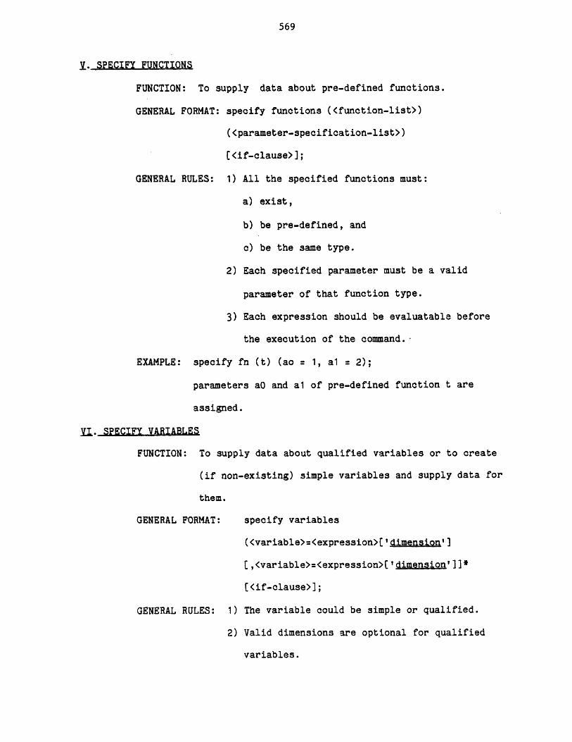
569
VX. SPECIFY FUNCTIONS
FUNCTION: To supply data about pre-defined functions.
GENERAL FORMAT: specify functions (<function-list>)
(<parameter-specification-list>)
[<if-clause>];
GENERAL RULES: 1) All the specified functions must:
a) exist,
b) be pre-defined, and
c) be the same type.
2) Each specified parameter must be a valid
parameter of that function type.
3) Each expression should be evaluatable before
the execution of the command.-
EXAMPLE: specify fn (t) (ao = 1, al = 2);
parameters aO and al of pre-defined function t are
assigned.
Y. SPECIFY VARIABLES
FUNCTION: To supply data about qualified variables or to create
(if non-existing) simple variables and supply data for
them.
GENERAL FORMAT: specify variables
(<variable>=<expression>['dimension']
[,<variable>=<expression>['dimension']]*
[<if-clause>];
GENERAL RULES: 1) The variable could be simple or qualified.
2) Valid dimensions are optional for qualified
variables.
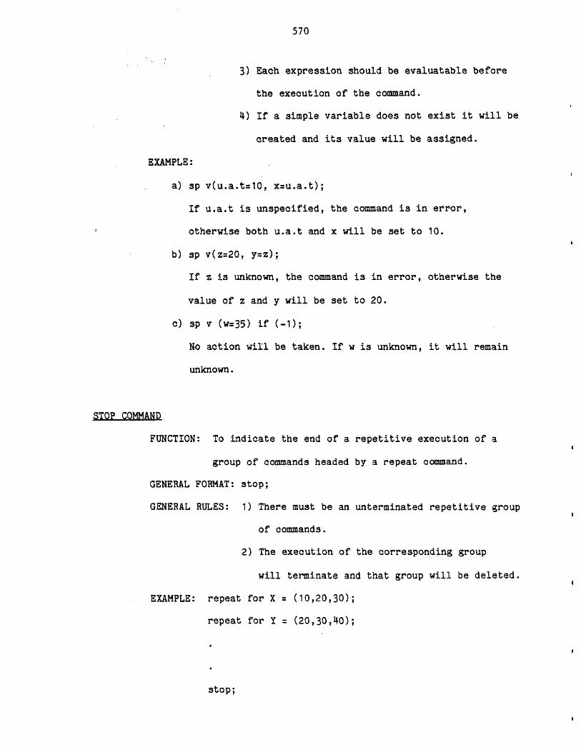
570
3) Each expression should be evaluatable before
the execution of the command.
4) If a simple variable does not exist it will be
created and its value will be assigned.
EXAMPLE:
a) sp v(u.a.t=10, x=u.a.t);
If u.a.t is unspecified, the command is in error,
otherwise both u.a.t and x will be set to 10.
b) sp v(z=20, y=z);
If z is unknown, the command is in error, otherwise the
value of z and y will be set to 20.
c) sp v (w=35) if (-1);
No action will be taken. If w is unknown, it will remain
unknown.
STOP COMMAND
FUNCTION: To indicate the end of a repetitive execution of a
group of commands headed by a repeat command.
GENERAL FORMAT: stop;
GENERAL RULES: 1) There must be an unterminated repetitive group
of commands.
2) The execution of the corresponding group
will terminate and that group will be deleted.
EXAMPLE: repeat for X = (10,20,30);
repeat for Y = (20,30,40);
stop;
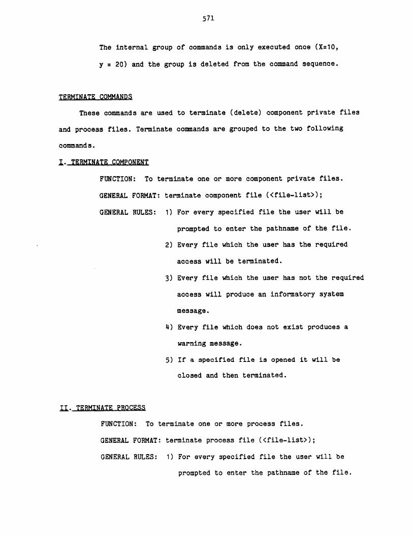
571
The internal group of commands is only executed once (X=10,
y = 20) and the group is deleted from the command sequence.
TERMINATE COMMANDS
These commands are used to terminate (delete) component private files
and process files. Terminate commands are grouped to the two following
commands.
I. TERMINATE COMPONENT
FUNCTION: To terminate one or more component private files.
GENERAL FORMAT: terminate component file (<file-list>);
GENERAL RULES: 1) For every specified file the user will be
prompted to enter the pathname of the file.
2) Every file which the user has the required
access will be terminated.
3) Every file which the user has not the required
access will produce an informatory system
message.
4) Every file which does not exist produces a
warning message.
5) If a specified file is opened it will be
closed and then terminated.
II. TERMINATE PROCESS
FUNCTION: To terminate one or more process files.
GENERAL FORMAT: terminate process file (<file-list>);
GENERAL RULES: 1) For every specified file the user will be
prompted to enter the pathname of the file.
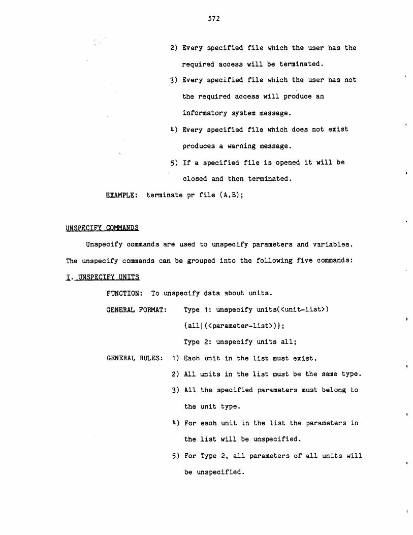
572
2) Every specified file which the user has the
required access will be terminated.
3) Every specified file which the user has not
the required access will produce an
informatory system message.
4) Every specified file which does not exist
produces a warning message.
5) If a specified file is opened it will be
closed and then terminated.
EXAMPLE: terminate pr file (A,B);
UNSPECIFY COMMANDS
Unspecify commands are used to unspecify parameters and variables.
The unspecify commands can be grouped into the following five commands:
j. UNSPECIFY UNITS
FUNCTION: To unspecify data about units.
GENERAL FORMAT: Type 1: unspecify units(<unit-list>)
{all|(<parameter-list>)};
Type 2: unspecify units all;
GENERAL RULES: 1) Each unit in the list must exist.
2) All units in the list must be the same type.
3) All the specified parameters must belong to
the unit type.
4) For each unit in the list the parameters in
the list will be unspecified.
5) For Type 2, all parameters of all units will
be unspecified.
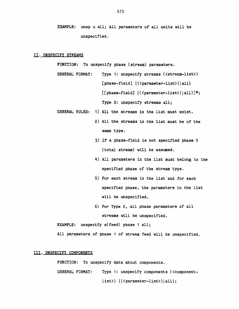
573
EXAMPLE: unsp u all; All parameters of all units will be
unspecified.
II. UNSPECIFY STREAMS
FUNCTION: To unspecify phase (stream) parameters.
GENERAL FORMAT: Type 1: unspecify streams (<stream-list>)
[phase-field) {(<parameter-list>)|all}
[[phase-field] {(<parameter-list>)|all}]*;
Type 2: unspecify streams all;
GENERAL RULES: 1) All the streams in the list must exist.
2) All the streams in the list must be of the
same type.
3) If a phase-field is not specified phase 0
(total stream) will be assumed.
4) All parameters in the list must belong to the
specified phase of the stream type.
5) For each stream in the list and for each
specified phase, the parameters in the list
will be unspecified.
6) For Type 2, all phase parameters of all
streams will be unspecified.
EXAMPLE: unspecify s(feed) phase 1 all;
All parameters of phase 1 of stream feed will be unspecified.
III. UNSPECIFY COMPONENTS
FUNCTION: To unspecify data about components.
GENERAL FORMAT: Type 1: unspecify components (<component-
list>) {(<parameter-list>)jall};
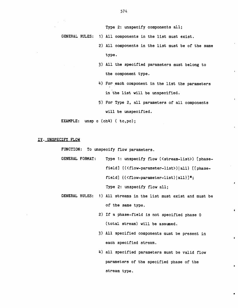
574
GENERAL RULES:
EXAMPLE: unsp
Type 2: unspecify components all;
1) All components in the list must exist.
2) All components in the list must be of the same
type.
3) All the specified parameters must belong to
the component type.
4) For each component in the list the parameters
in the list will be unspecified.
5) For Type 2, all parameters of all components
will be unspecified.
c (chO ( to,pc);
IV. UNSPECIFY FLOW
FUNCTION: To unspecify flow parameters.
GENERAL FORMAT: Type 1: unspecify flow (<stream-list>) [phase-
field] {(<flow-parameter-list>)|all} [[phase-
field] {(<flow-parameter-list)|all}]*;
Type 2: unspecify flow all;
GENERAL RULES: 1) All streams in the list must exist and must be
of the same type.
2) If a phase-field is not specified phase 0
(total stream) will be assumed.
3) All specified components must be present in
each specified stream.
4) all specified parameters must be valid flow
parameters of the specified phase of the
stream type.
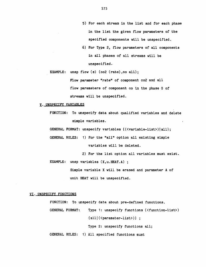
575
5) For each stream in the list and for each phase
in the list the given flow parameters of the
specified components will be unspecified.
6) For Type 2, flow parameters of all components
in all phases of all streams will be
unspecified.
EXAMPLE: unsp flow (s) (co2 (rate),co all);
Flow parameter "rate" of component co2 and all
flow parameters of component co in the phase 0 of
streams will be unspecified.
Y.. UNSPECIFY VARIABLES
FUNCTION: To unspecify data about qualified variables and delete
simple variables.
GENERAL FORMAT: unspecify variables {(<variable-list>)Iall};
GENERAL RULES: 1) For the "all" option all existing simple
variables will be deleted.
2) For the list option all variables must exist.
EXAMPLE: unsp variables (X,u.HEAT.A) ;
Simple variable X will be erased and parameter A of
unit HEAT will be unspecified.
Y. UNSPECIFY FUNCTIONS
FUNCTION: To unspecify data about pre-defined functions.
GENERAL FORMAT:. Type 1: unspecify functions (<function-list>)
{allt(<parameter-list>)} ;
Type 2: unspecify functions all;
GENERAL RULES: 1) All specified functions must
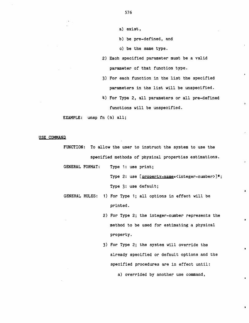
576
a) exist,
b) be pre-defined, and
c) be the same type.
2) Each specified parameter must be a valid
parameter of that function type.
3) For each function in the list the specified
parameters in the list will be unspecified.
4) For Type 2, all parameters or all pre-defined
functions will be unspecified.
EXAMPLE: unsp fn (h) all;
USE COMMAND
FUNCTION: To allow the user to instruct the system to use the
specified methods of physical properties estimations.
GENERAL FORMAT: Type 1: use print;
Type 2: use [property-name=<integer-number>]*;
Type 3: use default;
GENERAL RULES: 1) For Type 1; all options in effect will be
printed.
2) For Type 2; the integer-number represents the
method to be used for estimating a physical
property.
3) For Type 2; the system will override the
already specified or default options and the
specified procedures are in effect until:
a) overrided by another use command,
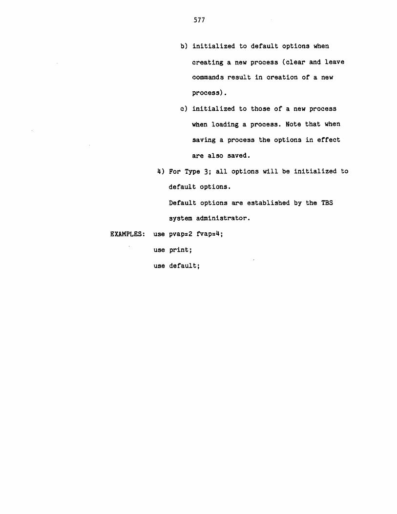
577
b) initialized to default options when
creating a new process (clear and leave
commands result in creation of a new
process).
c) initialized to those of a new process
when loading a process. Note that when
saving a process the options in effect
are also saved.
4) For Type 3; all options will be initialized to
default options.
Default options are established by the TBS
system administrator.
EXAMPLES: use pvap=2 fvap=4;
use print;
use default;
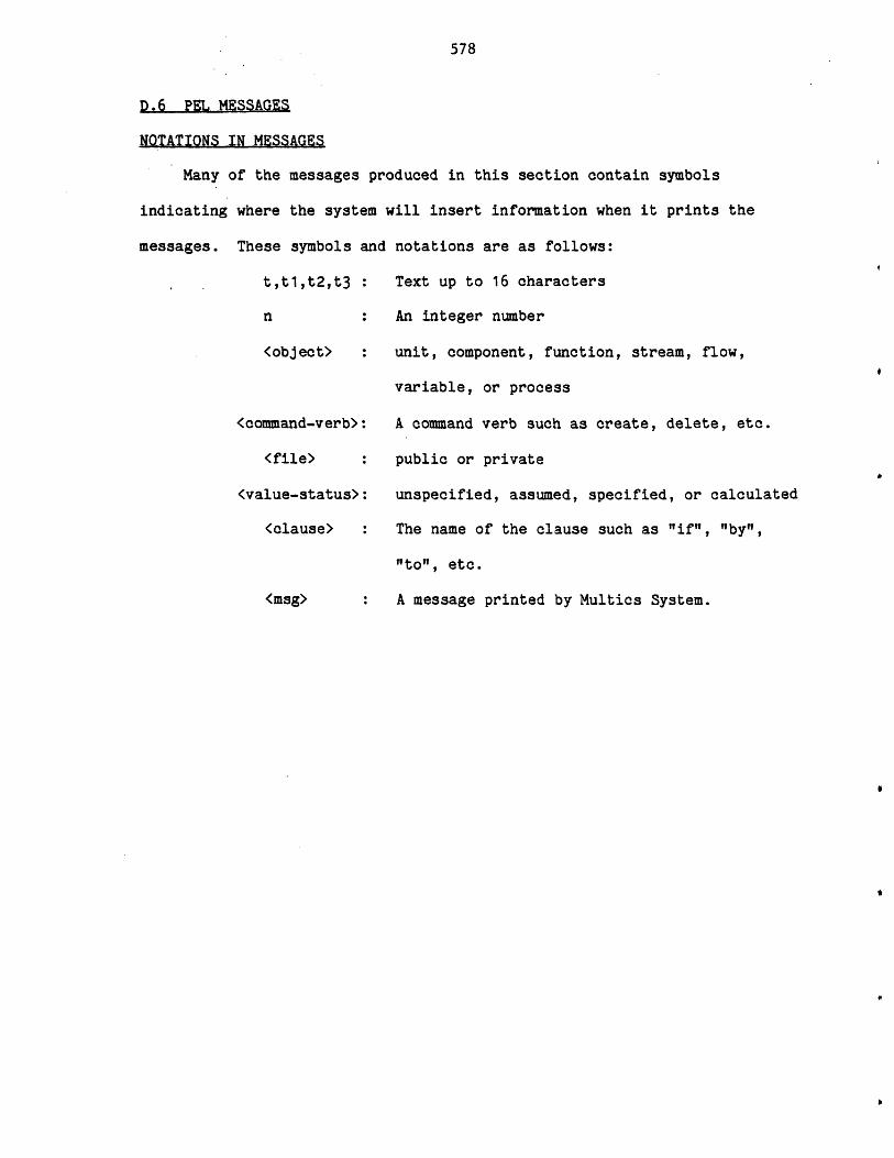
578
D.6 PEL MESSAGES
NOTATIONS IN MESSAGES
Many of the messages produced in this section contain symbols
indicating where the system will insert information when it prints the
messages. These symbols and notations are as follows:
t,tlt2,t3
n
<object>
<command-verb>
<file>
(value-status>
<clause>
<msg>
Text up to 16 characters
An integer number
unit, component, function, stream, flow,
variable, or process
A command verb such as create, delete, etc.
public or private
unspecified, assumed, specified, or calculated
The name of the clause such as "if", "by",
"to", etc.
A message printed by Multics System.
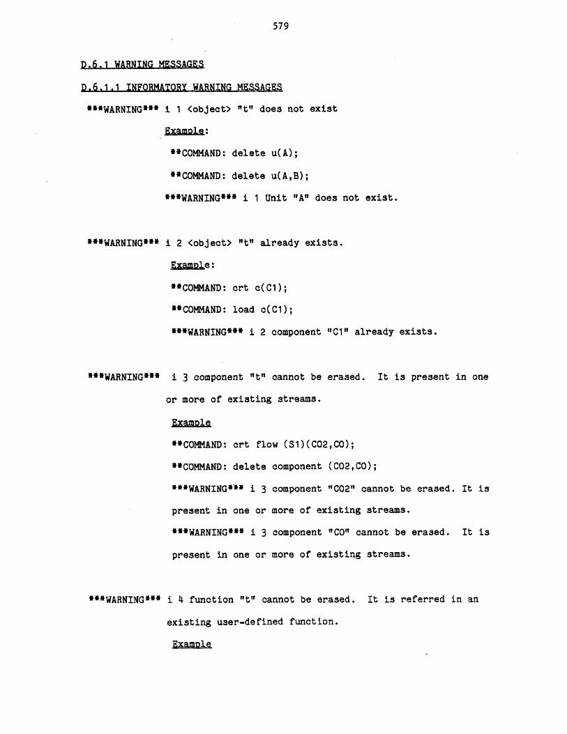
579
D.6.1 WARNING MESSAGES
D.6.1.1 INFORMATORY WARNING MESSAGES
***WARNING*** i 1 <object> "t" does not exist
ExamAle:
**COMMAND: delete u(A);
**COMMAND: delete u(A,B);
***WARNING*** i 1 Unit "A" does not exist.
***WARNING***
***WARNING***
"*WARNING***
i 2 <object> "t" already exists.
Example:
**COMMAND: crt c(C1);
**COMMAND: load c(C1);
***WARNING*** i 2 component "C1" already exists.
i 3 component "t" cannot be erased. It is present in one
or more of existing streams.
Example
**COMMAND: crt flow (S1)(C02,CO);
**COMMAND: delete component (C02,CO);
***WARNING*** i 3 component "C02" cannot be erased. It is
present in one or more of existing streams.
***WARNING*** i 3 component "CO" cannot be erased. It is
present in one or more of existing streams.
i 4 function "It" cannot be erased. It is referred in an
existing user-defined function.
Example
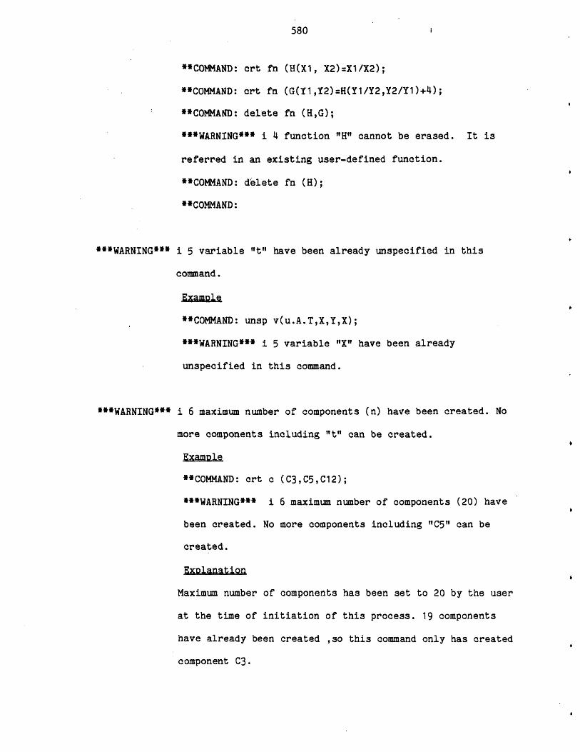
580
**COMMAND: art fn (H(X1, X2)=X1/X2);
"COMMAND: art fn (G(Y1,Y2)=H(Y1/Y2,Y2/Y1)+4);
"COMMAND: delete fn (H,G);
***WARNING*** i 4 function "H" cannot be erased. It is
referred in an existing user-defined function.
**COMMAND: delete fn (H);
**COMMAND:
"'WARNING*** i 5 variable "t" have been already unspecified in this
command.
ExamDle
**COMMAND: unsp v(u.A.T,X,Y,X);
***WARNING*** i 5 variable "X" have been already
unspecified in this command.
WARNING*** i 6 maximum number of components (n) have been created. No
more components including "t" can be created.
Example
**COMMAND: art a (C3,C5,C12);
***WARNING*** i 6 maximum number of components (20) have
been created. No more components including "C5" can be
created.
Explanation
Maximum number of components has been set to 20 by the user
at the time of initiation of this process. 19 components
have already been created ,so this command only has created
component C3.
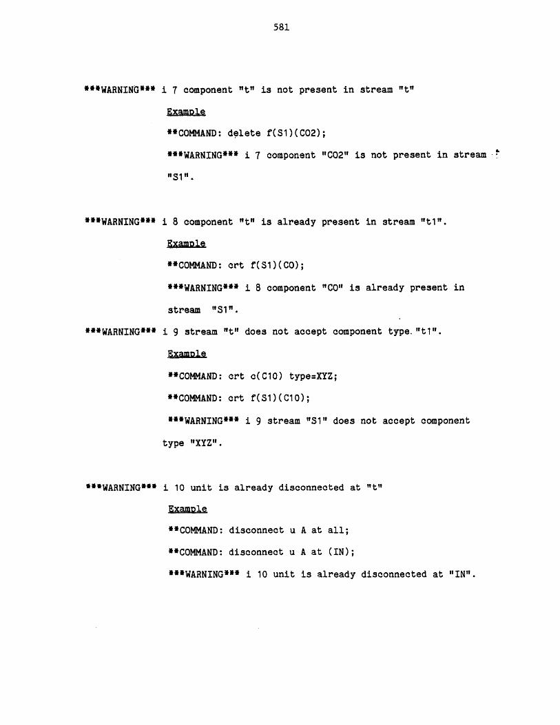
581
**WARNING*** i 7 component "t" is not present in stream "t"
Examole
**COMMAND: delete f(S1)(C02);
***WARNING*** i 7 component "C02" is not present in stream
"Si".
"*WARNING*** i 8 component "t" is already present in stream "t1I".
Example
**COMMAND: crt f(Sl)(CO);
***WARNING*** i 8 component "CO" is already present in
stream "S1"l.
**WARNING*** i 9 stream "t" does not accept component type. "t1".
Example
**COMMAND: crt c(C10) type=XYZ;
**COMMAND: crt f(S1)(C10);
***WARNING*** i 9 stream "Si" does not accept component
type "XYZ".
**'WARNING*** i 10 unit is already disconnected at "t"
ExamDle
**COMMAND: disconnect u A at all;
**COMMAND: disconnect u A at (IN);
***WARNING*** i 10 unit is already disconnected at "IN".
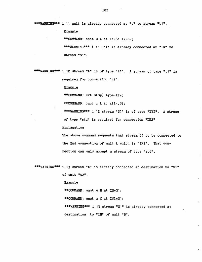
582
***WARNING***
**WARNING***
***WARNING***
i 11 unit is already connected at "t" to stream "t1i".
Example
**COMMAND: onct u A at IN=S1 IN=S2;
***WARNING*** i 11 unit is already connected at "IN" to
stream "S1".
i 12 stream "It" is of type "t1". A stream of type "t1" is
required for connection "t3".
Examole
**COMMAND: crt s(S9) type=XYZ;
**COMMAND: cnct u A at all=,S9;
***WARNING*** i 12 stream "S9" is of type "IXYZ". A stream
of type "std" is required for connection "IN2"
Exolanation
The above command requests that stream S9 to be connected to
the 2nd connection of unit A which is "IN2". That con-
nection can only accept a stream of type "std".
i 13 stream "t" is already connected at destination to "t1"
of unit "t2".
Example
**COMMAND: cnct u B at IN=S1;
**COMMAND: cnct u C at IN2=S1;
***WARNING*** i 13 stream "1i" is already connected at
destination to "IN" of unit "B".
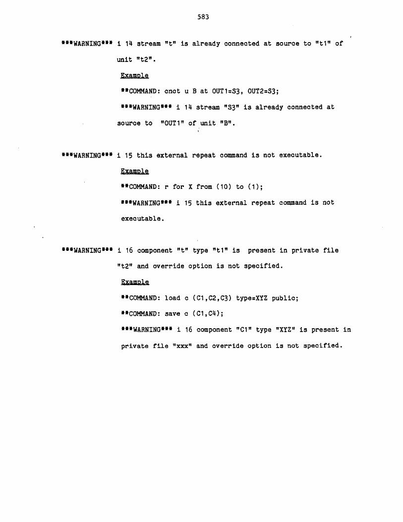
583
***WARNING***
**WARNING***
**WARNING***
i 14 stream "t" is already connected at source to "ti" of
unit "t2".
Example
"COMMAND: cnct u B at OUT1=S3, OUT2=S3;
***WARNING*** i 14 stream "S3" is already connected at
source to "OUT1" of unit "B".
i 15 this external repeat command is not executable.
Example
**COMMAND: r for X from (10) to (1);
***WARNING*** i 15 this external repeat command is not
executable.
i 16 component "t" type "ti" is present in private file
"t2" and override option is not specified.
.Example
**COMMAND: load c (C1,C2,C3) type=XYZ public;
**COMMAND: save c (C1,C4);
***WARNING*** i 16 component "C1" type "XYZ" is present in
private file "xxx" and override option is not specified.
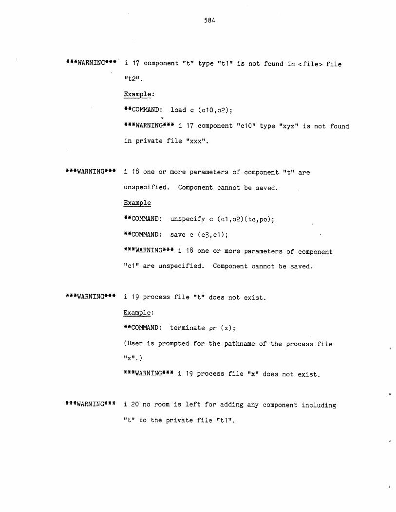
584
***WARNING***
***WARNING***
***WARNING***
***WARNING***
i 17 component "t" type "t1" is not found in <file> file
"t2".
Example:
**COMMNrD: load c (c10,c2);
***WARNING*** i 17 component "c10" type "xyz" is not found
in private file "xxx".
i 18 one or more parameters of component "t" are
unspecified. Component cannot be saved.
Example
**COMMAND: unspecify c (cl,c2)(tc,pc);
**COMMAND: save c (c3,cl);
***WARNING*** i 18 one or more parameters of component
"c1" are unspecified. Component cannot be saved.
i 19 process file "t" does not exist.
Example:
**COMMAND: terminate pr (x);
(User is prompted for the pathname of the process file
"x".)
***WARNING*** i 19 process file "x" does not exist.
i 20 no room is left for adding any component including
"t" to the private file "t1I".
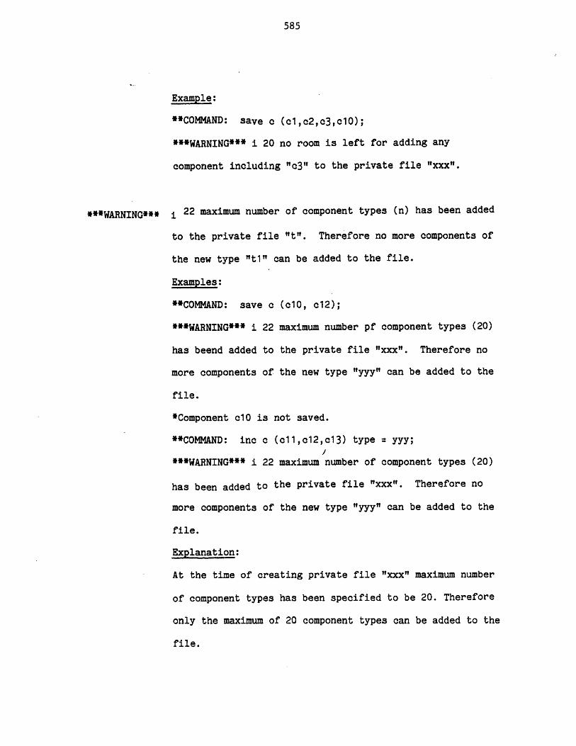
585
Example:
"COMMAND: save c (cl,c2,c3,c10);
***WARNING*** i 20 no room is left for adding any
component including "c3" to the private file "xxx".
***WARNING*** i 22 maximum number of component types (n) has been added
to the private file "t". Therefore no more components of
the new type "t1" can be added to the file.
Examples:
**COMMAND: save c (c10, c12);
***WARNING*** i 22 maximum number pf component types (20)
has beend added to the private file "xxx". Therefore no
more components of the new type "yyy" can be added to the
file.
*Component 10 is not saved.
**COMMAND: inc c (c11,c12,c13) type = yyy;
***WARNING*** i 22 maximum number of component types (20)
has been added to the private file "xxx". Therefore no
more components of the new type "yyy" can be added to the
file.
Explanation:
At the time of creating private file "xxx" maximum number
of component types has been specified to be 20. Therefore
only the maximum of 20 component types can be added to the
file.
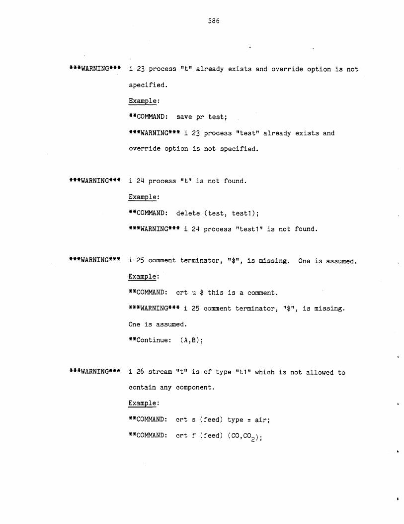
586
***WARNING***
***WARNING***
***WARNING***
i 23 process "t" already exists and override option is not
specified.
Example:
**COMMAND: save pr test;
***WARNING*** i 23 process "test" already exists and
override option is not specified.
i 24 process It" is not found.
Example:
**COMMAND: delete (test, test1);
***WARNING*** i 24 process "test 1" is not found.
i 25 comment terminator, "$", is missing. One is assumed.
Example:
**COMMAND: crt u $ this is a comment.
***WARNING*** i 25 comment terminator, "1$", is missing.
One is assumed.
**Continue: (A,B);
***WARNING*** i 26 stream
contain any
Example:
**COMMAND:
**COMMAND:
"t" is of type "t1" which is not allowed to
component.
crt s (feed) type = air;
crt f (feed) (CO,C02 );
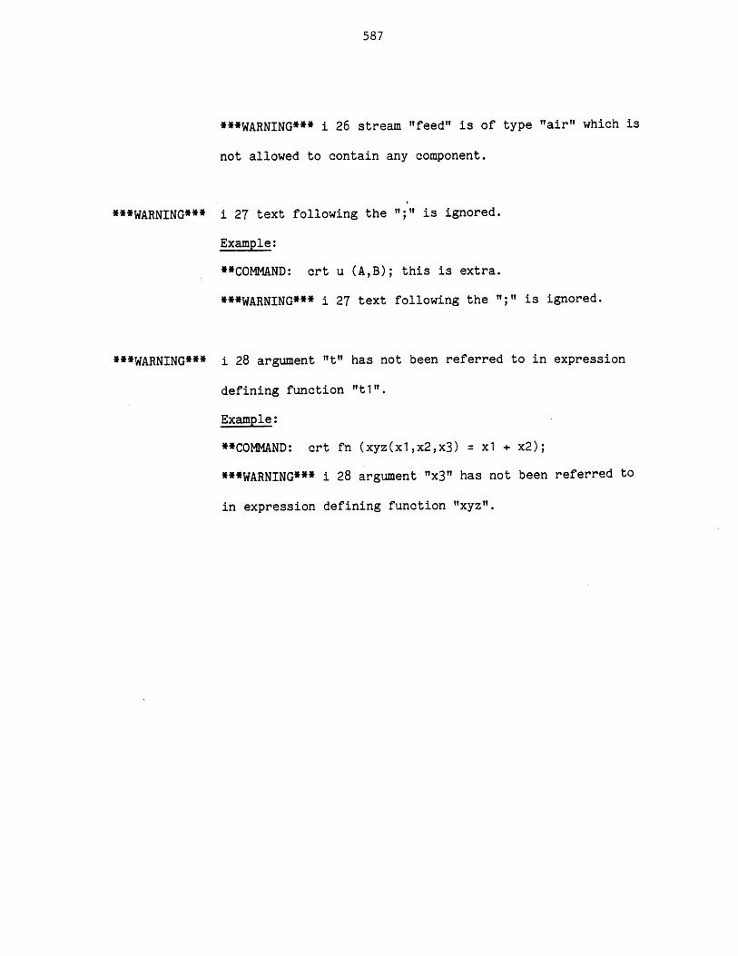
587
***WARNING*** i 26 stream "feed" is of type "air" which is
not allowed to contain any component.
**WARNING***
***WARNING***
i 27 text following the ";" is ignored.
Example:
**COMMAND: crt u (A,B); this is extra.
***WARNING*** i 27 text following the I;II is ignored.
i 28 argument "t" has not been referred to in expression
defining function "t1i".
Example:
**COMMAND: crt fn (xyz(xl,x2,x3) = x1 + x2);
***WARNING*** i 28 argument "x3" has not been referred to
in expression defining function "xyz".
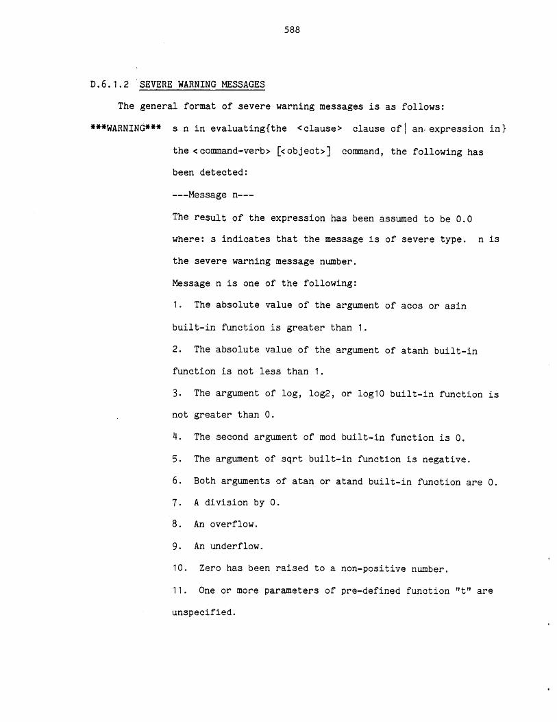
588
D.6.1.2 SEVERE WARNING MESSAGES
The general format of severe warning messages is as follows:
***WARNING*** s n in evaluating{the <clause> clause oft an-expression in}
the <command-verb> [<object>] command, the following has
been detected:
---Message n---
The result of the expression has been assumed to be 0.0
where: s indicates that the message is of severe type. n is
the severe warning message number.
Message n is one of the following:
1. The absolute value of the argument of acos or asin
built-in function is greater than 1.
2. The absolute value of the argument of atanh built-in
function is not less than 1.
3. The argument of log, log2, or log10 built-in function is
not greater than 0.
4. The second argument of mod built-in function is 0.
5. The argument of sqrt built-in function is negative.
6. Both arguments of atan or atand built-in function are 0.
7. A division by 0.
8. An overflow.
9. An underflow.
10. Zero has been raised to a non-positive number.
11. One or more parameters of pre-defined function "t" are
unspecified.
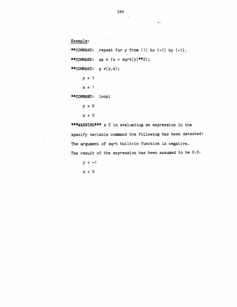
589
Example:
**COMMAND: repeat for y from (1) to (-1) by (-1).
**COMMAND: sp v (x = sqrt(y)**2);
**COMMAND: p v(y,x);
y= 1
x= 1
**COMMAND: loop;
y =0x= 0
***WARNING*** s 5 in evaluating an expression in the
specify variable command the following has been detected:
The argument of sqrt built-in function is negative.
The result of the expression has been assumed to be 0.0.
y = -1
x = 0
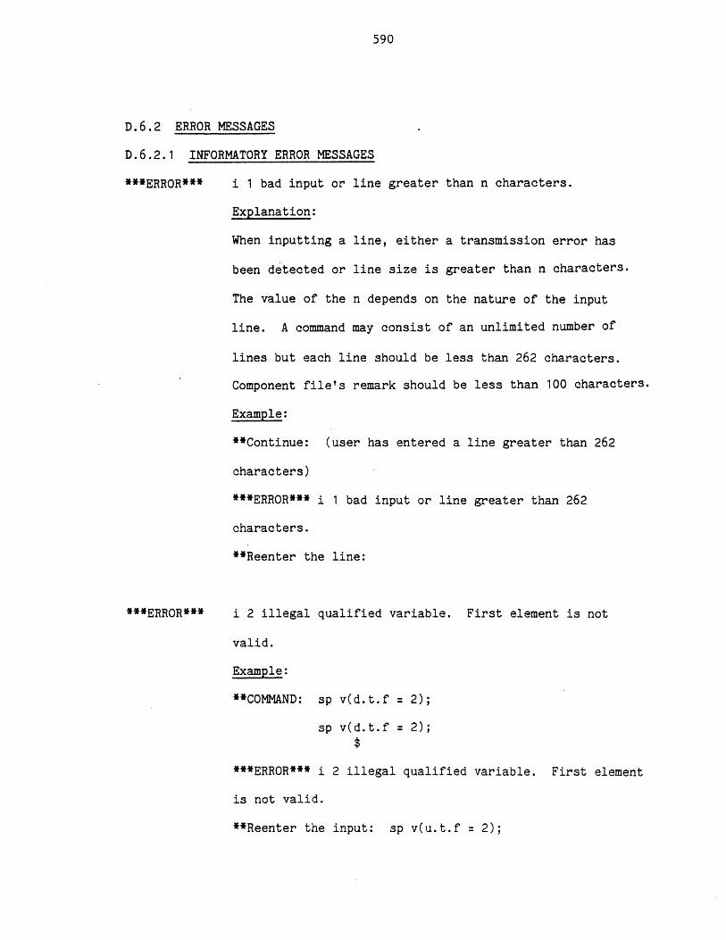
590
D.6.2 ERROR MESSAGES
D.6.2.1 INFORMATORY ERROR MESSAGES
***ERROR*** i 1 bad input or line greater than n characters.
Explanation:
When inputting a line, either a transmission error has
been detected or line size is greater than n characters.
The value of the n depends on the nature of the input
line. A command may consist of an unlimited number of
lines but each line should be less than 262 characters.
Component file's remark should be less than 100 characters.
Example:
**Continue: (user has entered a line greater than 262
characters)
***ERROR*** i 1 bad input or line greater than 262
characters.
**Reenter the line:
***ERROR*** i 2 illegal qualified variable. First element is not
valid.
Example:
**COMMAND: sp v(d.t.f = 2);
sp v(d.t.f = 2);
***ERROR*** i 2 illegal qualified variable. First element
is not valid.
**Reenter the input: sp v(u.t.f = 2);
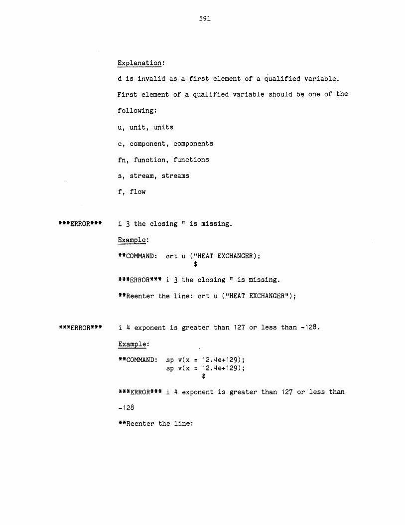
591
Explanation:
d is invalid as a first element of a qualified variable.
First element of a qualified variable should be one of the
following:
u, unit, units
c, component, components
fn, function, functions
s, stream, streams
f, flow
***ERROR***
***ERROR** *
i 3 the closing " is missing.
Example:
**COMMAND: crt u ("HEAT EXCHANGER);
***ERROR*** i 3 the closing " is missing.
**Reenter the line: crt u ("HEAT EXCHANGER");
i 4 exponent is greater than 127 or less than -128.
Example:
**COMMAND: sp v(x = 12.4e+129);sp v(x 12.4e+129);
***ERROR*** i 4 exponent is greater than 127 or less than
-128
**Reenter the line:
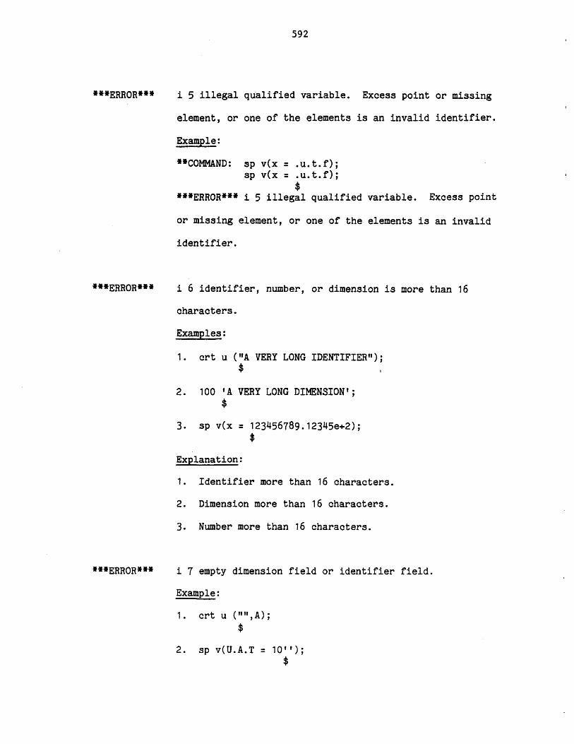
592
**ERROR***
***ERROR***
i 5 illegal qualified variable. Excess point or missing
element, or one of the elements is an invalid identifier.
Example:
"COMMAND: sp v(x = u.t.f);sp v(x = u.t.f);
***ERROR*** i 5 illegal qualified variable. Excess point
or missing element, or one of the elements is an invalid
identifier.
i 6 identifier, number, or dimension is more than 16
characters.
Examples:
1. crt u ("A VERY LONG IDENTIFIER");$
2. 100 'A VERY LONG DIMENSION';
3. sp v(x = 123456789.12345e+2);
Explanation:
1. Identifier more than 16 characters.
2. Dimension more than 16 characters.
3. Number more than 16 characters.
***ERROR*** i 7 empty dimension field or identifier field.
Example:
1. crt u ("",A);
2. sp v(U.A.T = 10'');
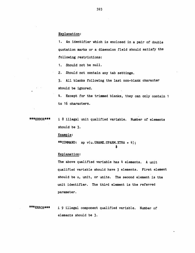
593
Explanation:
1. An identifier which is enclosed in a pair of double
quotation marks or a dimension field should satisfy the
following restrictions:
1. Should not be null.
2. Should not contain any tab settings.
3. All blanks following the last non-blank character
should be ignored.
4. Except for the trimmed blanks, they can only contain 1
to 16 characters.
***ERROR*** i 8 illegal unit qualified variable. Number of elements
should be 3.
Example:
*4COMMAND: sp v(u.UNAME.UPARM.XTRA =4);
Explanation:
The above qualified variable has 4 elements. A unit
qualified variable should have 3 elements. First element
should be u, unit, or units. The second element is the
unit identifier. The third element is the referred
parameter.
***ERROR*** i 9 illegal component qualified variable. Number of
elements should be 3.
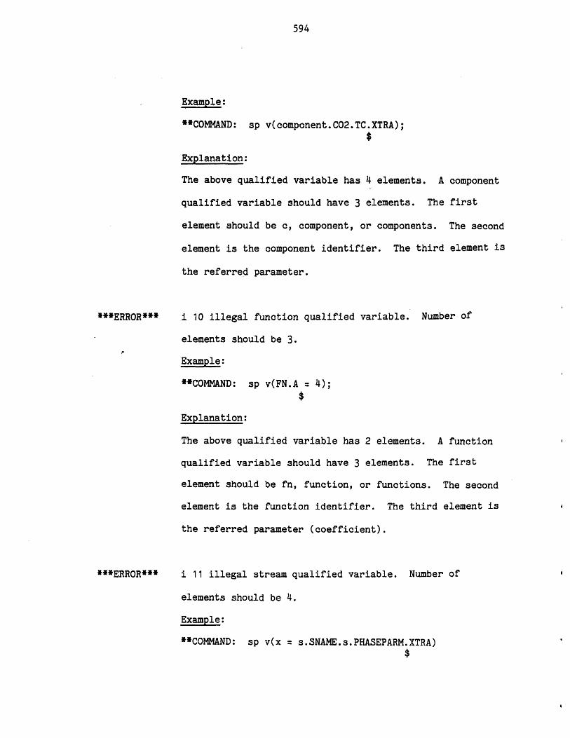
594
Example:
**COMMAND: sp v(component.C02.TC.XTRA);
Explanation:
The above qualified variable has 4 elements. A
qualified variable should have 3 elements. The
element should be c, component, or components.
element is the component identifier. The third
the referred parameter.
***ERROR***
***ERROR***
component
first
The second
element is
i 10 illegal function qualified variable. Number of
elements should be 3.
Example:
**COMMAND: sp v(FN.A =4);
Explanation:
The above qualified variable has 2 elements. A function
qualified variable should have 3 elements. The first
element should be fn, function, or functions. The second
element is the function identifier. The third element is
the referred parameter (coefficient).
i 11 illegal stream qualified variable. Number of
elements should be 4.
Example:
**COMMAND: sp v(x = s.SNAME.s.PHASEPARM.XTRA)
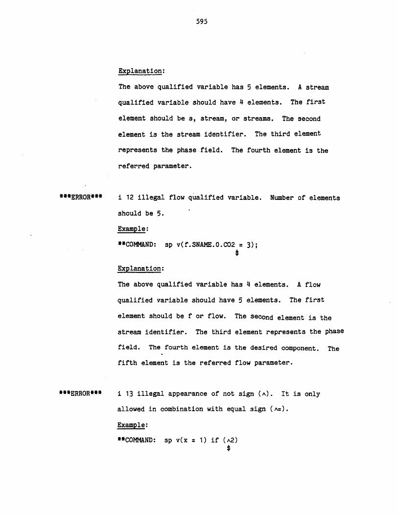
595
Explanation:
The above qualified variable has 5 elements. A stream
qualified variable should have 4 elements. The first
element should be s, stream, or streams. The second
element is the stream identifier. The third element
represents the phase.field. The fourth element is the
referred parameter.
***ERROR***
***ERROR***
i 12 illegal flow qualified variable. Number of elements
should be 5.
Example:
**COMMAND: sp v(f.SNAME.O.C02 = 3);
Explanation:
The above qualified variable has 4 elements. A flow
qualified variable should have 5 elements. The first
element should be f or flow. The second element is the
stream identifier. The third element represents the phase
field. The fourth element is the desired component. The
fifth element is the referred flow parameter.
i 13 illegal appearance of not sign (A). It is only
allowed in combination with equal sign (A=).
Example:
**COMMAND: sp v(x = 1) if (A2)
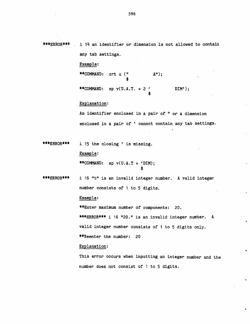
596
***ERROR*** i 14 an identifier or dimension is not allowed to contain
any tab settings.
Example:
**COMMAND: crt u (" A");
**COMMAND: sp v(U.A.T. = 2 ' DIM');
Explanation:
An identifier enclosed in a pair of' " or a dimension
enclosed in a pair of ' cannot contain any tab settings.
***ERROR***
***ERROR***
i 15 the closing ' is missing.
Example:
**COMMAND: sp v(U.A.T = 'DIM);
i 16 "t" is an invalid integer number. A valid integer
number consists of 1 to 5 digits.
Example:
**Enter maximum number of components: 20.
***ERROR*** i 16 "20." is an invalid integer number. A
valid integer number consists of 1 to 5 digits only.
**Reenter the number: 20
Explanation:
This error occurs when inputting an integer number and the
number does not consist of 1 to 5 digits.
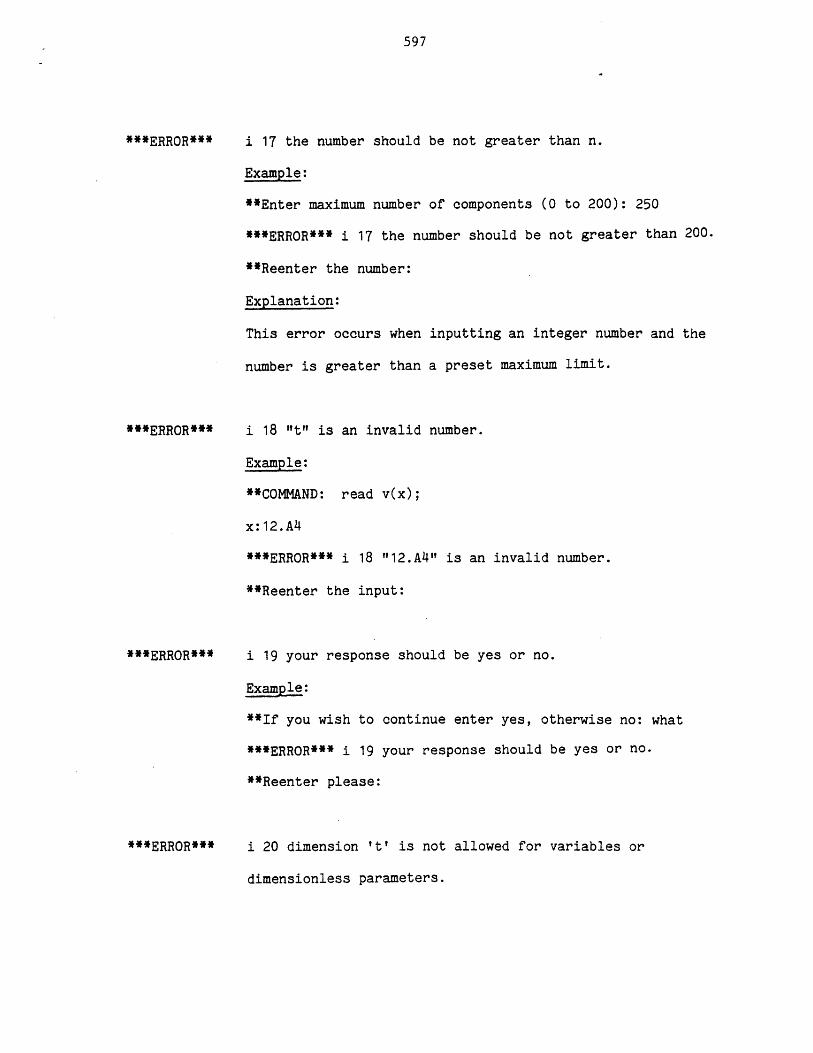
597
***ERR0R***
**ERROR***
***ERR0R***
***ERROR***
i 17 the number should be not greater than n.
Example:
**Enter maximum number of components (0 to 200): 250
***ERROR*** i 17 the number should be not greater than 200.
*Reenter the number:
Explanation:
This error occurs when inputting an integer number and the
number is greater than a preset maximum limit.
i 18 "t" is an invalid number.
Example:
**C0MAND: read v(x);
x:12.A4
***ERROR*** i 18 "12.A4"? is an invalid number.
**Reenter the input:
i 19 your response should be yes or no.
Example:
**If you wish to continue enter yes, otherwise no: what
***ERROR*** i 19 your response should be yes or no.
**Reenter please:
i 20 dimension It' is not allowed for variables or
dimensionless parameters.
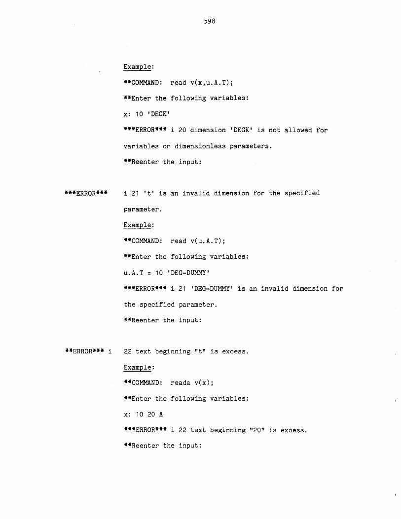
598
Example:
**COMMAND: read v(x,u.A.T);
**Enter the following variables:
x: 10 IDEGK'
***ERROR*** i 20 dimension tDEGK' is not allowed for
variables or dimensionless parameters.
**Reenter the input:
***ERROR***
**ERROR*** i
i 21 It' is an invalid dimension for the specified
parameter.
Example:
**COMMAND: read v(u.A.T);
**Enter the following variables:
u.A.T = 10 'DEG-DUMMY'
***ERR0R*** i 21 'DEG-DUMMY' is an invalid dimension for
the specified parameter.
**Reenter the input:
22 text beginning "t" is excess.
Example:
**COMMAND: reada v(x);
**Enter the following variables:
x: 10 20 A
***ERR0R*** i 22 text beginning "20" is excess.
**Reenter the input:
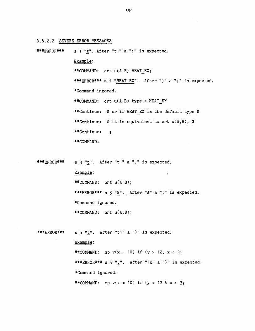
599
D.6.2.2 SEVERE ERROR MESSAGES
***ERROR*** s 1 "t". After "t1" a "1;"1 is expected.
Example:
**COMMAND: crt u(A,B) HEATEX;
***ERROR*** s i "HEAT EX"1. After ")" a "?;"t is expected.
*Command ingored.
**COMMAND: crt u(A,B) type = HEATEX
**Continue: $ or if HEATEX is the default type $
**Continue: $ it is equivalent to crt u(A,B); $
**Continue:
**COMMAND:
***ERROR***
***ERROR***
s 3 "t". After "It1" a "," is expected.
Example:
**COMMAND: crt u(A B);
***ERROR*** s 3 "1B". After "A" a "," is expected.
*Command ignored.
**COMMAND: crt u(A,B);
s 5 "t". After "t1" a "1)" is expected.
Example:
**COMMAND: sp v(x = 10) if (y > 12, x < 3;
***ERROR*** s 5 "" After "12" a ")" is expected.
*Command ignored.
**COMMAND: sp v(x 10) if (y > 12 & x < 3;
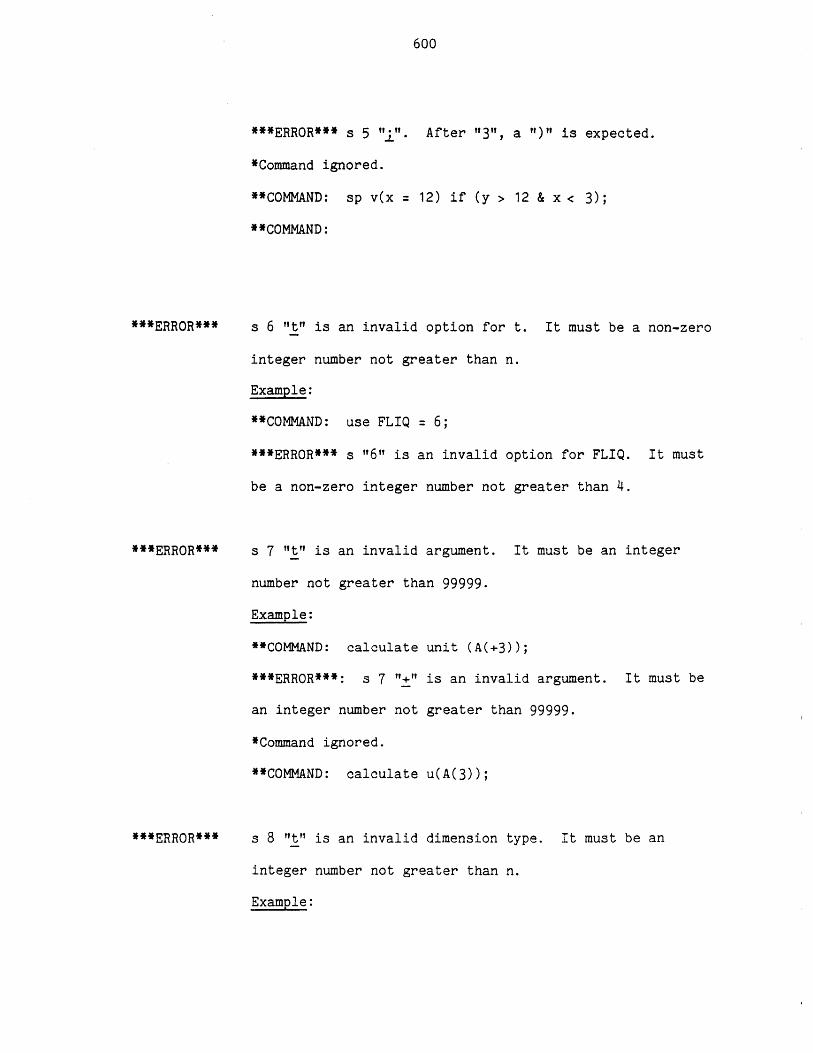
600
***ERROR*** s 5 ";". After "3", a ")" is expected.
*Command ignored.
**COMMAND: sp v(x = 12) if (y > 12 & x < 3);
**COMMAND:
***ERROR***
***ERROR***
s 6 "t" is an invalid option for t. It must be a non-zero
integer number not greater than n.
Example:
**COMMAND: use FLIQ = 6;
***ERROR*** s "16"1 is an invalid option for FLIQ. It must
be a non-zero integer number not greater than 4.
s 7 "It" is an invalid argument. It must be an integer
number not greater than 99999.
Example:
**COMMAND: calculate unit (A(+3));
***ERROR***: s 7 "+" is an invalid argument. It must be
an integer number not greater than 99999.
*Command ignored.
**COMMAND: calculate u(A(3));
s 8 "t" is an invalid dimension type. It must be an
integer number not greater than n.
Example:
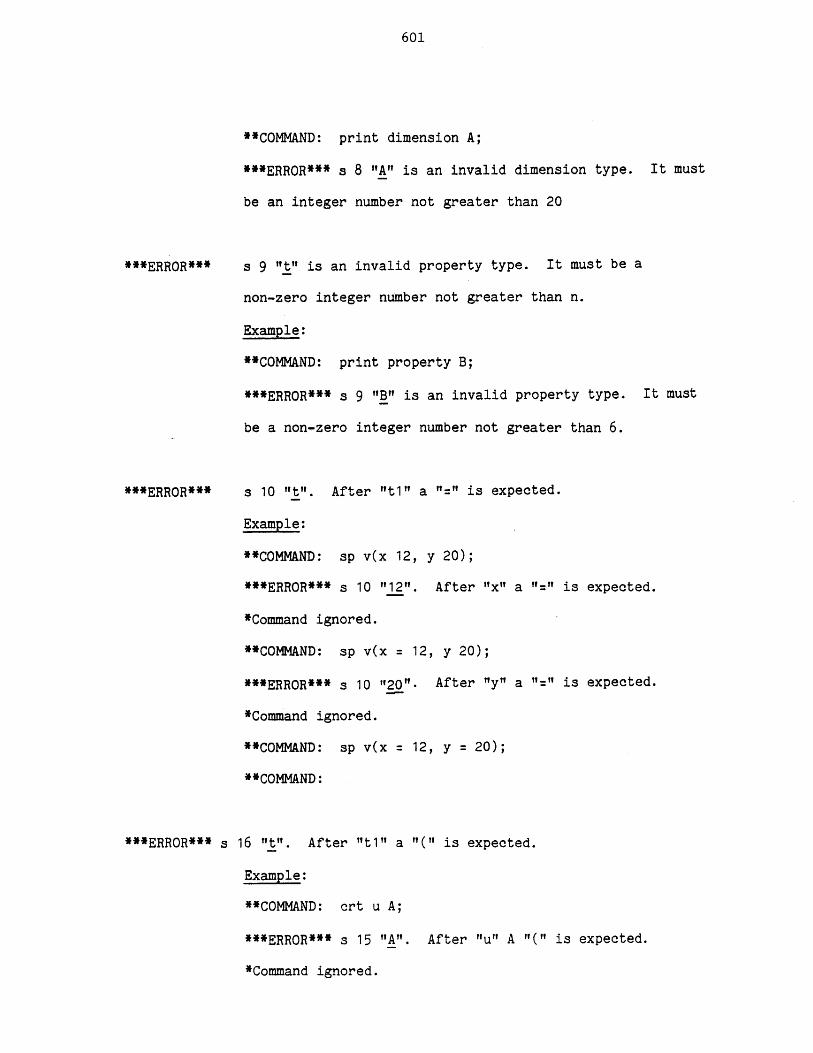
601
**COMMAND: print dimension A;
***ERR0R*** s 8 "A" is an invalid dimension type. It must
be an integer number not greater than 20
***ERROR***
**ERROR***
***ERROR*** s
s 9 "t" is an invalid property type. It must be a
non-zero integer number not greater than n.
Example:
**COMMAND: print property B;
***ERROR*** s 9 "B" is an invalid property type. It must
be a non-zero integer number not greater than 6.
s 10 "t". After "t1" a "=" is expected.
Example:
**COMAND: sp v(x 12, y 20);
***ERROR*** s 10 "12". After "x" a "=" is expected.
*Command ignored.
**COMMAND: sp v(x = 12, y 20);
***ERROR*** s 10 "20". After "y" a "=" is expected.
*Command ignored.
**COMMAND: sp v(x = 12, y = 20);
**COMMAND:
16 "t". After "t1" a "(" is expected.
Example:
**COMMAND: crt u A;
***ERROR*** s 15 "A". After "u" A "(" is expected.
*Command ignored.
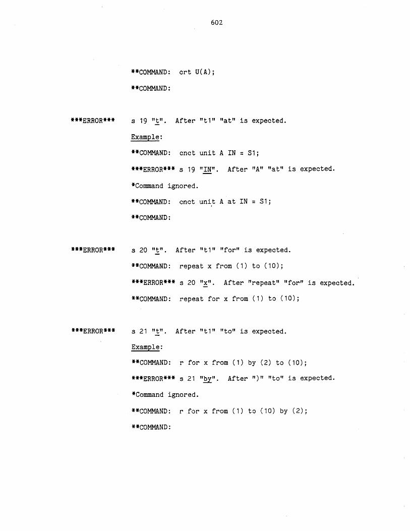
602
**COMMAND: crt U(A);
**COMMAND:
***ERROR***
***ERROR***
***ERROR***
s 19 "t". After "t1" "at" is expected.
Example:
**COMMAND: cnct unit A IN = S1;
***ERROR*** s 19 "IN". After "A" "at" is expected.
*Command ignored.
**COMMAND: cnct unit A at IN = Si;
**COMMAND:
s 20 "t". After "t1" "for" is expected.
**COMMAND: repeat x from (1) to (10);
***ERROR*** s 20 "x". After "repeat" "for" is expected.
**COMMAND: repeat for x from (1) to (10);
s 21 "t". After "t1" "to" is expected.
Example:
**COMMAND: r for x from (1) by (2) to (10);
***ERROR*** s 21 "by". After ")" "to" is expected.
*Command ignored.
**COMMAND: r for x from (1) to (10) by (2);
**COMMAND:
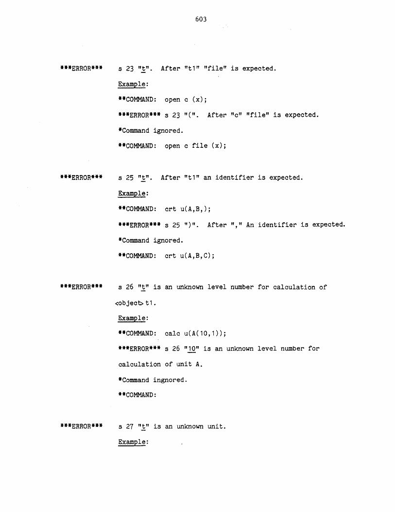
603
***ERROR***
***ERROR***
***ERROR***
***ERROR***
s 23 It". After "t1" "file" is expected.
Example:
**COMMAND: open c (x);
***ERROR*** s 23 T(". After "c"l "file" is expected.
*Command ignored.
**COMMAND: open c file (x);
s 25 "t". After "t1" an identifier is expected.
Example:
**COMMAND: crt u(A,B,);
***ERROR*** s 25 ")". After ","1 An identifier is expected.
*Command ignored.
**COMMAND: crt u(A,B,C);
s 26 "t" is an unknown level number for calculation of
<object> t.
Example:
**COMMAND: calc u(A(10,1));
***ERROR*** s 26 "10" is an unknown level number for
calculation of unit A.
*Command ingnored.
**COMMAND:
s 27 "t" is an unknown unit.
Example: ,
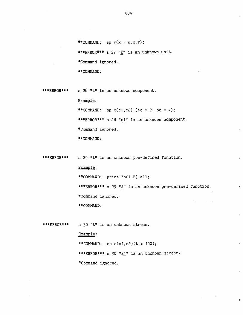
604
**COMMAND: sp v(x = u.E.T);
***ERROR*** s 27 "E" is an unknown unit.
*Command ignored.
**COMMAND:
***ERROR***
***ERROR***
s 28 "It" is an unknown component.
Example:
**COMMAND: sp c(cl,c2) (tc = 2, pc = 4);
***ERROR*** s 28 "el1" is an unknown component.
*Command ignored.
**COMMAND:
s 29 "t" is an unknown pre-defined function.
Example:
**COMMAND: print fn(A,B) all;
***ERROR*** s 29 "A" is an unknown pre-defined function.
*Command ignored.
**COMMAND:
s 30 "t" is an unknown stream.
Example:
**COMMAND: sp s(sl,s2)(t = 100);
***ERROR*** s 30 "s1" is an unknown stream.
*Command ignored.
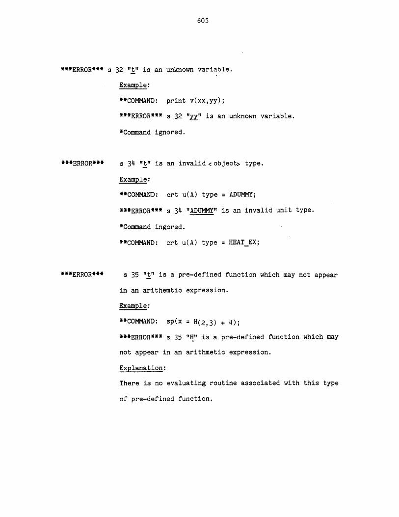
605
***ERROR*** s
**ERROR***
***ERROR***
32 It" is an unknown variable.
Example:
**COMMAND: print v(xx,yy);
***ERROR*** s 32 "IZ" is an unknown variable.
*Command ignored.
s 34 "It" is an invalid <object> type.
Example:
**COMMAND: crt u(A) type = ADUMMY;
***ERROR*** s 34 "ADUMMY" is an invalid unit type.
*Command ingored.
**COMMAND: crt u(A) type = HEATEX;
s 35 "t" is a pre-defined function which may not appear
in an arithemtic expression.
Example:
**COMMAND: sp(x = H(2,3) + 4);
***ERR0R*** s 35 "H" is a pre-defined function which may
not appear in an arithmetic expression.
Explanation:
There is no evaluating routine associated with this type
of pre-defined function.
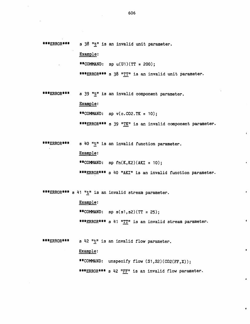
606
***ERROR*** s 38 "ti is an invalid unit parameter.
Example:
**COMMAND:
***ERROR***
sp u(Ul)(TT = 200);
s 38 "TT" is an invalid unit parameter.
***ERROR***
***ERROR***
***ERROR*** s
***ERROR***
s 39 "t" is
Example:
**COMMAND:
***ERROR***
s 40 't" is
Example:
**COMMAND:
***ERROR***
41 "t" is an
Example:
**COMMAND:
***ERROR***
s 42 "t" is
Example:
**COMMAND:
***ERROR***
an invalid component parameter.
sp v(c.C02.TK = 10);
s 39 "TK" is an invalid component parameter.
an invalid function parameter.
sp fn(K,K2)(AKI = 10);
s 40 "AKI" is an invalid function parameter.
invalid stream parameter.
sp s(sl,s2)(TT = 25);
s 41 "TT" is an invalid stream parameter.
an invalid flow parameter.
unspecify flow (S1,S2)(CO2(FF,X));
s 42 "FF" is an invalid flow parameter.
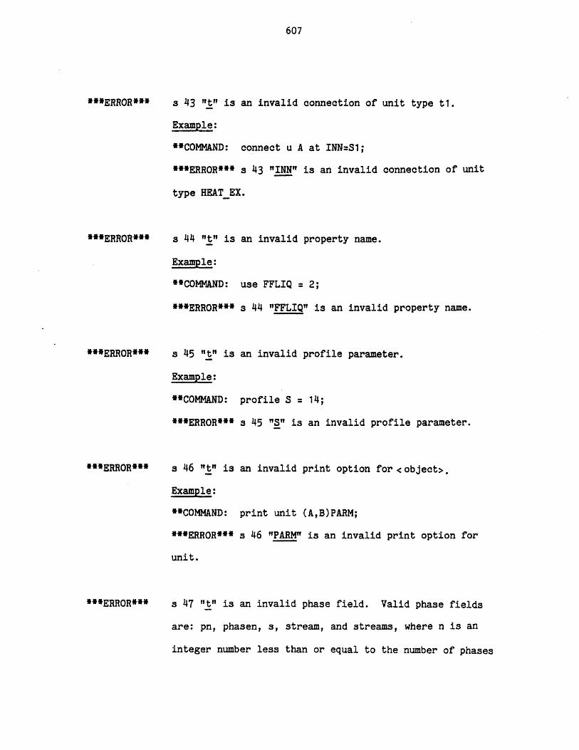
607
**ERROR*"
"*ERROR*"
"*ERROR*"
***ERROR*"
*"ERROR"*
s 43 "t" is an invalid connection of unit type ti.
Example:
"COMMAND: connect u A at INN=S1;
**ERROR*** s 43 "INN" is an invalid connection of unit
type HEATEX.
s 44 "t" is an invalid property name.
Example:
"COMMAND: use FFLIQ = 2;
"*ERROR*" s 44 "FFLIQ" is an invalid property name.
s 45 "t" is an invalid profile parameter.
Example:
"COMMAND: profile S = 14;
*"ERROR*** s 45 "S" is an invalid profile parameter.
s 46 "t" is an invalid print option for <object>.
Example:
**COMMAND: print unit (A,B)PARM;
*"ERROR* s 46 "PARM" is an invalid print option for
unit.
s 47 "t" is an invalid phase field. Valid phase fields
are: pn, phasen, s, stream, and streams, where n is an
integer number less than or equal to the number of phases
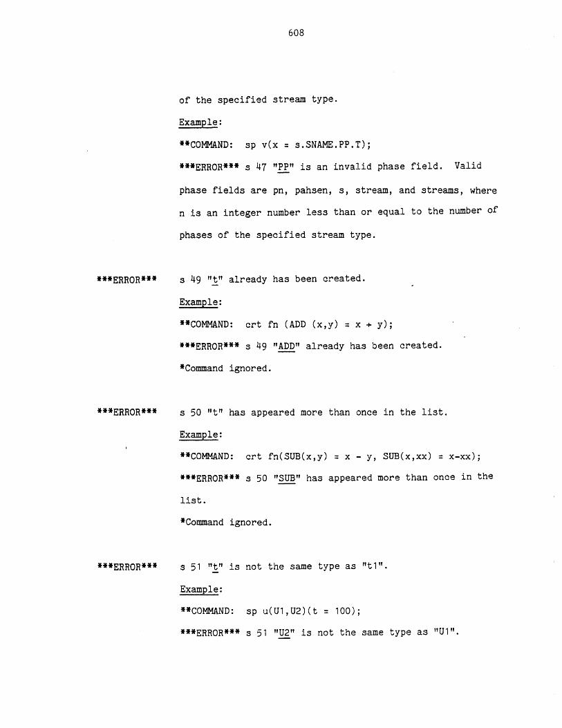
608
of the specified stream type.
Example:
**COMMAND: sp v(x = s.SNAME.PP.T);
***ERROR*** s 47 "PP" is an invalid phase field. Valid
phase fields are pn, pahsen, s, stream, and streams, where
n is an integer number less than or equal to the number of
phases of the specified stream type.
***ERROR***
***ERROR***
***ERROR***
s 49 't" already has been created.
Example:
**COMMAND: crt fn (ADD (x,y) = x + y);
***ERROR*** s 49 "ADD" already has been created.
*Command ignored.
s 50 "t" has appeared more than once in the list.
Example:
**COMMAND: crt fn(SUB(x,y) = x - y, SUB(x,xx) = x-xx);
***ERROR*** s 50 "SUB" has appeared more than once in the
list.
*Command ignored.
s 51 "t" is not the same type as "t1i".
Example:
**COMMAND: sp u(U1,U2)(t = 100);
***ERROR*** s 51 "U2" is not the same type as "U1".
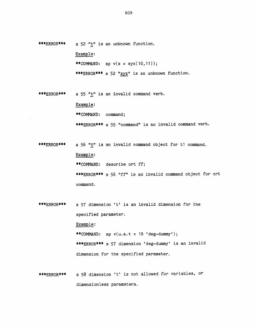
609
***ERROR***
***ERROR***
***ERROR***
***ERROR***
***ERROR***
s 52 "t" is an unknown function.
Example:
**COMMAND: sp v(x = xyz(10,11));
***ERROR*** s 52 "xyz" is an unknown function.
s 55 "t" is an invalid command verb.
Example:
**COMMAND: command;
***ERROR*** s 55 "command" is an invalid command verb.
s 56 "t" is an invalid command object for t1 command.
Example:
**COMMAND: describe crt ff;
***ERROR*** s 56 "ff" is an invalid command object for crt
command.
s 57 dimension 't' is an invalid dimension for the
specified parameter.
Example:
**COMMAND: sp v(u.a.t = 10 'deg-dummy');
***ERROR*** s 57 dimension 'deg-dummy' is an invalid
dimension for the specified parameter.
s 58 dimension 't' is not allowed for variables, or
dimensionless parameters.
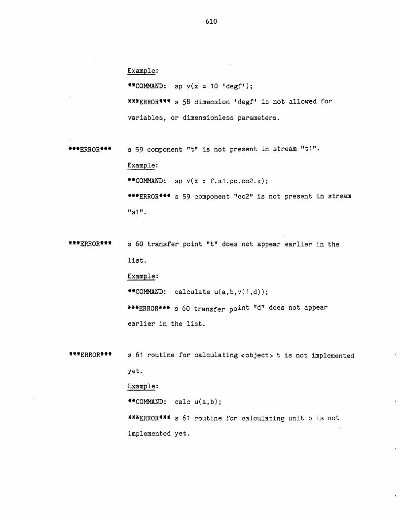
610
Example:
**COMMAND: sp v(x = 10 'degf');
***ERR0R*** s 58 dimension ?degf? is not allowed for
variables, or dimensionless parameters.
***ERROR***
***ERROR***
***ERROR***
s 59 component "t" is not present in stream "t1".
Example:
**COMMAND: sp v(x = f.sl.po.co2.x);
***ERROR*** s 59 component "co2" is not present in stream
"s 1?.
s 60 transfer point "t" does not appear earlier in the
list.
Example:
**COMMAND: calculate u(a,b,v(1,d));
***ERROR*** s 60 transfer point "d" does not appear
earlier in the list.
s 61 routine for calculating <object> t is not implemented
yet.
Example:
**COMMAND: calc u(a,b);
***ERR0R*** s 61 routine for calculating unit b is not
implemented yet.
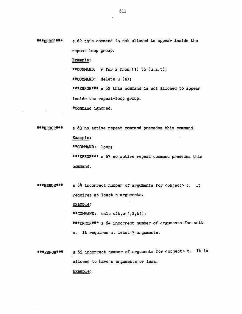
611
***ERROR***
***ERROR***
**ERROR***
**ERROR***
a 62 this command is not allowed to appear inside the
repeat-loop group.
Example:
*COMMAND: r for x from (1) to (u.a.t);
**COMMAND: delete u (a);
***ERROR*** s 62 this command is not allowed to appear
inside the repeat-loop group.
*Command ignored.
a 63 no active repeat command precedes this command.
Example:
**CONMAND: loop;
***ERROR*** s 63 no active repeat command precedes this
command.
a 64 incorrect number of arguments for <object> t. It
requires at least n arguments.
Example:
**COMMAND: calc u(b,c(1,2,b));
***ERROR*** s 64 incorrect number of arguments for unit
c. It requires at least 3 arguments.
s 65 incorrect number of arguments for <object> t. It is
allowed to have n arguments or less.
Example:
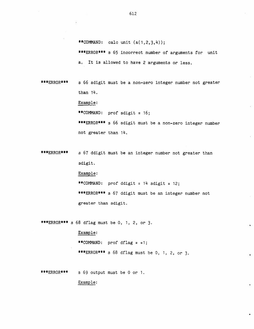
612
**COMMAND: calc unit (a(1,2,3,4));
***ERROR*** s 65 incorrect number of arguments for unit
a. It is allowed to have 2 arguments or less.
***ERROR***
***ERROR***
***ERROR*** s
***ERROR***
s 66 sdigit must be a non-zero integer number not greater
than 14.
Example:
**CONMAND: prof sdigit = 16;
***ERROR*** s 66 sdigit must be a non-zero integer number
not greater than 14.
s 67 ddigit must be an integer number not greater than
sdigit.
Example:
**COMMAND: prof ddigit = 14 sdigit = 12;
***ERROR*** s 67 ddigit must be an integer number not
greater than sdigit.
68 dflag must be 0, 1, 2, or 3.
Example:
**COMMAND: prof dflag = +1;
***ERROR*** s 68 dflag must be 0, 1, 2, or 3.
s 69 output must be 0 or 1.
Example:
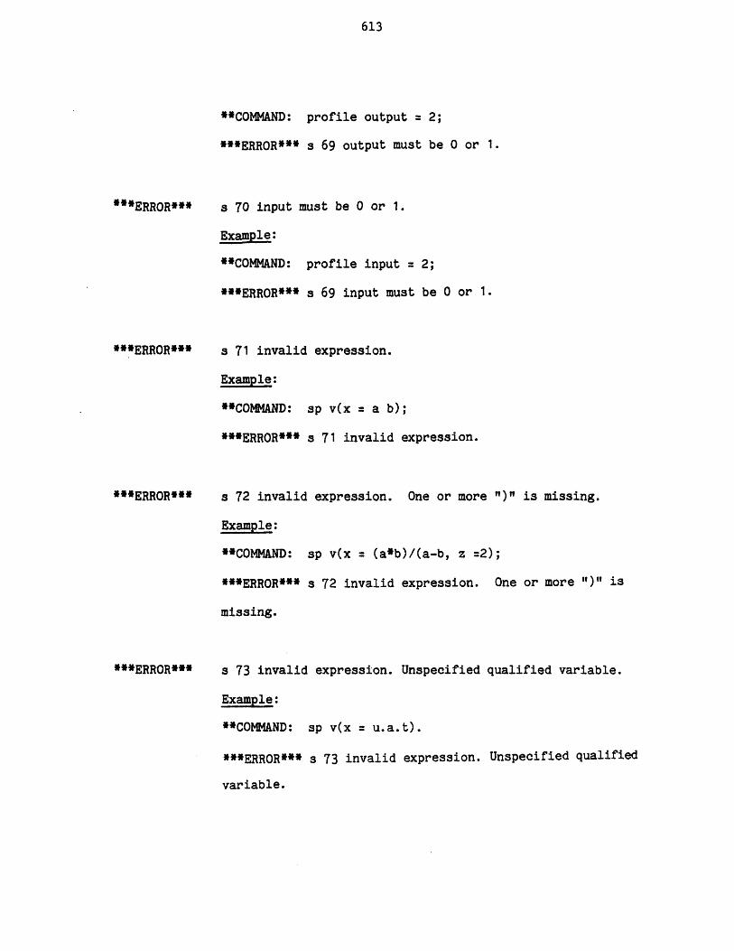
613
**COMMAND: profile output = 2;
***ERROR*** s 69 output must be 0 or 1.
***ERROR***
***ERROR***
***ERROR***
***ERROR***
a 70 input must be 0 or 1.
Example:
"COMMAND: profile input = 2;
***ERROR*** s 69 input must be 0 or 1.
a 71 invalid expression.
Example:
**COMMAND: sp v(x = a b);
***ERROR*** s 71 invalid expression.
s 72 invalid expression. One or more ")" is missing.
Example:
**COMMAND: sp v(x = (a*b)/(a-b, z =2);
***ERROR*** s 72 invalid expression. One or more ")"1 is
missing.
s 73 invalid expression. Unspecified qualified variable.
Example:
**COMAND: sp v(x = u.a.t).
***ERROR*** s 73 invalid expression. Unspecified qualified
variable.

614
"'ERROR***
**ERROR***
"*ERROR***
s 74 invalid expression. Wrong number of arguments for
function "t".
Example:
**COMMAND: crt fn(xyz(xl,x2) = x1 + x2);
**COMMAND: sp v(x = xyz(1,2,3) + 4.2);
***ERROR*** s 74 invalid expression. Wrong number of
arguments for function "xyz".
s 75 no< object> type exists.
Example:
**COMMAND: crt fn(wxyz);
***ERROR*** s 75 no function type exists.
Explanation:
The above command requests that a pre-defined function of
type wxyz be created. And since there is no pre-defined
function type the above error message has resulted.
s 76 number of specified parameters in "all" option
exceeds the number of parameters, or excess ",".
Example:
**COMMAND: sp u(A) (all = 1,2,3,4,5,6);
***ERROR*** s 76 number of specified parameters in "all"
option exceeds the number of parameters or excess ",".
Explanation:
Unit A has only 4 parameters while 6 parameters have been
specified in all option.
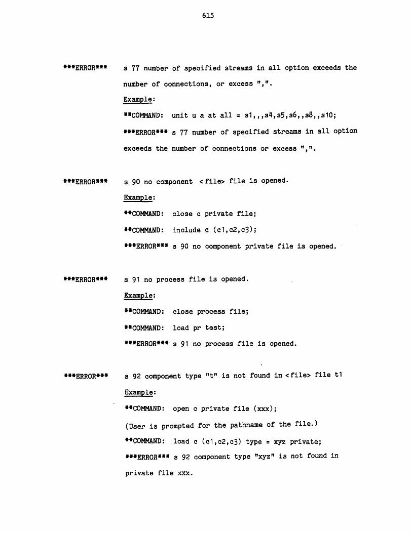
615
"*ERROR*"
*'ERROR"*
**ERROR***
**ERROR"*
s 77 number of specified streams in all option exceeds the
number of connections, or excess ",
Example:
"COMMAND: unit u a at all = s1,,,s4,s5,s6,,s8,,S10;
**ERROR*" s 77 number of specified streams in all option
exceeds the number of connections or excess "
s 90 no component <file> file is opened.
Example:
"COMMAND: close c private file;
"COMMAND: include c (c1,c2,c3);
"*ERROR*" s 90 no component private file is opened.
s 91 no process file is opened.
Example:
"COMMAND: close process file;
"COMMAND: load pr test;
***ERROR*** s 91 no process file is opened.
s 92 component type "t" is not found in <file> file t1
Example:
"COMMAND: open c private file (xxx);
(User is prompted for the pathname of the file.)
"COMMAND: load c (cl,c2,c3) type = xyz private;
"*ERROR** s 92 component type "xyz" is not found in
private file xxx.
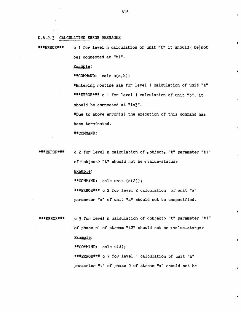
616
D.6.2.3 CALCULATING ERROR MESSAGES
***ERROR*** c 1 for level n calculation of unit "t" it should{ benot
be} connected at "ti".
Example:
**COMMAND: calc u(a,b);
*Entering routine aaa for level 1 calculation of unit "a"
***ERROR*** c 1 for level 1 calculation of unit "b", it
should be connected at "in3".
*Due to above error(s) the execution of this command has
been terminated.
**COMMAND:
***ERROR***
***ERROR***
c 2 for level n calculation of <object> "t" parameter "ti"
of <object> "t" should not be <value-status>
Example:
**COMMAND: calc unit (a(2));
***ERROR*** c 2 for level 2 calculation of unit "a"
parameter "x" of unit "a" should not be unspecified.
.c 3,for level n calculation of <object> "t" parameter "ti"
of phase n1 of stream "t2" should not be <value-status>
Example:
**COMMAND: calc u(A);
***ERROR*** c 3 for level 1 calculation of unit "a"
parameter "t" of phase 0 of stream "x" should not be

617
specified.
Explanation:
Stream "x" is connected to unit A and parameter "It" of the
stream is output of the unit calculation.
**ERROR***
**ERROR***
c 4 for level n calculation of< object >"t" flow parameter
"t1" of component "t2" in phase n1 of stream "t3" should
not be <value-status>
Example:
**COMMAND: calc u(A);
***ERROR*** c 4 for level 1 calculation of unit "a" flow
parameter "f" of component "nc4" in phase-O of stream "x"
should not be unspecified.
***ERROR*** c 4 for level 1 calculation of unit "a" flow
parameter "f" of component "nc5" in phase 0 of stream "x"
should not be unspecified.
*Due to above error(s) the execution of this command has
been terminated.
**COMMAND:
c 5 for level n calculation of <object> "t" parameter "t1"
of component "tt2I should not be <value-status>
Example:
**COMMAND: calc unit (b);
***ERROR*** c 5 for level 1 calculation of unit "b"
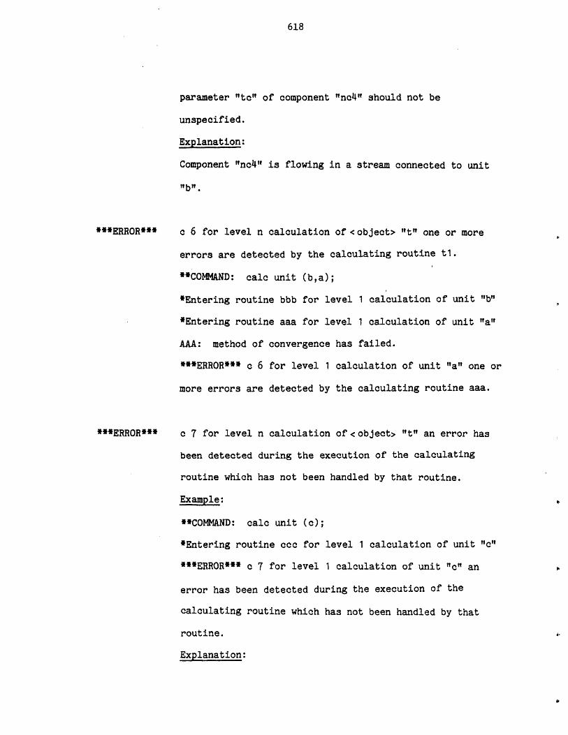
618
parameter "to" of component "nc4" should not be
unspecified.
Explanation:
Component "nc4l" is flowing in a stream connected to unit
"lb".
**ERROR***
***ERROR***
c 6 for level n calculation of <object> "t" one or more
errors are detected by the calculating routine t1.
*COMMAND: calc unit (b,a);
*Entering routine bbb for level 1 calculation of unit "b"
*Entering routine aaa for level 1 calculation of unit "a"
AAA: method of convergence has failed.
***ERROR*** c 6 for level 1 calculation of unit "a" one or
more errors are detected by the calculating routine aaa.
c 7 for level n calculation of <object> "t" an error has
been detected during the execution of the calculating
routine which has not been handled by that routine.
Example:
**COMMAND: calc unit (c);
*Entering routine ccc for level 1 calculation of unit "c"
***ERROR*** c 7 for level 1 calculation of unit "c" an
error has been detected during the execution of the
calculating routine which has not been handled by that
routine.
Explanation:
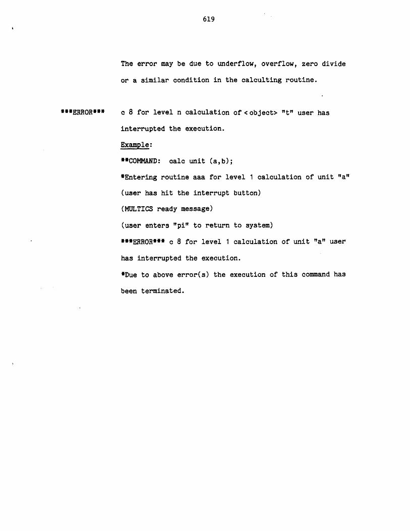
619
The error may be due to underflow, overflow, zero divide
or a similar condition in the calculting routine.
***ERROR*** c 8 for level n calculation of <object> 't" user has
interrupted the execution.
Example:
**COMMAND: calc unit (a,b);
*Entering routine aaa for level 1 calculation of unit "a"
(user has hit the interrupt button)
(MULTICS ready message)
(user enters "pi" to return to system)
***ERROR*** c 8 for level 1 calculation of unit "a" user
has interrupted the execution.
*Due to above error(s) the execution of this command has
been terminated.
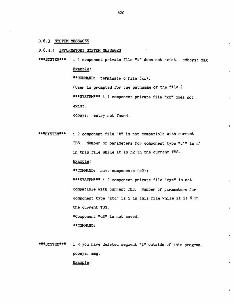
620
D.6.3 SYSTEM MESSAGES
D.6.3.1 INFORMATORY SYSTEM MESSAGES
***SYSTEM*** i 1 component private file "It" does not exist. cdbsys: msg
Example:
**COMMAND: terminate c file (xx).
(User is prompted for the pathname of the file.)
***SYSTEM*** i 1 component private file "xx" does not
exist.
cdbsys: entry not found.
***SYSTEM*** i 2 component file "t" is not compatible with current
TBS. Number of parameters for component type "t1" is n1
in this file while it is n2 in the current TBS.
Example:
**COMNMAND: save components (c2);
***SYSTEM*** i 2 component private file "xyz" is not
compatible with current TBS. Number of parameters for
component type "std" is 5 in this file while it is 6 in
the current TBS.
*Component "c2" is not saved.
**COMMAND:
***SYSTEM*** i 3 you have deleted segment "t" outside of this program.
pobsys: msg.
Example:
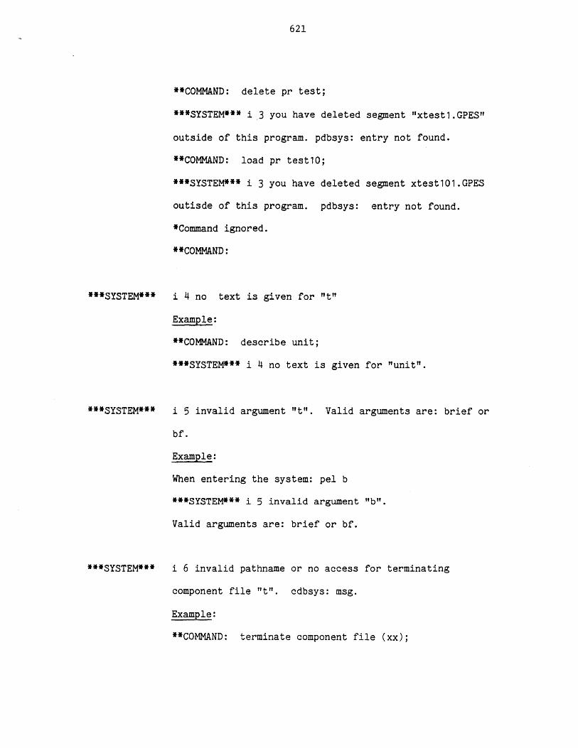
621
**COMMAND: delete pr test;
***SYSTEM*** i 3 you have deleted segment "xtest1.GPES"
outside of this program. pdbsys: entry not found.
**COMMAND: load pr test10;
***SYSTEM*** i 3 you have deleted segment xtest101.GPES
outisde of this program. pdbsys: entry not found.
*Command ignored.
**COMMAND:
***SYSTEM***
***SYSTEM***
***SYSTEM***
i 4 no text is given for "t"
Example:
**COMMAND: describe unit;
***SYSTEM*** i 4 no text is given for "unit".
i 5 invalid argument "t". Valid arguments are: brief or
bf.
Example:
When entering the system: pel b
***SYSTEM*** i 5 invalid argument "b".
Valid arguments are: brief or bf.
i 6 invalid pathname or no access for terminating
component file "t". cdbsys: msg.
Example:
**COMMAND: terminate component file (xx);
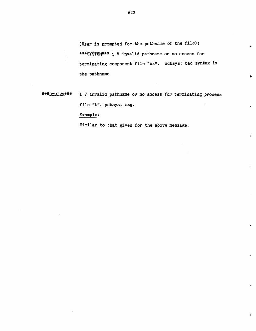
622
(User is prompted for the pathname of the file);
***SYSTEM*** i 6 invalid pathname or no access for
terminating component file "xx"t. cdbsys: bad syntax in
the pathname
**SYSTEM*** i 7 invalid pathname or no access for terminating process
file "t". pdbsys: msg.
Example:
Similar to that given for the above message.
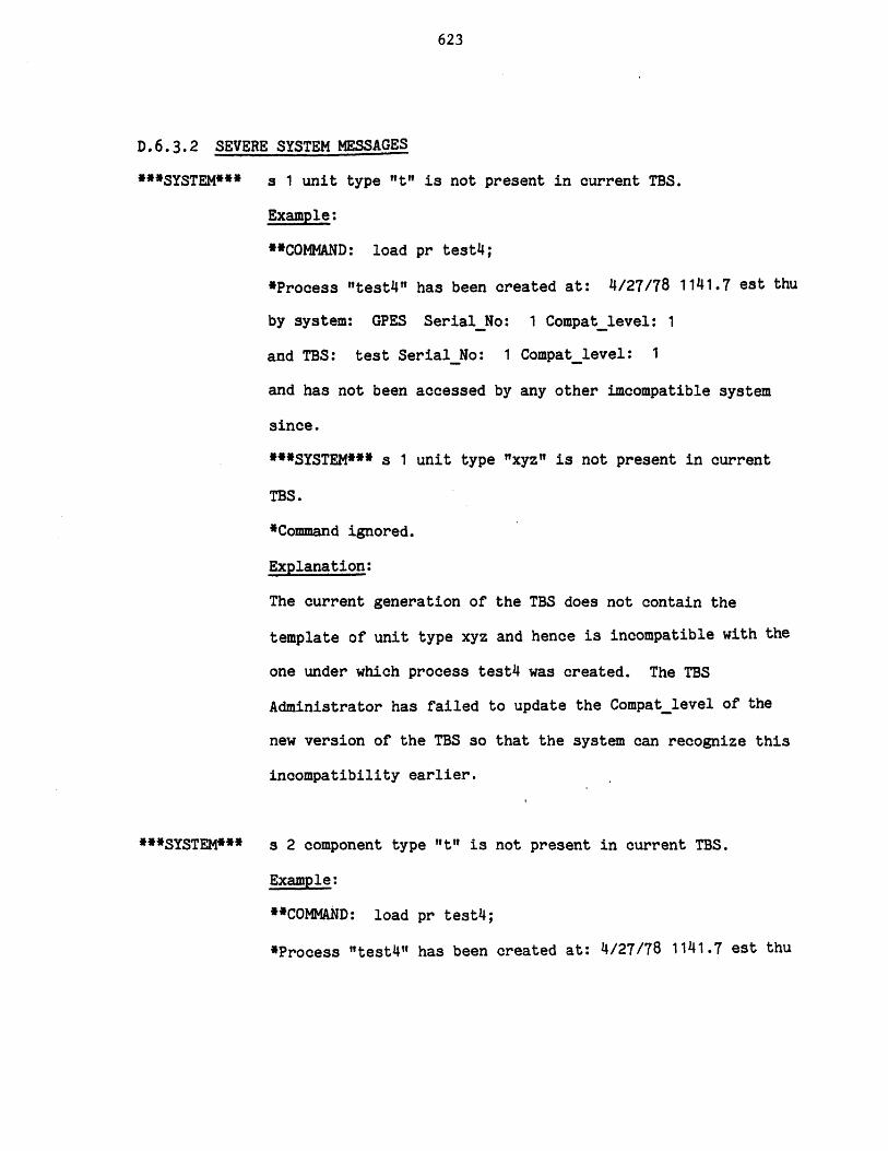
623
D.6.3.2 SEVERE SYSTEM MESSAGES
"*SYSTEM* s 1 unit type "t" is not present in current TBS.
Example:
**COMMAND: load pr test4;
*Process "test4" has been created at: 4/27/78 1141.7 est thu
by system: GPES SerialNo: 1 Compatlevel: 1
and TBS: test Serial No: 1 Compat-level: 1
and has not been accessed by any other imcompatible system
since.
**SYSTEM"* s 1 unit type "xyz"' is not present in current
TBS.
*Command ignored.
Explanation:
The current generation of the TBS does not contain the
template of unit type xyz and hence is incompatible with the
one under which process test4 was created. The TBS
Administrator has failed to update the Compatlevel of the
new version of the TBS so that the system can recognize this
incompatibility earlier.
***SYSTEM*** s 2 component type "t" is not present in current TBS.
Example:
**COMMAND: load pr test4;
*Process "test4l" has been created at: 4/27/78 1141.7 est thu
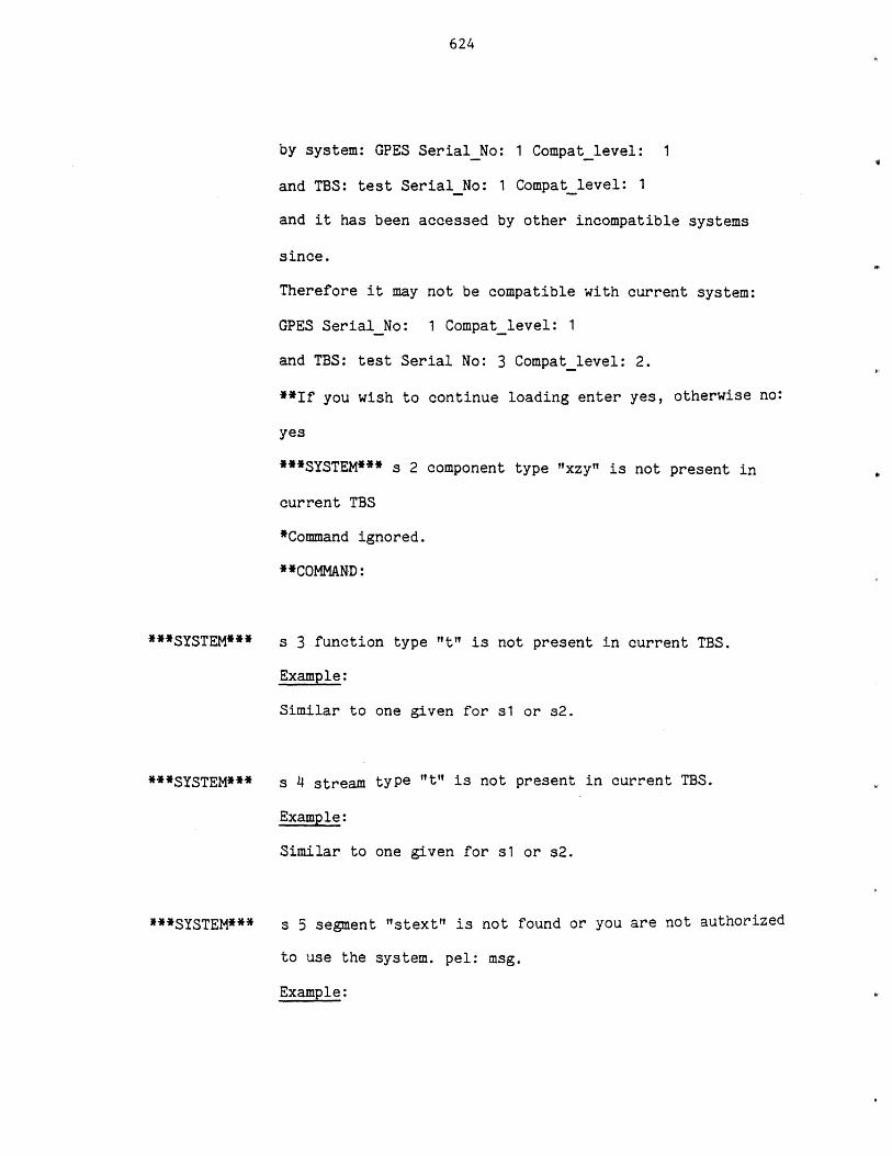
624
by system: GPES SerialNo: 1 Compatlevel: 1
and TBS: test SerialNo: 1 Compatlevel: 1
and it has been accessed by other incompatible systems
since.
Therefore it may not be compatible with current system:
GPES SerialNo: 1 Compatlevel: 1
and TBS: test Serial No: 3 Compat level: 2.
**If you wish to continue loading enter yes, otherwise no:
yes
***SYSTEM*** s 2 component type "xzy" is not present in
current TBS
*Command ignored.
**COMMAND:
***SYSTEM***
***SYSTEM***
***SYSTEM***
s 3 function type "t" is not present in current TBS.
Example:
Similar to one given for s1 or s2.
s 4 stream type "t" is not present in current TBS.
Example:
Similar to one given for s1 or s2.
s 5 segment "stext" is not found or you are not authorized
to use the system. pel: msg.
Example:

625
This message may be produced at the beginning of the
session: pel brief
***SYSTEM*** s 5 segment "stext" is not found or you are
not authorized to use the system. pel: entry not found.
*If you are an authorized user contact the GPES system
administrator. Goodbye now!
s 6 segment "t" is not found ormyou are not authorized to
use this TBS. pel: msg.
Example:
*Beginning of attachment process.
**Enter the name of the TBS you wish to use now: xyz
***SYSTEM*** s 6 segment "ctl info.syscopy" is not found
or you are not authorized to use this TBS. pel: entry
not found.
**If you desire another TBS enter yes, otherwise no: yes
**Enter the name of the TBS you wish to use now:
User response:
If the user is an authorized user of the TBS, he should
contact its system administrator.
s 7 routine "t" which calculates <object> "t1" is not
found or you are not authorized to use it. pel: msg.
Example:
**COMAND: calculate u(a);
*SYSTEM***
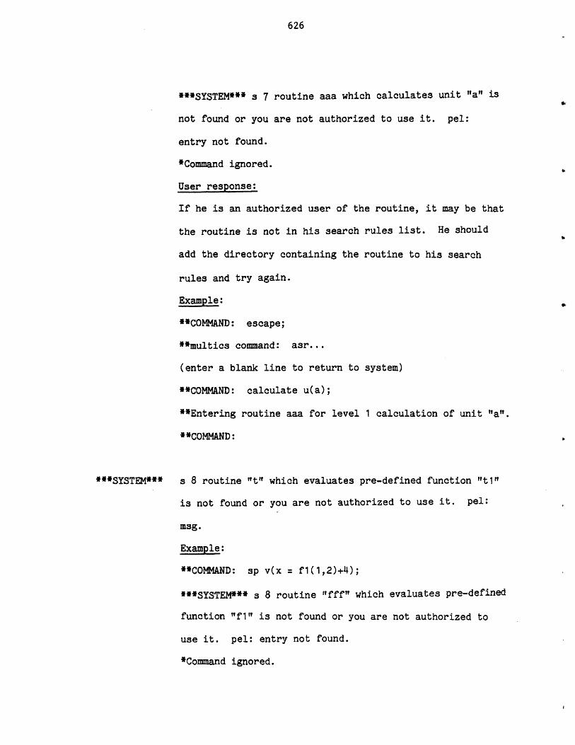
626
***SYSTEM*** s 7 routine aaa which calculates unit "al is
not found or you are not authorized to use it. pel:
entry not found.
*Command ignored.
User response:
If he is an authorized user of the routine, it may be that
the routine is not in his search rules list. He should
add the directory containing the routine to his search
rules and try again.
Example:
**COMMAND: escape;
**multics command: asr...
(enter a blank line to return to system)
**COMMAND: calculate u(a);
*Entering routine aaa for level 1 calculation of unit "a".
**COMMAND:
s 8 routine "t" which evaluates pre-defined function "t1"
is not found or you are not authorized to use it. pel:
msg.
Example:
**COMMAND: sp v(x = f1(1,2)+4);
***SYSTEM*** s 8 routine "fff" which evaluates pre-defined
function "f1" is not found or you are not authorized to
use it. pel: entry not found.
*Command ignored.
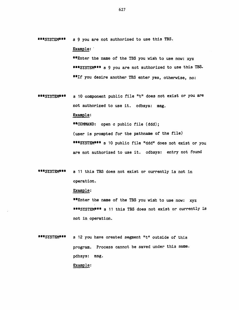
627
***SYSTEM***
***SYSTEM***
***SYSTEM***
***SYSTEM***
s 9 you are not authorized to use this TBS.
Example:'
**Enter the name of the TBS you wish to use now: xyz
***SYSTEM*** s 9 you are not authorized to use this TBS.
**If you desire another TBS enter yes, otherwise, no:
s 10 component public file "t" does not exist or you are
not authorized to use it. cdbsys: msg.
Example:
**COMMAND: open c public file (ddd);
(user is prompted for the pathname of the file)
***SYSTEM*** s 10 public file "ddd" does not exist or you
are not authorized to use it. cdbsys: entry not found
s 11 this TBS does not exist or currently is not in
operation.
Example:
**Enter the name of the TBS you wish to use now: xyz
***SYSTEM*** s 11 this TBS does not exist or currently is
not in operation.
s 12 you have created segment "t" outside of this
program. Process cannot be saved under this same.
pdbsys: msg.
Example:
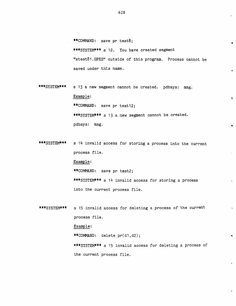
628
**COMMAND: save pr test8;
***SYSTEM*** s 12. You have created segment
"xtest81.GPES" outside of this program. Process cannot be
saved under this name.
***SYSTEM***
***SYSTEM***
***SYSTEM***
s 13 a new segment cannot be created. pdbsys: msg.
Example:
**COMMAND: save pr test12;
***SYSTEM*** s 13 a new segment cannot be created.
pdbsys: msg.
s 14 invalid access for storing a process into the current
process file.
Example:
**COMMAND: save pr test2;
***SYSTEM*** s 14 invalid access for storing a process
into the current process file.
s 15 invalid access for deleting a process of the current
process file.
Example:
**COMMAND: delete pr(dl,d2);
***SYSTEM*** s 15 invalid access for deleting a process of
the current process file.
629
***SYSTEM***
***SYSTEM***
s 16 invalid pathname or no access for opening process
file lIt".
Example:
**COMMAND: open pr file (xx);
(User is prompted for the pathname of the file)
***SYSTEM*** s 16 invalid pathname or no access for
opening process file "xx".
s 17 you have deleted segment "It" outside of this program
or you may not have the proper access for this segment.
pdbsys: msg.
Example:
**COMMAND: load pr test;
***SYSTEM*** s 17 you have deleted segment "xtest1.GPES"
outside of this program or you may not have the proper
access for this segment. pdbsys: entry not found.
s 18 invalid pathname or no access for opening component
file "t". cdbsys: msg.
Example:
*COMMAND: open c private file (x);
(User is prompted for the pathname of the file)
***SYSTEM*** s 18 invalid pathname or no access for
opening component file "x". cdbsys: bad syntax in the
pathname.
630
***SYSTEM*** s 19 invalid access for storing, deleting, copying, or
including operation on component private file t.
Example:
**COMMAND: save c (c1, c3);
***SYSTEM*** s 19 invalid access for storing, deleting,
copying, or including operation on component private file
x.

631
APPENDIX E
LITERATURE CITATIONS
1. Andrew, S.M. "Computer Flowsheeting Using Network 67: AnExample," Trans. Inst. Chem. Eng., 46 (4), T123-T132 (1968).
2. Arab-Ismaili, M.S., "A Ph.D. Proposal for Design of an InteractiveComputer System for Engineering of Chemical Processes,"Massachusetts Institute of Technology (April 1975).
3. ASPEN, "Computer-Aided Industrial Process Design," First QuarterlyProgress Report, MIT Report No. 2295T9-1 (August 1976).
4. ASPEN, "Computer-Aided Industrial Process Design," SecondQuarterly Progress Report, MIT Report No. 2295T9-2 (November 1976).
5. ASPEN, "Computer-Aided Industrial Process Design," Third QuarterlyProgress Report, MIT Report No. 2295T9-3 (February 1977).
6. ASPEN, "Computer-Aided Industrial Process Design," First AnnualReport, MIT Report No. 2295T9-4 (June 1977).
7. ASPEN, "Computer-Aided Industrial Process Design," Fifth QuarterlyProgress Report, MIT Report No. 2295T9-5 (September 1977).
8. ASPEN, "Computer-Aided Industrial Process Design," Sixth QuarterlyProgress Report, MIT Report No. 2295T9-6 (December 1977).
9. ASPEN, "Computer-Aided Industrial Process Design," Appendix I tothe Sixth Quarterly Progress Report, MIT Report No. 2295T9-7(December 1977).
10. ASPEN, "Computer-Aided Industrial Process Design," SeventhQuarterly Progress Report, MIT Report No. 2295T9-8 (April 1978).
11. Barkley, R.W. and Motard, R.L., "Decomposition of Nets," Chem.Eng. J., 3 (3), 265 (1972).
12. Barnes, J.G.P., "Network 67: A General Description," ImperialChemical Industries, Ltd., London, England (1967).
13. Batstone, D.B., Fenton, G. and Price, R.G.H., "The Steady StateDigital Simulation of Chemical Plant of Arbitrary Configuration,"Paper B2 Presented at IFAC Symposium of Digital Simulation ofContinuous Processes, GYOR, Hungary (1971).
14. Briddell, E.T., "Process Design by Computer, Part 1," Chem. Eng.,81, (3) 60 (1974a).
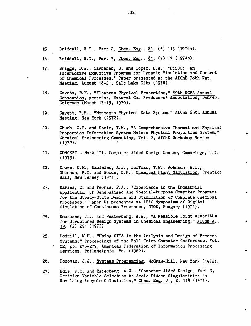
632
15. Briddell, E.T., Part 2, Chem. Eng., 81, (5) 113 (1974b).
16. Briddell, E.T., Part 3, Chem. Eng., 81, (7) 77 (1974c).
17. Briggs, D.E., Carnahan, B. and Lopez, L.A., "DYSCO: AnInteractive Exeuctive Program for Dynamic Simulation and Controlof Chemical Processes," Paper presented at the AIChE 78th Nat.Meeting, August 18-21, Salt Lake City (1974).
18. Cavett, R.H., "Flowtran Physical Properties," 49th NGPA AnnualConvention, preprint, Natural Gas Producers' Association, Denver,Colorado (March 17-19, 1970).
19. Cavett, R.H., "Monsanto Physical Data System," AIChE 65th AnnualMeeting, New York (1972).
20. Chueh, C.F. and Stein, T.W., "A Comprehensive Thermal and PhysicalProperties Information System-Halcon Physical Properties System,"Chemical Engineering Computing, Vol. 2, AIChE Workshop Series(1972).
21. CONCEPT - Mark III, Computer Aided Design Center, Cambridge, U.K.(1973).
22. Crowe, C.M., Hamielec, A.E., Hoffman, T.W., Johnson, A.I.,Shannon, P.T. and Woods, D.R., Chemical Plant Simulation, PrenticeHall, New Jersey (1971).
23. Davies, C. and Perris, F.A., "Experience in the IndustrialApplication of Generalized and Special-Purpose Computer Programsfor the Steady-State Design and Stimulation of Complete ChemicalProcesses," Paper D1 presented at IFAC Symposium of DigitalSimulation of Continuous Processes, GYOR, Hungary (1971).
24. Debrosse, C.J. and Westerberg, A.W., "A Feasible Point Algorithmfor Structured Design Systems in Chemical Engineering," AIChE J.,19, (2) 251 (1973).
25. Dodrill, W.H., "Using GIFS in the Analysis and Design of ProcessSystems," Proceedings of the Fall Joint Computer Conference, Vol.22, pp. 275-279, American Federation of Information ProcessingServices, Philadelphia, Pa. (1962).
26. Donovan, J.J., Systems Programming, McGraw-Hill, New York (1972).
27. Edie, F.C. and Esterberg, A.W., "Computer Aided Design, Part 3,Decision Variable Selection to Avoid Hidden Singularities inResulting Recycle Calculation," Chem. Eng. J., 2, 114 (1971).
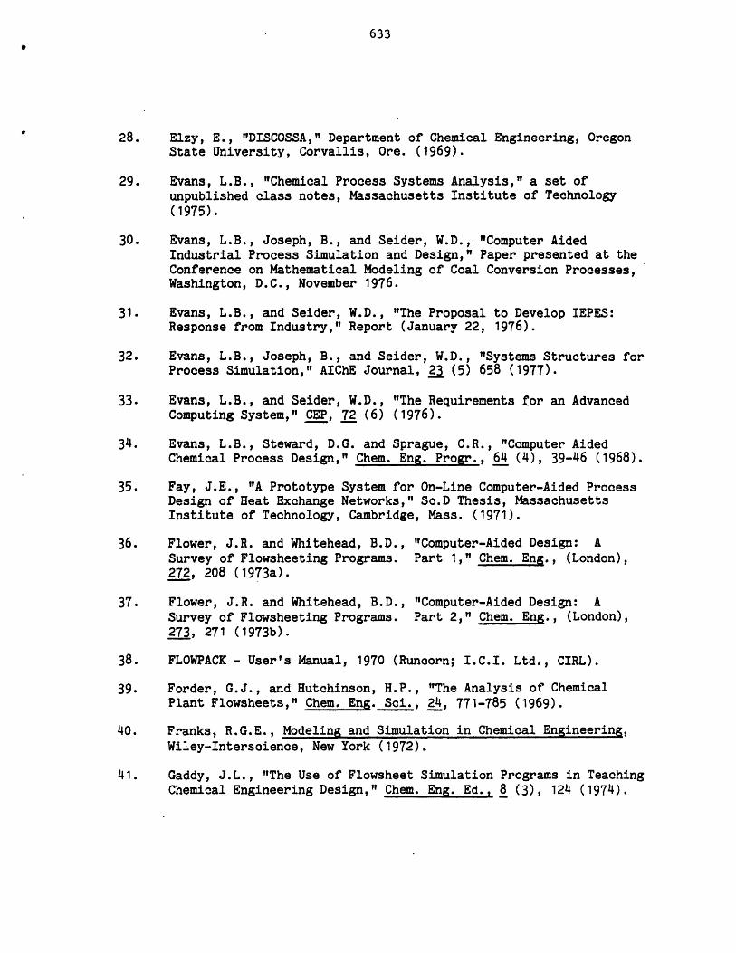
633
28. Elzy, E., "DISCOSSA," Department of Chemical Engineering, OregonState University, Corvallis, Ore. (1969).
29. Evans, L.B., "Chemical Process Systems Analysis," a set ofunpublished class notes, Massachusetts Institute of Technology(1975).
30. Evans, L.B., Joseph, B., and Seider, W.D., "Computer AidedIndustrial Process Simulation and Design," Paper presented at theConference on Mathematical Modeling of Coal Conversion Processes,Washington, D.C., November 1976.
31. Evans, L.B., and Seider, W.D., "The Proposal to Develop IEPES:Response from Industry," Report (January 22, 1976).
32. Evans, L.B., Joseph, B., and Seider, W.D., "Systems Structures forProcess Simulation," AIChE Journal, 23 (5) 658 (1977).
33. Evans, L.B., and Seider, W.D., "The Requirements for an AdvancedComputing System," CEP, 72 (6) (1976).
34. Evans, L.B., Steward, D.G. and Sprague, C.R., "Computer AidedChemical Process Design," Chem. Eng. Progr., 64 (4), 39-46 (1968).
35. Fay, J.E., "A Prototype System for On-Line Computer-Aided ProcessDesign of Heat Exchange Networks," Sc.D Thesis, MassachusettsInstitute of Technology, Cambridge, Mass. (1971).
36. Flower, J.R. and Whitehead, B.D., "Computer-Aided Design: ASurvey of Flowsheeting Programs. Part 1," Chem. Eng., (London),272, 208 (1973a).
37. Flower, J.R. and Whitehead, B.D., "Computer-Aided Design: ASurvey of Flowsheeting Programs. Part 2," Chem. Eng., (London),273, 271 (1973b).
38. FLOWPACK - User's Manual, 1970 (Runcorn; I.C.I. Ltd., CIRL).
39. Forder, G.J., and Hutchinson, H.P., "The Analysis of ChemicalPlant Flowsheets," Chem. Eng. Sci., 24, 771-785 (1969).
40. Franks, R.G.E., Modeling and Simulation in Chemical Engineering,Wiley-Interscience, New York (1972).
41. Gaddy, J.L., "The Use of Flowsheet Simulation Programs in TeachingChemical Engineering Design," Chem. Eng. Ed., 8 (3), 124 (1974).
634
42. Garcia-Gamboa, E., "Estimation of Physical Properties forCoal-Derived Liquids," M.S. Thesis, Chem. Eng. Dept, MIT (1977).
43. General Electric Company, "User's Guide, Process Design System --GEPDS (Version 2)," Information Services Department, Bethesda, Md.(1970).
44. Goodson, P.D., "The Applicability of Flowtran to Coal ConversionProcess Analysis," M.S. Thesis, University of Wisconsin (1976).
45. Gray, G.C., "Compound Data Structure for Computer-Aided Design: ASurvey," Proceedings of 22nd ACM National Meeting, Vol. 22, pp.355-367, Association for Computing Machinery,.Washington, D.C.(1967).
46. Ham, P.G., "The Transient Analysis of Integrated ChemicalProcesses," Ph.D. Dissertation, University of Pennsylvania,Philadelphia (1971).
47. Hankinson R.W. and Cantwell, K.R., "The Phillips Petroleum CompanyComputer Stored Physical Data System," Chemical EngineeringComputing, Vol. 2, AIChE Workshop Series (1972).
48. Hanyak, M.E. and Kalus, R.L., "Use of Translator Writing Systemsin the Development of Problem Oriented Languages," Paper presentedat AIChE 66th Annual Meeting, Philadelphia, Pa. (1973).
49. Henley, E.J. and Rosen, E.M., Material and Energy BalanceComputations, Wiley, New York (1969).
50. Himmelblau, D.M., Basic Principals and Caluclations in Chem Eng,3rd Ed., Prentice-Hall (1974).
51. Himmelblau, D.M., and Bischoff, K.B., Process Analysis andSimulation, John Wiley (1968).
52. Holland, C.D., Multicomponent Distillation, Prentice-Hall,Englewood.Cliffs, New Jersey (1968).
53. Honeywell Information Systems Inc., MULTICS PL/1 LanguageSpecifications, Order No. AG94 (1976).
54. Honeywell Information Systems Inc., MULTICS PL/1 Reference Manual,Order No. AM83 (1976).
55. Honeywell Information Systems Inc., MULTICS Programmers' Manual,Commands and Active Functions, Order No. AG92 (1976).
635
56. Honeywell Information Systems Inc., MULTICS Programmers' Manual,Introduction, Order No. AG90 (1973).
57. Honeywell Information Systems Inc., MULTICS Programmers' Manual,Reference Guide, Order No. AG91 (1975).
58. Honeywell Information Systems Inc., MULTICS Programmers' Manual,Subroutines, Order No. AG93 (1976).
59. Honeywell Information Systems Inc., MULTICS Programmers' Manual,Subsystem Writers' Guide, Order No. AK92 (1977).
60. Hughes, R.R., Singer, E. and Souders, M., "Machine Design ofRefineries," Sixth World Petroleum Congress, Section VII, Paper17, pp. 93-102, Frankfurt, W. Ger. (1963).
61. Hughson, R.V. and Steymann, E.H., "Computer Programs for ChemicalEngineers," Chem. Eng., 78 (14), 66 (1971).
62. Hughson, R.V. and Steymann, E.H., "Computer Programs for ChemicalEngineers, 1973, Part 1" Chem. Eng., 80 (19), 121 (1973a).
63. Hughson, R.V. and Steymann, E.H., "Computer Programs for ChemicalEngineers, 1973, Part 2" Chem. Eng., 80 (21), 127 (1973b).
64. Ingels, D.M., "A System for Simulating Chemical Process Dynamicsand Control, " Ph.D Dissertation, University of Houston (1970).
65. International Business Machines Corporation, "IBM System/360Operating System PL/1(F) Language Reference Manual," FormGC28-8201-4, IBM Corp., White Plains, New York (1972).
66. International Business Machines Corporation, "IBM System/360Operating System PL/1(F) Programmer's Guide," Form GC28-6594, IBMCorp., White Plains, New York (1972).
67. International Business Machines Corporation, "Problem LanguageAnalyzer (PLAN): Program Description Manual" TechnicalPublications Department, White Plains, New York (1969).
68. Jain, Y.V.S. and Eakman, J.M., "Identification of Process FlowNetworks," Paper presented at AIChE 69th National Meeting,Houston, Texas (1971).
69. James, J.L., Gardner, N.F., Reinhart, L.R. and Hellenack, L.J.,"Economic Design by Flexible Flowsheet Analysis," I. Chem. E.Symposium Series, Vol 18., pp. 11-18, Institution of ChemicalEngineers, London, England (1966).
636
70. Johnson, A.I., "The Modular Approach Applied to the Unsteady StateBehavior of Systems," Brit. Chem. Eng., Proc. Tech., 17 (3) 217(1972a).
71. Johnson, A.I., "Computer Aided Process Analysis and Design - AModular Approach," Brit. Chem. Eng. Proc. Tech., 17 (1) 28 (1972b).
72. Johnson, A.I., and Toong, T., "The Modular Approach to SystemAnalysis and Design," (GEMCS Manual), McMaster University (1968).
73. Johnson, A.I., and Toong, T., "GEMCS General Electric/McmasterSimulator: Information Handling Program for Analysis and Designof Engineering and Management Systems," Department of ChemicalEngineering, McMaster University, Hamilton, Ont., and CanadianGeneral Electric Company, -Toronto, Ont. (1968).
74. Joseph, B., Evans, L.B. and Seider, W.D., "The Use of PLEX DATAStructure in Process Simulation," Computers and ChemicalEngineering, Pergamon Press, to be published.
75. Kehat, E. and Shacham, M., "Chemical Process SimulationPrograms-1," Process Technol., 18 (1/2), 35 (1973a).
76. Kehat, E. and Shacham, M., "Chemical Process SimulationPrograms-2, Partitioning and Tearing System Flow Sheets" ProcessTechnol., 18 (3), 115 (1973b).
77. Kehat, E. and Shacham, M., "Chemical Process SimulationPrograms-3, Solution System of Nonlinear Equations" ProcessTechnol., 18 (4/5), 181 (1973c).
78. Kenny, L.N. and Prados, J.W., "A Generalized Digital ComputerProgram for Performing Process Material and Energy Balances,"University of Tennessee, Knoxville, Tenn. (1966).
79. Kesler, M.G. and Griffiths, P.R., "A Computer System for ProcessSimulation," Proceedings of the American Petroleum Institute,Section III, Vol. 43, pp. 49-56 (1963).
80. Kesler, M.G. and Kessler, M.M., World Petrol., 29, 60 (1958).
81. Kevorkian, A.K. and Snoek, J., "Decomposition of Large ScaleSystems, Theory and Applications in Solving Large Sets ofNon-Linear Simulations Equations," in Himmelblau, D.M. (ed),Decomposition of Large Scale Problems, North Holland/AmericanElsevier, Amstterdam (1973).
637
82. King, C.J., Foss, A.S., Grens, E.A., Lynn, S. and Rudd, D.F.,"Chemical Process Design and Engineering," Chem. Eng. Ed., 7 (2),72 (1973).
83. Kliesch, H.C., "An Analysis of Steady-State Process Simulation:Formulation and Convergence," Ph.D. Thesis, Tulane University, NewOrleans, La. (1967).
84. Klumpar, I.V., "Process Economics by Computer," Chem. Eng., 77(1), 107 (1970a).
85. Klumpar, I.V., "Process Economics by Computer," Chem. Eng., 77(14), 76 (1970b).
86. Kwon, Y.J., "Asymptotic Convergence Technique and ExecutiveConcept for Steady-State Process Systems Analysis," Ph.D. Thesis,Oregon State University, Corvallis, Ore. (1969).
87. Lederman, P.B., "Flowsheet Simulation and Beyond," Chem. Eng., 75(25), 127-132 (1968).
88. Leesley, M.E., "Process Plant Design by Computer," ProcessTechnol., 18, (11) 403 (1973).
89. Loibl, J.M., Camp, D.T. and Wilkins, G.S., "The Dynamic Analysisof Chemical Processes with a User-Oriented Executive Program,"Proc. 1973 Summer Computer Simulation Conference, July 17-19,Montreal Canada (1973).
90. Louis, J.F. et al., "Open Cycle Coal Burning MHD Power Generation,an Assessment and a Plan for Action," R&D Report No. 64, U.S.Department of Interior, Office of Coal Research (February 1972).
91. Louis, J.F. et al., "Open Cycle Coal Fired MHD Generation,"MIT-ERDA Report No. 1209-1 (July 1975).
92. Louis, J.F. et al., "Critical Contributions in MHD PowerGeneration," MIT-ERDA Report No. 2215-1 (September 1975).
93. Louis, J.F. et al., "Critical Contributions in MHD PowerGeneration," MIT-ERDA Report No. 2215-2 (December 1975).
94. Louis, J.F. et al., "Critical Contributions in MHD PowerGeneration," MIT-ERDA Report No. 2215-3 (March 1976).
95. Louis, J.F. et al., "Critical Contributions in MHD PowerGeneration," MIT-ERDA Report No. 2215-4 (July 1976).
96. Louis, J.F. et al., "Critical Contributions in MHD PowerGeneration," MIT-ERDA Report No. 2215-5 (September 1976).
638
97. Louis, J.F. et al., "Critical Contributions in MHD PowerGeneration," MIT-ERDA Report No. 2215-6 (December 1976).
98. Louis, J.F. et al., "Critical Contributions in MHD PowerGeneration," MIT-ERDA Report No. 2215-7 (March 1977).
99. Louis, J.F. et al., "Critical Contributions in MHD PowerGeneration," MIT-ERDA Report No. 2215-8 (June 1977).
100. Louis, J.F. et al., "Critical Contributions in MHD PowerGeneration," MIT-ERDA Report No. 2215-9 (October 1977).
101. Louis, J.F. et al., "Critical Contributions in MHD PowerGeneration," MIT-U.S. Department of Energy Report No. 2215-10(December 1977).
102. Louis, J.F. et al., "Critical Contributions in MHD PowerGeneration," MIT-U.S. Department of Energy Report No. 2215-11(March 1978).
103. Macable, W.L. and Smith, J.C., Unit Operations in ChemicalEngineering, McGraw-Hill, New York (1967).
104. Madnick, S.E. and Donovan, J.J., Operating Systems, McGraw-Hill,New York (1974).
105. Maejima, T., "Computer-Aided Chemical Process Design," M.S.Thesis, Massachusetts Institute of Technology, Cambridge, Mass.
(1970).
106. Maejima, T. and Shindo, A., "System Structure of a Computer AidedSystem for Process Engineering," Proc. 1973 Summer ComputerSimulation Conference, July 17-19, Montreal, Canada (1973).
107. Mah, R.S.H., "Recent Development in Process Design," Symposium on
Basic Questions of Design Theory, Columbia Univ., (May 30-31,1974).
108. Mah, R.S.H., "Structure Decomposition in Chemical EngineeringComputation, AIChE 72nd National Meeting, St. Louis, Mo. (1972).
109. Mah, R.S.H. and Rafal, M., "Automatic Program Generation in
Chemical Engineering Computation, Trans. Instn. Chem. Eng. 49, 407(1971).
110. Meadows, E.L., Jr., "AIChE Physical Properties Project,"Proceedings of the American Petroleum Institute, Section III, Vol.44, pp. 300-303 (1964).
639
111. Meadows, E.L., Jr., "Estimating Physical Properties: The AIChESystem," Chem. Eng. Progr., 61 (5), 93-95 (1965).
112. Moore, J.F., Bonner, J.S., and Karvelas, L.P., "Unit OperationsSimulator," Bonner and Moore Engineering Associates, Houston, Tex.(1960)
113. Mosler, H.A., "PACER -- A Digital Computer Executive Program forProcess Simulation and Design," M.S. Thesis, Purdue University,Lafayette, Ind. (1964).
114. Motard, R.L., "Optimization of Natural Gasoline Plant Operation,"in "Computers in Engineering Design Education," Vol. II, pp.36-70, University of Michigan, Ann Arbor, Mich. (1966).
115. Motard, R.L., Lee, H.M., Barkely, R.W., and Ingels, D.M., "CHESS,Chemical Engineering Simulating System, System Guide," TechnicalPublications Co., Houston, Tex. (1968).
116. Motard, R.L., Lee, H.M., "CHESS, Chemical Engineering User'sGuide," 3rd Ed., University of Houston (1971).
117. Motard, R.L., Shacham, M., and Rosen, E.M., "Steady State ChemicalProcess Simulation," AIChE J., 21 (3), pp. 417-4 36 (1975).
118. Myers, A.L. and Seider, W.D., Introduction to Chemical Engineeringand Computer Calculations, Prentice-Hall, New Jersey, 1976.
119. Nagiev, M.F., "Material Balance in Complex and Multistage RecycleChemical Processes," Chem. Eng. Progr. 53, 297-303 (1957).
120. Naphtali, L.M., "Process Heat and Material Balance," Chem. Eng.Progr., 60 (9), 70-74 (1964).
121. Newman, W.M., "A System for Interactive Graphical Programming,"Proceedings 1968 Spring Joint Computer Conference, Vol. 33, pp.47-54, American Federation of Information Processing Societies,Washington, D.C. (1968).
122. Norris, R.C., "Estimating Physical Properties - Route Selection,"CEP, 61, 5, 96-101 (May 1965).
123. Nott, H.D., "SLED: Simplified Language for Engineering Design - AComputerized System for the Design of Chemical Processes," Ph.D.Dissertation, University of Michigan (1971).
124. Nuttal, H.E., Jr. and Himmelblau, D.M., "Interactive ReactorSimulation," Proc. 1973 Summer Computer Simulation Conference,July 17-19, Montreal, Canada.
640
125. PACER 245 User Manual, Hanover, New Hampshire: Digital SystemsCorporation (197.1).
126. Peiser, A.M. and Kessler, M.M., "The Computer Approach toOptimizing Plant Design," Refining Eng., 32 C7-C9 (1960).
127. Perry, R.H., Chemical Engineers' Handbook, 5th Edition,McGraw-Hill, New York (1973).
128. Peters, N. and Barker, P.E., "PEETPACK - A Non-ProprietaryFlowsheeting Program," Chem. Engr., (London), pp. 763-768,(December 1974).
129. Peters, N. and Barker, P.E., "An Appraisal of the Use of PACER,GEMCS and CONCEPT for Chemical Plant Simulation and Design,"Chemical Eng., (London), 283, 149 (1974).
130. Peterson, J.N., "Survey of Software for Computer-Aided ChemicalProcess Design," M.S. Thesis, Department of Chemical Engineering,MIT, January 1977.
131. Petroleum Consultants, "An Introduction to the Chem. E.Simulator," Petroleum Consultants, Houston, Tex.
132. Pho, T.K. and Lapidus, L., "Topics in Computer Aided Design; Part1 An Optimum Tearing Algorithm for Recycle Systems," AIChE J., 19(6), 1170 (1973).
133. Porter, J.H., "Computer-Aided Process Design: An Exercise inDynamic Man-Machine Communication," Paper presented at the AnnualMeeting of AIChE, Los Angeles (December 1969).
134. Powers, G.J., "Heuristic Synthesis in Process Development," Chem.Eng. Prog., 68 (8) (1972).
135. Poznanovic, D.S., and Seider, W.D., "A Physical PropertyInformation System for Undergraduate Education," ChemicalEngineering Computing, Vol. 1, AIChE Workshop Series (1972).
136. PPDS - Physical Property Data System, The Institution of Chem.Eng., London (1971).
137. Ramirez, W.F. and Vestal, C.R., "Algorithms for Structuring DesignCalculations," Chem. Eng. Sci., 27, 2243 (1972).
138. Ravicz, A.E., and Norman, R.L., "Heat and Mass Balancing on aDigital Computer," Chem. Eng. Progr., 60 (5), 71-76 (1964).
641
139. Reid, R.C. and Evans, L.B., "Design Data for Industry, PropertyPrediction with Computer System," AIChE Today Series, AIChE, NewYork (1970).
140. Reid, R.C., Prausnitz, J.M. and Sherwood, T.K., The Properties of_Gases and Liquids, 3rd Ed., McGraw-Hill, New York (1977).
141. Rinard, I.H. and Ripps, D.L., "The Steady State Simulation ofContinuous Chemical Processes," Chemical Engineering ProgressSymposium Series No. 55, Vol. 61, pp. 34-51 (1965).
142. Ross, D.T., The AED Approach to Generalized Computer-Aided Design,Proceedings A.C.M. National Meeting (1967).
143. Rubin, D.I., "Generalized Material Balance," Chemical Engineering
Progress Symposium Series No. 37, Vol. 58, pp. 54-61 (1962).
144. Rudd, D.F., "The Synthesis of System Designs: I. ElementaryDecomposition Thery," A.I.Ch.E. Journal, 14 (2), 343-349 (1968).
145. Rudd, D.F. and Watson, C.C., Strategy of Process Engineering,Wiley (1968).
146. Sargent, R.W.H., "Integrated Design and Optimization ofProcesses," Chem. Eng. Progr., 63 (9), 71-78, (1967).
147. Sargent, R.W.H., "Developments in Computer-Aided Process Design,The Chem. Eng., (224), CE424-CE427 (1968).
148. Sargent, R.W.H. and Westerberg, A.W., "'Speed-Up' in ChemicalEngineering Design," Trans. Inst. Chem. Eng., 42, T190-T197 (1964).
149. Seader, J.D., Seider, W.D., and Pauls, A.C., "FLOWTRANSimulation: An Introduction - CACHE Committee," Ulrich'sBookstore, Ann Arbor, Michigan (1974).
150. Seider, W.D. (MOD), "Computer Aided Analysis and Design Packages,"Chemical Engineering Computing, Vol. 2, AIChE Workshop Series(1972).
151. Seider, W.D., Evans, L.B., Joseph, B., Wong, E., "Routing inProcess Simulation," Paper presented at the 69th Annual Meeting ofthe AIChE, Chicago, Illinois (November 1976).
152. Service Bureau Corporation, "GIFS -- Generalized Interrelated FlowSimulation User's Manual," Service Bureau Corporation, New York,N.Y. (1962).
642
153. Service Bureau Corporation, "Chemical Engineering InformationProcessing System -- CHIPS 2 -- User's Manual," Computing ServicesDivision, New York, N.Y. (1968).
154. Shannon, P.T. and Frantz, D.R., "The PACER System Manual,"Dartmouth College, Hanover, N.H. (1966).
155. Shannon, P.T., Johnson, A.I., Crowe, C.M., Hoffman, T.W.,Hamielec, A.E., and Woods, D.R., "Computer Simulation of a ContactSulfuric Acid Plant," Chem. Eng. Progr., 62 (6), 49-59 (1966).
156. Smith, B.D., Design of Equilibrium and Stage Processes,McGraw-Hill (1963).
157. Soylemez, S. and Seider, W.D., "The Chemical Engineering-ProcessAnalysis and Design Interface," Chemical Engineering Computing,Vol. 2, AIChE Workshop Series (1972).
158. Steward, D.G., "A Survey of Computer-Aided Chemical ProcessDesign," M.IS. Thesis, Massachusetts Institute of Technology,Cambridge, Mass. (1967).
159. Tsubaki, M., "Computer Aided Process Analysis and Design," Chem.Eng. Progr., 69 (9), 78 (1973).
160. Uhde, Freidrich, Thermophysical Properties Program Package, GMBH,Dortmund, Germany (1973).
161. Vora, K.T., "The Template Data Base System and Process ModuleInterface Design for the Interactive Chemical Process EngineeringSystem," M.S. Thesis, MIT, Cambridge, Mass. (June 1977).
162. Wells, G.L. and Robson, P.M., Computation for Process Engineers,Wiley, New York (1973).
163. Westerberg, A.W., "Decomposition Methods for Solving Steady StateProcess Design Problems,"- p. 379 in Himmelblau, D.M. (ed),Decomposition of Large Scale Problems, North Holland/AmericanElsevier, Amsterdam (1973).
164. Westerberg, A.W., "generalized Symbolic Programme for the Analysisof Interlinked Chemical Engineering Processes," Ph.D. Thesis,University of London, London, England (1964).
165. White, G.L., "Steady-State Simulation of the Hygas CoalGasification Process," M.S. Thesis, Chem. Eng. Dept., MIT (1977).
166. Wong, E., "Routing of Estimation Methods for Calculating PhysicalProperties," M.S. Thesis, MIT, Cambridge (June 1976).
643
167. Worley,'F.L., Jr. and Motard, R.L., 'Information Systems inChemical Engineering Design," Chemical Engineering Computation,Vol. 2, AIChE Workshop Series (1972).
168. Worley, F.L., Jr. and Motard, R.D., CEDA - Control EquipmentDesign and Analysis, University of Houston, Texas (1976).
644
BIOGRAPHICAL SKETCH
Mohammad Sharif Arab-Ismaili was born on February 10, 1949 in
Shahrood, Iran, the son of Ali-Mohammad and Jalileh Arab-Ismaili. He
received his formal education in the public school system of that city.
The author then entered Abadan Institute of Technology, majoring in
Chemical Engineering. He earned a B.S. with honors in September 1971,
and was class valedictorian. While attending A.I.T., he held summer jobs
at the Abadan Oil Refinery, the B.F. Goodrich Rubber Company, the Abadan
Petrochemical Company, and the Computer Information Services of the
Iranian Oil Operating Companies. Upon graduation he spent two years wih
the Iranian Oil Operating Companies as a computer systems analyst.
Entering the Massachusetts Institute of Technology in September
1973, the author began work toward his Ph.D. in the Department of
Chemical Engineering. On December 20, 1976 he married Mitra Khademi, and
they have an eight-month-old daughter, Neda Arab-Ismaili.
The author's immediate plan is to complete his studies toward the
degree of Master of Science in Management at MIT's Sloan School of
Management.
May 1978