Simulation of Horizontal Centrifugal Casting: Mold Filling and ...
Upload
independentCategory
view
5download
0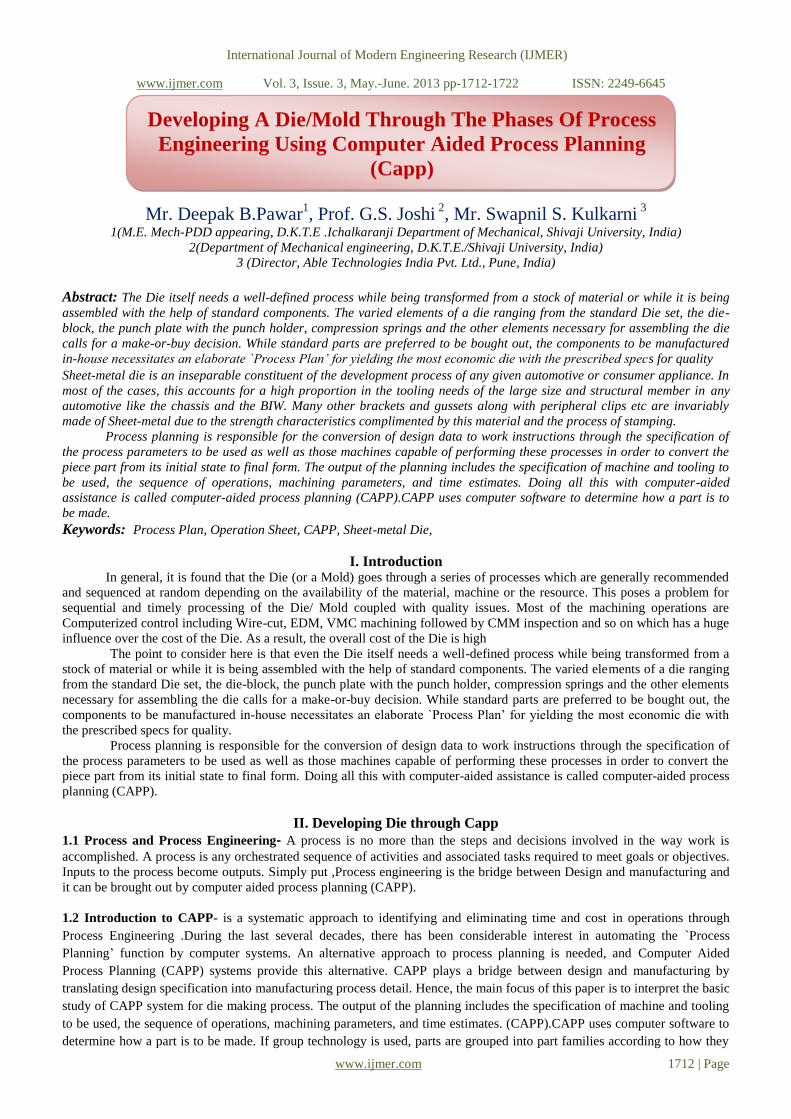
International Journal of Modern Engineering Research (IJMER)
www.ijmer.com Vol. 3, Issue. 3, May.-June. 2013 pp-1712-1722 ISSN: 2249-6645
www.ijmer.com 1712 | Page
Mr. Deepak B.Pawar1, Prof. G.S. Joshi
2, Mr. Swapnil S. Kulkarni
3
1(M.E. Mech-PDD appearing, D.K.T.E .Ichalkaranji Department of Mechanical, Shivaji University, India)
2(Department of Mechanical engineering, D.K.T.E./Shivaji University, India)
3 (Director, Able Technologies India Pvt. Ltd., Pune, India)
Abstract: The Die itself needs a well-defined process while being transformed from a stock of material or while it is being
assembled with the help of standard components. The varied elements of a die ranging from the standard Die set, the die-
block, the punch plate with the punch holder, compression springs and the other elements necessary for assembling the die
calls for a make-or-buy decision. While standard parts are preferred to be bought out, the components to be manufactured
in-house necessitates an elaborate `Process Plan’ for yielding the most economic die with the prescribed specs for quality
Sheet-metal die is an inseparable constituent of the development process of any given automotive or consumer appliance. In
most of the cases, this accounts for a high proportion in the tooling needs of the large size and structural member in any
automotive like the chassis and the BIW. Many other brackets and gussets along with peripheral clips etc are invariably
made of Sheet-metal due to the strength characteristics complimented by this material and the process of stamping.
Process planning is responsible for the conversion of design data to work instructions through the specification of
the process parameters to be used as well as those machines capable of performing these processes in order to convert the
piece part from its initial state to final form. The output of the planning includes the specification of machine and tooling to
be used, the sequence of operations, machining parameters, and time estimates. Doing all this with computer-aided
assistance is called computer-aided process planning (CAPP).CAPP uses computer software to determine how a part is to
be made.
Keywords: Process Plan, Operation Sheet, CAPP, Sheet-metal Die,
I. Introduction In general, it is found that the Die (or a Mold) goes through a series of processes which are generally recommended
and sequenced at random depending on the availability of the material, machine or the resource. This poses a problem for
sequential and timely processing of the Die/ Mold coupled with quality issues. Most of the machining operations are
Computerized control including Wire-cut, EDM, VMC machining followed by CMM inspection and so on which has a huge
influence over the cost of the Die. As a result, the overall cost of the Die is high
The point to consider here is that even the Die itself needs a well-defined process while being transformed from a
stock of material or while it is being assembled with the help of standard components. The varied elements of a die ranging
from the standard Die set, the die-block, the punch plate with the punch holder, compression springs and the other elements
necessary for assembling the die calls for a make-or-buy decision. While standard parts are preferred to be bought out, the
components to be manufactured in-house necessitates an elaborate `Process Plan’ for yielding the most economic die with
the prescribed specs for quality.
Process planning is responsible for the conversion of design data to work instructions through the specification of
the process parameters to be used as well as those machines capable of performing these processes in order to convert the
piece part from its initial state to final form. Doing all this with computer-aided assistance is called computer-aided process
planning (CAPP).
II. Developing Die through Capp
1.1 Process and Process Engineering- A process is no more than the steps and decisions involved in the way work is
accomplished. A process is any orchestrated sequence of activities and associated tasks required to meet goals or objectives.
Inputs to the process become outputs. Simply put ,Process engineering is the bridge between Design and manufacturing and
it can be brought out by computer aided process planning (CAPP).
1.2 Introduction to CAPP- is a systematic approach to identifying and eliminating time and cost in operations through
Process Engineering .During the last several decades, there has been considerable interest in automating the `Process
Planning’ function by computer systems. An alternative approach to process planning is needed, and Computer Aided
Process Planning (CAPP) systems provide this alternative. CAPP plays a bridge between design and manufacturing by
translating design specification into manufacturing process detail. Hence, the main focus of this paper is to interpret the basic
study of CAPP system for die making process. The output of the planning includes the specification of machine and tooling
to be used, the sequence of operations, machining parameters, and time estimates. (CAPP).CAPP uses computer software to
determine how a part is to be made. If group technology is used, parts are grouped into part families according to how they
Developing A Die/Mold Through The Phases Of Process
Engineering Using Computer Aided Process Planning
(Capp)
paration of Papers for International Journal of Modern
Engineering and Research (16 Bold)
International Journal of Modern Engineering Research (IJMER)
www.ijmer.com Vol. 3, Issue. 3, May.-June. 2013 pp-1712-1722 ISSN: 2249-6645
www.ijmer.com 1713 | Page
are to be manufactured. For each part family, a standard process plan is established. Products and their components are
designed to perform certain specific functions. Each product has some design specifications which ensure its functionality
aspects. The task of manufacturing is to produce components such that they get together the design specifications. The
process planning acts as a bridge between design and manufacturing by translating design specifications into manufacturing
process in detail. During the various process planning steps in Shape Depositiom Manufacturing[1], the CAD model
undergoes a series of geometric operations. In order to withstand the complex geometric operations, a powerful geometric
engine should serve as a backbone for the process planner. The process starts with the selection of raw material and ends
with the completion of part. Synergy results in when CAM is integrated with CAD to form CAD/CAM systems than a stand
alone CAD or CAM systems. In such a system CAPP becomes a direct connection between design and manufacturing.
Fig.1- Frame Work Of Process Planning
1.3 CAPP SYSTEMS:
Computer-aided process planning systems are designed around either of two approaches:
1) Retrieval systems and
2) Generative systems
Retrieval CAPP Systems - Also known as variant CAPP systems, based on GT and parts classification and coding, a
standard process plan is stored in computer files for each part code number, The standard plans are based on current part
routings in use in the factory on an ideal plan prepared for each family. For each new part, the standard plan is edited if
modifications are needed
Generative CAPP Systems - Rather than retrieving and editing existing plans from a data base, the process plan is created
using systematic procedures that might be applied by a human planner, In a fully generative CAPP system, the process
sequence is planned without human assistance and without predefined standard plans, designing a generative CAPP system

International Journal of Modern Engineering Research (IJMER)
www.ijmer.com Vol. 3, Issue. 3, May.-June. 2013 pp-1712-1722 ISSN: 2249-6645
www.ijmer.com 1714 | Page
is a problem in expert systems - computer programs capable of solving complex problems that normally require a human
with years of education and experience
1.4 IMPORTANT CHARACTERISTICS OF CAPP:
CAPP systems usually serve as link in integrating the CAD and CAM. Though, it is only the partial link due to lack
of part feature information provided by existing CAD or drafting system. Part feature information is an essential data for
CAPP. In other words, it is a tedious job for CAPP to understand the three dimensional geometry of the designed part from
CAD system in terms of their engineering meaning related to assembly and manufacturing. in general, all CAPP planning
method and systems suffered from such type of problem and is referred as feature identification in CAPP. Therefore, the
main objective feature credit is to bridge the space between the database and automated process planning systems by
automatically distinguishing the feature of a part from the geometry and topological data stored in the CAD system. Hence,
the features play a vital role in CAPP. In order to identify features and to solve CAD or CAPP interface problem, feature
recognition is one of the most efficient technique. Feature recognition transforms a general CAD model into an application
specific feature model. evaluated based on the objective functions. The objective of the CAPP problem is to obtain an
optimal operation sequence that results in optimizing resources and minimizing production costs as well as processing
time.[5]
1.5 BENEFITS OF CAPP:
The use of CAPP systems has the following potential advantages
Process rationalization and standardization –CAPP leads to more logical and consistent process plans than when
traditional process planning is used
Increased productivity of process planners
Reduced lead time to prepare process plans
Improved legibility over manually written route sheets
CAPP programs can be interfaced with other application programs, such as cost estimating, work standards, and others
1.6 RECENT TRENDS IN CAPP: -
In the global competitive market, various areas such as design process planning, manufacturing and inspection plays
a vital role in reducing cost and lead time [14] .In the various areas, different kind of interference mechanism has been
developed. A lot of difficulty arises while integrating the goal in CIM environment. A CAPP system, depending on the level
of sophistication of its capability, may involve automating the interface between design and process planning as well as
various process planning tasks.[6] Process Planning tasks such as process sselection, machine tool and cutting tools election,
set-up planning, fixture selection, machining parameter selection and so on.
Hence, it is not only desirable but also inevitable to develop a single database technology to address these problems.
The major challenges of and research areas are to make CAPP system affordable to the medium and small scale
manufacturing industries. Hence a recent trend in CAPP systems includes;
1) Automated translation of the design dimensions.
2) Tolerances into manufacturing dimensions.
3) Tolerances considering process capabilities.
4) Dimensional chains.
1.7 APPROACHES TO PROCESS PLANNING:-
There are basically two approaches to process planning which are as follows :
(i) Manual experience-based process planning, and
(ii) Computer-aided process planning method.
Following difficulties are associated with annual experienced based process planning method:
It is time consuming and over a period of time, plan developed are not consistent.
Feasibility of process planning is dependent on many upstream factors (design and availability of machine tools).
Downstream manufacturing activities such as scheduling and machine tool allocation are also influenced by such
process plan [14]..
Therefore, in order to generate a proper process plan, the process planner must have sufficient knowledge and
experience. Hence, it is very difficult to develop the skill of the successful process planner and also a time consuming
issue.
1.8 STEPS FOR DEVELOPMENT :-
The following are the activities for this exercise enumerated as steps:
1. Study the complete drawing of the Die and its elements including the material specifications and surface treatment, if
any
2. Identify each element as per the bill-of-material (BOM) and assign a make or buy tag

International Journal of Modern Engineering Research (IJMER)
www.ijmer.com Vol. 3, Issue. 3, May.-June. 2013 pp-1712-1722 ISSN: 2249-6645
www.ijmer.com 1715 | Page
3. While the materials with the `buy’ tag could be procured from competent sources, the materials with the `make’ tag
should be listed out separately for including in the Process Engineering plan
4. Study the design intent of each element or part and assign appropriate tooling faces for resting, location, orientation and
clamping
5. If additional fixtures or non-standard gauges are required, make a list of the same along with a Picture sheet for the
operation
6. Allocate the appropriate machine/s for each element during its machining cycle
7. Specify the process of sub-assembly followed by the main assembly
8. Identify critical dimensions/ specs to be measured at each stage for ensuring functionality and smooth assembly
9. Discuss the inspection dimensions for the completed Die in conjunction with the Die Designer
10. Organize the trials and document the results for further improvement in the Die
1.9 CAPP SYSTEM FOR DIE DEVELOPMENT:-
This system was constructed on the basis of the know-how of industrial field engineers. By interviewing them, the
production rules of the CAPP system are generated and developed. The cross-section of the product body, drawing
coefficient, punch radius (Rp), and die radius (Rd) are considered as the main design parameters. The input data of the system
is only the final product geometry of which modeling is performed on AutoCAD software along the major and minor axes of
the product. The system is typically composed of recognition of shape, 3-D modeling to calculate the surface area, blank
design and process planning modules. It means that we have to return first to rework the die construction by changing the
critical die parameters (e.g. die radii, drawing gap, etc.). If it does not solve the problem, a new die design, or a new process
planning is required. [2].The scope for this project work, although, is limited to generation of Process Plan aligning with its
cross-functional departments.
III. INDENTATIONS AND EQUATIONS Cutting speed (also called surface speed or simply speed) is the speed difference (relative velocity) between
the cutting tool and the surface of the workpiece it is operating on. It is expressed in units of distance along the workpiece
surface per unit of time, typically surface feet per minute (sfm) or meters perminute (m/min). Feed rate is the relative
velocity at which the cutter is advanced along the workpiece; its vector is perpendicular to the vector of cutting speed. Feed
rate units depend on the motion of the tool and workpiece; when the workpiece rotates (e.g., in turning and boring), the units
are almost always distance per spindle revolution (inches per revolution [in/rev or ipr] or millimeters per revolution
[mm/rev]). When the workpiece does not rotate (e.g., in milling), the units are typically distance per time (inches per minute
[in/min or ipm] or millimeters per minute [mm/min]), although distance per revolution or per cutter tooth are also sometimes
used.
Cutting Speeds For Various Materials Using A Plain High Speed Steel Cutter
Material Type Meters Per Min (MPM) Surface Feet Per Min (SFM)
Steel (Tough) 15–18 50–60
Mild Steel 30–38 100–125
Cast Iron (Medium) 18–24 60–80
Alloy Steels (1320–9262) 20-37 65–120
Carbon Steels (C1008-C1095) 21-40 70–130
Free Cutting Steels (B1111-B1113 & C1108-C1213)
35-69 115–225
Stainless Steels (300 & 400 Series) 23-40 75–130
Bronzes 24–45 80–150
Leaded Steel (Leadloy 12L14) 91 300
Aluminium 75–105 250–350
Brass 90-210 300-700 (Max. Spindle Speed)
Table No.1- Cutting Speeds For High Speed Steel
Approximate Material Cutting Speeds and Lathe Feed Per Revolution Calculating RPM and Feed Rates
Sr.
No. Material
Ballpark CS with HSS
Tool
Cutting Speed
HSS Tool
Cutting Speed
Carbide Tool
Feed/Rev HSS
Tool Lathe
Feed/Rev Carbide
Tool Lathe
1 SAE 1020-Low Carbon Steel
100 80-120 300-40 0.002-0.020 0.006-0.035
2 SAE 1050-Ligh 60 60-100 200 0.002-0.005 0.006-0.030

International Journal of Modern Engineering Research (IJMER)
www.ijmer.com Vol. 3, Issue. 3, May.-June. 2013 pp-1712-1722 ISSN: 2249-6645
www.ijmer.com 1716 | Page
Carbon Steel
3 Stainless Steel Aluminum
100 100-120 240-300 0.002-0.005 0.003-0.006
4 Brass And Bronze 200 110-300 600-1000 0.003-0.025 0.008-0.040
5 Plastic 500 500 1000 0.005-0.50 0.005-0.05
Table No.2- Approximate Material Cutting Speeds and Lathe Feed Per Revolution
Calculating RPM and Feed Rates
*Variation in Cutting-Speed & Feed-per-Revolution will exist with different alloys, procedures, tools & desired
finishes. Feed-Per-Revolution is also affected by the size of the lathe-tool, as well as the depth of cut. The cutting
speed and speed of plastics will vary greatly depending upon the type of plastic.
Table No.2 Approximate Material Cutting Speeds and Lathe Feed Per Revolution
Calculating RPM and Feed Rates
Accuracy
However, for more accurate calculations, and at the expense of simplicity, this formula can be used:
RPM = Speed = Speed .
Circumference π X Diameter
= 1000X20(mm/min)
πX100mm
RPM = 200
*Variation in Cutting-Speed & Feed-per-Revolution will exist with different alloys, procedures, tools & desired
finishes. Feed-Per-Revolution is also affected by the size of the lathe-tool, as well as the depth of cut. The cutting
speed and speed of plastics will vary greatly depending upon the type of plastic.
Calculations:- Feed Rate = fm (mm/min)
m = f × n
m = feed rate (mm/min) or MPM
f = feed (mm/rev)
n = rpm
the rate of tool travel through the work piece per unit of time, generally
expressed in mm per revolution (turning)
f = 0.010 (mm/rev)
n = 200 rpm
m=0.010X200
m=2 (mm/min)
Drilling Speeds and Feeds :-
The speed of a drill is usually measured in terms of the rate at which the outside or periphery of the tool moves in
relation to the work being drilled. The common term for this velocity is surface feet per minute", abbreviated as sfm. Every
tool manufacturer has a recommended table of sfm values for their tools. General sfm guidelines are commonly found in
resources such as the Machinery Handbook (see Table 1 in this document).
The peripheral and rotational velocities of the tool are related as shown in the following equation:
V = π * D * N (Eq. 1)
where ,
V is the recommended peripheral velocity for the tool being used
D is the diameter of the tool
N is the rotational velocity of the tool
Since the peripheral velocity is commonly expressed in units of feet/min and
tool diameter is typically measured in units of inches, Equation 1 can be
solved for the spindle or tool velocity, N in the following manner:
N [rpm] = 12 [in/ft] * V [sfm] / (π * D [in/rev]) (Eq. 2)
Equation 2 will provide a guideline as to the maximum speed when drilling
standard materials. The optimum speed for a particular setup is affected by
many factors, including the following:
• Composition, hardness & thermal conductivity (k) of material
• Depth of hole
• Efficiency of cutting fluid

International Journal of Modern Engineering Research (IJMER)
www.ijmer.com Vol. 3, Issue. 3, May.-June. 2013 pp-1712-1722 ISSN: 2249-6645
www.ijmer.com 1717 | Page
• Type, condition and stiffness of drilling machine
• Stiffness of workpiece, fixture and tooling (shorter is better)
• Quality of holes desired
• Life of tool before regrind or replacement
Table 2 contains recommended feeds for various drill diameters. For each diameter range there is
a corresponding feed range. Use the smaller values for stiffer/harder/stronger materials and the
larger values for softer materials. To calculate the feed rate, use the following formula:
f = N * fr
where
f = feed rate [mm/min]
N = spindle speed [rpm]
fr = feed per revolution [mm/rev]
SR .No. Material
Recommended
Speed(Surface ft/min)
1 Aluminum And Its alloys 250
2 Bronze(High Tensile) 100
3 Cast Iron(Soft) 100
4 Cast Iron(Medium Hard) 80
5 Cast Iron(Hard chilled) 20
6 Hastelloy 20
7 Inconel 25
8 Magnesium and its alloys 300
9 Monel 25
10 High nickel steel 50
11 Mild Steel(.2-.3 C) 100
12 Steel (.4-.5C) 60
13 Tool Steel 40
14 Forgings 40
15 Steel alloys(300-400 Brinell) 30
16
Heated Steels 35-40Rockwell 35-40 Rockwell C 20
40-45 Rockwell C 20
45-50 Rockwell C 15
50-55 Rockwell C 15
17 Stainless Steel free machining 40
18 Stainless work hardened 20
19 Titanium alloys 20
Table No.3-HSS speeds for common materials [13]
Sr.No.
Drill Diameter
[in] Recommended Feed,fr [in/rev]
1 under 1/8 " up to 0.002
2 1/8" to 1/4" 0.002 to 0.004
3 1/4" to 1/2" 0.004 to 0.008
4 1/2" to 1" 0.008 to 0.012
5 1" and over 0.012 to 0.020
Table No.4 HSS feed [13]
Table No.5- Cutting Parameters for HSS drill [13]

International Journal of Modern Engineering Research (IJMER)
www.ijmer.com Vol. 3, Issue. 3, May.-June. 2013 pp-1712-1722 ISSN: 2249-6645
www.ijmer.com 1718 | Page
Calculations:- V = π * D * N/1000
N = V *1000/π * D
= 13000/ π * 9
N = 460( RPM)
Also,
f (mm/min) = N * fr (mm/rev)
= 460*0.10
f = 46(mm/min)
Surface Grinding:-
Grinding is a material removal process in which abrasive particles are contained in a bonded grinding wheel that
operates at very high surface speeds. The grinding wheel is usually disk shaped and is precisely balanced for high roational
speeds. Cutting conditions in grinding The geometry of grinding is shown in the figure:
Fig.2 -The Geometry Of Surface Grinding Showing The Cutting Conditions
The geometry of surface grinding showing the cutting conditions.The cutting velocity V in grinding is very high. It is
related to the rotational speed of the wheel by
V = πDN
where D is the wheel diameter, and N is the rotational speed of the grinding wheel.Depth of cut d is called infeed and
is defined as the distance between the machined and work surfaces. As the operation proceeds, the grinding wheel is fed
laterally across the work surface on each pass by the workpart. The distance at which the wheel is fed is z.
V. FIGURES AND TABLES
WITH THE INPUTS GATHERED DURING COLLECTION PHASE, THE ANALYSIS IS DOCUMENTED AS PER THE PROCESS SHEET
BELOW.
PROCESS SHEETName of tool-Form /Deep Die
Name of the component -Die Block
Drawing No - AT0101
Material - 20MnCr5 (Case-hardness HRC 58-62)
Qty - 1no
Opn No. Operation Name Machine Name/ No. Instrument/ Fixture/ Gauge Description of operationEstimated time for
setting and machining
10 Milling milling machine Vernier Caliper - upto 200mm Hold the blank in vice 8hrs.(Each for 6 faces)
Rough & Finishing Clean out the face
Finish Face (Name) to size(….+0.5)
20 Drilling Radial Drilling machine Drill bit(HSS or Carbide) Drilling -1 hr
Tapping Tap -size M8 Tap to depth 15mm Tapping -1.5hr
30 Surface Grinding Rest face F,Grind G for clean finish
micrometer-50-100
Top Face Surface grinding m/c Hold ф A and Finish B/C to Size 1 hr
micrometer-50-100
Bottom Face cylindrical grinding m/c Set speed for grinding = 2300 (rpm) 1.5 hr
Set depth of cut = 0.003 to 0.005 mm
40 Heat Treatment Induction Furnace Hardness Tester (HRC)
0.5 hr
50 VMC Machining center V.M.C.(BFW-60)
Bull-nose Cutter Size-10mm
3 hr
Side Face Cutter Size-6mm
CMM/Robo-Arm Run The CMM Programe No-CMM021 1hr
Drill hole size ф6.8 thru's on
P.C.D.Equispaced
Run the machining program no -
CAM021
Pack carburize using carbon rich
material at about 800°C4 hr
Case Harden in the furnace at a
temperature of 580 to 920°C16 hr
Make identation using approprite
steel ball (indenter) to confirm

International Journal of Modern Engineering Research (IJMER)
www.ijmer.com Vol. 3, Issue. 3, May.-June. 2013 pp-1712-1722 ISSN: 2249-6645
www.ijmer.com 1719 | Page
Table No.6 - Process sheet for Die Block
Table No 7- Process sheet for Punch
DIE BLOCK (TWO VIEWS)
DIE BLOCK (2D DRAWING)
Fig.3- 2D drawing and 3D representation for Die Block
Face `F’
Face `G’
Dimn- `A’
Size `B/C’
International Journal of Modern Engineering Research (IJMER)
www.ijmer.com Vol. 3, Issue. 3, May.-June. 2013 pp-1712-1722 ISSN: 2249-6645
www.ijmer.com 1720 | Page
PUNCH (TWO VIEWS OF THE 3D MODEL)
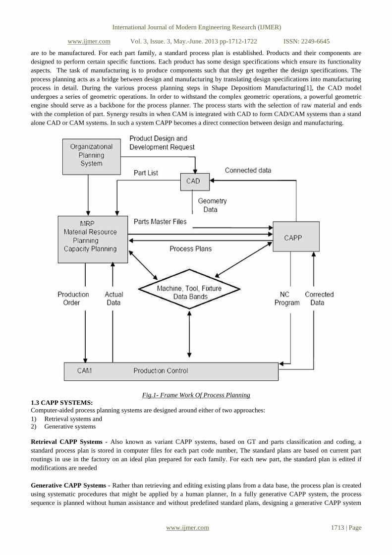
PUNCH (2D DRAWING)
Fig.4- 2D drawing and 3D representation for Punch
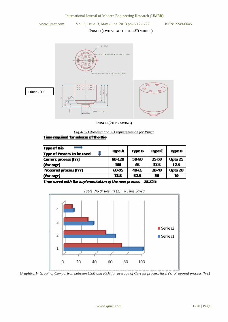
Table No 8: Results (1): % Time Saved
GraphNo.1- Graph of Comparison between CSM and FSM for average of Current process (hrs)Vs. Proposed process (hrs)
Dimn- `D’

International Journal of Modern Engineering Research (IJMER)
www.ijmer.com Vol. 3, Issue. 3, May.-June. 2013 pp-1712-1722 ISSN: 2249-6645
www.ijmer.com 1721 | Page
Table No. 9 - Results (2): % Reduction in Errors
Graph No. 2- Graph of Comparison between CSM and FSM for average of Current process Vs. Proposed process for
`number of Errors’ identified during development phase
V. CONCLUSION The objective of this exercise was to administer the use of Process Plan for planning principles as a way to logically
and sequentially plan process, to reduce time and errors and improve the process during developing a Die. This study
carries evidence of genuine advantages of applying computer aided process plan in a small scale industry. By applying
computer aided process planning tool in a die manufacturing industry, a current state map is developed. A future state value
stream map is created by eliminating time and errors during developing die. The future state map shows marked
improvement in the process planning.
A case study discussed outlines importance of Computer Aided Process Planning tool to achieve effectiveness by
using efficiently the process planning. Strategy to shorten proposed process time required for release of the Die and
Proposed process for number of Errors identified during development phase. The benefits realized through the pursuit of the
Case Study are:-
1. The future state map shows marked improvement in the process and Time saved with the implementation of the
new process = 23.25%.
2. Percentage reduction in the number of errors for the new process = 43.21%
For planning the implementation of the CAPP system, it is recommended that the Company should develop 5 to 10nos case
studies. This can provide as an input to developing the ‘Retrieval Method’ which can be maintained for the first 100nos of
Dies. Later, upon maturity, this system can be marked for transition to `Generative Method’ or `Feature based Method’ of
Process Planning.
VI. ACKNOWLEDGEMENTS
.The author gratefully acknowledges the support received from Mr.S.S.Kulkarni, Director- Able Technologies (India) Pvt.
Ltd. Pune, for his technical and administrative support from conceptual stage to the final stage for execution of this work.
The author also would like to thank Dr.V.R.Naik, Head of Department of Mechanical Engineering, Prof. G.S. Joshi,
Prof.A.R.Balwan, P.G.Coordinator, at D.K.T.E. Ichalkaranji, for guidance and crucial inputs over the project work.

International Journal of Modern Engineering Research (IJMER)
www.ijmer.com Vol. 3, Issue. 3, May.-June. 2013 pp-1712-1722 ISSN: 2249-6645
www.ijmer.com 1722 | Page
REFERENCES [1] Krishnan Ramaswami, International Journal of, process planning for shape deposition manufacturing, January 1997
[2] S.K. Gupta, D.A. Bourne, K.H. Kim, and S.S. Krishna, Rapid Manufacturing Laboratory, Robotics Institute, Carnegie Mellon
University, Pittsburgh,. International Journal of, Automated process planning for sheet metal bending operations, PA 1521.
[3] Dr.Thomas R. KramerGuest Worker, National Bureau of Standards, & Research Associate, Catholic University, International
Journal of, process planning for a milling machine from a feature-based design
[4] M. Tisza Department of Manufacturing Technologies, Research Group of Hungarian Academy of Sciences, University of Miskolc, 3515 Miskolc-
Egyetemváros, Hungary* Corresponding author: E-mail address: [email protected], Received 30.03.2007; published in revised form
01.09.2007, International Journal of, recent achievements in computer aided process planning and numerical modelling of sheet metal forming processes
[5] By T.N. Wong, LecturerDepartment of Industrial & Manufacturing Systems EngineeringUniversity of Hong Kong, International Journal of, development of a knowledge-based automated process planning system
[6] Sankha Deb, Department of Mechanical Engineering, Indian Institute of Technology Kharagpur, Kharagpur-721302, India. E-mail: [email protected] J. Raul Parra-Castillo Department of Mechanical Engineering, Escuelas Profesionales de la grada Familia, Cadiz,
Spain. E-Mail: [email protected] Kalyan Ghosh Department of Maths. & Industrial Engineering, École Polytechnique, Université de Montréal,
Montréal, Québec H3C 3A7, Canada. Email: [email protected] International Journal of ,an integrated and intelligent computer-aided
process planning methodology for machined rotationally symmetrical parts Volume 13 Issue 1 ©2011 ijams
[7] By Ramy F. Harik1, William J. E. Derigent2 and Gabriel Ris2, 1Lebanese American University, [email protected],2Université Henri Poincaré
- Nancy I, [email protected],Computer-Aided Design & Applications, 5(6), 2008, 953-962953,Computer-Aided Design and Applications© 2008 CAD Solutions, LLC,http://www.cadanda.com, DOI: 10.3722/cadaps.2008.953-962, International Journal of, computer aided
process planning in aircraft manufacturing,DOI: 10.3722/cadaps.2008.953-9628
[8] David J. Cooper Jr.Genworks International 5777 West Maple, Suite 130 West Bloom_eld, MI 48325.http://www.genworks.com [email protected] ,August 21, 1998 (updated August 13, 2002), International Journal of, understanding multi-state generative process
planning, August 21, 1998(updated August 13, 2002
[9] Dietmar Winkler Stefan Biffl Thomas Östreicher, Vienna University of Technology, Favoritenstrasse 9/188, 1040 Vienna, Austria,{dietmar.winkler, stefan.biffl, thomas.oestreicher}@qse.ifs.tuwien.ac.at, test-driven automation: adopting test-first development to improve automation systems
engineering processes.
[10] Dhiman Johns, Thapar University, Patiala, International Journal of Computer Aided Process Planning(CAPP)\
[11] V. Naranje, S. Kumar, American Journal of Intelligent Systems , International Journal of,A Knowledge Based System for Selection of Components of Deep Drawing Die, 2(2): 1-11, (2012)
[12] John Wiley and Sons, M. P. Groover, International Journal of , Fundamentals of Modern Manufacturing 2/e,2002
[13] http://www.zianet.com/ebear/metal/heattreat3.html
[14] http://www.ignou.ac.in/upload/Unit-9-CRC.pdf
Copyright © 2022 FDOKUMEN