Geodesy - CORE
351
İSTANBUL TECHNICAL UNIVERSITY INSTITUTE OF SCIENCE AND TECHNOLOGY Ph.D. Thesis by Caner GÜNEY, M.Sc. Department : Geodesy and Photogrammetry Engineering Programme: Geomatics Engineering DECEMBER 2006 A CONCEPTUAL DESIGN FOR THE DEVELOPMENT OF A CUSTOMIZABLE FRAMEWORK FOR THE CULTURAL HERITAGE DOMAIN
-
Upload
khangminh22 -
Category
Documents
-
view
5 -
download
0
Transcript of Geodesy - CORE
İSTANBUL TECHNICAL UNIVERSITY INSTITUTE OF SCIENCE AND TECHNOLOGY
Ph.D. Thesis by
Caner GÜNEY, M.Sc.
Department : Geodesy and Photogrammetry Engineering
Programme: Geomatics Engineering
DECEMBER 2006
A CONCEPTUAL DESIGN FOR THE DEVELOPMENT OF A CUSTOMIZABLE FRAMEWORK
FOR THE CULTURAL HERITAGE DOMAIN
İSTANBUL TECHNICAL UNIVERSITY INSTITUTE OF SCIENCE AND TECHNOLOGY
Ph.D. Thesis by
Caner GÜNEY, M.Sc.
(501022300)
Date of submission : 24 November 2006
Date of defence examination: 22 December 2006
Supervisor (Chairman): Assoc. Prof. Dr. Rahmi N. ÇELİK
Members of the Examining Committee Assoc. Prof. Dr. Necla ULUĞTEKİN (İTÜ)
Assist. Prof. Dr. Lucienne T. ŞENOCAK (KÜ)
Prof. Dr. Tevfik AYAN (İTÜ)
Prof. Dr. Julian D. RICHARDS (UOY)
DECEMBER 2006
A CONCEPTUAL DESIGN FOR THE DEVELOPMENT OF A CUSTOMIZABLE FRAMEWORK
FOR THE CULTURAL HERITAGE DOMAIN
İSTANBUL TEKNİK ÜNİVERSİTESİ FEN BİLİMLERİ ENSTİTÜSÜ
KÜLTÜREL MİRASLAR İÇİN UYARLANABİLİR BİR ÇATKININ GELİŞTİRİLMESİNE YÖNELİK
KAVRAMSAL BİR TASARIM
DOKTORA TEZİ Y. Müh. Caner GÜNEY
(501022300)
ARALIK 2006
Tezin Enstitüye Verildiği Tarih : 24 Kasım 2006 Tezin Savunulduğu Tarih : 22 Aralık 2006
Tez Danışmanı : Doç. Dr. Rahmi N. ÇELİK
Diğer Jüri Üyeleri Doç. Dr. Necla ULUĞTEKİN (İTÜ)
Yard. Doç. Dr. Lucienne Thys-ŞENOCAK (KÜ)
Prof. Dr. Tevfik AYAN (İTÜ)
Prof. Dr. Julian D. Richards (UOY)
iii
PREFACE
I have always been interested in technology, information systems, and management of these systems.
My fundamental purpose was to present “whole picture” of the cultural heritage activity with a top-down approach, in particular in terms of technology, rather than exploring only specific topics with a bottom-up approach. In this dissertation, I therefore decided to study conceptually the holistic design of the business and the information&communication technologies concepts and how these could be implemented for a better future in the cultural heritage field. Moreover, I had a head start due to my master thesis that was entitled “Multimedia Supported Geographic Information System Applications over the Internet and Geodetic Infrastructure (Application: The Documentation of Cultural Heritage Resources)”.
Here I attempted to touch on evolving business and technical concepts in order to deliver an innovative road map for the cultural heritage community. Therefore, since the beginning of the dissertation, a great deal of attention has been dedicated to researching technical issues, gaining experience with innovative technologies, their philosophies and methods, and the integration of such technologies.
I set up an overall geoenterprise architecture framework for the management, analysis and decision-making process in the cultural heritage sector. The ideas proposed in the dissertation are largely hypothetical. However, it provides an opportunity for the cultural heritage domain to share rethinking on the direction of the cultural heritage resource management and research, and on future cultural heritage strategies for improving and evaluating the impact of these on the cultural heritage sector.
Although this dissertation presents the conceptual design from a technical perspective, it is not intended exclusively for technologists. Any specialist or provider or stakeholder from the cultural heritage community familiar with databases, application servers and the basic Internet standards will find the dissertation accessible and informative.
It aims to have a transforming impact by enabling research practitioners and lecturers to embed the advanced use of information and communication technologies in their research and teaching strategies, in their creation and use of digital information, and in facilitating collaboration across traditional subject and discipline boundaries.
I know I can not boil the ocean. But I hope to draw attention to exploring new technologies, sharing my experiences and ultimately expanding our knowledge to improve the way the cultural heritage sector is developing.
NOVEMBER, 2006 Caner GÜNEY
iv
ACKNOWLEDGEMENT
I wish to thank the following individuals for their assistance with this project.
First and foremost thanks are due to my supervisor Assoc. Prof. Dr. Rahmi Nurhan Çelik (the Division of Geodesy, ITU). His encouraging comments over the last four years (8 years indeed along with master and undergraduate theses), particularly aligned to his pervasive knowledge and his ability to turn what I saw as problems into what he saw as opportunities, have made him an ideal supervisor. He saw potential where others, myself included, saw only complication. I recognize that at times I was not an easy student to supervise, so for his patience and commitment but above all, his humanity I must thank him. His ideas have inspired me throughout this work, and will no doubt continue to do so in the future. I am truly indebted to him.
Very special thanks must go to Assis. Prof. Dr. Lucienne Thys-Şenocak (the Department of History, Koç University), for her unflinching support, invaluable practical and theoretical advice throughout this project. Whilst my focus of study diverged form her own she had a keen interest that was appreciated.
Thanks to my adviser, Assoc. Prof. Dr. Necla N. Uluğtekin (the Division of Cartography, ITU), who is always supportive and has given me invaluable guidance. I thank her for encouraging me, giving me confidence and for all her support since I was an undergraduate.
I would like to extend my thanks to Prof. Dr. Julian Richards (the Department of Archaeology, the University of York) for his measured criticisms. He was and is, completely honest and told me exactly what he thought: I think I listened.
I would like to express sincere appreciation to Prof. Dr. Dana C. Tomlin (the Department of Landscape Architecture, the University of Pennsylvania) for giving me several excellent ideas as well as carefully examining the many manuscripts of this thesis. Thank you for spending time reading and commenting on my work during his busy schedule.
I must thank the Istanbul Technical University and the Tinçel Foundation which funded a 9 month period of research in the University of Pennsylvania, USA, for which I am grateful. Special thanks to Prof. Dr. Dana C. Tomlin who gave me the possibility of working at the University of Pennsylvania.
A particular appreciation must be given to the European Union-funded “Cultural Heritage Informatics Research Oriented Network (CHIRON)” project under Marie-Curie Actions for providing a year fellowship to support my research on my dissertation at the University of York, UK. Special thanks to Prof. Dr. Julian D. Richards who gave me the possibility of working at the University of York.
A profound recognition must be made to my colleagues in the Division of Geodesy at Istanbul Technical University, whose support, assistance, patience and encouragement over many years, made all things possible. In the first place, I acknowledge with gratitude Prof. Dr. Tevfik Ayan (the head of the Geodesy Division,

v
ITU) for providing the productive working environment in the Division and having brilliant suggestions and discussions.
I am also grateful to the “Kaletakimi”, all members of the “Seddülbahir-Kumkale” project team, for their assistance and moral support.
PhD students Holly Wright (the Department of Archaeology, the University of York) and Nicholas Lowell Stapp (the Department of Landscape Architecture, the University of Pennsylvania) provided extremely useful discussions on the papers related to this work. Their appreciation of my work proved highly motivating, and their comments were at all times well received, being both clear and accurate. They will make great professors, should they choose to.
I wish to acknowledge the intellectual contributions made by colleagues in the King's Manor and G65 (University of York) and the School of Design (University of Pennsylvania).
My gratitude must also go to my parents, Şahsene and İsmet Güney, and my brother, Önder Güney, who deserve more than just a mention at the bottom of an acknowledgments page. They are proud of me and everything I do. Any words of thanks are insufficient when weighed against the help they have given. They have always encouraged my academic adventure and tolerated my abstraction with understanding. Endless thanks and appreciation for their support, generosity and everything they have given me.
Finally, and most importantly of all, I would like also to thank the love of my life and gorgeous wife Ceren Bilgin Güney for making my life worth living and being both tolerant and remarkably patient on numerous occasions when my priorities did not coincide with hers. Without her encouraging words, stimulating discussions and astute criticisms this thesis would never have been written. Now it is your turn to do what you want.
ISTANBUL, 2006 Caner GÜNEY

vi
TABLE OF CONTENTS
LIST OF ABBREVATIONS ix LIST OF TABLES xiv LIST OF FIGURES xv SUMMARY xvii ÖZET xix
1. INTRODUCTION 1 1.1. Overview 1 1.2. Location and Brief Information about the Historical Background of the Fortresses 3 1.3. Evolution of the Project 5 1.4. Scope and Contents of the Dissertation 6
2. AN ENTERPRISE ARCHITECTURE FRAMEWORK: "GeoCHEAF" 10 2.1. Defining Enterprise and Enterprise Architecture 10 2.2. Business Architecture of "GeoCHEAF" 15
2.2.1. User requirements 17 2.2.2. Vision and mission statements 19 2.2.3. Business goals 20 2.2.4. Business strategy 23
2.2.4.1. Design strategy 23 2.3. Technical Architecture of "GeoCHEAF" 29
3. INITIAL STRUCTURAL ARCHITECTURES 32 3.1. Open Architecture 32 3.2. Semantic Architecture 36 3.3. Modeling Architecture 40
3.3.1. UML diagrams 42 3.3.2. UML tools 45 3.3.3. Modeling approach 50
3.4. Extensible Architecture 51 3.4.1. HTML limitations and XML benefits 51 3.4.2. Towards e(X)tensible HTML: XHTML 53 3.4.3. XML family 55 3.4.4. XML-based "GeoCHEAF" 66
vii
4. WEB-BASED DISTRIBUTED MULTI-TIER ARCHITECTURE 69 4.1. Evolution of Application Architectures 73
4.1.1. First generation: database and client-server applications 74 4.1.2. Second generation: web applications 75 4.1.3. Third generation: web services 77
4.2. Early Second Generation Technologies 78 4.2.1. Common gateway interface 78 4.2.2. Scalable CGI implementations 80 4.2.3. Web server extension interfaces 80 4.2.4. Browser extension interfaces 81 4.2.5. Interpreted template-based scripting 89
4.3. An Evolutionary Step: Middle-Tier Architecture 92 4.3.1. Presentation tier 93 4.3.2. Business logic tier 103 4.3.3. Integration tier 107 4.3.4. Configuration 109
4.4. A Revolutionary Evolutionary Step: Web Services & Web Services Architecture 114
4.4.1. A thorny problem: application integration 114 4.4.2. The key characteristics of web services 116 4.4.3. Internet middleware 119 4.4.4. Web services architecture and its specifications 122 4.4.5. Implementing web services 137 4.4.6. Web services in the cultural heritage domain 142
5. DATA ARCHITECTURE 146 5.1. Conceptual Design 147
5.1.1. Data modeling 148 5.1.2. Geospatial data modeling 149 5.1.3. Object data modeling 150 5.1.4. Spatiotemporal data modeling 151 5.1.5. Data model of "GeoCHEAF" 152
5.2. Functional Model 162 5.2.1. XML and databases 169
5.3. Data Handling and Standardization 173 5.4. Data Warehousing 175
5.4.1. Defining data warehouse 175 5.4.2. ETL process 177 5.4.3. Warehouse schemas 178 5.4.4. Data marts 178 5.4.5. OLAP 179 5.4.6. Data mining process 180 5.4.7. Decision-making process 181

viii
6. VISUALIZATION ARCHITECTURE 183 6.1. Visualization Architecture of "GeoCHEAF" 185 6.2. Multi-dimensional Hybrid Visualization 196 6.3. XML-based Visualization 201 6.4. VRML and Building 3D Geospatial Scenes in VRML 202 6.5. Multimedia Applications 208 6.6. Rendering and Real-time Graphics 210 6.7. Generating Web Images on the Fly 212 6.8. Virtual Worlds on the Web 215
7. OTHER MAJOR ARCHITECTURES 219 7.1. Web Content Management Architecture 219
7.1.1. Web portal architecture 225 7.2. Mobile Computing Architecture 233 7.3. Security Architecture 235 7.4. ICT Infrastructure 238
7.4.1. Physical infrastructure 238
8. SPATIAL INFORMATICS TECHNOLOGY ARCHITECTURE 248 8.1. Overview 248 8.2. SIS Subsystems 251 8.3. Evolution of SIS Technologies Followed by ICT Evolutionary 252 8.4. Standards for the Development of Internet GIS 254 8.5. Scope of Geospatial World 257 8.6. Narrowing the Scope for the Cultural Heritage Domain 264 8.7. Proposing a Leading SIS Architecture for the Cultural Heritage Domain 269 8.8. Spatial Data Infrastructures 278 8.9. Geospatial Information Infrastructure for the Cultural Heritage Domain 280
9. CONCLUSIONS AND SUGGESTIONS FOR FUTURE WORK 283
WEBLIO/BIBLIOGRAPHY 301
APPENDICES 315
BIOGRAPHY 330
ix
LIST OF ABBREVATIONS
2D : Two Dimensional 3D : Three Dimensional 3NF : Third Normal Form A2A : Application to Application ADML : Architecture Description Markup Language AJAX : Asyncrohronous JavaScript and XML AOP : Aspect Oriented Programming API : Application Programming Interface ASP : Active Server Pages ArcXML : Arc Extensible Markup Language AVR : Automatic Voltage Regulator B2B : Business to Business B2C : Business to Computer BI : Business Intelligence BSD : Berkley Software Distribution C2C : Computer to Computer C2H : Computer to Human CAD : Computer Aided Design CBD : Component Based Development CFML : ColdFusion markup Language CGI : Common Gateway Interface CH : Cultural Heritage CIDOC : International Committee for Documentation CLR : Common Language Runtime CMS : Content Management System CRM : Conceptual Reference Model COM : Common Object Model CORBA : Common Object Request Broker Architecture CSS : Cascade Style Sheets CSV : Comma Separated Value DB : Database DBMS : Database Management System DC : Dublin Core DCE : Distributed Computing Environment DCMI : Dublin Core Metadata Initiative DCOM : Distributed Component Object Model DHTML : Dynamic Hypertext markup Language DOM : Document Object Model DTD : Document Type Definition DTM : Digital Terrain Model EA : Enterprise Architecture EAI : Enterprise Application Integration

x
EAI : External Authoring Interface EJB : Enterprise JavaBeans EIS : Enterprise Information System ESB : Enterprise Service Bus ER : Entity Relationship ETL : Extraction Transforming and Loading FGDC : Federal Geographic Data Committee FISH : Forum on Information Standards in Heritage FO : Formatting Object FOA : Formatting Object Authoring FSF : Free Software Foundation GeoCHEAF : Geo-enable Cultural Heritage Enterprise Architecture Framework GIOP : Generic Inter-ORB Protocol GIS : Geospatial Information System GNU : GNU’s Not Unix GML : Geographic Markup Language GPL : General Public License GPS : Global Positioning System GPU : Graphic Processing Unit GSM : Global System for Mobile Communications GUI : Graphical User Interface H2A : Human to Application H2H : Human to Human HDBMS : Hierarchical Database Management System HM : Hierarchical Model HOLAP : Hybrid OLAP HPC : High Performance Computing HQL : Hibernate Query Language HTML : Hypertext Markup Language HTTP : Hypertext Transfer Protocol ICOM : International Council of Museums ICT : Information and Communication Technology IDE : Integrated Development Environment IDL : Interface Definition Language IEEE : Institute of Electrical and Electronics Engineering IIOP : Internet Inter-ORB Protocol IIS : Internet Information Server IPS : Inter Portlet Communication IS : Information System ISAPI : Internet Server Application Programming Interface ISO : International Organization for Standardization IT : Information Technology J2ME : Java 2 Micro Edition J2EE : Java 2 Enterprise Edition J2SE : Java 2 Standard Edition JAAS : Java Authentication and Authorization Service JavaEE : Java Enterprise Edition JAXM : Java API for XML Messaging JAXR : Java API for XML Registiry JAX-RPC : Java API for XML-based RPC
xi
JDBC : Java Database Connectivity JDK : Java Development Kit JDO : Java Data Objects JFC : Java Foundation Class JIT : Just In Time JNI : Java Native Interface JMS : Java Message Service JRE : Java Runtime Environment JSP : JavaServer Faces JSP : JavaServer Pages JSSE : Java Secure Socket Extension JVM : Java Virtual Machine JWSDL : Java API for WSDL MS : Microsoft LAMP : Linux - Apache - MySQL - PHP/Perl/Python LDAP : Lightweight Directory Access Protocol LGPL : Lesser General Public License LOD : Level of Details MathML : Mathematical Markup Language MBD : Model Based Development MDBMS : Multidimensional Database Management System MIT : Massachusetts Institute of Technology MDA : Model Driven Architecture MOLAP : Multidimensional OLAP MOM : Message Oriented Middleware MRDB : Multiple Representation Database MSIL : Microsoft Intermediate Language MVC : Model View Controller N/A : Not Available NDBMS : Network Database Management System NSAPI : Netscape Server Application Programming Interface NXD : native XML DBMS OAI : Open Archives Initiative OAI-PMH : Open Archives Initiative Protocol for Metadata Harvesting OAIS : Open Archival Information System OASIS : Organization for the Advancement of Structured Information Standards ODBC : Open Database Connectivity ODBMS : Object Database Management System ODS : Operational Data Source OGC : Open Geospatial Consortium OLAP : Online Analytical Processing OLTP : Online Transactional Processing OO : Object Oriented OpenGL : Open Graphics Library OpenSG : Open Scene Graph ORDBMS : Object Relational Database Management System ORM : Open Geospatial Consortium Reference Model ORM : Object Relational Mapping OS : Operating System
xii
OSI : Open Source Initiative OMG : Object Management Group OOGQL : Object Oriented Geo Query Language OQL : Object Query Language OSI : Open Systems Interconnection OWL : Web Ontology Language PHP : Hypertext Preprocessor PIM : Platform Independent Model POJO : Plain Old Java Objects PPU : Physics Processing Unit QTVR : Quicktime Virtual Reality RDBMS : Relational Database Management System RDF : Resource Description Framework REST : Representational State Transfer RHEL : Red Hat Enterprise Linux RIA : Rich Internet Applications RM : Relational Model RMI : Remote Method Invocation ROLAP : Relational OLAP RPC : Remote Procedure Call SAAJ : SOAP with Attachments API SAI : Script Authoring Interface SAI : Scene Access Interface SAX : Simple API for XML SDBMS : Spatial Database Management System SDI : Spatial Data Infrastructure SGML : Standard Generalized Markup Language SHTTP : Secure Hypertext Transport Protocol SI : Spatial Information SIS : Spatial Information System SLES : Suse Linux Enterprise Server SMIL : Synchronized Multimedia Integration Language SOA : Service Oriented Architecture SOC : Service Oriented Computing SOAP : Simple Object Access Protocol SOX : Schema for Object-oriented XML SSL : Secure Socket Layer SSO : Single Sign-On SSJS : Server Side JavaScript SSI : Server Side Includes SSL : Secure Sockets Layer SQL : Structured Query Language SVG : Scalable Vector Graphics SWT : Standard Widget Toolkit TLS : Transport Layer Security TPS : Total Positioning System UDDI : Universal Description Discovery and Integration UI : User Interface UML : Unified Modeling Language UPS : Uninterruptible Power Supply
xiii
URI : Uniform Resource Identifier URL : Uniform Resource Locator VML : Vector Markup Language VRML : Virtual Reality Modeling Language VSIS : Virtual Spatial Information System W3C : World Wide Web Consortium WAMP : Windows - Apache - MySQL - PHP/Perl/Python WCM : Web Content Management WCS : Web Coverage Service WFS : Web Feature Service Wi-Fi : Wireless Fidelity WiMAX : Worldwide Interoperability for Microwave Access) WML : Wireless Markup Language WMS : Web Map Service WORA : Write Once Run Anywhere WS-I : Web Services Interoperability Organization WSA : Web Services Architecture WSDL : Web Service Description Language WSDL : Web Service Developer Pack WSRP : Web Service for Remote Portlets WYSIWYG : What You See Is What You Get X3D : Extensible 3 Dimension XAML : Extensible Application Markup Language XDBMS : XML Database Management System XHTML : Extensible Hypertext Markup Language XInclude : XML Inclusions XLink : XML Linking Language XLiP : XLink Processor XML : Extensible Markup Language XMI : XML Metadata Interchange XPath : XML Path Language XPointer : XML Pointer Language XQuery : XML Query Language XSD : XML Schema Definition XSL : XML Stylesheet Language XSLT : XML Stylesheet Language Transformation XSSI : Extended Server Side Includes XUL : XML User Interface Language XUpdate : XML Update Language

xiv
LIST OF TABLES
Page No
Table 3.1 The appropriate open source software selection of “GeoCHEAF”.. 35 Table 4.1 The tiers and sub-tiers of “GeoCHEAF” …………………………. 71 Table 4.2 The generations of web application technologies …….………….. 73 Table 4.3 Most commonly used web application development frameworks .. 101 Table 4.4 The tools and technology for building and deploying web services 139 Table 5.1 Components of SI-Tuple …..……………………………………... 159 Table 5.2 Discussion of 3 NXDs ……………………………………………. 173 Table 8.1 G-world …………………………………………………………... 258 Table 8.2 GIS-matrix ………………………………………………………... 259 Table 8.3 Main SDI activities ……………………………………………….. 279
xv
LIST OF FIGURES
Page No
Figure 1.1 : The location of the fortresses, Seddülbahir and Kumkale ……..... 4 Figure 2.1 : A schematic view of the “KaleTakimi” …………………………. 11 Figure 2.2 : The business architecture scope of “GeoCHEAF” …………….... 16 Figure 2.3 : Frameworks and components of “GeoCHEAF ………………….. 25 Figure 2.4 : Component-based modeling and design approach of
“GeoCHEAF” …………………………...……………………….. 27
Figure 3.1 : Semantic categorization types …………...………………………. 37 Figure 3.2 : The hierarchy chart of UML 2.0 diagrams ………………………. 44 Figure 4.1 : Application architectures ………………………………………... 70 Figure 4.2 : The multi-tier architecture of “GeoCHEAF” ……………………. 72 Figure 4.3 : Evolution of web application architectures ……………………… 74 Figure 4.4 : The traditional model for web applications compared to the Ajax
model …………………………………………………………….. 87
Figure 4.5 : The synchronous interaction pattern of a traditional web application compared with the asynchronous pattern of an Ajax application ………………………………………………………..
88
Figure 4.6 : The middle-tier architecture of “GeoCHEAF” …………… ……. 110 Figure 4.7 : The general WSA based on the SOA …………………………..... 122 Figure 4.8 : Using s SOAP header to pass security information ……………... 129 Figure 4.9 : WSDL description ……………………………………………….. 135 Figure 4.10 : Internet Middleware ……………………………………………... 138 Figure 5.1 : The framework designed for data architecture …………………... 147 Figure 5.2 : The data modeling component of the data architecture of
“GeoCHEAF” ……………………………………………………. 153
Figure 5.3 : Temporal changes of the same facade of Seddülbahir Fortress in passed time ……………………………………………………….
155
Figure 5.4 : Data model schema of the archaeological database of Seddülbahir Fortress ……………………………………………...
157
Figure 5.5 : A part of the UML-based SIS data modeling of Kumkale Fortress 158 Figure 5.6 : Data repository architecture of “GeoCHEAF” ………………….. 163 Figure 5.7 : The data warehousing architecture of “GeoCHEAF” …………… 176 Figure 6.1 : Data, information, and knowledge visualization ………………… 183 Figure 6.2 : Methodology and technology used for designing the visualization
architecture of “GeoCHEAF” ……………………………………. 186
Figure 6.3 : An animation example for Kumkale Cemetery ………………….. 193 Figure 6.4 : A sample electronic form for a tombstone ………………………. 194 Figure 6.5 : The generated tombstones samples for Kumkale Cemetery …...... 195 Figure 6.6 : Multimedia application of Kumkale Cemetery SIS application …. 196 Figure 6.7 : The design scheme of the GUI of “GeoCHEAF” ……………….. 201 Figure 6.8 : Capture of VRML application of Seddülbahir Fortress …………. 204 Figure 6.9 : Methods of building VRML files ………………………………... 206
xvi
Figure 6.10 : Capture of GeoVRML application of Kumkale Cemetery ………. 206 Figure 6.11 : Visualization of Seddülbahir Fortress with OpenGL ……………. 207 Figure 6.12 : Graphics pipeline ………………………………………………... 211 Figure 6.13 : Snapshots of the photogallery application ………………………. 215 Figure 7.1 : One editing use case ……………………………………………... 221 Figure 7.2 : Design philosophy of the portal …………………………………. 226 Figure 7.3 : The ICT infrastructure of “GeoCHEAF” ………………………... 240 Figure 7.4 : Data storage infrastructure ….…………….……………………... 244 Figure 8.1 : A 3D view of an archaeological site from ArcMap, ESRI. ……... 267 Figure 8.2 : GIS usage in archaeology ………………………………………... 268 Figure 8.3 : The most successful uses to which GIS has been applied within
archaeology ………………………………………………………. 269
Figure 8.4 : Web-based GIS application of Kumkale Cemetery ……………... 274 Figure 8.5 : Bad web map samples …………………………………………… 277 Figure 8.6 : Interoperable spatial and non-spatial data cycle ………………… 279 Figure B.1 : Overall mapping “GeoCHEAF” ………………………………… 329
xvii
A CONCEPTUAL DESIGN FOR THE DEVELOPMENT OF A CUSTOMIZABLE FRAMEWORK FOR THE CULTURAL HERITAGE DOMAIN
SUMMARY
In recent years there has been a surge of popular interest in the cultural heritage domain and a phenomenal growth in the use of the web to undertake management and research at all levels. Hence, organizations from across the cultural heritage sector have been able to take advantage of ICT to offer to their users new forms of access to their resources. However, users are still faced with the perennial problem of finding those resources that will be most relevant to any particular research project. To conclude this, “GeoCHEAF” develops business processes and strategies focusing on the review, implementation, management and dissemination of CH information. “GeoCHEAF” is the result of rigorous analysis of the CH domain operations and data sharing requirements and consideration of the ways in which modern internet technologies can support the CH projects workflows.
“GeoCHEAF” is a spatially-enabled open enterprise architecture framework that explores and captures the business and technical requirements of the cultural heritage domain (challenge) and elaborate design principles for the requirements (objective). These principles are intended to provide decision-making activities.
The goal of “GeoCHEAF” is to deliver enterprise solutions. For complex solutions, a modeling and design approach is needed. Therefore, in this dissertation, first a conceptual enterprise architecture design is mentioned to provide “GeoCHEAF” as an enterprise architecture framework for all present and future needs of the CH community. Then, the conceptual design process of the comprehensive and sophisticated framework “GeoCHEAF” is explained as a development and customization framework for the cultural heritage projects.
“GeoCHEAF” demonstrates how a cultural heritage enterprise works within a geo-enable enterprise architecture and the relationship between the parts (systems) of the whole by capturing the structure and the behavior of the systems in the enterprise.
“GeoCHEAF” benefits from the natural cohesion of Business&Technology in order to achieve business goals of the CH domain. It includes the IS/IT strategy, the solution blueprints and associated roadmaps, the supporting standards, and the design/governance processes to reach the mainstream in order to see the big picture in the complex technological environment. “GeoCHEAF” increases the operational capacity and efficiencies of any CH enterprise through adoption of modern interoperability approaches that are compatible with web and Internet technologies.
The conceptual framework “GeoCHEAF” is comprised of many other sub-frameworks, such as an enterprise-wide business framework, web computing framework, geoprocessing framework, run-time framework for visualization.
xviii
“GeoCHEAF” uses service-oriented architecture for the overall enterprise by organizing business systems as reusable components, not fixed processes. It aims to turn platform-based data processing into value-based services. The fact that XML is more than a data storage, retrieval and preservation mechanism holds enormous promise for the understanding, promotion, and preservation of cultural heritage.
Effective seamless integration of technology based upon the open standards and semantic technologies provides an interoperable architecture which expands communication and dissemination of the cultural heritage data and information to the public.
The configurations of global data sharing through the Internet, reusable component-based development and design, scalable web application topology, building loosely-coupled dynamic web applications are critical issues in the design of “GeoCHEAF”. Choosing and assessing the right technologies for the design is another critical issue. The effort to integrate the technology of “GeoCHEAF” brings together and organizes best-of-breed open source technologies to combine and apply to key issues in cultural heritage.
“GeoCHEAF” uses this approach not only to create a better modularity for user and functional requirements of the enterprise, but also to create the most productive enterprise computing architecture for the cultural heritage domain and cultural heritage informatics.
xix
KÜLTÜREL MİRASLAR İÇİN UYARLANABİLİR BİR ÇATKININ GELİŞTİRİLMESİNE YÖNELİK KAVRAMSAL BİR TASARIM
ÖZET
Son yıllarda kültürel miraslar alanında internet uygulamalarının kültürel mirasların araştırılmasında ve yönetiminde kullanılmasına büyük bir ilgi vardır. Bunun sonucunda kültürel miraslar ile ilgili projelerin her aşamasında bilişim ve iletişim teknolojilerinden yararlanılmakta ve proje ürünleri ya da kaynakları kullanıcılara bu yolla sunulmaktadır. Bu ürünlerin ve kaynakların kullanıcılara sunulmasında ve sunulan bu kaynaklara ulaşılmasında gerek kullanıcı gerekse sunan organizasyon yıllardır süre gelen sorunlarla karşılaşmaktadır. “GeoCHEAF” bu sorunları ortadan kaldırmak için kültürel miras bilgisinin incelenmesine, uygulamasına, yönetimine ve yayınlanmasına odaklanarak yöntem ve stratejiler geliştirmektedir. “GeoCHEAF” kültürel miraslar alanındaki çalışmaların ve veri/bilgi paylaşımının gereksinimleri ile kültürel miraslarla ilgili projelerde gelişkin internet teknolojilerinin nasıl kullanıldığına yönelik gerçekleştirilen titiz bir analizin sonucunda ortaya çıkmıştır.
“GeoCHEAF” mekansal özelliği olan açık yapıdaki bir kuruluşa ait mimari bir çatkıdır. Kültürel miraslara yönelik kuruluşun işleyişine ve teknik boyutuna yönelik gereksinimlerini araştırır ve özümser, bunlara yönelik tasarım ilkelerini, bu ilkelerin karar verme süreçlerinde kullanılacağını öngörerek özenle detaylandırır.
“GeoCHEAF”in amacı kuruşa yönelik çözümler sunmaktadır. Karmaşık çözümler sunabilmek modelleme ve tasarım yaklaşımını gerektirir. Bunun için bu tez kapsamında ilk olarak kültürel miraslarla ilgilenen grupların mevcut ve gelecekteki gereksinimlerini karşılamak için geliştirilen kuruluş mimari çatkısının kavramsal tasarımı sonrasında da karmaşık ve kapsamlı bir mimari çatkı olan ve kültürel miraslarla ilgili projelerin geliştirilmesinde ve özelleştirilmesinde kullanılan “GeoCHEAF”in bu tasarıma uyarlama süreci açıklanmıştır.
“GeoCHEAF” mekansal özelliği olan kültürel miraslarla ilgili bir kuruluşun kendisine ait mimari bir çatkıda nasıl işleyeceğini ve kuruluşun bileşenlerinin (sistemlerinin) birbiri ve bütün ile olan ilişkilerini kuruşta bulanan sistemlerin yapılarını ve davranışlarını özümsemiş bir şekilde ifade eder.
“GeoCHEAF” kültürel miraslarla ilgili amaçları gerçekleştirebilmek için iş ve teknolojinin doğal uyumundan yararlanır. “GeoCHEAF” teknoloji karmaşıklığını yansıtan büyük resmi görebilecek ana görüşe ulaşabilmek için bilgi sistemi/teknolojisi, kültürel miraslar alanındaki çözüm taslakları ve ilgili yol haritaları, destekleyici standartları, tasarım ve yönetim süreçleri konularını içerir. “GeoCHEAF” kültürel miraslarla ilgili kuruluşun kullanılmaya hazır kapasitesini ve etkinliğini internet teknolojileri ile uyumlu birlikte işlerlik yaklaşımları üzerinden arttırır.
xx
Kavramsal bir çatkı olan “GeoCHEAF” kuruluşun tamamını kapsayan iş çatkısı, internet üzerinden hesaplama çatkısı, mekansal veri işleme çatkısı, görselleştirme çatkısı gibi diğer bir çok alt çatkıdan oluşur.
“GeoCHEAF” tüm kuruluş için servise yönelik bir mimari kullanır. Bu mimari iş sistemlerini yeniden kullanabilen bileşenler şeklinde düzenler. Sözü edilen mimarinin amacı altyapıya bağımlı veri işlemeyi değer tabanlı servislere çevirmektir. Ayrıca XML teknolojisinin veri depolama, erişim ve korumasından daha ileri bir araç olduğu gerçeği kültürel mirasların anlaşılması ve korunması için büyük potansiyel içerir.
Açık standartlara ve semantik teknolojilere dayalı etkin kusursuz teknoloji bütünleşmesi birlikte işlenebilir bir mimariyi ortaya çıkarır. Bu mimari kültürel miraslara yönelik veri ve bilgilerin kullanıcılarla iletiminde ve yayılmasında kullanılır.
Küresel ölçekte internet üzerinden veri paylaşımı, yeniden kullanılabilir bileşenlere dayalı gelişim ve tasarım, ölçeklenebilir internet uygulama topolojisi, gevşek bir biçimde bağlı dinamik yapıdaki internet uygulamalarının geliştirilmesi konularının yapılandırılması “GeoCHEAF”in tasarımındaki kritik noktalardır. Tasarım için doğru teknolojilerin tayini ve seçimi diğer bir önemli konudur. “GeoCHEAF”in teknoloji birleştirme gayreti açık kod türündeki en etkin teknolojileri bir araya getirir ve bunları kültürel miraslar alanına uygular.
“GeoCHEAF”in yukarıda belirtilen yönleri gerek kullanıcılar ve kuruluşun işlevsel gereksinimleri için daha iyi bir modülerlik oluşturmak gerekse kültürel miraslar alanı ve kültürel miras bilişimi için en üretken kuruluş hesaplama mimarisini oluşturmakta kullanılır.
1. INTRODUCTION
1.1 Overview
Cultural heritage is the most important evidence regarding the past society and each
object of this heritage has valuable information about the past. Unfortunately each
valuable element of the cultural heritage resources has been vanishing day by day
through time, vandals and the elements. The combination of natural disasters such as
earthquakes and erosion along with the destruction brought by man-made processes
such as military conflicts and urbanization dramatically accelerate the rate at
inevitable ravages of the cultural heritage resources. Hence, some precautions are
needed for protecting these valuable examples of cultural heritage from further
deterioration and eventual extinction. (Guney et al., 2002; Guney and Celik, 2003a)
Among the examples of cultural heritage, there are two 17th century Ottoman
fortresses, called “Seddülbahir” and “Kumkale”, located at the southern tip of the
Dardanelles in Turkey. A series of projects have been undertaken to save these
endangered structures and the historical environment of the fortresses. This
dissertation proposed that the fortresses can be restored and protected only when they
have been fully measured, documented and stored in a proper information and
management system. (Guney et al., 2002)
Information and Communication Technology (ICT) plays an increasingly critical role
in almost everything these days including the work of the heritage sector, which acts
to understand, promote, present, preserve, and improve access to humanity’s cultural
and natural heritage. Many of today’s cultural heritage (CH) organizations rely on
digital information and communication technology to gather, organize, interpret, and
disseminate data relating to their various projects. In many cases, this involves
applications and services that were created at different times and designed for
1

different computing platforms. The challenge now faced by these organizations is to
provide efficient and effective methods by which these disparate technologies can
work together to achieve academic and/or commercial objectives that are constantly
evolving. The Geo-enable Cultural Heritage Enterprise Architecture Framework
(GeoCHEAF), a spatially-enabled open enterprise architecture framework for the
cultural heritage domain, has been developed in the the dissertation in response to
this challenge. (Guney et al., 2006)
Enterprise Architecture (EA) is a concept from the business world which involves
identifying the main components of an organization or project and clearly
articulating how these components function together to achieve defined objectives.
(McGovern et al., 2003; Schekkerman, 2004; Stevenson, 1997) To achieve this,
enterprise architecture requires a framework for focused business-ICT alignment,
change management, technology selection & fusion, organizational agility and
excellence in execution. “GeoCHEAF”, as an enterprise architecture framework,
applies this approach to the cultural heritage domain through the use of spatial
informatics and cultural heritage informatics. (Guney et al., 2006)
“GeoCHEAF” faces the challenge of designing, building, deploying, implementing,
validating, monitoring, evaluating, and maintaining an enterprise architecture
framework modeled specifically for the cultural heritage domain. In the context of
this dissertation, the focus will be mainly on the design process which describes its
design rationale in attempting to achieve maximum openness, interoperability,
flexibility, interactivity, maintainability and scalability for projects of cultural
significance.
This comprehensive approach is demonstrated using a real-world case: the
documentation, survey, restitution, restoration and re-usage project of Seddülbahir
and Kumkale, and its goal is to realize the project’s motto: 'sharing the life history of
two Ottoman fortresses' with a broad range of enterprise constituents and public
users. In that sense, the 'life history of the fortresses' is modeled within a Spatial
Information System (SIS) to determine more accurately and efficiently the
architectural changes from 17th century to the present day and to explore the natural,
2
economical, social and political events, which have caused structural changes to the
fortresses and surrounding buildings and environs. (Guney and Celik, 2003a; Guney
and Celik, 2004a; Ozludemir et al., 2004)
Finally, this dissertation examines not only how a modern-day spatially-enabled open
enterprise architecture framework can be configured to embrace cultural heritage
projects, but also addresses how the cultural heritage strategy proposed can drive
positive change within the cultural heritage domain by simply adopting elements of
the enterprise architecture process.
1.2 Location and Brief Information about Historical Background of the
Fortresses
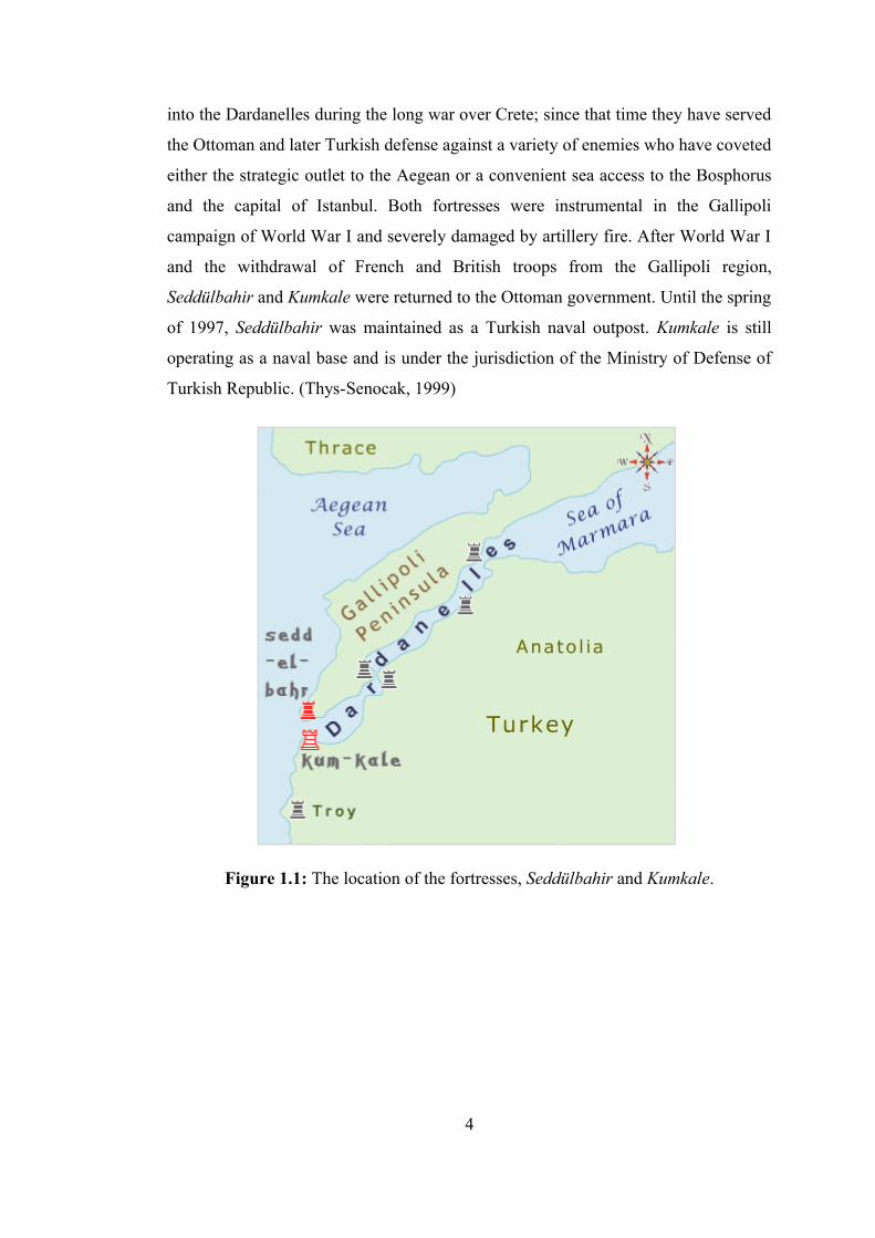
The location of the fortresses is approximately 26°.199 EITRF and 41°.006 NITRF and
the distance between the two fortresses is approximately 4150 meters. As shown in
figure 1.1, they stand opposite each other on either shore of the Dardanelles, in north
western Turkey. Seddülbahir is located on the European side of the straits, at the
southern end of the Gallipoli Peninsula. The fortress of Kumkale is on the opposite
Asian shore, approximately five kilometers from Troy. (Guney et al., 2002)
The cultural heritage of a region such as Dardanelles is of extreme importance to
understanding of the many civilizations and peoples who inhabited and controlled
these ancient straits. As the site of cities such Dardanos and Homerös Troy, much
attention has been devoted to the documentation and preservation of the very ancient
cultural heritage sites in the Dardanelles. However, comparatively little attention has
focused upon the more recent Ottoman past and the architectural sites which remain
from the seventeenth centuries of the Ottoman presence in this region. (Thys-
Senocak, 1999)
The fortresses of Seddülbahir and Kumkale were built in the mid-seventeenth century
(1658-1659) at the entrance to the Aegean, on either side of the Straits by Hatice
Turhan Sultan, the mother of the Ottoman sultan, Mehmed IV. Initially the fortresses
were constructed as part of the Ottoman defense against Venetian naval invasions
3
into the Dardanelles during the long war over Crete; since that time they have served
the Ottoman and later Turkish defense against a variety of enemies who have coveted
either the strategic outlet to the Aegean or a convenient sea access to the Bosphorus
and the capital of Istanbul. Both fortresses were instrumental in the Gallipoli
campaign of World War I and severely damaged by artillery fire. After World War I
and the withdrawal of French and British troops from the Gallipoli region,
Seddülbahir and Kumkale were returned to the Ottoman government. Until the spring
of 1997, Seddülbahir was maintained as a Turkish naval outpost. Kumkale is still
operating as a naval base and is under the jurisdiction of the Ministry of Defense of
Turkish Republic. (Thys-Senocak, 1999)
Figure 1.1: The location of the fortresses, Seddülbahir and Kumkale.
4
1.3 Evolution of the Project
Due to the fact that each valuable element of the historical remains from this
Ottoman era is vanishing as a result of the deleterious effects of natural and human
interventions, the first step in the preservation of these historical remains was a
thorough documentation of existing structures and site characteristics. It is with this
larger, long-term goal that the team of land surveyors, architects, historians and
archaeologists began in 1997 to work on the Documentation Project of Seddülbahir
and Kumkale Ottoman Fortresses. Apart from very simple drawings by the Ottoman
military and European the Ottoman fortresses of Seddülbahir and Kumkale had not
been documented or surveyed until this project began. (Guney et al., 2002)
The aim of the project was twofold: first to document the existing remains of the
fortresses by generating the maps of the sites and architectural drawings of the
structures on these sites; second, to bring together a vast array of both spatial and
non-spatial data such as repair records from the Ottoman archives, European and
Ottoman historical chronicles, historical maps, drawings, engravings and archival
photographs from various libraries’ collections in order to assess the development of
the fortresses and adjoining structures. (Ozsavasci et al., 2003)
An additional facet of the project that developed in the 1999-2001 seasons at
Seddülbahir and Kumkale was the oral history of the villages whose locations were
within the parameters of the historical research and survey project work. (Ozsavasci
et al., 2003) Another part of the project that the epigraphic-morphological-
demographic documentation of the remaining 287 Ottoman tombstones of the
Kumkale cemetery which was completed using a Geospatial Information System
(GIS) application. (Guney et al., 2002)
Although there are several consecutive projects regarding the fortresses Seddülbahir
and Kumkale, they are basically a joint project undertaken at the Division of
Geodesy, İstanbul Technical University (Turkey) and the Department of History,
Koç University (Turkey) for the preservation of the fortresses.
5
The projects regarding the fortresses are the following:
• the Documentation Project of Seddülbahir and Kumkale Ottoman Fortresses
(1997-2003)
• the Oral History Project of two Villages of Seddülbahir and Kumkale
• the Epigraphic-Morphological-Demographic Documentation Project of
Kumkale Cemetery
• Seddülbahir Fortress Site Survey-Restitution-Restoration-Reusage Project
(2004-2006)
• the Museum Project of Seddülbahir Fortress (in the planning phase)
1.4 Scope and Contents of the Dissertation
The design of “GeoCHEAF” will be examined in this dissertation, followed by an
explanation of the process through which the appropriate methods, technologies,
standards and tools were chosen to fulfill the requirements of the cultural heritage
domain.
The scope includes every phase of CH informatics: initial data capture/digitization,
information/data processing and analyzing, reconstruction, visualization and
documentation as well as the dissemination of results to the scientific and CH
communities and to the general public.
There is a growing movement toward developing enterprise architectures. Chapter 2
first introduces enterprise and enterprise architecture concepts and terms,
emphasizing the importance of these architectures in reaching business goals. Then,
it analyzes the challenges of application in the CH domain and illustrates a high-level
approach for building “GeoCHEAF”. This chapter intends to convey the message
that this architecture is a business tool and attempts to take a holistic view of the
business architecture while aligning with the technical architecture.
In the following chapters, the technical sub-architectures of “GeoCHEAF” are
expanded. A summary and classification of the relevant technologies and techniques
are presented in these chapters, providing a roadmap for technology selection &
fusion and pointing out the strengths and weaknesses of each.
6

The first section of chapter 3 will describe the impact of open source strategy in the
CH sector and illustrate these with open source solutions. Section 2 explains
semantics architecture of “GeoCHEAF”. In the another section of this chapter, an
overview of what the Unified Modeling Language (UML) stands for and the thirteen
diagrams that make up UML will be discussed. This section will help the reader
understand what features are required when selecting a UML tool. At the end of the
section, a figure and a UML diagram for the project will be built. In the last section,
the reader will be introduced to the role of Extensible Markup Language (XML) and
how XML and its offshoots, such as GML and X3D, can be used in the CH projects
and SIS applications will be explored and defined. Additionally, this chapter will
focus upon the potential impact of GML on the SIS.
Chapter 4 takes the reader through the web application world, explaining the road to
dynamic content as a sequential narrative, starting with a brief review of the
architectural foundations of the web and design points for web applications. The goal
of this chapter is to derive order from the chaos by describing the foundations of the
web and classifying the related technologies and programming techniques that are
used to create dynamic web applications. In this chapter, the reader will be
introduced the Java Enterprise Edition (Java EE) application environment as well as
the concept of Service Oriented Architecture (SOA). It examines the qualities of a
good middle-tier architecture so that an assessment can be drawn of these
architectures. In addition, this chapter looks beyond Java at standards and
implementations that provide for broad interoperability across heterogeneous
application environments. Finally, this chapter presents a picture of web services and
provides a look at how emerging web services standards will address the next
generation of reliable information systems. The vision of this chapter is to enable CH
enterprises to quickly deploy complex web applications and services for their
projects.
The goal of chapter 5 is to form a comprehensive framework for data encoding, data
exchanging among different systems of “GeoCHEAF”, and data/information storing.
The process towards integration is going to be achieved by developing a dynamic
data model capable of understanding complex realities, as the opposite of a static
7

model of only information retrieving and query, and constructing an enterprise level
database able to manipulate these data sets. This chapter also discusses the process of
extracting, transporting, transforming, and loading data in a data warehousing
environment.
The main goal of chapter 6 is to provide the reader with an overview and basic
understanding of the key ideas and principles in data visualization. In this chapter
how to apply the visualization framework to build a web-based visualization tool for
geospatial data and how graphical methods can increase the understanding of
complex data will be examined. Specifically, an interactive web-based CH data
visualization architecture is going to be aimed to design. It explores various
possibilities and ways to represent CH data in a virtual environment with a goal to
help both expert and non-expert users to understand CH data more intuitively.
Chapter 7 addresses the topic of content networking exclusively and
comprehensively. It emphasizes why and how content delivery works today, and
applies that knowledge in the future. The first section of the chapter summarizes the
content management architecture by presenting a classification of technologies that
are relevant to dynamic content generation for the web. This section also
demonstrates how to develop the successful use of a web portal to manage a multi-
participant SIS project. Here, what would otherwise serve primarily as a data source
has been expanded into a communication hub and a collaborative analysis tool for
enterprise constituents, project members and the general public alike. The following
sections presents security and physical infrastructure issues.
The main aim of chapter 8 is to develop strategies, which would allow for a universal
method of mapping the spatial dimensions of CH resources. It describes spatial
informatics technology and mostly demonstrates how a SIS project can be designed
and managed for the CH domain. It presents the development of a web-based SIS
system as a component of the technical architecture framework of “GeoCHEAF”
and, discusses and critiques the performance of an interactive geo-query tool. The
chapter also examines the past, current, and future of SIS within an enterprise
architecture context, and applies the experience, discipline, and future direction of
the Information Systems (IS) profession to GIS.
8

Finally, chapter 9 draws the conclusions and recommendations of the dissertation.
Appendix A focuses on the languages. It first explains what a markup language is,
the brief history of markup languages and some of the people involved their creation,
the value of using markup languages, a comparison of them and why XML was
chosen in this dissertation. Afterwards, it investigates programming languages.
Appendix B provides the overall figure of “GeoCHEAF”.
9
2. AN ENTERPRISE ARCHITECTURE FRAMEWORK: “GeoCHEAF”
2.1 Defining Enterprise and Enterprise Architecture
This section provides a conceptual overview of the field of Enterprise Architecture
(EA) and its associated disciplines. EA is still relatively immature from both a
research and practical perspective and there is not a widespread consensus on the
terminology. The terms 'Enterprise Architecture' and 'Enterprise' are interpreted and
defined in many different ways and there is no single universally accepted definition
yet.
An Enterprise is any collection of organizations that has a common set of
goals/principles and/or single bottom line. In that sense, an enterprise can be a whole
corporation, a division of a corporation, a government organization, a single
department, or a network of geographically distant organizations linked together by
common objectives. (Schekkerman, 2004)
From the viewpoint of this study, the definition of an enterprise is an open networked
organization together with its systems (nodes) and their relationships (links) for
which knowledge is the primary resource, information is the main asset, data and
data sharing is the main business concern, and ICT is the underlying tool.
In this context, the “KaleTakimi”, which is a small scale enterprise, is comprised of
systems (internal entities including Archaeology, History, Architecture, Land
Information/Management Systems) that interact with each other and which also have
external constituencies (external entities including other academic, governmental
and private-sector organizations). The internal and external business processes often
share common characteristics when managing the enterprise’s functional areas.
Those systems developed by different groups in different times are operating as one
system with a wide vision: This is what is defined as enterprise in the course of
10
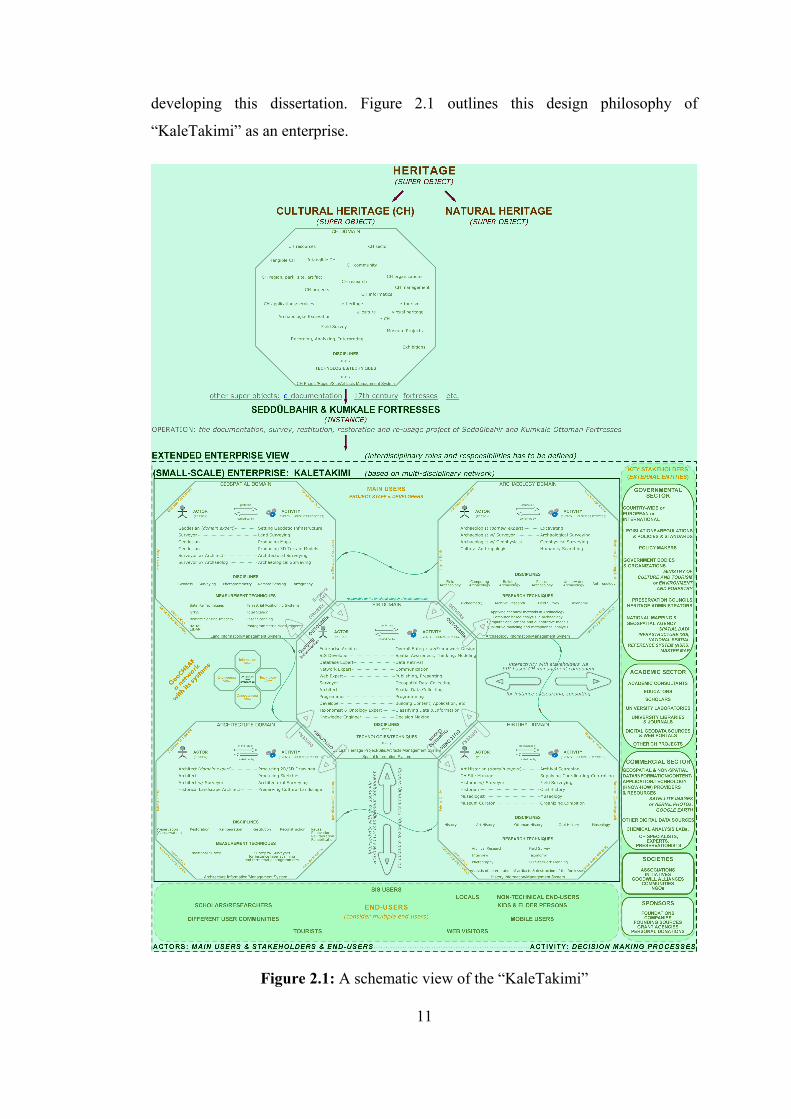
developing this dissertation. Figure 2.1 outlines this design philosophy of
“KaleTakimi” as an enterprise.
Figure 2.1: A schematic view of the “KaleTakimi”
11
It includes the full breadth of the organization, as well as the full depth of systems.
Different teams in different systems bring their own special set of demands to the
business processes. More demands require secure and fast interactions which are
electronic, common standards for information and communication technology. The
role-based process in this entity-driven architecture applied to the “KaleTakimi” is
innovative and disciplined, while ensuring consistent, reliable and adaptive business
operations. As shown in figure2.1, each system in the “KaleTakimi” generally takes
a set of drivers and produces a well thought-out and co-ordinated set of outcomes to
understand the enterprise environment and to explore solution opportunities. In other
words, these systems in the “KaleTakimi” now need to extend into the central
system, that is a spatially-enabled CH Management System, which is not under their
control and yet integrates effectively by blurring the organizational boundaries.
EA is the key facilitating ingredient providing a holistic view and a mechanism for
enabling the design and development as well as the communication and
understanding of the enterprise.
EA refers to the top level architecture of an enterprise, identifies the main
components of an organization and how the components in the organization’s
nervous system function together to provide the capability for an enterprise to
achieve defined business goals in its wide vision. The components in this context
include categories like people, processes, business and technology for instance,
goals, strategies, financial information, governance, domains, stakeholders, services,
information, communications, applications, technological infrastructure, databases,
networks etc. (McGovern et al., 2003; Schekkerman, 2004; Stevenson, 1997)
In the context of this dissertation, EA describes these systems in terms of their
behaviors, method of communications, and constraints. It holds the organization
together as it grows and evolves into the future and works across organizational
boundaries and disciplines.
It is worthwhile noting that EA is an evolving discipline and, in its relatively short
life, has already changed considerably in its scope. In the beginning, EA was
regarded as a tool for Information Technologies (IT) rationalization. Its work was
12
focused on issues involving enterprise application integration and the formulation
and the implementation of technological standards across the enterprise. While this
delivers real value, the potential is far greater. Over the last decade, the EA concept
is still evolving and moving from the technology spectrum to the overall business
spectrum. Increasingly EA is being seen as a uniquely powerful knowledge base and
route map to guide business and ICT decision-making and innovation. EA has
broadened to become a critical connection between high level business vision and its
effective expression through strategy, human process and automation. If well
executed, it will enable the design of more efficient, flexible organizations, create
more agile loosely coupled processes, and identify new forms of value to be gained
from ICT. As a discipline, it is an umbrella, over business, technology, application
and information architecture. (Slusanchi, 2005)
EA is a term that is understood differently by technology and business professionals.
Technology professionals have a wide-ranging view of EA -starting from a
structured family of technical guidelines including concepts, principles, rules,
patterns and interfaces, and the relationships among them, to use when building a
new ICT capability. In contrast, business professionals tend to ignore the term as an
ICT-only issue. Rather, they talk in terms of business models, business processes
and, sometimes, the business architecture. The technical architecture refers to how
the ICT components fit together, just as a business architecture describes how the
business is put together. In reality, they are opposite sides of the same coin -joined
completely within the EA because these two activities can be synchronized.
An EA is, in some sense, a statement of philosophy. Like all philosophies, it must
begin with assumptions about the present state and the desired future state. (Dillon,
2004) After documenting the present state architecture (current state of the
enterprise), understanding the reason for change and designing the future state
architecture (its future state), a transformation (or migration) strategy is developed
by identifying the gaps between the as-is state (current as-is architecture) and the to-
be state (target to-be architecture), which enables an enterprise to evolve from the
legacy systems of disparate stovepipe applications towards the to-be set of
modernized, agile, and integrated business processes.
13
When creating an architecture it is useful to have a framework to identify and
categorize the parts of the architecture. (Stevenson, 1997) Since there is no single
universally correct or widely agreed-upon standard enterprise architecture framework
model, organizations can either create their own framework based on their vision or
use an existing one of which there are several well-known reference frameworks
available like The Open Group Architecture Framework (TOGAF), Integrated
Architecture Framework (IAF), Federal Enterprise Architecture Framework (FEAF),
Zachman Framework, Joint Technical Architecture (JTA). (Stevenson, 1997; Dillon,
2004)
Many organizations borrow/select one or more of existing proven EA frameworks
and adapt/customize them to their needs rather than starting from scratch. On the
other hand, with such a broad array of goals, it can be very difficult to determine
which framework is right for an organization. After reviewing several different
schemes for defining enterprise architecture structure, “GeoCHEAF”, multi-tiered
conceptual framework, was developed from scratch with its own interpretation of the
CH domain, including a detailed meta-model in the form of an entity-relationship
model rather than adhering to one of the high-level industry-accepted frameworks.
Object Management Group (OMG)’s Model Driven Architecture (MDA) and
Unified Modeling Language (UML) modeling techniques were used to design
“GeoCHEAF” and to make it an executable model for the CH domain.
Enterprise models must be composed of rich semantic descriptions of organizations.
(Stevenson, 1997) Semantic web technologies (in particular, Resource Description
Framework (RDF) and Web Ontology Language (OWL)) were used to represent a
conceptual EA reference model of “GeoCHEAF” by benefiting from exiting
reference models, like International Committee for Documentation-Conceptual
Reference Model (CIDOC-CRM) by the International Committee for Documentation
(CIDOC) of the International Council of Museums (ICOM), Open Archival
Information System (OAIS) by the International Organization for Standardization
(ISO), Open Geospatial Consortium Reference Model (ORM) by Open Geospatial
Consortium (OGC), Open Systems Interconnection (OSI) etc.
14
As intended in its design, semantic interoperability capability of “GeoCHEAF”
allows it to behave in a modular fashion, allowing additional functionality and uses
to be customized as different uses for other CH projects or organizations within the
CH domain.
2.2 Business Architecture of “GeoCHEAF”
Business architecture of “GeoCHEAF” is a functional representation of a CH activity
which is meaningful to the various levels of users and encapsulated in the business
concepts that constitute well-defined structure to operate the activity properly. The
goal of the business architecture is to specify the behavior of a “system of systems”
in the context of the business for which it is implemented in terms of collaborating
and coordinating chunks of business functionality represented as business
components.
Although, at first, the term “business” seems to define a profit-generating activity, in
the context of this dissertation, the term “business” is intended to define a concept of
an organization which is directed towards maintaining collective productivity and
realizing creative goals regardless of involving commercial aspects, like profit or
trade. Rather the term “business” as it is used here, relies on sharing know-how and
know-why through the exchange of expertise and information to generate new ideas.
The reason to use the term “business” in this context is to transcend the limitations
imposed by the post modern definition of the term “business”. By expanding the
definition of this term the promotion of a common approach to the tasks of
e-documentation, preservation, management and communication of CH resources
can be better realized.
As a robust EA framework, the business architecture scope of “GeoCHEAF”
typically includes user requirements, high-level vision, missions, business goals,
objectives, strategies, solutions, and design/governance processes under its business
architecture. This scope focuses on functional and technical aspects of the enterprise
from the perspective of the users of the systems within the enterprise. This is built up
from a gap analysis of the existing environment and of the future state user
15
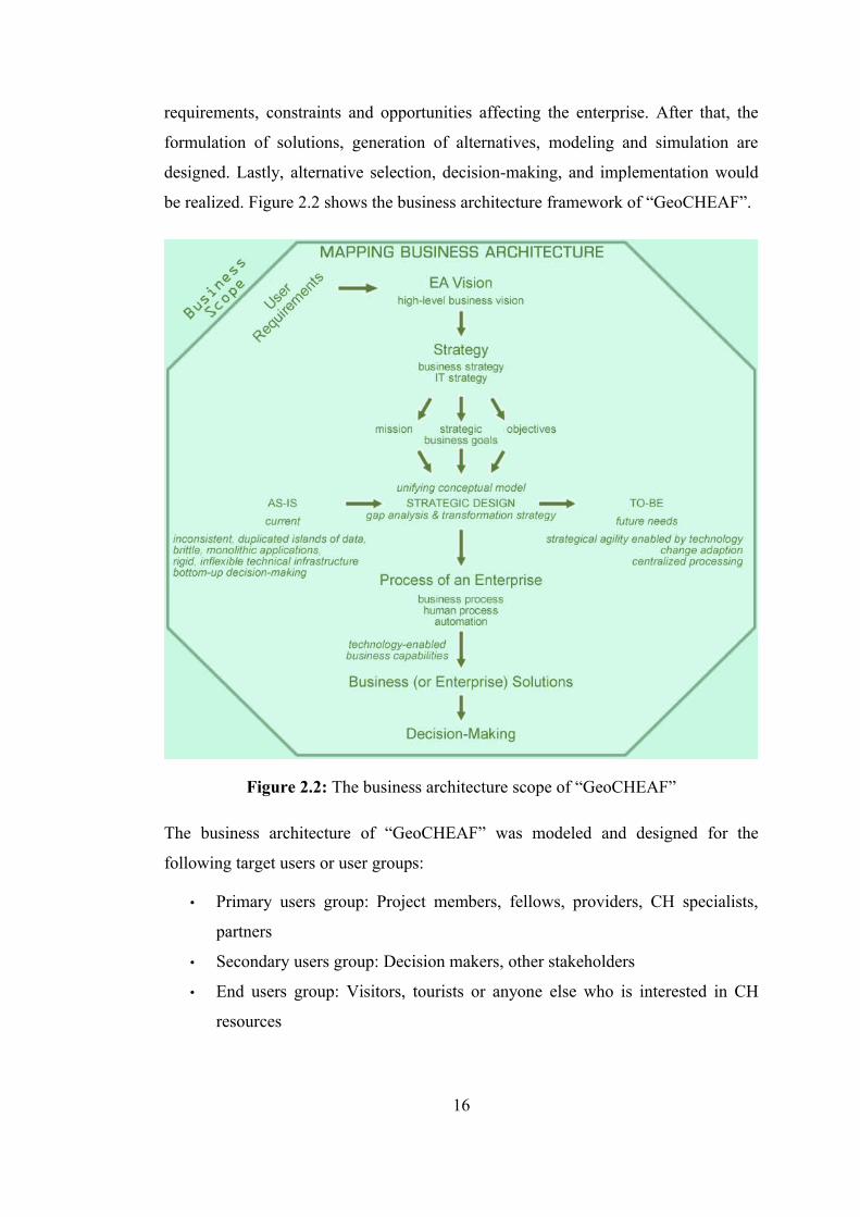
requirements, constraints and opportunities affecting the enterprise. After that, the
formulation of solutions, generation of alternatives, modeling and simulation are
designed. Lastly, alternative selection, decision-making, and implementation would
be realized. Figure 2.2 shows the business architecture framework of “GeoCHEAF”.
Figure 2.2: The business architecture scope of “GeoCHEAF”
The business architecture of “GeoCHEAF” was modeled and designed for the
following target users or user groups:
• Primary users group: Project members, fellows, providers, CH specialists,
partners
• Secondary users group: Decision makers, other stakeholders
• End users group: Visitors, tourists or anyone else who is interested in CH
resources
16
In terms of “KaleTakimi”, after the project team understood the context of the
project and “KaleTakimi” as an enterprise, identified the various user groups,
formulated the questions concerning the project with rich pictures and root
definition, and determined the expectations from the project. The vision and mission
of the project was created, and the development strategy of the project was produced
due to the user requirements matrix and the gap analysis. Prioritization of those
requirements, flow chart of the stages and timings were constituted upon that
strategy. Roles and responsibilities were defined and rationalization of ICT
investment were realized due to these user requirements.
2.2.1 User requirements
In cultural heritage research, having an idea, acquiring data, and processing it is not
enough for the CH community. With regard to ICT, there are many scientific and
technological challenges facing those working in the CH domain. These challenges
below address the problems encountered at the user level by CH community, which
will be endeavored to solve in the course of the dissertation.
The initial challenge for CH organizations is to better understand the past, achieve
sustainable and successful management of cultural heritage resources and facilitate
effective decision-making on these resources by reducing project costs and time.
Recent developments in computing –the growth of web applications, advances in
data management and visualization technology, object-oriented programming,
mobile computing, and global GIS adaption- have led to an evolving vision and role
of the CH domain. CH organizations demand the application of best-of-breed ICTs in
their projects in order to promote their research and teaching practice while enabling
significant scientific research of cultural heritage which would not be possible
without them. Furthermore, these state-of-the-art technologies make it possible to
access the data in a virtual state, as cultural heritage objects, simulating intact
artifacts, while preserving them untouched for future research.
On the other hand, most of these organizations claim that using these dizzying
cutting-edge technologies is difficult due to the high cost of software and/or data
17
processing, complexity, and the high degree of training. In other words, researchers
would prefer to focus on the science of CH instead of computer science.
The CH community needs more versatile communication among all relevant
disciplines, stakeholders and users of a cultural heritage project, primarily, between
CH data/information/content/application providers, who are aware of that their
expertise has strategic potential for CH projects, such as surveyors,
photogrammetrists, cartographers, mathematicians, statisticians, computer scientists,
data management specialists, graphic designers, and CH specialists or
professionals, who are sensitive to the importance of cultural heritage resources,
such as archaeologists, historians, art historian, architects, conservation experts,
museologists, curators and other related disciplines.
The field of CH is now a very data and information abundant sector because of the
exponential growth of data volume, complexity and quality driven by the exponential
surveying (involving laser scanning, Global Positioning System (GPS),
photogrammetry, satellite imagery, geophysics, chemical analysis) and computing
technology. One of the challenges for many organizations is to unlock existing data
held in the research team’s own silos and to make it available across the CH
organization to perform strategic and operational decisions.
There is also a need within the CH community to deliver more innovative, accurate
and better content/data/information/applications/services since better service delivery
enables the exchange and sharing of spatial and non-spatial digital CH resources
easily and effectively.
As indicated at the beginning of this section, in cultural heritage research, having an
idea, acquiring data, and processing it is not enough for the CH community. CH
research requires exploration of terabytes of data and the transformation of
qualitative observations into quantitative results by placing management, process,
computation, presentation and dissemination of vast volumes of data at the heart of
modern cultural heritage research.
18
2.2.2 Vision and mission statements
The high-level vision of “GeoCHEAF” is to engineer a spatially-enabled enterprise
architecture framework pattern for the CH domain which employs science-oriented,
user(or domain)-driven, technology-enabled, business sensitive approach.
The fundamental mission of “GeoCHEAF” is to propose innovative, interoperable,
scalable, and flexible enterprise solutions in a holistic way in order to fulfill the CH
community’s specific user requirements indicated above in achievable strategic goals
indicated below.
“GeoCHEAF” highlights an enterprise architecture approach, such that all data and
services associated with CH resources can be accessed and manipulated through the
Internet in an open, seamless framework to ensure accurate and effective enterprise
scale decision-making on sustainable and successful cultural heritage management
process by maximizing the use of (geo)data, (geo)semantics and (geo)visualization.
To achieve this, the key issue is 'technology choice and fusion' based on an open
architecture. “GeoCHEAF” uses the integration of technology that brings together
different open source state-of-the-art technologies and open standards, including
UML, XML, SOAP and Java, and extends their functionality with Internet, object-
oriented concepts, business logic and GIS features to create a highly scalable ICT
infrastructure by initiating a dialog between key technologies and CH professionals.
This strategy makes it possible for “GeoCHEAF” to have a broad interoperability
across heterogeneous data silos and application environments. It closely follows
emerging standards and technologies and also validates new technological
approaches to develop the best of breed cultural heritage applications and services.
“GeoCHEAF” contains a set of functional tools and provides a common vocabulary.
It also includes a list of recommended standards and products that can be used to
implement the CH projects.
A Communication Tool: Members of a CH project who comes from a variety of
disciplines including archaeology, art and architectural history, cultural history, oral
history, anthropology etc., need to work closely with other project members on
19
generating the conceptual model, structure and other more pragmatic aspects of the
desired project. The dialogue between project members must be able to move beyond
the project itself and present the results in an accessible and comprehensible format
to the extended enterprise constituencies such as heritage administrators, experts,
grant agencies, preservationists, and educators via a project web portal transmitted
over the web. “GeoCHEAF” provides a communication tool that first addresses and
then bridges the gaps among CH specialists, data/information providers,
content/application developers, management specialists and users including project
members, academia, researchers, scholars, end-users, stakeholders, decision-makers
for further collaboration to participate in the process. Finally, it initiates a dialogue
between technologies and CH professionals. Hence, it encourages collaboration
among all the components of the enterprise.
A Business Tool: “GeoCHEAF” fills the EA knowing-doing void among the all
components within the enterprise. It manages the complexity of the enterprise, align
business strategies and implementations, and facilitate rapid change in order to
maintain business and technical advantages. It integrates business processes among
the systems of the enterprise.
A Seamless Computing Tool: “GeoCHEAF” provides a streaming tool to integrate
all EA components, promote integration of technologies, and improve the availability
of needed data by providing distributed computing services.
2.2.3 Business goals
The business goals of “GeoCHEAF” were extrapolated at a conceptual level below
based on the future state functional and technical user requirements of CH domain:
1. Gather the knowledge and experience of how best to bring technology,
processes and people together and address the impact they can have on each
other in order to describe a specific way in which to model CH research,
projects, organizations as an enterprise, and explore spatial, temporal, social,
cultural, and economic interactions.
20
2. Perform adaptable design of “GeoCHEAF” in order to position the enterprise
to respond rapidly to changing needs, emerging opportunities and threats of
the CH domain in terms of business strategies, governance, and technologies
by aligning business and ICT strategies. Propose a service-oriented, model-
driven, component-based modeling and design approach organized around
the concepts of services and components in the Service-Oriented Architecture
(SOA). Make all the business processes web-based as part of the e-business
that is e-heritage solutions for the CH domain by ensuring adequate security
& authentication.
3. Transcend the traditional hierarchical boundaries among different systems
within an inherently interdisciplinary enterprise that has a broad range of
constituents and interfaces. Provide better understanding, productivity,
decision-making and science by supplying interdisciplinary collaboration,
exchange of knowledge and expertise in a multi-participant working
environment.
4. Share consistently deliverables internally and externally. Join up data, meta-
data, information, knowledge, contents, web applications, services, resources,
and systems in one unified environment, which is web portal, in order to
enable every member of a research team and/or other users to globally
interact with the deliverables, thus releasing the research team from a location
specific dependency. Build a rich virtual research environment and a web
based resource for edutainment and e-tourism.
5. Reduce data silos with higher levels of integrity and accuracy. User works
against one integrated system of systems that provides dynamic and
changeable views of same information and eliminates duplication of data or
data silos.
6. Set up technology enabled platform fundamentally based on a rapidly
developing technology. Provide CH professionals with an understanding of
some of the complex technology and specific technical management issues
that must be addressed when carrying out CH projects.
21
7. Deploy high-level technologies. Provide seamless integration of information,
communication and geospatial technologies and their functionalities to
improve the acquisition, distribution and use of data and information.
Facilitate interpretation, exploration and analysis of large data sets by
providing 'data exploration and discovery tools', 'state-of-the-art
visualization', 'interaction and computing technology', 'analytical tool kit'.
8. Extrapolate at a conceptual level the future state functional and technical
requirements and compare current technologies to those future state needs to
identify gaps.
9. Formulate affordable and interoperable solutions. Assemble “GeoCHEAF”
based on open architecture involving open computing standards, such as
UML, XML, SOAP and Java to formulate and implement technology
standards across the enterprise and to ensure interoperability with third-party
tools.
10. Examine geospatial information technologies, like SIS, within both enterprise
architecture and cultural heritage domain. Integrate various information
systems (CH Site Management System, Architectural or Archaeological
Information System, Monument Information System, Tourist Information
System, (Geo)Spatial Information System, etc.) in one coherent architecture.
This is done to facilitate integration of enterprise data/contents/services,
further information sharing, increase usability, reduce ICT maintenance costs
and promote effective management.
11. Document the entire architecture from requirements to implementation and
define the shortcomings in business and technological considerations which
need to be addressed.
22
2.2.4 Business strategy
“GeoCHEAF” life cycle is divided into seven parts:
1. Analysis (Preparation)
2. Design and Assess (Modeling)
3. Build
4. Deploy and Implement
5. Validate
6. Monitor and Evaluate (Operational experience, user feedbacks)
7. Maintain (Projected further developments)
2.2.4.1 Design strategy
“GeoCHEAF” presents an innovative, adaptive and holistic unified framework
design for EA that breaks the overall architecture into its major component areas.
Afterwards for each component area, a sub-architecture framework is defined.
Together, all architecture frameworks define a vision for successfully implementing
EA in CH projects through openness, interoperability, semantics and enterprise
integration.
The design of “GeoCHEAF” is defined as a four-phase development process
consisting of requirement analysis, overall EA framework and its sub-frameworks
design, the components design within the frameworks and seamless integration of the
components steps.
Requirement analysis step includes organizational structure and roles within it, target
users, exploring users’ and stakeholders’ requirements, business goals, cost &
schedule estimation, etc. Requirements comprise the contract between a developer
and all level of users that specifies what the enterprise going to be built will do to
support its vision.
The overall framework is a multi-tiered structure to maximize flexibility, adaptability
and stability. In a multi-tiered model, “GeoCHEAF” consists of several distinct but
highly interrelated frameworks, each of which can be conceptualized as having its
own distinct architecture.
23
“GeoCHEAF” is an integrating framework which incorporates the following
architectures:
1. Business Architecture: The EA describes the business but is also a part of the
business. Therefore the architecture can be described within the architecture
in terms of its models, processes, etc.
2. Technical Architecture: The technical architecture within EA is the design
required in order to 'build a responsive IT infrastructure', 'develop and
manage distributed systems', 'plan and manage communication networks', and
'define how the business will operate in the next generation of enterprise
technology'.
3. Data Architecture: A major design objective of the data architecture within
EA is to enable 'effective use of the data resources'.
4. Information Architecture: Information Architecture within EA is defined as 'a
high-level map of the information requirements of an organization'. It shows
how major classes of information are related to major functions of the
organization.
5. Application Architecture: The form and structure of the application
architecture within EA is specifically designed to 'improve the effectiveness
of application development'.
In the context of this dissertation, as displayed in figure 2.3, the focus is mainly on
technical attributes. Data, information, and application aspects are expanded as sub-
architectures of the technical architecture to be able to maintain wholeness and
harmony in the scope of the dissertation.
EA is about understanding all of the different components that go to make up the
enterprise and how those components interrelate. Components in this context are all
the components that enclose the areas of people, processes, business and technology.
In that sense, examples of components are: strategies, business drivers, governance
principles, stakeholders, units, locations, budgets, domains, functions, processes,
24
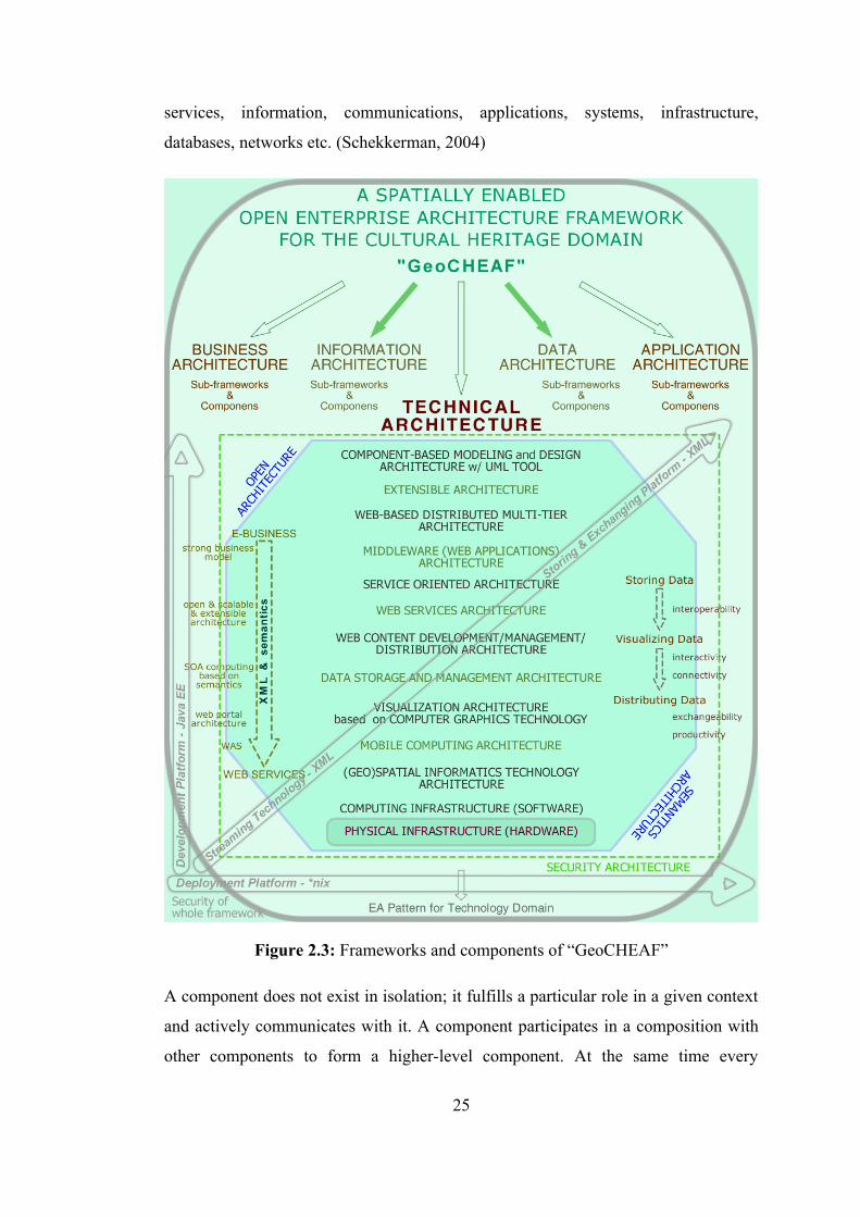
services, information, communications, applications, systems, infrastructure,
databases, networks etc. (Schekkerman, 2004)
Figure 2.3: Frameworks and components of “GeoCHEAF”
A component does not exist in isolation; it fulfills a particular role in a given context
and actively communicates with it. A component participates in a composition with
other components to form a higher-level component. At the same time every
25
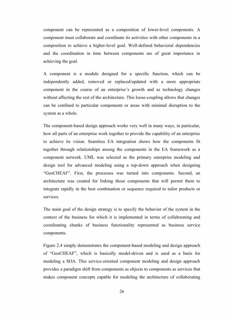
component can be represented as a composition of lower-level components. A
component must collaborate and coordinate its activities with other components in a
composition to achieve a higher-level goal. Well-defined behavioral dependencies
and the coordination in time between components are of great importance in
achieving the goal.
A component is a module designed for a specific function, which can be
independently added, removed or replaced/updated with a more appropriate
component in the course of an enterprise’s growth and as technology changes
without affecting the rest of the architecture. This loose-coupling allows that changes
can be confined to particular components or areas with minimal disruption to the
system as a whole.
The component-based design approach works very well in many ways, in particular,
how all parts of an enterprise work together to provide the capability of an enterprise
to achieve its vision. Seamless EA integration shows how the components fit
together through relationships among the components in the EA framework as a
component network. UML was selected as the primary enterprise modeling and
design tool for advanced modeling using a top-down approach when designing
“GeoCHEAF”. First, the processes was turned into components. Second, an
architecture was created for linking those components that will permit them to
integrate rapidly in the best combination or sequence required to tailor products or
services.
The main goal of the design strategy is to specify the behavior of the system in the
context of the business for which it is implemented in terms of collaborating and
coordinating chunks of business functionality represented as business service
components.
Figure 2.4 simply demonstrates the component-based modeling and design approach
of “GeoCHEAF”, which is basically model-driven and is used as a basis for
modeling a SOA. This service-oriented component modeling and design approach
provides a paradigm shift from components as objects to components as services that
makes component concepts capable for modeling the architecture of collaborating
26
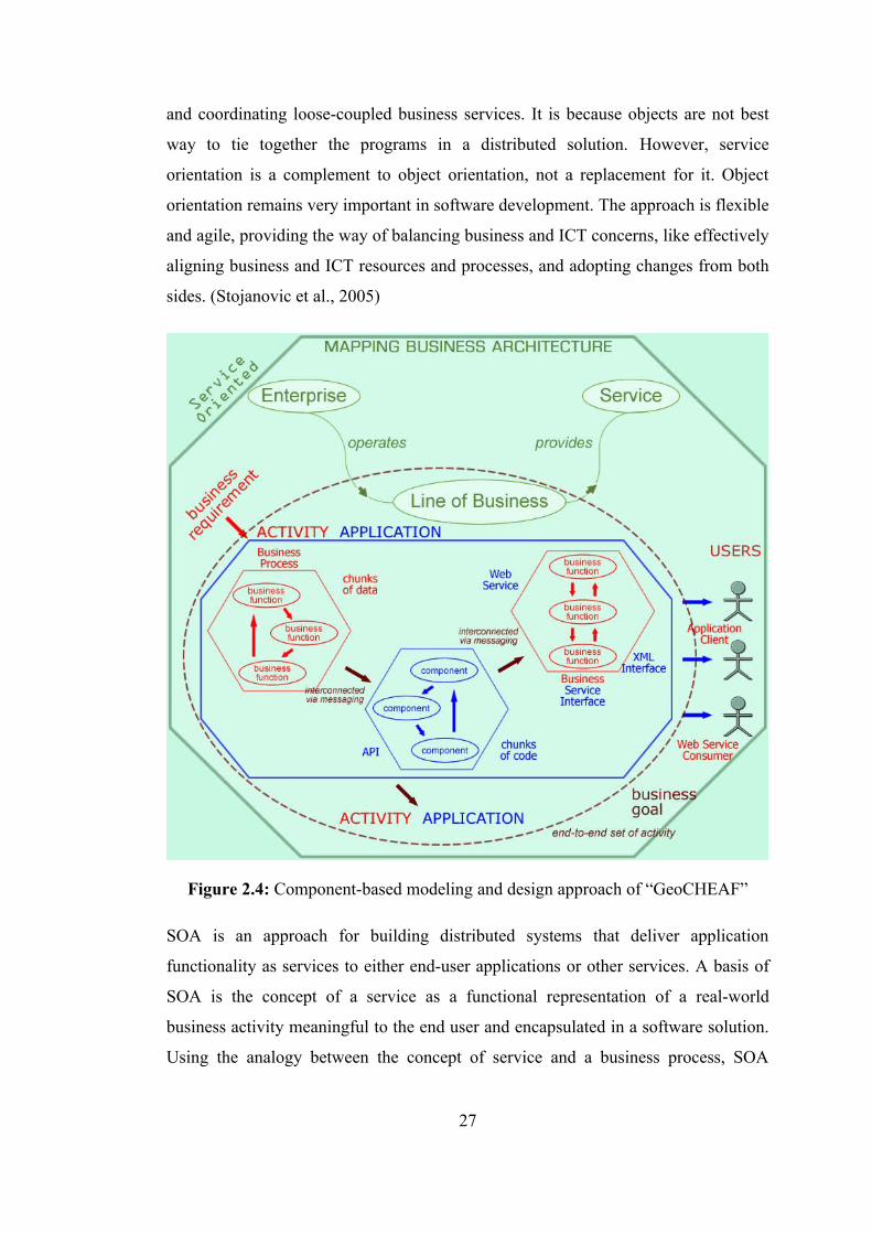
and coordinating loose-coupled business services. It is because objects are not best
way to tie together the programs in a distributed solution. However, service
orientation is a complement to object orientation, not a replacement for it. Object
orientation remains very important in software development. The approach is flexible
and agile, providing the way of balancing business and ICT concerns, like effectively
aligning business and ICT resources and processes, and adopting changes from both
sides. (Stojanovic et al., 2005)
Figure 2.4: Component-based modeling and design approach of “GeoCHEAF”
SOA is an approach for building distributed systems that deliver application
functionality as services to either end-user applications or other services. A basis of
SOA is the concept of a service as a functional representation of a real-world
business activity meaningful to the end user and encapsulated in a software solution.
Using the analogy between the concept of service and a business process, SOA
27
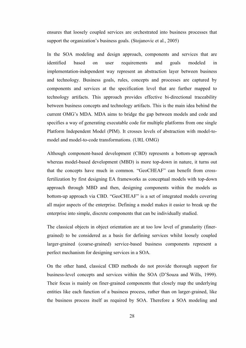
ensures that loosely coupled services are orchestrated into business processes that
support the organization’s business goals. (Stojanovic et al., 2005)
In the SOA modeling and design approach, components and services that are
identified based on user requirements and goals modeled in
implementation-independent way represent an abstraction layer between business
and technology. Business goals, rules, concepts and processes are captured by
components and services at the specification level that are further mapped to
technology artifacts. This approach provides effective bi-directional traceability
between business concepts and technology artifacts. This is the main idea behind the
current OMG’s MDA. MDA aims to bridge the gap between models and code and
specifies a way of generating executable code for multiple platforms from one single
Platform Independent Model (PIM). It crosses levels of abstraction with model-to-
model and model-to-code transformations. (URL OMG)
Although component-based development (CBD) represents a bottom-up approach
whereas model-based development (MBD) is more top-down in nature, it turns out
that the concepts have much in common. “GeoCHEAF” can benefit from cross-
fertilization by first designing EA frameworks as conceptual models with top-down
approach through MBD and then, designing components within the models as
bottom-up approach via CBD. “GeoCHEAF” is a set of integrated models covering
all major aspects of the enterprise. Defining a model makes it easier to break up the
enterprise into simple, discrete components that can be individually studied.
The classical objects in object orientation are at too low level of granularity (finer-
grained) to be considered as a basis for defining services whilst loosely coupled
larger-grained (coarse-grained) service-based business components represent a
perfect mechanism for designing services in a SOA.
On the other hand, classical CBD methods do not provide thorough support for
business-level concepts and services within the SOA (D’Souza and Wills, 1999).
Their focus is mainly on finer-grained components that closely map the underlying
entities like each function of a business process, rather than on larger-grained, like
the business process itself as required by SOA. Therefore a SOA modeling and
28
design approach should be naturally based on standard practices of component-based
and object-oriented (OO) paradigms integrated with business process and workflow
design concept and techniques. (Stojanovic et al., 2005)
2.3 Technical Architecture of “GeoCHEAF”
The technical architecture is an underlying architecture that plays a significant role in
the success of the e-heritage solutions for the CH domain. Its scope includes every
phase of CH information and communication technology: initial data
capture/digitization, information/data processing, reconstruction, visualization and
documentation as well as dissemination of results to the scientific and cultural
heritage communities and to the general public.
“GeoCHEAF” has a comprehensive and sophisticated ICT strategy to fulfill CH
enterprises’ technical requirements by deploying, customizing and optimizing
high-level innovative technologies. The major challenge is seamless integration of
multiple disparate technologies to distribute the standards-based, interoperable and
interactive services through an open, secure, scalable, distributed and
loosely-coupled technical architecture and infrastructure that meets the demands of
those enterprises’ growth.
In the course of designing technical architecture, to suit the needs of the CH domain,
a comprehensive overview of ICT and their integration problem was realized. There
are not only a vast number of both open source and proprietary technologies
available in the tremendous ICT market, but there are also rapidly evolving new
technologies. To survive within such an enormous market, the enterprise needs a
strong technical architecture, which is possible only when the architecture is flexible
enough to accommodate the integration of existing legacy applications, scalable
enough to accommodate the new innovative technologies and adaptable enough to
future changes in technology. In the market today, CH communities should be
naturally cautious about any swiftly evolving technology hype when they choose the
right technology which supports their technical architecture of their studies or
projects, especially in terms of cost, time and labor efficiency. In the ICT design
29
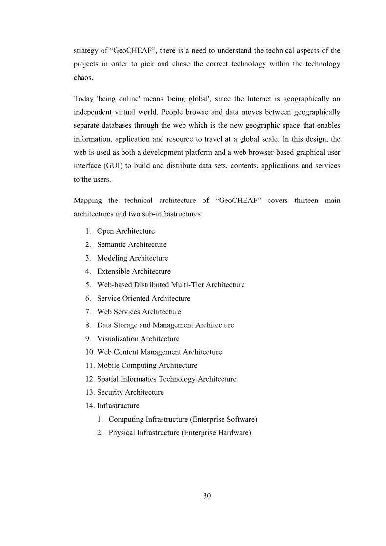
strategy of “GeoCHEAF”, there is a need to understand the technical aspects of the
projects in order to pick and chose the correct technology within the technology
chaos.
Today 'being online' means 'being global', since the Internet is geographically an
independent virtual world. People browse and data moves between geographically
separate databases through the web which is the new geographic space that enables
information, application and resource to travel at a global scale. In this design, the
web is used as both a development platform and a web browser-based graphical user
interface (GUI) to build and distribute data sets, contents, applications and services
to the users.
Mapping the technical architecture of “GeoCHEAF” covers thirteen main
architectures and two sub-infrastructures:
1. Open Architecture
2. Semantic Architecture
3. Modeling Architecture
4. Extensible Architecture
5. Web-based Distributed Multi-Tier Architecture
6. Service Oriented Architecture
7. Web Services Architecture
8. Data Storage and Management Architecture
9. Visualization Architecture
10. Web Content Management Architecture
11. Mobile Computing Architecture
12. Spatial Informatics Technology Architecture
13. Security Architecture
14. Infrastructure
1. Computing Infrastructure (Enterprise Software)
2. Physical Infrastructure (Enterprise Hardware)
30
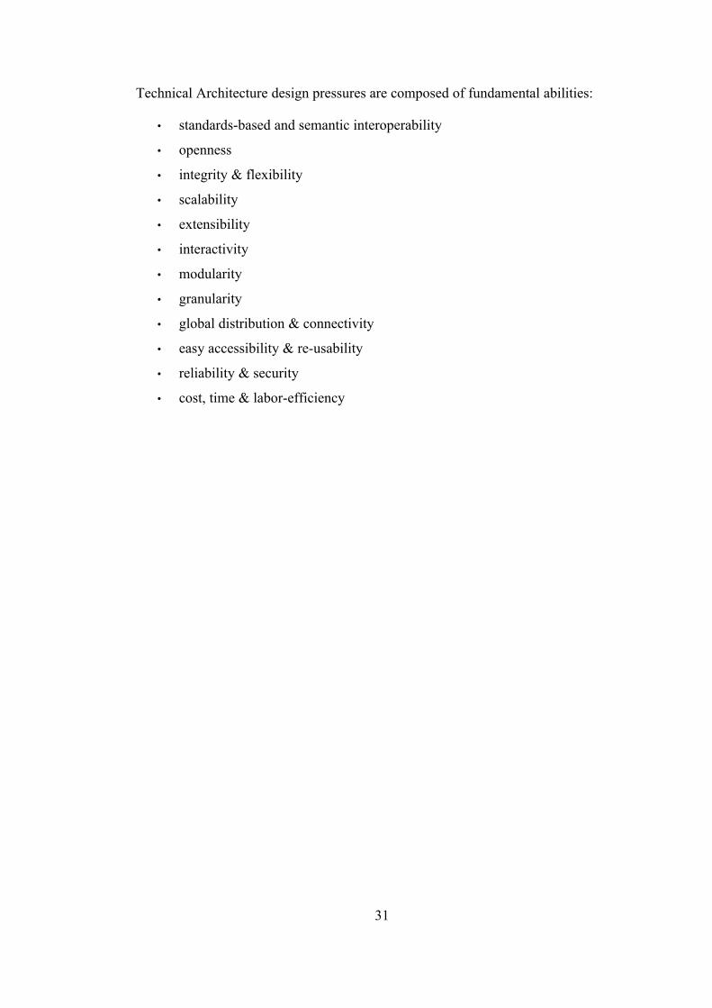
Technical Architecture design pressures are composed of fundamental abilities:
• standards-based and semantic interoperability
• openness
• integrity & flexibility
• scalability
• extensibility
• interactivity
• modularity
• granularity
• global distribution & connectivity
• easy accessibility & re-usability
• reliability & security
• cost, time & labor-efficiency
31
3. INITIAL STRUCTURAL ARCHITECTURES
3.1 Open Architecture
Before, open source software was disliked. The preconceived opinion was that a
product free of charge can not be worth as much as one which has a cost. In certain
cases, this opinion was correct, since many open source projects were not developed
well enough. But with the success of several open source projects, public interest has
been awakened. Moreover, high-end systems in many sectors were custom-built,
monolithic proprietary software systems that were expensive to develop and
maintain. With the arrival of object- and service-oriented technology, systems
integrators and software developers have realized the benefits of open, component-
based software solutions and have adopted this technology. Today, the use of open
source software has become increasingly prevalent in many areas of ICT. For
example, the majority of web sites run on open source web server software e.g.
Apache, Tomcat etc; operating systems such as Linux, BSD etc. have an increasing
share of the market; open source web browsers are also increasing in popularity e.g.
Firefox, Galeon etc. However, open source solutions might not always be better or
more advantageous than proprietary software for an enterprise. This decision is based
upon the business objectives, timeframes and the quality of the open source product.
An open architecture can help to define these decisions for an enterprise.
The open architecture of “GeoCHEAF” is not just about source code. But, it covers
the following strategic considerations together:
• Adopting and using appropriate open standards like XML, HTML, GML, and
technologies/software like Java, Linux
• Obtaining more favorable open source licensing
• Selecting the appropriate open source software
32
• Getting support from multiple communities and/or vendors
• Ensuring interoperability with third-party tools and integrating with new
technologies later in the process
The architecture based on these strategic considerations maximizes interoperable
information and knowledge sharing via standards-based open source
solutions/technology/software/products. Additionally, it investigates what the
business benefits and pitfalls would be for open source technology for the CH
community.
The architecture was to be based on mainstream ICT developments, including open
standards such as those of the International Organization for Standardization (ISO),
the Open Geospatial Consortium Inc (OGC), the World Wide Web Consortium
(W3C) and the Organization for the Advancement of Structured Information
Standards (OASIS).
Benefits of open source solutions/technology/software/products are:
• Lower cost of ownership & reduced start up cost (Open source does not
always mean free. Free and open source concepts are different. There are
also commercial open source products in market. However, property
solutions are still more expensive.)
• Independence and control over the final product
• More frequent software releases
• Faster innovation
• Support for standards
• Open source community, user groups, discussion forums and good support
• Open code
• Good functionality
• Well tested software
• Availability of alpha releases
• Maximizing the client rights
33
Pitfalls of open source solutions/technology/software/products are:
• Hacking
• Often poorly documented
• Support from original developers sometimes slow
• No liability, responsibility is on the user
Pitfalls of closed source/proprietary software/commercial products/vendor products
are:
• Higher cost
• Closed source
• Vendor perspective
• Support generally available at a price
As the industry moves more toward open standard technologies, more vendors
support them. For example XML, GML, SVG, all major software vendors like
Autodesk, ESRI, are supporting these standards in their own products like Autodesk
Map Guide Open Source, ArcGIS.
On the other side, it is a tough challenge to choose the right open source solution
because presently there is too much fragmentation in the market. For instance, there
are over 100,000 open source Linux projects, or more than 50 open source web
application development frameworks. Not all of them will be successful or get
noticed in the realm of the Enterprise. “GeoCHEAF”s open architecture identified
each of the technology domains needed in the enterprise and matched open source
products to them as shown in table 3.1 briefly.
The open source technologies chosen tightly dovetailed as the components of the
technical architecture of “GeoCHEAF” to create an affordable and effective open
source computing platform for the CH domain.
Open source starts with licenses. Open source software is distributed under a variety
of different types of open source licenses -GNU General Public License (GPL), GNU
Lesser GPL (formerly Library GPL) (LGPL), Berkley Software Distribution (BSD),
Massachusetts Institute of Technology (MIT), mixed/dual licensing, e.g. MySQL- all
34

with the intent of guaranteeing that the code remains open. By definition, these
licenses must not be specific to certain software distributions, and cannot restrict any
product that is distributed alongside the open source software. Open source
foundations such as Open Source Initiative (OSI), Free Software Foundation (FSF),
GNU (that is a recursive acronym for 'GNU’s Not Unix'), are non-profit
organizations dedicated to managing and promoting open source definition.
Table 3.1: The appropriate open source software selection of “GeoCHEAF”
Technology Domain Open Source Software (Product)
License
Modeling and Designing Tool
ArgoUML & PoseidonCE BSD
Operating System (OS) Solaris 10 Distro License for Java (DLJ)
Development Platform Java EE Java Research License(JRL)
Integrated Development Environment (IDE)
Eclipse Eclipse Public License
Web Server Apache + Tomcat GNU GPLApplication Server JBoss GNU LGPLDatabase Server MySQL & PostgreSQL GNU GPL & BSDXML Database eXist GNU LGPLDatabase Tool phpMyAdmin / phpPgAdmin GNU GPLMap Server UMN MapServer MapServer LicenseData Persistence Tool Hibernate GNU LGPLProgramming & Scripting Java, PHP, Python PHP License, Python
LicenseWeb Content Management
Typo3 GNU GPL
Productivity OpenOffice.org GNU LGPLSecurity OpenSSH BSDWeb Browser Mozilla Firefox & Opera Mozilla Public License
(MPL) & Opera License
Directory OpenLDAP OpenLDAP Public License
35
Linux is written and distributed under the GNU GPL which means that its source
code is open, freely-distributed and available to the general public. So, even one can
modify source code, and recompile and make one's own Linux version.
3.2 Semantic Architecture
The meaning of information is referred to as semantics and meaning is always in the
relationships between things. The semantics architecture of “GeoCHEAF” provides
semantic representation for the enterprise and its architecture including systems,
data, adaptive information, declarative knowledge, applications and services in order
to improve e-heritage solutions for the CH domain through semantic standards and
technologies, semantic and enterprise integration, ontology driven semantic
interoperability, and semantic web ontologies. In such an architecture, distributed
repositories can be searched and relevant information according to user specified
criteria are found and merged by means of an intelligent web agent or web services
through the semantic web. For instance, a sort of specific artifact in the fortresses
belongs to 17th century can be searched in different CH projects’ databases and
portals, digital archives, museum collections and old antiquarian reports.
Ontologies play a critical role in associating meaning with data such that computers
can understand enough to meaningfully process data automatically. Compared to
syntactic means, a semantic approach leads to high quality and more relevant
information for improved decision-making. Equally important is the use of
ontologies to achieve shared understanding. Ontologies are also evolving as the basis
for improving data usage, achieving semantic interoperability, developing advanced
methods for representing and using complex metadata, correlating information,
knowledge sharing and discovery. Ultimately, ontologies can be an important tool in
expediting the advancement of related sciences, and they can reduce the cost by
improving sharing of information and knowledge.
Figure 3.1 demonstrates interoperability spectrum from weak semantics to strong
semantics. Ontologies provide vocabulary control just as taxonomies and thesauri do,
but there are important differences. In general, ontologies aim to represent
36
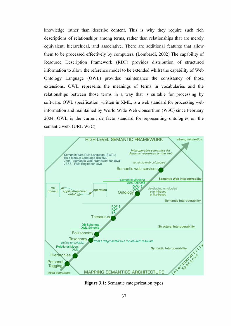
knowledge rather than describe content. This is why they require such rich
descriptions of relationships among terms, rather than relationships that are merely
equivalent, hierarchical, and associative. There are additional features that allow
them to be processed effectively by computers. (Lombardi, 2002) The capability of
Resource Description Framework (RDF) provides distribution of structured
information to allow the reference model to be extended whilst the capability of Web
Ontology Language (OWL) provides maintenance the consistency of those
extensions. OWL represents the meanings of terms in vocabularies and the
relationships between those terms in a way that is suitable for processing by
software. OWL specification, written in XML, is a web standard for processing web
information and maintained by World Wide Web Consortium (W3C) since February
2004. OWL is the current de facto standard for representing ontologies on the
semantic web. (URL W3C)
Figure 3.1: Semantic categorization types
37
The semantic web is a new form of web content that is meaningful to computers and
in particular, connects web services. The emerging idea of the semantic web is based
on the maximum automation of the complete knowledge life-cycle processes:
knowledge representation, acquisition, adaptation, reasoning, sharing and use.
RDF is a metadata-based mechanism for helping to identify interoperability that is
maintained by the W3C . In its syntax, 'a subject makes an assertion (a predicate)
about an object' with an RDF triplet that includes a subject, pedicate and an object.
(URL W3C) Metadata means 'data about data' or 'information about information' (or
the information needed to communicate sensibly about information). (Wise and
Miller, 1997). A metadata record is a file of information, usually presented as an
XML document, which captures the basic characteristics of a data or information
resource. It represents the who, what, when, where, why and how of the resource. In
case of cartography, it could be the scale, the year of the publication or the datum
and projection of the map.
In the digital age with ever-increasing quantities of CH data being collected, stored,
and distributed in computer-readable forms, interconnection of information is
becoming essential. In other words, a coherent and standardized metadata schema is
necessary for the CH domain. There is a variety of metadata approaches which exist,
such as MidasXML schema, Dublin Core (DC) element set, Federal Geographic Data
Committee (FGDC)’s digital geospatial metadata system, and Global Change Master
Directory (GCMD)’s Directory Interchange Format (DIF), and Open Achieves
Initiative Protocol for Metadata Harvesting (OAI-PMH).
MidasXML is proposed as a historic environment-specific XML schema by the
Forum on Information Standards in Heritage (FISH), further information available at
http://www.heritage-standards.org/.
The Dublin Core Metadata Initiative (DCMI) is an organization dedicated to
promoting the widespread adoption of interoperable metadata standards that support
a broad range of purposes and business models, and is developing specialized
metadata vocabularies for describing resources that enable more intelligent
information discovery systems. The Dublin Core is a metadata element set that
38
provides an easy and concise 15 element core designed to describe any type of
information. It includes all DCMI terms (that is, refinements, encoding schemes, and
controlled vocabulary terms) intended to facilitate discovery of resources.
Implementations of Dublin Core typically make use of XML and RDF-based. (URL
DCMI)
Geospatial metadata are used to document geospatial digital resources such as GIS
files, geospatial databases, and earth imagery. A geospatial metadata record includes
core library catalog elements such as Title, Abstract, and Publication Data;
geographic elements such as Geographic Extent and Projection Information; and
database elements such as Attribute Label Definitions and Attribute Domain Values.
(URL FGDC)
Metadata has three main purposes (metadata allows one to do). First, it allows the
nature of a body of information to be assessed without having to access the data
themselves. The second purpose of metadata is that it allows a user to locate a piece
of information. The third use of metadata is that it allows similar bodies of
information to be grouped or linked together. Thus, the information about
information communicated through metadata is generally: (Wise and Miller, 1997)
• the nature of information
• the location of information
• existence of similar information
In an archaeological context, examples of each of these might be: (Wise and Miller,
1997)
• that a dataset contains information on stone tools
• that the dataset may be viewed online through the Archaeology Data Service
homepage
• that the British Museum holds a similar data set.
Since, of these metadata systems, the DC seems the most useful and the most widely
applicable metadata system, and its concise 15 element core designed to describe any
type of information including images, electronic texts, HTML pages, geospatial
surveys, etc., both the DC and RDF were used in the design of semantic architecture
39
of “GeoCHEAF” as a standard grammar for describing the content of information
resources and exchanging them across different applications and subjects.
3.3 Modeling Architecture
It is a fact that architecture framework modeling and designing process takes longer
than the development of it. However, that development time can be drastically
reduced by proper architecture framework modeling and designing.
UML is a graphical open modeling standard language defined and maintained by the
OMG. UML 2.0 is the current official version which released in 2004. (URL OMG;
URL UML) UML was devised to satisfy the need to model OO systems and to
enable CBD. In an OO system, generally several components are tied together using
'interfaces'. To understand how those different components interact, it is quite useful
to build a model. (Maksimchuk and Nailburg, 2004)
In the design of “GeoCHEAF”, UML was selected as the primary modeling and
design tool for a CH enterprise and its systems, applications and data architectures
even though other EA and system modeling techniques and tools such as XML-based
Architecture Description Markup Language (ADML) were considered. UML-based
design of “GeoCHEAF” is matured from use cases to pattern-based EA as a
conceptual model of the CH domain.
The reason why UML was chosen for modeling and designing is standardization.
Different languages have been used for depicting systems using OO methodology.
The prominent among these were the Rumbaugh methodology, the Booch
methodology, and the Jacobson methodology. The problem was that, although each
methodology had its advantages, they were essentially disparate. UML 'unifies' the
design principles of each of these methodologies into a single, standard, language
that can be easily applied across the board for all OO systems. But, unlike the
different methodologies that tended more to the design and detailed design of
systems, UML spans the realm of requirements, analysis, and design and, uniquely,
implementation as well. (Chitnis et al., 2004a) The other reasons are:
40
• Vendor-neutral standard and authoritative source
• Best of breed solution based on natural selection
• Visual representation of executable architecture
• Reduce cost through round trip engineering
• Traceability across levels of abstraction
• Extensible semantics through profiles
Designing EA framework is a complicated task requiring the coordinated efforts of
different user groups performing various functions involving capturing the needs of
the systems and their business, bringing software components together, constructing
databases, assembling hardware to support the systems. Fortunately, the UML
enables one to model many different facets of their business, from the actual business
and its processes to ICT functions such as database design, application architectures,
hardware designs, and much more. (Maksimchuk and Nailburg, 2004)
UML provides a common graphical language for “GeoCHEAF” to bring together all
the actors of the extended enterprise, such as historians, archaeologists, architects,
surveyors, developers, users, so that they can understand the enterprise, its
requirements, and how EA framework will be created for the enterprise in a
collaborative modeling environment. By using UML, development teams of the
enterprise gained significant benefits, including easier communication between team
members, easy integration to repositories due to this language based on meta-models,
use of a standardized input/output format (XML Metadata Interchange (XMI)),
universal use for application and data modeling, unified representation from analysis
to implementation to deployment.
UML-based design of “GeoCHEAF” features an underlying meta-model which is a
model of a model. The UML meta-model expresses the proper semantics and
structure for “GeoCHEAF”. In this way, “GeoCHEAF” is flexible and adaptable
enough to be customized to the specific needs of any other CH projects or
enterprises.
41
UML is based on OO paradigm (OO modeling and design), and has some limitation
regarding ontology development (ontology modeling). These limitations can be
overcome using UML’s extensions, like UML profiles, as well as other OMG’s
standards, like MDA. Currently, there is an initiative (i.e. RFP) within the OMG
aiming to define a suitable language for modeling semantic web ontology languages
in the context of the MDA. (URL OMG; URL UML)
3.3.1 UML diagrams
A model is an abstraction that contains all the elements needed to describe the
intention of the thing being modeled. A diagram is a specific view into what one is
trying to understand in a specific context at all or some part of the model. Each UML
diagram is used for a specific purpose, typically to visualize a certain aspect of the
thing being modeled and each diagram uses specific UML symbols to achieve its
purpose. (Maksimchuk and Nailburg, 2004)
UML provides the ability to capture the characteristics of a system by using
notations. UML provides a wide array of simple, easy to understand notations for
documenting systems based on the OO design principles. These notations are called
the thirteen diagrams of UML 2.0. The beauty of UML lies in the fact that any of the
thirteen diagrams of UML can be used on an incremental basis as the need arises. For
example, if there is a need to model requirements for a given system, only the use
case diagrams can be used without using the other diagrams in UML. (Chitnis et al.,
2004a)
To understand the thirteen diagrams of UML 2.0, they were categorized
hierarchically, as shown in figure 3.2, and the ones most common used are explained
briefly as following:
1. Use case diagram: The use case diagram is used to identify the primary
elements and processes that form the system. The primary elements are
termed as “actors” and the processes are called “use cases”. The use case
diagram shows which actors interact with each use case. (Chitnis et al.,
2004a)
42
2. Class diagram: The class diagram is used to refine the use case diagram and
defines a detailed design of the system. The class diagram classifies the actors
defined in the use case diagram into a set of interrelated classes. The
relationship or association between the classes can be either an “is-a” or
“has-a” relationship. Each class in the class diagram may be capable of
providing certain functionalities. These functionalities provided by the class
are termed “methods” of the class. Apart from this, each class may have
certain “attributes” that uniquely identify the class. (Chitnis et al., 2004a)
3. Object diagram: The object diagram is a special kind of class diagram. An
object is an instance of a class. This essentially means that an object
represents the state of a class at a given point of time while the system is
running. The object diagram captures the state of different classes in the
system and their relationships or associations at a given point of time.
(Chitnis et al., 2004a)
4. State diagram: A state diagram, as the name suggests, represents the
different states that objects in the system undergo during their life cycle.
Objects in the system change states in response to events. In addition to this,
a state diagram also captures the transition of the object’s state from an initial
state to a final state in response to events affecting the system. (Chitnis et al.,
2004a)
5. Activity diagram: The process flows in the system are captured in the
activity diagram. Similar to a state diagram, an activity diagram also consists
of activities, actions, transitions, initial and final states, and guard conditions.
(Chitnis et al., 2004a)
6. Sequence diagram: A sequence diagram represents the interaction between
different objects in the system. The important aspect of a sequence diagram is
that it is time-ordered. This means that the exact sequence of the interactions
between the objects is represented step by step (in time order). Different
objects in the sequence diagram interact with each other by passing
“messages”. (Chitnis et al., 2004a)
43
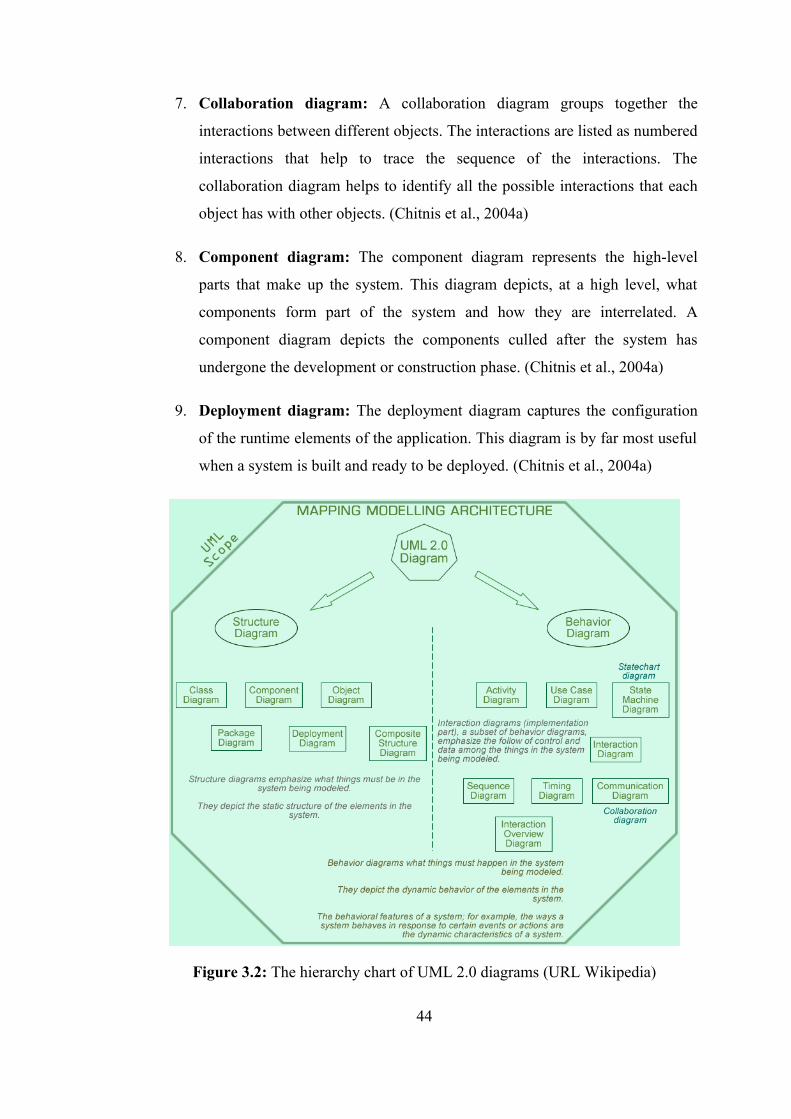
7. Collaboration diagram: A collaboration diagram groups together the
interactions between different objects. The interactions are listed as numbered
interactions that help to trace the sequence of the interactions. The
collaboration diagram helps to identify all the possible interactions that each
object has with other objects. (Chitnis et al., 2004a)
8. Component diagram: The component diagram represents the high-level
parts that make up the system. This diagram depicts, at a high level, what
components form part of the system and how they are interrelated. A
component diagram depicts the components culled after the system has
undergone the development or construction phase. (Chitnis et al., 2004a)
9. Deployment diagram: The deployment diagram captures the configuration
of the runtime elements of the application. This diagram is by far most useful
when a system is built and ready to be deployed. (Chitnis et al., 2004a)
Figure 3.2: The hierarchy chart of UML 2.0 diagrams (URL Wikipedia)
44
3.3.2 UML tools
UML does not have any dependencies with respect to any technologies or languages.
This implies that UML can be used to model systems and applications based on
either of the current hot technologies; for example, Java 2 Enterprise Edition (J2EE)
and .NET. Every effort has been made to keep UML as a clear and concise modeling
language without being tied down to any technologies.
A number of modeling tools are available on the market, ranging in price from free
to tens of thousands of dollars per seat license. Choosing the right modeling tool to
design the architecture framework of an enterprise depends on the needs, the
preferences and the budget of the enterprise. In general, the desirable features that
would definitely be noticed whether that UML tool has them:
• UML 2.0 diagram support: The UML tool should support UML 2.0 and its
all the thirteen diagrams that make up UML. (Chitnis et al., 2004b)
• Forward engineering: A UML tool should not have its use limited to just a
pictorial depiction of diagrams. Because the structure of the system defined
by the diagram is translated by a developer into actual source code (classes),
the UML tool should bridge this step by generating the source code of the
classes with the methods stubbed out. Developers can take up this stub code
and fill in with the actual code. This characteristic of automating the
generation of source code is called forward engineering. Forward engineering
support by a UML tool is normally for a specific language or a set of
languages like Java. (Chitnis et al., 2004b)
• Reverse engineering: Reverse engineering is exactly the opposite of forward
engineering. In reverse engineering, the UML tool loads all the files of the
application/system, identifies dependencies between the various classes, and
essentially reconstructs the entire application structure along with all the
relationships between the classes. Reverse engineering is a feature normally
provided by sophisticated and high-end UML tools. (Chitnis et al., 2004b)
45
• Round-trip engineering: Another useful feature apart from forward and
reverse engineering is round-trip engineering. Forward and reverse
engineering are essentially one-off activities that take input and generate the
required output. Round-trip engineering extends these features. An important
rule in software design is that no design remains unchanged. This is as true
for small systems as it is for large systems. During development, the design
structure defined in the UML model does undergo changes to incorporate
physical differences in implementation that may not have been envisaged
during design. It becomes very difficult to keep the design of the system
updated with the changes in the source code. The round-trip engineering
feature enables the UML tool to synchronize the model with the changes in
the application code. (Chitnis et al., 2004b)
• Documentation: Documentation is an integral aspect of a UML tool.
Software designing, by nature, is an abstract process. Apart from a few syntax
and semantic ground rules, there are no other rules. The thought process of a
software architect who designs applications using UML can be lost if the
reasons behind certain design decisions are not captured and well
documented. This becomes painfully clear when large systems are maintained
and no one has a clue to why a subsystem was designed in a certain way.
Hence, a UML tool must necessarily provide some way for the designer to
document design decisions in the diagrams by using simple things such as
annotations or comments. In addition to this, the UML tool should support
the generation of reports/listings of the different design elements of the
diagram. (Chitnis et al., 2004b)
• Version control: A very important feature to have in the UML tool is either
an integrated version control mechanism or connectivity to a standard version
control system. Configuration management is an integral part in the building
of software systems. Considering that the design of a system is a very
important artifact of the software lifecycle, maintaining versions and
baselines of the system design is a desirable feature to have in UML tools. In
the absence of direct support for version control, it is the responsibility of the
designer to maintain versions of the design. (Chitnis et al., 2004b)
46
• Collaborative modeling environment: Enterprise systems are huge and
their designs are quite complex. While designing complex systems, there may
be different teams involved and may carry out design work on different
subsystems in parallel. This collaborative design effort needs to be properly
synchronized by the UML tool. The UML tool should provide support for a
collaborative modeling environment with capability to compare different
versions designs for differences or even merge different versions of a design.
Collaborative modeling is always a nice feature to have in UML tools.
(Chitnis et al., 2004b)
• Integration with popular Integrated Development Environments (IDE):
With the increasing use of iterative methodologies for building software
systems, it becomes very difficult to keep the design of the system in sync
with the developed code. Hence, it would be useful if the UML tool provides
integration with an IDE. This integration of a UML tool with the IDE will
help developers to really benefit from round-trip engineering. Any changes in
the application code that developers make in the IDE are immediately
reflected in the model in the UML tool and vice versa. (Chitnis et al., 2004b)
• Test script generation: The system or subsystem designed in a UML tool
may represent a set of functional aspects as well. Hence, it would be really
useful if, in addition to generating stub code, the tool also generates test
scripts that can be used for testing how the generated class functions. (Chitnis
et al., 2004b)
• Model View Controller (MVC) modeling: Enterprise application
architectures have increasingly begun to standardize and are based on the
MCV architecture. Hence, if an n-tier web-enabled enterprise applications are
designed, a UML tool that supports designing applications based on the MVC
architecture should be used. Support for MVC modeling makes it easier to
organize and clearly distinguish the design elements along the lines of the
MVC layers. This will help in the long run in improving the readability of the
model. (Chitnis et al., 2004b)
47
The feature of publishing the UML diagrams as a set of web pages and images
enables enterprises to share and distribute their application design where the UML
tool used is not installed.
Both modeling tools 'ArgoUML', which is open source and a free-of-charge UML
modeling tool under the BSD Open Source License, and 'Poseidon for UML
community edition' from Gentleware, Inc., which has its roots in the ArgoUML open
source project, were selected to design “GeoCHEAF” in this dissertation.
Java-based ArgoUML is the leading open source UML modeling tool and includes
support for all standard UML 1.4 diagrams. It runs on any Java platform and is
available in ten languages. It also has the ability to reverse engineer compiling Java
code and generate UML diagrams for it. (URL ArgoUML)
Gentleware has taken ArgoUML a step further and turned it into a good modeling
tool. Poseidon comes in different flavors suited to different requirements. Poseidon
supports forward and reverse engineering and documentation generation by using
special-purpose plug-ins. Gentleware has not forgotten its open source moorings and
offers the Poseidon for UML Community Edition free for individual software
developers. (URL Poseidon)
It supports the UML 2.0 specification, which describes a visual language by which
maps or models of a project can be defined. It is a progressive tool that covers all
aspects of the development cycle, providing full traceability from initial design phase
through to deployment and maintenance. It also provides support for testing,
maintenance and change control. High quality documentation can be quickly
exported from their models in industry standard .RTF format and imported into Word
for final customization and presentation. (URL Poseidon)
Poseidon contains the following features: (URL Poseidon)
• UML 2.0-compliant state diagrams
• Complete copy/cut/paste of diagrams and semantic model elements
• Customizable UMLdoc for HTML
• Concurrent license server as a Windows service
48

Community Edition: (URL Poseidon)
• Fully implemented in Java, platform independent
• Forward engineering for Java
• Supports all 9 diagrams of the UML
• Saving format compliant to the UML 2.0 Diagram Interchange Standard
• Supports XMI 1.2 as the standard saving format. XMI 1.0, 1.1 and 1.2 can be
loaded
• Advanced printing options
• Exports as GIF, JPG, PNG, PS, EPS, SVG
• Undo/Redo
• Copy/Cut/Paste
• Internationalization and localization for English, German, Russian, French,
Spanish, and Chinese
'Apollo for Eclipse' from Gentleware is the first UML modeling tool that is based on
open source technology developed by the Eclipse Graphical Modeling Framework
(GMF) project and is tightly integrated into the Eclipse IDE . The fully synchronized
roundtrip engineering employs the latest releases of UML 2.1 and Java 5 to provide
an instant visualization of any existing Java code through UML class diagrams, and
likewise propagate changes to the UML model throughout the code. The tool fully
integrates into the Eclipse environment, which makes it easy for developers to view
code as models, and vice versa. (URL Poseidon)
eUML for Eclipse is a plugin for UML modeling in Eclipse. eUML Free Edition
comes with most useful diagrams: class diagram, sequence diagram, use-case
diagram. The class diagram includes real-time synchronization with the java code
inside Eclipse.
'Poseidon Community Edition' and 'Apollo for Eclipse' were used as a
comprehensive UML-based analysis and design tools that aid in “GeoCHEAF”
development from the requirements gathering stage through to analysis, design
models, testing and maintenance.
49
3.3.3 Modeling approach
A business model shows the enterprise’s function in the world, what it does, how and
when. The model should emphasize the architecture, that is, the static structures in
the enterprise, besides explaining the various flows of events, that is, the dynamic
behavior of the elements in the architecture. (Maksimchuk and Nailburg, 2004)
A use case simply describes the actions that user takes on a system. A use case
diagram includes users, use cases, and the many relationships between the two within
a system and possibly one or more subsystems. A use case diagram identifies the
actors in a system and the operations they may perform. These system use cases will
capture the scenarios of how the various actors will use the system being built. (Roff,
2002) Use case diagrams address the business processes that the system will
implement while the use cases describe ways the system will work and who will
interact with it. (Maksimchuk and Nailburg, 2004)
Use case diagrams (context diagrams) are starting pointing for designing a system or
sometimes, to describing an existing system. A use case diagram is the highest form
of detail about a system (a high-level view of a system). It is an excellent way to
communicate to management, users, and other non-development people what a
system will do when it is completed. A use case diagram does not go into detail
about how a system will do something. A use case diagram does, however, illustrate
who will use the system and what they will able to do with it. (Roff, 2002)
Actors within an enterprise -all people, businesses, and systems- play a role in
dealing with the business. Bringing these elements (business actors and business use
cases) together, the business use case model for the business are created.
(Maksimchuk and Nailburg, 2004)
Use cases approach serves as a bridge between what the business wants to be (which
is expressed in the business models) and what the system design will be (which is
expressed in the future architecture and application design models). This approach
also keeps the developer focused on the user. (Maksimchuk and Nailburg, 2004)
50
During this inception phase of the design of “GeoCHEAF”, “who will use the
system” and “what they will do it” were determined as shown in appendix B. Once
this information has been gathered, it was turned into use case diagrams and
continued on to design so that an enterprise was built that effectively meets the needs
of newly identified users and requirements. The behavioral requirements of systems
and business processes of the enterprise were also captured by writing use cases.
A business analysis model establishes what is done inside the business to fulfill its
purpose. The business object model shows which people use which things to
complete their functions. Together these provide the internal view of how the
business responds to requests from the outside world. The business use case model
and business analysis model depict how business can be described in terms of
processes that achieve goals by collaborating with different types of resource objects.
(Maksimchuk and Nailburg, 2004)
3.4 Extensible Architecture
3.4.1 HTML limitations and XML benefits
The real job of a markup language is to define information in a document. eXtensible
Markup Language (XML) is an open web standard developed by the W3C (the
original recommendation was released in December, 1997) making information
passed across the Internet 'self describing (data format)', which is independent of
platform, infrastructure, language or tool. XML transports structured text between
client and server by using pairs of human-readable text-based tags. The tags may be
nested in hierarchical tree structures upon texts. Like HyperText Markup Language
(HTML), XML is an easy markup language to understand and use. It is platform
independent and supports internationalization and localization. While HTML defines
how to display content in browsers by mixing content and presentation together,
XML is a semi-structured document, which has a custom element set that defines and
holds the content to be displayed by strictly separating the two. XML, the encoding
standard deals only with data structure. This simple fact that XML holds data
liberates it from mere document description to become a general tool for data
51
description. The motto of HTML is: “I know how it looks,” whereas the motto of
XML is: “I know what it means, and you tell me how it should look.” (Lake 2001;
Waters 1999; URL 2002; URL W3C)
Although XML and HTML look similar in coding style, XML differs from HTML in
that programmers define the rules. HTML is not extensible; it is a fixed format
markup language that is limiting. For example, in HTML one can only create one
type of document -a web page. Unlike HTML which uses a limited number of
“known” tags agreed upon W3C specifications as a fixed element set, XML allows
definition of user-defined markup elements as custom tags. Thus XML is eXtensible
that is the source of the “X” in XML. In addition, XML describe those user-defined
tags in a meta language known as the Document Type Definition (DTD). However,
DTD is difficult to write because its syntax is different from XML, so it has recently
been supplemented by XML schema, which is a meta language defined in terms of
XML itself. The XML Stylesheet Language (XSL) is more powerful than Cascade
Style Sheets (CSS), with both transformation (XSLT) and formatting object (FO)
components. (Tworkowski 2001; URL Wikipedia; Cameron 2003; Schutzberg 1999)
Though similar to HTML, XML is far more descriptive, in two ways. First, while
HTML is primarily a 'syntactic (or presentation)' language, used to specify how
things should look in a browser, XML is primarily a 'semantic” (or logical)'
language, used to specify what things mean. Second, while HTML is a single
language, XML is a meta-language –a language used as the foundation for the
creation of any number of other languages. (White Paper, 2003a)
The problem with HTML was that people wanted a system that would understand the
nature of the information it carried. The Internet’s native language, HTML, was not
designed for these tasks like re-routing vehicles, running shortest-path algorithms
and re-directing results to a variety of output devices, including full graphics for a
dispatch office’s computer, a text-based list for a hand-held organizer and audible
speech for a courier’s cell phone. HTML is a WYSIWYG language: “What You See
Is What You Get”. But the problem with that is, “What You See Is All You've Got”,
and that is not enough for Internet-based business purposes. HTML certainly is not
enough to automate spatial processing via the Internet either. A set of 'tags' are
52
needed to describe the information’s nature. A new language is required to encode
rules that describe different data types. (Waters, 1999)
HTML has been defined as 'very loose'. This means that browsers and other web
tools have been instructed to ignore minor errors or inconsistencies within the
markup up page. If one forgets to close a tag by only including the first tag (i.e. one
type<bold> but forget </bold>) this will not negatively effect the document as a
whole. In contrast, XML is very rigid, in that its guidelines prescribe that one wrong
markup tag should render the document inoperable. (Tworkowski, 2001) One
consequence of permitting authors to invent their own tags is that XML coding must
be strictly correct and contain no broken or missing tags. (Brooks, 2004)
HTML provides a simple form of linking one web page to another. This linking
mechanism, a coarse grained mechanism that only allows one to point to complete
web pages and only to single points in those web pages, is one of the key foundations
of the web. The link is established through an anchor or bookmark embedded in the
target page and a link reference embedded in the source page. Note that such a link
associates only two resources (the source and target pages) and it does so in a
unidirectional manner (source to target). XML goes much further. XML provides a
mechanism for linking multiple resources into a complex association. XML links
also can be traversed in both directions. XML further enables fine-grained
associations to be constructed. Where HTML linking only supports the linking or
association of web pages, XML linking can associate single XML elements or even
element fragments. In particular, this has profound implications for Geographic
Markup Language (GML)’s ability to build associations between spatial features.
(Lake, 2001)
3.4.2 Towards e(X)tensible HTML: XHTML
XML, unlike Standard Generalized Markup Language (SGML) is widely spread.
(Courtaud, 2002) XML is similar to the concept of SGML, and in fact, in general
terms, XML is a subset of SGML and a superset of HTML. The main purpose of
XML as opposed to using SGML is to keep the system simpler by focusing on a
particular problem -documents on the Internet. By doing so it is hoped to avoid the
53
feature-creep that complicated SGML. The newest incarnation of HTML is
eXtensible Hypertext Markup Language (XHTML), a more rigorous and robust
version that is in fact XML, and requires documents to be 'well-formed' as does
XML, but which uses mostly the familiar HTML tags. The main difference between
HTML and XHTML from the standpoint of coding the language is that all tags must
be closed, including the so-called 'empty' tags such as <br> which, not being a
'container tag', must be 'closed' in every instance like:<br />. (URL Wikipedia)
Further information pertaining to markup languages is available in the Appendix A
of the dissertation.
XHTML is not merely an expansion of previous HTML versions as HTML 4.x was
to HTML3.x, and so forth. It, although seemingly a direct descendant of the HTML
lineage, is for all intensive purposes, a new markup language. It is an XML
application that recognizes HTML 4.x and its predecessors (due to the backwards
compatibility of HTML). Its documents can still be read by HTML browsers.
XHTML is a reformation of HTML 4.x as an XML application so that HTML can
access the advantages of XML. (Tworkowski, 2001)
The problems with HTML are the followings: (Abrams, 1997)
• HTML syntax is not XML-compliant, so HTML will not work with the new
generation of web tools.
• HTML has many complex tags. It is not easy to implement all of them on
portable computing devices, cars, kiosks, etc. Additionally, HTML needs
more specialized tags for specific devices, like televisions.
XHTML characteristics are:
• Extensibility: It extends HTML by making it XML compliant.
• Modularity: It defines different groups of tags, and a device can indicate what
group(s) it implements.
• Interoperability: It permits embedding of markup tags specific to vector
graphics, multimedia, math, e-commerce, etc.
• Accessibility: It could be accessed by a wide-range of devices.
54
The e(X)tensible part of XHTML is the real key. Because it is XML-based, XHTML
allows users to create their own document types. XHTML can be extended to do
whatever the enterprise needs. To create a valid XHTML document two lines at the
top of each page must be placed: (URL W3C)
• The first line selects the XHTML Doctype (strict, transitional, frameset).
DTD (or DOCTYPE)
• The second line identifies the namespace being used.
HTML documents contain text interspersed with formatting elements. CSS allow
formatting elements to be separated into reusable style sheets. Uneven CSS
implementations in browsers and ingrained practices resulted in an extended
acceptance period for style sheets. Promotion of web standards and improved
browser implementations of the standards have recently resulted in a steadily
increasing use of CSS to separate presentation attributes from content. Client-side
scripts can be embedded in HTML documents to add interactivity to web pages and
further process a document before it is rendered by a browser. The Document Object
Model (DOM) interface allows embedded scripts to modify the structure, content,
and presentation of documents. The combination of HTML, client-side scripting, and
DOM is informally known as Dynamic HTML (DHTML). The most popular client-
side scripting language is JavaScript. It is also possible to reference Java applets,
Flash presentations, and other kinds of precompiled programs within HTML
documents, but the approach has compatibility, latency, and security issues that limit
its effectiveness. (Doyle and Lopes, 2005; URL W3C)
3.4.3 XML Family
XML is the basis of many key technologies on the web and many growing areas of
software development. XML was first designed to take into account the needs of
semantics on the web. But XML is now seen as a standardized and easy way to make
web data understandable and processable automatically with computers by making
up the meaning of the web data as the core of the web services through XML-based
web. (Courtaud, 2002) XML-based web components have proved to be the critical
technology that makes the web services application model possible. (White Paper,
55

2003a) Configurations for web applications and services are now commonly
maintained within XML files. The extensive availability of XML parsers makes it
more convenient for programmers to work with XML files rather than develop
parsers for proprietary file formats. (Doyle and Lopes, 2005) On such a semantic
web, everything -from web documents to technologies for their visualization- tends
to be presented using XML.
XML describes a family, or more correctly a class of data objects called XML
documents which are stored on computers, and partially describes the behavior of
programs that process these objects. (Tworkowski, 2001)
XML family has an extensive set of associated languages or a large set of XML-
related processing technologies:
• XML Base
• XML Inclusions (XInclude)
• XML Fragment Interchange
• DTD
• XML Schema and XSD
• Extensible Stylesheet Language (XSL)
• XSL Formating Objects (XSL-FO)
• Extensible Stylesheet Language Transformations (XSLT)
• XML Path Language (XPath)
• XML Linking Language (XLink)
• XML Pointer Language (XPointer)
• XML Query (XQuery)
• The Document Object Model (DOM)
• XForm
• XML Update Language (XUpdate)
• Simple API for XML (SAX)
and specialized languages
• Scalable Vector Graphic (SVG)
• Extensible 3D (X3D)
56

• Synchronized Multimedia Integration Language (SMIL)
• Geography Markup Language (GML)
• Resource Description Framework (RDF)
• Mathematical Markup Language (MathML)
• and the hundreds dedicated to specific applications
XML documents have a basic structure defined by the base XML specification, but
this is very generic. There are two main standards for defining the structure of
document formats using XML. The earlier standard is called a DTD, which allows
the description of the overall structure of a document, but does not provide much
control in terms of data typing or validation of those documents. (White Paper,
2003c) DTDs proved to be inadequate for the needs of users of XML due to a
number of reasons. The main reasons behind the criticisms of DTDs were the fact
that they used a different syntax than XML -SGML syntax- and their non-existent
support for datatypes. (Obasanjo, 2001) The more recent standard is XML Schema,
which provides very detailed control over the structure and content of XML
documents. As XML Schemas include type information, it is possible to validate
documents to ensure that they are in conformance with the schema, in terms of both
their structure and the data they contain. DTDs, on the other hand, can be used only
to verify the structure of a document. (White Paper, 2003c)
Unlike C, C++ and even Java, XML is not a binary language. With a simple text
editor, anyone can open any component based on any XML language and look at
what is inside. This is important in a number of respects. Any XML component can
be 'validated', i.e. read and checked for conformity with public standards. While this
would be tedious work for the human eye, validation programs can easily parse and
validate non-binary files. Also, organizations can develop more finely tuned
validators, to make sure all components conform to internal standards or industry
specific schemas. (White Paper, 2003a)
XML Schema Definitions (XSDs) can draw on a comprehensive set of predefined
data types, as well as create new user-defined types. W3C XML Schema is a
schema-definition language expressed in XML syntax.
57
An XML based schema definition language called 'Schema for Object-oriented XML
(SOX)' is for defining the structure, content and semantics of XML documents to
enable XML validation and higher levels of automated content checking. SOX
provides an alternative to XML DTDs for modeling markup relationships to enable
more efficient software development processes for distributed applications. SOX also
provides basic intrinsic datatypes, an extensible datatyping mechanism, content
model and attribute interface inheritance, a powerful namespace mechanism, and
embedded documentation. As compared to XML DTDs, SOX dramatically decreases
the complexity of supporting interoperation among heterogenous applications by
facilitating software mapping of XML data structures, expressing domain
abstractions and common relationships directly and explicitly, enabling reuse at the
document design and the application programming levels, and supporting the
generation of common application components. (URL W3C)
XML’s popularity has resulted in a proliferation of schemas and related Internet
standards. Enterprises are creating these XML dialects to suit their particular
business needs. These standards vary not only from sector to sector, but even among
individual systems within the enterprise. Integrating these different XML formats can
quickly become a nightmare. XSLT, which is a native XML transformation
mechanism, provides a mechanism to map one to another. XSLT is a language
(defined in XML itself) that allows developers to define rules for programmatically
transforming the structure of XML documents, such as transforming XML to XML,
XML to other XML-compatible languages (e.g., XHTML). XSLT does not contain
just mechanisms for mapping XML documents from one form to another, but it can
also be used to convert common document formats such as Comma-Separated
Values (CSVs), HTML, DTDs, XSDs and so on. XSLT mappings can be applied
dynamically at runtime, thus automating one of the more tedious aspects of
integration –data transformation. (White Paper, 2003c) For the beginner, although
XSLT provides an extremely powerful XML mapping and transformation capability,
it also has a considerable technical learning curve since XSLT mapping definitions
can quickly become very complex. (URL Cocoon) XSLT is designed to be used with
XML documents to transform data into a form appropriate for presentation in a
particular context or into an alternate XML structure. The output from an XSLT
58
transformation can be another XML format. XSLT is ideally suited to creating
HTML documents from XML server-side with the HTML produced being processed
by a user’s web browser in the normally way.
Apache Cocoon, a well-known XML transformation framework, supports dynamic
content generation to multiple client types (channels) through its XSLT-based
eXtensible Server Page (XSP) templating language. (Doyle and Lopes, 2005)
XSLT is usually used in conjunction with another standard XML technology-XPath.
XPath is an expression language used by XSLT to address a part of an XML
document. XPath makes it easy for developers to select, group, sort, or compare data
in XML documents. In XPath, an XML document is treated as a logical structure and
is viewed as a hierarchy of nodes. The combination of XSLT and XPath enables
developers to build very sophisticated mappings. For example, it is possible to
construct conditional mappings, where the transformations depend on the actual
dynamic data in the document being processed. This flexibility and power make the
XSLT/XPath combination a fantastic tool for systems integrators, who often have to
integrate data from many incompatible sources. (White Paper, 2003c; Obasanjo,
2001)
Smallx is a library and set of tools that is being developed to process XML infosets.
It has two distinct features in that the infoset implementation allows streaming of
documents and that processing of infosets can be accomplished using a concept
called pipelines. The library contains a full compliment of technologies including
XPath and XSLT. All of the sources for smallx are organized into a set of Netbeans
projects. (https://smallx.dev.java.net/)
XLink and its associated XPointer specification are intended to provide linking
functionality on the web. This will provide XML-based linking functionality
equivalent to HTML, but with significant enhancements (more sophisticated form of
hyperlink). Relevant parts of XLink and XPointer have already been implemented in
SVG and probably will be implemented in at least some other XML applications.
59

XML query languages like XPath and XQuery address the problem of accessing
specific information inside the tree structure of XML data.
XQuery is an attempt to provide a query language that provides the same breadth of
functionality and underlying formalism as SQL does for relational databases.
XQuery is a functional language where each query is an expression. XQuery
expressions fall into seven broad types; path expressions, element constructors,
FLWR expressions, expressions involving operators and functions, conditional
expressions, quantified expressions or expressions that test or modify datatypes. The
syntax and semantics of the different kinds of XQuery expressions vary significantly
which is a testament to the numerous influences in the design of XQuery. XQuery
has a sophisticated type system based on XML schema datatypes and supports the
manipulation of the document nodes unlike XPath. Also the data model of XQuery is
not only designed to operate on a single XML document but also a well-formed
fragment of a document, a sequence of documents, or a sequence of document
fragments. (Obasanjo, 2001)
XML appears to have the potential to make a significant impact on database
applications, and XML is already being used in several database applications. One of
the main reasons for this is that the “superiority” of XML schemas for data modeling
-recursion and union types are easily specified using XML schemas. In order to do
data modeling effectively, it should be studied systematically. A data model has three
constituents to it -structural specification, constraint specification, and operators for
manipulating and retrieving the data. Regular tree grammar theory has established
itself as the basis for structural specification for XML schemas. Constraint
specification is still being studied, and there are some approaches such as 'path-based
constraint specification' and 'type-based constraint specification', with strong
indications of type-based constraint specification as a very suitable candidate.
Operators are available as part of XPath, XSLT, XQuery etc.
Many applications need to access both XML and relational data. This is often done
by representing relational data as XML or by using an XML view of relational data.
The ISO SQL/XML specification provides a mapping from relational data to XML.
Given that, XQuery can be useful both for XML and XML views of relational
60
sources (XML queries on relational sources), but mapping XQuery to SQL is
complicated by the lack of nested structures in the relational model and the
difference in expressive power between XQuery and SQL. XQuery facilities to
access XML documents like databases for pattern matching and manipulation.
W3C has released XML Syntax for XQuery (XQueryX), in June 2001, that has the
same semantics but uses XML based syntax instead called XQueryX. XQueryX is
designed to be machine-readable to enable standard XML tools to create, read and
modify queries. Expected uses of XQueryX include: automatic generation of queries,
queries on queries (where queries are queried, and may be transformed into new
queries), parser reuse (where one parser may generate XQueryX for multiple
systems) and embedding of queries in XML documents. (URL W3C)
The XML DOM, a series of W3C specifications, defines a standard way for
accessing and manipulating XML documents. The DOM presents an XML document
as a tree-structure (a node tree, XML document trees), with the elements, attributes,
and text defined as nodes. (URL W3C) Simple API for XML (SAX) is a serial access
parser for XML. It provides a mechanism for reading data from an XML document.
It is a popular alternative to the DOM. (URL Wikipedia)
GML is an XML-based encoding standard (or an XML grammar written in XML
Schema) for the modeling, transport and storage of geospatial data and information,
including both the spatial and non-spatial attributes of geographic features. (URL,
2003a) It has been developed by the the OGC as medium of uniform geospatial data
storage and exchange among diverse applications, especially in a wide-area Internet
context allowing web browsers the ability to view web based mapping without
additional components or viewers. (URL, 2002) Since spatial databases are also used
to store geospatial information, the concepts of GML can be used for the storage and
exchange of spatial databases. GML is a uniform format to store geospatial data.
GML representation of geospatial data and information is unique but the use of
information can be different and meaning can vary depending on the context. This
makes the data very flexible and portable. (Ying et al., 2006) The key concepts used
by GML to model the world are drawn from the OGC Abstract Specification that
provides a variety of kinds of objects for describing geospatial content including
61
features, coordinate reference systems, geometry, topology, time, units of measure
and generalized values. (URL, 2003a) GML must be styled for presentation.
Presentation may mean being styled to a graphical form such as a map, but equally it
could mean being styled to text or even to a sequence of voice instructions. (Lake,
2001) The weakness of a GML file is its large size because it is a single ASCII file.
The difference between XML and GML is that GML provides support for the
geometric elements corresponding to the Point, LineString, LinearRing, Polygon,
MultiPoint, MultiLineString, MultiPolygon and GeometryCollection. (URL, 2003a)
GML 1.0, published 1.0 in May 2000, was based on a combination of XML DTDs
and RDF. This was an awkward but useful combination. DTDs were in widespread
use, but lacked the ability to support type inheritance, had no underlying semantic
model, and did not support namespaces. RDF on the other hand was less accepted
but did offer namespace support, distributed schema integration, type hierarchies and
a simple semantic model. While it was possible to more or less use all of these
features it was at best an awkward combination. On February 20, 2001, the OGC
published Version 2.0 of the GML, thus laying the foundations for the development
of a geospatial web. GML 2.0 is based entirely on XML Schema and the adoption of
XSD is a major advance. XML Schema incorporates support for type inheritance,
distributed schema integration, and namespaces. Moreover there are now a great
variety of tools and parsers that support XML Schema and more are anticipated in
the near future. GML 2.0 makes use of the XLink and XPointer specifications to
express relationships between geospatial entities. This means that such relationships
can be expressed between features in the same database or between features across
the Internet. Furthermore, GML 2.0 allows relationships to be constructed between
GML feature elements in different databases without requiring any modification of
the participating databases. No more than read access is required to establish a
relationship. With GML 2.0, GML has reached a stage of maturity that enables the
construction of real spatial datasets, the interchange of spatial information and the
construction of distributed spatial relationships. (Lake, 2001)
Current version GML 3.0 has been extended to represent geospatial phenomena in
addition to simple 2D linear features, including features with complex, non-linear,
62
3D geometries, spatial and temporal reference systems, topology, units of measure,
metadata, gridded data, features with 2D topology, features with temporal properties,
dynamic features, observations, and coverage visualization. GML 3.0 is almost
entirely backwards compatible with GML 2. Like GML 2, GML 3 will play a key
role in both spatial data encoding and transport, and in the description of geographic
objects for geospatial web services. (URL, 2003a)
GML 3.0 is modular, meaning that users can select out only the parts necessary for
use, which simplifies and minimizes the size of implementations. Implementers may
use a selective subset of the GML 3.0 schemas sufficient to support the definitions in
their application schemas. GML 3.0 also includes a sample packaging tool that
creates a tailored schema containing only the required components from the GML
core schemas. GML application schemas may also be constructed as part of a model
driven process by automated translation to XML/Schema from conceptual models
defined in other conceptual schema languages such as UML. A UML diagram is
used to show the hierarchy of GML objects defined in the XML schemas. GML 3.0
uses an object hierarchy to define the various entities such as features, geometries,
and topologies. (URL, 2003a)
Arc eXtensible Markup Language (ArcXML) is ESRI’s flavor of XML. It is used for
sending requests and receiving responses through ArcIMS’ spatial server. (URL
ESRI) LandXML is a common, open data format, or schema, which describes
industry-specific data such as points, parcels and alignments. It is a specialized XML
data file format containing civil engineering and survey measurement data
commonly used in the land development and transportation industries. (URL
LandXML) There are third party editors to help with programming in ArcXML. One
such editor is called Xeena and can be downloaded from the IBM web site. Xeena is
written in Java and is no-cost. Another editor is called XMLSpy but costs. A third
option is Microsoft’s XML notepad. (URL ESRI) ArcXML will eventually be a
superset of GML. ArcXML provides the glue to link the parts of ArcIMS. For those
using ArcIMS who are not programmers, there is no need to learn ArcXML; it is
written automatically. ArcXML stores configurations and display information for
web applications as well as playing a part in the movement of data from the server to
63

the client. The response from a service might be ArcXML describing candidate
geocoding points along with their x,y coordinates, a pointer to a zip file of shape files
or the location of raster map images. (Schutzberg, 1999)
Written in XML, SVG and X3D are the application language choice for visualizing
information in 2D and 3D, respectively. They can be integrated easily with other
members of the large XML family -other XML application languages- and can also
be processed using any XML-relevant tools and technologies. For example, to view
maps in XML, SVG could be used to present GML data to the user by on the fly
conversions using XML transformations such as XML Schema, XSLT or one could
use SVG images within an XHTML web page that also contains forms using the
XML-based Xforms specification. SVG is intended to replace many uses of bitmap
graphics on the web and provide a 2D vector graphics standard that is not
vendor-specific (compare Microsoft VML) and that is open source (compare
Adobe’s Flash/SWF). Microsoft has developed Vector Markup Language (VML) as
an XML-based solution for vector graphics. Microsoft (MS) Office 2000 creates
graphics in VML from MS Word and MS Powerpoint. On the viewing side, Internet
Explorer is the only program capable of viewing these VML graphics. AutoCAD
Map also outputs VML graphics. The widespread adoption of SVG clients,
particularly those natively embedded in web browsers as it is in Firefox and Opera,
but Safari and Internet Explorer requiring a plugin.
SVG is an XML-based language used to describe an image, especially for display in
a web browser. It is a standard developed by the W3C. The use of the word
“scalable” in SVG has two meanings. First, vector graphic images can easily be
made scalable, i.e., they are not limited to a single and fixed pixel size. This means
SVG format can be displayed on any device of any size and any resolution without
changing the image clarity. This contrasts with raster image files, which are difficult
to modify without loss of information. Second, a particular technology can
accumulate a larger number of files, a large number of users, and a wide variety of
applications on the web. Other characteristics of SVG include a smaller file size and
searchable text information. Text information inside SVG is still text and can be
searchable, while text information inside the raster file becomes integrated into the
64
image and is no longer recognized as text. Further, SVG is also based on XML and
therefore conforms to other XML-based standards and technologies, such as XML
Namespace, XLink, and XPointer. XLink and XPointer allow for linking from within
SVG files to other files on the web, like a GML data element, HTML pages, or other
SVG files. (URL W3C)
Adobe SVG viewer is a plug-in for conventional web browsers.
(http://www.adobe.com/svg) The Mozilla SVG implementation from the Mozilla
project is a native SVG implementation. This is as opposed to plug-in SVG viewers
such as the Adobe viewer which is currently the most popular SVG viewer.
(http://www.mozilla.org/projects/svg/) Batik standalone SVG viewer (SVG toolkit)
from the Apache Software Foundation can also be used Java applications to
dynamically create and display SVG. (http://xml.apache.org/batik/) Other well-
known vector-drawing tools such as Adobe Illustrator (version 9 and onward) and
Corel (version 10 and onward) have SVG export facilities.
SMIL is a W3C recommended XML-based language, which facilitates the
construction of interactive multimedia applications for the Internet and mobile
devices and enables simple authoring of interactive audiovisual presentations. SMIL
is a markup language like HTML and VRML with a different tags and simple
structure to integrate and manipulate images, text, streaming audio, video and other
multimedia for “rich media”/multimedia presentation on the web. SMIL also enables
authoring of TV-like multimedia presentations. It is an easy-to-learn HTML-like
language, and many SMIL presentations are written using a simple text-editor. (URL
W3C)
Basically there are two major issues in using XML, one is how to generate an XML
document and the other is how to parse an XML document. There are different
XML, XSLT, XLink and XPointer tools available to achieve these issues, for
instance an XML tool, such XMLSpy (http://www.altova.com/), or an XML editor,
such as XMLwriter (http://www.xmlwriter.com). Open source Saxon is a Java-based
XSLT and XQuery processor. (http://sourceforge.net/projects/saxon) Xalan-Java
from the Apache Software Foundation is a Java-based XSLT processor for
transforming XML documents into HTML, text, or other XML document types. It
65
implements XSLT and XPath. (http://xml.apache.org/xalan-j/) Mozilla web browser
implements simple XLink links. The most full-featured XLink processor is the XLiP
processor from Fujitsu, which is a Java application. XLink Processor(XLiP) is an
implementation of XLink and Xpointer.
(http://software.fujitsu.com/en/interstage - xwand/activity/xbrltools/xlip/ )
New generation browsers such as the X-Smiles browser enable multiple XML
languages to combined into XML-based Web pages. X-Smiles is a Java based open
XML-dedicated browser for exotic devices. (www.x-smiles.org). It is intended for
both desktop use and embedded network devices and to support multimedia services.
The main advantage of the X-Smiles browser is that it supports several XML related
specifications and is still suitable for embedded devices supporting the Java
environment.
Formatting Object Authoring (FOA) is an authoring tool that applies XSL-FO styling
to XML content. Authors can build, modify, or import a library of style components,
which can be re-used across documents. Based on the style information, FOA
generates an XSLT stylesheet, takes in XML content, and produces an XSL-FO
document, which can then be rendered into different output formats.
(http://foa.sourceforge.net/)
XDuce ('transduce') is a typed programming language that is specifically designed
for processing XML data. One can read an XML document as an XDuce value,
extract information from it or convert it to another format, and write out the result
value as an XML document. Since XDuce is statically typed, XDuce programs never
yield run-time type errors and the resulting XML documents always conform
specified types. (http://xduce.sourceforge.net/)
3.4.4 XML-based “GeoCHEAF”
The CH community needs a global and standardized format for encoding CH data
sets that are from different sources with different formats in order to integrate and
present multiple data sources and types in a comprehensible fashion. In this manner,
the user can focus on extracting meaning from data without being required to
66
explicitly manage the heterogeneous data. Since XML provides a common medium
of data description and display for diverse systems to understand each other, the
eXtensible architecture of “GeoCHEAF” can describe virtually any type of CH data
and it can also map to the structure of the data as a well-formed XML document
and/or a highly structured hierarchical data storage like XML Native Database
(XND).
XML is a commonly available export format for databases. The XML encoding
procedure is independent of hardware and software, and therefore guarantees the
easy transfer of files to different systems.
In SIS, XML might be used to define a query. A query in XML would not, in
substance, be different than what it is asked of a SIS today: “take the area I describe
below and please buffer it. Then, send me the answer”. The response might also be
delivered in XML. The content of the reply, again, might not be so different than a
reply seen today: “Here’s where to look for the bitmap showing the answer”. The
difference using XML is that the data (the geometry in question) and the request (in
the example here, the buffer) is included in a single XML document. The reply,
basically a pointer to the bitmap, is also within an XML document.
Taken together in the design of the extensible architecture, the use of open exchange
format files (GML files) and the modular structure of the web-based SIS, customized
with scripting languages, increases the level of cross-platform interoperability and
Internet-based research. Consequently, for the CH domain, “GeoCHEAF” makes use
of the ubiquity of XML and its family as:
• an X-recording language (lingua franca for the CH domain) for the storage,
exchange and preservation of data and/or information about CH resources
and/or artifacts
• an open- and industry-standard way of representing data and database, in
particular, for the web
• a geospatial and non-spatial interoperability of the CH enterprises to share
information source with one another, and to enable linked geospatial datasets
through GIS services and web services
67

• a behind-the-scene language used to move structured data between web
applications/services.
68
4. WEB-BASED DISTRIBUTED MULTI-TIER ARCHITECTURE
To make the architecture distributed, scalable, flexible, it is designed in a multi-tiered
manner. Multi-tier architecture (may also be referred as an n-tier architecture in
reference to the unlimited number -n) provides the simplicity of developing the
system on one development machine and the flexibility of moving the components to
several distributed machines in production.
A multi-tiered architecture design should be used as the high-level architecture
design for dynamic web applications. It involves subdividing the web application
into functional components and partitioning these components into a set of physical
tiers. (Shen, 2004) A tier is composed of one or more computers that share one or
more common characteristics. Tiers are used to allow servers and client computers to
be optimized for specific tasks, such as interacting with users, serving web pages and
hosting databases. In that way, the administration and deployment overhead required
of distributed applications are reduced.
The multi-tiered architecture is fundamentally about servers. Key aspects of this
perspective include the number of servers, the role each server plays in the solution,
the relationship between servers and how the multiple servers collaborate together to
meet enterprise-level operational requirements. It is also fundamentally concerned
with components, includes packaging components into deployment units, mapping
deployment units to operating system (OS) processes and mapping these processes to
servers.
The multi-tiered architecture ensures a clean division of responsibility and makes the
system more maintainable and extensible by structuring the servers and user
computers, and distributing functionality across them to efficiently meet the
operational requirements of the enterprise. Hence, it has become the dominant
69
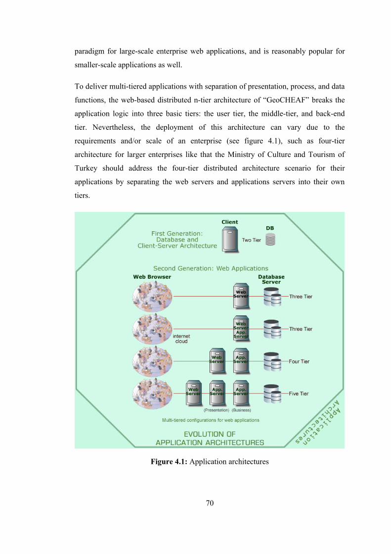
paradigm for large-scale enterprise web applications, and is reasonably popular for
smaller-scale applications as well.
To deliver multi-tiered applications with separation of presentation, process, and data
functions, the web-based distributed n-tier architecture of “GeoCHEAF” breaks the
application logic into three basic tiers: the user tier, the middle-tier, and back-end
tier. Nevertheless, the deployment of this architecture can vary due to the
requirements and/or scale of an enterprise (see figure 4.1), such as four-tier
architecture for larger enterprises like that the Ministry of Culture and Tourism of
Turkey should address the four-tier distributed architecture scenario for their
applications by separating the web servers and applications servers into their own
tiers.
Figure 4.1: Application architectures
70

The distributed three-tier architecture of “GeoCHEAF” for “KaleTakimi”s web
applications consists of three tiers and additional sub-tiers. Table 4.1 shows those
tiers in process order. The multi-tier architecture of “GeoCHEAF” that supports web
applications is shown in figure 4.2.
Table 4.1: The tiers and sub-tiers of “GeoCHEAF”
Tiers Sub-tiers Function DescriptionUser Tier Web browser as a
Thin User GUI or Thick Client
one or more applications or the Web browser
Middle-Tier Web Application TierPresentation Tier Web Server Also refers to Presentation
Logic, View Layer, Web tierBusiness Logic Tier
Application Server
Business Logic
Data Access Tier Integration Tier, data persistence, persisting, data access concerns, object-relational mapping
Back-End Tier
Data Repository Also refers to Underlying Tier, Data-Tier, and Enterprise Information System (EIS) Tier
The infrastructure required to support this architecture consists of servers to host the
web and business components, and the data tier. Network devices (routers and
switches) and communication protocols, like TCP/IP, connect servers within the
enterprise.
The user tier is where the data model is consumed and presented. For a web
application, the user tier is normally the web browser that communicates with the
web server. (Shen, 2004) In this design, web-based distributed computing has been
implemented using a thin client model that enables conversion of client/server
applications to the web. A thin client makes it possible for all business processing to
be performed in a controlled environment on a managed server (fat server). It also
eliminates the requirement that clients download additional software in order to use
the site. This distributed computing architecture enables large number of users to
71

easily and efficiently access information from all over the world. A standard web
browser is used to access and manipulate dynamic information over the Internet.
(Guney et al., 2005)
Figure 4.2: The multi-tier architecture of “GeoCHEAF”
Web browsers process user interface commands, format and send request messages
to web servers, wait for and interpret server response messages, and render content
within the browser’s display window area. HTML, CSS and XHTML are the most
common content types on the web. Browser extensibility features allow many other
content types to be displayed by deferring their rendering to registered plug-in
components (helper applications) that handle the content. Myriad browser plug-ins
provide all sorts of client-side processing. The pervasiveness of HTML makes it a
friendly target for dynamic content generation systems. (Doyle and Lopes, 2005)
72
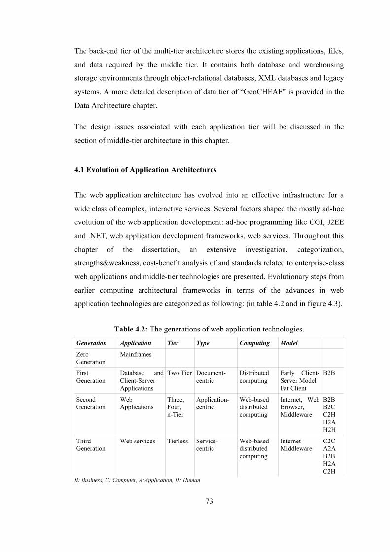
The back-end tier of the multi-tier architecture stores the existing applications, files,
and data required by the middle tier. It contains both database and warehousing
storage environments through object-relational databases, XML databases and legacy
systems. A more detailed description of data tier of “GeoCHEAF” is provided in the
Data Architecture chapter.
The design issues associated with each application tier will be discussed in the
section of middle-tier architecture in this chapter.
4.1 Evolution of Application Architectures
The web application architecture has evolved into an effective infrastructure for a
wide class of complex, interactive services. Several factors shaped the mostly ad-hoc
evolution of the web application development: ad-hoc programming like CGI, J2EE
and .NET, web application development frameworks, web services. Throughout this
chapter of the dissertation, an extensive investigation, categorization,
strengths&weakness, cost-benefit analysis of and standards related to enterprise-class
web applications and middle-tier technologies are presented. Evolutionary steps from
earlier computing architectural frameworks in terms of the advances in web
application technologies are categorized as following: (in table 4.2 and in figure 4.3).
Table 4.2: The generations of web application technologies.
Generation Application Tier Type Computing Model
Zero Generation
Mainframes
First Generation
Database and Client-Server Applications
Two Tier Document-centric
Distributed computing
Early Client-Server ModelFat Client
B2B
Second Generation
Web Applications
Three, Four, n-Tier
Application-centric
Web-based distributed computing
Internet, Web Browser,Middleware
B2BB2CC2HH2AH2H
Third Generation
Web services Tierless Service-centric
Web-based distributed computing
Internet Middleware
C2CA2AB2BH2AC2H
B: Business, C: Computer, A:Application, H: Human
73
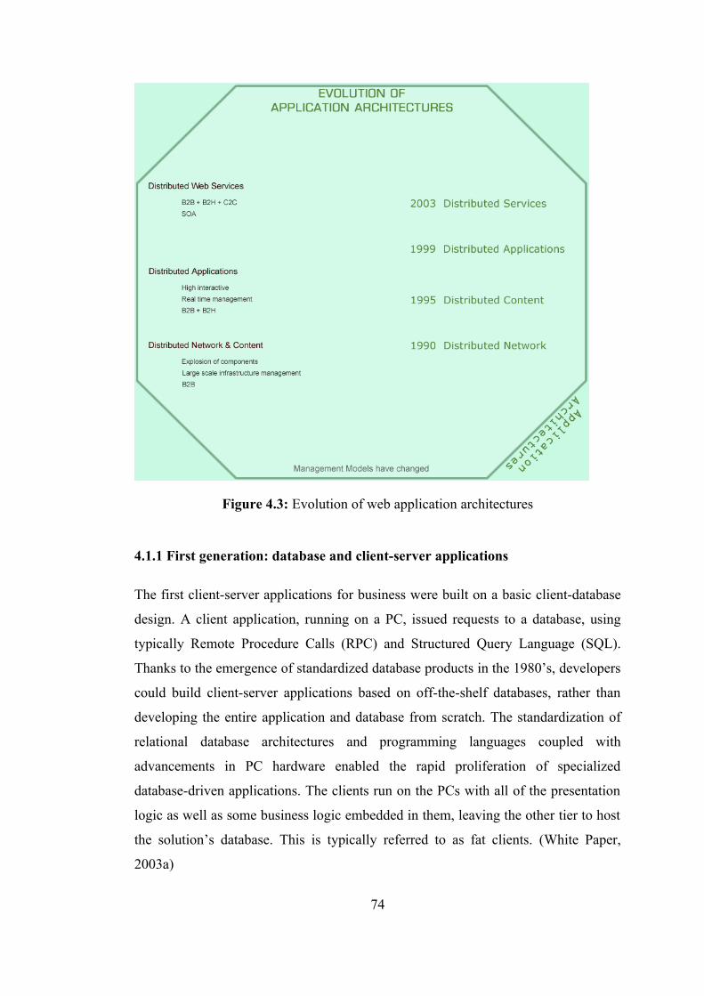
Figure 4.3: Evolution of web application architectures
4.1.1 First generation: database and client-server applications
The first client-server applications for business were built on a basic client-database
design. A client application, running on a PC, issued requests to a database, using
typically Remote Procedure Calls (RPC) and Structured Query Language (SQL).
Thanks to the emergence of standardized database products in the 1980’s, developers
could build client-server applications based on off-the-shelf databases, rather than
developing the entire application and database from scratch. The standardization of
relational database architectures and programming languages coupled with
advancements in PC hardware enabled the rapid proliferation of specialized
database-driven applications. The clients run on the PCs with all of the presentation
logic as well as some business logic embedded in them, leaving the other tier to host
the solution’s database. This is typically referred to as fat clients. (White Paper,
2003a)
74
The application builds on a standard database package, making it affordable, but the
application has some limitations. Although the server can be accessed by more than
one client, the client application requires a top-of-the-line PC, and all clients must be
on the same enterprise’s network. In addition, when the number of users exceeds 100
simultaneously, performance begins to deteriorate. Also, it has limited flexibility in
moving program functionality from one server to another.
4.1.2 Second generation: web applications
The most important difference between the two generations is that, in contrast to a
dedicated connection between the client and the server, web applications are
designed to communicate “through the cloud,” i.e. over the Internet –an enormous,
publicly accessible network based on agreed standards (HTTP over TCP/IP).
Hypertext Transfer Protocol (HTTP) is the standard protocol currently used to access
the Internet. According to the W3C, HTTP 'is an application-level protocol for
distributed, collaborative, hypermedia information systems'. (URL W3C)
HTTP does not remember past commands and will forget the current command as
soon as it is executed. As such, it is very hard to make HTTP to be more interactive
and dynamic without additional technologies such as JavaScript, cookies, PHP and
other programming scripts. Nevertheless, efforts have been made to improve HTTP.
From the first HTTP 0.9, through HTTP 1.0, to the latest HTTP 1.1, numerous
improvements have been made. (URL W3C)
The architectural foundation of the web is the request-response cycle realized by the
HTTP, HTML and XHTML standards. The Representational State Transfer (REST)
architectural style provides a model architecture for the web that was used to
rationalize the definition of the HTTP 1.1 recommendation. Modularity,
extensibility, and inversion of control are characteristics inherent in the web that
have allowed incorporation of features supporting dynamic content. Inversion of
control is implemented on both clients and servers by various plug-in, content
handling, and filtering interfaces that allow custom components to be invoked in
response to events. (Doyle and Lopes, 2005) The web was originally designed for the
75
delivery of online documents, but now serves as the primary vehicle for the delivery
of dynamic networked applications.
Although early web architectures allowed web browsers to access databases directly,
generally through a Common Gateway Interface (CGI) which is part of the web
server, the advent of the application server proved even more useful when the client
was no longer a PC-based application, but a web browser. As with the client-server
architecture, web application servers brought increased performance and scalability,
as well as enabling far more sophisticated business logic. (White Paper, 2003a)
The web gave enterprises the opportunity to serve clients directly over the Internet,
but taking a business online entailed a number of challenges, including the enormous
workload that would be placed on web servers and web application servers.
Obviously, an online system would have to support an enormous number of clients.
While even the largest first-generation client-server applications were designed to
support hundreds of simultaneous clients, the Internet could open an application to
hundreds of thousands, even millions of customers. (White Paper, 2003a)
Also, unlike dedicated PC clients, web browsers have no inherent knowledge about
the systems to which they are talking because of the stateless nature of the protocol.
Thus web servers must be highly scalable to handle the large number of incoming
requests, as well as a more sophisticated outgoing presentation logic. Similarly,
application servers must scale dramatically to provide load balancing and transaction
management in communications with databases. (White Paper, 2003a)
While scaling up to the enterprise for the web application development, it would be
practical to separate infrastructure concerns from architecture concerns like business
logic and presentation. As the e-business grows, both the business tier as well as the
data tier may need to be scaled to accommodate the growth. The middle tier may be
expanded to include several web servers to serve a growing number of users, as well
as dedicated servers to support middleware business logic components. Adding more
database servers to accommodate the growing data may expand the data tier. More
infrastructure is required to support this architecture.
76
4.1.3 Third generation: web services
Web services are enterprise applications, much like the ones in the previous section,
so fundamentally they do what the second generation web applications do today.
However, the way they do things is different. The difference is that they use
languages and protocols based on a universally accepted XML standard to function
more intelligently. Unlike typical applications, web services literally describe
themselves to the outside world – telling what functions they perform, how they can
be accessed, and what kinds of data they require. (White Paper, 2004b)
Just as the second generation of application architecture grew from first generation
technologies, the web services architecture is based on –and incorporates the
advantages of– its predecessors. It lies at the convergence of three technologies. First
is the web with universal standardized communications using standard protocols
such as HTTP and XML as a formatting language. Second is the evolution of Service
Oriented Computing (SOC) where data and business logic is exposed through
programmatic interfaces, like web application servers built on the J2EE environment
using concepts from SOC. (White Paper, 2003a) Third is the best aspects of
component-based development. Like components, web services represent
functionality that can be easily reused without knowing how the service is
implemented. Unlike current component technologies which are accessed via
proprietary protocols, web services are accessed via ubiquitous web protocols (ex:
HTTP) using universally-accepted data formats (ex: XML). (White Paper, 2003b)
Though web services are based on the same foundation, they take application design
to the next level of openness and interoperability. (White Paper, 2003a)
Web service represents an information resource or business process or programmable
application logic that can be accessed over the web by another application, and that it
communicates using standard Internet protocols. What distinguishes web services
from other types of web-based applications is that web services are designed to
support application-to-application communication. Other web applications support
human-to-human communication (email and instant messaging) or human-to-
application communication (browsers). Web services are designed to allow
applications to communicate without human assistance or intervention. (White Paper,
77

2002) In other words, web services does for computer-to-computer interactions what
the Internet and the browsers did for computer-to-human interactions. (White Paper,
2004b) This distinction makes XML-based web services a giant step ahead of any
previous application model.
In a nutshell, web services are applications that do a better job of communicating
with other applications because they are based on open standards, they are easy to
learn and have a low price point.
4.2 Early Second Generation Technologies
4.2.1 Common gateway interface
The earliest technologies that allowed for interactive and dynamic content were
HTML forms, the HTTP POST request method, and the CGI. (Doyle and Lopes,
2005)
The HTML forms capability naturally extends the web’s document metaphor by
allowing user input data (form data) to be entered on web pages that is submitted to a
form processor on a web server in a request method (GET or POST message). The
forms interface is simple, cross-platform, supports light data validation, and allows
pages to be event-driven. The loosely coupled interaction between forms and their
processors can be a source of problems related to reliability since there is no static
guarantee that the data types of submitted data elements conform to the expectations
of the form processor. By 1993, the availability of CGI completed the forms
processing path by providing a means by which web servers could process and
respond to submitted data from HTML forms. CGI allows server-side programs to be
invoked in response to HTTP requests. (Doyle and Lopes, 2005)
The disadvantages of CGI scripting are related to scalability and usability concerns.
CGI is not highly scalable because a web server creates a new process for each CGI
request. For busy web sites serving thousands of concurrent users, the CPU and
memory usage required to constantly create and destroy processes severely limits the
number of concurrent requests that can be handled. The use of scripting languages
78
further strains a web server’s capacity due to the need to start an interpreter for each
request. (Doyle and Lopes, 2005)
The usability problems of CGI stem from the limitations of its thin abstraction over
the HTTP protocol. Programmers must understand the workings of HTTP, down to
the level of formatting details of resource identifiers and messages, to be able to
create CGI scripts. No page computation model is provided; the programmer is
responsible for generation of the response by printing HTML to the standard output
stream. Role separation between designers and programmers is diminished due to the
fact that the presentation attributes of pages are embedded with print statements in
programs. Web page authoring tools such as Dreamweaver or FrontPage can not be
used since the presentation HTML is embedded within a program’s logic. Other
responsibilities including state management, security, validation, data access, and
event handling are completely delegated to programmers. (Doyle and Lopes, 2005)
Additionally, CGI programs are stateless and do not know what the user previously
requested. To preserve the state, HTML pages must be created to dynamically embed
the state information as hidden fields, but this makes the architecture non-scalable.
(Namuduri and Ram, 2001)
Despite its limitations, CGI is not obsolete. CGI was the first widely supported
technology for interactive and dynamic content and is still in use mainly due to the
increasing popularity of scripting languages, which can provide a straightforward,
portable alternative to Java. In tandem with scripting languages including, but not
limited to, Perl, Python, Ruby, C, and C++, CGI is a platform-independent solution
with a simple, well-known interface. It natively exists within most web servers such
as Apache and Microsoft Internet Information Server (IIS), in contrast to other
dynamic content solutions that require additional component installation. According
to the benchmark comparisons to other options for generating dynamic content, CGI
is inefficient in handling concurrent client requests and therefore suitable only for
low-traffic applications. Even though CGI architecture is functional, easier to
implement than a scalable one, and many CH organizations have used it and have
evolved from it successfully in the past, “GeoCHEAF” is not using CGI technology
because it is not scalable and is becoming an obsolete technology.
79
4.2.2 Scalable CGI implementations
To address the scalability shortcomings of CGI, a number of software providers
produced different schemes for communication between the core webserver and
plug-in programs. One such e- commerce company was Open Market, Inc., which
introduced FastCGI into their webserver product in the mid 1990s. FastCGI is a
language independent, scalable, open extension to CGI that provides high
performance without the limitations of server specific APIs.
(http://www.fastcgi.com) FastCGI is a CGI implementation that maintains a pool of
persistent processes that are reused for multiple requests to reduce process creation
overhead. mod_perl is an optional module for the Apache HTTP server. It embeds a
Perl interpreter into the Apache server, so that dynamic content produced by Perl
scripts can be served in response to incoming requests, without the significant
overhead of re-launching the Perl interpreter for each request. mod_perl can emulate
a CGI environment, so that existing Perl CGI scripts can benefit from the
performance boost without having to be re-written. (URL Wikipedia)
4.2.3 Web server extension interfaces
The initial reaction from web server providers to CGI performance issues was to
create proprietary APIs with similar capabilities. All of the major web servers have
APIs that can be used to introduce new functionality into a web server through
extension modules. The most well-known examples are Netscape Server API
(NSAPI), originally created for Netscape web servers by Sun Microsystems, Inc.;
Microsoft Internet Server API (ISAPI) by Microsoft Corporation; and the Apache
module API by Apache Software Foundation 2003. Extension modules are usually
required to be written in C or C++ and compiled into dynamic link libraries that are
linked into the web server at runtime. Extensions can run extremely fast since they
are compiled code that runs in the web server address space. ISAPI and the Apache
interface are representative of web server APIs in general. ISAPI supports the
development of extensions and filters that modify the behavior of IIS. The
corresponding Apache API constructs are modules, handlers, and filters. ISAPI
extensions behave like CGI scripts; extensions are invoked directly by clients or
80
through Uniform Resource Identifier (URI) mapping, and are responsible for
handling requests and creating responses. On IIS servers, a well-known example is
the mapping of 'Active Server Pages (ASP)' files to asp.dll, the ASP interpreter. A
corresponding example for Apache is the association of 'Hypertext Preprocessor
(PHP)' files to the mod php extension module. ISAPI filters perform additional
behaviors in addition to the default behaviors, and can be used to implement custom
logging, authentication, mapping, and retrieval features. The Apache API also filters
as a modular way to manipulate request or response data streams. (Doyle and Lopes,
2005)
Web server APIs were originally designed as scalable replacements for CGI, but they
are rarely used to build web applications directly. The APIs are complex,
non-portable, and require advanced programming knowledge, so extension modules
are difficult to build, test, and maintain. Reliability can be compromised due to the
tight integration of extensions into web servers; a single flaw in an extension module
can crash a web server. The cost of developing extensions is easier to justify for
widely reusable features than for those supporting only a single application. In spite
of their weaknesses, web server APIs are an important building block for dynamic
content generation systems. In fact, for performance reasons most serverside
technologies that support dynamic content are based on web server extension
modules. They enable programmers to create web-based applications that are more
sophisticated and run much faster than applications based on CGI scripts since they
are more tightly integrated with the web server.
4.2.4 Browser extension interfaces
During the browser wars of the mid-1990s all of the major browser providers created
proprietary APIs to differentiate their products. The Netscape Plug-In API and
Microsoft ActiveX are examples of browser-specific APIs. For systems requiring
dynamic interfaces, the key features of browser-specific APIs are support for plug-in
components and access to internal browser methods and properties related to the
presentation of content. Security that prevents downloaded components from
performing undesirable actions is a key requirement for browser extensions. ActiveX
81

makes use of “Authenticode”, a code-signing scheme that verifies that downloaded
binary components are pristine as offered by a certified provider prior to their
execution by a browser. (Doyle and Lopes, 2005)
Browser Extension Interfaces:
Applets
Java applets represent an extension approach that is not browser-specific since it
leverages the portable Java byte code format. Applets are Java class files that are
downloaded and interpreted by a Java Virtual Machine (JVM) running within the
browser address space. The JVM executes applets only after verifying that their code
is safe, meaning that it not been tampered with and contain no instructions that
violate the client’s security policy. Applets can also be digitally signed and verified
to provide an additional level of security. Java applets initially suffered from poorly
perceived performance due to extended download times and slow interpretation;
therefore the technology has been relegated to a secondary role, even though
performance has since been vastly improved by the introduction of just-in-time (JIT)
compilation to native code. The pervasive Adobe (formerly Macromedia) Flash
animation player plug-in provides an alternative to Java applets that is now
commonly used to embed dynamic presentations in web pages. (Doyle and Lopes,
2005)
Client Side Scripting
Interpreters for lightweight scripting languages such as JavaScript and VBScript
were available for most browsers by the end of 1996. Client-side scripting languages
interfaces are more accessible than browser extension APIs, since they remove the
need to know an entire API to add pieces of useful functionality to an HTML
document. Client-side scripts are slightly less efficient than plug-ins, but the
advantages of easy access to browser properties and methods outweigh the
performance penalty. Initially, each browser creator implemented a proprietary
scripting language and API that was incompatible by design with other browsers.
Scripting language standards, including ECMAScript and DOM, have improved the
82
situation to the point that cross-browser scripting is possible. (Doyle and Lopes,
2005)
Rich Internet Applications
Increased demand for application responsiveness, interactivity, and disconnected
access has promulgated a review of the applet concept under the guise of Rich
Internet applications (RIA). The objective of the RIA concept is to break away from
the page-centered constraints imposed by the web to support a more interactive user
experience. RIA solutions that attempt to introduce a new plug-in architecture on to
the web have attracted attention, but eventually lose momentum due to the
requirement to download and install a plug-in. 'Laszlo' and 'Macromedia Flex' are
RIA frameworks (sometimes referred to as rich client architectures or the executable
Internet) that are attempting to exploit the large installed base of Flash users to
provide improved interactivity without requiring plug-in installation. Laszlo
applications are described using an XML application description language. The
Laszlo Presentation Server is a Java servlet that dynamically composes and serves
Flash interfaces in response to requests for Laszlo applications. RIA solutions can
improve the responsiveness and presentation quality of web user interfaces, but have
not reached the mainstream of development. More experience with the technologies
is needed to assess their compatibility with the existing web infrastructure before
widespread adoption of RIA will occur.
Expanded Use of Dynamic HTML
Dynamic HTML technology has been around for many years. Recently, Google’s
state-of-the-art web applications, GMail, Google Suggests, and Google Maps, have
brought the standards-based DHTML development model back to the front pages.
Google has demonstrated that the DHTML development model is capable of letting
developers create visually appealing and highly interactive (RIAs). (Schiefelbein,
2005) Google and other IT giants are making a huge investment in developing the
Ajax approach. All of the major products Google has introduced over the last year
-Orkut, Gmail, the latest beta version of Google Groups, and Google Maps-
additionally, the Amazon.com A9 search engine and Flickr are Ajax applications.
83
Ajax, shorthand for “Asynchronous JavaScript and XML”, a web development
technique for creating interactive web applications using a combination of a set of
technologies that are based on open standards and partially avoids the issue of vendor
lock-in:
• HTML (or XHTML) and CSS for presenting information (standards-based
presentation using XHTML and CSS)
• The DOM manipulated through JavaScript to dynamically display and
interact with the information presented (dynamic display and interaction
using the DOM)
• The XMLHttpRequest object to exchange data asynchronously with the web
server (asynchronous data retrieval using XMLHttpRequest)
• Data interchange and manipulation using XML and XSLT
• The JavaScript API for accessing web services (JavaScript binding
everything together).
Ajax is not a new concept or even a single technology and it is not a technology in
itself, but a term that refers to the use of a group of technologies together. It only
gives a name to techniques that have been in use on the web for many years. In fact,
derivative/composite technologies based substantially upon Ajax. Ajax applications
use web browsers that support the above technologies as a platform to run on.
Browsers that support these technologies include Mozilla Firefox, Opera, Konqueror,
Apple Safari and Microsoft Internet Explorer.
AJAX solutions contain a client-side engine, consisting of JavaScript functions,
which renders the user interface and communicates with the server in XML format.
This engine sits in the web browser and does not require a plug-in or user install.
An Ajax application eliminates the start-stop-start-stop nature of interaction on the
web by introducing an intermediary -an Ajax engine- between the user and the
server. It seems like adding a layer to the application would make it less responsive,
but the opposite is true. Instead of loading a webpage at the start of the session, the
browser loads an Ajax engine -written in JavaScript and usually tucked away in a
hidden frame. This engine is responsible for both rendering the interface the user
sees and communicating with the server on the user’s behalf. The Ajax engine allows
84
the user’s interaction with the application to happen asynchronously -independent of
communication with the server. So the user is never staring at a blank browser
window and an hourglass icon, waiting around for the server to do something. Every
user action that normally would generate an HTTP request takes the form of a
JavaScript call to the Ajax engine instead. Any response to a user action that does not
require a trip back to the server -such as simple data validation, editing data in
memory, and even some navigation- the engine handles on its own. If the engine
needs something from the server in order to respond -if it is submitting data for
processing, loading additional interface code, or retrieving new data- the engine
makes those requests asynchronously, usually using XML, without stalling a user’s
interaction with the application. (Garrett, 2005) How Ajax is different from the
classic web application model is shown in figure 4.4 and figure 4.5.
OpenLaszlo is a widely adopted open source application development platform that
uses Ajax-style programming techniques, integrating XML and JavaScript to create
rich and robust online experiences, and delivery of RIA on the web. It is released
under the OSI-certified Common Public License by Laszlo Systems. OpenLaszlo -an
XML framework for RIA- is designed to support deployment of Ajax applications
across multiple runtimes and devices. OpenLaszlo is 100% pure Java and runs in
server environments -J2EE application servers and Java Servlet Containers. The
OpenLaszlo APIs provide animation, layout, data binding, server communication,
and declarative User Interface (UI). OpenLaszlo is write once run everywhere. An
OpenLaszlo application developed on one machine will run on all leading web
browsers on all leading desktop operating systems. OpenLaszlo currently targets the
Flash Player, versions SWF6, SWF7 and SWF8. (http://www.openlaszlo.org/)
Ajax-based RIAs are fast becoming the benchmark for web application front ends
because they provide the best of both worlds: rich and reach. Ajax applications are as
rich as desktop applications and highly responsive, and provide all data on a single
page without page refreshes. They also have the reach of standards-based browser
applications that can be deployed easily without any browser plug-ins or client-side
applets. (Schiefelbein, 2005) The number of Ajax-based libraries and tools has
flourished in both the commercial and open source sectors, creating many options for
85
developers who want to use Ajax with minimal effort. Ajax-based RIA frameworks
like open source Dojo (licensed under the BSD License) or proprietary standards-
based Backbase allow developers to easily build dynamic capabilities into web pages
and any other environment that supports JavaScript. (http://dojotoolkit.org/)
(http://www.backbase.com) Some web-based resources like AjaxInfo
(http://www.ajaxinfo.com/) and Ajaxian (http://www.ajaxian.com/) popularize new
Ajax tools and techniques with incredible speed.
Other technologies that could be used to develop RIAs include 'XML User Interface
Language (XUL)', 'Extensible Application Markup Language (XAML)', Java, Flash,
and SVG. XUL is a high-performance markup language for creating rich, dynamic
user interfaces. It's part of the Mozilla browser and related applications, and is
available in Mozilla browsers (like Firefox). XAML is a high-performance markup
language for creating rich, dynamic user interfaces. It is part of the Windows
Presentation Framework, Microsoft’s next generation UI technology, and will be
supported in future versions of the Internet Explorer browser. A Java Applet is a
program written in Java that can be included on a web page. Applets are programs
that require the proprietary Java plugin from Sun in order to run. Adobe (formerly
Macromedia) Flash is a powerful presentation-layer framework that comes
preinstalled on most PCs and Macs. It is possible to use Flash to build web-based
user interface components that are highly configurable. SVG is an XML-based
graphics language that describes images with vector shapes, text, and embedded
raster graphics. It can be integrated with XML data sources or SMIL. It has good
interoperability with CSS and JavaScript. (http://www.mozilla.org/projects/xul/)
(http://www.xaml.net/)
When compared to competing UI technologies like XUL, XAML, Java, Flash, and
SVG, it is understood why Ajax is such a big deal. Many of these alternatives offer
opportunities for similar functionality with as-good-if-not-better UI capabilities, but
either force the user to install plugins, as is the case with Flash, Java Applets, and
SVG, or limit her to a specific browser or operating system, as is the case with XUL
and XAML. In fact there are many examples of Flash and SVG being used in
conjunction with Ajax to provide an even more immersive user experience. Ajax
86
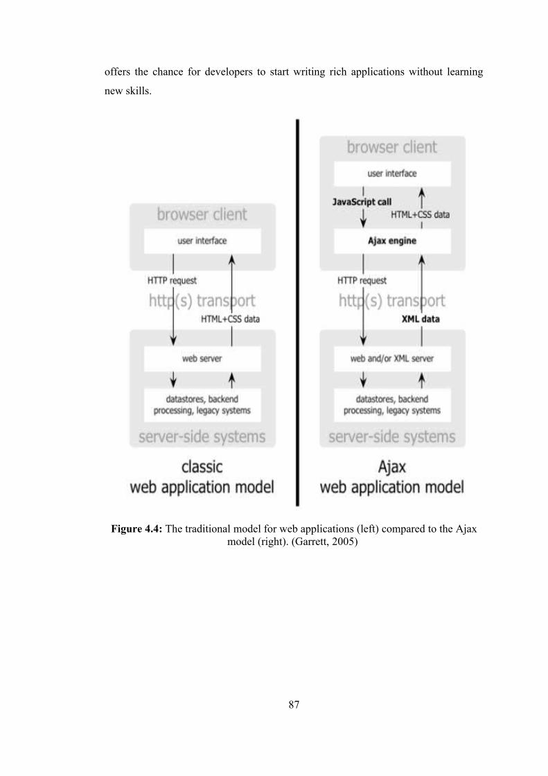
offers the chance for developers to start writing rich applications without learning
new skills.
Figure 4.4: The traditional model for web applications (left) compared to the Ajax model (right). (Garrett, 2005)
87
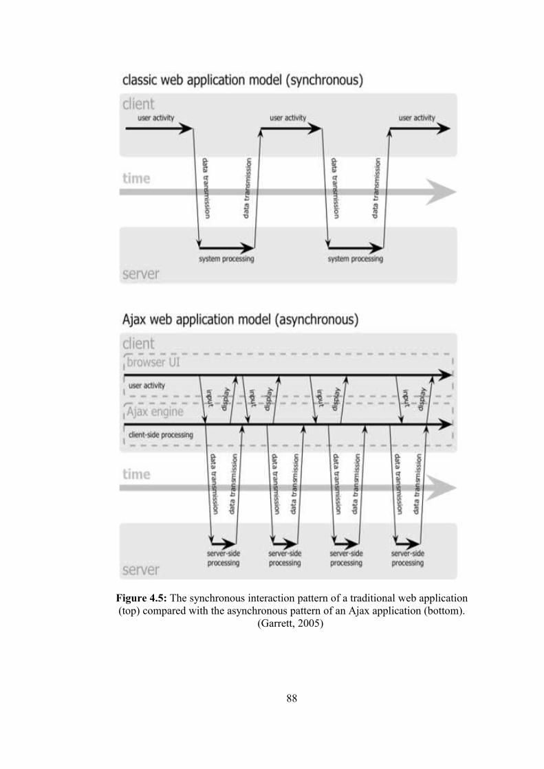
Figure 4.5: The synchronous interaction pattern of a traditional web application (top) compared with the asynchronous pattern of an Ajax application (bottom).
(Garrett, 2005)
88
4.2.5 Interpreted template-based scripting
The use of templates is a common characteristic of pattern-based program
construction systems. A template is a model for a set of documents, composed of
fixed and variable parts, that is contextually expanded to yield conforming document
instances. The variable parts of a template encapsulate programming logic such that
each variable part exposes a program function that specifies how it is expanded in
context. Predominately-fixed templates are easier to construct and comprehend than
more variable templates since less programming is required and the defined structure
is largely static. Many web sites consist of generally fixed HTML pages with small
amounts of variable content. In contrast to template processing, CGI processing is
more suitable for applications with mostly variable content, which are not as
common on the web. The template model better supports the common web
application pattern by embedding logic within fixed presentation markup. Templates
reduce the programming skill needed to create dynamic content. Role separation is
well-supported since the addition of logic can be delegated to programmers. (Doyle
and Lopes, 2005) Interpreted template-based scripting:
Server-Side Includes
The Server Side Includes (SSI) capability was introduced by NCSA in 1993 as
method for embedding trivial computations within HTML pages to be processed
directly by the web server, instead of by a separate process as with CGI. SSI
templates contain fixed HTML text and variable areas with commands that execute
before a response is sent to a user. The technology is tag-centered in that dynamic
behavior is specified by special HTML tags, and formatted comments that denote
command keywords and parameters. The initial SSI implementation supported the
include command for text file inclusion, the echo command for variable output, and
the exec command for running external programs. Conditional processing and other
features were independently added to SSI by web server providers. On Apache web
servers, SSI plus several extensions is known as Extended SSI (XSSI). While
infrequently used, SSI is not completely obsolete and the core set of commands is
supported by most web servers. Role separation is better supported by SSI than by
CGI since the fixed and variable areas of pages can be built independently. Web
89

designers can work strictly with HTML to design the appearance of a page, adding
exec commands to retrieve information where dynamic content is required.
Development of logic invoked by exec commands can be delegated to programmers.
The disadvantages of SSI are related to scalability and usability concerns. SSI is no
more scalable than CGI, and can be worse for documents with multiple exec
commands. Each exec command leads to a process creation, adding appreciably to
the web server processing load even relative to CGI. The usability concerns are due
to the primitive syntax and CGI-based process model. The syntax is error-prone and
difficult to internalize, but does not not support complex processing other than
through CGI via exec commands. The dependence on exec for non-trivial processing
renders templates defeats role separation. For larger applications, the inevitable
reliance on exec leads to barely maintainable, multi-language tangles of templates,
scripts, and programs. While SSI is rarely appropriate for new applications, it
provides an accessible, low cost alternative for non-critical, low-traffic web
applications. (Doyle and Lopes, 2005)
Coldfusion
ColdFusion was introduced in 1995 by Allaire Corporation as an “easy to program”
technology for creating dynamic content. The defining feature of the technology is
the template-based ColdFusion Markup Language (CFML), originally interpreted but
now JIT-compiled into servlets. CFML advanced the templating model of SSI by
providing a large set of commands, originally focused on database processing but
ultimately also supporting other functions including file management, flow control,
and forms processing, that is designed to be comprehensive for web applications.
ColdFusion is comparable to SSI, sharing many of its advantages and disadvantages.
Templates are portable since interpreters are available for several web servers
including Apache and IIS. Role separation between web designers and programmers
is possible to a similar extent as with SSI. Database access is optimized compared to
CGI and SSI. The syntax is more expressive than that of SSI, but still not well-suited
for expressing complex logic. The size of the language, in terms of the sheer number
of options, reduces its usability. (Doyle and Lopes, 2005)
90
Server-Side Java Script
The next widely-used technology for server-side scripting was script-centered
templating as exemplified by the introduction of Server-Side JavaScript (SSJS) and
the Microsoft ASP environment in 1996. In script-centered templating, blocks of
logic are embedded in HTML pages. Script-centered templating quickly gained
popularity among programmers as a more natural way to produce dynamic content.
SSJS pages were constructed from HTML and JavaScript code and interpreted by an
interpreter on the web server. The SSJS development and runtime environment
provided server, application,database, client, and request objects that supported state
management. SSJS preceded and influenced ASP but did not catch on with
developers and is obsolete.
Active Server Pages
ASP is a server-side scripting environment for web applications that provides a
scripting language engine that supports several languages, an object model, and an
interface for accessing server components. The most commonly used scripting
language for ASP pages is VBScript. JScript, a JavaScript variant, is also supported
out-of-the-box, and other languages can be installed. The integrative power of ASP
comes from the ability to access Component Object Model (COM) components on
the server from within web pages. The COM is a Microsoft standard that provides a
language-independent means for defining and referencing components as objects. In
the hands of experienced programmers, ASP’s combination of HTML, scripting
language code, and access to COM components can be a powerful tool for building
dynamic web applications. ASP became the most popular scripting-based templating
technology on the web, at least partially due to the large installed base of Microsoft
server operating systems. The emergence of ASP was a step forward for web
application development; many systems supporting dynamic content that followed
were influenced by the technology. (URL Microsoft) The disadvantages of ASP are
related to portability, scalability, integration, reliability, and usability concerns. Since
ASP is still primarily applicable only to Microsoft systems despite various porting
efforts, applications are generally not portable and integration with other platforms
can be problematic. Scalability is limited due to runtime interpretation, which
91
consumes extra CPU cycles compared to compiled code execution. While COM
integration provides access to an ad-hoc set of advanced features including support
for transactions, the technology was not designed from ground up as a
comprehensive, service-oriented framework, so critical concerns such as security and
reliability are not integral to the environment. While the programming model is
conceptually simple, the fundamental mismatch between the event-driven nature of
applications and the page-centered interaction constraints of the web are not
addressed. The script-centered approach is less accessible to non-programmers than
tag-centered approaches, so role separation is diminished.
Hypertext Preprocessor
PHP is an open source, cross-platform, object-based scripting language for dynamic
web applications that is analogous to ASP. Versions of PHP run on many operating
systems and web servers, and interfaces are available to many database systems. PHP
is available for Windows operating systems, but since ASP being generally the
preferred option on Windows systems, PHP is most prevalent on Linux systems
running Apache. The PHP syntax contains elements borrowed from C, Perl, and
Java. While PHP has comparable advantages and disadvantages as classic ASP, the
portability of PHP can be beneficial if an application needs to run on several
platforms or web servers. The open source combination of Linux, Apache, MySQL,
and PHP, commonly referred to as LAMP*, is gaining interest as a low cost platform
for web applications.
4.3 An Evolutionary Step: Middle-Tier Architecture
The middle-tier architecture of “GeoCHEAF” consists of three sub-tiers:
Presentation, Business Logic, and Integration. In this collocated architecture, these
sub-tiers are physically located in the same web application container and
well-defined interfaces isolate each sub-tier’s responsibility. This collocated
architecture makes the application simple and scalable.
*LAMP (Linux-Apache-MySQL-Perl/PHP/Python) WAMP (Windows-Apache-MySQL-Perl/PHP/Python)
92
4.3.1 Presentation tier
The browser-based thin/minimal client does not contain presentation logic; it relies
on the presentation tier. The presentation tier exposes the business logic tier services
to the users. It knows how to process a user request, how to interact with the
business-logic tier, and how to select the next view to display. (Shen, 2004)
Fundamentally, it contains web server, web container and web application
framework technology components.
Web servers implement the server-side duties of HTTP, the application-layer
protocol that governs message-passing between web users and servers (Doyle and
Lopes, 2005) in order to make web pages viewable in web browsers. In the web
server’s delegation model, when an HTTP request comes into the web server, the
web server simply passes the request to the program best able to handle it. To
process the request, a web server may respond with a static HTML page or image,
send a redirect, or delegate the dynamic response generation to some other server-
side program such as CGI scripts, JavaServer Pages (JSP), servlets, server-side
JavaScripts, or some other server-side technology. The server-side program usually
provides for itself such functions as transaction processing, database connectivity,
and messaging. Whatever their purpose, such server-side programs generate a
response, most often in HTML, for viewing in a web browser. To summarize, the
web server does not provide any functionality beyond simply providing an
environment in which the server-side program can execute and pass back the
generated responses.
The most common web server implementations are the Apache HTTP server (URL
Apache), which is open source and available for most operating systems, and the
Microsoft IIS, available only for Microsoft Windows operating systems. Other web
server implementations for several platforms are Sun Java System Web Server from
Sun, proprietary Zeus Web Server form Zeus Technology, free and open source
Jigsaw (the official W3C Java-based Web server) and Lighttpd (also called Lighty)
(free and open source under BSD license). (http://www.lighttpd.net)
(http://www.zeus.com/products/zws/)
93
Apache HTTP server has been the most popular web server on the Internet since
April of 1996. More than 60% of the web sites on the Internet are using Apache, thus
making it more widely used than all other web servers combined. (URL Apache) The
November 2006 Netcraft Web Server Survey found that market shares for top
developers Apache (60.32%), Microsoft (31.35%), Sun (1.68%), Zeus (0.51%).
(URL Netcraft)
The web server software in the design of the middle-tier architecture of
“GeoCHEAF” is internally modified version of the 'Apache Web Server' under GNU
GPL. This system includes 'Secure Sockets Layer (SSL)' and 'PHP (ZEND)'.
Web applications that run within a web container (may also be referred as web
engine) of a web server in the presentation tier are composed of web components and
other data such as HTML pages. Web components can be servlets, JSP, other type of
templates, web filters, and web event listeners. These components typically execute
in a web server and may respond to HTTP requests from web users. Servlets, JSP
pages, and filters may be used to generate HTML pages that are an application’s user
interface. They may also be used to generate XML or other format data that is
consumed by other application components.
In the servlet-based architecture, the servlet acts as a gateway between the outside
world and the enterprise. It is an HTTP protocol-based request-response mechanism.
(Namuduri and Ram, 2001) Servlets are modules of Java code that run in a server
application (hence the name 'Servlets', similar to 'Applets' on the user side) to answer
user requests. Java servlets extend web servers to support dynamic content
generation.
Servlets are executed by servlet containers, also known as servlet engines, which are
Java applications that manage threads through their life cycle. The use of lightweight
Java thread in the servlet architecture instead of a complete process in the CGI
architecture improves efficiency and scalability, while providing efficient access to
global objects initialized by the container. Since successive requests to a servlet are
handled by a continuous thread, local objects instantiated within the thread are
available throughout a servlet’s lifetime. (Doyle and Lopes, 2005)
94
As mentioned earlier, the traditional way of adding functionality to a web server is
the CGI: a language-independent interface that allows a server to start an external
process which gets information about a request through environment variables, the
command line and its standard input stream and writes response data to its standard
output stream. Each request is answered in a separate process by a separate instance
of the CGI script.
The Java Servlet API was introduced in 1997 as a Java technology’s answer to CGI
programming. Servlets are functionally similar to CGI scripts in that both are
intermediary components that generate dynamic responses to HTTP requests.
Problems areas for CGI addressed by servlets are performance, state management,
and standardized access to middleware. The process model is similar to scalable CGI
in that instances service multiple requests, but with servlets each instance is
dedicated to a particular servlet. (URL Java)
Servlets have several advantages over CGI:
• A Servlet does not run in a separate process. This removes the overhead of
creating a new process for each request.
• A Servlet stays in memory between requests. A CGI program (and probably
also an extensive runtime system or interpreter) needs to be loaded and
started for each CGI request.
• There is only a single instance which answers all requests concurrently. This
saves memory and allows a Servlet to easily manage persistent data.
• A Servlet can be run by a Servlet engine in a restrictive Sandbox (just like an
Applet runs in a web browser’s Sandbox) which allows secure use of
untrusted and potentially harmful Servlets.
• Servlets are written in Java, and can take advantage of Java’s memory
management and rich set of APIs. Servlets can also run on numerous
platforms and HTTP servers without change.
• Java servlets are more efficient, easier to use, more powerful, more portable,
and cheaper than traditional CGI and than many alternative CGI-like
technologies.
95
The usability disadvantages of servlet programming are analogous to those of CGI.
As with CGI, the servlet model provides only a thin abstraction over HTTP.
Programmers must manually generate responses by writing to the standard output
stream, so role separation is not well supported. Therefore, relatively few web
applications are composed entirely of servlets. Instead, servlets are used as an
underlying mechanism behind the template-based, model-driven, and framework-
based technologies that were subsequently developed.
JSP is a templating technology for web application development that was introduced
in 1999 to simplify servlet development. (URL Java) On the surface, the JSP is
reminiscent of ASP, but the implementation is very different. While ASP pages are
interpreted, JSP pages are transformed by a JSP container into servlets. A JSP
container is a modified servlet container that also serves JSP pages.
JSP technology enables web developers and designers to rapidly develop and easily
maintain, information-rich, dynamic web pages that leverage existing business
systems. As part of the Java technology family, JSP technology enables rapid
development of web-based applications that are platform independent. JSP
technology separates the user interface from content generation, enabling designers
to change the overall page layout without altering the underlying dynamic content.
JSP technology and servlets provide an attractive alternative to other types of
dynamic web scripting/programming by offering platform independence, enhanced
performance, separation of logic from display, ease of administration, extensibility
into the enterprise, and most importantly, ease of use. (URL Java) Much of the
subsequent innovation for web development has been motivated by a search for
techniques that properly exploit the capabilities of JSP and servlets.
Other templating engines are generally designed to not allow Java code to be added
to templates, so developers are not tempted to mix business and presentation logic in
templates. Dedicated templating engines such as Velocity and WebMacro aim to
replace JSP as a presentation technology for web applications.
96
Velocity is a Java-based template engine. It permits anyone to use a simple yet
powerful Velocity template language to reference objects defined in Java code.
When Velocity is used for web development, web designers can work in parallel
with Java programmers to develop web sites according to the Model-View-
Controller (MVC) model. In other words, web page designers can focus solely on
creating a site that looks good, and programmers can focus solely on writing top-
notch code. Velocity separates Java code from the web pages, making the web site
more maintainable over its lifespan and providing a viable alternative to JSP or PHP.
Velocity’s capabilities reach well beyond the realm of the web. For example, it can
be used to generate SQL, PostScript and XML from templates. It can be used either
as a standalone utility for generating source code and reports, or as an integrated
component of other systems. (URL Velocity)
Apache Tomcat from Apache is the most widely used web container (servlet/JSP
container) used in the official reference implementation for these complementary
technologies, the Java Servlet and JSP. It is a runtime shell that manages,
executes/runs and invokes servlets and JSPs. (URL Tomcat)
Apache Tomcat web container was configured to run in-process in conjunction with
the Apache HTTP server (may also be referred as 'in-process add-on' to the Apache
web server) in order to execute servlets and JSPs in the presentation tier, instead of
deploying Tomcat as out-of-process or stand-alone, since generally running in-
process is easier to configure and gives better performance. (URL Tomcat)
When running Tomcat in-process, the Apache HTTP Server starts Tomcat as threads
within the Apache HTTP Server job. Tomcat inside Apache in one server (in-
process) integrating Tomcat as a plugin. In-process where Tomcat and the Apache
Server run in the same process and communicate through a Java Native Interface
(JNI). In-process Tomcat is a combination of a web server plugin and a Java
container implementation. The web server plugin opens a JVM inside the web
server’s address space and lets the Java container run in it. If a certain request should
execute a Servlet, the plugin takes control over the request and passes it to the Java
container using JNI. (URL Tomcat)
97
When running Tomcat out of process (out-of-process add on), Tomcat is a separate
job (or process) that can even be on a different computer than the Apache HTTP
Server (two different farms), which communicates with the Apache HTTP Server via
TCP/IP sockets. Out-of-process Tomcat is a combination of a web server plugin and
a Java container implementation that runs in a JVM outside the web server. The web
server plugin and the Java container JVM communicate using some IPC mechanism
(usually TCP/IP sockets). If a certain request should execute a Servlet, the plugin
takes control over the request and passes it to the Java container using the IPCs.
(URL Tomcat)
It is important to note that if SSL support is configured between the web browser and
the web server, the connection between the web server and the out-of-process
Tomcat server is not secured with SSL. Running in-process allows developers to
configure authentication through the HTTP server where out-of-process does not.
An in-process container is suitable for multi-threaded single-process servers and
provides good performance but is limited in scalability. Running out-of-process
allows more flexibility in the number and type of processes that can be configured.
The response time of an out-of-process engine is not as good as in the in-process one
but the out-of-process engine performs better in many measurable ways (scalability,
stability, etc.)
Running Tomcat as a stand-alone server is another option. Stand-alone Tomcat is an
integral part of the web server. Stand-alone is the default mode used by Tomcat.
(URL Tomcat)
As a site grows in complexity, it is more and more difficult to manage the
relationship between the various JSP pages, the back-end business logic, and the
forms and validations that move around the site. A large number of web application
development frameworks emerged in response to the increasingly common problem
in web application development using J2EE and .NET platforms. A web application
development framework helps developers build applications faster and better by
providing prepackaged starter. It simplifies writing web applications and makes them
98
much easier to develop and maintain. It also allows developers to create cross-
platform applications and dynamic content generation systems.
Frameworks are an extensible module sets supporting rapid development of
repetitive requirements in a reliable way through reusable skeletal design pattern
realizations. The objective is to allow developers to concentrate on the problem
domain rather than on low-level implementation details, while providing concrete
benefits beyond the associated acquisition and learning curve costs.
Model-driven development technologies for web applications aim to simplify the
development process by generating deployable sites from presentational, behavioral,
and navigational requirements specified in models. In the tradition of prior work in
automatic programming and CASE, which were not completely successful, model-
driven development technologies aim to reduce the dependency on low-level
programming by raising the abstraction model to a higher level.
One approach to designing technical architecture is MVC architecture. The MVC
architectural design pattern for building interactive applications is commonly used in
user interface programming to separate presentation, business, and state management
concerns, thereby decreasing code duplication, centralizing control, and making the
application more extensible. MVC that is a logical architectural choice for the
presentation tier matches the event-driven nature of dynamic web applications. It
also helps developers with different skill sets focus on their core skills and
collaborate through clearly defined interfaces. (Shen, 2004) A Model View
Controller-based development framework that enables developers to quickly
assemble applications in a pluggable and extensible manner.
The benefits of using the MVC architecture are: (Namuduri and Ram, 2001)
• Clear separation of modules: This provides the ability to extend and replace
modules with ease. When the business logic changes, the corresponding
business component can be modified without affecting other parts of the
systems. In the MVC architecture, changes can be confined to particular
components or areas.
99
• Flexibility of the views: For the same function, different views can be
generated. For example, the same data can be implemented as an HTML
page, applet, spreadsheet, text document or PDF document.
• Ease of change: When technology changes, the model can still be used with
the updated view components. For example, conversion from HTTP request
to WAP request does not affect the underlying business model.
There are two types of MVC frameworks: application-driven and page-driven. While
application-driven web MVC frameworks implement MVC using the Front
Controller pattern, page-driven MVC frameworks implement MVC using Page
Controller pattern. Page-driven MVC frameworks provide an event-driven model for
web programming that recalls traditional desktop GUI programming. Relative to
application-driven frameworks, the higher degree of page independence allows
heavier abstraction over resource implementation details that supports rapid
component-based development through drag-and-drop GUI page composition. The
highly abstraction level may extend the learning even for experienced web
programmers due to the need to become familiar with with a completely different
object model. (Doyle and Lopes, 2005)
There are currently two types of web frameworks in Java: request-based and
component-based.
Much attention has been focused on creating web MVC frameworks since 2000,
when the potential for reuse and streamlining the development process became
evident. As a result, many competing frameworks are available, many of which are
products of open source development projects. While the most well known
frameworks currently target the J2EE platform, several have been ported to .NET.
Well-known web application frameworks are also available for server-side scripting
languages such as Perl, PHP, and Python. Although View templates are normally JSP
pages, some frameworks also allow other template engines to be used, including
Velocity and WebMacro. Table 4.3 shows the most commonly used frameworks for
web applications and user interfaces.
100
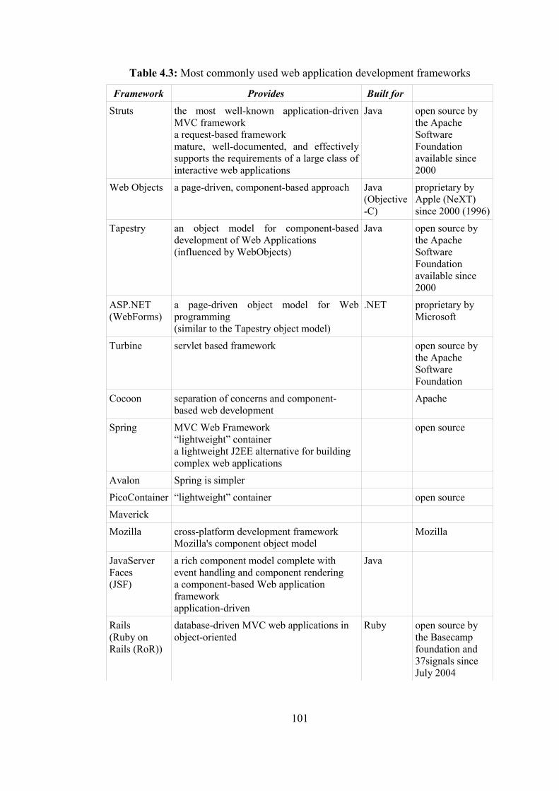
Table 4.3: Most commonly used web application development frameworks
Framework Provides Built for Struts the most well-known application-driven
MVC frameworka request-based frameworkmature, well-documented, and effectively supports the requirements of a large class of interactive web applications
Java open source by the Apache Software Foundation available since 2000
Web Objects a page-driven, component-based approach Java (Objective-C)
proprietary by Apple (NeXT) since 2000 (1996)
Tapestry an object model for component-based development of Web Applications(influenced by WebObjects)
Java open source by the Apache Software Foundation available since 2000
ASP.NET(WebForms)
a page-driven object model for Web programming (similar to the Tapestry object model)
.NET proprietary by Microsoft
Turbine servlet based framework open source by the Apache Software Foundation
Cocoon separation of concerns and component-based web development
Apache
Spring MVC Web Framework“lightweight” containera lightweight J2EE alternative for building complex web applications
open source
Avalon Spring is simpler
PicoContainer “lightweight” container open source
Maverick
Mozilla cross-platform development frameworkMozilla's component object model
Mozilla
JavaServer Faces(JSF)
a rich component model complete with event handling and component renderinga component-based Web application frameworkapplication-driven
Java
Rails(Ruby on Rails (RoR))
database-driven MVC web applications in object-oriented
Ruby open source by the Basecamp foundation and 37signals since July 2004
101
JavaServer Faces (JSF) is a server-side user interface component framework for
Java-based web applications and is also a specification for a component-based web
application framework built over servlets and JSP. JSF fits well with the MVC-based
presentation-tier architecture. It offers a clean separation between behavior and
presentation. It leverages familiar UI-component and web-tier concepts without
limiting developers to a particular scripting technology or markup language. It can be
used to bring rapid user-interface development to server-side Java, and link and
manage user interface events. (URL Java)
JSF uses a similar architecture in Struts (the most popular open source JSP-based
web application framework), but is more flexible and extensible. JSF also comes
with server-side components and an event model, which are fundamentally similar to
the same concepts in Swing (the standard Java user interface framework for desktop
applications). JSF can be thought as a combination of those two frameworks.
JSF differentiates from other web frameworks with the following features: (Geary,
2002; Shen, 2004)
• Swing-like object-oriented web application development: The server-side
stateful UI component model with event listeners and handlers initiates
object-oriented web application development.
• Backing-bean management: Backing beans are JavaBeans components
associated with UI components used in a page. The backing bean defines
properties and handling-logics associated with the UI components used on the
page. Backing-bean management separates the definition of UI component
objects from objects that perform application-specific processing and hold
data. JSF implementation stores and manages these backing-bean instances in
the proper scope.
• Extensible UI component model: JSF UI components are configurable,
reusable elements that compose the user interfaces of JSF applications. The
standard UI components can be extended and developed a more complex
component, e.g., menu bar and tree component.
102
• Flexible rendering model: A renderer separates a UI component’s
functionality and view. Multiple renderers can be created and used to define
different appearances of the same component for the same client or for
different clients.
• Extensible conversion and validation model: Based on the standard
converters and validators, customized converters and validators can be
developed, which provide better model protection.
There are more than 50 web application development frameworks available in the
market. The frameworks are very various and are slightly different both in concept
and implementation. Furthermore, there are a few good configurations, like Apache
Velocity and Turbine, or Apache Cocoon and Spring. Apache Jakarta Velocity (Java-
based template engine) provides template services for the Apache Turbine (Web
application framework), together resulting in a view engine facilitating development
of web applications according to a true MVC model. Apache Cocoon gives the
flowscript and forms, the sitemap, lots of prebuilt components, a Portal, etc. whilst
Spring is geared towards developing enterprise web applications. This duo is very
efficient for building web applications. Since JSF represents an open source (de-
facto) standard for Java-based web application frameworks and provides
functionalities other web frameworks like Struts lack, “GeoCHEAF” concentrated on
developing IDEs for JSF instead of developing an IDE for one of approximately 35
existing Java-based web application frameworks.
4.3.2 Business logic tier
The business logic tier contains an application’s business objects and business
services. It receives requests from the presentation tier, processes the business logic
based on the requests, and mediates access to the back-end tier’s resources. (Shen,
2004) The response or output from the business logic tier consists of the data or
content, which is passed on to the user. The content may need to be converted to
different formats depending on the users’ and business’ needs. The output may be
formatted to an HTML, PDF, XML or a serialized object if the client is an applet.
(Namuduri and Ram, 2001)
103
An application server is a component-based product that resides in the middle-tier of
a server centric architecture. It forms the middle tier, acting as a container and
runtime environment for business logic. Its performance is key in determining the
performance of the overall enterprise web application. A web server mainly deals
with sending HTML for display in a web browser whereas an application server
provides access to business logic for user. Application servers can be also configured
to work as web server. In short, application server is a super set of which web server
is a sub set.
The application server does not drive the GUIs; rather it shares business logic,
computations, and a data retrieval engine. Advantages are that with less software on
the client there is less security to worry about, applications are more scalable, and
support and installation costs are less on a single server than maintaining each on a
desktop client. The application server design should be used when security,
scalability, and cost are major considerations.
An application server exposes business logic to user applications through a
component API, such as Enterprise JavaBean (EJB) components and various
protocols, including HTTP, TCP/IP and many more protocols. Application servers
provide containers for such components along with APIs to support the components.
These APIs are to the existing systems and databases.
Business components, such as JavaBeans, Enterprise JavaBeans (EJB) components
(enterprise beans), entity beans, session beans, run inside a EJB container of the
application server in the business logic tier. Enterprise beans typically contain the
business logic for a J2EE application.
The application server must provide one or more EJB containers. An EJB container
that manages the enterprise beans contained within it. For each enterprise bean, the
container is responsible for registering the object, providing a remote interface for
the object, creating and destroying object instances, checking security for the object,
managing the active state for the object, and coordinating distributed transactions.
Optionally, the container can also manage all persistent data within the object.
104
EJB containers and servers handle transactions. EJB architecture encourages
developers to focus on pure business logic by relieving them of technical
responsibilities that are irrelevant to the business problem. Other advantages include
portability, scalability, automatic state persistence and declarative transaction
demarcation. J2EE is an EJB-based architecture that includes several other
components to provide a component-based, scalable, distributed computing
environment.
EJB technology supports both transient and persistent objects. A transient object is
called a session bean, and a persistent object is called an entity bean. A session bean
exists only for the duration of a single client/server session. A session bean performs
operations such as accessing a database or performing calculations. Session beans
can be transactional, but normally are not recoverable following a system crash.
Session beans can be stateless, or they can maintain conversational state across
methods and transactions. A session bean must manage its own persistent data. An
entity bean is an object representation of persistent data maintained in a permanent
data store, such as a database. An entity object can manage its own persistence, or it
can delegate its persistence to its container.
Either EJB or Plain Old Java Objects (POJO) can be used to build the business logic
tier. In the design of the architecture, EJB with remote interfaces was chosen to
implement the business logic tier since the applications are distributed, rather than
POJO with Spring Framework.
The web application server is the principal software system brokering service
requests between users and the external services provided by back-end systems.
These application servers can range from a simple runtime engine that supports
server-side dynamic page generation in a manner similar to CGI programming, to
large, complex enterprise transaction servers that might be hybrids of TP monitors or
CORBA application servers.
The enormous processing demands, combined with a need for flexibility and
adaptability, led to a new type of architecture for web application servers based on
the Java platform. Standardized third-party web application servers emerged to
105
provide a platform for a wide variety of specialized applications. The J2EE, released
in 1999, provided a complete environment for application development, web-based
communications, database access, and interoperability, based on modular
components running on an application server. It quickly became the “standard”
(albeit with no ISO or ECMA standard) for application server developers. (White
Paper, 2003a) It is a comprehensive set of standards designed to provide a portable
environment that supports the requirements of large, enterprise web applications,
which was a flashpoint for the dynamic web J2EE 5.0 features some specifications
unique to J2EE for components, including: (URL Java)
• EJB: Enterprise JavaBeans 3.0
• JSF: JavaServer Faces 1.2
• JSP: JavaServer Pages 2.1
• Java Servlets 2.5
When implementing an enterprise server-side web application, it is important to
decide which services are required for the application to help determine the class of
application server that is needed. High-end application servers that implement all of
the J2EE specifications tend to be much more expensive than simpler servers that
provide fewer services. In many cases, support for servlets and JSP is sufficient to
meet the needs of an application.
J2EE has been successful and compliant application servers are available from many
providers. The platform can be very scalable if properly exploited, but the size and
complexity of the architecture can make it a difficult environment to work with. The
learning curve for J2EE developers can be relatively lengthy, especially if EJB is
used, due to the complexity of the component architecture.
There are a number of J2EE or .NET compatible robust open source, such as JBoss
Application Server (JBoss), Jetty, JonAS, Geronimo, and proprietary application
servers, such as Oracle’s Application Server, BEA’s WebLogic, IBM’s WebSphere,
Adobe’s JRun, on the market. J2EE based JBoss application server was chosen in the
design of the multi-tier distributed architecture of “GeoCHEAF”.
106
The JBoss is the leading open source, standards-compliant, J2EE based application
server implemented in 100% pure Java (http://sourceforge.net/projects/jboss) J2EE
1.4 application server JBoss provides full support for J2EE web services and the
SOA. It supports Aspect-Oriented Programming (AOP) model for developing
middleware solutions. JBoss Application Server enables developers to get started
with EJB and JSF to create web applications, create business logic with EJB 3.0 and
persist data through the EJB 3.0 Java Persistence API. Essentially, JBoss Seam is an
integration framework that seamlessly ties together the Java presentation layer and
the transactional/database layer. Seam integrates JSF and EJB. (URL JBoss)
4.3.3 Integration tier
The heart of the middle tier that has been discussed so far is its 'request/reply' or
'services' or 'API' nature. The idea is not based on objects. Entity beans are
completely object-based. The middle tier is seen as a collection of objects. This
makes perfect sense if the back-end is an object database. When the back end is a
relational database, two things seem to trip up entity beans. These are: (Komantineni,
2003)
1. Object-relational (O/R) mapping (or Object Relational Mapping (ORM)).
2. The fluid and changing world of relational databases and the fixed and typed
world of objects.
The problems that EJBs are trying to solve are the same problems that object
databases are trying to solve. The rigidity of types in OO databases, or the inability to
accomplish fluidity in types, might be the reason for the lack of success on part of
object databases. (Komantineni, 2003)
The integration tier is the bridge between the business logic tier and the back-end
tier. It encapsulates the logic from web components, enterprise beans and application
client components to interact with the back-end tier. (Shen, 2004)
107
The integration tier handles the data persistence with the relational database.
Different approaches can be used to implement the integration tier: (Shen, 2004)
• Pure Java Database Connectivity (JDBC): This is the most flexible
approach; however, low-level JDBC is cumbersome to work with, and bad
JDBC code does not perform well. SQL/JDBC (plain JDBC SQL statements,
Java API and Java code) is a common solution for solving persistence
problem.
• Entity beans: An entity bean with container-managed persistence is an
expensive way to isolate data-access code and handle O/R mapping data
persistence. It is an application-server-centric approach. An entity bean does
not tie the application to a particular type of database, but does tie the
application to the EJB container.
• O/R mapping/persistence framework: Persistence frameworks aim to allow
programmers to efficiently retrieve and update database information through
encapsulated objects rather than through direct SQL calls, or through EJB
entity beans. An O/R mapping framework takes an object-centric approach to
implementing data persistence. An object-centric application is easy to
develop and highly portable. Several frameworks (O/R mapping tools) exist
under this domain: Hibernate, Java Data Objects (JDO), iBATIS, TopLink,
TopView and CocoBase are a few examples.
Hibernate is an open source O/R mapping/persistence framework that stores Java
objects in relational databases or provides an object oriented view of existing
relational data. It relieves the need to use the JDBC API. It also provides data
querying and retrieval functions in a Java environment. Hibernate supports all major
SQL database management systems and offers facilities for data retrieval and update,
transaction management, database connection pooling, programmatic and declarative
queries, and declarative entity relationship management. The Hibernate Query
Language (HQL), designed as a minimal OO extension to SQL, provides an elegant
bridge between the object and relational worlds. Hibernate also does some XML data
binding (XML mapping). (http://www.hibernate.org/)
108
While Hibernate is only for mapping relational databases and objects, JDO is more
general -it can work with object databases and other technologies besides just
relational databases. (http://java.sun.com/products/jdo/) However, Hibernate does not
modify source or byte code to persist a Java object; JDO implementations either
require a special interface be implemented or do bytecode modifications at runtime.
In the middle-tier design of “GeoCHEAF”, Hibernate is used as ORM solution to
complete Java-based middleware design since it is less invasive than other O/R
mapping frameworks, much easier to use than handwritten SQL/JDBC (by
eliminating JDBC coding) and much more powerful than EJB entity beans. It creates
a mapping between Java objects and database entities.
4.3.4 Configuration
Depends on the user and functional requirements of the CH domain, the
configuration of the middle-tier architecture of “GeoCHEAF” was realized as
following. Figure 4.6 shows the partitioning of the application tiers and the
technologies chosen for each tier. It also serves as the sample web application’s
deployment diagram.
The design of the multi-tier architecture of “GeoCHEAF” for component-based
enterprise web applications supports a variety of application types from large scale
web applications to small client server applications. In this architecture such
components use services provided by the container, which would otherwise typically
need to be incorporated in application code. Note this may not be ideal in all
scenarios: for example, a small scale application might be a better fit for a
light-weight Java technology solution (e.g. Servlets, JSPs, etc.).
The most useful frameworks supporting web application development can be
categorized as web application and user interface frameworks, persistence
frameworks, and lightweight containers. Java Servlets are designed to handle
requests made by web browsers. JSPs are designed to create dynamic web pages. JSF
makes web applications much easier to design, create, and maintain. Also, JSF fits
into the MVC design pattern very well and can be used to implement the presentation
109

tier. The Spring Framework can be used in the business logic tier to manage business
objects, and provide declarative transaction management and resource management.
Spring integrates with Hibernate very well. Hibernate is a powerful O/R mapping
framework and can provide the best services inside the integration tier. The
combination of and the interconnectivity among these three technologies provides a
solid web application development framework.
Figure 4.6: The middle-tier architecture of “GeoCHEAF”
The web application server in the design of the middleware architecture of
“GeoCHEAF” consists of the Tomcat web container add-on the Apache web server
and J2EE-based JBoss application server with Spring and Hibernate frameworks to
provide full support for J2EE web applications and web services.
By partitioning the whole web application into tiers and programming against
interfaces, the technology used for each application tier can be replaced according to
110
the requirements of an enterprise. For example, in this design, Struts can take the
place of JSF for the presentation tier, and JDO can replace Hibernate in the
integration tier.
Deployment Platform: Java based web application development on
Solaris operating system
Unlike Windows, which has only a few versions in production, all from the same
vendor, Linux offers many different ones, called distributions (or 'distros' in Linux-
speak). These are available from a long list of companies and individuals, priced
from nothing to hundreds of dollars. Even restricting them to those that run on Intel
x86 hardware leaves literally dozens of options. For those taking a closer look at
Linux, an essential first decision is picking the 'distribution'. It is useful to group the
distros into two categories: commercial and noncommercial.
Server OSs available for both x86-64 and i386 (64-bit CPU):
• Unix
• Unix (BSD communities): FreeBSD, OpenBSD, NetBSD, etc.
• Unix (Sun): Solaris
• Commercial Unix: HP-UX (HP), AIX, IRIX
• Linux
• Open source Linux for servers (GNU Linux OS):
• Fedora Core Project (the community-driven Linux distribution started
by RedHat)
• OpenSuse (community-based development of Suse)
• other Linux distributions (distros) Debian, CentOS, Ubuntu,
Mandriva2006, Turbolinux, Slackware, etc.
• Commercial Linux: Linux Enterprise Server (Proprietary Linux):
• Red Hat Enterprise Linux (RHEL),
• Novel Suse Linux Enterprise Server (SLES),
• Caldera OpenLinux,
• SuSE Linux,
• TurboLinux.
111
• Microsoft 2003 Enterprise Server (for 32-bit or 64-bit) by Microsoft
• Mac OS by Apple
• Novell
Solaris 10 was chosen as an enterprise OS for the application environment of
“GeoCHEAF” environment since Unix is more suitable for a production
environment than the other ones. It really matches the needs and resources of the
enterprise and its e-business.
Solaris Enterprise System, the only comprehensive and open infrastructure software
platform available today - Solaris 10 OS, Java Enterprise System, development tools,
N1 software, for no cost. (http://www.sun.com/software/solaris/)
Development Platform:
The Java EE platform works with an array of tools, including IDEs, performance and
testing tools, and performance monitoring tools. Integrated Development
Environment (IDE) (also known as an integrated design environment or integrated
debugging environment) is a cross-platform programming environment integrated
into a single software application that provides a GUI builder, a text or code editor, a
compiler and/or interpreter and a debugger. An IDE is a necessity for enterprise
developers who want to have all their productivity tools under one umbrella. The
extensible open source development platforms for building enterprise Java
applications: NetBeans (plus Java Studio Enterprise) (Sun), Eclipse (IBM), and
Jbuilder (Borland).
In addition to general features, some features are best for enterprise development
needs:
• Provide templates for quick creation of JSP pages, servlets and other web
components
• Automatically create classes, methods, and properties
• Integrate with source code repositories, such as CVS
• Integrate with web application servers, such as Apache Tomcat
• Integrate with build utilities, such as Apache Ant
112
• Unified UI for debugging Java code
• Provide UML support
NetBeans and Eclipse, both projects aim to develop a flexible Java IDE, and both
benefit from large industry support. The most visible difference is that NetBeans is
Swing-based, while Eclipse builds on the Standard Widget Toolkit (SWT). Both
Swing and SWT aim to offer a rich, portable set of Java widgets. NetBeans is written
in the Java programming language. It is also the first IDE to fully support JDK 5.0
features.
The most important aspect in the architecture is that the HTML page sent by the web
server to the web browser is generated dynamically and only upon request. It is not
stored statically as a text file, and therefore, it is not necessary to manually maintain
the information in static text files. Any dynamic data embedded in the HTML page is
actually stored and managed in the DBMS and can be temporarily presented to users
as HTML pages upon request.
While the J2EE-based web application server can be seen as an evolutionary step
from earlier computing architectures, it is distinguished by a number of evolutionary
features. Unlike earlier systems, a JavaEE-based application is built in components,
which can be independently added, removed or updated with minimal disruption to
the system as a whole. A result of the component-based architecture is the ability to
develop chunks of code dedicated to specific functions, which -implemented
properly- could run on the same application server and efficiently interact with other
chunks of code dedicated to other functions. Unlike first-generation client-server
applications, second-generation Internet-based applications had to communicate
through a “cloud”, called the Internet. This was only possible through standards at
every level -including networking (TCP/IP, HTTP), presentation (HTML), security
(HTTPS, digital certificates), application logic (Java, JavaScript, CGI), etc. Internet
standards enabled applications to run 'on both sides of the cloud'. The pieces of the
application could run where it made the most sense for them to run. For example,
while business logic ran on the server side, the server might download some
presentation logic to the client in the form of JavaScript, style sheets, cookies and
JSP.
113
4.4 A Revolutionary Evolutionary Step: Web Services & Web Services
Architecture
'Web Service' is a software application or component that are loosely coupled, re-
usable and distributed, semantically encapsulates business functionality and is
programmatically accessible over standard Internet protocols. Technically, web
services are built upon open, often already widely adopted standards such as HTTP
and XML, which ensures interoperability between services, facilitating the
integration of heterogeneous environments. Web services standards define an
interface and communication protocol that can be invoked from an application client
or provided through a server. Web services are applicable to any type of networking
environment (Internet, intranet, or extranet) and can support business-to-consumer,
business-to-business, department-to-department, or peer-to-peer interactions. Web
services are identified by a Uniform Resource Identifier (URI) and accessed by a
Uniform Resource Locator (URL). A Web Service consumer can be a human user
accessing the service through a desktop or wireless browser; it can be an application
program; or it can be another web service. (White Paper, 2003a; White Paper, 2004a;
White Paper, 2003b; White Paper 2002)
4.4.1 A thorny problem: application integration
For years, enterprises have faced a thorny problem: how to flexibly modify,
increment, and connect heterogeneous applications to meet the requirements of an
enterprise. In second generation web applications, the data and logic of one
application are basically useless to other applications. When an application and its
data are isolated from other applications, it is called that they are in “silos”. After
many years of ballooning applications within an enterprise, enabling cross-silo
communications was the emerging business challenge in the 1990’s and it continues
today. The first solution to the silo problem was the traditional Enterprise
Application Integration (EAI). (White Paper, 2004b)
In traditional EAI solutions, an application communicates with another application
through a bus (enterprise service bus (ESB)) or a hub that packages and translates
114
information in one application according to specific rules provided by the receiving
application. All of the packaging instructions for the receiving application are tied
closely to the sending application, making each application ‘integration’ a one-to-one
relationship, that is, a single application communicating with a single application.
These relationships are describe as ‘tightly coupled’. (White Paper, 2004a)
Although cumbersome, EAI was a big step forward, allowing enterprises to leverage
their investment in their most critical business applications, rather than rewriting the
application or migrating it to a new technology. However, traditional EAI presented
a new set of problems revolving around the integration software costs, complexity of
the effort, and inflexibility of the solutions. These three factors -cost, complexity,
and solution inflexibility- have driven enterprises to choose the EAI solutions for
only their most critical business requirements. (White Paper, 2004b)
The web services paradigm has emerged as a powerful mechanism for integrating
disparate ICT systems and assets. It attacks the three problems identified above -cos,
complexity, and solution inflexibility- with a new model that is lower cost, easier to
learn and deploy, and more adaptable to changing business needs. The result is a
faster, easier application-to-application integration, allowing enterprises to connect
many more applications within their enterprise, and opening the door for more
efficient business processes, within the enterprise and across businesses. Now many,
rather than only the most critical, applications can talk to each other, presenting
enormous opportunities for improved business performance. (White Paper, 2004b)
From a historical perspective, combining the best aspects of component-based
development and the web, web services leverage a concept known as SOA. SOAs
have evolved over the last 10 years to support high performance, scalability,
reliability, and availability. (White Paper, 2003b) Using an SOA is an increasingly
popular way of building distributed systems. (White Paper, 2003c) To achieve the
best performance, applications are designed as services that run on a cluster of
centralized application servers. A service is an application that can be accessed
through a programmable interface. (White Paper, 2003b) A service is also a network-
enabled component. Like components, services in general (and web services in
115
particular) represent functionality that can be easily reused without knowing is the
details of how the service is implemented. (White Paper, 2004a)
In the past, clients accessed these services using a tightly coupled, distributed
computing protocol, such as Common Object Request Broker Architecture
(CORBA), Remote Method Invocation (RMI), or Distributed Component Object
Model (DCOM). While these protocols are very effective for building a specific
application, they limit the flexibility of the system. The tight coupling used in this
architecture limits the re-usability of individual services. Each of the protocols is
constrained by dependencies on vendor implementations, platforms, languages, or
data encoding schemes that severely limit interoperability. And none of these
protocols operates effectively over the web. (White Paper, 2003b)
The Web Services Architecture (WSA) takes all the best features of the SOA and
combines it with the web. The web supports universal communication using loosely
coupled connections. Since web protocols are completely independent across vendor,
platform, and language implementations, the result is an application that integrates
well with the rest of the enterprise while being flexible enough to modify as business
needs change. The resulting effect is an architecture that eliminates the usual
constraints of CORBA, RMI, or DCOM. Web services support web-based access,
easy integration, and service re-usability. (White Paper, 2004a; White Paper, 2003b)
4.4.2 The key characteristics of web services
Web services facilitate services reuse and provides support for greater business
flexibility to meet enterprises’ constantly changing business needs. Web services
exhibit the following key characteristics:
• Enables SOAs Loosely Coupled:
In the SOA model, the business processes that make up an application are separated
into independent, easily distributed components known as services. These processes
inter-operate across processes and machines to create a complete solution for a
business problem. Loose coupling means that each service exists independently of
the other services that make up the application. This allows for easy changes to the
116
application by inserting new and revised services into the application without having
to modify the unrelated services. Loose-coupling is ably provided by web services
through established standards that define services and how they inter-operate. (White
Paper, 2004a)
Applications are developed independent of who accesses them and are exposed to
other applications only through predefined interfaces (WSDL files). This means that
the underlying implementations can be changed without changing the service
requesting application. (White Paper, 2003a)
Recently, there has been a trend towards making services loosely coupled, which
means introducing greater flexibility in the interface between the service consumer
and the service provider. Most existing platforms have a very tight coupling between
the client and server side. For example, CORBA Interface Definition Language
(IDL) defines an interface in very precise terms, and any change to that interface
usually requires significant rework across both the client and the server. This makes
it difficult to evolve a service over time, as there are significant resulting effects. It
also makes it more difficult to build applications that can change their behavior based
on the services available at runtime. (White Paper, 2003c) Loose-coupling can
however provide dramatic time and cost savings by rectifying the annoying and
expensive syntactical differences that typically plague interoperability. In the web
services domain, loose-coupling allows a service to be accessed using any arbitrary
document format, regardless of syntax, providing the physical business data is
present within, or can be determined from, the document contents. (White Paper,
2004c)
• Ease of Integration and Business Flexibility:
Historically, business applications are rather rigid. Updating them with new
functionality to meet changing business requirements has traditionally been
expensive, complex, and time consuming. Unlike other methods of integration, web
services based integration solutions are more flexible, decreasing the time and effort
required to meet changing business needs. (White Paper, 2004b)
117
Web Services communicate using platform-independent and language-neutral web
protocols. These web protocols ensure easy integration of heterogeneous
environments. (White Paper, 2003b) Thus, web services are becoming widely
adopted across the entire software industry to integrate incompatible applications.
(White Paper, 2004a)
• Easily Accessible:
Web services are distributed and easily accessible over the Internet. Web services
make use of existing, ubiquitous transport protocols like HTTP, leveraging existing
infrastructure and allowing information to be requested and received in real time.
(White Paper, 2004a)
• Openness:
Web Services technologies are based on open standards. What makes a web service
special is its XML-based components. Fortunately, the designs of these components
are specified by independent standards bodies. (White Paper, 2004b) Because web
services use these open standards, the cost point is substantially reduced. Enterprises
do not have to use the more traditional and expensive EAI product suites to build
successful solutions. In addition, the open standards are easier to learn and to use
than traditional methods. The faster learning curve translates into faster deployment
increasing the productivity of an enterprise.
• Re-usability:
For years it is known that reusing code, or parts of applications, rather than rewriting
them for a new application increases productivity. Web services promote service
reuse. Services reuse capability increases enterprise's productivity, reduces the
amount of new services that need to be developed and makes it much easier to
change and/or add services as enterprise needs change. (White Paper, 2004b)
Because the packaging and delivery information is isolated and maintained
independently from either the provider or consumer application, business service
developers need only focus on the business logic and functionality. The business
118
logic remains neutral (or generic) and can be re-used for the overall needs of the web
service. (White Paper, 2004b; White Paper, 2003b)
• Granularity
Web services are coarse grained in that they are usually mapped to business level
processes as opposed to low level data or API functions. (White Paper, 2003a)
An often-asked question in distributed system building is what is a sensible interface
size or granularity for an entity within the system? In previous generations for
entities real objects, components or classes. In SOA they are business services used
within the context of a business process that will need to be understood by business
users. Therefore a business service interface should typically reflect real-world
business documents: archives, archaeological excavation forms, and oral history
records. Note that this is a much coarser granularity than previous integration
models, which focused on low-level programming APIs. While earlier RPC or
message-passing approaches used simple messages flowing between complex API
endpoints, in the SOA case there is larger, richly typed, self-contained documents
flowing between coarse endpoints. (White Paper, 2004c)
4.4.3 Internet middleware
Although web services are new, introduced in 2001, the concepts behind SOAs have
been around for quite a while. Most standard distributed computing middleware
technologies implement a SOA system (for application-to-application
communication). The genesis for SOC is in technologies such as RPC,
Message-Oriented Middleware (MOM), the OMG’s CORBA IDL, Java RMI, the
Open Group Distributed Computing Environment (DCE), Microsoft DCOM.
Each SOA system defines its own a set of formats and protocols that implement the
core SOA functions. An SOA system often also defines an invocation mechanism,
which includes an API and a set of language bindings. This approach ensures
consistency among applications that share the same middleware, but prevents
interoperability with applications that use different middleware. It also requires that
119
every service producer and service consumer that engages in a conversation must
have the appropriate middleware loaded on its machine. (White Paper, 2002)
SOAs almost always contain some formal mechanism for defining the precise
interface provided by a service. For example, each of DCE, CORBA, and DCOM
have a formal IDL. Unfortunately, each of these platforms has defined its own
unique IDL, making moving from one platform to the other very difficult. J2EE
relies on Java interface classes -there is no separate IDL, and tools use the Java
reflection API to determine the makeup of each interface. (White Paper, 2003c)
SOAs also typically define a set of protocols for invoking remote services. CORBA
and J2EE use IIOP, while Microsoft DCOM has its own proprietary protocol. Where
these protocols are managed as open standards, they enhance interoperability
between different vendors for a given platform, for example, IIOP is an open
standard maintained by the OMG consortium. However, interoperability is still a
major problem when trying to integrate different platforms such as CORBA and
DCOM, because these protocols must be mapped at a very low level at runtime.
(White Paper, 2003c)
Web services can be thought as a new form of middleware, 'Internet middleware'.
But unlike previous SOA systems, Internet middleware does not require an entirely
new set of protocols. The most basic web services protocol is the ubiquitous standard
XML, which is used as the message data format, and is also used as the foundation
for all other web services protocols. Today most Internet middleware systems are
implemented using a core set of technologies, including: (White Paper, 2003b; White
Paper, 2004a; White Paper, 2003a; White Paper, 2002)
• An encoding format for remote invocation: Simple Object Access Protocol
(SOAP)
SOAP defines a standard communications protocol for web services by which
data is transported between a service requestor (or service consumer) and a
service provider.
120
• An interface definition language: Web Service Description Language
(WSDL)
WSDL defines a standard mechanism to describe a web service.
• A directory service: Universal Description, Discovery, and Integration
(UDDI)
UDDI provides a standard mechanism to register and discover web services.
These technologies define the transport, description, and discovery mechanisms,
respectively. Three XML-based specifications (or technologies) have emerged as the
de facto standards for web services and that cover most every aspect of standard
service communication. Each of these technologies are defined and implemented in
XML. One important ramification of the use of XML is that any application, written
in any language, running on any platform, can interpret web services messages,
descriptions, and discovery mechanisms. No specific middleware technology needs
to be available to converse using web services. (White Paper, 2003b; White Paper,
2004a; White Paper, 2003a; White Paper, 2002)
Typically, these standards are maintained by independent, non-profit standards
organizations composed of a diverse membership. Members submit various
requirements for the standard and agree to a specification after many review phases,
resulting in a free and open standard upon which any group can build web
service-compliant applications and tools. Three dominant standards boards lead this
critical effort:
• World Wide Web Consortium (W3C): The driving force behind the largest
number of highly adopted standards in the web services space including some
web building blocks such as HTML. (http://www.w3.org)
• Organization for the Advancement of Structured Information Standards
(OASIS): Source of the original specification from which XML evolved, as
well as the home of the current XML and UDDI specification.
(http://www.oasis-open.org)
121
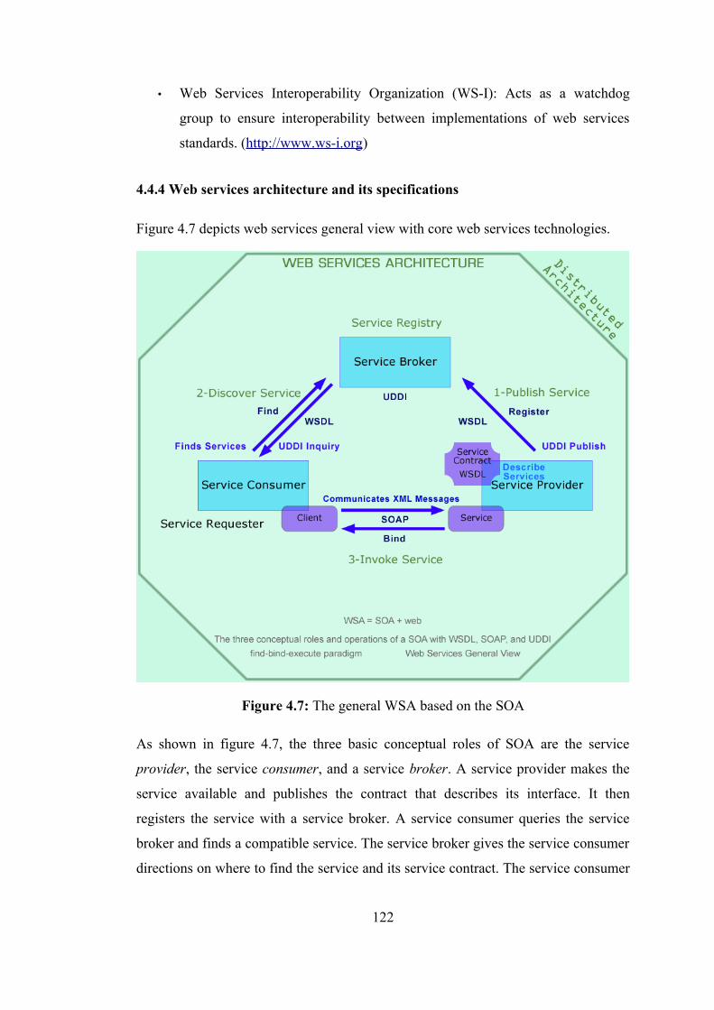
• Web Services Interoperability Organization (WS-I): Acts as a watchdog
group to ensure interoperability between implementations of web services
standards. (http://www.ws-i.org)
4.4.4 Web services architecture and its specifications
Figure 4.7 depicts web services general view with core web services technologies.
Figure 4.7: The general WSA based on the SOA
As shown in figure 4.7, the three basic conceptual roles of SOA are the service
provider, the service consumer, and a service broker. A service provider makes the
service available and publishes the contract that describes its interface. It then
registers the service with a service broker. A service consumer queries the service
broker and finds a compatible service. The service broker gives the service consumer
directions on where to find the service and its service contract. The service consumer
122
uses the contract to bind itself to the service. In order for the three conceptual roles to
accomplish the three conceptual operations, an SOA system must supply three core
functional architecture components: (White Paper, 2002)
• Transport. The transport component represents the formats and protocols
used to communicate with a service. The data format specifies the data types
and byte stream formats used to encode data within messages. The wire
protocol specifies the mechanism used to package the encoded data into
messages. The transfer protocol specifies the application semantics that
control a message transfer. The transport protocol performs the actual
message transfer.
• Description: The description component represents the languages used to
describe a service. The description provides the information needed to bind to
a service. At a minimum, a description language provides the means to
specify the service contract, including the operations that it performs and the
parameters or message formats that it exchanges. A description language is a
machine-readable format that can be processed by a compiler to produce
communication code, such as client proxies, server skeletons, stubs, and ties.
These generated code fragments automate the connection between the
application code and the communications process, insulating the application
from the complexities of the underlying middleware.
• Discovery: The discovery component represents the mechanisms used to
register or advertise a service and to find a service and its description.
Discovery mechanisms may be used at compile time or at runtime. They may
support static or dynamic binding.
Web services are an example of a SOA. In most Internet middleware configurations,
the three core functional components (transport, description, and discovery) in the
WSA are implemented using SOAP, WSDL, and UDDI, respectively. A UDDI
registry plays the role of service broker. The register and find operations are
implemented using the UDDI Inquiry and UDDI Publish APIs. A WSDL document
123
describes the service contract, and is used to bind the consumer to the service. All
transport functions are performed using SOAP. (White Paper, 2002)
In the WSA, when a service provider deploys a web service to make the service
available to service consumers, it describes the service using WSDL and registers the
service and its WSDL description in a UDDI registry to help service consumers find
the service that matches their needs. The UDDI registry will then maintain pointers
to the services and its WSDL description. When the service consumer wants to use
the service, it queries the UDDI registry to find the service and obtains the WSDL
description of the service, as well as the access point of the service. The service
consumer uses the WSDL description to construct a SOAP message with which to
communicate with the service. (White Paper, 2003b; White Paper, 2004a)
Transport
The transport functional component defines the formats and protocols used to
communicate between service consumer (client applications) and services. The WSA
formats and protocols are defined by SOAP. SOAP provides a simple messaging
framework that allows one application to send an XML message to another
application. (White Paper, 2002)
• Data format. The SOAP data format is XML. The mechanism by which the
data are encoded is totally extensible, and in fact can be specified within each
SOAP message. The data format can represent an RPC invocation, in which
case the message body is composed as a structure containing the RPC input
parameters or return value. The name of the structure indicates the method to
be invoked. When using the RPC representation, the data are normally
encoded using an XML-based encoding style. Alternately, the data format
can be in the form of an XML document, in which case the data are normally
encoded using a specific XML Schema.
• Wire format. The SOAP wire format is an XML document called a SOAP
envelope. The envelope contains an optional SOAP header and a mandatory
124
SOAP body. The SOAP body contains the message payload, encoded in
XML.
• Transfer protocol. SOAP defines an abstract binding framework that allows
SOAP messages to be transferred using a variety of underlying transfer
protocols. The SOAP specification defines a protocol binding for HTTP.
Bindings have also been defined for HTTPS, SMTP, POP3, IMAP, JMS, and
other protocols.
• Extensions. Additional information can be included with a SOAP message
within a SOAP header. The SOAP header can provide directive or control
information to the service, such as security information, transaction context,
message correlation information, session indicators, or management
information.
Description
The description functional component defines the language used to describe a
service. The service consumer uses the description to bind itself to the service. The
WSA description language is the WSDL. A WSDL document describes what
functionality a Web service offers, how it communicates, and where to find it. The
various parts of a web service description can be separated into multiple documents
to provide more flexibility and to increase reusability. A WSDL implementation
document can be compiled to generate a client proxy that can call the web service
using SOAP. (White Paper, 2002)
• Abstract interface. The what part of a WSDL document describes the
abstract interface of the web service. It essentially describes a service type.
Any number of service providers can implement the same service type. The
WSDL what part defines a logical interface consisting of the set of operations
that the service performs. For each operation it defines the input and/or output
messages that are exchanged, the format of each message, and the data type
of each element in the message.
125
• Concrete binding. The how part of a WSDL document describes a binding
of the abstract interface to a concrete set of protocols. The binding indicates
whether the message is structured as an RPC or as a document; it specifies
which encoding style or XML Schema should be used to encode the data; it
specifies which XML protocol should be used to construct the envelope; it
indicates what header blocks should be included in the message; and it
indicates which transfer protocol should be used. The how part includes or
imports the associated WSDL what part.
• Implementation. The where part of a WSDL document describes a service
implementation. A service implementation is a collection of one or more
related ports. Each port implements a specific concrete binding of an abstract
interface. The port specifies the access point of the service endpoint. A
business might offer multiple access points to a particular service, each
implementing a different binding. The where part includes or imports the
associated WSDL how part. A service producer should always publish the
where WSDL part with the web service.
Discovery
The discovery functional component provides a mechanism to register and find
services. Some discovery functions are used at development time, while others are
used at runtime. The WSA discovery mechanism is implemented using a UDDI
registry service. For the most part, UDDI is used at development time, although it
can also be used at runtime. UDDI is itself a web service, and users communicate
with UDDI using SOAP messages. UDDI manages information about service types
and service providers, and it provides mechanisms to categorize, find, and bind to
services. (White Paper, 2002)
• Service types. A service type, defined by a construct called a tModel, defines
an abstract service. Multiple businesses can offer the same type of service, all
supporting the same service interface. The tModel provides a pointer to the
WSDL document that describes the abstract interface (the what part).
126
• Service providers. A service provider registers its business and all the
services it offers. For each service offered, the service provider supplies the
binding information needed to allow a consumer to bind to the service. The
bindingTemplate construct provides a pointer to the WSDL document that
describes the service binding (the how part). It also specifies the access point
of the service implementation. The WSDL where part is usually co-resident
with the access point.
• Categorization. When a service provider registers a service or service type, it
can categorize the entity (business, service, or tModel) using a variety of
taxonomies. The UDDI specification defines a core set of taxonomies, such
as geographic location, product codes, and industry codes. Additional
taxonomies can be added to the registry to support more focused or
customized categorization and search.
• Find. When looking for a web service, a service consumer queries the UDDI
registry, searching for a business that offers the type of service that it wants.
Consumers can search the registry for services by service type or service
provider, and queries can be qualified using the taxonomies. From the tModel
entry for the service type, the consumer can obtain the WSDL description
describing the abstract interface. The consumer can compile this what part
description to create a client interface for the abstract service. This abstract
interface could be used to access multiple implementations of the service
type. From the bindingTemplate entry for a specific service, the consumer
can obtain the access point of the service and the WSDL description of the
service binding.
• Static binding. Developers can bind clients to services either at compile time
or at runtime. Using the WSDL how part, a developer can compile a concrete
SOAP client interface or stub that implements the binding required to
communicate with a specific web service implementation. This pre-compiled
stub can be included in a client application. The access point can be specified
at runtime.
127
• Dynamic binding. Because a WSDL document is machine-readable, WSA
also supports dynamic binding. Using just the WSDL what part at compile
time, a developer can generate an abstract client interface that can work with
any implementation of a specific service type. At runtime the client
application can dynamically compile the WSDL where part (containing the
how part) and generate a dynamic proxy that implements the binding.
• Dynamic discovery. Since UDDI is itself a web service, an application can
query the registry at runtime, dynamically discover a service, locate its access
point, retrieve its WSDL, and bind to it, all at runtime. The client interprets
the WSDL to dynamically construct the SOAP calls.
UDDI is particularly useful if the service consumer does not know which type of
web service it wants to use, which service providers provide the service, or where to
go to find the services. If a service consumer already knows this information, then
the consumer can use a simpler, more direct form of discovery as an alternate
discovery mechanism, such as the Web Services Inspection Language (WS-
Inspection18). WS-Inspection is an XML format that can be used to inspect a web
site for available web services. Assuming that the service consumer knows the home
page URL for the service provider, and knows which service type it is looking for, it
can use WS-Inspection to find information (including WSDL where part
descriptions) about all of the web services offered by that service provider. Given a
WSDL where part description, a service consumer has everything it needs to bind to
the service. (White Paper, 2002)
SOAP: Simple Object Access Protocol
SOAP was first developed in late 1999 by DevelopMentor, Microsoft, and UserLand
as a Windows-specific XML-based RPC protocol. In early 2000 Lotus and IBM
joined the effort and helped produce an open, extensible version of the specification
that is both platform- and language-neutral. This version of the specification, called
SOAP v1.1, was submitted to the W3C. W3C subsequently initiated a
standardization effort, May 08th, 2000. The latest version of SOAP is version 1.2,
approved version of the standard at June 24th, 2003. (http://www.w3.org/TR/SOAP/)
128
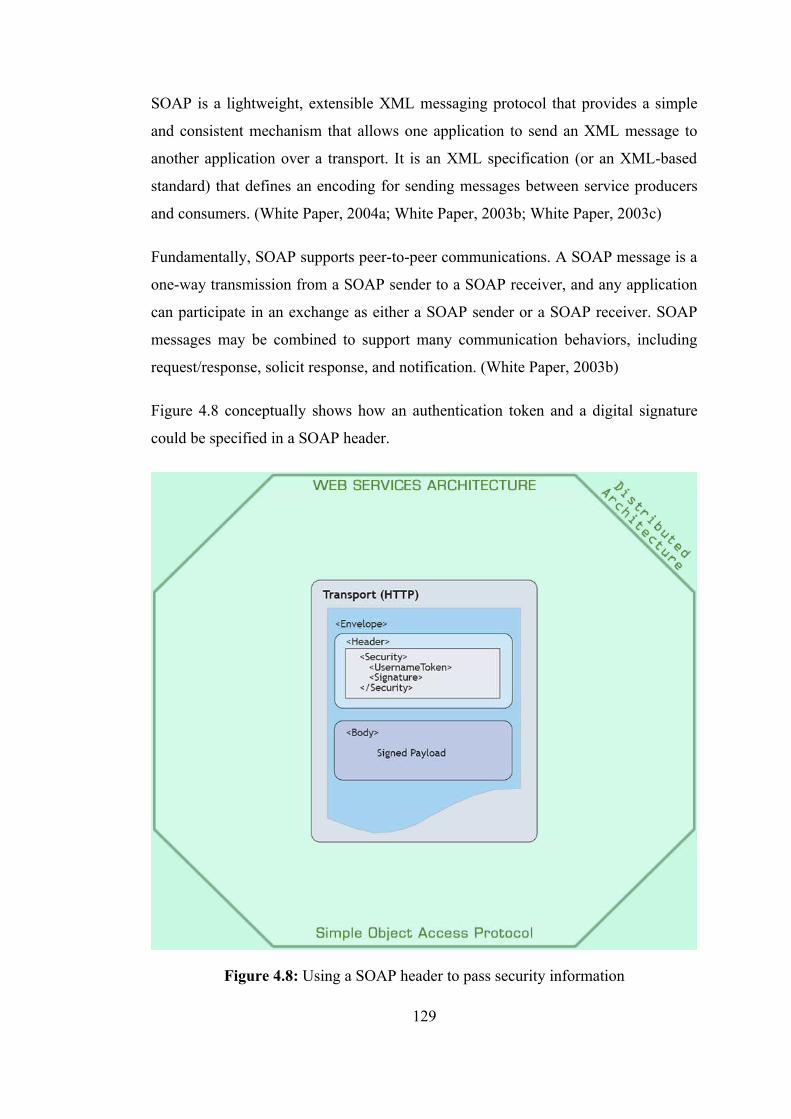
SOAP is a lightweight, extensible XML messaging protocol that provides a simple
and consistent mechanism that allows one application to send an XML message to
another application over a transport. It is an XML specification (or an XML-based
standard) that defines an encoding for sending messages between service producers
and consumers. (White Paper, 2004a; White Paper, 2003b; White Paper, 2003c)
Fundamentally, SOAP supports peer-to-peer communications. A SOAP message is a
one-way transmission from a SOAP sender to a SOAP receiver, and any application
can participate in an exchange as either a SOAP sender or a SOAP receiver. SOAP
messages may be combined to support many communication behaviors, including
request/response, solicit response, and notification. (White Paper, 2003b)
Figure 4.8 conceptually shows how an authentication token and a digital signature
could be specified in a SOAP header.
Figure 4.8: Using a SOAP header to pass security information
129
SOAP consists of four parts: (White Paper, 2004a; White Paper, 2003b; White Paper,
2003c; White Paper, 2002)
• SOAP Envelope - Describes the contents of a message and how to process it,
and contains extra details such as security information or the final destination
of the message. A SOAP envelope includes a SOAP header and a SOAP
body. The SOAP header provides an extensible mechanism to supply
directive or control information about the message. For example, a SOAP
header could be used to implement among other things: Transactions,
Security, for instance, using WS-Security, Reliability, using the upcoming
WS-ReliableMessaging standard, Routing, Payment mechanisms.
Many middleware capabilities can be added to the WSA using SOAP
headers, such as security, transactions, conversations, and reliable message
delivery. The transport delivery, context, security, and management functions
are provided through SOAP extensions.
All SOAP messages are encoded inside a SOAP envelope. The envelope can
contain information on the encoding used in the message, as well as the body
of the message, which contains the (message) payload sent to/from the
service endpoint (as it moves between service producers and consumers).
Basically, the SOAP envelope is sent in a standard HTTP request, with some
extra information in the HTTP header to identify the target service.
• SOAP Body. The SOAP body contains the payload that is being sent in the
SOAP message.
• SOAP Transport Binding Framework - An abstract framework for
exchanging SOAP envelopes (messages) using an underlying protocol,
including HTTP or other transports.
SOAP defines the layout of web service requests and replies, but allows for
bindings to different transport mechanisms. It is not tied to a particular
transport. The core SOAP specification details bindings to HTTP and HTTPS
(for encrypted communication) for basic web invocations, as well as an
SMTP binding for sending SOAP messages by e-mail. Other bindings are
POP3, IMAP, JMS and other protocols. Other mappings exist that allow web
services to be readily integrated with platforms such as CORBA and J2EE,
130
and Microsoft has evolved DCOM into .NET, which is based around a web
service core.
• SOAP Serialization Framework - A set of SOAP encoding rules for
expressing instances of application-defined data types, such as numbers and
text, and a convention for representing RPCs and responses.
SOAP provides a number of different encoding mechanisms, but it is
recommended to use WSDL, XML Schema, and “literal” encoding, which are
the up-to-date standards.
Services may be designed to work on the raw XML payload, but it is more
common for the payload to be mapped or bound directly to data types in the
host language. This step is called serialization and is implemented by most
web service implementations. Serialization is possible regardless of whether
the payload is a literal XML document or SOAP encoded as both support
common features found in the type systems of most programming languages
and databases. This includes simple scalar types such as strings, integers, and
floats, and complex types, such as structures and arrays.
SOAP RPC Style Messaging
SOAP supports a tightly coupled communication scheme based on the SOAP RPC
representation. The SOAP RPC representation defines a programming convention
that represents RPC requests and responses. Using SOAP RPC, the developer
formulates the SOAP request as a method call with zero or more parameters. When
the payload is constructed into a single structure the outermost element represents the
name of the method or operation, and the innermost elements represent the
parameters to the operation. The SOAP response is similar with an outermost
element named in relation to the method name and the innermost parameters
representing zero or more return parameters. (White Paper, 2003b)
SOAP Document Style Messaging
SOAP also supports very loosely coupled communications between two applications.
The SOAP sender sends a message and the SOAP receiver determines what to do
with it. The SOAP sender does not really need to know anything about the
131
implementation of the service other than the format of the message and the access
point URI. It is entirely up to the SOAP receiver to determine, based on the contents
of the message, what the sender is requesting and how to process it. Note that even
with Document Style Messaging it is possible to emulate RPCs by putting the
method/operation name in the SOAPAction header of the HTTP request. (White
Paper, 2003b)
SOAP with Attachments
The SOAP with Attachments binding can be used to transport non-XML data, such
as multimedia files, as attachments to a SOAP message. This specification uses
MIME to encode messages. This is useful if the application requires passing large
binary data with a request or response, where the overhead of converting that data to
XML would be high or unnecessary (for example, if the data was opaque). MIME is
an Internet standard for formatting e-mail messages so that they can be exchanged
between different e-mail systems. MIME enables messages to contain a wide variety
of data types, including text, graphics, audio, and video. Though MIME is ubiquitous
it is not necessarily the best mechanism for sending binary messages in a SOAP
envelope. An alternate mechanism is called DIME, and the WSAttachments
specification describes how to embed DIME in a SOAP Envelope.
(http://www.w3.org/TR/SOAP-attachments)
The Apache Axis Project is an implementation of the SOAP submission to W3C.
(http://ws.apache.org/axis/)
WSDL: Web Service Description Language
WSDL describes the interface to a web service. -it defines the operations together
with the data a web service can perform, the formats of the messages that it can
process and the protocols that it supports (how it communicates), and the access
point of an instance of the web service (where it is accessible)- basically the content
of a SOAP message. WSDL uses the XML Schema standard, so it can use all of the
standard XML Schema data types. It is also possible to define new structured types
132

(user-defined type) using the standard XML Schema constructs. (White Paper,
2004a; White Paper, 2003b; White Paper, 2003c)
A WSDL description defines a service as a set of network endpoints or ports
operating on messages containing either document-oriented or procedure-oriented
information. Each port is defined abstractly as a port type, which supports a
collection of operations. Each operation processes a particular set of messages. A
binding maps a port type to a specific concrete network protocol and data (or
message) format to define the service endpoint. In other word, a binding maps the
WSDL operations onto SOAP operations, and specifies the SOAP parameters and
encoding used. A port instantiates a port type and binding at a specific network
address, for example, a URL reference to a server’s SOAP/HTTP listener. (White
Paper, 2004a; White Paper, 2003b; White Paper, 2003c)
Most often, these messages are bound to the SOAP protocol and the HTTP transport,
but these are not the only set of bindings supported. WSDL’s abstract nature for
describing services makes it very flexible for describing complex web services
applications also by supporting other encoding and transport mechanisms. (White
Paper, 2004a; White Paper, 2003b; White Paper, 2003c)
A WSDL document uses the following elements in the definition of network
services: (White Paper, 2004a; White Paper, 2003b)
• Types– A container for data type definitions using some type system, such as
XSD.
The <types> element defines the data types that are used within messages.
WSDL uses the data typing system defined in the W3C XML Schema Part 2:
Data types Recommendation (http://www.w3.org/TR/xmlschema-2/) as its
canonical type system, although any data typing system may be used. The
type system supports simple scalar types and complex types. Schema types
can be mapped to most programming language type systems. SOAP tools use
the type information to encode and decode the data in SOAP messages.
• Message– An abstract, typed definition of the data being communicated.
A <message> element defines the format of a message. Messages are used as
133
input or output structures for operations. A message can consist of one or
more logical parts, each of which is associated with a type. When using the
SOAP RPC programming model, each part represents a method parameter.
• Port Type–An abstract set of operations supported by one or more endpoints.
A <portType> element defines a set of operations. Each <operation> element
defines an operation and the input and output messages associated with the
operation. When using the SOAP RPC programming model, each operation
represents a method.
• Operation– An abstract description of an action supported by the service.
• Binding– A concrete protocol and data format specification for a particular
port type.
A <binding> element maps the operations and messages defined in a port
type to a concrete protocol and data format specification. For example, a
binding element might map a port type to a specific SOAP RPC interface
using the HTTP transport protocol and the SOAP data encoding system.
• Service– A collection of related endpoints.
A <service> element defines a collection of related ports.
• Port– A single endpoint defined as a combination of a binding and a network
address.
A <port> element maps a binding to the location (a URL) of an instance of
the Web Service.
Figure 4.9 maps the three parts of a WSDL description to the specific WSDL
definition elements.
All WSDL definitions follow the same basic structure. The top-level XML element is
called <definitions>. This <definitions> element will contain one or more
<portType> elements. Port types are basically the equivalent of class interfaces. They
are basically sets of methods or operations, defined in <operation> elements.
134
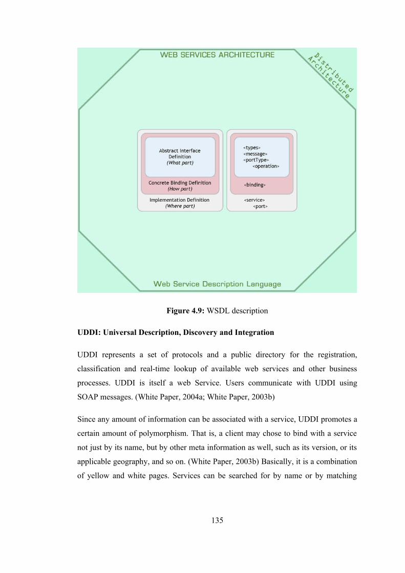
Figure 4.9: WSDL description
UDDI: Universal Description, Discovery and Integration
UDDI represents a set of protocols and a public directory for the registration,
classification and real-time lookup of available web services and other business
processes. UDDI is itself a web Service. Users communicate with UDDI using
SOAP messages. (White Paper, 2004a; White Paper, 2003b)
Since any amount of information can be associated with a service, UDDI promotes a
certain amount of polymorphism. That is, a client may chose to bind with a service
not just by its name, but by other meta information as well, such as its version, or its
applicable geography, and so on. (White Paper, 2003b) Basically, it is a combination
of yellow and white pages. Services can be searched for by name or by matching
135
properties. Entries in a UDDI repository can contain business information as well as
web service APIs (that is, WSDL definitions). (White Paper, 2003c)
The information that can be registered includes simple data that help others
determine the answers to the questions “who, what, where, and how?”: (White Paper,
2003c)
• Human-readable details include things such as entity name, contact
information, product codes, and so on.
• Details aimed at machine consumers includes the URL or other service
endpoints and references to details on service interfaces and other properties.
These describe the behavior of a particular software package or technical
interface. They are called tModels in the UDDI specification.
The UDDI standards process is managed by OASIS, with V2.03 being the latest
version (19 July 2002). An important new feature of the UDDI V3 specification is
Subscriptions and Notifications, which allow clients to automatically receive
notification of changes made to registered web services. Without this, subscribers
would not be aware of web service changes until they attempted to use the service.
(http://www.oasis-open.org)
A UDDI Registry contains information about businesses and the services they offer.
The information is organized as follows: (White Paper, 2003b)
• Business Entity. A business entity contains information about a business
including its name, a short description, and some basic contact information.
Each business can also be associated with unique business identifiers,
including a Thomas Register identifier and a D-U-N-S number, and with a list
of categorizations that describe the business. UDDI V2 products allow
businesses or industry groups to create additional describing categories, a
very powerful feature.
• Business Service. Associated with the business entity is a list of business
services offered by the business entity. Each business service entry contains a
business description of the service, a list of categories that describe the
136
service, and a list of binding templates that point to technical information
about the service.
• Binding Templates. Associated with each business service entry is a list of
binding templates that provide information on where to find the service and
how to use the service. For example, a binding template may contain the
access point of the service implementation. The binding template also
associates the business service with a service type.
• Service Types. A service type, defined by a construct called a tModel,
defines an abstract service. Multiple businesses can offer the same type of
service, all supporting the same service interface. A tModel specifies
information such as the tModel name, the name of the organization that
published the tModel, a list of categories that describe the tModel, and
pointers to technical specifications for the tModel. For example, a tModel
may point to a WSDL document that describes an abstract service type.
4.4.5 Implementing web services
Developing web services-based applications requires a different approach than
traditional web application development. Web services, and service-based
development in general, require a strong focus on the design step of the development
process. The application design will define the services, data types, and message
formats, and how they interact. Web services require that the design is represented in
a WSDL document. The WSDL document lists all the services and data types that
make up an application in XML Schema format.
Internet middleware products, sometimes referred to as a web services platform,
provide a ready-made foundation for building and deploying web services. The
advantage of using a web services platform is that developers do not need to be
concerned with constructing or interpreting SOAP messages. A developer simply
writes the application code that implements the service, and the Internet middleware
does the rest. A web services platform generally consists of development tools, a
runtime server, and a set of management services. Figure 4.10 shows a typical web
services platform runtime environment.
137
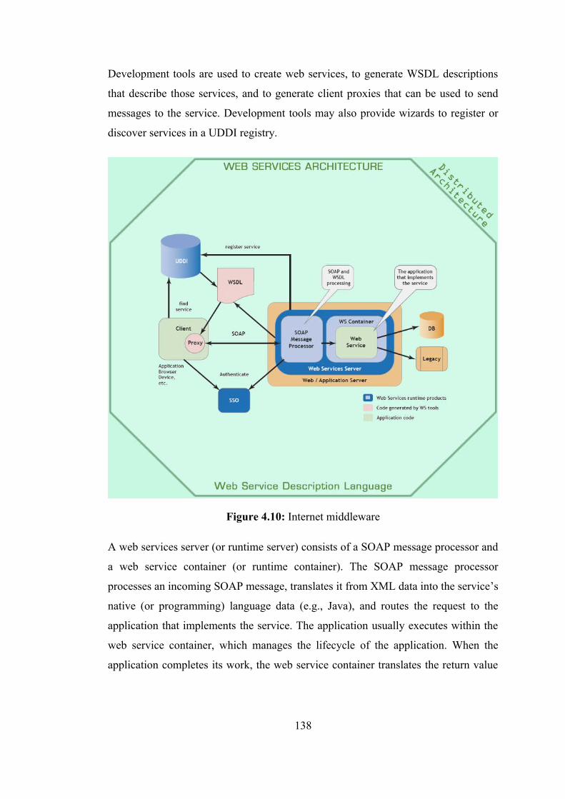
Development tools are used to create web services, to generate WSDL descriptions
that describe those services, and to generate client proxies that can be used to send
messages to the service. Development tools may also provide wizards to register or
discover services in a UDDI registry.
Figure 4.10: Internet middleware
A web services server (or runtime server) consists of a SOAP message processor and
a web service container (or runtime container). The SOAP message processor
processes an incoming SOAP message, translates it from XML data into the service’s
native (or programming) language data (e.g., Java), and routes the request to the
application that implements the service. The application usually executes within the
web service container, which manages the lifecycle of the application. When the
application completes its work, the web service container translates the return value
138
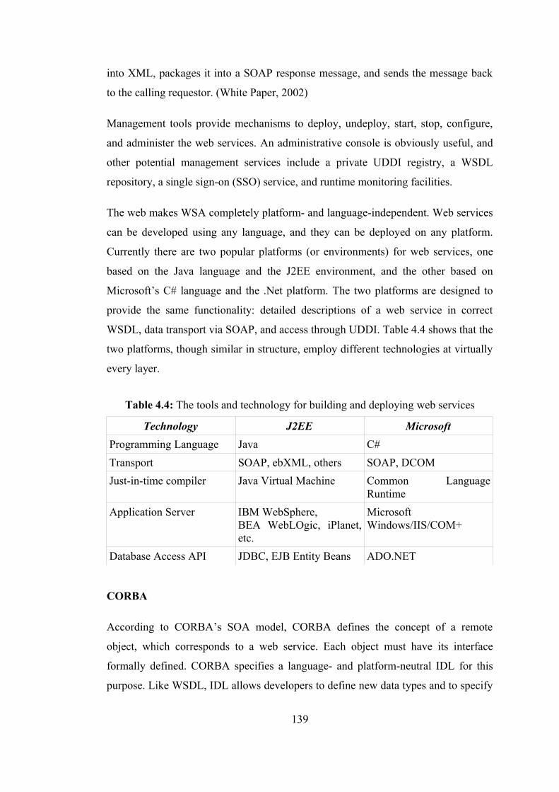
into XML, packages it into a SOAP response message, and sends the message back
to the calling requestor. (White Paper, 2002)
Management tools provide mechanisms to deploy, undeploy, start, stop, configure,
and administer the web services. An administrative console is obviously useful, and
other potential management services include a private UDDI registry, a WSDL
repository, a single sign-on (SSO) service, and runtime monitoring facilities.
The web makes WSA completely platform- and language-independent. Web services
can be developed using any language, and they can be deployed on any platform.
Currently there are two popular platforms (or environments) for web services, one
based on the Java language and the J2EE environment, and the other based on
Microsoft’s C# language and the .Net platform. The two platforms are designed to
provide the same functionality: detailed descriptions of a web service in correct
WSDL, data transport via SOAP, and access through UDDI. Table 4.4 shows that the
two platforms, though similar in structure, employ different technologies at virtually
every layer.
Table 4.4: The tools and technology for building and deploying web services
Technology J2EE MicrosoftProgramming Language Java C#Transport SOAP, ebXML, others SOAP, DCOMJust-in-time compiler Java Virtual Machine Common Language
RuntimeApplication Server IBM WebSphere,
BEA WebLOgic, iPlanet, etc.
Microsoft Windows/IIS/COM+
Database Access API JDBC, EJB Entity Beans ADO.NET
CORBA
According to CORBA’s SOA model, CORBA defines the concept of a remote
object, which corresponds to a web service. Each object must have its interface
formally defined. CORBA specifies a language- and platform-neutral IDL for this
purpose. Like WSDL, IDL allows developers to define new data types and to specify
139
the operations, argument, and exceptional conditions used in an object’s interface.
(URL OMG)
For remote invocation, CORBA defines an encoding mechanism called Generic
Inter-ORB Protocol (GIOP) and a binding for using GIOP over TCP/IP called
Internet Inter-ORB Protocol (IIOP). These correspond to SOAP and the
SOAP/HTTP binding, respectively. (URL OMG)
CORBA also defines a set of what it terms Common Object Services, which provide
runtime support services. These include naming (lookup by name), trading (lookup
by property), security, messaging, and so on. UDDI corresponds to a combination of
CORBA naming and CORBA trading services. (URL OMG)
Wrapping CORBA components as web services requires three steps: (URL OMG)
1. Mapping IDL to WSDL.
2. Run-time mapping of SOAP to IIOP.
3. Integration of CORBA naming service, and so on.
WSA Invocation Mechanism
Unlike other SOA systems, Internet middleware does not define a specific invocation
mechanism. The core Internet middleware specifications simply define the
communication protocols. The specifics of how applications interact with SOAP and
WSDL have been left as an exercise to the application community. Any application
language can parse and process XML, so at a minimum, applications can simply
construct XML messages directly, package them in a SOAP envelope and exchange
messages. Such manual processing is not particularly conducive to developer
productivity, and it does not exploit the fact that WSDL is machine-readable and can
be compiled into application code. Hence the application community has produced a
set of standard invocation mechanisms.
140
The Java Community Process has defined a set of standard programming interfaces
for Java applications. (URL Java)
• The Java API for WSDL (JWSDL) provides an API to create, inspect, and
manipulate a WSDL document. JWSDL is used when compiling WSDL files
into client stubs and proxies, and it is used to process a WSDL file at runtime
for dynamic binding and discovery.
• The Java API for XML based RPC (JAX-RPC), working with JWSDL,
provides support for static binding, dynamic binding, and dynamic discovery.
JAX-RPC also defines mappings between Java data types and XML types.
The JAX-RPC client APIs automatically marshal and unmarshal SOAP
requests on behalf of the client application.
• The Java API for XML Messaging (JAXM) provides an API to construct
SOAP messages without the benefit of a WSDL document. JAXM works
with profiles that define a template for a SOAP message structure,
automatically constructing the SOAP envelope, SOAP header, and SOAP
body. The client application simply adds the XML payload to the message.
• The SOAP with Attachments API (SAAJ) provides a low level SOAP API.
Client applications can use SAAJ to manually construct and process SOAP
messages.
• The Java API for XML Registries (JAXR) is an API that can be used to
access a variety of XML registries, including UDDI registries and electronic
business XML (ebXML) registries. Given that it is a generic registry API, the
JAXR data model is different from the UDDI data model. There are a number
of other UDDI client APIs that more closely match the UDDI data model,
including two open source projects: UDDI4J and the Systinet UDDI Client
API.
• Java Service Developer Pack (Java WSDP) is an integrated toolset that in
conjunction with the Java platform allows Java developers to build, test and
deploy XML applications, web services, and web applications. The Java
141
WSDP provides Java standard implementations of existing key web services
standards including WSDL, SOAP, ebXML, and UDDI as well as important
Java standard implementations for web application development such as JSP
technology pages and the JSP Standard Tag Library.
Microsoft has defined a set of standard programming interfaces and class libraries for
the Visual Studio .NET languages within the .NET framework, and the Microsoft
SOAP Toolkit provides support for COM-based applications written in Visual Basic
and Visual C++. (URL Microsoft)
4.4.6 Web services in the cultural heritage domain
Z39.50 communications protocol
Z39.50 is an American development intended to facilitate networked access to
distributed database resources. Basically, Z39.50 itself is no more than a network
protocol: the thing that controls how two or more computers talk to each other. The
rest of the work is done by the database software or some other tool. There are
currently two main flavors of Z39.50 -- Z39.50-1992 (version 2) and Z39.50-1995
(version 3, recently ratified as ISO 23950). The simpler Z39.50-1992 appears to
remain the most frequent implementation, although this is changing gradually.
(Miller, 1997)
More often used within academic information systems, Z39.50 is a protocol that can
be used to communicate data between remote systems. However, it is a relatively
outdated and rather cumbersome and static technology. (Miller, 1997) Z39.50
requires a dedicated Z39.50 server acting as a host to a number of Z-targets. Each of
these targets need their database and related connections aligned to the Z39.50
protocol by using what are known as 'profiles' held on the server. A Z-client or
gateway can then hook into the server, request a query and await results. Aside from
being notoriously complicated to implement correctly, the use of specific server-side
profiles to link the server to its related data sources thus present a somewhat tight
coupling between the various remote systems. (Waller, 2005) A web service is not
directly a web-based implementation of the RPC protocols, or indeed a technology
142
designed as a replacement to the dated Z39.50 protocol. A web service is, however, a
much simpler protocol that offers greater flexibility for achieving the same goal – the
retrieval of information from a remote system. (Waller, 2005) It is for this reason that
CH enterprises can use web services to embrace an altogether more efficient and
flexible infrastructure for the search, retrieval and ultimately integration of remote
datasets and information from remote systems.
As a nascent technology in the CH domain, the critical issue for web services is to
determine what needs of the CH community are addressed by them, where they are
used in the CH projects, how a common architecture would be established for them
in which components are distributed and loosely coupled, and what the functions of
that architecture should be.
SOA, web services and WSA enable the extended CH enterprises like “KaleTakimi”
dealing with numerous stakeholders both internally as well as externally and being
constantly engaged with systems, actors, disciplines, technologies etc. to be more
agile and flexible by providing the powerful technology for doing a number of things
from integration of applications, systems, processes within the enterprise to building
better business processes that span across extended enterprise or multiple enterprises.
The integration of all business functions into a seamless process requires integration
of the applications that support these functions -even if many of those applications
belong to other CH enterprises. Hence, the various systems are speaking the same
language even if they are owned by different CH organizations. This approach allows
business processes or functionality residing on completely different systems and
unknown to each other to communicate in a standard way.
“GeoCHEAF” is challenged to provide common pattern for implementing web
services architecture, that best fits CH communities and organizations’ needs and
expectations, such as application integration, extended functionality for web
applications, portal integration.
To realize the advanced degree of interoperability and openness that web services
can deliver, “GeoCHEAF” designs, develops, deploys, executes and manages those
143
services within the WSA. XML-based standards-compliant web services run on the
J2EE-compliant 'Web Applications and Services Platform' of this architecture. In this
platform, applications are building that query UDDI, parse WSDL documents, and
construct SOAP requests. Web services can be developed and deployed using Java as
a programming language and a platform. Apache AXIS uses to implement SOAP.
In the service-oriented, component-based web application architecture of
“GeoCHEAF”, web services are deployed in a web service server (or a runtime
server) that runs as a servlet within the web server Apache. There is no need for any
specialized software on the user tier to request a web service. Thin user is presented
with HTML form-based view of the interfaces contained in the WSDL by a JSP,
which run in any standard web browser. The web services client does not have to be
a browser on a PC. The discovery could be through any type of Internet-enabled
device and application. For example a web service request might come from a cell
phone using Wireless Markup Language (WML). At runtime, in the presentation
layer, the JSP is executed on Tomcat engine to create HTML pages dynamically by
doing transformation between the HTML browser view and the WSDL/SOAP web
service view. These pages are then displayed in the browser window on the client.
JSP applications are packaged in web archive (WAR) files, which are the equivalent
of JAR files in pure Java applications.
HTTP is currently the standard transport used for sending SOAP messages to a web
service. HTTP is simple, ubiquitous, and scales well due to its stateless design. It can
typically pass through firewalls without the need to make any changes to network
topology. However, HTTP is not a suitable transport for many applications, because
there is no guarantee that a message has reached its target process. HTTP is not
transactional, meaning that if an error occurs while transmitting the message, the
client may not be able to determine if the message was received by the server.
Therefore, the public Internet is not sufficiently reliable for some types of message
transfers. A client calling a web service that does not get a result before timing out
has no way of determining if the message was received, fully or partially processed,
or lost during the communication. In addition, message retries cannot ensure that
requests are not duplicated. “GeoCHEAF” supports SOAP over HTTP, HTTPS,
144
SMTP as a web service transport as well as Java Message Service (JMS) since using
JMS overcomes these limitations.
A web service provides an interface that can be called from another program. This
application-to-application programming interface can be invoked from any type of
application client or service. The web service interface acts as a liaison between the
web and the actual application logic that implements the service. (White Paper,
2003b) The operator of the client is not always a person, but is typically another
application or web service. For example, one might develop a web service whose job
is to summon other web services. In fact, the SOAP transport is designed to support
these 'machine-to-machine' transactions. The function of a web service may involve
issuing a request to another web service, and that web service may issue a request to
yet another web service, and so on. This leads to what is called an 'n-tier' application
model, in which an application comprises multiple web services. Finally, web
services leave the client-server paradigm behind. (White Paper, 2003a) Web Services
support loosely coupled connections between systems. Web Services communicate
by passing messages to each other. The Web Service interface adds a layer of
abstraction to the environment that makes the connections flexible and adaptable.
(White Paper, 2003b)
145
5. DATA ARCHITECTURE
As ICT becomes increasingly integrated with the business operations, data also
assumes a growing role in the ICT architecture, while data and data sharing is the
main business concern in the enterprise. In particular, the ability to store and retrieve
growing quantities of critical data according to usage and value is becoming a
fundamental consideration when building a storage environment.
Other requirements including the variability of data value over time, differing
content formats, protection from improper access, and the specific archival
requirements of particular industries, are also promoting a new focus on
incorporating data life cycle management within storage infrastructures.
An evolutionary path has been witnessed in the database industry in the development
of the following functionalities: data collection, data modeling and database creation,
data management (including data storage, retrieval and database transaction
processing), data analysis and understanding (involving data warehousing and data
mining), and ultimately decision-making relies on all those functionalities. In this
manner, “GeoCHEAF” provides robust data life-cycle management to control and
manage CH data throughout its entire life-cycle from collection, acquisition,
modeling, storage, access, process, visualization, dissemination, usage, integration,
protection and corruption to eventual deletion. In addition to data management, it
promotes a new focus for information and knowledge management for the CH
domain through data, information, knowledge, and wisdom chain. Figure 5.1 shows
the data flow in the data architecture of “GeoCHEAF”.
A repository is a collection of resources from multiple systems that can be accessed
to retrieve information. Repositories often consist of several databases (or files) tied
together by a common search engine that is directly accessible to the user. It is a
central place where digital data is stored and maintained. (URL Wikipedia) In the
146
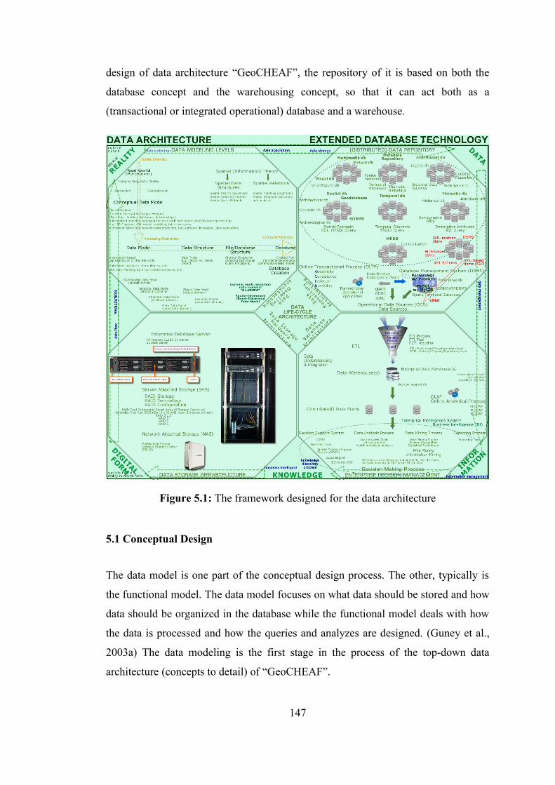
design of data architecture “GeoCHEAF”, the repository of it is based on both the
database concept and the warehousing concept, so that it can act both as a
(transactional or integrated operational) database and a warehouse.
Figure 5.1: The framework designed for the data architecture
5.1 Conceptual Design
The data model is one part of the conceptual design process. The other, typically is
the functional model. The data model focuses on what data should be stored and how
data should be organized in the database while the functional model deals with how
the data is processed and how the queries and analyzes are designed. (Guney et al.,
2003a) The data modeling is the first stage in the process of the top-down data
architecture (concepts to detail) of “GeoCHEAF”.
147
5.1.1 Data modeling
An CH enterprise requires a model of how the CH phenomenon exists in the real
world; without the model, an CH organization has only the sample data and no
inferences can be made about the behavior of the CH phenomenon in the real world.
Since a data model provides the means to making it simple and clear, as the
complexity of the enterprise increases, so does the importance of good modeling
techniques.
A data model presents the conceptual core of an information system. At the same
time a data model is a set of guidelines for the representation of the logical
organization of the data in a database. It defines the data objects (with data object
types, data type), the associations between data objects (relationships), operations,
and the rules that govern operations on the objects to build a database and maintain
its integrity. (Yuan, 1995; Nadi and Delavar, 2003; URL, 2003b)
A data model and its related data structuring must be independent of hardware or
software constraints. Rather than trying to represent the data as a database would see
it, the data model focuses on representing the data as the user sees it in the real
world. It serves as a bridge between the concepts that make up real world events and
processes and the physical representation of those concepts in a database. (URL,
2003b) To be effective, the data model must be simple enough to communicate to the
end user the data structure required by the database yet detailed enough for the
database design to use to create the physical structure. (Guney et al., 2003a)
There are two major approaches used to create a data model: the Entity-Relationship
(ER) modeling and the Object Model.
ER is a conceptual data model that views the real world as consisting of entities and
relationships. Thus, it is the traditional relational modeling approach. Originally, it
unifies the network and relational database views. Database designers often use this
methodology to gather requirements and define the architecture of the database
systems. The output of this methodology is a list of entity types, relationship types,
and constraints. ER modeling itself also defines the methodology used in the analysis
148
and design of information-based systems. (Gornik, 2003) The major drawback of ER
modeling is the lack of a tool facilitating conceptual data model design and its
associated implementation. UML notation can be used for the graphic representation
of ER diagrams while UML is a tool for designing an object-oriented data model.
Developing of a data model is an important step in order to integrate large volumes
of different data. However, searching and analyzing the data can become very time
consuming and complicated without a proper data model. Data modeling is probably
the most labor intensive and time consuming part of the development process.
Constructing functionally-integrated and coherent data model is on-going process
since an incorrect or incomplete data model can cause potential conflicts. The data
model is open ending so the designers/developers in the enterprise could
accommodate new information without restrictions. (Guney et al., 2003a)
5.1.2 Geospatial data modeling
The real world and geographic variation in it is infinitely complex. Both natural and
built environments have many levels of subcomponents. There are complex
relationships and interdependencies among them. It would take an infinitely large
database to capture the real world precisely. But computers are finite. Therefore,
difficult choices have to be made about what and how things are modeled. It is very
important to note that the modeling process is not attempting to develop a copy of
reality. It is much more concerned with describing the important features of the
systems in terms of processes and information considered important by the users like
analysts and decision-makers in the enterprise. Data must somehow be reduced to a
finite and manageable quantity by a process of abstraction and generalization,
geographical variation must be represented in terms of discrete elements or objects;
the rules used to convert real geographical variation into discrete objects is the
geospatial data model. Maps and SIS are geospatial models of reality. Maps
emphasize some aspects of reality in a cartographic representation and SIS
emphasize some aspects of reality in a database representation while ignoring or
greatly simplifying other aspects of reality. (URL, 2003c; Tomlin and Klinkenberg,
2004; Star and Estes, 1990; Maguire and Grise, 2001; Beaumont 2000)
149
The type of analytical operations that can be performed are strongly influenced by
the way the real world is modeled. Therefore, a complete and rigorous geospatial
data model is vital to the success of a SIS project to overcome the difficulty in
understanding proximity, density, connectivity, and accessibility among real-world
entities in the complex systems. (Maguire and Grise, 2001; URL, 2003c; Yuan 1995)
Since the type of phenomena the CH community study have different characteristics
and each study use SIS for different purposes, there is no single type of data model
that is best for all circumstances. There is not a universe data model for geographic
reality. According to the goals and parameters of a project, various distinctive
models can be built.
5.1.3 Object data modeling
Object data modeling is an object oriented approach to mimic a more natural way of
defining systems and to model complex entities and relationships more intuitive than
that offered by the traditional data and process modeling techniques. This approach
reduces the conceptual and structural mismatch found in more traditional approaches
between a problem's description and its computational solution. (Beaumont, 2000;
URL, 2003c) Moreover, object-oriented data modeling can provide more
functionalities and semantic constructs for modeling complex objects and
inter-relationships among them.
The approach does not just mean that there is a database with objects in it, but that
the system is organized around the concept of objects which have behavior
(methods). Objects belong to classes which are arranged in a hierarchy (preferably a
heterarchy). Subclasses inherit behavior and communication between objects is via a
system of message passing thereby providing very robust interfaces. (Chance et al.,
2003) In addition to domain related behavior, objects representing real world
phenomena are linked to spatial classes from which they can inherit appropriate
spatial behavior.
150
Furthermore, there is a hybrid approach -an object-relational data model- that
gradually becomes an industry trend because it borrows rich data types and
operations from relational models and concepts from object-oriented models.
In the relational model, all information is in the form of multiple related tables each
consisting of rows and columns rather than putting all the data in one big storeroom,
and relationships are presented by the use of values common to more than one table.
The tables are linked by defined relations making it possible to combine data from
several tables on request. This adds speed and flexibility. Other models such as the
hierarchical model and the network model use a more explicit representation of
relationships. (URL Wikipedia)
5.1.4. Spatiotemporal data modeling
Most phenomena are changed over time. From temporality point of view, there are
two types of information; static information and dynamic information. Most of the
phenomena in the real world are dynamic in nature. This static can only be used for
objects such as cartographic maps, roads, facilities, utilities, etc. that may not change
in a short period of time. However, all of these objects will change during a long
period of time. Dynamic information refers to that information of geospatial objects
that change in a short period of time. The length of this period is defined according to
its usage fields.
Simply connecting a spatial data model to a temporal data model will result in a
spatiotemporal data model that may capture time referenced sequences of spatial data
or time spatial objects to model dynamic phenomena in SIS.
Designing three-dimensional (3D) and time-dependent data model in the CH domain
is a key issue especially when using SIS for the CH projects to support
decision-making based on analysis of and reasoning on 4D CH data objects of
dynamic CH phenomena since many CH objects have attributes about location, time
and geometry changing over time. Such spatiotemporal CH objects can only model
with a spatiotemporal object (ST-Object) model. Additionally, a spatio-bitemporal
151
data model that handles information about valid time and transaction time allows for
retroactive as well as post-active changes.
Transaction time is defined as the time when a fact is stored in the database. Valid
time is defined as the time when a fact becomes effective (valid) in reality or when
an event occurred in the real world.
5.1.5 Data model of “GeoCHEAF”
To incorporate temporal information into spatial databases over 2D/3D base map, the
dynamic multi-resolution data model of “GeoCHEAF” is a spatio-bitemporal object-
relational data model designed as an open-ending and dynamic SIS data modeling for
the CH projects according to the user requirements and expectations of the CH
domain. It recognizes the composite structure of spatiotemporal CH objects with
with spatial and non-spatial dimensions under the same architecture to implement a
complete database system based on this geomodel. It represents the real world as a
set of discrete objects hold in both space and time.
As presented in Figure 5.2, this multi-purpose data model fundamentally relies on six
different data modeling aspect:
1. Spatial data modeling
2. Thematic data modeling
3. Temporal data modeling
4. Object-relational data modeling
5. Metadata modeling
6. Semantic modeling
Its general framework uses a set of geometry-based spatial objects to represent
reality, such as representation of objects’ position is space (spatial modeling aspect).
Thematic characteristics are represented as attributes of spatial objects (thematic
modeling aspect). Temporal information is associated with time-stamping events or
processes such as the capture of valid time of objects’ properties (temporal modeling
aspect). Metadata and semantic modeling aspects extend the concepts both of spatial
152
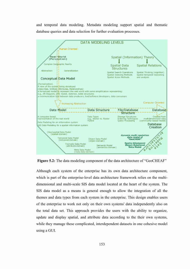
and temporal data modeling. Metadata modeling support spatial and thematic
database queries and data selection for further evaluation processes.
Figure 5.2: The data modeling component of the data architecture of “GeoCHEAF”
Although each system of the enterprise has its own data architecture component,
which is part of the enterprise-level data architecture framework relies on the multi-
dimensional and multi-scale SIS data model located at the heart of the system. The
SIS data model as a means is general enough to allow the integration of all the
themes and data types from each system in the enterprise. This design enables users
of the enterprise to work not only on their own systems' data independently also on
the total data set. This approach provides the users with the ability to organize,
update and display spatial, and attribute data according to the their own systems,
while they manage these complicated, interdependent datasets in one cohesive model
using a GUI.
153
In developing the SIS data model, two more main principles were concerned. First,
the SIS data model must match all the various types of data required in any system in
the enterprise. Second, the data model must be strictly implementation independent
whatever the evolution of database and application of computer technology.
In terms of the fortresses, problem appears in accurately modeling the phenomenon
of 'life history of the fortresses' since the phenomenon has been continuously
changing over time and conventional SIS data models merely emphasize static
representations of reality. It is obvious that this kind of life history can only be
modeled with the spatio-bitemporal object-relational data model of “GeoCHEAF”
and captured by a database that handles changing information. Thus, the SIS
application of the fortresses acquires a dynamic structure, so that CH data of the
fortresses can be manipulated in multidimensional space including time (as the forth
dimension) to describe various types of dynamic changes of historical objects.
(Guney and Celik, 2003a; Guney et al., 2004)
With this type of data model both the present situation of the fortresses and the
condition of the fortresses in the past can be recorded and the architectural changes
from the 17th century to the present day can be determined more efficiently. Natural,
economical, social and political events, which have caused structural changes to the
fortresses and surrounding buildings and environs, can be discovered. (Guney, 2002)
Most of phenomena in the 17th century Ottoman fortresses are dynamic and have
changed discretely over time. The value of time is represented by the number of
years. For example, after the World War I the fortress was damaged and re-
constructed. The shape of most buildings within the border of the fortresses
architecturally changed. (Guney et al., 2004) Additionally, how the fortress
developed and changed through several centuries of usage.
The discrete changes of a CH object of the fortresses during a time interval, from
17th century to today, can be seen as snapshots of that object, taken in time points of
this time interval. Versions of the same facade of Seddülbahir in different time of the
same period are shown in the figure 5.3. Changes occur to attributes of a
154
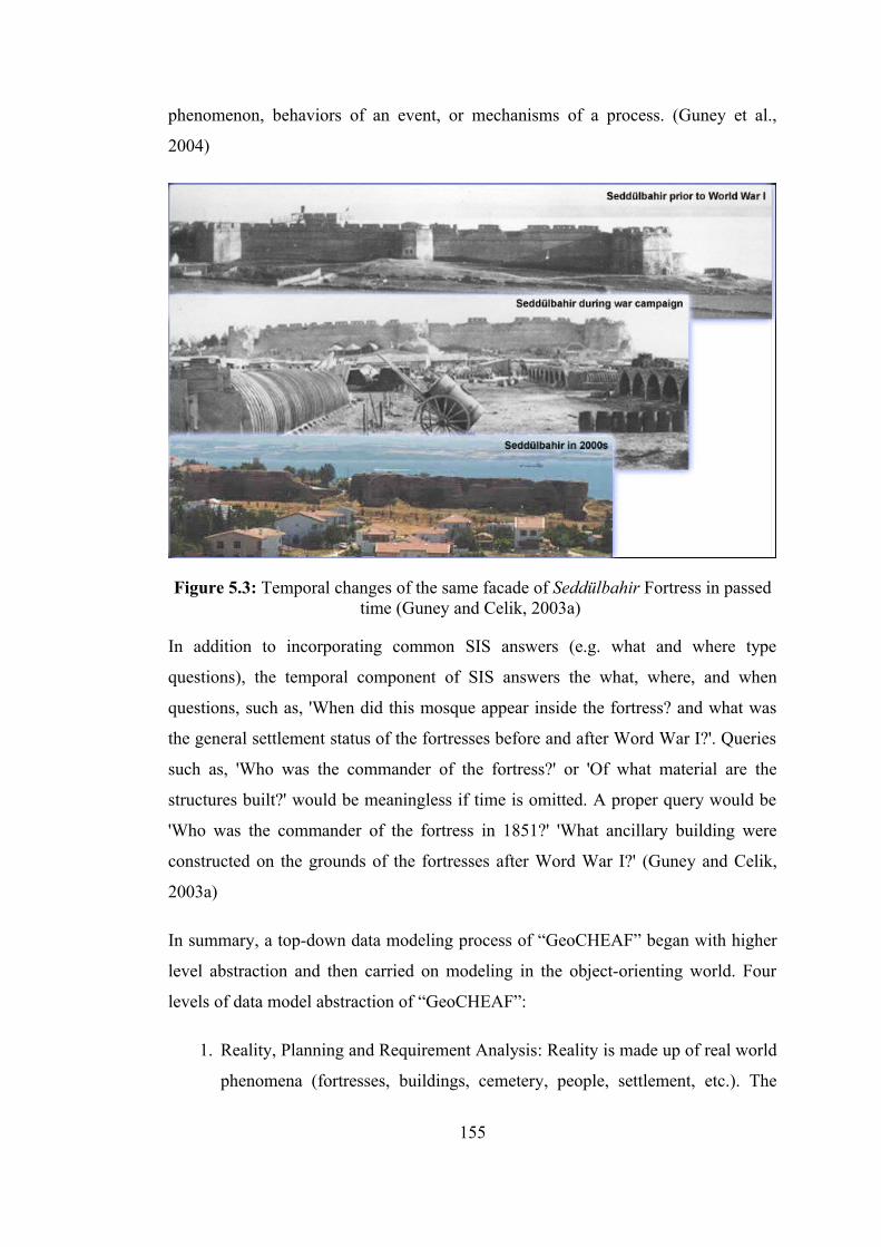
phenomenon, behaviors of an event, or mechanisms of a process. (Guney et al.,
2004)
Figure 5.3: Temporal changes of the same facade of Seddülbahir Fortress in passed time (Guney and Celik, 2003a)
In addition to incorporating common SIS answers (e.g. what and where type
questions), the temporal component of SIS answers the what, where, and when
questions, such as, 'When did this mosque appear inside the fortress? and what was
the general settlement status of the fortresses before and after Word War I?'. Queries
such as, 'Who was the commander of the fortress?' or 'Of what material are the
structures built?' would be meaningless if time is omitted. A proper query would be
'Who was the commander of the fortress in 1851?' 'What ancillary building were
constructed on the grounds of the fortresses after Word War I?' (Guney and Celik,
2003a)
In summary, a top-down data modeling process of “GeoCHEAF” began with higher
level abstraction and then carried on modeling in the object-orienting world. Four
levels of data model abstraction of “GeoCHEAF”:
1. Reality, Planning and Requirement Analysis: Reality is made up of real world
phenomena (fortresses, buildings, cemetery, people, settlement, etc.). The
155
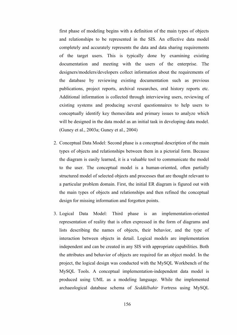
first phase of modeling begins with a definition of the main types of objects
and relationships to be represented in the SIS. An effective data model
completely and accurately represents the data and data sharing requirements
of the target users. This is typically done by examining existing
documentation and meeting with the users of the enterprise. The
designers/modelers/developers collect information about the requirements of
the database by reviewing existing documentation such as previous
publications, project reports, archival researches, oral history reports etc.
Additional information is collected through interviewing users, reviewing of
existing systems and producing several questionnaires to help users to
conceptually identify key themes/data and primary issues to analyze which
will be designed in the data model as an initial task in developing data model.
(Guney et al., 2003a; Guney et al., 2004)
2. Conceptual Data Model: Second phase is a conceptual description of the main
types of objects and relationships between them in a pictorial form. Because
the diagram is easily learned, it is a valuable tool to communicate the model
to the user. The conceptual model is a human-oriented, often partially
structured model of selected objects and processes that are thought relevant to
a particular problem domain. First, the initial ER diagram is figured out with
the main types of objects and relationships and then refined the conceptual
design for missing information and forgotten points.
3. Logical Data Model: Third phase is an implementation-oriented
representation of reality that is often expressed in the form of diagrams and
lists describing the names of objects, their behavior, and the type of
interaction between objects in detail. Logical models are implementation
independent and can be created in any SIS with appropriate capabilities. Both
the attributes and behavior of objects are required for an object model. In the
project, the logical design was conducted with the MySQL Workbench of the
MySQL Tools. A conceptual implementation-independent data model is
produced using UML as a modeling language. While the implemented
archaeological database schema of Seddülbahir Fortress using MySQL
156
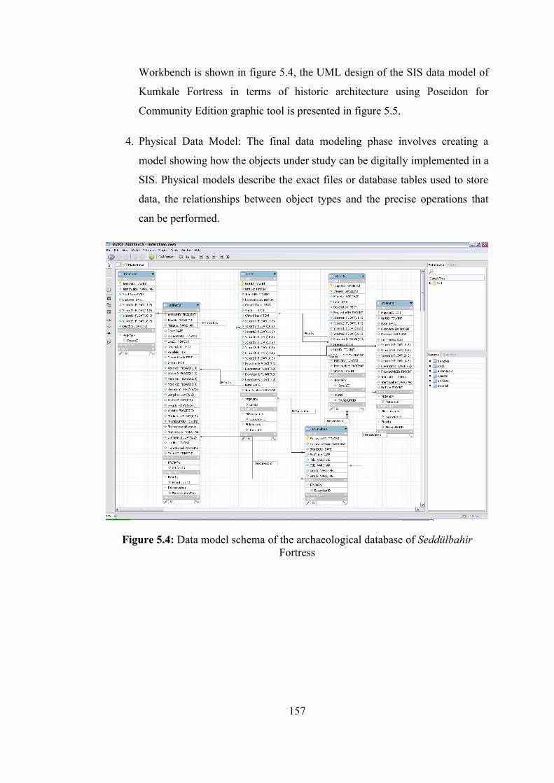
Workbench is shown in figure 5.4, the UML design of the SIS data model of
Kumkale Fortress in terms of historic architecture using Poseidon for
Community Edition graphic tool is presented in figure 5.5.
4. Physical Data Model: The final data modeling phase involves creating a
model showing how the objects under study can be digitally implemented in a
SIS. Physical models describe the exact files or database tables used to store
data, the relationships between object types and the precise operations that
can be performed.
Figure 5.4: Data model schema of the archaeological database of Seddülbahir Fortress
157
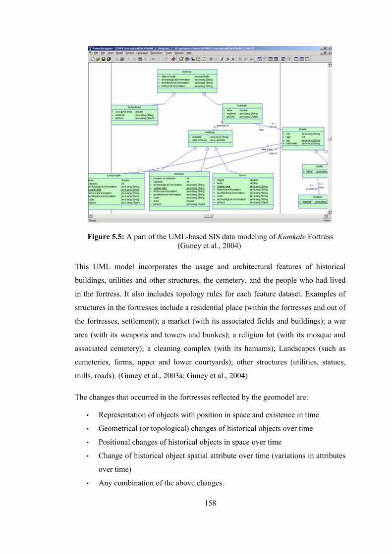
Figure 5.5: A part of the UML-based SIS data modeling of Kumkale Fortress (Guney et al., 2004)
This UML model incorporates the usage and architectural features of historical
buildings, utilities and other structures, the cemetery, and the people who had lived
in the fortress. It also includes topology rules for each feature dataset. Examples of
structures in the fortresses include a residential place (within the fortresses and out of
the fortresses, settlement); a market (with its associated fields and buildings); a war
area (with its weapons and towers and bunkes); a religion lot (with its mosque and
associated cemetery); a cleaning complex (with its hamams); Landscapes (such as
cemeteries, farms, upper and lower courtyards); other structures (utilities, statues,
mills, roads). (Guney et al., 2003a; Guney et al., 2004)
The changes that occurred in the fortresses reflected by the geomodel are:
• Representation of objects with position in space and existence in time
• Geometrical (or topological) changes of historical objects over time
• Positional changes of historical objects in space over time
• Change of historical object spatial attribute over time (variations in attributes
over time)
• Any combination of the above changes.
158
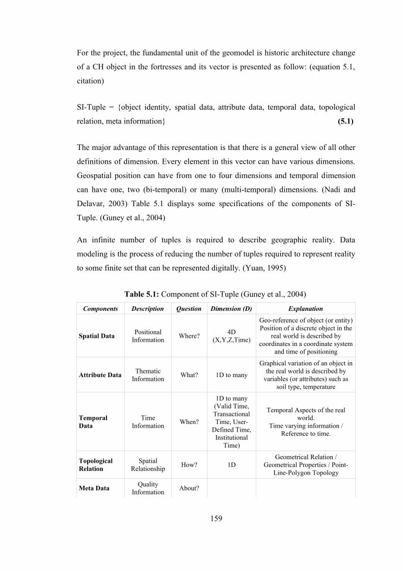
For the project, the fundamental unit of the geomodel is historic architecture change
of a CH object in the fortresses and its vector is presented as follow: (equation 5.1,
citation)
SI-Tuple = {object identity, spatial data, attribute data, temporal data, topological
relation, meta information} (5.1)
The major advantage of this representation is that there is a general view of all other
definitions of dimension. Every element in this vector can have various dimensions.
Geospatial position can have from one to four dimensions and temporal dimension
can have one, two (bi-temporal) or many (multi-temporal) dimensions. (Nadi and
Delavar, 2003) Table 5.1 displays some specifications of the components of SI-
Tuple. (Guney et al., 2004)
An infinite number of tuples is required to describe geographic reality. Data
modeling is the process of reducing the number of tuples required to represent reality
to some finite set that can be represented digitally. (Yuan, 1995)
Table 5.1: Component of SI-Tuple (Guney et al., 2004)
Components Description Question Dimension (D) Explanation
Spatial Data Positional Information Where? 4D
(X,Y,Z,Time)
Geo-reference of object (or entity)Position of a discrete object in the
real world is described by coordinates in a coordinate system
and time of positioning
Attribute Data Thematic Information What? 1D to many
Graphical variation of an object in the real world is described by
variables (or attributes) such as soil type, temperature
Temporal Data
Time Information When?
1D to many(Valid Time, Transactional Time, User-
Defined Time, Institutional
Time)
Temporal Aspects of the real world.
Time varying information / Reference to time.
Topological Relation
Spatial Relationship How? 1D
Geometrical Relation / Geometrical Properties / Point-
Line-Polygon Topology
Meta Data Quality Information About?
159
The main approach of the proposed data model is the abstraction and decomposition
of geometry, topology and thematic information.
In this design, spatial concepts of spatial (information) theory is presented as
following:
1. Spatial Data Structures (in spatial database)
• Spatial Data Structures: R-tree (R: rectangular), R+-tree, B-tree, Quad-
tree (to visualize and organize large 3D SIS databases)
(The R-tree: an efficient and robust access method for points and
rectangles)
(R, O) (Rectangle, Object) Minimal bounding rectangle (MBR) (a linear
container)
• Spatial Search Operations
• Spatial Indexing Methods (rapid access the data)
• Spatial Access Methods
2. Spatial Relations (topologic, metric, direction, linguistic)
• Spatial Thinking (cognition)
• Spatial Reasoning (spatiotemporal reasoning and analysis, temporal
reasoning, spatiotemporal modeling)
Topological relations that are intelligent data that understands connectivity and
adjacency were identified as a set of spatial relations that had to be formalized. The
formalism for binary topological spatial relations:
• The 4-intersection (2 objects’ interiors and boundaries)
• The 9-intersection (interior, exterior, boundaries)
In GIS it is not enough to know the position of an element, it is also essential to
know how it relates to other elements in the system. For example, it is not enough to
be able to locate the fire; it is also imperative to find the nearest fire station or to
determine how the fire affects the region. But showing all possible spatial relations
may be very complex and costly or maybe impossible. This is why some relations are
explicitly defined and others must be calculated.
160
The research on spatial theory focus has shifted from the technical problem of how to
represent geometric figures, and now is firmly centered on the question of how to
represent geographic space and geographic phenomena in ways that are consistent
with how people understand spatial situations.
People often use qualitative spatial thinking and reasoning in everyday life; however,
current commercial GISs support primarily quantitative spatial queries and answers,
and in general lack direct support for users to make qualitative queries about spatial
relations. For example, point to point distance in metric units or direction in degrees
does not necessarily conform to people’s usage of terms and concepts in natural-
language. People’s spatial concepts are often more qualitative in nature, including
such concepts in natural-language. People’s spatial concepts are often more
qualitative in nature, including such concepts as north, near and far. A qualitative
GIS model that is capable of answering queries of the form, “Show me the road that
goes around the fortresses” will complement the existing models. The incorporation
of natural-language spatial relations such as along, goes by, and through will give
GIS users a greater choice in formulating queries, depending on the task being
performed. By better accommodating the human requirements, qualitative models
will also contribute toward the greater utilization of GIS technology. Among the
potential applications of such a model are road navigation system, tourist databases,
etc.
Scientists and engineers using geographic databases need query languages with
powerful spatial selection methods and capabilities to infer spatial information in a
manner similar to a human expert. Crucial for geospatial databases, containing very
large amounts of spatial data, are appropriate operators to access and manipulate
spatial data in large-scale, geographic space, far beyond what is currently being
offered by traditional database management systems. The objective of the design is
to construct a coherent reasoning system that integrates spatial concepts about
topology, cardinal directions, and approximate distances so that they can serve as a
spatial extension to geospatial databases and query languages. The reasoning system
focused on large-scale, geographic space. The hypothesis is that powerful and
complex spatial reasoning can be formalized as the product of the interaction
161
between relatively simple spatial relations with specific inference rules. First,
individual spatial relations of topology, distance, and direction are formalized.
Afterwards these formalizations were used to develop an integrated, comprehensive
system, i.e., a more complex algebra, from the previously defined ones, adding more
power through the coexistence of the different relationships in a single system. The
major results are a set of primitives, with rules describing their combinations, for the
design of domain specific spatial query languages.
5.2. Functional Model (Database Architecture/Component)
Database and database management have become the key components of a SIS. As
the need for large and complex databases continues to grow, more effective access to
the data is needed than ever. Figure 5.6 illustrates the data repository architecture of
“GeoCHEAF”.
The central concept of a database is that of a collection of related records stored in a
computer in a systematic way, so that a computer can consult it to answer questions.
The items retrieved in answer to queries become information that can be used to
make decisions. Database Management System (DBMS) is the software or computer
program for the management and operation of databases. (URL Wikipedia)
For better retrieval and sorting, each record is usually organized as a set of data
elements (facts). Typically, for a given database, there is a structural description of
the type of facts held in that database: this description is known as a schema. The
schema describes the objects that are represented in the database, and the
relationships among them. (URL Wikipedia)
162
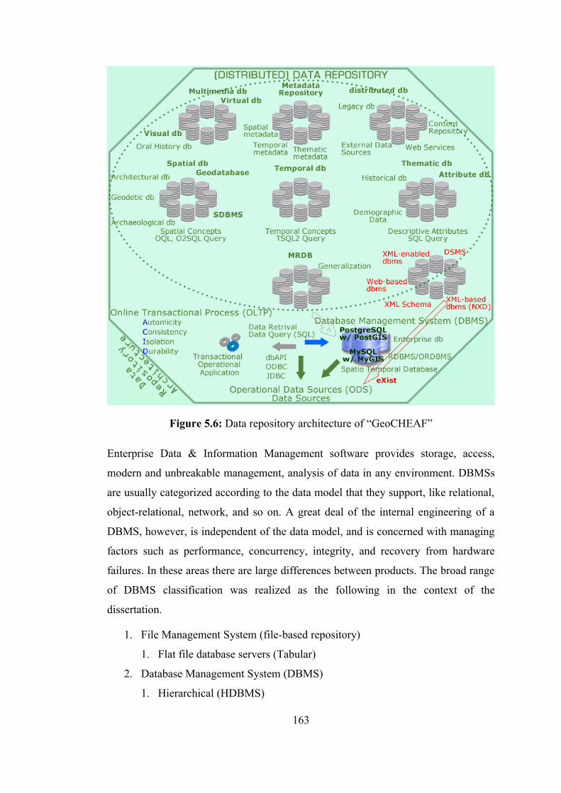
Figure 5.6: Data repository architecture of “GeoCHEAF”
Enterprise Data & Information Management software provides storage, access,
modern and unbreakable management, analysis of data in any environment. DBMSs
are usually categorized according to the data model that they support, like relational,
object-relational, network, and so on. A great deal of the internal engineering of a
DBMS, however, is independent of the data model, and is concerned with managing
factors such as performance, concurrency, integrity, and recovery from hardware
failures. In these areas there are large differences between products. The broad range
of DBMS classification was realized as the following in the context of the
dissertation.
1. File Management System (file-based repository)
1. Flat file database servers (Tabular)
2. Database Management System (DBMS)
1. Hierarchical (HDBMS)
163
2. Network (NDBMS)
3. Relational Database Management Systems (RDBMS)
1. Open Source RDBMS
1. MySQL 5.x by MySQL AB (MyGIS) (MaxDB)
2. SQLite 3.x
3. Firebird 2.x (the first new-generation descendant of Borland’s
InterBase)
4. Borland’s InterBase 6.0 Open Edition code (under the InterBase
Public License (IPL))
5. One$DB (open source version of Daffodil DB)
2. Proprietary RDBMS
1. Oracle 10g (Oracle Spatial 10gR2) (the first relational database
designed for Grid Computing)
2. Oracle 9i (Oracle 9i Spatial (Object Relational Model), map
viewer)
3. Oracle 8i GeoXML server
4. Microsoft SQL Server 2005 (MSSQL)
5. IBM DB2
6. IBM Informix
7. dBASE Plus 2.x
8. Sybase Adaptive Server Anywhere 8
9. InterBase 7.x by Borland Software Corporation
10. Daffodil DB (the first Java RDBMS)
11. Mimer SQL 9.x
12. Microsoft Access
4. Object Database Management Systems (ODBMS)
1. Smalltalk
2. ObjectStore
3. O2
4. Orion
5. Object Relational Database Management Systems (ORDBMS) (Hybrid)
1. Open Source ORDBMS
164
1. PostgreSQL 8.x (PostGIS)
2. Proprietary ORDBMS
1. Oracle
6. Spatial Database Management System (SDBMS)
1. Open Source SDBMS
1. MyGIS by MySQL AB
2. PostGIS by PostgreSQL
2. Proprietary SDBMS
1. ArcSDE by ESRI (an advanced spatial data server for managing
geographic information in numerous relational database
management systems)
2. Oracle Spatial
3. Data Stream Management System (DSMS)
4. XML Databases Management System (XDBMS) (or Web-based DBMS)
1. XML-enabled DBMS
1. IBM DB2
2. Oracle
3. SQL Server
2. Native XML(-based) DBMS (NXD)
1. Commercial NXD
1. Tamino
2. Open Source NXD
1. eXist
2. dbXML
3. Xindice
5. Enterprise DB
1. PostWest
6. Data Warehousing Environment
7. Multiple Representation Database (MRDB)
A spatial database system has been defined as a database system supporting spatial
data types. Spatial data type objects not only have a non-spatial description such as
name and population but also have spatial attributes associated with them such as
165
location, geometry and neighborhood properties - distance and borders etc. A spatial
database system has to provide various functionalities including input, storage,
retrieval, selection, analysis and display of the information.
Database APIs that considered in the context of the dissertation are the followings:
• Open Database Connectivity (ODBC) by Microsoft (used to communicate
with RDBMS)
• OLE-DB by Microsoft (used to communicate with all DBMS)
• Java Database Connectivity (JDBC): JDBC is the key Java technology for
interacting with relational database and a Java API for executing dynamic
SQL statements.
• MySQL Connector/J as JDBC driver
• JDO API
• SQLJ
Query languages that are available to access the database:
1. Structured Query Language (SQL)
• SQL Standards: SQL-86 (1986) / SQL 89 (1989) / ANSI/ISO Standard
SQL92 (1992) (SQL 2) / SQL-99 (1999) (SQL 3) / SQL-2003 (2003)
(XML support)
• SQL-compatible databases
• Data Manipulation in SQL
• SQL server / SQL client
• SQL Programming
• Interactive SQL / Embeded SQL
• geoSQL
2. Object Query Language (OQL)
3. Object-Oriented Geo Query Language (OOGQL)
SQL is the most common standardized language used to access databases. The two
most recent iterations are SQL-99 (also sometimes known as SQL-3) and SQL-92,
both named for the years in which they were first released. (SQL-99 had been
originally planned for release in 1996). More importantly, SQL-99 also added some
basic support for object features, extending SQL’s usefulness and blurring the
166
distinction between relational and object approaches to databases. SQL-99 extends
relational data model to include object-oriented constructs into language for object-
relational models.
In the course of the design work of “GeoCHEAF”, highly scalable PostgreSQL 8.x
and multi-threaded MySQL 5.x were chosen to implement multiple databases and to
develop dynamic database-backed web sites, portals and applications, such as web-
based database and SIS query. Both MySQL and PostgreSQL are two of the world’s
the most popular enterprise-level open source free SQL-compliant relational database
systems (de facto databases). PostgreSQL based on POSTGRES, Version 4.2,
developed at the University of California at Berkeley Computer Science Department,
is also object-relational DBMS. They are renowned for their wide range of
capabilities to perform functions not available in many other databases. They are
attractive alternative to higher-cost, more complex database technology with their
speed, scalability, reliability, ease of deployment and features as sophisticated as the
number one commercial database. They are powerful, compact client/server database
management systems that can run on a variety of server and client operating system
platforms, including Windows, Linux, and several other UNIX platforms. (URL
MySQL; URL PostgreSQL)
MySQL runs on a multi-threaded database engine. This means that MySQL can
handle many tasks and requests at the same time - clients connecting to a MySQL
database server do not need to wait for other clients' queries or processes to end
before their requests are executed. (URL MySQL)
MySQL GUI tools provided by MySQL AB is a single bundle including all GUI
tools MySQL Administrator, MySQL QueryBrowser, MySQL MigrationToolkit and
MySQL Workbench. MySQL Administrator is a visual console that allows a user
access to a variety of administrative tasks, as well as performance and data structure
information. (URL MySQL)
Addition to MySQL GUI tools, there are a number of third-party user interfaces to
MySQL that make it easier to access and alter the data stored in the MySQL
databases. The most popular of these, by far, is phpMyAdmin, a web-based open
167
source application written in PHP. Like MySQL, PostgreSQL can be operated over
the Internet using phpPgAdmin. (http://phppgadmin.sourceforge.net)
phpMyAdmin is a tool written in PHP to establish a web-based powerful interface
for MySQL database administration and development. OS-independent
phpMyAdmin is an open-source application used under GNU GPL.
(http://www.phpmyadmin.net)
The PHP server-side scripting language and the MySQL database management
system make a potent pair (like MSSQL and ASP) to build dynamic database-driven
CGI applications. Both are open source products -free of charge for most purposes-
remarkably strong, and capable of handling all but the most enormous transaction
loads. Both are supported by large, skilled, and enthusiastic communities of
architects, programmers, and designers.
PostgreSQL does not impose a limit on the total size of a database. Databases of 4
terrabytes (TB) are reported to exist. Some other key features of PostgreSQL:
• Database size: No limit
• Table size: 16 TB-64 TB
• Rows in a Table: No Limit
• Table Indexes: No Limit
• Field size: 1 GB
• Row size: No Limit
PostgreSQL and MySQL database management systems enable increased
accessibility to spatial data with respectively PostGIS (under the license GPL) and
MyGIS extensions. They provide a number of geometric types and functions to build
a web-based SIS applications and to generate maps. They support the SQL with
geometry types proposed by the OGC for efficiently storing and manipulating spatial
data. This allows for efficiently storage and manipulation of spatial data.
PostGIS allows the use of GIS objects and other objects that appear in the OGC
specifications. One can think of things like points, lines, polygons, multilines,
multipoints and geometric collections. It works with Geometry Engine Open Source
168
(GEOS) as drive for the topological control. PostGIS, and generally any spatial
extension to a RDBMS, allows a high flexibility, as it is possible to realize spatial
operations at the source of the data. PostGIS is an extension for PostgreSQL and
defines new types of data, creates two tables with relevant information to the system
(data projection and a column that contains the geospatial information).
5.2.1 XML and databases
Although the original purpose of XML is as a way to mark up content, it also
provides a way to describe structured data thus making it important as a data storage
and interchange format. On one hand there is the document-centric model of XML
where XML is typically used as a means to creating semi-structured documents with
irregular content that are meant for human consumption. An example of document-
centric usage of XML is XHTML which is the XML based successor to HTML. The
other primary usage of XML is in a data-centric model. In a data-centric model,
XML is used as a storage or interchange format for data that is structured, appears in
a regular order and is most likely to be machine processed instead of read by a
human. In a data-centric model, the fact that the data is stored or transferred as XML
is typically incidental since it could be stored or transferred in a number of other
formats which may or may not be better suited for the task depending on the data and
how it is used. An example of a data-centric usage of XML is SOAP. In both models
where XML is used, it is sometimes necessary to store the XML in some sort of
repository or database that allows for more sophisticated storage and retrieval of the
data especially if the XML is to be accessed by multiple users. Below is a description
of storage options based on what model of XML usage is required.
In a data-centric model where data is stored in a relational database or similar
repository; one may want to extract data from a database as XML, store XML into a
database or both. For situations where one only needs to extract XML from the
database one may use a middleware application or component that retrieves data
from the database and returns it as XML. Middleware components that transform
relational data to XML and back vary widely in the functionality they provide and
how they provide it. The alternative to using middleware components to retrieve or
169
store XML in a database is to use an XML-enabled database that understands how to
convert relational data to XML and back. (Obasanjo, 2001)
Content management systems are typically the tool of choice for document-centric
model when considering storing, updating and retrieving various XML documents in
a shared repository. (Obasanjo, 2001)
In situations where both documentric-centric and data-centric models of XML usage
will occur, the best data storage choice is usually a native XML database. Native
XML database is a database that has an XML document as its fundamental unit of
(logical) storage and defines a (logical) model for an XML document, as opposed to
the data in that document, and stores and retrieves documents according to that
model. (Obasanjo, 2001)
As can be seen from the above descriptions, there is currently no standard way to
access XML from relational databases. This may change with the development of the
SQL/XML standard currently being developed by the SQLX group. SQLX.org is a
web site that makes the SQL/XML standard, and the technology that it includes,
more highly visible to interested parties. SQL/XML (may also be referred as SQLX)
is an ANSI and ISO standard that provides support for using XML in the context of
an SQL database system. Because SQL is the standard language for accessing and
managing data stored in relational databases, it is natural that enterprises and users
worldwide need the ability to integrate their XML data into their relational data
through the use of SQL facilities. SQL/XML makes it possible to store the XML
documents in the SQL database, to query those documents using XPath and XQuery,
and to publish the existing SQL data in the form of XML documents. In 2003, the
first edition of the SQL/XML standard was published by the International
Organization for Standardization (ISO) as part 14 of the SQL standard: ISO/IEC
9075-14:2003. (URL SQLX)
On the other hand, there is a big debate about XML databases in terms of the use of
hierarchical data model (HM) rather than relational models (RM) in the fields of ICT
and CH. In fact, hierarchical systems were tried and discarded years ago in database
systems.
170
The RM is known simpler, more flexible, and more practical data model than the
HM underlying XML. Due to their horrendous complexity and inflexibility,
databases and DBMSs relying on the hierarchical model became obsolete in the 80's,
at least technologically. (Pascal, 2005)
XML documents are organized as tree structures. Relational databases organize data
in a tabular, or grid-like fashion, and use relational linking in order to expose
hierarchical constraints on the data. Unfortunately, while it is generally very easy to
map relational data into XML, trying to map XML, which can be very complex and
freeform, into relational data can be incredibly difficult and lossy. (URL Xindice)
The fact is that XML was devised by text publishers (see Appendix A), not data
management people, with whom the concept of markup tags originates. And it was
intended mainly for data interchange, not data management, which requires an
agreed physical format, not a data model. But the industry has a long history of
blindly extending technology invented for one purpose to other, unintended
purposes. (Pascal, 2005)
The both models -HM and RM- have pros. and cons. There is XML technology. It
provides transmitting structured data to various users & other applications easily and
prevents repeating fields in a hierarchical XML schema without difficulty. Indeed,
some businesses have adopted XML, but more use XML only as a data transmission
protocol, leaving the data in traditional databases on corporate computers. (Eiteljorg,
2005) NXDs have also extended functionalities such as Query and Update.
As the volume and complexity of e-business transactions increases, the overhead that
is needed to convert back and forth between XML and some other data
representation will seriously affect the speed, reliability and functionality of
XML-enabled systems. Native XML servers that deliver not only the appearance, but
also the reality of the XML architecture will run faster, more reliably and with less
administration overhead. Although all NXD implementations have their strengths
and weaknesses, due to the more features of eXist as shown table 5.2 and its better
performance than other two NXDs, it is used as XML data management tool in the
design of the data architecture of “GeoCHEAF”.
171
eXist is an open source native XML database featuring efficient, index-based
XQuery processing, automatic indexing, extensions for full-text search, XUpdate
support, XQuery update extensions and tight integration with existing XML
development tools. It provides a powerful environment for the development of web
applications based on XQuery and related standards. Entire web applications can be
written in XQuery, using XSLT, XHTML, CSS and Javascript (for AJAX
functionality). XQuery server pages can be executed from the filesystem or stored in
the database. (URL eXist)
dbXML server is a native XML database from the dbXML group as an open source
project under the terms of an MIT Style License. It is capable of storing and indexing
collections of XML documents in both native and mapped forms for highly efficient
querying, transformation, and retrieval. In addition to these capabilities, the server
may also be extended to provide business logic in the form of scripts, classes and
triggers. (URL dbXML)
Xindice is an open source based XML document management system and
maintained by the Apache organization. It is written in Java. (URL Xindice)
Tamino XML Server is a commercial native XML server from Software AG for
storing, managing, publishing and exchanging all kinds of data -specifically XML
documents- in their native format, based on open standard Internet technologies. It is
able to store and access XML documents in a true native XML data storage
integrated in an XML server. Tamino XML Server stores XML objects without
transforming them into another data format. In this sense, Tamino XML Server is a
native XML database. It supports access to external data sources, such as relational
database systems, and also process conventional data and context information. (URL
Tamino)
172
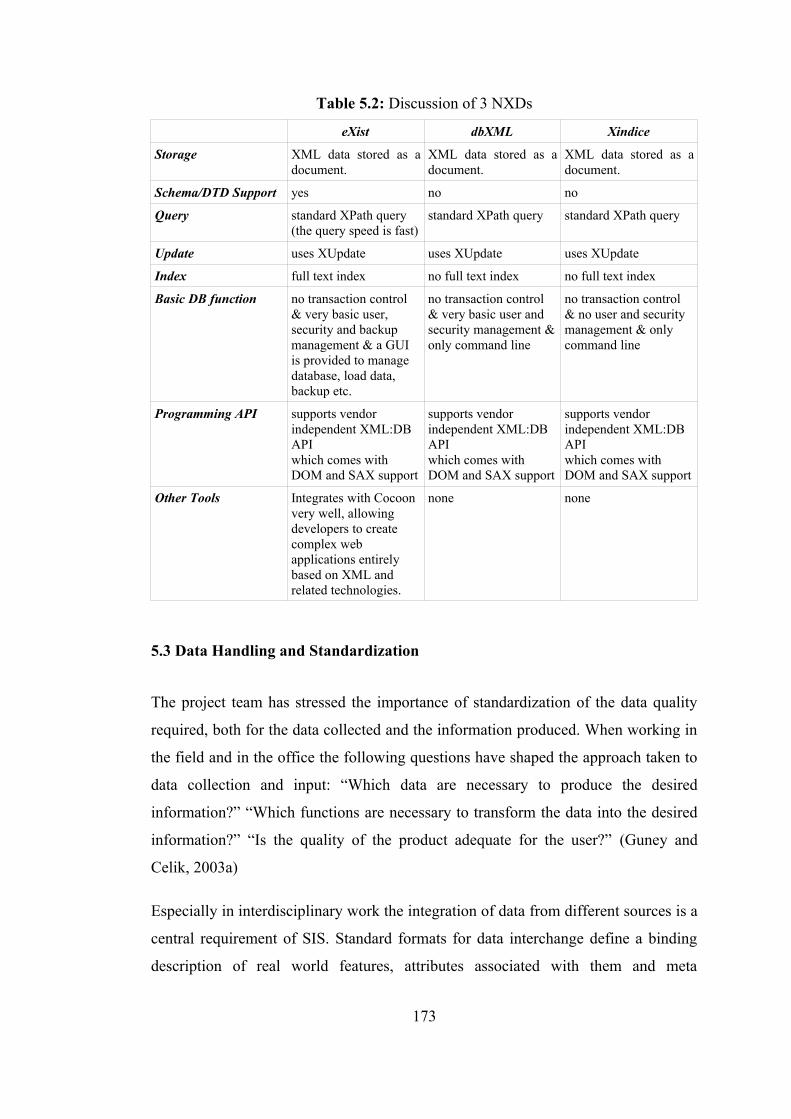
Table 5.2: Discussion of 3 NXDs
eXist dbXML Xindice
Storage XML data stored as a document.
XML data stored as a document.
XML data stored as a document.
Schema/DTD Support yes no no
Query standard XPath query(the query speed is fast)
standard XPath query standard XPath query
Update uses XUpdate uses XUpdate uses XUpdate
Index full text index no full text index no full text index
Basic DB function no transaction control & very basic user, security and backup management & a GUI is provided to manage database, load data, backup etc.
no transaction control & very basic user and security management & only command line
no transaction control & no user and security management & only command line
Programming API supports vendor independent XML:DB APIwhich comes with DOM and SAX support
supports vendor independent XML:DB APIwhich comes with DOM and SAX support
supports vendor independent XML:DB APIwhich comes with DOM and SAX support
Other Tools Integrates with Cocoon very well, allowing developers to create complex web applications entirely based on XML and related technologies.
none none
5.3 Data Handling and Standardization
The project team has stressed the importance of standardization of the data quality
required, both for the data collected and the information produced. When working in
the field and in the office the following questions have shaped the approach taken to
data collection and input: “Which data are necessary to produce the desired
information?” “Which functions are necessary to transform the data into the desired
information?” “Is the quality of the product adequate for the user?” (Guney and
Celik, 2003a)
Especially in interdisciplinary work the integration of data from different sources is a
central requirement of SIS. Standard formats for data interchange define a binding
description of real world features, attributes associated with them and meta
173
information. The main purpose of standardization is to promote interoperability and
portability of data and data processing tools. Defining attribute encoding in the
specific standards facilitates the transfer of self-describing databases. One of the
goals of the standardizing in the dissertation is that geospatial data can be transferred
between all kinds of CH SIS products and platforms. Obviously, SIS cannot be
tailored to individual differences. However, the identification of specific SIS user
groups and usage scenarios -representing users with similar abilities and skills
making similar use of the same SIS functionalities- can be of enormous help in
shaping the SIS for CH domain.
In the project, thousands of points like geodetic and topographic feature points and
object detail points have been measured with different techniques, computed in one
coordinate system and organized within SIS layers properly. Additionally attribute
data handling is the other main capability required of a SIS. Without the ability to
properly handle the related non-spatial information the technology of SIS would
never have taken off as it has. (Guney and Celik, 2003a)
The project team has worked carefully to create a structure based on specific and
high standards before developing SIS. All the sources that have been incorporated
into the database like photographs, archives, slides, engravings have been given
specific coding. Thereafter, the whole codes used in the repository matched the
attributes perfectly. In addition to assigning the codes of info-sources, the team has
identified key issues related to the project and the SIS, and carries on discussions on
a regular basis about the required steps to further progress in achieving a useful SIS.
This approach is time consuming, however, that forms the basis for standardization
when developing a SIS project. (Guney, 2002)
This standardization and methodology can differ due to the building scale and the
particular processes involved in the realization of a project, but in the CH projects
there should be principle criteria in order to reuse and represent the survey data and
the surveys of different periods which are used in the evaluation of the architecture.
174
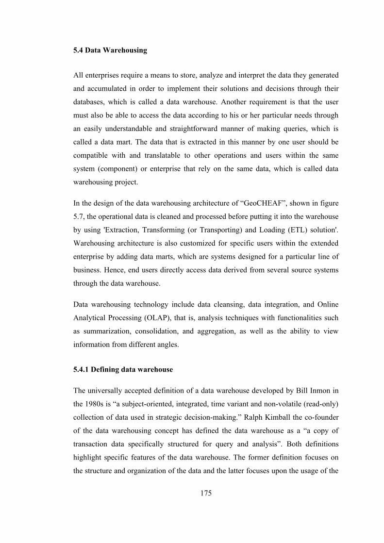
5.4 Data Warehousing
All enterprises require a means to store, analyze and interpret the data they generated
and accumulated in order to implement their solutions and decisions through their
databases, which is called a data warehouse. Another requirement is that the user
must also be able to access the data according to his or her particular needs through
an easily understandable and straightforward manner of making queries, which is
called a data mart. The data that is extracted in this manner by one user should be
compatible with and translatable to other operations and users within the same
system (component) or enterprise that rely on the same data, which is called data
warehousing project.
In the design of the data warehousing architecture of “GeoCHEAF”, shown in figure
5.7, the operational data is cleaned and processed before putting it into the warehouse
by using 'Extraction, Transforming (or Transporting) and Loading (ETL) solution'.
Warehousing architecture is also customized for specific users within the extended
enterprise by adding data marts, which are systems designed for a particular line of
business. Hence, end users directly access data derived from several source systems
through the data warehouse.
Data warehousing technology include data cleansing, data integration, and Online
Analytical Processing (OLAP), that is, analysis techniques with functionalities such
as summarization, consolidation, and aggregation, as well as the ability to view
information from different angles.
5.4.1 Defining data warehouse
The universally accepted definition of a data warehouse developed by Bill Inmon in
the 1980s is “a subject-oriented, integrated, time variant and non-volatile (read-only)
collection of data used in strategic decision-making.” Ralph Kimball the co-founder
of the data warehousing concept has defined the data warehouse as a “a copy of
transaction data specifically structured for query and analysis”. Both definitions
highlight specific features of the data warehouse. The former definition focuses on
the structure and organization of the data and the latter focuses upon the usage of the
175
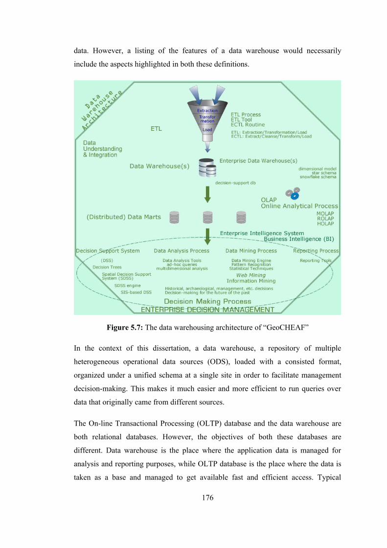
data. However, a listing of the features of a data warehouse would necessarily
include the aspects highlighted in both these definitions.
Figure 5.7: The data warehousing architecture of “GeoCHEAF”
In the context of this dissertation, a data warehouse, a repository of multiple
heterogeneous operational data sources (ODS), loaded with a consisted format,
organized under a unified schema at a single site in order to facilitate management
decision-making. This makes it much easier and more efficient to run queries over
data that originally came from different sources.
The On-line Transactional Processing (OLTP) database and the data warehouse are
both relational databases. However, the objectives of both these databases are
different. Data warehouse is the place where the application data is managed for
analysis and reporting purposes, while OLTP database is the place where the data is
taken as a base and managed to get available fast and efficient access. Typical
176

relational databases are designed for OLTP and do not meet the requirements for
effective OLAP (Naude, 2002). However, the data warehouse supports OLTP system
by providing a place for the latter to offload data as it accumulates and by providing
services which would otherwise degrade the performance of the database.
The OLTP database records transactions in real time and aims to automate clerical
data entry processes of a business entity. Addition, modification and deletion of data
in the OLTP database is essential and the semantics of the application used in the
front end impact on the organization of the data in the database. The data warehouse
on the other hand does not cater to real time operational requirements of the
enterprise. It is a relational database that is designed for query and end-use analysis
rather than for transaction processing. It usually contains and maintains historical
data derived from transaction data (rather keeping it in the real-time OLTP database),
but it can include data from other sources. It separates analysis and reporting
workload from transaction workload (not to decrease the processing time of the
OLTP database server) and enables an organization to consolidate data from several
sources. (URL, 2006a)
In addition to a relational database, a data warehousing environment includes an ETL
solution, an OLAP engine, analysis tools, and other applications that manage the
process of gathering data and delivering it to business users. (URL, 2006a)
5.4.2 ETL process
Designing and maintaining the ETL process is often considered one of the most
difficult and resource-intensive portions of a data warehousing project. ETL is the
data warehouse acquisition process of extracting data from source systems and
bringing it into the data warehouse to facilitate business analysis. (Naude, 2002;
URL, 2006a)
During extraction, the desired data from one or more operational systems, including
database systems and applications, needs to be identified and extracted. After
extracting data, it has to be physically transported to the target system or an
intermediate system for further processing. Depending on the chosen way of
177
transportation, some transformations can be done during this process, too. Lastly, the
new data (after transformation) needs to be copied into warehouse regularly. (URL,
2006a)
Many data warehousing projects use ETL tools to manage this process. Oracle
Warehouse Builder (OWB), for example, provides ETL capabilities and takes
advantage of inherent database abilities. Other data warehouse builders create their
own ETL tools and processes, either inside or outside the database.
5.4.3 Warehouse schemas
Data warehouses often use denormalized or partially denormalized schemas (such as
a star schema) to optimize query performance, while OLTP systems often use fully
normalized schemas to optimize update/insert/delete performance, and to guarantee
data consistency. (URL, 2006a)
The star schema is the simplest data warehouse schema. Snow flake schema is
similar to the star schema. It normalizes dimension table to save data storage space.
It can be used to represent hierarchies of information. (Naude, 2002)
5.4.4 Data marts
A data mart is a specific, subject oriented, repository of data designed to answer
specific questions for a specific set of users. In contrast, a data warehouse is a single
organizational repository of enterprise wide data across many or all subject areas.
The data warehouse is the authoritative repository of all the fact and dimension data
(that is also available in the data marts) at an atomic level. (URL, 2006b; Naude,
2002)
In top-down approach, “GeoCHEAF” has multiple data marts serving the needs of
systems within the enterprise, such as archaeology, history, museology, architecture.
While these data marts only contain the required subject specific data for their own
analysis, the data warehouse is viewed as an enterprise-level single repository that
feeds those subject-oriented data marts by keeping the meta data consistency and
connectivity requirements. Data marts containing atomic or aggregated information,
178

but they are based on the data warehouse and are really subsets of the data contained
therein. In that sense, data flows from the data warehouse into the data marts. Most
of the analytical activities in the Business Intelligence (BI) environment takes place
in the data marts.
The data warehouse architecture design relies on a relational or Third Normal Form
(3NF) design foundation with data stored at the atomic level in the data warehouse.
Relationally designed data warehouse data stored at a low level of granularity can be
used in a wide variety of ways, which is then aggregated and made accessible across
the enterprise by exploration warehouses, data mining warehouses and OLAP data
bases.
This architecture embraces the star schema design for the dependent data marts only,
not for the design of the data warehouse, since the star schema is closely aligned to
end-user requirements. Therefore, it does not produce a reusable form of data for the
enterprise. It uses the dependent data mart as the source for star schema usage, solves
the problem of enterprise-wide access to the same data, which can change over time.
A data mart usually is organized as one dimensional model as a star-schema (OLAP
cube) made of a fact table and multiple dimension tables.
5.4.5 OLAP
OLAP is a technology that enables a data warehouse to be used effectively for online
analysis using complex analytical queries. OLAP provides multidimensional,
summarized views of business data in the data warehouse and is used for reporting,
analysis, modeling and planning for optimizing the business.
ROLAP, MOLAP and HOLAP are specialized OLAP applications. (Naude, 2002)
ROLAP stands for Relational OLAP. Users see their data organized in cubes with
dimensions, but the data is really stored in a RDBMS. The RDBMS will store data at
a fine grain level, response times are usually slow. (Naude, 2002)
MOLAP stands for Multidimensional OLAP. Users see their data organized in cubes
with dimensions, but the data is store in a multi-dimensional database (MD-database,
179
MDBMS). In a MOLAP system lot of queries have a finite answer and performance
is usually critical and fast. (Naude, 2002)
HOLAP stands for Hybrid OLAP, it is a combination of both worlds. In a HOLAP
system one will find queries on aggregated data as well as on detailed data. (Naude,
2002)
Normal relational databases store data in two-dimensional tables and analytical
queries against them are normally very slow. Data in a MDBMS is stored as business
people views it, allowing them to slice and dice the data to answer business
questions. When designed correctly, an OLAP database will provide must faster
response times for analytical queries. (Naude, 2002)
Although OLAP tools support multidimensional analysis and decision-making,
additional data analysis tools are required for in-depth analysis, such as data
classification, clustering, and characterization of data changes over time.
5.4.6 Data mining process
“GeoCHEAF” utilizes data mining approach that is the process of discovering
knowledge in data to turn huge amounts of data into useful information and
knowledge using pattern recognition technologies as well as statistical and
mathematical techniques (by sifting through large amounts of data stored in
repositories). The information and knowledge gained can be used for decision-
making processes.
Data mining constitutes one or more of the following functions, namely,
classification, regression, clustering, summarization, image retrieval, discovering
association rules and functional dependencies, rule extraction, etc. Clustering is the
process of grouping the data into classes or clusters so that objects within a cluster
have high similarity in comparison to one another, but are very dissimilar to objects
in other clusters.
180
5.4.7 Decision-making process
A decision is defined as the choice of one among a number of alternatives (or
solutions), and decision-making refers to the whole process of making the choice,
which includes: (Bohanec, 2001)
• assessing the problem,
• collecting and verifying information,
• identifying alternatives,
• anticipating consequences of decisions,
• making the choice using sound and logical judgement based on available
information,
• informing others of decision and rationale,
• evaluating decisions.
Decision Support that is a part of decision-making processes. The term Decision
Support contains the word 'support', which refers to supporting people in making
decisions. Thus, Decision Support is concerned with human decision-making.
(Bohanec, 2001)
There is a variety of artificial systems that also make decisions: computer programs,
autonomous expert systems and software agents, etc. Decision systems, which
(primarily) deals with computer-based programs and technologies intended to make
routine decisions, monitor and control processes concern with machine decision-
making. Machine decision-making is another part of decision-making processes.
(Bohanec, 2001)
Decision Support encompasses a number of disciplines, including operations
research, decision analysis, decision support systems, data warehousing, and group
decision support. Data warehouse and OLAP refer two different components of a
decision support system.
181
A Modern Scientific Discovery Process:
• Data Gathering
• Data Farming (Database Technology)
• Storage/Archiving
• Indexing, Searchability
• Data Fusion, Interoperability
• Data Mining (or Knowledge Discovery in Database) (Key Technical
Challenges)
• Pattern or Correlation Search
• Clustering analysis, automated classification
• Outlier/anomaly searches
• Hyperdimensional visualization
• Data Understanding (Key Methodological Challenges)
• New Knowledge
Knowledge discovery consists of an iterative sequence of the following steps:
1. Data cleaning (to remove noise and inconsistent data)
2. Data integration (where multiple data sources may be combined)
3. Data selection (where data relevant to the analysis task are retrieved from the
database)
4. Data transformation (where data are transformed or consolidated into forms
appropriate for mining by performing summary or aggregation operations, for
instance)
5. Data mining (an essential process where intelligent methods are applied in
order to extract data patterns)
6. Pattern evaluation (to identify the truly interesting patterns representing
knowledge based on some interestingness measures)
7. Knowledge presentation (where visualization and knowledge representation
techniques are used to present the mined knowledge to the user)
182

6. VISUALIZATION ARCHITECTURE
Visualization is computer graphic representation of reality. Visualization technology
is used by a wide range of fields of science and engineering, such as in the CH sector
for the analysis of the CH phenomenon, data and information. (see Figure 6.1)
Figure 6.1: Data, information, and knowledge visualization
Two goals of visualization are communication and discovery. The growing number
and variety of complex information makes visual approaches for communication a
necessity. Visualization is an important technique that helps in the understanding and
analysis of complex data with data warehousing and data mining techniques. In
183
complex data, the structure, features, patterns, trends, anomalies and relationships are
not easily detectable (Ying et al., 2006). Where the data collected is summarized,
data visualization supports the extraction of interests by presenting the data in
various visual forms with different interactions to aid in decision-making and in
grasping the minute details and relationships of data sets (Ying et al., 2006). For
instance, recreating the 3D fortresses in the project brings the discoveries to life for
the users and public.
Collecting information is no longer a problem, but extracting value from information
collections has become progressively more difficult. Visualization links the human
eye and computer, helping to identify patterns and to extract insights from large
amounts of information Visualization has been used to communicate ideas, to
monitor trends implicit in data, and to explore large volumes of data from hypothesis
generation.
The ability to visualize complex geospatial systems introduces fundamental new
challenges to the theory and application of visualization. The key reason that these
systems have not reached their full potential has been an inability to communicate
either current system state or expected system state information to decision makers in
a meaningful format. The system state description is derived from many data sources
so to fuse this data and concisely define the state of the system is a daunting task. To
go further to visualize this information so that a decision-maker can use it is even
more difficult. Currently, only simplistic graphic maps are used for this purpose.
Such maps fail to effectively capture temporal information or any level of spatial
resolution. Such systems like CH management are characterized by presence of rich
information. That information has significant geospatial and temporal characteristics
and consists of large quantities of data from a variety of data sources. As information
should be stored efficiently and then integrated in a common visualization
framework. (Ying et al., 2006) It becomes ever more important to provide proper
visualization architectures for the user interfaces of information systems.
CH is a fast growing area of visualization, simulation and virtual reality applications.
Using all the existing technologies in 3D modeling and reconstruction a large
number of monuments, museums, and sites are represented through virtual replicates
184

over Internet, on DVD-ROM, and through immersive peripherals such as HMDs and
CAVEs. For instance, CAD models of what CH specialists believe a structure looked
like can be created based on excavation results, and then can be placed it into the
modern landscape or a recreation of how CH specialists think the ancient landscape
looked. However, large and complex populated CH resources are still not widely
simulated in their integrability due to their complexity, lack of historical references,
and high computational requirements. Recent advances in computer graphics
hardware allows easier access to these computational requirements but still a clear
methodology is to be drawn for the conduction of virtual restitutions of CH
resources.
6.1 Visualization Architecture of “GeoCHEAF”
“GeoCHEAF” provides a uniform visualization architecture framework based on
computer graphics technology for exploratory (may also be also referred as
scientific) visualization that is for effective integration and web-based realistic
presentation of complex heterogeneous CH spatiotemporal object data sources and
types in a comprehensible fashion.
This framework facilitates interpretation, exploration and analysis of large volume of
CH data with significant geospatial, temporal and semantic characteristics and
effective communication between the developer and the user about promoting
quality, usability and navigability of the visualization component. Advantages of this
approach include improved visualization of geospatial and temporal raw data; better
navigation and selection of data; and intuitive user interface. Thus, a user can focus
on extracting meaning from data without being required to explicitly manage the
heterogeneous data.
The framework for data visualization architecture of “GeoCHEAF” is illustrated in
figure 6.2. It consists of four parts: general visualization component, exploratory data
visualization component (the GUI of “GeoCHEAF”), visualization process
component, and VRML development architecture component.
185
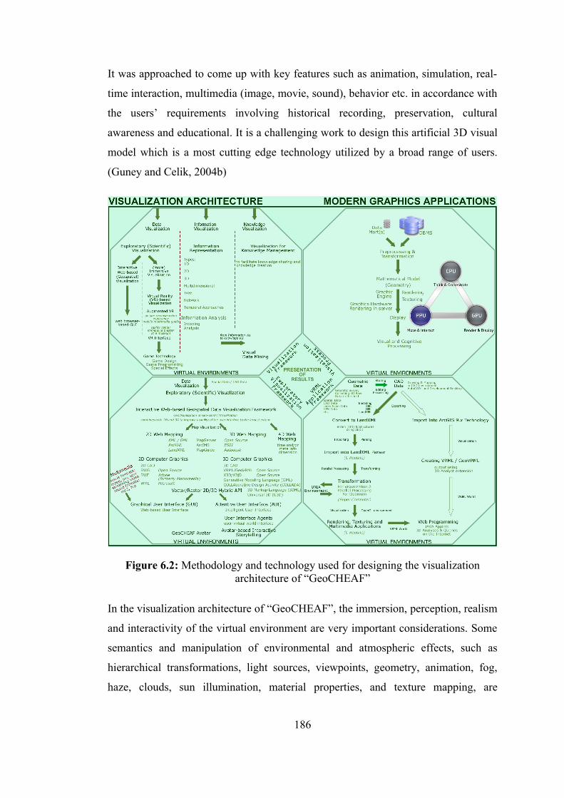
It was approached to come up with key features such as animation, simulation, real-
time interaction, multimedia (image, movie, sound), behavior etc. in accordance with
the users’ requirements involving historical recording, preservation, cultural
awareness and educational. It is a challenging work to design this artificial 3D visual
model which is a most cutting edge technology utilized by a broad range of users.
(Guney and Celik, 2004b)
Figure 6.2: Methodology and technology used for designing the visualization architecture of “GeoCHEAF”
In the visualization architecture of “GeoCHEAF”, the immersion, perception, realism
and interactivity of the virtual environment are very important considerations. Some
semantics and manipulation of environmental and atmospheric effects, such as
hierarchical transformations, light sources, viewpoints, geometry, animation, fog,
haze, clouds, sun illumination, material properties, and texture mapping, are
186
integrated to the scenes of the CH sites to promote these considerations. For
example, the addition of fog helps to blend the sky with the low-resolution portion of
the terrain in order to hide rough surface features. It also gives the environment a
better sense of depth and atmosphere. Another example is that the surveying
architectural ruins were initially rendered realistically with image maps from
photographs taken on site. In such way, the visualization framework creates more
realistic images, including fog and scene-edge effects that make images fade into the
distance. It also include capabilities to define camera paths that can be predefined
vectors or interactively developed. The paths then are used to create an interactive
video in AVI or MPEG format. Texture mapping is used to support realistic
rendering of polygonal features such as walls, meadows, open water and background
sky. Once the background has been created a number of people can be added around
the scene to increase realism and movement.
A web-based graphical user interface (GUI) was designed as an interactive and
immersive virtual reality interface for 2D/3D SIS applications to enable the
researchers to easily perform complete and accurate spatiotemporal analysis of the
data collected about CH resources.
In the context of the project, the GUI of “GeoCHEAF” represents graphically spatial
reality of the fortresses, their surroundings and spatial relationships between the
artifacts, the architecture, and the topography as realistic as in 3D display and full
color that allows the user to more quickly recognize the issues within the life history
of the fortresses through various visualization approaches with different levels of
detail (LOD) such as terrain&plant modeling and landscape visualization, building
visualization, facade visualization, human visualization, artifacts visualization.
To enhance reality of features displayed on 3D SIS, three methods to manipulate the
appearance can be considered. First, it is to use realistic colors with well-mixed
combination of RGB. In the commercial feature-based 2D GIS packages, feature
vector data are usually drawn by primary colors and its simple combinations.
Whereas, if one uses these colors to 3D virtual world, the reality will be so
drastically diminished. Second, it is to use texture mapping. Using a single color has
its own limitation in reality. Texture can be utilized to represent the appearance
187
characteristic of 3D features more effectively. As a texture image, artificially drafted
images such as various wall textures can be used. For more reality, the very picture
of the feature taken by camera can also be used. The third is to use wire frame model
instead of the simply extruded shape. Wire frame model can provide much detailed
reality, which is more advanced through rendering process. This method takes
relatively much computational time to load wire frame data and render them. From
the visualization speed point of view, the first method is the fastest, and the second
next, and the third is most slow. So, the second and the third method can be improper
to real-time web SIS applications.
The geovisualization framework of “GeoCHEAF” was designed through visualizing
CH objects, time and space:
• to reconstruct an accurate and realistic visualization of 3D CH site with 3D
CH objects like monuments on the site in a computer-generated environment
(in terms of easy extensibility and flexibility). For instance, recreating and
visualizing both the present situation of the fortresses, the condition of the
fortresses in the past and its evolution through time.
• to allow a user to be immersed in this 3D scene of the site (3D virtual world)
via interactive navigation techniques like virtual flights over the virtual CH
site (may also be also referred as virtual fly-through or fly-over or fly-by), a
walkthrough on the web or real-time 3D (RT3D) walk-through (in terms of
increasing perception).
• to integrate much more realistic graphics into the scene, such as a wealth of
photographs and video clips of some of the finds and remains (in terms of
increasing realism).
• to allow a user with avatars (or agents) to interact those CH objects within the
scene of the site through standard SIS capabilities such as query, selection,
spatial analysis (in terms of increasing interactivity and spatial awareness).
• to merge visualization technology and multimedia capabilities with SIS,
particularly the incorporation of interaction and animation for the display of
188
maps and their distribution through the web, in order to obtain better 3D
spatial operations, such as geospatial query and analyzes, richer methods of
presentation of data, easier systems for end-users and enhanced management
of spatial phenomena.
• to reveal unknown in data by visualizing spatial uncertainty like non-visible
connections between finds and building remains through 3D interactive maps
and virtual 3D SIS (in terms of making invisible visible).
• to visualize multi-dimensional data to understand multi-dimensional
databases
• to supply with more advanced decision-making methodologies.
• to exhibit a stunning VR presentation of 3D virtual tour of the CH site as a
narrated show in an immersive (domed-)theater at the virtual museum or
interpretation center of the site in terms of seeing CH resources projected on a
large, immersive screen makes their impact even greater.
• to research the entire model of the CH resource in the real-time-a full
interactive mode like an interactive cave or an immersive desk to exhibit by a
museum expert. A user uses wands that have one joystick and three buttons.
• to enable to visitors to tour the entire CH site immersively and interactively
using 3D model within mobile devices in the real-time, filled with the living,
breathing activities of its long history.
• to make remote or destroyed CH site virtually accessible over the Internet to
the public from anywhere in the world.
• to allow for improved education and bringing the value of the cultural
resources to the public and decision makers.
• to achieve all these with the high graphic quality and visual accuracy, and the
low cost.
189

The photo-realistic 3D virtual restitution framework of “GeoCHEAF” covers the
modeling of the whole site, 3D model of exterior and interior of the structures, the
geometrical restitution of the artifacts, the simulating historical high-quality virtual
characters of that time (with the virtual human bodies and their clothes), and
architectural evolution in one united and optimized model based on a very precise
scenario. It is for the multi-resolution real-time and non real-time 3D realistic virtual
simulation of the ancient life, the restoration and renovation process of ancient
monuments, and the full understanding of the historical and social development of
vast communities, with accurate choices of each phase of modeling, texturing, and
lighting processes. The immersive experience could be heavily enhanced by the
addition of 3D rendered sound sequences, like background music, in order to
enhance the virtual acoustical restitution on the CH structure like secular structure,
e.g. mosque, church. Finally the adoption of the large-screen stereoscopic projectors
and 3D shutter glasses will enhance greatly the visualization experience.
The importance of a heritage site resides as well as in the historical characters and
social interactions that were taking place there: this information allows better
understanding of the function and the importance of the selected site in connection
with the cultural aspects of the life at a certain time. In order to strengthen the feeling
of immersion in a heritage edifice virtually restituted, it is important to recreate
virtual life and describe the timely evolutionary aspects of the CH resources as well.
In order to achieve an accurate simulation the social aspect must not be forgotten.
A simulation model considering above would be an immersive virtual environment
that allows the visitors to virtually explore the site, to experience its architecture,
dimensions, and atmosphere, and to obtain architectural, cultural, and historical
information. A virtual guide, in traditional clothes, talks to visitors giving
explanations about the CH resource.
In order to achieve a successful realistic 3D simulation of a selected heritage site,
different aspects are critical: the choice of the appropriate modeling techniques, the
preparation of the lighting models and the texture creation process (which heavily
contributes to the surface appearance representation).
190
The Fortresses have a huge wealth of historically significant and cultural important
material in the form of buildings and events. “GeoCHEAF” enables this information
to be recreated as virtual reality worlds for the users and visitors to see for
themselves how buildings once looked; to hear from virtual guides the history of
significant buildings and events; to explore locations unavailable to them.
Interactive virtual tour guides called the avatars of “GeoCHEAF” was designed to
talk to visitors in bilingual (Turkish & English) pointing out historical, artistic and
architectural facts of the CH objects through an interactive story telling system, like
'the life history of the fortresses'. The use of an avatar (or multiple avatars) can
provide a distinct point of view, attitude, and physical appearance to enhance effect
of the interactively created story on the particular visitor or visitor group (URL
EPOCH). Furthermore, users or visitors can chat with each other in a multi-user
version of the avatar-based interactive story telling system.
Storytelling is a familiar and effective way to convey information to a general
audience in the field of CH. Yet with the increasing use of standardized interactive
applications in museums and historic sites, it is difficult to appeal to a wide range of
visitor interests. This problem can be solved through the use of interactive
storytelling, which allows the visitor to choose from a large selection of subjects and
themes to create a personalized 'story', appropriate to his or her interests and the time
available for the visit. (URL EPOCH)
Several historical scenarios created in the project was derived from investigating of
the life history of the fortresses. Bilingual avatars (Ottoman virtual humans) exist in
virtual life of the fortress within these scenarios, sometimes only appearing with a
narrator’s voice, sometimes an actor/actress. For example, the avatar can be used to
explore the identities and experiences of different persons who could have lived or
been involved in the construction of the fortress. One could choose the figure of the
patron of the fortress, the commander of the navy that was stationed there, the mason
who built the Turkish bath etc. The common point for all scenarios is to give an
abundant amount of historical information concerning the CH objects of the
fortresses, the freedom of movement, interactivity and representation of
191
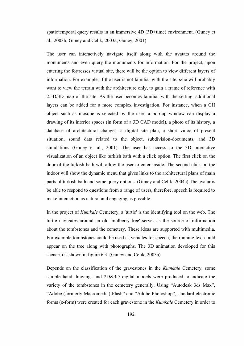
spatiotemporal query results in an immersive 4D (3D+time) environment. (Guney et
al., 2003b; Guney and Celik, 2003a; Guney, 2001)
The user can interactively navigate itself along with the avatars around the
monuments and even query the monuments for information. For the project, upon
entering the fortresses virtual site, there will be the option to view different layers of
information. For example, if the user is not familiar with the site, s/he will probably
want to view the terrain with the architecture only, to gain a frame of reference with
2.5D/3D map of the site. As the user becomes familiar with the setting, additional
layers can be added for a more complex investigation. For instance, when a CH
object such as mosque is selected by the user, a pop-up window can display a
drawing of its interior spaces (in form of a 3D CAD model), a photo of its history, a
database of architectural changes, a digital site plan, a short video of present
situation, sound data related to the object, subdivision-documents, and 3D
simulations (Guney et al., 2001). The user has access to the 3D interactive
visualization of an object like turkish bath with a click option. The first click on the
door of the turkish bath will allow the user to enter inside. The second click on the
indoor will show the dynamic menu that gives links to the architectural plans of main
parts of turkish bath and some query options. (Guney and Celik, 2004c) The avatar is
be able to respond to questions from a range of users, therefore, speech is required to
make interaction as natural and engaging as possible.
In the project of Kumkale Cemetery, a 'turtle' is the identifying tool on the web. The
turtle navigates around an old 'mulberry tree' serves as the source of information
about the tombstones and the cemetery. These ideas are supported with multimedia.
For example tombstones could be used as vehicles for speech, the running text could
appear on the tree along with photographs. The 3D animation developed for this
scenario is shown in figure 6.3. (Guney and Celik, 2003a)
Depends on the classification of the gravestones in the Kumkale Cemetery, some
sample hand drawings and 2D&3D digital models were produced to indicate the
variety of the tombstones in the cemetery generally. Using “Autodesk 3ds Max”,
“Adobe (formerly Macromedia) Flash” and “Adobe Photoshop”, standard electronic
forms (e-form) were created for each gravestone in the Kumkale Cemetery in order to
192
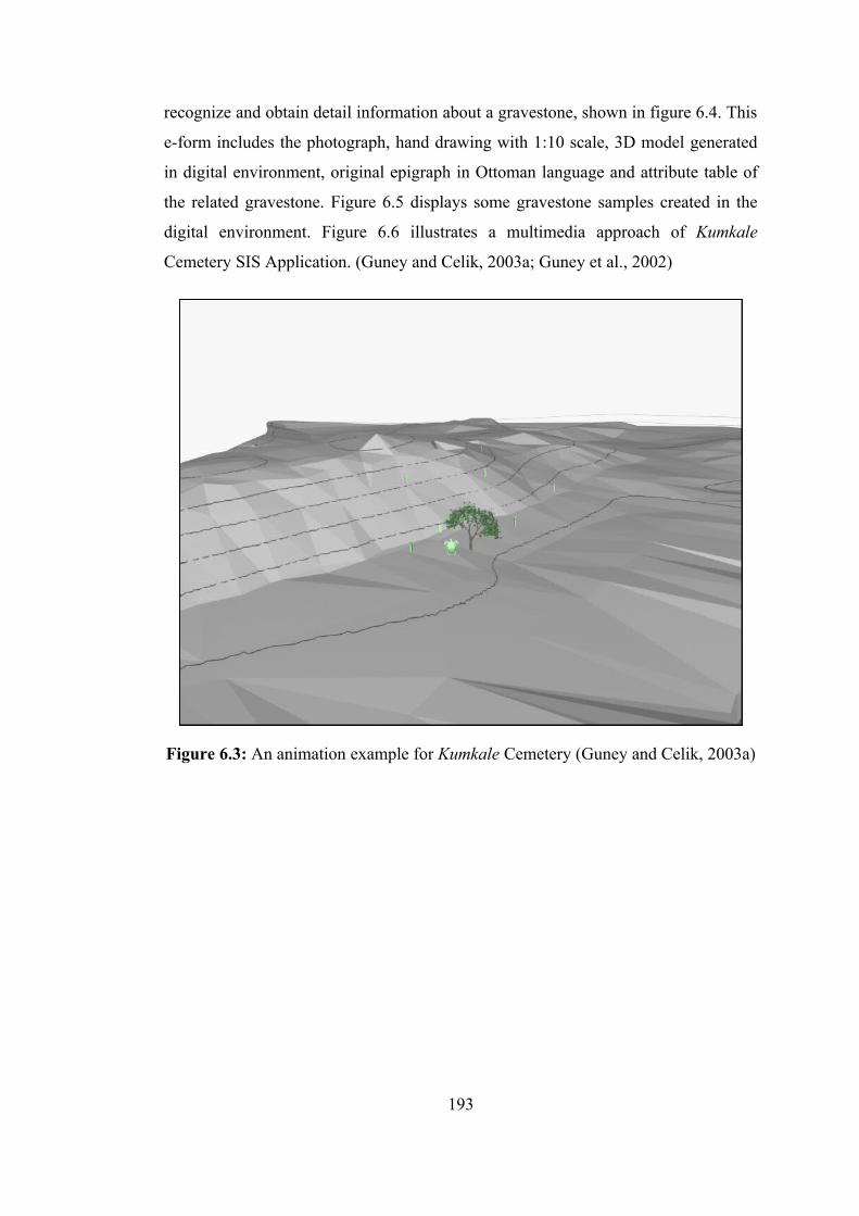
recognize and obtain detail information about a gravestone, shown in figure 6.4. This
e-form includes the photograph, hand drawing with 1:10 scale, 3D model generated
in digital environment, original epigraph in Ottoman language and attribute table of
the related gravestone. Figure 6.5 displays some gravestone samples created in the
digital environment. Figure 6.6 illustrates a multimedia approach of Kumkale
Cemetery SIS Application. (Guney and Celik, 2003a; Guney et al., 2002)
Figure 6.3: An animation example for Kumkale Cemetery (Guney and Celik, 2003a)
193
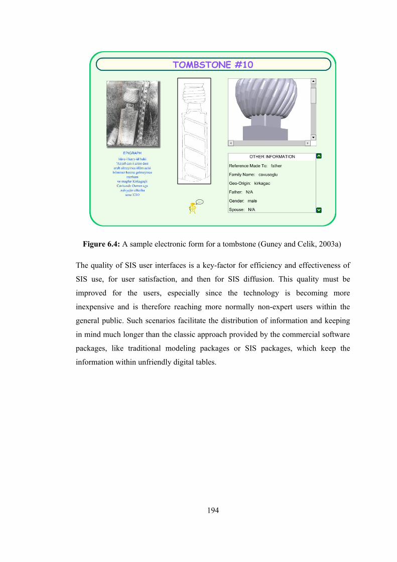
Figure 6.4: A sample electronic form for a tombstone (Guney and Celik, 2003a)
The quality of SIS user interfaces is a key-factor for efficiency and effectiveness of
SIS use, for user satisfaction, and then for SIS diffusion. This quality must be
improved for the users, especially since the technology is becoming more
inexpensive and is therefore reaching more normally non-expert users within the
general public. Such scenarios facilitate the distribution of information and keeping
in mind much longer than the classic approach provided by the commercial software
packages, like traditional modeling packages or SIS packages, which keep the
information within unfriendly digital tables.
194
Figure 6.5: The generated tombstones samples for Kumkale Cemetery (Guney and Celik, 2003a)
With this architecture designed, the users neither need nor are required to have a
previous knowledge of computers or SIS and they are unaware that they using SIS.
While designing the system, it was kept in mind that the total system must be highly
interactive so that the users can proceed in one of the scenarios offered to the user.
The concepts and features of fortresses are explained through graphic illustrations,
supported by brief textual descriptions. (Guney and Celik, 2003a) Some of the texts
contain hyperwords, which are highlighted. By clicking on them one can get detailed
information on these words. (Guney, 2001)
195

Figure 6.6: Multimedia application of Kumkale Cemetery SIS application (Guney et al., 2002)
6.2 Multi-dimensional Hybrid Visualization
Whilst a map can be defined as an abstraction and a representation of reality and map
features symbolize objects in the real world. There are long established techniques,
patterns and symbols to summarize the real world via visual references. (Koehnen,
2002)
In the book of Nature of Maps a map is defined as a 'graphic representation of the
milieu' based on that the purpose of maps is to model reality. The use of the term
milieu is interesting because it suggests much more than the flat, static maps being
familiar with. It presents a challenge to step beyond the comfortable reach of two-
dimensional representations to higher dimensions of (geo)visualization. Humans see
in 3D & full color and 3D displays stimulate more neurons: involving a larger
portion of the brain in the problem solving process. Visual information is processed
and absorbed by human brains much more efficiently than textual, numerical and
196
even diagrammatic data. With 2D contour map (2.5D capability), for example, the
mind must first build a conceptual model of the relief before any analysis can be
made. Considering the cartographic complexity of some terrain, this can be an
arduous task for even the most dexterous mind. 3D display, however, simulates
spatial reality, thus allowing the viewer to more quickly recognize and understand
changes in elevation. (Swanson, 1996) Until relatively recently, however, SIS has
focused primarily on static 2D imagery, although 3D (geo)databases and
(geo)visualization are common.
The increased complexity of tasks in many applications seeks for an integration of
3D spatial and thematic data and mutual relationships. Existing systems either fall
short of dealing with 3D geometry (2D SIS) or lack extended spatial and thematic
analysis. For example, queries such as “show which buildings in the fortresses
architectural changes”, “show how digital terrain models of the fortresses changed
through World War I”, “show all important architectural features on the second floor
of the south-east tower in the fortress of Kumkale still can not be accomplished by
any of the commercially available systems.
Additionally the step from 2D to 3D causes several problems; building 3D models,
storing them and providing a user interface to visualize and manipulate them. As 3D
SIS applications become increasingly important, new database technologies such as
OODBMS are essential. Object-oriented programming systems are now recognized
as a key component in building powerful applications which are robust and
maintainable and which are also to be seamlessly extensible. (Chance et al., 2003)
Advancement in technology and navigable 3D graphics has enabled cartographers to
produce maps that are both interactive and animated maps, similar to most things
experienced in reality. More recent developments in hardware and software
capability and price have made three-dimensional output extremely affordable.
People live in a 3D reality and the purpose of a map is to be an abstraction of reality;
so the output of 3D SIS that can be both interactive and animated maps. The
conventional 2D maps output by conventional SIS applications or 2D
static/dynamic/interactive web mapping on the Internet, combining 2D maps with
thematic information, adequately represent functional data, but cannot represent
197
visual data well at all. On the other hand, 3D maps do an excellent job of
representing visual data and are also capable of handling functional data. The
coupling of 3D SIS and/or 3D web mapping with interactive and animated output can
not only serve to further a map’s ability to accurately depict geospatial data, also
gives the ability to immerse in 3D worlds, adding objects 'on-the-fly', generating
sounds three dimensional and letting the user navigate with complete freedom of his
movements. (Guney et al., 2003b) In both today's heritage sector and cartography,
the most common dynamic streams are ubiquitous dynamic mapping, interactive
Internet maps, cyber maps and animated maps. For example, the public, museum
visitors or history students could see the Ottoman Empire rise and fall in an animated
time series that shows the land mass of the conquered territories expand and shrink
over time via 2D/3D animated maps of a SIS application.
Today’s some proprietary GIS/CAD software, like ESRI’s ArcGIS & ArcScene,
Autodesk’s Land Development Desktop & Map Studio, is characterized by
traditional 3D mapping techniques, such as wireframe terrain characterization with
light-source-shaded perspectives as well as vector and image draping. These 3D
views can be generated from specific x,y viewpoints, supporting a wide range of
surface-definition parameters. Full-featured SIS software also supports image-
rendering enhancements (e.g., atmospheric effects such as sky, fog and haze). Recent
additions support the generation of map animations using standard MPEG encoding
formats. However, SIS and CAD software typically do not have 3D object rendering
capabilities. Some users have integrated SIS capabilities with photo imaging, but
these are usually project-based efforts and typically do not reflect a readily available
functionality. (Berry et al., 1998)
Recently, virtual SIS (VSIS) based on 3D geoprocessing methodology with
navigable 3D graphics, and the Internet environment have opened an exiting research
area for spatial informatics technology, virtual 3D GIS on the web. While, some 2D
SIS software running on the web is appearing in SIS worldwide commercial market,
but their functionalities are not satisfied with advanced SIS user requirements due to
less spatial analysis functions and weakness of 3D data modeling. A 3D SIS should
198
be a system capable of maintaining and analyzing 3D spatial and thematic properties
of real geospatial objects. (Kim et al., 1998; Zlatanoval, 1999; Koehnen, 2002)
In the context of this dissertation, interactive web-based geospatial visualization
techniques can be classified by whether data display is 2D or 3D based. Most of
current CH organizations widely use 2D visualization techniques. On the other hand,
there is an increasing interest in 3D representations of geospatial data, especially for
the universal web access of such data.
Both 2D and 3D visualization have their own strength and weakness. When a large
amount of data has to be presented in a limited space, visualizing in 2D will
introduce a cognitive overload and thus heavily reduce usability. Instead, 3D
visualization uses an extra spatial dimension to create a virtual world where
information is presented. 3D modeling of the real world and the real-phenomena
presents opportunities of scientific exploration and visualization that are not possible
in 2D. Additionally some information is best experienced three dimensionally such
as documentation and research of CH sites and structures. However, delivering 3D
content over Internet is more technically challenging. The difficulty of the
distribution and navigation of 3D content over the Internet is one of the main
obstacles that prevent the popularity of 3D web sites. The creation of detailed and
accurate 3D models is always time consuming and requiring hours of data collection,
processing and rendering. Moreover, user interaction in a 3D environment is not
always intuitive and may be difficult to learn.
Fortunately, recent innovative 3D computer graphic technologies being gradually
developed on the web and state-of-the-art surveying methods such as remote sensing,
photogrammetry, Global Positioning System (GPS), laser scanners and Total
Positioning System (TPS), are providing a wealth of geodata that makes the third
dimension possible in web mapping.
The visualization architecture of “GeoCHEAF” provides a good foundation to
integrate various data sources and generate 2D, 2.5D, 3D and 4D worlds in an
automatic way, and supplies highly interactive, flexible and intuitive GUI for users.
It provides the option of viewing project maps in 2D (SVG graphics) and 3D (X3D
199

graphics) format. The 2D map orients the user to the big picture and giving an
overview of the whole CH site, while the 3D virtual world presents spatiotemporal
CH objects in more detail, accurate and in a more realistic way. Both 2D and 3D
environments can be presented with different LOD, like site, buildings, facade,
artifacts,objects, features, or at different scales, giving the user a choice about the
granularity of presented data. Current Web technologies: Scalable Vector Graphics
(SVG), Virtual Reality Modeling Language (VRML&GeoVRML), and eXtensible
3D (X3D&X3jD), defined by the World Wide Web Consortium (W3C) provide a
necessary foundation for such an architecture to explore the potential of 2D&3D
visualization of reality.
The GUI of “GeoCHEAF” has been designed as that the left panel (larger window) is
3D virtual world in X3D, and right panel (smaller window) is 2D map in SVG,
shown in figure 6.7. The 2D map provides an overview of the CH site, while the 3D
world provides a more detailed and flexible view. The 2D map is also a navigator of
the 3D virtual world. If user move mouse in the map, the viewpoint in the 3D world
will change correspondingly. These two worlds are synchronized so as to provide
user different references of navigation. For example, user moves mouse over the icon
tower in 2D map, in the 3D world, user’s viewpoint will move close to the tower.
User can also use mouse or key to control the viewpoint in 3D freely. The navigation
facilities are provided such as zoom in, zoom out, walk, fly, pan, rotate, etc.
In most of the cases, the value of the selected data type or the result of probabilistic
and statistical analysis is used to create a visual cue in the 3D virtual environment.
The visual cues include both geometry and appearance. The preferred choice in this
case is the vertical extrusion of the polygon specifying the region of the sensor. The
amount of the extrusion is proportional to the value of the result of statistical
analysis. In addition, a color coding is used to indicate different levels of data. The
time dimension of the data is presented by animating the visual cues with appropriate
scaling. Due to the spatial and temporal characteristics of the CH data, several
selection mechanisms are available for interaction. User could use traditional dialog
provided in HTML to select data type for a given CH object or a set of CH objects,
as well as the time interval of interest. The user can also pick in the 2D and 3D
200
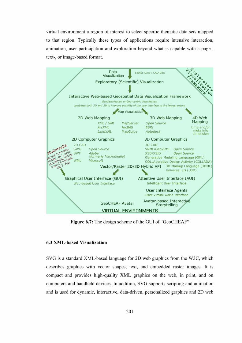
virtual environment a region of interest to select specific thematic data sets mapped
to that region. Typically these types of applications require intensive interaction,
animation, user participation and exploration beyond what is capable with a page-,
text-, or image-based format.
Figure 6.7: The design scheme of the GUI of “GeoCHEAF”
6.3 XML-based Visualization
SVG is a standard XML-based language for 2D web graphics from the W3C, which
describes graphics with vector shapes, text, and embedded raster images. It is
compact and provides high-quality XML graphics on the web, in print, and on
computers and handheld devices. In addition, SVG supports scripting and animation
and is used for dynamic, interactive, data-driven, personalized graphics and 2D web
201
mapping. Its major strengths are quality (vector-based), feature manipulation on the
client side (eliminates the need for a SIS application server & client-side
interactivity), cost (free and open-source), and platform-independent. Its weakness is
its text-based structure that causes larger file size and slower rendering speed than
binary formats.
X3D is the ISO standard for real-time 3D computer graphics, the successor to Virtual
Reality Modeling Language (VRML). It defines several profiles (sets of extensions)
for various purposes, such as X3D Core, X3D Interchange, X3D CAD, X3D
Geospatial and X3D Immersive, and browser makers can define their own extensions
prior to submitting them for standardization by the W3C. (URL Wikipedia)
6.4 VRML and Building 3D Geospatial Scenes in VRML
VRML is used as a highly structured dynamic 3D scene description language, a
simple 3D modeling tool and an effective 3D interchange format, which integrates
three dimensions, two dimensions, text, and multimedia into a coherent model. It is
open, standard, extensible, platform-and software-independent language in the form
of human-readable text file (ASCII or UTF8) for describing and publishing
interactive 3D objects, the behavior of 3D objects and 3D worlds delivered over the
Internet and parsed by a web browser with VRML plugin that sensually renders the
plain text document into an interactive form to display the geometry, lighting, and
animation in the VRML file. It also allows “script nodes” by which the developer can
add external programs (typically written in Java or JavaScript) to extend its
functionality implementing programmed behavior for the objects in the created
worlds. Such that the user can easily interact with the 3D model, predefined walking
or flying around and through it. Script nodes can be inserted between event
generators (typically sensor nodes) and event receivers. Events, (such as
mouse/cursor/keyboard combinations) can be sent from the VRML scene nodes
where they are detected to Java programs that react correspondingly. The converse is
possible too. Scripts allow the developers to define arbitrary behaviors, defined in
any supported scripting language. VRML allows fully immersive environments,
interactivity and real-time animation capabilities. (URL Web3D; URL VRML)
202
Additionally, VRML files may contain references to files in many other standard
formats on the web. These links represent interrelations that can be used to retrieve
and visualize 3D spatial data and information. Thus, it can serve as a virtual 3D GUI
to 3D SIS. JPEG, PNG, GIF, and MPEG files may be used as texture maps on
objects. WAV and MIDI files may be used to specify sound that is emitted in the
world. (URL VRML; Zlatanoval, 1999)
The current VRML specification is VRML97. The specification has been ratified by
the International Standards Organization (ISO), where it is referred to as ISO/IEC
DIS 14772-1, or (informally) as VRML 97. VRML 1.0 supports worlds with
relatively simple animations while VRML 2.0 supports complex 3D animations,
simulations, and behaviors by allowing Java and JavaScript programmers to write
scripts that act upon VRML objects. (URL Web3D; URL VRML)
VRML browsers (or VRML viewers) work as plugins for common Web browsers
and are currently available for most platforms. Plug-ins add functionality to the web
browser. There are many freely available VRML browsers that can be used to view
and interact with the model; although there is considerable variation in how well they
render the models. (URL Web3D; URL VRML)
Geographic VRML (GeoVRML), as an extension to VRML, has addressed issues
specific to geospatial data that VRML does not. The desire is to enable
geo-referenced data, such as maps and 3D terrain models, to be viewed over the web
by a user with a standard VRML plugin for their web browser. (URL Web3D; URL
VRML)
Based on all the features of it mentioned above, VRML was chosen as a means of
visualizing in 3D. In the project, once the all computer-aided design (CAD) drawings
has completed and stored as DWG AutoCAD file format and imported into ArcGIS
technology. ESRI’s 3D Analyst, which is one of ESRI’s ArcGIS extensions, has been
used to create VRML output files for the historical site, shown in figure 6.8.
VRML output obtained the integration of CAD and SIS technologies is of particular
importance to the CH domain with so many objects that are recreated in CAD
203
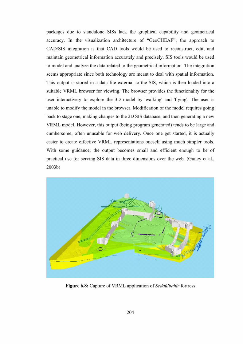
packages due to standalone SISs lack the graphical capability and geometrical
accuracy. In the visualization architecture of “GeoCHEAF”, the approach to
CAD/SIS integration is that CAD tools would be used to reconstruct, edit, and
maintain geometrical information accurately and precisely. SIS tools would be used
to model and analyze the data related to the geometrical information. The integration
seems appropriate since both technology are meant to deal with spatial information.
This output is stored in a data file external to the SIS, which is then loaded into a
suitable VRML browser for viewing. The browser provides the functionality for the
user interactively to explore the 3D model by 'walking' and 'flying'. The user is
unable to modify the model in the browser. Modification of the model requires going
back to stage one, making changes to the 2D SIS database, and then generating a new
VRML model. However, this output (being program generated) tends to be large and
cumbersome, often unusable for web delivery. Once one get started, it is actually
easier to create effective VRML representations oneself using much simpler tools.
With some guidance, the output becomes small and efficient enough to be of
practical use for serving SIS data in three dimensions over the web. (Guney et al.,
2003b)
Figure 6.8: Capture of VRML application of Seddülbahir fortress
204
As Figure 6.9 displayed, VRML files are being produced in this study with two
different methods, open source and commercial ways. Figure 6.10 presents a capture
of VRML application of the Kumkale Cemetery.
Digital Terrain Models (DTM) of the fortresses’ areas and 3D architectural plans of
the remaining of the fortresses were produced in the CAD environment with the
'DWG' format using “AutoCAD Land Development Desktop Release 2.0/3.0,
Autodesk Inc.” software. DWG-format 3D terrain models and 3D architectural
models were converted to LandXML format, which is a version of XML developed
by Autodesk in order to transport the geometric data to the program developed in
(C++) Java using several libraries like OpenGL. This program is used to render the
geometric data to use in the animations and other presentations. Thereafter, produced
animation has broadcasted over internet with java applets, API functions and some
plugins. System requirements are automatically provided with the system itself when
the user has only a Java enabled browser and a VRML plugin respectively a VRML
browser. This allowed land information to interoperate among various software
solutions, to be explored interactively in OpenGL, shown in figure 6.11. (Guney et
al., 2002; Guney and Celik, 2003a) The query capabilities on a 3D map about
attribute data have been added the model.
205

Figure 6.9: Methods of building VRML files
Figure 6.10: Capture of GeoVRML application of Kumkale Cemetery (Guney and Celik, 2004c)
206
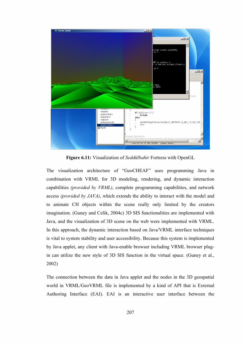
Figure 6.11: Visualization of Seddülbahir Fortress with OpenGL
The visualization architecture of “GeoCHEAF” uses programming Java in
combination with VRML for 3D modeling, rendering, and dynamic interaction
capabilities (provided by VRML), complete programming capabilities, and network
access (provided by JAVA), which extends the ability to interact with the model and
to animate CH objects within the scene really only limited by the creators
imagination. (Guney and Celik, 2004c) 3D SIS functionalities are implemented with
Java, and the visualization of 3D scene on the web were implemented with VRML.
In this approach, the dynamic interaction based on Java/VRML interface techniques
is vital to system stability and user accessibility. Because this system is implemented
by Java applet, any client with Java-enable browser including VRML browser plug-
in can utilize the new style of 3D SIS function in the virtual space. (Guney et al.,
2002)
The connection between the data in Java applet and the nodes in the 3D geospatial
world in VRML/GeoVRML file is implemented by a kind of API that is External
Authoring Interface (EAI). EAI is an interactive user interface between the
207
encapsulating HTML browser and the embedded VRML browser, and is used as a
dynamic (geo)visualization tool through the Internet. It provides to access nodes and
event structure from outside of VRML browser instead of comprehensive node
access within VRML browser via a Script node that is another alternative using
Script Authoring Interface (SAI) that is the interface between a script contained
within a Script node and the browser functionality. This interactivity enables Java
applet to build and update dynamically the data in VRML, and in turn, the applet’s
data can also be dynamically updated through the VRML interface. The changes in
Java applet can affects the 3D geospatial world built in VRML file form. And the
event occurred in VRML world can be detected and processed in Java applet side.
Complex 3D spatial queries and analysis such as selection, 3D feature identifying,
3D buffering, 3D overlaying, and near operation can be performed on Java applet,
and its result is visualized in VRML world. The result may also be presented in
textual (numerical) or graphical form in the GUI of “GeoCHEAF”. (Guney and
Celik, 2004c) The interface provides two-way communication between the user and
the VR terrain, not only extracting positional information from the model but also
allowing the user to move between viewpoints and select the view required. (Guney
et al., 2003b)
Multimedia data such as text, sound, images, animations and videos is also linked to
3D geographical features in a somewhat application level in the visualization
framework of “GeoCHEAF”, and it is partly similar to basic concepts within 3D
hypermap. (Guney and Celik, 2004b)
6.5 Multimedia Applications
Multimedia combines multiple forms of media in the communication of information,
such as audio, video, graphics, photographs, animation and text. The combination of
several media creates a powerful and richer presentation of information and ideas to
stimulate interest and enhance information retention.
While traditional SIS data are based on maps, multimedia SIS allows the user to
access a wide range of georeferenced multimedia data (e.g., simulations, sounds and
208
videos) by selecting resources from a georeferenced image map base. A map serving
as the primary index to multimedia data in a multimedia georepresentation is termed
a hypermap. Multimedia and virtual georepresentations can be stored either in
extended relational databases, object databases or in application-specific data stores.
(Guney and Celik, 2003a)
SIS is acquiring ever more multimedia functions. These multimedia abilities are
potentially very useful in the CH activities to describe and visualize built
environments. It is now possible to display pictures within a SIS, to run animations
based on abstract maps as well as video clips and photorealistic VR panoramas, and
to link such media to many of the data and functions of the SIS. Much graphics
software is moving to web. It is now possible to develop extremely elegant and
powerful animations, 3D design, and virtual reality systems in a networked
environment using such technologies like VRML and QuicktimeVR (QTVR)
variants. QTVR and streaming digital video multimedia techniques could be mixed
for optimal viewing in order to construct the realistic model of the CH resources, or
to visualize the existing environments and interiors of the historical structures.
(Guney et al., 2002)
SIS and multimedia can be combined in various ways, for example, the output of SIS
systems can be integrated with stand-alone multimedia authoring software or some
simple multimedia applications present in commercial SIS packages. In this
dissertation, SIS applications like spatial analyzes and multimedia implementations
combined in the web using Java programming. Java, which is interpreted by the web
browser, can be used to develop interactive web pages that check user input into
forms, change the look of web pages, or display informative messages in the status
bar of a web browser.
QTVR is one of the first 3D technologies for the web developed by Apple
Computers. The concept of the QTVR technology is that it enables users to
experience a fully navigable 360˚ panoramic scene of a site, from a particular
location or node (Bodum et al., 1998). The Quicktime technology uses a cylindrical
projection of the panorama, thus some distortion is evident when the panoramic
image is viewed as an image.
209
Once the individual images have been captured for a node and stitched together, the
panoramic image can be formed and saved as a QTVR movie. Before saving the
panoramic picture and generating the QTVR movie, hotspots and other objects were
placed inside the movie. The user can 'walk' around the fortresses’ sites and enjoy a
full 360° view of the area from specific points. This sophisticated technology allows
the user to interactively 'look' in all directions and, in some cases, provides clickable
features. With clicking at so called 'hot spots' that lead to the digital video of the
present condition of interior space of the related feature. (Guney et al., 2002)
A very interesting part of the Internet multimedia technology is the possibility to
integrate digital live video into the web pages. Although digital video demands a
very high bandwidth on the Internet, the recent developments of video compression
technology and the concept of streaming media create the possibility to observe
digital video on the Internet.
6.6 Rendering and Real-time Graphics
“GeoCHEAF” allows developers to incorporate a broad set of rendering, texture
mapping, special effects and other powerful visualization functions and provides a
graphics pipeline that allows unfettered access to graphics hardware acceleration.
(see Figure 6.12)
The two most widely used rendering libraries for PCs are DirectX and Open
Graphics Library (OpenGL). Open GL is a library/software interface to create 2D
and 3D graphics and animations. OpenGL is a cross-platform for 3D
rendering/visualization and 3D hardware acceleration. The software runtime library
ships with all Windows, Mac OS, Linux and Unix systems.
3D GIS functionalities are now being implemented with Java using several existing
libraries, like OpenGL and API functions, like EAI or GUI. OpenGL is a software
interface consisting of several hundred functions and procedures used to render high-
quality 2D and 3D graphical images in applications. OpenGL allows geometric
objects to be specified in two or three dimensions, along with providing commands
to control how they are rendered. Some functions produce the geometric objects, and
210
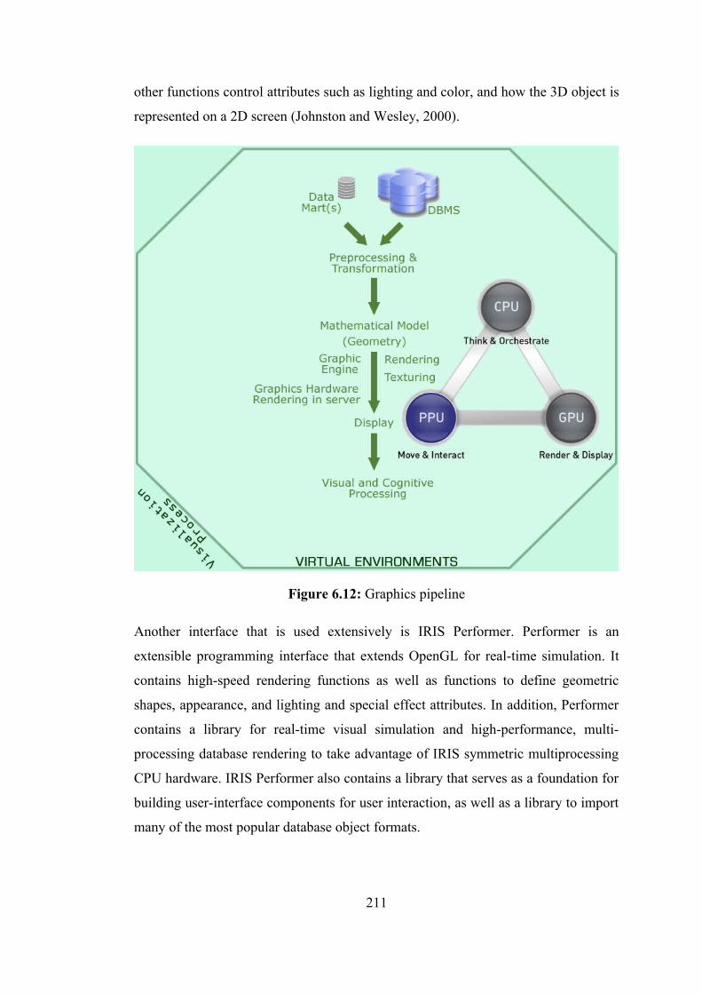
other functions control attributes such as lighting and color, and how the 3D object is
represented on a 2D screen (Johnston and Wesley, 2000).
Figure 6.12: Graphics pipeline
Another interface that is used extensively is IRIS Performer. Performer is an
extensible programming interface that extends OpenGL for real-time simulation. It
contains high-speed rendering functions as well as functions to define geometric
shapes, appearance, and lighting and special effect attributes. In addition, Performer
contains a library for real-time visual simulation and high-performance, multi-
processing database rendering to take advantage of IRIS symmetric multiprocessing
CPU hardware. IRIS Performer also contains a library that serves as a foundation for
building user-interface components for user interaction, as well as a library to import
many of the most popular database object formats.
211
Realtime rendering in a PC cluster environment provided by Open source Scene-
Graph (OpenSG) technology. Geovisualization supports for multidimensional
clustering.
OpenGL ES is a cross-platform API for full-function 2D and 3D graphics on
embedded systems - including consoles, phones, appliances and vehicles. It consists
of well-defined subsets of desktop OpenGL, creating a flexible and powerful low-
level interface between software and graphics acceleration.
Real-Time Graphics (Techniques) / Realtime interactive computer graphics
Early visualization systems were built from loosely integrated graphics and
computational components. They were often based on mainframe computers facing
strict limitations in memory, processor power, and disk speeds. To improve
performance, high-performance computing (HPC) graphics pioneers focused on
more tightly integrating system resources. Key to this effort was the specialized
graphics processing unit (GPU), a hardware processor developed to render polygons.
GPU-based workstations became the platform of choice for driving most demanding
visualization applications.
The resulting bottleneck between CPUs and GPUs has not presented much of a
problem for most applications. But as advances in scanning and measurement
technologies create a data glut in HPC environments new problems are arising. Data
sets are growing fast. And today’s graphics acceleration hardware needs help
carrying the load. While increasing visualization performance and image quality by
combining the power of multiple GPUs is one solution, another is using a dedicated
Physics Processing Unit (PPU) to handle physics computation, just like the GPU
handles graphics.
6.7 Generating Web Images on the Fly
One of the web applications of “GeoCHEAF” is an easy-to-use image gallery GUI
that lets authorized users view all old and current visual materials of on the two
Ottoman Fortresses. This photo gallery application allows users to display images on
212
a website as thumbnails with a large image that displays over the top of the
thumbnails after clicking one. Some features of photo gallery GUI include: (Guney et
al., 2005)
• Arrangement of images in categories and albums
• Automatic thumbnail
• Caption, title, description and user defined fields for each picture
• Image information stored in database
• Users can download images with Web interface
• Slideshow viewer
• Capture & Trim
• Print with associated data from database
PhotoGallery web application runs in a LAMP environment along with a Adobe
Flash (formerly Macromedia Flash) front end that loads data through the standard
Adobe Flash Remoting Components. This connects Adobe Macromedia Flash MX
2004 and application server, integrating rich Macromedia Flash content (Flash
Client) with PHP (server) applications via another open source project called “Flash
Remoting for PHP (AMFPHP).” According to the developers of AMFPHP, Flash
Remoting for PHP enables objects in PHP to become objects in ActionScript. (Guney
et al., 2005)
Flash Remoting Components extend the Adobe Macromedia Flash MX authoring
environment to develop rich web applications, adding the ActionScript APIs needed
to invoke remote services using Flash Remoting MX. (Guney et al., 2005)
Because Macromedia did not provide support for PHP in Flash Remoting, an open
source project was started to give PHP coders the benefits of Flash Remoting under
their preferred server-side language.
AMFPHP is a class library for the PHP scripting language, which is used to allow
PHP programmers to access Flash Remoting objects natively in PHP and connect
Macromedia Flash to data. (Guney et al., 2005)
213

AMFPHP is a free, open source replacement for the many commercial Flash
Remoting packages provided by Macromedia for ColdFusion Server, .NET and Java.
It is able to read the binary ActionScript Message Format (AMF) data sent from the
Flash player to the server and can provide results back to the player in AMF format.
AMF is a binary format that can describe any Flash variable of any data type. This
format which is used by Flash to communicate with the server can be delivered over
regular HTTP, is the core of Macromedia Flash Remoting. AMF is essentially a
lightweight binary version of SOAP. (URL AMFPHP)
The AMF format was created by Macromedia as an attempt to obviate the need for
XML objects when transferring data between a Flash movie and the server. XML
objects proved to be quite inefficient; large amounts of data were required to describe
simple objects, and the amount of bandwidth needed to transfer complex objects
from some large Flash projects was simply not acceptable. (URL AMFPHP)
In this project, Macromedia Flash Remoting MX Components for Macromedia Flash
MX 2004 Action Script 2.0 and AMFPHP 0.9.0 are used under GNU GPL. A
dynamic graphics generation tool, GD Library 2.0.33, is also used under PHP on the
application server. Figure 6.13 displays a snapshot of the application.
GD is an open source code library for the dynamic creation of images by
programmers. GD is written in C, and “wrappers” are available for Perl, PHP and
other languages. GD creates PNG, JPEG and GIF images, among other formats. GD
is commonly used to generate charts, graphics, and thumbnails on the fly.
Essentially, GD Library will convert the project’s uploaded images to a smaller
physical size, so that each image uses less disk space and pages will load faster.
(URL AMFPHP)
214
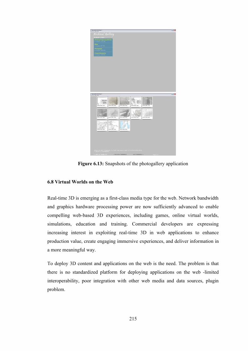
Figure 6.13: Snapshots of the photogallery application
6.8 Virtual Worlds on the Web
Real-time 3D is emerging as a first-class media type for the web. Network bandwidth
and graphics hardware processing power are now sufficiently advanced to enable
compelling web-based 3D experiences, including games, online virtual worlds,
simulations, education and training. Commercial developers are expressing
increasing interest in exploiting real-time 3D in web applications to enhance
production value, create engaging immersive experiences, and deliver information in
a more meaningful way.
To deploy 3D content and applications on the web is the need. The problem is that
there is no standardized platform for deploying applications on the web -limited
interoperability, poor integration with other web media and data sources, plugin
problem.
215
Much of the infrastructure has been put into place to enable professional web 3D
deployment in a cross-platform, open, royalty-free environment. Interoperability
standards such as ISO standard X3D are now mature, fully functional and robust, and
supported by multiple open source implementations and affordable production
pipelines. However, those technologies only go so far, in that they are focused on the
transportability of embedded rich content, and not on the applications that embed it.
The industry is in need of a rapid development environment for creating scalable,
highly interactive client-server 3D applications on the web.
Ajax has emerged as a preferred method for developing sophisticated web
applications. Ajax makes client-server programming available to Javascript
developers via Dynamic HTML, resulting in rich, responsive applications hosted in a
web browser. While Ajax is being used to deploy some of the industry’s leading
applications, such as Google Maps and Netflix, current browsers are limited in their
capabilities to render dynamic content, in particular high performance real-time 3D.
Ajax3D (the open platform for rich 3D web applications) combines the power of
X3D, the standard for real-time 3D on the web, with the ease of use and ubiquity of
Ajax. Ajax3D employs the X3D Scene Access Interface (SAI) -the X3D equivalent
of the DOM- to access and control 3D worlds via Javascript. With the simple
addition of an X3D plugin to today’s web browsers, the awesome power of video
game technology could be brought to the everyday web experience.
With Ajax3D, immersive virtual worlds can be deployed within a web browser,
integrated with pages and other media. Ajax3D worlds can communicate with
standard web servers using XML and Ajax technologies, enabling professional,
scalable, industrial strength applications with high production value and visual
impact.
Ajax3D was developed for the open source community by Media Machines, creator
of the Flux 3D Player plug-in for Internet Explorer and Firefox on the PC.
(http://www.mediamachines.com/)
216
Ajax3D.org is an industry forum dedicated to the research and development of online
virtual worlds using 3D open standards and Ajax best practices.
(http://www.ajax3d.org/)
Xj3D is an open source (LGPL) project of the Web3D Consortium focused on
creating a toolkit for VRML97 and X3D content written completely in Java. It serves
a dual purpose of being an experimental codebase for trying out new areas of the
X3D specification and as a library that we encourage application developers to use
within their own application to support X3D technology.
(http://www.web3d.org/x3d/xj3d/) (http://www.xj3d.org/)
The Xj3D Toolkit is an open source API for developing an X3D/VRML 97
compliant applications, and is the sample implementation and test bed for the X3D
specification.
The key to the success of the X3D standard is the plethora of browser
implementations by different vendors. Having multiple vendors means that the X3D
standard is not at the mercy of a single commercial entity. Each X3D browser
implementation has its own strengths, and no one can provide a browser that fits the
needs of everyone. In fact, the future evolution of X3D will be far better by having
different browser vendors competing to be the most conformant and the most
innovative.
FreeWRL VRML/X3D browser is an open source, cross platform VRML2.0,
VRML97, and X3D compliant browser, with script and EAI support. Platforms
supported: Linux; Mac OS/X, and other Unix-style platforms. A Windows port is not
yet started, but will eventually happen. FreeWRL has been placed under the GNU
Library General Public License (GPL). FreeWRL can be run standalone, or within
browsers (platform dependent for now). FreeWRL can also be accessed via the EAI
interface to enable control of visual content via an external programming interface.
FreeWRL supports script nodes, and shortly will support the X3D SAI programming
interface. (http://freewrl.sourceforge.net/)
217
Nexus3d: NeXus 3D X3D browser is a Java based X3D browser supporting the
immersive profile (Apache Software License).
Cortona VRML Client from Parallel Graphics is a fast and highly interactive Web3D
viewer that is ideal for viewing 3D models on the web. A set of optimized 3D
renderers guaranties the best visual quality on both PCs with the latest video-cards
and those with more basic video card capabilities. Cortona VRML Client works as a
VRML plug-in for popular Internet browsers (Internet Explorer, Netscape Browser,
Mozilla, etc.) and office applications (Microsoft PowerPoint, Microsoft Word, etc).
(http://www.parallelgraphics.com/products/cortona/)
The free Flux Player from Media Machines allows developers and content creators to
publish their interactive 3D animations, models and virtual worlds to a web browser
using industry-standard X3D and JavaScript. This FLUX source code includes Flux
Player, our light-weight, high-performance 3D player; an easy content authoring and
publishing tool; and a set of server-side technologies for dynamic, database-driven
delivery of 3D content and multi-user messages over the web. The complete source
code to Flux is being licensed under the GNU Lesser General Public License
(LGPL). Flux Player is free for personal use. It has some utilities and converters,
such as GoogleSketchup KML converter (KML2X3D) (The open-source converter,
KML2X3D, that translates Google SketchUp version 3 and Google Earth files
(KML) into X3D files.), 3D Studio exporter, Maya exporter.
(http://www.mediamachines.com/)
OpenWorldsTM is an open X3D-compatible system which extends new and legacy
applications with immersive Web 3D graphics, multimedia, animation, and VR
capabilities.
218
7. OTHER MAJOR ARCHITECTURES
7.1 Web Content Management Architecture
As the Internet has grown, so have the challenges associated with delivering static,
streaming, and dynamic content to end-users. Tracing the evolution from traditional
web caching to today’s open and vastly more flexible architecture, today’s web sites
serve as an extremely effective vehicle for data and information exchange and
transactions with users, project members and stakeholders, but the details behind
these operations can be very difficult to manage. The ability to easily update web
content is a key benefit of a dynamic web site. However, the scope of “Web Content
Management (WCM)” is much broader than having the ability to edit a block of text
on the web site.
Enterprise Web Content Management Architecture of “GeoCHEAF” refers to
development, management, distribution of enterprise content in a collaborative
environment through a web (geo)portal and portlets. It manages the lifecycle of
content in the enterprise’s resource repositories via a top-down framework. The
architecture provides the same content/layout components to be rendered (reused)
through various user devices in a number of different formats, such as PDA or
WML. The architecture facilitates collaborative creation of following Web content
types:
• HTML, XML, any text
• Images, photo galleries
• Documents, PDF files
• Publications articles, journals
• CH Project proprietary doc formats
• Forums
219

• Audio, video, streaming video
• Flash movies, SVG files
• Multimedia
• Hyperlinks/web resources
• Downloads
• Surveys and statistics
• FAQs
• Any other bits (or etc.)
Web content management is usually a collaborative effort that involves various roles,
including authoring, viewing, editing, approving, and players, including
administrator, editor, end user, approver, designer, junior editor, website manager.
The idea is to allow both technical and non-technical personnel to easily work
together in order to simplify and streamline the process of creating and serving high-
quality, accessible web portals. Thus, it is a communication means among various
developers and various users.
Web Content Management divides logically into three areas:
• Web content creation and contribution: web page composition, authoring &
adding to the site
• Web content management and administration: editing & updating the site
• Web content publishing and serving: Approval & Workflow / user
submission and publishing logic
A CH enterprise requests for a designer to build an HTML page for the project. The
page is built by the designer in their tool of choice such as any text editor,
WYSIWYG XHTML editor, or hardcoding editors like Adobe Dreamweaver, Adobe
GOLive CS2, NetObject Fusion 9, Microsoft FrontPage 2003, and saved to a web
site manager content repository. Then, the editors are given a reference of a wording
change and slight HTML format adjustment in the web pages. Through the use of the
web-based content templates and inline editing tools available in the website
manager, editors opens the content file on the web and make the necessary change.
220
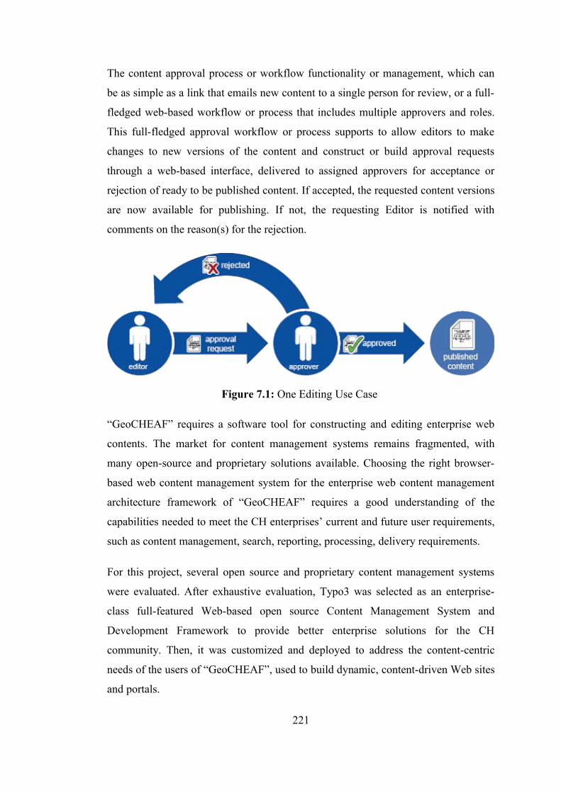
The content approval process or workflow functionality or management, which can
be as simple as a link that emails new content to a single person for review, or a full-
fledged web-based workflow or process that includes multiple approvers and roles.
This full-fledged approval workflow or process supports to allow editors to make
changes to new versions of the content and construct or build approval requests
through a web-based interface, delivered to assigned approvers for acceptance or
rejection of ready to be published content. If accepted, the requested content versions
are now available for publishing. If not, the requesting Editor is notified with
comments on the reason(s) for the rejection.
Figure 7.1: One Editing Use Case
“GeoCHEAF” requires a software tool for constructing and editing enterprise web
contents. The market for content management systems remains fragmented, with
many open-source and proprietary solutions available. Choosing the right browser-
based web content management system for the enterprise web content management
architecture framework of “GeoCHEAF” requires a good understanding of the
capabilities needed to meet the CH enterprises’ current and future user requirements,
such as content management, search, reporting, processing, delivery requirements.
For this project, several open source and proprietary content management systems
were evaluated. After exhaustive evaluation, Typo3 was selected as an enterprise-
class full-featured Web-based open source Content Management System and
Development Framework to provide better enterprise solutions for the CH
community. Then, it was customized and deployed to address the content-centric
needs of the users of “GeoCHEAF”, used to build dynamic, content-driven Web sites
and portals.
221
The features of the enterprise web content management architecture of
“GeoCHEAF” are the following: The enterprise web content management
architecture of “GeoCHEAF” provides:
• Content separated from design by using presentation templates, so the two
can be changed independently.
• Management of content can be done by the CH specialist or CH project
members, without day to day involvement of technical staff. Often this is
accomplished through simple customized web interfaces included with the
Content Management System (CMS), though many systems can work with
content from third party HTML authoring tools.
• Content is stored in a content repository that is a centralized place to edit
content, with prior versions tracked and available for review (or restoration)
as needed. Content Versioning automatically saves previous updates to
content, allowing administrators to browse and publish previous changes to
production systems. Each new update to a piece of content saves off the
previous version. CVS is the Concurrent Versions System, the dominant
open-source network-transparent version control system. CVS is useful for
everyone from individual developers to large, distributed teams:
• Locking lets concurrent users work safely and efficiently without fear of
overwriting someone else’s work.
• Granular security control (or multiple security levels) ensures that only
authorized user can administer content. Different users can have different
access levels — for example an archaeologist may be allowed to add some
excavation information but not modify the homepage.
• Audit trails track who made what change and when.
• Approval (workflow) process functionality, which can be as simple as a link
that emails new content to a single person (editor) for review, or a full-
fledged web-based workflow process that includes multiple approvers and
222
roles. This full-fledged workflow approval process support to allow Editors to
make changes to new versions of the content and construct approval requests,
delivered to assigned Approvers.
• Search functionality that helps users find content quickly. Searching feature
of CMS uses open standard full text searching technology, and provides
programming API's to allow third party data and projects to interface,
providing fast reliable searches.
• Scheduling to automatically publish (or remove) content at a predetermined
date/time — so the webmaster does not have to stay up until midnight to do
that.
• Syndication to let one feed dynamic content from outside partners directly
into your site (or visa versa).
• Multi-lingual support that makes it easier to provide content in multiple
languages, potentially increasing the audience.
• Manages the users who author content (access; rights; workflow)
• Control who has access to Web pages, or specific assets, and who is
responsible for reviewing and approving changes before they are published to
a live Web site.
• Manages the publication of content (Structures content for delivery)
• Facilitates the upholding of standards.
• Content contributors can focus on content instead of getting bogged down in
web technology or manual coordination with web masters and content
approvers
• Cost savings resulting from a more efficient content management and
publishing process
223
• Eliminate the unnecessary duplication of work, mistakes and inefficiencies
that occur when those responsible for creating new content run into those
responsible for publishing and maintaining the information on the live Web
site.
• Better utilize resources and empower team members to take ownership of
their job responsibilities
• Improve workflow and accountablity
• Streamline implementation and management (the flexibility of Web-based
access more appropriate for your needs)
• the privileges at multiple defined role levels: Viewer, Editor, and Approver
Many web services currently exist that provide information sources and functions for
Content Management Systems. Such services include search engines, address
validation, and bibliographic lookup. The major problem is integrating these web
services into existing CMS tools and environments. AXIS, a toolkit for deploying
and using web services, allows developers and CMS users to integrate web services
into their CMS applications without the need to learn SOAP or other low-level
Internet protocols.
“GeoCHEAF”s approach is based purely on XSLT (XSL Transformations) to
manage the content repository and to assemble and publish sites. This framework is
based upon an XML vocabulary called the Web Page Composition Markup
Language.
CMS facilitates delivery of web content and applications to specific audience
segments or individuals, so that only certain users have access certain content:
• Dynamic Web Sites (Public Front End)
• Portals ((Public) Internet) (Public Front End)
• Intranets (Private Front End) (The intranet is accessible
only to the users who log in the system successfully.)
• Extranets (Private Front End)
224
7.1.1 Web portal architecture
The web allows CH community to make much more comprehensive information
available to a wider variety of users. The web portal architecture of “GeoCHEAF”
serves up its valuable content, information and web applications pertaining to CH
resources and CH projects through a fascinating graphic design considering that the
design of a portal has to be flexible enough to meet diverse users’ and visitors’
needs, yet structured enough to accommodate a wide range of content and visual
elements. (Guney et al., 2005) It allows various users and stakeholders share data,
information, content, application, service about the enterprise and its CH projects.
The web geo-portal of “GeoCHEAF” is a dynamic, interactive, extensible, object
oriented, easy-to-use portal framework. Both administrators and users can change the
look of the entire web site with just a click of a mouse since there are many themes
are available on the portal.
The web portal architecture of “GeoCHEAF” provides two distinctive phases in
terms of concept: general project content for a free-access public web site and intra
project content for a secured private web page for the authorized enterprise
constituencies. These two separate sets of capabilities are encompassed for internal
and external use. Figure 7.2 outlines this design philosophy. (Guney et al., 2005)
225

Figure: 7.2: Design philosophy of the portal
A complete Java-based enterprise and community portal framework has been
designed for managing the multi-participant CH projects over the Internet transforms
226
a data source into communication hub and a collaborative analysis tool effectively
with the following web pages:
• GUI: It acts as a GUI.
• Enterprise-level institutional portal: Project scope, purpose, target audience,
tasks, labor (human) resources, costs, publications, discussions, forums,
virtual meetings, chat rooms, charts, reports, schedule, articles, events,
contact (address/phone) book, status, terminology, bills & invoices, polling
systems, guest book for survey and feedback, public relations (PR) activities,
search engine, page visit counter & statistics, etc. which are semi-secured
public web pages. (e-management)
• Blog (weblog), photoblog, podecast, vlog (short for videoblog) for visitors
(unique visitors, fist time visitors, returning visitors) and users (registered
users, project users) regarding the CH resources through open source blog
server like Roller (Java-based).
• It provides web features, such as discussion platform, e-mail lists, a notice
board, an online calendar of events and a help-desk.
• Data Portal (especially an XML based portal for low-bandwidth
communications): Inhouse project spatiotemporal database which is a secured
private web page for the enterprise constituencies only to store the various
different data sets. Discussion platform that is open for exchanging
comments, options and ideas based on phpBB.
• Spatial portal: Project Location and Site Query/Analysis using a SIS viewer
which is a free-access public interactive web-based SIS system. It has also
map functionality (or feature) that provides the ability to view results on a
map interface.
phpBB is a high powered, fully scalable, and highly customizable Open Source
bulletin board package. phpBB has a user-friendly interface, simple and
straightforward administration panel, and helpful FAQ. Based on the powerful PHP
server language and your choice of MySQL, MS-SQL, PostgreSQL or
Access/ODBC database servers, phpBB is the ideal free community solution for all
web sites. (http://www.phpbb.com/)
227
The portal architecture framework of “GeoCHEAF” is a multi faceted and multi
dimensional and its web business strategy is comprised of the followings. (Guney et
al., 2005)
1. Web designing (Web Portal Design Strategy)
1. Determining goals & target audience, who sees content (What, When,
Why)
2. Generating usable content (web page document/component
composition/generating)
3. Developing attractive graphic (layout or site) design (Aesthetic graphic
design requirements)
1. Graphic Design involves screen resolution including best viewed and
at least resolution, web image resolution, image editing, logo design,
banner design.
2. Web building
1. Developing web services/applications/modules (using web building
technologies including standards like HTML, XHTML, XML etc. and
other technologies like scripting languages such as PHP)
2. Domain name registration and web hosting
3. Broadcasting (publishing) (server etc.)
4. Testing (testing web page and application through all web browser)
3. Web managing
1. Optimizing
2. Updating content
While a Web Content Management System is a producer-facing tool for building and
maintaining web content for web sites, a web portal is an end-user facing content and
service aggregator. CMS software can be a content a aggregator, a content tagging
system, however, it is not a content delivery system.
Content-related Portal Functions:
• Aggregate content
• A portal combines content, information and services from multiple,
distributed resources in a meaningful way and renders them as a
228

collection of channels
• Personalize content (users can personalize their own settings)
• Customize content (authorized users can edit their profiles)
• Recommend content
• “Excerpt” or summarize content
• Contextualizes and frames large content sets
• Delivers personalized or customized content to audience segments or
individual end users
• Manages access to published content and applications (single sign on)
The project web site has been developed as a hybrid Macromedia Flash-based
website with Action Script, the XHTML with CSS attributes and XML, and script
languages (PHP) and Ajax.. It has been designed for at least 1024x768 screen
resolution, tested using Mozilla Firefox. It uses XML with Flash MX and CSS to
define the content to be displayed, since XML is only a semi-structured document
that holds content. XML can be transformed at runtime into a presentation markup
language, such as HTML or XHTML. (Guney et al., 2005)
Adobe Flash animation is the most effective form and remarkable small size of
interaction with web site visitors by combining expressive graphic images, 3D
animation, exclusive sound and action script. Basic site (non-flash version)
guaranteed to work in all browsers. (URL Flash) Alternatively SVG capabilities in
HTML pages took place in the design.
This all leads up to the interactive part of the site where the user can choose to view
the data in three ways. (Guney and Celik, 2003b)
• Data can be viewed in a Flash Presentation of Kumkale Cemetery’s with
scenario animated.
• Data can be viewed in 3D in VRML and QuickTime environments. (VRML,
GeoVRML, X3D, X3jD, Ajax3D)
• The data can also be viewed in an interactive map. Users can also identify the
gravestones and find out information about them.
229
A device/platform independent and major open source and vendor web browsers
compatible, verified with major web/3D/audio browsers (Mozilla Firefox, Opera,
Internet Explorer, Netscape) and various deliver channels (smart phones, Macintosh
computers, PCs, pocket PCs, kiosks), web-based GUI of “GeoCHEAF” can be
visited at the project web address http://www.seddulbahir-kumkale.org via any web
browser with Flash Player. (Guney et al., 2005)
Portlets are distinct, functional components of a portal. They are implemented in
Java and are based on a well-defined portlet API. The component model of portlets is
closely related to JSF, which features integration with the Java Portlet API. Portlets
are managed Java components that respond to requests and generate dynamic
content. Java Portlet API specifies how to compose component portlets into
combined portals that aggregate content from portlet subject to personalization. A
similar component model is provided by the ASP.NET WebParts framework.
If the portal is the container, portlets can be thought of as the building-blocks that
make up the content. Essentially, portlets are used by portals as pluggable user
interface components that provide a presentation layer to information systems. In a
typical institutional portal, portlets are presented across a predefined collection of
pages arranged by tabs. The user can edit existing pages or create further pages
within the portal by choosing 'which' portlets he/she requires, and 'where' they are to
be arranged on the page.
There are a number of different portal and content management solutions available,
ranging from leading commercial packages such as IBM's WebSphere Portal or
Oracle Portal Server, to open source products such as Java Architectures–Special
Interest Group (JA-SIG)'s uPortal or Apache's JetSpeed 2. (http://www.uportal.org/)
(http://www.ja-sig.org/) Other enterprise open source portals are Liferay
(http://rollerweblogger.org), JBoss Portal (http://www.jboss.org/products/jbossportal)
As the number of different portal frameworks has grown, so too has the need to
create portlets that can be used within each of these differing platforms. By defining
the Java Specification Request 168 portlet specification (JSR-168) (JSR-168
Portlets), Sun and partners have potentially allowed developers to create a one-hat-
230

fits-all solution to providing portability. In other words, if a portlet has been written
to be JSR-168 compliant, then any portal framework that supports the JSR-168
specification can host it. Although this specification is indeed Java-specific, it has
nevertheless been adopted as one of the definitive standards from which to base
portlet development. (Waller, 2005)
The standard method for deploying JSR-168 portlets is literally to 'plug' the portlet
component into the various portal systems. Each portlet needs to be installed on the
same machine as the portal, which can lead to issues regarding portlet maintenance
and updates. For example, if changes need to be made to the portlet code then the
host would need to acquire the latest version of the portlet and reinstall it into the
portal system. When portlets have been developed in-house, this may not necessarily
be too much of a problem. However, for institutions that have outsourced portlet
development or perhaps acquired portlets from various online repositories, this could
indeed become a concern. (Waller, 2005)
The Web Services for Remote Portlets (WSRP) v1.0 OASIS open standard was
approved in 2003 to help address such issues. WSRP is a web services protocol for
aggregating content and interactive web applications from remote sources. By using
WSRP, the institutional portal can consume and aggregate a portlet within its
framework without the need to host the actual portlet itself. This allows the most up-
to-date version of the portlet to be displayed upon request. (URL, 2004b)
One of the biggest shortcomings of the JSR-168 specification is the lack of support
for Inter Portlet Communication (IPC). The fact that individual portlet applications
can communicate between themselves is an invaluable asset to the specification and
promotion of the idea of portlet-based research toolkits. Indeed, the current trend for
the development of Virtual Research Environments, such as the Sakai project, which
also supports JSR-168, could well benefit from the inclusion of a standardized
method for IPC. (Waller, 2005)
The JSR-168 specification makes it apparent that it is possible to package several
portlets together to create what is known as a 'portlet application'. Further, all portlets
contained within a portlet application have access to a shared 'portlet session' – an
231
area where various information can be stored that is explicitly related to the
individual users session. An IPC mechanism was achieved by exploiting these two
features drawn from the specification. (Waller, 2005)
The WSRP mechanism is relatively straightforward: a WSRP Producer is responsible
for hosting the portlet and offering it as a service, while a WSRP Consumer, such as
uPortal, sends SOAP requests to the Producer for a portlet instance. The Producer
sends the relevant mark-up back to the Consumer in order for it to be aggregated
along with other local or remote portlets on a portal page. This 'handshaking' is a
continual relationship throughout the portlet lifecycle – when the user clicks a portlet
action, the relevant code is sent back to the Producer which in turn performs the
required actions and sends the updated mark-up back to the Consumer.
The Java portlets of “GeoCHEAF” instance uPortal was designed to conform with
the JSR-168 specification; consequently the portlet can be 'plugged' into any JSR-
168 compliant portal framework. Apache's WSRP-4J Producer software is used to
communicate with uPortal's own WSRP Consumer interface. This portal exploits
computer communications technology to enable users to carry out simultaneous
searches of four geographically separate databases.
In the e-tourism through e-cultural route application within the web portal, each user
can discover CH his own way even before or after the visit. Prior to a visit, users can
easily plan their own route, they can search for routes and sites that match their
interests, they can fully plan their trip by adding sites, museums, events etc. to a
personal and printable route-program. During the visit, they can acquire digital
souvenirs and content that are added to their portal. After the visit users can publish a
personal travel journal and share their experiences and ideas about certain routes,
sites, their architectural styles and artifacts, and their continuing tangible and
intangible legacy with other visitors, friends and family, creating a digital community
around the route theme. This way the portal will be a unique two-way
communication medium that lives from constant input by museums, local authorities,
communities, tourist professionals as well as involvement from visitors, schools,
families. (URL EPOCH)
232
Local Cultural Route Systems can take many different forms, ranging from marked
walking tours with PDAs to car routes with brochures. This molecular structure gives
each city or region the freedom to develop and maintain their own route as a part of
the bigger cultural route concept, a common database structure however binds these
different micro-routes together and provides the central portal website with the
necessary information. (URL EPOCH)
7.2 Mobile Computing Architecture
All devices exist in the physical infrastructure of “GeoCHEAF”, such as servers,
workstations, laptops, tablet PCs, pocket PCs, PDAs, smart mobile phones,
multimedia phones, and smart kiosks, are in a distributed environment in order to
support problem solving and decision-making at any time and any place.
Incorporating both mobile communication and spatial data, these applications
represent a novel challenge both conceptually and technically.
Mobile phones and other mobile digital devices are rapidly gaining location
awareness and web connectivity, promising new spatial technology applications that
will yield vast amounts of spatial information. Examples of such applications include
in-the-field data entry and access, and mobile geoprocessing like mobile SIS and
field mapping applications. All data traffic “over-the-air” from a mobile device to the
Wi-Fi network is encrypted for secure wireless communication network. Luckily,
mobile devices getting affordable and GPS instruments are getting cheaper and
cheaper. Some Java ME phones are location aware and provides a location API.
However, wireless and mobile telecommunications also pose the following security
challenges: more connectivity resulting in more points of vulnerability; information
is more easily intercepted; and devices, being more portable, are more easily lost or
stolen.
The basic integration of four technology components for field application are:
• Lightweight, low cost, hand-held mobile data capture devices (hardware) like
Pocket PC with phone or smart phones or multimedia phones or uggedized
field PCs.
233
• Location positioning (GPS) (GPS-enabled mobile devices like Pocket PC
with GPS or field-based Tablet PCs with integrated/add-on GPS) (also
compatible with TPS)
• Wireless communication (CH site wide wireless connections with enhanced
security for Internet access) (like GSM, Wi-FI (IEEE 802.11), WiMAX
(IEEE 802.16))
• Mobile SIS
Traditionally, the process of field data collection and editing has been time
consuming and error prone. Geospatial data has traveled into the field in the form of
paper maps. Field edits were performed using sketches and notes on paper maps and
clipboards. Once back in the office, these field edits were deciphered and manually
entered into the GIS database. The result has been that GIS data has often not been as
up-to-date or accurate as it should have been. Consequently, GIS analysis and
decisions have been delayed. Recent developments in mobile technologies have
enabled GIS information to be taken into the field as digital maps on compact,
powerful mobile computers, providing field access to enterprise geospatial
information. This enables CH organizations to add real-time (or near real-time)
information to their enterprise (geo)database and applications, speeding up analysis,
display, and decision-making by using up-to-date, more accurate spatial data. It
extends GIS capabilities to staff in the field and gives them access to entire mapping
systems on laptop, tablet computers and other hand-held devices.
GPS-enabled mobile devices like a Pocket PC can be incorporated into a
hypermedia-SIS system to bring it one step closer to virtual reality in the field as a
real time for the researchers and visitors of the CH site. While Pocket PC would
enable the attainment of real time information input, display and query, GPS allows
more accurate reference to locations one can see himself on the screen of Pocket PC
in real-time. (Guney et al., 2002)
Pocket PC devices are small yet increasingly powerful. Onboard processors rival
clock speeds of desktop PCs from five years ago, memory sizes of more recent PC
vintages, excellent color displays that can be read even in bright light, easy
234
expansion, linkage to GPS receivers, mobile telecommunications and desktop PCs
using either card slots/serial, USB, infrared ports or bluetooth.
Mobility component of “GeoCHEAF” designs wireless covering entire CH site like
fortress wide wireless connections and features enhanced security based on the
industry-leading 802.1x authentication standard. Devices in the distributed
environment of “GeoCHEAF” support the wireless application protocol.
7.3 Security Architecture
In this age of widespread virus infections, worms, and digital attacks, no one can
afford to neglect network defenses. Since “GeoCHEAF” relies on open web
technologies, there is a need to set up some form of open security to protect it from
unauthorized access or malicious use. Security for enterprise, web applications, web
services, data and information at the portal is one of the key concerns in any
enterprise deployment. There is no single 'fix' for security, because precise
requirements vary from one enterprise to another. There are several standards in this
area, each of which addresses a particular aspect of security issue. Security
architecture framework of “GeoCHEAF” involves not only network security
(hacking) concern but also firewalls, power supplies, backup (restore) issues.
The security architecture supports the standard Java Authentication and
Authorization Service (JAAS) framework, which makes it easy to integrate existing
authentication mechanisms such as Lightweight Directory Access Protocol (LDAP)
directories. In this case, it is not necessary to provide a separate user directory or
password store (although this can be done, if required). Secure protocols such as
Secure Socket Layer (SSL), Secure HyperText Transport Protocol (SHTTP), Digital
certificates and secure cookies are used in the architecture.
There are four different functions that fall under the network security component:
(White Paper, 2002)
• Authentication and Proof of Identity. Authentication is the process used to
verify an entity’s identity in order to ensure that only valid users can use
235
data/content/application/service. There are a number of mechanisms that can
be used to authenticate an entity, such as HTTP Basic and HTTP Digest
authentication, a PKI certificate authority, and a Kerberos login. Once an
authentication authority has verified user's identity, user may receive an
authentication token that user can use in future interactions as proof of
identity. Such an authentication token could take the form of an X.509
certificate, a Kerberos ticket, or a SAML19 authentication assertion.
• Authorization and Access Control. Authorization is the process used to
determine if an authenticated entity has permission to perform a particular
action or function. Authorization establishes privileges granted to a login.
Access control policies are defined for all services at a given location, for
individual services, or for specific operations in a service. Access control or
auditing provides finer-grained control over who can access what, even down
to determining which constituent parts of a service may be used by which
users (White Paper, 2003c).
• Confidentiality and Integrity. Encryption protects the confidentiality and
integrity of message communication. Confidentiality prevents unauthorized
access to the contents of the message. Integrity prevents unauthorized
modification of the message.
• Proof of Origin. A digital signature provides proof that the signed data was
sent from a specific authenticated identity. All or part of the message may be
signed.
The servers in the infrastructure of “GeoCHEAF” supports encryption using the SSL
protocol through the standard Java Secure Socket Extension (JSSE) package that
implements SSL and Transport Layer Security (TLS) over TCP/IP. SSL is a public
key-based protocol that provides authentication, privacy, and message integrity for
communications between distributed software components.
In SSL authentication, a component proves its identity using a combination of a
private key and an X.509 certificate. Each certificate contains information about the
236

caller’s identity. It must also be signed by a certificate authority to indicate that it is
valid. OpenSSL is an open source implementation of the SSL and TLS protocols.
(http://www.openssl.org/)
SSH, the Secure Shell, is a popular, powerful, software-based approach to network
security (in client/server architecture). Whenever data is sent by a computer to the
network, SSH automatically encrypts (scrambles) it. Then, when the data reaches its
intended recipient, SSH automatically decrypts (unscrambles) it.
In computing, Secure Shell or SSH provides secure encrypted communications
between two untrusted hosts over an insecure network.
SSH is a set of standards and an associated network protocol that allows establishing
a secure channel between a local and a remote computer. It uses public-key
cryptography to authenticate the remote computer and (optionally) to allow the
remote computer to authenticate the user. SSH provides confidentiality and integrity
of data exchanged between the two computers using encryption and message
authentication code. SSH is typically used to login to a remote machine and execute
commands, but it also supports tunneling, forwarding arbitrary TCP ports and X11
connections; it can transfer files using the associated SFTP or SCP protocols. An
SSH server, by default, listens on the standard TCP port 22. (URL Wikipedia)
Open Secure Shell (OpenSSH) is a set of open source computer programs providing
encrypted communication sessions over a computer network using the SSH protocol.
(URL Wikipedia) OpenSSH allows remote access and secure file transfer between
servers and clients.
LDAP is an Internet protocol that email and other programs use to look up
information from a server.
Kerberos, the single-sign-on authentication system originally developed at MIT.
Kerberos makes your network more secure and convenient for users by providing a
single authentication system that works across the entire network. One username, one
password, one login is all need.
237
Remote Access Architecture: 'HP Integrated Lights-Out (iLO)' remote management
solution is a management processor on the mainboard and firmware developed by
HP for HP servers that enables virtual administration of the servers. Web-based
graphical remote console of iLO provides full “in-front-of-the-server” control over
the host server display, keyboard, and mouse to remotely control systems whether or
not the system is operating normally. Virtual Media (Virtual CD, Virtual Floppy and
Virtual USB keys) enables efficient firmware updates on remote host servers over
the Internet or LAN from an image on the client PC floppy diskette, CD-ROM, or
web server. Two-factor authentication provides strong authentication to restrict iLO
access in more advanced security environments. iLO provides strong security for
remote management by using 128-bit SSL encryption of HTTP data transmitted
across the network. SSL encryption ensures that the HTTP information is secure as it
travels across the network. Remote Console data is protected using 128-bit RC4
bidirectional encryption. (URL ILO)
7.4 ICT Infrastructure
“GeoCHEAF”s ICT “in-ternal fra-mework structure (infrastructure)” has two
compatible infrastructure: Physical infrastructure, including enterprise hardware,
network, storage, and computing infrastructure, including enterprise software,
services and other resources. Since the computing infrastructure has already
mentioned in the previous chapters in detail, the physical infrastructure of
“GeoCHEAF” will be discussed in the following section.
7.4.1 Physical infrastructure
Whereas hardware configuration requires high budget, there is also upgrade and
expenditure budget for the hardware configuration. Generally, equipment is bought
and replaced over time with a four-year life cycle. If that approach was followed and
purchased this equipment incrementally, enterprise would have found itself in that
multiple different machines running different software. This occurs because each
year vendors change and when one purchase in stages the equipment is a little bit
different than what was purchased last year. In which case, well-thought
238
infrastructure design compatible with computing architecture is required for mature
and cheap technology:
• Seamlessly and independently scale compute, memory, graphics I/O
• Start small and expand to meet the needs of the enterprise
• Ensure portability over heterogeneity
More database servers may be added in the data tier to meet the demands of user
growth. The database servers may also be geographically distributed for convenience
and improved performance. For example, the databases in the southern and northern
regions of an organization might represent customer data in each of those regions.
An enterprise also may have multiple databases to store and retrieve different types
of data such as human resources and inventory. Data replication is another reason for
maintaining multiple copies of databases. Data replication increases the availability
of the enterprise systems.
To accommodate growth, the architecture needs to be scaled appropriately. Scaling
may require expanding the business and data tiers to include more web and database
servers to accommodate growing enterprises needs. Clustering may be used as a
solution for this purpose. A server cluster is a group of independent servers running
Cluster service and working collectively as a single system. Server clusters provide
high-availability, scalability, and manageability for resources and applications.
Several smaller, slower and less expensive machines can be clustered together to
gain enough processing power to handle the workload in the middle tier. Clusters
also improve the availability of servers because other machines can do the processing
if a member of the cluster goes offline. Another benefit of clustered servers is that
computing capacity can be added incrementally without disrupting clients.
Today’s distributed, complex ICT infrastructures -made up of heterogeneous servers,
routers, switches and other devices- are challenging environments to control and
manage. The main goal of the infrastructure of “GeoCHEAF” is to configure
physical infrastructure by taking account computing infrastructure requirements and
enterprise's scalable growth, while keeping costs down. Additionally, it delivers
flexible, high-performance, reliable, secure and extensible enterprise 64-bit
computing platform solution throughout the extended enterprise in order to have
239
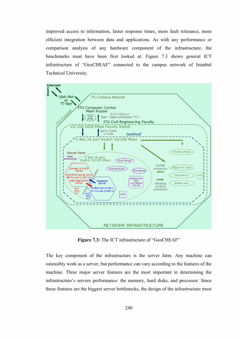
improved access to information, faster response times, more fault tolerance, more
efficient integration between data and applications. As with any performance or
comparison analysis of any hardware component of the infrastructure, the
benchmarks must have been first looked at. Figure 7.3 shows general ICT
infrastructure of “GeoCHEAF” connected to the campus network of Istanbul
Technical University.
Figure 7.3: The ICT infrastructure of “GeoCHEAF”
The key component of the infrastructure is the server farm. Any machine can
ostensibly work as a server, but performance can vary according to the features of the
machine. Three major server features are the most important in determining the
infrastructure’s servers performance: the memory, hard disks, and processor. Since
these features are the biggest server bottlenecks, the design of the infrastructure must
240
be focused the budget on beefing up these features before splurging on less necessary
items like remote management cards. In addition, if the server farm is under too
much strain, it will slow down the whole network.
The single biggest hardware issue affecting Web server performance is memory.
Like databases many things are memory hungry, they have to be fed. Random
Access Memory (RAM) types are:
• DRAM: Stands for Dynamic RAM
• SDRAM: Short for Synchronous Dynamic or Single Data Access RAM
• (PC-66, PC-100, PC-133)
• DDR SDRAM: Double Data Rate SDRAM
• DDR-200, DDR-266, DDR-333, DDR-400
• PC-1600, PC-2100, PC-2700, PC-3200
• DDR RAM with 400 MHz clock rate: DDR-400 PC3200 SDRAM 3.200
GB/sec. bandwidth
• DDR2 SDRAM
• DDR-400, DDR-533, DDR-667, DDR-800
• PC-3200, PC-4200, PC-5300, PC-6400
• DDR2-800 PC2-6400 MHz SDRAM 6.400 GB/sec. bandwidth
DDR2-SDRAM is high-performance main memory. Over its predecessor, DDR-
SDRAM, DDR2-SDRAM offers greater bandwidth and density in a smaller package
along with a reduction in power consumption. In addition DDR2-SDRAM offers
new features and functions that enable higher a clock rate and data rate operations of
400 MHz, 533 MHz, 667 MHz, and above. DDR2 transfers 64 bits of data twice
every clock cycle. DDR2-SDRAM memory is not compatible with current DDR-
SDRAM memory slots. (http://www.webopedia.com)
32-bit processors can address 4 GB of memory and even larger amounts through
memory address extensions such as Intel Architecture 32 bit extended (IA-32e). By
moving to a fully 64-bit platform, existing memory scalability limits are significantly
increased, allowing developers the flexibility to create more powerful applications
with greater features and functionality.
241
64-bit processor architectures:
• Intel’s 64-bit CPU architecture is known as IA-64, and it is being sold under
the Itanium name.
• x86-64 AMD’s 64-bit architecture (under the names Opteron and Athlon)
The goal is to choose the right CPU for the OS that was already chosen. For instance,
the Linux kernel was originally written for the Intel 80386 (or i386) CPU. This CPU
is part of a family of CPUs known as the 80x86, x86, or Intel Architecture 32 (IA-
32) family. Multi-processor dual core 64-bit CPU-based X86 server platforms are the
ideal solution for multithreaded and multi-task usage environments.
The infrastructure enables enterprise a seamless transition from one storage
architecture to another or hybrid architecture as the storage requirements grow.
Operations can continue while the transition is in progress, and data is always
consistent and available. The storage architectures are:
• Direct Attached Storage (DAS): Disks, tapes, optical devices
• Storage virtualization / Storage virtualization using RAID
• Network Attached Storage (NAS) (LinkStation Network Storage Center
250GB from Buffalo Technology, additional drive capacity via USB 2.0
Ports)
• Server Attached Storage (SAS)
• Storage Area Network (SAN)
• Storage networks
Figure 7.4 displays the data storage infrastructure of “GeoCHEAF”.
Distributed storage model provides scalable, high-performance storage solutions for
consolidation, data access, heterogeneous data sharing, data protection and robust
data lifecycle management.
For desktop and laptop PCs, regular Integrated Drive Electronics (IDE) hard drives
are fine. When configuring a server or high end custom computer, SCSI and/or
SATA with a wide variety of flavors have to be considered. Two interface standard
in the hard disk market:
242
• Advanced Technology Attachment (ATA)
• Single-tasking
• Cheaper
• Parallel ATA (PATA)
• Ultra ATA
• Serial ATA (SATA) (1.5 Gbps)
• SATA II with SATA II RAID controller (up to 300 MB/sec data transfer
speed) (SATA II solution feature sets comparable to UltraSCSI 320
solutions.)
• Small Computer System Interface (SCSI)
• Multitasking
• Expensive
• SCSI bus is capable of 80MB/s transfers
• Fast-20 UltraSCSI (up to 40 MB/sec data transfer speed)
• Ultra2 SCSI (up to 80 MB/sec data transfer speed)
• Ultra160 SCSI (up to 160 MB/sec data transfer speed)
• Ultra320 SCSI (up to 320 MB/sec data transfer speed) (Parallel
SCSI) (the fastest version currently on the market)
• Ultra640 SCSI (under development)
• Serial Attached SCSI (SAS) (up to 300 MS/sec data transfer
speed)
• Too expensive
SCSI controllers provide fast access to very fast SCSI hard drives. They can be much
faster than the IDE controllers. SCSI controllers have their own advanced processing
chips, which allows them to rely less on the CPU for handling instructions than IDE
controllers do.
Some very high-end ATA and SCSI controllers support Redundant Array of
Independent (or Interface or Inexpensive) Disk (RAID) technology. RAID is capable
of linking together multiple hard disks for improved speed (performance), improved
reliability (fault tolerance), or both. There are two different types of RAID: hardware
RAID and software RAID. Although there are number of different RAID levels,
243
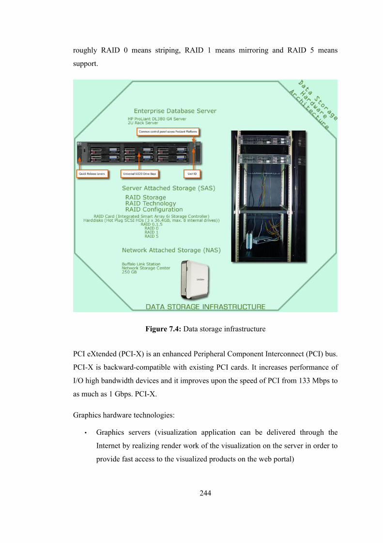
roughly RAID 0 means striping, RAID 1 means mirroring and RAID 5 means
support.
Figure 7.4: Data storage infrastructure
PCI eXtended (PCI-X) is an enhanced Peripheral Component Interconnect (PCI) bus.
PCI-X is backward-compatible with existing PCI cards. It increases performance of
I/O high bandwidth devices and it improves upon the speed of PCI from 133 Mbps to
as much as 1 Gbps. PCI-X.
Graphics hardware technologies:
• Graphics servers (visualization application can be delivered through the
Internet by realizing render work of the visualization on the server in order to
provide fast access to the visualized products on the web portal)
244
• Graphics (graphical) workstations, such as Macintosh computers (workstation
rendering) (CAD or 3D workstation)
• Parallel processing configuration for rendering and analyzing
• Multi-tasking
• Graphic cards, such as NVIDIA GeForce 6150 GPU
• XGA projection technology for multi-channel projection systems
• Spherical Screen (passive and active stereo projection, Immersive VR,
simulators)
• Cylindrical screen
• Flat screen
High performance computers and HPC are increasingly used to solve the large and
complex problems that can no longer be solved productively on the desktop.
Remote server management & monitoring products designed to give systems
administrators direct access to remote machines and ease management tasks.
The open and robust 64-bit Solaris 10 enterprise operating system running on
scalable enterprise-class rack-mounted 2U HP servers (server farm) were chosen for
the project because of the results of benchmark tests, lower price and HW/SW
compatibility.
(Java-based) Web Application Server (Front-end server): HP ProLiant DL380 G4
[$3462.00+VAT (February 2006)]
• Dual processor dual core 64-bit CPUs: Intel Xeon IA-64 3.2GHz 800MHz
FSB 2MB L2 cache per core (with Extended Memory 64-bit Technology
(EM64T) & Hyper-Threading Technology)
• 2GB PC3200 400MHz DDR2 SDRAM DIMM Memory Kit (4 x 512MB)
(Max. 16GB)
• 108GB (3 x 36GB) 15K-rpm Ultra320 SCSI HDD Hot Plug (Hot Swap)
U320 HDDs (Max. 6 x 300GB)
• Smart Array 6i RAID Controller (integrated on system board) (supported
RAID configuration: RAID 0, or RAID 0+1, or RAID 5)
• Integrated ATI RAGE XL Video Controller with 8MB Video Memory
245
• NC7782 Dual Port PCI-X Gigabit Server Adapter (embedded) (NICs) (Dual
integrated 10/100/1000 Mbps Ethernet)
• 3 years guarantee
• 24X Slim CD-ROM, No FDD
• 3 RJ-45 (1 for ILO), 3 USB, 1 serial, 1 graphic, 1 mouse, 1 keyboard ports
• I/O Slot: 3 x 64-bit/133MHz PCI-X Non HotPlug)
• Integrated Lights-Out (iLO) remote management
Database Server (Back-end server): HP ProLiant DL385 G1
[$4309.00+VAT (February 2006)]
• Dual processor dual core 64-bit CPUs: AMD Opteron x86-64 2.2GHz 1MB
L2 cache per core (with HyperTransport Technology)
• 2GB PC3200 400MHz DDR SDRAM DIMM Memory Kit (4 x 512MB)
(Max. 16GB at 400 MHz or 32GB at 333 MHz)
• 108GB (3 x 36GB) 15K-rpm Ultra320 SCSI HDD Hot Plug (Hot Swap)
U320 HDDs (Max. 6 x 300GB)
• Smart Array 6i Controller (integrated on system board) (supported RAID
configuration: RAID 0, or RAID 0+1, or RAID 5)
• Integrated ATI RAGE XL Video Controller with 8MB Video Memory
• NC7782 Dual Port PCI-X Gigabit Server Adapter (embedded) (NICs) (Dual
integrated 10/100/1000 Mbps Ethernet)
• 3 years guarantee
• 24X Slim CD-ROM, No FDD
• 3 RJ-45 (1 for ILO), 3 USB, 1 serial, 1 graphic, 1 mouse, 1 keyboard ports
• I/O Slot: 3 x 64-bit/133MHz PCI-X Non HotPlug)
• Integrated Lights-Out (iLO) remote management
A Proxy server accepts request for clients, forwards them to the real servers, and then
sends the real servers’ responses back to the clients. There are two reasons why a
proxy server required:
• The proxy might be running on the far side of a firewall giving its users to
access to the Internet.
• The proxy might cache popular pages to save re-accessing them
246

A web proxy server is a specialized HTTP server. The primary use of a proxy server
is to allow internal clients access to the Internet from behind a firewall. Anyone
behind a firewall can now have full web access past the firewall host with minimum
effort and without compromising security. The proxy server listens for requests from
clients within the firewall and forwards these requests to remote Internet servers
outside the firewall. The proxy server reads responses from the external servers and
then sends them to internal client clients. In the usual case, all the clients within a
given subnet use the same proxy server. This makes it possible for the proxy to cache
documents efficiently that are requested by a number of clients.
Today the problem is energy. A Uninterruptible Power Supply (UPS) with at least
one hour running time is strongly recommended. UPS types are online and Line-
Interactive, which are CPU controlled and have Automatic Voltage Regulator (AVR)
feature.
247
8. SPATIAL INFORMATICS TECHNOLOGY ARCHITECTURE
8.1 Overview
Everything happens somewhere, from the cradle to the grave and in all aspects of
life. Positive events like births, schooling, work, marriage, as well as negative ones
such as crime, disasters and death, all occur at a location. As a result, 80% of
information has some spatial connection to location (URL, 2003a). Increasingly,
because technology makes it possible, the linking of that location to people or
incidents has become a powerful tool to understanding, analyzing and managing the
world mankind live in. Technology does not just help to predict future events and
manage them but it also to helps evaluate a past situation and reconstruct it again as
effectively as possible.
Fast developing technology in the area of geo-informatics makes the use of SIS
exciting to utilize and an opportunity to challenge much better decision-making for
many fields like history, archaeology etc. SIS can be used to analyze any issue with a
spatial component in these fields.
(Geo)Spatial Informatics Technology Architecture of “GeoCHEAF” provides the
ability to gather (geo)spatial data, information and associated attributes about the
location and characteristics of man-made and natural features and events above, on
and beneath the surface of the earth by encompassing a broad range of disciplines
including geodesy, surveying, remote sensing, photogrammetry, archaeology,
history, etc. It then is capable of utilizing (geo)spatial data and information to model,
analyze and interpret spatial relationships by encompassing cartography, mapping,
generalization, SIS technology, etc. Subsequently, it provides the ability to present
and distribute results to enable better decision-making by surrounding SIS
technology, Internet, cartography etc. Eventually, it provides the ability to track
248
man-made and natural features as they change over time and space through SIS
technology, etc.
When implementing a management information system with a SIS component, the
technical capabilities of the SIS are probably the least difficult issue to be
considered. Yet they often receive the most attention, perhaps because it is easier to
focus on technical issues rather than organizational ones.
The main business objective of this architecture is to apply geo-informatics to the
widest possible range of users in the enterprise by embedding spatial data and
technologies, and SIS functionality in the enterprise applications, and to enable the
CH enterprises to freely exchange and apply spatial information, applications and
services across networks, different platforms and products through OGC's open
interface specifications.
(Geo)spatial vision in the business architecture and SIS-driven technical architecture
of “GeoCHEAF”:
• Lead to a better understanding of the potential of geospatial sciences in
enabling enterprises take better decisions
• Turn the enterprise into the spatially-enabled enterprise
• Maximizes use of geospatial data through enterprise repository
• Ensure the architectures supports SIS and “traditional” business applications
• Integrate SIS into the business process to obtain geospatial intelligence
business solutions
• Use data standards to integrate business processes with SIS
• Integrate SIS with other enterprise systems or information systems like
management information system to enable information sharing
• Aim to advance geo-processing interoperability across the enterprise
• Use open source low-cost geographic information technologies
The architecture enables the decision-makers to carry out spatial analyses more
easily, to tailor maps exactly to the needs, to support management of spatial objects.
It may even be possible to produce spatial information that has not been available
before, such as determining location of the tower within the fortress area that does
249
not exist now. The contribution of the architecture may be of different nature,
improving the decision-making, speeding up decisions, serving the user better,
reducing the cost of operation etc.
The heart of “GeoCHEAF” is the SIS. In the context of the dissertation, SIS is
mainstream and integral part of any process that tries to visualize complex
interrelationships of data or information with a specific purpose of generating spatial
intelligence.
The SIS architecture of “GeoCHEAF” is emerging based on some new technologies
that allow all SIS functions to run in a centralized server environment and be
accessed a variety of users wherever it is needed from any device on a network, to a
browser-based or kiosk-based user to onsite mobile computing devices in the field to
GIS services.
In the design of “GeoCHEAF”, to provide a spatially-enabled enterprise, SIS
functionality and data are embedded inside other applications, like functions
embedded within word processing documents and spreadsheets, or mapping provided
within non-SIS applications.
Another objective is to develop an open SIS architecture including open source SIS
software and open standards in SIS. Both open source GIS databases PostGIS from
PostgreSQL and MyGIS from MySQL have been selected to store spatial data.
MapServer developed by University of Minnesota is used as a SIS map server in the
architecture. Since more than 65 spatial data formats are available in SIS market, to
retain the interoperability, the architecture is based on open standards, in particular,
OGC standards, such as GML, WMS, WCS, WFS, JPEG2000, GMLJP2.
The spatial informatics technology architecture of “GeoCHEAF” includes not only
geospatial information systems, but also mapping, earth imaging, sensor webs, and
mobile wireless services. It also highlights the importance of OGC web services
standards as part of information technology best practices for integrating geospatial
processing into service-oriented architectures and enterprise workflows.
250
8.2 SIS Subsystems
SIS comprises three major subsystems as follow. A useful, general purpose SIS
needs capabilities in all these areas. (Morais, 2000; Maguire, 2003)
1. Data Management (Geodatabase)
2. Geoprocessing (Operations and Analysis)
3. Mapping (Rendering and User Interface / GeoVisualization)
The mapping subsystem deals with the manipulation and visualization of geospatial
information. It is here that users will find projection and datum transformations, map
to page transformations, symbology models, map displays, 2D and 3D visualization
tools, editing components, and the framework for interacting with geospatial data in
the form of a map. (Morais, 2000; Maguire, 2003)
The spatial analysis subsystem implements a series of geospatial analysis functions
for overlay analysis, grid analysis (watershed modeling, intervisibility analysis, etc.),
network analysis, three-dimensional analysis (calculation of slope, aspect, etc.),
proximity analysis, and data conversion (import CAD data, export graphics, etc.).
The operations and analysis functions refer to the actual logical processing of the
data, including things like feature overlay and map projection. (Morais, 2000;
Maguire, 2003)
The data management functions refer to the reading and writing of spatial and non-
spatial attribute data to some type of permanent storage media, usually a hard disk.
DBMS products have been widely used in SIS because they allow users to create a
single, centralized data repository (avoiding redundancy and duplication); they
facilitate data sharing (by establishing de facto standards); they support multiuser
editing of continuous geospatial databases; and they allow users to employ DBMS
backup and recovery tools. However, the limited support for advanced geographic
data types; the weaknesses of SQL as a geospatial data access and programming
language; and concerns about scalability for operations, such as topology
management, have instigated a reexamination of the role of DBMS in SIS and have
prompted the development of n-tiered GIS applications.
251
8.3 Evolution of SIS Technologies Followed by ICT Evolutionary
Throughout the course of the last 40 years , GIS technology has been implemented
using a variety of contemporary computer architectures. The earliest systems were
built to run on mainframe and minicomputers, then came workstations, next PCs, and
now system designers are recommending web-based technologies for distributed
systems. (Maguire, 2003)
The architecture of early GISs developed during the late 1970s and early 1980s
resembled a stovepipe because all three components were tightly coupled and sold as
part of a single entity. In other words, the earliest GIS software was responsible for
providing functionality related to all three aspects of the GIS. Not surprisingly the
weakness of this approach was quickly exposed when the software produced during
this era could not adequately perform all three tasks. Even worse, there was little or
no interoperability between software packages. (Morais, 2000)
The evolution in systems architecture presented a new paradigm in the early 1990s as
a solution, the client-server architecture. The client-server approach disaggregated
the data management duties from the rendering and user interface. This approach
benefited from the introduction of commercial relational database technology and
inexpensive client-side desktop PCs or UNIX network terminals. Many of the GIS
installations today still use a client-server architecture. For example, an organization
which stores spatial data on a central server in an ArcSDE or Oracle Spatial database,
but uses ArcView or ArcInfo to manipulate this data, is taking advantage of the
classical client-server architecture. The client-server approach provides an amicable
distinction between the data management and user interface responsibilities, but
suffers because there is no well defined place for the operations and analysis logic.
For example, if one has to find all features within a certain distance of a given point,
is it the responsibility of the data management or the user interface component of the
GIS to do this. (Morais, 2000)
The most recent evolutionary stage in systems architecture is the distributed n-tier
approach. In n-tiered architecture the operations and analysis component is explicitly
restricted from being coupled to the user interface and data management
252
components. So, the architecture can be easily extended in the future and interacted
with other software which it has no prior knowledge of. (Morais, 2000)
In this type of configuration the client has sophisticated capabilities and, in advanced
systems, can comprise several hundreds of megabytes of code (a so-called “thick”
client implementation). This configuration has served GIS users well for the last
decade and will continue to do so for advanced GIS tasks such as editing,
cartographic compilation, three-dimensional modeling, and spatial analysis.
However, in recent years users have become dissatisfied with this type of
architecture for less demanding tasks because the cost of client machines and
software is prohibitive, it is expensive to maintain and update widely distributed PCs.
An alternate, in the design of more centralized architecture of “GeoCHEAF”, the
three SIS subsystems are deployed on the distributed multi-tier architecture of her.
All the SIS components -topographic and thematic mapping, spatial analysis,
geospatial processing and data access functions- are deployed on the middle-tier and
run on the web application server. The presentation sub-tier is responsible for
interfacing with the network and for allocating requests to server containers within
the business logic sub-tier that perform the actual work. The server containers obtain
the data required to fulfill a task from the data management subsystem that runs on
the DBMS in the data tier. A thin client can be used to initiate processing requests
and display the results of SIS tasks. Addition to Internet delivery of comprehensive
GIS functionality, the design involves a central SIS web portal for information
discovery and use.
In the same way that the adoption of the client-server approach was assisted by the
introduction of relational databases and desktop computers, the n-tiered architecture
will require the introduction of industry standards and improvements in component
software technology. The industry standards in SIS generally come in one of two
forms. Data standards have been developed by industry consortiums, such as the
simple features specification of the OGC, or in a de facto manner if a particular
proprietary format is popular enough, the ESRI shapefile is a good example. The
second suite of standards are processing standards, such as the OGC's services model
253
and catalog, that relate the operations that must be made available in a piece of SIS
middleware.
The open standards-based approach to data management, application development,
and data and processing access makes the SIS architecture of “GeoCHEAF” ideal for
providing SIS services to a wide range of distributed users, from stakeholders to end-
users. The architecture has a number of benefits -the low cost of maintenance, high
scalability, and excellent reliability- for the enterprises. For instance, because all data
and processing capabilities are centralized in one location, costs of upgrade and
maintenance are minimized (e.g., software updates do not need to be pushed out to
hundreds of PCs), SIS servers can be installed alongside an enterprise's other servers,
and the same ICT staff can be used to maintain both.
Finally, “GeoCHEAF” foresees a future in which traditional, architecturally closed
and centralized information systems (GISystems), designed as isolated islands, will
become increasingly less attractive, maybe disappearing altogether. Even, most of
the current web-based GIS applications cannot be shared and are not interoperable
because of their heterogeneous environments. However, the open and distributed
Internet GIS services architecture (GIServices) would be common in any area by
means of ICT technologies, such as distributed component technology, XML,
network communication and programming technologies in order to access
heterogeneous servers dynamically.
8.4 Standards for the Development of Internet GIS
Internet GIS has been the most rapidly developing field in the geospatial technology
industry. Many commercial Internet GIS programs have been developed, such as:
ESRI MapObject IMS and ArcIMS, Autodesk MapGuide, Geomedia WebMap
Server, and MapInfo MapXtreme, GE Smallworld Internet Application Server and
ER Mapper's Image Web Server. Although these commercial Internet GIS programs
greatly increase the accessibility of GIS data and tools, there are two problems
associated with the current Internet GIS programs. First, current Internet GIS
programs are not interoperable. This non-interoperability has two aspects. The first
254
aspect is the data interoperability issue; the data created by different programs cannot
be shared by others without data conversion. This causes problems for real-time data
access, especially at the feature level. The second aspect is the access interoperability
issue; data on the server can only be accessed by its own client. Other clients cannot
access data due to proprietary access methods implemented by different Internet GIS
programs. For example, a GeoMedia Web Map client cannot access data on the
ArcIMS server. Enabling interoperability among heterogeneous systems and
geospatial data is a challenging task for the development of Internet GIS, both
technically and institutionally. The second problem of current Internet GIS is that the
graphic output of most commercial Internet GIS programs is in raster image formats
such as GIF and JPEG. The graphic quality of raster images is limited, and becomes
blurred when zooming in. Delivering spatial data in a high-resolution vector format
over the web is becoming more important as data availability and global sharing
increases. “GeoCHEAF” proposes a standard-based architectural framework for
interoperable Internet GIS.
This architectural framework uses GML as a coding and data transporting
mechanism to achieve data interoperability, WFS as a data query mechanism to
access and retrieve data from the heterogeneous systems at the feature level on the
web to achieve access interoperability, and SVG to display GML data on the web as
vector graphics to improve the display quality of map graphics. The combination of
the three standard technologies provides efficiency in promoting interoperability of
Internet GIS programs and improving cartographic quality of Internet GIS
visualization on the web.
GML, SVG, and WFS are standard technologies, and each has a unique role on the
web and Internet GIS. As mentioned in the section of 'Extensible Architecture', GML
models the world in terms of features based on the OGC Abstract Specification. A
feature is an abstraction of a real world phenomenon; a geographic feature is any
real-world object that is associated with a location. The Web Feature Services (WFS)
is an another OGC implementation specification that allows a client to retrieve
geospatial data encoded in GML from multiple Web Feature Services. The WFS is
written in XML and uses GML to represent features, but the database (or datastore in
255
OGC's term) could be in any format. In fact, the structure of those databases should
be opaque to client applications. Any access to the database should be through the
WFS interface. WFS has a tight relationship with GML. The WFS allows the client
applications to access, query, create, update, and delete data elements from the GML
feature database server. The WFS provides interfaces for four basic data
manipulation operations on GML features: create a new feature instance, delete a
feature instance, update a feature instance, and get or query features based on some
spatial or non-spatial query constraints. Client applications can post requests for
feature level data in XML. Such a request can include query or data transformation
operations, which can be applied to one or more features in one or more database,
locally or remotely. The WFS server reads and passes the request and returns the
result in the form of GML. (URL OGC) Finally, W3C's SVG standard is used to
display spatial data as vector maps on the web browser.
GML is an effective means to encode, store, and transport geospatial data. It is also
an efficient means to foster data portability and interoperability. SVG produces high-
quality graphics on the Web, which is ideal for displaying spatial data and making
intelligent maps. The OGC Web Feature Service works well with querying and
retrieving GML data from different servers. The advantage of this standard-based
approach is interoperability. Users can gain access to data that are stored in different
Internet GIS servers that conform to the same standard. Data in their original formats
can be retrieved using WFS and transformed into GML on the fly. Thus, the end user
can retrieve information at the feature level from different data sources with different
data formats.
The user can search, access, and retrieve spatial data at the feature level through a
web-based search engine. A user's query goes through the web server and WFS to the
respective geodatabase. The retrieved feature data will then be displayed as SVG in
the user's web browser and/or applications. The main purposes of this architectural
framework are twofold: to facilitate users to access data from the heterogeneous
systems at the feature level in real time on the Web, and deliver high quality vector
GIS by SVG on the Web.
256

8.5 Scope of Geospatial World
Depending on the needs of the user, currently two kinds of SIS software fulfill the
main requirements: the light web client or the heavy client, also called Desktop SIS.
While the first one only offers basic tools, the desktop GIS offers authoring, sharing,
managing and publishing geospatial information.
In the last years, open source software has been getting very popular. Numerous
software areas already offer an equivalent option to proprietary products. But until
now, the market segment of SIS and CAD software did not provide series
alternatives to the expensive and sometimes oversized market-leading software
packages. On the other hand, the market of software that is dedicated to modify and
treat spatial information and cartography has been monopolized by a few proprietary
products that shown in table 8.1. Due to this lack of selection, the main part of the
fast growing community of SIS users has been bound to use certain softwares. So,
the selection of a SIS normally was neither a well-considered decision nor the result
of an analysis of the existing possibilities. The situation in many SIS evaluation
processes is that not the most suitable product is selected but the most habitual one.
Normally, the software user is not aware of his requirements and functions he needs.
Although users often only need certain basic functions, they are constrained to buy
expensive software with many complex, but unnecessary tools. The logical decision
should not be buying the most common software, but buying software that fulfills the
user's requirements best. One can think of language, comfort, price,
comprehensibility, and compatibility, to mention a few in a SIS evaluation process.
Is open source SIS software really an alternative for commercial GIS software? Yes
and No. No, because of lack of capabilities for analysis, which means there is no
server-side logic and the files are hosted on a web server, such as Google Earth's
KML file. Yes, because the goal is to make spatial data available online to the
researchers, general public, government institutions or companies.
257

Table 8.1: G-World
Which GIS toolkit/software?
Free
but
not
Ope
n So
urce
?
Prop
rieta
ry (C
lose
d So
urce
)?
Quantum GIS (QGIS)
uDig
MapWindow GISGeoTools
gvSIG
Thuban
UMN MapServerGeoServerdeegreeJMap Serverka-MapMapbenderMapBuilderOpenLayers
PostgreSQL – PostGIS Oracle Spatial
Spatial DB in Box
Geo
spat
ial L
ibra
ries
GeoTools
Ope
n So
urce
Thi
ck (H
eavy
) Clie
nts?
/ O
pen
Sour
ce G
IS
Proc
essi
ng T
ools
?Geographic Resources Analysis Support System (GRASS)
Diva-GIS by Lizard Tech, Inc. and University of
California
ESRI ArcGIS
Open Source Software Image Map (OSSIM)
Autodesk Map, MapGuide, MapGuide Enterprise, MapGuide StudioIntergraph GeoMedia & GeoMedia ProfessionalBentley Microstation GeoGraphics
System for Automated Geoscientific Analyses (SAGA)
MapInfo Professional
CadCorp SISIonic RedSpider
Generic Mapping Tools (GMT)
Snowflake Software Go Loader & Publisher
JUMP Unified Mapping Platform (JUMP) PCI Geomatics IMAGiS
Northgate Information Solutions StruMapGE Energy Smallworld
Ope
n So
urce
Thi
n Cl
ient
s? /
Ope
n So
urce
GIS
Map
Ser
vers
Prop
rieta
ry T
hin
Clie
nts?
/ Pr
oprie
tary
GIS
Map
Ser
vers
ESRI ArcIMS & ArcServerAutodesk MapGuideIntergraph Geomedia WebMapMapInfo MapXtereme
Autodesk MapGuide Open SourceIntergraph OGC WMS Viewer
data
base
sp
atia
l ex
tens
ions
data
base
sp
atia
l ex
tens
ionsMySQL – MYSQL
Spatial (MyGIS)ESRI ArcSDE for Microsoft SQL Server and Oracle
Geospatial Data Abstraction Layer (GDAL)Geometry Engine Open Source (GEOS)Java Topology Suite (JTS)
258
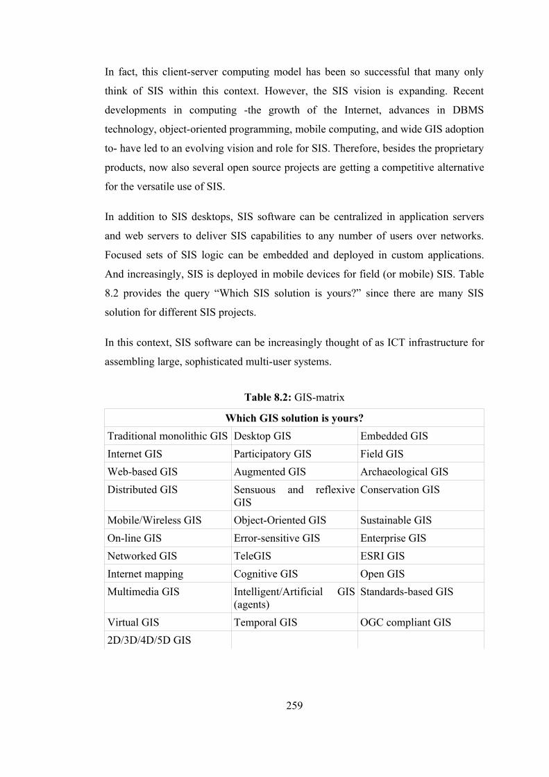
In fact, this client-server computing model has been so successful that many only
think of SIS within this context. However, the SIS vision is expanding. Recent
developments in computing -the growth of the Internet, advances in DBMS
technology, object-oriented programming, mobile computing, and wide GIS adoption
to- have led to an evolving vision and role for SIS. Therefore, besides the proprietary
products, now also several open source projects are getting a competitive alternative
for the versatile use of SIS.
In addition to SIS desktops, SIS software can be centralized in application servers
and web servers to deliver SIS capabilities to any number of users over networks.
Focused sets of SIS logic can be embedded and deployed in custom applications.
And increasingly, SIS is deployed in mobile devices for field (or mobile) SIS. Table
8.2 provides the query “Which SIS solution is yours?” since there are many SIS
solution for different SIS projects.
In this context, SIS software can be increasingly thought of as ICT infrastructure for
assembling large, sophisticated multi-user systems.
Table 8.2: GIS-matrix
Which GIS solution is yours?Traditional monolithic GIS Desktop GIS Embedded GISInternet GIS Participatory GIS Field GISWeb-based GIS Augmented GIS Archaeological GISDistributed GIS Sensuous and reflexive
GISConservation GIS
Mobile/Wireless GIS Object-Oriented GIS Sustainable GISOn-line GIS Error-sensitive GIS Enterprise GISNetworked GIS TeleGIS ESRI GISInternet mapping Cognitive GIS Open GISMultimedia GIS Intelligent/Artificial GIS
(agents)Standards-based GIS
Virtual GIS Temporal GIS OGC compliant GIS2D/3D/4D/5D GIS
259
Spatial informatics technology architecture of “GeoCHEAF” covers all technologies
and their products, and standards pertaining to the geospatial infrastructure, its data
and metadata.
There is currently a trend within the SIS user community toward more sophisticated
uses of raster data, for instance, feature and/or information extraction from
geoimagery, long-term monitoring. So, today, organizations are searching for
solutions that provide easily integration of raster data with vector-based data and for
tools to effectively search these vast and growing collections of photos and images.
Spatial data acquisition techniques and measurement technologies matrix for the CH
domain, which can be directly entered into the SIS:
• Imagery
• Remote Sensing / Satellite Imagery (spectral resolution (low spatial
resolution) & geometric resolution (ultra-high spatial resolution))
• Satellites
• QuickBird-2
• IKONOS
• OrbVIEW-3
• Satellite Pour l'Observation de la Terre (SPOT)
• LandSAT (Landsat 5, Landsat 7)
• European Remote Sensing Satellite (ERS)
• Enterprise Geospatial Imagery Solutions (software packages):
• ERDAS Imagine (Leica Geosystems)
• ER Mapper
• ENVI
• PCI
• Idrisi
• GeoExpress 6 (LizardTech)
• Aerial Photogrammetry
• Stereo aerial photographs from aircraft, zeppelin, balloon, kite
• Terrestrial Photogrammetry
• RADAR Imagery
260
• Synthetic Aperture Radar (SAR)
• LIght Detection And Ranging (LIDAR)
• InterFerometric Synthetic Aperture Radar (IFSAR)
• Integration of LIDAR and IFSAR for high resolution multispectral
imagery and mapping
• Laser Scanning (Hybrid approach for surveying facades: 3D Laser-based
photogrammetry)
Benefits of using 3D laser scanning in the CH domain:
• Better measurements and much faster than manual documentation
methods
• Ability to measure inaccessible structures accurately
• Rapid scanning time reduced the minimized the project life cycle
• Collection of additional measurements for future use (The output data
directly kept in digital format for future reference (no digitization is
required like stereophotogrammetric images, however, required some
algorithms, like point thinning algorithm, and special software, like
Geomagic Raindrop studio or Cyclon))
• Ability to do as-builts without disrupting the tourists and ongoing
works
• Captured details of the complex structures
The point cloud could be used to prepare the following deliverables:
• 2D Drawings in CAD environment
• 3D Models of the existing structures
• Sectional drawings
• Virtual walk through of the CH complex
• Registered point cloud data in digital format
• Historic Imagery
• Image Processing
• Digital Surface Models (DSMs) (generally first pulse signal equal
DSM)
• Digital Terrain Models (DTMs) (last pulse signal processed and
filtering and additional processing required)
261

• Digital Elevation Models (DEMs)
• Orthorectified Radar Images (ORIs)
• Pictometry technology combines packages of oblique and vertical aerial
aerial images with a viewing software application designed to enable
accurate measurements.
• Geophysical (or Ground) remote sensing (used to know ho and where to
excavate)
• ground penetrating radar
• resistivity
• magnetometry
• sub-bottom profiler
• Positioning
• Total Positioning System (TPS)
• Global Positioning System (GPS)
• A-GPS
• Internet GPS
• Underwater GPS
• Hydrographic Survey, Conventional Bathymetry, Bathymetry from
Space, Geodetic Altimetry (satellite altimetry, airborne altimetry,
shipborne altimetry)
• Geodetic/Geophysical Satellite (GeoSat)
• European Remote Sensing Satellite (ERS)
• Seasat
• TOPEX/Poseidon
• Cellular Network Positioning
• Mapping
• Computer Assisted Design (CAD)
• Internet Mapping Services
• Geography Networks
• Google Map/Earth/3D warehouse
• Yahoo Local Map
• MapQuest
262
• Windows Live Local
• Virtual Globes
• Google Earth
• TerraExplorer (from Skyline Software Systems)
• NASA's World Wind
• Historic Map Collections (georeferencing the historical maps using
polynomial transformations)
• Mapping Standards
• XML
• GML (DXF/SHP to GML approach)
• Autodesk DWG/DXF
• Intergraph GeoMedia Warehouse
• MapInfo MID/MIF
• MicroStation Design
• Oracle and Oracle Spatial
• ESRI shp file
• JPIP Streaming (JPIP: JPEG 2000 Interactive Protocol)
• MrSID: the industry-standard image compression format
• GeoTIFF format
• JPEG2000 (ISO-standard) (open standard)
• GMLJP2 (OGC's standard GML + JPEG2000)
• TOP10NL (the Dutch standard format for sharing GIS data across
multiple platforms)
• etc.
The raster data management component of “GeoCHEAF” stores orthorectified and
georeferenced satellite imagery (acquired from satellite image data services) and
aerial photogrammetry (aquired from aerial photogrammetric archives) data in the
multi-resolution image database. Then, “GeoCHEAF” integrates imagery data with
other spatial data sources to generate the image-based maps to extract information
from images and thematic maps to visualize queries' results.
263
8.6 Narrowing the Scope for the Cultural Heritage Domain
The benefits of modern SIS for the CH domain have so far not been fully realized
due to uneven spread, missing capacities, differing databases and systems and lack of
information exchange mechanisms.
Since the days of Heinrich Schliemann's search for Troy, archaeologists have been
confronted with the dilemma of how to record the spatial characteristics of
archaeological data, and once recorded, how to analyze those data. This spatial
information has historically been recorded on paper maps of varying accuracy and
scales. When researchers wanted to perform analyzes of these data, they were
required to spend hours, if not days, transposing this information to new paper maps
and making arduous measurements by hand. (Brandon et al., 1999) Before GIS, each
field season produced a unique set of paper maps and photo prints that were difficult
to integrate with each other, or with other data. (Madry, 2004) This time-consuming
process has come to an end as researchers have moved to take advantage of GIS for
spatial analysis. (Brandon et al., 1999) Now with GIS, all of the data, as it becomes
available, are entered into a single, integrated database where archaeologists can
analyze the data at any scale, from a single excavation to regional analysis of the
patterns of many sites across the landscape. (Madry, 2004)
If an archaeologist links the geometry of features from an excavation site to
collection data tables using GIS, s/he can dynamically update the maps to show, for
example, all the rooms that date to a specific time period or the rooms where a
certain type of object was found. Instead of sitting at a drafting table to create a
single site map, archaeologists can now sit at their computers and make the same
basemap with their GIS software. The time required to add the feature geometries to
the GIS is no greater than that previously invested in manually drafting static site
maps or using CAD or drawing packages to create illustrations for publication.
However, after they draw in the features and attribute them with feature
identification numbers, they can use database join operations to link data from
analysis tables to the map. This lets them interactively create multiple maps showing
264
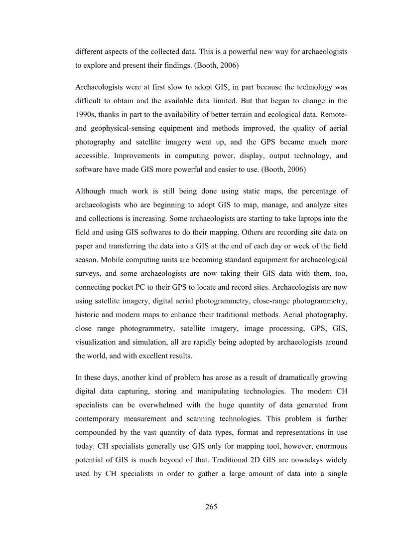
different aspects of the collected data. This is a powerful new way for archaeologists
to explore and present their findings. (Booth, 2006)
Archaeologists were at first slow to adopt GIS, in part because the technology was
difficult to obtain and the available data limited. But that began to change in the
1990s, thanks in part to the availability of better terrain and ecological data. Remote-
and geophysical-sensing equipment and methods improved, the quality of aerial
photography and satellite imagery went up, and the GPS became much more
accessible. Improvements in computing power, display, output technology, and
software have made GIS more powerful and easier to use. (Booth, 2006)
Although much work is still being done using static maps, the percentage of
archaeologists who are beginning to adopt GIS to map, manage, and analyze sites
and collections is increasing. Some archaeologists are starting to take laptops into the
field and using GIS softwares to do their mapping. Others are recording site data on
paper and transferring the data into a GIS at the end of each day or week of the field
season. Mobile computing units are becoming standard equipment for archaeological
surveys, and some archaeologists are now taking their GIS data with them, too,
connecting pocket PC to their GPS to locate and record sites. Archaeologists are now
using satellite imagery, digital aerial photogrammetry, close-range photogrammetry,
historic and modern maps to enhance their traditional methods. Aerial photography,
close range photogrammetry, satellite imagery, image processing, GPS, GIS,
visualization and simulation, all are rapidly being adopted by archaeologists around
the world, and with excellent results.
In these days, another kind of problem has arose as a result of dramatically growing
digital data capturing, storing and manipulating technologies. The modern CH
specialists can be overwhelmed with the huge quantity of data generated from
contemporary measurement and scanning technologies. This problem is further
compounded by the vast quantity of data types, format and representations in use
today. CH specialists generally use GIS only for mapping tool, however, enormous
potential of GIS is much beyond of that. Traditional 2D GIS are nowadays widely
used by CH specialists in order to gather a large amount of data into a single
265
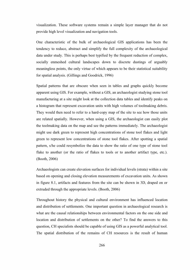
visualization. These software systems remain a simple layer manager that do not
provide high level visualization and navigation tools.
One characteristic of the bulk of archaeological GIS applications has been the
tendency to reduce, abstract and simplify the full complexity of the archaeological
data under study. This is perhaps best typified by the frequent reduction of complex,
socially enmeshed cultural landscapes down to discrete dustings of arguably
meaningless points, the only virtue of which appears to be their statistical suitability
for spatial analysis. (Gillings and Goodrick, 1996)
Spatial patterns that are obscure when seen in tables and graphs quickly become
apparent using GIS. For example, without a GIS, an archaeologist studying stone tool
manufacturing at a site might look at the collection data tables and identify peaks on
a histogram that represent excavation units with high volumes of toolmaking debris.
They would then need to refer to a hard-copy map of the site to see how those units
are related spatially. However, when using a GIS, the archaeologist can easily plot
the toolmaking data on the map and see the patterns immediately. The archaeologist
might use dark green to represent high concentrations of stone tool flakes and light
green to represent low concentrations of stone tool flakes. After spotting a spatial
pattern, s/he could resymbolize the data to show the ratio of one type of stone tool
flake to another (or the ratio of flakes to tools or to another artifact type, etc.).
(Booth, 2006)
Archaeologists can create elevation surfaces for individual levels (strata) within a site
based on opening and closing elevation measurements of excavation units. As shown
in figure 8.1, artifacts and features from the site can be shown in 3D, draped on or
extruded through the appropriate levels. (Booth, 2006)
Throughout history the physical and cultural environment has influenced location
and distribution of settlements. One important question in archaeological research is
what are the causal relationships between environmental factors on the one side and
location and distribution of settlements on the other? To find the answers to this
question, CH specialists should be capable of using GIS as a powerful analytical tool.
The spatial distribution of the remains of CH resources is the result of human
266
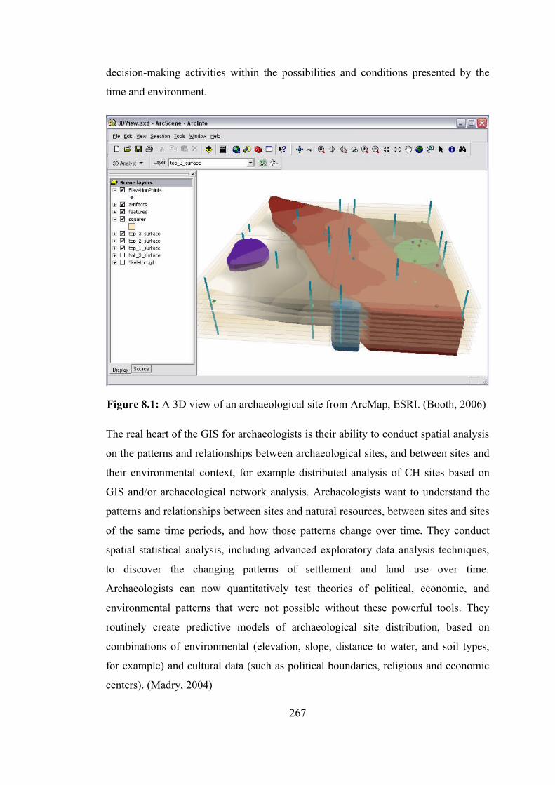
decision-making activities within the possibilities and conditions presented by the
time and environment.
Figure 8.1: A 3D view of an archaeological site from ArcMap, ESRI. (Booth, 2006)
The real heart of the GIS for archaeologists is their ability to conduct spatial analysis
on the patterns and relationships between archaeological sites, and between sites and
their environmental context, for example distributed analysis of CH sites based on
GIS and/or archaeological network analysis. Archaeologists want to understand the
patterns and relationships between sites and natural resources, between sites and sites
of the same time periods, and how those patterns change over time. They conduct
spatial statistical analysis, including advanced exploratory data analysis techniques,
to discover the changing patterns of settlement and land use over time.
Archaeologists can now quantitatively test theories of political, economic, and
environmental patterns that were not possible without these powerful tools. They
routinely create predictive models of archaeological site distribution, based on
combinations of environmental (elevation, slope, distance to water, and soil types,
for example) and cultural data (such as political boundaries, religious and economic
centers). (Madry, 2004)
267
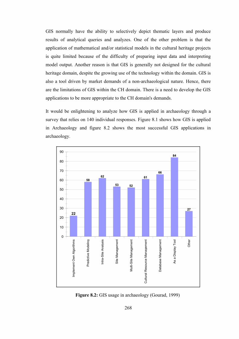
GIS normally have the ability to selectively depict thematic layers and produce
results of analytical queries and analyzes. One of the other problem is that the
application of mathematical and/or statistical models in the cultural heritage projects
is quite limited because of the difficulty of preparing input data and interpreting
model output. Another reason is that GIS is generally not designed for the cultural
heritage domain, despite the growing use of the technology within the domain. GIS is
also a tool driven by market demands of a non-archaeological nature. Hence, there
are the limitations of GIS within the CH domain. There is a need to develop the GIS
applications to be more appropriate to the CH domain's demands.
It would be enlightening to analyze how GIS is applied in archaeology through a
survey that relies on 140 individual responses. Figure 8.1 shows how GIS is applied
in Archaeology and figure 8.2 shows the most successful GIS applications in
archaeology.
Impl
emen
t Ow
n A
lgor
ithm
s
Pre
dict
ive
Mod
elin
g
Intra
-Site
Ana
lysi
s
Site
Man
agem
ent
Mul
ti-S
ite M
anag
emen
t
Cul
tura
l Res
ourc
e M
anag
emen
t
Dat
abas
e M
anag
emen
t
As
a D
ispl
ay T
ool
Oth
er
0
10
20
30
40
50
60
70
80
90
22
5862
53 52
6166
84
27
Figure 8.2: GIS usage in archaeology (Gourad, 1999)
268
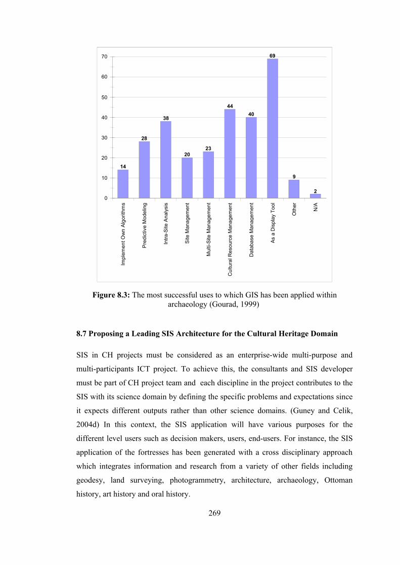
Impl
emen
t Ow
n A
lgor
ithm
s
Pre
dict
ive
Mod
elin
g
Intra
-Site
Ana
lysi
s
Site
Man
agem
ent
Mul
ti-S
ite M
anag
emen
t
Cul
tura
l Res
ourc
e M
anag
emen
t
Dat
abas
e M
anag
emen
t
As
a D
ispl
ay T
ool
Oth
er
N/A
0
10
20
30
40
50
60
70
14
28
38
2023
4440
69
9
2
Figure 8.3: The most successful uses to which GIS has been applied within archaeology (Gourad, 1999)
8.7 Proposing a Leading SIS Architecture for the Cultural Heritage Domain
SIS in CH projects must be considered as an enterprise-wide multi-purpose and
multi-participants ICT project. To achieve this, the consultants and SIS developer
must be part of CH project team and each discipline in the project contributes to the
SIS with its science domain by defining the specific problems and expectations since
it expects different outputs rather than other science domains. (Guney and Celik,
2004d) In this context, the SIS application will have various purposes for the
different level users such as decision makers, users, end-users. For instance, the SIS
application of the fortresses has been generated with a cross disciplinary approach
which integrates information and research from a variety of other fields including
geodesy, land surveying, photogrammetry, architecture, archaeology, Ottoman
history, art history and oral history.
269
SIS requirements influence how SIS software is chosen and used. SIS, similar to
other information and communication technologies, must be treated in a manner that
easily allows applications to support each organization's workflows and business
requirements. This is accomplished by providing a SIS architecture that provides
comprehensive support for the complete range of geospatial knowledge elements as
well as comprehensive tools for data management, editing, analysis and display.
Clues to the relationships between environmental factors and location and
distribution of settlements are preserved in many existing maps. Combining these
maps with remote sensing data and non-spatial information from a variety of sources
in a geospatial data management system (geo-DBMS) enables the creation of virtual
models of cultural heritage sites and querying relationships or adjacencies between
disparate forms of physical and social data at household, cluster, site and regional
level. Such SIS has the potential to incorporate a limitless amount of information for
proper spatiotemporal analyzes, to predict the presence of undocumented
archaeological sites and to discover heretofore-unidentifiable relationships.
To ensure valid analyzes and robust conclusions, the SIS architecture should be
coupled with proper spatiotemporal statistical methods including multivariate spatial
statistical analysis, overlay analysis of thematic data and spatial intersection, buffer
generation, neighborhood analysis, vector-based grid generation, network analysis,
(raster) surface modeling and land use & land cover analyses. In the multivariate
spatial statistical analysis, spatial weights computed, spatial autocorrelation on
predictor variables assessed, and probability scenarios of mapped variables explored
based on modeled changes in regression coefficients over time, with unparalleled
computational speed and ease.
The engineering-oriented SIS architecture of “GeoCHEAF” provides all the
capabilities necessary to support this enlarged vision for the CH domain:
• Spatiotemporal object data modeling and spatial data structures, and a
comprehensive 4D (3D+Time) geo-processing model for implementing and
maintaining spatiotemporal applications
• Multi-resolution data storage scheme for 3D GIS
270
• Geodatabase to store and manage all geospatial objects; efficient and flexible
data management
• Geospatial data accessibility through a web-based interactive mapping
interface
• Extensive support of coordinate systems (including coordinate
transformation) and map projections
• An interactive interface on the web to manipulate the historical information
• Modeling historical changes in the CH resources with temporal SIS
development using an extensible database system
• Spatial analyzes and viewing results on interactive maps as well as tables and
distribution charts
• Towards a model for multimedia supported SIS
• Decision-making
• Modular software components (engines) to embed SIS logic in other
applications and build custom applications
• A web-based network for distributed geospatial information management and
sharing.
• Geospatial information services for multi-tier centralized SIS systems and
web services: mapping, geoprocessing, shared geospatial data and services
• On-the-fly queries, data integration, digital web mapping, thematic mapping,
time-based interactive mapping, animated mapping, etc.
The SIS architecture of “GeoCEHAF” integrates spatial data with non-spatial data to
create essential topologies, including dynamic topology, enhanced topology, on-the-
fly topology, 3D topology, planar topology, non-planar topology, to perform queries
and spatial analysis using these topologies and finally to produce thematic maps
presented as choropleth (grey-scale) maps, dot-density maps, proportional circles,
contour (isopleths) maps, etc.
In term of the project, after generating all topographic maps and architectural plans
for the two sites and collecting a substantial amount of historical information about
the fortresses, the architecture combines layers of information involving topography
(contours, DEM, DTM), planimetric data (monuments, roads, trees, sea-coast),
271

architectural data (the 2D and 3D architectural plans of cultural remains, walls,
structures), land use (residential, agricultural, plants), utilities (water and sewer
installations, heat system), cadastral data (ownership), art historical data, Ottoman
historical data, oral history data, archaeological data and past plans (historic maps,
past maps, plans, residential, natural reserves) and defensive considerations.
Interpreting the interplay of these multiple thematic layers of information related to
these and their various permutations may reveal identifiable patterns that reflect
actual human behavioral patterns and choices. In this context, it identifies the
fortresses, displays the locations of historical and topographical features; pertinent
aspects of the environment like soils, plant cover; the location and condition of
existing structures, roads, other facilities; and traditional use areas such as
cemeteries. Finally it records architectural changes and expands the system to
incorporate data and compare the fortresses from other fortresses in the region for
further research.
First, the SIS of the fortresses was set up to serve users with specialized training in
art and architectural history, Ottoman history, and archaeology. The SIS must be
tailored to the information needs of these researchers and facilitate the analytical
tasks that they must perform. Each discipline in the project team collects the
information necessary for a decision and then uses this information in making the
decision. Therefore, SIS developers in the project team must always be concerned
about the type of information that is necessary for these researchers and which form
of information is easiest to understand within these disciplines. Information in this
context is defined here as “answering a question of an art-historian” in the beginning.
A successful SIS must provide useful information to a user and it is essential that a
constant dialog occur in order for the SIS developers to best adapt the existing SIS
programs to the specialized needs of the users, in this case the historians and
archaeologist on the project and those who will make decisions related to the future
preservation of the structures. Second, the intention of the SIS for the fortresses is to
anticipate the questions that people from other disciplines may have about the
historical development of these fortresses and their environs. (Guney and Celik,
2003a)
272

Most data manipulation and analysis functions would not be practical or feasible
without a topologic data structure in a vector based SIS. The appropriate topology
structures have been applied for the fortresses depends on the goals of the spatial
queries and analyzes. Since the gravestones are the spatial objects, node topology
was created for them in the “Kumkale Cemetery SIS application”. On the other hand,
polygon topology was generated for the enter gate, which is called “Bab-i Kebir”,
and its environs in the fortress of Seddülbahir in order to track the temporal changes
of “Bab-i Kebir”. (Guney and Celik, 2003a)
With accurate position data and necessary epigraphic and morphological attribute
data of the tombstones that corresponds to the identical physical objects, which users
want to analyze, combined node topology structure in order to develop powerful
“Ottoman Cemetery GIS application”. This means that the structure of the physical
object data in the GIS data must be attuned to the types of application that the system
is meant for. The idea is that data has to be structured in a certain way to carry out
certain types of spatial analysis. (Guney and Celik, 2003a)
Queries and analyzes realize on the various topologies present the researchers
valuable information to find out some inferences. Prosopographical index in
Kumkale Cemetery was generated using node topology and SQL queries. The
relationships among the gravestones were presented with thematic maps. The
temporal changes of the main gate of the fortress of Seddülbahir were traced and
explained using various interrogations. (Guney and Celik, 2003a)
Visitors unfamiliar with the cemetery often have difficulty locating graves. If the
cemetery provides paper maps showing the location of each grave, however, these
paper maps often causes problems of their own due to their age (sections of the
cemetery are 250 years old) and over recording of information – e.g where there is
more than one deceased in a grave, recording and providing details becomes
increasingly complicated. To alleviate these problems, 'Cemetery Management
System' has been implemented as a web-based mapping system using Autodesk
technology. The web-based mapping system based on Autodesk's MapGuide solution
provides project staff and the public with accurate and reliable information. That
using the web-based mapping system, the cemetery is able to provide the public with
273
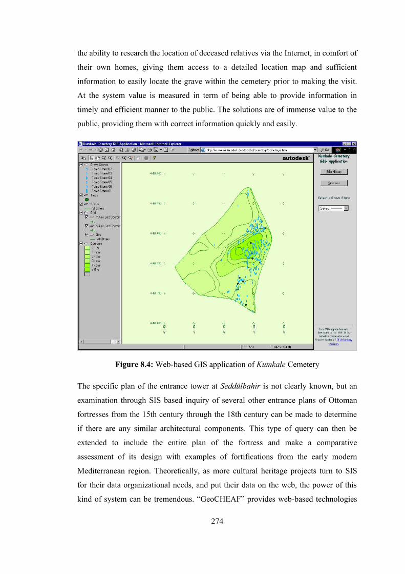
the ability to research the location of deceased relatives via the Internet, in comfort of
their own homes, giving them access to a detailed location map and sufficient
information to easily locate the grave within the cemetery prior to making the visit.
At the system value is measured in term of being able to provide information in
timely and efficient manner to the public. The solutions are of immense value to the
public, providing them with correct information quickly and easily.
Figure 8.4: Web-based GIS application of Kumkale Cemetery
The specific plan of the entrance tower at Seddülbahir is not clearly known, but an
examination through SIS based inquiry of several other entrance plans of Ottoman
fortresses from the 15th century through the 18th century can be made to determine
if there are any similar architectural components. This type of query can then be
extended to include the entire plan of the fortress and make a comparative
assessment of its design with examples of fortifications from the early modern
Mediterranean region. Theoretically, as more cultural heritage projects turn to SIS
for their data organizational needs, and put their data on the web, the power of this
kind of system can be tremendous. “GeoCHEAF” provides web-based technologies
274
that are based on open standards to stick interoperability and promote sharing of
geospatial data and thematic & topological database queries regardless of country,
application, or format. Moreover, graphical and geometrical overlay can be
performed.
“GeoCHEAF” delivers geospatial data using following OGC compliant standards for
GIS web services and web mapping since OGC specifications support interoperable
solutions: Geographic Markup Language (GML) encoding specification (may
become de facto technology for data exchange), Web Map Service (OGC WMS),
Web Coverage Service (OGC WCS), Web Feature Service (OGC WFS) and Styled
Layer Descriptors (SLD) implementation specifications.
OGC WMS technology enables users to easily query operational geoinformation
using a standard web browser, simple hardware and limited bandwidth. Via the OGC
transactional WFS, users can retrieve original feature-level data originating from
distributed operational databases. The WFS transforms this data into standard GML
encoding. The use of WFS separates the application logic from the database, thus
improving interoperability between diverse data sources. (URL OGC)
In the design of the SIS architecture of “GeoCHEAF”, open source PostGIS/MyGIS
and OGC-compliant (WMS, WCS) web map servers from Minnesota University
(UMN's MapServer) have been selected because architecture has been already using
PostgreSQL/MySQL database. Benefit of using PostGIS/MyGIS is map and other
data being stored in the same database. Mapserver includes PHP scripting abilities
and offers support of WMS and WCS. Maps are created by MapServer, data is
queried directly by SQL. UMN's MapServer is used to broadcast the SIS applications
over the web. Then, the connection between SIS application and some multimedia
applications developed using Java Applets. This system design allows users to
collect the geo-spatial data, author maps and layers, and create the application all in
one central place in order to quickly publish maps and spatial applications to the
web. It also allows users to integrate with GIS-based services, like Google
Earth/Map or Map Quest, and GIS networks, like ESRI GIS Network.
275
MapServer is a CGI application that, although not being a full-featured GIS, offers
enough core web-GIS functionality to create map-based web applications.
Communication between the portlet and MapServer was achieved by using both a
JavaBean acting as a wrapper for the CGI application, and a basic MapFile template
that returned MapServer output variables as a java collection. This mechanism
allowed the creation of maps with dynamically generated points to be used within the
portlet.
The PHP MapScript module is a PHP dynamically loadable module that makes
UMN MapServer’s MapScript functions and classes available in a PHP environment.
MySQL has proved adequate for the task although PostGIS probably has better
geospatial capability. PostGIS includes support for GiST-based R-Tree spatial
indexes, and functions for analysis and processing of GIS objects.
UMN MapServer may be installed like a CGI or a module on a web server (in case of
Apache). PostGIS possesses interfaces for the data exchange with MapServer.
A SIS is a tool that uses various forms of data as inputs to produce a map as an
output. Because these maps are easier to understand than raw data, they can be used
as a tool to communicate geospatial information to a general audience. SIS is a great
success in both areas, but as time goes on, the more expected things have come. Until
recently, 2D maps have been the only format available to visually process geospatial
information. This is no longer the case because modern sensors, such as laser
altimeter data, global positioning system, laser trackers, photogrammetric techniques
and remote sensing, are providing a wealth of information that makes the third
dimension possible in mapping. People wish to use SIS to manage data without being
constrained by the inherit limitations of 2D maps. Internet, distributed mapping and
3D visualization technologies will make 3D web mapping common in the near
feature.
While one problem in the past was lack of data, today, the problem in mapping is too
much and too complex data and how to present and distribute these dense data to the
public on the web. Many organizations have large volumes of data stored in SIS
276
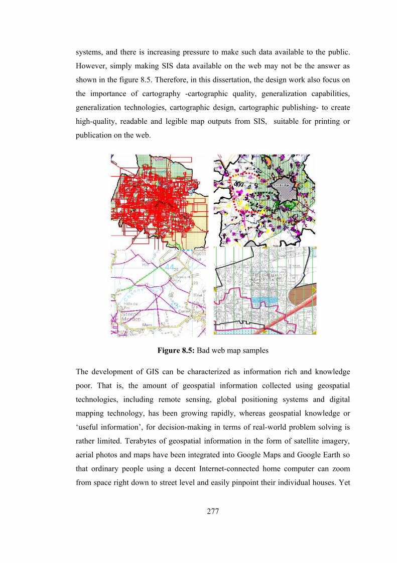
systems, and there is increasing pressure to make such data available to the public.
However, simply making SIS data available on the web may not be the answer as
shown in the figure 8.5. Therefore, in this dissertation, the design work also focus on
the importance of cartography -cartographic quality, generalization capabilities,
generalization technologies, cartographic design, cartographic publishing- to create
high-quality, readable and legible map outputs from SIS, suitable for printing or
publication on the web.
Figure 8.5: Bad web map samples
The development of GIS can be characterized as information rich and knowledge
poor. That is, the amount of geospatial information collected using geospatial
technologies, including remote sensing, global positioning systems and digital
mapping technology, has been growing rapidly, whereas geospatial knowledge or
‘useful information’, for decision-making in terms of real-world problem solving is
rather limited. Terabytes of geospatial information in the form of satellite imagery,
aerial photos and maps have been integrated into Google Maps and Google Earth so
that ordinary people using a decent Internet-connected home computer can zoom
from space right down to street level and easily pinpoint their individual houses. Yet
277
these services are considered information providers rather than knowledge suppliers.
Current GIS still lack relevant tools for uncovering geospatial knowledge in various
forms of patterns, structures, relationships and rules. This is another challenge today
to be resolved. “GeoCHEAF” utilizes the data warehousing architecture within
geospatial informatics architecture for spatial data mining and knowledge discovery.
8.8 Spatial Data Infrastructure
A Spatial Data Infrastructure (SDI) is a mechanism that unites and standardizes
spatial information in and between organizations. The history of the SDI started in
the year 1994, when the then North American president, William J. Clinton,
published a presidential order to develop the National Infrastructure of Spatial Data
for the USA (NSDI). The main idea behind this: “sharing knowledge is a source of
economical growing”. In the year 2004, the European Commission also decided to
create a SDI inside the European Community, called INSPIRE. The European SDI
was composed like a puzzle, created by several parts of national and local SDIs. The
aim is to maximize access to spatial data and minimize the redundancy of
investments. (Alvaro and Wehrle, 2006)
SDIs are ideal way to acquire spatial data in different levels as follows:
• Global level (world-wide)
• National level (Turkey-wide)
• Regional level
• Local level
High accuracy positioning is now a reality for all users. There is a trend to capture
data at highest resolution and then, use various resolution. There is also demand to
access spatial data through geoportals that are the key components of the SDIs. A
few main existing SDIs and SDI initiatives at different levels of development
worldwide are shown in the table 8.3. Figure 8.6 illustrates spatial and non-spatial
data acquiring component of “GeoCHEAF”.
278
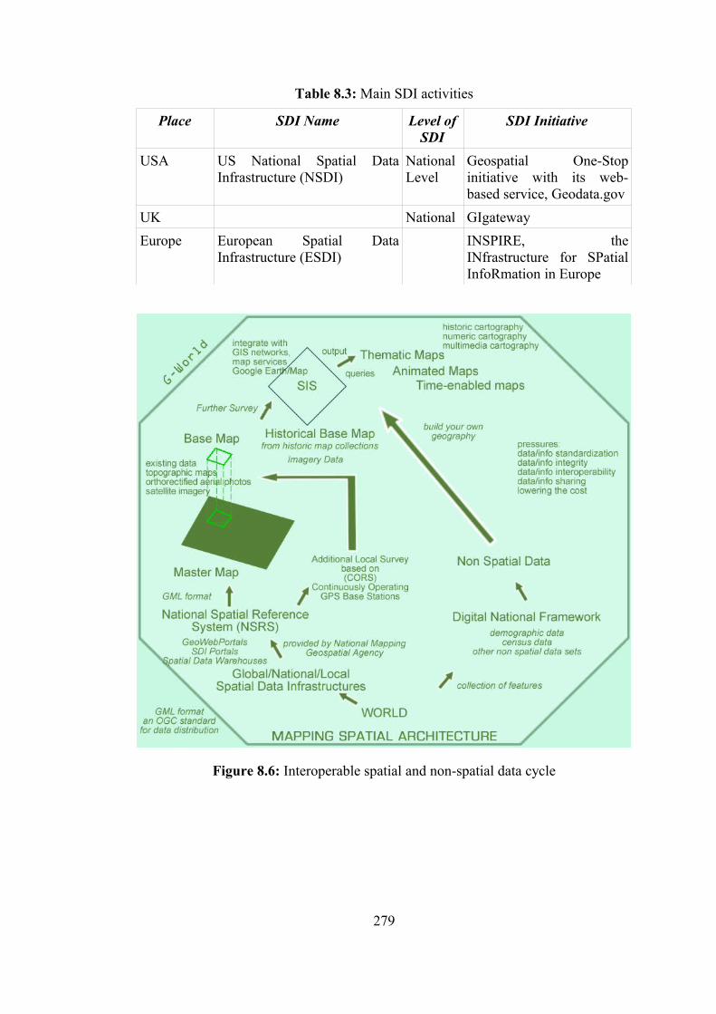
Table 8.3: Main SDI activities
Place SDI Name Level of SDI
SDI Initiative
USA US National Spatial Data Infrastructure (NSDI)
National Level
Geospatial One-Stop initiative with its web-based service, Geodata.gov
UK National GIgatewayEurope European Spatial Data
Infrastructure (ESDI)INSPIRE, the INfrastructure for SPatial InfoRmation in Europe
Figure 8.6: Interoperable spatial and non-spatial data cycle
279

There are two major organizations that set standards for the exchange of geospatial
data sets:
• The Open Geospatial Consortium, Inc. (OGC) (http://www.opengis.org)
• The Technical Committee tasked by the International Standards Organization
(ISO/TC211). (http://www.isotc211.org)
Both organizations were founded in 1994. ISO is an international organization and its
members are mainly from the public sector, including national standards bodies and
organizations. For example, the US national standard body is American National
Standards Institute (ANSI). OGC's members come mainly from the private sector,
including software vendors and GIS companies, such as ESRI Inc, ERDAS Inc,
INTERGRAPH Corp, AutoDesk Inc etc. OGC puts great emphasis on working
prototype implementations as validation for the effectiveness of a given standard
whereas TC211 uses international representative consensus and review. OGC has a
cooperative relationship to ISO such that OGC standards can become ISO standards
(such as GML, location-based services, and metadata contents).
8.9 Geospatial Information Infrastructure for the Cultural Heritage Domain
If anyone was to ever calculate how much time is spent obtaining data, integrating it
and cleaning it to make it fit with other data it would typically account for around 30
percent of a project or ICT development budget. If anyone then consider that this is
happening in countless organizations in the CH sector as well as all other sectors, it
is not hard to understand that a lot of energy and investment costs are being devoted
to processes that are not really necessary. If this gathering, cleaning, and
standardizing was undertaken once and reused -that money could be more wisely
invested on developing the services. This would provide a better service to the end
user and a much more cost-effective solution for the provider.
World is collection of objects of cultural and natural heritage resources. Each
application projected in the CH sector takes a different view of the time period of the
CH resource. In other words, the projects belongs to same time period but in
different place could be correlated each other through a geoportal using standard data
280
formats. To integrate spatiotemporal data, information, application and then share
them, the CH community needs a “Digital Global Heritage Framework”. Not only
spatial data sets, topographic and thematic maps but also demographic data,
geo-demographic data, census data, archaeological, architectural, historical data
(including date of recording, recording by, structural changes (shape, size, width,
length, height), construction date-material, technique, archaeological finds (ceramic,
lithic, metal, textiles, bone, other), architectural features) and other geodata or
geoscience data, and SIS files are shared via open standard formats, such as XML,
and services on the web through a geoweb portal.
“Digital Global Heritage Framework” is primarily concerned with geospatial
information and is relationship to other data and information from multiple sources
for interoperable geospatial data sharing online relies on web-based geospatial data
standards and services by OGC, such as GML.
Uncontrolled exchange, involving transformation, transfer and exchange, of
data/information/content between enterprises (organizations) and systems
(departments) within them is the reason for spatial data quality degradation.
Recently there have been some important archaeological advances with geospatial
tools. An ancient Roman city has been deciphered and signs of a city that matches
Atlantis have been unearthed based on geospatial tools. Even though such cases
could happen different places across the world. There needs to be aggregation of the
various disparate, yet exciting cases onto a common platform for sharing and
dissemination.
Fundamental mission of “Digital Global Heritage Framework” should be:
'Generating a virtual globe on the web like CH-specific Google Earth for the CH
community, which organizes the world's CH information by enabling users to
publish their own data/information/content in whatever format, so long as it is
compliant with OGC specifications, and make all them universally accessible for the
CH community'. In this manner, users can search, find, see and analyze their
concerned topics using a free search, visualization and sharing tool. Additionally,
281
they can add value on the maps either to customize their own data set or to enrich the
globe.
If the CH sector uses the geoenterprise architecture like “GeoCHEAF” individually,
then integration of standard project based architectures could be done easily through
a portal since, in the near future, more CH organizations will use GIS to share their
results via the web, to visualize site data in 3D, to create animations, and to create
and visualize multidimensional datasets. There will be tremendous potential in
almost every subfield of the CH sector by utilizing a network-based CH-specific
geospatial information services to access geospatial information, spatial analytical
tools, and GIS web services (GIServices). The contents of the “Digital Global
Heritage Framework” include not only displaying Internet maps or sharing on-line
geospatial information, but also providing advanced GIS analysis functions and new
information services. In this way, the entire framework would be open, distributed,
interoperable, sharable and exchangeable rather than traditional architecturally closed
and centralized information systems (GISystems). With the comprehensive
architecture for bridging heterogeneous GIServices, researchers, scientists,
stakeholders and agencies can easily share their geospatial data, GIS models, and
knowledge.
282

9. CONCLUSIONS AND SUGGESTIONS FOR FUTURE WORK
As stated in the introduction, the purpose of this dissertation is to explore the
enormous potential inherent in an intimate relationship between the geoenterprise
architecture concept and cultural heritage conservation and management challenges.
The theoretical concepts underlying the approaches to be advocated here concerned
the CH domain-driven science-oriented technology-enabled business-sensitive CH
studies. The intention in this dissertation was to establish connections between post-
modern approaches to the organization of knowledge and information and the
implementation of this in the CH domain.
This dissertation began with a management introduction to the concept of the EA
approach and its accompanying framework and methodology for the CH domain. It
continued with a brief description of the interaction of technology with business by
taking a holistic view of the natural cohesion of Business&Technology. Thereafter,
business concepts were mapped to information technology concepts. Throughout this
dissertation the motivation was to understand this interaction on a conceptual level
and attempted to convey the message that geoenterprise architecture framework,
which involves a strong business model and a strong technical architecture, should be
considered as a necessity for the growth, maintenance and success of today's small,
large-scale or complex CH organizations.
There is only one Enterprise Architecture for an Enterprise but there may be more
Enterprise Solution Architectures within the scope of an Enterprise. “GeoCHEAF”
was created to have the most optimum overall coherent geoenterprise solution for the
CH domain, and provides a common basis for recognizing, understanding and
communicating how systems (constituent parts) and their inter-operation and
inter-dependencies in the extended enterprise are effectively structured to meet
business strategic goals. The conceptual design of “GeoCHEAF” was explained and
completed. However, a great deal of implementation work of it is now in progress.
283
Years of experience with distributed systems have led to the inevitable conclusion
that it is practically impossible to eradicate incompatibilities between interfaces
through standardization. Despite the best intentions, and investment in
standardization initiatives, there will always be problems due to political, technical,
geographical or philosophical boundaries. Hence, “GeoCHEAF” investigated
technologies and their fusion to develop the best model that ensures the standards-
based interoperability available across the entire enterprise, which transcends these
boundaries by aligning business and ICT strategies in the enterprise architecture
framework concept.
A meaningful mission of this dissertation is first to put “GeoCHEAF” to work via the
projects regarding the Ottoman fortresses Seddülbahir and Kumkale. “GeoCHEAF”
became the blueprint of the “KaleTakimi”s business goals, processes and underlying
IT infrastructure. Subsequently, “GeoCHEAF” was developed as a design pattern
that has proven solutions for the business requirements and goals of the CH domain
indicated above. Lastly, it is being developed as an EA pattern, including semantic
approaches, which have proven architecture blueprints for the CH enterprises. Open
and ready-to-manipulate capabilities of the “GeoCHEAF” allow the other CH
organizations to tailor their solutions freely and easily. Hence, the concepts and
principles presented in this dissertation can be also applied to other cultural heritage
projects.
The design of “GeoCHEAF” utilized open interoperable technologies (specifications,
guidelines, software, and tools) to bring the power of cutting edge ICT technology to
the study of CH resources and to create a modern-day enterprise CH e-business
computing platform to support the entire life cycle of CH information: documenting,
preserving, managing, presenting and communicating CH.
It is a common communication problem with technology architectures that contain
parts that are front ended by different languages that it is not possible to integrate
them properly. For example, a graphics system for mapping, which is hooked into a
database, typically does not allow the full power of the database to be accessed from
within the graphics command language, nor can the power of the graphics system be
invoked from within the database query language. What is really needed is that all
284
data and functions can be accessed and manipulated in one seamless computing
environment. “GeoCHEAF” was designed to have interoperability in an open,
seamless web computing environment in which all object- and service-oriented
technologies and applications communicate in the same language.
The open, semantics and eXtensible architectures and standards-based
interoperability feature of “GeoCHEAF” provides the ability to quickly and easily
exchange, share, and distribute CH information to anyone and in any format.
“GeoCHEAF” was defined as a various visualization and interaction techniques
supported GUI delivering on the web through distributed multi-tier architecture,
based on spatio-bitemporal data model to manage the CH resources, to manipulate
the CH research for fellows, to promote the CH teaching activities for students and to
use as an edutainment means for pupils, children and their parents. It is also
anticipated that delivering the described systems online is the change in the society’s
perception of the CH resources. People can explore and appreciate all the
information gathered about the CH resources.
“GeoCHEAF” was designed to assist the CH community by offering an innovative
approach to simplify cultural heritage including (e-Heritage/e-Culture/e-Tourism as
an e-business) management complexities, decision-making, virtual research
environment, edutainment (education + entertainment), knowledge sharing,
documentation service, a central storage and retrieval point for all data/information
relating to the CH resources, sharing of them and knowledge across the extended
enterprise and public users.
“GeoCHEAF” anticipates that its audience will be both the CH community involving
archaeologists, historians, art historians, architects, conservation experts,
museologists, curators, decision makers, stakeholders, sponsors, suppliers, other
partners and the end-users such as visitors, and tourists on a global level. The
capabilities of the framework will be housed on both DVD-ROM and a high-speed
Internet server, thus allowing for many visitors, who are interested in, tourists and
people who are interested in trying to discover the past.
285

While the comprehensive and sophisticated design of “GeoCHEAF” aims to
illuminate the road towards the “future of the past” with a cross-disciplinary
approach it hides the size and complexity of ICTs used behind an easy to use
interface. However, the crucial point of the design is to position the web based-SIS at
the center of the enterprise architecture framework and integrate with those ICTs in a
coherent conceptual model with an executable architecture for optimized use.
“GeoCEHAF” provides an e-solution to let users in the systems within the enterprise,
such as archaeologist and art historians, simply integrate the enterprise's base map
with their own thematic geo-referenced information along with associated text
information through the web-based SIS architecture of “GeoCHEAF”.
SIS must exist through a commitment to developing and exploring cultural heritage
modes of inquiry, thus the usage of spatiotemporal SIS with 2D/3D hybrid web
mapping instead of conventional SIS is unavoidable and dominant within the design
of “GeoCHEAF”. To insure that SIS can benefit from other technical architectures of
“GeoCHEAF” such as visualization architecture, including GUI and virtual reality
technologies, and data architecture, it is essential to include data modeling and data
management, where significant advances are needed to meet requirements of users
whose profiles and needs have drastically changed.
The combination of an object oriented approach, such as object oriented
programming&database management systems, and service-oriented architecture is
one of the key components in building powerful applications which are robust and
maintainable and which are also seamlessly extensible.
At the core of the framework is a language as a modular data encoding system which
provides a technology to enable the data sets in various levels of detail to be handled
in a structured manner. The need for a highly formalized language, in order to avoid
ambiguities and misunderstandings in the data sets is required, as is the use of
markup languages as a tool for documenting, querying, analyzing and subsequently
interpreting the features of the CH resources in hypertext format. In this manner, the
pervasive XML processing technologies are fundamental for this project because it is
286
extensible and flexible; it can be used for exchanging information in a structured and
definable way, and in applications with radically differing needs.
It is important to understand that XML is an elementary technology used for a broad
range of purposes: XML can be used to exchange, format, search and transform
data. For the CH domain, XML is a simple and convenient solution to the intractable
problems of working with cultural heritage data, and is in fact the only technology
that gives the CH community the means to share information between interoperable
technical platforms, convert information between different data formats, document
information in a structured and established information standard, and preserve
information in a long-term, vendor-neutral format.
Markup languages playing a central role in the exchange of information. In this
design, XML has been used as a documentation language (web markup language),
UML has been used as modeling language, XHTML and CSS 3.0 has been used as
an extensible web page formatting for the desktop and mobile Internet and all XML-
enabled devices.
XML, the lingua franca of web services, is a web standard developed by the W3C
and is the fastest evolving technology for web applications. It is a standard for
describing, storing and transporting data across the web. The Internet is the hot
medium for delivering information and GIS applications as it is playing a central role
in the exchange of information. Markup languages open up new opportunities to
build a semantic context model and to specify and exchange ontologies. The portal of
“GeoCHEAF” relies on XML to make disparate pieces of information web-
accessible in a common form. As such, it is presented as a prototype for the exchange
of spatial information through a semantic context model.
XML can allow for the integration of data from disparate sources, with middleware
applications pulling data from different databases and translating it into neutral XML
for client-side processing. An XML document can contain descriptions of data that
can be used in multiple applications, each application using the specific tags and
delivering appropriate views for their particular tasks. As a behind-the-scenes
language in web applications, XML, can readily combine together a wide variety of
287
data types including text, graphics, audio, voice, spatial and more. This means that
geometric data can readily be integrated with a wide range of semantic data types
thus greatly enhance the value and accessibility of spatial information.
XML technology has the capability to serve as a communication protocol (or
language) for information integration in a web environment, XML-based information
mediation, among the distributed heterogeneous systems, applications, databases,
web portals and portlets, data providers and CH specialists because of the following
reasons:
• Text-based information exchange protocol ensures platform independence
and easy implementation.
• The data provider can be any system with any data format as long as it can
generate XML documents.
• The generated XML document is application independent, which can be used
in any applications as long as the application can parse XML documents.
Java servlet programs are written to translate data in distributed websites into an
XML document. Data in distributed websites can be stored in a flat file, relational
database, object-oriented database or object-relational database. A Java servlet
program in the mediator server will retrieve the data from related distributed
websites in the XML format upon a request from the client side, parse the retrieved
XML documents, perform merge or other operations on the retrieved XML
document to build a new XML document and send it back to the client side. When
the client side gets the requested data from the mediator, it will parse the returned
XML document and draw it inside the browser using a Java applet.
Another key component is XML-based technologies for information integration in
the XML-based web (as long as the web-based semi-structured information
expressed is in tag-based XML). The third generation web applications (which may
also be also referred as second-generation web) allows the developers to mark up the
meaning of web data to make them understandable and automatically processable
computers. They also open up new opportunities to build a semantic context model,
and to specify and exchange ontologies. On such a semantic web, everything, from
web documents to technologies for their visualization, tends to be presented using
288
XML. XML, SVG and X3D are the language choice for visualizing information in
2D and 3D, respectively. They can be integrated easily with other members of the
large XML family and can also be processed using any XML-relevant tools and
technologies.
The transition to the modern dynamic web and beyond has generally been neither
organized nor orderly. Rather it was accomplished through independent innovation
by many individuals and groups, sometimes collaboratively, sometimes
competitively, and often in isolation. As a result, the web development landscape is
cluttered with a variety of technologies and tools, and littered with obsolete or failed
options that can trap newcomers. Besides newcomers face a long learning curve
before they can become productive.
Many technologies are available, including application servers, distributed objects,
and integration servers. The choice of technology is likely a mix of products and
vendors that, together, meet the needs of an enterprise. It is very rare for a single
vendor to be able to solve all problems. Even when using the most advanced
frameworks or development environments to program simple applications,
programmers must internalize several programming modes and languages within a
single implementation stream. Examples are abundant, as in the case of the .NET
Web programmer who must be minimally be familiar with HTTP, C#, ASP.NET,
JavaScript, HTML, XML, WebForms, VisualStudio.NET, and various middleware
interfaces of the .NET Framework, including ADO.NET for access to databases,
before even starting to build an application. For example, in heterogeneous and
changing software environment, today’s Windows-based data-entry system may need
to run on tomorrow’s GNU/Linux tablet PC.
Technology selection is a difficult process that requires a great deal of time and
effort. Creating the criteria for technology and products, understanding available
solutions, and then matching the criteria to those products is hardly a piece of cake.
To be successful, this “marriage” of criteria and products often requires a pilot
project to prove that the technology will work. The time it takes to select the right
technologies could be as long as the actual development of the SOA. While this
289
might seem daunting, consider the alternative: picking the wrong technology for the
problem domain. A bad choice practically ensures the failure of the SOA applied.
An extensive survey, several categorizations, comparisons and assessment of
technologies related to web programming, web application development and
dynamic content generation systems have been presented. The classification was
based on (1) foundational technologies; (2) integration with other information
sources such as integration with SIS; and (3) dynamic content generation. The
several figures and tables presented throughout the dissertation can serve as a
roadmap for platforms, languages, frameworks and choosing technical artifacts
according to specific application needs. Although the infrastructure problems of the
web applications have largely been solved, web application development is still hard
and the cacophony of technologies for web-based applications reflects the lack of a
solid model tailored for this domain.
This dissertation has proposed the following ideas:
• Multiple tiers are better than a single tier.
• Business logic is better represented in objects.
• One must work only with objects and not data.
• Transactions should be controlled by the framework and not by the business
components.
• One object for one service.
• Write for single tier, but deploy in a multi-tiered environment.
Middle tier architecture is taking a turn towards the well tested SOA. SOA and web
services technologies will drive the standards-based interoperability mechanism
between distributed services. Web services and web services architecture is a new
paradigm for web application design within the enterprise. Leveraging the
expressiveness of XML and web services bring interoperability and flexibility to
enterprise applications. By leveraging the progress made to date through the
standardization of databases, application servers and Internet communications, web
services present a model for the applications of the future. Web services are
revolutionizing the way enterprise systems are designed, integrated, and shared.
290
Within a decade of its inception, the web evolved from a static hypertext presentation
medium into a standard user interface technology for a growing class of interactive
information systems. The initial web implementation, defined by its static nature and
a purposefully low barrier to entry, was sufficient for sharing documents but
inadequate for more advanced applications. Up-to-date information and effective
user interfaces, essential requirements for online service applications, could not be
practically implemented with only static content. Methods for providing dynamic
content on-the-fly in response to user requests were developed to meet the demands
of web service applications.
The development model for dynamic and interoperable Internet GIS applications is
based mainly on the dynamic integration of Internet GIS components by applying
XML, XML Web Service, GML, and SVG, etc. The web-based GIS applications
highlight the concept of “service-oriented” rather than “system-oriented”. In the
scope of the dissertation, the following ideas are also propagated:
• Internet GIServices are user-centered: In the past GIS users were forced to
rely on GIS professionals to interface with geographic information sources.
Misuse of geographic information results from miscommunication between
the GIS users and the GIS professionals. Future GIS service interactions will
reduce miscommunication by giving end-users direct access to GIS
components and service agents tailored to the particular task.
• Internet GIServices focus on long-term, evolution-type operations:
Distributed GIServices will emphasize long-term information services rather
than project-based, short-term GIS solutions. Traditional GIS are difficult to
be migrated and upgraded into a new system. Internet GIS with dynamic
architecture can easily be upgraded to a new framework and continue their
services in the long run.
• Diversified GIServices are required: In the demanding applications of the
future, different users will require different information services, different
tasks require different information sources, and different countries require
different information interfaces. Internet GIS will provide a dynamic
291
architecture and customizable GIS components in order to create the
diversified, customizable information services necessary for diverse
situations.
Data Streaming is also another key component. The “GeoCHEAF” concentrates on
combining diverse data sets -spatial data sets taken from geodetic, photogrammetric,
architectural and archaeological surveys, and non-spatial data sets taken from
documentary research, oral history and excavations- within a model of an integrated
SIS. Geospatial and attribute data is retrieved from the data storage tier and is to be
further analyzed based on requirements using data mining techniques. The analysis
results are presented in various visual forms. The data described and stored in GML
can be extracted and customized to suitable graphical representation either by direct
rendering, or preferably by transforming the XML encoded geographic features
(GML) into XML encoded graphic formats such as SVG or X3D since the GML
encoding is not concerned with the visualization of geographic features. XSLT could
be applied to the geospatial content (GML) to generate 2D (SVG) and 3D (X3D)
cartographic presentation. Such a transformation can be done anywhere in the
processing chain between the data store and the visualization component. Within this
context there is a tight integration of 3D visualization technology with already
widely spread enterprise level database technology. At the same time modern object
relational database management systems provide a basis for extending a database
with user defined data types and functions. These ORDBMS are therefore
predestined to integrate external technologies such as visualization technologies.
Digital data that is being created, converted, syndicated or scanned needs a
repository to reside in so it can be accessed by a content management system and
served to a user. These database systems must be secure, reliable and expandable to
create a stable environment for the storage of content. This can often only be
guaranteed through the implementation of a dedicated storage environment.
The CH community has been too much on its own; it has neglected to look around
and see how the gaming industry has found better ways to make large datasets
viewable in an interactive way. The potential is greatly increased for visitors to
engage in virtual experiences of the CH resources, such as the fortresses, the access
292
to which is limited by physical distance, conservation requirements, or limitations on
exhibition space. In the virtual fortresses, the documentation of the fortresses is
available at any time online. Using VR technologies, a series of low-end, 3D models
have been constructed that are navigable through the web. This gives the visitors the
opportunity to visualize, explore and learn about historical sites in their original
content.
Applications have been moving to the web in various shapes: simple forms, scripted
pages (DHTML), AJAX and RIA using client side frameworks like Java or Flash.
Each component in a solution framework comprises a SOA that can fit within
existing server-side technical infrastructure and a client-side RIA component (Ajax)
that implements the look, feel and functionality of the component.
The visualization architecture of “GeoCHEAF” presents a modular software- and
hardware-independent framework for the 3D reconstruction in the area of cultural
heritage. This framework can be used for the digitization of 3D cultural objects,
monuments, and sites. The clouds of 2D or 3D scanned points (matrix oriented or
scattered) and even the 3D wireframe model are acquired by photogrammetric
techniques (for example, digital cameras or laser scanners) using different digitizing
strategies in various fields of cultural heritage. This input can be processed using an
efficient algorithm for the reconstruction of the digitized object. If the digitization
delivers a complete set of scanned 2D or 3D data from all sides of the object, then
the volume or so-called solid structure can be calculated. In addition to this, using
special objects such as mummies, jewels, or, in general, metal or ceramic artifacts
that have interior structures (holes), the internal geometry can also be measured
through the use of x-ray scanners, and in this way the complete 3D reconstruction of
the object can be achieved. Furthermore, the development system can generate the
exchange of the processed data with other systems (CAD/CAM, e-libraries, e-
museums) into 3D data sets in standard data exchange formats (IGES, STEP,
VDAFS), as well as to VRML format for the visualization by a standard browser on
the web. A variety of visualization techniques can be used for different multimedia
and virtual reality applications.
293
Building 3D models, storing them and providing a user interface to visualize and
manipulate them require new database and graphic technologies and robust
programming languages. What is really needed is a framework where all data and
functions can be accessed and manipulated in one seamless programming
environment. “GeoCHEAF” has been designed in order to build an open, seamless
development environment.
The holistic, adaptable and achievable design of the technical architecture of
“GeoCHEAF” which comprises of streaming model of web computation that is from
real to virtual, from low-cost to high-tech (high-performance), a digital
infrastructure, cross-platform architecture and services with wide public
accessibility, takes the best advantage of a common modular component-based
design approach.
“GeoCHEAF” offers the followings business benefits for the CH domain:
• achieves sustainable and successful management of systems, users, resources,
services, data, information, knowledge and contents
• ties all these components together in an all-in-one model
• improves team collaboration, cost and efficiency savings
• responds quickly and effectively to changing circumstances, opportunities,
emerging threads at reduced cost and risk
• stores and centralizes massive and complex data, metadata, information and
tremendous content in one united repository
• collects data once, uses it many times; avoids duplication and inconsistencies
in data/information; reduces data management costs
• enables dynamic interaction, advanced visualization and manipulation of vast
volumes of data/information
• presents and distributes digital content through a unified web portal to its
various users in a highly secure and reliable manner on a 24x7 availability
basis
• uses cutting-edge visualization solutions and data harvesting techniques to
improve data/end-user interaction
• applies a virtual time-space approach based on SIS
294

• makes all business processing web-centric (web-based)
• facilitates process, interpretation, exploration, query and analysis of large
volume of data/information with significant geospatial and temporal
characteristics through web-based SIS applications that meet critical business
needs
• provides service-oriented applications, dynamic & interactive web mapping
services through a web geoportal.
• reduces solution delivery time and development costs
• improves interoperability among various systems
• shares knowledge internally and externally
• supports better decision-making
• makes effective use of emergent technologies, solves technology integration
challenges, streamlining the technology; reduce complexity and cost
• ensues adequate security & authentication
• proposes Ajax supported dynamic web applications and XML-based web
services over the semantic geoweb in a SOA model as ways of building high
quality and flexible enterprise-scale e-heritage solutions in the CH sector
• exploits web services together with portal/portlet technology to create a more
efficient model for access/reuse of existing networked data.
“Sharing” is the major concept of “GeoCHEAF”. To sharing data, information, and
knowledge among the CH community, standardized communication protocols,
standardized metadata contents, and interoperable programming interfaces are
essential for the success of “the future of th past”. Therefore, “GeoCHEAF” is a
sharing hub for the proposed efficient interoperable global CH network or all
interconnected systems of the enterprise, which exposes how the CH
data/information/content/application can benefit from the dynamic interoperability
and distributed services issue through the following scenario:
• On site, CH recording is achieved by a mobile computing component (a local
fieldwork unit) and uploaded to the server farm in XML format and
automatically validated by the XML program and checked by the CH manger
without the need for extensive printing and posting of reports. Depending on
295
the status of the record and the role of the user, this record could be requested
for amendment and validation, either via the same or similar portlet interface
or perhaps a local application, and returned to the system. At some point, the
same record could be marked as 'public' where it would automatically
become available for request by the general public.
• CH spatiotemporal object data/information/content/application are encoded
and presented with a structured XML document along with its standard CH-
specific & CH community-wide defined schema rather than a common XML
schema, such as MidasXML, OCHRE (formerly XSTAR), ArchML or
Dublin Core (consolidation will be more useful than elaboration), that can be
validated to ensure data integrity and coherence without the need for human
interaction. For an SOA system to be truly effective, the use of various XML
schema are considered necessary to ensure that all interconnected systems of
the enterprise can design their systems to be interoperable. The CH data can
be prepared in such a way that lends itself directly to the concepts that drive
the SOA model.
• After the CH information can be structured in a standardized manner, the
developers create an application that can find, extract and present information
to the user in a more appropriate format.
• CH communities expose their NXD repositories as XML-based web services,
portal technology, and inter-communicating portlets. The portlets of CH
communities' portals send queries to each of the data sources, returning
results as a collection of XML formatted data, and then, XSLT transformation
can be exported in a number of different formats (e.g. Word, PDF, txt etc.), in
a way best suited to a portal environment.
• Heritage organizations, museums and libraries considering making data sets
available through web-portals (Inter-operable systems and people)
• Global CH data/information/content/application discovery network for
diverse information collection, collation, aggregation, integration or
296

presentation services. (a standards-based CH (re)search tool across different
data sets on the web - virtual research environment)
• Data mining and web mining, (looking for information on the Internet, not
just data files for downloading but actual data from within such files), and
decision support and making. (realize the benefits of a network of semantic
websites)
When conducting online portlet-based research, aggregating information from these
searches across the different datasets, and making data available from different sites
in different locations for different user groups need dynamic interoperable data
sharing on a global scale for the CH domain via XML-formatted datasets.
GIS is inherently distributed and its databases have cumulative nature. Today, there
is widespread recognition that the data layers and tables in most geographic
information systems come from multiple organizations. Each GIS organization
develops some, but not all, of its data content. At least some of the layers come from
outside the organization. The necessity for shared GIS data drives users to acquire
their data in the most effective and timely manner include acquiring portions of their
GIS databases from other GIS users. Thus, GIS data management is distributed
among many users.
How information from different sources pertaining to the historic environment can be
gathered together and presented in one place to improve and accelerate the flow of
information about CH resources is defining standard service components for
interoperability among geospatial data and information portals.
The archaeological community must attempt to create standards for artifact
descriptions or to encourage/enforce the use of existing standards, various
archaeological organizations from many countries would need to be involved, as
would archival organizations in the collection, management, exchange and long-term
preservation of CH data.
The main purpose of standardization is to promote geometric and non-geometric
encoding standards as these are particularly important in facilitating the transfer of
297
self-describing databases. To do so, all data sets must be documented, and a seamless
interpretative framework must be established. XML is intended to facilitate the
exchange of information in a well-structured yet highly flexible manner.
Another archiving strategy that must be defined is the process of data
transformations from one XML format to another. While the process still entails that
a 'mapping' between schemas that is created manually by someone familiar with
both, the mapping itself can be read by most XML software applications for large-
scale data transformation.
The CH organizations increasingly face the challenge of integrating various web
services, applications, and other technologies into a single network. With this
mechanism, “GeoCHEAF” hopes to provide information, strengthen co-operation
and networking among CH community members, as well as to provide assistance for
the improvement of CH management.
In addition to developing technical solutions, a series of recommendations and
management are required for the effective workflow of information, from local
fieldworker to regional heritage curator to national agencies and the public. How
fieldworkers report surveys, excavations is one example. Bringing information
resources together in a web-portal depends on policy decisions made at senior levels
in organizations, funding agencies and in government departments.
The key to faster, better, discovery of CH information is metadata which can be
quickly and thoroughly searched by computers and presented in an understandable
form to users. Therefore, the CH domain needs standardized metadata entries and a
standard metadata framework or frameworks.
Whichever method is used to support technical interoperability, web-portals also
need to achieve semantic interoperability between databases to return useful sets of
results to its users to share information on the semantic web.
For CH enterprises, using “GeoCHEAF” based on structured methodologies and
proven ICT processes help to increase its key features: interoperability, flexibility,
extensibility, scalability, re-usability, reliability, adaptability and to reduce
298
complexity, risks and costs associated with multi-tier development. It is widespread,
device-independent, and provides access to a SIS for large numbers of contributors
and users. These specifications of “GeoCHEAF” enhance productivity and overall
effectiveness of the enterprise to build more understandable, easier to configure,
more rapid development, and lower cost systems.
In addition to all these benefits of “GeoCHEAF”, the implementation of it is cost-,
labor-, as well as time-effective. Since the computing infrastructure of it relies on
standards-based open source technologies, it can be scaled to the user's future needs
and/or exponential data growth with the lowest operational and administration costs.
Furthermore, users will be able to avoid redundancy and consequently reduce both
cost and time during each CH project.
Having the right technology might be important, but not as important as having the
right combination of skill sets to address and deliver. None of the features are novel,
but the packaging of the features within a single environment as depicted in
Appendix B is timely and has gained momentum with developers. As mentioned
above, each of these capabilities alone is useful, but the ability to fully integrate these
in the overall “GeoCHEAF” context creates a powerful synergy effect. When
implemented “GeoCHEAF” will reduce redundancy, enhance decision-making
capacity and improve operational efficiency. This architectural approach allows
enterprises to make hardware and software choices best suited for themselves,
requiring only correct measure of ICT penetration when using and applying of
technologies.
“GeoCHEAF” was developed as a modular customizable framework for the CH
community to make them more effective in almost every sense if they re-envision
their own specific CH business and informatics technology priorities through the
“GeoCHEAF”. Although the remarkably capable and reliable conceptual design of
“GeoCHEAF” benefits from business and technical innovations, “GeoCHEAF”
should not be seen as panacea to solve all CH related problems.
It must be remembered that the proposed conceptual model is largely based on
observations of technology gained from specific literature, rather than as a result of
299
direct working experience with each and every component despite some of the
required technology utilized for the documentation, survey, restitution, restoration
and re-usage project of Seddülbahir and Kumkale.
It is the time for change. Computers have changed a lot, but people have not. When
CH organizations and the related research in this field are able to expand the more
narrow and traditional definitions of business the conceptual framework will be
greatly enriched and the sharing of CH resources and information will be greatly
facilitated. The challenge of change begins with the “GeoCHEAF”s motto: 'think
globally, act regionally'. Under this motto “GeoCHEAF” seeks to reach out across
the CH domain for partnering with CH enterprises' research, development and
solutions.
In conclusion, this dissertation was intended to be a pioneering study for the CH
domain, which assists the organizations and researchers methodologically to ensure
information-based CH management, to develop new approaches to the CH field and
to facilitate further research for exploration and communication of the past regardless
of dealing with complex business and technical issues addressed in this dissertation.
300
WEBLIO/BIBLIOGRAPHY
Abrams, M., 1997. Java and the World-Wide Web: HTML History, Course Notes, Computer Science Department, Virginia Tech, USA, February 21. http://ei.cs.vt.edu/~jwww/courseNotes/html/HTMLinfo/History.html, January 4, 2005.
Alvaro, A.A. and Wehrle, A., 2006. Open Source Software Enters GIS Market, GEOInformatics Magazine for Surveying, Mapping and GIS Professionals, 9/4, 6-8.
Beaumont, R., 2000. “Introduction to Systems Modeling: Objects and UML”, Course Notes. http://www.robinbt2.free - online.co.uk/virtualclassroom /chap11/s2/omt1.htm, September 25, 2003.
Berry, J.K., Buckley, J.D. and Ulbricht, C., 1998. Visualize Realistic Landscapes, GIS World Magazine, 11/8, 42-47.
Bodum, L., Afman, I. and Smith, J., 1998. Visualization of Spatial Planning with the Use of New Media, GIS Planet '98– International Conference and Exhibition on Geographic Information, Lisbon, Portugal, September 7-11.
Bohanec, M., 2001. What is Decision Support?, Proceedings of the 4th International Multi-conference Information Society (IS 2001), Ljubljana, Slovenia, October, 86-89.
Booth, B., 2006. GIS: Changing the Way Archaeologists Analyze and Interpret Their Finds, ESRI ArcWatch, e-magazine for GIS News, Views and Insights, November. http://www.esri.com/news/arcwatch/1106/ feature.html, October 15, 2006.
Brandon, R.J., Kludt, T. and Neteler, M., 1999. Archaeology and GIS – The Linux Way, Linux Journal, 63, July 1. http://www.linuxjournal.com/ article/2983 December 05, 2005.
301
Brooks, T., 2004. The Cyborg’s Guide to Reading and Writing (GIS 163), Course Notes, Information School, University of Washington, USA. http://www.ischool.washington.edu/tabrooks/163_GIS/2004/script.htm, January 04, 2005.
Cameron, D.R., 2003. Markup and Style: History and Philosophy, Course Notes, School of Computing Science, Simon Fraser University, Burnaby, Canada. http://www.cs.sfu.ca/~cameron/Teaching/470/markup1.html, January 4, 2005.
Chance, A., Newell, R.G. and Theriault, D.G., 2003. An Object-Oriented GIS-Issues and Solutions. http://emea.smallworld.co.uk/support/techpaper/ tp3.html, November 27, 2004.
Chitnis, M., Tiwari, P. and Ananthamurthy, L., 2004a. UML Overview, Developer.com - Site for News, Articles, and Tutorials. http://www.developer.com/design/article.php/1553851, August19, 2005.
Chitnis, M., Tiwari, P. and Ananthamurthy, L., 2004b. UML Tools, Developer.com - Site for News, Articles, and Tutorials. http://www.developer.com/design/article.php/1593811, August19, 2005.
Courtaud, D., 2002. From GenCode to XML: An History of Markup Languages, ENSAM Courses, Athens, Greece, November 18-20. http://www.renater.fr/Video /2002ATHENS/P/DC/History/plan.htm , January 03, 2005.
D’Souza, D.F. and Wills, A.C., 1999. Objects, Components, and Frameworks with UML: the Catalysis Approach, Addison-Wesley Professional, ISBN: 0201310120, New York.
Dillon, J.T., 2004. Principles Governing The New York State Information Technology Enterprise Architecture Report, The State of New York, USA, March 5. http://www.oft.state.ny.us/policy/P04 - 001/ principles.htm, November 25, 2005.
302
Doyle, B. and Lopes, C.V., 2005. Survey of Technologies for Web Application Development, Association for Computing Machinery (ACM) Journal, 2-3, 1-43.
Eiteljorg, H., 2005. XML, Databases, and Standardized Terminology for Archaeological Data, CSA Newsletter - Computer Technologies for Archaeologists & Architectural Historians, 18/1.
Garrett, J.J., 2005. Ajax: A New Approach to Web Applications, adaptive path, February 18. http://www.adaptivepath.com/publications/essays/ archives/000385.php, October 12, 2006.
Geary, D., 2002. A first look at JavaServer Faces, JavaWorld Magazine, November. http://www.javaworld.com/javaworld/jw-11-2002/jw-1129-jsf.html, May 14, 2005.
Gillings, M. and Goodrick, G.T., 1996. Sensuous and Reflexive GIS: Exploring Visualisation and VRML, Internet Archaeology – the premier e-Journal for archaeology, 1, ISSN: 1363-5387. http://intarch.ac.uk/ journal/issue1/gillings_index.html, October 19, 2005.
Goodman, D., 2002. Dynamic HTML: The Definitive Reference, O’REILLY, New York, ISBN: 0-596-00316-1.
Gornik, D., 2003. Entity Relationship Modeling with UML, Business Technology Advisor Magazine. http://businesstechnologyadvisor.com/doc/12785, September, 2003.
Gourad, K., 1999. Geographic Information Systems in Archaeology: A Survey, Master of Art Thesis, Department of Anthropology, Hunter College of the City University of New York, USA. http://khalid.gourad.com/thesis/, August 06, 2006.
Guney, C., Celik, R.N. and Erturk, S.G., 2006. An Open Enterprise Architecture Framework Design for the Cultural Heritage Domain, Twenty Sixth Annual ESRI International User Conference, San Diego, USA, August 7-11.
303
Guney, C., Thys-Senocak, L., Ulugtekin, N., Tomlin, D. and Celik, R.N., 2005. An e(X)tensible and Modular Historical Documentation Model: The “GeoHistoryPortal”, The XXth CIPA International Symposium, Turin, Italy, September 26-30.
Guney, C., Yuksel, B. and Celik, R.N., 2004. GIS Data Modeling of 17th Century Fortresses on Dardanelles, 12th International Conference on Geoinformatics - Geospatial Information Research: Bridging the Pacific and Atlantic, Gävle, Sweden, June 7-9.
Guney, C. and Celik, R.N., 2004a. Development Process of Interactive “GeoHistory” Storming and Virtual Discovering, ISPRS 2004 – XXth International Congress: Geo-Imagery Bridging Continents, Istanbul, Turkey, July 12-23.
Guney, C. and Celik, R.N., 2004b. Designing Process of a GIS-based System for Historical Documentation of two Ottoman Fortresses on Dardanelles, FIG 27th Working Week – The Olympic Spirit in Surveying, Athens, Greece, May 22-27.
Guney, C. and Celik, R.N., 2004c. Interacting with 17th Century Fortresses on Dardanelles Through Web-based Geo-Visualization, 12th International Conference on Geoinformatics - Geospatial Information Research: Bridging the Pacific and Atlantic, Gävle, Sweden, June 7-9.
Guney, C. and Celik, R.N., 2004d. The “M” of GIS As An Information Technology Project, Communication & Sharing Technology In The Place of Geomatic Engineering, Bulletin of Chamber of Survey and Cadastre Engineers of Turkey, ISSN 1300-3534, (in Turkish).
Guney, C. and Celik, R.N., 2003a. Multimedia Supported GIS Application For The Documentation Of Historical Structures, Survey Review, 37, ISSN 0039-6265, 66-83.
Guney, C. and Celik, R.N., 2003b. A GIS Application Of An Ottoman Cemetery On Dardanelles Over Internet, International Symposium On Modern Technologies, Education And Professional Practice In The Globalizing World, Sofia, Bulgaria, November 6-7.
304
Guney, C., Celik, R.N. and Yuksel, B., 2003a. Object Oriented Approach To 3D GIS, International Symposium On Modern Technologies, Education And Professional Practice In The Globalizing World, Sofia, Bulgaria, November 6-7.
Guney, C., Duman, M., Uylu, K., Avcı, O. and Celik R. N., 2003b. Multimedia Supported GIS On Internet (Case Study: Two Ottoman Fortresses and A Cemetery On The Dardanelles), CIPA 2003 XIXth International Symposium: New Perspectives To Save The Cultural Heritage, Antalya, Turkey, September 30 - October 4.
Guney, C., Ozsavasci, A., Ozoner, B., Thys-Senocak, L. and Celik, R.N., 2002. Virtual 3D GIS Application at the Ottoman Fortresses on the Dardanelles, UNESCO World Heritage in the Digital Age, The International Conference On Heritage Management Mapping – GIS and Multimedia, Alexandria, Egypt, October 21-23.
Guney, C., 2002. İnternet Ortamında Çoğulortam Destekli CBS Uygulamaları ve Jeodezik Altyapı (Uygulama: Tarihi Eserlerin Dokümantasyonu, Master Thesis, Istanbul Technical University, Institute of Science and Technology, Istanbul, (in Turkish).
Guney, C., 2001. Çoğul Ortam Destekli Bilgi Sistemi Uygulaması: Osmanlı Kaleleri Bilgi Sistemi, Magazine of Sanal Gazete, Istanbul, December, 6/4, ISSN 1301-0190, (in Turkish).
Guney, C., Özöner, B., Duman, M., Uylu, K. and Celik, R.N., 2001. MM-CBS’nin Tarihi Dokümantasyon Çalışmasına Uygulanması, Coğrafi Bilgi Sistemleri Bilişim Günleri, Istanbul, November 13-14, (in Turkish).
Johnston, D. and Wesley, R., 2000. 3D Visualization of Geographic Data Using the CAVE, Geographic Modeling Systems Laboratory, University of Illinois. http://www.gis.uiuc.edu/research/hpgis/cave.htm, August 17, 2002.
305
Kim, K.H., Lee, K., Lee, H.G. and Ha, Y.L., 1998. Virtual 3D GIS's Functionalities Using Java/VRML Environment, EOGEO'98 - Earth Observation & Geo-Spatial Web and Internet Workshop 1998, Salzburg, Austria, February 17-19, ISBN: 3-85283-014-1.
Koehnen, R.T., 2002. Building 3D Geographic Models in VRML: An Experiment Using USGS DEMs to Build Internet Browser Viewable Terrains, A Senior Project, Faculty of the Department of Geography, University of Minnesota, USA, April 24, 2002.
Komantineni, S., 2003. Qualities of a Good Middle-Tier Architecture, O'REILLY ONJava.com, October 1. http://www.onjava.com/pub/a/onjava/2003/ 10/01/ middletier.htm , September 22, 2005.
Lake, R., 2001. Geography Markup Language (GML) 2.0 - Enabling the Geo-spatial Web, GIS Lounge – GIS Information Portal. http://gislounge.com/ ucon/ucgmlintro.shtml, January 03, 2005.
Lombardi, V., 2002. Smarter Content Publishing, Digital Web Magazine, August 6. http://www.digital-web.com/articles/smarter_content_publishing/ October 20, 2005.
Madry, S., 2004. Geomatics in Archaeology – High tech for old digs, GIS Development Magazine – The Geospatial Resource Portal, 8/6, ISSN: 0971-9377. http://www.gisdevelopment.net/magazine/years/2004/jun/ geomatics.asp, June 07, 2005.
Maguire, D., 2003. Enterprise Geographic Information Servers, GIS Development Magazine – The Geospatial Resource Portal, 7/8. http://www.gisdevelopment.net/magazine/years/2003/ aug/egis.asp , October 19, 2005.
Maguire, D.J. and Grise, S., 2001. Data Models for Object Component Technology, 24th Geospatial Information & Technology Association (GITA)'s Conference and Exhibition, San Diego, USA, March 4-7. http://www.gisdevelopment.net/proceedings/gita/2001/system/sa002.shtml, September 15, 2003.
Maksimchuk, R.A. and Nailburg, E.J., 2004. UML for Mere Mortals, Addison Wesley Professional, Boston, USA, ISBN: 0-321-24624-1.
306
McGovern, J., Ambler, S.W., Stevens, M.E., Linn, J., Jo, E.K. and Sharan, V., 2003. The Practical Guide to Enterprise Architecture, The Coad Series, Prentice Hall, ISBN: 0131412752.
Miller, P., 1997. Z39.50 Explained - An Almost User-Friendly Introduction, Archaeology Data Service - Online Publications, March 20. http://ads.ahds.ac.uk/project/z3950/z3950.html, August 31, 2006.
Morais, M., 2000. Realizing the Benefits of an N-Tiered Enterprise GIS, GIS Lounge – GIS Information Portal, June 21. http://gislounge.com/ features/aa062100.shtml, October 19, 2005.
Nadi, S. and Delavar, M.R., 2003. Spatiotemporal Modeling Of Dynamic Phonemena in GIS, Scandinavian Research Conference on Geograhical Information Science (ScanGIS), Espoo, Finland, June 04-06, 215-225, ISBN: 951-22-6565-6.
Namuduri, K.R. and Ram, P., 2001. Designing a Scalable dot.com Architecture Using J2EE, Application Development Trends Magazine, 5. http://www.adtmag.com/article.aspx?id=3446, September 22, 2005.
Naude, F., 2002. Oracle Data Warehousing FAQ Revision 1.41, The Oracle FAQ, March 4. http://www.orafaq.com/faqwh.htm, April 08, 2006.
Obasanjo, D., 2001. An Exploration of XML in Database Management Systems, TopXML – XML Learning Tutorials. http://www.topxml.com/xml/ articles/xmldb/default.asp, September 30, 2006.
Ozludemir, M.T., Guney, C., Thys-Senocak, L. and Celik, R. N., 2004. Roadmap for a Multidisciplinary Project: The Historical Documentation of two Ottoman Fortresses on Dardanelles: Seddulabhir & Kumkale, FIG 27th Working Week 2004 – The Olympic Spirit in Surveying, Athens, Greece, May 22-27.
Ozsavasci, A., Guney, C., Celik R.N. and Thys-Senocak, L., 2003. The Utility Of Geodetic Survey Techniques And Equipments In Architectural Documentation – An Assessment Of Recent Approaches In Turkey: The Documentation Project Of The Ottoman Fortresses Of Seddulbahir And Kumkale, CIPA 2003 XIXth International Symposium: New Perspectives To Save The Cultural Heritage,
307
Antalya, Turkey, September 30 - October 4.
Pascal, F., 2005. No Database Champion, dbazine.com – Portal for Database Industry, April 12. http://www.dbazine.com/ofinterest/oi-articles/ pascal11, August 31, 2006.
Roff, J.T., 2002. UML: A Beginner’s Guide, McGraw Hill/Osborne, Berkeley, California, USA, ISBN: 0-07-222460-6.
Schekkerman, J., 2004. How to Survive in the Jungle of Enterprise Architecture Frameworks, Trafford, Victoria, Canada, ISBN: 141201607X.
Schiefelbein, M., 2005. A Backbase AJAX Front-End For J2EE Applications, Dev2Dev - By Developers, for Developers Articles, August 29. http://dev2dev.bea.com/pub/a/2005/08/backbase_ajax.html, October 10, 2006.
Schutzberg, A., 1999. XML, GIS and You, GISCafe.com - GIS Vision, December. http://www.gisvisionmag.com/vision.php?article=%2FGIS Vision%2F Review%2FXML.html, January 03, 2005.
Shen, D.Y., 2004. Put JSF to work, JavaWorld Magazine, July. http://www.javaworld.com/javaworld/jw-07-2004/jw-0719-jsf.html, October 16, 2005.
Slusanchi, H., 2005. Why Enterprise Architecture?, Global Enterprise Architecture Organization (GEAO) Newsletter, 4, April. http://www.geao.org /pdf/GEAO%20News%20Apr%202005.pdf, November 25, 2005.
Star, J.L. and Estes, J.E., 1990. Geographic Information Systems: An Introduction, Prentice Hall, New Jersey, USA.
Stevenson, D.A., 1997, Enterprise Architecture, Enterprise Architecture International Research Stream, http://users.iafrica.com/o/om/omis ditd/denniss/text/entparch.html, November 25, 2005.
Stojanovic, Z., Dahanayake, A. and Sol, H., 2003. Agile Modeling and Design of Service-Oriented Component Architecture, Second European Workshop on Object Orientation and Web Services (EOOWS), Darmstadt, Germany, July 21-25.
308
Swanson, J., 1996. The Three Dimensional Visualization & Analysis of Geographic Data, A Senior Project, Cartography and Geographic Information Systems Laboratory, University of Nebraska, Omaha, USA. http://maps.unomaha.edu/Peterson/gis/Final_Projects/1996/Swanson/GIS_Paper.html, August 12, 2002.
Thys-Senocak, L., 1999. The Ottoman Fortresses of Seddülbahir and Kumkale, Essays in Honor of Aptullah Kuran, pp. 311-323, Eds. Thys-Senocak L. & Kafescioglu C., Yapi Kredi Yayınları, Istanbul, ISBN 975-08-0061-3.
Tomlin, D. and Klinkenberg, B., 2004. Raster GIS, Course Notes, Department of Geography, University of British Columbia, USA, August 30. http://www.geog.ubc.ca/courses/klink/gis.notes/ncgia/u04.html, March 22,.2004.
Tworkowski, A., 2001. Linux Power Tools and Applications: Introduction to Markup Languages, Course Notes, School of Computer Studies, Seneca College, Canada, November 21. http://cs.senecac.on.ca/ ~ atworkow/11lecture/11lecture.html, January 03, 2005.
URL, 2002. HTML to XML: Markup Languages, ShiftyEye Articles, December 30. http://www.shiftyeye.com/Articles.asp?ArticleID=75, January 4, 2005.
URL, 2003a. OpenGIS Geography Markup Language Implementation Specification (GML 3), OASIS Online Resource for Markup Technologies, February 6. http://xml.coverpages.org/ni2003-02-06-c.html, March 1, 2005.
URL, 2003b. Windows Database Services, Information Technology Service, University of Texas at Austin. http://www.utexas.edu/its/windows/ database/datamodeling/index.htm, September, 2003.
URL, 2003c. Introduction to Object-Oriented GIS Technology, Complex Systems Modeling. http://mara.jrc.it/OOgis/ppframe.htm, September, 2003.
URL, 2004a. A History of Markup Languages, Course Notes, The Resource Pool, June 22. http://careo.prn.bc.ca/losc/mod1t1.html, January 3, 2005.
309
URL, 2004b. Web Services for Remote Portlets 1.0 Primer, Organization for the Advancement of Structured Information Standards Consortium, December 03. http://www.oasis-open.org/committees/download.php/ 10539/wsrp-primer-1.0.html, February 13, 2006.
URL, 2006a. Oracle9i Data Warehousing Guide, http://www.lc.leidenuniv.nl/ awcourse/oracle/server.920/a96520/toc.htm, April 08, 2006.
URL, 2006b. The Great Debate: Data Mart vs. Data Warehouse, Open Source Analytics, March 14. http://opensourceanalytics.com/2006/03/14/data-mart-vs-data-warehouse-the-great-debate/, April 09, 2006.
URL AMFPHP, Flash Remoting for PHP Main Reference Web Page. http://www.amfphp.org, November 14, 2004.
URL Apache, Apache HTTP Server Project Official Web Site, Apache Software Foundation. http://httpd.apache.org/, April 19, 2005.
URL ArgoUML, Tigris.org Open Source Software Engineering Tools Web Site. http://argouml.tigris.org, May 07, 2005.
URL Cocoon, Apache Cocoon Project Official Web Site, Apache Software Foundation. http://cocoon.apache.org/, June 17, 2005.
URL dbXML, The dbXML Group, L.L.C. Official Web Site. http://www.dbxmlgroup.com/, September 30, 2006.
URL DCMI, Dublin Core Metadata Initiative Main Reference Web Page. http://dublincore.org, December 16, 2006.
URL EPOCH. Scenarios/Showcases, The European Research Network Of Excellence in Open Cultural Heritage (EPOCH), http://www.epoch-net.org/index.php?option=com_content&task=view&id=118&Itemid=211, June 08, 2006.
URL ESRI, ESRI GIS and Mapping Software Official Web Site. http://www.esri.com, July 01, 2004.
URL eXist, Open Source Native XML Database. http://exist.sourceforge.net, September 30, 2006.
310
URL FGDC, Federal Geographic Data Committee of USA Official Web Site. http://www.fgdc.gov, March 25, 2006.
URL Flash, Adobe – Macromedia Flash Official Web Page http://www.adobe.com/ products/ flash/flashpro/, November 04, 2004.
URL ILO, Integrated Lights-Out Advanced Pack Official Web Site, Hewlett-Packard Development Company. http://h18013.www1.hp.com/ products/servers/management/iloadv/index.html?jumpid=reg_R1002_USEN, October 22, 2005.
URL Java, Java Technology Official Web Site, Sun Microsystems. http://java.sun.com/, February 13, 2005.
URL JBoss, JBoss Application Server Official Web Site, JBoss Inc. http://www.jboss.org/products/jbossas, June 14, 2005.
URL LandXML, LandXML Industry Consortium Web Site, http://www.landxml.org, April 18, 2004.
URL Microsoft, Microsoft Corporation. http://www.microsoft.com, June 22, 2006.
URL MySQL, MySQL AB Open Source Database. http://www.mysql.com, April 30, 2006.
URL Netcraft, November 2006 Web Server Survey Result, Netcraft Web Server Survey. http://news.netcraft.com/archives/web_server_survey.html, November 19, 2006.
URL OGC, Open Geospatial Consortium, Inc. Official Web Site. http://www.opengeospatial.org, September 11, 2005.
URL OMG, Object Management Group, Inc. Official Web Site. http://www.omg.org, April 21, 2005.
URL Poseidon, Poseidon for UML & Apollo for Eclipse Web Site, Gentleware AG. http://www.gentleware.com, May 07, 2005.
URL PostgreSQL, PostgreSQL Open Source Database. http://www.postgresql.org, April 30, 2006.
311
URL SQLX, SQL&XML Working Together Main Reference Web Site. http://sqlx.org, August 14, 2006.
URL Tamino, Native XML Management, Software AG. http://www.softwareag.com/Corporate/products/tamino/default.asp, September 30, 2006.
URL Tomcat, Apache Tomcat Project Official Web Site, Apache Software Foundation. http://tomcat.apache.org, April 19, 2005.
URL UML, Unified Modeling Language of Object Management Group, Inc. Official Web Site. http://www.uml.org, April 21, 2005.
URL Velocity, Apache Jakarta Project Velocity Official Web Site, Apache Software Foundation. http://jakarta.apache.org/velocity/, June 17, 2005.
URL VRML, VRML Consortium Official Web Site. http://www.vrml.org, February 10, 2004.
URL W3C, World Wide Web Consortium Official Web Site. http://www.w3.org, January 25, 2004.
URL Web3D, Open Standards for Real-Time 3D Communication, Web3D Consortium Official Web Site. http://www.web3D.org, February 10, 2004.
URL Wikipedia, Wikipedia Free Encyclopedia. http://en.wikipedia.org , May 2006.
URL Xindice, Apache XML Project Official Web Site, Apache Software Foundation. http://xml.apache.org/xindice/, September 30, 2006.
Waller, S., 2005. Future Connections: The Potential of Web Service and Portal Technologies, Internet Archaeology – the premier e-Journal for archaeology, 18. ISSN: 1363-5387. http://intarch.ac.uk/journal/ issue18/index.html, October 24, 2005.
Waters, N., 1999. Is XML the Answer for Internet-based GIS?, GeoWorld Magazine. http://www.geoplace.com/gw/1999/0799/799edge.asp, January 03, 2005.
312

White Paper, 2004a. An Introduction to Web Services, Rogue Wave Software Incorporation. http://www.webservices.org/index.php/ws/content/ view/full/1390, October 19, 2005.
White Paper, 2004b. Web Services: The Executive’s Guide, Infravio Incorporation. http://www.webservices.org/index.php/ws/content/view/full/40922, October 19, 2005.
White Paper, 2004c. Principles of SOA Design, Cape Clear Software, Inc. http://www.webservices.org/index.php/ws/content/view/full/40335 , October 19, 2005.
White Paper, 2003a. Web Services: Next Generation Application Architecture, Infravio Incorporation. http://www.webservices.org/index.php/ws/ content/view/full/40924, October 19, 2005.
White Paper, 2003b. Web Services: A Practical Introduction, Systinet Corporation. http://www.webservices.org/index.php/ws/content/view/full/1392. October 19, 2005.
White Paper, 2003c. Architectural Overview for Enterprise Integration, Cape Clear Software Incorporation. http://www.webservices.org/index.php/ws/ content/view/full/48429, October 19, 2005.
White Paper, 2002. Introduction to Web Services Architecture, Systinet Corporation. http://www.webservices.org/index.php/ws/content/view/ full/1390, October 19, 2005.
Wise, A. and Miller, P., 1997. Why Metadata Matters in Archaeology, Internet Archaeology – the premier e-Journal for archaeology, 2, ISSN: 1363-5387. http://intarch.ac.uk/journal/issue2/wise_index.html, August 19, 2006.
Ying, J., Gracanin, D. and Lu, C.T., 2004. Web Visualization of Geo-Spatial Data using SVG and VRML/X3D, Third International Conference on Image and Graphics (ICIG'04), China, December 18-20, pp. 497-500.
313
Yuan, M., 1995. Temporal GIS and Spatio Temporal Modeling, Third International Conference on Integrating GIS and Environmental Modeling, Santa Fe, New Mexico, USA, January 21-25. http://www.ncgia.ucsb.edu /conf/SANTA _FE_CDROM/sf_papers/yuan_may/may.html , March 22, 2004.
Zijm, D.J., 2000. The History of Markup Languages, Luminous Solutions LLC. http://www.luminoussolutions.com/data/history_of_markup.pdf, January 4, 2005.
Zlatanoval, S., 1999. VRML for 3D GIS, Proceedings of the 15th Spring Conference on Computer Graphics, Budmerice, Slovakia April 28-May 01, pp. 74-82.
314
APPENDIX A
LANGUAGES
To communicate with the CH community the languages are needed.
Spoken language is very intricate, dynamic and exists as a moment in time. Written language often includes special style formatting, for example, references to another text are represented in by a footnote or endnote, simply do not exist in spoken language -the context is specific to the realm of written or printed language. Special written symbols have been created to augment limitations of verbal language, for example, mathematical and scientific symbols. Written text often intended to contain far more information than conversational language. The issue of referencing paragraphs and quotations non-existent in spoken language. Computers have dramatically changed construct of written language. Concepts such as hypertext links, which are now often taken for granted, really supersede written language and are plainly irrelevant to spoken language. The web has started to cause a paradigmatic shift. Traditionally written language has been static. As the basic web page is superseded by complex on-the-fly parsing, direct user participation and the intermeshing of 3D video display with text, rich audio, and other sensory features, the medium of printed text is losing its staticiticy at an immense rate. (Tworkowski, 2001)
Languages:
1. Spoken Language 2. Body Language 3. Written Language 4. Computer Languages
a. Markup (Encoding) Languagesb. Programming Languagesc. Database and Query Languages
5. Geographic Language (“Cartography”)
A document with markup can do nothing by itself. A programming language can easily process the information in markup for different uses. Markup languages identify similar units of information and aids the way in which an application can read and process the document.
315
MARKUP LANGUAGES
“With the invention of the telegraph, we saw the beginning of what is known as the Information Age. This machine was a tool that could transmit information over long distances. Dots and dashes, known as Morse code, is the “language” that is used to convey the message. The telegraph machine doesn’t “know” anything about the information being transmitted. Today, the computer is at the heart of the Information Age. As our demand for information has increased, so has our demand to have the machine “understand” the information and make use of it.” (Zijm, 2000)
The term Markup has its origin in publishing and printing industry. The stylistic instructions were written on a manuscript prior to being typeset are known as Markup to provide the typesetter with instructions as to how things should look. (URL, 2004a; Zijm, 2000) Basic markup has existed for centuries, for example, notes in the margins of medieval texts, Gutenberg's “reminders-to-self” as to how to set up the next page on his infamous press. The origins of markup can be traced back to the simple markup of written language from the days of antiquity. The marking up of written language is probably as old as written language itself. (Tworkowski, 2001)
In the electronic world, Markup is text that is added to the data of a document in order to convey information about it. (Courtaud, 2002) Markup is code that is included when a document is created often to provide display instructions, but also to provide meaning or semantics to words or phrases or to provide processing instructions. If one used the first word processors s/he will probably remember including codes as s/he typed to make text bold or italicized. Modern word processors still use these codes, but for the most part they are hidden from the end user who applies them with a click of a mouse. (URL, 2004a)
Why markup matters? (Courtaud, 2002)
• Preservation • How does markup affect a document's “longevity”?
• Access to information content • How does markup affect a document's “processability”?
A markup language is formalized way of providing markup that is a group of tags which is inserted into document’s content. It is a kind of text encoding (or code) that represents text as well as details about the structure and appearance of the text. A common feature of many markup languages is that they intermix the text of a document with markup instructions in the same data stream or file. (URL Wikipedia) Very popular markup languages are HTML, XML, and XHTML.
Several generalizations about markup can be made: (Tworkowski, 2001; Courtaud, 2002; Brooks, 2004)
• simple (or procedural) markup (physically based markup schemes - physically formatting, presentation)
• descriptive (or declarative) markup (logical structure - logical document model of a document independent of its physical representation)• structural markup and semantic markup
316

Declarative markup separates the physical formatting of a document from its logical structure. (Cameron, 2003)
Another categorization could be done to the type of user (human versus machine) for whom they are designed and to compare what computers need with what people need. For example, when parsing data, machines decode, while humans read.
There is a specific grammar or syntax that needs to be used when elements are created so that computers will be able to understand. (URL, 2004a)
Brief History of Markup Languages
There is a direct lineage between markup as used by typesetters to layout complex documents and the markup languages common today. The roots of Markup languages go far and wide. There have been many people that contributed to the development of past and present markup languages. In an effort to keep this appendix brief, only some of the major events and people involved will be mentioned. Although there have been other markup languages in use over the years, the following language families are of particular importance.
1. Birth of the modern markup languages
Starting with a simple system to run off a document on computing systems of the 1960s, troff (typesetter run off) or Runoff or nroff represents the culmination of a family of markup languages that have been widely used with UNIX. Scribe is the first widely used markup system based on the logical document model. (Cameron, 2003)
Most people believe that modern markup languages had their beginnings at a government meeting at the Canadian Government Printing Office, in Ottawa in September of 1967 when an American William Tunnicliffe made a presentation titled “The Separation of Information Content of Documents from their Format”. He presented for the first time the idea of separation between the contents and formatting of a document. During this period of his life he was chairman of the Composition Committee of the Graphic Communications Association (GCA). At the same time, Stanley Rice, an editor and a book designer at a Major Publishing house in Newyork was writing about “Standardized Editorial Structures”, a set of labels allowing to describe a so-called editorial structure. This was the beginning of a movement to separate the formatting of a document from its content. GCA took this idea together with Tunnicliffe's work to create the GCA Gencode Committee and a project named GenCode stemmed from the works of Tunnicliffe and Rice. Some main conclusions of the committee after many meetings: (URL, 2004a; Brooks, 2004; Zijm, 2000; Courtaud, 2002; Tworkowski, 2001)
• It is impossible to describe all the documents with one set of codes • Markup should be descriptive rather than procedural • Markup should take into account the hierarchical structure of the document.
317
GenCode was created as a generic typesetting codes for clients who sent data typeset differently to different vendors. GenCode allowed them to maintain an integrated set of archives despite the records being set in multiple types. Some important concepts that exist today are the product of this committee. In 1969, Charles F. Goldfarb, a young attorney practicing in Boston and two years out of Hardward Law School joined IBM to lead a project to create an integrated juridical information system. Charles Goldfarb resumed the works of Rice and Tunnicliffe for GCA Gencode committee and extended them creating the concept of well defined documents with his colleagues at IBM Edward Mosher and Raymond Lorie. They cerated a markup language with nested structures specifically to make searching through legal resources more manageable and they called GML (initials of the creators). (URL, 2004a; Zijm, 2000; Brooks, 2004; Tworkowski, 2001; Courtaud, 2002) GML proposed by Charles Goldfarb based on the premises that: (1) markup should describe a document's structure rather than its physical characteristics, and (2) markup should be rigorous so that it can be unambiguously understood by a program or a human interpreter. (Zijm, 2000)
GenCode and GML are first two attempts at managing structured documents in a standard open format optimized for free, cross platform exchange and manipulation.
2. From GML to an international norm: SGML
In 1978 American National Standards Institute (ANSI) created The Computer Languages for the Processing of Text Committee and this committee invited Goldfarb to elaborate a norm for text interchange and a markup language for future processing based upon the GML language. Despite the surrender of GenCode, GCA joined this committee. Several years later and with the influence of hundreds of people, Standard Generalized Markup Language (SGML) was born and new concept of structural markup with first working draft of SGML was introduced in 1980. (Courtaud, 2002; Zijm, 2000; Brooks 2004)
SGML added additional concepts that were not part of the GML project such as link processing, concurrent document types and most importantly the concept of a validating parser that could read and check the accuracy of the markup. (Zijm, 2000)
SGML is a well-documented markup language that provides a standard-based storage and exchange format.
In the 1970’s the popularity of GML and SGML grew as the benefits became obvious. By 1980, 90% of IBM’s documents were produced using GML. In 1983 GCA recognizes the Sixth Working Draft (WD) of SGML as a GCA norm (GCA 101-1983). Department of Finance (IRS) and Department of Defense (DoD) were first important academic users of SGML in the USA The DoD began using GML in the 1980’s and eventually the Army required that contractors submit documentation using SGML. SGML was becoming more standardized and, at the same time, was growing as a standard both in the US and internationally. In 1984 ISO joins the WG of ANSI and Goldfarb leads both committees. (Courtaud, 2002; Zijm, 2000) SGML was the next iteration on GML and was promulgated as an ISO international standard in 1986 (ISO 8879/1986). (URL, 2004a; Brooks, 2004; Courtaud, 2002)
318
The SGML document structure is an inverted tree structure -a root component branching out into leaves. There are three objects: (Courtaud, 2002)
• Elements are the basis structural components • Attributes are qualities of elements • Entities are a short representation of special characters
SGML differs from other markup languages in that it does not simply indicate where a change of appearance occurs, or where a new element starts. SGML sets out to clearly identify the boundaries of every part of a document. To allow the computer to do as much of the work as possible, SGML requires users to provide a model of the document being produced. This model, called a DTD, describes each element of the document in a form that the computer can understand. The DTD shows how the various elements that make up a document relate to one another. (Brooks, 2004) The documents (or the syntax of the SGML file) can be validated against DTD. It is possible to do these controls automatically and programs which do this job are called parsers.
SGML is the basis for various markup languages that are in common use today. (Tworkowski, 2001) SGML with thousands of applications and options is extremely complicated and more powerful than needed for most applications, therefore SGML can provide detail markup for just about anything – music, archaeological digs, movie scripts, etc. (URL, 2002; URL, 2004a; URL Wikipedia) Despite its advantages, SGML remains a niche market in the 1980's, not well supported by the major editors of the software market since SGML specification was complicated and not designed for easy implementation. (Courtaud, 2002) It appeared that SGML would be limited to niche uses while “What you see is what you get (WYSIWYG)” tools (storing documents in proprietary binary formats) would take over the vast majority of document processing. (URL, 2002; URL, 2004a; URL Wikipedia)
During this period new user paradigms: (Courtaud, 2002)
• Networks are developing themselves • ARPANET created in 1968 has hundreds of computers • Network protocols are created: TCP/IP (1974 - 1978) • First ideas of a network of networks
• Hyper navigation • Theory: Ted Nelson (1982) • First implementation: Hyper Card (Apple) (1985)
• First Information systems: WAIS,Gopher (1985 - 1990)
3. Subset of SGML: HTML and Web’s birth
The credit for the development of HTML and the web is given to Tim Berners-Lee, who is a network engineer, with his knowledge of the networks, the hypertext and SGML while working at CERN (Conseil Europeen pour la Recherche Nucleaire - European Organization for Nuclear Research) in Geneva. In his World Wide Web Proposal (WWWP) explicitly outlines the need for an electronic networking infrastructure model from human networking infrastructure. In 1989 March, Tim Berners-Lee and a collegue, Robert Caillau, were working on a linked information
319
system to make it easy to share scholarly information between physicists. Their system used a NeXT computer and incorporated the concept of hyperlinks. Tim realized the need for a markup language that was easy to use and implement into their system to facilitate links (“click-here-to-go-here” type links) between documents and for display in a browser, and so HyperText Markup Language was born along with the web in 1991. (Zijm, 2000; URL, 2004a; Tworkowski, 2001; Courtaud, 2002)
At the beginning of web three main concepts of web:
• a network protocol HyperText Transfer Protocol• an SGML compliant hypertext markup language HTML• a hypertext document location system Uniform Resource Locator (URL)
In October 1994, Tim Berners-Lee founded the World Wide Web Consortium (W3C). The mission of W3C is to create an open forum in which to lead the technical evolution of the web. HTML went through several versions as new features were added along the way: (Zijm, 2000; Courtaud, 2002)
• 1991: HTML 1: first implementation by Tim Berners-Lee on a NeXT computer at CERN • Use of SGML tools to create HTML language (DTD, parser) • Simplicity of the language and universality of the web against Wais or
Gopher are the basis of the web success • Many HTML compliant text browers: Viola, Cello (CERN), Lynx, etc.
• 1993: HTML 2 = HTML 1 + Images + Forms • First graphical web browser: Mosaic at NCSA • Evolution of HTML reflects the new Mosaic capabilities • The killing application of the Internet is born • Number of web servers explode; HTTP precedes FTP on the networks
• 1995: Beginning of the competition • Microsoft retires MSN (Microsoft Networks) to adopt the web • Marc Andreesen and his colleagues leave NCSA to found Netscape • Beginning of the specification of HTML 3
• 1996: Beginning of the commercial web • Apparition of Internet Explorer and Netscape Communicator • Divergence of the set of supported HTML tags between IE and Netscape • Standardization of HTML 3.2 long and difficult • New technologies: Java, DHTML, etc.• Creation of the WWW Consortium to safe the standards of the web
• 1996-1997: Needs for a more powerful web • Explosion of the HTML tags with an increasing incompatibility between
the various browsers • HTML 4 standardization seems difficult or even impossible (it was finally
standardized in 1999) due to different interests between scientific or technical applications and commercial ones
• Explosion of applications • HTML and the web are used for applications they have not been designed for • Legacy applications want to be able to use the web technologies • Needs for a more abstract and a more semantic language
320
HTML is a document-layout and hyperlink-specification language. It defines the syntax and placement of special, embedded directions that are not displayed by the browser, but tell it how to display the contents of the document, including text, images, and other support media. (Brooks, 2004)
Adding effective DHTML content to the pages requires an understanding of other technologies, specified by additional standards that exist outside the charter of the original HTML Working group. DHTML is an amalgam of specifications that stem from multiple standards efforts and proprietary technologies that are built into the two most popular DHTML-capable browsers, Netscape Navigator and Internet Explorer, beginning with Version 4 of each browser. (Goodman, 2002) Technologies covered by Goodman: (1) Cascading stylesheets and (2) JavaScript. In 1994 Hakon Lie proposed the concept of Cascading Style Sheets (CSS) to aid web authors produce more consistent and expressive HTML pages. (Brooks, 2004; Abrams, 1997) CSS1 (Dec. 1996) allows incorporation of page style (e.g., fonts) and layout (e.g, positioning) info. CSS2 (May 1998) supports additonal features and improvements in CSS3 (2000s).
As an SGML compliant language, HTML has a DTD. It has also a fixed set of tags of the SGML syntax as a simplified version of SGML and/or an online subset of SGML. At the beginning, the number of tags are limited (~10) and are very easy to remember and to use. (Courtaud, 2002) The situation changed dramatically. In HTML the markup consists of a set of “known” tags that handle common formatting tasks. However the language was originally created to markup simple scientific papers and therefore had to be greatly expanded in order to offer the rich content the web has today, and for this reason the additions often follow no logical design, although recent efforts have attempted to address this. HTML is likely to be the most used document format in the world today. (URL Wikipedia) It is the first only encoding system most people know.
HTML was originally designed to handle only the logical structure of a document: headings, paragraphs, links, quotes, etc. Web authors wanted more expressive documents so HTML acquired more and more tags devoted to fonts, margins, colors, etc., hence the development of style sheets. Style sheets can be used to give a common or consistent "look and feel" to either one very voluminous web page and/or thousands of web pages. What if an organization (e.g., Ford motors, a law firm, etc.) has thousands of web pages available and everybody was doing their own thing? Different fonts, different colors, different logos, etc. Common Look and Feel (CLF) becomes important in creating and maintaining a certain image, or to use a big word, aesthetic. (Brooks, 2004)
4. SGML comes back: XML
As markup languages go, SGML is powerful, flexible and complex. HTML, a subset of SGML is on the other hand easy to learn but not nearly as powerful. (Zijm, 2000)
As the Web grew significantly in complexity, a new more powerful markup language, which provides structure and meaning within documents, and facilitates the exchange data, was needed to support the evolving demands. A markup language
321
was needed that was easier to use than SGML but still would be capable of describing the content. The result was XML.
Since 1995, SGML afficionados were thinking about using SGML on the Web. Problems to solve:
• SGML appeared as too complex to people having the habit to use HTML • Some technical issues had to be clean up (instruction for typewriters for
instance) • The validation process of SGML seemed to be difficult across a network
In July or August of 1996, SGML experts met, led by Jon Bosak at Sun. Wanted to know how to re-inject SGML into web, especially SGML's extensible tags. John Bosak at Sun and small group of SGML experts proposed new W3C working group to devise modified SGML. Three phases:
1. XML: the syntax itself 2. XLL (Extensible Link Language): the linking semantics of XML 3. XSL (Extensible Stylesheet Language): the presentation of XML
In November of 1996, the initial working draft for eXtensible Markup Language (XML) was presented and afterwards, XML 1.0 became a W3C specification at February 10, 1998. XML is less complicated than SGML, but more powerful than HTML. XML took power and extensibility of SGML with the simplicity of HTML. (URL, 2004a; Zijm, 2000; Abrams, 1997; Courtaud 2002)
XML technology has also evolved in response to the limitations of HTML. (Lake, 2001) XML was not meant to replace HTML. The goals of each are different in that XML focuses on the structure of data and what the data is while HTML focuses on how it looks. In addition, XML is quickly becoming a standard way for applications to exchange information in a structured, human-readable and machine-readable way. (Zijm, 2000)
XHTML is a markup language that has the same expressive possibilities as HTML, but a stricter syntax. Whereas HTML was an application of SGML, a very flexible markup language, XHTML is an application of XML, a more restrictive subset of SGML. XHTML 1.0 became a W3C Recommendation on January 26, 2000. (URL Wikipedia)
PROGRAMING LANGUAGES
There are thousands of programming languages and new ones are created every year. Few languages ever become sufficiently popular that they are used by more than a few people. Different programming languages support different styles of programming and require different levels of detail to be handled by the programmer when implementing algorithms, often in a compromise between ease of use and performance.
322
Computer Programming Languages:
• Assembly Programming Languages• System Programming Languages (or Hard-Core Programming Languages)
• High-level Programming Languages• Fortran• Lisp
• Logic Programming Languages• Prolog
• Object-Oriented Programming Languages• COBOL• C, C++• C#• Java• D
• Enterprise Computing Platforms (Multi-tiered Object-Oriented Platforms for Enterprise Web Application Development)• Open Source Platforms
• CORBA (Common Object Request Broker Architecture (CORBA) is an open industry standard that is managed by the OMG)
• Java EE (with Java general purpose (system) programming language from Sun Microsystems)
• Proprietary Platforms• .NET (with C# general purpose (system) programming language from
Microsoft)• Scripting Languages (Script Programming)
• Server-side Scripting Languages • Python• Jython• IronPython• PHP• Ruby• JRuby• Perl• ASP• Tool Command Language (Tcl)• Smalltalk• Magik• Scheme
• Client-side Scripting Languages• JavaScript• JScript• VBScript• ECMAScript• Adobe's Flash ActionScript
323
Java Technology
Java technology, consists of both a programming language and a platform, is based on the power of networks and the idea that the same software should run on many different kinds of systems and devices. As such, it standardizes the development and deployment of the kind of secure, portable, reliable, and scalable applications required by the networked economy. Because the Internet and web play a major role in new business development, consistent and widely supported standards are critical to growth and success. (URL Java)
The Java programming language is a popular general-purpose, garbage-collected, object-oriented, concurrent language developed by Sun Microsystems. Its syntax is similar to C and C++, but it omits many of the features that make C and C++ complex, confusing, and unsafe.
Java programs are run on -interpreted by- another program called the Java Virtual Machine (JVM). Rather than running directly on the native operating system, the program is interpreted by the JVM for the native operating system. This means that any computer system with the JVM installed can run a Java program regardless of the computer system on which the application was originally developed. [80] It is the component of the technology responsible for its hardware- and operating system- independence, the small size of its compiled code, and its ability to protect users from malicious programs. This component makes the Java technology cross-platform, that is “Write Once, Run Anywhere (WORA)”. Enterprise-worthy programs run in the browser, from the desktop, on a server, or on a consumer device. The portability of Java applications between platforms that support JVM implementations is a particularly valuable feature for the web, the most diverse computing environment imaginable (Doyle and Lopes, 2005). JVM provides a unique “sandbox” for each application, so the failure or corruption of an application would not interrupt the system as a whole.
Although Java initially gained attention on the web as a client-side technology for running secure applets within browsers, its impact has ultimately been greater on the server-side.
The Java platform was initially developed to address the problems of building software for networked consumer devices. It was designed to support multiple host architectures and to allow secure delivery of software components. To meet these requirements, compiled code had to survive transport across networks, operate on any client, and assure the client that it was safe to run.
The Java platform is a software-only platform that runs on top of other hardware-based platforms. Because hardware-based platforms vary in their storage, memory, network connection, and computing power capabilities, specialized Java platforms are available to address applications development for and deployment to those different environments. Java technology has grown to include the portfolio of specialized platforms listed below. Each platform is based on a JVM that has been ported to the target hardware environment. This means, for example, in the case of
324

Desktop Java, desktop applications written in the Java programming language can run on any JVM-enabled desktop without modification.
• Java 2 Platform, Standard Edition (J2SE), provides an environment for “Core Java” and “Desktop Java” applications development, and is the basis for “Java 2 Platform”, “Enterprise Edition (J2EE)” and “Java Web Services” technologies. It has the compiler, tools, runtimes, and Java APIs that let developers write, test, deploy, and run applets and applications. J2SE software is the premier platform for rapidly developing and deploying secure, portable applications that run on server and desktop systems spanning most operating systems. [J2SE (Core/Desktop)]
• Java 2 Platform, Enterprise Edition (J2EE), defines the standard for developing component-based multi-tier enterprise web applications. It is based on J2SE and provides additional services, tools, and APIs to support simplified enterprise applications development. It is implemented by web application server providers, that defines a standards for enterprise middleware services that provide infrastructure for large scale web applications. [J2EE (Enterprise/Server)]
• Java 2 Platform, Micro Edition (J2ME), is a set of technologies and specifications targeted at consumer and embedded devices, such as mobile phones, personal digital assistants (PDA's), printers, and TV set-top boxes. [J2ME (Mobile/Wireless)]
• Java Card Technology adapts the Java platform to enable smart cards and other intelligent devices with limited memory and processing capabilities to benefit from many of the advantages of Java technology.
Here are the releases of the J2SE platform: J2SE 5.0 and J2EE 1.4.2
The J2SE API consists of technologies organized into two groups: Core Java and Desktop Java. Core Java provides essential functionality for writing powerful enterprise-worthy programs in key areas such as database access, security, remote method invocation, and communications, to name a few. Desktop Java provides a full range of features to help build desktop applications that provide a rich user experience. Desktop Java consists of deployment products such as Java Plugin, component modeling APIs such as JavaBeans, GUI APIs such as the Java Foundation Classes (JFC) and Swing, and multimedia APIs such as Java3D. Desktop Java technology in conjunction with the Core Java technologies, one has everything s/he needs to create PC desktop applications and applets with rich client interfaces that are secure, portable, and high-performance that run on almost every popular operating system including Linux, Macintosh, Solaris, Windows and others.
There are two principal products in the J2SE platform family: J2SE Runtime Environment (JRE) and J2SE Development Kit (JDK). The JRE provides the Java APIs, JVM, and other components necessary to run applets and applications written in the Java programming language. It is also the foundation for the technologies in the J2EE for enterprise software development and deployment. The JRE does not
325

contain tools and utilities such as compilers or debuggers for developing applets and applications. The JDK is a superset of the JRE, and contains everything that is in the JRE, plus tools such as the compilers and debuggers necessary for developing applets and applications.
Java Platform, Standard Edition or Java SE formerly known up to version 5.0 as Java 2 Platform, Standard Edition or J2SE 5.0 (Tiger). As of 2006, Java SE 6 (Mustang) is being developed. Java Platform, Enterprise Edition or Java EE is formerly known as Java 2 Platform, Enterprise Edition or J2EE up to version 1.4. The J2EE 1.2 includes software developed by the Apache Software Foundation. The J2EE 1.3 SDK was first released by Sun as a beta in April 2001. The J2EE 1.4 SDK beta was released in December 2002. The Java EE 5 specification is the final release and was released in May 2006.
Java EE is the latest version of the Java Platform technology that is the industry standard for developing portable, robust, scalable and secure server-side Java applications. Building on the solid foundation of Java SE, Java EE provides web services, component model, management, and communications APIs that make it the industry standard for implementing enterprise class SOA and Web 2.0 applications. It supports rich thin-client technologies such as AJAX, technologies that are crucial for building applications for Web 2.0. [http://java.sun.com/javaee/] The GlassFish community is building a free, open source application server that implements the newest features in the Java EE 5 platform.
.NET Architecture
.NET is an enterprise computing platform which is provided as a set of products for Microsoft operating systems. .NET provides an environment for enterprise web applications that is comparable to J2EE. While designed to be a cross-platform environment, .NET is most relevant for Microsoft operating systems, although the open source Mono project promises to bring .NET to Linux. Due to the large installed base of Microsoft operating systems, .NET has been steadily gaining traction with developers since its initial production release in 2001.
The main components of the .NET platform are the Common Language Runtime (CLR) and the .NET Framework class library. The CLR is a virtual machine that dynamically compiles Microsoft Intermediate Language (MSIL) byte code into native executable code at runtime. .NET is a multi-language environment in that multiple source languages can be compiled into MSIL byte code and executed by the CLR. The Common Type System (CTS) defines how types are declared and used in the CLR, providing a basis for type interoperability between modules implemented in different languages. Self-describing components, known as assemblies within .NET, are managed and executed by the CLR. The .NET Framework class library is large class library that provides similar functionality as the Java Platform APIs. Assemblies and the types they define are hierarchically grouped into namespaces that can be referenced by programs. While many programming languages are supported, the primary development language is C#, which is very similar to Java. ASP.NET is
326
a reworked version of ASP that enables rapid development of web applications that make use of the capabilities of the .NET framework.
Scripting Languages
Scripting languages and system programming languages are complementary. The languages are typically used together in component frameworks, where components are created with system programming languages and glued together with scripting languages. However, several recent trends, such as faster machines, better scripting languages, the increasing importance of graphical user interfaces and component architectures, and the growth of the Internet, have greatly increased the applicability of scripting languages. In the design of “GeoCHEAF”, an integrated approach of system and scripting programming languages together has been considered. Python and PHP have been preferred as a single-purpose language below to general-purpose language, Java since one language can not do it all, and monolithic applications and on the contrary spaghetti code are not desired in the computing architecture of “GeoCHEAF”. Additionally, Python and PHP are ideal for scripting (glueing together) components build in Java, C# or C++; easy reuse through classes, polymorphism, operator overloading and even multiple inheritance. Moreover, they boast speed improvements over Java
Python is a robust dynamic object-oriented scripting language created by Guido van Rossum in the early 90's to bridge the gap between shell and C programming. Originally designed as an advanced scripting language, it is a rapid application development language for web, database and GUI applications as well as for distributed systems and mobile code. Python's elegant, remarkably easy to use and learn syntax (no curly braces, no semicolons, dynamic typing and so on), high-level data types (lists, maps, big numbers, and more), elaborate library, portability, and ease of extending and embedding in C/C++ all contribute to Python's popularity. It offers strong support for integration with other languages and tools, comes with extensive standard libraries -it can be integrated with COM, .NET, and CORBA objects. Python is distributed under an OSI-approved open source license that makes it free to use and distribute, even for commercial products. The Python licenses administered by the Python Software Foundation. While Jython is used an implementation of Python for the JVM, IronPython is the implementation of Python for .NET. Jython is a 100 % Java version of the Python scripting language that allows developers to compile Python scripts to Java byte code that runs on any JVM. Jython offers seamless and smooth Java integration: all Java libraries can be accessed from Python, applets or Java beans can be built. IronPython is a new implementation of the Python programming language running on .NET. It supports an interactive console with fully dynamic compilation. It is well integrated with the rest of the .NET Framework and makes all .NET libraries easily available to Python programmers, while maintaining full compatibility with the Python language. (http://www.python.org) (http://www.jython.org)
PHP is a widely-used object-oriented scripting language useful for many things, but with particular focus on the web and web development, back-end services, and desktop applications. It was written as a set of CGI binaries in the C programming
327

language by Rasmus Lerdorf in 1994, to replace a small set of Perl scripts he had been using to maintain his personal homepage. Today, it is an HTML-embedded scripting language. Much of its syntax is borrowed from C, Java and Perl with a couple of unique PHP-specific features thrown in. The goal of the language is to allow web developers to write dynamically generated pages quickly. PHP generally runs on a web server, taking PHP code as its input and creating web pages as output, but command line scripting and client side GUI applications are part of the three primary uses of PHP as well. Available under the PHP License, PHP is an open source language and is considered to be free software by the Free Software Foundation. The LAMP architecture has become popular in the web industry as a way of deploying inexpensive, reliable, scalable, secure web applications. PHP is commonly used as the “P”in this bundle alongside Linux, Apache and MySQL. PHP can be used with a large number of RDBMS, runs on all of the most popular web servers and is available for many different operating systems. This flexibility means that PHP has a wide installation base across the Internet. (www.php.net) (URL Wikipedia)
Ruby is a dynamic, open source object-oriented scripting language with a focus on simplicity and productivity, written in C and created by Yukihiro Matsumoto in 1995. It is free under an open source license. (http://www.ruby-lang.org) JRuby is an 100% pure-Java implementation of the Ruby programming language. (http://jruby.codehaus.org/)
Jelly is a Java and XML based scripting and processing engine for turning XML into executable code. It is open source under Apache license and official Apache Jakarta Project. (http://jakarta.apache.org/commons/jelly/)
JavaScript is a scripting language, similar to a programming language. The primary difference is that JavaScript is interpreted by the web browser. JavaScript can be used to develop interactive web pages that check user input into forms, change the look of web pages, or display informative messages in the status bar of a web browser.
Rhino is an open source JavaScript engine. It is developed entirely in Java and managed by the Mozilla Foundation. It converts JavaScript scripts into Java classes and is typically embedded into Java applications to provide scripting to end users. The Foundation also provides an implementation of JavaScript in C known as SpiderMonkey. SpiderMonkey and Rhino have implemented support for the ECMAScript for XML (E4X) standard. (http://www.mozilla.org/rhino/) (URL Wikipedia)
Ant is an open source Java-based software build tool developed by the Apache Software Foundation. It is similar in purpose to build tools such as Make, but is based on XML and is extensible through a Java interface for adding new tasks. Ant is extremely widely used throughout the Java community. (White Paper, 2003c) Ant is a software tool for automating software build processes. It is similar to Make but is written in the Java language and is primarily intended for use with Java. (http://ant.apache.org)
328
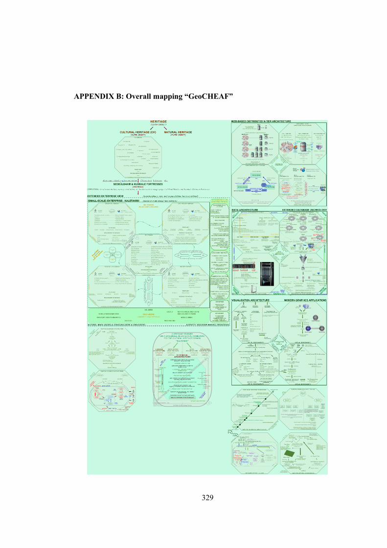
APPENDIX B: Overall mapping “GeoCHEAF”
329
BIOGRAPHY
Caner GÜNEY is a research&teaching assistant at the IGS-ISTA Satellite Observation and Processing Laboratory of the Division of Geodesy at the Istanbul Technical University (ITU), Turkey, since 1999.He is currently a PhD student in the Program of Geomatics Engineering at the ITU since 2002. He completed undergraduate in 1999, and, in 2002, received an M.Sc. in the Department of Geodesy and Photogrammery Engineering at ITU. His master thesis' title was “Multimedia Supported GIS Applications over the Internet and Geodetic Infrastructure
(Case Study: The Documentation of Cultural Heritage Resources)”. He was visiting scholar in the School of Design at the University of Pennsylvania, Philadelphia, USA, from 01.12.2004 to 01.08.2005 and Marie-Curie “Cultural Heritage Informatics Research Oriented Network (CHIRON)” research fellow in the Department of Archaeology at the University of York, UK from 03.10.2005 to 29.09.2006. He has also been working as a surveyor, GIS developer and web master in the documentation, restoration and reusage project of two 17th century Ottoman Fortresses on the Dardanelles, “Seddülbahir” and “Kumkale”. His main scientific and technical interests include the use of information and communication technologies for the area of Enterprise Architecture, Geomatics, GIS, Navigation, and Cultural Heritage as well as designing new technical approaches for these domains. His informatics skills on the web-based GIS applications, 2D/3D visualization technologies, database management systems, programming, design and modeling techniques.
E-mail: [email protected]
330