Gas Hold-Up and Mass Transfer in a Vessel with an Unsteady ...
15
Citation: Frankiewicz, S.; Woziwodzki, S. Gas Hold-Up and Mass Transfer in a Vessel with an Unsteady Rotating Concave Blade Impeller. Energies 2022, 15, 346. https://doi.org/10.3390/en15010346 Academic Editor: Moghtada Mobedi Received: 8 November 2021 Accepted: 1 January 2022 Published: 4 January 2022 Publisher’s Note: MDPI stays neutral with regard to jurisdictional claims in published maps and institutional affil- iations. Copyright: © 2022 by the authors. Licensee MDPI, Basel, Switzerland. This article is an open access article distributed under the terms and conditions of the Creative Commons Attribution (CC BY) license (https:// creativecommons.org/licenses/by/ 4.0/). energies Article Gas Hold-Up and Mass Transfer in a Vessel with an Unsteady Rotating Concave Blade Impeller Sebastian Frankiewicz and Szymon Woziwodzki * Division of Chemical Engineering and Equipment, Poznan University of Technology, 60-965 Poznan, Poland; [email protected] * Correspondence: [email protected]; Tel.: +48-616-652-147 Abstract: The steady mixing of gas-liquid systems is used where a large development of the interfacial area is required. However, the presence of gas in the liquid reduces the efficiency of mass transfer by reducing the mixing power, due to the creation of gas formations behind the impeller blades and the reduction in density. The efficiency of mass transfer can be increased by using a concave blade impeller or unsteady mixing. Mass transfer efficiency studies for these impellers and unsteady mixing are limited. This paper presents an analysis of the influence of the impeller construction on the gas hold-up and volumetric mass transfer coefficient k L a. Impellers with a different number of concave blades, and with alternatively arranged concave blades, were analyzed. The obtained results were compared with the standard flat blade turbine. The obtained results indicate that the arrangement of the concave blades has the greatest effect on reducing the gas hold-up and k L a. Higher values were obtained for the four-bladed and six-bladed impellers. A comparison of the gas hold-up rate for the unsteady and steady mixing has shown that for steady mixing greater gas hold-up is achieved. The volumetric mass transfer coefficient for unsteady mixing is also greater compared to steady mixing, indicating greater efficiency in mass transfer. Keywords: mixing; unsteady mixing; gas-liquid; gas hold-up; mass transfer 1. Introduction Mechanical mixing is the most frequently used unit operation in many industries including in chemical, food, or pharmaceutical. Mixing is carried out in single-phase and multiphase systems to intensify the mass transfer and is especially used for gases that are poorly soluble in liquids. The intensification of mass transfer is realized by increasing the interfacial area in the liquid-liquid and gas-liquid systems. It can be implemented in several ways, including by using unsteady mixing or eccentrically mounted impellers. Mixing through oscillation is used in the mass exchange processes, among others, in OBR and OBC extraction columns [1]. Ni and Gao [2] show that in the OBC column an approximately five-fold increase in the mass transfer coefficient is observed for water-air systems. The use of oscillation in fermentation also contributes to an approximately twofold increase in the mass transfer coefficient [3]. The oscillating motion can also be used during mechanical mixing. In unsteady mixing, the impeller mounted in the unbaffled vessel performs a rotary motion that changes with time. The advantage of such mixing (compared to eccentricity) is that there are no required changes in the construction of the vessel and drive system, because the impeller is mounted at the vessel axis, and changes in impeller rotation could be realized by the inverter. Today, inverters are equipped with waveform generators, and it is quite easy to set the impeller speed course. The nature of the impeller movement may be sinusoidal [4–7], triangular [8], rectangu- lar [9], or asymmetrical [10]. As a result of unsteady motion, an increase in mixing power Energies 2022, 15, 346. https://doi.org/10.3390/en15010346 https://www.mdpi.com/journal/energies
-
Upload
khangminh22 -
Category
Documents
-
view
1 -
download
0
Transcript of Gas Hold-Up and Mass Transfer in a Vessel with an Unsteady ...

�����������������
Citation: Frankiewicz, S.;
Woziwodzki, S. Gas Hold-Up and
Mass Transfer in a Vessel with an
Unsteady Rotating Concave Blade
Impeller. Energies 2022, 15, 346.
https://doi.org/10.3390/en15010346
Academic Editor: Moghtada Mobedi
Received: 8 November 2021
Accepted: 1 January 2022
Published: 4 January 2022
Publisher’s Note: MDPI stays neutral
with regard to jurisdictional claims in
published maps and institutional affil-
iations.
Copyright: © 2022 by the authors.
Licensee MDPI, Basel, Switzerland.
This article is an open access article
distributed under the terms and
conditions of the Creative Commons
Attribution (CC BY) license (https://
creativecommons.org/licenses/by/
4.0/).
energies
Article
Gas Hold-Up and Mass Transfer in a Vessel with an UnsteadyRotating Concave Blade ImpellerSebastian Frankiewicz and Szymon Woziwodzki *
Division of Chemical Engineering and Equipment, Poznan University of Technology, 60-965 Poznan, Poland;[email protected]* Correspondence: [email protected]; Tel.: +48-616-652-147
Abstract: The steady mixing of gas-liquid systems is used where a large development of the interfacialarea is required. However, the presence of gas in the liquid reduces the efficiency of mass transfer byreducing the mixing power, due to the creation of gas formations behind the impeller blades andthe reduction in density. The efficiency of mass transfer can be increased by using a concave bladeimpeller or unsteady mixing. Mass transfer efficiency studies for these impellers and unsteady mixingare limited. This paper presents an analysis of the influence of the impeller construction on the gashold-up and volumetric mass transfer coefficient kLa. Impellers with a different number of concaveblades, and with alternatively arranged concave blades, were analyzed. The obtained results werecompared with the standard flat blade turbine. The obtained results indicate that the arrangement ofthe concave blades has the greatest effect on reducing the gas hold-up and kLa. Higher values wereobtained for the four-bladed and six-bladed impellers. A comparison of the gas hold-up rate for theunsteady and steady mixing has shown that for steady mixing greater gas hold-up is achieved. Thevolumetric mass transfer coefficient for unsteady mixing is also greater compared to steady mixing,indicating greater efficiency in mass transfer.
Keywords: mixing; unsteady mixing; gas-liquid; gas hold-up; mass transfer
1. Introduction
Mechanical mixing is the most frequently used unit operation in many industriesincluding in chemical, food, or pharmaceutical. Mixing is carried out in single-phase andmultiphase systems to intensify the mass transfer and is especially used for gases that arepoorly soluble in liquids.
The intensification of mass transfer is realized by increasing the interfacial area in theliquid-liquid and gas-liquid systems. It can be implemented in several ways, including byusing unsteady mixing or eccentrically mounted impellers.
Mixing through oscillation is used in the mass exchange processes, among others, inOBR and OBC extraction columns [1]. Ni and Gao [2] show that in the OBC column anapproximately five-fold increase in the mass transfer coefficient is observed for water-airsystems. The use of oscillation in fermentation also contributes to an approximately twofoldincrease in the mass transfer coefficient [3].
The oscillating motion can also be used during mechanical mixing. In unsteady mixing,the impeller mounted in the unbaffled vessel performs a rotary motion that changes withtime. The advantage of such mixing (compared to eccentricity) is that there are no requiredchanges in the construction of the vessel and drive system, because the impeller is mountedat the vessel axis, and changes in impeller rotation could be realized by the inverter. Today,inverters are equipped with waveform generators, and it is quite easy to set the impellerspeed course.
The nature of the impeller movement may be sinusoidal [4–7], triangular [8], rectangu-lar [9], or asymmetrical [10]. As a result of unsteady motion, an increase in mixing power
Energies 2022, 15, 346. https://doi.org/10.3390/en15010346 https://www.mdpi.com/journal/energies
Energies 2022, 15, 346 2 of 15
requirements is observed. It is observed for single impeller systems i.e., Rushton turbine,Smith turbine, or PBT for Newtonian fluids (water [8] and electrolyte solutions [11,12]),as well as multi-impeller systems [13]. Unsteady mixing possesses a faster mixing ofingredients and longer mixing time in double-impeller systems [13] and single impellersystems [14], greater intensity of laminar mixing of Newtonian (shorter mixing time) forradial and axial impellers [9] and turbine-impeller systems [15]. A shortening of mixingtime is also observed for non-Newtonian fluids with yield stress [16].
The above results indicate that transient mixing can be used during gas-liquid mixing.For such systems, it is advisable to supply as much power as possible, because the presenceof gas in the liquid, as well as gas caverns, lead to a decrease in mixing power and, thus, toa reduction of the mass transfer efficiency [17].
For this reason, radial impellers with curved blades are preferred e.g., CD-6, BT-6,or Scaba 6SRGT, which achieve higher relative power requirements in comparison to aRushton turbine. This causes greater gas dispersion capacity of the impellers and gasflooding at higher gas flow rates.
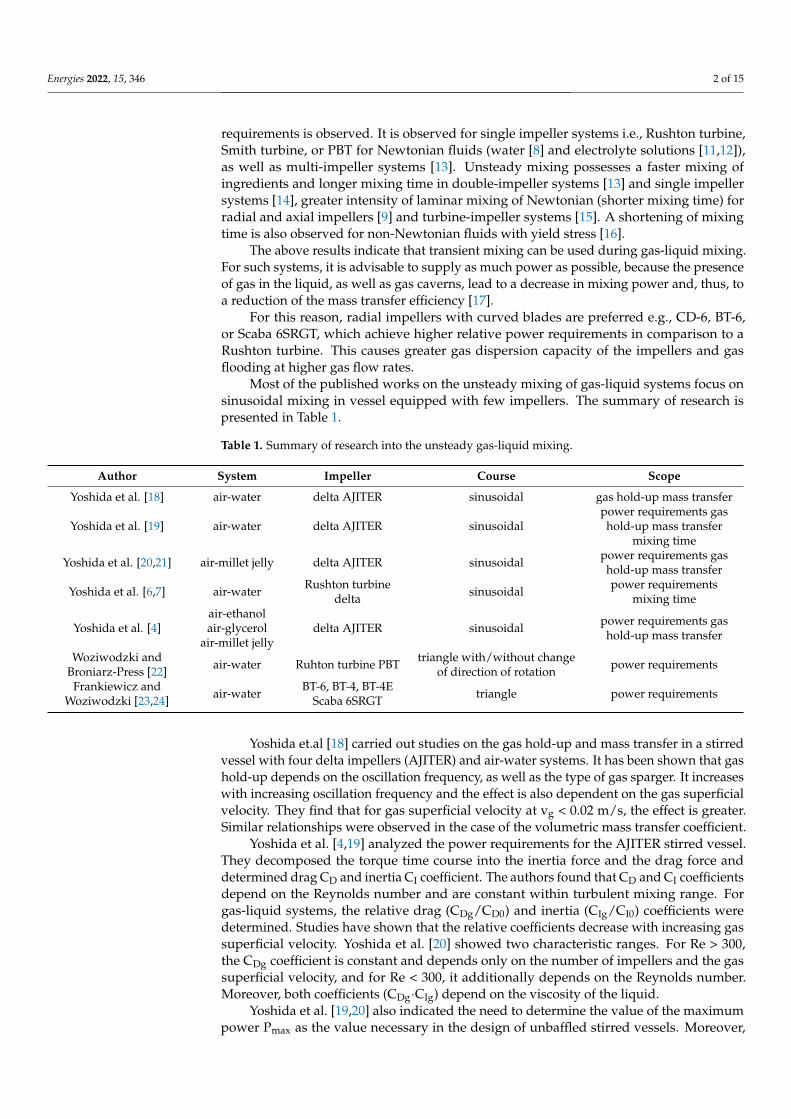
Most of the published works on the unsteady mixing of gas-liquid systems focus onsinusoidal mixing in vessel equipped with few impellers. The summary of research ispresented in Table 1.
Table 1. Summary of research into the unsteady gas-liquid mixing.
Author System Impeller Course Scope
Yoshida et al. [18] air-water delta AJITER sinusoidal gas hold-up mass transfer
Yoshida et al. [19] air-water delta AJITER sinusoidalpower requirements gashold-up mass transfer
mixing time
Yoshida et al. [20,21] air-millet jelly delta AJITER sinusoidal power requirements gashold-up mass transfer
Yoshida et al. [6,7] air-water Rushton turbinedelta sinusoidal power requirements
mixing time
Yoshida et al. [4]air-ethanolair-glycerol
air-millet jellydelta AJITER sinusoidal power requirements gas
hold-up mass transfer
Woziwodzki andBroniarz-Press [22] air-water Ruhton turbine PBT triangle with/without change
of direction of rotation power requirements
Frankiewicz andWoziwodzki [23,24] air-water BT-6, BT-4, BT-4E
Scaba 6SRGT triangle power requirements
Yoshida et.al [18] carried out studies on the gas hold-up and mass transfer in a stirredvessel with four delta impellers (AJITER) and air-water systems. It has been shown that gashold-up depends on the oscillation frequency, as well as the type of gas sparger. It increaseswith increasing oscillation frequency and the effect is also dependent on the gas superficialvelocity. They find that for gas superficial velocity at vg < 0.02 m/s, the effect is greater.Similar relationships were observed in the case of the volumetric mass transfer coefficient.
Yoshida et al. [4,19] analyzed the power requirements for the AJITER stirred vessel.They decomposed the torque time course into the inertia force and the drag force anddetermined drag CD and inertia CI coefficient. The authors found that CD and CI coefficientsdepend on the Reynolds number and are constant within turbulent mixing range. Forgas-liquid systems, the relative drag (CDg/CD0) and inertia (CIg/CI0) coefficients weredetermined. Studies have shown that the relative coefficients decrease with increasing gassuperficial velocity. Yoshida et al. [20] showed two characteristic ranges. For Re > 300,the CDg coefficient is constant and depends only on the number of impellers and the gassuperficial velocity, and for Re < 300, it additionally depends on the Reynolds number.Moreover, both coefficients (CDg·CIg) depend on the viscosity of the liquid.
Yoshida et al. [19,20] also indicated the need to determine the value of the maximumpower Pmax as the value necessary in the design of unbaffled stirred vessels. Moreover,
Energies 2022, 15, 346 3 of 15
Yoshida et al. [21] proposed correlations making the degree of gas hold-up dependent ontotal power input per unit mass, gas superficial velocity, liquid viscosity, and volumetricmass transfer coefficient from total power input per unit mass, superficial gas velocity,liquid viscosity, and liquid diffusivity. They also compared the volumetric mass transfercoefficients for standard mixers and the AJITER with unsteady mixing. They showed thata stirred vessel with several impellers, such as multiple turbine-type, helical ribbon-type,and anchor-type, achieves greater mass transfer coefficients compared to standard stirredvessels and steady mixing.
Yoshida et al. [6] also observed the behavior of the gas-liquid system in the vicinity ofthe blade of an unsteadily rotating Rushton turbine and four delta blade impeller. Underconditions of unsteady mixing, gas caverns become unstable, which contributes to anincrease in the relative power requirements in the gas-liquid system by up to 40%.
The comparison [7] of the kLa coefficients in a vessel equipped with 2–4 Rushtonturbines and delta type impellers during unsteady mixing indicates that higher masstransfer is obtained for delta impellers. Furthermore, in the case of these impellers, a greaterinfluence of the number of impellers on the kLa value is observed. Moreover, comparisonof mixing time in multiple-impeller systems, for unsteady and steady mixing, shows thatunsteady mixing time is shorter at an energy dissipation rate lower than 1 W/kg [7].
Yoshida et al. [4] also analyzed gas hold-up and mass transfer for 10% ethanol solution,glycerol (20%, 60%, and 99%), and millet-jelly solutions (50% and 80%) in the AJITERstirred vessel. They found that gas hold-up decreases with surface tension for liquidviscosity from 0.000894 Pas to 0.002 Pas and increases with surface tension in viscosityrange from 0.002 Pas to 1.18 Pas. The same relation was observed for volumetric masstransfer coefficient kLa.
Woziwodzki and Broniarz-Press [22] conducted a study of the power requirementsof an unsteady rotation Rushton turbine in unbaffled vessel. They found that the relativepower demand for a Rushton turbine is higher for unsteady mixing. They also examinedtwo various time-courses of impeller rotation: triangle with (FR) and without (F1) changein direction of the rotation. The relative power demand was smaller for F1 triangle mode.The authors also observed that above oscillation frequency f = 0.46 Hz relative powerdemand decreases.
Power requirements for unsteady rotating BT-6, BT-4, BT-4E, and Scaba 6SRGT wereconducted by Frankiewicz and Woziwodzki [23,24]. At triangle time-course of impellerspeed they observed lower relative power requirements in comparison to steady mix-ing. The results show that blade shape has a significant effect on unsteady relativepower requirements.
Most of the works on gas-liquid unsteady mixing focus on multi-impeller systems,(AJITER mixers) and sine time-course of impeller speed. A few of them concern stirredvessels equipped with a single impeller (Rushton turbine and delta impeller) and the effectof impeller type on mass transfer in unsteady mixing.
No mass transfer comparisons were made for steady and unsteady mixing. There arealso no studies on the influence of the impeller type or the blade shape on the volumetricmass transfer coefficient.
The purpose of this work is to analyze the gas-liquid mass transfer in a stirred vesselwith a single turbine impeller and unsteady mixing. The gas hold-up and volumetricmass transfer coefficient studies were carried out for vessels equipped with impellerswith various blade shapes and blades number. A comparison with steady mixing wasalso performed.
2. Experimental Set-Up
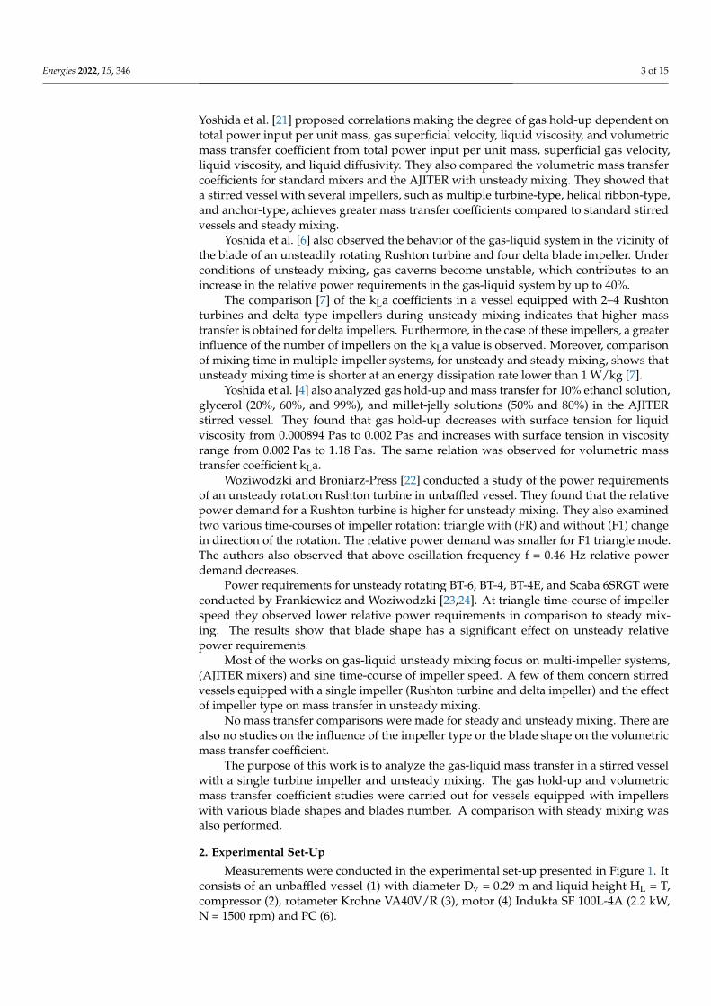
Measurements were conducted in the experimental set-up presented in Figure 1. Itconsists of an unbaffled vessel (1) with diameter Dv = 0.29 m and liquid height HL = T,compressor (2), rotameter Krohne VA40V/R (3), motor (4) Indukta SF 100L-4A (2.2 kW,N = 1500 rpm) and PC (6).
Energies 2022, 15, 346 4 of 15
Figure 1. Experimental set-up.
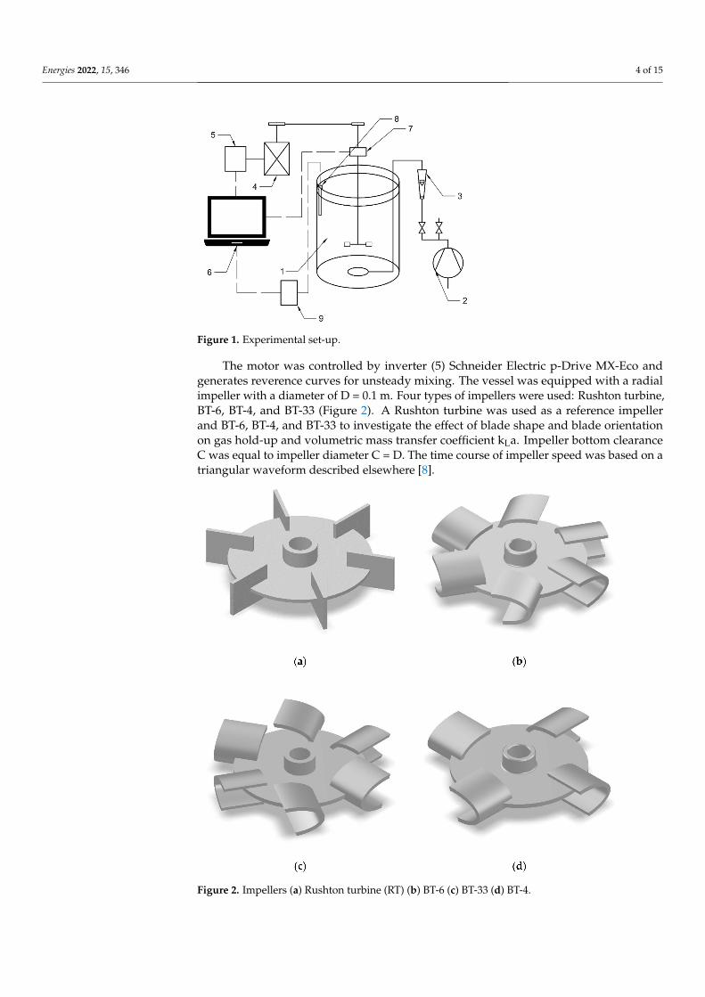
The motor was controlled by inverter (5) Schneider Electric p-Drive MX-Eco andgenerates reverence curves for unsteady mixing. The vessel was equipped with a radialimpeller with a diameter of D = 0.1 m. Four types of impellers were used: Rushton turbine,BT-6, BT-4, and BT-33 (Figure 2). A Rushton turbine was used as a reference impellerand BT-6, BT-4, and BT-33 to investigate the effect of blade shape and blade orientationon gas hold-up and volumetric mass transfer coefficient kLa. Impeller bottom clearanceC was equal to impeller diameter C = D. The time course of impeller speed was based on atriangular waveform described elsewhere [8].
Figure 2. Impellers (a) Rushton turbine (RT) (b) BT-6 (c) BT-33 (d) BT-4.
Energies 2022, 15, 346 5 of 15
Maximum impeller speed Nmax was equal to absolute value of Nmin, Nmax = |Nmin|.An impeller speed above zero, N > 0, means that the impeller rotates clockwise, while N < 0the impeller rotates in a counterclockwise direction. Oscillation frequency f of unsteadymixing was changed from 0.23 Hz to 0.92 Hz.
Measurements were performed in the air-water system. The air, from a compressor,was introduced into the vessel through ring sparger with a diameter of Ds = 0.085 m andthe distance between it and the impeller was 0.1 m (∆C = 0.1 m). The gas flow rate waschanged from 0.5 m3/h to 1.2 m3/h, which gives a superficial gas flow velocity in the rangeof 0.0021 m/s to 0.005 m/s.
The measurement of the torque and rotational frequency of the stirrer was performedusing the MT2 torque meter and the Sensor AT MW-2006-2 m adapted to work with MTtype strain gauges by SENSOR-AT and PCIN inductive sensors by SELS and others withsimilar parameters to measure the rotational speed.
The digital strain gauge measuring the torque (±2 Nm) on the vessel shaft had asampling frequency of up to 1600 Hz and a resolution of 11 bit. The accuracy of themeasurement was higher than 0.25%. The MW-2006-2 m worked with the samplingfrequency from 1 Hz to 1600 Hz for the torque measurement and from 1 Hz to 100 Hz forthe impeller speed measurements.
The Elmetron CO-505 oxygen meter and COG-1 galvanic oxygen sensors were used tomeasure the dissolved oxygen in the solution. The CO-505 oxygen meter allowed for themeasurement of the dissolved oxygen concentration in the range of 0–60 mg/L with anaccuracy of 0.1 mg/L, and for the application of temperature effect compensation in therange of 0–40 ◦C, and pressure effect in the range of 80,000–110,000 Pa.
2.1. Methods
In the paper, power requirement, gas hold-up, and volumetric mass transfer coeffi-cients, were examined.
A modified Morison equation was applied [8,25]
Ts =1
16ρC1D5CD|ω|ω+ C1
πD5ρ
16CI
dωdt
(1)
The time-course of the impeller speed was similar to a triangle wave and described bythe following equation [8,25]:
N =8π2 Nmax
(sin(2πft)− 1
9sin(6πft) +
125
sin(10πft))
(2)
The volumetric mass transfer coefficient was determined by the dynamic method bymeasuring the dissolved oxygen level in the liquid with an oxygen sensor. The sensor wasplaced about 1 cm from the vessel wall and about 12 cm below the liquid free surface. Thevolumetric mass transfer coefficient was determined using the below equation:
−kLa(t − t0) = ln((c* − ct)/(c* − c0)) (3)
where ct is instantaneous oxygen concentration, c*-equilibrium concentration of oxygen,c0-initial concentration of oxygen, a-interfacial area per volume unit.
Plotting on the right side of the above equation, a straight line is obtained, the slope ofwhich is equal to the value of the volumetric mass transfer coefficient −kLa.
The volumetric mass transfer coefficient is dependent on temperature. To reducechanges in temperature the following correction was applied [26]:
(kLa)20 = 1.02420−T(kLa)T (4)
where T-is measurement temperature, (kLa)T-mass transfer coefficient in measurementtemperature, (kLa)20-kLa in 20 ◦C.
Energies 2022, 15, 346 6 of 15
The volumetric mass transfer coefficient kLa was corrected because of the effect of thesensor time constant τ. The time constant was defined as the measurement time of 63% ofthe total oxygen concentration in the solution [27,28]:
1/kLa′ = 1/kLa + τ (5)
where kLa′ is obtained from the experiment.Before starting the measurements of dissolved oxygen, the calibration process of
the measuring electrode and the deoxygenation process with nitrogen passed througha sparger were performed. The electrode was calibrated before each measurement. Aone-point calibration was used, which consisted of measuring the oxygen in the air andsetting this value as 100% oxygen content.
After deoxygenation, gas was introduced into the impeller zone and the dissolved oxy-gen concentration in the liquid was measured according to the procedure described above.
Gas hold-up measurements were based on volumetric method and observation oflevel change in comparison to initial ungassed conditions.
2.2. States of Gas Dispersion
Gas dispersion states depend on gas loading and impeller speed and impeller diam-eter. For radial impellers three states are distinguished: flooding, loading, and completedispersion. During unsteady mixing the impeller speed was changed from Nmin up toNmax (negative value of N means opposite direction of impeller rotation).
In the experiment the state of gas dispersion was not constant, and it changed withtime. For this reason, all dispersion states were observed. It was assumed that Nmax shouldbe large enough to avoid flooding in the entire range of the impeller speed. Taking thiscriterion into account, the loading and full dispersion states were achieved.
3. Results
The experiments were comprised of two stages. In the first, the power requirementsfor the BT-33 impeller were examined; in the second, step gas hold-up and mass transferwere studied for all impellers.
3.1. Power Requirements3.1.1. Liquid Mixing
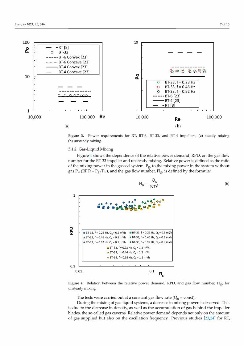
Research on the mixing power demand for the BT-6, BT-4, and RT impellers has beenpreviously published [22–24] for homogeneous systems. Figure 3 shows a comparisonof the steady mixing power (Figure 3a) and unsteady mixing power (Figure 3b) for allimpellers and the BT-33 impeller.
The power number (Po = P/(N3D5ρ)) for the BT-33 impeller is Po = 2.83 and is compa-rable with the power number for the BT-4 (convex) (Po = 2.66) and BT-6 (concave) Po = 2.6.The steady power number for the BT-6 (convex, Po = 3.78) was about 31% higher than forthe BT-33 and 48% higher than BT-4 (concave, Po = 1.91). The highest value of the powernumber was obtained for Rushton’s turbine (Po = 4.9) [8]. Figure 3b presents the power ofthe unsteady mixing. For unsteady mixing, an increase in the power demand is observed.For the BT-33 impeller, the unsteady mixing power is about 36% higher and amountsto Po = 3.86. Similar relationships were obtained for the remaining impellers [23,24]. Noeffect of the oscillation frequency on the mixing power of homogeneous systems in therange f = 0.23–0.92 Hz was observed. This indicates that the drag forces dominate theinertia forces.
The obtained results also show that changing the blade shape from straight to curvedresults in a decrease of the unsteady mixing power by 39% (BT-6) and about 23% for steadymixing. The greater drop in unsteady mixing power is related to the shape of the blade andthe direction of impeller rotation. The impeller with concave blades moves in a clockwisedirection and the convex blades move in a counter-clockwise rotation direction.
Energies 2022, 15, 346 7 of 15
Figure 3. Power requirements for RT, BT-6, BT-33, and BT-4 impellers, (a) steady mixing(b) unsteady mixing.
3.1.2. Gas-Liquid Mixing
Figure 4 shows the dependence of the relative power demand, RPD, on the gas flownumber for the BT-33 impeller and unsteady mixing. Relative power is defined as the ratioof the mixing power in the gassed system, Pg, to the mixing power in the system withoutgas Pu (RPD = Pg/Pu), and the gas flow number, Flg, is defined by the formula:
Flg =Qg
ND3 (6)
Figure 4. Relation between the relative power demand, RPD, and gas flow number, Flg, forunsteady mixing.
The tests were carried out at a constant gas flow rate (Qg = const).During the mixing of gas-liquid systems, a decrease in mixing power is observed. This
is due to the decrease in density, as well as the accumulation of gas behind the impellerblades, the so-called gas caverns. Relative power demand depends not only on the amountof gas supplied but also on the oscillation frequency. Previous studies [23,24] for RT,
Energies 2022, 15, 346 8 of 15
BT-4, BT-6, and BT-33 impellers indicate that the RPD increases with increasing oscillationfrequency. The influence of the number of blades and their shape are observed. Increasingthe number of blades from four (BT-4) to six (BT-6) reduced the oscillation frequency impact.The same applies to the shape of the blade. The use of an ellipsoidal closed blade alsoreduces the influence of the oscillation frequency [23].
Relative power is an important parameter to determine the amount of energy dissi-pated in the stirred vessel and the efficiency of mass transfer. From the point of the latter, itis advisable to use impellers that are characterized by high relative power in the range ofthe gas flow number Flg of interest. Therefore, considering the RPD, it is advisable to useimpellers with curved blades, for which the minimum relative power is about 0.65. In thecase of the straight blade (RT) impellers, the power drop is approximately 50%.
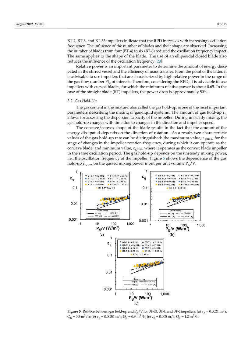
3.2. Gas Hold-Up
The gas content in the mixture, also called the gas hold-up, is one of the most importantparameters describing the mixing of gas-liquid systems. The amount of gas hold-up εgallows for assessing the dispersion capacity of the impeller. During unsteady mixing, thegas hold-up changes with time due to changes in the direction and impeller speed.
The concave/convex shape of the blade results in the fact that the amount of theenergy dissipated depends on the direction of rotation. As a result, two characteristicvalues of the gas hold-up rate can be distinguished: the maximum value, εgmax, for thestage of changes in the impeller rotation frequency, during which it can operate as theconcave blade; and minimum value, εgmin, where it operates as the convex blade impellerin the same oscillation period. The gas hold-up depends on the unsteady mixing power,i.e., the oscillation frequency of the impeller. Figure 5 shows the dependence of the gashold-up εgmax on the gassed mixing power input per unit volume Pg/V.
Figure 5. Relation between gas hold-up and Pg/V for BT-33, BT-4, and BT-6 impellers: (a) vg = 0.0021 m/s,Qg = 0.5 m3/h; (b) vg = 0.0038 m/s, Qg = 0.9 m3/h; (c) vg = 0.005 m/s, Qg = 1.2 m3/h.
Energies 2022, 15, 346 9 of 15
The gas hold-up for unsteady mixing increases with the mixing power, as well as thegas flow rate Qg. The lowest hold-up values were observed for the BT-33 impeller, whilefor the BT-4 and BT-6 impellers they were comparable. A slight influence of the oscillationfrequency was also observed, with its increase, a slight increase in the gas hold-up isobserved. Moreover, as the amount of gas increased, the differences in the gas hold-upbetween the impellers decreased, with the lowest values observed for the BT-33 impeller.Figure 5 also compares the results obtained for the unsteady mixing with the results of thegas hold-up for the steady mixing and the A315, PBT, RT, and BT-6 impellers [28–31]. Theobtained results show that for the unsteady mixing the rate of gas hold-up is greater than forthe steady mixing. Moreover, as the energy input per unit volume increases, the differencesin the gas hold-up decrease, and above 1000 W/m3, for the analyzed impellers, the gashold-up for unsteady mixing is lower than for the steady mixing in a vessel equippedwith the Rushton turbine and the BT-6 impeller [28–31]. In the case of the A315 and PBTimpellers, the advantage of unsteady mixing disappears above Pg/V = 700 W/m3.
For the obtained dependences of the gas hold-up rate, the correlation equations of thegeneral form were proposed:
εg = C1
(Pg
V
)C2
vC3g KCC4 (7)
where C1, C2, C3, C4 are constants (Table 2) and KC is Keaulegan-Carpenter number.
KC =Nmax
f(8)
Table 2. Constants in Equation (7).
Impeller C1 C2 C3 C4 R2
BT-33 0.432 0.167 0.621 −0.108 0.729BT-4 0.156 0.136 0.412 −0.029 0.931BT-6 0.204 0.111 0.439 −0.035 0.918
The Keulegan-Carpenter number is useful to consider the effect of the oscillationfrequency, as well as to determine the ranges of the inertia force and drag effect [32]. ForKC > 15, the drag force is dominant, while for KC < 4, the inertia force is the dominant one.
Equation (7) is valid in the following ranges: Pg/V ε (10; 1000) W/m3, vg ε < 0.0021;0.005 > m/s and KC ε (4; 130).
In the case of the BT-33 impeller, a greater influence of the amount of gas is observedthan in the case of the BT-4 and BT-6 impellers. This may indicate that when the blades arearranged in a concave-convex blade configuration, the gas caverns forming in the spacebetween the blades have a greater influence. In the case of the BT-4 and BT-6 impellers, theeffect is comparable and the constant C3 varies in the range from 0.412 to 0.439. Similarly,in the case of oscillation frequencies, a greater influence is observed for the BT-33 than forthe BT-4 and BT-6.
In the case of the influence of the mixing power, the constant C2 varies in the rangefrom 0.111 to 0.167 and is smaller compared to the steady mixing, for which C2 varies inthe range from 0.2 to 0.63, and C3 in the range from 0.265 to 1.95 [17,28–30,33–35].
Unsteady mixing shows less dependence on Pg/V for concave impellers. The reasonfor this is the variability of the gas hold-up and dispersion states over time.
3.3. Volumetric Mass Transfer Coefficient KLa
The volumetric mass transfer coefficient, according to Higbi’s [36] theory, depends onthe contact time between phases t, the diffusion coefficient in the liquid phase DL, and theinterfacial area a:
kLa =
√4DL
πta (9)
Energies 2022, 15, 346 10 of 15
Calderbank [37] proposed a relationship that allows for determining the interfacialarea based on the gassed power input per unit volume Pg/V, physicochemical parametersof fluids, and gas flow velocities vg:
a = 1.44
(PgV
)0.4ρ0.2
c
σ0.6
(vg
vt
)0.5(10)
where ρc, σ, vt are the density of the continuous phase, the interfacial tension, and theterminal velocity of raising up gas bubble, respectively.
It follows that the volumetric mass transfer coefficient can also be presented in theform of a dependence on the Pg/V and the superficial gas flow velocity.
Substituting Equation (10) into Equation (9) we obtain:
kLa = 1.44
√4DL
πt
(PgV
)0.4ρ0.2
c
σ0.6
(vg
vgr
)0.5(11)
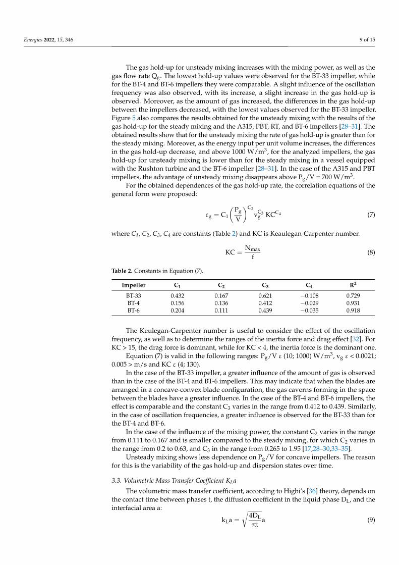
Figure 6 shows the dependence of kLa on the superficial gas flow velocity vg for theanalyzed impellers and different oscillation frequencies, as well as maximum impellerspeed Nmax. For Nmax = 5 1/s, the values of the volumetric mass transfer coefficient kLawere comparable for all impellers, regardless of the gas flow velocity vg. Larger differencesare observed for Nmax = 14 1/s. The highest efficiency of mass transfer is observed for the RTimpeller and the lowest for the BT-33 impeller. With an increase in the oscillation frequency,it was observed that the advantage of Rushton’s turbine decreased with increasing gasvelocity vg. This suggests that for gas flow velocities greater than vg = 0.0058 m/s or greateroscillation frequency, the impellers with ellipsoidal blades (BT-4 or BT-6) will show highermass transfer efficiency. The differences between the impellers also result from the fact thatat vg = const each impeller has a different gassed mixing power and RPD.
Figure 6. Relation between volumetric mass transfer coefficient kLa and superficial gas velocity vg
for BT-33, BT-4, BT-6, and RT impellers: (a) f = 0.23 Hz, (b) f = 0.46 Hz, (c) f = 0.92 Hz.
Energies 2022, 15, 346 11 of 15
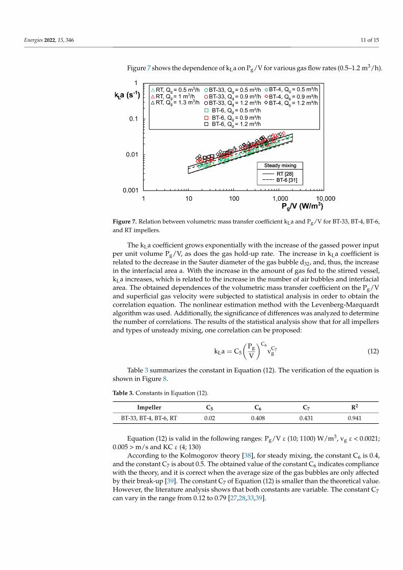
Figure 7 shows the dependence of kLa on Pg/V for various gas flow rates (0.5–1.2 m3/h).
Figure 7. Relation between volumetric mass transfer coefficient kLa and Pg/V for BT-33, BT-4, BT-6,and RT impellers.
The kLa coefficient grows exponentially with the increase of the gassed power inputper unit volume Pg/V, as does the gas hold-up rate. The increase in kLa coefficient isrelated to the decrease in the Sauter diameter of the gas bubble d32, and, thus, the increasein the interfacial area a. With the increase in the amount of gas fed to the stirred vessel,kLa increases, which is related to the increase in the number of air bubbles and interfacialarea. The obtained dependences of the volumetric mass transfer coefficient on the Pg/Vand superficial gas velocity were subjected to statistical analysis in order to obtain thecorrelation equation. The nonlinear estimation method with the Levenberg-Marquardtalgorithm was used. Additionally, the significance of differences was analyzed to determinethe number of correlations. The results of the statistical analysis show that for all impellersand types of unsteady mixing, one correlation can be proposed:
kLa = C5
(Pg
V
)C6
vC7g (12)
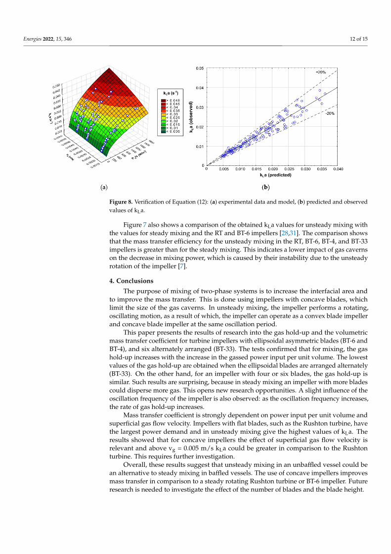
Table 3 summarizes the constant in Equation (12). The verification of the equation isshown in Figure 8.
Table 3. Constants in Equation (12).
Impeller C5 C6 C7 R2
BT-33, BT-4, BT-6, RT 0.02 0.408 0.431 0.941
Equation (12) is valid in the following ranges: Pg/V ε (10; 1100) W/m3, vg ε < 0.0021;0.005 > m/s and KC ε (4; 130)
According to the Kolmogorov theory [38], for steady mixing, the constant C6 is 0.4,and the constant C7 is about 0.5. The obtained value of the constant C6 indicates compliancewith the theory, and it is correct when the average size of the gas bubbles are only affectedby their break-up [39]. The constant C7 of Equation (12) is smaller than the theoretical value.However, the literature analysis shows that both constants are variable. The constant C7can vary in the range from 0.12 to 0.79 [27,28,33,39].
Energies 2022, 15, 346 12 of 15
Figure 8. Verification of Equation (12): (a) experimental data and model, (b) predicted and observedvalues of kLa.
Figure 7 also shows a comparison of the obtained kLa values for unsteady mixing withthe values for steady mixing and the RT and BT-6 impellers [28,31]. The comparison showsthat the mass transfer efficiency for the unsteady mixing in the RT, BT-6, BT-4, and BT-33impellers is greater than for the steady mixing. This indicates a lower impact of gas cavernson the decrease in mixing power, which is caused by their instability due to the unsteadyrotation of the impeller [7].
4. Conclusions
The purpose of mixing of two-phase systems is to increase the interfacial area andto improve the mass transfer. This is done using impellers with concave blades, whichlimit the size of the gas caverns. In unsteady mixing, the impeller performs a rotating,oscillating motion, as a result of which, the impeller can operate as a convex blade impellerand concave blade impeller at the same oscillation period.
This paper presents the results of research into the gas hold-up and the volumetricmass transfer coefficient for turbine impellers with ellipsoidal asymmetric blades (BT-6 andBT-4), and six alternately arranged (BT-33). The tests confirmed that for mixing, the gashold-up increases with the increase in the gassed power input per unit volume. The lowestvalues of the gas hold-up are obtained when the ellipsoidal blades are arranged alternately(BT-33). On the other hand, for an impeller with four or six blades, the gas hold-up issimilar. Such results are surprising, because in steady mixing an impeller with more bladescould disperse more gas. This opens new research opportunities. A slight influence of theoscillation frequency of the impeller is also observed: as the oscillation frequency increases,the rate of gas hold-up increases.
Mass transfer coefficient is strongly dependent on power input per unit volume andsuperficial gas flow velocity. Impellers with flat blades, such as the Rushton turbine, havethe largest power demand and in unsteady mixing give the highest values of kLa. Theresults showed that for concave impellers the effect of superficial gas flow velocity isrelevant and above vg = 0.005 m/s kLa could be greater in comparison to the Rushtonturbine. This requires further investigation.
Overall, these results suggest that unsteady mixing in an unbaffled vessel could bean alternative to steady mixing in baffled vessels. The use of concave impellers improvesmass transfer in comparison to a steady rotating Rushton turbine or BT-6 impeller. Futureresearch is needed to investigate the effect of the number of blades and the blade height.
Energies 2022, 15, 346 13 of 15
Author Contributions: Conceptualization, S.W.; investigation, S.F. and S.W.; writing—original draftpreparation, S.W. and S.F.; writing—review and editing, S.W. and S.F.; supervision, S.W. All authorshave read and agreed to the published version of the manuscript.
Funding: This research was funded by the Ministry of Education and Science of Poland.
Conflicts of Interest: The authors declare no conflict of interest.
Nomenclature
a interfacial area per volume unit, (m2/m3)C impeller bottom clearance, (m)c oxygen concentration, (mg/L)CD drag coefficientCI inertia coefficientD impeller diameter, (m)DL diffusion coefficient in the liquid phaseDs ring sparger diameter, (m)DV vessel diameter, (m)Flg gas flow number, Flg = Qg/(ND3ρ)f oscillation frequency, (Hz)HL liquid height, (m)KC Keaulegan-Carpenter numberkLa volumetric mass transfer coefficient, (s−1)N impeller speed, (s−1)P mixing power, (W)Po power number, Po = P/(N3D5ρ)Q flow rate, (m3s−1)Re Reynolds number, Re = ND2ρ/ηRPD relative power demand, RPD = Pg/PuT temperature, (◦C)TS torque, (Nm)t time, (s)V volume, (m3)v velocity, (m/s)Greek lettersεg gas hold-upρ density, (kg m−3)σ interfacial tension, (Nm−1)ω angular frequency, (rad s−1)Subscriptsmax maximummin minimumt instantaneous* equilibrium0 initialg gassed conditionsu ungassed conditionsc continuous phase
References1. Ni, X.; Mackley, M.R.; Harvey, A.P.; Stonestreet, P.; Baird, M.H.I.; Rama Rao, N.V. Mixing through oscillations and pulsations—a
guide to achieving process enhancements in the chemical and process industries. Chem. Eng. Res. Des. 2003, 81, 373–383.[CrossRef]
2. Ni, X.; Gao, S. Scale-up correlation for mass transfer coefficients in pulsed baffled reactors. Chem. Eng. J. Biochem. Eng. J. 1996, 63,157–166. [CrossRef]
3. Ni, X.; Gao, S.; Cumming, R.H.; Pritchard, D.W. A comparative study of mass transfer in yeast for a batch pulsed baffled bioreactorand a stirred tank fermenter. Chem. Eng. Sci. 1995, 50, 2127–2136. [CrossRef]
Energies 2022, 15, 346 14 of 15
4. Yoshida, M.; Taguchi, Y.; Yamagiwa, K.; Ohkawa, A.; Abe, M.; Tezura, S.; Shimazaki, M. Design and operation of unbaffledaerated agitated vessels with unsteadily forward-reverse rotating impellers handling viscous Newtonian liquids. J. Chem. Technol.Biotechnol. 2003, 78, 474–483. [CrossRef]
5. Yoshida, M.; Kimura, A.; Yoneyama, A.; Tezura, S. Design and operation of unbaffled vessels agitated with an unsteadilyforward–reverse rotating impeller handling solid–liquid dispersions. Asia-Pac. J. Chem. Eng. 2012, 7, 572–580. [CrossRef]
6. Yoshida, M.; Watanabe, M.; Yamagiwa, K.; Ohkawa, A.; Abe, M.; Tezura, S.; Shimazaki, M. Behaviour of gas-liquid mixtures in anunbaffled reactor with unsteadily forward-reverse rotating impellers. J. Chem. Technol. Biotechnol. 2002, 77, 678–684. [CrossRef]
7. Yoshida, M.; Akiho, M.; Nonaka, H.; Yamagiwa, K.; Ohkawa, A.; Tezura, S. Mixing and mass transfer characteristics of an unbaffledaerated agitation vessel with unsteadily forward-reverse rotating multiple impellers. Lat. Am. Appl. Res. 2005, 35, 37–42.
8. Woziwodzki, S. Unsteady mixing characteristics in a vessel with forward-reverse rotating impeller. Chem. Eng. Technol. 2011, 34,767–774. [CrossRef]
9. Takahashi, K.; Takahata, Y.; Kurisaka, K.; Sekine, H. Mixing performance experiments in an agitated vessel equipped with apitched paddle subjected to unsteady agitation. J. Chem. Eng. Jpn. 2011, 44, 852–858. [CrossRef]
10. Kato, Y.; Tada, Y.; Ban, M.; Nagatsu, Y.; Iwata, S.; Yanagimoto, K. Improvement of mixing efficiencies of conventional impellerwith unsteady speed in an impeller revolution. J. Chem. Eng. Jpn. 2005, 38, 688–691. [CrossRef]
11. Yoshida, M.; Shigeyama, M.; Hiura, T.; Yamagiwa, K.; Ohkawa, A.; Tezura, S. Liquid-Phase Mixing in an Unbaffled AgitatedVessel with an Unsteady Forward-Reverse Rotating Impeller. Asia-Pac. J. Chem. Eng. 2007, 2, 659–664. [CrossRef]
12. Yoshida, M.; Wakura, Y.; Yamagiwa, K.; Ohkawa, A.; Tezura, S. Liquid Flow Circulating within an Unbaffled Vessel Agitated withan Unsteady Forward-Reverse Rotating Impeller. J. Chem. Technol. Biotechnol. 2010, 85, 1017–1022. [CrossRef]
13. Yoshida, M.; Taguchi, Y.; Yamagiwa, K.; Ohkawa, A.; Abe, M.; Tezura, S.; Shimazaki, M. Mixing Characteristics of Liquid Phase inan Unbaffled Vessel Agitated by Unsteadily Forward-Reverse Rotating Multiple Impellers. Lat. Am. Appl. Res. 2004, 34, 35–40.
14. Yoshida, M.; Nagai, Y.; Yamagiwa, K.; Ohkawa, A.; Tezura, S. Turbulent and Laminar Mixings in an Unbaffled Agitated Vesselwith an Unsteadily Angularly Oscillating Impeller. Ind. Eng. Chem. Res. 2009, 48, 1665–1672. [CrossRef]
15. Woziwodzki, S. Mixing of Viscous Newtonian Fluids in a Vessel Equipped with Steady and Unsteady Rotating Dual-TurbineImpellers. Chem. Eng. Res. Des. 2014, 92, 435–446. [CrossRef]
16. Woziwodzki, S.; Broniarz-Press, L. Mixing of Shear-Thinning Fluid with Yield Stress in a Vessel with Unsteadily Rotating Impeller.In Proceedings of the 14th European Conference on Mixing, Warsaw, Poland, 10 September 2012; pp. 515–521.
17. Middleton, J.C.; Smith, J.M. Gas-liquid mixing in turbulent systems. In Handbook of Industrial Mixing. Science and Practice; Paul,E.L., Atiemo-Obeng, V., Kresta, S.M., Eds.; John Wiley & Sons: Hoboken, NJ, USA, 2004; pp. 585–635.
18. Yoshida, M.; Kitamura, A.; Yamagiwa, K.; Ohkawa, A. Gas hold-up and volumetric oxygen transfer coefficient in an aeratedagitated vessel without baffles having forward-reverse rotating impellers. Can. J. Chem. Eng. 1996, 74, 31–39. [CrossRef]
19. Yoshida, M.; Yamagiwa, K.; Ohkawa, A.; Takahashi, K.; Shimazaki, M.; Abe, M. Torque of drive shaft with unsteadily rotatingimpellers in an unbaffled aerated agitation vessel. Mater. Technol. 1999, 17, 19–31.
20. Yoshida, M.; Ito, A.; Yamagiwa, K.; Ohkawa, A.; Abe, M.; Tezura, S.; Shimazaki, M. Power characteristics of unsteadily forward-reverse rotating impellers in an unbaffled aerated agitated vessel. J. Chem. Technol. Biotechnol. 2001, 76, 383–392. [CrossRef]
21. Yoshida, M.; Yamagiwa, K.; Ito, A.; Ohkawa, A.; Abe, M.; Tezura, S.; Shimazaki, M. Flow and mass transfer in aerated viscousNewtonian liquids in an unbaffled agitated vessel having alternating forward-reverse rotating impellers. J. Chem. Technol.Biotechnol. 2001, 76, 1185–1193. [CrossRef]
22. Woziwodzki, S.; Broniarz-Press, L. Power characteristics of unsteadily rotating rushton turbine in aerated vessel. Tech. Trans.2014, 2-Ch, 155–164.
23. Frankiewicz, S.; Woziwodzki, S. Effect of Blade Shape on Unsteady Mixing of Gas-Liquid Systems. In Practical Aspects ofChemical Engineering; Lecture Notes on Multidisciplinary Industrial Engineering; Springer: Cham, Switzerland, 2018; pp. 127–136,ISBN 978-3-319-73977-9.
24. Frankiewicz, S.S.; Woziwodzki, S. Gas-Liquid Mixing in an Unbaffled Vessel with a Forward-Reverse Rotating Scaba Impeller.In Practical Aspects of Chemical Engineering; Ochowiak, M., Woziwodzki, S., Mitkowski, P.T., Doligalski, M., Eds.; SpringerInternational Publishing: Cham, Switzerland, 2020; pp. 79–88, ISBN 978-3-030-39867-5.
25. Woziwodzki, S. Application of Morison Equation in Unsteady Mixing Characteristics. In Practical Aspects of Chemical Engineering;Ochowiak, M., Woziwodzki, S., Mitkowski, P.T., Doligalski, M., Eds.; Springer International Publishing: Cham, Switzerland, 2020;pp. 491–499, ISBN 978-3-030-39867-5.
26. Bouaifi, M.; Roustan, M. Bubble size and mass transfer coefficients in dual-impeller agitated reactors. Can. J. Chem. Eng. 1998, 76,390–397. [CrossRef]
27. Kiełbus-Rapała, A.; Karcz, J. Mass transfer in multiphase mechanically agitated systems. In Mass Transfer in Multiphase Systemsand Its Applications; El-Amin, M., Ed.; InTech: London, UK, 2011; ISBN 978-953-307-215-9.
28. Van’t Riet, K. Review of measuring methods and results in nonviscous gas-liquid mass transfer in stirred vessels. Ind. Eng. Chem.Process. Des. Dev. 1979, 18, 357–364. [CrossRef]
29. Bakker, A. Hydrodynamics of Stirred Gas-Liquid Dispersions; Technische Univesiteit Delft: Delft, The Netherlands, 1992.30. Chapman, C.M.; Nienow, A.W.; Cooke, M.; Middleton, J.C. Particle-gas-liquid mixing in stirred vessels. Part II: Gas-liquid mixing.
Chem. Eng. Res. Des. 1983, 61, 82–95.
Energies 2022, 15, 346 15 of 15
31. Zheng, Z.; Sun, D.; Li, J.; Zhan, X.; Gao, M. Improving oxygen transfer efficiency by developing a novel energy-saving impeller.Chem. Eng. Res. Des. 2018, 130, 199–207. [CrossRef]
32. Sarpkaya, T. Wave Forces on Offshore Structures; Cambridge University Press: Cambridge, NY, USA, 2010.33. Jesus, S.S.; Santana, A.; Filho, R.M. Hydrodynamic and mass transfer study in a mechanically stirred hybrid airlift bioreactor
based on impeller type. Int. J. Chem. Eng. Appl. 2014, 5, 41–45. [CrossRef]34. Vasconcelos, J.M.T.; Orvalho, S.C.P.; Rodriguez, A.M.A.F.; Alvez, S.S. Effect of blade shape on the performance of six-bladed disk
turbine impellers. Ind. Eng. Chem. Res. 2000, 39, 203–213. [CrossRef]35. Woziwodzki, S.; Broniarz-Press, L.; Radecki, R. Mieszanie układów ciecz-gaz w mieszalniku z mieszadłem A310 wykonujacym
ruch nieustalony. Inz. Apar. Chem. 2015, 54, 364–365.36. Higbie, R. The Rate of Absorption of a Pure Gas into a Still Liquid during Short Periods of Exposure. Trans. AIChE 1935, 31, 365–389.37. Calderbank, P.H. Physical rate processes in industrial fermentation. Part I: The interfacial area in gas-liquid contacting with
mechanical agitation. Chem. Eng. Res. Des. 1958, 36, 443–463.38. Kolmogorov, A.N. On the Disintegration of Drops in a Turbulent Flow. Dokl. Akad. Nauk SSSR 1949, 66, 825–828.39. Martín, M.; Montes, F.J.; Galán, M.A. Physical explanation of the empirical coefficients of gas-liquid mass transfer equations.
Chem. Eng. Sci. 2009, 64, 410–425. [CrossRef]