WORKHOLDING SOLUTIONS - Support, Locate and Hold
292
-
Upload
khangminh22 -
Category
Documents
-
view
0 -
download
0
Transcript of WORKHOLDING SOLUTIONS - Support, Locate and Hold


www.jergensinc.com
What started as a simple
component-based business has
grown into a full workholding
solutions line that includes
engineered products to help
customers implement lean
manufacturing programs.
Whether you’re looking for a
full line of tooling and locating
components, vises, power
clamps or quick change fixturing
solutions, Jergens has the
products you need. We back
up our products with a quality
guarantee, and engineering
assistance to help you with your
application challenges.
Support, Locate and Hold: Jergens Workholding Solutions has all the standard components you need, plus vises and innovative quick change fixturing systems to help you maximize your machine uptime.
WORKHOLDING SOLUTIONS
QUICK CHANGE FIXTURING .................................. 5–64
Jergens is the world leader in quick change fixturing systems that help you maximize efficiency and uptime. These productivity-boosting systems include the Ball Lock® Mounting System, Bock Brand Quick Change Fixturing System, the Zero Point System, and the Fixture Pro® 5-Axis Quick Change Fixturing System.
PRODUCTION VISES ...................................................... 65–126
With quick-change, machinable jaws and other time-saving features, Jergens vises can integrate with Ball Lock® and Bock DexLoc™ to dramatically reduce set up times. Our entire vise line was designed to help you machine more efficiently, saving you time and money on HMCs, VMCs, and 5-axis machines.
POWER CLAMPING ....................................................... 127–194
Durable, reliable clamping solutions from Jergens provide cost-effective performance, with a wide selection of boosters, clamps, cylinders, pumps, swing cylinders, hydraulic controls, and more.
LOCATING COMPONENTS .................................195–224
Whether you’re building your own fixtures or customizing existing workholding devices, Jergens has all the locating components you need to ensure fast, accurate locating.
WORKHOLDING COMPONENTS ...............225–293
With one of the largest selections of workholding components available, Jergens has everything you need to design and build fixtures, jigs, and other workholding devices.

3Phone: 877-426-2504 | Fax: +1 216-481-6193 | E-mail: [email protected] | www.jergensinc.com
COMPANY INFORMATION
CO
MP
AN
Y I
NF
OR
MA
TIO
N
Jergens Company Profile
Jergens Inc. was founded in 1942 by Jack Schron, Sr. and his father Christy, to provide standard components for building jigs and fixtures. Today the fourth generation of family involvement continues stronger than ever. Throughout it’s sixty-year history the company has grown into four separate operating divisions: Tooling Component Division (TCD), Jergens Industrial Supply (JIS), Acme Industrial Company (AIC), and Advanced Systems Group (ASG) Division of Jergens. While all divisions are vital to the Jergens family, the TCD Division is the centerpiece of our manufacturing capabilities. In June 1999, Jergens moved into a new 110,000 square foot facility and prides itself by manufacturing over 80% of it’s product offering, as well as setting the standard for producing the highest quality components in our industry.
Since our founding Jergens, Inc. has grown to comprise 3 distinct business units: Workholding Solutions, Lifting Solutions and Specialty Fasteners. Building on its reputation of uncompromising quality standards, Jergens is committed to helping its customers achieve leaner, more profitable manufacturing, and continues to add products and engineered solutions for an integrated approach to “Manufacturing Efficiency.”
Today, you’ll find our tooling components, fasteners and hoist rings at work in just about every industry on every continent. And our innovative Quick Change
Workholding Solutions like Ball Lock® Mounting System have changed the way manufacturers worldwide think about productivity.
Additionally, we offer a wide range of metalworking tools, clamps, and supplies to manufacturers in Northeastern Ohio, through our JIS Division. Acme Industrial, located in Carpentersville, Illinois, is a premium manufacturer of precision drill bushings and keylocking thread inserts. Our ASG Division specializes in products for light assembly ranging from torque-controlled electric screwdrivers to automation systems.
In addition to our unique product designs, we lead the industry with unparalleled customer service and delivery. Our website is a good example of our commitment to be the most innovative company in our industry. Customers and distributors can check stock and order on-line, view the Jergens catalog, and even download 2D, 3D and solid model CAD drawings in a variety of formats. Visit our website at www.jergensinc.com for the latest news and product information, as well as links to our other divisions. The Jergens family thanks you for your business.

Jergens, Inc. | 15700 S. Waterloo Road | Cleveland, Ohio 44110-3898 USA4
COMPANY INFORMATION
CO
MP
AN
Y IN
FO
RM
AT
ION
Distribution of Jergens Products Jergens is proud to be represented by a network of qualified distributors throughout the world. If you do not know the name of the distributor nearest you, please call Jergens Customer Service at 1-877-486-1454 or visit www.jergensinc.com.
Quality Policy Jergens, Inc. manufactures and supplies only quality products. Our quality system is ISO 9001: 2008 Certified. Center-Pull and Side-Pull Hoist Rings are CE Certified. If there is a problem with any of our products, please contact your local Jergens Distributor or contact our Customer Service Department.
Design AidsJergens, Inc. offers several CAD drawing formats for use in fixture design. Our Fixture Pro® software is available on CD. Our internet site (www.jergensinc.com) offers our complete catalog with hot links to CAD drawings on most of our products. We also offer 3D solid models of our products via the internet.
Application AssistanceJergens Inc. maintains a complete Technical Sales Department to work with you. Please feel free to call upon their knowledge and experience. Application videos are available for the Ball Lock® Mounting System, 5-Axis Fixture Pro®, Spinner-Grip™ Flange Nuts, and Hydraulic Vise Column products at www.jergensinc.com or www.youtube.com/users/jergensinc.
Engineering Changes Product improvement is a continuing process at Jergens, Inc. Specifications and engineering data are subject to change without notice. If current information is critical to your design, it is suggested that you contact the Jergens Customer Service Department, or download the most current drawing from our website*, to verify any dimensions or specifications.
Bar CodingJergens’ boxed and bagged products are fully bar coded for automatic identification. The bar code labels contain the ASCII Code 39 format, which was chosen as being suitable for most bar code readers. Jergens’ bar codes will identify part numbers and manufacturer’s codes.
Specials Jergens, Inc. will modify any item that is similar to our standard component parts. Please contact your Jergens Distributor with your request for a quote. Prints or sketches should be furnished if possible.
TCMA StandardsProducts throughout this catalog meet the standards of the Tooling Component Manufacturers’ Association. The items are asterisked and are interchangeable with other tooling component manufacturer’s products.
Material and Finish SpecificationsStressproof®: A severely cold worked, furnace treated steel bar. Produced by a LaSalle patented process to obtain high strength, free machinability, good wear, and minimum warpage in the bar.
Alloy Steel - 4140 or equivalent
Low Carbon Steel - Free Machining 1215, 1018, or equivalent
52100: QQS-624
Zinc Plate: ASTM B633, Type III, Class FE/ZN 5
Cadmium Plate: AMS-QQ-P-416, Class 3, Type 1
Black Oxide: MIL-DTL-13924 and AMS-2485
Black Anodize: per Mil. Spec. MIL-A-8625, Type II, Class 2 and AMS-2472
Passivate: AMS 2700
Alternate Finishes available upon request.
* 3D Solid Models are available in multiple formats from www.jergensinc.com Jergens, Inc.
Manufacturing Number: 697830FSCM #94882
ISO 9001: 2008Registration #00010133

5
Ball Lock® Mounting System (Inch)
Ball Lock® for Rotary Indexers ...............................20–21Ball Lock® Accessories ................................................... 24Commonly Asked Questions About the Ball Lock®
Mounting System ..................................................... 8–9Fast Acting Ball Lock® Shanks ...................................... 24Fixture Kits for HAAS ..................................................... 18Fixture Plates ....................................................................13Fixture Plates for Multi-Purpose Subplates .............. 10Fixture Plates for Tooling Columns ............................. 16Jigsaw Interlocking Plates .............................................11Liners ................................................................................ 23Modular Grid Fixture Plates ..........................................11Multi-Purpose Subplates .............................................. 10Quick Change Kits ...........................................................17Receiver Bushings .......................................................... 23Repair Kits ........................................................................ 22Set-Up Reduction Worksheet ...................................... 19Shanks .............................................................................. 22Subplates ..........................................................................12Subplates for Tooling Columns ................................... 16Tooling Columns, 4 sided .............................................. 15Tooling Columns, T-Columns ....................................... 14
Ball Lock® Mounting System (Metric)
Ball Lock® for Rotary Indexers ...............................33–34Ball Lock® Accessories ................................................... 37Fast Acting Ball Lock® Shanks ...................................... 37Fixture Plates ................................................................... 28Fixture Plates for Multi-Purpose Subplates .............. 26Fixture Plates for Tooling Columns ............................. 32Jigsaw Interlocking Plates ............................................ 26Liners ................................................................................ 36Modular Grid Fixture Plates ......................................... 26Multi-Purpose Subplates .............................................. 25Quick Change Kits .......................................................... 29Receiver Bushings .......................................................... 36
Repair Kits ........................................................................ 35Shanks .............................................................................. 35Subplates ......................................................................... 27Subplates for Tooling Columns ................................... 32Tooling Columns, 4 sided .............................................. 31Tooling Columns, T-Columns ....................................... 30
Zero Point Mounting System
Clamping Bracket ........................................................... 50Pull Studs & Engagement Screws ......................... 44–45Clamping Plates .............................................................. 43Clamping and Positioning ............................................ 42Flange Type Installation Module ................................. 51Horizontal Rapid-Clamping Cylinder ......................... 52Threaded Clamping Module ................................. 46–47Raised/Mounted Clamping Module .................... 48–49System Overview ......................................................38–41
Fixture Pro® 5-Axis Quick Change Fixturing
Bushings, QLS (Quick Lock System) ............................ 64Chip Plug, QLS (Quick Lock System) ........................... 64Fixture Plates, Blank ...................................................... 60Locating Keys .................................................................. 62Locating Pins ................................................................... 63Machinable Blanks, Steel .............................................. 60Pallet Changers, Drop & Lock™ .................................... 62Risers, Aluminum & Steel ........................................57–58Shoulder Screws, QLS (Quick Lock System)............... 64Subplates ......................................................................... 57Top Plates, Riser .............................................................. 59Top Tooling, Dovetail Vises .......................................... 61System Overview ......................................................53–56
QUICK CHANGE FIXTURING
QU
ICK
CH
AN
GE
FIX
TU
RIN
G

Jergens, Inc. | 15700 S. Waterloo Road | Cleveland, Ohio 44110-3898 USA6
WORKHOLDING SOLUTIONS GROUP
BALL LOCK® MOUNTING SYSTEM
QU
ICK
CH
AN
GE
FIX
TU
RIN
G »
BA
LL
LO
CK
® MO
UN
TIN
G S
YS
TE
M
We Put It All Together… In Seconds.
Maximize productivity levels and dramatically increase throughput with Ball Lock®.
The Ball Lock® Mounting System is used as a Quick Change Solution on the following:
• CNC Machines
• Palletized Fixtures
• Stamping
• Fabricating
• Injection Molding
• Packaging Machines
• Assembly Machines
• EDM
• Robotics
• Welding Fixtures
Looking to realize the full benefits of lean manufacturing? Then you need the one system that puts it all together, so you can put it all together…and that’s Ball Lock®.
Ball Lock® is the industry’s most popular quick-change, fixturing-flexible mounting system that can be configured to create lean-optimized solutions for your most demanding needs.

7Phone: 877-426-2504 | Fax: +1 216-481-6193 | E-mail: [email protected] | www.jergensinc.com
WORKHOLDING SOLUTIONS GROUP
BALL LOCK® MOUNTING SYSTEM
QU
ICK
CH
AN
GE
FIX
TU
RIN
G »
BA
LL
LO
CK
® M
OU
NT
ING
SY
ST
EM
Accurately Locate and Lock Fixture Plates to Subplates in Seconds… With No Indicating Required.
Previous Set Up Method:Located part with dowel pins, bolted part to tomb-stone fixture. Indicated part to zero datum point.
Set Up Using Ball Lock® System:Mount parts to fixture plate while machining other parts. Mount fixture plate to tombstone using Ball Lock® shanks. No indicating required because system provides +0.0005 (±0.013mm)repeatability.
Previous Set-Up Time:15 minutes
Set Up Time With Ball Lock® System:60 seconds
Drilling and reaming forged part.
Previous Set Up Method:Fixture plate located with dowel pins bolted to machine base. Fixture plate and parts indicated.
Set Up Using Ball Lock® System:Parts are pre-mounted on fixture plate, which is then mounted to machine base using Ball Lock®
shanks. No need to indicate.
Previous Set Up Time:7 minutes
Set Up Time with Ball Lock® System:60 seconds
Drilling and tapping cylindrical bodies.
Previous Set Up Method:Fixture located and bolted to tombstone. Had to be indicated.
Set Up Using Ball Lock® System:Fixture plate mounted and located with Ball Lock®
shanks. No need to indicate.
Previous Set Up Time:12 minutes
Set Up Time with Ball Lock® System:45 seconds
Machining aircraft valve parts
Previous Set Up Method:New Project. New Machine.No Prior History.
Set Up Using Ball Lock® System:Using Ball Lock® Jig Saw Plate on Multi-Purpose Subplate enables operator to mount two more vises on the fixture. No indicating needed.
Previous Set Up Time: New Set Up.
Set Up Time With Ball Lock® System: 80 seconds setting up six vises.
Lean Manufacturing and Set Up Reduction Applications
Machining Cast Part
CNC Machine Base:
CNC Vertical Machining Center
Two-Sided Tombstone

Jergens, Inc. | 15700 S. Waterloo Road | Cleveland, Ohio 44110-3898 USA8
WORKHOLDING SOLUTIONS GROUP
BALL LOCK® MOUNTING SYSTEM
QU
ICK
CH
AN
GE
FIX
TU
RIN
G »
BA
LL
LO
CK
® MO
UN
TIN
G S
YS
TE
M
LocatesThe Ball Lock® System accurately positions your fixtureplate with a repeatability of ±0.0005" (±0.013mm) or better, minimizing the need to indicate your fixture.
The Ball Lock® Mounting System is designed to speed the accurate locating and locking of fixture plates to subplates. The system consists of three parts: a Locating Shank, a Liner Bushing, and a Receiver Bushing. Using the Ball Lock® Mounting System is a simple process: Install a subplate with receiver bushings on your machine table; add your fixture plate with two locating liner
bushings; then insert two locating shanks through the liners and into the receiver bushings to provide accurate location. 21/2 turns of the set screw in each of the locating shanks provides positive holding force. Additional Ball Lock® Shanks are inserted through clearance holes in the fixture plate and set screws tightened for additional holding force distributed across
the fixture plate.It is recommended that the use of
the Ball Lock® Mounting System for locating and clamping of fixture plates be incorporated in a systematic process. All fixture plates should have two locating points positioned as far apart as possible. There is no advantage to having more than two
LocksThe Ball Lock® System securely holds fixture plates to subplates with up to 20,000 lbs. (9000 Kg) of hold-down force per shank.
The Ball Lock® Mounting System provides a method of quickly and accurately locating fixtures onto machine tables. The Ball Lock® Mounting System has done for machining centers what the Japanese SMED concept did for presses. Instead of single minute exchange of dies, Ball Lock® provides single minute exchange of fixtures. Fixtures can often be exchanged in less than a minute and with position repeatability of ±0.0005" (±0.013mm). Fixtures can be exchanged between different machines when both are using the Jergens Ball Lock® Mounting System.
Commonly Asked Questions
Q. What is the Ball Lock® Mounting System?A. It is a means of locating and locking two flat surfaces together, normally a fixture plate and a sub-plate.
Q. How does it locate?A. Similar to locating pins, two Ball Lock® shanks (pins) pass through two precision liner bushings on the fixture plate and into two precision receiver bushings on the subplate.
Q. How does it lock?A. Inside the shank are three balls that expand into a tapered groove in the receiver bushing. This action draws the plates together. The locking balls are activated by turning a setscrew in the head of the shank, which pushes a 4th ball to distribute the clamping forces between the 3 locking balls.
Q. How many shanks are required to locate and lock each fixture?A. Only two shanks, passing through bushings in the fixture plates, are required for location. However,additional shanks passing through clearance holes in the fixture plate will provide additional holding force distributed across the plate.

Back Mount Bushing
Ball Lock®
Shank
Fixture Plate
Liner BushingBall Lock®
Shank Liner Bushing
SubplateDrilled Hole
Slip Fit Hole Press Fit Hole Socket Head Cap Screws (3)
Face Mount Bushing
Fixture Plate
Mounting Method With Back Mount Bushing
Mounting Method With Face Mount Bushing
Counter-Bored Hole
Machine Table or Subplate
9Phone: 877-426-2504 | Fax: +1 216-481-6193 | E-mail: [email protected] | www.jergensinc.com
WORKHOLDING SOLUTIONS GROUP
BALL LOCK® MOUNTING SYSTEM
QU
ICK
CH
AN
GE
FIX
TU
RIN
G »
BA
LL
LO
CK
® M
OU
NT
ING
SY
ST
EM
locating points. If more than two flanged shanks are required to provide additional hold- down force, omit liner bushings in the additional holes in the fixture plate and allow 0.030" (0.76mm) over the nominal size. The additional clearance will insure that these holes have no influence on the locating holes.
How accurate should positioning be?The center distance of the receiver bushings in the machine table, tombstone, or subplate should be as accurate as possible ±0.0002" (±0.005mm) recommended. Accurate location will assure interchangeability of numerous fixture plates. For accurate repeatability
within ±0.0005" (±0.013mm) of true position, both liner bushings in the fixture plate should be primary liners and the center distance tolerance should be ±0.0002" (±0.005mm). For a slightly looser fit, repeatability within 0.0015" (0.04mm) of true position, use one primary and one secondary liner with a center distance tolerance of ±0.001" (±0.003mm).
Q. Is there a preferable location for the liner bushing?A. System repeatability is improved if the liners are located at opposite corners of a rectangular fixture plate. For consistency, we recommend locating the liner bushings at top left and bottom right.
Q. What are the advantages of using the Ball Lock® System over the conventional method of dowelpins and cap screws?A. Both locating and locking are accomplished in the same motion. Ball Lock® shanks require only 2.5 turns to lock a 1/2–13 (M12) screw
with ¾" (18mm) of thread engagement require 10 turns to lock. On CNC machines, the repeatability of fixture locations makes indicating of the fixture unnecessary.
Q. How do I recess the fixtureplate for a clear surface ?A. Counterbore the fixture plate to a diameter large enough to allow easy removal of the shank. Note: The thickness of the plate section under the head of the shank is critical and must conform to mounting instructions .
Q. What if my plate is thinner than the recommended thickness?A. By adjusting the depth of the counterbore for the receiver bushing in the subplate, you can still use the Ball Lock® System. If there are any questions on this type of application, please call 1-877-426-2504.
Q. Can I use the shanks in a heated environment?A. The shank is made of alloy steel, heat treated to 40-45 Rc and should with stand temperatures up to 400°F.(200°C).Note: Thermal expansion of fixture plates may affect the center distance tolerance and repeatability.

28706
28801
49406
28719
28713 or 28715
28727
49112
17.0000
12.0000
17.0000
12.0000
17.0000
20
40
12.0000
8.0000
(8) 25MM FACE MOUNT BUSHINGSINSTALLED
(18) 20MM FACE MOUNT BUSHINGSINSTALLED
5/8" BORED HOLEFOR SINE FIXTURE KEYS(2) PLACES
6.0000
8.00008.00008.0000
Jergens, Inc. | 15700 S. Waterloo Road | Cleveland, Ohio 44110-3898 USA10
WORKHOLDING SOLUTIONS GROUP
BALL LOCK® MOUNTING SYSTEM
QU
ICK
CH
AN
GE
FIX
TU
RIN
G »
BA
LL
LO
CK
® MO
UN
TIN
G S
YS
TE
M
INCH FIXTURE/SUBPL ATES
The Jergens Multi-Purpose Subplate accommodates a wide variety of fixture plates and vises. This versatility facilitates using the same VMC for diverse products in repetitive runs, long and short batch sizes.
Multi-Purpose Subplates
• FreMax™ 15 Steel or Equivalent• Thickness: 1 1/4" ±0.005"• Parallel within 0.001"
Part Number Wt. (lbs) 49112 285
40x20 Multi-Purpose Subplate
Fixture Plate Options for Multi-Purpose Subplates – Aluminum or Steel
* See next page for dimensional data on fixture plates. Part numbers shown for aluminum plates, also available in steel.** Counterbored to 1" at mounting holes.
Number of Fixture Receiver Required Number Plates/Vises That Mount Bushing Receiver Ball Lock® of Shanks Fixture Plate*/Vise Thickness of on Multi-Purpose Center Bushing Shank Required Per Part Number Fixture Plate Subplate Distance Size Part Number Fixture Plate/Vise
28713 (14 x 14) 3/4" 2 12 x 12 20 mm 49601 4Fixture Plate
28715 (16 x 16) 3/4" 2 12 x 12 20 mm 49601 4Fixture Plate
28801 (16 x 16) 1 1/8"** 2 12 x 12 20 mm 49602 4Modular Grid Plate
28706 Jigsaw 3/4" 4 8 x 12 20 mm 49601 3 Interlocking Plate
28727 (20 x 20) 1" 2 17 x 17 25 mm 49612 4Fixture Plate
28719 (20 x 16) 3/4" 1 16 x 12 20 mm 49601 4Fixture Plate
49406 3/4" 4 8 x 12 20 mm 49601 36" Jigsaw Base Vise

A
B
D
12.0000
Clearance hole for holddown
6.0000
C
(2) 20mm Primary Liners Installed
Clearance holes for holddown (2) places
6.000
12.00005/8" Bored hole for sine fixture keys (2) places
12.000012.0000
12.0000
12.0000
1.50TYP
16.0000
16.0000
CLEARANCE HOLESFOR HOLDDOWN(2) PLACES
(2) 20MMPRIMARY LINERSINSTALLED
COUNTERBORE
1/2-13TAPPED HOLE
.625 x .25 Deep-0.000+0.0005
12.0000
12.0000
1.50TYP
16.0000
16.0000
CLEARANCE HOLESFOR HOLDDOWN(2) PLACES
(2) 20MMPRIMARY LINERSINSTALLED
COUNTERBORE
1/2-13TAPPED HOLE
.625 x .25 Deep-0.000+0.0005
17.0000
17.0000
(2) 25mm Primary Liners Installed
Clearance holes for holddown (2) places
5/8" Bored hole for sine fixture key(2) places
8.500
(2) 20mm Primary Liners Installed
Clearance hole for holddown
11Phone: 877-426-2504 | Fax: +1 216-481-6193 | E-mail: [email protected] | www.jergensinc.com
WORKHOLDING SOLUTIONS GROUP
BALL LOCK® MOUNTING SYSTEM
QU
ICK
CH
AN
GE
FIX
TU
RIN
G »
BA
LL
LO
CK
® M
OU
NT
ING
SY
ST
EM
INCH FIXTURE/SUBPLATES
Fixture Plates for Multi-Purpose Subplate
Jigsaw Interlocking Fixture Plate
14x14x3/4" Fixture Plate
Aluminum Plate Part Number Wt. (lbs)
28713 14
20x20x1" Fixture Plate
• Cast Aluminum or FreMax™ 15 Steel or equivalent• Thickness: 1" ±0.005"• Parallel within 0.001" Steel• Mounts to subplates with Ball Lock® Shank 49612 (25 x 1")
16x16 Modular Grid Fixture Plate
• FreMax™ 15 Steel or equivalent• Thickness: 1 1/8" ±0.005"• Parallel within 0.001"• Mounts to subplates with Ball Lock®
Shank 49602 (20 x 1")
16x16x3/4" Fixture Plate
Steel Plate Part Number Wt. (lbs)
28813 42
Aluminum Plate Part Number Wt. (lbs)
28715 18
Steel Plate Part Number Wt. (lbs)
28815 55
Steel Plate Part Number Wt. (lbs)
28801 80
Aluminum Steel Plate Jergens Vise Plate Part No Wt. Part No Wt. A B C D P/N
28705 6 — — 7.97 5.97 15.00 6.0000 49401 28706 11 28806 34 9.97 7.97 16.00 8.0000 49402
• Cast Aluminum or FreMax™ 15 Steel or equivalent• Thickness: 3/4" ±0.005"• Parallel within 0.001" Steel• For use with narrow base 4" or 6" vise models• Design allows close vise spacing for more parts per run• Easily mounts to Subplates using the
Ball Lock® Shank 49601 (20 x 3/4")• Useful for high density fixturing of small parts
Aluminum Plate Part Number Wt. (lbs)
28727 38
Steel Plate Part Number Wt. (lbs)
28827 114
• Cast Aluminum or FreMax™ 15 Steel or equivalent• Thickness: 3/4" ±0.005"• Parallel within 0.001" Steel• Mounts to subplates with Ball Lock® Shank 49601 (20 x 3/4")

˚˚˚
˚˚˚
˚˚˚
˚˚˚
10
2.50
2.50
1512.00003/4
8.0000
(2) 16mm face mount bushings installed
(4)1/2 dia. for mounting to table
5/8 Bored holes for sine fixture keys (2) places
• ••
• ••
• ••
• ••
12.0000
(2) 20mm face mount bushings installed
5/8 Bored holes for sine fixture keys(2) places
12.0000
6.000
• ••
• ••
• ••
• ••
• ••
• ••
• ••
• ••
• ••
• ••
• ••
• ••
12.0000
16
11.000
2.0
6.000(12) 20mm face mount bushings installed
9.0000 12.5
5/8 Bored holes for sine fixture keys(2) places
1.600
25
12.0000
6.000
28713 or 28715
28711
49111
Jergens, Inc. | 15700 S. Waterloo Road | Cleveland, Ohio 44110-3898 USA12
WORKHOLDING SOLUTIONS GROUP
BALL LOCK® MOUNTING SYSTEM
QU
ICK
CH
AN
GE
FIX
TU
RIN
G »
BA
LL
LO
CK
® MO
UN
TIN
G S
YS
TE
M
INCH FIXTURE/SUBPL ATES
Equipped with four installed 16mm receiver bushings and 1/2" mounting holes. Used with the Bridgeport™ style fixture plates 28731 or 28831. • Thickness: 3/4" ±0.005"• Parallel within 0.001"
Equipped with twelve installed 20mm receiver bushings to easily locate and mount Jergens Standard Fixture Plates:
Equipped with four 20mm receiver bushings for use with 14x14 or 16x16 fixture plates. Ideal for horizontal machining centers or multiple pallet machining centers.
• Fremax™ 15 steel plate or equivalent• Thickness: 1-1/8" ±0.005" • Parallel within 0.001"
Ball Lock® Standard Subplates16x16 Subplate
25x16 Dual Station Subplate
15x10 Bridgeport™ – Style Subplate
• Fremax™ 15 steel plate or equivalent• Thickness: 1-1/8" ±0.005"• Parallel within 0.001"
Part Number Wt (lbs) 49101 81
Part Number Wt (lbs) 49111 128
Aluminum Steel Plate Number Plate Plate Part Part of Fixture Width and Number Number Plates Length
28713 28813 1 14"x14" 28715 28815 1 16"x16" 28711 28811 2 12"x14"
Part Number Wt (lbs) 49121 32
Ball Lock® Quick Change Kits include all components needed in a single package. See page 17 for details.

8.0000
5/8 Bored Holes for Sine Fixture Keys(2) Places
Clearance Hole for Holddown (2) Places
(2) 16mm Primary Liners Installed
(2) 20mm Primary Liners Installed
5/8 Bored holes for sine fixture keys(2) places
9.0000
6.000
12.0000
12.0000
4.000
Clearance Hole for Holddown (2) Places
13Phone: 877-426-2504 | Fax: +1 216-481-6193 | E-mail: [email protected] | www.jergensinc.com
WORKHOLDING SOLUTIONS GROUP
BALL LOCK® MOUNTING SYSTEM
QU
ICK
CH
AN
GE
FIX
TU
RIN
G »
BA
LL
LO
CK
® M
OU
NT
ING
SY
ST
EM
INCH FIXTURE/SUBPLATES
15x10x3/4" Fixture Plate Bridgeport™ Style
• Machined to close tolerances• Repeatability ±0.0005" or better• Reduces fixture set-up and
assembly time• Provided with 5/8" bored holes
for sine fixture keys• For horizontal or vertical
machining centers, Tool Room Mills, or multiple pallet machining centers
• Cast Aluminum or FreeMax™ 15 Steel or equivalent• Thickness tolerance ±0.005" • Parallel within 0.001" Steel• 6061–T-651 Aluminum plates, within .001 available upon request
12x14x3/4" Fixture Plate
Ball Lock® Fixture Plates
Custom Sizes AvailableJergens will make Ball Lock® fixture plate or subplates to your specifications. Call 1-877-426-2504 for further information.
28706 9 28806 34 9.97 x 16 3/4 20 49601 28711 12 28811 36 12 x14 3/4 20 49601 28713 14 28813 42 14 x14 3/4 20 49601 28715 18 28815 55 16 x 16 3/4 20 49601 28722 16 28822 48 12 x 14 1 25 49612 28724 19 28824 56 14 x 14 1 25 49612 28726 24 28826 73 16 x 16 1 25 49612 28719 23 28819 68 20 x 16 3/4 20 49601 28727 38 28827 114 20 x 20 1 25 49612 28731 11 28831 32 15 x 10 3/4 16 49608 — — 28801 80 16 x 16 1 1/8 20 49602
PlateDimensions
(in.)
Plate
Thickness(in.)
±0.005
Plate Part Plate Part Number Weight Number Weight Aluminum (lbs) Steel (lbs)
Aluminum Ball Lock®
Fixture Plates with 2 Primary Liners Installed
Shank SizeDia. (mm)
ShankPart
Number
Ball Lock®
Aluminum Plate Part Number Wt. (lbs)
28731 11
Aluminum Plate Part Number Wt. (lbs)
28711 12
Steel Plate Part Number Wt. (lbs)
28831 32
Steel Plate Part Number Wt. (lbs)
28811 36

*Note: Window sections are also available on T-Columns. Specify window size and location (Q and R Dimensions).
FixturePlate
Tooling Column
Subplate
See page 16 for Fixture Plates and Subplates
Jergens, Inc. | 15700 S. Waterloo Road | Cleveland, Ohio 44110-3898 USA14
WORKHOLDING SOLUTIONS GROUP
BALL LOCK® MOUNTING SYSTEM
QU
ICK
CH
AN
GE
FIX
TU
RIN
G »
BA
LL
LO
CK
® MO
UN
TIN
G S
YS
TE
M
INCH FIXTURE/SUBPL ATES
Corresponding Fixture Plates, Subplates and Ball Lock® Shanks
Cast Iron T-Columns With Ball Lock®
Receiver Bushings Installed
• Class 40 Cast Iron• Also available in Aluminum• Ball Lock® Receiver Bushings and Liner Bushings installed• Perpendicularity is 0.001" per foot
Ball Lock® T-Columns
Pallet Part O P Wt. Size (mm) Number C D E F G H I J K L M N (mm) (mm) (lbs)
400 69101 16.375 1 16 16 14 14 14 14 4 19.875 4.875 3.5 20 20 425 500 69111 22.375 1 20 20 19 17 17 17 4.7 25.875 5.375 3.5 25 25 700 630 69121 26.375 1.5 25 25 23 22 21 21 4 29.875 5.375 3.5 35 25 1125
Custom Sizes Available with or without Ball Lock®
We are able to quote you on your special requirement with or without the Ball Lock® Mounting System. Call 1-877-426-2504 for design specification information.
Engineering ChangesProduct improvement is a continuing process at Jergens. Specifications and engineering data are subject to change after publishing. Contact Jergens Technical Sales Department to verify any dimensions or specifications.
Pallet T-Column Aluminum Steel Fixture Fixture Plate Subplate Size Part Fixture Plate Fixture Plate Plate Ball Lock® Shank Shank Subplate Ball Lock® Shank Shank (mm) Number Part Number Part Number Size Part Number Size Part Number Part Number Size
400 69101 28717 28817 16 x 16 49601 20mm x 3/4 49102 49602 20mm x 1 500 69111 28745 28845 20 x 22 49612 25mm x 1 49103 49612 25mm x 1 630 69121 28746 28846 25 x 26 49612 25mm x 1 49104 49633 35mm x 1-1/2
Use Hoist Ring 23411, see Lifting Solutions Catalog or Master Catalog for lifting and handling – Order separately.

FixturePlate
Tooling Column
Subplate
See page 16 for Fixture Plates and Subplates
15Phone: 877-426-2504 | Fax: +1 216-481-6193 | E-mail: [email protected] | www.jergensinc.com
WORKHOLDING SOLUTIONS GROUP
BALL LOCK® MOUNTING SYSTEM
QU
ICK
CH
AN
GE
FIX
TU
RIN
G »
BA
LL
LO
CK
® M
OU
NT
ING
SY
ST
EM
INCH FIXTURE/SUBPLATES
Corresponding Fixture Plates, Subplates and Ball Lock® Shanks
Custom Sizes Available with or without Ball Lock®
We are able to quote you on your special requirement with or without the Ball Lock® Mounting System. Call 1-877-426-2504 for design specification information.
Engineering ChangesProduct improvement is a continuing process at Jergens. Specifications and engineering data are subject to change after publishing. Contact Jergens Technical Sales Department to verify any dimensions or specifications.
Pallet Part O P Wt. Size (mm) Number A B C D E F G H I J K L M N (mm) (mm) (lbs)
400 69001 10 10 20 1 16 16 18 6.75 14 14 1.75 23.875 4.875 3.875 20 20 510 500 69011 12 12 25 1 20 20 22 8 17 17 1.625 28.875 5.375 3.875 25 25 736 630 69021 16 16 26 1.5 25 25 23 11.50 21 21 2 29.875 5.375 3.875 35 25 1122
Cast Iron 4-Sided Tooling Columns With Ball Lock®
Receiver Bushings Installed
• Class 40 Cast Iron• Also available in Aluminum• Ball Lock® Receiver Bushings and Liners installed• Provides accurate fixturing base for CNC machining centers• Perpendicularity is 0.001" per foot
Ball Lock® 4-Sided Tooling Columns
Pallet T-Column Aluminum Steel Fixture Fixture Plate Subplate Size Part Fixture Plate Fixture Plate Plate Ball Lock® Shank Shank Subplate Ball Lock® Shank Shank (mm) Number Part Number Part Number Size Part Number Size Part Number Part Number Size
400 69001 28741 28841 10 x 20 49601 20mm x 3/4 49102 49602 20mm x 1 500 69011 28742 28842 12 x 25 49612 25mm x 1 49103 49612 25mm x 1 630 69021 28743 28843 16 x 26 49612 25mm x 1 49104 49633 35mm x 1-1/2
Use Hoist Ring 23411, see Lifting Solutions Catalog or Master Catalog for lifting and handling – Order separately.

JE
I F
NOTE: Aluminum and steel expand at different rates. Please take this information into consideration when creating your own Ball Lock® fixture and subplates.
A
BB
A
5/8 Bored holes for sine fixture keys (2) places
5/8 Bored holes for sine fixture keys (2) places
Clearance Hole for Holddown (2) Places
Clearance Hole for Holddown (2) Places
5/8 Bored holes for sine fixture keys (2) places
Receiver BushingsInstalled
(2) Primary LinersInstalled
(2) Primary LinersInstalled
Aluminum and Steel Expansion(per inch)
Diff
eren
ce b
etw
een
Alu
min
um a
nd S
teel
(inch
es)
0.00015
0.000125
0.0001
0.000075
0.00005
0.000025
00 5 10 15 20 25 30
Change in Degrees F
Aluminum and Steel Expansion(per inch)
Diff
eren
ce b
etw
een
Alu
min
um a
nd S
teel
(inch
es)
0.00015
0.000125
0.0001
0.000075
0.00005
0.000025
00 5 10 15 20 25 30
Change in Degrees F
Jergens, Inc. | 15700 S. Waterloo Road | Cleveland, Ohio 44110-3898 USA16
WORKHOLDING SOLUTIONS GROUP
BALL LOCK® MOUNTING SYSTEM
QU
ICK
CH
AN
GE
FIX
TU
RIN
G »
BA
LL
LO
CK
® MO
UN
TIN
G S
YS
TE
M
INCH FIXTURE/SUBPL ATES
Ball Lock®
Pallet Part Number Plate Dim. Fixture Plate Pattern Liner Size For E F Thickness I J Size (mm) Aluminum (lbs) Steel (lbs) Subplate (In.) (in.) ±0.005" (In.) (In.) (mm)
400 28717 18 28817 55 49102 16 16 3/4 14 14 20
500 28727 38 28827 114 49103 20 20 1 17 17 25
630 28732 58 28832 177 49104 25 25 1 21 21 35
Fixture Fixture Plate Ball Lock® Pattern Liner Pallet Part Number For Tooling Plate Size Thickness H G Size Size (mm) Aluminum (lbs) Steel (lbs) Columns Type (in.) ±0.005" (In.) (In.) (mm)
400 28741 14 28841 43 69001 4-S 10x20 3/4 6.75 18 20
500 28742 28 28842 85 69011 4-S 12x25 1 8 22 25
630 28743 39 28843 118 69021 4-S 16x26 1 11.50 23 25
400 28717 18 28817 55 69101 T 16x16 3/4 14 14 20
500 28745 41 28845 125 69111 T 20x22 1 17 19 25
630 28746 61 28846 184 69121 T 25x26 1 22 23 25
Fixture Plates for Standard Tooling Columns and T-ColumnsSupplied with 2 primary Ball Lock® Liner Bushings installed.
Fixture Plates for Tooling Column SubplatesSupplied with 2 primary Ball Lock® Liner Bushings installed.
Subplates For Tooling Columns and Fixture Plates
*49103-C is a dual pattern subplate. Please contact Jergens Technical Service at 1-877-426-2504 for design specific information.
Standard Steel Subplates for Tooling Columns
Ball Lock® Pattern Receiver Thickness of Part Pallet Size For Tooling A B Size Subplate Wt Number (mm) Columns (in.) (in.) (mm) (in.) ±0.005 (lbs)
49102 400 69001, 69101 14 14 20 1 1/8 79
49103 500 69011, 69111 17 17 25 1 1/4 137
49103-C* 500 69101, 69001 14/17 14/17 20/25 1 1/4 137 — — 69111, 69011 Dual Dual Dual 1 1/4 —
49104 630 69021, 69121 21 21 35 1 3/8 240
Subplate Mounting holes can be provided per customer specification. Supplied with Ball Lock® Receiver Bushings installed.

Steel Subplate
Ball Lock® Shank5/8" Bored Hole for Sine Fixture Keys
5/8" Bored Hole for Sine Fixture Keys
Receiver Bushings (4 places)
Aluminum Fixture Plate
Primary Liner Bushings (2 places)
17Phone: 877-426-2504 | Fax: +1 216-481-6193 | E-mail: [email protected] | www.jergensinc.com
WORKHOLDING SOLUTIONS GROUP
BALL LOCK® MOUNTING SYSTEM
QU
ICK
CH
AN
GE
FIX
TU
RIN
G »
BA
LL
LO
CK
® M
OU
NT
ING
SY
ST
EM
INCH FIXTURE/SUBPLATES
Quick Change Kits
Part No. Kit Includes
49001 2 - 28713 (14"x14"x3/4") aluminum fixture plates with 20mm liner bushings installed
1 - 49101 (16"x16"x1-1/8") steel subplate with receiver bushings installed
4 - 49601 (20mm) Ball Lock® Shanks
49002 2 - 28715 (16"x16"x3/4") aluminum fixture plates with 20mm liner bushings installed
1 - 49101 (16"x16"x1-1/8") steel subplate with receiver bushings installed
4 - 49601 (20mm) Ball Lock® Shanks
49004 Bridgeport™-Style
2 - 28731 (10"x15"x3/4") aluminum fixture plates with 16mm liner bushings installed
1 - 49121 (10"x15"x3/4") steel subplate with receiver bushings installed
4 - 49608 (16mm) Ball Lock® Shanks
The Jergens Ball Lock® Quick Change Kits speed fixture changeover in all types of manufacturing operations. Each kit includes two aluminum fixture plates with two primary liner bushings installed; one steel subplate with receiver bushings installed, and four 20mm Ball Lock®
shanks with working loads of 3000 lbs. each. While one fixture plate is on the machine, the operator can load parts on the other. This minimizes downtime for true set-up reduction. To enable the subplate to be mounted on a slotted table without the need to indicate the subplate, sine fixture keys can be used. The sine fixture key bored holes are oriented parallel to the receiver bushings on the subplate and to the liner bushings on the fixture plate. These also allow the fixture plate to be mounted on a toolroom mill without the need to indicate it. This is extremely useful when machining location points on your fixture.
Quick Change Kits
Everything You Need to Change Fixtures in Less Than One Minute

Pre-Engineered HAAS Kitsavailable. PDF Catalog
Available at www.jergensinc.com
Ball Lock® Mounting SystemJergens Introduces Another Piece to the Quick Change Puzzle
Ball LockBa ckMountingSystem
Ball Lock®
Fixture Kits For HAAS*
HAAS models:• MINI MILL• VF-E• VF-O• VF-1• VF-OE• VF-2• VF-3• VF-4• VF-5
*HAAS is a trademark of HAAS Automation, Inc.Kits for other machine manufacturers available.
Changes Fixtures in 60 Seconds ...or Less
Jergens, Inc. | 15700 S. Waterloo Road | Cleveland, Ohio 44110-3898 USA18
WORKHOLDING SOLUTIONS GROUP
BALL LOCK® MOUNTING SYSTEM
QU
ICK
CH
AN
GE
FIX
TU
RIN
G »
BA
LL
LO
CK
® MO
UN
TIN
G S
YS
TE
M
INCH FIXTURE/SUBPL ATES
Pre-Engineered Ball Lock®
Fixture Kits for HAAS*
These kits include:• Steel Subplate with receiver bushings• Aluminum Fixture Plate(s) with 2 primary liner bushings• Pre installed receiver and Liner Bushings• Ball Lock® Shanks• T-Slot nuts for mounting subplate to machine table• 2 Sine Fixture Keys for accurate subplate locating• Socket head cap screws
Benefits:• Save time specifying and ordering• Saves installation time and cost• Eliminates potential installation errors
Acer
Bridgeport
Brother
Chevalier
Chiron
DMG
Enshu
Excel
Ask about these other machine manufacturers where Ball Lock® kits can be utilized.Call customer support at 1-877-426-2504
Fanuc Robodrill
HAAS
Hardinge
Hitachi
Hitachi Seiki
Hurco
Hyundai-Kia
Johnsford
Kira Mill
Kitamura
Leadwell
MAG
Makino
Matsuura
Mazak
Milltronics
*HAAS is a trademark of HAAS Automation, Inc.
Miyano
Mori-Seiki
OKK
Okuma
Republic Lagun
Toyoda
Tree
YCI
Try the Ball-Lock® Wizard Configurator for Customized Workholding Solutions http://jergens.configurators.com

19Phone: 877-426-2504 | Fax: +1 216-481-6193 | E-mail: [email protected] | www.jergensinc.com
WORKHOLDING SOLUTIONS GROUP
BALL LOCK® MOUNTING SYSTEM
QU
ICK
CH
AN
GE
FIX
TU
RIN
G »
BA
LL
LO
CK
® M
OU
NT
ING
SY
ST
EM
INCH FIXTURE/SUBPLATES
Current MethodMinutes per set-up = minutes
Number of set-ups per 8 hour shift = set-ups
Total minutes of set-up per shift (set-up minutes x number of set-ups) = minutes
Using the Ball Lock® SystemMinutes per set-up = minutes
Number of set-ups per 8 hour shift = set-ups
Total minutes of set-up per shift (set-up minutes x number of set-ups) = minutes
Increased capacity per machine per shift(current method – Ball Lock® method) = minutes
Savings per machine per shift = minutes
Increased capacity(number of minutes / 60) = hours
Example (actual case study):60 minutes
1.5 set-ups
90 minutes
8 minutes
1.5 set-ups
12 minutes
78 minutes
78 minutes
1.3 hours
Set-Up Reduction WorksheetBenefits of Set-Up Reduction (Capacity)
Machine cost per hour = $ $80.00 Increased production hours per shift (increased capacity from above) = hours 1.3 hours
Savings (profit) per machine per shift(machine cost per hour x increased = $ per machine $104.00 per machine production hours) per shift per shift
Benefits of Set-Up Reduction (Profit)

Ball Lock® Subplate
Ball Lock® Shanks
Indexer Face Plate
Workpiece
Ball Lock® Fixture PlateFor Holding Production Workpiece
Ball Lock® Fixture PlateFor Mounting Indexer to Subplate and Machine Table
Jergens, Inc. | 15700 S. Waterloo Road | Cleveland, Ohio 44110-3898 USA20
WORKHOLDING SOLUTIONS GROUP
BALL LOCK® MOUNTING SYSTEM
QU
ICK
CH
AN
GE
FIX
TU
RIN
G »
BA
LL
LO
CK
® MO
UN
TIN
G S
YS
TE
M
INCH FIXTURE/SUBPL ATES
Ball Lock® For 4th Axis Rotary IndexersProblem: Rotary indexers increase the versatility of vertical machining centers, yet they offer one major challenge: set-up is so time-consuming that it may limit a machine’s flexibility. In many cases, machinists dedicate their 4th Axis tool to a single machine to avoid the agony of an extended set-up and changeover.
Jergens’ Solution: Ball Lock® Mounting System for Indexers provides a double solution.
First, Ball Lock® mounting plates free up your machine for additional work by allowing a fast and accurate installation and removal of the complete indexer. Avoid hours of set up. The Ball Lock® System does it in minutes, with repeatability at ±0.0005" (±0.013mm). Low profile, positive clamping, proven in over many years of field use.
Second, the Ball Lock® System provides your fixture plate changeover. By mounting the round subplate to the indexer faceplate, you’ll “plug-in” new fixtures in record time (less than 60 seconds).
Benefits:• Maximize indexer utilization • Eliminate lengthy set-ups• Accurate fixture plate changover in seconds
Subplates and fixture plates come with bushings pre-installed.

Cast Aluminum, FreeMax™ or Steel equivalent
21Phone: 877-426-2504 | Fax: +1 216-481-6193 | E-mail: [email protected] | www.jergensinc.com
WORKHOLDING SOLUTIONS GROUP
BALL LOCK® MOUNTING SYSTEM
QU
ICK
CH
AN
GE
FIX
TU
RIN
G »
BA
LL
LO
CK
® M
OU
NT
ING
SY
ST
EM
INCH FIXTURE/SUBPLATES
Round Ball Lock® Fixture Plates and Subplates
Engineering ChangesProduct improvement is a continuing process at Jergens. Specifications and engineering data are subject to change without notice. If current information is critical to your design, it is suggested that you contact Jergens Technical Sales Department to verify any dimensions or specifications.
Standard Round
Custom Round Plates
Indexer:
Make:
Model:
Diameter:
Light Duty or Heavy Duty:
Through Hole Bore:
CNC Machine:
Make:
Model:
Weight Capacity:
Indexer Faceplate:
T-Slot Size:
Configuration/Orientation:
or
Drilled Tapped Hole Size:
Configuration/Orientation:
Fixture Plate Part Thickness Ball Lock® Ball Lock® Weight No. A B ±0.005" Liner Shank (lbs)
28707 8" 6" 3/4 16mm 49608 3.5 28708 10" 8" 1 20mm 49602 7.0 28709 12" 10" 1 20mm 49602 11.0
Subplate Part Thickness Ball Lock® Center Weight No. A B ±0.005" Receiver Hole (lbs)
49107 8" 6" 3/4 16mm 1.00" 11.0 49108 10" 8" 1 20mm 2.00" 21.0 49109 12" 10" 1 20mm 2.00" 33.0Metric sizes also available; please call for information.
A
C
D
B
Jergens, Inc. | 15700 S. Waterloo Road | Cleveland, Ohio 44110-3898 USA22
WORKHOLDING SOLUTIONS GROUP
BALL LOCK® MOUNTING SYSTEM
QU
ICK
CH
AN
GE
FIX
TU
RIN
G »
BA
LL
LO
CK
® MO
UN
TIN
G S
YS
TE
M
INCH BALL LOCK® COMPONENTS
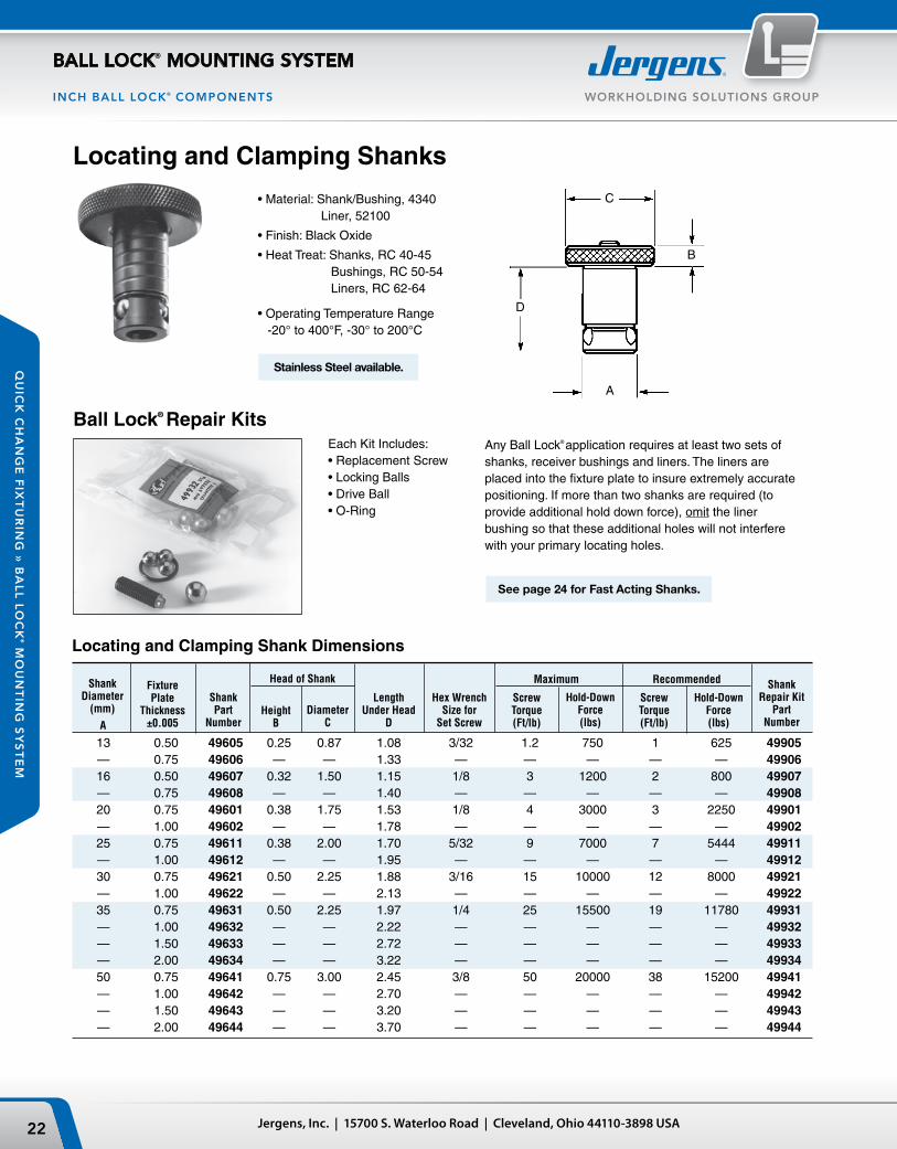
13 0.50 49605 0.25 0.87 1.08 3/32 1.2 750 1 625 49905 — 0.75 49606 — — 1.33 — — — — — 49906 16 0.50 49607 0.32 1.50 1.15 1/8 3 1200 2 800 49907 — 0.75 49608 — — 1.40 — — — — — 49908 20 0.75 49601 0.38 1.75 1.53 1/8 4 3000 3 2250 49901 — 1.00 49602 — — 1.78 — — — — — 49902 25 0.75 49611 0.38 2.00 1.70 5/32 9 7000 7 5444 49911 — 1.00 49612 — — 1.95 — — — — — 49912 30 0.75 49621 0.50 2.25 1.88 3/16 15 10000 12 8000 49921 — 1.00 49622 — — 2.13 — — — — — 49922 35 0.75 49631 0.50 2.25 1.97 1/4 25 15500 19 11780 49931 — 1.00 49632 — — 2.22 — — — — — 49932 — 1.50 49633 — — 2.72 — — — — — 49933 — 2.00 49634 — — 3.22 — — — — — 49934 50 0.75 49641 0.75 3.00 2.45 3/8 50 20000 38 15200 49941 — 1.00 49642 — — 2.70 — — — — — 49942 — 1.50 49643 — — 3.20 — — — — — 49943 — 2.00 49644 — — 3.70 — — — — — 49944
Locating and Clamping Shank Dimensions
Each Kit Includes:• Replacement Screw • Locking Balls • Drive Ball • O-Ring
Ball Lock® Repair KitsAny Ball Lock® application requires at least two sets of shanks, receiver bushings and liners. The liners are placed into the fixture plate to insure extremely accurate positioning. If more than two shanks are required (to provide additional hold down force), omit the liner bushing so that these additional holes will not interfere with your primary locating holes.
• Material: Shank/Bushing, 4340 Liner, 52100
• Finish: Black Oxide
• Heat Treat: Shanks, RC 40-45 Bushings, RC 50-54 Liners, RC 62-64
• Operating Temperature Range -20° to 400°F, -30° to 200°C
Locating and Clamping Shanks
See page 24 for Fast Acting Shanks.
ShankRepair Kit
PartNumber
ShankDiameter
(mm)
A
FixturePlate
Thickness±0.005
ShankPart
NumberDiameter
C
Head of Shank
HeightB
LengthUnder Head
D
Hex WrenchSize for
Set Screw
Maximum Recommended
ScrewTorque(Ft/lb)
Hold-DownForce(lbs)
ScrewTorque(Ft/lb)
Hold-DownForce(lbs)
Stainless Steel available.

Face Mount Bushing Installation Instructions
Back Mount Bushing Installation Instructions
23Phone: 877-426-2504 | Fax: +1 216-481-6193 | E-mail: [email protected] | www.jergensinc.com
WORKHOLDING SOLUTIONS GROUP
BALL LOCK® MOUNTING SYSTEM
QU
ICK
CH
AN
GE
FIX
TU
RIN
G »
BA
LL
LO
CK
® M
OU
NT
ING
SY
ST
EM
INCH BALL LOCK® COMPONENTS
3/43/47/81
1-1/41-5/161-3/4
Back Mount
Face Mount
13 49506 1.3750 11/16 1.3750 0.469 8-32x5/16 0.984 16 49507 1.4370 13/16 1.4370 0.469 8-32x5/16 1.125 20 49501 1.6873 13/16 1.6873 0.637 10-32x3/8 1.362 25 49502 2.0623 1 2.0623 0.799 1/4-28x1/2 1.644 30 49503 2.2654 1 3/16 2.2654 0.871 1/4-28x3/4 1.876 35 49504 2.6873 1 9/16 2.6873 0.904 5/16-24x7/8 2.178 50 49505 3.4998 2 5/32 3.4998 1.239 3/8-24x1 2.916
Back Mount
13 49516 0.7870 .277 1.000 16 49517 0.8760 .285 1.155 20 49511 1.0950 .345 1.280 25 49512 1.3763 .416 1.593 30 49513 1.6264 .432 1.906 35 49514 1.8764 .493 2.155 50 49515 2.6269 .621 2.988
3/43/41
1-1/41-3/81-1/2
2
Installation DimensionsFace Mount
1Cap Screws Supplied with Face Mount Bushings.
Liner Bushings for Fixture Plates
.50 13 49705 49805 0.7518 .75 13 49706 49806 0.7518 .50 16 49707 49807 1.0018 .75 16 49708 49808 1.0018 .75 20 49701 49801 1.3772 1.00 20 49702 49802 1.3772 .75 25 49711 49811 1.3772 1.00 25 49712 49812 1.3772 .75 30 49721 49821 1.7523
Liner Dimensions
ShankDia.(mm)
BackMountPart
Number
SecondaryLinerPart
Number
Liner O.D. +0.0000 -0.0004
Locating repeatability will determine if one primary and one secondary or two primary liners are needed. With two primary liners, repeatability of ±0.0005" can be maintained if the two holes for receiver bushings are held to a centerline distance of ±0.0002" tolerance.
PrimaryLinerPart
Number
Shank Diameter
(mm)
Fixture PlateThickness
±0.005
ShankDia.(mm)
FaceMountPart
Number
ActualO.D.
+0.0000 -0.0004
ClearanceDrill
DiameterE
Two styles of receiver bushings are available. Generally, the face mount receiver bushing is utilized in blind hole applications (Slip Fit). The back mount receiver bushing is used in through hole applications (Light Press Fit).
Note: Installed bushings should be approximately .012" below subplate surface. See reference below for installation of back mount style bushings.
Min.SubplateThickness
D
Bore+0.0005 -0.0000
F
Depth+0.002 -0.000
G
TapSize &Depth1
H
Bolt CircleDiameter
3 PL Equally Spaced
Min.SubplateThickness
D
ActualO.D.
+0.0000 -0.0004
A
Depth+0.000 -0.002
B
C-Bore±0.006
C
Receiver Bushings
1.00 30 49722 49822 1.7523 .75 35 49731 49831 1.7523 1.00 35 49732 49832 1.7523 1.50 35 49733 49833 1.7523 2.00 35 49734 49834 1.7523 .75 50 49741 49841 2.5025 1.00 50 49742 49842 2.5025 1.50 50 49743 49843 2.5025 2.00 50 49744 49844 2.5025
SecondaryLinerPart
Number
Liner O.D. +0.0000 -0.0004
PrimaryLinerPart
Number
Shank Diameter
(mm)
Fixture PlateThickness
±0.005
Note on Installation of Press Fit Liners & Back Mount Style Receiver Bushings: To alleviate the possibility of binding the shank in the bore, the maximum interference fit between bore and bushing O.D. should not exceed .0005".

Thumb Screw
Adjustable Handle
• Fast acting thumb screws 2 1/2 turns. No tools needed.
• Handle can be moved out of the work area to avoid interference.
Jergens, Inc. | 15700 S. Waterloo Road | Cleveland, Ohio 44110-3898 USA24
WORKHOLDING SOLUTIONS GROUP
BALL LOCK® MOUNTING SYSTEM
QU
ICK
CH
AN
GE
FIX
TU
RIN
G »
BA
LL
LO
CK
® MO
UN
TIN
G S
YS
TE
M
INCH BALL LOCK® COMPONENTS
Sine Fixture Keys
NOTE: All shanks are 5/8" diameter
Accessories
Locate subplates or fixture plates to slotted machine tables without having to slot the plate. Available in inch sizes from 1/2" to 7/8" slots, and in metric sizes from 14mm to 22mm slots.NOTE: See page 215 for dimensions.
Lifting HandlesFor easy handling of fixture plates up to 500 lbs.
Tapered Caps and PlugsKeep debris out of your subplate’s receiver bushings when not in use. Polyethylene caps snap in and out easily.
Part Number Length Ht. W Mounting Distance
33701 4.21 1.42 0.83 3.68
Packaged 10 per pack.
Receiver Bushing Part Diameter Number
13 49201 16 49202 20 49203 25 49204 30 49205 35 49206 50 49207
Fast Acting Ball Lock® Shanks
B B Table Table Slot A Slot Size A Size (mm) Part +0.000 +0.000 Part +0.000 +0.000 Number -0.0005 -0.0005 C Number -0.013 -0.013 C
39501 .625 1/2 1 39562 16 14 1 39502 .625 9/16 1 39563 16 16 1 39503 .625 5/8 1 39564 16 18 1 39504 .625 11/16 1 39565 16 20 1-1/8 39505 .625 3/4 1-1/8 39566 16 22 1-1/8 39506 .625 13/16 1-1/8 — — — — 39507 .625 7/8 1-1/8 — — — —
Ball Lock® Shank
Diameter (mm)
Fixture Plate
Thickness (in.)
FAST ACTING
Jergens Ball Lock® Jergens Ball Lock®
Shank w/Jergens Shank Thumb Screw Adjustable Handle Part Number Part Number Assembly T-Screw Assembly Handle
16 1/2 49607-S 43904 49607-H 34314 — 3/4 49608-S 43904 49608-H 34315 20 3/4 49601-S 43904 49601-H 34315 — 1 49602-S 43905 49602-H 34316 25 3/4 49611-S 43907 49611-H 34328 — 1 49612-S 43908 49612-H 34329 30 3/4 49621-S 43910 49621-H 34334 — 1 49622-S 43911 49622-H 34335 35 3/4 49631-S 43913 49631-H 34339 — 1 49632-S 43913 49632-H 34339 — 1-1/2 49633-S 43914 N/A — — 2 49634-S 43914 N/A —

1000
500
200
425 425
300 300
425
300
150
(8) 25MM FACE MOUNTBUSHINGS I NSTALLED
(18) 20MM FACE MOUNTBUSHINGS I NSTALLED
16MM BORED HOLEFOR SINE FIXTURE KEYS
(2) PLACES
58706
58801
69406
58713 or 58715
58727
59112
25Phone: 877-426-2504 | Fax: +1 216-481-6193 | E-mail: [email protected] | www.jergensinc.com
WORKHOLDING SOLUTIONS GROUP
BALL LOCK® MOUNTING SYSTEM
QU
ICK
CH
AN
GE
FIX
TU
RIN
G »
BA
LL
LO
CK
® M
OU
NT
ING
SY
ST
EM
METRIC DIMENSIONS - METRIC FIXTURE/SUBPLATES
The Jergens Multi-Purpose Subplate accommodates a wide variety of fixture plates and vises. This versatility facilitates using the same VMC for diverse products in repetitive runs-long and short batch sizes.
• FreMaxTM 15 Steel or Equivalent• Thickness: 31.75mm ±0.13mm• Parallel within 0.025mm
Multi-Purpose Subplates1000x500 Multi-Purpose Subplate
Fixture Plate Options for Multi-Purpose Subplates – Aluminum or Steel
* See next page for dimensional data on fixture plates. Part numbers shown for aluminum plates, also available in steel. ** Counterbored to 25mm at mounting holes.
Number of Fixture Receiver Required Number Plates/Vise That Mount Bushing Receiver Ball Lock
®
of Shanks Fixture Plate*/Vise Thickness of on Multi-Purpose Center Bushing Shank Required Per Part Number Fixture Plate Subplate Distance Size Part Number Fixture Plate/Vise
58713 (350 x 350) 20mm 2 300 x 300 20 mm 49651 4Fixture Plate
58715 (400 x 400) 20mm 2 300 x 300 20 mm 49651 4Fixture Plate
58801 (400 x 400) 30mm** 2 300 x 300 20 mm 49652 4Modular Grid Plate
58706 Jigsaw 20mm 4 300 x 200 20 mm 49651 3 Interlocking Plate
58727 (500 x 500) 25mm 2 425 x 425 25 mm 49662 4Fixture Plate
69406 20mm 4 300 x 200 20 mm 49651 3150mm Jigsaw Vise
Part Number Wt. (Kg) 59112 130
ME
TR
IC

300
150 200
400
200
250
CLEARANCE HOLE FORHOLDDOWN
(2) 20MMPRIMARY LINERSINSTALLED
500
500
425
425
212.50
CLEARANCE HOLESFOR HOLDDOWN
(2) PLACES
16MM BORED HOLEFOR SINE FIXTURE KEYS(2) PLACES
(2) 25MMPRIMARY LINERS
INSTALLED
300
300
50TYP
400
400
CLEARANCE HOLESFOR HOLDDOWN(2) PLACES
(2) 20MMPRIMARY LINERSINSTALLED
16MM X 6MM DEEPCOUNTERBORE
M12 X 1.75TAPPED HOLE
300
300
150
CLEARANCE HOLESFOR HOLDDOWN
(2) PLACES
16MM BORED HOLEFOR SINE FIXTURE KEYS(2) PLACES
(2) 20MM PRIMARY LINERS
INSTALLED
Mounts to Subplate with Ball Lock® Shank 49652 (20x25mm)
Jergens, Inc. | 15700 S. Waterloo Road | Cleveland, Ohio 44110-3898 USA26
WORKHOLDING SOLUTIONS GROUP
BALL LOCK® MOUNTING SYSTEM
QU
ICK
CH
AN
GE
FIX
TU
RIN
G »
BA
LL
LO
CK
® MO
UN
TIN
G S
YS
TE
M
METRIC DIMENSIONS - METRIC FIXTURE/SUBPL ATES
Fixture Plates for Use on Multi-Purpose Subplate
Jigsaw Interlocking FixturePlate
350x350x20mm Fixture Plate
500x500x25mm Fixture Plate
• Cast Aluminum or FreMax™
15 Steel or equivalent• Thickness: 25mm ±0.13mm• Parallel within 0.025mm Steel• Mounts to Subplates using Ball Lock
®
Shank 49662 (25x25mm)
400x400 Modular Grid Fixture Plate
• FreMax™
15 Steel or equivalent• Thickness: 28.57mm ±0.13mm• Parallel within 0.025mm Steel
400x400 Fixture Plate
• Cast Aluminum or FreMax™
15 Steel or equivalent• Thickness: 20mm ±0.13mm• Parallel within 0.025mm Steel• Mounts to subplates with Ball
Lock®
Shank 49651 (20x20mm)
• Material: Cast Aluminum or FreMax™
15 Steel or equivalent• Thickness: 20mm ±0.13mm• Parallel within 0.025mm Steel• For use with narrow base 100mm or 150mm vise models• Design allows close spacing of vises for more parts per run• Mounts to Subplates using Ball Lock
®
Shank 44651 (20x20mm)• Useful for high density fixturing
Aluminum Plate Part Number Wt. (Kg)
58713 6
Aluminum Plate Part Number Wt. (Kg)
58801 38
Aluminum Plate Part Number Wt. (Kg)
58715 8
Steel Plate Part Number Wt. (Kg)
58813 19
Steel Plate Part Number Wt. (Kg)
58815 25
Aluminum Plate Part Number Wt. (Kg)
58706 4
Aluminum Plate Part Number Wt. (Kg)
58727 17
Steel Plate Part Number Wt. (Kg)
58806 12
Steel Plate Part Number Wt. (Kg)
58827 48
ME
TR
IC

400
400
300
300
150
(4) 20MMFACE MOUNT BUSHINGS
INSTALLED
16MM BORED HOLEFOR SINE FIXTURE KEYS(2) PLACES
250
300
150
300
650
400
325
25
150
(12) 20MMFACE MOUNT BUSHINGSINSTALLED
16MM BORED HOLEFOR SINE FIXTURE KEYS(2) PLACES
˚˚˚
˚˚˚
˚˚˚
˚˚˚
250
63.5
63.5
375
300 20
200
(4) 16mm Face Mount Bushings Installed
12mm Dia. For Mounting To Table (4) Places
16mm Bored Holes For Sine Fixture Keys (2) Places
58713 or 58715
58711
59111
27Phone: 877-426-2504 | Fax: +1 216-481-6193 | E-mail: [email protected] | www.jergensinc.com
WORKHOLDING SOLUTIONS GROUP
BALL LOCK® MOUNTING SYSTEM
QU
ICK
CH
AN
GE
FIX
TU
RIN
G »
BA
LL
LO
CK
® M
OU
NT
ING
SY
ST
EM
METRIC DIMENSIONS - METRIC FIXTURE/SUBPLATES
Equipped with twelve installed 20mm receiver bushings to easily locate and mount Jergens Standard Fixture Plates.
Equipped with four 20mm receiver bushings for use with 350x350 or 400x400 (mm) fixture plates. Ideal for horizontal machining centers or multiple pallet machin-ing centers.
• FreMax™
15 steel plate or equivalent• Thickness: 28.57mm ±0.13mm• Parallel within 0.025mm
Pre-Machined Ball Lock® Steel Subplate400 x400 Subplate
650x400 Dual Station Subplate
• Ideal for vertical machining centers• Thickness: 28.57mm ±0.13mm• Parallel within 0.025mm
Part Number Wt. (Kg) 59101 37
Equipped with four installed 16mm receiver bushings and 12mm mounting holes. Used with the Bridgeport
™
style fixture plates 58731 or 58831.• Thickness: 19.05mm ±0.13mm• Parallel within 0.025mm
250x375 Bridgeport™
- Style Subplate
Ball Lock® Quick Change Kits include all components needed in a single package. See page 29 for details.
Part Number Wt. (Kg) 59111 58
Part Number Wt. (Kg) 59121 15
Aluminum Steel Plate Number Plate Plate Part Part of Fixture Width and Number Number Plates Length (mm)
58713 58813 1 350x350 58715 58815 1 400x400 58711 58811 2 300x350
ME
TR
IC

200
16mm Bored Holes For Sine Fixture Keys(2) Places
(2) 16mm Primary Liners Installed
(2) 20mm Primary Liners Installed
16mm Bored Holes For Sine Fixture Keys(2) Places
250
150
300
300
100
250
375
Clearance Hole For Holddown (2) Places
300
Clearance Holes For Holddown (2) Places
350
Jergens, Inc. | 15700 S. Waterloo Road | Cleveland, Ohio 44110-3898 USA28
WORKHOLDING SOLUTIONS GROUP
BALL LOCK® MOUNTING SYSTEM
QU
ICK
CH
AN
GE
FIX
TU
RIN
G »
BA
LL
LO
CK
® MO
UN
TIN
G S
YS
TE
M
METRIC DIMENSIONS - METRIC FIXTURE/SUBPL ATES
• Machined to close tolerances• Repeatability ±0.013mm or better• Reduces fixture set-up and
assembly time• Provided with 16mm bored holes
for sine fixture keys• For horizontal or vertical
machining centers, Tool Room Mills machines, or multiple pallet machining centers
• Cast Aluminum; or FreMax™
15 Steel or equivalent• Thickness ±0.13mm• Parallel within .025mm Steel• 6061–T-651 plates, flat within 0.03mm available upon request
Ball Lock® Fixture Plates
Custom Sizes AvailableJergens will make Ball Lock
®
fixture plates or subplates to your specifications. Call 1-877-426-2504 for further information.
PlateDimensions
(mm)
Plate
Thickness±0.13(mm)
Ball Lock®
Shank Size(mm)
Ball Lock®
Shank PartNumber
Part Number
Weight Weight
Ball Lock®
Fixture Plates with 2 Primary Liners Installed
Aluminum (Kgs) Steel (Kgs)
375x250x20mm Fixture Plate Bridgeport™
Style
300x350x20mm Fixture Plate
58706 4 58806 12 250 x400 20 20 49651 58711 5 58811 16 300 x350 20 20 49651 58713 6 58813 19 350 x 350 20 20 49651 58715 8 58815 25 400 x 400 20 20 49651 58727 17 58827 48 500 x 500 25 25 49662 — — 58801 38 400 x 400 28.57 20 49652 58731 5 58831 15 375x250 20 16 49657
Aluminum Plate Part Number Wt. (Kg)
58731 5
Aluminum Plate Part Number Wt. (Kg)
58711 5
Steel Plate Part Number Wt. (Kg)
58831 15
Steel Plate Part Number Wt. (Kg)
58811 16
ME
TR
IC

29Phone: 877-426-2504 | Fax: +1 216-481-6193 | E-mail: [email protected] | www.jergensinc.com
WORKHOLDING SOLUTIONS GROUP
BALL LOCK® MOUNTING SYSTEM
QU
ICK
CH
AN
GE
FIX
TU
RIN
G »
BA
LL
LO
CK
® M
OU
NT
ING
SY
ST
EM
METRIC DIMENSIONS - METRIC FIXTURE/SUBPLATES
Quick Change Kits
Part No. Kit Includes
59002 2 - 58715 (400x400x20) aluminum fixture plates with 20mm liner bushings installed
1 - 59101 (400x400x25) steel subplate with receiver bushings installed
4 - 20mm Ball Lock®
Shanks (49651)
Quick Change Kits
Custom Kits AvailableJergens manufactures ready to use kits includingBall Lock
®
subplate and fixture plates. For a special kit tailored to your CNC machine, please provide:Name and Type of Machine __________________Travel of Machine Table (x, y, z) _______________Dimensions of Machine Table (x and y) _________Maximum Weight allowed on Machine Table _____T-slot Width and Center to Center Distance ______
Everything You Need to Change Fixtures in Less Than One Minute
The Jergens Ball Lock® Quick Change Kits speed fixture changeover in all types of manufacturing operations. Each kit includes two aluminum fixture plates with 2 primary liner bushings installed; one steel subplate with receiver bushings installed, and four 20mm Ball Lock® shanks with working loads of 3000 lbs. each. While one fixture plate is on the machine, the operator can load parts on the other. This minimizes downtime for true set-up reduction. To enable the subplate to be mounted on a slotted table without the need to indicate the subplate, sine fixture keys can be used. The sine fixture key reamed holes are oriented parallel to the receiver bushings on the subplate and to the liner bushings on the fixture plate. These also allow the fixture plate to be mounted on a toolroom mill without the need to indicate it. This is extremely useful when machining location points on your fixture.
ME
TR
IC
Steel Subplate
20mm Ball Lock®
Shank16mm Bored Hole for Sine Fixture Keys
16mm Bored Hole for Sine Fixture Keys
(4) 20mm Receiver Bushings Installed
(2) 20mm Primary Liner Bushings Installed
AluminumFixture Plate

FixturePlate
Tooling Column
Subplate
M12
Jergens, Inc. | 15700 S. Waterloo Road | Cleveland, Ohio 44110-3898 USA30
WORKHOLDING SOLUTIONS GROUP
BALL LOCK® MOUNTING SYSTEM
QU
ICK
CH
AN
GE
FIX
TU
RIN
G »
BA
LL
LO
CK
® MO
UN
TIN
G S
YS
TE
M
METRIC DIMENSIONS - METRIC TOOLING COLUMNS
Corresponding Fixture Plates, Subplates and Ball Lock® Shanks
Use Hoist Ring 23462, see Lifting Solutions Catalog or Master Catalog for lifting and handling – Order separately.
Cast Iron T-Columns With Ball Lock® Receiver Bushings Installed
• Class 40 Cast Iron• Also available in Aluminum• Ball Lock
®
Receiver Bushings and Liners installed• Provides accurate fixturing base for CNC machining centers• Perpendicularity is 0.025 mm per 250 mm
Pre-Machined Ball Lock® T-Columns
*Note: Window sections are also available on T-Columns. Specify window size and location (Q and R Dimensions).
Custom Sizes Available with or without Ball Lock®
We are able to quote you on your special requirement with or without the Ball Lock® Mounting System. Call 1-877-426-2504 for design specification information.
Engineering ChangesProduct improvement is a continuing process at Jergens. Specifications and engineering data are subject to change after publishing. Contact Jergens Technical Sales Department to verify any dimensions or specifications.
Pallet T-Column Aluminum Steel Fixture Fixture Plate Subplate Size Part Fixture Plate Fixture Plate Plate Ball Lock® Shank Shank Subplate Ball Lock® Shank Shank (mm) Number Part Number Part Number Size Part Number Size Part Number Part Number Size
400 69151 58717 58817 400 x 400 49651 20 x 20 59102 49652 20 x 25 500 69161 58745 58845 500 x 550 49662 25 x 25 59103 49662 25 x 25 630 69171 58746 58846 625 x 650 49662 25 x 25 59104 49683 35 x 40
Pallet Part O P Wt. Size (mm) Number C D E F G H I J K L M N (mm) (mm) (Kg)
400 69151 410 25 400 400 350 350 350 350 100 500 125 90 20 20 190 500 69161 560 25 500 500 475 425 425 425 120 650 137.5 90 25 25 310 630 69171 660 40 630 630 575 550 525 525 100 750 137.5 90 35 25 500
See page 32 for Metric Fixture Plates and Subplates
ME
TR
IC

FixturePlate
Tooling Column
Subplate
M12
31Phone: 877-426-2504 | Fax: +1 216-481-6193 | E-mail: [email protected] | www.jergensinc.com
WORKHOLDING SOLUTIONS GROUP
BALL LOCK® MOUNTING SYSTEM
QU
ICK
CH
AN
GE
FIX
TU
RIN
G »
BA
LL
LO
CK
® M
OU
NT
ING
SY
ST
EM
METRIC DIMENSIONS - METRIC TOOLING COLUMNS
Corresponding Fixture Plates, Subplates and Ball Lock® Shanks
Custom Sizes Available with or without Ball Lock®
We are able to quote you on your special requirement with or without the Ball Lock® Mounting System. Call 1-877-426-2504 for design specification information.
Engineering ChangesProduct improvement is a continuing process at Jergens. Specifications and engineering data are subject to change after publishing. Contact Jergens Technical Sales Department to verify any dimensions or specifications.
Use Hoist Ring 23462, see Lifting Solutions Catalog or Master Catalog for lifting and handling – Order separately.
Pallet Part O P Wt. Size (mm) Number A B C D E F G H I J K L M N (mm) (mm) (Kg)
400 69051 250 250 505 25 400 400 450 150 350 350 40 600 125 95 20 20 225 500 69061 300 300 630 25 500 500 550 175 425 425 40 725 137.5 95 25 25 320 630 69071 400 400 655 40 630 630 575 275 525 525 45 750 137.5 95 35 25 495
Cast Iron 4-Sided Tooling Columns With Ball Lock®
Receiver Bushings Installed
• Class 40 cast iron• Also available in Aluminum• Ball Lock
®
Receiver Bushings and Liner Bushings installed• Provides accurate fixturing base for CNC machining centers• Perpendicularity is 0.025 mm per 250 mm
Pre-Machined Ball Lock® 4-Sided Tooling Columns
Pallet T-Column Aluminum Steel Fixture Fixture Plate Subplate Size Part Fixture Plate Fixture Plate Plate Ball Lock® Shank Shank Subplate Ball Lock® Shank Shank (mm) Number Part Number Part Number Size Part Number Size Part Number Part Number Size
400 69051 58741 58841 250 x 500 49651 20 x 20 59102 49652 20 x 25 500 69061 58742 58842 300 x 625 49662 25 x 25 59103 49662 25 x 25 630 69071 58743 58843 400 x 650 49662 25 x 25 59104 49683 35 x 40
See page 30 for Metric Fixture and Subplates
ME
TR
IC

JE
I F
A
BB
A
16mm Bored holes for sine fixture keys (2) places
16mm Bored holes for sine fixture keys (2) places
16mm Bored holes for sine fixture keys (2) places
Receiver Bushings
Primary Liners
Primary Liners
5.45.4
Aluminum and Steel Expansion(per cm)
Diff
eren
ce b
etw
een
Alu
min
um a
nd S
teel
( m
m)
0.0015
0.00125
0.001
0.00075
0.0005
0.00025
02.8 8.4 11.2 14 16.8
Change in Degrees C
0
Jergens, Inc. | 15700 S. Waterloo Road | Cleveland, Ohio 44110-3898 USA32
WORKHOLDING SOLUTIONS GROUP
BALL LOCK® MOUNTING SYSTEM
QU
ICK
CH
AN
GE
FIX
TU
RIN
G »
BA
LL
LO
CK
® MO
UN
TIN
G S
YS
TE
M
METRIC DIMENSIONS - METRIC FIXTURE/SUBPL ATES
Receiver Thickness of Part Pallet Size For Tooling Size Subplate Wt Number (mm) Columns (mm) (mm) (mm) (mm) ±0.13 (Kgs)
59102 400 69151/69051 350 350 20 28.57 31 59103 500 69161/69061 425 425 25 31.75 59 59103-C* 500 69151, 69051 350/425 350/425 20/25 31.75 59 — — 69161, 69061 Dual Dual Dual — — 59104 630 69171/69071 525 525 35 34.92 124
Fixture Fixture Plate Ball Lock® Pattern Liner Pallet Part Number For Tooling Plate Size Thickness H G Size Size (mm) Aluminum (Kg) Steel (Kg) Columns Type (mm) (mm) ±0.13 (mm) (mm) (mm)
400 58741 7 58841 19 69051 4-S 250x500 150 450 20 20
500 58742 13 58842 36 69061 4-S 300x625 175 550 25 25
630 58743 18 58843 50 69071 4-S 400x650 275 575 25 25
400 58717 8 58817 25 69151 T 400x400 350 350 20 20
500 58745 19 58845 53 69161 T 500x550 425 475 25 25
630 58746 27 58846 63 69171 T 625x650 550 575 25 25
Fixture Plates for Standard Tooling Columns and T-ColumnsSupplied with 2 primary Ball Lock
®
Liner Bushings installed.
Fixture Plates for Tooling Column Subplates
NOTE: Aluminum and steel expand at different rates. Please take this information into consider-ation when creating your own Ball Lock
®
fixture and subplates.
Supplied with 2 primary Ball Lock®
Liner Bushings installed.
Subplates for Tooling Columns and Fixture PlatesStandard Steel Subplates for Tooling Columns
A BBall Lock® Pattern
Subplate Mounting holes can be provided per customer specification. Supplied with Ball Lock® Receiver Bushings installed.
Ball Lock®
Pallet Part Number Plate Dim. Fixture Plate Pattern Liner Size For E F Thickness I J Size (mm) Aluminum (Kg) Steel (Kg) Subplate (mm) (mm) ±0.13 (mm) (mm) (mm) (mm)
400 58717 8 58817 25 59102 400 400 20 350 350 20
500 58727 17 58827 48 59103 500 500 25 425 425 25
630 58732 27 58832 76 59104 630 630 25 525 525 35
ME
TR
IC

Ball Lock® Subplate
Ball Lock® Shanks
Indexer Face Plate
Workpiece
Ball Lock® Fixture Plate For Holding Production Workpiece
Ball Lock® Fixture Plate For Mounting Indexer to Subplate and Machine Table
33Phone: 877-426-2504 | Fax: +1 216-481-6193 | E-mail: [email protected] | www.jergensinc.com
WORKHOLDING SOLUTIONS GROUP
BALL LOCK® MOUNTING SYSTEM
QU
ICK
CH
AN
GE
FIX
TU
RIN
G »
BA
LL
LO
CK
® M
OU
NT
ING
SY
ST
EM
METRIC DIMENSIONS - METRIC FIXTURE/SUBPLATES
Ball Lock® For 4th Axis Rotary IndexersProblem: Rotary indexers increase the versatility of vertical machining centers, yet they offer one major challenge: set-up is so time-consuming that it may limit a machine’s flexibility. In many cases, machinists dedicate their 4th Axis tool to a single machine to avoid the agony of an extended set-up and changeover.
Jergens’ Solution: Ball Lock® Mounting System for Indexers provides a double solution.
First, Ball Lock® mounting plates free up your machine for additional work by allowing a fast and accurate installation and removal of the complete indexer. Avoid hours of set up. The Ball Lock® System does it in minutes, with repeatability at ±0.0005" (±0.013mm). Low profile, positive clamping, proven in over many years of field use.
Second, the Ball Lock® System provides your fixture plate changeover. By mounting the round subplate to the indexer faceplate, you’ll “plug-in” new fixtures in record time (less than 60 seconds).
Benefits:• Maximize indexer utilization • Eliminate lengthy set-ups• Accurate fixture plate changover in seconds
Subplates and fixture plates come with bushings pre-installed.
ME
TR
IC

Jergens, Inc. | 15700 S. Waterloo Road | Cleveland, Ohio 44110-3898 USA34
WORKHOLDING SOLUTIONS GROUP
BALL LOCK® MOUNTING SYSTEM
QU
ICK
CH
AN
GE
FIX
TU
RIN
G »
BA
LL
LO
CK
® MO
UN
TIN
G S
YS
TE
M
METRIC DIMENSIONS - METRIC FIXTURE/SUBPL ATES
Fixture Plate (mm) Part Ball Lock
®
Ball Lock®
Weight No. A B Thickness Liner Shank (Kgs)
58707 200 150 20 16 49657 1.6 58708 250 200 25 20 49652 3.2 58709 300 250 25 20 49652 5.0
Subplate(mm) Part Ball Lock
®
Center Weight No. A B Thickness Receiver Hole (Kgs)
59107 200 150 20 16 25 5.0 59108 250 200 25 20 50 9.6 59109 300 250 25 20 50 15.0Note: Equivalent system available in inch dimensions.
Engineering ChangesProduct improvement is a continuing process at Jergens. Specifications and engineering data are subject to change without notice. If current information is critical to your design, it is suggested that you contact Jergens Technical Sales Department to verify any dimensions or specifications.
Round Ball Lock® Fixture Plates and Subplates
Standard Round
Custom Round Plates
Indexer:
Make:
Model:
Diameter:
Light Duty or Heavy Duty:
Through Hole Bore:
CNC Machine:
Make:
Model:
Weight Capacity:
Indexer Faceplate:
T-Slot Size:
Configuration/Orientation:
or
Drilled Tapped Hole Size:
Configuration/Orientation:
Cast Aluminum, FreeMax™ or Steel equivalent
ME
TR
IC

A
C
D
B
35Phone: 877-426-2504 | Fax: +1 216-481-6193 | E-mail: [email protected] | www.jergensinc.com
WORKHOLDING SOLUTIONS GROUP
BALL LOCK® MOUNTING SYSTEM
QU
ICK
CH
AN
GE
FIX
TU
RIN
G »
BA
LL
LO
CK
® M
OU
NT
ING
SY
ST
EM
METRIC DIMENSIONS - METRIC BALL LOCK® COMPONENTS
Locating and Clamping Shank Dimensions
ShankPart
Number B C D
Each Kit Includes:• Replacement Screw • Locking Balls • Drive Ball • O-Ring
Replacement KitsAny Ball Lock
®
application requires at least two sets of shanks, receiver bushings and liners. The liners are placed into the fixture plate to insure extremely accurate positioning. If more than two shanks are required (to provide additional hold down force), omit the liner bushing so that these additional holes will not interfere with your primary locating holes.
Fixture Plate
Thickness±0.13mm
ShankDiameter
(mm)A
• Material: Shank/Bushing, AISI 4340 Liner, 52100
• Finish: Black Oxide
• Heat Treat: Shanks, RC 40-45 Bushings, RC 50-54 Liners, RC 62-64
• Stainless Steel available
Locating and Clamping Shanks
U.S. Patents: 3,498,653 4,135,418
See page 37 for Fast Acting Shanks.
• Operating Temperature Range: -30°C to 200°C
DiameterHeight
Head of Shank Maximum Screw Holddown Torque Force (N.m) (KN)
Recommended
Screw Holddown Torque Force (N.m) (KN)
HexWrench Size
ForSet Screw
ShankRepair Kit
PartNumber
496554965649657496584965149652496614966249671496724968149682496834968449691496924969349694
132020252025202520252025405020254050
13—16—20—25—30—35———50———
6—8—10—10—13—13 ———20———
22—32—40—45—50—60———75———
27.634.636.541.539.544.544.049.049.054.051.056.071.081.064.069.084.094.0
3.3—
5.3—
13.3—30—44—68———88———
1—3—4—9—15—25———50———
2.5—3—3—4—5—6———10———
499554995649957499584995149952499614996249971499724998149982499834998449991499924999349994
1.2—4.5—5.3—11—18—33———65———
2.7—3.5—10—23—35—52———67———
ME
TR
IC
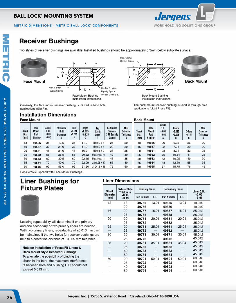
Max. Corner
Radius 0.5mm
Max. Corner
Radius 0.5mmH – Tap 3 Holes
Equally Spaced
On Bolt Circle Dia.
Jergens, Inc. | 15700 S. Waterloo Road | Cleveland, Ohio 44110-3898 USA36
WORKHOLDING SOLUTIONS GROUP
BALL LOCK® MOUNTING SYSTEM
QU
ICK
CH
AN
GE
FIX
TU
RIN
G »
BA
LL
LO
CK
® MO
UN
TIN
G S
YS
TE
M
METRIC DIMENSIONS - METRIC BALL LOCK® COMPONENTS
Back MountFace Mount
Back Mount Installation DimensionsFace Mount
1
Cap Screws Supplied with Face Mount Bushings.
ShankDia.(mm)
BackMountPart
Number
ShankDia.
(mm)
Face Mount Part
Number
ActualO.D.-0.01-0.02
ClearanceDrill
DiameterE
Two styles of receiver bushings are available. Installed bushings should be approximately 0.3mm below subplate surface.
Min.SubplateThickness
D
Bore+0.010+0.003
F
Depth+0.025 -0.025
G
TapSize &Depth
1
H
Bolt CircleDiameter
3 PL Equally Spaced
Min.SubplateThickness
D
ActualO.D.+0.04+0.03
A
Depth+0.025 -0.025
B
C-Bore±0.15
C
Receiver Bushings
Face Mount Bushing Installation Instructions
Back Mount Bushing Installation Instructions
13162025303550
M4x0.7 x 7M4x0.7 x 7M5x0.8 x 9M6x1.0 x 10M6x1.0 x 11M8x1.25 x 17M10x1.5 x 18
49556495574955149552495534955449555
35374555607092
13.521.021.025.530.540.055.0
35374555607092
11.9111.9116.2120.3222.1522.9931.50
25293542485675
20202530354050
13162025303550
49566495674956149562495634956449565
20222835424867
6.927.248.74
10.5410.9512.5015.75
26293341495576
20202525303545
Note on Installation of Press Fit Liners & Back Mount Style Receiver Bushings: To alleviate the possibility of binding the shank in the bore, the maximum interference fit between bore and bushing O.D. should not exceed 0.013 mm.
Liner Bushings for Fixture Plates
Liner Dimensions
Liner O.D. +0.00- 0.01
Locating repeatability will determine if one primary and one secondary or two primary liners are needed. With two primary liners, repeatability of ±0.013 mm canbe maintained if the two holes for receiver bushings areheld to a centerline distance of ±0.005 mm tolerance.
Shank Diameter
(mm)
Fixture PlateThickness
+0.13- 0.13
498554985649857498584985149852498614986249871
19.04019.04025.04225.04235.04235.04235.04235.04245.042
13—16—20—25—30—
132020252025202520
35———50———
497724978149782497834978449791497924979349794
498724988149882498834988449891498924989349894
45.04245.04245.04245.04245.04263.54663.54663.54663.546
Generally, the face mount receiver bushing is utilized in blind hole applications (Slip Fit).
The back mount receiver bushing is used in through hole applications (Light Press Fit).
Primary Liner Secondary Liner
Part Number Part NumberI.D. I.D.
13.01—
16.01—
20.01—
25.01—
30.01—
35.01———
50.01———
13.04—
16.04—
20.04—
25.04—
30.04
35.04———
50.04———
497554975649757497584975149752497614976249771
252025405020254050
ME
TR
IC

37Phone: 877-426-2504 | Fax: +1 216-481-6193 | E-mail: [email protected] | www.jergensinc.com
WORKHOLDING SOLUTIONS GROUP
BALL LOCK® MOUNTING SYSTEM
QU
ICK
CH
AN
GE
FIX
TU
RIN
G »
BA
LL
LO
CK
® M
OU
NT
ING
SY
ST
EM
METRIC DIMENSIONS - METRIC BALL LOCK® COMPONENTS
Sine Fixture Keys
Accessories
Locate subplates or fixture plates to slotted machine tables without having to slot the plate. Available in sizes from 12mm to 32mm slots.
Packaged 10 per pack.
Receiver Bushing Part Diameter Number 13 49201 16 49202 20 49203 25 49204 30 49205 35 49206 50 49207
Fast Acting Ball Lock® Shanks
Ball Lock®
Shank
Diameter (mm)
Fixture Plate
Thickness (mm)
FAST ACTING BALL LOCK®
SHANKS
Shank with Shank with Thumb Screw Adjustable Handle Part Number Part Number Assenbly T-Screw Assenbly Handle
13 13 49655-S 43971 49655-H 34360 — 20 49656-S 43972 49656-H 34361 16 20 49657-S 43974 49657-H 34365 — 25 49658-S 43975 49658-H 34365 20 20 49651-S 43974 49651-H 34365 — 25 49652-S 43975 49652-H 34365 25 20 49661-S 43977 49661-H 34378 — 25 49662-S 43978 49662-H 34379 30 20 49671-S 43980 49671-H 34385 — 25 49672-S 43980 49672-H 34385 35 20 49681-S 43985 49681-H 34393 — 25 49682-S 43985 49682-H 34393
Lifting HandlesFor easy handling of fixture plates up to 500 lbs.
Part Number Length Ht. W Mounting Distance
33701 107mm 36mm .38 Kg 93.47mm
Thumb Screw
Adjustable Handle
• Fast acting thumb screws 2 1/2 turns. No tools needed.
• Handle can be moved out of the work area to avoid interference.
Tapered Caps and PlugsKeep debris out of your subplate’s receiver bushings when not in use. Polyethylene caps snap in and out easily.
Part Number
Shank Size
A
Slot Size
B CWeight
(Kg)Recommended Hole Diameter
39550 16 10 25 .04
16mm Shank Size:16.01 ± 0.01
39551 16 12 25 .04
39552 16 14 25 .05
39553 16 16 25 .05
39554 16 18 29 .05
39555 16 20 29 .06
39556 16 22 29 .06
39557 20 24 35 .0720mm Shank Size:
20.01 ± 0.0139558 20 28 35 .10
39559 20 32 40 .10
ME
TR
IC

Jergens, Inc. | 15700 S. Waterloo Road | Cleveland, Ohio 44110-3898 USA38
WORKHOLDING SOLUTIONS GROUP
ZERO POINT MOUNTING SYSTEM
QU
ICK
CH
AN
GE
FIX
TU
RIN
G »
ZE
RO
PO
INT
MO
UN
TIN
G S
YS
TE
M
Typical applications for the Jergens Zero Point System:
• Milling
• Assembly
• Welding
• Injection Molding
• Grinding
• Measuring
Features of the Jergens Zero Point Mounting System
• Positioning and clamping in one operation• High repeatability and accuracy• Low cost solution for quick pallet changing
Pull Studs can also be installed directly into the workpieces, making 5-sided processing possible.
Best results with large and heavy workpieces.
Jergens Zero Point clamping systems are made exclusively of rust-free materials and so are ideally suited for use in the food-service area as well as in the pharmaceutical and chemical industry.
Through different dimensions, the advantage of the Zero Point clamping system are optimally used.

39Phone: 877-426-2504 | Fax: +1 216-481-6193 | E-mail: [email protected] | www.jergensinc.com
WORKHOLDING SOLUTIONS GROUP
ZERO POINT MOUNTING SYSTEM
QU
ICK
CH
AN
GE
FIX
TU
RIN
G »
ZE
RO
PO
INT
MO
UN
TIN
G S
YS
TE
M
Threaded Clamping Modules
Flange Type Module
Clamping Plates with Built-In Modules
Raised/Mounted Clamping Modules
Horizontal Rapid-Clamping Module
Pull Studs and Engagement Screws
• Machine tables• Plates• 4-axis/5-axis machining• Columns• Pallets
• For large & heavy workpieces• Pull Studs installed
directly into workpiece
• Used to fasten surface-mounted clamping modules on the machine table
• Hydraulic release with or without blowout
• For easy handling of heavy fixtures
Pages 46–47
Pages 48–49
Page 51
Page 52
Pages 42–43
Pages 44–45

K40ø148mm
Pull-in / Locking Forceup to 40kN / 9000lbs.
Pull-in / Locking Forceup to 20kN / 4530lbs.
Pull-in / Locking Forceup to 10kN / 2290lbs.
Pull-in / Locking Forceup to 5kN / 1100lbs.
K20ø112mm
K10ø78mm
K5ø45mm
Jergens, Inc. | 15700 S. Waterloo Road | Cleveland, Ohio 44110-3898 USA40
WORKHOLDING SOLUTIONS GROUP
ZERO POINT MOUNTING SYSTEM
QU
ICK
CH
AN
GE
FIX
TU
RIN
G »
ZE
RO
PO
INT
MO
UN
TIN
G S
YS
TE
M
Unique design eliminates the need for perfect lifts on entry and exit.
Jergens’ Zero Point Mounting System – Cut Set-up Times by Up to 90%.Fix, Position and Clamp in a Single Step with Jergens’ Zero Point Mounting System.
Smart Features for Process Improvement
Jergens is proud to introduce the best-engineered Zero Point Mounting System (ZPS) on the market. This revolutionary technology cuts set-up time by up to 90% by combining fixing, positioning and clamping in a single operation. Available with either pneumatic or hydraulic release, these positive locking locating modules allow operators to quickly change out large and small machine fixtures with extreme accuracy and minimal effort. Other features include:
• Repeatability <0.005mm (0.0002")
• Minimizes set-up time
• Hardened stainless (AISI 440B) steel construction
• Integrated safety system
• Compact design
• Positive locking
• High retaining force
Reduce set-up times and increase both accuracy and repeatability with design features exclusive to the Jergens ZPS:
Alignment
The self-guiding, tapered profile of the mounting stud allows heavy plates to be installed more easily.
Self Guiding

41Phone: 877-426-2504 | Fax: +1 216-481-6193 | E-mail: [email protected] | www.jergensinc.com
WORKHOLDING SOLUTIONS GROUP
ZERO POINT MOUNTING SYSTEM
QU
ICK
CH
AN
GE
FIX
TU
RIN
G »
ZE
RO
PO
INT
MO
UN
TIN
G S
YS
TE
M
Experience high holding force without the need to maintain hydraulic pressure.
Mechanical Locking System
Free movement of the bearing balls reduces friction.
No Ball Cage
Equal load spacing optimizes force distribution.
Three-Point Load Distribution
Provides increased strength and even load distribution.
Large Ball Diameter
Tapered contact areas eliminate point loads and reduce failures.
Form Fit Ball Channel
Process-sure clamping module can always be opened, eliminating the need to forcibly remove modules if a failure should occur.
Integrated Safety System

CLEARANCE PULL STUDFOR HOLD DOWN
ZERO POINT PULL STUD
TIMING PULL STUD
CLEARANCE PULL STUDFOR HOLD DOWN
Jergens, Inc. | 15700 S. Waterloo Road | Cleveland, Ohio 44110-3898 USA42
WORKHOLDING SOLUTIONS GROUP
ZERO POINT MOUNTING SYSTEM
QU
ICK
CH
AN
GE
FIX
TU
RIN
G »
ZE
RO
PO
INT
MO
UN
TIN
G S
YS
TE
M
Note:• Pull Stud with internal thread for clamping from above• Pull Studs with different diameter D1, preventing interchange of the
Zero Point, timing and clearance Pull Stud during installation.• Pull Stud for series production, (notch type), Floating Pull Stud for
compensation of thermal expansion• Automatic lifting of the pallet / fixture
Figure:Shown with Pull Stud and engagement screw
Dimensions for machining pull stud mountings
Size ØD1 ØM S1 S2
K5 10 M6 2.5 12 K10 15 M8 3.5 16 K20 25 M12 5.5 23 K40 25 M16 5.5 30
Clamping and PositioningOn each fixture use:• 1 – Zero Point Pull Stud• 1 – Timing Pull Stud• The Zero Point and Timing Stud
should be perpendicular• Use any combination of clearance
and/or protection Pull Stud

43Phone: 877-426-2504 | Fax: +1 216-481-6193 | E-mail: [email protected] | www.jergensinc.com
WORKHOLDING SOLUTIONS GROUP
ZERO POINT MOUNTING SYSTEM
QU
ICK
CH
AN
GE
FIX
TU
RIN
G »
ZE
RO
PO
INT
MO
UN
TIN
G S
YS
TE
M
4-Way Clamping StationHydraulic UnlockingRepeatability < 0.005 mm (0.0002")
2-Way Clamping StationHydraulic UnlockingRepeatability < 0.005 mm (0.0002")
Part Size Pull-In/Locking Force Number up to kN / (lbs) A B HA K L L1 ØN R S SM Kg
303321 20 4 x 20 / (4 x 4500) 396 396 10 18 148 180 20 G1/4 46 200 44.0 303339 40 4 x 40 / (4 x 9000) 546 546 15 26 217 250 25 G1/4 61 320 110.0
Part Pull-In/Locking Force Number Size up to kN / (lbs) A B HA K L L1 ØN R S SM Kg
303289 20 2 x 20 / (2 x 4500) 196 396 10 19 45 180 20 G1/4 46 200 21.9 303297 40 2 x 40 / (2 x 9000) 296 546 15 26 57 250 25 G1/4 61 320 59.5
All linear dimensions in (mm)Note: On request, we can incorporate mounting holes to your requirements in the base plate. Other dimensions, gauges and number of clamping module layouts on request.
All linear dimensions in (mm)Note: On request, we can incorporate mounting holes to your requirements in the base plate. Other dimensions, gauges and number of clamping module layouts on request.

Jergens, Inc. | 15700 S. Waterloo Road | Cleveland, Ohio 44110-3898 USA44
WORKHOLDING SOLUTIONS GROUP
ZERO POINT MOUNTING SYSTEM
QU
ICK
CH
AN
GE
FIX
TU
RIN
G »
ZE
RO
PO
INT
MO
UN
TIN
G S
YS
TE
MK40 ModulesHardened Stainless Steel, for hydraulic and pneumatic clamping modules
K20 ModulesHardened Stainless Steel, for hydraulic and pneumatic clamping modules
K10 ModulesHardened Stainless Steel, for hydraulic and pneumatic clamping modules
Part Number Size Description ØDN ØD1 ØD2 H H1 M T g
306019 K5 Zero Point Stud 15.0 10 6 12.7 10.2 — 2.5 15 306035 K5 Timing Stud 15.0 10 6 12.7 10.2 — 2.5 15 306050 K5 Clearance Stud 14.8 10 6 12.7 10.2 — 2.5 15 306076 K5 Protection Plug 14.8 — — 10.2 — M 6 8.0 12
Part Number Size Description ØDN ØD1 ØD2 H H1 M T g
303610 K10 Zero Point Stud 22.0 15 8 19 16 — 3 30 303636 K10 Timing Stud 22.0 15 8 19 16 — 3 30 304519 K10 Clearance Stud 21.8 15 8 19 16 — 3 30 304535 K10 Protection Plug 21.8 — — 16 — M 8 12 30
Part Number Size Description ØDN ØD1 ØD2 H H1 M T g
303149 K20 Zero Point Stud 32.0 25 12 28 23 — 5 110 303156 K20 Timing Stud 32.0 25 12 28 23 — 5 110 303164 K20 Clearance Stud 31.8 25 12 28 23 — 5 110 303172 K20 Protection Plug 31.8 — — 23 — M8 16 110
Part Number Size Description ØDN ØD1 ØD2 H H1 M T g
303180 K40 Zero Point Stud 40.0 25 16 34 29 — 5 180 303198 K40 Timing Stud 40.0 25 16 34 29 — 5 180 303206 K40 Clearance Stud 39.8 25 16 34 29 — 5 180 303214 K40 Protection Plug 39.8 — — 29 — M8 20 180
Pull Studs K5 ModulesHardened Stainless Steel, for hydraulic and pneumatic clamping modules
Zero Point Timing Clearance Protection Pull Stud

45Phone: 877-426-2504 | Fax: +1 216-481-6193 | E-mail: [email protected] | www.jergensinc.com
WORKHOLDING SOLUTIONS GROUP
ZERO POINT MOUNTING SYSTEM
QU
ICK
CH
AN
GE
FIX
TU
RIN
G »
ZE
RO
PO
INT
MO
UN
TIN
G S
YS
TE
M
Pull Stud With Internal ThreadHardened for hydraulic and pneumatic clamping modules
Part Number Size Description ØDN ØD1 ØD2 M S1 U T g
427021 K20 Zero Point Stud 32.0 25 37 M12 5.5 18 5 136
427047 K20 Timing Stud 32.0 25 37 M12 5.5 18 5 136
427062 K20 Clearance Stud 31.6 25 37 M12 5.5 18 5 136
Floating Pull StudHardened for hydraulic and pneumatic clamping modules
Part Number Size Description ØDN ØD2 H1 g
340059 K10 Zero Point Stud 21.8 12.0 16 25
305912 K20 Timing Stud 31.8 15.5 23 80
426882 K40 Clearance Stud 39.8 20.0 29 160
Note: The floating pull stud is supported by bearings so that it is axially mobile and is used when large distance and angle tolerances between the stud holes have to be compensated. The stud has only a holding function and does not take on any lateral load.
Engagement Screw For Floating Pull StudStrength class 10.9
Part Number Size Description ØD2 M L L1 L2 L3 g
340034 K10 Zero Point Stud 11.0 M8 35 6 16.1 12.9 24
305938 K20 Timing Stud 13.5 M10 50 9 23.1 17.9 55
426908 K40 Clearance Stud 17.0 M12 59 10 29.1 19.9 100
Engagement ScrewsStrength class 10.9For installation and surface mounted clamping modules
Horizontal Engagement ScrewsStrength class 10.9For horizontal rapid clamping cylinder on page 52
Part Number Size M L L1 g
303248 K20 M12 56 10.5 100
303255 K40 M16 73 13.0 200
Part Number Size M L L1 g
306092 K 5 M 6 25 3.4 18
303578 K10 M 8 37 6.0 30
303222 K20 M12 54 9.0 70
303230 K40 M16 69 10.0 130

Jergens, Inc. | 15700 S. Waterloo Road | Cleveland, Ohio 44110-3898 USA46
WORKHOLDING SOLUTIONS GROUP
ZERO POINT MOUNTING SYSTEM
QU
ICK
CH
AN
GE
FIX
TU
RIN
G »
ZE
RO
PO
INT
MO
UN
TIN
G S
YS
TE
M
Part Size Pull-In/Locking Holding Force Number Force up to kN / (lbs) kN / (lbs) ØD ØDN ØD1 H HA ØLK T g
480244 K5 5 / (1100) 13 / (2900) M45 x 1 15 39 19.8 5.8 36 14 300
Part Size Pull-In/Locking Holding Force Number Force up to kN / (lbs) kN / (lbs) ØD ØDN ØD1 H HA ØLK T g
480343 K5 1.5 / (330) 13 / (2900) M45 x 1 15 39 19.8 5.8 36 14 300
Threaded Clamping Modules (K5)Round, Screw-In Version Hydraulic UnlockingCover and piston hardened. Repeatability < 0.005 mm (0.0002")
With a small footprint for installation in base plates, machine tables, clamping profiles, columns and towers, swivel bridges, machine pallets and clamping pallets.• Installation diagrams on request
All linear dimensions in (mm)
Note: Threaded clamping module with a low installation height of 19.8 mm and an installation diameter of 45 mm (M45 x 1). Hydraulic supply and pressure is only needed for unclamping (min. 50 bar / 725psi, max. 60 bar / 870psi). The threaded clamping module is mechanically locked in the clamped position. The unique mechanical locking system results in virtually no vibration even with extensive machining forces. Further more, there are no cumbersome lines or dangers of leakage. The contact surface is the upper surface of the housing. The hydraulic design has 1 connection: 1 x unclamping
All linear dimensions in (mm)
Note: Threaded clamping module with a low installation height of 19.8 mm and an installation diameter of 45 mm (M45 x 1).Pneumatic pressure is needed for unclamping ( min 8 bar/ 116 psi, max 12 bar/ 175 psi). For clamping process pneumatic pressure of min 5 bar / 75 psi, max 6 bar / 90 psi is required briefly in order to achieve defined pull-in force. The threaded clamping module is mechanically locked in the clamped position. The unique mechanical locking system results in virtually no vibration even with extensive machining forces. Further more, there are no cumbersome lines or dangers of leakage. The pneumatic design has 2 connections: 1 x unclamping / 1 x clamping.
Hardened Stainless Steel
Hardened Stainless Steel
Round, Screw-in Version Pneumatic UnlockingCover and piston hardened. Repeatability < 0.005 mm (0.0002")
With a small footprint for installation in base plates, machine tables, clamping profiles, columns and towers, swivel bridges, machine pallets and clamping pallets. Pneumatic modules are optimally suited for use in the food, pharmaceutical and chemical industries, as well as in oil-free applications.• Installation diagrams on request

47Phone: 877-426-2504 | Fax: +1 216-481-6193 | E-mail: [email protected] | www.jergensinc.com
WORKHOLDING SOLUTIONS GROUP
ZERO POINT MOUNTING SYSTEM
QU
ICK
CH
AN
GE
FIX
TU
RIN
G »
ZE
RO
PO
INT
MO
UN
TIN
G S
YS
TE
M
Threaded Clamping Modules (K10, K20, K40)Round, Hydraulic UnlockingCover and piston hardened. Repeatability < 0.005 mm (0.0002")
Pneumatic UnlockingCover and piston hardened. Repeatability < 0.005 mm (0.0002")
With a small foot-print for installation in base plates, machine tables, clamping profiles, columns and towers, swivel bridges, machine pallets and clamping pallets.• Installation diagrams on request
With a small footprint for installation in base plates, machine tables, clamping profiles, columns and towers, swivel bridges, machine pallets and clamping pallets.
• Installation diagrams on request
Part Pull-in/locking Holding force Number Size force up to kN / (lbs) kN / (lbs) Blow out ØD ØDN ØD1 H HA ØLK M T Kg
480228 K10 10 / (2250) 25 / (5620) Yes 78 22 50 30 7 60 M5 23 0.45 480186 K20 20 / (4500) 55 / (12350) Yes 112 32 78 44 10 88 M6 34 1.40 480525 K40 40 / (9000) 105 / (23600) Yes 148 40 102 57 15 118 M8 42 3.40
All linear dimensions in (mm)
Note: Threaded installation clamping modules have high holding and pull-in forces with very small installation dimensions. Hydraulic supply and pressure is only needed for unclamping (min. 50 bar / 725psi, max. 60 bar / 870psi). The threaded clamping module is mechanically locked in the clamped position. The unique mechanical locking system results in virtually no vibration even with extensive machining forces. Further more, there are no cumbersome lines or dangers of leakage. The contact surface is the upper surface of the housing. The hydraulic design has 1 connection: 1 x unclamping
Part Pull-In/Locking Holding Force Number Size force up to kN / (lbs) kN / (lbs) Blow out ØD ØDN ØD1 H HA ØLK M T Kg
480202 K10 8 / (1800) 25 / (5620) Yes 78 22 50 30 7 60 M5 23 0.45 480160 K20 17 / (3800) 55 / (12350) Yes 112 32 78 44 10 88 M6 34 1.40 480541 K40 30 / (6700) 105 / (23600) Yes 148 40 102 57 15 118 M8 42 3.40
All linear dimensions in (mm)
Note: The installation clamping modules have high holding and pull-in forces with very small installation dimensions. Pneumatic pressure is needed for unclamping ( min 8 bar/ 116 psi, max 12 bar/ 175 psi). For clamping process pneumatic pressure of min 5 bar / 75 psi, max 6 bar / 90 psi is required briefly in order to achieve defined pull-in force. The installation clamping module is mechanically locked in the clamped position. The unique mechanical locking system results in virtually no vibration even with extensive machining forces. Further more, there are no cumbersome lines or dangers of leakage. The pneumatic design has 2 connections: 1 x unclamping / 1 x clamping.
Hardened Stainless Steel
Hardened Stainless Steel

Jergens, Inc. | 15700 S. Waterloo Road | Cleveland, Ohio 44110-3898 USA48
WORKHOLDING SOLUTIONS GROUP
ZERO POINT MOUNTING SYSTEM
QU
ICK
CH
AN
GE
FIX
TU
RIN
G »
ZE
RO
PO
INT
MO
UN
TIN
G S
YS
TE
M
Part Pull-In/Locking Holding Force Number Size Force up to kN / (lbs) kN / (lbs) ØB ØD ØDB ØDN HA K R g
480566 K5 5 / (1100) 13 / (2900) 5.8 62 54 15 26 15 G1/8 300
For mounting on machine tables, clamping profiles, columns and towers, measuring machines, assembly stations.• Installation diagrams on request
All linear dimensions in (mm)
Note: Hydraulic supply and pressure is only needed for unclamping (min. 50 bar / 725psi, max. 60 bar / 870psi). The installation clamping module is mechanically locked in the clamped position. The unique mechanical locking system results in virtually no vibration even with extensive machining forces. The contact surface is the upper surface of the housing. The hydraulic design has 1 connection: 1 x unclamping
Stainless Steel
Raised/Mounted Clamping Modules (K5)Round, Hydraulic UnlockingCover and piston hardened. Repeatability < 0.005 mm (0.0002")
Part Pull-In/Locking Holding Force Number Size Force up to kN / (lbs) kN / (lbs) ØB ØD ØDB ØDN HA K R g
480582 K5 1.5 / (330) 13 / (2900) 5.8 62 54 15 26 15 G1/8 300
All linear dimensions in (mm)
Note: Pneumatic pressure is needed for unclamping ( min 8 bar/ 116 psi, max 12 bar/ 175 psi). For clamping process pneumatic pressure of min 5 bar / 75 psi, max 6 bar / 90 psi is required briefly in order to achieve defined pull-in force. The installation clamping module is mechanically locked in the clamped position. The unique mechanical locking system results in virtually no vibration even with extensive machining forces. The pneumatic design has 2 connections: 1 x unclamping / 1 x clamping.
Hardened Stainless Steel
Round, Pneumatic UnlockingCover and piston hardened. Repeatability < 0.005 mm (0.0002")
For mounting on machine tables, clamping profiles, columns and towers, measuring machines, assembly stations.• Installation diagrams on request

49Phone: 877-426-2504 | Fax: +1 216-481-6193 | E-mail: [email protected] | www.jergensinc.com
WORKHOLDING SOLUTIONS GROUP
ZERO POINT MOUNTING SYSTEM
QU
ICK
CH
AN
GE
FIX
TU
RIN
G »
ZE
RO
PO
INT
MO
UN
TIN
G S
YS
TE
M
All linear dimensions in (mm)
Note: Hydraulic supply and pressure is only needed for unclamping (min. 50 bar / 725psi, max. 60 bar / 870psi). The installation clamping module is mechanically locked in the clamped position. The unique mechanical locking system results in virtually no vibration even with extensive machining forces. Further more, there are no cumbersome lines and no danger of leakage. The contact surface is the upper surface of the housing. The hydraulic design has 1 connection: 1 x unclamping
All linear dimensions in (mm)
Note: Pneumatic pressure is needed for unclamping ( min 8 bar/ 116 psi, max 12 bar/ 175 psi). For clamping process pneumatic pressure of min 5 bar / 75 psi, max 6 bar / 90 psi is required briefly in order to achieve defined pull-in force. The installation clamping module is mechanically locked in the clamped position. The unique mechanical locking system results in virtually no vibration even with extensive machining forces. The pneumatic design has 2 connections: 1 x unclamping / 1 x clamping.
Raised/Mounted Clamping Modules (K10, K20, K40)Round, Hydraulic UnlockingCover and piston hardened. Repeatability < 0.005 mm (0.0002")
Round, Pneumatic UnlockingCover and piston hardened. Repeatability < 0.005 mm (0.0002")
For mounting on machine tables, clamping profiles, columns and towers, measuring machines,assembly stations in connection with clamping bracket on page 50.
For mounting on machine tables, clamping profiles, columns and towers, measuring machines,assembly stations in connection with clamping bracket on page 50.
Hardened Stainless Steel
Hardened Stainless Steel
Part Pull-In/Locking Holding Force Number Size Force up to kN / (lbs) kN / (lbs) Blow out ØD ØDB ØDN HA K R Kg
480608 K10 10 / (2250) 25 / (5620) Yes 78 77.5 22 30 16.50 G1/8 0.90 480624 K20 20 / (4500) 55 / (12350) Yes 112 110.0 32 50 28.25 G1/4 2.70 480640 K40 40 / (9000) 105 / (23600) Yes 148 146.0 40 62 32.50 G1/4 3.80
Part Pull-In/Locking Holding Force Number Size Force up to kN / (lbs) kN / (lbs) Blow out ØD ØDB ØDN HA K R Kg
480665 K10 8 / (1800) 25 / (5620) Yes 78 77.5 22 30 16.50 G1/8 0.90 480681 K20 17 / (3800) 55 / (12350) Yes 112 110.0 32 50 28.25 G1/4 2.60 480707 K40 30 / (6700) 105 / (23600) Yes 148 146.0 40 62 32.50 G1/4 6.40

Installation comparison
Standard Clamping Module
Cover Ring
Flange Type Module Installation Module
OilOil
No seal face needed centering only
Sealing face O-ring
Flange
Base PlateOil Supply by Manifold
Oil Supply by Pipes
Jergens, Inc. | 15700 S. Waterloo Road | Cleveland, Ohio 44110-3898 USA50
WORKHOLDING SOLUTIONS GROUP
ZERO POINT MOUNTING SYSTEM
QU
ICK
CH
AN
GE
FIX
TU
RIN
G »
ZE
RO
PO
INT
MO
UN
TIN
G S
YS
TE
M
Clamping Bracket for Raised/Mounted Clamping ModulesBlack Nitrided
Clamping flanges are used to fasten raised/mounted clamping modules on the machine table. See pages 48 & 49.• Special clamping flanges for various
T-slot tables• Clamping flange and housing
manufactured as a single piece
Stainless Steel
Part Pieces Number Size Per Module ØD ØDB H ØLK M g
303495 10 2 114 77.5 7.75 94 8.5 180 302901 20 2 164 110.0 13.00 136 11.0 400 302919 40 2 202 146.0 16.00 172 13.0 550
All linear dimensions in (mm)
Features:• Oil supply by pipes or manifolds• Integrated centering• Provided as assembled unit
Benefits: • Simple design and manufacturing of adaptor plate• Weight saving due to less thickness for adaptor plate • Easy to adapt to existing mounting angles and cubes
Flange Type Installation Modules

51Phone: 877-426-2504 | Fax: +1 216-481-6193 | E-mail: [email protected] | www.jergensinc.com
WORKHOLDING SOLUTIONS GROUP
ZERO POINT MOUNTING SYSTEM
QU
ICK
CH
AN
GE
FIX
TU
RIN
G »
ZE
RO
PO
INT
MO
UN
TIN
G S
YS
TE
M
Flange Type Installation ModulesHydraulic ReleaseCover and piston hardened. Repeatability < 0.005 mm (0.0002")
Part Pull-In/Locking Holding Force Number Size force up to kN / (lbs) kN / (lbs) Blow out ØDA ØDN ØD1 HA K ØLK M R T Kg
480301 K10 10 / (2250) 25 / (5620) Yes 100 22 67 24 9 90 M5 G1/8 5.9 1.35 480269 K20 20 / (4500) 55 / (12350) Yes 136 32 100 35 13 124 M6 G1/8 8.9 3.76 480723 K40 40 / (9000) 105 / (23600) Yes 180 40 120 45 15 163 M8 G1/8 11.9 4.97All linear dimensions in (mm)
Note: Combines features of the Threaded Module and Raised/Mounted module. Especially designed when installation space is limited and base plate or angle plate has relatively thin dimensions. The positioning of the module is simple and accurate when using the precision flange diameter. Hydraulic supply is possible by manifolds or pipes/hoses. Hydraulic supply and pressure is only needed for unclamping (min. 50 bar / 725psi, max. 60 bar / 870psi). The module is mechanically locked in the clamped position. The unique mechanical locking system results in virtually no vibration even with extensive machining forces. The hydraulic design has 1 connection: 1 x unclamping
Part Pull-In/Locking Holding Force Number Size force up to kN / (lbs) kN / (lbs) Blow out ØDA ØDN ØD1 HA K ØLK M R T Kg
480327 K10 8 / (1800) 25 / (5620) — 100 22 67 24 9 90 M5 G1/8 5.9 1.35 480285 K20 17 / (3800) 55 / (12350) — 136 32 100 35 13 124 M6 G1/8 8.9 4.97 480749 K40 30 / (6700) 105 / (23600) — 180 40 120 45 15 163 M6 G1/8 11.9 4.97
All linear dimensions in (mm)
Note: Combines features of the Threaded Module and Raised/Mounted module. Especially designed when installation space is limited and base plate or angle plate has relatively thin dimensions. The positioning of the module is simple and accurate when using the precision flange diameter. Pneumatic supply is possible by manifolds or pipes/hoses. Pneumatic pressure is needed for unclamping ( min 8 bar/ 116 psi, max 12 bar/ 175 psi). For clamping process pneumatic pressure of min 5 bar / 75 psi, max 6 bar / 90 psi is required briefly in order to achieve defined pull-in force. The installation clamping module is mechanically locked in the clamped position. The unique mechanical locking system results in virtually no vibration even with extensive machining forces. The pneumatic design has 2 connections: 1 x unclamping / 1 x clamping.
Hardened Stainless Steel
Hardened Stainless Steel
Pneumatic ReleaseCover and piston hardened. Repeatability < 0.005 mm (0.0002")

Jergens, Inc. | 15700 S. Waterloo Road | Cleveland, Ohio 44110-3898 USA52
WORKHOLDING SOLUTIONS GROUP
ZERO POINT MOUNTING SYSTEM
QU
ICK
CH
AN
GE
FIX
TU
RIN
G »
ZE
RO
PO
INT
MO
UN
TIN
G S
YS
TE
M
Horizontal Rapid-Clamping CylinderHydraulic UnlockingCover and piston hardened. Repeatability < 0.005 mm (0.0002")
• For easy handling of heavy fixtures• Makes palletization very quick by hooking
into a hole at the top and moving downwards• No searching for the holes• No damage to Zero Point bore or pull studs
Hardened Stainless Steel
Dimensions (mm)
Part Pull-In/Locking Holding Advance Motion, Hydr. Number Size Force up to kN / (lbs) Force kN / (lbs) Blow Out Suspension Piston Kg
303065 K20 20 / (4500) 55 / (12350) — — 2.1 306217 K20 20 / (4500) 55 / (12350) — Yes 2.1 303073 K20 20 / (4500) 55 / (12350) Yes — 2.1 306233 K20 20 / (4500) 55 / (12350) Yes Yes 2.1 303107 K40 40 / (9000) 105 / (23600) — — 5.2 306258 K40 40 / (9000) 105 / (23600) — Yes 5.2 303115 K40 40 / (9000) 105 / (23600) Yes — 5.2 306274 K40 40 / (9000) 105 / (23600) Yes Yes 5.2
All linear dimensions in (mm)Note: As standard, there is a manaul or hydraulic advance motion of the suspension piston.
Part Number ØD ØDN ØD1 ØD2 H HA ØLK ØLK1 M M1 T T1
303065 112 32 78 40 109 10 88 60 M6 M6 56.5 99 306217 112 32 78 40 109 10 88 60 M6 M6 56.5 99 303073 112 32 78 40 109 10 88 60 M6 M6 56.5 99 306233 112 32 78 40 109 10 88 60 M6 M6 56.5 99 303107 148 40 102 48 144 15 118 76 M8 M6 73 129 306258 148 40 102 48 144 15 118 76 M8 M6 73 129 303115 148 40 102 48 144 15 118 76 M8 M6 73 129 306274 148 40 102 48 144 15 118 76 M8 M6 73 129
Release Mode Clamped Mode

53Phone: 877-426-2504 | Fax: +1 216-481-6193 | E-mail: [email protected] | www.jergensinc.com
WORKHOLDING SOLUTIONS GROUP
QU
ICK
CH
AN
GE
FIX
TU
RIN
G »
FIX
TU
RE
PR
O® 5
-AX
IS Q
UIC
K C
HA
NG
E F
IXT
UR
ING
FIXTURE PRO® 5-AXIS QUICK CHANGE FIXTURING
Maximize the Benefits of Your 5-Axis Machine
Getting your spindle and cutting tool close to the workpiece without running into obstructions is a challenge on a 5-axis machine. Jaws and other vise components, and even the machine table itself, can restrict your access and prevent you from machining multi-sided parts. Your only choice is stopping the machine and repositioning your part…
Jergens’ unique modular system features a variety of riser sizes and styles to get your part off the table and allow unrestricted access. This system was built with rigidity in mind, from uniquely designed pull studs to 5-axis vises and dovetail clamps. This added rigidity helps maintain accuracy, even in your most aggressive roughing and finishing operations.
Best of all, you can integrate this system with our best-selling Ball Lock® Mounting System, for quick change capabilities even at the subplate level.
...until now.The basis of the system is very simple:Raise the part, Rigidly clamp it, and RaPidly change it out.

Jergens, Inc. | 15700 S. Waterloo Road | Cleveland, Ohio 44110-3898 USA54
WORKHOLDING SOLUTIONS GROUP
QU
ICK
CH
AN
GE
FIX
TU
RIN
G » F
IXT
UR
E P
RO
® 5-A
XIS Q
UIC
K C
HA
NG
E F
IXT
UR
ING
FIXTURE PRO® 5-AXIS QUICK CHANGE FIXTURING
SYSTEM FEATURES & BENEFITS
Modular approach designed for 5-axis machining
• Unrestricted access to the part• Extremely customizable to
your application
Uniquely designed pull studs and vises with high clamping forces
• Added rigidity for aggressive operations• Higher cutting rates
Quality construction – Components made from high strength steel and aluminum
• Long life & durability
Integration of unique quick change elements at virtually every level of your setup
• Complete part to part changeover in under 60 seconds
• Maximizes your machine table• Provides additional productivity gains

55Phone: 877-426-2504 | Fax: +1 216-481-6193 | E-mail: [email protected] | www.jergensinc.com
WORKHOLDING SOLUTIONS GROUP
QU
ICK
CH
AN
GE
FIX
TU
RIN
G »
FIX
TU
RE
PR
O® 5
-AX
IS Q
UIC
K C
HA
NG
E F
IXT
UR
ING
FIXTURE PRO® 5-AXIS QUICK CHANGE FIXTURING
How Does It Work?
STEP 1: KNOW YOUR MACHINE TABLE
Jergens’ 5-Axis Quick Change Fixturing System provides incredible flexibility. The Fixture Pro® System can mount to any machine or rotary table. Contact Jergens customer service at 877-426-2504 to help you select the components for your application.
STEP 3: SELECT YOUR MOUNTING COMPONENTS
• Center locating pins• Timing pins• QLS bolts• Locating Keys
STEP 2: SELECT YOUR SUBPLATE
Subplates can be configured with either the Ball Lock® Mounting System or the QLS for quick fixture changeover at the subplate level.
STEP 4: SELECT YOUR RISER, TOP PLATES AND MINI PALLET
Get your part off the table and allow tool clearance by selecting the right riser for your application. Rectangle, square, cone and mini risers are available in a variety of sizes. Adapter plates and the patent pending Drop & Lock™ Pallet Changer allow for lightning fast part to part changeover.

Feature Focus:The Drop & Lock™ Pallet Changer
Install pull studs into your fixture or vise.
Drop your fixture or vise into the Pallet Changer.
Two quick turns of a hex wrench and you’re ready to machine. No re-indicating!
Simply install 2 or 4 pull studs into the bottom of your fixture or vise and literally drop it into the pallet changer. In less than two quick turns of a hex wrench, you can switch out your workpiece without re-indicating.
Drop it, lock it, and go!
Jergens, Inc. | 15700 S. Waterloo Road | Cleveland, Ohio 44110-3898 USA56
WORKHOLDING SOLUTIONS GROUP
QU
ICK
CH
AN
GE
FIX
TU
RIN
G » F
IXT
UR
E P
RO
® 5-A
XIS Q
UIC
K C
HA
NG
E F
IXT
UR
ING
FIXTURE PRO® 5-AXIS QUICK CHANGE FIXTURING
STEP 5: SELECT YOUR TOP TOOLING
Choose from a variety of incredibly strong clamping products, from dovetail vises to self-centering vises specially designed for 5-axis workholding applications.
Quick Change Element! Drop & Lock™ Pallet Changer
5-Axis Vise or Dovetail Vise
Accessories and hardware help you customize
You can use a simple adapter plate instead of the Drop & Lock™ Pallet Changer
Choose from a range of risers
Quick Change Element! Choose from a variety of standard subplates. Configure with Ball Lock® or QLS for quick change capabilities at the subplate level.

ØA A
A
ØD
ØA
C
C
ØD
ØA
B
B
A
VMC 250mm
VMC 130mm
Used for mounting risers & other Fixture Pro® items to a Vertical Machining Center
57Phone: 877-426-2504 | Fax: +1 216-481-6193 | E-mail: [email protected] | www.jergensinc.com
WORKHOLDING SOLUTIONS GROUP
QU
ICK
CH
AN
GE
FIX
TU
RIN
G »
FIX
TU
RE
PR
O® 5
-AX
IS Q
UIC
K C
HA
NG
E F
IXT
UR
ING
FIXTURE PRO® 5-AXIS QUICK CHANGE FIXTURING
5-Axis Subplates
5-Axis Risers, Mini & Barbell Style – Steel or Aluminum
Part Number Style
A (mm)
B (mm)
Thickness of Subplate
(mm) LocatingMounting
Type Mounting GridWeight
lbs (Kgs)
5SP130 Round 130 130 35 Center (50H7), Timing Pin 12mm SHCS 12mm x 50mm 6.3 (2.86)
5SP160 Round 160 160 35 Center (50H7), Timing Pin 12mm SHCS 12mm x 50mm 10.36 (4.7)
5SP210 Round 210 210 35 Center (50H7), Timing Pin 12mm SHCS 12mm x 50mm 18.83 (8.54)
5SP250 Round 250 250 35 Center (50H7), Timing Pin 12mm SHCS 12mm x 50mm 26.5 (12)
5SP310 Round 310 310 35 Center (50H7), Timing Pin 12mm SHCS 12mm x 50mm 41.89 (19)
5SP400 Round 400 400 35 Center (50H7), Timing Pin 12mm SHCS 12mm x 50mm 70.44 (31.95)
5SP500 Round 500 500 35 Center (50H7), Timing Pin 12mm SHCS 12mm x 50mm 88 (39.9)
5SP630 Round 630 630 35 Center (50H7), Timing Pin 12mm SHCS 12mm x 50mm 110.9 (50.3)
5SP800 Round 800 800 35 Center (50H7), Timing Pin 12mm SHCS 12mm x 100mm 139.3 (63.2)
5SP400S Square 400 400 35 Center (50H7), Timing Pin 12mm SHCS 12mm x 50mm 176.8 (80.2)
5SP500S Square 500 500 35 Center (50H7), Timing Pin 12mm SHCS 12mm x 50mm 296.3 (134.4)
Part Number Style
A (mm)
B (mm)
Thickness of Subplate
(mm) LocatingMounting
Type Mounting GridWeight
lbs (Kgs)
5QP130020 VMC 130 250 35 Center (12mm), Timing Pin 12mm SHCS 12mm x 50mm 19.86 (9.01)
5QP250020 VMC 250 340 35 Center (12mm), Timing Pin 12mm SHCS 12mm x 50mm 51.75 (23.47)
Part NumberStyle
A (mm)
B (mm)
C (mm)
D (mm)
Locating Keyway, Timing Pin Mounting Type Mounting Grid
Weight lbs (Kgs)Steel Aluminum Steel Aluminum
5RS130001 5RS130004 Mini 130 — 75 70.3 Center (50H7) QLS, 12mm SHCS 12mm x 50mm 8.21 (3.72) 2.84 (1.29)
5RS130002 5RS130005 Barbell 130 — 75 130 Center (50H7) QLS, 12mm SHCS 12mm x 50mm 12.82 (5.82) 4.44 (2.01)
5RS130003 5RS130006 Barbell 130 — 125 130 Center (50H7) QLS, 12mm SHCS 12mm x 50mm 16.8 (7.62) 5.82 (2.64)
5RS250001 5RS250005 Barbell 250 — 75 250 Center (50H7) QLS, 12mm SHCS 12mm x 50mm 88.6 (40.2) 20.5(9.3)
5RS250002 5RS250006 Barbell 250 — 125 250 Center (50H7) QLS, 12mm SHCS 12mm x 50mm 93.3 (42.3) 25.34 (11.5)
• Material: 1018 Steel• Thickness Tolerance ±0.005• Flat & Parallel within .0005"/Ft. (.013mm)• Includes Pre-Installed QLS Bushings
Aluminum Mini 130mm Barbell
Fixture Pro® 5-Axis Risers raise, position and locate the part off the machine or rotary table so the part is accessible for machining all 5 sides. Mounts to tables with Sine Fixture Keys, Fixture Pro® Machine Keys, SHCS or QLS Grids.
• Material: 1018 Steel• Thickness Tolerance ±0.002• Flat & Parallel within:
.0005"/Ft. (.013mm)• Finish: Black Oxide or Aluminum
Mini Risers – Designed for use with small pallet machine tools and the 75mm platform top tooling.
Round Square
250mm Barbell

C
ØD
ØA
ØD
ØA
C
B
A
C
D
A
B
C
D
Jergens, Inc. | 15700 S. Waterloo Road | Cleveland, Ohio 44110-3898 USA58
WORKHOLDING SOLUTIONS GROUP
QU
ICK
CH
AN
GE
FIX
TU
RIN
G » F
IXT
UR
E P
RO
® 5-A
XIS Q
UIC
K C
HA
NG
E F
IXT
UR
ING
FIXTURE PRO® 5-AXIS QUICK CHANGE FIXTURING
Part NumberStyle
A (mm)
B (mm)
C (mm)
D (mm)
Locating Keyway, Timing Pin Mounting Type Mounting Grid
Weight lbs (Kgs)Steel Aluminum Steel Aluminum
5RS200007* 5RS200010* Straight Flanged 200 — 75 130 Center (50H7) QLS, 12mm SHCS 12mm x 50mm 24.0 (10.9) 8.4 (3.8)
5RS200008* 5RS200011* Straight Flanged 200 — 125 130 Center (50H7) QLS, 12mm SHCS 12mm x 50mm 36.0 (16.4) 12.4 (5.6)
5RS250003 5RS250007 Tapered Flanged 250 — 75 130 Center (50H7) QLS, 12mm SHCS 12mm x 50mm 36.8 (16.7) 12.75 (5.78)
5RS250004 5RS250008 Tapered Flanged 250 — 125 130 Center (50H7) QLS, 12mm SHCS 12mm x 50mm 53.2 (24.1) 18.42 (8.36)
5RS150001 5RS150002 Rectangle 250 300 100 150 Center (50H7) QLS, 12mm SHCS 12mm x 50mm 87.0 (39.5) 30.67 (13.9)
5RS250009 5RS250010 Square 250 250 100 250 Center (50H7) QLS, 12mm SHCS 12mm x 50mm 77.3 (35.1) 28.0 (12.7)
Rectangle RiserTapered Flanged RiserStraight Flanged Riser Square Riser
Tapered Flanged Steel Riser
Straight Flanged Steel Riser Rectangle Steel Riser
Tapered Flanged Aluminum Riser
5-Axis Risers, Flanged, Rectangle or Square Style – Steel or Aluminum
Fixture Pro® 5-Axis Risers raise, position and locate the part off the machine or rotary table so the part is accessible for machining all 5 sides. Mounts to tables with Sine Fixture Keys, Fixture Pro® Machine Keys, SHCS or QLS Grids.
• Material: 1018 Steel• Thickness Tolerance ±0.002 (.05mm)• Flat & Parallel within:
.0005"/Ft. (.013mm)• Finish: Black Oxide
or Aluminum
Square and Rectangle Risers – For use with 3-axis VMC’s and 4-axis HMC’s to reduce spindle dead zones. Mounts to table using T-Slots with SHCS & Jergens Sine Fixture Keys, or Fixture Pro® Locating Pins and Keys.
* 200mm risers are designed to work with rotary tables. If intended for use on Fixture Pro® subplates, 4 extra mounting holes are needed. Call 877-426-2504 for assistance.
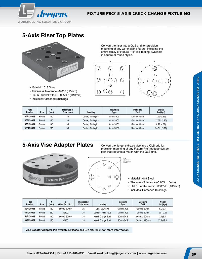
A
A
A
59Phone: 877-426-2504 | Fax: +1 216-481-6193 | E-mail: [email protected] | www.jergensinc.com
WORKHOLDING SOLUTIONS GROUP
QU
ICK
CH
AN
GE
FIX
TU
RIN
G »
FIX
TU
RE
PR
O® 5
-AX
IS Q
UIC
K C
HA
NG
E F
IXT
UR
ING
FIXTURE PRO® 5-AXIS QUICK CHANGE FIXTURING
5-Axis Riser Top Plates
5-Axis Vise Adapter Plates
Part Number Style
A (mm)
Thickness of Plate (mm) Locating
Mounting Type
Mounting Grid
Weight lbs (Kgs)
5TP130002 Round 130 35 Center, Timing Pin 8mm SHCS 12mm x 50mm 7.09 (3.22)
5TP250002 Round 250 35 Center, Timing Pin 8mm SHCS 12mm x 50mm 27.02 (12.26)
5TP130001 Square 130 35 Center, Timing Pin 8mm SHCS 12mm x 50mm 8.97 (4.07)
5TP250001 Square 250 35 Center, Timing Pin 8mm SHCS 12mm x 50mm 34.81 (15.79)
Part Number Style
A (mm)
B (Vise Part. No.)
Thickness of Plate (mm) Locating
Mounting Type
Mounting Grid
Weight lbs (Kgs)
5VA130001 Round 130 80000, 80400 35 QLS, Dowel Pin 12mm SHCS 12mm x 50mm 6.9 (3.1)
5VA250001 Round 250 80100 35 Center, Timing, QLS 12mm SHCS 12mm x 50mm 27 (12.2)
5VA130002 Round 130 80000, 80400 35 Quick Change Stud 20mm QCS 60mm x 60mm 7.4 (3.4)
5VA250002 Round 250 80100 35 Quick Change Stud 20mm QCS 120mm x 120mm 27.5 (12.5)
Vise Locator Adapter Pin Available. Please call 877-426-2504 for more information.
Convert the riser into a QLS grid for precision mounting of any workholding fixture, including the entire family of Fixture Pro® Top Tooling. Available in square or round styles.
Convert the Jergens 5-axis vise into a QLS grid for precision mounting of any Fixture Pro® modular system part that requires a match with the QLS grid.
• Material: 1018 Steel• Thickness Tolerance ±0.005 (.13mm)• Flat & Parallel within: .0005"/Ft. (.013mm)• Includes: Hardened Bushings
• Material: 1018 Steel• Thickness Tolerance ±0.005 (.13mm)• Flat & Parallel within: .0005"/Ft. (.013mm) • Includes: Hardened Bushings
A B(MOUNTING CONFIGURATION FOR VISE)

A
C C
A
B B
A
Jergens, Inc. | 15700 S. Waterloo Road | Cleveland, Ohio 44110-3898 USA60
WORKHOLDING SOLUTIONS GROUP
QU
ICK
CH
AN
GE
FIX
TU
RIN
G » F
IXT
UR
E P
RO
® 5-A
XIS Q
UIC
K C
HA
NG
E F
IXT
UR
ING
FIXTURE PRO® 5-AXIS QUICK CHANGE FIXTURING
5-Axis Machinable Blanks
Square Part Number
Round Part Number
A (mm)
B (mm)
C (mm) Locating
Mounting Type
Mounting Grid
Square Weight lbs (Kgs)
Round Weight lbs (Kgs)
5MB130002 5MB130003 130 30 60 Quick Change Stud 20mm QCS 60mm x 60mm 9.2 (4.2) 6.9 (3.1)
5MB130006 — 130 130 60 Quick Change Stud 20mm QCS 60mm x 60mm 38.5 (17.5) —
5MB160002 5MB160003 160 30 60 Quick Change Stud 20mm QCS 60mm x 60mm 13.3 (6) 10.9 (5)
5MB210002 5MB210003 210 30 60 Quick Change Stud 20mm QCS 120mm x 120 mm 21.2 (9.6) 16.3 (7.4)
5MB210006 5MB210007 210 30 120 Quick Change Stud 20mm QCS 120mm x 120 mm 21.2 (9.6) 16.3 (7.4)
5MB250002 5MB250003 250 30 120 Quick Change Stud 20mm QCS 120mm x 120 mm 32.9 (14.9) 25.9 (11.8)
5MB310002 5MB310003 310 30 120 Quick Change Stud 20mm QCS 60mm x 60mm 47.1 (23.4) 37.1 (16.8)
Designed for 2nd operation machining. Blanks can be machined to accept parts and clamping systems.
5-Axis Blank Fixture PlatesMount fixtures that already have mounting holes that do not match the QLS grid. Available in round and square styles.
Part Number Style
A (mm)
Thickness of Plate (mm) Locating
Mounting Type
Weight lbs (Kgs)
5FP130002 Round 130 35 Center, Timing Pin 12mm SHCS 7.41 (3.36)
5FP250002 Round 250 35 Center, Timing Pin 12mm SHCS 28.65 (13)
5FP130001 Square 130 35 Center, Timing Pin 12mm SHCS 9.62 (4.36)
5FP250001 Square 250 35 Center, Timing Pin 12mm SHCS 36.78 (16.68)
• Material: 1018 Steel• Thickness Tolerance ±0.005 (.13mm)• Includes: Hardened Bushings
• Material: 1018 Steel• Tolerance: ±0.005 (.13mm)• Includes: Hardened Bushing• Pull Studs Not Included

A
F
E
B G
C
D
A
B
C
G
A
F
E
B
D
C
ØA
B
C C
D
61Phone: 877-426-2504 | Fax: +1 216-481-6193 | E-mail: [email protected] | www.jergensinc.com
WORKHOLDING SOLUTIONS GROUP
QU
ICK
CH
AN
GE
FIX
TU
RIN
G »
FIX
TU
RE
PR
O® 5
-AX
IS Q
UIC
K C
HA
NG
E F
IXT
UR
ING
FIXTURE PRO® 5-AXIS QUICK CHANGE FIXTURING
5-Axis Top Tooling – 130mm Dovetail Vises
5-Axis Top Tooling – Block Dovetail Vises
Mounts directly to a rotary table, Fixture Pro® Riser or any QLS Grid. Reduces distortion of parts. Requires 0.060" or less material to clamp.
By cutting a 10° angle cut in the bottom surface of a machinable part it allows for extremely high clamping forces while leaving all 5 sides accessible. The heavy duty 130mm version has higher torque and tilting moments than the standard 130mm Fixture Pro® Dovetail Vise.
Dovetail cutter (part number SDC3) available.
Mounts directly to a rotary table, Fixture Pro® Riser or any QLS Grid. Reduces distortion of parts. Requires 0.060" or less material to clamp.
By cutting a 10° angle cut in the bottom surface of a machinable part it allows for extremely high clamping forces while leaving all 5 sides accessible.
Dovetail cutter (part number SDC3) available.
• Material: 1018 Steel• Flat & Parallel within:
.002"/Ft. (.05mm)• Includes: Hardened
Bushings• Includes Center
Locator Pin
• Material: 1018 Steel• Flatness: .002"/Ft.• Flat & Parallel within:
.002"/Ft. (.05mm)• Includes: Hardened Bushings
Part Number Description
A (mm)
B (mm)
C (mm)
D (mm)
E (mm)
F (mm)
G (mm) Locating
Mounting Type
Mounting Grid
Weight lbs (Kgs)
5DV200 Dovetail Pre-Cut Vise, Steel 120.7 130 50 16.5 76.2 63.5 63.5 Center, Timing Pin, QLS 12mm SHCS 12mm X 50mm 7.36 (3.34)
5DV400 Dovetail Pre-Cut Vise, Steel 120.7 130 50 16.5 76.2 63.5 100.6 Center, Timing Pin, QLS 12mm SHCS 12mm X 50mm 7.21 (3.27)
5MB250 Machinable Blank Steel 120.7 130 50 16.5 76.2 63.5 — Center, Timing Pin, QLS 12mm SHCS 12mm X 50mm 7.99 (3.62)
5DV600 Dovetail Pre-Cut Vise Steel 130 200 50 — — — 151.4 Center, Timing Pin, QLS 12mm SHCS 12mm X 50mm 19.73 (8.95)
Part Number Description
A (mm)
B (mm)
C (mm)
D (mm) Locating
Mounting Type
Mounting Grid
Weight lbs (Kgs)
5DV130002 130mm L.D. Dovetail Vise, Steel 130 25 75 50 Center, Timing Pin, QLS 12mm SHCS 12mm X 50mm 7.36 (3.34)
5DV130003 130mm H.D. Dovetail Vise, Steel 130 25 50 65 Center, Timing Pin, QLS 12mm SHCS 12mm X 50mm 7.21 (3.27)
See additional 5-Axis top tooling on pages 115–126
Light Duty
Heavy Duty

A
D
E
C
HEX SIZE F
A
B
D
E
C
HEX SIZE F
Jergens, Inc. | 15700 S. Waterloo Road | Cleveland, Ohio 44110-3898 USA62
WORKHOLDING SOLUTIONS GROUP
QU
ICK
CH
AN
GE
FIX
TU
RIN
G » F
IXT
UR
E P
RO
® 5-A
XIS Q
UIC
K C
HA
NG
E F
IXT
UR
ING
FIXTURE PRO® 5-AXIS QUICK CHANGE FIXTURING
5-Axis Drop & Lock™ Pallet Changer
5-Axis Locating Keys
Mount parts or fixtures quickly to a machine. Available in Round and Square styles. Drop a fixture or Vise into the Pallet Changer using the Fixture Pro® pull stud system. With two quick turns of a hex wrench it’s ready to machine. Drop it, Lock it, and go!
• Material: A2 Steel• Hardness: 58-62 Rc• Flatness: Ground .0002"/Ft.• Thickness Tolerance: ±0.002• Finish: Black Oxide
130
250
Part Number Style
Configuration of Pins
A (mm)
B (mm)
C (mm)
D (mm)
E (mm)
Hex Size F (mm) Locating Mounting Type
Weight lbs (Kgs)
Pull StudSize (mm)
Part Number
5QP130002 Round 4 130 — 30 60 60 8 Center, Timing Pin, QLS QLS, 12mm SHCS 4.7 (2.13) 20 5QP020
5QP250002 Round 4 250 — 30 120 120 8 Center, Timing Pin, QLS QLS, 12mm SHCS 27 (12.2) 20 5QP020
5QP130001 Square 4 130 130 30 60 60 8 Center, Timing Pin, QLS QLS, 12mm SHCS 6.17 (2.8) 20 5QP020
5QP250001 Square 4 250 250 30 120 120 8 Center, Timing Pin, QLS QLS, 12mm SHCS 34 (15.4) 20 5QP020
5QP130003 Round 2 130 130 30 60 60 8 Center, Timing Pin, QLS QLS, 12mm SHCS 4.7 (2.13) 20 5QP020
5QP130004 Square 2 130 130 30 60 60 8 Center, Timing Pin, QLS QLS, 12mm SHCS 6.17 (2.8) 20 5QP020
Part Number
Mounts to Riser Size
(mm)A
in (mm)B
in (mm)C
(mm)Weight
lbs (Kgs)
5LK1301812 130 .472 (12) .709 (18) 25.26 .02 (.009)
5LK1301814 130 .551 (14) .709 (18) 25.26 .02 (.009)
5LK1301816 130 .630 (16) .709 (18) 25.26 .02 (.009)
5LK1301818 130 .709 (18) .709 (18) 25.26 .03 (.014)
5LK13018500 130 .500 (12.7) .709 (18) 25.26 .02 (.009)
5LK13018562 130 .562 (14.3) .709 (18) 25.26 .02 (.009)
5LK13018625 130 .625 (15.9) .709 (18) 25.26 .02 (.009)
5LK13018687 130 .687 (17.4) .709 (18) 25.26 .03 (.014)
5LK2501812 250 .472 (12) .709 (18) 48 .04 (.018)
5LK2501814 250 .551 (14) .709 (18) 48 .05 (.023)
5LK2501816 250 .630 (16) .709 (18) 48 .05 (.023)
5LK2501818 250 .709 (18) .709 (18) 48 .06 (.027)
5LK25018500 250 .500 (12.7) .709 (18) 48 .05 (.023)
5LK25018562 250 .562 (14.3) .709 (18) 48 .05 (.023)
5LK25018625 250 .625 (15.9) .709 (18) 48 .05 (.023)
5LK25018687 250 .687 (17.4) .709 (18) 48 .06 (.027)
C
B
A
Pull Studs Adapt any machinable part or fixture directly to the part. Use with our quick change Drop & Lock™ Pallet Changer.
• Material: A2 Steel• Hardness: 50-54 Rc
• Case Hardened: 60 Rc• Thickness Tolerance: ±0.0005• Finish: Black Oxide
Used to adapt any of the Fixture Pro® elements with bottom keyway slots for alignment to your machine table slots. Unique design accommodates SHCS, which will tighten a T-nut to the T-slot in your machine.

A
B
DIAMOND RELIEF
A
B
C A
SCREW SIZE E B
D
A
SCREW SIZE C B
63Phone: 877-426-2504 | Fax: +1 216-481-6193 | E-mail: [email protected] | www.jergensinc.com
WORKHOLDING SOLUTIONS GROUP
QU
ICK
CH
AN
GE
FIX
TU
RIN
G »
FIX
TU
RE
PR
O® 5
-AX
IS Q
UIC
K C
HA
NG
E F
IXT
UR
ING
FIXTURE PRO® 5-AXIS QUICK CHANGE FIXTURING
5-Axis Locating Pins
Center Locator Pins
Part Number
A (mm)
B (mm) Thread
Weight lbs (Kgs)
5LP1220 12 20 M6 0.03 (.014)
5LP1224 12 24 M6 0.04 (.018)
5LP1225 12 25 M6 0.04 (.018)
5LP1230 12 30 M6 0.05 (.023)
5LP50075 0.5 0.75 1/4-20 0.03 (.014)
5LP500100 0.5 1 1/4-20 0.04 (.018)
5LP500125 0.5 1.25 1/4-20 0.05 (.023)
Center Locator Pins, Long
Part Number
A (mm)
B (mm)
C Screw Size
Weight lbs (Kgs)
5LP5050 50 50 M12, 1/2 SHCS 1.49 (.68)
5LP5070 50 70 M12, 1/2 SHCS 2.11 (.96)
5LP5090 50 90 M12, 1/2 SHCS 2.73 (1.24)
5LP50110 50 110 M12, 1/2 SHCS 3.35 (1.52)
Diamond Timing Pins
Part Number
A (mm)
B (mm) Thread
Weight lbs (Kgs)
5LP1220001 12 20 M6 0.03 (.014)
5LP1224001 12 24 M6 0.04 (.018)
5LP1225001 12 25 M6 0.04 (.018)
5LP1230001 12 30 M6 0.05 (.023)
5LP50075001 0.5 0.75 1/4-20 0.03 (.014)
5LP500100001 0.5 1 1/4-20 0.04 (.018)
5LP500125001 0.5 1.25 1/4-20 0.05 (.023)
Center Locator Pins
Diamond Timing Pins
Center Step Locator
Center Locator Pins, Long
Center Step Locator
Part Number
A (mm)
B (mm)
C in (mm)
D (mm)
E Screw Size
Weight lbs (Kgs)
5LP1255020 50 20 1.25 (31.75) 40 M12, 1/2 SHCS 0.8 (.36)
Locates subplates to machine rotary tables, risers to subplates, and mounts Fixture Pro® Top Tooling directly to a rotary table.
Special center locators available upon request.
• Material: 1018 Steel• Tolerance: ±0.0002 (.005mm)
Vise Locator Adapter Pin Available. Please call 877-426-2504 for more information.

E F
A
B
C
D
THREAD SIZE G
B A
C
Jergens, Inc. | 15700 S. Waterloo Road | Cleveland, Ohio 44110-3898 USA64
WORKHOLDING SOLUTIONS GROUP
QU
ICK
CH
AN
GE
FIX
TU
RIN
G » F
IXT
UR
E P
RO
® 5-A
XIS Q
UIC
K C
HA
NG
E F
IXT
UR
ING
FIXTURE PRO® 5-AXIS QUICK CHANGE FIXTURING
5-Axis Quick Locating System (QLS) Bushings
5-Axis Quick Locating System (QLS) Shoulder Screws
5-Axis Quick Locating System (QLS) Chip Plug*
Part Number
A (mm)
B (mm)
C (mm)
Weight lbs (Kgs)
5BS128 16 12 8 .01 (.005)
5BS1212 16 12 12 .02 (.009)
5BS1216 16 12 16 .02 (.009)
5BS1232 16 12 32 .05 (.023)
Part Number
A (in)
B (in)
C (in)
Weight lbs (Kgs)
5BS500375 0.75 0.5 0.375 .01 (.005)
5BS500500 0.75 0.5 0.5 .02 (.009)
5BS500625 0.75 0.5 0.625 .02 (.009)
5BS5001375 0.75 0.5 1.375 .05 (.023)
Part Number
A (mm)
B (mm)
C (mm)
D (mm)
E (mm)
Hex Size F (mm)
Thread Size G (mm)
Weight lbs (Kgs)
5SH1220 12 20 40 47 18 8 M12 X 1.75 .09 (.04)
5SH1225 12 25 45 52 18 8 M12 X 1.75 .1 (.045)
5SH1230 12 30 50 57 18 8 M12 X 1.75 .11 (.05)
5SH1235 12 35 55 62 18 8 M12 X 1.75 .12 (.054)
5SH1240 12 40 60 67 18 8 M12 X 1.75 .13 (.06)
5SH1245 12 45 65 72 18 8 M12 X 1.75 .14 (.064)
5SH1250 12 50 70 77 18 8 M12 X 1.75 .15 (.07)
Part Number
A (in)
B (in)
C (in)
D (in)
E (in)
Hex Size F (in)
Thread Size G (in)
Weight lbs (Kgs)
5SH50075 0.5 0.75 1.375 1.625 0.74 0.313 1/2-13 .09 (.04)
5SH500100 0.5 1 1.625 1.875 0.74 0.313 1/2-13 .1 (.045)
5SH500125 0.5 1.25 1.875 2.125 0.74 0.313 1/2-13 .11 (.05)
5SH500150 0.5 1.5 2.125 2.375 0.74 0.313 1/2-13 .13 (.06)
5SH500175 0.5 1.75 2.375 2.625 0.74 0.313 1/2-13 .14 (.064)
5SH500200 0.5 2 2.625 2.875 0.74 0.313 1/2-13 .15 (.07)
Part Number
A (mm)
B (mm)
C (mm)
D (mm)
Thread Size (mm)
Weight lbs (Kgs)
5PL12002 12 7 14.5 11.8 M12 X 1.75 .02 (.01)
5PL23002 23 14 14.5 11.8 M12 X 1.75 .04 (.02)
5PL30002 30 16 14.5 11.8 M12 X 1.75 .05 (.023)
Part Number
A (mm)
B (mm)
C (mm)
D (mm)
Thread Size (mm)
Weight lbs (Kgs)
5PL500001 0.5 0.3 0.57 0.50 1/2-13 .03 (.014)
5PL500002 1.0 0.6 0.57 0.50 1/2-13 .05 (.023)
* O-ring included.
• Hardened and Ground• Concentric within 0.0002" (0.005mm)
• Hardened and Ground• “A” Diameter
±0.0003" (0.008mm)

65
PRODUCTION VISES
Vises
Introduction to Design ........................................... 66–67VMC/HMC Solutions ............................................ 68–69Ball Lock® Mounting System ...............................70–71
Production Vises4" (100 mm) Production Vises ................................72–736" (150 mm) Production Vises ................................. 74–75Self Centering Vises .................................................764" (100 mm) ................................................................76–776" (150 mm) ................................................................78–79Accessories ...................................................................... 79Production Vise Columns4" (100 mm) Production Vise
4 Sided ........................................................................... 803 Sided ........................................................................... 81
6" (150 mm) Production Vise4 Sided ........................................................................... 823 Sided ........................................................................... 83
12 Station Hex ................................................................. 8412 & 16 Station Multi Quads .................................. 85–86Hydraulic Production Vises .....................................874" (100 mm) ............................................................... 88–896" (150 mm) ............................................................... 89–90Hydraulic Vise Columns ...........................................914" (100 mm) 4 sided ........................................................ 924" (100 mm) 3 sided ........................................................ 936" (150 mm) 4 sided ........................................................ 946" (150 mm) 3 sided ........................................................ 95Column Subplates .......................................................... 96Hydraulic Vise Accessories......................................97–98Vise Accessories ............................................... 99–104Jaw Selections ..................................................99–101Ball Lock® Shanks/Plates .....................................102–103Sine Fixture Keys/T-Slot Nuts ..................................... 104Cast Iron Shop Vises ...................................... 105–106
Bock Quick Change Fixturing
Introduction .................................................................. 107System Overview ................................................. 108–109Twin Vises ........................................................................110Jaw System .....................................................................111 Twin Vise Data ................................................................112Locator Plates .................................................................113DexLoc™ Locator Pins ...................................................113 Mono-Quad System ......................................................114
5-Axis Production Vises
Introduction ...................................................................115Self Centering .................................................................116
Jaws /Accessories ................................................117–118Fixed .................................................................................119
Jaws/Accessories ....................................................... 120Quick Clamping Block ................................................. 121Super Compact Clamp ................................................. 122
Jaws/Accessories ...............................................123–124Vise with Reversible and Interchangeable Inserts ... 125
Jaws/Accessories ....................................................... 125Pallet Clamps .......................................................................... 126
PR
OD
UC
TIO
N V
ISE
S
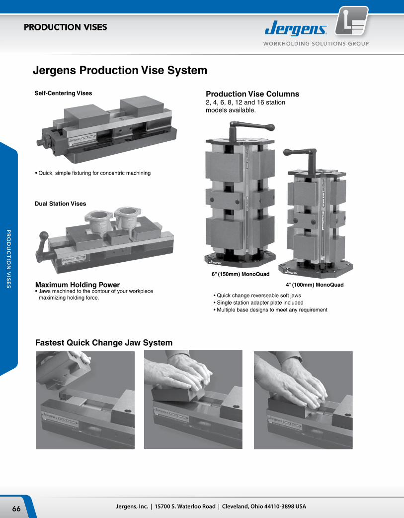
Jergens, Inc. | 15700 S. Waterloo Road | Cleveland, Ohio 44110-3898 USA66
WORKHOLDING SOLUTIONS GROUP
PRODUCTION VISES
PR
OD
UC
TIO
N V
ISE
S
Jergens Production Vise System
Fastest Quick Change Jaw System
Maximum Holding Power• Jaws machined to the contour of your workpiece
maximizing holding force.
• Quick, simple fixturing for concentric machining
6" (150mm) MonoQuad
4" (100mm) MonoQuad
• Quick change reverseable soft jaws• Single station adapter plate included• Multiple base designs to meet any requirement
Production Vise Columns2, 4, 6, 8, 12 and 16 station models available.
Dual Station Vises
Self-Centering Vises

67Phone: 877-426-2504 | Fax: +1 216-481-6193 | E-mail: [email protected] | www.jergensinc.com
WORKHOLDING SOLUTIONS GROUP
PRODUCTION VISES
PR
OD
UC
TIO
N V
ISE
S
Jergens Production VisesFeatures and Benefits:
Fully machinable and reversible jaws
Benefit: More workholding flexibility per jaw set. Machine “Pockets” into the vise jaws, in the shape of your workpiece.
Easy to remove center fixed jaw
Benefit: Quick change over to single station vise for larger parts
Fastest quick change jaw system
Benefit: Reduce set-up times and parts change over
Wide/Full jaw travel
Benefit: Larger workpiece holding capacity
Multiple mounting base configurations available
Benefit: Increased flexibility and use with existing equipment and hardware
Fully sealed lead screw assembly
Benefit: Lower maintenance and repair problems/cost
Rigid construction with hardened and ground stainless steel rails
Benefit: High accuracy and repeatability
Chip and fluid flow through base
Benefit: Easier to keep clean, no more clogging

Jergens, Inc. | 15700 S. Waterloo Road | Cleveland, Ohio 44110-3898 USA68
WORKHOLDING SOLUTIONS GROUP
PRODUCTION VISES
PR
OD
UC
TIO
N V
ISE
S
Vertical Machine Solutions
Hydraulic VisePages 88–90Innovative compact design. Reduced set-up time. Internal Slide Assembly with Hydraulic Clamping Cylinder.
Universal Base Production VisesPages 73 & 75The mounting flange has slotted holes to allow mounting on any machine table.
Ball Lock® Base Production VisesPages 72 & 74The mounting flange is cut into a jigsaw pattern to allow vises to nest closely together. Designed for use with Jergens Ball Lock® Mounting System.
5-Axis Production VisesPages 115–1265-Axis production vises and accessories rigidly clamp parts without obstructing access to multiple part faces.
Self Centering Vises (3 Base Styles)Pages 76–79Self-Centering vises provide quick, simple fixturing for concentric machining of different sized workpieces.
Narrow Base Production VisesPages 73 & 75The small footprint allows maximum density of vises on your fixture or table. Best choice for applications where parts are held in multiple vises.
Bock Brand Quick Change SystemPages 107–114Bock Brand vises combine with alpha-numeric locator plates and Dex-Loc™ pins for maximum quick change efficiency.
Indexer SystemsPage 81Indexer solutions can be customized to your requirements. Choose either three or four sided columns.

69Phone: 877-426-2504 | Fax: +1 216-481-6193 | E-mail: [email protected] | www.jergensinc.com
WORKHOLDING SOLUTIONS GROUP
PRODUCTION VISES
PR
OD
UC
TIO
N V
ISE
S
Horizontal Machine Solutions
6-Sided Production Vise ColumnsPage 84Increase the number of parts per load, while maintaining a small footprint. Available with bases to fit directly onto machine tables or to a Ball Lock® sub-plate.
4-Sided Production Vise Multi-ColumnsPages 85 & 86Multiple columns mounted on a single base provide 12 or 16 workstations. Available with bases to fit directly onto your machine table or to a Ball Lock® sub-plate.
4-Sided Production Vise ColumnsPages 80 & 82Available with bases to fit directly onto machine table pallets or to a Ball Lock® sub-plate.
3-Sided Production Vise ColumnsPages 81 & 83For machining 3 faces of production parts on HMC's. Large spindle noses can access the workpiece. Allows for up to 240° workpiece accessibility.
Multi-Vise FixturesPages 73, 75, 77, 79 & 89To maximize productivity, mount multiple narrow body vises onto a single fixture plate. Mount the fixture plate onto the tombstones with the Jergens Ball Lock® Mounting System.
Hydraulic Vise ColumnsPages 91–97Innovative compact design. Reduced set-up times, faster workpiece change overs.

Jergens, Inc. | 15700 S. Waterloo Road | Cleveland, Ohio 44110-3898 USA70
WORKHOLDING SOLUTIONS GROUP
PRODUCTION VISES
PR
OD
UC
TIO
N V
ISE
S
LocatesThe Ball Lock® System accurately positions your fixture plate...to within ±0.0005" (±0.013mm) repeatability or better, minimizing the need to indicate your fixture.
LocksThe Ball Lock® System securely holds fixture plates to subplates with up to 20,000 lbs (88kN) of hold-down force per shank.
Ball Lock® Fixture Mounting System for Jergens Production Vises
The Ball Lock® Mounting System provides a method of quickly and accurately locating fixtures onto machine tables. The Ball Lock® Mounting System has done for machining centers what the Japanese SMED (Single Minute Exchange of Die) concept did for presses. Instead of SMED, Ball Lock® provides single minute exchange of fixtures. Fixtures can often be exchanged in less than a minute with position repeatability of ±0.0005" (±0.013mm). Fixtures can be exchanged between different machines when both are using the Jergens Ball Lock® Mounting System.
Commonly Asked Questions
Q. What is the Ball Lock® Mounting System?A. It is a means of locating and locking two flat surfaces together, normally a fixture plate to a sub-plate.
Q. How does it locate?A. Similar to locating pins, two Ball Lock® shanks (pins) pass through two precision liner bushings on the fixture plate and into two precision receiver bushings on the subplate.
Q. How does it lock?A. Inside the shank are three balls that expand into a tapered groove in the receiver bushing. This action draws the plates together. The locking balls are activated by turning a setscrew in the head of the shank, which pushes a 4th ball to distribute the clamping forces between the 3 locking balls.
Q. How many shanks are required to locate and lock each fixture?A. Only two shanks, passing through bushings in the fixture plates, are required for location. However,additional shanks passing through clearance holes in the fixture plate will provide additional holding force distributed across the plate.

71Phone: 877-426-2504 | Fax: +1 216-481-6193 | E-mail: [email protected] | www.jergensinc.com
WORKHOLDING SOLUTIONS GROUP
PRODUCTION VISES
PR
OD
UC
TIO
N V
ISE
S
Unmatched Setup Speed and Workholding Flexibility
Q. Is there a preferable location for the liner bushing?A. System repeatability is improved if the liners are located at opposite corners of a rectangular fixture plate. For consistency, we recommend locating the liner bushings at top left and bottom right.
Q. What are the advantages of using the Ball Lock® System over the conventional method of dowelpins and cap screws?A. Both locating and locking are accomplished in the same motion. Ball Lock® shanks require only 2.5 turns to lock a 1/2–13 (M12) screw
with ¾" (18mm) of thread engagement requires 10 turns to lock. On CNC machines, the repeatability of fixture locations makes indicating of the fixture unnecessary.
Q. How do I recess the fixtureplate for a clear surface ?A. Counterbore the fixture plate to a diameter large enough to allow easy removal of the shank.
Note: The thickness of the plate section under the head of the shank is critical and must conform to mounting instructions .
Q. What if my plate is thinner than the recommended thickness? A. By adjusting the depth of the counterbore for the receiver bushing in the subplate, you can still use the Ball Lock® System. If there are any questions on this type of application, please call 1-877-426-2504.
Q. Can I use the shanks in a heated environment?A. The shank is made of alloy steel, heat treated to 40-45Rc and should with stand temperatures up to 400°F.(200°C).
Note: Thermal expansion of fixture plates may affect the center distance tolerance and repeatability.

4.00
1.22
3.370 ±0.0010.75
15.00
6.00
12.00
3.00
6.00 7.92
20mmPrimaryLiners(2) Plcs
ClearanceHole ForHolddown
100
30
85.620
380
150
300
75
150 200
20mmPrimaryLiners(2) Plcs
ClearanceHole ForHolddown
0.38[10]
0.96[24]
3.438[87.5]
1.683.00[73]
1.22[30]
[190]7.50
0.25[6]
0.50[12]0.81
[20]
2.50[64][56]
2.20[176]7.00
4.00[100]
[20 MAX.].80 MAX.
15.00[380] [6.4]
.25
Machinable Area
0.38[10]
0.96[24]
3.438[87.5]
1.683.00[73]
1.22[30]
[190]7.50
0.25[6]
0.50[12]0.81
[20]
2.50[64][56]
2.20[176]7.00
4.00[100]
[20 MAX.].80 MAX.
15.00[380] [6.4]
.25
Machinable Area
Jergens, Inc. | 15700 S. Waterloo Road | Cleveland, Ohio 44110-3898 USA72
WORKHOLDING SOLUTIONS GROUP
PRODUCTION VISES
PR
OD
UC
TIO
N V
ISE
S
Production Vises – 4" (100mm)
Ball Lock® BaseThe Ball Lock® Base Vise is for use with the Jergens Ball Lock® Quick Change Mounting System. The base has a “jig saw” pattern to allow the vises to be mounted close to each other. For more information about Ball Lock®, see pages 70–71.
Vise With Machinable Soft JawsVise With Hard Jaw Carrier Set
and hardened steel inserts
Mounting Dimensions
Clamping Force Jergens 4" (100mm)
Torque Clamping Force ft. lbs N•m lbs kgf
20 27 3,600 1,630 30 41 4,500 2,040 40 54 5,300 2,400 50 68 6,200 2,800 60 81 7,200* 3,250*
*Recommended Maximum
Features and Benefits:• Compact design in 3 extruded aluminum base
styles for easy setup and to reduce weight on worktable.
• Fully sealed, patented lead screw assembly for long maintenance free service. Openings allow chips to flow out of the vise base.
• Hardened stainless steel rails, ground within ±0.001" (0.025mm) provide precise location, resist wear and provide strong support to jaws.
Ball Lock® Shank Shank Part No. Wt. Part No. Size
69405 14 Kg 49651 20mm x 20mm
Ball Lock® Shank Shank Part No. Wt. Part No. Size
49405 31 lbs 49601 20mm x 3/4"
Inch
Metric
Maximum Clamping Range With Shaped JawsDual Station: 6.75" (170mm)Single Station: 14.40" (365mm)
• Supplied with aluminum soft jaws, fully machineable and reversible. Additional jaws can be ordered separately, see page 100. Alternate jaw types can be ordered with the vise base by adding the following suffix to the part numbers:-H for Jaw Carrier Set with Hardened Steel Inserts
-S for machineable Steel Jaws-T for extra Tall aluminum jaws sets-W for extra Wide aluminum jaw sets

NARROW BASE PRODUCTION VISE4" / 100MM
4.00[100]
1.22[30]
3.370 ±0.001[85.6]
0.500[12]
2.953[75]
3.937[100]
4.921[125]
4.688[120]
0.984[25]
1.550[40]
1.975[50]
0.500[12]
Mounting Holes (3) Plcs:17/32"[13.5]
Locating Holes (2) Plcs:.472[12]
Mounting HolesM10 x 1.5 Tap:(6) Plcs
Locating Holes.6255 (4) Plcs ForSine Fixtures Keys
UNIVERSAL BASE PRODUCTION VISE4" / 100MM
1.22[30]
3.370[85.6]
1.25[32]
4.00[100]
7.00[175]
6.00[150]
17/32" (4) Plcs[13.5]
Slotted Mounting Holes:
3.13[80]
2.50[63.5]
6.00[150]
2.063[52.5]
Mounting Holes (2) Plcs:17/32"[13.5]
Locating Holes:.6255 (4) Plcs ForSine Fixture Keys[16]
73Phone: 877-426-2504 | Fax: +1 216-481-6193 | E-mail: [email protected] | www.jergensinc.com
WORKHOLDING SOLUTIONS GROUP
PRODUCTION VISES
PR
OD
UC
TIO
N V
ISE
S
Production Vises – 4" (100mm)Narrow Base
Universal Base
The Universal Base Vise is easily mounted directly to machine tool tables. Slotted mounting holes will match almost any table slot pattern. Location holes are provided for Jergens Sine Fixture Keys, to provide easy and accurate alignment with table slots.
• Easy to mount directly to machine tables
The Narrow Base Vise can be mounted as a stand-alone vise with traditional strap clamps. The narrow base has 2 locating holes for 12mm dowel pins and 2 locating holes for sine fixture keys to align vise in T-slots. Keys for inch and metric T-slots shown on page 104. Recessed mounting holes (3) are also provided for top mounting to fixture plates with socket head cap screws. Tapped mounting holes (6) are provided for bottom mounting. The slim design allows a high density of vises on machine tables, tombstones, or columns. Maximize flexibility by utilizing the Jergens Ball Lock® Quick Change Mounting System. See page 70.
• Easy to mount to Ball Lock® or other fixture plates
Mounting Dimensions
Mounting Dimensions
Part Wt. Number lbs/Kg
49401 30/14
Part Wt. Number lbs/Kg
49471 31/14

1.45
3.370 ±0.0010.75
6.00
6.00
12.00
20.00
4.00
8.00 9.92
ClearanceHole ForHolddown
20mmPrimaryLiners(2) Plcs
38
85.6
20
150
150
300
508
100
200 250
ClearanceHole ForHolddown
20mmPrimaryLiners(2) Plcs
0.50[12]
4.50[114]
4.00[100]
10.00[248]
1.45[38]
0.96[24]
0.25[6]
0.60[15]1.00
[25]
3.00[78]
3.75[88]
5.00[127]
10.50[254]
1/4[6.4]0.80
[20]20.00[508]
Machinable Area
0.50[12]
4.50[114]
4.00[100]
10.00[248]
1.45[38]
0.96[24]
0.25[6]
0.60[15]1.00
[25]
3.00[78]
3.75[88]
5.00[127]
10.50[254]
1/4[6.4]0.80
[20]20.00[508]
Machinable Area
Jergens, Inc. | 15700 S. Waterloo Road | Cleveland, Ohio 44110-3898 USA74
WORKHOLDING SOLUTIONS GROUP
PRODUCTION VISES
PR
OD
UC
TIO
N V
ISE
S
Production Vises – 6" (150mm)
Ball Lock® BaseThe Ball Lock® Base Vise is for use with the Jergens Ball Lock® Quick Change Mounting System. The base has a “jigsaw” pattern to allow the vises to be mounted close to each other. For more information about Ball Lock®, see pages 70–71.
Mounting Dimensions
Inch
Metric
Torque Clamping Force ft. lbs N•m lbs kgf
20 27 3,600 1,63030 41 4,500 2,04040 54 5,300 2,40050 68 6,200 2,80060 81 7,200 3,25070 95 8,400 3,80080 108 9,200 4,15090 122 10,100* 4,550* *Recommended Maximum
Clamping Force Jergens 6" (150mm)
Ball Lock® Shank Shank Part No. Wt. Part No. Size
49406 68 lbs 49601 20mm x 3/4"
Ball Lock® Shank Shank Part No. Wt. Part No. Size
69406 31 Kg 49651 20mm x 20mm
Maximum Clamping Range With Shaped JawsDual Station: 9.2" (233mm)Single Station: 19.5" (495mm)
Vise With Machinable Soft Jaws
Vise With Hard Jaws Carrier Set and hardened steel inserts
Features and Benefits:• Compact design in 3 extruded aluminum base
styles for easy setup and to reduce weight on worktable.
• Fully sealed, patented lead screw assembly for long maintenance free service. Openings allow chips to flow out of the vise base.
• Hardened stainless steel rails, ground within ±0.001" (0.025mm) provide precise location, resist wear and provide strong support to jaws.
• Supplied with aluminum soft jaws, fully machineable and reversible. Additional jaws can be ordered separately, see page 100. Alternate jaw types can be ordered with the vise base by adding the following suffix to the part numbers:-H for Jaw Carrier Set with Hardened Steel Inserts
-S for machineable Steel Jaws-T for extra Tall aluminum jaws sets-W for extra Wide aluminum jaw sets

NARROW BASE PRODUCTION VISE6" / 150MM
3.370 ±0.001[85.6]
1.45[38]
6.00[150]
1.968 TYP.[50]
1.125[28]
2.952[75]
4.921[125]
7.874[200]
6.000[150]
Mounting Through Holes (4) Plcs:17/32[13.5]
Locating Holes (2) Plcs:.472[12]
Mounting Holes:M10 x 1.5 Tap(6) Plcs
Locating Holes (4) Plcs:.6255 For Sine Fixture Keys
UNIVERSAL PRODUCTION VISE6" / 150MM
3.370 ±0.001[85.6]
1.45[38]
6.00[150]
1.250[32] 9
[225]
20.0[508]
3.00[75]
3.937[100]
2.50[63.5]
3.875[100]
7.874[200]
8.50[216]
8.50[216]
17/32"[13.5]
Slotted Mounting Holes (4) Plcs:Mounting Holes (6) Plcs:17/32[13.5]
Locating Holes:.6255 (4) PlcsFor Sine Fixture Keys
75Phone: 877-426-2504 | Fax: +1 216-481-6193 | E-mail: [email protected] | www.jergensinc.com
WORKHOLDING SOLUTIONS GROUP
PRODUCTION VISES
PR
OD
UC
TIO
N V
ISE
S
Production Vises – 6" (150mm) Narrow Base
Universal Base
The Universal Base Vise is easily mounted directly to machine tool tables. Slotted mounting holes will match almost any table slot pattern. Location holes are provided for Jergens Sine Fixture Keys, to provide easy and accurate alignment with table slots.
• Easy to mount directly to machine tables
The Narrow Base Vise can be mounted as a stand-alone vise or mounted to a fixture plate. The slim design allows a high density of vises on machine tables, tombstones, or columns. Maximize flexibility by utilizing the Jergens Ball Lock® Quick Change Mounting System. See pages 70–71.
• Easy to mount to Ball Lock® or other fixture plates
Mounting Dimensions
Mounting Dimensions
Part Wt. Number lbs/Kg
49402 66/30
Part Wt. Number lbs/Kg
49472 68/31

7.00"
4.00"
1.22"(31.0)
1.25"(31.75)
17.688
15.00
5.684.00 4.00
2.50"3.125"
6.00"
2.063"(52.40)
6.00"
(4) PLACES0.6255"(15.888) LOCATING HOLES
17/32"(13.5) SLOTTED MTG. HOLES(4) PLACES
17/32"(13.5) MTG. HOLES(2) PLACES
3.370"(85.60)±0.001"(0.03)
(152.4)
(152.4)
(101.6)
(177.8)
(63.5)(79.38)
7.00"
4.00"
1.22"(31.0)
1.25"(31.75)
17.688
15.00
5.684.00 4.00
2.50"3.125"
6.00"
2.063"(52.40)
6.00"
(4) PLACES0.6255"(15.888) LOCATING HOLES
17/32"(13.5) SLOTTED MTG. HOLES(4) PLACES
17/32"(13.5) MTG. HOLES(2) PLACES
3.370"(85.60)±0.001"(0.03)
(152.4)
(152.4)
(101.6)
(177.8)
(63.5)(79.38)
MACHINABLE AREA8.055(203)
5.00(125)
5.00(125)
20.00(508)
22.688(577)
.25(6.4)
17.688(449)
15.00(381)
5.68(142)
4.00(100)
4.00(100)
Jergens, Inc. | 15700 S. Waterloo Road | Cleveland, Ohio 44110-3898 USA76
WORKHOLDING SOLUTIONS GROUP
PRODUCTION VISES
PR
OD
UC
TIO
N V
ISE
S
• Easy to mount directly to machine tables• Slotted mounting holes fit most machinable centers
Self-Centering Precision Production Vises
Features and Benefits:• Self-Centering vises provide quick, simple
fixturing for concentric machining of different sized workpieces.
• Adjustable gib design increases accurracy.• Compact design in 3 extruded aluminum
base styles for easy setup and to reduce weight on worktable.
• Fully sealed, patented lead screw assembly for long maintenance free service. Openings allow chips to flow out of the vise base.
• Hardened stainless steel rails, ground within ±0.001" (0.025mm) provide precise location, resist wear and provide strong support to jaws.
• Shown in Universal Base, also available in Narrow Bases and Ball Lock® Mounting Base.
Technical Specifications:Maximum jaw opening (Unmachined jaws) 4" (100mm) model: 5.6" (142mm) 6" (150mm) model: 8" (200mm)Centering accuracy from minimum to
maximum opening: 0.0006" (0.015mm)Repeatability: 0.0002" (0.005mm)Maximum Clamping Force: 4600lbs (2000kgf)
Maximum Clamping RangeWith Shaped Jaws4" Vise: 13" (330mm)6" Vise: 17.5" (440mm)
Torque Clamping Force ft. lbs N•m lbs kgf
20 27 1100 50030 41 1500 68040 54 2200 100050 68 2700 122060 81 3100 140070 95 3800 172080 108 4200* 1900*
*Recommended Maximum
Clamping Force Jergens 4" (100mm) & 6" (150mm) Self-Centering Vises
6" (150mm) Self-Centering Vises4" (100mm) Self-Centering Vises
Part Number Wt. (lbs)
49471SC 38
Self-Centering Vises – 4" (100mm)Universal Base
• Supplied with aluminum soft jaws, fully machineable and reversible. Additional jaws can be ordered separately, see page 100. Alternate jaw types can be ordered with the vise base by adding the following suffix to the part numbers:
-H for Jaw Carrier Set with Hardened Steel Inserts -S for machineable Steel Jaws -T for extra Tall aluminum jaws sets -W for extra Wide aluminum jaw sets

1.22"
4.00"
0.75"
7.92"
15.00
17.688
4.00 5.68 4.00
12"
6"
6"
3"
20MM PRIMARY LINERS(2) PLACES
CLEARANCE HOLEFOR HOLD DOWN
3.370"±0.001"
15.00
17.688
4.00 5.68 4.00
20MM PRIMARY LINERS(2) PLACES
CLEARANCE HOLEFOR HOLD DOWN
85.6
30
100
20
200
150
75
300
150
1.22"
4.00"
0.75"
7.92"
15.00
17.688
4.00 5.68 4.00
12"
6"
6"
3"
20MM PRIMARY LINERS(2) PLACES
CLEARANCE HOLEFOR HOLD DOWN
3.370"±0.001"
15.00
17.688
4.00 5.68 4.00
20MM PRIMARY LINERS(2) PLACES
CLEARANCE HOLEFOR HOLD DOWN
85.6
30
100
20
200
150
75
300
150
3.370"(85.60)±0.001"(0.03)
1.22"(31.0)
4.00"
17.688"
15.00"
4.00" 4.00"
0.984"(25.00)
1.550"(39.37)
0.50"(12.7)
0.50"(12.7)
4.688" 3.937"
4.921"
6.00"
0.6255"(15.888) LOCATING HOLES(6) PLACES
0.472"(12.00) LOCATING HOLES(2) PLACES
17/32"(13.5) MTG. HOLES(5) PLACES
2.00" 2.953"
M10 TAPPED MTG. HOLES(6) PLACES
(125.00)
(100.00)
(75.00)
(152.4)
(50.8)
(119.08) (101.6)
(101.6) (101.6)
(381)
(449.28)
77Phone: 877-426-2504 | Fax: +1 216-481-6193 | E-mail: [email protected] | www.jergensinc.com
WORKHOLDING SOLUTIONS GROUP
PRODUCTION VISES
PR
OD
UC
TIO
N V
ISE
S
Self-Centering Vises – 4" (100mm) Ball Lock®
Narrow Base
• Integrates with the Jergens Ball Lock® mounting system• Jigsaw pattern allows for “nesting” on Jergens Ball Lock® subplates
• Designed for stand alone or fixture plate mounting• Slim design enables high density mounting
Part Number Wt. (lbs)
49401SC 34
Part Number Wt. lbs 49405SC 36
Part Number Wt. Kg 69405SC 17
Inch
Metric

1.448"(36.78)
6.00"
9.00"
1.25"
5.00 8.055 5.00
20.00
22.688
3.00"
2.50"(63.5)3.875"
7.874"8.50"(215.9)
6.00"
7.874"
0.6255"(15.888) LOCATING HOLES (6) PLACES
17/32"(13.5) MTG. HOLES(6) PLACES
17/32" (13.5)SLOTTED MTG. HOLES(4) PLACES
3.370"(85.60)±0.001"(0.03)
(200.00)
(76.2)
(152.4)(200.00)
(98.43)
(152.4)
(228.6)
(31.75)
1.448"
0.75"
6.00"
9.92"
12"
8"
6"
4"
20MM PRIMARY LINERS(2) PLACES
CLEARANCE HOLEFOR HOLD DOWN
3.370"±0.001"
20MM PRIMARY LINERS(2) PLACES
CLEARANCE HOLEFOR HOLD DOWN
85.6
38
20
150
250
150
100
300
200
Jergens, Inc. | 15700 S. Waterloo Road | Cleveland, Ohio 44110-3898 USA78
WORKHOLDING SOLUTIONS GROUP
PRODUCTION VISES
PR
OD
UC
TIO
N V
ISE
S
Universal Base
Ball Lock® Base
Self-Centering Vises – 6" (150mm)
• Easy to mount directly to machine tables• Slotted mounting holes fit most machinable centers
• Integrates with the Jergens Ball Lock® mounting system• Jigsaw pattern allows for “nesting” on Jergens Ball Lock® subplates
Part Number Wt. (lbs)
49472SC 70
Part No. Wt. lbs 49406SC 66
Part No. Wt. Kg 69406SC 30
Inch
Metric

1.448"
6.00"
5.00" 5.00"
20.00"
22.688"
1.125"
1.125"(28.58)
2.952"
7.874"
6.00" 4.00"
(6) PLACES0.6255"(15.888) LOCATING HOLES
0.472"(12.00) LOCATING HOLES(2) PLACES
17/32"(13.5) MTG. HOLES(7) PLACES
3.938"(100.00)
4.921"M10 TAPPED HTG. HOLES(6) PLACES
(200.00)
(125.00)
(101.6)(152.4)
(74.98)(28.58)
(152.4)
(36.78)
3.370"(85.60)±0.001"(0.03)
(127)
(508)
(127)
(576.28)
GIB PINSGIB ADJUSTMENT SCREW (BOTH ENDS)3/16" HEX.
2" (5
0mm
)
12" (300mm)
79Phone: 877-426-2504 | Fax: +1 216-481-6193 | E-mail: [email protected] | www.jergensinc.com
WORKHOLDING SOLUTIONS GROUP
PRODUCTION VISES
PR
OD
UC
TIO
N V
ISE
S
Narrow Base
Self-Centering Vises – 6" (150mm)
• Designed for stand alone or fixture plate mounting• Slim design enables high density mounting
Part Number Wt. (lbs)
49402SC 64
Part No.
49442SC
Self Centering Vise AccessoriesJaws with Adjustable Gib Screw*• Better location accuracy than conventional Jergens Quick Change Vise Jaws
*Jergens Standard Jaws fully compatible, see complete selection on page 100.To order Jergens Production Vise Jaws with Adjustable Gib Screw, use standard jaw part no. followed by "SC".
• Ergonomic hinge handle.• Specification: Chrome Plated Steel, 9/16 Hex Socket
HandleSelf-Centering Vise Handle One Piece Included with 4" (100mm) & 6" (150mm) Self-Centering Vises

J
Q
H
Ball Lock®
Mtg. Pattern
.50[12]
4.00[100]
7.00[176]
2.50[64]
.25[6]
1.22[30]
Machinable area
.56[14]
17.56[446]
8.50[216]
.81[20]
2.20[56]
1.00[25]
1.23[30]
3.00[73]
7.50[190]
.96[24]
.38 TYP[10]
3.44[87.5]
1.00[25]
Jergens, Inc. | 15700 S. Waterloo Road | Cleveland, Ohio 44110-3898 USA80
WORKHOLDING SOLUTIONS GROUP
PRODUCTION VISES
PR
OD
UC
TIO
N V
ISE
S
Production Vise Columns – 4" (100mm)4-SidedThe 4-Sided Columns have eight stations for holding parts. Two standard bases and custom mounting patterns are available. The universal base mounts directly to most HMC tables using the provided mounting holes on 80mm or 100mm centers.
Further reduce set-up times by adding the Jergens Ball Lock® Mounting System to your HMC. Exchange your vise columns and any other fixture in less than a minute. Location of all fixtures will repeat within ±0.0005" (±0.013mm) or better. Please contact Jergens Customer Service for more information.
4-Sided 4" Vise Columns
4-Sided 100mm Vise Columns Metric Bases
Production Vise Columns – 4" (100mm) • 3 or 4-Sided Columns• Multiple mounting systems• Fastest quick-change jaw system• Full jaw travel• Hardened stainless steel rails
support jaws and resist wear• Fully sealed lead screw assembly• Supplied with machinable soft jaws• Available with hard jaws
Column With Soft Jaws Column With Hard Jaws
* Bases on Universal Columns are provided with two sets of mounting holes, to fit grids or T-Slots on 80mm and 100mm centers. Custom mounting patterns and base sizes are available upon request.
Base Base Ball Lock® Mounting Mounting Wt. Ball Lock® Shank Mounting Part No. H J Q Width Length Mtg Pattern Pattern 1* Pattern 2* (lbs) Part No. Size
Ball Lock® 49403 9.56 4.00 2.80 15.75 15.75 14 x 14 n/a n/a 132 49602 20mm x 1" Universal 49475 9.56 4.00 2.80 11.81 11.81 n/a 80mm 100mm 122 — —
Base Base Ball Lock® Mounting Mounting Wt. Ball Lock® Shank Mounting Part No. H J Q Width Length Mtg Pattern Pattern 1* Pattern 2* (Kg) Part No. Size
Ball Lock® 69403 240 100 70 400 400 350 x 350 n/a n/a 60 49652 20mm x 25mm Universal 69475 240 100 70 300 300 n/a 80mm 100mm 55 — —
Clamping ForceJergens 4" (100mm)
Torque Clamping Force ft. lbs N•m lbs kgf
20 27 3,600 1,630 30 41 4,500 2,040 40 54 5,300 2,400 50 68 6,200 2,800 60 81 7,200* 3,250*
*Recommended Maximum

J
H
Q
120˚
Ball Lock®
Mtg. Pattern
81Phone: 877-426-2504 | Fax: +1 216-481-6193 | E-mail: [email protected] | www.jergensinc.com
WORKHOLDING SOLUTIONS GROUP
PRODUCTION VISES
PR
OD
UC
TIO
N V
ISE
S
* Bases on Universal Columns are provided with two sets of mounting holes, to fit grids or T-Slots on 80mm and 100mm centers. Custom mounting patterns and base sizes are available upon request.
Indexer SystemsMaximize the productivity of your Vertical Machining Center. Jergens Production Columns can be mounted onto most any indexer. Columns can be attached directly to an indexer or become part of a quick-change system by adding the Jergens Ball Lock® Mounting System. Contact Jergens Technical Service for help designing a system for your application.
• Add capabilities to your VMC• Reduce set-ups• Mounts to most rotary table/indexer• Hold 4, 6, or 8 parts in each load.• Use standard jaws and accessories
The 3-Sided Columns have six workstations, and may provide greater access to three or more sides of your work pieces. This design is especially beneficial on machining centers with large spindles. No need to sacrifice tool rigidity for access, by having tools extended too far from the tool holders. The universal base mounts directly to most HMC tables using the provided mounting holes on 80mm or 100mm centers.
Further reduce set-up time with the Jergens Ball Lock® Mounting System to your HMC. Exchange your vise columns and all other fixtures in less than a minute. Location of all fixtures will repeat within ±0.0005" (±0.013mm)or better.
3-Sided 4" Vise Columns
3-Sided 100mm Vise Columns Metric Bases
Production Vise Columns – 4" (100mm)3-Sided
Base Base Ball Lock® Mounting Mounting Wt. Ball Lock® Shank Mounting Part No. H J Q Width Length Mtg Pattern Pattern 1* Pattern 2* (lbs) Part No. Size
Ball Lock® 49409 9.55 4.00 4.22 15.75 15.75 14 x 14 n/a n/a 125 49602 20mm x 1" Universal 49473 9.55 4.00 4.22 11.81 11.81 n/a 80mm 100mm 115 — —
Base Base Ball Lock® Mounting Mounting Wt. Ball Lock® Shank Mounting Part No. H J Q Width Length Mtg Pattern Pattern 1* Pattern 2* (Kg) Part No. Size
Ball Lock® 69409 225 100 90 400 400 350 x 350 n/a n/a 57 49652 20mm x 25mm Universal 69473 225 100 90 300 300 n/a 80mm 100mm 52 — —
Tri-column design allows up to 240° accessibility

1.75[38]
4.00[100]
10.00[248]
.96[24]
.50 TYP[12]
4.50[114]
.60[15]
5.00[127]
10.00[254]
3.00[78]
.25[6]
1.45[37]
Machinable Area
.56[14]
22.56[573]
11.00[280]
1.00[25]
3.50[88]
1.00[25]
J
Q
H
Ball Lock®
Mtg. Pattern
Jergens, Inc. | 15700 S. Waterloo Road | Cleveland, Ohio 44110-3898 USA82
WORKHOLDING SOLUTIONS GROUP
PRODUCTION VISES
PR
OD
UC
TIO
N V
ISE
S
Production Vise Columns – 6" (150mm) • 3 or 4-Sided Columns• Multiple mounting systems• Fastest quick-change jaw system• Full jaw travel• Hardened stainless steel rails support jaws and resist wear• Fully sealed lead screw assembly• Supplied with machinable soft jaws• Available with hard jaws
Column With Soft Jaws Column With Hard Jaws
Production Vise Columns – 6" (150mm)4-SidedThe 4-Sided Columns are the workhorses of the Jergens Production Vise Columns. They have eight stations for holding your parts. Two standard bases are available. The universal base will mount directly to most HMC tables, using the provided mounting holes on 80mm or 100mm centers.
Further reduce set-up times by adding the Jergens Ball Lock®
Mounting System to your HMC. Exchange your vise columns and any other fixture in less than a minute. Location of all fixtures will repeat within ±0.0005" (±0.013mm) or better.
Base Base Ball Lock® Mounting Mounting Wt. Ball Lock® Shank Mounting Part No. H J Q Width Length Mtg Pattern Pattern 1* Pattern 2* (lbs) Part No. Size
Ball Lock® 49412 11.50 6.00 2.75 15.75 15.75 14 x 14 n/a n/a 244 49602 20mm x 1" Ball Lock® 49404 11.50 6.00 2.75 19.68 19.68 17 x 17 n/a n/a 258 49612 25mm x 1" Universal 49476 11.50 6.00 2.75 15.75 15.75 n/a 80mm 100mm 235 — —
Base Base Ball Lock® Mounting Mounting Wt. Ball Lock® Shank Mounting Part No. H J Q Width Length Mtg Pattern Pattern 1* Pattern 2* (Kg) Part No. Size
Ball Lock® 69412 290 150 70 400 400 350 x 350 n/a n/a 111 49652 20mm x 25mm Ball Lock® 69404 290 150 70 500 500 425 x 425 n/a n/a 117 49662 20mm x 25mm Universal 69476 290 150 70 400 400 n/a 80mm 100mm 107 — —
4-Sided 6" (150mm) Vise Columns
4-Sided 150mm Vise Columns Metric Bases
* Bases on Universal Columns are provided with two sets of mounting holes, to fit grids or T-Slots on 80mm and 100mm centers. Custom mounting patterns and base sizes are available upon request.
Torque Clamping Force lbs ft. N•m lbs kgf
20 27 3,600 1,63030 41 4,500 2,04040 54 5,300 2,40050 68 6,200 2,80060 81 7,200 3,25070 95 8,400 3,80080 108 9,200 4,15090 122 10,100* 4,550* *Recommended Maximum
Clamping ForceJergens 6" (150mm)

J
H
Q
120˚
Ball Lock®
Mtg. Pattern
83Phone: 877-426-2504 | Fax: +1 216-481-6193 | E-mail: [email protected] | www.jergensinc.com
WORKHOLDING SOLUTIONS GROUP
PRODUCTION VISES
PR
OD
UC
TIO
N V
ISE
S
The 3-Sided Columns have only six workstations, but provide much greater access to three or more sides of your work pieces. This design is especially beneficial on machining centers with large spindle noses. No need to sacrifice tool rigidity for access, by having tools extended too far from the tool holders. The universal base will mount directly to most HMC tables, using the provided mounting holes on 80mm or 100mm centers.
Further reduce your set-up time by adding the Jergens Ball Lock® Mounting system to your HMC. Exchange your vise columns and all other fixtures in less than a minute. Location of all fixtures will repeat within ±0.0005" (±0.013mm)or better.
Production Vise Columns – 6" (150mm)3-Sided
Base Base Ball Lock® Mounting Mounting Wt. Ball Lock® Shank Mounting Part No. H J Q Width Length Mtg Pattern Pattern 1* Pattern 2* (lbs) Part No. Size
Ball Lock® 49408 12.57 6.00 5.12 15.75 15.75 14 x 14 n/a n/a 252 49602 20mm x 1"
Ball Lock® 49410 12.57 6.00 5.12 19.68 19.68 17 x 17 n/a n/a 266 49612 25mm x 1" Universal 49474 12.57 6.00 5.12 19.68 19.68 n/a 80mm 100mm 240 — —
Base Base Ball Lock® Mounting Mounting Wt. Ball Lock® Shank Mounting Part No. H J Q Width Length Mtg Pattern Pattern 1* Pattern 2* (Kg) Part No. Size
Ball Lock® 69408 318 150 130 400 400 350 x 350 n/a n/a 115 49652 20mm x 25mm Ball Lock® 69410 318 150 130 500 500 425 x 425 n/a n/a 121 49662 25mm x 25mm Universal 69474 318 150 130 500 500 n/a 80mm 100mm 109 — —
3-Sided 6" Vise Columns
3-Sided 150mm Vise Columns Metric Bases
* Bases on Universal Columns are provided with two sets of mounting holes, to fit grids or T-Slots on 80mm and 100mm centers. Custom mounting patterns and base sizes are available upon request. .
Tri-column design allows up to 240° accessibility

R
K
H
P
J
E
S
D
A
C
N
B
Ball Lock®
Mtg. Pattern
R
K
H
P
J
E
S
D
A
C
N
B
Ball Lock®
Mtg. Pattern
Jergens, Inc. | 15700 S. Waterloo Road | Cleveland, Ohio 44110-3898 USA84
WORKHOLDING SOLUTIONS GROUP
PRODUCTION VISES
PR
OD
UC
TIO
N V
ISE
S
Production Vise Columns 12 Station Hex
Jergens Hex Production Vise Columns provide 12 stations to maximize the number of parts per load. Available with bases to fit directly onto your machine table, or to a Ball Lock® sub-plate.
• Reduce part processing costs by machining 3 sides of 12 parts• Increase unattended machine time• Improve part throughput• One piece column with hardened steel guide ways• Full jaw travel permits clamping a larger variety of parts
Ball Lock® Base Universal Base Ball Lock® Base Universal Base Dimensions 49413 49414 49477 49478 69413 69414 69477 69478 Vise Size 4" /100mm 6"/150mm 4" /100mm 6"/150mm 100mm 150mm 100mm 150mmA Max Jaw Opening* 2.25 3.50 2.25 3.50 56 88 56 88B Max Jaw Opening (1 station)* 7.00 10.00 7.00 10.00 178 254 178 254C Fixed Jaw Width 2.50 3.00 2.50 3.00 64 78 64 78D Moveable Jaw Length 4.00 5.00 4.00 5.00 100 127 100 127E Base to Center of Fixed Jaw 8.50 11.00 8.50 11.00 241 305 241 305H Overall Width 11.81 16.91 11.81 16.91 300 432 300 432J Jaw Width 4.00 6.00 4.00 6.00 100 150 100 150K Outside Rail to Rail 9.37 14.01 9.37 14.01 238 356 238 356N Base Plate Thickness 1.00 1.00 1.00 1.00 25 25 25 25P Overall Height 17.56 22.56 17.56 22.56 446 573 446 573R Top Plate Thickness 0.56 0.56 0.56 0.56 14 14 14 14S Center to Face 1.25 1.50 1.25 1.50 32 39 32 39 Base Length & Width 15.75 19.68 15.75 19.68 400 500 400 500 Ball Lock® Mounting Pattern 14x14 17x17 n/a n/a 350x350 425x425 n/a n/a Mounting Pattern 1** n/a n/a 80mm 80mm n/a n/a 80mm 80mm Mounting Pattern 2** n/a n/a 100mm 100mm n/a n/a 100mm 100mm Weight 206 lbs 355 lbs 206 lbs 355 lbs 94 Kg 161 Kg 94 Kg 161 Kg
Hex Production Vise Columns (Inch & Metric)
* Larger parts can be clamped by machining jaws to fit workpiece.** Bases on Universal Columns are provided with two sets of mounting holes, to fit grids or T-Slots on 80mm and 100mm centers.
Custom mounting patterns and base sizes are available upon request.

A
R
S
E
N
PBC
D
H
QK
Ball Lock®
Mtg. PatternK Q
H
J
Ball Lock®
Mtg. Pattern
A
R
S
E
N
PBC
D
H
QK
Ball Lock®
Mtg. Pattern
85Phone: 877-426-2504 | Fax: +1 216-481-6193 | E-mail: [email protected] | www.jergensinc.com
WORKHOLDING SOLUTIONS GROUP
PRODUCTION VISES
PR
OD
UC
TIO
N V
ISE
S
12 Station
Production Vise Columns 12 & 16 Station Multi-Quads
Jergens Multi-Quad Production Vise Columns provide 12 or 16 stations to maximize the number of parts per load. Available with bases to fit directly onto your machine table, or to a Ball Lock® sub-plate.
Ball Lock® Base Universal Base
Inch Multi-Quad Production Vise Columns12 Station 16 Station
Dimensions
• Machine more parts per set-up• Reduce changeover time• Hold larger parts• Reduce cost per part• Run longer without operator involvement
* Larger parts can be clamped by machining jaws to fit workpiece.** Bases on Universal Columns are provided with two sets of mounting holes, to fit grids or T-Slots on 80mm and 100mm centers. Custom mounting
patterns and base sizes are available upon request. Contact Jergens Technical Service for more information.
Ball Lock® Base Universal Base 49415 49416 49479 49480 49417 49418 49481 49482 Vise Size 4"/100mm 6"/150mm 4"/100mm 6"/150mm 4"/100mm 6"/150mm 4"/100mm 6"/150mm
A Max Jaw Opening (2 station)* 2.25 3.50 2.25 3.50 2.25 3.50 2.25 3.50 B Max Jaw Opening (1 station)* 7.00 10.00 7.00 10.00 7.00 10.00 7.00 10.00C Fixed Jaw Width 2.50 3.00 2.50 3.00 2.50 3.00 2.50 3.00 D Moveable Jaw Length 4.00 5.00 4.00 5.00 4.00 5.00 4.00 5.00 E Base to Center of Fixed Jaw 8.50 11.00 8.50 11.00 8.50 11.00 8.50 11.00 H Overall Width 11.81 16.91 11.81 16.91 11.81 16.91 11.81 16.91 J Jaw Width 4.00 6.00 4.00 6.00 4.00 6.00 4.00 6.00 K Outside Rail to Rail 9.37 14.01 9.37 14.01 9.37 14.01 9.37 14.01 N Base Plate Thickness 1.00 1.00 1.00 1.00 1.00 1.00 1.00 1.00 P Overall Height 17.56 22.56 17.56 22.56 17.56 22.56 17.56 22.56 Q Clearance 2.80 2.75 2.80 2.75 2.80 2.75 2.80 2.75R Top Plate Thickness 0.56 0.56 0.56 0.56 0.56 0.56 0.56 0.56 S Center to Face 1.25 1.50 1.25 1.50 1.25 1.50 1.25 1.50 Base Length & Width 15.75 19.68 15.75 19.68 15.75 19.68 15.75 19.68 Ball Lock® Mounting Pattern 14x14 17x17 n/a n/a 14x14 17x17 n/a n/a Mounting Pattern 1** n/a n/a 80mm 80mm n/a n/a 80mm 80mm Mounting Pattern 2** n/a n/a 100mm 100mm n/a n/a 100mm 100mm Weight (lbs) 190 380 190 380 360 720 360 720
16 Station
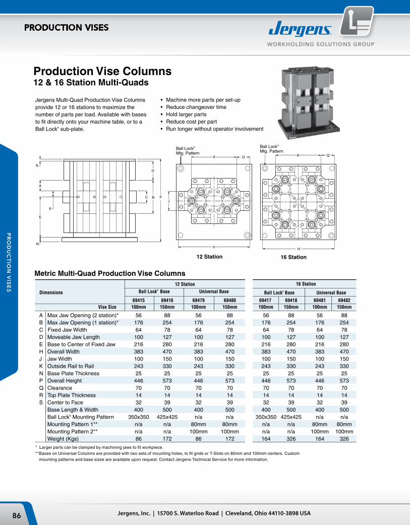
Ball Lock�
Mtg. PatternK Q
H
DR
A
E
S
N
C B P
Ball Lock�
Mtg. Pattern
A
R
S
E
N
PBC
D
H
QK
Ball LockMtg. Pattern
Jergens, Inc. | 15700 S. Waterloo Road | Cleveland, Ohio 44110-3898 USA86
WORKHOLDING SOLUTIONS GROUP
PRODUCTION VISES
PR
OD
UC
TIO
N V
ISE
S
12 Station
16 Station
Production Vise Columns 12 & 16 Station Multi-Quads
Jergens Multi-Quad Production Vise Columns provide 12 or 16 stations to maximize the number of parts per load. Available with bases to fit directly onto your machine table, or to a Ball Lock® sub-plate.
Ball Lock® Base Universal Base
Metric Multi-Quad Production Vise Columns12 Station 16 Station
Dimensions
• Machine more parts per set-up• Reduce changeover time• Hold larger parts• Reduce cost per part• Run longer without operator involvement
* Larger parts can be clamped by machining jaws to fit workpiece.** Bases on Universal Columns are provided with two sets of mounting holes, to fit grids or T-Slots on 80mm and 100mm centers. Custom
mounting patterns and base sizes are available upon request. Contact Jergens Technical Service for more information.
Ball Lock® Base Universal Base 69415 69416 69479 69480 69417 69418 69481 69482 Vise Size 100mm 150mm 100mm 150mm 100mm 150mm 100mm 150mm
A Max Jaw Opening (2 station)* 56 88 56 88 56 88 56 88 B Max Jaw Opening (1 station)* 176 254 176 254 176 254 176 254 C Fixed Jaw Width 64 78 64 78 64 78 64 78 D Moveable Jaw Length 100 127 100 127 100 127 100 127 E Base to Center of Fixed Jaw 216 280 216 280 216 280 216 280 H Overall Width 383 470 383 470 383 470 383 470 J Jaw Width 100 150 100 150 100 150 100 150 K Outside Rail to Rail 243 330 243 330 243 330 243 330 N Base Plate Thickness 25 25 25 25 25 25 25 25 P Overall Height 446 573 446 573 446 573 446 573 Q Clearance 70 70 70 70 70 70 70 70R Top Plate Thickness 14 14 14 14 14 14 14 14 S Center to Face 32 39 32 39 32 39 32 39 Base Length & Width 400 500 400 500 400 500 400 500 Ball Lock® Mounting Pattern 350x350 425x425 n/a n/a 350x350 425x425 n/a n/a Mounting Pattern 1** n/a n/a 80mm 80mm n/a n/a 80mm 80mm Mounting Pattern 2** n/a n/a 100mm 100mm n/a n/a 100mm 100mm Weight (Kgs) 86 172 86 172 164 326 164 326
16 Station
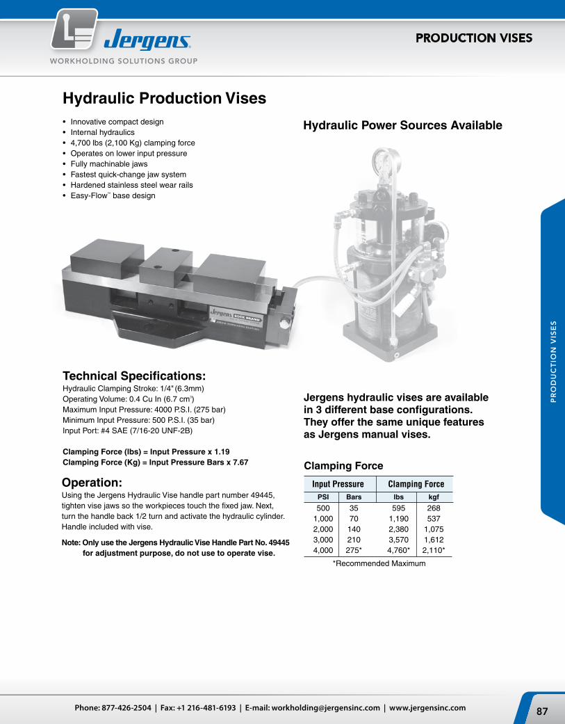
87Phone: 877-426-2504 | Fax: +1 216-481-6193 | E-mail: [email protected] | www.jergensinc.com
WORKHOLDING SOLUTIONS GROUP
PRODUCTION VISES
PR
OD
UC
TIO
N V
ISE
S
Hydraulic Production Vises• Innovative compact design• Internal hydraulics• 4,700 lbs (2,100 Kg) clamping force• Operates on lower input pressure• Fully machinable jaws• Fastest quick-change jaw system• Hardened stainless steel wear rails• Easy-Flow™ base design
Jergens hydraulic vises are available in 3 different base configurations. They offer the same unique features as Jergens manual vises.
Technical Specifications:Hydraulic Clamping Stroke: 1/4" (6.3mm)Operating Volume: 0.4 Cu In (6.7 cm3)Maximum Input Pressure: 4000 P.S.I. (275 bar)Minimum Input Pressure: 500 P.S.I. (35 bar)Input Port: #4 SAE (7/16-20 UNF-2B)
Clamping Force (lbs) = Input Pressure x 1.19Clamping Force (Kg) = Input Pressure Bars x 7.67
Operation:Using the Jergens Hydraulic Vise handle part number 49445, tighten vise jaws so the workpieces touch the fixed jaw. Next, turn the handle back 1/2 turn and activate the hydraulic cylinder. Handle included with vise.
Note: Only use the Jergens Hydraulic Vise Handle Part No. 49445 for adjustment purpose, do not use to operate vise.
Hydraulic Power Sources Available
Clamping Force
Input Pressure Clamping Force PSI Bars lbs kgf
500 35 595 268 1,000 70 1,190 537 2,000 140 2,380 1,075 3,000 210 3,570 1,612 4,000 275* 4,760* 2,110*
*Recommended Maximum

4.00
1.22
3.370±0.001 0.75
6.00
12.00
3.00
6.00
15.00
16.51
3.967.92
20mm Primary Liners(2) Plcs
Clearance HoleFor Holddown
20mm Primary Liners(2) Plcs
Clearance HoleFor Holddown
150
300
75
150
380
420
100200
100
30
85.6 20
UNIVERSAL HYDRAULIC PRODUCTION VISE4" / 100MM
3.370±0.001[85.6]
1.22[30]
4.00[100]
1.25[32]
3.96[100]
7.00[175]
15.00[380]
16.51[420]
2.50[63.5]
3.125[80]
6.00[150]
2.063[52.5]
6.00[150]
17/32" (4) Plcs[13.5]
Slotted Mounting Holes:Mounting Holes :17/32" (2) Plcs[13.5]
Locating Holes:.6255 (4) Plcs ForSine Fixture Keys
Jergens, Inc. | 15700 S. Waterloo Road | Cleveland, Ohio 44110-3898 USA88
WORKHOLDING SOLUTIONS GROUP
PRODUCTION VISES
PR
OD
UC
TIO
N V
ISE
S
Universal Base
Ball Lock® Base
• Easy to mount directly to machine tables• Slotted mounting holes fit most machines
• Designed for use with the Jergens Ball Lock® mounting system• Jigsaw pattern allows for “nesting” on Jergens Ball Lock® subplates
Hydraulic Production Vises – 4" (100mm)
Inch
Metric
Ball Lock® Shank Shank Part No. Wt. Part No. Size
49485 32 lbs 49601 20mm x 3/4"
Ball Lock® Shank Shank Part No. Wt. Part No. Size
69485 15 Kg 49651 20mm x 20mm
Part Wt. Number lbs/Kg
49483 35/16

NARROW BASE HYDRAULIC PRODUCTION VISE4" / 100MM
3.370 ±0.001[85.6]
1.22[30]
4.00[100]
0.984[25]
1.55[40]
0.50[12]
15.00[380]
16.51[420]
3.96[100]
0.50[12]
2.953[75]
3.937[100]
4.921[125]
6.000[150]
2.000[50]
4.688[120]
Mounting Holes:.531 (5) Plcs[13.5] Mounting Holes:
M10 x 1.5 Tap (6) Plcs
Locating Holes:.472 (2) Plcs[12]
Locating Holes:.6255 (6) PlcsFor Sine Fixture Keys
1.25[32]
3.370 ±.001[85.6]
1.448[38]
6.00[150]
20.00[508]
21.83[555]
9.00[225]
5.96[150]
2.500[63.5]
3.875[100]
7.874[200]
8.500[216]
3.000[75]
7.874[200]
[13.5]
SLOTTED MOUNTING HOLES (4) Plcs:17/32"
LOCATING HOLES:.6255 (4) Plcs ForSine Fixture Keys
MOUNTING HOLES (6) Plcs:17/32"[13.5]
3.370±.001[85.6]
1.448[38]
6.00[150]
20.00[508]
21.83[555]
1.969[50] 3.938
[100]
2.952[75]
4.00[100]
4.921[125]
7.874[200]
1.125[28]
1.125[28]
6.00[150]
5.96[150]
LOCATING HOLES:.6255 (6) PlcsFor Sine Fixture Keys
MOUNTING HOLES:M10 Tap (6) Plcs
MOUNTING HOLES (7) Plcs:17/32"[13.5]
LOCATING HOLES (2) Plcs:.472"[12]
89Phone: 877-426-2504 | Fax: +1 216-481-6193 | E-mail: [email protected] | www.jergensinc.com
WORKHOLDING SOLUTIONS GROUP
PRODUCTION VISES
PR
OD
UC
TIO
N V
ISE
S
Narrow Base• Designed for stand alone or fixture plate mounting• Slim design enables high density mounting
Hydraulic Production Vises – 4" (100mm)
Part Wt. Number lbs/Kg
49487 30/14
Universal Base
Narrow Base
• Easy to mount directly to machine tables• Slotted mounting holes fit most machines
• Designed for stand alone or fixture plate mounting• Slim design enables high density mounting on fixture plates
Hydraulic Production Vises – 6" (150mm)
Part Wt. Number lbs/Kg
49484 65/29
Part Wt. Number lbs/Kg
49488 60/27
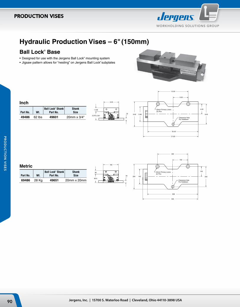
.753.370±.001
1.448
6.00
20.00
21.83
4.00
8.00
6.00
12.00
5.969.92
20mm Primary Liners(2) Plcs
Clearance HoleFor Holddown
20mm Primary Liners(2) Plcs
Clearance HoleFor Holddown
20
85.6
38
150
508
555
100
200
150
300
150250
Jergens, Inc. | 15700 S. Waterloo Road | Cleveland, Ohio 44110-3898 USA90
WORKHOLDING SOLUTIONS GROUP
PRODUCTION VISES
PR
OD
UC
TIO
N V
ISE
S
Ball Lock® Base• Designed for use with the Jergens Ball Lock® mounting system• Jigsaw pattern allows for “nesting” on Jergens Ball Lock® subplates
Inch
Metric
Ball Lock® Shank Shank Part No. Wt. Part No. Size
49486 62 lbs 49601 20mm x 3/4"
Ball Lock® Shank Shank Part No. Wt. Part No. Size
69486 28 Kg 49651 20mm x 20mm
Hydraulic Production Vises – 6" (150mm)

Shown with base for
Other bases offered.
91Phone: 877-426-2504 | Fax: +1 216-481-6193 | E-mail: [email protected] | www.jergensinc.com
WORKHOLDING SOLUTIONS GROUP
PRODUCTION VISES
PR
OD
UC
TIO
N V
ISE
S
Hydraulic Vise Column• Innovative compact design.• Consistent clamping force: 595 – 4,760 lbs
268 – 2,110 Kgs• Available in 4" (100mm) and 6" (150mm) sizes,
3-sided and 4-sided models.
Technical Specifications:Hydraulic Clamping Stroke: 1/4" (6.3 mm) total for both sides.Operating Volume: 0.4 cu in (6.6 cm3) – per station.Input Pressure: 500–4000 psi (35–275 bar).Dual station with center jaw for location; Cannot be used as a single station vise.
Input Pressure Clamping Force psi bars lbs Kg
500 35 595 268 1,000 70 1,190 537 2,000 140 2,380 1075 3,000 210 3,570 1612 4,000* 275* 4,760 2110
*Recommended Maximum
Clamping ForceMeasured at Jaws
Rotary Hydraulic Union Dual Passage
Allows vise to rotate while hoses remain stationary.
Fully Machinable and Reversible Aluminum/Steel Jaws
More workholding flexibility per jaw set.
Fastest Quick-Change Jaw Mechanism.
Reduce set-up times, faster workpiece change over.
See page 98 for Air Powered Hydraulic Pump
Hydraulic Vise Column Kits Include:• Control Valves for each side.• Rotary Coupler Dual Passage.• Internal Accumulator.• Pressure Gauge:
500–4000 PSI (35–275 Bar).• Adjustment Handle included
with all columns.
Setup & Operation:1) Prepare machinable aluminum jaws or steel jaws to fit the workpiece.2) Using the Jergens Hydraulic Vise adjustment handle to tighten vise jaws until
the workpieces touch the fixed jaw. 3) Next, turn the handle back 1/2 to 2 revolutions to set opening.4) Actuate the hydraulic source to operate control valves for each face.
Built-in Accumulator with Check Valves
Permits easy disconnection when clamped.
Download Cad Models!www.jergensinc.com
Individual Control Valves
Operate Vises one at a time.
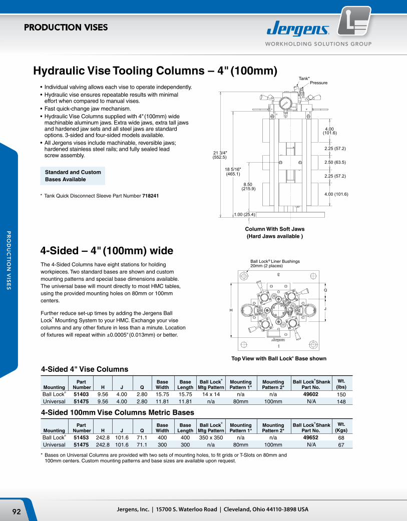
18 5/16"
21 3/4"
1.00
8.50
4.00
2.25
2.50
2.25
4.00
REVISIONS RECORDDATE REV DRREV.
51403
.XX
.XXX
.XXXXFRACTIONALANGULARFINISH
.005
.002
.0005
.0152
125 MICRO
CAD GENERATED DRAWING,
DO NOT MANUALLY UPDATE 51403 SHT 1 OF 2DWG. NO.DATECHECKEDDRAWNSCALE
1:3
FINISH:
MATERIAL:
HEAT TREAT:
CLEVELAND, OH, U.S.A.
4" HYD QUAD ASSEMBLY
TOLERANCESUNLESS OTHERWISE SPECIFIED
ELC
NONE NONE
PERMISSION OF JERGENS INC. IS PROHIBITED.
JERGENS INC. ANY REPRODUCTION IN PART OR WHOLE WITHOUT T HE WRITTENTHE INFORMATION CONTAINED IN THIS DRAWING IS THE SOLE PROPERTY OF
20MM Ball Lock®
Copyright Jergens, Inc. 2005
WEIGHT:
MADE FROM MODEL
9/30/2008
153.728 LBS
SHT 1 OF 2
51403
H J
Q
Ball Lock® Liner Bushings20mm (2 places)
4.00 (101.6)
2.25 (57.2)
2.50 (63.5)
2.25 (57.2)
4.00
1.00 (25.4)
8.50
18 5/16"
21 3/4"
REVISIONS RECORDDATE REV DRREV.
51475
.XX
.XXX
.XXXXFRACTIONALANGULARFINISH
.005
.002
.0005
.0152
125 MICRO
CAD GENERATED DRAWING,
DO NOT MANUALLY UPDATE 51475 SHT 1 OF 2DWG. NO.DATECHECKEDDRAWNSCALE
1:3
FINISH:
MATERIAL:
HEAT TREAT:
CLEVELAND, OH, U.S.A.
4" HYD QUAD ASSEMBLY
TOLERANCESUNLESS OTHERWISE SPECIFIED
MTA
NONE NONE
PERMISSION OF JERGENS INC. IS PROHIBITED.
JERGENS INC. ANY REPRODUCTION IN PART OR WHOLE WITHOUT THE WRITTENTHE INFORMATION CONTAINED IN THIS DRAWING IS THE SOLE PROPERTY OF
UNIVERSAL
Copyright Jergens, Inc. 2005
WEIGHT:
MADE FROM MODEL
11-11-08
147.895 LBS
SHT 1 OF 2
51475
J
Q
H
Ball Lock®
Mtg. Pattern
(552.5)
(465.1)
(215.9)
(101.6)
Tank*Pressure
Jergens, Inc. | 15700 S. Waterloo Road | Cleveland, Ohio 44110-3898 USA92
WORKHOLDING SOLUTIONS GROUP
PRODUCTION VISES
PR
OD
UC
TIO
N V
ISE
S
4-Sided – 4" (100mm) wideThe 4-Sided Columns have eight stations for holding workpieces. Two standard bases are shown and custom mounting patterns and special base dimensions available. The universal base will mount directly to most HMC tables, using the provided mounting holes on 80mm or 100mm centers.
Further reduce set-up times by adding the Jergens Ball Lock
®
Mounting System to your HMC. Exchange your vise columns and any other fixture in less than a minute. Location of fixtures will repeat within ±0.0005" (0.013mm) or better.
4-Sided 4" Vise Columns
Hydraulic Vise Tooling Columns – 4" (100mm) • Individual valving allows each vise to operate independently.• Hydraulic vise ensures repeatable results with minimal
effort when compared to manual vises.• Fast quick-change jaw mechanism.• Hydraulic Vise Columns supplied with 4" (100mm) wide
machinable aluminum jaws. Extra wide jaws, extra tall jaws and hardened jaw sets and all steel jaws are standard options. 3-sided and four-sided models available.
• All Jergens vises include machinable, reversible jaws; hardened stainless steel rails; and fully sealed lead screw assembly.
Standard and Custom Bases Available
* Tank Quick Disconnect Sleeve Part Number 718241
Column With Soft Jaws(Hard Jaws available )
* Bases on Universal Columns are provided with two sets of mounting holes, to fit grids or T-Slots on 80mm and 100mm centers. Custom mounting patterns and base sizes are available upon request.
Part Base Base Ball Lock
®
Mounting Mounting Mounting Number H J Q Width Length Mtg Pattern Pattern 1* Pattern 2* Ball Lock® 51403 9.56 4.00 2.80 15.75 15.75 14 x 14 n/a n/a Universal 51475 9.56 4.00 2.80 11.81 11.81 n/a 80mm 100mm
Top View with Ball Lock® Base shown
Wt.(lbs)
150148
Ball Lock®
Shank Part No. 49602
N/A
Part Base Base Ball Lock
®
Mounting Mounting Mounting Number H J Q Width Length Mtg Pattern Pattern 1* Pattern 2* Ball Lock® 51453 242.8 101.6 71.1 400 400 350 x 350 n/a n/a Universal 51475 242.8 101.6 71.1 300 300 n/a 80mm 100mm
Wt.(Kgs)
6867
Ball Lock®
Shank Part No. 49652
N/A
4-Sided 100mm Vise Columns Metric Bases

21 3/4"
18 5/16"
8.50
1.00
4.00
2.25
2.50
2.25
4.00
.XX
.XXX
.XXXXFRACTIONALANGULARFINISH
.005
.002
.0005
.0152
125 MICRO
CAD GENERATED DRAWING,
DO NOT MANUALLY UPDATE 51409 SHT 1 OF 2DWG. NO.DATECHECKEDDRAWNSCALE
1:3
FINISH:
MATERIAL:
HEAT TREAT:
CLEVELAND, OH, U.S.A.
4" HYD TRI ASSEMBLY
TOLERANCESUNLESS OTHERWISE SPECIFIED
ELCPERMISSION OF JERGENS INC. IS PROHIBITED.
JERGENS INC. ANY REPRODUCTION IN PART OR WHOLE WITHOUT T HE WRITTENTHE INFORMATION CONTAINED IN THIS DRAWING IS THE SOLE PROPERTY OF
20MM Ball Lock
Copyright Jergens, Inc. 2005
WEIGHT:
MADE FROM MODEL
10/3/2008
156.023 LBS
51409
J
H
Q
Ball Lock® Liner Bushings20mm (2 places)
93Phone: 877-426-2504 | Fax: +1 216-481-6193 | E-mail: [email protected] | www.jergensinc.com
WORKHOLDING SOLUTIONS GROUP
PRODUCTION VISES
PR
OD
UC
TIO
N V
ISE
S
• Provide greater access to three or more sides of the workpiece.
• Design is beneficial on machining centers with large spindle noses.
• Reduce any sacrifice of tool rigidity for access. • The universal base will mount directly to most
HMC tables, using the provided mounting holes on 80mm or 100mm centers.
• Further reduce set-up times by adding the Jergens Ball Lock® Mounting System to your HMC. Exchange your vise columns and all other fixtures in less than a minute. Location of all fixtures will repeat within ±0.0005" (0.013mm) or better.
3-Sided 4" Vise Columns
* Bases on Universal Columns are provided with two sets of mounting holes, to fit grids or T-Slots on 80mm and 100mm centers. Custom mounting patterns and base sizes are available upon request.
Part Base Base Ball Lock®
Mounting Mounting Mounting Number H J Q Width Length Mtg Pattern Pattern 1* Pattern 2* Ball Lock® 51409 9.55 4.00 4.22 15.75 15.75 14 x 14 n/a n/a Universal 51473 9.55 4.00 4.22 11.81 11.81 n/a 80mm 100mm
Hydraulic Vise Tooling Columns3-Sided – 4" (100mm) wide
3-Sided 100mm Vise Columns Metric Bases Part Base Base Ball Lock
®
Mounting Mounting Mounting Number H J Q Width Length Mtg Pattern Pattern 1* Pattern 2* Ball Lock® 51459 242.6 101.6 107.2 400 400 350 x 350 n/a n/a Universal 51473 242.6 101.6 107.2 300 300 n/a 80mm 100mm
Top View with Ball Lock® Base shown
Wt.(lbs)
160145
Ball Lock®
Shank Part No. 49602
N/A
Wt.(Kgs)
7266
Ball Lock®
Shank Part No. 49652
N/A
Allows for up to 240° accessibility.

1.00” (25.4mm)
11.00”
23 5/16"26 3/4"
5.00” (127mm)
3.026” (76.86mm)
2.99” (75.95mm)
3.026” (76.86mm)
5.00” (127mm)
DWG. NO.
REVISION RECOEDDATE REV DR
51476SHT 1 OF 2
6" HYDRAULIC QUADSCALE DRAWN CHECKED DATE
1:3
HEAT TREAT:FINISH:
MATERIAL:
DO NOT MANUALLY UPDATE
CAD GENERATED DRAWING,
.XX
.XXX
.XXXXFRACTIONALANGULARFINISH
.005
.002
.0005
.0152
125 MICRO
UNLESS OTHERWISE SPECIFIEDTOLERANCES
CLEVELAND, OH, U.S.A.
MTA 11-11-08
--
-
REV.
51476
--
THE INFORMATION CONTAINED IN THIS DRAWING IS THE SOLE PROPERTY OFJERGENS INC. ANY REPRODUCTION IN PART OR WHOLE WITHOUT THE WRITTENPERMISSION OF JERGENS INC. IS PROHIBITED. Copyright Jergens, Inc. 2006
MADE FROM MODEL
WEIGHT: 271.704 LBS
SHT 1 OF 2
51476
H J
Q
(679mm) (592mm)
(279.4mm)
Tank*Pressure
1.00
11.00
23 5/16"26 3/4"
5.00
3.026
2.99
3.026
5.00
DWG. NO.
REVISION RECOEDDATE REV DR
51412SHT 1 OF 2
6" HYDRAULIC QUADSCALE DRAWN CHECKED DATE
1:3
HEAT TREAT:FINISH:
MATERIAL:
DO NOT MANUALLY UPDATE
CAD GENERATED DRAWING,
.XX
.XXX
.XXXXFRACTIONALANGULARFINISH
.005
.002
.0005
.0152
125 MICRO
UNLESS OTHERWISE SPECIFIEDTOLERANCES
CLEVELAND, OH, U.S.A.
10-13-08 10/13/2008
--
-
REV.
51412
--
THE INFORMATION CONTAINED IN THIS DRAWING IS THE SOLE PROPERTY OFJERGENS INC. ANY REPRODUCTION IN PART OR WHOLE WITHOUT T HE WRITTENPERMISSION OF JERGENS INC. IS PROHIBITED. Copyright Jergens, Inc. 2006
MADE FROM MODEL
WEIGHT: 272.815 LBS
SHT 1 OF 2
51412
Ball Lock® Liner Bushings 20mm (2 places)
J
Q
H
Jergens, Inc. | 15700 S. Waterloo Road | Cleveland, Ohio 44110-3898 USA94
WORKHOLDING SOLUTIONS GROUP
PRODUCTION VISES
PR
OD
UC
TIO
N V
ISE
S
* Bases on Universal Columns are provided with two sets of mounting holes, to fit grids or T-Slots on 80mm and 100mm centers. Custom mounting patterns and base sizes are available upon request.
Part Base Base Ball Lock®
Mounting Mounting Mounting Number H J Q Width Length Mtg Pattern Pattern 1* Pattern 2*
Ball Lock® 51412 11.50 6.00 2.75 15.75 15.75 14 x 14 n/a n/a Ball Lock® 51404 11.50 6.00 2.75 19.68 19.68 17 x 17 n/a n/a Universal 51476 11.50 6.00 2.75 15.75 15.75 n/a 80mm 100mm
4-Sided 6" Vise Columns
Column With Soft Jaws(Hard Jaws available)
Top View with Ball Lock® Base shown
The 4-Sided Columns have eight stations for holding workpieces. Two standard bases are available. The universal base will mount directly to most HMC tables, using the provided mounting holes on 80mm or 100mm centers.
Further reduce set-up times by adding the Jergens Ball Lock®
Mounting System to your HMC. Exchange your vise columns and any other fixture in less than a minute. Location of fixtures will repeat within ±0.0005" (0.013mm) or better.
Hydraulic Vise Tooling Columns – 6" (150mm)• Individual valving allows each vise to operate independently.• Hydraulic vise ensures repeatable results with minimal
effort when compared to manual vises.• Fast quick-change jaw mechanism.• Hydraulic Vise Columns supplied with 6" (150mm) wide
machinable aluminum jaws. Extra wide jaws, extra tall jaws and hardened jaw sets and all steel jaws are standard options. 3-sided and four-sided models available.
• All Jergens vises include machinable, reversible jaws; hardened stainless steel rails; and fully sealed lead screw assembly.
Standard and Custom Bases Available
* Tank Quick Disconnect Sleeve Part Number 718241
4-Sided – 6" (150mm) wide
Ball Lock® 51462 292.1 152.4 69.9 400 400 350 x 350 n/a n/a Ball Lock® 51454 292.1 152.4 69.9 500 500 425 x 425 n/a n/a Universal 51476 292.1 152.4 69.9 400 400 n/a 80mm 100mm
4-Sided 150mm Vise Columns Metric Bases
Wt.(lbs)
270285270
Ball Lock®
Shank Part No.
4960249612
N/A
122130122
4965249662
N/A
(Kgs)
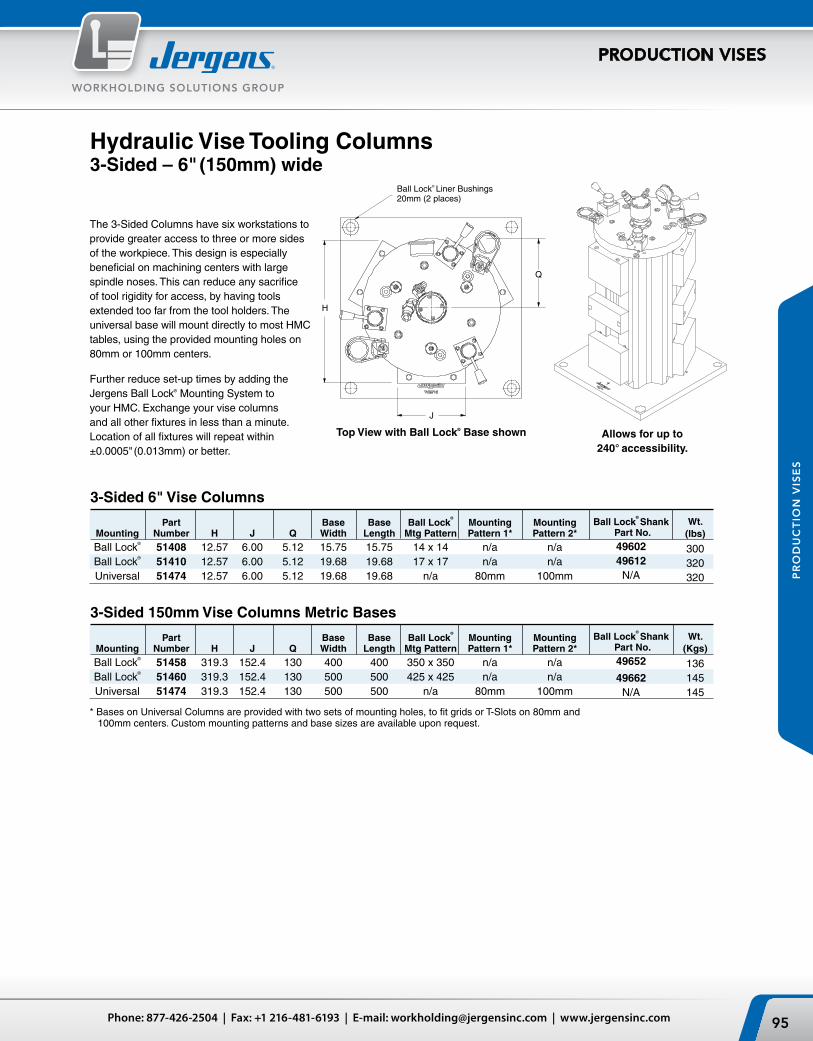
1.00
11.00
23 5/16"
26 11/16"
5.00
3.026
2.99
3.026
5.00
DWG. NO.
REVISION RECOEDDATE REV DR
51408SHT 1 OF 2
6" HYDRAULIC TRISCALE DRAWN CHECKED DATE
1:3
HEAT TREAT:FINISH:
MATERIAL:
DO NOT MANUALLY UPDATE
CAD GENERATED DRAWING,
.XX
.XXX
.XXXXFRACTIONALANGULARFINISH
.005
.002
.0005
.0152
125 MICRO
UNLESS OTHERWISE SPECIFIEDTOLERANCES
CLEVELAND, OH, U.S.A.
ELC 10/15/2008
REV.
51408
--
THE INFORMATION CONTAINED IN THIS DRAWING IS THE SOLE PROPERTY OFJERGENS INC. ANY REPRODUCTION IN PART OR WHOLE WITHOUT T HE WRITTENPERMISSION OF JERGENS INC. IS PROHIBITED. Copyright Jergens, Inc. 2006
MADE FROM MODEL
WEIGHT: 303.504 LBS
SHT 2 OF 2
51408
J
H
Q
Ball Lock® Liner Bushings20mm (2 places)
95Phone: 877-426-2504 | Fax: +1 216-481-6193 | E-mail: [email protected] | www.jergensinc.com
WORKHOLDING SOLUTIONS GROUP
PRODUCTION VISES
PR
OD
UC
TIO
N V
ISE
S
* Bases on Universal Columns are provided with two sets of mounting holes, to fit grids or T-Slots on 80mm and 100mm centers. Custom mounting patterns and base sizes are available upon request.
Part Base Base Ball Lock®
Mounting Mounting Mounting Number H J Q Width Length Mtg Pattern Pattern 1* Pattern 2* Ball Lock® 51408 12.57 6.00 5.12 15.75 15.75 14 x 14 n/a n/a Ball Lock® 51410 12.57 6.00 5.12 19.68 19.68 17 x 17 n/a n/a Universal 51474 12.57 6.00 5.12 19.68 19.68 n/a 80mm 100mm
3-Sided 6" Vise Columns
Part Base Base Ball Lock®
Mounting Mounting Mounting Number H J Q Width Length Mtg Pattern Pattern 1* Pattern 2* Ball Lock® 51458 319.3 152.4 130 400 400 350 x 350 n/a n/a Ball Lock® 51460 319.3 152.4 130 500 500 425 x 425 n/a n/a Universal 51474 319.3 152.4 130 500 500 n/a 80mm 100mm
3-Sided 150mm Vise Columns Metric Bases
Top View with Ball Lock® Base shown
Hydraulic Vise Tooling Columns3-Sided – 6" (150mm) wide
The 3-Sided Columns have six workstations to provide greater access to three or more sides of the workpiece. This design is especially beneficial on machining centers with large spindle noses. This can reduce any sacrifice of tool rigidity for access, by having tools extended too far from the tool holders. The universal base will mount directly to most HMC tables, using the provided mounting holes on 80mm or 100mm centers.
Further reduce set-up times by adding the Jergens Ball Lock® Mounting System to your HMC. Exchange your vise columns and all other fixtures in less than a minute. Location of all fixtures will repeat within ±0.0005" (0.013mm) or better.
Wt.(lbs)
300320320
Ball Lock®
Shank Part No.4960249612
N/A
Wt.(Kgs)
136145145
Ball Lock®
Shank Part No.49652
49662N/A
Allows for up to 240° accessibility.

A
BB
A
5/8" (16mm) Bored holes for sine fixture keys(2) places
Receiver Bushings
Jergens, Inc. | 15700 S. Waterloo Road | Cleveland, Ohio 44110-3898 USA96
WORKHOLDING SOLUTIONS GROUP
PRODUCTION VISES
PR
OD
UC
TIO
N V
ISE
S
Receiver Thickness of Part Pallet Size For Vise A B Size Subplate Wt. Number (mm) Columns (mm) (mm) (mm) (in.)(Kg)
59102 400 51453, 51459 350 350 20 28.57 31 51462, 51458 59103 500 51454, 51460 425 425 25 31.75 59 59103-C 500 All above 350 350 20 31.75 59 Combination Subplate 425 425 25
Hydraulic Vise Tooling Columns Standard Subplates
Metric Steel Subplates for Vise Columns
Standard Steel Subplates for Vise Columns Receiver Thickness of Part Pallet Size For Vise A B Size Subplate Wt Number (mm) Columns (in.) (in.) (mm) (in.) (lbs)
49102 400 51403, 51409 14 14 20 1.125 79 51412,51408 49103 500 51404, 51410 17 17 25 1.25 137 49103-C 500 All above 14 14 20 1.25 137 Combination Subplate 17 17 25
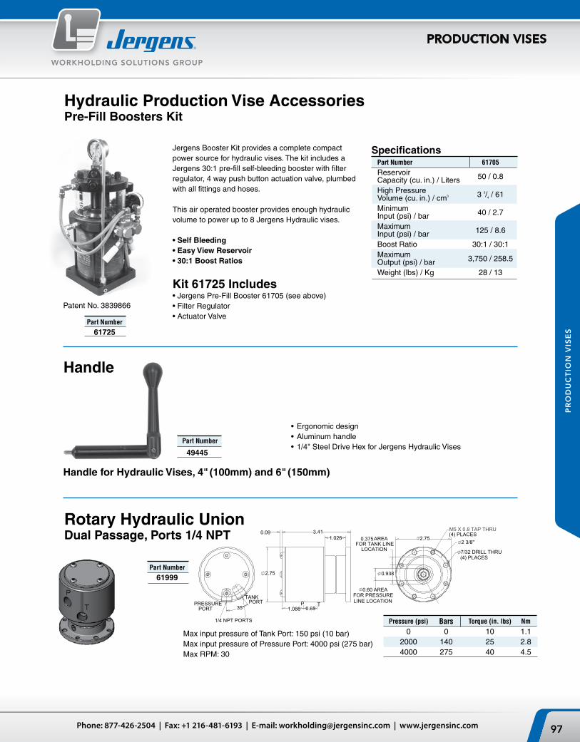
35°
TANK PRESSURE
PORT
1/4 NPT PORTS
3.411.026
0.09
1.066
2.75
0.65
0.938
0.375 AREAFOR TANK LINE
LOCATION
0.60 AREAFOR PRESSURELINE LOCATION
2.752 3/8"
M5 X 0.8 TAP THRU(4) PLACES
7/32 DRILL THRU(4) PLACES
P
T
P TPORT
97Phone: 877-426-2504 | Fax: +1 216-481-6193 | E-mail: [email protected] | www.jergensinc.com
WORKHOLDING SOLUTIONS GROUP
PRODUCTION VISES
PR
OD
UC
TIO
N V
ISE
S
Jergens Booster Kit provides a complete compact power source for hydraulic vises. The kit includes a Jergens 30:1 pre-fill self-bleeding booster with filter regulator, 4 way push button actuation valve, plumbed with all fittings and hoses.
This air operated booster provides enough hydraulic volume to power up to 8 Jergens Hydraulic vises.
• Self Bleeding• Easy View Reservoir• 30:1 Boost Ratios
Kit 61725 Includes• Jergens Pre-Fill Booster 61705 (see above)• Filter Regulator • Actuator Valve
Patent No. 3839866
Hydraulic Production Vise AccessoriesPre-Fill Boosters Kit
SpecificationsPart Number 61705
Reservoir Capacity (cu. in.) / Liters 50 / 0.8
High Pressure Volume (cu. in.) / cm3 3 3/4 / 61
Minimum Input (psi) / bar 40 / 2.7
Maximum Input (psi) / bar 125 / 8.6
Boost Ratio 30:1 / 30:1Maximum Output (psi) / bar 3,750 / 258.5
Weight (lbs) / Kg 28 / 13
Part Number
61725
Handle
• Ergonomic design• Aluminum handle• 1/4" Steel Drive Hex for Jergens Hydraulic Vises
Part Number
49445
Handle for Hydraulic Vises, 4" (100mm) and 6" (150mm)
Rotary Hydraulic UnionDual Passage, Ports 1/4 NPT
Pressure (psi) Bars Torque (in. lbs) Nm
0 0 10 1.1 2000 140 25 2.8 4000 275 40 4.5
Part Number
61999
Max input pressure of Tank Port: 150 psi (10 bar)Max input pressure of Pressure Port: 4000 psi (275 bar)Max RPM: 30

61755 Performance Curve*
LIQ
UID
FL
OW
IN3 /M
IN (
LTR
/MIN
)
120(1.97)
80(1.31)
40(0.655)
0 1000 2000 3000 4000 5000 (69) (138) (207) (276) (345)
OUTPUT PRESSURE, PSI (BAR)
Jergens, Inc. | 15700 S. Waterloo Road | Cleveland, Ohio 44110-3898 USA98
WORKHOLDING SOLUTIONS GROUP
PRODUCTION VISES
PR
OD
UC
TIO
N V
ISE
S
The “Shoebox” Pump is a low cost, compact unit used on smaller hydraulic circuits. Its small size offers the versatility of mounting on wheels (such as a workcart) and moving the pump from workstation to workstation. The “Shoebox” is a cost effective power source for hydraulic tooling column vises. Note: Do not use more than 4,000 PSI
input pressure on Jergens Vises
Part Number
61759
Hydraulic Production Vise AccessoriesAir-Powered Hydraulic PumpsShoebox™ Pumps
SpecificationsPart Number 61755 Reservoir Capacity 300 cu. in. (4.9 liter)Minimum Input 25 psi (1.7 Bar)Maximum Input 125 psi (8.5 Bar)Boost Ratio 36:1Maximum Output 4500 psi (306 Bar) Free Flow 100 cu.in./min.@ 100 psi (6.8 Bar) (1.64 liter/min.)Weight 24 lbs (11Kg)
Kit Includes61755 36:1 Pump61643 Remote four-way zero-leakage
valve with subplate60703 6000psi (414 Bar) gauge
Low Pressure Air HoseHose I.D. 1/4" 3/8" 1/2"
HosePart Number 61106 61108 61110FittingPart Number 61107 61109 61111
High Pressure Hydraulic HoseLength 12" 18" 24" 36" 72"
Part Number4000 psi 61201 61202 61203 61204 61205Part Number7000 psi 61211 61212 61213 61214 61215
*Also available in 5000 psi.
Length 25' Hose Ends Hose Ends
Part Number 61221 61226 612272750 psi 1/4 Hose 1/4 Npt Male 1/4 37° JIC Swivel Female
Hydraulic Hose (Build Your Own)
Hydraulic Hose
Air HoseLow pressure flexible PVC air hose is sold by the foot in bulk lengths. Order the total footage and number of push-on fittings required by using the number to the right.
High pressure hose is supplied assembled and to lengths indicated. Lengths are measured from end of coupling to end of coupling. Hose is 3/8" ID and available in 4000 psi or 7000 psi rating. 3/8" female tubing fittings on each end.
Quick Disconnect CouplersAir Couplers
Sleeve Nipple
1/4 NPT Female 1/4 NPT Male 61916 61966
Hydraulic couplers have dual checks.
Hydraulic Coupler Sleeve Nipple
1/8 NPT Female 1/8 NPT Male 61904 61950 1/4 NPT Female 1/4 NPT Male 61905 61951 1/4 NPT Female 61954 Air couplers have checks on sleeves only.
Adapter for BSP Elbows
1/4 Male NPT 1/4 NPT x 1/4 Tube 1/4 Female BSP 60221 61004
Adapters & Elbows

99Phone: 877-426-2504 | Fax: +1 216-481-6193 | E-mail: [email protected] | www.jergensinc.com
WORKHOLDING SOLUTIONS GROUP
PRODUCTION VISES
PR
OD
UC
TIO
N V
ISE
S
Jergens Production Vise SystemFlexible Clamping – Flexible ProductionVariable batch sizes? Many different types of workpieces? Frequent set-ups?
The Jergens Production Vise System is the answer for these manufacturing flexibility issues!
The clamping system consists of only a few components, for quick dismantling and minimum maintenance.
Completely sealed lead screw assembly for trouble-free operation, power transmission through inserted steel nut, large slide stroke.
Hard coated base made of high-strength, light-weight, aluminum extrusion. Guideway Rails made of hardened stainless steel.
Aluminum jaws can be completely milled, therefore a high degree of adaptability to the workpiece shape. For clamping, stop, and supporting surfaces.
Aluminum or steel jaws suitable for milling:• Milling of stop, supporting and clamping surfaces• Quick set-up for formed parts and workpieces with complex clamping contours• Significant reduction in expenditure on fixtures
Jaws change in a few seconds:• Rapid changeover from one workpiece to the next• Machine downtimes are minimized
High versatility:• The clamping element can be made available for simple and complex clamping applications in a very short time
Extra Wide Jaws
Full Face Vise Plate
Dual Station with Hard Jaw
Single Workpiece with Hard Jaws

B
A
C D
E
B
A
C D F
G
E
Soft Jaws Hard Jaw Carrier Setwith hardened steel inserts
B
A
C D
E
B
A
C D F
G
E
Soft Jaws Hard Jaw Carrier Setwith hardened steel inserts
Jergens, Inc. | 15700 S. Waterloo Road | Cleveland, Ohio 44110-3898 USA100
WORKHOLDING SOLUTIONS GROUP
PRODUCTION VISES
PR
OD
UC
TIO
N V
ISE
S
Production Vise Jaws
Jaws for 4" (100mm) Production Vises
Jaws for 6" (150mm) Production Vises
Part Number Description A B C D E (1) F G
49420 Standard Machinable Soft Jaw Set (3pcs.) 3.95 1.22 4.00 2.50 2.20 49421* Pair of Std Moveable Jaws Only (2pcs.) 3.95 1.22 4.00 49422 Std Fixed Jaw Only (1pc.) 3.95 1.22 2.50 49423 Extra Wide Machinable Soft Jaw Set (3pcs.) 5.95 1.22 4.00 2.50 2.20 49424* Pair of Wide Moveable Jaws Only (2pcs.) 5.95 1.22 4.00 49425 Wide Fixed Jaw Only (1pc.) 5.95 1.22 2.50 49450 Extra Tall Machinable Soft Jaw Set (3pcs.) 3.95 2.00 5.00 2.50 1.70 49451* Pair of Tall Moveable Jaws Only (2pcs.) 3.95 2.00 5.00 49452 Tall Fixed Jaw Only (1pc.) 3.95 2.00 2.50 49426 Hard Jaw Carrier Set (2) (3pcs.) 3.95 1.22 3.44 .96 2.88 (2) Steel Jaw Plates not included
49428* Pair of Moveable Hard Jaws Only (2pcs.) 3.95 1.22 3.44 49427 Fixed Hard Jaw Only (1pc.) 3.95 1.22 .96 49429 Hardened Steel Jaw Insert (3) (4pcs.) 4.00 .35 1.23 (3) Steel Jaw Plates have black-oxide finish, and are hardened to Rc 54/58.
Part Number Description A B C D E (1) F G
49430 Standard Machinable Soft Jaw Set (3pcs.) 5.95 1.45 5.00 3.00 3.50 49431* Pair of Std Moveable Jaws Only (2pcs.) 5.95 1.45 5.00 49432 Std Fixed Jaw Only (1pc.) 5.95 1.45 3.00 49433 Extra Wide Machinable Soft Jaw Set (3pcs.) 7.95 1.45 5.00 3.00 3.50 49434* Pair of Wide Moveable Jaws Only (2pcs.) 7.95 1.45 5.00 49435 Wide Fixed Jaw Only (1pc.) 7.95 1.45 3.00 49455 Extra Tall Machinable Soft Jaw Set (3pcs.) 5.95 2.50 6.00 3.00 3.00 49453* Pair of Tall Moveable Jaws Only (2pcs.) 5.95 2.50 6.00 49454 Tall Fixed Jaw Only (1pc.) 5.95 2.50 3.00 49436 Hard Jaw Carrier Set (2) (3pcs.) 5.95 1.48 4.50 .96 4.00 (2) Steel Jaw Plates not included
49438* Pair of Moveable Hard Jaws Only (2pcs.) 5.95 1.48 4.50 49437 Fixed Hard Jaw Only (1pc.) 5.95 1.48 .96 49439 Hardened Steel Jaw Insert Set (3) (4pcs.) 6.00 .48 1.75 (3) Steel Jaw Plates have black-oxide finish, and are hardened to Rc 54/58.
Note: Steel available for all soft jaw sets, add -S to the base part number. Example: 49420-S*For Self Centering Vises. Moveable jaw sets available with gibs for tighter tolerances within rails. Add "SC" to part number. Example: 49421SC
• Standard Jaws are machinable aluminum.
(1) Mounted Dimensions
(1) Mounted Dimensions

A
B
C
D
E
A
B
C
D
E
101Phone: 877-426-2504 | Fax: +1 216-481-6193 | E-mail: [email protected] | www.jergensinc.com
WORKHOLDING SOLUTIONS GROUP
PRODUCTION VISES
PR
OD
UC
TIO
N V
ISE
S
Quick Change Fixture Plate
Production Vise Accessories Jaws & Fixture Plates
Jaws• Standard fully machinable soft jaws, as supplied on
the Production Vises and Columns• Extra Wide fully machinable soft jaws. (-W)• Extra Tall fully machinable soft jaws. (-T)• Hard Jaw Carriers are drilled and tapped to
accept hard jaw plates. (-H)• Hard Jaw Plates are hardened steel plates that bolt
onto the hard jaw carriers. (-H)
Jaws are offered three ways:• Jaw Sets include two moveable jaws and one fixed jaw.• Moveable Jaws are sold in pairs• Fixed Jaws are sold separately.
Quick Change Fixture Plates Fixture plates provide an alternative to holding parts in the jaws. Build dedicated fixtures on the plates, and then just snap onto a vise or column. Switch between jaws and fixture plates without removing the vise or column from the machine.
NOTE: Conversion plates include mounting screws.
• Allows for easy conversion from twin station to single station vise
• Hard coat anodized aluminum
• Ergonomic Design• 5/8" Hex Size
• Easily mounts to side of twin vise
• Allows for precise part location
Vise Conversion Plates
Vise Handles
Hard Jaw Carriers With Steel Inserts*
Part No. Vise Size
49440 4"/100mm
49441 6"/150mm Part No. Vise Size
49442 4"/100mm
49443 6"/150mm
Part No. Type
49444 Double Pivot
49459 Single Pivot
Machinable Soft Jaws (Standard Sets included with Vises)
Quick Change Fixture Plates for 4" (100mm) Production Vises
Part No. Description A B C D E 49446 Standard Fixture Plate 4 14.90 1.475 .25 .50 49448 Wide Fixture Plate 6 14.90 1.475 .25 .50
Quick Change Fixture Plates for 6" (150mm) Production Vises
Part No. Description A B C D E 49447 Standard Fixture Plate 6 19.90 1.475 .25 .688 49449 Wide Fixture Plate 8 19.90 1.475 .25 .688
Vise Work Stop

Primary Liners (2) Plcs
Clearance holes for holddown (2) Plcs
5/8" Bored hole for sine fixture key(2) Plcs
12.0000
Clearance hole for holddown
6.0000Standard
ShankThumb Screw
Jigsaw Fixture Plate
Multiple Vise Fixture Plate
Jergens, Inc. | 15700 S. Waterloo Road | Cleveland, Ohio 44110-3898 USA102
WORKHOLDING SOLUTIONS GROUP
PRODUCTION VISES
PR
OD
UC
TIO
N V
ISE
S
Production Vise Ball Lock® Accessories – Inch
Ball Lock® Sub-Plates for Ball Lock® Vises, Columns, and Fixture Plates
*Fits Jergens Tooling Column 69011
Ball Lock® Fixture Plates for Multiple Production Vises
Jigsaw Interlocking Fixture Plates
Jergens manufactures standard Ball Lock® Fixture Plates for various applications. A small sample is listed below. These fixture plates will accept multiple Jergens Production Vises. However, the Jergens Ball Lock® Mounting System can provide the greatest benefits, when designed for your specific applications and your machine tools. Please contact Jergens Technical Service to select the proper fixture and sub-plate for your applications.
Jergens manufactures standard sub-plates for popular machine tools. Three standard plates are shown. These sub-plates will accept Jergens Ball Lock® Vises, Columns and Fixture Plates. Some of the sub-plates have multiple mounting patterns that will allow multiple sizes and styles
Ball Lock® Shanks Shank Shank Fixture Plate Standard with Diameter Thickness Shank Thumbscrew
20 3/4 49601 49601-S 20 1" 49602 49602-S 25 3/4 49611 49611-S 25 1" 49612 49612-S
of fixture plates and vises to be used on the same machine. However, the Jergens Ball Lock® Mounting System can provide the greatest benefits, when designed for your specific applica-tions and your machine tools. Please contact Jergens Techni-cal Service to select the proper sub-plate for your machine.
Plate Machine Table Ball Lock® Part Number Type Size Pattern Applications
49102 HMC 400mm 14x14 Vise Columns, Tooling Columns, Other 49103-C HMC 500mm 17x17&14x14 Vise Columns, Tooling Columns, Other 49112 VMC 20x40 Multiple Patterns Jigsaw Vises & Plates, Multiple Vise Fixtures, Other
Plate Ball Lock® Shank Plate Outer Vises/ Use With Wt. Part No. Pattern Diameter Thickness Dimensions Plate Vise No. (lbs)
28713 12 x 12 20mm 3/4 14 x 14 2 49401 14 28715 12 x 12 20mm 3/4 16 x 16 2 49401 18 28727 17 x 17 25mm 1" 20 x 20 3 49401 38 28727 17 x 17 25mm 1" 20 x 20 2 49402 38 *28742 8 x 22 25mm 1" 12 x 25 2 49401 28
Plate Jig Saw Plate Outer Use With Wt. Part No. Pattern Thickness Dimensions Vise No. (lbs)
28705 6 x 12 3/4 8 x 15 49401 9 28706 8 x 12 3/4 10 x 16 49402 9

Primary Liners (2) Plcs
Clearance holes for holddown (2) Plcs
16mm Bored hole for sine fixture key(2) Plcs
300
Clearance hole for holddown
150Standard
ShankThumb Screw
Jigsaw Fixture Plate
Multiple Vise Fixture Plate
103Phone: 877-426-2504 | Fax: +1 216-481-6193 | E-mail: [email protected] | www.jergensinc.com
WORKHOLDING SOLUTIONS GROUP
PRODUCTION VISES
PR
OD
UC
TIO
N V
ISE
S
Production Vise Ball Lock® Accessories – Metric
Ball Lock® Sub-Plates for Ball Lock® Vises, Columns, and Fixture Plates
Ball Lock® Fixture Plates for Multiple Production Vises
Jigsaw Interlocking Fixture Plates
Jergens manufactures standard Ball Lock® Fixture Plates for various applications. A small sample is listed below. These fixture plates will accept multiple Jergens Production Vises. However, the Jergens Ball Lock® Mounting System can provide the greatest benefits, when designed for your specific applications and your machine tools. Please contact Jergens Technical Service to select the proper fixture and sub-plate for your applications.
Jergens manufactures standard sub-plates for popular machine tools. Three standard plates are shown. These sub-plates will accept Jergens Ball Lock® Vises, Columns and Fixture Plates. Some of the sub-plates have multiple mounting patterns that will allow multiple sizes and styles
Ball Lock® Shanks Shank Shank Fixture Plate Standard with Diameter Thickness Shank Thumbscrew
20 20 49651 49651-S 20 25 49652 49652-S 25 20 49661 49661-S 25 25 49662 49662-S
of fixture plates and vises to be used on the same machine. However, the Jergens Ball Lock® Mounting System can provide the greatest benefits, when designed for your specific applica-tions and your machine tools. Please contact Jergens Techni-cal Service to select the proper sub-plate for your machine.
Plate Machine Table Ball Lock® Part Number Type Size Pattern Applications
59102 HMC 400mm 350 x 350 Vise Columns, Tooling Columns, Other 59103-C HMC 500mm 350 x 350 Vise Columns, Tooling Columns, Other 425 x 425 59112 VMC 500 x 1000 Multiple Patterns Jigsaw Vises & Plates, Multiple Vise Fixtures, Other
Plate Ball Lock® Shank Plate Outer Vises/ Use With Wt. Part No. Pattern Diameter Thickness Dimensions Plate Vise No. (Kg)
58713 300 x 300 20mm 20 350 x 350 2 49401 6 58715 300 x 300 20mm 20 400 x 400 2 49401 8 58727 425 x 425 25mm 25 500 x 500 3 49401 18 58727 425 x 425 25mm 25 500 x 500 2 49402 18 58742 175 x 550 25mm 25 300 x 625 2 49401 12
Plate Jig Saw Plate Outer Use With Wt. Part No. Pattern Thickness Dimensions Vise No. (Kg)
58706 200 x 300 20 250 x 400 49402 4

Jergens, Inc. | 15700 S. Waterloo Road | Cleveland, Ohio 44110-3898 USA104
WORKHOLDING SOLUTIONS GROUP
PRODUCTION VISES
PR
OD
UC
TIO
N V
ISE
S
T-Slot Nuts
Production Vise AccessoriesSine Fixture Keys for Vises
Locate subplates or fixture plates to T-slotted machine tables. Available in inch sizes for 1/2" to 7/8" slots, and in metric sizes for 12mm to 22mm slots.
T-Slot Wt. Part Width (lbs) Number Thread A B C D E 10 Pcs.
*43302** 3/8-16 7/16 11/16 7/32 1/2 7/8 0.50 *43303** 3/8-16 1/2 7/8 9/32 1/2 7/8 0.70 *43301 3/8-16 9/16 7/8 1/4 1/2 7/8 0.70 *43305** 1/2-13 9/16 7/8 11/32 5/8 1 1/8 1.20 *43306 1/2-13 5/8 1 11/32 5/8 1 1/8 1.50 *43304 1/2-13 11/16 1 1/8 7/16 3/4 1 1/4 2.10 *43308** 5/8-11 11/16 1 1/8 7/16 3/4 1 1/4 1.14 *43309 5/8-11 3/4 1 1/4 15/32 3/4 1 1/4 1.60 *43307 5/8-11 13/16 1 1/4 9/16 1 1 1/2 3.11 *Conforms to TCMA. **Not Hardened
Metric
Inch
Inch – 5/8" Shanks for Inch T-Slots
Metric – 5/8" Shanks for Metric T-Slots
T-Slot Wt. Part Width (Kg) Number Thread A B C D E 10 pcs.
43372 M10 x 1.5 12 19 7 13 25 0.25 43373 M10 x 1.5 14 22 9 16 29 0.35 43374 M10 x 1.5 16 25 9 16 29 0.35 43375 M12 x 1.75 14 22 9 16 29 0.60 43376 M12 x 1.75 16 25 9 16 29 0.75 43377 M12 x 1.75 18 29 11 19 32 1.1 43378 M16 x 2.0 18 29 11 19 32 0.57 43379 M16 x 2.0 20 32 14 25 38 0.80 43380 M16 x 2.0 22 35 14 25 38 1.56
Note: Complete offering of T-Slot Nuts available on page 258.
Table Shank Slot Part Size Size Wt. Number A B C (lbs) 39501 0.625 0.4995 1 .09 39502 0.625 0.562 1 .11 39503 0.625 0.6245 1 .11 39504 0.625 0.687 1 .11 39505 0.625 0.7495 1 1/8 .13 39506 0.625 0.812 1 1/8 .14 39507 0.625 0.8745 1 1/8 .15
Table Shank Slot Part Size Size (mm) Wt. Number A B C (Kg)
39561 0.625 12 1 .04 39562 0.625 14 1 .04 39563 0.625 16 1 .05 39564 0.625 18 1 1/8 .05 39565 0.625 20 1 1/8 .06 39566 0.625 22 1 1/8 .07Note: Complete offering of Metric/Metric Sine Fixture Keys available on page 215.

107Phone: 877-426-2504 | Fax: +1 216-481-6193 | E-mail: [email protected] | www.jergensinc.com
WORKHOLDING SOLUTIONS GROUP JERGENS-BOCK QUICK CHANGE SYSTEM
PRODUCTION VISES
PR
OD
UC
TIO
N V
ISE
S »
JE
RG
EN
S-B
OC
K Q
UIC
K C
HA
NG
E S
YS
TE
M
FAST • FLEXIBLE • PRODUCTIVE
Bock Workholding for machining centers is a complete workholding system designed from the ground up to be FAST, FLEXIBLE and PRODUCTIVE.
FAST in setting up new and repeat jobs. Bock’s Twin Vises can be positioned and repositioned on the Bock Locator Plate with speed and accuracy. Quick change jaws snap on and off in seconds.
FLEXIBLE by being able to hold a great variety of part sizes and shapes. Bock’s quick change jaws are machined to nest your parts and can hold a great variety of sizes and shapes.
PRODUCTIVE by reducing spindle down-time to a minimum. The combination of short setup times, the ability to move setups away from the machine and fast loading keeps your spindle cutting, not waiting.
Technical Data
Part Jaw Width Jaw Opening Jaw Depth Length Width Height Net Weight
Number Inch mm Inch mm Inch mm Inch mm Inch mm Inch mm Kgs
110250 6 150 7 1/2 188 1 1/2 38 20 507 9 225 6 3/4 170 36.00 110255 8 200 10 250 2 50 21 533 11 1/2 292 7 175 68.00

Jergens, Inc. | 15700 S. Waterloo Road | Cleveland, Ohio 44110-3898 USA108
WORKHOLDING SOLUTIONS GROUPJERGENS-BOCK QUICK CHANGE SYSTEM
PRODUCTION VISES
PR
OD
UC
TIO
N V
ISE
S »
JE
RG
EN
S-B
OC
K Q
UIC
K C
HA
NG
E S
YS
TE
M
Bock Twin Vise SystemThe Bock Twin Vise is the key component of the complete Bock Workholding system. A variety of body styles made from high-strength aluminum, ground steel guides, snap-on quick-change machinable aluminum jaws and a solid clamping screw and third hand mechanism combine for fast, flexible and productive milling.
System Overview
Bock Locator Plate SystemBock Locator Plates are a great platform to quickly and accurately mount your Twin Vises in a number of different positions. Locator/mounting holes with alpha-numeric identifiers and Bock’s DexLoc™ double-expanding locators give you +/- .0005" repeatability.
DexLoc™ Locator PinsPatented DexLoc™ double-expanding locator pins allow for fast and accurate location of twin vises on locator plates.
1
2
3

109Phone: 877-426-2504 | Fax: +1 216-481-6193 | E-mail: [email protected] | www.jergensinc.com
WORKHOLDING SOLUTIONS GROUP JERGENS-BOCK QUICK CHANGE SYSTEM
PRODUCTION VISES
PR
OD
UC
TIO
N V
ISE
S »
JE
RG
EN
S-B
OC
K Q
UIC
K C
HA
NG
E S
YS
TE
M
Bock Jaw SystemAn assortment of snap-on jaws and face plates gives you the ability to hold most parts.
Bock Mono-Quad SystemBock Mono-Quad vises are the extension of the Bock System for horizontal machining centers. Available in models that can hold 6, 8, 12 and 16 parts in one clamping to give you maximum productivity.
4
5

Hard-coated high-strength aluminum
base for lighter weight
Jergens, Inc. | 15700 S. Waterloo Road | Cleveland, Ohio 44110-3898 USA110
WORKHOLDING SOLUTIONS GROUPJERGENS-BOCK QUICK CHANGE SYSTEM
PRODUCTION VISES
PR
OD
UC
TIO
N V
ISE
S »
JE
RG
EN
S-B
OC
K Q
UIC
K C
HA
NG
E S
YS
TE
M
Bock’s Twin Vises are available in 100mm (4") and 150mm (6") models, with three different base types:
Straight base for use on Bock Locator Plates or with toe clamps
Slim-Line for high density mounting
on Bock Locator Plates
Standard interlocking base for fast mounting on
Bock Locator Plates
Screw on guideways made
from hardened steel
Third-hand function for fast sequential loading of parts
Exact positioning of center jaw using locator pins; removing center
jaws allows the holding of one single large part
Aluminum jaws can be milled out
to meet each part’s holding and locating
requirements
Sturdy mechanical lead screw
Generous cut-outs to prevent
chip and coolant accumulation
Bock Twin Vise System
Three different base styles for your specific
mounting needs

111Phone: 877-426-2504 | Fax: +1 216-481-6193 | E-mail: [email protected] | www.jergensinc.com
WORKHOLDING SOLUTIONS GROUP JERGENS-BOCK QUICK CHANGE SYSTEM
PRODUCTION VISES
PR
OD
UC
TIO
N V
ISE
S »
JE
RG
EN
S-B
OC
K Q
UIC
K C
HA
NG
E S
YS
TE
M
Bock Jaw System
Bock Machinable Jaws are made from high-strength aircraft grade anodized aluminum. Once machined to hold a specific part they become quick-change dedicated fixtures ideal for holding even complex shapes.
STANDARD JAWS snap on and off in
seconds and can be machined to nest
most any part.
QUICK CHANGE FACE PLATES
can be converted to snap-on snap-
off fixtures holding many small parts.
TALL JAWS to hold larger parts.
WIDE JAWS to hold several smaller parts or
wide parts.
To order jaws, please refer to page 101.
UNIQUE SNAP-ON MECHANISM
holds the jaws from below the bed and allows the industry’s
most generous machining area.
1 2 3
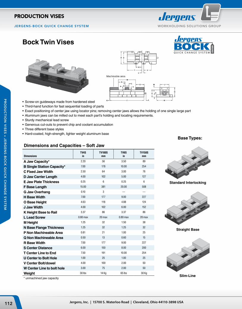
Jergens, Inc. | 15700 S. Waterloo Road | Cleveland, Ohio 44110-3898 USA112
WORKHOLDING SOLUTIONS GROUPJERGENS-BOCK QUICK CHANGE SYSTEM
PRODUCTION VISES
PR
OD
UC
TIO
N V
ISE
S »
JE
RG
EN
S-B
OC
K Q
UIC
K C
HA
NG
E S
YS
TE
M
• Screw-on guideways made from hardened steel• Third-hand function for fast sequential loading of parts• Exact positioning of center jaw using locator pins; removing center jaws allows the holding of one single large part• Aluminum jaws can be milled out to meet each part’s holding and locating requirements.• Sturdy mechanical lead screw• Generous cut-outs to prevent chip and coolant accumulation• Three different base styles• Hard-coated, high-strength, lighter weight aluminum base
Bock Twin Vises
Base Types:
Dimensions and Capacities – Soft JawTV4S
inTV100S
mmTV6S
inTV150S
mmDimensions
A Jaw Capacity* 2.20 56 3.50 89
B Single Station Capacity* 7.00 178 10.00 254
C Fixed Jaw Width 2.50 64 3.00 76
D Jaw Carrier Length 4.00 102 5.00 127
E Jaw Plate Thickness 0.25 6 0.25 6
F Base Length 15.00 381 20.00 508
G Jaw Overhang 0.10 3 — —
H Base Width 7.00 177 9.00 227
O Base Height 4.63 118 4.88 124
J Jaw Width 4.00 102 6.00 152
K Height Base to Rail 3.37 86 3.37 86
L Lead Screw 0.80 max 20 max 0.80 max 20 max
M Height 1.25 32 1.50 38
N Base Flange Thickness 1.25 32 1.25 32
P Non Machineable Area 0.81 21 1.00 25
Q Non Machineable Area 0.50 13 0.60 15
R Base Width 7.00 177 9.00 227
S Center Distance 6.00 150 8.00 200
T Center Line to End 7.50 191 10.00 254
U Center to Bolt Hole 1.00 25 1.00 25
V Center Bolt/dowel 4.00 100 2.00 50
W Center Line to bolt hole 3.00 75 2.00 50
Weight 30 lbs 14 Kg 65 lbs 30 Kg
* unmachined jaw capacity
Straight Base
Slim-Line
Standard Interlocking

113Phone: 877-426-2504 | Fax: +1 216-481-6193 | E-mail: [email protected] | www.jergensinc.com
WORKHOLDING SOLUTIONS GROUP JERGENS-BOCK QUICK CHANGE SYSTEM
PRODUCTION VISES
PR
OD
UC
TIO
N V
ISE
S »
JE
RG
EN
S-B
OC
K Q
UIC
K C
HA
NG
E S
YS
TE
M
Bock Locator Plates give you the ability to mount and locate Bock Twin Vises, and to change their size, type, number and position in minutes. Using Bock’s DexLoc™ Double-Expanding Locator Pins gives you repeatability of +/- .0005".Bock Locator Plates are made from precision machined aluminum or steel with a grid of locating/mounting holes. Each hole is identified by a letter and a number.Bock Twin Vises with standard interlocking base gives you great flexibility at tremendous setup speeds while Bock SlimLine Twin Vises give you the possibility to mount vises very close to each other for maximum number of parts in the machine.Each Locator Plate is custom-made for your particular application. Need a prompt quote? Call (877) 426-2504 with your specifications.
Bock Brand Locator Plate System
DexLoc™ Locator Pins
Bock Brand Locator Plates
Patented DexLoc™ double-expanding locator pins allow for fast and accurate location of twin vises on locator plates. • Self-centering pins relocate
within +/- .0005"• Available in a wide variety of
standard sizes and materials
StandardPart
Number
Hex Key Size (in)
Diameter Height Top Bottom
29404 5/8 1-1/4 7/32 3/16
MetricPart
Number
Hex Key Size (mm)
Diameter Height Top Bottom
29454 16 32 6 5
Part Number
Compatible Machine
Thickness (in)
Size (in) Material
933804 HAAS VF-2 1.42 14 x 36 Aluminum
933956 Robodrill 1.42 15.35 x 27.5 Aluminum
934204 Mazak VTC200B 1.42 20 x 57.5 Aluminum
934340 HAAS VE-2YT 1.42 18 x 36 Aluminum
To order DexLoc™ Locator Pins in other sizes, please refer to page 201.
• Repeat setups to within +/- .001"• Locator Plates are available in a wide array
of sizes, both in inch and metric dimensions.• Jergens Bock Brand Locator Plates are
made of hard coated aluminum for a durable surface
• Alpha-numeric coded holes for an accurate and repeatable baseline reference
• Every hole precision bored to fit Dex-Loc™ locating pins and threaded through for maximum versatility• Brass protection plugs included for every hole• Eliminate time consuming "dialing in" for every setup

Jergens, Inc. | 15700 S. Waterloo Road | Cleveland, Ohio 44110-3898 USA114
WORKHOLDING SOLUTIONS GROUPJERGENS-BOCK QUICK CHANGE SYSTEM
PRODUCTION VISES
PR
OD
UC
TIO
N V
ISE
S »
JE
RG
EN
S-B
OC
K Q
UIC
K C
HA
NG
E S
YS
TE
M
Bock Mono-Quad System
This complete range of Mono-Quad vises are designed to hold a multitude of parts and give access to several part sides in one clamping – a tremendous productivity booster on your horizontal machining center or on an indexer.
Hold 6 parts with 240°, 8 parts with 180°, 12 parts with 120°, or 16 with 90° tool access.
Mono-Quad vises are made with a high-strength aluminum column and use the same steel guides, screw mechanism and jaws as Bock’s Twin Vises.
Available in 100mm (4") and 150mm (6") models and with custom base plates to fit your machine’s pallet.
To order, please refer to pages 80–86.

115Phone: 877-426-2504 | Fax: +1 216-481-6193 | E-mail: [email protected] | www.jergensinc.com
WORKHOLDING SOLUTIONS GROUP JERGENS 5 -A XIS
PRODUCTION VISES
PR
OD
UC
TIO
N V
ISE
S »
JE
RG
EN
S 5
-AX
IS
5-Axis Workholding Solutions
5-Axis Machining Designed to Improve Productivity by Providing:• High Clamping Force
• Accurate Repeatability
• Fast Set-Up and Changeovers
• High Productivity Capacity
• For Complex Components/Materials

W
H**
h2
L
g
h1**
l1**
l3
l2 d1* g2l2 d1*
SW
L
SW
g
W
H**
h2
l2
d1*
l1**
g2
I3
l2
L
d1
WH**
h2
l1**
g1
SW
g2
l3
l2
Jergens, Inc. | 15700 S. Waterloo Road | Cleveland, Ohio 44110-3898 USA116
WORKHOLDING SOLUTIONS GROUP
PRODUCTION VISES
JERGENS 5 -A XIS
PR
OD
UC
TIO
N V
ISE
S »
JE
RG
EN
S 5
-AX
IS
Customized design for positioning and fastening in the base on request.
Part Clamping Force** Weight Dimensions (mm) Hex Number Size (kN/Torque Nm) (Kg) L W H** d1* g g1 g2 h1** h2 l1* l2 l3 (mm)
81600 40mm 7.5 / 23 2.0 100 40 53 6H7 x8 – – M6 x 8 – – 80 40.0 30 13 Male
80000 60mm 15 / 50 3.8 170 60 70 10F7 – M10 x 11 M8 x 12 – 12 100 36.0 42 12 Male
80100 100mm 25 / 80 18.0 260 100 100 25 x 5/ M10 x 14 M8 x 11 – M10 x 14 – 14 200 80.0 70 14 Male
80200 125mm 35 / 200 49.0 465 125 130 25 x 5/ M10 x 14 M12 x 16 – M12 x 16 98 27 200 82.5 66 19 Male
Note: Vise handles included with each Jergens 5-Axis Vise
** Kg x 2.205= lbs Nm x 8.85= in. lbs* Tolerance ±0.01mm
** Tolerance ±0.02mm
5-Axis Self Centering VisesThis series is suitable for many clamping tasks on 5-Axis machining centers and pallet systems. Whether the workpieces are angular or round, the concentric clamping system provides the same zero position.
The compact design, high stability and versatile selection of jaws (grip jaws, plain jaws, soft jaws, pendulum jaws, V-Type jaws) are additional features tailored for 5-Axis machining.
The 40, 60, 100 and 125 clamping systems are suitable for I.D. to O.D. clamping.
• Designed for 5-Axis machining• Free access to the workpiece, allowing the use of short standard tools• Simple, robust construction, smooth surfaces for easy cleaning• Also suitable as a module for standard devices• Comprehensive jaw selection
40mm 60mm
100mm 125mm
View from belowView from below
View from belowView from below
Shown with optional jaws.
Supplied with jaws.
Long inside guideways
Hardened Steel Base
Chip Cleanout
Sealed Leadscrew
Versatile range of jaws

w
a*h
l
f
j
w
h
f
l
= MAXMILLINGDEPTH
wa*
*
l
h
ef ji
e
j
a*h
l
d
w
117Phone: 877-426-2504 | Fax: +1 216-481-6193 | E-mail: [email protected] | www.jergensinc.com
WORKHOLDING SOLUTIONS GROUP JERGENS 5 -A XIS
PRODUCTION VISES
PR
OD
UC
TIO
N V
ISE
S »
JE
RG
EN
S 5
-AX
IS
Reversible step jaw, 2 steps, hardened Clamping Range Part Number Vise(s) l w h a* f j min./max. (mm)
80010 80000 49 60 23 18 3 5 6 – 150 80110 80100 60 100 30 25 3 5 6 – 204
Reversible step jaw with interchangeable grip insert Clamping Range Part Number Vise l w h a* d e j min./max. (mm)
80210 80200 86 125 72 62 6x 5 10 10 – 400 d10
Soft jaw for milling workpiece contours Part Number Vise(s) l w h f
80015 80000 42 60 25 8 80115 80100 64 100 35 18 80215 80200 88 125 55 32
V-Type jaw with clamping inserts Clamping Range Part Number Vise(s) l w h a min./max. (mm)
80030 80000 60 60 70 40 D10-76 (1) 80130 80100 64 100 70 38 D12-80 (2)
(1) = D10 – 20, D20 – 58, D58 – 76(2) = D12 – 26, D25 – 54, D53 – 80
Pendulum jaw with interchangeable insert, hardenedFor safe clamping of one workpiece with non-parallel clamping surfaces or two workpieces with different tolerances.
Clamping Range Part Number Vise(s) l w h a** e f i j min./max. (mm)
80120 80100 56 100 54 50 4.5 6 2.5 4 12 – 204 80220 80200 88 125 66 62 4.5 6 2.5 4 12 – 400
Dimensions (mm)
Dimensions (mm)
* Tolerance ±0.01mm** Tolerance ±0.02mm
5-Axis Self Centering Jaws
Dimensions (mm)
Dimensions (mm)
Dimensions (mm)

l
l
l
l
l
l
Jergens, Inc. | 15700 S. Waterloo Road | Cleveland, Ohio 44110-3898 USA118
WORKHOLDING SOLUTIONS GROUP
PRODUCTION VISES
JERGENS 5 -A XIS
PR
OD
UC
TIO
N V
ISE
S »
JE
RG
EN
S 5
-AX
IS
Step Jaw with Hardened Jaw Insert (Wide) Clamping Range Part Number Vise(s) l w h a* c* e f i j k min./max.
80035 80000 56 60 34 30 4.5 6 2.5 4 60 12 – 126 80135 80100 / 80900 56 100 54 50 35 4.5 6 2.5 4 100 12 – 204 80235 80200 88 125 66 62 42 4.5 6 2.5 4 125 12 – 400
Step Jaw with Hardened Jaw Insert (Medium)
Clamping Range Part Number Vise(s) l w h a* c* e f i j k min./max.
80040 80000 56 60 34 30 4.5 6 2.5 4 35 12 – 126 80140 80100 / 80900 56 100 54 50 35 4.5 6 2.5 4 65 12 – 204 80240 80200 88 125 66 62 42 4.5 6 2.5 4 80 12 – 400
Step Jaw with Hardened Jaw Insert (Narrow) Clamping Range Part Number Vise(s) l w h a* c* e f i j k min./max.
80145 80100 / 80900 56 100 54 50 35 4.5 6 2.5 4 32 12 – 204
Dimensions (mm)
Dimensions (mm)
Dimensions (mm)
Torque wrench
Part Number Vise(s) Torque (Nm)
80070 80000 5 – 60 80170 80100 20 – 120 80270 80200 40 – 200
Socket
Part Number Vise(s) Torque (Nm)
80071 80000 12 80171 80100 14 80271 80200 19
5-Axis Self Centering Step Jaws
5-Axis Self Centering Accessories
* Tolerance ±0.01mm
Positioning Pins, Various Diameters, for Grid Plate, set of 2
Part Number Vise(s) Ø (mm)
80060 80000 10/12 80160 80100 / 80200 25/12 80165 80100 / 80200 25/16
Positioning Pins, Various Diameters, for Table with T-Slots, Set of 2
Part Number Vise(s) Ø (mm)
80065 80000 10/14 80260 80100 / 80200 25/14 80265 80100 / 80200 25/18
Clamping Claws, Set of 4, Including Screws
Part Number Vise(s) Torque (Nm)
80050 80000 M10 80053 80000 M12 80150 80100 M12 80250 80200 M12 80253 80200 M16

W
W
119Phone: 877-426-2504 | Fax: +1 216-481-6193 | E-mail: [email protected] | www.jergensinc.com
WORKHOLDING SOLUTIONS GROUP JERGENS 5 -A XIS
PRODUCTION VISES
PR
OD
UC
TIO
N V
ISE
S »
JE
RG
EN
S 5
-AX
IS
Jergens 5-Axis Fixed Jaw ViseDesigned especially for multi-face machining with a single clamping operation. Ideal for machining complicated workpieces in a single clamping operation, such as in mold making. These vises are small, but have a large holding capacity. A variety of jaw options increase the range of applications. Grip jaws and V-type jaws enhance the retention force of the workpiece. The hydraulic version provides automatic power clamping with exact force.
• Designed for 5-Axis machining• Free access to the workpiece, allowing the use of short standard tools• Simple and robust construction, smooth surfaces, easy cleaning• Also suitable as a module for standard devices• Comprehensive jaw selection
Hydraulic Drive Unit 60 HVD
Plug-type connector Ø 10
Dimensions (mm) Part Clamping Force** Weight Hex
Number Size (kN/Torque Nm) (Kg) Stroke L W H** d1 g g1 g2 h2 l1** l2 l3 14* (mm)
80300 40mm 8.0 / 15 Nm 1.3 – 117 40 44 6H7 M5 x 6 – M6 x 7 – 80 40 30 10 6 Female
80400 60mm 15.0 / 25 Nm 3.3 – 168 60 57 10F7 M6 x 10 M10 x 11 M8 x 12 12 100 36 42 17 8 Female
80500 60mm Hyd 15.0 / 260 bar 3.8 4 185 60 57 10F7 M6 x 10 M10 x 11 M8 x 12 12 100 36 42 17 8 Female
Note: Vise handles included with each Jergens 5-Axis Vise
** Kg x 2.205= lbs Nm x 8.85= in. lbs* Tolerance ±0.01mm
** Tolerance ±0.02mm
40mm
60mm / 60mm Hyd
View from below
View from below
Shown with optional jaws.

Jergens, Inc. | 15700 S. Waterloo Road | Cleveland, Ohio 44110-3898 USA120
WORKHOLDING SOLUTIONS GROUP
PRODUCTION VISES
JERGENS 5 -A XIS
PR
OD
UC
TIO
N V
ISE
S »
JE
RG
EN
S 5
-AX
IS
5-Axis Fixed Jaw Accessories
Fixed Jaw Movable Jaw
Fixed jaw
Movable jaw
* Tolerance ±0.01mm
Step Jaw, Reversible Clamping Part Number Part Number Range Fixed jaw Movable jaw Vise(s) l l1 w h a* f j min./max.
80310 80315 80300 40 34 40 15 12 3 3 6 – 70 80410 80415 80400 65 35 60 23 18 3 5 6 – 106
l1 only for movable jaw
Block Jaw, Soft for Milling Workpiece Contours Part Number Part Number Fixed jaw Movable jaw Vise l l1 w h f
80420 80425 80400 65 35 60 25 11
l1 only for movable jaw
Dimensions (mm)
Dimensions (mm)
Positioning Pins, Various Diameters, for Grid Plate, set of 2
Part Number Vise(s) Ø (mm)
80060 80400 / 80500 10/12
Torque Wrench
Part Number Vise(s) Torque (Nm)
80070 80300 / 80400 5 – 60
Clamping Claws, set of 4, Including Screws
Part Number Vise(s) Thread
80050 80400 / 80500 M10 80053 80400 / 80500 M12
Positioning Pins, Various Diameters, for Table with T-Slots, Set of 2
Part Number Vise(s) Ø (mm)
80065 80400 / 80500 10/14
Socket
Part Number Vise(s) SW
80380 80300 6 80430 80400 8
Socket Wrench
Part Number Vise SW
80531 80500 8
5-Axis Jaws for Fixed Jaw Vises

121Phone: 877-426-2504 | Fax: +1 216-481-6193 | E-mail: [email protected] | www.jergensinc.com
WORKHOLDING SOLUTIONS GROUP JERGENS 5 -A XIS
PRODUCTION VISES
PR
OD
UC
TIO
N V
ISE
S »
JE
RG
EN
S 5
-AX
IS
��� ���
����
���
����
����
��
��
����
���
����
���
����
��������������������������
���������������������������
��
�����
��
����
����� ���
����
���
����
���������������������������
������������������������ ���
� �
��� ���
����
���
����
5-Axis Quick Clamping BlockThe Jergens 5-Axis Quick Change System (QCB) is an ideal partner for the Jergens 5-Axis Clamping System. The QCB changes the workpiece position on 5-Axis machining centers. This helps reduce interference for the tool.
Rapid and precise change of clamping elements optimize efficiency. The QCB with its integral mechanical Zero-Point Clamping System provides you with the ability to increase productivity and lower costs.
80656 Adapter Plate for QCB 1with Pull-In Bolt, Parallelism 0.008/100 mmcan be customized by the user
80716 Adapter Plate for QCB 2 with pull-in bolt, parallelism 0.008/100 mmcan be customized by the user
80655 Adapter Platefor QCB 1 with Self-Centering Chuck DIN 6350-1with pull-in bolt, plate 170 x 80 mm
80715 Adapter Platefor QCB 2 with Self-Centering Chuck DIN 6350-1with pull-in bolt, plate 320 x 160 mm
Accessories: Fastening and Positioning
* Tolerance ±0.01mm
QCB 2
Optional extra centering bolt
Optional extra positioning keyblock
Optional extra keyblock
QCB 1
Optional extra centering bolt
Optional extra keyblock
Optional extra positioning keyblock
QCB 3
Optional extra centering bolt
Optional extra keyblock
Optional extra positioning keyblock
Centering Bolts for QCB 1, 2, 3
Part Number Ø mm L
80610 D 30 g6 25 / 48 80615 D 32 g6 25 / 48 80620 D 50 g6 25 / 48 80625 D 50 g6 18 / 41
Centering Bolts, Set
Part Number Models
80630 QCB 1 / 80000 + 81000 80710 QCB 2 / 80100 + 81100 80810 QCB 3 / 80200
Positioning Keyblock with Screw
Part Number T-Slot (mm)
80640 DIN 6322, 1 pc. 14
Positioning pin for QCB 2, 1 pc.
Part Number Ø (mm)
80065 10/14
Keyblock with Screws
Part Number T-Slot (mm)
80650 DIN 508, 4 pcs. 14
Socket Feeding force Weight Model Part Number L W H* g l1* l2 l3 l4 Wrench (kN / Nm) (Kg)
QCB 1 80600 225 80 72 KM12 100 100 8 12 / 60 9 QCB 2 80700 260 225 65 KM12 200 50 80 63 13 2x 20 / 80 18 QCB 3 80800 464 225 80 KM12 200 150 160 189 13 3x 20 / 80 42

SW
l2 d1
l1*
g2
l3
W
H*
h2
g1
g
L
l2
Jergens, Inc. | 15700 S. Waterloo Road | Cleveland, Ohio 44110-3898 USA122
WORKHOLDING SOLUTIONS GROUP
PRODUCTION VISES
JERGENS 5 -A XIS
PR
OD
UC
TIO
N V
ISE
S »
JE
RG
EN
S 5
-AX
IS
5-Axis Compact VisesNew machining technologies and manufacturing methods call for the development of new solutions in clamping technology. The Jergens 5-Axis Compact Vise, with its short base and easy movement of the fixed jaw, is ideal for 5-sided machining.
The well balanced design of the guide between the base and the moveable jaw allows the use of high clamping jaws, for performing machining operations close to the workpiece.
The base is made from cast steel for rigidity and dimensional stability. All sides are hardened and ground.
View from below
Figure: Hydraulic drive unit C80, C120
Plug-type connector Ø 10
• High degree of freedom for spindle and tools; low risk of collision
• Well suited for short standard tools• Repeatable and controllable clamping
forces of up to 25 kN Compact 80 and 40 kN Compact 120
• Jaw with a special grip for maximum holding force (factor 3 as compared with standard jaw)
80mm / 80mm Hyd
120mm / 120mm Hyd
View from below
Part Clamping Force** Weight Dimensions (mm) Hex Number Size (kN/Torque Nm) (Kg) Stroke L W H* d1* g g1 g2 h2 l1* l2 l3 (mm)
81000 80mm Man 25/ 60 Nm 8.8 – 206 80 85 10F7 M6 x 10 M10 x 11 M10 x 16 18 100 60 60 12 Female
81100 120mm Man 40/100 Nm 18.4 – 260 120 100 25 x 5/ M10 x 14 M8 x 15 M12 x 18 18 200 100 80 14 Female
81200 80mm Hyd 20/310 bar 9.0 4 227 80 85 10F7 M6 x 10 M10 x 11 M10 x 16 18 100 60 60 12 Female
81300 120mm Hyd 40/270 bar 20.4 4 282 120 100 25 x 5/ M10 x 14 M8 x 15 M12 x 18 18 200 100 80 14 Female
Note: Vise handles included with each Jergens 5-Axis Vise
** Kg x 2.205= lbs Nm x 8.85= in. lbs* Tolerance ±0.01mm
Shown with optional jaws.

l
l
l
l
123Phone: 877-426-2504 | Fax: +1 216-481-6193 | E-mail: [email protected] | www.jergensinc.com
WORKHOLDING SOLUTIONS GROUP JERGENS 5 -A XIS
PRODUCTION VISES
PR
OD
UC
TIO
N V
ISE
S »
JE
RG
EN
S 5
-AX
IS
* Tolerance ±0.01mm** Tolerance ±0.02mm
Precision Step Reversible Jaw for 81000 / 81200 Clamping Range Part Number l w h a* c* f G j k min./max.
81010 60 50 48 45 30 2.5 M6 x 10 3 25 5 – 155 81015 60 50 48 45 30 2.5 M6 x 10 3 50 5 – 155 81020 60 80 48 45 30 2.5 M6 x 10 3 80 5 – 155
Soft Jaws
Part Number Vise(s) l w h Material
81045 81000 / 81200 97 80 53 Steel C 45 81050 81000 / 81200 97 80 53 Aluminium 81145 81100 / 81300 97 120 53 Steel C 45 81150 81100 / 81300 97 120 53 Aluminium
5-Axis Compact Vise Jaws
Dimensions (mm)
Dimensions (mm)
Dimensions (mm)
Dimensions (mm)
Dimensions mm
Precision Step Reversible Jaw for 81100 / 81300 Clamping Range Part Number l w h a* c* f G g1 j k min./max.
81110 79 84 55 35 35 4 M8 x 14 M4 x 7 20 40 8 – 200 81120 79 84 55 35 35 4 M8 x 14 M4 x 7 20 84 8 – 200 81125 79 120 55 35 35 4 M8 x 14 M4 x 7 20 120 8 – 200
Special Grip Jaw for 81000 / 81200 Provides maximum retaining force
Clamping Range Part Number l w h a** f G j k min./max.
81025 63 50 48 45 3.5 M6 x 10 3 25 7 – 151 81030 63 50 48 45 3.5 M6 x 10 3 50 7 – 151 81040 63 80 48 45 3.5 M6 x 10 3 80 7 – 151
Special Grip Jaw for 81100 / 81300 Provides maximum retaining force
Clamping Range Part Number l w h a** c** f G g1 j k min./max.
81130 81 84 55 52 35 3.5 M8 x 14 M4 x 7 3 40 7 – 195 81135 81 84 55 52 35 3.5 M8 x 14 M4 x 7 3 84 7 – 195 81140 81 120 55 52 35 3.5 M8 x 14 M4 x 7 3 120 7 – 195

Jergens, Inc. | 15700 S. Waterloo Road | Cleveland, Ohio 44110-3898 USA124
WORKHOLDING SOLUTIONS GROUP
PRODUCTION VISES
JERGENS 5 -A XIS
PR
OD
UC
TIO
N V
ISE
S »
JE
RG
EN
S 5
-AX
IS
C80
C120
Positioning Pins, Various Diameters, for Grid Plate, set of 2
Part Number Vise(s) Ø (mm)
80060 81000 / 81200 10/12 80160 81100 / 81300 25/12 80165 81100 / 81300 25/16
Clamping Claws, set with M10 Fastening Screws
Part Number Vise(s) Qty.
81075 81000 / 81200 4 81180 81100 / 81300 6
Torque Wrench
Clamping
Part Number Vise(s) Force (Nm)
80070 81000 5 – 60 80170 81100 20 – 120
Double Clamping Claws, set with M10 Fastening Screws
Part Number Vise(s) Qty.
81080 81000 / 81200 4 81185 81100 / 81300 6
Socket for Torque Wrench
Part Number Vise(s) SW
81060 81000 12, 3/8" 81160 81100 14, 1/2"
Workstops
Part Number Vise(s)
81090 81000 / 81200 81195 81100 / 81300
Positioning Pins, Various Diameters, for Table with T-Slots, set of 2
Part Number Vise(s) Ø (mm)
80065 81000 / 81200 10/14 80260 81100 / 81300 25/14 80265 81100 / 81300 25/18
5-Axis Compact Vise Accessories

Stroke
125Phone: 877-426-2504 | Fax: +1 216-481-6193 | E-mail: [email protected] | www.jergensinc.com
WORKHOLDING SOLUTIONS GROUP JERGENS 5 -A XIS
PRODUCTION VISES
PR
OD
UC
TIO
N V
ISE
S »
JE
RG
EN
S 5
-AX
IS
Jergens 5-Axis Fixed Jaw Vise with Reversible and Interchangeable Inserts
Jergens 5-Axis Fixed Jaw Vise Accessories
Clamping JawsSet of 4 pieces, with nuts
Socket for Torque Wrench
Torque Wrench
Workpiece Stop
With reversible (1 face flat, 1 face with grip) and interchangeable inserts, as well as round inserts (with grip), this vise allows machining of both machined and un-machined parts. Insert design minimizes change over time and an all-steel construction guarantees a long service life and high stability. With pre-drilled holes in the base for positioning and fastening, the KC100 is ideal for use with Jergens’ Zero Point System and Ball Lock® Quick Change System.
•Suitable for clamping both un-machined and machined parts• Interchangeable inserts allow machining of the 6th face with minimal set up•Free access to the workpiece, allowing the use of standard tools•Minimal clamping edge reduces material losses
Part Number Size
Clamping Force
(kN/Nm)Weight
(Kg)Stroke (mm) S S1 L B H d1 g g2 h1 h2 l1 l2 l3 j SW
80900 100mm 25/60 19.6 96 18-204 6-192 285 100 100 25 x 5/M10 x 14 M8 x 15 M10 x 15 50 14 200 80 70 4 12
Part Number Vise Thread
80150 80900 M12
Part Number Vise
Width Across Flats
81060 80900 12
Part Number Vise
Torque (Nm)
80070 80900 5 – 60
Part Number Vise
81195 80900

69 – 119
51 – 99
5 – 53
170
81
75 – 139
170
76
17 – 79
Jergens, Inc. | 15700 S. Waterloo Road | Cleveland, Ohio 44110-3898 USA126
WORKHOLDING SOLUTIONS GROUP
PRODUCTION VISES
JERGENS 5 -A XIS
PR
OD
UC
TIO
N V
ISE
S »
JE
RG
EN
S 5
-AX
IS
Jergens 5-Axis Pallet ClampsJergens pallet clamps (comprised of clamping jaws with a grip structure) can be used either for concentric clamping or for clamping to the fixed jaw. These pallet clamps are an effective, affordable clamping solution.
Fixed Pallet ClampClamping to the fixed jaw Clamping jaws with a grip structure
Concentric Pallet ClampConcentric clamping Clamping jaws with a grip structure
Part Number Clamping Principle
Jaw Width (mm)
Clamping Force (kN)
Clamping Width (mm)
Clamping Step (mm)
Weight (Kg)
81400 Against the fixed jaw 80 20 at 60 Nm 5 – 119 4 x 4 6.9
Part Number Clamping Principle
Jaw Width (mm)
Clamping Force (kN)
Clamping Width (mm)
Clamping Step (mm)
Weight (Kg)
81500 Concentric clamping 80 20 at 60 Nm 15 – 139 4 x 4 6.4
• 2 designs available: concentric clamping or clamping to a fixed jaw• Highest quality, compact, all-steel construction • Precise clamping• Easy to dismantle and clean

127
PO
WE
R C
LA
MP
ING
POWER CLAMPING
Power Clamping
Air Circuit Controls – 2-Hand No Tie Down ............. 183Booster Clamping Kit ................................................... 173Boosters, High Pressure/Volume............................... 171Boosters Installation Kits ............................................ 172Boosters, Pre-Fill ........................................................... 168Boosters, Pre-Fill Accessories ..................................... 169Boosters, Standard & Accessories ............................. 170Clamps, Toe ...........................................................136–137Cylinders, Block ....................................................150–151Cylinders, Double Acting ............................................ 147Cylinders, Flange Mount ............................................. 152Cylinders, Hollow Rod .........................................140–141Cylinders, Intensifier ............................................153–154Cylinders, Miniature ..................................................... 142Cylinders, Single Acting .............................................. 146Cylinders, Swing ...................................................128–133Cylinders, Threaded .............................................142–144Fittings ....................................................................190–191Hoses – Air & Hydraulic ............................................... 192Hydraulic Fluids ............................................................ 187Hydraulic Gauges ......................................................... 183Hydraulic Intensifier......................................................174Inserts, Toe ..................................................................... 136Jam Nuts ......................................................................... 145Manifolds ....................................................................... 188Mounting Brackets - Cylinders ................................... 148Mounting Plates ........................................................... 135Oil Reservoirs ................................................................ 187Pallet Decoupler Valve ................................................ 180Piston Buttons ............................................................... 145Pumps, Air – Breadbox™ ............................................. 176Pumps, Manual ............................................................. 179Pumps, Shoebox™ ....................................................... 175Power Pac, Pre-Fill ........................................................ 173Quick Disconnects Air & Hydraulic ........................... 192
Repair Kits ...................................................................... 193Rotary Couplers ............................................................ 188Swing Cylinder Arms .................................................... 130Swing Cylinder – Bottom Flange ............................... 129Swing Cylinder – Top Flange ...................................... 128Tubing, Steel .................................................................. 192Valves, Air Circuit ..................................................182–183Valves, Flow Control.............................................181, 186Valves, Flow Limit ......................................................... 166Work Supports ......................................................138–139Air-Powered Hydraulic Pumps ........................... 175–176Block Clamp ................................................................... 164Breadbox™ Pump ......................................................... 176Proximity Switch ...................................................160–161Pump Kits and Accessories ................................. 175–178Sensor Interlock ............................................................ 159Shoebox™ Pump ........................................................... 175Staylock Clamps ....................................................156–167Valves, Flow Limit ......................................................... 166Valves and Subplates for
Air Powered Hydraulic Pumps ................................ 178

L
K
28°TYP.
H
JJ
M
N
I
90°
C*3 PLACES
CLAMP PORT
UNCLAMP PORT(DBL ACTING ONLY)
TOTAL STROKE
CLAMPING STROKE
ROTATING STROKE
G
F
D
B
A
E
T BHCS
#4 SAE PORT2 PLACES
SR
P P
O
Q
#2 SAE PORT2 PLACES
UNCLAMP PORT(DBL ACTING ONLY)
CLAMP PORT
C ± .005
A ± .01
F ± .01
.13
.09CLAMP FEED HOLE
.13
.09UNCLAMP FEED HOLE
(DBL ACTING ONLY)
TYP.E ± .005
G ± .01 TYP.
B TAP3 PLACES
D ± .005
Jergens, Inc. | 15700 S. Waterloo Road | Cleveland, Ohio 44110-3898 USA128
WORKHOLDING SOLUTIONS GROUP
POWER CLAMPING
PO
WE
R C
LA
MP
ING
Swing Cylinder – Top Flange/Manifold Mount
•Clampingcapacityfrom1,100-5,000lbs.max.•Versatilemanifoldmountorconventionallyplumbed•SingleandDoubleActingavailable•Availableinthreebodysizes•AssortmentofClampingArms(soldseparately)Seepage130•Populartopflangemountingdesign
Single Acting Double Acting
Specifications 60660 60662 60664 60670 60672 60674
Maximum Output Force (lbs) 1100 2600 5000 1100 2600 5000Stroke (in) Total .79 1.16 1.66 .76 1.16 1.66 Rotating .48 .66 1.03 .45 .64 1.03 Clamping .31 .50 .63 .31 .52 .63Operating Volume Clamp (cu in) .23 .72 1.95 .23 .72 1.98Operating Volume Unclamp (cu in) N/A N/A N/A 0.46 1.43 4.00Minimum Operating Pressure (psi) 750 750 750 500 500 500Maximum Operating Pressure (psi) 5000 5000 5000 5000 5000 5000Effective Piston Area (sq in) .30 .62 1.18 .30 .62 1.18
Top Flange Mount
These popular and highly adaptable swing style cylinders contain built in features, which allow users to simplify the design process. They are directly interchangeable with competitive products.
* Mounting Hole Counter Bore
Manifold Mounting Dimensions - Top Flange Single Double Acting Acting Part No. Part No. A B C D E F G
60660 60670 1.476 1/4-20 0.340 1.030 0.880 0.560 0.845 60662 60672 1.809 5/16-18 0.440 1.250 1.000 0.530 1.050 60664 60674 2.433 3/8-16 0.600 1.720 1.375 0.750 1.410
Part No. *Counter Bore Size
60660 60670 1/4" S.H.C.S. 60662 60672 5/16" S.H.C.S. 60664 60674 3/8" S.H.C.S.
CAUTION! DON’T ALLOW SWING ARM TO CONTACT THE WORKPIECE OR FIXTURE WHILE ROTATING.
Single Double Acting Acting Part No. Part No. A B D E F G H I J K L M N O P Q R S T
60660 60670 1.43 0.623 0.38 2.57 1.03 5.28 2.31 1.16 0.88 2.06 1.32 0.34 1.03 0.56 .845 1.23 0.66 0.136 3/8-24 x 5/8 60662 60672 1.75 0.874 0.41 3.35 1.06 6.78 2.69 1.35 1.00 2.53 1.63 0.44 1.25 0.53 1.05 1.53 1.00 0.196 1/2-20 x 3/4 60664 60674 2.37 1.247 0.54 4.40 1.48 9.33 3.60 1.80 1.38 3.35 2.12 0.60 1.72 0.75 1.41 2.04 1.38 0.196 5/8-18 x 1
The piston rotates 90° to the right, but may be ordered with 90° left rotation (add - LH to clamp part no.) or no rotation (add - SP to clamp part no.)
WARNING: All swing cylinders must be used with flow limit valves to dampen the rotat-ing action. Please see maximum flow rate shown below. See page 134.
Inch to metric fittings available – see page 191.

BASE FOR 60665 & 60675
C5 PLACES
JJ
I
H
M
M
N
L
K
90°
TOTAL STROKE
ROTATING STROKE
CLAMPING STROKE
B
F
G
O
A
O
E
D
#4 SAE PORT2 PLACES
T BHCS
CLAMP PORT
UNCLAMP PORT(DBL ACTING ONLY)
Q
P
P
R S
#2 SAE PORT4 PLACES
UNCLAMP PORTTOP & BOTTOM(DBL ACTING ONLY)
CLAMP PORTTOP & BOTTOM
I
H RAD. J
J
M
M
L
K
Q
P
P
C4 PLACES
CLAMP PORTTOP & BOTTOM
UNCLAMP PORTTOP & BOTTOM(DBL ACTING ONLY)
C ± .005
A ± .01
F ± .01
.13
.09CLAMP FEED HOLE.13.09
UNCLAMP FEED HOLE(DBL ACTING ONLY)
TYP.E ± .005
G ± .01 TYP.
B TAP5 PLACES
D ± .005
129Phone: 877-426-2504 | Fax: +1 216-481-6193 | E-mail: [email protected] | www.jergensinc.com
WORKHOLDING SOLUTIONS GROUP
POWER CLAMPING
PO
WE
R C
LA
MP
ING
Bottom Flange Swing Cylinders offerversatility as a through hole bottommount or top plate mounting device.
• Clamping capacity from 1,100-5,000 lbs. max.• Manifold mounting or standard plumbing• Single and Double Acting available• Highly adaptable flange mount design(Clamping Arms sold separately)
Single Acting Double Acting
Specifications 60661 60663 60665 60671 60673 60675
Maximum Output Force (lbs) 1100 2600 5000 1100 2600 5000Stroke (in) Total .79 1.16 1.66 .76 1.16 1.66 Rotating .48 .66 1.03 .45 .64 1.03 Clamping .31 .50 .63 .31 .52 .63Operating Volume Clamp (cu in) .23 .72 1.96 .23 .72 1.98Operating Volume Unclamp (cu in) N/A N/A N/A 0.46 1.43 4.00Minimum Operating Pressure (psi) 750 750 750 500 500 500Maximum Operating Pressure (psi) 5000 5000 5000 5000 5000 5000Effective Piston Area (sq in) .30 .62 1.18 .30 .62 1.18
Swing Cylinder – Bottom Flange/Manifold Mount
Bottom Flange Mount
Manifold Mounting Dimensions - Bottom Flange
Single Double Acting Acting Part No. Part No. A B C D E F G H I J K L M N O P Q R S T
60661 60671 1.50 0.623 0.28 0.63 2.40 1.25 5.29 2.50 0.75 0.56 2.00 1.00 0.81 0.99 0.56 0.56 1.13 0.66 0.136 3/8-24 x 5/8 60663 60673 1.87 0.874 0.34 0.63 3.18 1.25 6.78 3.00 0.94 0.69 2.50 1.25 1.00 1.21 0.75 0.75 1.25 1.00 0.196 1/2-20 x 3/4 60665 60675 2.50 1.247 0.41 0.74 4.39 1.50 9.34 3.39 1.27 0.94 3.12 1.56 1.25 – – 0.75 1.38 1.38 0.196 5/8-18 x 1
Single Double Acting Acting Part No. Part No. A B C D E F G
60661 60671 1.540 1/4-20 0.560 0.990 0.810 1.130 0.562 60663 60673 1.920 5/16-18 0.690 1.210 1.000 1.250 0.750 60665 60675 2.550 3/8-16 0.940 – 1.250 1.375 0.750
CAUTION! DON’T ALLOW SWING ARM TO CONTACT THE WORKPIECE OR FIXTURE WHILE ROTATING.
The piston rotates 90° to the right, but may be ordered with 90° left rotation (add - LH to clamp part no.) or no rotation (add - SP to clamp part no.)
WARNING: All swing cylinders must be used with flow limit valves to dampen the rotat-ing action. Please see maximum flow rate shown below. See page 134.
Inch to metric fittings available – see page 191.
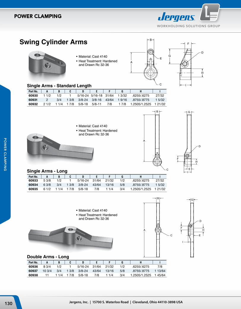
A
B
C
E
D
F
G
H
I
A
B
C
F
D
E
G
H
I
A
B
C
F
D
E
H
G
I
639420
639423
639426
A
B
C
E
D
F
G
H
I
A
B
C
F
D
E
G
H
I
A
B
C
F
D
E
H
G
I
639420
639423
639426
A
B
C
E
D
F
G
H
I
A
B
C
F
D
E
G
H
I
A
B
C
F
D
E
H
G
I
639420
639423
639426
Jergens, Inc. | 15700 S. Waterloo Road | Cleveland, Ohio 44110-3898 USA130
WORKHOLDING SOLUTIONS GROUP
POWER CLAMPING
PO
WE
R C
LA
MP
ING
Single Arms - Standard Length
Single Arms - Long
Double Arms - Long
Swing Cylinder Arms
Part No. A B C D E F G H I
60936 8 3/4 1/2 1 5/16-24 31/64 21/32 1/2 .6255/.6275 7/8 60937 10 3/4 3/4 1 3/8 3/8-24 43/64 13/16 5/8 .8755/.8775 1 13/64 60938 11 1 1/4 1 7/8 5/8-18 7/8 1 1/4 3/4 1.2505/1.2525 1 45/64
Part No. A B C D E F G H I
60930 1 1/2 1/2 1 5/16-24 5/16-18 31/64 1 3/32 .6255/.6275 27/32 60931 2 3/4 1 3/8 3/8-24 3/8-16 43/64 1 9/16 .8755/.8775 1 5/32 60932 2 1/2 1 1/4 1 7/8 5/8-18 5/8-11 7/8 1 7/8 1.2505/1.2525 1 21/32
Part No. A B C D E F G H I 60933 5 3/8 1/2 1 5/16-24 31/64 21/32 1/2 .6255/.6275 27/32 60934 6 3/8 3/4 1 3/8 3/8-24 43/64 13/16 5/8 .8755/.8775 1 5/32 60935 6 1/2 1 1/4 1 7/8 5/8-18 7/8 1 1/4 3/4 1.2505/1.2525 1 21/32
•Material:Cast4140•HeatTreatment:HardenedandDrawnRc32-36
•Material:Cast4140•HeatTreatment:HardenedandDrawnRc32-36
•Material:Cast4140•HeatTreatment:HardenedandDrawnRc32-36

131Phone: 877-426-2504 | Fax: +1 216-481-6193 | E-mail: [email protected] | www.jergensinc.com
WORKHOLDING SOLUTIONS GROUP
POWER CLAMPING
PO
WE
R C
LA
MP
ING
Swing Cylinder - Application Information
• Arm length can effect clamping pressure - See Chart and Data• Weight should be considered when utilizing modified or
special arms, other than those provided by Jergens. Excessive weight and length may damage external rotating components.
• Speed of operation is a major consideration. All swing cylinders MUST BE USED WITH FLOW LIMIT VALVES to show the rotation action.
• Full second rotation time is recommended.• Care should be used when select hydraulic power sources -
be aware of maximum operating pressures.
Swing Cylinder Arm Ratings
Medium Cylinders (2,600#) p/n’s 60662, 60672, 60663, & 60673
input pressure (psi) max. arm length (in)
1,666 6.0 1,750 5.7 2,000 5.0 2,250 4.4 2,500 4.0 2,750 3.6 3,000 3.3 3,250 3.1 3,500 2.9 3,750 2.7 4,000 2.5 4,250 2.4 4,500 2.2 4,750 2.1 5,000 2.0 Large Cylinders (5,000#) p/n’s 60664, 60674, 60665, & 60675
input pressure (psi) max. arm length (in)
1,923 6.5 2,000 6.3 2,250 5.6 2,500 5.0 2,750 4.5 3,000 4.2 3,250 3.8 3,500 3.6 3,750 3.3 4,000 3.1 4,250 2.9 4,500 2.8 4,750 2.6 5,000 2.5
Small Cylinders (1,100#) p/n’s 60660, 60670, 60661, & 60671
input pressure (psi) max. arm length (in)
1,500 5.0 1,750 4.3 2,000 3.8 2,250 3.3 2,500 3.0 2,750 2.7 3,000 2.5 3,250 2.3 3,500 2.1 3,750 2.0 4,000 1.9 4,250 1.8 4,500 1.7 4,750 1.6 5,000 1.5
Max. Arm Length vs. Pressure
CLAMPING PRESSURE (PSI)
MA
X. A
RM
LE
NG
TH (I
N)
7
6
5
4
3
2
1500 1000 1500 2000 2500 3000 3500 4000 4500 5000
60660, 60661, 60670 & 60671
60662, 60663, 60672 & 60673
60664, 60665, 60674 & 60675

Jergens, Inc. | 15700 S. Waterloo Road | Cleveland, Ohio 44110-3898 USA132
WORKHOLDING SOLUTIONS GROUP
POWER CLAMPING
PO
WE
R C
LA
MP
ING
Clamp Return
(pull) (push)
Operating Volume (cu in) .18 .33Effective Piston Area (sq in) .24 .44Minimum Operating Pressure (psi) 120 –Maximum Operating Pressure (psi) 3000 3000Maximum Output Force (lbs) 730 1320Stroke (in): Full .75 .75 Rotating .50 .50 Clamping .25 .25Weight (lbs) 1 1
Swing Cylinders
60680 Swing Cylinder
Specifications
Part Description Number
Mounting Block 60953 Hex Jam Nut 60964 See page 145. Optional Double Arm 60923
Accessories
•Canbemountedusingfour#10capscrewsorthe1"-12threadontheO.D.ofthecylinder•Optionalcomponentsincludethethreadedmountingbracketandjamnutshownbelow•Canbeusedasanon-rotatingclamp•Maximumrecommendedflowrateis20cubicinchesperminuteperclamp(approximately1secondclamptime)•Note: Arm length can affect clamping pressures.
See chart at right for more information.•AvailableinFixturePro®DesignSoftware
WARNING: All swing cylinders must be used with flow limit valves to dampen the rotating action. Please see maximum flow rate shown below. See page 134.
These versatile swing cylinders/clamps can be used as single or double acting rotating clamps, or push/pull cylinders. The piston in the Swing Cylinders rotate 90° to the right, but may easily be changed to 90° left rotation, or to no rotation at all.
Mounting Block
Double Arm
Inch to metric fittings available – see page 191.

133Phone: 877-426-2504 | Fax: +1 216-481-6193 | E-mail: [email protected] | www.jergensinc.com
WORKHOLDING SOLUTIONS GROUP
POWER CLAMPING
PO
WE
R C
LA
MP
ING
Single ArmPart
Number
60921
Jam NutPart
Number60967
See page 145.
Swing CylindersLarge
60681 Swing Cylinder
Accessories
Double ArmPart
Number
60922
•Standardwithoutanarm.•SocketHeadCapScrewisincluded.•Singleordoublearmsareavailable.•Canbemountedusingfour3/8"capscrews,orthe17/8"-16O.D.threadofthecylinder.•OptionalcomponentsincludeajamnutoramountingbrackettoreplaceoldJergenspartnumber60621.•Canbeusedasanon-rotatingclamp.•Maximumrecommendedflowrateis90cubicinchesperminuteperclamp.(Approximately1secondclamptime.)•Note: Arm length can affect clamping pressures.
See chart, page 132, for more information.•AvailableinFixturePro®DesignSoftware
Specifications
WARNING:All swing cylinders must be used with flow limit valves (see page 134) to dampen the rotating action. Please see maximum flow rate shown above.
Mounting BracketPart
Number60954
Clamp Return (pull) (push)
Operating Volume (cu in) 1.5 2.7Effective Piston Area (sq in) .98 1.77Minimum Operating Pressure (psi) 200 —Maximum Operating Pressure (psi) 3000 3000Maximum Output Force (lbs) 2900 5300Stroke (in): Full 1.5 1.5 Rotating 1 1 Clamping .50 .50Weight (lbs) 5 5
Inch to metric fittings available – see page 191.

Jergens, Inc. | 15700 S. Waterloo Road | Cleveland, Ohio 44110-3898 USA134
WORKHOLDING SOLUTIONS GROUP
POWER CLAMPING
PO
WE
R C
LA
MP
ING
Swing Clamps
Flow Limit Valves
Part Number
61648
IMPORTANT:Jergens Swing Clamps are built to operate on pre-fill systems allowing much larger circuits to be used. To use a Jergens Swing Clamp with a standard booster or with any other power source you must use the Flow Limit Valve shown below.
Jergens Swing Clamps are designed to swing 80° away from the workpiece to allow easy accessibility for part insertion or removal. Swing Clamps may be used in any attitude. The clamping arm may be positioned to swing either to the left or right by repositioning one cap screw. The right hand swing is standard.
•RightorLeftHandSwing•4800lbs.ClampingForce•Operatesinanyposition•Clamparmhas1/4"ofverticaltravel•Canbeusedwithfloodcoolant•AvailableinFixturePro®DesignSoftware
SpecificationsPart Number 60685Operating Volume (Cu. In.) 1.6
Minimum Operating Pressure (psi) 80*
Maximum Operating Pressure (psi) 3000
Maximum Output Force (lbs.) 4800
Weight (lbs.) 9.25*80 psi to swing, 200 psi to clamp.
The Flow Limit Valve restricts the flow of oil to dampen the rotating action of the Swing Clamp. Flow Limit Valves are not needed with 36:1 or 71:1 Air Powered Hydraulic Pumps. (Part Number 61755 or 61756).
Inch to metric fittings available – see page 191.

135Phone: 877-426-2504 | Fax: +1 216-481-6193 | E-mail: [email protected] | www.jergensinc.com
WORKHOLDING SOLUTIONS GROUP
POWER CLAMPING
PO
WE
R C
LA
MP
ING
Swing ClampApplication
For hydraulic clamping directly on the machine table, use Jergens Swing Clamps and Mounting Plates. The workpiece is positioned using Threaded Cylinders and fixed stops. Manifolds at the edges of the table, with hydraulic quick disconnects, allow any number of clamps to be used.
Mounting plates are subplates for Swing Clamps and are designed to save fixturing cost and allow versatil-ity in set-ups. Mounting Plates may be bolted directly to your machine table and moved to any location on the table. Each mounting plate has pre-drilled mounting holes or can be easily adapted to your machine table or application.
Mounting Plates
Part Number
60971
•Material:LowCarbonSteel•Finish:BlackOxide•AvailableinFixturePro®DesignSoftware

Jergens, Inc. | 15700 S. Waterloo Road | Cleveland, Ohio 44110-3898 USA136
WORKHOLDING SOLUTIONS GROUP
POWER CLAMPING
PO
WE
R C
LA
MP
ING
Toe Clamps
U.S. Patents:No. 4406445
A washer (60636), to prevent damage by the cap screw, is included with each clamp.
Features•SingleActing•LowProfile•DirectMounting•3/16"Stroke•3000lbs.Force•SteelorBrassToeInsertAvailable•AvailableinFixturePro®DesignSoftware
Part Number Insert
60633 Steel 60632 Brass
Toe Inserts
Toe Insert is not supplied with the Toe Clamp. See below to order the Toe Inserts.
SpecificationsPart Number 60631
Operating Volume (cu. in.) .115Minimum OperatingPressure (psi) 200Maximum OutputForce (lbs.) 3000
Overall Stroke 3/16
Hydraulic Force in Pounds
Pressure A B
1500 900 750 3000 1800 1500 5000 3000 2500
Inch to metric fittings available – see page 191.
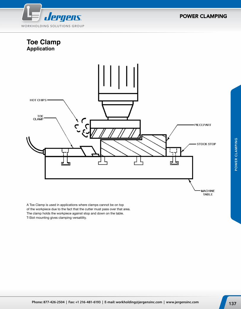
137Phone: 877-426-2504 | Fax: +1 216-481-6193 | E-mail: [email protected] | www.jergensinc.com
WORKHOLDING SOLUTIONS GROUP
POWER CLAMPING
PO
WE
R C
LA
MP
ING
Toe ClampApplication
A Toe Clamp is used in applications where clamps cannot be on top of the workpiece due to the fact that the cutter must pass over that area. The clamp holds the workpiece against stop and down on the table. T-Slot mounting gives clamping versatility.

A
B
C
D
O
G
J
F
EK
L
HI
9/16-18 PORT
BLEED PORT
1/4-20 X 3/8
11/32 DIA.
Jergens, Inc. | 15700 S. Waterloo Road | Cleveland, Ohio 44110-3898 USA138
WORKHOLDING SOLUTIONS GROUP
POWER CLAMPING
PO
WE
R C
LA
MP
ING
Bolt Size Height Part Thru Tapped Tap E Port Number A A B C Min Max F G H I J K L M N
60513 1/4 5/16-24 .50 1/4-20 2.45 2.70 .49 2.36 1.12 .81 1.75 9/16-18 .5 1.5 2
Work Supports
Hydraulically-locked Work Supports differ from clamps and vises in that they do not actually exert force upon the workpiece. Rather, they are used to support the part being machined, offering resistance to any clamping forces acting counter to the direction of travel of the piston.
In a typical application, a large, thin casting is located on several tooling point pads for posi-tioning. Work Supports will automatically adjust to support the delicate sections of the casting. When hydraulic pressure is applied, the float-ing pistons within the Work Support are locked in position and resist any downward movement exerted on the casting. After the casting is removed, the floating pistons return to their fully-raised position.
•AvailableinFixturePro®DesignSoftware
SpecificationsPartNumber 60513 60512OperatingVolume (cu. in.) .04 .06Support to PressureRatio 1.6:1 3.3:1Minimum OperatingPressure (psi) 500 500Maximum OperatingPressure (psi) 3000 3000Maximum SupportCapacity (lbs.) 5000 10000Plunger Spring Start 2 14Force (lbs.) Finish 7 40Weight (lbs.) 2.0 5.5
Part G Number A B C D E F Min Max H I J K L O 60512 3 9/16 1 3/8 2 3/4 .990 5/8 3.69 4.15 4.65 4 3/16 2 3/32 3/8 3 1 7/8 1.07
Inch to metric fittings available – see page 191.

139Phone: 877-426-2504 | Fax: +1 216-481-6193 | E-mail: [email protected] | www.jergensinc.com
WORKHOLDING SOLUTIONS GROUP
POWER CLAMPING
PO
WE
R C
LA
MP
ING
The top and bottom surfaces of the large casting must be machined to be flat, parallel, and at a fixed distance from each other. Jergens Work Supports eliminate deflection at the outer edge while compensating for variations between castings. A Jergens Hollow Rod Cylinder, stud and “C” washer are used to hold the casting.
The workpiece is located and clamped on the right end by a Jergens Swing Clamp. The Work Support resists the machining forces applied to the other end of the casting. Variations between castings are compensated for by the floating support plunger in the Work Support.
Work SupportApplications

Jergens, Inc. | 15700 S. Waterloo Road | Cleveland, Ohio 44110-3898 USA140
WORKHOLDING SOLUTIONS GROUP
POWER CLAMPING
PO
WE
R C
LA
MP
ING
Hollow Rod Cylinders
Thd. Part Depth Port Wt. Number A B C D E F G H J Size (lbs)
60413 3/8-16 1 15/16 1 13/16 5/16 1 5/8 10-32 3/4 1/2 7/8 7/16-20 1.0 60414 1/2-13 1 15/16 1 13/16 5/16 1 5/8 10-32 3/4 1/2 7/8 7/16-20 1.0 60410 1/2-13 2 1/2 2 3/16 5/16 2 7/32 10-32 7/8 7/8 1 1/4 9/16-18 2.5 60411 5/8-11 2 1/2 2 3/16 5/16 2 7/32 10-32 7/8 7/8 1 1/4 9/16-18 2.5 60412 3/4-10 2 1/2 2 3/16 5/16 2 7/32 10-32 7/8 7/8 1 1/4 9/16-18 2.5
Tapped Hole Cylinders
Through Hole Cylinders
* With Spring Installed
Specifications
Hollow Rod Cylinders can either push or pull. Two styles are available, either Through Hole or Tapped Hole. In the Through Hole style, the piston rod is hollow to accept a bolt. The Tapped Hole cylinders accept a bolt threaded into the piston. Because of the piston design, the Tapped Hole style cannot gain stroke. Removing the return springs make the Hollow Rod Cylinders suitable for air operation.
Hollow Rod Cylinders are ideal for converting existing fixtures to power clamping. Replaces clamps which use double cams, flange nuts, draw bars, or other mechanical devices. Generally, no special machining is re-quired, just a longer stud.
•AvailableinFixturePro®DesignSoftware
Part Number 60403 60401 60405 60404 60402 60413 60410 60414 60411 Specifications 60412 Operating Stroke (in.) .24 .31 .64 Operating Volume (cu. in.) .3 .7 3.2 Effective Piston Area (sq. in.) .96 1.9 5 Min. Oper. Pressure (psi)* 100 100 100 Max. Oper. Pressure (psi) 5000 5000 5000 Max Output Force (lbs.) 4800 9850 25000
Part Rod Dia. Port Wt. Number A B C† D E F G H J Size (lbs)
*60403 13/32 1 15/16 1 7/8 5/16 1 5/8 10-32 3/4 1/2 7/8 7/16-20 1.0 *60404 17/32 1 15/16 1 7/8 5/16 1 5/8 10-32 3/4 1/2 7/8 7/16-20 1.0 60401 21/32 2 1/2 2 3/16 5/16 2 7/32 10-32 7/8 3/8 1 1/4 9/16-18 2.5 60402 25/32 2 1/2 2 3/16 5/16 2 7/32 10-32 7/8 7/8 1 1/4 9/16-18 2.5 60405 1 1/64 4 3 9/16 5/8 3 1/2 1/4-28 No Boss 2 1/8 9/16-18 10.5 *Cannot increase stroke† Measured over piston in the retracted position.
Inch to metric fittings available – see page 191.
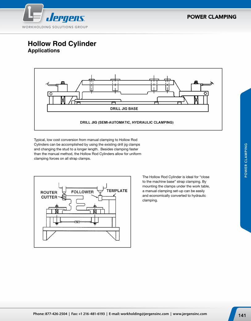
141Phone: 877-426-2504 | Fax: +1 216-481-6193 | E-mail: [email protected] | www.jergensinc.com
WORKHOLDING SOLUTIONS GROUP
POWER CLAMPING
PO
WE
R C
LA
MP
ING
Typical, low cost conversion from manual clamping to Hollow Rod Cylinders can be accomplished by using the existing drill jig clamps and changing the stud to a longer length. Besides clamping faster than the manual method, the Hollow Rod Cylinders allow for uniform clamping forces on all strap clamps.
The Hollow Rod Cylinder is ideal for “close to the machine base” strap clamping. By mounting the clamps under the work table, a manual clamping set-up can be easily and economically converted to hydraulic clamping.
Hollow Rod CylinderApplications

Jergens, Inc. | 15700 S. Waterloo Road | Cleveland, Ohio 44110-3898 USA142
WORKHOLDING SOLUTIONS GROUP
POWER CLAMPING
PO
WE
R C
LA
MP
ING
Part Body End Number Stroke Thread A B C D E F Port
60461 3/16 1/2-20 1 13/16 1 9/16 1/4 3/16 3/8 7/16 1/16-27 NPTF 60462 1/2 3/4-16 2 3/8 2 5/16 1/4 21/32 5/8 1/8-27 NPTF
Part Number 60461 60462OperatingStroke (in.) 3/16 1/2
OperatingVolume (cu. in.) .018 .049
Effective PistonArea (sq. in.) .096 .196
Minimum OperatingPressure (psi) 200 300
Maximum OperatingPressure (psi) 10000 10000
Maximum OutputForce (lbs.) 960 1960
Weight (lbs.) .5 .7
Jergens Pressure Points may be used with any power source and are de-signed to be used in restricted areas where space is at a minimum. Pressure Points can be used to eliminate part distortion during machining operations or to hold large diameter castings or rings in place while machining the upper surface. Pressure Points have hardened tool steel tips (50-60Rc). Jam nuts are included. Not suitable for air operation.
•AvailableinFixturePro®DesignSoftware
Threaded CylindersPressure Points
Miniature Cylinders
PartNumber
61514
PartNumber
61512
Specifications
Specifications
Part Number 61512 61514OperatingStroke (in.) 3/16 3/16
OperatingVolume (cu. in.) .037 .037
Effective PistonArea (sq. in.) .20 .20
Minimum OperatingPressure (psi) 400 400
Maximum OperatingPressure (psi) 5000 5000
Maximum OutputForce (lbs.) 1000 1000
Weight (lbs.) .5 .6
Small, fully-threaded bodies ensure easy mounting and simple length adjustments. Their small size provides high workholding forces in tight plac-es. Threaded Cylinders have hardened piston rods, steel bodies, alloy springs and Teflon® back-up rings which ensure trouble-free operation and long life. Not suitable for air operation. For mounting, see brackets on page 148. Jam nuts are included.
•AvailableinFixturePro®DesignSoftware

3/16"
Ø1/2"
3/4"
3/16"
5/8"5/16"
5/16"1 11/16"
Ø.78 Ø1/2"
7/8-14 UNF-2A
1 1/8" HEX
1/64"
Ø1.344MIN.
1.468 MIN.DRILL DEPTH LOCATION
RECOMMENDEDCROSS DRILL
Ø 13/16" MIN. DRILL3/8 DIA. DRILL
#10 SAE STRAIGHT THREAD PORTPER SAE J514(7/8-14 UNF 2AX21/32 DEPTH)
3/16"
Ø1/2"
3/4"
3/16"
5/8"5/16"
5/16"1 11/16"
Ø.78 Ø1/2"
7/8-14 UNF-2A
1 1/8" HEX
1/64"
Ø1.344MIN.
1.468 MIN.DRILL DEPTH LOCATION
RECOMMENDEDCROSS DRILL
Ø 13/16" MIN. DRILL3/8 DIA. DRILL
#10 SAE STRAIGHT THREAD PORTPER SAE J514(7/8-14 UNF 2AX21/32 DEPTH)
STROKE
A
H G E
BCD
F
Ø ØØ
I
1/4-28 UNF-2B X 1/4 DEEP60483 THRU 60486
143Phone: 877-426-2504 | Fax: +1 216-481-6193 | E-mail: [email protected] | www.jergensinc.com
WORKHOLDING SOLUTIONS GROUP
POWER CLAMPING
PO
WE
R C
LA
MP
ING
Manifold Mount Cylinders
SpecificationsPart Number 61522 61524OperatingStroke (in.) 3/16 3/16
OperatingVolume (cu. in.) 0.049 0.049
Effective PistonArea (sq. in.) 0.261 0.261
Minimum OperatingPressure (psi) 400 400
Maximum OperatingPressure (psi) 5000 5000
Maximum OutputForce (lbs.) 1305 1305
Weight (lbs.) 0.5 0.5
Specifications
Pressure Points
Part No. SAE No. Thread Size Thread Depth J K L M
60481 6 9/16-18 UNF 1/2 .970 1/2 1.09 1/460482 8 3/4-16 UNF-2A 9/16 1.19 11/16 1.41 5/1660483 16 1 5/16-12 UN-2A 3/4 1.91 1 7/32 2.00 1/260484 15 1 5/16-12 UN-2A 3/4 1.91 1 7/32 2.50 1/260485 24 1 7/8-12 UN-2A 3/4 2.56 1 13/16 2.00 9/1660486 24 1 7/8-12 UN-2A 3/4 2.56 1 13/16 2.50 9/16
DRILL DEPTHL MIN.
.031 MAX. C BORE DIA.J MIN.
DRILL DIA.K MIN.
LOCATION
RECOMMENDEDCROSS DRILL
M DIA. DRILL
SAE STRAIGHT THREAD PORTPER SAE J514
Part No. Body Thread Stroke A B C D E Dia. F G Dia. H Dia. I Hex.
60481 9/16-18 UNF 3/16 1 13/32 .375 1/2 1/8 3/8 1/4 3/16 .48 3/4 60482 3/4-16 UNF-2A 1/2 1 23/32 .375 9/16 1/8 41/64 3/8 1/4 .66 7/8 60483 1 5/16-12 UN-2A 1/2 2 1/2 .615 3/4 1/4 1 7/32 5/16 3/4 1.19 1 1/2 60484 1 5/16-12 UN-2A 1" 3 .615 3/4 1/4 1 7/32 5/16 3/4 1.19 1 1/2 60485 1 7/8-12 UN-2A 1/2 2 1/2 .615 3/4 1/4 1 47/64 5/16 1 1/4 1.75 2 1/8 60486 1 7/8-12 UN-2A 1" 3 .615 3/4 1/4 1 47/64 5/16 1 1/4 1.75 2 1/8
Part Number 60481 60482 60483 60484 60485 60486 Operating Stroke (in.) 3/16 1/2 1/2 1 1/2 1
OperatingVolume (cu. in.) 0.017 0.098 0.393 0.785 0.884 1.767
Effective PistonArea (sq. in.) 0.093 0.196 0.785 0.785 1.767 1.767
Minimum OperatingPressure (psi) 200 200 200 200 200 200
Maximum OperatingPressure (psi) 5000 5000 5000 5000 5000 5000
Maximum OutputForce (lbs.) 465 980 3925 3925 8835 8835
Weight (lbs.) 0.5 0.7 1 1.5 2 2.5
61522 61524
• Provides for clean installation• Eliminates exposed fittings and plumbing• Well suited for use in custom design fixtures
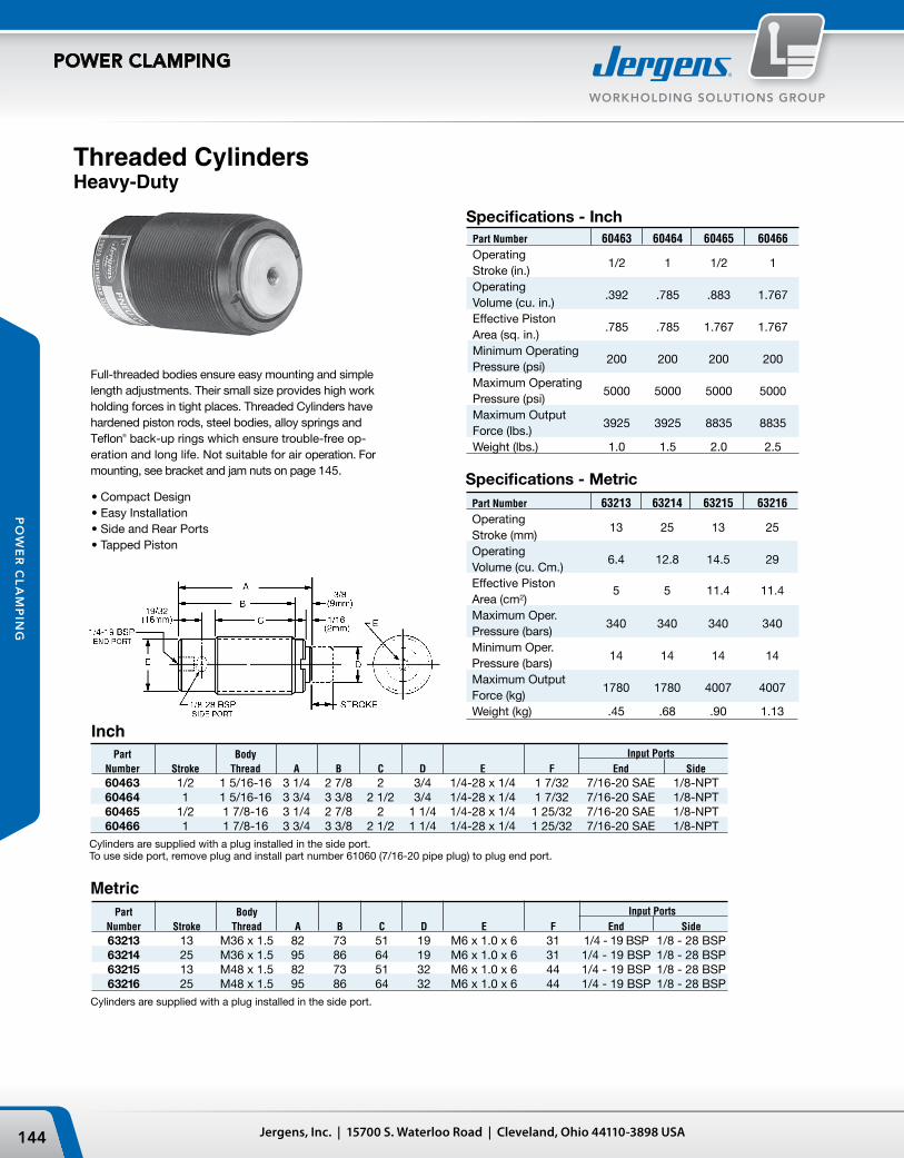
Jergens, Inc. | 15700 S. Waterloo Road | Cleveland, Ohio 44110-3898 USA144
WORKHOLDING SOLUTIONS GROUP
POWER CLAMPING
PO
WE
R C
LA
MP
ING
Threaded CylindersHeavy-Duty
Full-threaded bodies ensure easy mounting and simple length adjustments. Their small size provides high work holding forces in tight places. Threaded Cylinders have hardened piston rods, steel bodies, alloy springs and Teflon® back-up rings which ensure trouble-free op-eration and long life. Not suitable for air operation. For mounting, see bracket and jam nuts on page 145.
• Compact Design• Easy Installation• Side and Rear Ports• Tapped Piston
Part Number 60463 60464 60465 60466Operating Stroke (in.)
1/2 1 1/2 1
OperatingVolume (cu. in.)
.392 .785 .883 1.767
Effective PistonArea (sq. in.)
.785 .785 1.767 1.767
Minimum OperatingPressure (psi)
200 200 200 200
Maximum OperatingPressure (psi)
5000 5000 5000 5000
Maximum OutputForce (lbs.)
3925 3925 8835 8835
Weight (lbs.) 1.0 1.5 2.0 2.5
Specifications - Inch
Part Number 63213 63214 63215 63216Operating Stroke (mm)
13 25 13 25
Operating Volume (cu. Cm.)
6.4 12.8 14.5 29
Effective Piston Area (cm2)
5 5 11.4 11.4
Maximum Oper. Pressure (bars)
340 340 340 340
Minimum Oper. Pressure (bars)
14 14 14 14
Maximum Output Force (kg)
1780 1780 4007 4007
Weight (kg) .45 .68 .90 1.13
Specifications - Metric
Metric
Part Body Input Ports Number Stroke Thread A B C D E F End Side 60463 1/2 1 5/16-16 3 1/4 2 7/8 2 3/4 1/4-28 x 1/4 1 7/32 7/16-20 SAE 1/8-NPT 60464 1 1 5/16-16 3 3/4 3 3/8 2 1/2 3/4 1/4-28 x 1/4 1 7/32 7/16-20 SAE 1/8-NPT 60465 1/2 1 7/8-16 3 1/4 2 7/8 2 1 1/4 1/4-28 x 1/4 1 25/32 7/16-20 SAE 1/8-NPT 60466 1 1 7/8-16 3 3/4 3 3/8 2 1/2 1 1/4 1/4-28 x 1/4 1 25/32 7/16-20 SAE 1/8-NPTCylinders are supplied with a plug installed in the side port. To use side port, remove plug and install part number 61060 (7/16-20 pipe plug) to plug end port.
Part Body Input Ports Number Stroke Thread A B C D E F End Side 63213 13 M36 x 1.5 82 73 51 19 M6 x 1.0 x 6 31 1/4 - 19 BSP 1/8 - 28 BSP 63214 25 M36 x 1.5 95 86 64 19 M6 x 1.0 x 6 31 1/4 - 19 BSP 1/8 - 28 BSP 63215 13 M48 x 1.5 82 73 51 32 M6 x 1.0 x 6 44 1/4 - 19 BSP 1/8 - 28 BSP 63216 25 M48 x 1.5 95 86 64 32 M6 x 1.0 x 6 44 1/4 - 19 BSP 1/8 - 28 BSPCylinders are supplied with a plug installed in the side port.
Inch

145Phone: 877-426-2504 | Fax: +1 216-481-6193 | E-mail: [email protected] | www.jergensinc.com
WORKHOLDING SOLUTIONS GROUP
POWER CLAMPING
PO
WE
R C
LA
MP
ING
•Material:LowCarbonSteel•Finish:BlackOxide
Flange Mountings
Threaded CylindersBlock Mountings
•Material:LowCarbonSteel•Finish:BlackOxide
B
Jam Nuts Part Number 60961 60962 60963 60964 60965 60966 60967Thread 1/2-20 3/4-16 7/8-14 1-12 1 5/16-16 1 9/16-16 1 7/8-16Thickness 5/16 3/8 5/16 35/64 25/64 25/64 7/16Width Across Flats 3/4 1 1/8 1 5/16 1 5/8 1 7/8 2 1/4 3
Hardened steel buttons for use on 60463 thru 60466 cylinders.
60471 60472 60473
Threaded CylindersPiston Buttons
Inch Part Number A B C D E F G Wt. (lbs)
60950 1/2-20 1 3/8 3/4 5/8 15/16 1/4 1/4 .125 60951 3/4-16 1 5/8 1 1/8 1 1 1/8 1/4 1/4 .375 60959 7/8-14 2 3/4 1 1/2 1 1/2 3/8 21/64 .40 60956 1 5/16-16 3 1 1/4 1 13/16 2 1/8 7/16 25/64 1.27 60957 1 9/16-16 3 1/4 1 1/2 2 2 7/16 7/16 25/64 1.95 60958 1 7/8-16 4 2 2 3/8 3 1/2 33/64 —
Part Number A B C D E F G Wt. (kg)
60997 M36 x 1.5 6H 82.6 38.1 50.8 62 12 10.8 .86 60998 M48 x 1.5 6H 101.6 38.1 60.3 76 12 13 1.13
Metric
Inch Part Number A B C D E Wt. (lbs)
60952 1 5/16-16 1 5/8 1/2 1 1/4 17/64 .18 60955 1 9/16-16 2 1 1 1/2 17/64 .56 60954 1 7/8-16 2 1/4 1 1 3/4 21/64 .625
Part Number A B C D E Wt. (kg)
60995 M36 x 1.5 6H 50.8 25.4 38 6.7 .30 60994 M48 x 1.5 6H 63.5 25.4 50 8.8 .42
Metric

Jergens, Inc. | 15700 S. Waterloo Road | Cleveland, Ohio 44110-3898 USA146
WORKHOLDING SOLUTIONS GROUP
POWER CLAMPING
PO
WE
R C
LA
MP
ING
Standard CylindersSingle Acting
These single-acting, spring-return cylinders will operate on air or oil; all have a 1" stroke.
Single-acting cylinders are especially applicable to large circuits where cylinders are plumbed into the air side of the circuit and used to align parts in the fixture prior to hydraulic clamping. These applications are primarily pushing type operations where the cylinder return spring pulls only the piston rod.
•AvailableinFixturePro®DesignSoftware
NOTE: Not recommended for applications where coolant or chips are prevalent. Use double acting style (next page) for these applications
Part Number 60301 60307 60303Operating Stroke (in.) 1 1 1
Operating Volume (cu. in.) .44 1.22 3.14
Effective Piston Area (sq. in.) .44 1.22 3.14
Minimum Operating Pressure (psi) 32 25 25
Maximum Operating Pressure (psi) 3000 3000 3000
Maximum Output Force (lbs.) 1320 3660 9300
Weight (lbs.) .5 1 3
Bore Tolerances: +.0005 -.0010
Specifications
Dimensions
Part Tap Number A B C D E G K
60301 1.000 2 3/8 2 5/8 1 15/64 1/4-20 x 1/2 7/16 3/8 60307 1.500 2 3/8 2 5/8 1 47/64 3/8-16 x 3/4 7/16 1/2 60303 2.500 2 3/8 2 5/8 2 47/64 3/8-16 x 3/4 7/16 3/4
Inch to metric fittings available – see page 191.

147Phone: 877-426-2504 | Fax: +1 216-481-6193 | E-mail: [email protected] | www.jergensinc.com
WORKHOLDING SOLUTIONS GROUP
POWER CLAMPING
PO
WE
R C
LA
MP
ING
Double Acting Cylinders can be used for clamping, holding posi-tioning, staking, punching...anywhere that a heavy duty cylinder is needed. If the cylinder is mounted in the fixture (as opposed to using mounting brackets), the fixture should be bored to between .0005 and .0010 over the “A” dimension. Doing so will prevent an out-of-round condition of the cylinder body which could damage the piston. They may be returned by air or by hydraulic pressure.
•AvailableinFixturePro®DesignSoftware
Dimensions
Return Part Tap Port Number A B C D E F G H J K 60345 1.500 2 7/16 3 1/8 2 15/32 3/8-16 x 3/4 7/16-20 31/32 1 9/32 1/4 1/2 60341 2.500 2 11/16 3 3/8 2 31/32 3/8-16 x 3/4 7/16-20 31/32 1 9/32 1/4 3/4 60350 1.500 3 1/2 4 1/2 2 15/32 1/4-20 x 1/2 9/16-18 1 7/32 2 11/32 1/4 7/16 60351 2.500 3 3/4 4 23/32 2 31/32 3/8-16 x 3/4 9/16-18 1 3/16 2 11/32 1/4 3/4 60360 1.500 4 1/2 5 1/2 2 15/32 1/4-20 x 1/2 9/16-18 1 7/32 3 11/32 1/4 7/16 60361 2.500 4 3/4 5 23/32 2 31/32 3/8-16 x 3/4 9/16-18 1 3/16 3 11/32 1/4 3/4
Standard CylindersDouble Acting
SpecificationsPart Number 60345 60341 60350 60351 60360 60361Operating Stroke (in.) 1 1 2 2 3 3Operating Volume (cu. in.) 1.1 3.14 2.2 6.28 3.31 9.42
Effective Piston -Push 1.1 3.14 1.1 3.14 1.1 3.14 Area (sq. in.) -Pull .912 2.699 .956 2.699 .956 2.699Minimum Operating Pressure (psi) 20 20 20 20 20 20
Maximum Operating Pressure (psi) 3000 3000 3000 3000 3000 3000
Maximum Output Force (lbs.) 3300 9300 3300 9300 3300 9300
Weight (lbs.) 2.5 4.5 3.5 6.0 4.75 6.2
Inch to metric fittings available – see page 191.

Jergens, Inc. | 15700 S. Waterloo Road | Cleveland, Ohio 44110-3898 USA148
WORKHOLDING SOLUTIONS GROUP
POWER CLAMPING
PO
WE
R C
LA
MP
ING
Standard CylindersMounting Brackets
Mounting Brackets are designed to save you time and money when laying out your fixture.
All Mounting Brackets are made of low carbon steel, which is not heat-treated. This allows you to custom fit or weld the brackets into your fixture. The cylinder clamping area is concen-tric to the OD of the various cylinders to avoid distortion of the cylinder walls which may cause damage to the piston.
Spacers may be used to add height to the cylinders when using Jergens Mounting Brackets.
•Material:LowCarbonSteel•Finish:BlackOxide•BoreTolerances:+.0005 -.0010•AvailableinFixturePro®DesignSoftware
(2 Bolts Part Tap Supplied) Wt. Number A B C D E F G H I (lbs)
60901 1 1/4 3 3/4 2 3/8 1 1/2 1.00 1/2-13 3/4 2 3/8-16 x 4 2.75 60902 1 1/4 4 3 1/2 2 1/8 1.50 3/4-10 1 2 1/2-13 x 4 1/2 3.5 60903 1 1/4 4 1/2 4 3/8 3 1/4 2.50 3/4-10 1 1/2 2 5/8-11 x 5 4.75
(2 Bolts Part Tap Supplied) Wt. Number A B C D E F G H I J (lbs)
60904 1 1/4 3 3/4 2 3/8 1 1/2 1.00 1/2-13 3/4 2 2 9/16 3/8-16 x 1 1/2 2.7 60905 1 1/4 4 3 1/8 2 1/8 1.50 3/4-10 1 2 2 1/2 1/2-13 x 1 1/2 3.5 60906 1 1/4 4 1/2 4 3/8 3 1/4 2.50 3/4-10 1 1/2 2 2 7/16 5/8-11 x 1 1/2 4.7
(2 Bolts Part Supplied) Wt. Number A B C D E F G (lbs)
60907 1 1/4 1 1/2 2 3/8 1 1/2 1.00 3/4 3/8-16 x 1 3/4 .95 60908 1 1/4 2 3 1/8 2 1/8 1.50 1 1/2-13 x 2 1/4 1.50 60909 1 1/4 3 4 3/8 3 1/4 2.50 1 1/2 5/8-11 x 3 1/4 2.75

149Phone: 877-426-2504 | Fax: +1 216-481-6193 | E-mail: [email protected] | www.jergensinc.com
WORKHOLDING SOLUTIONS GROUP
POWER CLAMPING
PO
WE
R C
LA
MP
ING
Standard CylinderApplications
Holding FixtureA Single Acting Cylinder is used to locate and clamp the workpiece in a channel fixture. The cylinder rod automatically returns when the booster pressure is released.
Vise FixtureA Double Acting Cylinder is being used to operate a Vee Jaw in the above fixture. Hydraulic pressure is used to clamp and unclamp the jaw. Air pressure, used to return the Double Acting Cylinder, is connected to the air return line of the Booster. Jergens Double Acting Cylinders will operate with as little as 10 psi of air pressure or up to 3000 psi of hydraulic pressure.
Threaded CylinderApplications
By replacing step blocks or similar mechanical devices with a threaded cylinder, manual clamping is easily adaptable into a more productive hydraulic clamping set-up.
This principle of “building block” components can be combined with various Jergens cylinders, standard components and mounting blocks or strap clamps; thus allowing an almost infinite method of production clamping.

Jergens, Inc. | 15700 S. Waterloo Road | Cleveland, Ohio 44110-3898 USA150
WORKHOLDING SOLUTIONS GROUP
POWER CLAMPING
PO
WE
R C
LA
MP
ING
Block CylindersSingle Acting Horizontal
• Vertical and Horizontal Styles• Simple Mounting• Compact Design
Part Number A B C D E F G H J K L M N 60372* 1 3/4 1 3/4 2 7/16 11/16 7/8 7/8 1 3/8 1 15/32 9/32 3/16 2 1/2 .194
Single Acting VerticalSpecifications (Both Styles)
Part Number 60371 60372 60373 60374Operating Stroke (in.) 5/8 5/8 1/2 1/2Operating Volume (cu. in.) .77 .77 1.1 1.96
Effective Piston -Push 1.22 1.22 1.77 3.14Area (sq. in) -Pull Spring Spring Spring Spring Return Return Return ReturnMaximum OperatingPressure (psi) 5000 5000 5000 5000
Maximum OutputForce (lbs.) 6100 6100 8850 15700
Weight (lbs.) Approx. 2 2 5 11Mounting Location X As Y X Position Shown Position Position
Dimensions (Vertical Style) Mtg. Part Screw Mtg. Number A B C D E F G H J K L M N P Size Thread
60371* 1 3/4 1 3/4 2 1/2 11/16 1 7/8 1 1/8 5/16 1 11/16 1/4 1 13/16 1/4-28 .194 1 9/16 #10 1/4-20 UNF UNC 60373 2 1/2 2 1/2 3 3/16 1 1/2 1 11/32 1 1/4 — — 2 3/32 7/16 2 11/16 3/8-24 .257 1 15/16 5/16 3/8-16 UNF UNC 60374 3 1/2 3 4 2 1 1/2 1 3/4 1 3/4 7/8 — — 3 3/8 1/2-20 — 2 1/4 5/16 3/8-16 UNF UNC*Not recommended for applications where coolant or chips are prevalent.
Dimensions (Horizontal Style)
“X” refers to double mounting hole style.“Y” refers to single mounting hole style.
Inch to metric fittings available – see page 191.

151Phone: 877-426-2504 | Fax: +1 216-481-6193 | E-mail: [email protected] | www.jergensinc.com
WORKHOLDING SOLUTIONS GROUP
POWER CLAMPING
PO
WE
R C
LA
MP
ING
Block CylindersHeavy Duty Double Acting
• Simple Mounting• Compact Design• High Output Forces
“X” refers to double mounting hole style.“Y” refers to single mounting hole style.
SpecificationsPart Number 60381 60382 60383 60384
Operating Stroke (in.) 1/2 1 1/2 1
Operating Volume (cu. in.) .88 1.77 1.57 3.14
Effective Piston -Push 1.77 1.77 3.14 3.14Area (sq. in) -Pull .98 .98 1.37 1.37Minimum OperatingPressure (psi) 20 20 20 20
Maximum OperatingPressure (psi) 5000 5000 5000 5000
Maximum OutputForce (lbs.) 8850 8850 15700 15700
Weight (lbs.) Approx. 4 4.8 10.5 12.1Mounting Location Y Position X Position
Dimensions Part Number A B C D E F G H J K L M N P Stroke Q
60381 2 1/4 2 5/16 3 2 7/16 1 1 1/8 1 11/32 — — 5/16 5/16 2 3/32 .257 1 15/16 1/2 3/8-24 UNF-2B
60382 2 1/4 2 13/16 3 2 15/16 1 1 1/8 1 11/32 — — 5/16 5/16 2 3/32 .257 1 15/16 1 3/8-24 UNF-2B
60383 3 1/4 3 1/4 3 3/4 3 3/8 1 1/2 1 5/8 1 1/2 1 3/4 3/4 — — — — 2 1/4 1/2 1/2-20 UNF-2B
60384 3 1/4 3 3/4 3 3/4 3 7/8 1 1/2 1 5/8 1 1/2 1 3/4 3/4 — — — — 2 1/4 1 1/2-20 UNF-2B
Inch to metric fittings available – see page 191.

Jergens, Inc. | 15700 S. Waterloo Road | Cleveland, Ohio 44110-3898 USA152
WORKHOLDING SOLUTIONS GROUP
POWER CLAMPING
PO
WE
R C
LA
MP
ING
Flange Mount Cylinders
•EasyMounting•HeavyDuty•HighOutputForces•LongLasting
•AvailableinFixturePro®DesignSoftware
The Jergens Heavy Duty Flange Mount Cylinders mount through holes on the flange of the cylinder body. This feature eliminates the need for separate mounting brackets. The cylinders can provide high forces for clamping, lifting and pressing. Not recommended with flood coolant applications.
SpecificationsPart Number 62721 62722Operating Stroke (in.) 1/2 1
Operating Volume (cu. in.) 1.9 3.9
Effective Piston Area (sq. in.) 3.9 3.9
Minimum Operating Pressure (psi) 100 100
Maximum Operating Pressure (psi) 5000 5000
Maximum Output Force (lbs.) 19880 19880
Weight (lbs.) 5.0 6.5
Inch to metric fittings available – see page 191.

153Phone: 877-426-2504 | Fax: +1 216-481-6193 | E-mail: [email protected] | www.jergensinc.com
WORKHOLDING SOLUTIONS GROUP
POWER CLAMPING
PO
WE
R C
LA
MP
ING
SpecificationsPart Number 60596 60598OperatingStroke (in.) 1/4 1/4
Force (lbs.) atInlet Air Pressure 950 3700125 psi Max. 100 psi 700 290075 psi 450 210050 psi 250 130025 psi Min. 50 450Weight (lbs.) 2.2 4.5Ratio 8:1 30:1
Intensifier Cylinders
Intensifier Cylinders are combination air-hydraulic cylinders. An air powered cylinder is driven into a small oil reservoir which produces a nominal 8:1 or 30:1 power boost ratio, depending upon air pressure and the cylinder used. These miniature, self-contained power sources are ideal where fast action (100 operations per minute), a short stroke and high power are needed.
•8:1and30:1BoostRatios•Self-Contained•FastActing•AirControlled•EasyRechargeWithoutDisassembly•AvailableinFixturePro®DesignSoftware
For Mounting Brackets see page 148.
Dimensions Across Across Part Thread Flats Tap Flats Port Number A B C D E F G H J K
60596 7 1/4 2 13/16 1 9/16-16 1 3/4 23/32 2 3/4 5/16-24 x 1/2 7/8 9/16-18 60598 9 5/16 3 15/16 1 7/8-16 2 1/2 23/32 2 1/2 3/4 5/16-24 x 1/2 7/8 9/16-18
Inch to metric fittings available – see page 191.

Jergens, Inc. | 15700 S. Waterloo Road | Cleveland, Ohio 44110-3898 USA154
WORKHOLDING SOLUTIONS GROUP
POWER CLAMPING
PO
WE
R C
LA
MP
ING
Intensifier CylinderApplications
ClampingInstalled in a Jergens Mounting Bracket, the Intensifier Cylinder provides efficient, versatile, yet economical clamping.
PositioningA series of plates are gang loaded into the fixture. Air operation of the intensifier assures fast and positive positioning of the plates, after which the multiple hydraulic cylinders are used to clamp.
CrimpingThe intensifiers may be installed at any attitude. Mounted in a vertical attitude (as shown), up to 1 1/2 tons of force is available for crimping, punching, or notching.
Circuit DiagramsA filter/regulator and a 3-way hand valve are all that is required to control an Intensifier Cylinder. Installation is as simple as an air cylinder but the resulting force is much greater.

155Phone: 877-426-2504 | Fax: +1 216-481-6193 | E-mail: [email protected] | www.jergensinc.com
WORKHOLDING SOLUTIONS GROUP
POWER CLAMPING
PO
WE
R C
LA
MP
ING
How to Design Your Own Hydraulic System
1. Calculate the force used to hold the workpiece during machining. To convert the torque applied to a fastener into holding force use the following formula:
P = T KD
Where: P = Holding Force (lbs.) T = Torque (in. lbs.) D = Nominal Thread Diameter (in.) K = Friction Factor
(K Varies with material, finish, and lubrication, .19 to .25) Example: 1/2-13 bolt tightened to 30 ft. lbs
(360 in. lbs.) provides 3600 lbs. of force.
P = 360 = 3600 (.2 x .5)
2. Calculate the force required at each work unit. Total Force Number of work units
3. Select the style of work unit to be used at each location. Select units which can be easily mounted and will allow access for loading and unloading of the workpiece.
4. Compare the force required by each work unit with the maximum force available from the unit selected. If the required force is greater than the available force, substitute larger work units or increase the number of work units to be used.
5. Calculate the hydraulic pressure required to provide the force needed at each work unit. To determine pressure, divide the force required at the work unit by the effective piston area of the unit selected.
Force Area
The unit requiring the highest pressure determines the requirement for the entire system.
6. Determine the total volume of oil required to operate all of the work units (Volume = Piston Area x Stroke). Operating volume requirements for work units are listed in the specifications chart for the item.
7. Select a power source which will provide the required pressure, using the available air pressure. To determine if a power source will provide the required pressure from available air pressure, multiply the available air pressure by the boost ratio of the power source.
Example: (90 psi air pressure) (15:1 boost ratio) = 1350 psi hydraulic pressure
The power source must also provide the total volume of oil required by the system. When using a standard booster, the high pressure volume of the unit must exceed the system requirement.
8. If you need help, call Jergens Technical Sales at: 1-877-426-2504.
= Force per unit
= Pressure

Jergens, Inc. | 15700 S. Waterloo Road | Cleveland, Ohio 44110-3898 USA156
WORKHOLDING SOLUTIONS GROUP
POWER CLAMPING
PO
WE
R C
LA
MP
ING
StayLock Swing Clamp on a Tombstone Fixture
The Swing Clamp rotates 80° away from the workpiece, allowing easy loading and unloading of the part. In this application, the tombstone is mounted on a double pallet machining center. When the pallet rotates, the StayLock Clamp remains clamped. There is no need for an accumulator in the hydraulic system. Nor is there a chance of hydraulic hoses getting tangled or accidentally cut while the part is being machined. StayLock Swing Clamps are available in left-hand or right-hand swing styles.
Stays Mechanically Locked– Even When Disconnected from Hydraulic Pressure
StayLock Clamps ...the Hydraulic clamp with the mechanical advantage! With conventional power clamping, when pressure is put to the clamp, it clamps...take the pressure away (on purpose or not), it unclamps. With the StayLock Clamp's patented internal locking mechanism, hydraulic pressure is needed to clamp...and to unclamp!
StayLock Rocker Clamp Holding a Die
The Rocker Clamp is ideal for quick change clamping on dies, molds, and fixture plates where a standard height subplate is employed. Because of the unique body design of the Rocker Clamp, it can easily be adapted with a T-slot nut mounted on the bottom. This enables the Rocker Clamp to slide in and out, making part removal easier, plus it allows for various widths of subplates or fixture plates to be used.
StayLock Block Clamp on a Tombstone
The Block Clamp is a multi-purpose utility clamp, utilized, as any StayLock Clamp can be, in either the horizontal or vertical clamping positions. In this application, the Block Clamp (at the top of the tombstone) is replacing step blocks and tedious manual clamping.
Staylock Clamps

CUT AWAY VIEW OF TYPICAL STAY LOCK CLAMP
PISTON
PISTONPLUG PISTON
PLUG
BODY
LOCKINGANGLE
LOCKINGPIN
157Phone: 877-426-2504 | Fax: +1 216-481-6193 | E-mail: [email protected] | www.jergensinc.com
WORKHOLDING SOLUTIONS GROUP
POWER CLAMPING
PO
WE
R C
LA
MP
ING
Once clamped, you can:• disconnect your hydraulic power source• move the fixture, with the part still clamped, to other machines• not worry about your part unclamping due to hydraulic power failure, a cut line, or leaks in the hydraulic system
Patented positive mechanical lock minimizes:• reclamping• set-up costs• parts accidentally becoming unclamped
Jergens StayLock Clamps can provide solutions to many clamping problems. They are designed for use on:• palletized fixtures• transfer machines• machining centers• any power clamping application• quick change on molds and dies
Use the StayLock Clamps with Jergens Air-Operated Hydraulic Pumps (described on pages 175–176). One Hydraulic Pump can service several machines because there is no need to maintain hydraulic pressure when clamping StayLock Clamps. Once StayLock Clamps are in a clamping position, the hydraulic hoses can be disconnected, and the part will remain clamped indefinitely. Once the machining cycle is completed, applying hydraulic pressure to the release port unclamps the part.
Positive Mechanical LockJergens StayLock Clamps offer a breakthrough in clamping flexibility! These mechanically locked clamps are activated and released by hydraulic pressure. Once activated, the clamps automatically lock and will not release until hydrau-lic pressure is applied to the release port.
Most Commonly Asked QuestionsQ. Does the StayLock Clamp lose pressure?
A. No, it does not. Because of a patented mechanical lock, a positive locking wedge is activated when pressure is applied to the clamp port. There is no need to maintain hydraulic pressure; therefore, the power source can be disconnected. There is no pressure to lose.
Q. How do I lock StayLock Clamps in place?
A. Applying hydraulic pressure to the clamp port of a StayLock Clamp drives two internal wedges together. The two wedges form a mechanical lock and will not retract until hydraulic pressure is applied to the release port.
Q. Can these clamps be used with air?
A. No. Air pressure does not apply enough force to lock or unlock the internal wedge mechanism.
Q. How much hydraulic pressure is needed to activate the clamps?
A. The minimum pressure required on most of the StayLock Clamps is 500 psi. The minimum and maximum pressure re-quirements are specified for each clamp on the following pages.
Q. What is needed to set up a hydraulic system using StayLock Clamps?
A. Typically, a system includes several clamps (depending on individual requirements); a power source; a four-way, three-position, zero-leakage control valve (see page 178); and hydraulic hose and fittings. There is no need for an accumulator in the system.
Q. Can an air/oil booster be used with StayLock Clamps?
A. No. Boosters typically are used with standard hydraulic clamps because pressure is needed to activate and maintain the clamp in the clamping position. With a Booster set-up, there is only one hydraulic line that provides the pressure needed. StayLock Clamps need pressure to clamp and unclamp; therefore, a Booster would not provide the needed pressure to the release port to unclamp the part.
Q. Can I get technical assistance from Jergens when designing a StayLock Clamping system?
A. Yes. Jergens will assist you by providing a CAD schematic drawing of your system, including all of the part numbers needed to order the system.
For assistance, call 1-877-426-2504.
Staylock Clamps

Jergens, Inc. | 15700 S. Waterloo Road | Cleveland, Ohio 44110-3898 USA158
WORKHOLDING SOLUTIONS GROUP
POWER CLAMPING
PO
WE
R C
LA
MP
ING
Part Number 62801 62802 62803 62804 Operating Volume (cu. in.) 1 1 1 1Min Operating Pressure (psi) 500 500 500 500Max Operating Pressure (psi) 2000 5000 5000 5000Force to Pressure Ratio 2:1 2:1 2:1 2:1Clamping Range (in.) 1.03/.95 1.03/.95 1.03/.95 1.15/.97Max Output Force (lbs) 4000 10000 10000 10000Weight (lbs) 9.5 9.5 9.5 9.5
Specifications
Die/Mold Clamps
U.S. Patents:No. 4,511,127No. 4,471,293
Four models of Die/Mold Clamps are available. Part number 62801 provides 4000 lbs. of output pressure. It is only available in the T-Slot mounting style. The T-Slot mount allows the clamp to be mounted on a machine base via a T-Slot nut, thus allowing the clamp to slide to and from the workpiece. Part number 62802 provides 10,000 lbs. of clamping force. It employs standard mounting bolts for permanent mounting to the machine base, subplate, or fixture plate. Part number 62803 also provides 10,000 lbs. of clamping force. This clamp is provided with a Sensor Interlock which, when wired to a control panel, indicates
whether the clamp is locked or not. Sensor Interlocks are available as an accessory for part numbers 62801 and 62802. Part number 62804 is similar to part number 62802, except it has a greater clamping range. It does not have mounting holes for the Sensor Interlock. Die/Mold Clamps are available with Viton® seals for high temperature applica-tions.Ideal for:
• Injection molding machines• Die casting machines• Punch presses• Machining centers
•AvailableinFixturePro®DesignSoftware
Part Number 62804
Part Number 62801 T-Slot Style
Part Number 62803 with Sensor Interlock
Part Number 62802
Staylock Clamps
Inch to metric fittings available – see page 191.

159Phone: 877-426-2504 | Fax: +1 216-481-6193 | E-mail: [email protected] | www.jergensinc.com
WORKHOLDING SOLUTIONS GROUP
POWER CLAMPING
PO
WE
R C
LA
MP
ING
Die/Mold StayLock® Clamp Applications
The Sensor Interlock (62816) can be mounted on the Die/Mold Clamp and is used to indicate that the clamping piston is engaged or disengaged. Because of the minimal movement of the clamping piston, some applications may require more than a visual method of determining if the Die/Mold Clamp is in the clamping position. The Sensor Interlock is a normally open, 110 volt, 6 amp switch. It is supplied with a six foot long wire and mounting hardware to mount in the control panel of a machine. The switch contacts on the Sensor Interlock will only close when the clamping piston is within the clamping range of the Die/Mold Clamp. It is included with Part Number 62803.
PartNumber
62816
Sensor Interlock
Injection Molding Press
Punch Press
•AvailableinFixturePro®DesignSoftware
The Die/Mold Clamp is mounted (either permanently, or by using T-Slots) on the injection molding machine platen. The mold is mounted on subplates. By standardizing on subplates with the same height and width, several different molds can be used on one injection molding machine. The mold is lowered into the machine, the Die/Mold Clamps are activated, hydraulic connections are removed, and the job is run. A Sensor Interlock can be added to indicate to the operator that the Die/Mold Clamp is clamping. If molds are used that have a clamping slot, either a StayLock Retractable Clamp or a StayLock Rocker Clamp can be used.Die/Mold Clamps are mounted on the Punch Press table either permanently or by using T-Slots. The top and bottom dies are slid into place, hydraulic connections are removed and the job is run.
At changeover time, the hydraulic quick disconnect fittings are reconnected, the die is removed and replaced with the next die, and the process is repeated. In some applications on punch presses, the Die/Mold Clamp may create a shut height problem. If this is the case, the StayLock Rocker Clamp is an excellent substitute.
Staylock Clamps

C'BORED FOR 3/4" SHCS4 REQ'D.
CLAMP PORT
3
2
1
9
1
2
3
RELEASE PORT
M5 X .8 X 10MM DEEP(WILL ACCEPT #10-32)
REMOVE 1/8 NPT PLUG FOR MANIFOLD MOUNTING
M12 X 1.0 FOR OPTIONAL PROXIMITY SWITCH
7/16-20UNF SAE PORTS
4
2.56
1.15
4.962 1.34
1 DIA.
.06
.375 STROKE
CLAMPING PISTON
STAYLOCKCLAMP
ADAPTERPLATE
MOLD
PORTS
ROLLERS
SENSOR
Jergens, Inc. | 15700 S. Waterloo Road | Cleveland, Ohio 44110-3898 USA160
WORKHOLDING SOLUTIONS GROUP
POWER CLAMPING
PO
WE
R C
LA
MP
ING
Part Number 62806Operating Volume (cu. in.) 7Minimum OperatingPressure (psi) 500
Maximum OperatingPressure (psi) 3500Force to Pressure Ratio 8:1Clamping Stroke .38Maximum OutputForce (lbs.) 28,000
Weight (lbs.) 43
Specifications
Large Capacity Mold Clamp The Jergens Large Capacity Mold Clamp is used on molding machines and wherever heavy clamping forces are required. It has a clamping force of 28,000 lbs. The clamp can be mounted either individually or in series on a manifold.
Proximity SwitchThe Proximity Switch indicates the clamp’s piston position. A single switch is required for each Large Capacity Clamp. Stainless steel construction with 16' cord, 10-30 VDC.
Typical StayLock Manifold Layout on Injection Molding Machine
Part Number 62817
Staylock Clamps
Inch to metric fittings available – see page 191.

3 3/81.56
3/47.02
7.17
1 1/16
1 1/16
7/8
ALTERNATECLAMP PORT(NORMALLY PLUGGED)
1.56
RELEASE PORT9/16-18
ALTERNATERELEASE PORT(NORMALLY PLUGGED)
3/4
CLAMP PORT
9/16-18
4 1/2
SLOT FOR 5/8 SHCS WASHERS INCLUDED2 PL
1.04
4 1.5
M12
LED
1/2-20
40 mm
70 mm
161Phone: 877-426-2504 | Fax: +1 216-481-6193 | E-mail: [email protected] | www.jergensinc.com
WORKHOLDING SOLUTIONS GROUP
POWER CLAMPING
PO
WE
R C
LA
MP
ING
U.S. Patents:No. 4,511,127No. 4,471,293
Retractable Clamps
Part Number 62852
Operating Volume (in3) 1.6
Minimum OperatingPressure (psi) 500
Maximum OperatingPressure (psi) 2500
Force to Pressure Ratio 2:1
Clamping Stroke .13
Maximum OutputForce (lbs.) @ 2500 (psi) 5000
Weight (lbs.) 23
Specifications
Jergens StayLock Retractable Clamps are designed to allow quick change of molds in injection molding machines and die casting machines. The locking arm, which retracts into the clamp body for easy loading and unloading of a mold, is adaptable to clamp many standard mold slots. The Retractable Clamp is double acting and includes alternate clamp and release ports for easier hydraulic plumbing set-up. A Proximity Switch, which indicates the Retractable Clamp is in the extended or retracted position, is also available (see below).
High temperature version available, contact Technical Sales for more information
Proximity SwitchThe Proximity Switch senses the position of the clamping arm within the Retractable Clamp. Two Proximity Switches are required for each clamp. They have a stainless steel housing and are mounted in the Retractable Clamp. One Switch senses the arm extended; the other, the arm retracted. A sixteen foot cord is included with each Proximity Switch, 35-250 VAC.
Part Number 62857
Staylock Clamps
Inch to metric fittings available – see page 191.

1 11/1611/16
3/8-16 x 5/8 2 PLACES
Jergens, Inc. | 15700 S. Waterloo Road | Cleveland, Ohio 44110-3898 USA162
WORKHOLDING SOLUTIONS GROUP
POWER CLAMPING
PO
WE
R C
LA
MP
ING
Rocker Clamps
U.S. Patents:No. 4,511,127No. 4,471,293
Part Number 62841 62842OperatingVolume (cu. in.) .67 .67
Minimum Operating Pressure (psi) 500 500
Maximum OperatingPressure (psi) 2,000 2,000
Force to Pressure Ratio 1.9:1 1.9:1Clamping Range (in.) .92 to 1.00 .10*Maximum OutputForce (lbs.) @2,000 psi 3,800 3,800
Weight (lbs.) 7.5 7.6
*After adjustment for height.
Mounting holes for T-Slot applications.
Compact design and dual mounting capability make the Jergens StayLock Rocker Clamp versatile for many applica-tions. The Rocker Clamps come in two styles. Part number 62841 is typically used with standard height subplates upon which the die, mold, or fixture plate is mounted. Part number 62842 has an adjustable spindle which adapts to the height of the workpiece. Both styles of Rocker Clamps have drilled and tapped holes on the bottom of the clamp for mounting T-Slot nuts for use on slotted tables. This method of mounting allows the operator to slide the clamp to and from the workpiece for easier part loading and unloading. Bolt down mounting holes are also provided. For mounting appli-cations, contact the Jergens Technical Sales Department.Ideal for:
•Holdingdiesonpunchpresses•Moldsoninjectionmoldingmachines•Diesondiecastingmachines•Useonhydraulicfixtures•AvailableinFixturePro®DesignSoftware
Specifications
Part Number 62841
Part Number 62842
Part Number 62841
Part Number 62842
Staylock Clamps
Inch to metric fittings available – see page 191.

163Phone: 877-426-2504 | Fax: +1 216-481-6193 | E-mail: [email protected] | www.jergensinc.com
WORKHOLDING SOLUTIONS GROUP
POWER CLAMPING
PO
WE
R C
LA
MP
ING
Mini-Rocker Clamps
Part Number 62845* 62846**OperatingVolume (cu. in.) .08 .08
Minimum Operating Pressure (psi) 500 500
Maximum OperatingPressure (psi) 3,500 3,500
Force to Pressure Ratio .2:1 .2:1Clamping Range .09 .09Clamping Force @ 3500 psi 700 lbs 700 lbsClamping Force @ 1000 psi 200 lbs 200 lbsWeight (lbs.) 2.1 2.1 * Includes four plugs & two O-Rings, SAE style,
for manifold mounting
** Includes two plugs
SpecificationsSocket Toggle Screw
Part Number
33302 Set Screw/Jam Nut not included.
See page 240.
The StayLock Mini-Rocker Clamp is designed for small parts workholding. Like the other StayLock Clamps, the Mini-Rocker can be mounted at any angle. Clamping forces range from 200 lbs. to 700 lbs. The Mini-Rocker can be used as a single clamp; or because of its unique port arrangement, it can be manifold mounted.
Staylock Clamps
Optional Toggle Pad (Shown in picture)
Part Number 43502
See page 241.
Inch to metric fittings available – see page 191.

DRILL & C'BORE FOR5/8 SOC HD CAP SCREWS(4)
#6 SAE STR. THD. PORT(9/16-18 UNF-2B THD.)(4)
2 1/8"
1"2"
5 3/8"
1/4-28 X 1/2 DEEP9/16 FLATS FOR WRENCH
2 1/8"1 3/16"
7/8"
3 1/8"
DRILL & C'BORE FORM16 MOUNTING SCREWS(4)
1/4-19 ISO PIPE PORT(2)
136.5
50
25
54
M6 X 1.0 X 12MM DEEP14MM FLAT FOR WRENCH
5430.5
66.7
79.5
22.2
Jergens, Inc. | 15700 S. Waterloo Road | Cleveland, Ohio 44110-3898 USA164
WORKHOLDING SOLUTIONS GROUP
POWER CLAMPING
PO
WE
R C
LA
MP
ING
U.S. Patents:No. 4,511,127No. 4,471,293
Jergens StayLock Block Clamps are multi-purpose utility clamps designed for many versatile applica-tions. Block Clamps may be mounted for either vertical or horizontal clamping. They may be used with strap clamps or similar workholding devices for maximum adaptability (see illustration below). The Block Clamp plunger has a 1/4 - 28 thread on the I.D. for use with various contact points.
Block Clamps
Part Number 62831Operating Volume (cu. in.) 1.1Minimum OperatingPressure (psi) 500
Maximum OperatingPressure (psi) 5,000
Force to Pressure Ratio 2:1Clamping Stroke (in.) .18Maximum OutputForce (lbs.) @ 5,000 psi 10,000
Weight (lbs.) 6.5
Specifications Inch
•AvailableinFixturePro®DesignSoftware
Part Number 63816Operating Volume (cu. cm) 18Minimum OperatingPressure (kg/cm2) 14
Maximum OperatingPressure (kg/cm2) 350
Force to Pressure Ratio 12.8:1Clamping Stroke (mm) 4.7Maximum OutputForce (kg) @ 351(kg/cm2) 4,500
Weight (kg) 2.93
Specifications Metric
Staylock Clamps
Inch to metric fittings available – see page 191.

165Phone: 877-426-2504 | Fax: +1 216-481-6193 | E-mail: [email protected] | www.jergensinc.com
WORKHOLDING SOLUTIONS GROUP
POWER CLAMPING
PO
WE
R C
LA
MP
ING
High Toe Style
Part Number Insert
60633 Steel 60632 Brass
Part Number 62811Part Number 62812Operating Volume (cu. in.) .5Minimum OperatingPressure (psi) 500
Maximum OperatingPressure (psi) 3,000
Hydraulic Force in PoundsPressure (psi) A* B* 1,500 1,200 800 3,000 2,500 1,800Clamping Stroke .09Maximum OutputForce (lbs.) @3,000 psi 2,500
Weight (lbs.) 6.7
Specifications
U.S. Patents:No. 4,511,127No. 4,471,293
Toe Clamps
Low Toe Style
Jergens StayLock Toe Clamps are designed for edge gripping of parts when the clamp height must be kept at a minimum, such as in a milling operation. They are available in Low Toe (62811) or High Toe (62812) styles.
Toe Clamps provide two directional clamping forces: one pushes the work-piece against a positive stop, the other pushes it down against the table or fixture. A brass or steel insert is available on the low toe style Toe Clamp. The inserts must be ordered separately.
IMPORTANT: Jergens 62811 Toe Clamp is supplied without toe insert. Please order one of the inserts below.
• Two special washers which prevent damage by the cap screws are included with each toe clamp. To order washers separately, order Part Number 60636.
• Toe is moved back by spring.• Available in FixturePro® Design Software
Part Number 62812
Part Number 62811
Staylock Clamps
Inch to metric fittings available – see page 191.

37.7
52.5 22 HEX
1/4-19 ISO PIPE
3/8-19 ISO PIPE
Jergens, Inc. | 15700 S. Waterloo Road | Cleveland, Ohio 44110-3898 USA166
WORKHOLDING SOLUTIONS GROUP
POWER CLAMPING
PO
WE
R C
LA
MP
ING
Jergens StayLock Swing Clamps are designed to be used when accessible loading and unloading of a workpiece is required. The clamping arm rotates 80° away from the workpiece. The Swing Clamp operates in any position and is sealed so it can be used with coolant applications.
Important: When using the High Volume Air-Powered Hydraulic Pumps (61761 and 61762), the Flow Limit Valve (shown below) must be used to limit the flow of hydraulic oil going to the clamp port of the Swing Clamp. This will extend the life of the clamp by minimizing the clamp arm from slamming into the clamping position.
Specifications
U.S. Patents:No. 4,511,127No. 4,471,293
Swing Clamps (Metric)
The Flow Limit Valve restricts the flow of oil to dampen the rotating action of the Swing Clamp. It is recommended that the Flow Limit Valve be used with the High Volume Air-Powered Hydraulic Pump (61761 or 61762). It is not needed with the lower volume “Shoebox” Pumps (61755 or 61756).
•AvailableinFixturePro®DesignSoftware
Flow Limit Valves
Part Number 63603
Part Number (Right Swing) 63801Part Number (Left Swing) 63802Operating Volume (cm3) 20.5Minimum Operating Pressure (bar) 6*/7
Maximum Operating Pressure (bar) 200
Force to Pressure Ratio 8.5:1Clamping Stroke (mm) 5.5Maximum Output Force (kN) @ 200 bar 18
Effective Piston Area (cm2) 8.6Weight (kg) 5.5
*5.4 bar to swing, 7 bar to clamp.
Staylock Clamps

RELEASE
9/16-18 PORTS
CLAMP2 1/2
17/32
8 0° SWING RIGHT HAND
4 9/162 3/43/8-16 THREAD
1 1/16
2 29/32
4 3/32
1 1/8
1 1/85/8
Clamp Arm Has 3/16" Of Vertical Travel
167Phone: 877-426-2504 | Fax: +1 216-481-6193 | E-mail: [email protected] | www.jergensinc.com
WORKHOLDING SOLUTIONS GROUP
POWER CLAMPING
PO
WE
R C
LA
MP
ING
Part Number (Right Swing) 62823Part Number (Left Swing) 62824Operating Volume (cu. in.) 1Minimum Operating Pressure (psi) 80*/300
Maximum Operating Pressure (psi) 3,000
Force to Pressure Ratio 1.3:1Clamping Stroke (in.) .18Maximum Output Force (lbs.) @ 3,000 psi 3,900
Weight (lbs.) 11
*80 psi to swing, 300 psi to clamp.
Jergens StayLock Swing Clamps are designed to be used when accessible loading and unloading of a workpiece is required. The clamping arm rotates 80° away from the workpiece. The Swing Clamp operates in any position and is sealed so it can be used with coolant applications.
Important: When using the High Volume Air-Powered Hydraulic Pumps (61761 and 61762), the Flow Limit Valve (shown below) must be used to limit the flow of hydraulic oil going to the clamp port of the Swing Clamp. This will extend the life of the clamp by minimizing the clamp arm from slamming into the clamping position.
Specifications
U.S. Patents:No. 4,511,127No. 4,471,293
Swing Clamps
The Flow Limit Valve restricts the flow of oil to dampen the rotating action of the Swing Clamp. It is recommended that the Flow Limit Valve be used with the High Volume Air-Powered Hydraulic Pump (61761 or 61762). It is not needed with the lower volume "Shoebox" Pumps (61755 or 61756).
•AvailableinFixturePro®DesignSoftware
Flow Limit Valves
Part Number 61648
Staylock Clamps

Jergens, Inc. | 15700 S. Waterloo Road | Cleveland, Ohio 44110-3898 USA168
WORKHOLDING SOLUTIONS GROUP
POWER CLAMPING
PO
WE
R C
LA
MP
ING
Pre-Fill Boosters
• Self Bleeding• Easy View Reservoir• 15:1, 30:1, and 54:1 Boost Ratios
These units offer many more advantages than conventional boosters, while maintaining the same basic simplicity. The pre-fill booster has two automatic cycles. The first cycle pre-fills the work circuit using low pressure with a large reservoir to provide volume. The second cycle then automatically provides high pressure, as needed. These units also provide automatic bleeding of the work circuit. This self-bleeding feature negates the need to “bleed the lines” after it is set up.
The pre-fill booster is ideal for any general use production system requiring maximum efficiency with minimum effort! Pre-fill boosters must be used in the upright (vertical) position.
• InstallationKitsAvailable.Seepage172.•Seepage169forRapidExhaustandRapidAdvanceKits,Handles,andMountingBases.
Patent No. 3839866
SpecificationsPart Number 61704 61705 61706Reservoir Capacity (cu. in.) 50 50 55
High Pressure Volume (cu. in.) 7 1/2 3 3/4 2
Minimum Input (psi) 40 40 40
Maximum Input (psi) 125 125 75
Boost Ratio 15:1 30:1 55:1Maximum Output (psi) 1875 3750 4100
Weight (lbs.) 28 28 28
Inch to metric fittings available – see page 191.

Schematic
Graphic
169Phone: 877-426-2504 | Fax: +1 216-481-6193 | E-mail: [email protected] | www.jergensinc.com
WORKHOLDING SOLUTIONS GROUP
POWER CLAMPING
PO
WE
R C
LA
MP
ING
Valve Only
61641
BoostersCircuit Diagrams
These kits include everything needed to convert a standard Pre-Fill Booster to high speed operation. Fittings, pre-bent tubing, and the quick exhaust valve are included.
Rapid Exhaust and Advance Kits
Accessories
Convert your Pre-Fill Booster to a portable power source. The 62621 handle is for use when the hydraulic gage is mounted on the top of the booster.
PartNumber
62621
Handle
RapidAdvance
PartNumber
62215
RapidExhaust
PartNumber
62214

Jergens, Inc. | 15700 S. Waterloo Road | Cleveland, Ohio 44110-3898 USA170
WORKHOLDING SOLUTIONS GROUP
POWER CLAMPING
PO
WE
R C
LA
MP
ING
SpecificationsPart Number 61709 61710 61711Reservoir Capacity (cu. in.) 15 15 18
High Pressure Volume (cu. in.) 4 7 1/2 3 3/4
Minimum Input (psi) 20 20 20
Maximum Input (psi) 125 125 125
Boost Ratio 15:1 15:1 30:1Maximum Output (psi) 1875 1875 3750
Weight (lbs.) 20 24 22Height (H) 10 7/16 14 7/16 14 7/16
Standard Boosters
Base 60973 can be used to mount Jergens Boosters 61709 thru 61711 in a horizontal position.
• Easy to view reservoir• 15:1 and 30:1 boost ratios• May be mounted vertically or horizontally
3/8" TUBE FITTING PROVIDEDFOR EACH INLET AND OUTLET PORT.
Valve Only
61641
The Rapid Exhaust Kit includes a valve, muffler, and fittings needed to convert Booster numbers 61709 thru 61711 to high speed operation.
Standard Boosters are ideal for permanent fixtures, special machines or O.E.M. applications.
The volume of oil available to operate the work circuit de-pends upon the high pressure capacity of the booster. Work circuits using standard boosters require manual bleeding.
Rapid Exhaust Kit
Installation Kits See page
172
Accessories
PartNumber
62215
Part Number
60973
Mounting Bases
Inch to metric fittings available – see page 191.

171Phone: 877-426-2504 | Fax: +1 216-481-6193 | E-mail: [email protected] | www.jergensinc.com
WORKHOLDING SOLUTIONS GROUP
POWER CLAMPING
PO
WE
R C
LA
MP
ING
Unit must be used only in the horizontal position Specifications
Part Number 61720 61721 61722Reservoir Capacity (cu. in.) 17 17 17High pressure Volume (cu. in.) 12.9 9.1 5.3Minimum Input (psi) 10 10 10Maximum Input (psi) 125 125 125Boost Ratio 26:1 37:1 64:1Maximum Output (psi) 3250 4625 8000Length (L) 19 11/16 19 5/8 19 1/2Weight (lbs.) 28 28 28
• Available in 26:1, 37:1, and 64:1 boost ratios.• High output pressure• High pressure volume
GRAPHIC SCHEMATIC
Circuit Diagrams
High Pressure/Volume Boosters
Inch to metric fittings available – see page 191.

Jergens, Inc. | 15700 S. Waterloo Road | Cleveland, Ohio 44110-3898 USA172
WORKHOLDING SOLUTIONS GROUP
POWER CLAMPING
PO
WE
R C
LA
MP
ING
Boosters Installation KitsJergens offers four kits to simplify the installation of your Jergens booster. The kits may be used with any Jergens booster.
62203 — This kit is recommended for most applications. The kit includes everything needed to connect your air line to the booster and everything needed to connect the booster to your fixture.
62204 — This kit should be used when the protection of a pilot check valve is not required, as in punching or staking applications.
62205 — This kit is the same as kit 62203 except the hand valve has been eliminated. Use this kit when the system will be activated by a foot valve, solenoid or pilot operated valve.
62206 — This kit should be used for punching or other applications where no check valve is required and the system will be activated by a foot valve.
Quick 4-Way Air Pilot Hydraulic Disconnect Filter/ Hand Hose Check Hose Couplings Fittings Regulator Valve Muffler (18Ft.) Valve (6Ft.) 61915 as 61617 61615 62613 61108 61629 61205 61965 Req’d. (1) (2) (3) (4) (5) (6) (7) (8) See page 181 See page 182 See page 181 See page 192 See page 186 See page 192 See page 192
Jergens recommends the use of a gage kit with any standard booster.
Part PSI Number
60711 3000 psi 60712 6000 psi 60713 10000 psi
Gage Kit
Part Items Included Number In Kit 62203 1, 2, 3, 4, 5, 6, 7, 8 62204 1, 2, 3, 4, 6, 7, 8 62205 1, 3, 4, 5, 6, 7, 8 62206 1, 3, 4, 6, 8
Selection Data

173Phone: 877-426-2504 | Fax: +1 216-481-6193 | E-mail: [email protected] | www.jergensinc.com
WORKHOLDING SOLUTIONS GROUP
POWER CLAMPING
PO
WE
R C
LA
MP
ING
3 Second Clamping Kit
Jergens Pre-Fill Power Pacs provide a complete portable power source. Everything required to power and control your hydraulic fixture is included. Connect your shop air to the filter/regulator, and your fixture to the hydraulic hose. The self bleeding feature and the hydraulic quick disconnects (provided) make these units the ideal power sources for job shops and production lines.
• Completely Assembled• Self Contained• Portable• Self Bleeding• Fast Set-Up
Pre-Fill Power Pacs
Selection Data Part Included In Power Pac Number Booster Accessories*
61714 61704 1, 2, 3, 5, 6, 7, 8 61715 61705 1, 2, 3, 5, 6, 7, 8
*As shown on page 168.
Selection Data
Part Included in Kit Number Booster Accessories* 61717 61711 2, 3, 4, 6, 8, 9 61719 61705 1, 2, 3, 4, 5, 6, 7, 8 61716 61710 2, 3, 4, 6, 8, 9 61718 61704 1, 2, 3, 4, 5, 6, 7, 8*As shown on page 168.
To simplify the installation of Jergens power clamps, Jergens offers its 3 SECOND Clamping Kit. The Kits contain everything required to convert your shop air pressure to hydraulic power for your clamping fixture.
61717 —This kit contains a 61711 booster, control valve, gage, hoses and fittings. This kit should be used for fixtures which will remain on a machine for long periods of time, such as a vise on a milling machine.
61719 —This kit contains a 61705 booster, control valve, filter-regulator, pilot check valve, quick disconnects and all hose and fittings required. This kit should be used on machines where the fixture changes frequently. The 61705 booster eliminates the need to bleed each fixture after it is connected. To change the fixture, simply switch the hydraulic hose from one fixture to the other using quick disconnect fittings.

Jergens, Inc. | 15700 S. Waterloo Road | Cleveland, Ohio 44110-3898 USA174
WORKHOLDING SOLUTIONS GROUP
POWER CLAMPING
PO
WE
R C
LA
MP
ING
This unit is designed to be used on any machine tool with its own hydraulic system where higher pressures are needed. Jergens Intensifiers will pre-fill your circuit at approximately 200 psi maximum. Once the Intensifier sequences over to its high pressure mode, it will deliver one cubic inch of working oil at seven times the input pressure.
Circuit Diagrams
Hydraulic Intensifier
SpecificationsPart Number 61701High Pressure Volume (cu. in.) 1
Minimum Input (psi) 50
Maximum Input (psi) 710
Boost Ratio 7:1Maximum Output (psi) 5000
Prefill (psi) Adjustments 50-200
Weight (lbs.) 4.4
Inch to metric fittings available – see page 191.

61755 Performance Curve*120
(1.97)
80(1.31)
40(0.655)
0 1000 2000 3000 4000 5000 (69) (138) (207) (276) (345)
OUTPUT PRESSURE, PSI (BAR)
61756 Performance Curve*60
(0.983)
40(0.655)
20(0.328)
0 2000 4000 6000 8000 10000 (138) (276) (414) (552) (689)
OUTPUT PRESSURE, PSI (BAR)
LIQ
UID
FLO
WIN
3 /MIN
(LTR
3 /MIN
)
LIQ
UID
FLO
WIN
3 /MIN
(LTR
3 /MIN
)
* Air Drive Pressure (SOLID Lines) / Air Drive Flow (DASHED Lines)
175Phone: 877-426-2504 | Fax: +1 216-481-6193 | E-mail: [email protected] | www.jergensinc.com
WORKHOLDING SOLUTIONS GROUP
POWER CLAMPING
PO
WE
R C
LA
MP
ING
Part Number 61755 61756Reservoir Capacity (cu.in.) 300 300Minimum Input (psi) 25 25Maximum Input (psi) 125 85Boost Ratio 36:1 71:1Maximum Output 4500 6000Free Flow (psi)@100 psi (cu.in./min.) 100 50
Weight (lbs.) 24 24
Specifications
A ten cubic inch accumulator (Part Number 62601) is available to increase the clamping speed if needed. Contact our Technical Sales Department for details.
The “Shoebox” Pump is a low cost, compact unit used on smaller hydraulic circuits. Its small size offers the ver-satility of mounting on wheels (such as a workcart) and moving the pump from workstation to workstation. Like the High Volume Pump, this pump allows independent control of multiple workstations.
Jergens Air-Powered Hydraulic Pumps are used as a power source to acti-vate Hydraulic Clamps. Shop air is introduced into the Filter/Regulator and converted to hydraulic pressure. These pumps are available in two styles: the High Volume Pump (61761 and 61762) with Boost Ratios of 20:1 and 50:1 and the standard, more compact “shoebox” pump (61755 and 61756) with Boost Ratios of 36:1 and 71:1. The Air-Powered Hydraulic Pumps are easy to use, energy efficient, versatile and affordable. They are completely self- contained and do not require any external reservoirs or motors.
NOTE: See page 178 for Valve and Subplate options.
Air-Powered Hydraulic PumpsShoebox™ Pumps
Part Number 61757 includes: Part Number 61758 includes:
61755 36:1 Pump 61756 71:1 Pump61642 Four-way, 61642 Four-way, zero-leakage valve zero-leakage valve61647 Subplate 61647 Subplate60703 6000 psi gauge 60706 10,000 psi gauge
Pump KitsThe 61757 Pump Kit includes a 61755 Pump (36:1 Ratio), a 61642 Four-Way, Zero-Leakage Valve, a 61647 Subplate, and a 60703 gauge (6000 psi). The valve, subplate and gauge are supplied mounted on the pump.
The 61758 Pump Kit includes a 61756 Pump (71:1 Ratio), a 61642 Four-Way, Zero-Leakage Valve, a 61647 Subplate, and a 60706 gauge (10,000 psi). The valve, subplate and gauge are supplied mounted on the pump.
Inch to metric fittings available – see page 191.
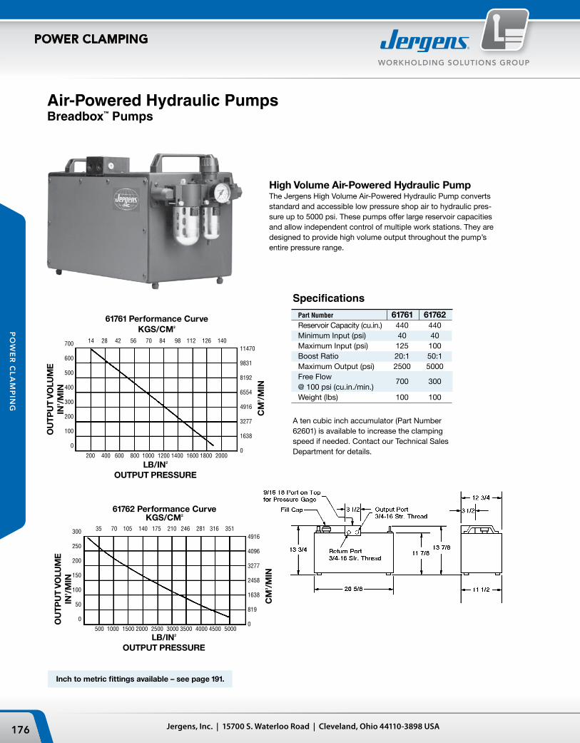
14 28 42 56 70 84 98 112 126 140
61761 Performance CurveKGS/CM2
LB/IN2
OUTPUT PRESSURE
700
600
500
400
300
200
100
0
OU
TPU
T VO
LUM
EIN
3 /MIN
11470
9831
8192
6554
4916
3277
1638
0
CM
3 /MIN
200 400 600 800 1000 1200 1400 1600 1800 2000
35 70 105 140 175 210 246 281 316 351
61762 Performance CurveKGS/CM2
300
250
200
150
100
50
0
4916
4096
3277
2458
1638
819
0
CM
3 /MIN
OU
TPU
T VO
LUM
EIN
3 /MIN
LB/IN2
OUTPUT PRESSURE
500 1000 1500 2000 2500 3000 3500 4000 4500 5000
Jergens, Inc. | 15700 S. Waterloo Road | Cleveland, Ohio 44110-3898 USA176
WORKHOLDING SOLUTIONS GROUP
POWER CLAMPING
PO
WE
R C
LA
MP
ING
Specifications
Part Number 61761 61762Reservoir Capacity (cu.in.) 440 440Minimum Input (psi) 40 40Maximum Input (psi) 125 100Boost Ratio 20:1 50:1Maximum Output (psi) 2500 5000Free Flow @ 100 psi (cu.in./min.)
700 300
Weight (lbs) 100 100
A ten cubic inch accumulator (Part Number 62601) is available to increase the clamping speed if needed. Contact our Technical Sales Department for details.
High Volume Air-Powered Hydraulic PumpThe Jergens High Volume Air-Powered Hydraulic Pump converts standard and accessible low pressure shop air to hydraulic pres-sure up to 5000 psi. These pumps offer large reservoir capacities and allow independent control of multiple work stations. They are designed to provide high volume output throughout the pump’s entire pressure range.
Air-Powered Hydraulic PumpsBreadbox™ Pumps
Inch to metric fittings available – see page 191.

177Phone: 877-426-2504 | Fax: +1 216-481-6193 | E-mail: [email protected] | www.jergensinc.com
WORKHOLDING SOLUTIONS GROUP
POWER CLAMPING
PO
WE
R C
LA
MP
ING
Circuit Diagram
Typical Installation — Two Station Milling Operation
Typical Hydraulic CircuitApplication
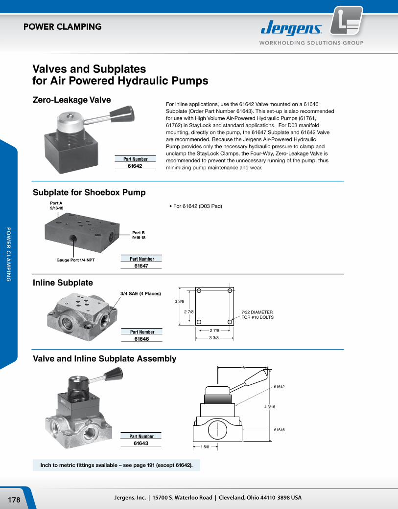
Port B9/16-18
Gauge Port 1/4 NPT
Port A9/16-18
4 3/16
61642
61646
3
1 5/8
2 7/8
7/32 DIAMETERFOR #10 BOLTS
2 7/8
3 3/8
3 3/8
3/4 SAE (4 Places)
Jergens, Inc. | 15700 S. Waterloo Road | Cleveland, Ohio 44110-3898 USA178
WORKHOLDING SOLUTIONS GROUP
POWER CLAMPING
PO
WE
R C
LA
MP
ING
Valves and Subplates for Air Powered Hydraulic Pumps
Inline Subplate
Subplate for Shoebox Pump
For inline applications, use the 61642 Valve mounted on a 61646 Subplate (Order Part Number 61643). This set-up is also recommended for use with High Volume Air-Powered Hydraulic Pumps (61761, 61762) in StayLock and standard applications. For D03 manifold mounting, directly on the pump, the 61647 Subplate and 61642 Valve are recommended. Because the Jergens Air-Powered Hydraulic Pump provides only the necessary hydraulic pressure to clamp and unclamp the StayLock Clamps, the Four-Way, Zero-Leakage Valve is recommended to prevent the unnecessary running of the pump, thus minimizing pump maintenance and wear.
Zero-Leakage Valve
Valve and Inline Subplate Assembly
Part Number 61646
Part Number 61642
Part Number 61647
Part Number 61643
• For 61642 (D03 Pad)
Inch to metric fittings available – see page 191 (except 61642).

179Phone: 877-426-2504 | Fax: +1 216-481-6193 | E-mail: [email protected] | www.jergensinc.com
WORKHOLDING SOLUTIONS GROUP
POWER CLAMPING
PO
WE
R C
LA
MP
ING
Manual PumpsLever Type
These units offer greater versatility than screw pumps. The pumps have a built-in reservoir check valve and control. Single and two stage models are available. Applications are the same as for the screw pump but allow for larger circuits. Circuits require manual bleeding.
Specifications Pump Max. Pump Pump Plunger Pump Low-Speed High-Speed Pipe Pump Usable Working Plunger Plunger Displace- Delivery By-Pass By-Pass Thread Handle Model Oil Cap Pressure Dia. Stroke Ment (Cu. In./ Pressure Pressure Conn. Length Length Width Height Weight No. (Cu. In.) (psi) (in.) (in.) (cu. in.) Min.) (psi) (psi) (in.) (in.) (in.) (in.) (in.) (lbs)
61736 45 10000 1/2 1 .19 3.6 10500 - 3/8 NPTF 20 24 1/2 5 1/2 6 1/4 16 61737 143 10000 1/2 1 .19 3.6 10500 300 3/8 NPTF 20 23 5/16 7 7 3/8 29
Manual PumpsApplication
Typical Manual Pump application on a boring mill. The clamping is a self-contained set-up for rotary indexing for large multi-side castings.
Circuit Diagram

PORT 9/16-18
5.14
ø2.56
Jergens, Inc. | 15700 S. Waterloo Road | Cleveland, Ohio 44110-3898 USA180
WORKHOLDING SOLUTIONS GROUP
POWER CLAMPING
PO
WE
R C
LA
MP
ING
Accumulator Part Max. Pre-Charge Weight Number Pressure Pressure Volume (lbs)
62603 3600 psi 1500 psi 5 cu. in. 1.5*Other Accumulators and pre-charge pressure are available upon request.
To order components separately
Male Quick Coupler Hydraulic Ball Valve Disconnect Sleeve Gage
61639 61965 61915 60703
Pallet Decoupler Valve
The Pallet Decoupler Valve allows hydraulically clamped tooling fixtures to maintain pressure when disconnected from their power source. The built-in pre-charged accumulator maintains pressure within a hydraulic system, compensating for slow leaks. The Pallet Decoupler Valve adds a level of security to fixtures that must be disconnected from a power source while being moved. Ideal for use with palletized fixtures and machining centers.
• Manifold• Accumulator• Hydraulic Connections• Hydraulic Gauge• Manual Ball Valve
Part Number 62605

181Phone: 877-426-2504 | Fax: +1 216-481-6193 | E-mail: [email protected] | www.jergensinc.com
WORKHOLDING SOLUTIONS GROUP
POWER CLAMPING
PO
WE
R C
LA
MP
ING
Specifications 160 PSI
Part Number 60701 60702 60705Thread Size 1/8 NPT 1/4 NPT 1/4 NPTLocation Back Bottom BackWeight (lbs) .16 .25 .25
Air Circuit ControlsFilter/Regulators
The filter element removes the solid impurities and condensates before the compressed air enters the regulator. The regulator valve supplies a preset pressure regardless of main circuit pressure as long as pressure in the main circuit is higher than that in the secondary.
Specifications
Part Number 61616 61617Port Size 1/4 NPT 3/8 NPTSCFM Rating 53 SCFM 80 SCFMWeight (lbs) 1.6 3.2
Manually adjusted control of input pressures. Allows the regulation of pressures into a work circuit. Reverse flow is unrestricted. Used for throttling or metering a circuit so that actuator speed meets work requirements.
Used to reduce air flow noise. Installation is recommended at exhaust ports of Air Control Valves.
Mufflers
When sizing a pressure gauge, the maximum output of the system should be approximately 2/3 of the gauge capacity.
Gauges
SpecificationsPart Number 62612 62613Thread Size 1/4 NPT 3/8 NPTWeight (lbs) .06 .22
SpecificationsPart Number 61603Port Size 1/4 NPTWeight (lbs) .31
Flow Control Valve

Jergens, Inc. | 15700 S. Waterloo Road | Cleveland, Ohio 44110-3898 USA182
WORKHOLDING SOLUTIONS GROUP
POWER CLAMPING
PO
WE
R C
LA
MP
ING
A variety of directional control valves are offered. Manual valves are normally two position, detented. Solenoid valves are 115V-60 Hz; other voltages are available.
Part Number 61615 61620 61621 61630 61631*Actuator Type Hand Solenoid Solenoid Treadle PedalReturn Actuator Hand Spring Solenoid Treadle SpringPort Size 3/8 NPT 3/8 NPT 3/8 NPT 3/8 NPT 3/8 NPTCV Rating 1.5 1.0 1.0 2.3 2.3Weight (lbs) 2.75 5.0 5.5 4.0 3.5
*Foot Guard for 61631 Valve; Part Number 61632
Air Circuit Controls2-Way and 3-Way Valves
2-way valves are in-line ball valves. They are used as a shut-off valve in simple circuits.
3-way valves are similar to 2-way valves but have a third port which is generally used as a vent or exhaust.
Specifications
Part Number 61601 61634Type 2-way 3-wayPort Size 3/8 NPT 1/8 NPTWeight (lbs) .81 .22
4-Way Valves
Specifications
Part Number
61601Part Number
61634
Part Number
61615Part Number
61620 & 61621Part Number
61630 & 61631

183Phone: 877-426-2504 | Fax: +1 216-481-6193 | E-mail: [email protected] | www.jergensinc.com
WORKHOLDING SOLUTIONS GROUP
POWER CLAMPING
PO
WE
R C
LA
MP
ING
Selection Data Part Number
3000 Psi 6000 Psi 10000 PsiGauge Only 60704 60703 60706Block Only 61055 61055 61055Gauge Kit* 60711 60712 60713
SpecificationsPart Number 61304Medium Clean, dry compressed air onlyWorking Range 50 to 100 psiTemperatureRange -300 to 1800FAir Flow (with Modular Valves)
10 CFM at 100 psi
Exhaust To atmosphere through holes in plateMounting 7/32 holes provided in subplateMaterials Clear Acrylic, brassFiltration 40 Micron requiredLubrication Recommended
Air Circuit Controls2-Hand No Tie Down
Requires the operator to use both hands when activating a work circuit. Two counterbored finger buttons are installed at a minimum center distance.
Hydraulic Circuit ControlsGauges
Recommended as a visual pressurized monitor-ing gauge to be used on all pressuring systems.
When sizing a pressure gauge, the maximum output of the system should equal approximately 2/3 of the gauge capacity.
Gauges are filled with glycerine in order to dampen internal movement.
Gauge blocks facilitate the installation of pres-sure gauges on standard boosters.
* Gauge, Block and Fittings included in kits. All Gauges 1/4" NPT, bottom ported.

7/32 THRU
3/6-16 THREAD
3.31
3”
4 1/4”
2.83
Jergens, Inc. | 15700 S. Waterloo Road | Cleveland, Ohio 44110-3898 USA184
WORKHOLDING SOLUTIONS GROUP
POWER CLAMPING
PO
WE
R C
LA
MP
ING
Hydraulic Circuit Controls2-Way Valves
2-way valves are in-line ball valves. They are used as a shut-off valve in simple circuits.
4-Way Valves
Dimensions Part Number A B C 61610 2 11/16 2 5/8 5 1/4 61639 3 2 4 1/4
A variety of directional control valves are offered. Manual valves are normally two position, detented. Solenoid valves are 115V-60 Hz; other voltages are available.
For 4-Way, Zero Leakage Valves, see page 178.
SpecificationsPart Number 61610 61639Port Size 1/4 NPT 3/8 NPTPressureRating (psi) 3000 5000
Part Number
61638Part Number
61643
SpecificationsPart Number 61643 61644 61636 61637 61638Actuator Hand Solenoid Solenoid Solenoid Air Type (115 VAC) (115 VAC) (115 VAC)Return Hand Solenoid Spring Solenoid Spring Actuator (115 VAC) (115 VAC)Port Size 3/4-16 DO3 MT6 3/4-16 3/4-16 3/8 NPTFlow Rating 5 GPM 3 GPM 5 GPM 5 GPM 12 GPMPressure Rating (psi) 5000 6000 5000 5000 5000Weight (lbs) 3.75 3 6.75 7.3 17.5
Dimensions Part Number A B C D
61636 3 1/4 5 5/64 5 21/32 — 61637 3 1/4 5 5/64 — 8 3/8 61644 2 3/8 — — 8 3/16

185Phone: 877-426-2504 | Fax: +1 216-481-6193 | E-mail: [email protected] | www.jergensinc.com
WORKHOLDING SOLUTIONS GROUP
POWER CLAMPING
PO
WE
R C
LA
MP
ING
Hydraulic Circuit ControlsPressure Reducing Valve
SpecificationsPart Number 61619Port Size 3/8 NPTPressure Rating (psi) 5000Regulating Range (psi) 500-4500
Senses pressure in a circuit and may be used to start or shut down a system. A pressure switch can be used to remove the cutting tool and turn off machine in the event of loss of clamping pressure.
Pressure Switch
SpecificationsPart Number 61633Port Size 1/4 NPTPressure Rating (psi) 10000Regulating Range (psi) 350-5000
With adjustable opening pressure, this valve may be used to control the sequence of work devices in a common circuit.
Sequence Valve
SpecificationsPart Number 61640Port Size 9/16-18Pressure Rating (psi) 5000Sequence Range* (psi) 500-3000* Factory Adjusted to sequence at 1000 psi.
Allow individual cylinders or clamps to operate at different pressures from the same power source.

Jergens, Inc. | 15700 S. Waterloo Road | Cleveland, Ohio 44110-3898 USA186
WORKHOLDING SOLUTIONS GROUP
POWER CLAMPING
PO
WE
R C
LA
MP
ING
Check Valve
Flow Control Valve
Specifications
Part Number 61609Port Size 3/8 NPTPressure Rating (psi) 5000Flow Rating CV .78Weight (lbs) .63
• Recommended for use with Jergens Swing Clamps
Hydraulic Circuit ControlsPilot Operated Check Valve
A two-way valve used to lock pressure in a working circuit. Automatic free return flow is provided via air pilot operation. Designed so that loss of shop air line pressure will have no effect on the hydraulic circuit in booster applications.
Used to control the flow of pressure in a system, to slow the movement of individual cylinders, or decrease shock.
Allows pressure flow in one direction only.
Specifications Part Number
Valve only 61629Valve withInstallation Kit 62211*
* Includes hose, fittings and valves
SpecificationsPart Number 61607Port Size 3/8 NPTPressureRating (psi) 5000Flow Rating CV .83Weight (lbs) .63
SpecificationsPart Number 61629HydraulicPorts 3/4-16Pilot Port 7/16-20PressureRating (psi) 5000
• Minimum operating pressure 500 psi
• 50:1 differential pressure• Pilot not to exceed 125 psi

187Phone: 877-426-2504 | Fax: +1 216-481-6193 | E-mail: [email protected] | www.jergensinc.com
WORKHOLDING SOLUTIONS GROUP
POWER CLAMPING
PO
WE
R C
LA
MP
ING
Can be used with air pressure on top of oil to do work in your system, such as returning double acting cylinders with hydraulic pressure. The acrylic reservoir allows easy monitoring of oil level. Special baffle plates in the top of the reservoir distribute incom-ing air pressure evenly against the top surface of the oil.
Oil Reservoirs
Part Capacity Side End Wt Number A B (Cu. In.) Ports Ports (lbs) 61750 2 7/8 9 1/2 18 9/16-18 9/16-18 3.0 61751 4 13/16 8 1/2 55 NONE 9/16-18 6.8• Maximum air operating pressure rating 125 PSI.
Hydraulic FluidsFood Grade Hydraulic OilJergens Food Grade Hydraulic Oil is a blend of food grade lubricants designed for use as a hydraulic media in food packaging and other similar equipment. It is composed of 100% chemically produced synthetic lubricants and contains no petroleum hydrocarbons.
Its viscosity is 140 SUS at 100°F and 725 SUS at 35°F.
Hydraulic OilJergens Hydraulic Oil is special-ly formulated to minimize foam-ing and to protect metal parts from rust. It is an aircraft type oil with high wetting out and film strength characteristics.
Its viscosity is 170/190 at 100°F and it maintains functional characteristics down to 25°F below zero.
One Quart .........................60813One Gallon ........................6081255 Gallon Drum .................60811
One Quart ........................60801One Gallon .......................60802Five Gallon ...................... 6080355 Gallon Drum .............. 60804
Inch to metric fittings available – see page 191.

Jergens, Inc. | 15700 S. Waterloo Road | Cleveland, Ohio 44110-3898 USA188
WORKHOLDING SOLUTIONS GROUP
POWER CLAMPING
PO
WE
R C
LA
MP
ING
SpecificationsMaximum Air Pressure (psi) 150
Maximum Vacuum (Hg.) 28"Maximum Hydraulic Pressure (psi) 3000Maximum Temperature 2500FMaximum Speed (rpm) 250
The six port hex manifold, with SAE straight thread ports, can be mounted in the center of several work units or used with a 61031 union (see page 191) to mount the manifold directly to the output port of your Jergens Booster.
Part Number 61805
Rotary CouplerSingle and Dual Passage
ManifoldStrip
• Material: Aluminum• Finish: Black Oxide
Hex
Dimensions Number End Part Of Side Ports Ports Wt. Number Ports A B C D E F G H J K (lbs) 61801 4 1/4 1 1/2 5/8 7/8 3/8 1 3/4 13/64 3 7/8 1 1/64 3/4 .75 61802 8 1/4 1 1/2 5/8 7/8 3/8 5 1/4 13/64 7 3/8 1 1/64 3/4 1.50NOTE: Maximum operating pressure is 3000 PSI for all aluminum manifolds.
Dimensions Rotor Rotor Part Thread Tap Tap Port Hex Hex Tap Lockup Wt. Number A B1 B2 C1 C2 D E F G H1 H2 I J (lbs)
61997 3/8 1/4 — 1 1/2 — 3 1/4 1 1/8 5/8 5/16 7/8 — — 1 25/32 .5 NPT NPT 61998 3/4 1/2 1/4 2 3/4 1 1/2 7 11/16 1 15/16 7/8 1/4 1 3/8 7/8 1/4 2 7/8 3.0 NPT NPT NPT NPT
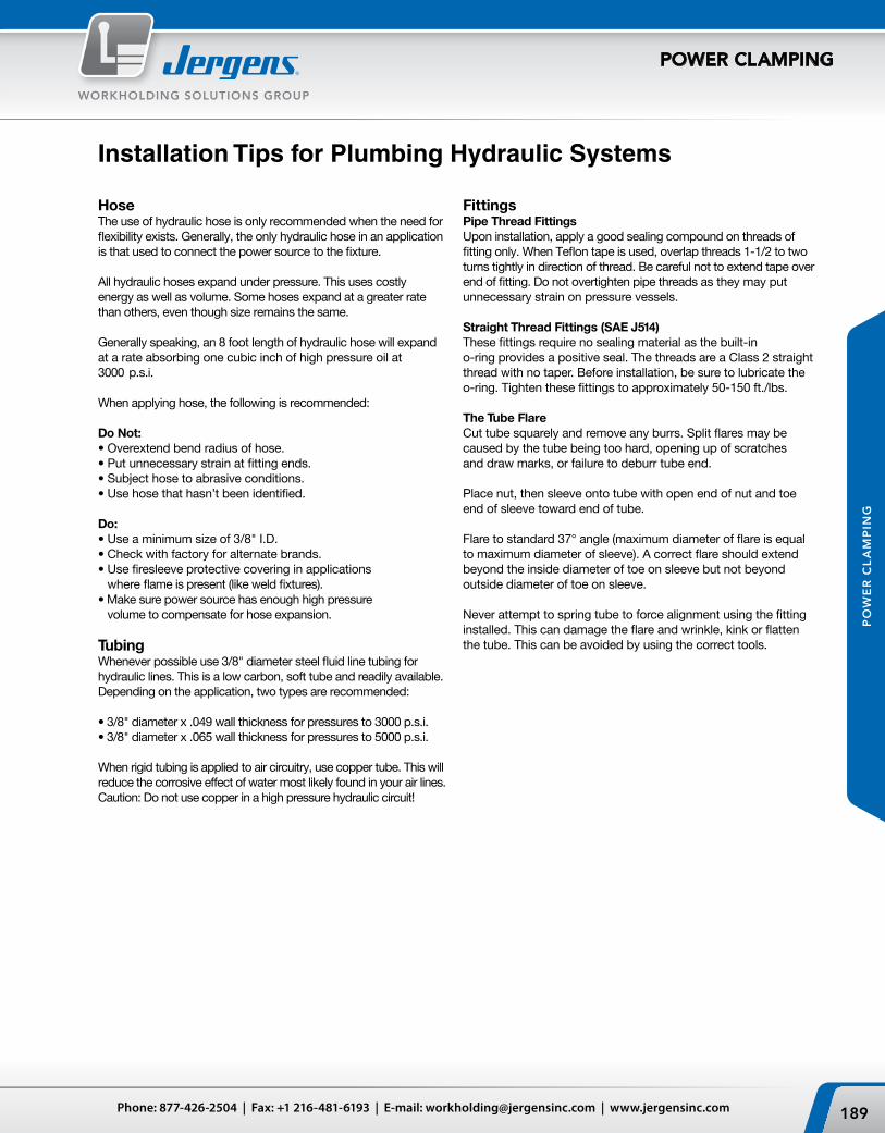
189Phone: 877-426-2504 | Fax: +1 216-481-6193 | E-mail: [email protected] | www.jergensinc.com
WORKHOLDING SOLUTIONS GROUP
POWER CLAMPING
PO
WE
R C
LA
MP
ING
Installation Tips for Plumbing Hydraulic Systems
HoseThe use of hydraulic hose is only recommended when the need for flexibility exists. Generally, the only hydraulic hose in an application is that used to connect the power source to the fixture.
All hydraulic hoses expand under pressure. This uses costly energy as well as volume. Some hoses expand at a greater rate than others, even though size remains the same.
Generally speaking, an 8 foot length of hydraulic hose will expand at a rate absorbing one cubic inch of high pressure oil at 3000 p.s.i.
When applying hose, the following is recommended:
Do Not:• Overextend bend radius of hose.• Put unnecessary strain at fitting ends.• Subject hose to abrasive conditions.• Use hose that hasn’t been identified.
Do:• Use a minimum size of 3/8" I.D.• Check with factory for alternate brands.• Use firesleeve protective covering in applications
where flame is present (like weld fixtures).• Make sure power source has enough high pressure
volume to compensate for hose expansion.
TubingWhenever possible use 3/8" diameter steel fluid line tubing for hydraulic lines. This is a low carbon, soft tube and readily available. Depending on the application, two types are recommended:
• 3/8" diameter x .049 wall thickness for pressures to 3000 p.s.i.• 3/8" diameter x .065 wall thickness for pressures to 5000 p.s.i.
When rigid tubing is applied to air circuitry, use copper tube. This will reduce the corrosive effect of water most likely found in your air lines. Caution: Do not use copper in a high pressure hydraulic circuit!
FittingsPipe Thread FittingsUpon installation, apply a good sealing compound on threads of fitting only. When Teflon tape is used, overlap threads 1-1/2 to two turns tightly in direction of thread. Be careful not to extend tape over end of fitting. Do not overtighten pipe threads as they may put unnecessary strain on pressure vessels.
Straight Thread Fittings (SAE J514)These fittings require no sealing material as the built-in o-ring provides a positive seal. The threads are a Class 2 straight thread with no taper. Before installation, be sure to lubricate the o-ring. Tighten these fittings to approximately 50-150 ft./lbs.
The Tube FlareCut tube squarely and remove any burrs. Split flares may be caused by the tube being too hard, opening up of scratches and draw marks, or failure to deburr tube end.
Place nut, then sleeve onto tube with open end of nut and toe end of sleeve toward end of tube.
Flare to standard 37° angle (maximum diameter of flare is equal to maximum diameter of sleeve). A correct flare should extend beyond the inside diameter of toe on sleeve but not beyond outside diameter of toe on sleeve.
Never attempt to spring tube to force alignment using the fitting installed. This can damage the flare and wrinkle, kink or flatten the tube. This can be avoided by using the correct tools.

Jergens, Inc. | 15700 S. Waterloo Road | Cleveland, Ohio 44110-3898 USA190
WORKHOLDING SOLUTIONS GROUP
POWER CLAMPING
PO
WE
R C
LA
MP
ING
Fittings
Male Male Union Ferrule Nut Connector Elbow Tee 1/8 Tube 1/8 Tube 1/8 NPT x 1/8 Tube 1/8 Tube 1/8 Tube
60201 60202 60204 60205 60207
Flareless Fittings
These fittings are the most common types needed to plumb Pressure Points and Screw Pumps. Use 1/8" Heavy Duty High Pressure, Fluid Line Steel Tube.
37° Flare FittingsSleevePart Number Item Tube
61001 Sleeve 1/4
61015 Sleeve 3/8
61049 Sleeve 1/2
NutsPart Number Item Tube
61002 Nuts 1/4
61016 Nuts 3/8
61050 Nuts 1/2
CapsPart Number Item Tube
61056 Caps 1/4
61057 Caps 3/8
PlugsPart Number Item Tube
61058 Plugs 1/4
61059 Plugs 3/8
ReducerPart Number Item Tube
61063 Reducer 1/4 Tube 3/8 Female
Tee Nut FittingsPart Number Thread Tube
61051 Swivel Nut Branch Tees 1/4
61062 Swivel Nut Branch Tees 3/8
61023 Union Tee 3/8
Male ConnectorsPart Number Thread Type Thread/ Tube
61007 Pipe 1/8 NPT x 1/4 Tube
61054 Pipe 1/8 NPT x 3/8 Tube
61008 Pipe 1/4 NPT x 1/4 Tube
61020 Pipe 1/4 NPT x 3/8 Tube
61028 Pipe 3/8 NPT x 1/4 Tube
61034 Pipe 3/8 NPT x 3/8 Tube
61048 Pipe 3/8 NPT x 1/2 Tube
61009 Straight 7/16-18 x 1/4 Tube
61030 Straight 9/16-18 x 1/4 Tube
61021 Straight 9/16-18 x 3/8 Tube
61046 Straight 3/4-16 x 3/8 Tube
61047 Straight 3/4-16 x 1/2 Tube
Male ElbowsPart Number Type Thread/ Tube
61003 Pipe Thread 1/8 NPT x 1/4 Tube
61004 Pipe Thread 1/4 NPT x 1/4 Tube
61017 Pipe Thread 1/4 NPT x 3/8 Tube
61064 Pipe Thread 3/8 NPT x 3/8 Tube
61045 Pipe Thread 3/8 NPT x 1/2 Tube
61072 45 Elbow 3/8 NPT x 3/8 Tube
61005 Straight Thread 7/16-20 x 1/4 Tube
61029 Straight Thread 9/16-18 x 1/4 Tube
61018 Straight Thread 9/16-18 x 3/8 Tube
61044 Straight Thread 3/4-16 x 1/2 Tube
Male Branch TeesPart Number Type Thread/ Tube
61014 Pipe Thread 1/8 NPT x 1/4 Tube
61027 Pipe Thread 1/4 NPT x 3/8 Tube
61043 Pipe Thread 3/8 NPT x 1/2 Tube
61040 Straight Thread 7/16-20 x 1/4 Tube
61041 Straight Thread 9/16-18 x 3/8 Tube
61042 Straight Thread 3/4-16 x 1/2 Tube
61032 Male Run Tees 7/16-20 x 1/4 Tube
61061 Male Run Tees 9/16-18 x 3/8 Tube

191Phone: 877-426-2504 | Fax: +1 216-481-6193 | E-mail: [email protected] | www.jergensinc.com
WORKHOLDING SOLUTIONS GROUP
POWER CLAMPING
PO
WE
R C
LA
MP
ING
Fittings
AdaptersPart Number Thread Type Male Female
61075 Pipe 1/16 NPT 1/4 NPT
61076 Pipe 1/8 NPT 1/4 NPT
60221 Mixed 1/4 NPT 1/4 BSP
61082 Mixed 7/16-20 1/4 NPT
61081 Mixed 9/16-18 1/4 NPT
60211 Mixed 9/16-18 3/8 Tube
60217 Mixed 3/8 Tube 1/4 NPT
60222 Mixed 3/8 NPT 3/8 BSP
61035 Mixed 3/4-16 1/4 NPT
61036 Mixed 3/4-16 3/8 NPT
61077 Metric 7/16-20 1/8 ISO
61078 Metric 9/16-18 1/4 ISO
61079 Metric 3/4-16 3/8 ISO
61150 Mixed 7/16-20 1/8 BSPP
61151 Mixed 7/16-20 1/4 BSPP
61153 Mixed 9/16-18 3/8 BSPP
61152 Mixed 9/16-18 1/4 BSPP
61154 Mixed 3/4-16 1/4 BSPP
61155 Mixed 3/4-16 3/8 BSPP
Reducers/ExpandersPart Number Thread Type Male Female
61074 Pipe 1/4 NPT 1/8 NPT
61025 Pipe 3/8 NPT 1/4 NPT
61038 Pipe 1/2 NPT 3/8 NPT
61067 Pipe 3/4 NPT 3/8 NPT
61039 Pipe 3/4 NPT 1/2 NPT
61033 Straight 9/16-18 7/16-20
61080 Straight 7/16-20 9/16-18
61037 Straight 3/4-16 9/16-18
ElbowsPart Number Thread
61095 1/8 NPT Female —
61070 1/8 NPT Straight —
61096 1/4 NPT Female —
61071 1/4 NPT Straight —
61097 3/8 NPT Female —
61066 3/8 NPT Male —
61098 1/2 NPT Female —
61065 3/4-16 Male 3/8 NPT Female
TeesPart Number Thread
61087 1/8 NPT Female
61088 1/4 NPT Female
61089 3/8 NPT Female
61090 1/2 NPT Female
NipplesPart Number Thread
61083 1/8 NPT
61084 1/4 NPT
61085 3/8 NPT
61086 1/2 NPT
61052 1/8 NPT x 3/8 NPT
61053 1/4 NPT x 3/8 NPT
60210 9/16-18 Union
61031 3/4-16 Union
PlugsPart Number Thread
61091 1/8 NPT
61092 1/4 NPT
61093 3/8 NPT
61094 1/2 NPT
61060 7/16-20
61068 9/16-18
61069 3/4-16

Jergens, Inc. | 15700 S. Waterloo Road | Cleveland, Ohio 44110-3898 USA192
WORKHOLDING SOLUTIONS GROUP
POWER CLAMPING
PO
WE
R C
LA
MP
ING
Low Pressure Air HoseHose I.D. 1/4 3/8 1/2HosePart Number 61106 61108 61110FittingPart Number 61107 61109 61111Thread Size 7/16-20 9/16-18 3/4-16
High Pressure Hydraulic HoseLength 12" 18" 24" 36" 72"Part Number4000 psi 61201 61202 61203 61204 61205Part Number7000 psi 61211 61212 61213 61214 61215
*Also available in 5000 psi.
Steel Tubing Part Number Description
60209 3/8 DIA. x 5 Ft.
Quick Disconnect Couplers
Steel Tubing
Air Couplers
Length 25' Hose Ends Hose EndsPart Number 61221 61226 612272750 psi 1/4 Hose 1/4 Npt Male 1/4 37° JIC Swivel Female
Hydraulic Hose (Build Your Own)
Hydraulic Hose
Flexible HoseLow pressure air hose is sold by the foot in bulk lengths. Order the total footage and number of push-on fittings required by using the number to the right.
Whenever possible, 3/8" diameter steel tubing should be used for hydraulic lines. Jergens tubing is low carbon soft tube with .065 wall thickness. The tubing is rated at 5000 psi.
High pressure hose is supplied assembled and to lengths indicated. Lengths are measured from end of coupling to end of coupling. Hose is 3/8" ID and available in 4000 psi or 7000 psi rating. 3/8" female tubing fittings on each end.
Sleeve Nipple
3/8 NPT Female 3/8 NPT Female 61915 61965 1/4 NPT Female 1/4 NPT Male 61916 61966
Hydraulic couplers have dual checks.
Hydraulic Coupler Sleeve Nipple 1/8 NPT Female 1/8 NPT Male 61904 61950 1/4 NPT Female 1/4 NPT Male 61905 61951 1/4 NPT Female 61954 Air couplers have checks on sleeves only.

193Phone: 877-426-2504 | Fax: +1 216-481-6193 | E-mail: [email protected] | www.jergensinc.com
WORKHOLDING SOLUTIONS GROUP
POWER CLAMPING
PO
WE
R C
LA
MP
ING
Hydraulic Product Repair Kits with Replacement Seals
Jergens maintains a qualified staff whose primary responsibility is to provide technical assistance to our distributors and customers.
Your direct connection number for dimensional questions, circuit assistance and troubleshooting is:
1-877-426-2504OR
E-mail: [email protected]
Hydraulic Part Repair Kit Hydraulic Part Repair Kit Hydraulic Part Repair Kit Hydraulic Part Repair Kit Hydraulic Part Repair Kit Number Number Number Number Number Number Number Number Number Number
60302 6210260303 6210360307 6210260340 6210460341 6210560345 6218960350 6212060351 6212160360 6212060361 6212160371 6216760372 6216760373 6216860374 6216960381 6217060382 6217060383 6217160384 6217160401 6210660402 6210660403 6219560404 6219560405 6212460410 6210660411 6210660412 6210660413 62195
60414 6219560461 6212560462 6212660463 6212760464 6212860465 6212960466 6213060511 6213960512 6214060513 6219460554 6215160555 6215160593 62145 (1)
60594 62146 (1)
60595 62147 (1)
60596 6217760597 6217860598 6217960601 62102 (2)
— 62162 (3)
60602 62103 (2)
— 62162 (3)
60621 6215460622 6215560631 6215660650 62104 (4)
— 62189 (5)
— 62162 (3)
60651 62105 (2)
— 62162 (3)
60660 6236060661 6236060662 6236260663 6236260664 6236460665 6236460670 6236060671 6236060672 6236260673 6236260674 6236460675 6236460680 6219060681 6219660685 6213161501 6213361612 6213461514 6213461623 6216361629 6212361640 6216461701 6213261704 6210761705 62108
61709 6210961710 6210961711 6211061714 6210761715 6210861720 6217361721 6217461722 6217561736 6215961737 6216061755 6219761756 6219861761 6214461762 6214461997 6216561998 6216662721 6216162722 6216162801* 6217262802* 6217262803* 6217262804* 6217262805 6230162806 6230262811 6218362812 6218362823 62184
62824 6218462831 6218762841 6218562842 6218562845 6230362846 6230362852 6219963101 6210163103 6210363107 6210263113 6210563117 6210463123 6210663201 6213463202 6213463212 6212663213 6212763214 6212863215 6212963216 6213063302 6214063303 6219463801 6218463802 62184— —— —— —
(1) Special tools required: use 62148 tool for 60556, use 62149 tool for 60597 or 60598.(2) Cylinder Kit (3) Mechanical Kit (4) Kit for cylinder with 3/8" piston (5) Kit for cylinder with 1/2" piston(*) Tool kit 62176 required for 62801, 62802, 62803, 62804
Technical Assistance
Recommendation – when replacing seals in hydraulic cylinders, we recommend replacing all seals at the same time.
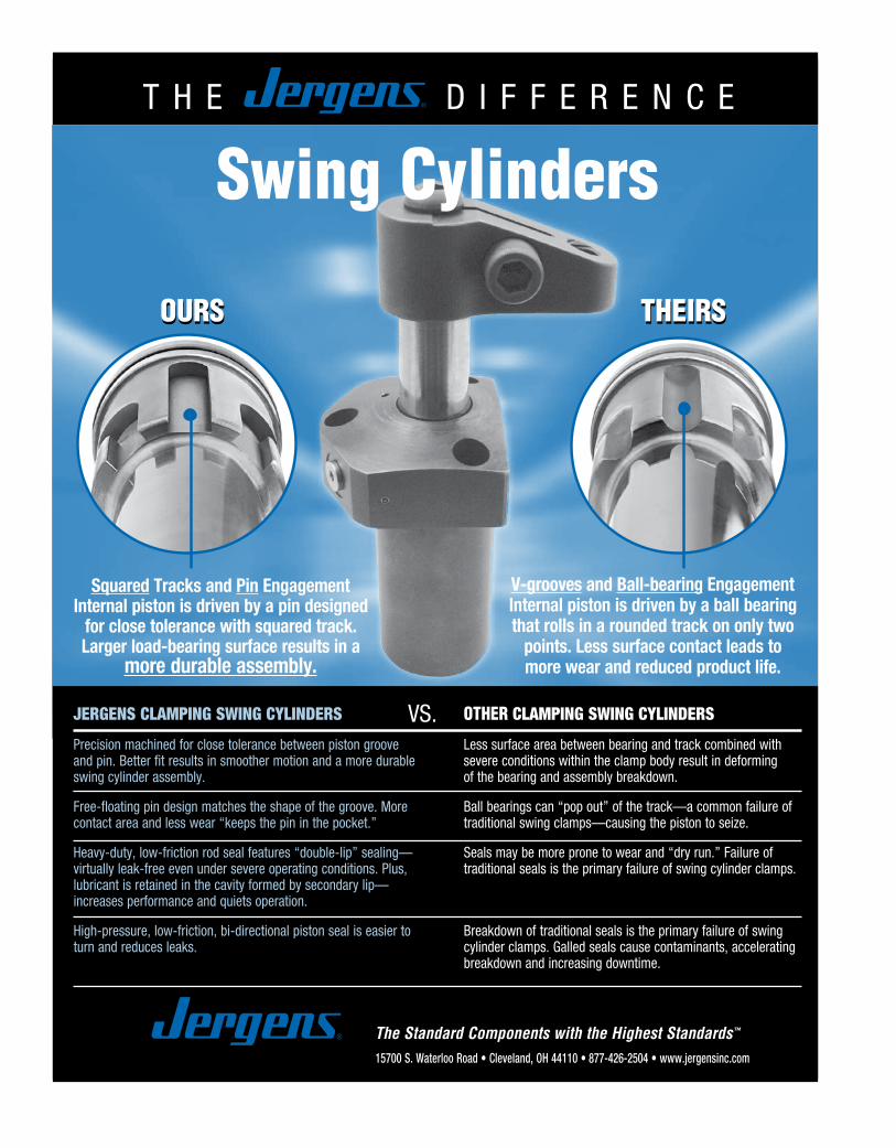
T H E D I F F E R E N C E
The Standard Components with the Highest Standards™
JERGENS CLAMPING SWING CYLINDERS
Precision machined for close tolerance between piston grooveand pin. Better fit results in smoother motion and a more durableswing cylinder assembly.
Free-floating pin design matches the shape of the groove. Morecontact area and less wear “keeps the pin in the pocket.”
Heavy-duty, low-friction rod seal features “double-lip” sealing—virtually leak-free even under severe operating conditions. Plus,lubricant is retained in the cavity formed by secondary lip—increases performance and quiets operation.
High-pressure, low-friction, bi-directional piston seal is easier toturn and reduces leaks.
OTHER CLAMPING SWING CYLINDERS
Less surface area between bearing and track combined withsevere conditions within the clamp body result in deformingof the bearing and assembly breakdown.
Ball bearings can “pop out” of the track—a common failure oftraditional swing clamps—causing the piston to seize.
Seals may be more prone to wear and “dry run.” Failure oftraditional seals is the primary failure of swing cylinder clamps.
Breakdown of traditional seals is the primary failure of swingcylinder clamps. Galled seals cause contaminants, acceleratingbreakdown and increasing downtime.
V-grooves and Ball-bearing EngagementInternal piston is driven by a ball bearingthat rolls in a rounded track on only two
points. Less surface contact leads tomore wear and reduced product life.
Squared Tracks and Pin EngagementInternal piston is driven by a pin designed
for close tolerance with squared track.Larger load-bearing surface results in a
more durable assembly.
VS.
OURSOURS THEIRSTHEIRS
15700 S. Waterloo Road • Cleveland, OH 44110 • 877-426-2504 • www.jergensinc.com
Swing Cylinders

195
Locating Components
Adjustable Jack Screws ............................................... 212Adjustable Locating Buttons ..................................... 212Alloy Steel Pull Dowel Pins .................................198–199Bullet Nose Dowels ...................................................... 219Bullet Nose Pins ............................................................ 220Drift Handles ................................................................. 213Fixture Jacks .................................................................. 212Fixture Keys, Sine .................................................214–215Fixture Keys, Standard ................................................ 213Flat Feet .......................................................................... 210Jig Feet ...........................................................................209Jig Legs ........................................................................... 210Jig Pins ............................................................................ 203Lanyards ......................................................................... 203Locating Pins .........................................................216–217Locating Pin Liners ....................................................... 218Locating Pin Lock Screws ............................................ 218L-Pins............................................................................... 202Pilot Locating Pins ........................................................ 219Precision Expanding Dowels ...................................... 201Pull Dowel Pins, Alloy Steel ................................198–199Pull Dowels ....................................................................200Rest Buttons ......................................................... 205–207Rest Buttons, Carbide Insert ...................................... 207Rest Buttons, Threaded ...............................................206Rest Pads ........................................................................208Screws, Adjustable Jack .............................................. 212Slotted Locator Bushings ............................................204Stripper Bolts, Kwik-Strip ....................................196–197Tooling/Inspection Balls .....................................221–223T-Pins............................................................................... 202Work Support Jacks, Manual .......................................211
LOCATING COMPONENTS
LO
CA
TIN
G C
OM
PO
NE
NT
S

Step 1 Step 2 Step 3
Step 4
Jergens, Inc. | 15700 S. Waterloo Road | Cleveland, Ohio 44110-3898 USA196
WORKHOLDING SOLUTIONS GROUP
LOCATING COMPONENTS
LO
CA
TIN
G C
OM
PO
NE
NT
S
A New Perspective on Stripper PlatesToday's more complex dies require more time to service. The advantage of time saving devices such as ball and roll lock punches is minimized unless the stripper plate can be removed first.
The patented Jergens Kwik-Strip Stripper Bolts provide an inexpensive, simple method of stripper plate removal. The stripper can be removed with the die still mounted in the press!
InstallationStep 1: Drill a through hole 1/32" larger than the nominal
body diameter of the bolt to be used.
Step 2: Using a Jergens Drill Jig, drill the auxiliary 1/4" hole. The 1/4" hole may be located radially at any position on the periphery of the body hole. Drill the 1/4" hole slightly deeper than the proposed counterbore.
Step 3: Using a standard counterboring tool, counterbore to required depth. See counterbore selection chart for proper size.
Step 4: Drill and counterbore the stripper plate for a socket head cap screw.
Installation in Existing DiesTo convert an existing die for use with Jergens Kwik-Strip Stripper Bolts, simply mill a 1/4" slot down the side of the stripper counterbore, then drill and counterbore the stripper plate. If the same size thread must be maintained, the through hole and counterbore in the punch holder will have to be increased.
Disassembly in the PressBlock the stripper plate in position, remove the cap screws using a hex wrench, then carefully remove stripper plate. Replace stripper plate after completion of required service.
Kwik-Strip® Stripper Bolts

197Phone: 877-426-2504 | Fax: +1 216-481-6193 | E-mail: [email protected] | www.jergensinc.com
WORKHOLDING SOLUTIONS GROUP
LOCATING COMPONENTS
LO
CA
TIN
G C
OM
PO
NE
NT
S
Kwik-Strip® Stripper Bolts
•Material: Alloy Steel•Heat Treat: Rc 32-36•Available in Fixture Pro® Design Software
Selection of SizesSize selections should be based upon thread size. For example, if your application calls for a 1/2" stripper bolt (with a 3/8" thread) use a 5/8" Kwik-Strip bolt (with a 3/8" thread). Kwik-Strip bolts may be shortened by 1/4" and still have sufficient thread depth for the cap screw.
Part Thread Wt. Number A B C D E F G Size (lbs)
46601 1/2 2 5/16 .409 57/64 3/4 1 5/16-18 .14 46602 1/2 2 1/2 5/16 .409 57/64 3/4 1 5/16-18 .17 46603 1/2 3 5/16 .409 57/64 3/4 1 5/16-18 .20 46604 1/2 3 1/2 5/16 .409 57/64 3/4 1 5/16-18 .23 46605 1/2 4 5/16 .409 57/64 3/4 1 5/16-18 .26 46606 1/2 4 1/2 5/16 .409 57/64 3/4 1 5/16-18 .29 46607 1/2 5 5/16 .409 57/64 3/4 1 5/16-18 .32 46608 5/8 2 3/8 .472 1 1/64 7/8 1 1/8 3/8-16 .18 46609 5/8 2 1/2 3/8 .472 1 1/64 7/8 1 1/8 3/8-16 .23 46610 5/8 3 3/8 .472 1 1/64 7/8 1 1/8 3/8-16 .27 46611 5/8 3 1/2 3/8 .472 1 1/64 7/8 1 1/8 3/8-16 .32 46612 5/8 4 3/8 .472 1 1/64 7/8 1 1/8 3/8-16 .36 46613 5/8 4 1/2 3/8 .472 1 1/64 7/8 1 1/8 3/8-16 .41 46614 5/8 5 3/8 .472 1 1/64 7/8 1 1/8 3/8-16 .45 46615 3/4 2 1/2 .534 1 9/64 1 1 1/4 1/2-13 .26 46616 3/4 2 1/2 1/2 .534 1 9/64 1 1 1/4 1/2-13 .33 46617 3/4 3 1/2 .534 1 9/64 1 1 1/4 1/2-13 .39 46618 3/4 3 1/2 1/2 .534 1 9/64 1 1 1/4 1/2-13 .46 46619 3/4 4 1/2 .534 1 9/64 1 1 1/4 1/2-13 .52 46620 3/4 4 1/2 1/2 .534 1 9/64 1 1 1/4 1/2-13 .59 46621 3/4 5 1/2 .534 1 9/64 1 1 1/4 1/2-13 .65

±
±
±
±
±
±
±
±
±
Jergens, Inc. | 15700 S. Waterloo Road | Cleveland, Ohio 44110-3898 USA198
WORKHOLDING SOLUTIONS GROUP
LOCATING COMPONENTS
LO
CA
TIN
G C
OM
PO
NE
NT
S
Alloy Steel Pull Dowel Pins
Spiral Groove (Grooves Help to Relieve Trapped Air)
Flat Vent (Ground Flat Helps to Relieve Trapped Air)
Standard Round (Non-Vented)
Features, Applications & Benefits• Internallythreadedholeallows
removal of pull dowels with a standard screw.
•StandardRoundPullDowelsare typically used in applications featuring a through hole.
•SpiralGroovePull Dowels feature a groove cut to allow trapped air to be released.
•FlatVentPullDowelsfeatureaground flat on one side to release trapped air.
•SpiralGrooveandFlatVentPullDowels are typically used in blind hole applications.
•AllofJergensPrecisionGroundPull Dowels are constructed of heat treated alloy steel.
Jergens Offers 3 Styles of Precision Ground Pull Dowels

199Phone: 877-426-2504 | Fax: +1 216-481-6193 | E-mail: [email protected] | www.jergensinc.com
WORKHOLDING SOLUTIONS GROUP
LOCATING COMPONENTS
LO
CA
TIN
G C
OM
PO
NE
NT
S
Spiral Groove
Precision Ground Pull DowelsTechnical DataMaterial: Alloy Steel
Length Tolerance: ± .010"
Core Hardness: 47 - 58 Rockwell C
Diameter Tolerance: ± .0001"
Surface Hardness: 60 - 64 Rockwell C
Recommended Hole Size: .0005" under Nom. Dia.
Surface Finish: 8 Micro-Inch
Specification: ASME B18.8.2
Flat Vent
Standard Round
Spiral Groove Flat Vent Standard Round Nominal Actual Length Internal Thread
31800 31400 31600 1/4 .2502 1/2 8 - 32 31801 31401 31601 1/4 .2502 3/4 8 - 32 31802 31402 31602 1/4 .2502 1 8 - 32 31803 31403 31603 1/4 .2502 1-1/4 8 - 32 31804 31404 31604 1/4 .2502 1-1/2 8 - 32 31805 31405 31605 1/4 .2502 1-3/4 8 - 32 31806 31406 31606 1/4 .2502 2 8 - 32 31807 31407 31654 1/4 .2502 2-1/4 8 - 32 31808 31408 31607 1/4 .2502 2-1/2 8 - 32 31809 31409 31608 5/16 .3127 3/4 10 - 32 31810 31410 31609 5/16 .3127 1 10 - 32 31811 31411 31610 5/16 .3127 1-1/4 10 - 32 31812 31412 31611 5/16 .3127 1-1/2 10 - 32 31813 31413 31612 5/16 .3127 2 10 - 32 31814 31414 31613 5/16 .3127 2-1/4 10 - 32 31815 31415 31614 5/16 .3127 2-1/2 10 - 32 31816 31416 31615 3/8 .3752 3/4 10 - 32 31817 31417 31616 3/8 .3752 1 10 - 32 31818 31418 31617 3/8 .3752 1-1/4 10 - 32 31819 31419 31618 3/8 .3752 1-1/2 10 - 32 31820 31420 31619 3/8 .3752 1-3/4 10 - 32 31821 31421 31620 3/8 .3752 2 10 - 32 31822 31422 31621 3/8 .3752 2-1/4 10 - 32 31823 31423 31622 3/8 .3752 2-1/2 10 - 32 31824 31424 31623 3/8 .3752 3 10 - 32 31825 31425 31624 7/16 .4377 1 1/4 - 20 31826 31426 31625 7/16 .4377 1-1/2 1/4 - 20 31827 31427 31626 7/16 .4377 2 1/4 - 20 31828 31428 31627 1/2 .5002 3/4 1/4 - 20 31829 31429 31628 1/2 .5002 1 1/4 - 20 31830 31430 31629 1/2 .5002 1-1/4 1/4 - 20 31831 31431 31630 1/2 .5002 1-1/2 1/4 - 20 31832 31432 31631 1/2 .5002 1-3/4 1/4 - 20 31833 31433 31632 1/2 .5002 2 1/4 - 20 31834 31434 31633 1/2 .5002 2-1/4 1/4 - 20 31835 31435 31634 1/2 .5002 2-1/2 1/4 - 20 31836 31436 31635 1/2 .5002 3 1/4 - 20 31837 31437 31636 1/2 .5002 3-1/2 1/4 - 20 31838 31438 31637 1/2 .5002 4 1/4 - 20 31839 31439 31638 5/8 .6252 1-1/4 1/4 - 20 31840 31440 31639 5/8 .6252 1-1/2 1/4 - 20 31841 31441 31640 5/8 .6252 2 1/4 - 20 31842 31442 31641 5/8 .6252 2-1/4 1/4 - 20 31843 31443 31642 5/8 .6252 2-1/2 1/4 - 20 31844 31444 31643 5/8 .6252 3 1/4 - 20 31845 31445 31644 5/8 .6252 4 1/4 - 20 31846 31446 31645 3/4 .7502 1-1/2 5/16 - 18 31847 31456 31655 3/4 .7502 1-3/4 5/16 - 18 31848 31447 31646 3/4 .7502 2 5/16 - 18 31849 31448 31647 3/4 .7502 2-1/2 5/16 - 18 31850 31449 31648 3/4 .7502 3 5/16 - 18 31851 31450 31649 3/4 .7502 4 5/16 - 18 31856* 31451 31656 1 1.0002 1-3/4 5/16 - 18 31852* 31452 31650 1 1.0002 2 5/16 - 18 31853* 31453 31651 1 1.0002 2-1/2 5/16 - 18 31854* 31454 31652 1 1.0002 3 5/16 - 18 31855* 31455 31653 1 1.0002 4 5/16 - 18
*3/8-16 Internal Thread

Jergens, Inc. | 15700 S. Waterloo Road | Cleveland, Ohio 44110-3898 USA200
WORKHOLDING SOLUTIONS GROUP
LOCATING COMPONENTS
LO
CA
TIN
G C
OM
PO
NE
NT
S
Part Number A L T
31751 8 20 M5 x 1.0 31753 8 30 M5 x 1.0 31755 8 40 M5 x 1.0 31759 10 20 M6 x 1.0 31761 10 30 M6 x 1.0 31763 10 40 M6 x 1.0 31765 10 50 M6 x 1.0 31767 10 70 M6 x 1.0 31769 12 20 M6 x 1.0 31771 12 30 M6 x 1.0 31773 12 40 M6 x 1.0
Part Number A L T
31775 12 50 M6 x 1.0 31776 12 60 M6 x 1.0 31777 12 70 M6 x 1.0 31780 16 40 M8 x 1.25 31782 16 50 M8 x 1.25 31783 16 60 M8 x 1.25 31784 16 70 M8 x 1.25 31787 20 50 M10 x 1.6 31788 20 60 M10 x 1.6 31789 20 70 M10 x 1.6
•Material: Low Carbon Steel•Heat Treat: Case Hardened•Available in Fixture Pro® Design Software
Flat ground on the side for air release in blind holes.
Pull DowelsMetric
Button head screw not included.

A
LL1
B
EXPANDING DOWELS1-8-10
A
LL1
B
EXPANDING DOWELS1-8-10
201Phone: 877-426-2504 | Fax: +1 216-481-6193 | E-mail: [email protected] | www.jergensinc.com
WORKHOLDING SOLUTIONS GROUP
LOCATING COMPONENTS
LO
CA
TIN
G C
OM
PO
NE
NT
S
Inch
PartNumber
NominalDiameter
Inch
NominalLength (L)
Inch
RecommendedHole Diameter
Hex Key Sizes
A Diameter B Diameter L1 Bottom Top
+0.001/-0.000" +0.000/-0.001" +0.000/-0.010" ±0.005" Step 1 Step 2
29401 1/4 1/2 0.250 0.249 0.245 0.428 5/64 3/32
29402 3/8 3/4 0.375 0.374 0.370 0.634 1/8 5/32
29403 1/2 1 0.500 0.499 0.495 0.881 5/32 3/16
29404 5/8 1 1/4 0.625 0.624 0.620 1.162 3/16 7/32
29405 3/4 1 1/2 0.750 0.749 0.745 1.390 1/4 5/16
29406 1 2 1.000 0.999 0.995 1.758 3/8 1/2
Metric
Part Number
Nominal Diameter
(mm)
Nominal Length (L)
(mm)
Recommended Hole Diameter
Hex Key Sizes
A Diameter B Diameter L1 Bottom Top
+0.025/-0.00mm +0.00/-0.025mm +0.00/-0.25mm ±0.13mm Step 1 Step 2
29451 10 20 10 9.98 9.88 17.45 3 4
29452 12 25 12 11.98 11.89 22.48 4 5
29453 14 28 14 13.97 13.89 24.74 4 5
29454 16 32 16 15.98 15.90 29.51 5 6
29455 20 38 20 19.98 19.89 35.31 6 8
Installation Instructions
Step 1Remove the top screw, insert the dowel into the locating hole of the first part, and expand the bottom half with a hex wrench.
Step 2Replace the top screw, slide the locating hole of the second part over the dowel and expand top half with a hex wrench.
Precision Expanding Dowels
•Material:AlloySteel,casehardenedto50-55RockwellC•Self-CenteringandRepeatablewithin+/- 0.0005" (0.013mm)•Topandbottomhalfofdowelexpandseperately•Patented
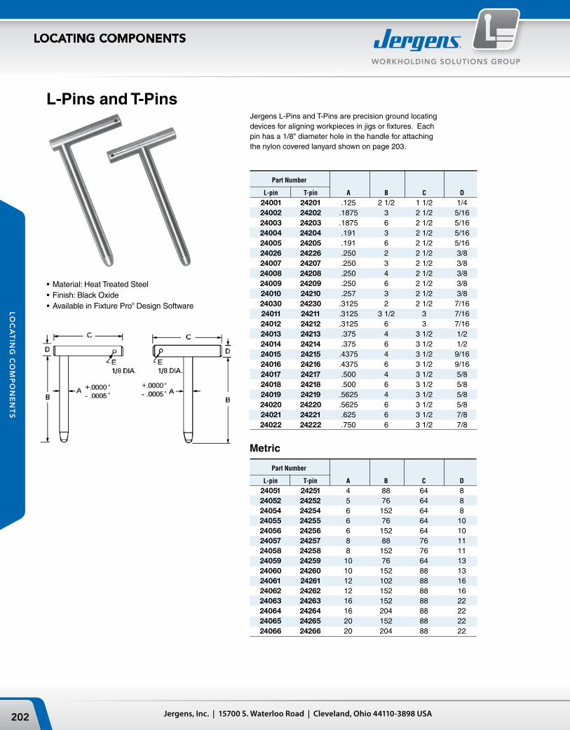
Jergens, Inc. | 15700 S. Waterloo Road | Cleveland, Ohio 44110-3898 USA202
WORKHOLDING SOLUTIONS GROUP
LOCATING COMPONENTS
LO
CA
TIN
G C
OM
PO
NE
NT
S
L-Pins and T-Pins
•Material: Heat Treated Steel•Finish: Black Oxide•Available in Fixture Pro® Design Software
Jergens L-Pins and T-Pins are precision ground locating devices for aligning workpieces in jigs or fixtures. Each pin has a 1/8" diameter hole in the handle for attaching the nylon covered lanyard shown on page 203.
Part Number
L-pin T-pin A B C D
24001 24201 .125 2 1/2 1 1/2 1/4 24002 24202 .1875 3 2 1/2 5/16 24003 24203 .1875 6 2 1/2 5/16 24004 24204 .191 3 2 1/2 5/16 24005 24205 .191 6 2 1/2 5/16 24026 24226 .250 2 2 1/2 3/8 24007 24207 .250 3 2 1/2 3/8 24008 24208 .250 4 2 1/2 3/8 24009 24209 .250 6 2 1/2 3/8 24010 24210 .257 3 2 1/2 3/8 24030 24230 .3125 2 2 1/2 7/16 24011 24211 .3125 3 1/2 3 7/16 24012 24212 .3125 6 3 7/16 24013 24213 .375 4 3 1/2 1/2 24014 24214 .375 6 3 1/2 1/2 24015 24215 .4375 4 3 1/2 9/16 24016 24216 .4375 6 3 1/2 9/16 24017 24217 .500 4 3 1/2 5/8 24018 24218 .500 6 3 1/2 5/8 24019 24219 .5625 4 3 1/2 5/8 24020 24220 .5625 6 3 1/2 5/8 24021 24221 .625 6 3 1/2 7/8 24022 24222 .750 6 3 1/2 7/8
Metric
Part Number
L-pin T-pin A B C D 24051 24251 4 88 64 8 24052 24252 5 76 64 8 24054 24254 6 152 64 8 24055 24255 6 76 64 10 24056 24256 6 152 64 10 24057 24257 8 88 76 11 24058 24258 8 152 76 11 24059 24259 10 76 64 13 24060 24260 10 152 88 13 24061 24261 12 102 88 16 24062 24262 12 152 88 16 24063 24263 16 152 88 22 24064 24264 16 204 88 22 24065 24265 20 152 88 22 24066 24266 20 204 88 22

ØA
1/2"
D
C
B
ØE
+.000-.0005 -.0005
+.000
F
D
ØE
1/2"
C
B
ØA
ØA
1/2"
D
C
B
ØE
+.000-.0005 -.0005
+.000
F
D
ØE
1/2"
C
B
ØA
203Phone: 877-426-2504 | Fax: +1 216-481-6193 | E-mail: [email protected] | www.jergensinc.com
WORKHOLDING SOLUTIONS GROUP
LOCATING COMPONENTS
LO
CA
TIN
G C
OM
PO
NE
NT
S
Jig PinsJig Pins are precision ground locating devices. The straight handle style comes with a hole for easy attachment of a lanyard. The T-handle style can be converted to an L-handle style by tapping the roll pin with a hammer.
•Material:LowCarbonSteel•Finish:BlackOxide•HeatTreat:CaseHardenedRc58-62(pinonly)
Part Number A B C D E F
24111 .2500 2 1/2 2 5/8 1/2 1/4 2 24112 .3125 2 1/2 2 5/8 9/16 1/4 3 24113 .3750 4 2 5/8 5/8 1/4 3 24114 .5000 3 2 5/8 3/4 5/16 3
T- Handle Jig Pin
Straight Handle Jig Pin
T-Handle Jig Pins
Straight Handle Jig Pin
Part Number A B C D E
24101 .2500 2 1/2 2 5/8 1/2 1/4 24102 .3125 2 1/2 2 5/8 9/16 1/4 24103 .3750 4 2 5/8 5/8 1/4 24104 .5000 3 2 5/8 3/4 5/16
Lanyards with Tabs
890054* 890104* 890056* 890106* 890058* 890108* 890060* 890110* 890062* 890112* 890066* 890116* 890070* 890120* 890074* 890124*
Ordering Lanyards When Supplied Separately Without Pins
Substitute the asterisk (*) with the proper hole size letter from Table 1.
890204 890254 890304 890404890206 890256 890306 890406890208 890258 890308 890408890210 890260 890310 890410890212 890262 890312 890412890216 890266 890316 890416890220 890270 890320 890420890224 890274 890324 890424
Lanyards without TabsLanyardLoop/Eyelet
Round Tab Oval Tab Stainless
Aluminum
Steel
468
1012162024
102 152 203 254 305 406 508 610
M5 #10
2 Loops 1 Loops (Pin) For Screw SizeLength
inch mm
Table 1 Tab Hole Size
Tab Mounting Hole Diameter Inch mm Size Letter
0.131 3.3 P0.196 4.9 Q0.257 6.5 R0.283† 7.1† S0.320† 8.1† T0.379† 9.6† U0.406† 10.3† V0.468† 11.8† W0.515† 13.1† Y
(†) These sizes only available in stainless steel round tabs
Length inch mm468
1012162024
102 152 203 254 305 406 508 610
•To attach lanyard to L or T Pins order Split Ring 890000•To permanently attach Lanyard to L or T Pins add -C to Lanyard part number•For Lanyard &Tab drawings see Kwik-Lok™ Pins in Specialty Fastener Solutions Catalog or Master Catalog
Lanyards

A/2
C/2
A
D
Roll Pin
B Dia
C Dia +.0004+.0001
ConcentricGround Lead
16-PitchDiamond
Knurl
A Dimension CenteredWithin ±.0001 of C Dia.
A
D
B Dia
C Dia Over Knurl
+.001-.001
A/2
C/2
A
D
Roll Pin
B Dia
C Dia +.0004+.0001
ConcentricGround Lead
16-PitchDiamond
Knurl
A Dimension CenteredWithin ±.0001 of C Dia.
A
D
B Dia
C Dia Over Knurl
+.001-.001
Jergens, Inc. | 15700 S. Waterloo Road | Cleveland, Ohio 44110-3898 USA204
WORKHOLDING SOLUTIONS GROUP
LOCATING COMPONENTS
LO
CA
TIN
G C
OM
PO
NE
NT
S
Slotted Locator Bushing
•UsewithLPinstoaligntwo holes without binding.•Availablefor3/16"through1"
diameter pins (6mm-25mm in metric sizes).•ToolSteel,heattreated
to Rc 58-62•SuppliedwithRollPin:
Locate within ±.002" of slot centerline.
Knurled Part Pin Dia Dia Number Dia A B C D
24331 3/16 0.188 0.312 0.565 .50 24332 1/4 0.25 0.375 0.64 .50 24333 5/16 0.313 0.437 0.765 .50 24334 3/8 0.375 0.5 0.89 .50
Press Fit Metric Part Pin Dia Dia Number Dia A B C D
24351 6mm 6.00/6.03 9.0 20.000 9.0 24352 8mm 8.00/8.03 11.0 24.000 9.0 24353 10mm 10.00/10.03 13.0 24.000 9.0 24354 12mm 12.00/12.03 15.0 24.000 14.0 24355 16mm 16.00/16.03 18.0 30.000 12.0 24356 20mm 20.00/20.03 22.0 35.999 19.0 24357 25mm 25.00/25.03 27.0 40.000 19.0
Press Fit Part Pin Dia Dia Number Dia A B C D
24301 3/16 .1876/.1882 0.312 0.75 0.400 24302 1/4 .2501/.2507 0.375 0.75 0.400 24303 1/4 .2501/.2507 0.375 1 0.400 24304 5/16 .3126/.3132 0.437 1 0.400 24305 3/8 .3751/.3757 0.5 1 0.400 24306 1/2 .5001/.5007 0.625 1 0.400 24307 1/2 .5001/.5007 0.625 1 0.900 24308 5/8 .6251/.6257 .075 1.25 0.900 24309 3/4 .7501/.7510 0.812 1.5 1.0000 24310 7/8 .8751/.8760 1 1.5 1.0000 24311 1 1.0001/1.0010 1.062 1.5 1.0000

205Phone: 877-426-2504 | Fax: +1 216-481-6193 | E-mail: [email protected] | www.jergensinc.com
WORKHOLDING SOLUTIONS GROUP
LOCATING COMPONENTS
LO
CA
TIN
G C
OM
PO
NE
NT
S
“B” Ground† “B” Unground† Part Part Number Number A B C D 34751 45771 10 6 12 5 34754 45774 13 6 18 6 34757 45777 16 6 18 10 34758 45778 16 10 22 10 34759 45780 16 12 25 10 34763 45786 22 16 31 12 34766 45790 25 12 30 16
†“B” Dimension for ground style is +.013/-.000mm, ungrounded style is +.25/+.38mm.
Part Part Wt. Number Number (lbs) “B” Ground† “B” Unground† A B C D 10 Pcs.
— 45719 1/4 1/4 15/32 .1885-.188 .05 34701* 45721 3/8 1/4 15/32 .1885-.188 .08 34702* 45722 3/8 3/8 19/32 .1885-.188 .16 34703* 45723 3/8 1/2 23/32 .1885-.188 .16 34704* 45724 1/2 1/4 23/32 .251-.2505 .16 34705* 45725 1/2 3/8 27/32 .251-.2505 .21 34706* 45726 1/2 1/2 31/32 .251-.2505 .31 34707* 45727 5/8 1/4 23/32 .376-.3755 .31 34708* 45728 5/8 3/8 27/32 .376-.3755 .47 — 45729 5/8 7/16 29/32 .376-.3755 .50 34709* 45730 5/8 1/2 31/32 .376-.3755 .55 34710* 45731 5/8 5/8 1 3/32 .376-.3755 .62 34711 45732 5/8 3/4 1 7/32 .376-.3755 .78 — 45733 7/8 3/8 31/32 .501-.5005 .68 34712 45734 7/8 7/16 1 1/32 .501-.5005 .78 — 45735 7/8 1/2 1 3/32 .501-.5005 .94 34713* 45736 7/8 5/8 1 7/32 .501-.5005 1.10 34714 45737 7/8 3/4 1 11/32 .501-.5005 1.25 — 45738 1 3/8 1 3/32 .626-.6255 1.20 34715 45739 1 7/16 1 5/32 .626-.6255 1.45 34716* 45740 1 1/2 1 7/32 .626-.6255 1.65 — 45741 1 5/8 1 11/32 .626-.6255 2.00 — 45742 1 3/4 1 15/32 .626-.6255 2.50 — 45743 1 1/4 3/8 1 7/32 .751-.7505 1.80 — 45744 1 1/4 7/16 1 9/32 .751-.7505 2.10 — 45745 1 1/4 1/2 1 11/32 .751-.7505 2.50 34717* 45746 1 1/4 5/8 1 15/32 .751-.7505 3.10 34718 45747 1 1/2 3/4 1 31/32 1.001-1.0005 6.90
Rest ButtonsGround and Unground
Jergens is proud of the close tolerances heldonthe“B”dimensionofourGroundRest Buttons. When it becomes necessary through constant wear to replace rest buttons, they can be replaced with the assurance of being within .0005 (.013mm)
•Material: Ground,LowCarbonSteel Unground, 52100•Finish:BlackOxide•HeatTreat: Ground,CaseHardened 75-77 R30N Unground, 58-62 Rc•AvailableinFixturePro®
Design Software
†“B” dimension for ground style is +.0005/-.000, unground +.010/+.015
Rest ButtonsMetric Ground and Unground
*Conforms to TCMA
of the original location. Where replacement is not going to be a problem, we recommend the use of the Unground Buttons, which have a +.010 (.25mm) grinding stock to be ground after the fixture is assembled.
The Closest Tolerances in the Industry...

Jergens, Inc. | 15700 S. Waterloo Road | Cleveland, Ohio 44110-3898 USA206
WORKHOLDING SOLUTIONS GROUP
LOCATING COMPONENTS
LO
CA
TIN
G C
OM
PO
NE
NT
S Across Part Dia. Flats Number A B C†
D
E
21551 10 6 14 M6x1.0 8 21554 13 6 17 M10x1.5 10 21558 16 10 25 M12x1.75 14 21561 25 12 30 M16x2.9 20
†+.25/+.38mmGrindingStock
Threaded Rest Buttons
Thread into job instead of press fit. “B” dimensionleft with .010-.015 for finishing after assembly. For cutter setting blocks on milling fixtures, grind to your own specifications. Case hardened to approximately .030 deep.
•Material: Low Carbon Steel•Finish: Black Oxide•Heat Treat: Case Hardened 75-77 R30N•Thread: 2A-UNF•Available in Fixture Pro® Design Software
Threaded Rest ButtonsMetric
•Material:LowCarbonSteel•Finish:BlackOxide•HeatTreat:CaseHardened75-77R30N•Thread:Class6g
Part Thread wt/lbs Number A B C D Pitch 10 pcs.
21501 3/8 1/4 5/8 1/4-28 fine .16 21521 3/8 1/4 5/8 1/4-20 coarse .16 21502 3/8 3/8 3/4 1/4-28 fine .16 21522 3/8 3/8 3/4 1/4-20 coarse .16 21503 3/8 1/2 7/8 1/4-28 fine .16 21523 3/8 1/2 7/8 1/4-20 coarse .16 21504 1/2 1/4 11/16 3/8-24 fine .24 21524 1/2 1/4 11/16 3/8-16 coarse .24 21505 1/2 3/8 13/16 3/8-24 fine .31 21525 1/2 3/8 13/16 3/8-16 coarse .31 21506 1/2 1/2 15/16 3/8-24 fine .47 21526 1/2 1/2 15/16 3/8-16 coarse .47 21507 1/2 3/4 1 3/16 3/8-24 fine .47 21527 1/2 3/4 1 3/16 3/8-16 coarse .47 21508 3/4 3/8 15/16 1/2-20 fine .78 21528 3/4 3/8 15/16 1/2-13 coarse .78 21509 3/4 1/2 1 1/16 1/2-20 fine .94 21529 3/4 1/2 1 1/16 1/2-13 coarse .94 21510 3/4 1 1 9/16 1/2-20 fine 1.56 21530 3/4 1 1 9/16 1/2-13 coarse 1.56 21511 1 1/2 1 3/16 5/8-18 fine 1.72 21531 1 1/2 1 3/16 5/8-11 coarse 1.72 21512 1 1 1/2 2 3/16 5/8-18 fine 4.10 21532 1 1 1/2 2 3/16 5/8-11 coarse 4.10

207Phone: 877-426-2504 | Fax: +1 216-481-6193 | E-mail: [email protected] | www.jergensinc.com
WORKHOLDING SOLUTIONS GROUP
LOCATING COMPONENTS
LO
CA
TIN
G C
OM
PO
NE
NT
S
•Material: Body, Low Carbon Steel Insert, Carbide
•Available in Fixture Pro® Design Software
Carbide Insert Rest Buttons
Part Number A B C D E
34951 13 6 18 6 10 34953 16 10 22 10 10 34955 25 12 30 16 19
Metric Carbide Insert Rest Buttons
•Material: Body,LowCarbonSteel Insert, Carbide
Wt. Part (lbs) Number A B C D E 10 Pcs.
34901 1/2 .250 23/32 .2505/.2510 3/8 .25 34902 5/8 .250 23/32 .3755/.3760 3/8 .42 34903 5/8 .375 27/32 .3755/.3760 3/8 .58 34904 3/4 .4375 1 1/32 .5005/.5010 1/2 .92 34905 1 .4375 1 5/32 .6255/.6260 3/4 1.80

Jergens, Inc. | 15700 S. Waterloo Road | Cleveland, Ohio 44110-3898 USA208
WORKHOLDING SOLUTIONS GROUP
LOCATING COMPONENTS
LO
CA
TIN
G C
OM
PO
NE
NT
S
Part Number A B C E F G H
35951 25 25 50 12 10 13 M5 38 35952 25 38 64 15 13 13 M6 50 35954 25 50 89 18 16 19 M8 70
Part Wt. Number A B C E F G H I J (lbs)
35903 2 2 3 .725 1/2 1/2 1/4 2 1/2 1/2 1 1.06
Part Wt. Number A B C E F G H (lbs)
35901 1 1 2 .475 3/8 1/2 #10 1 1/2 .22 35902 1 1/2 1 1/2 2 1/2 .600 1/2 1/2 1/4 2 .58 35904 1 2 3 1/2 .720 5/8 3/4 5/16 2 3/4 .63 35905 1 3 4 1/2 .720 5/8 3/4 5/16 3 3/4 .84 35906 1 4 5 1/2 .720 5/8 3/4 5/16 4 3/4 1.06
•Material: Low Carbon Steel•Finish: Black Oxide•Heat Treat: Case Hardened 75-77 R30N•Available in Fixture Pro® Design Software
Rest Pad
Rest Pads are designed to be used when you need a larger hardened wearing surface for heavy duty applications. Rest Pads can also be used as hardened work rests or as wear plates on your jigs and fixtures.
•Material: Low Carbon Steel•Finish: Black Oxide•Heat Treat: Case Hardened
75-77 R30N•Available in Fixture Pro® Design Software
+0.013 -0.000
D
Part Number A B C E F G H I J
35953 50 50 75 18 12 13 M6 64 13 25
+0.013-0.000
D
+0.0005-0.000
D
+0.0005-0.000
D
Metric
Metric
Rest Pad Rest Pads are designed to be used when you need a larger hardened wearing surface for heavy duty applications. Rest Pads can also be used as hardened work rests or as wear plates on your jigs and fixtures.
Jergens Feature:By holding close tolerances on the “D” dimension, when replacement becomes necessary, your original tolerances are maintained within .0005 (.013)

209Phone: 877-426-2504 | Fax: +1 216-481-6193 | E-mail: [email protected] | www.jergensinc.com
WORKHOLDING SOLUTIONS GROUP
LOCATING COMPONENTS
LO
CA
TIN
G C
OM
PO
NE
NT
S
Jig Feet•Material: Low Carbon Steel•Finish: Black Oxide•Cap Screw included•Heat Treat: Case Hardened
75-77 R30N•Available in Fixture Pro® Design Software
Metric Jig Feet
+0.013 Socket Head Part -0.000 Capscrew Number A B C D
25751 16 10 M6 x 10 7 25752 16 12 M6 x 12 7 25754 16 20 M6 x 20 7 25757 22 12 M8 x 12 9 25759 22 20 M8 x 20 9 25761 22 24 M8 x 25 9 25766 32 24 M10 x 25 11
+0.0005 Socket Head Wt. Part -0.000 Capscrew (lbs) Number A B C D 10 Pcs.
25701* 5/8 3/8 1/4-20 x 3/8 9/32 .31 25702* 5/8 1/2 1/4-20 x 1/2 9/32 .31 25703* 5/8 5/8 1/4-20 x 5/8 9/32 .47 25704* 5/8 3/4 1/4-20 x 3/4 9/32 .55 25705 5/8 7/8 1/4-20 x 7/8 9/32 .62 25706 5/8 1 1/4-20 x 1 9/32 .78 25707* 7/8 1/2 5/16-18 x 1/2 11/32 .78 25708* 7/8 5/8 5/16-18 x 5/8 11/32 .94 25709* 7/8 3/4 5/16-18 x 3/4 11/32 1.03 25710 7/8 7/8 5/16-18 x 7/8 11/32 1.12 25711* 7/8 1 5/16-18 x 1 11/32 1.15 25712 7/8 1 1/8 5/16-18 x 1 1/4 11/32 1.17 25713 7/8 3/4 3/8-16 x 3/4 13/32 1.11 25714* 1 1/4 3/4 3/8-16 x 3/4 13/32 2.50 25715 1 1/4 7/8 3/8-16 x 7/8 13/32 2.70 25716* 1 1/4 1 3/8-16 x 1 13/32 3.30 25717* 1 1/4 1 1/2 3/8-16 x 1 1/2 13/32 5.00 25718 1 1/4 2 3/8-16 x 2 13/32 6.60 25719 1 5/8 1 1/4 1/2-13 x 1 1/2 17/32 7.00 25720 1 5/8 1 3/4 1/2-13 x 1 3/4 17/32 9.80 25721 1 5/8 2 1/4 1/2-13 x 2 1/2 17/32 13.75
*Conforms to TCMA
Jergens Feature:By holding close tolerances on the “B” dimension, when replacement becomes necessary, your original tolerances are maintained within .0005 (.013)

Jergens, Inc. | 15700 S. Waterloo Road | Cleveland, Ohio 44110-3898 USA210
WORKHOLDING SOLUTIONS GROUP
LOCATING COMPONENTS
LO
CA
TIN
G C
OM
PO
NE
NT
S
Jig Legs
The Jergens Jig Legs are ideal for cutting costs in simple jig plates. They assure lasting accuracy in your jig plate with a larger bearing surface at the top the the leg. The large diameter rest button provides more bearing surface for spot facing or counterboring on the bottom side. Both legs and rest buttons are hardened for long life.
•Material: Low Carbon Steel•Finish: Black Oxide•Heat Treat: Case Hardened 75-77 R30N•Cap Screw Included•Available in Fixture Pro® Design Software
Part Cap Screw Wt. Number A B C D F (lbs)
25301 1 5/8 1/4-20 5/8 1/4-20 x 1 .13 25302 2 5/8 1/4-20 5/8 1/4-20 x 1 .20 25303 3 5/8 1/4-20 7/8 1/4-20 x 1 .28 25304 4 7/8 3/8-16 7/8 3/8-16 x 1 3/4 .81 25305 5 7/8 3/8-16 7/8 3/8-16 x 1 3/4 1.00 25306 6 7/8 3/8-16 7/8 3/8-16 x 1 3/4 1.10
Flat Head Wt. Part Screw (lbs) Number A C 10 Pcs
19301 1/2 1/8 8-32 x 3/8 .06 19302 1/2 1/4 8-32 x 1/2 .16 19303 5/8 1/4 10-32 x 5/8 .21 19304 7/8 3/8 1/4-20 x 3/4 .62 19305 1 1/4 3/8 5/16-18 x 3/4 1.25 19306 1 5/8 3/8 3/8-16 x 3/4 2.20
•Material: Low Carbon Steel•Heat Treat: Case Hardened 75-77 R30N•Cap Screw Included•Available in Fixture Pro® Design Software
Flat Feet
+0.0005-0.000
B
Metric
Jergens Feature:By holding close tolerances on the “B” dimension, when replacement becomes necessary, your original tolerances are maintained within .0005 (.013mm)
Flat Head Part Screw Wt. (Kg) Number A C 10 Pcs
19351 13 3 M4 x 10 .03 19352 13 6 M4 x 12 .09 19353 16 6 M5 x 16 .11 19354 22 10 M6 x 20 .33 19355 31 10 M8 x 20 .47
+0.013 -0.000
B
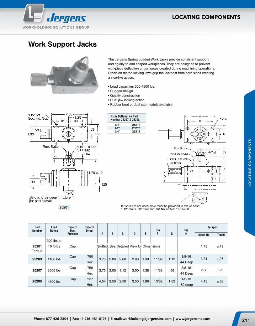
211Phone: 877-426-2504 | Fax: +1 216-481-6193 | E-mail: [email protected] | www.jergensinc.com
WORKHOLDING SOLUTIONS GROUP
LOCATING COMPONENTS
LO
CA
TIN
G C
OM
PO
NE
NT
S
Riser Optional on Part Number 25207 & 25208
1/4" 25211 1/2" 25212 3/4" 25213
If risers are not used, hole must be provided in fixture base: 1.12" dia. x .50" deep for Part No.'s 25207 & 25208
The Jergens Spring Loaded Work Jacks provide consistent support and rigidity to odd shaped workpieces. They are designed to prevent workpiece deflection under forces created during machining operations. Precision mated locking jaws grip the jackpost from both sides creating a vise-like action.
•Loadcapacities300-4500lbs.•Ruggeddesign•Qualityconstruction•Dualjawlockingaction•Rubberbootordustcapmodelsavailable
25201
Work Support Jacks
Part Load Type Of Type Of Jackpost Number Rating Dust Driver Dia. Tap J Protector A B C D E F G H Mean Ht. Travel
300 lbs at
25201 10ft-lbs Cap Slotted,SeeDetailedViewforDimensions 1.75 ±.19 Torque
25203
1400 lbs
Cap .750 3.75 2.00 2.00 3.00 1.38 11/32 1.13
3/8-16 3.31 ±.25
Hex .44 Deep
25207
2500 lbs
Cap .750 3.75 2.00 1.12 3.00 1.38 11/32 .56
3/8-16 2.38 ±.25
Hex .44 Deep
25205
4500 lbs
Cap .937 4.54 2.50 2.50 3.50 1.88 13/32 1.63
1/2-13 4.13 ±.38
Hex .59 deep

BHEX
D
E F
A
ØC
THREAD SIZEG SPHER. RAD.
21403_CAT
Jergens, Inc. | 15700 S. Waterloo Road | Cleveland, Ohio 44110-3898 USA212
WORKHOLDING SOLUTIONS GROUP
LOCATING COMPONENTS
LO
CA
TIN
G C
OM
PO
NE
NT
S
Fixture Jacks
Part Part Press D Number Number Fit Thread Wt. Radius Serrated A B C Min. Max. E F G H Size (lbs)
24901 25101 5/8 1 3/16 3/16 9/16 1 1/2 1 1/4 5/32 3/8 3/8-16 .19 24902 25102 1 1 5/8 3/16 7/8 2 7/16 1 5/16 15/32 7/16 7/16 5/8-11 .55 24903 25103 1 1/2 2 3/4 3/16 7/8 3 1/2 1 3/4 13/16 1/2 9/16 1-8 1.90
Designed as a positive locking jack for irregular clamping to achieve various heights requiring a positive pressure stop. Adjustable to fit height irregularities of milling operations. Available in either a smooth radius head or a hardened tool steel serrated gripping surface. Elevates vertically, no rotation. Outer diameter of bushing ground for press-fit.
•Material: Bushing, Low Carbon Steel Radius Stem, Low Carbon Steel Serrated Stem, 4140
•Finish: Bushing, Black Oxide Radius Stem, Black Oxide Serrated Stem, Black Oxide
•Heat Treat: Bushing, Case Hardened 74-77 R30N Radius Stem, Case Hardened Serrated Stem, Rc 45-48
•Available in Fixture Pro® Design Software
Adjustable Locating Buttons •Material:LowCarbonSteel•Finish:BlackOxide•HeatTreat:CaseHardened87-92R15N
Part Thread Number Size A B C D E F G
21401 10-32 1 1/4 3/16 1/8 1/8 3/4 1/8 21402 1/4-28 1 1/2 3/8 1/4 3/16 3/16 1 1/8 3/16 21403 5/16-24 1 3/4 7/16 5/16 1/4 1/4 1 1/4 3/16 21404 3/8-24 2 1/2 3/8 1/4 1/4 1 1/2 1/4 21405 1/2-20 2 1/2 5/8 1/2 5/16 5/16 1 7/8 5/16 21406 5/8-18 3 3/4 5/8 3/8 3/8 1 1/4 3/8 21407 3/4-16 3 1/2 7/8 3/4 7/16 7/16 2 5/8 7/16
Adjustable Jack Screws
Part Wt. Lock Nut Number A B C (lbs) (Not Included)
25001 3/8-16 1-1/4 1-1/8 0.15 28101 25003 3/8-16 2 1-1/8 0.18 28101 25005 1/2-13 1-5/8 1-1/8 0.20 28102 25007 1/2-13 2-1/2 1-1/8 0.25 28102 25009 5/8-11 2 1-3/8 0.34 28103 25011 5/8-11 3 1-3/8 0.43 28103
•Material:LowCarbonSteel•Finish:BlackOxide•HeatTreat:Screw/StemCaseHardened87-92R15N

213Phone: 877-426-2504 | Fax: +1 216-481-6193 | E-mail: [email protected] | www.jergensinc.com
WORKHOLDING SOLUTIONS GROUP
LOCATING COMPONENTS
LO
CA
TIN
G C
OM
PO
NE
NT
S
-0.0005 Socket Wt. Part -0.0010 Head Screw (lbs) Number A B C D 10 Pcs.
19701* .5000 1/2 3/4 1/4 .14 19702* .5625 1/2 3/4 1/4 .65 19703* .6250 1/2 3/4 5/16 .68 19704* .6875 1/2 1 5/16 .98 19705 .7500 1/2 1 1/4 5/16 1.10 19706 .8125 1/2 1 1/4 5/16 1.25
Standard Fixture Keys
*Conforms to TCMA
•Material:C-1018•Finish:BlackOxide•HeatTreat:CaseHardened74-77R30N•AvailableinFixturePro® Design Software
-0.0013 Socket Part -0.0026 Head Screw Number A B C D
19751 12 13 19 M5 19752 14 14 22 M6 19753 16 13 22 M6 19754 18 14 22 M6 19755 20 13 22 M6 19756 22 13 32 M6
Metric
Part Wt. Number (lbs)
22902 1.1 22903 1.2
Part Wt. Number (lbs)
22901 1.0
•Material: AISI-S7•Finish: Black Oxide•Heat Treat: Rc 44-48•Available in Fixture Pro®
Design Software
Drift Handles

Jergens, Inc. | 15700 S. Waterloo Road | Cleveland, Ohio 44110-3898 USA214
WORKHOLDING SOLUTIONS GROUP
LOCATING COMPONENTS
LO
CA
TIN
G C
OM
PO
NE
NT
S
PRESENT METHOD TIME
1. Finish one edge. .5 hours
2. Locate on jig bore and bore locating point and two locator pin holes 1.75 hours
3. Relocate, position and mill two fixture key slots. 1.75 hours
4. Relocate and, by use of sine bar or other positioning device, establish and mill two fixture key slots. 2.35 hours
5. For opposite slots-same as above 2.35 hours
6. Drill and tap six holes for holding fixture keys in slots. 1.5 hours
7. Set up and perform inspection-if inaccurate, reroute for reworking. 1.0 hours
TOTAL TIME REQUIRED 11.2 hours
ON THIS PARTICULAR FIXTURE - SAVE OVER 50% OF SET-UP TIME!
Present MethodA total of 11.2 hours was required to complete this fixture base with finished edge, milled fixture key slots, bored loca-tor pin holes and drilled and tapped set screw holes.
Jergens MethodIt took only 5 1/2 hours to complete this fixture with bored sine fixture key holes and bored locator pin holes
Compare The Jergens Sine Fixture Key Method To The Standard Method Construct a fixture to mill slots in castings A, B, and C. The locator pins to be common.
A B C
JERGENS METHOD TIME
1. Eliminated.
2. One set-up serves for establishing locator holes and 4.5 hours sine fixture keys.
3. Eliminated.4. Eliminated5. Eliminated.6. Eliminated.7. Inspect on original set-up. 1.0 hours
TOTAL TIME REQUIRED 5.5 hours

215Phone: 877-426-2504 | Fax: +1 216-481-6193 | E-mail: [email protected] | www.jergensinc.com
WORKHOLDING SOLUTIONS GROUP
LOCATING COMPONENTS
LO
CA
TIN
G C
OM
PO
NE
NT
S
Metric Sine Fixture Keys
Sine Fixture Keys locate jigs and fixtures on machine tool tables and position the part in one operation. They eliminate the need to slot fixture bases, make step fixture keys, or drill and tap keys. Simply ream two holes, depending upon the shank size shown in the table below.
The unique expansion shaft allows the key to be locked in the fixture from either the top or the bottom using a standard hex wrench.
Sine Fixture Keys
•Material:4140•HeatTreat:26-30•AvailableinFixturePro® Design Software•Reducefixturecosts•Cutextraset-uptime•Completelyinterchangeable•Fitsmanytableslotsizes
Slot Shank Size Part Size (Mm) Wt. Number A B C (lbs)
39561 .625 12 1 .09 39562 .625 14 1 .09 39563 .625 16 1 .11 39564 .625 18 1 1/8 .11 39565 .625 20 1 1/8 .14 39566 .625 22 1 1/8 .15
Metric Slot/Inch Shank
Shank Slot Part Size Size Wt. Number A B C (kg)
39550 16 10 25 .04 39551 16 12 25 .04 39552 16 14 25 .05 39553 16 16 25 .05 39554 16 18 29 .05 39555 16 20 29 .06 39556 16 22 29 .06 39557 20 24 35 .07 39558 20 28 35 .10 39559 20 32 40 .10
Jergens Feature:Full 360° contact for more accurate locating.
Used primarily for adapting existing fixtures with inch locating holes to metric table slots.
Shank Slot Part Size Size Wt. Recommended Number A B C (lbs) Hole Diameter
39501 .625 .4995 1 .09 39502 .625 .562 1 .11 39503 .625 .6245 1 .11 39504 .625 .687 1 .11 39505 .625 .7495 1 1/8 .13 39506 .625 .812 1 1/8 .14 39507 .625 .8745 1 1/8 .15 39509 .750 .9995 1 3/8 .22 .75 Shank Size: 39510 .750 1.062 1 3/8 .23 0.7505 ± 0.0005
.625 Shank Size:0.6255 ± 0.0005
RecommendedHole Diameter
16mm Shank Size:16.01 ± 0.01
20mm Shank Size:20.01 ± 0.01
RecommendedHole Diameter
0.6255 ± 0.0005

Jergens, Inc. | 15700 S. Waterloo Road | Cleveland, Ohio 44110-3898 USA216
WORKHOLDING SOLUTIONS GROUP
LOCATING COMPONENTS
LO
CA
TIN
G C
OM
PO
NE
NT
S
Locating Pins-Slip FitRound
•Material: Low Carbon Steel•Heat Treat: Case Hardened
74-77 R30N•Available in Fixture Pro®
Design Software
• Sizesrangefrom1/8"to1"headdiameters• Concentricityinbothdiametersisheldwithin.0002• Forspecialapplicationswewillgrindthe“A”
dimension to your specifications• Quickturnaroundonspecials• Maybeusedinbushingapplicationsorpressfit
with Lock Screws.
Wt. Part Number (lbs) Round A B C D F G H 10 Pcs.
29101* .1245 5/16 1 3/16 7/16 5/8 33/64 1/32 .31 29102 .1401 5/16 1 3/16 7/16 5/8 33/64 1/32 .31 29103* .1558 5/16 1 3/16 7/16 5/8 33/64 3/64 .31 29104 .1714 5/16 1 3/16 7/16 5/8 33/64 3/64 .31 29105* .1870 5/16 1 3/16 7/16 5/8 33/64 1/16 .31 29106 .2026 5/16 1 3/16 7/16 5/8 33/64 1/16 .31 29107* .2183 5/16 1 3/16 7/16 5/8 33/64 5/64 .31 29108 .2339 5/16 1 3/16 7/16 5/8 33/64 3/32 .31 29109* .2495 5/16 1 3/16 7/16 5/8 33/64 3/32 .31 29110 .2651 5/16 1 3/16 7/16 5/8 33/64 3/32 .31 29111* .2808 5/16 1 3/16 7/16 5/8 33/64 3/32 .36 29112 .2964 5/16 1 3/16 7/16 5/8 33/64 3/32 .36 29113* .3120 5/16 1 3/16 7/16 5/8 33/64 3/32 .36 29114* .3115 1/2 1 1/2 1/2 7/8 41/64 1/8 .90 29115 .3271 1/2 1 1/2 1/2 7/8 41/64 1/8 .90 29116* .3428 1/2 1 1/2 1/2 7/8 41/64 1/8 .90 29117 .3584 1/2 1 1/2 1/2 7/8 41/64 1/8 .90 29118* .3740 1/2 1 1/2 1/2 7/8 41/64 1/8 .90 29119 .3896 1/2 1 1/2 1/2 7/8 41/64 1/8 .90 29120* .4053 1/2 1 1/2 1/2 7/8 41/64 1/8 .90 29121 .4209 1/2 1 1/2 1/2 7/8 41/64 1/8 .90 29122* .4365 1/2 1 1/2 1/2 7/8 41/64 1/8 .90 29123 .4521 1/2 1 1/2 1/2 7/8 41/64 1/8 .95 29124* .4678 1/2 1 1/2 1/2 7/8 41/64 1/8 .95 29125 .4834 1/2 1 1/2 1/2 7/8 41/64 1/8 1.00 29126* .4990 1/2 1 1/2 1/2 7/8 41/64 1/8 1.00 29127* .4980 3/4 1 15/16 11/16 1 1/8 49/64 3/16 2.0 29128* .5293 3/4 1 15/16 11/16 1 1/8 49/64 3/16 2.0 29129* .5605 3/4 1 15/16 11/16 1 1/8 49/64 3/16 2.5 29130* .5918 3/4 1 15/16 11/16 1 1/8 49/64 3/16 2.5 29131* .6230 3/4 1 15/16 11/16 1 1/8 49/64 3/16 2.5 29132* .6543 3/4 1 15/16 11/16 1 1/8 49/64 3/16 2.5 29133* .6855 3/4 1 15/16 11/16 1 1/8 49/64 3/16 2.5 29134* .7168 3/4 1 15/16 11/16 1 1/8 49/64 3/16 2.5 29135* .7480 3/4 1 15/16 11/16 1 1/8 49/64 3/16 2.5 29136* .7480 1 2 5/8 1 1 1/2 61/64 9/32 5.0 29137* .7793 1 2 5/8 1 1 1/2 61/64 9/32 5.0 29138* .8105 1 2 5/8 1 1 1/2 61/64 9/32 5.0 29139* .8418 1 2 5/8 1 1 1/2 61/64 9/32 5.0 29140* .8730 1 2 5/8 1 1 1/2 61/64 9/32 5.0 29141* .9043 1 2 5/8 1 1 1/2 61/64 9/32 5.0 29142* .9355 1 2 5/8 1 1 1/2 61/64 9/32 5.0 29143* .9668 1 2 5/8 1 1 1/2 61/64 9/32 5.0 29144* .9980 1 2 5/8 1 1 1/2 61/64 9/32 5.0* Conforms to TCMA See page 218 for Liners and Lock Screws.

217Phone: 877-426-2504 | Fax: +1 216-481-6193 | E-mail: [email protected] | www.jergensinc.com
WORKHOLDING SOLUTIONS GROUP
LOCATING COMPONENTS
LO
CA
TIN
G C
OM
PO
NE
NT
S
Locating Pins-Slip FitRelieved
•Material:LowCarbonSteel•HeatTreat:CaseHardened 74-77 R30N•AvailableinFixturePro®
Design Software
• Sizesrangefrom1/8"to1"headdiameters• Concentricityinbothdiametersisheldwithin.0002• Forspecialapplicationswewillgrindthe“A”
dimension to your specifications• Quickturn-aroundonspecials• Maybeusedinbushingapplicationsorpressfit
with lock screws.
* Conforms to TCMA See page 218 for Liners and Lock Screws.
Wt. Part Number (lbs) Relieved A B C D F G H 10 Pcs.
29301* .1245 5/16 1 3/16 7/16 5/8 33/64 1/32 .31 29302 .1401 5/16 1 3/16 7/16 5/8 33/64 1/32 .31 29303* .1558 5/16 1 3/16 7/16 5/8 33/64 3/64 .31 29304 .1714 5/16 1 3/16 7/16 5/8 33/64 3/64 .31 29305* .1870 5/16 1 3/16 7/16 5/8 33/64 1/16 .31 29306 .2026 5/16 1 3/16 7/16 5/8 33/64 1/16 .31 29307* .2183 5/16 1 3/16 7/16 5/8 33/64 5/64 .31 29308 .2339 5/16 1 3/16 7/16 5/8 33/64 3/32 .31 29309* .2495 5/16 1 3/16 7/16 5/8 33/64 3/32 .31 29310 .2651 5/16 1 3/16 7/16 5/8 33/64 3/32 .31 29311* .2808 5/16 1 3/16 7/16 5/8 33/64 3/32 .36 29312 .2964 5/16 1 3/16 7/16 5/8 33/64 3/32 .36 29313* .3120 5/16 1 3/16 7/16 5/8 33/64 3/32 .36 29314* .3115 1/2 1 1/2 1/2 7/8 41/64 1/8 .90 29315 .3271 1/2 1 1/2 1/2 7/8 41/64 1/8 .90 29316* .3428 1/2 1 1/2 1/2 7/8 41/64 1/8 .90 29317 .3584 1/2 1 1/2 1/2 7/8 41/64 1/8 .90 29318* .3740 1/2 1 1/2 1/2 7/8 41/64 1/8 .90 29319 .3896 1/2 1 1/2 1/2 7/8 41/64 1/8 .90 29320* .4053 1/2 1 1/2 1/2 7/8 41/64 1/8 .90 29321 .4209 1/2 1 1/2 1/2 7/8 41/64 1/8 .90 29322* .4365 1/2 1 1/2 1/2 7/8 41/64 1/8 .90 29323 .4521 1/2 1 1/2 1/2 7/8 41/64 1/8 .95 29324* .4678 1/2 1 1/2 1/2 7/8 41/64 1/8 .95 29325 .4834 1/2 1 1/2 1/2 7/8 41/64 1/8 1.00 29326* .4990 1/2 1 1/2 1/2 7/8 41/64 1/8 1.00 29327* .4980 3/4 1 15/16 11/16 1 1/8 49/64 3/16 2.0 29328* .5293 3/4 1 15/16 11/16 1 1/8 49/64 3/16 2.0 29329* .5605 3/4 1 15/16 11/16 1 1/8 49/64 3/16 2.5 29330* .5918 3/4 1 15/16 11/16 1 1/8 49/64 3/16 2.5 29331* .6230 3/4 1 15/16 11/16 1 1/8 49/64 3/16 2.5 29332* .6543 3/4 1 15/16 11/16 1 1/8 49/64 3/16 2.5 29333* .6855 3/4 1 15/16 11/16 1 1/8 49/64 3/16 2.5 29334* .7168 3/4 1 15/16 11/16 1 1/8 49/64 3/16 2.5 29335* .7480 3/4 1 15/16 11/16 1 1/8 49/64 3/16 2.5 29336* .7480 1 2 5/8 1 1 1/2 61/64 9/32 5.0 29337* .7793 1 2 5/8 1 1 1/2 61/64 9/32 5.0 29338* .8105 1 2 5/8 1 1 1/2 61/64 9/32 5.0 29339* .8418 1 2 5/8 1 1 1/2 61/64 9/32 5.0 29340* .8730 1 2 5/8 1 1 1/2 61/64 9/32 5.0 29341* .9043 1 2 5/8 1 1 1/2 61/64 9/32 5.0 29342* .9355 1 2 5/8 1 1 1/2 61/64 9/32 5.0 29343* .9668 1 2 5/8 1 1 1/2 61/64 9/32 5.0 29344* .9980 1 2 5/8 1 1 1/2 61/64 9/32 5.0

Jergens, Inc. | 15700 S. Waterloo Road | Cleveland, Ohio 44110-3898 USA218
WORKHOLDING SOLUTIONS GROUP
LOCATING COMPONENTS
LO
CA
TIN
G C
OM
PO
NE
NT
S
Wt. Part (lbs) Number A B C D E F 10 Pcs.
10101 1/4 .135 3/8 3/8 5/8 5/16-18 .16
Wt. Part (lbs) Number A B C D E 10 Pcs.
40901 .3129 .5017 1/2 5/8 3/32 .16 .3126 .5014 40902 .5005 .7518 3/4 7/8 3/32 .47 .5002 .7515 40903 .7506 1.0018 1 1 1/8 1/8 .94 .7503 1.0015 40904 1.0007 1.3772 1 3/8 1 1/2 1/8 2.65 1.0004 1.3768
Locating Pin Lock Screws
•Material:LowCarbonSteel•Finish:BlackOxide•HeatTreat:CaseHardened•Thread:2A-UNC
Locating Pin Liners
Locating Pin Shoulder Liners
•Material:52100Steel
•Material:52100Steel
Wt. Part (lbs) Number A B C 10 Pcs.
28501 .3129 .5017 1/2 .16 .3126 .5014 28502 .5005 .7518 3/4 .47 .5002 .7515 28503 .7506 1.0018 1 .94 .7503 1.0015 28504 1.0007 1.3772 1 3/8 2.80 1.0004 1.3768

ØCE
ØD ØAØB
F
G
H
+.000 -.001
+.0000 -.0003
ØA ØG
ED
F
ØB
.03
+.0000 -.0005
+.0000 -.0003
ØC
219Phone: 877-426-2504 | Fax: +1 216-481-6193 | E-mail: [email protected] | www.jergensinc.com
WORKHOLDING SOLUTIONS GROUP
LOCATING COMPONENTS
LO
CA
TIN
G C
OM
PO
NE
NT
S
Bullet Nose Dowels
Bullet Nose Dowels are used for aligning two pieces of a fixture together.•Pinandheadcentricwithin.0005TIR•BushingIDandODconcentricwithin.0003TIR•Material:Lowcarbonsteel•HeatTreat:Casehardened72-82R30N•Groundfinish
Part Number A B C D E F G
29221 .2499 .2516 .280 1/2 .12 .90 1/8 29222 .3124 .3141 .344 1/2 .16 .94 5/32 29223 .3749 .3766 .407 1/2 .19 1.03 3/16 29224 .4999 .5017 .532 1/2 .19 1.09 1/4
•Material:Lowcarbonsteel•HeatTreat:Casehardened72-82R30N•Groundfinish
Pilot Locating Pins
Bullet-Nose Dowels
Bullet-Nose Dowel Liners (Bushings) Part Number A B C D
40921 .2501 .5017 5/8 3/8 40922 .3126 .5017 5/8 3/8 40923 .3751 .6267 3/4 1/2 40924 .5001 .7518 7/8 5/8
Pilot Locating Pins
Part Number A B C D E F G H
29231 .249 .4078 9/16 5/32 9/32 3/32 15/32 27/32 29232 .312 .5017 5/8 3/16 9/32 3/32 15/32 27/32 29233 .624 .8768 1 5/16 3/8 1/8 7/8 1 5/8

Bullet Nose Liners
Bullet NoseRound Pin
Bullet NoseRelieved Pin
ØAØB
CD
E
+.0000 -.0003
+.0000 -.0003 60˚
ØF
ØAØB
C
D
E
+.0000 -.0003
ØF
+.0000 -.0003
Jergens, Inc. | 15700 S. Waterloo Road | Cleveland, Ohio 44110-3898 USA220
WORKHOLDING SOLUTIONS GROUP
LOCATING COMPONENTS
LO
CA
TIN
G C
OM
PO
NE
NT
S
Bullet Nose Pins are used for aligning two pieces of a fixture together. The round and relieved style are used in conjunction with a matching bushing to locate radially on the round pin. The flats on the relieved pin prevents binding, yet allows a high degree of accuracy to be maintained.
•Material:Lowcarbonsteel•HeatTreat:Casehardened72-82R3ON•Groundfinish
Bullet Nose Pins
Bullet-Nose Pins – Round Part Number A B C D E F
29201 .2499 .4078 3/8 1/16 7/32 9/16 29202 .3124 .5017 3/8 1/16 9/32 5/8 29203 .3749 .6267 1/2 1/16 5/16 3/4 29204 .4998 .7518 1/2 1/16 13/32 7/8 29205 .7498 1.0018 3/4 1/8 9/16 1 1/8 29206 .9998 1.3771 3/4 1/8 3/4 1 1/2
Bullet-Nose Pins – Relieved Part Number A B C D E F
29211 .2499 .4078 3/8 1/16 7/32 9/16 29212 .3124 .5017 3/8 1/16 9/32 5/8 29213 .3749 .6267 1/2 1/16 5/16 3/4 29214 .4998 .7518 1/2 1/16 13/32 7/8 29215 .7498 1.0018 3/4 1/8 9/16 1 1/8 29216 .9998 1.3771 3/4 1/8 3/4 1 1/2
Bullet Nose Pins Liners (Bushings) Part Number A B C D E
40911 .2501 .4078 9/16 7/16 1/16 40912 .3126 .5017 5/8 7/16 1/16 40913 .3751 .6267 3/4 7/16 1/16 40914 .5001 .7518 7/8 1/2 1/16 40915 .7502 1.0018 1 1/8 1/2 1/8 40916 1.0002 1.3771 1 1/2 1 11/16 1/8
Bullet-Nose Pins – Round
Bullet-Nose Pins – Relieved

Ø A
C
ØB ØF
D
E THREAD
Ø A
C
D
ØB ØF
ØA
C
D
ØB Ø F
221Phone: 877-426-2504 | Fax: +1 216-481-6193 | E-mail: [email protected] | www.jergensinc.com
WORKHOLDING SOLUTIONS GROUP
LOCATING COMPONENTS
LO
CA
TIN
G C
OM
PO
NE
NT
S
Inspection BallsPremium Short Shank
•OnePieceConstruction•CloseTolerances–0.0002T.I.R.•8620SteelHardenedRc58-62
Precision Slip Fit
One Piece with Shoulder
•UsedasreferencepointsforinspectionapplicationsinconjunctionwithCoordinate Measuring Machines to accurately measure the workpiece.•ConcentricityofBalltoShank-0.0002T.I.R.•Hardenedandgroundsteel(440Stainless)•Two-piececonstruction
•Material:8620Steel•CaseHardened•Usedasreferencepointsforinspectionapplicationsin
conjunction with Coordinate Measuring Machines to accurately measure the workpiece.•ConcentricityofBalltoShank-0.0001T.I.R.•One-piececonstruction
+0.0000 Weight Part ±0.0005 -0.0002 ±0.0002 Dia (lbs) Number A B C D F 10 Pcs.
29075 0.2500 0.1247 0.2000 9/16 1/4 .1 29076 0.3750 0.1872 0.3000 3/4 3/8 .1 29077 0.5000 0.2497 0.4000 15/16 1/2 .3 29078 0.6250 0.3122 0.4500 1 1/16 5/8 .6 29079 0.7500 0.3747 0.5000 1 1/4 3/4 1.0 29080 0.8750 0.4372 0.6000 1 7/16 3/4 .7 29081 1.0000 0.4997 0.7000 1 5/8 1 2.4
+0.0000 +0.0000 Weight Part -0.0002 -0.0002 ±0.0002 Thread Dia. (lbs) Number A B C D E F 10 Pcs.
29060 0.2500 0.1247 0.2000 0.58 1/4 .1 29061 0.3750 0.1872 0.3000 0.75 3/8 .1 29062 0.3750 0.3125 0.3000 0.74 8-32 1/2 .3 29063 0.5000 0.2497 0.3125 0.63 6-32 1/2 .3 29064 0.5000 0.2497 0.4000 0.93 6-32 1/2 .3 29065 0.5000 0.2497 0.5000 0.88 6-32 1/2 .3 29066 0.5000 0.3750 0.3750 1.31 10-24 5/8 .6 29067 0.6250 0.3122 0.4500 1.08 8-32 5/8 .6 29068 0.6250 0.3750 0.4500 1.42 10-24 5/8 .7 29069 0.6875 0.3750 0.5000 1.47 10-24 3/4 .9 29070 0.7500 0.3750 0.5625 1.53 10-24 3/4 1.3 29071 1.0000 0.5000 0.7000 1.64 10-24 1 2.5
Slip Fit
Press Fit
+0.0000 Weight Part ±0.0002 -0.0004 ±0.0002 Dia (lbs) Number A B C D F 10 Pcs.
29041 .2500 .1250 .2000 9/16 1/4 .1 29042 .3750 .1875 .3000 3/4 3/8 .1 29043 .5000 .2500 .4000 15/16 1/2 .3 29044 .5000 .2500 .5000 1 3/8 1/2 .4 29045 .7500 .3750 .5000 1 1/4 3/4 1.0
±0.0002 +0.0003 Wt. Part Dia -0.0000 ±0.0002 Dia (lbs) Number A B C D F 10 Pcs.
29085 0.2500 .1253 .2000 9/16 1/4 .1 29086 0.3750 .1878 .3000 3/4 3/8 .1 29087 0.5000 .2503 .4000 15/16 1/2 .3 29088 0.5000 .2503 .5000 1 3/8 1/2 .4 29089 0.7500 .3753 .5000 1 1/4 3/4 1.0

D
C
Ø B ØE
ØA
F THREAD
D
Ø B
Ø A
.28.1563 ±.0002
Ø.1255 /.1253 Ø.19
Ø.1250 ± .0003
Jergens, Inc. | 15700 S. Waterloo Road | Cleveland, Ohio 44110-3898 USA222
WORKHOLDING SOLUTIONS GROUP
LOCATING COMPONENTS
LO
CA
TIN
G C
OM
PO
NE
NT
S
•Heavy-Duty,ResistsLateralForces•CloseTolerances–0.0002T.I.R.•8620SteelHardenedRc58-62
Construction Balls-Tapped, One-Piece Construction
Inch
Tooling Balls - Standard Tolerance, One-Piece Construction•OnePieceConstruction•CloseTolerances–0.0002T.I.R.•8620SteelHardenedRc58-62
•Mountsdirectlytothefixturewithtwonumber10(M4)screws.•Fitsmosttoolingballsupto3/4".
Metric
Mounting Mounting Part Hole-Center to Center Hole Overall Number ±0.005 Diameter Height
29049 1.875 7/32 1.590
Carbide •Two-piececonstruction•Usedasreferencepointsforinspectionapplicationsin
conjunction with Coordinate Measuring Machines to accurately measure the workpiece.•ConcentricityofBallto
Shank - 0.0002 T.I.R.•Hardenedandground•Material:Ball-Carbide
Shank - 440 Stainless•Weightper10pcs.0.1lbs.
Part Number
29099
+0.0000 Weight Part ±0.0002 -0.0004 (lbs) Number A B D 10 Pcs
29031 .2500 .1250 9/16 .1 29032 .3750 .1875 3/4 .1 29033 .5000 .2500 15/16 .3 29034 .5000 .2500 1 1/2 .3 29035 .5000 .3750 1 1/2 .8
+0.0000 Weight Part ±0.0002 -0.0004 ±0.0002 Dia. (lbs) Number A B C D E F 10 Pcs
29051 0.5000 0.2500 .3125 5/8 .490 6-32 x 1/4 .3 29052 0.5000 0.2500 .3125 5/8 .490 Not Tapped .3
+0.000 Weight Part ±0.005mm -0.010mm ±0.005mm Dia. (kgs) Number A B C D E F 10 Pcs
29090 6mm 3mm 6mm 16mm 6mm Not Tapped .05 29091 10mm 5mm 10mm 20mm 10mm Not Tapped .15 29092 12mm 6mm 12mm 22mm 12mm Not Tapped .15
Tooling/Inspection Ball Covers

29003TOOLING BALLS
FIXTURE BALLS (PLAIN SHANK)PG 2.29
PARTNUMBER
A
± .0001
B+.0000-.0003
D
± .005
29001 .2500 .1247 .560
29002 .3750 .1872 .750
29003 .5000 .2497 .940
29004 .6250 .3122 1.060
29005 .7500 .3747 1.250
29006 .8750 .4372 1.440
29007 1.0000 .4997 1.620
D
Ø B
Ø A
29013CHECKING BALLS
WITH REFERENCE SHOULDERPG 2.29
PART NUMBER
AB
+.0000-.0002
C± .0002
D± .005
29010 .1250 .1255 .0938 .375
29011 .2500 .1247 .2000 .560
29012 .3750 .1872 .3000 .750
29013 .5000 .2497 .4000 .940
29014 .6250 .3122 .4500 1.060
29015 .7500 .3747 .5000 1.250
29016 .8750 .4372 .6000 1.440
29017 1.0000 .4997 .7000 1.620
C
D
ØB
A DIM1/8 thru 5/8 ±.00002 3/4 thru 1" ±.00005
Ø.5000 ±.0002
.3125 ±.0002
.96
Ø.2499±.0001 Ø1/2"
6-32 UNC-2B TAP3/16 DEEP
223Phone: 877-426-2504 | Fax: +1 216-481-6193 | E-mail: [email protected] | www.jergensinc.com
WORKHOLDING SOLUTIONS GROUP
LOCATING COMPONENTS
LO
CA
TIN
G C
OM
PO
NE
NT
S
Checking Balls (with reference shoulders)High precision stainless steel checking balls are made to closer tolerances and avoid excessive side forces. The accurately located shoulder provides for positive positioning, re-positioning, or replacement.
•Material:Type440-CStainlessSteel hardened to Rc 58-62•Eccentricity,balltoshank,0.0002T.I.R.maximum•TwoPieceWeldedConstruction
B Part A +0.0000 C Number ±0.0001 -0.0003 ±0.005
29001 0.2500 0.1247 0.560 29002 0.3750 0.1872 0.750 29003 0.5000 0.2497 0.940 29004 0.6250 0.3122 1.060 29005 0.7500 0.3747 1.250 29006 0.8750 0.4372 1.440 29007 1.0000 0.4997 1.620*Metric available if requested
Tooling Balls
•Material:Type440-CStainlessSteel hardened to Rc 58-62•Eccentricity,balltoshank,
0.0002 T.I.R. maximum•TwoPieceWeldedConstruction
Checking Balls (with reference shoulder and tapped shank)This Checking Ball can be pulled into a hole or bushing from below without applying pressure on the ball (accomplished by using a cap screw in the tapped hole in the shank).
•Material:Type440-CStainlessSteelhardenedtoRc58-62•Eccentricity,balltoshank,0.0002TIRmax.•TwoPieceWeldedConstruction
PartNumber
29021
NOTE: The weld between the ball and the shank is made so that the ball will drop off if subjected to unusually heavy lateral forces. This prevents setup and inspection errors that might occur because of accidental bending of the shank.
Fixture Balls (plain shank)These Tooling balls are assembled by a welding technique that retains the initial high precision and fine finish of the balls.
*29010 is supplied with tungsten carbide ball only, with Rockwell hardness 91.5 - 92.5**Metric available if requested
B Part +0.0000 C D Number A -0.0002 ±0.0002 -0.005
*29010 0.1250 0.1255 0.0938 0.375 29011 0.2500 0.1247 0.2000 0.560 29012 0.3750 0.1872 0.3000 0.750 29013 0.5000 0.2497 0.4000 0.940 29014 0.6250 0.3122 0.4500 1.060 29015 0.7500 0.3747 0.5000 1.250 29016 0.8750 0.4372 0.6000 1.440 29017 1.0000 0.4997 0.7000 1.620

Jergens, Inc. | 15700 S. Waterloo Road | Cleveland, Ohio 44110-3898 USA224
WORKHOLDING SOLUTIONS GROUP
Jergens Workolding Solutions Group...Your Uptime Consultants
“The applications of the Ball Lock®
System are basically limitless – you’re
completely free from the design
limitations of common tooling. We have
increased utilization rates 75% – 90%.”
Jergens Ball Lock® Customer
To compete in today’s global industry you need to accommodate shorter lead times, smaller batch sizes and frequent set up changes.
Get more savings by changing what’s UNDER the spindle, not ON it.
Shave 90% from your set up times by implementing a quick change fixturing system for a fraction of the cost of your cutting tool investment. Jergens’ workholding efficiency improvement process helps:
• Increasespindleuptime
• Speedimplementationofleanmanufacturing
• Improveproductivity
• Optimizeworkholding
• Reducedowntime
• Maximizecostsavings
• Eliminatesetuperrorsandinefficiencies
• Fasterpart-to-partchangeover

225
WORKHOLDING COMPONENTS
Workholding Components
Adjustable Clamp Heels............................................................268Adjustable Clamp Rests ............................................................ 267Adjustable Step Blocks .............................................................278Assemblies, Spherical Flange ..................................................254 Bolts, Dovetail .............................................................................252Bolts, Swing .................................................................................235Bolts, T ..........................................................................................252Bolts, T-Slot .................................................................................. 251Bolts, T-Strap ............................................................................... 247Clamp Assemblies, Double Cam .............................................228Clamp Assemblies, Flange Nut ................................................227Clamp Assembly, Heel Pad .......................................................226Clamp Assemblies, Hook ..........................................................233Clamp Assemblies, Knob ..........................................................229Clamp Assemblies, Miniature Flat ..........................................226Clamp Assemblies, Miniature Radius .....................................226Clamp Assemblies, Radius End Flange Nut ..........................227Clamp Assemblies, Radius Swing ...........................................227Clamp Assemblies ............................................226–229, 232–233Clamp Rests .................................................................................230Clamping Kits ..............................................................................280Clevis Pins ....................................................................................246Collars, Steel Shaft ..................................................................... 247Double Cams ............................................................................... 231Finger Handles ............................................................................230Forged Adjustable Clamp ........................................................ 276Forged Straps, U Clamp ............................................................ 275Forged Straps, Finger Clamp ................................................... 275Forged Straps, Gooseneck Clamp .......................................... 274Forged Straps, Heel Clamp ....................................................... 274Guide Blocks................................................................................230Replaceable Grippers .......................................................264–265
Tapered Hardened Steel ..............................................264–265Tapered Carbide Steel ...........................................................264
I.D. Expansion Clamp ................................................................285Leveling Mounts .........................................................................244Leveling Pads ..................................................................... 242–243Machine Vise ...............................................................................293Micro Clamps, Adjustable ........................................................284Micro Clamps, Edge ...................................................................290Micro Clamps, Expanding ........................................................287Micro Clamp, Knife Edge ..........................................................286Micro Clamp, Low Profile ..........................................................283Micro Clamps, Machinable Expanding ..................................288Micro Clamps ..............................................................................286Micro Clamps, T-Slot ..................................................................289Micro Clamps, Toe ......................................................................289Modular Mini Vise ...................................................................... 291Nuts, Acorn ..................................................................................257Nuts, Check ..................................................................................256Nuts, Coupling ............................................................................256Nuts, Equalizing Hex Head .......................................................254Nuts, Flange ................................................................................253Nuts, Heavy Duty Hex ...............................................................254Nuts, Knurled Equalizing ..........................................................257Nuts, Knurled Lock .....................................................................256Nuts, Spherical Flange ..............................................................255
Nuts, Spinner-Grip™...................................................................255Nuts, Stainless Steel...................................................................257Nuts, T-Slot ..................................................................................258Plastic Pad Covers ......................................................................240Revolving Clamp Assemblies, Long Bushing Type .............232Revolving Clamp Assemblies, Short Bushing Type.............232Revolving Clamp Base ...............................................................232Rod Ends ......................................................................................236Screw, Half Turn ..........................................................................237Screws, Hand Knob ....................................................................230Screws, Quarter Turn .................................................................237Screws, Socket Shoulder..................................................234–235Screws, Thumb............................................................................238Set-Up Kits, Die ...........................................................................280Set-Up Kits ..........................................................................279–280Single Cams ................................................................................. 231Step Blocks ..................................................................................278Strap Pads .................................................................................... 231Straps, Heel .................................................................................277Straps, Miniature Flat ................................................................ 267Straps, Miniature Radius ...........................................................266Straps, Padded ............................................................................269Straps, Plain .................................................................................268Straps, Radius.............................................................................. 271Straps, Slotted Radius ............................................................... 271Straps, Taper Nose Stainless Steel .......................................... 267Straps, Taper Nose .....................................................................273Straps, Tapped Radius ...............................................................266Straps, Tapped ............................................................................272Studs, Alloy Steel ...............................................................248–249Studs, Fixture ..............................................................................250Studs, Set-Up ...............................................................................250Studs ....................................................................................248–250Tee Strap Bolts ............................................................................ 247Toe Clamp, Kits .................................................................. 281–282Toe Clamps, Large ......................................................................282Toe Clamps, Small ...................................................................... 281Toggle Pads ................................................................................. 241Toggle Screws, Adjustable Torque .........................................239Toggle Screws, Hand Knob ......................................................239Toggle Screws, Socket Toggle .................................................240Toggle Screws, Thumb ..............................................................240U-Straps, Long Slot .................................................................... 270Washers, “C” ................................................................................260Washers, Equalizing “C” ............................................................260Washers, Equalizing Swing “C” Assembly ............................. 261Washers, Equalizing Swing “C” ...............................................260Washers, Flat ...............................................................................259Washers, Heavy Duty Flat .........................................................259Washers, Heavy Duty Square .................................................. 261Washers, Self Aligning ..............................................................262Washer, USAE ..............................................................................263Yokes ....................................................................................245–246
WO
RK
HO
LD
ING
CO
MP
ON
EN
TS

Jergens, Inc. | 15700 S. Waterloo Road | Cleveland, Ohio 44110-3898 USA226
WORKHOLDING SOLUTIONS GROUP
WORKHOLDING COMPONENTS
WO
RK
HO
LD
ING
CO
MP
ON
EN
TS
Part Thread Wt. Number A B C D E F Size (lbs)
12901 5/8 1/4 1/8 1 1/2 1 9/16 11/16 10-24 .19 12902 5/8 1/4 1/8 2 1 9/16 15/16 1/4-20 .22 12903 9/16 1/4 1/8 2 1/2 1 9/16 1 3/16 1/4-20 .25
Miniature Radius
Heel Pad
Clamp AssembliesMiniature Flat
Fast-acting clamp for light-duty holding. Includes strap, knurled thumb screw, spherical washer, stud, plain flat washer, three hex jam nuts and spring. Features free swinging adjustments for positioning the assembly without interference.
In one movement this clamp assembly can be moved into place and tightened; recommended where hand pressure clamping is suitable for the application.
A light-duty clamp assembly for clamping close to the edge. Complete with radius strap, double jam nuts with spherical washers, finger tip, quick-action knurled thumb screw heel rest, stud, spring and washer. The latter allows free swinging and lateral adjustments for easier set-ups.
Part Thread Wt. Number A B C D E F G Size (lbs)
13101 1/2 1/2 1/4 1 1/2 7/16 1 9/16 9/16 10-24 .20 13102 1/2 1/2 1/4 1 3/4 9/16 1 9/16 11/16 10-24 .22 13103 1/2 1/2 1/4 2 11/16 1 9/16 13/16 10-24 .24
Part Thread Wt. Number A B C D E F G H Heel Pad J Size (lbs)
13301 5/8 5/8 1/2 2 5/8 1 15/16 25/32 3/4 13701 1/2 1/4-20 .38 13312 9/16 7/8 11/16 2 1/2 3/4 2 9/16 15/16 1 13703 5/8 5/16-18 .69 13306 13/16 1 1/4 7/8 3 1/2 1 2 7/8 1 7/16 1 13703 1/2 3/8-16 1.38 13308 13/16 1 1/4 7/8 4 1/2 1 5/8 2 7/8 1 13/16 1 13703 1/2 3/8-16 1.68 13313 1 1/4 1 1/2 1 4 1/2 1 1/4 3 7/8 1 15/16 1 1/2 13705 1 1/8 1/2-13 2.20

227Phone: 877-426-2504 | Fax: +1 216-481-6193 | E-mail: [email protected] | www.jergensinc.com
WORKHOLDING SOLUTIONS GROUP
WORKHOLDING COMPONENTS
WO
RK
HO
LD
ING
CO
MP
ON
EN
TS
Part Thread Wt. Number A B C D E F G* Size (lbs)
12701† 3/4 5/8 1/2 2 5/8 1 5/8 7/8 1/4-20 .27 12703 1 1/2 1 1/4 7/8 3 1/2 1 1/8 2 15/16 1 7/16 3/8-16 1.12 12705 1 1/2 1 1/4 7/8 4 1/2 1 5/8 2 15/16 1 15/16 3/8-16 1.38 12707 1 1/8 1 1/2 1 1/8 4 1/2 1 1/4 3 2 1/8 1/2-13 2.12 12710 1 1/8 1 1/2 1 1/8 6 2 3 2 7/8 1/2-13 2.62 12711 2 5/8 1 3/4 1 3/8 5 1 1/2 5 1/16 2 1/8 5/8-11 3.50 12713 2 5/8 1 3/4 1 3/8 7 2 1/2 5 1/16 3 1/8 5/8-11 4.12 12714 1 3/4 1 3/4 1 1/2 5 1 1/2 4 3/8 2 1/8 3/4-10 4.12 12716 1 3/4 1 3/4 1 1/2 7 2 1/2 4 3/8 3 1/8 3/4-10 4.87
*G dimension represents an optimum dimension. † Does not include finger handle. See page 230.
Radius End Flange Nut
Heavy-duty clamping with spherical flange nut and spherical washer for greater flex-ibility. Extra long, true milled slot allows more clearance for placing and removing work. Brass and plastic pads are available, see page 231.
Use where great clamping pressures are needed and vibration is a problem.
Heavy-duty clamping of plain surfaces with spherical flange nut and spherical washer for angular flexibility. Long, true milled slot allows greater clearance for placing and removing work. Spring-loaded stud for quick release.
Part Thread Wt. Number Size A B C D E F G (lbs)
14123* 1/4-20 7/8 5/8 3/8 2 1 1 5/8 11/16 .25 14125 3/8-16 1 3/4 1 1/4 5/8 3 1/2 1 1/2 2 15/16 1 1/4 1.10 14128 1/2-13 1 1/2 1 1/2 3/4 4 1/2 1 13/16 3 1 15/16 2.00 14131 5/8-11 3 1/8 1 3/4 7/8 5 2 1/16 5 1/16 2 3/16 3.25 14134 3/4-10 2 1/4 1 3/4 1 5 2 1/16 4 3/8 2 3/16 3.88
*Does not include finger handle. See page 230.
Radius Swing Clamp
Features fast-action, light-duty holding of plain surface work where quick movements are required in a restricted space. Radial milled slots allows for 90° swing. Ideally suited for placing and removing workpiece.
Part Thread Wt. Number A B C D E F G* Size (lbs)
14103† 7/8 5/8 3/8 2 5/8 1 5/8 7/8 1/4-20 .25 14104† 7/8 5/8 3/8 2 1/2 1 1 5/8 7/8 1/4-20 .28 14117† 1 1/8 7/8 1/2 2 1/2 3/4 2 1/4 15/16 5/16-18 .75 14118† 1 1/8 7/8 1/2 3 1/2 1 1/4 2 1/4 15/16 5/16-18 .85 14105 1 3/4 1 1/4 5/8 3 1/2 1 1/8 2 15/16 1 7/16 3/8-16 1.10 14119 1 3/4 1 1/4 5/8 4 1/2 1 5/8 2 15/16 1 7/16 3/8-16 1.20 14108 1 1/2 1 1/2 3/4 4 1/2 1 1/4 3 1 7/8 1/2-13 2.00 14110 1 1/2 1 1/2 3/4 6 1 1/2 3 1 7/8 1/2-13 2.44 14111 3 1/8 1 3/4 7/8 5 1 1/2 5 1/16 2 5/8-11 3.25 14113 3 1/8 1 3/4 7/8 7 2 1/2 5 1/16 2 5/8-11 3.88 14114 2 1/4 1 3/4 1 5 1 1/2 4 3/8 2 1/8 3/4-10 3.88 14116 2 1/4 1 3/4 1 7 2 1/2 4 3/8 2 1/8 3/4-10 4.85
*G dimension represents an optimum dimension. † Does not include finger handle. See page 230.
Clamp AssembliesFlange Nut

Jergens, Inc. | 15700 S. Waterloo Road | Cleveland, Ohio 44110-3898 USA228
WORKHOLDING SOLUTIONS GROUP
WORKHOLDING COMPONENTS
WO
RK
HO
LD
ING
CO
MP
ON
EN
TS
Features fast-action, light-duty holding of plain surface work where quick movements are required in a restricted space. Long end slot for lateral adjustment. Spring-loaded stud member under sturdy double-cam lever. Plastic and brass pads available for protect-ing workpiece, see page 231.
Part Thread Wt. Number A B C D E G* H Size (lbs)
12501† 5/8 5/8 1/2 2 5/8 7/8 2 1/2 1/4-20 .40 12502 1 5/16 1 1/4 7/8 3 1/2 1 1/8 1 7/16 3 7/16 3/8-16 1.50 12503 1 1 1/2 1 1/8 4 1/2 1 1/4 1 7/8 5 1/2-13 3.00 12504 2 1/8 1 3/4 1 3/8 5 1 1/2 1 15/16 5 1/16 5/8-11 4.70
*G dimension represents an optimum dimension.† Does not include finger handle. See page 230.
Clamp AssembliesDouble Cam
Part Thread Wt. Number A B C D E G* H Size (lbs)
12511† 3/4 5/8 3/8 2 5/8 7/8 2 1/2 1/4-20 0.35 12512† 3/4 5/8 3/8 2 1/2 1 7/8 2 1/2 1/4-20 0.40 12513† 1 1/8 7/8 1/2 2 1/2 3/4 1 1/4 3 7/16 5/16-18 1.25 12514† 1 1/8 7/8 1/2 3 1/2 1 1/4 1 1/4 3 7/16 5/16-18 1.40 12515 1 1/2 1 1/4 5/8 3 1/2 1 1/8 1 7/16 3 7/16 3/8-16 1.50 12516 1 1/2 1 1/4 5/8 4 1/2 1 5/8 1 7/16 3 7/16 3/8-16 1.80 12517 1 3/8 1 1/2 3/4 4 1/2 1 1/4 1 7/8 5 1/2-13 3.00 12518 1 3/8 1 1/2 3/4 6 2 1 7/8 5 1/2-13 3.40 12519 1 5/8 1 3/4 7/8 5 1 1/2 1 15/16 5 1/16 5/8-11 4.70
*G dimension represents an optimum dimension. † Does not include finger handle. See page 230.
Double Cam Clamp Assemblies W/Radius Nose Strap
Part Thread Wt. Number A B C D E H Size (lbs)
12523 1 3/8 1 1/2 3/4 4 1 1/4 5 1/2-13 2.50 12524 1 3/8 1 1/2 3/4 5 1 1/4 5 1/2-13 3.00 12526 1 5/8 1 5/8 7/8 6 1 1/2 5 1/16 5/8-11 5.30
Double Cam Clamp Assemblies W/Double End Radius Nose Strap
Same fast-action as Standard Double Cam Clamp but with a radius strap.
Double Cam Clamp featuring a radius at both ends of the strap.

229Phone: 877-426-2504 | Fax: +1 216-481-6193 | E-mail: [email protected] | www.jergensinc.com
WORKHOLDING SOLUTIONS GROUP
WORKHOLDING COMPONENTS
WO
RK
HO
LD
ING
CO
MP
ON
EN
TS
Clamp AssembliesKnob
Designed for light-duty clamping, the hand knob eliminates wrenching for faster work changes. Spherical washer allows for clamping irregular surfaces.
• Interchangeable pad option• Steel pad standard, brass and plastic pads are available, see page 231• Pads machinable to part configuration
Part Thread Wt. Number A B C D E F G* Size (lbs)
13501† 3/4 5/8 1/2 2 5/8 2 5/16 1 1/4-20 .35 13503 1 1/2 1 1/4 7/8 3 1/2 1 1/8 3 19/32 1 7/16 3/8-16 1.22*G dimension represents an optimum dimension.† Does not include finger handle. See page 230.
Part Thread Wt. Number A B C D E G* H Size (lbs)
13512† 7/8 5/8 3/8 2 1/2 1 2 1/4 7/8 1/4-20 .32 13515 1 3/4 1 1/4 5/8 3 1/2 1 1/8 3 1/2 1 7/16 3/8-16 1.10 13516 1 3/4 1 1/4 5/8 4 1/2 1 5/8 3 1/2 1 7/16 3/8-16 1.30
*G dimension represents an optimum dimension. † Does not include finger handle. See page 230.
Knob Clamp Assemblies w/Radius Nose Strap

Jergens, Inc. | 15700 S. Waterloo Road | Cleveland, Ohio 44110-3898 USA230
WORKHOLDING SOLUTIONS GROUP
WORKHOLDING COMPONENTS
WO
RK
HO
LD
ING
CO
MP
ON
EN
TS
Wt. Part Radius (lbs) Number A B C D E F G 10 Pcs.
13901 1/4-20 3/4 11/64 1/4 1 1/8 7/8 1/8 .78 13902 5/16-18 1 1/16 7/32 5/16 1 1/2 1 1/4 1.57 13903 3/8-16 1 3/16 1/4 5/16 2 1 1/8 1/4 1.87 13904 1/2-13 1 5/8 3/8 3/8 2 1/2 1 1/2 3/8 4.00 13905 5/8-11 1 3/4 15/32 3/8 3 2 3/8 12.50
Finger Handles
Clamp Assembly Guide Blocks
Clamp Rests
Wt. Part (lbs) Number A B C D 10 Pcs.
19501 3/4 1/4 10-32 1/4 .08 19502 1 3/16 3/8 5/16-18 5/16 .31
• Material: Low Carbon Steel• Finish: Black Oxide
• Material: Low Carbon Steel• Finish: Black Oxide• Heat Treat: Case Hardened• Thread: 2A-UNC
• Material: Low Carbon Steel• Finish: Black Oxide• Heat Treat: Case Hardened 74-77 R30N
• Mounting Screws Supplied with Heel.
Soc. Hd. Wt. Part Cap (lbs) Number A B C D E F G H I J 10 Pcs.
13701 7/8 3/4 5/16 1/8 7/32 5-40 1/8 1/2 3/16 1/2 .06 13703 1 1/8 1 1/2 3/16 9/32 8-32 3/16 5/8 1/4 5/8 .12 13705 1 5/8 1 1/2 5/8 1/4 13/32 1/4-20 1/4 1 3/8 7/8 .38
Clamp Assemblies Components
Part Thread (lbs) Number A B C D E F G Size 10 Pcs.
21301 3/4 3/8 5/32 5/64 11/64 1/2 13/32 10-24 .19 21302 1 1/4 7/16 5/32 5/64 11/64 1 29/32 1/4-20 .22 21307 1 7/8 1/2 7/32 3/16 7/32 1 15/32 1 5/16 5/16-18 .60 21308 3 1/4 1/2 7/32 3/16 7/32 2 27/32 2 11/16 5/16-18 1.25 21303 2 1/2 9/16 11/32 5/32 11/32 2 1 13/16 3/8-16 .70 21313 3 7/8 9/16 11/32 5/32 11/32 3 3/8 3 3/16 3/8-16 2.80 21304 2 3/8 7/8 11/32 3/16 1/2 1 11/16 1 1/2 1/2-13 1.88 21314 3 7/8 7/8 11/32 3/16 1/2 3 3/16 3 1/2-13 3.50 21315 2 5/8 7/8 11/32 3/16 1/2 1 15/16 1 11/16 5/8-11 2.25 21305 3 27/32 7/8 11/32 3/16 1/2 3 5/32 2 15/16 5/8-11 3.60 21316 2 3/4 7/8 11/32 3/16 1/2 2 1/16 1 7/8 3/4-10 2.75 21306 3 1/2 7/8 11/32 3/16 1/2 2 13/16 2 3/8 3/4-10 4.70
Wt.
• Material: Stem, Stressproof®
Head, Cast Iron• Finish: Stem, Black Oxide Head, Zinc Plate• Thread: 2A-UNC
Designed for applications where thumb screws are too light, and a heavier, larger unit is needed. Cast iron knob, dog point end.
Hand Knob Screws
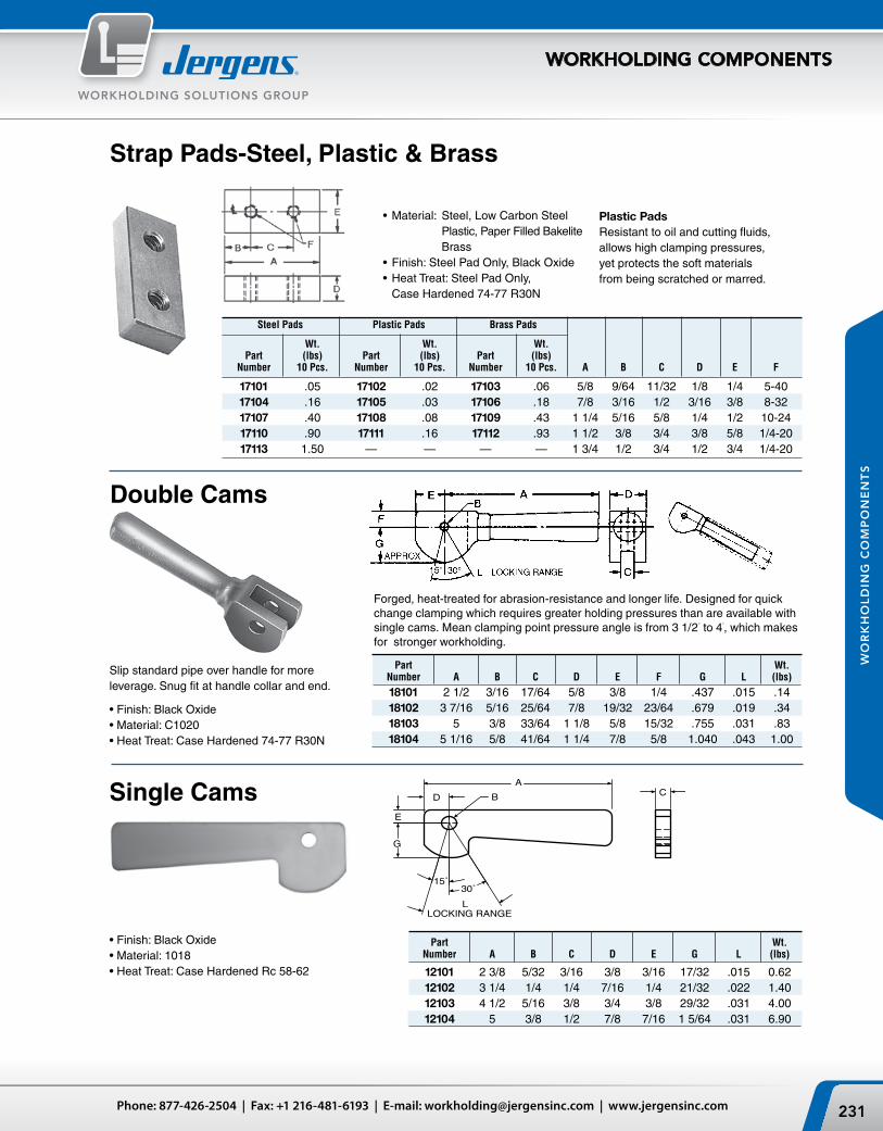
15˚30˚
LOCKING RANGEL
D
A
E
G
B C
231Phone: 877-426-2504 | Fax: +1 216-481-6193 | E-mail: [email protected] | www.jergensinc.com
WORKHOLDING SOLUTIONS GROUP
WORKHOLDING COMPONENTS
WO
RK
HO
LD
ING
CO
MP
ON
EN
TS
Strap Pads‑Steel, Plastic & Brass
Plastic PadsResistant to oil and cutting fluids, allows high clamping pressures, yet protects the soft materials from being scratched or marred.
Steel Pads Plastic Pads Brass Pads
Wt. Wt. Wt. Part (lbs) Part (lbs) Part (lbs) Number 10 Pcs. Number 10 Pcs. Number 10 Pcs. A B C D E F
17101 .05 17102 .02 17103 .06 5/8 9/64 11/32 1/8 1/4 5-40 17104 .16 17105 .03 17106 .18 7/8 3/16 1/2 3/16 3/8 8-32 17107 .40 17108 .08 17109 .43 1 1/4 5/16 5/8 1/4 1/2 10-24 17110 .90 17111 .16 17112 .93 1 1/2 3/8 3/4 3/8 5/8 1/4-20 17113 1.50 — — — — 1 3/4 1/2 3/4 1/2 3/4 1/4-20
• Material: Steel, Low Carbon Steel Plastic, Paper Filled Bakelite
Brass• Finish: Steel Pad Only, Black Oxide• Heat Treat: Steel Pad Only,
Case Hardened 74-77 R30N
Part Wt. Number A B C D E F G L (lbs)
18101 2 1/2 3/16 17/64 5/8 3/8 1/4 .437 .015 .14 18102 3 7/16 5/16 25/64 7/8 19/32 23/64 .679 .019 .34 18103 5 3/8 33/64 1 1/8 5/8 15/32 .755 .031 .83 18104 5 1/16 5/8 41/64 1 1/4 7/8 5/8 1.040 .043 1.00
Forged, heat-treated for abrasion-resistance and longer life. Designed for quick change clamping which requires greater holding pressures than are available with single cams. Mean clamping point pressure angle is from 3 1/2° to 4°, which makes for stronger workholding.
Double Cams
Slip standard pipe over handle for more leverage. Snug fit at handle collar and end.
• Finish: Black Oxide• Material: C1020• Heat Treat: Case Hardened 74-77 R30N
Single Cams
• Finish: Black Oxide• Material: 1018• Heat Treat: Case Hardened Rc 58-62
Part Wt. Number A B C D E G L (lbs)
12101 2 3/8 5/32 3/16 3/8 3/16 17/32 .015 0.62 12102 3 1/4 1/4 1/4 7/16 1/4 21/32 .022 1.40 12103 4 1/2 5/16 3/8 3/4 3/8 29/32 .031 4.00 12104 5 3/8 1/2 7/8 7/16 1 5/64 .031 6.90

Jergens, Inc. | 15700 S. Waterloo Road | Cleveland, Ohio 44110-3898 USA232
WORKHOLDING SOLUTIONS GROUP
WORKHOLDING COMPONENTS
WO
RK
HO
LD
ING
CO
MP
ON
EN
TS
Revolving Clamp Assemblies
Short Bushing Type
• Body Material: Malleable ASTM A47, GR32510 • Finish: Black Oxide• Bushings: Hardened & Ground Rc 56-60
Long Bushing Type
• Body Material: Malleable ASTM A47, GR32510 • Finish: Black Oxide• Bushings: Hardened & Ground Rc 56-60
• Stop pin supplied with each base.
Revolving Clamp Base(for use with Short Bushing Type only)
Part Wt. Number A B D E F L M (lbs)
.5610/ 35119 2 1 1/2 3 1 1/2 5/16-18 .5595 5/8 0.8 .6235/ 35103 2 1 1/2 3 1/4 1 1/2 3/8-16 .6220 3/4 0.8 .8735/ 35116 3 3/8 3 5 2 1/4 1/2-13 .8720 1 1/4 4.5 1.1235/ 35106 3 3/4 3 5 2 1/4 5/8-11 1.1220 1 1/2 4.8 1.1235/ 35109 3 3/4 4 5 2 1/4 5/8-11 1.1220 1 1/2 5.0
Quick hold-down of workpiece with hand tightening, then loosen and revolve out of the way. Saves time for moderate-duty clamping.
Malleable cast iron body. Case-hardened swivel pad uses “tru-center” feature to maintain even, in-line pressure on work-piece.
Part Number Base Clamp Clamp Wt. Part Only w/ Base A B D E F (lbs) Number
35117 35118 2 1 1/2 2 1 1/2 5/16-18 0.7 35113 35101 35102 2 1 1/2 3 1/4 1 1/2 3/8-16 0.7 35110 35114 35115 3 3/8 3 5 2 1/4 1/2-13 4.3 35112 35104 35105 3 3/4 3 3 2 1/4 5/8-11 4.5 35111 35107 35108 3 3/4 4 5 2 1/4 5/8-11 4.8 35111
Mtg. Part Bold Size Wt Number A B C D E F G (lbs)
35113 3/4 1 1 7/16 1 1/2 1 #10 5/16-18 0.5 35110 7/8 1 1 7/16 1 1/2 1 #10 3/8-16 0.6 35112 1 1/8 1 3/8 2 1/4 2 1/4 1 1/4 1/4 1/2-13 1.2 35111 1 1/4 1 1/2 2 1/4 2 1/4 1 1/4 3/8 5/8-11 1.7

233Phone: 877-426-2504 | Fax: +1 216-481-6193 | E-mail: [email protected] | www.jergensinc.com
WORKHOLDING SOLUTIONS GROUP
WORKHOLDING COMPONENTS
WO
RK
HO
LD
ING
CO
MP
ON
EN
TS
Hook Clamp Assemblies 829Moderate to heavy-duty holding power in close quarters. When released, the hook clamp swings quickly and easily out of the way for fast maneuvering of work. Spring-loaded shank for speedy clamp release.
• Material: Cast Steel Body, 4140• Finish: Black Oxide• Heat Treat: Rc 42-46• Stud: Furnished
Alternative to the above assembly, features flush-mounted socket screw instead of acorn nut. Designed for limited space applications and moderate holding power.
• Material: Cast Steel Body, 4140• Finish: Black Oxide• Heat Treat: Rc 42-46• Screw: Furnished
Hook Clamp Assemblies 829
Max. Part Cap Screw Wt. Torque Number A B C D E F G H K (lbs) (Ft/lbs)
41904* 11/16 5/16-18 x 1 3/4 7/8 .624/.625 3/8 1 3/8 1/4 5/8 3/8 .14 25 41905* 1 3/8-16 x 3 1 5/8 .874/.875 9/16 2 1/4 5/8 1 1/16 5/8 .44 40 41907 1 1/2-13 x 3 1 5/8 .874/.875 9/16 2 1/4 5/8 1 1/8 5/8 .47 100 41906 1 7/16 5/8-11 x 3 1/2 1 13/16 1.124/1.125 7/8 2 3/4 13/16 1 9/16 3/4 1.00 180*Conforms to TCMA
Max. Part Stud Size Wt. Torque Number A B C D E F G H J K (lbs) (Ft/lbs)
41901* 11/16 5/16-18 x 2 1/2 7/8 .624/.625 3/8 1 3/8 5/16 3/4 5/8 3/8 .21 25 41908 1 3/8-16 x 4 1 5/8 .874/.875 9/16 2 1/4 3/4 1 1/4 3/4 5/8 .59 40 41902* 1 1/2-13 x 4 1 5/8 .874/.875 9/16 2 1/4 5/8 1 1/8 15/16 5/8 .64 100 41903 1 7/16 5/8-11 x 5 1 13/16 1.124/1.125 7/8 2 3/4 7/8 1 3/8 1 3/16 3/4 1.38 180*Conforms to TCMA

Jergens, Inc. | 15700 S. Waterloo Road | Cleveland, Ohio 44110-3898 USA234
WORKHOLDING SOLUTIONS GROUP
WORKHOLDING COMPONENTS
WO
RK
HO
LD
ING
CO
MP
ON
EN
TS
Socket Shoulder ScrewsNylon Locking
Socket Shoulder Screws are held to much closer tolerances than on standard Strip-per Bolts. The “B” dimension is always a plus to eliminate the binding on movable plates. The “A” dimension is held closer for bearing-type locating. You’ll get more positive holding power and greater turning leverage. Ideal for all sliding mechanisms. Nylon locking element is incorporated in all Jergens Shoulder Screws.
• Material: 4140• Heat Treat: Rc 38-42• Thread: 2A-UNC Thread Hex Wt.
Diameter Part Size Size (lbs) A B Number C D E F G 10 Pcs.
.249 1/4 41701* 10-24 3/8 13/16 3/8 1/8 .09 .249 3/8 41702* 10-24 3/8 15/16 3/8 1/8 .12 .249 1/2 41703* 10-24 3/8 1 1/16 3/8 1/8 .13 .249 5/8 41704* 10-24 3/8 1 3/16 3/8 1/8 .15 .249 3/4 41705* 10-24 3/8 1 5/16 3/8 1/8 .16 .249 7/8 41706* 10-24 3/8 1 7/16 3/8 1/8 .19 .374 1/4 41707* 5/16-18 1/2 1 9/16 3/16 .30 .374 3/8 41708* 5/16-18 1/2 1 1/8 9/16 3/16 .32 .374 1/2 41709* 5/16-18 1/2 1 1/4 9/16 3/16 .38 .374 5/8 41710* 5/16-18 1/2 1 3/8 9/16 3/16 .41 .374 3/4 41711* 5/16-18 1/2 1 1/2 9/16 3/16 .45 .374 7/8 41712* 5/16-18 1/2 1 5/8 9/16 3/16 .48 .499 3/8 41713* 3/8-16 5/8 1 5/16 3/4 1/4 .68 .499 1/2 41714* 3/8-16 5/8 1 7/16 3/4 1/4 .73 .499 5/8 41715* 3/8-16 5/8 1 9/16 3/4 1/4 .78 .499 3/4 41716* 3/8-16 5/8 1 11/16 3/4 1/4 .86 .499 7/8 41717* 3/8-16 5/8 1 13/16 3/4 1/4 .93 .624 1/2 41718* 1/2-13 3/4 1 5/8 7/8 5/16 1.22 .624 5/8 41719* 1/2-13 3/4 1 3/4 7/8 5/16 1.36 .624 3/4 41720* 1/2-13 3/4 1 7/8 7/8 5/16 1.41 .624 7/8 41721* 1/2-13 3/4 2 7/8 5/16 1.56 .624 1 41722* 1/2-13 3/4 2 1/8 7/8 5/16 1.85 .749 5/8 41723* 5/8-11 7/8 2 1 3/8 2.25 .749 3/4 41724* 5/8-11 7/8 2 1/8 1 3/8 2.47 .749 7/8 41725* 5/8-11 7/8 2 1/4 1 3/8 2.60 .749 1 41726* 5/8-11 7/8 2 3/8 1 3/8 2.75 .749 1 1/4 41727* 5/8-11 7/8 2 5/8 1 3/8 2.90 .999 1 41728 3/4-10 1 2 5/8 1 3/8 1/2 5.47 .999 1 1/2 41729 3/4-10 1 3 1/8 1 3/8 1/2 6.56 .999 2 41730 3/4-10 1 3 5/8 1 3/8 1/2 7.66*Conforms to TCMA

235Phone: 877-426-2504 | Fax: +1 216-481-6193 | E-mail: [email protected] | www.jergensinc.com
WORKHOLDING SOLUTIONS GROUP
WORKHOLDING COMPONENTS
WO
RK
HO
LD
ING
CO
MP
ON
EN
TS
Swing Bolts (Latch Bolt)
Thread Wt. Part Size (lbs) Number A B C D E F G 10 Pcs.
29501* 3/8-16 2 1/2 3/8 1 3/8 1/2 3/4 3/8 .93 29502 3/8-16 3 1/4 3/8 1 3/4 1/2 3/4 3/8 1.25 29513 1/2-13 2 5/8 3/8 1 1/2 5/8 1 7/16 1.95 29504* 1/2-13 3 1/8 1/2 1 3/4 5/8 1 7/16 2.04 29505 1/2-13 4 1/8 1/2 2 1/4 5/8 1 7/16 2.64 29516 5/8-11 3 3/4 1/2 2 3/4 1 1/8 1/2 3.64 29507 5/8-11 3 1/2 5/8 1 3/4 3/4 1 1/8 1/2 3.67 29508 5/8-11 4 3/4 5/8 2 1/2 3/4 1 1/8 1/2 4.75 29509 3/4-10 4 3/8 3/4 2 1/2 7/8 1 3/8 11/16 6.10 29510 3/4-10 6 1/2 3/4 3 1/4 7/8 1 3/8 11/16 8.85
*Conforms to TCMA.
Not to be used for lifting.
• Material: 4140• Finish: Black Oxide• Heat Treat: Rc 36-40• Thread: Class 2A-UNC
Swing Bolts (Latch Bolt)Stainless Steel• Material: 303 Stainless • Thread: Class 2A-UNC
• Material: 303 Stainless
Not to be used for lifting.
Wt. (lbs)
10 Pcs.
.09
.12
.13
.15
.16
.19
.30
.32
.38
.41
.45
.48
.68
.73
.78
.86
.931.221.361.411.85
Part Diam. Hex Size Number A B C D E F G
41801 1/4 1/4 10-24 3/8 13/16 3/8 1/8 41802 1/4 3/8 10-24 3/8 15/16 3/8 1/8 41803 1/4 1/2 10-24 3/8 1 1/16 3/8 1/8 41804 1/4 5/8 10-24 3/8 1 3/16 3/8 1/8 41805 1/4 3/4 10-24 3/8 1 5/16 3/8 1/8 41806 1/4 1 10-24 3/8 1 9/16 3/8 1/8 41807 3/8 1/4 5/16-18 1/2 1 9/16 3/16 41808 3/8 3/8 5/16-18 1/2 1 1/8 9/16 3/16 41809 3/8 1/2 5/16-18 1/2 1 1/4 9/16 3/16 41810 3/8 5/8 5/16-18 1/2 1 3/8 9/16 3/16 41811 3/8 3/4 5/16-18 1/2 1 1/2 9/16 3/16 41812 3/8 1 5/16-18 1/2 1 3/4 9/16 3/16 41813 1/2 3/8 3/8-16 5/8 1 5/16 3/4 1/4 41814 1/2 1/2 3/8-16 5/8 1 7/16 3/4 1/4 41815 1/2 5/8 3/8-16 5/8 1 9/16 3/4 1/4 41816 1/2 3/4 3/8-16 5/8 1 11/16 3/4 1/4 41817 1/2 1 3/8-16 5/8 1 15/16 3/4 1/4 41818 5/8 1/2 1/2-13 3/4 1 5/8 7/8 5/16 41819 5/8 5/8 1/2-13 3/4 1 3/4 7/8 5/16 41820 5/8 3/4 1/2-13 3/4 1 7/8 7/8 5/16 41822 5/8 1 1/2-13 3/4 2 1/8 7/8 5/16
*B dimension indicates minimum length.
Thread Wt. Part Size (lbs) Number A B C D E F G 10 Pcs. 29601 3/8-16 2 1/2 3/8 1 3/8 1/2 3/4 1/2 1.1 29602 3/8-16 3 1/2 3/8 2 1/2 3/4 1/2 1.4 29603 1/2-13 3 1/8 1/2 1 5/8 5/8 1 5/8 2.6 29604 1/2-13 4-1/8 1/2 2 1/2 5/8 1 5/8 3.0 29605 5/8-11 3 1/2 5/8 1 5/8 3/4 1 1/4 3/4 4.6 29606 5/8-11 4 3/4 5/8 2 1/2 3/4 1 1/4 3/4 5.5
Socket Head Shoulder ScrewsStainless Steel
Socket Shoulder Screws are held to much closer tolerances than on standard Stripper Bolts. The “B” dimension is always a plus to eliminate the bind-ing on movable plates. The “A” dimension is held closer for bearing-type locating. You’ll get more positive holding power and greater turning leverage. Ideal for all sliding mechanisms. Nylon locking ele-ment is incorporated in all Jergens Shoulder Screws.

F
E
A
B
Jergens, Inc. | 15700 S. Waterloo Road | Cleveland, Ohio 44110-3898 USA236
WORKHOLDING SOLUTIONS GROUP
WORKHOLDING COMPONENTS
WO
RK
HO
LD
ING
CO
MP
ON
EN
TS
Part Thread D Wt. Number A B C Minimum E F (lbs)
35301* 1/4-20 2 3/16 3/4 1/4 1/2 .04 35302 1/4-20 2 1/4 3/4 1/4 1/2 .03 35318* 5/16-18 3 1/4 1 1/2 5/16 5/8 .08 35319* 5/16-18 3 5/16 1 1/2 5/16 5/8 .08 35303* 3/8-16 3 5/16 1 1/2 3/8 3/4 .11 35320 3/8-16 4 5/16 1 3/4 3/8 3/4 .11 35304 3/8-16 2 3/16 3/8 1 1/4 3/8 3/4 .08 35305* 3/8-16 3 3/8 1 1/2 3/8 3/4 .11 35306* 3/8-16 5 3/8 2 1/2 3/8 3/4 .12 35307* 1/2-13 3 3/4 3/8 1 1/2 1/2 1 .25 35308 1/2-13 2 11/16 1/2 1 1/2 1/2 1 .19 35309 1/2-13 3 3/4 1/2 1 1/2 1/2 1 .24 35310 1/2-13 5 1/2 1 1/2 1/2 1 .31 35311 5/8-11 3 11/16 5/8 2 5/8 1 1/4 .40 35312* 5/8-11 4 1/2 5/8 2 5/8 1 1/4 .46 35314* 5/8-11 6 5/8 2 1/2 5/8 1 1/4 .60 35315* 3/4-10 4 1/2 3/4 2 3/4 1 1/2 .73 35321* 3/4-10 6 3/4 2 1/2 3/4 1 1/2 1.00 35317 1-8 8 1 3 1 2 2.25*Conforms to TCMA. Not to be used for lifting.
Rod EndsThreaded
Rod Ends are forged and finished for applications not requiring flat contact with the head. All holes are reamed. Rod Ends can be used with spherical flange assemblies, flange nuts and clamp assemblies.
Part Number Stainless Ref. Wt. Standard Steel A B* E F (lbs)
35511 35701 1/4 2 1/4 1/2 .04 35512 35702 3/8 5 3/8 3/4 .13 35513 35703 1/2 6 1/2 1 .44 35514 35704 5/8 6 5/8 1 1/4 .70 35515 — 3/4 6 3/4 1 1/2 1.8 35516 — 1 8 1 2 2.5
*B dimension indicates minimum length. Not to be used for lifting.
Blank Rod Ends can be machined to yourspecifications; please send prints for quotation.Maximum thread length 1/2" from head.
• Material: Alloy Steel• Finish: Black Oxide• Heat Treat: 32-36 Rc• Thread: Class 2A-UNC * 150,000 PSI Tensile
• Material: Standard, Alloy Steel Forging Stainless, 18-8 Forging* Not Heat Treated
Rod EndsBlank Forging
Part Ref. Ref. Number A B C D E F
35721 1/4-20 2 1/8 3/16 7/8 1/4 1/2 35722 1/4-20 2 1/8 1/4 7/8 1/4 1/2 35723 5/16-18 3 1/2 1/4 1 1/2 5/16 5/8 35724 5/16-18 3 1/2 5/16 1 1/2 5/16 5/8 35725 3/8-16 3 1/2 3/8 1 1/2 3/8 3/4 35726 3/8-16 5 3/8 2 1/2 3/8 3/4 35727 1/2-13 3 3/4 1/2 1 1/2 1/2 1 35728 1/2-13 5 1/2 2 1/2 1 35729 5/8-11 4 1/2 5/8 2 5/8 1 1/4 35730 5/8-11 6 5/8 3 5/8 1 1/4 35731 3/4-10 4 1/2 3/4 2 3/4 1 1/2 35732 3/4-10 6 3/4 2 1/2 3/4 1 1/2Not to be used for lifting.
Rod EndsStainless Steel
• Material: 303 Stainless • Thread Class 2A-UNC

E
C B
237Phone: 877-426-2504 | Fax: +1 216-481-6193 | E-mail: [email protected] | www.jergensinc.com
WORKHOLDING SOLUTIONS GROUP
WORKHOLDING COMPONENTS
WO
RK
HO
LD
ING
CO
MP
ON
EN
TS
Quarter Turn Screws
Wt. Part (lbs) Number A B C D E F 10 Pcs.
34501* 10-32 7/8 1 1/2 1/2 3/16 .31 34502* 1/4-20 1 1 1/4 5/8 3/4 1/4 .47 34503 1/4-20 1 1/2 1 3/4 5/8 3/4 1/4 .48 34504* 5/16-18 1 1/4 1 1/2 3/4 1 5/16 .90 34505 5/16-18 1 3/4 2 3/4 1 5/16 1.10 34506* 3/8-16 1 1/4 1 1/2 1 1 3/8 1.25 34507 3/8-16 1 3/4 2 1 1 3/8 1.45 34508* 1/2-13 1 1/2 1 3/4 1 1 1/4 1/2 2.35 34509 1/2-13 2 2 1/4 1 1 1/4 1/2 2.65*Conforms to TCMA
The diamond on all four corners of the Jergens Quarter Turn and Half Turn Screws, makes the opening and closing of jig lids easier. Ideally suited for clamping lids, covers and swing-away type bushing arms. Quarter Turn and Half Turn Screws may be machined for finishing requirements.
• Material: Stem, Low Carbon Steel Head, Low Carbon Steel• Finish: Black Oxide• Thread: 2A-UNC (inch); Class 6g (Metric) 2A-UNF (10-32)
Half Turn Screws
• Material: Low Carbon Steel • Finish: Black Oxide• Thread: 2A-UNF (10-32) 2A-UNC (other sizes)
Wt. Part (kg) Number A B C D E F 10 Pcs.
34571 M5 x 0.8 22 25 13 13 5 .14 34573 M6 x 1.0 25 32 16 19 6 .21 34575 M8 x 1.25 32 38 19 25 8 .41 34577 M10 x 1.5 32 38 25 25 10 .57 34579 M12 x 1.75 38 44 25 32 13 1.06
Wt. Part Thread (lbs) Number A B C D E F 10 Pcs.
34521 10-32 1 3/16 1-11/16 3/4 3/16 .3 34522 1/4-20 1-1/4 3/16 2 3/4 1/4 .3 34523 5/16-18 1-1/4 3/16 2-1/16 1 5/16 .3 34524 3/8-16 1-3/4 1/4 1-11/16 1-1/16 3/8 .3 34525 1/2-13 1-3/4 1/4 2-3/4 1-1/4 1/2 .3

Jergens, Inc. | 15700 S. Waterloo Road | Cleveland, Ohio 44110-3898 USA238
WORKHOLDING SOLUTIONS GROUP
WORKHOLDING COMPONENTS
WO
RK
HO
LD
ING
CO
MP
ON
EN
TS
ScrewsThumb Screws
• Materials: 1215 Steel with black oxide finish, 303 Stainless
• Thread: 2A-UNC 2A-UNF (10-32)
The half-dog point protects the threads in case of peening.
Metric
Part No. Part No. Wt. Steel Stainless A B C D E F G (lbs)
43901 — 10-24 1 9/16 1 1/4 1 1/16 3/64 1/8 3/4 .44 43902 — 10-24 1 5/16 1 5/8 1 7/16 3/64 1/8 3/4 .47 43903* — 10-24 2 5/16 2 1 13/16 3/64 1/8 3/4 .48 — 44001 10-32 1 3/16 1 3/4 7/32 3/16 3/4 .45 — 44002 10-32 1 7/16 1 1/4 1 7/32 3/16 3/4 .45 — 44004 1/4-20 1 5/16 1 25/32 3/32 11/64 1 .75 43904* 44005* 1/4-20 1 13/16 1 1/2 1 1/4 1/16 5/32 1 .78 43905* 44006 1/4-20 2 5/16 2 1 3/4 1/16 5/32 1 .86 43906* — 1/4-20 2 13/16 2 1/2 2 1/4 1/16 5/32 1 .91 43907 44008 5/16-18 2 1/8 1 3/4 1 7/16 5/64 13/64 1 1/8 1.30 43908 44009 5/16-18 2 5/8 2 1/4 1 15/16 5/64 13/64 1 1/8 1.36 43909 44010 5/16-18 3 1/8 2 3/4 2 7/16 5/64 13/64 1 1/8 1.50 43910* 44011 3/8-16 2 7/16 2 1 5/8 3/32 1/4 1 1/4 1.93 43911* 44012* 3/8-16 2 15/16 2 1/2 2 1/8 3/32 1/4 1 1/4 2.00 43912* 44013* 3/8-16 3 7/16 3 2 5/8 3/32 1/4 1 1/4 2.20 43913 — 1/2-13 2 15/16 2 1/2 2 1/8 1/8 11/32 1 1/4 2.55 — 44014 1/2-13 3 2 1/2 2 1/4 3/8 1 1/4 2.55 43914* — 1/2-13 3 7/16 3 2 5/8 1/8 11/32 1 1/4 2.80 — 44015 1/2-13 3 1/2 3 2 1/2 1/4 3/8 1 1/4 3.00 43915* — 1/2-13 3 15/16 3 1/2 3 1/8 1/8 11/32 1 1/4 3.10 — 44016 1/2-13 4 3 1/2 3 1/4 3/8 1 1/4 3.10* Conforms to TCMA
Part Wt. Number A B C D E F G (Kg)
43971 M5x0.8 30 25 20 1.2 3 20 0.20 43972 M5x0.8 45 40 35 1.2 3 20 0.21 43973 M5x0.8 55 50 45 1.2 3 20 0.22 43974 M 6 x 1.0 50 40 35 1.5 4 25 0.35 43975 M 6 x 1.0 60 50 45 1.5 4 25 0.39 43976 M 6 x 1.0 75 65 55 1.5 4 25 0.41 43977 M8 x 1.25 50 40 35 2.4 5 30 0.59 43978 M8 x 1.25 60 50 45 2.4 5 30 0.62 43979 M8 x 1.25 75 65 60 2.4 5 30 0.68 43980 M10 x 1.5 60 50 45 2.4 6 30 0.88 43981 M10 x 1.5 75 65 60 2.4 6 30 0.91 43982 M10 x 1.5 85 75 70 2.4 6 30 1.00 43983 M 12 x 1.75 90 75 70 3 11 30 1.27 43984 M 12 x 1.75 105 90 85 3 11 30 1.41 43985 M 12 x 1.75 80 65 55 3 11 30 1.25

239Phone: 877-426-2504 | Fax: +1 216-481-6193 | E-mail: [email protected] | www.jergensinc.com
WORKHOLDING SOLUTIONS GROUP
WORKHOLDING COMPONENTS
WO
RK
HO
LD
ING
CO
MP
ON
EN
TS
Tru‑Center™ Toggle Products
Adjustable Torque Toggle Screws
The Jergens patented “Tru-Center” products are the only pad type on the market to provide true center line clamping. The cut-away drawing illustrates how this works. The center line of the pad and the center line of the nut always intersect at the point of contact between the pad and the workpiece.
Perfect for delicate and fine clamping. Once the end holding force is reached, the head breaks free. Larger radius, straight knurled head for easy turning.
• Material: Stem, Stressproof®
Pad, 4140 Head, Cast Iron• Finish: Stem, Black Oxide Pad, Zinc Plate Head, Cadnium Plate• Thread: 2A-UNC• Pad: Angular movement either side
of center (total 16°)
For clamping of irregular surfaces while the swivel shoe prevents marring of polished surfaces. Shoe is hardened for longer life. The cast iron hand knob is included for hand tightening. To remove pad for installation, pull and turn counter-clockwise.
• Material: Stem, Stressproof®
Pad, 4140• Finish: Stem, Black Oxide Head, Chrome Plate• Thread: 2A-UNC• Pad: Angular movement either
side of center (total 16°)
Hand Knob Toggle Screws
Wt. Part (lbs) Number A B C D E F G 10 Pcs.
36301 3/8-16 2 1 21/32 11/16 3/8 1 1/8 2 .21 36302 3/8-16 2 3/4 2 13/32 11/16 3/8 1 1/8 2 .24 36303 3/8-16 3 5/8 3 9/32 11/16 3/8 1 1/8 2 .25 36304 1/2-13 2 1/8 1 21/32 13/16 15/32 1 1/2 2 1/2 .44 36305 1/2-13 2 3/4 2 9/32 13/16 15/32 1 1/2 2 1/2 .48 36306 1/2-13 3 3/8 2 29/32 13/16 15/32 1 1/2 2 1/2 .52 36307 1/2-13 4 3 17/32 13/16 15/32 1 1/2 2 1/2 .55 36308 5/8-11 3 2 17/32 15/16 1/2 2 3 1.38 36309 5/8-11 3 3/4 3 9/32 15/16 1/2 2 3 1.50 36310 3/4-10 4 7/8 4 11/32 1 1/8 19/32 2 3 1.56
Wt. Part End Force (lbs) Number A B C D E F (lbs) 10 Pcs.
31101 10-24 1 1/4 1 23/32 .140 3/16 0-50 1.7 31102 1/4-20 1 1/2 1 23/32 .185 15/64 0-50 1.7 31103 1/4-20 2 1/2 1 23/32 .185 15/64 0-50 1.8 31104 5/16-18 1 3/4 1 23/32 .240 9/32 0-50 1.9 31105 5/16-18 2 3/4 1 23/32 .240 9/32 0-50 2.1 31106 3/8-16 2 1 1/4 25/32 .294 11/32 0-60 3.0 31107 1/2-13 3 1 1/4 25/32 .400 7/16 0-60 4.2

Jergens, Inc. | 15700 S. Waterloo Road | Cleveland, Ohio 44110-3898 USA240
WORKHOLDING SOLUTIONS GROUP
WORKHOLDING COMPONENTS
WO
RK
HO
LD
ING
CO
MP
ON
EN
TS
Tru‑Center™ Toggle ProductsSocket Toggle Screws
Plastic Pad Covers snap over outside diameter of Jergens swivel pads.
Where soft material with fine finished surfaces must be clamped with relatively high pressures, we recommend the use of the Jergens Plastic Pad Covers. Resistant to oils and cutting compounds, they snap over the swivel end of our Hand KnobToggle Screws, Socket Toggle Screws, Toggle Thumb Screws, Toggle Pads and ad-justable Torque Thumb Screws.
• Material: Nylon
Plastic Pad Covers
Toggle Thumb Screws
• Material: Stem and Head 1215, Pad, 4140
• Finish: Black Oxide• Thread: 2A-UNC
• Material: 4140• Finish: Black Oxide• Heat Treat: 38-42 Rc• Screws may be inserted
without removing pads.
Thread Wt. Part Size (lbs) Number A B C D E F 10 Pcs.
33501 10-24 1 3/4 5/16 3/16 .140 .31 33502 10-24 1 1/2 3/4 5/16 3/16 .140 .47 33503* 1/4-20 1 1/2 1 5/16 15/64 .185 .78 33504* 1/4-20 2 1 5/16 15/64 .185 .94 33505* 5/16-18 1 1/2 1 1/8 3/8 9/32 .240 1.05 33506* 5/16-18 2 1 1/8 3/8 9/32 .240 1.25 33507* 5/16-18 2 1/2 1 1/8 3/8 9/32 .240 1.40 33508* 3/8-16 1 1/2 1 1/4 7/16 11/32 .294 1.70 33509* 3/8-16 2 1 1/4 7/16 11/32 .294 1.88 33510* 3/8-16 2 1/2 1 1/4 7/16 11/32 .294 2.04 33511* 3/8-16 3 1 1/4 7/16 11/32 .294 2.20*Conforms to TCMA
To Fit O.D. of To Fit O.D. of Part Over O.D. Plastic Part Over O.D. Plastic Number of Pad Pad Number of Pad Pad
32901 .140 .250 32907 9/16 .625 32902 .185 .250 32908 5/8 .750 32903 .240 .312 32909 11/16 .812 32904 .294 .375 32910 13/16 .937 32905 .400 .500 32911 15/16 1.062
E Wt. Part Thread Size Hex (lbs) Number A B C D Size 10 Pcs.
33301* 1/4-20 1/2 15/64 .185 1/8 .03 33302* 1/4-20 1 15/64 .185 1/8 .09 33303* 5/16-18 3/4 9/32 .240 5/32 .09 33304* 5/16-18 1 1/2 9/32 .240 5/32 .24 33305* 3/8-16 1 11/32 .294 3/16 .20 33306* 3/8-16 2 11/32 .294 3/16 .45 33307* 1/2-13 1 7/16 .400 1/4 .30 33308* 1/2-13 2 7/16 .400 1/4 .78 33310* 5/8-11 2 17/32 .507 5/16 1.25*Conforms to TCMA
Same as our standard Thumb Screw only with the addition of our patented swivel pad on the end.

241Phone: 877-426-2504 | Fax: +1 216-481-6193 | E-mail: [email protected] | www.jergensinc.com
WORKHOLDING SOLUTIONS GROUP
WORKHOLDING COMPONENTS
WO
RK
HO
LD
ING
CO
MP
ON
EN
TS
Tru‑Center™ Toggle ProductsToggle Pads
• Material: 4140 or Carbide Insert Tip• Finish: Black Oxide• Heat Treat: Plain Pad Rc 36-40• Thread: 2B-UNC
Carbide Tipped Toggle Pads provide multiple point contact to compensate for surfaces that are rough or out-of-round. Points will embed themselves in the workpiece, which assures positive gripping. It eliminates possible radial load on the workpiece.
Toggle PadsMetric
• Material: 4140 or Carbide Insert Tip• Finish: Black Oxide• Heat Treat: Plain Pad Rc36-40• Thread class: 6h
Note: Metric Toggle Pads have two flats instead of a hex configuration on the head.
Thread Across Wt. Part Number Size Flats Plain Serrated (kg) Plain Serrated A B C C D E 10 Pcs.
43552 43752 M6 x 1.0 12 13 14.4 14 1.4 .09 43553 43753 M8 x 1.25 14 17 18.4 16 1.4 .13 43554 43754 M10 x 1.5 16 18 20.4 18 1.4 .19 43555 43755 M12 x 1.75 22 22 23.4 21 1.4 .28 43556 43756 M16 x 2.0 26 25 26.4 24 2.2 .43 43557 43757 M20 x 2.5 30 29 31.2 28 2.2 .73
Thread Across Wt. Part Number Size Flats Plain Serrated (lbs) Plain Serrated A B C C D E 10 Pcs.
43502 43702 1/4-20 1/2 1/2 9/16 9/16 .055 .20 43503 43703 5/16-18 9/16 11/16 3/4 5/8 .055 .28 43504 43704 3/8-16 5/8 25/32 3/4 11/16 .055 .41 43505 43705 1/2-13 3/4 7/8 15/16 13/16 .055 .62 43506 43706 5/8-11 7/8 1 1 1/32 15/16 .086 .94 43507* 43707 3/4-10 1 1/16 1 5/32 1 1/4 1 1/8 .086 1.60*Plastic Pad is not available for this item.

Jergens, Inc. | 15700 S. Waterloo Road | Cleveland, Ohio 44110-3898 USA242
WORKHOLDING SOLUTIONS GROUP
WORKHOLDING COMPONENTS
WO
RK
HO
LD
ING
CO
MP
ON
EN
TS
Tapped
• Material: 4140• Finish: Zinc Plated• Heat Treat: Rc 36-40• Thread: UNC-2B
Provides a greater surface area where heavy loads are to be applied or where heavy pressures must be exerted on flex-
• Material: 4140• Finish: Zinc Plated• Heat Treat: Rc36-40• Thread class: 6h
Metric Tapped
Thread Across Load Part Size Flats Capacity Wt. Number A B C D (kg) (kg)
32551 M10 x 1.5 16 21 32 1000 .05 32552 M12 x 1.75 22 27 48 1900 .10 32553 M16 x 2.0 26 31 57 2900 .19 32554 M20 x 2.5 30 39 76 4500 .38
Thread Across Load Part Size Flats Capacity Wt. Number A B C D (lbs) (lbs)
32501 3/8-16 5/8 3/4 1 1/4 2300 .10 32502 1/2-13 3/4 1 1 7/8 4200 .22 32503 5/8-11 7/8 1 1/8 2 1/4 6600 .42 32504 3/4-10 1 1/16 1 7/16 3 10,000 .84
ible or softer materials. Pad face swivels and aligns with no damage to the uneven surfaces.
Leveling Pads
SwIveLS 6° eACH SIde OF CeNTeR
Note: Metric Toggle Pads have two flats instead of a hex configuration
on the head.

243Phone: 877-426-2504 | Fax: +1 216-481-6193 | E-mail: [email protected] | www.jergensinc.com
WORKHOLDING SOLUTIONS GROUP
WORKHOLDING COMPONENTS
WO
RK
HO
LD
ING
CO
MP
ON
EN
TS
Threaded
• Material: 4140• Finish: Zinc Plated Pad• Heat Treat: Rc 36-40• Thread: UNC-2A
Metric Threaded
• Material: 4140• Finish: Zinc Plated• Heat Treat: Rc36-40• Thread class: 6g
Thread Across Load Part Size Flats Capacity Wt. Number A B C D (lbs) (lbs)
32521 3/8-16 5/8 3/4 1 1/4 2300 .16 32522 1/2-13 3/4 1 1 7/8 4200 .37 32523 5/8-11 7/8 1 1/8 2 1/4 6600 .58 32524 3/4-10 1 1/16 1 7/16 3 10,000 1.22Jam nut is furnished.
Thread Across Load Part Size Flats Capacity Wt. Number A B C D (kg) (kg)
32571 M10 x 1.5 16 21 32 1000 .07 32572 M12 x 1.75 22 27 48 1900 .17 32573 M16 x 2.0 26 31 57 2900 .26 32574 M20 x 2.5 30 39 76 4500 .55
Note: Metric Toggle Pads have two flats instead of a hex configuration on the head.
Leveling Pads

D
Jergens, Inc. | 15700 S. Waterloo Road | Cleveland, Ohio 44110-3898 USA244
WORKHOLDING SOLUTIONS GROUP
WORKHOLDING COMPONENTS
WO
RK
HO
LD
ING
CO
MP
ON
EN
TS
• Material: 1214 Steel• Non-Skid Material: Neoprene• Case hardened, file hard• Swivels 10° in all directions
Leveling Mounts
Maximum Load
*Add 1/8" to C dimension for non-skid style.
Maximum Load
*Add 1/8" to C dimension for non-skid style.
Threaded
AcrossFlats
AcrossFlats
• Available with non-skid on base• Available in stainless steel, or with a
delrin pad, and in larger sizes upon request.
Tapped
Part Number
(lbs)
Standard Non-skid A B C* D Standard Non-skid
32601 32651 10-32 3/4 17/32 3/8 700 550 32602 32652 1/4-20 1 45/64 1/2 1000 825 32606 32656 3/8-16 1 1/4 7/8 5/8 3750 2820 32608 32658 1/2-13 1 7/8 1 1/8 3/4 5000 3750 32610 32660 5/8-11 2 1/2 1 1/4 7/8 6000 5000 32612 32662 3/4-10 3 1 1/2 1 1/16 7400 6000 32616 32666 1-8 4 1 7/8 1 3/8 21000 16500
Part Number
(lbs)
Standard Non-skid A B C* D E Standard Non-skid
32621 32671 10-32 3/4 1 17/32 3/8 1 700 550 32623 32673 1/4-20 1 1 61/64 1/2 1 1/4 1000 825 32626 32676 3/8-16 1 1/4 2 7/8 5/8 2 3750 2850 32629 32679 1/2-13 1 7/8 3 1/8 3/4 2 5000 3750 32632 32682 5/8-11 2 1/2 3 1/4 7/8 2 6000 4350 32635 32685 3/4-10 3 3 1/2 1 1/16 2 7400 5500 32640 32690 1-8 4 5 3/8 1 3/8 3 1/2 20000 16500
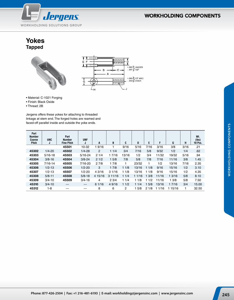
245Phone: 877-426-2504 | Fax: +1 216-481-6193 | E-mail: [email protected] | www.jergensinc.com
WORKHOLDING SOLUTIONS GROUP
WORKHOLDING COMPONENTS
WO
RK
HO
LD
ING
CO
MP
ON
EN
TS
Jergens offers these yokes for attaching to threaded linkage at stem end. The forged holes are reamed and faced-off parallel inside and outside the yoke ends.
• Material: C-1021 Forging• Finish: Black Oxide• Thread: 2B
YokesTapped
Part Number Part Wt. Coarse UNC Number UNF (lbs) Pitch J Fine Pitch J A B C D E F G H 10 Pcs.
45501 10-32 1 9/16 1 9/16 5/16 7/16 3/16 3/8 3/16 .21 45302 1/4-20 45502 1/4-28 2 1 1/4 3/4 7/16 5/8 9/32 1/2 1/4 .62 45303 5/16-18 45503 5/16-24 2 1/4 1 7/16 13/16 1/2 3/4 11/32 19/32 5/16 .94 45304 3/8-16 45504 3/8-24 2 1/2 1 5/8 7/8 5/8 7/8 7/16 11/16 3/8 1.45 45305 7/16-14 45505 7/16-20 2 7/8 1 7/8 1 23/32 1 1/2 13/16 7/16 2.35 45306 1/2-13 45506 1/2-20 3 1 7/8 1 1/8 13/16 1 1/8 9/16 15/16 1/2 3.10 45307 1/2-13 45507 1/2-20 4 3/16 3 1/16 1 1/8 13/16 1 1/8 9/16 15/16 1/2 4.35 45308 5/8-11 45508 5/8-18 4 15/16 3 11/16 1 1/4 1 1/16 1 3/8 11/16 1 3/16 5/8 8.10 45309 3/4-10 45509 3/4-16 4 2 3/4 1 1/4 1 1/8 1 1/2 11/16 1 3/8 5/8 7.50 45310 3/4-10 — — 6 1/16 4 9/16 1 1/2 1 1/4 1 5/8 13/16 1 7/16 3/4 15.00 45312 1-8 — — 8 6 2 1 5/8 2 1/8 1 1/16 1 15/16 1 32.50

Jergens, Inc. | 15700 S. Waterloo Road | Cleveland, Ohio 44110-3898 USA246
WORKHOLDING SOLUTIONS GROUP
WORKHOLDING COMPONENTS
WO
RK
HO
LD
ING
CO
MP
ON
EN
TS
• Material: Low Carbon Steel• All Clevis Pins supplied with cotter pins.
Clevis Pins
Wt. Part (lbs) Number A B C D E F G H J K 10 Pcs.
32701 3/16 37/64 29/64 31/64 41/64 1/16 5/16 5/64 1/16 1/2 .08 32702 1/4 49/64 41/64 43/64 55/64 3/32 3/8 5/64 1/16 1/2 .15 32703 5/16 15/16 49/64 13/16 1 1/32 3/32 7/16 7/64 3/32 1/2 .30 32704 3/8 1 1/16 57/64 15/16 1 3/16 1/8 1/2 7/64 3/32 5/8 .45 32705 7/16 1 3/16 1 1/64 1 1/16 1 11/32 5/32 9/16 7/64 3/32 5/8 .60 32706 1/2 1 23/64 1 9/64 1 13/64 1 33/64 5/32 5/8 9/64 1/8 1 1.00 32707 5/8 1 39/64 1 25/64 1 29/64 1 13/16 13/64 13/16 9/64 1/8 1 1.18 32708 5/8 1 3/4 1 33/64 1 19/32 1 63/64 13/64 13/16 9/64 1/8 1 1.82 32709 3/4 1 29/32 1 41/64 1 23/32 2 5/32 1/4 15/16 11/64 5/32 1 1/2 3.00 32711 1 2 13/32 2 9/64 2 7/32 2 3/4 11/32 1 3/16 11/64 5/32 1 1/2 7.00
Threaded
This style yoke is similar to the above except the stem is threaded for attaching to tapped linkage.
• Material: C-1021 Forging• Finish: Black Oxide• Thread: 2A-UNC
Wt. Part (lbs) Number K A B C D E F G H J 10 Pcs.
45902 1/4-20 1 3/4 5/8 1 1/8 1/4 3/4 1/2 5/8 9/32 1/4 .47 45903 5/16-18 2 3/4 1 1/4 5/16 3/4 19/32 3/4 11/32 5/16 .85 45904 3/8-16 2 1/8 27/32 1 9/32 3/8 3/4 11/16 7/8 7/16 3/8 1.10 45906 1/2-13 2 1/2 1 1/8 1 3/8 1/2 3/4 15/16 1 1/8 9/16 1/2 2.35 45907 5/8-11 2 7/8 1 7/16 1 7/16 5/8 3/4 1 3/16 1 3/8 11/16 5/8 4.20 45908 3/4-10 3 5/8 1 11/16 1 15/16 3/4 1 1/4 1 7/16 1 5/8 13/16 3/4 7.35 45910 1-8 4 1/2 2 1/2 2 1 1 1/8 1 15/16 2 1/8 1 1/16 1 17.50
Yokes

247Phone: 877-426-2504 | Fax: +1 216-481-6193 | E-mail: [email protected] | www.jergensinc.com
WORKHOLDING SOLUTIONS GROUP
WORKHOLDING COMPONENTS
WO
RK
HO
LD
ING
CO
MP
ON
EN
TS
Steel Shaft Collars
• Material: Low Carbon Steel• Finish: Zinc Plate• Set Screws Furnished• Tolerances on I.D. +.005 -.000
Wt. Part (lbs) Number A B C D 10 Pcs.
40101 5/8 1/4 3/8 10-32 0.21 40102 5/8 5/16 3/8 10-32 0.21 40103 3/4 3/8 7/16 1/4-28 0.4 40104 7/8 1/2 1/2 1/4-28 0.6 40105 1 1/8 5/8 1/2 1/4-28 0.94 40106 1 1/4 3/4 1/2 5/16-18 1 40107 1 3/8 7/8 9/16 5/16-18 1.13 40108 1 1/2 1 9/16 5/16-18 1.5 40109 1 3/4 1 1/8 9/16 5/16-18 2 40110 2 1 1/4 11/16 3/8-16 3.5 40111 2 1/4 1 3/8 3/4 3/8-16 4 40112 2 1/4 1 1/2 3/4 3/8-16 4.3 40113 2 7/8 1 3/4 7/8 1/2-13 10.9 40114 3 2 7/8 1/2-13 9.5
• Material: C-1021 Forging• Finish: Black Oxide• Thread: 2A-UNC
Tee Strap Bolts
Thread Part Size Wt. Number A B C D E (lbs)
43101 1/4-20 2 1/2 1/4 1 1/2 1 1/4 .09 43102 3/8-16 5 3/8 4 1 3/4 .19 43103 1/2-13 6 1/2 5 3 .44

Jergens, Inc. | 15700 S. Waterloo Road | Cleveland, Ohio 44110-3898 USA248
WORKHOLDING SOLUTIONS GROUP
WORKHOLDING COMPONENTS
WO
RK
HO
LD
ING
CO
MP
ON
EN
TS
Alloy Steel Studs
• Material: Stressproof®
(125,000 psi Min.) Tensile (100,000 psi Min.)Yield
• Finish: Black Oxide• Available in metric sizes.
See the next page.
Longer or special studs are avail-able upon request. Please send your print or sketch to our Customer Service Department.
Wt. Wt. Thread Part (lbs) Thread Part (lbs) A L Number N 10 Pcs A L Number N 10 Pcs.
1/4-20 1 1/2 37720 7/16 .21 5/8-11 2 1/2 38520 13/16 2.12 1/4-20 2 37721 11/16 .28 5/8-11 3 38521 1 1/16 2.55 1/4-20 2 1/2 37722 15/16 .35 5/8-11 3 1/2 38522 1 5/16 2.97 1/4-20 3 37723 1 .42 5/8-11 4 38523 1 9/16 3.40 1/4-20 3 1/2 37724 1 .49 5/8-11 4 1/2 38524 1 3/4 3.82 1/4-20 4 37725 1 .56 5/8-11 5 38525 1 3/4 3.25 5/16-18 1 1/2 37920 7/16 .33 5/8-11 5 1/2 38526 1 3/4 4.68 5/16-18 2 37921 11/16 .44 5/8-11 6 38527 1 3/4 5.10 5/16-18 2 1/2 37922 15/16 .55 5/8-11 7 38529 1 3/4 5.90 5/16-18 3 37923 1 1/8 .66 5/8-11 8 38531 1 3/4 6.80 5/16-18 3 1/2 37924 1 1/8 .77 5/8-11 9 38532 1 3/4 7.60 5/16-18 4 37925 1 1/8 .88 5/8-11 10 38533 1 3/4 8.50 3/8-16 1 1/2 38120 3/8 .54 5/8-11 12 38534 1 3/4 10.20 3/8-16 2 38121 5/8 .62 3/4-10 3 38721 15/16 3.75 3/8-16 2 1/2 38122 7/8 .77 3/4-10 3 1/2 38722 1 3/16 4.35 3/8-16 3 38123 1 1/8 .93 3/4-10 4 38723 1 7/16 5.00 3/8-16 3 1/2 38124 1 1/4 1.10 3/4-10 4 1/2 38724 1 11/16 5.60 3/8-16 4 38125 1 1/4 1.24 3/4-10 5 38725 1 15/16 6.20 3/8-16 4 1/2 38126 1 1/4 1.39 3/4-10 5 1/2 38726 2 6.90 3/8-16 5 38127 1 1/4 1.55 3/4-10 6 38727 2 7.50 3/8-16 5 1/2 38128 1 1/4 1.71 3/4-10 7 38729 2 8.75 3/8-16 6 38129 1 1/4 1.86 3/4-10 8 38731 2 10.00 3/8-16 7 38131 1 1/4 2.27 3/4-10 10 38733 2 12.50 3/8-16 8 38133 1 1/4 2.48 3/4-10 12 38734 2 15.00 1/2-13 2 38321 5/8 1.10 7/8-9 4 38922 1 13/32 6.80 1/2-13 2 1/2 38322 7/8 1.37 7/8-9 5 38923 1 29/32 8.50 1/2-13 3 38323 1 1/8 1.65 7/8-9 6 38924 2 1/4 10.20 1/2-13 3 1/2 38324 1 3/8 1.92 7/8-9 8 38925 2 1/4 13.60 1/2-13 4 38325 1 1/2 2.20 7/8-9 10 38926 2 1/4 17.00 1/2-13 4 1/2 38326 1 1/2 2.47 7/8-9 12 38927 2 1/4 20.40 1/2-13 5 38327 1 1/2 2.75 1-8 4 39122 1 3/8 8.80 1/2-13 5 1/2 38328 1 1/2 3.02 1-8 5 39123 1 7/8 11.00 1/2-13 6 38329 1 1/2 3.30 1-8 6 39124 2 3/8 13.20 1/2-13 7 38331 1 1/2 3.85 1-8 8 39125 2 1/2 17.60 1/2-13 8 38333 1 1/2 4.40 1-8 10 39126 2 1/2 22.00 1/2-13 9 38334 1 1/2 4.95 1-8 12 39127 2 1/2 26.40 1/2-13 10 38335 1 1/2 5.50 1/2-13 12 38336 1 1/2 6.60

249Phone: 877-426-2504 | Fax: +1 216-481-6193 | E-mail: [email protected] | www.jergensinc.com
WORKHOLDING SOLUTIONS GROUP
WORKHOLDING COMPONENTS
WO
RK
HO
LD
ING
CO
MP
ON
EN
TS
All dimensions in Millimeters.
• Material: Stressproof®
862 Tensile (MPa) 689 Yield (MPa)• Finish: Black Oxide• Longer or special studs are available on request
StudsMetric
Thread Part Wt. A L Number N kg
M6 x 1.0 50 37771 18 .04 M6 x 1.0 66 37772 25 .06 M6 x 1.0 81 37773 28 .06 M6 x 1.0 96 37774 28 .09 M8 x 1.25 50 37971 18 .09 M8 x 1.25 66 37972 25 .11 M8 x 1.25 81 37973 32 .13 M8 x 1.25 96 37974 32 .15 M8 x 1.25 111 37975 32 .18 M10 x 1.5 50 38171 16 .13 M10 x 1.5 66 38172 23 .18 M10 x 1.5 80 38173 30 .20 M10 x 1.5 95 38174 35 .24 M10 x 1.5 110 38175 35 .29 M10 x 1.5 125 38176 39 .31 M10 x 1.5 140 38177 39 .35 M10 x 1.5 155 38178 39 .40 M12 x 1.75 50 38371 16 .18 M12 x 1.75 66 38372 23 .24 M12 x 1.75 81 38373 31 .29 M12 x 1.75 95 38374 40 .33 M12 x 1.75 111 38375 40 .40 M12 x 1.75 125 38376 40 .46 M12 x 1.75 141 38377 40 .53 M12 x 1.75 156 38378 40 .55 M16 x 2.0 80 38571 29 .51 M16 x 2.0 95 38572 36 .59 M16 x 2.0 110 38573 44 .70 M16 x 2.0 125 38574 47 .81 M16 x 2.0 150 38575 47 1.00 M16 x 2.0 175 38576 47 1.17 M16 x 2.0 200 38577 47 1.36 M20 x 2.5 81 38771 30 .84 M20 x 2.5 96 38772 37 1.0 M20 x 2.5 111 38773 45 1.14 M20 x 2.5 126 38774 52 1.25 M20 x 2.5 151 38775 48 1.54 M20 x 2.5 176 38776 56 1.85 M20 x 2.5 201 38777 56 2.16

Jergens, Inc. | 15700 S. Waterloo Road | Cleveland, Ohio 44110-3898 USA250
WORKHOLDING SOLUTIONS GROUP
WORKHOLDING COMPONENTS
WO
RK
HO
LD
ING
CO
MP
ON
EN
TS
Set‑Up StudsStainless Steel
Fixture StudsStainless Steel
• Material: 303 Stainless
• Material: 303 Stainless
Part Thread Number A L N
38421 1/2-13 2 3/4 38422 1/2-13 2 1/2 1 1/8 38423 1/2-13 3 1 3/8 38424 1/2-13 3 1/2 1 1/2 38425 1/2-13 4 1 1/2 38426 1/2-13 4 1/2 1 1/2 38427 1/2-13 5 1 1/2 38428 1/2-13 5 1/2 1 1/2 38429 1/2-13 6 1 1/2 38431 1/2-13 7 1 1/2 38433 1/2-13 8 1 1/2 38434 1/2-13 9 1 1/2 38435 1/2-13 10 1 1/2 38436 1/2-13 12 1 1/2
Part Thread Number A L N
38620 5/8-11 2 1/2 1 1/8 38621 5/8-11 3 1 3/8 38622 5/8-11 3 1/2 1 3/4 38623 5/8-11 4 1 3/4 38624 5/8-11 4 1/2 1 3/4 38625 5/8-11 5 1 3/4 38626 5/8-11 5 1/2 1 3/4 38627 5/8-11 6 1 3/4 38629 5/8-11 7 1 3/4 38631 5/8-11 8 1 3/4 38632 5/8-11 9 1 3/4 38633 5/8-11 10 1 3/4 38634 5/8-11 12 1 3/4
Part Stud Fit Nut Fit Number A B C Thread
37601 1 7/32 1/2 10-32 37602 1 1/2 7/32 3/4 10-32 37603 2 7/32 3/4 10-32 37802 1 1/2 9/32 5/8 1/4-20 37804 2 9/32 3/4 1/4-20 37806 2 1/2 9/32 3/4 1/4-20 37808 3 9/32 1 1/4-20 38002 1 1/2 11/32 5/8 5/16-18 38004 2 11/32 1 5/16-18 38006 2 1/2 11/32 1 1/4 5/16-18 38008 3 11/32 1 3/8 5/16-18 38009 3 1/2 11/32 1 1/2 5/16-18 38010 4 11/32 1 1/2 5/16-18 38201 1 5/8 11/32 3/4 3/8-16 38202 2 11/32 1 3/8-16 38204 2 1/2 11/32 1 1/4 3/8-16 38206 3 11/32 1 3/8 3/8-16 38207 3 1/2 11/32 1 1/2 3/8-16 38208 4 11/32 1 1/2 3/8-16
Part Thread Number A L N
38821 3/4-10 3 1 3/8 38822 3/4-10 3 1/2 1 1/2 38823 3/4-10 4 1 3/4 38824 3/4-10 4 1/2 2 38825 3/4-10 5 2 38826 3/4-10 5 1/2 2 38827 3/4-10 6 2 38829 3/4-10 7 2 38831 3/4-10 8 2 38833 3/4-10 10 2 38834 3/4-10 12 2

251Phone: 877-426-2504 | Fax: +1 216-481-6193 | E-mail: [email protected] | www.jergensinc.com
WORKHOLDING SOLUTIONS GROUP
WORKHOLDING COMPONENTS
WO
RK
HO
LD
ING
CO
MP
ON
EN
TS
Jergens Feature:
T‑Slot Bolts
Protect your expensive machine table slots with Jergens T-Slot Bolts. The completely finished machined head provides at least 50% more bearing surface under your table slot. T-Slot Bolts outlast T-Bolts in wearability in most applications.
• Material: Alloy Steel• Finish: Black Oxide• Heat Treat: Rc 34-38• Thread: 2A-UNC• Available in lengths up to 24"
Thread Part Size Wt. Number A B C D E F G H (lbs)
44101 1/2-13 2 7/8 5/16 1 1/2 9/32 1 1/4 .22 44102 1/2-13 2 1/2 7/8 5/16 1 1/4 1/2 9/32 1 1/4 .25 44103 1/2-13 3 7/8 5/16 1 1/2 1/2 9/32 1 1/4 .27 44104 1/2-13 3 1/2 7/8 5/16 1 1/2 1/2 9/32 1 1/4 .30 44105 1/2-13 4 7/8 5/16 1 1/2 1/2 9/32 1 1/4 .33 44106 1/2-13 5 7/8 5/16 2 1/2 9/32 1 1/4 .37 44107 1/2-13 6 7/8 5/16 2 1/2 9/32 1 1/4 .44 44108 1/2-13 8 7/8 5/16 2 1/2 9/32 1 1/4 .53 44301 5/8-11 2 1 1/8 3/8 1 1/4 5/8 3/8 1 1/2 .39 44302 5/8-11 2 1/2 1 1/8 3/8 1 1/4 5/8 3/8 1 1/2 .41 44303 5/8-11 3 1 1/8 3/8 1 1/2 5/8 3/8 1 1/2 .44 44304 5/8-11 3 1/2 1 1/8 3/8 1 1/2 5/8 3/8 1 1/2 .50 44305 5/8-11 4 1 1/8 3/8 1 1/2 5/8 3/8 1 1/2 .55 44306 5/8-11 5 1 1/8 3/8 1 1/2 5/8 3/8 1 1/2 .62 44307 5/8-11 6 1 1/8 3/8 1 1/2 5/8 3/8 1 1/2 .72 44308 5/8-11 8 1 1/8 3/8 3 5/8 3/8 1 1/2 .85 44309 5/8-11 10 1 1/8 3/8 3 5/8 3/8 1 1/2 1.00 44310 5/8-11 12 1 1/8 3/8 3 5/8 3/8 1 1/2 1.25 44502 3/4-10 2 1/2 1 5/16 7/16 1 1/4 3/4 7/16 1 3/4 .64 44503 3/4-10 3 1 5/16 7/16 1 1/2 3/4 7/16 1 3/4 .70 44504 3/4-10 3 1/2 1 5/16 7/16 1 1/2 3/4 7/16 1 3/4 .77 44505 3/4-10 4 1 5/16 7/16 1 1/2 3/4 7/16 1 3/4 .85 44506 3/4-10 5 1 5/16 7/16 1 1/2 3/4 7/16 1 3/4 .95 44507 3/4-10 6 1 5/16 7/16 1 1/2 3/4 7/16 1 3/4 1.05 44508 3/4-10 8 1 5/16 7/16 3 3/4 7/16 1 3/4 1.25 44509 3/4-10 10 1 5/16 7/16 3 3/4 7/16 1 3/4 1.45 44510 3/4-10 12 1 5/16 7/16 3 3/4 7/16 1 3/4 1.75 44701 1-8 3 1/2 1 11/16 1/2 2 1 1/2 2 1/4 1.25 44702 1-8 4 1 11/16 1/2 2 1 1/2 2 1/4 1.50 44703 1-8 4 1/2 1 11/16 1/2 2 1/2 1 1/2 2 1/4 1.62 44704 1-8 5 1 11/16 1/2 2 1/2 1 1/2 2 1/4 1.75 44705 1-8 6 1 11/16 1/2 2 1/2 1 1/2 2 1/4 2.00 44706 1-8 8 1 11/16 1/2 3 1 1/2 2 1/4 2.40 44707 1-8 10 1 11/16 1/2 3 1 1/2 2 1/4 2.75 44708 1-8 12 1 11/16 1/2 3 1 1/2 2 1/4 3.10

Jergens, Inc. | 15700 S. Waterloo Road | Cleveland, Ohio 44110-3898 USA252
WORKHOLDING SOLUTIONS GROUP
WORKHOLDING COMPONENTS
WO
RK
HO
LD
ING
CO
MP
ON
EN
TS
T‑Bolts
• Material: Alloy Steel• Finish: Black Oxide• Heat Treat: Rc 34-38• Thread: 2A-UNC• Available in lengths up to 24"
Dovetail Bolts can be used for clamping guide members on the front of press brakes.
Dovetail Bolts
Thread Part Size Wt. Number A B C D E (lbs)
42101 3/8-16 1 1/2 11/16 1/4 3/4 .07 42102 3/8-16 2 11/16 1/4 1 1/4 .08 42103 3/8-16 2 1/2 11/16 1/4 1 1/4 .09 42104 3/8-16 3 11/16 1/4 1 1/2 .11 42105 3/8-16 3 1/2 11/16 1/4 1 1/2 .12 42106 3/8-16 4 11/16 1/4 1 1/2 .14 42301 1/2-13 1 1/2 7/8 1/4 3/4 .12 42302 1/2-13 2 7/8 1/4 1 1/4 .14 42303 1/2-13 2 1/2 7/8 1/4 1 1/4 .17 42304 1/2-13 3 7/8 1/4 1 1/2 .20 42305 1/2-13 3 1/2 7/8 1/4 1 1/2 .22 42306 1/2-13 4 7/8 1/4 2 .25 42307 1/2-13 4 1/2 7/8 1/4 2 .27 42308 1/2-13 5 7/8 1/4 2 .30 42309 1/2-13 5 1/2 7/8 1/4 2 .33 42310 1/2-13 6 7/8 1/4 2 .36 42502 5/8-11 2 1 1/8 3/8 1 1/4 .28 42503 5/8-11 2 1/2 1 1/8 3/8 1 1/4 .33 42504 5/8-11 3 1 1/8 3/8 1 1/2 .37 42505 5/8-11 3 1/2 1 1/8 3/8 1 1/2 .41 42506 5/8-11 4 1 1/8 3/8 1 1/2 .44 42507 5/8-11 5 1 1/8 3/8 1 1/2 .53 42508 5/8-11 6 1 1/8 3/8 1 1/2 .61 42509 5/8-11 8 1 1/8 3/8 3 .78 42510 5/8-11 10 1 1/8 3/8 3 .97 42511 5/8-11 12 1 1/8 3/8 3 1.13
• Material: Alloy Steel• Finish: Black Oxide• Heat Treat: Rc 34-38• Thread: 2A-UNC
Thread Wt. Part Size (lbs) Number A B C D E F G 10 Pcs.
17901 5/8-11 1 1/4 1 1/16 3/8 3/4 3/4 1 1/8 2.00 17902 5/8-11 2 1 1/16 3/8 1 1/8 3/4 1 1/8 2.30 17903 5/8-11 2 3/4 1 1/16 3/8 1 1/2 3/4 1 1/8 3.10 17904 5/8-11 3 3/4 1 1/16 3/8 1 1/2 3/4 1 1/8 5.15 17905 5/8-11 4 1/2 1 1/16 3/8 3/4 3/4 1 1/8 6.10
Thread Part Size Wt. Number A B C D E (lbs)
42701 3/4-10 2 1/2 1 1/4 1/2 1 1/4 .48 42702 3/4-10 3 1 1/4 1/2 1 1/2 .55 42703 3/4-10 3 1/2 1 1/4 1/2 1 1/2 .61 42704 3/4-10 4 1 1/4 1/2 1 1/2 .66 42705 3/4-10 5 1 1/4 1/2 1 1/2 .78 42706 3/4-10 6 1 1/4 1/2 1 1/2 .90 42707 3/4-10 8 1 1/4 1/2 3 1.17 42708 3/4-10 10 1 1/4 1/2 3 1.38 42709 3/4-10 12 1 1/4 1/2 3 1.62 42901 1-8 4 1 11/16 11/16 2 1/2 1.25 42902 1-8 5 1 11/16 11/16 2 1/2 1.50 42903 1-8 6 1 11/16 11/16 2 1/2 1.75 42911 1-8 7 1 11/16 11/16 2 1/2 1.88 42904 1-8 8 1 11/16 11/16 3 2.00 42912 1-8 9 1 11/16 11/16 3 2.25 42905 1-8 10 1 11/16 11/16 3 2.50 42906 1-8 12 1 11/16 11/16 3 3.00 42907 1-8 14 1 11/16 11/16 3 3.50 43003 1 1/4-7 8 1 7/8 7/8 5 3.65 43004 1 1/4-7 9 1 7/8 7/8 5 4.00 43005 1 1/4-7 10 1 7/8 7/8 5 4.35 43006 1 1/4-7 12 1 7/8 7/8 5 5.05 43007 1 1/4-7 14 1 7/8 7/8 5 5.75 43008 1 1/4-7 16 1 7/8 7/8 5 6.45 43009 1 1/4-7 18 1 7/8 7/8 5 7.15 43011 1 1/4-7 22 1 7/8 7/8 5 8.20 43012 1 1/4-7 24 1 7/8 7/8 5 9.25

253Phone: 877-426-2504 | Fax: +1 216-481-6193 | E-mail: [email protected] | www.jergensinc.com
WORKHOLDING SOLUTIONS GROUP
WORKHOLDING COMPONENTS
WO
RK
HO
LD
ING
CO
MP
ON
EN
TS
Flange Nuts
Where heavy clamping pressures and vibrations could cause trouble, the wide face surface of the flange nut holds through with greater friction.
• Material: Low Carbon Steel• Finish: Black Oxide• Heat Treat: Case Hardened• Thread: 2B-UNC
• Material: Low Carbon Steel• Finish: Black Oxide• Heat Treat: Case Hardened• Thread: Class 6h
Stainless Steel
Flange NutsMetric
Wt.(kg) 10 pcs.
Part Thread Number A B C D E
19952 M6 x 1.0 8 10 16 2 19953 M8 x 1.25 10 13 19 2 19954 M10 x 1.5 13 17 22 3 19955 M12 x 1.75 17 19 25 5 19957 M16 x 2.0 21 24 32 5 19959 M20 x 2.5 25 30 38 6
.07
.09
.23
.50
.791.45
Coarse Pitch Fine Pitch Wt. Part Part (lbs) Number A Number A B C D E 10 Pcs.
19901 10-24 - - 5/16 3/8 1/2 7/64 0.15 19902* 1/4-20 20101 1/4-28 5/16 1/2 5/8 7/64 0.15 19903* 5/16-18 20102 5/16-24 3/8 9/16 3/4 7/64 0.19 19904* 3/8-16 20103 3/8-24 1/2 11/16 7/8 1/8 0.51 19905* 7/16-14 20104 7/16-20 9/16 3/4 15/16 1/8 0.62 19906* 1/2-13 20105 1/2-20 11/16 7/8 1 1/8 5/32 1.10 19907* 5/8-11 20106 5/8-18 13/16 1 1/16 1 3/8 3/16 1.75 19908* 3/4-10 20107 3/4-16 1 1 1/4 1 5/8 1/4 3.20 19909* 7/8-9 20108 7/8-14 1 1/8 1 7/16 1 3/4 1/4 4.20 19910* 1-8 20109 1-14 1 1/4 1 5/8 2 1/4 6.00 19911 1 1/8-7 20110 1 1/8-12 1 3/8 1 13/16 2 1/4 1/4 8.00 19912 1 1/4-7 20111 1 1/4-12 1 3/8 1 13/16 2 1/4 1/4 7.60 19913 1 1/2-6 20112 1 1/2-12 1 1/2 2 3/16 2 3/4 1/4 11.90
* Conforms to TCMA
Carbon Steel
Wt. (lbs) Part Number A B C D E 10 Pcs.
20002 1/4-20 5/16 1/2 5/8 3/32 .15 20003 5/16-18 3/8 9/16 3/4 3/32 .19 20004 3/8-16 1/2 11/16 7/8 1/8 .51 20006 1/2-13 11/16 7/8 1 1/8 5/32 1.10 20007 5/8-11 13/16 1 1/16 1 3/8 3/16 1.75 20008 3/4-10 1 1 1/4 1 5/8 1/4 3.20

Jergens, Inc. | 15700 S. Waterloo Road | Cleveland, Ohio 44110-3898 USA254
WORKHOLDING SOLUTIONS GROUP
WORKHOLDING COMPONENTS
WO
RK
HO
LD
ING
CO
MP
ON
EN
TS
Spherical Flange Assemblies
Same advantages as Spherical Washers but with the addition of a nut to replace the top sec-tion of the washers. Convex bottom of nut nests into the concave bottom section for full floating action.
• Material: Low Carbon Steel• Finish: Black Oxide• Heat Treat: Case Hardened
• Finish: Black Oxide• Grade 8, Hardness HRC of 28-38
Heavy Duty Hex Nuts
Spherical Flange AssembliesMetric
Stainless Steel Hex Head Equalizing Nuts
• Material: 303 Stainless
Nut Washer Wt. Part P/N P/N (lbs) Number A B C 10 Pcs.
39301 10-24 39701 41301 .12 39302 1/4-20 39702 41302 .16 39303 5/16-18 39703 41303 .31 39304 3/8-16 39704 41304 .65 39305 1/2-13 39705 41305 1.45 39306 5/8-11 39706 41306 2.44 39307 3/4-10 39707 41307 4.10 39308 7/8-9 39708 41308 6.00 39309 1-8 39709 41309 8.10 39311 1 1/4-7 39711 41311 13.40 39312 1 1/2-6 39712 41312 15.70
Across Washer Part Flats P/N
Number A B C
39352 M6 x 1.0 10 41302 39353 M8 x 1.25 13 41303 39354 M10 x 1.5 17 41304 39355 M12 x 1.75 19 41305 39356 M16 x 2.0 24 41306 39357 M20 x 2.5 30 41357
Wt. Part (lbs) Number A B C 100 Pcs.
20711 1/4-20 7/16 7/32 .74 20712 5/16-18 1/2 17/64 1.10 20713 3/8-16 9/16 21/64 1.60 20714 1/2-13 3/4 7/16 3.75 20716 5/8-11 15/16 35/64 7.33 20717 3/4-10 1 1/8 41/64 11.90 20718 7/8-9 1 5/16 3/4 19.00 20719 1-8 1 1/2 55/64 28.30
Part Number A B C D E F
12311 10-32 7/16 5/16 5/32 1/8 3/8 12312 1/4-20 1/2 5/16 5/32 1/8 7/16 12313 5/16-18 9/16 5/16 5/32 1/8 1/2 12314 3/8-16 11/16 3/8 3/16 3/16 5/8
Wt. (kg)
10 pcs.
.07
.14
.30
.661.101.80
• Material: Low Carbon Steel• Finish: Black Oxide• Heat Treat: Case Hardened

255Phone: 877-426-2504 | Fax: +1 216-481-6193 | E-mail: [email protected] | www.jergensinc.com
WORKHOLDING SOLUTIONS GROUP
WORKHOLDING COMPONENTS
WO
RK
HO
LD
ING
CO
MP
ON
EN
TS
• Free spinning installation eliminates the need to wrench the nut down the fastener.
• Locks to the part, not to the threads. • Grade 8 strength and quality, and will work with
any grade fastener.• Hardness of 28 – 38 HRC: more effective at
maintaining clamp load under vibration.• Greater temperature range than nylon insert
locknuts, and will not be effected by humidity.• Flat washers are not needed, unless in a slotted
application.• Spinner-Grips™ are not limited to 5 reuses, unlike
most prevailing torque lock nuts.• Jergens maintains inventory of Zinc plated product,
as well as plain finished (un-plated) product so you can specify your plating of choice. (Please allow 2 – 3 weeks lead time for plating.)
• Material: Low Carbon Steel• Finish: Black Oxide• Heat Treat: Case Hardened• Thread: 2B-UNC, Class 6h
Spinner‑Grip™ Flange Lock Nuts
Spherical Flange Nuts
Wt. (kg) 10 pcs.
.05
.10
.23
.50
.831.41
Part Number A B C D E F
39752 M6 x1.0 10 16 2 6 25 39753 M8 x 1.25 13 19 3 7 25 39754 M10 x 1.5 17 22 4 10 38 39755 M12 x 1.75 19 25 5 13 51 39756 M16 x 2.0 24 32 6 16 57 39757 M20 x 2.5 30 38 6 19 64
Wt. Part (lbs) Number A B C D E F 10 Pcs.
39701 10-24 3/8 1/2 3/32 1/4 3/4 .10 39702* 1/4-20 1/2 5/8 3/32 1/4 1 .12 39703* 5/16-18 9/16 3/4 1/8 9/32 1 .21 39704* 3/8-16 11/16 7/8 1/8 13/32 1 1/2 .50 39705* 1/2-13 7/8 1 1/8 3/16 1/2 2 1.00 39706* 5/8-11 1 1/16 1 3/8 7/32 5/8 2 1/4 1.82 39707* 3/4-10 1 1/4 1 5/8 1/4 3/4 2 1/2 3.10 39708* 7/8-9 1 7/16 1 3/4 1/4 7/8 2 1/2 4.35 39709* 1-8 1 5/8 2 1/4 1 3 1/2 5.90 39711 1 1/4-7 1 13/16 2 1/4 5/16 1 1/16 4 7.20 39712 1 1/2-6 2 3/16 2 3/4 5/16 1 3/16 4 1/2 11.60*Conforms to TCMA.
Note: Additional charges apply to plated product. Charges vary by plating type.
Part Number
Plain Finish Zinc Plated Stainless Steel Thread Size A B C
19800 19820 19880 1/4-20 7/16 19/32 1/4 19801 19821 19881 5/16-18 1/2 11/16 9/32 19802 19822 19882 3/8-16 9/16 3/4 11/32 19803 19823 19883 7/16-14 11/16 15/16 3/8 19804 19824 19884 1/2-13 3/4 1 7/16 19805 19825 19885 5/8-11 15/16 1 1/4 9/16 19806 19826 19886 3/4-10 1 1/4 1 1/2 11/16Metric 19807 19827 19887 M6-1.00 10 15.1 6.0 19808 19828 19888 M8-1.25 13 19.0 8.8 19809 19829 19889 M10-1.50 15 24.1 10.0 19810 19830 19890 M12-1.75 19 25.5 11.6 19811 19831 19891 M16-2.00 24 38.0 17.2

Jergens, Inc. | 15700 S. Waterloo Road | Cleveland, Ohio 44110-3898 USA256
WORKHOLDING SOLUTIONS GROUP
WORKHOLDING COMPONENTS
WO
RK
HO
LD
ING
CO
MP
ON
EN
TS
Most convenient for quick thread locking on your jig and fixture work. Straight knurled ra-dius provides sure, non-slip finger grip in oily conditions. Faces are square with threads which assures a large locking surface.
Knurled Lock Nuts
• Material: Low Carbon Steel• Finish: Black Oxide• Heat Treat: Case Hardened• Thread: 2B-UNC
• Material: Low Carbon Steel• Finish: Black Oxide• Heat Treat: Case Hardened• Thread: 2B-UNC
Check Nuts
Wt. Part (lbs) Number A B C D E 10 Pcs.
28101 3/8-16 1 3/8 3/4 .188 .62 28102 1/2-13 1 1/4 7/16 1 .257 1.10 28103 5/8-11 1 3/8 7/16 1 1/8 .257 1.10 28104 3/4-10 1 3/4 9/16 1 1/2 .316 2.50 28105 1-8 2 9/16 1 3/4 .316 3.10
Multi-use Locknut for hand tightening applications
Wt. Part (lbs) Number A B C D E 10 Pcs.
16901 10-24 3/4 7/32 1/2 5/32 .15 16902 1/4-20 3/4 7/32 1/2 5/32 .15 16903 5/16-18 3/4 5/16 1/2 1/4 .21 16904 3/8-16 3/4 5/16 1/2 1/4 .21 16905 1/2-13 1 3/8 3/4 1/4 .47
Coupling Nuts
• Material: Low Carbon Steel• Finish: Black Oxide• Heat Treat: Case Hardened• Thread: 2B-UNC
Wt. Part (lbs) Number A B C 10 Pcs.
18711* 3/8-16 1 11/16 .94 18712* 1/2-13 1 1/4 7/8 2.00 18713* 5/8-11 1 5/8 1 1/16 3.40 18714* 3/4-10 1 7/8 1 1/4 5.65 18715 7/8-9 2 1/4 1 7/16 8.60 18716 1-8 2 1/2 1 5/8 12.50*Conforms to TCMA.
Wt. Part (kg) Number A B C 10 Pcs.
18761 M10 25 16 .05 18762 M12 32 19 .81 18763 M16 41 24 1.55 18764 M20 51 27 2.6
Metric

HG-RADIUS
257Phone: 877-426-2504 | Fax: +1 216-481-6193 | E-mail: [email protected] | www.jergensinc.com
WORKHOLDING SOLUTIONS GROUP
WORKHOLDING COMPONENTS
WO
RK
HO
LD
ING
CO
MP
ON
EN
TS
Part Number A B C D E F G H
12301 3/4 3/16 3/8 3/4 13/64 1/4 1/8 10-32
12302 13/16 1/4 7/16 1 17/64 1/4 1/8 1/4-20
Part Number A B C
12321 10-32 3/8 1/8 12322 1/4-20 7/16 3/16 12323 5/16-18 1/2 9/32 12324 3/8-16 9/16 11/32
• Material: 300 Series Stainless Steel
Stainless Steel Knurled Equalizing Nuts
Stainless Steel Nuts
For use with stainless steel equalizing “C” washer. See page 260.
Acorn Nuts
• Material: Low Carbon Steel • Finish: Black Oxide• Heat Treat: Case Hardened• Thread: 2B-UNC
Acorn nuts are used to cover threaded ends to protect them from dirt, grit or damage to the thread.
Wt. Part (lbs) Number A B C 10 Pcs.
10501 5/16-18 5/8 5/8 .44 10502 3/8-16 3/4 3/4 .78 10503 1/2-13 15/16 7/8 1.25 10504 5/8-11 1 3/16 1 1/16 2.35

Jergens, Inc. | 15700 S. Waterloo Road | Cleveland, Ohio 44110-3898 USA258
WORKHOLDING SOLUTIONS GROUP
WORKHOLDING COMPONENTS
WO
RK
HO
LD
ING
CO
MP
ON
EN
TS
Metric Stainless Steel
T-slot Part Width Number Thread A B C D E Material
43372 M10x1.5 12 19 7 13 25 Steel 43373 M10x1.5 14 22 9 16 29 Steel 43374 M10x1.5 16 25 9 16 29 Steel 43375 M12x1.75 14 22 9 16 29 Steel 43376 M12x1.75 16 25 9 16 29 Steel 43377 M12x1.75 18 29 11 19 32 Steel 43378 M16x2.0 18 29 11 19 32 Steel 43379 M16x2.0 20 32 14 25 38 Steel 43380 M16x2.0 22 35 14 25 38 Steel 43381 M20x2.5 22 35 14 25 38 Steel 43382 M20x2.5 24 38 16 25 44 Steel
43383 M20x2.5 28 41 18 29 51 Steel
T‑Slot Nuts
• 1/4 turn design allows the Kwik-Turn to be installed from the top of the T-Slot, in order to avoid uninstallation of set-ups when additional nuts and studs are required
• Material: Low Carbon Steel,• Finish: Black Oxide• Threads: 2B-UNC (Inch)• Heat Treat: Case Hardened
Part Wt. (lbs) Number Thread T-Slot A B C D E 10 pcs
43332** 3/8-16 7/16 .432 .432 11/16 1/2 7/32 0.27 43333 3/8-16 1/2 .495 .495 7/8 1/2 9/32 0.45 43334** 1/2-13 11/16 .683 .683 1-1/8 3/4 7/16 0.58 43335 1/2-13 9/16 .562 .562 7/8 5/8 11/32 0.79 43336 1/2-13 5/8 .620 .620 1 5/8 11/32 1.26 43338** 5/8-11 11/16 .683 .683 1-1/8 3/4 7/16 1.08 43339 5/8-11 3/4 .745 .745 1-1/4 3/4 15/32 1.44 43345 3/4-10 1 .995 .995 1-5/8 1 5/8 3.50
Kwik‑Turn T‑Slot Nuts
T-slot Wt. Part Width (lbs) Number Thread A B C D E 10 Pcs.
*43302** 3/8-16 7/16 11/16 7/32 1/2 7/8 0.50 *43303** 3/8-16 1/2 7/8 9/32 1/2 7/8 .070 43301 3/8-16 9/16 7/8 1/4 1/2 7/8 0.70 *43305** 1/2-13 9/16 7/8 11/32 5/8 1 1/8 1.20 *43306 1/2-13 5/8 1 11/32 5/8 1 1/8 1.50 *43304 1/2-13 11/16 1 1/8 7/16 3/4 1 1/4 2.10 *43308** 5/8-11 11/16 1 1/8 7/16 3/4 1 1/4 1.14 *43309 5/8-11 3/4 1 1/4 15/32 3/4 1 1/4 1.60 *43307 5/8-11 13/16 1 1/4 9/16 1 1 1/2 3.11 *43311** 3/4-10 13/16 1 1/4 9/16 1 1 1/2 3.60 43312 3/4-10 7/8 1 1/2 9/16 1 1 1/2 4.10 *43310 3/4-10 1 1/16 1 5/8 1 1/16 1 1/4 2 7.20 43313** 7/8-9 1 1 5/8 5/8 1 1/4 2 7.30 43314 7/8-9 1 1/16 1 3/4 5/8 1 1/4 2 8.00
*Conforms to TCMA. **Not Hardened
• Material: Low Carbon Steel, 303 Stainless• Finish: Black Oxide• Threads: 2B-UNC (Inch); Class 6h (Metric)
Jergens Table-Saver design provides a safety-stop feature to preventturning stud into tableways.
Jergens Feature:
• Heat Treat: Case Hardened• Available in metric sizes.
See below.
T-slot Part Width Number Thread A B C D E
43402 3/8-16 7/16 3/4 7/32 1/2 1 43403 3/8-16 1/2 7/8 1/4 5/8 7/8 43405 1/2-13 9/16 7/8 5/16 3/4 1 1/4 43406 1/2-13 5/8 1 3/8 3/4 1 1/4 43408 5/8-11 11/16 1 1/4 15/32 1 1 1/2 43409 5/8-11 3/4 1 1/4 17/32 1 1/4 1 1/2 43411 3/4-10 13/16 1 1/2 9/16 1 1 3/4 43410 3/4-10 1 1/16 1 5/8 9/16 1 1 3/4
Jergens Table-Saver design provides a safety-stop feature to prevent turning stud into tableways.
Jergens Feature: **Not Hardened

259Phone: 877-426-2504 | Fax: +1 216-481-6193 | E-mail: [email protected] | www.jergensinc.com
WORKHOLDING SOLUTIONS GROUP
WORKHOLDING COMPONENTS
WO
RK
HO
LD
ING
CO
MP
ON
EN
TS
Flat Washers
• Material: Cold Rolled Low Carbon Steel, 303 Stainless• Finish: Black Oxide• Heat Treat: Carbon Nitride to 60• Flat and parallel within .005
• Material: High Carbon Steel• Finish: Black Oxide• Heat Treat: Rc 40-45 (Through Hardened)• Flat & Parallel within .005 (.01mm)
Stainless Steel
Heavy Duty Flat Washers
Part Bolt Wt. (kg) Number A B C Size 10 Pcs.
31961 38 17 5.5 16 0.40 31962 48 20 6.5 18 0.73 31963 54 23 6.5 20 1.05 31964 64 27 6.5 24 1.62
Metric Dimensions
Part Bolt Number A B C Size
32001 7/16 .196 5/64 3/16 32002 5/8 17/64 3/32 1/4 32003 11/16 11/32 1/8 5/16 32004 7/8 25/64 1/8 3/8 32005 1 1/8 17/32 1/8 1/2 32006 1 1/4 21/32 1/8 5/8 32007 1 1/2 25/32 5/32 3/4
Wt. Part Bolt (lbs) Number A B C Size 10 Pcs.
31901 1/2 13/64 3/32 3/16 .04 31902* 5/8 9/32 1/8 1/4 .05 31903* 3/4 11/32 1/8 5/16 .10 31904* 7/8 13/32 1/8 3/8 .21 31905* 1 1/8 17/32 1/8 1/2 .42 31906* 1 3/8 21/32 1/8 5/8 .63 31907* 1 5/8 25/32 5/32 3/4 1.10 31908* 1 3/4 29/32 5/32 7/8 1.20 31909* 2 1 1/32 3/16 1 1.70 31910 2 1/2 1 9/32 9/32 1 1/4 2.20*Conforms to TCMA
Jergens Feature:Made from high-carbon through- hard-ened steel which makes them up to 50% stronger than standard heavy duty washers. Also more fracture resis-tant under heavy loads.
Wt. Part Bolt (lbs) Number A B C Size 10 Pcs.
31967 5/8 9/32 3/16 1/4 0.72 31968 3/4 11/32 3/16 5/16 0.79 31969 7/8 13/32 3/16 3/8 0.87 31960 1 1/2 17/32 7/32 1/2 1.00 31961 1 1/2 21/32 7/32 5/8 0.88 31962 1 7/8 25/32 1/4 3/4 1.61 31963 2 1/8 29/32 1/4 7/8 2.31 31964 2 1/2 1 1/16 1/4 1 3.56 31965 2 1/2 1 5/16 1/4 1 1/4 3.98 31966 2 3/4 1 9/16 1/4 1 1/2 4.20

Jergens, Inc. | 15700 S. Waterloo Road | Cleveland, Ohio 44110-3898 USA260
WORKHOLDING SOLUTIONS GROUP
WORKHOLDING COMPONENTS
WO
RK
HO
LD
ING
CO
MP
ON
EN
TS
Washers“C” Washers
Equalizing Swing “C” WasherStainless Steel
• Material: 303 Stainless
The “C” Washers are ground parallel on both surfaces with a knurled O.d.
Equalizing “C” WashersStainless Steel
• Material: 303 Stainless
• Material: Low Carbon Steel• Finish: Black Oxide• Heat Treat: Case Hardened• Faces: Ground Parallel
Part Wt. Number A B C (lbs)
17701* 3/4 9/32 1/4 .02 17702* 1 9/32 1/4 .04 17703* 1 1/4 9/32 1/4 .07 17704* 1 1/4 13/32 3/8 .09 17705* 1 1/2 13/32 3/8 .14 17706* 1 3/4 13/32 3/8 .20 17707* 1 7/8 17/32 3/8 .17 17708* 2 1/4 17/32 3/8 .35 17709* 2 1/8 21/32 3/8 .32 17710 2 1/2 21/32 3/8 .53 17711* 2 1/2 25/32 7/16 .55*Conforms to TCMA
+.0000 +.0005 Part
Radius -.0015 -.0000
Number A B C D E F G H
12341 1 1/8 13/64 9/16 5/64 3/16 3/8 .1870 .1875 12342 1 1/4 17/64 5/8 3/32 3/16 7/16 .1870 .1875 12343 1 1/2 21/64 3/4 1/8 1/4 1/2 .2495 .250 12344 1 3/4 25/64 7/8 1/8 1/4 5/8 .2495 .250
Part Wt. Number A B C lbs
12331 3/4 7/32 3/16 .02 12332 7/8 9/32 3/16 .04 12333 1 11/32 1/4 .04 12334 1 1/4 13/32 5/16 .04

261Phone: 877-426-2504 | Fax: +1 216-481-6193 | E-mail: [email protected] | www.jergensinc.com
WORKHOLDING SOLUTIONS GROUP
WORKHOLDING COMPONENTS
WO
RK
HO
LD
ING
CO
MP
ON
EN
TS
Heavy Duty Square Washers
Washers Swing “C” Washer Assembly
• Material: Low Carbon Steel• Finish: Black Oxide• Heat Treat: Case Hardened
The Swing “C” Washer has a concave center for self-locating around the stud, which prevents creeping while tighten-ing, and allows acceptance of the mat-ing spherical flange nuts. The Spherical Flange Nut assures that the washer cannot back out either during clamping or due to vibration during the operation. The shoulder screw has a nylon lock to prevent loosening of the screw during operation.
Stud Part Number
Part Size Shoulder Spherical Wt. Number A B C D E F G R Screw Flange Nut (lbs)
37301* 1 3/8 1/4 13/16 5/16-18 1/2 3/8 3/4 41707 39704 .12 37302 1 1/4 1/2 3/8 1 1/8 5/16-18 1/2 1/2 1 41708 39705 .30 37303* 1 1/2 5/8 3/8 1 5/16 3/8-16 5/8 9/16 1 1/8 41713 39706 .39 37304* 1 3/4 3/4 1/2 1 9/16 3/8-16 5/8 5/8 1 1/4 41714 39707 .72*Conforms to TCMA
• Material: Low Carbon Steel• Finish: Black Oxide• Heat Treat: Case Hardened
Part ±.010 ±.010 Bolt Number A B Size Thickness
31920 11/32 1 3/8 5/16 3/16 31921 13/32 1 3/8 3/8 3/16 31932 17/32 1 3/8 1/2 1/4 31933 17/32 2 1/2 1/4 31934 21/32 2 5/8 1/4 31935 13/16 2 3/4 1/4 31922 15/16 2 7/8 1/4 31936 13/16 2 1/2 3/4 1/4 31923 15/16 2 1/2 7/8 1/4 31937 1 1/16 2 1/2 1 1/4 31924 13/16 3 3/4 5/16 31925 15/16 3 7/8 5/16 31926 1 1/16 3 1 5/16 31927 1 1/16 3 1 3/8 31928 1 5/16 3 1 1/4 3/8 31929 1 9/16 3 1 1/2 3/8

Jergens, Inc. | 15700 S. Waterloo Road | Cleveland, Ohio 44110-3898 USA262
WORKHOLDING SOLUTIONS GROUP
WORKHOLDING COMPONENTS
WO
RK
HO
LD
ING
CO
MP
ON
EN
TS
• Material: Low Carbon Steel• Finish: Black Oxide• Heat Treat: Case Hardened
Self Aligning Washers (Two‑Piece)Stainless Steel
• Material: 303 Stainless
These washers are ideally suited for joining machine sections which are out of parallel. They adjust themselves for a positive, firm base. With radius “E” and the angular 140 combination, line contact is formed around the two mating washer surfaces, allowing the two washers the ability to seek misalignment in the com-panion clamping members. The heat treated I.D. of the bottom concave piece is larger than the I.D. of the top convex section for free action. It is precision ground and the sharp edges are removed.
Upper
Lower
Metric Two-Piece Assemblies Single Units
Part Bolt Wt. Part Number Number A B C D E Size (lbs) Upper Lower
41101 3/16 1/2 13/64 15/64 3/4 3/16 .01 41501 41301 41102 3/16 5/8 17/64 19/64 1 1/4 .01 41502 41302 41103 7/32 3/4 11/32 23/64 1 5/16 .01 41503 41303 41104 7/32 7/8 13/32 15/32 1 1/2 3/8 .03 41504 41304 41105 9/32 1 1/8 17/32 19/32 2 1/2 .08 41505 41305 41106 3/8 1 3/8 21/32 23/32 2 1/4 5/8 .13 41506 41306 41107 13/32 1 5/8 25/32 27/32 2 1/2 3/4 .20 41507 41307 41108 17/32 1 3/4 29/32 31/32 2 1/2 7/8 .33 41508 41308 41109 9/16 2 1 1/32 1 3/32 3 1/2 1 .41 41509 41309 41110 5/8 2 1/4 1 5/32 1 7/32 3 1/2 1 1/8 .77 41510 41310 41111 5/8 2 1/4 1 9/32 1 11/32 4 1 1/4 .62 41511 41311 41112 11/16 2 3/4 1 17/32 1 19/32 4 1/2 1 1/2 .85 41512 41312
Part Bolt Wt. Part Number Number A B C D E Size (kg) Upper Lower
41102 5 16 6.5 7.5 25 M6 .01 41502 41302 41103 5.5 19 8.5 9 25 M8 .01 41503 41303 41104 5.5 22 10.5 12 38 M10 .01 41504 41304 41105 7 28 13.5 15 51 M12 .03 41505 41305 41106 9.5 35 17 18 57 M16 .06 41506 41306 41157 10.5 41 21 21.5 63.5 M20 .09 41557 41357
Part Bolt Wt. Number A B C E Size (lbs)
41202 3/16 5/8 9/32 3/4 1/4 .01 41203 1/4 3/4 11/32 1 5/16 .01 41204 1/4 7/8 13/32 1 1/4 3/8 .03 41205 5/16 1 1/8 17/32 1 1/2 1/2 .08 41206 5/16 1 3/8 21/32 1 3/4 5/8 .13
41207 3/8 1 5/8 25/32 2 1/4 3/4 .20
Washers Self Aligning Washers (Two‑Piece)

263Phone: 877-426-2504 | Fax: +1 216-481-6193 | E-mail: [email protected] | www.jergensinc.com
WORKHOLDING SOLUTIONS GROUP
WORKHOLDING COMPONENTS
WO
RK
HO
LD
ING
CO
MP
ON
EN
TS
USS + SAE = USAEWhat is a USAETM Washer?• It is a simple but effective idea that is long overdue.
• The Outside diameter conforms to USS standards. This provides a washer that is up to 36% larger than standard hardened washers.
More Contact Area = More Holding Power• The Inside diameter conforms to SAe standards. The small Id provides a
more precise fit on bolts, studs, etc.
• USAe washers are also up to 37% thicker than standard hardened washers for greater strength.
• washers are made from mild steel. They are case hardened to 60 HRc and have a black oxide finish.
• Bolt size is stamped on each washer for easy identification.
USAE™ Heavy Duty Flat Washers
*Tolerances for all dimensions are +/- .010"
USAE™ Heavy Duty Flat Washers
Part No. Bolt Size A (OD) B (ID) C (Thickness)
FW00001 1/4 3/4 9/32 9/64 FW00002 5/16 7/8 11/32 9/64 FW00003 3/8 1 13/32 9/64 FW00004 1/2 1-3/8 17/32 5/32 FW00005 5/8 1-3/4 21/32 5/32 FW00006 3/4 2 13/16 1/4 FW00007 1 2-1/2 1-1/16 1/4

Jergens, Inc. | 15700 S. Waterloo Road | Cleveland, Ohio 44110-3898 USA264
WORKHOLDING SOLUTIONS GROUP
WORKHOLDING COMPONENTS
WO
RK
HO
LD
ING
CO
MP
ON
EN
TS
• Material: 8620• Finish: Black Oxide• Heat Treat: Case Hardened• Available in FixtureProTM Design Software
• Material: Body 8620 Insert, Carbide• Finish: Zinc Plate• Available in FixtureProTM Design Software
Jergens introduces a new concept in replaceable grippers. It is now easier to modify soft top jaws, strap clamps, or fixtures to hold irregu-larly shaped material. The grippers can be installed from one side, using a combination center drill, a tap, and a box wrench. There is no need to drill through holes from difficult to reach locations. Simply drill, tap, and install.
Replaceable GrippersTapered – Hardened Steel
Tapered – Carbide Tipped
Pointed Fine Serrated
Hardened Steel Grippers Part Number Hex Thread Center Drill To Serrated Pointed A B C D E Drill Diameter
23801 23811 5/16 .093 .32 .19 8-32 No. 4 .310 23802 23812 1/2 .125 .46 .25 1/4-28 No. 6 .498 23803 23813 3/4 .187 .70 .38 3/8-16 No. 8 .745
Part Hex Thread Center Drill To Number A B C D E Drill Diameter
23822 1/2 .125 .46 .25 1/4-28 No. 6 .498 23823 3/4 .187 .70 .38 3/8-16 No. 8 .745
Carbide Tipped Grippers

265Phone: 877-426-2504 | Fax: +1 216-481-6193 | E-mail: [email protected] | www.jergensinc.com
WORKHOLDING SOLUTIONS GROUP
WORKHOLDING COMPONENTS
WO
RK
HO
LD
ING
CO
MP
ON
EN
TS
Replaceable Grippers
The Jergens Replaceable Grippers are available in Hardened High Speed Tool Steel or with Carbide Inserts. The points of the grippers embed themselves into the work piece giving greater holding power with less actual pressure. Jergens Grippers may be held in place using either a set screw on the flat of the gripper or the threaded hole in the back of the gripper.
Use Jergens Grippers to make hardened serrated jaws from Jergens soft top jaws or add the grippers to Jergens strap clamps for extra holding power. Use Jergens replaceable grippers anywhere that rough surfaces are being held in position for machining.
• Material: High Speed Tool Steel• Finish: Black Oxide• Heat Treat: Rc 60-62• Serrations: .09" x 90°• Available in FixtureProTM Design Software
• Material: Body, Low Carbon Steel Insert, Carbide• Finish: Zinc Plate• Serrations: .09" x 90°• Available in FixtureProTM Design Software
SQUARE GRIPPERSROUND GRIPPERS
Wt. Part (lbs) Number Style A B C E 10 Pcs.
23710 Round 3/8 3/8 3/8 10-32 x 3/8 .15 23711 Round 1/2 3/8 1/2 10-32 x 3/8 .20 23712 Round 1/2 1/2 1/2 10-32 x 1/2 .22 23713 Round 1/2 21/32 1/2 10-32 x .651 .30 23714 Round 5/8 3/8 5/8 1/4-28 x 3/8 .36 23715 Round 3/4 3/8 3/4 1/4-28 x 3/8 .44 23716 Square 1/2 3/8 1/2 10-32 x 3/8 .30
Wt. Part (lbs) Number Style A B C E 10 Pcs.
23708 Round 3/8 3/8 5/16 10-32 x 7/32 .15 23707 Round 1/2 3/8 3/8 10-32 x 7/32 .20 23702 Round 1/2 1/2 3/8 10-32 x 11/32 .22 23703 Round 1/2 21/32 3/8 10-32 x 7/16 .30 23704 Round 5/8 3/8 1/2 1/4-28 x 7/32 .36 23705 Round 3/4 3/8 5/8 1/4-28 x 7/32 .44 23706 Square 1/2 3/8 13/32 10-32 x 1/4 .30
Hardened Tool Steel Grippers
Carbide Tipped Grippers

Jergens, Inc. | 15700 S. Waterloo Road | Cleveland, Ohio 44110-3898 USA266
WORKHOLDING SOLUTIONS GROUP
WORKHOLDING COMPONENTS
WO
RK
HO
LD
ING
CO
MP
ON
EN
TS
• Material: 303 Stainless
Miniature Straps – Radius
A light-duty strap with a specially designed radius end provides maximum pressure for extreme close-to-the-edge clamping. Features a tapped hole in the rear for knurled head thumb screw and a long slot for lateral adjustment.
Tapped Radius StrapsStainless Steel
• Material: Low Carbon Steel• Finish: Black Oxide• Heat Treat: Case Hardened
Rockwell 30N Scale 59-69
Thread Wt. Part Bolt Size (lbs) Number Size A B C D E F W H L 10 Pcs.
29704 #10 or M5 7/32 7/16 5/16 10-24 3/16 1/4 1/2 1/4 1 1/2 .44 29705 #10 or M5 7/32 9/16 5/16 10-24 3/16 1/4 1/2 1/4 1 3/4 .44 29706 #10 or M5 7/32 11/16 5/16 10-24 3/16 1/4 1/2 1/4 2 .44
Part Bolt Number Size A B C D H J L S W
12211 #10 or M5 7/32 5/16 5/16 10-32 1/4 11/16 1 1/2 5/64 1/2 12212 #10 or M5 7/32 7/16 5/16 10-32 1/4 13/16 1 3/4 5/64 1/2 12213 1/4 or M6 9/32 1/2 3/8 1/4-20 5/16 7/8 2 3/32 5/8 12214 1/4 or M6 9/32 11/16 3/8 1/4-20 5/16 1 3/16 2 1/2 3/32 5/8 12215 5/16 or M8 11/32 1/2 7/16 5/16-18 3/8 1 3/16 2 1/8 3/4 12216 5/16 or M8 11/32 7/8 7/8 5/16-18 3/8 1 3/8 3 1/8 3/4 12217 3/8 or M10 13/32 3/4 9/16 3/8-16 1/2 1 5/16 3 1/8 7/8 12218 3/8 or M10 13/32 1 1/8 1/2 3/8-16 1/2 2 4 1/8 7/8

A
A
G
F
L
E
W
H
D
C
B
267Phone: 877-426-2504 | Fax: +1 216-481-6193 | E-mail: [email protected] | www.jergensinc.com
WORKHOLDING SOLUTIONS GROUP
WORKHOLDING COMPONENTS
WO
RK
HO
LD
ING
CO
MP
ON
EN
TS
Part Number A B C D E
12231 3/4 .190 1/2 10-32 1/16 12232 1 1/4 .190 1 10-32 1/16 12233 1 1/4 11/16 1/4-20 5/64 12234 1 1/2 1/4 1 3/16 1/4-20 5/64 12235 1 3/8 5/16 1 1/8 5/16-18 3/32 12236 1 7/8 5/16 1 5/8 5/16-18 3/32 12237 1 5/8 3/8 1 3/8 3/8-16 1/8 12238 2 1/8 3/8 1 7/8 3/8-16 1/8
Adjustable Clamp RestsStainless Steel
Miniature Straps – Flat
• Material: 303 Stainless
• Material: Low Carbon Steel• Finish: Black Oxide• Heat Treat: Case Hardened
Rockwell 30N Scale 59-69
A “chisel nose”, flat strap for light-duty hold-ing where clamping is restricted. Features a tapped hole in back for heel rest and a drilled hole for stud clearance.
Part Number A B C D E F G H W L
12201 7/32 5/8 3/8 13/64 10-32 1/4 1/8 1/4 1/2 1 1/2 12202 9/32 7/8 3/8 3/16 1/4-20 1/4 1/8 1/4 1/2 2 12203 9/32 1 1/8 3/8 9/32 1/4-20 1/4 1/8 5/16 1/2 2 1/2
Taper Nose StrapsStainless Steel
• Material: 303 Stainless
Thread Wt. Part Size (lbs) Number A B C D E F G W H L 10 Pcs.
29701 7/32 5/8 3/8 3/16 10-24 1/4 1/8 1/2 1/4 1 1/2 .47 29702 9/32 7/8 3/8 3/16 10-24 1/4 1/8 1/2 1/4 2 .62 29703 9/32 1 1/8 3/8 3/16 10-24 1/4 1/8 1/2 5/16 2 1/2 .94

Jergens, Inc. | 15700 S. Waterloo Road | Cleveland, Ohio 44110-3898 USA268
WORKHOLDING SOLUTIONS GROUP
WORKHOLDING COMPONENTS
WO
RK
HO
LD
ING
CO
MP
ON
EN
TS
Adjustable Clamp Heels
Plain Straps• Material: Low Carbon Steel, 2024 Aluminum
• Material: Stud, Stressproof® Pad, Low Carbon Steel• Finish: Black Oxide• Thread: 2B-UNC (Inch); 6h (Metric)
Metric
Part Thread Hex Key Wt. Number Size A B C Size (lbs)
47213 3/8-16 2 5/8 1 1/4 3/16 .20 47214 3/8-16 3 5/8 1 1/4 3/16 .30 47215 3/8-16 4 5/8 1 1/4 3/16 .40 47201 1/2-13 3 5/8 1 1/2 1/4 .40 47202 1/2-13 4 5/8 1 1/2 1/4 .50 47203 1/2-13 5 5/8 1 1/2 1/4 .60 47204 5/8-11 4 3/4 1 3/4 5/16 .70 47205 5/8-11 5 3/4 1 3/4 5/16 .80 47206 5/8-11 6 3/4 1 3/4 5/16 .90 47207 3/4-10 5 7/8 2 3/8 1.20 47208 3/4-10 6 7/8 2 3/8 1.35 47209 3/4-10 7 7/8 2 3/8 1.50 47210 1-8 4 1 2 1/2 9/16 1.90 47211 1-8 6 1 2 1/2 9/16 2.30
Part Thread Hex Wt. Number Size A B C Size (kg)
47263 M10 x 1.5 50 16 32 5 .09 47264 M10 x 1.5 75 16 32 5 .11 47265 M10 x 1.5 100 16 32 5 .11 47251 M12 x 1.75 75 16 38 6 .11 47252 M12 x 1.75 100 16 38 6 .13 47253 M12 x 1.75 125 16 38 6 .15 47254 M16 x 2.0 100 19 44 8 .25 47255 M16 x 2.0 125 19 44 8 .29 47256 M16 x 2.0 150 19 44 8 .32 47257 M20 x 2.5 125 22 50 10 .44 47258 M20 x 2.5 150 22 50 10 .46 47259 M20 x 2.5 175 22 50 10 .55 47260 M24 x 3.0 100 25 64 14 .44 47261 M24 x 3.0 150 25 64 14 .50
Part Number Bolt Width Wt. Steel Aluminum Size A B C Steel Aluminum H L (lbs)
33111 33001 1/4 or M6 9/32 5/8 3/8 5/8 3/4 3/8 2 .09 33113 — 5/16 or M8 11/32 3/4 9/16 7/8 — 1/2 2 1/2 .18 33114 33004 5/16 or M8 11/32 1 1/4 9/16 7/8 1 1/2 3 1/2 .25 33115 — 3/8 or M10 13/32 1 1/8 11/16 1 1/4 — 5/8 3 1/2 .61 33116 33006 3/8 or M10 13/32 1 5/8 11/16 1 1/4 1 1/2 5/8 4 1/2 .90 33117 — 1/2 or M12 17/32 1 1/4 7/8 1 1/2 — 3/4 4 1/2 1.12 33118 33008 1/2 or M12 17/32 2 7/8 1 1/2 2 3/4 6 1.60 33119 — 5/8 or M16 21/32 1 1/2 1 1/16 1 3/4 — 7/8 5 1.75 33120 — 5/8 or M16 21/32 2 1/2 1 1/16 1 3/4 — 7/8 7 2.60 33121 — 3/4 or M19 25/32 1 1/2 1 1/8 1 3/4 — 1 5 2.00 33122 — 3/4 or M19 25/32 2 1/2 1 1/8 1 3/4 — 1 7 2.90

269Phone: 877-426-2504 | Fax: +1 216-481-6193 | E-mail: [email protected] | www.jergensinc.com
WORKHOLDING SOLUTIONS GROUP
WORKHOLDING COMPONENTS
WO
RK
HO
LD
ING
CO
MP
ON
EN
TS
Padded Straps
• Material: Low Carbon Steel• Finish: Low Carbon Steel• Heat Treat: Case Hardened Rockwell 30N Scale 59-69
Metric
The elongated slot allows for greater clamping force on the part. A steel pad is standard. Plastic or brass pads may be ordered separately for both inch and metric straps. See page 231.
Part Bolt Wt. Number Size A B C D E F G I J K M N W H L (lbs)
37101 1/4 or M6 9/32 5/8 3/8 1/4 1/8 1/4 1/8 9/64 9/64 11/32 — — 5/8 3/8 2 .09 37103 3/8 or M10 13/32 1 1/8 11/16 3/8 3/16 1/2 1/4 1/4 5/16 5/8 1/2 5/16-18 1 1/4 5/8 3 1/2 .65 37105 3/8 or M10 13/32 1 5/8 11/16 3/8 3/16 1/2 1/4 1/4 5/16 5/8 1/2 5/16-18 1 1/4 5/8 4 1/2 .83 37107* 1/2 or M12 17/32 1 1/4 7/8 3/8 1/4 5/8 3/8 5/16 3/8 3/4 1/2 5/16-18 1 1/2 3/4 4 1/2 1.24 37110* 1/2 or M12 17/32 2 7/8 3/8 1/4 5/8 3/8 5/16 3/8 3/4 1/2 5/16-18 1 1/2 3/4 6 1.63 37111* 5/8 or M16 21/32 1 1/2 1 1/16 3/8 1/4 3/4 1/2 3/8 1/2 3/4 3/4 5/16-18 1 3/4 7/8 5 1.88 37113* 5/8 or M16 21/32 2 1/2 1 1/16 3/8 1/4 3/4 1/2 3/8 1/2 3/4 3/4 5/16-18 1 3/4 7/8 7 2.63 37114* 3/4 or M20 25/32 1 1/2 1 1/8 3/8 1/4 3/4 1/2 3/8 1/2 3/4 3/4 5/16-18 1 3/4 1 5 2.12 37116* 3/4 or M20 25/32 2 1/2 1 1/8 3/8 1/4 3/4 1/2 3/8 1/2 3/4 3/4 5/16-18 1 3/4 1 7 2.88
*Carbide Gripper Kits are available, contact Technical Sales Department for details. Gripper Part #23704.
Part Bolt Wt Number Size A B C D E F G M N W H I J K L (kg)
37151 M6 7 16 10 6 3 6 3 — — 16 9 4 4 9 50 .04 37153 M8 10 28 17 10 5 13 6 13 M8 32 16 6 8 16 89 .29 37157 M10 13 32 22 10 6 16 10 13 M8 38 19 8 10 19 114 .38 37161 M16 17 38 27 10 6 19 13 19 M8 44 22 10 13 19 127 1.19 37164 M20 20 38 29 10 6 19 13 19 M8 44 25 10 13 19 127 1.31
• Material: Low Carbon Steel• Finish: Low Carbon Steel• Heat Treat: Case Hardened Rockwell 30N Scale 59-69
Padded StrapsMetric
Jergens Feature:
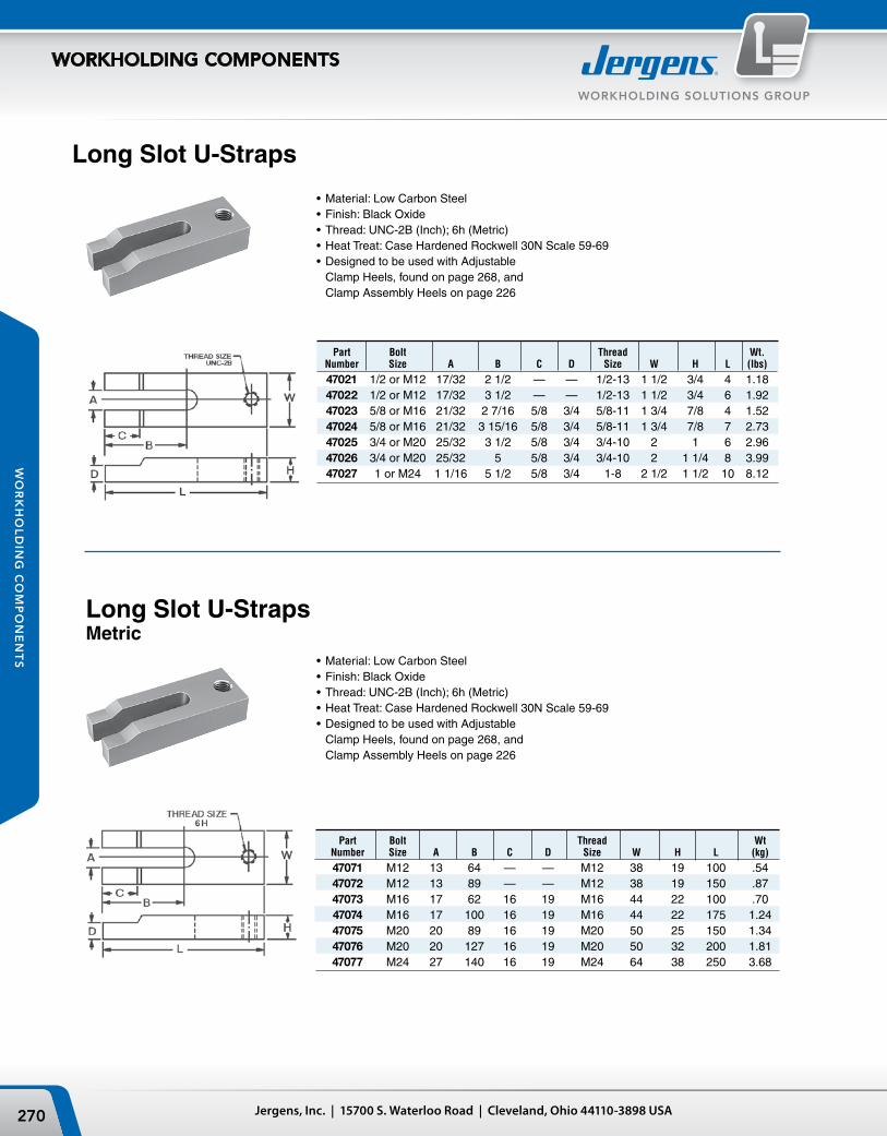
Jergens, Inc. | 15700 S. Waterloo Road | Cleveland, Ohio 44110-3898 USA270
WORKHOLDING SOLUTIONS GROUP
WORKHOLDING COMPONENTS
WO
RK
HO
LD
ING
CO
MP
ON
EN
TS
Long Slot U‑Straps
Part Bolt Thread Wt. Number Size A B C D Size W H L (lbs)
47021 1/2 or M12 17/32 2 1/2 — — 1/2-13 1 1/2 3/4 4 1.18 47022 1/2 or M12 17/32 3 1/2 — — 1/2-13 1 1/2 3/4 6 1.92 47023 5/8 or M16 21/32 2 7/16 5/8 3/4 5/8-11 1 3/4 7/8 4 1.52 47024 5/8 or M16 21/32 3 15/16 5/8 3/4 5/8-11 1 3/4 7/8 7 2.73 47025 3/4 or M20 25/32 3 1/2 5/8 3/4 3/4-10 2 1 6 2.96 47026 3/4 or M20 25/32 5 5/8 3/4 3/4-10 2 1 1/4 8 3.99 47027 1 or M24 1 1/16 5 1/2 5/8 3/4 1-8 2 1/2 1 1/2 10 8.12
• Material: Low Carbon Steel• Finish: Black Oxide• Thread: UNC-2B (Inch); 6h (Metric)• Heat Treat: Case Hardened Rockwell 30N Scale 59-69• designed to be used with Adjustable
Clamp Heels, found on page 268, and Clamp Assembly Heels on page 226
Long Slot U‑StrapsMetric
Part Bolt Thread Wt Number Size A B C D Size W H L (kg)
47071 M12 13 64 — — M12 38 19 100 .54 47072 M12 13 89 — — M12 38 19 150 .87 47073 M16 17 62 16 19 M16 44 22 100 .70 47074 M16 17 100 16 19 M16 44 22 175 1.24 47075 M20 20 89 16 19 M20 50 25 150 1.34 47076 M20 20 127 16 19 M20 50 32 200 1.81 47077 M24 27 140 16 19 M24 64 38 250 3.68
• Material: Low Carbon Steel• Finish: Black Oxide• Thread: UNC-2B (Inch); 6h (Metric)• Heat Treat: Case Hardened Rockwell 30N Scale 59-69• designed to be used with Adjustable
Clamp Heels, found on page 268, and Clamp Assembly Heels on page 226
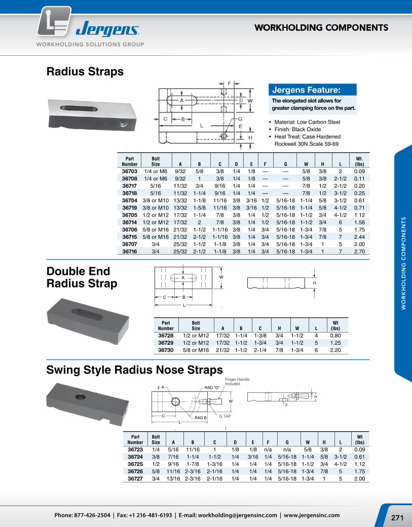
271Phone: 877-426-2504 | Fax: +1 216-481-6193 | E-mail: [email protected] | www.jergensinc.com
WORKHOLDING SOLUTIONS GROUP
WORKHOLDING COMPONENTS
WO
RK
HO
LD
ING
CO
MP
ON
EN
TS
Radius Straps
• Material: Low Carbon Steel• Finish: Black Oxide• Heat Treat: Case Hardened Rockwell 30N Scale 59-69
Jergens Feature:The elongated slot allows for greater clamping force on the part.
Double End Radius Strap
Part Bolt Wt Number Size A B C H W L (lbs)
36728 1/2 or M12 17/32 1-1/4 1-3/8 3/4 1-1/2 4 0.80 36729 1/2 or M12 17/32 1-1/2 1-3/4 3/4 1-1/2 5 1.25 36730 5/8 or M16 21/32 1-1/2 2-1/4 7/8 1-3/4 6 2.20
Swing Style Radius Nose Straps
Part Bolt Wt. Number Size A B C D E F G W H L (lbs)
36703 1/4 or M6 9/32 5/8 3/8 1/4 1/8 — — 5/8 3/8 2 0.09 36708 1/4 or M6 9/32 1 3/8 1/4 1/8 — — 5/8 3/8 2-1/2 0.11 36717 5/16 11/32 3/4 9/16 1/4 1/4 — — 7/8 1/2 2-1/2 0.20 36718 5/16 11/32 1-1/4 9/16 1/4 1/4 — — 7/8 1/2 3-1/2 0.25 36704 3/8 or M10 13/32 1-1/8 11/16 3/8 3/16 1/2 5/16-18 1-1/4 5/8 3-1/2 0.61 36719 3/8 or M10 13/32 1-5/8 11/16 3/8 3/16 1/2 5/16-18 1-1/4 5/8 4-1/2 0.71 36705 1/2 or M12 17/32 1-1/4 7/8 3/8 1/4 1/2 5/16-18 1-1/2 3/4 4-1/2 1.12 36714 1/2 or M12 17/32 2 7/8 3/8 1/4 1/2 5/16-18 1-1/2 3/4 6 1.56 36706 5/8 or M16 21/32 1-1/2 1-1/16 3/8 1/4 3/4 5/16-18 1-3/4 7/8 5 1.75 36715 5/8 or M16 21/32 2-1/2 1-1/16 3/8 1/4 3/4 5/16-18 1-3/4 7/8 7 2.44 36707 3/4 25/32 1-1/2 1-1/8 3/8 1/4 3/4 5/16-18 1-3/4 1 5 2.00 36716 3/4 25/32 2-1/2 1-1/8 3/8 1/4 3/4 5/16-18 1-3/4 1 7 2.70
Part Bolt Wt Number Size A B C D E F G W H L (lbs)
36723 1/4 5/16 11/16 1 1/8 1/8 n/a n/a 5/8 3/8 2 0.09 36724 3/8 7/16 1-1/4 1-1/2 1/4 3/16 1/4 5/16-18 1-1/4 5/8 3-1/2 0.61 36725 1/2 9/16 1-7/8 1-3/16 1/4 1/4 1/4 5/16-18 1-1/2 3/4 4-1/2 1.12 36726 5/8 11/16 2-3/16 2-1/16 1/4 1/4 1/4 5/16-18 1-3/4 7/8 5 1.75 36727 3/4 13/16 2-3/16 2-1/16 1/4 1/4 1/4 5/16-18 1-3/4 1 5 2.00

Jergens, Inc. | 15700 S. Waterloo Road | Cleveland, Ohio 44110-3898 USA272
WORKHOLDING SOLUTIONS GROUP
WORKHOLDING COMPONENTS
WO
RK
HO
LD
ING
CO
MP
ON
EN
TS
Thread Part Bolt Size 6h Wt. Number Size A B C D E F G I J K W H L (Kg)
36961 M6 7 16 9 6 3 5 M6 4 4 9 16 9 50 .05 36963 M8 9 19 14 9 5 6 M8 5 5 12 22 13 63 .11 36965 M10 10 28 17 13 6 9 M10 6 8 16 32 16 88 .37 36967 M12 13 31 22 16 9 11 M12 6 9 19 38 19 113 .47
Thread Part Bolt Size Wt. Number Size A B C D E F G I J K W H L (lbs)
36911 1/4 or M6 9/32 5/8 3/8 1/4 1/8 7/32 1/4-20 9/64 9/64 11/32 5/8 3/8 2 .10 36913 5/16 or M8 11/32 3/4 9/16 3/8 3/16 1/4 5/16-18 3/16 3/16 1/2 7/8 1/2 2 1/2 .20 36914 5/16 or M8 11/32 1 1/4 9/16 3/8 3/16 1/4 5/16-18 3/16 3/16 1/2 7/8 1/2 3 1/2 .27 36915 3/8 or M10 13/32 1 1/8 11/16 1/2 1/4 3/8 3/8-16 1/4 5/16 5/8 1 1/4 5/8 3 1/2 .69 36916 3/8 or M10 13/32 1 5/8 11/16 1/2 1/4 3/8 3/8-16 1/4 5/16 5/8 1 1/4 5/8 4 1/2 .88 36917* 1/2 or M12 17/32 1 1/4 7/8 5/8 3/8 7/16 1/2-13 1/4 3/8 3/4 1 1/2 3/4 4 1/2 .70 36918* 1/2 or M12 17/32 2 7/8 5/8 3/8 7/16 1/2-13 1/4 3/8 3/4 1 1/2 3/4 6 .90
• Material: Low Carbon Steel• Finish: Black Oxide• Thread: 2B-UNC• Heat Treat: Case Hardened Rockwell 30N Scale 59-69• Tapped for use with adjustable clamp heel
found on page 268
Tapped Straps
• Material: Low Carbon Steel• Finish: Black Oxide• Thread: 6h• Heat Treat: Case Hardened
Rockwell 30N Scale 59-69• Tapped for use with adjustable clamp heel
found on page 268
Tapped StrapsMetric
* Carbide Gripper Kits are available, contact Technical Sales Department for details. Gripper Part #23704.
* Carbide Gripper Kits are available, contact Technical Sales Department for details. Gripper Part #23704.
Jergens Feature:The elongated slot allows for greater clamping force on the part. A steel pad is standard. Plastic or brass pads may be ordered separately, see page 231.

273Phone: 877-426-2504 | Fax: +1 216-481-6193 | E-mail: [email protected] | www.jergensinc.com
WORKHOLDING SOLUTIONS GROUP
WORKHOLDING COMPONENTS
WO
RK
HO
LD
ING
CO
MP
ON
EN
TS
Taper Nose Straps
• Material: Low Carbon Steel• Finish: Black Oxide• Thread: UNC-2B• Heat Treat: Case Hardened Rockwell 30N Scale 59-69• designed to be used with Adjustable
Clamp Heels, found on page 268
• Material: Low Carbon Steel• Finish: Black Oxide• Thread: 6h• Heat Treat: Case Hardened Rockwell 30N Scale 59-69• designed to be used with Adjustable
Clamp Heels, found on page 268
Metric Taper Nose Straps
Part Bolt Thread Wt. Number Size A B C D E F Size W H L (lbs)
47119 3/8 or M10 13/32 1/2 13/16 3/8 3/16 7/16 3/8-16 1 1/2 3 .55 47120 3/8 or M10 13/32 1 15/16 3/8 3/16 7/16 3/8-16 1 1/4 5/8 4 .75 47123 3/8 or M10 13/32 1 1/2 15/16 3/8 3/16 7/16 3/8-16 1 1/4 5/8 5 .90 47124 1/2 or M12 17/32 1/2 1 1/16 1/2 1/4 7/16 1/2-13 1 1/4 5/8 3 1/2 .80 47125 1/2 or M12 17/32 1 1/4 1 3/16 1/2 1/4 7/16 1/2-13 1 1/4 3/4 4 1/2 1.10 47126 1/2 or M12 17/32 2 1 5/16 1/2 1/4 7/16 1/2-13 1 1/4 7/8 6 1.60 47127 5/8 or M16 21/32 1/2 1 3/16 5/8 1/4 1/2 5/8-11 1 1/4 5/8 4 1.80 47128 5/8 or M16 21/32 1 1/4 1 3/16 5/8 3/8 1/2 5/8-11 1 1/2 3/4 5 2.20 47129 5/8 or M16 21/32 2 1 5/16 5/8 3/8 1/2 5/8-11 1 1/2 7/8 7 3.10 47130 3/4 or M20 25/32 3/4 1 5/16 5/8 3/8 9/16 3/4-10 1 1/2 3/4 5 2.85 47131 3/4 or M20 25/32 1 1/2 1 1/2 5/8 3/8 9/16 3/4-10 1 1/2 1 6 3.40 47132 3/4 or M20 25/32 2 1/4 1 5/8 5/8 3/8 9/16 3/4-10 1 3/4 1 1/8 8 4.70 47134 1 or M24 1 1/16 2 2 5/8 7/8 5/8 11/16 1-8 2 1 1/2 10 9.55
Part Bolt Thread Wt. Number Size A B C D E F Size W H L (Kg)
47169 M10 11 13 21 10 5 11 M10 x 1.5 25 13 75 .30 47175 M12 13 33 30 13 10 11 M12 x 1.75 32 19 114 .60 47179 M16 17 50 33 16 10 13 M16 x 2.0 38 22 175 1.70 47182 M20 21 57 41 16 10 14 M20 x 2.5 44 29 200 2.53 47184 M24 26 50 67 22 16 17 M24 x 3.0 50 38 250 5.15

M
L
HR
BK
F E T
A
D
JC
S
Jergens, Inc. | 15700 S. Waterloo Road | Cleveland, Ohio 44110-3898 USA274
WORKHOLDING SOLUTIONS GROUP
WORKHOLDING COMPONENTS
WO
RK
HO
LD
ING
CO
MP
ON
EN
TS
Part Number Bolt Wt. Standard Tapped Size A B C D E F J K S* T (Kg)
37201 37252 M16 100 19 41 17 17 42 30 13 M12 x 1.75 13 .53 37203 37254 M16 150 22 44 17 35 59 32 14 M16 x 2.0 16 .94 37205 37256 M20 200 29 54 21 50 75 38 19 M20 x 2.5 19 2.0 37207 37258 M20 250 35 63 24 70 92 44 24 M24 x 3.0 22 3.8
• Material: C-1030 or C-1035
Forged Strap Clamps
Heel Clamp
Metric Standard & Tapped Heel Clamps
Gooseneck Clamp
*Applicable to Tapped Clamp Only
Standard & Tapped Heel Clamps
Standard & Tapped Gooseneck Clamps
Part Number Bolt Wt. Standard Tapped Size A B C D E F J K S* T (lbs)
37201 37202 5/8 or M16 4 3/4 1 5/8 11/16 11/16 1 21/32 1 3/16 1/2 1/2-13 1/2 1.00 37203 37204 5/8 or M16 6 7/8 1 3/4 11/16 1 3/8 2 5/16 1 1/4 9/16 5/8-11 5/8 1.75 37205 37206 3/4 or M20 8 1 1/8 2 1/8 13/16 2 3 1 1/2 3/4 3/4-10 3/4 3.75 37207 37208 7/8 or M20 10 1 3/8 2 1/2 15/16 2 3/4 3 5/8 1 3/4 15/16 7/8-9 7/8 7.00
• Material: C-1030 or C-1035
Part Number Bolt Wt. Standard Tapped Size A B C D E F H J K L M R S* T (lbs)
37211 37212 5/8 4 3/4 1 5/8 11/16 1/4 1 7/8 3/8 1 3/16 1/2 13/16 3/4 1 7/16 5/8-11 1/2 1.00 37213 37214 5/8 6 7/8 1 3/4 11/16 1 2 1/2 7/16 1 1/4 9/16 15/16 1 1/8 1 9/16 5/8-11 5/8 2.00 37215 37216 3/4 8 1 1/8 2 1/8 13/16 1 5/8 3 3/16 9/16 1 1/2 3/4 1 1/8 1 1/4 2 1/16 5/8-11 1 4.25
*Applicable to Tapped Clamp Only
*Applicable to Tapped Clamp Only
Part Number Bolt Wt. Standard Tapped Size A B C D E F H J K L M R S* T (Kg)
37211 37262 M16 100 19 41 17 6 48 10 30 13 20 19 37 M16 x 2.0 13 .53 37213 37264 M16 150 22 44 17 25 63 11 32 14 24 28 40 M16 x 2.0 16 1.4 37215 37266 M20 200 29 54 21 41 81 14 38 19 28 32 52 M16 x 2.0 25 2.3 *Applicable to Tapped Clamp Only

275Phone: 877-426-2504 | Fax: +1 216-481-6193 | E-mail: [email protected] | www.jergensinc.com
WORKHOLDING SOLUTIONS GROUP
WORKHOLDING COMPONENTS
WO
RK
HO
LD
ING
CO
MP
ON
EN
TS
Part Bolt Wt. Number Size A B C D E F G H J K (Kg)
37221 M16 100 19 41 17 17 42 13 13 30 11 .40 37223 M16 150 22 44 17 32 59 16 16 32 13 .81 37225 M20 200 29 54 21 44 79 19 19 38 16 1.6
Part Bolt Wt. Number Size A B C D E F G H J K (lbs)
37221 5/8 or M16 4 3/4 1 5/8 11/16 11/16 1 21/32 1/2 1/2 1 3/16 7/16 .75 37223 5/8 or M16 6 7/8 1 3/4 11/16 1 1/4 2 3/8 5/8 5/8 1 1/4 1/2 1.50 37225 3/4 or M20 8 1 1/8 2 1/8 13/16 1 3/4 3 1/8 3/4 3/4 1 1/2 5/8 3.00
Finger Clamp
Forged Strap Clamps
Metric
“U” Clamp
Forged Strap Clamps
• Material: C-1030 or C-1035
Part Bolt Wt. Number Size A B C D E F G H J (Kg)
37231 M16 100 19 44 17 14 37 14 13 13 .53 37232 M16 150 22 50 17 17 43 17 16 14 1.1 37233 M20 200 29 59 21 21 50 21 19 17 2.2 37234 M24 250 32 70 24 24 59 24 22 19 3.5 37235 M24 300 35 83 27 27 68 27 25 21 4.9
Part Bolt Wt. Number Size A B C D E F G H J (lbs)
37231 5/8 or M16 4 3/4 1 3/4 11/16 9/16 1 7/16 9/16 1/2 1/2 1.00 37232 5/8 or M16 6 7/8 2 11/16 11/16 1 11/16 11/16 5/8 9/16 2.00 37233 3/4 or M20 8 1 1/8 2 3/8 13/16 13/16 2 13/16 3/4 11/16 4.00 37234 7/8 or M24 10 1 1/4 2 3/4 15/16 15/16 2 5/16 15/16 7/8 3/4 6.50 37235 1 or M24 12 1 3/8 3 1/4 1 1/16 1 1/16 2 11/16 1 1/16 1 13/16 9.00
• Material: C-1030 or C-1035

Jergens, Inc. | 15700 S. Waterloo Road | Cleveland, Ohio 44110-3898 USA276
WORKHOLDING SOLUTIONS GROUP
WORKHOLDING COMPONENTS
WO
RK
HO
LD
ING
CO
MP
ON
EN
TS
Forged Adjustable Clamps
Forged Adjustable Clamp holding one side of a hydraulic vise on a milling machine table.
Part Bolt Clamping Maximum Max Holding* Wt. Number Size Range W T L X Torque (ft-lbs) Force (lbs) (lbs)
19101 1/2 0-2 1 3/4 1 1/2 4 1/4 2 1/2 90 6800 1.1 19102 5/8 0-2 3/8 2 1 5/8 5 3 180 10600 1.7 19103 3/4 0-2 3/4 2 1/2 1 3/4 6 1/4 3 3/4 300 16000 3.0 19104 7/8 0-3 1/2 3 2 3/8 7 4 1/4 500 21800 5.3 19104 1 0-3 1/2 3 2 3/8 7 4 1/4 760 28600 5.3
Forged Adjustable Clamps automatically compensate forclamping height changes within their clamping ranges (see chart for ranges). The swivel bushing is permanentlymounted in the clamp which alleviates lost or missing parts. The standard brass heel plate protects the machine table.
• Material: 1137 Forged Steel, Heat Treated• Finish: Black Oxide• One Piece Construction• versatile Clamping Height• Made in U.S.A.
Metric
Features high quality forging providing superior clamping strength.
Part Bolt Clamping Maximum Max Holding* Wt. Number Size Range W T L X Torque (N.m) Force (Kgf) (Kg)
19101 M12 0-50 44 38 108 63 100 2800 0.60 19102 M16 0-60 50 41 125 75 260 5250 0.92 19103 M20 0-70 63 44 159 95 500 8250 1.60 19104 M24 0-89 75 60 175 108 870 11850 2.90
* Note: Holding forces are based on using Jergens heat treated alloy steel T-slot bolts, Studs, T-nuts and Flange nuts in order at the recommended torque.
Accessories Available T-Slot Bolts Flange Nuts T-Slot Nuts Studs Washers
Page 251 Page 253 Page 258 Page 248 Page 259

277Phone: 877-426-2504 | Fax: +1 216-481-6193 | E-mail: [email protected] | www.jergensinc.com
WORKHOLDING SOLUTIONS GROUP
WORKHOLDING COMPONENTS
WO
RK
HO
LD
ING
CO
MP
ON
EN
TS
Part Bolt Wt. Number Size A B C D E H L W (lbs)
46814 1/2 or M12 17/32 1/2 1 1/16 1/2 1/4 5/8 2 1/2 1 1/4 .46 46815 1/2 or M12 17/32 1 1/4 1 3/16 1/2 1/4 3/4 4 1 1/4 .65 46816 1/2 or M12 17/32 2 1 5/16 1/2 1/4 7/8 6 1 1/4 .95 46817 5/8 or M16 21/32 1/2 1 3/16 5/8 1/4 5/8 3 1 1/4 .66 46818 5/8 or M16 21/32 1 1/4 1 3/16 5/8 3/8 3/4 5 1 1/2 .93 46819 5/8 or M16 21/32 2 1 5/16 5/8 3/8 7/8 7 1 1/2 1.36 46820 3/4 or M20 25/32 3/4 1 5/16 5/8 3/8 3/4 4 1 1/2 1.39 46821 3/4 or M20 25/32 1 1/2 1 1/2 5/8 3/8 1 6 1 1/2 1.94 46822 3/4 or M20 25/32 2 1/4 1 5/8 5/8 3/8 1 1/8 8 1 3/4 2.48
Steel Heel StrapsCoarse Pitch
• Material: Low Carbon Steel• Finish: Black Oxide• Heat Treat: Case Hardened
Rockwell 30N 50-54
Fine Pitch
• Material: Low Carbon Steel• Finish: Black Oxide• Heat Treat: Case Hardened Rockwell 30N 50-54
The step teeth of the Fine Pitch Steel Heel Straps match the Jergens Steel Step Blocks. These straps facilitate easier height adjustment on set-ups.
The step teeth of the Coarse Pitch Steel Heel Straps match the Jergens Alumi-num Step Blocks. These straps facilitate easier height adjustments on set-ups.
Part Bolt Wt. Number Size A B C D E H L W (lbs)
46834 1/2 or M12 9/16 1/2 1 1/16 1/2 1/4 1/2 2 1/2 1 1/8 .46 46835 1/2 or M12 9/16 1 1/4 1 3/16 1/2 1/4 3/4 4 1 1/4 .65 46836 1/2 or M12 9/16 2 1 5/16 1/2 1/4 7/8 6 1 1/4 .95 46837 5/8 or M16 11/16 1/2 1 3/16 5/8 1/4 5/8 2 1/2 1 1/4 .66 46838 5/8 or M16 11/16 1 1/4 1 3/16 5/8 3/8 3/4 4 1 1/2 .93 46839 5/8 or M16 11/16 2 1 5/16 5/8 3/8 7/8 6 1 1/2 1.36 46840 3/4 or M20 13/16 3/4 1 5/16 5/8 3/8 3/4 4 1 1/2 1.39 46841 3/4 or M20 13/16 1 1/2 1 1/2 5/8 3/8 1 6 1 5/8 1.94 46842 3/4 or M20 13/16 2 1/4 1 5/8 5/8 3/8 1 1/8 8 1 3/4 2.48

Jergens, Inc. | 15700 S. Waterloo Road | Cleveland, Ohio 44110-3898 USA278
WORKHOLDING SOLUTIONS GROUP
WORKHOLDING COMPONENTS
WO
RK
HO
LD
ING
CO
MP
ON
EN
TS
Qty Part Per Number Step Wt. Kit (Blocks Only) A B C Elevation (oz)
8 21831 1 5/8 1 1/8 3/32 2 8 21832 1 1 1/16 1 3/4 3/32 4 4 21833 1 2 3/8 3 7/8 3/32 14 16 21706 Protective Aluminum Pad
Adjustable Step BlocksAluminum — Coarse Pitch
Heavy Duty (2" Width) Kit
21711
Included in Kit:
Included in Kit:
1" & 2" Wide Adjustable Step Block KitsStep blocks are made of aluminum to prevent damage to machine table surfaces.
Tooth design has no sharp edges which helps to prevent burrs and chip build-up in the steps. Blocks are completely interchangeable with each other, and with the Jergens Coarse Pitch Step Straps.
Steel — Fine Pitch
Included in Kit:
Adjustable Step Block Kit21821
Standard (1" Width) Kit 21701
Adjustable Step Block KitBlocks are completely interchangeable with each other, and with the Jergens Fine Pitch Step Straps.
Qty Part Per Number Step Wt. Kit (Blocks Only) A B C Elevation (lbs)
8 21712 2 5/8 1 1/16 11/64 .06 8 21713 2 1 1 3/4 11/64 .18 4 21714 2 2 3/16 3 3/4 11/64 .78 16 21715 Protective Pad 11/64 .04
Qty Part Per Number Step Wt. Kit (Blocks Only) A B C Elevation (lbs)
8 21705 1 5/8 1 1/16 11/64 .03 8 21702 1 1 1 3/4 11/64 .09 4 21703 1 2 3/16 3 3/4 11/64 .39 16 21706 Protective Pad 11/64 .02
Step Blocks sold individually.
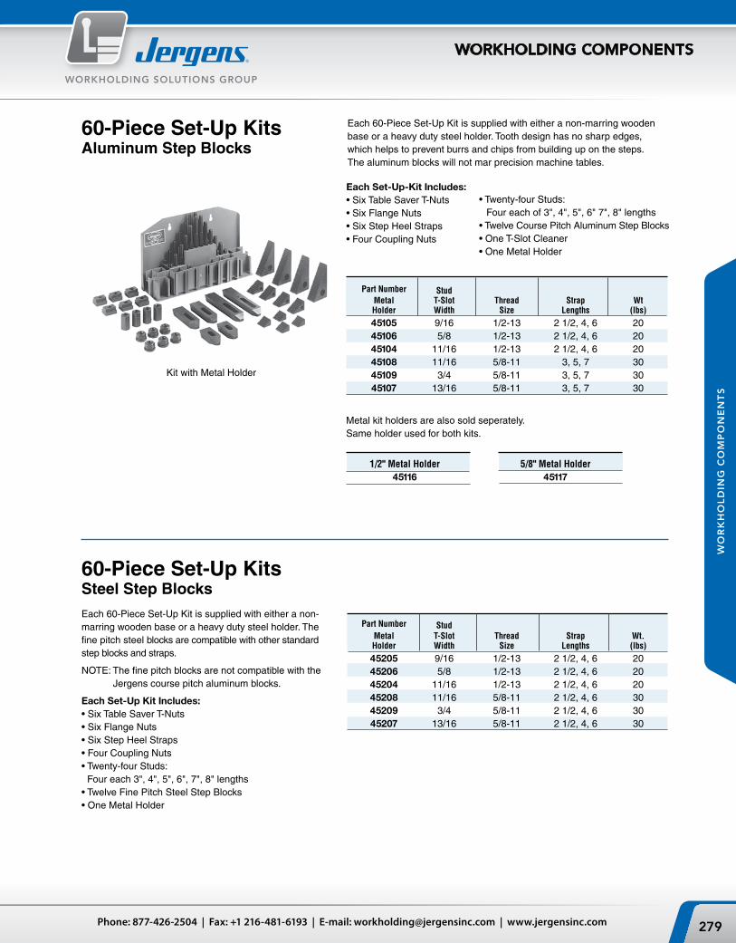
279Phone: 877-426-2504 | Fax: +1 216-481-6193 | E-mail: [email protected] | www.jergensinc.com
WORKHOLDING SOLUTIONS GROUP
WORKHOLDING COMPONENTS
WO
RK
HO
LD
ING
CO
MP
ON
EN
TS
Each 60-Piece Set-Up Kit is supplied with either a non-marring wooden base or a heavy duty steel holder. Tooth design has no sharp edges, which helps to prevent burrs and chips from building up on the steps. The aluminum blocks will not mar precision machine tables.
Each Set-Up-Kit Includes:• Six Table Saver T-Nuts• Six Flange Nuts• Six Step Heel Straps• Four Coupling Nuts
1/2" Metal Holder45116
60‑Piece Set‑Up KitsAluminum Step Blocks
5/8" Metal Holder 45117
Part Number Stud Metal T-Slot Thread Strap Wt Holder Width Size Lengths (lbs)
45105 9/16 1/2-13 2 1/2, 4, 6 20 45106 5/8 1/2-13 2 1/2, 4, 6 20 45104 11/16 1/2-13 2 1/2, 4, 6 20 45108 11/16 5/8-11 3, 5, 7 30 45109 3/4 5/8-11 3, 5, 7 30 45107 13/16 5/8-11 3, 5, 7 30
Each 60-Piece Set-Up Kit is supplied with either a non-marring wooden base or a heavy duty steel holder. The fine pitch steel blocks are compatible with other standard step blocks and straps.
NOTe: The fine pitch blocks are not compatible with the Jergens course pitch aluminum blocks.
Each Set-Up Kit Includes: • Six Table Saver T-Nuts• Six Flange Nuts• Six Step Heel Straps• Four Coupling Nuts• Twenty-four Studs:
Four each 3", 4", 5", 6", 7", 8" lengths• Twelve Fine Pitch Steel Step Blocks• One Metal Holder
Part Number Stud Metal T-Slot Thread Strap Wt. Holder Width Size Lengths (lbs)
45205 9/16 1/2-13 2 1/2, 4, 6 20 45206 5/8 1/2-13 2 1/2, 4, 6 20 45204 11/16 1/2-13 2 1/2, 4, 6 20 45208 11/16 5/8-11 2 1/2, 4, 6 30 45209 3/4 5/8-11 2 1/2, 4, 6 30 45207 13/16 5/8-11 2 1/2, 4, 6 30
60‑Piece Set‑Up KitsSteel Step Blocks
Kit with Metal Holder
Metal kit holders are also sold seperately.Same holder used for both kits.
• Twenty-four Studs: Four each of 3", 4", 5", 6" 7", 8" lengths• Twelve Course Pitch Aluminum Step Blocks• One T-Slot Cleaner• One Metal Holder

Jergens, Inc. | 15700 S. Waterloo Road | Cleveland, Ohio 44110-3898 USA280
WORKHOLDING SOLUTIONS GROUP
WORKHOLDING COMPONENTS
WO
RK
HO
LD
ING
CO
MP
ON
EN
TS
40‑Piece Clamping Kit
Each Kit includes:• Four Flange Nuts• Four Heavy duty washers• Twelve Steel Step Blocks• Twenty Studs• One wooden Holder
Die Set‑Up Kits
Each Clamping Kit Includes:• Four Table Saver T-Nuts• Twenty Studs: Four each 4", 5", 6", 7", 8" lengths• Four Adjustable Clamp Heels• Four Flange Nuts• Four Coupling Nuts• Four Taper Nose Straps• One T-Slot Cleaner• One wooden Holder (†)
Contains the same quality components as the larger kits but without the step blocks and step heel straps. This Clamping Kit includes taper nose straps, T-nuts, coupling nuts, flange nuts, clamping heels and studs.
Thread Part Stud Size Number Lengths
1/2-13 44921 3, 4, 5, 6, 8 5/8-11 44922 3, 4, 5, 6, 8 3/4-10 44923 4, 5, 6, 8, 10
These die Set-Up Kits can be used with any of the Jergens heavy duty straps; however, the kits are best suited for use with forged strap clamps found on pages 274 thru 276.
Stud Part T-Slot Thread Strap Adjustable Wt. Number Width Size Clamp Clamp Heel (lbs)
45022 † 7/16* 3/8-16 5/8 x 1 1/4 x 5 3/8-16 x 3 12 45023 † 1/2 3/8-16 5/8 x 1 1/4 x 5 3/8-16 x 3 12 45021 9/16 3/8-16 5/8 x 1 1/4 x 5 3/8-16 x 3 12 45025 9/16* 1/2-13 7/8 x 1 1/4 x 6 1/2-13 x 4 20 45026 5/8 1/2-13 7/8 x 1 1/4 x 6 1/2-13 x 4 20 45024 11/16 1/2-13 7/8 x 1 1/4 x 6 1/2-13 x 4 20 45028 † 11/16* 5/8-11 7/8 x 1 1/2 x 7 5/8-11 x 5 30 45029 † 3/4 5/8-11 7/8 x 1 1/2 x 7 5/8-11 x 5 30 45027 † 13/16 5/8-11 7/8 x 1 1/2 x 7 5/8-11 x 5 30 45031 13/16* 3/4-10 1 x 1 1/2 x 6 3/4-10 x 6 40 45032 7/8 3/4-10 1 x 1 1/2 x 6 3/4-10 x 6 40 45030 1 1/16 3/4-10 1 x 1 1/2 x 6 3/4-10 x 6 40
*T-Nuts not hardened due to thin wall.† Includes Wood Holder.

281Phone: 877-426-2504 | Fax: +1 216-481-6193 | E-mail: [email protected] | www.jergensinc.com
WORKHOLDING SOLUTIONS GROUP
WORKHOLDING COMPONENTS
WO
RK
HO
LD
ING
CO
MP
ON
EN
TS
Jergens Feature:
Toe ClampsSmall
Toe Clamps are powerful, low profile clamps that grip on the side of the workpiece leaving the top surface open. This minimizes interfer-ence with cutting tools or measuring instruments. Ideal for use on mills, planers, jig borers, drill presses, and faceplates.
• Steel or brass toe and special washer are included with each clamp
• Slotted for 5/16 or M8 Cap Screws
• Case hardened for maximun wear
• Black Oxide finish Part Toe Toe Wt. Toe Number Material Style A B C D E F G (lbs) Only
46921 STeeL STANdARd 1 1/2 1/2 1/16 3/4 1/8 1 5/8 .24 46952 46961 BRASS STANdARd 1 1/2 1/2 1/16 3/4 1/8 1 5/8 .24 46946 46971 STEEL HIGH GRIP 1 1/2 1/2 1/16 3/4 5/8 1 5/8 .26 46948 46981 BRASS HIGH GRIP 1 1/2 1/2 1/16 3/4 5/8 1 5/8 .26 46950 46922 STeeL STANdARd 2 1/2 1/16 1 1/4 1/8 1 5/8 .30 46952 46962 BRASS STANdARd 2 1/2 1/16 1 1/4 1/8 1 5/8 .30 46946 46972 STEEL HIGH GRIP 2 1/2 1/16 1 1/4 5/8 1 5/8 .32 46948 46982 BRASS HIGH GRIP 2 1/2 1/16 1 1/4 5/8 1 5/8 .32 46950 46923 STeeL STANdARd 2 1/2 1/2 1/16 1 3/4 1/8 1 5/8 .35 46952 46963 BRASS STANdARd 2 1/2 1/2 1/16 1 3/4 1/8 1 5/8 .35 46946 46973 STEEL HIGH GRIP 2 1/2 1/2 1/16 1 3/4 5/8 1 5/8 .37 46948 46983 BRASS HIGH GRIP 2 1/2 1/2 1/16 1 3/4 5/8 1 5/8 .37 46950
3° Taper Prevents Back-off
Small Toe Clamp Kits
Slotted for 5/16" or M8 Socket Head Cap Screws
Each Clamp Kit Includes:• Six Toe Clamps:Two of each length (1 1/2", 2", 2 1/2")• Six Low Grip Steel Toes• Six Toe Clamp Nuts• Six Protective washers• One T-wrench• One wooden Holder
Toe lbs Part Table Toe Clamp Per Number Slot Clamps Nuts Washers Kit
44901 3/8 46921, 46922, 46923 46931 46942 3 44902 7/16 46921, 46922, 46923 46932 46942 3 44903 1/2 46921, 46922, 46923 46933 46942 3 44904 9/16 46921, 46922, 46923 46934 46942 3 44905 5/8 46921, 46922, 46923 46935 46942 3
* Replacement Parts available, contact customer service.
* Replacement Parts available, contact customer service.

Jergens, Inc. | 15700 S. Waterloo Road | Cleveland, Ohio 44110-3898 USA282
WORKHOLDING SOLUTIONS GROUP
WORKHOLDING COMPONENTS
WO
RK
HO
LD
ING
CO
MP
ON
EN
TS
Toe ClampsLarge
• Steel or brass toe and special washer are included with each clamp.
• Slotted for 1/2" or M12 Cap Screws• Low Carbon Steel hardened for
maximum wear• Black Oxide finish
Part Toe Toe Wt. Toe Number Material Style A B C D E F G (lbs) Only
46926 STeeL STANdARd 3 1/4 13/16 1/8 2 1/4 1 1/2 7/8 1.0 46953 46966 BRASS STANdARd 3 1/4 13/16 1/8 2 1/4 1 1/2 7/8 1.0 46947 46976 STEEL HIGH GRIP 3 1/4 13/16 1/8 2 7/8 1 1/2 7/8 1.3 46949 46986 BRASS HIGH GRIP 3 1/4 13/16 1/8 2 7/8 1 1/2 7/8 1.3 46951 46927 STeeL STANdARd 4 11/16 13/16 1/2 2 3/4 1/4 1 1/2 7/8 1.4 46953 46967 BRASS STANdARd 4 11/16 13/16 1/2 2 3/4 1/4 1 1/2 7/8 1.4 46947 46977 STEEL HIGH GRIP 4 11/16 13/16 1/2 2 3/4 7/8 1 1/2 7/8 1.7 46949 46987 BRASS HIGH GRIP 4 11/16 13/16 1/2 2 3/4 7/8 1 1/2 7/8 1.7 46951 46928 STeeL STANdARd 6 5/8 13/16 1 3 3/4 1/4 1 1/2 7/8 2.0 46953 46968 BRASS STANdARd 6 5/8 13/16 1 3 3/4 1/4 1 1/2 7/8 2.0 46947 46978 STEEL HIGH GRIP 6 5/8 13/16 1 3 3/4 7/8 1 1/2 7/8 2.3 46949 46988 BRASS HIGH GRIP 6 5/8 13/16 1 3 3/4 7/8 1 1/2 7/8 2.3 46951
Large Toe Clamp KitsEach Clamp Kit Contains:• Six Toe Clamps: Two of each length (3 1/4", 4 11/16", 6 5/8")• Four Low Grip Steel Toes• Six Toe Clamp Nuts• Six Protective washers• One T-wrench• One wooden Holder
Slotted for 1/2" or M12 Socket Head Cap Screws
Toe lbs Part Table Toe Clamp Per Number Slot Clamps Nuts Washers Kit
44906 9/16 46926, 46927, 46928 46936 46943 11 44907 5/8 46926, 46927, 46928 46937 46943 12 44909 11/16 46926, 46927, 46928 46938 46943 12 44910 13/16 46926, 46927, 46928 46939 46943 13 44911 7/8 46926, 46927, 46928 46940 46943 14 44912 1 46926, 46927, 46928 46941 46943 15
Jergens Feature:3° Taper Prevents Back-off
Toe Clamps are powerful, low profile clamps that grip on the side of the workpiece leaving the top surface open. This minimizes interference with cutting tools or measuring instruments. Ideal for use on mills, planers, jig borers, drill presses, and faceplates.
* 5/8 or M16 Cap Screw Slot and replacement parts available, contact customer service.
* 5/8 or M16 Cap Screw Slotted Kits and replacement parts available, contact customer service.

283Phone: 877-426-2504 | Fax: +1 216-481-6193 | E-mail: [email protected] | www.jergensinc.com
WORKHOLDING SOLUTIONS GROUP
WORKHOLDING COMPONENTS
WO
RK
HO
LD
ING
CO
MP
ON
EN
TS
Material:• Available in tool steel or brass• extraordinary horizontal and vertical force• Extremely low profile• Very small foot print• High resistance to pull-out• Choose among three sizes with inch or metric screws• Knife and blunt edge styles
Lo‑Profile Micro™ Clamps
Problem: You require a clamping device which can grip low on a work piece, has exceptional horizontal and vertical holding force, and can be mounted below the fix-ture plate surface.
Solution: Jergens new Lo-Profile Micro clamps are the answer!
Lo‑Profile Micro™ Clamps
Part Number Type A B C D* E
Clamp Width
Screw Size
Torque (ft/lbs)
Max. Holding Force (lbs)
Total Throw
Clamps Per Package
13201 Tool Steel, Knife Edge .150 .140 .375 .075 .260 .375 4-40 1.30 650 .0075 8
13202 Tool Steel, Blunt Edge .150 .140 .375 .075 .260 .375 4-40 1.30 650 .0075 8
13203 Brass, Blunt Edge .150 .140 .375 .075 .220 .375 4-40 .41 200 .0075 8
13211 Tool Steel, Knife Edge .200 .187 .500 .100 .390 .500 8-32 3.70 1500 .0160 8
13212 Tool Steel, Blunt Edge .200 .187 .500 .100 .390 .500 8-32 3.70 1500 .0160 8
13213 Brass, Blunt Edge .200 .187 .500 .100 .340 .500 8-32 2.00 400 .0160 8
13221 Tool Steel, Knife Edge .300 .280 .750 .150 .570 .750 1/4-20 14.50 3600 .0240 6
13222 Tool Steel, Blunt Edge .300 .280 .750 .150 .570 .750 1/4-20 14.50 3600 .0240 6
13223 Brass, Blunt Edge .300 .280 .750 .150 .440 .750 1/4-20 4.10 950 .0240 6
* Combination horizontal and vertical force.
Metric Lo‑Profile Micro™ Clamps
Part Number Description A B C D*
Clamp Width
Screw Size
Max. Holding Force (N)
Torque (Nm)
Total Throw
Clamps Per Package
13251 Tool Steel, Knife Edge 3.81 3.55 9.52 1.90 9.52 M2.5 2800 1.8 .190 8
13252 Tool Steel, Blunt Edge 3.81 3.55 9.52 1.90 9.52 M2.5 2800 1.8 .190 8
13253 Brass, Blunt Edge 3.81 3.55 9.52 1.90 9.52 M2.5 875 .56 .190 8
13261 Tool Steel, Knife Edge 5.08 4.75 12.70 2.54 12.70 M4 6600 5.6 .406 8
13262 Tool Steel, Blunt Edge 5.08 4.75 12.70 2.54 12.70 M4 6600 5.6 .406 8
13263 Brass, Blunt Edge 5.08 4.75 12.70 2.54 12.70 M4 1750 2.8 .406 8
13271 Tool Steel, Knife Edge 7.62 7.11 19.05 3.81 19.05 M6 16000 22.5 .610 6
13272 Tool Steel, Blunt Edge 7.62 7.11 19.05 3.81 19.05 M6 16000 22.5 .610 6
13273 Brass, Blunt Edge 7.62 7.11 19.05 3.81 19.05 M6 4200 5.6 .610 6
* Combination horizontal and vertical force.

Jergens, Inc. | 15700 S. Waterloo Road | Cleveland, Ohio 44110-3898 USA284
WORKHOLDING SOLUTIONS GROUP
WORKHOLDING COMPONENTS
WO
RK
HO
LD
ING
CO
MP
ON
EN
TS
1 ........12mm (.4724)2 ........13mm (.5118)3 ........14mm (.5512)4 ........15mm (.5906)5 ........16mm (.6299)6 ........17mm (.6693)
7 ........18mm (.7086)8 ........19mm (.7480)9 ........20mm (.7874)10 ......21mm (.8268)11 ......22mm (.8661)12 ......23mm (.9055)
Adjustable Micro Clamps decrease design and set-up times for modular fixtures, work cubes, and standard fixtures. Without changing hole locations, clamping range from 12mm to 35mm can be achieved.
The clamps are available with either smooth or serrated faces which make them ideal for clamping machined parts, castings, and rough cut stock. The clamps work with a cam action, always following the contour of the workpiece for maximum surface contact.
All clamps include a cam screw. Clamps are 10mm (.394) thick.
13 ......24mm (.9449)14 ......25mm (.9842)15 ......26mm (1.0236)16 ......27mm (1.0630)17 ......28mm (1.1024)18 ......29mm (1.1417)
19 ......30mm (1.1811)20 ......31mm (1.2205)21 ......32mm (1.2598)22 ......33mm (1.2992)23 ......34mm (1.3386)24 ......35mm (1.3780)
Locking Screw is 1/2-13 for inch sizes and 12M for metric sizes; total distance of movement is .100".
Adjustable Micro™ Clamps
Measured from the centerline, each face of these low profile clamps increases 1mm (.0394) from the smallest to the largest face.
• Cam action• Low profile• Available in four sizes• Heat treated and plated• Serrated or smooth edges• Adjustable clamps and stops• Includes Cam Screw*
Inch Metric Part Number Part Number Description
68601 68651 1-6 smooth 68602 68652 7-12 smooth 68603 68653 13-18 smooth 68604 68654 19-24 smooth 68611 68661 1-6 serrated 68612 68662 7-12 serrated 68613 68663 13-18 serrated 68614 68664 19-24 serrated
Part Number Thread
*68615 Cam Screw 1/2-13
Face #
Distance From
Center Line Face #
Distance From
Center Line Face #
Distance From
Center Line Face #
Distance From
Center Line

285Phone: 877-426-2504 | Fax: +1 216-481-6193 | E-mail: [email protected] | www.jergensinc.com
WORKHOLDING SOLUTIONS GROUP
WORKHOLDING COMPONENTS
WO
RK
HO
LD
ING
CO
MP
ON
EN
TS
The ID expansion clamp is the ideal way to hold parts on an inside diameter for multiple machining on a vertical or horizontal machining center.
The larger diameter of the clamp is held to a close tolerance for precision locating in a machined pocket on work cubes and fixture plates.
The customer machines the mild steel clamp to match the bore of the part ensuring proper fit. Often times the clamps can be remachined for different size jobs.
ID Expansion Clamp
• Body Material: Mild Steel• Low Profile• Ideal for Secondary Operations
on Lathe Parts• easily Machined to Size on
Lathe or Mill
* (3) Mounting Screws Included+
Minimum diameter the “F” dimension can be machined too.
• excellent for Palletized Setups• Allows More Parts Per workcube or Fixture Plate• Tighten with Hex Key or Hydraulic Pull Cylinders
(Drill clearance hole for longer bolt into hydraulic cylinder)
• Instructions included with each clamp
+.000 Holding Part -.002 Torque Force Number A B C D E F G
+
H* I J (ft/lbs) (lbs)
68401 .42 .30 .24 .12 .787 .29 .16 2-56 on .540 BHC 2-56 .16 .05 250 68402 .86 .63 .59 .23 1.170 .49 .28 6-32 on .825 BHC 8-32 .30 3.6 950 68403 .98 .75 .59 .23 1.240 .56 .48 6-32 on .910 BHC 1/4-20 .50 13.3 1900 68404 .98 .75 .59 .23 1.476 .79 .53 6-32 on 1.140 BHC 5/16-18 .56 27.6 2500 68405 1.13 .88 .69 .25 1.968 1.06 .71 8-32 on 1.550 BHC 3/8-16 .71 49.3 4500 68406 1.25 1.0 .81 .25 2.205 1.39 .90 8-32 on 1.790 BHC 1/2-13 .71 120.0 5900 68407 1.56 1.25 1.06 .31 2.736 1.65 1.15 10-32 on 2.200 BHC 5/8-11 .79 224.0 10000 68408 1.56 1.25 1.06 .31 2.972 2.03 1.15 10-32 on 2.515 BHC 5/8-11 .79 224.0 10000 68409 1.79 1.48 1.27 .31 4.232 3.06 1.15 1/4-20 on 3.646 BHC 5/8-11 .79 224.0 10000 68410 1.79 1.48 1.27 .31 5.232 4.06 1.15 1/4-20 on 4.648 BHC 5/8-11 .79 224.0 10000
Metric +0.00 Holding Part -0.05 Torque Force Number A B C D E F G
+
H* I J (Nm) (N.)
68829 10.7 7.6 6.1 3.0 20.0 7.4 4.1 M2 on 13.7 BHC M2 4.1 .70 1,113 68830 21.8 16.0 15.0 5.9 29.72 12.4 8.0 M3 on 20.95 BHC M4 7.2 5.00 4,228 68831 24.9 19.0 15.0 5.9 31.5 14.2 12.2 M3 on 23.1 BHC M6 11.2 17.00 8,455 68832 24.9 19.0 15.0 5.9 37.5 20.0 13.5 M3 on 29.0 BHC M8 13.2 34.00 11,125 68833 28.6 22.2 17.5 6.4 50.0 27.0 18.0 M4 on 39.4 BHC M10 16.3 60.00 20,025 68834 31.8 25.4 20.6 6.4 56.0 35.3 23.0 M4 on 45.5 BHC M12 20.3 150.00 26,255 68835 39.6 31.8 27.0 7.9 69.5 42.0 29.3 M5 on 55.9 BHC M16 21.4 280.00 44,500 68836 39.6 31.8 27.0 7.9 75.5 51.5 29.3 M5 on 63.9 BHC M16 21.4 280.00 44,500 68837 45.5 37.6 32.3 7.9 107.5 77.7 29.3 M6 on 92.6 BHC M16 19.3 280.00 44,500

Jergens, Inc. | 15700 S. Waterloo Road | Cleveland, Ohio 44110-3898 USA286
WORKHOLDING SOLUTIONS GROUP
WORKHOLDING COMPONENTS
WO
RK
HO
LD
ING
CO
MP
ON
EN
TS
Knife edge clamps can be used for clamping rough cut stock, castings, or any material that re-quires a hardened clamping element. Hardened steel, brass-plated.
Jergens Micro™ Clamps feature both high hold down forces and low profiles, which makes them ideal for building fixtures on Ball Lock® fixturing plates. Two simple components make them work: a hardened steel socket cap screw with an offset head and a hexagonal washer. A half turn tightens or loosens the workpiece.
Knife Edge Clamps
Micro™ Clamps
• Low profile makes computer programming easier• Cam action provides fast, strong clamping• Small size allows more parts per load• Requires only a tapped hole in your fixture• Available in stainless steel• Note clockwise rotation recomended workpiece
stop should be on the right of the Clamp.
Replacement Screws available, contact customer service for more information.
Replacement Screws available, contact customer service for more information.
Total Distance Part Number Part Number of Measurement Key Size Maximum Holding Steel Stainless A B C D E F G* Force (N)
68571 – M4x0.7 9.6 7.93 2.8 .76 3 3.8 910 68572 68551 M6x1.0 11.2 15.86 4.75 1.01 4 7.8 3,558 68573 68553 M8x1.25 15.0 20.61 4.75 1.01 5 10.15 3,355 68574 – M10x1.5 19.0 20.61 6.35 1.52 7 10.15 8,895 68575 – M12x1.75 22.8 25.38 9.52 2.03 8 12.7 17,790 68576 – M16x2.0 28.5 30.13 12.69 2.54 12 15.0 26,680* This measurement is the correct location to drill and tap the hole from the edge of the work piece.
Total Distance Part Number Part Number of Measurement Key Size Maximum Holding Steel Stainless A B C D E F G* Force (lbs)
68501 – 8-32 .350 .312 .110 .030 5/64 .150 205 68502 – 10-32 .340 .500 .160 .040 3/32 .250 350 68503 68513 1/4-20 .470 .625 .190 .040 1/8 .308 800 68505 5/16-24 .460 .812 .190 .040 3/16 .400 750 68506 68515 5/16-18 .460 .812 .190 .040 3/16 .400 750 68507 – 3/8-16 .710 .812 .250 .050 3/16 .400 2,000 68509 – 1/2-13 .900 1.000 .375 .100 5/16 .500 4,000 68511 – 5/8-11 1.125 1.187 .500 .100 3/8 .590 6,000* This measurement is the correct location to drill and tap the hole from the edge of the work piece.
Metric
Part Torque Max. Holding Number A B C D E F G* (ft. lbs) Force (lbs)
68547 3/8-16 0.710 0.812 0.250 0.050 3/16 0.400 16.6 2,000 68548 1/2-13 0.900 1.000 0.375 0.100 5/16 0.500 52.0 4,000 68549 5/8-11 1.125 1.187 0.500 0.100 3/8 0.590 80.0 6,000 Metric (Nm) (N)
68840 M10 19.0 1.52 20.60 6.35 7M 10.15 28 8,895 68841 M12 22.8 2.03 25.40 9.52 8M 12.70 88 17,790 68842 M16 28.5 2.54 30.15 12.70 12M 15.00 135 26,680* This measurement is the correct location to drill and tap the hole from the edge of the work piece.
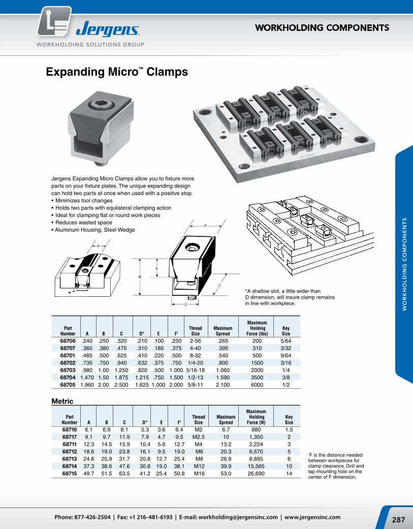
F
287Phone: 877-426-2504 | Fax: +1 216-481-6193 | E-mail: [email protected] | www.jergensinc.com
WORKHOLDING SOLUTIONS GROUP
WORKHOLDING COMPONENTS
WO
RK
HO
LD
ING
CO
MP
ON
EN
TS
Jergens expanding Micro Clamps allow you to fixture more parts on your fixture plates. The unique expanding design can hold two parts at once when used with a positive stop.• Minimizes tool changes• Holds two parts with equilateral clamping action• Ideal for clamping flat or round work pieces• Reduces wasted space• Aluminum Housing, Steel wedge
*A shallow slot, a little wider than D dimension, will insure clamp remains in line with workpiece.
Expanding Micro™ Clamps
Maximum Part Thread Maximum Holding Key Number A B C D* E F† Size Spread Force (lbs) Size
68706 .240 .250 .320 .210 .100 .250 2-56 .265 200 5/64 68707 .360 .380 .470 .310 .185 .375 4-40 .395 310 3/32 68701 .485 .500 .625 .410 .220 .500 8-32 .540 500 9/64 68702 .735 .750 .940 .632 .375 .750 1/4-20 .800 1500 3/16 68703 .980 1.00 1.250 .820 .500 1.000 5/16-18 1.060 2000 1/4 68704 1.470 1.50 1.875 1.215 .750 1.500 1/2-13 1.590 3500 3/8 68705 1.960 2.00 2.500 1.625 1.000 2.000 5/8-11 2.100 6000 1/2
Maximum Part Thread Maximum Holding Key Number A B C D* E F† Size Spread Force (N) Size
68716 6.1 6.9 8.1 5.3 3.6 6.4 M2 6.7 880 1.5 68717 9.1 9.7 11.9 7.9 4.7 9.5 M2.5 10 1,350 2 68711 12.3 14.5 15.9 10.4 5.6 12.7 M4 13.2 2,224 3 68712 18.6 19.0 23.8 16.1 9.5 19.0 M6 20.3 6,670 5 68713 24.8 25.9 31.7 20.8 12.7 25.4 M8 26.9 8,895 6 68714 37.3 38.6 47.6 30.8 19.0 38.1 M12 39.9 15,565 10 68715 49.7 51.5 63.5 41.2 25.4 50.8 M16 53.0 26,690 14
Metric
†F is the distance needed between workpieces for clamp clearance. Drill and tap mounting hole on the center of F dimension.

Jergens, Inc. | 15700 S. Waterloo Road | Cleveland, Ohio 44110-3898 USA288
WORKHOLDING SOLUTIONS GROUP
WORKHOLDING COMPONENTS
WO
RK
HO
LD
ING
CO
MP
ON
EN
TS
Machinable Expanding Micro™ Clamps
The compact Machinable expanding Micro™ Clamp is available with extra material on the clamping jaw so it can be machined to conform to the shape of your workpiece – enabling you to fixture unusual applications easily. The specially designed steel wedge spreads the clamping force uniformly on both sides of the aluminum channel. Clamps may be ordered with a unique locking plate to make the clamp rigid while machining the jaw to your specifications, without vibration.
• Material: Channel 7075-76 Alumnium• Mounting Screws Included• Compact design• Allows more parts to be mounted on Fixture
Part No. Part No. Mounting With Without Screw Locking Plate Locking Plate A* B C D E F† G **H I
68770 68771 1.125 0.50 0.62 0.420 0.18 0.18 0.400 2-56 8-32 68772 68773 1.500 0.75 0.94 0.632 0.37 0.26 0.624 6-32 1/4-20 68774 68775 2.000 1.00 1.25 0.820 0.50 0.39 0.812 6-32 5/16-18 68776 68777 3.000 1.50 1.87 1.215 0.75 0.62 1.200 10-32 1/2-13 68778 68779 4.000 2.00 2.50 1.625 1.00 0.80 1.625 1/4-20 5/8-11 * The distance needed between workpieces for clamp clearance, drill and tap mounting holes on the center of “A” dimension.
† The amount of machinable stock on jaws.** Mounting Screws Included
Part No. Part No. Mounting With Without Screw Locking Plate Locking Plate A* B C D E F† G **H I
68870 68871 28.6 12.7 15.7 10.67 6.3 4.6 10.16 M2 M4 68872 68873 38.1 19.1 23.9 16.05 9.4 6.6 15.87 M4 M6 68874 68875 50.8 25.4 31.8 20.83 12.7 9.9 20.62 M4 M8 68876 68877 76.2 38.1 47.5 30.86 19.1 15.7 30.48 M5 M12 68878 68879 101.6 50.8 63.5 41.28 25.4 20.3 41.28 M6 M16
Metric
* The distance needed between workpieces for clamp clearance, drill and tap mounting holes on the center of “A” dimension.† The amount of machinable stock on jaws.** Mounting Screws Included

289Phone: 877-426-2504 | Fax: +1 216-481-6193 | E-mail: [email protected] | www.jergensinc.com
WORKHOLDING SOLUTIONS GROUP
WORKHOLDING COMPONENTS
WO
RK
HO
LD
ING
CO
MP
ON
EN
TS
Micro™ T-Slot Toe Clamps
This cam action fixture clamp provides positive down force while using very little space on the fixture. Workpieces can be clamped in series by using the back surface of a clamp to locate the next workpiece. The hardened steel clamping element has both a smooth surface for machined workpieces and a serrated clamping surface for rougher work. The height of the clamp can be adjusted by milling the slot deeper in the fixture plate.
This clamp is like the Micro Toe Clamp, only it is designed to be used in the T-slots of machine tables. It provides positive down force while maintaining a low profile. The hardened steel clamping element has both a smooth surface for machined work pieces and a serrated clamping surface for rougher work.
Micro™ Toe Clamps
Part Cam Distance of Mounting Number A B C D E† F G Screw Movement Screws
68731 1.70 .75 .50 1.00 .090 .75 .25 68527 .050 5/16 – 18 x 3/4 LH 68732 2.12 1.00 .45 1.32 .110 1.00 .38 68529 .100 3/8 – 16 x 3/4 LH 68733 2.95 1.50 .99 2.00 .130 1.50 .50 68531 .100 1/2 – 13 x 1 1/4 SHCS† “E” is the distance needed between the front of the clamp base and the workpiece.
Part Cam Distance of Mounting Number A B C D E† F G Screw Movement Screws
68781 43.2 19.0 12.7 25.4 2.3 19.0 6.4 M10 1.6 M8 68782 54.0 25.4 11.4 33.5 2.8 25.4 9.7 M12 2.0 M10 68783 75.0 38.1 25.2 50.8 3.3 38.1 12.7 M16 2.5 M12† “E” is the distance needed between the front of the clamp base and the workpiece.
Metric
Metric
Part Number T-Slot Size
68741 9/16 68742 5/8 68743 11/16 68744 3/4
Part Number T-Slot Size
68791 14 68792 16 68793 18 68794 No T-Nut
Metric
A B C D E
50 28.5 15.7 25.4 9.6
A B C D E
1.94 1.12 .62 1.00 .38

A
B
C
D
E
D
FG
D
A
C
B
E
F
G
D
C
F
A
B
E
C
F
E
B
A
Jergens, Inc. | 15700 S. Waterloo Road | Cleveland, Ohio 44110-3898 USA290
WORKHOLDING SOLUTIONS GROUP
WORKHOLDING COMPONENTS
WO
RK
HO
LD
ING
CO
MP
ON
EN
TS
The Micro edge Clamp offers increased versatility through its unique elevated clamping abilities.• workpiece is elevated for through milling
and drilling• Cam action provides positive holddown force• Provides flexible set-ups for hard to hold parts• works in plates, both with tapped hole layouts
or T-slot configurations• Can be mounted vertically or horizontally• Built-in stops locate workpiece for repeat
positioning• Larger sizes are ideal for mold shop applications• Tapered mounting slot prevents movement
when clamping pressure is applied• Hardened steel clamping element,
low carbon steel body
Micro™ Edge Clamps
+.0000 -.0005
Open slot styleClosed slot style
Cam Screw Part Mounting Part Number Item A B C D E F G Number Screw Slot
68721 Clamp 2.50 .75 .62 .4600 .31 .83 .53 68527 5/16 Closed 68722 Stop 2.50 .75 .75 .4600 .31 1.11 .53 N/A 5/16 Closed 68723 Clamp 3.75 1.12 .62 .4800 .37 1.68 .50 68529 1/2 Closed 68724 Stop 3.75 1.12 .87 .4800 .37 1.68 .50 N/A 1/2 Closed 68725 Clamp 4.21 1.50 1.62 1.3780 .37 1.82 N/A 68535 5/8 Open 68726 Stop 4.21 1.50 2.00 1.3780 .37 1.82 N/A N/A 5/8 Open
Metric
Inch
Cam Screw Part Mounting Part Number Item A B C D E F G Number Screw Slot
68821 Clamp 63.5 19.1 15.8 11.68 8.0 21.1 13.5 68532 M8 Closed 68822 Stop 63.5 19.1 19.1 11.68 8.0 28.2 13.5 NA M8 Closed 68823 Clamp 95.3 28.5 15.8 12.19 9.4 42.7 12.7 68534 M12 Closed 68824 Stop 95.3 28.5 22.1 12.19 9.4 42.7 12.7 NA M12 Closed 68825 Clamp 107.0 38.1 41.2 35.00 9.4 46.2 NA 68535 M16 Open 68826 Stop 107.0 38.1 50.8 35.00 9.4 46.2 NA NA M16 Open
+.0000 -.0130

291Phone: 877-426-2504 | Fax: +1 216-481-6193 | E-mail: [email protected] | www.jergensinc.com
WORKHOLDING SOLUTIONS GROUP
WORKHOLDING COMPONENTS
WO
RK
HO
LD
ING
CO
MP
ON
EN
TS
Modular Mini Vise
The Jergens Modular Mini vise provides accurate location and positive holding. The bases are hardened and ground to the same height as Jergens Rest Pads for accurate location. The jaws are serrated and hardened to provide positive holding. These versatile clamps may be used as shown, or the jaws may be reversed to allow the workpiece to rest on the machine table or fixture base. The clamps can be made part of a dedicated fixture by removing the T-nuts and fastening the 3/8-16" cap screws directly to the fixture.
Part Description Number
Fixed Jaw Clamp 46711 Adj. Jaw Clamp 46721T-Slot Nut 46731
• Material: C-1018• Finish: Black Oxide Case Hardened 58-62 Rc
+.0000 Maximum Table -.0005 Height Slot A B C D E F G H I J
.7205 3 1 1/4 1-9/16 3/4 5/8 5/8 5/8 11/32 1
To use the Jergens Modular Mini vise: position the fixed jaw clamp and tighten all three cap screws to secure the clamp. Position the adjustable clamp and tighten the outside capscrews. Insert the workpiece and tighten the center cap screw. The adjustable jaw will force the workpiece down against the base and over against the fixed jaw clamp.
The 46711 clamp has a fixed jaw for locating. The 46721 clamp has an adjustable jaw for clamping. each clamp is supplied with three 3/8-16" cap screws and three 46731 T-nuts.

Jergens, Inc. | 15700 S. Waterloo Road | Cleveland, Ohio 44110-3898 USA294
NO
TE
S
NOTES

MANUFACTURING EFFICIENCY
We Are JergensWe got our start back in
1942, manufacturing tooling
components to help American
manufacturers operate quickly
and more efficiently. “The
Standard Components with
the Highest Standards:” This
founding philosophy put Jergens
on the forefront of the “lean
manufacturing” movement
before anyone even thought to
put those two words together.
In the years since, Jergens
has structured its offering to
advance the cause of leaner
manufacturing, adding products
and engineered solutions for
an integrated approach to
“Manufacturing Efficiency.”
You can find Jergens products
just about anywhere in the
manufacturing environment.
Lift, Turn and Track: From chain sling and eye bolts to hoist rings and our proprietary Lift ID™ Automated Inspection and Compliance program.
LIFTING SOLUTIONS
Fasten, Strengthen and Secure:From threaded inserts and Spinner-Grip™ Flange Nuts & Bolts to Kwik-Lok® Pins.
SPECIALTY FASTENERS
Support, Locate and Hold: From standard components like toggle screws and T-bolts to vises and quick change fixture systems like Ball Lock® and ZPS.
WORKHOLDING SOLUTIONS