time resolved measurements and - Eindhoven University of ...
Upload
independentCategory
view
0download
0
1 © 2014 IOP Publishing Ltd Printed in the UK
Journal of Micromechanics and Microengineering
Gas-assisted annular microsprayer for sample preparation for time-resolved cryo-electron microscopy
Zonghuan Lu1, David Barnard2, Tanvir R Shaikh2,3, Xing Meng2, Carmen A Mannella2, Aymen S Yassin2,4, Rajendra K Agrawal2,5, Terence Wagenknecht2,5 and Toh-Ming Lu1
1 Center for Materials, Devices and Integrated Systems, Rensselaer Polytechnic Institute, Troy, NY 12180, USA2 Division of Translational Medicine, Wadsworth Center, New York State Department of Health, Albany, NY 12201, USA3 CEITEC, Masaryk University, Brno, Czech Republic4 Department of Microbiology and Immunology, Faculty of Pharmacy, Cairo University, Cairo, Egypt5 Department of Biomedical Sciences, School of Public Health, University at Albany, SUNY-Albany, Albany, NY 12222, USA
E-mail: [email protected]
Received 17 March 2014, revised 21 July 2014Accepted for publication 18 August 2014Published 9 October 2014
AbstractTime-resolved cryo-electron microscopy (TRCEM) has emerged as a powerful technique for transient structural characterization of isolated biomacromolecular complexes in their native state within the time scale of seconds to milliseconds. For TRCEM sample preparation, a microfluidic device has been demonstrated to be a promising approach to facilitate TRCEM biological sample preparation. It is capable of achieving rapidly aqueous sample mixing, controlled reaction incubation, and sample deposition on electron microscopy (EM) grids for rapid freezing. One of the critical challenges is to transfer samples to cryo-EM grids from the microfluidic device. By using a microspraying method, the generated droplet size needs to be controlled to facilitate thin ice film formation on the grid surface for efficient data collection, whilst not being so thin that it dries out before freezing, i.e. an optimized mean droplet size needs to be achieved. In this work, we developed a novel monolithic three dimensional (3D) annular gas-assisted microfluidic sprayer using 3D MEMS (MicroElectroMechanical System) fabrication techniques. The microsprayer demonstrated dense and consistent microsprays with average droplet size between 6 and 9 μm, which fulfilled the droplet size requirement for TRCEM sample preparation. With droplet density of around 12–18 per grid window (window size 58 × 58 μm), and a data collectible thin ice region of >50% total wetted area, we collected ~800–1000 high quality CCD micrographs in a 6–8 h period of continuous effort. This level of output is comparable to what were routinely achieving using cryo-grids prepared by conventional blotting and manual data collection. In this case, weeks of data collection with the previous device has been shortened to a day or two. And hundreds of microliters of valuable sample consumption can be reduced to only a small fraction.
Keywords: microfluidics, micronozzle, microspray, microdroplet, monolithic device, cryo-EM, time-resolved TEM
(Some figures may appear in colour only in the online journal)
Z Lu et al
Printed in the UK
115001
jmm
© 2014 IOP Publishing Ltd
2014
24
j. micromech. microeng.
jmm
0960-1317
10.1088/0960-1317/24/11/115001
Papers
11
journal of micromechanics and microengineering
IOP
0960-1317/14/115001+9$33.00
doi:10.1088/0960-1317/24/11/115001J. Micromech. Microeng. 24 (2014) 115001 (9pp)

Z Lu et al
2
1. Introduction
As is well appreciated by structural biologists, knowledge of a single static molecular structure of a complex macromo-lecular assembly (e.g. a ribosome or a virus) is insufficient to understand the mechanisms by which the complex per-forms its functions. In some cases, biochemical modification allows for the elucidation of structures for complexes that are trapped in distinct functional states; however, application of this approach is limited. Ideally, ‘snapshot’ structural models of the complex in all the conformational states that are rel-evant to its functioning are desirable, but existing biophysical techniques capable of providing such detailed information are inadequate [1–3]. One promising biophysical technique in this area is cryo-electron microscopy (cryo-EM) of frozen-hydrated, isolated macromolecular assemblies in conjunction with single-particle image processing [4]. Transient struc-tural states of macromolecular complexes can be viewed with cryo-EM by rapid quenching to liquid nitrogen tempera-ture. However, the potential for time-resolved cryo-electron microscopy (TRCEM) to provide structural details about the dynamics of macromolecular assemblies remains largely unrealized due to technical limitations and difficulties in applying existing technologies [5–8]. The key challenge for TRCEM remains how to rapidly mix reactants, incubate them for a specific time (usually from a few milliseconds to sec-onds), and deposit the products in a thin aqueous film (less than 200 nm in thickness) on electron microscope grids for near-instantaneous freezing.
In the past works [9, 10], we have made major strides in the development of microfluidic devices for performing TRCEM on reacting solutions of macromolecular complexes. The devices integrated an ultrafast micromixer, and a two dimensinal (2D) in-plane gas assisted liquid microsprayer in a monolithic microchip. An important feature of these devices is that the bulk of the reaction does not take place while the specimen is adhering to the carbon support film of the EM grid, as is the case in other techniques, but, rather it takes place in solution prior to deposition on the grid. The devices are capable of fully mixing two reactant solutions, spraying the mixed solution on an EM grid and freezing it in times as short as 10 ms. Using the device we have observed reassociation of 30S and 50S ribosomal subunits to form 70S ribosomes. This technology will allow TRCEM to reach its potential to produce the structural ‘snapshots’ necessary to study the mechanisms by which bio-macromolecular complexes perform their func-tions (e.g. [11]).
In addition to the requirement of millisecond time resolution, there are other challenges that one has to overcome to make TRCEM an efficient technique which can be routinely applied in any laboratory that is proficient at cryo-electron microscopy. One critical challenge is the microspray droplet size control to improve the data collection efficiency and reduce the con-sumption of valuable samples. Microdroplet generation is one of the major microfluidic research areas [12], the applications including ink-jet printing [13], biomedicine [14], chemical analysis [15], fuel-injection [16], etc. Numerous operating mechanisms and designs have been developed [12–15, 17–19],
including piezoelectric droplet ejection, acoustic-wave actua-tion, thermal, and electrostatic actuation. These methods have the advantages of generating micro-sized droplets with accu-rately controlled droplet size and number. However, the system complexity and the droplet throughput are the major obstacles to applying them in our application, which requires minimum reactant residence time dispersion and the least time of droplet-grid interaction. Furthermore, these techniques commonly involve high electrical or acoustic energy to generate and dis-perse microdroplets, which can impose detrimental effects on potentially fragile macromolecular complexes and their activities. On the other hand, the gas-assisted spray nozzles, which utilize the interaction of gas and liquid flows to generate microdroplets, have the advantage of fast atomization speed, low device cost, and flexible system integration capability [18, 20, 21]. With MEMS fabrications techniques, nozzles with dimensions of tens of microns, or even scaled down to several microns can be fabricated, and the droplet size can be reduced to several microns with the sample consumption reduced to sub-microliters per minute.
In this study, the droplet size generated by the micronozzle needs to be modulated to facilitate a thin enough ice film gen-eration on the grid surface, whilst not being so thin that it dries out before freezing. That means an optimized mean droplet size (~5–10 µm) needs to be achieved. Normally, for cryo-EM sample grid preparation, the grid is coated with a thin layer of continuous carbon film and glow discharged to render the surface hydro-philic. This process facilitates droplet spreading and improves thin ice formation on the grid surface. Smaller droplets with less liquid volume tend to spread more easily after contacting the grid surface, and form more thin ice regions than larger ones before freezing in a very short time (usually in milliseconds). In the previous work, 2D in-plane nozzle generated sparse and large droplets (with mean droplet size larger than ~20 µm). It was found to be difficult for the large droplets to form sufficient thin ice regions due to spreading difficulty in a limited time (in milliseconds) before freezing. Thus only the edge of the large droplets (<15% in total wetting regions) was thin enough for data collection, and thus ice regions with contrast suitable for high resolution imaging are highly limited [9]. The consequential data collection process was considerably inefficient. It consumed a large number of samples due to the need for preparing many EM grids, and thus large scale dataset collecting became difficult.
In this work, we focus on design and develop a novel type of three dimensional (3D) annual gas-assisted micronozzle sprayer. The new design was implemented using 3D MEMS (MicroElectroMechanical System) microfabrication tech-niques and tested with the goal of further reducing the mean droplet size and increasing the droplet density to form suf-ficient thin ice regions for data collection.
2. Device design
The previous 2D microspray nozzle [10] consisted of in-plane shallow microfluidic channels with rectangular cross-sections, two of which carried gas and sandwiched a third channel that transported the aqueous reaction mixture. This type of in-plane
J. Micromech. Microeng. 24 (2014) 115001

Z Lu et al
3
nozzle structure induces significant gas resistance inside the gas channel, and limits the mass flow rate of the gas available for liquid atomization. Theoretically, the droplet size and its size dis-tribution generated by a nozzle largely depend on the gas–liquid volumetric flow rate ratio, as indicated by the following theory for a prefilming air/gas assist/blast atomizer (in which liquid is pre-formed as a thin film and is discharged as a thin sheet at the nozzle opening [22]). The Sauter Mean Droplet Size (SMD) of the nozzle is determined by the following equation (22):
δ
ρμ
δρ= + + +
⎛
⎝⎜
⎞
⎠⎟
⎛⎝⎜
⎞⎠⎟
⎛
⎝⎜
⎞
⎠⎟
⎛⎝⎜
⎞⎠⎟
LA
U D
m
mB
D
m
m
SMD1
˙
˙1
˙
˙,
c A A p
L
A
L
L p
L
A2
0.5 2 0.5
(1)
where Lc is the characteristic dimension of the atomizer, and A and B is are constants related to atomizer design and can be deter-mined experimentally. δ is the liquid surface tension, ρA and ρL are the gas and liquid density, mA and mL are the mass flow rates of the gas and liquid, UA is the gas velocity at the nozzle exit, μL is the liquid dynamic viscosity, and Dp is the prefilmer nozzle diameter.
In general, the mean droplet size is proportional to liquid viscosity and surface tension, and inversely proportional to gas pressure, the relative velocities of gas and liquid, and mass flow rate ratio of gas and liquid. The droplet size is determined by the atomizer geometry as well, such as liquid and gas contact region.
Based on the above theory, the novel nozzle design included a 3D gas–liquid–gas annular nozzle structure to increase liquid–gas contact region, as shown in figure 1. The gas flow is introduced from the back side of the device, and then blows out vertically to the front surface through the gas nozzles. The in-plane liquid flow is first parallel to the device surface, and then changes to the vertical direction and reaches the device surface as a thin film between the annular gas nozzle openings. The liquid and gas meet in parallel at the surface where atomization occurs. The thin liquid films are surrounded by the gas flows. The design significantly increases the liquid–gas contact region, and facilitates the breakdown of the liquid films into small droplets. The nozzle design minimizes the resistance of the gas channels and would easily control the mass
gas flow rate available to the liquid atomization, thereby helps to reduce the droplet size. Another potential advantage is that, the distance between the micromixer and the micronozzle can be sig-nificantly reduced as compared to the 2D in-plane nozzle design, thus further reducing the incubation time for the reaction mixture. It has the potential to extend the time scale to the sub-millisecond region for time-resolved EM study [9].
The specific scheme and dimensions of the circular nozzle designs used in this study are shown in figure 2. The overall dimensions of the nozzle range from several hundred microm-eters to slightly more than 1.0 mm. The annular-shaped outer gas nozzle openings have a width of 100–200 µm, the inner gas round-shaped nozzle openings have a diameter of 200 µm, and the two small arc-shaped liquid nozzle openings have a width of 50 µm. The geometrical parameters selected are the consid-erations of both the previous device design parameters and the 3D MEMS microfabrication technical difficulty and limitation.
3. Device fabrication
The device fabrication procedure is illustrated in figure 3. In addition to the annular nozzle patterns, the photomasks also contained micromixer patterns. The micromixer has been described in the previous work [10]. The purpose of the mixer integration is for future studies on potential bio-logical reactions. As shown in figure 3, a 4 in-diameter silicon wafer (Wafer 1) of 325 µm thickness was coated with a thin layer of 2.0 μm silicon oxide on one side. The other side was spin-coated with a 20.0 µm thick SU-8 photoresist. Then, the micronozzle patterns were transferred from the mask to the SU-8 resist layer and DRIE etched in Alcatel AMS100 DRIE etcher (Alcatel Vacuum Products, Tempe, AZ) to produce the front liquid/gas nozzle openings. Another 4 in-diameter silicon wafer (Wafer 2) of 525 µm thickness was spin-coated on the front side with a 1.0 µm thick positive 1813 photore-sist. The silicon wafer was DRIE etched to produce 40 µm deep liquid microchannels. Then, the gas/liquid inlet patterns
Figure 1. A schematic cross-section view of the new gas-assisted microsprayer design.
J. Micromech. Microeng. 24 (2014) 115001

Z Lu et al
4
were aligned and transferred to the back side coated with a 20.0 µm negative SU-8 photoresist, and DRIE-etched through the whole wafer to produce the backside liquid/gas inlets of the device. The two wafers were diced into individual chips using a ThermoCarbon Tcar 864-1 dicing saw (Thermocarbon Inc., Casselberry, FL). The corresponding chip pair were then
aligned and bonded to each other so as to seal the microchan-nels and finalize the device.
The bonding was conducted using a thin layer of 1.0 μm Polyset epoxy siloxane (PES) polymer [23]. The bonding process was carried out at 165 °C for 1.0 h using a Fineplacer Pico Ma multipurpose die bonder (Finetech USA, Tempe, AZ)
Figure 2. Nozzle design schemes (top), and SEM micrographs (bottom) of fabricated gas/liquid nozzles and liquid channels on two silicon chips. Note: the edge artifacts on wafer 2 nozzle are small pieces of thin Si debris left during the back side DRIE etching through the wafer. They could be removed by sonication during device cleaning.
Figure 3. The fabrication procedure for the designed annular nozzles.
J. Micromech. Microeng. 24 (2014) 115001

Z Lu et al
5
with alignment. After the bonding process, the device was immersed in BOE buffer with sonication for 30 min to remove oxide covering the micronozzle. As the final step, three Nanoport assemblies (Upchurch Scientific, Oak Harbor, WA) were attached to the device as fittings for tubing connections. The process resulted in strong PES bonding of the two silicon chips: no liquid leaking was observed with the flow rate up to 10 µL s−1. SEM micrographs of one typical pair of fabricated micronozzles before bonding are shown in figure 2.
Prior to each experiment, the device was cleaned by flushing microchannels with 4.0 mL double-distilled, deionized, auto-claved water, followed by 2.0 mL of buffer solution [9].
4. Device evaluation methods
4.1. Microspraying evaluation
The performance of the device in generating microdroplets was first evaluated by spraying deionized water onto carbon-coated hydrophobic EM grids. The grids were then examined using a cryo-EM. A ~20 nm hydrophobic carbon thin film was pre-coated on each 3 mm diameter holey TEM grid before the testing. The carbon film was deposited to reinforce the original holly carbon films on the grid. Then a thin (5 nm) continuous carbon support film was transferred from a mica substrate to the grids to coat the holes on the grids. The carbon film was coated to the grid using a Bal-Tec MED 020 high vacuum coater (Leica Microsystems) without further treatment. The grid surface was deliberately kept hydrophobic in the tests to
minimize the droplet spreading on the grid surface, in order to evaluate the droplets size.
The testing system setup scheme is shown in figure 4. The device was held vertical in the holder with the nozzle facing the EM grid plunger. Deionized water was fed to the device from the back side through 1/16″ polyetheretherketone (PEEK) capillary tubing (125 µm inner diameter) and 2.0 µm PEEK micro filters by a dual syringe pump (Cole Parmer Inc. Vernon Hills, IL). The flow rate was maintained constant at 6.0 µL s−1 for all the experiments. The liquid flow rate was pre-determined by the upstream micromixer to assure complete liquid mixing for future biological reactions [10]. Nitrogen gas was fed into the gas nozzle by a nitrogen tank from the back side as well. The regulated pressures at the gas tank were 20 and 40 psi.
Each grid to be tested was held with sharp-tip tweezers, and was aligned and plunged through the spray into liquid ethane cryogen. The plunge speed (1.0 m s−1) was controlled by a computer-controlled grid freezing instrument [24]. The grid containing the collected microdroplets was instantaneously frozen in the liquid ethane, and placed in a TEM grid holder. The sample was then examined using an FEI Tecnai F20 transmission electron microscope (FEI Company, Hillsboro OR) for droplet size evaluation.
4.2. Ice thickness and EM data collection evaluation
In contrast to the droplet size evaluation experiments, for cryo-EM imaging of actual biological samples, it is important
Figure 4. Experimental Setup with photograph of sprays generated by one of the devices. The top diagram is the experimental setup; bottom photographs are the actual experimental system. (a) Side view of the device mounted on the device holder; (b) front view of the device; and (c) microspray generated which was illuminated by a green-color laser beam. The annotations are (1) device itself; (2) micronozzle; (3) liquid feeding connections; (4) gas feeding connections, right on the back of the nozzle; (5) cryo-EM grid mounted on the grid plunger, (6) cryogen (liquid ethane) holder, (7) device holder, and (8) microspray generated at a gas pressure of 20 psi.
J. Micromech. Microeng. 24 (2014) 115001

Z Lu et al
6
to render the EM grid surface hydrophilic in order to induce the droplet spreading for thin ice formation. Although the ice thickness can be estimated from micrographs by comparing densities of ice-containing and ice-free regions of the grid, the more efficient and convenient method is to evaluate the ice thickness from the image contrast (signal to noise ratio) of the biological samples (such as 70S E. coli ribosome particles): when the contrast of the ribosome is good, the ice must be less than 1000 Å in thickness. In this study, we used the latter method to do ice thickness evaluation.
In the test, prior to using the grids, the carbon coated grids were glow discharged for 30 s using a plasma cleaner (medium setting on Harrick model PKC-3xG) to render the surface hydrophilic [26]. To evaluate the ice thickness and the available data collection region from the generated micro-droplets, we sprayed the 70S E. coli ribosomes suspensions (final concentrations 2.0 μM) at room temperature onto the cryo-EM grids and examined the microdroplet spreading and thin ice forming using TEM. Ribosomes were purified as described in the literature [25] with a slight modification. Ribosome samples were prepared in polymix buffer (95 mM KCl, 8 mM putrescine, 5 mM KH2PO4, 5 mM NH4Cl, 5 mM magnesium acetate, 1 mM spermidine, 1 mM dithiothreitol, 0.5 mM CaCl2, (pH 7.3)). The selected microsprayer was mounted onto the computer-controlled grid-plunging device. Ribosomes were then loaded in one syringe, sprayed (with flow rate 6 μL s−1) onto R2/4 Quantifoil grids (Micro Tools GmbH, Jena, Germany), and plunged into liquid ethane for freezing.
EM evaluation was performed on the F20 platform operating at 200 kV. The TEM was configured at nominal 50 000X magnification (50 360X calibrated), under low-dose conditions, and with defocus ranging from 2.3 to 4.4 μm under focus. Micrographs were collected using a 4 K CCD camera (TIETZ F415MP 4k × 4k multiport CCD camera (4096 × 4096 pixels). The number of ribosome micrographs collected from the spread droplets in which the ice thickness
was equivalent to that produced by the conventional blotting methods (~100 nm or less) was evaluated.
5. Device test results and discussion
5.1. Micronozzle spraying characterization
Three fabricated devices (differing from one another in the geometrical dimensions of the liquid and gas nozzle openings) specified in table 1 were tested in this study. Generally, device #1, #2, and #3 have the overall nozzle dimensions of 1100, 700, and 900 μm in diameter, respectively. The gas pressures were controlled constant at 20 and 40 psi using a pressure regulator at a nitrogen tank. The nitrogen gas passed through two GE bubbling humidifying filters via a 2-foot long, 1/8 in silicon tube to saturate the humidity and then fed to the device via 12 cm long capillary tubing with the inner diameter of 1.2 mm. The gas volumetric flow rate was measured using a flow meter with maximum scale of 10.0 standard cubic feet per hour (SCFH).
As shown in figure 4(c) as an example, all the devices gen-erated dense and steady sprays at the testing gas pressures. With regulated gas pressure of 20 and 40 psi, the gas flow rates were in the range of 4.0–7.0 SCFH. The actual spray angle was wider than the laser illuminated portion shown in the photo: at about 2.0 cm away from the nozzle, the micro spray size reached 0.5–1.0 cm in diameter. The sprays were strong enough to reach beyond 2 feet from the nozzle while still remaining steady. This is different from the in-plane noz-zles tested in the previous study [9], which was much weaker and less steady; the gas mass flow rate was less than 1.0 SCFH at a regulated gas pressure of 50 psi. Figure 5(a) showed a typical cryo-EM micrograph of deionized water microdrop-lets sprayed on a quantifoil grid window. As shown in table 1, for all the spray conditions tested, the average droplet diam-eter calculated is between 6 and 9 μm, and the droplet density per grid window is around 12–18. Note that the microdroplets
Figure 5. Cryo-EM micrograph of droplets (a) and a 70S ribosome micrographs (b). The results were obtained from device #3. The cryo-EM grid window dimension showed in (a) is 58 × 58 µm.
J. Micromech. Microeng. 24 (2014) 115001
Z Lu et al
7
with diameter less than 2 μm were neglected because they were difficult to track and to collect data due to the tiny size. The results showed a significant spraying improvement com-pared to the in-plane nozzles [9]. The in-plane nozzle showed sparse and much larger droplets with a diameter mostly larger than 20 μm, with the droplet density of 2–3 per window.
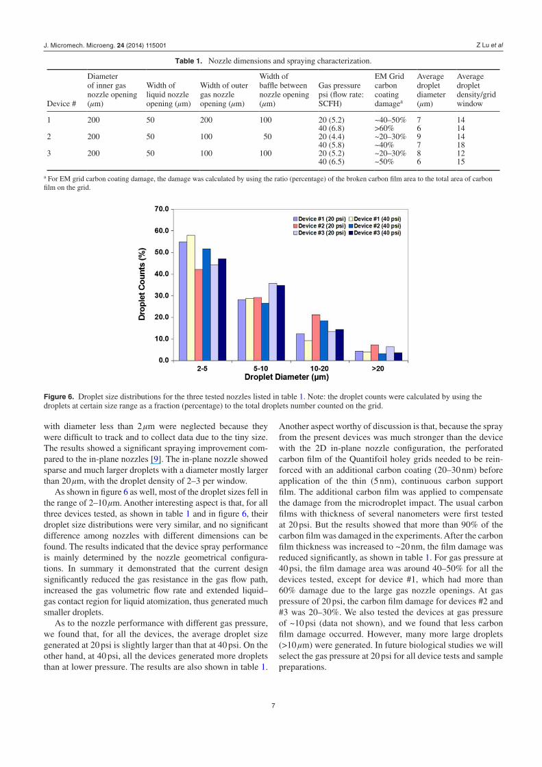
As shown in figure 6 as well, most of the droplet sizes fell in the range of 2–10 μm. Another interesting aspect is that, for all three devices tested, as shown in table 1 and in figure 6, their droplet size distributions were very similar, and no significant difference among nozzles with different dimensions can be found. The results indicated that the device spray performance is mainly determined by the nozzle geometrical configura-tions. In summary it demonstrated that the current design significantly reduced the gas resistance in the gas flow path, increased the gas volumetric flow rate and extended liquid–gas contact region for liquid atomization, thus generated much smaller droplets.
As to the nozzle performance with different gas pressure, we found that, for all the devices, the average droplet size generated at 20 psi is slightly larger than that at 40 psi. On the other hand, at 40 psi, all the devices generated more droplets than at lower pressure. The results are also shown in table 1.
Another aspect worthy of discussion is that, because the spray from the present devices was much stronger than the device with the 2D in-plane nozzle configuration, the perforated carbon film of the Quantifoil holey grids needed to be rein-forced with an additional carbon coating (20–30 nm) before application of the thin (5 nm), continuous carbon support film. The additional carbon film was applied to compensate the damage from the microdroplet impact. The usual carbon films with thickness of several nanometers were first tested at 20 psi. But the results showed that more than 90% of the carbon film was damaged in the experiments. After the carbon film thickness was increased to ~20 nm, the film damage was reduced significantly, as shown in table 1. For gas pressure at 40 psi, the film damage area was around 40–50% for all the devices tested, except for device #1, which had more than 60% damage due to the large gas nozzle openings. At gas pressure of 20 psi, the carbon film damage for devices #2 and #3 was 20–30%. We also tested the devices at gas pressure of ~10 psi (data not shown), and we found that less carbon film damage occurred. However, many more large droplets (>10 µm) were generated. In future biological studies we will select the gas pressure at 20 psi for all device tests and sample preparations.
Table 1. Nozzle dimensions and spraying characterization.
Device #
Diameter of inner gas nozzle opening (µm)
Width of liquid nozzle opening (µm)
Width of outer gas nozzle opening (µm)
Width of baffle between nozzle opening (µm)
Gas pressure psi (flow rate: SCFH)
EM Grid carbon coating damagea
Average droplet diameter (µm)
Average droplet density/grid window
1 200 50 200 100 20 (5.2) ~40–50% 7 1440 (6.8) >60% 6 14
2 200 50 100 50 20 (4.4) ~20–30% 9 1440 (5.8) ~40% 7 18
3 200 50 100 100 20 (5.2) ~20–30% 8 1240 (6.5) ~50% 6 15
a For EM grid carbon coating damage, the damage was calculated by using the ratio (percentage) of the broken carbon film area to the total area of carbon film on the grid.
Figure 6. Droplet size distributions for the three tested nozzles listed in table 1. Note: the droplet counts were calculated by using the droplets at certain size range as a fraction (percentage) to the total droplets number counted on the grid.
J. Micromech. Microeng. 24 (2014) 115001

Z Lu et al
8
5.2. Ice thickness evaluation and EM data collection
Figure 5(b) showed a typical cryo-EM micrograph with frozen ribosome particles. The micrograph was obtained from small droplets dispersed on the hydrophilic EM grid. The ribosome particles in the micrograph appeared to be in good integrity and intact through the spraying process. A few ribosome particles are highlighted in the micrograph. The 70S E. coli ribosomes are compact asymmetric macromolecular complexes that are about 23 nm in diameter. The particles presented a variety of appear-ances because they lie in the grid in multiple orientations. The appearance of the ribosomes in the micrograph are typical of those obtained by conventional cryo-EM [26]. Generally, due to the smaller size of the droplets, more thin ice regions were formed during sample preparation step and were available for data col-lection. The micrographs with high quality (high signal-to-noise ratio) are significantly more prevalent than those using the 2D in-plane nozzles. As for the output of the data collected from the EM grids, we collected ~800–1000 high quality CCD micrographs (1024 × 1024 pixels) in a 6–8 h period of continuous effort, and we estimate that an equivalent amount of data could have been obtained with additional effort. This level of output is comparable to what was routinely achieved using cryo-grids prepared by con-ventional blotting and manual data collection; and many more micrographs were collected using the new device than in the pre-vious study. As a point of reference, previously only 200–300 CCD micrographs could be collected from one TEM grid that were of acceptable signal-to-noise ratio, and weeks of EM work was required to collect a reasonable size of data set for analysis.
6. Conclusion
In this study, we have demonstrated a novel 3D annular microspray nozzle design for time-resolved cryo-EM sample preparation. The devices were fabricated using 3D MEMS fabrication techniques. The experimental results showed a significant improvement in multiple aspects over the previous 2D in-plane nozzle design, The microsprayer demonstrated dense and consistent sprays with average droplet size between 6–9 μm. With droplet density of around 12–18 per grid window and the EM data collectible thin ice region of >50% total wetted area, ~800–1000 high quality CCD micrographs were collected in a 6–8 h period of continuous effort. This level of output is comparable to what was routinely achieved using cryo-grids prepared by traditional blotting and manual data collection. The appearance of the ribosomes in the micro-graph are typical of those obtained by conventional cryo-EM. The results indicated that the new annular nozzle design would significantly increase the data collection efficiency and output, and reduce the number of the prepared sample grids for a single experiment, thus considerably reducing the con-sumption of the sparse and valuable biological samples.
Acknowledgements
This work is supported by the Wadsworth Center’s Resource for Visualization of Biological Complexity (NIH Biotechnol-ogy Resource Grant RR01219), and in part by NIH R01 grant
GM0615576 (to RKA). We thank Dr Pei-I Wang at Rensse-laer Polytechnic Institute for his help on the PES bonding pro-cess. We acknowledge the Micro and Nano Fabrication Clean Room at Rensselaer Polytechnic Institute for their help with device fabrication.
References
[1] Berriman J and Unwin N 1994 Analysis of transient structures by cryo-microscopy combined with rapid mixing of spray droplets Ultramicroscopy 56 241–52
[2] White H D, Walker M L and Trinick J 1998 A computer-controlled spraying-freezing apparatus for millisecond time-resolution electron cryomicroscopy J. Struct. Biol. 121 306–13
[3] Tittor J, Paula S, Subramaniam S, Heberle J, Henderson R and Oesterhelt D 2002 Proton translocation by bacteriorhodopsin in the absence of substantial conformational changes J. Mol. Biol. 319 555–65
[4] Frank J 2006 Three-Dimensional Electron Microscopy of Macromolecular Assemblies (Oxford, New York: Oxford University Press)
[5] Menetret J F, Hofmann W, Schroder R R, Rapp G and Goody R S 1991 Time-resolved cryo-electron microscopic study of the dissociation of actomyosin induced by photolysis of photolabile nucleotides J. Mol. Biol. 219 139–44
[6] Subramaniam S, Gerstein M, Oesterhelt D and Henderson R 1993 Electron diffraction analysis of structural changes in the photocycle of bacteriorhodopsin EMBO J. 12 1–8
[7] Unwin N 1995 Acetylcholine receptor channel imaged in the open state Nature 373 37–43
[8] Frederik P M and Sommerdijk N 2005 Spatial and temporal. resolution in cryo-electron microscopy—a scope for nano-chemistry [Review] Curr. Opin. Colloid Interface Sci. 10 245–9
[9] Lu Z, Shaikh T R, Barnard D, Meng X, Mohamed H, Yassin A, Mannella C A, Agrawal R K, Lu T-M and Wagenknecht T 2009 Monolithic microfluidic mixing-spraying devices for time-resolved cryo-electron microscopy J. Struct. Biol. 168 388–95
[10] Lu Z, McMahon J, Mohamed H, Barnard D, Shaikh T R, Mannella C A, Wagenknecht T and Lu T 2010 Passive microfluidic device for submillisecond mixing Sensors Actuators: B Chem. 144 301–9
[11] Shaikh T R, Yassin A S, Lu Z, Barnard D, Meng X, Lu T-M, Wagenknecht T and Agrawal R K 2014 Initial bridges between two ribosomal subunits are formed within 9.4 miliseconds, as studied by tim-resolved cryo-EM PNAS 111 9822–7
[12] Tseng F-G 2006 Microdroplet Generators MEMS: Applications The MEMS Handbook 2nd edn (Boca Raton: Taylor and Francis) chapter 10
[13] Percin G and Khuri-Yakub B T 2003 Piezoelectric droplet ejector for ink-jet printing of fluids and solid particles Rev. Sci. Instrum. 74 1120–7
[14] Xu Q, Zhou Z, Zhu J, Feng Y, Lin D and Du G 2007 Piezoelectrically actuated array microjet for biomedical purpose Indian J. Pure Appl. Phys. 45 273–7
[15] Deng W, Klemic J F, Li X, Reed M A and Gomez A 2006 Increase of electrospray throughput using multiplexed microfabricated sources for the scalable generation of monodisperse droplets Aerosol Sci. 37 696–714
[16] Baik S, Blanchard J P and Corradini M L 2003 Development of micro-diesel injector nozzles via microelectromechanical systems technology and effects on spray characteristics J. Eng. Gas Turbines Power 125 427–34
J. Micromech. Microeng. 24 (2014) 115001

Z Lu et al
9
[17] Rajan R and Pandit A B 2001 Correlations to predict droplet size in ultrasonic atomization Ultrasonics 39 235–55
[18] Yamagata Y 2010 Surface acoustic wave atomizer and electrostatic deposition Adv. Biochem. Eng./Biotechnol. 119 101–14
[19] Kim W, Guo M, Yang P and Wang D 2007 Microfabricated monolithic multinozzle emitters for nanoelectrospray mass spectrometry Anal. Chem. 79 3703–7
[20] Yang J-T, Huang K-J and Chen A C 2004 Microfabrication and laser diagnosis of pressure-swirl atomizers J. Microelectromech. Syst. 13 843–50
[21] Naik N et al 2007 Microfluidics for generation and characterization of liquid and gaseous micro- and nanojets Sensors Actuators A 134 119–27
[22] Liu H 2000 Science and Engineering of Droplets: Fundamentals and Applications (Bracknell: Noyes Publications)
[23] Wang P, Nalamasu O, Ghoshal R, Ghoshal R, Schaper C D, Li A and Lu T 2008 Novel photocurable epoxy siloxane polymers for photolithography and imprint lithography applications J. Vac. Sci. Technol. B 26 244–8
[24] White H D, Thirumurugan K, Walker M L and Trinick J 2003 A second generation apparatus for time-resolved electron cryo-microscopy using stepper motors and electrospray J. Struct. Biol. 144 246–52
[25] Blaha G, Stelz U, Spahn C M T, Agrawal R K, Frank J and Nierhaus K H 2000 Preparation of functional ribosomal complexes and effect of buffer conditions on tRNA positions observed by cryoelectron microscopy [Review] RNA-Ligand Interact. Method Enzymol. 317 292–309
[26] Grassucci R A, Taylor D J and Frank J 2007 Preparation of macromolecular complexes for cryo-electron microscopy Nat. Protoc. 2 3239–46
J. Micromech. Microeng. 24 (2014) 115001
Copyright © 2022 FDOKUMEN