Cryo-EM structure of MukBEF reveals DNA loop entrapment at ...
36
Article Cryo-EM structure of MukBEF reveals DNA loop entrapment at chromosomal unloading sites Graphical abstract Highlights d Complete atomic structures of the bacterial SMC complex MukBEF on and off DNA d MukBEF entraps two DNA double helices when bound to the unloader MatP d In vivo topology of DNA loop entrapment determined by cysteine cross-linking d Arms of the DNA loop thread through separate compartments of MukBEF Authors Frank B€ urmann, Louise F.H. Funke, Jason W. Chin, Jan Lo ¨ we Correspondence [email protected] (F.B.), [email protected] (J.L.) In brief The SMC complex MukBEF organizes bacterial chromosomes into large DNA loops. In this article, B€ urmann et al. report the cryo-EM structure of MukBEF bound to its unloading factor, MatP, and two DNA segments corresponding to the arms of a loop. The article provides insights into how SMC complexes topologically entrap DNA and unload from chromosomes. B€ urmann et al., 2021, Molecular Cell 81, 4891–4906 December 2, 2021 ª 2021 MRC Laboratory of Molecular Biology. Published by Elsevier Inc. https://doi.org/10.1016/j.molcel.2021.10.011 ll
-
Upload
khangminh22 -
Category
Documents
-
view
3 -
download
0
Transcript of Cryo-EM structure of MukBEF reveals DNA loop entrapment at ...

Article
Cryo-EM structure of Muk
BEF reveals DNA loopentrapment at chromosomal unloading sitesGraphical abstract
Highlights
d Complete atomic structures of the bacterial SMC complex
MukBEF on and off DNA
d MukBEF entraps two DNA double helices when bound to the
unloader MatP
d In vivo topology of DNA loop entrapment determined by
cysteine cross-linking
d Arms of the DNA loop thread through separate compartments
of MukBEF
B€urmann et al., 2021, Molecular Cell 81, 4891–4906December 2, 2021 ª 2021 MRC Laboratory of Molecular BiologyPublished by Elsevier Inc.https://doi.org/10.1016/j.molcel.2021.10.011
Authors
Frank B€urmann, Louise F.H. Funke,
Jason W. Chin, Jan Lowe
[email protected] (F.B.),[email protected] (J.L.)
In brief
The SMC complex MukBEF organizes
bacterial chromosomes into large DNA
loops. In this article, B€urmann et al. report
the cryo-EM structure of MukBEF bound
to its unloading factor, MatP, and two
DNA segments corresponding to the
arms of a loop. The article provides
insights into how SMC complexes
topologically entrap DNA and unload
from chromosomes.
.
ll

OPEN ACCESS
llArticle
Cryo-EM structure of MukBEFreveals DNA loop entrapmentat chromosomal unloading sitesFrank B€urmann,1,* Louise F.H. Funke,2 Jason W. Chin,2 and Jan Lowe1,3,*1MRC Laboratory of Molecular Biology, Structural Studies Division, Cambridge Biomedical Campus, Cambridge, UK2MRC Laboratory of Molecular Biology, Protein and Nucleic Acid Chemistry Division, Cambridge Biomedical Campus, Cambridge, UK3Lead contact
*Correspondence: [email protected] (F.B.), [email protected] (J.L.)https://doi.org/10.1016/j.molcel.2021.10.011
SUMMARY
The ring-like structural maintenance of chromosomes (SMC) complex MukBEF folds the genome of Escher-ichia coli and related bacteria into large loops, presumably by active DNA loop extrusion. MukBEF activitywithin the replication terminus macrodomain is suppressed by the sequence-specific unloader MatP.Here, we present the complete atomic structure of MukBEF in complex with MatP and DNA as determinedby electron cryomicroscopy (cryo-EM). The complex binds two distinct DNA double helices correspondingto the arms of a plectonemic loop. MatP-bound DNA threads through the MukBEF ring, while the secondDNA is clamped by the kleisin MukF, MukE, and the MukB ATPase heads. Combinatorial cysteine cross-link-ing confirms this topology of DNA loop entrapment in vivo. Our findings illuminate how a class of near-ubiq-uitous DNA organizerswith important roles in genomemaintenance interacts with the bacterial chromosome.
INTRODUCTION
Associations between molecules due to their topology are
known as mechanical bonds (Stoddart, 2009). In eukaryotes as
well as prokaryotes, ring-like structural maintenance of chromo-
somes (SMC) complexes are thought to structure chromosomes
via mechanical bonds with DNA (also referred to as ‘‘DNA
entrapment’’) and active DNA loop extrusion (Davidson and Pe-
ters, 2021; Hassler et al., 2018; M€akel€a and Sherratt, 2020a;
Nasmyth, 2001; Yatskevich et al., 2019). These activities have
been suggested to enable or facilitate processes such as length-
wise condensation of chromosomes, sister chromatid cohesion,
regulation of interactions between enhancers and distant pro-
moters, disentangling of replicated DNA by topoisomerases,
DNA recombination, and DNA double-strand break repair. Sup-
port for DNA entrapment, whereby the SMC complex encircles
the nucleic acid polymer, comes from experiments probing
DNA association after high salt treatment or, more stringently,
chemical circularization and denaturation of the complex (Cuylen
et al., 2011; Haering et al., 2008; Ivanov and Nasmyth, 2005;
Kanno et al., 2015; Murayama and Uhlmann, 2014; Niki and
Yano, 2016; Wilhelm et al., 2015). How DNA entrapment is
achieved on the molecular level is less understood, as SMC
complexes contain multiple topological compartments that can
or could accommodate one or more DNA double strands (Cha-
pard et al., 2019; Collier et al., 2020; Higashi et al., 2020; Shi
et al., 2020; Vazquez Nunez et al., 2019).
Molecular Cell 81, 4891–4906, December 2, 2021 ª 2021 MRThis is an open access article und
At the core of SMC complexes—such as cohesin, condensin,
Smc5-6, Smc-ScpAB, MksBEF, andMukBEF—is a tripartite ring
composed of two SMC proteins and a kleisin. SMC proteins
contain a 50-nm-long intra-molecular anti-parallel coiled-coil
‘‘arm,’’ which can fold over at an ‘‘elbow’’ in MukBEF, cohesin,
and condensin (B€urmann et al., 2019; Lee et al., 2020; Niki
et al., 1992). The arm separates a ‘‘hinge’’ dimerization domain
from an ABC-type ATPase ‘‘head’’ domain, which undergoes cy-
cles of ATP-dependent dimerization (called ‘‘engagement’’),
ATP hydrolysis, and disengagement (Hopfner et al., 2000). The
kleisin bridges hinge-dimerized SMC proteins in an asymmetric
arrangement, whereby its N- and C-terminal domain bind the
SMC ‘‘neck’’ and ‘‘cap’’ surfaces, respectively (B€urmann et al.,
2013; Gligoris et al., 2014; Haering and Gruber, 2016; Haering
et al., 2004; Schleiffer et al., 2003; Woo et al., 2009; Zawadzka
et al., 2018). The neck is located at the very head-proximal region
of the arm, whereas the cap is part of the head domain. The
neck-bound SMC is designated n-SMC (nu for neck), and the
cap-bound subunit is designated k-SMC (kappa for cap).
MukBEF is the SMC complex of E. coli and other enterobacte-
ria. Its SMC subunit is MukB, which associates with the kleisin
MukF (Woo et al., 2009; Zawadzka et al., 2018). MukF binds
the dimeric KITE protein MukE, which is structurally related
to ScpB of prokaryotic Smc-ScpAB and Nse1-3 of the Smc5-6
complex (Palecek and Gruber, 2015). MukB2E2F assemblies
(hereafter ‘‘MukBEF monomers’’) dimerize via MukF (Fennell-
Fezzie et al., 2005; Woo et al., 2009) into MukB4E4F2 complexes
C Laboratory of Molecular Biology. Published by Elsevier Inc. 4891er the CC BY license (http://creativecommons.org/licenses/by/4.0/).

(legend on next page)
llOPEN ACCESS Article
4892 Molecular Cell 81, 4891–4906, December 2, 2021

llOPEN ACCESSArticle
(also called ‘‘MukB dimers of dimers’’; hereafter simply
‘‘MukBEF dimers’’), which are the functional forms (Badrinar-
ayanan et al., 2012; Rajasekar et al., 2019).
MukBEF organizes large fractions of the E. coli chromosome
and is essential for chromosome segregation and cell survival
under conditions of fast growth (Danilova et al., 2007; Hiraga
et al., 1989; Lioy et al., 2018). In the replication terminus macro-
domain (Ter), MukBEF activity is suppressed by unloading at
matS sites, which are the signature sequences of Ter (Lioy
et al., 2018; M€akel€a and Sherratt, 2020b; Mercier et al., 2008;
Nolivos et al., 2016). Dedicated removal of SMC complexes
from the replication terminus appears widespread among bacte-
ria, as B. subtilis Smc-ScpAB is unloaded by the chromosome
resolvase XerD (Karaboja et al., 2021). Unloading of MukBEF
drastically changes the loop-size distribution of Ter compared
to other chromosomal macrodomains, a process that depends
on the matS-binding protein MatP (Lioy et al., 2018). Although
MukBEF function relies on the full ATPase cycle (Badrinarayanan
et al., 2012; Woo et al., 2009), association with matS requires
ATP-dependent head engagement only (Nolivos et al., 2016).
Head engagement and ATP hydrolysis have been suggested to
mediate unloading of cohesin in eukaryotes, which involves
dissociation of the neck/kleisin interface (Chan et al., 2012;
Muir et al., 2020; Murayama and Uhlmann, 2015). This interface
also disengages during the ATPase cycle of condensin, raising
the possibility that SMC complexes may use related mecha-
nisms for DNA unloading (Hassler et al., 2019).
Here, using electron cryomicroscopy (cryo-EM) single-particle
analysis, we discovered that MukBEF entraps two distinct DNA
double helices when bound to the unloader MatP. The DNAs
reside in separate compartments, which are located inside the
large circumference of the tripartite ring and in a much smaller
clamp at the ATPase heads. Topological mapping by chemical
circularization of endogenous MukBEF in cells suggests that
these compartments enclose each arm of a DNA loop in vivo.
Our findings illuminate how MukBEF can entrap DNA loops
and how these loops are primed for unloading from the complex.
RESULTS
MukBEF-MatP entraps two DNA double helices intopologically separate compartmentsInitial attempts to determine the structure of E. coliMukBEFwere
unsuccessful. We then recombinantly produced MukBEF com-
plexes from 11 different species in E. coli and identified the com-
Figure 1. Cryo-EM structure of MukBEF-MatP bound to two distinct D
(A) Reconstitution of MukBEF dimers. Co-purified MukBEF and free MukB were
(B) Composition of the MukBEF-MatP-matS sample used for structure determin
(C) Coomassie stained SDS-PAGE gel of the reconstituted complex used for cry
(D) Example micrograph of the sample used for structure determination.
(E) A 4.6-A-resolution cryo-EM density map (left, EMDB: EMD-12657) and comple
monomer.
(F) Slice through a 3.1-A-resolution cryo-EM density map of the DNA-binding reg
(G) k-MukB and n-MukB superimposed on the head domain. The arms adopt ra
(H) DNA binding topology on plectonemic loops inferred from the DNA crossing
used. The schematic on the right shows the simplified topology used for clarity t
See also Figures S1–S3 and Video S1.
plex from Photorhabdus thracensis as a suitable candidate for
structure determination by cryo-EM. The complex has 78%
sequence identity to its E. coli homolog and stably co-purified
with the E. coli acyl-carrier protein AcpP, an essential protein
that is a binding partner ofE. coliMukBEF (Niki et al., 1992; Prince
et al., 2021). E. coli AcpP is 85% identical to P. thracensis
AcpP. The purified complex had an estimated stoichiometry of
MukB2E4F2-AcpP2, which is a MukB2-AcpP2 unit short of the
MukB4E4F2 dimer expected from quantitative live-cell fluores-
cence microscopy (Badrinarayanan et al., 2012). We reasoned
that this was due to either dissociation of MukBEF dimers during
purification or overproduction of MukEF, leading to saturation
and incomplete assembly of the complex. We therefore titrated
the preparation with MukB2-AcpP2 to reconstitute intact
MukB4E4F2 dimers. This almost quantitatively shifted MukBEF
to a smaller elution volume in size-exclusion chromatography
(SEC), indicating the formation of the physiological complex
(Figure 1A).
To gain insights into how MukBEF interacts with matS
sites during chromosomal unloading, we purified P. thracensis
MatP, identified a cognate high-affinity matS site (Figure S1),
and introduced the E1407Q mutation (hereafter, MukBEQ) into
MukB to slow down ATP hydrolysis (Woo et al., 2009). We then
reconstituted a complex of MukBEQEF dimers, MatP, and an
80-bp DNA oligonucleotide containing matS close to one end
in the presence of ATP and magnesium ions (Figures 1B and
1C). The sample was then imaged by cryo-EM in vitreous ice
(Figure 1D).
We obtained a reconstruction of the DNA-bound MukBEF
monomer part at an overall nominal resolution of 4.6 A (Figures
1E and S2). Focused classification and refinement produced a
map of 3.1 A resolution for the more rigid head module, with
clearly resolved ATP and magnesium ions mediating head
engagement (Figures 1F and S3A). This allowed the construction
of a complete atomic model for the complex, facilitated by pre-
vious crystallographic information for individual parts (PDB:
3EUH, 3EUJ, 3IBP, 3VEA, 6DFL, 6H2X) (B€urmann et al., 2019;
Dupaigne et al., 2012; Kreamer et al., 2018; Li et al., 2010;
Woo et al., 2009).
MukBEF adopts a compact and highly asymmetric conforma-
tion, with its ATPase heads bridged by the kleisin MukF (Fig-
ure 1E; Video S1). The heads and hinge of MukB are brought
into proximity by folding at the elbow. In addition to the elbow
and the ‘‘joint’’ at the heads (Diebold-Durand et al., 2017), the
MukB arms contain several other coiled-coil discontinuities
NA double helices
mixed (top) and resolved by SEC (bottom).
ation.
o-EM.
te atomic model (middle, right, PDB: 7NYX) of the DNA-bound MukBEF-MatP
ion of MukBEF-MatP (EMDB: EMD-12656, PDB: 7NYW).
dically different conformations.
angle Q. The crossing angle convention employed by Rawdon et al. (2016) is
hroughout, with the in-reality elbow-folded conformation flattened into a ring.
Molecular Cell 81, 4891–4906, December 2, 2021 4893

Figure 2. DNA binding and subunit interfaces
of the MukBEF-MatP complex
(A) Model of the DNA-bound head module (PDB:
7NYW).
(B) Path of the kleisin MukF and DNA contacts of the
MukB larynx.
(C) Interface between the MukF linker and the
clamped DNA.
(D) Interface between the top surface of the n-MukB
head and the clamped DNA.
(E) Interface between MukE and MatP.
(F) Interface between the MukB joint and MatP.
(G) Interfaces between MukB and AcpP and be-
tween the k-MukB joint and the hinge-proximal arm
of n-MukB.
See also Figures S2 and S3 and Video S1.
llOPEN ACCESS Article
(Weitzel et al., 2011). Plasticity in these regions allows k-MukB
and n-MukB to adopt radically different conformations and,
thus, break homodimer symmetry (Figure 1G).
The head-proximal arms ofMukB are open to allow accommo-
dation of two distinct DNA double helices (Figures 1E, 1F, 1H,
and 2A). One DNA is bound by MatP and threads through the in-
ter-arm space near the joint. The other is clamped by the MukB
heads, MukF, and MukE. The kleisin MukF is resolved between
residues 10 and 440, which represent 98% of the protein (Fig-
ures 1F and 2B). It partitions the two DNAs into topologically
separate compartments: the ‘‘ring’’ delimited by MukF and the
MukB arms and the ‘‘clamp’’ delimited by MukF and the MukB
heads (Figures 1E and 1H). The DNA double helices have a
crossing angle of 60�, which is close to what has been estimated
for negatively supercoiled plectonemes (Rawdon et al., 2016).
This suggests that in the context of an intact chromosome,
they may originate from a single plectonemic loop, with MukBEF
binding across the long axis of the loop (Figure 1H). This hypoth-
esis will be explored below.
The clamp contacts DNA across all core subunitsThe clamp has a highly asymmetric architecture imposed by the
kleisinMukF.MukF comprises aC-terminal winged-helix domain
(cWHD), a four-helix bundle forming themiddle domain (MD), and
an N-terminal WHD (nWHD). The cWHD and MD are connected
by a 64-amino-acid linker, which contains theMukE binding sites
(Figure 2B). The cWHD binds the cap of its cognate k-SMC (Fig-
ure 1F), similar to the corresponding interface in other SMC com-
4894 Molecular Cell 81, 4891–4906, December 2, 2021
plexes (B€urmann et al., 2013; Haering et al.,
2004; Hassler et al., 2019;Woo et al., 2009).
The MD, which can bind the MukB neck
(Zawadzka et al., 2018), is in a position
roughly equivalent to binding sites between
the kleisins and n-SMCs of cohesin, con-
densin, and Smc-ScpAB (B€urmann et al.,
2013; Gligoris et al., 2014; Hassler et al.,
2019) (Figure S3B). The MD is, however,
structurally unrelated to the N-terminal
a-helical domain (nHD) of these kleisins.
MukB forms a homodimer; thus, both
MukB subunits contain MukF binding sites
at cap and neck. However, the n-MukB does not form the cap/
cWHD interface, and k-MukB does not associate with an MD.
This asymmetric configuration is enabled by two separate steric
occlusion mechanisms. At the n-MukB cap, binding of the MukF
linker to n-MukB prevents binding of a cWHD, as has been
observed before (Woo et al., 2009) (Figures 1F and 2B). In addi-
tion, the neck of k-MukB is occluded by the hinge (Figure 1E),
which prevents binding of an MD. These mechanisms preclude
recruitment of additional MukEF subunits to the complex and,
thus, prevent chaining of MukBEF monomers into higher-order
polymers.
Within the clamp, all core subunits of MukBEF are in contact
with DNA. The MukF linker is guided over the clamped DNA by
theMukE dimer, which also binds DNA along its central cleft (Fig-
ures 2A and 2B). The linker itself contacts the phosphate back-
bone with R322 and R327 (Figure 2C). The MukB heads bind
the clamped DNA along their top surface (Figure 2D). The ‘‘lar-
ynx’’ of n-MukB provides additional DNA contacts with Q1327
and R1328 (Figure 2B). This globular domain is situated at the
base of the neck and is not present in most other SMC proteins
(Figure S3C). Interestingly, the nHD of cohesin’s kleisin Rad21
provides DNA contacts that are located in a position similar to
the larynx (Figure S3B).
The overall architecture of the MukBEF clamp appears analo-
gous to what has been observed for the nuclease clamp in
SbcCD (Rad50-Mre11) and the HAWK clamp in cohesin (Collier
et al., 2020; Higashi et al., 2020; K€ashammer et al., 2019; Shi
et al., 2020) (Figure S3D). The KITE MukE is unrelated to any

llOPEN ACCESSArticle
subunit in these complexes; however, other KITE-based SMC
complexes, such as Smc5-6 and Smc-ScpAB, may clamp
DNA in a manner similar to MukBEF. We conclude that DNA
binding on top of the ATPase heads is a common principle be-
tween different SMC complexes, whereas the non-SMC sub-
units create structurally divergent but topologically equivalent
clamps.
MatP and MukE bridge the two DNAsWhereas the clamped DNA is contacted by all core subunits of
the complex, the DNA inside the ring is mostly bound by MatP,
with only K1178 in the MukB joint contacting the phosphate
backbone. The MatP dimer recognizes matS by inserting its a4
and b1 elements into the major grove, as has been determined
for MatP-matS complexes in isolation (Dupaigne et al., 2012)
(Figure S1C). The C-terminal tetramerization tail of MatP, how-
ever, is not visible and is likely disordered, consistent with the
finding that it is not required for MukBEF-related functions (Noli-
vos et al., 2016).
Interestingly, one of the MatP monomers forms a contact with
one of theMukEmonomers (Figures 2A and 2E). The DNAs in the
ring and clamp are, thus, physically linked via MukE and MatP.
The bridge is formed by residues between H38 and D42 in
MatP and an N-terminal tail of MukE (Figure 2E). The latter in-
volves residues between S2 and Q8, which are disordered in
the second MukE subunit and in previous crystal structures
(Gloyd et al., 2011;Woo et al., 2009). The bridge interface is small
and likely prone to dissociation, consistent with the finding that
recombinantly overexpressed MukEF does not co-immunopre-
cipitate with purified MatP (Nolivos et al., 2016). This suggests
that the bridge may have a transient role during unloading and
dissociates once the reaction is complete, permitting the release
of MukBEF from matS sites.
TheMukB joint is an interaction hub forMatP, AcpP, andthe hinge-proximal MukB armThe joint of MukB is located at a central region of the complex. It
is formed by an 84-amino-acid insertion into the C-terminal
coiled-coil strand and forms a slightly larger domain than the
joints found in other SMC proteins (Figure S3C). The joint binds
and positions MatP between the MukB arms (Figures 2A and
2F). This interface is much larger than the MukE-MatP bridge
and likely provides the major binding energy for association
with MatP. The joint also provides a docking site for the hinge-
proximal arm, with an interface formed between residues 602–
609 of the n-MukB arm and residues 1136 –1140 of the k-
MukB joint (Figure 2G). This likely contributes to stabilization of
the elbow-folded conformation of MukBEF.
AcpP binds MukB close to the joint between R281 and F296
on the N-terminal coiled-coil helix and Y1103 and R1122 on
the C-terminal helix (Figure 2G). Weak density protrudes from
S36 of AcpP, which we have modeled as phosphopantetheine
(PNS), the prosthetic group of AcpP that is covalently bound to
S36 and can flip out its core upon association with binding part-
ners (Cronan, 2014). At the k-MukB binding site, PNS projects
toward the space between the head-proximal arm of k-MukB
and the hinge-proximal arm of n-MukB. The phosphate group
of PNS is in contact with R839 of n-MukB. PNS is modified
with acyl moieties during fatty acid synthesis, and although the
biological function of AcpP within the MukBEF complex is un-
clear, it may have a regulatory role coupling metabolism to chro-
mosome organization (Gully et al., 2003). Because of its position
near the joint-arm contact, it is possible that AcpP, perhaps
controlled by its modification state, could have an influence on
the elbow-folded state of MukBEF.
The joint is situated near the heads and is, thus, expected to be
a central conduit for conformational changes imposed by the
ATPase cycle. Consistent with this idea, AcpP binding at the joint
strongly increases MukBEF ATPase activity (Prince et al., 2021).
Release of MukBEF from matS will likely require detachment
fromMatP; hence,MatP binding at the joint seems ideal for regu-
lation by the ATPase cycle, as will be explored below.
Architecture of apo-MukBEF and the MukBEF dimerIn the same sample that produced reconstructions of MukBEF
bound to MatP-matS, we also observed particles with disen-
gaged heads and that were neither DNA nor MatP bound (Fig-
ure 3A). Although the map was resolved to only 6.8 A, which pre-
vented determination of the nucleotide state, it was very similar
to exploratory reconstructions of nucleotide-free MukBEF (Fig-
ure S2A). Hence, we refer to it as the ‘‘apo state.’’ The apo com-
plex is comparable in size and shape to apo yeast condensin,
with arms fully juxtaposed (Figure S3E). The apo clamp is more
flexible because it is not held in place by ATP and DNA, but clear
density was observed at lower contour levels that allowed unam-
biguous positioning of MukEF. Themap also revealed density for
the second monomer within the context of a MukBEF dimer.
Further classification produced a low-resolution map for the
apo dimer, from which we obtained a model by rigid body fitting
(Figure 3B; Video S2).
The MukBEF dimer is held together by an extensive interface
betweenMukF’sMD and nWHD,whichwas observed previously
by crystallography (Fennell-Fezzie et al., 2005; Woo et al., 2009).
The two MukBEF monomers associate head to head with their
MukEF subunits on the same face of the dimer. As dictated by
its symmetry, the complex thus has a front and back (Figure 3B).
In addition to dimers in the apo state, dimers associated with
MatP and DNA were readily resolved (Figure 3C; Video S2).
Because we positioned the matS site close to one end of the
80-bp DNA used for sample preparation, two dimers were able
to associate with four DNAs in a ‘‘tetrad’’ arrangement. Different
classes of tetrads allowed us to assess the distance between the
two dimers. We observed dimers distantly bridged by the DNA
molecules (Figure 3C) and closely apposed (Figure 3D). This is
explained by sequence-independent binding of the clamp,
which can associate with any position along the DNA double
strand (Figure 3E). Assuming that the clamp binds DNA not
only during unloading at matS, but also during a tentative trans-
location reaction, it may step or slide along the DNA track. Since
the DNAs are roughly aligned with the dimer symmetry axis, it is
conceivable that DNA translocation may operate along this axis.
Conformational changes associated with unloadingThe MukBEQEF-MatP-matS complex is prevented from hydro-
lysing ATP and shows a state prior to unloading. The apo form,
however, lacks both MatP and DNA and therefore represents
Molecular Cell 81, 4891–4906, December 2, 2021 4895

Figure 3. Architecture of apo-MukBEF and the MukBEF dimer
(A) Model of the apo-MukBEF monomer (PDB: 7NYY) and 6.8-A cryo-EM density (EMDB: EMD-12658) at low contour level.
(B) Model for the apo-MukBEF dimer (PDB: 7NZ4) and 13-A cryo-EM density (EMDB: EMD-12664).
(C) The 11-A cryo-EM density (EMDB: EMD-12662) and model (PDB: 7NZ2) for two MukBEF dimers bridged by four MatP-DNA complexes (‘‘MukBEF tetrad’’).
The apo-MukBEF dimer is shown on the left.
(D) The 11-A cryo-EM density (EMDB: EMD-12663) and model (PDB: 7NZ3) for a MukBEF tetrad with closely apposed dimers. Only one monomer for each
MukBEF dimer was modeled due to weak density for their partner monomers.
(E) Schematic for variable positioning of the clampDNAbinding site, as shown in (C) and (D). Only a singleMukBEF dimer and only two of the four DNAs are shown
for clarity.
See also Figures S2 and S3 and Video S2.
llOPEN ACCESS Article
the result of a completed unloading reaction. Comparison of the
two states should yield insights into conformational changes that
take place during MatP-dependent DNA exit.
Sub-classification of the cryo-EM dataset revealed additional
forms of MukBEF-MatP with arms in different states of openness
(Figure 4A). This suggests that the arms can gradually ‘‘zip up,’’
similar to what has been proposed for Smc-ScpAB based on dis-
tance measurements by electron paramagnetic resonance (Vaz-
quez Nunez et al., 2021). The most open class has arms unzip-
ped up to the elbow, and the most closed one is the apo state.
In the apo state, the heads disengage and tilt, and the joints
and larynx become closely juxtaposed (Figure 4B; Video S3).
This occludes the binding sites for both MatP-matS and the
clamped DNA and strongly supports the idea that ATP hydrolysis
promotes dissociation from MatP-matS and DNA unloading.
Conformational changes associated with the release of nucle-
otide andDNApropagate through thewhole complex and can be
observed even in the hinge-proximal coiled-coil (Figure 4C). The
4896 Molecular Cell 81, 4891–4906, December 2, 2021
hinge follows the tilting k-MukB neck during DNA unloading, and
the hinge-proximal arm changes from a straightened conforma-
tion to a strongly curved one. This indicates that the arm stores
parts of the binding energy provided by ATP, MatP, and DNA
as elastic energy, similar to a spring. This energy may be har-
nessed to expel MatP and DNA after ATP hydrolysis. Although
the apo state was readily resolved, we did not observe classes
with only one DNA bound in either compartment, nor with only
MatP bound at the joints, nor with heads engaged but no DNA
bound. This suggests that the binding sites cooperate and are
regulated by ATP hydrolysis.
In cohesin, DNA unloading proceeds via opening of the
interface between the kleisin Scc1 and the n-SMC Smc3 (Chan
et al., 2012; Muir et al., 2020; Murayama and Uhlmann, 2015).
In MukBEF, the corresponding interface, which we name ‘‘neck
gate,’’ is formed by the neck of n-MukB and the MD of one
MukF (MukFcis) together with the nWHD of the second MukF
(MukFtrans) (Figure 4D). Intriguingly, the neck gate is open by a

Figure 4. Conformational changes associ-
ated with release of MatP/DNA/ATP
(A) Cryo-EM densities for the MukBEF-MatP-DNA
complexes with different arm conformations
(EMDB: EMD-12660, EMD-12659, EMD-12657, and
EMD-12658; PDB: 7NZ0, 7NYZ, 7NYX, and 7NYY).
(B) Blocking of MatP and DNA binding sites at the
MukB joint and larynx. Structures were super-
imposed on the ATPase domains. MatP/DNA/ATP-
bound conformation is shown in color, and apo
conformation is in gray.
(C) Conformational change at the MukB neck/hinge
interface (left) and at the hinge-proximal arm (right).
Structures were superimposed on the ATPase
domain (left) or the hinge (right).
(D) Cryo-EM density at the neck gate in the MatP/
DNA/ATP-bound state. The solvent accessible cleft
between MukB and MukF is indicated by a double
arrow.
(E) Superimposition of the neck gate in apo
and MatP/DNA/ATP-bound states (top). Minimum
backbone VDW distances of the interface are given
(bottom).
See also Figures S2 and S3 and Video S3.
llOPEN ACCESSArticle
narrowcleft along the interface in theMatP/DNA-bound structure
but is closed in the apo structure (Figures 4D and 4E). The mini-
mum backbone Van-der-Waals (VDW) distance is 2.8 A across
the interface in the MatP/DNA-bound state, which is reduced to
0.1-A minimum backbone VDW distance in the apo structure.
Although the cleft is too narrow for DNA to pass through, it may
represent a step toward full opening of the neck gate.
MukBEF adopts a folded conformation in vivo
MukBEF adopts an elbow-folded conformation, at least in its apo
state and when bound to ATP, MatP, and DNA. However, the
elbow has also been crystallized in an extended conformation,
suggesting that MukBEF may convert to extended rods or fully
open rings with disengaged arms (B€urmann et al., 2019) (Fig-
ure 5A). The hinge-proximal arms are in a closed-rod conforma-
tion in our structures, similar to those of other SMC complexes
(Figure S3F), but a conformation compatible with open rings
Molecular C
has been observed by crystallography (Li
et al., 2010) (Figure S3G). Additional sup-
port for the existence of open rings comes
from rotary shadowing electron micro-
scopy experiments (Matoba et al., 2005).
A closed-rod-to-open-ring transition has
been proposed to drive a peristalsis-like
translocation mechanism of SMC com-
plexes (Marko et al., 2019; Minnen et al.,
2016; Nomidis et al., 2021). We thus
decided to clarify whether the elbow-
folded conformation is abundant in vivo
and whether it may be controlled by the
ATPase cycle of MukBEF. To accomplish
this, we probed the conformation of
endogenous E. coli MukBEF by site-spe-
cific cysteine cross-linking.
To introduce multiple point mutations spread across the 8-kb
chromosomal mukFEB locus, we used a derivative of REXER
(Wang et al., 2016) (replicon excision for enhanced genome
engineering through programmed recombination) (Figure S4).
In addition to introducing mutations A304C and D857C into
MukB to probe the folded conformation (Figure 5A), we intro-
duced C1118S, which ablated weak background cross-linking
with a small protein, possibly AcpP (Figures 2G and S5). Next,
we treated the E. coli cells with bismaleimidoethane (BMOE),
which rapidly in vivo cross-links closely spaced thiols such
as cysteine sidechains. We then detected reaction products
labeled with HaloTag-tetramethylrhodamine (TMR) by SDS-
PAGE and in-gel fluorescence (Figure 5B). Residues A304C
and D857C cross-linked specifically with about 40% efficiency,
demonstrating that the folded conformation exists in vivo. The
reaction efficiency was comparable to that of constitutive inter-
faces (see below), indicating that the folded state is abundant.
ell 81, 4891–4906, December 2, 2021 4897

Figure 5. Detection of arm folding in vivo
(A) Residues employed as sensors for the folded
conformation. The folded conformation and a
tentative extended conformation based on the
structure of the extended elbow (PDB: 6H2X) are
shown on the left. A close-up on the P. thracensis
structure is shown on the right. Corresponding
E. coli residues are in parentheses.
(B) BMOE reaction scheme (top) and BMOE medi-
ated in vivo cysteine cross-linking of E. coli strains
carrying sensor cysteine mutations (bottom). Re-
action products were detected by SDS-PAGE and
in-gel fluorescence using a TMR fluorophore bound
to MukB-HaloTag.
See also Figures S4–S6.
llOPEN ACCESS Article
Next, we generated ATPase mutant strains S1366R (MukBSR,
blocking head engagement), D1406A (MukBDA, blocking ATP
binding), or E1407Q (MukBEQ, blocking ATP hydrolysis) (Woo
et al., 2009) (Figure S6A). As expected, all mutations conferred
a mukB-null phenotype, characterized by an inability to grow
on rich media at 37�C. To probe the effect of the mutations on
the ATPase cycle, we then introduced G67C, which is located
at the top of the MukB head and close to its symmetry mate in
the second MukB (Figure S6A). This residue pair changes dis-
tance upon head engagement and should respond to alterations
in the ATPase cycle. The residue cross-linked with similar effi-
ciencies in wild-type (WT) and the ATP binding mutant MukBDA,
with 22% ± 1% and 21% ± 2%, respectively. The cross-linked
fraction was increased to 30% ± 1% in MukBEQ, indicating
enhanced head engagement in this mutant (Figure S6B). As
MukBDA is deficient in head engagement and, thus, is an esti-
mator for baseline cross-linking in the apo state, this suggests
that a large fraction ofWTMukBEF heads are disengaged. These
findings are similar to what has been observed for B. subtilis
Smc-ScpAB (Minnen et al., 2016) and confirm that the assay is
able to detect conformational changes in vivo.
We then probed for elbow folding in MukBSR, MukBDA, and
MukBEQ strains, which resulted in similar reaction efficiencies
to WT (Figure S6C). These findings suggest that the elbow-
folded state of MukBEF is not controlled by steps preceding
ATP hydrolysis, consistent with our structural data. However,
folding could still be affected during formation of an ATP hydro-
lysis transition state, during asymmetric hydrolysis between the
two active sites, or upon product release. These states are
currently inaccessible by mutagenesis.
Clamp and ring compartment entrap separate segmentsof a DNA loop in vivo
MukBEF-MatP entraps DNA within its ring and clamp compart-
ments. This implies that in the context of a circular chromosome,
DNA would have to enter through one or more entry gates. For
biochemical preparation of the cryo-EM sample, however, any
loading or partial unloading reactionswere bypassed using linear
DNA and an ATPase-deficient mutant. As an additional caveat,
linear DNA prevents determination of the DNA connectivity that
would occur in a physiological context. For example, DNAs in
4898 Molecular Cell 81, 4891–4906, December 2, 2021
the ring and clamp may originate from the same or from different
chromosomes. Hence, we decided to map the DNA binding to-
pology of MukBEF in vivo.
We adapted an assay that measures chromosome entrap-
ment by chemically circularized protein complexes for use in
E. coli (Vazquez Nunez et al., 2019; Wilhelm et al., 2015). In
this assay, covalent circularization of a protein compartment
around chromosomal DNA preserves DNA association after
denaturation of DNA-binding surfaces (Figure 6A). Guided by
structural information, we designed cysteine cross-links at the
cap (R143C in MukB and Q412C in MukF), the neck (K1246C
in MukB and D227C in MukF), and the hinge (C730 and R771C
inMukB) to probe DNA entrapment in the ring compartment (Fig-
ure 6B and S7A). We also combined cap and neck cysteines with
the G67C head cysteine to probe entrapment in the clamp (Fig-
ures 6B and S6A). In addition, head and hinge cysteines were
combined to probe entrapment in the ‘‘frame’’ compartment,
which is the union of ring and clamp.
Combinations of cysteines were introduced into the endoge-
nousmukFEB locus, cells were treated with BMOE, and reaction
species were identified by SDS-PAGE and in-gel fluorescence
(Figure 6C). Cross-linking was specific and efficient at all sites.
For some reaction products, species were not completely
resolved from each other due to their high molecular weight,
identical mass, and mere shape differences. However, depletion
of precursors in expected ratios indicated successful multi-site
reactions in all cases. For example, the MukB species cross-
linked at the heads was reduced from 29% to 12% when com-
bined with the hinge cross-link. This corresponds to a reduction
by 60% and is in excellent agreement with the 62% cross-linking
efficiency observed for the hinge alone.
First, we tested entrapment in the ring compartment using
cap, neck, and hinge cysteine pairs. We treated cells with
BMOE, lysed them in agarose plugs to protect chromosomal
DNA from shearing, and subjected plugs to electrophoresis in
the presence of 0.1% SDS. This denatures and extracts proteins
and retains only cross-linked species that have been circularized
around DNA. We then digested chromosomal DNA to elute
bound proteins. A cross-linked high-molecular-weight MukB
species was retained only when cap, neck, and hinge interfaces
all contained cysteine pairs, indicating that it is the covalently

Figure 6. Mapping of DNA binding topology in vivo
(A) Principles (left) and workflow (right) of the chromosome entrapment assay in agarose plugs.
(B) Combinations of cross-links used for probing DNA entrapment in the ring, clamp, and frame compartments. Hinge cross-link, C730 and R771C in MukB; cap
cross-link, Q412C in MukF and R143C in MukB; neck cross-link, D227C in MukF and K1246C in MukB; head cross-link, G67C in MukB (Figures S6A and S7A).
(legend continued on next page)
llOPEN ACCESSArticle
Molecular Cell 81, 4891–4906, December 2, 2021 4899

Figure 7. Model for DNA binding and unload-
ing at matS sites
(A) Schematic for association of MukBEF with
MatP-matS in the Ter macrodomain. MukBEF or-
ganizes the chromosome into loops. Upon invasion
of Ter, MukBEF encounters MatP-matS and un-
loads via the double-lock topology in the context of
a plectonemic loop.
(B) Model for unloading of DNA. A MatP-matS
encounter is followed by ATP hydrolysis and
opening of the head gate to permit exit of the
clamped DNA.matS DNA follows through neck and
head gates, facilitated by the bridge between MatP
and MukE. Arm zip-up prevents reversal, and the
neck gate closes after MatP/DNA dissociation.
llOPEN ACCESS Article
circularized MukB2F (Figure 6D). The species was not retained
from MukBDA or MukBEQ strains, which suggests that DNA
entrapment critically depends on ATP hydrolysis.
Next, we tested for DNA entrapment in the clamp compart-
ment using cap, neck, and head cysteines (Figure 6E). The
cross-linked MukB species corresponding to the circularized
clamp was isolated as the major band, accompanied by smaller
amounts of protein that presumably resulted from chemical
cross-link reversal during the protein isolation procedure (Shen
et al., 2012; Wilhelm and Gruber, 2017). The retained amount
was similar to that of the ring compartment species, consistent
with the notion that both clamp and ring entrap DNA simulta-
neously. Protein was not retained from MukBDA or MukBEQ
strains. This finding indicates that DNA entrapment in the clamp,
as in the ring, depends on ATP hydrolysis in vivo.
Next, we tested for DNA entrapment in the frame compart-
ment using the combination of head and hinge cysteines (Fig-
ure 6F). Head and hinge cross-linked MukB was not detected
in eluates from WT, MukBDA, or MukBEQ strains. This and the
above two findings are best explained by the notion that the
ring and clamp each entrap different strands of the same loop.
Cross-linking the frame around this loop allows DNA to slip
(C) Combinatorial cross-linking for identification of reaction species. Combinations: hinge, cap, and nec
(middle); head and hinge (right). C730 was mutated to serine when indicated by a minus sign. Cells were g
(D) Chromosome entrapment in MukBEF with a covalently closed ring compartment. Input and agarose plu
species is retained only in WT ATPase cells. DA, D1406A (blocks ATP binding); EQ, E1407Q (blocks ATP h
(E) Chromosome entrapment in MukBEF with covalently closed clamp compartment. As in (D). Species that
sample preparation are marked with asterisks.
(F) Chromosome entrapment in MukB with covalently closed frame compartment. As in (D). Species produ
cross-links) are indicated.
(G) Structure-based topological interpretation of the entrapment reactions. Only the frame species can sli
catenane.
(H) DNA entrapment in the ring compartment in the absence of MatP. Signal of the plug eluate relative toWT
means, purple lines indicate standard deviations, and colored bars indicate 95% credible intervals.
See also Figures S6 and S7.
4900 Molecular Cell 81, 4891–4906, December 2, 2021
out of the covalent protein circle because
no protein-DNA catenane is formed
(Figure 6G).
Taken together, these results fully sup-
port entrapment of a loop as suggested
by the structure (Figures 1H, 6G, S7B,
and S7C). Because no DNA entrapment
is detected in the frame compartment and signals for the clamp
and ring are similar, most, if not all, complexes with DNA in the
clamp must have DNA catenated with the ring, and vice versa.
The results are incompatible with entrapment in only ring or
clamp, with entrapment of sister chromosomes, or with a loop
axis running parallel to the plane of the ring (Figure S7C). Any
of these forms would lead to catenation with the frame
compartment.
Finally, we investigated whether chromosome entrapment
was dependent on MatP. Deletion of the matP gene had little,
if any, effect on DNA inside theMukBEF ring (Figure 6H).We sug-
gest that DNA entrapment is a more general feature of MukBEF
and does not exclusively occur during unloading at matS sites.
DISCUSSION
The double-locked loopThe structure of MukBEF bound to MatP-matS revealed the
simultaneous entrapment of two DNA double helices, topologi-
cally separated into ring and clamp compartments. We name
this configuration the ‘‘double lock’’ (Figure 7A). The DNA
crossing angle in the MatP-bound double lock indicates that a
k cross-links (left); cap, neck, and head cross-links
rown to stationary phase. Detection as in Figure 5B.
g eluate are shown. Detection as in (C). The circular
ydrolysis). ATPase is WT if not indicated otherwise.
have undergone chemical cross-link reversal during
ced by higher-order oligomers in EQ mutants (trans
de off DNA because it does not form a protein/DNA
is shown for biological triplicates. Black lines indicate

Table 1. Cryo-EM data collection and model statistics
Head module
EMD-12656
PDB 7NYW
Holocomplex
EMD-12657
PDB 7NYX
Holocomplex (apo)
EMD-12658
PDB 7NYY
Holocomplex (partially
open) EMD-12658
PDB 7NYZ
Holocomplex (open)
EMD-12658
PDB 7NZ0
Tetrad
EMD-12662
PDB 7NZ2
Tetrad (apposed)
EMD-12663
PDB 7NZ3
Dimer (apo)
EMD-12664
PDB 7NZ4
Data collection and processing
Magnification 81,000
Voltage (kV) 300
Electron fluence (e–/A2) 40
Defocus range (mm) �1 to �3
Pixel size (A) 1.07
Symmetry imposed C1
Initial particle images (no.) 3,391,688
Final particle images (no.) 200,438 74,064 96,150 41,109 60,245 12,010 8,561 4,197
Map resolution (A) 3.1 4.6 6.8 6.5 6.3 11 11 13
FSC threshold 0.143 0.143 0.143 0.143 0.143 0.143 0.143 0.143
Model
Initial model used (PDB code) 3EUJ, 3EUH, 3VEA,
3IBP, 6DFL
3IBP, 6H2X,
7NYW
7NYX 7NYX 7NYX 7NYX 7NYX 7NYY
Model resolution (A) 3.25 5.0 7.5 8.1 7.3 — — —
FSC threshold 0.5 0.5 0.5 0.5 0.5
Map sharpening B factor (A2) �33 �87 �174 �162 �157 — — —
Model composition
Non-hydrogen atoms 24,792 36,100 31,563 36,100 36,100 148,563 74,338 63,192
Protein residues 2,795 4,186 3,910 4,186 4,186 16,752 8372 7824
Nucleic acid residues 104 104 — 104 104 614 312 —
Ligands PNS: 2 PNS: 2 PNS: 2 PNS: 2 PNS: 2 PNS: 8 PNS: 4 PNS: 4
ATP: 2 ATP: 2 ATP: 2 ATP: 2 ATP: 8 ATP: 4
Mg: 2 Mg: 2 Mg: 2 Mg: 2 Mg: 8 Mg: 4
RMSDs
Bond lengths (A) 0.004 0.004 0.004 0.009 0.005 0.004 0.004 0.005
Bond angles (�) 0.867 0.926 0.942 1.102 0.969 0.929 0.925 0.954
Validation
MolProbity score 1.57 1.78 1.99 1.77 1.82 1.85 1.83 2.01
Clashscore 5.9 10.9 14.51 10.63 12.31 12.96 12.37 15.24
Poor rotamers (%) 0 0 0 0.08 0.03 0.04 0 0.03
Ramachandran plot
Favored (%) 96.31 96.57 95.35 96.54 96.64 96.55 96.58 95.31
Allowed (%) 3.69 3.43 4.65 3.46 3.36 3.45 3.42 4.68
Disallowed (%) 0 0 0 0 0 0 0 0.01
llOPEN
ACCESS
Artic
le
MolecularCell81,4891–4906,December2,2021
4901

llOPEN ACCESS Article
DNA loop passes through MukBEF with the loop long axis
perpendicular to the ring plane. Topological mapping in vivo sup-
ports this notion.
DNA entrapment in the MukBEF ring occurs mainly outside of
the MatP-matS context, as it is unperturbed in DmatP cells.
Because localization of MukBEF to chromosomal foci is also
largely independent of MatP, and focal MukBEF turns over in
an ATP-hydrolysis-dependent manner (Badrinarayanan et al.,
2012; M€akel€a and Sherratt, 2020b; Nolivos et al., 2016), it
is conceivable that unloading via the double lock happens
throughout the chromosome and is not exclusive for the Ter re-
gion. At matS sites, MatP may enhance the positioning of DNA
within the ring for an efficient unloading reaction.
How abundant is the double lock? The fraction of cross-linked
species retained by the entrapment assay is low, raising the pos-
sibility that the double lock is a sparsely populated state. How-
ever, the relative signal of the assay will depend on factors such
aspreservation of chromosomal DNAand the fraction ofMukBEF
complexes that is loaded. The assay, therefore, likely underesti-
mates abundance by an unknown and possibly large factor and
may not be suitable for its quantification. In other words, the
data support the existence of the double lock but do not neces-
sarily reveal its incidence. What the experiments do suggest,
however, is that a large fraction of MukBEF with a loaded clamp
is in the double-lock configuration. Hence, transactions that
involve DNA binding inside the clamp may largely progress via
the double lock. The same statement applies to DNA entrapment
inside the ring. DNA transactions that involve catenation with the
ring may predominantly progress via the double lock.
The role of MukBEF dimerizationThe architecture of the MukBEF dimer permits binding of two
double-locked loops, whereby the loop axes are parallel and
monomers are arranged side by side. If loop extrusion by
MukBEF monomers was an asymmetric process, similar to
what has been observed for monomeric condensin (Ganji
et al., 2018), such side-by-side coupling could symmetrize
the overall extrusion process. Highly asymmetric loop extrusion
is considered a hindrance for physiological chromosome
folding and may be resolved using a dimerization mechanism
(Banigan and Mirny, 2019). We suggest that the arrangement
of the MukBEF dimer is well suited to implement symmetric
loop extrusion.
DNA entrapment in MukBEF and other SMC complexesMukBEF monomers do not entrap sister DNAs or loops with a
long axis perpendicular to the one proposed (Figure S7C). How-
ever, the low sensitivity of our assay may have precluded detec-
tion of rare species. Our experiments also do not exclude forma-
tion of ‘‘pseudo-topological’’ loops or ‘‘non-topological’’ loops,
whichmay form in addition to the double lock. The former are es-
tablished by threading DNA through the same compartment
twice, constituting a protein-DNA rotaxane instead of a cate-
nane, whereas the latter do not thread through the complex at
all but bind to its outer surface (Figure S7C). These structures
may be involved in loop extrusion by cohesin (Davidson et al.,
2019; Pradhan et al., 2021; Srinivasan et al., 2018), but their bind-
ing by MukBEF is hypothetical. If ‘‘pseudo-topological’’ loops
4902 Molecular Cell 81, 4891–4906, December 2, 2021
exist, however, they will need to be accommodated in the ring
and not in the clamp due to space limitations (Figure S7B).
Whereas the clamp is highly constrained by a short and compact
MukEF and can thus accommodate only a single DNA, the ring
would be able to embracemultiple DNAs and could even enlarge
its capacity by extending the elbow and fully opening the arms.
How MukBEF would achieve ‘‘non-topological’’ loop extrusion
with only a single known biochemical DNA binding site—namely,
the clamp—is unclear. A quantitative translocation model, which
involves a capacity change of the ring and proceeds via the dou-
ble-locked loop as a reaction intermediate, has been proposed
recently (Marko et al., 2019; Nomidis et al., 2021).
Cysteine cross-linking has been used tomapDNA entrapment
in other SMC complexes (Chapard et al., 2019; Gligoris et al.,
2014; Haering et al., 2008; Vazquez Nunez et al., 2019; Wilhelm
et al., 2015). Cross-linking at cap, neck, and hinge of cohesin and
Smc-ScpAB (also designated as ‘‘SK’’ cross-links) retains either
complex on DNA after denaturation. When cross-linked at cap,
neck, and juxtaposed heads (also designated as ‘‘JK’’ cross-
links), DNA association is also maintained. Entrapment is not
observed when cysteines in hinge and juxtaposed heads are
combined (also designated as ‘‘JS’’ cross-links). These patterns
are topologically equivalent to the ones determined here. Hence,
the MukBEF structure may provide an attractive interpretation
for these observations, namely, that cohesin and Smc-ScpAB
can entrap DNA in a manner similar to the double-lock
configuration.
Interestingly, the head cross-links used for cohesin and Smc-
ScpAB can capture a ‘‘head-juxtaposed’’ state, which is different
from engaged heads in the corresponding ATP hydrolysis mu-
tants. A large fraction of MukBEF heads are disengaged in vivo
as judged by our cross-linking experiments, and the G67C
cross-link at the heads used for topology mapping can capture
the disengaged state. It is, therefore, possible that DNA may
be retained in the clamp even after ATP hydrolysis.
Implications for chromosomal turnover of MukBEFBoth ring and clamp of MukBEF fully encircle DNA. This raises
the question of how DNA enters and exits these compartments.
The structure of MukBEF-MatP-matS shows a state before DNA
release, whereas the apo structure shows the state after release.
The latter also represents the state before DNA has entered the
complex. Models for chromosomal turnover of MukBEFwill have
to fit these observations.
We envision that unloading ofmatS from the ring is coupled to
unloading of DNA from the clamp (Figure 7B). For the clamped
DNA, the interface between the heads is a prime candidate for
an exit gate because its formation is regulated by ATP binding
and hydrolysis. Upon ATP hydrolysis and phosphate/nucleotide
release, heads disengage and dissociate their DNA binding sur-
faces. Clamped DNA may then be able to exit via the cleft
between disengaging heads. For this to happen, theMukF linker,
which also seals the head gate, needs to detach from the
n-MukB head. MukEF can stay bound to and move along with
the DNA because the neck gate is open, which allows MukEF
to reposition in relation to the n-MukB head. Concurrently, a
deformation at the joints releases MatP, which stays associated
with MukEF via the MatP-MukE bridge. Next, the head proximal

llOPEN ACCESSArticle
arms of MukB zip up and occlude the binding sites for MatP and
DNA at the joints and heads, respectively. Release of energy
stored as deformations in the hinge-proximal arm will reinforce
this process. MatP and DNA are ejected and are free to disso-
ciate from the complex. Finally, closure of the neck gate reverts
MukBEF to its apo form. We note that the proposed mechanism
would not strictly depend on MatP-matS but could also eject
‘‘free’’ DNA from the ring compartment. Its driving force comes
from relaxation of MukB into the apo conformation, whereas
MatP is a structural element that ensures ideal positioning of
DNA close to the exit gate.
The proposed unloading model, which is purely based on
structural data, is attractive for several reasons. First, it explains
how the process is regulated by ATP hydrolysis, namely, by
opening the head gate and blocking the binding sites for MatP
and DNA. Second, it explains how the process is enhanced at
matS sites. Third, the model designates the neck gate as the to-
pological exit gate of the tripartite ring. The equivalent interface
in the distantly related cohesin is the exit gate of this complex
(Chan et al., 2012; Muir et al., 2020; Murayama and Uhlmann,
2015). We suggest that unloading via the neck gate is a widely
conserved activity of SMC complexes.
An interaction of MatP with the MukB hinge, at least in the
absence of DNA, has been reported (Fisher et al., 2021; Nolivos
et al., 2016) but is not seen in our structures. It is conceivable that
this occurs at a different stage during unloading and could sug-
gest subunit and DNA transport within the complex. Interest-
ingly, MukBEQ can associate with matS in cells (Nolivos et al.,
2016), but DNA entrapment is not detected in our assay. This
may point toward a state that binds MatP but does not
entrap DNA.
In the light of our structures, DNA entry into MukBEF appears
enigmatic, as is the case for other SMC complexes. The joint,
which has emerged as a central region regulated by the
ATPase, is required for recruitment of Smc-ScpAB to its
loading factor, ParB (Gruber and Errington, 2009; Minnen
et al., 2016). ParB is typically not present in bacteria that use
MukBEF, and no substitute loading factor has been identified.
Importantly, loading of MukBEF does not depend on MatP,
and a reverse and MatP-independent version of the unloading
mechanism proposed above would have to work against a
large entropic barrier. This rather unlikely pathway would also
depend on ATP binding only, whereas loading in vivo requires
nucleotide hydrolysis. We suspect that chromosomal loading
and unloading of MukBEF are achieved by considerably
different means.
OutlookHere, we have determined the structure of MukBEF both in its
apo state and in aMatP/DNA/ATP-bound form, providingmolec-
ular insight into how MukBEF is released from chromosomes.
This led to the finding that MukBEF can entrap DNA loops in a
double-lock configuration, which links two important topological
concepts: DNA entrapment inside the ring and inside the clamp
compartment. Our work opens the questions of how the double-
locked loop is established and how MukBEF operates on this
and possibly other types of DNA structures. We anticipate that
biochemical reconstitution of the process by which MukBEF
organizes chromosomes, coupled to structural analysis, will
further our understanding of chromosome folding in bacteria
and beyond.
Limitations of the studyOur cryo-EM single-particle analysis may have missed confor-
mational states that do not average well due to heterogeneity
or that align poorly against the reference model. Although
cross-linking suggests that arm folding of MukBEF does not
change upon ATP binding in vivo, we note that the ATPase mu-
tants employed do not load onto chromosomal DNA. These ex-
periments, thus, do not resolve whether arm folding may change
upon ATP binding while DNA is entrapped.
STAR+METHODS
Detailed methods are provided in the online version of this paper
and include the following:
d KEY RESOURCES TABLE
d RESOURCE AVAILABILITY
B Lead contact
B Materials availability
B Data and code availability
d EXPERIMENTAL MODEL AND SUBJECT DETAILS
B E. coli strains
d METHOD DETAILS
B Protein production and purification
B matS sites and electrophoretic mobility shift
assay (EMSA)
B Cryo-EM sample preparation
B Cryo-EM data collection
B Genome engineering
B In vivo cross-linking
B Chromosome entrapment assay
d QUANTIFICATION AND STATISTICAL ANALYSIS
B Cryo-EM data analysis
B Structural model building
B Analysis of EMSA experiments
B Analysis of cross-linking experiments
B Analysis of chromosome entrapment assays
SUPPLEMENTAL INFORMATION
Supplemental information can be found online at https://doi.org/10.1016/j.
molcel.2021.10.011.
ACKNOWLEDGMENTS
We thank J. Prince, G. Fisher, and D. Sherratt (Oxford, UK) for discussions and
sharing of unpublished results; R. Vazquez Nunez and S. Gruber (Lausanne,
Switzerland) for discussions and advice on the chromosome entrapment
assay; all members of the Lowe and K. Nasmyth (Oxford, UK) groups for dis-
cussions; D. Komander (WEHI, Australia) for the gift of the GST-hSENP1
expression vector; G. Cannone and all members of the LMB electron micro-
scopy facility for excellent EM training and support; and T. Darling and J. Grim-
mett (LMB scientific computing) for computing support. F.B. was supported by
an EMBO Advanced fellowship (ALTF 605-2019). This work was funded by the
UKRI Medical Research Council.
Molecular Cell 81, 4891–4906, December 2, 2021 4903

llOPEN ACCESS Article
AUTHOR CONTRIBUTIONS
F.B. performed protein purification, cryo-EM sample preparation, cryo-EM
data acquisition and analysis, model building, strain construction, and all other
experiments; L.F.H.F. designed the genome mutagenesis strategy; F.B.
adapted this strategy for combinatorial mutagenesis; J.W.C. supervised tech-
nology development; J.L. supervised the overall study; F.B. prepared the
manuscript with contributions from all authors.
DECLARATION OF INTERESTS
The authors declare no competing interests.
Received: June 29, 2021
Revised: August 31, 2021
Accepted: October 12, 2021
Published: November 4, 2021
REFERENCES
Afonine, P.V., Poon, B.K., Read, R.J., Sobolev, O.V., Terwilliger, T.C.,
Urzhumtsev, A., and Adams, P.D. (2018). Real-space refinement in PHENIX
for cryo-EM and crystallography. Acta Crystallogr. D Struct. Biol. 74, 531–544.
Badrinarayanan, A., Reyes-Lamothe, R., Uphoff, S., Leake,M.C., and Sherratt,
D.J. (2012). In vivo architecture and action of bacterial structural maintenance
of chromosome proteins. Science 338, 528–531.
Banigan, E.J., and Mirny, L.A. (2019). Limits of Chromosome Compaction by
Loop-Extruding Motors. Phys. Rev. X 9, 031007.
B€urmann, F., Shin, H.-C., Basquin, J., Soh, Y.-M., Gimenez-Oya, V., Kim,
Y.-G., Oh, B.-H., and Gruber, S. (2013). An asymmetric SMC-kleisin bridge
in prokaryotic condensin. Nat. Struct. Mol. Biol. 20, 371–379.
B€urmann, F., Lee, B.-G., Than, T., Sinn, L., O’Reilly, F.J., Yatskevich, S.,
Rappsilber, J., Hu, B., Nasmyth, K., and Lowe, J. (2019). A folded conformation
of MukBEF and cohesin. Nat. Struct. Mol. Biol. 26, 227–236.
Butt, T.R., Edavettal, S.C., Hall, J.P., and Mattern, M.R. (2005). SUMO fusion
technology for difficult-to-express proteins. Protein Expr. Purif. 43, 1–9.
Chan, K.-L., Roig, M.B., Hu, B., Beckou€et, F., Metson, J., and Nasmyth, K.
(2012). Cohesin’s DNA exit gate is distinct from its entrance gate and is regu-
lated by acetylation. Cell 150, 961–974.
Chapard, C., Jones, R., van Oepen, T., Scheinost, J.C., and Nasmyth, K.
(2019). Sister DNA Entrapment between Juxtaposed Smc Heads and Kleisin
of the Cohesin Complex. Mol. Cell 75, 224–237.e5.
Collier, J.E., Lee, B.-G., Roig, M.B., Yatskevich, S., Petela, N.J., Metson, J.,
Voulgaris, M., Gonzalez Llamazares, A., Lowe, J., and Nasmyth, K.A. (2020).
Transport of DNA within cohesin involves clamping on top of engaged heads
by Scc2 and entrapment within the ring by Scc3. eLife 9, e59560.
Croll, T.I. (2018). ISOLDE: a physically realistic environment for model building
into low-resolution electron-density maps. Acta Crystallogr. D Struct. Biol. 74,
519–530.
Cronan, J.E. (2014). The chain-flipping mechanism of ACP (acyl carrier pro-
tein)-dependent enzymes appears universal. Biochem. J. 460, 157–163.
Cuylen, S., Metz, J., and Haering, C.H. (2011). Condensin structures chromo-
somal DNA through topological links. Nat. Struct. Mol. Biol. 18, 894–901.
Danilova, O., Reyes-Lamothe, R., Pinskaya, M., Sherratt, D., and Possoz, C.
(2007). MukB colocalizes with the oriC region and is required for organization
of the two Escherichia coli chromosome arms into separate cell halves. Mol.
Microbiol. 65, 1485–1492.
Davidson, I.F., and Peters, J.-M. (2021). Genome folding through loop extru-
sion by SMC complexes. Nat. Rev. Mol. Cell Biol. 22, 445–464.
Davidson, I.F., Bauer, B., Goetz, D., Tang, W., Wutz, G., and Peters, J.-M.
(2019). DNA loop extrusion by human cohesin. Science 366, 1338–1345.
Diebold-Durand, M.-L., Lee, H., Ruiz Avila, L.B., Noh, H., Shin, H.-C., Im, H.,
Bock, F.P., B€urmann, F., Durand, A., Basfeld, A., et al. (2017). Structure
4904 Molecular Cell 81, 4891–4906, December 2, 2021
of Full-Length SMC and Rearrangements Required for Chromosome
Organization. Mol. Cell 67, 334–347.e5.
Dupaigne, P., Tonthat, N.K., Espeli, O., Whitfill, T., Boccard, F., and
Schumacher, M.A. (2012). Molecular basis for a protein-mediated DNA-
bridgingmechanism that functions in condensation of the E. coli chromosome.
Mol. Cell 48, 560–571.
Emsley, P., Lohkamp, B., Scott, W.G., and Cowtan, K. (2010). Features and
development of Coot. Acta Crystallogr. D Biol. Crystallogr. 66, 486–501.
Engler, C., Kandzia, R., and Marillonnet, S. (2008). A one pot, one step, preci-
sion cloning method with high throughput capability. PLoS ONE 3, e3647.
Fennell-Fezzie, R., Gradia, S.D., Akey, D., and Berger, J.M. (2005). The MukF
subunit of Escherichia coli condensin: architecture and functional relationship
to kleisins. EMBO J. 24, 1921–1930.
Fisher, G.L.M., Bolla, J.R., Rajasekar, K.V., M€akel€a, J., Baker, R., Zhou, M.,
Prince, J.P., Stracy, M., Robinson, C.V., Arciszewska, L.K., et al. (2021).
Competitive binding ofMatP and topoisomerase IV to theMukB hinge domain.
eLife 10, e70444.
Fredens, J., Wang, K., de la Torre, D., Funke, L.F.H., Robertson, W.E.,
Christova, Y., Chia, T., Schmied, W.H., Dunkelmann, D.L., Beranek, V., et al.
(2019). Total synthesis of Escherichia coli with a recoded genome. Nature
569, 514–518.
Ganji, M., Shaltiel, I.A., Bisht, S., Kim, E., Kalichava, A., Haering, C.H., and
Dekker, C. (2018). Real-time imaging of DNA loop extrusion by condensin.
Science 360, 102–105.
Gligoris, T.G., Scheinost, J.C., B€urmann, F., Petela, N., Chan, K.-L., Uluocak,
P., Beckou€et, F., Gruber, S., Nasmyth, K., and Lowe, J. (2014). Closing the co-
hesin ring: structure and function of its Smc3-kleisin interface. Science 346,
963–967.
Gloyd, M., Ghirlando, R., and Guarne, A. (2011). The role of MukE in assem-
bling a functional MukBEF complex. J. Mol. Biol. 412, 578–590.
Gruber, S., and Errington, J. (2009). Recruitment of condensin to replication
origin regions by ParB/SpoOJ promotes chromosome segregation in B. sub-
tilis. Cell 137, 685–696.
Gully, D., Moinier, D., Loiseau, L., and Bouveret, E. (2003). New partners of acyl
carrier protein detected in Escherichia coli by tandem affinity purification.
FEBS Lett. 548, 90–96.
Haering, C.H., and Gruber, S. (2016). SnapShot: SMC protein complexes part
I. Cell 164, 326–326.e1.
Haering, C.H., Schoffnegger, D., Nishino, T., Helmhart, W., Nasmyth, K., and
Lowe, J. (2004). Structure and stability of cohesin’s Smc1-kleisin interaction.
Mol. Cell 15, 951–964.
Haering, C.H., Farcas, A.-M., Arumugam, P., Metson, J., and Nasmyth, K.
(2008). The cohesin ring concatenates sister DNA molecules. Nature 454,
297–301.
Hassler, M., Shaltiel, I.A., and Haering, C.H. (2018). Towards aUnifiedModel of
SMC Complex Function. Curr. Biol. 28, R1266–R1281.
Hassler, M., Shaltiel, I.A., Kschonsak, M., Simon, B., Merkel, F., Th€arichen, L.,
Bailey, H.J., Maco�sek, J., Bravo, S., Metz, J., et al. (2019). Structural Basis of
an Asymmetric Condensin ATPase Cycle. Mol. Cell 74, 1175–1188.e9.
Higashi, T.L., Eickhoff, P., Sousa, J.S., Locke, J., Nans, A., Flynn, H.R.,
Snijders, A.P., Papageorgiou, G., O’Reilly, N., Chen, Z.A., et al. (2020). A
Structure-Based Mechanism for DNA Entry into the Cohesin Ring. Mol. Cell
79, 917–933.e9.
Hiraga, S., Niki, H., Ogura, T., Ichinose, C., Mori, H., Ezaki, B., and Jaffe, A.
(1989). Chromosome partitioning in Escherichia coli: novel mutants producing
anucleate cells. J. Bacteriol. 171, 1496–1505.
Hopfner, K.P., Karcher, A., Shin, D.S., Craig, L., Arthur, L.M., Carney, J.P., and
Tainer, J.A. (2000). Structural biology of Rad50 ATPase: ATP-driven conforma-
tional control in DNA double-strand break repair and the ABC-ATPase super-
family. Cell 101, 789–800.
Inoue, H., Nojima, H., and Okayama, H. (1990). High efficiency transformation
of Escherichia coli with plasmids. Gene 96, 23–28.

llOPEN ACCESSArticle
Ivanov, D., and Nasmyth, K. (2005). A topological interaction between cohesin
rings and a circular minichromosome. Cell 122, 849–860.
Kanno, T., Berta, D.G., and Sjogren, C. (2015). The Smc5/6 Complex Is an
ATP-Dependent Intermolecular DNA Linker. Cell Rep. 12, 1471–1482.
Karaboja, X., Ren, Z., Brandao, H.B., Paul, P., Rudner, D.Z., and Wang, X.
(2021). XerD unloads bacterial SMC complexes at the replication terminus.
Mol. Cell 81, 756–766.e8.
K€ashammer, L., Saathoff, J.-H., Lammens, K., Gut, F., Bartho, J., Alt, A.,
Kessler, B., and Hopfner, K.-P. (2019). Mechanism of DNA End Sensing and
Processing by the Mre11-Rad50 Complex. Mol. Cell 76, 382–394.e6.
Kreamer, N.N.K., Chopra, R., Caughlan, R.E., Fabbro, D., Fang, E., Gee, P.,
Hunt, I., Li, M., Leon, B.C., Muller, L., et al. (2018). Acylated-acyl carrier protein
stabilizes the Pseudomonas aeruginosa WaaP lipopolysaccharide heptose ki-
nase. Sci. Rep. 8, 14124.
Lee, B.-G., Merkel, F., Allegretti, M., Hassler, M., Cawood, C., Lecomte, L.,
O’Reilly, F.J., Sinn, L.R., Gutierrez-Escribano, P., Kschonsak, M., et al.
(2020). Cryo-EM structures of holo condensin reveal a subunit flip-flop mech-
anism. Nat. Struct. Mol. Biol. 27, 743–751.
Li, Y., Schoeffler, A.J., Berger, J.M., and Oakley, M.G. (2010). The crystal
structure of the hinge domain of the Escherichia coli structural maintenance
of chromosomes protein MukB. J. Mol. Biol. 395, 11–19.
Lioy, V.S., Cournac, A., Marbouty, M., Duigou, S., Mozziconacci, J., Espeli, O.,
Boccard, F., and Koszul, R. (2018). Multiscale Structuring of the E. coli
Chromosome by Nucleoid-Associated and Condensin Proteins. Cell 172,
771–783.e18.
Lobry, J.R. (1996). Asymmetric substitution patterns in the two DNA strands of
bacteria. Mol. Biol. Evol. 13, 660–665.
M€akel€a, J., and Sherratt, D. (2020a). SMC complexes organize the bacterial
chromosome by lengthwise compaction. Curr. Genet. 66, 895–899.
M€akel€a, J., and Sherratt, D.J. (2020b). Organization of the Escherichia coli
Chromosome by a MukBEF Axial Core. Mol. Cell 78, 250–260.e5.
Marko, J.F., De Los Rios, P., Barducci, A., and Gruber, S. (2019). DNA-
segment-capture model for loop extrusion by structural maintenance of chro-
mosome (SMC) protein complexes. Nucleic Acids Res. 47, 6956–6972.
Mastronarde, D.N. (2005). Automated electron microscope tomography using
robust prediction of specimen movements. J. Struct. Biol. 152, 36–51.
Matoba, K., Yamazoe, M., Mayanagi, K., Morikawa, K., and Hiraga, S. (2005).
Comparison of MukB homodimer versus MukBEF complex molecular archi-
tectures by electron microscopy reveals a higher-order multimerization.
Biochem. Biophys. Res. Commun. 333, 694–702.
Mercier, R., Petit, M.-A., Schbath, S., Robin, S., El Karoui, M., Boccard, F., and
Espeli, O. (2008). The MatP/matS site-specific system organizes the terminus
region of the E. coli chromosome into a macrodomain. Cell 135, 475–485.
Minnen, A., B€urmann, F., Wilhelm, L., Anchimiuk, A., Diebold-Durand, M.-L.,
and Gruber, S. (2016). Control of Smc Coiled Coil Architecture by the
ATPase Heads Facilitates Targeting to Chromosomal ParB/parS and
Release onto Flanking DNA. Cell Rep. 14, 2003–2016.
Miyazaki, K. (2015). Molecular engineering of a PheS counterselection marker
for improved operating efficiency in Escherichia coli. Biotechniques 58, 86–88.
Muir, K.W., Li, Y., Weis, F., and Panne, D. (2020). The structure of the cohesin
ATPase elucidates the mechanism of SMC-kleisin ring opening. Nat. Struct.
Mol. Biol. 27, 233–239.
Murayama, Y., and Uhlmann, F. (2014). Biochemical reconstitution of topolog-
ical DNA binding by the cohesin ring. Nature 505, 367–371.
Murayama, Y., and Uhlmann, F. (2015). DNA Entry into and Exit out of the
Cohesin Ring by an Interlocking Gate Mechanism. Cell 163, 1628–1640.
Nasmyth, K. (2001). Disseminating the genome: joining, resolving, and sepa-
rating sister chromatids during mitosis and meiosis. Annu. Rev. Genet. 35,
673–745.
Niki, H., and Yano, K. (2016). In vitro topological loading of bacterial condensin
MukB on DNA, preferentially single-stranded DNA rather than double-
stranded DNA. Sci. Rep. 6, 29469.
Niki, H., Imamura, R., Kitaoka, M., Yamanaka, K., Ogura, T., and Hiraga, S.
(1992). E.coli MukB protein involved in chromosome partition forms a homo-
dimer with a rod-and-hinge structure having DNA binding and ATP/GTP bind-
ing activities. EMBO J. 11, 5101–5109.
Nolivos, S., Upton, A.L., Badrinarayanan, A., M€uller, J., Zawadzka, K., Wiktor,
J., Gill, A., Arciszewska, L., Nicolas, E., and Sherratt, D. (2016). MatP regulates
the coordinated action of topoisomerase IV and MukBEF in chromosome
segregation. Nat. Commun. 7, 10466.
Nomidis, S.K., Carlon, E., Gruber, S., and Marko, J.F. (2021). DNA tension-
modulated translocation and loop extrusion by SMC complexes revealed by
molecular dynamics simulations. bioRxiv. https://doi.org/10.1101/2021.03.
15.435506.
Palecek, J.J., and Gruber, S. (2015). Kite Proteins: a Superfamily of SMC/
Kleisin Partners Conserved Across Bacteria, Archaea, and Eukaryotes.
Structure 23, 2183–2190.
Pettersen, E.F., Goddard, T.D., Huang, C.C., Meng, E.C., Couch, G.S., Croll,
T.I., Morris, J.H., and Ferrin, T.E. (2021). UCSF ChimeraX: Structure visualiza-
tion for researchers, educators, and developers. Protein Sci. 30, 70–82.
Pradhan, B., Barth, R., Kim, E., Davidson, I.F., Bauer, B., van Laar, T., Yang,
W., Ryu, J.-K., van der Torre, J., Peters, J.-M., et al. (2021). SMC complexes
can traverse physical roadblocks bigger than their ring size. bioRxiv. https://
doi.org/10.1101/2021.07.15.452501.
Prince, J.P., Bolla, J.R., Fisher, G.L.M., M€akel€a, J., Robinson, C.V.,
Arciszewska, L.K., and Sherratt, D.J. (2021). Acyl Carrier Protein is essential
for MukBEF action in Escherichia coli chromosome organization-segregation.
bioRxiv. https://doi.org/10.1101/2021.04.12.439405.
Rajasekar, K.V., Baker, R., Fisher, G.L.M., Bolla, J.R., M€akel€a, J., Tang, M.,
Zawadzka, K., Koczy, O., Wagner, F., Robinson, C.V., et al. (2019). Dynamic
architecture of the Escherichia coli structural maintenance of chromosomes
(SMC) complex, MukBEF. Nucleic Acids Res. 47, 9696–9707.
Rawdon, E.J., Dorier, J., Racko, D., Millett, K.C., and Stasiak, A. (2016). How
topoisomerase IV can efficiently unknot and decatenate negatively super-
coiled DNA molecules without causing their torsional relaxation. Nucleic
Acids Res. 44, 4528–4538.
Rohou, A., and Grigorieff, N. (2015). CTFFIND4: Fast and accurate defocus
estimation from electron micrographs. J. Struct. Biol. 192, 216–221.
Rosenthal, P.B., and Henderson, R. (2003). Optimal determination of particle
orientation, absolute hand, and contrast loss in single-particle electron cryomi-
croscopy. J. Mol. Biol. 333, 721–745.
Russo, C.J., and Passmore, L.A. (2014). Electron microscopy: Ultrastable gold
substrates for electron cryomicroscopy. Science 346, 1377–1380.
Scheres, S.H.W. (2012). A Bayesian view on cryo-EM structure determination.
J. Mol. Biol. 415, 406–418.
Schleiffer, A., Kaitna, S., Maurer-Stroh, S., Glotzer, M., Nasmyth, K., and
Eisenhaber, F. (2003). Kleisins: a superfamily of bacterial and eukaryotic
SMC protein partners. Mol. Cell 11, 571–575.
Shen, B.-Q., Xu, K., Liu, L., Raab, H., Bhakta, S., Kenrick, M., Parsons-
Reponte, K.L., Tien, J., Yu, S.-F., Mai, E., et al. (2012). Conjugation site mod-
ulates the in vivo stability and therapeutic activity of antibody-drug conjugates.
Nat. Biotechnol. 30, 184–189.
Shi, Z., Gao, H., Bai, X.-C., and Yu, H. (2020). Cryo-EM structure of the human
cohesin-NIPBL-DNA complex. Science 368, 1454–1459.
Srinivasan, M., Scheinost, J.C., Petela, N.J., Gligoris, T.G., Wissler, M.,
Ogushi, S., Collier, J.E., Voulgaris, M., Kurze, A., Chan, K.-L., et al. (2018).
The Cohesin Ring Uses Its Hinge to Organize DNA Using Non-topological as
well as Topological Mechanisms. Cell 173, 1508–1519.e18.
Stoddart, J.F. (2009). The chemistry of the mechanical bond. Chem. Soc. Rev.
38, 1802–1820.
Studier, F.W. (2005). Protein production by auto-induction in high density
shaking cultures. Protein Expr. Purif. 41, 207–234.
Vazquez Nunez, R., Ruiz Avila, L.B., and Gruber, S. (2019). Transient DNA
Occupancy of the SMC Interarm Space in Prokaryotic Condensin. Mol. Cell
75, 209–223.e6.
Molecular Cell 81, 4891–4906, December 2, 2021 4905

llOPEN ACCESS Article
Vazquez Nunez, R., Polyhach, Y., Soh, Y.-M., Jeschke, G., and Gruber, S.
(2021). Gradual opening of Smc arms in prokaryotic condensin. Cell Rep.
35, 109051.
Wagner, T., Merino, F., Stabrin, M., Moriya, T., Antoni, C., Apelbaum, A.,
Hagel, P., Sitsel, O., Raisch, T., Prumbaum, D., et al. (2019). SPHIRE-
crYOLO is a fast and accurate fully automated particle picker for cryo-EM.
Commun. Biol. 2, 218.
Wang, K., Fredens, J., Brunner, S.F., Kim, S.H., Chia, T., and Chin, J.W. (2016).
Defining synonymous codon compression schemes by genome recoding.
Nature 539, 59–64.
Waterhouse, A., Bertoni, M., Bienert, S., Studer, G., Tauriello, G., Gumienny,
R., Heer, F.T., de Beer, T.A.P., Rempfer, C., Bordoli, L., et al. (2018). SWISS-
MODEL: homology modelling of protein structures and complexes. Nucleic
Acids Res. 46, W296–W303.
Weitzel, C.S., Waldman, V.M., Graham, T.A., and Oakley, M.G. (2011). A
repeated coiled-coil interruption in the Escherichia coli condensin MukB.
J. Mol. Biol. 414, 578–595.
4906 Molecular Cell 81, 4891–4906, December 2, 2021
Wilhelm, L., and Gruber, S. (2017). A Chromosome Co-Entrapment Assay
to Study Topological Protein-DNA Interactions. Methods Mol. Biol. 1624,
117–126.
Wilhelm, L., B€urmann, F., Minnen, A., Shin, H.-C., Toseland, C.P., Oh, B.-H.,
and Gruber, S. (2015). SMC condensin entraps chromosomal DNA by an
ATP hydrolysis dependent loading mechanism in Bacillus subtilis. eLife 4,
e06659.
Woo, J.-S., Lim, J.-H., Shin, H.-C., Suh, M.-K., Ku, B., Lee, K.-H., Joo, K.,
Robinson, H., Lee, J., Park, S.-Y., et al. (2009). Structural studies of a bacterial
condensin complex reveal ATP-dependent disruption of intersubunit interac-
tions. Cell 136, 85–96.
Yatskevich, S., Rhodes, J., and Nasmyth, K. (2019). Organization of
Chromosomal DNA by SMC Complexes. Annu. Rev. Genet. 53, 445–482.
Yu, D., Ellis, H.M., Lee, E.C., Jenkins, N.A., Copeland, N.G., and Court, D.L.
(2000). An efficient recombination system for chromosome engineering in
Escherichia coli. Proc. Natl. Acad. Sci. USA 97, 5978–5983.
Zawadzka, K., Zawadzki, P., Baker, R., Rajasekar, K.V., Wagner, F., Sherratt,
D.J., and Arciszewska, L.K. (2018). MukB ATPases are regulated indepen-
dently by the N- and C-terminal domains of MukF kleisin. eLife 7, e31522.

llOPEN ACCESSArticle
STAR+METHODS
KEY RESOURCES TABLE
REAGENT or RESOURCE SOURCE IDENTIFIER
Chemicals, peptides, and recombinant proteins
4-chloro-phenylalanine (4-CP) Sigma-Aldrich Cat#C6506-5G
Adenosine triphosphate (ATP) Sigma-Aldrich Cat#A26209-10G
Benzonase Merck Cat#E1014-25KU
Bis(maleimido)ethane (BMOE) Thermo Fisher Scientific Cat#22323
B-PER Thermo Fisher Scientific Cat#78266
Costar Spin-X 0.45 mm filter Corning Cat#8162
Glutathione Sepharose 4B GE Healthcare Cat#17-0756-01
GST-hSENP1 MRC-LMB N/A
HaloTag TMR ligand Promega Cat#G8251
HiPrep 26/60 Sephacryl S-200 GE Healthcare Cat#17-1195-01
HisTrap HP 5 mL GE Healthcare Cat#17-5248-02
HiTrap Heparin HP 5 mL GE Healthcare Cat#17-0407-03
HiTrap Q HP 5 mL GE Healthcare Cat#17-1154-01
HiTrap SP HP 5 mL GE Healthcare Cat#17-1152-01
Low-Melt agarose BioRad Cat#1613111
Ni-NTA agarose QIAGEN Cat#30210
P. thracensis MatP This paper N/A
P. thracensis MukB This paper N/A
P. thracensis MukB(E1407Q) This paper N/A
P. thracensis MukB2E4F2 This paper N/A
P. thracensis MukB(E1407Q)2E4F2 This paper N/A
Protease inhibitor cocktail (cOmplete, EDTA-free) Roche Cat#48047900
ReadyLyse lysozyme Lucigen Cat#E0057-D2
Superose 6 Increase 10/300 GL GE Healthcare Cat#29-0915-96
Superose 6 Increase 3.2/300 GE Healthcare Cat#29-0915-98
UltrAuFoil R2/2 Au 200 mesh Quantifoil Cat#N1-A1BnAu20-01
Vivaspin 2 MWCO 30 Sartorius Cat#VS0222
Vivaspin 20 MWCO 10 Sartorius Cat#VS2002
Vivaspin 20 MWCO 30 Sartorius Cat#VS2021
Zeba Micro Spin 7K MWCO Thermo Fisher Scientific Cat#89877
b-octyl glucoside Sigma-Aldrich Cat#O-8001
Critical commercial assays
6% DNA retardation gel Thermo Fisher Scientific Cat#EC63655BOX
LDS sample buffer Thermo Fisher Scientific Cat#NP0007
NuPAGE 3-8% Tris-acetate gel Thermo Fisher Scientific Cat#EA03755BOX
NuPAGE 4-12% Bis-tris gel Thermo Fisher Scientific Cat#NP0321BOX
Deposited data
Raw micrographs of MukB(EQ)EF in complex with MatP
and DNA
This paper EMPIAR-10755
Cryo-EM densities, see Table 1 This paper N/A
Atom coordinates, see Table 1 This paper N/A
Original gel images This paper https://dx.doi.org/10.17632/rvd864rz78.1
(Continued on next page)
Molecular Cell 81, 4891–4906.e1–e8, December 2, 2021 e1

Continued
REAGENT or RESOURCE SOURCE IDENTIFIER
Experimental models: Organisms/strains
E. coli strains, see Table S1 and Data S1 N/A N/A
Oligonucleotides
21 bp matS1 strand 1: [6-FAM]CACTGTGACATTGTCACGGCA This paper FBA747
21 bp matS1 strand 2: TGCCGTGACAATGTCACAGTG This paper FBA748
21 bp matS2 strand 1: [6-FAM]CACTGTTACAGTGTAACGGCA This paper FBA765
21 bp matS2 strand 2, TGCCGTTACACTGTAACAGTG This paper FBA766
80 bp matS2 strand 1: CTCGCCTGTAAAGTAGGCATTAGTTGT
TCGTAGTGCTCGTCTGGCTCTGGATTACCCGCCACTGTTACA
TTGTAACGGCA
This paper FBA769
80 bp matS2 strand 2: TGCCGTTACAATGTAACAGTGGCGGG
TAATCCAGAGCCAGACGAGCACTACGAACAACTAATGCCTA
CTTTACAGGCGAG
This paper FBA770
Recombinant DNA
Plasmid DNA, see Table S2 and Data S1 N/A N/A
Software and algorithms
ChimeraX Pettersen et al., 2021 https://www.cgl.ucsf.edu/chimerax/
Coot Emsley et al., 2010 https://www2.mrc-lmb.cam.ac.uk/personal/
pemsley/coot/
crYOLO Wagner et al., 2019 https://cryolo.readthedocs.io/en/stable
CTFFIND4 Rohou and Grigorieff, 2015 https://grigoriefflab.umassmed.edu/ctffind4
ISOLDE Croll, 2018 https://isolde.cimr.cam.ac.uk/
PHENIX v1.19 Afonine et al., 2018 https://phenix-online.org
RELION v3.1 Scheres, 2012 https://relion.readthedocs.io/en/release-3.1/
SerialEM Mastronarde, 2005 https://bio3d.colorado.edu/SerialEM/
Wolfram Mathematica Wolfram Research https://wolfram.com
Other
AKTA Ettan GE Healthcare N/A
GIF imaging filter Gatan https://www.gatan.com/products/tem-
imaging-spectroscopy
K3 Camera Gatan https://www.gatan.com/products/tem-
imaging-spectroscopy
SC7620 glow discharger Quorum https://www.quorumtech.com/sc7620/
Titan Krios, X-FEG Thermo Fisher Scientific https://www.thermofisher.com/us/en/
home/electron-microscopy/products/
transmission-electron-microscopes.html
Typhoon FLA9000 GE Healthcare N/A
Vitrobot Mark IV Thermo Fisher Scientific https://www.thermofisher.com/us/en/
home/electron-microscopy/products/
sample-preparation-equipment-em/
vitrobot-system.html
llOPEN ACCESS Article
RESOURCE AVAILABILITY
Lead contactFurther information and requests for resources and reagents should be directed to and will be fulfilled by the lead contact, Jan Lowe
Materials availabilityAll unique reagents generated in this study are available upon request, restricted by the use of a material transfer agreement (MTA).
e2 Molecular Cell 81, 4891–4906.e1–e8, December 2, 2021

llOPEN ACCESSArticle
Data and code availabilityd Raw micrographs and particle parameters have been deposited in the EMPIAR. EM density maps have been deposited in the
EMDB. Atom coordinates have been deposited in the PDB. Raw gel images have been deposited at Mendeley. The deposited
data are available as of the date of publication. Accession numbers are listed in the key resources table. All other data will be
shared by the lead contact upon request.
d This paper does not report original code.
d Any additional information required to reanalyze the data reported in this paper is available from the lead contact upon request.
EXPERIMENTAL MODEL AND SUBJECT DETAILS
E. coli strainsStrains are based on E. coli MG1655 and are listed in Table S1. The parental strain was obtained from the DSMZ strain collection
(DSM 18039). All strains were viable in LB at 37�C, except forDmukB,mukB(S1366R),mukB(D1407A) andmukB(E1406Q) derivatives
whichwere cultivated at 22�C, their permissive temperature. The strain containing cap, neck, and head cysteines for circularization of
the clamp compartment (SFB202) was viable at 37�C but grew with a reduced rate, whereas all other strains with functional alleles
grew with rates similar to WT. Strains were verified by phenotype, marker analysis, PCR, and Sanger sequencing as required. Pre-
cultures for all experiments were grown side-by-side to stationary phase and stored at 4�C for up to twoweeks. Proteinswere purified
from E. coli BL21-Gold(DE3) or E. coli C41(DE3) transformed with the appropriate expression plasmids as indicated (see also
Table S2).
METHOD DETAILS
Protein production and purificationAll protein concentrations were determined by absorbance at 280 nm using theoretical absorption coefficients. Annotated se-
quences of expression constructs are provided in Data S1. See also Table S2.
GST-hSENP1
GST-tagged hSENP1 protease was produced from a T7 expression plasmid (pFB83) in E. coliC41(DE3) by induction with 1mM IPTG
in 2xYTmedium at 18�C overnight. All purification steps were carried out at 4�C. 83 g of cells were resuspended in 300mL of buffer A
(50 mM Tris/HCl pH 8.0 at room temperature (RT), 150 mM NaCl, 1 mM EDTA pH 8.0 at RT, 5% glycerol, 2 mM DTT) supplemented
with protease inhibitor cocktail (Roche) and Benzonase (Merck) and lysed at 172 MPa in a high-pressure homogenizer. The lysate
was cleared by centrifugation at 40,000 x g for 30 min and incubated with 10 mL Glutathione Sepharose 4B (GE Healthcare) for
14 h. The resin washed with 15 column volumes (CV) of buffer A, 5 CV of buffer B (50 mM Tris/HCl pH 8.0 at RT, 500 mM NaCl,
1 mM EDTA pH 8 at RT, 5% glycerol, 2 mM DTT) and protein was eluted in 5 CV of buffer A containing 3 mg/mL glutathione. Aliquots
of the eluate were passed through a 0.22 mmfilter and injected into a HiPrep 26/60 Sephacryl S-200 column (GE Healthcare) in buffer
G1 (25 mM Tris/HCl pH 8.0 at RT, 250mMNaCl, 0.5 mMDTT). Peak fractions were pooled, concentrated to 9.3 mg/mL on a Vivaspin
20 MWCO 30 filter (Sartorius), aliquoted, frozen in liquid nitrogen and stored at �80�C.MukBEF
Wild-type P. thracensis MukBEF (NCBI accession identifiers WP_046975681.1, WP_046975682.1, and WP_046975683.1) was pro-
duced from a polycistronic expression construct assembled into a pET28 based backbone by Golden Gate cloning (Engler et al.,
2008) (pFB403). The construct contained a His6-SUMO tag fused to residue 1 of MukB which allowed affinity purification and
scar-less tag removal by hSENP1 protease (Butt et al., 2005). The complex was produced in E. coliBL21-Gold(DE3) by autoinduction
in ZYP-5052 media (Studier, 2005) at 24�C. All purification steps were carried out at 4�C. 15 g of cells were resuspended in 90 mL of
IMAC buffer (50 mM Tris, 300 mM NaCl, 40 mM imidazole, 1 mM TCEP, pH 7.4 at RT) supplemented with protease inhibitor cocktail
and Benzonase and lysed at 172 MPa in a high-pressure homogenizer. The lysate was cleared by centrifugation at 96,000 x g for
30 min, passed through a 0.45 mm filter, and incubated for 30 min with 25 mL Ni-NTA agarose (QIAGEN) equilibrated in IMAC buffer.
The resin was packed into a gravity flow column and washed with 3 3 50 mL IMAC buffer, then resuspended in 25 mL IMAC buffer
containing 1 mg GST-hSENP1 and incubated for 1 h on a roller. Eluate was collected and pooled with a 12.5 mL wash using IMAC
buffer, diluted with 18.8mL buffer Q (10mMTris, pH 7.4 at RT), passed through a 0.22 mmfilter and applied to a 20mLHiTrap Heparin
HP column (GE Healthcare). MukBEF was largely found in the flowthrough and was applied to a 5 mL HiTrap Q HP column (GE
Healthcare). The column was washed with 2 CV of 10 mM Tris, 200 mM NaCl, 1 mM TCEP, pH 7.4 at RT, and protein was eluted
with a 20 CV linear gradient from 200 mM NaCl to 1 M NaCl in buffer Q. MukBEF eluted at about 450 mM NaCl, was concentrated
to 0.5 mL on a Vivaspin 20 MWCO 30 filter and was injected into a Superose 6 Increase 10/300 GL column (GE Healthcare) in buffer
H200 (20 mM HEPES, 200 mM NaCl, 1 mM TCEP, pH 7.3 at RT). Peak fractions were pooled, concentrated to 8.2 mg/mL on a Vi-
vaspin 2 MWCO 30 filter, aliquoted, frozen in liquid nitrogen and stored at �80�C until use. Protein stoichiometry was estimated by
SDS-PAGE and Coomassie staining as MukB2E4F2–AcpP2.
MukB was produced from pFB468 and purified as above except for omission of the Heparin step. Protein was concentrated to
8 mg/mL. Estimated stoichiometry was MukB2–AcpP2.
Molecular Cell 81, 4891–4906.e1–e8, December 2, 2021 e3

llOPEN ACCESS Article
Wewere unable to establish polycistronic MukBEQEF expression constructs, likely due to toxicity in the cloning host. Therefore, we
cloned His6-SUMO-MukBEQ and MukEF as two separate expression constructs, pFB485 and pFB486, whereby the His6-SUMO-
MukBEQ construct was always propagated at 22�C. Proteins were separately produced as above, with His6-SUMO-MukBEQ produc-
tion at 22�C. Cell pellets of both strains (15 g each) were mixed in 180 mL IMAC buffer, and the complex was purified as described
above, except that 1 mM EDTA (pH 7.4 at RT) was added before application to the Heparin column with the intention to improve
dissociation of potentially co-purifying nucleotides. Estimated stoichiometry was MukBEQ2E4F2–AcpP2.
MukBEQ was purified as above except for omission of the Heparin step. Protein was concentrated to 8 mg/mL. Estimated stoichi-
ometry was MukBEQ2–AcpP2.
MatP
P. thracensisMatP (NCBI accession identifier WP_046976581.1) was cloned without tag (pFB469) and expressed as above. The un-
tagged protein bound tightly to IMAC resin. Extract was prepared as above and was passed through a 5 mL HisTrap HP column (GE
Healthcare). The column was washed with 10 CV of IMAC buffer, and the protein was eluted with IMAC buffer containing 270 mM
imidazole. The eluate was diluted with an equal volume of buffer Q, passed through a 0.45 mm filter and applied to a 5 mL HiTrap
Q HP column. MatP was largely found in the flowthrough, which was then loaded on a 5 mL HiTrap SP HP column (GE Healthcare).
The columnwaswashedwith 2 CV buffer Q containing 150mMNaCl and elutedwith a 20CV linear gradient from 150mM to 1MNaCl
in buffer Q. The protein eluted at around 400 mM NaCl. Peak fractions were pooled, concentrated in a Vivaspin 20 MWCO 10 filter
(Sartorius) to 4.8 mg/mL, aliquoted, frozen in liquid nitrogen and stored at �80�C.
matS sites and electrophoretic mobility shift assay (EMSA)Initial binding experiments indicated that the affinity of P. thracensisMatP for the consensus E. coli matS GTGACATTGTCAC (palin-
drome underlined) was about an order of magnitude lower than reported for other MatP proteins (Dupaigne et al., 2012; Mercier et al.,
2008). To identify alternative matS sites, we mapped all sites with edit distance up to 2 within the palindromic region onto the
P. thracensis chromosome (NCBI accession identifier CP011104.1) using Wolfram Mathematica, and ranked them by median dis-
tance to the replication terminus predicted by cumulative GC skew (Lobry, 1996). This identified GTTACNNNGTAAC as an abundant
site with 9 occurences (Figure S1A) which was further characterized by EMSA.
6-Carboxyfluorescein (6-FAM) labeled DNA oligonucleotides matS1 (annealed from single stranded oligonucleotides FBA747:
[6-FAM]CACTGTGACATTGTCACGGCA, and FBA748: TGCCGTGACAATGTCACAGTG; E. coli consensus matS underlined) or
matS2 (FBA765: [6-FAM]CACTGTTACAGTGTAACGGCA, and FBA766: TGCCGTTACACTGTAACAGTG; P. thracensis candidate
site underlined) at a final concentration of 2 nM in buffer H30 (20 mM HEPES, 30 mM NaCl, 1 mM TCEP, pH 7.3 at RT) were titrated
with MatP and incubated for 5 min at RT. Samples were resolved on a 6% DNA Retardation gel (Thermo Fisher Scientific) with 0.5x
TBE running buffer at 100 V for 60 min at 4�C. Gels were scanned on a Typhoon TLA9000 with Cy2 setup.
Cryo-EM sample preparationOptimal protein ratio for formation of MukBEF dimers was estimated by titrating 375 nM MukB2E4F2–AcpP2 with MukB2–AcpP2 in
buffer H200 (20 mM HEPES, 200 mM NaCl, 1 mM TCEP, pH 7.3 at RT), followed by size exclusion chromatography on a Superose
6 Increase 3.2/300 column (GE Healthcare) mounted on an AKTA Ettan (GE Healthcare). An equimolar mixture shifted most protein to
the dimer fraction, with some residual material in MukB2E4F2–AcpP2 and MukB2–AcpP2 fractions.
MukBEQ2E4F2–AcpP2 and MukBEQ
2–AcpP2 were mixed at 10 mM each in 4.8 mL buffer H200 (20 mM HEPES, 200 mM NaCl, 1 mM
TCEP, pH 7.3 at RT) and incubated for 10min on ice. Then, 0.48 mL of a 100 mMstock of DNA inwater (annealed from oligonucleotides
FBA769:CTCGCCTGTAAAGTAGGCATTAGTTGTTCGTAGTGCTCGTCTGGCTCTGGATTACCCGCCACTGTTACATTGTAACGGCA,
and FBA770: TGCCGTTACAATGTAACAGTGGCGGGTAATCCAGAGCCAGACGAGCACTACGAACAACTAATGCCTACTTTACAGG
CGAG;matS sequence underlined) and 1.8 mL ofMatP2 (26.8 mMstock in buffer H200) were added. After 5min on ice, 4.9 mL of buffer
H30 (20 mMHEPES, 30 mMNaCl, 1 mM TCEP, pH 7.3 at RT) were added and the sample was passed through a ZebaMicro Spin 7K
MWCOcolumn (ThermoFisher Scientific) equilibrated in bufferH30 containing 1mMATP, 2mMMgCl2 and 0.05% (w/v)b-octyl gluco-
side. The sample was incubated for 10 min at RT, then for 30 min on ice.
Cryo-EM grids were prepared as follows. UltrAuFoil (Russo and Passmore, 2014) R2/2 200 mesh grids (Quantifoil) were glow dis-
charged for 15 s at 30 mA in a SC7620 (Quorum), and 2.5 mL sample were applied to a freshly glow discharged grid mounted in a
Vitrobot Mark IV (Thermo Fisher Scientific), equilibrated at 4�C and 100% humidity. Grids were immediately blotted at blot
force �15, 2-4 s blotting time, no drain time and plunge frozen in liquid ethane. Grids were stored in liquid nitrogen until use. Sample
screening and optimization was performed on TFS Tecnai F20, Polara and Glacios microscopes.
Cryo-EM data collectionData was collected onmultiple grids over three sessions on a TFS Titan Krios with X-FEG emitter at 300 kV, equipped with aGatan K3
detector operating in countingmode and aGatanQuantumenergy filter with 20 eV slit width centered on the zero-loss peak. Datasets
1 and 2 were collected with hardware binning at 1.07 A calibrated pixel size. Dataset 3 was acquired without hardware binning at
0.535 A calibrated pixel size. Movies were acquired in SerialEM (Mastronarde, 2005) at three areas per hole, using image shift
with beam-tilt compensation to collect 9 holes per stage movement. Target defocus was �1 to �3 mm, total electron fluence was
40 e-/A2 collected over 2.5 s and fractionated into 40 frames.
e4 Molecular Cell 81, 4891–4906.e1–e8, December 2, 2021

llOPEN ACCESSArticle
Genome engineeringThe DNA assembly and recombination strategy is shown in Figure S4.We used the helper plasmid pKW20 (NCBI accession identifier
MN927219.1) (Wang et al., 2016) for genome engineering, which constitutively expresses a tracrRNA gene, and cas9 and l-Red com-
ponents (a, b, and g) upon L-arabinose induction. If required, pKW20 can be efficiently cured by growth in the absence of selection
(about 1 in 8 loss frequency after overnight growth and single colony plating). For construction of acceptor strains we integrated a
pheS(T251, A294G)-hygR double selection cassette either downstream of the mukFEB operon (SFB047, SFB180) or replacing the
mukFEB coding region (SFB053) by l-Red recombineering (Yu et al., 2000). pheS(T251A, A294G) is a robust negative selection
marker that encodes a mutant phenylalanyl-tRNA synthetase which confers toxicity in presence of 4-chloro-phenylalanine (4-CP)
(Miyazaki, 2015). We observed that the efficiency of introducing the desired point mutations decays with distance from the selection
marker and generally recommend deleting the target locus if possible. For a target locus that cannot be deleted, we recommend
placing the double selection cassette at the upstream end of the locus for efficient replacement with the DNA of interest in case a
downstream positive selection marker is used, or vice versa (Wang et al., 2016).
A marker-free DmatP allele was constructed by replacing matP with pheS(T251, A294G)-hygR and subsequent cassette ejection
with a double-stranded oligonucleotide coding for a matP in-frame deletion.
We used SFB065 as a conjugative donor; this is a DH5a strain bearing the non-transferrable conjugative plasmid pJF146 (NCBI
accession identifier MK809154.1), a pRK24 derivative with a truncated nick site of the origin of transfer (oriT) and aprR selection
marker (Fredens et al., 2019). DH5a achieves high transformation efficiencies using chemical competence (Inoue et al., 1990) which
aids parallelization of transformation reactions, and can be easily outcompeted by MG1655 due to its slow growth. In addition, it is
thi – and can be counter-selected on minimal media lacking thiamine.
Shuttle plasmids were constructed with a pMB1 origin of replication, a pheS(T251, A294G)-hygR cassette, an oriT, a CRISPR array,
and a ccdB toxin gene flanked by BsaI acceptor sites for Golden Gate assembly (Engler et al., 2008). We designed several shuttle
plasmid variants: pFB448 contains a BsmBI Golden Gate acceptor site for convenient assembly of custom CRISPR arrays,
pFB377 contains a CRISPR array targeting mukFEB, pFB411 targets mukFEB and the pKW20 helper plasmid, and pFB449 targets
mukB and pKW20. crRNA encoded by theCRISPR arrayswere designed such that theywouldmediate scarless excision, using 30 bp
of homology to the target (Figure S4). Plasmids were propagated in ccdB Survival cells.
The mukFEB locus was split into four modules, and individual modules were BsmBI assembled into a backbone containing a bla
marker (pFB017). Desired point mutations were introduced by PCR during this assembly step and modules were designed such that
they could be excised and assembled with BsaI (Figure S4). Module architectures as exemplified for construction of themukFEB ring
cysteine strain are shown in Data S1 (pFB507, pFB502, pFB508, and pFB287). If sequencing and re-use of the modules is not
required (‘screening mode’), the cloning step can be omitted, and PCR products can be assembled directly into the shuttle back-
bone. The assembly scheme resulted in a final targeting construct that was flanked by 50 bp homology regions for recombination
and protospacer adjacent motives (PAM) for Cas9 excision (Figure S4). The construct introduced a kanamycin selectable neoR
marker integrated downstream of the operon. Cloned modules were then BsaI assembled into an appropriate shuttle backbone
and transformed into SFB065 with 200 mg/mL hygromycin-B and 50 mg/mL apramycin selection.
Recipient cells were grown to stationary phase in 5 mL LB with 5 mg/mL tetracycline and 2% glucose at 37�C for muk+ (SFB047,
SFB180) and at 22�C formuk– (SFB053). If grown at 22�C, cultures were protected from light to prevent degradation of tetracycline.
4 mL were harvested by centrifugation and washed three times in 1 mL LB, transferred to 50 mL LB with 5 mg/mL tetracycline and
0.5% (w/v) L-arabinose and incubated for 1 h at 37�C. Cells were harvested by centrifugation and washed three times in 1 mL LB.
Donor colonies werewashed off the transformation plate using 2mL LB. All cultures were resuspended in LB to a final OD of 40. Next,
12.5 mL recipient were mixed with 87.5 mL donor and spotted in small volumes onto a well-dried TYE plate. Spots were air-dried, and
the conjugation plate was incubated at 30�C for 1 h. Cells were washed off and transferred into 50mL LBwith 12.5 mg/mL kanamycin
and 5 mg/mL tetracycline. In cases where pKW20 was targeted by the CRISPR array, tetracycline was omitted. If the conjugated
construct was muk+, cells were incubated for 4 h at 37�C to allow for recombination and loss of the counter-selection marker. If
the construct was muk–, cells were incubated for 1 h at 37�C and then overnight at 22�C. Serial dilutions were plated and colonies
were selected on LB with 12.5 mg/mL kanamycin and 2.5 mM 4-CP, and additional 5 mg/mL tetracycline and 2% glucose if pKW20
was to be maintained. In some cases, cells were selected on M9 glucose with 50 mg/mL kanamycin and 2.5 mM 4-CP, without
thiamine.
All strains were single colony purified, and verified by marker analysis, phenotype, PCR, and Sanger sequencing as required.
Annotated shuttle plasmid sequences, mukFEB GoldenGate module architecture, and architecture of genomic loci are provided
in Data S1. Plasmids are listed in Table S2.
In vivo cross-linkingCells were grown to exponential phase in LB (OD 0.2-0.3) if not indicated otherwise. Cultures were mixed with 30% (w/v) ice,
harvested by centrifugation, and kept cold for the duration of the experiment. 0.5 OD units of cells were washed in 500 mL of ice-cold
PBS and resuspended in 50 mL PBS. Next, 1.25 mL of BMOE (20 mM stock in DMSO) were added and the suspension was incubated
for 10 min on ice. The reaction was quenched by addition of 1 mL of 2-mercaptoethanol (2-ME, 1.4 M stock in water). Cells were
resuspended in 50 mL of B-PER (Thermo Fisher Scientific) containing 1 mM EDTA (pH 7.4 at RT), 14 mM 2-ME, protease inhibitor
cocktail (Roche), 1 mM HaloTag-TMR substrate (Promega), 0.25 U/mL Benzonase (Merck), and 0.1 U/mL ReadyLyse Lysozyme
Molecular Cell 81, 4891–4906.e1–e8, December 2, 2021 e5

llOPEN ACCESS Article
(Lucigen). The suspension was incubated for 5 min at RT and then for 10 min at 37�C, after which 16.6 mL of 4x LDS sample buffer
(Thermo Fisher Scientific) containing 6% (v/v) 2-ME were added and the sample was incubated for 5 min at 95�C. 10 mL of sample
were resolved on NuPAGE 4%–12% Bis-Tris gels (Thermo Fisher Scientific) using MOPS running buffer. Gels were scanned on a
Typhoon FLA9000 (GE Healthcare) with Cy3 setup.
Chromosome entrapment assayThe E. coli chromosome entrapment assay was based on protocols developed for B. subtilis (Vazquez Nunez et al., 2019; Wilhelm
et al., 2015). Stationary phase cultures were inoculated into 100 mL LB and grown to OD 0.2-0.3 at 22�C, which is the permissive
temperature for ATPase deficient mukFEB strains. We obtained similar results at 37�C for WT ATPase strains. Cells were harvested
by centrifugation, washed in 1mL of ice-cold PBS, and 14 OD units were resuspended in 720 mL PBS. 18 mL BMOE (20mM in DMSO)
were added, and the suspension was incubated for 10 min on ice. The reaction was quenched by addition of 14.4 mL 2-ME (1.4 M in
water). Cells were resuspended in 200 mL PBS containing 10 mM EDTA (pH 7.4 at RT), protease inhibitor cocktail (Roche), and 5 mM
HaloTag-TMR substrate (Promega) and incubated for 15 min at 37�C with shaking. Samples were protected from light from now on.
For input samples, 0.5 OD units from the labeling mix were collected, resuspended in 50 mL B-PER (Thermo Fisher Scientific) with
1 mM EDTA (pH 7.4 at RT), protease inhibitor cocktail, 0.25 U/mL Benzonase (Merck), and 10 U/mL ReadyLyse lysozyme (Lucigen)
and incubated for 1 h at RT. Input samples were stored at �20�C after addition of 16.6 mL 4x LDS sample buffer containing 6%
(v/v) 2-ME. Two agarose plugs per sample were formed each by mixing 100 mL cells with 100 mL low-melt agarose (2% (w/v), freshly
melted at 80�C and equilibrated to 45�C) in the bottom of a 2 mL tube, and incubation of the suspension for 5 min on ice. Both plugs
were pooled into 3 mL B-PER with 10 mM EDTA (pH 7.4 at RT), protease inhibitor cocktail, and 10 U/mL ReadyLyse lysozyme and
incubated for 2.5 h at RT on a roller. Plugs were transferred into 50 mL TGES (25 mM Tris, 192 mM glycine, 10 mM EDTA (pH 7.4 at
RT), 0.1% SDS) and incubated for 2 h at RT on a roller. Plugs were mounted in a 1% (w/v) agarose gel in TGES and subjected to
electrophoresis in TGES at 10 mA/cm2 for 1.5 h in a chamber cooled on ice. Next, plugs were transferred into 50 mL PBS, incubated
for 2 h at RT on a roller, then transferred to 2 mL tubes and melted at 80�C for 3 min with occasional vortexing. The solution was
incubated at 45�C for 5 min, thoroughly mixed with 200 mL PBS containing 20 mM MgCl2 and 0.25 U/mL Benzonase and solidified
on ice. Samples were incubated at 37�C for 30 min and stored at �80�C overnight. Next, samples were thawed at RT for 20 min
and spun at 21,000 x g and 4�C for 15 min. Extract from both plugs was combined and passed through a 0.45 mm Costar Spin-X
filter (Corning) by centrifugation at 10,000 x g for 1 min. Samples were brought to 1 mL with water before addition of 6 mL BSA
(1 mg/mL) and 110 mL of 100% (w/v) trichloroacetic acid. Tubes were incubated on ice for 30 min and precipitated protein was
collected by centrifugation at 21,000 x g and 4�C for 15min, careful removal of the supernatant, and a second spin for 3min to remove
remaining liquid. The precipitate, which formed a haze on the tube wall, was dissolved in 20 mL 2x LDS sample buffer containing 3%
(v/v) 2-ME. Samples were incubated for 5min at 95�C, and 5 mL of input and 10 mL of eluate were separated onNuPAGE 3%–8%Tris-
Acetate gels (Thermo Fisher Scientific) run at 4�Cand 35mA/gel for 1.5 h. Gels were scanned on a Typhoon FLA9000 (GEHealthcare)
with Cy3 setup.
QUANTIFICATION AND STATISTICAL ANALYSIS
Cryo-EM data analysisAn overview of the data analysis workflow is shown in Figure S2. Motion correction and dose weighting was performed in RELION
(Scheres, 2012) with one patch per micrograph and on-the-fly gain correction. Super-resolution data of dataset 3 were binned by a
factor of 2. The contrast transfer function (CTF) was fitted with CTFFIND4 (Rohou and Grigorieff, 2015). Automated particle picking
was performed with crYOLO (Wagner et al., 2019). All further processing was done in RELION.
An initial model of MukBEF was reconstructed from an exploratory dataset collected on apo-MukB2E4F2–AcpP2 (Figure S2A).
Particles were picked with a custom trained crYOLO model and subjected to 2D classification. Particles from good classes were
used for ab initio reconstruction. The model was manually sculpted at to remove obvious artifacts, and iteratively improved by 3D
classification, auto-refinement, sculpting, optimization of the crYOLO model and repicking.
MukBEQEF–MatP–DNA particles were picked from dataset 1 using the apo-MukBEF crYOLO model. Using the apo-MukBEF
reconstruction as a starting model, an initial model for MukBEQEF–MatP–DNA was obtained after rounds of refinement, 2D classifi-
cation without alignment, 3D classification with global pose search and masked 3D classification without alignment focused on the
joint (Figure S2A). Next, particles from all datasets were extracted at 4.3 A/px and partitioned into optics groups by hole position and
grid. The initial model was separately refined against batches of particles, and batches were cleaned by 2D classification without
alignment. Particles were re-extracted with re-centering at 4.3 A/px, and the initial model was refined against all of them. Particles
were then subjected to 3D classification without alignment. The best class showed residual density for additional monomers
arranged in a tetrad (Figures 3C and S2A). Monomers of the tetrad were extracted at 1.45 A/px and pooled. Refinement with global
pose search, followed by duplicate removal and refinement with local pose search resulted in a map at 6.2 A resolution. This was
further classified without alignment using a mask around the arms, followed by signal subtraction of the head module, and focused
refinement and 3D classification without alignment of the elbow region. After reverting to original particles, focused refinement of the
head module followed by CTF refinement (beam tilt, anisotropic magnification, per-particle defocus) and Bayesian polishing were
performed. A final refinement that contained the full complex inside its mask yielded a map at an overall nominal resolution of 4.6 A.
e6 Molecular Cell 81, 4891–4906.e1–e8, December 2, 2021

llOPEN ACCESSArticle
Reconstructions of the open states and apo complex as shown in Figure 4A were obtained by branching off the main processing
tree. Similarly, low resolution reconstructions for the apo dimer and DNA-bound tetrads (Figures 3B–3D) were obtained by re-
centering and sub-classification of classes from the main tree.
A focused reconstruction of the MukBEF–MatP–DNA head module was obtained as follows. Datasets were processed separately
as shown in Figure S2B. Briefly, headmodules frommonomers within a tetrad were extracted with re-centering, subjected tomultiple
rounds of 3D classification, 3D refinement, CTF refinement (beam tilt, anisotropic magnification, per-particle defocus) and a final
round of Bayesian polishing. Duplicate removal was performed on multiple occasions to exclude the same head in a tetrad contrib-
uting multiple times. At final stages, refinement was performed with local pose search. Using a mask around the head module, this
resulted in two maps, one from pooled datasets 1 and 2 at 3.5 A resolution, and one from dataset 3 at 3.4 A resolution. After pooling
particles, the combined refinement yielded amap at 3.3 A resolution. Re-centering on the holocomplex with box expansion, followed
by CTF refinement and Bayesian polishing yielded a final map at 3.1 A resolution.
Maps were rendered in ChimeraX (Pettersen et al., 2021). Fourier shell correlation (FSC) for half-maps was computed in PHENIX
and is shown in Figure S2C. Data collection and map statistics are shown in Table 1.
Structural model buildingFirst, a model for the headmodule was built into its map at 3.1 A resolution, sharpened by B-factor compensation and FSCweighting
(Rosenthal and Henderson, 2003) in RELION PostProcess. Homology models were obtained from PDB entries 3EUJ, 3EUH, 3VEA
and 3IBP (Dupaigne et al., 2012; Li et al., 2010; Woo et al., 2009) using SWISS-MODEL (Waterhouse et al., 2018), and rigid body fitted
using ChimeraX. PDB: 6DFLwas used as a startingmodel for AcpP (Kreamer et al., 2018). The hinge-proximal arm region was flexibly
fitted by interactive molecular dynamics simulation in ISOLDE (Croll, 2018). Themodel was then partially rebuilt in Coot (Emsley et al.,
2010), whereby the necks, joints and parts of the hinge-proximal armwere built de novo. The clamped DNAwasmodeled as poly-AT.
Next, the model was subjected to phenix.real_space_refine (Afonine et al., 2018) to resolve major clashes, and annealed using
ISOLDE. The model was improved by cycles of editing in ISOLDE and Coot, and automated refinement in phenix.real_space_
refine using secondary structure restraints (alpha, beta, base-pair), Ramachandran restraints, without non-crystallographic symme-
try (NCS) constraints. Model versus map FSC was computed in PHENIX and is shown in Figure S2C.
A medium resolution model for the complete MukBEF–MatP–DNAmonomer was built as follows. The headmodule was rigid body
fitted into the 4.6-A holocomplexmap sharpened in RELIONPostProcess. Homologymodels for hinge and elbowwere obtained from
PDB: 3IBP and 6H2X (B€urmann et al., 2019; Li et al., 2010), respectively, using SWISS-MODEL. Homology models were split and
flexibly fitted using ISOLDE. Connecting segments between head- and hinge-proximal arms and the elbow coiled coil were built
de novo. There was little or no sidechain information for these segments, but their simple coiled-coil architecture and highly con-
strained ends allowed building of a realistic model. For example, residues of the predicted hydrophobic heptad-repeat patterns
locate to the helix interfaces, and prolines locate to helix breaks. The model was improved by editing in ISOLDE and Coot, and auto-
mated refinement in phenix.real_space_refine using reference model restraints for hinge and head module, secondary structure re-
straints, Ramachandran restraints, and no NCS constraints. Model versus map FSC was computed in PHENIX and is shown in
Figure S2C.
Models for apo state and states with more open arm conformations were obtained by flexible fitting of the holocomplex reference
model in ISOLDE followed by automated refinement in phenix.real_space_refine.
Low resolution models for dimers and tetrads were obtained by rigid body fitting of holocomplex monomers into multimer maps
blurred to 20 A resolution. Connecting peptides in MukF were built in Coot with a homology model of the MukF dimer based on PDB
entry 3EUH (Woo et al., 2009) as a guide. The models contained some clashes at the MukF interfaces, some of which were resolved
by changing sidechain rotamers without touching themain chain. Next, idealized 80-bp double-stranded DNAwas generated in Coot
and flexibly fitted in ISOLDE using strong distance restraints. Protein-bound regions of the DNA were replaced by the corresponding
parts of the rigid-body docked medium resolution DNAmodels. The head-bound poly-AT models were edited to match the oligonu-
cleotide sequence. DNA was subjected to a single cycle of phenix.real_space_refine with base pair and input model restraints to
resolve major geometry errors. For the tetrad with dimers directly apposed (Figure 3D), only two monomers were modeled due to
weak density for the remaining two monomers.
Model Figures were rendered in ChimeraX. Movies were rendered in PyMOL (Schrodinger). Model statistics are listed in Table 1.
Analysis of EMSA experimentsQuantification of bands was performed withWolframMathematica usingmovingmedian estimation of background signal. Data were
fit by a rate equation model at equilibrium in an arbitrary time domain, parametrized by dissociation rate kd, baseline and asymptote,
and with the association rate ka as an arbitrary model constant. The equilibrium dissociation constant Kd was determined as kd/kawhich is independent of the time domain. This approach is easily extendable to reactionmodels where analytical solutions or approx-
imations are difficult to derive and can be adapted to time resolved detection methods for determination of true rate constants.
Molecular Cell 81, 4891–4906.e1–e8, December 2, 2021 e7

llOPEN ACCESS Article
Analysis of cross-linking experimentsQuantification of bands was performed with Wolfram Mathematica using moving median estimation of background signal. Credible
intervals were estimated from posterior distributions using a normally distributed likelihood with mean m and standard deviation s, a
uniform prior over [0, 1] for m and a 1/s2 prior for s.
Analysis of chromosome entrapment assaysQuantification of bands was performed with Wolfram Mathematica using moving median estimation of background signal. Credible
intervals were estimated from posterior distributions using a normally distributed likelihood with mean m and standard deviation s, a
uniform prior over [-10 m, 10 m] for m and a 1/s2 prior for s.
e8 Molecular Cell 81, 4891–4906.e1–e8, December 2, 2021

Molecular Cell, Volume 81
Supplemental information
Cryo-EM structure of MukBEF
reveals DNA loop entrapment
at chromosomal unloading sites
Frank Bürmann, Louise F.H. Funke, Jason W. Chin, and Jan Löwe

Figure S1. matS binding by P. thracensis MatP. Related to Figure 1. (A) Location of the E. coli matS consensus sequence (left) and the matS sequence used for structure determination (right) mapped onto the P. thracensis chromosome. (B) Affinities of P. thracensis MatP for matS sites shown in A as determined by EMSA. (C) Superimposition of MatP–matS in the MukBEF-bound form (colored) and a crystal structure in the absence of MukBEF (gray, PDB: 3VEA). Positions of the matS binding elements α4 and β1 and the C-terminal tetramerization tail are indicated. Ype, Yersinia pestis; Pth, P. thracensis.

Figure S2. Cryo-EM data analysis workflow. Related to Figures 1-3. (A) The processing tree for structure determination of MukBEF–MatP–DNA and apo-MukBEF monomers. (B) Data processing tree for focused structure determination of the head module. (C) FSC curves for MukBEF–MatP–DNA head module and holocomplex structures.

Figure S3. Conserved structural features and comparison with other SMC complexes. Related to Figures 1-4. (A) Cryo-EM density and atomic model for the nucleotide binding site at the ν-MukB Walker A and B motives and the κ-MukB signature motive. (B) Architecture of the neck gate in MukBEF (left) and cohesin (right, PDB: 6WG3). An asymmetric DNA contact at the larynx of MukBEF and the N-terminal helical domain of Rad21 is indicated. (C) Comparison of the head-proximal regions of MukB, Smc (PDB: 5XEI) and Smc3 (PDB: 6WGE). (D) Architecture of SMC–DNA clamps. Models were aligned on the κ-SMC ATPase domain. PDB: 6S85, 6WG3. (E) Comparison of apo-MukBEF and apo-condensin (PDB: 6YVU). (F) Comparison of the hinge-proximal regions of MukB, Smc (PDB: 4RSJ) and Smc2/4 (PDB: 4RSI). (G) Superimposition of the hinge-proximal region of MukB in an open conformation (PDB: 3IBP) and in the closed conformation.

Figure S4. DNA assembly and excision scheme used for REXER-based strain construction. Related to Figure 5. Modules containing cysteine point mutations were prepared as cloned and verified plasmids but can be substituted by linear PCR products (module preparation phase). Modules were assembled into a shuttle backbone (shuttle assembly phase), conjugated, and excised in vivo (Cas9 excision phase). Design of 30 bp homology crRNA for scarless Cas9 excision is indicated. The targeting construct is designed such that 50 bp homology regions (HR) direct the recombination into the target locus (recombination phase). Recombinants are selected for a positive marker in the targeting construct and against the pheS* marker at the recipient locus.

Figure S5. Background cross-linking of endogenous MukB cysteines. Related to Figure 5. Screening of endogenous cysteines for background cross-linking. E. coli ∆mukB was transformed with plasmids carrying mukB-HaloTag variants under control of a T7 promoter. Leaky expression in the strain lacking a T7 RNA polymerase gene produced about 40 % MukB-HaloTag compared to mukB-HaloTag expressed from the endogenous locus. The mukB null phenotype was complemented in all cases. Cells were treated with BMOE and proteins were detected by in-gel fluorescence. C1118S and C1118N abolished background cross-linking with a low-molecular weight protein.

Figure S6. In vivo head engagement and arm folding in ATPase mutants. Related to Figures 5 and 6. (A) Schematic of the ATP hydrolysis cycle and blocking mutations (top). Location of the head engagement sensor residue G67 in MatP/DNA/ATP and apo states (bottom). S1366R (‘SR’) blocks head engagement, D1406A (‘DA’) blocks ATP binding, E1407Q (‘EQ’) blocks ATP hydrolysis. (B) BMOE cross-linking of strains carrying the head engagement sensor mutation G67C and ATPase blocking mutations. Cells were grown in LB for 1.5 h at 37 °C before cross-linking. In-gel fluorescence is shown on the left, and quantification of three technical replicates is shown on the right. Black lines indicate means, purple lines indicate standard deviations, and colored bars indicate 95 % credible intervals. (C) BMOE cross-linking of arm folding sensor strains carrying ATPase mutations. As in B.

Figure S7. Chromosome entrapment by MukBEF. Related to Figure 6. (A) Design of cap, neck and hinge cross-links. Location of residues chosen for cysteine mutagenesis at the hinge (left, PDB: 3IBP), cap (middle), and neck (right) is shown. Labels for cap and neck are shown for the P. thracensis structure and corresponding E. coli residues are in parentheses. (B) Space for hypothetical accommodation of additional DNA double strands. Only the ring compartment is large enough to embrace more than one DNA. (C) Comparison of experimentally observed and expected catenanes for different DNA binding topologies. The topology consistent with the experimental data is highlighted. For clarity, the double-locked plectoneme topology is also shown as a simplified version without

DNA crossings. Hypothetical ‘pseudo-topological’ and ‘non-topological’ DNA loops do not produce catenanes. Their tentative formation in addition to catenated forms is therefore not excluded by the data.

Table S1. Bacterial strains. Related to STAR Methods.
Strain ID Genotype Figures BL21-Gold(DE3) F-, lon-, ompT-, hsdS(rb- mb-), dcm+, tet, gal, λ(DE3), endA-, Hte C41(DE3) F-, ompT, gal, dcm, hsdSB(rB- mB-), λ(DE3) MG1655 F-, λ-, rph-1, fnr+ SFB018 MG1655, ∆mukB::neoR S5 SFB047 MG1655, mukB::pheS(T251A, A294G)-hygR, pKW20 Para lambda-red cas9 tet tracrRNA SFB053 MG1655, ∆mukFEB::pheS(T251A, A294G)-hygR, pKW20 Para lambda-red cas9 tet tracrRNA SFB065 DH5α, pJF146 RK24 lux apR bsd SFB114 MG1655, mukB(A304C, N857C, C1118S)-TEV-HaloTag(C61V, C262A)::neoR 5B, S6C SFB115 MG1655, mukB(G67C, C1118S)-TEV-HaloTag(C61V, C262A)::neoR 6C, S6B SFB116 MG1655, mukB(C1118S)-TEV-HaloTag(C61V, C262A)::neoR 5B, S6B, S6C SFB117 MG1655, mukB(A304C, C1118S)-TEV-HaloTag(C61V, C262A)::neoR 5B SFB118 MG1655, mukB(N857C, C1118S)-TEV-HaloTag(C61V, C262A)::neoR 5B SFB119 MG1655, mukB(R771C, C1118S)-TEV-HaloTag(C61V, C262A)::neoR 6C SFB120 MG1655, mukB(G67C, C1118S, E1407Q)-TEV-HaloTag(C61V, C262A)::neoR S6B SFB121 MG1655, mukB(C730S, R771C, C1118S)-TEV-HaloTag(C61V, C262A)::neoR 6C SFB122 MG1655, mukB(G67C, C1118S, D1406A)-TEV-HaloTag(C61V, C262A)::neoR S6B SFB126 MG1655, mukB(A304C, N857C, C1118S, S1366R)-TEV-HaloTag(C61V, C262A)::neoR S6C SFB127 MG1655, mukB(A304C, N857C, C1118S, D1406A)-TEV-HaloTag(C61V, C262A)::neoR S6C SFB128 MG1655, mukB(A304C, N857C, C1118S, E1407Q)-TEV-HaloTag(C61V, C262A)::neoR S6C SFB167 MG1655, mukF(D227C) mukE mukB(C1118S)-TEV-HaloTag(C61V, C262A)::neoR 6C SFB168 MG1655, mukB(C1118S, K1246C)-TEV-HaloTag(C61V, C262A)::neoR 6C SFB169 MG1655, mukF(D227C) mukE mukB(C1118S, K1246C)-TEV-HaloTag(C61V, C262A)::neoR 6C SFB170 MG1655, mukF(Q412C) mukE mukB(C1118S)-TEV-HaloTag(C61V, C262A)::neoR 6C SFB171 MG1655, mukF(Q412C) mukE mukB(R143C, C1118S)-TEV-HaloTag(C61V, C262A)::neoR 6C SFB172 MG1655, mukF(Q412C) mukE mukB(R143C, R771C, C1118S)-TEV-HaloTag(C61V, C262A)::neoR 6D, 6C SFB173 MG1655, mukF(D227C, Q412C) mukE mukB(R143C, C1118S, K1246C)-TEV-HaloTag(C61V,
C262A)::neoR 6D, 6C
SFB174 MG1655, mukF(D227C, Q412C) mukE mukB(R143C, R771C, C1118S, K1246C)-TEV-HaloTag(C61V, C262A)::neoR
6C-F, 6H
SFB180 MG1655, mukF(D227C, Q412C) mukE mukB(R143C, R771C, C1118S, K1246C)::pheS(T251A, A294G)-hygR, pKW20 Para lambda-red cas9 tet tracrRNA
SFB183 MG1655, mukB(R143C, C1118S)-TEV-HaloTag(C61V, C262A)::neoR 6C SFB184 MG1655, mukF(D227C) mukE mukB(R771C, C1118S, K1246C)-TEV-HaloTag(C61V, C262A)::neoR 6H, 6C SFB188 MG1655, mukB(G67C, R771C, C1118S)-TEV-HaloTag(C61V, C262A)::neoR 6C, 6F SFB190 MG1655, mukF(D227C, Q412C) mukE mukB(R143C, R771C, C1118S, K1246C, D1406A)-TEV-
HaloTag(C61V, C262A)::neoR 6D, 6H
SFB191 MG1655, mukF(D227C, Q412C) mukE mukB(R143C, R771C, C1118S, K1246C, E1407Q)-TEV-HaloTag(C61V, C262A)::neoR
6D
SFB192 MG1655, mukB(G67C, R771C, C1118S, D1406A)-TEV-HaloTag(C61V, C262A)::neoR 6F SFB193 MG1655, mukB(G67C, R771C, C1118S, E1407Q)-TEV-HaloTag(C61V, C262A)::neoR 6F SFB202 MG1655, ∆matP, mukF(D227C, Q412C) mukE mukB(R143C, R771C, C1118S, K1246C)-TEV-
HaloTag(C61V, C262A)::neoR 6H
SFB203 MG1655, mukF(D227C, Q412C) mukE mukB(G67C, R143C, C1118S, K1246C)-TEV-HaloTag(C61V, C262A)::neoR
6C, 6E
SFB204 MG1655, mukF(D227C, Q412C) mukE mukB(G67C, R143C, C1118S, K1246C, D1406A)-TEV-HaloTag(C61V, C262A)::neoR
6E
SFB205 MG1655, mukF(D227C, Q412C) mukE mukB(G67C, R143C, C1118S, K1246C, E1407Q)-TEV-HaloTag(C61V, C262A)::neoR
6E
SFB206 MG1655, mukF(D227C, Q412C) mukE mukB(G67C, R143C, C1118S)-TEV-HaloTag(C61V, C262A)::neoR
6C
SFB207 MG1655, mukF(D227C, Q412C) mukE mukB(G67C, C1118S, K1246C)-TEV-HaloTag(C61V, C262A)::neoR
6C
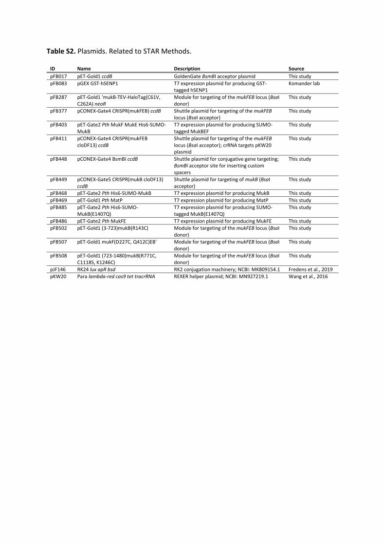
Table S2. Plasmids. Related to STAR Methods.
ID Name Description Source pFB017 pET-Gold1 ccdB GoldenGate BsmBI acceptor plasmid This study pFB083 pGEX GST-hSENP1 T7 expression plasmid for producing GST-
tagged hSENP1 Komander lab
pFB287 pET-Gold1 'mukB-TEV-HaloTag(C61V, C262A) neoR
Module for targeting of the mukFEB locus (BsaI donor)
This study
pFB377 pCONEX-Gate4 CRISPR(mukFEB) ccdB Shuttle plasmid for targeting of the mukFEB locus (BsaI acceptor)
This study
pFB403 pET-Gate2 Pth MukF MukE His6-SUMO-MukB
T7 expression plasmid for producing SUMO-tagged MukBEF
This study
pFB411 pCONEX-Gate4 CRISPR(mukFEB cloDF13) ccdB
Shuttle plasmid for targeting of the mukFEB locus (BsaI acceptor); crRNA targets pKW20 plasmid
This study
pFB448 pCONEX-Gate4 BsmBI ccdB Shuttle plasmid for conjugative gene targeting; BsmBI acceptor site for inserting custom spacers
This study
pFB449 pCONEX-Gate5 CRISPR(mukB cloDF13) ccdB
Shuttle plasmid for targeting of mukB (BsaI acceptor)
This study
pFB468 pET-Gate2 Pth His6-SUMO-MukB T7 expression plasmid for producing MukB This study pFB469 pET-Gold1 Pth MatP T7 expression plasmid for producing MatP This study pFB485 pET-Gate2 Pth His6-SUMO-
MukB(E1407Q) T7 expression plasmid for producing SUMO-tagged MukB(E1407Q)
This study
pFB486 pET-Gate2 Pth MukFE T7 expression plasmid for producing MukFE This study pFB502 pET-Gold1 (3-723)mukB(R143C) Module for targeting of the mukFEB locus (BsaI
donor) This study
pFB507 pET-Gold1 mukF(D227C, Q412C)EB' Module for targeting of the mukFEB locus (BsaI donor)
This study
pFB508 pET-Gold1 (723-1480)mukB(R771C, C1118S, K1246C)
Module for targeting of the mukFEB locus (BsaI donor)
This study
pJF146 RK24 lux apR bsd RK2 conjugation machinery; NCBI: MK809154.1 Fredens et al., 2019 pKW20 Para lambda-red cas9 tet tracrRNA REXER helper plasmid; NCBI: MN927219.1 Wang et al., 2016