
Fuzzy Assisted Handoff Algorithm for Micro and Macro ... - CORE
69
Fuzzy Assisted Handoff Algorithm for Micro and Macro Cellular System A thesis submitted in partial fulfilment of the requirements for the degree of Master of Technology in Telematics & Signal Processing By Pragyana Patnaik Roll No: 208EC113 Department of Electronics & Communication Engineering National Institute of Technology, Rourkela-769008 May 2010 brought to you by CORE View metadata, citation and similar papers at core.ac.uk provided by ethesis@nitr
-
Upload
khangminh22 -
Category
Documents
-
view
0 -
download
0
Transcript of Fuzzy Assisted Handoff Algorithm for Micro and Macro ... - CORE
Fuzzy Assisted Handoff Algorithm for Micro and Macro
Cellular System
A thesis submitted in partial fulfilment of the requirements for the degree of
Master of Technology
in
Telematics & Signal Processing
By
Pragyana Patnaik
Roll No: 208EC113
Department of Electronics & Communication Engineering
National Institute of Technology, Rourkela-769008
May 2010
brought to you by COREView metadata, citation and similar papers at core.ac.uk
provided by ethesis@nitr
Fuzzy Assisted Handoff Algorithm for Micro and Macro
Cellular System
A thesis submitted in partial fulfilment of the requirements for the degree of
Master of Technology
in
Telematics & Signal Processing
By
Pragyana Patnaik
Roll No: 208EC113
Under the supervision of
Dr. Sarat Kumar Patra
(Professor)
Department of Electronics & Communication Engineering
National Institute of Technology, Rourkela-769008
May 2010

Department of Electronics & Communication Engineering
National Institute of Technology, Rourkela
Orissa, India – 769 008
This is to certify that the thesis titled ―Fuzzy Assisted Handoff Algorithm for Micro and
Macro Cellular System”, submitted by Pragyana Patnaik, Roll No. 208EC113 in partial
fulfillment of the requirements for the award of the degree of Master of Technology in
Electronics & Communication Engineering with specialization in Telematics and Signal
Processing, to National Institute of Technology, Rourkela is an authentic work carried out by
him under my supervision and guidance.
To the best of my knowledge, the matter embodied in the thesis has not been submitted to any
other University / Institute for the award of any Degree or Diploma.
.
Prof. S. K. Patra
Professor
Email: [email protected]
CERTIFICATE
i
ACKNOWLEDGEMENTS
I am deeply indebted to Prof. (Dr.) SARAT KUMAR PATRA, HOD, Dept. of
E&CE, my supervisor on this project, for consistently providing me with the required
guidance to help me in the timely and successful completion of this project. In spite of his
extremely busy schedules in Department, he was always available to share with me his deep
insights, wide knowledge and extensive experience. His advices have value lasting much
beyond this project. I consider it a blessing to be associated with him. Also I am very
thankful to him for reviewing my thesis.
I would like to express my humble respects to Prof. G. S. Rath, Prof. G. Panda,
Prof. K. K. Mahapatra, Prof. S. Meher, Prof. S. K. Behera, Prof. D.P. Acharya, and
Prof.A.K.Sahoo for teaching me and also helping me how to learn. I would like to thanks all
faculty members of ECE Department for their help and guidance. They have been great
sources of inspiration to me and I thank them from the bottom of my heart.
I would to like express my special thanks to my research seniors of mobile communication
lab and my classmates, for their help during the research period. I‘ve enjoyed their
companionship so much during my stay at NIT, Rourkela.
I would like to thank the people who made my stay at NIT, Rourkela productive and
pleasurable. My academic experience in their company has built a strong foundation for an
exciting career
Last but not least, I would like to thank my parents, who taught me the value of hard
work by their own example. They rendered me enormous support being apart during the
whole tenure of my stay in NIT Rourkela.
Pragyana Patnaik

ii
Contents
Acknoledgment………………………………………………………………………….i
List of Figures……………………………………………………………………………………...v
List of Tables……………………………………………………………………………………..vii
List of Acronyms………………………………………………………………………………...viii
Abstract…………………………………………………………………………………………….x
CHAPTER-1 Introduction
1.1 Introduction ...................................................................................................................................... 1
1.2 Cellular Concept ............................................................................................................................... 3
1.3 Cellular Wireless Standards [8] ........................................................................................................ 4
1.4 Thesis Outline ................................................................................................................................... 8
CHAPTER-2 Cellular Handoff Fundamentals
2.1 Introduction ...................................................................................................................................... 9
2.2 Cellular Handoff Fundamentals ........................................................................................................ 9
2.3 Types of Handoff ............................................................................................................................ 10
2.4 Handoff Initiation ........................................................................................................................... 11
2.5 Features of Handoff ........................................................................................................................ 12
2.6 Handoff Complexities ..................................................................................................................... 14
2.7 Handoff Decision ............................................................................................................................ 14
2.8 Prioritization Schemes .................................................................................................................... 16
2.9 Literature Review ........................................................................................................................... 17
2.10 Conclusion .................................................................................................................................... 19
iii
CHAPTER-3 Fuzzy Logic System & ANFIS- An Introduction
3.1 Introduction .................................................................................................................................... 20
3.2 Introduction to Fuzzy Logic ........................................................................................................... 20
3.3.1 Mamdani fuzzy inference system ............................................................................................ 22
3.3.2 Sugeno Fuzzy System .............................................................................................................. 26
3.4 Introduction to ANFIS .................................................................................................................... 28
3.5 ANFIS Architecture ........................................................................................................................ 28
3.6 Conclusion ...................................................................................................................................... 31
CHAPTER-4 Fuzzy Assisted Handoff Algorithm
4.1 Introduction .................................................................................................................................... 32
4.2 FLS Handoff Structure ................................................................................................................... 32
4.3 Proposed Fuzzy Logic System ........................................................................................................ 34
4.4 ANFIS for Handoff ......................................................................................................................... 37
4.5 Conclusion ...................................................................................................................................... 38
CHAPTER-5 Result Discussion
5.1 Introduction .................................................................................................................................... 39
5.2 Simulation model ............................................................................................................................ 39
5.3 Performance of Handoff with Signalling delay and Velocity (Mamdani) ..................................... 39
5.4 Relationship between False Handoff Probability (Pfh) and Velocity .............................................. 40
5.5 Relationship between Handoff Failure Probability (Phf) and Velocity ........................................... 42
5.6 Relationship between handoff failure probability and signalling delay ......................................... 43
5.7 Sugeno Output ................................................................................................................................ 45

iv
5.8 ANFIS Output ................................................................................................................................. 47
5.9 Conclusion ...................................................................................................................................... 51
CHAPTER-6 Conclusion and Future work
6.1 Conclusion ...................................................................................................................................... 52
6.2 Scope of Future Work .................................................................................................................... 53
Bibliography ......................................................................................................................................... 54

v
List of Figures
Figure 1. 1: Cellular Concept .................................................................................................... 3
Figure 2. 1: Handoff Scenarios in Cellular System ................................................................. 10
Figure 2.2: Analysis of Handoff Process ................................................................................. 11
Figure 3. 1: An Example of Fuzzy Logic Membership Function............................................ 21
Figure 3. 2: An Example of Fuzzy Inference System ............................................................. 24
Figure 3. 3: A Two Input Two Rule Mamdani FIS with a Fuzzy Input .................................. 26
Figure 3. 4: Sugeno Rule ......................................................................................................... 27
Figure 3. 5: ANFIS Architecture ............................................................................................. 29
Figure 4. 1: Proposed Fuzzy Logic based Handoff Algorithm ............................................... 32
Figure 4. 2: Membership Function of Fuzzy Variable "Angle of Motion" ............................ 35
Figure 4. 3: Membership Function of Fuzzy Variable "Velocity" ......................................... 35
Figure 4. 4: Membership Function of Fuzzy Variable "Signalling Delay" ............................ 35
Figure 4. 5: ANFIS Structure .................................................................................................. 37
Figure 5. 1: Handoff for Different Signalling Delay (Microcellular System) ......................... 40
Figure 5. 2: Handoff for Different Velocity (Macro cellular system) ..................................... 40
Figure 5. 3: Relationship between False Handoff Initiation Probability and Velocity when BS
belongs to a Macro cellular System for Fixed Delay .............................................................. 41
Figure 5. 4: Relationship between Handoff Initiation Probability and Velocity when BS
belongs to a Microcellular System for Fixed Delay ................................................................ 41
Figure 5. 5: Relationship between Handoff Failure Probability and Velocity when BS belongs
to a Macro cellular System for Fixed Delay ............................................................................ 42
vi
Figure 5. 6: Relationship between Handoff Failure Probability and Velocity when BS belongs
to a Microcellular System for Fixed Delay ............................................................................. 42
Figure 5. 7: Relationship between Handoff Failure Probability and Delay when BS belongs to
a Micro cellular System for Fixed Velocity ............................................................................ 44
Figure 5. 8: Relationship between Handoff Failure Probability and Delay when BS belongs to
a Macrocellular System for Fixed Velocity ............................................................................. 44
Figure 5. 11: Surface plot of Handoff vs Signalling Delay and Velocity ............................... 45
Figure 5. 12: Surface plot of Handoff vs. Signalling Delay and Angle of Motion ................. 46
Figure 5. 13: Surface plot of Handoff vs. Angle of Motion and Velocity .............................. 46
Figure 5. 14: Error plot after Training ..................................................................................... 48
Figure 5. 15: FIS output after Testing with Training Data ...................................................... 48
Figure 5. 16: FIS output after Testing with Checking Data .................................................... 48
Figure 5. 17: Error plot with Gaussian Membership Function ................................................ 49
Figure 5. 18: FIS output after testing with Training Data (Gaussian Membership Function) 49
Figure 5. 19: FIS output after Testing with Training Data ...................................................... 50
vii
List of Tables
Table 1: First Generation Analog Cellular Systems .................................................................. 5
Table 2: Second Generation Digital Cellular System................................................................ 6
Table 3: Overview of 3G / IMT-2000 Standards ...................................................................... 7
Table 4: Brief Overview of Handoff Protocol ......................................................................... 15
Table 5: Fuzzy Rule Base (Mamadani Model)........................................................................ 36
Table 6: ANFIS Information (trapizoidal membership function) ........................................... 47
Table 7: ANFIS Information (Gaussian Membership function) ............................................. 49
viii
List of Acronyms
ANFIS Adaptive neuro fuzzy inference system
BS Base Station
COA Centre of area
CCI Co-channel Interference
CDMA Code division multiple access
1G First generation
4G Fourth generation
FDMA Frequency division multiple accesses
FLS Fuzzy logic system
GUI Graphical user interface
HHO Hard handoff
HMIP Hierarchical Mobile IP
IMT International Mobile Telecommunications
LOS Lline of sight
MAHO Mobile Assisted Handoff
MS Mobile Station
MSC Mobile Switching Centre
MTSO Mobile Telephone Switching Office
MT Mobile Terminal
NCHO Network Controlled Handoff
NLOS Non line of sight
QOS Quality of service
ix
RSS Received Signal Strength
2G Second generation
SHO Soft handoff
3G Third generation
TDMA Time division multiple accesses
x
Abstract
Handoff is an essential part of any Mobile Communication Network. Efficient handoff
algorithms provide cost-effective way for enhancing the capacity and QOS of cellular system.
The work reported here in presents multi-criteria based hard handoff algorithm for micro and
macro-cellular architecture. Fuzzy technique has been used as optimization engine. The fuzzy
handoff algorithm based on Received Signal Strength (RSS), absolute threshold value,
hysteresis level, slope ratios and speed of Mobile Terminal (MT) have been previously
developed for conventional cellular networks. In this work the handoff algorithm has been
improved by considering two new parameter, signalling delay and angle of motion of MT
along with velocity as our input criteria. Two fuzzy models named Mamdani and Sugeno
have been used for processing the input criteria. Further, ANFIS has also been used to tune
the Sugeno model for parameter adjustment. The proposed fuzzy inference scheme uses
triangular and trapezoidal membership function for fuzzification. The types of defuzzification
method used are centriod and weighted average formula for Mamdani and Sugeno model
respectively. Extensive simulation analysis has been used to validate the proposed technique.
The results show that fuzzy is a viable option for handoff.

1
Chapter-1 Introduction
1.1 Introduction
Handoff is one of the key operations in cellular mobile communication systems. It is the
means through which the continuity of a call is maintained when Mobile Terminal (MT)
coverage moves from one cell area to another. Handoff can be defined as the process of
transferring a mobile station from one base station or channel to another. The channel change
due to handoff occurs through a change in time slot, frequency band, codeword, or a
combination of these. In time division multiple accesses (TDMA) it occurs through a change
in time slot. Where as in case of frequency division multiple accesses (FDMA) and code
division multiple accesses (CDMA) it is achieved by frequency change and code change
respectively. Efficient handoff algorithms preserve and enhance the capacity and quality of
service (QOS) of communication systems. It is necessary to ensure that handoff should be
performed reliably and without disruption to any calls. Failing which, leads to dropped calls
and customer dissatisfaction. Thus it is necessary to revive the handoff issues in cellular
mobile systems. The process of handoff can be divided into three stages: decision stage,
planning stage and execution stage. In the decision stage, predefined matrices parameters are
measured by mobile unit to determine whether handoff should be initiated. In planning stage,
the necessary resource (e.g. available bandwidth) in the candidate base station that the mobile
unit would be handed over to is checked and assigned to the mobile unit. In the execution
stage, connection is transferred from the serving base station to candidate base station and the
appropriate protocols are performed.
The work reported here focuses on the decision stage of handoff process. Many of the
existing handoff algorithms do not exploit the advantage of multi-criteria handoff, which can
provide better performance than single criterion algorithms. This is due to the flexible and
complementary nature of handoff criteria. A fuzzy based multi-criteria handoff algorithm is
proposed as a solution to handoff decision. Following are the reasons for using fuzzy system:
2
[A] Fuzzy systems are conceptually easy to understand; [B] it brings in intelligence in the
system; [C] Fuzzy system has been implemented in many engineering application with a
considerable success; [D] Fuzzy system are simple and hence easy to implement in hardware.
Handoff with fixed parameters cannot perform well in different system environment. Specific
characteristics of the communication system should be taken into account while designing a
handoff algorithm. Recently, the use of link layer information for handoff detection has [1]
[2] [3], Signalling delay of handoffs mainly depends on traffic load in the network and
distance between user and its home network. So designing handoff algorithms with fixed
signalling delay can suffer from poor performance when the handoff signalling delay varies.
The existing link-layer assisted handoff algorithms do not consider the influence of user‘s
speed on the performance of handoff. An attempt has been made to address this issue.
Fuzzy logic based techniques for handoff in cellular communication has been reported in [4] -
[5]. The handoff criteria use threshold values to membership functions. The possible
weakness in [4] and [6] is the jump values inherent in some fuzzy sets and takes only non line
of sight (NLOS) transmission into consideration. The fuzzy sets chosen in this work have
smooth membership function that increases or decreases gradually. Handoff techniques in
cellular networks are reported briefly in literature review of Chapter-2.
In our new handoff decision algorithm the handoff decision matrices are, velocity of the MT
which we consider positive for moving away and negative for approaching the serving BS,
signalling delay and angle of motion of MT. We use Mamdani and Sugeno fuzzy inference
system to process these matrices parameters. The output of our FIS is the membership value
of handoff. Considering the threshold for handoff as 0.5 we plot the probability of false
handoff and handoff failure. Our tests for the studied case have shown that the handoff
increases with increasing velocity of MT and signalling delay. There is a significant decrease
in false handoff initiation probability as compared to analytical results. From the results it
was observed that the false handoff initiation probability and handoff failure probability
increase with increase the cell radius. The output surface plot of Sugeno model clearly
specify inter and intra system handoff. ANFIS is applied to Sugeno model to tune the
parameter and to make the model adaptive. The error shown after training is satisfactory. The
output with training and testing data were also presented.
3
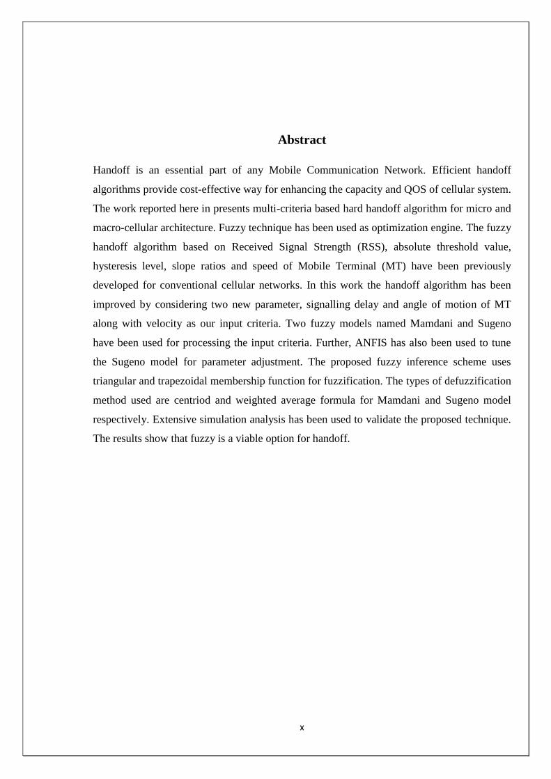
1.2 Cellular Concept
The cellular concept is the idea of replacing large, single high power transmitter cells with
several small, low power transmitter cells. Each of these cells typically provides coverage to
a small portion of the coverage area. This effectively solved the problem of limited user
capacity and spectral congestion by frequency reuse. This permits high capacity in a limited
spectral allocation without any major system overhauls [7]. A base station transmitter at the
centre of the cell is assumed to service all the mobile stations within the cell area. This can be
seen in Figure-1.1. Some of the terminology used in cellular communications is explained
below:
Mobile Station (MS): The mobile station is intended for use while in motion at an
unspecified location.
Base Station (BS): The base station is a fixed station used for radio communication
with MS.
Figure1. 1: Cellular Concept
Cell 1
Cell 3
Cell 2
4
Mobile Switching Centre (MSC): The mobile switching centre coordinates the
routing of calls in a large service area. It is also referred to as the Mobile Telephone
Switching Office (MTSO).
Forward Channel: The forward channel is the radio channel used for the transmission
of information from the base station to the mobile station. It is also known as the downlink.
Reverse Channel: The reverse channel is the radio channel used for the transmission of
information from the mobile station to the base station. It is also known as the uplink.
Handoff: Handoff is a process of transferring a mobile station from one base station or
channel to another. The channel change due to handoff occurs through a time slot for time
division multiple access (TDMA), frequency band for frequency division multiple access
(FDMA), and codeword for code division multiple access (CDMA) systems.
Co-channel Interference (CCI): The co channel interference is caused when the
signal of the specified cell is corrupted due to another signal in remote cell using the same
frequency or channel.
The following phases are involved in the planning of cellular communications:
Assessment of traffic density;
Determination of cell sizes and capacity;
Decisions about unidirectional or sectored cells and antenna directions;
Selection of best BS sites to cover the required area;
Frequency allocation;
Choice of power control parameters; and
Selection of handoff parameters.
1.3 Cellular Wireless Standards [8]
Cellular wireless standard can be broadly divided into four categories, i.e. first generation
(1G), second generation (2G), third generation (3G) and fourth generation (4G) respectively.
The first generation (1G) wireless communications system use frequency division multiple
access (FDMA) as the multiple access technology. FDMA is an analog transmission
technique that is inherently narrowband. The individual calls used different frequencies and
5
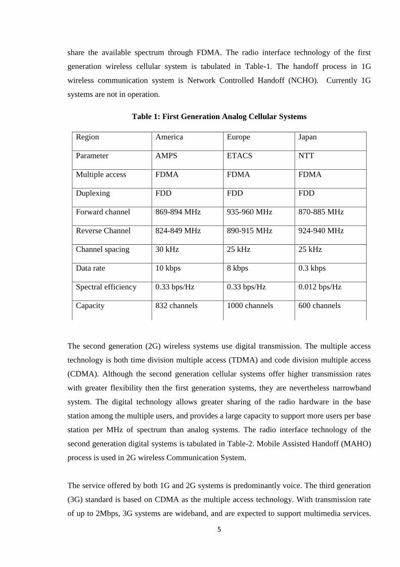
share the available spectrum through FDMA. The radio interface technology of the first
generation wireless cellular system is tabulated in Table-1. The handoff process in 1G
wireless communication system is Network Controlled Handoff (NCHO). Currently 1G
systems are not in operation.
Table 1: First Generation Analog Cellular Systems
The second generation (2G) wireless systems use digital transmission. The multiple access
technology is both time division multiple access (TDMA) and code division multiple access
(CDMA). Although the second generation cellular systems offer higher transmission rates
with greater flexibility then the first generation systems, they are nevertheless narrowband
system. The digital technology allows greater sharing of the radio hardware in the base
station among the multiple users, and provides a large capacity to support more users per base
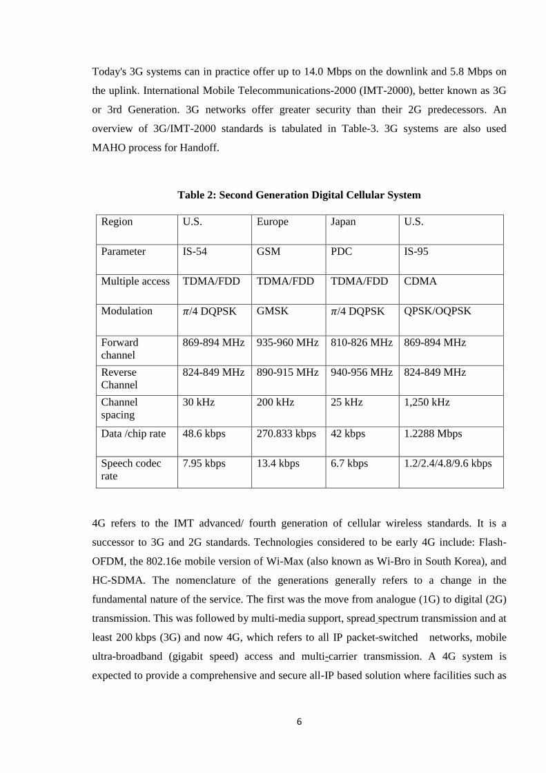
station per MHz of spectrum than analog systems. The radio interface technology of the
second generation digital systems is tabulated in Table-2. Mobile Assisted Handoff (MAHO)
process is used in 2G wireless Communication System.
The service offered by both 1G and 2G systems is predominantly voice. The third generation
(3G) standard is based on CDMA as the multiple access technology. With transmission rate
of up to 2Mbps, 3G systems are wideband, and are expected to support multimedia services.
Region America Europe Japan
Parameter AMPS ETACS NTT
Multiple access FDMA FDMA FDMA
Duplexing FDD FDD FDD
Forward channel 869-894 MHz 935-960 MHz 870-885 MHz
Reverse Channel 824-849 MHz 890-915 MHz 924-940 MHz
Channel spacing 30 kHz 25 kHz 25 kHz
Data rate 10 kbps 8 kbps 0.3 kbps
Spectral efficiency 0.33 bps/Hz 0.33 bps/Hz 0.012 bps/Hz
Capacity 832 channels 1000 channels 600 channels
6
Today's 3G systems can in practice offer up to 14.0 Mbps on the downlink and 5.8 Mbps on
the uplink. International Mobile Telecommunications-2000 (IMT-2000), better known as 3G
or 3rd Generation. 3G networks offer greater security than their 2G predecessors. An
overview of 3G/IMT-2000 standards is tabulated in Table-3. 3G systems are also used
MAHO process for Handoff.
Table 2: Second Generation Digital Cellular System
4G refers to the IMT advanced/ fourth generation of cellular wireless standards. It is a
successor to 3G and 2G standards. Technologies considered to be early 4G include: Flash-
OFDM, the 802.16e mobile version of Wi-Max (also known as Wi-Bro in South Korea), and
HC-SDMA. The nomenclature of the generations generally refers to a change in the
fundamental nature of the service. The first was the move from analogue (1G) to digital (2G)
transmission. This was followed by multi-media support, spread spectrum transmission and at
least 200 kbps (3G) and now 4G, which refers to all IP packet-switched networks, mobile
ultra-broadband (gigabit speed) access and multi-carrier transmission. A 4G system is
expected to provide a comprehensive and secure all-IP based solution where facilities such as
Region U.S. Europe Japan U.S.
Parameter IS-54 GSM PDC IS-95
Multiple access TDMA/FDD TDMA/FDD TDMA/FDD CDMA
Modulation 𝜋/4 DQPSK GMSK 𝜋/4 DQPSK QPSK/OQPSK
Forward
channel
869-894 MHz 935-960 MHz 810-826 MHz 869-894 MHz
Reverse
Channel
824-849 MHz 890-915 MHz 940-956 MHz 824-849 MHz
Channel
spacing
30 kHz 200 kHz 25 kHz 1,250 kHz
Data /chip rate 48.6 kbps 270.833 kbps 42 kbps 1.2288 Mbps
Speech codec
rate
7.95 kbps 13.4 kbps 6.7 kbps 1.2/2.4/4.8/9.6 kbps

7
IP telephony, ultra-broadband Internet access, gaming services and streamed multimedia may
be provided to users.
Table 3: Overview of 3G / IMT-2000 Standards
ITU IMT
2000
Common names Bandwid
th of data
Pr
e
4G
duplex chan
nel
description Geogra
phical
areas
TDMA
single
carrier
(IMT-SC)
EDGE (UWT-
136)
EDGE
Evolutio
n
N
O
N
E
FDD
TD
MA
Evolutionar
y upgrade to
GSM/GPRS
World
wide
except
Japan
and
south
Korea
CDMA
multi
carrier
(IMT-MC)
CDMA2000
EV-DO
U
M
B
CD
MA
Evolutionar
y upgrade to
CDMA one
(IS-95)
Americ
as,
Asia‘s,
some
other
CDMA
direct
spread
(IMT_DS)
UMTS
W-
CDMA
HSPA
L
T
E
Family of
revolutionar
y standard
World
wide
TD-
CDMA
Europe CDMA-
TDD
(IMT-TC)
TDD
china TD-
SCDM
A
FDMA/T
DMA
(IMT-FT)
DECT
none
FD
MA/
TD
MA
Short-range,
standard for
cordless
phone
Europe,
USA
IP-
OFDMA
WIMAX
(IEEE 802.16)
OFD
MA
World
wide

8
1.4 Thesis Outline
This section outlines the thesis layout. This thesis is organised into seven chapters. Following
this introduction; Chapter-2 reviews in brief the overview of handoff in cellular mobile
communication systems. Chapter-3, discusses fuzzy logic, Mamdani and Sugno inference
engine and Adaptive neuro fuzzy inference system (ANFIS). Chapter-4 we describes the
proposed algorithm and its design procedure. Chapter-5 analyzes the performance of
Mamdani and Sugeno fuzzy handoff performance is analyzed. Anfis is used for learning and
model validation. Finally, Chapter-6 presents the concluding remarks and future work.

9
Chapter-2 Cellular Handoff Fundamentals
2.1 Introduction
This chapter presents various aspects of handoff and discusses handoff related features of
cellular systems. Desirable features of handoff are highlighted, and complexities of handoff
are described. Handoff criteria‘s, conventional handoff algorithms and emerging handoff
algorithms are discussed.
2.2 Cellular Handoff Fundamentals
Handoff is the key operation in cellular mobile communication systems. It is the means
through which the continuity of a call is maintained when MT moves from one cell area to
another. Handoff can be defined as the process of transferring a mobile station from one base
station or channel to another. The channel change due to handoff occurs through a change in
time slot, frequency band, codeword or a combination of these. In time division multiple
access (TDMA) time slot is changed. Where as in frequency division multiple access
(FDMA) frequency is changed and code division multiple access (CDMA) code is changed.
Efficient handoff algorithms cost-effectively preserve and enhance the capacity and quality of
service (QOS) of communication systems.
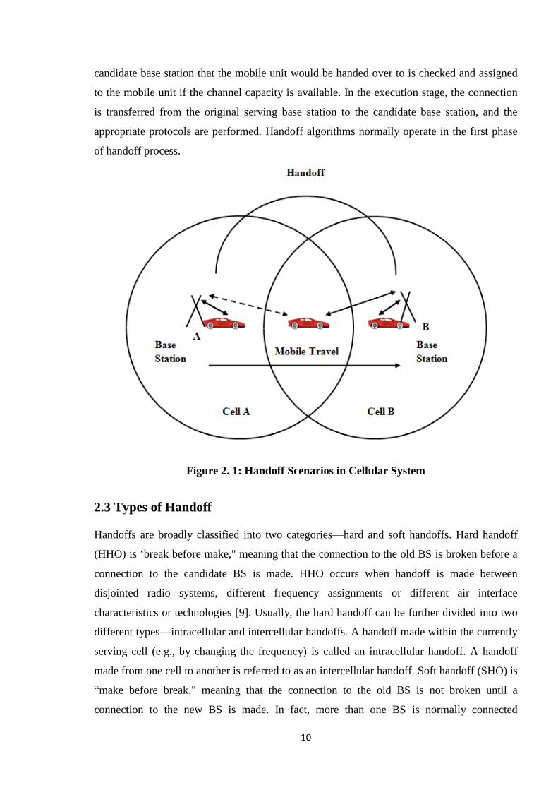
Figure-2.1 shows a simple handoff scenario in which a Mobile Station (MS) travels from
Base Station (BS) A to BS B. Initially, the MS is connected to BS A. The overlap between
the two cells is the handoff region in which the mobile may be connected to either BS A or
BS B. At a certain time during the travel, the mobile is handed off from BS A to BS B. When
the MS is close to BS B, it remains connected to BS B. The process of handoff has to be
completed in the overlap region.
The process of handoff can be divided into three stages: the decision stage, the planning stage
and the execution stage. In the decision stage, predefined link quality metrics are measured
by the network elements or by the mobile unit to decide whether the handoff should be
initiated. In the planning stage, the necessary resource (e.g., the available bandwidth) in the
10
candidate base station that the mobile unit would be handed over to is checked and assigned
to the mobile unit if the channel capacity is available. In the execution stage, the connection
is transferred from the original serving base station to the candidate base station, and the
appropriate protocols are performed. Handoff algorithms normally operate in the first phase
of handoff process.
Figure 2. 1: Handoff Scenarios in Cellular System
2.3 Types of Handoff
Handoffs are broadly classified into two categories—hard and soft handoffs. Hard handoff
(HHO) is ‗break before make," meaning that the connection to the old BS is broken before a
connection to the candidate BS is made. HHO occurs when handoff is made between
disjointed radio systems, different frequency assignments or different air interface
characteristics or technologies [9]. Usually, the hard handoff can be further divided into two
different types—intracellular and intercellular handoffs. A handoff made within the currently
serving cell (e.g., by changing the frequency) is called an intracellular handoff. A handoff
made from one cell to another is referred to as an intercellular handoff. Soft handoff (SHO) is
―make before break," meaning that the connection to the old BS is not broken until a
connection to the new BS is made. In fact, more than one BS is normally connected
11
simultaneously to the MS. There are different types of SHO. When sectors of the same BS
are involved in communication with the MS, the handoff is called softer handoff. When one
sector from each BS is involved, the handoff is called soft handoff. When multiple sectors of
one BS and one or more sectors of another BS communicate with the MS, the resulting SHO
is called softer-soft handoff. Mobility in network is managed by two different handoff
strategies, namely Horizontal Handoff and Vertical Handoff. In case of Horizontal Handoff,
handoff is between two network access points or base stations that use the same wireless
network access technology. The handoff is purely due to mobility of the mobile station. In
case of Vertical Handoff, handoff is between two network access points or base stations that
use the different wireless network access technology.
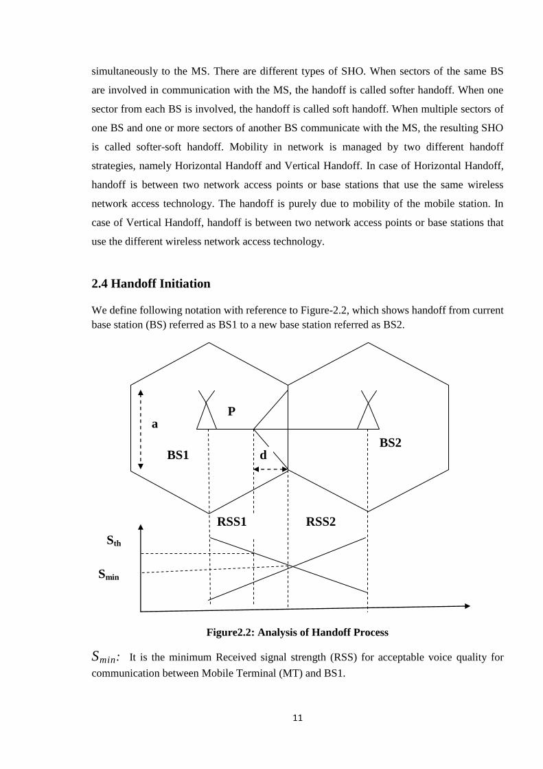
2.4 Handoff Initiation
We define following notation with reference to Figure-2.2, which shows handoff from current
base station (BS) referred as BS1 to a new base station referred as BS2.
Figure2.2: Analysis of Handoff Process
Smin: It is the minimum Received signal strength (RSS) for acceptable voice quality for
communication between Mobile Terminal (MT) and BS1.
d BS1 BS2
RSS2 RSS1
Sth
Smin
a P
12
Sth: The threshold value of RSS to initiate handoff. Therefore when RSS of BS1 drops
below Sth the MT initiate handoff to new base station i.e. BS2.
Δ = Sth – Smin: This margin is called Δ should not be very large (for unnecessary
handoff) or too small (leading to call drop due to weak signal before handoff is completed).
During the course of movement, the MT discovers that it is going to move into the coverage
area of the BS2 and hence needs to perform hierarchical Mobile IP (HMIP) registration with
the BS2. The MT may learn about the possibility of moving into another cell when the RSS
of BS1 decreases continuously. Once the MT discovers that it may enter into the coverage
area of the BS2, the next challenge is to decide the right time to initiate HMIP registration
procedures with the BS2. The existing link-layer-assisted HMIP protocols propose to initiate
the HMIP registration when the RSS from the serving BS, e.g., BS1 in Figure-2.2 drops
below a fixed threshold value (Sth). Below, we analyze the performance of these solutions.
We assume that, during the course of its movement, when the MT reaches the point P (the
distance of P from the cell boundary is d) as shown in Figure-2.2, the RSS from the BS1
drops below Sth. Therefore, when the MT reaches P, it initiates the HMIP registration with
the BS2. At this point, the RSS received by the MT from BS2 shown as RSS2 in Figure-2.2
may not be sufficient for the MT to send the HMIP registration messages to BS2. Hence, the
MT may send the HMIP registration messages to BS2 through BS1. This is called
preregistration [3]. For a smooth and successful handoff from BS1 to BS2, MT‘s HMIP
registration with BS2 and link and MAC layer associations with BS2 must be completed
before the RSS of BS1 drops below Smin, i.e., before the MT moves beyond the coverage area
of BS2.
2.5 Features of Handoff
An efficient handoff algorithm can achieve many desirable features by trading different
operating characteristics. A list of desirable features of handoff algorithms are described
below [10] [11] [12] [13] [14].
Handoff should be fast so that the user does not experience service degradation or
interruption. Service degradation may be due to a continuous reduction in signal
strength or an increase in CCI adds to the network delay at the Mobile Switching .

13
Service interruption may be due to a ―break before make" approach of HHO. Note
that the delay in the execution of a handoff algorithm Centre (MSC) or Mobile
Telephone Switching Office (MTSO). Fast handoff also reduces CCI since it prevents
the MS from going too far into the new cell.
Handoff should be reliable. This means that the call should have good quality after
handoff. SIR and RSS help determine the potential service quality of the candidate
BS.
Handoff should be successful; a free channel should be available at the candidate BS.
Efficient channel allocation algorithms and some traffic balancing can maximize the
probability of a successful handoff.
The effect of handoff on the quality of service (QoS) should be minimal. The quality
of service may be poor just before handoff due to a continuous reduction in RSS, SIR,
etc.
Handoff should maintain the planned cellular borders to avoid congestion, high
interference, and use of assigned channels inside the new cell. Each BS can carry only
its planned traffic load. Moreover, there is a possibility of increased interference if the
MS goes far into another cell site while still being connected to a distant BS because
co channel distance is reduced and the distant BS tends to use a high transmit power
to serve the MS.
The number of handoffs should be minimized. Excessive handoffs lead to heavy
handoff processing loads and poor communication quality, which may result
following: (i) the more attempts at handoff, the more chances that a call will be denied
access to a channel, resulting in a higher handoff call dropping probability, (ii) a lot of
handoff attempts causes more delay in the MSC processing of handoff requests,
which will cause signal strength to decrease over a longer time period to a level of
unacceptable quality. Also, the call may be dropped if sufficient SIR is not achieved.
Handoff requires network resources to connect the call to a new BS. Thus,
minimizing the number of handoffs reduces the switching load. Unnecessary handoffs
should be prevented; the current BS might be able to provide the desired service
quality without interfering with other MSs and BSs.
14
2.6 Handoff Complexities
Several factors complicate the process of handoff. Some of these handoff complexities are
briefly listed below:
Cellular structures and topographical features: There are different types of
cellular system deployment scenarios. There could be big cells in rural or suburban areas
(called macro cells), small cells in urban areas (called microcells) or an overlay system with a
given area, both containing macro cells and microcells. The propagation environment is quite
different in micro or macro cells. Large scale fading and small scale fading has large
variations in urban microcells then in rural macro cells. Furthermore, in urban microcells
effects such as street corner effect exists, are characterized by a sudden drop in signal
strength over a short distance.
Traffic: Traffic distribution is a function of time and space. The handoff process should
work well in different traffic scenarios. Examples of approaches to deal with traffic no
uniformities include traffic balancing in adjacent cells, use of different cell sizes, no uniform
channel allocation and dynamic channel allocation.
System constraints: Several systems have constraints over common characteristics,
such as transmit power and propagation delay. The handoff process should consider such
system constraints.
Mobility: The quality of communication link is influenced by the degree of mobility. A
high speed MS moving away from a serving BS, experiences signal degradation faster than a
low speed MS. Hence mobility plays an important role in the handoff process.
2.7 Handoff Decision
There are numerous methods for performing handoff, at least as many as the kinds of state
information that have been defined for MSs, as well as the kinds of network entities that
maintain the state information [15]. The decision-making process of handoff may be
centralized or decentralized (i.e., the handoff decision may be made at the MS or network).
From the decision process point of view, there are at least four different kinds of handoff
decisions; network controlled handoff (NCHO), mobile assisted handoff (MAHO), soft
handoff (SHO) and mobile controlled handoff (MCHO).
15
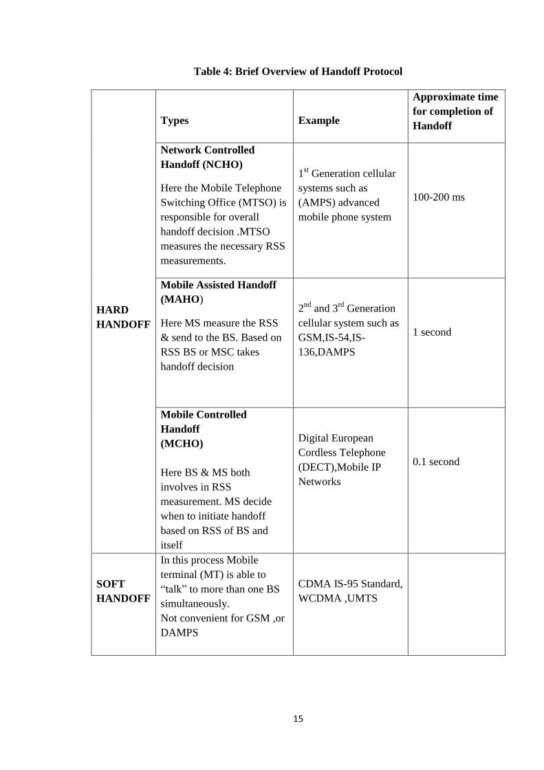
Table 4: Brief Overview of Handoff Protocol
HARD
HANDOFF
Types
Example
Approximate time
for completion of
Handoff
Network Controlled
Handoff (NCHO)
Here the Mobile Telephone
Switching Office (MTSO) is
responsible for overall
handoff decision .MTSO
measures the necessary RSS
measurements.
1st Generation cellular
systems such as
(AMPS) advanced
mobile phone system
100-200 ms
Mobile Assisted Handoff
(MAHO)
Here MS measure the RSS
& send to the BS. Based on
RSS BS or MSC takes
handoff decision
2nd
and 3rd
Generation
cellular system such as
GSM,IS-54,IS-
136,DAMPS
1 second
Mobile Controlled
Handoff
(MCHO)
Here BS & MS both
involves in RSS
measurement. MS decide
when to initiate handoff
based on RSS of BS and
itself
Digital European
Cordless Telephone
(DECT),Mobile IP
Networks
0.1 second
SOFT
HANDOFF
In this process Mobile
terminal (MT) is able to
―talk‖ to more than one BS
simultaneously.
Not convenient for GSM ,or
DAMPS
CDMA IS-95 Standard,
WCDMA ,UMTS
16
As the handoff decision making Process is decentralized (i.e., moving from NCHO to
MCHO), handoff delay (i.e., the time required to execute a handoff request) decreases, but
the measurement information available to make a handoff decision also decreases. These
protocols are summarised in Table-4
2.8 Prioritization Schemes
One of the ways to reduce the handoff failure rate is to prioritize handoff. Handoff algorithms
that try to minimize the number of handoff give poor performance in heavy traffic situations.
In such situations, a significant handoff performance improvement can be obtained by
prioritizing handoff. Two of the most important parameter for evaluating a handoff processes
are forced termination probability and call blocking probability. An ideal handoff is one in
which forced probability decreases while maintaining blocking probability. In non
prioritization scheme new call and handoff calls are treated in same way, leading to increases
in the forced termination probability. Prioritization scheme reduce the forced termination
probability by assigning more channel to handoff calls. The two known prioritization
schemes are: Guard channels and Queuing of handoff calls.
Guard channels:
In this scheme some of the total available channels in a cell are reserved for handoff calls
only. Hence, less no of channels are available for originating call. This process increases the
call blocking probability. However, Guard channel scheme provide better spectrum
utilization under dynamic channel assignment strategies.
Queuing handoff:
Queuing schemes queues the handoff calls when all channels are occupied in a base station.
When a channel is released it is assigned to one of the handoff calls in queue. Queuing is
possible due to time interval between handoff initiation and receiver threshold. This scheme
can be used with or without the guard channel scheme and does not provide any guarantee for
zero forced termination probability.

17
2.9 Literature Review
A large number of handoff algorithms have been proposed in the literature and classified
according to the metrics used to decide whether a handoff is necessary or not, where these
metrics are monitored, and how these metrics are processed. Some of the metrics proposed
are; signal strength [16], distance [10], signal to noise ratio [17], bit error rate [18], traffic
load [19], word error indicator [11], quality indicator [11] and some combination of these
[11] [12]. Metrics can be measured and processed on the network entity or on the mobile.
There are several handoff decision algorithms that employ tools of artificial intelligence like
fuzzy logic systems [20] [13], neural networks [20], [14], and pattern recognition algorithms
[20], [21] [22] to process the collected metrics.
The Received Signal Strength (RSS) based handoff algorithm associates mobile host to the
access point, which has the strongest perceived signal strength at the mobile host side. The
signal received from an access point degrades as the distance between the mobile and the
access point increases. However, this degradation is a random process due to uncertainties in
the propagation environment. Around mid-point between two access points, the difference in
the signal strengths received from access point 1 and access point 2 oscillates and the mobile
may handoff several times between access point 1 and access point 2. This is called the ping-
pong effect.
To remedy the ping-pong effect, a threshold is introduced to the received signal strength
based handoff algorithm [23]. The mobile does not hand off as long as the received signal
strength from the currently serving access point does not drop below the predetermined
threshold level. This algorithm is called Absolute Signal Strength algorithm [20]. Another
technique is to introduce a hysteresis to the RSS algorithm [23]. The mobile does not hand
off to another access point while the received signal strength from the candidate access point
is not better an amount of predetermined hysteresis level than the received signal strength of
the currently serving access point. This algorithm is called Relative Signal Strength algorithm
[20]. Introducing both hysteresis and threshold is called the combined absolute and relative
signal strength algorithm [20]. Either introducing hysteresis or threshold reduces the ping-
pong effect but introduces a delay to the handoff, i.e., handoff is done later than it is
expected. Effects of delaying handoff are increased interference, lower grade of service, i.e.,
increased call blocking and dropping rates. There are studies that have optimized signal-
18
strength based handoff algorithms by minimizing two conflicting design criteria, the handoff
delay and the mean number of handoffs between access points [10] [12]. In the design of
handoff algorithms, there is an inherent trade off in timeliness and accuracy. The algorithms,
which we explained thus far, were signal strength based algorithms. Another category is the
distance-based algorithms.
Distance-based algorithms relate the mobile with the closest access point [10]. The relative
distance measurements can be obtained by comparing propagation delay times. Velocity
adaptive handoff algorithms consider mobiles with different velocities, i.e., the handoff needs
of fast moving mobiles should be determined immediately. This can be achieved by adjusting
the effective length of the averaging window in which received signal strengths from the
access point are averaged [15]. In direction biased algorithms handoffs to the access points
towards which the mobile is moving are encouraged, while handoffs to the access points from
which the mobile is receding is discouraged [20]. In pre-selection handoff algorithm, a
mobile hands off to the access point towards which the mobile is moving even though
measured handoff decision metrics of that access point is not the best. Considering that these
metrics will improve as the mobile gets closer to the access point. However it is essentially
complex to make handoff decision considering multiple criteria. Sometimes, the trade-off of
some criteria should be considered. Therefore heuristic approaches based on Neural network
(NN), Genetic algorithm (GA) and fuzzy logic (FL) can prove to be efficient for wireless
networks.
Fuzzy logic systems and neural network classifiers are good candidates for pattern classifiers
due to their non-linearity and generalization capability. When employing pattern recognition
based algorithms, we have the overhead of obtaining the training data and actually pre-
training the system. However, when the system is trained, we have the opportunity to employ
multi-criteria algorithms and optimizing the handoff decision with conflicting criteria, i.e.,
handoff delay and number of handoffs. Some researchers have applied fuzzy logic theory in
handoff process such as Kinoshita and Oku [24], Homnan and Benjapolakul [25], and
Edwards et al. [26]. Kinoshita and Oku applied fuzzy logic for creating inference rules for
softer decision but emphasizing on HHO in indoor areas. Homnan and Benjapolakul
proposed HHO based on fuzzy inference. The signal strength that a mobile station receives
from a base station and the distance between a mobile station and a base station are used as
inputs, while the output is the handoff decision value. Edwards et al. [26] proposed two
handoff techniques using fuzzy logic for microcellular HHO. The first algorithm uses an

19
adaptive fuzzy predictor, while the second algorithm uses a fuzzy averaging technique. The
results of [26] show that fuzzy is a viable option for microcellular HHO.
2.10 Conclusion
A high performance handoff algorithm can achieve many of the desirable features by making
appropriate tradeoffs. However, several factors such as topographical features, traffic
variations, propagation environments, and system-specific constraints complicate the task of
handoff algorithms. Handoff algorithms with a specific set of parameters cannot perform
uniformly well in different communication system deployment scenarios. These system
structures are expected to co-exists in future wireless communication systems and warrant a
substantial study. Handoff represents one of the radio resource management tasks carried out
by cellular systems. Other resource management functions include admission control, channel
assignment, and power control. If resource management tasks are treated in an integral
manner, better overall performance can be obtained to achieve global goals by making
appropriate tradeoffs.
20
Chapter-3 Fuzzy Logic SystemAnd ANFIS
- An Introduction
3.1 Introduction
There are several tools of AI that help utilize human knowledge about the system to develop
high performance systems. Some of the major AI tools are artificial neural network, fuzzy
logic, and genetic algorithm and experts systems. This research exploits capability of fuzzy
logic to develop adaptive intelligent handoff algorithms.
3.2 Introduction to Fuzzy Logic
Information can be represented by numbers or linguistic descriptions. For example,
Temperature can be represented by the number 20 0F or by the linguistic description ―Cold."
The description ―cold" is fuzzy and may represent any temperature between 10 0F and 30
0F,
which can be called the fuzzy set (or fuzzy region) for the fuzzy variable temperature. Since
humans usually think in terms of linguistic descriptions, giving these descriptions some
mathematical form helps exploit human knowledge. Fuzzy logic utilizes human knowledge
by giving the fuzzy or linguistic descriptions a definite structure.
A concise description of fuzzy logic theory is given next. First, basic concepts of fuzzy logic
are introduced. These concepts are then utilized to explain a popular form of fuzzy logic
system (FLS) that can serve as a building block in a system incorporating fuzzy logic. A
comprehensive theory of fuzzy logic can be found in [27].
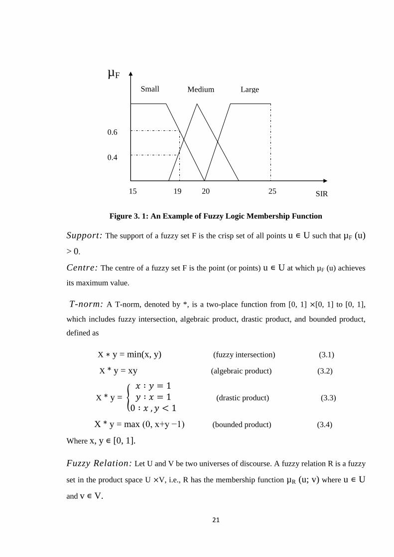
Fuzzy Set: Let U be a collection of objects and be called the universe of discourse. A
fuzzy set F ∊ U is characterized by a membership function µF (u): U → [0, 1] where µF
(u) represents the degree (or grade) of membership of u ∊ U in the fuzzy set F. Figure- 3.1
shows the membership functions of three fuzzy sets, ―small," ―medium," and ―large," for a
fuzzy variable SIR. The universe of discourse is all possible values of SIRs, i.e., U = [15, 25].
At an SIR of 19 dB, the fuzzy set ―small" has the membership value 0.6.
Hence, µsmall (19) = 0:6. Similarly, µmedium (19) = 0:4, and µlarge (19) = 0.
21
Figure 3. 1: An Example of Fuzzy Logic Membership Function
Support: The support of a fuzzy set F is the crisp set of all points u ∊ U such that µF (u)
> 0.
Centre: The centre of a fuzzy set F is the point (or points) u ∊ U at which µF (u) achieves
its maximum value.
T-norm: A T-norm, denoted by *, is a two-place function from [0, 1] ×[0, 1] to [0, 1],
which includes fuzzy intersection, algebraic product, drastic product, and bounded product,
defined as
X ∗ y = min(x, y) (fuzzy intersection) (3.1)
X * y = xy (algebraic product) (3.2)
X * y =
𝑥 ∶ 𝑦 = 1𝑦 ∶ 𝑥 = 1
0 ∶ 𝑥 ,𝑦 < 1
(drastic product) (3.3)
X * y = max (0, x+y −1) (bounded product) (3.4)
Where x, y ∊ [0, 1].
Fuzzy Relation: Let U and V be two universes of discourse. A fuzzy relation R is a fuzzy
set in the product space U ×V, i.e., R has the membership function µR (u; v) where u ∊ U
and v ∊ V.
15 19 20 25
0.6
0.4
µF
SIR
Small Medium Large

22
Sup-Star Composition: Let R and S be fuzzy relations in U ×V and V ×W;
respectively. The sup-star composition of R and S is a fuzzy relation denoted by RoS and is
given by
µ RoS (u, w) = supv∊V [µR (u, v) *µS (v, w)] (3.5)
Where u ∊ U, w ∊ W; and * could be any operator in the T-norm defended earlier. It is
clear that RoS is a fuzzy set in U ×W.
Fuzzy Implications: Let A and B be fuzzy sets in U and V; respectively. A fuzzy
implication, denoted by a → B, is a special kind of fuzzy relation in U × V with the
following membership function:
µA→B (u, v) =µA (u)*µB (v) (3.6)
This fuzzy implication is known as fuzzy conjunction. Other types of fuzzy implications are
also available [27].
3.3 Fuzzy Inference System
Fuzzy inference systems (FISs) are also known as fuzzy rule-based systems, fuzzy model,
fuzzy expert system, and fuzzy associative memory. This is a major unit of a fuzzy logic
system. The decision-making is an important part in the entire system. The FIS formulates
suitable rules and based upon the rules the decision is made. This is mainly based on the
concepts of the fuzzy set theory, fuzzy IF–THEN rules, and fuzzy reasoning. FIS uses ―IF. . .
THEN‖ statements, and the connectors present in the rule statement are ―OR‖ or ―AND‖ to
make the necessary decision rules. The basic FIS can take either fuzzy inputs or crisp inputs,
but the outputs it produces are almost always fuzzy sets. When the FIS is used as a controller,
it is necessary to have a crisp output. Therefore in this case de-fuzzification method is
adopted to best extract a crisp value that best represents a fuzzy set. The whole FIS is
discussed in detail in the following subsections:
3.3.1 Mamdani fuzzy inference system
Mamdani fuzzy inference method is the most commonly seen fuzzy methodology. Mamdani
method was among the first control systems built using fuzzy set theory. It was proposed by
Mamdani (1975) as an attempt to control a steam engine and boiler combination by
synthesizing a set of linguistic control rules obtained from experienced human operators.
23
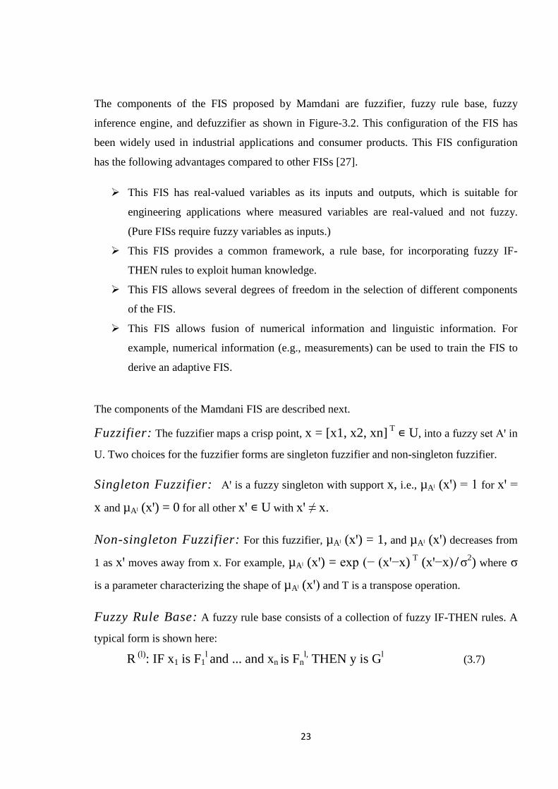
The components of the FIS proposed by Mamdani are fuzzifier, fuzzy rule base, fuzzy
inference engine, and defuzzifier as shown in Figure-3.2. This configuration of the FIS has
been widely used in industrial applications and consumer products. This FIS configuration
has the following advantages compared to other FISs [27].
This FIS has real-valued variables as its inputs and outputs, which is suitable for
engineering applications where measured variables are real-valued and not fuzzy.
(Pure FISs require fuzzy variables as inputs.)
This FIS provides a common framework, a rule base, for incorporating fuzzy IF-
THEN rules to exploit human knowledge.
This FIS allows several degrees of freedom in the selection of different components
of the FIS.
This FIS allows fusion of numerical information and linguistic information. For
example, numerical information (e.g., measurements) can be used to train the FIS to
derive an adaptive FIS.
The components of the Mamdani FIS are described next.
Fuzzifier: The fuzzifier maps a crisp point, x = [x1, x2, xn] T
∊ U, into a fuzzy set Aꞌ in
U. Two choices for the fuzzifier forms are singleton fuzzifier and non-singleton fuzzifier.
Singleton Fuzzifier: Aꞌ is a fuzzy singleton with support x, i.e., µAˡ (xꞌ) = 1 for xꞌ =
x and µAˡ (xꞌ) = 0 for all other xꞌ ∊ U with xꞌ ≠ x.
Non-singleton Fuzzifier: For this fuzzifier, µAˡ (xꞌ) = 1, and µAˡ (xꞌ) decreases from
1 as xꞌ moves away from x. For example, µAˡ (xꞌ) = exp (− (xꞌ−x) T
(xꞌ−x) ̸ σ2) where σ
is a parameter characterizing the shape of µAˡ (xꞌ) and T is a transpose operation.
Fuzzy Rule Base: A fuzzy rule base consists of a collection of fuzzy IF-THEN rules. A
typical form is shown here:
R (l)
: IF x1 is F1l and ... and xn is Fn
l, THEN y is G
l (3.7)
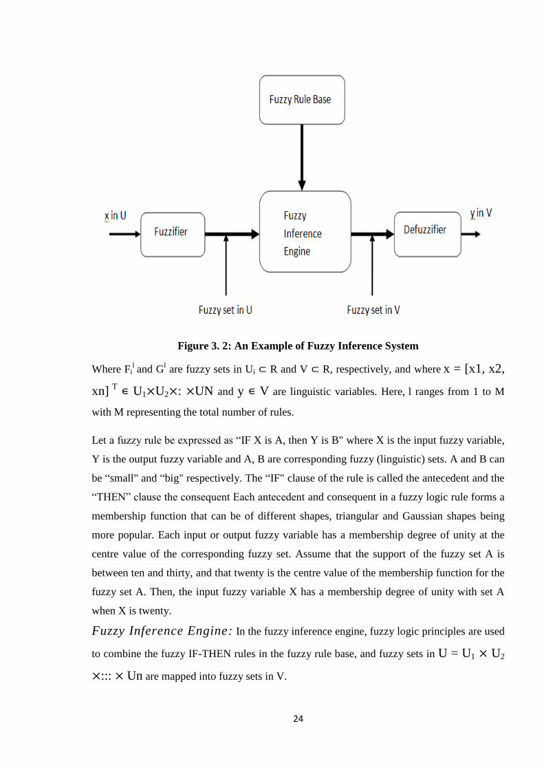
24
Figure 3. 2: An Example of Fuzzy Inference System
Where Fil and G
l are fuzzy sets in Ui ⊂ R and V ⊂ R, respectively, and where
x = [x1, x2,
xn] T
∊ U1×U2×: ×UN and y ∊ V are linguistic variables. Here, l ranges from 1 to M
with M representing the total number of rules.
Let a fuzzy rule be expressed as ―IF X is A, then Y is B" where X is the input fuzzy variable,
Y is the output fuzzy variable and A, B are corresponding fuzzy (linguistic) sets. A and B can
be ―small" and ―big" respectively. The ―IF" clause of the rule is called the antecedent and the
―THEN‖ clause the consequent Each antecedent and consequent in a fuzzy logic rule forms a
membership function that can be of different shapes, triangular and Gaussian shapes being
more popular. Each input or output fuzzy variable has a membership degree of unity at the
centre value of the corresponding fuzzy set. Assume that the support of the fuzzy set A is
between ten and thirty, and that twenty is the centre value of the membership function for the
fuzzy set A. Then, the input fuzzy variable X has a membership degree of unity with set A
when X is twenty.
Fuzzy Inference Engine: In the fuzzy inference engine, fuzzy logic principles are used
to combine the fuzzy IF-THEN rules in the fuzzy rule base, and fuzzy sets in U = U1 × U2
×::: × Un are mapped into fuzzy sets in V.
25
A fuzzy rule is interpreted as a fuzzy implication F1l×: ×Fn
l → G
l in U ×V. Let a fuzzy
set Aꞌ ∊ U be the input to the fuzzy inference engine. Then, each fuzzy IF-THEN rule
determines a fuzzy set Bl ∊ V using the sup-star composition:
𝜇𝐵𝑙 (U, w) = supx∊U [𝜇𝐹1𝑙×…×𝐹𝑛
𝑙→𝐺𝑙 (x, y)*µA ꞌ(x)] (3.8)
Let F1l× : × Fn
l = A and G
l = B.
There are different interpretations for a fuzzy implication, and there are different T-norms as
defined earlier. Hence, the above equation can be interpreted in a number of ways. One
interpretation, called the product-operation rule, is shown here:
µA→B (u, v) = µA(x) *µB(y). (3.9)
This interpretation follows from the fuzzy conjunction implication by using the algebraic
product for *.
Overall mapping of the fuzzy inference engine is described next. For an input Aꞌ (a fuzzy set
in U), the output of the fuzzy inference engine can take two forms: (1) M fuzzy sets Bꞌ (l =
1,2, ...M) as in Eq. 3.8 with each one determined by one fuzzy IF-THEN rule as in Eq. 3.7,
(2) one fuzzy set Bꞌ, which is the union of the M fuzzy sets Bl. Thus,
𝜇𝐵ꞌ(y) = 𝜇𝐵𝑙 (y) ∪ … . .∪ 𝜇𝐵𝑀 (y). (3.10)
Defuzzifier: The defuzzifier maps fuzzy sets in V into a crisp point, y ∊ V. One of the
choices for the defuzzifier is centre average defuzzifier, defined as
y= y l μ
B l y l Ml=1
μB l y l M
l=1
(3.11)
Where y l is the centre of the fuzzy set Gl, i.e., the point in V at which 𝜇𝐺𝑙 (y) achieves its
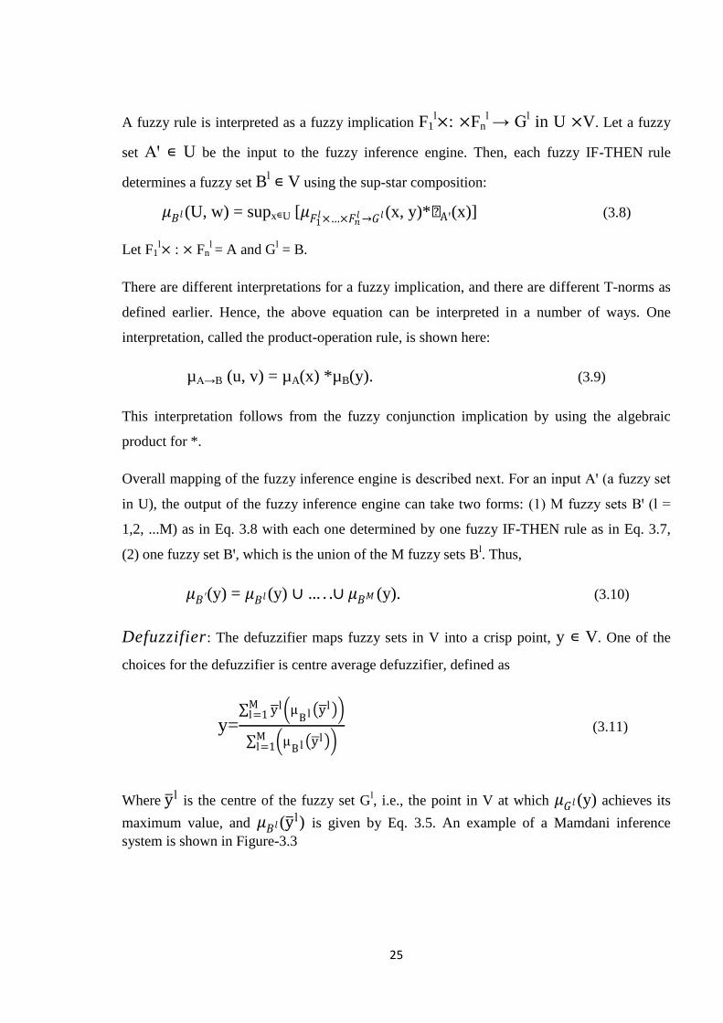
maximum value, and 𝜇𝐵𝑙 (y l) is given by Eq. 3.5. An example of a Mamdani inference
system is shown in Figure-3.3
26
Figure 3. 3: A Two Input Two Rule Mamdani FIS with a Fuzzy Input
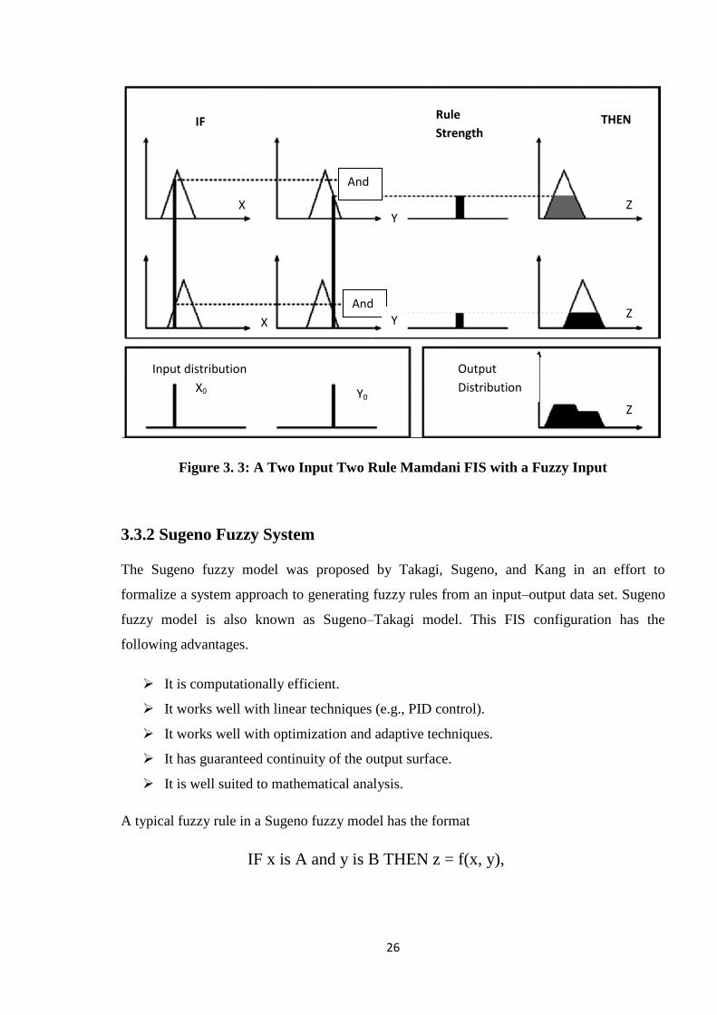
3.3.2 Sugeno Fuzzy System
The Sugeno fuzzy model was proposed by Takagi, Sugeno, and Kang in an effort to
formalize a system approach to generating fuzzy rules from an input–output data set. Sugeno
fuzzy model is also known as Sugeno–Takagi model. This FIS configuration has the
following advantages.
It is computationally efficient.
It works well with linear techniques (e.g., PID control).
It works well with optimization and adaptive techniques.
It has guaranteed continuity of the output surface.
It is well suited to mathematical analysis.
A typical fuzzy rule in a Sugeno fuzzy model has the format
IF x is A and y is B THEN z = f(x, y),
X0 Y0
Z
Output
Distribution
Input distribution
And
And
IF Rule
Strength THEN
Z
Z X
X
Y
Y
27
Where AB are fuzzy sets in the antecedent; Z = f(x, y) is a crisp function in the consequent.
Usually f(x, y) is a polynomial in the input variables x and y, but it can be any other functions
that can appropriately describe the output of the output of the system within the fuzzy region
specified by the antecedent of the rule. When f(x, y) is a first-order polynomial, we have the
first-order Sugeno fuzzy model. When f is a constant, we then have the zero-order Sugeno
fuzzy model, which can be viewed either as a special case of the Mamdani FIS where each
rule‘s consequent is specified by a fuzzy singleton, or a special case of Tsukamoto‘s fuzzy
model where each rule‘s consequent is specified by a membership function of a step function
cantered at the constant. Moreover, a zero-order Sugeno fuzzy model is functionally
equivalent to a radial basis function network under certain minor constraints.
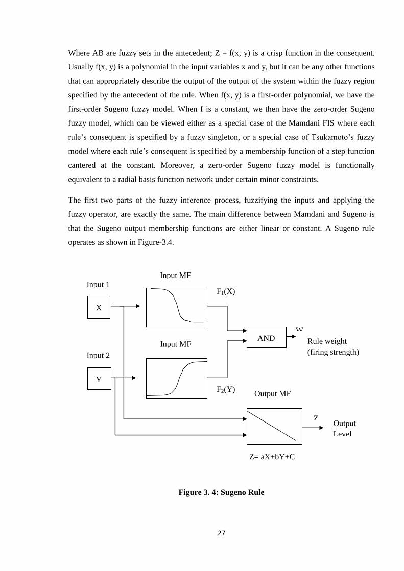
The first two parts of the fuzzy inference process, fuzzifying the inputs and applying the
fuzzy operator, are exactly the same. The main difference between Mamdani and Sugeno is
that the Sugeno output membership functions are either linear or constant. A Sugeno rule
operates as shown in Figure-3.4.
Figure 3. 4: Sugeno Rule
X
Y
AND W
Z
Input 1
Output MF
Z= aX+bY+C
Input 2
Input MF
Input MF
Output
Level
F1(X)
F2(Y)
Rule weight
(firing strength)
28
A typical rule in a Sugeno fuzzy model has the form
IF Input 1 = x AND Input 2 = y, THEN Output is z = ax + by + c.
For a zero-order Sugeno model, the output level zi a constant (a = b = 0).The output level zi
of each rule is weighted by the firing strength WI of the rule. For example, for an AND rule
with Input 1 = x and Input 2 = y, the firing strength is
Wi = And Method (F1(x), F2(y)),
Where F1, 2(·) are the membership functions for Inputs 1 and 2. The final output of the system
is the weighted average of all rule outputs, computed as
Final output = 𝑤𝑖 𝑧𝑖𝑁𝑖=1
𝑤𝑖𝑁𝑖=1
3.4 Introduction to ANFIS
ANFIS is one of the Neuro-fuzzy models. Neural networks and fuzzy systems both are stand-
alone systems. With the increase in the complexity of the process being modelled, the
difficulty in developing dependable fuzzy rules and membership functions increases. This has
led to the development of another approach which is mostly known as ANFIS approach. It
has the benefits of both neural networks and fuzzy logic. Some of the main disadvantages of
fuzzy systems are that expert‘s knowledge or instructions are needed in order to define fuzzy
rules, and that the process of tuning of the parameters of the fuzzy system (e.g. parameters of
the membership functions) often requires a relatively long time. Both these disadvantages are
related to the fact that it is not possible to train fuzzy systems. In order to compensate the
disadvantages a hybrid system named ANFIS (Adaptive-Network-Based Fuzzy Inference
System) has been proposed by Jang. Fuzzy inference in this system is realized with the aid of
a training algorithm, which enables to tune the parameters of the fuzzy system.
3.5 ANFIS Architecture
The ANFIS is a fuzzy Sugeno model put in the framework of adaptive systems to facilitate
learning and adaptation. The Sugeno fuzzy model was proposed by Takagi & Sugeno in an
effort to formalize a systematic approach to generating fuzzy rules from an input-output data
set.

29
A typical fuzzy rule in a Sugeno fuzzy model has the format
If x is A and y is B then z = f(x,y),
Where A , B are fuzzy sets in the antecedent; z = f(x, y) is a crisp function in the consequent.
Usually f(x, y) is a polynomial in the input variables x and y,but it can be any other
functions that can appropriately describe the output of the system within the fuzzy region
specified by the antecedent of the rule. If f(x, y) is a first-order polynomial, than model is
called as the first-order Sugeno fuzzy model. If f is a constant, then it is called the zero-order
Sugeno fuzzy model, which can be viewed either as a special case of the Mamdani fuzzy
inference system, where each rule‘s consequent is specified by a fuzzy singleton, or a special
case of Tsukamoto‘s fuzzy model where each rule‘s consequent is specified by a membership
function of a step function centered at the constant. Moreover, a zero order Sugeno fuzzy
model is functionally equivalent to a radial basis function network under certain minor
constraints.
To facilitate the learning of the Sugeno fuzzy model, it is convenient to put the fuzzy model
into framework of adaptive networks that can compute gradient vectors systematically. The
resultant network architecture is ANFIS, which is shown in Figure-3.5, where node within the
same layer performs functions of the same type, as detailed below. Here circle indicates a
fixed node, whereas a square indicates an adaptive node.
Figure 3. 5: ANFIS Architecture
A2
f1
X
Y
W1
∏
F N
N
A1
B1
B2
∏
S
Layer 1 Layer 2 Layer 3
Layer 4
Layer 5
W2
f2
X Y
X Y

30
Layer 1 Each node in this layer generates a membership grade of a linguistic label. For
instance, the node function of the ith node may be a generalized bell membership function:
O1i= µAi(x) =
1
1+((𝑥−𝑐𝑖𝑎 𝑖
)2)bi i=1, 2 (3.12)
where x is the input to node i; Ai is the linguistic label (small, large, etc.) associated with this
node; and {ai, bi, ci} is the parameter set that changes the shapes of the membership function.
Parameters in this layer are referred to as the premise parameters.
Layer 2 Each node in this layer calculates the firing strength of a rule via multiplication and
the nodes are fixed:
Oi2 = wi = µAi(x) µBi(y), i=1, 2 (3.13)
Layer 3 The nodes are fixed nodes. They are labeled with N, indicating that they play a
normalization role to the firing strengths from the previous layer. The outputs of this layer
can be represented as:
Oi3 = 𝑤 i =
𝑤 𝑖
𝑤1+𝑤2 , i =1, 2 (3.14)
Layer 4 The nodes are adaptive nodes. The output of each node in this layer is simply the
product of the normalized firing strength and a first-order polynomial (for a first-order
Sugeno model). Thus, the outputs of this layer are given by:
O4i = 𝑤 ifi = 𝑤 i(pix +qiy + ri) i= 1,2 (3.15)
Where 𝑤 is the output of layer 3, and {pi, qi, ri} is the parameter set. Parameters in this layer
will be referred to as the consequent parameters.
Layer 5 There is only one single fixed node labelled with S. This node performs the
summation of all incoming signals. Hence, the overall output of the model is given by:
O5i = 𝑤 𝑖𝑓𝑖
2𝑖=1 =
( 𝒘 𝒊𝒇𝒊𝟐𝒊=𝟏 )
𝒘𝟏+𝒘𝟐 (3.16)

31
3.6 Conclusion
The tools of AI, such as neural networks and fuzzy logic, possess certain useful features such
as nonlinearity, massive parallelism, learning capability, and human knowledge encoding
capability. Fuzzy inference system is the most important modelling tool based on fuzzy set
theory. The FISs are built by domain experts and are used in automatic control, decision
analysis, and various other expert systems. In particular, this research uses a full-fledged
fuzzy logic system proposed by Mamdani and Sugeno. Adaptive neuro fuzzy inference
system (ANFIS) is also utilized in this research
32
Chapter-4 Fuzzy Assisted Handoff Algorithm
4.1 Introduction
In the reported work here we proposed a new (hard) handoff algorithm for both microcellular
and macro cellular architecture with LOS (line of sight) transmission. In this chapter the
design and analysis procedure for handoff algorithm is presented. A generalized frame work
for the design of fuzzy logic based handoff algorithm is proposed and described. Different
matrices that have been used to measure handoff related system performance are briefly
touched upon here. Further more, ANFIS is applied for parameter adjustment to make the
algorithm adaptive.
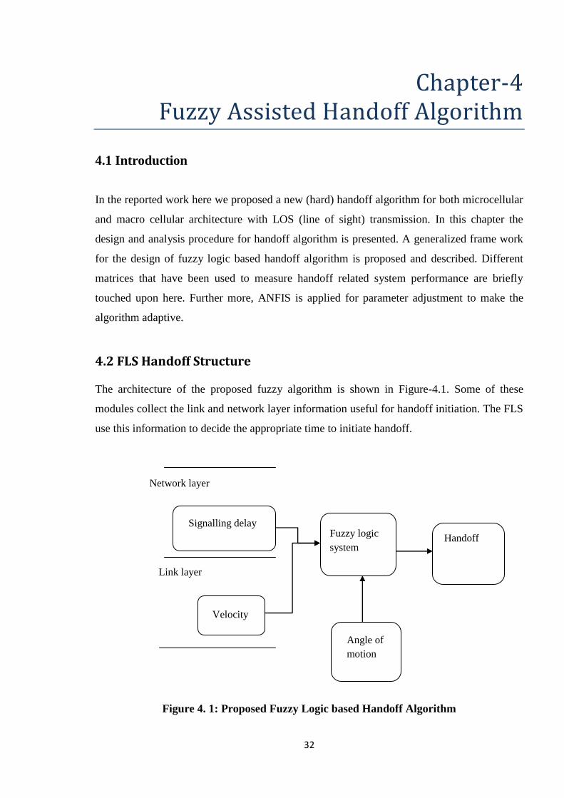
4.2 FLS Handoff Structure
The architecture of the proposed fuzzy algorithm is shown in Figure-4.1. Some of these
modules collect the link and network layer information useful for handoff initiation. The FLS
use this information to decide the appropriate time to initiate handoff.
Figure 4. 1: Proposed Fuzzy Logic based Handoff Algorithm
Fuzzy logic
system
Angle of
motion
Network layer
Link layer
Signalling delay
Velocity
Handoff
33
The functionalites of these units are described as follows:
Signalling delay unit:
Information about velocity is collected from link layer and information about signalling delay
is collected from Network layer. Signalling delay block in Figure-4.1 estimates the delay
associated with handoffs. It is difficult to predict which particular BS the MT will move
unless the handoff instance is very close. Our objective is to estimate the handoff signalling
delay in advance without knowing which particular BS the MT will move. We used the
technique proposed in [28] to estimate the delay. Estimating signalling delay in advance
eliminates the adverse effect of parameters such as type of handoff, location of MT and load
on network. Here we have taken the range of this input as 0- 2 second.
Velocity unit:
The most significant feature of mobile cellular system is that the users are moving. The
velocity block of Figure-4.1estimates the velocity of mobile using VEPSD [29]. Doppler
frequency (fm) is related to speed (v) of a mobile user, speed of light in free space (c), and
carrier frequency of the received signal (fc) through
𝑣 = 𝑐
𝑓𝑐 𝑓𝑚
VEPSD uses fm of received signal envelope to estimate speed of a mobile user. It estimates
fm using the slope of power spectral density (PSD) of the received signal envelope. The slope
of PSD of received signal envelope has maxima at frequencies fc ± fm in mobile
environments. VEPSD detects the maximum value of received signal envelopes PSD that
corresponds to the highest frequency component (fc + fm) to estimate fm. Here we have taken
velocity range from -100Km/h to +100Km/h, for macro cellular system and -15 Km/h to 15
Km/h for microcellular system. We have taken negative sign for, MT approaching the old
base station and positive sign for moving away from it.
Angle of motion:
Referring to Figure-2.2 of chapter-2, during the course of movement of the MT let ‗P‘ is the
point where signal strength from BS1 is below the RSS threshold. Let ‗P‘ be at a distance
of‗d‘ from the cell boundary and ‗a‘ is the cell radius. When the MT is located at point P, it
34
can move in any direction with equal probability. The need for handoff to BS2 arises only if
MT‘s direction of motion from P is in the range [θ ∊ (-θ1, θ1)], where θ1=arc tan (a/2d).
Otherwise, the handoff initiation is a false one. For macro cellular system we have taken
a=1000m and d=100m, we calculate the range was -780 to +78
0. Similarly for
microcellular system we have taken a=30m and d=1m and we calculate the range was -860
to +860. We have taken this parameter range from -180
0 to +180
0.
Finally the fuzzy logic unit process the input criteria and produces an output which is a
membership value. This membership value represents the degree of handoff, which triggers
the initiation of handoff.
4.3 Proposed Fuzzy Logic System
A fuzzy logic rule base is created based on the known sensitivity of handoff algorithm
parameters. The operation of fuzzy logic system has been explained in chapter-3. We use FIS
and ANFIS editor GUI (graphical user interface) of MATLAB for simulation. The
membership function for input and output fuzzy variable is shown Figures-4.2-3.
The system has three iputs and one output.Each of the input is fuzzified at the input stage of
FIS. The fuzzification process is presented in Figure-3.2 of chapter-3. Each input variable is
categorised into 3 categories of fuzzy, ―low‖, ―medium‖ and ―high‖. For input variable
―velocity‖ the 3 catagories of fuzzy are ―-ve‖, ―NZ‖,(near zero) and ―+ve‖. Therefore, the
total numbers of rules for the fuzzy systems are 3×3×3=27. In this work we used both
―Mamdani‖ and ―Sugeno‖, fuzzy logic system. Triangular and trapezoidal membership
functions with 50% overlap of assigned fuzzy sets were considered. Trapizoidal membership
function is consider for edges andthe centre part is described using triangular membership
function.The non-singelton fuzzifier and the centre of area (COA) de-fuzzification method
are used for Mamdani model. Weighted average de-fuzzification method is used for Sugeno
model. We used ―AND‖ operator, ―MIN‖ implication and ―MAX‖ aggression method for
both Mamdani and Sugeno model. The rules used in the proposed Mamdani FLS model were
shown in the table-4.1. Similarl rules were defined for sugeno model as well. Resolving
conflicting criteria in accordance with the global system goals is an important advantage of
fuzzy logic. For example, consider rule 16 Signalling delay ―high‖ encourages for handoff
while ―low‖ angle discourages the handoff. MTs velocity is neutral. Hence, the fuzzy logic

35
rule makes the logical decision to keep handoff value medium. Results for the work is
presented in chapter-5.
Figure 4. 2: Membership Function of Fuzzy Variable "Angle of Motion" (Mamdani
System)
Figure 4. 3: Membership Function of Fuzzy Variable "Velocity" (Mamdani System)
Figure 4. 4: Membership Function of Fuzzy Variable "Signalling Delay" (Mamdani
System)

36
Table 5: Fuzzy Rule Base (Mamadani Model)
Rule no. VELOCITY SIGNALLING
DELAY
ANGLE OF
MOTION
HANDOFF
1 -VE LOW LOW NO
2 -VE LOW MEDIUM NO
3 -VE LOW HIGH NO
4 -VE MEDIUM LOW NO
5 -VE MEDIUM MEDIUM MEDIUM
6 -VE MEDIUM HIGH NO
7 -VE HIGH LOW NO
8 -VE HIGH MEDIUM YES
9 -VE HIGH HIGH NO
10 NZ LOW LOW NO
11 NZ LOW MEDIUM MEDIUM
12 NZ LOW HIGH NO
13 NZ MEDIUM LOW MEDIUM
14 NZ MEDIUM MEDIUM YES
15 NZ MEDIUM HIGH MEDIUM
16 NZ HIGH LOW MEDIUM
17 NZ HIGH MEDIUM YES
18 NZ HIGH HIGH MEDIUM
19 +VE LOW LOW NO
20 +VE LOW MEDIUM YES
21 +VE LOW HIGH NO
22 +VE MEDIUM LOW MEDIUM
23 +VE MEDIUM MEDIUM YES
24 +VE MEDIUM HIGH MEDIUM
25 +VE HIGH LOW YES
26 +VE HIGH MEDIUM YES
27 +VE HIGH HIGH YES
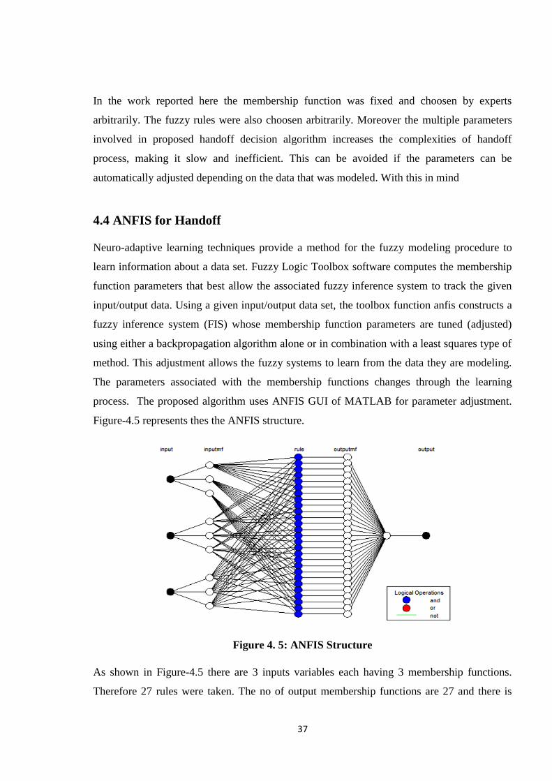
37
In the work reported here the membership function was fixed and choosen by experts
arbitrarily. The fuzzy rules were also choosen arbitrarily. Moreover the multiple parameters
involved in proposed handoff decision algorithm increases the complexities of handoff
process, making it slow and inefficient. This can be avoided if the parameters can be
automatically adjusted depending on the data that was modeled. With this in mind
4.4 ANFIS for Handoff
Neuro-adaptive learning techniques provide a method for the fuzzy modeling procedure to
learn information about a data set. Fuzzy Logic Toolbox software computes the membership
function parameters that best allow the associated fuzzy inference system to track the given
input/output data. Using a given input/output data set, the toolbox function anfis constructs a
fuzzy inference system (FIS) whose membership function parameters are tuned (adjusted)
using either a backpropagation algorithm alone or in combination with a least squares type of
method. This adjustment allows the fuzzy systems to learn from the data they are modeling.
The parameters associated with the membership functions changes through the learning
process. The proposed algorithm uses ANFIS GUI of MATLAB for parameter adjustment.
Figure-4.5 represents thes the ANFIS structure.
Figure 4. 5: ANFIS Structure
As shown in Figure-4.5 there are 3 inputs variables each having 3 membership functions.
Therefore 27 rules were taken. The no of output membership functions are 27 and there is
38
only one output. This is because ANFIS does not allow any rule sharing. To train the ANFIS
55 pairs of input output data were generated using the above discussed Mamdani system. Out
of that 45 pairs are used for training and 10 pairs are used as checking data. There are two
options available for designing a FIS in the ANFIS editor. They are [A] Grid partition method
and [B] substractive clustering method. In this proposed work grid partition method is used.
Hybrid algorithm is used for training the model. The model is then tested using training data
set. Finally cheking datas are presented to the trained FIS model for validation, to see how
well the FIS model predicts the corresponding data set output values. The details of ANFIS
information, error plot, training and testing plots are shown and analyzed in chapter-5.
4.5 Conclusion
This chapter introduces a new class of handoff algorithms that exploits the knowledge of the
working of several existing algorithms and uses fuzzy logic to adapt the parameters of
handoff algorithms. A fuzzy logic rule base is created using the known sensitivities of
handoff parameters. Furthermore, the proposed approach allows tuning of the FLS
parameters using ANFIS to achieve a balanced trade-off among different system
characteristics in the dynamic cellular environment. The design procedure for a generic fuzzy
logic based algorithm is outlined.
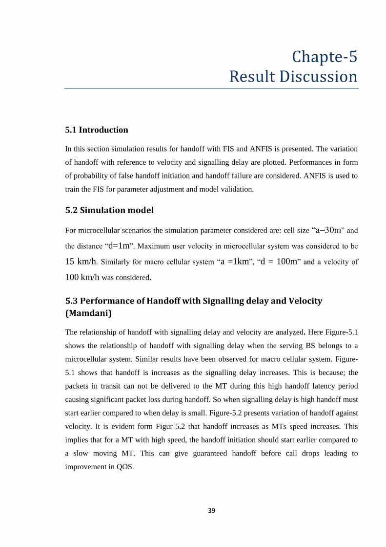
39
Chapte-5 Result Discussion
5.1 Introduction
In this section simulation results for handoff with FIS and ANFIS is presented. The variation
of handoff with reference to velocity and signalling delay are plotted. Performances in form
of probability of false handoff initiation and handoff failure are considered. ANFIS is used to
train the FIS for parameter adjustment and model validation.
5.2 Simulation model
For microcellular scenarios the simulation parameter considered are: cell size ―a=30m‖ and
the distance ―d=1m‖. Maximum user velocity in microcellular system was considered to be
15 km/h. Similarly for macro cellular system ―a =1km‖, ―d = 100m‖ and a velocity of
100 km/h was considered.
5.3 Performance of Handoff with Signalling delay and Velocity
(Mamdani)
The relationship of handoff with signalling delay and velocity are analyzed. Here Figure-5.1
shows the relationship of handoff with signalling delay when the serving BS belongs to a
microcellular system. Similar results have been observed for macro cellular system. Figure-
5.1 shows that handoff is increases as the signalling delay increases. This is because; the
packets in transit can not be delivered to the MT during this high handoff latency period
causing significant packet loss during handoff. So when signalling delay is high handoff must
start earlier compared to when delay is small. Figure-5.2 presents variation of handoff against
velocity. It is evident form Figur-5.2 that handoff increases as MTs speed increases. This
implies that for a MT with high speed, the handoff initiation should start earlier compared to
a slow moving MT. This can give guaranteed handoff before call drops leading to
improvement in QOS.

40
Figure5.1: Handoff for Different Signalling Delay (Microcellular System)
Figure5.2: Handoff for Different Velocity (Macro cellular system)
5.4 Relationship between False Handoff Probability (Pfh) and Velocity
Figure-5.3 and Figure-5.4 shows the comparison of the false handoff initiation probability
(Pfh) of our new FLS with distance and velocity based FLS when the serving BS belongs to
macro cellular and microcellular system respectively for fixed delay. The false handoff
initiation probability of our new FLS is 10 percent to 17 percent less as compared to the
1 1.1 1.2 1.3 1.4 1.5 1.6 1.7
0.35
0.4
0.45
0.5
0.55
0.6
0.65
0.7
handoff
signalling delay
-7 -6 -5 -4 -3 -2 -1 0
0.35
0.4
0.45
0.5
0.55
0.6
0.65
0.7
handoff
velocity
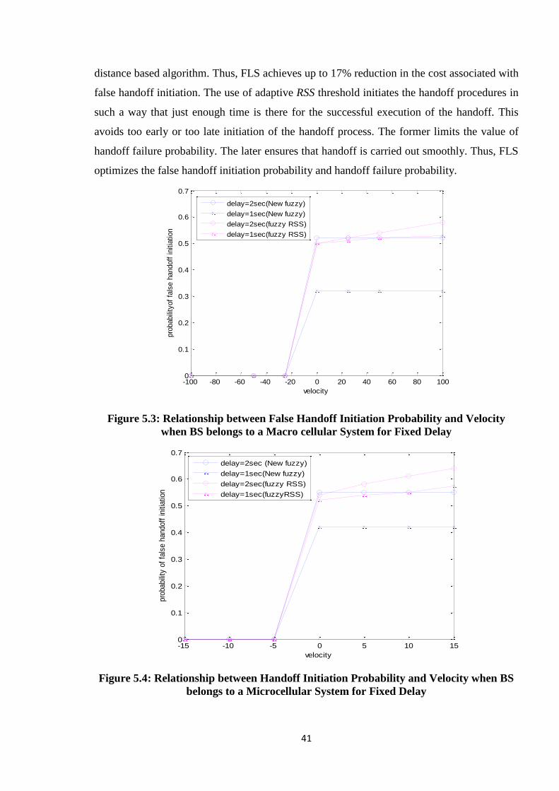
41
distance based algorithm. Thus, FLS achieves up to 17% reduction in the cost associated with
false handoff initiation. The use of adaptive RSS threshold initiates the handoff procedures in
such a way that just enough time is there for the successful execution of the handoff. This
avoids too early or too late initiation of the handoff process. The former limits the value of
handoff failure probability. The later ensures that handoff is carried out smoothly. Thus, FLS
optimizes the false handoff initiation probability and handoff failure probability.
Figure 5.3: Relationship between False Handoff Initiation Probability and Velocity
when BS belongs to a Macro cellular System for Fixed Delay
Figure 5.4: Relationship between Handoff Initiation Probability and Velocity when BS
belongs to a Microcellular System for Fixed Delay
-100 -80 -60 -40 -20 0 20 40 60 80 1000
0.1
0.2
0.3
0.4
0.5
0.6
0.7
velocity
pro
babili
tyof
fals
e h
andoff
initia
tion
delay=2sec(New fuzzy)
delay=1sec(New fuzzy)
delay=2sec(fuzzy RSS)
delay=1sec(fuzzy RSS)
-15 -10 -5 0 5 10 150
0.1
0.2
0.3
0.4
0.5
0.6
0.7
pro
babili
ty o
f fa
lse h
andoff
initia
tion
velocity
delay=2sec (New fuzzy)
delay=1sec(New fuzzy)
delay=2sec(fuzzy RSS)
delay=1sec(fuzzyRSS)
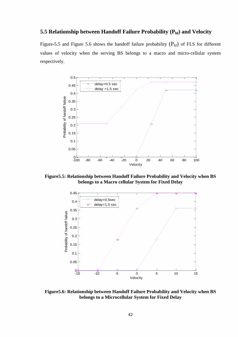
42
5.5 Relationship between Handoff Failure Probability (Phf) and Velocity
Figure-5.5 and Figure 5.6 shows the handoff failure probability (Phf) of FLS for different
values of velocity when the serving BS belongs to a macro and micro-cellular system
respectively.
Figure5.5: Relationship between Handoff Failure Probability and Velocity when BS
belongs to a Macro cellular System for Fixed Delay
Figure5.6: Relationship between Handoff Failure Probability and Velocity when BS
belongs to a Microcellular System for Fixed Delay
-100 -80 -60 -40 -20 0 20 40 60 80 1000
0.1
0.2
0.3
0.4
0.5
0.6
0.7
0 0.2 0.4 0.6 0.8 1 1.2 1.4 1.6 1.8 20
0.1
0.2
0.3
0.4
0.5
0.6
0.7
-100 -80 -60 -40 -20 0 20 40 60 80 1000
0.05
0.1
0.15
0.2
0.25
0.3
0.35
0.4
0.45
0.5
Velocity
Pro
babili
ty o
f handoff
failu
re
0 0.2 0.4 0.6 0.8 1 1.2 1.4 1.6 1.8 20
0.05
0.1
0.15
0.2
0.25
0.3
0.35
0.4
0.45
0.5
delay=0.5 sec
delay =1.5 sec
-15 -10 -5 0 5 10 150
0.1
0.2
0.3
0.4
0.5
0.6
0.7
0 0.2 0.4 0.6 0.8 1 1.2 1.4 1.6 1.8 20
0.1
0.2
0.3
0.4
0.5
0.6
0.7
-15 -10 -5 0 5 10 150
0.05
0.1
0.15
0.2
0.25
0.3
0.35
0.4
0.45
Velocity
Pro
babili
ty o
f handoff
failu
re
0 0.2 0.4 0.6 0.8 1 1.2 1.4 1.6 1.8 20
0.1
0.2
0.3
0.4
0.5
0.6
0.7
0.8
0.9
1
delay=0.5sec
delay=1.5 sec
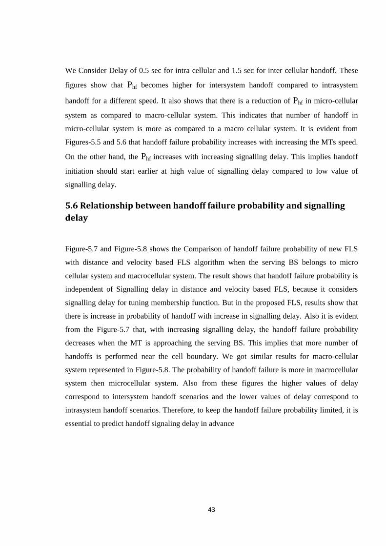
43
We Consider Delay of 0.5 sec for intra cellular and 1.5 sec for inter cellular handoff. These
figures show that Phf becomes higher for intersystem handoff compared to intrasystem
handoff for a different speed. It also shows that there is a reduction of Phf in micro-cellular
system as compared to macro-cellular system. This indicates that number of handoff in
micro-cellular system is more as compared to a macro cellular system. It is evident from
Figures-5.5 and 5.6 that handoff failure probability increases with increasing the MTs speed.
On the other hand, the Phf increases with increasing signalling delay. This implies handoff
initiation should start earlier at high value of signalling delay compared to low value of
signalling delay.
5.6 Relationship between handoff failure probability and signalling
delay
Figure-5.7 and Figure-5.8 shows the Comparison of handoff failure probability of new FLS
with distance and velocity based FLS algorithm when the serving BS belongs to micro
cellular system and macrocellular system. The result shows that handoff failure probability is
independent of Signalling delay in distance and velocity based FLS, because it considers
signalling delay for tuning membership function. But in the proposed FLS, results show that
there is increase in probability of handoff with increase in signalling delay. Also it is evident
from the Figure-5.7 that, with increasing signalling delay, the handoff failure probability
decreases when the MT is approaching the serving BS. This implies that more number of
handoffs is performed near the cell boundary. We got similar results for macro-cellular
system represented in Figure-5.8. The probability of handoff failure is more in macrocellular
system then microcellular system. Also from these figures the higher values of delay
correspond to intersystem handoff scenarios and the lower values of delay correspond to
intrasystem handoff scenarios. Therefore, to keep the handoff failure probability limited, it is
essential to predict handoff signaling delay in advance
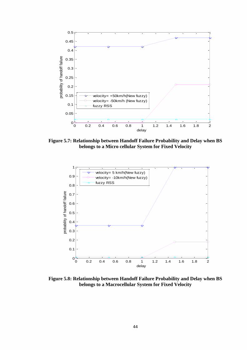
44
Figure 5.7: Relationship between Handoff Failure Probability and Delay when BS
belongs to a Micro cellular System for Fixed Velocity
Figure 5.8: Relationship between Handoff Failure Probability and Delay when BS
belongs to a Macrocellular System for Fixed Velocity
0 0.2 0.4 0.6 0.8 1 1.2 1.4 1.6 1.8 20
0.05
0.1
0.15
0.2
0.25
0.3
0.35
0.4
0.45
0.5
delay
prob
abili
ty o
f ha
ndof
f fa
ilure
velocity= +50km/h(New fuzzy)
velocity= -50km/h (New fuzzy)
fuzzy RSS
0 0.2 0.4 0.6 0.8 1 1.2 1.4 1.6 1.8 20
0.1
0.2
0.3
0.4
0.5
0.6
0.7
0.8
0.9
1
delay
pro
babili
ty o
f handoff
failu
re
velocity= 5 km/h(New fuzzy)
velocity= -10km/h(New fuzzy)
fuzzy RSS

45
5.7 Sugeno Output
The simulation results for handoff in case of Sugeno model is analyzed below.The results
shown are clearly able to describe the intercellular and intra cellular handoff. Figure-5.11
represents the surface plot of handoff against velocity and Signalling delay of MT. From
Figure-5.11, it is evident that the handoff is low when the MT approaching the serving BS.
The value of handoff is high for high velocity and signalling delay. This can be cosnidered as
intercellular handoff. Similarly for medium value of velocity and signalling delay the
handoff is high. This can be considered as intra cellular handoff. Figure-5.12 represents the
surface plot of handoff with respect to angle of motion and signalling delay of MT.
In this figure, handoff increase with increaseing signalling delay. For the calculated value of
signalling delay (refer chapter-4) high handoff can be considered as inter cellular handoff.
Other than the calculated range (±780
for macro and ±860 for micro cellular) the handoff is
also high for high signalling delay which can be reffered as intra cellular handoff.
Figure 5.9: Surface plot of Handoff vs Signalling Delay and Velocity

46
Figure 5.10: Surface plot of Handoff vs. Signalling Delay and Angle of Motion
Figure 5.11: Surface plot of Handoff vs. Angle of Motion and Velocity
Figure 5.13represents the surface plot of handoff against angle of motion and velocity of MT.
It impliest that when MT is moving away from the serving BS with high velocity the handoff
increases whatever may be the value of angle of motion.

47
5.8 ANFIS Output
In above discussed Sugeno model, we used trapezoidal membership function with three
fuzzy sets for each input variable. In this section the Sugeno model is trained with known
input /output data set. We generate 80 data pairs using Mamdani model discussed in chapter-
5 to tune the Sugeno model. The first 45 pairs used for training, last 10 pairs used for
checking and the rest 5 pairs with another 5 pair from training data were used for testing data.
With the following ANFIS information given in Table-6, the training error plot is shown in
Figure-5.14. The model is validated using 10 number of checking data pairs, to see how well
the FIS model predicts the corresponding data set output values. Here two similar data sets
are used for training and checking, but the checking data set is corrupted by a small amount
of noise. Figure-5.15 and 5.16 represents the FIS output after testing with training and
checking data respectively.
Table 6: ANFIS Information (trapizoidal membership function)
Learning Algorithm Hybrid
No.of Nodes 78
Error Tolerence 0
No.of Epoches 20
No. of Linear parameter 27
No. of Non- Linear parameter 36
Total No. Of parameter 63
No.of Training data pairs 45
No.of Checking data pairs 10
No.of Rules 27
The idea behind using a checking data set for model validation is that after a certain point in
the training, the model begins over fitting the training data set. The model error for the
checking data set tends to decrease as the training takes place up to the point that over fitting
begins, and then the model error for the checking data suddenly increases. Over fitting is
accounted for by testing the FIS trained on the training data against the checking data, and
choosing the membership function parameters to be those associated with the minimum
checking error if these errors indicate model over fitting.
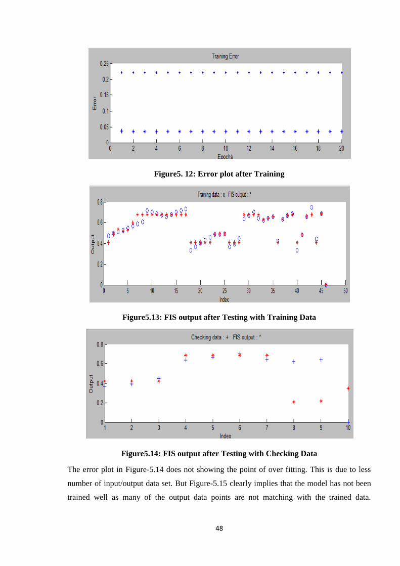
48
Figure5. 12: Error plot after Training
Figure5.13: FIS output after Testing with Training Data
Figure5.14: FIS output after Testing with Checking Data
The error plot in Figure-5.14 does not showing the point of over fitting. This is due to less
number of input/output data set. But Figure-5.15 clearly implies that the model has not been
trained well as many of the output data points are not matching with the trained data.
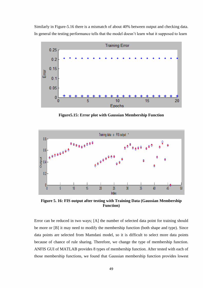
49
Similarly in Figure-5.16 there is a mismatch of about 40% between output and checking data.
In general the testing performance tells that the model doesn‘t learn what it supposed to learn
Figure5.15: Error plot with Gaussian Membership Function
Figure 5. 16: FIS output after testing with Training Data (Gaussian Membership
Function)
Error can be reduced in two ways; [A] the number of selected data point for training should
be more or [B] it may need to modify the membership function (both shape and type). Since
data points are selected from Mamdani model, so it is difficult to select more data points
because of chance of rule sharing. Therefore, we change the type of membership function.
ANFIS GUI of MATLAB provides 8 types of membership function. After tested with each of
those membership functions, we found that Gaussian membership function provides lowest
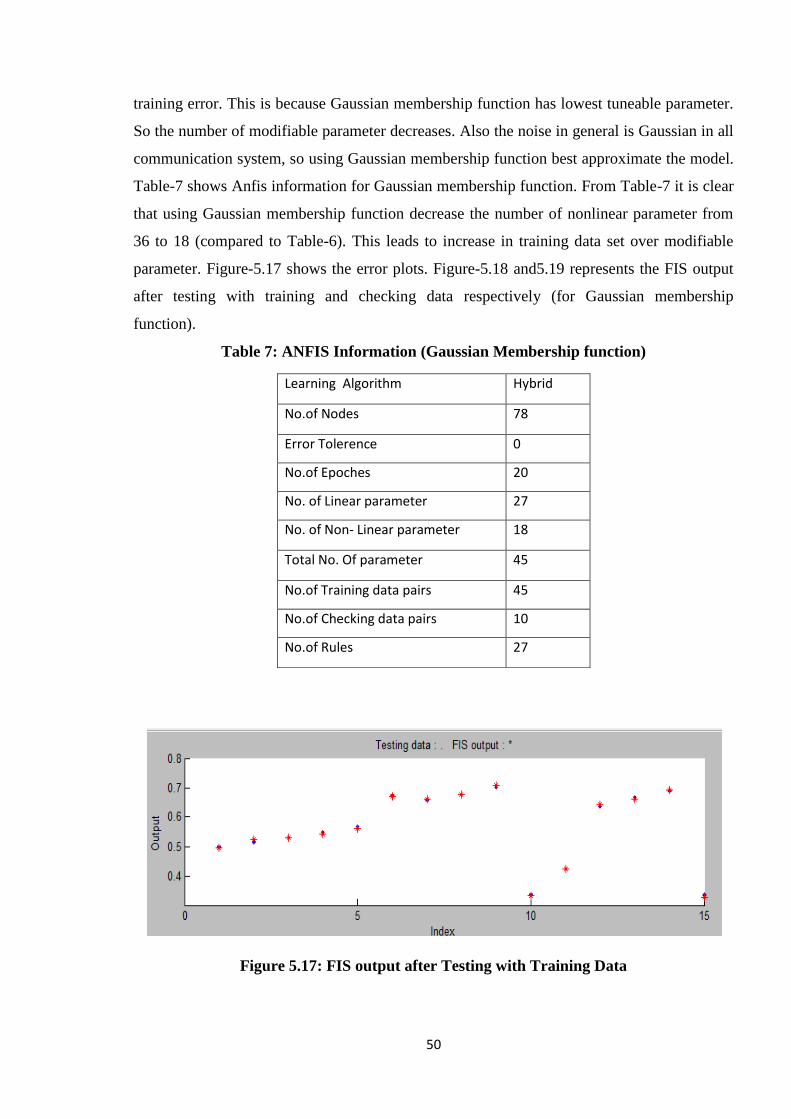
50
training error. This is because Gaussian membership function has lowest tuneable parameter.
So the number of modifiable parameter decreases. Also the noise in general is Gaussian in all
communication system, so using Gaussian membership function best approximate the model.
Table-7 shows Anfis information for Gaussian membership function. From Table-7 it is clear
that using Gaussian membership function decrease the number of nonlinear parameter from
36 to 18 (compared to Table-6). This leads to increase in training data set over modifiable
parameter. Figure-5.17 shows the error plots. Figure-5.18 and5.19 represents the FIS output
after testing with training and checking data respectively (for Gaussian membership
function).
Table 7: ANFIS Information (Gaussian Membership function)
Figure 5.17: FIS output after Testing with Training Data
Learning Algorithm Hybrid
No.of Nodes 78
Error Tolerence 0
No.of Epoches 20
No. of Linear parameter 27
No. of Non- Linear parameter 18
Total No. Of parameter 45
No.of Training data pairs 45
No.of Checking data pairs 10
No.of Rules 27
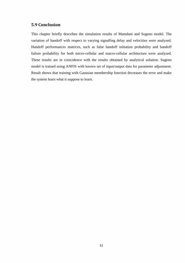
51
5.9 Conclusion
This chapter briefly describes the simulation results of Mamdani and Sugeno model. The
variation of handoff with respect to varying signalling delay and velocities were analyzed.
Handoff performances matrices, such as false handoff initiation probability and handoff
failure probability for both micro-cellular and macro-cellular architecture were analyzed.
These results are in coincidence with the results obtained by analytical solution. Sugeno
model is trained using ANFIS with known set of input/output data for parameter adjustment.
Result shows that training with Gaussian membership function decreases the error and make
the system learn what it suppose to learn.

52
Chapter-6 Conclusion and Future work
6.1 Conclusion
This chapter summarizes the dissertation research and discusses potential directions for future
research in the area.
Thesis Contribution
Handoff is an integral component of cellular communications. The handoff process
determines the spectral efficiency and the quality perceived by users. Many of the existing
handoff algorithms do not exploit advantages of multi-criteria handoff. In this research a new
fuzzy logic based hard handoff algorithm for micro and macro cellular architecture is
introduced. A fuzzy logic rule base is created using the known sensitivities of handoff
parameters. It uses mobile‘s speed, direction of motion and signalling delay information to
enhance the performance of handoff initiation significantly. It also significantly reduces the
cost associated with the false handoff initiation because it achieves lower false handoff
initiation probability than existing handoff algorithms. Furthermore, the proposed approach
allows tuning of the FLS parameters to achieve a balanced tradeoff among different system
characteristics in the dynamic cellular environment.
Chapter 2 discusses different aspects of handoff and provides a literature survey of handoff
related research work. The contents of this chapter are extremely valuable since the full
potential of any new approaches for an efficient handoff process cannot be realized without
the essential knowledge about the cellular system and the response of the cellular system to
different handoff parameters.
Chapter 3 introduces two major tools of AI that are utilized in this research. Background
information on fuzzy logic and ANFIS is given. These tools provide an efficient and
convenient architecture to represent the designer's knowledge about the system and its
environment.
Chapter 4 outlines the design procedure of proposed handoff algorithm.The handoff
algorithm has been improved by considering two new parameter, signalling delay and angle
53
of motion of MT along with velocity as input criteria. The proposed fuzzy inference scheme
uses triangular and trapezoidal membership function for fuzzification. The types of
defuzzification method used are centroid and weighted average formula for Mamdani and
Sugeno model respectively. Extensive simulation analysis has been used to validate the
proposed technique
Chapter 5 describes the simulation results of Mamdani and Sugeno model. The variation of
handoff with respect to varying signalling delay and velocities were analyzed. Handoff
performances matrices, such as false handoff initiation probability and handoff failure
probability for both micro-cellular and macro-cellular architecture were analyzed. These
results are in coincidence with the results obtained by analytical solution. Sugeno model is
trained using ANFIS with known set of input/output data for parameter adjustment. Result
shows that training with Gaussian membership function decreases the error and make the
system learn what it suppose to learn.
This work can be extended in several directions as described next.
6.2 Scope of Future Work
Algorithm Study
This dissertation focuses on fuzzy assisted handoff algorithms. Some of the other potential
new classes of algorithms capable of providing high performance may include prediction
based algorithms and self-tuning algorithms.
Application Study
The proposed algorithms can serve as a basis to obtain high performance algorithms for other
architetures such as overlay architecture, femto cell structure, sattelite based communication
systems and next genaration communication systems.
54
Bibliography
[1] W.Wang I.F.Akyildiz, "A predictive User Mobility Profile for Wireless Multimedia Networks,"
IEEE/ACM Trans. Networking, vol. 12, pp. 1021-1035, DEC 2004.
[2] J.Xie,S. Mohanty I.F. Akyildiz, "A Survey on Mobility Management in Next generation All IP
Based Wireless Systems," IEEE Wireless Communication, vol. 11, no. 4, pp. 16-28, aug 2004.
[3] K.El Malki et al., "Low latency Handoff in Mobile IPv4," internet draft.internet engineering tak
force, may 2001.
[4] T. Itoh Y. Kinoshita, "Performance Analysis of a Fuzzy Handoff Algorithm by an Indoor
Propagation Simulator," in Proc.IEEE VT, 1993, pp. 241-245.
[5] Ravi Sankar G.Edwards, "Microcellular Handoff Using Fuzzy Techniques," Wireless Networks, vol.
4, pp. 401-409, 1998.
[6] K. Cattermole D. Muaoz-Rodiguez, "Handoff Procedure for Defined Radio Cells," in Proc.IEEE VT,
1987, pp. 38-44.
[7] T. S. Rappaport, Wirelwss Communications, Principles and Practice. Upper Saddel River, NJ:
Prentice Hall, 1996.
[8] W.Zhuang J.W.Mark, Wireless Communications and Networking, Eastern Economy ed.: PHI
Leearning private Limited, 2009.
[9] V.K.Garg and J.E Wilkes, Wireless and Personal Communications System.: Prentice Hall inc.,
1996.
[10] W.R.Mende, "Evaluation of Proposed Handoff Algorithm for the GSM Cellular System," in IEEE
Vehicular Technology Conference, 1990, pp. 264-269.
[11] A. and Y. Lin Noerpel, "Handover Management for a PCS Network," IEEE Personal
Communication, vol. 4, no. 6, pp. 18-24, dec 1997.
[12] M.D. and G. L. Stuber Austin, "Velocity adaptive Handoff Algorithm for Microcellular Systems,"
IEEE Transaction on Vehicular Technology, vol. 43, no. 3, pp. 549-561, AUG 1994.
[13] H. and W.Benjapolakul Bongkarn, "Trunk-Resource-Efficency-Controlling Soft Handoff Based on
Fuzzy Logic and Gradient Descent Method," in IEEE Vehicular Technology Conference, 2001.
[14] K.,P. Krishnamurty, M. Ylianttila, J.P. Makela, R. Pichna and J. Vallstrom Phalavan, "Handoff in
Hybrid Mobile Data Networks," IEEE Personal Communication, pp. 34-47, April 2000.
[15] J. H. Reed and H. F. Vanlandingham N. D. Tripathi, "Handoff in Cellular System," IEEE Personal
Communication, DEC 1998.
55
[16] Holtzman J. M. and Sampath A., "Adaptive Averaging Methodology for Handoffs in Cellular
Systems," IEEE Transacations on Vehicular Technology, vol. 44, no. 1, pp. 59-66, FEB 1995.
[17] French E. A. and C. L. Masquida, "Cellular Models and Handoff Criteria," in IEEE Vehicular
Technology Conference, 1989, pp. 128-135.
[18] Cornett K. G. and S. B. Wicker, "Bit Error Rate Estimation Technique for Digital Land Mobile
Radios," in IEEE VTC, 1991, pp. 543-548.
[19] Rappaport S., "Blocking, Handoff and Traffic Performance for Cellular Communication Systems
with Mixed Platforms," in IEEE Proceedings-I, OCT 1993.
[20] Tripathi N. D., "Generic Adaptive Handoff Algorithms Using Fuzzy Logic and Neural Networks,"
Virgina Polytechnique Institute and State University, PhD Thesis 1997.
[21] K.D. and D.C.Cox Wong, "A pattern Recognition System for Handoff Algorithms," IEEE Journal on
SAC, vol. 18, no. 7, July 2000.
[22] R. and D. C. Cox Narasimhan, "A Handoff Algorithms for Wireless Systems Using Pattern
Recognition," in Proceedings of the IEEE International Symposium on the Personal Indoor,
Mobile Radio Communication, Boston, 1998.
[23] M. and T. Nagatsu Hata, "Mobile Location Using Signal Strength Measurements in a Cellular
System ," IEEE Transactions on VTC, vol. 29, no. 2, pp. 245-252, May 1980.
[24] Y. Kinoshita and K. Oku, "Robustness Analysis of New Fuzzy Handover Control for Indoor
Cellular," in 4th IEEE ICUPCR, 1995.
[25] W. Benjapolakul B. Hommnan, "A Handover Decision Procedure for Mobile Telephone Systems
Using Fuzzy Logic," in IEEE APCCAS, 1998, pp. 503-506.
[26] A. Kandel, R. Sankar G. Edwards, "Fuzzy handoff algorithms for Wireless Communication, Fuzzy
sets and systems," vol. 110, no. 3, pp. 379-388, 2000.
[27] L. X.Wang, Adaptive Fuzzy Systems and Control. New Jersey: PTR Prentice Hall, 1994.
[28] K. Lai and M. Maker, "Measuring Link Bandwidths Using a Deterministic Model of Packet Delay
," in SGCOMM Comput.Commun.Rev, 2000, pp. 283-294.
[29] S. Mohanty, "VEPSD: Velocity Estimation Using the PSD of the Received Signal Envelope in Next
Generation Wireless System," IEEE Trans.Wireless Comm., vol. 4, no. 6, pp. 2655-2660, NOV
2005.
[30] MATLAB , Fuzzy logic Tool box, User guide
[31] H., D. Munoz-Rodriguez, F. Jaimes-Romero and H. Tawfik Maturino-Lozoya, "Handoff Algorithm
56
Based on Fuzzy Classifiers," IEEE Trans. on VTC, vol. 49, no. 6, pp. 2286-2294, NOV 2000.
[32] S. Mohanty and Ian F. Akyildiz, "A cross layer (layer 2+3) Handoff Management Protocol for Next
Generation Wireless Systems," IEEE Transactions on Mobile Computing, vol. 5 , no. 10, p. , OCT
2006.
[33] N., Salih, T., Kucukoner, S., Fidanboylu, K. Ekiz, "An Overview of Handoff Techniques in Cellular
Networks," in Proceedings - Wec 05.Fourth World Enformatika Conference 6, 2005, pp. 1-4.
[34] Namvi Chakma, M. M. A. Hashem Presila Israt, "A Fuzzy Logic Based Adaptive Handoff
Management Protocol for Next Generation Wireless Systems," Journal of Networks, vol. 4, no.
10, DEC 2009.
[35] N. A. Shah and Moinuddin G.M. Mir, "Decentralized Handoff for Microcellular Mobile
Communication System Using Fuzzy Logic," World Academy of Science , Engineering and
Technology, 2009.
[36] T., Erosy,C., Cayirci, E., Parr, G. Onel, "A Multi- criteria Handoff Decision Scheme for the Next
Generation Tactical Communication Systems," Computer Networks, vol. 46, no. 5, pp. 695-708,
2004.
[37] J.-S. R Jang, "ANFIS: Adaptive-Network-based Fuzzy Inference Systems," IEEE Transactions on
Systems, Man, and Cybernetics, vol. 23, no. 3, pp. 665-685, May 1993.